moab umtra project crescent junction disposal cell interim
TRANSCRIPT

DOE-EM/GJRAC2040-A
Moab UMTRA Project Crescent Junction Disposal Cell Interim Completion Report Addendum A
Revision 0
December 2012

DOE-EM/GJRAC2040-A
Moab UMTRA Project Crescent Junction Disposal Cell Interim Completion Report
Addendum A
Revision 0
December 2012
Prepared by the Remedial Action Contractor under contract numbers DE-AT30-07CC00014 and DE-DT0002936 for the U.S. Department of Energy Office of Environmental Management, Grand Junction, Colorado.


U.S. Department of Energy Moab UMTRA Project Crescent Junction Disposal Cell Interim Completion Report Addendum A Revision 0 December 2012 DOE-EM/GJRAC2040-A
Page ii
Revision History
Revision No. Date Reason/Basis for Revision 0 December 2012 Initial issue.
U.S. Department of Energy Moab UMTRA Project Crescent Junction Disposal Cell Interim Completion Report Addendum A Revision 0 December 2012 DOE-EM/GJRAC2040-A
Page iii
Contents Section Page Acronyms and Abbreviations .......................................................................................................v Executive Summary ................................................................................................................ ES-1 1.0 Introduction ........................................................................................................................1 2.0 Critical Review ...................................................................................................................3
2.1 Cell Excavation ........................................................................................................6 2.2 Perimeter Embankment ............................................................................................6 2.3 RRM… .....................................................................................................................8
2.3.1 Computer Aided Earthmoving System Performance Verification Testing..........................................................................................................8
2.3.2 RRM Placement ...........................................................................................9 2.4 Interim Cover .........................................................................................................13 2.5 Radon Barrier .........................................................................................................16
2.5.1 Radon Barrier Placement ...........................................................................16 2.5.2 Verification Measurements for Radon Flux ..............................................19
2.6 Infiltration and Biointrusion Barrier ......................................................................22 2.7 Frost Protection Layer ............................................................................................24 2.8 Cap Rock and Armoring ........................................................................................26
3.0 Design Assessment ...........................................................................................................28 3.1 Design Criteria Changes ........................................................................................28 3.2 Design Changes .....................................................................................................28 3.3 QA Requirements...................................................................................................29 3.4 Permits and Agreements ........................................................................................30
4.0 Remedial Action Assessment ..........................................................................................33 4.1 Pre-Excavation Site Conditions .............................................................................33 4.2 Cell Construction ...................................................................................................33
4.2.1 Excavation..................................................................................................34 4.2.2 Perimeter Embankment Construction ........................................................35 4.2.3 RRM Placement .........................................................................................35 4.2.4 Cover and Rock Armoring Placement .......................................................35 4.2.5 Spoils Embankment Construction..............................................................35
4.3 Soil Compaction and Testing .................................................................................39 4.4 Lift Approval .........................................................................................................40 4.5 Geotechnical Testing .............................................................................................40
4.5.1 Soils Testing...............................................................................................41 4.5.2 Aggregate Testing ......................................................................................41
4.6 Radiological Verification .......................................................................................42 4.7 QA Requirements...................................................................................................44 4.8 Monitoring for Presence of Free Liquids ...............................................................49 4.9 Monitoring for Presence of Ground Water ............................................................49
5.0 References .........................................................................................................................51
Tables Table 1. Lifts/Testing Totals ........................................................................................................3 Table 2. Cell Excavation Inspection and Testing ........................................................................6 Table 3. Perimeter Embankment Inspection and Testing ............................................................7 Table 4. CAES Performance Verification Testing .......................................................................8

U.S. Department of Energy Moab UMTRA Project Crescent Junction Disposal Cell Interim Completion Report Addendum A Revision 0 December 2012 DOE-EM/GJRAC2040-A
Page iv
Tables (continued) Table 5. RRM Inspection and Testing .......................................................................................10 Table 6. Interim Cover Inspection and Testing ..........................................................................13 Table 7. Radon Barrier Inspection and Testing .........................................................................16 Table 8. Radon Flux Measurements ..........................................................................................19 Table 9. Infiltration and Biointrusion Barrier Inspection and Testing .......................................22 Table 10. Frost Protection Layer Inspection and Testing ............................................................25 Table 11. Cap Rock and Armoring Inspection and Testing .........................................................26 Table 12. DCNs Submitted to NRC .............................................................................................28 Table 13. Audits and Surveillances Conducted during Design ...................................................30 Table 14. Crescent Junction Site Permits and Agreements .........................................................30 Table 15. Descriptions of Compaction Equipment Used during Cell Construction ....................34 Table 16. Spoils Embankment Inspection and Testing ................................................................36 Table 17. Rock Durability Test Results and NRC Rock Quality Scores .....................................42 Table 18. Results of Ra-226 Activity in Upper 7 Ft of Placed RRM ..........................................43 Table 19. Audits and Surveillances Conducted during Construction ..........................................44 Table 20. Results of Monitoring for the Presence of Fluids in Standpipe ...................................49 Table 21. Results of Monitoring for Presence of Ground Water .................................................49
Figures Figure 1. Location of Moab and Crescent Junction Sites ..............................................................1 Figure 2. Crescent Junction Site Features .....................................................................................2 Figure 3. General Extent of Cover Layers ....................................................................................4 Figure 4. Extent of Phase 2 Excavation and South Perimeter Embankment ................................5 Figure 5. Distribution of Survey Points to Verify Compliance with RRM Specification ...........12 Figure 6. Distribution of Survey Points to Verify Compliance with Interim Cover
Specification ................................................................................................................15 Figure 7. Distribution of Survey Points to Verify Compliance with Radon Barrier Specification ................................................................................................................18 Figure 8. Radon Flux Measurement Grid Numbers and Locations ............................................21 Figure 9. Distribution of Survey Points to Verify Compliance with Infiltration and
Biointrusion Barrier Specification ...............................................................................23 Figure 10. Distribution of Survey Points to Verify Compliance with Frost Protection Layer
Specification ................................................................................................................25 Figure 11. Distribution of Survey Points to Verify Compliance with Cap Rock Specification ....27 Figure 12. Spoils Embankment Topographic Surface ...................................................................38 Figure 13. Locations of Abandoned and Recompleted Boreholes and Standpipe .......................50
Appendices Appendix A. Construction Verification Data ........................................................................ A-1 Appendix B. Photographs.......................................................................................................B-1
Attachments Attachment 1. Geologic Verifications of Phase 1 and Phase 2 Cell Excavation Attachment 2. Procedures and Work Instruction Attachment 3. Design Change Notices Attachment 4. NRC Correspondence Attachment 5. Supporting Documents

U.S. Department of Energy Moab UMTRA Project Crescent Junction Disposal Cell Interim Completion Report Addendum A Revision 0 December 2012 DOE-EM/GJRAC2040-A
Page v
Acronyms and Abbreviations ASME American Society of Mechanical Engineers ASTM American Society for Testing and Materials CAT Caterpillar, Inc. CAES Computer Aided Earthmoving System CID Construction Interface Document DCN Design Change Notice DOE U.S. Department of Energy DOE O DOE Order EPA U.S. Environmental Protection Agency ft feet GPS global positioning system NQA Nuclear Quality Assurance NRC U.S. Nuclear Regulatory Commission pCi/g picocuries per gram pCi/m2/s picocuries per square meter per second QA Quality Assurance Ra-226 radium-226 RAC Remedial Action Contract or Contractor RAIP Remedial Action Inspection Plan RAP Remedial Action Plan RAS Remedial Action Selection Report RRM residual radioactive material TAC Technical Assistance Contract or Contractor UMTRA Uranium Mill Tailings Remedial Action yd3 cubic yards

U.S. Department of Energy Moab UMTRA Project Crescent Junction Disposal Cell Interim Completion Report Addendum A Revision 0 December 2012 DOE-EM/GJRAC2040-A
Page ES-1
Executive Summary This Interim Completion Report Addendum A documents the construction of a portion of a disposal cell near Crescent Junction, Utah. The disposal cell is being constructed under the U.S. Department of Energy (DOE) Moab Uranium Mill Tailings Remedial Action (UMTRA) Project. The purpose of the disposal cell is to isolate and stabilize uranium mill tailings and other contaminated materials, known as residual radioactive material (RRM), removed from the former millsite in Moab, Utah. The disposal cell is designed to be effective for 1,000 years to the extent reasonably achievable, with a minimum performance period of 200 years. The Crescent Junction disposal cell will require many years to construct. Multiple Interim Completion Reports will be prepared to compile and document data collected during the ongoing construction process. These Interim Completion Reports will be written in the format of sequential addenda that are referenced in a Final Completion Report that will be prepared to address the entire cell construction. This Addendum A addresses activities performed by EnergySolutions, the DOE Remedial Action Contractor (RAC) for the Moab Project, and its teaming partner, Jacobs Engineering, Inc., from June 20, 2007, through April 29, 2012. This report includes excavation of the first two phases of the disposal cell totaling 3.5 million cubic yards (yd3) of soils, placement of 2.4 million yd3 of RRM, and placement of almost 28 acres of final cover materials. This Addendum A demonstrates that the referenced portion of the disposal cell was constructed in accordance with the Moab UMTRA Project Final Remedial Action Plan and Site Design for Stabilization of Moab Title I Uranium Mill Tailings at the Crescent Junction, Utah, Disposal Site (DOE-EM/GJ1547). The Remedial Action Plan (RAP) received conditional concurrence from the U.S. Nuclear Regulatory Commission (NRC). Included in this report are a critical review, design assessment, and remedial action assessment of activities performed during this report period. Also provided are associated data tables, photographs, laboratory results, and other supporting documentation. During construction of the cell, conditions were encountered that could affect the cell performance and, therefore, required modifications to the final designs. The design changes are documented on Design Change Notices (DCNs). Some of the conditions were sufficient to require changes to the RAP; therefore, DOE sought and obtained NRC acceptance of these changes. The Moab Project follows the Nuclear Quality Assurance-1 (NQA-1) requirements for quality assurance, including conducting audits and surveillances during the design and construction of the cell.

U.S. Department of Energy Moab UMTRA Project Crescent Junction Disposal Cell Interim Completion Report Addendum A Revision 0 December 2012 DOE-EM/GJRAC2040-A
Page 1
1.0 Introduction The scope of the Moab UMTRA Project is to relocate RRM from the former uranium-ore processing facility and from offsite properties known as vicinity properties in Moab, Utah, to an engineered disposal cell constructed near Crescent Junction, Utah. Most of the processing buildings at the Moab site were demolished and placed in the southeast corner of the tailings pile. An interim cover was placed over the tailings pile as part of decommissioning activities between 1988 and 1995. The estimated volume of the tailings pile is 12 million yd3 (16 million tons). The RRM is being transported to Crescent Junction primarily by rail. The Moab site is located about 3 miles northwest of the city of Moab in Grand County. The Crescent Junction site is located northeast of the junction of Interstate 70 and U.S. Highway 191, approximately 30 miles north of the Moab site, also in Grand County (see Figure 1). The completed disposal cell will be generally rectangular and will encompass approximately 230 acres. Figure 2 shows general features of the Crescent Junction site.
Figure 1. Location of Moab and Crescent Junction Sites

U.S. Department of Energy Moab UMTRA Project Crescent Junction Disposal Cell Interim Completion Report Addendum A Revision 0 December 2012 DOE-EM/GJRAC2040-A
Page 2
Figure 2. Crescent Junction Site Features This Interim Completion Report Addendum A documents the excavation of the first two phases of the disposal cell, placement of RRM removed from the Moab site, and placement of final cell cover materials. Removal of the RRM began in April 2009. This report was written to document activities performed by the RAC for the Project from June 20, 2007, through April 29, 2012. This document is structured as follows: Section 2.0 summarizes the results of critical aspects of the disposal cell construction and
provides tables and figures summarizing data found in Appendix A. Section 3.0 describes any differences in the completed design to the design requirements in
the RAP. Section 4.0 provides verification that the excavation of the cell and placement of RRM were
conducted according to RAP requirements. Section 5.0 is a list of references for this document. Appendix A includes test results to demonstrate compliance with compaction requirements. Appendix B contains photographs of the various stages of cell construction. Attachment 1 contains the geologic verifications of Phase 1 and 2 cell excavation. Attachment 2 contains copies of the procedures and a work instruction associated with
constructing the cell.

U.S. Department of Energy Moab UMTRA Project Crescent Junction Disposal Cell Interim Completion Report Addendum A Revision 0 December 2012 DOE-EM/GJRAC2040-A
Page 3
Attachment 3 contains copies of the DCNs that required NRC concurrence. Attachment 4 contains correspondence with NRC. Attachment 5 contains other supporting information used in preparing this Addendum. 2.0 Critical Review The critical review provides the reader with key technical information about the disposal cell construction. This section contains tables summarizing inspections or tests for cell excavation, embankment construction, RRM placement, and cover placement. The tables reference the criteria and material testing procedures used to verify that the cell excavation and placement of each type of material was performed in accordance with design specifications or drawings and with the Remedial Action Inspection Plan (RAIP), which is Addendum E to the RAP. The distribution survey associated with each material type is also included in this section. Information regarding total lifts of compacted material, tests performed, and geotechnical data is outlined in Table 1. Additional geotechnical data are located in Appendix A. Figure 3 shows the general extent of cell cover layers as of the end of this Addendum period, and Figure 4 shows the extent of the Phase 2 excavation and the south perimeter embankment.
Table 1. Lifts/Testing Totals
To
tal V
olu
me
Pla
ced
(yd
3)
To
tal
# o
f L
ifts
Ap
pro
ved
Lif
ts A
pp
rove
d U
sin
g C
AE
S
Lif
ts A
pp
rove
d N
ot
Usi
ng
CA
ES
To
tal
# o
f S
tan
dar
d P
roct
or
Tes
ts
To
tal #
of
In-P
lace
D
ensi
ty/M
ois
ture
Tes
ts
To
tal A
vera
ge
fo
r al
l In
-Pla
ce
Den
sity
Tes
ts P
erfo
rmed
(%
)
To
tal A
vera
ge
CA
ES
Pas
ses
th
at
Mee
t C
om
pac
tio
n C
rite
ria
(%)
To
tal #
of
So
il C
lass
ific
atio
ns
To
tal
# o
f D
ura
bili
ty T
ests
To
tal #
of
Gra
dat
ion
Tes
ts
Cell Perimeter Embankment
182,860 93 N/A 93 57 208 97.5 N/A N/A N/A N/A
RRM 2,382,080 3,155 2,905 250 281 336 92.5 87.3 N/A N/A N/A
Interim Cover 71,865 35 19 16 7 41 >90.0 >90.0 N/A N/A N/A
Radon Barrier 187,744 72 43 29 47 71 98.3 97.5 47 N/A N/A
Infiltration and Biointrusion Barrier
25,151 6 N/A 6 N/A N/A N/A N/A N/A 7 12
Frost Protection Layer 135,731 40 10 30 10 34 96.0 92.8 N/A N/A N/A
2-in. Cap Rock 25,502 3 N/A 3 N/A N/A N/A N/A N/A 10 13
# = number; % = percent; CAES = Computer Aided Earthmoving System; in. = inch; N/A = not applicable

Figure 3. General Extent of Cover Layers
U.S. D
epartment of Energy
Moab U
MTR
A Project Interim
Com
pletion Report A
ppendix Package AR
evision 0 Decem
ber 2012
DO
E-EM/G
JRA
C2040-A
Page 4

Figure 4. Extent of Phase 2 Excavation and South Perimeter Embankment
U.S. D
epartment of Energy
Moab U
MTR
A Project Interim
Com
pletion Report A
ppendix Package AR
evision 0 Decem
ber 2012
DO
E-EM/G
JRA
C2040-A
Page 5

U.S. Department of Energy Moab UMTRA Project Crescent Junction Disposal Cell Completion Report Addendum A Revision 0 December 2012 DOE-EM/GJRAC2040-A
Page 6
2.1 Cell Excavation The inspection and testing summary for disposal cell excavation can be found in Table 2. The RAC hired S.M. Stoller Corporation to perform independent evaluation of the Phase 1 disposal cell excavation. A geologist with the Technical Assistance Contractor (TAC) performed a review of the Phase 2 cell excavation. The geologic characterization report prepared for Phase 1 and summary of the Phase 2 review can be found in Attachment 1.
Table 2. Cell Excavation Inspection and Testing
Inspection or
Test Type Criteria and Method #
RAP Specification
Section or Drawing #
RAIP Section #
Verification Results
Visual Observation
The disposal cell floor is weathered Mancos Shale bedrock or low spots have been compacted with processed Mancos Shale bedrock.
N/A 6.2.3
All locations observed met criteria. Phase 1: 76 locations observed. Phase 2: 24 locations observed.
High-Accuracy GPS Survey
Floor and side slopes are per design plans. Final floor and side slopes survey match the coordinates and elevations in the plans. The cell floor slopes 2.3% from northeast to southwest. The cut slopes on the north, west, and south sides of the cell slope at 2:1 or 3:1.
Drawing C-02-C-102
6.2.1
The design volume in Phase 1 was compared to the final survey. The discrepancy was 968 yd3. See the email of approval of Jacobs Engineering Cell Conformance dated 03/19/09 (Attachment 1).
# = number; % = percent; GPS = global positioning system; N/A = not applicable
2.2 Perimeter Embankment The inspection and testing for the perimeter embankment can be found in Table 3. The standard Proctor test results summary, lift approval summary, and one lift approval package for the perimeter embankment are provided in Appendix A1. A lift approval package consists of documentation of the tests conducted to demonstrate that the lift met requirements. A package could include lift approval forms and associated figures, slope elevation surveys, and field density tests.

U.S. Department of Energy Moab UMTRA Project Crescent Junction Disposal Cell Completion Report Addendum A Revision 0 December 2012 DOE-EM/GJRAC2040-A
Page 7
Table 3. Perimeter Embankment Inspection and Testing
Inspection or
Test Type Criteria and Method #
RAPSpecification
Section or Drawing #
RAIP Section #
Verification Results
Visual Observation
Common fill: fill material is placed in continuous and approximately horizontal lifts. The method of dumping and spreading material shall result in loose lifts of nearly uniform thickness, not to exceed 12 in. Compaction: embankment fill shall be compacted with a minimum 45,000 lb static weight compactor. The compactor shall be a footed roller capable of kneading compaction, with feet having a minimum length of 6 in.
Specification 31-00-00 Section 3.11.1.2
6.3.4
Methodology verified with photographs, lift reports, and visual observations. Compaction performed using a Caterpillar 816 sheepsfoot compactor
High-Accuracy GPS Survey
Interior slopes are 3:1. Exterior slopes are 5:1 with a minimum 30-ft wide and level top.
Specification 31-00-00 Section 3.11.1.2
6.3.4
Phase 1: See design Drawing C-02-C-102 and email of approval of Jacobs Engineering Cell Conformance dated 03/19/09 (Attachment 1). Phase 2: See Johansen & Tuttle Engineering, Inc. as-built drawing dated 01/04/12 (Figure 4).
In-Place Density/
Moisture Test
Common fill: compaction 95% of maximum dry density (standard Proctor). Optimum moisture content ± 5%. Perform in accordance with the following as applicable: ASTM D1556, D2216, D4643, or D6938.
Specification 31-00-00
Section 3.14 6.3.4
93 lifts were approved. 208 tests were performed with average density of 97.5% of the laboratory-determined maximum dry density.
Moisture Correlation
Perform one correlation test for moisture in accordance with ASTM D4643 or D2216 for every 10 tests performed per ASTM D6938.
Specification 31-00-00
Section 3.14.26.3.4
> 42 moisture correlation tests were performed to correlate with 208 density tests.
Sand Cone Correlation
When ASTM D6938 is used, check in-place densities by ASTM D1556.
Specification 31-00-00
Section 3.14.26.3.4
Sand cone correlation performed. 1 sand cone check test for each. 20 nuclear density gauge tests completed. > 21 sand cone tests performed.
Laboratory Compaction
Characteristics
Common fill: perform laboratory density (standard Proctor) and moisture content tests for each type of fill material to determine the optimum moisture and laboratory maximum density values. Perform in accordance with the following as applicable: ASTM D698 and D2216.
Specification31-00-00 Section 3.14.4
6.3.4
57 tests were performed to determine compaction characteristics.
# = number; % = percent; ASTM = American Society for Testing and Materials; ft = feet; in. = inches; lb = pounds

U.S. Department of Energy Moab UMTRA Project Crescent Junction Disposal Cell Completion Report Addendum A Revision 0 December 2012 DOE-EM/GJRAC2040-A
Page 8
2.3 RRM 2.3.1 Computer Aided Earthmoving System Performance Verification Testing The Project utilized machines equipped with a Computer Aided Earthmoving System (CAES) to compact RRM to meet verification requirements of in-place density tests in compliance with Section 6.4.3 of the RAIP. Two test pads were created to develop the criteria for demonstrating that the CAES-equipped dozers met the compaction requirements. Additional information about the CAES verification testing is provided in Section 4.3 of this Addendum. Four lifts of RRM were placed to establish the criteria for demonstrating that the CAES-equipped 825H sheepsfoot compactor met the compaction requirements. The lift approval packages for the test pads and the four lifts of RRM are provided in Appendix A2. The RAIP also requires periodic verification of the CAES compaction by comparing the results to in-place density test results. Table 4 shows the results of the comparison tests.
Table 4. CAES Performance Verification Testing
Lift ID # Test Performance
Date
In-Place Density Compaction
(%)
Lift Area Meeting CAES Compaction
Criteria (%)
UWA32090423-00 04/23/09 93.1 70.9
UWG32090430-00 04/30/09 91.8 79.6
UWA32090430-00 04/30/09 94.3 80.0
UWA32090430-00 04/30/09 94.3 80.0
UWG32090430-01 04/30/09 90.0 78.3
UWA32090430-01 04/30/09 90.3 85.0
UWG32090430-02 04/30/09 90.5 81.4
UWA32090430-02 04/30/09 93.1 80.4
UWA32090501-00 05/01/09 92.0 83.1
UWG32090501-00 05/01/09 91.4 90.8
UWA32090507-00 05/07/09 92.1 79.7
UWG32090507-00 05/07/09 91.5 89.0
UWG32090513-02 05/13/09 97.5 89.8
UWA32090513-00 05/13/09 98.4 80.3
UWA32090603-02 06/03/09 94.9 96.0
UWA32090603-03 06/03/09 93.4 95.8
UWG32090603-03 06/03/09 91.5 80.9
UWG32090604-00 06/04/09 91.5 73.9
UWD22090604-00 06/04/09 95.2 97.3
UWA32090604-00 06/04/09 90.1 98.2
UWA32090604-01 06/04/09 91.8 89.4
UWD22090616-00 06/16/09 91.3 70.9
UWA32090617-02 06/17/09 95.6 89.3
UWI35090617-02 06/17/09 93.1 89.1
UWI35090626-01 06/26/09 91.1 83.7
UWH33090626-02 06/26/09 91.5 84.6

U.S. Department of Energy Moab UMTRA Project Crescent Junction Disposal Cell Completion Report Addendum A Revision 0 December 2012 DOE-EM/GJRAC2040-A
Page 9
Table 4. CAES Performance Verification Testing (continued)
Lift ID # Test Performance
Date
In-Place Density Compaction
(%)
Lift Area Meeting CAES Compaction
Criteria (%)
UWH33090701-01 07/01/09 91.8 76.3
UWI35090701-02 07/01/09 91.1 70.6
UWH33090709-02 07/09/09 92.0 94.8
UWI35090709-01 07/09/09 94.3 90.1
UWF28090827-01 08/27/09 94.9 79.2
UWA32090827-01 08/27/09 90.8 79.3
UWH31090827-01 08/27/09 91.4 76.3
UWH32090827-01 08/27/09 93.7 78.1
UWE27090901-00 09/01/09 94.5 78.1
UWC23090901-00 09/01/09 91.3 91.3
UWF24090910-04 09/10/09 95.6 96.0
UWF24090911-03 09/11/09 90.9 73.5
UWH21091028-02 10/29/09 92.0 71.7
UWD20100111-00 01/11/10 90.4 74.1
UWE19100112-00 01/12/10 91.6 72.9
UWG14100205-00 02/05/10 92.1 75.2
UWE19100205-00 02/05/10 92.6 74.4
UWB03100414-00 04/14/10 92.4 92.3
UWH03100702-00 07/02/10 94.5 90.8
UWM12101117-01 11/17/10 90.9 95.7
UWJ21101211-00 12/11/10 90.6 94.8
UWM12101216-01 12/16/10 91.0 93.4
UWZ07110120-00 01/20/11 95.6 92.7
UWZ07110121-00 01/21/11 90.9 90.9
UWJ21110120-00 01/21/11 91.0 97.3
UWI24110120-00 01/21/11 94.2 94.7
UWN19110209-01 02/09/11 92.3 97.0
UWV21110802-00 08/02/11 92.5 93.9
UWR05110809-00 08/09/11 91.1 90.5
UWR06110812-00 08/12/11 90.9 96.0
UWP01111205-00 12/07/11 92.6 98.6
UWT01120404-00 04/05/12 92.4 98.4
UWZ06120419-00 04/20/12 91.3 98.9
# = number; % = percent
2.3.2 RRM Placement The inspection and testing for RRM can be found in Table 5. The distribution of survey points is shown in Figure 5. The standard Proctor test results summary, lift approval summaries, one lift approval package, and top-of-waste buyoff surveys for the RRM are provided in Appendix A2.

U.S. Department of Energy Moab UMTRA Project Crescent Junction Disposal Cell Completion Report Addendum A Revision 0 December 2012 DOE-EM/GJRAC2040-A
Page 10
Table 5. RRM Inspection and Testing
Inspection or
Test Type Criteria and Method #
RAPSpecification
Section or Drawing #
RAIP Section #
Verification Results
Visual Observation
At a minimum, scarify the top 1 in. of subsoil or preceding RRM lift, using a footed roller or a dozer, prior to placement of subsequent RRM layers. Fill material is placed in continuous and planar lifts. The method of dumping and spreading RRM shall result in loose lifts. Average thickness of fill area is not to exceed 12 in. Dozers shall have a minimum ground pressure of 1,650 lb/ft2. Compaction equipment shall be footed rollers or dozers. Footed rollers shall have a minimum weight of 45,000 lb and at least one tamping foot provided for each 110 in.2 of drum surface. The length of each tamping foot from the outside surface of the drum shall be at least 6 in. After lift placement, moisture content shall be maintained until the next lift is placed. Erosion that occurs in the RRM layers shall be repaired and grades reestablished. If freezing or desiccation occurs, the affected soil shall be reconditioned, as directed.
Specification 31-00-20
Sections 1.3.2, 3.2.1, and 3.2.4
6.4.2 Documented on lift approval packages.
Laboratory Compaction
Characteristics
Assessment tests shall be performed on RRM to ensure compliance with specified requirements and to develop compaction requirements for placement. Perform tests (standard Proctor) in accordance with the following, as applicable: ASTM D698 and D2216.
Specification 31-00-20
Section 3.1.1 6.4.3
281 tests were performed to determine compaction characteristics.
Sand Cone and Moisture
Correlation Test
Companion sand cone tests and moisture tests must be performed with nuclear tests until a sufficient number have been performed to demonstrate a clear correlation. Perform in accordance with the following, as applicable: ASTM D1556, D2216, and D4643.
Specification 31-00-20
Section 3.4.1 6.4.3
Sand cone and moisture tests performed for correlation.
Moisture Test
Fill material is properly moisture conditioned. Optimum moisture content is ± 3% of optimum. Perform in accordance with the following, as applicable: ASTM D4643, D4944, and D4959.
Specification 31-00-20
Section 3.4.2 6.4.3
Moisture tests performed daily and documented in lift approval packages.

U.S. Department of Energy Moab UMTRA Project Crescent Junction Disposal Cell Completion Report Addendum A Revision 0 December 2012 DOE-EM/GJRAC2040-A
Page 11
Table 5. RRM Inspection and Testing (continued)
Inspection or
Test Type Criteria and Method #
RAPSpecification
Section or Drawing #
RAIP Section #
Verification Results
In-place Density/ Moisture Test
Must meet 90% of maximum dry density standard Proctor. Optimum moisture content is ± 3% of optimum. Perform in accordance with the following, as applicable: ASTM D1556, D2216, D4643, and D6938.
Specification 31-00-20
Section 3.2.2 6.4.3
3,155 lifts were approved; 250 lifts were approved using in-place density/ moisture testing; 336 tests were performed with average in-place density of 92.5%, the laboratory-determined maximum dry density.
Compaction by CAES
QC shall monitor CAES compaction by visually inspecting the process and reviewing the computer records for each layer of soil placed.
Specification 31-00-20
Section 3.4.1 6.4.3
3,155 lifts were approved; 2,905 lifts were approved using CAES.
High-accuracy GPS
The top surface of the RRM shall be no greater than 2 in. above the lines and grades shown on the drawings, and verified by survey or the use of the CAES. No minus tolerance is permitted.
Specification 31-00-20
Section 3.3 6.4.5
Completed using high-accuracy GPS. Top-of-waste surveys (see Appendix A2).
Visual Observation
Each container of demolition debris shall be spread in a single layer (not stacked) and placed in a manner that results in a minimum of voids around the debris. Wood, concrete, and masonry: cut or break up to a maximum size of 3 ft measured in any dimension. Structural steel member, pipes, ducts, and other long items: cut into maximum lengths of 10 ft concrete, clay tile, and other pipes: crush concrete and clay tile pipes. Crush other pipes and ducts that are 6 in. or greater in diameter or, if crushing is impractical, cut pipes and ducts in half longitudinally. Do not crush asbestos-cement pipe. Rubber tires excavated at the site: cut into two halves around the circumference. Geo-membranes and other sheet material: cut into strips with a maximum of 4 ft wide by 4 ft long. Tree limbs with a diameter of 4 in. and larger: cut into lengths of 8 ft or less.
Specification 31-00-20
Section 3.2.5 6.4.4
Debris inspections performed during debris placement. Inspections documented in lift approval packages.
# = number; ASTM = American Society for Testing and Materials; ft = feet; GPS = global positioning system; in. = inches; in2 = square inches; lb = pounds; lb/ft2 = pounds per square feet; QC = Quality Control

Figure 5. Distribution of Survey Points to Verify Compliance with RRM Specification
U.S. D
epartment of Energy
Moab U
MTR
A Project Interim
Com
pletion Report A
ppendix Package AR
evision 0 Decem
ber 2012
DO
E-EM/G
JRA
C2040-A
Page 12

U.S. Department of Energy Moab UMTRA Project Crescent Junction Disposal Cell Completion Report Addendum A Revision 0 December 2012 DOE-EM/GJRAC2040-A
Page 13
2.4 Interim Cover The inspection and testing for the interim cover can be found in Table 6. The distribution of survey points is shown in Figure 6. The standard Proctor test results summary, lift approval summaries, one lift approval package, and buyoff surveys for the interim cover are provided in Appendix A3.
Table 6. Interim Cover Inspection and Testing
Inspection or
Test Type Criteria and Method #
RAPSpecification
Section or Drawing #
RAIP Section #
Verification Results
Visual Observation
Common fill (1 ft clean compacted): loose lifts with an average thickness not to exceed 12 in. Interim cover is placed in continuous and approximately horizontal lifts. Soil shall be free of roots, debris, and organic or frozen material. After lift placement, moisture content shall be maintained until the next lift is placed. Erosion that occurs in the RRM layers shall be repaired and grades re-established. Freezing and desiccation of the RRM shall be prevented. If freezing or desiccation occurs, the affected soil shall be reconditioned, as directed.
Specification 31-00-20
Section 3.2.1 6.5.4
Visually verified throughout material preparation, ground preparation, and interim cover placement. Documented on lift approvals.
High-Accuracy GPS Survey
The top surface of the interim cover shall be no greater than 2 in. above the lines and grades shown on the drawings. No minus tolerance is permitted.
Specification 31-00-20
Section 3.3 6.5.5
Completed using high-accuracy GPS.
In-Place Density/ Moisture Test
Common fill: 90% of maximum dry density standard Proctor test. Optimum ±5%. Perform in accordance with the following as applicable: ASTM D1556, D2216, D4643, and D6938.
Specification 31-00-20
Section 3.4.1 6.5.4
35 approved lifts; 16 using in-place density/moisture testing. 41 in-place tests were performed with average density >90% of laboratory-determined maximum dry density.
Compaction by CAES
QC shall monitor CAES compaction by visually inspecting the process and reviewing the computer records for each layer of soil placed.
Specification 31-00-20
Section 3.4.1 6.5.4
35 approved lifts; 19 lifts approved using CAES.
Sand Cone and Moisture
Correlation Test
Common fill. Along with nuclear tests. Perform in accordance with the following as applicable: ASTM D1556, D2216, and D4643.
Specification 31-00-20
Section 3.4.1 6.5.4
Sand cone and moisture-correlation testing performed.
Laboratory Compaction
Characteristics
Common fill. Perform in accordance with the following as applicable: ASTM D698 and D2216.
Specification 31-00-20
Section 3.1.1 6.5.4
7 tests performed to determine compaction characteristics.

U.S. Department of Energy Moab UMTRA Project Crescent Junction Disposal Cell Completion Report Addendum A Revision 0 December 2012 DOE-EM/GJRAC2040-A
Page 14
Table 6. Interim Cover Inspection and Testing (continued)
Inspection or
Test Type Criteria and Method #
RAPSpecification
Section or Drawing #
RAIP Section #
Verification Results
Visual Observation
A smooth, non-vibratory steel-wheeled roller shall be used to produce a smooth compacted surface on the top of the completed interim cover layer, such that direct rainfall causes minimal erosion. Steel-wheeled rollers shall weigh a minimum of 20,000 lb. The final lift shall be rolled smooth with at least 3 passes of the smooth steel-wheeled roller to provide a smooth surface or proof rolled with rubber-tired construction equipment, such as a loaded dump truck or loaded scraper, with a minimum weight of 45,000 lb to produce a smooth compacted surface on the top of the completed interim cover layers, such that direct rainfall causes minimal erosion.
Specification 31-00-20
Section 1.3.3 and 3.2.4
6.5.5
Visually verified cover compaction using rubber tired construction equipment or a smooth drum roller performed on the final lift of the interim cover.
# = number; % = percent; ASTM = American Society for Testing and Materials; ft = feet; GPS = global positioning system; in. = inches; lb = pounds; QC = Quality Control

Figure 6. Distribution of Survey Points to Verify Compliance with Interim Cover Specification
U.S. D
epartment of Energy
Moab U
MTR
A Project Interim
Com
pletion Report A
ppendix Package AR
evision 0 Decem
ber 2012
DO
E-EM/G
JRA
C2040-A
Page 15
U.S. Department of Energy Moab UMTRA Project Crescent Junction Disposal Cell Completion Report Addendum A Revision 0 December 2012 DOE-EM/GJRAC2040-A
Page 16
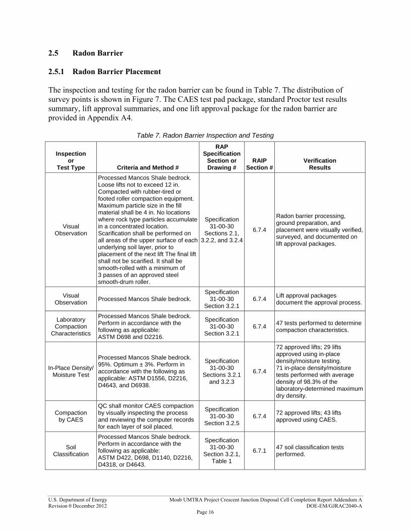
2.5 Radon Barrier 2.5.1 Radon Barrier Placement The inspection and testing for the radon barrier can be found in Table 7. The distribution of survey points is shown in Figure 7. The CAES test pad package, standard Proctor test results summary, lift approval summaries, and one lift approval package for the radon barrier are provided in Appendix A4.
Table 7. Radon Barrier Inspection and Testing
Inspection or
Test Type Criteria and Method #
RAPSpecification
Section or Drawing #
RAIP Section #
Verification Results
Visual Observation
Processed Mancos Shale bedrock. Loose lifts not to exceed 12 in. Compacted with rubber-tired or footed roller compaction equipment. Maximum particle size in the fill material shall be 4 in. No locations where rock type particles accumulate in a concentrated location. Scarification shall be performed on all areas of the upper surface of each underlying soil layer, prior to placement of the next lift The final lift shall not be scarified. It shall be smooth-rolled with a minimum of 3 passes of an approved steel smooth-drum roller.
Specification 31-00-30
Sections 2.1, 3.2.2, and 3.2.4
6.7.4
Radon barrier processing, ground preparation, and placement were visually verified, surveyed, and documented on lift approval packages.
Visual Observation
Processed Mancos Shale bedrock. Specification
31-00-30 Section 3.2.1
6.7.4 Lift approval packages document the approval process.
Laboratory Compaction
Characteristics
Processed Mancos Shale bedrock. Perform in accordance with the following as applicable: ASTM D698 and D2216.
Specification 31-00-30
Section 3.2.1 6.7.4
47 tests performed to determine compaction characteristics.
In-Place Density/ Moisture Test
Processed Mancos Shale bedrock. 95%. Optimum ± 3%. Perform in accordance with the following as applicable: ASTM D1556, D2216, D4643, and D6938.
Specification 31-00-30
Sections 3.2.1 and 3.2.3
6.7.4
72 approved lifts; 29 lifts approved using in-place density/moisture testing. 71 in-place density/moisture tests performed with average density of 98.3% of the laboratory-determined maximum dry density.
Compaction by CAES
QC shall monitor CAES compaction by visually inspecting the process and reviewing the computer records for each layer of soil placed.
Specification 31-00-30
Section 3.2.5 6.7.4
72 approved lifts; 43 lifts approved using CAES.
Soil Classification
Processed Mancos Shale bedrock. Perform in accordance with the following as applicable: ASTM D422, D698, D1140, D2216, D4318, or D4643.
Specification 31-00-30
Section 3.2.1, Table 1
6.7.1 47 soil classification tests performed.

U.S. Department of Energy Moab UMTRA Project Crescent Junction Disposal Cell Completion Report Addendum A Revision 0 December 2012 DOE-EM/GJRAC2040-A
Page 17
Table 7. Radon Barrier Inspection and Testing (continued)
Inspection or
Test Type Criteria and Method #
RAPSpecification
Section or Drawing #
RAIP Section #
Verification Results
Moisture Test
Processed Mancos Shale bedrock. Optimum ± 3%. Perform in accordance with the following as applicable: ASTM D4643 and D4944 or D4959.
Specification 31-00-30
Section 3.2.3 6.7.4
Tests performed to ensure moisture is within acceptable range.
High-Accuracy GPS Survey
Processed Mancos Shale bedrock. Confirm the total fill thickness of the radon barrier is in accordance with plans and specifications.
Specification 31-00-30
Section 3.5.2 6.7.5
Completed using high-accuracy GPS.
Sand Cone and Moisture
Correlation Test
Processed Mancos Shale bedrock. With nuclear tests. Perform in accordance with the following as applicable: ASTM D1556, D2216, and D4643.
Specification 31-00-30
Section 3.6.1 6.7.4
Sand cone and moisture correlation tests performed.
# = number; % = percent; ASTM = American Society for Testing and Materials; GPS = global positioning system; in. = inches; QC = Quality Control.

Figure 7. Distribution of Survey Points to Verify Compliance with Radon Barrier Specification
U.S. D
epartment of Energy
Moab U
MTR
A Project Interim
Com
pletion Report A
ppendix Package AR
evision 0 Decem
ber 2012
DO
E-EM/G
JRA
C2040-A
Page 18

U.S. Department of Energy Moab UMTRA Project Crescent Junction Disposal Cell Completion Report Addendum A Revision 0 December 2012 DOE-EM/GJRAC2040-A
Page 19
2.5.2 Verification Measurements for Radon Flux Table 8 shows how the radon flux measurements met the performance criteria. The grid locations referenced in the table are shown on Figure 8, which contains all radon flux grid locations for the entire disposal cell. Further information can be found in Section 4.6.
Table 8. Radon Flux Measurements
Grid # Location Date
Counted
Flux*
(pCi/m2/s)
1 6795750 N 2122250 E
10/09/2011 7.8804
2 6795500 N 2122250 E
10/09/2011 3.3663
3 South Position 1
6795202 N 2122305 E
09/15/2011 11.8050
4 South Position 2
6794997 N 2122235 E
09/15/2011 2.1364
5 North Position 1
6794837 N 2122242 E
09/15/2011 5.4166
6 South Position 3
6794376 N 2122349 E
09/15/2011 0.5048
7 North Position 2
6794291 N 2122347 E
09/15/2011 4.2170
8 6795750 N 2122500 E
06/10/2011 0.2177
9 6795499 N 2122500 E
06/10/2011 0.2393
10 6795250 N 2122500 E
06/10/2011 0.2601
11 6795000 N 2122500 E
06/10/2011 0.3338
12 6794750 N 2122500 E
06/10/2011 0.2326
13 6794500 N 2122500 E
06/10/2011 0.2374
14 6794250 N 2122500 E
06/10/2011 0.3133
19 6794749.993 N 2122749.997 E
10/18/2011 5.4953
20 674499.999 N 2122749.987 E
Re-validated per procedure
30.5212
20 674499.999 N 2122749.987 E
Re-validated per procedure
30.6035
20 674499.999 N 2122749.987 E
10/21/2011 20.6410

U.S. Department of Energy Moab UMTRA Project Crescent Junction Disposal Cell Completion Report Addendum A Revision 0 December 2012 DOE-EM/GJRAC2040-A
Page 20
Table 8. Radon Flux Measurements (continued)
Grid # Location Date
Counted
Flux*
(pCi/m2/s)
21 6794250.020 N 2122749.978 E
10/18/2011 2.0430
27 6794750.264 N 2122999.663 E
10/18/2011 0.5453
28 6794500.325 N 2122999.313 E
10/18/2011 0.2426
29 6794249.995 N 2122999.996 E
10/18/2011 0.8099
E = Easting; N = Northing; pCi/m2/s = picocuries per square meter per second *Average activity measurement is 3.3469 pCi/m2/s

Figure 8. Radon Flux Measurement Grid Numbers and Locations
U.S. D
epartment of Energy
Moab U
MTR
A Project Interim
Com
pletion Report A
ppendix Package AR
evision 0 Decem
ber 2012
DO
E-EM/G
JRA
C2040-A
Page 21

U.S. Department of Energy Moab UMTRA Project Crescent Junction Disposal Cell Completion Report Addendum A Revision 0 December 2012 DOE-EM/GJRAC2040-A
Page 22
2.6 Infiltration and Biointrusion Barrier The inspection and testing for the infiltration and biointrusion barrier can be found in Table 9. The distribution of survey points is shown in Figure 9. The lift approval summary, one lift approval package, buyoff surveys, and durability and gradation test results for the infiltration and biointrusion barrier are provided in Appendix A5.
Table 9. Infiltration and Biointrusion Barrier Inspection and Testing
Inspection or
Test Type Criteria and Method #
RAPSpecification
Section or Drawing #
RAIP Section #
Verification Results
Visual Observation
Gravel material is placed and compacted to produce a continuous, uniform thickness of at least 6 in. Compaction is performed by a vibratory steel-drum roller, and as the roller makes a minimum of 2 passes over the placed gravel fill.
Specification 31-00-30
Section 3.4.1 6.8.2
Material placement was visually observed and surveyed throughout placement and documented in lift approval packages.
Durability
Perform in accordance with the following as applicable: ASTM C88, C127, and C131; Schmidt rebound hardness ISRM Method and Splitting Tensile Strength ISRM Method.
Specification 32-11-23 Table 2
6.8.1 7 durability tests performed.
Gradation Perform in accordance with the following as applicable: ASTM C117 and C136.
Specification 32-11-23 Table 3
6.8.2 12 gradation tests performed.
High-Accuracy GPS Survey
Confirm total thickness is in accordance with plans and specifications.
Specification31-00-30
Section 3.5.1 6.8.2
Completed using high-accuracy GPS.
# = number; ASTM = American Society for Testing and Materials; in. = inches; ISRM = International Society for Rock Mechanics.

Figure 9. Distribution of Survey Points to Verify Compliance with Infiltration and Biointrusion Barrier Specification
U.S. D
epartment of Energy
Moab U
MTR
A Project Interim
Com
pletion Report A
ppendix Package AR
evision 0 Decem
ber 2012
DO
E-EM/G
JRA
C2040-A
Page 23

U.S. Department of Energy Moab UMTRA Project Crescent Junction Disposal Cell Completion Report Addendum A Revision 0 December 2012 DOE-EM/GJRAC2040-A
Page 24
2.7 Frost Protection Layer The inspection and testing for the frost protection layer can be found in Table 10. The distribution of survey points is shown in Figure 10. The standard Proctor test results summary, lift approval summary, one lift approval package, and buyoff surveys for the frost protection layer are provided in Appendix A6.
Table 10. Frost Protection Layer Inspection and Testing
Inspection or
Test Type Criteria and Method #
RAPSpecification
Section or Drawing #
RAIP Section
# Verification
Results
Visual Observation
Common fill: 3 ft of clean, compacted soil. Loose lifts average thickness not to exceed. 12 in. compacted with rubber-tired or -footed roller compaction equipment. Scarification of the upper surface of each underlying soil layer prior to placement of the next lift Final lift of soil shall not be scarified. Final lift shall be smooth rolled with at least 3 passes of the approved, smooth steel-wheeled roller weighing a minimum of 20,000 lb.
Specification 31-00-30
Sections 3.3.2 and 3.3.4
6.9.3
Material preparation, ground preparation, and fill placement operations were visually verified throughout placement. Smooth drum rolling was also observed on final grade of frost protection layer. Documentation is provided in lift approval packages.
High-Accuracy GPS Survey
Document the pre-cap and post-cap geometry of the site.
Specification 31-00-30
Section 3.3.2 6.9.5
Pre-installation and post-cap survey performed using high-accuracy GPS.
High-Accuracy GPS Survey
Confirm that the total fill thickness is in accordance with plans and specifications.
Specification 31-00-30
Section 3.2.2 6.9.5
Completed using high-accuracy GPS.
In-Place Density/ Moisture Test
Common fill: 90% standard Proctor. Optimum ±5%. Perform in accordance with the following as applicable: ASTM D1556, D2216, D4643, and D6938.
Specification 31-00-30
Section 3.3.3 6.9.4
40 lifts approved; 30 lifts approved using in place density/moisture testing. 34 in-place density/moisture tests performed with an average density of 96% of the laboratory determined maximum dry density.
Compaction by CAES
QC shall monitor CAES compaction by visually inspecting the process and reviewing the computer records for each layer of soil placed.
Specification 31-00-30
Section 3.3.5 6.9.4
40 lift approved; 10 lifts approved using CAES.
Sand Cone and Moisture
Correlation Test
Common fill, along with nuclear tests. Perform in accordance with the following as applicable: ASTM D1556, D2216, and D4643.
Specification 31-00-30
Section 3.6.1 6.9.4
Sand cone and moisture correlation tests performed.
Laboratory Compaction
Characteristics
Tests have been performed on the common fill to determine its maximum dry density and optimum moisture content per ASTM D 698. Perform in accordance with the following as applicable: ASTM D698 and D2216.
Specification 31-00-30
Section 3.3.5 6.9.4
10 tests performed to determine compaction characteristics.
# = number; % = percent; ASTM = American Society for Testing and Materials; ft = feet; GPS = global positioning system; in. = inches; lb = pounds; QC = Quality Control

Figure 10. Distribution of Survey Points to Verify Compliance with Frost Protection Layer Specification
U.S. D
epartment of Energy
Moab U
MTR
A Project Interim
Com
pletion Report A
ppendix Package AR
evision 0 Decem
ber 2012
DO
E-EM/G
JRA
C2040-A
Page 25

U.S. Department of Energy Moab UMTRA Project Crescent Junction Disposal Cell Completion Report Addendum A Revision 0 December 2012 DOE-EM/GJRAC2040-A
Page 26
2.8 Cap Rock and Armoring The inspection and testing for the cap rock and armoring can be found in Table 11. Rock armoring includes the side slopes and apron of the disposal cell. The distribution of survey points to verify compliance for the cap rock is shown in Figure 11. The distribution surveys for the rock armoring are shown in Appendix A7. The lift approval summaries, one lift approval package for the cap rock, buyoff surveys, and durability and gradation test results are also provided in AppendixA7.
Table 11. Cap Rock and Armoring Inspection and Testing
Inspection or
Test Type Criteria and
Method Number
RAP Specification
Section or Drawing #
RAIP Section
# Verification
Results
Visual Observation
Periodically, at the quarry operations, a geologist will inspect the stockpiles to ensure the percent of other-than-gray basalt does not exceed 10% for rock for the final cover layers.
N/A 6.10.1 Inspection performed.
Visual Observation
and High-Accuracy GPS Survey
Thickness required by plans for each area.
Specification32-11-23 Table 3
6.10.2 Cap thickness verified visually and verified by high-accuracy surveys.
Durability
Perform in accordance with the following as applicable: Specific gravity saturated surface dry absorption sodium sulfate soundness (5 cycles); L.A. abrasion (100 cycles); Schmidt rebound hardness ISRM Method; ASTM C88, C127, and C131.
Specification32-11-23
Section 2.1.56.10.1 9 durability tests performed.
Gradation Perform in accordance with the following as applicable: ASTM C117 and C136.
Specification32-11-23 Table 3.
6.10.2 13 gradation tests performed.
# = number; % = percent; ASTM = American Society for Testing and Materials; GPS = global positioning system; ISRM = International Society for Rock Mechanics; L.A. = Los Angeles

Figure 11. Distribution of Survey Points to Verify Compliance with Cap Rock Specification
U.S. D
epartment of Energy
Moab U
MTR
A Project Interim
Com
pletion Report A
ppendix Package AR
evision 0 Decem
ber 2012
DO
E-EM/G
JRA
C2040-A
Page 27

U.S. Department of Energy Moab UMTRA Project Crescent Junction Disposal Cell Completion Report Addendum A Revision 0 December 2012 DOE-EM/GJRAC2040-A
Page 28
3.0 Design Assessment The disposal cell design incorporates established design criteria, drawings and specifications, and calculations, all of which are included in the RAP. This section discusses design criteria changes, changes to the design of the disposal cell and associated erosion control features, fulfillment of Quality Assurance (QA) requirements, and compliance with permit requirements. 3.1 Design Criteria Changes Design criteria were identified in the RAP as a reference to the “Technical Approach Document” (UMTRA-DOE/AL 050425.0002). The Technical Approach Document was prepared during the UMTRA surface remediation program in the 1980s to describe the general technical approaches and design criteria adopted by DOE to implement RAPs and final designs that comply with U.S. Environmental Protection Agency (EPA) standards. No changes to the design criteria were made during the period represented by this Addendum. 3.2 Design Changes Design changes may take the form of a new or revised specification or drawing. Design changes are made to correct or improve a project construction or operational activity, or to take advantage of a superior or more cost-efficient design solution. Design control is implemented following project work instruction, “Design Change Control with NQA-1 QA Requirements” (FONQAWI 105) (see Attachment 2), to identify, register, and communicate design changes. The Construction Interface Document (CID) is used to resolve a construction issue or to propose a design change, and to document its resolution. If a design change is required, a DCN is prepared. The DOE requested concurrence of NRC for DCNs that could affect the cell performance. Table 12 summarizes DCNs that were submitted to NRC for concurrence, and the DCNs are included in Attachment 3. Specifications referenced in Table 12 are from Addendum B of the RAP. Correspondence between DOE and NRC is presented in Attachment 4. DCNs 1-16 were issued for design changes outside the Crescent Junction disposal cell.
Table 12. DCNs Submitted to NRC
DCN #
Date of Issue DCN Description Status
17 02/15/10 Revise the top-of-waste plane drawings, C-02-C-124 and C-02-C125, to show adjusted contours along edge of top-of-waste. (CID 053)
As-built drawing of top of waste to be submitted at cell completion.
18 08/02/10
Revise Specification 31-00-30 to redefine the 1-in. requirements for radon barrier material to allow for presence of occasional shale fragments with a maximum particle size 3-4 in. (CID 055)
Approved in Revision 4 of Specification 31-00-30 on 08/03/10.

U.S. Department of Energy Moab UMTRA Project Crescent Junction Disposal Cell Completion Report Addendum A Revision 0 December 2012 DOE-EM/GJRAC2040-A
Page 29
Table 12. DCNs Submitted to the NRC (continued)
DCN #
Date of Issue DCN Description Status
19 09/02/10
Revise Specification 31-00-30 to state placement of Mancos Shale bedrock will be visually inspected to ensure there are no locations where rock-type particles accumulate in a concentrated location. Particles found in a concentrated location will be removed or reworked per QC direction. (CID 056)
Approved in Revision 5 of Specification 31-00-30 on 09/02/10.
20 09/09/10
Revise Specification 32-11-23 to change the infiltration and biointrusion barrier stone gradation for 1.5-in. rock from 40-50 to 40-60. Revise Specification 31-00-30 and add a subsection that describes aggregate gradation testing and provides guidance for evaluating the gradation tests for acceptability. Revise Table 1 of Specification 31-00-30 to change the minimum liquid limit from 35 to 30 and add a maximum liquid limit of 50. (CID 057 and CID 058)
Approved in Revision 6 of Specification 31-00-30 on 09/09/10 and Revision 6 of Specification 32-11-23 on 09/08/10.
21 05/21/11 Revise Specification 32-11-23 and Drawing E-02-C-501 to change selected riprap D50 size and gradation. (CID 062 and CID 063)
Approved in Revision 7 of Specification 32-11-23 on 05/20/11.
22 08/18/11 Revise Table 3 of Specification 32-11-23 to change selected gradations of fines. (CID 065 and CID 067)
Approved in Revision 8 of Specification 32-11-23 on 08/18/11.
# = number; D50 = median particle size; in. = inches; QC = Quality Control
3.3 QA Requirements QA activities were conducted in accordance with the Moab UMTRA Project Quality Assurance Plan for the Remedial Action Contractor (DOE-EM/GJRAC1766), which complies with the following: American Society of Mechanical Engineers (ASME) NQA-1 2004 and addenda through
2007 consensus standard, “Quality Assurance Requirements for Nuclear Facility Applications (QA).”
Appendix A of DOE Order (O) 226.1B, “Implementation of Department of Energy Oversight Policy.”
Title 10 Code of Federal Regulations Part 830, “Nuclear Safety Management,” Subpart A, “Quality Assurance.”
DOE O 414.1D, “Quality Assurance.” During design activities, quality audits and surveillances were performed by the RAC, including one conducted by the EnergySolutions’ corporate office, to verify and provide assurance that these activities were performed in accordance with established plans, drawings, instructions, procedures, specifications, and other applicable documents. For definitions of audit activities, see the Introduction in Part 1 of ASME NQA-1-2004. During the disposal cell design phase, five audits and four surveillances were performed. A summary is contained in Table 13. Any issues identified during these audits and surveillances have been addressed.

U.S. Department of Energy Moab UMTRA Project Crescent Junction Disposal Cell Completion Report Addendum A Revision 0 December 2012 DOE-EM/GJRAC2040-A
Page 30
Table 13. Audits and Surveillances Conducted during Design
Date Conducted By Type Assessment # Scope
08/13/07 RAC Audit X-07-22 Approve Jacobs Engineering QA Program
11/30/07 RAC Audit X-07-22a Approve Jacobs Engineering QA Program
02/04/08 – 02/07/08
EnergySolutions’ Corporate
Audit AS-08-01 QA Program Readiness Assessment
06/09/08 – 06/17/08
RAC Surveillance MB-08-S-005 Evaluate the RAC’s preparation and issuance of project procedures
06/18/08 – 06/30/08
RAC Surveillance MB-08-S-008
Evaluate RAC employee knowledge of the project’s organizational structure, responsibilities, authority of individuals, and lines of communication
07/14/08 – 07/16/08
RAC Audit MB-08-A-002 Evaluate Jacobs Engineering’s NQA-1 Program
10/30/08 – 10/31/08
RAC Audit MB-09-A-001 Approve corrective actions completed by Jacobs Engineering and verify the QA Program meets NQA-1 requirements
02/26/09 – 02/27/09
RAC Surveillance MB-09-S-007 Verify completion of corrective actions under Jacobs Engineering Corrective Action Program
08/12/09 RAC Surveillance MB-09-S-011 Verify that contract-required environmental records have been submitted and continue to be submitted to DOE
# = number.
3.4 Permits and Agreements The Project is in compliance with permits and agreements applicable to the Crescent Junction site. These are summarized in Table 14.
Table 14. Crescent Junction Site Permits and Agreements
Agreement # Document Nameor Description Issuing Agency Purpose
Resolution 2006-2741 Grand County
Council ResolutionGrand County
Approves Conditional Use Permit for the Project.
DE-RO01-05GJ68003 Access Agreement DOE EMCBC For installation and maintenance of air monitoring equipment and collection of air quality data for monitoring station MPS-0306.
DE-RO01-05GJ68004 Access Agreement DOE EMCBC For installation and maintenance of air monitoring equipment and collection of air quality data for monitoring station MPS-0307.
Public Land Order 7697 Permanent Land
Transfer BLM
Order permanently transferred 500 acres of BLM public domain land to DOE for disposal cell.
Public Land Order 7734 Public Land Withdrawal
BLM
Order withdrew 936 acres of public land for activities to support disposal of mill tailings at the Crescent Junction disposal site. The withdrawal is for 20 years to support Public Land Order 7697.

U.S. Department of Energy Moab UMTRA Project Crescent Junction Disposal Cell Completion Report Addendum A Revision 0 December 2012 DOE-EM/GJRAC2040-A
Page 31
Table 14. Crescent Junction Site Permits and Agreements (continued)
Agreement # Document Name or Description Issuing Agency Purpose
Not assigned Water Use Agreement
Thompson Special Service
District
Water use agreement between Thompson Special Service District in Grand County; Crescent Junction Properties, Inc.; and DOE to install potable waterline from Thompson Springs, Utah, to the disposal site.
UTU-83353 ROW BLM, Moab Field
Office
ROW for 3-in. service culinary waterline and a 2-in. delivery culinary waterline to the disposal site.
UTU-83450 ROW BLM, Moab Field
Office ROW for power line to the disposal site.
Case # 11-0028 Memorandum of
Agreement
BLM, Utah State Preservation
Office
Between DOE, BLM, and Utah State Historic Preservation Office regarding cultural resource issues related to development of disposal site.
Not assigned Memorandum of
Agreement BLM, Moab Field
Office
Between BLM and DOE for management of existing uses on lands withdrawn in conjunction with the Project.
UTR359187 Storm Water
Permit Utah Division of Water Quality
For the disposal site.
UTU-83396 ROW BLM, Moab Field
Office For buried telephone line at the disposal site.
Folder # 02399-44 Pipeline Crossing
Agreement Union Pacific
Railroad
Agreement grants right to construct, maintain, and operate one underground waterline and access for phone line and 1-1/4 in. conduit at mile post 0.25, Cane Creek Subdivision, Thompson Springs, for the disposal site.
Folder # 02392-96 Pipeline Crossing
Agreement Union Pacific
Railroad
Agreement grants right to construct, maintain, and operate one underground waterline and access for phone line and 1-1/2 in. conduit across Union Pacific Railroad's property at mile post 533.2, Green River Subdivision.
U.S. DOT-SP 14283 Special Permit Authorization
U.S. DOT Permit to transport mill tailings from Moab site to the disposal site.
U.S. DOT # 011309550013QR
U.S. DOT Hazardous Materials
Certificate of Registration
U.S. DOT For shippers of hazardous materials for 2008 – 2010.
UTU-83354 Waterline ROW BLM, Moab Field
Office For construction of 14.5 miles of waterline on BLM land from Green River to disposal site.
REECBCDOE-6-08-0302 Waterline Easement
Grand County Easement within CR-175 or old Highway 6 & 50 and Hastings Lane ROWs to construct waterline within 60-ft ROW and operate within 20-ft ROW.
REECBCDOE-6-08-0304 Waterline Easement
Private Owner
Easement across private land near the Green River to construct waterline within 60-ft ROW and operate within 20-ft ROW and pump station.
REECBCDOE-6-08-0301-1 Waterline Easement
Private Owner Permanent easement across private land near Crescent Junction to construct waterline within 60-ft ROW and operate within 20-ft ROW.
REECBCDOE-6-08-0309 Waterline Easement
City of Green River
Easement to construct waterline within 60 ft of CR-175 or old Highway 6 & 50 ROWs within Green River city limits and operate within 20-ft ROWs.

U.S. Department of Energy Moab UMTRA Project Crescent Junction Disposal Cell Completion Report Addendum A Revision 0 December 2012 DOE-EM/GJRAC2040-A
Page 32
Table 14. Crescent Junction Site Permits and Agreements (continued)
Agreement # Document Name or Description Issuing Agency Purpose
REECBCDOE-6-08-0308, SITLA # 1345
Waterline Easement
SITLA
Easement to construct waterline within 60-ft ROW and operate within 20-ft ROW on three parcels on SITLA land near Green River and Crescent Junction.
ESMT 463 Waterline Easement
SITLA Easement across state land for potable waterline.
400 00177 Waterline Easement
Utah Division of Forestry, Fire,
and State Lands
ROW easement to construct and operate waterline in the Green River.
Statewide Utility License Agreement # 8439
UDOT Utility License
Permits Officer License with State of Utah to construct waterline across UDOT property.
Property # 70-4;189A: AEQ
UDOT Easement Permits Officer Easement for waterline across UDOT property near Floy Wash that allows 60-ft construction ROW and 20-ft permanent ROW.
4P-082341-1 UDOT
Encroachment Permit
UDOT To construct waterline within UDOT 60-ft ROW and operate within 20-ft ROW near Floy Wash.
4P-082364-0 UDOT
Encroachment Permit
UDOT To construct waterline within UDOT 60-ft ROW and operate within 20-ft ROW for State Route 19 near City of Green River.
SPK-2007-632 Corps of Engineers
404 Permit Corps of
Engineers To construct pump station on the Green River.
08-92-01SA Stream Channel Alteration Permit
Utah Division of Water Rights
To construct pump station on the Green River.
Folder # 2537-02 Industrial Track
Contract Union Pacific
Railroad
Covers construction, maintenance, and operation of 5,209-ft Track A, 3,524-ft Track B, and 617-ft Track C at mile post 533.21, Green River Subdivision line.
DE-RO01-06GJ68009 Access Roadway
Contract and Grant of Easement
Private Owner Perpetual easement and ROW for construction of an access roadway and related utilities at the disposal site.
DAQC-1110-2006
Fugitive Dust Control Plan (08/07/06)
UAC R307-309-6 “Fugitive Emissions and Fugitive Dust-
Fugitive Dust Control Plan-Uranium Mill
Tailings Repository (UMTRA) Project
near Crescent Junction-Grand Co”
Utah Division of Air Quality
Approval letter from the State of Utah for the Fugitive Dust Control Plan for the Crescent Junction disposal cell.
# = number; BLM = Bureau of Land Management; CR = County Road; EMCBC = Environmental Management Consolidated Business Center; ft = feet; in. = inches; ROW = right- of-way; SITLA = School and Institutional Trust Lands Administration; UAC = Utah Administrative Code; UDOT = Utah Department of Transportation; U.S. DOT = U.S. Department of Transportation

U.S. Department of Energy Moab UMTRA Project Crescent Junction Disposal Cell Completion Report Addendum A Revision 0 December 2012 DOE-EM/GJRAC2040-A
Page 33
4.0 Remedial Action Assessment A description of the pre-excavation site conditions, construction activities, and verification performed at the Crescent Junction disposal site is provided in this section. 4.1 Pre-Excavation Site Conditions The U.S. Department of Interior permanently transferred 500 acres at the Crescent Junction site to DOE for the disposal cell. An additional 936 acres is in temporary withdrawal to support cell construction and RRM placement activities. Ten boreholes and five test pits were located to characterize subsurface conditions as reported in Attachment 5, “Field and Laboratory Results,” in Volume 1 of the RAP. Construction of infrastructure, including access and haul roads, a rail load-out area, retention ponds, waterlines, initial site drainage control, and administrative areas necessary for support of the disposal operations was performed largely prior to excavation of the cell. 4.2 Cell Construction Cell construction includes five major activities: Excavation of the soils to the design depth to ensure a competent surface for placement of
RRM. Construction of the perimeter embankment, which will extend along the western, southern,
and eastern cell boundaries. Placement of RRM to the design thickness, and assuring that the radium-226 (Ra-226)
activity in the upper 7 feet (ft) of placed material does not exceed design criteria. Placement of cover material and rock armoring. Construction of a spoils embankment. The Moab UMTRA Project Lift Approval Procedure (DOE-EM/GJRAC1803) was used to ensure that the material placed met the compaction criteria. Descriptions of compaction equipment used during the construction of the cell are provided in Table 15. Each activity performed as part of this Addendum is further described in the following subsections. Photographs representative of the cell construction activities are included in Appendix B.

U.S. Department of Energy Moab UMTRA Project Crescent Junction Disposal Cell Completion Report Addendum A Revision 0 December 2012 DOE-EM/GJRAC2040-A
Page 34
Table 15. Descriptions of Compaction Equipment Used during Cell Construction
Compaction Equipment
MachineWeight
(lb) Eq
uip
ped
wit
h C
AE
S
Material Layer Equipment Used On
RR
M
Inte
rim
Co
ver
Rad
on
Bar
rier
Infi
ltra
tio
n a
nd
Bio
intr
usi
on
Bar
rier
Fro
st P
rote
ctio
n
Ro
ck A
rmo
r
Sp
oils
Em
ban
kmen
t
Per
imet
er E
mb
ankm
ent
CAT 825H Soils Compactor 69,000 X X X X X X X
CAT D-8 Bulldozer 84,850 X X
CAT D-7 Bulldozer 56,669 X X
Komatsu 275X Bulldozer 112,466 X X
CAT 637G Scraper 118,084 X X X X X
CAT 815 Soils Compactor 45,765 X X X X X
CAT CS563 Vibratory Roller 24,537 X X X X
CAT = Caterpillar, Inc., lb = pounds.
4.2.1 Excavation The disposal cell is being excavated in phases. Excavation of Phase 1 began in June 2008 and was completed in December 2008. This phase encompassed approximately 44 acres and consisted of the following. Excavation of approximately 1.7 million yd3 of soil to a depth of about 25 ft, including 2 ft
into the weathered Mancos Shale bedrock. This phase of the cell was constructed to store roughly 2.4 million yd3 of RRM.
Stockpiling excavated materials as Mancos Shale bedrock or common fill for later use in cell cover layers.
Creation of the spoils embankment and the embankment for the construction water storage pond using excavated materials.
Excavation of Phase 2, encompassing about 49 acres, began in January 2010, and was completed in December 2011. Approximately 1.8 million yd3 of soil was excavated to a depth of about 25 ft, including 2 ft into the weathered Mancos Shale bedrock. This phase of the cell was constructed to store roughly 3.5 million yd3 of RRM. About a 2-acre area of the cell was not

U.S. Department of Energy Moab UMTRA Project Crescent Junction Disposal Cell Completion Report Addendum A Revision 0 December 2012 DOE-EM/GJRAC2040-A
Page 35
excavated to the design grade so as to create a platform to facilitate emptying and decontaminating RRM containers. Figure 4 shows the extent of the Phase 2 excavation and south perimeter embankment. 4.2.2 Perimeter Embankment Construction Soils from the Phase 1 excavation that met the specification for common fill were used to construct the perimeter embankment along the western and southern boundaries. Soils from the Phase 2 excavation were used to continue the perimeter embankment along the southern boundary, except where the platform lies. 4.2.3 RRM Placement Placement of RRM began in April 2009 in the southwestern corner of the cell and progressed to the north and east. Initially the material was end-dumped from the containers onto the cell floor and spread directly in loose lifts not exceeding 1 ft following the Lift Approval Procedure. Over time, the dumping location shifted from the cell floor to the top of the interim cover. In March 2010, containers began being emptied from the platform discussed in Section 4.2.1. The dumped material was loaded into dump trucks, and driven to the disposal area where it was spread for compaction using a bulldozer. A sheepsfoot roller was then used to compact the RRM in place. In a letter dated October 26, 2009, DOE notified NRC that polypropylene liners were being used in the RRM containers to facilitate complete dumping of the material. Use of the liners did not result in voids in the waste mass. NRC accepted the liner use in its response letter dated November 23, 2009. Oversized material from an off-pile area at the Moab site was shipped by truck to the disposal cell in 2010. On March 18, 2010, DOE requested a variance to allow for disposal of debris that was too large to be sized to meet RAIP Section 6.4.4 for demolition debris. NRC accepted the size variance in its response letter dated November 15, 2010. Copies of this correspondence between DOE and NRC regarding liners and the size variance are included in Attachment 4. 4.2.4 Cover and Rock Armoring Placement The cover on the disposal cell consists of multiple layers of soil and rock as illustrated in Figure 5-1 of the “Remedial Action Selection Report” (RAS) of the RAP. Once the RRM placed in the cell has reached the design thickness, a minimum of 1 ft of interim cover is placed over the RRM. The interim cover material comes from soils excavated to create the cell that have been stockpiled on-site. Three additional cover layers are placed over the interim cover before the final rock cover. Material for the radon barrier and frost protection layer also come from materials excavated on-site (processed Mancos Shale bedrock). Rock for the infiltration and biointrusion barrier and the uppermost cover layer is transported from a quarry at Fremont Junction, Utah, and stockpiled at the Crescent Junction site. During this Addendum period, almost 28 acres of final cover was placed. 4.2.5 Spoils Embankment Construction Material excavated to construct the disposal cell was used to create a spoils embankment, or wedge, between the north side of the cell and the Book Cliffs mountain range. The spoils embankment helps control drainage of storm water around the cell perimeter. The inspection and testing for the spoils embankment can be found in Table 16. The topographic surface of the spoils embankment is shown on Figure 12. The standard Proctor test results summary, lift approval summary, and one lift approval package for the spoils embankment are provided in Appendix A8.

U.S. Department of Energy Moab UMTRA Project Crescent Junction Disposal Cell Completion Report Addendum A Revision 0 December 2012 DOE-EM/GJRAC2040-A
Page 36
Table 16. Spoils Embankment Inspection and Testing
Inspection or
Test Type Criteria and Method #
RAPSpecification
Section or Drawing #
RAIP Section #
Verification Results
Visual Observation
Common fill: fill material is placed in continuous and approximately horizontal lifts. The method of dumping and spreading material shall result in loose lifts of nearly uniform thickness, not to exceed 12 in. Compaction: embankment fill shall be compacted with rollers, equipment tracks, or successive passes of scrapers with a minimum 45,000-lb static weight. Fill material shall be properly moisture conditioned near optimum moisture content levels.
Specification 31-00-00 Section 3.11.1.3
6.3.5
Visual inspection performed throughout placement to verify compaction and lift thickness. Compaction performed using CAT 816 compactor. Thickness was visually verified. Each lift is documented.
High-Accuracy GPS Survey
Exterior slopes are 3:1. Drawing
C-02-C-501 6.3.5
Survey performed. See drawings C-02-C-102 and C-02-C-501.
Laboratory Compaction
Characteristics
Common fill: spoil material shall be tested to determine maximum dry density and the moisture content shall be modified to bring fill to near optimum for compaction. Perform in accordance with the following as applicable: ASTM D 698.
Specification 31-00-00 Section 3.11.1.3
6.3.5 57 tests performed to determine compaction characteristics.
In-place Density/ Moisture Test
Initial layers of soil placed, and on any specific type of material in which the CAES is used. (Follow non-CAES frequency.) One test per 100,000 ft2 or 3,700 yd3 of material placed for material compacted by other than hand-operated machines. One test per 500 ft2, or fraction thereof, of each lift of fill or backfill areas for material compacted by hand-operated machines. Perform in accordance with the following as applicable: ASTM D1556, D2216, D4643, and D6938
Specification 31-00-00 Section 3.14.1.2
6.3.5
803 in-place density/moisture tests performed with an average density of >90% of the laboratory-determined maximum dry density.
Sand Cone Correlation
One check test for every 20 tests per ASTM D6938, of fill or backfill compacted by other than hand-operated machines. One check test for every 20 tests per ASTM D6938, of fill or backfill compacted by hand-operated machines. Perform in accordance with the following as applicable: ASTM D1556.
Specification 31-00-00
Section 3.14.26.3.5
Sand cone correlation performed.

U.S. Department of Energy Moab UMTRA Project Crescent Junction Disposal Cell Completion Report Addendum A Revision 0 December 2012 DOE-EM/GJRAC2040-A
Page 37
Table 16. Spoils Embankment Inspection and Testing (continued)
Inspection or
Test Type Criteria and Method #
RAPSpecification
Section or Drawing #
RAIP Section #
Verification Results
Moisture Correlation
Test
One correlation test for moistures every 10 tests per ASTM D6938 will be performed in accordance to ASTM D4643 or D2216.
Specification 31-00-00
Section 3.14.26.3.5
Moisture correlation tests performed.
Laboratory Compaction
Characteristics
Perform laboratory density and moisture content tests for each type of fill material to determine the optimum moisture (optimum moisture content ±5%) and laboratory maximum density values. One representative density test per material type and every 20,000 yd3, thereafter, or when any change in material occurs, which may affect the optimum moisture content or laboratory maximum dry density. Perform in accordance with the following as applicable: ASTM D698 and D2216.
Specification 31-00-00
Section 3.14.36.3.5
57 tests performed to determine compaction characteristics.
# = number; % = percent; ft2 = square feet, ASTM = American Society for Testing and Materials; CAT = Caterpillar, Inc., GPS = global positioning system; in. = inches; lb = pounds, yd3 = cubic yards

Figure 12. Spoils Embankment Topographic Surface
U.S. D
epartment of Energy
Moab U
MTR
A Project Interim
Com
pletion Report A
ppendix Package AR
evision 0 Decem
ber 2012
DO
E-EM/G
JRA
C2040-A
Page 38

U.S. Department of Energy Moab UMTRA Project Crescent Junction Disposal Cell Completion Report Addendum A Revision 0 December 2012 DOE-EM/GJRAC2040-A
Page 39
4.3 Soil Compaction and Testing The RAC followed Addendum B, “Final Design Specifications,” of the RAP and the Lift Approval Procedure to verify proper compaction of each lift. The RAC performed soil compaction using the CAES, which was developed by Caterpillar, Inc. (CAT). The system includes a global positioning system (GPS) receiver, multi-radio wireless transmitter receivers, and a display mounted in the cab of each piece of outfitted equipment, such as a bulldozer or compactor, and a desktop computer equipped with terrain modeling software that is located at the Crescent Junction site. The CAES was utilized on the CAT D-7, CAT D-8, and Komatsu 275X bulldozers that spread lifts and compact RRM, and on the 825H sheepsfoot compactor. Three test pads for verifying the CAES operations were constructed of the processed Mancos Shale bedrock stockpile material. The test pad results for the CAT D-8 bulldozer were used for the Komatsu 275X bulldozer based on allowances in the Lift Approval Procedure. The CAT D-8 bulldozer constructed a test area on a 5:1 slope. The soils were amended to +/- 5 percent of optimum moisture content for the standard Proctor, as specified in the RAIP. Stakes were used to designate a 1-ft loose lift and the CAT D-8 bulldozer placed the lift in the test area. The CAT D-8 bulldozer passed over the material until uniform compaction was observed. The compaction was also tracked using the desktop computer with the CAES software. The following items were noted during the compaction test with the CAT D-8 bulldozer: Each pass of the bulldozer met the terrain model calculation performed by the CAES desktop
computer. Three passes with the CAT D-8 bulldozer achieved a compaction rate greater than or equal to
the required 90 percent of the laboratory-determined maximum dry density. The color code of the CAES computer display ranged from red (representing an
uncompacted lift), to purple (representing one machine pass), to yellow (representing two bulldozer passes), and to green (representing three bulldozer passes), which completed the area.
The test area for material placed met the RAIP compaction specification when three machine passes were performed over the entire lift area and 80 percent of the area met CAES compaction criteria (80% was required to demonstrate that the lift area was uniformly compacted). Later in-place density testing showed that, for the slopes, when 70 percent of the test area met CAES compaction criteria, the area would still achieve greater than or equal to the required 90 percent of the laboratory-determined maximum dry density.
The CAT D-7 bulldozer went through the same tests as stated above on a separate test pad. The difference between the CAT D-8 and the CAT D-7 bulldozer is the number of passes required to achieve the same desired degree of compaction. The following items were noted during the compaction test with the CAT D-7 bulldozer: Each pass of the bulldozer met the terrain model calculation performed by the CAES desktop
computer. Four passes with the CAT D-7 bulldozer achieved a compaction rate greater than or equal to
the required 90 percent of the laboratory-determined maximum dry density.
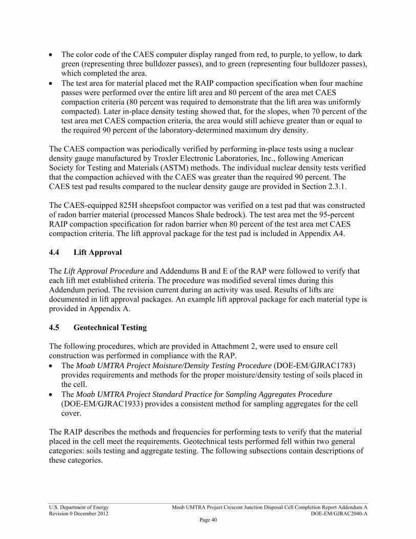
U.S. Department of Energy Moab UMTRA Project Crescent Junction Disposal Cell Completion Report Addendum A Revision 0 December 2012 DOE-EM/GJRAC2040-A
Page 40
The color code of the CAES computer display ranged from red, to purple, to yellow, to dark green (representing three bulldozer passes), and to green (representing four bulldozer passes), which completed the area.
The test area for material placed met the RAIP compaction specification when four machine passes were performed over the entire lift area and 80 percent of the area met CAES compaction criteria (80 percent was required to demonstrate that the lift area was uniformly compacted). Later in-place density testing showed that, for the slopes, when 70 percent of the test area met CAES compaction criteria, the area would still achieve greater than or equal to the required 90 percent of the laboratory-determined maximum dry density.
The CAES compaction was periodically verified by performing in-place tests using a nuclear density gauge manufactured by Troxler Electronic Laboratories, Inc., following American Society for Testing and Materials (ASTM) methods. The individual nuclear density tests verified that the compaction achieved with the CAES was greater than the required 90 percent. The CAES test pad results compared to the nuclear density gauge are provided in Section 2.3.1. The CAES-equipped 825H sheepsfoot compactor was verified on a test pad that was constructed of radon barrier material (processed Mancos Shale bedrock). The test area met the 95-percent RAIP compaction specification for radon barrier when 80 percent of the test area met CAES compaction criteria. The lift approval package for the test pad is included in Appendix A4. 4.4 Lift Approval The Lift Approval Procedure and Addendums B and E of the RAP were followed to verify that each lift met established criteria. The procedure was modified several times during this Addendum period. The revision current during an activity was used. Results of lifts are documented in lift approval packages. An example lift approval package for each material type is provided in Appendix A. 4.5 Geotechnical Testing The following procedures, which are provided in Attachment 2, were used to ensure cell construction was performed in compliance with the RAP. The Moab UMTRA Project Moisture/Density Testing Procedure (DOE-EM/GJRAC1783)
provides requirements and methods for the proper moisture/density testing of soils placed in the cell.
The Moab UMTRA Project Standard Practice for Sampling Aggregates Procedure (DOE-EM/GJRAC1933) provides a consistent method for sampling aggregates for the cell cover.
The RAIP describes the methods and frequencies for performing tests to verify that the material placed in the cell meet the requirements. Geotechnical tests performed fell within two general categories: soils testing and aggregate testing. The following subsections contain descriptions of these categories.
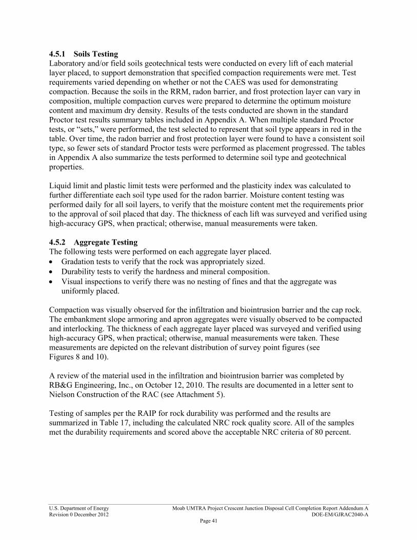
U.S. Department of Energy Moab UMTRA Project Crescent Junction Disposal Cell Completion Report Addendum A Revision 0 December 2012 DOE-EM/GJRAC2040-A
Page 41
4.5.1 Soils Testing Laboratory and/or field soils geotechnical tests were conducted on every lift of each material layer placed, to support demonstration that specified compaction requirements were met. Test requirements varied depending on whether or not the CAES was used for demonstrating compaction. Because the soils in the RRM, radon barrier, and frost protection layer can vary in composition, multiple compaction curves were prepared to determine the optimum moisture content and maximum dry density. Results of the tests conducted are shown in the standard Proctor test results summary tables included in Appendix A. When multiple standard Proctor tests, or “sets,” were performed, the test selected to represent that soil type appears in red in the table. Over time, the radon barrier and frost protection layer were found to have a consistent soil type, so fewer sets of standard Proctor tests were performed as placement progressed. The tables in Appendix A also summarize the tests performed to determine soil type and geotechnical properties. Liquid limit and plastic limit tests were performed and the plasticity index was calculated to further differentiate each soil type used for the radon barrier. Moisture content testing was performed daily for all soil layers, to verify that the moisture content met the requirements prior to the approval of soil placed that day. The thickness of each lift was surveyed and verified using high-accuracy GPS, when practical; otherwise, manual measurements were taken. 4.5.2 Aggregate Testing The following tests were performed on each aggregate layer placed. Gradation tests to verify that the rock was appropriately sized. Durability tests to verify the hardness and mineral composition. Visual inspections to verify there was no nesting of fines and that the aggregate was
uniformly placed. Compaction was visually observed for the infiltration and biointrusion barrier and the cap rock. The embankment slope armoring and apron aggregates were visually observed to be compacted and interlocking. The thickness of each aggregate layer placed was surveyed and verified using high-accuracy GPS, when practical; otherwise, manual measurements were taken. These measurements are depicted on the relevant distribution of survey point figures (see Figures 8 and 10). A review of the material used in the infiltration and biointrusion barrier was completed by RB&G Engineering, Inc., on October 12, 2010. The results are documented in a letter sent to Nielson Construction of the RAC (see Attachment 5). Testing of samples per the RAIP for rock durability was performed and the results are summarized in Table 17, including the calculated NRC rock quality score. All of the samples met the durability requirements and scored above the acceptable NRC criteria of 80 percent.

U.S. Department of Energy Moab UMTRA Project Crescent Junction Disposal Cell Completion Report Addendum A Revision 0 December 2012 DOE-EM/GJRAC2040-A
Page 42
Table 17. Rock Durability Test Results and NRC Rock Quality Scores
Laboratory Sample* ID #
Rock Durability Test Results NRC Rock Quality Score
Specific Gravity
Absorption (%)
SodiumSulfate
(%) L.A.
Abrasion Schmidt Hammer Total Maximum
Final (%)
Infiltration and Biointrusion Barrier
233040 2.685 0.6 0.0 6.6 56 228.7 260 88.0
258885 2.721 0.7 0.0 7.4 60 239.6 260 92.1
258889 2.709 0.5 0.0 6.7 63 241.0 260 92.7
287641 2.62 0.6 0.0 7.1 51 216.2 260 83.2
287644 2.64 1.0 0.0 6.6 65 222.6 260 85.6
287647 2.62 0.6 0.8 6.7 49 216.7 260 83.3
287662 2.63 0.6 0.0 7.6 48 217.2 260 83.5
Cap Rock
179332 2.670 0.8 0.0 6.5 52 222.7 260 85.7
211600 2.677 0.5 0.1 6.3 37 219.3 260 84.3
211607 2.675 0.8 0.1 6.7 39 217.0 260 83.5
233040 2.685 0.6 0.0 6.6 56 228.7 260 88.0
258881 2.706 0.5 0.0 7.1 64 241.5 260 92.9
258885 2.721 0.7 0.0 7.4 60 239.6 260 92.1
287650 2.62 0.9 0.0 6.8 45 211.0 260 81.2
287653 2.63 0.6 0.0 6.6 52 219.8 260 84.5
287656 2.62 0.6 0.0 6.3 57 220.2 260 84.7
287659 2.63 0.7 0.0 6.7 42 214.0 260 82.3
Side Slopes
211613 2.716 0.6 0.1 7.3 43 228.0 260 87.9
241264 2.674 0.79 0.0 6.6 54 224.0 260 86.2
241267 2.706 0.67 0.0 6.0 57 234.8 260 90.3
Apron
241270 2.681 0.52 0.4 6.2 57 228.4 260 87.8
241273 2.659 1.35 0.0 7.1 54 218.7 260 84.1
295294 2.64 1.0 0.0 7.3 42 213.7 260 82.2
% = percent; ID = identification; L.A. = Los Angeles * All samples are of gray basalt.
4.6 Radiological Verification Section 5 of the RAS identifies two primary verification criteria associated with construction of the disposal cell: Ra-226 measurements in RRM placed in the upper 7 ft, and radon flux measurements to verify the integrity of the radon barrier. The RAC must ensure that the radon flux does not exceed the EPA standard of an average of 20 picocuries per square meter per second (pCi/m2/s) once the radon barrier is placed. Based on modeling presented in Addendum D, “Final Design Calculations,” of the RAP, the Project

U.S. Department of Energy Moab UMTRA Project Crescent Junction Disposal Cell Completion Report Addendum A Revision 0 December 2012 DOE-EM/GJRAC2040-A
Page 43
controls the Ra-226 activity in the upper 7 ft of RRM placed in the disposal cell to meet this standard. The Ra-226 activity is controlled by monitoring the RRM just prior to shipment from the Moab site. The RAC uses 707 picocuries per gram (pCi/g) as the limit of the activity in samples collected in the material shipped to provide reasonable assurance that the radon flux limit will not be exceeded. A minimum of 26 samples is collected in the upper 7 ft of each 10,000-square meter area of placed RRM to verify that the average sample concentration is below the 707 pCi/g limit. For clarification, DOE requested in a letter to NRC dated June 20, 2011 (see Attachment 4), to add the word “average” before “radium activity in the upper seven feet” in Section 5.2.6 of the RAS. On August 1, 2011, the Project received verbal acceptance of this change (see Attachment 4). The basis for collecting at least 26 samples was determined using DOE Pacific Northwest National Laboratory-developed software, called Visual Sample Plan, which conforms to the DOE-approved sampling methodology defined in NRC Guide 1575, “Multi-Agency Radiation Survey and Site Investigation Manual.” An explanation of the Ra-226 sample verification process for the 7-ft criterion is provided in Attachment 5. Radon flux measurements were taken using Moab UMTRA Project Radon Flux Measurements Procedure (DOE-EM/GJRAC1939) and are used to validate that the cell design criteria have been met. Radon flux measurement results are presented in the Critical Review section and ranged from 0.2177 to 20.6410 pCi/m2/s, with an average flux of 3.3469 pCi/m2/s, which is well below the 20 pCi/m2/s limit. During this Addendum period, 615 samples of RRM were taken in the upper 7 ft of 16 lifts, and the Ra-226 activity of the lifts ranged from 298.34 to 627.96 pCi/g, with an average of 442.22 pCi/g. Table 18 shows the average result for each lift tested.
Table 18. Results of Ra-226 Activity in Upper 7 Ft of Placed RRM
Lift ID # # of Samples Taken Average Ra-226 Activity
(pCi/g)
UWH06 28 468.90
UWM12 31 365.40
UWI12 32 405.77
UWN23 38 347.58
UWN19 40 386.86
UWJ21 41 306.33
UWI24 36 474.14
UWK28 31 298.34
UWS31 30 624.47
UWR12 29 505.71
UWQ21 27 544.51
UWW27 26 627.96

U.S. Department of Energy Moab UMTRA Project Crescent Junction Disposal Cell Completion Report Addendum A Revision 0 December 2012 DOE-EM/GJRAC2040-A
Page 44
Table 18. Results of Ra-226 Activity in Upper 7 Ft of Placed RRM (continued)
Lift ID # # of Samples Taken Average Ra-226 Activity
(pCi/g)
UWS16 27 480.40
UWV21 26 530.54
UWR08 28 477.61
UWR06 28 468.90
UWP01 28 372.96
UWO04 28 374.32
UWQ01 33 381.82
UWQ04 28 401.86
Totals: 615 Average: 442.22
# = number.
4.7 QA Requirements QA activities were conducted in accordance with documents identified in Section 3.3. All personnel who performed work addressed in this Addendum were qualified in accordance with the requirements of the Quality Assurance Plan for the Remedial Action Contractor. During construction activities, audits and surveillances were performed by the RAC, including some conducted by the EnergySolutions’ corporate office, to verify and provide assurance that these activities were performed in accordance with established plans, drawings, instructions, procedures, specifications, and other applicable documents. In addition, DOE and the TAC performed audits and surveillances of these activities. During this Addendum period, nine audits and 46 surveillances were performed of disposal cell construction practices (see Table 19). Any issues identified during these audits and surveillances have been addressed.
Table 19. Audits and Surveillances Conducted during Construction
Date Conducted
By Type Assessment # Scope 03/25/08 – 03/28/08
DOE EMCBC Audit EM-PE-08-002 Evaluate QA Phase I Program to verify NQA-1 requirements are met.
03/25/08 – 03/26/08
RAC Surveillance MB-08-S-003
Evaluate airborne radioactivity monitoring (particulate and radon) being conducted by RAC radiation protection staff, including sample collection, equipment use, counting (analysis) methods, and documentation.
06/19/08 RAC Surveillance MB-08-S-006 Evaluate IWP implementation by reviewing documentation.
07/02/08 RAC Surveillance MB-08-S-010
Evaluate and verify the implementation of the Crescent Junction IWP scope, hazard identification, and controls along with responsibilities of individuals, and the lines of communication.

U.S. Department of Energy Moab UMTRA Project Crescent Junction Disposal Cell Completion Report Addendum A Revision 0 December 2012 DOE-EM/GJRAC2040-A
Page 45
Table 19. Audits and Surveillances Conducted during Construction (continued)
07/10/08 RAC Surveillance MB-08-S-011
Evaluate and verify subcontractor Johansen and Tuttle Engineering laboratory for calibrated equipment and process of proctor testing and concrete strength testing.
07/13/08 RAC Surveillance MB-08-S-004 Verify that contract-required environmental records have been submitted and continue to be submitted to DOE per RAC contract.
08/04/08 - 08/08/08
DOE EMCBC Audit Phase I ISMS Evaluate Project ISMS Phase I Program.
08/05/08 – 08/07/08
RAC Surveillance MB-08-S-012 To verify field inspection and oversight activities.
08/07/08 – 08/11/08
RAC Surveillance MB-08-S-013
Evaluate and verify the Equipment Inspection and Preventive Maintenance Program for EnergySolutions was implemented and followed accordingly.
09/05/08 –09/11/08
RAC Surveillance MB-08-S-009
Evaluate and verify the implementation of the Emergency Response Program on the Project in accordance with Moab UMTRA Project Emergency Response Plan, Rev.0 (DOE-EM/GJ1520). Also, review training, qualifications, and records management requirements.
11/13/08 – 11/19/08
DOE EMCBC Audit Phase II ISMS Evaluate implementation of Project ISMS Phase II Program
11/24/08 – 12/01/08
RAC Surveillance MB-09-S-003 Evaluate RAC implementation of the requirements for control of M&TE.
02/02/09 – 02/04/09
RAC Surveillance MB-09-S-005
Evaluate RAC implementation of Airborne Radioactivity Monitoring Program. Key elements assessed: personnel training and qualifications, documents and records, M&TE, and sample collection and analysis.
02/18/09 – 02/24/09
RAC Surveillance MB-09-S-006
Evaluate RAC implementation of Procurement Document Control Program. Key elements assessed: personnel training and qualifications, and documents and records.
05/04/09 – 05/26/09
RAC Surveillance MB-09-S-010
Evaluate and verify Equipment Inspection and Preventive Maintenance Program for RAC was implemented and followed accordingly. Key elements assessed: daily checklist, equipment repair tracking, and training.
06/29/09 – 07/01/09
EnergySolutions Corporate
Audit IA-09-03 Evaluate Project programs.
07/30/09 DOE/TAC Surveillance DOE-09-SUR-007 QC field operations compliance with test control.
09/22/09 DOE/TAC Surveillance DOE-09-SUR-014
QA/QC field operations, management, and performance compliance with the Quality Assurance Plan for the Remedial Action Contractor.
12/08/09 – 12/14/09
RAC Surveillance MB-10-S-003 Evaluate implementation of the Project Confined Space Program.
12/09/09 – 12/14/09
RAC Surveillance MB-10-S-002
Evaluate and verify implementation of RAC-IWP-024, Rev. 2, for the Crescent Junction Radioactive Material Handling. Evaluate hazard identification and controls, along with responsibilities of individuals and the lines of communication.
12/10/09 – 12/18/09
RAC Surveillance MB-10-S-001 Evaluate RAC implementation of requirements for control of M&TE.
01/11/10 – 01/15/10
RAC Surveillance MB-10-S-005 Evaluate and verify implementation of MB-IWP-022, Rev.2, Moab RRM Handling and Transportation Activities at the Moab Project.

U.S. Department of Energy Moab UMTRA Project Crescent Junction Disposal Cell Completion Report Addendum A Revision 0 December 2012 DOE-EM/GJRAC2040-A
Page 46
Table 19. Audits and Surveillances Conducted during Construction (continued)
Date Conducted
By Type Assessment # Scope
02/03/10 – 02/05/10
RAC Surveillance MB-10-S-011 Evaluate and verify MB-IWP-004, Rev.2, General Equipment Maintenance for the Moab UMTRA Project, is implemented with work steps.
02/10/10 – 02/12/10
RAC Surveillance MB-10-S-010 Evaluate and verify MB-IWP-023, Rev. 0, Train Arrival, Container Handling, and Train Departure is implemented.
02/22/10 – 02/24/10
RAC Surveillance MB-10-S-007
Evaluate RAC implementation of Airborne Radioactivity Monitoring Program. Key elements assessed: personnel training and qualifications, documents and records, M&TE, sample collection and analysis.
03/24/10 DOE/TAC Surveillance DOE-10-SUR-002
Surveillance of TAC subcontractor Geotechnical Engineering Group’s laboratory and processes to ensure compliance to testing specified within the RAP Addendum D, “Final Design Specifications,” and Addendum E, the RAIP.
04/01/10 – 04/09/10
RAC Surveillance MB-10-S-014
Evaluate and verify the Equipment Inspection and Preventive Maintenance Program for the RAC was implemented and followed accordingly. Key elements assessed: daily checklist, equipment repair tracking, and training.
06/21/10 – 06/25/10
DOE EMCBC Audit Phase III ISMS Evaluate implementation of Project ISMS Phase III Program.
07/01/10 – 08/30/10
RAC Surveillance MB-10-S-015
Evaluate RAC suppliers to determine if suppliers’ capabilities meet the quality and technical criteria for procurement of items and services of Moab UMTRA Project Supplier Evaluation, Rev.3 (DOE-EM/GJRAC1703)
07/19/10 RAC Surveillance MB-10-S-008
Evaluate RAC implementation of Procurement Document Control Program. Key elements assessed: personnel training and qualifications and documents and records.
07/19/10 – 07/23/10
RAC Surveillance MB-10-S-020
Evaluate RAC implementation of the Statistical Survey and Release Procedure for RRM Transport Containers, Rev. 1 (DOE-EM/GJRAC1874)
07/19/10 – 07/23/10
RAC Surveillance MB-10-S-021
Evaluate RAC implementation of the requirements of Radiological Posting and Access Control, Rev.2 (DOE-EM/GJRAC1748). Key elements assessed: field reviews and observations, documents and records, and implementation of the radiological posting and access control.
08/23/10 – 08/27/10
EnergySolutions Corporate
Audit IA-10-03 Evaluate Project programs.
09/20/10 – 09/23/10
RAC Surveillance MB-10-S-017
Evaluate RAC implementation of Suspect and Counterfeit Items, Rev. 2 (DOE-EM/GJRAC1704), including the process to identify S/CI, prevent delivery of S/CI to DOE facilities, and notify DOE’s Office of Inspector General when S/CI are found.

U.S. Department of Energy Moab UMTRA Project Crescent Junction Disposal Cell Completion Report Addendum A Revision 0 December 2012 DOE-EM/GJRAC2040-A
Page 47
Table 19. Audits and Surveillances Conducted during Construction (continued)
Date Conducted
By Type Assessment # Scope
10/18/10 – 10/22/10
RAC Surveillance MB-11-S-001
Evaluate and verify implementation of MB-IWP-004, Rev 2, General Equipment Maintenance for the Moab UMTRA Project, and MB-IWP-026, Rev. 0, Container Maintenance. The assessment includes interviews, and review of procedures, processes, and guidelines. Key elements assessed: documents and records, implementation of IWPs, maintenance program, and training and qualifications.
11/14/10 – 11/23/10
RAC Surveillance MB-11-S-002
Evaluate and verify implementation of MB-IWP-039, Rev. 0, The Dumping and Decontamination of the Intermodal Containers and Haul Trucks at the Crescent Junction Site; MB-IWP-049, Rev. 0, The Handling and Disposal of RRM at the Crescent Junction Site; and MB-IWP-050, Rev. 0, The Use of a Temper Attachment to Dislodge Built-Up RRM in the Intermodal Containers. The assessment included interviews and review of procedures, processes, and guidelines. Key elements assessed: documents and records, implementation of the IWPs, and training and qualifications.
12/02/10 – 12/09/10
RAC Surveillance MB-11-S-005
Evaluate RAC implementation of Airborne Radioactivity Monitoring Program. Key elements assessed: training and qualifications, documents and records, M&TE, and sample collection and analysis.
12/13/10 – 12/16/10
DOE EMCBC Audit EM-PA-10-08 Evaluate implementation of QA Program.
01/10/11 – 01/24/11
RAC Surveillance MB-11-S-010 Evaluate and verify implementation of MB-IWP-013, Rev. 1, Excavation & Conditioning.
02/01/11 – 02/11/11
RAC Surveillance MB-11-S-012
Evaluate and verify implementation of MB-IWP-023, Rev.1, Train Arrival, Container Handling and Train Departure, and MB-IWP-038, Rev. 0, Railway Operations.
02/17/11 – 02/23/11
RAC Surveillance MB-11-S-013
Verify implementation of Moab UMTRA Project Standard Practice for Sampling Aggregates, Rev. 0 (DOE-EM/ GJRAC1933). The assessment included interviews and review of procedures, processes, and guidelines.
02/28/11 – 03/22/11
RAC Surveillance MB-11-S-014 Evaluate and verify implementation of Moab UMTRA Project Lockout/Tagout Hazardous Energy Control, Rev. 0 (DOE-EM/GJ1552).
03/14/11 – 03/24/11
RAC Surveillance MB-11-S-016 Evaluate and verify implementation of MB-IWP-072, Rev. 0, Dumping and Placement of Potentially Hazardous Off-Pile Materials.
03/29/11 – 04/18/11
RAC Surveillance MB-11-S-017
Evaluate and verify implementation of RAC-MB-IWP-052, Rev. 0, The Processing and Placement of the Interim Cover Layer, and RAC-MB-IWP-053, Rev. 0, The Processing and Placement of the Radon Barrier Layer.

U.S. Department of Energy Moab UMTRA Project Crescent Junction Disposal Cell Completion Report Addendum A Revision 0 December 2012 DOE-EM/GJRAC2040-A
Page 48
Table 19. Audits and Surveillances Conducted during Construction (continued)
Date Conducted
By Type Assessment # Scope
04/06/11 DOE/TAC Surveillance DOE-11-SUR-018
Observe placement of RRM and construction of cover components (radon barrier and interim cover layer) and discuss QC operations and processes with RAC QC staff to verify compliance to the RAP, Addendum B, Specifications, and Addendum E, Remedial Action Inspection Plan.
04/21/11 – 05/23/11
RAC Surveillance MB-11-S-026 Radon barrier soil properties testing.
05/23/11 – 06/10/11
RAC Surveillance MB-11-S-024
Evaluate and verify implementation of RAP, Addendum E, Remedial Action Inspection Plan. The assessment included interviews, review of programs and procedures, and verification of the placement process.
06/06/11 – 06/09/11
EnergySolutions Corporate
Audit IA-11-13 Evaluate Project programs.
06/20/11 – 06/28/11
RAC Surveillance MB-11-S-027
Evaluate and verify implementation of Suspect and Counterfeit Items (DOE-EM/GJRAC1704). The assessment included interviews, review of procedures, and verification of the process by which to identify S/CI, prevent delivery of S/CI to DOE facilities, and notify DOE’s Office of Inspector General when S/CI are found.
07/19/11 – 07/26/11
RAC Surveillance MB-11-S-028
Evaluate and verify the implementation of Moab UMTRA Project Particulate Air Monitoring (DOE-EM/GJRAC1744), Rev. 5. The assessment includes interviews, review of program, procedures, and lines of communication.
08/01/11 – 12/31/11
DOE/TAC Surveillance DOE-12-SUR-002TAC subcontractor Geotechnical Engineering Group verification of RAC field operations and compliance with the RAP
08/25/11 DOE/TAC Surveillance TAC-12-SUR-011 Crescent Junction disposal cell.
10/24/11 – 10/27/11
DOE EMCBC Audit Phase IV ISMS Evaluate implementation of Project ISMS Phase IV Program.
10/26/11 – 11/11/11
RAC Surveillance MB-12-S-002
Evaluate and verify implementation of MB-IWP-026, Rev. 0, Container Maintenance, and MB-IWP-068, Rev. 0, Water Testing Intermodal Containers. The assessment included interviews and review of procedures, processes, and guidelines.
11/15/11 – 11/30/11
RAC Surveillance MB-12-S-003
Evaluate and verify implementation of MB-IWP-039, Rev. 1, The Dumping and Decontamination of Intermodal Containers and Haul Trucks at the Crescent Junction Site, and MB-IWP-049, Rev. 0, The Handling and Disposal of RRM at the Crescent Junction Site. The assessment included interviews and review of procedures, processes, and guidelines.
04/26/12 RAC Surveillance MB-12-S-007 Evaluate the implementation of the Confined Space Program.
EMCBC = Environmental Management Consolidated Business Center; ISMS = Integrated Safety Management System; IWP = Integrated Work Plan; M&TE = measuring and test equipment; QC = Quality Control; S/CI = suspect and counterfeit items

U.S. Department of Energy Moab UMTRA Project Crescent Junction Disposal Cell Completion Report Addendum A Revision 0 December 2012 DOE-EM/GJRAC2040-A
Page 49
4.8 Monitoring for Presence of Free Liquids To monitor for the presence of free liquids in the disposal cell, four standpipes are specified in Section 7.2.4 of the RAS to be completed so that the screens are at the base of the placed RRM. In August 2011, the RAC placed one standpipe in a southeastern location in the cell (see Figure 13). During the period covered in this Addendum, RRM lifts surrounding the standpipe were placed to a total thickness of about 7 ft Results of periodic monitoring for the presence of fluids are shown in Table 20.
Table 20. Results of Monitoring for the Presence of Fluids in Standpipe
Date Monitored
Presence or Level of Fluids
(ft)
10/28/11 Dry
02/22/12 Dry
04/27/12 Dry
Dry = no fluids present.
4.9 Monitoring for Presence of Ground Water To monitor for the presence of ground water outside of the disposal cell footprint, Section 7.2.4 of the RAS specified that four of the characterization boreholes would be recompleted from a depth of about 300 ft below ground surface to near the contact between the weathered and unweathered Mancos Shale bedrock. The RAS indicated that the recompletion was to be performed prior to initiating RRM placement in the disposal cell. DOE notified NRC in a letter dated November 29, 2010, that the boreholes had not been recompleted prior to initiation of RRM placement. In a second letter to NRC on the subject, dated May 9, 2011, DOE indicated its intent to recomplete the wells, which occurred in September 2011. Copies of this correspondence with NRC are included in Attachment 4. Three borehole locations were abandoned in 2008, because they were within the Phase 1 excavation area. Three additional borehole locations were abandoned in 2011 because they were either unnecessary or located inside of future excavation phases. The recompletion of the four wells and the well abandonments are detailed in the Moab UMTRA Project Crescent Junction Disposal Site Borehole Abandonment and Monitoring Well Completion Report (DOE-EM/GJTAC2018). The well and borehole locations are shown on Figure 13. Results of monitoring for the presence of ground water in the wells are shown in Table 21.
Table 21. Results of Monitoring for Presence of Ground Water
Date Monitored
Monitor Well Number
202 203 205 210
10/28/2011 Dry Dry Dry NM
11/03/2011 NM NM NM Dry
02/22/2012 Dry Dry Dry Dry
NM = not measured; Dry = no fluids present

U.S. D
epartment of Energy
Moab U
MTR
A Project Interim
Com
pletion Report A
ppendix Package AR
evision 0 Decem
ber 2012
DO
E-EM/G
JRA
C2040-A
Page 50
Figure 13. Locations of Abandoned and Recompleted Boreholes and Standpipe

U.S. Department of Energy Moab UMTRA Project Crescent Junction Disposal Cell Completion Report Addendum A Revision 0 December 2012 DOE-EM/GJRAC2040-A
Page 51
5.0 References 10 CFR 830, (Code of Federal Regulations), “Nuclear Safety Management,” Subpart A, “Quality Assurance.”
American Society for Testing and Materials (ASTM) Standard C88, “Standard Test Method for Soundness of Aggregates by Use of Sodium Sulfate or Magnesium Sulfate.”
American Society for Testing and Materials (ASTM) Standard C117, “Standard Test Method for Materials Finer than 75-micrometer (No. 200) Sieve in Mineral Aggregates by Washing.”
American Society for Testing and Materials (ASTM) Standard C127, “Standard Test Method for Density, Relative Density (Specific Gravity), and Absorption of Coarse Aggregates.”
American Society for Testing and Materials (ASTM) Standard C131, “Standard Test Method for Resistance to Degradation of Small-Size Coarse Aggregate by Absorption and Impact in the Los Angeles Machine.”
American Society for Testing and Materials (ASTM) Standard C136, “Standard Test Method for Sieve Analysis of Fine and Course Aggregates.”
American Society for Testing and Materials (ASTM) Standard D422, “Standard Test Method for Particle-Size Analysis of Soils.”
American Society for Testing and Materials (ASTM) Standard D698, “Standard Test Method for Laboratory Compaction Characteristics of Soil Using Standard Effort.”
American Society for Testing and Materials (ASTM) Standard D1140, “Standard Test Method for Amount of Material in Soils Finer than the No. 200 (75-micrometer) Sieve.”
American Society for Testing and Materials (ASTM) Standard D1556, “Standard Test Method for Density and Unit Weight of Soil in Place by the Sand-Cone Method.”
American Society for Testing and Materials (ASTM) Standard D2216, “Standard Test Methods for Laboratory Determination of Water (Moisture) Content of Soil and Rock by Mass.”
American Society for Testing and Materials (ASTM) Standard D4318, “Standard Test Method for Liquid Limit, Plastic Limit, and Plasticity Index of Soils.”
American Society for Testing and Materials (ASTM) Standard D4643, “Standard Test Method for Determination of Water (Moisture) Content of Soil by the Microwave Oven Heating.”
American Society for Testing and Materials (ASTM) Standard D4944, “Standard Test Method for Field Determination of Water (Moisture) Content of Soil by the Calcium Carbide Gas Pressure Tester.”
American Society for Testing and Materials (ASTM) Standard D4959, “Standard Test Method for Determination of Water (Moisture) Content of Soil by Direct Heating Method.”
American Society for Testing and Materials (ASTM) Standard D6938, “Standard Test Method for In-Place Density and Water content of Soil and Soil-Aggregate by Nuclear Methods (Shallow Depth)”
American Society of Mechanical Engineers (ASME), Nuclear Quality Assurance (NQA)-1 2004 and addenda through 2007 consensus standard, “Quality Assurance Requirements for Nuclear Facility Applications (QA).”

U.S. Department of Energy Moab UMTRA Project Crescent Junction Disposal Cell Completion Report Addendum A Revision 0 December 2012 DOE-EM/GJRAC2040-A
Page 52
DOE (U.S. Department of Energy), Moab UMTRA Project Crescent Junction Disposal Site Borehole Abandonment and Monitoring Well Completion Report (DOE-EM/GJTAC2018), November 2011.
DOE (U.S. Department of Energy), Moab UMTRA Project Final Remedial Action Plan and Site Design for Stabilization of Moab Title I Uranium Mill Tailings at the Crescent Junction, Utah, Disposal Site (DOE-EM/GJ1547), July 2008 (Note: was updated December 2012).
DOE (U.S. Department of Energy), Moab UMTRA Project Lift Approval Procedure (DOE-EM/GJRAC1803), July 2011.
DOE (U.S. Department of Energy), Moab UMTRA Project Moisture/Density Testing Procedure (DOE-EM/GJRAC1783), April 2011.
DOE (U.S. Department of Energy), Moab UMTRA Project Quality Assurance Plan for the Remedial Action Contractor (DOE-EM/GJRAC1766), March 2011.
DOE (U.S. Department of Energy), Moab UMTRA Project Radon Flux Measurements Procedure (DOE-EM/GJRAC1939), May 2011.
DOE (U.S. Department of Energy), Moab UMTRA Project Standard Practice for Sampling Aggregates Procedure (DOE-EM/GJRAC1933), October 2010.
DOE (U.S. Department of Energy), Order 226.1B, “Implementation of Department of Energy Oversight Policy,” Appendix A.
DOE (U.S. Department of Energy), Order 414.1D, “Quality Assurance.”
DOE (U.S. Department of Energy), Technical Approach Document (UMTRA-DOE/AL 050425.002), December 1989.
Jacobs Engineering Group, Inc., “Design Change Control with NQA-1 QA Requirements” (FONQAWI 105), May 2008
NRC (U.S. Nuclear Regulatory Commission), Regulatory Guide 1575, “Multi-Agency Radiation Survey and Site Investigation Manual (MARSSIM),” August 2000.