mns r - main distribution switchgear system guide switchgear ... are located into the single column...
TRANSCRIPT

Contact us
Doc
umen
t ID
MNS R - Main distribution switchgearSystem Guide


ABB SACE 1
MNS Rmain low voltagedistribution switchgear
Index
General
Introduction .................................................................................................................................2
Technical data .............................................................................................................................3
Construction and functional characteristics
Switchgear frame ........................................................................................................................4
Earthing ......................................................................................................................................4
Circuit-breakers used ..................................................................................................................5
Circuit-breaker compartment ......................................................................................................5
Instrument compartment .............................................................................................................6
Busbar compartment ..................................................................................................................7
Main busbars ..............................................................................................................................7
Distribution busbars ....................................................................................................................8
Cable compartment ....................................................................................................................9
Segregation forms .....................................................................................................................10
Construction forma type ............................................................................................................10
Typical units and cross-sections ................................................................................................12
Ventilation .................................................................................................................................13
Standardisation
Typical configurations ................................................................................................................14
Switchgear depth ......................................................................................................................16
Versions
Available versions ......................................................................................................................17
Arc-proof ..................................................................................................................................17
Power Motor Control Center integrated solutions ...................................................................... 17
Intelligent switchgear .................................................................................................................20
Installation
Fixing the units to the floor ........................................................................................................22
Tests and certifications .........................................................................................................23
ABB PC30 23-11-2009, 8:121
2 ABB SACE
General
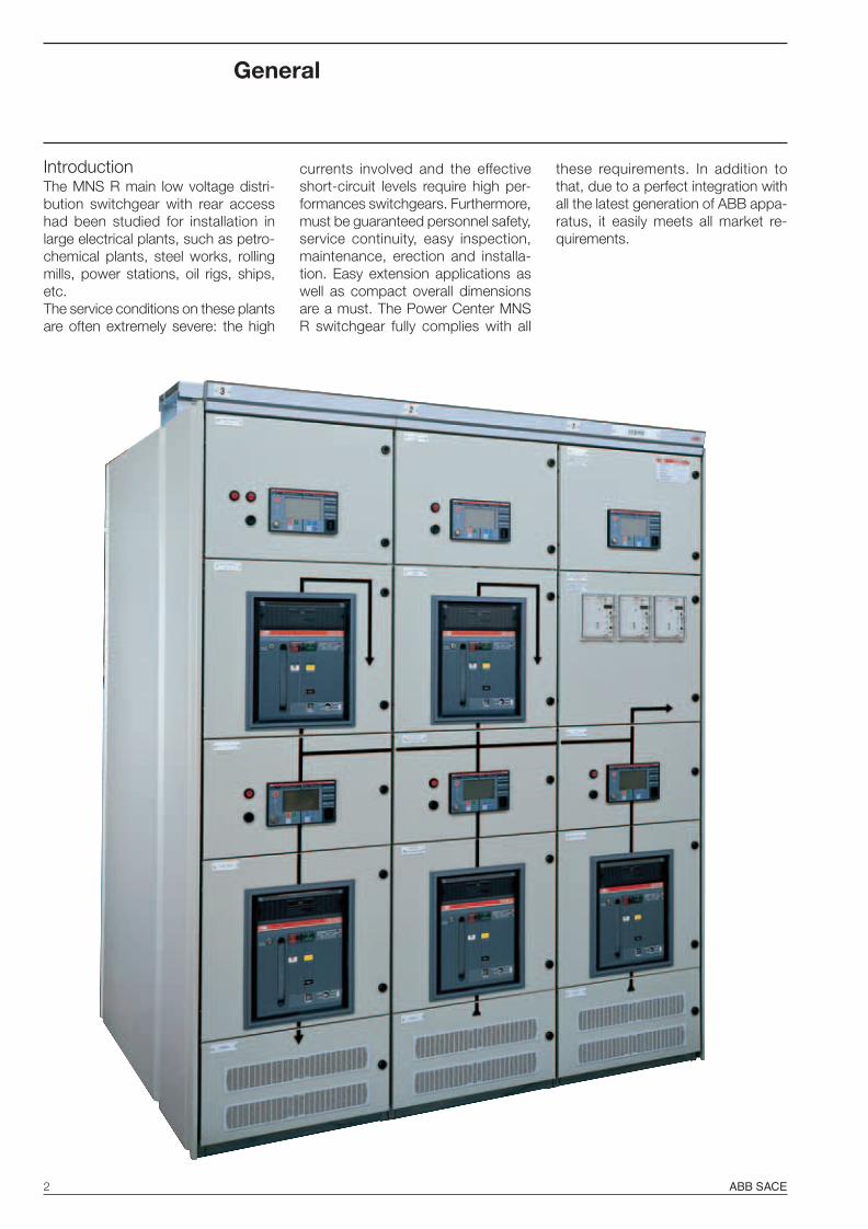
IntroductionThe MNS R main low voltage distri-bution switchgear with rear accesshad been studied for installation inlarge electrical plants, such as petro-chemical plants, steel works, rollingmills, power stations, oil rigs, ships,etc.The service conditions on these plantsare often extremely severe: the high
currents involved and the effectiveshort-circuit levels require high per-formances switchgears. Furthermore,must be guaranteed personnel safety,service continuity, easy inspection,maintenance, erection and installa-tion. Easy extension applications aswell as compact overall dimensionsare a must. The Power Center MNSR switchgear fully complies with all
these requirements. In addition tothat, due to a perfect integration withall the latest generation of ABB appa-ratus, it easily meets all market re-quirements.
ABB PC30 23-11-2009, 8:122
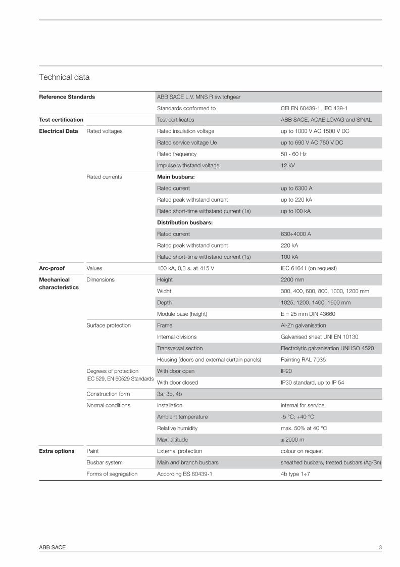
ABB SACE 3
Technical data
Reference Standards ABB SACE L.V. MNS R switchgear
Standards conformed to CEI EN 60439-1, IEC 439-1
Test certification Test certificates ABB SACE, ACAE LOVAG and SINAL
Electrical Data Rated voltages Rated insulation voltage up to 1000 V AC 1500 V DC
Rated service voltage Ue up to 690 V AC 750 V DC
Rated frequency 50 - 60 Hz
Impulse withstand voltage 12 kV
Rated currents Main busbars:
Rated current up to 6300 A
Rated peak withstand current up to 220 kA
Rated short-time withstand current (1s) up to100 kA
Distribution busbars:
Rated current 630÷4000 A
Rated peak withstand current 220 kA
Rated short-time withstand current (1s) 100 kA
Arc-proof Values 100 kA, 0,3 s. at IEC 61641 (on request)
Mechanical Dimensions Height 2200 mmcharacteristics
Widht 300, 400, 600, 800, 1000, 1200 mm
Depth 1025, 1200, 1400, 1600 mm
Module base (height) E = 25 mm DIN 43660
Surface protection Frame Al-Zn galvanisation
Internal divisions Galvanised sheet UNI EN 10130
Transversal section Electrolytic galvanisation UNI ISO 4520
Housing (doors and external curtain panels) Painting RAL 7035
Degrees of protection With door open IP20IEC 529, EN 60529 Standards
With door closed IP30 standard, up to IP 54
Construction form 3a, 3b, 4b
Normal conditions Installation internal for service
Ambient temperature -5 °C; +40 °C
Relative humidity max. 50% at 40 °C
Max. altitude 2000 m
Extra options Paint External protection colour on request
Busbar system Main and branch busbars sheathed busbars, treated busbars (Ag/Sn)
Forms of segregation According BS 60439-1 4b type 1÷7
ABB PC30 23-11-2009, 8:123
415 V

4 ABB SACE
Construction and functional characteristics
Switchgear frameThe MNS R frame is based onmodular 2 mm thick still C sec-tions, pre-drilled at a pitch of 25mm. Each unit is based onmodular elements and consistsof:– circuit-breaker compartments– instruments compartments– busbar compartment– cable compartment.
All compartments are meccani-cally segregated from the others.The switchgear is pre set foreasy extensions on both sides.
EarthingThe switchgear is provided with acontinuous electrolytic copper earth-ing busbar, with a cross-section suit-able for the proper switchgear short-circuit rating and pre-set on bothsides for connection to the earthingnetwork.
Are connected to the earthing busbar- all the metallic structures of the indi-
vidual units;- all not live metallic parts of the cir-
cuit-breakers;- all CTs and VTs secondary earthing
connections.All others not live metallic parts of theapparatus are connected to the earth-ing busbar by means of the unit me-tallic structure.
The doors with apparatus installed areconnected to the structure by meansof flexible copper braids. All theground connections are made withscrews or bolts provided with grippingwashers.
ABB PC30 23-11-2009, 8:134

ABB SACE 5
Circuit-breaker compartmentThe compartment is suitable to accept both air andmoulded-case circuit-breakers and it is accessible from thefront side by means of a locked hinged door. The circuit-breakers can be installed in all the available versions, fixed,plug-in and withdrawable. With all the widrawable circuit-breakers, in order do guarantee the maximum safety levelto the operator, the apparatus handling can be carried outwith the door closed.
Circuit-breaker compartment with EmaxCircuit-breaker compartment with Isomax
Circuit-breakers used
System Pro M modular circuit-breakers (MCBs)
SACE Emax air circuit-breakers (ACBs) SACE Isomax S moulded-case circuit-breakers (MCCBs)
Tmax moulded-case circuit-breakers (MCCBs)
ABB PC30 23-11-2009, 8:135

6 ABB SACE
Construction and functional characteristics
Instrument compartmentThe instrument compartment as wellis located in the front side of theswitchgear and it is accessible bymeans of a locked hinged door. It canbe dedicated to each functional unitor be common to several ones. Themeasuring instruments, protection re-lays, control and signalling devices arenormally mounted on the door,whereas any other auxiliary appara-tus, such as miniature circuit-break-ers, protection fuses and auxiliary re-lays are placed inside the compart-ment. Apparatus wiring is made withflexible copper cables and arrangedin dedicated wiring channels. Eachcircuit-breaker terminal blocks areseparated from the others and prop-erly identified.
Internal compartment with auxiliary apparatus and terminal boxes
Instrument compartment with protection relay mounted on the door
ABB PC30 23-11-2009, 8:136

ABB SACE 7
Busbar compartmentThe busbar compartment is locatedin the middle section of theswitchgear. Main busbars can be lo-cated at the top, in the centre or atthe bottom of the panel depending onthe selected design and they distrib-ute the power to the variousswitchgear panels. In some of the ex-isting configurations main busbarscan be directly connected to a circuit-breaker as well. Distribution busbarsare located into the single column andpositioned vertically to feed panel cir-cuit-breakers. The busbar system canbe composed by 1, 2 or 3 busbarsper phase, according to requestedrated current, short-circuit level andoperational ambient conditions interms of temperature, altitude andhumidity. Busbars are normally barecopper made, on request can be suit-ably treated with tinning, silver-platingand/or sheathing.
Main busbar system with connections for incoming busbars and bus-tie from the top
Main busbarsMNS R main busbars are available forcurrents up to 6300 A. Main busbars,as well as distribution busbars, can becompletely segregated. Each MNS Rpanel can be fitted with three busbarsystems at the same time (top-cen-tre-bottom) each segregated from theothers.
Detail of a compartment with entry from the top and connection on the main busbar system
ABB PC30 23-11-2009, 8:137

8 ABB SACE
Construction and functional characteristics
Distribution busbarsMNS R distribution busbars are avail-able for currents up to 4000 A. Distri-bution busbars, branched directlyfrom main busbars, are vertically in-stalled either on the right or on the leftin the column. They are feeding out-going circuit-breakers, and are con-nected to them by means of rigid orflexible copper busbars, or cables. Inany case, all the connections are suit-ably sized to withstand the thermody-namic stresses of the fault currents.
Busbar distribution system with connections to the outgoing circuit-breakers made with copperbusbars and cables.
Cableconnections
Copper busbarconnections
ABB PC30 23-11-2009, 8:138

ABB SACE 9
Cable compartmentThe cable compartment is located inthe rear side of the panel and and it isaccessible by means of a lockedhinged door or a removable bolteddoor.Its purpose is to contain:– power terminals– outgoing cables– current reducers– auxiliary terminal boxes (if any).
Removablesheets
for cableentry
Distributionbusbars
Connectionterminals
ABB PC30 23-11-2009, 8:139

10 ABB SACE
Construction and functional characteristics
Segregation formsThe MNS R segregation forms arecompliant with the relevant standardIEC 60439-1 annex D. The purposeof the segregations is mainly to allowsafety access to the internal parts ofthe switchgear to operational person-nel and to minimize propagation ofany faults it may happen in the circuitsand in the adjacent compartments, tothe benefit of service continuity of theinstallation.
Form 4b, rear side.Both main and distribution busbars are metallically segregated, plastic covers are used for cableconnections.
Form 1 No segregation
Form 2a Segregation of the busbars from the functional units; terminals are not separated from the busbars
Form 2b Segregations of the busbars from the functional units; the terminals are separated from the busbars
Form 3a Segregations of the busbars from functional units and between functional units; segregation of the terminalsfrom the functional units, but not from the busbars; terminals not separated from each other
Form 3b Segregations of the busbars from the functional units and between functional units; segregation of theterminals from the functional units and from the busbars, but not from each other
Form 4a Segregations of the busbars from the functional units and between functional units; segregation of theterminals from the functional units and from the busbars; the terminals for external conductors are in the samecompartment as the associated functional unit
Form 4b Segregations of the busbars from the functional units and between functional units; segregation of theterminals from the functional units and from the busbars; the terminals for external conductors are not in thesame compartment as the associated functional unit
Form 4b, rear side Both main and distribution busbars are metallically segregated, plastic covers are used for cable connections.
Construction forms type
ABB PC30 23-11-2009, 8:1410
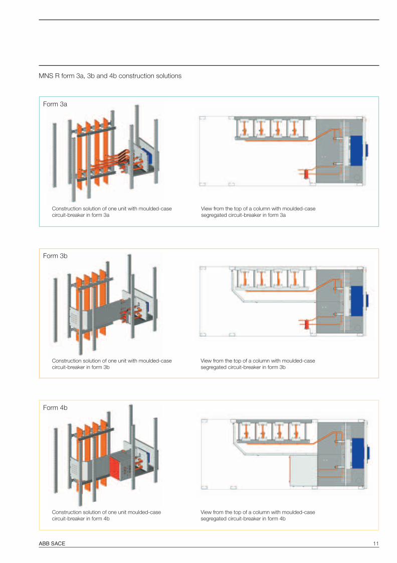
ABB SACE 11
Form 3a
Construction solution of one unit with moulded-casecircuit-breaker in form 3a
View from the top of a column with moulded-casesegregated circuit-breaker in form 3a
Form 3b
Construction solution of one unit with moulded-casecircuit-breaker in form 3b
View from the top of a column with moulded-casesegregated circuit-breaker in form 3b
Form 4b
Construction solution of one unit moulded-casecircuit-breaker in form 4b
View from the top of a column with moulded-casesegregated circuit-breaker in form 4b
MNS R form 3a, 3b and 4b construction solutions
ABB PC30 23-11-2009, 8:1411
12 ABB SACE
Construction and functional characteristics
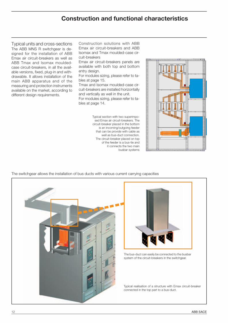
Typical units and cross-sectionsThe ABB MNS R switchgear is de-signed for the installation of ABBEmax air circuit-breakers as well asABB Tmax and Isomax moulded-case circuit-breakers, in all the avail-able versions, fixed, plug-in and with-drawable. It allows installation of themain ABB apparatus and of themeasuring and protection instrumentsavailable on the market, according todifferent design requirements.
Construction solutions with ABBEmax air circuit-breakers and ABBIsomax and Tmax moulded-case cir-cuit-breakersEmax air circuit-breakers panels areavailable with both top and bottomentry design.For modules sizing, please refer to ta-bles at page 15.Tmax and Isomax moulded-case cir-cuit-breakers are installed horizontallyand vertically as well in the unit.For modules sizing, please refer to ta-bles at page 14.
The bus-duct can easily be connected to the busbarsystem of the circuit-breakers in the switchgear.
Typical realisation of a structure with Emax circuit-breakerconnected in the top part to a bus-duct.
Typical section with two superimpo-sed Emax air circuit-breakers. The
circuit-breaker placed in the bottomis an incoming/outgoing feeder
that can be provide with cable aswell as bus-duct connection.
The circuit-breaker placed on topof the feeder is a bus-tie and
it connects the two mainbusbar systems
The switchgear allows the installation of bus ducts with various current carrying capacities
ABB PC30 23-11-2009, 8:1412

ABB SACE 13
AB
C
VentilationThe ABB MNS R switchgear havebeen studied to create separated airflows for all the internal compartmentsin order to guarantee an efficient natu-ral ventilation to all the installed com-ponents. Ventilation grides for naturalcooling are placed on the front andrear side of the the panel on both, topand bottom positions, and on the roofas well.
A= Apparatus areaB= Busbar areaC= Cable area
Diagram of natural ventilation of the unit
ABB PC30 23-11-2009, 8:1413
14 ABB SACE
B1 B4
A1 A4
Standardisation
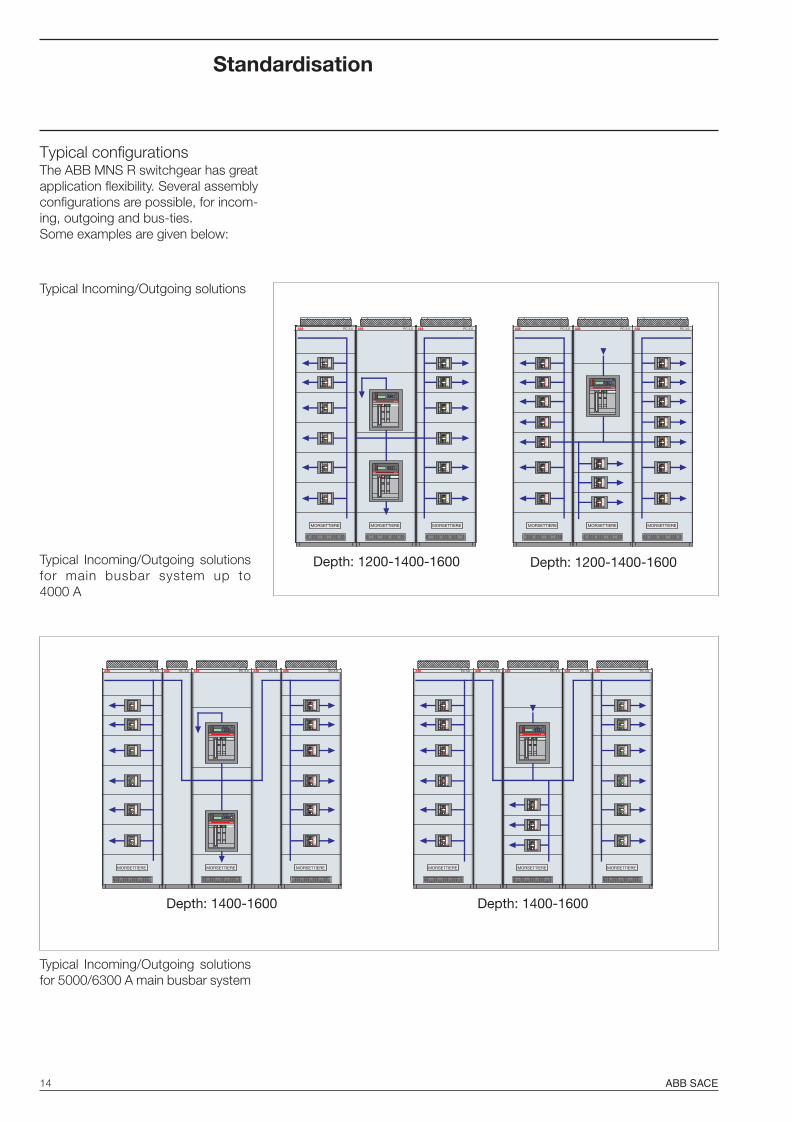
Typical configurationsThe ABB MNS R switchgear has greatapplication flexibility. Several assemblyconfigurations are possible, for incom-ing, outgoing and bus-ties.Some examples are given below:
Typical Incoming/Outgoing solutions
Typical Incoming/Outgoing solutionsfor 5000/6300 A main busbar system
Typical Incoming/Outgoing solutionsfor main busbar system up to4000 A
Depth: 1200-1400-1600
PC 3.0 PC 3.0 PC 3.0
MORSETTIERE MORSETTIERE MORSETTIERE
SACE
SACE
Depth: 1200-1400-1600
PC 3.0
MORSETTIERE
PC 3.0
MORSETTIERE
PC 3.0
MORSETTIERE
SACE
Depth: 1400-1600
PC 3.0
MORSETTIERE
SACE
MORSETTIERE
PC 3.0
SACE
PC 3.0 PC 3.0
MORSETTIERE
PC 3.0
Depth: 1400-1600
PC 3.0
MORSETTIERE
SACE
MORSETTIERE
PC 3.0 PC 3.0 PC 3.0
MORSETTIERE
PC 3.0
ABB PC30 23-11-2009, 8:1414

ABB SACE 15
C1 C4
D1 D4
Typical Incoming and Bus-tiesolutions
Typical Incoming and Bus-tie solu-tions for main busbar system from5000 to 6300 A
Typical Incoming and Bus-tie solu-tions for main busbar systemup to 4000 A
For customised solutions, please contact ABB SACE S.p.A. directly
Depth: 1200-1400-1600
PC 3.0 PC 3.0PC 3.0
SACE
SACE
SACE
PC 3.0
SACE
PC 3.0
SACE
PC 3.0
Depth: 1200-1400-1600
PC 3.0
SACE
MORSETTIERE MORSETTIERE MORSETTIERE MORSETTIERE MORSETTIERE MORSETTIERE
Depth: 1400-1600
PC 3.0PC 3.0
SACE
PC 3.0
SACE
SACE
PC 3.0 PC 3.0
Depth: 1400-1600
PC 3.0 PC 3.0 PC 3.0PC 3.0
SACE
SACE
SACE
MORSETTIERE MORSETTIERE MORSETTIERE MORSETTIERE MORSETTIERE MORSETTIERE
ABB PC30 23-11-2009, 8:1415

16 ABB SACE
P A B C1025 450 525 50
1200 450400 350
525 225
1400 450525 425
650 300
1600 450525 625
650 500
FRONT
Switchgear depthThe switchgear can have differentdepths. Selection mainly depends onthe rated current of the main busbarsystem, on the short-time withstandcurrent and on the space needed forfeeder connections.
Depth
Standardisation
Switchgear depth in relation to the main busbars rated currentAmperes Depth
Max. 50 kA 400 1200630 1200800 1200
1000 12001250 12001600 12002000 12002500 1200
Max. 75 kA 400 1025-1200630 1025-1200800 1025-1200
1000 1025-12001250 1025-12001600 1025-1200-14002000 1025-1200-14002500 1025-1200-14003200 1025-1200-1400-1600
Max. 100 kA 3200 1400-16004000 1400-16005000 1400-16006300 1400-1600
ABB PC30 23-11-2009, 8:1416

ABB SACE 17
Available versionsThe ABB MNS R switchgear is avail-able in the following versions/types:- For indoor installation- Top and bottom entry power cables- Top and bottom entry bus-duct- Top and bottom entry auxiliary cables- Standard painting- Special painting cycle for aggressive
environments- Bare busbars- Sheathed busbars- Busbars with protective electrolytic
treatment- Flame-proof cables and wiring- Flame-proof and alogen free cables
and wiring- Arc-proof- Degree of protection IP30…54- IEC segregation forms 3a, 3b and 4b.
Versions
Arc-proofOn request, in order to achieve themaximum safety level, is available aversion tested in conformity with thetechnical report IEC 61641. The arcproof ABB MNS R switchgear canwithstand the stresses caused by anyinternal arcs for short-circuitcurrents up to 100 kA for 300 ms at
at 415 V unaltered.
Version according to UL StandardsABB MAX SG is the solution availablein accordance with the AmericanStandards UL 1558. Please refer to therelevant technical documentation fordetails.
ABB PC30 23-11-2009, 8:1417
415 V, still keeping the voltage value
18 ABB SACE
Versions
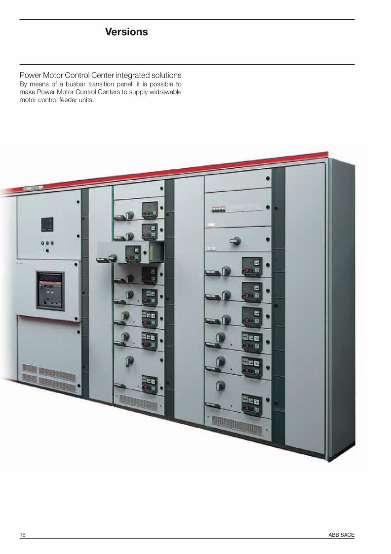
Power Motor Control Center integrated solutionsBy means of a busbar transition panel, it is possible tomake Power Motor Control Centers to supply widrawablemotor control feeder units.
ABB PC30 23-11-2009, 8:1518

ABB SACE 19
Furthermore it is possible to make Power Motor ControlCenterx with withdrawable drawers without transitionpanels by using MCC columns with rear access.
FRONT VIEW LATERAL SECTION
INTERNAL DIVISIONS
Drawers/apparatus area
Auxiliary cable area
Power cable connection area (form 4b)
Power cable entry/exit
Vertical busbar area
In this solution, the auxiliary connections are alwaysaccessed from the front, whereas the power connectionsare available on the rear.
FRONT
800/900600
1025
/120
0/14
00/1
600
200/300
600 200/300800/900 1025/1200/1400/1600
EARTHINGBUSBAR
MAIN BUSBARSCOMPARTMENT
POWER CABLE ENTRY
2200
2200
ABB PC30 23-11-2009, 8:1519

20 ABB SACE
Intelligent switchgearThanks to the use of electronic releases with dialogue func-tion, the air and moulded-case circuit-breakers mountedinside the switchgear can be controlled and managed by asupervision system.To integrate the moulded-case and air circuit-breakers fit-ted with electronic releases into correct installation man-agement, ABB SACE supplies SD-View 2000, a “ready touse” system consisting of software which, when installedon a personal computer with standard configuration, al-lows full control of the low voltage electrical installation.Modbus® RTU, the recognised standard in the electricaldistribution sector, is supplied as the communication pro-tocol.
ApplicationsSD-View 2000 is a system specially studied for applicationin those electrical distribution installations which requireefficient management without the need to use complex andcostly systems.It is able to dialogue and control all the protection units ofthe installation and, in particular, low voltage Tmax, Isomaxand Emax series of circuit-breakers in the following con-figurations:– Tmax T4 and T5 series of moulded-case circuit-
breakers fitted with PR222DS/PD release– Isomax S from S4 to S7 series of moulded-case
circuit-breakers fitted with PR212/P release andPR212/D-M communication unit
– Emax E1 to E6 air circuit-breakers fitted withPR112/PD or PR113/PD Modbus releases.
Versions
Tmax T4 and T5
Emax E1…E6
Isomax S4…S7
ABB PC30 23-11-2009, 8:1520

ABB SACE 21
Modbus RTU on RS-485
RS232-RS485Converter
Emax E1-E6with PR112/PD or PR113/PD
Isomax S4-S7with PR212/P
and PR212/D-M
Tmax T4-T5with PR222DS/PD
In particular it is possible to:– send opening and closing commands to the
circuit-breakers– read the electrical values of the installation (current,
voltage, power factor, etc.)– read and modify the trip characteristics of the protection
unit– determine the status of the apparatus (open, closed,
number of operations, trip for fault, etc.)– determine abnormal operating situations (e.g. overload)
and, in the case of releases tripping, the type of fault(short-circuit, ground fault, value of the interruptedcurrents, etc.)
– log the history of the installation (energy consumed, mosthighly loaded phase, any warnings of anomalies or faults,etc.)
– illustrate evolution of the installation over time by meansof graphic diagrams.
Access to the various functions of the system can be ena-bled by means of a password with different levels of au-thorisation.Putting the SD-View 2000 system into service is simpleand rapid: in fact, the software itself guides the user in rec-ognition and configuration of the protection unit.The user only needs to know the characteristics of the in-stallation.
Operator use is extremely simple: the graphic pages of SD-View 2000, based on Internet Explorer, makemanagement of the installation as simple as surfingthe Internet. The graphic pages relative to eachcircuit-breaker are particularly intuitive and easy to use.
SD-View 2000 is the ideal tool available to managers inorder to have the situation of the plants under control at alltimes and to be able to control all their functions simplyand immediately.The operator station (personal computer) allows informa-tion to be received from the installation and to control thecircuit-breakers and relative releases.
ABB PC30 23-11-2009, 8:1521
22 ABB SACE
Installation
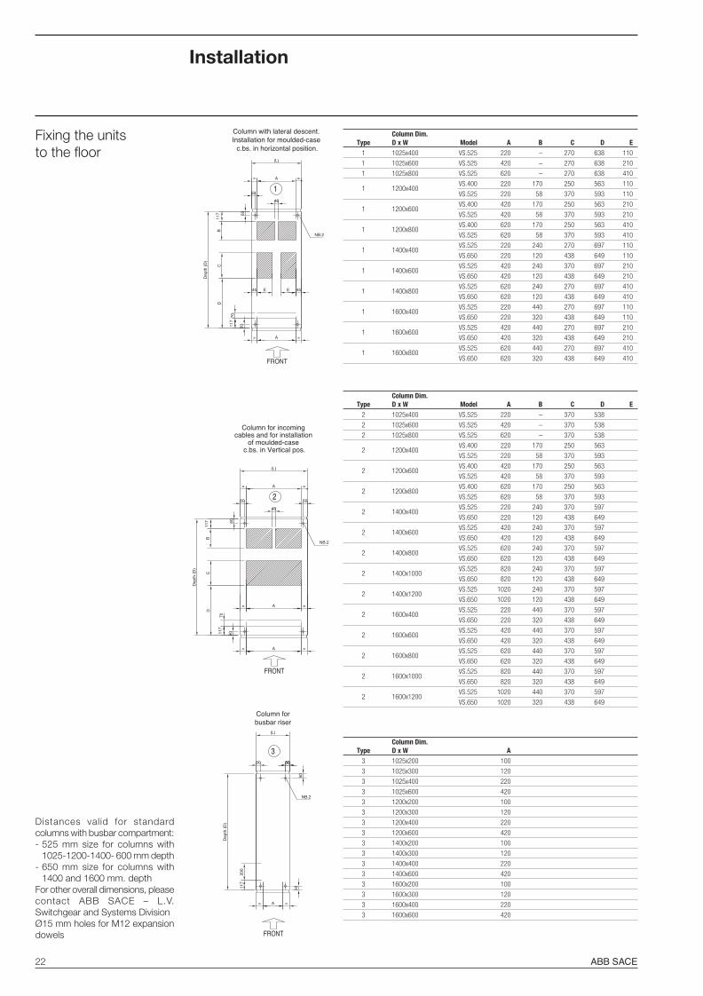
Column for incoming cables and for installation
of moulded-case c.bs. in Vertical pos.
50
= A =
50
C
Dep
th (
D)
117
D
70
117
B
50
= =
NB.2
=
2=
50
A
48
A
(L)
FRONT
Dep
th (
D)
5050
200
117
FRONT
=
50 5050
3
NB.2
(L)
Column forbusbar riser
A=
Distances valid for standardcolumns with busbar compartment:- 525 mm size for columns with
1025-1200-1400- 600 mm depth- 650 mm size for columns with
1400 and 1600 mm. depthFor other overall dimensions, pleasecontact ABB SACE – L.V.Switchgear and Systems DivisionØ15 mm holes for M12 expansiondowels
45
==
NB.2
A
48
=
1
D
A=
(L)
Dep
th (
D)
Column with lateral descent. Installation for moulded-case
c.bs. in horizontal position.
5050
EE45
50
CB
117
7011
7
FRONT
Column Dim.Type D x W Model A B C D E
1 1025x400 VS.525 220 – 270 638 110
1 1025x600 VS.525 420 – 270 638 210
1 1025x800 VS.525 620 – 270 638 410
1 1200x400VS.400 220 170 250 563 110
VS.525 220 58 370 593 110
1 1200x600VS.400 420 170 250 563 210
VS.525 420 58 370 593 210
1 1200x800VS.400 620 170 250 563 410
VS.525 620 58 370 593 410
1 1400x400VS.525 220 240 270 697 110
VS.650 220 120 438 649 110
1 1400x600VS.525 420 240 370 697 210
VS.650 420 120 438 649 210
1 1400x800VS.525 620 240 270 697 410
VS.650 620 120 438 649 410
1 1600x400VS.525 220 440 270 697 110
VS.650 220 320 438 649 110
1 1600x600VS.525 420 440 270 697 210
VS.650 420 320 438 649 210
1 1600x800VS.525 620 440 270 697 410
VS.650 620 320 438 649 410
Column Dim.Type D x W Model A B C D E
2 1025x400 VS.525 220 – 370 538
2 1025x600 VS.525 420 – 370 538
2 1025x800 VS.525 620 – 370 538
2 1200x400VS.400 220 170 250 563
VS.525 220 58 370 593
2 1200x600VS.400 420 170 250 563
VS.525 420 58 370 593
2 1200x800VS.400 620 170 250 563
VS.525 620 58 370 593
2 1400x400VS.525 220 240 370 597
VS.650 220 120 438 649
2 1400x600VS.525 420 240 370 597
VS.650 420 120 438 649
2 1400x800VS.525 620 240 370 597
VS.650 620 120 438 649
2 1400x1000VS.525 820 240 370 597
VS.650 820 120 438 649
2 1400x1200VS.525 1020 240 370 597
VS.650 1020 120 438 649
2 1600x400VS.525 220 440 370 597
VS.650 220 320 438 649
2 1600x600VS.525 420 440 370 597
VS.650 420 320 438 649
2 1600x800VS.525 620 440 370 597
VS.650 620 320 438 649
2 1600x1000VS.525 820 440 370 597
VS.650 820 320 438 649
2 1600x1200VS.525 1020 440 370 597
VS.650 1020 320 438 649
Column Dim.Type D x W A
3 1025x200 100
3 1025x300 120
3 1025x400 220
3 1025x600 420
3 1200x200 100
3 1200x300 120
3 1200x400 220
3 1200x600 420
3 1400x200 100
3 1400x300 120
3 1400x400 220
3 1400x600 420
3 1600x200 100
3 1600x300 120
3 1600x400 220
3 1600x600 420
Fixing the unitsto the floor
ABB PC30 23-11-2009, 8:1522
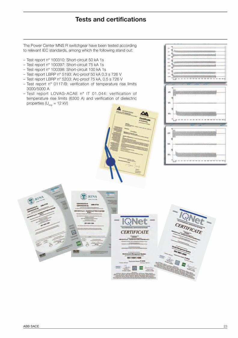
ABB SACE 23
The Power Center MNS R switchgear have been tested accordingto relevant IEC standards, among which the following stand out:
– Test report n° 100310: Short-circuit 50 kA 1s– Test report n° 100397: Short-circuit 75 kA 1s– Test report n° 100398: Short-circuit 100 kA 1s– Test report LBRP n° 5193: Arc-proof 50 kA 0.3 s 726 V– Test report LBRP n° 5203: Arc-proof 75 kA, 0.5 s 726 V– Test report n° 0117/B: verification of temperature rise limits
3000/5000 A– Test report LOVAG-ACAE n° IT 01.044: verif ication of
temperature rise limits (6300 A) and verification of dielectricproperties (Uimp = 12 kV)
Tests and certifications
ABB PC30 23-11-2009, 8:1523

ABB PC30 23-11-2009, 8:1524


1TTB
9000
01D
0201
- 1
2/20
09
Contact us
ABB SACEA division of ABB S.p.A.Low Voltage SystemsFrazione Cà de Bolli26817 S. Martino in Strada (LO) - Italy Tel.: +39 0371 453 1 Fax: +39 0371 [email protected] www.abb.com/mns
The data and illustrations are not binding. We reservethe right to modify the contents of this document onthe basis of technical development of the products,without prior notice.
Copyright 2009 ABB. All right reserved.