mne-240 e-panel instructions
TRANSCRIPT

1 | P a g e 1 0 - 0 2 9 - 1 R E V : B
MNE-240 E-PANEL INSTRUCTIONS
MNE-240 Series E-Panel
Owner’s Manual

2 | P a g e 1 0 - 0 2 9 - 1 R E V : B
MNE-240 E-PANEL INSTRUCTIONS
IMPORTANT SAFETY INSTRUCTIONS
SAVE THESE INSTRUCTIONS - These instructions contain important safety and operating instructions for MidNite Solar E-Panels.
If you do not fully understand any of the concepts, terminology, or hazards outlined in these instructions, please refer installation to a
qualified dealer, electrician or installer. These instructions are not meant to be a complete explanation of a renewable energy system.
GENERAL PRECAUTIONS
WORKING WITH OR IN THE VICINITY OF A LEAD ACID BATTERY, SEALED OR VENTED IS DANGEROUS. VENTED
BATTERIES GENERATE EXPLOSIVE GASES DURING NORMAL OPERATION. FOR THIS REASON, IT IS VERY IMPORTANT
THAT BEFORE SERVICING EQUIPMENT IN THE VICINITY OF LEAD-ACID BATTERIES YOU REVIEW AND FOLLOW THESE
INSTRUCTIONS CAREFULLY.
If service or repair should become necessary, contact MidNite Solar Inc. Improper servicing may result in a risk of shock, fire or explosion.
To reduce these risks, disconnect all wiring before attempting any maintenance or cleaning. Turning off the inverter will not reduce these
risks. Solar modules produce power when exposed to light. When it is not possible to disconnect the power coming from the Photovoltaics
by an external means such as a combiner, cover the modules with an opaque material before servicing any connected equipment.
Never attempt to charge a frozen battery.
When it is necessary to remove a battery, make sure that the battery bank disconnect breaker is in the off position and that the PV breakers,
grid breakers and any other sources of power to the inverter are in the off position. Then remove the negative terminal from the battery first.
To reduce risk of battery explosion follow these instructions and those published by the battery manufacturer as well as the manufacturer of
any additional equipment used in the vicinity of the batteries. Before installing the battery enclosure, read all instructions and cautionary
markings in or on any connected electrical equipment.
Avoid producing sparks in the vicinity of the batteries when using vented batteries. Provide ventilation to clear the area of explosive gases.
Sealed AGM and Gel batteries do not under normal conditions create explosive gases. Be especially cautious when using metal tools.
Dropping a metal tool onto batteries can short circuit them. The resulting spark can lead to personal injury or damage to the equipment.
Provide ventilation to outdoors from the battery compartment when installing vented batteries such as golf cart T-105 batteries. The
addition of a spill tray is also a good idea.
Clean all battery terminals. Very high currents are drawn from the batteries; even a small amount of electrical resistance can result in
overheating, poor performance, premature failure or even fire.
Have plenty of fresh water and soap nearby in case battery acid contacts skin, clothing or eyes. Wear complete eye and clothing protection.
Always avoid touching eyes while working near batteries. If battery acid or battery terminal corrosion contacts skin or clothing, wash
immediately with soap and water. If acid enters the eyes, immediately flood with cool running water for at least 15 minutes and get medical
attention immediately. Baking soda neutralizes battery acid electrolyte. Keep a supply near the batteries.
Do not work alone. Someone should be in the range of your voice or close enough to come to your aid when you work with or near
electrical equipment.
Remove rings, bracelets, necklaces, watches etc. when working with batteries, photovoltaic modules or other electrical equipment. Power
from an illuminated photovoltaic array makes a very effective arc welder with dire consequences if one of the welded pieces is on your
person.
To reduce the risk of injury, connect only deep cycle lead acid type rechargeable batteries. Other types of batteries may leak or burst,
causing personal injury or damage.
This equipment is NOT intended for use with life support equipment or other medical equipment or devices.
It is the responsibility of the installer to verify compliance with all applicable codes.
Before making any connections verify that the circuit breakers are in the off position including the inverter breaker. Double check all
wiring before applying power.

3 | P a g e 1 0 - 0 2 9 - 1 R E V : B
MNE-240 E-PANEL INSTRUCTIONS
INSTRUCTIONS DE SECURITÉ IMPORTANTES
CONSERVER CES INSTRUCTIONS
Ces instructions contiennent des informations importantes pour utiliser le Midnite Solar SMA MNX-240 Autotransformer en toute sécurité.
1. Avant l’utilisez cet appareil lis et comprends toutes les instructions et avertissements.
2. Si vous ne comprenez pas l’une des concepts ou des instructions contenu dans cette manuel consulter un
agent spécialisé.
3. Si des réparations sont nécessaires contactez MidNite Solar pour plus des informations. Danger de choc
électrique et de risque de brulure. Rien à dépanner à l'intérieure du cette appareil. Ne pas ouvrir le couver.
Pour toute réparation ou service d'entretien, consulter un agent spécialisé. Il y’a peut-être plusieurs sources
d’alimentation dans cette system. Débrancher toutes les interrupteurs avant toute d'entretien où nettoyage.
4. Ne travaillez pas seul. Quelqu'un devrait toujours être à proximité pour aider en cas d'une situation d'urgence.
5. Retirer bagues, bracelets, colliers, montres, et quelles choses comme ça. Il y’a risque des blessures graves
s’il y’a un court-circuit. Cela pourrait ruiner votre journée entière.
6. Le câblage doit être fait en conformité avec le National Electrical Code ANSI / NFPA 70. Utiliser des
méthodes de câblage de catégorie 1 pour les connexions de câblage sur .des terminaux d'un circuit de classe 2.
Utilisez uniquement des fils de AWM de calibre 14-1/0. Sélectionnez le type de câble utilisé sur la base de la
protection prévue par les disjoncteurs / fusibles.

4 | P a g e 1 0 - 0 2 9 - 1 R E V : B
MNE-240 E-PANEL INSTRUCTIONS
1.0 Introduction
The MNE-240 Series E-Panel enclosure from MidNite Solar provides the basic DC and AC over- current protection and disconnects required for a NEC compliant renewable energy system. It is specifically designed to accommodate inverters that provide 120/240VAC in a single unit. The MNE-240 Series E-Panel can expand to grow as your needs arise and includes the following:
• Powder-coated steel chassis with knockouts to accommodate various install needs.
• Inverter mounts on a unique hinged door to keep a small system foot-print
• E-Panel mounting brackets are included to aid in one person installations
• Inverter battery breaker, inverters cables and snap in grommets included
• 500 amp/50 mV shunt included for battery monitoring systems
• Heavy duty 150 amp bus-bars for AC HOT, NEUTRAL, GROUND, BATT +/- and PV + included
• Dual 50 amp AC input disconnects for generator or utility (prewired)
• Dual 50 amp inverter AC Bypass Switch (prewired)
• Bracket included for mounting optional charge controller (Classic or MX60)
• Inverter, remote control and charge controller mounting hardware included
• One rectangular cut-out for mounting a North American GFCI style AC outlet
• Cut-outs for mounting up to six additional 13mm wide din-rail mount AC and DC breakers (for circuits such as PV, wind, hydro or AC distribution)
• Conforms to UL508A 1st Edition and CSA C22.2 #14-M95 (Industrial Control Panel)
2.0 Features
Refer to Figure 1 for the following information.
The MNE-240 Series E-Panel incorporates all the AC and DC wiring bus-bars and disconnects required to connect the Magnum MS-AE Series inverter/charger system.
It also provides additional room to install additional equipment, such as the MidNite Classic Charge controller (with accompanying solar array breakers/disconnects and battery temp sensors), the Magnum Battery Monitor, a PV Ground Fault device, and AC branch breakers (that can be used in lieu of an AC sub-panel to power the inverter’s AC loads). These additional breakers are installed on a supplied Din-rail mounting bracket that has space for up to six 13mm sized AC or DC breakers.
The E-Panel includes a DC Breaker used to disconnect the battery bank from the inverter as required by the National Electric Code (NEC). This breaker is also used as an overcurrent device to protect against extremely high currents that a battery is capable of producing if any short circuits occur. A variety of DC Breaker options are available from MidNite Solar.
Next to the DC Breaker is a 500 amp/50 mV shunt with a DC negative bus-bar attached. The shunt is provided so that a Battery Monitor, which is used to determine the battery bank’s state of charge, may be easily connected without any rewiring. The DC negative bus-bar provides a DC negative connection point for any DC loads or PV Panels in the installation.
Located on the right side of the E-Panel system is an AC input disconnect and an inverter bypass switch. The AC disconnect is used to remove the incoming AC power to the inverter input. The inverter bypass switch is provided to easily route the incoming AC power around the inverter and directly to the AC loads in the system - without rewiring or losing power to the AC loads in the system - in case the inverter needs to be removed.

5 | P a g e 1 0 - 0 2 9 - 1 R E V : B
MNE-240 E-PANEL INSTRUCTIONS
303 0
30
ME-RC
Remote
PW R
FAULT
CHG
I NV
O N /O F
F
CHARGER
Inv erting
DC 50.4 5A
S E LE C T
FRONT SIDE
PV Positive (+) Bus-bar
Upper Mounting Bracket
Control O N / O F F
INVERTER SHORE AGS METER SETUP TECH Right Hinge Door (left hinge door is available )
Upper Shield
AC Input/Output
Bus-bars
Battery
Positive (+)
Bus-bar
Battery
Negative (-)
Bus-bar
Ground
Bus-bar
ME-BMK
Battery
Monitor
MS-AE
Series
Inverter /
Charger
500A/50mV
Shunt
Charge
Controller
DC Cover
Positive and Negative Inverter Cables
Inverter AC input/Output Wires
Door Grommet (3.5")
Lower Mounting Bracket
ME-RC Remote
Mounting Bracket
(Optional Remote available )
O N O N
O FF O FF
I N V E R TE R
B Y P A S S
AC Input Disconnect Inverter Bypass Switch
Cutouts for GFCI AC Outlet
(not supplied )
Cutouts for up to six 13mm
Din Rail Circuit Breakers
(breakers not supplied )
Mounting Bracket for
Charge Conroller Battery Shut Off
(for inverter )
Many Knockouts with
various sizes on every side
LEFT
SIDE
RIGHT
SIDE

6 | P a g e 1 0 - 0 2 9 - 1 R E V : B
MNE-240 E-PANEL INSTRUCTIONS
Figure 1, MNE-240 Series E-Panel Features
3.0 Installation
Before installing, read the entire installation section to determine how you are going to install your E-Panel. The more thorough you plan in the beginning, the better your overall system needs will be met.
A basic system diagram for the MNE-240 Series E-Panel is shown in Figure 2, MNE-240 Series
E-Panel System Wiring Diagram. This diagram should be reviewed to assist you in planning and designing your installation.
Info: Installations should be performed by qualified personnel, such as a licensed or certified electrician. It is the installer’s responsibility to determine which safety codes apply and to ensure that all applicable installation requirements are followed.
Info: It is easier to install and wire any additional accessories (i.e. breakers for charge control, the inverter, etc.) while the E-Panel is still lying horizontal on a table. Do as much as possible before mounting the E-Panel on the wall.
3.1 Door Configuration
The standard E-Panel ships with breakers on the right side and with a left hand hinge. The door will open to the right over the breakers. If for some reason you need the breakers on the right, but the door to open to the left, then you can purchase the left hand door (part number MNEleftdoorSTM-240).
Info: The circuit-breakers can be moved from the right side and reassembled on the left side of the chassis. Even though this is possible, it is not advised. Moving the breakers is very time consuming and the bypass switch will need to be re-positioned and rewired. It is much more efficient to so spend the time before the installation to pre-determine and order the correct side (left hinge or right hinge door).
3.2 Knockout Preparation
Info: See Figure 3 for the location and dimensions for the knock-outs on the MNE-240
Series E-Panel.
Think about all the different wiring required and remove the appropriate knockouts before mounting the E-Panel. Knockouts for breakers and outlets are best accomplished using a straight bladed screw driver and hammer. A hacksaw blade is another way to cut them out.
Determine the knockout uses for:
• wiring from the E-Panel to an AC sub-panel
• wire runs from utility and/or a generator to the E-Panel
• battery cable wiring from the battery bank to the E-Panel
• additional wiring from any external DC source (PV, Wind or Hydro) to the E-Panel
• small signal wiring (battery sensors, battery monitoring, auto gen starting)
• attaching lightning arrestors
• charge control wiring

7 | P a g e 1 0 - 0 2 9 - 1 R E V : B
MNE-240 E-PANEL INSTRUCTIONS
0 A5 0 A 5
ON
ON
O
N
ON
O
N
O N
O
N
ON
O
N
OF
F
OFF
OF
F O
F F
OFF
O F
F
OF
F O
F F
OFF
ON
O
N
O
N
O
N
ON
O
N
O
N
O N
OF
F
O
F F
OFF
OFF
OF
F
O
F F
OFF
O F
F
AC
H
ot
In
1
AC
H
ot
In
2
AC
N
eu
tral
Main
B
att
er
y
Sh
uto
ff
AC
H
ot
Ou
t 1
AC
H
ot
Ou
t 2
PV
O u
tp u
t
120
VA
C
Ou
tpu
t
240
VA
C
Ou
tpu
t P
V +
In
pu
t
120
VA
C
Ou
tpu
t D
C-G
FP
Utility or Generator
120/240VAC Output
ON ON ON ON
OFF
OFF OFF
OFF
15A
30A 30A
15A
From
E-Panel
(AC In)
to
Inverter
AC Input
ON
OFF
ON
OFF
AC Ground
Bypass
Switch
IN V E R TE R
ON ON
120VAC
Outlet
240VAC
Outlet
120VAC
Oulet
Inverter
(AC In)
Disconnect
(30A) (50A)
B Y P A S S OFF OFF
50A 50A
From Inverter
(AC Out) to
Remote Control
P W R
FA U LT
E-Panel (AC Out) C H G
I N V
SELECT
ON /OF F
CHARG ER
ON /OF F
I NVERTER SHO RE AG S M ETER SETUP TECH
MAGNUM ENERGY MS-AE Series
DC WIRING Inverter/Charger
AC WIRING MIDNIGHT SOLAR Classic Controller
PV Panels
Optional Breakers/Disconnects
(6 spaces max @ 13mm)
Battery Temperature
Sensor
Battery Bank
(48VDC)
DC - Buss
DC
Shunt
ON
OFF
DC + Buss
PV
B B PV PV
PV
PV + Buss
12V 12V
DC
Ground
ON
OFF
63A
ON
OFF
63A
ON ON
OFF OFF
63A 0.5A
12V 12V
Figure 2, MNE-240 Series E-Panel System Wiring Diagram

8 | P a g e 1 0 - 0 2 9 - 1 R E V : B
MNE-240 E-PANEL INSTRUCTIONS
3.3 Knockout sizes and Dimensions
The dimensioned chassis drawing in figure 3 shows the location of the conduit knockouts, mounting holes and mounting brackets.
• Knockouts on the top surface are directly in line with ones on the bottom surface for stacking units vertically.
TOP VIEW
UPPER CONDUIT
KNOCKOUTS ARE
MIRROR IMAGE OF
BOTTOM KNOCKOUTS
4.67"
12.90"
22.37" 0.75 "
17.00"
4.17"
INSIDE 1.13" (3/4 CONDUIT ) INSIDE 1.38" (1" CONDUIT )
24.91" 26.45"
INSIDE 0.87" (1/2” CONDUIT ) INSIDE 2.47" (2" CONDUIT )
25.55"
0.87" (1/2” CONDUIT) 2.47" ( 2" CONDUIT)
1.13" ( 3/4 CONDUIT)
1.38" ( 1" CONDUIT)
1.00" 14.41"
18.50"
0.87" (1/2” CONDUIT) 2.47" ( 2" CONDUIT)
1.13" ( 3/4 CONDUIT)
1.38" ( 1" CONDUIT)
LEFT SIDE VIEW RIGHT SIDE VIEW
1.13"
(3/4 CONDUIT)
1.13" ( 3/4 CONDUIT)
1.38" (1" CONDUIT)
1.75" 1 1/4” CONDUIT)
0.50"
0.87" ( 1/2” CONDUIT )
2.47" ( 2" CONDUIT)
BOTTOM VIEW
Figure 3, MNE-240 Series E-Panel Dimensions and Knockout Sizes

9 | P a g e 1 0 - 0 2 9 - 1 R E V : B
MNE-240 E-PANEL INSTRUCTIONS
3.4 Installing Optional Hardware
Additional Breakers
Additional AC circuit breakers can be installed per the manufacturer’s instructions on the open DIN Rail in the E-Panel. This DIN Rail has locations available for six additional 13mm wide AC and DC circuit breakers. These additional circuit breakers can be used for such things as: solar, wind or hydro charge controllers, DC ground fault protector, AC and/or DC distribution center and more.
Info: MidNite offers 150VDC breakers in 1, 6, 7, 8, 10, 12, 15, 20, 30, 50 and 63 amps. AC breakers are available in 10, 15 and 20 amp sizes that carry the UL489 and UL489A branch circuit rating. MidNite also offers 30, 50 and 60 amp sizes that carry the UL1077 listing for supplementary protection but are not branch circuit rated; these breakers are rated for continuous duty and are usually used as AC disconnects.
To install additional breakers, remove the side breaker cover with the circuit-breaker cut-outs;
see figure 4. Each 13mm wide breaker requires removal of two cut-outs and the 17.5mm wide breakers require removal of three cut-outs.
Caution: Torque the breaker terminals to 20 in. lbs. using a 1/4” wide flat-blade screwdriver (do not use a 3/16” wide or Phillips screwdriver, they can damage the screw terminals easily). It is highly recommended to recheck all terminations after an hour and also conduct a pull test. You may be surprised that what you thought was a tight connection actually pulls out with little effort. Copper is a relatively soft metal and will continue to move under inadequate clamping pressure; a 20 inch pound of torque takes a lot of strength!
When installing DC and AC breakers together on the same din rail. Some local inspectors will
require physical separation between the AC and DC breakers. There are UL listed plastic 2” x 6” insulators supplied with this E-Panel to fulfill this separation requirements; see figure 5.
Info: UL and the NEC allow mixing AC and DC wiring in this installation because the wire insulation is rated for the highest voltage encountered in the enclosure. Both AC and DC circuits are considered part of the same Renewable Energy circuit for this installation.
2 x 6" insulators (placed between the din-rail mounted DC and AC breakers)
Figure 4, Removing and replacing
the breaker cover
Charge Controller Bracket
Figure 5, Insulators between AC and DC
breakers
If installing a Charge Controller, secure the charge control bracket to the E-Panel with two #10 x
3/8” sheet metal screws supplied.
Inverter Remote Bracket
If installing the inverter remote control, secure the remote bracket to the upper left hand side of the E-Panel with two #10 x 3/8” sheet metal screws supplied. When installing the bracket on the right side, use two sheet metal screws and one machine screw. The remote bracket hides the space of the AC outlet cut out, but the outlet still can be used with the bracket installed.

10 | P a g e 1 0 - 0 2 9 - 1 R E V : B
MNE-240 E-PANEL INSTRUCTIONS
3.5 Locating and Mounting the E-Panel
Review Figure 6, MNE-240 Series E-Panel Mounted to determine the mounting space requirements for the E-Panel with the inverter/charger and any other optional equipment that may be mounted.
Info: Do as much of the additional wiring as possible before hanging the E-Panel on the wall.
Install the E-Panel in a location that meets the following requirements:
• The E-Panel must be mounted vertically on a flat surface (such as a wall).
• Do not mount the E-Panel near any flammable or combustible fluid or components (i.e. paper, cloth, plastic, etc.) that may be ignited by heat, sparks or flames - they must be at a minimum distance of 2 feet away from the E-Panel/inverter.
• Τhis E Panel system will weigh approximately 100 pounds. The mounting surface and hardware must be capable of supporting at least twice the weight of the E-Panel/inverter combination.
• The area must be free from any risk of condensation, water or any other liquid that can enter or fall on the inverter.
• Locate the E-Panel and inverter system as close to the batteries as possible. Long DC wires tend to loose efficiency and reduce the overall performance of an inverter. However, the unit should not be mounted where it will be exposed to gases produced by the batteries. These gases are corrosive and will damage the inverter; also if these gases are not ventilated and if allowed to collect, they could ignite and cause an explosion.
• Ensure the E-Panel is accessible after it is mounted. Select a wall that has suitable clearance to open the door with the inverter attached. It must also have adequate clearance to operate the breakers and outlets that protrude out the sides.
E-Panel Mounting Procedure
Info: Prior to mounting the E-Panel to the wall, ensure the bottom mounting bracket has been installed and the door has been removed.
1. Use a level and hold the top mounting bracket on the wall in a horizontal position and mark on
the wall where you want the mounting screw holes.
2. If required, drill holes using a #10 (0.193” diameter) drill bit. Drill appropriately sized holes for anchors when installing on non-wood surfaces.
3. Secure the top mounting bracket to the wall using the three ¼ X 1½ hex-head lag bolts. If
mounting to other than a wood wall or surface, use appropriate screws and anchors as required.
4. Lift the E-Panel and place the keyhole slots (located in the upper back of the E-Panel) directly over the mounting screws on the mounting bracket and lower into place.
5. Tighten the top mounting screws to secure the E-Panel to the mounting bracket.
6. Secure the bottom mounting bracket to the wall.

11 | P a g e 1 0 - 0 2 9 - 1 R E V : B
MNE-240 E-PANEL INSTRUCTIONS
Ceiling
22.37"
18.50"
14.41"
22.23" 16.00"
Top Mounting
Bracket
Remote
Control
P W R
FA U LT
C H G
I N V
SELECT
CHARG ER
Magnum
Inverter/
Charger
MidNite
Solar
Classic
Controller
MNE-240
Series
E-Panel
I NVERTER SHO RE AG S M ETER SETUP TECH
Bottom
Mounting
Bracket
Mounting
Bolts (x4)
24.91"
26.45"
Plywood
Floor
Wall studs
16 inches on center
Figure 6, MNE-240 Series E-Panel Mounted
Remote Control
12 | P a g e 1 0 - 0 2 9 - 1 R E V : B
MNE-240 E-PANEL INSTRUCTIONS
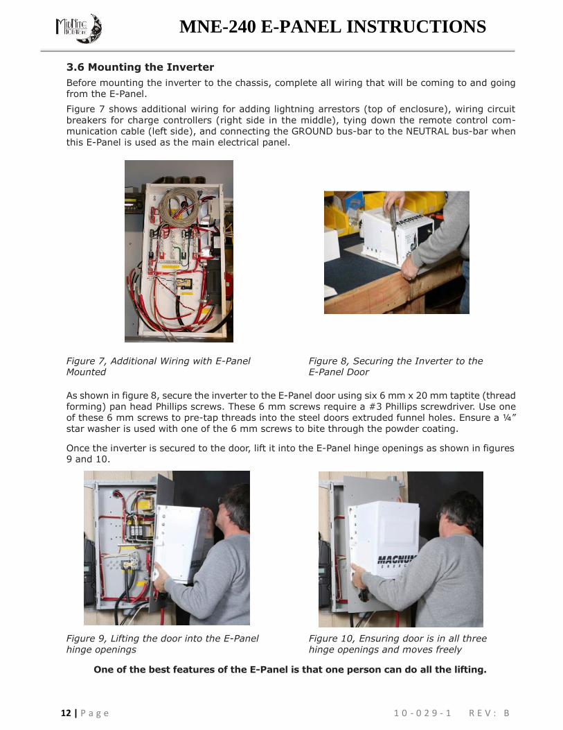
3.6 Mounting the Inverter
Before mounting the inverter to the chassis, complete all wiring that will be coming to and going from the E-Panel.
Figure 7 shows additional wiring for adding lightning arrestors (top of enclosure), wiring circuit
breakers for charge controllers (right side in the middle), tying down the remote control com- munication cable (left side), and connecting the GROUND bus-bar to the NEUTRAL bus-bar when this E-Panel is used as the main electrical panel.
Figure 7, Additional Wiring with E-Panel Mounted
Figure 8, Securing the Inverter to the E-Panel Door
As shown in figure 8, secure the inverter to the E-Panel door using six 6 mm x 20 mm taptite (thread forming) pan head Phillips screws. These 6 mm screws require a #3 Phillips screwdriver. Use one of these 6 mm screws to pre-tap threads into the steel doors extruded funnel holes. Ensure a ¼” star washer is used with one of the 6 mm screws to bite through the powder coating.
Once the inverter is secured to the door, lift it into the E-Panel hinge openings as shown in figures 9 and 10.
Figure 9, Lifting the door into the E-Panel hinge openings
Figure 10, Ensuring door is in all three hinge openings and moves freely
One of the best features of the E-Panel is that one person can do all the lifting.

13 | P a g e 1 0 - 0 2 9 - 1 R E V : B
MNE-240 E-PANEL INSTRUCTIONS
3.7 Wiring the E-Panel and Inverter
Review the following information prior to wiring the E-Panel it is imperative that the following steps be taken to help reduce the risk of electric shock to you and damage to the E-Panel/inverter.
1. Disconnect the main AC panel that will feed the E-Panel (if using utility power) by switching off the main circuit breaker. Lock out the AC breaker box to ensure no one will accidentally turn the power on during the installation process. If the AC panel does not have provision for locking the breaker box, place a sign on the box and tape the door closed to warn others from opening or turning on the AC panel.
2. Place the main DC shutoff breaker (DC disconnect) in the OFF position.
3. If additional breakers are installed, place them in the OFF position.
4. Turn the inverter bypass switch to the “BYPASS” position (see the label on the bypass switch).
Pre-Wiring Requirements
• All wiring and installations methods should conform to applicable electrical and building codes.
• Always check for existing electrical, plumbing or other areas of potential damage prior to making cuts in structural surfaces or walls.
• Make sure all wires have a smooth bend radius and do not become kinked.
• Both AC and DC overcurrent protection must be provided in this installation.
• Use only copper wires with a minimum temperature rating of 75° C (176° F) to connect to the wiring terminals.
• All wiring within the E-Panel enclosure, except low voltage control wiring, shall be rated at least
250V or a combination of 250V (e.g., 125V cable enclosed in 125V insulation/heat shrink).
• All wiring to the battery terminals should be checked periodically (once a month) for proper tightness.
Install the Door Grommets
All wires that need to pass through the door of the E-Panel must be routed through the provided serrated snap-in grommets. These grommets help minimize wire insulation damage such as chafing, which can be caused by constant rubbing when opening and closing the door. A 3.5” plastic grommet is supplied and should be snapped into the larger hole in the door as shown in figure 11. The smaller 1” hole can be used for small signal wires (e.g. remote communications wire, battery temperature sensor cable, etc.), but no grommet is provided. It is important to route the wires so the door closes freely without undue force.
Grounding
Figure 11, Installing 3.5” Grommet in the Door
The E-Panel should be connected to a grounded, permanent wiring system.
DC Grounding - The negative battery conductor should be bonded to the grounding system at only one point in the system. The size for the conductor is usually determined by the size of the DC overcurrent protection (DC disconnect) per the NEC/CEC.
If the MNDC-GFP ground fault protector is installed, DO NOT connect battery negative to ground
- this connection is accomplished by the MNDC-GFP. Any additional DC grounding will make the
MNDC-GFP inoperative.
AC Grounding - The AC neutral and ground should only be bonded at the main service panel for the AC system.

14 | P a g e 1 0 - 0 2 9 - 1 R E V : B
MNE-240 E-PANEL INSTRUCTIONS
AC CONNECTIONS
AC CONNECTIONS
AC HOT
IN 2 (from Utility/
Generator)
AC
GROUND
connection
AC HOT IN 1
(from Utility/ Generator)
AC
NEUTRAL connection
AC HOT
OUT 2
(to sub-panel
or circuit
breakers)
AC HOT
OUT 1
(to sub-panel
or circuit breakers)
AC HOT OUT 2
(to sub-panel
or circuit
breakers)
AC HOT
OUT 1
(to sub-panel
or circuit
breakers)
AC
NEUTRAL connection
AC HOT IN 1
(from Utility/ Generator)
AC HOT
IN 2
(from Utility/ Generator)
AC
GROUND
connection
DC
GROUND connection
Battery Cable
to Inverter
Positive (+)
connection
Battery Bank Positive (+)
connection
Battery Bank
Negative (-) connection
Battery Cable
To Inverter
Negative (-)
connection
Battery
Positive (+)
Bus (for DC Loads)
Battery
Positive (+)
Bus
(for PV Input)
Battery Negative
(–) Bus (for
PV Input/ DC
Loads)
Battery
Positive (+)
Bus (for DC Loads)
Battery
Positive (+)
Bus
(for PV Input)
Battery Negative
(–) Bus (for
PV Input/ DC
Loads)
Battery Cable
To Inverter
Negative (-)
connection
DC
GROUND connection
Battery Cable
to Inverter
Positive (+)
connection
Battery Bank Positive (+)
connection
Battery Bank
Negative (-) connection
DC CONNECTIONS
DC CONNECTIONS
E-Panel with Left Hand Door E-Panel with Right Hand Door
Figure 12, E-Panel Wiring Connections
AC Wiring Connections
The AC Bus-Bars (for neutral and hot connections) have dual sizes. The smaller nine holes accept #6 to 14 AWG wire and the larger two holes accept #1/0 to 14 AWG. Torque small screws to 30 in-lbs (3.4 NM) and the large screws to 45 in-lbs (5.1 NM).
DC Wiring Connections
The DC bus-bars (for battery positive/negative and PV) have dual sizes. The smaller nine holes accept #6 to 14 AWG wire and the larger two holes accept #1/0 to 14 AWG. Torque small screws to 30 in-lbs (3.4 NM) and large screws to 45 in-lbs (5.1 NM).
The DC shunt uses 3/8” bolts and requires cables having ring terminal lugs with a 3/8” hole. Torque these bolts between 10 to 12 foot-pounds.
The 175A and 250A DC Disconnect (Main Battery Shut-Off) uses a 3/8-16 stud and requires cables having ring terminals with a 3/8” hole. The 125A DC Disconnect has 1/4-20 studs and requires cables with a 1/4” hole. Torque the 175 A and 250 A breakers to 220 in-lbs (24.9 NM) and torque 125 amp breakers to 30 in-lbs (3.4 NM).
Ground Connections
The ground bar has nine holes and accepts #6 to 14 AWG wires. Torque small ground screws to
20 in-lbs (2.3 NM) and the large ground screws to 45 in-lbs (5.1 NM).

15 | P a g e 1 0 - 0 2 9 - 1 R E V : B
MNE-240 E-PANEL INSTRUCTIONS
3.9 DC Cable Wiring
It is important to use the correct DC cable and corresponding circuit breaker to achieve maximum efficiency from the system and reduce fire hazards associated with overheating. See the MS-AE Series Owner’s Manual to determine the minimum DC cable size needed based on your inverter model and the total cable distance.
Pre-DC Wiring Checklist
• DC wires and cables should be tied together with wire ties or electrical tape approximately every 6 inches. This helps improve the surge capability and reduces the effects of inductance, which
improves the inverter waveform and reduces the wear of the inverter’s filter capacitors.
• The DC cables/wires must be color coded with colored tape or heat shrink tubing: RED for positive
(+); WHITE for negative (-); and GREEN for DC ground.
• It is important to route the cables so the doors close freely without undue force.
• The inverter uses 5/16” bolts and requires cables having ring terminal lugs with a 5/16 hole.
Torque these bolts between 10 to 12 foot-pounds.
• To ensure the maximum performance from the inverter, all connections from the battery bank to the inverter should be minimized. Any additional connection may contribute to additional voltage drops and may loosen during use.
• The DC cables must be a fine strand super flexible, such as Cobra cable (or equivalent) and be approved for residential wiring per the NEC (THW for example).
Caution: The inverter is NOT polarity protected; the battery’s negative and positive terminals
MUST be correctly connected to the inverter’s negative and positive terminals before turning ON the DC battery breaker or damage will occur. The inverter’s warranty doesn’t cover repair to the inverter from this damage.
Caution: The battery bank voltage MUST match the inverter’s required DC voltage (i.e.
48vdc battery for a 48vdc inverter) or the inverter may be damaged.
Info: After making the battery connections, cover the outside of the connection with petroleum jelly or another form of battery terminal anticorrosive grease. Do not put anti- corrosion grease between the terminal and the battery cable.
Connecting the DC cables
Refer to figure 13 for connecting the cables in the following steps:
Info: Figure 13 shows the battery cables coming from below, but the E-Panel has knockouts that allows the cables to come from the sides or back.
Connecting the Inverter DC Cables
1. Route the pre-wired positive (+) battery cable from the DC disconnect in the E-Panel through the grommet/door and connect to the positive battery terminal on the inverter.
2. Route the pre-wired negative (-) battery cable from the DC shunt in the E-Panel through the grommet/door and connect to the negative battery terminal on the inverter.
Connecting the Battery DC Cables
1. Route a DC cable from the negative (-) battery terminal of the battery bank through the conduit/E-Panel knock-outs and connect to the open terminal on the DC shunt.
2. Route a DC cable from the positive (+) battery terminal of the battery bank through conduit
and connect to the bottom (source) side of the DC disconnect.
Connecting the Battery Temperature Sensor (BTS)
1. Connect the BTS ring terminal end to the negative terminal on the battery bank. Route its cable from the battery bank through either the 3.5” or 1” hole in the E-Panel door and connect to the inverter’s RJ11 BTS PORT (yellow label).

16 | P a g e 1 0 - 0 2 9 - 1 R E V : B
MNE-240 E-PANEL INSTRUCTIONS
30
30
DC
D
iscon
nect
MidNite MNE-240 Series E-Panel
P W R
FA U L
T
C H G
I N V
Inverting
DC 50.4 5A
SELECT
O N / O F F
CHARG E
R O
N /
O
F
F
I NVERTE SHO R AG S
M ETE SETU TECH
R E R P
ME-RC Remote Control
Remote Cable
(from remote
to inverter)
DC Negative
(from battery to shunt )
GROUND
DC Shunt
DC Positive
MS-AE Series
Inverter/ Charger
DC Positive
(from disconnect
to inverter)
DC Negative
(from shunt to inverter )
Wire Grommet
(snapped into door )
DC Ground
(from battery to E-Panel
(from battery to disconnect)
Battery Temp Sensor
(from battery to inverter)
12V
12V
Battery Temp Sensor
(from battery to
inverter)
Remote Cable
(from remote
to inverter)
12V 12V
DC Negative
(from shunt to inverter )
DC Positive
(from disconnect to inverter)
Battery Bank (48VDC)
The battery bank voltage MUST match the DC voltage
required by the inverter (i.e. 48-volt battery bank for a 48- volt inverter) or the inverter may be damaged .
Figure 13, E-Panel DC and Accessory Wiring

17 | P a g e 1 0 - 0 2 9 - 1 R E V : B
MNE-240 E-PANEL INSTRUCTIONS
3.10 AC Wiring
The full AC pass-thru capacity of the MS-AE Series inverter/charger is 30 amps for both AC legs (AC HOT 1 and AC HOT 2). To obtain the full pass-thru capability of the inverter and protect the inverter’s pass-thru relay, use a maximum 30 amp double-pole breaker, which corresponds to a cable size of #8 AWG (THHN) in conduit. If you are using other wire sizes, please refer to your local electrical code for breaker requirements.
Pre-AC Wring Checklist
• AC input to the inverter requires a maximum 30 amp circuit-breaker to each of the inverter’s AC Hot inputs. If the dual-pole AC input disconnect in the E-Panel is rated for 30 amps, it will meet this requirement.
• AC Loads powered by the inverter will need to installed into an electrical sub-panel; or optional
branch-rated breakers may be may be installed in the E-Panel and used to power these AC loads.
• Always use properly rated circuit-breakers. If using an electrical sub-panel, circuit breakers can be moved from the main electrical panel to the sub-panel only if the breakers are also listed to be installed in the sub-panel.
• AC wiring must be no less than 10 AWG (5.3 mm2) gauge copper wire and be approved for
residential wiring per the NEC (THHN as an example).
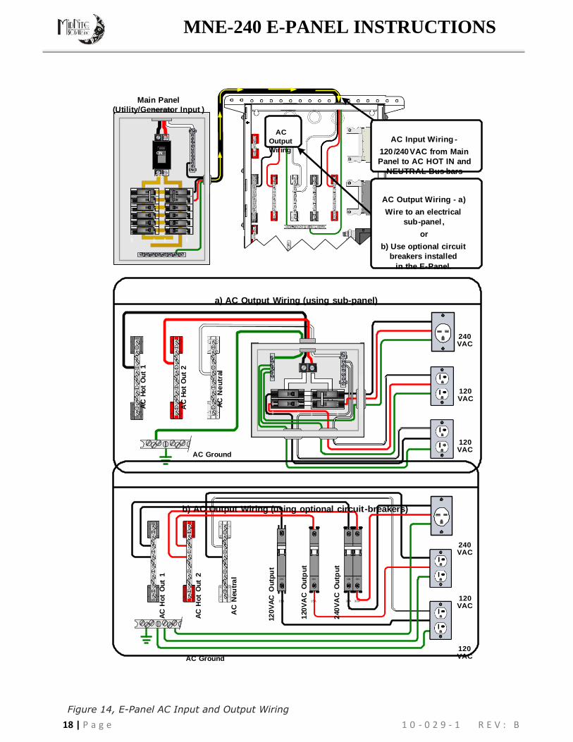
Connecting the AC wires
Connecting E-Panel AC Input/Output Wires (refer to Figure 12 and 14 for the following steps):
1. Route two wires [AC hot 1 (black/L1) and AC hot 2 (red/L2)] from a double-pole circuit breaker in the main panel and connect to the AC HOT IN 1 and AC HOT IN 2 bus-bars in the E-Panel respectively.
2. Route a wire from the neutral bus-bar in the main panel and connect to the NEUTRAL bus-bar
in the E-Panel.
3. Route a wire from the ground bus-bar in the main panel and connect to the GROUND bus-bar in the E-panel.
4. Route wires from the AC HOT OUT 1 (black/L1), AC HOT OUT 2 (red/Leg 2), NEUTRAL and
GROUND bus-bars in the E-Panel and either connect to: A) the sub-panel, or B) to each individual circuit breaker if installed in the E-Panel.
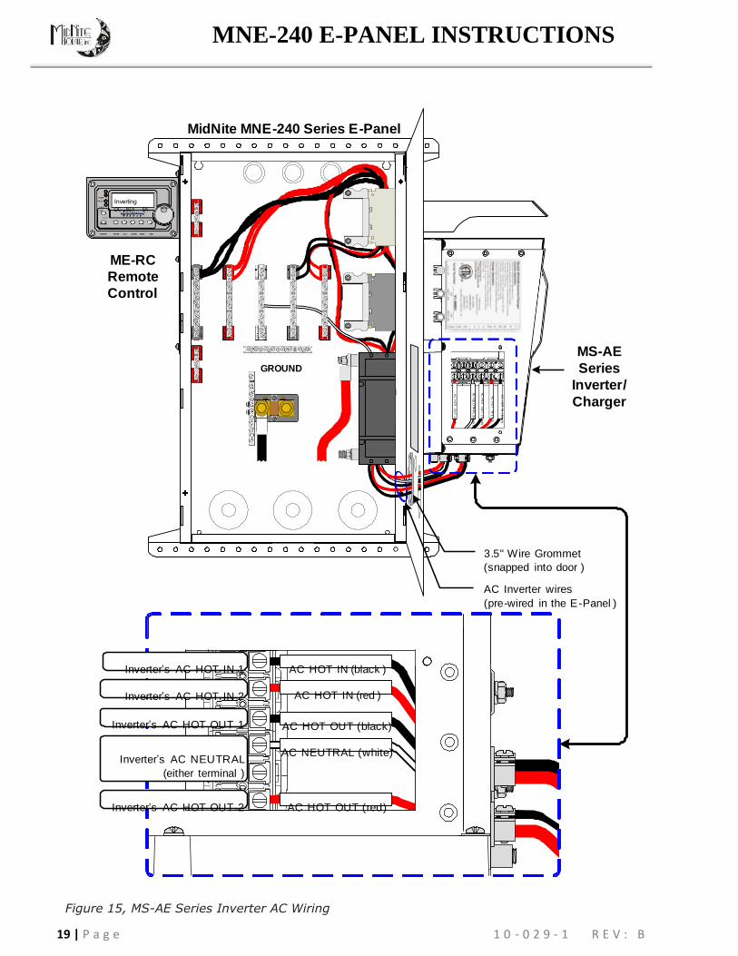
Connecting to the Inverter AC terminals
Before connecting the wires to the inverter’s AC terminal block: 1. Ensure the wires are routed through the 3.5” grommet in the door; and 2. Establish the correct length of wire by opening and closing the door, then cut back the wires as required.
Info: Remove the AC access cover to expose the AC terminal block in the MS-AE Series
Inverter as described in owner’s manual.
For the following steps, refer to figure 4-5 to locate the #8 AWG wires in the E-Panel:
1. Connect the black wire labeled AC HOT OUT to the inverter’s AC HOT OUT 1 terminal.
2. Connect the red wire labeled AC HOT OUT to the inverter’s AC HOT OUT 2 terminal.
3. Connect the white wire from the NEUTRAL bus-bar in the E-Panel to either one of the inverter’s
AC NEUTRAL terminals.
4. Connect the black wire labeled AC HOT IN to the inverter’s AC HOT IN 1 terminal.
5. Connect the red wire labeled AC HOT IN to the inverter’s AC HOT IN 2 terminal.
Info: A ground wire from the E-Panel to the inverter AC ground terminal is not required, because the inverter is sufficiently grounded through the E-Panel to the permanent ground system. A ground wire may be connected from the GROUND bus-bar in the E-Panel to the inverter’s AC GROUND for additional redundancy.
18 | P a g e 1 0 - 0 2 9 - 1 R E V : B
MNE-240 E-PANEL INSTRUCTIONS
ON
O
N
OFF
OF
F
ON
O
N O
N O
N O
N O
N
OF
F O
FF
OF
F O
FF
O
FF
O
F F
AC
Ho
t O
ut
1
AC
Ho
t O
ut
1
ON
O
N
O
N
ON
ON
ON
AC
Ho
t O
ut
2
OFF
OF
F
OFF
OF
F
OF
F
O
FF
AC
Ho
t O
ut
2
AC
Ne
utr
al
AC
Neu
tra
l
12
0V
AC
Ou
tpu
t
120
VA
C O
utp
ut
ON
O
N
240
VA
C O
utp
ut
OF
F
OF
F
Main Panel
(Utility/Generator Input )
ON
OFF
AC
Output
Wiring
AC Input Wiring -
120 /240 VAC from Main
Panel to AC HOT IN and
NEUTRAL Bus-bars
AC Output Wiring - a)
Wire to an electrical
sub -panel ,
or
b) Use optional circuit
breakers installed
in the E-Panel.
a) AC Output Wiring (using sub-panel)
240 VAC
120 VAC
AC Ground
120 VAC
b) AC Output Wiring (using optional circuit -breakers)
240 VAC
ON ON ON ON
OFF
15A
OFF
15A
OFF OFF
30A 30A
120 VAC
AC Ground
120 VAC
Figure 14, E-Panel AC Input and Output Wiring
19 | P a g e 1 0 - 0 2 9 - 1 R E V : B
MNE-240 E-PANEL INSTRUCTIONS
AC
H
OT
IN
( b
lack)
AC
H
OT
IN
(r e
d)
AC
H
OT
O
UT
( b
lack)
AC
N
E U
TR
A L
(wh
ite )
AC
H
OT
O
UT
(r e
d)
30
3
0
MidNite MNE -240 Series E -Panel
P WR
FA U LT
C H G
I N V
Inverting
DC 50.4 5A SELECT
O N /O F F
CHARG ER
O N /O F F
I NVERTER SHO RE AG S M ETER SETUP TECH
ME-RC
Remote
Control
GROUND
MS-AE
Series
Inverter/
Charger
3.5" Wire Grommet
(snapped into door )
AC Inverter wires
(pre-wired in the E -Panel )
Inverter’s AC HOT IN 1 AC HOT IN (black )
Inverter’s AC HOT IN 2 AC HOT IN (red )
Inverter’s AC HOT OUT 1
Inverter’s AC NEUTRAL
(either terminal )
AC HOT OUT (black)
AC NEUTRAL (white)
Inverter’s AC HOT OUT 2 AC HOT OUT (red)
Figure 15, MS-AE Series Inverter AC Wiring

20 | P a g e 1 0 - 0 2 9 - 1 R E V : B
MNE-240 E-PANEL INSTRUCTIONS
3.11 Final Installation Tidbits:
Wiring the Inverter Remote Control
Refer to figure 13 for the following steps:
1. Connect one of the RJ11 connector ends of the remote communication cable to the back of the remote; refer to the ME-RC owner’s Manual for specific information.
2. Route the other RJ11 connector end through the E-Panel and E-Panel door and connect to the inverter’s RJ11 REMOTE PORT (blue label).
Additional Accessory Wiring
Before attaching the DC cover to the inverter end, if you have any of the following inverter accessories, then you will also need to route their connecting cables through the E-Panel (and pass through the small snap-in grommet in the door) to the RJ11 Ports on the inverter:
• Automatic Generator Start Controller (ME-AGS) for automatic generator starting an stopping.
• Battery Monitor (ME-BMK-NS) for determining your batteries State of Charge.
• Simple ON/OFF adapters (ME-RSA, ME-RSA-M) that allow the inverter to be remotely turned on/off.
See the appropriate accessory owner’s guide or further information about the installation and configuration of these accessories.
Installing Inverter Shield/Covers
Refer to figure 1 to identify the following components:
Upper Shield - Attach the upper shield to the E-Panel door using three 10-32 x 3/8” machine screws and kepnuts.
DC Cover - Attach the DC cover using four 10-32 x 7/16” taptite screws and at least one #10 internal tooth star washers.

21 | P a g e 1 0 - 0 2 9 - 1 R E V : B
MNE-240 E-PANEL INSTRUCTIONS
4.0 Start-up and Testing
After the DC and AC wiring has been completed, a series of voltage checks should be performed to ensure the system wiring is correct. If any of the tests fail, recheck the AC wiring.
Before beginning, ensure all circuit breakers pertaining to the E-Panel system are OFF, this
includes:
• all circuit breakers in the main panel from all AC sources (utility or generator, if any) feeding the E-Panel.
• all circuit breakers in the sub-panel (if used).
• all circuit breaker within the E-Panel, this includes the AC Input disconnect, the DC Disconnect Breaker, and any additional AC or DC breakers installed.
A. Testing the Inverter AC Output Wiring
1. Slide the Inverter Bypass switch to the “INVERTER” position and turn the battery DC disconnect to the ON (up) position.
2. Turn ON the inverter as outlined in the MS-AE Owner’s Manual (or ME-RC Owner’s Manual if
using a remote control). The inverters should be providing 120/240 VAC to the E-Panel AC Output Bus-Bars (ensure the inverter is not in search mode).
3. Inside the E-Panel enclosure, use an AC voltmeter and measure the inverter voltage (Refer to
figure 16 for the following voltage checks):
a. between the AC HOT OUT 1 bus-bar and the NEUTRAL bus-bar, this voltage should be 120
Vac (± 3%).
b. between the AC HOT OUT 2 bus-bar and the NEUTRAL bus-bar, this voltage should be 120
Vac (± 3%).
c. between the AC HOT OUT 1 bus-bar and the AC HOT OUT 2 bus-bar, this voltage should be
240 Vac (± 3%).
B. Testing the E-Panel AC Input/Output Wiring
1. If the Inverter AC output voltages are correct (tested above): a) turn the inverter OFF; b) slide the Inverter Bypass switch to the “BYPASS” position; c) switch ON the circuit breakers in the AC main panel switch (from the generator or utility) feeding the E-Panel; and switch the AC input disconnect to ON. These tests assume that the AC input source (Utility/Generator) is 120/240VAC and that the neutral and ground are bonded together by the incoming AC source.
2. In the E-Panel, use an AC voltmeter and measure the generator or utility voltage (Refer to
figure 16 for the following voltage checks):
a. between the AC HOT OUT 1 bus-bar and the NEUTRAL bus-bar, this voltage should be 120
Vac (± 3%).
b. between the AC HOT OUT 2 bus-bar and the NEUTRAL bus-bar, this voltage should be 120
Vac (± 3%).
c. between the AC HOT OUT 1 bus-bar and the AC HOT OUT 2 bus-bar, this voltage should be
240 Vac (± 3%).
d. between the NEUTRAL bus-bar and the GROUND bus-bar, this voltage should be <0.5 Vac.
3. If all voltages/tests are correct, a) turn the inverter ON; b) slide the Inverter Bypass switch to the “INVERTER” position; c) switch ON the circuit breakers either in the E-Panel or in the AC sub- panel, depending on which is used for the inverter AC loads. Verify the inverter is charging the batteries and powering the inverter AC loads.
4. Secure all covers/panels on the E-Panel, inverter, main panel and sub-panel (if used).
The MNE-240 Series E-Panel system is now tested and ready for operation. If the inverter needs programming or is not operating properly, refer to the MS-AE Series Owner’s Manual for setup and troubleshooting information.

22 | P a g e 1 0 - 0 2 9 - 1 R E V : B
MNE-240 E-PANEL INSTRUCTIONS
A. Testing the Inverter AC Output Wiring
(Inverter is ON , Utility and/or Generator power to E -Panel is OFF and
the bypass switch is in the “INVERTER” mode )
AC
Input
AC
Output
AC
Output
AC
Input
120VAC (+/- 3%)
120VAC (+/- 3%)
120VAC (+/- 3%)
120VAC (+/- 3%)
240VAC (+/- 3%)
240VAC (+/- 3%)
E-Panel with Left Hand Door E-Panel with Right Hand Door
B. Testing the E -Panel AC Input/Output wiring
(Inverter is OFF , Utility or Generator power to E -Panel is ON and
the bypass switch is in the “BYPASS” mode )
AC
Input
AC
Output
AC
Output
AC
Input
<0.5VAC <0.5VAC
120VAC (+/- 3%)
120VAC (+/- 3%)
120VAC (+/- 3%)
120VAC (+/- 3%)
240VAC (+/- 3%)
240VAC (+/- 3%)
E-Panel with Left Hand Door E-Panel with Right Hand Door
Figure 16, Testing AC Wiring Connections

23 | P a g e 1 0 - 0 2 9 - 1 R E V : B
MNE-240 E-PANEL INSTRUCTIONS
ON ON
0 A 5 0 A5
OFF OFF
O FF O FF
50A 50A
ON ON
ON
O
N
ON
ON
ON
ON
O
N
ON
ON
O
N O
N
ON
ON
O
N
30A
OF
F
OFF
OF
F O
FF O
FF
OFF
OF
F O
FF O
FF O
FF O
FF O
FF O
FF
OFF
ON
ON
ON
ON
O
N
ON
O
N
ON
ON
ON
O
N
ON
OF
F O
FF
OF
F O
FF
OF
F
OFF
OF
F
OFF
OF
F
OF
F
OF
F
OF
F
5.0 Operation
When 120/240 VAC power (Utility or Generator) is provided to the inverter/charger through the E-Panel, the battery charger function and internal transfer switch are enabled. This allows the batteries to be kept fully charged and pass incoming AC power through the inverter to power to the AC loads that are connected to the inverter. If the incoming power fails or the generator stops feeding the E-Panel, the inverter function automatically is enabled to keep the inverter AC loads from be interrupted. See the MS-AE Owner’s Manual for more information on it’s setup and operation.
Main Battery Shutoff
The Battery Disconnect Breaker (see figure 1) is used to provide overcurrent protection for the battery and inverter DC cables. This disconnect can also be used to disconnect the battery during battery maintenance.
AC Input Disconnect
The AC Input disconnect is a dual-pole 30 amp circuit breaker. It allows full pass-thru capability of the MS-AE inverter when switched ON. This breaker can be switched OFF to remove power to the E-Panel from the incoming AC source (utility or generator). With this switch OFF and the inverter turned off, the inverter, the connected loads, or any other installed equipment beyond the E-Panel can be serviced.
Inverter Bypass Switch
The Inverter Bypass Switch allows the incoming AC power (utility or generator) to be connected to the inverter AC loads either through the “inverter” or connected directly by “bypassing” the inverter. After AC power is provided to the E-Panel, the bypass switch is ready to operate, either in “INVERTER” mode or “BYPASS” mode. This simple switch uses a pair of double-pole 50 amp circuit-breakers behind a sliding switch plate, which allows only one of the breaker pair to be turned on at a time. This switch is wired between the AC source (utility or generator) and the electrical sub-panel (or optional output breakers if installed in the E-Panel). This switch can easily be moved to the “BYPASS” mode allowing the AC loads to continue to be powered if the inverter or battery bank needs to be serviced/disconnected - without any re-wiring.
INVERTER Mode: Normally the Inverter Bypass Switch would be left in the “INVERTER” mode. In the “INVERTER” mode, power from the utility (or generator) is routed to the ‘Bypass Switch’ and passes through the inverter’s internal transfer relay. After leaving the inverter, the power continues back to the bypass switch onto the sub-panel. In this mode, the AC power from the utility (or generator) passes through the inverter to the sub-panel loads; and if the AC power fails, the inverter automatically comes on to continue powering the sub-panel loads.
“INVERTER” mode (slide switch up)
MidNite Solar E-Panel
Main Panel
INVERTER
BYPASS
Bypass Switch
Sub-Panel
Figure 17, Inverter Bypass Switch - INVERTER Mode

24 | P a g e 1 0 - 0 2 9 - 1 R E V : B
MNE-240 E-PANEL INSTRUCTIONS
ON ON
0 A 5 0 A5
OFF OFF
O FF O FF
50A 50A
ON ON
ON
ON
O
N O
N
ON
ON
O
N O
N
ON
OFF
OF
F
OF
F O
FF
O
FF O
FF
OFF
OF
F
OFF
ON
O
N
ON
ON
O
N
ON
O
N
ON
OF
F
OFF
OF
F
OFF
O
FF
OF
F
OF
F
OF
F
ON
ON
O
N
ON
O
N
30 A
OFF
OFF
OFF
OF
F O
FF
ON
O
N O
N O
N
OFF
O
FF
OF
F
OF
F
BYPASS Mode: In the Bypass mode, the power from the utility (or generator) routes through the Inverter Bypass Switch directly to the sub-panel. This mode allows the AC power to “bypass” the inverter and continue powering the sub-panel loads if the inverter or batteries need to be serviced or removed. While in this mode, the sub-panel loads will not continue to be powered if utility power fails or the generator is turned off.
“BYPASS” mode (slide switch down)
MidNite Solar E-Panel
Main Panel
INVERTER
BYPASS
Sub-Panel
Bypass Switch
Figure 18: Inverter Bypass Switch

MNE-240 E-PANEL INSTRUCTIONS
MIDNITE SOLAR INC. LIMITED WARRANTY MidNite Solar Power electronics, sheet metal enclosures and accessories
MidNite Solar Inc. warrants to the original customer that its products shall be free from defects in materials and workmanship. This warranty will be valid for a period of five (5) years for all products except the MNKID Charge Controller which will be two (2) years. At its option, MidNite Solar will repair or replace at no charge any MidNite product that proves to be defective within such warranty period. This warranty shall not apply if the MidNite Solar product has been damaged by unreasonable use, accident, negligence, service or modification by anyone other than MidNite Solar, or by any other causes unrelated to materials and workmanship. The original consumer purchaser must retain original purchase receipt for proof of purchase as a condition precedent to warranty coverage. To receive in-warranty service, the defective product must be received no later than two (2) weeks after the end of the warranty period. The product must be accompanied by proof of purchase and Return Authorization (RA) number issued by MidNite Solar. For an RMA number contact MidNite Solar Inc., 17722 67th Ave NE, Arlington, WA 98223 (360) 403-7207. Purchasers must prepay all delivery costs or shipping charges to return any defective MidNite Solar product under this warranty policy. Except for the warranty that the products are made in accordance with, the specifications therefore supplied or agreed to by customer: MIDNITE SOLAR MAKES NO WARRANTY EXPRESSED OR IMPLIED, AND ANY IMPLIED WARRANTY OF MERCHANTABILITY OR FITNESS FOR A PARTICULAR PURPOSE WHICH EXCEEDS THE FOREGOING WARRANTY IS HEREBY DISCLAIMED BY MIDNITE SOLAR AND EXCLUDED FROM ANY AGREEMENT MADE BY ACCEPTANCE OF ANY ORDER PURSUANT TO THIS QUOTATION. MIDNITE SOLAR WILL NOT BE LIABLE FOR ANY CONSEQUENTIAL DAMAGES, LOSS OR EXPENSE ARISING IN CONNECTION WITH THE USE OF OR THE INABILITY TO USE ITS GOODS FOR ANY PURPOSE WHATSOEVER. MIDNITE SOLAR’S MAXIMUM LIABILITY SHALL NOT IN ANY CASE EXCEED THE CONTRACT PRICE FOR THE GOODS CLAIMED TO BE DEFECTIVE OR UNSUITABLE. Products will be considered accepted by customer unless written notice to the contrary is given to MidNite Solar within ten (10) days of such delivery to customer. MIDNITE SOLAR is not responsible for loss or damage to products owned by customer and located on MIDNITE SOLAR’S premises caused by fire or other casualties beyond MIDNITE SOLAR’s control. This warranty is in lieu of all other warranties expressed or implied. MIDNITE SOLAR INC. 17722 67TH AVE NE ARLINGTON, WA 98223 Email: [email protected] PH: 360.403-7207 FAX: 360-691-6862