mlm consulting engineers ltd - welcome | · pdf filemlm consulting engineers ltd tel: 01473...
TRANSCRIPT

MLM Consulting Engineers Ltd Tel: 01473 231100
North Lodge, 25 London Road, Ipswich, Suffolk IP1 2HF Fax: 01473 231515
Email: [email protected]
Land at Heath Road
Coxheath, Maidstone, Kent ME17 4EF
Flood Risk Assessment
Document Ref: SJC/615809/JRC Prepared: James Calvert
Revision: 2 Principal Engineer
Date: 24 July 2015
Checked: Steve Cox
Director

Land at Heath Road, Coxheath © MLM Consulting Engineers Limited Flood Risk Assessment
615809-REP-CIV-FRA
Project Revision Sheet
Revision
No Date Status Changes Author Approved
- 20/02/14 First
Issue N/A
James
Calvert
Steve
Cox
1 27/02/15 Revised Surface water drainage
strategy amended. JRC SJC
2 24/07/15 Revised Updated with infiltration
test results
JRC SJC

Land at Heath Road, Coxheath © MLM Consulting Engineers Limited Flood Risk Assessment
615809-REP-CIV-FRA
Contents
Page
1 Introduction 1
2 Site Description 2
3 Flood Risk 3
4 Surface Water Drainage 5
5 Conclusions 7
Land at Heath Road, Coxheath © MLM Consulting Engineers Limited Flood Risk Assessment
615809-REP-CIV-FRA
Appendices
Appendix A – Existing Site
MLM drawing 615809/100 – Site Location Plan
Environment Agency Online Flood Map
Appendix B – Proposed Site
CB2 Architecture Drawing 1208/2 Site Plan
CB2 Architecture Drawing 1208/3 Site Plan
Appendix C – Surface Water Drainage
Greenfield Run-off Calculations
Microdrainage Calculations – Initial soakaway sizing
Appendix D – Southern Water Asset Plans
Appendix E – Soakaway Testing Results
MLM Letter dated 11 February 2015 – Soakaway Infiltration Tests
MLM Letter dated 1 July 2015 – Preliminary Borehole Soakaway Infiltration Tests

Land at Heath Road, Coxheath © MLM Consulting Engineers Limited Flood Risk Assessment
615809-REP-CIV-FRA Page 1
1 Introduction
1.1 MLM Consulting Engineers Ltd is acting on behalf of Mr M J Older in the
preparation of a Flood Risk Assessment (FRA) for the proposed residential
development of land at Heath Road, Coxheath, Maidstone, Kent ME17 4EF.
1.2 The site is shown on the Environment Agency (EA) flood map to lie in Flood
Zone 1 (the low probability flood area) and is not considered to be at risk
of flooding from the sea or main watercourses. This FRA primarily focuses
on the surface water drainage strategy for the site but also addresses flood
risk from other sources of flooding.
1.3 This report has been prepared for the sole use of Mr M J Older and the
contents should not be relied upon by others without the express written
authority of MLM Consulting Engineers Ltd. If any unauthorised third party
makes use of this report they do so at their own risk and MLM owes them
no duty of care or skill.
1.4 This report has been completed in accordance with the National Planning
Policy Framework (NPPF) and its accompanying Planning Practice Guidance
(PPG).
1.5 Revision 1 of this report addresses issues raised by the EA contained within
the Planning Committee Report. This report includes details of
permeability tests undertaken at the site and a revised surface water
drainage strategy for the proposed development. This explains how
surface water from the development can be managed and discharged to a
watercourse without increased off site flood risk.
1.6 Revision 2 of this report includes an update following borehole infiltration
tests to determine the permeability of the underlying bedrock. The tests
were undertaken to address the EA concern regarding the discharge of
surface water run-off to the River Medway and the potential increase in
flood risk associated with the river.

Land at Heath Road, Coxheath © MLM Consulting Engineers Limited Flood Risk Assessment
615809-REP-CIV-FRA Page 2
2 Site Description
Existing Site
2.1 The site is located to the north of Heath Road to the north west of
Coxheath village centre. The site is approximately centred on Ordnance
Survey grid reference 573780, 151425. The site covers an area of
approximately 2.4 ha.
2.2 The site consists of an area of woodland and scrub, characterised by small
trees and bushes with an open grassed area to the northern extent of the
site. The B2163 Heath Road lies to the immediate south of the site with
residential properties of Whitebeam Drive to the east. To the north and
west of the site are further areas of woodland and scrub with residential
properties of Fairhurst Drive to the north-west corner of the development.
2.3 The site falls from south to north with a level difference between Heath
Road and the northern boundary of the site in the region of 5 m as shown
on Ordnance Survey (OS) mapping. There is no topographical survey of
the site available however level contours on OS mapping show that the site
falls from approximately 120 mAOD in the south to 115 mAOD in the
north.
Proposed Site
2.4 It is proposed to develop the site to provide 55 residential units together
with a new access off Heath Road.

Land at Heath Road, Coxheath © MLM Consulting Engineers Limited Flood Risk Assessment
615809-REP-CIV-FRA Page 3
3 Flood Risk
Tidal and Fluvial
3.1 According to the web based flood map the site lies in Flood Zone 1 (the low
probability flood area). The site is situated at a level of more than 100 m
above sea level. The site is not at risk of flooding from this source.
Minor Watercourse
3.2 There are no watercourses within the vicinity of the development. The
closest watercourse, the River Medway, lies approximately 2 km to the
north east of the site. The site is not at risk of flooding from this source.
Surface Water
3.3 To the south of the site lies Heath Road and residential development.
Wherever development has decreased the permeability of the soils through
the use of impermeable surfacing there is an increased risk of surface
water run-off. Heath Road falls from the east for approximately 200 m and
from the west for approximately 100 m. The access roads to the
residential development to the south also fall towards the site. Surface
water run-off from the highways could therefore run towards and onto the
site. Careful design of the on-site access road will be needed to ensure
that surface water run-off from this source will be directed away from the
proposed residential units towards the wood and scrubland to the north of
the site.
3.4 The EA ‘Risk of Flooding from Surface Water’ map shows that the site is at
risk of flooding from this source but that the risk is classified as low. With
careful consideration of finished levels on site to direct any surface water
run-off away from buildings the site will be at low risk of flooding from this
source.
Infrastructure Flooding
3.5 The Southern Water asset plans show that there are no sewers in Heath
Road to the south of the site. There is the possibility that there are sewers
or highway drains in Heath Road that could cause flooding in Heath Road if
they were to become blocked or their capacity exceeded. As discussed
above under Surface Water careful consideration should be given to
finished levels to direct any such flows away from buildings.
3.6 Figure 4.1 of the Maidstone Borough Strategic FRA shows that the site has
not previously been affected by flooding from this source. The site is
considered to be at low risk of flooding from this source.
Waterbodies
3.7 A review of OS mapping shows that there are no waterbodies in the vicinity
that could cause a flood risk to the site. The EA reservoir inundation map
shows that the site is not at risk of flooding from this source.

Land at Heath Road, Coxheath © MLM Consulting Engineers Limited Flood Risk Assessment
615809-REP-CIV-FRA Page 4
Groundwater
3.8 The underlying geology of the site is shown on British Geological Survey
mapping to be Head Deposits (Clay, Silt, Sands and Gravels) overlying
Hythe Formation (Sandstone and Limestone). Prior to the site walkover
there had been an extended period of wet weather, however there were no
signs of groundwater issuing at the site. Figure 4.1 of the Maidstone
Borough Strategic FRA shows that the site has not had any reported
flooding incidents from groundwater. The site is considered to be at low
risk of flooding from this source.

Land at Heath Road, Coxheath © MLM Consulting Engineers Limited Flood Risk Assessment
615809-REP-CIV-FRA Page 5
4 Surface Water Drainage
4.1 The site is greenfield and is not surrounded by any ditches, it is therefore
likely that surface water either infiltrates into the underlying soils or
discharges as overland flow to adjacent land to the north of the site.
4.2 Greenfield run-off rates have been calculated for the site using the method
described in report W5-074A ‘Preliminary Rainfall Run-off Management for
Developments’. The greenfield rates calculated are as follows:
Return Period
(Yrs)
Greenfield Run-off
Rate (l/s/ha)
Greenfield Run-off
Rate (l/s)
1 1.42 3.40
30 3.84 9.22
100 5.28 12.67
4.3 The site is underlain by Hythe sandstone and Limestone which may be
suitably permeable for the utilisation of soakaways to discharge surface
water run-off from the development. Intrusive site investigation, including
permeability testing, was undertaken to determine whether infiltration is
feasible.
4.4 MLM undertook shallow permeability tests at the site on 3 February 2015,
the results of which show that despite the presence of sandstone and
limestone in the underlying geology, the soils are not of sufficient
permeability for infiltration drainage. The results of the testing are
included in Appendix E of this report.
4.5 Deep borehole soakaway tests were undertaken on 18 June 2015; two
borehole locations were identified and falling head and constant head tests
were undertaken.
4.6 At borehole 1, located in the north of the site, a falling head test was
undertaken at 10 m below ground level (bgl). This did not show any
significant fall in water within the borehole. At 12-12.5 m bgl a void was
encountered and a constant head test was undertaken. Water was
discharged into the borehole at 16 l/s however this rate was not sufficient
to induce a head of water in the borehole and the test was abandoned after
11 minutes. Finally the borehole was progressed to 20 m bgl where a
second falling head test was undertaken. The borehole was filled to 12.5
m bgl; there was no fall in water level in this part of the borehole.
4.7 At borehole 2, two falling head tests were undertaken at depths of 7 m and
20 m bgl. There was no noticeable fall in head in either of the tests.
4.8 The extent of the void in borehole 1 was not proven due to the limited
number of boreholes. However the discharge rate of 16 l/s into the
borehole shows that the capacity of the void to accept surface water run-
off is significant. It is proposed to discharge surface water run-off into the
void, potentially at the location of borehole 1, but also at other areas
identified during further borehole investigations that could be undertaken
prior to detailed design. The layout of the site should be developed around
areas where the void is shown to be present to enable attenuation to be
provided in areas adjacent to the boreholes/void.

Land at Heath Road, Coxheath © MLM Consulting Engineers Limited Flood Risk Assessment
615809-REP-CIV-FRA Page 6
4.9 Microdrainage calculations; see Appendix C, show that an attenuation
storage volume in the region of 905 m3 would be required based on
discharge of surface water run-off at 16 l/s, based on a single borehole
discharge location. This is an estimate for the total volume of attenuation
required for the whole site based on an assumed 60% impermeable
surfacing of the developed site, i.e. 14400 m2. If other locations are
identified where discharge to the void can be made then the required
volume of attenuation would be lower.
4.10 The SuDS hierarchy requires that surface water run-off is controlled and
preferably re-used wherever possible. In the event that it cannot be re-
used it should be disposed of to a receptor in the order described in
Building Regulations Part H and CIRIA 697 The SuDS Manual:
• via infiltration,
• to watercourse, and finally,
• to sewers.
4.11 In accordance with good practice finished floor levels of any buildings
should be raised above surrounding ground levels by a minimum of 150
mm in order that any flooding from the surface water run-off, or from
other sources as described in section 3, would not cause internal flooding
of the buildings. Flow routes should be designed so that in the event of
failure of the surface water drainage network flood water would be routed
away from / around buildings.

Land at Heath Road, Coxheath © MLM Consulting Engineers Limited Flood Risk Assessment
615809-REP-CIV-FRA Page 7
5 Conclusions
5.1 The site is shown to lie in Flood Zone 1 on the EA web based flood map, it
does not lie in a reservoir inundation zone. From a review of the
Maidstone Strategic FRA and the topography of the site it is concluded that
there are no other significant flood risks to the site and that any flood risk
to the site can be managed through the careful design of finished levels on
site. Particular attention should be given in the design to the potential for
surface run-off to enter the site via the proposed access road. Overland
flood flow routes should be incorporated into the design.
5.2 Permeability testing at the site has shown that discharge of surface water
run-off via infiltration to the void within the northern part of the site is
feasible. Discharge at a rate of 16 l/s has been shown to be feasible which
would mean that the site would require an approximate attenuation
volume of 905 m3 for the 100 year return period rainfall event inclusive of
climate change.
5.3 The site is therefore not at significant risk of flooding and will not cause an
increase in off-site flood risk.

Land at Heath Road, Coxheath © MLM Consulting Engineers Limited Flood Risk Assessment
Appendix A – Existing Site
MLM drawing 615809/100 – Site Location Plan
Environment Agency Online Flood Map


Cymraeg About us Jobs Contact us Sitemap Help | Search Enter keywords here
Enter a postcode or place name:
ME17 4EF
Other topics for this area...
Flood Map for Planning (Rivers and Sea)
Flood Map for Planning (Rivers and Sea)
Map legend
Click on the map to see what Flood Zone (National Planning Policy Guidance definitions) the proposed development is in.
gfedcb Flood Map for Planning
(Rivers and Sea)
Flood Zone 3
Flood Zone 2
Flood defences (Not all may be shown*)
Areas benefiting from flood defences (Not all may be shown*)
Main rivers
ME17 4EF at scale 1:10,000 Data search Text only version
Customers in Wales - From 1 April 2013 Natural Resources Wales (NRW) will take over the responsibilities of the Environment Agency in Wales. © Environment Agency copyright and database rights 2013. © Ordnance Survey Crown copyright. All rights reserved. Environment Agency, 100026380.
Contains Royal Mail data © Royal Mail copyright and database right 2013. This service is designed to inform members of the public, in line with our terms and conditions. For business or commercial use, please contact us.
Follow us: YouTube Twitter Flickr Facebook RSS feeds
Privacy policy | Terms and conditions | Accessibility | About us | Jobs | Contact us | Sitemap | Help © Environment Agency 2014
Author: The Environment Agency | [email protected]
Last updated: 15th January2014
More about flooding:
Understanding the Flood Map for Planning (Rivers and Sea)
A more detailed explanation to help you understand the flood map shown above.
Current flood warnings
We provide flood warnings online 24 hours a day. Find out the current flood warning status in your local area.
* Legend Information: Flood defences and the areas benefiting from them are gradually being added through updates. Please contact your local environment agency office for further details.
Page 1 of 1Environment Agency - What's in your backyard?
17/02/14http://maps.environment-agency.gov.uk/wiyby/wiybyController?value=ME17+4EF&lan...

Land at Heath Road, Coxheath © MLM Consulting Engineers Limited Flood Risk Assessment
Appendix B – Proposed Site
CB2 Architecture Drawing 1208/2 Site Plan
CB2 Architecture Drawing 1208/3 Site Plan


Revision Notes:
Revision Notes00/00/2010P1CB2
38 DITTON PLACE, DITTON, AYLESFORD, KENT, ME20 6SXT: 01732 875015 M: 07913 158707 E: [email protected]
© CB2 ARCHITECTURE LTD
DESIGNS THAT ADD VALUE
CB2 ARCHITECTURE LTDDrawing:
Project & Client:
Project Ref:
Date:
Scale @ A3:
Purpose of issue:Drawing Ref: Revision:
1:500
NOV 2013
31208
LAND ADJACENT TO HEATH ROAD,COXHEATH
SITE PLAN
Land at Heath Road, Coxheath © MLM Consulting Engineers Limited Flood Risk Assessment
Appendix C – Proposed Site
Greenfield Run-off Calculations
Microdrainage Calculations – Initial soakaway sizing


MLM Consulting Engineers Page 1
North Lodge 615809 Heath Road
25 London Road Coxheath
Ipswich IP1 2HF Attenuation Crates
Date 24.07.15 Designed by J Calvert
File 615809-CALC-CIV-MDCalc-... Checked by
XP Solutions Source Control 2014.1.1
Summary of Results for 100 year Return Period (+30%)
©1982-2014 XP Solutions
Half Drain Time : 466 minutes.
Storm
Event
Max
Level
(m)
Max
Depth
(m)
Max
Infiltration
(l/s)
Max
Control
(l/s)
Max
Σ Outflow
(l/s)
Max
Volume
(m³)
Status
15 min Summer 8.909 0.509 0.0 16.0 16.0 546.9 O K30 min Summer 8.971 0.571 0.0 16.0 16.0 613.4 O K60 min Summer 9.031 0.631 0.0 16.0 16.0 677.4 O K120 min Summer 9.076 0.676 0.0 16.0 16.0 725.9 O K180 min Summer 9.088 0.688 0.0 16.0 16.0 738.1 O K240 min Summer 9.082 0.682 0.0 16.0 16.0 732.5 O K360 min Summer 9.050 0.650 0.0 16.0 16.0 697.3 O K480 min Summer 9.016 0.616 0.0 16.0 16.0 661.5 O K600 min Summer 8.990 0.590 0.0 16.0 16.0 633.3 O K720 min Summer 8.968 0.568 0.0 16.0 16.0 609.8 O K960 min Summer 8.944 0.544 0.0 16.0 16.0 583.7 O K1440 min Summer 8.893 0.493 0.0 16.0 16.0 528.8 O K2160 min Summer 8.813 0.413 0.0 16.0 16.0 443.8 O K2880 min Summer 8.738 0.338 0.0 16.0 16.0 363.3 O K4320 min Summer 8.584 0.184 0.0 16.0 16.0 198.1 O K5760 min Summer 8.483 0.083 0.0 16.0 16.0 89.1 O K7200 min Summer 8.423 0.023 0.0 16.0 16.0 25.1 O K8640 min Summer 8.403 0.003 0.0 16.0 16.0 2.8 O K10080 min Summer 8.402 0.002 0.0 16.0 16.0 2.0 O K
15 min Winter 8.973 0.573 0.0 16.0 16.0 614.9 O K
Storm
Event
Rain
(mm/hr)
Flooded
Volume
(m³)
Discharge
Volume
(m³)
Time-Peak
(mins)
15 min Summer 209.120 0.0 564.2 1930 min Summer 119.493 0.0 644.6 3360 min Summer 68.280 0.0 736.8 64120 min Summer 39.016 0.0 842.4 122180 min Summer 28.123 0.0 910.6 182240 min Summer 22.294 0.0 962.4 242360 min Summer 16.070 0.0 1041.6 352480 min Summer 12.739 0.0 1100.6 404600 min Summer 10.639 0.0 1148.6 464720 min Summer 9.182 0.0 1190.4 524960 min Summer 7.412 0.0 1280.1 6621440 min Summer 5.481 0.0 1421.1 9362160 min Summer 4.053 0.0 1586.8 13402880 min Summer 3.272 0.0 1704.1 17284320 min Summer 2.346 0.0 1834.3 24605760 min Summer 1.853 0.0 1904.9 31127200 min Summer 1.543 0.0 1986.1 37448640 min Summer 1.328 0.0 2064.3 435210080 min Summer 1.171 0.0 2095.8 5208
15 min Winter 209.120 0.0 632.2 19

MLM Consulting Engineers Page 2
North Lodge 615809 Heath Road
25 London Road Coxheath
Ipswich IP1 2HF Attenuation Crates
Date 24.07.15 Designed by J Calvert
File 615809-CALC-CIV-MDCalc-... Checked by
XP Solutions Source Control 2014.1.1
Summary of Results for 100 year Return Period (+30%)
©1982-2014 XP Solutions
Storm
Event
Max
Level
(m)
Max
Depth
(m)
Max
Infiltration
(l/s)
Max
Control
(l/s)
Max
Σ Outflow
(l/s)
Max
Volume
(m³)
Status
30 min Winter 9.044 0.644 0.0 16.0 16.0 691.8 O K60 min Winter 9.115 0.715 0.0 16.0 16.0 767.8 O K120 min Winter 9.173 0.773 0.0 16.0 16.0 829.9 O K180 min Winter 9.194 0.794 0.0 16.0 16.0 851.9 O K240 min Winter 9.197 0.797 0.0 16.0 16.0 855.2 O K360 min Winter 9.177 0.777 0.0 16.0 16.0 834.2 O K480 min Winter 9.141 0.741 0.0 16.0 16.0 795.6 O K600 min Winter 9.099 0.699 0.0 16.0 16.0 750.5 O K720 min Winter 9.071 0.671 0.0 16.0 16.0 720.4 O K960 min Winter 9.036 0.636 0.0 16.0 16.0 682.4 O K1440 min Winter 8.954 0.554 0.0 16.0 16.0 594.3 O K2160 min Winter 8.826 0.426 0.0 16.0 16.0 457.6 O K2880 min Winter 8.708 0.308 0.0 16.0 16.0 330.2 O K4320 min Winter 8.493 0.093 0.0 16.0 16.0 99.4 O K5760 min Winter 8.403 0.003 0.0 16.0 16.0 2.8 O K7200 min Winter 8.401 0.001 0.0 16.0 16.0 2.0 O K8640 min Winter 8.401 0.001 0.0 16.0 16.0 2.0 O K10080 min Winter 8.401 0.001 0.0 16.0 16.0 2.0 O K
Storm
Event
Rain
(mm/hr)
Flooded
Volume
(m³)
Discharge
Volume
(m³)
Time-Peak
(mins)
30 min Winter 119.493 0.0 721.9 3360 min Winter 68.280 0.0 825.6 62120 min Winter 39.016 0.0 944.2 120180 min Winter 28.123 0.0 1019.8 178240 min Winter 22.294 0.0 1077.7 236360 min Winter 16.070 0.0 1166.3 348480 min Winter 12.739 0.0 1232.2 454600 min Winter 10.639 0.0 1286.1 502720 min Winter 9.182 0.0 1331.9 564960 min Winter 7.412 0.0 1434.2 7201440 min Winter 5.481 0.0 1590.8 10222160 min Winter 4.053 0.0 1775.2 14482880 min Winter 3.272 0.0 1916.6 18444320 min Winter 2.346 0.0 2057.5 25085760 min Winter 1.853 0.0 2133.8 29127200 min Winter 1.543 0.0 2225.5 39448640 min Winter 1.328 0.0 2287.1 381610080 min Winter 1.171 0.0 2327.3 5424
MLM Consulting Engineers Page 3
North Lodge 615809 Heath Road
25 London Road Coxheath
Ipswich IP1 2HF Attenuation Crates
Date 24.07.15 Designed by J Calvert
File 615809-CALC-CIV-MDCalc-... Checked by
XP Solutions Source Control 2014.1.1
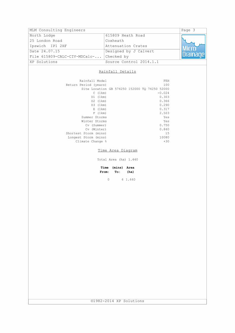
Rainfall Details
©1982-2014 XP Solutions
Rainfall Model FEHReturn Period (years) 100
Site Location GB 574250 152000 TQ 74250 52000C (1km) -0.024D1 (1km) 0.303D2 (1km) 0.366D3 (1km) 0.290E (1km) 0.317F (1km) 2.503
Summer Storms YesWinter Storms YesCv (Summer) 0.750Cv (Winter) 0.840
Shortest Storm (mins) 15Longest Storm (mins) 10080
Climate Change % +30
Time Area Diagram
Total Area (ha) 1.440
Time
From:
(mins)
To:
Area
(ha)
0 4 1.440

MLM Consulting Engineers Page 4
North Lodge 615809 Heath Road
25 London Road Coxheath
Ipswich IP1 2HF Attenuation Crates
Date 24.07.15 Designed by J Calvert
File 615809-CALC-CIV-MDCalc-... Checked by
XP Solutions Source Control 2014.1.1
Model Details
©1982-2014 XP Solutions
Storage is Online Cover Level (m) 10.000
Cellular Storage Structure
Invert Level (m) 8.400 Safety Factor 2.0Infiltration Coefficient Base (m/hr) 0.00000 Porosity 0.95Infiltration Coefficient Side (m/hr) 0.00000
Depth (m) Area (m²) Inf. Area (m²) Depth (m) Area (m²) Inf. Area (m²)
0.000 1130.0 0.0 0.801 0.0 0.00.800 1130.0 0.0
Pump Outflow Control
Invert Level (m) 8.400
Depth (m) Flow (l/s) Depth (m) Flow (l/s)
0.001 16.0000 1.600 16.0000

Land at Heath Road, Coxheath © MLM Consulting Engineers Limited Flood Risk Assessment
Appendix D – Southern Water Asset Plans

Southern Water Southern House Capstone Road Chatham Kent ME5 7QA www.southernwater.co.uk Southern Water Services Ltd Registered Office: Southern House Yeoman Road Worthing BN13 3NX Registered in England No. 2366670
Your Ref Our Ref Date Contact
[email protected] Fax 01634 844514 DX:400450 Chatham 5
Attention: Dear Sirs
Further to your recent enquiry regarding the provision of Southern Water apparatus record extracts for the above location. Please be aware that there are areas within our region in which there are neither sewers nor water mains. Similarly, whilst the enclosed extract may indicate the approximate location of our apparatus in the area of interest, it should not be relied upon as showing that further infrastructure does not exist and may subsequently be found following site investigation. Therefore actual positions of the disclosed (and any undisclosed) infrastructure should be determined on site, because Southern Water does not accept any responsibility for inaccuracy or omission regarding the enclosed plan and accordingly it should not be considered to be a definitive document. I confirm payment of the appropriate fee in the sum of £ The breakdown of costs is as follows: -
Provision of record extracts £
VAT @ 20.0% £
VAT Registration Number 543 9000 63
Should you require any additional information regarding this matter please contact this office at the address given at the foot of this letter. Yours faithfully Land Search Department
MLM Consulting Engineers LimitedNorth Lodge 25London RoadIpswichSuffolkIP1 2HF
615809
168684
18 February 2014
James Calvert
Provision of Public Sewer Main Record Extracts – VAT ReceiptLand at Heath Road, Coxheath
48.00
40.00
8.00


Land at Heath Road, Coxheath © MLM Consulting Engineers Limited Flood Risk Assessment
Appendix E – Soakaway Testing Results
MLM Letter dated 11 February 2015 – Soakaway Infiltration Tests
MLM Letter dated 1 July 2015 – Preliminary Borehole Soakaway Infiltration Tests

MLM Consulting Engineers Limited 01223 632800 Building 7200, Cambridge Research Park, Cambridge, CB25 9TL 01223 815630
Our Ref: 772596-LET-ENV-001 11 February 2015
Mr Chris Atkinson 9 St. Luke’s Avenue Maidstone Kent ME14 5AN Dear Chris Re: Land off Heath Road, Coxheath, near Maidstone, Kent, ME17 4EQ Soakaway Infiltration Tests
Further to your recent instruction we are pleased to provide the results of the additional soakaway infiltration tests undertaken at the above site. 1 Background
This report has been prepared for Chris Atkinson, to describe the results gathered for the five number soakaway tests for the proposed residential development at the above site. The investigation and assessment will be used to assist in the preparation of a drainage strategy for the new development. The site is located off Heath Road in Coxheath, near Maidstone Kent and currently comprises a rectangular area of part wooded/part open ground flanked by residential developments. The site is used by the general public and pedestrian access comprising footpaths are present across the site linking the residential areas and the main road to the south. A gated access and sty is present at the south western corner off Heath Road. Observed geology from the five trial pits was firm cohesive silty clay consistent with Head Deposits, overlying weathered sandstone considered to be the Hythe Beds. This investigation and assessment has been undertaken to meet the requirements of the following:
• Building Regulations Approved Document C. • BS EN 1997-2: 2007 and, where there is no conflict is in general accordance
with the reporting requirements of BS5930:1999+A2:2010. • AGS Guidelines for Combined Geo-environmental and Geotechnical
Investigations 2000. 2 Field Work
Soakaway infiltration testing was undertaken at five positions (SA1 to SA5) on 03/02/2015. All five locations (SA1 to SA5) were selected by MLM Environmental engineers in consultation with MLM drainage engineers and the Client who arranged the access and the clearing of vegetation. The soakaway test positions are shown on Figure 1. Each position was initially cleared of underground services using a CAT and ground probing radar. The test pits were then excavated using a back acting excavator with a width of 0.8m and lengths of between 2.10m and 2.60mm.

Page: 3 Our Ref.: 772596-LET-ENV-001 11 February 2015 Mr Chris Atkinson
The pits were excavated down to the top of a weathered sandstone rock unit of the Hythe Beds. Once completed, the trial pit sides were trimmed to create as regular sided pit as possible. Soakaway infiltration testing was undertaken in general accordance with BRE Digest 365 (2007). Clean water was added to each pit from a bowser and the rate at which the water level fell measured from a datum point.
On completion of the testing, all pits were emptied of any remaining water, backfilled with arisings compacted in layers using the excavator bucket.
3 Test Results
The test results are presented in Appendix A attached along with infiltration rates calculated in accordance with BRE 365.
The ground conditions identified in the pits were as follows:
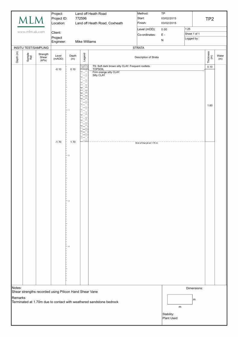
Depth to base Stratum 0.10m – 0.50m Soft dark brown silty CLAY. Frequent rootlets. (Topsoil)
0.70m (SA1) Black slightly gravelly fine to coarse ashy sand. Gravel is fine
to medium, angular to sub-rounded of brick. Occasional cobbles of brick (Made Ground).
0.65m – 2.60m
Firm orange silty CLAY.
0.65m – 1.10m
Soft light orangish brown silty slightly sandy CLAY. Sand is fine to coarse.
2.60m (SA1) Soft light orangish brown very sandy slightly gravelly SILT. Gravel is fine to medium, angular to sub-rounded. Sand is fine to coarse. Occasional cobbles of sandstone.
Top encountered between depths of 1.45 and 2.60m bgl.
Weak weathered SANDSTONE.
Each pit was filled to a depth of between 0.43m and 0.92m bgl. The pit sides remained stable throughout excavation and testing. Infiltration rates calculated from the testing were as follows:
Test Position Test Depth Infiltration Stratum Infiltration Rate1
SA1 0.59m Firm orange silty CLAY Test failed SA2 0.43m Firm orange silty CLAY Test failed SA3 0.92m Firm orange silty CLAY Test failed SA4 0.88m Firm orange silty CLAY Test failed SA5 0.55m Firm orange silty CLAY Test failed 1. Infiltration rate calculated from test.
The tests in all of the pits were left to run for a minimum of 120 minutes (2 hours) but, in this time, the water level failed to fall sufficiently for the infiltration rate to be calculated using the method of BRE365.

Page: 3 Our Ref.: 772596-LET-ENV-001 11 February 2015 Mr Chris Atkinson
The test results of SA1 and SA5 have been extrapolated to provide an estimate of the infiltration rate and this suggests an infiltration rate of the order of 10-9 - 10-
8m/s which corresponds to poor drainage potential. Infiltration for tests SA2–SA4 was so low that extrapolated results cannot be easily calculated and on this basis the results of SA2–SA4 suggest an infiltration rate of 10-9m/s or lower indicating negligible permeability. Based on the extrapolation of the test results in SA1 and SA5, the estimated times required for the water to fall to a sufficient level to allow the soil infiltration rates to be calculated (based on BRE Digest 365) was in the order of 18 to 27 hours (SA1 and SA5 respectively). It was not possible to calculate the soil infiltration rates for tests SA2–SA4 due to extremely low infiltration.
4 Conclusions
Based on the soakaway tests, undertaken by MLM, it is clear that the infiltration rates in the upper 1m of the ground surface do not vary greatly across the site due to the consistency of the nature of the soil across the site. The presence of the firm orange silty clay indicates likely infiltration rates of 10-9m/s or lower. The other soils found in the area also have a high content of clays and silts which will also slow the infiltration rate. The permeability of the underlying sandstone is also evidently very low and it is expected that this is because any fissures or discontinuities are clay filled. Based on the investigations undertaken, design soil infiltration rates within firm orange silty clay 10-8m/s–10-9m/s. An overall design value of 10-9m/s may be prudent for the site.
We trust that the above meets with your present requirements. Should you should have any further queries please do not hesitate to contact the undersigned. Yours sincerely
Mike Williams Enc. Soakaway test results

Figure 1 Soakaway Test Locations
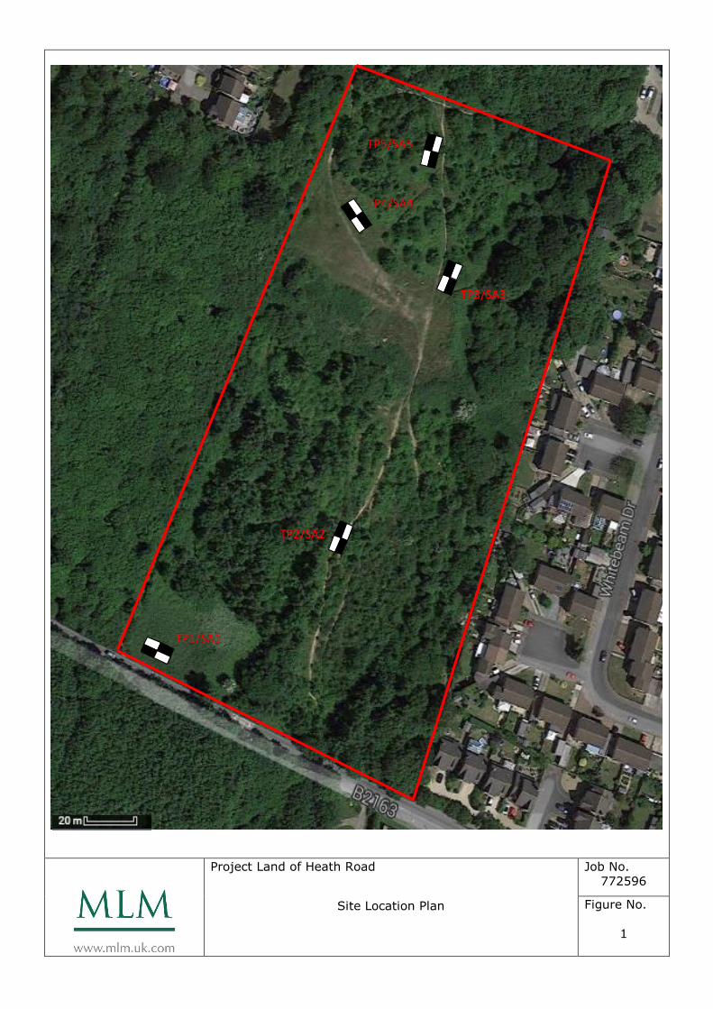
Project Land of Heath Road
Site Location Plan
Job No.
772596
Figure No.
1
S
I
T
E
N
TP1/SA1
TP2/SA2
TP3/SA3
TP4/SA4
TP5/SA5

Soakaway Test Results
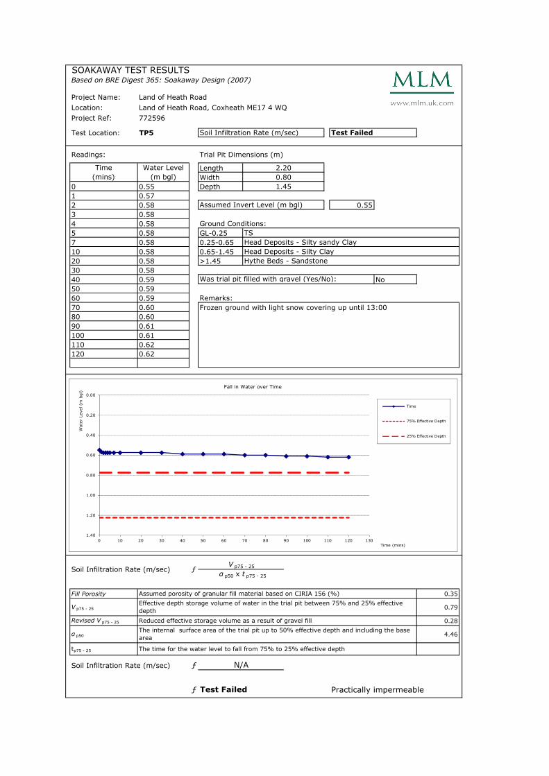
SOAKAWAY TEST RESULTSBased on BRE Digest 365: Soakaway Design (2007)
Project Name: Land of Heath Road
Location: Land of Heath Road, Coxheath ME17 4 WQ
Project Ref: 772596
Test Location: TP5
Readings: Trial Pit Dimensions (m)
Length
Width
0 0.55 Depth
1 0.57
2 0.58 0.55
3 0.58
4 0.58 Ground Conditions:
5 0.58 GL-0.25
7 0.58 0.25-0.65
10 0.58 0.65-1.45
20 0.58 >1.45
30 0.58
40 0.59 No
50 0.59
60 0.59 Remarks:
70 0.60 Frozen ground with light snow covering up until 13:00
80 0.60
90 0.61
100 0.61
110 0.62
120 0.62
Fill Porosity 0.35
V p75 - 25 0.79
Revised V p75 - 25 0.28
α p50 4.46
tp75 - 25
ƒ
ƒ Practically impermeable
Soil Infiltration Rate (m/sec) Test Failed
Time
(mins)
Water Level
(m bgl)
2.20
0.80
1.45
Assumed Invert Level (m bgl)
TS
Head Deposits - Silty sandy Clay
Head Deposits - Silty Clay
Hythe Beds - Sandstone
Was trial pit filled with gravel (Yes/No):
Soil Infiltration Rate (m/sec) ƒV p75 - 25
α p50 x t p75 - 25
Assumed porosity of granular fill material based on CIRIA 156 (%)
Effective depth storage volume of water in the trial pit between 75% and 25% effective
depth
Reduced effective storage volume as a result of gravel fill
The internal surface area of the trial pit up to 50% effective depth and including the base
area
The time for the water level to fall from 75% to 25% effective depth
Soil Infiltration Rate (m/sec) N/A
Test Failed
0.00
0.20
0.40
0.60
0.80
1.00
1.20
1.40
0 10 20 30 40 50 60 70 80 90 100 110 120 130
Water Level (m
bgl)
Time (mins)
Fall in Water over Time
Time
75% Effective Depth
25% Effective Depth
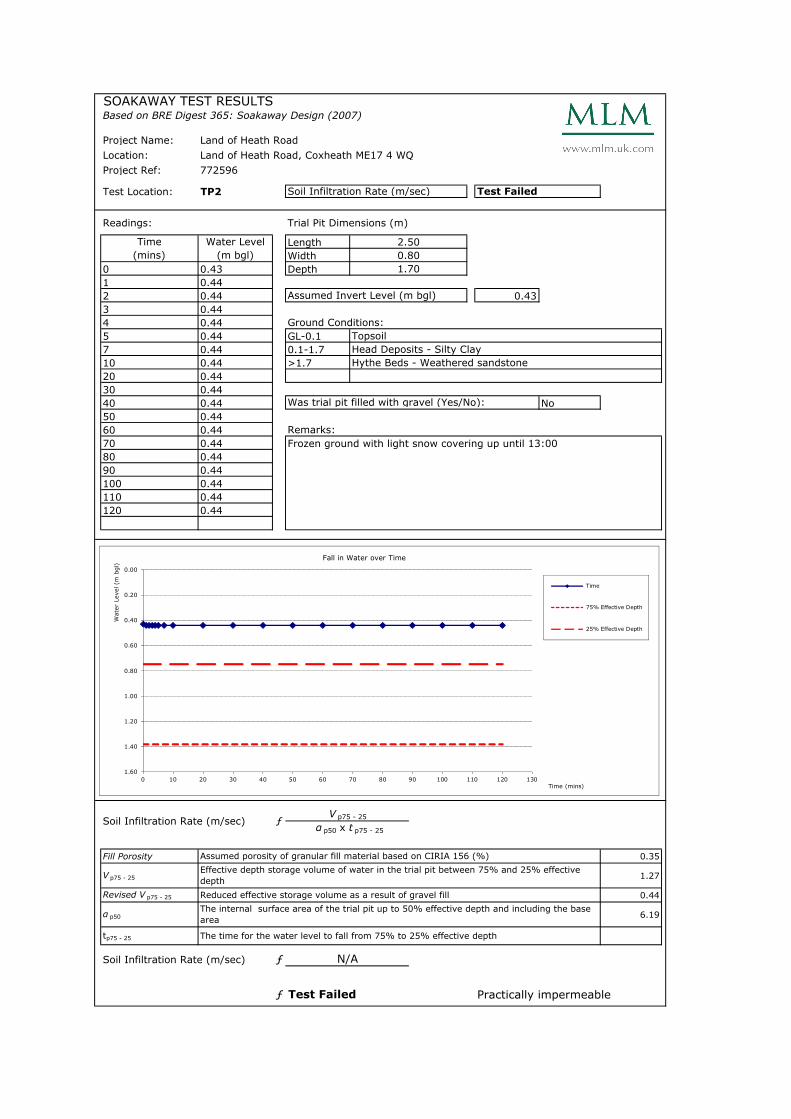
SOAKAWAY TEST RESULTSBased on BRE Digest 365: Soakaway Design (2007)
Project Name: Land of Heath Road
Location: Land of Heath Road, Coxheath ME17 4 WQ
Project Ref: 772596
Test Location: TP2
Readings: Trial Pit Dimensions (m)
Length
Width
0 0.43 Depth
1 0.44
2 0.44 0.43
3 0.44
4 0.44 Ground Conditions:
5 0.44 GL-0.1
7 0.44 0.1-1.7
10 0.44 >1.7
20 0.44
30 0.44
40 0.44 No
50 0.44
60 0.44 Remarks:
70 0.44 Frozen ground with light snow covering up until 13:00
80 0.44
90 0.44
100 0.44
110 0.44
120 0.44
Fill Porosity 0.35
V p75 - 25 1.27
Revised V p75 - 25 0.44
α p50 6.19
tp75 - 25
ƒ
ƒ Practically impermeable Test Failed
Soil Infiltration Rate (m/sec) Test Failed
Time
(mins)
Water Level
(m bgl)
2.50
0.80
1.70
Assumed Invert Level (m bgl)
Topsoil
Head Deposits - Silty Clay
Hythe Beds - Weathered sandstone
Was trial pit filled with gravel (Yes/No):
Soil Infiltration Rate (m/sec) ƒV p75 - 25
α p50 x t p75 - 25
Assumed porosity of granular fill material based on CIRIA 156 (%)
Effective depth storage volume of water in the trial pit between 75% and 25% effective
depth
Reduced effective storage volume as a result of gravel fill
The internal surface area of the trial pit up to 50% effective depth and including the base
area
The time for the water level to fall from 75% to 25% effective depth
Soil Infiltration Rate (m/sec) N/A
0.00
0.20
0.40
0.60
0.80
1.00
1.20
1.40
1.60
0 10 20 30 40 50 60 70 80 90 100 110 120 130
Water Level (m
bgl)
Time (mins)
Fall in Water over Time
Time
75% Effective Depth
25% Effective Depth

SOAKAWAY TEST RESULTSBased on BRE Digest 365: Soakaway Design (2007)
Project Name: Land of Heath Road
Location: Land of Heath Road, Coxheath ME17 4 WQ
Project Ref: 772596
Test Location: TP3
Readings: Trial Pit Dimensions (m)
Length
Width
0 0.92 Depth
1 0.93
2 0.93 0.92
3 0.93
4 0.93 Ground Conditions:
5 0.94 GL-0.5
7 0.94 0.5-1.1
10 0.94 1.1-2.6
20 0.94 >2.6
30 0.94
40 0.94 No
50 0.94
60 0.95 Remarks:
70 0.95 Frozen ground with light snow covering up until 13:00
80 0.95
90 0.95
100 0.95
110 0.95
120 0.95
Fill Porosity 0.35
V p75 - 25 1.61
Revised V p75 - 25 0.56
α p50 7.30
tp75 - 25
ƒ
ƒ Practically impermeable
Soil Infiltration Rate (m/sec) Test Failed
Time
(mins)
Water Level
(m bgl)
2.40
0.80
2.60
Assumed Invert Level (m bgl)
Topsoil
Head Deposits - Silty sandy Clay
Head Deposits - Silty Clay
Hythe Beds - Weathered sandstone
Was trial pit filled with gravel (Yes/No):
Soil Infiltration Rate (m/sec) ƒV p75 - 25
α p50 x t p75 - 25
Assumed porosity of granular fill material based on CIRIA 156 (%)
Effective depth storage volume of water in the trial pit between 75% and 25% effective
depth
Reduced effective storage volume as a result of gravel fill
The internal surface area of the trial pit up to 50% effective depth and including the base
area
The time for the water level to fall from 75% to 25% effective depth
Soil Infiltration Rate (m/sec) N/A
Test Failed
0.00
0.20
0.40
0.60
0.80
1.00
1.20
1.40
1.60
1.80
2.00
2.20
2.40
0 10 20 30 40 50 60 70 80 90 100 110 120 130
Water Level (m
bgl)
Time (mins)
Fall in Water over Time
Time
75% Effective Depth
25% Effective Depth
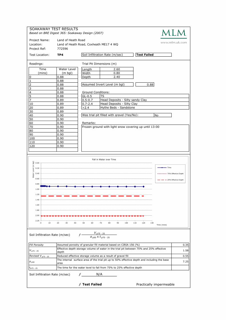
SOAKAWAY TEST RESULTSBased on BRE Digest 365: Soakaway Design (2007)
Project Name: Land of Heath Road
Location: Land of Heath Road, Coxheath ME17 4 WQ
Project Ref: 772596
Test Location: TP4
Readings: Trial Pit Dimensions (m)
Length
Width
0 0.88 Depth
1 0.88
2 0.88 0.88
3 0.88
4 0.88 Ground Conditions:
5 0.88 GL-0.5
7 0.89 0.5-0.7
10 0.89 0.7-2.4
20 0.89 >2.4
30 0.89
40 0.90 No
50 0.90
60 0.90 Remarks:
70 0.90 Frozen ground with light snow covering up until 13:00
80 0.90
90 0.90
100 0.90
110 0.90
120 0.90
Fill Porosity 0.35
V p75 - 25 1.58
Revised V p75 - 25 0.55
α p50 7.25
tp75 - 25
ƒ
ƒ Practically impermeable
Soil Infiltration Rate (m/sec) Test Failed
Time
(mins)
Water Level
(m bgl)
2.60
0.80
2.40
Assumed Invert Level (m bgl)
TS
Head Deposits - Silty sandy Clay
Head Deposits - Silty Clay
Hythe Beds - Sandstone
Was trial pit filled with gravel (Yes/No):
Soil Infiltration Rate (m/sec) ƒV p75 - 25
α p50 x t p75 - 25
Assumed porosity of granular fill material based on CIRIA 156 (%)
Effective depth storage volume of water in the trial pit between 75% and 25% effective
depth
Reduced effective storage volume as a result of gravel fill
The internal surface area of the trial pit up to 50% effective depth and including the base
area
The time for the water level to fall from 75% to 25% effective depth
Soil Infiltration Rate (m/sec) N/A
Test Failed
0.00
0.20
0.40
0.60
0.80
1.00
1.20
1.40
1.60
1.80
2.00
2.20
0 10 20 30 40 50 60 70 80 90 100 110 120 130
Water Level (m
bgl)
Time (mins)
Fall in Water over Time
Time
75% Effective Depth
25% Effective Depth

SOAKAWAY TEST RESULTSBased on BRE Digest 365: Soakaway Design (2007)
Project Name: Land of Heath Road
Location: Land of Heath Road, Coxheath ME17 4 WQ
Project Ref: 772596
Test Location: TP5
Readings: Trial Pit Dimensions (m)
Length
Width
0 0.55 Depth
1 0.57
2 0.58 0.55
3 0.58
4 0.58 Ground Conditions:
5 0.58 GL-0.25
7 0.58 0.25-0.65
10 0.58 0.65-1.45
20 0.58 >1.45
30 0.58
40 0.59 No
50 0.59
60 0.59 Remarks:
70 0.60 Frozen ground with light snow covering up until 13:00
80 0.60
90 0.61
100 0.61
110 0.62
120 0.62
Fill Porosity 0.35
V p75 - 25 0.79
Revised V p75 - 25 0.28
α p50 4.46
tp75 - 25
ƒ
ƒ Practically impermeable
Soil Infiltration Rate (m/sec) Test Failed
Time
(mins)
Water Level
(m bgl)
2.20
0.80
1.45
Assumed Invert Level (m bgl)
TS
Head Deposits - Silty sandy Clay
Head Deposits - Silty Clay
Hythe Beds - Sandstone
Was trial pit filled with gravel (Yes/No):
Soil Infiltration Rate (m/sec) ƒV p75 - 25
α p50 x t p75 - 25
Assumed porosity of granular fill material based on CIRIA 156 (%)
Effective depth storage volume of water in the trial pit between 75% and 25% effective
depth
Reduced effective storage volume as a result of gravel fill
The internal surface area of the trial pit up to 50% effective depth and including the base
area
The time for the water level to fall from 75% to 25% effective depth
Soil Infiltration Rate (m/sec) N/A
Test Failed
0.00
0.20
0.40
0.60
0.80
1.00
1.20
1.40
0 10 20 30 40 50 60 70 80 90 100 110 120 130
Water Level (m
bgl)
Time (mins)
Fall in Water over Time
Time
75% Effective Depth
25% Effective Depth

Trial Pit Logs

Project:
Project ID:
Location:
Client:
ProjectEngineer:
Land off Heath Road
772596
Land off Heath Road, Coxheath
Mike Williams
Method:
Start:
Finish:
Level (mOD):
Co-ordinates:
TP
03/02/2015
03/02/2015
TP1
0.00 1:25
E -
N
Sheet 1 of 1
Logged by:
Notes:Shear strengths recorded using Pilicon Hand Shear Vane
Remarks
Terminated at 2.30m due to contact with weathered sandstone bedrock
Dimensions:
m
m
Stability:
Plant Used:
INSITU TEST/SAMPLING
De
pth
(m
)
Sa
mp
le
Ref. Strength
Shear(kPa)
STRATA
Level(mAOD)
-0.50
-0.70
-2.00
-2.30
Depth(m)
1
2
3
4
0.50
0.70
2.00
2.30
Leg
en
d
Description of Strata
TS: Soft dark brown silty CLAY. Frequent rootlets.TOPSOIL
MG: Black slightly gravelly fine to coarse Sand of ash. Gravel is fine to medium, angular to sub-rounded of brick. Occasional cobbles of brick.MADE GROUNDFirm orange slightly silty CLAY.Silty CLAY
Soft light orangish brown very sandy slightly gravelly SILT. Gravel is fine to medium, angular to sub-rounded. Sand is fine to coarse. Occasional cobbles of sandstone.Sandy gravelly cobbly SILT
End of trial pit at 2.30 m
Thic
kn
ess
(m)
0.50
0.20
1.30
0.30
Water(m)
Project:
Project ID:
Location:
Client:
ProjectEngineer:
Land off Heath Road
772596
Land off Heath Road, Coxheath
Mike Williams
Method:
Start:
Finish:
Level (mOD):
Co-ordinates:
TP
03/02/2015
03/02/2015
TP2
0.00 1:25
E -
N
Sheet 1 of 1
Logged by:
Notes:Shear strengths recorded using Pilicon Hand Shear Vane
Remarks
Terminated at 1.70m due to contact with weathered sandstone bedrock
Dimensions:
m
m
Stability:
Plant Used:
INSITU TEST/SAMPLING
De
pth
(m
)
Sa
mp
le
Ref. Strength
Shear(kPa)
STRATA
Level(mAOD)
-0.10
-1.70
Depth(m)
1
2
3
4
0.10
1.70
Leg
en
d
Description of Strata
TS: Soft dark brown silty CLAY. Frequent rootlets.TOPSOILFirm orange silty CLAY.Silty CLAY
End of trial pit at 1.70 m
Thic
kn
ess
(m)
0.10
1.60
Water(m)

Project:
Project ID:
Location:
Client:
ProjectEngineer:
Land off Heath Road
772596
Land off Heath Road, Coxheath
Mike Williams
Method:
Start:
Finish:
Level (mOD):
Co-ordinates:
TP
03/02/2015
03/02/2015
TP3
0.00 1:25
E -
N
Sheet 1 of 1
Logged by:
Notes:Shear strengths recorded using Pilicon Hand Shear Vane
Remarks
Terminated at 2.60m due to contact with weathered sandstone bedrock
Dimensions:
m
m
Stability:
Plant Used:
INSITU TEST/SAMPLING
De
pth
(m
)
Sa
mp
le
Ref. Strength
Shear(kPa)
STRATA
Level(mAOD)
-0.50
-1.10
-2.60
Depth(m)
1
2
3
4
0.50
1.10
2.60
Leg
en
d
Description of Strata
TS: Soft dark brown silty CLAY. Frequent rootlets.TOPSOIL
Soft light orangish brown silty slightly sandy CLAY. Sand is fine to coarse.Silty sandy CLAY
Firm orange mottled grey silty CLAYSilty CLAY
End of trial pit at 2.60 m
Thic
kn
ess
(m)
0.50
0.60
1.50
Water(m)
Project:
Project ID:
Location:
Client:
ProjectEngineer:
Land off Heath Road
772596
Land off Heath Road, Coxheath
Mike Williams
Method:
Start:
Finish:
Level (mOD):
Co-ordinates:
TP
03/02/2015
03/02/2015
TP4
0.00 1:25
E -
N
Sheet 1 of 1
Logged by:
Notes:Shear strengths recorded using Pilicon Hand Shear Vane
Remarks
Terminated at 2.40m due to contact with weathered sandstone bedrock
Dimensions:
m
m
Stability:
Plant Used:
INSITU TEST/SAMPLING
De
pth
(m
)
Sa
mp
le
Ref. Strength
Shear(kPa)
STRATA
Level(mAOD)
-0.50
-0.70
-2.40
Depth(m)
1
2
3
4
0.50
0.70
2.40
Leg
en
d
Description of Strata
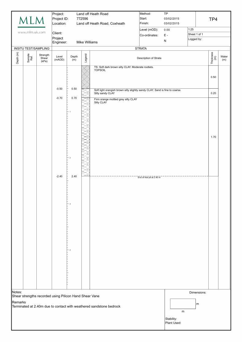
TS: Soft dark brown silty CLAY. Moderate rootlets.TOPSOIL
Soft light orangish brown silty slightly sandy CLAY. Sand is fine to coarse.Silty sandy CLAY
Firm orange mottled grey silty CLAYSilty CLAY
End of trial pit at 2.40 m
Thic
kn
ess
(m)
0.50
0.20
1.70
Water(m)

Project:
Project ID:
Location:
Client:
ProjectEngineer:
Land off Heath Road
772596
Land off Heath Road, Coxheath
Mike Williams
Method:
Start:
Finish:
Level (mOD):
Co-ordinates:
TP
03/02/2015
03/02/2015TP5
0.00 1:25
E -
N
Sheet 1 of 1
Logged by:
Notes:Shear strengths recorded using Pilicon Hand Shear Vane
Remarks
Terminated at 1.45m due to contact with weathered sandstone bedrock
Dimensions:
m
m
Stability:
Plant Used:
INSITU TEST/SAMPLING
De
pth
(m
)
Sa
mp
le
Ref. Strength
Shear(kPa)
STRATA
Level(mAOD)
-0.25
-0.65
-1.45
Depth(m)
1
2
3
4
0.25
0.65
1.45
Leg
en
d
Description of Strata
TS: Soft dark brown silty CLAY. Moderate rootlets.TOPSOIL
Soft light orangish brown silty slightly sandy CLAY. Sand is fine to coarse.Silty sandy CLAY
Firm orange silty CLAY.Silty CLAY
End of trial pit at 1.45 m
Thic
kn
ess
(m)
0.25
0.40
0.80
Water(m)
MLM Consulting Engineers Limited Main Tel: 01233 610530 190 Eureka park, Upper Pemberton, Ashford, Kent, TN25 4AZ Main Fax: 01233 618299
V3
Our Ref: 772845-REP-ENV-001 1 July 2015
Chris Atkinson Consultant Town Planner 9 St. Luke’s Avenue Maidstone Kent ME14 5AN Dear Mr Atkinson Re: Land off Heath Road, Coxheath Preliminary Borehole Soakaway Infiltration Tests
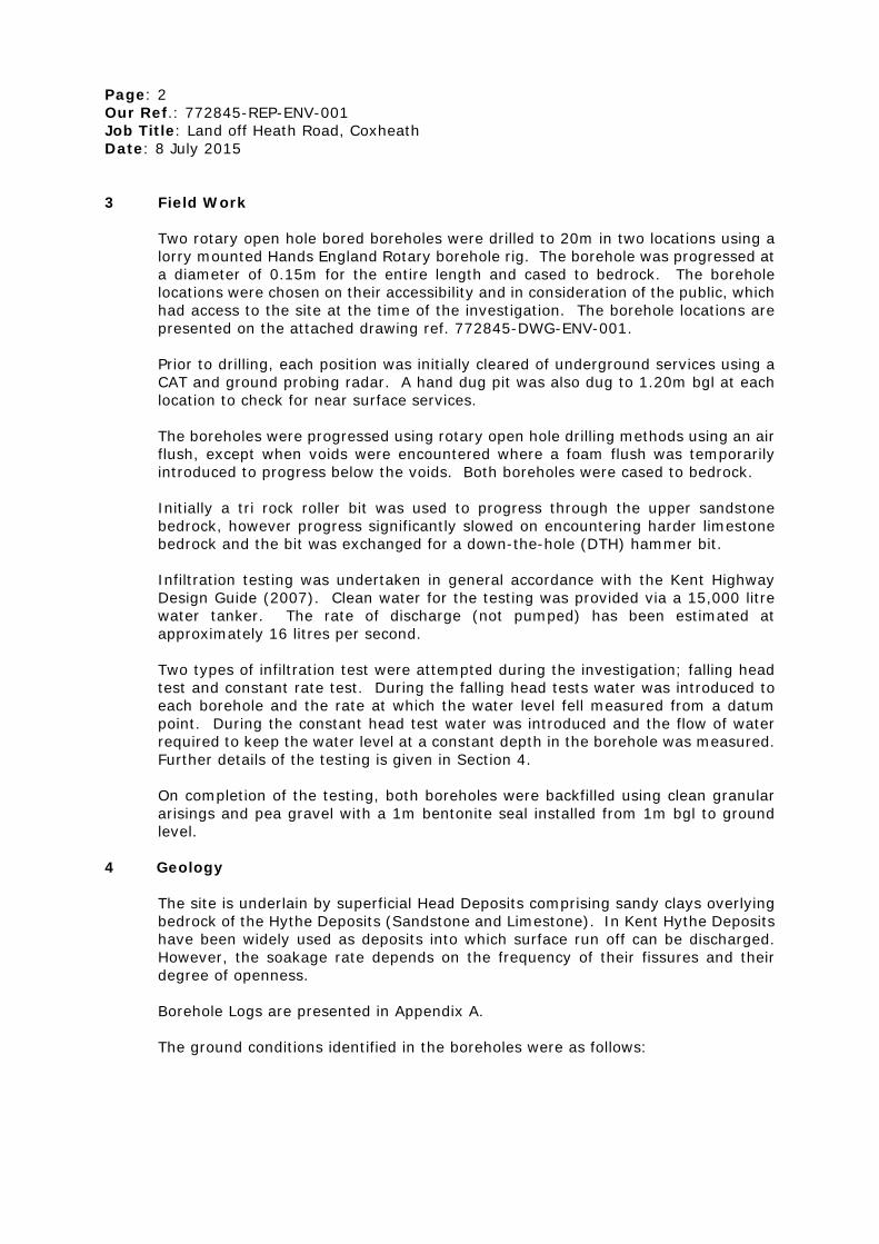
This report has been prepared for Mr Michael Older (Client) who is proposing to develop the site at land off Heath Road, Coxheath for a residential end use. MLM Environmental (MLME) was commissioned to undertake soakage testing in deep boreholes to assist in the preparation of a drainage strategy for the site. The terms of reference for the work were set out in a letter by MLME ref. 772845-FEE-ENV-001 dated 28 May 2015. The scope of work was for the drilling of two rotary open hole bored boreholes to 20m and soakage testing at intervals in general accordance with the Kent Soakaway Design Guide to assess the viability of deep bored soakaways. 1 Background
MLM has been appointed as drainage engineers for the proposed residential development. To assist in the design of the drainage strategy MLME has carried out investigations to assess the viability of discharging surface water via deep bored soakaways. Prior to the current investigation five shallow trial pit (BRE365) soakage tests were undertaken in February 2015. This investigation revealed cohesive drift deposits (Head Deposits) overlying sandstone (Hythe Formation). All of the tests failed due to negligibly permeable strata and therefore it was concluded that shallow soakaways would not be a viable drainage option. The current investigation was instructed to assess the viability of deep bored soakaways as an alternative drainage option.
2 Site Description The site comprises a rectangular area of land bound by Heath Road to the south, residential development to the east and west and open access wooded land to the north. The site itself is undeveloped and comprises part wooded, part grassed open space which is currently open to the public.
Page: 2 Our Ref.: 772845-REP-ENV-001 Job Title: Land off Heath Road, Coxheath Date: 8 July 2015
3 Field Work
Two rotary open hole bored boreholes were drilled to 20m in two locations using a lorry mounted Hands England Rotary borehole rig. The borehole was progressed at a diameter of 0.15m for the entire length and cased to bedrock. The borehole locations were chosen on their accessibility and in consideration of the public, which had access to the site at the time of the investigation. The borehole locations are presented on the attached drawing ref. 772845-DWG-ENV-001. Prior to drilling, each position was initially cleared of underground services using a CAT and ground probing radar. A hand dug pit was also dug to 1.20m bgl at each location to check for near surface services. The boreholes were progressed using rotary open hole drilling methods using an air flush, except when voids were encountered where a foam flush was temporarily introduced to progress below the voids. Both boreholes were cased to bedrock. Initially a tri rock roller bit was used to progress through the upper sandstone bedrock, however progress significantly slowed on encountering harder limestone bedrock and the bit was exchanged for a down-the-hole (DTH) hammer bit. Infiltration testing was undertaken in general accordance with the Kent Highway Design Guide (2007). Clean water for the testing was provided via a 15,000 litre water tanker. The rate of discharge (not pumped) has been estimated at approximately 16 litres per second. Two types of infiltration test were attempted during the investigation; falling head test and constant rate test. During the falling head tests water was introduced to each borehole and the rate at which the water level fell measured from a datum point. During the constant head test water was introduced and the flow of water required to keep the water level at a constant depth in the borehole was measured. Further details of the testing is given in Section 4.
On completion of the testing, both boreholes were backfilled using clean granular arisings and pea gravel with a 1m bentonite seal installed from 1m bgl to ground level.
4 Geology
The site is underlain by superficial Head Deposits comprising sandy clays overlying bedrock of the Hythe Deposits (Sandstone and Limestone). In Kent Hythe Deposits have been widely used as deposits into which surface run off can be discharged. However, the soakage rate depends on the frequency of their fissures and their degree of openness.
Borehole Logs are presented in Appendix A.
The ground conditions identified in the boreholes were as follows:

Page: 3 Our Ref.: 772845-REP-ENV-001 Job Title: Land off Heath Road, Coxheath Date: 8 July 2015
BH1 (North)
Depth (m bgl) Stratum GL - 0.30 Orange brown clayey fine to coarse SAND (TOPSOIL) 0.30 – 1.50 Orange brown sandy CLAY with occasional gravel to cobble
sized sandstone (HEAD DEPOSITS) 1.50 - 7.00 Yellowish brown SANDSTONE with interbedded bands of
LIMESTONE (HYTHE FORMATION) 7.00 – 12.00 Strong bluish grey LIMESTONE (HYTHE FORMATION) 12.00 – 12.50 Voided Strata 12.50 – 20.00 Strong bluish grey LIMESTONE (HYTHE FORMATION)
* base not proven in this phase of investigation.
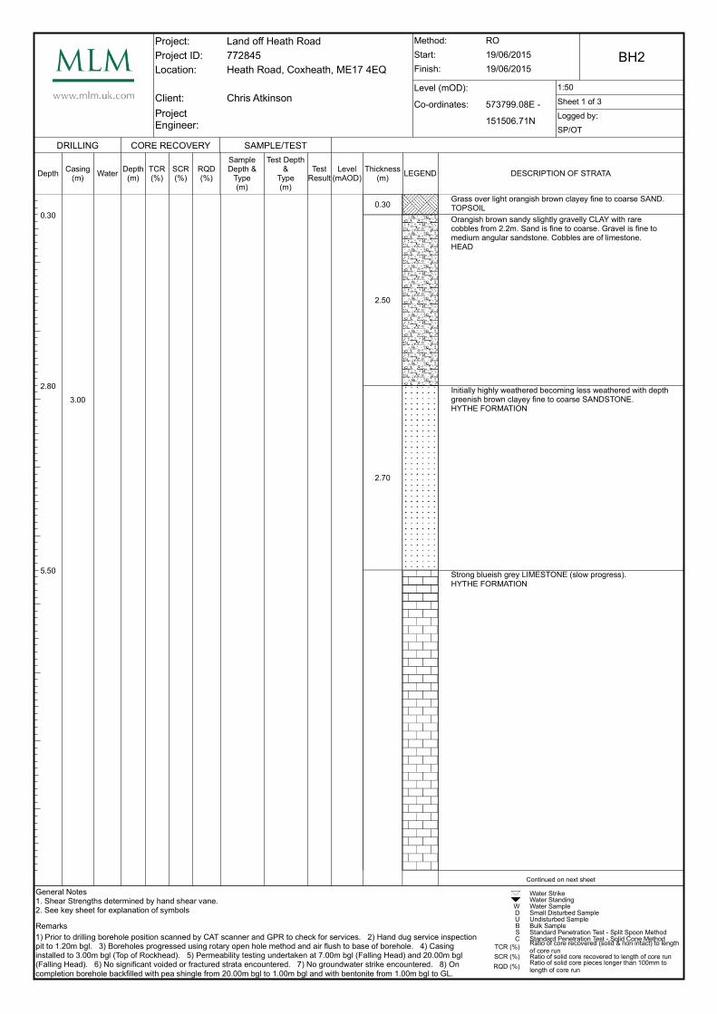
BH2 (South) Depth (m bgl) Stratum GL – 0.30 Orange brown clayey fine to coarse SAND (TOPSOIL) 0.30 – 2.80 Orange brown sandy slightly gravelly CLAY with rare
sandstone cobbles. (HEAD DEPOSITS) 2.80 – 5.50 Greenish brown clayey fine to coarse SANDSTONE (HYTHE
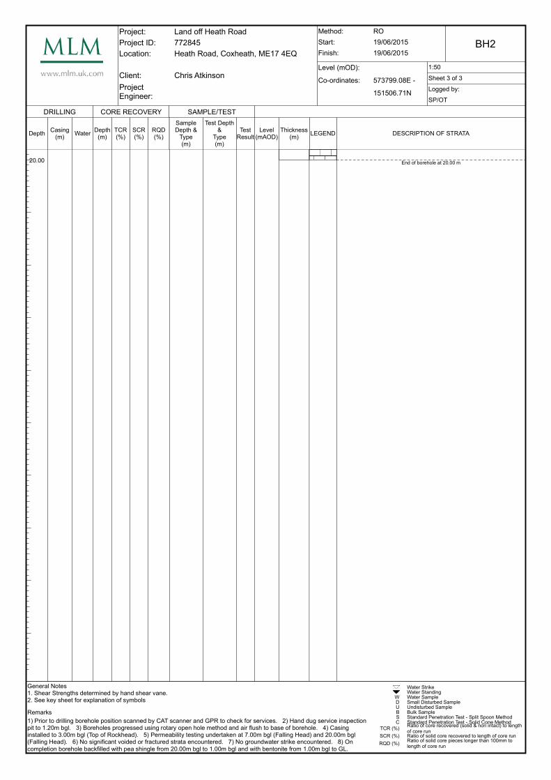
FORMATION) 5.50 – 20.00 Strong bluish grey LIMESTONE (HYTHE Formation)
* base not proven in this phase of investigation. The ground conditions encountered in the boreholes is consistent with the trial pits undertaken in the February 2015 investigation in that the depth to rockhead increases from north to south. The head deposits are predominantly cohesive and have been proved by previous testing to be negligibly permeable. During drilling, the pressure of the drilling bit and the pressure of the flush and the rate of drilling is continuously monitored by the driller. A sudden decrease in the pressure of bit or flush or sudden increase in drill rate can be indicative of fissured or voided ground. The flushed returns were inspected by a geoenvironmental engineer to determine the type of rock being drilled and to identify changes in strata. Sandstone or sandstone interbedded with limestone bedrock was initially encountered below the head deposits to depths of 7.00m bgl in BH1 and 5.50m bgl in BH2. The sandstone was generally fine grained and contained a significant proportion of silt sized particles. The drilling rate in this strata varied depending on whether limestone or sandstone was being drilled, and was significantly slower in the limestone which was harder but no sudden decreases/increases in rate were noted. In addition there was no sudden decreases in pressure on the drilling bit or flush. Below the sandstone or interbedded sandstone and limestone, intact limestone rock was encountered. The limestone was significantly harder and this was evidenced by much slower progress in drilling and the requirement for a change in drilling bit from a tri cone rock roller to DTH hammer. In the majority of the limestone the rate of drilling was constant with no obvious decreases in pressure of bit or flush, however a complete loss of flush was encountered together with a ‘drop’ of the drilling tools in BH1 between 12.00 and 12.50m bgl. This was identified as voided strata and a constant head permeability test was attempted at 12.50m bgl.

Page: 4 Our Ref.: 772845-REP-ENV-001 Job Title: Land off Heath Road, Coxheath Date: 8 July 2015
Following the test a foam flush was introduced to the voided area so that the borehole could be progressed to the target depth of 20m bgl. Below the void the strata was again drilled at a constant rate with no obvious decreases in pressure of bit or flush indicating that the rock was again intact without any significant fissures or fractures.
5 Testing BH1 – Test 1 – Falling Head The borehole was initially progressed to 10m bgl and then water was introduced to the bottom of the casing at 1.50m bgl. The groundwater was then monitored for a period of 30mins over which period there was no significant fall in water level. BH1 – Test 2 – Constant Head The borehole was progressed and on encountering suspected voided strata between depths of 12.00 and 12.50m bgl a constant rate test was attempted. Water was discharge into the borehole at the approximate rate of 16 litres/second for 11 minutes (10,560 litres). However, it was not possible to introduce a head of water into the borehole as the water was draining at such a high rate. BH1 – Test 3 – Falling Head The borehole was progressed to the target depth of 20.00m bgl and then water introduced to a depth of 12.50m bgl which corresponded to the base of the voided strata. The groundwater level was then monitored over a period of 30mins over which period there was no significant fall in water level. BH2 – Test 1 – Falling Head The borehole was progressed to a depth of 7.00m bgl and then water introduced to the base of the casing at a depth of 3.00m bgl. The groundwater level was then monitored over a period of 30mins over which period there was no significant fall in water level. BH2 – Test 2 – Falling Head The borehole was progressed to the target depth of 20.00m bgl and then water introduced to a depth of 10m bgl. The groundwater level was then monitored over a period of 30mins over which period there was no significant fall in water level.
6 Conclusions
All the attempted falling head tests in solid strata failed to record a significant fall in water level over a range of response zones. It is considered that this is due to the scarcity of fissures and fractures within the limestone of the Hythe Beds which provide the primary pathway for water flow through the rock mass. This is further confirmed by the constant drilling rates and flush/bit pressures recorded when progressing the boreholes.
Page: 5 Our Ref.: 772845-REP-ENV-001 Job Title: Land off Heath Road, Coxheath Date: 8 July 2015
However, voided limestone was encountered in BH1 from 12.00m to 12.50m and it was demonstrated, through discharging high volumes of water, that significant infiltration drainage potential exists where fractures are present. It can therefore be confirmed, at least in the area of BH1 (north of site), that drainage via deep bored soakaways is viable. However, we would advise that when the proposed layouts have been confirmed, further soakage testing is undertaken across the site to confirm the most appropriate locations for deep bored soakaways. We trust that the above meets with your present requirements. Should you should have any further queries please do not hesitate to contact the undersigned.
Yours sincerely
Mike Williams Senior Geoenvironmental Engineer D: 01233 610530 M: 07825 032687 E: [email protected] Enc.: 772845-DWG-ENV-001 Exploratory Hole Location Plan Appendix A - Borehole Logs

Figure
772845-DWG-ENV-001 Exploratory Hole Location Plan

Project: Land of Heath Road, Coxheath
Borehole Location Plan
Job No. 772845
Figure No. 1
N
BH2
BH1

Appendix A
Borehole Logs

Project:
Project ID:
Location:
Client:
ProjectEngineer:
Land off Heath Road
772845
Heath Road, Coxheath, ME17 4EQ
Chris Atkinson
Method:
Start:
Finish:
Level (mOD):
Co-ordinates:
RO
18/06/2015
18/06/2015BH1
1:50
573721.16E -
151363.49N
Sheet 1 of 3
Logged by:
SP/OT
General Notes1. Shear Strengths determined by hand shear vane.2. See key sheet for explanation of symbols
Remarks
1) Prior to drilling borehole position scanned by CAT scanner and GPR to check for services. 2) Hand dug service inspectionpit to 1.20m bgl. 3) Borehole progressed using rotary open hole method and air flush to 12m bgl and using foam flush thereafter. 4) Heavily voided strata encountered from 12.00 to 12.45m bgl evidenced by total loss of air flush. 5) Heavily voided at 10.00m bgl (Falling Head), 12m (Constant Head) and 20m (Falling Head). 6) No groundwater strikes encountered. 7) On completion borehole backfilled with pea shingle from 20.00m bgl to 1.00m bgl and with bentonite from 1.00m bgl to GL.
WDUBSC
TCR (%)
SCR (%)
RQD (%)
Water StrikeWater StandingWater SampleSmall Disturbed SampleUndisturbed SampleBulk SampleStandard Penetration Test - Split Spoon MethodStandard Penetration Test - Solid Cone MethodRatio of core recovered (solid & non intact) to length of core runRatio of solid core recovered to length of core runRatio of solid core pieces longer than 100mm to length of core run
DRILLING
Depth
0.30
1.50
7.00
Casing(m)
1.50
Water
CORE RECOVERY
Depth(m)
TCR(%)
SCR(%)
RQD(%)
SAMPLE/TEST
SampleDepth &
Type(m)
Test Depth &
Type(m)
TestResult
Level(mAOD)
Thickness(m)
0.30
1.20
5.50
5.00
LEGEND DESCRIPTION OF STRATA
Grass over light orangish brown clayey fine to coarse SAND.TOPSOIL
Orangish brown sandy CLAY with occasional gravel and cobble sized sandstone fragments.HEAD
Yellowish brown SANDSTONE with interbedded limestone bands.HYTHE FORMATION
Strong blueish grey LIMESTONE (slow progress)HYTHE FORMATION
Continued on next sheet

Project:
Project ID:
Location:
Client:
ProjectEngineer:
Land off Heath Road
772845
Heath Road, Coxheath, ME17 4EQ
Chris Atkinson
Method:
Start:
Finish:
Level (mOD):
Co-ordinates:
RO
18/06/2015
18/06/2015BH1
1:50
573721.16E -
151363.49N
Sheet 2 of 3
Logged by:
SP/OT
General Notes1. Shear Strengths determined by hand shear vane.2. See key sheet for explanation of symbols
Remarks
1) Prior to drilling borehole position scanned by CAT scanner and GPR to check for services. 2) Hand dug service inspectionpit to 1.20m bgl. 3) Borehole progressed using rotary open hole method and air flush to 12m bgl and using foam flush thereafter. 4) Heavily voided strata encountered from 12.00 to 12.45m bgl evidenced by total loss of air flush. 5) Heavily voided at 10.00m bgl (Falling Head), 12m (Constant Head) and 20m (Falling Head). 6) No groundwater strikes encountered. 7) On completion borehole backfilled with pea shingle from 20.00m bgl to 1.00m bgl and with bentonite from 1.00m bgl to GL.
WDUBSC
TCR (%)
SCR (%)
RQD (%)
Water StrikeWater StandingWater SampleSmall Disturbed SampleUndisturbed SampleBulk SampleStandard Penetration Test - Split Spoon MethodStandard Penetration Test - Solid Cone MethodRatio of core recovered (solid & non intact) to length of core runRatio of solid core recovered to length of core runRatio of solid core pieces longer than 100mm to length of core run
DRILLING
Depth
12.00
12.50
Casing(m)
Water
CORE RECOVERY
Depth(m)
TCR(%)
SCR(%)
RQD(%)
SAMPLE/TEST
SampleDepth &
Type(m)
Test Depth &
Type(m)
TestResult
Level(mAOD)
Thickness(m)
0.50
7.50
LEGEND DESCRIPTION OF STRATA
Total loss of flushVOID
Blueish grey LIMESTONEHYTHE FORMATION
Continued on next sheet

Project:
Project ID:
Location:
Client:
ProjectEngineer:
Land off Heath Road
772845
Heath Road, Coxheath, ME17 4EQ
Chris Atkinson
Method:
Start:
Finish:
Level (mOD):
Co-ordinates:
RO
18/06/2015
18/06/2015BH1
1:50
573721.16E -
151363.49N
Sheet 3 of 3
Logged by:
SP/OT
General Notes1. Shear Strengths determined by hand shear vane.2. See key sheet for explanation of symbols
Remarks
1) Prior to drilling borehole position scanned by CAT scanner and GPR to check for services. 2) Hand dug service inspectionpit to 1.20m bgl. 3) Borehole progressed using rotary open hole method and air flush to 12m bgl and using foam flush thereafter. 4) Heavily voided strata encountered from 12.00 to 12.45m bgl evidenced by total loss of air flush. 5) Heavily voided at 10.00m bgl (Falling Head), 12m (Constant Head) and 20m (Falling Head). 6) No groundwater strikes encountered. 7) On completion borehole backfilled with pea shingle from 20.00m bgl to 1.00m bgl and with bentonite from 1.00m bgl to GL.
WDUBSC
TCR (%)
SCR (%)
RQD (%)
Water StrikeWater StandingWater SampleSmall Disturbed SampleUndisturbed SampleBulk SampleStandard Penetration Test - Split Spoon MethodStandard Penetration Test - Solid Cone MethodRatio of core recovered (solid & non intact) to length of core runRatio of solid core recovered to length of core runRatio of solid core pieces longer than 100mm to length of core run
DRILLING
Depth
20.00
Casing(m)
Water
CORE RECOVERY
Depth(m)
TCR(%)
SCR(%)
RQD(%)
SAMPLE/TEST
SampleDepth &
Type(m)
Test Depth &
Type(m)
TestResult
Level(mAOD)
Thickness(m)
LEGEND DESCRIPTION OF STRATA
End of borehole at 20.00 m
Project:
Project ID:
Location:
Client:
ProjectEngineer:
Land off Heath Road
772845
Heath Road, Coxheath, ME17 4EQ
Chris Atkinson
Method:
Start:
Finish:
Level (mOD):
Co-ordinates:
RO
19/06/2015
19/06/2015BH2
1:50
573799.08E -
151506.71N
Sheet 1 of 3
Logged by:
SP/OT
General Notes1. Shear Strengths determined by hand shear vane.2. See key sheet for explanation of symbols
Remarks
1) Prior to drilling borehole position scanned by CAT scanner and GPR to check for services. 2) Hand dug service inspectionpit to 1.20m bgl. 3) Boreholes progressed using rotary open hole method and air flush to base of borehole. 4) Casing installed to 3.00m bgl (Top of Rockhead). 5) Permeability testing undertaken at 7.00m bgl (Falling Head) and 20.00m bgl (Falling Head). 6) No significant voided or fractured strata encountered. 7) No groundwater strike encountered. 8) On completion borehole backfilled with pea shingle from 20.00m bgl to 1.00m bgl and with bentonite from 1.00m bgl to GL.
WDUBSC
TCR (%)
SCR (%)
RQD (%)
Water StrikeWater StandingWater SampleSmall Disturbed SampleUndisturbed SampleBulk SampleStandard Penetration Test - Split Spoon MethodStandard Penetration Test - Solid Cone MethodRatio of core recovered (solid & non intact) to length of core runRatio of solid core recovered to length of core runRatio of solid core pieces longer than 100mm to length of core run
DRILLING
Depth
0.30
2.80
5.50
Casing(m)
3.00
Water
CORE RECOVERY
Depth(m)
TCR(%)
SCR(%)
RQD(%)
SAMPLE/TEST
SampleDepth &
Type(m)
Test Depth &
Type(m)
TestResult
Level(mAOD)
Thickness(m)
0.30
2.50
2.70
LEGEND DESCRIPTION OF STRATA
Grass over light orangish brown clayey fine to coarse SAND.TOPSOIL
Orangish brown sandy slightly gravelly CLAY with rare cobbles from 2.2m. Sand is fine to coarse. Gravel is fine to medium angular sandstone. Cobbles are of limestone.HEAD
Initially highly weathered becoming less weathered with depth greenish brown clayey fine to coarse SANDSTONE.HYTHE FORMATION
Strong blueish grey LIMESTONE (slow progress).HYTHE FORMATION
Continued on next sheet

Project:
Project ID:
Location:
Client:
ProjectEngineer:
Land off Heath Road
772845
Heath Road, Coxheath, ME17 4EQ
Chris Atkinson
Method:
Start:
Finish:
Level (mOD):
Co-ordinates:
RO
19/06/2015
19/06/2015BH2
1:50
573799.08E -
151506.71N
Sheet 2 of 3
Logged by:
SP/OT
General Notes1. Shear Strengths determined by hand shear vane.2. See key sheet for explanation of symbols
Remarks
1) Prior to drilling borehole position scanned by CAT scanner and GPR to check for services. 2) Hand dug service inspectionpit to 1.20m bgl. 3) Boreholes progressed using rotary open hole method and air flush to base of borehole. 4) Casing installed to 3.00m bgl (Top of Rockhead). 5) Permeability testing undertaken at 7.00m bgl (Falling Head) and 20.00m bgl (Falling Head). 6) No significant voided or fractured strata encountered. 7) No groundwater strike encountered. 8) On completion borehole backfilled with pea shingle from 20.00m bgl to 1.00m bgl and with bentonite from 1.00m bgl to GL.
WDUBSC
TCR (%)
SCR (%)
RQD (%)
Water StrikeWater StandingWater SampleSmall Disturbed SampleUndisturbed SampleBulk SampleStandard Penetration Test - Split Spoon MethodStandard Penetration Test - Solid Cone MethodRatio of core recovered (solid & non intact) to length of core runRatio of solid core recovered to length of core runRatio of solid core pieces longer than 100mm to length of core run
DRILLING
DepthCasing
(m)Water
CORE RECOVERY
Depth(m)
TCR(%)
SCR(%)
RQD(%)
SAMPLE/TEST
SampleDepth &
Type(m)
Test Depth &
Type(m)
TestResult
Level(mAOD)
Thickness(m)
14.50
LEGEND DESCRIPTION OF STRATA
Continued on next sheet
Project:
Project ID:
Location:
Client:
ProjectEngineer:
Land off Heath Road
772845
Heath Road, Coxheath, ME17 4EQ
Chris Atkinson
Method:
Start:
Finish:
Level (mOD):
Co-ordinates:
RO
19/06/2015
19/06/2015BH2
1:50
573799.08E -
151506.71N
Sheet 3 of 3
Logged by:
SP/OT
General Notes1. Shear Strengths determined by hand shear vane.2. See key sheet for explanation of symbols
Remarks
1) Prior to drilling borehole position scanned by CAT scanner and GPR to check for services. 2) Hand dug service inspectionpit to 1.20m bgl. 3) Boreholes progressed using rotary open hole method and air flush to base of borehole. 4) Casing installed to 3.00m bgl (Top of Rockhead). 5) Permeability testing undertaken at 7.00m bgl (Falling Head) and 20.00m bgl (Falling Head). 6) No significant voided or fractured strata encountered. 7) No groundwater strike encountered. 8) On completion borehole backfilled with pea shingle from 20.00m bgl to 1.00m bgl and with bentonite from 1.00m bgl to GL.
WDUBSC
TCR (%)
SCR (%)
RQD (%)
Water StrikeWater StandingWater SampleSmall Disturbed SampleUndisturbed SampleBulk SampleStandard Penetration Test - Split Spoon MethodStandard Penetration Test - Solid Cone MethodRatio of core recovered (solid & non intact) to length of core runRatio of solid core recovered to length of core runRatio of solid core pieces longer than 100mm to length of core run
DRILLING
Depth
20.00
Casing(m)
Water
CORE RECOVERY
Depth(m)
TCR(%)
SCR(%)
RQD(%)
SAMPLE/TEST
SampleDepth &
Type(m)
Test Depth &
Type(m)
TestResult
Level(mAOD)
Thickness(m)
LEGEND DESCRIPTION OF STRATA
End of borehole at 20.00 m