mitigating signaling congestion in lte location management ...576877/fulltext01.pdf · mitigating...
TRANSCRIPT
Mitigating signaling congestion in LTE location
management by overlapping tracking area lists
Sara Modarres Razavi and Di Yuan
Linköping University Post Print
N.B.: When citing this work, cite the original article.
Original Publication:
Sara Modarres Razavi and Di Yuan, Mitigating signaling congestion in LTE location
management by overlapping tracking area lists, 2012, Computer Communications, (35), 18,
2227-2235.
http://dx.doi.org/10.1016/j.comcom.2012.08.008
Copyright: Elsevier
http://www.elsevier.com/
Postprint available at: Linköping University Electronic Press
http://urn.kb.se/resolve?urn=urn:nbn:se:liu:diva-86384
Mitigating Signaling Congestion in LTE LocationManagement by Overlapping Tracking Area Lists
Sara Modarres Razavia,!, Di Yuana,b
aDepartment of Science and Technology, Linkoping University, SwedenbEricsson Research, Ericsson AB, Sweden
Abstract
Avoiding signaling congestion is a key aspect in location management of
cellular networks. The signaling load in this context corresponds to the use
of location update and paging messages for tacking user equipments (UEs).
Signaling congestion may occur due to many UEs behaving in a similar man-
ner, e.g., massive and simultaneous UE mobility in a train movement sce-
nario. For Long Term Evolution (LTE) networks, location management can
be based on the use of tracking area lists (TALs), each being a list containing
multiple tracking areas (TAs). In this paper, the scheme of using TALs with
overlapping TAs is applied for signaling congestion mitigation. One or mul-
tiple TALs that potentially overlap are allocated to each cell, and the TALs
are assigned to the UEs that make their location updates in the cell. We
derive linear programming formulations for finding the optimal proportional
use of overlapping TALs for congestion avoidance. The main advantage of
our approach is that it does not require the collection of detailed UE mo-
bility information apart from what is available to the network. We report
numerical results for realistic scenarios. The optimization approach yields
!Corresponding author.
Preprint submitted to Computer Communications Journal August 6, 2012

promising results for reducing signaling congestion, and the performance re-
gion of optimized overlapping TALs goes significantly beyond the capability
of the conventional TA scheme.Keywords: location management, long term evolution, signaling congestion
mitigation, tracking area list.
1. Introduction
Location management is of fundamental importance in cellular communi-
cations. In Long Term Evolution (LTE) networks, the tasks are performed by
the Mobility Management Entity (MME). The basic concept for tracking user
equipments (UEs) is area partitioning. The network is divided into track-
ing areas (TAs), each consisting of a subset of the cells [1]. Typically, most
network-registered UEs are in idle mode, and form the bulk of location man-
agement in the network. The network has the knowledge of the location of
LTE-idle UEs to the granularity of TA. The MME location register connects
each UE with its currently located TA. In the conventional TA scheme, a UE
performs a TA update (TAU) when moving across its current TA boundary,
by sending an uplink signaling message to the MME. When a call has to be
placed to a UE, the MME sends downlink paging signaling messages to the
cells inside the UE’s current TA, in order to learn the specific cell to which
the call should be directed. Although the term TA is LTE-specific, this basic
location management scheme is adopted also in other network types, in form
of the Location Area (LA) concept in the circuit-switched domain of GSM,
and the Routing Area (RA) concept in the packet-switched domain of GPRS
and UMTS networks.
2

In designing the layout of TAs, signaling overheads generated by TAU and
paging messages pose a major concern, leading to two types of optimization
problems. The first is to minimize the sum (or equivalently the average) of
TAU and paging overheads in the network. The second takes a load balancing
perspective, with the performance target of reducing congestion, i.e., to avoid
heavy amount of signaling overhead in any part of the network caused by
many UEs behaving in a similar manner, e.g., massive and simultaneous UE
mobility in a train scenario.
The rationale of avoiding signaling congestion is to ensure no significant
degradation in the quality of service, which may occur due to resource ex-
haustion for tracking UEs. In addition to the train scenario, there are several
types of mobility patterns that may cause TAU congestion. For example, in
densely-populated cities, there is a drastic di!erence in the mobility between
day and night. That a very large number of UEs moving concurrently into a
central area (typically early morning of a weekday) may generate excessive
signaling around the center [3, 13, 14]. Conversely, heavy paging may occur
as a result of massive and close-to-static UEs simultaneously located at some
hotspot (e.g., a large stadium).
In this paper, we present an optimization framework for mitigating sig-
naling congestion, based on the use of LTE tracking area lists (TALs) that
may contain overlapping TAs. TAL is an LTE-specific concept for location
management [2]. Instead of belonging to one TA, a UE can be assigned a
list of TAs, referred to as a tracking area list. The UE makes a TAU when
it moves into a TA that is not part of the list. Thus, the UE’s location is
known to the MME to at least the accuracy of the list allocated to that UE.
3

Moreover, a cell can assign di!erent TALs to its UEs, and the TALs used
by the network may overlap in their TA elements. As the creation and re-
configuration of TALs are supported in the LTE network architecture, the
optimization framework we propose is cost-e"cient in implementation.
The optimization framework for overlapping TALs can be used for reduc-
ing TAU or paging signaling congestion, depending on network configuration
and scenario (massive mobility or UE gathering). The flexibility in forming
TAs is related to the sizes of its building elements (i.e., TAs). The most
flexible setting is that each cell (or site) is considered a TA, and the e!ect of
larger TAs is implemented by TALs [8, 16, 17]. For reducing TAU, this set-
ting is not necessary, as overlapping TALs can be created and applied to any
given TA layout in order to yield a “blurring e!ect” of the TA boundaries,
with the e!ect of smearing the TAUs over a larger area. For reducing paging
congestion, TALs are assumed to be in place in form of lists of site-based
TAs. For areas with risk of paging signaling congestion, new and overlap-
ping TALs can be created inside the original ones. We will deal with both
cases in this paper, with focus on TAU congestion due to massive mobility,
assuming that paging will be a less critical issue in real-life deployments.
A major di"culty in optimizing TALs is to assess its performance in the
planning stage. For conventional TAs, both the TAU and paging overhead
can be e!ectively assessed, because the boundaries between TAs are sharp,
and all UEs in the same location are consistent in whether or not TAU is
required, which is indeed the cause of potential TAU congestion in case of
massive mobility. In the literature (e.g., [27]), handover and cell-load statis-
tics of active UEs, that also represent accurately the behavior of the idle ones,
4

are commonly used as input for optimal TA design. For TALs, UEs at the
same location may in general hold di!erent lists, and thus where TAUs will
be made depend on the specific mobility pattern of each individual UE. This
information is however not available. Thus, it is hard to calculate or estimate
the performance of candidate TAL configurations in advance. One approach
for circumventing the issue is to use mobility models [8, 16, 17]. However,
the performance is highly sensitive to the validity of the assumptions made
in the models.
Our optimization framework for overlapping TALs overcomes the uncer-
tainty in modeling UE mobility, as no mobility model or detailed UE move-
ment information is required. Yet, performance evaluation is straightforward
because, by construction, all sites in the same area will assign TALs consis-
tently based on their proportional usage. Computational results show that
the optimization approach is highly promising for mitigating signaling con-
gestion, and optimized overlapping TALs are able to perform significantly
better than what ultimately is achievable by the conventional TA scheme.
The remainder of the paper is organized as follows. In Section 2 we
review some works that are relevant to our study. Section 3 is devoted to
basic notation and an illustrative example of the optimization approach. We
detail the optimization formulations using the overlapping TAL scheme for
congestion avoidance of TAU and paging in Sections 4 and 5, respectively.
In Section 6, we present results of performance evaluation of the proposed
approach and compare it to the conventional TA scheme. Conclusions are
provided in Section 7.
5
2. Related Works
For surveys of performance engineering in location management, we refer
to [5, 30]. Among the engineering tasks, planning and optimization of TAs (or
LAs and RAs for previous generations of cellular networks) considering sig-
naling overhead have been dealt with extensively. For models and algorithms
of TA layout optimization and re-configuration, we refer to [6, 7, 9, 15, 27, 28]
and the references therein. Another line of research is the design of uncon-
ventional location update and paging schemes, such as mobility-model based
TAU and sequential paging, see, for example, [4, 21, 22, 29]. Signaling conges-
tion avoidance and load balancing inside the location management system are
investigated in [13, 23, 26, 31]. In [13], randomized delay in cell re-selection
of UEs is used to smooth out the signaling peak generated by massive mo-
bility. In [31], the authors present a queuing model for location updates by
group mobility, and examine the performance of using an information bu!er
at base stations to reduce update failures. Distributed database solutions
for location management are proposed in [23, 26]. The main contributions
of [23, 26] are models and algorithms for load balancing among the database
servers in location update. Most of the mechanisms of unconventional up-
date and paging schemes however require the use of non-standard system
elements and parameters.
Recently, there has been an increasing amount of attention on the de-
velopment of using the concept of TALs for location management in LTE
[14, 20, 24, 25, 32] in order to provide better flexibility over the conventional
TA concept. In the conventional case, TAs are disjoint, and each cell is in
exactly one TA. Two schemes have been considered for extending the TA
6

to lists of TAs. The first scheme is to allow a cell to simultaneously belong
to multiple TAs (in form of a list), where each UE registered by the cell is
assigned one of the TAs from the cell’s list. In the second scheme, every cell
belongs to only one TA, but a UE can be assigned a list of TAs, with the
e!ect that TAU takes place only if the UE moves outside the union of the
TAs in the assigned list. The assignment of TAL may di!er by UE. Both
schemes are mainly intended to tackle issues related to TAU, assuming that
the problem of paging is less critical. The optimization framework in this
paper can be adapted to both schemes. Merely for unifying the presentation
and easing the comparison with the conventional TA concept, from now on
and throughout the rest of the paper, we will adopt the latter scheme, that
is, TAL is considered from a UE perspective.
TAL is promising for solving some issues imposed by the conventional
TA scheme. For example, TAL can be used to prevent the frequent updates
when a UE keeps hopping between two or more adjacent cells in di!erent TAs
(aka the ping-pong e!ect) [20]. Another example is the aforementioned train
scenario associated with high uplink signaling tra"c due to simultaneous
updates of massive UEs crossing a TA boundary along a line [14, 18]. The
current paper provides significant extensions of [18] in two aspects. First, the
TAL optimization framework is generalized from a line scenario (modeling
train movement) to arbitrary network topology. Second, we show how the
optimization approach can be adapted to downlink signaling for reducing
peak paging overhead.
TAL provides a high level of flexibility. In fact, if a UE’s location and
mobility pattern were completely known, then the network can tailor a UE-
7

specific TAL that virtually eliminates tracking signaling for the UE. In reality,
however, the exact UE’s future trajectories are not available, and models and
algorithms for TAL configuration at a more aggregate level are required.
Previous studies of using TAL for minimizing the overall signaling over-
head, with the assumption that a cell gives one common TAL to all UEs
getting updated in the cell, have been presented in [8, 16, 17]. TALs, in
forms of rings of cells, are used in [8]. In [16, 17], each cell has a cell-specific
TAL to be assigned to all users registered or updated in the cell. To optimize
the composition and use of TALs, one has to take into account the fact that,
in general, UEs in the same location may hold di!erent TALs, in contrast
to the conventional TA case. This heterogeneity impacts on the signaling
overhead. Clearly, imposing assumptions on UE behavior, ranging from sim-
ple rules of thumb to statistical mobility models of UE trajectory, constrains
the applicability of TAL optimization. Nevertheless, previous works, in par-
ticular [16, 17], show TAL is promising in extending the capability of the
conventional TA concept.
Our application focus is signaling congestion mitigation. The TAL scheme
proposed in the current paper allows a cell to have a collection of potentially
overlapping TALs to be assigned to its UEs. The cells are fully consistent in
the proportional use of the correlated TALs. As a result, signaling overhead
estimation becomes straightforward, and no assumption of UE trajectories
is required. Moreover, the TAL scheme we present is coherent with the LTE
system architecture, and thus it is cost-e"cient to implement.
8

3. System Model: Basic Elements
Denote by N = {1, . . . , N} the set of sites in an LTE network. In real-
life networks, a site may consist of several cells. Splitting the cells of a site
into di!erent TAs is however not a common practice. Therefore, throughout
the remainder of the paper, TA and TAL will be defined on the site level.
This does not impose any loss of generality, as our framework generalizes
straightforwardly to the cell level. A TA design is a partitioning of the
network into groups of sites. The design can be represented by an N ! N
symmetric and binary matrix S, in which the entry at row i and column j,
denoted by sij, indicates whether or not sites i and j are in the same TA,
i.e.,
sij =
!"#
1 if sites i and j are in the same TA,
0 otherwise.(1)
TAs, as well as LAs and RAs in other cellular network types, do not
overlap. As a result, the S-matrix has the transitive property, meaning that
for any three sites i, j, and k, sij = sjk = 1 implies sik = 1.
Two types of input data, representing the UE location and mobility be-
havior for a given time period of interest, are used for performance evaluation
of a TA design. Denote by ui the total number of UEs of site i, scaled by the
time proportion that each UE spends in site i. For UE movement, denote by
hij the number of UEs having handover from site i to site j. Parameters ui
and hij can be e!ectively obtained by site load and handover statistics of ac-
tive UEs [15]. It is very reasonable to assume that the behavior of idle UEs is
close or identical to that of the active UEs, hence the cell load and handover
9

statistics can be used for performance evaluation of the signaling overhead.
The amount of overhead of one TA update and one paging are denoted by
cu and cp, respectively. The exact relationship between cu and cp depends
on radio system specification [10]. We use parameter ! to denote the call
intensity factor (i.e., the probability that a UE has to be paged within the
time period).
Denote by CU the total TAU signaling overhead for the given TA design
S. UE movements between two sites i and j contribute to CU if and only if
the two sites are in di!erent TAs, leading to the following equation.
CU =$i"N
$j"N :j #=i
cuhij(1" sij) (2)
For paging a UE, a message is sent to all sites of the TA in which the UE
is currently registered. Paging overhead is generated in each of the sites in
the TA, except the site giving the positive response, i.e., the site where the
UE is actually located. Thus, the overall paging overhead is given by (3),
in which the total paging overhead generated by site i to other sites in the
same TA is determined by the load of site i and the TA size. Note that inner
sum is zero, if site i forms its own TA.
CP =$i"N
$j"N :j #=i
!cpuisij (3)
From Equations (2) and (3), it is seen that TA design has to deal with
a trade-o! between CU and CP . Having very small TAs (e.g., one site per
TA) virtually eliminates paging, but causes excessive TAU, whereas TAs of
too large size give the opposite e!ect.
10

Figure 1: A small example with three sites.
Table 1: Possible TA configurations of the network in Figure 1.
Configuration CU CP
1. {A},{B},{C} cu(hAB + hBA + hAC + hCA + hBC + hCB) 0
2. {A,B}, {C} cu(hAC + hCA + hBC + hCB) !cp(uA + uB)
3. {A,C},{B} cu(hAB + hBA + hBC + hCB) !cp(uA + uC)
4. {A}, {B,C} cu(hAB + hBA + hAC + hCA) !cp(uB + uC)
5. {A,B,C} 0 !cp(uA + uB + uC)
We illustrate the trade-o! and introduce the TAL scheme using a small
example of three sites A, B, and C, see Figure 1. Here, the term “site” shall
not be interpreted in a restrictive sense, as the example is easily generalized
to the case where the three elements A, B, and C in the figure are TAs,
each containing multiple sites. With the conventional TA concept, there
are in total five possible design solutions, as summarized in Table 1. The
table also display the corresponding TAU and paging overheads for these
configurations, calculated according to Equations (2) and (3).
Consider the total TAU overhead (i.e., CU). The value is either zero, or
a sum taken over some pairs of sites (e.g., cu(hAB + hBA) for sites A and B);
no other values are attainable. This also holds in general, because the TA
11

boundaries are sharp by the conventional TA scheme.
Suppose A, B, and C are (single-sited) TAs, and TALs which may par-
tially overlap in their compositions are created and assigned to UEs. There
are a total of seven possible TALs, each being a non-empty subset of {A,B,C}
for the example in Figure 1. Any UE in this network will hold one of the
seven TALs. Note that the three network elements have their respective ap-
plicable collections of TALs. For each site, the collection is formed by the
TALs containing the site. For example, A will potentially assign four TALs
to UEs registered or updated in A: {A}, {A,B}, {A,C}, {A,B,C}. Each of
the four TALs has a proportional value of usage by A, and the values sum up
to one. Clearly, among UEs that are updated by A, the percentage of UEs
holding each of the four TALs will follow the proportional value used by A
for the TAL.
Consider, for example, TAL {A,B}. The TAL appears in the collections
of both A and B. If the two sites apply di!erent proportional values to this
TAL, then the overall proportion of UEs holding the TAL in the area defined
by {A,B}, including those performing handover in the two directions, will
depend on the UE mobility behavior. In this case, it becomes very hard to
calculate the number of UEs holding {A,B} without imposing assumption
on the mobility pattern. To tackle this di"culty, in our optimization frame-
work, it is required that A and B apply the same proportional value for the
TALs containing both A and B. This is generalized to any TAL, that is, all
sites within a TAL are fully consistent in their proportional use of the TAL.
Denote by x! a non-negative optimization variable representing the propor-
tional usage of TAL " by all sites (or, TAs in general) within list ". The
12

solution space of applying overlapping TALs to the three-elements network
is given by the equations below. For convenience, we use the composition
of " as subscript, and skip any explicit set notation for TAL in the three
equations.
xA + xAB + xAC + xABC = 1 (4)
xB + xAB + xBC + xABC = 1 (5)
xC + xAC + xBC + xABC = 1 (6)
Because the usage of any TAL " is unified within the entire service area of
", no matter if the UEs are currently stationary or making handover between
sites in ", x! accurately provides the proportion of UEs holding " among all
UEs in the area. Also, note that these UEs could have received list " from
any of the sites in the list.
The TAU and paging overhead of the proposed TAL scheme are deter-
mined by the x-variables, and the computation does not require any addi-
tional data apart from what already is available in form of cell load and han-
dover statistics. For example, consider the amount of TAUs between A and
B. The number of UEs performing handover in the direction A # B is repre-
sented by the handover statistic hAB. Among them, a UE makes a TAU if and
only if its TAL does not contain B. Therefore, the TAU is cuhAB(xA+xAC).
For the opposite direction, the value is cuhBA(xB + xBC). Recall that, using
the conventional TA concept, the total amount of TAU signaling overhead
between the two sites is either zero, or cu(hAB + hBA). With the overlapping
TAL scheme, the TAU becomes cuhAB(xA + xAC) + cuhBA(xB + xBC). As
13

x-variables are allowed to be fractional, the amount of TAU signaling may
attain values in the range [0, cu(hAB + hBA)]. This observation intuitively
provides the potential of the proposed TAL scheme for congestion mitiga-
tion. In other words, whereas any conventional TA design S is constrained
to satisfy transitivity, TAL does not have this limitation.
4. TAL Optimization for Congestion Mitigation of TAU
In this section, we generalize the previous example and formalize the opti-
mization approach for TAU congestion mitigation, e.g., the train scenario, by
optimizing the TALs for a network region where massive TAU is of concern.
All sites in one TA will use the same collection of TALs, and they update
their UEs with the same proportional use of each TAL. We consider a con-
ventional TA design as the underlying structure. For the network region in
question, denote the current TAs forming the region by set T = {1, . . . , T}.
Each TA v $ T is a set of sites. The TAs can be, for example, optimized for
the overall TAU and paging overhead, that is, the corresponding S-matrix
yields the minimum sum of (2) and (3).
We apply a min-max approach for congestion mitigation, that is, TALs are
used to minimize the maximum TAU between all pairs of TAs. To this end,
an upper bound on the increase of the total paging overhead is necessary, as
otherwise the optimum would be to completely eliminate TAU by exclusively
using the TAL containing all TAs (i.e., as if all sites form one TA). The
bound is expressed as #CP , where CP is the total paging overhead of TA
design T , and # is a non-negative parameter denoting the allowed percentage
of increase.
14

The set of all possible TALs of T is denoted by L. Thus L is the set of
all non-empty subsets of T . We use uv to denote the total load parameter
of all sites inside TA v $ T , and hvw the total handover between TAs v
and w . These values are easily derived from the load and handover values
between sites. Parameter av! is a binary indicator, denoting whether or not
TA v is in TAL ". Moreover, nv denotes the number of sites in TA v . The
aforementioned continuous variable x! represents the proportional use of TAL
" by all sites of the TAs in ". We use an auxiliary variable z to denote the
maximum TAU between TAs. The min-max TAU optimization problem can
then be modeled by the following linear program (LP).
min z (7a)
s. t.$!"L
av!x! = 1, v $ T (7b)
cu(hvw$!"L
av!(1" aw !)x! + hwv$!"L
aw !(1" av!)x!) % z, v ,w $ T ,v &= w
(7c)
!cp$!"L
$v"!
$w"!,v #=w
uvnwx! % #CP , (7d)
x! ' 0, " $ L. (7e)
The first constraint set (7b) assures that, within any TA, the proportional
usage values of TALs containing the TA sum up to one. This is the general-
ization of (4)-(6). The next set of constraints (7c) defines the maximum TAU
between TA pairs. For each ordered pair v and w , there is a contribution of
cuhvwx!, if TAL " contains v (i.e., av! = 1) but not w (i.e., aw ! = 0). Con-
straints (7d) bound the overall paging overhead. For any list ", the overhead
15
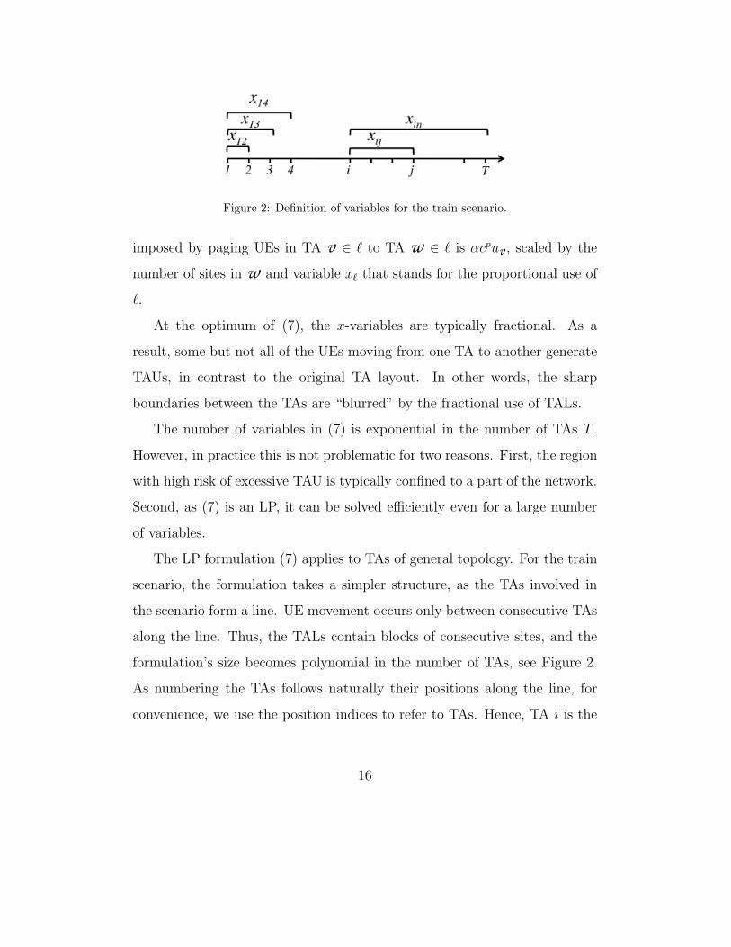
Figure 2: Definition of variables for the train scenario.
imposed by paging UEs in TA v $ " to TA w $ " is !cpuv , scaled by the
number of sites in w and variable x! that stands for the proportional use of
".
At the optimum of (7), the x-variables are typically fractional. As a
result, some but not all of the UEs moving from one TA to another generate
TAUs, in contrast to the original TA layout. In other words, the sharp
boundaries between the TAs are “blurred” by the fractional use of TALs.
The number of variables in (7) is exponential in the number of TAs T .
However, in practice this is not problematic for two reasons. First, the region
with high risk of excessive TAU is typically confined to a part of the network.
Second, as (7) is an LP, it can be solved e"ciently even for a large number
of variables.
The LP formulation (7) applies to TAs of general topology. For the train
scenario, the formulation takes a simpler structure, as the TAs involved in
the scenario form a line. UE movement occurs only between consecutive TAs
along the line. Thus, the TALs contain blocks of consecutive sites, and the
formulation’s size becomes polynomial in the number of TAs, see Figure 2.
As numbering the TAs follows naturally their positions along the line, for
convenience, we use the position indices to refer to TAs. Hence, TA i is the
16

ith TA on the line, without the calligraphic style in the notation that has
hitherto been used for sets. Each TAL is uniquely identified by its starting
and ending TAs, therefore the variable definition is simplified to xij for the
TAL containing i, j and all the TAs between them. The corresponding LP
formulation is given below.
min z (8a)
s. t.k$
i=1
T$j=k
xij = 1, k = 1, . . . , T (8b)
cu(hi,i+1
i$k=1
xki + hi+1,i
T$k=i+1
xi+1,k) % z, i = 1, . . . , T " 1 (8c)
!cpT$1$i=1
T$j=i+1
j$k=i
j$h=k+1
(uknh + uhnk)xij % #CP , (8d)
xij ' 0, i = 1, . . . , T, j = i, . . . , T. (8e)
Constraints (8b)–(8d) are respectively obtained by adapting (7b)–(7d).
For the train scenario, it is su"cient to account for UE movements between
adjacent TAs on the line, as can be seen in (8c). In (8d), paging is consid-
ered for all TA pairs of a line segment, and further over all the segments.
Apart from the non-negativity requirement, the numbers of variables and
constraints in (7a) are of O(T 2) and O(T ), respectively. Thus, the optimiza-
tion approach has very low complexity in the train scenario.
Consider two consecutive TAs, i and i+ 1. It is easily verified that there
are a total of i(T"i+1) TALs containing i, and, among them, i TALs do not
contain i+ 1. Thus, the amount of TAU generated by UE movement from i
to i + 1 depends on the proportional usage levels of the i TALs. Typically,
17

the values are strictly between zero and one at optimum, thus not all of the
UEs inside the train will perform TAU at a TA boundary, giving the desired
e!ect of TAU congestion mitigation.
5. TAL Optimization for Congestion Mitigation of Paging
The min-max optimization approach is not limited to congestion mitiga-
tion of TAU. It is easily adapted to reducing the risk of signaling congestion
in paging that may become of concern for scenarios where massive UEs are
populated densely in some area with little mobility. The paging overhead in
this area becomes considerably higher than that in the rest of the network.
To reduce the paging overhead, some type of area splitting needs to take
place. However, if the area would be in one common TA, such a split would
not be possible without reconfiguring the TAs into smaller ones. For clarity
in our discussion, we assume that every single site is a TA in the current
configuration. The assumption does not impose excessive TAU, because the
e!ect of “TA” of any size equivalently can be achieved by using a TAL con-
taining the corresponding single-site TAs [8, 17]. Thus, in this section, it is
assumed that non-overlapping TALs contain single-sited TAs. Each TAL has
the function of one TA a conventional sense. For mitigating paging conges-
tion, new (and smaller) TALs are created within the original ones, and their
proportional usage levels are determined by min-max optimization.
Let T = {1, . . . , T} be the set of single-site TAs in the TAL containing
the area with risk of paging congestion. As in the previous section, L is used
to denote the non-empty collections of elements of T . The other variable and
parameter definitions are reused as well. Note that within T , TAU is zero for
18

the mentioned configuration (single TAL containing all TAs of T ). Reducing
paging would lead to a positive amount of TAU, and the limit is denoted
by CUlim. The min-max LP formulation of paging congestion mitigation is
provided below.
min z (9a)
s. t.$!"L
av!x! = 1, v $ T (9b)
!cp$v"T
uv$!"L
av!aw !x! % z, w $ T (9c)
$v"T
$w"T :v #=w
cu(hvw$!"L
av!(1" aw !)x! + hwv$!"L
aw !(1" av!)x!) % CUlim,
(9d)
x! ' 0, " $ L. (9e)
The first set of constraints are identical to that of (7). Constraints (9c)
define, together with the objective, the maximum paging. For each single-
site TA w , the left-hand side of (9c) represents the total amount of overhead
generated to w because of paging UEs located in TAs other than w , due to
the use of TALs with multiple sites. The next constraint set is the aggregated
form of (7c) to represent the total TAU, bounded by the limit value in the
right-hand side.
The limit value in (9) and parameter # in (7) are not necessarily con-
sidered constants prior to running TAL optimization. In fact, the LP can
be solved repeatedly for a range of limit values. Doing so generates a set of
candidate solutions representing various levels of the trade-o! between con-
gestion reduction of TAU and the price of more paging, and vice versa (cf.
19

Pareto optimization).
In previous studies of applying TALs, e.g., [8, 16], the performance com-
parison relies heavily on the assumptions made on UE mobility and other
network parameters, because in general, UEs that are initially registered to
the same TAL by a site will spread out within the area defined by TAL. After
some time duration, the proportion of UEs belonging to the TAL will become
heterogeneous over the area, as a result of each UE’s individual movement.
Note that the amount of TAU and paging generated by a UE are both depen-
dent on the content of its TAL. Therefore, unless a very accurate mobility
model is available (which is hardly the case in many scenarios), the practical
performance of TAL may deviate significantly from the estimated one.
In our overlapping TAL scheme, the construction of the LPs ensures the
same proportional use of each TAL by all sites within the TAL. Therefore,
statistically the proportion of UEs of each TAL remains homogeneous with
the TAL’s area, meaning that the performance is insensitive to individual
UE movement. Provided that the location distribution and mobility pattern
of idle UEs are similar to those of active UEs, which is a well-accepted as-
sumption, the performance of the overlapping TAL scheme is conveniently
assessed. This makes the performance comparison both simple and unbiased,
and its validity is not impacted by mobility models.
6. Performance Evaluation
In this section we present results of performance evaluation of the pro-
posed TAL optimization framework. In Section 6.1, we provide performance
evaluation of TAU congestion mitigation for a train scenario. Next, the re-
20

sults of reducing TAU as well as paging congestion for a general network
topology are reported in Section 6.2.
In the performance evaluation, the overhead of a single TAU, cu, is set
ten times as much as cp [12]. Parameter ! is set to 0.05, i.e. 5% of the UEs
are paged. For all the scenarios, there is an underlying TA layout (possi-
bly implemented via TALs) that represents the most likely design in terms
of planning. Namely, the TA layout is the global optimum in minimizing
the overall signaling overhead (i.e., CP + CU). This optimum TA layout is
computed using the integer programming formulation in [27] and software
CPLEX [11].
Whereas comparing the performance of the proposed TAL scheme with
the underlying TA design gives insights, it is somewhat biased to the favor of
the former, because the latter is not optimized for signaling congestion but for
the overall signaling overhead. For this reason, the performance comparison
is conduced between overlapping TALs and a re-optimization of TA layout
for the objective metrics of this paper, that is, the TAs can be merged for
the objective function (7a) or split for the objective function (9a). This gives
an unbiased assessment of optimized overlapping TALs.
The trade-o! between the signaling overhead of TAU and paging has to
be dealt with in both the conventional TA scheme and the proposed over-
lapping TAL scheme. For the latter scheme, reducing TAU congestion by
using overlapping TALs results in overall higher paging in comparison to the
baseline TA design, and vice versa. This aspect is reflected by the limit pa-
rameters in (7), (8), and (9). For the limit parameter # in (7) and (8), the
minimum possible value is zero. In this case, no additional paging is permit-
21

ted, and consequently the only feasible solution is to reuse the baseline TA
design. That is, the conventional TA scheme and overlapping TAL scheme
coincide. When # increases, the concern of paging overhead is diminishing,
and both schemes will eventually coincide again, giving the same solution
with one single TA (or TAL) containing all sites with zero TAU overhead.
At this point, constraint (7d) is void, and increasing # further clearly has no
e!ect. A similar observation applies to the TAU limit in (9). Namely, the
two schemes coincide when the limit is zero for which the baseline TA design
is kept, or when the limit is very large such that the optimum for both is to
split TAs maximally with zero paging (but completely sacrifices TAU). Thus,
for each of the limit parameters, there is a maximum value of significance.
In our performance evaluation, for each limit parameter we first find its
maximum value of significance, using bi-section search for the given planning
scenario. Then, within the range of significance, we conduct computations for
500 equally-spaced values of the limit parameter, in order to give a compre-
hensive performance picture. The results represent, in fact, a large number
of possible options for the trade-o! between TAU and paging, both for the
conventional TA scheme and for the overlapping TAL scheme, allowing the
network operator to select the solution to implement, based on the operator’s
preference.
6.1. Results for a Train Scenario
To evaluate the performance of the proposed overlapping TAL scheme
for the train scenario, a railway path with five TAs {A,B,C,D,E} of 150
km in length is considered (see Figure 3). Each TA contains five sites. The
configuration is the optimum conventional TA design with minimum total
22

Figure 3: The train scenario.
signaling overhead, CU + CP , by solving the model in [27], for a baseline
scenario that does not account for the massive mobility of UEs due to train
movement. For this TA design, the total signaling overhead is 841.7, with
CU = 122 and CP = 719.7.
In the train scenario (Figure 3), a train moves from A to E having 600
passengers on-board. One example can be TGV Eurostar train which can
move at a speed up to 300 km/h and may carry up to 784 passengers [14].
After a main station in C, the number of on-board passengers is reduced
to 400. We assume that all passengers inside the train hold cell phones
belonging to the same operator. It takes about half an hour for the train to
pass the whole path (ignoring the time spent at the main station).
We aggregate the load and handover data resulted from the train move-
ment and add them to the baseline scenario. All the UEs in the train passing
each TA boundary add to the corresponding handover. The load is increased
accordingly, taking into account the proportion of time the train is spent in
each TA. For example, the train spends about 6 minutes in A, therefore the
load of A is increased by 600 ! 110 = 60, due to the fact that the handover
and load data should be specified for one hour period of time.
We apply LP formulation (8) to the train scenario for # $ [0, 0.8], which
is the range of significance for the scenario. Next, for the same range of
#, we re-design the TAs by minimizing the maximum TAU using objective
23
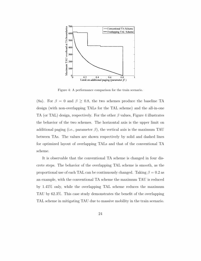
Figure 4: A performance comparison for the train scenario.
(8a). For # = 0 and # ' 0.8, the two schemes produce the baseline TA
design (with non-overlapping TALs for the TAL scheme) and the all-in-one
TA (or TAL) design, respectively. For the other # values, Figure 4 illustrates
the behavior of the two schemes. The horizontal axis is the upper limit on
additional paging (i.e., parameter #), the vertical axis is the maximum TAU
between TAs. The values are shown respectively by solid and dashed lines
for optimized layout of overlapping TALs and that of the conventional TA
scheme.
It is observable that the conventional TA scheme is changed in four dis-
crete steps. The behavior of the overlapping TAL scheme is smooth, as the
proportional use of each TAL can be continuously changed. Taking # = 0.2 as
an example, with the conventional TA scheme the maximum TAU is reduced
by 1.45% only, while the overlapping TAL scheme reduces the maximum
TAU by 62.3%. This case study demonstrates the benefit of the overlapping
TAL scheme in mitigating TAU due to massive mobility in the train scenario.
24

6.2. Performance Assessment in a Large-scale Network
For performance evaluation on a general and large-scale topology, we use
a realistic cellular network scenario for the downtown area of Lisbon. The
scenario is provided by the MOMENTUM EU project [19]. The network
consists of 60 sites and 164 cells. Figure 5(a) illustrates the network topology.
The sites are represented by disks. For every site, its cells are denoted by
squares. The location of a square in relation to the site center shows the
direction of cell antenna. The darkness of each cell is set in proportion to
its accumulated cell load. A link is drawn between two cells if there is any
handover between them, and the amount of handover is proportional to the
thickness of the link.
(a) (b)
Figure 5: An illustration of (a) Lisbon network topology and key statistics, (b) the under-
lying TA design.
25

Figure 6: Performance evaluation of TAU congestion mitigation.
Figure 5(b) illustrates the underlying TA layout (i.e., the optimum with
respect to the overall signaling overhead). There are seven TAs in the design;
these are used for creating overlapping TALs. Note that, in mitigating signal-
ing congestion of paging, the functionality of the conventional TA scheme is
implemented with non-overlapping TALs of single-sited TAs (see Section 5).
In this case, we will use the term TA group for the sake of clarity. Key statis-
tics of the TA design are as follows. The overall TAU overhead CU = 23849,
the overall paging overhead CP = 18603. The highest TAU between TAs,
denoted by CUmax, equals 5996, and the most congested site in paging has a
paging overhead of CPmax = 1058.
For parameter #, the range of significance in this case is [0, 0.56]. Formu-
lation (7) in Section 4 is solved with # varying within the range. The same
range is applied in re-optimizing TAs with the conventional TA scheme for
the same objective function (7a). The results are displayed in Figure 6 and
Table 2. In addition to signaling overhead, the table contains information of
26

Table 2: Performance comparison and computing time for TAU congestion mitigation.
" Conventional TA scheme Overlapping TAL scheme
Maximum TAU Time (ms) Maximum TAU Time (ms)
0.0 5963 - 5953 8
0.1 4109 52 537 12
0.2 2953 52 131 12
0.3 2423 76 62 12
0.4 1910 60 37 12
0.5 373 230 14 12
the computing time.
As was explained in the case of train scenario, the performance curves
coincide at the two ends. One immediately observes that the curve of the
overlapping TAL scheme is smooth, whereas that of the conventional TA
scheme has a stepwise shape. For the latter, the TAs may not overlap due
to the binary and transitive properties of the S matrix (Section 3). As a
result, the only possibility of reducing the maximum TAU is by merging
TAs. This inherent limitation of the conventional TA scheme leads to the
stepwise shape. Overlapping TALs, in contrast, can achieve “partial merge”
of TAs, by solving the optimization formulation (7), yielding a smooth curve
that significantly outperforms the conventional TA scheme.
For example, if the overall paging overhead is allowed to increase by 10%,
re-optimizing TAs by the conventional TA scheme reduces the peak TAU
between TAs from CUmax = 5996 to slightly above 4109. Using optimized
overlapping TALs, the peak is pushed down to 537, see Table 2. This is
27

only one seventh of the maximum TAU resulted from the conventional TA
scheme. Thus TAU signaling congestion can be e!ectively handled by the
proposed TAL scheme with little price paid for a higher amount of paging.
Examining the computing time in Table 2, one immediately observes that
solving (7) for TAU mitigation runs very fast, and the computing time is not
sensitive at all to the limit value. In fact, the overlapping TAL scheme runs
several times faster than the conventional TA scheme. In conclusion, the for-
mer has superior performance both in TAU mitigation and the computational
burden.
(a) (b)
Figure 7: An illustration of the design by (a) the conventional TA scheme and (b) over-
lapping TAL, for selected value of maximum TAU.
Figure 7 provides an illustration of the designs corresponding to the two
markers in Figure 6. The conventional TA scheme and overlapping TAL
28

Figure 8: Performance evaluation of paging congestion mitigation.
give the same level of peak TAU (approximately 2400) for selected solutions,
although the former has considerably higher paging. Figure 7(a) shows the
TA layout given by the conventional TA scheme; one can see this layout is
a simple merge of TAs 1-3 in Figure 5(b). The composition and usage of
TALs are shown in Figure 7(b). The original three TAs are still used, but to
lesser extent. In addition, TALs containing pairs of TAs are in place, with
the e!ect of reducing TAU peak between them. The illustration highlights
the e!ect of blurring TA boundaries by overlapping TALs.
As the last part of our performance evaluation, we apply the overlapping
TAL scheme for mitigating paging congestion, using Figure 5(b) as the base
layout. In this case, the TAs are assumed to be single-sited, and the grouping
in Figure 5(b) is implemented by means of non-overlapping TALs (see Section
5). Overlapping TALs are then created and optimized by formulation (9)
to achieve partial split within each TA group. The TA groups are also re-
optimized following the conventional principle of TA design; this corresponds
29

Table 3: Performance comparison and computing time for paging congestion mitigation.
# Conventional TA scheme Overlapping TAL scheme
Maximum paging Time (s) Maximum paging Time (s)
1.0 1058 - 1058 < 1
1.2 847 45 201 33
1.4 501 555 72 94
1.6 400 340 22 1881
1.8 340 517 11 259
2.0 324 378 6 384
to finding the optimal split (with sharp boundaries) for objective function
(9a). The performance comparison is given in Figure 8 and Table 3. For the
sake of compactness, the results represent the aggregated values over all TA
groups. Thus CUlim can be set in relation to CU of the baseline design. We
denote by $ the ratio between CUlim and CU . The range of significance for the
scenario is $ $ [1.0, 6.3].
In the figure, the horizontal axis is $, For example, $ = 2.0 on the axis
means that the CUlim = 2CU . The vertical axis represents the maximum
paging overhead generated by the sites. For each site, this overhead is the
amount of paging overhead sent by the site in order to locate UEs of other
sites. When $ = 1.0, the only feasible solution is to keep the baseline TA
groups, for which the maximum site paging equals CPmax. The maximum
decreases gradually in respect of $, and reaches zero (i.e., full split) when
$ ' 6.3. Note that in Table 3, $ is limited to 2.0, because the maximum
paging in the overlapping TAL scheme is virtually zero beyond this point.
30

In comparison to Figure 6, the performance curve of the conventional TA
scheme in Figure 8 is much smoother. This is because splitting a TA group
can be done with a much better granularity (e.g., one site at a time) than
merging TAs. Nevertheless, the performance is evidently inferior to that of
adopting overlapping TALs, as can be seen from Figure 8 and Table 3. The
overlapping TAL scheme is able to reduce the maximum paging much more
steeply in comparison to conventional split of TA groups. For example, the
former virtually eliminates paging, if the TAU is allowed to be doubled (i.e.,
$ = 2.0), whereas in the latter case the maximum paging is still above one
third of the baseline value, as shown in Table 3. Moreover, the magnitude
of the performance di!erence grows in $ for the range considered in the
table. As another comparison, recall that the average site paging of the
baseline design is approximately 310 (that is, CP divided by the number of
sites), and suppose we would like to bring the maximum paging level down
to this value, for which the two markers in the figure show the performance
of the two schemes. Using the conventional TA scheme (or equivalently non-
overlapping TALs), the TAU overhead has to be doubled. With optimized
overlapping TALs, the e!ect is achieved with merely a 13% increase in TAU.
Thus overlapping TALs provide an e!ective means of splitting hotspots for
avoiding paging congestion.
In Table 3, the computing time used by the overlapping TAL scheme is
up to 30 minutes. The major part of the time is attributed to the largest
TA group with 16 sites, see Figure 5(b). For this TA group, the LP (9)
contains 216 " 1 variables. Although the time range may not admit on-line
use, it remains reasonable in a planning stage, because typically a hotspot
31

of massive and close-to-static UEs can be predicted in advance. We observe
also that time values for the overlapping TAL scheme and the conventional
TA scheme are comparable in magnitude, and the former scheme runs faster
for all except one of the cases in the table.
7. Conclusions
We have proposed a scheme using overlapping tracking area lists (TALs)
and a min-max optimization approach for the purpose of mitigating signaling
congestion for location management in LTE networks. The optimization task
was formulated and computed by means of linear programming. As the key
aspect of the optimization framework, consistency in the proportional use of
TALs is maintained throughout the network, and consequently no assump-
tion or model of UE mobility is required in order to assess the performance of
overlapping TALs. Numerical evaluations of mitigating massive TAU as well
as paging congestion demonstrate that the proposed optimization framework
is very e!ective. Optimization of overlapping TALs significantly outperforms
the conventional TA scheme in signaling congestion. By providing high gran-
ularity in re-distributing the signaling overhead over the network area, TALs
open up a new dimension of freedom in location management.
An interesting line of extension of the current work is dynamic config-
uration of overlapping TALs. By monitoring TAU and paging statistics
and adapting the proportional use of TALs accordingly, the proposed TAL
scheme can be extended to form an automated process in location manage-
ment within the paradigm of self-optimization networks. This topic will be
addressed in our forthcoming research.
32

8. Acknowledgments
The work has been supported by CENIIT centrum of Linkoping Univer-
sity, the Swedish Research Council, and the Swedish Foundation of Strategic
Research.
References
[1] 3GPP. TS 23.002 – v9.1.0, Network Architecture, 3G Release 9, 2009.
http://www.3gpp.org/ftp/specs/archive/23 series/23.002/.
[2] 3GPP. TS 23.401 – v8.6.0, General Packet Radio Services (GPRS) en-
hancements for Evolved Universal Terrestrial Radio Access Network (E-
UTRAN) access, 3G Release 8, 2009.
http://www.3gpp.org/ftp/specs/archive/23 series/23.401/.
[3] 3GPP. TR 23.880 – v0.1.0, Stage2 for registration in densely-populated
area (RED), 3G Release 8, 2007.
http://www.3gpp.org/ftp/specs/archive/23 series/23.880/.
[4] I.F. Akyildiz, J.S.M. Ho, Y.B. Lin, Movement-based location update
and selective paging for PCS networks, ACM/IEEE Transactions on
Networking 4 (1996) 629–638.
[5] I.F. Akyildiz, J. McNair, J.S.M. Ho, H. Uzunalioglu, W. Wang, Mobility
management in next generation wireless systems, Proceeding of IEEE
87 (1999) 1347–1384.
33

[6] Y. Bejerano, M.A. Smith, J. Naor, N. Immorlica, E"cient location area
planning for personal communication systems, ACM/IEEE Transaction
on Networking 14 (2006) 438–450.
[7] E. Cayirci, I.F. Akyildiz, Optimal location area design to minimize reg-
istration signaling tra"c in wireless systems, IEEE Transactions on Mo-
bile Computing 2 (2003) 76–85.
[8] Y.W. Chung, Adaptive design of tracking area list in LTE, in: Pro-
ceeding of 8th IEEE International Conference on Wireless and Optical
Communications Networks (WOCN), Paris, 2011.
[9] I. Demirkol, C. Ersoy, M.U. Caglayan, H. Delic, Location area planning
and cell-to-switch assignment in cellular networks, IEEE Transactions
on Wireless Communications 3 (2004) 880–890.
[10] P. Garcia, V. Casares, J. Mataix, Reducing location update and paging
costs in a PCS network, IEEE Transactions on Wireless Communica-
tions 1 (2002) 200–209.
[11] ILOG CPLEX 12.2, User’s Manual, 2010.
[12] K. Kyamakya, K. Jobmann, Location management in cellular net-
works: classification of the most important paradigms, realistic simula-
tion framework, and relative performance analysis, IEEE Transactions
on Vehicular Technology 54 (2005) 687–708.
[13] T. Mach, R. Tafazolli, Mass mobility signaling congestion avoidance
mechanism using randomized time distribution of cell reselections, in:
34

Proceedings of International Conference on Telecommunications (ICT),
Marrakesh, 2009, pp. 238–242.
[14] Mitsubishi Electric, Tracking areas sizes and tracking area list optimiza-
tion, Technical Report in 3GPP TSG RAN WG3 Meeting, R3-071931,
2007.
[15] S. Modarres Razavi, D. Yuan, F. Gunnarsson, J. Moe, Performance and
cost trade-o! in tracking area reconfiguration: a Pareto-optimization
approach, Journal of Computer Networks 56 (2012) 157–168.
[16] S. Modarres Razavi, D. Yuan, F. Gunnarsson, J. Moe, Exploiting track-
ing area list for improving signaling overhead in LTE, in: Proceedings
of IEEE Vehicular Technology Conference (VTC Spring), Taipei, 2010.
[17] S. Modarres Razavi, D. Yuan, F. Gunnarsson, J. Moe, Dynamic tracking
area list configuration and performance evaluation in LTE, in: Proceed-
ings of IEEE Global Communications Conference Workshop (GLOBE-
COM Workshop), Miami, 2010.
[18] S. Modarres Razavi, D. Yuan, Mitigating mobility signaling congestion
in LTE by overlapping tracking area lists, in: Proceedings of the 14th
ACM International Conference on Modeling, Analysis and Simulation
of Wireless and Mobile Systems (MSWiM), Miami, 2011, pp. 285–292.
[19] IST-2000-28088 Momentum project. http://momentum.zib.de.
[20] Motorola, Long Term Evolution (LTE): A technical overview, Technical
White Paper, 2007.
35

[21] Z. Naor, H. Levy, Minimizing the wireless cost of tracking mobile users:
an adaptive threshold scheme, in: Proceedings of IEEE Conference on
Computer Communications (INFOCOM), San Francisco, 1998, pp. 720–
729.
[22] G.P. Pollini, I. Chih-Lin, A profile-based location strategy and its
performance, IEEE Journal on Selected Areas in Communications 15
(1997) 1415–1424.
[23] R. Prakash, Z. Haas, M. Singhal. Load-balanced location management
for cellular mobile systems using quorums and dynamic hashing, Wire-
less Networks 7 (2001) 497–512.
[24] NEC, Tracking area concepts and influence on paging load, Technical
Report in 3GPP TSG RAN2 Meeting, R2-070655, 2007.
[25] QUALCOMM Europe and T-Mobile, New SON user case: tracking area
optimization, Technical Report in 3GPP TSG RAN WG3 Meeting, R3-
071594, 2007.
[26] S. Subramaniam, G. Krishnamurthi, Load balancing location manage-
ment, in: Proceedings of IEEE International Conference on Communi-
cations (ICC), Helsinki, 2001, pp. 2835–2839.
[27] D.W. Tcha, T.J. Choi, Y.S. Myung, Location-area partition in a cellular
radio network, Journal of the Operational Research Society 48 (1997)
1076–1081.
[28] T. Winter, Mobility management and network design for UMTS, in:
36

Proceedings of IEEE International Symposium on Personal, Indoor and
Mobile Radio Communications (PIMRC), 2004.
[29] W. Wang, I.F. Akyildiz, G.L. Stuber, B. Chung, E!ective paging
schemes with delay bound as QoS constraints in wireless systems, Wire-
less Networks 7 (2001) 455–466.
[30] V.W.S. Wong, V.C.M. Leung, Location management for next generation
personal communication networks, IEEE Network 14 (2000) 18–24.
[31] Y. Zhang, M. Fujise, Location management congestion problem in
wireless networks, IEEE Transactions on Vehicular Technology 56 (2007)
942–954.
[32] ZTE, Self optimization for tracking areas, Technical Report in 3GPP
TSG RAN WG3 Meeting, R3-071415, 2007.
37