mit radiaton lab series v20 electronic time measurements
TRANSCRIPT
ASSACHUSETTS INSTITUTE OF TECHNOLOGY
RADIATION LABORA ORY SERIES
Lou Is N. RIDENOUR, Editor-in-Chief
ELECTRONIC T1MJ 3 MEASUREMENTS

i ,.
, / +’
MASSACHUSETTS INSTITUTE OF TECHNOLOGY
RADIATION LABORATORY SERIES
Board of Editors
LOU IS N. RIDENOUR, &Mor -kCh~ef
GEORGE B. COLLINS, Deput y Ed it or -i n-Chi ef
BRITPON CHANCE, S . A. GOUDSMIT) R. G. HERB , HUBERT M. JAMES, JULIAN K. KNIPP,
JAMES L. LAWSON, LEON B. LINFORD , CAROLG . MONTGOMERY, C. NEWTON, ALBERT
M. STONE, Lours A. TURNER, GEORGE E. VALLEY, J R., HERBERT H. WHEATON
1 .
2 .
3 .
4 .
5 .
6 .
7 .
8 .
9 .
1 0 .
1 1 .
1 2 .
1 3 .
1 4 .
1 5 .
1 6 .
1 7 .
1 8 .
1 9 .
2 0 .
2 1 .
2 2 .
2 3 .
2 4 .
2 5 .
2 6 .
2 7 .
2 8 .
RADAR SYSTEM ENGINEERING—Ridt? nOUr
RADAR AIDS TO NAVIGATION—Hall
RADAR Br!xcom—RoberLs
LoRAN—PieTce, McKen zie, an d Woodward
PULSE GENERAToRs ~la soe a nd Leb acqz
MICROWAVE MAGNETRONS—COllinS
KLYSTRONS AND MICROWAVE TR1oDEs—Ham ilionj Knipp, and Kuper
PRINCIPLES OF MICROWAVE CIRculTs—Montgomery, Dick e, an d Pu rcell
MICROWAVE TRANSMISSION CIRcuITs—Ragan
WAVEGUIDE HANDBooK—MaTcu viLz
TECHNIQUE OF MICROWAVE MEAsu REMENTs—Montgomery
MICROWAVE ANTENNA THEORY AND DESIGN—SdUc?r
PROPAGATION OF SHORT RADIO WAvEs—Kc??
MICROWAVE DUPLEXERS—Snu llin a nd Mon t gome ry
CRYSTAL Rectifiers—Torrey a nd Whitmer
MICROWAVE MIXERS—POUnd
COMPONENTS HANDBooK—B~ack bu rn
VACUUM TUBE ,kMPLIF IERs -Va lle y a n d Wa zlm a n
WAvEFoRM—Chance, Hughes , MacNichOl , S’ayre, and Williams
ELECTRONIC TIME MEASUREMENTS—Cha nCt?, Huls iz er , MacNichol ,
and Witliams
ELECTRONIC I t +s ’r riuME iws -6’r eenwood , Hold am , a nd MacRae
CATHODE RAY TUBE DISPLAYS—SOlk r, S ta rr , a n d Valley
MICROWAVE RECEIVERS—Van Voorhis
THRESHOLD SIGNALS—LawSOn an d Uhlenbeck
THEORY OF Servomechan isms—J ames , Nichols, and Phillips
RADAR SCANNERS ND RADoMEs—Cady, Ka relilz, a n d Tu r n er
COMPUTING MECHANISMS AND LINKAGEs—&Iobod a
lNDEx—Henney
.

ELECTRONIC TIME
MEASUREMENTS
Edited by
BR ITTON (XA~CE
ASSISTANT PI+OFESSoR OF BIOPHYSICS, UNNEF iSITY OF PENNSYLVANIA
ROBERT I. 13ULSIZER
DEPARTMENT OF PHYsICS, MASSACHUSETTS INSTITUTE OF TECHNOLOGY
EDWARD F . MAcNICHOL, J R .
DEPAliTMENT OF BIOPHYSICS, UNIVERSITY OF PENNSYLVANIA
FRE13ER ICK C. WILLIAMS
PROFESSOR OF ELECTRO-TECHNICS, MANCHESTER UNIVERSITY
OFF ICE OF SCIENTIF IC RESEARCH AND DEVELOP MENT
NATIONAL DEF ENSE RESEAR CH COM IITTEE
FIRST 1 3DITION
NEW YORK .
TORONTO . LONDON
McGRAW HILL BOOK CO Ilf PAiVY, INC.
1949
ELECTRONIC TIME LIEASUREMENTS
cOPYRI HT, 1949, BY THE
IVICGRAW-HILL BOOK COMPANY, lXC.
PRINTED IN ‘THE L-XITED ST TES OF AMERIC
All rights resewed . Th is ook, or
parts th~reojf, )nay not
be reproduced
in any fnrm withou l prrrn ission Oj
(he pub/ isher .~ .
TFIE MA hE PRESS COMP,4NY, YORK, PA.
m

ELECTRONIC TIME MEASUREMENTS
EDITORIAL STAFF
BIUTTON CIIANCE
EDITOR
ROBERT I. HULSIBER
VOLUMEEDITOR
E. F. MACNICHOL, J R . VOLUME EDITOR
F . C. WILLIAMS
VOLUME EDITOR
CONTRIBUTING AUTHORS
BRTTTON CEANCE
RICHARD N. CLOSE
DAVID GALE
J , V. HOLDAM
ROBERT I. HULS IZER
HILLARD B. HUNTINGTON
WILLIAM J . J ACOBI
WILLIAM B. J ONES
ROBERT C. KELNER
ROBERT B. LEACHMAN
E. F . MACNICHOL, J R .
J . ROBERT ROGE S
DAVID SAYRE
WALTER SELOVE


Foreword
)
I
T
EE
development of radar and rela ted techniques dur ing Wor ld War II
resulted not only in hundreds of radar set s for military (and some for
possible peacet ime) use but also in a grea t body of informat ion and new
techniques in the elect ron ics and high-frequency fields. Because this
basic mater ia l may be of grea t value t o science and engineer ing, it seemed
most impor tant to publish it as soon a secur ity permit ted.
The Radiat ion Labora tory of MIT’, which opera ted under the super -
vision of the Nat ional Defense Research Commit tee, under took the grea t
t ask of pr epa rin g t hese volumes.
The wor k descr ibed her ein , h owever , is
the collect ive result of work done at many labora tor ies, Army, Navy,
u niver sit y, a nd in du st ria l, bot h in this count ry and in England, Canada,
and other Domin ions.
The Radiat ion Labora tory, once its proposa ls were approved and
fin an ces pr ovided by t he Office of Scien tific Resea rch a nd Developmen t,
chose Louis N. Ridenour as Editor -in-Chief to lead and direct the ent ire
project . An editor ia l staff wa then selected of those best qualified for
this type of task. Fina ly the authors for the var ious volumes or chapters
or sect ions were chosen from among those exper t s who were int imately
familiar with the var ious fields, and who were able and willing to r te
the summar ies of them. This ent ire sta ff agreed to remain a t work at
MIT for six months or more after the work of the Radiat ion Labora tory
was complete. These volumes sta~d as a monument to this group.
These volumes serve as a memor ia l to the unnamed hundreds and
thousands of other scient ists, engineers, and others who actually car r ied
on the research , development , and engineer ing wor k the results of which
are herein des r ibed. There were so many involved in this work and they
wor ked so closely t oget her even though oft en in widely sepa ra ted labor a-
tor ies that it is impossible to name or even to know those who cont r ibuted
t o a pa rt icu la r idea or developmen t.
On ly cer ta in on es who wr ot e r epor ts
or a r t icles have even been ment ioned. But to all those who cont r ibuted
in any way to this grea t coopera t ive development enterpr ise, both in this
count r y and in England, these volumes are dedica ted.
L A. DUBRIDGE
v i i


Preface
T
HE preserva t ion of the techn ica l advancements represen ted by the
precision circu its of the Radiat ion Laboratory was made possible
th rou gh th e for esigh t of Drs. Rabi and DuBr idge. Th ey appoin ted a com-
m it tee con sist in g of Dr s. L. J . H awor th , G. E . Va lley, a nd t he edit or t o con -
sider t he scope an d con ten t of a ser ies of book s on cir cu it s, wh ich r esu lt ed
in Vols. 17–22 of t he Ser ies. At t he t ermin at ion of h ost ilit ies a n in ten sive
wr it ing program was put in to opera t ion under the able leadership of
Dr . L. N. Ridenour and resu lted in the complet ion of the Ser ies on an
a cceler ated sch edu le. This sch edu le r equ ired t he u se of as ma y au th or s
as possible and has inevitably resu lted in discon t inuit ies in the method
of t r ea tm en t and scope of mater ia l.
The object of th is book is to presen t the method of approach to the
problems of t ime and distance measurement by manual and au tomatic
m ea ns, a nd t he pr act ica l cir cu it s em ployed for t hese pu rposes.
In addi-
t ion , impor tan t tech niques of pu lse data t ransmission and pu lse-ampli-
tude cancella t ion methods are included. The accura te measurement
of shor t t ime intervals is not a new subject since many exper imen t s have
been d voted to the accura te determinat ion of the velocity of ligh t .
The simplifica t ion and increased precision possible th rough the se of
cir cu it t ech niqu es of Vol. 19 of t he Ser ies h ave led t o t im e-m ea su rem en t
techn iques that have resu lted in pract ica l and accura te radar distance-
finding and data-t r ansmit t ing systems. Since the character ist ics of
these circu its depend upon those of the radar system, the book is in tr~
duced by a survey of techn iques for radio distance and speed measure
ment . The mater ia l then cont inues with a survey of basic techniq es
and methods in pu lse t ime measurement , including the genera t ion of
fixed and movable t iming markers and their applica t ions to manual and
a ut omat ic t im e mea su remen ts.
The use of these techniques for pre-
cision data transmission and for the relaying of the radar PPI to remote
points is next presen ted, and the book concludes with a discussion of
the use of superson ic delay devices for the cancella t ion of recu r ren t
waveforms.
Ma ny of t he developm en ts descr ibed in t his volume a re con tr ibu tion s
from other labora tor ies in th is coun t ry or in the United Kingdom. It
is a pleasure to acknowledge the excellen t suppor t to th is project by th e
Brit ish Laborator ies, and especia lly Telecommuni at ions Research
ix

x
PREFACE
Establishment . Through their generosity severa l exper t s have visited
this laboratory and have cont r ibuted much useful informat ion, and,
in fact , thk book has drawn heavily upon TRE repor t s.
Ou r gr at it u de
is due Sir Rober t Watson Wat t , D s. W. B. Lewis and B. 1’. Bowden.
and F. S. Bar ton for st imulat ing and author izing this excellen t exchange
of informat ion which required severa l visits of Dr . F. C. Williams and
others.
The for eword has indicated the difficulty of giving proper credit t o
all tho~ who cont r ibuted to the writ ing or to the exper imental develop-
ments that have made this work possible. However , r eferences in the
t ext have been made to journa l papers on rada and associated subjects
and declassified r epor ts on r ada r.
Many of the cont r ibutors t o this volume gave up indust r ia l posit ions
or academic fellowships in order t o complete their cont r ibut ions and
much credit is due them for this sacr ifice.
The authors also wish to
express their gra t it ude to those who cont r i u ted por t an t background
mater ia l from which the final manuscr ipt was written, E. B. Hales,
C. L. Longmire, F. Coffin , L. Bess, R. N. Close, 1. Sudman, and J . R,
Roger s. The speed of this program would have been impossible without
the exper t assistance of the product ion depar tment under C. Newton.
The efficiency of the typing pool under M. Dolbeare and P. Phillips and
the draft ing room under Dr . V. J osephson has been of grea t assistance.
In addit ion, t he Tech nical Coor din at ion Group under Dr . Leon Linford
has done much to ensure a coordina ion of style and a maintenance of
standard.
The authors wish t o name specifically t he following edit or ia l
assistants, product ion assistants, and secreta r ies whose aid has been
invaluable in the prepara t ion of this book: Nora Van der Gr en , J oan
Br own, J oan Leamy, Helene Benvie, Ter esa Sheehan , Barbara Davidson,
A few waveform phot ogr aphs have been used t o illust ra te this volume.
Nearly all these were taken by C. M. Connelly and the associa ted photo-
graphic work was car r ied out by P. D. Bales and credit to their work is
gratefully acknowledged.
THE AUT ORS.
C-RIDGE, MASS.,
Mag, 1946.

Contents
FOREWORD . . . . . . . . . . . . . . . . . . . . . . . . . . . . . vi
PREFACE . . . . . . . . . . . . . . . . . . . . . . . . . . . . . ..xi
CUP.1. INTRODUCTION. . . , . . . . . . . . . . . . . . . . . . 1
CHAP.2. RADIO DISTANCEANDSPEED MEASUREMENTS . . . . . 4
DISTANCE MEASUREMENTS . . . . . . . . . . . . . . . . . . . . ..4
2 .1 . In t rodu ct ion . . . . . . . . . . . . . . . . . . . . . . . . 4
22. Defin it i n s of Meth ods of Dis ta n ce Measu rem en t . . . . . 4
23. Tim e Modu la t ion an d Demodu la t ion . . . . . . . 5
2 .4 . Ph as e Modu la t ion and Demodula t ion . . . . . 7
2.5. F requency Modula t ion and Demodula t ion. . . . . . . 13
2.6. Summary . . . . . . . . . . . . . . . . . . . . . . . . . 15
SPEED MEASUREMENTS . . . . . . . . . . . . . . . . . . . . . ..16
2 7 . Con t in u ou s -wave Sys tem s . . . . . . . . . . . . 16
2 .8 . Pu ls e Sys tem s—In tern a lly Coheren t . . . . . . . . . 18
29. Pulse Systems—Externally Coheren t , . . . . . . . . . . . . 20
SPEED AND DISTANCE MEASUREMENTS. . . . . . . . . . . . . . . 24
210. Phase and Rate of Change of Phase . . . . . . . . . 25
2.11. Time Demodula t ion and Different ia t ion . . . . . . . . , . 26
2.12. Phase and Frequency Demodulat ion . . . . . 26
2.13. Time, Phase, and Frequency Demodulat ion. . . 28
2.14. Considera t ions Applying to In termit t ent Data. . . 28
POSITION-F INDING . . . . . . . . . . . . . . . . . . . . . . . . .2 9
2 . 1 5 .
2 1 6 .
2 1 7 .
2 . 1 8 ,
2 . 1 9 .
In t roduct ion . . . . . . . . . . . . . . . . . . . . . ...29
Pulse-echo Systems . . . . . . . . . . . . . . . . . . ...31
Radar Beacons .,...... . . . . . . . . . . . ...33
Hyperbolic Systems . . . . . . . , . . . . . . . . . ...34
An Omnidirect ional Beacon Using Time Modulat ion . . . 36
CHAP. 3. TECHNIQUES OF PULSE TIME MEASUREMENTS. . . . . 37
TRANSMISSION AND RECEPTION. . . . . . . . . . 37
3 ,1 . Tran sm iss ion of Pu ls es . .“ . . . , 37
3 .2 . Th e Recep t ion of Pu ls es . . . . . . . . . . . . . . . 99
xi
- ..
- —.-

xii
CONTENTS
SYNCIIRONIZATION . . . . . . . . . . . . . . . . . . . . . . . . . .42
3.3. Synchroniza t ion of the R-f Pulse Genera tor . . . . . . . 43
3.4. Gontrol of the PRF by the Timing Waveform. . . . . . 44
3.6. Zero Calibra t ion . . . . . . . . . . . . . . . . . . . . . 45
3.7. Remote Cont rol of Synchroniza t ion . . . . . . . . . . . . 46
TIME MODULATION . . . . . . . . . . . . . . . . . . . . . . . . .47
3.8. Siigle-sca le Time Modula t ion . . . . . . . . . . . . . 47
3.9. Mult iple-sca le Time Modula t ion . . . . . . . . . . . . . 48
T)w C%zracteristics of Com ponents . . . . . . . . . . . . . . . 50
3.10. Timing Standards . . . . . . . . . . . . . . . . . . ...50
3.11. Vacuum Tubes . . . . . . . . . . . . . . . . . . . . . . 51
3.12. Calibrated Su assemblies. . . . . . . . . . . . . 52
Fized and Modulated T im ing Pukes . . . . . . . . . 53
3.13. Fixed Pulses . . . . . . . . . . . . . . . . . . . . ...54
3.14. Single-sca le Time-modula t ion Circuit s . . . . . . . . 55
3.15. Double-sca le Time-modula t ion Circuit s. . . . . . . 58
3.16. Mult iple-sca le Systems . . . . . . . . . . . . . 61
TIME Demodu la t ion . . . . . . . . . . . . . . . . . . . . . . . .62
3.17. Tim e Select ion and Discr iminat ion. . . . . . . . . . . . . . 62
SOME PROPERTIES OF C.4THonE-RAY-’r r -mE DmPuYs. . . . . . . . . . . 64
3.18. Time Select ion and Discriminat ion. . . . . . . . . . . 64
3.19. Time Demodula t ion . . . . . . . . . . . . . . . . . . . . 64
320. TimeModula t ion . . . . . . . . . . . . . . . . . . ...65
CHAP. 4 . GENERATION OF FIXED INDICES. . . . . . . . . . . . 69
SINGLE-FREQUENCY MARKER GENERATORS . . . . . . . . 69
4 . 1 . Sinusoidal Oscilla tors and Amplitude Compara tors. . . 69
4.2. Regenera t ive Amplitude-compar ison Circuit s . . . . . . 73
4.3. Claas C Crysta l Oscilla tor and Blocking Oscilla tor . 75
4.4. Gaa-tet rode 300-cps Relaxat ion Oscilla tor . . . . 76
4.5. Blocking Oscilla tors.. . . . . . . . 78
4.6. Mult ivibra to s . . . . . . . . . . . . . . . . . . . . . . . ~
MULTIPLE-FREQUENCY MARKER AND TRIGGER GENERATORS . . . . . . 81
4.7. Frequency Division . . . . . . . . . . . . . . . . . . . . 81
4.8. Frequency Divisien and Pulse Select ion . . . . . . 87
4.9. Separa te Oscilla tors and Pulse Selector . . . . . 89
4.10. Synchroniza t ion by Automat ic Frequency Tracking . . . . . . 95
4.11. Lightweight Direct -reading Loran PRF Genera tor . . . . . . 100
4.12, In ject ion Feedback Divider for Oboe PRF . . . . . . . . 103
CONTENTS
...
Xlll
GROUPED-MARKER GENERATION. . , . . . . . . . . . . . . . 1 0 6
4.13. Single-frequen t y Grouped-marker Genera tors . . . . . . 107
4.14. Mult iple-frequency Grouped Markers. . . . . . . . . . 109
CHAP. 5. GENERATION OF MOVABLE INDICES-SINGLE-SCALE CIE
CHITS . . . . . . . . . . . . . . . . . . . . . . . . ...111
INTRODUCTION . . . . . . . . . . . . . . . . . . . . . .1 1 1
51. Applica t ions of Time-modulated Indices . . . . . . . 111
52. System Requirements and Defin it ion of Er ror . . . . . . . 112
VOLTAGE SAWTOOTH CIRCUITS. . . . . . . . . . . . . . .114
5 .3 . A Ga ted Miller In tegra tor w th a Mult ia r Comparator . 114
5.4. A Gated Mult istage Miller n tegra tor with a Cathode-coupled
Double-t r iode Compara tor . 116
5.5. Self-gat ing Miller In tegra tor -The Phantast ron . . . . 118
5.6. Self-gat ing Miller In tegrata~The Precision Sana tron 124
5.7. Bootst rap Tr iangle Genei ator with Diode Comparator 125
58. The Delay Mult ivibra tor . . . . . 131
Variable Delay L ine . . . . . . . . . . . . . . . . . . . . . . . . 132
5.9. Superson ic Delay Tank. . . . . . . . . . . . . . . .132
SINUSOIDAL OSCILLATOR RANGE CIRCUITS . . . . . . . . 135
510. LC-oscilla tor , Phase Modulator , and Compara tor . . . . 135
5.11. The Var iable-frequency Oscilla tor . . . . . . . 137
5,12. A Compar ison of Some Single-scale Circu its. . . . . 140
&AF. 6. GENERATION OF MOVABLE INDICES—CIRCUITS . . . . 142
PHAS MODULATION AND AMIJ LITUDE COMFARISCN. . . . . . 142
61. MeachamR angeU nit .... . . . . . . . . . . . . ...142
&2. Precision Ranging Indica tor . . . . : 147
6.3. Scale Coordinat ion by Frequency Division . . . . 153
6.4. Sine-wave Tracking.. .,. . . . . .155
6.5. Three-scale Phase-modulat ion System . . 157
CIRCULAR-SWEEP DISPLAYS AS A MRTHOD OF PHASE MODULATION AND
AMPLITU~E COMPARISON.,,.. . . . . . . . . . . . . . . . . .161
6,6. Circu lar -sweep Time Modulators, SC R-584 . . . . . 161
STEP-INTERPOLATION TIME MODULATION. . . . . . . 164
6 . AN/APS-15 Range Unit ,. .’. . .164
6.8. Lightweight Direct-reading Loran Indica tor . . 169
6.9. Summary . . . . . . . . . . . . . . . . . . . . . . ...174
xiv CONTENTS
CHAP. 7. MANUAL MEASUREMENTS. . . . . . . . . . . . . . . . . 176
GENERAL CONSIDERATIONS . . . . . . . . . . . . . . . . . . . . .. 1 7 6
INTRODUCTION . . . . . . . . . . . . . . . . . . . . . . . . . .. 1 7 6
7.1. Uses . . . . . . . . . . . . . . . . . . . . . . . . ...177
CHARACTERISTICS OF Dm PLAYS AND Cum+oRS. . . . . . . . . , . . . . 1 7 8
7.2. General Considera t ions. . . . . . . . . . . . . . . . . . 178
7.3. Indices, . . . . . . . . . . . . . . . . . . . . . . ...180
7.4. Circular Sweeps . . . . . . . . . . . . . . . . . . . . . . 184
7.5. Linear Sweep and Synchronized Presenta t ion . . . . . . . . . 185
ACCURACY CONSIDERATIONS. . . . . . . . . . . . . . . . . . .. 1 8 5
7 6 . Gen era l Con s id e r a t ion s . . . , . . . . . . 1 8 6
7 7 . De fle c t ion -m odu la t ed Disp lay an d Defle c t ion -m odu la t ed In dex . 1 8 7
7 8 . De fle c t ion -m odu la t ed Sign a l an d Mech an ic a l In dex. . . 1 9 0
7 .9 . De fle c t ion -m odu la t ed Sign a l an d In t en s it y-m odu la t ed In dex 1 9 0
7 .1 0 . J u xt apos it ion of In t en s it y -m odu la t ed Sign a l an d In dex 1 9 0
7 .1 1 . Su pe rpos it ion of S ign a l an d In dex in De flec t ion -m odu la t ed
Disp lays . . . . . . . . . . . . . . . . . . . . . .. .1 9 5
7 .1 2 . Re se t Er r o r wit h In t e rm it t e n t Da t a an d wit h Two-coord in a t e
7 .1 3 . Sum m ary an d Com pa r is on of Met h od s . . . . . . . . . . . . 1 9 9
TRACKING METHODS . . . . . . . . . . . . . . . . . . . . . . . . 2 0 0
7 .1 4 . Con t in u ou s Da t a . . . . . . . . . . . . . . . . . . . . . . 2 0 0
7 15 . In t e rm it t e n t D a t a . . . . . . . . . . . . . . . . . . . . . 2 0 6
7 .1 6 . Com pa r is on of Me t h od s , . . . . . . . . . . ; . . . . 2 1 3
FIXED INDICES FOR MANUAL TIME MEASU EMENT. . . . . . . . . . . 2 1 5
7.17. A-scope . . . . . . . . . . . . . . . . . . . . . . . . . . 215
7,18. J -scope . . . . . . . . . . . . . . . . . . . . . . . ...216
719. Plan-posit ion Indica tor with Mechanica l Scale. . . . . . . . . 219
7.20. Elect ronic Time Marks. . . . . . . . , . . . . . . . 219
MOVABLE TRACKING MARKS FOR MANUAL TIME MEASUREMENT. . . . . . 22o
Direcl Track ing, . . . . . . . . . . . . . . . . . . . . . . ...220
721. In t roduct ion . . . . . . . . . . . . . . . . . . . . . . . 22o
7.22. Movable E lect ronic Marks . . . . . . . . . . . . 222
7.23. Detai ed Circuit Descr ipt ion of Falcon . . . . . . . . . . 225
7.24. A/R-scope . . . . . . . . . . . . . . . . . . . . . . 231
7.25. A-scope Presenta t ion Used in Brit ish CMH System . . . . . . 238
7.26. Systems Using a J -scope with a PPI or B-scope . . . . . . . 243
Track ing with Interm ittent Data. . . . . . . . . . . . . 247
7.27. Aided Trackin g with In t rm it ten t Da ta . . . . . . . . . . . . . 247
7.28. T o-coordin a te Track in g. . . . . . . . . . . . . . . . . . 251
CONTENTS
xv
Especially Accurate T im e-m easuring S ystem s . . 261
7 .29. In t rodu ct ion . . . . . . . . . . . . . . . . . .. 261
730. Tim in gS equ en ce . . . . . . . . .,............264
7 .31. Circu it Deta ils of Lora n In d ica tor . 267
CHAP. 8. TECHNIQUES OF AUTOMATIC TIME MEASUREMENT 275
INTIIODUCTION . . . . . . . . . . . . . . . . . . . . 275
81. Au tom a t ic vs . Man u a l Measu rem en t s . 275
82. Gen era l Tech n iqu e of Au tom a t ic Tim e Mea su rem en t . 276
83. Na tu re of Da ta an d It s Effect on Perform an ce , 278
AUYOMATIC TIME MEASUREMENT WTTH NORMALLY CONTINUOUS DATA. 2 79
Design oj Function Unit
8,4. Genera l Theoret ica l Sta tement of the Problcm.
8.5. Single-in t egra tor Funct ion Unit
8.6. Double-in tegra tor System.
8.7. Effect of Addit ion l Smoothing
88. Elect r ica l In tegra tors.
89. Memory and Coast .
810. Mechan ica l Funct ion Units
,.. . . 279
279
,..
280
282
286
,.. 291
,..
304
. . , . .
3 0 5
T im e Discrim inators . . . . . . . . . . . . . . . . . . . . . . . .308
8.11. Gepera l Considera t ions. . . 308
8.12. Simple Time Discr iminators. 309
813. Time Discr iminators Consist ing of Separa t e Time Selectors and
Detectors . . . . . . . . . . . . . , . . . . . . . ...314
8.14. Time Discr imina tors with Time Selectors, Pulse St ret cher , and
Narrow-band Pulse Amplifica t ion 317
8.15. Time Select ion . . . . . . . . . . . . . . . . . . . . ...321
Target S election . . . . . . . . . . . . . . . . . . . . . . . . 325
8.16. Genera l Considera t ions. . . . . . . . 325
817. Pract ica l Examples of Automat ic Target Select ion . . . 330
S ummary . . . . . . . . . . . . . . . . . . . . . . . . . . . .337
8.18. System Planning . . . . . . . . . . . . . . . . . . . . . 337
CHAP. 9. SYSTEMS FOR AUTOMATIC TIME AND POSITION MEAS-
UREMENT . . . . . . . . . . . . . . . . . . . . . ...341
PRACTICAL SYBTEMBFOR AUTOMATIC TEWE MEASUREMENT 341
9 .1 . ARO E lect r ica l Sys tem . . .342
9.2 . Br it ish Oboe E lect r ica l Sys tem . 348
9.3 . E lect rom ech an ica l Sys tem s . 357
POSITION ERROR DETECTORSAND INDICATORS. ~. 367
9.4 . Gen era l Con s id era t ion s . . . . . . . . . . . . 367
xvi
CONTENTS
9.5. Design Requirements. , . . . 368
96. Manual Tracking Systems. . . . 371
97. Automat ic Tracking Systems . . . . 376
T ACKING ON GEOUI=EDou PERIODICALLY INTERRUPTED DATA “. .-. 378
9.8. In t roduct io n........ . . . . . . . . ...”..... 378
9.9. Automat ic Time Measurement on Grouped Data . 380
9.10. Example of Automat i Range Tracking on Grouped Data. 386
9 11. Automat ic Angle-posit ioning with Grouped Data. . . . 389
CHAP. 10. SP ECIAL DATA-TRANSMISSION SYSTEMS. . . . . . . . 391
INTRODUCTION . . . . . . . . . . . . . . . . . . . . . . . . .. 391
SHORT-IMSTANCE WIRE DATA TIiANSWSSION . . . . 39i
10.1. Telemeter ing . . . . . . . . . . . . . . . ..3!)1
10.2. Transmission of Cont inuous Rota t ion . . . . 393
10.3. Follow-up Systems. . . ,395
10.4. Character ist ics of the Transmission Circuit s. . . . 397
RADIO DATA TBANSMMSION. . . . . . . . . . . . . . . ,3g8
10.5. In t roduct ion . . . . . . . . . . . . . . . . . . . . . . .. 398
106. A Pulse Remote-cont rol System . . . . . 400
10.7. Radiosonde . . . . . . . . . . . . . . . . . . . . . . . .408
10.8. A Brit ish Omnidirect ional Beacon . . . . . . . . 410
CRAP 11.
RELAY RADAR SYSTEMS. . . . . . . .417
TIME-MODULATED S INE-COSINE SYSTEM. . . . . . . 417
1 1 . 1 .
Principle Of Opera t ion .. . . . . . . . ,417
11.2. The Synchronizer . . . . . . . . . . . . . . . . . . . . .424
11.3. Receiving Equipment . . . . . . . 426
11.4. Synchron zing-pulse Decoding Circuit s . . . . . 426
11.5. Sequencing Circuit s a d Linear Delays . . . . . . . 429
11.6. Step-gate Tracking Ckcuit s. . . . . . . . . 433
11.7. Modula tors and Bidirect iona l Switch Detectors . . . . . . 435
11.8. Arms Resolver and Servoamplifier . . . . . . . . . . . . . . 438
11.9. Performance . . . . . . . . . . . . . . . . . . . . . . .. 439
11.10. Later Developments in Receiving Equipment . . . . . . 44o
PEAsE-bronuU’rED P ULSE SYSTEM. . . . . . . . . . . . . . 442
11.11 . I n t roduct ion . . . . . . . . . . . . . . . . . . . . . . .. 44
11.12. Pulse Representa t ion of Phase-m dula ted Sinusoids . . . . . 442
11.13. Discussion of Phase-shift er System. . , . . . . . . . . . . 443
SI~PLKFIED RELAY RADAR SYSTEM FOR coMTAm -sF EEn ROTATION . . , . 450
11.14, ln tmduct ion. ..,... . . . . . . . . . . . . . . . ..45o
11.15 .Deta ils of the System. . . . . . . . . . . . . . . . .451
CONTENTS
xvii
C-W RELAY RADAR SYSTEM . . . . . . . . . . . . . . . . . . . . .. 458
11 . 1 6 . General Descr ipt ion of Transmit t er Funct ions. . . . . . . . . 458
11.17. General Descr ipt ion of Receiving Equipment . . . . . . . 459
11.18 .Details of t he System. . . , . . . . , . . . . , .461
11.19. Remarks nd Comments on the System. . . . . . . . . . 47o
CEIAF . 12. DELAY AND CANCELLATION OF RECURRENT WAVE
TRAINS . . . . . . . . . . . . . . . . . . . . . . ...471
12.1. In t roduct ion . . . . . . . . . . . . . . . . . . . . . .
471
,-
THE DELAY LINE . . . . . . . . . . . . . . . . . . . . . . . . . .475
Design ojDelay L ine for Cancellation . . . . . . . . . . . . . . . . 475
12.2. Int roduct ion . . . . . . . . . . . . . . . . . . . . . . .. 475
12.3. Echo Eliminat ion . . . . . . . . . . . . . . . . . . . .. 476
12.4. Bandpass Shaping . . . . . . . . . . . . . . . . . . . ..479
12.5. Equalizat ion of ~elay Time with Repet it ion Interval, . . , 48o
Ezamples of De ay Design . . . . . . . . . . . . . . . . . . . . . 481
12. . Mercury &es. . .. . . . . . . . . . . . . . . . . . . . .481
12. . Water Delay Line in System Use. . . . . . . . . . 482
12. . Possibility of Using Delays in Solids . . . . . . . . , . 484
~IRCUIT CONSIDERATIONS IN DRNING LINE . . . . . . . . . . . . . . . 487
12 . 9 . Required Nature f Signal . . . . . . . . . . . 487
12.10. Method of Obtaining Required Type of Signal. . . . . . . . . 489
Ca r r i e r Gen er at or a nd Modulator Unit . . . . . . . . . . . . . 491
12.11 . Oscilla tor . . . . . . . . . . . . . . . . . . . . . . . . .491
12.12. Modulat ion . . . . . . . . . . . . . . . . . . . . . . . .491
12.13 . Amplifica t ion . . . . . . . . . . . . . . . . . . . . . . .495
12.14 . Output Circu it . . . . . . . . . . . . . . . . . . . . . .495
Dynamic-range Compression. . . . . . . . . . . . . . . . . . . 496
12.15. Definit ion and Advantages of Compression . . . . . . . . . . 496
12.16. Methods . . . . . . . . . . . . . . . . . . . . . . . . 497
CANCELLATION AMPLIFIERS . . . . . . . . . . . . . . . . . . ...498
12 .17 . In t rodu ct ion . . . . . . . . . . . . . . . . . . . . . . .. 498
12.18 . Can cella t ion Meth ods . . . . . . . . . . . . . . . . . . 498
Ca r rier -jr equ sn cy Channels and Cancellation Circuit . . . . . . . . . . 499
12.19 . Pass Band . . . . . . . . . . . . . . . . . . . . . . . .499
12.20 . Linear ity . . . . . . . . . . . . . . . . . . .. . . . . . . 501
12.21 a gain . . . . . . . . . . . . . . . . . . . . . . . . ...504

...
Xvlll
CONTENTS
12.22 . Detect ion . . . . . . . . . . . . . . . . . . . . . . . .. 506
12.23. Cancella t ion Circu it . . . . . . . . . . . . . . 507
12.24 .Coupling to Delay Line. . . . . . . . . . . . . . 507
Viu!eo S eciwn . . . . . . . . . . . . . . . . . . . . . . . ...508
12.25. Requirem nts of Video Sect ion. . . . . . . . . . . 508
12.26. Amplifier for Bidirect iona l Video. . . . . . . . . . . 508
12.27 . Video Rect ifica t ion . . . . . . . . . . . . . . . . . 10
REPETITION-RATE CONTItOL. . . . . . . . 511
12 . 2 8 . Repet it ion-ra te Requirements . . . . . . 511
1229. Manua lC ontrolofP RF. . . . . . . . . . .514
12.30. Line Synchron ized Methods. . . . . . . . . . . . . 515
12.31. Elect ronic Frequency Tracking . . . . . . . . . . 522
12.32. Pract ica l Circu it Deta ils. . . . . . . . . . . . . 523
GLOSSARY . . . . . . . . . . . . . . . . . . . . . . . . . . . . . . 527
INDEX . . . . . . . . . . . . . . . . . . . . . . . . . . . . . ...529
CHAPTER 1
INTRODUCTION
BY BRITTON CHANCE
The resolu t ion and measurement of ext remely shor t t ime in terva ls
and the precise measu rement of much longer in terva ls a re not new tech-
n iques; many devices were developed for measur ing the ext remely shor t
t imes in volved in elect r ica l disch ar ges, 1
Th ese devices in clude ra pidly
ota t ing opt ica l systems recor ing on photographic film, Kerr -cell
d vices, 2 a nd ext remely h igh -speed osci110scopes,3 a nd h ave a r esolu tion
of roughly 10-9 sec. On the other hand, methods or the precision
measurement of approximately known time in tervak have been studied
exha ust ively for determina t ions of the velocity of light4 or radio waves. 6
In most recen t and accu ra te measurements, a precision of approxima tely
5 par ts in 100,000 has been obta ined. 6 The problems of measuremen t
of the heigh t of the ionosphere,
7 the distance of a radar reflector , or
the velocity of nuclear par t icles in physical inst ruments require a
technique combin ing the proper t ies of both methods descr ibed above.
In radar it is requ ired to measure a var iable t ime in terva l between 10-0
and 10-2 sec ith a precision ranging from 1 par t in 100 to 1 par t in
10 000. In cont ra st with measurement of the velocity of light , the
approximate va lu of the t ime in terva l is unknown; for example, the echo
may cor respond to n a ircra ft of unknown loca t ion .
This device must ,
therefore, give immedia te and unambiguous indicat ions over the full
sca le. This has led to the use of mult iple scales, which permit cont inu-
ou s mea su remen ts over a wide r an ge of t im e wit h ext remely h igh pr ecision .
I C. V. Boys, ‘<ProgressiveLightning,” Nat ure,118, 749 (1926).
~F . G. Dunnington , “The Elect ro-p t ica l Shut ter—ItsTheory and Technique,”
Phys.Rev., 2-38, 1506 (1931).
$G. M. Lee,
“A Three-beam Oscilloscopefor Record ing a t Frequenciesup to
10,000MC,” Pr oc. Z.R.E., 34, 121W (1946).
~N. E. Dorsey, “The Velocity of Light ,” Trams.Am . Ph il. S ac., 34, Part 1 , (1944).
~F. T. Farmer and H. B. Mohanty,
“The Velocity of Propaga t ion of Wireless
Wavesover the Ground,”Proc. Phys. Sac., 52,456, (1940).
0N. E. Dorsey, la t . cit .
t G. Br eit a nd M. A. Tuve, Phus. Rev., 28, 554 (1926).
s C. P. Bakerand R. F . Bather, “Exper iments with Slow Neut ron Velocity Spec-
t rameter~Phys. R ev., 2-69, 332 (1941).
1

2
INTRODUCTION
Another impor tant requ ir ement of t ime measurement in radar or
nuclear physics is tha t of t ime select ivit y.
In radar a p r t icu lar ta rget
must be select ed to the exclusion of in t er fer ing echoes and in nuclear
physics ordy those par t icles having a t ime of ar r ival cor r esponding to a
par t icula r velocit y are to be counted. These problems have led to
t he developm ent of ca thode-ray-tube displays or elect ron ic devices hav-
in g appr opr ia te t ime select ivit y.
Another impor tant r equ irement of radar is cont nuous measurement
of var iable t ime intervals by manual or au tomat ic means.
Th e ch ar a -
manual opera t ion have been extensively studied and in addi~lon a number
of ext remely impor tant automat ic devices have been developed t o accom-
plish the same funct ion with an equa l precision . Both manual and
automat ic devices combine a high accuracy with a h igh degree of t ime
select ivit y, These devices r ely upon a repet it ion of the phenomenon and
have not been t est ed for the measurement of a single t ransien t even t .
Although radar could t ake over the basic ele en ts of the physicist s’
methods, an ex remely la rge amount of circu it and component develop-
ment was required before techniques capable of measur ing 2 or 3 ft in
60,000 ft wer e r eliable u nder milit ary con dit ion s.
Improvements in frequency dividers, rect angula r pu lse genera tor s,
and sawtooth genera tors were of t remendous impor tance in secur ing
rapidly r ising and yet stable t iming waveforms. The development of
im pr oved phase-sh ift in g con den ser s and pr ecision linear pot en tiom et er s
and the use of cen t er -elect rode ca thode-ray tubes did much to permit t he
building of simple yet accura te ranging systems. An understanding of
t he minimum r equir em en ts for a sa tisfact or y olut ion of t he synch ron iza -
t ion problem in radar systems led to a grea t increase in the economy of
circu it planning and execu t ion . In the la ter phases of the war , the devel-
opmen t of small efficien t pu lse t ra nsformer s a nd impr oved cir cu it design s,
pa rt icu la rly in blockin g o cilla tor s, con tr ibu ted much t o t he efficien cy a nd
comp ctness of ra a r t iming equipment . Grea t progress was made in the
standardiza t ion of the charact er ist ics of vacuum tubes, resistors, and
con den ser s t hr ou gh t he in tr odu ct ion of t he JAX specifica tions.
Highly precise t iming techniques a re an essent ia l par t of most radars.
A number of systems for precision navigat ion embody no other funct ion
than t ime measurement : the Amer ican Micro-H, Shoran , and Loran
systems, and the Br it ish Oboe, Gee, and Gee-H systems are examples.
P recision t im ing met hods, h owever , are u sefu l for sever al ot h er impor ta nt
funct ions. Transmission of in telligence by pulse t ime modula t ion and
demodula t ion has a lready been used for iden t ifica t ion , communicat ion ,
and the t ransmission of linear and rot a ry mot ion.
High fidelity and
accuracy, can be obta ined by means of the linear modula t ion and demodu-

INTRODUCTION
3
lat ion character ist cs of t iming circuit s. The precision and rapidity of
pulse methods have led to the use of these methods in computa t ion ,
and all indicat ions are tha t th is use will grea t ly increase.
The radar
techn iqu es of synchron iza t ion and display ser ve admirably for graphical
indica t ion and recording of the opera t ion of complex elect r ica l and
mechanica l devices and, in fact , have already been much used for the
observa t ion of b io-elect r ic poten t ia ls .
The possibilit ies for the fu tu re development of t iming methods of
higher resolu t ion and precision are excellen t . The improvement of
cat hodes, permit t in g la rger pea k cu rr en ts, is of fu ndamen ta l impor tan ce
to the whole field of pulse systems.
At presen t , peak cur ren ts in excess
of one ampere a re obtainable in receiver -type tubes and it is likely that
thk can be improved by special designs. Such large peak cur ren ts are of
impor ta nce in t he gen er at ion of sh or ter pu lses fr om blockin g oscilla tor s.
For ext remely shor t pulses shor t lengths of coaxia l cable become much
mor e pract ica l for t iming elemen ts and th eir use should grea t ly facilita te
cir cu it design and const ruct ion .
A sign ifica nt r edu ct ion in cir cu it ca pacit an ce is obt ain ed by u tilizin g
baseless su miniature vacuum tubes. Fu rth ermor e th e” solder -in ” ch ar -
acter ist ic of these tubes encourages a new approach to the problem of
component var iat ion by the use of funct ional subassemblies tha t may be
p ecalibr ated t o equal standards of per forman ce dur ing th e manu factur -
ing process. Thus subassemblies of precision circuits may be replaced
wit hou t t he n eed for r eca libr at ion .
In th is way a number of otherwise
impr act ica l cir cu it design s, pr eviou sly lim it ed t o la bor at or y con st r uct ion
meth ods, may become a commercia l r ea lity.

CHAPTER 2
IUIDIO DISTANCE AND SPEED MEASUREMENTS
BY BRITTON CHANCE
DISTANCE MEASUREMENTS
2.1. In t roduct ion .-This chapter br iefly present s cha racter ist ics of
some systems for dist ance and speed measurements by cont inuou s-wave
c-w) and pulse t ransmission from the standpoin t of accuracy and not
from the standpoin t of economy or efficiency of r -f t ransmission and
recept ion . For a full discussion of the genera l character ist ics of these
systems see Vol. 1.1
Exper imenta l test s and quant ita t ive result s tha t a re available a re
summar ized. Th e discu ssion of ~n tr ied met hods is, o cou rse, specu la tive.
2.2. D 6nit ions of Met hods of Dista nce Mea surem ent .—The dist ance
to any dist inguishable object is measurable in terms of the t ime in terva l
At requ ired for a radio wave to t ravel from a transmit ter t o a reflector and
back to a receiver . The velcmty of propaga t ion of radio waves is, aa
far aa can be determined, equal to tha t of light . The distance is obta ined
from the product At . c. Radar systems have been used to measure pre-
cisely distances from 50 ft to 1500 miles cor responding to a range of
M from 0.1 to 15,000 psec. Bu t the quant ity At may be reprewmted in
a number of forms and may be measured by severa l methods:
1. Method (1) ut ilizes the fact tha t the t ime delay betw en a pa ir of
r adio-fr equ en cy pulses, on e cor respon din g t o t h t ra nsm it ted pulse
a nd t he ot her cor respon din g t o t he r eceived ech o, dir ect ly r epr esen ts
the in terva l At as At = 2d/c, where d = dist ance and c = velocity
of light . This method is t ermed “t ime modula t ion” (VOl. 19,
Chap. 13) because the t ime delay modula tes the in terva l betweeu
the two pulses. The measurement is t ermed” t ime demodula t ion , ”
(see Vol. 19, Cha p. 14) and can be a ccomplished by t he com a riso~
of t he in ter va l between t hese two pu lses wit h t ria ngu la r or sin usoida l
t iming waveforms, or with the delay of a super sonic tank, or ar i
elect rica l dela y n etwor k. F or a t ria ngu la r wa veform V = k.!. The
increment of vol age, cor responding to the in terva l At , is V = kA~
and AV is a measure of distance.
I The referencesto oth er volumesof th e Radiation Labora tory Seriwwill appearir
this form.
4

SEC.23]
T IME MODULATION AND DEMODULAT ION
5
2.
.3.
4.
Th e secon d met hod u tilizes t he fa ct th at t he delay t ime cor respon ds
to the phase shift by a number of oscilla t ions n of the t ransmit ted or
modula t ing frequen t y; n = jAt , wh er e fis the t ransmit t ed frequen cy
in megacycles pe secon d and At is the t ime delay in microseconds.
This method is termed “phase modula t ion” and occur s in pu lse or
con t inuous-wave systems. The measuremen t of the exten t o this
phase shift is t ermed “phase demodula t ion” and depends pon a
compar ison of the phase sh ift with that obta ined from inductance
or capacitance phase sh ifters. An importan t character ist ic of
phase modula t ion is that t he ra t e of change of phase sh ift dn/dt
indicates direct ly the radial velocity of the r eflector with respect
t o th e t ransmit t er -receiver as a beat (or doppler ) frequ en cy.
Methods 1 and 2, where pu lses a re t ransmit t ed and distance is
measu red by phase and t ime demodula t ion .
In pulse systems,
phase demodula t ion requ ir s t he main tenance of r -f oscilla t ions of
the t ransmit ted phase for the in terval At and gives a precise but
ambiguous value of the dis ance.
Time demodula t ion gives an
approximate va lue of the distance.
Pu lse t ransmission is often
used to obta in t a rget discr iminat ion , and the doppler frequency
obta ined from phase demodula t ion may be employed to indicate
t a rget speed.
A fou r th method ut ilizes the fact that t he t ime delay At mav be
measured in terms of the amount of frequency m~dulat io~ Aj
of th e t ran smit t er occu rr in g in this in terval.
If fr equ en cy modu -
la t ion is linear with t ime, the frequency sh ift A.f occu r r ing in the
in ter val At is
where dj/dt is th e ra te of chan ge of frequency.
The mea su r emen t
of Aj may be termed “frequency demodula t ion , ” and is car r ied ou t
by fr equ en cy select ion or met er in g.
The genera l haracter ist ics of th se fou r methods are discussed in
the next sect ions from the standpoin t of distance measurement and/or
speed measu remen t .
2.3. Time Modulat ion and Demodula t ion .—In a pulse distance fin der
the measurement of distance involves the measurement of the t ime delay
At between the t ransmission and recept ion of a radio-frequency pulse as
indicated in the w veform diagram of Fig. 2“1. The pr incipal requ ire-
ments of th is system are tha t t he r ise t ime of the t ransmit t ed and received
pulses be no grea t er than 10 or 20 t imes the desired accuracy, and that the
proper t ies of the t ransmit t ing and receiving system have adequate

6
RADIO DIS TA CE AND SPEED MEASUREMENTS
[SEC. 23
angular and t ime resol t ion to permit discr iminat ion of the desired
r eflector . Some examples of radar systems a re given in Sees. 2“15to219.
The block diagram of Fig. 2.1 shows a typica l pulse radar system
descr ibed in terms of the basic p ocesses of Chap. 3 of th is volume and of
Chaps. 13 and 14 of Vol. 19. It is to be noted tha t the opera t ion of
distance measurement depends upon time modulat ion and demodula-
t ion . Modula t ion is accomplished by t ransmit t ing a radio-frequency
pulse over the path from transmit ter to reflector and back to receiver .
The t ime delay of th is pulse is given by 2d/c, an d t he velocit y of pr opaga -
r - —— -—--- --———-———— —————
I
1
~
.
H-v R-f
+-
ge%%cr
pulse
generator
I
u t
‘~-~
TR-
1
PRF
I
switch
**rotor
I
&n:l#je r
Reflector
I
detector
I
t -----’ ------+
Time modulotor
L_ —____ f__— —__ —–—–_–.-—
-———— ————— —————
lr____— ——__7
1
,Selecfor
I
l!
Timing
Amplitude
i pulse -
Time I
waveform
-
--&
generator
comparator I Control
discriminator
I
,1
I 1 T~me rnodulgto~ _ _ _
,L—_—
I
~ Time demodulator
.—— ——— ———— —.—— ——— ~
I
I
I
I
I
I
I
I
–J
+___ Time
delay
I *
Tronsmilled Received
pulse echo
FIG.2.1.—Pu lsedista ncefinderemployingtimemodula tionan d demodulat ion,
t ion of radio waves is assumed to be equal to the velocity f light . The
factor of 2 ar ises from the fact tha t the radio wave t ravels twice the
distance d. The measurement is, of course, independen t of small var ia-
t ion s of th e t r n smit ter fr equ en cy.
The radio system consists of a repet it ion -ra te (PRF) genera tor of a
per iod greater than that of the maximum value of At and a h igh-voltage
pulse gen ra tor dr iven in exact synchr nism with the repet it ion -ra te
genera tor . The pulse genera tor cts as a switch o init ia te the opera t ion
of the radio-frequency pu lse genera tor at precisely known instants.
Another switch (TR), termed a “ duplexer assembly” (see Vol. 14) makes
possibl th e se of a single antenna for transmit t ing and receivin g.
SEC.2.4]
PHASE MODULATION A D DEMODULATION
7
Most processes of t ime demodula t ion depend upon the genera t ion
of a waveform which r ises linear ly with t ime dur ing the in terva l between
transmission of a pulse and recept ion of an echo. An adjustable ampli-
t udewompa rison l circu it gen er at es a pulse at a con tr olla ble dela y r ela tive
to the transmit ted pulse (t ime modula t ion) and a t ime-discr imina t ion
circu it indica tes when the t ime of occu r r ence of t e measur ing pulse is
equal to tha t of the echo. When they a re not equal, an er ror signal is
given which indica tes the cor rect ion to be applied. Thus t ime demodula-
t ion consist s of th ree processes: t ime modula t ion , t ime discr imina t ion,
and con t rol. These a re processes of considerable accuracy and sens t iv-
ity; the er ror of t ime modula t ion lies between one par t in 102 t o one par t
in 105 and the sensit ivity is bet ter than 0.01 #sec. These processes a re
descr ibed in deta il in Chaps. 3 to 9 and in Vol. 19, Chaps. 13 and 14.
The complexity of th is system is obvious from the block diagram,
and a considera t ion of the systems descr ibed in Sec. 2.4 will indica te
clear ly tha t pulse methods do n ot represen t th e simplest means of distance
determina ion . Bu t ot her considera t ions (see Vol. 1) ma ke pulse systems
the only pract ica l ones for the determina t ion of the distance of many
types of reflect or under a wide ran ge of condit ions.
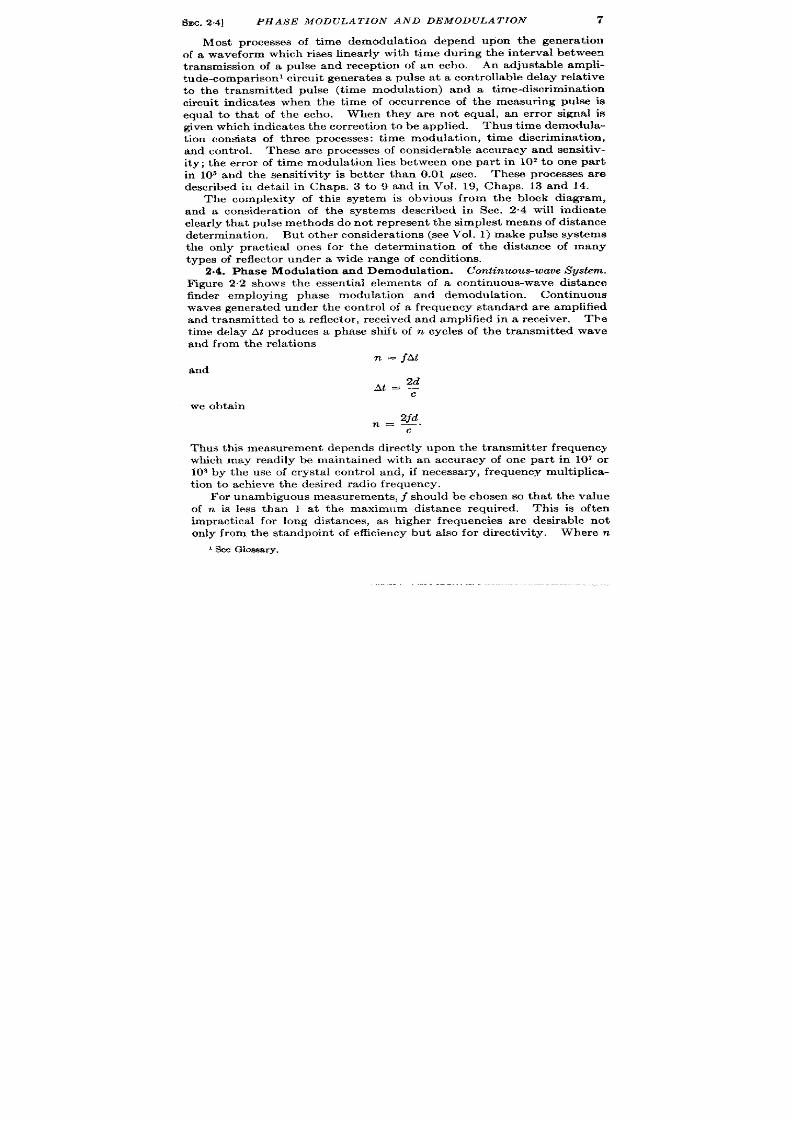
2.4. Phase Modula t ion and Demodula t ion . Cont inuous-wave System.
F@re 2.2 shows the essen t ia l elements of a cont inuous-wave distance
finder employing phase modula t ion and demodula t ion . Cont inuous
waves genera ted under the cont rol of a frequency standard are amplified
and transmit ted t o a eflector , received and amplified in a receiver .
The
t ime delay At produces a phase shift of n cycles of the t ransmit ted wave
and from th e rela t ions
n = jAt
and
2d
At=;
we obta in
2fd
n=_.
c
Thus this mea surement depends direct ly upon th e t ransmit ter frequ en cy
which may readily be mainta ined with an accuracy of one par t in 107 or
108 by the use of cr sta l con t rol and, if necessa ry, frequ en cy mult iplica-
t ion t o a ch ieve t he desired ra dio frequ en cy.
For unambiguous measurements, j should be chosen so tha t the va lue
of n is less than 1 a t the maximum distance required.
This is often
impract ical for long distances, as h igher frequenc es a re desirable not
on ly from the standpoin t of efficiency but a lso for direct ivity. Where n
I See Glossary.

8
RADIO DIS TANCE AND SPEED MEASUREMENTS
[SEC.24
is la rge, seconda ry means a re employed to obta in the in tegra l va lue of n.
For example, if the approxima te va lue of the distance is known, the exact
va lue may be obta ined by th is method. On the other hand, small
devia t ions from a known value of d due to movemen t of the reflector or
t ransmit ter - eceiver a re easily measured. In a method to be descr ibed
shor t ly, t ime modula t ion and demodula t ion a re employed to obta in the
approximate va lue of d.
Phase demodula t ion is ca r r ied out by means of processes which a re
a lready well k own a d which have been descr ibed br iefly in Vol. 19,
Sec. 13.3 and 14.4. Th waveform diagram of Fig. 2.2 indica tes a typica l
phase shift between the transmit ted and received sig a ls. A reference
~————
——— ——— —.—— ——— ———————
I
1
I
I
I
/
I
I
I
tor
I
L_
—————
)
i-----------4 ----
‘ Phase demodulator
4 output
l–— —_ —_-___ —_– —__ _.
1
1Tr&smittod
I
I
Received
wove
J
FIG.2 2.—Cont inuous -wave istancefinder employingphase modulat ionan d demodula -
tion.
signa l obta ined from the oscilla tor is phase-sh if ed by a phase modula tor
in response to a cont rol. Phase-discr imina t ing circu it s simila r to those
descr ibed in Vol. 19, Sec. 14.4 detect the sense and the approxima te
magnitude of the phase sh ift between the phase-sh ifted and received
frequencies. The ou tpu t voltage is su itable for cont rolling a servo-
mechanism tha t rota tes the phase sh ifter to give zero outpu t from the
phase discr imina tor . A shaft posit ion cor responding to the phase sh ift
between the received and transmit ted signal is then ava ilable a t the
ou tpu t . This shaft posit ion represen ts on ly the fract iona l pa r t of n .
Typica l phase modu la tors a re capacitance or inductance goniometers
wh ;ch a re usua lly accu ra te to 1° (see Vol. 19, Sec. 13,3, and Vol. 17,
Sec. 9“1).
If the va lue of d is known accura tely to one wavelength by other
methods, an indica t ion of the fract iona l va lue may be obta ined with h ig
SEC. 24] PHASE MODULATION AN D DEMODULATION
9
sen sit ivity. This pr in ciple has been used in a low-fr equ en cy cont inu ous-
wave hyperbolic navigat ion system termed ‘‘ Decca” (see Sec. 2.18 and
Vol. 2). In this hyperbolic system the t ransmit t er and receiver are
separa ted, and the reference for the hase discr iminator is t ransmit t ed
at a separa te radio frequency. The outpu t reading is not the distance
from a single t ransmit t ing sta t ion, but the difference in the distances
from two transmit t ing stat ions.
A wavelength of about one mile is
employed, and t he syst em is ambiguous and relies u pon an approximat ely
known posit ion for determining the integra l value of n . Devia t ions from
a given reading can, of course, be followed with considerable accuracy,
var iously est imated as ~ to & of a mile.
The employment of a means
of obtaining the integra l value of n will great ly ncrease the ut ility of
th is syst em.
?
Amplitude
+
modulotor
-
R-f
and r-f
?ransmilter
oscillator
r
Constont
frequency
. m
oscillator
-
Phase
Phose
modulator
Control discriminator
+
t
+ output
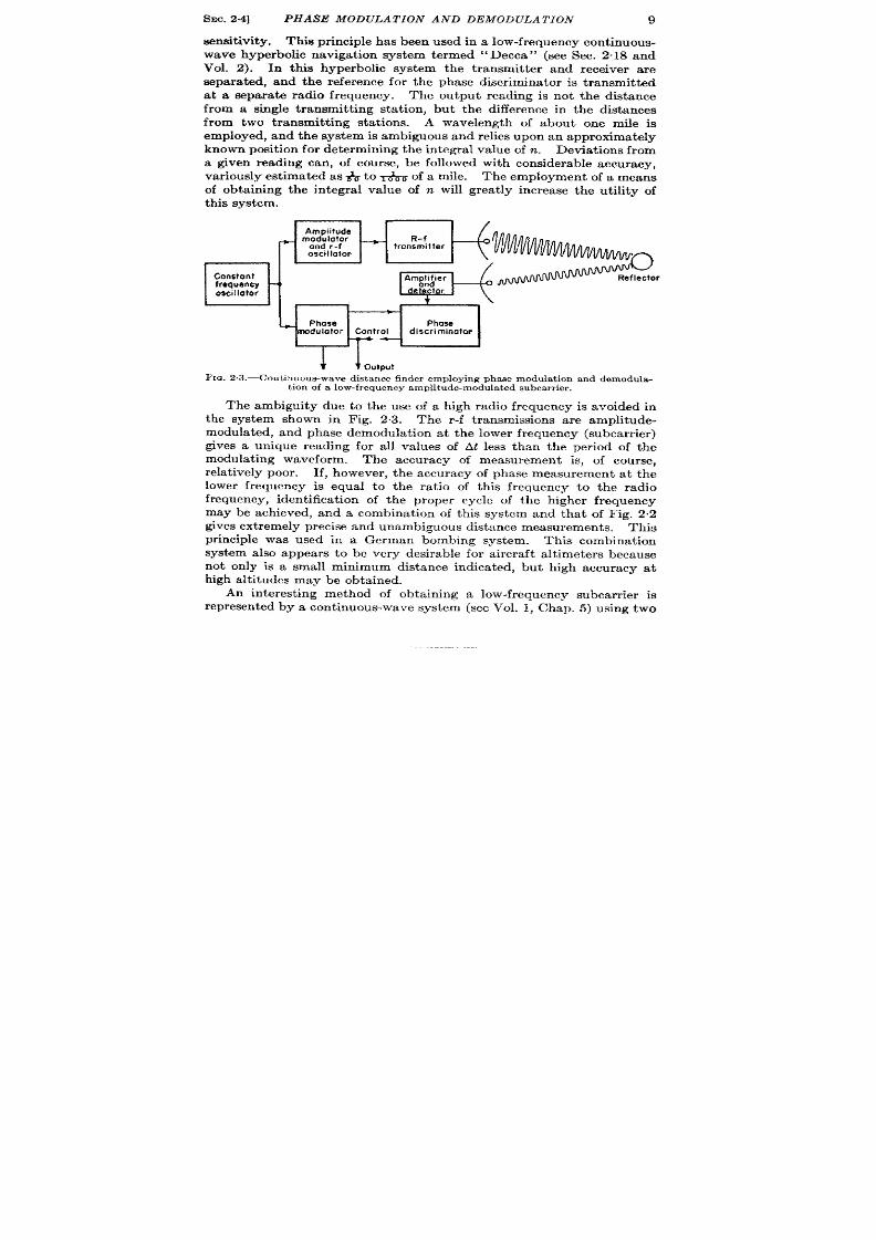
FIG. 2 .3 .—Cont inuous-wave dis tance finder employing phase modula t ion and demodula-
t ion of a low-frequency amplitude-modula ted subcarr ier .
The ambiguity due to the use of a high radio frequency is avoided in
the system shown in Fig. 2.3. The r-f t ransmissions are amplitude-
modulated, and phase demodula t ion at the lower frequency (subcarr ier )
gives a unique reading for all values of At less than the pe iod of the
modula t ing waveform. The accuracy of measurement is, of course,
rela t ively poor . If, however , the accuracy of phase measurement a t the
lower frequency i equal to the ra t io of th is frequency to the radio
frequency, iden t ifica t ion of the proper cycle of the h igher frequency
may be ach ieved, and a combinat ion of th is system and that of Fig. 2.2
gives ext remely precise and unambiguous distance measurements. This
pr inciple was used in a German bombing system. This combinat ion
system also appears to be very desirable for a ircraft a lt imeters because
not on ly is a small minimum distance indicated, but high accuracy at
h igh alt it udes may be obt ained.
An in terest ing method of obtaining a low-frequency subcarr ier is
represen ted by a cont inuous-wave system (see Vol. 1, Chap. 5) using two

10 RADIO DIS TANCE AND SPEED MEASUREMENTS
[SEC.2.4
t ransmit ters with a frequency difference of approximately 10 kc/see.
Th e phase shalt of th e beat n ot e between th e t wo transmit t er s is negligible
for a r eflect or of zer o dist an ce.
Up to a distance of 10 miles, t he phase
of the rece ved beat note is propor t iona l t o the distance of the reflector ,
and phase-demodula t ion circu it s similar t o those indicated in Fig. 22
may be employed to measure the distance of the target .
Puke Methods.—One of the most pract ica l ethods of determin ing
the approximate distance of the reflector is the use of pu lse techn iques,
wh ich in effect , affor d a su bcar rier by wh ich un ambiguou s m easu remen ts
~.. .-.-— ——————— ———————— —-7
-!:.-!
---’wlM—————n !
I
)’+’
#.JwJ—
Reflector 1
I
Amplifier
I
L–––– –– __p!V:o?dlim: !2°YWL ––––J
r–
————— ————— ——— —7
I
lw~
- ———— ————
———— ——— —
J
Fm. 2.4.—Pukedis tance finder employing phase modula t ion and demodula t ion .
of distance may be obta ined. In addit ion , t he advan tages of range dki-
cr iminat ion are obta ined and the possibility of la rge range er rors du to
t he in ter fer en ce of u nwa nted r efl ct ion s is gr eat ly r edu ced.
The simplest applica t ion of pu lse t rans ission to phase modula t ion
and demodula t ion is indicated in Fig. 2.4, based upon components of
Figs. 2“1 and 2.2. In spite of the fact tha t pu lses ar e t ransmit ted, the
phase of the received energy is modula ted in exact ly the same way as in
F ig. 22.
The phase sh ift between the constan t -frequency oscilla tor and the
received signal is demodu la ted in the same way as is indicated in Fig. 2.2
On e may, however , obta in an addit ional advan tage of pu lse t ransmission
since the phase dk+cr iminator need be opera t ed only at the t ime of occur -
r en ce of th e received pulse.
and power amplifier ; t he t ransmit t er may in it ia t e a pu lsed oscilla tor of th e
SEC.24]
PHASE MOD ULA T ION AND DEMODULAT ION
11
s me frequency, the ou tpu t o which may be compared with that of
thereceived signal a t theendof the in terval At . Such a pulsed oscilla tor
is oft en ca lled a ‘(coh er en t oscilla tor , ”
and it s stability must be su fficien t
t o preven t phase shift dur ing the in terval At . With every recu r r ence
of the pu lse t ransmission , ,th is oscilla tor is rest ar t ed in phase with the
t ransmit t ed oscilla t ions. Phase demodula t ion is then car r ied ou t as
shown in Fig. 2,4.
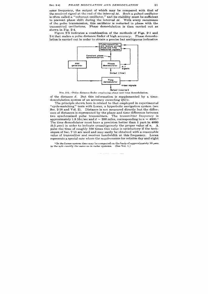
F igure 2.5 indica tes a combinat ion of the methods of Figs 2“1 and
2.4that makes apu lsedistance finder ofh igh accuracy. Phase demodu-
lat ion is car r ied ou t in order to obta in a precise but amb@ous indicat ion
I
cOflSt0i3fhase
synchronization
--l
I
I
Output [fine)
<putCoorse)
FIG. 2.5.—Pulse d is t ance finder employing phase and t ime demodu la t ion .
of the distance d. But th is in format ion is supplemented by a t ime-
demodu la tion syst em of an a ccu ra cy exceedin g zjd/c.
The pr inciple shown here is rela ted to that employed in exper imen ta l
“cycle-match ing” test s with Loran , a hyperbolic navigat ion system (see
Sec. 2“18and Vol. 2). Distance is not measured direct ly but the differ :
en ce of distances isrepresen ted by the phase and t ime differen ce between
two synch ron ized pulse t ransmit ters. The t ransmit ter frequency is
approximately l.8 c/secandcl = 200miles, cor responding ton = 4000.1
The t ime demodu la tor must have a precision bet ter than 1 par t in 4000
(0.5 psec) in order to indicate unambiguously the proper value of n . A
pulse r ise t ime of roughly 100 t ime th is value is sa t isfactory if the tech-
niques of Sec. 7.11 are sed and may easily be obta ined with a reasonable
value of t ransmit t er and receiver bandwidth at th is frequency. Loran
represen t s a specia l case wh ere th e requ iremen ts for reliable day and night
I In theI ,oran systemtimemay be computedon the basisof approximate ly10 pseo
to themile exact ly the sameas in r ada r syst ems. (See Vol. 1.)

12 RADIO DIS TANCE AND SPEED MEASUREMENTS
[SEC. 2.4
coverage at great distances necessit a te the use of a low frequency whereas
the requ irements of the navigat ion problem require the u t ost accuracy
of dist a nce mea su r emen t .
Simple meth ods for coordin at in g t he con tr ols of t he t wo measu remen t
systems of F ig. 2.5 in order to obta in a single con t rol opera t ing con t inu-
ously over the whole range are presen t ed br iefly in Sec. 3.16.1
At th e presen t t ime it does not appear possible t o obta in unambiguous
distance measurements by phase modula t ion and demodula t ion in micro-
wave radar systems. If the method of Fig. 2.4 were ap lie to microwave
transmit t ers and receivers, cer ta in difficult ies would be encountered.
H-v
R-f
3000 Me/see
-
pulse
—
pulse
generator generator
PRF
generator “
Reflector
Defector
Stable
local
osci Ilator
30-M
clsec
Pulsed
Amplifier
coherent
oscillator
EiEa-D--@
IG. 2.6.—Het cr odyn c syst cm for employin g ph ase demodu la t ion a t a low fr equ en cy in a
pulse system.
First , the synchron izat ion of a pu lsed magnet ron with a con t inuous signal
is no assured although preliminary cxpcr imcnts give promising resu lts
(see Vol. 6). Second, a microwave coheren t oscilla tor must be in it ia ted
exact ly in phase with the h i h-power t ransmission .
Th ir d, con t inuou s
phase modula tors opera t ing at these frequencies a re n ot available.
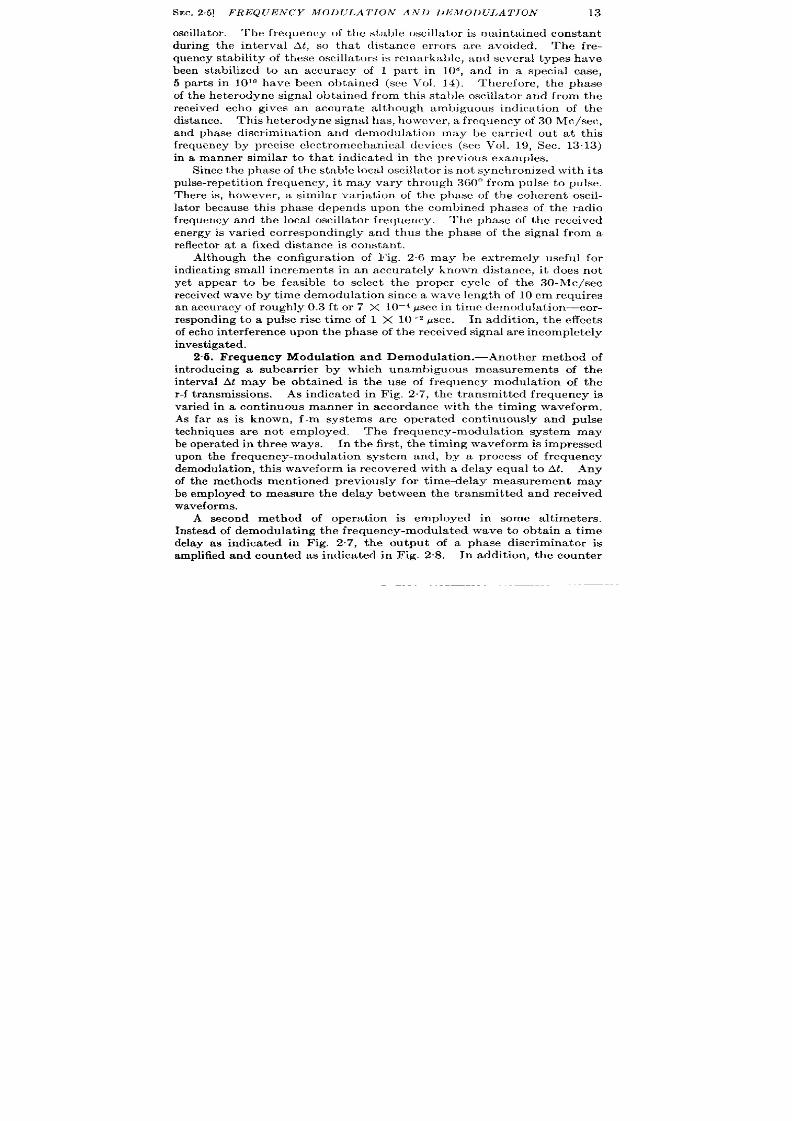
On the other hand, it is possible to car ry ou t phase demodula t ion at
frequencies differ ing from the radio frequency, and advan tage is taken
of he fact that the pha e of the t ransmit t ed and received waves is
preserved even though they are heterodyned to a differen t frequency
(see Vol. 1, Chap. 16). As indicated in the block diagram of Fig. 26, a
30 Me/see pu lsed coher en t oscilla tor is in it ia ted exact ly in phase with th e
heterodyne signal between the t ransmit t ed pu lse and the stable local
1The similar ityof the sys tcm of Fig. 2.5 to a mult ip le-scalerangesystem using a
pu lsed oscilla tor a nd ph ase sh ift er is st rikin g (see Ch aps. 3 an d 6). Th e pu lsed
oscillatorused in time demodulationis ana logousto th e coherentoscillatorof Fig. 2,6,
except that lower fmquencics are employed (O.1 to 1 Me/see).
SEC. 2.5] FREQUENCY MODIJ LA T ION AND L)liMOI)ULA TION
13
oscilla tor . Th e frequency of the stable oscilla tor is main tained constant
during the interval At , so that distance er rors a re avoided. The fre-
qu en cy stability of t hese oscilla tors is r ema rka ble, an d sever al t ypes h ave
been stabilized to an accuracy of 1 pa t in 108, and in a specia l case,
5 part s in 10’0 have been obta ined (see Vol. 14). ‘1’hercf ore, the phase
of the heterodyne signal obtained from this stable oscilla t r and from the
received echo gives an accura te a lthough ambiguous indica t ion of the
dist an ce. This h et er odyn e signal has, h owever , a fr equ en cy of 30 Me/see,
and phase discr iminat ion and demodula t ion may be car r ied out at this
frequency by precise elect romechanica l devices (see Vol. 19, Sec. 13.13)
in a manner similar to tha t indica ted in the previous examples.
Sin ce t he pha se of t he stable loca l oscilla tor is n ot syn ch ron ized wit h its
pulse-repet it ion frequency, it may vary through 360° from pulse to pulse.
Th re is, however , a similar var ia t ion of th phase of the coheren t oscil-
la tor because this phase depends upon the combined phases of the radio
frequency and the loca l oscilla tor frequency. The phase of the eceived
energy is var ied correspondingly and thus the phase of the signal from a
r eflect or a t a fixed dista nce is con st ant .
Although the configura t ion of Fig. 26 may be ext remely usefu l for
indica t ing small increments in an accura tely known distance, it does not
yet appear to be feasible to select the proper cycle of the 30-Mc/sec
received wave by t ime demodula t ion since a wave length of 10 cm requires
an a ccu ra cy of r ou gh ly 0.3 ft or 7 X 10⁻⁴ ~sec in t ime demodu la tion—cor -
responding to a pulse r ise t ime of 1 X 10⁻² psec. In addit ion, the effects
of ech o in ter fer en ce upon t he ph ase of t he r eceived sign al a re in complet ely
investigated.
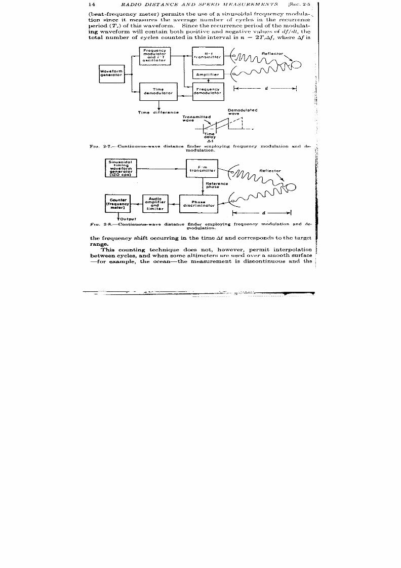
2.6. F requency Modulat ion and Demodula t ion .—Another method of
int roducing a subcarr ier by which unambiguous measurements of the
in terva l At may be obta ined is the use of frequency modula t ion of the
r -f t ransmissions. As indicated in Fig. 27, the transmit ted frequency is
var ied in a cont inuous manner in accordance with the t iming waveform.
s far as is known, f-m syst ms are opera ted cont inuously and pulse
techniques are not employed. The frequency-modula t ion system may
be opera ted in th ree ways. In the first , the t iming waveform is impressed
upon the frequency-modul t ion system and, by a process of frequency
demodulat ion, th is waveform is recovered with a delay equal to AL Any
of the methods ment ioned previously for t ime-delay measurement may
be employed to measure the delay between the transmit ted and received
waveforms.
A second method of opera t ion is employed in some alt imeters.
Instead of demodula t ing the frequency-modula ted wave to obtain a t ime
delay as indica ted in Fig. 2.7, the output of a phase discr imina tor is
amplified and coun ted as indica ted in Fig. 2.8. In addit ion, the counter
14 RADIO DIS TANCE AND S PElil~ J !!l<AS (J REM.EN TS
[SEC.25
(bea t -frequency meter ) permit s the use of a sinusoidal frequency modula- ,
t ion since it measures the average number of cycles in the recur rence
per iod (T,) of this waveform. Since the r ecur rence per iod of the modula t -
ing waveform will con ta in both posit ive and negat ive values of df/dt, the
tota l number of cycles coun ted in th is in terval is n = 2T,Af, where A~ is
FIG.
Fm
the
Frequency
modu Iator
R-f
and r-f
— transmitter
oscillator
Woveform
genera to r
Amplifier
t
Time
“ d;::;:;;, t+---’--+
+
demodulator
—
+
Time difference
Demodulate
wove
,
“’’w--
elay
At
2.7.—Continuous-wave dist an ce fin der employin g fr equ en cy modu la tion a nd de.
Sinusoidal
timing
waveform
F-m
&n;r&fOJ
transmitter
W&e nce
*
Counter
Audio
(f r:~:cy
+
amplifier
Phose
and
+
discriminator
limiter
I
1+-~---+l
+Output
2.S.—Cont inuoue-waveistan ce finder employing frequencymodulat ion and de-
modulation.
frequency shift occur r ing in the t ime At and cor responds to the ta rget
range.
This count ing technique does not , however , permit in terpola t ion
between cycles, and when some alt imeters are used over a smooth sur fa e
—for example, the ocean—the measurement is discont inuous and the
. .,.—.—. —.
.-
—-—---z -J-—-
SEC. 26]
SUMMARY la
indicated distance increases in in tegra l value of n, that is, in steps of
magnitude Ad = c/4F , where F is the tota l frequency devia t ion . In a
par t icular system this may amount to as much as 6 ft . 1 On the other
hand, th is discon t inuity causes lit t le difficulty under usual condit ions of
opera t ion over rough ter ra in , and accuracies of 1 per cen t of full sca le
(5000 ft ) and minimum distances of 1 ft a re easily obta ined with com-
mercia l des igns. z
A third method depends upon cont rol of the value of df/dt from the
output of the phase discr iminator . This ou tpu t is, of course, a frequency
shift Aj occur r ing in the in terva l At and, for a fixed target , is constan t .
Since df/dt usually has posit ive and n ega tive values, t her e is a cor respon d-
ing phase reversa l of A~. Usually this difficu lty is avoided by shift ing
the modula ted frequency by an amount + Af depending upon the sign of
df/dt, and in this ay a constan t phase f Af is obta ined for both signs of
df/dt (see Sec. 2.12). A tomat ic frequency demodula t ion is ca r r ied ou t
by var ia t ion of df/dt in two ways: first by var ia t ion of the repet it ion ra te
of the t iming ave, an second by var ia t ion of the exten t of frequency
modula t ion at a constant repet it ion ra te. The use of this techn ique in
distance and speed measurements is given in grea ter deta il in Sec. 2.12.
Ta rget select ion a nd discr imin at ion in fr equ en cy-modu la tion syst em s
must depend upon fre uency select ion . 3 The distance of any ta rget
cor responds to a par t icular value of frequency, and the tota l frequency
shift cor responding to the maximum value of At must be sufficient to
permit fr equ en cy select ion with reasonable cir cuits, tha t is, bandwidths
of approxi a tely 10 cps or grea ter .
But the problem of const ruct ing
100 or more select ive cir u it s t o display ta rgets, as on a PPI, is cumber-
some compa red wi h t he simplicity of t ime select iv t y in t he ca th ode-r ay-
tube display (see Vol. 19, Sec. 10.6).
Exist ing frequency-modula t ion systems have not been used for pre-
cision dist an ce mea su remen ts.
Accu rate frequency demodula t ion is
pos sible with elect ron ic coun ter s.
2.6. Summary.-In most radar systems the need for ta rget discr imi-
nat ion in range and azimuth has led to the use of frequencies and pulse
durat ions that permit an ult imate range accuracy high compared with
that actually requ ired for military use.
But there are severa l systems in
which other requirements have diet a ted th e pulse r iw t ime, and with these
the ult imate accuracy is requ ired.
An example of such a system is
Loran, where a frequency of 2 Me/see is employed in order to ach ieve
sat isfactory propagat ion over grea t distance .
There are a lready
] SeeD. G. Fink, “The F-m Alt imeter ,” Elect ronics ,19, No. 4, 130, (Apr . 1946).
2L-X.cit.
sUnless,for example,the durat ionof the t iming waveform is short enoughto per-
mit time selection.

16 RADIO DISTANCE AND SPEED MEASUREMENTS
[SEC. 27
pr elim in ar y da ta t ha t in dica te t he pot en tia l u sefu ln ess of t he combin at ion
of pha e and t ime demodula t ion for such a system.
Combinat ions of phase and t ime demodula t ion in micro}i ave radar
systems are not yet possible although phase demodula t ion may give a
ver y sen sit ive in dica tion of in cr emen ts of dist an ce.
At this poin t it is desirable to r efer t o the accuracy of t ime discr imina-
t ion obt ain able wit h specia l displa ys in volvin g su per posit ion of two video
signals as in Loran . In an exper imenta l t est using syn thet ic signals fr ee
from noise, the accuracy of t ime discr iminat ion approached tha t obta in-
able by phase discr iminat ion of the r -f pulse car r ier (see Sec. 7.11). In
gen er al, such a ccu ra cy wou ld n ot be expect ed u nder pra ct ica l con dit ion s
of oper at ion wh er e appr eciable n oise wou ld be pr esen t.
The accuracy of t ime and phase modulators used in measurement of
th is type is discus ed br iefly in Sec. 3.14 and in considerable deta il in
C ap. 5. It is sufficien t t o ment ion here that accuracies of 0.3 per cen t
of full scale a re readily obta ina ble wit h pr act ica l cir cuits.
Wit h cer ta in
a r rangements, a cascade of a number of t ime- or phase-demodulat ion
circu its increases the accuracy by the produ ct of th e accuracies of th e two
circu its tha t a re cascaded (see Sees. 3. and 3.15 and Chap. 6). Consider -
ably less has been done to develop precision fr equency modulators that
would be used for cor r espon ding measurements in frequency-modula -
t ion systems. The sual accuracies obta inable are approximately 1 per
cen t and, as fa r as is known, no effor t s have been made to cascade
frequency-demodula t ion systems as is usually done in t ime- and phase-
demodula t ion syst ems.
SPEED MEASUREMENTS
In radar systems having inadequate range and angle resolu t ion , mov-
in g object s a re som et imes dist in gu ish ed fr om fixed object s—r ocks, t rees,
etc.—by speed measurements. The emphasis here is upon the means
for dete min ing ta rget speed as supplementa ry in format ion to ta rget
distance in order tha t predict ion of fu tu e posit ion of the ta rget may be
obta ined. In a number of specia l cases, predict ion along a radia l line is
sufficien t , and th e following discussion is confined t o this subject . Ra te
in forma tion can , of cou rse, be obta in ed u pon differ en tia tion of displace-
ment measurements and this method is discussed in Sec. 2.11 and in
Chaps. 7 to 9. In scann ing radar systems, the in terval between dis-
placement measurements is often so grea t tha t a considerable t ime is
r equ ir ed befor e su fficien t in forma tion is a vaila ble t o permit sa tisfa ct or y
differen t ia t ion . Some asp ct s of this problem are r e~-iewed in Sec. 2.14.
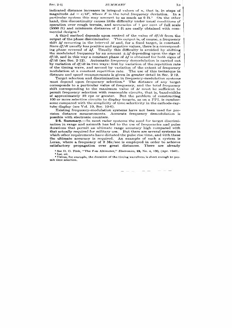
2.7. Cont inuous-wave Systems. —Figure 29 indicates a typica l con-
t inuous-wave speed measurement system. It is based upon the elements
of F ig. 2.2 and takes advan tage of the fact tha t the ra te of change of the
SEC. 27] CON TINUO US -WAVE SYS TEMS 17
received phase due to mot ion of the reflector is given direct ly in the out -
put of a phase discr iminator as a doppler frequency.
The value of the output frequency may be calculated by the formulal
89.4V,
F,=r cps/mph
where V. is the radial velocity of the target with respect to the trans-
mit ter -receiver system in mph, Fd is the doppler frequency or the ra te of
change of phase, and h is the wavelength in cm. For example, a t a
wavelength of 3 cm, Fd is equal to 29.8 cps/mph.
A var iety of frequency-meter ing circuits may be employed similar to
those used in the measurement of distance in a frequency-modula ted
syste (see Sec. 2.5).
or
FIG. 2.9 .—Cont inuous-wave speed measurement system.
The rela t ive merit s of a number of these systems used for a ircraft
detect ion are discussed in Vol. 1, Chap. 5. For most purposes the lack
of range resolu t ion has been a grea t handicap to cont inuous-wave sys-
t ems u sed for speed mea su remen t.
F or isolated objects—for example, a bomb or project ile—accura te
speed measurements a re possible without the n eed for range resolu t ion .
In fact , cont inuous-wave systems would seem to be part icu lar ly usefu l
for th is purpose, and frequencies of 10,000 Me/see would be expected to
give good results by direct r ecording of the doppler frequency. A read-
ing accuracy of roughly one-quar ter cycle at this frequency would give
velocit ies accu ate to a fract ion of a per cent provided a reasonable num-
ber of cycles were recorded. In fa t , such an accurac would exceed
that obtainable by t ime demodula t ion and different ia t ion by a factor of
roughly 5 (see Sec. 2.11). The exact value of the distance may or may
1The factor 89.4 is twice th e norma l conversionfactor for th e doppler effect since
boththe tran smitterand the receivermay be consideredto be moving with respect to
thereflector.
18
RADIO DIS TANCE AND SPEED MEASUREMENTS
[SEC. 28
not be obta ined in these speed measurements depending upon whether
the zero poin t of r ecording the doppler cycles is accura tely known. From
tha t poin t onward distance measurement is obta ined by simply count ing
the cycles and conver t ing these into distance (for th is fr equency, one
doppler cycle equals 1.6 cm ).
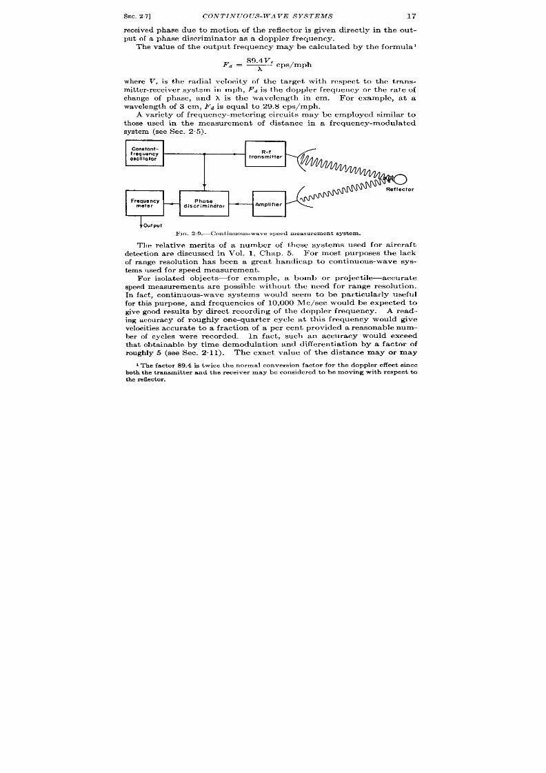
2.8. Pulse Systems—Interna lly Coherent .—The doppler bea t note
der ived from the ra t e of change of phase due to a moving ta rget is readily
obta ined with the system shown in Fig. 2“4 by the a ltera t i ns indica ted
in Fig. 210. As in Fig. 2.9, the phase-discr imina tor output is measured
direct ly by a frequency meter . This method has been applied to severa l
rada r systems opera t ing a t 100 to 200 Me/see where audible indica t ions
Y
onstant
frequent y
oscillator
TR-
!witch,
--( ‘- -
I ‘—o
ef Iector
‘“$3EE+EY
IG. 2.10.—Pulse speed measurement sys tem employing in terna l coherence .
of the speed. of a moving ta rget a re required. It usua lly suffices to
em ploy ea rphones for frequency est imat ion.
The modifica t ion of the
r adio-fr equ en cy por tion s of t his syst em a s in dica ted in F ig. 2“6 is desir able
wh en m icr owave fr equ en cies a re employed.
A qualita t ive indica t ion of the speed of a la rge number of ta rgets
withh the view of a scanning radar system is obta inable as indica ted in
the rudimenta ry schematic diagram of Fig. 2.11. This system is iden-
t ica l to tha t indica ted in Fig. 201Owith the except ion tha t the fr equency
meter is r eplaced by a elay device of a delay tha t is exact ly equal to the
pulse recu r rence interva l. The input and output of this delay device
a re subt racted, and therefore ta rgets moving more slowly than a given
speed do not appea r a t the output of the subt ract ion circu it because
they will have an inappreciable change of phase dur ing the repet it ion
interval.
Some of the delay devices descr ibed in Chap. 12 are usefu l
for t hese pu rposes.

SEC. 2.8] PULSE SYSTEMS—INTERNALL Y COHERENT
19
The grea t usefulness of th is system is that it gives a qualita t ive
indicat ion of the spe d of a la rge number of ta rgets.
In the form indi-
ca ted here, it does not , however , give accura te speed indicat ions, and
these are more appropr ia tely obtained through phase demodulat ion.
For microwave frequencies the heterodyne method of Fig. 2.6 is, of
course , desirable.
If the doppler frequency in any of these systems is equal to or is an
int egral mult iple of t he r epet it ion frequ en cy of t he t ran smit ter , n o modu-
lat ion is observed. The radar then fails to detect the t ar et and is said
I
COnstant
TR-
1
frequency
switch
oscillator
‘ $–~ 0
eflector
\ r
Delay
device
Phase
dlscrlminotor
+ Amplifier
At=&
Pulse
subtraction
circuil
+ outDut
Fm. 2.1 1.—Pulse syst em for t he qu alit at ive in dk at ion of t he speed of a la rge number of
slowly movingta rget s by means of frequency select ion a t the pu lse recur rence frequency.
t o be “blind.” The cor responding speed is the “ blind speed.” This
may be sta ted more genera lly by the formula
Vb,id =
n“PRFo A
2
where n is equal to 1, 2, 3, etc.
For the par t icular case, where x is equal to 3 cm and PRF is equal
t o 2000,
V,u = 67n mph.
When th is effect is object ionable, a slight var ia t ion of PRF increases
the amplitude of the beat note to a measurable va lue. Usually fluctua-
t ions in the phase of the reflected signal that a re due to the fin ite size
of the t a rget will cause th is effect to be of small impor tance.

20
RADIO DIS TANCE AND SPEED MEASUREMENTS
[%c. 2.9
2.9. Pu lse Syst ems.—Extemally -coh er en t E ch o Int er fer ence.-In t he
previously discussed systems the t ime delay between transmission and
recept ion of the pulse requ ires the main tenance of the phase of the t r ans-
mit ted wave dur ing th is t ime in terva l in order to permit simultaneous
compar ison of the phase of the t r ansmit ted and r eceived wave .
The
necessity for the coheren t oscilla tor der ives from the fact tha t the t r ans-
mit ted and r eceived en er gies do n ot exist simultaneously a t t he t ransmit -
r eceive poin t . On the other hand, the inciden t and reflect ed energy a re
coinciden t at the reflector for an in terva l equal to the pulse dura t ion .
Ext remely impor tan t methods of rela t ive speed measuremen t , wh ich
der ive fr om this simple fact , a r e t ermed “ext er na l coh er en ce. ” 1 E xter na l
coherence may be employed to measure the rela t ive ra te of a m v-
ing vehicle with respect to a sta t ionary background or the rela t ive
mot ion of por t ions of a large sta t ionary object with respect to a moving
transmitter-receiver.
Retiive Speed of Vehicle and Ground.-The energy of the r -f p lse
incident upon a moving reflector is a lso inciden t upon the sta t ionary
medium over which the object is moving. Exper imental observat ions
and theoret ica l ca lcu la ions have indica ted tha t the phase shift due to a
large number of sta t ionary sca t t erer s is constant , even in the neighbor -
hood of a dist inct ve moving reflector ;2 but the phase of the ener~
reflected from the moving object var ies in accordance with the usual
doppler formula. The r eflect ed energy then contains a componen t equal
to the sum or difference of the t ransmit ted frequency and the frequency
cor responding to the ra t e of change of phase (doppler fr equency) ca sed
by the mot io of the object away from or toward the t r ansmit ter .
Although the speed of the moving object maybe determined by the dop-
pler fr equency, in format ion on its r ange must be obtained by t ime
demodulation.
F igure 2.12 shows the ext r eme simplicity of speed measurement by
this means. All the elemen ts are par t s of a convent iona l r adar system
except the frequency meter . Since the energy reflect ed from the moving
and stat ionary targets contains both th t ransmit ted frequency and th is
fr equency plus or minus the doppler fr equency, phase disc imina t ion is
accomplished in a simple detector . Pract ica l considera t ons in the
design of these ci cu it s a re given in Vol. 19, Sec. 14.5, and in Vol. 1.
Time select ion of the energy reflect ed from the desir ed target is, of
cour se, impor tan t in order to secure minimum target confusion and
1Externa l coherence is often termed ‘‘noncoherent”
doppler detect ion . Th is
term is not appropriatebecause th e energyfrom stationar yscatt erersis mhsr erdwith
the incident radiation.
*A. J . F . Sieger t , “F luct uat ion s in Retu rn Signa ls fr om Random Sca t t er er s,”
RL Repor t No. 773, 1945.
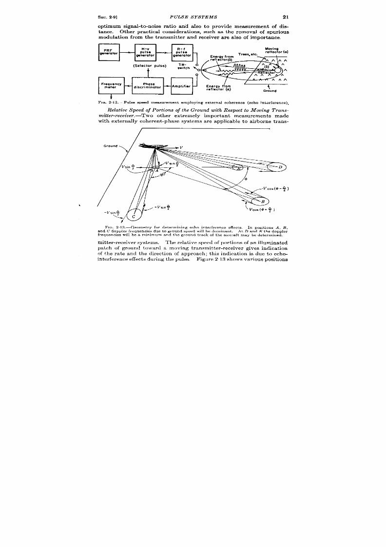
SEC.29]
PULSE S YS TEMS
21
opt imum signa l-to-noise ra t io and also to provide measurement of dis-
tance. Other pract ica l considera t ions, such as the remova l of spur ious
modula t ion from the t ransmit ter and receiver are a lso of importance.
Frequency
Phase
meter
- discriminator
4 Amplifier
Ground
t
F1m 2.12.—Pu1se speed measurement employing exte rna l coherence (echo ~n~cxfe rence).
Relative Speed of Portions of the Ground with Respect to Mowing Trans-
mitter-receiver. -Two other ext remely impor tant measuremen s made
with ext er na lly coh er en t-p ba se system s a re pplicable t o a ir bor ne tr an -
1
F IO. 2,13.—Geomet r y for d et erm in ing echo in t er fer en ce effect s. I n posit ion s A, B,
a nd C doppler fr equ en cies du e t o gr ou n d speed will be dom in an t. At D a nd E t he doppler
fr equ en cies will be a m in imum and t h e gr ou n d t ra ck of t he a ir cr aft m ay be det ermin e .
m it ter -r eceiver system s. Th e r ela tive speed of por tions of a n illum inated
patch of ground toward a moving t ransmit ter -r eceiver gives indica t ion
of the ra te and the direct ion of approach; this indica t ion is due to echo-
in t er fer ence effect s du r ing t he pu lse
F igu re 213 shows va riou s posit ion s

22
RADIO DISTANCE AND SPEED MEAS UREMENTS
[SEC. 2.9
of the illuminat ing beam which emphasize var ious measurements of
doppler bea t frequencies. In A the beam is project ed ver t ica lly down-
ward from the moving airplane, and the rela t ive mot ion of por t ions of the
illuminated reflectors is toward the a irplane if t he reflector s a re ahead
and away if they a re behind. The rela t ive mot ion of the poin t of closest
D
Vcosf’+++ )
FIc+.2,14.—Differential doppler shift due
to d iffe rence of mot ion of por t ions of reflector
A a nd B t owa rd t he a ir cr aft .
approach is,
of cou rse, zero.
Par t icu lar r eflectors at t he ex-
t remit ies of the beam are ap-
proach ing or receding from the
airplane with a velocity denoted
by & V sin A/2 where A is the
beamwidth . The doppler beat
n ot e between t hese t wo r ef ect or s
is 2V/X sin A/2.
Actua lly the exist ence of two
discret e reflectors at t ese posi-
t ions is un likely, bu t a frequency
spect rum approaching the above
expression as a maximum value is
obta ined from the doppler beats of all t he reflectors illuminated by the
beam. The genera l form of this spect rum is indicat ed by Fig. 2.15.
Another possible geomet ry is indica ted by posit ion B in which the
beam is direct ed a t an angle @ with respect to the ground path of the
aircr ft , and a por t ion of the ground at a considerable dist ance from
the airplane is illuminated. Here the rela t ive velocity of por t ions of the
illuminated pat ch of ground is in the hori on ta l plane, the componen t in
the ver t ica l plane being negligible. Taking two poin ts at t he ext reme
lateral edges of the b am, their rela t ive velocity of approach toward the
a ircra ft may be compu ted as indicated in Fig. 2“14. This is
where @is the azimuth angle of the an tenna with respect to the ground ~
t ra ck of t he airpla ne, an d t he differ en tia l doppler fr equ en cy is mu lt iplied
by th is geom et ric fact or . A in th e previous case, t he doppler -frequency
spect rum has a la rge energy at a small va lue of frequency and decreasing
energy ou t to a frequency determined by the differen t ia l velocity of
poin ts a t the ext r eme edges of the beam. An est imated spect rum for
th is differen t ia l doppler ffect a t two azimuth angles is indica ted in
Fig. 2.15. The amplitude of the h i h -frequency co ponent s increases
as @ increases and reaches a maximum where o is equa l to 90°. When
a radar fr equ ency of 10,000 Me/see is used, t he mid-frequency is cen ter ed
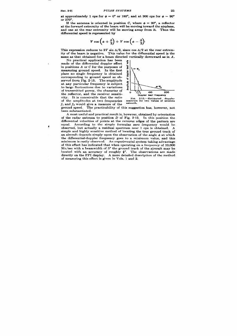
SEC.2.9]
PULS E S YS TEMS
23
at approximately 1 CPS for @ = 0° or 180°, and a t 300 cps for + = 90°
or 270”
If the antenna is or ien ted in posit ion C, where + = 90°, a reflector
a t th forward ext remity of the beam will be moving toward the ai plane,
and one a t the r ea r ext r emity will be moving away from it . Thus the
differ en tia l speed is r epr esen ted by
v’4’+$+vcOs(’-$”
This expression reduces to 2V sin A/2, since cos A/2 at the rea r ext r em-
ity of the beam is negat ive. This va ue for the differen t ia l speed is the
same as that obta ined for a beam directed ver t ica lly downwa d as in A.
No pract ica l applica t ion has been =
made of the differen t ia l doppler effect ,g
in posit ions A or C for the purposes of ~
/
+ 01
measur ing ground speed. In the t it ~
place no single frequency s obta ined ~
~
cor responding to ground speed as ob-
served from Fig. 2.15. The amplitude ~
~
q!
t any par t icu la r frequency is subject ~
to la rge fluctuat ions due to var ia t ions
of t ransmit t ed power , the character of
the reflector , and the r eceiver sensit i-
12
Ooppler beat frequency
vity. It is conceivable that the ra t io
Fm. 2. 15.—Est ima ted doppler
of the amplitudes at two frequencies
spectrumfor two va lues of antenna
jl and f~ would give a measure of the azimuth”
ground speed. The pract icability of th is suggest ion has, however , not
been subs tant ia ted .
A most u seful and pr act ica l r esu lt is, h owever , obta in ed by or ien ta tion
of the radar antenna to posit ion D of Fig. 2.13. In thk posit ion the
differen t ia l velocit ies of poin ts a t the ext r eme edges of the pa t tern ar e
equal. Accord ng to the simple formu as zero fr equency would be
observed, bu t actually a residual spect rum near 1 cps is obta ined. A
simple and high ly sensit ive method of loca t ing the t rue ground t r ack of
an a ircra ft depends simply upon the observa t ion of the angle ~ at which
the differen t ia l-doppler frequency goes to a minimum value, and th is
minimum is easily observed. An exper imental system taking advantage
of this effect has indicated tha t when operat ing on a frequency of 10,000
Me/see with a beamwidth of 3“ the ground t rack of the a ircra ft may be
loca ted with an accuracy of roughly ~. The observa t ions ar e made
direct ly on the PPI display. A more deta iled descr ipt ion of the method
of measur ing th is effect is given in Vols. 1 and 2.

24
RADIO DISTANCE AND SPEED MEASUREitI ENTS
[SEC.2.9
The doppler indicat ions indica te the t r ack of the a ircraft a long the
lin e pa ra llel t o t he pla ne fr om wh ich ech o-in ter fer en ce effect s a re obt ain ed.
If th is plane is hor izon tal, the ground t rack is determined. u t in
mountainous ter r a in the doppler fr equency null may not be observed
since the beam may not illum nate a hor izonta l a rea.
This effect has
been obser ved in exper im en ta l fligh t t est s a nd h as ca used some difficu lt y.
In spite of th is limitat ion , the doppler ground t rack is an ext remely
impor tan t naviga t ional aid for a irborn e r adar systems.
Two other methods of determin ing round speed do not depend upon
the reia t ive mot ion of eflector s illuminated by the same pulse of r -f
energy.
If two antennas are used to project a cont inuous-wave beam
direct ly forward and aft a long the ground t rack, the doppler fr equency
may be measured to bet t er than 5 mph.
This method is not , however ,
immedia tely a pplicable t o pu lse r ada r syst em s.
A proposed system uses one beam but compares the energy at two
differen t ranges. If, for example, the r eceived energy from illuminated
portion D is compared with that from E (Fig. 213), the following doppler
fr equ en cy will be obser ved:
Aj = ~ (sin ~ – sin a),
where P and a a re the ver t ica l angles of D and E, r espect ively. 1 As t her e
is an appreciable t i e del y between the recept ion of the energy from
these two differen t por t ions of the ground, a delay device opera t ing at the
radio frequency or the in termedia t e fr equency is employed in order to
permit phase discr imina t ion . Frequency measuremen t , of cour se, gives
a value rela t ed to the ground speed as previously indica ted. This
method has two limita t ions: the angle + should be made zero; and suit -
able reflector s a re requ ir ed a t two places on the ground ra ther than at a
single place, A considera t ion of th is method will indica te its similar ity
to coher en t methods in which the phase of the t r ansmit ted pulse is com-
pared with the reflect ed energy from D. It has the grea t advantage,
however , that the requ ired length of the delay element maybe made shor t
compared with tha t r equ ired if the t ransmit ted pulse wer e to be delayed
unt il t he recept ion of a su itable echo.
SPEED AND DISTANCE MEASUREMENTS
Both ra te and displacement in format ion are required for the predic-
t ion of the t ime of ar r iva l of a moving object at a par t icu lar poin t . In
genera l, da ta in two or th ree coordina tes ar e requ ired, but a grea t many
1D. Sa yr e,
“ Pulse Doppler with Refer ence to Ground Speed Indica t ion ,” RL
Grou p Repor t , hla r . 20, 1944.

SEC.2.10] 25
pract ica l problems of predict ion a re sa t isfied by a knowledge of radia l
dist ance and speed .
Th e n aviga tion pr oblem is u su ally solved by est ablish in g a “collision ”
course with the object ive and by ca lcu la t ing the t ime of ar r iva l on the
basis of ra nge and r an ge-r at e data .
The bombing problem is simila r , for r elease is required a t a distance
from the ta rget approximately equal to V,tt – T where V, is ground
speed, t f is t ime of fall, and T is t ra il of the par t icu lar bomb. At low
alt itudes the slant r ange is approximately equal to ground range a t the
release poin t , bu t a t high a lt itudes the slant range is conver t ed to ground
range by a computer (see Vol. 19, Sec. 8.5 and Vol. 21, Sec. 6.3).
A specia lized naviga t ional computer , which has been developed for
the solu t ion of these problems, presen ts a dir ect indica t ion of course to
and t ime of ar r iva l a t a dest ina t ion (see Sec. 7.28 and Vol. 21, Chap. 7).
Associa ted equipment may often grea t ly decrease the accuracy
problem of Ground Cont rol of In ter ept ion , GCI. Similar ly, proximity
fuses and gu ided missiles decr ease th e a ccura cy requ ir ed of ant ia ircraft
fir e con tr ol a nd bombin g syst ems.
The block diagrams of var ious methods of obta in ing dktance and
speed are preeen ted and are followed by a br ief discussion of some of the
pr oblems of t hese mea su remen ts a rising in sca nnin g r ada r syst ems.
2.10. Phase and Ra te of Change of Phase.—The problem of obta in ing
bot h dist an ce a nd speed sepa ra tely in ph ase-modu la tion syst ems ha s been
d iscussed in Sees . 24,-2”7, and 2“8.
In a syst em in which it is desir ed
to measure both distance and
speed simultaneously, th e meas-
uremen t systems may opera te in-
dependent ly. A typica l block
diagram of a c-w system is shown
in Fig. 216 in which coheren t
oscilla tion s est ablish synch r on i-
za t ion between the pha se demodu -
la tor and the t r ansmit t er -r eceiver
(ph asemodu la tor ). Th e r eceived
sign als a re ph ase-demodu la ted
giving ran g e informat ion . In
Constant DhO$e
synchronization
/
~1~
hase
modulator
(Transmitter -
receiver )
Received
_ signals
Phase
Frequency
demodulator
demodulator
t
/
Speed
FIG. 2.16.—Dis tance and epeed meamme-
men t s by phase and fr equency demodula t ion
in a c-w syst em .
addit ion , t he r ate of cha nge of ra nge is obta ined by phase discr imina t ion
and frequency select ion using t he t ransmit ted phase as a r efer en ce.
This method has, of course, the advan tage of ext reme sensit ivity in
displacement and speed measurements, tha t is, it may respond to a
fract ion of the per iod of the radio frequency but wil be subject t o ambi-

26
RAD1O DISTANCE AN D S PEED MEAS UREMENTS [SEC.2.11
guit ies in r ange as di cussed in Sec. 2“4. There have be n few pract i a l
applica t ions of the method in this form although the two processes are
u sed sepa ra tely for a number of ver y a ccu ra te mea sur ement s (see Sees. 2.4
and 2.7). A more pract ica l device would result from a combinat ion of
t ime demodulat ion for approximate r ange measurement and ta rget dis-
cr imina tion as discussed in Sec. 2“13.
2.11. Time Demodula t ion and DMerent ia t ion .
—The only feasible
method of deter mining speed in a t ime-demodula t ion system is by differ -
ent ia t ion of the distance. In fact , a ll pulse-radar systems so far us d for
distance-finding employ this method. A number of methods for differ -
ent ia t ion by manual or automat ic means are descr ibed in Sec. 7.14 and
Sec. 9“3 and a lso in Vol. 21, Sec. 4.5. In genera , manual methods consist
synchronizotion~
!
+?--- ‘iJance
I
FIG. 2 17.—Dis tance and speed measur e-
ment s by t ime demodula t ion and differ -
entiation.
of va riou s a idin g devices for est ab-
lish in g con tin uit y of t he displa ce-
ment informat ion in the interva l
between displacement measure-
ments.
The speed o a motor or
ot her device r equir ed t o establish
this cont inuity is then a measure
of the ra te. Automat ic t racking
methods of high sensit ivity and
rapid response are employed
wherever pract icable. A block
diagram of a typica l system is indica ted in Fig. 2.17 where st ra ight for -
ward different ia t ion of the distance outpu t of the t ime demodula tor is
indicated.
The proper t ies and per formance of a number of radar systems using
t hese t ech niqu es a re given in t he n ext sect ion s, especia lly Sees. 2.15, 2.16,
a nd 2.17.
2.12. P ha se a nd F requ en cy Demodu la tion .-In fr equ en cy-modu la ted
istance finders the output in format ion is obta ined as a fr quency shift
Af cor respon din g t o t he pr odu ct of t he t im e dela y bet ~l-een tr ansmission
and recept ion o informat ion and the ra te of change of fr equency with
t ime. If there is rela t ive motion of the t r ansmit ter -r eceiver system and
the reflector , an addit iona l fr equency shift ~ ~ is added to Aj. A
method of dist inguishing between the frequency shift s due to distance
and speed depends upon the fact that A~ is subt racted from the doppler
frequency for osit ive va lues of dj/dt and added o it for nega t ive values.
A block diagram of a possible system is shown in Fig. 2.18. In the
init ia l condit ion the t iming-waveform genera tor which cont r ols t he fr e-
quency modula t ion of .4 is disabled and the system opera tes by ordinary
c-w doppler . If energy is reflected from an object moving within the
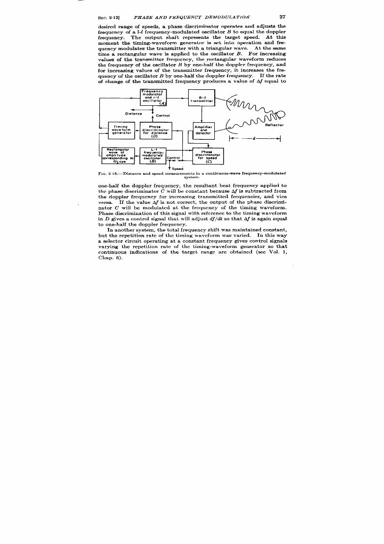
SEC.2.12]
PHASE AND FREQUENCY DEMODULATION
27
desired range of speeds, a phase discr imina tor opera tes and adjusts the
fr equency of a l-f frequency-modula ted oscilla tor B t o equal the doppler
frequency. The output shaft represents the ta rget speed. At th
moment the thning-waveform genera tor is set into opera t ion and fre-
quency modula tes the t ransmit ter with a tr iangular wave. At the same
time a rectangular wave is applied to the oscilla tor B. For increasing
values of the transmit ter frequency, the ,rectangular waveform reduces
t he fr equ en cy of t he oscilla tor B by one-ha lf the doppler frequency, and
for increasing values of the t ransmit ter frequency, it increases the fre-
quency of t h e oscilla t or B by one-ha lf the doppler frequency. If the ra te
of change of the transmit ted frequency produces a va lue of Aj equal to
Frequency
modulator
and r-f
R-f
oscillator
transmitter
(A)
4
Distance
I
Cent rol
1
-
Timing
Phase
Amplifier
wave form
+
discriminator
—
and
generator
for distance
detector
(D)
+—d—+
+
R;K$nq#or L-f
frequency-
Phose
amplitude
+
modulated
discriminator
corresponding to
oscillator
Control for speed
D/2 cpe
(B )
(C)
t Speed
Fxa.2 18.—Dis tance and speed measurements i a con t inuous-wave frequency-modula ted
system.
one-ha lf the doppler frequency, the resultant bea t frequency applied to
the phase discr imina tor C will be constan t because Aj is subtracted from
the doppler fr equency for increasing transmit ted frequencies, and vice
versa . If the value Aj is not cor rect , the output of the phase discr imi-
na tor C will be modula ted a t the fr equency of the t iming waveform.
P ha se discr im ina tion of this signal with r efer en ce t o t he t im ing wa veform
in D gives a cont rol signal tha t will adjust dj/dt so tha t Aj is again equal
t o on e-h alf t he doppler fr equ en cy.
In a noth er system , t he tota l fr equ en cy shift was m aintained consta nt ,
but the repet it ion ra te of the t iming waveform was var ied. In this way
a selector circu it oper at ing t a constan t fr e uency gives cont r ol signa ls
varying the repet it ion ra te of the t iming-waveform genera tor so tha t
cont inuous indicat ions of the ta rget r ang a re obta ined (see Vol. 1,
Cha p. 5).

28 RADIO DIS TANCE AND SPEED MEASUREMENTS [SEC.2.13
2.13. Time, Phase, and Frequency Demodula t ion .—A possible pulse
system is indica ted in Fig. 2.19. An approximate value of the dktance
is obta ined by t ime demodula t ion as indica ted in Fig. 2.17 and is used to
remove the ambiguit ies in the accura te va lue obta ined by phase demodu-
la t ion as indica ted in Fig. 2.16. Ra t e informat ion is obta ined by fre-
quency demodula t ion of the output of a phase discr imina tor .
At the present t ime this th oret ica lly a t t ract ive s stem is impossible
to apply to a microwave radar since the bandwidth of exist ing receivers
and the accuracy of available t ime demodula tors a re inadequa te to
remove the ambiguity of the phase-demodula t ion system.
Neverthe-
less, t he possibilit ies of ext rem ely a ccu ra te dist ance mea surement s com-
bined it h ra pid det ermina tion of speed may wa rra nt som e considera tion
Am blquou9 preci9e distance
1
:i;;~d
I
Pho;&,e’
,\ I ~-
Phase
Frequency
—
Time
+ modulator
d;~f;~ -
d;~:; -
demo:ru -
(Tronsmiltsf
-
rscslvsr )
Constont phose
I
APPros
eynchronlzatlon
distance
PRF Wnchronization
t
Speed Precise
di9t0nM
FIG.2 .19.—Dis tance and epeed measurements by phase, t ime, and frequency demodula t ion
in a pu lse syst em .
of th is method-especia lly in the case of slowly scanning radars giving
int ermit tent dat a.
2.14. Considera t ions Applying to Intermit t ent Data .- ist ance and
speed determina t ion in scanning radars resent s some specia l problems.
A par t icula r radar employs a pulse length of 1 psec, a beamwidth oi
+0, a scanning ra te of 3 rpm, and maximum range scale of 300 mi]es in
order to cover la rge areas and dist inguish many ta rget s.
The amount oi
informat ion obta ined from each individual t a rget is meager and infre-
quent because only 10 pulses a re receive at an interva l of 20 see, cor -
responding to an intermit t ence of 1 par t in 3300 in range and 1 par{ in
720 in azimuth or a net in termit t ence of 1 par t in 240,000.
In near ly all pract ica l applica t ions of radar of this type, the necessit~
a rises for obta in ing prec se informat ion on a few of the many ta rget !
det ect ed, and specia l methods must therefore be employed to obta ir
distance and speed informat ion in a reasonable amount of t ime. A fev
considera t ions of impor tance in determining distance and speed are out
lined below. Similar considera t ions for the determina t ion of angula ]
posit ion a re given elsewhere (see Vol. 1 and Sec. 9“1 1).
Distance Measu remen t s.—An elect r ica lly con t rolled t ime demodu la t or
can give a sa t isfactory displacement measurement from severa l pulses

SEC.2.15]
IN TROD(JCTION
29
(5 to 10) provided the displacement er ror is not la rge. Mechanically
con t rolled t ime demodula tors are more sluggish and, hence, do not
respond to a gr up of pulses immedia tely. Therefore, the mec anica l
systems assess the er or dur ing the ecept ion of the pulse group and
r emove the er ror dur ing the per iod between scans.
A pa rt icu la r ca t hode-
ray -tube display permits the same type of opera t ion under manual con-
t rol (Sec. 7.15). Similar con sider at ion s apply t o mecha nica lly con tr olled
phase demodulators .
Speed Mea su remen ts. —Alt hou gh a cr ude in dica tion of t ar get velocit y
is obta ined in elect r ica lly on t rolled t ime demodula t ion systems dur ing
th recept ion of a few ulses, accura te ra te informat ion is only obtained
by averaging the increments of displacement obta ined on successive
scans. It requires, t herefore, severa l scan per iods (equiva len t to severa l
minutes) to obtain accura te ra t e informat ion . An even longer t ime may
be r equ ir ed in mecha nica lly con tr olled t im e demodula tion syst em s.
It is oft en highly desirable to obta in the r te informat ion as soon as
the displacement informat ion is obta ned. This is difficu lt with t ime
demodulat ion, but measurement of t he doppler frequency appears t o have
severa l advantages. Since the t ime required for a speed measurement
depends upon the sensit ivity of the method employed, t ime and phase
demodula t ion may be compared in this respect . A sensit ivity of 5 ft is
considered very good for most t ime-demodulat ion systems. On the other
hand, a movement of the reflector less than a wavelength causes a per -
cep tible doppler indica t ion .
For microwave radar , t herefore, t here is a
theoret ica l factor of improvement in sensit ivity of speed measurement
of r ou gh ly on e h un dr edfold, a lth ough this may n ot be obt aina ble wit h flu c-
tua t ing echoes.
POSITION-FINDING
2.15. In t roduct ion .-The pract ica l applicat ion of distance-finding is,
of cou rse, t o posit ion-finding, and a few of th e methods by which posit ion
may be found by t ime-in terval measurements are out lined. For the
sa ke of completeness, a few types of angular measurements a re included.
Range and angle measurements of an isolated reflector shown in
Fig. 2.20a give good result s a t rela t ively shor t distances. For example,
the t acking of an a ircra ft by microwave radar is accura te to bet t er than
& of a degree. Also, a irborne navigat ion with simple types of scan-
ning radar systems is accura te to a few hundred feet over distances of
several miles .
A more accura te method is based upon the measurement of the dis-
t an ces t o two a ccu ra tely loca ted object s.
Th e in ter sect ion of t he cir cu la r
lines of posit ion defin ed by t he dist ance mea su remen ts gives t he loca tion
of the radar sta t ion as in Fig. 2“20b a nd 2“20c. Usin g dist in ct ive r eflect or s
as beacons, this method is capable of h igh accuracy and is employed in

30
RADIO DIS TANCE A?vTD SPEED MEASUREMENTS [%c. 215
t he precision beacon navigat ion systems, Shoran , Micro-H, and Gee-H in
which reproducibilit ies of posit ion -finding of rough ly 25, 100, and 150 ft
respect ively have been obta ined a t distances of approximately 100 miles.
There a re, of course, two possible a r rangements, one in which the
posit ion of the t ran smit er -receiver is found with respect t o the posit ion
of wo known reflector s as in Fig. 2.20b, and one in which the posit ion of a
par t icu lar object is found wit respect to the known posit ions of two
t ransmit t er -receiver s as in Fig. 2.20c. The la t ter system is known as
d
eflector
North
8+
Trons. ond rec.
(a) Range azimuth
‘rans
b) TWO circular lines of position
>
0 d,
OT : ; : ~
Trans.l and rec.,
Reflector
Trons.l
o ‘2
+
..a;”;jb%R-
Trons.2 and rec.2
~Trmrs.s
(c) Two circulor lines of position
(d)Twohyperbolic lines of position
FIQ. 2,20.—Someposition-findingmethods .
The figure shows four basic posit ion-
findingmethode. In (a) the posit ionof the reflectoris basedon both the ran geand angle
rn eseur ementmade from a singletra nsmitterand receiver.
In (b) two c rcular lines of
posit ion a re obt ain ed fr om a pa ir of r eflect or s a nd a sin gle t ra nsm it ter -r eceiver . In (c)
t h eee lin es a r e obt a in ed fr om a pair of t r an sm it t er -r eceiver s and a single r eflect or . In (d )
two hyper bolic lin es of posit ion a re obt ain ed by a r eceiver a t poin t A in combin at ion wit h
th ree t r ansmit t er s and two receiver s .
“Oboe” when a responder beacon is used at A; it h as given r epr oducibil-
ity of rough ly 50 ft a t 200 miles.
Figure 2.20d indica tes a system in which on ly the difference of the
distances dl and dz is measured. For example, if the t ransmissions of
Sta t ion 2 are synchron ized with those of Sta t ion 1, the t ime difference in
r ecept ion at A gives t he difference of distances to the two sta t ions. A
constan t difference of dl and dt defines a hyperbolic line of posit ion
having Sta t ions 1 and 2 as its foci.
The in te sect ion of th is line of
posit ion with another similar ly der ived from Sta t ions 1 and 3 gives the
posit ion of A.
Alt ough this system has geom et ry tha t yields somewhat
less accuracy than a system employing circu la r lines of posit ion , it is of
ext reme impor tance because it permits the posit ion of A t o be found by
receiving equ ipment a lone. Examples of th is system are Loran and Gee.

SEC.216]
PULSE ECHO SY TEMS
31
fin
A
din
brief
lg Sys
discussion of the character ist ics of a few pract i(
terns follows.
losition-
FIQ. 2.21 .—A microwave radar sys tem specia lized for accura te range measurement.
2.16. Pulse Echo Systems.—A simple radar system specia lized for
accura te range measurement is shown in Fig. 2.21. At a frequency of
3000 Me/see and with a 4-ft paraboloid, a beamwidth of 4° is obta ined.
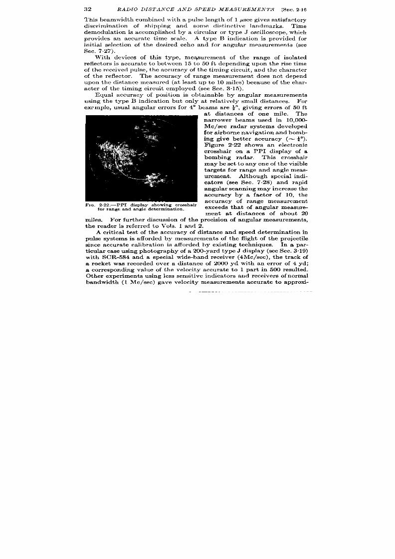
32
RADIO DISTANCE AND SPEED MEASUREMENTS [SEC.216
Thk beamwidth combined with a pulse length of 1 ,usec gives sat isfactory
discr iminat ion of shipping and some dist inct i e landmar s. Time
demodula t ion is accomplished by a circular or type J oscilloscope, which
provides an accurate t ime scale.
A t pe B indicat ion is provided for
in it ial select ion of the desired echo and for angular measurements (see
Sec. 7.27).
With devices of this type, measurement of the range of isola ted
reflector s is accurate to between 15 to 50 ft depending upon the r ise t ime
of the received pulse, the accuracy of the t iming circu it , and the character
of the reflector . The accuracy of range measurement does not depend
upon the distance measured (a t least u to 10 miles) because of the char -
acter of the t iming circuit employed (see Sec. 3.15).
Equal accuracy f posit ion is obta inable by angular measurements
using the type B indica t ion but on ly at rela t ively small distances. For
exr mple, usual angular er ror s for 4° beams are ~, giving er rors of 50 ft
a t distances- of one mile. The
nar rower beams used in 10,000-
Mc/sec radar systems developed
for a ir bor ne n avigat ion a nd bomb-
ing give bet ter accuracy (N +).
F igure 2-22 shows an elect ron ic
crossh ir on a PPI display of a
bombing radar . This crosshair
may be set to any one of the visible
targets for range and angle meas-
urement.
Alt hou gh specia l in di-
ca tors (see Sec. 7.28) and rapid
angular scanning may in cr ease t he
accuracy by a factor of 10, the
accuracy of range measurement
exceeds that of angular measure-
ment a t distances of about 20
iles. For fur ther discussion of the precision of angular measurements,
the reader is refer red to Vols. 1 and 2.
A cr it ica l t est of the accuracy of distance and speed determinat ion in
pulse systems is afforded by measurements of the flight of the project ile
sin ce accur at e calibra t ion is a fforded by exist in g techniques.
In a par-
t icular case using photography of a 200-yard type J display (see Sec. 3.19)
with SCR-584 and a spec al wide-band receiver (4Mc/see), the t rack of
a rocket was recorded over a distance of 2000 yd with an er ror of 4 yd;
a cor responding value of the velocity ac urate to 1 par t in 500 resu lted.
Ot her exper iment s using less sensit ive indicators and r eceiver s of normal
bandwidth (1 Me/see) gave velocity measurements accurate to approxi-
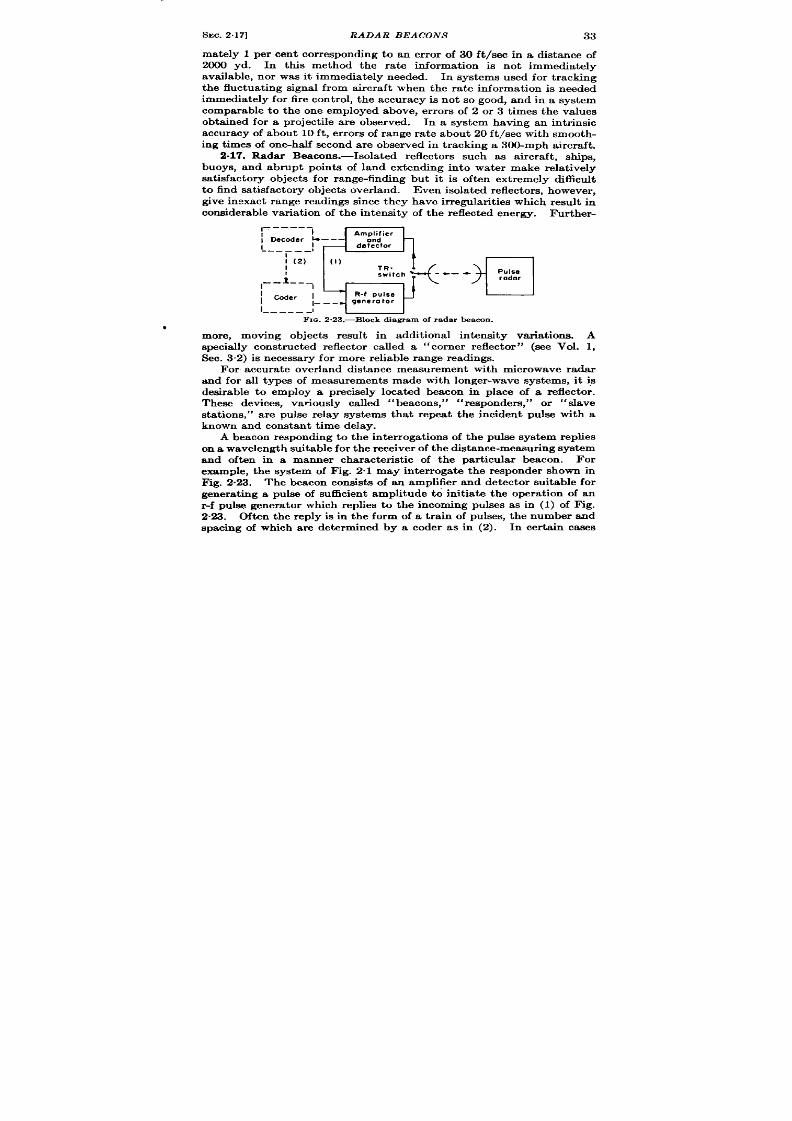
SEC.2.17]
RADAR BEACON S
33
mately 1 per cen t cor respo ding to an er ror of 30 ft /sec in a distance of
2000 yd. In this method the ra te informat ion is not immediately
available, nor was it immedia tely needed. In systems used for t racking
the fluctuat ing signal from aircraft when the ra te information is needed
immediately for fire cont rol, the accuracy is not so good, and in a system
comparable to the one employed above, er ro s of 2 or 3 t imes the values
obt t ined for a pr oject ile are observed.
In a system having an int r insic
accuracy of about 10 ft , er ror s of range ra te about 20 ft /sec with smooth-
ing t imes of one-ha lf sec nd are observed in t racking a 300-mph aircraft .
2.17. Radar Beacons.—Isola ted reflector s such as aircraft , sh ips,
uoys, and abrupt poin ts of land extending in to water make rela t ively
sat isfactory objects for range-finding but it is oft en ext remely difficu lt
t o fin d sa tisfa ct or y object s over la nd.
Even isola ted r eflect or s, h owever ,
ive inexact range readhgs since they have ir r egular it ies which resu lt in
con sider able va riat ion of t he in ten sit y of t he r eflect ed en er gy.
Fur ther -
,–-––-–
I
‘a
Amplifier
i Decoder ~—––
and
detector
-- —— __ I
I (2)
[1)
--i--_l
““+”-”~-l
Coder I
R-f pulse
l––-
generator
I–––––J
FIG. 2.23 .—Block diagram of radar beacon .
more, moving objects resu lt in addit ional in tensity var iat iona. A
specially const ructed reflector called a “corner reflector” (see Vol. 1,
Sec. 3“2) is n ecessa ry for mor e r elia ble r an ge r eadin gs.
For accurate over land distance measurement with microwave radar
and for all types of measurements made with longer -wave systems, it is
esirable to employ a precisely located beacon in place of a reflector .
These devices, var iously called “beacons,” “responders,” or “slave
stat ions, ” are pulse relay systems that r epea t the incident pulse with a
known and constan t t ime delay.
A beacon responding to the in ter roga t ions of the pulse system replies
on a wavelen gt h su it able for t he r eceiver of t he dist an ce-mea su rin g syst em
and often in a manner character ist ic of the par t icu lar beacon.
For
example, the system of Fig. 2“1 may inter rogate the responder shown in
Fig. 2%3. The beacon consist s of an amplifier and detector suitable for
generat ing a pulse of suficien t amplitude to in it ia te the operat ion of an
r -f pulse genera tor which replies to the incoming pulses as in (1) of F]g.
2.23. Often the reply is in the form of a t rain of pulses, the number and
spacing of which are determined by a coder as in (2). In cer ta in cases

34
RADIO DIS TANCE AND SPEED MEASUREMENTS ISEC.2.18
t he beacons are ar ranged to respond only to a par t icu lar code in order
that a pa t icu lar t ransmit ter may designate th e beacon t o reply.
The reply of the beacon is charact er ized by two faults in so far as
accura te distance measurements are concerned. Th first is t he inevi-
table delay between the recept ion of the in ter roga t ion and the t rans-
mission of the response. ‘IT& delay is due to a number of factors which
are discussed in Sees. 3.1 and 3 “2. The principal cause, however , is t he
delay of the receiver . In addit ion, the decoding of a coded in t er rogat ion
pulse requires an in terval equal to the length of the code. These delays
in t roduce a fixed cor rect ion in the distance measured and the apparen t
distance of th e beacon is always grea t er than it s actual distance by severa l
h un dr ed ya rds.
The second fundamental fault is due to the var ia t ion
of the actual delay in the response with var ia t ions in the amplitude of t e
in t er roga t ing signal. This effect is due not only to the character ist ic
of the receiver discussed in Sec. 3.2 but also to the character ist ic of the
decoder . With carefu l design this var ia t ion may be reduced to 0.1 paw
for a wide var ia t ion of signal in tensity. A complet e discussion appears
in Vol. 3.
2.18. Hyperbolic Systems. —These systems, known as “Loran” and
“Gee” navigat ional systems, permit distanc~fimiing in a number of
applicat ions wher e weight or power rest rict ions prevent t he use of t rans-
mit t ing equipment . In miMary operat ions requir ing secrecy, these
systems are advantageous in tha t no t ransmission is required. In other
situat ions, for example, where a la rge number of mobile cra ft requ ire
distance informat ion , no problem of mutual in t er ference is involved. *
One ser ious drawback to their use as t raff c cont rol systems is tha t no
indicat io of the posit ion of the receiver is obtained at the t ransmit t ing
stations.
A system has a lready been ment ioned (see “ Decca ,” Sec. 2.4) in
which synchronized cont inuous waves are sen t from two stat ions to a
r emot e r eceiver and in cr emen ts of dist an ce a re obt ain ed by ph ase demodu -
lat ion. The Loran and Gee systems, however , employ a pulse subcar r ier
of suffici n t ly low frequency (25 and 500 cps, respect ively), t o permit
unambiguous distance measurements over t he en t ire range.
In t hese syst emsa simple bea con in dica ted by F ig. 2“23 is n ot employed
because t he bandwidth and signal-t -noise rat io are inadequate t o permit
direct synchronizat ion of the responder . In addit ion, it is des rable to
in t roduce very la rge coding delays t o permit iden t ificat ion of master and
slave sta t ions. A block diagram of a possible system is indica ted in
Fig. 2.24 and it is seen that the system con ta in s t h re syn ch ron ized t im ing
oscilla tors. The PRF is set by the master sta t ion , and tho e of the slave
sta t ion and the receiver are cont rolled by a process of frequency and
phase demodula t ion whi h may be either manual or au tomat ic.
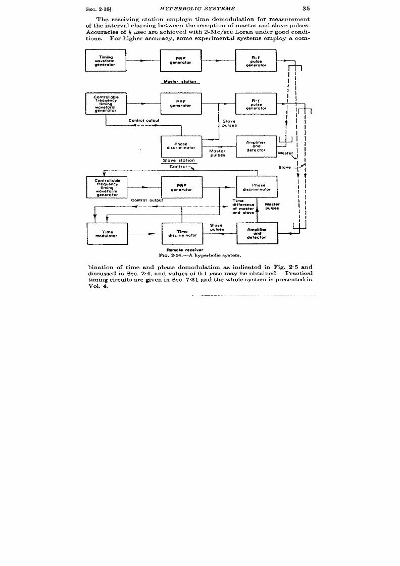
SEC. 2.18]
HYPERBOLIC S YS TEMS
35
The receiving sta t ion employs t ime demodula t ion for measurement
of the interva l elapsing between the recept ion of master and slave pulses.
Accuracies of ~ psec are achieved with 2-Me/see Loran under good condi-
t ions. For higher accuracy, some exper imenta l systems e ploy a com-
l“tming
PRF
R-t
SrOvefom
ganarator
pulsa
generator
qenero!or
l!
I
Conlrolloble
;~
frequency
timing
PRF
R-f
I
,
waveform
generator
pulse
generator
generolor
Control outpul
Slove
*
t
----
pulses
—
Amplifler
Phose
discriminator
and
Master
detector
pulses
Stove stollon
Control
I
Slove
?
;:
Conlrolloble
frequency
timing
PRF
-
Phose
gene rotor
discriminator
II
waveform
generator
II
11
Control oufput
Time
1,
*
~ differe ce
-——
Master
-——— .—
pulses
1,
of master
andslowi‘
II
!r
t
II
I
1
Slave
Time
lame
pulses
Amp#er
modulator
discriminator
detector
Remote receiver
~G. 2.24.-A hyperbolic system.
binat ion of t ime and phase demodula t ion as indica ted in Fig. 2.5 and
discussed in Sec. 2“4, and values of 0.1 psec may be obta ined. Pract ica l
t iming circuits a re given in Sec. 7.31 and the whole system is presen ted in
vol. 4.

36
RADIO DISTANCE AND SPEED MEASUREMENTS @EC.2.19
2.19. An Omnidirect iona l Beacon Using Time Modulat ion .-An
in terest in g u se of pr ecision dista nce m easur emen ts for obta ining angular
data is indicated in Fig. 2.25. In a hyperbolic system in which the base
lin e is ext rem ely sh or t compar ed with t he dista nce of t he r em ot e r eceiver ,
th e t im e differ en ce m easu red is pr opor tion al t o t he angular posit ion of t he
r eceiver with respect to the antenna system. A master and slave com-
binat ion similar to that used for posit ion-finding is indicated in Fig. 2“2
except th at th e dista nces a re so sh or t th at dir ect wir e t ransmission fr om D
t o A, B, an d C is possible an d t he t ra nsmit ter is a lt er na tely swit ch ed fr om
FIG.2.25.—Anomnidirectionalbeaconusingtimemethdation.
A t o B to C. The rela t ive t imes of arr ival of pulses from A, B, and C at a
r emot e r eceiver va ries, depen din g u pon it s a ngu la r posit ion .
F or exam -
ple, when a receiver is posit ioned as indicated in Fig. 225, pulses from
B are r eceived t it -those from C second-and those from A last.Th e
t ime difference of the received pulses, for example, on switch ing from
antenna A t o B is pr opor tion al t o D cos 0 where Ois the direot ion of the
receiver . In a typica f system where d is equal to 500 ft , the maximum
time difference is equivalen t to 4 Psecl and a sensit ivity of 0.01 paec or
approximately 1“ is obta ined. Deta ils o this sys em are given in Sec.
10.8.
1One-waytran emtilon at approximately1000ft /pee&

TECHNIQUES
This charher dea ls
CHAPTER 3
OF PULSE TIME MEASUREMENTS
BY BRI~ON CHANCE
with the character ist ics of the componen ts and
with t heir possible ar rangements
to make differen t types of sys-
tems. Methods of t ime measure-
ment will be surveyed, and an
a t tempt will be made to establish
con tin uit y between t he t rea tm en t
of t he basic methods of wa veform
genera t ion and manipulat ion dis-
cussed in Vol. 19 and t he pract ica l
circu it s to be descr ibed in la ter
chapters of th is book on manual
and automat ic t ime measur ing
systems. The t ransmit ter and
receiver are t rea ted br iefly and
t he t ime-measur ing components
in some deta il. As sta t ed in Sec.
2.3, pr ecision t ime demodu la tion
requires the processes of t ime
modu la tion , t ime discr im in at ion ,
and con t r ol.
TRANSMISSION AND RECEPTION
3.1. Transmission of Pul es.
Common to all distance measur -
ing systems using pulse t ime
met hods is th e necessity for t rans-
m it tin g a r ect an gu la r wa veform of
hor t dura t ion. Usually a high-
volt age switch is used to connect
the supply voltage momentar ily
t o an r -f oscilla tor , for example,
the magnet ron . F igure 3.1 shows
(a)
C&p
cJl&Lging
Dc
Power
supply
J
Pulse
transformer
(b)
FIG. 3.1.—Two t ypes of h igh-volt age
pu lse-genera tor circuit s. In (a ) vacuum
tubes a re used in the switch to discharge
condenser C. In (b) a hydrogen thyra t ron
i~ u sed t o disch arge t he pu lse formin g n et -
work d.
two typica l circu it s for genera t ing a l-gsec pulse. Full det ails a ppea r
in Vol. 5.
37
—
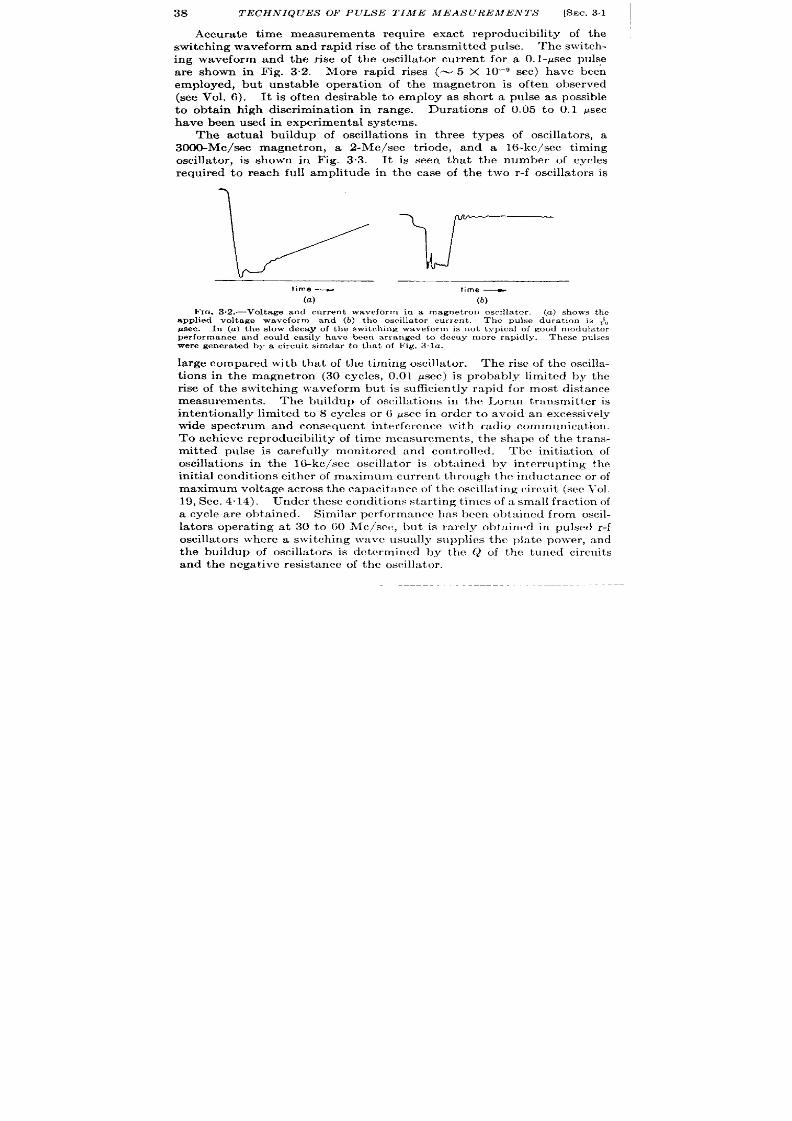
38
TECHN IQUES OF PULSE TIME MEASUREMENTS
[SEC. 31
Accu ate t ime measurements require exact reproducibility of the
switching waveform and rapid r ise of the t ransmit ted pulse. The switch -
ing waveform and the r ise of the oscilla tor cu rren t for a O.I-Asec pulse
a re shown in Fig. 32. More rapid r ises (~ 5 X 10-’ see) have been
employed, but unstable opera t ion of the magnet ron is often observed
(see Vol. 6). It is often desirable to employ as shor t a pulse as possible
to obta in high discr iminat ion in range. Dura t ions of 0.05 to 0.1 Psec
have been used in exper imenta l systems.
The actua l buildup of oscilla t ions in th ree types of oscilla tors, a
300&Mc/sec magnet ron , a 2-Me/see t r iode, and a 16-kc/sec t iming
oscilla tor , is shown in Fig. 3.3. It is seen
requ ired to reach fu ll amplitude in the case
tha t the number of cycles
of the two r-f oscilla tors is
\ /“)
If=
. .
Ilme —
time —
(a)
(b)
F ICJ .3.2.—Volt age a nd cu rr en t waveform in a magn et r on oscilla tor . (a ) sh ows the
.wdiedvoltaeea veform and (b) the oscilla tor cur rent .
The pulse dura t ion is 71,
#sec. In (a ) t he slow deca y of t he swit ch in g wa veform is n ot t ypi a l of good r ,,odu la tor
wer e gen er at ed by a cir cu it simila r t o t ha t of F ig. 3.la .
la rge compared with tha t of the t i ing oscilla tor . The r ise of the oscilla -
t ions in the magnet ron (30 cycl s, 0.01 ~sec) is probably limited by the
r ise of the switching waveform but is sufficien t ly rapid for most distance
measurements. The buildup of oscilla t ons in the I,orm transmit ter is
in ten t ionally l mited to 8 cycles or G ysec in order to avoid an excessively
wide spect rum and consequent in ter ference with radio communica t ion .
To ach ieve reproducibility of t ime measurements, the shape of th trans-
mit ted pulse is ca refu lly monitored and cont rolled. The in it ia t ion of
oscilla t ions in the 16-kc/scc oscilla tor is obta ined by in ter rupt ing the
init ia l condit ions either of maximum c rren t th rough the inductance or of
ma ximum volt age a cr oss t he ca pa cit an ce of t he oscilla tin g r ir ru it (see Yol.
19, Sec. 4.14). Under these condit ions star t ing t imes of a small fract ion of
a cycle a re obta ined. Similar per formance has been obta ined from oscil-
la tors opera t ing at 30 to 60 LIc/see, but is ra rely obta ined in pulsed r-f
oscilla tors where a switching wave usually supplies the pla te power , and
the buildup of oscilla tors is dct r rmincd hy the Q of the tuned circu it s
and th e n ega tive resista nce of th e oscilla tor .

fiEC.3.2]
THE RECEPT ION
Although the t ime delay between
the r ise of the switch ing waveform
and the in it ia t ion of r-f oscilla t ions
in the magnet ron is ext remely small
(< I&’ see), th is in terva l may be
appreciable in other oscilla tors, for
example, t he ligh th ou se-tu be oscilla -
tors. 1 F igu re 3.4 indica tes 0.3-psec
delay between the r ise of the switch -
ing waveform and the in it ia t ion of
oscilla t ion in type 2C43. Not only
does this factor have to be taken
in to accoun t in the ca libra t ion of
ranging equipment , but shor t - and
long-per iod var ia t ions of th is va l e
must be kept a t a minimum in order
t o a void ser iou s er ror s.
‘I’he short -t ime var ia t ions can be
pract ica lly elimina ted by the in t ro-
duct ion of a low-level c-w signa l a t
a ppr oxima tely t h e r eson ant fr equ en cy
—and some reduct ion of the delay
is a lso ach ieved. This ethod is
par t icu la r ly usefu l a t frequencies of
200 Me/see .
3.2. The Recept ion of Pulses.—
As far as is known , the propaga t ion
of the t ransmit ted pulse to the reflec-
tor and back to the receiver occu rs
a t the velocity of ligh t . The distor -
t ion of the leading edges of pulses
reflected from some small sta tionary
OF PULSES
39
(a)
3000 t#clsec
(b) 2 Mclsec
(c)
16 Kc/see
FIG. 3.3.—Tracingsof oscillograms
r epr esen tin g t he sta rt n g t imes of
various oscillator circuits.
(a ) r ep re-
sen ts t h e st ar tin g of a 3000-Mc/sec
magnetronoscillator . To achieve full
amplitude30 oscillationsar e required.
(~) representsth e initiationof oscilla-
t ions in a Loran t ransmit teropera t ing
a t 2 Me/see. Th e bu ildu p of oscilla -
tionsherecloselyfollowstherise01the
swit ch in g waveform. (c) shows t h e
initiationof oscillationsin a 1&kc/sec
t im in g waveform gen er at or . Not e t ha t
pr act ica lly r apid gt ar tin g is obt ain ed.
F IG. 3,4.—Dela y between t he
switch ing waveform and the in it ia -
t ion of r -f oscilla tion s. Th e bu ild-
u p of oscillat ions in a ligh th ou se
t ube (2C43) oper at in g wit h 1000
volts at the pla te is shown, indi-
ca t ing a delay of rough ly ipsec.
Tbe dur at ion of t he cur ren t pu lse
is 1.16 #sec.
object s is sligh t , bu t distor t ion of pulses
reflected from other object s may be very
ser ious and is due to the in t er ference be-
tween rays reflected from various pa r ts
of the object (see Vol. 1).
Bandwidth and Rise Time.—An ideal
receiver wou ld exact ly reproduce the
transmit ted waveform, and thus achieve
opt imum accuracy. Unfor tuna tely, no
receiver has been made to reproduce
1A microwavetr iode transmit tertube (see Vcl. 7).
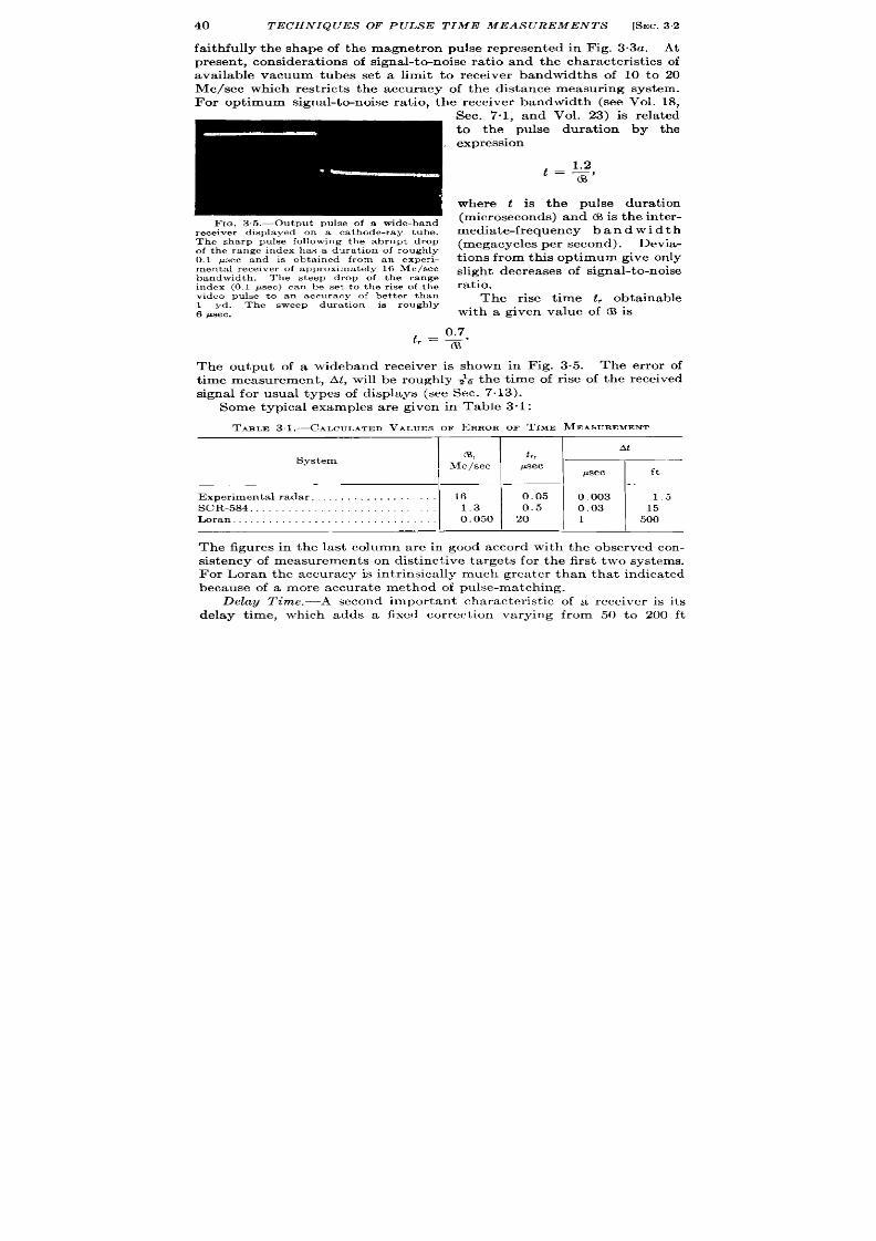
40 TECHNIQUES OF PULSE TIME MEASUREMENTS
[SEC.32
faithfully the shape of the magnet ron pulse repr esen ted in Fig. 3.3a. At
pr esen t, consider at ions of signal-to-noise ra tio and t he ch aract er ist ics of
available vacuum tubes se a limit t o receiver bandw dths of 10 to 20
Me/see which rest r ict s the acc racy of the distance measur ing system.
For opt imum signal-tc+noise ra t io, the receiver bandwidth (see Vol. 18,
FIG, 35.-Ou tput pu lse of a wide-band
r eceiver displayed on a ca t hode-ra y t ube.
Th e sharp pulse following t he abrupt dr op
of t he r an ge in dex h as a du ra tion of r ou gh ly
0,1 psec and is obta ined from an exper i-
menta l rece iver of approximate ly 16 Nfclsec
bandwidth. The steep drop of the range
index (0.1 #see) can be set to tbe r ise of the
video pu lse to an accuracy of bet t er than
1 yd. The sweep dura t ion is rough ly
6 psec.
Sec. 7.1, an Vol. 23) is rela ted
to the pulse dura t ion by the
expression
where t is the pulse dura t ion
(m icr os con ds) an d (S is t he in ter -
media te-frequency ban d w i d t h
(megacycles per second). Devia -
t ions from this opt imum give only
sligh t decr ea ses of signa l-t o-noise
ratio.
The r ise t ime t , obta inable
with a given value of @ is
The outpu t of a wideband receiver is shown in Fig. 3.5. The er ror of
t ime measurement , At , will be rough ly ~a the t ime of r ise of the r eceived
signal for usual types of displays (see Sec. 7.13).
Some typica l examples a re given in Table 3“1:
TABLE 31.-CALCULATED VALUES OF EEUtOROF TIME MEASUIIEMENT
System
At
CB, t
r,
—
Me/see
gsec
psec
I
ft
l—l—l
1
Exper imen ta l radar . . . . . . . . . . . . . 16
0.05
0.003
1.5
SCR-584. . . . . . . . . . . . . . . . . . . . . . . . .
1.3 0.5
0.03
15
Loran . . . . . . . . . . . . . . . . . . . . . . . . .
0.050 20 1
500
The figures in the last column are in good accord with the observed con-
sistency of measurements on dist inct ive targets for the first t wo systems.
For Loran the accuracy is in t r insica lly mu h grea ter than that indica ted
because of a more accura te method of pulse-matching.
Delay Time.—A second impor tant character ist ic of a r eceiver is it s
delay t ime, which adds a fixed cor rect ion var ing from 50 to 200 ft

SEC. 3.2]
THE RECEPTION OF PULSES
41
depending upon the bandwidth and number of stages of the receiver (see
Vol. 18, Chap. 4).
This dela y is expr essed a ppr oxim at ely as follows:
h=?
for a six- or seven-stage single-tuned amplifier . The delay is roughly
twice this value for a double-
tuned amplifier of the same num-
ber of stages. In actual pract ice,
td is measured for each par t icu la r
radar system, and fo a given
radar it is found to be repro-
ducible. The measurement of t~
is discussed briefly in Sec. 3.6.
Va ria tion oj Delay w“th Signal
Amplitude.-A third practical
considera t ion in the choice of re-
ceiver bandwidth is the effect of
signa l-amplitude fluctuat ions
upon the t ime delay of the re-
ceived pulse. In radar systems
for t racking moving ta rgets, such
a s sh ips or a ir pla nes, in ter fer en ce
effect s give very la rge signa l fluctu -
a t ions. Also the echo is oft en
am litude-modula ted by the an-
gula r scan of the radar . F igure
3.6 in dica tes va ria tion s of t he t ime
types of receiver s of inadequate
bandwidth.
Gain Cont rol.—The er ror due
t o signa l-amplit ude f uctu at ion s
is considerably reduced by auto-
%
a
=
~
0
G
.
.=
m
1
1
0
350
700
Range In feet
FIG. 3.6.—The effect of s igna l amplitude
var ia t ion upon t ime delay in receivers of
inadequat e bandwidth . In both (a ) and
(b) the signa l of smalle t amplitude is de-
la yed t he most , a nd inc ea sing am plit udes
give an apparen t decreas in range. The
receiver of AN /A PS-15 is represent ed by
(a ) and that of AN/APG-5 is represen ted
by (b).
matic cont rol of the gain of the receiver .
Simple cir u it s that will
mainta in the average value of the signal amplitude constant a re well
known, and manyfold reduct ion of the range er ror s is readily obtained.
Often the fluctuat ions of signal in tensity a re a t a ra te comparable to the
pulse-repet it ion frequency—for example, fluctuat ions due t o propeller
modulat ion , slow changes of aspect , or angular scanning.
Rapidly
act ing ga in-cont rol circu it s may be used to remove amplitude changes
due to these causes. Since some of these modulat ions may bear

42 TECHNIQUES OF PULSE TIME MEASU EMENTS
[SEC. 3.2
desir able in format ion -for example, modulat ion due to angular scan—
these volt ages are recover ed as a fluctua t ion of the cont rol signal to the
in termedia te fr equ en cy amplifier a nd a re su ita ble for dir ect ion al con tr ol
(s ee Sec. 9.5).
In hyperbolic naviga t ion systems, the t ime difference between the
recept ion of two signals is required. Since both these signals pass
th rough the same amplifier , they ar e delayed an equal amount provided
they a re adjusted to the same amplitude. The Loran display is designed
to permit the adj stmen t of the received signal amplitudes to equality.
An elect ronica lly switched display and gain cont rol ar e used so that the
t wo r eceived signals ar e a ltern ately displayed and cont rolled in r espon se
t o th e set t ing of separ ate ga in cont rols. If signal-in tensity ch an ges occu r
simultaneously for both waveforms, then the compensa t ion for t ime
er ror s occur s automat ically. Otherwise, manual or automat ic ga in con-
t rol may compen sa te for differ en tia l flu ct ua tion s of t he sign al amplit udes.
In th is way a high accuracy of t ime measurement is obtainable with a
na r row-band r eceiver .
Sin ce t im e-discr im in at ion cir cu it s a re n ever per fect ly ba la nced, t heir
sen sit ivit y t o amplit ude ch an ges is m in im ized by sa tisfa ct or y ga in con tr ol.
In addit ion , automat ic ga in con tr ol gives opt imal immunity fr om smaller
in ter fer ing signals, since the gain con t rol is always held to the value
relevant to the desired signal.
In view of all these advantages, th is
fea tu re is included in all r eceiver s in which range accuracy is impor tan t .
Automat ic gain con t rol does not always ensure the elimina t ion of
r eceiver -dela y va ria tion s du e t o sign al-in ten sit y ch anges, sin ce a lt er at ion s
of the gain -con t rol volt age it self may cause var iat ions in r eceiver band-
width and hence var ia t ions in t ime delay.
In par t icu lar , gain con t rol
that depends upon var ia t ion of the t r ansconductance of an amplifier tube
must also vary the bandwidth of this stage to a cer ta in exten t .
Quanti-
ta t ive data are available on his effect for SCR-584, where a 30-db signal-
amplitude change resu lt ed in a var ia t ion of receiver delay of 0.1 ~sec
in spite of the main tenance of a constan t ou tpu t amp itude.
Differ en t ia tion . -pu lse-sh ar pen ing or puk,edlffer en tia tin g cir cu it s a nd
large amplificat ion have been used to increase the ra t e of r ise of the
receiver ou tput ; some typical circu it s a re given in Vol. 19, Sec. 9.8. No
real increase in a ccu racy is obta ined, h owever , tha t cou ld not be ach ieved
by more sensit ive t ime-discr imina t ion cir cu it s. A differen t ia t ed pulse,
h owever , m ay be con ven ien t for man ual r an ge-t ra ckin g on a ca th ode-r ay-
t ube d isplay.
SYNCHRONIZATION
Synchron iza t ion is the process of ensu r ing tha t the t ime reference for
the t ime-modulat ion system and the t ime-demodulat ion system is the
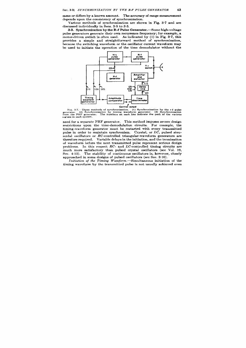
SEC. 33] S YNCHRON IZE T ION BY THE R-F PULSE GENERATOR 43
same or differ s by a kn own amount .
Th e a ccu ra cy of r an ge mea su remen t
depends upon t he con sist en cy of syn ch ron iza tion .
Var ious methods of synchroniza t ion a re shown in Fig. 3.7 and a re
d scussed individua lly in Sees. 3.3 t o 3.5.
3.3. Syn chr oniza tion by t he R-f P ulse Gen er at or .-Som e high-volt age
pulse gen er at or s gen er at e t heir own r ecu rr en ce fr equency; for example, a
motor -dr iven switch is often used. As indica ted by (1) in Fig. 3“7, th is
provides a simple and str a igh t forward method of synchroniza t ion,
because the switching waveform or the oscilla tor cur ren t waveform may
be used to init ia te the opera t ion of the t ime demodula tor without the
H v R-f
pulse
—
pulse
generalor generator
Tf
1
I
1
Amplifier
Timing
wove for m
generator
~ discriminobr
Confrol wtpuf
FIG. 3.7.—Three methods of synchronization. (1) Synchronization by the r-f pulse
generator. (2) Synchronization by timing waveform generator. (3) Synchronization
from the P1lF generator.
The number s on ea ch line in dicate t he pa th of. t he va rious
s igna ls in each sys tem.
need for a separa te PRF genera tor .
This met hod imposes sever e design
r est r ict ions upon the t ime-demodulat ion circuit s.
For example, the
t iming-waveform genera tor must be resta r ted with every t ransmit ted
pulse in order to mainta in synchronism. Crysta l, or LC, pu lsed sin u-
soidal oscilla t or s or h%’-cont rolled t ria ngula r-wa veform gener at or s a re
t her efor e requ ired. Var iable delays h the init ia t io , and the terminat ion
of waveform before the next t ransmit ted pulse r epresen t ser ious design
problems. In this r espect RC- and LC-cont rolled t iming circuits a r e
much m re sa t isfactory than pulsed crysta l oscilla tors (see Vol. 19,
Sec. 4.15). The stability of cont inuous oscilla tors is, however , closely
a ppr oa ch ed in some designs of pulsed oscilla t or s (see Sec. 3.10).
Initiation of the ,Timing Waueform.—Simult an eou s in it ia tion of t he
t iming waveform by the t ransmit ted pulse is not usually achieved even

44
TECHNIQUES OF PULSE TIME MEASUREMENTS
[SEC. 3.4
in the most ca refu lly designed circuit s. As a result , each system haa a
cor rect ion to be applied to compensa te for this delay. This correct ion
var ies from a fract ion of a microsecond for RC-cont rolled t r iangular
t iming wa veforms t o sever al m icr osecon ds for pu lsed cr yst al oscilla tor s.
Th e st ar t in g t im e of pulsed LC’-oscilla tor s is ver y small, a nd t he t ra nsien t
response of associa ted phase-shift ing networks usually determines the
delay in opera t ion . This, however , ra rely exceeds ~ cycle of the t iming
wave. The necessary cor rect ion is usually determined by measuring
the er ror in the range of a ta rget a t a known distance.
Minimum Range. -A other consequence of the delay in the init ia t ion
of the t iming waveform is the inaccuracy of range measurements made a
few microseconds a ft er the t ransmit t ed pulse. This sets a limit to the
m in imum dist an ce mea su ra ble.
In many circuit s this cor responds o a
few per cent of the full range sca le, and it is oft en desirable to inser t a
delay device between the receiver output and the t ime discr iminator as
shown in F ig. 3.7. This permi s cont inuous range readings through
zero. A delay line of 3 to 4 psec is required, and it s tempera ture coeffi-
cient may cause addit ional er ror s (see Vol. 19, Sec. 13.7).
3.4. Con trol of the PRF by the Timing Waveform.-This method of
synchroniza t ion , shown as (2) in Fig. 3.7, permit s complet e fr eedom in t he
design of t he t im ing-wa veform gen er at or an d u sua lly r esu lt s in a dist an ce-
measur ing systcm of grea ter simplicity and accuracy than any other .
One of the principa l advantages is tha t a cont inuously oscilla t ing t ime
standard, such as a crysta l-cont rolled oscilla tor , is employed.
The
relia ility and stability of the quar tz crysta l r emove the need for any
other t ime standards. -4 chain of frequency dividers maybe employed to
genera te a synchronizing pulse of a constant or adjustable PRF for the
t ransmit ter , as discussed in Sees. 3“13 and 3“15. Simple circu it s a re
available for giving pmcisc phasing bet ween t he sinusoida l oscilla t or and
t he t rigger pulse. Finally, t he essent ia ls of simple and accura te mult iple-
sca le range systems form an in tegra l par t of the oscilla tor fr equency-
di idcr syst cm (see Sec. 3.15).
Another advantage of this type of synchroniza t ion is tha t cont inuous
and accura te t ime measurements may be made before and aft er pulse
transmission.
Since the t iming-waveform genera tor opera tes cont inu-
ously, any er ror s due to it s sta r t ing t ime are eliminated.
In t heir pla ce,
In some designs the phase of the output
of the frequency-dividing system may vary with respect to the t iming
waveform. This er ror may be almost completely avoided by the use o
a frequency divider tha t incorpora tes t ime select ion of a pulse genera ted
a t the frequency of the t iming wav form (see Sec. 4.8). Another er ror
may ar ise from a varia t ion in the delay between the t r igger to the high-
volt age pulse genera tor and the t ransmission of the r -f pulse
In order
SEC. 3.6]
ZERO CAL IBRAT ION
45
t o min imize t hese difficu lt ies, an ext rem ely r apid t rigger is u sed t o in it ia te
the high-voltage pulse genera tor tha t in turn must in it ia te the radio-
fr equ en cy oscilla t ion s wit h ext rem e r apidit y. Th e la tt er is a ccomplish ed
sat isfact or ily in most cases (see Sec. 3“1).
If the given synchronizing waveforms are of equal rapidity, there is
ver y lit t le t o ch oose between th e accu racy of synch roniza t ion obta inable
with this method and that descr ibed in Sec. 3.3.
The main advantage
of this method is the simplicity-, economy, and accuracy of the t ime
modula tor built around the crysta l oscilla tor and the frequency divider .
Th e disadvantage is th e r egular ity of pu lse-r ecur rence in ter va l.
3.5. Synchroniza t ion by a PRF Genera tor .—A separa te PRF gener -
a tor may be used to init ia te the opera t ion of the t ime demodu la tor and the
r -f pulse genera tor as shown by (3) of Fig. 3.7. This connect ion is sub-
ject to the er ror s of both the previous systems since the sta r t ing t imes of
both the r -f oscilla tor and t ime demodula tor may vary. This connec-
t ion is, however , often employed for medium-precision ranging systems
having RC t iming elements in the t ime demodu la tor and vacuum-tube
swit ch es in t he h igh -volt age pu lse gen er at or .
The opera t ion of the t ime
demodulator is usually sta r ted in advance of the r -f t ransmit ter by a
precisely known t ime in terva l to permit accura t e zero calibrat ion and to
indi a te t he t r ansmit ted pulse on t he ca th ode-ray-tube display.
A var iant of this type of synchroniza t ion is one in which the funct ion
of the PRF genera tor is to select a tr ain of t iming waves from a con t inu-
ous oscilla tor . The fir st member of this pulse tra in serves as the refer ence
pulse of the t ime-demodula t ion system and also as the t r igger for the r -f
pulse genera tor . The other members of the selected pulse t ra in are
used in the t iming circu it s. The necessity for a fr equency divider is
avoided, and yet exact synchronism between the t iming waveform and the
r -f pulse is main tained. Also the average PRF s cont inuously var iable
(s ee Sec. 4.9).
3.6. Zero Calibrat ion .-The existence of a number of fixed or var iable
dela ys etween em ission of t he r - pu lse a nd in it ia tion of t he demodu la tion
system haa been indica ted. If accura te t ime measurements are requ ired,
a zero-ca librat ion procedur e must be employed to determine the exact
va lue of the delay and to cor r ect for any var iat ion which may occur
because of the effects of t ime, tempera ture, or ’ other var iables upon the
equipment.
The zero poin t for distance measurement is the moment of appear -
ance, at the termina ls of the t ime discr iminator , of an echo from a target
cor responding to zero range. Th s echo is, of cour se, never physically
rea lizable because of the fin ite length of the t ransmit ted pulse. A sat is-
fa ct or y su bst it ut e is a r eflect or pla ced a t a k nown dist an ce (a ppr oximat el
1000 ft ) tha t is la rge compared with the pulse length . The t ime-&

46
TECHNIQUES OF PULSE TIME MEASUREMENTS
[SEC.3.7
modula t ion circuit is ca libra ted against some known standard such as
the crys ta l-con t rolled oscilla tor .
The difference between the reading of
the t ime demodula tor and the known distance of the ar t ificia l r eflector
then gives the proper zero cor rect ion for the system. This cor rect ion
takes in to account all er ror s. Par t icu la r ca re is needed when using t ime-
demodula tion circu it s in which the ca libra t ion of the zer o poin t in tera cts
with the ca librat ion of its slope.
Since t he pr ecise loca t ion of such a r eflector is an ext rem ely awkwa rd
opera tion under field condit ions, any a lterna t ive pr oposa l is prefera ble
a lthough the zero-ca libra t ion procedure becomes much more involved
and much less accura te. One may assume tha t the signa l of la rgest
amplitude appear ing a t the output termina ls of the receiver is the r -f
p lse and tha t this pulse cor responds to an echo of zero range. This
assumption is ra rely just ified since the energy of the high-voltage of r -f
pulse may be sufficient to excite the la ter amplificat ion stages of the
receiver and in this way a r r ive in advance of energy which has t raveled
the same path as a received echo.
Depending upon the shielding of the
receiver and the energy of the t ransmit ted pulse, the signa l obta ined in
th is manner may ant icipa te t e t rue zero poin t of r ange by values indl-
ca ted in th e following table and must , th er efor e, be init ia lly ca libra ted as
descr ibed above. Such ca libra t ion is constan t and holds t rue for a given
type of radar .
T-LE 3.2.—APPROXIMATEEROCORRECTIONORTYPICALRADARSYSTEMS
System AhJ ,IILles
Exper imenta lr adar. . . . . . . . . . . . . . . . . . . . . . . . . . . . . . . . . . . . . . 0.1
SCR-5S4. . . . . . . . . . . . . . . . . . . . . . . . . . . . . . . . . . . . . . . . . . . . . . . . 0.2
AN/APG-5 . . . . . . . . . . . . . . . . . . . . . . . . . . . . . . . . . . . . . . . . . . . 0.3
A pract ica l dificulty in measur ing the t i e of appearance of the pulse
cor responding to zero range is due to possible nonlinear ity of the char -
a cter ist ics of t he t im e demodu la tor n ea r zer o r an ge.
If t he t im e demodu -
la tor cover s a ra nge gr ea ter than the interva l between transmit ted pulses,
the zero set t ing is made, ot with respect to the t ransmit ted pulse, bu t
with respect to the pulse immediately succeeding it . For systsms having
a known and c nstan t r epet it ion interva l, this elimina tes the effects of
a ny sh or t-r ange n on linea rit ies of t he t im edemodu la tion cir cuit .
S.7. Remote Cont rol of Synchroniza t ion.-Naviga t iona l systems in
which a t ime demodula tor is loca ted remotely are synchronized by radio
t ra nsmission of t he r efer en ce pulse.
This pulse may init ia te the t iming
wa veform of the r em ot e r eceiver by direct t r igger ing, or may be protected
by pu lse coding and decoding or pu ls e-r ecu r r ence-fr equency demodu la t ion .
It ia necessary to consider not only the ra te of r ise of the synchronipiing
waveform but a lso the effects of noise and in ter ference on the reliability
a nd a ccu ra cy wit h which t he r emot e t im e demodu la to is synchr on ized.

SEC.3.8]
S IN GLE-S CALE TIME MODULATION
47
Sin ce a sin gle u ncoded pu lse is r ar ely sa tisfa ct or y, t he simplest syst em s
employ coding and decoding circuit s depending upon pulse dura t ion
or spacing. As shown in Vol. 19, Sec. 10”2, the ea r lier members of a
mult iple-pulse code permit unique t ime select ion of the la t er members.
The secur ity of a code against in t er ference increases much more rapidly
than the number of pulses in the code.
In a pa rt icu la r ca se t he fr equ en cy
at which a three-pu lse code will be simula ted by severa l in t er fer ing
radars is but Zh tha t of a tw~pulse code.
If in t er ference is heavy or the r ise t ime of the synchronizing puke is
not sufficient ly rapid to secure accura te t r igger ing by pulse c ding and
decoding, pulse-recur rence-frequency demodula t ion is employed (see
Fig. 2“23). This method has severa l advantages. If the t ransmit t ed
PRF is cryst al-cont rolled, t he frequency-m odula t ed oscilla t or of t he fr e-
quency demodula tor may also be crysta l-con t rolled and have a stability
permit ting oper at ion for apprecia ble in terva ls in t he absence of syn c r o-
nizing pulses. For example, in Loran ground sta t ions synchroniza t ion
loses a ccu ra cy (~ psec) on ly a ft er a 3-r ein in ter ru pt ion -cor respon din g
to a 10SSof 45OO pulses. Another advantage of crysta l-cont rolled PRF
demodulator.
Often init ia l select ion of the cor r ect PRF is made on the basis of
pulse coding and decoding since instantaneous response to the cor r ect
code is obta ined. This process is t hen combined wit h PRF demodula tion .
TIME MODULATION
GENERAL DESCRIPTION
The subject of t ime modula t ion has been discumed extensively in
Vol. 19, Chaps. 7, 9, and 13, and a number of pract ica l single- and
mult iple-sca le circu it s a re given in Chaps. 5 and 6 of this volume.
only
t he gen era l proper t ies of t ime-m odula t ion device a re pr es nt ed h er e.
3.8. Single-sca le Time Modula t ion.-Time modula t ion is defined as
the odula t ion of the t ime in tewal between two waveforms or between
two por t ions of a waveform. The
ea r lier waveform or por t ion of a
pwlaa “pomian ,“,0,”0,
i
wavefo m is termed the “t ime
eference” pulse while the la t t er ‘“’crone’ ‘Isc
is the “t ime-modula ted” puke. n
The in terva l over which t ime Tim.-modulated puke
modula t ion may be expect ed is
k
Range of time
t ermedt h e” r ange of modu la t ion .”
modulation
--l
This may be equal t o the pulae-
Fm. 3&-S,n d~a le t im emodu la tor .
ecur rence in terva l of the radar system, but is usually ra ther less
than th is va lue to permit the pul&waveform genera tor to return to
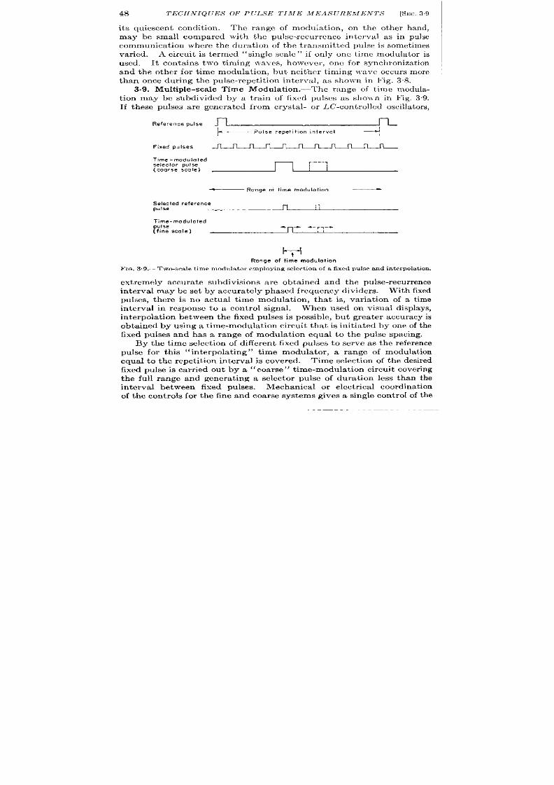
48
TECHN IQUES OF PULSE TIfifE MEASUREMENTS [SEC,39
its quiescent condit ion . The range of modula t ion , on the other hand,
may b small compared with the pulse-recur rence interval as in pulse
communicat ion wher e the durat ion of the t ransmit ted pulse is somet imes
var ied. A circuit is termed “ single scale “ if only one t ime modula tor is
us d. It conta ins two timing waves, ho~~-ever , one for synchron izat ion
and the other for t ime modulat ion, but ncit -ner t iming lva~,e occurs more
than once dur ing the pulse-repet it ion interval, as shown in Fig. 38.
3.9. Mult iple-scale Time Modulat ion .—The range of t ime modula-
t ion may be subdivided by a tra in of fixed pulses as sho]~n in Fig. 39.
If these pulses are genera ted from crysta l- or LC-cont rolled oscillators,
Reference pulse n
~—Pu15e repe!i+icm interval $
Fixed pulses
n
n
n
n
n n n
n
n n n
Time -modulated
selector pulse
(coarse scale)
~ Range or l ime modulation —
Selected reference
n
:,
pulse
Time-modulated
pulse ++. -
(fine scale)
~,-+
l+
Range of time modulation
Ft~. 3 .9.—Two-sca le t ime modula tor employing select ion of a fixed pulse and in terpola t ion .
ext remely accurate subdivisions are obta ined and the pulse-recur rence
interval may be set by accur ately ph ased fr equency dividers.
With fixed
pulses, there is no actual t ime modula t ion, that is, var ia t ion of a t ime
interval in response to a cont rol signal.
When used on visual di plays,
in terpola t ion between the fixed pulses is possible, but grea ter accuracy is
obta ined by using a t ime-modula t ion circuit that is in it ia ted by one of the
fixed pulses and has a range of modula t ion equal to the pulse spacing.
By the t ime select ion of differen t fixed pulses o serve as the r efer ence
pulse for th is
“in terpola t ing” t ime modula tor , a range of modula t ion
equal to the repet it ion interval is covered. Time select ion of the desired
fixed pulse is ca r r ied out by a “coarse”
t ime-modu la t ion cir cu it cover ing
the full range and genera t ing a selector pulse of dura t ion less than the
in terval between fixed pulses.
Mech an ica l or elect rica l coor din at ion
of the cont rols for the fine and coarse systems gives a single con trol of the

SEC. 3.9] MULTIPLE-S CALE T IME MODULATION
49
fine-sca le pulse over the ent ire range. As shown in Fig. 39 this process
depends upon two time modula tors and a fixed pulse train genera ted by a
pr ecise t im in g waveform r ecu rr in g many t im es du rin g t he fu ll modu la tion
in terva l. Three t iming waves a re involved, one for the fixed pulses and
two for the coa rse and fine scales. This combina t ion is said to be
“dou ble sca le. ”
This ar rangement is simila r to double-sca le synchro
systems (see Vol. 19, Sec. 12.6), and the same accur cy increase is
obtained.
The er or of a t ime modula tor may be considered a fixed fract ion of
the full range of modulat ion independent of the t ime sca le. Thus the
smaller the range of modulat ion in t ime units, the grea t er the accuracy
in t ime units. Thus the accuracy is propor t iona l to the number of t imes
Reference pulse
Fixed pulses
Phase -modulated
PUIses
Time .modulofad
selector pulse
( caarse stole )
Time-modulated
Nlse
_ Pulse repetition interval
~~
n
n n
n
n
n n
n
n
n
n
i
phase rnadulation is
continuous over this interval
+-
—Range af time modulation _
-rl--
_ Range of time modulation _
FIG. 3.10.—Two-sca1e t ime modula tor emp loying select ion of a phase-modula t ed puls e.
the range of modula t ion is subd vided by the fixed pulses. The accuracy
ga in cor respondin g t o Fig. 3.9 is 10-fold.
A differen t type of mult iple-sca le system depends upon phase modu-
la t ion_ (see Sec. 13.13, Vol. 19) of the t iming waveform tha t is als used
to genera t i the tra in of fixed pulses as shown in Fig. 3.10. Since phase
modula t ion may be car r ied out by capacitance and inductance phase.
sh if+~r s t ha t sh ift t he ph ase con tin uou sly, efiect ive in ter pola tion over t he
in terva l between fixed pulses is immedia tely achieved, and the phase
sh ift er r epla ces t he in ter pola tin g dela y.
In mult iple-sca le opera t ion the ext en t of phase modula t ion may cover
many cycles of the t iming wave, and t ime select ion of a par t icu la r mem-
ber of the pulse tra in is car r ied out by a coar se t ime modula tor . The
mechanica l or electr ica l connect ion between the coa rse and fine sca les is
so ar ranged that a single cont rol gives the same ra te of change of t ime
delay to both the ph se-shifted puke t ra in and the selector pulse. A
I Frequencymodulat ion of the t iming waveform is rarelyused.
50
TECHNIQUES OF PULSE T IME MEASUREMENTS [SEC.3.10
par t icu lar phase-sh ifted pulse, once select ed, is con t inuously selected
over the ent ir e range. The factor by which the accuracy is increased
over a sin gle-scale ph ase modu la tor is t heor et ica lly equ al t o t he n umber of
su bdivision s of t he r an ge of modu lat ion .
The next sect ions discuss the accuracy obta ined with these t iming
systems.
THE CHARACTERISTICS OF COMPONENTS
The precision of waveform genera t ion and the stability of volt age
m ea su rem en ts det ermin e t he a ccu ra cy of elect rica l t im ing.
Befor e pr o-
ceeding with a discussion of the employment of these methods, a br ief
r eview of th e ch ar acter ist ics of available com ponen ts will be pr esent ed.
Grea ter deta il is available in Vols. 17, 18, and 19.
3.10. Timing Standards. —Resistance-capacitance, inductance-
capacitance, and quar tz-crysta l standards are used for the genera t ion of
p recis ely t imed sinu soida l waves .
Th e RC-st an da rds a re a lso ext en sively
u sed for det ermin in g t he slope of t ria ngu la r, expon en tia l, h yper bolic, an d
parabolic waveforms. The accuracy of the RC-standards for determin-
ing the slope of a wave is compared with the accuracy of quar tz and
LC-standards for determining th e per iod of a sinusoidal wave.
Accuracy oj Specijicaiion.-The per fect ion of met hods of manufa ct ur e
and quality cont rol yields quar tz crystals of an accuracy considerably
in excess of one par t per million—a simple and most accura t e standard.
T e precision of manufacture of L-, C-, and R-componen ts is negligi le
by compar ison . Ordinary carbon resistor s and paper condensers used in
r adio r eceiver s ar e specified t o with in 5, 10, or 20 per cen t depending u pon
the degree of select ion whic is specified. IIica dielect r ic condenser s,
wire-wound resistors, and permeability-tuned inductor s are obtained
\ \ ith in con siderably closer toler ances, and specificat ions of 1 per cen t ar e
met by most manufacturer s. The process analogous to the final gr inding
of quar tz crysta ls may also be car r ied out with LC- and RC-st andards
since the per iod of sinusoids or the slope of t r iangular -waves may be
checked against quar tz standards and adjusted to an equal precision .
This is a more sa t isfactory procedure than direct measurem nt of the
com pon en t values becau se var ia t ions of st ray capacitance and tu be char -
a ct er ist ics usu ally n ecessit at e a final calibr at ion of t he a ctu al cir cu it .
The f rm of a sinusoidal or t r iangular wave may be accurately con-
t rolled by the character ist ics of the associated amplifier . \ “egat i\ ,e-
feedback cir cu it s of ext r eme gain stability may be used to ach ieve a
linear ity of a t r iangular wave of a few par ts in ten thousand (see Yol. 19,
Sec. 7.11).
Refutive Stability oj Similar Oscilla tors.-The rela t ive stability of
crysta l< on t rolled oscilla tor s is outstanding, For example, the rela t ive

SEC.3.11]
VACUUM TUBES
51
dr ift of the PRF of the t imers used in the Loran master and slave sta t ions
lies between 0.1 and 0.03 psec/min , or 100 and 30 ft /min. This cor -
r esponds to a rela t ive stability of one par t in 10* or 10s, equiva len t to tha t
obta inable from high-quality clocks. Grea ter r ela t ive stabilit ies are
obser ved in cavity-stabilized m icr owave oscilla tors wh er e values of five
par t s in 10’0 have been obtained (see Vol. 7).
Temperature Coejicien t .-This character ist ic of the t iming elemen t is
ext rem ely impor tan t, especially for a ir bor ne a pplica tion s.
H er e again
the quar tz crysta l excels since tempera tu re coeffici n ts of severa l par t s
per million per degree cen t igrade are readily obtainable. In M! and RC
timing elements, the componen ts have appreciable tempera tu re coeffi-
cien ts. In RC-combinat ions car bon r esistor s and paper condenser s often
give changes of 5 or 10 per cen t in tempera tu re in terva ls of 40”C. On
the other hand, carefu lly selected combinat ions of mica condenser s of
temper at ur e coefficien t give an over-all temper at ur e coefficien t of t en to
twen ty par ts per million per degree cen t igrade. 1 By carefu l quality
con tr ol LC-combina tion s h avin g over -a ll t emper at ur e coeffi ien ts of five
par t s per million per degr ee ce t igr ade ar e also obta in ed.
To obtain ult imate precision thermostat ic con t rol of all t h ree types of
t iming standards is desirable. This pract ice has been em loyed for muy
year s in communicat ions t ransmit ters. Rela t ively com act and simple
t emper at ur e r egu la tor s a re available for th is pu rpose.
3.11. Vacuum Tubes.—Although the slope or durat ion of a wave is
accur ately determine by pr ecision t iming elemen ts and negat ive-feed-
back amplifiers, th e gener at ion of accu ra te t iming indices depen ds upon
compar ison of the amplitude of the t iming wave to a refer ence volt age.
At the moment of equality of these two voltages, a h igh-ga in nonlinear
vacuum-tube amplifier instan taneously r esponds and mar ks th e equality
by a sharp pulse. This process is termed “amplitude compar ison” and
the combhat ion of circu it elements producing the pulse, an “amplitude
compara tor” (see Sec. 9.8, Vol. 19). F luctuat ions due to the effect of
t ime, voltage, etc., upon a par t icu lar vacuum tube or var ia t ions among
differen t vacuum tubes of the same type may cause large er ror s in the
indica ted instan t of equality of the two voltages.
Accuracy of Speczj’icat ion . -The th ermionic vacuum tu be is th e least
repr odu cible cir cu it elem ent u s d in th e pr ocesses descr ibed in th k book.
In the case of the popu lar 6SN7 double t r iode, the J AN Specifica t ion
lists an a llowable var iat ion of the pla te cur ren t at constant plate volt -
age, gr id bias, and heater volta e of between 5.5 and 12.5 ma from
tube to tube becau e of var iables in the manufactur ing process-a
I These coefficient sun fort un at elyvary slightlywith temper at ur e,and th e compen-
sat ion k unsat isfactoryover wide temperatu reranges.
E.G. & G. LIBRARY
LAS VEGAS BRANCH
52
TECHNIQUES OF PULSE TIME MEASUREMENTS [SEC.3.12
var ia tion r esu lt in g in an er ror of t im e mea su rem en t r ou gh ly a million t im es
grea ter than tha t of ordinary quar tz crystals.
There is, however , a specially selected double t r iode, type 6SU7, in
which a pair of t r iode elements is matched in such a way tha t the differ -
ence between their pla te cur ren ts is very mall.
In term s of equiva len t
gr id b as th is amounts to less than 0.1 volt , rough ly 3 per cen t f the
lin ea r r ange.
The cutoff poin t of thermion ic vacuum tubes is very poor ly defined
and var ia t ions between ~ volt and 10 or more volt s (depending upon the
type of vacuum tube and the cu toff volt age) may be expected. Diodes,
on the other hand, are much more stable in th is respect and stabilit ies
of a few tenths of a volt may be achieved. Contact r ect ifiers, such as
germanium crysta ls, a r e excellen t in this respect , and var ia t ions consid-
erably less than a millivolt a re obta ined.
Other por t ions of their char -
acter ist ic may, however , be very tempera ture-sensit ive and unsuitable
for th is pu rpose.
The gr id cur ren t of vacuum tubes, a lthough often found to be in the
region of a hundredth or a ten-thousandth of a mic oampere, is permit t ed
to reach a few microampere in near ly all vacuum tubes before they are
r eject ed by the manufactu rer . The type 6SU7 has, however , a specifica-
t ion requir ing a gr id cu r ren t of less than 0.01 pamp.
Effect of Time and Mechanical Shock.-The change of the cha racter -
ist ics of a thermion ic vacuum tube with t ime is considerable, and var ia-
t ions cor responding o 10 mv of gr id bias (a t constant pla te cur ren t ) per
week are obta ined even under the most carefu lly con t rolled condit ions.
Diodes r epr esen t some impr ovemen t over t his figu re, a nd con ta ct r ect ifier s
a re super ior . Another var iable in vacuum-tube cir cu it s is the effect of
mechanica l shock which ranges from severa l hundred microvolt to com-
plet e dest ru ct ion of t he elem en ts.
In th is connect ion it is in terest ing to
note tha t ‘‘ r uggedized” tubes apparent ly give lit t le r educt ion of micro-
phonics, a lthough t hey undou btedly withstand la rger acceler at ions with-
ou t failure. Ther e is some evidence to indica te tha t the subminia ture
tubes, t ype 6K4 etc., h ave ver y small microphonics noise.
The stability of gaseous discharge tubes used for volt age standards is
rough ly 1 per cen t of the nominal volt age if var ia t ions due to tube changes
a re exclu ded. F or h igh er accu racy, elect roch emica l standards ar e pr efer -
able (see Vol. 21, Sec. 15-2).
3.12. Calibrated Subassemblies.-The largest var iable of t iming
cir cu it s baa ed u pon R-, L-, and C-component s and thermion ic vacuum
tubes is the accuracy of their specifica t ion . Near ly all the dificu lt iea of
manufacture and maintenance of precision equ ipment ma be at t r ibu ted
to th is factor . This is due, in a la rge par t to the desir e of consumers to
replace vacuum tubes withou t reca libra t ion simply because they may be
,.,

SEC. 3.12]
CALIBRATED SUBASSEMBLIES 53
plugged in to their sockets, as opposed to the replacement of “fixed”
component s, such as an inductor in an oscilla tor circu it where reca libra-
t ion is r ecogn ized a s ess n tia l.
A solu t ion t o th is dificu lty lies in t he use of funct iona l subassemblies
in which th e circu it compon en ts a re adjusted t o accou nt for t he var ia t ions
in the charact er ist ics of vacuum tubes. in fact , such funct iona l sub-
assemblies may be preca libra ted t o equal st andards of per formance
dur ing the manufactur ing process.
The replacement of a fau lty sub-
assembly can therefore be accomplished without loss of calibra t ion
provided the consumer is willing to discard the faulty unit .
This procedure is probably impract ica l with ordinary receiver tubes,
bu t t he” solder -in ” su bmin ia tur e vacu um t ubes pr esen t n ew possibilit ies,
FIG.3.11.—A calibra tedsubassemblyu sed in an exper imen t al model of a Lor an indica t or .
and an example of a ca librated subassembly using these tubes is shown
in Fig. 3.11. The resistance element s of this circu it (not shown since
they are mounted on the back of the card) are chosen with rega rd to the
charact er ist ics of the par t icu lar vacuum tube used in order that the per -
formance of all subassemblies may be adjust ed to the same standards
with a very close tolerance. The success of th is procedure must depend
u pon tubes of adequate life and freedom from dr ift and mechanical shock.
At the presen t t ime, the life of these tubes under normal opera t ing
con dit ion is in excess of 1000 h ou rs a nd t hey a re except ion a ly in sen sit ive
t o mech an ica l sh ock.
F IX D AND MODULATED TIMING PULSES
Th e gen er at ion of wa veforms of pr ecisely con tr olled slopes or per iods
and their compar ison with fixed or var iable r efer en ce poten t ia ls lead t o
the impor tan t methods of producing fixed or modula ted puleea for t ime
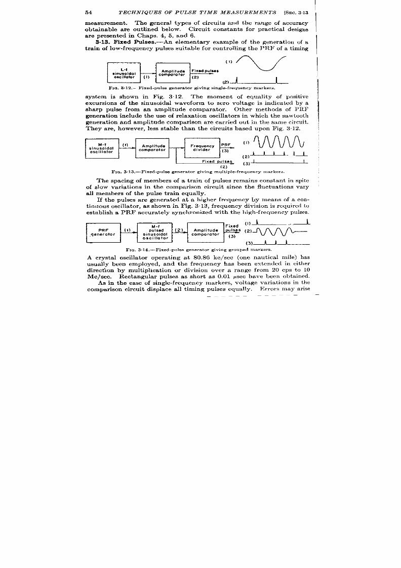
54
TECHN IQUES OF PULSE TIME MEASUREMENTS [SEC. 3.13
measurement.
The genera l t ypes of circuit s and the range of accuracy
obta inable a re out lined below. Circuit constants for pract ica l designs
a re presen ted in Chaps. 4, 5, and 6.
3.13. Fixed Pulses.-An elementa ry exampl of the genera t ion of a
t ra in of low-frequency pulses suitable for cont rolling the PRF of a t iming
~’(,).l:l.
Fm. 3.12.—Fixed-pulse generator giving single-frequency markers .
system is shown in Fig. 3.12. The moment of equality of posit ive
\
excursions of the sinusoidal waveform to zero volt age is indica ted by a ~
sharp pulse from n amplitude compara tor .
Other methods of PRF
gener at ion include t he use of relaxa tion oscilla t ors in which t he sawt oot h
1
genera t ion and amplitude compar ison are carr ied out in the same circuit .
They are, however , less stable than the circuits based upon Fig. 312. :
FIG. 3.13.—Fixed-pulse generat or giving multiple-frequency mar kers.
The spacing of members of a t ra in of pulses remains constant in spite
of slow var ia t ions in the compar ison circuit sin e the fluctuat ions vary
all m mbers of the pulse t ra in equally.
If t he pulses a re genera ted at a higher frequency by means of a con-
t inuous oscilla tor , as shown in Fig. 313, frequency division is required t o
establish a PRF accura t ely synchr onized wit h t he high-frequency pulses.
7
,ixedo)~
M-f
PR F
[1)
pulsed
(2)
Amplitude
,qeneraloc
sinusoidal
comparator
y “)~
oscillator
(3)~
Fta . 3.14.—Fixed-pulse genera tor giving grouped markers .
A crysta l oscilla tor opera t ing at 80.86 kc/see (one naut ica l mile) has
usually been employed, and the frequency has been ext ended in either
direct ion by mult iphcat ion or division over a range from 20 cps to 10
Me/see. Rectangula r pulses as shor t as 0.01 psec have bee obta ined.
As in the case of single-frequency markers, voltage varia t ions in the
compar ison circuit displace all t iming pulses equally.
Er rors may ar ise

SEC. 3.14]
S INGLE-S CALE TIME-MODULATION CIRCUITS
55
due to varia t ions in the phase of the output of the frequency divider
unless it opera tes to select a par t icular one of the fix d pulses (see Vol. 19,
Cha p. 15).
The third method of genera t ing fixed pulses is indicated in Fig. 3.14,
where a pu lse-recur rence frequency genera tor (for example, that of
Ilg. 3.12) is employed to init ia te the opera t ion of the pulsed sinusoidal
oscilla tor . This method is essent ia l when the PRF is genera te by a
mechan ica l switch .
The accuracy depends upon the ra te of r ise of the
wavefmm init ia t ing the sinusoidal oscilla t ions.
If this is sufficien t ly
rapid, small fluctuat ions in the character ist ics of the switching tube for
the pulsed oscilla tor wi l have lit t le effect . The object ionable fea t res
ment ioned in Sec. 3.3 apply here.
3.14. Single-sca le Time-modula t ion Circuits.—Two important
methods of t ime modulat ion depend upon varia t ion of the parameters
in t he pr ocesses of wa veform gen er at ion an d compa rison .
The r efer ence
potent ia l of t e compar ison circu it is amplitude-modulated or the t iming
wave is phase-modula ted in accordance with the desired si nal. The
instant of equality of the waveform and the reference potent ia l is no
longer fixed but is var iable in accordance with the modula t ing sig-
nal. In the fir st method t ime modula t ion may be car r ied ou t by elec-
t r ica l means, but in the second method only mechanica l signals may be
employed (unless a servomechanism is used). The two types a re there-
for e oft en cla ssified as elect rica l a nd mech an ica l met hods.
Variation oj th Rejerence Potential oj the Comparison Circuit. —Time
modula t ion by waveform genera t ion and amplitude compar ison is shown
in Fig. 3.15. The instan t of equality of the t r iangu ar waveform and the
cont rol voltage applied to the comparison circu it is var iable in response
to changes of the cont rol voltage. This produces a var ia t ion of the spac-
ing of the delayed pulse in accordance with the cont rol voltage as shown
by the waveform. The process of amplit de comparison may occur exter -
na lly as indicated in Fig. 3.15 or within the waveform genera tor as in the
case of the mult ivibrator , phantast ron , etc. (see Vol. 19, Sec. 13 12).
As already expla ined, the slope or shape of the waveform may be
cont rolled to a high degr ee of precision by negat ive-feedback amplifiers
and tempera ture-compensa ted t iming elements to accuracies of one par t
in five thousand and 20 parts per million per degree cent igrade, r espec-
t ively. The level of the waveform and the performance of the com-
par ison circuit a re, however , subject to the voltage fluctuat ions of
vacuum tubes. Since these fluctua t ions are likely to amount to a few
tenths of a volt on changing tubes and a few tenths of a volt per week
with t ime, over-a ll accurac es of single-scale t ime modula tors of this
type are limited to roughly 0.3/V, where V is the amplitude of the t iming
waveform corresponding to the full range of modula t ion. Since reason-
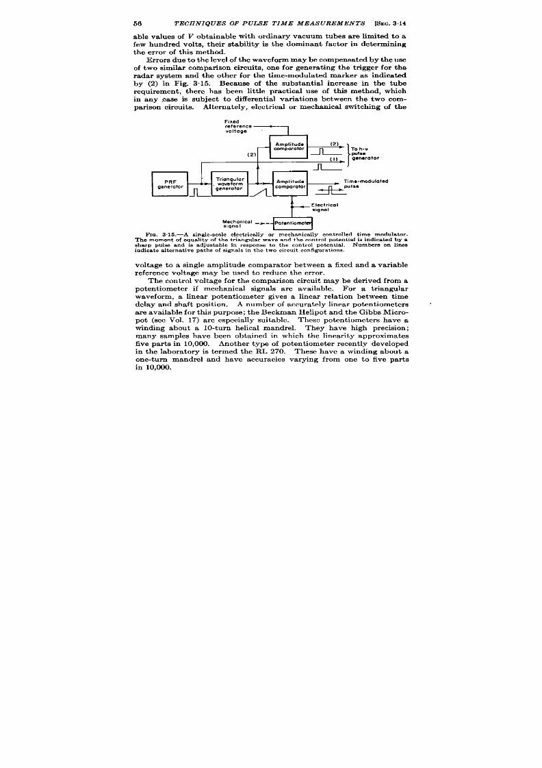
56
TECHNIQUES OF PULSE TIME MEASUREMENTS [SEC.3.14
able values of V obta inable with ordina ry vacuum tubes a re limited to a
few hundred volt s, their stability is the dominant factor in determining
the er ror of this method.
Er rors due to the level of the waveform maybe compensated by the use
of two similar compar ison circuit s, one for genera t ing the t r igger for the
rada r system and the other for he t ime-modula ted marker as indica ted
by (2) in Fig. 3“15.
Because of the substant ial increase in the tube
requirement , here has b en lit t le pract ica l us of this method, which
in any case is subj ct to different ia l var ia t ions between the two com-
par ison circuit s. Alterna tely, elect r ica l or mechanica l switching of the
Fixed
“’’”=
– r+!=!=~’”
RF
Triangular
Amplitude
waveform
Time-moduloted
*
generator
generator
-n_ A comp;r”t”r * ”’se
A
Electrical
signal
Mechanical _*_ pote”tiow
signal
F Ic+. 3.15.—A s ingle-sca le elect r ica lly or mechan ica lly con t r olled t ime modula t or .
Th e momen t of equ alit y of t he t ria ngu la r wa ve a nd t he con tr ol pot en tia l is in dica ted by a
sh arp P ul e a nd ie a dju st able in r espon se t o t he con tr ol pot en tia l.
Number s on lin ee
ind ica t e a lt erna t ive pa th s of s igna ls in the two cir cu it con figu ra t ions .
voltage to a single amplitude compara tor between a fixed and a variable
reference volt age may be used to reduce the er ror .
The con t rol volt age for the compar ison circuit may be der ived from a
potent iometer if mechanica l signals are available. For a t r iangular
waveform, a linear potent iometer gives a linear rela t ion between t ime
delay and shaft posit ion . A number of accura tely linear potent iometers
a re available for this purpose; the Beckman Helipot and the Gibbs Micro-
pot (see Vol. 17) a re especia lly suitable. These potent iometers have a
winding about a 10-turn helica l mandrel.
They have high precision;
many samples have been obta ined in which the linearity approximates
five par t s in 10,000. Another type of po ent iometer recen t ly developed
in the labora tory is t ermed the RL 270. These have a winding about a
one-turn mandrel and have accuracies varying from one to five par ts
in 10,000.

SEC. 3.14]
SINGLE-SCALE TIME-MODULATION CIRCUITS
57
A high-resistance poten t iom eter (approximately 20k) is desirable in
order to have adequate resolu t ion and to dissipate a small amount of
power when supplied with a steady voltage equal to the full range of the
t im ing wave (a ppr oximat ely 200 volt s).
Th e pot en tiomet er s list ed above
fu lt ill these requirements .
Phase Modulation of the Timing Wavejorm.-Phase shift of a sym-
metr ica l waveform by an inductance or capacitance goniometer var ies
the instant a t which the waveform passes through zero amplitude as
shown in Fig. 3.16. A compar ison circuit res ondi g to the zeros of the
amplitude of the phase-modula ted wave will give a tra in of pulses tha t
a re t ime-modula ted with respect to the unshifted pulse tra in as shown in
Fig. 3.16. The process of compar ison is therefore the same as befo e, but
the r efer en ce poten t ia l is constant , usua lly a t gr ound.
~-< Mechanica signal
F1~ . 3.16.—Single-s cn le mechan ica lly con t rolled t ime modula tor emdovin rz
phase
modu la tion of a sin usoida l waveform. ‘Th e momen t a t wh ich t he sin uso;da i w;veform
crosses t he zer o axis is in dicat ed by t he gener at ion of a pulse. Var ia t ion of t he t im e of
occur rence of th is pu lse with re fe rence to the unsh ift ed s inusoid is accomplished by rota t ing
t he h aft of t he ph ase sh ift er .
The pur ity of the sinusoid and the constancy of its fr equency may be
determined by the proper t ies of nega t ive-feedbac amplifiers and pre-
cision-t iming elements such as quartz crysta ls. The couplin of the
symmetr ica l wave through a low-impedance t ransformer to a hlgh-
impedance amplitude compa ra tor is often used t o set the level of the wa ve
without er ror ; but the stabil ty of the process of amplitude compar ison
limits the accuracy of pulse genera t io . As before, pract ica l considera-
t ions limit the amplitude of the sinu oid to 100 or 200 volts, but , since
the slope of the sinusoida l waveform at zero amplitude is T t imes tha t of
a t r iangular wave of the same tota l amplitude and range of modula t ion,
less difficu lty is exper ien c d with fluctu at ions of va cu um tubes.
Also, it is usual pract ice to employ two similar compar ison circuit s as
shown in Fig. 3.16, one opera t ing on the t iming wave and the other upon
the phase-shifted wave. This results in compensa t ion of some error s.

58
TECHN IQUES OF PULSE TIME IUEASUREMEN TS [SEC.3.15
The fract ion l accuracy of phase-sh ifter is much less than tha t of
precision poten t iometer s and er ror s of one par t in 360 are commonly
observed. Since addit ional er ror s a re in troduced by imperfect ba lancing
of the phase-split t ing br idge, a t best there exist s an er ror of one par t in
300, compared with about one par t in 2000 for the linea r poten t iometer .
Th is sixfold difference in accuracy i not mainta ined in pract ica l cir cu it s
because of the er ror in t roduced by the amplitude compara tor .
The choice between phase- and t ime-modula t ion methods is usually
decided by the requ irement for automat ic con t rol; where on ly elect r ica l
ou tpu t da ta a re requ ired, elect r ica lly con t rolled t ime modula tor s a re
used. In double-sca le systems mechanica l con t rol of phase modula t ion
is much simpler as is shown in the next sect ion .
3.16. Dou ble-sca le Time-modu la t ion Circu it s. Puke Selection and
Zn terpoZu tion .-Figu re 3“17 illust ra tes a two-sca le elect r ica l t im e modu -
la tor based upon in terpola t ion between selected members of the t ra in of
mult iple-frequency pulses genera ted in Fig. 3.13. With proper design
the increase of accuracy over tha t obta inable in Fig. 315 may equal the
number of t imes tha t the fixed pulses subdivide the desired range of
modula t ion . The th oret ica l number of subdivisions is determined by
the accuracy of the coarse sca le which , if opera t ing as indica ted in
Sec. 3“14, cou ld be on e par t in 300, resu lt ing in an over-a ll accuracy of on e
par t in 10s. In pract ice, however , fu ll advan tage is ra rely taken of the
theoret ica l accuracy because fau lty opera t ion of the coarse sca le causes
an er ror equal to the per iod of the fixed pu lses, and such a gross er ror is
in tolerable. Usually less than 100 subdivisions of the full r ange of
modula t ion a re made, and th is has given accu racy compat ible with the
ch ar act er ist ics of t he t ra nsm it ter a nd r eceiver , a nd t heir syn ch ron iza tion ,
approximately one par t in 30,000. (Usually 1- or 10-mile subdivisions
are employed.)
In the actua l design of such a t iming system, the character ist ics of
the radar system usually determine t e requ ired repe it ion ra te The
frequency of the fixed pu lses is chosen not on ly with regard to the esired
number of subdivisions of the sca le, bu t a lso with rega rd to the unit s
employe , for example, 1 naut ica l mile (80.86 kc/see), 1 sta tu te mile
(93.1 kc/see), 2000 yd (81.94 kc/see), et c.
In some cases independen t con t rol of the coarse and fine sca les is
sa t isfactory, especia lly for naviga t ion , etc., wh er e cen t inuous measure-
ments a re ra rely needed. Considerable difficu lty is encoun tered in
coordina t ing the con t rols t o ach ieve con t inuous modula t ion over the
en t ire range. For example, when the fine con t rol is increased to an
in terva l exceeding tha t between t wo fixed pulses, the coarse con trol must
be advanced to select the next pu lse.
This req ires tha t the set t ing
of the fine sca le be simultaneously reduced from maximum to zero in
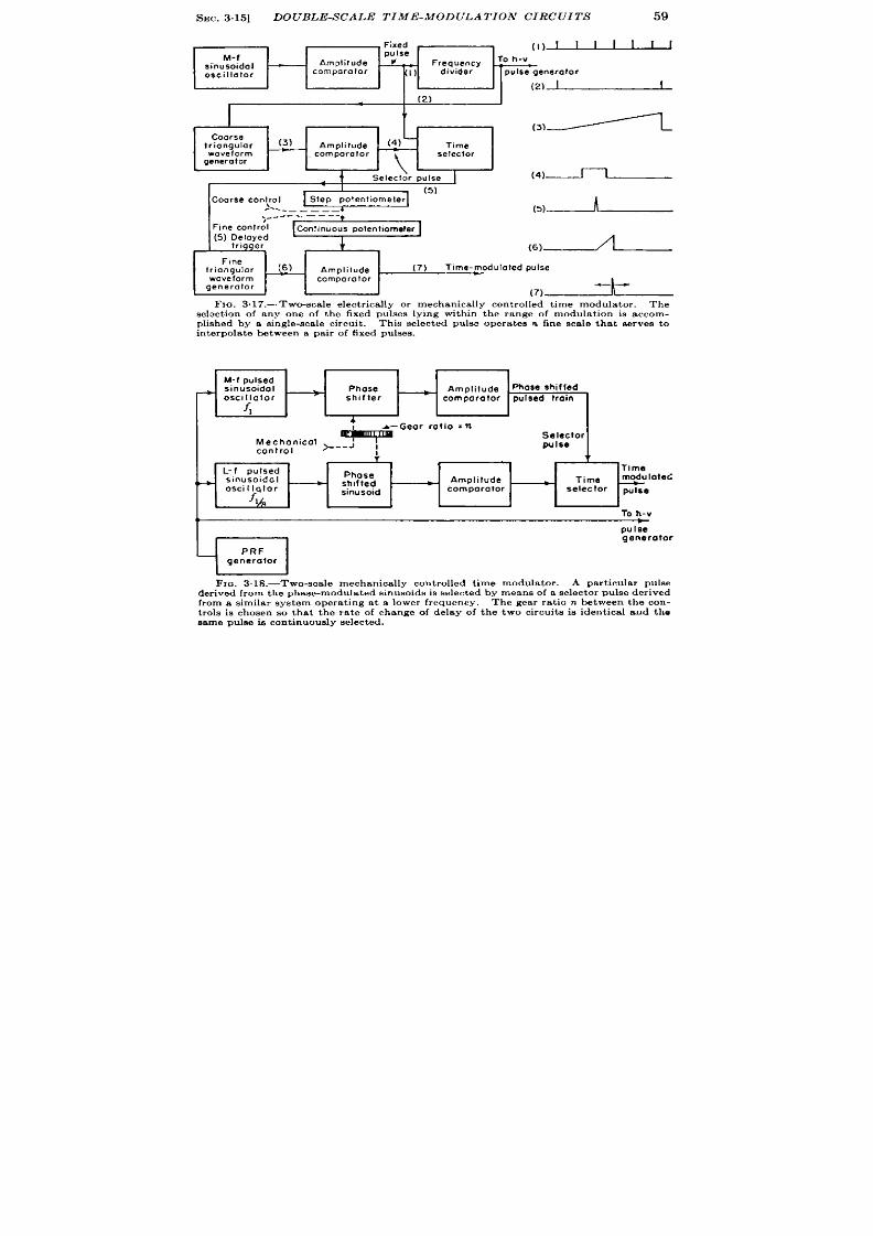
SEC. 3.15]
DOUBLE-S CALE TIM -MODULATION CIRCUITS
59
, F,xed
(I)JJJ—UJJ
M-f
pulse
Amplitude
~
To h-v
sinusoidal
Frequency
oscillator
comparator
d!vider
pulse generator
(z)~
T
(3)~
Coarse
triangular
(3)
Amplitude
(4)
Time
wavefcrm
comporolor
t
\
selector
general or
Selector pulse
J
(4)~
(5)
Coarse con~ol
Step potentiometer
----—-———
(,)~
,---. -— —..
Fine contr;l
COnlinuOus polentnometer
(5) Delayed
trigger
i
@)~
Fine
triangular
(.6)
Amplitude
(7)
Time-modulated pulse
waveform
comparator
generator
-.
(7)
F IG. 3.17.—Two-s ca le elect r ica lly or mechanica lly con t rolled t ime modula t or . The
selsct ion of a ny on e of t he fixed pu lse lyin g wit hin th e r an ge of modu la tion is a ccom -
plished by a sin gle-sca le cir cu it . Th is select ed pu lse oper at es n fin e sca le t ha t ser veg t o
in t erpola t e between a pair of fixed puls es .
M-f pulsed
sinusoidal
+
~
Phase
Amplifude
Phase shifted
oscillator
sh!fter
—
~
comparator pulsed train
4
*=Ge”r ‘0”0 ‘n
Mechonicol ~__j
Selector
control
pulse
1
T
t
L-f pulsed
Time
Phose
+
sinusoidal
—
sh!fted
Amplitude
Time
modu toted
osclllqtor
f,~
sinusoid
comparolor selector
pulse
To h-v
puIie
generator
FIG. 318.-Two-sca le m ech an ica lly con tr olled t im e modu la tor . A pa rt icu la r pu lse
der ived from the phase-modula ted s inuso ds is selected by mean~of a selector pu lse der ived
from a sim ila r sy t em oper at in g a t a lower fr equ en cy. Th e gea r r at io n between t he con -
t rols is ch osen so that t he r ate of ch an ge of dela y of t he t wo cir cu it e ie iden tica l a nd t he
same pu lse ie con tin uou sly select ed. -
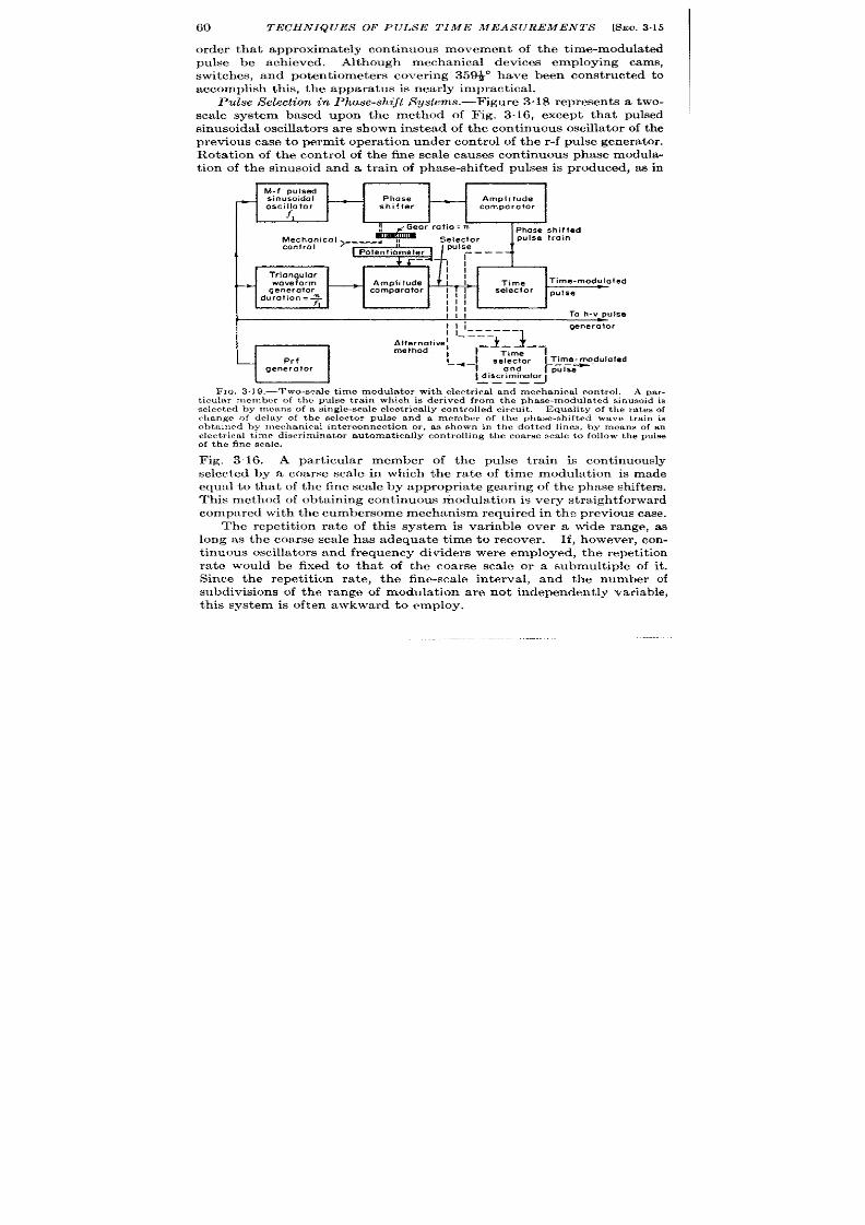
60
TECHNIQUES OF PULSE TIME MEASUREMENTS [SEC.3.15
ord r that approximately cont inuous mo ement of the t ime-modula ted
pulse be achieved. Although mechanical devices employing cams,
switches, and poten t iometers cover ing 35~ have been const ructed to
a ccomplish this, t he a ppa rat us is n ea rly impract ical.
Pulse Selection in Phase-shift Systems.—Figure 318 r epresen ts a two-
sca le system based upon the method of Fig. 3.16, except that pulsed
sinusoidal oscilla tors a re sh own in stead of t he con tin uou s oscilla tor of t he
previous case t o permit opera t ion u n er cont rol of the r -f pulse genera tor .
Rota t ion of th e cont r o of the fine scale causes cont inuous phase modula-
t ion of the sinusoid and a tra in of phase-sh ifted pulses is produced, aa in
1
M-f pulsed
sinusoidal
-
—
Phase
—
Amplitude
oscillator
f,
shifter
comparator
&lli&”r ‘“::;;.,
Phose shifted
g:;t:::ic”’ >==-=’ !:
pulse
i
Potentiometer ---–
+J
--
-
I
Triangular
11
II
b
waveform
—
Amplitude Time
Time-modulated
generator
comparator I
T
selector
durotion=~
,1/
pulse
Ill
Ill
111
To h-v pulse
I I i------
11
generator
Alternotive~
--,:-l_ 4--,
meth d ,
Prf I_ ~ _~ s~~’%ar
generator
Idi’c::?””tor;:;+d”l”ted-——. —
FIG. 3.19.—T we-sca le t ime modu la tor with elect r ica l and mechan ica l con t rol, A par -
t icu la r member of t he pu lse t ra in wh ich is der ived fr om t he ph ase-modu la ted sin usoid is
selected hy means of a s ingle-scale elect r ica lly controlled circuit .
E qu alit y of t he r at es of
ch an ge of dr l:Ly of t he select or pu lse an d a m ember of t he ph ase-sh ift ed wa ve t ,ra in is
obt ain ed by ]I)ech an ica l in ter conn ect ion or , m shown in t h e dot ted lin es, by means of m
elect r ica l t ime discr imina tor au tomat ica lly con t rolling tbe coarse sca le to follow the pulse
of the fine sca le.
Fig. 316. A par t icular member of the pulse t rain is cont inuously
selected by a coarse sca le in which the ra te of t ime modulat ion is made
equal to tha t of the fine scale by appropr ia te gear ing of the phase shifters.
This m et hod of obta inin g con tin u u s modu la tion is ver y str aigh tforwa rd
compared with the cumbersome me hanism required in the previous case.
The repet it ion ra te of th is system is variable over a wide range, as
long as the coarse scale has adequate t ime to recover . If, however , con-
t in uous oscilla tors and fr equ en cy divider s wer e employed, t he r epet it ion
ra te would be fixed to tha t of the coar se scale or a submult iple of it .
Since the repet it ion ra te, the fine-sca le in terva l, and the number of
su divisions of the range of modulat ion are not independent ly variable,
this system is often awkward to employ.

SEC.316]
MULTIPLE-S CALE S YS TEMS
61
The ult imate accuracy that might be expect ed from this system
would be roughly ten par ts per mi lion, but , as in the previous case, a
considerable safety factor should be applied to the opera t ion of the
coarse sca le.
In Fig. 3.19 is shown a combinat on of a phase-shift modula tor for the
fine sca e and an elect r ica lly con t rolled t ime modula tor for the coarse
scale. Although a pulsed sinusoidal oscillator is shown, a cont inuous
oscillator similar t o that shown in Fig. 3.13 may be used. The pulse-
repet it ion frequency of the coarse scale may be var ied over a wide range
provided the pulse-repet it ion in terval is roughly 25 pcr cen t grea ter than
the range of modula t ion. This is a defin it e advan tage over the version
of Fig. 3.18, which uses a con t inuous oscilla tor for the coarse scale.
Con tin uou s t ime modula t ion may be obta ined by con nect in g t he pot en tio-
meter to the phase shifter with appropr ia te gear ra t ios and elect r ica l
scale factors so that the movement of the selector pu lse and the phasc-
shlf t ed wave tra in occurs at the same rate.
The possibility of elect r ica l con t rol of the fine scale permit s a novel
a lternat ive indicated by the dot ted lines of F ig. 3.19. If, for example,
the selector pu lse of the coarse scale and the phase-sh ift ed pulse t rain
are connected to a t ime discr imi ator (see Sec. 3.17) instead of to a t ime
selector , an elect r ica l signal may be obta ined which will con t rol the
modula t ion of the coarse scale. This system has the advantage of
simplicity since it does n ot requ ire a poten t iometer or associated mecha-
nism for con trolling the t ime delay of the coarse scale. C)n the other
hand, momentary power fa ilu re or a t ransien t mechanical shock might
cause the t ime discr iminator to opera te upon a pulse other than the one
init ially selected and would resu lt in a gross er ror of the reading. The
accuracy would, of course, be regained by a simple reset mechan ism.
3.16. Mu lt iple-scale Syst ems.—Accu racies consider ably in excess of
those ment ioned in the previous sect ion may be obta ined with systems
employing a th ird or a four th scale.
Th e fr equ en cy st abilit y of ava ilable
sinusoidal oscilla tors would seldom warran t an increase beyond th ree
where, for example, a poten t ia l accuracy of th ree par t s in 1010 is obta in-
able. Th er e ar e, h owever , some mechanical difficult ies in mu lt iple-scale
systems of high a ccu racy especia lly if a pr ecise cou nt er readin g is desired,
since the fine scale has a large number of tu rns for the full sca le. A
le=t count of near ly & of the fine scale may be desired for accura te
readkg. Most military applica t ions requ ire that th ou tpu t be shifted
from one end of the scale to the other in roughly 20 see, which demands
impossible shaft s eeds in the count ing mechan ism.
Although these
difficult ies are mit igated by dial indicators, they st ill remain ser ious in
h igh-accuracy sys tems.
In a cont inuous-reading three-scale Loran indicator th is difficu lty is
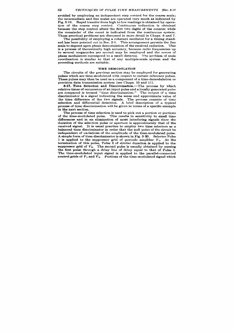
62
TECHNIQUES OF PULSE TIME MEASUREMENTS [%?c. 3.17
avoided by employing an independent st ep con t rol for the coar se sca le;
the intermedia te and fine sca les a re opera ted very much as indica ted by
Fig. 3.19. Rapid t ransfer from high to low readings is obta ined by opera -
t ion of the coarse step cont rol.
Cont inuous indicat ion is obta ined
because the step cont rol a lters the first two digit s of the counter while
the remainder of the count is indica ted from the cont inuous system.
These pract ica l problems are discussed in more deta il in Chaps. 6 and 7.
The possibility of employing a coheren t oscilla tor for a t iming stand-
ard has been pointed out in Sec. 2.4.
This ar rangement permits the fine
sca le to depend upon phase demodula t ion of the received radia t ion. This
is a process of theoret ica lly high accuracy, because radio fre uencies up
to severa l megacycles p r second may be employed and the er r r s of
phaae modula tors correspond to a small distance. The problem of sca le
coordina t ion is similar t o tha t of any mult iple-scale system and the
pr ecedin g met hods a re su it able.
TIME DEMODULATION
The circuit s of the previous sect ion may be employed for genera t ing
pulses wh ich a re t ime-modu la ted wit h r espect t o cer ta in r efer en ce pulses
These pulses may then be used as a component of a t ime-demodula t ion or
precision data transmission system (see Chaps. 10 and 11).
3.17. Time Select ion and Discr iminat ion.-The process by which
rela t ive t imes of occur ren ce of an input pulse and a loca lly genera ted pulse
are compared is t ermed “t ime discr iminat ion .” The output of a t ime
discr iminator is a signal indica t ing the sense and approximate value of
bhe t ime difference of the two signa s. The process consist s of t ime
select ion and cliffer en t ia l det ect ion .
A brief descr ipt ion of a typica l
pr ocess of t ime discr iminat ion will be given in terms of a specific example
in t he n ext sect ion .
The process of t ime select ion is used to pick out a por t ion or por t ions
of the t ime-modula ted pulse. This result s in sensit ivity t o small t ime
differences and in an eliminat ion of most in ter fer ing signala since the
dura t ion of the select ion pulse or aper tu re is approximately tha t of the
received signal. It is usual pract ice to employ two t ime selectors as a
balanced t ime dwcr irnina tor in order tha t the null poin t of the circuit be
independent of var ia t ions of the amplitude of the t ime-modula ted pulse.
A simple form of t ime discr iminator is shown in Fig. 3.20. Selector Pulse
1 is applied to the suppressor gr id of pen tode amplifier VI. At the
terminat ion of this pulse, Pulse 2 of similar dura t ion is applied to the
suppressor gr id of V*. The second pulse is usually obta ined by passing
the fir st pulse through a delay line of delay equal to tha t of Pulse 1,
The t im~modula ted input signal is applied to the para llel-connected
cont rol grids of VI and Vz. Por tion s of t he t im e-modu la ted signa l which
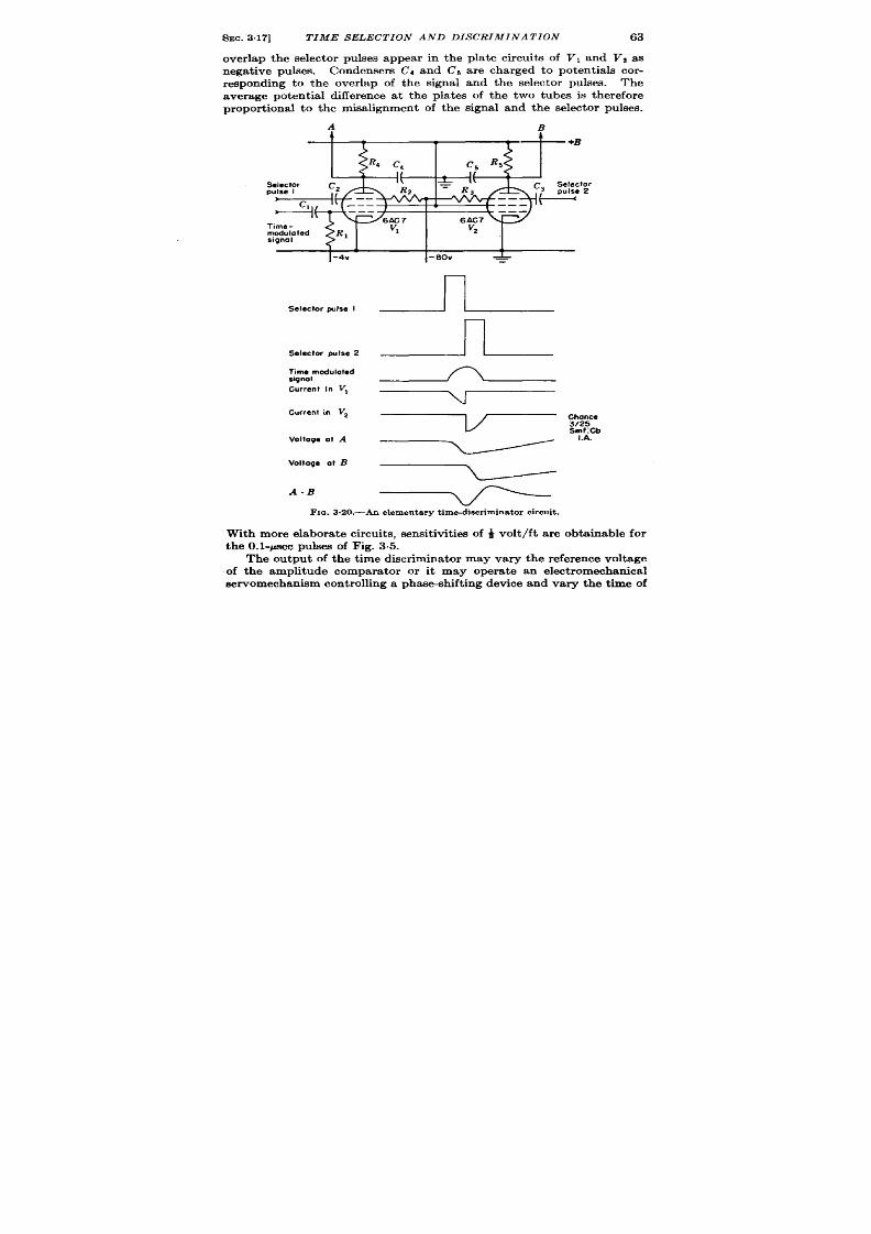
SEC.3.17]
TIME SELECTION AND DISCRIMINATION 63
over lap the selector pulses appear in the pla te circuit s of VI and z as
nega t ive pulses. Condensers (74 and Cb are charged to potent ia ls cor -
r esponding to the over lap of the signal and the selector pulses.
The
average poten t ia l difference a t t he pla tes of the two tubes is ther efore
propor t iona l t o the misa lignment of the signal and the selector pulses.
A
B
+B
S elector
Time-
modulated
signal
1-4”-
S elector pulse I
Selec!Orwise 2
Time modulated
signal
Current in V,
Current in V2
Volt age a t A
Voltage atB
A-B
FIG. 3.20.—AII elementary time-discriminator circuit .
With mor e elabora te circuits, sensit ivit ies of ~ volt /ft a re obta inable for
t he O.1-psec pu lses of F ig. 3.5.
The outpu t of the t ime discr imina tor may vary the refer ence voltage
of the amplitude compara tor or it may opera t e an elect romechanica l
servomechanism cont rolling a phae -shift ing device and var y the t ime of

64
Y’-M2HN IQUES OF PULIS E TIME MEASUREMEN TS [SEC. 318
occu rr en ce of t he select or pu lses so as t o follow t he t ime-modula ted sign al.
In either case problems o stability and transient response a re important
(see Chap. 8).
SOME PROPERTIES OF CATHODE-RAY-TUBE DISPLAYS
The cathode-ray-tube display has two impor tant funct ions in t ime
measurement by pulse methods: select ion of the proper t ime-modula ted
signal and de odula t ion or measurement of a t ime-modula ted signal.
These two processes will be discussed briefly, but the mater ia l is
in t roductory to the dis ussion of Chap. 7. A more complete descr ipt ion
of all uses of ca thode-ray-tube displays appears in Vol. 22.
3.18. Time Select ion and Discr im nat ion .-The type A or linear -
.
sweep oscilloscope is u sed mainly for t he pu rpose of select in g a pa rt icu la r
ta rget on the basis of its range.
Other types of displays such as the
B-scope or PPI are used to select ta rgets in range and azimuth or range
and eleva t ion . This select ion pro-
cess is, of course, an essent ia l pre-
limina ry t o a ccu ra te measu remen t.
Often the select ion process in-
volves manual adjustment of the
selector pulse of an electr ica l t ime
discr imina tor to the approximate
range of the target . In th is way
the opera t ion of an elect r ic t ime
demodula tor is init ia ted and con-
t inuou~ t racking of the ta rget may proceed. An example of a ca thode-
ray-tube display for this purpose is given i Fig. 3.21. Manual con t rol
of the selector pulse, can , of course, be used for manual t racking of the
ta rget as discussed in the next sect ion .
3.19. Time Demodula t ion .-The ca thoderay-tube display may
be used in two ways for t ime demodula t ion . First , it serves simply as a
t ime discr imina tor or null indica tor ; tha t is, it gives the opera tor visual
indica t ion of the displacement between the t ime-modula ted signal and
an elect r ica l range index genera ted by the ime-modula t ion systems of
Sees. 3.14 and 3“15. In the second case, a mechanical index is used to
r epr esen t a t ime-modu la ted pu lse,
Time Discrimination on Cathode-ray-tube Displays. —This is t h e p roc-
ess of determining the po it ion of a t ime-modula ted pulse with respect to
a given index; the accuracy with which it can be done is often termed the
“ reset tability” of a display.
Fig. 3.22 gives examples of both . Highly sensit ive indicat ions of the
displacement of signal and index a re afforded by the fine elect ron ic cross-
ha ir , and accura te t ime demodula t ion or range-t racking is possible. In
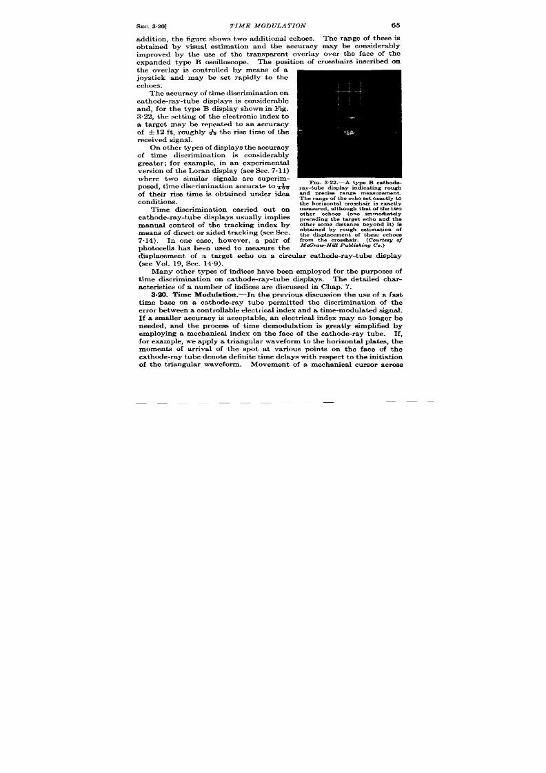
SEC. 3.20]
T IME MODULAT ION
65
a ddit ion , t he figu re sh ows two a ddit iona l ech oes.
The range of these is
obta ined by visual est imat ion and the accuracy may be considerably
improved by the use of the t ransparent over lay over the face of the
expanded type B oscilloscope. The posit ion of crossha ir s inscr ibed on
the over lay is cont rolled by means of a
joyst ick and may be set rapidly to the
echoes.
Th e a ccu ra cy of t im e discr im in at ion on
ca t hode-r a y-t ube displa ys is con sider able
and, for the type B display shown in Fig.
3.22, the set t ing of the elect ron ic index to
a ta rget may be repea t ed to an accuracy
of f 12 ft , roughly ~ the r ise t ime of the
rece ived s igna l.
On ot her t ypes of displa ys t he a ccu ra cy
of t ime discr imina t ion is considerably
grea ter ; for example, in an exper imenta l
ver sion of t he Lor an displa y (see Sec. 7.11)
where two simila r signa ls a r e super im-
posed, t im e discr im in at ion a ccu ra te t o&
of their r ise t ime is obta ined under idea
conditions.
Time discr imina t ion car r ied out on
ca th ode-r a y-t ube displa ys u su ally implies
manual con t rol of the t racking index by
means of dir ect or a ided t ra cking (see Sec.
7.14). In one case, however a pa ir of
Dhotocelk has been used to measure the
&placement of a ta rget echo on a circula r ca thode-ray-tube display
(see ol. 19, Sec. 14.9).
Many other types of indices have been emplo ed for the purposes of
t ime discr imina t ion on ca thode-ray-tube displays. The deta iled char -
acter ist ics of a number of indices ar e discussed in Chap. 7.
3.20. Time Modulat ion.-In the previous discussion the use of a fast
t ime base on a ca thode-ray tube permit ted the discr iminat ion of the
er r or between a con tr o la bl elect rica l in dex a nd a t im e-modu la ted sign al.
If a smaller accuracy is acceptable, an elect r ica l index may no longer be
needed, and the process of t ime demodula t ion is grea t ly simplified by
employing a mechanica l index on the face of the ca thode-r ay tube. If,
for example, we apply a t r iangula r waveform t o the hor izonta l pla tes, the
moments of a r r iva l of the spot a t var ious poin ts on the face of the
ca th ode-r ay t ube den ot e defin it e t ime dela ys wit h r espect t o t he init ia t ion
of t he t ria ngula r wa veform.
Movement of a mechanical cur sor across
66
TECHN IQUES OF PULSE TIME MEASUREMENTS [SEC.320
the face of the tube on which a t r iangular waveform is displayed thus
crea tes an effect ively t ime-modula ted index with which the process of
demodulat ion may be readily ca rr ied ou t .
It is profitable to compare this process to tha t used in the genera t ion
of elect r ica l indices, wh er e an elect rica l amplitude compar at or indica tes
the equality of a t iming waveform and a voltage by the genera tor of an
index. The moment of displacement equality of the spot of the ca thode-
ray tube and the mechanica l index represen t s the same process. As in
the case of elect ron ic indices, the mechanical indices may be fixed or
movable; for movable indices the display serves not only to crea te the
t ime-modula ted index but also to permit t ime select ion and discr imina-
t ion by a human opera tor in order to give cont inuous t ime demodula t ion
of a signal of var iable range.
The lack of an elect r ica l ulse cor respon ing t o the mechanica l index
often causes difficulty in secur ing automat ic opera t ion of these methods
wit hou t r esor tin g t o phot ocell pickoffs.
The accuracy of t ime modula t ion with a mechanica l index on a linear
sweep is low. The rela t ion between spot deflect ion and applied voltage
is no more accura te than 1 or 2 per cen t in most ca thode-ray tubes. In
addit ion, a number of factor s a lt er the posit ion of the t race with respect
to the index, especia lly var ia t ion of accelera t ing volt age and st ray mag-
n et ic fields. Ot her pr act ica l difficult ies ar e in volved in avoiding parallax
between t e mechanica l index and the t race. It is often desirable to
project an illuminated gr id dkect ly upon the face of a ca thode-ray tube
(Chap. 7 and Vol. 22). The inaccuracy of the cathode-ray-tube dkplay
is usualfy so large that one encoun ter s lit t le dificu lty with the var ia t ions
in t he pr oper ties of waveform gen er at or s.
The accuracy may be increased by subdivision of the range of t ime
modula t ion by the use of fixed indices (Sees. 3.13 and 3“15) or by the use
of phase modula t ion as discussed in the next paragraph.
Phase Modula t ion .-The circular or t ype J ca thode-ray-tube display
may be used as an elect romechanica l phase modulator very much in the
fashion of those descr ibed in Sec. 3.14. The circular pat t ern is obta ined
by applying dist or tion -fr ee tw~ph ase sinusoidal voltages of appropr ia te
var ious points on the circle have a t ime delay which is propor t ional to
thei dist ance along the circumference, the angular osit ion of a mechan-
ical index rota t ing about the cen ter of the display represent s a linear ly
phase-modula t d index. In circu lar -sweep displays the signal may be
applied as a deflect ion modula t ion by means of a cent ra l elect rode as
shown in Fig. 3.23.
The stability of the circular sweep is somewhat bet t er than that of the
linear sweep kcause var iat ions of acceler at ing olt age cause a negligible

SEC. 3.30]
T IME MODULAT ION
67
er ror . The main er rors of the display are due to recen ter ing, ellipt icity,
and parallax. The employment of the mechanical cursor mounted ery
close to the face of the tube and including an inscr ibed circle makes these
er rors eviden t and easy to cor rect .
A deta iled analysis of the er rors of
the circu lar -sweep display is given in Vol. 22. One advantage of the
cir cu la r-sweep ph ase sh ift er over in du ct an ce- apa cit an ce gon iomet er s is
that the ach ievement of a circular pat t ern immediately indicates proper
adjustment of the phase and magnitude of the applied voltages.
Tra king index
Intensified trot
FIO. 3.23.—Cimular-sweap ran ge syste,m.
The accuracy of a proper ly adjusted circular sweep is roughly 1°,
comparable to that obta inable with other elect romechan ical phase
sh ift rs. One of the grea t advan tages of this type of display is the fact
that it maybe con er t ed to a mult iple scale system by employing a h igh-
frequency sinusoid to genera te the sweep and a single-scale elect r ica l
circu it to supply an intensifying pulse that will select the desired cycle
of the high-frequency timing waveform as shown by the block diagram
of F ig. 3.23.
This mult iple-scale system has a number of advan tages; the obvious
one is simplicity and economy of vacuum tubes bec use the funct ions
indicated in the block diagram may be carr ied out with as few as five
double t r iodes. A less obvious bu equ lly important advan tage is
gain ed by t he employment of t he mechanical t ime in d x that is equivalent
t o a marker pulse of accuracy equal to ~ per cen t of the per iod of the t im-

68
TECHNIQUES OF PULSE TIME MEASUREMENTS [SEC,320
ing waveform and of inf n itely rapid r ise t ime.
This situa t ion is prefer -
able to tha t exist ing with an inductance or capacitance gon iometer where
th e phase-shifted t iming wa veform must be amplified and passed th rou gh
an amplitude compara tor before an elect r ica l marker pu lse is obta ined.
On the other hand, no elect r ica l pu lse is available for elect r ica l t ime
select ion or discr iminat ion necessa ry for automat ic t r acking withou t the
use of photocells. Circu lar -sweep displays opera te sa t isfactor ily a t
fr equ en cies n ea r 1 Me/see.
A type A display or type B display is usually included in the circu it of
Fig. 3.23 for su rveying simultaneously all ta rgets with in the desired
range of modula t ion and for permit t ing init ia l t a rget select ion , as n the
radar system (Hit ) ment ioned in Chap. 2 and discussed fu r ther in Chap. 7.
Mechanica l coordina t ion of the coarse and fine sca les is ca r r ied ou t
in a manner similar to tha t of previous mult iple-sca le systems; the
mechanica l cur sor and a poten t iometer cont rolling the coarse sca le a re
gea red together a t a ra t io determined by the quot ien t of the fu ll range of
modula t ion of the coa se and fine cales.
The mult iple-sca le system cor responding to tha t of Sec. 3.15 employ-
ing severa l circu lar sweeps is not a usefu l system and has severa l basic
limitations.
If, for example, a low-fr equ en cy circula r sweep is used in th e
coarse sca le, one of the weaknesses of th is type of phase shifter is immedl-
a tely obvious; no selector u lse is genera ted by the display which may be
used to select the desired por t ion of the fine sca le, and it is necessary to
use an elect r ic circuit for the coarse sca le. If the t iming oscilla tor oper -
a tes cont inuously and if the rep t it ion ra te is equa to the frequency of the
sinusoid applied to the coarse sca le, var ia t ions of the repet it ion ra te a re
not permit t ed. If, however , pulsed oscilla tors a re used, va ria t ions are
permit t ed in the same way they are permit t ed in the circuits discussed in
Sec. 3.15.
Pu lsed sinusoidal oscilla tors may be employed to in it ia te the circular
sweep.
The minimum range of t ime modula t ion at which linea r indica-
t ions a re obta i ed is slight ly grea ter in th is case than in the case of the
pulsed-oscilla tor and condenser phase-shifter system of Sec. 3.14. This
difference s due mainly to the necessity of applying large deflect ing
volt ages to the ca thode-ray tube to obta in a circle of adequate diameter
as opposed to the rela t ively small volt ages tha t can be used with the phase
shifters. The pulsed sinusoida l oscilla tor system is undesirable because
it lacks the simplicity and stability of the crysta l-con t rolled cont inuot is
oscilla tor system; only one tube and a t ransformer a re necessa r for the
la t ter system, but the former may requ ire five or more vacuum tubes to
gen er ate pulsed oscilla t ions and an a ccur at e sweep.
CHAPTER 4
GENERATION OF FIXED INDICES
BY R. I.
HULSIZER, D. SAYRE, AND R. B. LEACHMAN
In Chap. 3 it was poin ted out that a sequence of fixed t ime markers is
needed in t ime measurement to init ia te opera t ions periodica lly, to mark
off t ime in tervals on CRT displays, and to provide a coarse sca le fo
mult iple-sca le t ime modula t ion. Some methods of genera t ing fixed
markers were also out lined and illust ra ted with block diagrams. The
fir st method is t o der ive pulses from a sinusoidal oscilla tor with an
amplitude compara tor , as in Fig. 3.12. The second employs relaxat ion
oscilla tor s wh ich per form t he oper at ion s of sawt oot h waveform gen er at ion
and amplitude compar ison in the same circuit . If markers of more than
one frequency are desired, it is possible to employ frequency dividers
F ig. 3.13) or fr equ en cy mult iplier s.
A somewh at mor e flexible, t hou gh
more cost ly, method is to use low’-frequenc y markers to init ia te pulsed
oscilla tors of h igher frequencies to genera te markers of any frequency
desir ed (see F ig. 314).
The purpose of this chapter is to descr ibe severa l usefu l circuit s for
genera t ing fixed markers by these techniques. In genera l those circuit s
con sider ed relia ble, a lt hough some of t hem r epr esen t t echn iques n ow con -
sidered to be infer ior . The reader will find in Vol. 19 deta iled t rea tments
of the var ious component circuit s tha t a re used in mark r genera t ion––
or example, crysta l and relaxa t ion oscilla t ors, amplitude compara tors,
a nd fr equ en cy dividers a nd mult ipliers.
SINGLE-FREQUENCYMARKER GENERATORS
BY D. SAYRE AND R. I. HULSIZER
4.1. Sin usoida l Oscilla tor s a nd Amplit ude Compa ra tor s .—The follow-
ing circuit s were designed as PRF or range-mark genera tors to provide
marker s of good fr equency st abilit y.
Often PRF t r iggers a re required to
be stable to .0 per cent either for coding purposes or because of r -f
switch or indica tors weep-gener at or dut y-ra t io sensit iv ty. Range mark-
frequency and fur thermore must usually be accura tely defined with
respect o the phase of the reference sine wave.
69
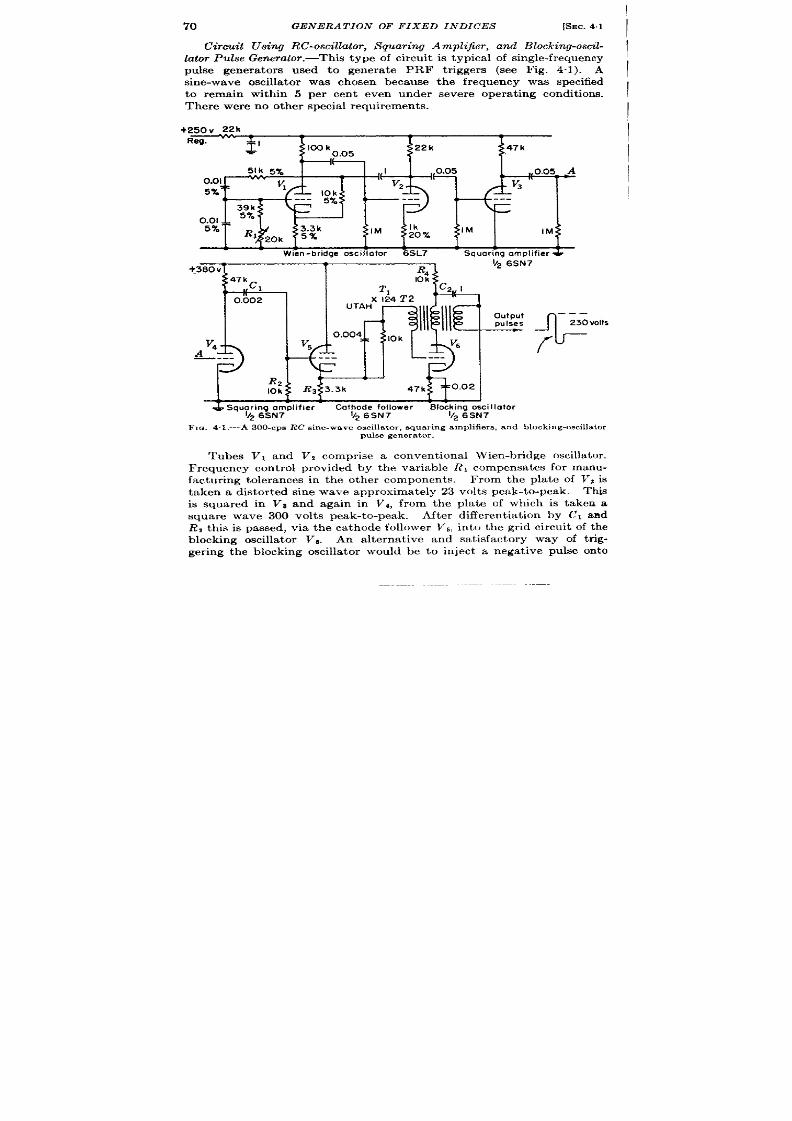
70
GENERA TION OF FIXED INDICES
[SEC. 41
Circuit using RC-oscillator, Squaring Amplifier, and Blo king-oscil-
lator Pulse Gen er at or .-Th is t ype of cir cu it is typica l of sin gle-frequ en cy
pulse genera tors used to genera te PRF tr iggers (see Fig. 4“1). A
sine-wave oscilla tor was c osen because the frequency was specified
to rema in with in 5 per cen t even nder severe opera t ing condit ions,
Th er e wer e n o ot her specia l requ ir em en ts.
+250v 22k
R-
L
$’
100 k
22k
0.05
47 k
,
L
L
1
L L
,
L
1
Wien-bridge oscillator
6SL7 Squaring amplifier &
1
k26SN7
A--,- .,-f
T
.
?aou v
l-n
fi4
47 k
c1
10 k
T1
0.002
X124T2
1+’%
I UTAH —,l, ) ,1,4
!)
.
A
—---
r
!$y--+
Ill
output
---
pul.ses
230 vOI!S
V6
f
---
c
J42
10 k
L
* Squoring omplifier
Cot bode fol Iowe r
Blocking osci Ilotor
v~ 6SN7
1/2 6SN7
1/2 6 SN7
FIQ 4.1 .—A 300-cPs RC sine-wave oscilla tor , squar ing amplifiers, and blocking-oscilla tor
pulse genera tor .
Tubes VI and Vz comprise a convent iona l Wien-br idge oscilla tor .
F requ ncy cen t rol provided by the var iable RI compensa tes for manu-
factur ing tolerances in the other componen ts. From the pla te of Vi is
t aken a distor ted sine wave approximately 23 volt s peak-to-peak. This
is squared i Vs and again in V 4, from the pla te of which is taken a
square wave 300 volt s peak-to-peak.
After differen t ia t ion by Cl and
R, th is is pa ssed, via the ca thode follower V5, in to the gr id circu it of the
blocking oscilla tor V . An a lterna t ive and sa t isfactory way of t r ig-
ger ing the blocking oscilla tor would be to in ject a nega t ive pulse on to

SEC. 4.1] SINUSOIDAL MARKER GENERATORS
71
t he pla te of V6 by r emovin g Ra and connect ing the plat e of V6 to the
pla te of Va instead of to the pla te supply. The decoupling network R4
and CZpreven ts t he la rge cur ren t pulse from get ting n to th e pla te supply,
from which it could get in to other par ta of the circu it . The output pulse
of 230 volt s is a t an impedance level of 500 ohrna . If grea t er frequency
stability is desired it could be obta ined by using a crysta l oscilla tor in the
100-kc/sec r an ge followed by st able fr equ en cy divider s, or for fr equ en cies
down to 2000 cps, by using a low-frequency cryst a l oscilla tor of the type
descr ibed in Vol. 19, hap. 4.
A fu r ther weakness of this circu it , which would become apparen t if
accu ra te phase lock between the sine wave and the pulses were required,
is tha t inadequate provision is made for accura t e determina t ion of the
exact poin t of the sine wave a t which the pulse shall be genera t ed. The
amplitude comparison is per formed by t he cut off and gr id-cu rren t poin ts
of t he t riode con trol-gr id character ist ics of Vg and Vq. A much more
accu ra te circu it in th is respect will be descr ibed n ext .
Crystal Oscillator and Diode Amplitude
Fig. 4.2 is par t of a radar synchronizer and two-sca le t i e modula tor .
A ser ies of fixed pulses is provided, one of which is select ed aa the PRF
t r igger every 330 psec. It a lso supplies 3-phase sinusoida l volt ages to a
condenser phase sh ifter . The phase-sh ift ed output of the condenser
is u sed t o gen er a te ph ase-sh ift ed pu lses.
Thus it is import an t t o main tain
not on ly accu ra te frequency, but also accu ra te phase.
This circu it gen era t es pulses approximat ely 6 psec apar t wh ose t ime of
appearance, rela t ive t o the sine wave which cont rols them, is stable
to 0.01 psec. In order to main tain the phasing with tha t accu racy,
the pulse must always be Formed at precisely the same poin t of the
sine wave. The zero poin t is the best , because there the ra t e of change
of volt age is grea test . By taking the sine wave across the inductance
LI the zero poin t is a lways accura tely a t ground. Since the plate of
the diode Vs. is held at ground by Rs, it will conduct on just exact ly the
lower half of the sine wave, the on ly possibility of er ror being a change
in the diode cu toff poten t ia l. Such a change is not likely t o affect the
pickoff poin t by more than 0.1 volt , and by using a modera t ely la rge
amounts t o about 0.003 psec.
The opera t ion of t he en tire circu it is as follows. Balanced 163-kc/sec
sine waves of ver y good quality ar e fed from t he t riple-tun ed t ransformer
21. In addit ion to the t ra in of pulses whose phase rela t ive t o these sine
waves is fixed, it is desired to genera t e another similar t ra in of pulses
which can be cont inuously phase-sh ifted. The balanced sine-wave ou t -
pu t , t herefore, is fed in to a phase-split t ing ne work which provides
3-ph ase sin e wa ves for a con tin uou s ph ase-sh ift ing con den ser (see Ch ap. 5
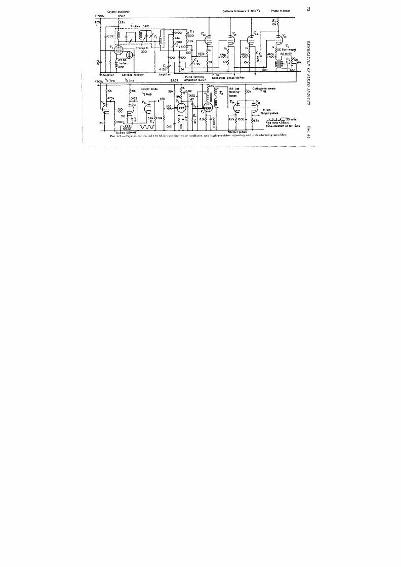
Crystol oscillator
Cathode fol lowers 2-6SN7’S
Phose trimmer
+ 300V 6SJ7
T T T r
,.0
i
h
l.Ok
A.
‘T3F
---
L
200
‘>
R I S lo
Ik
1’
100
470k
h
47C
100
100
TM
C2 ,A, .
‘T “.
qDi,;er -
Cothode-~ollower
Amplifier
.
WI
“,
o
, ‘4-50 ‘“K
I
Ici
m
2 mh
1
I
cl
L
I
4-50 24
1
1
-
e TA *
L--L
3
10k
v
3a
3b
~
Pulse forming ‘ ‘“’
+3CXYV 27F8
& 7F8
Condenser phos;-shifter
6A(-’ ‘--’;’ ;-” ‘AC7
Ik
t70k
10k
1
.470
t
I
f -,,. ’,.,.-. ----
I
volte
all=l#s
4
M

SEC. 4.2] REGENERATIVE AMPLITUDE-COMPARISON 73
and Vol. 19, Chap. 13). Con t rols Cl and C2 are provided for adjust ing
the amplitudes of two of the outputs to equality wit tha t of the th ird,
while RI and Rz permit adjustment of their phases t o + 120° rela t ive to
the th ird.
The th ree phase-sh ifted sine waves a re fed ou t to the con-
denser phase-sh ifter via the ca thode follotver s V*., V,~, and VW, The
nonadjustable sine wave from V2~ is a lso f d in to the ca thode follower
~3b, from which it en ter s upon a ser ies of amplifyi g and squar ing
circu it s, fina lly emer ging as t he desired ser ies of fixed pulses. The phase-
sh ifted output of the condenser , a fter a stage of amplifica t ion to br ing it
up to its init ia l level aga in , goes th rough a simila r circu it and ends up as a
ser ies of cen t inu ou sl y pha sa ble pu lses.
Tube V,b is a ca thode follow r with a t ransformer Tl in th e ca th ode.
The decoupling network R, and (73 serves to lower the pla te volt age
so tha t a la rger cu r ren t can be passed through the r imary of the t rans-
former T, without exceeding the ra t ed pla te dissipa t ion of the tube.
Simila r net~vorks a re used in the pla tes of V , V7, and V& The t rans-
former is used to o ta in a balanced output t o dr ive the adju table phase-
sh ift network Ri and CAthus providing a zero adjustment on the phase
shift bet ween t he t wo sets of pulses.
The output of th is networ k is ampli-
fied in V,a. Tube V,b is the ca thode follower tha t dr ives the inductance
T.,. The opera t ion of the inductance LI and the diode V,. ha s a lr ea dy
been descr ibed. The diode is ar ranged to pick off the nega t ive ha lf cycles
ra ther than the posit ive ones so tha t VG may be fu lly conduct ing and
consequent ly in it s region of h ighest g~, a t the moment of pickoff. After
amplificat ion in V6 the signal is differen t ia ted in CS and RG, amplified
once more in VT, inver t ed and stepped up n 2’2, and fina lly fed out
th rough ither of the ca thode follo~ver s Vs. The shape of the output
waveform is shown on the figu re.
The main weakness of the circu it lies
in the expensive amplifier following the diode amplitude compara tor .
Th e t ra nsformer T , used with VT for inver t ing the p lse ha excellen t
h igh-fr equency response and might well have been connected with the
diode VSC and the amplifier VG to form a regenera t ive amplitude com-
para tor similar to the one descr ibed in Vol. 19, Sec. 9“14, and in the
following sect ion . It wou ld a lso be possible to vary the quiescent pla t e
poten t ia l of the diode VS. to provide O-phase adjustment ra ther than the
more expensive pha e-sh ift circu it of vib and the t ransformer T’l.
4.2. Regen er at ive Amplit ude-compa rison Cir cu it s.—Regen er at ive
devices a e economica l for genera t ing a pulse a t the instant a sinusoidal
waveform passes th rough a par t icu lar potent ia l, bu t nca~ly all such
devices suffer from the fact tha t the poin t on the sine wave at which
regenera t ion begins is subject to ra ther severe var ia t ion \ vith a cor -
responding instability of th e phase r ela t ions between t he sine-wave input
and the pulse ou tput . iYlu lt ivibrators, blocking oscilla tors, and other

74 GENERA TION OF FIXED INDICES
[SEC.‘i.~
regenera t ive devices can be used but all suffer from this fau lt . Gaa-
filled tubes l kewis are economica l but subject to varia t ion of fir ing
characteristics.
The regenera t ive squaring amplifier to be descr ibed is
therefore especia lly aluable because the moment of regenera t ion is
determined by a diode and is quite well defined.
The fundamental circu it is shown in Fig. 4.3 a nd t ypica l wa veforms in
Fig. 4.4. The act ion of the circu it s descr ibed in considerable deta il in
Vol. 19, Chap. 9. Br iefly, a sine wave of t e desired frequency up to
perhaps 200 kc/see and with an amplitude of 50 volt s peak-to-peak is
Voltage at A
E
DD
+
2t
“
wove
—
F1o. 4.3.—Regener a tive amplit ude compa -
rator.
I
I
I
I
I
I
~
F IG. 4.4.—Waveforms fr om cir cu it of
F ig. 43.
in tr odu ced t hr ough t he low-r esist an ce t ra nsformer T1.
The pulse t rans-
former !fZ is ar ranged to give about a 2-to-1 stepup to the gr id, without
reversa l, from the ca thode. When poin t A is posit ive t he diode is cut off,
the gr id of the t r iode is a t ground, and the t r iode is on . Poin t A moves
downward; when poin t A reaches ground the diode conducts, the gr id
begins to move down, and the curren t in the pr imary of the t ransformer
is decreased, inducing a larger negat ive signal on tk.e gr id. This act ion is
regenera t ive and very quickly the t r iode is cu t off. The pla te volt age
increases rapidly to the pla te supply voltage, and a negat ive pulse is
genera ted at the ca thode. The sine wave now performs its negat ive half
cycle dur ing which t ime the diode is on and the t r iode is off.
When the
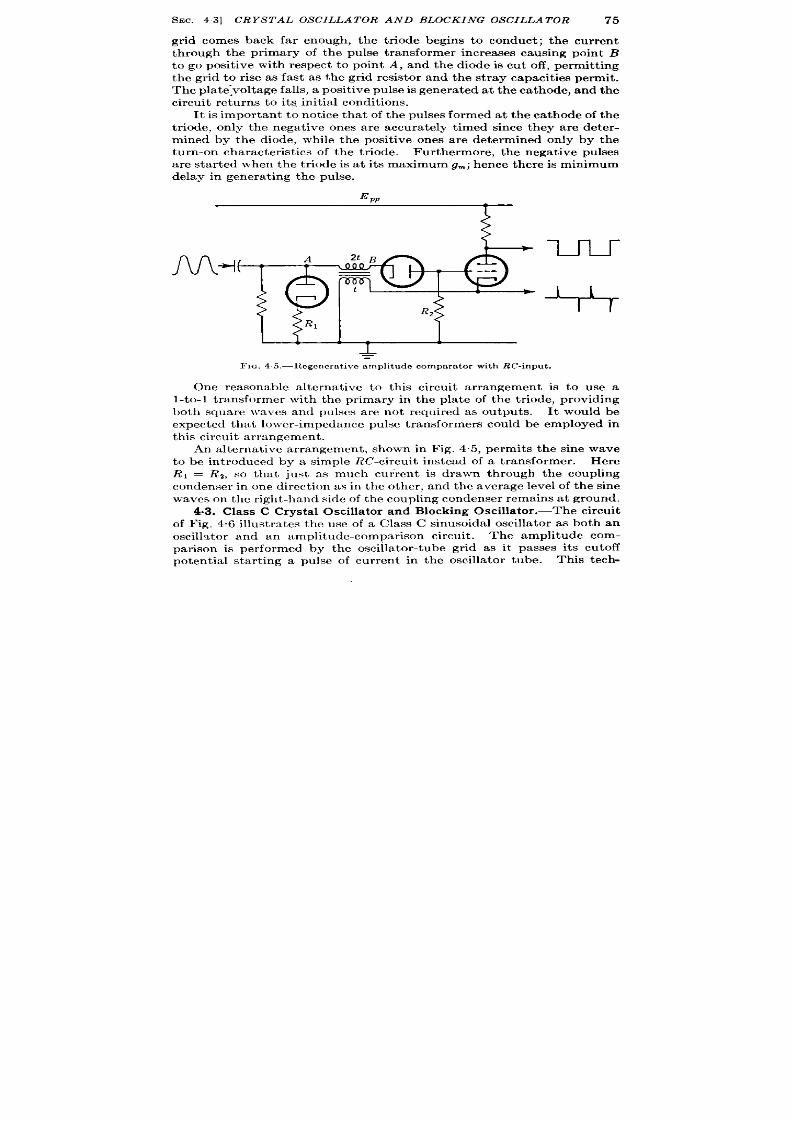
SEC. 43] CRYSTAL OSCILLATOR AND BLOCKING OSCILLATOR
75
gr id comes back far enough, the t r iode begins to conduct ; the cur ren t
through the pr imary of the pulse t ransformer increases causing point B
to go posit ive with respect to poin t A, and the diode is cu t off, permit t ing
the gr id to r ise as fast as the gr id resistor and the st ray capacit ies permit .
The pla te:voltage fa lls, a posit ive pulse is gen er at ed at th e ca th ode, and th e
cir cu it r et ur ns t o it s, in it ia l condit ion s.
It is impor tant to not ice that of the pulses formed at the cathode of the
t r iode, on ly the negat ive ones are accurately t imed since they are deter -
mined by the diode, while the posit ive ones are determined only by the
tu rn-on character ist ics of the t r iode. Fur thermore, the negat ive pulses
are star ted when the t r iode is at it s maximum g~; hence there is minimum
delay in genera t ing the pulse.
L
-
=
FIQ. 45.-lt egcucr a tivc amplit ude compa ra tor wit h RC-inpu t .
One reasonable a lternat ive to this circuit ar rangement is to use a
l-to-l t r nsformer with the pr imary in the pla te of the t r iode, providing
both square \ raves and pulses are not required as outputs. It would be
expect ed that 10wer -impeclan ce pu lse t ran sformer s cou ld be employed in
t his cir cu it a rr angemen t .
An alternat ive ar rangement , shown in ig. 4.5, permits the sine wave
to be in t roduced by a simple ZtC-cir u it instead of a t ransformer . Here
R, = R*, so that just as much cur ren t is drawn through the coupling
condenser in one direct ion as in the other , and the average level of the sine
waves on t he r igh t-hand side of t he cou plin g con den ser remain at gr oun d.
4.3. Class C Crysta l Oscilla tor and Blocking Oscilla tor .—The circu it
of F ig. 4.6 illust ra tes the use of a Class C sinusoidal oscilla tor as both an
oscill~t or and an amplitude-compar ison circu it .
The amplitude com-
par ison is per formed by the oscilla tor-tube gr id as it passe its cu toff
poten t ia l star t ing a puke of cur ren t in the oscilla tor tube. This tech-
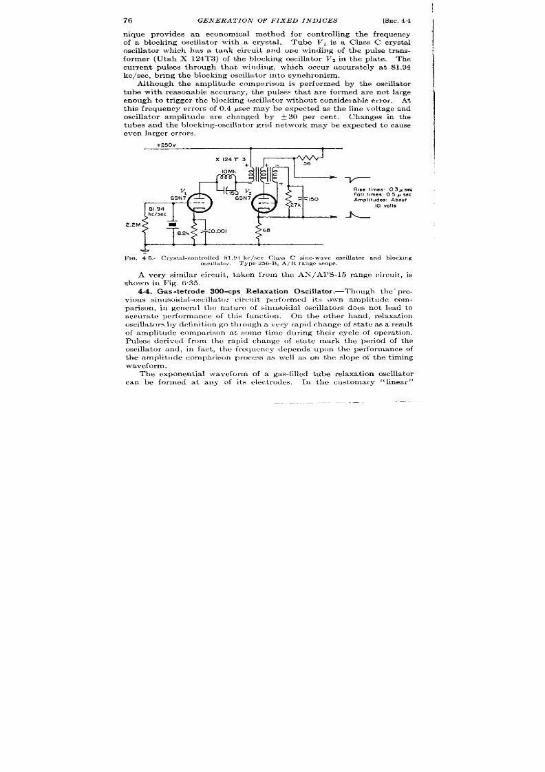
76
GENERAT ION OF FIXED INDICES
[SEC. ‘4.4
n ique provides an economica l method for controlling the frequency
of a blocking oscilla tor with a crysta l.
Tube VI is a Class C crysta l
oscilla tor which has a tank circu it and one winding of the pulse t rans-
former (Utah X 124T3) of Lhe blocking oscilla tor Vzin the pla te. The
cu r ren t pu lses through tha t winding, which occur accu ra tely a t 81.94
kc/see, br in g t he blockin g oscilla tor in to syn ch ron ism .
Although the amplitude comparison is per formed by the oscilla tor
tube with reasonable accuracy, the pulses tha t a re formed are not la rge
enough to t r igger the blocking oscilla tor withou t considerable er ror . At
thk frequency er rors of 0.4 psec may be expect ed as the line voltage and
oscilla tor amplitude a re changed by t3f) per cen t .
Changes in the
tubes andtheblocking-oscilla torgr id network maybe expect ed to cause
even la rger er ror s.
+250V
X124T3
+
10Mh
v,
Rise times: 0.3 Psec
6SN7
Fall times .05 Asec
Amplitudes: About
10 volts
2.2M
+
IPIG.4 .6.—Crys ta l-cor ) t r olled 81.!~4-kc/wc Cluss C s ine-wave oscilla t or and block ing
oscdla tor . Type 256-IL,A/lt r angc scope.
Avery similar circu it , t aken from the AN/A1 S-15 range circu it , is
shownin r ig. 635.
4.4. Gas-tet rode 300-cPs Relaxa t ion Oscilla tor .—Though the’ pre-
vious sinusoidd-oscilla tor circu it pcr formuf its owm amplitude com-
par ison , in gencru l the na ture of sinusoida l oscilla tors does not lead to
accura te per formance of this funct ion . On the other hand, relaxa t ion
oscilla tors by defin it ion go through a very rapid cha nge of sta te as a resu lt
of amplitude compar ison a t some t ime dur ing their cycle of opera t ion .
1’u lses der ived from the rapid c mge of sta te mark the per iod of the
oscilla tor and, in fact , the frequency (lcpcnds upon the er formance of
the amplitude comparison process as }vell as on the slope of the t iming
waveform.
The exponen t ia l waveform of a gas-filled tube relaxa t ion oscilla tor
can be formed at any of its clcct rodcs.
In the customary “linear”
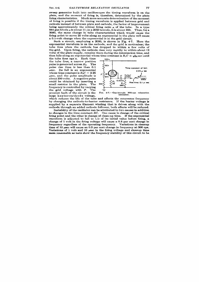
SEC.
4.4]
GAS -TETRODE RELAXATION OS CIL ATOR
77
sweep genera tor built into oscilloscopes the t iming waveform is n the
pla te, and the moment of fir ing is, therefore, determined by the pla te
fir ing character ist ics. Much more accura t e determinat ion of t he moment
of fir ing is possible if the t iming waveform is applied between gr id and
cat hode instead of bet ween pla te and ca thode, t he fa ct or of improvement
being approximately the cr it ical fir ing ra t io p of the’ tube. In a type
884 gas-t r iode p is about 11; in a 2050 tet rode, it is about 250. Thus, for a
2050, the same change in tube character ist ics which would cause the
fir ing point to move 25 volt s a long an exponent ia l in the pla t e will cause
a O.l-volt change w en the exponent ia l is ir i the gr id circuit .
Such a circuit , employing a 2050, is shown in Fig. 4.7. He e the
exponent ia l waveform is on the ca thode, and the gr id is mot ionless; the
tube fires when the ca thode has dropped to within a few volts of
the gr id. Upon fir ing, the ca thode r ises very rapidly to within about 12
volt s of the pla te supply, remains there dur ing the deioniza t ion t ime, and
then falls a long an exponent ia l whose t ime constant is RIC = & sec until
the tube fires ‘aga”n.- Each t ime
the tube fires, a narrow posit ive
pulse is genera ted across Ra. The
pulse r ise t ime is less than 0.1
~sec. It s fall is an exponent ia l
whose t ime cons ant is RIC = 2.25
psec, and the pulse amplitude is
about 200 volt s. A negat ive pulse
could be obta ined by inser t ing a
small resistor in the pla te. The
fr equ en cy is con tr olled by va ryin g
he gr id voltage with P. Th e
severest fault of the circuit is the
la r e hea ter -ca thode volt age,
---
330V
1 1
l-+
2k
Time-constant of fall:
2.25 g sec
.-.
P
-.. *
25 k
1
c ~;”~’ *
RI
T
0.0033
r
Rz
Rise lime: 0.1 g sw
33k
IM
6S0
t
& A
&
-=
FIG. 4.7 .--Ga tet rodede 300-cPs relaxa t ion
oscillator.
which reduces the life of the tube and affects the recur rence frequency
by changing the ca thode-t~heater resist ance. If the heater volt age is
supplied by a separa te filament winding tha t is dr iven along with the
ca t hode through an added cat hode follower , both effect s will be reduced.
Instability of t he oscilla tor can be at t ributed t o t wo causes i addit ion
to changes in the t ime constant RC.
One cause is change of the cri ica l
fir ing point and the other is change of clean-up t ime. If the exponent ia l
waveform is adjusted to fa ll to I/e of it s init ia l va lue before 6ring, a
change of 1 volt in the fir ing volt age will cause a 0.8 per cent change in
frequency rega rdless of the opera t ing frequency. Varia t ions in cleanup
t ime of 10 psec will cause an 0.3 per cent change in frequency at 300 cpe.
Variat ions of 1 volt and 10 psec in the fir ing voltage and cleanup t ime
seem reasonable as test s show the frequency stability of thi8 circu it to be
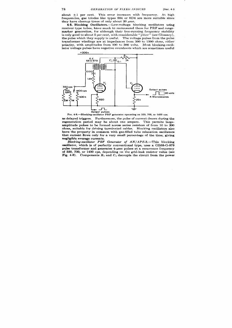
78
GENERATION OF FIXED INDICES
[SEC. 4.5
about + 1 per cent . This er ror increases with fr equency. At high
fr equencies, gas t r iodes like types 884 or 6D4 are more suitable since
they have cleanup t imes of on ly about 20 psec.
4.5. Blocking Oscilla tors.-Low-voltage blocking oscilla tors using
receiver type tubes, have much to recommend them for PRF and range-
ma rker genera t ion , for a lthough their free-r unning frequency stability
is on ly good t o a bout 5 per cent , wit h consider able” jit ter ” (see Glossa ry),
the pulse which they supply is useful.
The volta ge pulses from the pulse
t ransformer windings a re a t impedances from 300 to 1500 ohms, either
polar ity, with amplitudes from 100 to 300 volt s. Most blocking-oscil-
la tor volt age pulses ha ve n ega tive over sh oot s wh ich a re somet im es useful
+3i3Qv
~{$
0.001
1.8k
VI
350 Cps
..-
%
1400 Cps
500 k
2M IM
820
Ln
Output pulses
1$
9-
--
utput pulses
~,ovolts
4 Microseconds
$
5k
L
-L
=
Fm. 4&-Block ing- s ciUa tor PRF gener a t or oper a t ing on 350, 700, or 1400 cps.
M delayed t r iggers. Fur thermore, th pulse of cur r en t drawn dur ing the
regenera t ion per iod may be about one ampere. This permits la rge-
amplitude pulses to be formed across ser ies resistors of from 10 to 200
ohms, suitable for dr iving termina ted cables.
Blockin g oscilla tor also
have the proper ty in common with gas-filled tube relaxa t ion oscilla tors
th~t cur rent flows only for a v ry small percen tage of the t ime, giving
negligible aver age cu r r en t s.
Blocking-om”llator PRF Generator of AN/APLS-3.-This, blocking
odla tor , which is of per fect ly convent iona l type, uses a GE68-G-979
pulse t ransformer and genera tes 4-~ec pulses at a r ecur r ence fr equency
of 350, 700, or 1400 cps, depending on the gr id-leak resistor va lue (see
Fig. 4.8). Components RI and Cl decouple the c rcuit from the power
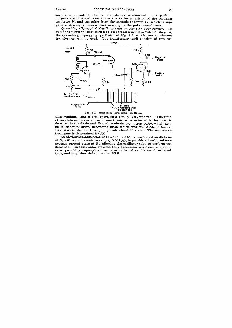
SEC.
4.5]
BLOCKING OSCILLATORS
79
supply, a precaut ion which should always be observed. Two posit ive
outputa a re obta ined, one across the ca thode resistor of the blocking
oscillator VI an the other from the cathode follower V2, which is sup-
plied with a signal from a third winding on the pulse t ransformer .
Quenching (S’quegging) Oscillator w“th an Air-core Tran#orm.er.-’o’o
avoid t he “jit ter” effect of an iron -core ransformer (see Vol. 19, Chap. 6),
t e quenching (squegging) oscilla tor of Fig. 4“9, which uses an air -core
t ransformer , can be used. The t ransformer it self consist s of two six-
4!$’sN
M
Tap f
mounti
-1
on eachcoil
FIG. 4,9.—Quenching (squegging) oscillator.
turn windings, spaced 1 in, apar t , on a l-in . polystyrene ro . The t ra in
of oscill t ions, taken across a small resistor in ser ies with the tube, is
detected in the diode and filtered to obta in the output pulse, which may
be of either polar ity, d pending upon which way the diode is facing.
Rise t ime is about 0.1 ~sec, amplitude about 40 volt s. The recurrence
frequency is det ermined by RC.
An obviou s simplifica tion of t his cir cu it is t o bypa ss t he r -f oscilla tion s
at RI wit h a small con den ser C (sa y 0.001 pf), t o pr ovide a low-impeda nce
a ver age-cu rr en t pu lse at R 1, a llowing the oscilla tor tube to perform the
detect ion . In some radar systems, the r -f oscilla tor is a llowed t o ope ate
ss a quenching (squegging) oscilla tor ra ther than the usual switched
type, and may then define its own PRF.

80
GENERA TION OF FIXED INDICES
[SEC. 4.6
4.6. Mult iVibra tors.-The symmetr ica l mult ivibrator of Fig. 4-10,
which oscilla tes a t abou t 440 cps, shows a frequency change of —1 cps
for a 10 per c n t increase of hea ter voltage and change of a – 1~ cps for
a 10 per cen t increase in plate supply voltage. Thus, a 10 per cen t change
in line voltage should cause about a 0.6 per cen t change in frequency.
Wire-wound resistore and good-quality condenser s must be used to
ach ieve this stability. Tube changes cause a fur ther change of A 3 per
cent.
Co pared with other types of PRF oscilla tors the mult ivibrator has
the advantages of fair ly high frequency s ability as indicated by the
data , low cur ren t drain (5 ma or less), and economy of space. The
blocking os illa tor requ ires a pulse
+250V
t r an sformer wh ich when hermet ica lly
sea led is almost as big as a tube.
50k
50k The RC sine-wave oscilla tor and
squ ar in g amplifier s a re ext ra va ga nt
of par ts and space and draw more
cur ren t (19 ma). One drawback of
the mult ivibra tor PRF genera tor is
0.0022
that the posit ive outpu t pulses a re
f rmed when the tube is c t t ing off
and therefore when the impedance is
essent ia lly tha t of the plate load
resistors. It is necessary, however ,
L
v
t o keep th e pla te load resistan ce high
F1a.4.10.—Symmetr ical mult ivibrator as
PRF gener a t or .
for frequency stability. The nega-
t ive pulse appears at the impedance
of the t r iode pla te resistance.
When a lower impedance is desired a
cathode follower may be used.
A simi ar mult ivibrator design using 6AK5 pen todes a ther than
t r iodes was studkd and found to have on ly slight ly bet ter frequency
stability than the t r iode with high plate loads.
Work don e at Rensselaer Polytechn ic Inst itu te led to some stabiliza-
t ion methods mainly effect ive against changes in pla te supply voltages
but also to a cer ta in exten t , against changes in heater supply voltages.1
A more effect ive refinement is the use of the double phantastron
descr ibed in Chap. 7 of th is volume and in Sec. 5.16 of Vol. 19, which
should be as much bet ter than the mult ivibrator as the phantastron
t ime-modula t ion circuit is bet t r than the delay mult ivibra tor . Con-
siderable though t has been given to the design of highly unsymmetr ical
mult ivibrator s which would provide a shor t low-impedance pu lse dur ing
one sta te of its opera t ion , and remain in the other sta te for the remainder
1See NDRC R+@ 14-155,Project No. 18.07, Cont ract OEMzr-781.
SEC. 47]
FREQUENCY DIVIS ION
81
of the recur rence interval. This subject is t r a ted in Vol. 19, Sees. 510,
5.11.
MULTIPLE-FREQUENCYMARKER AND TRIGGER GENERATORS
B R. I. HULSIZER
Single-frequency marker gen era tors are useful in providing t r iggers
and t ime markers. If a t r igger with an associa ted t iming scale, or a
system of t ime markers a t var ious frequencies is desired, it is necessary
to synchron ize two or more single-frequency marker ge era tors. There
are five methods of synchronizat ion: independen t pu lsed oscilla tors,
fr equ en cy division , fr equ en cy mu lt iplica tion , a ut oma tic fr equ en cy tmck-
ing, and pu lse select ion between two in depen den t oscillat ors.
Th e first
t h ree methods are standard pract ice and are descr ibed in deta il in
Vol. 19, Chaps. 4, 15, and 16. The four th method involves frequency-
modula t ing a slave oscilla tor according to the er ror signal from a phase
det ect or that compares the rela t ive phase of the refer ence oscilla tor and a
pulse der ived fro each cycle of the slave oscillator . The fifth method
genera tes a select ing gate from the low-fre~.lency oscilla tor t o select
one of the h igh-frequency markers for each per iod of the low frequency.
The resu ltant selected pulses will have an average per iod of the low-
frequency oscilla tor bu t will differ from it by an amount up to one per iod
of the higher frequency. The resu lt will be a jit t ery t ime interval
between select ed pu lses.
Examples of these types of synchron izat ion appear in the following
sections.
The techn ique of genera t ing markers a t inde enden t frequen-
cies will be discussed unde grouped markers in the J ast por t ion of the
chapter.
Before discussing the elect r ica l t echniques of genera t ing mult iple-
frequen cy markers it might be well to ment ion again a conven ien t elect ro-
mechan ica system for producing t ime markers.
If a linear sweep is
displayed on a CRT, t ime markers can be obta ined by placing a linear
scale a lon g t h display sweep.
The circular sweep ment ioned in Chap. 3
is a widely used method of obta in ing a sweep of adequate linear ity for
“t tds use. In this case the t ime markers a re made by inscr ibing equally
spaced radia l lines on the CRT face.
Two quant it ies specify the performance of mult iple-frequen t y—
marker gene ator-s. One is the stability of the ra t ios of the severa l
frequenci~. The other is the stability of the phase lock between pulses
of t he sepa ra te fr equ en cies wh ich sh ou ld n orma lly occu r simu lt an eou sly.
4.7. Frequency Division .-The following synchron izer represen t s a
good example of a system in wh ich exact fr equ en cy rat ios ar e specified, bu t
in which only moder te phase lock is required. AS a resu lt of th is condi-
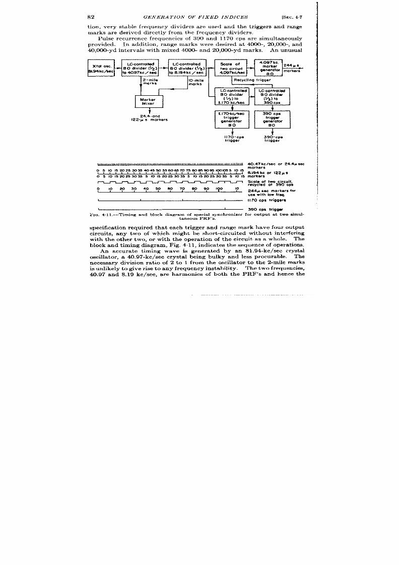
82
GENERA TION OF FIXED INDICES
[SEC.4.7
t ion , very stable frequency divider s a re used and the t r igger s and range
marks a re der ived direct 1y from the frequency divider s.
Pu lse recur ren ce frequencies of 390 and 1170 c s a re simultaneously
provided. In addit ion , r ange marks were desir ed a t 4000-, 20,000-, and
40,000-yd in terva ls with mixed 4000- and 20,000-yd marks. An unusua l
I&contrdled
LC-controMed
Xtol Osc.
- B O divider (~2)
+
BO divider (~s)
BL94kc/%ec
to 40.97kc / sec to &194kc / sec
generatar
markar~
2-mile
10-mile
Recycllng Irigqer
marks
1‘
marks
LCwntrolled
LC.controllal
Morker
Mixer
1.170 kc/kec
390 Cps
t
24.4-and
1.170-kcfiec
390 Cps
122-M s markers
trigger
trigger
genera tar
generator
BO
BO
,
t
t
l170-cps
triqger
o 5 lor5m25xs w45w55wa m75mmw~lma5 1015
0 5 101520253035 5 1015202530355 I0152025W 355 1015
0 10 20304030 s070
80 90 Iqo
10
t
390-cps
trigger
40.47 kc leec or 24.4u sec
markers
S.194kc or 122P
markers
Scaleof twocircuit,
recycled at 390 cpe
244x sec mark ersfor
use with bw freq.
1170 cps triggers
390 cpe tr igqer
F ICJ .4.11.—Tim ing a nd block dia gr am of specia l syn ch ron izer for ou tpu t a t two simul-
taneous PRF’s.
specifica t ion re u ired tha t each t r igger and range mark have four outpu t
cir cu it s, any two of which might be shor t -circu it ed withou t in t er fer ing
with the other two, or with the opera t ion of the circu it as a whole. The
block and t iming diagram, Fig. 4.11, in dica t es t he sequ en ce of opera tion s.
An accura te t iming wave is genera t ed by an 81.94-kc/see crysta l
oscilla tor , a 40.97-kc/sec crysta l being bu lky and less procurable. The
necessa ry division ra t io of 2 to 1 from the oscilla tor to the !Anile marks
is un likely t o give r ise t o any frequency instability. The two frequencies,
40.97 and 8.19 kc/see, a re harmonics of both the PRF’s and hence the
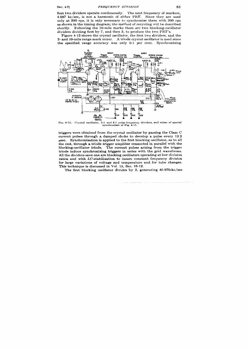
SEC. 4.7]
REQUEN CY DI VIS IOJ V
83
fir st two dividers opera te cont inuously. The next frequency of marker s,
.097 kc/see, is not a harmonic of either PRI?. Since they are used
nly at 390 cps, it is on ly necessary to synchron ize them with 390 CPS
as shown in t he t iming chagram; th e met hod of recyclin g will be descr ibed
shor t ly. Following t he 10-mile mar ks th er e ar e t wo blockin g-oscilla tor
dividers dkidlng fir st by 7, and then 3, to produce the two PRF’s.
F igure 4.12 shows the crystal oscilla tor , t he fir st two divider s, and the
2- an d 10-miJe r ange mark mixer . A t r iode crysta l oscilla tor is used since
the specified range accuracy was on ly 0.1 per cen t . Synchronizing
Ocmw
qU”
.*,. \ s~~”
..- ..- ,.,..-. ,
M4a.4 Ow
S)k
&
l%, 4. 12.—Cryst al oscih to~, 2:1 a nd 5:1 pu lse fr egu en cy divider s, a n d m ixer Of s pecia l
synchroniser of F ig. 4.11.
t r igger s wer e obt a ined horn the crysta l oscilla tor by passing the Class C
cur rent pulses through a damped choke to develop a pulse every 12.2
psec. Synchroniza t io is applied to the fir t Mocking oscilla tor , as to all
the rest , th rough a t r iode t r igger amplifier connected in parallel with the
Mocking-oscilla tor t r iode. The cur ren t pulses arising from the t r igger
t r iode induce synchronizing t r igger s in ser ies with the gr id waveforms.
All t he divider s sa ve n e a re blockln g oscilla t or s oper at in g a t low division
rat ios and with L&stabilizat ion to insure constan t fr equency division
for la rge ar ia t ions of voltage and tempera ture and for tube changes.
This technique is discussed in Vol. 19, Sec. 16.12.
The fir st blocking oscilla tor divides by 2, genera t ing 40.97&kc/sec
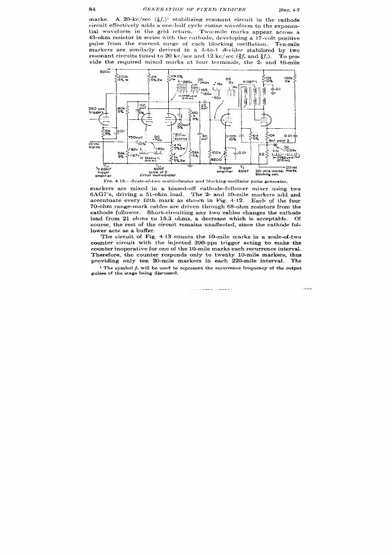
84
GENERA 7’ION OF FIXED INDICES
[SEC.47
marks. A 20-kc/sec (+],) 1 stabilizing resonant circu it in the ca thode
circu it effect ively adds a one-h alf cycle cosin e ~vavcform t o t he expon en -
t ia l waveform in the gr id retu rn .
Two-mile marks appear ac oss a
43-ohm resistor in ser ies with the ca thode, developing a 17-volt posit ive
pulse from the cur ren t su rge of each blocking oscilla t ion . Ten-mile
marker s a re simila r ly der ived in a 5-to-l divider stabilized by two
resonant circu it s tuned to 20 kc/scc and 12 kc/see (~j, and $f,). To pro-
vide the required mixed mmks at four tmminnls, the 2- and lo-mile
300V
1 T [ I
220k
5% Iw
,
{
1
I ,llrl’l+,65vll
I
4J[
90-pps
180k
triggers
57.
DC
50MJf
II
+70V
10-mi
170%
marks
&k
}{4
‘46?;7
.
6sN7
trigger scale of 2
omphfler 6SN7
2D-mile marker marks
omplifier
circwt multtwbrator
blocking osc
FrQ. 4.] 3.—Scale-of-t wo multivihratm-and blocking-oscillator pulse generator.
markers a re mixed in a biased-off ca thode-follower mixer using two
6AG7’s, dr iving a 51-ohm load. The 2- and 10-mile marker s add and
accen tua te every fifth mark as shown in Fig. 4.12. Each of the four
70-ohm range-mark cables a re dr iven th rough 68-ohm resistor s from t he
ca thode follower . Shor t -circu it ing any two cables changes the ca thode
load from 21 ohms to 15.3 ohms, a decrease whi h is acceptable. Of
course, the rest of the circu it remains una ffect ed, since the ca thode fol-
lower acts as a buffer .
The circu it of Fig. 4.13 coun ts the 10-mile marks in a sca le-of-two
coun ter circu it with the in jected 390-pps t r igger act ing to make the
cou nt er in opera tive for on e of t he 10-mile ma rks each r ecu rr en ce in terva l.
Therefore, the coun ter responds only to twen ty 10-mile markers, thus
providing only ten 20-mile marker s in each 220-mile in t erva l. The
1The symbol j, will be used to represent the r ecu rrence frequency of t e ou tpu t
pu lses of t he st age bein g discu ssed.

SEC. 4.7]
FREQUENCY DIVIS ION 85
~+300”
J $ Q- = : z
-’4”4
- 2562us
\
[210 m,)
ooin 5
IwI$ ? %wa , ?I I. . 1km”
trqgers
Tr,gger
16SN7
390-pps ,
I 170-pps rep
~
—
triggers
Trqger
390-pps rep rate
ompbfler
role blockingOSC.
amplifier
block!ng OSC.
FIG. 4.14.—PRF dividers .
1170-Or
390-pps
Iriggws
t
T
-
P?!t
300V
ipomllol’ II II ‘143T-3
2 k 6SN7 s
I+170V ‘-R
—_____
W
+25Sas+
(210 mi)
510
>Sg
(1170-ppsavoorm)5%
w
y
‘Z 6SN7
Trlgg.r
omphfw
I
5&k
(210ml)
1
I
95’1 I
,+105
I
II I
_ L
~ JJ
.1 0.I
~L_L~+
& 2562usd
(lZJJs6;0feZm)
(210 m,)
lF output rep rate
(210 mi)
‘2 6SN7
block,nq OSC
E outPut rep rate
T,,gge,
blocking osc
omol,f,er
FIG. 4.15.—A 20-mile marker genera tor .
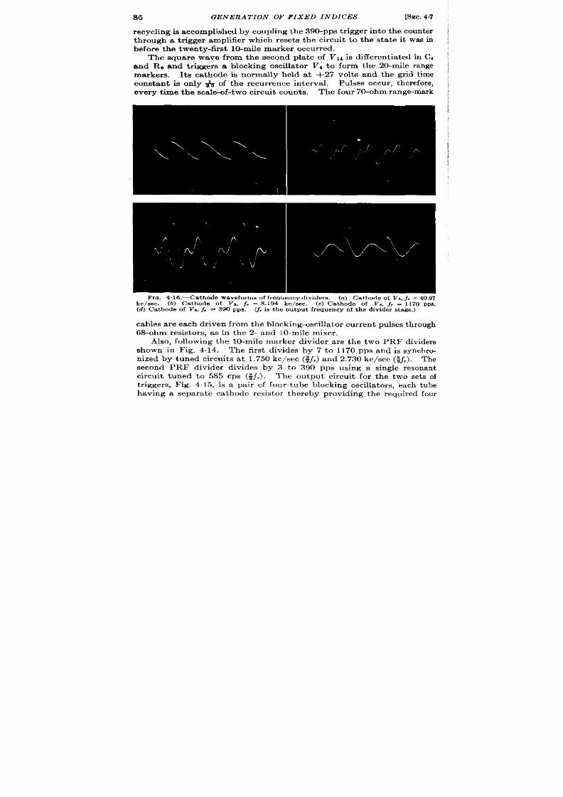
86
GENERA TION OF FIXED INDICES
[SEC.4.7
r ecyclin g is a ccomplish ed by cou plin g t he 390-pps t rigger in to t he cou nt er
th r ugh a t r igger amplifier which reset s he circu it t o the sta t e it was in
befor e t he twen ty-fir st lo-mile m ar ker occu rr ed.
The square wave from the second pla te of VM is differen t ia ted in Cd
and Ra and t r igger s a blocking oscilla tor VA t o form the 20-mile range
markers. It s ca thode is normally held a t +27 volt s and the gr id t ime
constan t is only & of the recu r rence in terva l. Pu lses occu r , therefore,
ever y t im e t he sca le-of-t wo cir cu it cou nt s.
Th e fou r 70-ohm r an ge-mar k
F IG. 4. 16.—Ca thode waveforms of fr equency divider s. (a ) Ca t hode of V,, j, = 40.97
kc/see. (b) Ca thode of V,, f, = 8.194 kc/see. (c) Ca thode of V,, jr = 1170 PPS.
(d) Ca thode of T’s, j, = 390 pps. (f, is t he out pu t fr equen cy of t he divider st age.)
cables a re ea ch dr iven fr om t he blockin g-oscilla tor cu rr en t pu lses t hr ou gh
68-ohm resistors, as in the 2- and 10-mile mixer .
Also, following the 10-mile marker divider a re the two PRF dividers
shown in Fig. 4.14. The first divides by 7 to 1170 pps and is synchro-
n ized by tuned circu it s a t 1.750 kc/see (~~,) and 2.730 kc/see (}j,). The
second PRF divider divides by 3 to 390 pps using a single resonant
circu it tuned to 585 cps (~f,). The output circu it for the two sets of
t r iggers, F ig. 415, is a pa ir of fou r -tube blocking oscilla tors, each tube
having a separa t e ca thode resistor thereby providing the required four
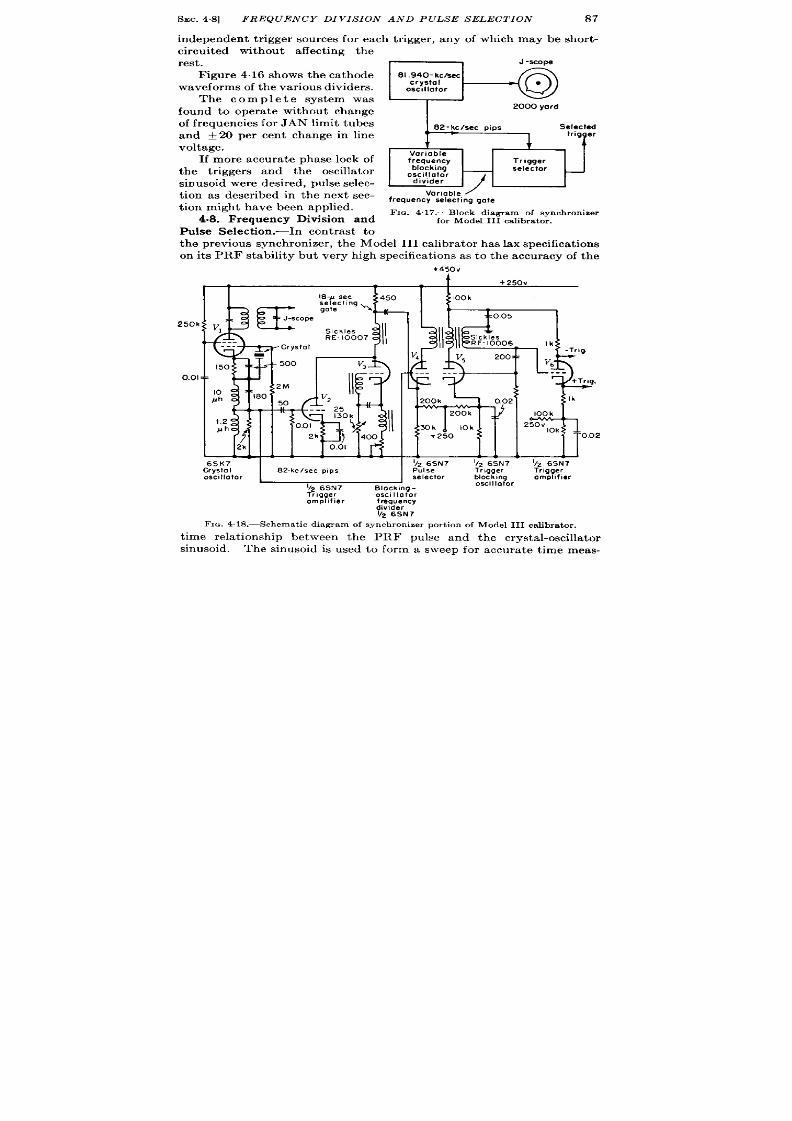
SEC.48]
FREQUENCY DIVIS ION AND PULSE SELECTION
87
independent t r igger sources for each t r igger , any o which m y be sh r t -
circu ited without a ffect ing the
rest .
F igure 4.16 sh ows th e ca th ode
waveforms of t he va riou s divider s.
The complete system was
found to opera te withou t change
of frequencies for J AN limit tubes
and k 20 per cen t change in line
voltage.
If more accura te phase lock of
the t r iggers and the oscilla tor
sin usoid wer e desir ed, pu lse selec-
t ion as descr ibed in the next sec-
t ion might have been applied.
4.8. Frequency Division and
Pulse Select ion .-In cont rast to
v
m
ariable
frequency selectlng gate
FIG. 4.17.—Block d iagr am of synch ron izer
for Model I II ca libr a t or .
t he pr eviou s syn ch ron izer , t he Model III ca libra tor ha s lax specifica tion s
on its PRF stability but very h igh specifica t ions as to the accu racy of the
+450V
+250v
r
T
r
1 1
‘250k
I
+Q
S- sec
r
450
se eel,ng
E
go~e \
J-scope
V,
S,chles
RE- 10007
---
.-.
Crystol
1
I50
500 V3
0.01
T
?...
I +’00’
f /11
3MJ0 Iol(
250v
10k
IT
1
002
c.
! ! 1
v.”!
111
!
1 ~ !
6SK7
1126SN7
IIz6SN7
CrystaI 82-kc/see PIPS
Pulse
Trlgqer
osctl lotor
selector
block, ng
~Z 6SN7
SlOcking -
oscillator
Trigger
oscll lotor
amplifier
frequency
divider
IIz 6SN7
FIG. 4. lS .—Schema t ic d iagr am of synch ron izer por t ion of Model I II
&
Trigger
omplifler
calibrator.
t i e rela t ionsh ip between the PRF pulse and the crysta l-oscilla tor
sinusoid, The sinusoid is used to form a sweep for accu ra te t ime meas-
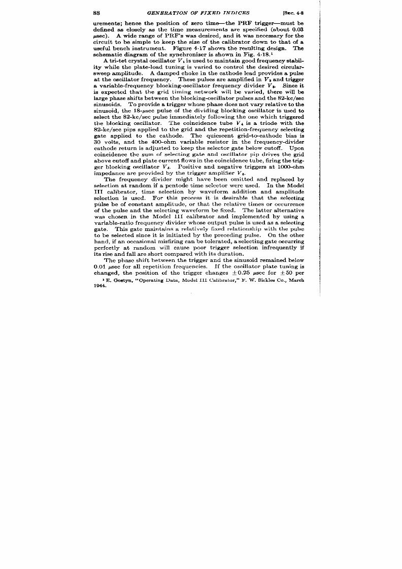
88
GENERATION OF FIXED INDI ES
[%c. 4.8
urements; hence the posit ion of zero t im~the PRF t r iggewmust be
defined aa closely as the t ime measurements a r e specified (about 0.03
~ec). A wide range of PRF’s was desired, and it was necessa ry for the
circuit t o be simple to keep the size of the calibra tor down to that of a
useful bench inst rument . F igure 4.17 shows the result ing design. The
schemat ic diagram of the synchron izer is shown in Fig. 4.18.1
A t r i-t et crys ta l oscilla tor VI is used t o mainta n good fr equ en cy st abd-
ity while the pla te-load tuning is var ied to cont rol the desired circu lar -
sweep amplitude. A damped choke in the ca thode lead provides a pulse
at the oscilla tor fr equency. These pulses a re amplified in Va and t r igger
a va ria ble-fr equ en cy block in g-oscilla tor fr equ en cy divider Vs. Since it
is expect ed tha t the gr id t iming network will be var ied, t here will be
la rge ph ase sh ift s between t he blockin g-oscilla tor pu lses a nd t he 82-k c/see
sinusoids. To provide a t r igger whose phase does not vary rela t ive to the
sinusoid, t he 18-psec pulse of the dividing blocking oscilla tor is used to
select t he 82-kc/see pulse immedia tely following t he on e which t rigger ed
the blocking oscilla tor . The coincidence tube Vf is a t r iode with the
82-kc/see pips applied t o t he gr id and t he repet it ion-fr equency select ing
ga te applied to the ca thode. The quiescen t gr id-to-ca thode bias is
30 volt s, and the 400-ohm var iable resistor in the fr equency-divider
ca thode return is adjusted to keep the selector ga t e elow cutoff. Upon
coincidence the sum of select ing ga te and oscilla tor pip dr ives the gr id
a bove cu toff and pla t e cu rr en t flows in t he coin cidence t ube, fir ing t he t rig-
ger block ing oscilla tor Vs. Posit ive and nega t ive t r iggers at 1000-ohm
impedance ar e provided by t he t r igger amplifier V6.
The frequency divider might have been omit ted and replaced by
select ion a t random if a pen tode t ime se ector were used. In the Model
III ca libra tor , t ime select ion by waveform addit ion and amplitude
select ion is used. For this p ocess it is desirable that t he select ing
pulse be of constan t amplitude, or tha t the rela t ive t imes or occu r r ence
of the pulse and the select ing waveform be fixed. The la t t er a ternat ive
was chosen in the Model III calibra tor and implemented by using a
var iable-ra t io frequency divider whose output pulse is used as a select ing
ga te. Thk ga te mainta ins a rela t ively fixed rela t ionship with the pulse
to be select ed since it is in it ia ted by the preceding pulse. On the other
h an d, if a n occa sion al m isfir in g ca n be t oler at ed, a select in g ga te occu rr in g
per fect ly at random will cause poor t r igger select ion infrequent ly if
it s r ise and fall a r e shor t compared with its durat ion.
The ph se shift between the t r igger and the sinusoid remained below
0.01 psec for a ll r epet it ion fr equ en cies.
If t he oscilla tor pla te tuning is
changed, the posit ion of the t r igger changes f 0.25 ~ec for f 50 per
I E . Gos tyn , “Opera t ing Da ta , Model III Ca libr a tor ,” F . W. Sick lesCo., March
1944.
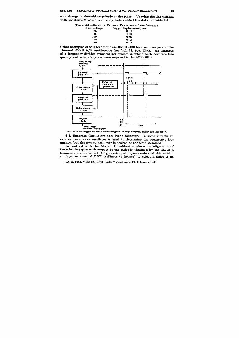
sm . 4.9] SEPARATE OSCILLATORS AND PUiXE SELECTOR
89
cen t change in sinusoid amplitude at the pla te. Varying the line voltage
with constant 82 kc sinusoid amplitude yielded the data in Table 4.1.
TABLZ4.1.-SHIPT IN TE1~~EBPEASEwrmi Lnrz VOLTAQm
Line voltage
Trigger displacemen t,~
75
0.10
S5
0.05
100 O.m
115
0.10
130 0.15
Ot her examples of this tech niqu e ar e t he TS-1OO t est oscilloscope and th e
Dumont 25&B A/R oscillo cope (see Vol. 21, Sec. 18.4). An example
of a frequencydivider synchronizer system in which both accura te fre-
qu ency and accu rat e phase wer e r equ ir ed is th e SCR-584.1
lh.n.~:ient
synch.
*--------
,~
Selector
--—-----—
n
gate *I
r
i
ABCD
tooo yd
/ / / / ~
range mk. -J ‘
‘,,’’’’’’’”
111111
-
II
Cohuldenee
generator
Stoga
*-
-. —-- --
Selector
gote *2
I
I
{
I
I
I
I
:
Colncldence
+
I
I
etage
I
I
I
i
1,
I
I
*--- —---
Trigger
B.O,
#
=
‘Jhter-froe
s
Tlnre
8electedpr e.tr igger
FIG.4.19.—Trigger-eelectar block diagram of experimental radar synchronizer .
.9. Separa te Oscilla tor s and Pulse Selector .—In some circu its an
external sine wave oscilla tor is used to determine the recur r ence fre-
quency, but the crysta l oscilla tor is desired as the t ime standard.
In cont rast with the Model III calibra tor where the alignment of
the select ing gate with respect to the pu lse is obta ined by the use of a
frequency divider as a PRF genera tor , the synchron izer of this sect ion
employs an external PRF oscilla tor (3 kc/see) to select a pulse A at
1D. G. F ink, “The SCR5S4 Rada r,” Electronics, 19, Februar y 1946.

90
GENERATI N OF FIXED INDICES
[SEC.4.9
squaring
M eelectof goto M time
2mdSsledorgate
om~ifier
+Wow 6AG7
‘?F;?”
selector Mxkingpllotar
6AG7 .
t
j~ blocking-o&Watar
ompliiih
lrwn srysIOI OSCIIIOW
+ 3C9V
SAC
7
~7F8 9s7F8
7 , 1
I-1 1
0k
100k
3rd
selector
*=0.01
II gate
22k
.
. t
!ifpf-
2000 yd
nega t iver igger
. .. ...
0.02 002
0.01
tOOk{:
0.01
+ Pr e-?rigger
h7f
4,7k
3.9k
of-2000 yd
-130V
i -20V
.,...,
— c,
gate
II
.01
Wk
Pk I N I iKll
‘4 h@Y-rl I%31 I
-151n.,1? ’ 02
fl
.-_-
--
Id 22 F F0022:
Modulator
t~m%
Modulatar tri~$it~tector trigger
M3dulotor trigg~
Selacti
+ 300V
‘t~g7F8
tim~gdor
6AC7
blocking oscillator
Y27FB
6AG7 ~+450v
I
IOk
Thi,l+ 66k ii
10k
22k
@ 132-DW
L= ..-
330
1 If
JL)Jf
2;
‘ok 100
All lronsformers
0.001
u?
re GE28G19
163kc/see pu lses
un leseoth sr se
fromcrystolscillator
med.
FIG. 4,20.—Synchronizer of exper imental radar .

SEC.49] SEPARATE SCILLATORS AND PULSE SELECTORS
91
random that forms a select ing ga te whose posit ion with respect t o t he suc-
cee in g pu lse B is thus adequately defined. As shown in Fig. 4.19,
select ion of pu lse B resu lt s in a t r igger which is stable with respect to the
phase of the 163-kc/sec oscilla tor . Figure 4.20 shows the circu it . The
f rst two rows of tubes per form the opera t ions indicated on the block
diagram. The th ird row uses the pret r igger to select a th ird pu lse C which
in tu rn t r iggers a select or gate to select the four th pulse D, thus provid ing
a t r igger delayed exact ly from the pret r igger by 2000 yd. The selected
pulse D dr ives a low-impedance blocking oscilla tor to supply the modu-
la tor t r igger . The advantages of th is t ype of synchronizat ion are that it
permit s complete freedom of choice of the PRF and at the same t ime
jit t ers, or phase-modula tes, the t r iggers with respect t o the PRF signal.
The la t t er is an advantage in radar applicat ions since it makes the radars
less su scept ible t o mut ua l in t er fer en ce.
A proposed and as yet incompletely test ed synchron izer was to be
incorporated in a revised mode of AN/APS-10 radar , and this circu it
incorporates a number of good techn iques and high ly economica l circu it
pract ices. This design was made possible in par t by the development of
baseless subminiatu re t riod s wh ich permit ver y low str ay capacitan ces, a
powdered iron l-mh choke having a high resonan t frequency, and the
germanium crysta l rect ifier which has a very low capacitance, about
0.5 ppf, and a forw rd resist ance of less than 1000 ohms. Shunt ing the
crysta l across the choke provides an economical method of obta in ing
shor t pulses for t r iggers or markers since the cr sta l does not lower the
ch ok e-r eson an t fr equ en cy a ppr ecia bly a nd yet offer s sever e dampin g a ft er
t he first half cycle. he low-capacitance tubes and wir ing permit th
design of stable h igh-impedance mult ivibra tors with reasonable ou tpu t
r ise t imes .
One precau t i n that was observed as a resu lt of large var ia t ions in the
ch ara ct er ist ics of t he tu bes was th at wh en two circu it s ar e dir ect -cou pled
the most significant value of the signal voltage should occur when the
associa ted vacuum tubes are in a nonconduct ing sta te. A study of the
schemat ic and block diagrams will illust ra te the use of hese specia l com-
ponen ts and th is philosophy of design .
One of the specia l requ irements of the AN/APS-10 synchron izer was
that it shou ld opera t e on an external PRF source wi hout in t roducing
more than 2 per cen t jit t er . In addit ion the following markers were
desired: posit ive and negat ive l-mile markers; posit ive and negat ive
5-mile m arkers; posit ive l-mile mar ker s phasable with r espect t o t he first
set ; a marker which would be movable in in tegra l mult iples of 5 miles,
ca lled the “ 5N-mile delayed t r igger”; a
PRF t r igger accura tely phased
with respect t o the above l-mile markers; and a prestar t t r igger a t the
PRF preceding the zero range marker by 135 psec.
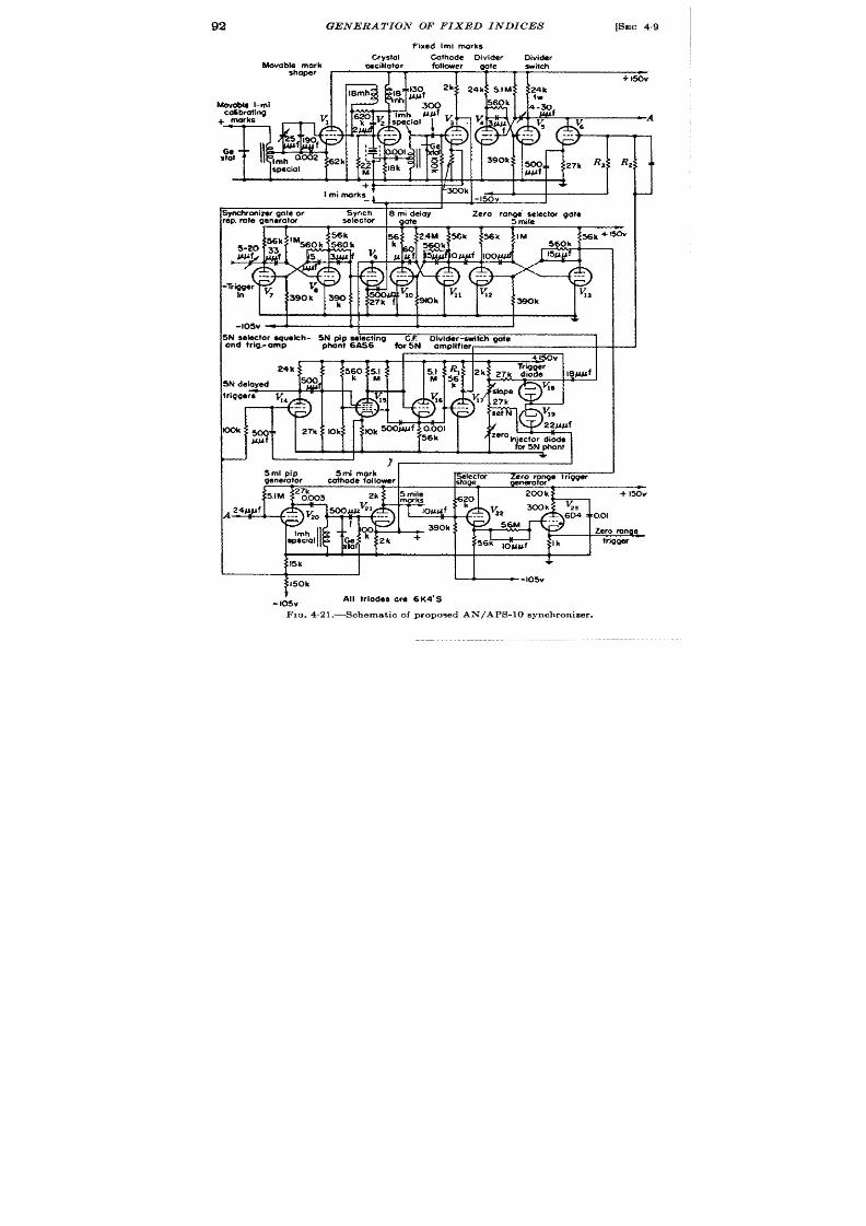
GENERA T ION OF FIXED INDICES [SEC49
fixed Imi morks
Crystal Cathode ivider
Divider
hfovab~ho~;k
oscillator follower
gote switch
I T T 1 T 11 + Isov
I mi marks
~:’ “k-”””
!
~
1’
1
I
J
Synch
8 mi delay
Zero raprni~lector gate
selector
gote
I .-.~~k~lMU {56’
‘: $ ~n.!
2.W 5&k 56k IM
~k +1*
nk Ken!. 56(M
I
5ml pip
5mi mork
I
.,.., - 7.. - ----- ..:-----
oenerotor
cathode fol Iowwr
A
l-b
mile
morks
l“fJ f
—
--A
-!..!”!
stage.
I 4
1
1
!
[
I I
1
I
I
I’k
H
+
--I05V
$50k
.
+
- I05V
All triodes are 6K4’S
FIG 4.21 .—Schematic of proposed AN/APS-10 synchronizer .

SEC. 4.91 SEPARATE OSCILLATORS AND PULSE SELECTORS
93
The value of pla te supply was set a t 150 volt s for the following reasons:
a simple 110-volt line-opera ted rect ifier could be used, the average
cu rren t consumpt ion is in genera l propor t ional to th e pla te supply, and th e
low voltage permits the use of low-voltage condensers and low-wat tage
resist ors.
To supply synchronizing t r igger s from the externa l PRF
without in troducing more than the specified 2 per cen t jit ter , it was
necessary to select one o the accura te l-mile markers and to use a gated
divider to supply the 5-mile markers.
A- X tOlmarks
B- l-mile marks
E- Selected pulse
F-E-mile deloy gate
G-Zero range
sele tor gate
I
I
I
h’-Phantastron
1:
plate
.J ‘Divider switch
gate
~-five-miledivider
L
n n
L- F ive.milepukes ~ ;
I
M Ze:g;:onge
I
I
1
N- Selected five.
i
~ le mark
FIG.4.22.—Timingdiagramof pr oposed AN/APS-10 syn ch ron izer . 1, 2, a nd 3 m ar k t he
thr ee time-selection operations.
Refer rin g t o t he diagrams, Figs. 4.21, 4.22, and 4.23, an 80.86-kc/sec
t r iode crysta l oscilla tor V2 genera tes sinusoids, waveform A, whose
per iod cor responds to 1 naut ica l mile of radar range. The unusual
fea tu res of this oscilla tor ar e th e pla te-to-gr id coupling conden ser n eces-
sary here becau e of the low in terelect rode capacitances of the sub-
minia ture tubes and the combined resist ive and induct ive coupling in to
the movable mark shaper V,. Tuning the secondary of the pla te trans-
former provides the necessary var ia t ion of phase shift of the movable
l-mile calibr t ing marks, and the addit ion of t he resist ive coupling place
the cen ter of the phase-sh ift var ia t ion at the desired phase. The mov ble
ma rk sh aper VI acts as a Class C amp~ifier , whose cur ren t surges shock-
excite the damped choke in the ca thode circu it , forming a shor t pulse,
waveform C. The phasable pulses are requ ired to per it the zero

94
GENERA TION OF FIX D INDICES
[SEC.4.9
cor r ect ion of radar syst em (see Chap. 3). Pu lses of fixed phase with
respect t o the crysta l oscilla t ions are formed from the cur r en t pu lses in
the crysta l oscilla tor it self, and a re developed across the damped choke
in it s ca thode. The succeeding amplifier s supplies these marks at low
impedance with both polar it ies to the rest of the synchron izer , and as
range marks for the indicators, wa veform B. As indica ted in Fig, 423,
the next opera t ion on the sequence is the select ion in Vg of the pret r igger
by the PRF synchron izer pu lse, waveform D, which is a posit ive ga t e
sligh t ly over 1 mile in dura t ion.
It is applied to the gr id of a t r iode
coincidence stage Vg whose ca thode is dr iven by the 1-mile marker
Phased me
mile
+
markers
c
External
one. mile
synch ronizat ion
pulse
selector
I
Ze;;;;~
Zero range
trigger
Smile
selector
delay
generator
mult!vib rotor
mulli vibrator
M
t
~‘E
1
+
mark
I/5
Pi selecting
Adjusl
1
shaper
divider
phonlastron
N
Zero
ronge
L
t
Iti
—
—
5-+mile
Selected delayed pip
(5x N miles)
markers
FIG.4.23.—Block d iagram of proposed AN/APS-l Osynchron ize r. Let t er s between b locks
r efer t o waveforms of F ig. 4.22.
pulses. The resultan t selected t r igger E in it ia tes an 8-mile delay ga te F
in Vlo and VII which in turn t r iggers the zero-range selector ga t e G
V12 and Vl~. These three ga tes a re genera t ed from unsymmetr ica l
monostable mult ivibra tors (Vol. 19, Chap. 5) whose outstanding char -
act er ist ics a re t he la rge pla t e r esist or s m ade possible by t he low capa cit ies
of the tubes and the pract ice of using only th nega t ive outpu t when st eep
wavefr on t s a r e desir ed.
In ord r to follow the sequence of opera t ions it is necessa ry to leave
this t ra in of opera t ions a t t he genera t ion of the zero-r ange selector ga t e
waveform G and consider the genera t ion of the 5-mile marks, since one
of t e 5-mile marks is to be elect ed by the ga t e G to form the zero-r ange
trigger M.
The 5N pulse-select ing phantast ron VM, V16 is triggered by the

SEC. 4.10]
A UTOMA TIC FREQUENCY TRACKING
95
select ed pu lse E. Its pla te waveform immedia tely shuts off VIT, which
in turn ga tes the 5-mile divider switch Vc with the waveform J . The
voltage to which the gr id of the divide switch tube Ve is brought by J is
deter mined by a bleeder R,, Rz, and R3 between EPP and the – 10~volt
supply a t a t ime when VIT is nonco duct ing. With this a r rangement ,
va ria tions in ch ar act er ist ics of V17 do not a ffect t he level to which he
gr id of t he t r iode coincidence tube Va is raised.
As a resu lt of the divider switch act ion, t he divider V,, Vs, sta r t s to
d vide on the f r st l-mile marker a fter the presta r t t r igger and cont inues
t o divide unt il the phanta st ron (VIJ pla te r ea ch es a volt a ge su fficien tly
low to cause conduct ion in the in jector diode V,g. As this happens, the
Nt h 5-mile m ar k cou ples int o t he ca thode fol ower Vla of t h e phant a st r on ,
dr iving t e pentode gr id more posit ive, genera t ing a posit ive pip in the
ca thode of tha t tube. This is coupled to the 5N s lector shu toff and
t r igger amplifier VM which then provi es a low-impedance 5N delayed
t r igger which shuts off t he phantast ron . As the phantast ron shuts off,
it s pla te r ises, tu rning t he divider -switch ga te amplifier VIT on again and
shut t ing oil the 5-mile divider switch V.S, thus termina t ing the divider
(V , V,) act ion unt il t he next r epet it ion per iod. S nce the zero-range
t r igger -selector ga te does not tu rn on unt il a fter the 8-mile delay ga te
and is 5 miles in dura t ion, it over laps the third 5-mile pip which occur s
11 miles a fter the pret r igger . Th coincidence of these two waveforms
in VZZ tr igger s a thyra t ron V23 to form the zero-r ange t r igger for the
radar modula tor . It is in erest ing to note tha t a lthough the coincidence
between the externa lly synchronized select ing mult ivibra tor will have
occasiona l jit t er s when the over lap occur s on the r ising edge of the
select ing ga te (about 1 per cen t of the t ime), the zero-r ange selector ga te
mainta ins a constant t ime rela t ionship to the 5-mile marker tha t it
select s. Thus a stable PRF tr igger is provided. The zero range t r igger
mainta ins a fixed t im e r ela tionsh ip t o t he fixed ma rker s t o within O.OIM.
One essent ia l design pract ice r equ ir ed by the use of t r iode t ime
selectors is tha t descr ibed in connect ion with the act ion of the t ime
selector Ve; the poten t ia l t o which the gr id is brought by the select ing
ga te is independent of var ia t ions in the character ist ics of the ga te:
genera t ing tube, VIT. This precau t ion is observed in the t ime selector s
VS and VW.
4.10. Syn ch ron iza tion by Au tomat ic F r equ en cy Tr a ck in g.-Develop-
ment of pulse techniques has led to a modifica t ion of the convent iona l
fr equ en cy t r ack in g cir cu it s t ha t permit s scilla tor s of two widely differ en t
fr equencies t o be synch ron ized.
If, as indica ted in Fig. 4.24, pulses ar e
formed from each oscilla tor , the r ela t ive t imes of appearance of these
pulses can be compared at A, B, C, et c. with a t ime discr imina tor . I If
1t%cs.3.17 and 3.18.

96
GENERA T ION OF FIXED INDICES
[SEC.4.10
the two freque~cies a re fixed, but a ligned a t A, the er ror signa l of the
t ime discr imina tor would indica te an increasing t ime difference a t B and
C. When this er ror signal is applied to a reactance tube controlling
either oscilla tor , th e two oscilla tors will be made to opera te t an in tegra l
frequency ra t io with an accura tely cont rolled phase rela t ionsh ip. If the
limits of con trol of the reactance tube are such that it cannot change the
frequency ra t io by one in teger , and the mean frequency of the cont rolled
n n n
n n n
n n n n n n n n n n n n
,
,
A
B c
FIG.4.24.—Frequency t rack ing by pu lse t ime d iscr imina tor .
oscilla tor is with in plus or minus one in teger of the desired ra t io, the
system cannot synchronize a t the wrong frequency ra t io.
Since the
limit ing factor to the frequency ra t io obta inable with th is system is
essen t ia l y the stability of the two oscilla tors, one would expect to be
able to work with frequency ra t ios from 100 to 10,000 depending upon
the type of oscilla tor used. The dist inct advantage of th is technique s
tha t in spite of la rge frequency ra t ios the t ime rela t ionsh ip of the pulses
er ived from the two oscilla tors is as stabl as the t ime discr imina tor.
F igure 4.25 shows the block diagram of an automat ic frequency-
t r ackin g syn ch ron izer wh er e a h igh -frequ en cy oscilla tor is c n trolled by
1-
Frequency
—
Pulse
Selector
modulated
generator
gates
oscillator
generator
t
Error signal
f
—————— ——_ ___ __
1
1
Low-frequency
Pu Ise
Time
oscillator
+
generator
-
discriminator
—
L
FIG.4.25.—Block diagram of automatic frequency-tracking synchronizer .
r efer ence to a low-frequency oscilla tor .
Th e da sh ed connect ion s in dica te
its use as a low-frequency oscilla tor cont rolled by reference to a high-
frequency oscilla tor .
A design proposed for a lightweight direct -reading Loran indica tor
is a good example of pulse frequency tracking. The block diagram of
Fig. 4.26 indica tes tha t the frequency of the 20-kc/sec oscil a tor is
adjusted so tha t it s l/800th subharmonic agrees exact ly with the PRF
of the incom ng video pulses received from the Loran ground sta t ions.
The automat ic frequency~ont rol circu it ia s own in Fig. 4.27. The
20-k c/sec LC-oscilla tor a nd pu lse gen er at or form 50-psec pu lses wh ich t rig-

SEC. 4.10]
A UTOMA TIC FREQUENCY TRACKING
97
ger a mult istage+ divider tha t in tu rn t r igger s a 100-gsec mult ivibra tor
t o form the ea r ly ga te for the t ime discr iminator . The back edge of th is
ga te t r igger s a similar mult ivibra tor to form the la te ga te. These two
ga tes tu rn on successively the gr ids of the top and bot tom sect ions
of a t r iode t ime discr iminator VZ and Va (see Chap. 3 and Fig. 4.28).
he ou tpu t con t rols the reactance tube VI.
The gr id of the reactance tube has fu ll sine waves from the ca thode
of V,t impressed on it . The ca thode is connected to the h igh-poten t ia l
end of the tank coil th rough 24 Ppf.
If VI condu ct s for th e wh ole cycle
of the sine wave, on ly a negligible volt age a t 20 kc/ ee appears across Cz
and no detun ing occ rs. On the other hand, if VI is so biased tha t it does
20-kcAec
Blocking
Lc
oscillat r _l_ frequency _
Scale of
oscillator
pulse
400divider
two
generotor
1
Pedestal
generator
I
+
{
Gated
Early gote
Error
detector multivibfotor
J
Reoctance
signol
Video from
tube
ground etation
I
\
Late gate
I
multivibrator
I
=
Fs~. 4.26.—Block diagram of lightweight Loran automatic frequency-t racking circuit .
not conduct dur ing any par t of the cycle, C2 is essent ia lly connected to
ground th rough 10k from the high-potent ia l side of t e tank coil. These
t wo con dit ions defin e th e limits of fr equ en cy modu la tion by VI as 0.24 per
cen t . In termedia te values of frequency resu lt when VI conducts for a
por t ion of the cycle, as con t olled by the bias produced by the t ime
dkcr imina tor . Th effect of switch ing a small condenser C2 across the
tank circu it fol a por t ion of the cycle apparen t ly has lit t le effect on the
waveform of the oscilla tor since it was found not to a ffect the accuracy
of the condenser phase sh ifter fed by the oscilla tor .
Th e applica t ion of th is circu it to the m ore direct problem of synchron-
izing two oscilla tors can be accomplished by t r igger ing the ea r ly- and
la t~ga te gen era tor s from the low-frequ en cy oscilla tor and feeding para-
phaaed sine waves of the high frequency ra ther than paraphrased video
pu lses in t o t h e t ime discr im ina tor .
Th e t im e discr im in at or t hu s becomes
a hybr id t ime and phase discr iminator .
Cir cu it s exemplifyin g t his t ype
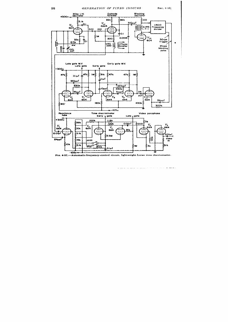
GENERA TION OF IXED INDICES
SEC.4.10]
20kc L-C
Cathode
oscillator
follower
Blocking
+300V -
oscillator
22k
v
6FK5
C4
m
/
5ocgs
trigger
23cp:
blanking
pulse
+300V
4
47k
o.l~f , .
120J$pf
P
330k
160k
I
~-losv
Reoctoncs
Timediscriminator
Videoooranhase
q
tuba
Early“@O
Lote v gate “ “”
-lo5v~
+
l%. 4.27.—Aut oma tiorequ ency<ont rolcircu it,lightweightLora nt ime discriminat or
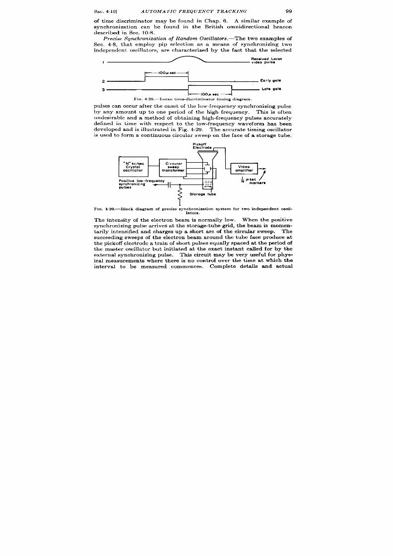
SEC.4.10]
AUTOMATIC FREQUENCY TRACKING
99
of t ime discr iminator may be found in Chap. 6. A similar example of
synchronizat ion can be found in the Brit ish omnidirect ional beacon
descr ibed in Sec. 10.8.
Precise Synchronization oj Random Oscillators.—The two examples of
Sec. 4.8, tha t employ pip select ion as a means of synchron izing two
independen t oscilla tors, a re character ize by the fact tha t the selected
, ~?;:~l:y
~100M see+
, ~ Eor l,We
3
1-----1oo. sac
Lote gote
FIG. 428,-Loran t ime-d iscr imina tor t iming d iagram.
pu lses ca n occu r a ft er t he on set of t he low-fr equ en cy syn ch ron izin g pu lse
by any am unt up to one per iod of the high frequency. This is often
u ndesir able an d a met hod of obtain in g h igh -fr equ en cy pu lses a ccu ra tely
defined in t ime with respect to the low-frequency waveform has been
developed and is illustra ted in Fig. 4.29.
The a ccu r at e t im ing oscilla tor
is used to form a cont inuous circular sweep on the face of a storage tube.
rl-
N“kclsec
Crystol
oscillator
Pickoff
Electrode
;Ip
Circular
sweep
Video
transformer amplifier
Positive low-frequency
~ #sac
/
synchronizing
+ ‘:-
morkem
pulsss
!
Storogeu’be
Fm. 4.29.—Block diagr am of p recis e synch ron iza t ion sys tem for two independen t oscil-
lators.
The in tensity of the elect ron beam is normally low. When the posit ive
synchronizing puke ar r ives a t the stor ge-tube gr id, the bea is momen-
tar ily in tensified and charges up a shor t arc of the circu lar sweep. The
succeeding sweeps of the elect ron beam around the tube fa e produce at
th e pickoff elect rode a train of sh or t pulse equally spaced at th e per i d of
the master oscilla tor but in it ia ted at the exact instant called for by the
external synchronizing pulse. This circu it may be very useful for phys-
ical measurements where there is no con t rol over the t ime at which the
in terval to be measured commences.
Co plete deta ils and actual

100
GENERA T ION OF FIXED INDICES
[SEC. 411
circu it s a re descr ibe in Vol. 19, Chap. 21 on the use of storage tubes. An
a lt erna t ve method of set t ing up an equally spaced t ra in of marker s
st a r t ing a t any random instan t is to use a pu lsed LC-oscilla tor and ampli-
tude compara tor .
Th is is descr ibed in Sees. 4.13 a nd 4.14.
FREQUENCY DIVIDERS WITH INJ ECTION FEEDBACK
There a re some applica t ions where a pu lse r ecu r r ence frequency is
desired with a frequency ra t io to the master oscilla to tha t is not factor -
able in to pract ica l sin gle-st age division ra tios.
It is a lso oft en desir ed
to hange the PRF by small incremen ts withou t radica lly modifying the
synchron izer cir cu it . Both of these problems maybe solved with the use
of in ject ion feedba ck divider i.1
In one form of th is t echn ique the last
divider t age, in fir ing, effect ively adds one or more ext ra t r igger s t o the
fir st st age of the chain . Fewer master -oscilla tor t r igger s re thus
requ ir ed to complete the next dividing per iod. In another form of
feedback divider , the fir st divider stage is held off from dividing for few
t r igger s a fter the last stage fires.
As a resu lt , a complet e dividing cycle
t akes a few more than the usua l number of master -oscilla tor t r igger s.
These methods will be illust ra ted with two examples.
4.11. Ligh tweight Direct -r eading Loran PRF Genera tor .—In the
previous sect ion , the PRF divider cir cu it of th e direct -r eading Loran was
indica ted as a standa rd frequency-dividing circu it having a ra t io of
800 to 1, Actua lly the Loran PRF’s a re given by the ra t ios ~~~c~~),
20 kc/see
20 kc/see
2(4 0 – N) ‘ and 2(500 – N)
?wh er e N is any in teger from O to 7 inclusive
a nd cor respon ds t o differ en t st at ion s.
Var ia t ions in N give pu lse recur -
r ence per iods which cliffer in steps of 2 x 50 ~ec.
The method of providing these odd-va lued PRF’s from the frequency-
con t rolled 20-kc/sec oscilla tor is shown in the schemat ic diagram, Fig.
4.30. F igure 4.31 shows the t iming sequences drawn as though the
l-to-5 coun ter were missing and the last coun ter were set to coun t by 6,
with N set for 2. To study the opera t ion of the circu it , let us consider
the act ion of the circu it without in ject ion feedback. The coun ters a re
gas-filled tu be step cou nt er s simila r t o t hose descr ibed in deta il in Vol. 19,
Chap. 16 of th is ser ies. Consider VM ju st a ft er it has fir ed. The
ca thode is held by Vla and V16 from going above +100 volt s. F ifty
microseconds a ft er it fires, a nega t ive pu lse will come from the pla t e of
t he block ing oscilla t or Vls, ca usin g t he diode V,b t o con du ct , wh er eu pon
the voltage of the t r igger pu lse will be shared between C7 and Cs, lower -
ing the ca thode of Vle by abou t 6.4 volt s. The succeeding pulse will
1Feedback in this sensedoes not have the rsmnotat ionusually at t r ibutedto feed-
back in amplifiers.

SEC.4.11] DIRECT-READING LORAN PRF GENERATOR
101
find 6.4 volt s bias a cr oss VM wh ich it must over come befor e Vld con du ct s;
CT and Ca will share the remainder of the pulse voltage. This process
I?.lock%gk%%atw
1/10 Counter
1/3 Counter
Fmm 20 kc/see
Osc.
240k
Ik
15#fAf
Iooppf
1 % m ’19
6C4
15Jqlf
“ . .
1
1
1
I
Feedback ini.s.cfion nulsa
T
60x WC negotive pips
+ 300V
1:6, IRE, cr l~lo counter
F
Vzo\
6K4m \
,.. –
----
-lL--Es
14
~;
-T[).~,, ,
\
\
\
,“W 6
10k
-..
300
V*,‘--
‘k
+Ioov
56k
i
10k
+ Ioov
+ Ioov
C,-C6 r0n9e from 125@ 700ppf Ond
Pulse 0! 2XPRF to scale of
ar,e chosen to give the Corract
Iwo circuit.
tn!ectlon pulne to V16
‘ICI.4.30.—Schematic circuit of ligh twe igh t d ir ect -r ead ing Loran feedback PRF d i%ider ,
@
Cathode waveform of Vlc
F IG. 4.31.—Abh revia ted t im in g dia gr am of ligh tweigh t dir er t -r ea din g Lor an PRF gen -
er at or . Dividin g ra tios a re +0 a nd ~ ; in ject ion fm dh ack n um ber , N, = 2.
cont inues for n ine pulses from V13, each one br inging the cathode of V16
closer t o it s fir in g pot en tia l.
If C7 has been proper ly adjusted, the ten th
E.G. & G. LIBRARY
,’
-:
?I’. .-$
LAS VEGAS BRANCH
‘t.
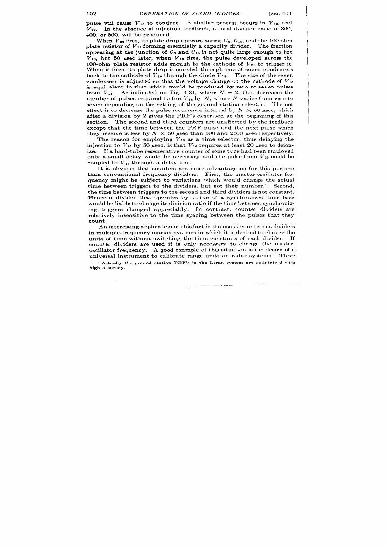
102
GENERA TION OF FIXED INDICES
[SEC.4.11
pulse will ca use VM to conduct.
A similar process occurs in V19, and
V,,. In the absence of in ject ion feedback, a tota l division ra t io of 300,
400, or WO, will be produced.
When VZZfires, it s pla te drop appears across C,, C,O, and t he 100-ohm
pla te r esist or of Vls forming essent ia lly a capacity divider . The fract ion
appear ing at the junct ion of Cg and C1Ois not quite large enough to fire
V8S, but 50 Wec la ter , when VN fires, t he pulse developed across the
100-ohm pla te resistor adds enough to the ca thode of VzS to t r igger it .
When it fires, it s pla te drop is coupled through one of seven condensers
back to the ca thode of V,6 th rough the diode V2S. The size of the seven
condensers is adjusted so that the voltage change on the ca thode of V18
is equivalen t to that which would be produced by zero to seven pulses
from VIS. As indica ted on Fig. 4.31, where N = 2, this decreases the
number of pulses required to fire VI 6 by N, where iV var ies from zero to
seven depending on the set t ing of the ground sta t ion selector .
The net
effect is o decrease the pulse recu r rence interva l by N X 50 ~sec, which
after a division by 2 gives the PRF’s descr ibed a t the beginning of this
section.
The second and th ird coun ters are unaffected by the feedback
except that the t ime between the PRF pulse and the next pulse which
they receive is less by N X 0 psec than 500 and 2500 psec respect ively.
The reason for employing VZS as a t ime selector , thus delaying the
in ject ion t o VM by 50 psec, is that V16 requires at least 20 psec to deion-
ize. If a hard-tube regenera t ive counter of some type had been employed
only a small delay would be necessary and the pulse from V2~ could be
cou pled t o Vld th rough a delay line.
It is obvious that co nters a re more advantageous for this purpose
t han con ven tiona l fr equ en cy divider s.
First , t he ma st er-oscilla tor fr e-
quency might be sub ect to var ia t ions which would cha ge the actua l
t ime between t r iggers to the dividers, but not their number . 1 Second,
the t ime between t r iggers to the second and third dividers is not constant .
Hence a divider tha t opera tes by ir tue of a synchronized t ime base
wou ld be liable t o cha nge its division r at io if t he t ime bet ween s ynch roniz-
ing t r iggers changed appreciably.
In cont rast , coun ter dividers are
rela t ively insensit ive to the t ime spacing between the pulses tha t they
count.
An in terest ing applicat ion of this fact is the use of counters as dividers
in mult iple-frequency marker systems in which it is desired to change the
units of t ime without switch ing the t ime constan ts of each divider . If
counter dividers are used it is on ly necessary to change the master-
oscilla tor frequency. A good example of this situat ion is the design of a
universal inst rument to calibra te range units on radar systems.
Three
1Actually t he ground st a tion PRF’E in t he Loran syst em a re main ta inedwit h
high accura cy.
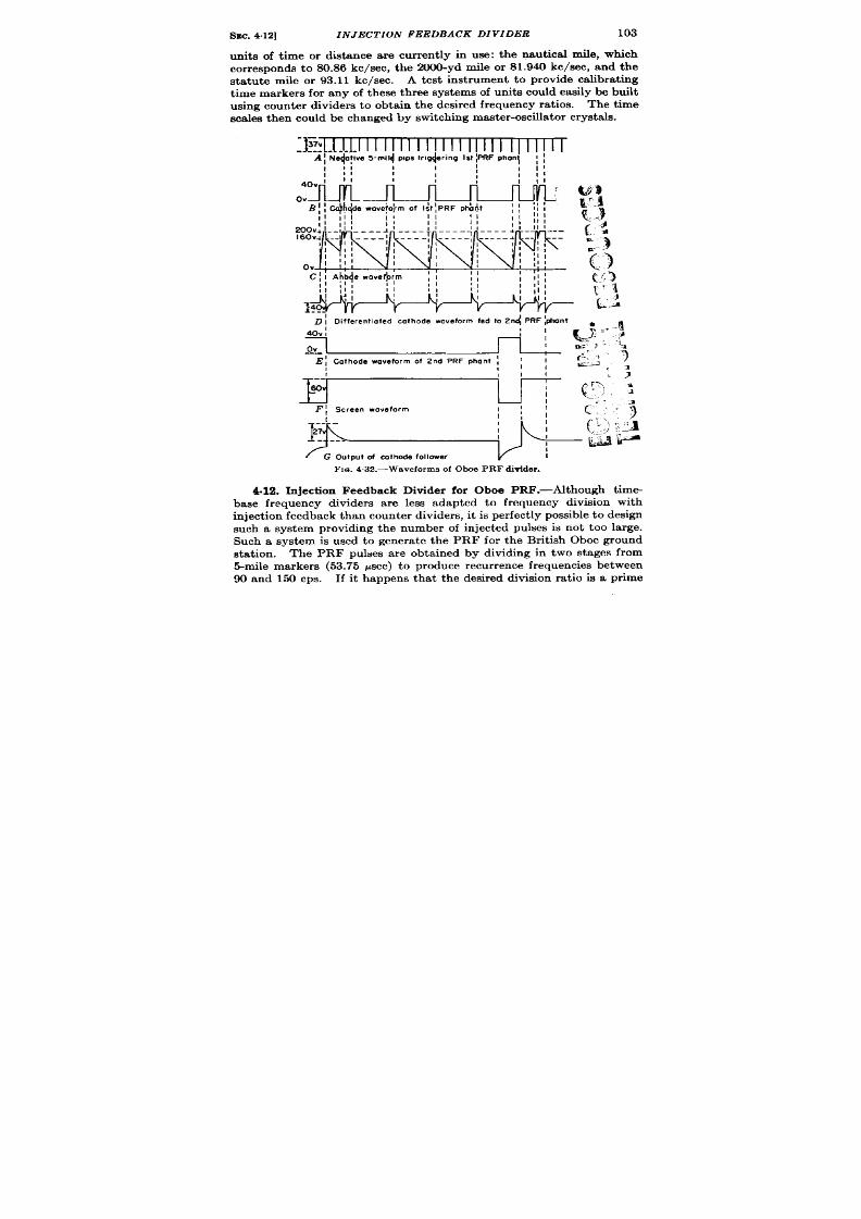
SEC.4.12]
IN J ECTION FEEDBACK DIVIDER
103
units of t ime or distance are cur rent ly in use: the naut ica l mile, which
cor responds to S0 86 kc/see, the 2000-yd mile or 81.9M kc/see, and the
sta tu te mile or 93.11 kc/see. A test inst rument to provide calibra t ing
t ime markers for any of these th ree systems of units cou ld easily be built
using cou nt er dlvider sto obta in t he desir ed frequ en cy r at ios.
The t ime
a ca lest hen cou ld be ch an ged byswit ch in g mast er -oscdla tor cr yst ak.
4.12. Inject ion Feedback Divider for Oboe PRF.-Although t ime-
base frequency dividers a re less adapted to frequency division with
in ject ion feedba ck t ha n cou nt er divider s, it im per fect ly possible t o design
such a system providing the number of in jected pulses is not t oo large.
Such a system is used to genera te the PRF for the Brit ish Oboe ground
station.
The PRF pulses are obta ined by dividing in two stages from
5-mile m ar kers (53.75 psec) t o pr odu ce r ecu rr en ce frequen cies bet ween
Wand 150cps. If it happens that thedesired division rat io is a pr ime

104
GENERATION OF FIXED INDICES
[SEC.4.12
number or is not the product of two small convenien t factom, in ject ion
feedback is employed. In this system, the method of in ject ion is tha t the
Negative
Ist. PRF divider I st. PRF controls
five mile
Ohnntastron
2nd. PRF 2nd. PRF
divider otmnfcmt on cmtrols
‘ k
HII HI’
+,, a
3.3k
.25
I
1
Feedback
switch
1 II
J
+.-r
C2
=0.05
22k
?OCk
O.ci
Injection feed back phanlos ron
+ 300V
M
.3h
R
0.1
I5k
8.2k
3.9k
I
FIC..4 .33.—Feedback divider phantas t ron from Oboe cal ibrator .
t r ig er init ia tes a phantast ron-ga te genera tor which prevents the fir st
phantastron divider from dividing for O, 1, 2, or 3 miles, a fter which it
divides in a normal fashion. In cont ra st t o the Loran fee back divider ,

SEC.412]
IN J ECTION FEEDBACK DIVIDER
105
the t ime in terva l between the PRF pulse and the fir st pulse fed to the
second divider is increased by the feedback ra ther than decreased.
Figure 4.32 shows thet iming sequences of the dividers set t divide
by 21 = 4 X 5 + 1. Thein ject ion feedback isset to l,t he fir t divider
divides by4, andthesecondby5.
Figure 4.33 shows the circuit of the
dividers. The negat ive 5-mile p lses areused to t r igger the first PRF
divider st age VJ on one cathode of the double dio e VI. The phan-
tast ron cathode waveform is shown in line B of Fig. 4.32. The nega-
t ive edges a re coincident with every nth 5-mile t r igger pulse in the
case of no feedback. The diode V~ is in t roduced in connect ion with
PRF pulse
+
~1 0..35 ;I.e pips
1
I
B
!
Cathode waveform
I I
of feedback phuntast ron
1
I
I
I
I
I
I
I
i.
I
I
I
I
I I(
I
I
i
l,,
11, ,
I
I
1 (,,
1
!l, ,
I I
I
Ill
I
I
II
/
Ill
Itt
I
Ill,
1,, ,
I
I
I
1:
I
I
II
I
tl;
i
I,tl
!
I
I
c
Screen woveform of
feedback phan tast ran
D
G3 of I St PRF phant
E
1
T= 0
Cathode of (st.
PRF phonl
F
G3 of I s!. PRF phonl
G
}
p. 2
~ of I st. PRF phont
FIG. 4.34,—Feedback wave forms of Oboe PRF d ivider .
t he feedback. With no feedback, which is the case to be considered
first , the diode is shor t -circuit ed. The se ond half of the diode VI is
t aken direct ly to ~200 volts on the bIeeder and is employed to ca tch
the pla te of the phantas ron as it r ises on the flyback. The next 5-mile
pulse developed a cross R ~ pulls the phantast ron pla te down (cut t ing
off the diode V J and thus t r iggers the phant ast ron.
The switch and
potent iometers in t e gr id circuit of V4 allow the division ra t io to be
adjusted to either one of two numbers.
The cathode and screen wave-
forms of the second PRF divider phantast ron are shown on lines II and F
of Fig. 4.32. The screen waveform F k different ia t ed and fed out
through a cathode follower to form the PRF pulse G.
t he su ppr essor gr id of t he feedba ck ph ant ast ron V~.
It is ako applied to
The dura t ion of the

106
GENERA TIOJ V OF FIXED INDICES [SEC. 4.12
waveforms from th is phantast ron is adjusted by Z?a to be about 7* miles
for r = 2.
The nega t ive pulse fed to the suppressor gr id of Vs has no
effect , but the pos t ive pulse t r iggers the phantast ron .
Th e ca th ode
waveform is t h eref ore as shown in Fig. 4’34, line B and the screen wave-
form as in line C. These two waveforms a re used to obta in feedback as
follows. The pr inciple of the feedback is to apply to the suppressor gr id
of the fir st PRF phantast ron a nega t ive pulse F of su fficien t amplit ude t o
cause the phantast ron to return to its qu iescen t condit ion .
Aa indi ated
by the ca thode aveform G, the nega t ive pulse cu ts ofl t e pla te which
t hen r ises t owa rds ED. unt il it is caugh t by the diode VI a t the +200 volt
level. At the same t ime the ca thode G and grid retu rn to their qu iescen t
voltages. The phantast ron is then ready to be t r iggered off again by a
5-mile pip when the suppressor gr id is a llowed to return to its normal
level. The ga te fed back to obta in r = 1, 2, 3 is obta ined from the
feedback phan ta st ron Va.
Th e number of five-mile in terva ls t o be added
to the pulse recu r r ence i terva l by the feedback is r . The two cases of
r = O or 2 will be dea lt with sepa ra tely.
. When r = O, th suppressor of the phantast ron Vi is held a t a
stea dy poten t ia l by shor t -circu it in g th e diode T’$.
2. When r = 2, th e ca th ode wa veform F of Va is applied to the sup-
pres or of Vi. The first PRF phantast ron is thus caused to retu rn
to its qu iescen t sta te immedia tely after being t r iggered, and the
suppressor voltage is held down while the next 5-mile pulse is fed
to the pla te. Hence the fir st PRF phantast ron cannot ret r igger
a t 5 miles. Th6 nega t ive feedback ga te, however , is lifted from
th e su ppressor befor e the secon d 5-mile pulse, and the phantast ron
is a llowed to t r igger a t 10 miles (F ig. 4.34h and j). Therea fter it
d ivides normally.
Lit t le difficu lt y sh ou ld be expect ed in th is a pplica tion fr om usin g t im e-
base dividers with t r iggers of var iable spacing since the maximum ch an ge
of the PRF division ra t io caused by feedback is on ly 15 per cen t .
GROUPED-MARKER GENERATION
BY R.. B. LEACHMANAND R. I. HULSIZER
Probably the ma jor ity of physica l situat ions in which t ime measure-
ments a re to be made require tha t the t ime measurements sta r t a t a pe -
fect ly random instan t . For th is purpose-circu it s have been developed
which will remain dorman t unt il t r iggered externa lly, whereupon they
provide ser ies of t ime markers of appropr ia te r ecu r rence frequencies.
Aft r a suitable per iod, the markers a re termina ted and the circu its retu rn
to their qu iescen t condit ion , await ing an other t r igger in g pulse.
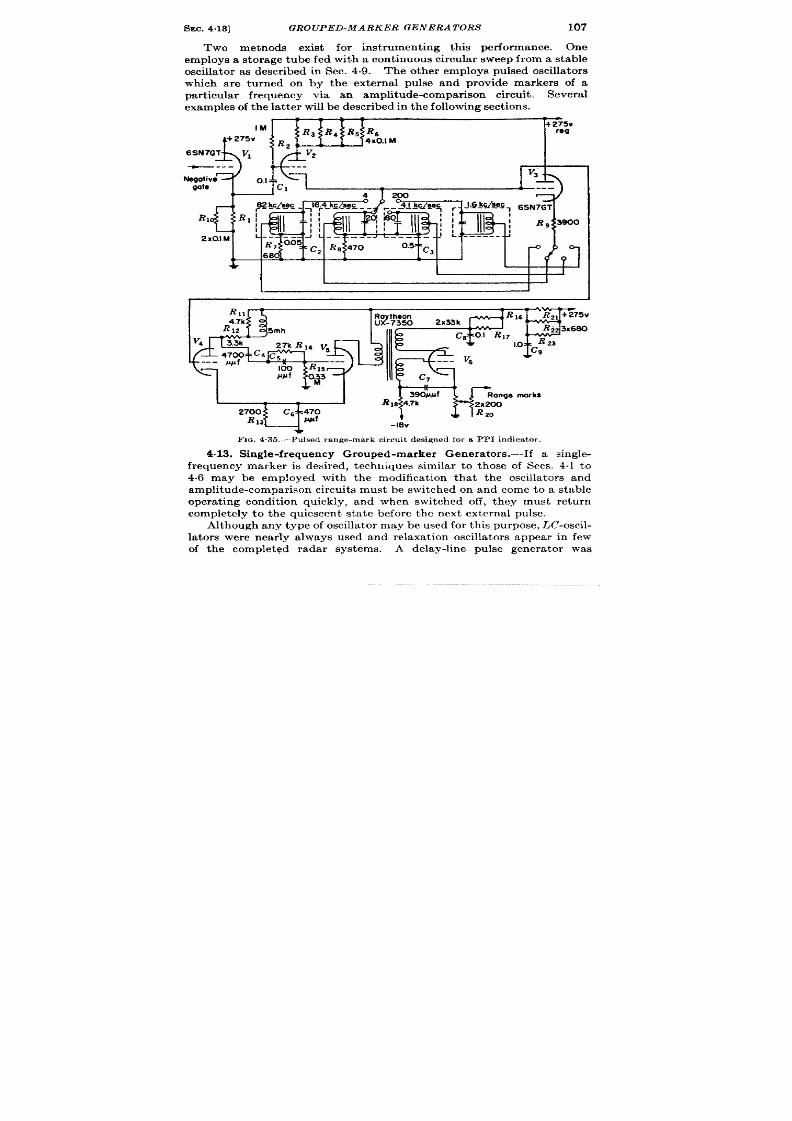
SEC.4.13]
GROUPED-MARKER GENERATORS
107
Two methods exist for inst rumenting this performance. One
employs a storage tube fed with a con tinuous circular sweep from a stable
oscilla tor as descr ibed in Sec. 4.9. The other employs pulsed oscilla tors
which are turned on by the external pulse and provide markers of a
par t icular frequency via an amplitude-compar ison circuit . Severa l
examples of t he la tt er will be descr ibed in t he followin g sect ion s.
IM
+275v
Ra RJ R~ RG
tog
+275v
$!
J {[i
R2
4X0.IM
6SN7GT
v’
V2
—---
---
OJ*. 1
V3.
Ne@ive
@e
1
I R,
2X0.IM
1
L
FIG. 4 35.—Pulsed range-mark cir cu it des igned for a PPI ind ica tor .
4.13. Single-frequency Grouped-marker Genera tor s.—If a single-
frequency marker is desired, techniques similar to those of Sees. 41 to
4.6 may be employed with the modifica t ion that the oscilla tors and
amplitude-compar ison circuits must be switched on and come to a stable
opera t ing condit ion quickly, and when switched off, they must return
completely to the quiescen t state before the next externa l pulse.
Alt hou gh an y t ype of oscilla tor maybe u sed for this pu rpose, .LC-oscil-
lators were near ly a lways used and relaxat ion oscilla tors appear in few
of the complet~d radar systems.
A delay-line pulse genera tor was
108
GENERA TION OF FIXED INDICES
[SEC. 4.13
employed in the preproduct ion AN/APG-5 range ca librator , but it was
abandoned for a m or e stable pulsed LC-oscilla tor because the delay-lin
t emper at ur e coefficien t wa s poor .
Many synchroscopes simply pulse a
tuned circu it t o obta in a damped sinusoidal t ra in for use in t ime calibra-
t ion. The Germans used a supersonic delay-line t ime-marker genera tor
to calibra te one of their height -finding systems. A pulse coupled in to a
glass rod produced a ser ies of t ime markers by supersonic reflect ion .
Pulsed LC Range-marker Circu it .—Figure 4.35 shows the schematic
diagram of a circu it for producing range marks of any one of four differ -
en frequencies for use on a radar indicator .
Tube VI is a cathode
follower feeding a ga te on to the gr id of Vz. When Vz is on, it supplies a
steady cur ren t a t a very low imp dance through one of the tank coils,
maintaining heavy damping on the tank circuit .
when Vz is cu t off, t he
sudden change of cu rren t sta r ts sinusoidal oscilla t ions in t he tank circu it .
Examina t ion of the init ia l condit ions for the t ransient shows tha t a
nega t ive sine wave commences immediately with no distor t ion . With
finite Q, the oscilla t ions would die ou t rapidly, bu t Va provides just
su fficien t posit ive feedba ck t o maintain t he oscilla tion s at fa ir ly con st ant
amplitude. Tubes Vq and VS amplify and distor t the sine wave to
t r igger t h e block ing oscilla t or Ve which forms the range markers. Tube
V, i provided with a steady bias grea ter than cutoff. The gr id-circu it
t ime constant of 2 psec is shor enough to prevent any cumula t ive change
in the point of t r igger ing. It will be not iced tha t the poin t of amplitude
compar ison as per formed by Vq depends on the gr id character ist ics and
the bias provided by the average cur ren t of Vk and VK flowing th rough
t heir common ca th ode r esist or .
The stability of the bias dep nds on the
symmetr ical behavior of the two tubes which may lead to some er ror ,
either in long t ime stabi ity, or as a t ransient er ror a t the beginning of
each marker group.
Prccisc Pulsed LC Range-marker Circuit jrom Precision Ranging
In dica tor .—Th e r an ge-m ar ker cir cu it ju st descr ibed pr ovides r an ge mar k-
ers for the PPI where high accuracy is not required. This is reflect ed
in the design of the amplitude-compar ison circu it and the absence of
tempera ture cont rol on the resonant circu its. In the same indica tor
there is a precise pulsed range-marker circu it for use with the t ime-
modu la ted r an ge-m ar ker cir cu it .
This is descr ibed in Sec. 6.2 as an
example of precision two-sca le t ime modula t ion .
Th e pr in ciple differ -
ences from the PPI range-marker circu it a re tha t the LC-circu it and the
feedba ck r esist or of t he oscilla tor a re pla ce in a t emper at ur e-con tr olled
oven , an oscilla tor circu it whose frequency is less sensit ive to tube
changes is employed, and the amplitude compar ison of the sine wave to
form the range marks is per formed by a diode amplitude-comparison
circuit.
An in expen sive sin gle-fr equ en cy gr ou ped-t im e-m ar ker cir cuit
is descr ibed in Sec. 7.28.

SEC,4.14]
GROIJPED MARKERS
109
4.14. Mult iple-frequency Grouped Markers.—The most genera l
solu tion t o t he pr oblem of pr ovidin g gr ou ps of mult iple-f r cqu tm cyr na rk-
ersin it ia ted by an externa l pulse andlast ing fora fixcd t ime istocmploy
Dmde
+ 400V
Marker gate
Switch PIP marker Cathode
omphtude
Pulsa
generator lube oscillator follower
comparator
bompl)fier
+ .250V
T
15k 15k
U14J”5 k
1500jl#f
5k 56k
0.05
1$
-7
125v
“~
5.6,,1’ ~= ,Ob
328 kc/see
n%Z
r
~f
From
trigger
buffer
--iik ‘“R?T’%TI%%H%I
6S
I.-1: w!
i I 2.7M< $’7;;k~ ;.;k
+ I I 0.054
LLU
11 l-”-”!! 1
--
Iwf
:
I
1
-lo%~
+
5Q0.ydmarlmr 4:1 Slocking
5:1 Slocking
generator
4:1 Blocking
oscillator divider oscillator divider oscillator divider
I
500yd
2000yd
IQOOO d
d
0.00 yd
&
FIG. 4 .3&-Mult ip le -frequency grouped-marker circu it us ing blocking-oscilla tor d ivider .
All t ransformers are Raytbeon UX8204.
severa l pulsed oscilla t ors and amplitude-compa rison circuit s of t he t ype
descr ibed in Sec. 4.13. Each type of marker then is i dependent of the
other and any desir ed frequency ra t io may be easily obta ined. Only

110
GENERA 7J ION OF FIXED IN DICES
[SEC. 414
one of the oscilla tors need possess long-t ime frequency stability for the
others may be ca libra ted against tha t one.
A more economica l, bu t less
flexible solu t ion is the use of a single-frequency marker gen ra tor and
sever a l pu lse-divider cir cu it s.
The main precau t ion to be obser ed in
the design of the dividers is tha t they remain inopera t ive except when
receiving pulses from the ga ted oscilla tor , and that they should respond
to the first few pulses of a group in exact ly the same manner as to all the
rest.
The circu it of F ig. 4.36 provides an example of this type of opera t ion . I
The externa l t r igger init ia tes a mult ivibra tor ga te who e dura t ion
determines the length of t ime after the t r igger tha t the markers will
occu r . It ga tes a 328-kc/see LC-oscilla tor similar to th one descr ibed
in Sec. 4.13. The amplitude comparison is per formed by the diode half of
Vs fed by the ca thode-follower ha lf. The ca thode Va is indica ted as hav-
ing a quiescen t level of 1 volt . The poin t of conduct ion of the diode ha lf
of Vs will depen d on va ria tion s of th is poten tia l.
A bet ter solu tion wou ld
be to replace the ca thode resistor of V, wit h a low-r esist an ce gr ou nded
choke. A 1 -mh choke would provide equiva len t impedance a t tha t
frequency, and would provide an acc ra te reference poten t ia l, ground,
wh en the sinusoid passes th rough zero amplitude.
Following th e diode is a squar ing amplifier and a 500-yd (328-kc/see)
block ng oscilla tor employing a 6V6 biased to 525 volts, about 10 volt s
below cu toff, The use of a tube with a long grid base seems inadvisable
a t th is poin t in the circu it where switching act ion at the instan t the sine
wave passes through zero amplitude is desired.
P la te-to-pla te t r igger ing is employed t o synch ronize th e succeeding
blocking-oscilla tor dividers .
As in t he 500-yd mar ker blockin g oscilla tor ,
each divider is normally biased below cu toff. Since the impedance of the
Raytheon UX8204 pulse t ransformer is about 500 ohms, the effect ive
t r igger ing pulse appear ing a t the gr id must be about 20 volts, which is
per fect ly adequa te to overcome the quiescen t bias. The division ra t ios
a re adjusted by varying the gr id t iming network resistance.
The requirement of main ta in ing the dividers nonopera t ive in the
absence of an externa l t r igger is cer ta in ly met by this circu it .
In r ega rd
to assur ing iden t ica l respo se to the first and last pu lses of a t ra in , there
is some uncer ta in ty. Because the gr id timing networks a re all very shor t
compared with their opera t ing frequency, lit t le cumula t ive bias may be
expected to develop there, bu t the bias bleeders have t ime constan ts
which a re neith er sh or t compa red with the h ighest pulse recu rren ce in ter -
va l (3 psec) nor long compared with the average externa l t r ig er recu r -
r ence in terva l. The saving fea ture may be tha t the average gr id ur ren t
might be too small to effect a change in ias dur ing a pulse group.
1War DepartmentTechnical Manual TM1l-1561, Aug. 31, 1944,

CHAPTER 5
GENERATION OF MOVABLE INDICES—SINGLE-SCALE CIRCUITS
BY R. KELNER
INTRODUCTION
6.1. Applicat i ns of Time-modulated Indices.-A tim~modulated
index is a means for the ident ificat ion of an instant of t ime that precedes
or follows a r eference instant by a cont rollable in terval (see Sec. 3.8).
The reference t ime instant may occur per iodica lly or sporadically many
times per second. The t ime interva l (usually a delay) between the
reference instant and the index is t he usefu l var iable of such ar range-
ments. This in terval is cont inuously or stepwise cont rollable and thus
may be considered as an adjustable magnitude or a ar iable. This
var iable may be const ra ined so that a number is assigned to it by an
automat ic computer or an observer . Cont inuous var iability is an
essent ial r oper ty for most applic t ions.
The maximum delay of the
indices discussed in th is chapter is a fract ion of a second. The index is
usually a voltage pulse or step, or a mechanical index on a ca thode-ray-
tube display. Such a pulse can be used as a visible marker on a cathode-
ray-tube display, as a t r igger for star t ing the act ion of a circuit , or as the
inpu t t o a demodu la tor .
The var ious methods for t ime modula t ion include the oscilla tor with
ph ase modu la tor , t he oscilla t or with fr equ en cy modu lat or , t he sawt oot h-
wa veform time modulat or , pr opagat ion -t ime devices, and combin at ion s
of these methods (see Vol. 19, Chap. 13). The fir st three types ut ilize
a comparator to der ive marker from the fundamental t iming wave.
The circuit s descr ibed in this chapter have, for the most ‘par t , been
designed as componen t in t ime-demodulat ion systems, but there are
numerous other applicat ions. The t ransmission of data by t ime modula-
t ion is exact ly an alogou s t o data t ran smissions by fr equ en cy or amplit ude
modulat ion. In t ime modulat ion, a t ime in terval is made moDor -
t ional to the signal input . The t ransmit ter emits a ser ies of r~fer~nce
pulses at regular intervals; each is followed by a movable pulse, and a
ser ies o t ime intervals is defined. The frequencies of the data sDect rum
.
.
must be lower than the repet it ion frequency of the reference pulsel (see
Chaps. 10 and 11).
1G. L. Fredendaletal., “Transmission of Telet ilon E!cnmdn the Picture Carr ier ,
Proc. 1. R . E., 34, No. 2, Febraar y 1946.
111

112
GENERA T ION OF MOVABLE INDICES
[SEC, 52
he rela t ion between the cont rol var iable and the delay t ime (the
t ransfer funct ion of the t ime-modulat ion circuit ) may be linear but a lso
may be para bolic, h yper bolic, or som e ot her sha pe.
iVIeans for achieving
nonlinear funct ions are descr ibed in Vol. 19, Chap. 8.
Non lin ea r t im e-modu la tion cir cu it s a re u sefu l for a ut omat ic a na logu e
computa t ions (see Vol. 21). An example of this type of t ransfer charac-
1
I
T,me
delov
I
At : kh
T,me of the
reference pulse
FIG. 5.1.—Transfer cha ract er is tic of a non -
linear t ime-modulat ion circui t .
t er ist ic is shown funct ionally in
Fig. 5.1. In this case the delay
t ime At is given by
At=k~~
(1)
where r is propor t ional to the con-
t rol var iable and h to a constan t .
This equat ion is used for conver t -
I
‘\
\
! Ground range, 7’
Earth
FIG. 5.2.—Dist ance measur emen t and t r i-
angulation.
ing a voltage tha t is propor t iona l to ground range into a delay t ime
that is propor t iona l to slant range.
These var iables a re ident ified for a
pract ica l distance-measurement problem in Fig. 5.2. The cont rol var ia-
ble of the t ime-modula t ion circu it is propor t iona l to ground range if t he
alt itude va lue is proper ly set in .
Time modulators of lesser precision maybe used for con t rollable t ime
delays. In order to obta in the proper sequence of even ts in a radar , a
t ime-modula t ion circuit with a readily adjustable but compara t ively
unstable or unknown t ransfer character ist ic maybe used since this delay
can be set by reference to some form of indicator .
F or example cer ta in
magnet ic deflect ion coils for radar displays delay the star t of a linear
cur ren t in the coil from the sta r t of the applied t rapezoidal wave.
Com-
pensat on ia achieved by applying the t ime-base waveform before the
sweep of the. elect ron beam is to sta r t .
An adjustable delay is used to
rela te the t r igger ing of the t iming components and the radio-frequency
components. Figure 5.3 is a t iming diagram of these circuit s.
5.2. Syst m Requirements snd Definit ion of Er ror .-From the
standpoint of the system designer , t he t ime-modulat ion circuit requ ires

SEC. 52] SYSTEM RE UIREMENTS AND DEFIN IT IONS OF ERROR 113
or deliver s a r efer ence pulse, deliver s an ou tpu t pulse at a t ime la ter than
tha t of the r efer ence pulse, and accept s another input var iable whose
magnitude con t rols the dur t ion of the
The system designer ordinar ily specifies
the na tu re of the pulses and of the cont rol
va r iable and the rela t ion between the con-
t rol var iable and the interval dura t ion .
Moreover , the pulse-repet it ion ra te, the
supply vol age , the permissible weight ,
size, complexity, power dissipa t ion , the
calibr at ion pr ocedu re and t he condit ion s
of tempera tu r e, humidity, and accelera -
t ion t o wh ich t he cir cu it s will be su bject ed
ar e more or less fixed. hese externa l
design factor s a re, of course, subject to
con t rol if ext remely high accuracy is
desired.
The Lransjer characteristic (re la t ing con-
t r ol var iable to delay t ime) is distor t ed
by t he dr ift s in compon en t ch ar act er ist ics
(see Chap. 3). Any devia t ion from the
desired character ist ic causes an er ror . In
r der t o pr ovide a ’ba sis for t he compa rison
f the er ror s in var ious circuit s, the
follo\ Ving t erms a re usefu l:
1.
2 .
The ~imi(ing error is the la rgest
devia t ion from a normal char acter -
ist ic tha t can ever be observed as
long as each compone t value does
not exceed its tolerances. Such a
value exists because each compo-
nen t and input for a circuit must
lie with in a cer ta in set of values.
in terva l between the pulses.
I Synchronizing pulse
a
I
I
I
I
t
, Wave farm applied to
sweep tails
I
Q/l
Electran beam deflection
I
L
Deloyed pulse, which
gotes r-f components
“ Time~
FIG. 53.-The presta r t ing of
magnet ic CRT sweep coils. The
a rr ow on t he r -f t rigger pu lse in di-
ca t es t ha t It is a dju st ed t o coin cid e
wit h t he sta rt of t he elect ron beam
deflection.
Qua lity con t rol insures the disca rd of componen ts tha t a re
not with in the requir ed values.
The normal t ransfer charac-
ter ist ic for a circuit is defined by the most probable of these values.
The limit ing er ror is caused by the worst possible combinat ion
of component va lues. Since each quant ity can vary in either
direct ion from its most probable value, the limit ing er r or value is
usually preceded by both the posit ive and the nega t ive sign.
The probable error is tha t devia t ion which will be exceeded in half
the cases of a sta t ist ica l study of a la rge number of these circuits

114
3.
f7ENERA TION OF MOVABLE INDICES [SEC.53
oper at in g u nder va riou s con dit ion s.
The analysis by which this
number is der ived requires assumptions about the dist r ibut ion of
component va lues, the dist r ibut ion of tempera ture var ia t ion, and
ot her u npr edict able qu an tit ies.
The resu lt s, t her fore, a re sub-
ject to the validit y of these assumptions. In most com lex circuit s,
t he ver ifica tion of a pr oba ble er ror va lue is ext rem ely difficult .
The linear itu of a circu it is a cr iter ion for those t ime-modula t ion
devices that a re designed to maintain a t ime in terva l propor t io a l
to the cont rol var iable. If the t ransfer char cter ist ic is graphed
and the st ra igh t line th t best fits is super imposed, the differences
in ordina tes a re the er ror s from linear ity. The best fit is tha t
which gives the smallest maximum difference of ordinates. The
term “linear ity” always has this connota t ion in this book. Since
approximately linear circu its a re common, slope and zero er ror s
con st it ut e con ven ien t ca tegor ies for lin ea rit y er ror an alysis.
VOLTAGE SAWTOOTH CIRCUITS
6.3. A Gated Miller In tegra tor with a Mult ia r Compara tor .—The
pr inciple upon which all volt age-sawtooth t ime modula tors depend is
Goled Miller
+-w Em2 Multior
Inteqrafor
comparator
T
T
I
E
992
T .
Zhaft
and
Voltoqo
I m
~=
%
% z
n“
V5
Pos#tivd
rectongle
-- - output
---
---
g
-r
Short *U+
neqotove puke
T ,
FIG.6.4.—A simpleMiller feedbackt ime modulator. The pen tode may he VR 91,
6AS6,VR 116, 6AC7, 6SA7etc., or any other type in which Plate currentcanhecutoff
by G,. The diodes maybe VR 92 or 6AL5.
A puke ou tpu t maybe t aken fr om t he ca t hode
of V6.
the ident ifica t ion of the instant at which a sawtooth wave reaches a
cer ta in amplitude. This amplitude is the cont rol var iable. The in terva l
between the sta r t of the sawtooth wave and the t ime when the wave
reaches this amplitude is the delay tha t is modulated. The for a t ion
of a step or pulse a t the instant when the waveform amplitude equals the
cont rol-var iable amplitude is per formed by a compara tor such as those
I
SEC. 5.3]
MILLER INTEGRATOR WITH A MULTIAR
115
of Vol. 19, Chap, 9. The genera t ion of linear sawtooth waveforms or
t r iangular waveforms is descr ibed also in Vol. 19, Chap. 7.
The circu it of Fig. 5.4 is an excellen t example of a simple but accura te
linear modula tor . The circu it consist s of a t r iangle genera tor—the
ga ted Miller in tegrator—and a mult iar l comparator . The cont rol var i-
able is a poten t io eter shaft rota t ion . When the linear r ise reaches the
voltage at the tap of this poten t iometer , a diode conducts and the mult iar
produces a step and a pulse marker .
The delay produced by the circuit
is the interval between the marker and the star t of the gat e for the saw-
t oot h gener a tor .
The circu it details may be understood by reference to Fig. 5.4.
Ordinarily Va is passing screen cu r ren t but no pla te cur ren t since the
suppressor gr id is held considerab y below the ca thode potent ia l. The
plate is caught 2 a t E,., by the diode Vs. When the posit ive ga te raises
the suppressor sufficien t ly, pla te cur ren t star t s to flow and the plate
rundown2 proceeds after a small init ial step. The fall of plate volt age
is linear and is of slope propor t iona l to (EPP, — V~,), where Vc, is the
init ia l poten t ia of the cont rol gr id of V2.
The mult iar act ion is a regenera t ive cutoff of V5 when V4 star t s to
conduct , that is, when the pla te rundown reaches the voltage at the tap
of the poten t iometer . The regenera t ive loop is completed through the
transformer T,. A posit ive st ep appears at the plate of Vfi when V.
sta r t s to conduct . The interval between the r ise of the ga te and the
step in the output is approximately propor t iona l to the difference
between the quiescent pla te voltages of Vs and V, divided by the slope
of the t r iangle. The diode biases and the slope are propor t ional to E,p,.
The t ime in terval is therefore near ly independent of EPP,.
The circuit of Fig. 5.4 accept s a ga t e and delivers a st ep; it may be
followed by a blockin g osc lla t or or a quasi differ en tia tor if a pulse ou tpu t
is desired. Alterna t ively a pulse may be taken from the cathode. The
addit ion of a m lt ivibrator or the use of the screen cur ren t of VI t o
provide a ga te that maybe applied to the suppressor gr id of V%will suffice
t o make t he circuit sensit ive t o a pulse instead of a t r iangle.
In an exper imenta l circu it using type VR-91 for Vz, a t ra nsfer ch ar -
acter ist ic that waa linear to within t 0.05 per cen t of the maximum
interval (36 p.see) wae obtained. A 5 per cent change of the supply
voltages, including t he filament supply, produced less than 0.04 per cent
change in the zero and 0.1 per cen t change in the slope of the charact er-
ist ic. These data were taken with a slight ly differen t compara tor (a
diode plus amplifier). The linear ity could be somewhat improved by
using an inductance in ser ies with the plate load resist or and thus increaa-
I See Glomary, and Vol. 19, Ssc. 9.14.
~SeeGlossary.

116
GENERATION OF MO VA B1,K INDICES 54
ing the ga in of V,. Compensa t ion of the dr ift s of VZ, VS, and V, would
r esu lt in con sidera ble in cr ea se in a ccur acy.
The methods discussed in
Vol. 19, Sec. 9.6, and Chap, 13, a re suitable.
The r ecovery t ime of the cir cu it is the in tdrva l a fter the end of the
ga te tha t is r equ ired for the cir cu it t o reestablish it s qu iescen t levels.
This t ime is shor t ened y the ca tch ing of the pla te of VZ a t a lower level
than it approaches asymptot ica lly. It is a lso desirable to make C a
minimum since the cha rging of C through the pla te load resistor is the
main act ion of the r ecovery. The in terwinding capacitance of the t rans-
form er Z’l is effe t ively in para llel with C dur ing r ecover y.
The con t rol of the delay is effect ed by varying the volt age tha t is
a pplied t o t he compa ra tor ,
This volt age m:~y va ry fr om Epp, t o approxi-
mately 50 volt s above ground,
‘on= (Trigger)
1
-+150V
a v,
I
T
+300V
6AL5
M,llw
IOM
integrator 10k 455h
+300W
Multiwt-–-
1
ode ~~~~ 1*
~47AbLlf
0.18
[
6AL5
00, 0.0046
I
6#K3
\
00075
I ,
I ,
,,001
0.01
~ v,
if
,M 6SU7
t
-150”-
I
I
la
k
I
-130V
. lam.
. .. . .. —
,*L 001
output
.
.“”.
47k
~arti
v,
0
~ ““’ hkk L v.
I--L I t --%r-i
Mow M sido of all
-“ ,,2 .
I
—.
hoataa m grou’ldd
o 22M
w hOndWI)- h...
o.47kk
47~.o
64L5
0.27M
27k
H
O 12M
.,*ti -
.“-.
COnworotw
+
~ .Iw ,
FIG. 6.6 .—Mult is tage Miller in tegrator and double-t r iode comparator .
5.4. A Gated Mult istage Miller In tegra tor with a Ca thode-coupled
Double-t r iode Compara tor .-The cir cu it of Fig. 5.5 is used as the con-
nect ing link between a computer and an a irborne radar .
The pr incip le
of opera t ion is the same as for the circu it s descr ibed in Sec. 5.3. An
externa l ga te from a mult ivibra tor tu rns on a Miller in tegra tor .
The
t r ian~e which in th is case is posit ive-going is genera t ed and applied to a
compara tor tha t a lso accepts the con t rol volt age. A fast pu lse is
d r ived a t the t ime when the linear ise of voltage equals the con t rol
voltage. This cir cu it is unusual in using th ree tubes as a high-ga in
amplifier for t he in tegr at or an d t her eby in cr ea sin g t he lin ea rit y a nd sta bil-
ity of the sawtooth wave.
SEC.5.4]
MULTISTAGE MILLER INTEGRATOR
117
Since the con t rol voltage supplied by the computer occurs a t a high
impedance, it is necessary that the compara tor circuit does not draw
cur ren t from the cont rol-voltage source.
The maximum distance at
which th is radar receives useful signals is approximately 30 nautica l
miles. The lengths of the ga te and the t r iangle are set at a delay cor -
responding to this distance. A posit ive t r igger or refer ence pulse is
supplied to the ga te genera tor a t arepet it ion frequency near 1000 cps.
After considera t ion of the accuracies of the radar and the computer ,
th is circu it was assigned a probable er ror of about 20 yd at any point over
the range of 60,000 yd. This figure cannot be ach ieved without the
weekly reset t ing of a slope con trol and a zero con t rol a lthough the
maximum er ror s ar e on ly slight ly gr ea ter with only an init ia l calibra t ion .
These con trols a re not apparen t in Fig. 5.5 since these opera t ions are
performed on the con t rol voltage in the computer . An absolu te standard
is not required for the supply olt age that determines the slope of the
t r iangle because the con t rol voltage is supplied from the same source.
Compensat ion of the dr ifts of VM would improve the st bilit y of the zero.
The linear ity requ irement for th is circuit is somewhat h igher than
the requirement for absolu te calibra t ion since it is to be used for ra te
determination.
The gate genera tor is a mult ivibra tor of conven tional design except
for the diode V5 which is used to stabilize the amptitude of the t iming
waveform and, hence, the dura t ion of the gate. The r ising gr id of V1~
a ct in g t hr ou gh V2,7,lift s t he gr id of Vti toits or igin al level a ft er t he small
fall dur ng the sweep. The gr id of VI. stops it s r ise when gr id current
star ts to flow. Thus the gr id of Vg~ is con nect ed to gr oun d th rou gh two
diodes in ser ies and of such polar ity that the effects of changing hea ter
voltage and of aging tend to cancel.
In th is way the slope of the tr iangle
is accur ately stablished. The ch ief var ia t ions ar ise th rou gh th e replace-
ment of the tube V1.
The amplifier of the Miller in tegra tor consist s of two t r iodes and one
pen tode; h en ce a gain of 3000 is obta ined.
This ensur es that th e tr iangle
shall have an exceedingly linear r ise.
Tests have shown that , the
depar tures from linear ity of the en t ir e modula tor do not exceed 1 or 2
par ts in 10,000. The limit ing el ment is probably the compara tor . The
6SU7 tr iode is used for the first stage of the amdifier because of it s low
gr id current , thus eliminat ing nonlinear it ies and changes of slope due to
var iat ions in gr id cur ren t . The t r iangle which ap ears at the ou tput
of the three-stage amplifier star t s a t a level that is determined en t irely
by the direct -cur ren t character ist ics of the last tube. In order to void
er ror s from this source a l vel-changing network and a diode v2b a re
connected to star t the linear r ise accura tely at ground. The behavior of
the Miller in tegra tor amplifier as a nega t ive feedback amplifier is shown
in Fig. 5.6,
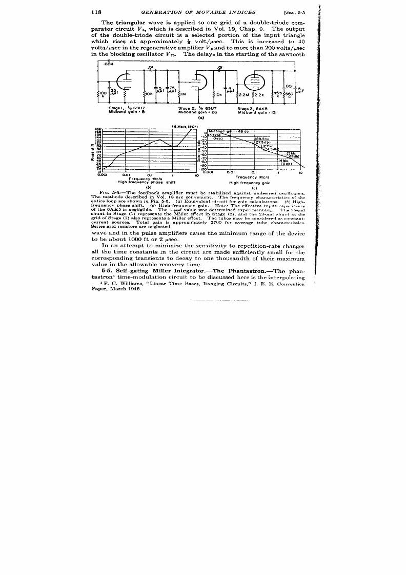
118
GENERATION OF MOVABLE INDICES
[SEC. 56
The triangula r wave is applied to one gr id of a double-t r iode com-
pa ra tor circu it V,, which is descr ibed in Vol. 19, Chap. 9. The outpu t
of the double-t r iode ci cu it is a selected or t ion of the input t r iangle
which r ises a t approximately ~ volt /psec. This is increased to 40
volt s/@ec in t he r egen er at ive amplifier VGand t o mor e t ha n 200 volt s/@ec
in t he blockin g oscilla tor VTb.
The delays in the sta r t ing of the sawtooth
.004
.Q1
.0!
Stage 1, *Z 6SU7
Sfoge 2, $ 6SU7
Siage 3, 6AK 5
hfidbond goln * 6
Midband goin = 26
Midtmnd gain = 13
(a)
E3sEzE27”
W
‘Iti!om
001 0. 1
0.1 I
10
Frequency MCIS
Frequency Me/s
High frequency phase shift
High frequency qain
(b)
(c)
Fm. 6.6.—The feedback amplifiermust be stabilizedagainst undesired oscillat ions,
The met hods descr ibed in Vol. 18 are conven ien t . The fr equ ency char act er ist ics of t h e
en tir e loop a re sh own in F ig. 5.6. (a ) E qu iva len t cir cu it for ga in ca lcu la tion s. (b) H igh .
fr equ en cy ph ase sh ift . (c) H igh -fr equ en cy ga in . Not e: The effect ive input capacitance
of t he 6AK5 is n egligible. Th e 4-ppf va lu e wa s det ermin ed ex~er imen ta lly. Th e 75-PPf
gr id of Stage(1) a lso r epr esen t s a Miller effect . The t ubes may be con sider ed a s con st an t -
current sources. Total gain is appr oximat ely 2700 for a ver age tu be character ist ics.
Ser ies gr id resis tors are neglected.
wave and in the pulse amplifiers cause the minimum range of the device
to be about 1000 ft or 2 psec.
In an a t tempt to minimize the sensit ivity to repet it ion-ra te changes
all the t ime constan ts in the circu it a re made sufficient ly small for the
corresponding transien ts to decay to one th usandth of their maximum
value in the a llowable recovery t ime.
6.6. Self -ga t ing Miller In tegra tor .—The Phantast ro .-The phan-
ta st r on ’ t ime-mo ula tion cir cu it t o be discu ssed h er e is t he in terpola ting
1F. C. Williams, “Linear Time Bases, Ranging Circuit s, ” I. E, R. Conven t ion
P aper , Ma rch 1946.

Srcc. 5.5] SELF-GATING MILLER INTEGRATOR 119
device in a two-sca le t ime-interval measurement system (see Chap. 6).
This system, as a par t of the Ha a irborne radar , aids in the accura te
det erm ina tion of dista nce (see Fig. 5.7).
?
Oscillator
10Mile
ond
6110~o; l
Puln
ompkifkor
—
Slocklng
divider
morkore A
b
Molllotor
IOMIlanorkors
B
A ~
[.
. F
Ratcmnc,WISO
Morku
E
a
f
eokfor
Switch
Phonta9tron
D
uwob18 mofku
E
Indicotor
PMentiomofU
ond
i
~
OM
switch
coit%!cca
dlodb
~86 kc ( Inou t .m i) p ip s fmm crya toloscillatorond PIPgonordt or
1111111111111111111111111111111111~
60.86 kc (10 nout .ml) p ips from l@ divid r
~
1350cgs (6 nout.mi ) or 340 cps240 naut .mi) pips from @ or 24A dlvldor
~B
Beoconphontastronaloygot,
~c
B milo soloctor got.
J ~D
Moyedselectedrigger
Rongophontost rondelayqote (0.6 to 16miles)
~F
FIG. 5.7.—H*X system.
The result s of the measurements a re applied to the navigat ion of the
airplane and to the indicat ion of the proper range at which to release
bombs. In this sect ion, the system is br iefly descr ibed and the t ime-
modulat ion circu it is t rea t ed in deta il. 1
1See H. J . Reed , A. H . F red rick , and B. Chance, ‘‘H2X Range Unit for Naviga .

120
GENERA T ION OF MOVABLE INDICES
[SEC. 5.5
Time-measurement System.-The range unit consists of a crysta l-
con tr olled oscilla tor (80.86 kc/see), pu lse fr equ en t y dividers su pplying
1-, 10-, and 60- or 240-mile pulses, a ca thode-ray-tube display, nd a
t ime modula tor . The coa rse-sca le t ime modula tor is t r iggered b
the reference pulse selector . The whole range unit is a mult iple-sca le
t ime-measur ing circu it tha t includes the single-sca le modula tor hat is
discussed here. The in terpola t ing delay (from the t r igger ing marker )
may be read from a dial on the shaft of the con trolling poten t iometer .
It is requ ired tha t th is precision ranging system have a probable
er ror of approximately 100 yd out to slan t range distances of 200 naut ica l
miles.
The er rors in the t ime-measurement circu it s a e those of the 10-mile
markers (er rors which may be as la rge as 0.05 per cen t of the in terva l
from the reference t ime) plus those of the t ime-modula t ion circu it . For
the 40-mile marker , the tota l is a 40-yd limit ing er ror . The probable
er ror of the in terpola t ing t ime-modula t ion circu it , therefore, can be
near ly 100 yd. The m ximum delay which the in terpola t ion device is
to produce must exceed the delay cor responding to 10 miles in order tha t
a ny instan t ca n be con ven ien tly iden tified.
This va lue is a rbit ra r ily set
a t 15 miles. The delay circu it can therefore have a probable er ror of
approximately 0.3 per cen t of the maximum delay.
This accu racy ca be provided by a phantast ron if the t ransfer
character ist ic is adjusted by a reset t ing of slope and zero con trols when
the phantast ron tube is changed.
A simple ca libra t io method is pos-
sible. An auxiliary type J oscilloscope is provided with a circu la r t ime
ba se by t he 80.86-kc/sec oscilla tor .
This t ime base permits the in terva l
between the reference t ime and the movable pulse to be determined to
an accuracy tha t corresponds to ranging er rors of ~ 20 yd plus the er rors
in t he oscilla tor fr equ en cy.
The tempera tures, humidit ies, and accelera tions tha t must be resisted
by these circu it s a re those specified for a ircra ft equipments. A par-
t icu la r effor t was made to reduce the size and po~ver requirements of the
H2X range unit . An unregula ted pla te-supply voltage can be used
because the phantast ron is insensit ive to var ia t ions in the pla te supply
if the cont rol poten t iometer is supplied from the same source as the
circu it . Since the du ty ra t io is a t most 25 per cen t , the recovery t ime is
sufficient ly shor t .
t ion and Bombing,” RL Repor t No. 342.
‘‘Ha ndbook of MaintenanceInstructionsfor Model AN/ APS-15 Aircraft Radar
Equipment ,” CO-AN-0830APS15-2, USN.
J . V. Holdam, S . McGra th , znd A. D. Cole, “ Rada r for Blind Bombing,” Pa r t 1,
Electr onics,19, 13S (May 1946).

SEC.5.5]
SELF-GATING MILLER INTEGRATOR
121
Phunfudnm Opemtion .-The phantast ron circuit of Fig. 5-8 accepts a
egat ive t r igger and genera tes a negat ive-going t r iangle and a simul-
t an eou s ga te t ha t ma in ta in s t he self-ga tin g Miller in tegr at or in oper at ion .
A complete descr ipt ion of its opera t ion is given in Vol. 19, Chap. 13.
+250v d-cun regula!ed
25k
12k
10
~lz6SN7
Ww
6SA7
Control
voltoge
0.02
o’--J -
L
(a)
+250v cl-c unregulated
IM
t $
-J
;
-,
pulse
I
OA18
oh Is
92 6SN7
6SN7
—-- ---
---
6S
27k
0.001
Movable pulse
o. I 27 k
(b)
FIQ.5.8.—The H*X t ime modula tor .
A n ega t ive t r igger is a pplied t o ga of t he6SA7.
The dura t ion of the gate, the tr iangular wave, and the marker delay are
modulated.
Br iefly, the circu it acts in t e following manner . A tr igger applied to
g3 of the 6SA7 disturbs the quiescent condit ion and star t s the plate run-
down from the reference volt age.
When t he plate has run down t o 50 volt s,
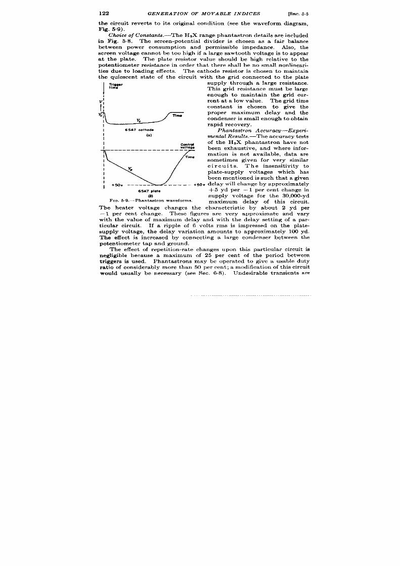
122
GENERA TION OF MOVABLE INDICES
[SEC.55
the circu it rever t s to its or igina l condit ion (see the waveform diagram,
Fig. 5.9).
Choice of Con&unts.-Th e HZX r an ge ph an ta st ron deta ils a re in cluded
in Fig. 5.8. The screen-poten t ia l divider is chosen as a fa ir balance
between power consumption and permissible impedance. Also, the
screen voltage cannot be too high if a la rge sawtooth voltage is to appear
a t the pla te. The pla te resistor va lue should be high rela t ive to the
poten tiometer resistance in order tha t th ere shall be no small nonlinear i-
t ies due to loading effects. The ca thode resist r is chosen to mainta in
the quiescen t sta te of the circu it with the gr id connected to the pla te
I
TrlQgOr
supply through a la rge resistance.
ilma
This gr id resistance must be la rge
t
enough to main ta in the gr id cu r-
v~
ren t a t a low value. The gr id t ime
II
constan t is chosen to give the
proper maximum delay and the
I
&
conden ser is small en ou gh t o obt ain
rapid recovery.
I
6S~7mfhoda
Phantastron Accuracy—Ezperi-
1
(a)
mental Results.—The accu r a cy t est s
I
con~rd
of the HZX phantast ron have not
I
Vologe
been exhaust ive, and where infor-
t i
1
lime
mation is not available, da ta a re
I
somet imes giv n for very similar
I
circuits.
I
The insensit ivity to
VP
I
pla te-supply voltages which has
been ment ioned is such tha t a given
I
+s0” -------
---- -—
+SOv delay will change by approxima tely
6SA7Plot*
+5 yd per – 1 per cen t change in
m supply voltage for the 30,000-yd
Fro. 5.9.—Phanta st ronwaveforms .
maximum delay of th is circu it .
The hea ter voltage changes the character ist ic by about 2 yd per
– 1 per cen t change. These figures a re very approxima te and va ry
with the va lue of maximum delay and with the delay set t ing of a par -
t icu la r circu it . If a r ipple of 6 volts rms is impressed on the pla te-
supply voltage, the delay var ia t ion amounts to approxima tely 100 yd.
The effect is increased by connect ing a la rge condenser between the
poten tiometer tap and ground.
The effect of repet it ion-ra te changes upon this par t icu la r circu it is
negligible because a maximum of 25 per cen t of the per iod between
t r iggers is used. Phantast rons may be opera ted to give a usable du ty
ra t io of considerably more than 50 per cen t ; a modifica t ion of this circu it
would usually be necessary (see Sec. 6.8). Undesirable t ransien ts a re
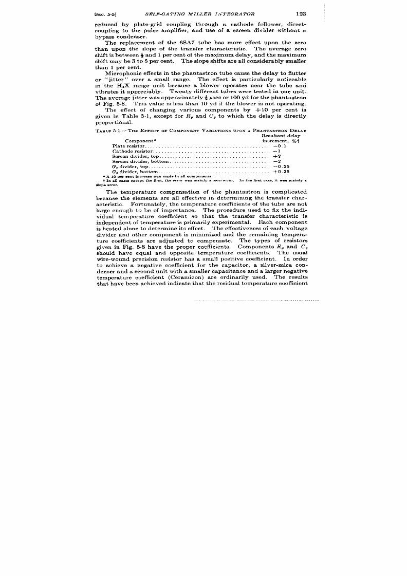
SEC. 5.5]
SELF-GATING MILLER INTEGRATOR 123
reduced by pla te-gr id coupling through a cathode follower , direct -
coupling to the pu lse amplifier , and use of a screen divider withou t a
bypass condenser .
The replacement of the 6SA7 tube has more effect upon the zero
than upon the slope of the t ransfer character ist ic. The average zero
sh ift is between i and 1 per cen t of he maximum delay, and the maximum
shift may be 3 to 5 per cen t . The slope shifts a re all considerably smaller
than 1 per cen t .
Micr oph on ics effect s in t he phan tast ron t ube cau se t he delay t o flu tt er
or “jit t er ”
over a small range. The effect is par t icular ly not iceable
in the HZX range unit because a blower opera tes near the tube ana
vibra tes it appreciably. Twen ty differen t tubes were tested in one un t .
The average jit t er was approximate y 4 jmec or 100 yd for th e han tast ron
of Fig. 5.8. This value is less than 10 yd if the blower is not opera t ing.
The effect of changing var ious componen s by +10 per cen t is
given in T ble 5.1, except for R, an C, to which the delay is direct ly
proportional.
TABLE 51.-THE 13FFEGTOF COMPONENTVARIATIONSUPON
A
PHANTASTRON DELAY
Resultantdelay
Componentq
increment, YO
Pla te r esietor. . . . . . . . . . . . . . . . . . . . . . . . . . . . . . . . . . . . . . . . . . . . –0.1
Cathoderesistor. . . . . . . . . . . . . . . . . . . . . . . . . . . –1
Screendivider , t op . . . . . . . . . . . . . . . . +2
%reendivider , bot tom...,..,.,,.. . . . . . . –2
G,divider , t op . . . . . . . . . . . . . . . . . . . . . . . . . . . . -0.25
G,divider) bot tom . . . . . . . . . . . . . . . . . . . . . . . . . . . . +0.25
q A10Pa centineresneanmadein all component-s.
t In allcaawexceptthe tirnt,the errorWSBmninlya zeroerror.
In the firs tcase,it wanmainlyq
slopeerror.
The tempera tu re compensat ion of the phan tast ron is complica ted
because the elements a re all effect ive in determin ing the t ransfer char -
acteristic.
For tunately, the temperat ure coefficien t s of th e tube are not
large enough to be of importance.
The procedu re used to fix the indi-
vidual tempera tu re coefficie t so that the t ransfer character ist ic “is
in depen den t of t empera tu re is pr imar ily exper imen ta l. Each compon en t
is h ea ted alon e t o det erm in e its effect .
Th e effect iven ess of ea ch volt age
divider and other component is minimized and the emain ing tempera-
tu re coefficien t s are adjusted to compensate. The types of resistor s
given in Fig. 5.8 have the proper coefficien t s. Components R. and C,
should have equal and opposite tempera tu re coefficien t s.
The usual
wir e-wou nd pr ecision r esist or h as a small posit ive c efficien t.
In order
to ach ieve a negat ive coefficien t for the capacitor , a silver -mica con-
denser and a second unit with a smaller capacitance and a larger nega t ive
temperatu re coefficien t (Ceramicon) are ordinar ily used. The resu lts
t ha t h ave been a ch ieved in dica te t ha t t he r esidu al t emper at ur e coefficien t
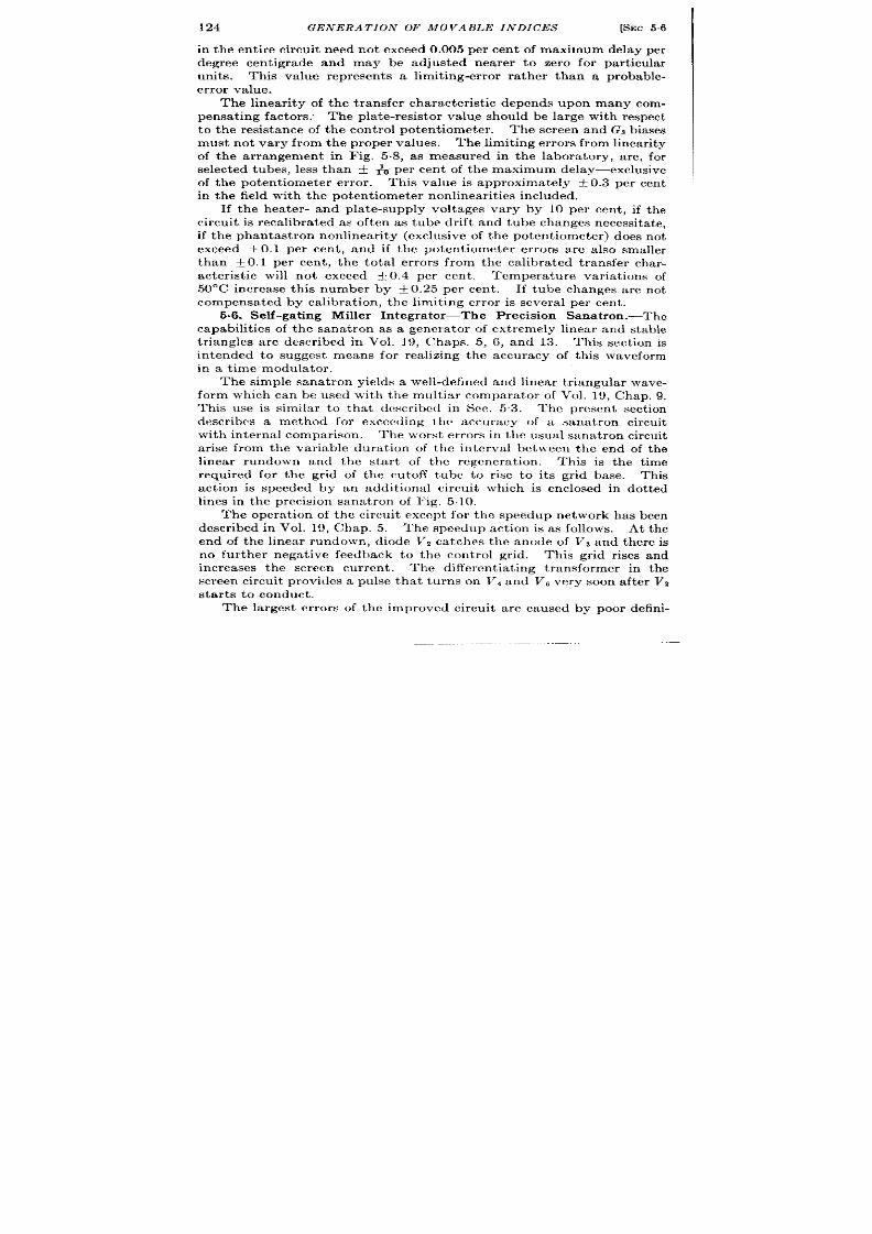
124 GENERATION OF MOVABLE INDICES
5.6
in the en t ir e circu it need not exceed 0.00 percen t of maximum delay per
degr ee cen t igrade and may be adjusted nea rer to zero for par t icu lar
unit s. This va lue represen t s a limit ing-er ror ra ther than a probable-
er r or va lue.
The linear ity of the t ransfer character is ic depends upon many com-
pensa t ing factors. The pla t e-resistor va lu ,e should be la rge with respect
t o the resistance of the con t rol poten t iometer . The screen and Gs biases
must not va ry from the proper va lues.
Th e limit in g er r or s fr om lin ea rit y
of the ar rangement in Fig. 5.8, as measured in the labora tory, a re, for
select ed tubes, less than + ~ per cen t of the max mum delay—exclusive
of the poten t iometer er ror . This va lue is approxima tely i 0.3 per cen t
in t he field with t he pot en tiom et er nonlinear it ics included.
If the hea ter - and pla te-supply voltages va ry by 10 per cen t , if t he
circu it is reca libra t ed as oft en as tube dr ift and tube changes necessita te,
if the phantast ron nonlinear ity (exclusive of the poten t iometer ) does not
exceed i 0.1 per c n t , and if the poten t iometer er ror s a re a lso smaller
than f 0.1 per cent , t he tota l er r or s from the ca libra ted t r ansfer char -
acter ist ic will not exceed f 0.4 per cen t .
Tempera tu re var ia t ions of
50”C increase th is number by ~ 0.25 per cen t . If tube changes a re not
compensa ted by ca libra t ion , the limit ing er ror is severa l per cen t .
5.6. Self -ga t ing Miller In tegra tor—The Precision Sanat ron .—The
capabilit ies of the sana t ron as a genera tor of ext r emely linear and stable
t iangles a re descr ibed in Vol. 19, Chaps. 5, 6, and 13. This sect ion is
in tended to suggest means for rea lizing the accuracy of this waveform
in a t ime modula tor .
The simple sanat ron yields a well-defined and linear t r iangula r wave-
form which can be used }vitb the mult iar compara tor of Vol. 19, Chap. 9.
This use is simila r to tha t descr ibed in Sec. 53.
l’hc pr esen t sect ion
descr ibes a method for excccding the accuracy of a sana t ron circu it
with in terna l compar ison The worst er ror s in the usual sana t ron circu it
a r ise from the var iable dura t ion of the in terva l bet}reen the end of the
linear rundown and the sta r t of the regenera t ion . This is the t ime
requ ired for the gr id of the cutoff tube to r ise t o it s gr id base.
This
act ion is speeded by an addit iona l circu it wh ich is enclosed in dot t ed
lines in the precision sana t ron of l’ig. 5.10.
The opera t ion of the cir cu it except for the speedup network has been
descr ibed in Vol. 19, Chap. 5. The speedup act ion is as follows. At the
end of the linear rundown, diode Vz ca tches the anode of Vs and there is
no fu r ther negat ive feedback to the con t rol gr id, This gr id r ises and
increases the scrccn cur ren t .
The differen t ia t ing t ransformer in the
screen cir u it provides a pulse tha t turns on Vi and l’s very soon aft er V2
st ar ts t o con du ct .
The largest er ror s of the improved circu it a rc caused by poor defin i-

SEC. 5.7]
BOOT STRAP TRIANGLE GENERA7’OR
125
t ion of voltages by t’, and V,, t he loading of the con t rol voltage by the
pla te resistor of V3, t he inconstancy of gr id bias of V3 at the sweep star t ,
t he fin ite and var iable ga in of V,, t he instability of the product RC, and
the var ia t ions of the supply volt ages. The va r ia t ion of he – 250- or
+300-volt supply by t 10 per cen t resu lt s in less than f 0.1 per cen t
er r or a t any poin t . If the hea ter supply is va r ied by f 10 per cen t , t he
delay increment is less than f 0.125 per cen t a t a ll ranges. Replacemen t
PO?
+2C
—
Irol
)metar
J
Dk
RE
—
u L-L
!4
200V
Delayed slep
J
T I ‘r71 > I I
‘ &oo \ 27011 ] V,
-250V I
1
.“ =, . . . 1 9n,, ..c
-L
.
I
(4%’)+
FIG. 5.10.—High.precision sana tron.
of either Va or Va may cause + 0.1 per cen t er r or ; r eplacemen t of Vl,
0.15 per cen t ; and replacemen t of V,, 0.2 per cen t er r or it maximum and
min imum r anges.
The linea r ity of the circu it as shown is computed to
be +0.05 per cen t . By the use of an inductance as pa r t of the pla te
load, the computed linea r ity may be increased to 0.0006 per cen t (see
Vol. 19, Chap. 7).
5.7. Boot st r ap Tr iangle Genera t or with Diode Compara tor . Time-
meaaur ing Sysizm.-This t ime-modula tion circu it ’ consist s of a ga t e gen -
era tor , a t r iangle genera tor , a linear poten t iometer and indica tor , a
compa ra tor cir cu it , an d a pu lse amplifier .
The funct ions per formed and
the rela t ion of the t ime-modula t ion circu it s to the other componen t
1G. Hite, “ Medium-precisionRange System
“ RL Repor t No. 579;V. W. Hughw,
“A Range-measur ingSys tem Using an RC Linear Sweep,” RL Repor t No. 540; and
Vol. 19, [email protected] and 13.

126
GENERA TION OF MOVABLE INDICES [SEC.
circu it s in the range indica tor are illust ra ted in Fig. 5.11. An oscilla tor
provides a reference pulse a t the ra t e of 2000 per second f 1 per cen t
or 500 per second f 10 per cent . 13xterna lly synchronized opera t ion is
a lso possible. In either case, the reference pulse t r igger s the ra a r
t ransmit ter , a t ime base extending from the refer ence t ime to either
240 or 960 psec, and a lso t he t ime-modula t ion circu it . The t ime-modula-
t ion circu it provides a movable pulse delayed 15 to 240 ~sec.
A marker pulse is delayed from the beginn ng of the expanded sweep
by an in terva l equa l to ha lf the dura t ion of the sweep. The stability
Pole;t$dmeter
Sawtooth
+
Amplitude
generator comporotor
+
counter
. Indication
4 t
M L.!5!ail
iii ,.-m
To rodor
transmitter
FIG. 51 I .—Block d iagram of t iming system.
of the expanded t ime base is unimpor tan t because er ror s from this source
tend to cancel. The coun ters th t indica te the shaft rot a t ion of the
cont rolling poten t iometer a re set to indica te the t ime in terva l (actua lly,
the cor responding distance in yards) from the refer ence t ime to the
marker . The t iming diagram shown in Fig. 5.12 illust ra tes the sequence
of even t s .
In this radar system posit ion is determined by turn ing the range-
poten t iometer shaft and the azimuth shaft unt il t he cen ter of the type B
display coincides with the unknown echo. The cou~ters which a re
coupled to the shaft s can be a r ranged to read range and bear ing of the
object which cor responds to the echo.
The externa l design factors which affect the design of these circu it s
a re those common to Navy equipment plus a few specia l requirement s.

SMC.57] BOOTSTRAP TRIANGLE GENERATOR
127
I
The t ime-modula t ion circu it is subject ch iefly to the accuracy requ ire-
men t s for r ange det erm ina tion .
In this case the limit ing er rors must not
exceed about i ~per cen t of the maximum range.
This er ror is appor -
t ioned equally bet ween the poten t iometer and the circu it s, a lthough the
circu it s must be calibra ted frequent ly to be a t isfactory.
In F ig. 5.13, t h e t ime-modu la -
t ion circu it s of the range unit a re
shown sch emat ica lly a nd in det ail.
The discussion of the deta iled
design of t he cir cu it is cla rified by
the funct iona l diagram Fig. 5.11
and by the t iming diagram Fig.
5.12. The reference pulse or
t rigger , fr om a sou rce eit her in ter -
nal or externa l to the range unit ,
is amplified in tube VI. This
amplifier is a 6AC7 wh ich is bia sed
beyond pla te-cur ren t cu toff by
fixing the ca thode a t a poten t ia l
a few volt s above tha t of the gr id.
Th e t rigger is posit ive and at lea st
5 volt s in amplitude. Since a
pen tode is u sed, t he t rigger ca uses
the tube to conduct st rongly and
a la rge negat ive pulse appears at
the pla te. This nega t ive pulse is
applied t o a monostable mult ivi-
brator Vz that genera tes the 300-
~sec n ega tive-ga te pu lse shown in
Fig. 5.13. This circu it is less
suscept ibl to changes of ga te
Reference Pulses
‘~-——— —.
500 or 2000 p sec
v
Output of rnhe amplifier
~
-----:
t
Sowtooth waveform
%
:
Waveform in coincidence circuit
9
A
Some wove form, differentiated’
B- trigger
v
s-gate
u
Marker
llme~
Fm. 6.12.—Timing diagram.
durat ion and amplitude caused by tube c anges than a re ca thode-
coupled circuits.
The nega t ive a te at the pla te of V,, is direct ioupled to the gr id
of a switch tube. The direct coupling enables the sta r t of the switch
act ion to be independent of the repet it ion frequency. The t r iode switch
Vh is closed except dur ing the 300 ~sec which follow the r efer en ce t ime.
Th e t ria ngle gen er at or r espon ds t o t he open in g of t h swit ch by pr odu cin g
a voltage that increaaes linear ly with t ime. The circu it is a bootst rap
circu it plus an in tegra t ion n et work, which is analyaed in Vol. 19, Chap. 7.
A linear r ise occur s at the gr id of tube V% and a r ise which is less linear
but which occurs at a lower-impedance appears at the ca thode. The gr id
waveform serves as the input to the compara tor .
The linear r ise

Pulse
%wtoot h
Gate
omplifiar
o boo?%’%gm,w
CO~;:::sOn
+WOV reg. e~for
r T
T
+’kla-ook
I
1 1 I
1
-,05 , , e, ,~
I Ilm
I
Conirol
vorioble
COmporofOr
~––– __
——. .—— ——. —
1
~——————
.—— ——— ——
I
I
1
I
Reference
I
+
Gole
Sawtooth
I Ouosi selector
Pulse
pulse
Movable
generator
generotor I
I
circuit omphfier
pulse
/ ‘
~
i
—————— -————— ———
––––––––--–.
1
I
I
.
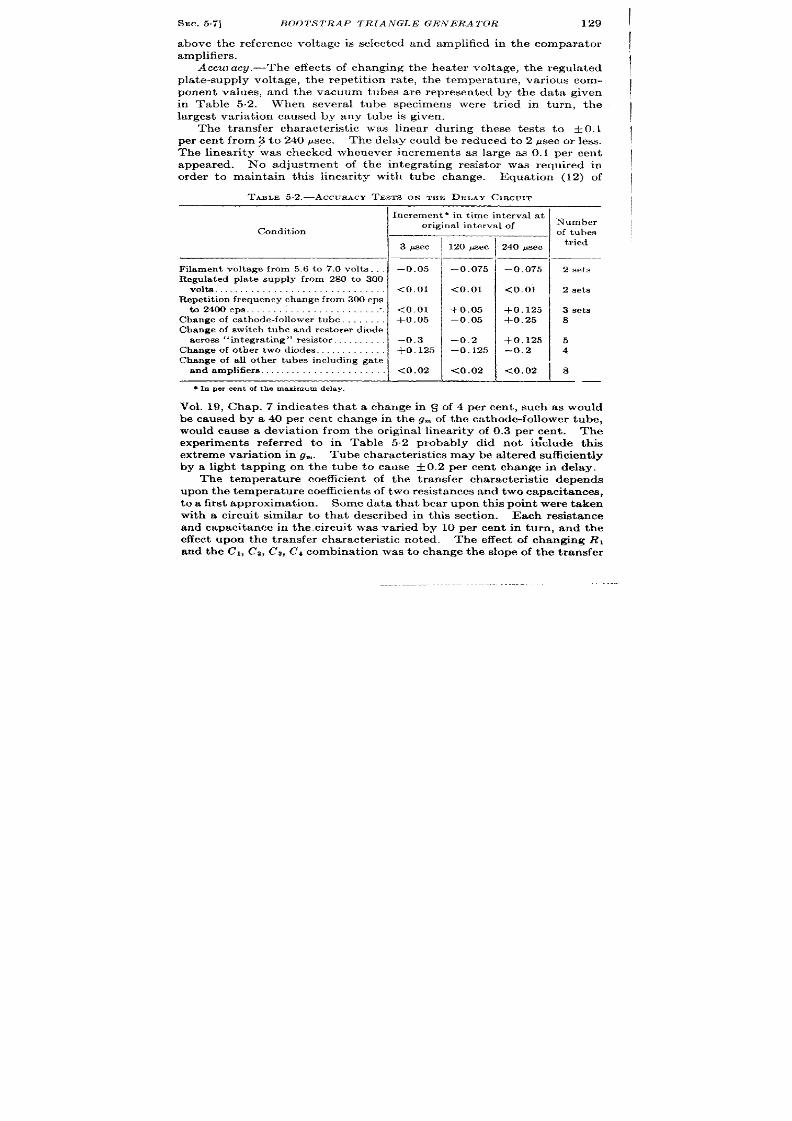
SEC.5.7]
BOOTS TRAP TRIANGLE GENERATOR 129
1
above the reference voltage is selected and amplified in the compara tor
1
amplifiers.
Accuracg.-The effect s of changing the hea ter voltage, the regula ted
pla te-supply voltage, the repet it ion ra te, the t empera ture, var ious com-
ponent values, and the vacuum tubes a rerepresen ted by the data given
in Table 5,2. When severa l tube specimens were t r ied in turn, the
largest var ia t ion caused by any tube is given.
The t ransfer character ist ic was linear d r ing these test s to + 0.1
per cent from 3 to 240 psec. The delay could be reduced to 2 psec or less.
The linear ity was checked whenever increments as la rge as 0.1 per cent
appeared. N’o adjustment of the integra t ing resistor was required in
order to maintain this linear ity with tube change.
Equat ion (12) of
TABLE 5.2,—ACCURACYTESTS ON THE DELAY CIRCUIT
\I
ncrem ent * in t ime int erval at
Condition
I
or igina l in t erva l of
I
3 ec
Filament voltage from 5.6 to 7.0 olts .
–0.05
Regulated plate supply from 280 to 300
vo ts . . . . . . . . . . . . . . . . . . . . <0,01
Repetitionfrequ encycha ngefrom 300 cps
to2400cps . . . . . . . . . . . . . . . . . . . . . ...”.
<0.01
Changeof ca th ode-followertu be.
+0.05
Changeof switch tube and restorerdiode
across “integra t ing” resistor , ., –0.3
Changeof other two diodes .
+0,125
Changeof aU other tubes including ga te
andamplit ier s. . . . . . . . . . . . . . . <0.02
q la percent of the maximumdelay.
120 @ec
–0.075
<0.01
+0. 05
–0.05
–0.2
–0.125
<0.02
240psec
–0.075
<0.01
+0.125
+0. 25
+0.125
–0.2
<0. P 2
Number
of tubes
tried
2 sets
2 set s
3 set s
8
5
4
8
——
Vol. 19, Chap. 7 indica tes that a change in S of 4 per cent , such as would
be caused by a 40 per cent change in the g~ of the ca thode-follower tube,
would cause a devia t ion from the or igina l linear ity of 0.3 per cen t . The
exper iments refer red to in Table 5.2 probably did not i~clude this
ext rem e var ia t ion in g.,. Tu be cha ract er ist ics maybe a lt er ed sufficient ly
by a light tapping on the tube to cause ~0.2 per cent change in delay.
The tempera ture coefficien t of the transfer character ist ic depends
upon t he t emper at ur e coefficien ts of two r esist an ces and two capa cit an ces,
to a first approximat ion . Some data that bear upon this point were taken
with a circuit similar to tha t descr ibed in this sect ion .
Each r esist ance
and capacitance in the. circu it was var ied by 10 per cent in turn, and the
effect upon the t ransfer character ist ic noted. The effect of changing RI
and the Cl, Cz, C3, Cd combinat ion was to change the slope of the t ransfer
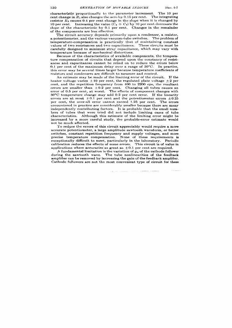
130
GENERA T ION OF MOVABLE INDICES
[SEC. .57
character ist ic propor t iona lly to the parameter increment . The 10 per
cen t ch an ge in RI also changes the zero by 0.15 per cen t . The in tegra t ing
resistor Rz causes 0.4 per cen t change in the slope when it is changed by
10 per en t . Increasing the value (C5 + C~) by 10 per cen t decreases the
slope of the character ist ic by 0.1 per cen t . Changes in the remainder
of th e compon en ts a re less effect ive.
The circu it accurac depends pr imar ily upon a condenser , a resistor ,
a poten t iometer , and the var ious vacuum-tube switches. The problem of
tempera tu re-compensa t ion is pract ica lly tha t of mainta in ing c nstan t
va lues of t wo resista nces an d two ca pacita nces.
These circu it s must be
ca refu lly designed to minimize st ray capacitance, which may vary with
t emper at ur e beca use of mech an ica l dist or tion s.
Because of the character ist ics of available compon en t s, th e tempera -
tu re compensa t ion of circu it s tha t depend upon the constancy of resist -
ances and capacitances cannot be relied on o reduce the er ror s below
0.1 per cen t of the maximum delay over a range of 50”C. In pract ice,
th is er ror may be severa l t imes la rger because tempera tu re coefficien t s of
r esist or s and con den sers a re difficu lt t o mea su re and con trol.
An est ima te may be made of the limit ing er ror of the circu it . If the
hea ter voltage var ies f 10 per cen t , th e regu la ted pla te volt age Y 2 per
cen t , and the repet it ion frequency from 400 to 2200 cps, the resu ltant
er ror s a re smaller than ~ 0.2 per cen t . Changing all tubes causes an
er ror of 0.5 per cen t , a t worst . The effects of componen t changes with
50°C tempera tu re change may add 0.2 per cen t er ror . If the Iinea r it y
er ror s a re a t most ~ 0.1 per cen t and the poten t iometer er ror s f 0 25
per cen t , the over-a ll er ror cannot exceed 1.25 per cen t . The er ror s
en cou ntered in pract ice a re considerably smaller because th ere a re many
i dependen t ly con t r ibu t ing factor s. It is probable tha t he small num-
bers of tubes tha t were t r ied did not include limit ing cases of tube
character ist ics. Although th is est imate of the limit ng er ror migh t be
increased by a more carefu l study, the probable-er ror est ima te would
not be much affected.
To red~ce the er ror s of th is circu it appreciably would requ ire a more
accu ra te poten t iometer , a a rge amplitude sawtooth waveform, or bet t er
switches, constant repet it ion frequency and supply voltages, and more
precise tempera tu re compensa t ion . None of these requ irements is
except iona lly difficu lt t o meet , pa r t icu la r ly in the labora tory. Per iodic
ca libra t ion r edu ces t he effects of som e er ror s.
This circu it is of value in
applica t ions where accuracies’ as grea t as t 0.1 per cen t a re requ ired.
A fundamenta l limita t ion is th e var ia t ion of g~ of the ca thode follower
dur ing the sawtooth wave.
The tube non linea r it ies of the fe dback
amplifier ca n be r emoved by in crea sin g t he gain of t he feedba ck amplifier .
Ca thode followers a re not the most conven ien t type of circu it for these

SEC.543]
THE DELAY MULTI VIBRATOR
131
more linear amplifier s. When the Mill r feedback pr inciple isused, t he
residual er ror s from linear ity a re much smaller . The Miller circuit s a re
t her efor e pr efer red for at ta in in g good linear it y.
6.8. The Delay Mult it ibra tor .-The delay mult ivibra tor (see Vol. 19,
Chap. 5) is a simple self-ga ted two-tube t ime-modulat ion circuit of the
sawtooth waveform type. The sawtooth waveform s exponent ia l in
shape but t he t ransfer character ist ic is linear .
The outpu t of the circuit
is a square wave that r ises a t t he refer ence t ime and falls a ft er a var iable
dura t ion . The fall is sufficient ly shar~ to ident ify an instant of t ime to
within an er ror considerably less than 1 psec for the maximum durat ion
+300v reg d,c.
25?
2k
low
Ww
::
ref8rence
pulse
=
L
=
FIG. 6. 14.—The SF delay mult ivib ra tor .
used in radar . The simplicity of the circuit is it s grea test vir tue and it
is not now used as a precise t ime modula tor a lthough it was or igina lly
developed for this purpose. Other volt age-cont rolled circu it s with more
sta ble t im ing wa veforms and mor e a ccur at e compa ra tor s ha ve suppla nt ed
it .
In one instance the circuit was used for the measurement of t ime
in terva ls in a shipborne radar . The step at the end of the modula ted
interval was used as a step on a CRT display. The t im~measurement
system was t her efor e ver y economical, consist ing of a pot en tiometer and
dia l, the delay mult ivibra tor , and a ca thode-ray tube. A cryst a l-
con tr olled oscilla tor pr ovided m ea ns for ch eckin g t he t ra nsfer ch ar act er -
ist ic of t h e mult ivibr at or .
The opera t ion of the circuit is descr ibed in Vol. 19, Chap. 5. A circu it
diagram is shown in Fig. 5.14. The means for t r igger ing and the regula -

132
GENi!7RA TION OF MOVABLE INDICES
[SEC.5.9
t ion of the supply volt age must be good if sat isfactory opera t ion is to be
achieved.
The linear ity of the t ransfer ch racter ist ic is usually about 1 per cen t ,
a lthough carefu l adjustment of constan ts may give bet t er resu lt s with
select ed tubes. Tempera ture sensit ivity of the delay is la rge and com-
pensa t ion is not usually profitable. The coefficien t of delay change
with hea ter -supply var ia t ion has been observed to be approximately
-0.2 per cen t per volt . A change of EPP from 250 volt s to 200 volt s
resu lted in a 0.4 per cen t change in delay.
Tube changes result in var ia -
t ion of the t ransfer character ist ic by as much as 10 per cen t .
This ircu it depends to a la rge exten t upon the constancy of tube
character ist ics. The applicat ion of precision tubes, such as the 6SU7,
to such circuit s has not been sufficient ly invest iga ted. It is probable,
-modula t ion circu it s is most easily done with more complex circuit s.
Some increase in accuracy might be expected by the use of diodes to
stabilize the init ia l amplitude of the t iming waveform and the fir ing
poin t of t he r egen er at ion .
VARIABLE DELAY LINE
5.9. Su per son ic Delay Tank,-A delay-tank t ime-modula t ion sys-
tem 1 consists of two crysta ls, a t ransmit ter and a receiver , of supersonic
oscilla t ions mounted in a tank of liquid (see also Chap. 12). The delay
is var iable over a range of 2 to 240 ,usec by alt era t ion of the dist ance
between the t ransmit t er and the receiver . A 240-Psec delay is ach ieved
with the t ransmit ter and receiver approximately 20 in . apar t .
The funct iona l diagram of Fig. 5.15 shows the delay tank and the
necessa ry circuits. The pulse genera tor accepts the reference pulse and
produces a sharply r ising high-voltage pulse tha t is applied to the t rans-
mit t ing crysta l. The crysta l oscilla t ing a t its na tural fr equency pr odu ces
a shor t damped wave t ra in of a lterna t ing compressiona l waves in the
liqu id su rr ou ndin g t he cr yst al.
This wave tra in is propagated a long the
tank, and when it r eaches the receiver , a volt age appears across tha t
crystal.
The amplifier follows the receiver to ra ise the signal to a usable level
since there a re considerable losses in the tank. The amplitude-selec o
circu it accepts only signals tha t a re grea ter than a cer ta in magnitude.
The automat ic gain cont rol ensures that only the la rgest signal from the
receiver exceeds this level. The undesi ed signals a re reflect ions from
the tank walls. The amplitude selector produces a pulse tha t t r iggers a
mult ivibra tor whose output is a shor t low-impedance movable pulse.
1See ‘(Inst ruct ion Book for Model SJ Radar Equipment ,” BuShips.
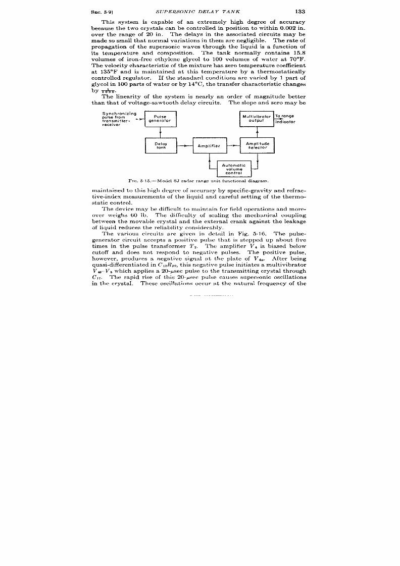
SEC. 59]
SUPERSONIC DELAY TANK 133
This system is capable of an ext r emely high degr ee of accuracy
because the two crysta ls can be cont rolled in posit ion to within 0.002 in .
over the range of 20 in. The delays in he associa ted circu it s may be
made sosmall tha t normal var ia t ions in them are negligible. The ra t e of
propaga t ion of the super sonic waves through the iqu d is a funct ion of
it s t empera ture and composit ion .
The tank normally conta ins 15.8
volumes of iron-fr ee ethylene glycol to 100 volumes of wa ter a t 70°F.
Th e velocit y ch ar act er ist ic of t he m ixt ur e h as zer o t emper at ur e coefficien t
a t 135°F and is maintained a t this tempera tu re by a thermosta t ica lly
con t rolled regula tor . If t he standard condit ions are va r ied by 1 par t of
glycol in 100 part s of wa ter or b y 14°C, t he t ransfer cha racter ist ic changes
by &.
The linear ity of the system is near ly an order of magnitude bet ter
than that of voltage-sawtooth delay circu it s. The slope and zero maybe
Synchronizing
pulse from
Pulse
Multivibrotor TO ronge
transmitter-
+
generator
receiver
output
indicator
1
t
~ 100
—
Amplifier
—
Amplilude
selector
I I
w
u fomotic
volume
control
171c. 5.15.—Model SJ radar range unit funct iona l d iagram.
mainta ined t o th is h igh degr ee of accura cy by specific-gr avity and r efra c-
t ive-index measurements of the liquid and carefu l set t ing of the thermo-
s ta t ic cont rol.
The device may be difficu lt t o maintain for field opera t ions and more-
over weighs 60 lb. he difficu lty of sea ling the mechanica l coupling
between the movable crysta l and the externa l crank aga inst the leakage
of liqu id r edu ces t h e r elia bilit y con sider ably.
The var ious circu it s a re given in deta il in Fig. 5.16. The pulse-
genera tor cir u it accept s a posit ive pulse tha t is stepped up about five
t imes in the pulse t ransformer 1’2.
The amplifier V4 is biased below
cutoff and does not r espond to negut ive pulses.
The posit ive pulse,
however , produces a nega t ive signal a t the pla te of Vh. Aft er bein g
quas i-d ifferen t ia ted in CIZRZO, t his nega t ive pulse init ia tes a mult ivibra tor
VWVS which applies a 20-p ec pulse to the t ra smit t ing crysta l th rough
l,. The rapid r ise of this 20-psec pulse causes supersonic oscilla t ions
in the crysta l. These oscilla t ions occu r a t the na tura l frequency of the
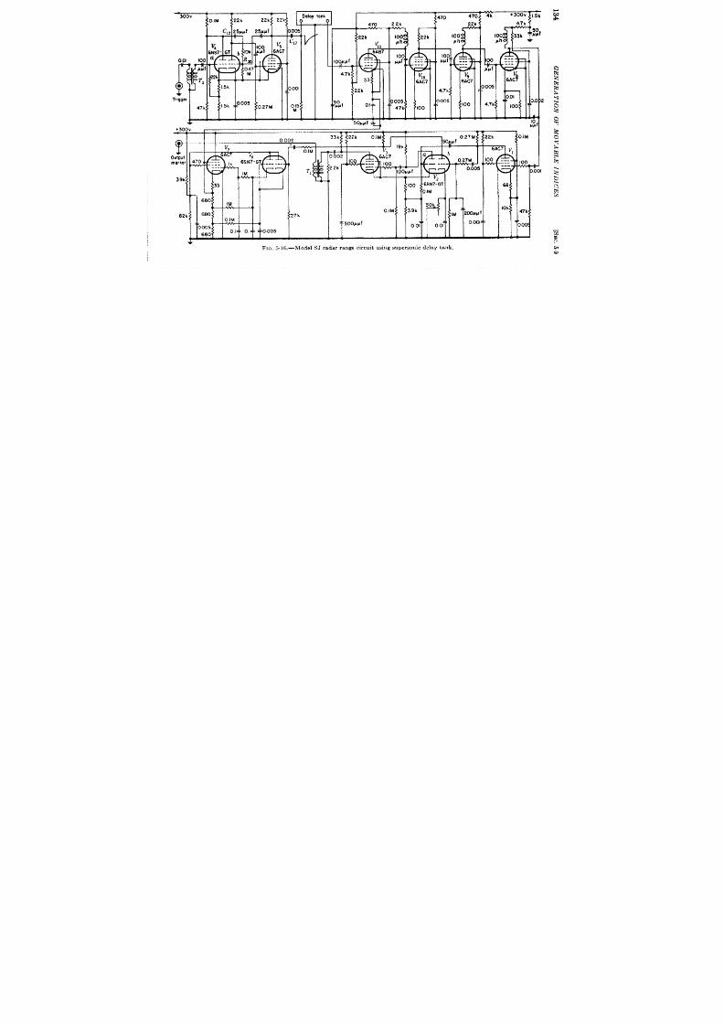
300V
O.IM
22k
2211 22k
/[
T
i
I I 1
I
1
0001
L
15:
~,
+300V
r
9 1
00
I I
v.
dOy tonk
—
r
470,4 4k
+300w [.5k
$470
2
T
!7 k
,2k
‘,-
FIG. 5 .16.—Model S J r ada r r ange cir cu it u s ing supe r son ic del ay t ank
70’” I
3
AC7 V,
---
---
100
---
J
0.001
6a
10k
47 k
o
SEC.5.10]
PHASE MODULATOR RANGE CIRCUIT 135
crysta l, about 1.4 Me/see. The fall of the !2(@ec pulse is not steep
en ou gh t o pr odu ce oscilla t ions in th e cr ysta l.
The transmit t ing and receiving crysta ls are fla t pla tes about ~ in .
square and 0.040 in . th ick, mounted with their la rge fla t faces direct ly
facing each other . The voltage wave applied to the t ransmit ter causes
it to oscilla te in a damped vibrat ion at it s natu ra l frequency for longi-
tudinal waves. This vibra t ion is h ighly damped because of the con tact
between the crysta l and the liquid and even more because of the mount-
ing in which it is placed. In this mount ing ther e is a brsae “backing
block” tb which the whole back face of the crysta l is t ight ly soldered.
This block is used as on e elect rode.
A grounded layer of solder applied
to the fron t face of the crysta l is the other elect rode. The backing block
is very effect ive in absorbing mechan ical energy from the quar tz and
thus in damping out the vibra t ion .
he faces f the crysta ls must be parallel t o within about 0.01 in . if
su fficien t voltage is to be produced across the receiving crysta l. The
liquid in the tan is held at 135° + #F by t e thermosta t TD~ and is
quickly ra ised to this temperatu re region by a high-heat el ment con-
t rolled by TD1. Thermostat TD1 is set a t a few degrees below TDz.
he elect r ica l connect ion to the moving crysta l consists of a cen t ra l
conductor of severa l small wires surrounded by a layer of rubber which
in tu rn is coa ted with Neoprene.
This st ructu re gives the wire low
ca pa cit an ce, h igh flexibilit y, a nd ch em ica l r esist an ce t o t he solu tion . Th e
capacitance to ground, measured at 1 or 2 Me/see is about 55 to 85 ypf.
The resistances to ground may be aa low as 50,000 ohms although nor -
mally they are much higher .
The loss in the flu id itself is on ly 60 or 70 per cen t , bu t the ou tpu t that
ppeans across the receiving crysta l is about 5 mv peak amplitude. The
amplifier a ccepts a 5-r ev signal and pr odu ces about 15 volts a t t he ou tpu t.
The maximum gain is 75 db and can be reduced to about 65 db by auto-
mat ic gain con t rol. The au tomat ic gain con trol maintains at a constan t
amplitude the signals to be applied to the amplitude selector .
Th e
amplitude selector is biased below cutoff so that on ly the h ighest peak
of the h ighest wave tra in makes VI conduct . Tubes Vza and Va make
u p a mon ost able mult ivibr at or t ha t is t rigger ed by t he amplit ude-select or
outpu t and roduces a movable marker pulse that is steppe down in
impeda nce by t ra nsformer T1.
SINUSOIDAL OSCILLATOR RANGE CIRCUITS
6.10. LC-oscilla tor , Phase Modulator , and Comparator .-Th is cir -
cuit is of very ear ly date and merit s only the br iefest descr ipt ion.
Th e
t ime measurement of the radar SCR-268’ is accomplished with an oscil-
1E/ ectronic8, 18, 10&109, September 1945.
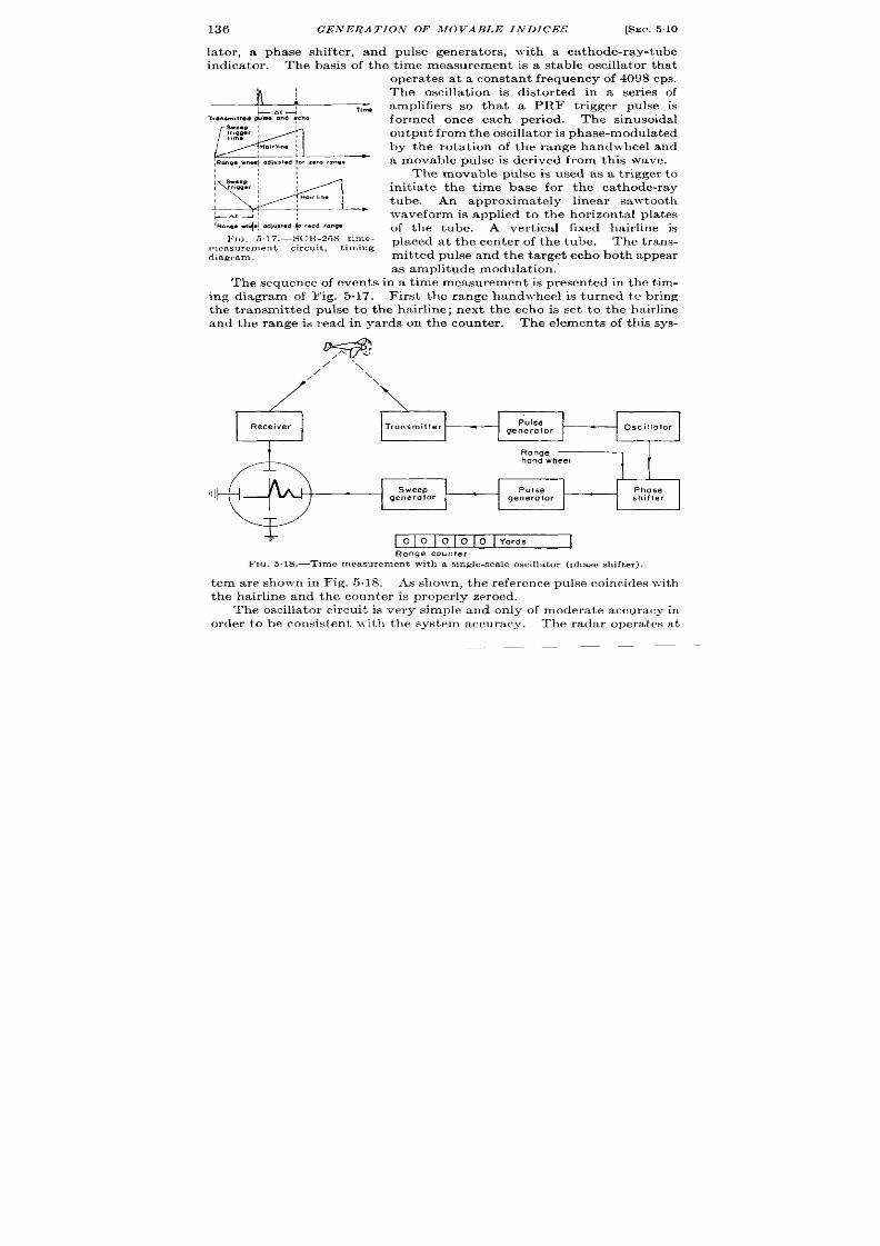
136 GENERA TION OF MOVABLE INDICES
[SEC.510
la ter , a phase sh ifter , and pulse genera tor s, with a ca thode-ray-tube
indica tor . The basis of the t ime measurement is a stable oscilla tor tha t
E++-
ing. .heq odwsl.d f., z.,. row.
1“:
w
F.14 :
‘ROIW cd,.smdoredmfw
I:[G. 5.17.—SCR-26S t ime-
mea su r emen t cir cu it ,
t iming
diagram,
oper at es a ta con st an t fr equ en cy of4098cps.
The oscilla t ion is distor ted in a ser ies of
amplifiers so tha t a PRF t r igger pulse is
formed once each per iod. The sinusoidal
ou tpu t fr om the oscilla t or is pha se-modu la t ed
by the rota t ion of the range handwheel and
a movable pulse is der ived from this wave.
The movable pulse is used as a t r igger to
in it i t e the t ime base for the ca thode-ray
tube. An approximately linear sawtooth
waveform is applied to the hor izonta l pla tes
of the tube. A ver t ica l fix d hair line is
placed a t the cen ter of the tube. The t rans-
mit ted pulse and the ta rget echo both appear
as amplitude modula t ion .
The sequence of event s in a t ime measurement is presen ted in the t im-
ing chagram of Fig. 5.17. F ir st he range handwheel is tu rned tc br ing
th ransmit ted pulse to the hair line; next the echo is set to the hair line
and the range is read in yards on the counter .
The elements of th is sys-
.
Receiver
Transmitter
,11
T
o 0 0 0 0 Yards
Range counter
FIG. 5,18.—Time measurement with a s ingle-sca le oscilla tor (phase shifter ).
tern are shown in Fig. 5.18. As shown, the reference pulse coincides with
the ha ir line and the counter is proper ly zeroed.
The oscilla tor circu it is ver y simple and on ly of modera t e accuracy in
order to be consist en t with the system accuracy. The radar opera tes a t
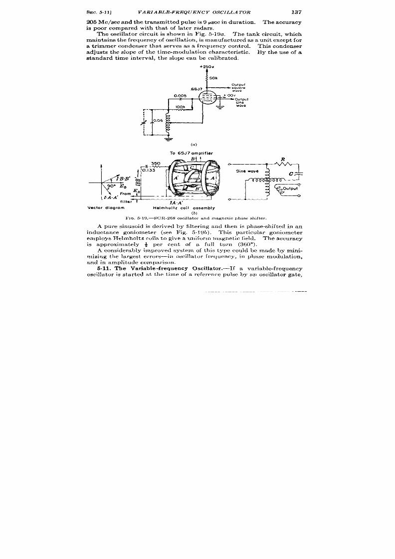
SEC. VARIABLE-FREQUENCY OSCZLLA TOR 137
205 Me/see and the transmit ted pulse is 9 psec in dura t ion . The accuracy
is poor compared with tha t of la ter radars.
The oscilla tor circu t is shown in Fig. 5,19a. The tank circuit , which
maintains t he fr equ en cy of oscilla tion, is ma nu fa ctu red as a un it except for
a t r immer condenser tha t serves as a frequency con t rol. This condenser
adjusts the slope of the t ime-modula t ion characte ist ic. By the use of a
standard t ime in terva l, the slope can be calibra ted.
+250w
t
6SJ?
1
&
‘
0.06
I
L-
To 6SJ7 omplifier
R
0
Sine wave
0
(b)
Fx~, 5.19. —SCR-26S oscillator and magnet ic phase shift er .
A pure sinusoid is der ived by filter ing and then is phase-sh ifted in an
inductance goniometer (see Fig. 5.196). This par t icu lar goniometer
employs Helmholtz coils to give a uniform magnet ic field. The accuracy
is approximately ~ per cent of a full tu rn (3600).
A considerably improved system of this type could be made by mini-
mizing the largest er rors—in oscilla to frequen cy, in phase modulat ion ,
and in amplit ude compa rison .
5.11. The Var iable-frequency Oscilla tor .—If a var iable-frequency
oscilla tor is sta r ted at the t ime of a reference pulse by an oscilla tor ga te,

13!3 GENERA TION OF MOVABLE INDICES
[SEC. 511
P’
eference pulse
Catrol shaft
I
/ ‘3-.63 \
Gafe
generators
Oscillator
Oscillator
I
gate
.
1 t
Pulse
Pulee
selector
generotor
i
Movable
pulse
FIG. 6.20.—Variable-frequency oscillator t ime-modulator circuit .
n-----
j---iz:ri-r
E
scillator gate
+kiR,,it_lw
I
q I
01
I
:1
I
:1
n _ , 4 ~-1+,+
I
Pulse generator output
I
I
I
I
I
I
I
F]o. 6,21
Time -
.—Timing diagram of the var iable-frequency oscilla tor t ime

SEC.5.11] VARIABLE-FREQUENCY OSCILLATOR
139
the fir st p r iod of the oscilla t ion const itu tes IJ var iable t ime delay. If a
pulse is genera t ed at the end of one per iod, the pulse will be t ime modu-
la ted. The block diagram of Fig. 5.20 shows a circuit of th i~ type. Since
the pulse genera tor opera t es on every per iod, it is necessa ry to eliminate
the undesired pulses with the pulse selector . The oscilla tor is stopped
shor t ly after one ycle by the oscilla tor ga te which changes in durat ion
with the cont rol shaft . L
Some of the waveforms of a circu it of th is t ype are shown in Fig. 5.21.
Those which are shifted or expanded along the t ime axis as a funct ion of
the cont rol var iable a re marked with an ar row.
The exper imental circuit shown in Fig. 5.22 with addit ional ga te gen-
era tors, pulse genera tor , and pulse selector has been opera t ed in the
Gateco!hodeollowsr
—
Weiobridotoscillobr
+35CW
t
J
+
F1o. 622.-A vm ie.ble-fr equ en cy oscilla tor for t ime modula t ion . The r n in jmum de]aY ia
3 We ; t he maximum dela y i~ 300 pa ec.
Th e linea r it y is +2.6 per cent .
laboratory, but was never fur ther developed. For an ideal Wien br idge
oscilla tor , t he per iod is propor t ional to the shaft rota t ion of the var iable
condensers if t he br idge impedances are proper ly propor t ioned. The t ime
intervals range from t o 300 ysec in t hr ee scales obta ined by switching the
br idge resistance. The maximum er ror s from linear ity a e 0.03, 0.3, and
7.5 psec on the scales. The probable cause of the limit ing er ror (2.5 per
cent of the maximum t ime interval) is br idge asymmetry. The slope of
t he character ist ic changes ~ per cen t for a per cen t pla te-supply voltage
change. Hea ter -voltage changes within 10 per cen t of the ra ted value
1See A. H. Freder ick,RL Group Report No. 63-9/11/42
140
GENERATION OF MOVABLE INDICES
[SEC. 512
had no appreciable effect . A tempera ture change from +20” to - 80”C
changes the slope of the character ist ic by severa l per cen t because of the
lack of per fect ly tempera ture-compensa ted resistance-capacitance ele-
ments. Somewhat bet ter frequency stability (and inear ity) is observed
wit h t he Hew it t-P acka rd oscilla tor .
The oscilla tor ga te is applied to the screen gr id of an oscilla tor tube by
a cathode follower Changes of the gate tube cause he oscilla tor to
oper te when it should be quiescent .
The effect can be eliminated by
capacitance coupling from the plate of the gate tube to the ca thode-fol-
lower gr id.
The second ca thode followe of Fig. 5.22 is used to cancel the gate
component par t ia lly in the osci la tor output by applying the gate to the
pla te of the oscilla tor tube. It is desirable to have the a lternat ing com-
ponen t swing about the quiescent level in order to square the waveform.
The ga te cannot be completely removed because a poin t is reached where
the oscilla t ion star ts in the opposite phase. The. ga te should probably be
removed at a poin t outside the oscilla tor feedback loop. The squaring
amplifier may increase the t ime delay by 2 per cent—this increase is a
funct ion of the tube character ist ics of severa l tubes. It is desirable to
use a bet ter method for synchronizing a pulse with the end of the per iod of
a sinusoid. Such methods have been descr ibed in Chap. 9, Vol. 19.
Differ ent ia t ion of t he squ ared wa ves pr odu ces signals of opposit e signs at
the 180° and 360° poin ts of the sine wave. The 1 0° signal is discr imi-
na ted against by a cliodc selector .
The frequ ency stability of th e oscilla tor would be improved if an auto-
ma tic amplitu de con tr ol wer e Oscd.
Such a device would have to opera te
on volt age and not on power bccausc the single pwiod of oscilla t ion does
not permit thermal equilibr ium to bc established. The high frequencies
necessary at minimum range incrcasc the power requirements for the
oscil a tor in or der t o maintain low-ph zse shift in t he oscilla tor amplifier .
This met hod of t ime modu lat ion has n ot pr oved reliable or in expen sive.
The delay mult ivibra tor is a much simpler circu it with approximately the
same accuracy.
The pr inciple may be useful, however , for some specia l
application.
5.12. A Compar ison of Some Single-sca le Circuits.—A br ief compa ri-
son of some of the single-sca le circu its may be of value if a choice for a
pa r ticu la r applica t ion is ncccssa ry.
The deta iled studies on which these
in Chap. 3, and in Chap. 13 of Vol. 19.
Without the repet it ion of a ~rea t dea l of data , complete comparisons
are not possible, The proccdur c h er e is t o indicate which circuit possesses
a part icu lar vir tue in the highest degree.
The best linear ity is obta ined with the supersonic delay tank and the

SEC. 512]
COMPARIS ON OF S INGLE-S CALE CIRCUITS
141
h igh -ga in Miller in tegr at or cir cu it s.
l’h csc sin gle-sca le cir cu it s, wh ich
may be made near ly as linear as more complex mult iple-scale circuit s,
have the addit iona advan tage of freedom from cyclic er ror (see Chaps.
2, 7, and 8 and Vol. 19, Chap. 3).
The least sensit ivity of the t ransfer character ist ic to tube changes,
tube dr ift s, and the vibra t ions occurs with th e propagat ion-t ime circu it s,
the liquid and elect r ic delay lines. The pulse amplifiers, which are the
on ly necessa ry vacuum tubes, can be designed to in t roduce negligible
delays int o t he cir cu it .
Th e least sen sit ivity t o t empera tu re ch an ges is fou nd in cir cu its wh ose
fu ndament al elem en t is a cr yst al-con trolled oscilla t or . Th ese a re usually
mult iple-scale circu it s. At the opposit e ext r eme are the propagat ion-
t ime circu its, for which the tempera tu r coefficien t s are so grea t tha t
con t rol of t he ambient t empera tu re is often necessary.
Er rors from changes in t r igger -repet it ion ra te a re smallest for the
propagat ion-t ime circu it s, as a re the effect s of supply-voltage change.
Th e r an ge of modu la t in g frequ en cies (speed of oper at ion ) is lar gest for t he
voltage-sawtooth circu it s that accept a voltage as th e con trol var iable.
Th e volt age-sawt oot h cir cu it s a re pa rt icu la rly u sefu l wher e some sa cr i-
fice of accuracy can be made in order to save size, weigh t , complexity,
expen se, and power con sumpt ion .
These have the fur ther advan tage
of being rela t ively simple to const ruct and mainta in as opposed to the
liquid delay tank. Thus, they have been very widely used for medium-
precision t ime measur ement in radar s.

CHAPTER 6
GENERATION OF MOVABLE INDICES-CIRCUITS
R. I. HULSIZER, R. B. LEACHMAN
PHASE MODULATION AND AMPLITUDE COMPARISON
This por tion of t he ch apt er descr ibes sever al t im e-modu la tion circu it s
that employ a method out lined in Sees. 39 and 3.15: cont inuous phase
modula t ion of the high-frequency t iming waveform to form a movable
t ra in of pulses and select ion of one of these pulses by a coarse-sca le t ime-
modu la t ed pu lse.
By far t he la rgest number of a ccu ra te r an ge-mea su rin g
systems tha t were used in adar dur ing the war employed th is method.
Th ese syst ems fa ll in to two cla sses: t hose a ct ua lly u sin g ph ase modu la tor s,
and those using circu la r -sweep indica tor s.
The cir cu la r sweep is, in effect ,
a cont inuous phase modula tor , since rota t ion of a radial index around the
t race selects instants cor responding to all phases of the sinusoid from
which the sweep is obta ined. Select ion of the cor rect cycle of the fine
sca le is provided by an intensify ng ga te, approximately cen tered on the
index and t ime-modula ted a t the same ra te as the index that moves
around the sweep.
601. Meacham Range Unit .—One of the most st ra ight -forward two-
sca le t ime modulators employing phase modula t ion is the following
and in tended as replacement for the supersonic tank of Sec. 5.9. Its
pr imary use was in fire-cont rol radars where a cont inuous shaft rota-
t ion indicat ing range is required for ballist ic computers. A block
diagram of this unit is shown in Fig. 6.1, with a waveform diagram,
Fig. 6.2. The system was designed to opera te from an externa l t r igger
and hence employs a pulsed oscilla tor .
Its tank circu it is tuned to
81.955 kc/see and is mounted in a tempera tu re-cont rolled oven for
frequency stability. Quadra ture voltage (Fig. 6.2d–g) dr ive the
condenser phase modula tor , whose output is amplified, squared (F g.
6.2i), and clifferen t ia ted as a method of amplitude comparison . The
blcck labeled “Pulse Selector” per forms the opera t ion of genera t ing an
exponent ia l sweep to which t ime-modula ted pulses are added, as in Fig.
6.2.i. Amplitude comparison with respect o a voltage from an exponen-
t ia lly tapered potent iometer selects one of the t ime-m dula ted pulses
(Fig. 6.2k) which is then shaped (Fig. 6.21) and made available a t 12&ohm
142

SEC. 6.1]
MEACHAM RANGE UNIT
143
I
To ,indicator I
&
circuit I
I
unil
L – _________ ______ _____~
F IG. 6 .1.—Block dia gr am of a two-sca le ph ase-modu la tion r an ge unit . Let ter s r efer t o
waveforms on F ig. 6.2.
(.) I .Extern .l t?
Phase-shifted
pulse
output sinusoid
‘m) *-mod
Fm. 6 .2 .—Waveformsof a two-sca le range unit .

144
GENERA TION OF MOVABLE INDEXES-CIRCUITS
[SEC. 6.1
level (F ig. 6.2m).
The circu it thus provides a single pulse, t ime-modu-
la ted wit~ respect t o the external t r igger from zero to 234psec.
Oscillator and Sawtooth Ga te.—Th e sch emat ic cir cu it ca n be descr ibed
in th r ee par t s. The fir st is the “wide-ga te” monostable mult ivibra tor
(F ig. 6.3), which gates the pulsed oscilla tor and the exponent ia l sweep
genera tor . The left sect ion is normally oN. The external t r igger ,
applied t o t he left sect ion, tu rns t he cult ivat or off for 240 psec, gen era t in g
a neg t ive gate at the pla te of V2.
Th e secon d circu it sect ion (F ig. 6.4) gen er at es and ph ase-modu la t es
the pulsed sinusoid. Normally the tuned circu it Z, is cla ped between
the pla te of Vt and the cathode of Vi is overdamped with an average cur-
+mov
NegotIve wide
)
0:01
‘!.-
1
“.. I I
i’
rigger y‘ v
Iu I I
4
FIG. 6.3.—Wide-gate monostable mult ivibrator .
r en t of about 12 ma flowing through it . Cut t ing off V~ and Vi with the
wide ga te star ts oscillat ions in the tuned circu it which are coupled to the
feedback and phase-sh ift ing amplifier VS.
F eedback t o susta in t he init ial
amplitu de of oscilla t ion s is pr ovided t hrou gh RI. The RC-constan t s in
the cathode circu it and the RL-constan ts in the pla te circu it are adjusted
to provide quadratu re voltages at the pla te and ca thode. These are
applied t o t wo paraphase amplifier V6 and VT which in tu rn dr ive the
conden ser pha se modu la tor .
Amplitude Comparator .—The phase-modula ted outpu t is amplified
in Vs and VD, which incorpora te negat ive feedback t o increase the input
impedance seen by the condenser phase modula tor (see Fig. 6.5). A
high-resistance load on the condenser phase modula tor is necessary to
preserve its response to the PRF components of the pulsed sinusoidal
waveform since its in t ernal impedan ce is th at of a ver y small capacitan ce.
Tube V1Operforms t he amplit ude compar ison, sin ce it has a la rge cat hode

SEC. 6.1]
MEACHAM RANGE UN IT
145
Feedback amplifier
Conden$er
Oscillator switch
and phase-shifter
Paraphase amplifier
phose. mcdulo for
0.25
Negot ive
Phose-modul.sled
.-
i
L
I
I
1-
1 .----l–-. ~:
‘“&l
.01
V3
---
IM
0.25
6SN7
—
/4- phase condenser
/ phase-modulator
10k
6AC7 6SN7
/ Mechanical link 10 pulse
: sslector potentiometer.
Fm. 6.+ Pulsed oscilla tor a nd ph ase modu la tor , 82 k c/see. Let ter s in pa ren th eses r efer
t o F ig. 6.2.
_Feedback amplifier Ampl iude comparator Pulse -former
I T
+ 300V
87 hehae Alltmrl
II M
--
..
--
.0
va-
6M27
V9 v
6AC7 6;7
v,~
6ffi7
Fm. 6+.-Shuaoid amplitudecomparat or .
Reference(t>is to waveform (t) in Fig. 6.2.

146
GEN ERA T ION OF MOVABLE IN DEXES -CIRCUITS
[SEC.
61
resist or , effect ively unbypassed.
When its gr id is more nega t ive than
cutoff, the cathode rest s at +6 volts.
When the gr id r ises past cutoff,
which with th is a r rangement is near ground potent ia l, cu r ren t will sta r t
t o flow in the tube, and the plate voltage to star t to fall. Thus the fixed
potent ia l to which the sinusoid is compared is the cutofl bias of T’lO. The
fall in pla te voltage after the instant of equality would be slow were it not
for t he small ca th ode bypass con den ser .
Th e following t ube Vl, operates
wit h its gr id n orma lly sligh tly posit ive.
When the pla te of V,O star t s t o
fall, the pla te of V,, star t s to r ise rapidly since VII is then oper at ing with
maximum gm. Different ia t ion in Cl and Rz forms shor t pulses for use in
t h e pu lse-select ion cir cu it .
Th e sta bilit y of t he amplit ude-compa rison
~pera t ion depends on the stability of the cutoff bias of a 6AC7. A shift of
Pulse-adding
Pulse Pulse-shaping
Sawtooth Swllch
network selection
amplifier
+300V
N
w
9
d
Time -modulated pujses
FIG. 66.-Coa r se-s ca le t ime modu la t or and pu lse s elect or .
th is bias by 1 volt should in t roduce an er ror of about 3 yd, but exper i-
mentally a change of heater volt age from 5 to 6.6 volt s shows less than 1 yd
er ror ; also, a change of plate supply volt age from 200 to 340 volt s shows
only 1 yd er ror .
Coarse-scale Pulse Select or .—F igur e 6.6 shows t he coar se-sca le t ime
modula tor and pulse selector . Tube V12 is a switch tube oper ted by the
nega t ive wide gate. It s pla te circuit conta ins an RC-element hich forms
an exponen t ia l waveform when the tube is cu t off. A small resistor is
inser ted in the circuit by which the t ime-modulated pulses a re added.
Tube V,S acts as a par t of an amplitude-compar ison circuit , the r efer ence
voltage being applied to it s ca thode from an exponent ia lly tapered
potent iometer . Since the t ime-modula ted pulses a re larger than the
amount by which the ex onen t ia l waveform changes between pulses, a

Sac. 6.2]
PRECISION RANGING INDICATOR
147
pulse, ra ther than th e exponent ia l waveform, will init ia te cur ren t in Vl$.
This act ion is an alogou s t o t hat of amplit ude-comparison mu lt ivibr at or
frequency dividers. The resultan t nega t ive pulse, whose leading edge
coincides with one of the t ime-modulated pulses, is amplified and dif-
feren t ia ted in the tubes V14 and V15 a nd t he pu lse t ra nsformer T1.
F@e 6.7 shows the er rors of the range unit from zero to 44,000 yd ou t
of the maximum of 76,0f)f) yd. The star t ing t ransien t is negligible after
r
+15
[
+1
:+
n
=
g.
&
w -1
-15 I
1
1
I I t 1
I I
I 1 I
I
I I
I
I
I
1 I 1 1
1
012345678910 111213141516171819 ~21 22
Range In thousands at yards
Nat.:maasummonts mad at
intervals of I mlcroaeco d
+Iop
(w 163.91 yards)
+5
:0
a
.5 -5
“;~
22324252s 272829303132 333435363738394041424344
Ran~ In thousands of yards
FIG.6.7.—Rearlt9of laboratay test of two-scale range tit.
300 yd. The other er r m are due to ir regular it ies in the condenser phase
sh ifter improper frequent y of the pulsed oscilla tor , and er rors in the
e ponent ia l poten t iometer which vary t h poin t of th e t ime-modula ted
pu lse a t wh ich pu lse select ion occu rs.
6.2. Precision Ranging Indicator .-In cont rast t o the circu it of the
previous sect ion in which all of the fin~swde pulses are added to an
exponent ia l waveform and then on e select ed by amplitude select ion , th e
circu it now t o be descr ibed select s on e of th e fine-scale pulses by means of
a pen tode amplifier switched on by a pulse that is t ime modula ted by the
coa .rw scale. This method of pulse select ion by mult i+lect rode vacuum
tube swi ches is descr ibed in Sees. 3“9 and 3.15 of this volume and Chap.
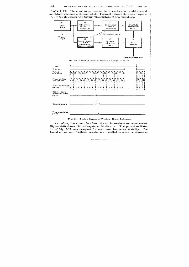
148 GIi’NllRA TION OF MOVABLE INDEXES-CIRCUITS
[SEC. 62
10 of Vol. 19. The er ror t o be expected in t ime select ion by addit ion and
amplit ude select ion is t hus avoid ed .
Figure 68 sh ows t h e block dia gr am .
Figure 69 illust ra tes the t iming rela t ionsh ips of th e opera t ions.
A
B
c
D
Wide
163kcjsec
Con!lnuous
Amplitude
—
gate
pulsed
phose
comparison
osctltator
modulator
circuit
L
i
.
.’
_ Mechonicol control
.
Trigger-
,/”
input
E
F
G
Linear sweep
b~ -mile
time
selecting
—
Pulse
gate
selector
(coarse scale )
I
Time modulated pulsa
FIG. 6.8. -—IMork <li:wv:~m of Prrcision ltnnge I[~dicator,
I
I
Tr,gger
Wide gate
1
I
Pulsed
oscillolor
11111
Phase shifted j
oscillations
1111 [1 [[111111111 I
11111
1111 ! 1111111111 11111
pulses
,1111111111111!1 Illil
11111
Coarse-scale ~
I
time -modulofed ,
pulse
I
!!
I
1]
j!
I
I
Selecting gole I
+
I
I
Time-modulated I
I
pu Ise
r
k
Fm. 6.9 .—Tlming d iagram of Precis ion Range Indica tor .
As before, the circu it has been drawn in sect ions for conven ience.
Vb of F ig. 6.11 was designed for maximum frequency stability. The
tuned circu it and feedback resistor a re insta lled in a temperatu re-con -
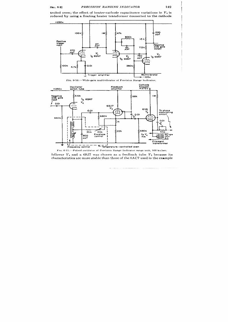
SEC. 6.2]
PRECISION RANGING INDICATOR 149
t rolled oven; the effect of hea ter -ca thode capacitance var ia t ions in Vi is
reduced by using a floa t ing hea ter t ransformer connecte to the ca thode
+250v
I
100k
Positive
trigger
input
I L
TL=
i?l?f
270
‘ook 4.7k
..= Triggar ompltfier
Mul?ivi brator
—-I05V
r
20
##f
V3
- 92 6SN7
.-
FIQ. 6.10.—Wide-gate mult ivibra tor of Precis ion Range Indica tor .
Cathode
Oscillator
Feedback
Follawer
+250v
sw!tch tube
amplifier
Ne ative
“2
I e gate
input
/ (),0,
modulating
680k: :
I
I
I
I
800
I
I 11,
Filament
Irons farmer
Frequency cmt ral
‘Temper ture -controlled oven
FIU .61 l.—Pu lsed oscilla t or of P recis,on lbngc Indica tor r ange un it , 163 kc/aec.
follower V, and a 6SJ 7 was chosen as a feedback tube V5 becau se its
character ist ics are more stable than those of t he 6AC7 used in the example
I ! 11%
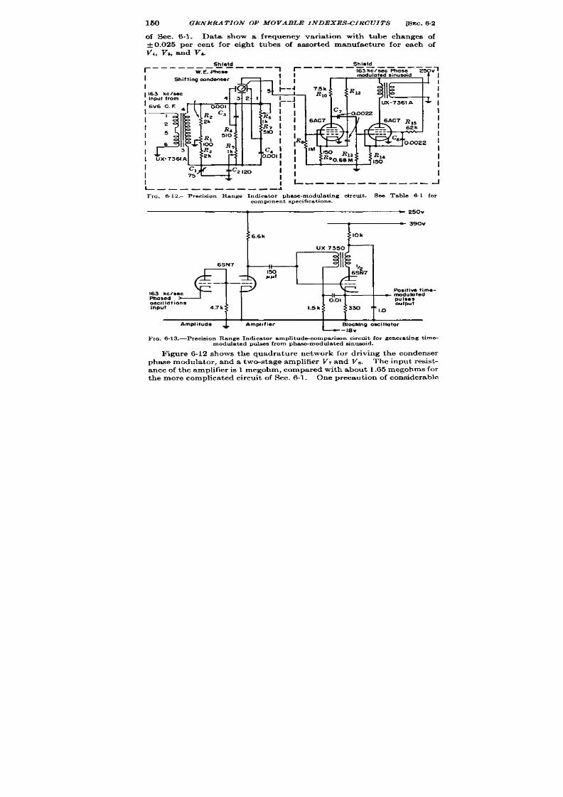
150 GENERA TION OF MOVABLE INDEXES-CIRCUITS
[SEC.
6.2
of Sec. 6.1 . Data show a frequency var iat ion with tube changes of
~ 0.025 per cen t for eigh t tubes of assor ted manufacture for each of
V,, V,, and Va.
I
1163 kc/ssc
, Inpu trom
I 6V6 c. E
.I-t-1=
daL1-l L
w
-1 !q_l
4321
101
C3
R6
Ik
R,
R7
510
510 I
R5
I
Ik
c, I
Shield
Shield
r
------ —- —-— --
W.E. Phase
1
“1
I
Shift inamnden=’ ~ !
I
1
I
I
I
c1
w“
Cz 120
1;
&
I
75
I
: l--------------
;
I
I
I
I
1
I
I
I
I
I
J
L ——-—- -— --- -
J
llc. 6.12.—P recision Ra nge In d ca tor ph ase-m odu la tin g circu it . See Table 6.1 for
component specificat ions.
I ~ 3’0”
6.6k
10k
Ux7350
6SN7
J #-
‘ ;1
b2
150
6SN7
#l/#f
---
---
---
163 kc/see
Phosed
oscillations
0.01
input
4.7k
1.5 k 330 ‘
Po itive fime-
— ~f; ted
output
c 1.0
L 1 1 1
L
Amplitude
J
Amplifier
Slocking osci Ilofor
-Iev
Fm. 6.13.—Pr ecisionRangeIn dicat or amplitu de-conlpar imnircuit for genera ting ime-
modulat edpu lsesfrom pbam -modula ted inusoid.
F igure 6.12 shows the quadratu re network for dr iving the condenser
phase modu la t or , and a two-st age amplifier VT and VS . Th e in pu t r esist -
ance of the amplifier is 1 megohm, compared with about 1.65 megohms for
t he mor e complica ted circu it of Sec. 6.1.
One p recau t ion of considerable

SEC.6.2]
PRECISION RANGING INDICATOR
151
impor tance is that the input and outp t circuit s must be carefully
sh ielded from each other since the output circu it of the phase modulator
is a t low voltage level and high impedance. Any st ray pickup of sinusoid
will in tr odu ce er ror s in t he ph ase odulat ion.
The circu it for genera t ing t ime-modula ted pulses from the phase-
modula ed sinusoid is shown in Fig. 6.13. The amplitude compar ison is
TABLE 6.1.—PARTsLISTFOEIFIG. 6.13
Item
R,
R,
R,
R,
R,
R,
R,
R,
R,
R,o
R,z
R ,,
R ,,
R,ti
c,
c,
c,
c,
c,
c,
c,
Value
100ohms
2k
2k
510 ohms
Ik
lk
510 ohms
lM
150ohms
7,5 ohms
62 k
68ok
150ohms
62 k
75 J ipf
120ppf
0.001 #f
0.001 J l f
o.oo22pf
0.0022 /J f
0.0022 pf
rolerance,Y
. .
2
2
5
. .
. .
5
10
5
5
5
10
5
5
5
2
2
10
10
10
Wattage
I
Miscellaneous
ww potent iometer
ww precision
ww precision
Ww
Potentiometer
Potentiometer
Ww
. . . . . . . . . . . . . . . . . . . . . . .
. . . . . . . . . . . . . . . . . . . . . . . .
. . . . . . . . . . . . . . . . . . . . . . . .
. . . . . . . . . . . . . . . . . . . .
. . . . . . . . . . . . . . . . . . . . .
,. .,... . . . . . . . . . . . . . . . . .
. . . . . . . . . . ...’. . . . . . . . .
Air tr immer, 180”balance
Silvermica
Silver mica
Silvermica
per formed by a diode whose output pulse is amplified and t r iggers a
blocking oscillator.
To provide a t ime-modulated ga te to select one of the accura tely
t ime-modulated pulses, a linear sawtooth waveform is genera ted tha t
dr ives an amplitude-comparison circu it . This is shown in Fig. 6.14 and
consist s of a” boot st ra p” linea r sawt oot h gen er at or VIZ, V13, V17, a nd V15,
and an amplitude-comparing diode V18; the la t ter is cont rolled by the
lin ea r r ange pot en tiomet er t ha t is gea r ed t o t he conden ser ph ase modu la tor .
The select ing ga te is formed from the compara tor output pulse by an
amplifier and blocking oscilla tor , as shown in Fig. 6.15. The gr id
bias of the second amplifier is obta ined from the gr id of the blocking
oscilla t or , wh ich supplies a la r ge nega t ive exponen t ia l immedia t ely follow-
ing the block ing-oscilla tor pu lse.
Th e pla te t ra nsformer f t he fir st ampli-
fier different ia tes the amplitude-selected sawtooth received from the
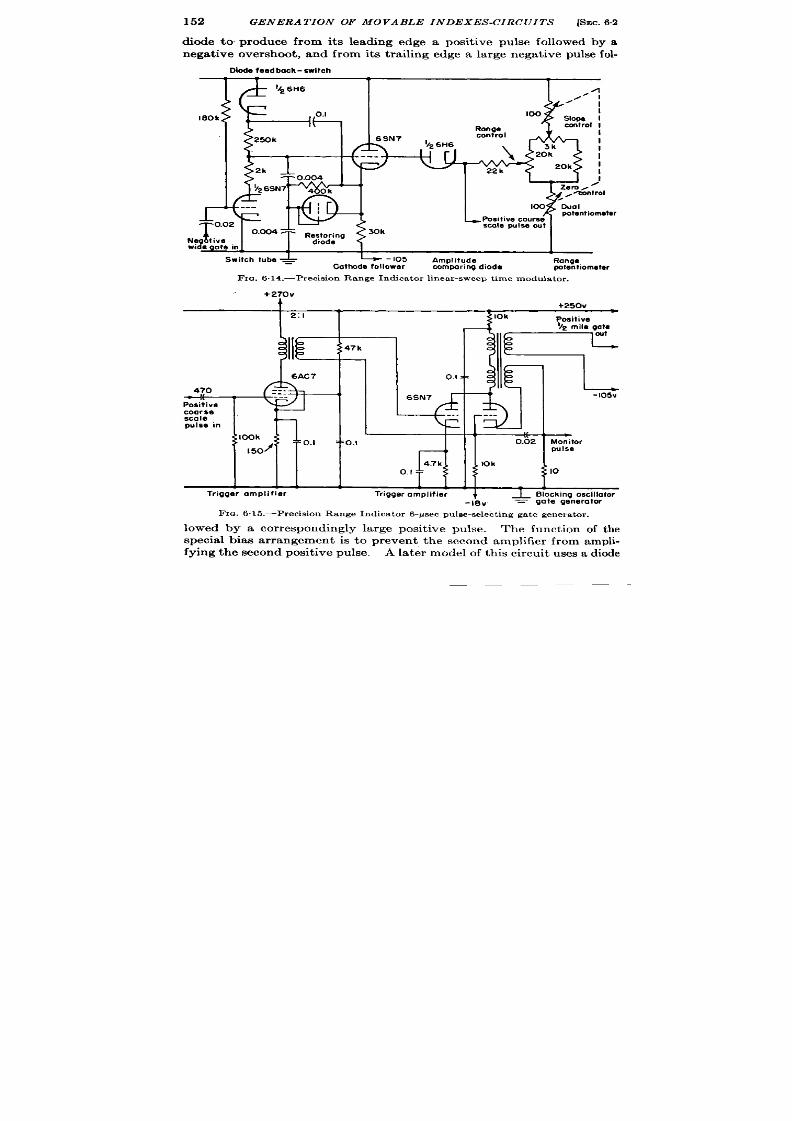
152
GENERA TION OF MOVABLE INDEXES-CIRCUITS [SEC. 62
diode to produce from its leadlng edge a posit ive pulse followed by a
nega t ive over shoot , and from its t r ailing edge a la rge negat ive pulse fol-
Dlode feed bock-switch
180k
I
I
100
Range
control
6SN7
Y* 6H6
100
- Posit ive course
T
0.02
0.CQ47 =
scale pulse out
Res;:;g
%%~%e i._
Switch tube ~
h -105
Amplitude
Cathode follower
Range
COmporirq diode
wtentiometw
FIG. 6.14.—Precis ion Range Indicator linear-sweep t ime modulator .
+270v
A
+250V
2:1
11!
:;47k
6AC7
0.1 z=
470
Positive
coarse
\ c
-. .
r
---
SCole
(
pulse in
~;100k
w
0.1
0.02 Monitor
I 50
pulse
IOk
o. I
T
10
—
-105’4
L
L 1
1 1
Trigger amplifier Trigger amplifier
J
~ Blocking oscillator
-IEIV
= gate generotor
FIG.6.15.—Precis ion Range Indicator 6-psec pulee-select ing gate generator .
lowed by a cor respondingly large posit ive pu lse. The funct ion of the
specia l bias a r rangement is t o preven t t he second amplifier from ampli-
fyin g t he secon d posit ive pu lse.
A la ter model of this circuit uses a diode
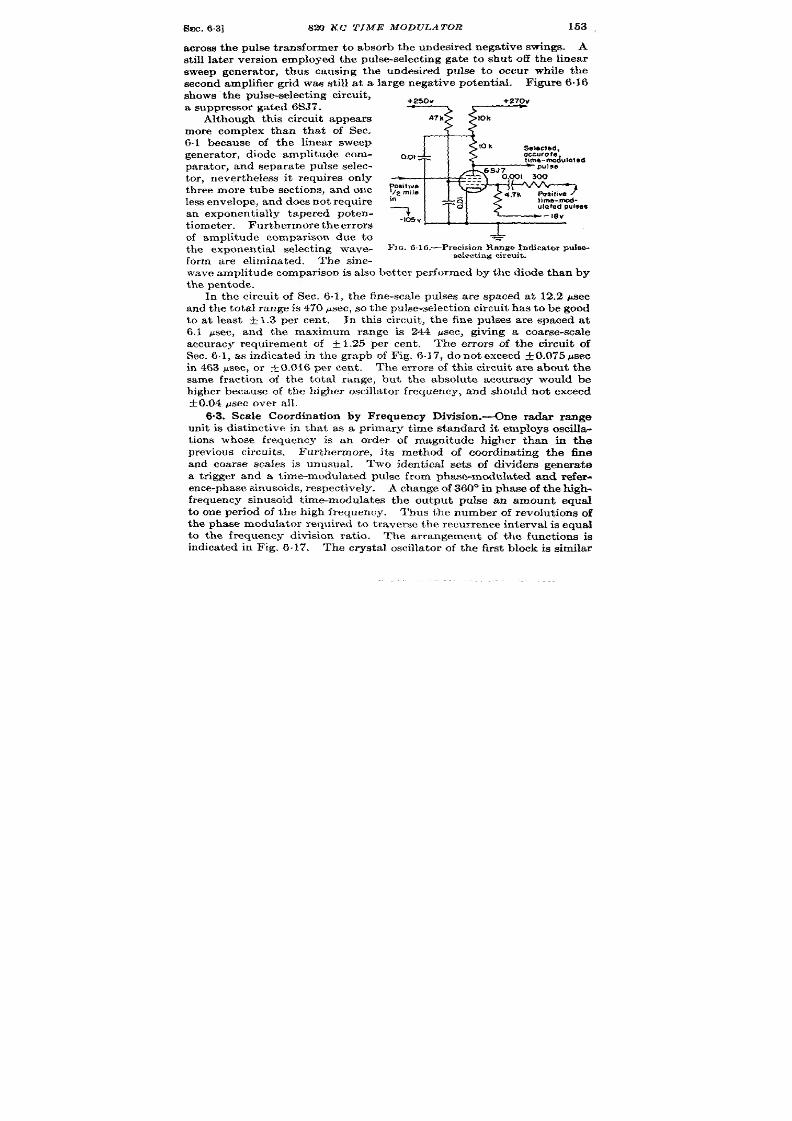
SEC.6.3]
820 KC T IME MODULATOR
153
across the pulse t ransformer to absorb he undesired negst ive swings. A
st ill la ter ver sion employed the pu lse-select ing gate to shu t off the linear
sweep gener a tor , thus causing the undesired p lse to occu r while the
second amplifier gr id was st ill a t a large negat ive poten t ia l. F igure 6.16
shows’ the pu~se-s elect ing cir cu it ,
a su ppr essor gated 6S37.
Although this circu it appear s
more complex than that of Sec.
6.1 because of the linear sweep
gen era tor , diode amplitude com-
par at or , an dsepar ate pulse selec-
tor , never theless it r equ ires on ly
th r ee more tube sect ions, and one
less en velope, a nd does n ot r equ ir e
an exponent ia lly tapered poten-
t iom et er . I?u rth ermor eth e er ror s
of amplitude compar ison due to
the exponen t ia l select ing wave-
form are eliminated. The sine-
0,01
~silive
/2 mila
in
)imb-mod-
7
ulated pulse9
-105”
j
=
FIG. 616, -P r ecis icm Range Ind ica t or puls e-
selecting circuit .
\ va ve amplit ude compa rison is also bet ter per formed by the diode than by
the pen tode.
In the circ it of Sec. 6.1, the fine-sca le pulses are spaced at 12.2 psec
and th e tota l range is 470 ~sec, so t he pu lse-select ion cir cu it ha s t o be good
to at least +1.3 per cen t . In thk circu it , the fine pulses a re spaced at
6.1 psec, and the maximum range is 244 ~sec, giving a coarse-sca le
accuracy requ irement of &1.25 per cen t .
‘I’he er ror s of the circu it of
Sec. 6.1, as indica ted in the graph of Fig. .17, do not exceed ~0.075 psec
in 463 ysec, or &0.016 per cen t .
The er ror s f th is circu it a re abou t the
same fract ion of the tota l r nge, bu t the absolu te accuracy would be
h igher because of the h igher oscilla tor frequency, and shou ld n ot exceed
+0.04 ~sec over all.
6“3. Scale Coordina t ion by Frequency Division .-One radar range
unit is dist inct ive in that as a pr imary t ime standard it employs oscill~
t ion s wh ose fr equ en cy is an order of magnitude h igher than in the
p revious cir cu it s. Furthermore, its method of coordina t ing the fine
and coarse scales is un ual. Two iden t ica l sets of divider s genera t
a t r igger and a t ime-modula ted pulse from phase-modula ted and refer -
ence-phase sinusoids respect ively.
A change of 360° in phase of the high-
fr equency sinusoid t ime-mo ula tes the ou tpu t pu lse an amount equal
to one per iod of the high frequency.
Thus the number of revolu t ions of
the phase modula tor requ ired to t raver se the recu rr ence in terva l is equal
to the frequency division ra t io.
The ar rangement of the funct ions is
indica ted in Fig. 6.17. The crysta l oscilla tor of the first block is similar

154
GENERA TION Of MOVABLE INDEXES-CIRCUITS
[SEC. .3
t o those previously shown. The phase modula tor is of the induct ive
gon iometer type and is coupled to the range dr iving motor .
Amplitude compar ison is per formed in this circu it by t he gr id-cu toff
character ist ics of a t r iode used as a squar ing amplifier . Thk pract ice is
r
1
ezok {see Sinusoidal
Time modulo?ad
crystal ,
*
frequency
oecillalor
divi er 200A
puke
A
,
Inductive
Sinusoidal
R.F switch
phase-modulator
*
frequency t riggef
divider 200A
Fr a. 6.17.—Blockdiagram of ra ngeunit usingph asemodulat ionand frequen cydivision.
p r fect ly rea son able at th is fr equ en cy sin ce a wh ole cycle is on ly 1.22 psec
and var ia t ions of 1 volt wou ld cause a sh ift of on ly 0.6 yd.
Mult ivibra tors a re used as pu lse-frequency dividers in the ra t ios of
4 to 1, t o 1, 5 to 1, and 2 to 1. The fir st th r ee employ tuned circu it s in
+250v
10k
{5
pp f
205-kc/sec
3900
56upf
FIG. 618. -Mt dt ivibr at or fr equ en cy di-
vider designed to opera te between 820 kc
and 205 kc, wit h t uned p la t e load for s tabih t y
of operat ion.
one pla te of the mult ivibra tor to
in cr ease t he stability of division .
F igu re 6.18 shows a ypical di-
vider circu it . The last st age of
frequency division is per formed
by a sca le-of-two cou nt er .
The unambiguity of the t ime-
modula ted pu lse relies on th e fact
that wh en t he power is fir st tu rn ed
on the mult ivibra tors are made to
divide in isochron ism with the
range coun ter set t o read zero
range. Before this is don , t here
exists a random probability that
any par t icu lar 820-kc/s c cycle
will be the on e that is isochronous
with the 4. l-kc/see t ime-modu-
la ted pu lse.
The method of cali-
bra t ing is to set the range coun ter
t o zero and couple the first t h ree
pair s of dividers together . If these dividers opera te undisturbed aft er
the couplin is removed, ther e wil resu lt a t ime modula t ion between the
un mbiguous for 200 revolu t ions o the phase-modula t ing goniometer .
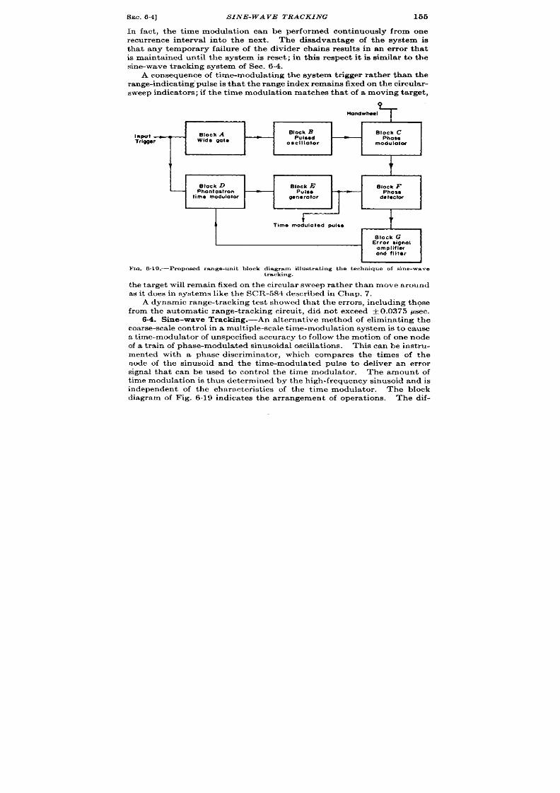
SEC. 6.4]
SINE-WAVE TRACKING
155
In fact , t he t ime modula t ion can be per formed cont inuously from one
r ecur r ence in t erva l in to the next .
The disadvantage of the system is
tha t any tempora ry fa ilure of the divider cha ins resu lt s in an er ror tha t
is main ta ined unt il t he system is reset ; in th is respect it is similar t o the
sin e-wa ve t ra ckin g syst em of Sec. 6.4.
A consequence of t ime-modula t ing the system t r igger ra ther than the
r an ge-in dica tin g” pu lse is t ha t t he r an ge in dex r emain s fixed on t he cir cu la r-
sweep ndica tors; if the t ime modula t ion matches tha t of a moving ta rg t ,
,?
Ondwhael
Input _
Block A
Block B
Block C
Pu18ed
Trigger
Wide gate
Phow
Osclllotor
modulator
I
i t
BIock F
Phose
da tOCIOI
t
t
-1
Block G
Error signal
amplifier
and filter
b
F IG. 6.19.—Proposed r ange-un it block diagr am illu st ra ting t h e t echn ique of s in e-wave
tracking.
the target will remain fixed on the circu lar sweep ra ther than move around
as it does in systems like the SCR-584 clescr ibed in Chap. 7.
A dynamic range-t racking test showed that the er rors, including thos
from the automat ic range-t acking circu it , did not exceed f 0.0375 gsec.
6.4. Sine-wave Tracking.-An a lterna t ive method of elimina t ing the
oarse-scale con trol in a mult iple-scale t ime-modulat ion system is t o cause
a t ime-modulator of unspecified accuracy to follow the motion of o e node
of a t ra in of phase-modu ated sinusoidal oscillat ions.
This can be inst ru-
mented with a phase discr iminator , which compares the t imes of the
node of the sinusoid and the t ime-modulated pulse to deliver an er ror
s gnal that can be used to con t rol the t ime modulator .
The amount of
t ime modulat ion is thus determined by the h igh-frequency sinusoid and is
independen t of the character ist ics of the t ime modu a tor .
The block
diagram of Fig. 6.19 indicates the ar rangement of operat ions. The dif-

156
GENERA TION OF MOVABLE INDEXES-CIRCUITS
[SEC. 6.4
ficu lty with the system is that the phase discr imina tor cannot dist inguish
one node from another . Thus a momenta ry power fa ilu re or disturbance
is liable to in t roduce a gross er r or .
s in the system of Sec. 6.3, no indi-
ca tion of t he exist en ce of t he gr oss er ror is r ovided.
A modifica t ion that would automat ica lly remove gross er rors can be
descr ibed br iefly ,by saying that an accura tely linear t im modula tor is
employed in the above system, and its con t rol voltage as fixed by the sine-
wave tracking opera t ion is con t inuously compared with that of a linear
poten t iometer having the same voltage range. The poten t iometer is
mate, but absolute, indicat ion of the t ime modula t ion indica ted by the
dia l. If the linear- t ime-modula tor con t rol voltage differs from that of
51k 50k
=
Phase shifted
oscillations in
~
>
=
, : , ,
0.001 0“ ‘
=
=
FIG. 6,20 .—Phase detector and er ror -s igna l amplifier of proposed s ine-wave t racking t ime
modulator.
the poten t iometer by an amount grea ter than th t r equ ired to displace the
t ime modula tor by half a cycle of the sinusoid, a relay closes and con-
nects the t ime-modu la tor con t rol voltage momentar ily to the poten t iom-
eter , thus br inging the pu lse ba k t the cor rect node.
It is thus seen that the pursu it of this method to a poin t of reliable
design yields a system closely para llel to th systems of Sees. 6.1 and 6.2.
The accuracy of the pu lse is limited in the la t ter systems by the stability
of the opera t ions of, amplitude compar ison and pu lse select ion , in the
former by the stability of the phase discr iminator . The on ly economy of
sine-wave t racking is the eliminat ion of the circuit s for genera t ing pulses
fro the sinusoid.
The two circu its r equ ired by th is method of t ime modula t ion tha t
have not been descr ibed previously are the phase detector and the er ror -
signal amplifier and filter . They are illust rated in Fig. 6.20. A complete

SEC. 6.5]
THRJ7E -SCA I.E ISYSTEM
157
discussion of a utomat ic t ime-modu la tion systems is con ta in ed in Ch aps.
8 and 9 in connect ion with automat ic t ime measurements. Time dis-
cr imina tors are also t rea ted in Chap. 14, Vol. 19.
-
93-kc)sec
m
Quadrature
93-kclsec
oscillator
network
phase
modulotor
+
I
t
93 to
Quadrature
9.3.kclsec
9.3kclsec
*
djvlder
network
phase
modulo!or
.
L
~
0
1
9.3-kc/see
b
Ouadroture
930-cps
to 930-cps
phase
dlvbc!er
network
-
modulotor
1
1
FIG. 6.21.—Block diagram of AN/APN-3, Shoran, t ime-measur ing circnite .
D
_ Panel of timing unit
FIG. 622.-Gea r in g mechan ism of AN/APN-3, Shor an.
6.5. Th ree-sca le Ph ase-modulat ion System .-Shora n o AN/APN-31
is an example of a three-sca le phase-modula t ion system.
The coa rsest
sca le covers 100 miles in a phase modula t ion of 360° to select one cycle
of the second scale. The second sca le of 10 miles per revolu t ion in turn
select s on e cycle of t he fin e sca le, wh ich gives da ta a t 1 m ile per r evolu tion .
1AN/APN-3 manual; RCA, Industry Serv ceDivision, J an. I&M.
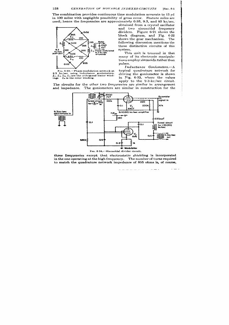
158 GENERA TION OF MOVABLE INDEXES-CIRC ITS
[SEC.65
I
The combina t ion provides con t inuous t ime modula t ion accura t e to 13 yd
in 100 miles with negligible possibility of gross er ror .
Sta tu te miles a re
used; hence the frequencies a re approxima te y 0.93, 9.3, and 93 kc/see,
obt ain ed fr om a cr yst al oscilla tor
f
and two sinusoida l fr equency
dividers. Figure 6.21 shows the
block diagram, and Fig. 6.22
shows th e gea r mechanism.
Th e
L
followin g discu ssion men tion s t he
th ree dist inct ive circu it s of thk ;
i
kc/see
system.
push-pull
This unit is nusua l in tha t j
many of it s elect ron ic manipula- i
t ions employ sinusoids ra th r than ~
0.02
pulses.
&
In du ct an ce Gon iomet er s.-A
FIG.6,23.—Phase-modulation network at
typical quadra tu re network for
9.3 kcleec u gin g in du ct an ce gon iomet er s.
Lt. L:, LJ, LJ are t he or thogona l ~t a tor wind -
dr iving the goniometer is shown
ings. L, i n the rotor winding.
in Fig. 6.23, wh re the va lues
apply to the 9.3-kc/see cir cu it .
The circu it s for the other two frequencies a re simila r in ar rangement
and impedance. The goniometer s a re similar in const ruct ion for the
Scmmbler
9,3 kc /wc
osclllallons In
+Em
9/10(93) kclsec omPlifier
-
IIT a
c
B+
= :2201Jpf
,
0.1
[
4
Tuned drcuit
40.1
!
4
311
f::::o[93)
I
0.5
m
‘ !311c
9.3kc&c
out
* Modulatoc
Fm. 6.24.—Shmsuidal divider circuit .
t h ree frequencies except tha t elect rost a t ic sh ielding is incorpora ted
in the one opera t ing a t the high frequency. The number of turns required
to match the quadra ture network impedance of 855 ohm is, of cour se,
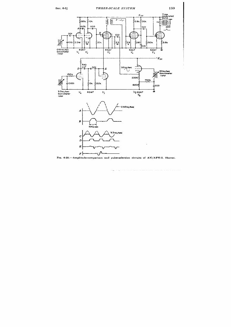
SEC. 65]
THREE-S CALE S YS TEM
159
d
390
D -i(-T-11
##f
0.01
*‘E
)50 k
---
---
II
‘iI {
/
15k
150k
I
I
‘Epp
H
50k
820
~ .01
93kc/sec
‘6
6SN7
v,
~Z6SN7
4
Goniometer
rotor
v*
\
‘w’””’
‘l-cl-’-
loo/Jsec
E
.
\ // ‘\
,f’\ 9.3kc/80c
c
D
E
F
Fva. 6.25.—Amplitude-compar iacm and pu lse-select ion cir cu it s of ANfAPN-3 . Shoran ,
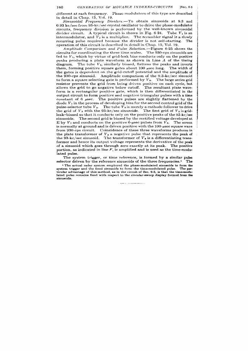
160
GENERA TION OF MOVABLE INDEXES-CIRCUITS
[SEC. 6.5
differen t a t each frequency. Phase modula tor s of th is type are descr ibed
in deta il in Chap. 13, Vol. 19.
Sinusoidal Frequencg Dividers.—’To obtain sinusoids a t 9.3 and
0.93 k c/see fr om 3-k c/see cr yst al oscilla tor t o dr ive t he ph ase-modu la tor
circuit s, fr equency division is per formed by the well-known sinusoidal
divider circuit . A typical circuit is shown in Fig. 624. Tub VI is n
in termodu la t or , and V2 is a mult iplier .
Th e scr ambler signal is a slowly
recur r ing pulse requ ired because the divider is not self-st ar t ing. The
opera t ion of th is circuit is descr ibed in detail in Chap. 15, Vol. 19.
Amplitude Compa rison a nd Pulse Select ion .—F igu re 6.25 sh ows t he
cir cu it s for coor din at in g t he t hr ee t im e sca les.
The 930-cps sinusoids a r e
fed to VI, which by vir tue of gr id-leak bias conduct s only on the posit ive
peaks producing a pla te waveform as shown in Line A of the t iming
diagram. The tu e Vz, similar ly biased, fla t t ens the peaks and inver ts
them, forming posit ive square ga tes about 100 psec long. The width of
the gates is dependen t on the gr id-cutoff potent ia l and the amplitude of
the 930-cps sinusoid Amplitude compar ison of the 9.3-kc/see sinusoid
to form a square select ing gate is per formed by Vs. The la rge ser ies gr id
resistor preven t s the gr id from being dr iven posit ive on each cycle, but
a llows the gr id to go negat ive below cutoff.
The result ant pla te wave-
form is a rectangu lar posi ive ga te, which is then different ia ted in the
outpu t ir cu it to form posit ive and negat ive t r iangular pulses with a t ime
constan t of 6 ~sec. The posit ive pu ses ar e slight ly fla t t ened by the
diode Vr in t he pr ocess of developin g bias for t he secon d cont rol gr id of t he
pu lse-selector tube Vs. The tube VE is mer ely a ca th ode follower t o dr ive
the gr id of VS with the 93-kc/see sinusoids. The fir st gr id of Va is gr id-
leak–biased so t hat it con duct s on ly on t he posit ive peaks of th e 93-kc/see
sinusoids. The second gr id is biased by the rect ified voltage developed at
E by V, and conduct s on the posit ive 6-psec pulses from V,. The screen
is normally a t gr ou nd and is dr iven posit ive with t he 100-psec square wa ve
fro 930-cps circuit . Coincidence of these t hree waveforms p oduces in
the pla te t ransformer of Vf a negat ive pulse that represen t s the peak of
the !33-kc/sec sinusoid. The t ransformer of Va is a differen t ia t ing t rans-
former and hence it s ou tput volt age represen t s he der iva t ive of the peak
of a sinusoid which goes th rough zero exact ly a t it s peak. The posit ive
por t ion , as indica ted in line F, is amplified and is used as t he t ime-modul-
a ted pulse.
The system t r igger , or t ime refer ence, is formed by a similar pulse.
selector dr iven by the r efer en ce sinu oids of the th r ee frequencies. 1 The
1The actual radar sys tem employed the phas~modula ted s inusoidsto form the
system t r igger and the fixed sinusoidsto form the t ir e-modula ted pulse. The par -
t icu la r advan tageof th is method , as in the circu it of sec. 6.3, is tha t the t ime-modu-
lated pulse remains fixed with respect to th e circular-sweepdisplay formedfrom the
sinusoids.

SEC. 66] SCR-584 TIME MODULATOR
161
resu ltan t system has the advantage, simila r to tha t of Sec. 6.3, of being
able to t ime-modula te cont inuously from one recu r rence in to the next if
t he r ange-in dica tin g dia ls a re pr oper ly design ed,
The Shoran system illust ra tes the ease of increasing the number of
sca les in order to ach ieve grea ter accuracy or grea ter reliability. In h is
circu it , the inductance goniometer has an accu racy of about +7* pa r ts
per thousand, causing a + 0.08-Psec er ror ; th e indica tors provide reset ta -
bilit y of 0.02 psec. Th s is sligh tly h igher than the er rors of the system
of Sec. 6.1, bu t the use of th ree sca les means tha t each of the coarse
sca les need only have an accu ra y of 5 per cen t The resu ltan t fu ll-scale
accu acy is * 7.5 X 10⁻³ per cent .
If the designer had wished, on the
oth er hand, t o wor k with closer tolera nces and achieve h igher accu a cies,
he might have employed frequency ra t ios of 50 to 1 and sta r ted a t 93o
kc/see, dividing down to 37o cps. In this way he might have measured
f 0.008 psec out of 2640, or th ree par ts per million, if the 930-kc/sec
cryst al oscilla tor a nd t he r eceiver ban dwidth wer e a dequ ate.
CIRCULAR-SWEEP DISPLAYS AS A METHOD O PHASE MODULATION
AND AMPLITUDE COMPARISON
As is poin ted ou t in Chap. 3 of this volume and in Chap. 13, Vol. 19
of the Ser ies, the circu la r sweep or any linear display may bec me a
t ime modula tor if a mechanica l index i moved a long the display in a
linear fash ion. The processes of phase modula t ion and amplitude
compar ison are then per formed by the rota t ion of the index and the
passage of the elect ron beam past the poin t tha t the index marks. A
sin gle-sca le cir cu la r-sweep syst em mer ely in volves on e r evolu tion of t he
elect ron beam around the circle between each t r igger .
If the circu la r
sweep is to be used in a mult iple-scale system, the elect ron beam must ,
t raverse the circle severa l t imes.
Pulse select ion is ca rr ied out bv
in tensifying, with a t ime-modula ted ga te, one of the severa l circles. Thi
mechanica l index d fines the t ime-modula ted instan t in tha t selected
circle.
6.6. Circu la r-sweep Time Modula tors, SCR-564.-AII example of
this tech niqu e is t he r an ge u nit of t he SCR-584, 1a widely u sed fire-con tr ol
radar . This uses a two-sca le t ime modula tor with an 82-kc/see (2000-yd)
circu la r swe p as the fine sca le, and a delay mult ivibra tor (Sec. 5.10)
to select one par t icu la r cycle of the sweep. The block diagram of Fig.
6% illust ra tes th e ar rangement .
A cryst al oscilla tor pr ovides qu adra -
tu re voltages for the circu la r sweep and 12,2-Ksec pulses for the mult i-
}ibra t or divider and t r igger selector . The division is from 82 to 16 to 5.1
to 1.7 kc/see. The ou tpu t square wave from the 5. l-kc/see mult ivibra tor
I A descr ipt ionof the circuitsof this system has been writ ten in ‘‘Elect ronicWar
Reporte,”Ekz4runics, 19, 2, (Feb. 1946).
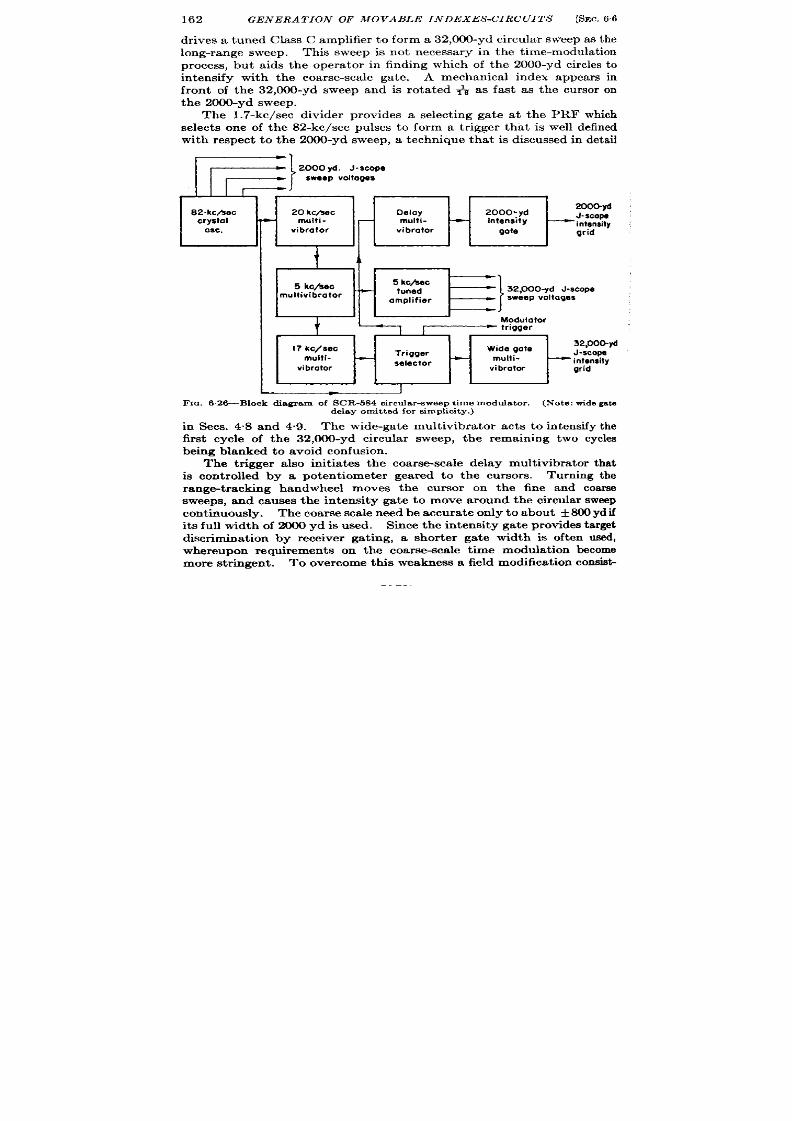
162
GENERA TION OF MOVABLE INDEXES -CIRCUITS
[SEC. 66
dr ives a tuned Class G amplifier t o form a 32,000-yd circu lar sweep as the
long-range sweep. This sweep is not necessa ry in the t ime-modula t ion
process, b t aids the opera tor in finding which of the 2000-yd circles to
in tensify with the coarse-sca le gate. A mechanica l index appears in
fron t of the 32,000-yd sweep and is rota t ed & as fast as the cursor on
t he 2000-yd sweep.
The 1.7-kc/sec divider provides a select ing gate a t the PRF which
selects one of the 82-kc/see pulses to form a t r igger tha t is well defined
with respect t o the 2#0-yd sweep, a techn ique that is discussed in deta il
1+
‘}
2000 yd. .t -scopO
sweepVoltoge$
82-kc,4ec
20 kc/see Oelay 20 0. yd
200Gyd
crystal
-
multi- multi-
-
intensity
J-SCOW
Osc.
‘intsnsity
vibrator vi brotor
gote
grid
+ d
1
5 kc/see
5 kc/eec
.
tuned
?}
32,000-yd J -scope
multivibrator
amplifier
sweep voltages
t
Modulator
L
trigger
<
17 kc/see
Wide gote
32,000-yd
multi.
Trigger
J-scope
- -
selector
multi-
— intensity
vibrator
grid
I
F IG. 6.26-B1ock dia gr am f SCR-6S4 cir cu la r -sweep t ime modu la t or . (Not e: wid egate
delay omit ted for s implicity .)
in Sees. 4.8 and 4.9. The wide-ga te mult ivibra tor act s t o in tensify the
fir st cycle of the 32,000-yd circula r sweep, the remaining two cycles
being bla nked t o a void confusion .
The t r igger a lso in it ia tes the coarsesca le delay mult ivibra tor tha t
is con t rolled by a pot en t iometer gear ed to the cursors.
Turn ing the
range-t racking handwheel moves the cur sor on the fine and coarse
sweeps, and causes the in tensity ga te to move around the cir u lar sweep
con t inuously. The coarse sca le need be accura te on ly to about +800 yd if
it s full width of 2000 yd is used. Since the in tensity ga te provides ta rget
discr iminat ion by receiver gat ing, a shor ter ga te width is oft en used,
whereupon requ irements on the coarse-sca le t ime modula t ion become
more st r ingent . To over com e th s weakness a field modifica t ion consist -

SEC. 6.6]
SCR-584 TIME MODULATOR 163
ing of a phase modula tor dr iven by the 82-kc/scc sinusoid was con nected
t o t he r an ge sh aft t o pr ovide ph ase-sh ift ed pu lses, on e of wh ich is select ed
by the CRT in tensity ga te as a shor t r eceiver gate.
This addit ion r emoves t he m ar ked disadvan tage of t ime modu la t ion by
cir cu la r-sweep pha se modu la t ion , t hat n o pu lse is gen er at ed at t he inst an t
cor responding to the posit ion of the fine mechanical index.
The HR
radar system is very similar t
t he SCR-584 and is descr ibed in
Sec. 7.26.
Wurzburg Range Unit. —Re-
por t s indicate that t he Germ n
Wurzburg fire-con t rol radar em-
ployed a type of t ime modula tor
very similar t o the SCR-584. The
basic difference is that in the
Wurzburg the coarse-sca le t ime
modula t ion is provided by phase
modula t ion and amplitude com-
par ison at 3.7 kc/see, instead of
by a delay mult ivibra tor . Both
the PRF and the long-range cir -
cu lar sweep as well as the quadra-
tu re voltages for the phase
modula tor a re formed from the
3.7-kc/see sinu soids. This makes
the wide in tensity ga te unnec s-
sary since an r -f pu lse is sen t ou t
Slock A
60 kc/see
~)
2.5km
Ktal
J-scope sweep
oscillolor
t
+—J
Y
lock C
Gonlomeler
Slock D
Narrow
phose
shifter
gate
F IG. 6,27.—Block d ia gr am
range un it .
Intensity grid
* of 2.5 hm
scope
Inlensily grid
wof 40km
scope
of Wurzburg
each t ime the 3.7-kc/see sweep makes a revolu t ion .
F igu re 6.27 is a
block diagram of the system.
The SCR-718 Alt imeter . -Although not exact ly a mult iple-scale
un it in the same sense as the SCR-584 and the Wurzburg, t he SCR-7 8
alt imeter offer s a novel approach to the two-sca le techn ique. This
unit measures absolu te alt i ude over the ter ra in below an a ircra ft by
the same pulse techn ique as those used in ordinary radar sets. It s
fin e-sca le r an ge-mea su rin g device is a J -scope; a complet ely in depen den t
in st rumen t, t he ba romet ric a lt imeter , su ffices as t he coa rse scale.
The sweep per iod of the J -scope is 5000 ft , and accordingly requ ires
a 98.4-kc/see crysta l oscilla tor . Neither in tensity ga tes nor moving
hair lines a re provided, on ly rad al calibra t ion marks. Reading on ly
from the CRT scale wou ld give ambigu it ies of 5000 feet . The barometer
is accu ra te enough to resolve the ambigu it ies. Heigh ts accura te to
30 ft should be obtainable with this combinat ion of equ ipment . Another
model of th is a lt imeter provides a switch to change the sweep per iod

164
GENERA T ION OF MOVABLE INDEXES -CIRCUITS [S EC.6.7
from 5000 to 50,000 ft in order to avoid reliance upon the baromet r ic
altimeter.
STEP-INTERPOLATION TIME MODULATION
Th e following sect ion s descr ibe systems in wh ich t he t ime modu la tion
is per formd in la rge steps, with an in terpola t ing t ime modula tor to
provide cont inuous modula t ion over th e in tervals between steps.
6s7. AN/APS-15 Range Unit .-This system represen ts an im lemen-
ta t ion of the step-in terpola t ion method of mult iple-scale t ime measure-
ment ou t lined in Sees. 3.9, 3.14, and 3.15. The specifica t ions call for
t ime modula t ion over 2240 psec, accura te to f 0.38 psec, and cont inuous
t ime modula t ion over any 125-psec in terval .Fur thermore the PRF
t r igger must be supplied by the range unit .
I
I
I
t t
~uwerneosuring
Sweep
trigger
Fm. 6.28.—AN /APS-l 5 range-un it block d iagram.
The phantast ron circu it descr ibed in deta il in Sec. 5.5 is used both for
the step-delay and the in terpola t ing t ime modula tors, with appropr a te
circu it va lues .
The display used for t ime measurement is one in which the t im~
measur ing pulse appears as an intensity modula t ion on an oscilloscope
sweep of about 20 miles durat ion .
This sweep is in it ia ted by the same
selected ulse as that which in it ia tes the in terpola t ing phantast ron .
Shown in Fig. 6.28 is a simplified block diagram of the AN/APS-15 range
unit . Reference should be made to Fig 6“29 to consider the t iming
sequence in the var ious blocks of F ig. 6.28.
The circu it of the t iming wave genera tor is F ig. 6.30. An 80.8&
kc/see crysta l oscilla tor genera tes cu r ren t pu lses which t r igger the
blocking oscilla tor VZ th rough the pulse t ransformer . Blocking oscil-
lator Va t hen su pplies n ega tive pulses spa ced at 10.75 psec, wa v form A,
a cr oss t he 120-ohm plate r esistor ,
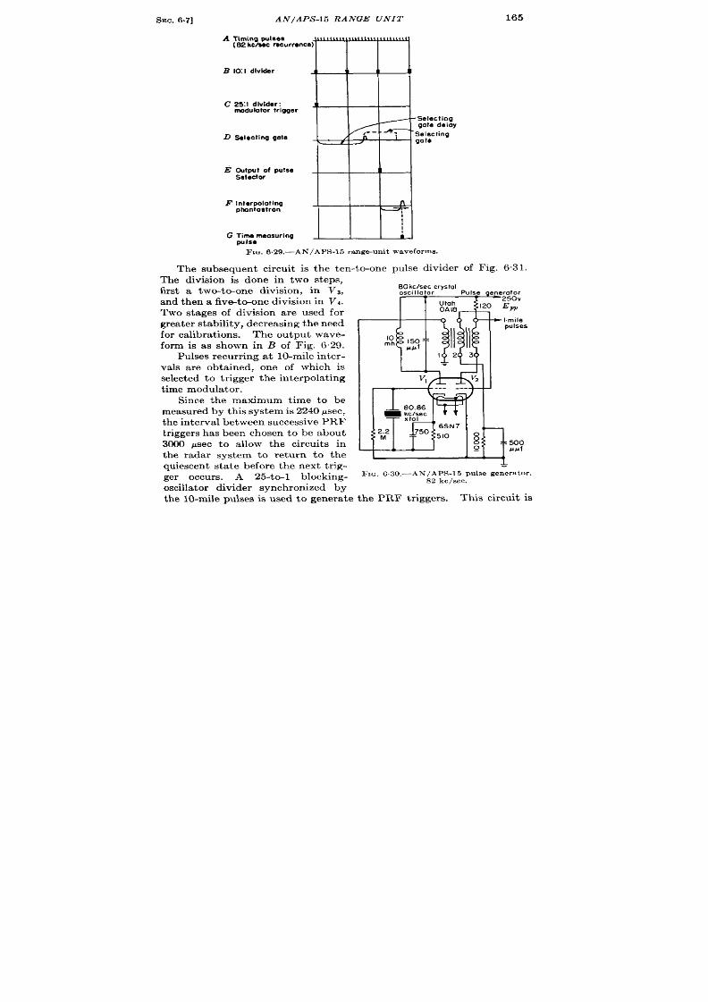
SEC. 6.7]
AN / APS -15 RANGE UNIT
165
A
Tim{ng pukes
(82 kc/eec recurr emca)~
B 10 I divider
~
.
C 2S1 dlvlder:
J
modulotor trigger
-Selecting
gote delay
,. -
. .,
D Selecting gate /
n
--T-- Selecting
L
P
J
gate
E Output of pulse
Selector
F Interpolotlng
n
ptuantastron
q
o
I
I
G ;i,emeosuring
b
FXQ.6.29.—AN /APS-l 5 ra nge-un it waveforms.
The subsequen t circuit is the ten -to-one pu lse divider of Fig. 631.
The division is done in two steps,
fir st a two-to-one division, in Va,
and t hen a five-t o-on e division in Vd.
Two stages of division are used for
for calibra t ions. The outpu t wave-
form is as shown in B of Fig. 629.
P ulses r ecu rr in g a t 10-m ile in ter -
vals a re obta ined, one of which is
select ed t o t rigger t he int er pola ting
t ime modula tor .
Since the maximum t ime to be
mea su red by t his syst em is 2240 ysec,
t he in ter va l between su ccessive PRF
t riggers has been chosen t o be about
3000 psec to a llow the circuit s in
th radar system to return to the
quiescent sta te before the next t r ig-
ger occurs. A 25-to-1 blocking-
w I.mile
pulses
FIG. 630,-AN / APS-15 pu lse gen er at or ,
S2 kclsec.
the 10-mile pulses is used to genera t e the PRF t r iggers. This circuit is
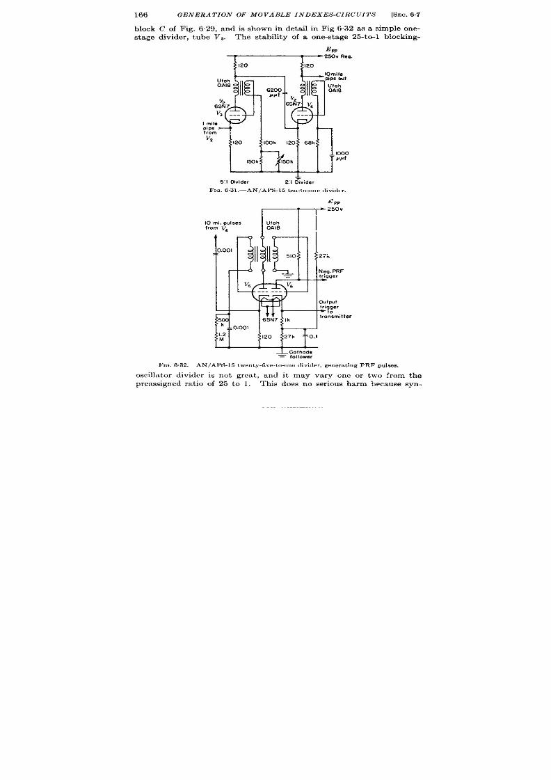
166
GENERA TION OF MOVABLE INDEXES-CIRCUITS
[SEC. 6.7
Mock C of Fig. 629, and is shown in deta il in Fig 632 as a simple one-
stage divider , tube V5. The stability of a one-stage 25-to-1 blocking-
Ew
Uloh
0A18
Imile
pips
from
V2
l~k
&
5:1 Divider
2:1bwider
FIG. 6 .31 —AN/APS-l5 ten-to-one divid t r .
FIG. 6.32.–
~PP
10
fro
ier
= follower
–AN/APS-15 twenty-five-to-o,w divider , generat ing
PRF pu lses.
oscilla tor divider is not grea t , and it may vary one or two from the
preassigned ra t io of 25 to 1. This does no ser ious harm because syn-
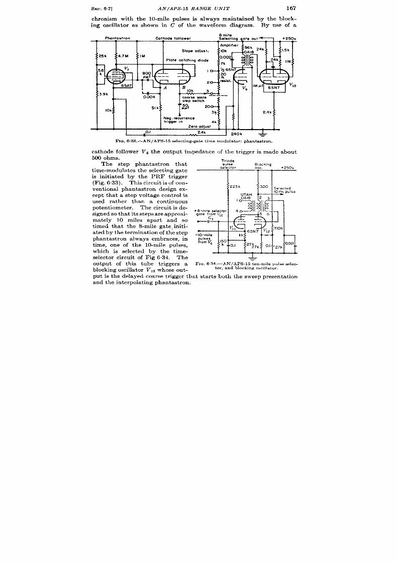
SEC. 67]
AN/APS-15 RANGE UNIT
167
chron ism with the 10-mile pulses is a lways mainta ined by the block-
ing oscillator as shown in C of the waveform diagram.
By use of a
8 mile
Phanlastron Cathode follower
Selecting gate out —
+250V
rn
.5k
I
Neg.ehrence
triggerin
4k
Zero &ju t
111. I
0.1 2.4k
240h &
Fm. 6.33.—AN/APS-l 5 select ing-ga te t ime modula tor : phantast ron .
ca thode follower Vb the outpu t impedance of the t r igger is made about
500 ohms.
The step phan tast ron that
t ime-modu la tes t he select in g ga te
is in it iat ed by the PRF t r igger
(F ig. 6.33). This circuit is of con-
ven t ional phantast ron design ex-
cept that a step voltage cont rol is
used ra ther than a cont inuous
poten t iometer . The circu it is de-
sign ed so t ha t it s st eps a re a ppr oxi-
mately 10 miles apar t and so
t imed that the 8-mile gate, in it i-
a ted by the terminat ion of the step
phantast ron alwa s embraces, in
t ime, one of the 10-mile pulses,
which is selected by the t ime-
selector circuit of Fig 6.34. The
outpu t of th is tube t r iggers a
block in g oscilla tor V,* whose ou t-
Tried.e
pulse
Slocking
selector
Osc, +250v
I
II
UTAH
+ S-rode selector 4
gate f$m l~o
-[ ‘
T
v
11
+
-l O-mile Ik
*
FIG.6.34,—AN/APS-15 ten-mile pulse selec-
tor , and blocking oscilla tor .
pu t i the delayed oarse t r igger that star t s both the sweep presenta t ion
a nd t he in ter pola tin g ph an ta st ron .
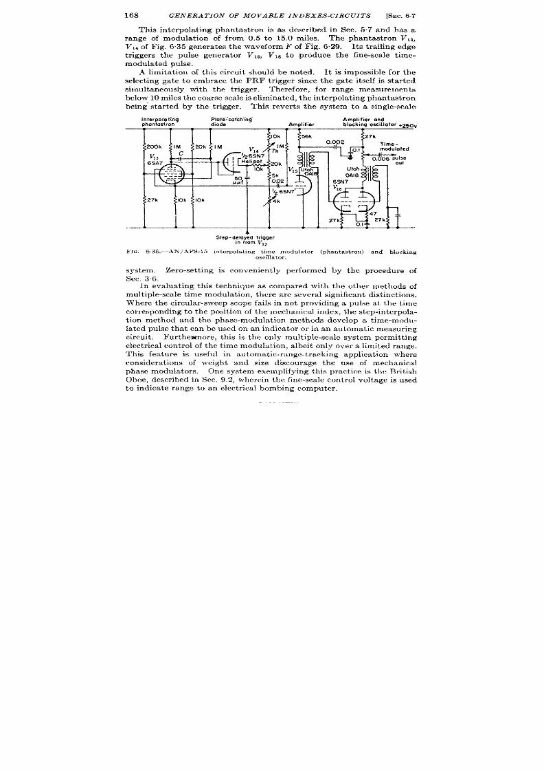
168
GEN ERA TION OF MOVABLE IN DEXES -CIRCUITS
[SEC. 67
This in terpola t ing phantast ron is as descr bed in Sec. 5.7 and has a
range of modulat ion of from 0.5 to 15.0 miles. The phantast ron Vlq,
V,, of Fig. 6.35 genera t es the wa veform F of Fig. 6.29. Its t ra iling edge
t r iggers the pulse gene a tor Vls, VILI t o produce the fine-sca le t ime-
modu la ted pu lse.
A limita t ion of th is circu it should be noted.
It is impossible for the
selec ing ga te to embrace the PRF tr igger since the a te it self is sta r ed
simultaneously with the t r igger .
Therefore, for r an e measurements
below 10 m iles t h e coa r se sca le is elim in at ed, t h e in ter pola tin g phan ta st ron
being’ sta r ted by the t r igger . This rever t s the system to a single-sca le
-—
terpoloting Plote~coichihq-
Amplifier and”
mntostron
diode
Amplifier blocking oscillator +250V
4
Step - delayed trigger
in from V12
~lG. 6.35.—.4APSP15l5 in ter pola tin g t im e modu la tor (ph an ta stmn ) a nd blockin g
oscillator.
system. Zero-set t ing is convenien t ly per formed by the procedure of
Sec. 36.
In eva lua t ing th is technique as compared with the other methods of
mult iple-sca le t ime modu la tion , t h er e a r e sever al sign ifica nt dist in ct ion s.
Where the circu la r -sweep scope fails in not providing a pulse a t the t ime
cor respondin g t o t he posit ion of t he me h an ica l in dex, t he st ep-in ter pola -
t ion method and the phase-modulat ion methods develop a t ime-modu-
la ted pulse tha t can be used on an indica tor or in an automat ic measur ing
circu it . Fur thewnore, this is the only mult iple-scale system permit t ing
elect r ica l cont rol of t he t ime modula t ion, a lbeit on ly over a limited range.
This fea ture is useful in au tomat ic-range-t racking applica t ion where
considera t ions of weight and size discourage he use of mechanical
phase modula tors. One system exemplifying th is pract ice is the Brit ish
Oboe, descr ibed in Sec. 9.2, wherein t he fine-sca le con trol voltage is used
to indica te rang to an elect r ica l bombing computer .

&JC.6.8]
LIGHT WEIGHT LORAN INDICATOR
169
A fur ther example of th is method, which illust ra tes the use of severa l
in terest ing circu it s, is the range unit tha t was designed for the revised
AN/APS-10. This cir cu i is descr ibed in Sec. 4.9 with a complete
cir cu it d iagram.
20kc/cec
_D_
Condenber *
Amplitude
LC OSC.
phase
modula!or
comparator
I
L_____
Manual
~----- ------ ~------
control and
I
1
counter
2-kc/eec
10: I divider
[
Step
Continuous
pulses
potentiometer
potentiometer
A
1
F
PRF
B
Stap-deloy
L
Pulse
50010
pulse selecting
G
divider
25,000 p sec
selector
phontostron
time
modulated
2.kc/sec
pulses
PR F pulse
Selected
pulse
2.kc/sec
pulses
2@kc/sec
sinusoid
Phose
modulo?ed
sinusoid
20.kc/sec
pulses
Pulse
phontosl~on
Pedestal
pulse
A 11111111111111 l)[ljjfllllllll} Illll[jljllll[lll
1(
!!
B i
II
II
c
81
1
..” ---~%
.<,
---
.-
--..
.-
-.. .
A 1’0
---
1
I
I
G J—j
I
I
I
H.
Fm. &3&-Block and t iming diagram of the ligh tweigh t direct -reading Loran t ime
modulator.
6.8. Lightweigh t Direct -r eading Loran I dica tor .—Cer ta in ly the
best example to da te of a three-sca le t ime-modula t ion system is the
ligh tweight dir ect -reading Loran indica tor . Designed for a irborne use
and in tended to provide t ime modula t ion from 500 to 25,000 ~sec with
an accuracy of 1 psec, the system employs a step delay to select an

170
GENERA TION OF MOVABLE INDEXES-CIRCUITS
[SEC. 6.5
a ccu ra tely t im e-modu la ted t rigger t o in it ia te a two-sca le t im e modu lat or
t o in ter pola te between t he steps.
Th e two-sca le t ime modu la tor employs
phaae modulat ion and pulse select ion as in the circu its descr ibed in
Sees. 6“1 and 6“2. The circu it techn ique represen ts the most recen t
pract ices and uses subminiature tubes and other componen ts that allow
the circuit to be built on small subassemblies, each represent ing a func-
t ional unit of the circu it . Repair of the t ime-modulat ion unit then
involves only loca t ing the faulty subassembly and replacing it in its
entirety,
The block diagram and the t iming diagram are shown in Fig. 6.36.
The divider circuits are discussed in Sec. 4.11 and the use of the system
20.kc/ssc sinusoids from V,,
w “’m “ ’
= A20
I
.-0”
Ccthode followsr
Amplifier Blocking oscillator
u
6K4
_ 6AK5 +300v
6C4
910 2k
3.9k
)#Jlf
Three-phass
—
4,
7.511 2.6k aoom
condenser
phass-modulotor
25k: F
25 k
---
I
.lo5v+y’f-y#
cko2
Fx~. 6.37.—Pha se modu la tor of ligh tweigh t dir ect -r ea dh g Lor an t im e modu fa tor
This circu it provides three phasevoltages from a 20-kc s ingle-phase s inusoid . A condenser -
t ype ph ase modu la tor pr ovides a ph ase-modu la ted sin usoid t o t h e ca th ode foUower a nd
amplifier VM and Vm ,whose output synchronizes the blocking oscillator VIO.
M a t ime-measur ing inst rument is dkcussed in Sec. 7.30. The step
poten t iometer that picks one o the 500-psec pulses to in it ia te the in ter -
polat ing t ime modula tor , the continuous poten t iometer tha t acts to
select one of the t i e-modulated 50-psec pulses, and the condenser
phase modula tor that phase-modulates the 20-kc/sec sinusoids are all
geared to one cont rol and to the coun ter that indicates the tota l t ime
modu la tion (see F ig. 6.40).
The first cir cuit to be considered is the 20-kc/sec phase modula tor .
Th e oscilla tor and dr iver circuit s ar e descr ibed in Sec. 4.11 and a re shown
in Fig 4.27. F igure 637 shows the network for producing 3-phase
20-kc/sec voltages, the 3-phase condenser phase modulator , and the
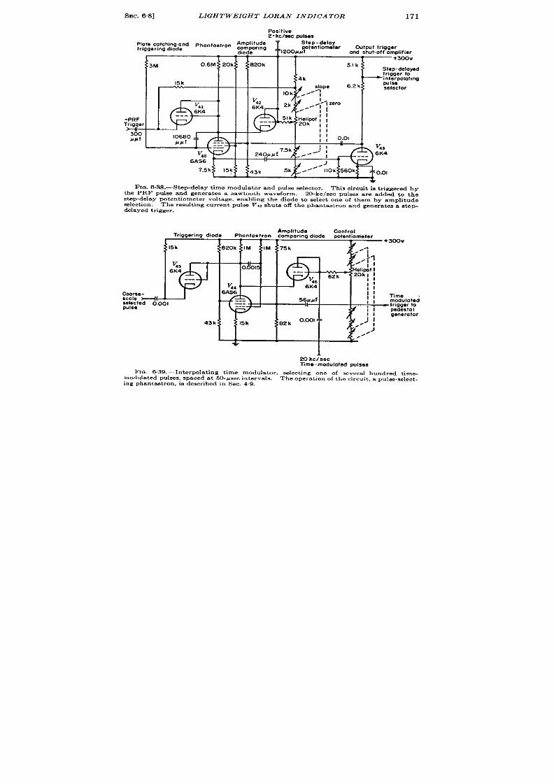
SEC. 6.8] LIGHTWEIGHT LORAN INDICATOR
171
Positive
2- kchec oule.es
Amplitude
IOie catching and pha”to~tron ~mparing
1,200~&~tenti0meter
Step-delay
tnggermg dgode
Outpwt trigger
diode
ord shut-off amplifier
1 1
+300V
TM
0.6M 20k
020k
5.1 k
II KRii7t I WI 2%‘<---”
.-’1- ‘‘=’”
,1
I
+
FIG.6 .38.—Step-delay t ime modula tor and pu ls e selector . Th ie cir cu it is t r igger ed by
t he PRF pu lse a nd gen er at es a sawt oot h waveform.
20-kc/sec pulses are added to the
step-d lay potentiometer voltage, enabling the diode to select one of them by amplitude
s elect ion . The r esult ing cu r r en t pu ls e V,z shut s off t h e phant a st ron and gener a tes a st ep-
delayed trigger.
Triggering diode
Amplitude
Phantostron comparing diode
potentiometer
v
6;:
Ccarsa -
sele ted o.001
pulss
43k
+
20 kc~sec
Time-modulated pulses
FIG. 6.39.—In t erpola t ing t ime modu la tor ,
select ing on e of severa l hu ndred t ime-
modula ted pulses , spaced at 50-pwc intervals.
The operat ion of the circuit , a pulee-select -
ing phan tast ron , is descr ibed in Sec. 4.9.

172
GENERA TION OF MOVABLE IN DEXES -CIRCUITS
[SEC. 643
amplit ude-compa r ison cir cu it .
The 3-phase condenser system is used
because it is possible to align the system with only a vacuum-tube
voltmeter or a standard test oscilloscope. This procedure is descr ibed
in Chap. 13, Vol. 19.
The output voltage from the phase modulator is amplified in a 6AK5
and dir ect ly syn ch ron izes t he blockin g oscilla tor Vw
Amplit ude com -
par ison of the sinusoid is thus per formed in Vag with reference to its
A =Transfers
B : Differential
FI~. 6 .40.—Schcmat ic diagram of mechanical t ime-modula tor control unit of direchreading
Loran indicator .
gr id-cutoff poten t ia l. The t ime constant of the blocking-oscilla tor gr id
circuit is adjusted so that the regenera t ion commences as the sinusoid
pa sses t hr ou gh zer o amplit ude.
The second circuit of interest is the pulse-select ing step delay, Fig.
638. The PRF tr igger init ia tes the rundown of a 6AS6 phantast ron ,
which cont inues unt il the plate voltage equals the sum of the step-delay
poten t iometer voltage and the amplitude of the 500-psec pulses. The
fir st 500-Asec pulse after the occu r rence of this equality will cause con-
duct ion in the diode V,,, shut t ing off the phan tast ron and providing a
step-delayed t r igger in t he same manner as the pu lse-select ing phan-
tast ron descr ibed in Sec. 4.9 on the ANIAPS-10 synchron izer .
SEC. 6,8]
LIGHTWEIGHT LGRAN INDICATOR
173
Th e st ep-dela yed t rigger is su pplied t o t he int erpola ting pu ke select or .
It should be noted that the event which direct ly init ia tes this t r igger to
the interpolat ing pulse selector is the flow of cur ren t in the amplitude-
compar ing diode V42 due t o one of the 500-@ec puises.
Thus the t r igger
to the interpola t ing pulse selector is t ruly the result of t ime select ion of
one of the 500-psec pulses. The 5-mile pip selector used in the Br it ish
Oboe (Sec. 9.2, F ig. 9“12) is of similar design .
The in terpola t ing t ime modula tor , Fig. 639, employs exact ly the same
technique as the step t ime modula tor except tha t the selected pulses are
t ime-modula ted ra ther than fixed, and the poten t iometer volt age is
var ied cont inuously ra ther than in steps.
The t r igger to the indica tor
pedest al gen er at or is obta ined by cliffer ent ia ting t he scr een wa veform.
The th ree sca les of the t ime-modula tor circuit a re cont rolled by the
mechanical unit , which opera tes as follows. Refer r ing to Fig. 640, the
coar se delay cont rol turns in quar ter -turn steps, one revolu t ion being
2000 ~sec—that is, fou r 500-psec steps. Through bevel gears with a
l-to-2~ stepdown the input reaches the “output” shaft of a different ia l.
Through the differen t ia l there is a 2-to-1 stepup which is geared to the
hundreds wheel of the counter with a 2+-to-l stepup. The gear on the
differen t ia l is preven ted from turn ing by ordinary cou nter const ruct ion .
The input from t he fine delay cont rol a t 50 ~sec per revolu t ion, reaches
the units wheel o the counter through a 5-to-1 stepup. Transfer from
the units wheel to the tens wheel is normal. From tens to hundreds the
t ransfer is accomplished through the l-to-l act ion of the different ia l by
having the t ransfer pin ion dr ive the diff rent ia l gear which also dr ives
the hundreds wh el of the counter after going through the differen t ia l.
The counter then gives the tota l delay reading by adding the outputs
of the coa rse and fine delay circu it on the hundreds wheel by means of
the different ia l.
The switch ing and var ious cont rols serve much the same funct ion
as in convent iona l Loran systems.
All the cont rols and switches neces-
sary for lin ing up the system and for taking a complete Loran fix are
mounted on the con t rol unit with the except ion that the CRT cont rols,
which are placed on the separa te indicator unit .
It is in terest in to compare this circu it with those of Sees. 61 and 6.2
on the basis of economy. By the use of pulse-select ing phantast rons, the
complet e oper at ion of r eceivin g a t rigger a nd pr odu cin g a t ime-modu la ted
pulse is per formed in 12 tube sect ions as compared with 15 for that of
Sec. 6.1 and 18 for that of Sec. 6“2, in spite of the fact tha t this is a
three-sca le system whereas the others are two-sca le. For per fect ly fa ir
comparison , an amplifier should be added to the Loran circu it t o provide
a sharper t ime-modula ted pulse.
A fur ther reserva t ion is that the
amplitude compar ison of t he phase-modula ted sinusoids is per forme by

174 GENEIM T ION OF MOVABLE IN D.UXAX-CIMJ ’UI 7’S
[SEC.6.9
a blocking oscilla tor and hence is of quest ionable accuracy. A liberal
a llowance of 2 volt s in the fir ing point of the blocking oscilla tor gives the
required accuracy of ~ psec out of 25,000, or 0.001 per cent . F igures of
t his a ccu ra cy a re ju st ifia ble sin ce t he fr equ en cy of t he 20-kc/sec oscilla tor
is cont r olled by automat ic fr equency cont rol with r eferen ce to the gr ound
sta t ion PRF, which is held to bet ter than 1 par t in 107 of the cor rect
frequency.
An example of the const ruct ion technique permit ted by this circu it
design is discussed in deta il in Chap. 17, Vol. 21 of the Ser ies. Figure
6.41 shows the subassembly containing the circuit of Fig. 6.39 and the
.
--=1
\
\
—.
FIG, 6.41 .—Subassembly con ta in ing in terpola t ing t ime-modula tor circu it of F ig 6.40 and
the phase-modula ted 20-kc/sec amplifier and block]ng oscilla tor of Fig. 6.3S.
circu it associa ted with Vss and V~~ of Fig. 6.37. The bakelite por t ion
of the card, on which the par t s a re mounted, is 38 by 3; in .
Th e con -
nector at the base of the card plugs into a sock t in the chassis, and the
card is suppor ted by ver t ica l slides.
This is an example of a calibrated
subassembly (see Chap. 3).
6.9. Surnmary.-In summary, the pr incipal fea ture which character -
izes t he va riou s mult iple-sca le t im e modu la tor s is t he met hod of coor din at -
ing scales. The highest accuracy is provided by the method of Sec. 6.2
in which pulses der ived carefully from the crysta l oscilla tor sinusoid a re
select ed in a ga ted video amplifier .
On the other hand, economy results
from adding the coarse-and-fine-sca le t iming waveforms to opera t e a
single instantaneous amplitude compara tor as in the circuit s of Sees.

SEC. 6.9] SUMMARY
175
6.1 and 6“8. Some economy is effected in the frequency-divider scheme
of Sec. 63 and in t he sin e-wa ve t ra ckin g sch eme of Sec. 6“4, bu t reliabilityy
is sacr if ced. The on ly system des r ibed which can be con trolled by an
electr ica l r ath e than mechanical signal is t he step and interpolat ion t ime
modula tor of Sec. 6.7. For t ime modula t ion in con junct ion with an
elect rica l compu ter t his fea tu re is va lu able.
CHAPTEIL 7
MANUAL MEASUREMENTS
BY BRITTON CHANCE AND . F. MACNICHOL, J R.
GENERAL CONSIDERATIONS
BY BRITTON CHANCE
INTRODUCTION
J lanual measur ements a re exten sively used in milita r y applica t ions.
Ext r eme flexibility is oft en requ ir ed to coun ter unexpected situa t ions.
(lften it has not been possible to design or to maintain automat ic equip-
ment . Economy of manpower is somet imes not r egarded as essent ia l in
milita ry o er t ions, and manual opera tor s a re often more available and
more expedient than automat ic equipment .
In radar systems manual
t r acking of the var ia t ions of range of a moving ta rget is an impor tant
pr ocedu re in plot tin g, in ter cept ion , na viga tion , bombin g, fir e con tr ol, a nd
many ot h er applica tion s.
The use of the ca thode-ray-tube display for these purposes and the
impor tant factor s a ffect ing the accuracy of manual measurements a re
discussed here. The use of the ca thode-ray tube for measurements of
waveforms is discussed in Chap. 20, Vol. 19. The deta iled design of
all types of ca thode-r ay-tube displays and a number of two-coordina te
displays a re presen ted in Vol. 22. The genera l pr inciples involved in
t ime modula t ion and demodula t ion by means of ca thode-ray-tube dis-
plays a re given in Vol. 19, Sec. 14.9, and in this volume, Sec. 3. 18–3.20.
Manual t ime-demodula t ion systems ar e nega t ive-feedback systems
in which an opera tor is an impor tant par t of the feedback loop. The
proper t ies of sign l and index permit the oper ator t o exer cise visual t ime
discr iminat ion, and with this informat ion he exer ts suitable con t rol over
t he t ime-modu la tion syst ems in or der t o follow con tin uou sly t he va ria tion s
of the input signal. In some opera t ions the par t played by the opera tor
is a very simple one and he may be easily replaced by an automat ic
device. But in a number of opera t ions he is ir replaceable. For example,
t a rget recognit ion is ver y difficult to descr ibe in terms of opera t ions that
cou ld be ca rr ied ou t a ut omat ica lly.
Often th e judgmen t and exper ien ce
of the opera tor a re of considerable value in avoiding the effect s of in ter -
fer ence and may achieve sat isfactory results wher e available automat ic
devices fa il completely.
176
SEC. 7.1]
USES
177
This chapter therefore t rea t s a number of methods for manually
t racking t ime-modula ted signals with spe ia l emphasis upon the suit -
a bility of t hese met hods in a dver se c n dit ion s in wh ich n oise in ter fer en ce
or in termit tence is presen t . In addit ion, some pract ica l circuits are
given for t racking in more than one coordinate.
The conten t of th is chapter is also a logical extension of the discus-
sion of methods for the determinat ion of distance and speed presen ted in
Sec. 2.11.
7.1. Uses.—Cathode-ray-tube displays are employed for two genera l
types of measurements: (1) the measurement of a t ime interval, which
may be r ega rded as u nvarying, for t he pu rpose of calibrat ion, for plot ting,
and crude navigat ion, etc.; (2) the measurement of the range and rate of
change of range of a ta rget for the purposes of precise navigat ion, bomb-
in g, fir e con tr ol, et c.
Th e design con sider at ion s in volved in t hese two ca ses differ con sider -
ably, since the first case involves the stat ic accuracy or reset tability
with which the t ime interval may be measured. The second case, how-
ever , includes in addit ion mechan i al t racking aids that genera te and
maintain the ra te of change of the range informat ion in accordance with
the opera t ion of the manual con t rols.
Pract ical examples of both ases
a re given in la ter sect ion s.
Fixed Time In tervals .—The st andardizat ion and calibrat ion of t ime-
modula t ion circuit s usually depend upon the use of cathode-ray-tube
displays. Similarly t he calibra t ion of t he zer o point f a r an ge-measur in g
system (see Sec. 3.6) involves this t ype of measu remen t.
Pract ica lly all the methods of rough posit ion-finding for plot t ing
borne bombing depend upon the measurement of range, which is assumed
t o be fixed at the moment of measurement .
In cer ta in systems where the
range is varying, similar techniques are employed, but the t ime cor -
responding to a given range is noted.
Variable Tirru In tervals.-It is desirable to move an index in synchro-
nism with the obsemed var ia t ions of the t ime-modulated signal. In radar
systems in wh ich t he an ten na cont in uou sly illuminates t he r eflect or such
as radar ran ge finders or posit ion-findin g systems employing a rapid scan
for angu lar data , t he signal in t ensit y n ever falls t o zer o for an appreciable
t ime and the t ime-modulated signal is near ly cont inuously available
to the observer . The tracking problem is rela t ively st raigh tforward,
and manually con t rolled mechanisms for genera t ing the ra te of change
of range in response to observat ions of the displacement of the signal
with respect to an index are effect ive in giving reasonably accurate ra te
information.
In many radar systems the excursion of the azimuth scan is equal

178
MANUAL MEAS UREMEN TS
[SEC. 72
to 360° or at least grea t ly exceeds the width of the an tenna pat tern .
Because of the limitat ions of mechan ical scann ing systems and because
of scann ing losses, the effect ive repet it ion ra te (V l. 1 of the Ser ies) of
the t ime-modula ted informat ion is oft en reduced, and specia l means are
employed in order t o assist in t e gen era t ion of accura te ra t e and displace-
ment data . One of the most effect ive methods calcu la tes from expect ed
character ist ics of the t ime-modula ted signal the probable ra te of change
of displacement . The manual opera t ion then consist s of readjust ing the
data en ter ed in to the comput ing device in view of dkcrepancies between
the observed and calcu la ted values. The computer and the t racking
process a re often ca led “ regenera t ive. ” Other systems are less preten -
t iou s and employ simpler t ra ckin g devices.
Sat isfactory demodula t ion of in termit t en t data usually requ ires a
display that con t inuously indicates the er ror between the t racking index
and the last value of the modula ted signal (see Sec. 7.27).
CHARACTERISTICS OF DISPLAYS AND CURSORS
7s2. General Conside at ions.—The ca thode-ray-tube display is the
most effect ive method of data indicat ion for the purposes of distance
measurement . It s basic advan tage is he la rge amount of in format ion
that it displays, as shown in the PPI display of F ig. 7.1 (see Vol. 22 of
the Ser ies). Range and azimuth indices a re also shown set near a radar
echo.
In usual pract ice, t a rg t select i n and accura te range-t racking are
car r ied ou t on separa te displays.
One display provides a view of all
t a rget s with in r nge of the radar set and is used pr imar ily for detect ion
and ta rget select ion . Th is display preferably combines azimuth indica-
t ion as in a B-scope or a PPI. Often , however , a simple linear t ime base
or type A display is employed as in Fig. 7.2 where two ta rget s a re shown.
Final ~ignal select ion and accura te t rget -f llowing are carr ied ou t
on an expanded sweep as represen t ed in Fig. 7“3. This display has a
number of impor t n t uses. It permit s discr iminat ion against in ter fer -
ing signals and accura te select ion of the desired one.
In addit ion , any
coding that may iden t ify a par t icu lar signal is easily observed. Fur ther -
more, the detectability of the signal will be opt imal—that is, the pulse
length is la rge compared with spot size of the cathode-ray tube (see
Vol. 22). The t racking opera t ion is grea t ly facilit a ted by the fast sweep,
since it conc n t ra tes the opera tor ’s a t ten t ion upon a par t icu lar ta rget
and increases the accuracy with which the t racking operat ion is ca r r ied
ou t . Oft en a por t ion of a slow sweep may be expanded in the vicin ity
of the index, and the advan tages of both types of sweep are obta ined in
one display, bu t th is procedu re is unsa t isfactory in most cases.

sEC
an<
:. 72]
ENERAL CONS IDERAT IONS
179
The deflect ion-modula ted linear or circu lar t ime base (see Figs. 7“
i 7.5) is almost always employed for the fast sweep in radars where th
4
.e
FXQ.7.1.—Rangeand azimuthindexset neara radarechoon a PPI display.
da ta a r e essen tia lly con tinuou s.
On the other hand, the type B or PPI
display is used when data a re in termit ten t at a slow ra te. When both

180
range and azimuth
is complica ted by
Sec. 7.28).
(a)
MANUAL MEASUREMEN TS
[SEC. 7.3
informat ion is requ ired the problem of ,th e opera tor
the requirement for two-coordina te t racking (see
(b)
FIG.7.4 .—Type J d isplay. The s igna lmaybe selected on the s low sweep (a )-and accura tely
followed on the fa st sweep (b).
. .
.———
—. . . ...
1
1
1
L_-
. ....—-.
4
(a )
(b)
~.- .. . .
~ ‘-”-
,
~<
---. _._.._.._ ........_J
(c)
F IG. 7.5.—Type M displa y. Th e t hr ee oscillogr am s sh ow t he set tin g of a sign al t o a
step type of marker . In (a ) the step is set too la te; in (b) it is too ea r ly.
In (c) t he st ep is
set cor r ect ly so t ha t t h e h eigh t of t h e not ch between t h e fa lf of t h e sign al a nd t h e r ise of t h e
marker va r ies rap id ly with t ime d iffe rence.
7.3. Indices.-Although th range of a ta rget may be cmdely est i-
ma ted by a simple display withou t an index, the provision of sa t isfac-
tory indices grea t ly increa ses the accu ra cy and th e ease of measurement .
The th ree ty es a re applicable: (1) in tensity-modula ted indices, (2)
deflect ion -modu la ted in dices, an d (3) mecha nica l m arkers th at a re eit her
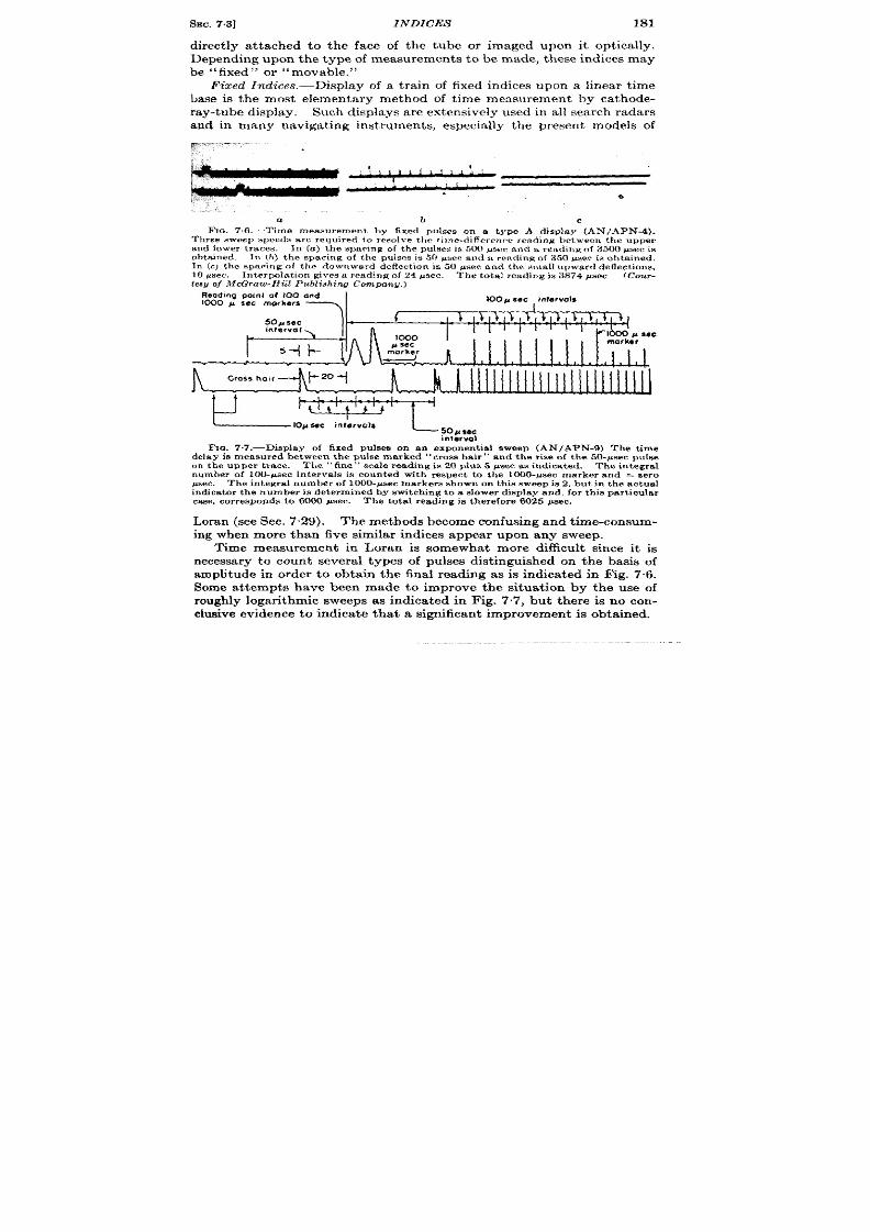
SEC.7.3]
INDICES
181
direct ly a t tached to the face of the tube or imaged upon it opt ica lly.
Depending upon the type of measurements to be made, these indices may
be “fixed” or “mova ble.”
Fixed Indices. —Display of a tra in of fixed indices upon a Iinear time
base is the most elementary method of t ime measurement by ca thode-
ray-tube isplay. Such displays a re extensively used in all search radars
and in many naviga t ing inst ruments, especia lly the presen t models of
~.-. - ,.
h
.,
0
,.. .
a
b
c
Fm. 7.6,—Time measurement by fixed pulses on a t ype A display (AN/APN- ).
Th ree sweep speeds a r e r equ ir ed to r esolve the t ime-d iffcr en r e r eading between the upper
and lowe traces. Iu (a ) the sparing of the pu lses is W! psm nnd u r ea diu g of 3500 psec is
obt a in ed. In b) t h e spa cing of t h e PUISCSs 50 w+ccand %rewdingO( 350 ~sec is obtained,
In (c) t h e spa cing of t h e downwa rd deflect ion is 50 LW.ecnd t h e smd upwa rd def ect ion s,
10 ~sec. In t er pola t ion gives a r eading of 24 psec. T}]e t ot a l r eadingk 3874 ps ec
ICour.
{esyof McGraw-Hill Publishing cotnpml~,)
Rwad ng point O( 100 and
1000 p sac markers
IO A sac inlarvols
Sofisec
interval
t
-
Cross hobr
~zo+
b.~
inlorvol
F IG. 7.7.—Displa y of fixed pu lses on a n expon en tia l sweep (AN/APN-9) Th e t im e
dela y is mea su red between t h e pu lse ma rk ed ‘‘ cr oss h air ” and t h e r ise of t h e 50-#see pu lse
on t he u pper t ra ce. Th e ‘‘ tin e” sca le r ea din g is 20 plu s 5 psec a s in dica ted.
The in tegra l
number of 100-psec in t erva ls is coun t ed with r espect t o tbe 1000-@see marker and = zero
#sec. The in t egr a l number of 1000-psec marker s shown on t his sweep is 2, bu t h t h e a ct ua l
indica tor t he number is det ermined by swit ch ing to a s lower d isplay and, for t h is pa r t icu la r
ca se, cor r esponds t o 6000 #sec. The t ot a l r eading is t h er efor e 6025 #sec.
Lora (see Sec. 7.29). The methods becom e confusing and t ime-consum-
ing when more than five similar indices appear upon any sweep.
Time measurement in Loran is somewhat m re difficu lt since it is
necessary to count severa l types of pulses dist inguished on the basis of
amplitude in order to obta in the final reading as is indica ted in Fig. 7.6.
Some at tempts have been made to improve the situat ion by the use of
roughly logar ithmic sweeps as indicated in Fig. 7.7, bu t there is no con-
clusive eviden ce t o indica te t hat a significan t impr ovemen t is obt ained.
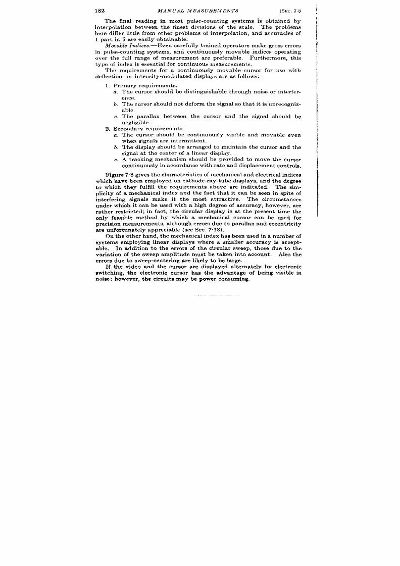
182 MANUAL MEAS UREMENTS
[SEC. 73 ~
The final reading in most pulse-count ing systems is obta ined by ~
in terpola t ion between the finest divisions of the scale. The problems ~
here differ lit t le from other problems of in terpola t ion , and accuracies of ~
1 par t in 5 ar e easily obta inable.
I
Mova ble Indices. —Even ca refu lly t ra in ed oper at or s ma ke gr oss er ror s
in pulse-count ing systems, and cont inuously mova ble indices oper at ing
!
~
over the full range of measurement a re preferable. Fur thermore, this
t ype of in dex is essent ia l for cont inuous measur ements.
The requ irements for a cont inuously movable curso for use with
deflect ion - or in ten s t y-modu la ted displa ys a re as follows:
1
1. P rimar y r equ ir emen ts.
a . The ct ir sor should be dist inguishable through noise or in ter fer -
1
ence.
b. The cursor should not deform the signal so that it is unrecogniz-
able.
I
c. The para llax between the cur sor and the signal should be I
negligible.
2. Seconda ry r equ ir emen ts.
~
a. The cur sor should be cont inuously visible and movable even
when sign als a r e in termit ten t.
b. The display should e ar ranged to mainta in the cur sor and the
signal a t the en ter of a linear display.
I
c. A tracking mechanism should be provided to move the cursor
I
ontinuously in a ccor da nce wit h r at e a nd displa cemen t con tr ols.
F@r e 7”8 gives t he ch ar act er ist ics of mech an ica l a nd elect rica l in dices
which have been employed on ca thode-ray-tube displays, and the degr ee
to which they fulfill the requirements above are indica ted. The sim-
plicity of a mechanical index and the fact tha t it can be seen in spite of
in ter fer ing signals make it the most a t t r act ive.
The cir cumst ances
under which it can be used with a high degree of accuracy, however , a re
ra ther rest r icted; in fact , the circu lar display is a t the present t ime the
only feasible method by which a mechanical cursor can be used for
pr ecision mea su remen ts, a lt hou gh er ror s du e t o pa ra llax a nd eccen tr icit y
a re u nfor tu na tely a ppr ecia ble (see Sec. 7’.18).
On the other hand, the mechanical index ha? been used in a number of
systems employing linear displays where a smaHer accuracy is accept -
able. In addit ion to the er rors of the circular sweep, those due to the
var ia t ion of the sweep amplitude must be taken into account . Also the
er ror s due to sweep-center ing are likely to be la rge.
If the video and the cursor ar e displayed altern tely by elect ronic
switching, the elect ron ic cursor has the advantage of being visible in
noise; however , the circuits may be power consuming,

SEC.7.3]
INDICES
188
Th e shape of t he elect ron ic inde maybe similar t o that of th e r eceived
pulse but should be easily dist inguishable from it , as shown in Fig. 7.8.
The step type of index is obtained when a rectangu lar waveform is
applied to the ver t ica l pla tes of the oscilloscope. The notch and pedesta l
t ype of index may be obta ined from a shor t er rect angular pulse in the
same manner . The notch presen ta t on is indica ted in Fig. 7.9.
On in tensity-modulat ed display a waveform similar t o tha t of the
rece%ed pulse is almost a lways used for a range marker .
H owever , it
Type
Step
Notch
Pedestal
Mechanicof
Intensified
Blanked
.. .
.-
Diagrom Correct setting
——
—-i7_-
Fua .7.8.—TYPesof tracking indices.
—.. . . .. . . . . . :,
Chief foults
Distorts signal
Slgnol seems to
disappear m notch
Signal seems to
dmappear off pedeetal
Porallaz may be bad
Accurocy depends on
Iineority of troce
Rises of signol and
noise elongate marker
obecured. by too
high trace inteneity
Rises of eignal ond
noiee elongate morker
: ‘ —’ q - ‘ —\ ~ :
. j
L:
.A
F1a 7.9.—Ca th ode-r ay-t ube displa y of n ot ch pr esen ta tion . Alt h ou gh t his gives a
sen sit ive i ndica t ion of t h e r ela t ive t im ing of sign al a nd index, a weak sign a l may eeem b
“d isa ppea r ” in t o t h e not ch .
is desirabl t o have it r ise and fall somewhat more rapidly than the
received signal. In the case of range-angle display, the range marker is
easily dist inguishable from the received signal by the fact tha t the index
consist s of a circle or a line depending upon whether the display is pola r
(PPI) or rect angular (type B) (see Fig. 7.1).
With near ly all t ypes of in tensity-modulated displa s and some types
of deflect ion -modu la ted displa ys, a con sider able t ime in t er ven es between
successive ren ewals of t he informat ion on t he screen because of t he in t er -
mit tence of the input data , and most of the t ime a persist en t t r ace
appears on the display. The effect of moving the range index, which ia
mixed with the video signals, cannot be compared with the desired echo
unt l the next scan . In the case of very slow scans, it has been necessary
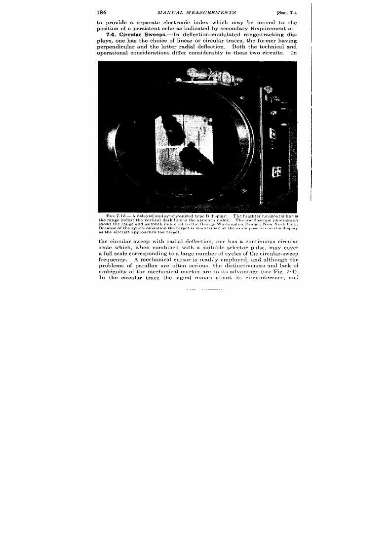
184
MANUAL MEAS UREMENTS [SEC. 74
to provide a separa te elect ronic index which may be moved to the
posit ion of a persisten t echo as indica ted by secondary Requirement a.
7.4. Circula r Sweeps.—In deflect ion-modula t ed r ange-t r acking dis-
plays, one has the choice of linear or circula r t ra es, the former having
perpendicular and the la t ter radial deflect ion . Both the technica l and
opera t iona l considera t ions differ considerably in these two cir uit s. In
FIG.7.10.—A delayed aud synchronimd type H display.
Thr l>riglt t r rhorizontal I ineis
the range index: the ve rt ica l da rk line is the az))]iu t l~il)dcx
The osri llowo]m pl,nt ,ograph
shows the range and azimuth index set to t llc C corKcWw+l]ingtol)PJndgc,New York City.
Becau se of t h e synch ron iza t ion t h e t a r get is mwn t a in ed a t t h e s a]]m pomtmnWI the d is play
a s t h e a ir cr aft a pp roa ch es t h e t a rget .
the circula r sweep with radial deflect ion , one has a cont inuous circular
sca le which , when combined with a suitable selector pulse, may cover
a full sca le cor respon din g t o a la rge n umber of cycles of t he cir cu la r-sweep
frequency. A mechanica l cursor is readily employed, and although the
problems of parallax are often ser ious, the dist inct iveness and lack of
ambiguity of the mechanical marker a re to it s advantage (see Fig. 7.4).
In the circular t r ace the signal moves about it s circumference, and
I
SEC. 7.5] LINEAR SWEEP AND S YNCHRONIZED PRESENTATION 185
t he tracking opera t ion involves following the signal down one side of the
circle and up the other side, a process tha t may be confusing to the
uninit ia ted opera tor .1 On the other hand, one advantage of the con-
t inuous movement f the signal with respect to the face of the ca thode-
ray tube is the addit ional information it gives—that is, the opera tor is
con tin ua lly in formed of t he a ppr oxima te va lue of r an ge r at e by t he motion
of the echo past fixed poin ts on the ca thode-ray-tube face as shown in
F ig. 7.4.
The ,circu lar t r ace is genera ted with grea t simplicity (see Sec. 7“18).
Th e sca le len gt h obt ain ed wit h a 3-in. circu la r t ra ce, of cou rse, is a pproxi-
ately equal to tha t obtainable from a 7-in. linea t race.
7.6. Linear Sweep and Synchron ized Presenta t ion .-Often the linear
display a d a step or other type of electr ica l mark is employed for range
t racking. If this display is an expanded por t ion of the full scale over
which range measurement is desired, the index is visible over a fr act ion
of the requ ired tota l range. This limitat ion is avoided if the elay of
the sweep is var ied with that of the tracking ind x so tha t the cursor
always appears in the middle of the t race.
Figure 7.10 illustra tes the use of a del yed synchronized linear
sweep for range t racking in a ircraft .
In this par t icu lar case, a range-
azimuth display is used, and the range index is an in tensity-modula ted
hor izonta l line. The azimuth index is mechanica l and is represented by
the vert ica l black line in the cen ter of the tube. The t racking process
maintains the target sta t ionary and at the cen ter of the display in spite
of the movement of the aircraft .
These synchronized displays give a
clea r in dica tion a nd h en ce a ccu ra te mea su remen ts.
ACCURACYCONSIDERATIONS
The accuracy with which the t ime-modula ted index may be set to a
received pulse on cathode-ray-tube display varies widely depending
upon a number of simple geometr ic factors.
F or maximum sensit ivity
of th is process of t ime discr iminat ion , it is desirable to have a high ra te
of change of movement of the over lapping por t ions of the index and
signal with respect to varia t ion of the t ime in terva l between them.
The accuracy with which the set t ing of index and signal may be made
u nder sta t ic condit ions is presented here; the t racking process involved
in following a cont inuously moving signal is discussed in a la ter sect ion .
It is required to set the index rela t i e to the pulse so that the index
represen ts the range of the pulse.
This is do e most accura tely by
defin ing as a coincident set t ing tha t set t ing from which there is the
1 Ph ase modu la tion of th e t ra nsmit ted pu lse giv s a cir cular display in which the
signalappearsto be stationary (seeSec. 63).
~Mr. D. Gale assis tedwith the preliminarydrafts of this mater ia l.
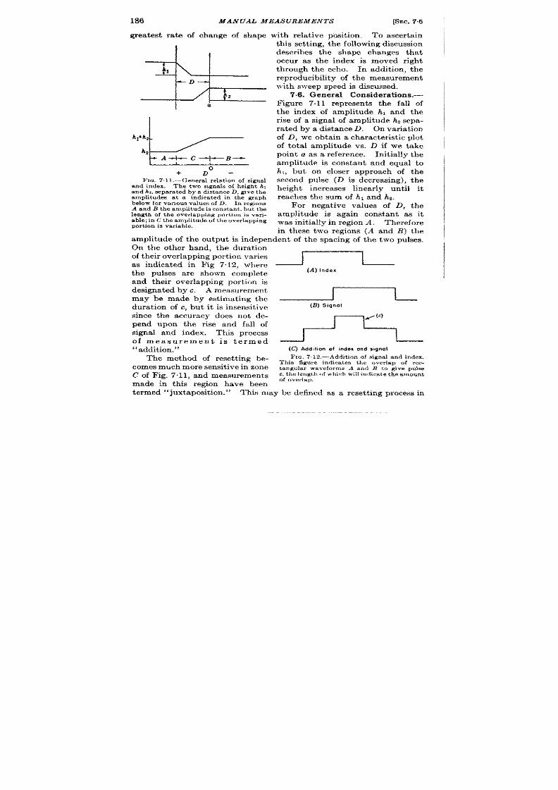
186
MANUAL MEASUREMENTS
[SEC. 7.6
grea test ra te of change of shape with rela t ive posit ion. To ascer ta in
I
‘2!EzzLe=
+
Do-
FIG. 7.11.—Genera l r ela t ion of s igna l
en d in dex. The two signals of heigh t h,
and hi,
separated by a distance
D, give t he
amplitudes a t a indica ted in the graph
below for va r ious va lues of D. In regions
A and B t h e amplit ude is const an t, bu t t h e
lengt h of t h e over la pp ing por t ion is va r i-
able; in C the amplitude of the over lapping
por t ion ie var iable .
t his set tin g, t h e following discu ssion
descr ibes the shape changes tha t
occu r as the in ex is moved r igh t
through the scho. In addit ion , the
r epr oducibilit y of t he mea sur em en t
wit h sweep speed is discussed.
7.6. Gen er al Con sider at ion s.—
Figure 7.11 represen t s the fall of
the index of amplitude h, and the
r ise of a signal of amplitude h~sepa-
r ated by a distance D. On varia t ion
of D, we obt ain a ch ar act er ist ic plot
of tota l amplitude vs. D if we take
poin t a as a refer ence. Init ia lly the
amplitude is constan t and equal to
hl, but on closer approach of the
second pulse (D is decreasing), t he
heigh t increases linear ly unt il it
r eaches the sum of h 1 and hz.
For nega t ive values of D, t he
amplitude is again constan t as it
was init ia lly in region A, Therefore
in these two regions (A and B) the
amplitude of the outpu t is independent of the spacing of the two pulses.
On the other hand, the dura t ion
of t heir over la ppin g por tion va ries
as indica ted in Fig 7.12, where
the pulses a re shown complet e
and their over lapping por t ion is
designa ted by c. A measurement
may be made by est imat ing the
dura t ion of c, but it is insensit ive
since the accuracy does not de-
pend upon the r ise and fall of
signal and index. This process
of measurement is t rmed
“addition.”
The method of r eset t ing be-
com es much mor e sen sit ive in zon e
C of Fig. 7.11, and measurements
made in this r egion have been
(A) Index
J
~
(B) Signal
(~ Add,ttion of index ond signal
FIG. 7 .12 .—Addit ion of s igna l and index.
Thie figure indica tes the over lap of ec-
tangular waveforms A and B to give pulse
c, the length of which will ind ica te the amoun t
of overlap.
t ermed d‘juxt aposit ion . ”
This may be defined as a reset t ing process in

SEC. 7.7]
DEFLECT ION -MODULA TED DIS PLAY
187
which the amount of over lap of two pulses s observed in t erms of the
amplitude or in tensity of their over lapping por t ions.
Two types of
juxtaposit ion of signal and index a re indica ted in Fig. 7.13. Fur ther -
more, the amplitude or in tensity of pulse c is constan t regardless of the
speed of the t ime base employed.
Thus, ju xt aposit ion may be con sider -
a bly mor e sen sit ive t ha n a ddit ion .
The most sensit ive method of matching a signal and index is indicated
in r ig. 7.14, and the measurement is made with completely over lapping
pulses. The deflect ions do not add, however , since they are displayed
separa tely either by elect ron ic switching or by the use of a mechanical
over lay or gr id ident ica l in size and shape with signal.
If elect ron ic
switching is used, the per sistence of the screen of a ca thode-ray tube or
of the eye may be relied up n to ma tain t}le t race of the signal while the
index is being displayed. The final set t ing may be made in terms of the
br illiance of the r ising edge of signa l and index which will pass through
the same configura t ions of addit ion or juxtaposit ion , but on a much finer
t ime scale. This method is possible, of cour se, on ly with deflect ion-
modula ted displays and p lses of iden t ical shape.
It is, however , of
considerable impor tance in obta in-
ing ext r emely accura te measure-
me ts with pulses of slow r ise and
fa ll t imes .
Th e a pplica tion of t hese met hods
of reset t ing to deflect ion - and in-
t en sit y-modu la ted displa ys wil n ow
be taken up and, where feasible,
formulas will be der ived indica t ing
the sensit ivity or reset tability in
t erms of r ise and fall t imes of the
pulses and speed of the t ime base
u pon wh ich t he pu lses a re displa yed.
7.7. Deflect ion-modula ted Dis-
play and Deflect ion-modula ted In-
dex. Addition.—The accuracy of
reset t ing of t wo pulses un der condi-
t ions where the length of their over -
lapping por t ion is employed as a
cr iter ion of the reset t ing is small
compa red with t he a ccu ra cy of j uxt a-
posit ion a s descr ibed below.
~
(A) Index
/
(B) S [gn.1 pas,!on 1
(C) Peakndtc.at,on
—____JT
(D) S ,gnol- pm .,!, z
‘-’ (c)
(El GODndicat ion
F IG, 7. 13.—Juxt aposit 1on of sign a l
and index. The amplitude of t he over .
lapping por t ion of the two pulses c is a
sen sit ive indica t ion of t h e sepa r at ion of
pulses (A) and (B). The amplit ude of
(c) may be pos,t ive or nega t ive with
r espect t o t ha t of (A) or (B ) @ving a peak
The opera tor a t tempts to reproduce the length of pulse c of Fig. 7.12.
P rovided th is pulse has a length grea t er than the spot size of the ca thode-
ray tube, the accuracy with which the length will be reproduced will be

188 MANUAL MEASUREMENTS
[SEC. 7.7
rela t iv ly constan t , and rough ly 1 par t in 10. The er ror of t ime measure-
ment cor responding to a fluctua t ion of 1 par t in 10 of D is O.ID/S, wh er e
S is the sweep speed in millimeters per microse ond and D is the length
of pu lse c in m illim et er s.
.luztaposit ion .-A considera t ion of Fig. 7.13 indica tes tha t th e varia -
t ion of amplitude of pu lse c is from zero to the sum of the pu lses a and b
depending upon their over lap. A va r iety of adjustments ma be made.
~
For example, pu lses a and b may be
adjusted so tha t con t inuity between
the two pulses is established. On
the other hand, the set t ing may be
FKO.7.14.—Electrical superposition
of signal and index. E le t r on ic swit ch -
made when the amplitude of pulse c
ing of the inputs to the ca thod -ray-
is equa l to a fract ion of a or b. But
t ube displa y permit s su per posit ion of
the rate of change of the amplitude
pu lses (4) and (b).
of pu lse c with over lap of a and b will
be approximately constan t rega rdless of the arbit r a ry cr it er ion of
measurement . A prefer red method of adjustmen t is one in which the
amplitude of pu lse c is ha lf tha t of signal and index, as is hown in
Fig. 7.5c. If a cr it er ion involving a la rge over lap is accepted, there is
danger tha t a ca reless opera tor would make the set t ing in terms of the
length of c and not it s amplitude, with a consequen t loss of accuracy.
A simplifyin g a ssumpt ion a pplyin g t o n ea rly a ll deflect ion -modu la ted
displays is tha t the speed of the t ime base S is la rge enough so tha t the r ise
(a)
(b)
FIG, 7.15.—J uxtaposit ion at two values of sweep speed. Th e not ch between sign al a nd
in dex is clea rly seen in (a ). Alt h ough t h e sweep sp ed h as been decr ea sed in (b) un til t h e
ga p is con fu sed wit h t he spot of t he ca th ode-r ay t ube, t he h eigh t of t he ga p is st ill clea rly
indicated.
of pulse a and the fa ll of pulse c do not obscure the amplitude changes of
pu lse c which occu r in the process of juxtap sit ion . A wide range of
sweep speeds is possible, as shown in Fig. 7.15a and b. In fact the sweep
speed may be so small tha t c has a length comparable to the spot size
of the ca thode-ray tube,
This is not t rue, however , in the case of
in ten sity-m odu la ted two-dimension al displa ys (see Sec. 7.10). A secon d
simplifying assumption is tha t pulses a and b a re t rapezoida l and have
the same r ise and fall t imes and amplitude . This, of course, represen ts
some devia t ion from the t rue shape of signal and index, especia lly a t the
in it ia t ion of the r ise or nea r it s complet ion . On the other hand, it is a
good approximat ion when the amplitude of pu lse c is rough ly half the
amplitude of signal and index.
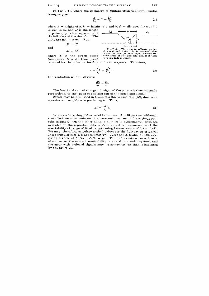
SEC. 7.7]
In Fig. 7“16,
t r iangles give
DEFLECTION -MODULATED DISPLAY 189
where the geomet ry of juxtaposit ion is shown, simila r
(1)
where h = heigh t of c, h, = height of a and b, d, = distance for a and b
to r ise to h,, and D is t he len gt h
of pulse c, plus the separa t ion of
(=) ~D-+j
the fall of a and the r ise of b. The
7 (d *
units a re millimeters. But
11
r
‘X’
D=tS
---- -—-— / _ ____ ___
and
~dr--l
FIG,7.16.—Thegeomet ry0[ju xtaposit ion
d, = t,S,
of signal and index. It is assumed that
pulses (a ) and (b) have equal amplitudes,
equal ra tes of r ise and fall, and that their
here s is the sweep speed
(mm/Ksec), t, is the t ime (~sec) ‘“es and ‘ails a re“near”
required for the pulse to r ise d,, and t is t ime (Psec). The efore,
()
= 2–: 1,.
r
(2)
Differen t ia t ion of ~q. (2) gives
The fract iona l ra te of change of heigh t of the pulse c is then inversely
proport iona l to the speed of r ise and fall of the index and signal.
Er rors may be eva lua ted in terms of a flu tua t ion of t , (At), due to an
opera tor ’s er ror (Ah) of reproducing h. Thus,
At=glt,
h , r
(3)
Wit h ca r efu l set ting, Ah/ h . wou ld n ot exceed 5 or 10 er cen t, a lth ou gh
cont rolled measurements on this h t ivc not been made for ca thode-ray-
tube displays. on the other hand, a number of exper imenta l data are
available on the reproducibility of At oht~incd in measurements of the
reset tability of range of fixed ta rget s using known values of t,(= d,/S).
We may, therefore, ca lcu la te typica l values for the fluctuat ion of Ah/h ,.
In a par t icula r ca se, t , is a pproxima tely 0.1 P scc a nd At is a bout 0.005 psec,
givin a va lue of Ah/ h, = At/ t, = #v. ‘1’hcse observa t ion s wer e ba sed,
of cou rse, on the over-a ll rmct t :~l)ility obscrvmf in a radar system, and
the er ror with art ificia l signals may be somewhat less than is indica ted
by the figure +.

190
MANUAL MEAS UREMENTS
[SEC. 7.8
7.8. Deflect ion-modula t ed Signal and Mechanica l Index.-The
mechanica l index represen ts an idea l index since it cor responds to a zero
t---+-i
FIG. 7.17,—Geometr y of electrical
signal a nd mech an ical in dex,
Th e
mechanical index is represented by (c).
t ime of r ise and fall of the index, and
the accuracy of reset t ing depends
solely upon the r ise t ime of the signa l
pulse.
As ih the previous case of Fig. 7.16,
we may obta in from Fig. 7-17 an ex-
p res sion for h,
Su bst it ut ion of D = St and d, = St, gives
t=l–; tr.
r
Likewise,
~t=lit
h, ‘“
(4)
(5)
(6)
In the case of SCR-584 (cir cu la r t r ace with mechanica l c r sor ), t he
fluctua t ion At was observed to be rough ly ~~ psec and the r ise t ime t,o
be ~ psec, giving values of At /t , or Ah/h , of approxima tely ~, similar to
tha t obta ined in the previous case.
7.9. Deflect ion -modu la ted Signa l and In ten sity-modula ted Index.—
Three typica l displays of signa l and index a re shown in Fig. 7.18a, b, and
c. In all pract ica l cases the dura t ion of the marker is made shor t com-
pa red with the r ise t ime of the signa l.
The reset tab lit y of these th ree
types of display may therefore be eva lua ted by exact ly the same formulo
as was used for the mechanica l index above.
An in tensifying pulse displayed on the r ise of a rapid signa l (as in
Fig. 7.18a) must a t the same t ime counteract the dimming of the t r a ,ce
due to the increase of sweep speed tha t is caused by the det lect ion -
modula t ed signa l. A dist inguishable and clear mark is, therefore, diffi-
cu lt t o obta in . Fur thermore, noise and in ter ference make it difficu lt to
loca te an in tensifying pulse. A blanking marker shown in Fig. 7. 18b and
c is more effect ive since it cannot be obscured so easily by any reasonable
va lue of sweep speed r by an incor rect adjustm nt of the bias of the
ca th ode-r ay t ube.
7.10. J uxtaposit ion of In tensity-modula ted Signa l and Index. Gen-
eral considerations.—As in Sec. 7.7, juxtaposit ion of signa l and index is
the pr efer r ed method, The amplitude of pulse c of Fig. 7.13 is, however ,
r epresen ted by an in tensity change instead of by a deflect ion .
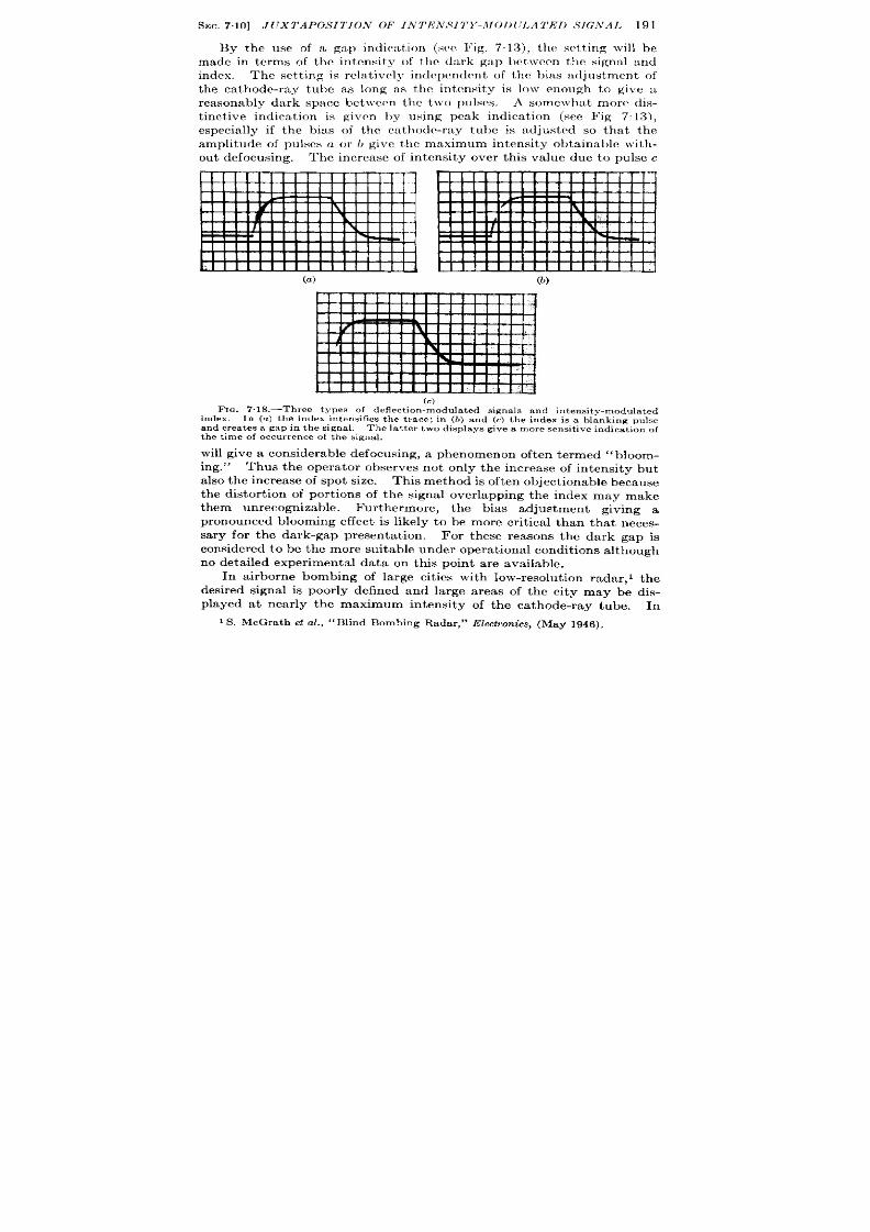
S~c, 7.10] J UXTAPOS II’1ON OF IN TEN ,Y I T1’-\ fol)(:l.A TED S IG’.VA 1. 191
By the use of a gap indica t ion (see l~ig. 7.13), t ile set t ing will be
made in terms of the in tensity of the da rk gtLp bet\vccm the signal ancl
index. The set t ing is rela t ively independent of the bias a{ljustment of
the ca thode-ray tube as long M the in tensity is 10!v enough to give a
reasonably da rk space bct ]vcen the two pulses.
A somewhat more dis-
t inct ive indica t ion is givrn I)y using peak indica t ion (see Fig 7 13),
especia lly if the bias nf the ca thode-ray tube is adjusted so tha t the
amplitu de of pu lses a or L give t llc maximum intensity obta inable \ vith -
ou t defocusing. The increase of in tensity over th is va lue due to pulse c
(c)
F IG. 7.l&-Th ree t ypes of deflect ion -modu la ted sign als a nd in ten sit y-modu la ted
in dex, In (a ) t he in dex in ten sifies t h t ra ce; in (b) a nd (c) th e in dex is a blan king pu lse
and cr ea tes a gap in t h e sign al. The la t ter two displa ys give a mor e sen sit ive indica t ion of
t he t ime of occu r r ence of t he signa l.
will give a con sidera ble def cu sin g, a ph en omen on oft en t ermed “bloom -
ing.”
Thus the opera tor observes not on ly the increase of in tensity but
a lso t he in cr ea se of spot size.
Th is met hod is oft en object ion able beca use
the distor t ion of por t ions of the signa l over lapping the index may make
them unrecogn izable. Fu r thermore, the bias adjustmen t givin g a
pronounced blooming effect is likely to be more cr it ica l than tha t neces-
sa ry for the da rk-gap presen ta t ion . For these reasons the dark gap is
con sider ed t o be t he mor e suita ble u nder opera tion al con dit ion s a lth ou gh
no deta iled exper imen ta l data on th s poin t a re ava ilable.
In a irborne bombing of la rge cit ies with low-resolu t ion radar , 1 the
desired signal is poor ly defined and la rge areas of the city may be dis-
played a t near ly the maximum intensity of the ca thode-ray tube. In
I S. McGrath et a l.,
“Blin d Bombin g Rada r,” ~lect ron ics, (May 1946),
192
MANUAL MEASUREMENTS
[SEC.710
th is case an in tensified index may be difficu lt to dist inguish from the
target unless it has an intensity grea ter than that of the signals. Some-
t imes a dark or blanking index is used for easier ident ificat ion . This,
however , leads to a considerable 10SS of accuracy since the set t ing is
made in terms of the length of ove Iap of si.grml and index, of which there
is n o m easur e until the signal appearq on both sides of the blanking index.
Most in tensity-modula ted displays are in t \ r o coordina tes and serve
the purposes of genera l su rvey in addit ion to precise t ime measurement .
On e met hod of meet in g t hese two r equ ir emen ts is t o in cr ea se pr ogr essively
the speed of the sweep as the ta rget is approached. Dur ing this per iod
it is desired to make accura te measurements of the range of the target ,
It is, therefor e, of considerable in terest t o determin the er ror of reset t a -
bility ver a wide range of sweep speeds. This range is so la rge that the
length of pulse c (Fig. 7“1 ) is no longer large compared with the spot
size for the slower sweeps. It is found that a very ser ious syst mat ic
error depending upon sweep s eed ar ises because of the addit ion of the
spot size to the length of the r ise of signal and index.
Reset Error .-The same reasoning em loyed in the analysis of the
amplitude-modula ted display is applicable to in tensity modula t ion pr o-
viding some assumpt ions concerning the modulat ion cbaracter ist i cs of
the ca thode-ray tube are made. The first and most basic assumpt ion is
tha t the var ia t ions of in tensity a re small enough to be linear ly rela ted
to the con t rol-gr id volt ages over the range of measurement . This is
approximately t rue where the var ia t ions of in tensity a re less than 10 per
cen t . Another simplifying assumpt ion is tha t the dist r ibut ion of in ten-
sity in the spot of the cathode-ray tube is roughly t r iangular and con-
sists of a linear r ise and fall of R millimeters.
This is not st r ict ly t rue,
a lthough in magnet ic tubes the in tensity var ia t ion approximates a
Gaussian dist r ibut ion. In elect rosta t ic tubes, this assumpt ion may not
be just ified as is pointed out in Sec. 7.11 (see Vol. 22, Chap. 17).
I spot size is neglected, the der iva t ion of the rela t ion between the
var iables is similar t o that employed in deflect ion -modu la ted displa ys
and the same formulas apply if we take in tensity of the display to be
equal t o h’ and h; over the required range,
(7)
The effect of the spot size of the cathode-ray tube must a lso be con-
sidered. T e quant ity R is defin ed a s t he dist an ce in m illimet er s r equ ir ed
for the in tensity of the t r iangular spot t o fall from its maximum value
t o zer o.
If it is assumed that R adds linear ly o the length of r ise of the
sign al, it follows t hat
d, = R f t,fl
{8)

SEC. 7.10] JUXTAPOS ITION OF INTENS ITY -MODULATED S IGNAL 193
Then
(
h?=h:2– ‘t
)
+t,s’
(9)
or
‘=@+ ’)(’-E)
(lo)
wher e h ’/h ~ is r epr esen ted as a ligh t-in ten sit y ch an ge.
The change in t ime corresponding to At’, a fluctua t ion of h’, (Ah’), is
given by
()
h’ R
At=z ~+t,
(11)
The assumpt ions in th is der iva t ion have not been checked by direct
exper iment . The rela t ion of the quant ity R t o ot her defin it ions of spot
size has n ot been ver ified, and a figu re for R of 0.4 mm has been a rbit ra rily
assumed. The validity of direct addit ion of the quant ity R t o t he len gth
o the r ise of signal d, has not been ver ified exper imen ta lly. On the
other hand, many data a re available on he over-a ll accuracy obta inable
in reset t ing on in tensity-modula ted displays for var ious valu es of S and t ,.
In th is way, the expressions a re subject to over-a ll check. The accuracies
will be compared by assuming the value of Ah’/h~ to have a probable
er ror of 5 per cen t and compar ing the calcula ted values with those
observed exper imenta lly. Formula (11) then reduces to
()
t = +0.05 : + t,.
(12)
Th e exper im en ta l da ta obta in ed fr om yn th et ic signa ls displa yed u pon
typica l indica tors of var ious radar systems a e listed in the fir st two
column s of Ta ble 7“1.
In addit ion , the display was repea ed at in terva ls
character ist ic of the scan of the par t icu lar radar system ment ioned. The
measurements were made under labora tory condit ions, however , and do
not represen t the performance tha t may be expected from an opera tor
under bat t le condit ions. Fur thermore, the problems of ta rget recogn i-
t ion wer e grea t ly simp ified by the use of dist inct ive synthet ic echoes.
The exper imenta l and calcula t d values of the er ror in feet , AP, a re
compared in Table 7.1. The agreement between the two sets of data is
rema rkably good in v ew of t he differen ces in th e ch ar acter of th e displays
and the rang of sweep speed over which data a re available. Unfor-
tunately the data were not all obta ined by the same opera tor , and some
par t of the discrepancies maybe due to th is factor .
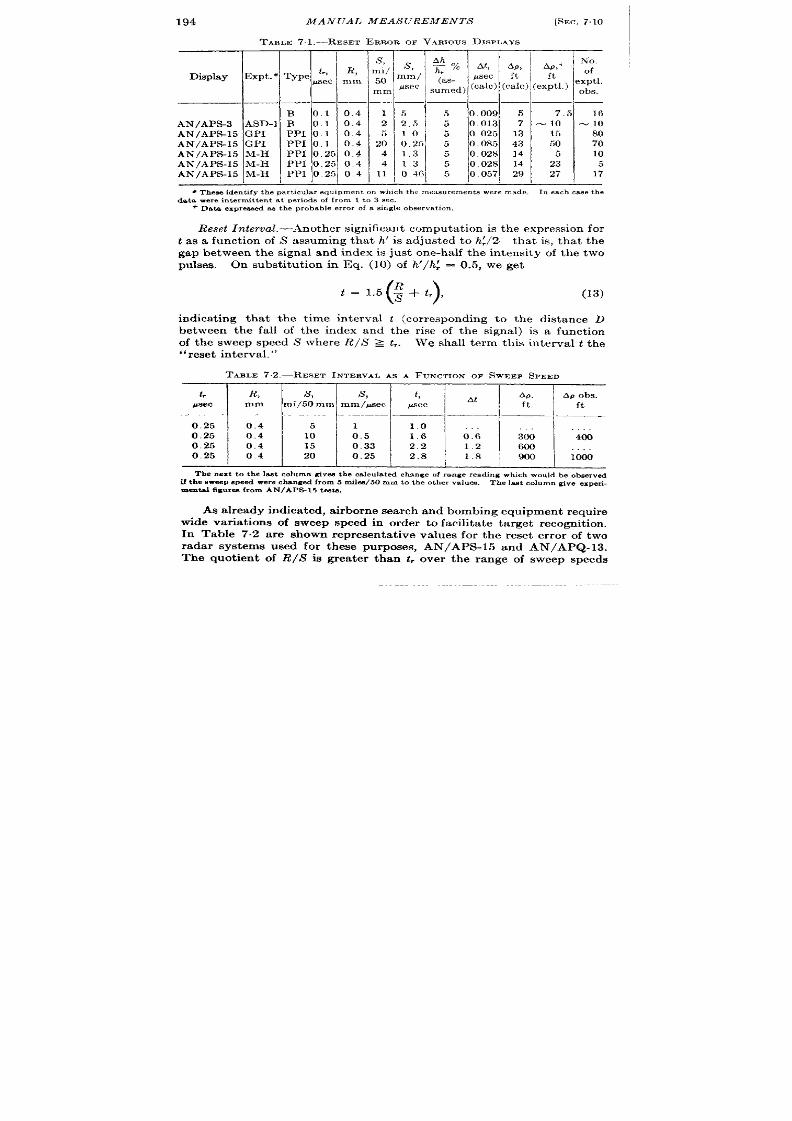
194
MANUAL MEAS UREMEN TS
[SEC. 7.10
TARLE 7.1.—REsET ERROR OF VAR1OUSDISPLAYS
Display
Expt . “ T pe
& ~R&
— —
—
B 0.1 0.4
AN/APs-3
ASD-1
B
0.1 0.4
AN/APs-15 GPI
PPI 0.1 0.4
AN/APs-15 GPI
PPI 0.1 0.4
AN/APs-15
M-H
PPI 0.25 0.4
AN/APs-15
M-H
PPI 0.25 0.4
AN/APs-15
M-H
PPI 0.25 04
s , s Ah
~%
A!
Ap,
No.
Ap,+
of
mi/ ‘
50
:,;; ~as-
@ec ‘t ‘t
exptl,
mm
sumed)
(talc)
(talc)
(exptl.)
ohs.
. —
1 5
2 2.5
5 1.0
20 0.25
4 1,3
4 1,3
11 0.46
5
5
5
5
5
5
5
—— —
0.009 5
0.013 7
0.025 13
0.085 43
0.028 14
0.028 14
0 057 29
7.
-10
15
50
5
23
27
16
= 10
80
70
10
5
17
I
I
I
I
I
I
q Theseiden tifyth par ticula requipmenton whichth em.asu rement aweremade.
In eachGM.the
data wereintermittentat periodsof from 1 to 3 sec.
+ Data expre.weds th e probableerrorof a singleobservation.
Reset n ter oa l.—Anot her sign ifica nt compu ta tion is t he expr ession for
t as a funct ion of S assuming tha t h’ is adjusted to h~/2—that is, tha t the
gap between the signa l and index is just one-ha lf the in tensity of the two
pulses. On subst itu t ion in Eq. (10) of h’/h~ = 0.5, we get
()
=l.5 :+tr,
(13)
indica t ing tha t the t ime in terva l t (cor responding to the dist ance D
between the fall of the index and the r ise of the signa l) is a funct ion
of the weep speed S where R/S z t,.
We shall t erm this in terva l tt he
“r eset in terva l. ”
TAME 72.-RE sET INTERVALAS A FUNCTIONOF SWEEP SPEED
t, R,
s,
s , t ,
At
Ap.
Ap ohs.
psec mm mi/50 mm
mm/@ec
psec ft
ft
0.25 0.4
5 1
1.0
0.25 0.4
10
0.5 1.6
0:6 ii
4G
0.25 0.4
15
0.33
2.2
1.2
600
. . .
0.25 04
20
0.25
2.8
1.8
900
1000
The next to th el-t columngiventh e calculatedcha ngeof ra ngereadingwhichwould heobserved
ii t h enweep speed were chan gedfrom5 mile450mm to the othervalues. Thelastolumngive eXPeIL
menta l fig ures from AN/APi%15teats.
As a lready indic ted, a irborn e sea rch and bombing equipment requir e
wide var ia t ions of sweep speed in order to facilit a te t a rget recognit ion .
In Table 7.2 a re shown represen ta t ive va lues for the reset er ror of two
rada r systems used for these purposes, AN/APS-l 5 and AN/ PQ- 13.
The quot ien t of R/S is gr ea ter than .$over the range of sweep speeds
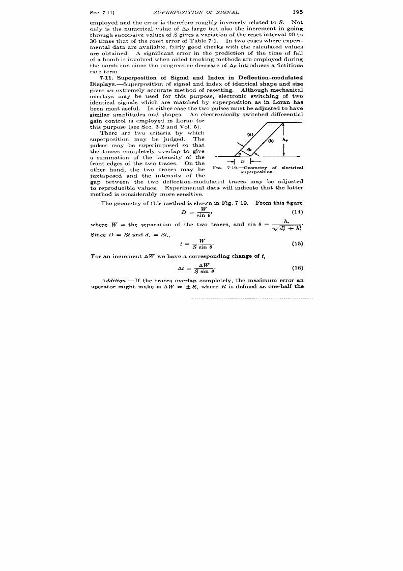
SEC.7.11]
S~TpERpOS~TION or SIGNAL
195
employed and the er ror is therefore rough ly inv rsely rela ted to S’. Not
only is the numerica l va lue of Ap la rge but a lso the ncrement in going
th rough successive va lues of S gives a var ia t ion of the reset in terva l 10 to
30t imes tha tof thereset er ror of Table 71. In twocases where exper i-
menta l da ta a re ava il~ble, fzir ly good checks with the ca lcu la ted va lues
a re obta ined. A significant er ror in the predict ion of the t ime of fa ll
of a bomb is involved when a ided t racking methods are employed during
t he bomb run since th e progressive decrea se of Ap in t roduces a fict it ious
ra te term.
7.11. Superposit ion of Signa l and Index in Deflect ion-modula ted
Displays .—Superposit ion of signa l and index of iden t ica l shape and size
gives an ext remely accu ra te method of reset t ing. Although mechanica l
over lays may be used for th is pu rpose, ele t ron ic switch ing of two
ident ica l signals which a re ma tched by superposit ion as in Loran has
been most useful. In either case the two pulses must be adjusted to have
simila r amplitudes and shapes.
An elect ron ica lly swit ch ed differ en tia l
ga in cont rol is employed in Loran for
th is pu rpose see Sec. 3.2 and Vol. 5).
There a re t ]vo cr iter ia by which
x
(a)
superposit on may be judged.
The
( ) ‘r
pulses may be super imposed so tha t
the traces completely over lap to give
a summation of the in tensity of the “
‘L
fron t edges of the two t races. On the
~eD~
other hand, the two t races may be
Fm. 7 9.—Geomet ry of electrical
superposition.
juxtaposed and the in tensity of the
gap between the two deflect ion-modula ted t races may be adjusted
to reproducible va lues. Exper imenta l da ta will indica te tha t the la t ter
met hod is con sider ably mor e sen sit ive.
The geomet ry of th is method is shown in Fig. 7“19. From this figu re
where W = the separa t ion
Since D = St and d, = St,,
D = ;O,
(14)
h,
of the two t races, and sin 0 =
m,”
w
t = Km-6’”
For an incremen t AW we have a cor responding change of t ,
Aw
At = -.
S sm 6
(15)
(16)
Ao!&t ion .-If he t races over lap completely, the maximum error an
qpera tor might make is AW = ~ R, where R is defined as on~half the
196
MANUAL MEASUREMEN~’S
[SEC. 711
trace width . 1 It is useful to represen t the fluctua t ion as a fract ion of the
maximum excursion as in the previous e uat ions, and we will define th is
fraction AW/R as AW’, from which Eq. (16) gives
At = R AW’
mi”
(17)
The accuracy of set t ing, therefore, increases with increasing sweep
speed. However , with increasing sweep speed sin 0 becomes much less
than one and the t race is near ly hor izonta l.
h , h,
‘in 0 = z, = %.”
The accuracy is then near ly independen t of
may be simplified t o give th e expr ession
()
T= RAW’ ~ .
,
sweep speed and Eq. (17)
(18)
Thus it is of no value to increase the sweep speed beyond a cer ta in point .
Juxtaposition.-The r eading may be taken by not ing the gap in
in ten sit y between t he t ra ces a and b of F ig. 7.14 a s in in ten sit y-modu la ted
displays.
F rom Eq. (7) we may compute the rela t ion between the t race separa-
tion a nd t he in ten sit y h’ of the gap between t races a and b in terms of
h;, the maximum in tensity of the two traces, and R, th e distance for the
t race in tensity to fall linear ly to zero.
or
()
=R 2_~
h: “
(19)
(20)
From Eqs. (20) and (15) we obtain
R
()
~_~,
t = S~6 h:
(21)
and for an increment Ah’
At
R
Ah’
‘-”X”
(22)
Equat ion (22) is similar in form to Eq. (16) with sweep speed being a
determin ing factor in the accuracy. Similar ly for sin O <<1, Eq. (20)
1For a t r iangular in tens itydis t r ibut ion , th ii is roughly equal to the value of R ES
previouslydefied.
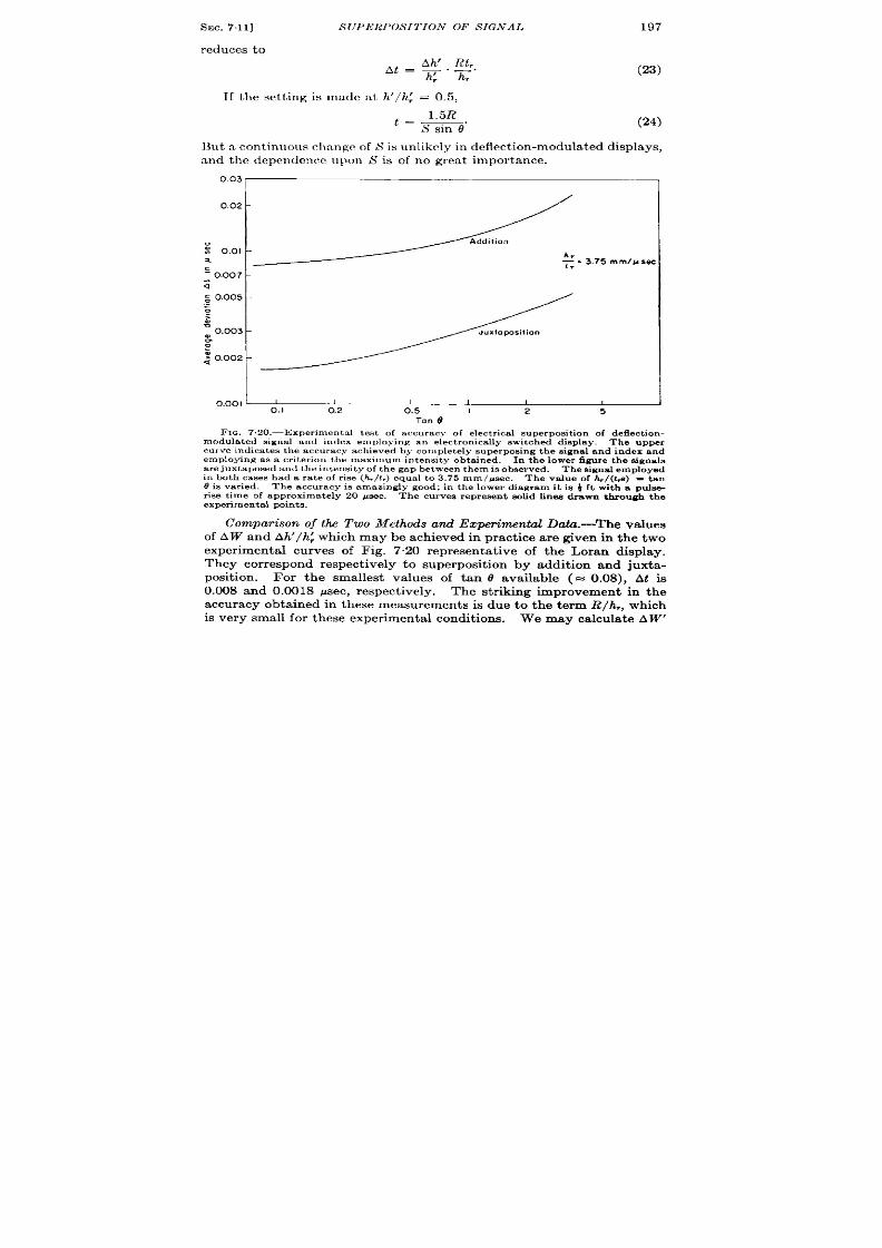
SEC.7.11]
r edu ces t o
S (J P1<lWOS IT ION OF S IGNAL
~t=A~,~r
h: h,”
Iftheset t ingis madca th ’/h~ =0 5,
~ = 1.5R
S sin 0“
197
(23)
(24)
But a cont inuous clmnge of S is un likely in deflect ion -m odu la ted displays,
and the dependence upon S is of no grea t impor tance.
“
:
a
.:1/,3.75.
=0.007
-
a
: 0.005 -
.-
~
>
:0.003
-
m
0
$ 0.002
-
I
0.001I
1
1
I I 1
,
0,1
0.2
0.5
I
2 5
Tan 0
F IG. 7.20.—Exper imen t al t est of a ccu r acy of elect r ica l su per posit ion of d eflect ion -
modula t ed sign a l a nd index employing an elect r on ica lly swit ch ed dkp la y.
The u pper
cu rve indica t es t h e accu r acy ach ieved by comp le tely superpos ing the s igna l and index and
employin g a s a cr it er ion t he max,mum in tenmt y obt ain ed. In t he lower figu re t he sign als
a re juxtaposed and the in tens ity of the gap between them is obse rved.
The signalemployed
in lm th ca ses h ada r at e of r ise (h , / t ,) equ a l t o 3,75
mm/psec. The va lue of &/(ha ) = tan
Ois va ried. Th ea ccu ra cy isam azin gly good; in th elower dla ~am it is }ft with a pu lse-
r ise t ime of a pp ro ima te y 20 p sec.
Th e cu rves r epr esen t solid fin es dr awn t hr ou gh t he
experimenta l points.
Compa ison of tlu Two Methods and Ezperimtd Daia.-The values
of AW and Ah’/h~ which may be ach ieved in p act ice are given in the two
exper imenta l curves of Fig. 7.20 represen ta t ive of the Loran display.
They cor respond respect ively to superposit ion by addit ion and juxta -
posit ion. For the smallest values of tan O available (= 0.08), At is
0.008 a nd 0.0018 ~sec, r espect ively.
The st r iking improvement in the
accuracy obta ined in these measurements is d e to the t erm R/h,, which
is er y small for t hese exper im en ta l con dit ion s.
We may ca l ula te AW’
198
MANUAL MEASUREMENTS
[SEC. 7.12
rmd Ah’/h~ from Eqs. (17) and (22).
Since these exper iments were
ca rr ied ou t with t,/h,
= 1/3.75 psec/mm, AW’ is calcu la ted to be ~ and
Ah’\h: to be ~, if it is assumed that R = 0.4 mm. Reset t ing is, there-
fore, somewhat mor e precise if an in tensity cr iter ion is used.
The la t ter va lue is much less than tha t employed in Table 7“1 and
the ass mpt ions about the shape of the intensity dist r ibu t ion of the
t r ace of the ca thode-ray tube may be at fau lt . In elect rosta t ic ca thode-
ray tubes using a mechan ical aper tu re for obta in ing a small spot size, the
t r ace may have an in tensity dist r ibut ion including a fla t top and ra ther
steeply sloping sides. 1 Alt ough no exper imental d ta a re available on
th is poin t , a slope approximat ly 3 t imes tha t assumed would give a
value of Ah’/h~ (+) in accord with tha t used in ‘I’able 7.1 (see Vol. 22,
Chap. 17). The nature of the intensity dist r ibu t ion of the ca thode-ray-
tube t r ace depends to a cons derable exten t upon the na ture of t e
elect ron-opt ica l system. Since thk is not con t rolled in product ion , the
abrupt in tensity dist r ibu t ion may not be obta ined in all tubes.
The ext r eme accu racy of reset t ing by superposit ion and in tensity-
~a tch ing is notewor thy; the r eset er ror is approximately one foot . This
$pproaches the values that migh t be expected fro r -f cycle-match ing in
2-Me/see Loran (see Vol. 5). However these test s were per formed on a
specia lly built in dica tor in wh ich stable swe ps an d a ccu ra te t ime-dela y
cir cu its and iden tica l pulses wer e available. F ur th ermor e, a tm osph er ics
and noise would distor t the pulses and considerably r educe the accur acy
of the set t ing. Also in the Loran system the accuracy of the synchroniza -
t ion and of the indicator circu it s is no bet ter than approximately 250 ft .
A considerably improved indicator is descr ibed in Sees. 7.29 to 7.3 .
7.12. Reset Er ror with In termit t en t Data and with Two-coordina te
Cont iols.-The opera tor is often requ ired to make an accura te set t ing of
signal and index even though they are displayed as in frequen t ly as every
5 to 20 sec. This is especia lly t rue in scann ing radar systems used for
naviga t ion, bombing, or figh ter direct ion . A considerable amount of
data was obta ined in on e par t icu lar case wh ere the oper ator was requ ired
to set a two-coordi a te index or crossha ir t o a radar echo in response to
the opera t ion of t wo con trols in rectangula r coor dina tes which adjusted
the index on a PPI display. A deta iled explanat ion of this system is
given in Sec. 7“28. As the data were taken under condit ions similar to
t hose r epr esen ted by Table 7.1, similar effect s of sweep speed wer e n ot ed.
The most signh icant da ta of this exper iment were the number of scans
requ ired to make a set t ing of u lt imate accuracy. Since the in terva l
between scans was appreciable, the number of t r ies necessa ry to make an
accura te set t ing defin ed the rapidity with which th e range was measured
and a range r te established. This is illust ra te in Fig. 7.21 where the
1In theset ea t s a type3BP1 opera t iog a t 2 kv was employed ,
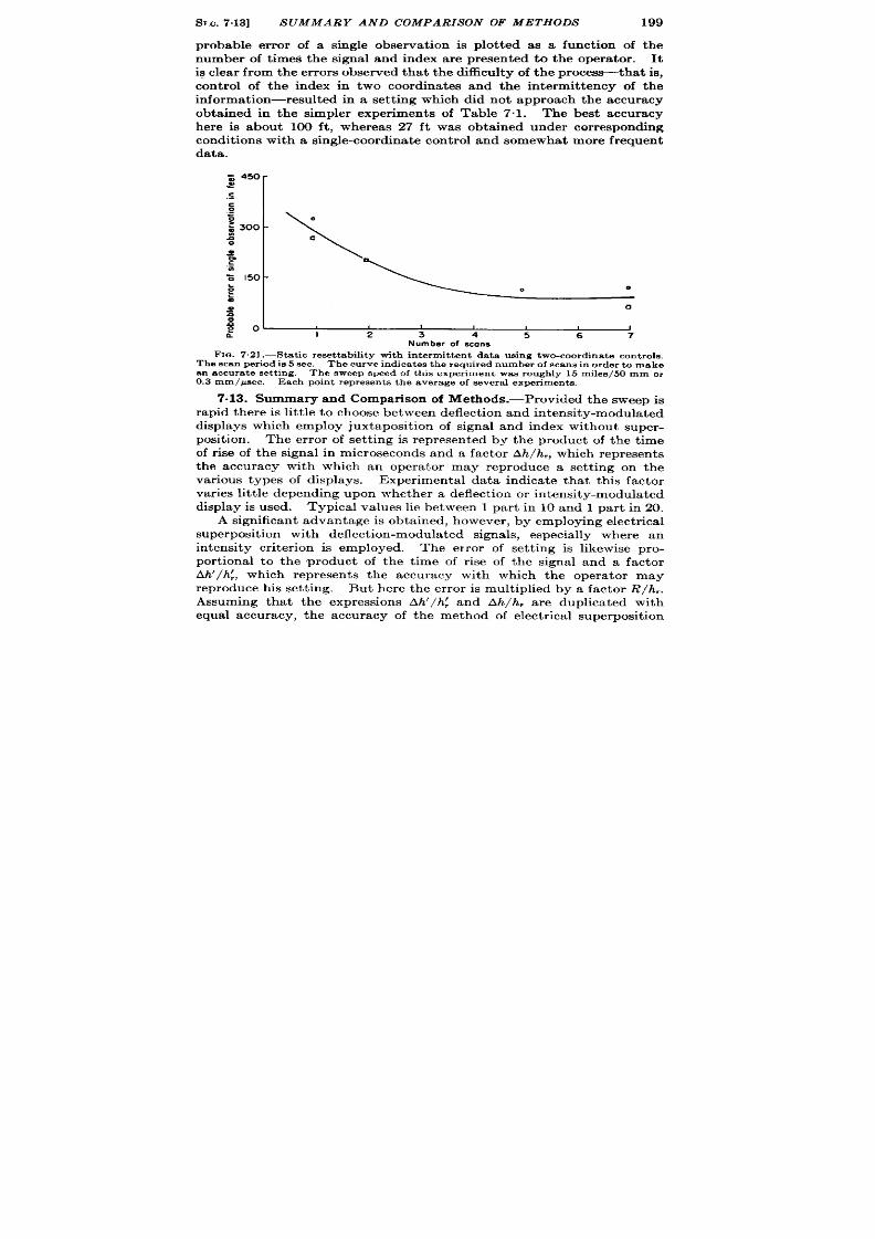
SM. 7.13]
SUMMARY AND COMPARISON OF METHODS
199
probable er ror of a single observa t ion is plot ted as a funct ion of the
number of t imes the signal and index are presen ted to the opera tor . It
ig clea r from the er ror s observed that the difficu lty of the proc~tha t is,
cont rol of the index in two coordina tes and the in termit tence of the
informat ion—resulted in a set t ing which did not approach the accuracy
obtained in the simpler exper iments of Table 7.1. The best accuracy
here is about 100 ft , whereas 27 ft was obta ined under cor responding
condit ions with a single-coordina t e cont r ol and somewhat more frequ ent
data .
:
-
?
-\
0
~ 300
~
a
0
~
0
.E
.
z 150
-
5
0
:
0
:
~ o -
I
, ,
,
I
I
2 3 4
5
6
7
Number of scans
FIG. 7.21 .—Stat ic reset t ability with in termit t en t da ta us ing two-coord ina te con t rols .
The scan per iod is 5 sec. The cu rve indica t es t he r equ ir ed number of s cane in orde r t o make
an a ccu ra te set tin g, Th e sweep speed of t his exper imen t wa s r ou gh ly 15 m ile8/50 mm or
0.3 mm/psec. Ea ch poin t r epr esen t s t h e aver age of sever a l exper imen t s.
7.13. Summary and Compar ison of Methods.-Provided the sweep is
r apid t her e is lit tle t o ch o se between deflect ion a nd in ten sit y-modu la ted
displays which employ juxtaposit ion of signal and index without super -
posit ion. The er r or of set t ing is represented by the product of the t ime
of r ise of the signal in microseco ds and a factor Ah/h ,, which represent s
the accuracy with which an opera tor may reproduce set t ing on the
var ious types of displays. Exper imenta l da ta indica te tha t th is factor
va ries lit tle depen din g u pon whet her a deflect ion or in ten sit y-modu la ted
display is used. Typica l values lie between 1 par t in 10 and 1 par t in 20.
A significan t a dvan ta ge is obt ain ed, h owever , by employin g elect rica l
superposit ion with deflect ion-modula ted signa ls, especia lly where an
in tensity cr iter ion is employed. The er ror of set t ing is likewise pro-
por t iona l to the product of the t ime of r ise of the signal an a factor
Ah’/h~, which represen ts the accuracy with which the opera tor may
reproduce his set t ing. But here the er ror is mult iplied by a factor R/h,.
Assuming that the expressions Ah’/ h~ and Ah/h, a re duplica ted with
equal accuracy, the accuracy of the method of elect r ica l superposit ion
200
ANUAL MEASUREMENTS [SEC.7.14
will exceed tha t of juxtaposit ion by a factor h,/R. For example, if a
5-in. ca thode-ray tube is employed, h, may be as la rge as 100 mm
and R aa small as 0.2 mm, giving an increase of accuracy of rough ly
W&fold.
Another onclusion of these sect ions regards the use of expandable
sweeps.
The employment of an in tensity cr it er ion for set t ingon in ten-
gity-modula ted ca thode-ray-tube displays of var iable sweep speeds
involves a systemat ic er ror which may be ’24)or 30 t imes the er ror of
reset t ing in the region where the spot size of the ca thode-ray tube is
comparable to the distance cor responding to the r ise and fall of the signal
a nd in dex.
TRACKINGMETHODS
7.14. Con tinuous Data. General Cons-ider at ion s.-Con tin uou s da ta
are here defined as those recur r ing at an in terva l tha t is shor t compared
to the response t ime of t e opera tor dur ing the t r acking operat ion .
.Cer ta in ly any data tha t r ecu r with in the per sistence of the opera tor ’s
vision can be termed cont inuous, and perhaps data tha t r ecu r as infre-
quent ly as once per second might be in th is class. The data are classed
aa in termit ten t if the t ime of their present t ion determines th moment
at wh ch the opera tor adjusts the t r acking apparatus.
With con t inuous
data the opera tor may adjust h is t racking con t rol at any t ime. Thug
other proper t ies of the t racking devices may determine th is t ime. On
the other hand with in termit ten t data any inherent per i dicity of the
t r acking mechanism must be adjusted to that f the data or eliminated.
A r igorous t r ea tmen t of manual t r acking methods is given in Vol. 25,
Chap. 8 of the Ser ies, and formulas are ther e der ived indicat ing the
opt imu per formance of a ided t racking. The following mater ia l t r ea ts
the t r acking met ods br iefly and the specia l problems occur r ing in their
use with oscilloscope displays of cont in uous or in termit t en t data .
The genera l methods of t r cking a re defined below and are shown in
Fig. 7.22. The discussion of th is chapter will be confined to the fir st
five methods since the last is the subject of Chap. 8.
1. Direct t racking. The movement of the cur sor is propor t ional to
the movement of the t racking cont rol.
2. Velocity t racking. The ra t e of movement of the cur sor is propor -
t ional to the movement of the t racking cont rol.
3. Aided t racking. This combines dir ect and ra te t racking. The
movement and the ra te of movement of the t racking index are
propor t iona l to the movement of the con t rol. The ra t io of dis-
placemen t to ra t e con t rol has the dimensions of t ime and is ca lled
the “t ime constan t .“
These two con t rols may be connected
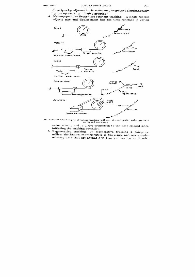
sEC 7.14]
CONTINUOUS DATA
201
dir ect ly or by a dja cent kn obs wh ich maybe gr asped simu ltaneou ly
by the opera tor by “double gripping.”
4. Memory-poin t or linear-t ime-constant t racking. A single con t rol
ad usts ra te and displacement but the t ime constan t is var ied
Constont epeed motor
‘d k:
Constont speed motor
Automothc
,,r&y
FIG. 7.22.—Pictor ia l display of var ious t racking methods—direct , velocity , a ided, regener-
5.
a t ive, and au tomat ic.
au tomatically and in direct propor t ion to the t ime elapsed since
in it ia tin g t he t ra ckin g oper at ion .
Regenera t ive tracking. In regenera t ive t racking a computer
ut ilizes the known character ist ics of the signal and a y supple-
menta y data tha t are available to genera te t r ia l values of ra te,

24)2
6.
MANUAL MEASUREMENTS
[SEC. 7.14
which , after a per iod of init ial t r acking by manual opera t ion of
con t rols, is exact ly cor rected and the computer con t inues to t r ack
t he t ar get as lon g as t he ch ar act er ist ics of t he sign al a re u nch an ged.
Automat ic t racking. Discr iminat ion of the er r or between index
and signal is au tomat ic and a servomechanism causes the signal
t o be followed au toma tica lly.
FIG.7 .23.—A type M display unit , Fa lcon AN/APG-13a .
Mor e det a ils of t his d evice me
given in Sec. 723, especial ly Fig. 7 .37.
Dir ect Z’racking.-Th e simplest met hod of following a movable signal
on a ca thode-ray-tube display is by direct t racking wher e a movement
of th e oper ator ’s handwheel pr odu ces a pr opor tion al displacement of t he
t racking index. An advantag of this method is the rapidity with which
the index may be set to a target and with which accura te easu rements
may be obta ined. For example, th is method is used for t racking ships
or ground echoes a a shor t r ange ahead of a rapidly moving airplane. A
SEC. 714]
CON TIN UOUS DATA
203
typica l equipment for direct t r acking is shown in Fig. 723. A complet e
descr ipt ion of this equipment is given in Sec. 7’.23. The scale factor
of the displacement cont rol is propor t ioned t o the character ist ics of the
input data and to the sca le of the diwlay. Usua lly the full sca le of the
displacement handwheel cor responds ro ghly t o twent y turns t o pr ovide
sufficien t accuracy con t rol and yet give a reasonably shor t t ime of
slewing* from one end of the sca le to the other . The excellen t per form-
ance of dir ect t racking under cer ta in circumstances is indica ted in Fig.
729. Dir ect t r acking is, however , fa t iguing for the opera tor if it must
be susta ined for long per iods of t ime.
Fur thermore, it is very unsat is-
factory for use with int ermit t ent informat ion since as it does not susta in
the ra te in the in terval between input signals (see Sec. 716). More
accura t in format ion on the ra t e of change of t a rget r ange is obta ined
fr om t he followin g met hods.
Velocity Tracking. —Velocity cont rol has been used in place of dis-
placement cont rol in order to obta in more accura te r a te informat ion .
The velocit of the index is var ied to equal tha t of the signa l. The
usual pr ocedur e for r educing displacement er ror s consist s of a rbit rar ily
increasing the velocity of the index and, when the displacement er ror
has been reduced to zero, retu rn ing the velocity cont rol t o the est imated
cor r ect r a t e.
Although this method affords a sat isfactory solut ion for a
ta rget moving at a constant velocity, it is r at her difficult t o use, because of
the lack of a displacement cont rol t o get the cur sor init ia lly set t o the t ar -
get and moving at the proper ra te.
Aided !!’rackinp.-This met od has the advantage of smooth ra te
in form at ion, obt ain ed wit h velocit y t ra cking, and t he acilit ies of get tin g
on ta rget rapidly and of adju t ing the ra t e for new condit ions. The
proper ties of t he system ar e simply expr essed below.
The scale factor of the displacement handwheel is defined as D yd
per tu rn and the sca le factor of the ra te cont rol as R yd/sec per tu rn .
It is assumed that both these quant it ies a r e constan t and tha t the input
signaI has a con st ant velocit y V,. At some instant T = O, t h e t ra ck in g
index and the input signal a re set in to coincidence and the t r acking
mechanism is sta r t ed at an arbit ra ry ra te V, which will probably be
differen t from tha t of the input signal. If, for example, V is t oo small,
t he t racking index will fall fa r ther and far ther behind the ta rget . Aft er
T see, it will be (V, – V) T yd behind, and a displacement of the hand-
()
V.–v
wheel equal to ~
T will be requ ired to set the index bacli t o the
ta rget . A cor r esponding increase of V equal to (R T / D) ( V, – V) is
produced. If t he t ime elapsed between reset t ing is D/ I? see, t hen the
] Alter ingthe posit ion of the index.
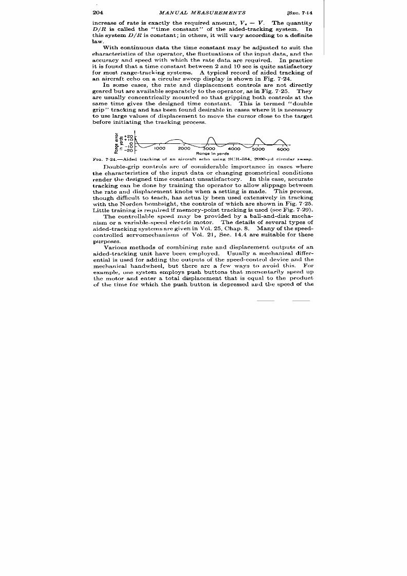
204 MANUAL MEASUREMENTS
[SEC. 7.14
increase of ra t e is exact ly the requ ired amount , V, — V. Th e qu an tit y
D/R is ca lled the “t ime constan t” of the a ided-t racking system. In
th is syst em D/R is constan t ; in other s, it will va ry according t o a defin ite
law.
With con t inuous data the t ime constan t may be adjusted to su it the
character ist ics of the opera tor , the fluctua t ions of the input d ta , and the
accuracy and speed with whi h the ra t e da ta a re r qu ir ed.
In pr a ct ice
it is found tha t a t ime constan t between 2 and 10 sec is quite sa t isfactory
for most range-t racking systems. A typica l r ecord of a ided t racking of
an a ircr ft echo on a circu la r sweep display is shown in Fig. 7.24.
In some cases, the ra t e and displacem nt con t rols a re not dir ect ly
gea r ed but a re available sepa ra tely t o the opera tor , as in Fig. 7.25. They
are usua lly concen t r ica lly moun ted so tha t gr ipping both con t rols a t the
same t ime gives the designed t ime constan t . This is t ermed “ double
gr ip” t r acking and has been found desirable in cases where it is necessa ry
to use la rge va lues of displacement t o move the cur sor close to the ta rget
befor e in it ia tin g t he t ra ckin g pr ocess.
; *+2~
:; +10
~:-1: -
-000
1
1
1
, \
~.- -20
2000
4000
‘5000
6000
K
Range in yards
F IG. 7.24.—Aided t ra ck in g of a n a ir cr aft ech o u sin g SCR-5S4, 2000-yd cir cu la r sweep.
Double-gr ip con t rols a re of considerable impor tance in cases wher e
the cha ract er ist ics of the input da ta or changing geomet r ica l condit ions
render the designed t ime constan t unsa t isfactory. In th is case, accura t e
t r acking can be done by t ra in ing the oper a tor t o a llow slippage between
the ra t e and displacemen t knobs when a set t ing is made. This process,
though difficu lt to t each , has actua”ly been used extensive y in t r acking
with the Norden bombsi h t , t he con t rols of which a re shown in Fig. 7.25.
Lit tle t ra in ing is r equ ir ed if memor y-poin t t ra ckin g is used (see Fig. 7.29).
Th con t rollable speed may be provided by a ball-and-disk mecha-
n ism or a var ia ble-speed elect ric mot or .
The deta ils of severa l typ s of
a ided-t racking systems are given in Vol. 25, Chap. 8. Many of the speed-
con t rolled servomechanisms of Vol. 21, Sec. 14.4 a re su itable for these
purposes.
Var ious methods of combining ra t e and displacemen t outpu t s of an
a ided-t r acking unit have been employed. Usually a mechan ica l differ -
en t ia l is used for adding the ou tpu ts of the speed-con t rol device and the
mechanica l handwheel, bu t th ere a re a few ways to avoid th is.
For
example, one system employs push bu t tons tha t momenta r ily speed up
the motor and en ter a tot a l displacemen t t a t is equal t o the product
of the t ime for which the push but ton is depressed and the speed of the
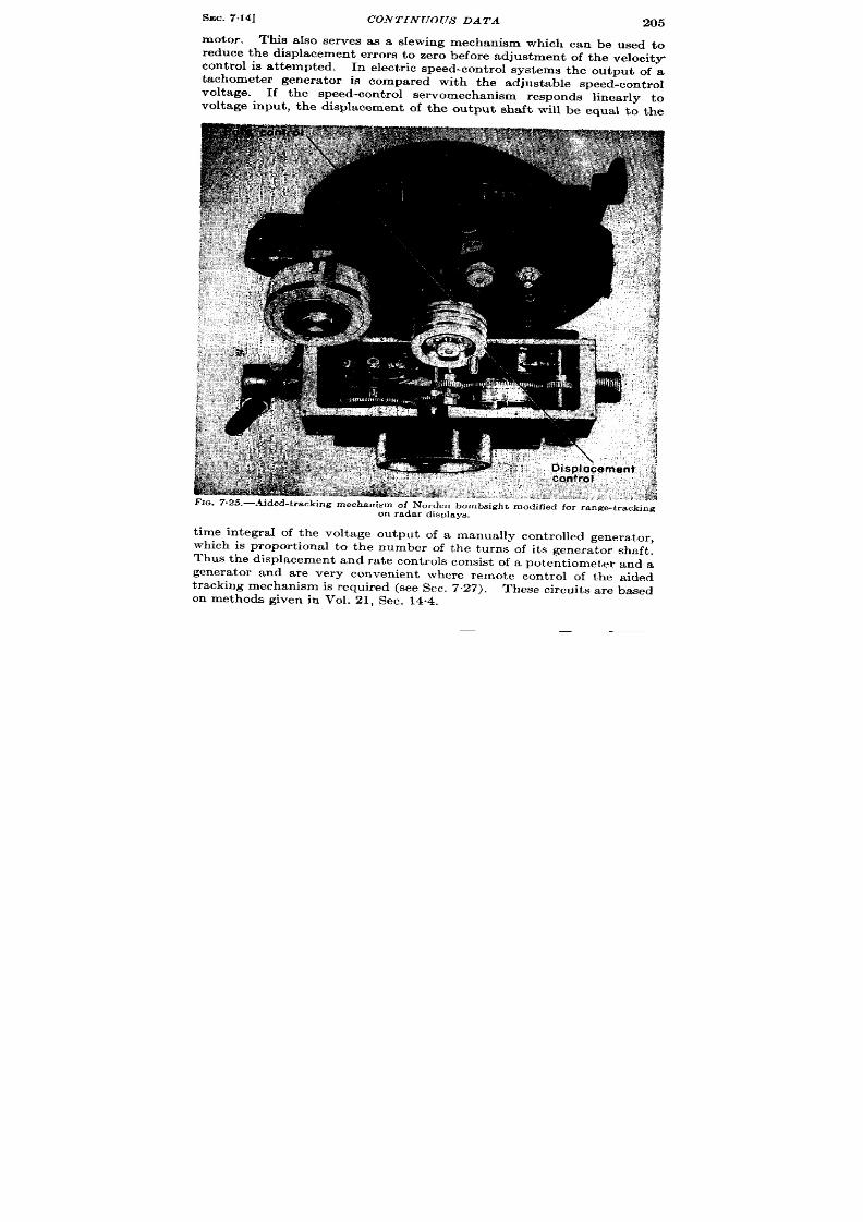
SEC. 7.14] CONTINUOUS DATA
205
This aIso erves as a slewing mechanism which can be used to
reduce the displacement er rors to zero before adjustment of the velocity
con t rol is a t tempted. In elect r ic speed-cont rol systems the outDut of a
tachometer genera tor is compared with the adjustable speed~cont rol
voltage.
If the speed-con t rol ser omechanism r spon s linear ly to
voltage input , t he displacement of the output shaft will be equa l to the
t ime in te ra l of the volt age output of a manually con t rolled genera tor ,
which is propor t iona l to the number of the turns of its genera tor shaft ,
Thus the displacement and ra t e cont rols consist of a poten t iometer and a
genera tor and a re very convenien t where remote con t rol of the a ided
t racking mechanism is requir ed (see Sec. 7.27). These circu it s a re based
on methods given in Vol. 21, Sec. 14.4.

206
MANUAL MEAS UREMENTS
[SEC. 715
7.16. In termit t en t Data . General Considerations. —The data of a
scanning radar system are presen ted for a t ime (rough ly ~ see) which is
t oo shor t t o permit anything more than a displacement measurement ,
and yet the r ecur r ence in terva l of the informat ion is so large, 3 to 20 see,
tha t a long t ime is requ ired before a range ra te of reasonable accuracy
may be obta i ed: If, however , the ta rget is moving so slowly that
severa l thousand observat ions may be obta ined while it t r aver ses the
full r ange of the radar system and a reasonable number of the measure-
ments may be averaged to obta in the r a te informat ion , the t racking
methods of the previous sect ion are suitable. But radar systems for
t racking rapidly moving aircraft from the ground or vice versa may give
on ly 30 to 60 obse~at ions of a ta rget in the en t ir e range. For example,
a ground radar having a range of 200 miles and a scan per iod of 30 sec
gives a t best on ly 60 observat ions of a 400-mph airplane. AIthough
the amount of in format ion available for a irborne bombing may be
increased by rapidly scann ing antennas, the limita t ion in long-range
ground radar employing a nar row beam is fundamenta l (see Vol. 1).
Dir ect or velocity t racking is of lit t le use for in termit t en t da ta. I is
ext r em ely difficult t o mainta in t he cor rect r ate dur ing the in tervals when
no data a re available, and it is equally difficult with velocit y t racking to
est imate the increase of ra te which will cause the displacement er ror to
become zero at a t ime when the data recu r .
Ther efor e, specia l methods
must be employed in order to obta in accura te ra te informat ion .
In a few specia l cases, however , the in terva l between displacement
measurements may be employed for approximate r a te measurements.
In a moving vehicle-for example, an airplane—some choice of the range
at which the displacement measurement is made is permissible. The
echo from a fixed object is a llowed to approach and to coincide with the
fir st of a ser ies of fixed r an ge ma rkers.
A stop watch is then star t ed and
it is stopped when the echo touches the next fixed index which represen t s
a dist ance, for example, of 5 miles nearer the a ircraft .
The average
ra te over th is in terva l is obta ined from a si ple slide ru le shown in
Fig. 7.26. Not on ly does th is slide ru le conver t the t ime in terval in to
speed along the line of sight but it a lso cor r ect s for the alt itude of the
Aided Tracking.—If the in termit t en t da ta r ecu r a t a constant ra te,
the t ime constant of an aided-t racking mechanism may be made equal
to th is in terval or t o any integra l mult iple of it . Therefore, the displace-
ment and ra te con t rols may be double-gr ipped in synchronism with the
scan per iod or a mult iple of it and the set t ing will have been made in
accordance with the requirements of the t ime constant . Depending
upon the t pe of cu rsor employed, the amount of cor r ect ion may be
en t ered in accordance with an est ima te of the er ror a t the t ime of appear -
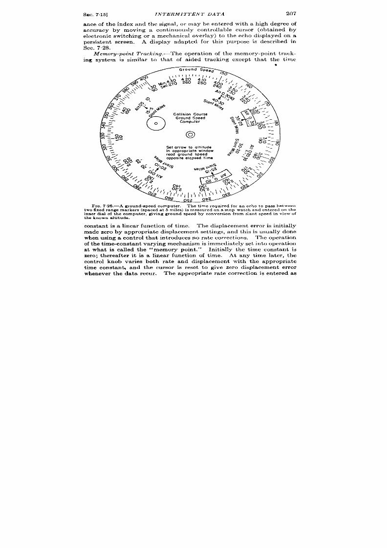
sEC.7.15]
INTERMITTENT DATA
207
an te of the index and the signal, or may be en t ered with a high egree of
accuracy by moving a con t inuously cont rollable cursor (obta ined by
elect ron ic switch ing or a mechanica l over lay) to the echo displayed on a
persisten t screen . A display adapted for th is purpose is descr ibed in
Sec. 7.28.
Memory-point Tracking.—The oper t ion of the memory-poin t t r ack-
ing system is similar to tha t of a ided t racking except tha t the t ime
FIQ.7.26.—A ground-speed compu t er . The t ime r equ ir ed for an echo t o pa ss between
two fixed r ange marker s (s paced a t 5 miles ) is mea su r ed on a st op wa t ch and en t er ed on the
in n er dia l of t h e compu t er , givin g gr ound speed by conver sion fr om d ant speed in view of
the known aft itude.
constan t is a linear funct ion of t ime. The displacement er ror is in it ia lly
made zero by appropr ia t e displacement set t ings, and th is is usually done
wh en using a on tr ol tha t in trodu ces n o r at e cor rect ion s.
The opera t ion
of t he t im e-con st an t va ryin g mech an ism is immedia tely set in to oper at ion
at wha t is ca lled the “memory point . ” In it ia lly the t ime constant is
zero; therea ft er it is a linea r funct ion of t ime. At any t ime la ter , the
con t rol knob var ies both ra te and displacement with the appropr ia te
t ime constan~ and the cursor is reset to give zero displacement er ror
whenever the da ta recu r . The appropr ia t e ra te cor rect ion is en tered as
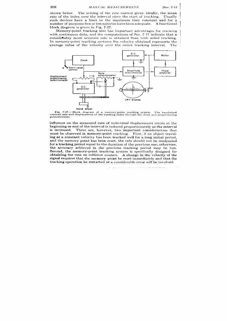
208
MA NUAI> MEAS lJh?EMENTS
[SEC. 7.15
shown below. The set t ing of the ra t e con t rol gives, ideally, the mean
ra te of the index over the interva l since the sta r t of t racking.
Usually
such dev ces have a limit t o the maximum t ime constant and for a
number of purposes five or t en minut es ha ve been a dequa t .
A functional
block diagram is given in Fig. 727.
Memory-point t racking also ha impor tant advantages for t racking I
with cont inuous data , and the computa t ions of Sec. 717 indica te that a I
,
consid~ably more accura te ra te is obta ined than ~vith aided t racking.
In memory-point t racking systems the velocity obta ined represent s the
I
average va lue of the velocity ovc,r the ent ire t racking interva l.
The
DC.
a
generator
Clock
q Slort-resetl
control I
Rate
Displacement
potentiometer
proportioning
potentiometer
D.C.
CRT display
‘-d
Hand wheel
Fm. 7.27.—Block diagram of a memory-poin t t racking system. The handw eel
con t rols r a te and displa cemen t of t h e t r ack ing index th rough the clock and p ropor t ion ing
potentiometer.
influence on the measured ra te of individual displacement er ror s a t the
beginning or end of the in terval is reduced propor t iona tely as the interva l
is increased. There are, however , two impor tant considera t ions tha t
must be observed in memory-point t racking. First , if an object t ravel-
ing at a constant velocity has been t racked well for a long init ia l per iod,
and the memory point has been reset , the ra te should not be readjusted
for a t racking per iod equal t o t he dura t ion of t he previous one; ot herwise,
the accuracy achieved in the previous t racking per iod may be lost .
Second, the memory-point t racking system is specifica lly designed for
obta ining t he ra te on collision courses.
A change in the velocity of the
signal requires tha t the memory point be reset immedia tely and tha t the
t racking opera tion be rest ar t ed or a considera ble er ror will be involved.

SEC.715]
IN TERMIT1’ENT DATA
209
Time const ant l T is defined as the ra t io of an increment of displace-
ment of the t racking index to the co responding increment of velocity.
The t ime constant is equal to the t ime t elapsed since the star t of the
t racking opera t ion . It will be shown that this fea ture enables the
opera tor to t rack out a velocity er ror regardless of how he makes co rec-
t ions, provided tha t he ult imately reduces the displacement er ror to zero.
If the velocity of the t racking index is V and the displacement z,
then the t ime constant is T = d.z/ dV. This definit ion applies to a
t racking system regardless of the independent var iable of the t racking
opera t ion . In the a ided-t rac ing system descr ibed in Sec. 714, the
independent var iable is shaft rota t ion 0, and the sca le factors of the
r espect ive h andwheels a re R = dV/ d O and D = dx/ d6, so tha t the t ime
constant is D/ R = dx/ d V. Since 0, V, and x are all changed propor-
t ionally it makes lit t le difference Ivhich is considered the independent
var iable. But in memory-poin t t racking, where the ra t ios are not
constant , there are severa l choices for the independent var iables: the
t racking cont rol may vary displacement direct ly, in which case z or
is an independent var iable; it may vary V dir ect ly, in wh ich ca se V or 0,
is the independent var iable; or it may be a push-but ton type of cont rol,
in which a cont rol may allow velocity to be cor rected at a constan t ra te
dV/ d t, so tha t t ime is the independent variable. In the first two cases
either R or D is var iable, and in the th ird the variable 0 s absent , so
tha t R and D cannot be defined. The defin it ion of memory-poin t t rack-
ing T = dx/dV = t can , however , be applied to any of these systems.
In order to show that tbe result of t racking is independent of the way
in which tbe opera tor br ings the index to the ignal, an equat ion may be
writ ten which gives the displacement er ror in any t racking opera t ion as
a funct ion of tbe cor rect ions that have been made,
Let z, = displacement of signal being t racked,
xi = displacement of index,
z, = total dis lacement correct ion applied to the index up to
time t,
V, = velocity of signal (assumed constant), and
Vi = velocity of index at the t ime /.
If the velocity of the signal is constant , the displacement of the signal is
giv n by
x, = x.(o) + V*L
(25)
The displacement of the index is given by
\
t
Zi = Zi(0) + ~. +
Vi dt.
o
1This der iva t ion was writ ten by Duncan acRae, J r .
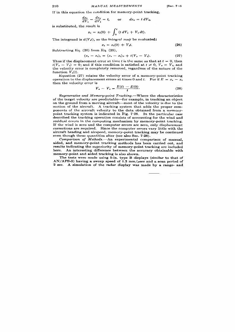
210
MAN UAL MEAS UREMEN TS
[SEC. 7.15
If in th is equa t ion the condit ion for memory-poin t t r acking,
dz, dze
m=ni=t’ ‘r
dzc = t dV~,
is subst itu ted, the resu lt is
Zi = z{(o) +
\
‘(tW, + v,
d).
o
The in tegrand is d(V~t), so th e in tegra l may be eva lua ted:
Z, = X,(O) + T’{t. (26)
Subt ract ing Eq. (26) from Eq. (25),
(X* – X,)1 = (XS – Z~)O+ t(V* – V,).
(27)
Thus if the displacement er ror a t t ime t is th e same as tha t a t t = O, then
L(V, – Vi) = O; and if th is condit ion is sa t isfied a t t # O, V, = Vi, and
the velocity er ror is completely removed, rega rdless of the na tu re of the
function V,(t).
Equa t ion (27) rela t es the velocity er ror of a memory-poin t t r acking
opera t ion to the displacement er ror s a t t imes O and t . For if E = z, — G
then the velocity er ror is
v _ v. = E(O – -E(O).
q s
t
(28)
Regenerative and Memory-point Tr aclcin g.-Wher e t he ch ar act er ist ics
of the ta rget velocity a re predi tablefor example, in t racking an object
on the ground from a moving a ircra ft—most of the velocity is due to the
mot ion of the a ircra t . A tracking system that adds the proper com-
ponen ts of the a ircra ft velocity to the data obta ined from a memory-
poin t t racking system is indica ted in Fig. 7. 8. In the par t icu la r case
descr ibed the t racking opera t ion consist s of accoun t ing for the wind and
residua l er ror s in the comput ing mechanism by memory-poin t t racking.
If the wind is zero and the compu ter er ror s a re zero, on ly displacement
correct ions a re requ ired. Since the computer er ror s va ry lit t le with the
a ircr ft heading and a ir speed, memory-poin t t racking may be con t inued
even though these quant it ies a ter (see a lso Sec. 7.28).
Comparison of Methods.—An exper imenta l compar ison of manual,
a ided, and memory-poin t t racking methods has been car r ied ou t , and
resu lt s indica t ing the super ior ity of memory-poin t t r acking a re included
here. An in terest ing difference between the accuracy obta inable with
memory-poin t and aided t racking is a lso shown.
The tests were made using 5-in . type B displays (similar t o tha t of
AN/APS-3) having a sweep speed of 1.3 mm/psec and a scan per iod of
2 sec. A simula t ion of the radar display was made by a range- and
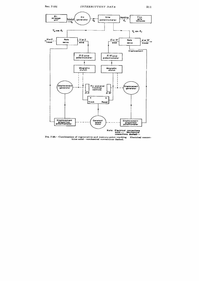
SEC.7.15]
INTERMITTENT DATA
211
Vame (?C
~ > ‘sin”
““-m
w’+”
I
Displacement
‘d
-S wind
potentiometer
E-ww i”d
potentiometer
I
i
I
Magnetic
clutch
I
v
ognetic
clutch
0:
isplacement
generator
..&-
I
‘? ‘
0
a
Track
Reset
I
b
isplacement
pro ortion – – –
Yoten Iomeler
--@----&
Note: ~$~tricol connections
— Mechanical
connections dashed --
-Fro.7 .28.-Combinat ion of regenerat ive and memory-point t racking. Electricalconnec.
t ions e.olid-mech.snical connections dashed.

212
MANUAL MEAS UREMEN TS
[SEC.715
a zimut h-ga ted 30-M c/sec oscilla tor .
The output of this oscilla tor was
connected to a high-gain amplifier giving an amplitude- and t ime-
modula ted l-~sec pulse of adjustable signa l-to-noise ra t io.
The wave-
forms of the receiver outpu t and the t racking marker had r ises of 0.3 and
().1 ysec, respect ively. The t ime delay of th is pulse was var ied at a
constan t ra te of 120 yd/sec by a synchronous motor .
A range-t rack ing
index of dura t ion approximately 0.3 psec was used. The range er ror
Operalor *I
Operator s 2
50
50
I IL
Avers e probable
40
!
rror _ 11,4 yd
40
t 17.lyd
,~;
::W
p.
30
-’u
.
=020
~m
h
20
------ -.----
ga
-lo --”---- ------10
‘!i!JL:L
~o.
246810
246810
d o-a
Numbwof t r ies
Numberof fr ies
FIG.7.29.—Compa r ia on of dir ect , a ided, a nd memory-poin t t r ack ing. These r esu lt s
we re obt a ined using an in t en sit y-modula t ed s igna l and index d isplayed on a type B indica -
tor havingsweepspeedcorrespondingo Z miles /50mm or 1.3 rnm/#sec. These data
represen tthe 6rst at tempt s01inexperiencedoperat ors .
was automat ically r ecorded on an Ester line-Angus m et er by subt ract ion
of the con t rol volt ages for the t ime-modula ted signal and the t ime-
modu la ted index.
Th e r esu lt s of t ra ckin g t est s wit h two in exper ien ced oper at or s a re given
in Fig. 7.29. The per formance with memory-poin t t racking is outstand-
ing; the per formance with a ided t racking is poor .
Wit h exper ien ced an d in telligent oper at or s u nder t he same condit ion s
much more accura te result s were obta ined, especia lly with a ided t rack-

I
SEC.7.16]
COMPARISON OF METHODS 213
ing: (1) manual t racking, average probable er ror— A 10 yd; (2) a ided
t racking, average probable er r or— f 8 yd; (3) linear t ime-constan t a ided
t racking, average probable er ror— + 5 yd. In these test s the t r acking
with (1) and (3 was easy as was the damping of er ror s. In (2) the
t r ack ing requ ir ed concen t ra t ion .
H owever , th e accu racy was bet t er than
that obta ined with manual t r acki g.
A number of test s were made with a pract ical memory-poin t t r acking
system oper at in g in t wo coor dina tes and supplied with in termit ten t da ta
of a 3-see per iod displayed on a 5-in. PPI. The t ime required for an
oper a tor to set up the cor r ect velocity “with memory-poin t t r acking
var ied from 4 to 16 scans depending upon a number of factor s, a ong
them the differenc of velocity between the t r acking s stem and the
movin g sign al. In addit ion, som e pr elimin ar y est ima tes of t he r eset tabil-
ity wer e obtained dur ing t he t r acking opera t ion .
When t h e differ en tia l
velocity between the cur sor and signal was 200 knots, the average er r or
of the fir st set t ing was 200 ft compared with 90 ft for stat ic condit ions.
Alt hou gh t he absolu te valu es of r eset tabilit y obta in ed a re n ot sign ificant
because of the cer ta in imperfect ions of the index and signal, t he effect
of the velocity different ia l is significant . As soon as the cor rect r a te was
established, the reset er r or d opped to the stat ic va lue.
7.16. Compar ison of Methods,l-The proper t ies of severa l types of
t ra ckin g syst em s employed for h igh -a lt it ude bombin g h ave been a na lyzed
in order to determine the theoret ica l er ror of their opera t ion . In all
cases it is assumed tha t the data are substant ia lly cont inuous or at least
r ecu r at t he per iod of th e aided-t racking mechanism.
The t ime of fall has been assumed to be 40 sec and the t ime allowed
for t r acking the radar echo is taken as twice th is va lue. Taking E. and
V“ as the displacement and velocity er ror s at the last fix, the er r or in fall
of the bomb will be f?- + Z’~V~, where T~ is the t ime of the fall of the
bomb. Assuming tha t the er r or in the next to last measurement is
equal to the er ror in the last measurement and that the t ime constant T
of the t racking mechanism is equal to 10 see, the rms value of the miss is
six and a half t imes the rms value of the last measurement .
For a
va lu e of T = 40, however , the mult iplier is r educed to 2.2.
In t he Nor den bombsight T = 10 sec in order to accommodate oper -
at ion a t low alt itude. The accuracy at high alt itude would be grea t ly
increaae by increasing the t ime constan t—for example, to the value of
40. This has been done by wait ing an increasing in terva l between
reset t ing as the end of th bombing run approach%. On the last set t ing
a t ime approximately equal to the t ime of fall is a llowed to elapse, and,
instead of double-gr ipping the r ate and displacement knobs of th e aided-
t r acking mechanism, the ra te knob is slipped so that it tu rns ordy ~ the
1Theseformulasand the computat ionsare the work of Mr. J . I rving.

214 MANUAL MEAS UREMEN TS
[SEC.716
amount that the displacement knob was reset . This is a difficult pro-
cedure but result s in one-th ird the er ror if proper ly done.
A ser iou s er ror , h owever , maybe in volved if t he r at e an d displacemen t
knobs are cor rected equally a fter wait ing a t ime long compared to the
t ime constan t . For example, er rors as la rg as th ree or fou r t imes the
va lue of 6.5 ment ioned above might be involved (see Table 7.4). In no
case is the er ror of the miss r educed to a value comparable to that of the
er ror of the last observat ion . In memory-poin t t racking a much closer
approach to th is ideal is ach ieved. Making the same assumpt ions as
previously with r egard to the er ror of the next to last measurement
being equal t o the er ror of the last measurement , we obta in the rms er ror
of the miss, which is
(29)
where EO is the init ial displacement er ror of the memory-poin t t racking
syste , made at the t ime when the t racking was in it ia ted and En is the
er ror of the final measurement as in the previous case. The t ime of
t rackin g is Tn. Taking, for example, condit ions similar t o those of the
previous prob em—that is, a t ime of fa ll of 40 sec and bombing run of
80 see—the rms value of the miss is equal t o 1.6 t imes therms er ror of the
last ob ervat ion ; a con sider able impr ovem en t over t he fa ct or 2.2 obt ain ed
under best condit ions in the previous case. If, however , t he init ia l va lue
of th e ra te is approximately known, th is factor is somewhat redu ced—for
examp e, t o 1.5.
Table 7“4 indicates some comparat ive values for a ided and memory-
poin t t r ack ing.
TABLE 7.4 .—REIATWE MERITS OF VARIOUSTRACKINGSYSTEMS
I
\ Miss of bomb
?’ (t ime con-
rrnserror (to
Nameof sys tem and condit ions of use
be multiplied
Stant,See)
by er r or of la at
observation)
1. Nordenbombsight—range-tr ackingixeddouble
gr ippingrat io. . . . . . . . . . . . . . . . . . . . . . . . . . . . . . . 10
2. Sameas (l) . . . . . . . . . . . . . . . . . . . . . . . . . . . . . . . . .
4 0
3. Norden bombsigh t r eset a t twice t h e t ime con -
stant . . . . . . . . . . . . . . . . . . . . . . . . . . . . . . . . . . . . . .
10
4. Memory-point t rack ng for 80 sec.. . . . . . . . . . . . .
80
5 . Memory-poin t t r ack ing for 60 sec (in it ia l va lue
known). . . . . . . . . . . . . . . . . . . . . . . . . . . . . . . . . . . .
.,
6.5
2.2
19.0
1.6
1.5
SEC. 7,17]
7.17.
215
-SCOPE
FIXSD INDICES FOR MANUAL TIME MEASUREMENT
BY E. F. MACNICHOL, J R.
A-scope.—The simplest type of manual measur ing device con-
sists of a ca thode-ray t be with a linear or exponent ia l t ime base applied
between one pair of deflect ing pla tes while the video signals are applied
to th other pair . If the deflect ion sensit ivity of the CRT is known and if
the sweep speed is defined by let t ing a known t ime constant charge
th rough a known voltage, t e t ime of occurrence of a signal maybe meas-
ured by means of a ru led scale pr in ted on the face of the CRT. Such a
simple device is shown in Fig. 7.30. The grid of the switch tube is
in it ia lly posit ive dr awin g cu rr en t t hr ou gh R i and the pla te is clamped to
within a volt or two of the ca thode (assuming R > 100 k), and C is dis-
Ew
4
Neg. gate
Video
eignol
Fm. 7,30.—SimsJe t ime-measur ing sys tem us ing exponent ia l sweep and fixed
t im ing marka .
mechanical
charged. The spot on the CRT is adjusted to the zero index by means
of a center ing voltage applied t the free hor izontal pla te. At the instant
measurement sta r ts, a negat ive gate is applied to the cont rol gr id of the
switch tube cut t ing it off and holding it off for the total t ime interval
to be measured. The condenser C charges exponent ia lly toward E,,
according to the well-known law
——
E = E..(1 – e ‘c).
If t he deflect ion sen sit ivit yy of t he CRT is ds/dE (in . /volt ), t he dist an ce in
t ime t t raveled is s = E ds/dE.
f; E,,(1 – e-+C).
s=—.
It is then a simple matter to mark off values ofs on a sca le on the face
of the ca thode-ray tube showing convenien t va lues of t . The edge of the

216
MAN UAL MEAS UREMEN TS
[SEC. 7.18
ver t ica l deflect ion marking the t ime of occu r rence of the signal may be
compared with the fixed t ime marks by means of visual in terpola t ion . If
a linear sweep is used equal sensit ivity is obta ined over the whole sca le
(see Vol. 19, Chap. 7).
In pract ice such a simple system is open to a number of object ions.
In the fir st place the CRT will not focus over the whole sweep length if the
t ime base is applied to on ly one pla te.
A unity-gain phase inver ter may
be used to apply an inverse poten t ia l t o the other pla te as indica ted in
ol. 19, Chap. 7. Another object ion is the var ia t ion of ds/dE fr om t ube
to tube over limits as great as t 20 per cen t . Th is can be a llowed for by
adjusting EPP so tha t t he tota l sweep always covers the distance between
two fixed indices.
Video input >
3DP-I
?
Sinusoidal
Phose
—
splitting
oscillolor
network
4E2 COSWt
Amplitude
—
Comparator
_ Trigger
output
FIG. 73] ,—lllemen ta ry J -sweep.
More ser ious object ions ar ise from the fact tha t ds/dE is not con st ant
or accura tely predictable and var ies with the accelera t ing poten t ia l.
Also, mechan ical indices give parnllax and are dificult t o see un less the
sca le is r u l~d n edge-illumina ted plt ist ic.
Th is t ype of displa y, h owever ,
is used with some refinemen ts in most of the ear ly radars such as the
B it ish Mark H ASV and U. S. Navy Radar ASB. It is probably
adequate for measur ing t ime in terva ls with an accuracy of t 10 per cen t .
7.18. J -scope.—As sta ted in Chap. 3 and Sec. 74, one type of evice
in which a t ime base can be compared \ vith fixed or movable mechanical
in dices wit h con siderable precision is t he cir cu la r-t ra ce in dica tor or t ype J
oscilloscope, shown in the block diagram Fig. 731. This method of
phase measurement was presen ted in Vol. 19, Chap. 20 and in Vol. 21,
Chap. 17. The deflect ing pla tes a re supplied \ vith two-phase sinusoidal
poten t ia ls. Since the deflect ion sensit ivit ies of th e t wo pairs of pla tes a re
differen t , the amplitudes of the sinusoids a re adjusted unt il both have the
same effect on the beam. If t he phases of the voltages a re in quadratu re
the spot will then move n a circu lar orbit with constan t angular velocity.

SEC.718]
J-SCOPE
The angle t raver sed by the spot in a given t ime in terva l is equal to the
phase change of the t iming wave.
F or sin usoids of fr equ en cy V,t he t im e
interva l t correspon din g t o an an gle 19is
t=~.
360.
This rela t ion is on ly t rue for a t race tha t is exact ly cen tered with respect to
the prot ractor for measur ing 8. If, however , harmonics a re present in the
sinusoids, appreciable er ror s a re presen t in circular pa t terns (see Chap.
1, T’ol. 22).
One advantage of the circu la r sweep for h igh-speed t races is tha t he
st ray capacitances of the deflect ing elect rodes become par t of the tuned
circu it genera t ing the sweep and therefore do not set a limita ion to the
sweep speed (see Vol. 19, Chap. 4). The adjustments for circu lar ity a re
st ra igh t fo ward, and the shape of the circle gives immedia te indica t ion
of any error s; therefore, adjustable phase-eht it ing circuit s may be
employed.
The most sa t isfactory fixed sca le is applied direct ly to the face of the ‘
tube and consists of radia l lines indica t ing fract ions of an orbit , and a
cil cular line to a id in center ing the t race.
It is, of course, of u tmost
impor tance tha t the t race and the sca le be accura tely concen t r ic.
Pho-
tographs of a typica l sca le a re shown in Fig. 7.32.1
Video signals a re appl ed t a deflect ing elect rode (see Vol. 22) which ,
consist s of a wire tha t passes through the cen ter of the face of the CRT
toward the c n ter of the elect ron gun.
The effect of a potent ia l applied
to th is wire is to deflect the spot radially inward or ou tward regardless of
it s posit ion along its circular pa tki.
The display may be though t of as
a polar coordin ate ana logu e t o th e A-scope in which R indica tes amplitude
and tI t ime. Because of the geomet ry of the tube, distor t ion occurs if
la rge signals a re applied to the cent ra l elect rode. This distor t ion is small
if the radia l deflect ion is less than ~ in. in the 3DP-1 tube. Although the
input ca pacita nce of th e tube is low (about 2 p~f) it s deflect ion sensit ivity
is a lso low (rough ly 106 volt s/~ in . a t 2 kv accelera t ing poten t ia l) so tha t
la rge video volt ages a re requ ired. 2
witha ru lingpen. The ink will adhere if the tube had previous lybeen cleanedwith a
slightlyabrasive clean ing powder.
A r ulin g “jig” for h oldin g t he CRT, a st ra igh t
edge, a nd a cir cu la r pr ot ra ct or ca n be r ea dily con st ru ct ed. Sca les may a lso be
pr in tedon thin collodion films (decal type) tha t are applied to the CRT face .
ZThe low capacitan ceof the deflectingelectr odemay be utilked to best advantage
by minimizingthe output capacitanceof the las t video s tage. This has been accom-
plishedby mounting t he t ube a nd pla te r esistor con cent rica lly wit h t he deflect in g
elect rode on a t ransparent disk placed in fron t of the face of the CRT. Tubes tha t
havebeen found sat is factoryfor th is purposeare 6AK5’s and 6K4’s . The la t te rare
connectedas groun ded-gridamplifiersto minimizeCOPnd to termina tethe input cable
correctly.

218
MANUAL MEASUREMENTS
[SEC. 7.18
A number of methods have been used to synchron ize the t r ace with the
video signals. If the phenomena to be observed are externally synchro-
~deo @Ut ~
3DPI
*
Sinusoidal
*
Phase
oscillator splitter
~
~ Intansifylnq pulse
.-.
e
1I
~Control
t
Peoker ond
Califi~Jed
+
frequency
+
Rectangle
divider
madulatgr
generator
L
Trigger output
(0)
(c)
(4
Fm. 7.32.—TS-1OOcope with sign rd and t r ansfer sca le. (a ) block diagram, (b)
typical echoes from l-psec radar pulse (c) 0 .2-psec pulsee 2 .4 psec apar t on 12.2-Lmecuweep,
(d ) echoes of (b) ae shown on conven t iona l linea r d ]splay.
nizable, the oscilla tor genera t ing the circula r t race may be crysta l-
con tr olled and r un cont inuously.
A basic t iming pulse may then be
ob ai ed by squar ing and differ ent ia t ing th e sinusoid fr om th e oscilla tor
/
SEC.720]
ELECTRONIC’ T IME MARKS
219
(Chap. 6; Vol. 19, Chap. 4; and Vol. 21, Chap. 18). An example of a
sin gle-sca le J -scope is t he SCR-718 a lt im et er . 1
If the phenomena to be studied ca nnot be synchronized externa lly a
pu lsed oscilla tor a nd a ph ase split ter ha vin g good tra nsien t respon se mu st
be used to genera te the cir u la r t race (Vol. 19, Chap. 4). Since the deflec-
t ion sensit ivityy of z- and y-axes is usua lly quite low (220 volts/in . for
3DP-1 at 2 kv accelera t ing poten t ia l), deflect ing amplifiers must give a
la rge ou tpu t voltage with good transient response. The complexity and
cu rr en t con sumption of su ch mpl fiers usua lly ca use de ign er s t o ch oose
other syst ems.
A grea t advantage of the J -scope is its adaptability to mult iple-sca le
systems. A typical example has a lready been shown in Fig. 7.32a. A
sin gle-sca le t im e-modu la tion cir cu it dela ys a r ect an gu la r pu lse a va ria ble
amount with respect to the t r igger .
The CRT grid is normally b ased
beyond cutoff so tha t no circu la r t race appears. The rectangula r pulse
which is con t rolled by the coa rse-sca le delay permits t ime eelect ion of a
par t icu la r cycle of the circu la r fine sca le. If the coa rse sca le is unca li-
bra ted the number of cycles can be counted by turn ing the cont rol slowly
from zero range to the desired cycle, since the br igh tened por t ion of the
t race will t ravel a round the tube once for each cycle (see Fig. 7.45).
7.19. P lan-posit ion Indica or with Mechanica l Sca le.-F ixed range
and angle marks are applied to edge-illumina ted plast ic screens fixed in
fron t of the face of the type B or PPI display. These methods, a lthou h
simple and convenien t , a re subject to the limita t ions ment ioned in the
discussion of their use with type A displays. Frequent ly the illumina ted
screen takes the form of a map over lay of the region in which the radar ,is
oper at in g. This fa cilita tes t he recogn it ion of sh or e lines, islands, or ot her
landmarks and makes naviga t ion simpler . (For deta ils of over lays and
photogra phic map projectors see Vol. 22.)
7.’20. Elect ron ic Time Marks.-Accura tely spaced, fixed t iming
marks may be genera ted by any of the methods discussed in Chap. 4 and
applied as deflect ion or in tensity modula t ion to the CRT. The posit ion
of the video signal with respect to the fixed indices may be est imated by
visua l in terpola t ion . The advantages of elect r ica l marks over mechan-
ica l marks are tha t the sweep speed does not have to be known or constan t ;
nor does the t race have to be accura tely cen tered, and para llax is non-
existen t . On the other hand a complex video signa l may obscure the
marker pulses.
A combinat ion of elect ron ic and mechanica l marks may frequ ent ly be
used to good advantage. If the sweep speed is adjustable, elect ron ic
marks may be adjusted to coincide with marks on a mechanica l over lay.
The mechanica l marks may then be relied upon for a shor t t ime. Since
1Albert Goldman , “Pu lse-type Radio Altimeter,”
Electronics, J une, 1946.

220
MAN UA MEASUREMENTS
[SEC.7.21
the video signals will not obscure them a large number of very na rrow
marks may be u sed t o fa cilita te in terpola tion .
Th e u se of elect ron ic in dices for PPI displays is complet ely discussed
in Vol. 22.
MOVABLE TWC~NG MARKS FOR MANUAL TIME MEASUREMENT
DIRECT TRACKING
7.21. In t roduct ion .-The simplest device for direct t r acking is a
mechanica l index moved across the face of a type A display by a crank
turned by the opera tor (see Sec. 7.9). A dial a t tached to the crank
mechanism is calibrated to read range. Because of the limita t ions of the
ca thode-ray tube, er ror s of the order of magnitude of f 10 per cen t will be
involved unless regu lar ca libra t ion is car r ied out .
The type J display
Ew
Precision
potentiometer
I T d
A
Caltbroted
dml
Negatwe
gate
+-L
~Y2r
b
’-
---
--(
V#deo
sfignol
-
A-J .-
— —
= —
{
Vert8caj
centerang
voltage
F IG. 7.33.—E lemen ta ry con tin uou s-t ra ck in g t ime-mea su rin g device u sin g CRT a s a
nu ll-measu ring device.
wit h movable in dex is, h owever , mor e a ccu ra te.
If ca re is taken t o redu ce
parallax the edge of the signa l maybe followed with an accuracy of t 1 per
cent.
The following methods will illust ra te how the accuracy of the type A
display with mechanical index may be improved by amplitude select ion
of a por t ion of the t ime base instead of using the whole t ime ase. In this
way, the effect of var iables of the display are reduced by a factor cor -
responding to the fract ion of the tota l t race which is displayed. This, of
cou rse, assumes that the t im ng waveform is linear and that the amplitude
select or is st able.
In Fig. 7.33 th e ca thode-ray tube itself is used as an amplitude selector
(see Vol. 19, Chap. 3). The t iming waveform is applied to one pla te of
th e ca th ode-ra y tu be, and th e r efer en ce pot ent ia l for amplitude select ion
to the other pla t . In this case the ca thode-ray tube funct ions as a null
in dica tor sin ce t he spot is cen ter ed wh en th e in stan ta neous sweep volt age
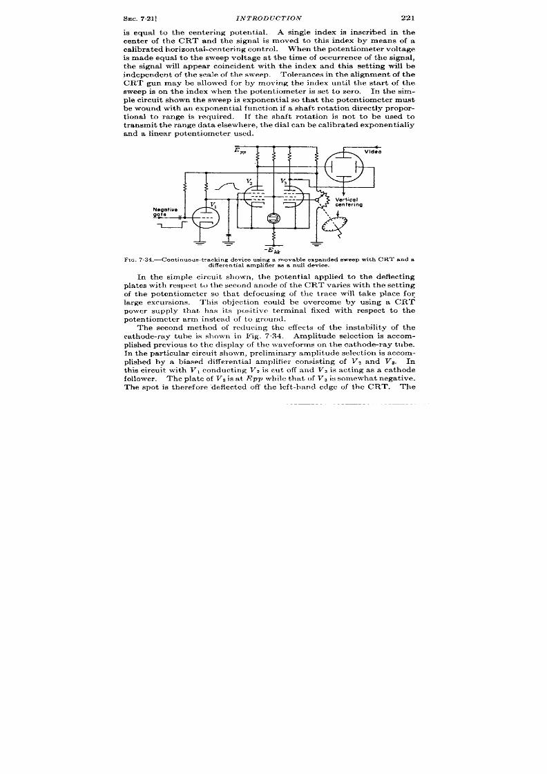
SEC. 7.21]
INTRODUCTION
221
is equa l to the c nter ing potent ia l. A single index i inscr i%ed in the
center of the CRT and the signal is moved to this index by means of a
ca libr at ed h or izon ta l-cen ter in g con tr ol. When t he pot en tiomet er volt age
is ade equal to the swee volt age at the t ime of occur rence of the signal,
t he signal will appear coincident with the index and this set t ing will be
independent of the sca le of the sweep. Tolerances in he a lignment o the
CRT gun may be allowed for by moving the index unt il the sta r t of the
sweep is on the index when the poten t iometer is set to zero.
In the sim-
ple circu it shown the sweep is exponent ia l so that the poten t iometer must
be wound with an exponent ia l funct ion if a shaft rota t ion direct ly pr opor -
t iona l to range is required. If the shaft rota t ion is not to be used to
t ra nsm it t he r an ge da ta elsewh er e, t he dia l ca n be ca libr at ed expon en tia lly
and a linear poten t iometer used.
Em
j f Ifi’
Video
i!
+
ertical
\
centering
‘\
‘,
+
~
=
F IG.734.-Con t inuou s-t r ack ing device u sing a movable expanded sweep wit h CRT and a
d iffe rent ia l amplifier as a nu ll device .
In the simple circu it shown, the poten t ia l applied to the deflect ing
pla tes with respect to the second anode of the CRT var ies with the set t ing
of the poten t iometer so tha t defocusing of the t race will t ake place fo~
large excursions. This object ion could be overcome by using a CRT
power supply tha t has i s pos t ive termina l fixed with respect to the
poten t iometer arm instead of to ground.
The second method of reducing the effect s of the instability of the
ca thode-ray tube is shown in Fig. 7.34. Amplitude select ion is accom-
plished previous t o th e display of the wa vef rms on the ca thode-ray tube.
In t he pa rt icu la r cir cu it sh own , pr elim in ar y amplit ude select ion is a ccom -
plished by a biased differen t ia l amplifier consist ing of V~ and V?. In
t his cir cu it wit h V, conduct ing V, is cu t off and VS is act ing as a ca thode
follower.
The pla te of VI is a t Epp while t hat of Vs is somewh at n ega tive.
The spot is therefore “deflected off the left -hand edge of the CRT. The
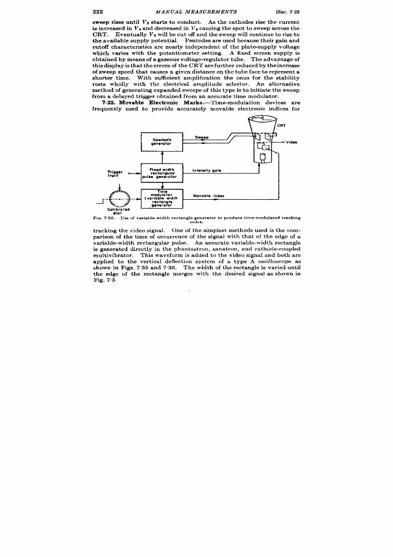
222
MANUAL MEASUREMENTS [SEC. 7.22
Bweep r ises un t il V~ st ar ts t o con du ct .
As the ca thodes r ise the cur ren t
is i creased in V2 and decrea sed in Va causing th e spot to sweep across th e
CRT. Eventua lly V8 will be cu off and the sweep will con t inue to r is to
t h e ava ila ble supply pot en tia l.
P en todes are used because their ga in and
cu toff ch ar act er ist ics a re n ea rly in depen den t of t he pla te-su pply volt age
which var ies with the poten t iometer set t ing. A fixed screen supply is
obta ined by means’ of a gaseous volta ge-regu la tor tube. The advantage of
of sweep speed that ca ses a given distance on the tube face to represen t a
shor ter t ime. With sufficien t amplifica t ion the onus for the stability
rests wholly with the elect r ica l amplitude selector .
An a lt ern at ive
method of gen era t ing expa nded sweeps of this type is t o in it ia te the sweep
from a dela yed t r igger obta ined from an a ccura te t ime modula tor .
.22. Movable Elect ron ic Marks.-Tlme-modula t ion devices a re
frequent ly used to provide accura tely movable elect ron ic indices for
1-
ee p
Sawtadh
5W4
gwwatar
Videa
t
;:~$r
Fixedwidth
Intensify gate
~ rectangular
pulse generator
t
Time
modulator
( variable width
Movoble index
rectangle
generatar
Cal$;led
FIG. 7.35.—Use of variable-width rectangle generator to produce time-modulated tracking
index.
m
-
I
t racking the video signa l. One of the simplest methods used is the com-
par ison of the t ime of occu r rence of the signal with tha t of the edge of a
va ria ble-widt h r ect angu la r pu lse.
An a ccu ra te va ria ble-widt h r ect an gle
is gen era ted direct ly in the phantast ron , sana tron , and ca thode-coupled
mu tivibra tor . This waveform is added to the video signa and both are
applied to the ver t ica l deflect ion system of a type A oscilloscope as
shown in Figs. 735 and 7.36. The width of the rectangle is var ied unt il
the edge of the rectangle merges with the desired signal as shown in
Fig. 7.5.
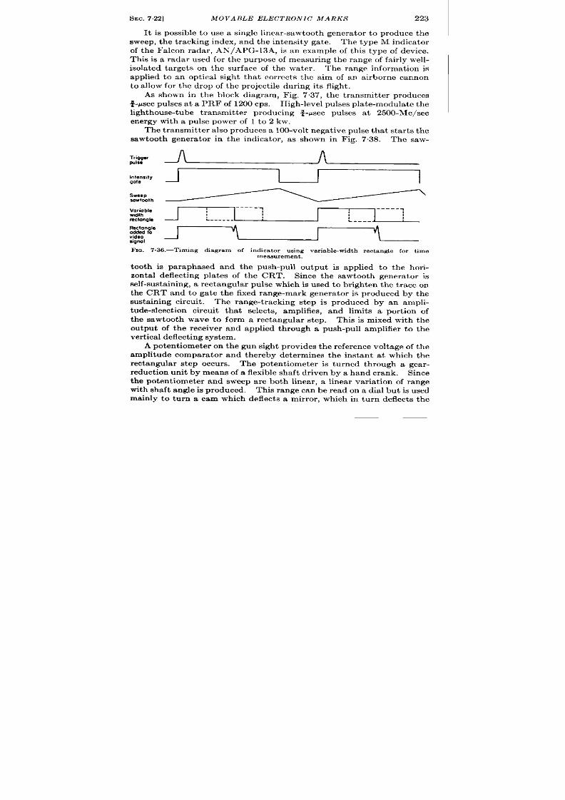
SEC.7,22]
MOVABLE ELECTRONIC MARKS 223
It is possible to use a single linea r-sawtooth genera tor to produce the
sweep, the t racking index, andthe in tensity ga te.
l’h e t ype M indica t or
of the Fa lcon rada r , AN/APG-13A, is an example of this type of device.
This is a radar used for the purpose of measur ing the range of fa ir ly well-
isola ted ta rget s on the su rface of the wa ter . The range informat ion is
applied to an opt ica l sigh t tha t cor rect s the aim of an a irborne ca non
to a llow for the drop of the project ile dur ing its fligh t .
As shown in the block diagram, Fig. 7.37, the t ransmit ter produces
~-~sec pulses a t a PRF of 1200 cps.
H igh -level pu lses pla te-modu la te t h e
ligh thouse-tube t ransmit ter producing +~sec pulses a t 2500-M c/sec
energy with a pulse power of 1 to 2 kw.
Th e t ra nsmit ter a lso produ ces a 100-volt n ega tive pulse tha t sta rts th e
sawtooth genera tor in the indica tor , as shown in Fig. 7.38. The saw-
3%%,~
l%. 7.36.—Timing diagram of indica tor using var iable-width rectangle for t ime
measurement.
tooth is paraphrased and the push-pull ou tpu t is applied to the hor i-
zonta l deflect ing pla tes of the CRT. Since the sawtooth genera tor is
self-susta in ing, a recta ngula r pu lse which is used to br igh ten th e t ra ce on
the CRT and to ga te the fixed range-mark genera tor is produced by the
susta in ing circu it . The range-t racking step is produced by an ampli-
tude-sleect ion circu it tha t select s, amplifies, and limits a por t ion of
the sawtooth wave to form a rectangula r step. This is mixed with the
outpu t of the receiver and applied th rough a push-pull amplifier to the
ver t ica l deflect ing syst em.
A poten t iometer on the gun sigh t provides the reference voltage of the
amplitude compara tor and thereby determines the instan t a t which the
rectangula r step occu rs. The poten t iometer is tu rned th r ugh a gea r -
reduct ion unit by means of a flexible shaft dr iven by a hand crank.
Since
the poten t iometer and sweep a re both linear , a linear var ia t ion of range
with shaft angle is produced. This range can be read on a dial bu t is used
mainly to turn a cam which deflect s a mir ror , which in turn deflect s the
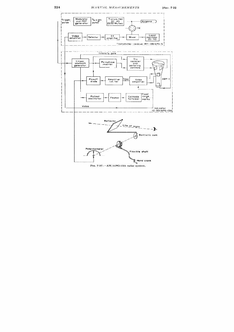
I
I
lTrigger
Modulator
34 psec
Transmitter
r
and PRF
2C-43 Antenna
pulse
generator
pulse
2500 Mclsec
1
1
I
L
I
I
I
I
Video
Local
ompllfier
0 y; :$1
Transmlfter -receiver RT-39/APG-5fl
—————— ———
-———— —— .—— .-
Inlensity gote
Linear
sowtooth
gene tor
I
Plckoff
diode
L
L_.
I
Fnxed
Pulsed
Peaker
Cathode Z
oscillator
fOll Ower marks
Video
.—— —__ _
—
— —— —
I
‘<
eflector
____
— L~e_o f_~ ilh,
——_
-%
Ball, s ic cam
/
/
nd, cafor
-93/APG-13AJ
FIG. 7 .37.—AN/APG-l3A radar sys tem.

f!iEc,723]
DETAILED CIRCUIT DESCRIPTION OF FALCON
225
line of ight for a iming t he cannon.
The cam is cu t with a ballist ic func-
t ion to give the cor rect supereleva t ion to the gun.
7.23. Deta iled Circuit Descr ipt ion of Falcon.—A co plete circuit
diagram of the Fa lcon indica tor is shown in Fig. 7.39. A posit ive-feed-
back linea r -sawtooth genera tor (Vol. 19, Chap. 7) is formed by V,6VZ.,
and V3.. The pla te of Vlb clamped at about + 1 volt and the sweep is
star ted when pla te cur r en t is cut off by the t r igger in t r oduced th rough Cl.
A posit ive step is produ ed across RI of amplitude Ebb
(~l?Rz)= ‘6
\ ’olt s. This step overcomes the fixed bias on the gr id of V1. ca usin g t he
Tr!gger
pulse
Sawtooth
Selected
port,on of
sawtooth
Derivative
of selected
porl, on
Step
ofter
Ilmitlng
Gate
Pulsed
oscillations
Fixed
range
marks
X
---
“
..-
+
!..
, ;
.
f
A
A
h
A
A A.
FIG. 7 .3S.—Timing diagram of Falcon M-scope.
pla t e to fa ll. The negat ive amplified step is applied to the gr id of Vlb
through Cz holding the tube cu t off a fter the terminat ion of the t r igger
pulse. Since the charging cur ren t for the sweep condensers C’Sand C,
flows through R, the step persists as long as the sweep cont inues. The
posit ive feedba ck fr om t he ca th ode follower Vs. t hr ough C’s to t he posit ive
end of R z serves o keep the voltage across Rz near ly constan t and hence
the sweep near ly linear . Fur ther compensat ion is in t roduced by the
network Cl, Rs so tha t the sweep is linear from +17 to +280 volt s with in
+0.2 per cen t (see Chap. 5). When the sweep has reached +280 volts
the gr id bias on Vu will have reached – 0.5 volt so that gr id cur ren t will
commence and the sawtooth will become slower and exponent ia l. E en-
tua lly the charging cur rent in C, and CAwill have decr eased sufficient ly

220k, B
:JOO ~
feJLf
2
0.1
I T--T 18k Receiver w
d ! - ! d ; y : ~ . ~
-Trig. in
200k
k
0.5 5k
e
f! ,, ‘,,
0.25 5.lk
~b
0.01 ‘
cwpAL1
@’l@
IM
163 K.C.R.E Ascmt
w
—
—
—
6-8v
11-
‘ll —
—
FIG..7.39.—Circuit diagram Falcon M-scope (1D-93 /APG-13A).
1?
$:~
inlen!
,Zev
l=.. ... I I
@
roe”,
-- -
250k ‘--
,0 510k IM
k
Iok
0.1
~F3
220k o.1
0.1
SEC. 7.23]
DETAILED CIRCUIT DESCRIPT ION OF FALCON
227
t o cu t off VI. so that its pla te r ises again causing Vlb to conduct discharg-
()
c, + c,
in g Cz an d C, t o their or igina l sta te. The t me constan t Rz —
2
is chosen so tha t the 263 volt s of linear sawtooth will cover 3 .6 ysec or
6000 yd radar range as given by the formula dE/dt = EpP/RC since E,.
is constan t due t o feedback.
~=&p~=470ppf
.“.
ER
The sweep will stop a t about 55 psec r 9000 yd. The cont rol R, is
adjusted so tha t 49 ysec or 8000 yd cover s the face of the CRT. With S1
in t he 24,000-yd posit ion t he t racking mark is rem oved and CPJwitched in
to give a 150-Wsec or 24,000-yd t race across the CRT. Par t of the nega-
t ive rectangula r pulse on the pla te of VI is applied to the CRT ca thode to
turn on the beam dur ing the sweep t ime. The sweep from R< is applied
to D2 of the CRT through CT. It is a lso applied to the gr id of VW through
R5 and Cs. Feedback through R, reduces the ga in of V3b to unity. Bias
is provided by the resistance net ork R7, Rs, and Rg. This pa th also
divides the signal applied to the gr id of V3 b by an amou nt a ppr oxim at ely
equal to its ga in so that on ly a small cor r ect ion need be applied via Cn.
Thk network keeps the biasing condit ion on ~3 b near ly co stan t and
independen t of duty ra t io since negligible volt age is built up across Ca.
The output wave from VW is exact ly the inverse of tha t appear ing on Dz of
the CRT. It is applied to Dl th rou gh Cg t o give push-pull deflect ion .
The diodes V,a and V,b a re d-c r est or er s and pr even t t he shift in h or izon ta l
cen ter ing which would otherwise occur when the PRF changes or S1 is
th rown. A du l poten t iometer h 10is used to der ive the cen er ing volt -
ages. The poten t ia ls applied to the two d-c restorer s change in opposit e
direct ion when t he cont rol is moved.
This produces a deflect ion of the
t race and st ill keeps the mean poten t ia l of the deflect ing system constan t
so that cor rect focus is main ta ined.
Th e video amplifier V5 is direct ly coupled to the ver t ica l def ect ing
system (Dj and Di) and produces push- ull ou tput by vir tue of the la rge,
common cath ode resistor Rll when signals a re applied to either gr id
Ver t ica l cen ter ing adjustment is obta ined by RIz which inser t s a differ -
en t ia l bias between the two gr ids keeping the common ca thode cur ren t
constan t . This produces a ver t ica l displacement of the t r ace without
a lter ing the mean poten t ia l of the deflect ing system.
Each half of V5
draws 12.5 ma and produces a ca thode voltage of + 100 and a pla te volt -
age of approximately +256 volt s. Each pla te re istor has a mean
volt age drop of 94 volt s. By reference to the published tube curves
of the 6SN7 using a 7.5-k load line sta r t ing a t +250 volt s it is evident tha t
120 volt s of deflect ing poten t ia l a re available from each t be and tha t

228
MANUAL MEASUREMEN TS
[SEC.7.23
the differen t ia l gain between pla tes will be approximately 11. Since a
large video deflect ion (N2 in. ) is desired a push-pu ll video amplifier is
necessary to preven t defocusing of the t race near the limits of deflec-
t ion . The t ime constan t of the video amplifier is given approxi-
mate y by [Cgp(4Pyf) + 2 X capacity between deflect ing pla tes (lOpPf )
+ st rays (10 p~f)] X Ru(7.5 k) = 2.5 X 10⁻⁷ sec. The t ime of r ise
to 90 per cen t
= 3RC = 0.75 psec which is barely adequate for the
0.75-Psec pulse. (It is assumed that t he gr ids a re dr iven from a low-
impedan ce sou rce and t hat t heir mot ion is negligible.)
The sect ion of the sawtooth producing the t racking step is select ed by
t h e d iode VM which is biased by means of the 50-k range poten t iometer a t
J ,. The pla te of the diode is supplied from the cathode of Vs. ra ther
than the gr id. This in t roduces an addit ional uncer ta in potent ia l in
ser ies with the lamped pla te voltage of Vlb and the emission potent ia l of
the diode but it cannot be a oided s nce the loading imposed by RM in
parallel with (Rl, + l/pC’,J’ would terminate the sweep on the CRT
shor t ly after the appearance of the step. The elected por t ion of the
sawtooth is “cliff eren t ia ted” by the 3-ksec t ime constan t RMC~o. The
drop across Ri, dur ing the r ise of the selected sawtooth will be ap roxi-
260 volts
mately En
= RC dv/dt = 3 X 10-’37 ~ ~o.-., ~ec = 21 volt s. Since V,
has approximately 3 volt s of gr id bias it is dr iven rapidly in to the gr id-
cu r ren t region so that the pla te drops abrupt ly cu t t ing off v6b.
The cur -
ren t in the pla te resistor is cu t off rapidly producing a step on the gr id of
t h e video amplifier V5m. The speed with which the step r ises is limited
by th e 0.25-psec t ime constan t of th e video amplifier which is slower than
the rest of the circu it . Unfor tunately the ear ly por t ion of the sawtooth
is a lso differen t ia ted by the -ppf pla te-to-ca thode capacitance of V2 b
before it conduct s. This produces a step of
R @
dt
= 3 x 104 x 4 x 10-’2 x y x 10-6 = 0 .8 volts
a t the gr id of Vti. As the over -a ll gain is 6 X 0.6 X 11 = 40 a step of
32 volt s would appear between Ds and Di. Also the init ial st ep of 16
volts a t the star t of t he sawtooth would be near ly unat tenuated, dr iving
the video amplifier t o sa tu ra t ion.
A neu tra lizin g con den ser C,, differ -
en t ia tes the whole sawtooth and applies it t o the gr id of Vti in oppos it e
phase to the ampl fied signal due to the diode. T e values of C,{ and the
mifin g n etwor k CIZR la a re ch osen exper iment ally t o n eu tra lize t he effect
of the diode capacity. It is not pract ica l t o calcu la te these values as
their magnitudes depend upon the st ray capacitance of the wir ing. The
step amplitude is iven by
(Ip of V.St ,)X Rl, X (Ga in of VJ = 14 ma X 470 ohms X 11 = 72 volts.
1This nota t ion is exp la ined in Vol. 19, Chap. 2.

SEC. 723]
DETAILED CIRCUIT DESCRIPTION OF FALCON
229
The CRT has a ver t ica l-pla te deflect ion sensit ivity of 132 volts/in . a t a
voltage of —1800. It will be apparent tha t the tota l deflect ion is,
therefore,
72 volts X ~3~ ;~lts
= 0.55 in .
The system is normalized by the ‘( zero” potent iometer R,9 which
adjusts the poten t ia l a t the nega t ive end of the range poten t iometer
and by th e “ slope” pot en tiometer RZOwhich adjusts t he cu rr ent th rough
it ,. The zero poten t iometer removes resistmce from the top of the resist -
ance network while adding it a t the bot t m so that the cur ren t in the
r esist an ce n etwor k is u nch anged.
Thus an adjustment of the zero does
not change the slope. The slope cont rol will change the tota l cur ren t
a lthough using RzO+ Rzl as a poten t iometer reduces the effect . There-
for e the zero con trol will have to be readjusted every t ime the slope
con t rol is changed.
Fixed range marks a re provided by the pulsed oscilla tor . Normally
12.5 ma is flowing through the switch tube VT. and the tuned circuit ,
being limited by R*?. The cur r en t is rapidly cu t off by the nega ive ga te
from V,.. The peak voltage of the fir st half cycle developed by the
tuned circuit is given by
J
=i +
= 12.5 X 10⁻³ amp X
J
2 X 1.2 X 10–3 henr ies _ 21 volts,
8 X 10-’0 farads –
The feedback tube V,, supplies a nega t ive resist ance that is adjusted by
R2i to neu tra lize the damping due to the resistance of the coil and R24,
so ma int ain ing t he init ial amplit ude.
The signal applied to the gr id of
VS. consists of nega t ive half cycles since the posit ive excursions of the
sinusoid ar e limited by gr id cur ren t drawn through RW
The value of
33 k was chosen to be la rge compared to the diode impedance of the
gr id ( =500 ohms) but small enough to int roduce negligible t ime delay
when shunted by the tube input capacit ance.
12.5 ma flows thr ough Vti being limited by R2E.. The cur ren t is abrupt ly
r educed at the star t of the nega t ive excursion of the sinusoid producing
an overdamped oscilla t ion in L1 which is tuned by st ray capacitance.
These pulses a re about ~ ~sec wide a t one-ha lf amplitude and ar e roughly
symmetr ica l. The ca th ode follower VU applies the pulses to the gr id of
the video amplifier . The ca thode follower has negligible effect on the
video since it is biased near cu toff and the video input is posit ive.
The
amp!itude of the range marks is adjusted by changing the bias of VW
by means of Rw. Unfor tuna tely moving this con t rol produces a var iable
delay in the sta r t of the range marks since it changes the por t ion of the
mark sel cted. 1 The condenser CISis made ver y la rge so tha t the aver age
1Better resultswould be obtained if t!.e tube was always conductingslightlyand
Zhowsa inserteda crossL, as a var!sk!e shuu~
230 MANUAL MEASUREMENTS
[SEC 723
pla te volt age of Vaachanges negligibly dur ing the t ime the pulsed oscil-
la tor s opera t ing. If it were small the pla t e volt age and hence the
puls curren t would increase causing an increase in the amplitude of
successive marker pulses. The tuned circuit Z, is ruggedly made and
temperature-compensated.
Theleads to the associa ted tubes a re made
as sh or t and dir ect as possible.
A ch an ge of 5 ~~f in t he self-ca pa cit an ce
of V7 or in the st ray capacitance (an ext reme value) would produce a
change of (t i~ — ~W)/t i800 = 0.3 per cen t in the oscilla tor
per iod. This is the same order of magnitu e as the expected change
in the delay circuit with tube and wir ing changes so tha t the fixed range-
mark circuit cannot be considered to be a pr imary standard; it must be
init ia lly ca libra ted against a crysta l-con t rolled circuit . The outpu
pulses from the oscilla tor a re brought in to coincidence on successive
cycles of t he cir cula r-sweep oscilloscope-for example, t he TS-100/AP
(see Vol. 21, Chap. 18). It is possible then to ca libra te accura tely this
step.
It has been found by exper iment tha t the proper ly spaced marks have
a fixed er ror with respect to t rue rada r range.
This er ror is mainly
in t roduced b the t ransmit t er and receiver delays (see Chap. 3). It is
r emoved by adding the magnitude of the er ror t o the reading on the sight
dia l when set t ing the step on the 1000-yd mark dur ing zero adjustment .
Th e power supplies used a re unr egula ted as near ly per fect compensa -
t ion is obta ined for changes in line volt age. The volt age across the
range potent iometer increases in direct propor t ion to the change in the
slope of the sawtooth so tha t no slope er ror is in t roduced. The change in
emission potent ia l of the sweep-clamp and pickoff diode a re in opposit e
direct ions and tend to cancel.1 As all th tubes tha t draw heavy cur rent
a re t riodes and as gr id bias is supplied fr om a ser ies resist or in t he negat ive
lead of the power supply the cha ge in gr id bias just compensa tes the
ch an ge in E,w The result is a change of less than 10 yd i dica ted range
over a range of line voltage of 100 to 130 volt s. The cha ge in sweep
length is a lso compensa t ed by a cor respondin g chan ge in deflect ion sensi-
t ivity of the CRT since the CRT supply volt age changes in direct propor -
t ion to line volt age. However , the t r ace length will change somewha t
with the waveform of the a-c supply since the CRT supply has a con-
denser input filter and hence it s d-c level is propor t iona l t o the peak of the
input wa ve whale EP is supplied from a choke-in put filter so tha t it will be
propor t ional t o the average value of the input wave.
The range of pulse recur rence frequencies is from 20 to 1400 cps and
negligible changes a re produced in the funct ioning of the circuit . Above
1400 cps the sweep and ga te circu it will divide frequency, because Cs and
Ct will not have t ime to discharge and because Cfi will not have t ime to
1Unfor t una t elyt he d rift due to change in g~ of vs . wit h G and -f& is uncOmWn-
satedbut its effectsare smafl,as th e performancedata show.

SEC. 7.24]
AIR SCOPE
231
recharge through Rd + RZ7, V,% bein g cu t off du ring th is t ime.
Th e ext r a
charge in Ci due to the linear izing resistor Rs will not have t ime to leak off
completely.
Performance.—The per formance of the system is indica ted by the fol-
lowing da ta :
A. Linear ity of d lay + 0.2 per cen t limit ing er ror
B. Maximum change in indicated range (6000-yd scale)
1. Line oltage changed 100 to 130 volts. AR < 10 yd
2. Tubes changed in t i e modula tor AR + 60 yd
C. Peak t racking er ror s of average opera tor on well-defined target
1. Sta t ionary reset bility i 5 to 10 yd
2. Steadily moving target (200 mph) ~ 15 to 30 yd
7.24. A/R-scope.—A delayable expa nded A-sweep, common ly kn own
as an R-sweep is oft en used when it is necessary to measure the range of a
moving signal with an accuracy greater than tha t obtainable on a full-
range display. It may also be used to examine cr it ically the amplitude
and shape of a delayed signal. As ment ioned previously it is possible to
produce such a sweep by amplifying a por t ion of a slow t ime base.
Instead of select ing a por t ion of a linear sawtooth cover ing the en t ir e
r an ge of modu lat ion , some circu it s employ amplitude compar ison t o gen -
era te a movable pulse and then in it ia te a delayed fast sweep with th is
t ime-modulated pulse. The Dumont 256-B A/R Oscilloscope is an
example of th is type of device. It was or igina lly de igned as a precision
ranging at tachment for the SCR-582 search radar but is now more gen-
era lly u sed as a pr ecision test and calibra t ing device.
As shown in the block d agram Fig. 740 either an in ternal or an
external t r igger may be used. The internal t r igger is der ivied from a
81 .94-kc / see crystal oscilla tor .
The ou tpu t of the oscilla tor is peaked to
produce 2000-yd range marks. Th se marks are also used to synchron ize
a blocking oscilla tor tha t divides by 5 to produce 10,000-yd marks. By
suitable swi ching the marks may be applied, separa tely or mixed, to
the CRT as deflect ion or in tensity modula t ion along with the video. A
fur ther blocking oscilla tor divides the 10,000-yd marks to an adjustable
PRF. As on ly simple division ra t ios are possible the I’IW will vary in
ste s tha t a re simple fract ions of 16.4 kc/see as the con t rol is moved.
Since a la rge division ra t io is used (the l’RF is adjustable from 80 to
20 0 cps) the divider cannot be cxpcctcd to coun stably but may skip
from on e submult iple of 16.4 kc/scc to another . A coincidence between
the divider pu lse and one of the 2000-yd marks forms the actual t r igger .
The in ternal t r igger genera tor therefor e forms a ser ies of very accura te
range marks that a re accura tely lockccl in phase with a t r igger of adjusta-
1A commercia l model of th is inst rument is now available from the Allen B.
Dumont Labora tor ies.
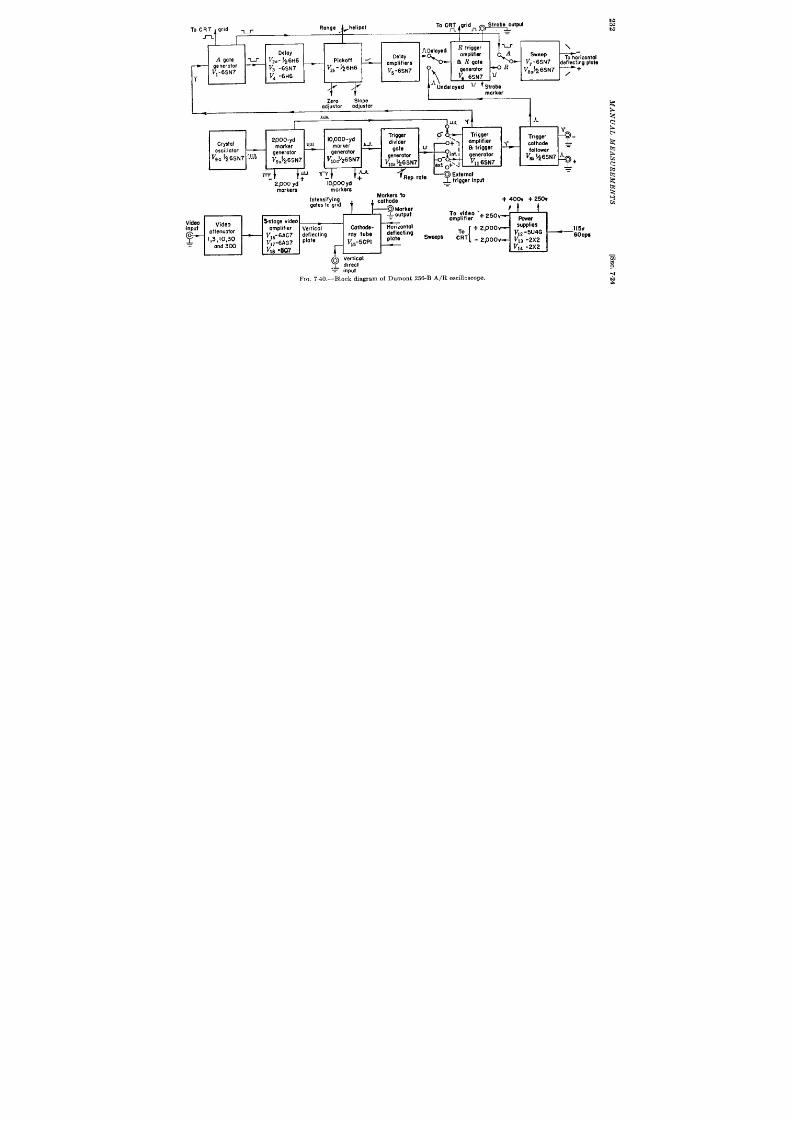
To CRT grid -
-t
Range
I
I
I
ADelayed
R trigger
—
—
‘ ,~!-
\
Delay
Delay
amplifier
A
A gate v
Vz . - b26H6
sweep
Pickoff &
~ R gate
To horizontal
amplifiers
V, -6SN7 dsflec:ing plote
generator
V1-6SN7
— V3 -6sN7 V2b-$6H6
V5 -6SN7
~
generatcr
R
V8a~6SN7 , +
1’
Vd -6H6
~ 6SN7 u
A
Undela ed u
Strobe
I
Zero
Slope
adiustor
adiustor
.LLJJ1
I
A
Trigger o-
2000- yd ~
10,000-yd
Crystal
divider
Trigger
morker
4;)
amplifier ~
marker ~
+-
oscillator
—
gote
u
~ trigger
cathode =
—
generator
generator
V9. ~z6SN7 ~
generofor
follower
V9C)’26SN7
VIOJ26SN7
generotor
V= 1A6SN7 A
Vlob26sN7
+
Vll 6sf.17
ext 0+’4
T+
m
J.lulm
U
‘?~%%np.t
v
+
+-
2,000 yd
70,000 ycf
.
morkers
markers
intensifying
;::;:;e to
gates to gnd
i
+ 4oOv + 260V
~~Marker
—
—
G
)
= output
To v jd eo ‘+ ~50v
Video
Video
%tage video
ompllfler
f%er
input
amplifier
Vertical
Cathode-
Horizontol
supplies
f& I:Y::: —
deeding
[
+ 2, 00
.I15V
JJ 6- &4c7 fi~~ing
roy fub~
To
Sweeps
V12 -5U4G
“CRT
60cP8
V*3 -2x2
V17-6AG7
V15-5CPI
- Zpoov
n
cmd 3CX3
V~e.8Q7
V14 -2x2
[g;’
F IC . 740 ,-B lock d iagr am of Dumon t 256 -B A/R osci ll os cope.

SEC.724]
A/ R SCOPE 233
ble PRF. Thet r igger andrange marks area lso available externa lly for
syn ch ron izin g a nd ca libr at in g ot h er devices.
The internally or externa lly genera ted t r igger is applied to the wide-
ga te mult ivibra tor that is adjustable to cover the full r ange of 20,000 to
200,000 yd. Therectangu la r pulse from this mult ivibra tor in it ia tes the
delaysawtooth tha t isformed ina``bootst rap' 'sawtooth genera tor . The
sawt oot h s picked off by an amplitude select or , is amplified, and t rigger s
t he 4000-yd R-ga te block in g oscilla tor .
Th is ga te is a va ila ble ext er na lly
as an accura tely delayed pulse andisa lso used toproduc a br igh t mark
or st robe on the A-sweep to facilita te in set t ing the R-sweep on a signal.
Thepush-pull sweep for the CRTisgenera ted by another boot st rap
sawtooth genera tor followed by a paraphase inver ter .
Th e t ime-ba se
sawtooth is in it ia ted and termina ted by the wide ga te when on the
A-sweeps and bythe R-ga te when onthe R-sweep. A-sweepsof 20,000,
200,000, and 400,000 yd and R-sweeps of 800, 2000, and 4000 yd are
available. Par t of the rectangu la r p lse genera ted by the A- or R-gate
is used to in tensify the CRT beam dur ing the sweep.
A 3-stage video amplifier is included which has a r ise or fa ll t ime of
0.08 psec and a 10 per cen t drop at the end of a rectangula r pulse of
1000-usec dura t ion . An a t tenuator is provided which gives a deflect ion
of ~ in. for 0.2, 0.6, 2.0, 6.0, and 20 volt s input . (For complete specifica-
t ions of this oscilloscope see Vol. 21 Chap. 18.)
Where used in conjunct ion with a radar set the R-ga te or st robe is
used to intensity-modula te the PPI producing an illuminated and which
can be readily set on a selected signal. This signal will then appear on the
R-displa y for cr it ica l examin at ion .
As the A/R-scope has been normally used, measurement of the delay
of the signal with r espect t o the t r igger is made by set t ing the edge of the
signal a t the ver y beginning of the R-sweep.
This method is not ent ir ely
sa t isfactory since the ear ly par t of the signal is not visible. If the video
pulse is complex a view of the ear ly par t is most desirable when making a
set t ing. An alternat ive method consists of placing a ruled gr id or ink
mark on the CRT and adjust ing the delay with re pect t o th is mark. The
stability of th is method is not very good since the hor izon ta l cen ter ing
may be changed by accident or by changes in PRF or line voltage since
no d-c restora t ion or volt age stabiliza t ion is provided. A bet ter method
of measurement would be obta ined if the R-ga te we e delayed 3 or 4 psec
by means of a delay network and applied to the fr ee ver t ica l pla te of the
CRT. The leading edge of the ga te would then appear as a step on he
t ra ce wh ich cou ld t hen be u sed for set tin g by ju xt aposit ion .
The slope adjustment of the delay circuit may readily be made by
refer ence to the crysta l-con trolled markers. If the radar system is t r ig-
ger ed from the A/R-scope a 4-psec delay l ne can be inser ted in to the

SEC. 7.241
AIR-SCOPE
235
t r igger lead to make the t ransmit ted pulse appear on the sweep. If
t he system supplies the t r igger pulse, t he delay line may be inser t ed in the
video lead to delay the video unt il t he t iming circu it s have sta r ted. By
this means the zero delays of the radar system and the nonlinear ity a t
minimum range may be ca libra ted out . 1
Detailed Circuit Description of the A /R-scope.—A complet e cir cu it
diagram is shown in Fig. 7.41. A convent iona l t r iode crysta l oscilla tor
vgb is opera t ed biased in the Class C region so that pu lses appear in the
pla te circui . These pulses a re separa ted from the sine wave appear ing in
the pla te circu it by means of the t ransformer Ts tha t has an nductance
tha t is small compared t o that of the resonant circuit ~lC4Z. The other
two windings in the t ransformer are used as a blocking oscilla tor in con-
ju nct ion wit h V9.. Posit ive 2000-yd marks of about 50 volt s amplitude
and l-psec dura t ion are produced across the 68-ohm ca thode resistor .
These marks a re used t o synchron ize t he 10,000-yd-mark genera tor V1OO,
wh ich is a ca th ode-feedba ck blockin g oscilla tor . Th e ca th ode-feedba ck
type appears to be more stable than the convent iona l type (see Vol. 19,
Chap. 6). The posit ive outpu t from the 33-ohm ca thode resistor is used
t o synchron ize the t r igger -divider blocking oscilla t or vlob. This is of t he
gr id-pla te–ca thode-coupled var iety since it was found tha t pu lses of
sufficient dura t ion could only be genera t ed by this connect ion (see Vol.
19, Chap. 6). A nega t ive 15- to 20-Psec pulse is obta ined from the
220-ohm r .xistor in ser ies with the pla te nd is applied to the a thode of
t h e t r igger amplifier (t ime select or ) V]la.
Th is pu lse a lon e is n ot su fficien t
t o permit pla te cur ren t t o flow. Posit ive 2000-yd marks from the ca thode
of V,. a re applied to the gr id. The fir st mark appear ing dur ing the
ca thode pulse is select ed an applied to the blocking oscilla tor Vl,b.
The outpu t of V I* is decoupled from the outpu t circu it by the ca thode-
follower-phase-inverter Vst, tha t pr odu ces posit ive and nega t ive t r igger s
of about 100-volt amplitude and l-psec dura t ion .
The division ra t ios of the dividers a r e adjust ed b y t h pot en t iom et ers
R,o and R,, wh ich form Par t of the gr id t ime constan ts of the blocking
oscillators. Rbo is fa ct or y-pr eset while RETis cont r olled fr om t he fr on t
panel to produce PRF’s from 80 to 400 pps when the 200,000-yd delay
is used and from 80 to 2000 pps when the 20,000-yd delay is in use.
Posit ive and nega t ive range marks are both produced by the 2000-yd
an d 10,000-yd blocking oscilla t or s a nd a re select ed by SA for a pplica tion
to an externa l circu it and to the ca thode of the CRT. When the posit ive
2000-yd marks are switched on , the 10,000-yd marks appear as nega t ive
over shoot s on every fifth a rk. This is due to back coupling through CAt i.
1A su it able dela y lin e in t he C,en er al 131ect rict ype Y134B wh ich in len gt hs of less
t ha n 4 psec pr odu ces n egligible dist or tion of sign als pr odu ced by r eceiver s of less t ha n
2 Me/see. video bandwidth . (SeeVol. 17, Chap,6 and Vol. 19, Chap.22).

236
MANUAL MEAS UREMENTS
[SEC. 7.24
The first 10,000-yd mark appears a t 8000 yd, the next a t 18,000, etc.
This is due to the fact tha t the t r igger selector is synchronized by a
10,000-yd mark while the t r igger is formed from the next 2000-yd mar .
When an externa l t r igger is used, the t r igger amplifier must be sup-
plied with sufficient ly large posit ive pulse on its gr id or nega t ive pulse
on its ca th ode t o fir e t he blocking oscilla tor Vllb.
The tr igge must a lso
r ise steeply enough to induce suffi ient voltage in the small inductance
of T6 t o init ia te r egen er at ion .
An amplitude of 15 volts with a ra te of
r ise not less than 100 volts/~sec. is the minimum permit ted for stable
operation.
The wide-gat e gen er at or VI is a conven tion al monost able mult ivi-
bra tor with pla te-to-gr id coupling.
This type of mult ivibra tor was
chosen because it is stable, is capable of rapid r ecovery, and gives a la rge
nega t ive rectangle with a fast leading edge to insure rapid cutoff of the
sawt oot h clamp V~.. The wide ga te is in it iated by a nega t ive t r igger
having a st eep fa ll and a slow r ecover y fr om t he gr id t ime-constant cir cuit
of l’l,~. This t rigger is cou pled via Cs an d in su res r elia ble oper at ion sin ce
the ta il of the pulse r ises t oo slowly in turn off the mult ivibra tor . The
“ boot st r ap” sawtooth gen er at or (V2C, V,., VW, Vd) pr odu cin g t he dela y
sawtooth uses a car efully t emper at ur e-compensa ted sweep net wor k with
manganin resistor and a combina t ion of silver mica and nega t ive-tem-
per at ur e coefficien t conden ser s.
A compensat ing network is used to
make Up for the lack of gain of VS6 and the loss of charge in CZI
dur ing the sweep. A resistor Rll is provided in the pla te circuit of
the clamp tube VSCto adjust the quiescent voltage on the gr id of the
cathode follower V3b so that this tube does not cu t off dur ing the recharg-
ing of Cz,. Restor ing diodes Vt a re connected across the sweep-
compen sa ting r esist or s Rl~ and R~a t stabilize the voltage between
the condensers and increase the permissible duty ra t io. The ampli-
tude selector VZ6is a diode biased by the range potent iometer . Although
the same potent iometer is used on both range scales separa te zero and
slope controls a re provided f r each range.
Th ey a re fa ct or y-pr eset
and very r arely need adjust ment a lthough they should be checked
if Vz or l’s is changed. The selected por t ion of the sawto th is differ -
ent ia ted, amplified, and limited by VS and V6b and applied to the block-
ing-oscilla tor R-ga te ge era tor , Vca. Like the t r igger divider , this
blocking oscilla tor uses a t ransformer Tt with gr id, pla te, nd ca thode
windings since it must produce a 4000-yd pulse and yet use a t ransy
for er capable of giving reasonable ra tes of r ise, When an undelayed
expanded sweep is desired, the R-gate blocking oscilla tor can be t r ig-
ger ed direct ly from the t r igger input through Sz. A posit ive ga te is
applied to the gr id of the CRT through IG from the po it ive-going pla te
of the wide-ga te genera tor or from the cathode of the R-gate blocking
SEC. 7.24]
A / R -SCOPE
237
oscilla tor . Th e n ega tive pu lse fr om th e blockin g oscilla tor VS . is u sed t o
cu t off the sweep clamp V7b and to produc the negat ive marking pu lse
(st robe) on the A-sweep or external PPI.
Th e sweep gen er at or is sim ilar
to the delay-sawtooth gener a tor except tha t specia l provisions have not
been made to insure accura t level set t ing and good linear ity. The com-
pensat ing network has been omit ted and the recharging diode has been
r epla ced by a r esist or RSS . As a resu lt the sweep speed will change with
du ty ra t io bu t the effect is un impor tant since the accuracy of measure-
ment does not depend direct ly upon the speed of the CRT trace.
The
gr id of the paraphase inver t er V,. is supplied by a signal from the sweep
gener a tor th rough CA, and feedback is supplied th rough C,, to hold the
gain exact ly equal to un ity. Bias is supplied th rough a resist ive divider
tha t passes the low-frequency componen t s of the sweep waveform since
it has a d-c a t tenuat ion approximately equal to the gain of the tube.
Video is applied dir ect ly t o on e of th e CRT deflect ing pla tes or th rou gh
the video ampli ier depending upon the posit ion of Sd. The video at tenu-
a tor is switched by mean of Sc and is of the resistance-capacity type so
that its character ist ics a re independen t of frequency. It presen t s a
near ly onstan t l ad of approximately 1 megohm.
Video input may be
supplied th rough a proper ly terminated cable of any length without
impa ir in g t he fr equ en cy r espon se.
If the cable is not terminated it must
be used in con junct ion with a capacity-divider probe or must be an open
wir e line. The amplifier is conven t ional, using shun t compensat ion in
the first and second stages and ser ies-shun t compensat ion in the ou tpu t .
The frequen cy response is flat from about 100 cps to severa l megacycles.
It is down 3 db at 7 Me/see and 6 db at 10 Me/see. Bias for the video
amplifier is obta in ed fr om par t of th e CRT-su pply divider .
Si ce th e t iming circu it s are self-compens t ing for changes in supply
voltage, u nregu la ted power supplies a re u sed. Th e indica ted r an ge var ies
less than 0.1 per cen t of fu ll sca le for a t 10 per cen t change in supply
voltage. As bleeder bias is used in all cir cu it s bu t the video amplifier
some economy in power consum tion migh t be brough t abou t by the use
of a negat ive supply.
The sawtooth delay circu it will oper a te with less than 0.1 per cen t
change in indica ted range up to about a 50 per cen t du ty ra t io a fter which
er ror s appear since C6 , the sweep network and CZI, do not have Suffi-
cien t t ime to discharge. When the in terna l PRF genera tor is used, the
du ty ra t io is limited to a safe value.
On external t r iggers when du ty
r at io becom es gr eat er than about 90 per cen t t he wide-ga te mult ivibra tor
divides the frequency. This is par t icu l r ly conven ien t as it permits the
viewing of the n ext t r igger pulse on th e 400,000-yd sweep.
Accuracy .-A pulse r ising in 0.5 psec may be reset at the star t of the
SOO-yd delayed sweep with in +10 yd.
The delay circu it s a re linear to

238
MAN UAL MEAS UREMENTS
[SEC. 7.25
within ~ 0.1 p r cen t of the tota l delay and the zero point is stable to
within + 0.1 per cen t of tota l delay for severa l days after c librat ion in
spite of line voltage changes of + 10 per cen t . For accurate following of
moving target s the range cont rol shoul be opera ted by the aided or
regenera t ive methods.
7.25. A-scope Presen ta t ion Used in Brit ish CMH System.—This
device produces a normal type A presen ta t ion cover ing 40 miles on the
CRT.’ Th e display, h owever , conta in s a con tinu ously var iable expan ded
Dor t ion tha covers about two ten ths of the tube face and has a durat ion of
about 4 ~sec. In the cen t er of the expanded por t ion is an accurate range
mark consist ing of a notch of 2-psec durat ion having a l ading edge with a
fall of 0.2 psec. The signal is matched with the leading edge of the no ch
by juxtaposit ion . The expanded sweep and notch are moved cont inu-
ously by means of a two-scale range circuit having an accuracy of about
The system is externally synchronized, and the t iming waveform is
obta ined by use of a pu lsed crystal oscillator and phase shift er so that
ext er n al ca libr at ion is unnecessa ry.
C muit Description oj (7MH A-scope. prefer ing to Fig. 742, a posi-
t ive t r igg r is amplified by Vs cu t t ing off the sweep clamp tube VE,. The
scr een cir cu it of VF and Vi form a mult ivibrator that holds VC, cu t off for
the ura t ion of the sweep. Condenser C’1 recharges thro gh R1 and
causes Vr to conduct a fter a t ime equivalent to 40,000 yd, cu t t ing off
Vi and returning the mult ivibrator to its in it ial condit ion . The t ime
constant long enough to hold Vd off dur ing the wait ing per iod
associa ted with any expect ed PRI?.
In it ia lly when V, is bottomed, Vs is dr awin g cu rr en t t hr ou gh Vs and
through the range poten t iometer from the + 1.2-kv supply. When Vs
is cut off the cathode degenera t ion in VC causes t to draw constan t cur-
ren t charging C at a constan t ra te and producing a linear sawtooth . The
impedance presen ted by the cathode circuit VC is about 50 megohms.
Only 100 volts of sweep is used before V, is again switched on . This
sweep is accurately linear but of small amplitude compared with cur ren t
pract ice, since it must be stable to within bet ter than 1 par t in 120 (l’Xl
cycles of the oscilla tor represen t full range). The bot toming of Vb may
vary +0.5 volt (1 par t in 200) with age and hea ter var iat ion which leaves
a very narrow margin of safety.
The sweep is amplified by V, and V,, applied t o on e hor izon ta l pla te
of the CRT, and gives the slow sweep.
The sweep amplitude is stabil-
ized by cat hode degen er at ion in VT and VS. The 300-,upf conden ser in t h e
ca thode of Vs is used to compensate st ray capacit ies in the anode circu it
1A Pu lsed Cryst alOscilla tor Cir cu it for Rada r Ranging J . D. Mynah , I.E .E .

---
75
+9%0”
,k
279.43 5k { ,O-,lo,,uf
1. -Sk]
31.1:1”/.
1.. ,. ....
25k
Ik
I,— ?%lk ----
Vmb
1
I
250
l,-
4 Goniometer
f
7;0
!t,hw>
I
>r-
?3002
To gote
volves
0
&
+1.2kv
Geared t e!
0
Ratio 144~o , <
f
~
I
VR92
O.IM
v,,
L 6=,%.
, IM
~~
I
Iw
! ! 1
! I
- c-u””
I
)
I
1
@@a-/ ‘
240
MAN UAL it!EASURi?MENTS
[SEC.725
permit t ing rapid sta r t ing oi the sweep.
Par t of the scree pulse of V,
is used to intensify the t race on the CRT.
The star t of the expanded por t ion of the sweep is determined by the
amplitude selector V,, v’,,. This is a differen t ia l amplifier having a ver y
la rge ca thode resistor drawing u ren t from the – 5-kv CRT supply.
Thus the two tubes a re supplied from a near ly constant -cur ren t source
and the cur ren t drawn by each tube is dependent only on the difference
between their gr id potent ia ls and not upon the common level of both
gr ids. The output of the range poten t iometer is applied to the gr id of
V,O wh ile t he sawt oot h fr om Vc is added to square waves der ived from the
o tput of the phase sh ifter in the fine sca le and the sum is applied to the
gr id o V,. When the voltage on the gr id of V, becomes near ly equal to
tha t of the gr id of Vla cur ren t shifts from Vlo to Vg. This act ion is
speeded by condenser coupling from the pla te of Vg to the gr id of VIO
causing the two tubes to behave as a ca thode-coupled mult ivibrator .
The posit ive step on the pla te of Vio causes Vl, t o conduct , cu t t ing off t he
fa st -sweep clamp V,z. The pla te poten t ia l of VIZ r ises exponent ia lly
toward + 1.2 kv and is caught by V13 after r ising to +250 volt s. This
250-volt sawtooth is applied t o the ot her hor izonta l pla te of the CRT caus-
ing the ra~id sweep. To assist in t rget select ion the sweep may be
slowed b.y a factor of 10 by depressing a push but ton which inser ts an
addit iona l capacitor n the sweep circu it .
Consider ing now the genera t ion of the t iming wave for the fine sca le,
par t of the nega t ive ga te produced in the plate circu it of V, is applied t o
the gr id of V,,. Cut t ing off Vl~ produces a transient in the crysta l dr iv-
ing t ransformer . The transient excites the rysta l which oscilla tes at
279.43 kc/see or 3 cycles per mile. The oscilla t ions of the crysta l are
amplified by Vlb, t he init ia t ing transient being balanced out by apply-
ing an adjustable por t ion of it t o the gr id of Vlfi in opposite phase. At the
end of 120 oscill t i ns the ga te pulse ends causing VM to conduct and
closing the nega t ive-feedback path from V16 ba k to V14.
The nega t ive
feedback stops the crysta l a fter severa l cycles. The pulsed oscilla t ions in
V16 are amplified by Vld which produces a cur ren t in the t ransformer
propor t iona l to the voltage on its gr id since it has ca thode degenera t ion .
The ou tpu t of t he t ra nsformer dr ives t he st at or windings of t he gon iomet er
through phase-split t ing networks. Since the gon iometer is induct ive,
resistance is inser ted in ser ies with one sta tor coil t o produce a 45° lag-
ging cur ren t .. Enough resistance and capacitance is inser ted in ser ies
with the other coil t o produce a 45° leading cur ren t . Thus the two fields
are in quadra ture. The t ransien t r sponse is sufficien t ly good that
steady-sta te condit ions are reached well with in the minimum range (3
cycles).
The goniometer is gea red to the coarse range poten t io eter with a 144
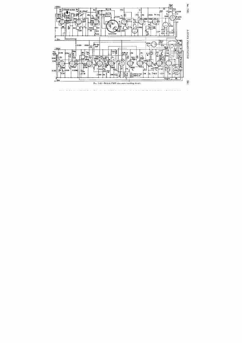
I250’ ” ,01:.2{ I
1
, ,
, ,
1!
I
111
1,
0002
*
0 gole
dves
,,
+1.2kv
L\------------- : UIl
$
n 7., t
VR92
y3
I
+ 250v
Trip
T 1
pulse
q
I
O.IM”
0.25
I
k!
.IM
25k .
70
:
y
---
. . .
. . .
R65 y
5k ) 0.25
005
L...
I
242 MANUAL MEASUREMENTS [SEC.725
to 1 ra t io so that the wave tra in from the goniometer and the picked-off
sawtooth voltage advance in synchronism as he range ha dwheel is
turned. The sinusoidal ou tput of V,, is conver ted to a square wave on
the gr d of V19 by the limit ing act ion of gr id cur rent in V19 and the diode
V18. The waveform at the ca thode of V,g is added to the coarse range
sawtooth waveform and the combined waveform used to actua te the
amplitude select or Vg, V,o. Tubes V,, and V20 form a para llel coinci-
dence circu it (t ime selector ). The step produced by V,, V,. is amplified
by V,, and shock-excit es a cr it ica lly damped tuned circuit in the gr id
cir cu it of VZO. This pulse is t imed t o select t he ensuing n ega tive half cycle
on the gr id of Vl~ when cur r en t is cut off in both Vlo a nd V20 ca using t he
pla te potent a l to r ise un il caught by the diode Vzl. This pulse is
inver ted by VZZ and forms the range “notch” on the CRT. It is a lso
used as a ga te for t he angle-following cir cuits.
Modification including sine-wave tracking. —Since it was not possi le
t o obta in coar se r ange poten t iometer s of sufficient accuracy dur ing the
ear ly par t of the War the sine-wave tr acking circuit shown in Fig 7.43
waa adopted for the product ion equipment . (For a complete discussion of
sin-wave tracking see Chap. 6.) The posit ive r ange mark from the
ca thode of V22 is applied to the anode of the t ime discr iminator V6. The
step pr oduced in the pla te circuit of VII sh ock-excit es a t un ed cir cu it in t he
gr id of Va producing a 4-~sec nega t ive pulse. The posit ive over shoot of
th is pulse permits pla te cur ren t to flow if the marker is applied simul-
taneously t o t he pla te cir cuit .
The rect ified cur ren t resukt ing from the
over lap of these pulses is applied to the Miller in tegra tor VT through a
phase-advance network. The ou tput of VT is then applied to the gr id of
V*. in place of the outp t of the coarse range poten t iometer . The feed-
back loop then holds this voltage so that the two pulses par t ia lly over lap.
The sawtooth pulse is synchronized with the desired cycle of the phase
shifter by cranking to zer o range, when a switch automat ica lly oper ates to
r aise t he cat hode potent ia l of V.gbr in gin g t he select or pu lse in to zer o r an ge.
Momenta ry fa ilure of power which might cause the selector to lock on the
wr ong cycle a lso opens a la tching relay which inter rupt s the CRT supply.
The t r ace on the CRT can be restored on ly by cranking to zero range
which resets the range circuit and reapplies the CRT potent ia l.
Although far advanced for it s t ime the equipment does not rep esen t
the best cur ren t design pract ice in that ra ther excessive potent ia ls a re
a pplied t o r eceivin g-t ype t ubes.
By use of the presen t types of sawtooth
genera tor s 150 to 200 volt s of accura tely linear sawtooth voltage can be
obta ined from a 250-volt supply without recourse to + 1.2 kv. A diode
amplitude selector would eliminate the use of the —5-kv supply for any-
th ing but the CRT. The type A presenta t ion with an expanded sect ion is
somewhat confusing to use and separa te A- and R-t races would be pr efer -
SEC. 7.25] S YS TEMS US ING A J -SCOPE WITH A PPI OR B-S COPE 243
able. These may be obta ined on separa te CRT’S, or on a single CRT, by
using elect ron ic swit ch in g or a dou ble-gu n t ube.
7.26. Systems Using a J -scope with a PPI or B-scope.—Severa sys-
tems h av been developed which use a J -scope with a movable mechan ical
mark for accu ra te following and a B-scope or PPI t o give angular in forma-
t ion and to presen t the full range scale. The J -scope ga te is used to
produce an illuminated band on the full range display to permit t a rget
acquisit ion . Th ese syst ems ar e dist ingu ish ed for t heir elect rica l simplic-
ity and reliability. A typica l example is provided by the indicator circu it
of the Hand Radar Set . (See Sec. 2.16.)
The indica tor circu it s of th is equ ipment a re shown in Fig 7.44. The
t imin g st andar d is a cryst al oscilla t or VI. using a react ive load (Ll, Cl) in
t he ca th ode cir cu it wh ich main tain s oscilla tion over a wide r an ge of a dju st -
ment of th e pla te-tu ned circu it .
The tun ing of the pla te circu it adjusts
the diameter of the circle on the J -scope. The secondar ies of the pla te
t ransformer 2’, are much less than cr it ica lly coupled to the pr imary and
tuned to obta in quadra ure voltage for the CRT deflect ing pla tes.
Since the oscilla tor opera tes in Class C, rmls s of pla te cur r en t appear
in the pr imary of the pu se t ransformer Tz.
The other two windings of
th e t ransformer in con junct ion with VM form a blocking oscilla tor which
divides th e or iginal 81.94 kc by five and produces 10,000-yd ran ge marks.
The pla te waveform of V,, is used to synch ron ize the PRF divider block-
ing oscillator V,a. This divider counts down to an adjustable PRF in the
neighborhood of 400 pps. Unlike the A/R-scope the ou tpu t of th is
divider is used direct ly to form the t r igger for the system. Since no
t r igger select ion circu it is u sed the t r igger may dr ift phase + ~ Psec with
respect t o the circu lar sweep if the divider adjustments, RI and R2, a re
changed. The cathode follower V2 b is used to preven t loading of the
blocking oscillator .
The t r igger from V,b is used to key the radar t ransmit ter and to
in it ia te the wide ga te produced by the cathode-coupled mult ivibra tor
Vs. The negat ive-going rectangle produced by this mult ivibra tor is
used to in it ia t e and to termina te the 50,000-yd linear sweep for the
B-scope. This sweep is produced by cu t t ing off pla te cu r ren t in Vti
which in ter rupt s the cu r ren t in LZ which is tuned by C2 and a. The
sweep consists of a small por t ion of the damped oscilla t ion produced
by th is circu it and is qu ite linear .
(For discussion of th e LCR-sweep see
Vol. 19, Chap. 7.)
This sweep is applied to one of the ver t ica l pla tes of the B-scope V,
and is inver ted by Vu and applied to the ot er ver t ica l pla te to give sym-
met r ica l deflect ion . The capacit divider (C*, CJ is used to at t enuate the
sweep by an amount equal to the gain of V6b.
This ar rangement is not

-2kv
r-
1
J scope
3)P-I
8
J sc@e centerina
+ 250v
Eii9
M
50k ‘w
!;
IW
001
Im
.0.01 01
I i
I
I 1
1*
I I IA-I I
II
Video input
I
l%” ~ I.L!M “-~
Ilt I +250.
t
-—
1 . . . .
d-la
,!.
2M
500
5ooJWf
‘s’d~
T
0k
200k
—
I
ryslol oscillator
4“
Range potentiometer
mulll-vlhior-
Elevation potentiometer
l’j
J
Azimuth potentiometer
FIG. 7.44. —HR indicator.
t o
A
A

SEC. 726] S YSTEMS US ING A J -SCOPE WITH A PPI OR B-SCOPE 245
A/R-scope since the sweep outpu t will be direct ly propor t iona l to the
ga in of Vob. A horizonta l sweep propor t iona l to the azimuth or eleva -
t ion angle of the an tenna is supplied to the hor izonta l pla tes of Vg from
the poten t iometer R~ or Rd via th e deflect ing amplifier VT. Th e azimuth
and eleva t ion poten t iometers a re moun ted direct ly on the an tenna axes.
The azimuth poten t iometer is dr iven by a mechanism tha t causes
it t o repea t its reading for e~ch quadran t of azimuth.
Par t of the posit ive-going wave a t the pla te of VW is applied to the
gr id of Vg t o illum ina te t he t ra ce.
Th e posit ive ga t e is a lso differ en tia ted
and u sed t o t r igger th e na rrow-ga te delay mult ivibra tor V4 which is a lso
of the ca thode-coupled type. This mult ivibra tor must be t r iggered from
a pulse of grea t er dm-a t ion than its own to avoid being t r iggered back by
the termina t ion of the t r igger pulse.
Ca re has been taken in the design
of the delay mult ivibra tor to secure maximum stability and linear ity
of its pu lse width as a fu ct io of the voltage supplied by he range
pot en ti m et er R 5.
The na r row ga te tha t illuminates the J -scope is obta ined rom the
ca t hode-coupled mu lt ivibr a tor Vb.
This mult ivibra to~ is normally
t r iggered by differen t ia t ing the end of the rectangula r pulse produced in
t he pla te circu it of V,”. The ga te is con ected to the gr id of V, and shou ld
remain symmetr ica l about the posit ion of the mechanica l cu rsor with in
~ ~ circle th roughou t the racking range. This means a stability of the
mult ivibra tor Vd of + 1 per cen t is requ ired. The nar row-ga te pulse is
in it ia ted by the r ise of the posit ive wide-ga te pulse from the pla te of
VW when approaching zero range.
This is accomplished by th rowing
S,. The band marking the posit ion of t e na r row ga te on the B-scope
is produced by mixi g par t of the nar row-ga te pulse with the wide-ga te
pulse in the common pla te resistor .
Nega t ive video is applied direct ly to the radia l deflect ing elect rode of
the J -scope th rough the condenser Cd and to the ca thode of the B-scope
th rough K and the a t tenua tor R7, Ra, Rg. Mixed 2000- a nd 10,000-yd
range marks a re obta ined from the common pla te resistor of the blocking
oscillators (R 10) through S2 and Ce and mixed with the video across Rg.
An exploded view of a mechanica l t racking system simila r to tha t
used in the HR is shown in Fig. 7“45. A ring gea r conta in ing a t rans-
pa ren t plast ic dia l is mounted in fron t of the J -scope. This gea r is dr iven
th rough a one-to-one gea r by the handwheel which a lso dr ives the range
potentiometer RS th rough a 25 to 1 gea r reduct ion . The tota l range is
indica ted on a counter gea red to the handwheel. The zero and slope
controls Rll and R,2 a re used to adjust the illumina ted por t ion of the
t race so tha t it is cor rect ly cen tered with respect to the scr ibed cu rsor on
the Plexiglas disk. The microswitch S’1 is opera ted by a cam on the

MANUAL MEAS UREMEN TS [SEC. 7.26
50,000-yd-per-turn shaft and set s the ga te at zero range when the mini-
mum range of the delay mult ivibra tor is approached.
Severa l fea tu res of the circu it are wor thy of note. AU tubes used are
of a single type, the 6SN7 dual t r iode. One type of blocking oscilla tor
and one type of mult ivibra tor a re used to genera te all pu lses, All neces-
sary a justments can be made bv observat ion of the J - and B-scopes.
Y M,..
J I
2000 vds)furn _
[N
1:1aevel
gear—
Veeder - Rob?
range counter
Range hand whael
FIG. 7 .45.—Mechanica l dr ive used with J -scope.
An improvement would be a replacement of the coarse scale by a more
stable circu it and the inclusion of t ime select ion of the PRF t r igger .
The accuracy of the system can be summar ized in t he following
manner.
1.
2.
3.
The dr ift in the crysta l oscilla tor frequency should not exceed
~ 15 cps. This amount would produce an er ror of ~ 10 yd
at 50,000 yd.
The ~ 0.25-t isec phase dr ift in the frequency divider can produce
an er ror of +40 yd.
An opera tor can reset t he cursor a 2000-yd circu lar sweep to
+10 yd on sta t ionary target s and +15 to 20 yd on a ta rget moving
at a constan t ra te.
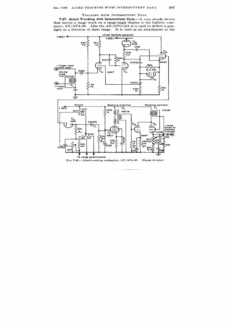
SEC. 727] AIDED TRACKING WITH INTERMITTENT DATA
247
T’RACKING wrm W7ERMITTENT DATA
7.27. Aided Tracking with In termit ten t Data .-A very simple device
that moves a range mark on a range-angle dkplay i the ballist ic com-
puter , AN/APA-30. Like the AN/APG-13A it is used to deflect a gun-
sigh t a a funct ion of slant range.
It is used as an at t achment to the
25 k
4W
- trigger input
from rodar
T
145 EW
o. I
pulse
transformer
I
T ,
+fngge
Input
T.
Li ear Oowfcdh generator
~
‘i ~
l
4<
@k
v
2b
Ww
---
220k
0.01
Iw
0.002
6SN7
-— —
---
150k
!’Z 95%
v
la
6SN7
v
l b
I
v
2a
1.5k
1%
I
I
Pickoff
;’-
L
%1
v
I
686
Omx)s
I
I
c ,
22k
!
I
3?2 .
slope
I
I
15k WW
$
~
R
50k
T
o.&2 - Ww
zero
To ronga potanliomefer
Sauarina omdifier
Blochina oscillo?or
1 1
FIQ. 7 ,46.—A,ded-t r ack ing mechan ism, AN/APA-30 . (Range ircu it s .)

248
MAN UAL MEAS UREMENTS [SEC. 727
sea rch radar (AN/APS-3, AN/APS-4, or AN/APS-10). The t racking
The range line is produced by mixing a ~-psec-delayed pulse der ived
from the t r acking device with the radar video. F igures 7.46 and 7.47
show a schemat ic diagram of the device.
A t r igger from the radar oper -
a tes the self-susta in ing linear sawtooth genera tor , VI, Vz, V~ which
opera tes in a manner ident ica l with that of AN/APG-13. A 250-volt saw-
tooth can be produced of which about 200 volt s a r e linea r and represen t
Range wtput
Fx~. 747.-Aided -t r a ck ing mechan ism, AN/APA-30, (Speed servomechan ism.)
10,000 yd. The amplitude-selector diode vsb is biased by the range
poten t iometer which is connected to the a ided-t racking mechanism. The
loading imposed by Rz, C,, and RS t ermina tes the sweep soon after selec-
t ion has been accomplished.
Th e select ed por tion is pa rt ly differ en tia ted
by R,(7,, amplified by V,, inver ted by T,, and applied to the dr iver amPli-
fier Vs. which fires the blocking oscilla tor VW. A posit ive 0.4-Lsec pulse
having a maximum amplitude of 50 volts is produced in the ca thode of
Vst ,and is mixed with the radar video in the radar indica tor . The ca thode
cu rr en t pulse is used beca use it has no over sh oot which wou ld cau se blank-
ing of the indica tor t r ace and consequen t obscura t ion of the video signal.
The gun-sight and con t rol unit a re shown in Fig. 7.48. The range-
t racki g poten t iometer is mounted in the gun sight and tu rned through a
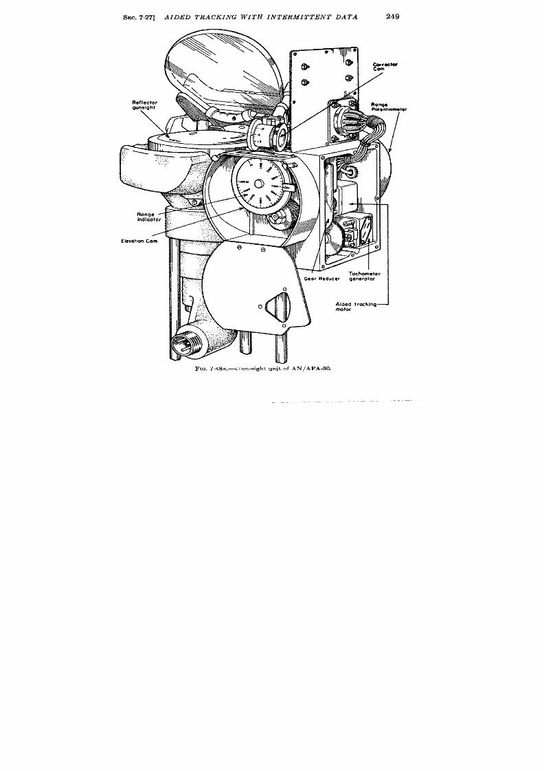
SEC. 727]
Reflector
guneight
\
Range ~
Indicator
/
EIevot,on Cam
AIDED TRACKING WITH INTERMITTENT DATA
249
—
FIG. 7.48a.<: .n-.ight uni-of AN/APA-30.
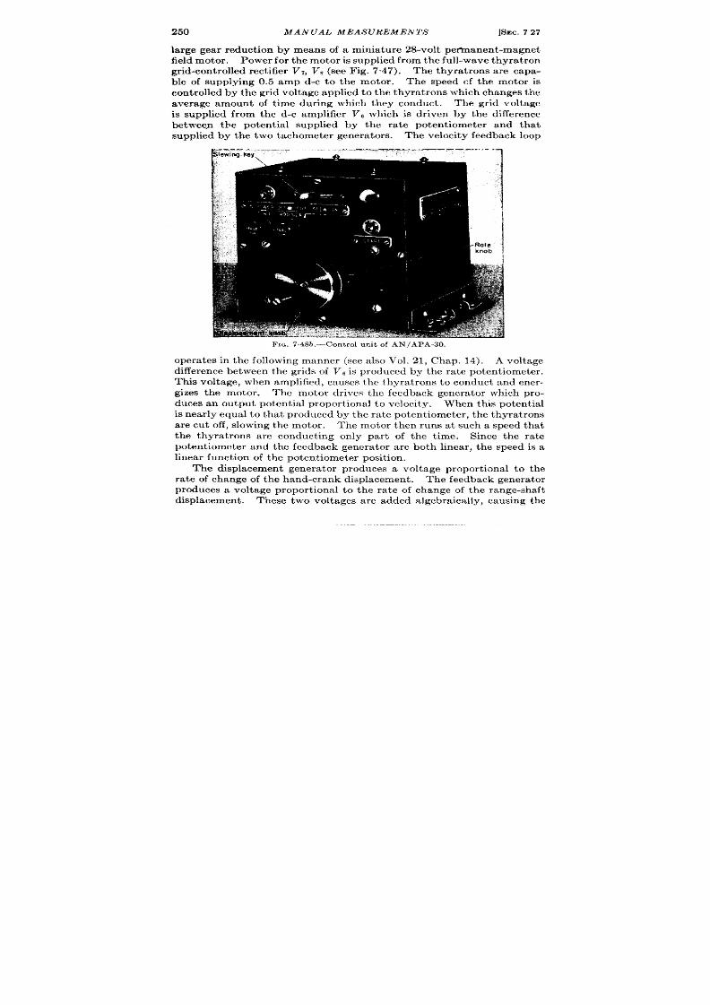
250 MANUAL MEAS UREMENTS [SEC. 727
la rge gear reduct ion by means of a min ia tu re 28-volt peftnanen t-magnet
field motor . P ower for th e motor is supplied from the full-wave thyrat ron
gr id-con t rolled rect ifier V,, V, (see Fig. 7.47). The thyrat rons are capa-
ble of supplying 0.5 amp d-c to the motor . The speed cf the motor is
con t rolled by the gr id voltage applied t o th e thyra t rons which changes the
average amount of t ime dur ing which they conduct . The gr id voltage
is supplied from the d- amplifier Vs which is dr iven by the clifference
betwee,n the poten t ia l supplied by the ra te pot en t iometer and that
supplied by the two tachometer genera tors.
Th e velocit y feedba ck loop
FIG. 748b.-Con t rol un it of AN/APA-30.
opera tes in the following manner (see also Vol. 21, Chap. 14). A voltage
differ en ce et ween t he gr ids of V6 is pr odu ced by t he r at e pot en tiomet er .
Thk voltage, when amplified, causes the thyra t rons to conduct and ener -
gizes the motor . The motor dr ives the feedback genera tor which pro-
duces an outpu t potent ia l propor t iona l t o velocity. When th is poten t ia l
is near ly equal t o that produced by the ra te poten tiometer , the thyra t rons
are cu t off, slowing the motor . The motor then runs at such a speed that
t he thyra t ro s a re conduct ing only par t of t he t ime. Since the ra t e
poten t iometer and the feedback genera tor a re both linear , the speed is a
linear fu nct ion of t he pot en tiom et er posit ion .
The displacement genera tor produces a v ltage propor t ional t o the
ra te of change of the hand-crank displacement . The feedback genera tor
produces a voltage propor t ional to the ra t e of change of the range-shaft
displacement . These two voltages are added algebraica lly, cau ing the
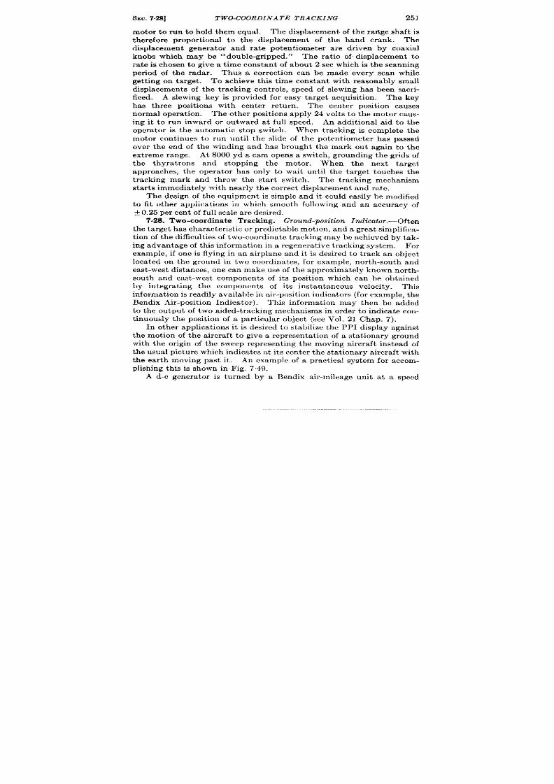
SEC. 7.28]
TWO-COORDIN AT E T RACKING
251
m tor to run to hold them equal. The displacement of the range shaft is
t herefore propor t ional to the displacement of the hand crank. The
displacement enera tor and rate poten t iometer a re dr iven by coaxial
knobs which may be “double-gr ipped.” The rat io of displacement to
ra te is chosen to give a t ime constan t of about 2 sec which is the scanning
per iod of the radar . Thus a cor rect ion can be made every scan while
get t ing on target . To achieve this t ime constant with reasonably small
displacements of the t racking cont rols, speed of slewing has be n sacr i-
ficed. A slewing key is provided for easy target acqu isit ion . The key
ha three posit ions with c n ter retu rn . The cen ter posit ion causes
normal opera t ion . The other posit ions apply 24 volt s t o the motor caus-
ing it to run inward or ou tward at full speed. An addit ional aid to the
opera tor is the automat ic stop switch . When t racking is complete the
m tor con t inues to run unt il the slide of the poten t i meter has passed
over the end of the winding and has brought the mark out again to the
ext reme range. At 8000 yd a cam opens a switch , grounding the gr ids of
the thyra t rons and stopping the motor . When the next target
approaches, the opera tor has on ly to wait unt il the target touches the
t racking mark and throw the star t switch . The t racking mechan ism
star t s immediately with near ly the cor rect displacement and rate.
The design of the equipment is simple and it cou ld easily be modified
to fit other applicat ions in which smooth following and an accuracy of
f 0.25 per cen t of fu ll sca le a re desir ed.
7.28. Two-coor din at e Tr ackin g. Ground-position Indicat or. -often
t he t ar get h as ch ar act er ist ic or pr edict able mot ion , an d a gr ea t simplifica-
t ion of t he difficult ies of t wo-coor din at e t r ackin g maybe ach ieved by tak-
ing advan tage of th is in format ion in a r egen er at ive t rackin g system.
For
example, if one is flying in an airplane and it is desired to t rack an object
located on the ground in two coordinates, for example, nor th-south and
east -west distances, one can make use of the approximate y known nor th-
south and east -west components of it s posit ion which can be obta ined
by in tegra t ing the components of it s instantaneous velocity. This
in forma tion is r ea dily a va ila ble in a ir -posit io in dica tor s (for example, t he
Bendix Air-posit ion Indica tor). This nformat ion may then be added
to the ou tpu t of two aided-t racking mechanisms in order to indicate con-
t inuously the posit ion of a par t icular object (see Vol. 21 Chap. 7).
In other applicat ions it is desired to stabilize the PPI display against
the mot ion of the aircraft to give a represen ta t ion of a sta t ionary ground
with the or igin of the sweep represen t ing the moving aircraft instead of
the usual picture which indicates at it s cen ter the stat ionary aircraft with
the ear th moving past it . An example of a pract ica l system for accom-
plishing this is shown in Fig. 7.49.
A d-c genera tor is tu rned by a Bendix air -mileage u it a t a speed

252
MANUAL MEASUREMENTS
[SEC. 728
propor t iona l to t rue a irspeed. The a ir -speed potent ia l der ived from it is
resolved by means of a sine-cosine poten t iometer in to nor th-south and
east -west compon en ts of air speed.
Since the N-S and E-W channels are
ident ical, on ly t he N-S channel will be descr ibed. A manually cont rolled
poten t ia l is added to the N-S component of air speed as a velocity cor -
rect ion . If the equipment is cor rect ly calibrated this potent ia l repre-
sent ing the difference between air speed and ground speed is equal to the
r
—-—. -
Ni-nA:t ,
I
.-J
Sine
I
D-c gw-lwdOr
poten!iomeler
i
Adding
l\i”tOgrOtOr ~,,q
N-S flx
I N-S ok position
r J ,COrrectedbynavigator
‘M
“”T I M ‘
I\ @actrochQmJj ‘].
1-
A
Jiffor. ;
entiol ,
&
lvc~ia
-1
\
Q
air’’’’hd’hd
.S ni,s.need+ wind:
Shah which turns
with velocity w@od-
ional to airspeed
(Smdix Air
MileOga Unit]
3.
,0 ““
rnatemaratmg I I
slew; i?-l
‘r I
compass
( FIIJX Gale
or Gyrosyn)
\ , N-S,m”ds,eed
Ns -G.,r .Y.-
lli~.w
Adding
network
4
17
E.Weir
1 corrected by navigator
posttion E;,+’
,
..”
E-Wwind
hand sat
Fm. 7.49.—Simplified GP I u sed t o st op mot ion of gr ound on a ir bor n e PPI’s.
N-s component of wind. The sum of N-S a r speed and AT-S wind is
t hen integra ted by means of an elect romechanica l in tegra tor (velocity
servomechanism) to give N-S ground posit ion.
The onstant of in tegra -
t ion in the form of a fix on some ident ifiable object is added through a dif-
ferent ia l. The naviga tor’s fix dia ls read N-S and E-W distance with
respect to some conven ien t referenc point in the area to be pa t rolled.
As the plane changes speed or direct ion, the N-S and E-W componen ts of
ground speed change accordingly, so that if posit ion and wind have been
en tered into the computer , the fix dia ls will r ead the posit ion of the plane
from the reference point a t a ll t imes.
Posit ion data a re taken from poten-

,
I
,,
I
,,
I
Video inmt
I
~
L
‘CL ~
*
‘,
w’’i-!
“:{‘~
r;+‘:’
ti-=c~:~:-L-=-=-L-L~––1
s)nchm-
1 ‘“ “\ .~?:
“’i”tix::hnim’
I
/
I “
t ilmuth switch
-——
————+—
Magnatic
––––––~PG,7m–-
1
I
Mimmum
, 60” Cam
clutch
Range
I
I
helipoi
‘“”9= L+% n
Canter
Irnll ‘
- ‘“%Jg”’:
-~ &“~’ia’ ,,, ,y
‘~!
I
LAzimuth input s nchro
I
r
ata (IO epccd from amfonna $ynchro
,
FIG.7.50.-Block diagram of precision B-scope.
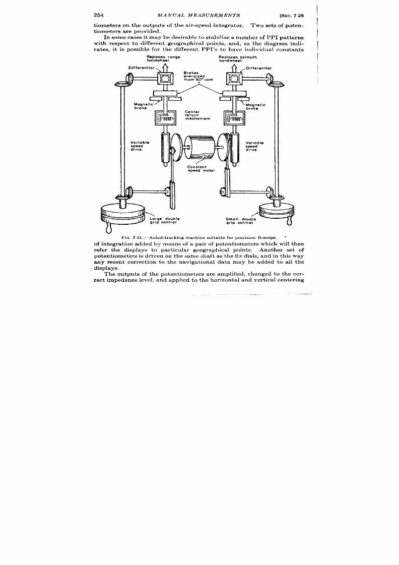
254 MANUAL MEAS UREMENTS
[SEC. 728
t iometers on the outpu ts of the a ir -speed in tegra tor . Two sets of poten-
t iomet er s a re pr ovided.
In some cases it may be desirable to stabilize a number of PPI pa t terns
with respect to differen t geographica l poin ts, and, as the diagram indi-
ca tes, it is possible for the differen t PPI’s to have individual constan ts
Repla cesrange
Reploces azimuth
hondwheel
handwheel
Differential,
A 4 ,Diffem”tial
4
Variable
speed
drive
Voriobla
speed
drive
b
FIQ.751 .—Aided-tracking machine suitable for precision B-scop . “
of in tegra t ion added by means of a pa ir of poten t iometers which will then
refer the displays to par t icu la r geographica l poin ts
Another set of
poten t iometers is dr iven on the same sh ft as the fix dia ls, and in this way
any recen t cor rect ion to the naviga t ional data may be added to all the
displays.
T e outputs of the poten t iometers a re amplified, changed to the cor -
r ect impedance level, and applied to th e hor izonta l and ver t ica l cen ter ing
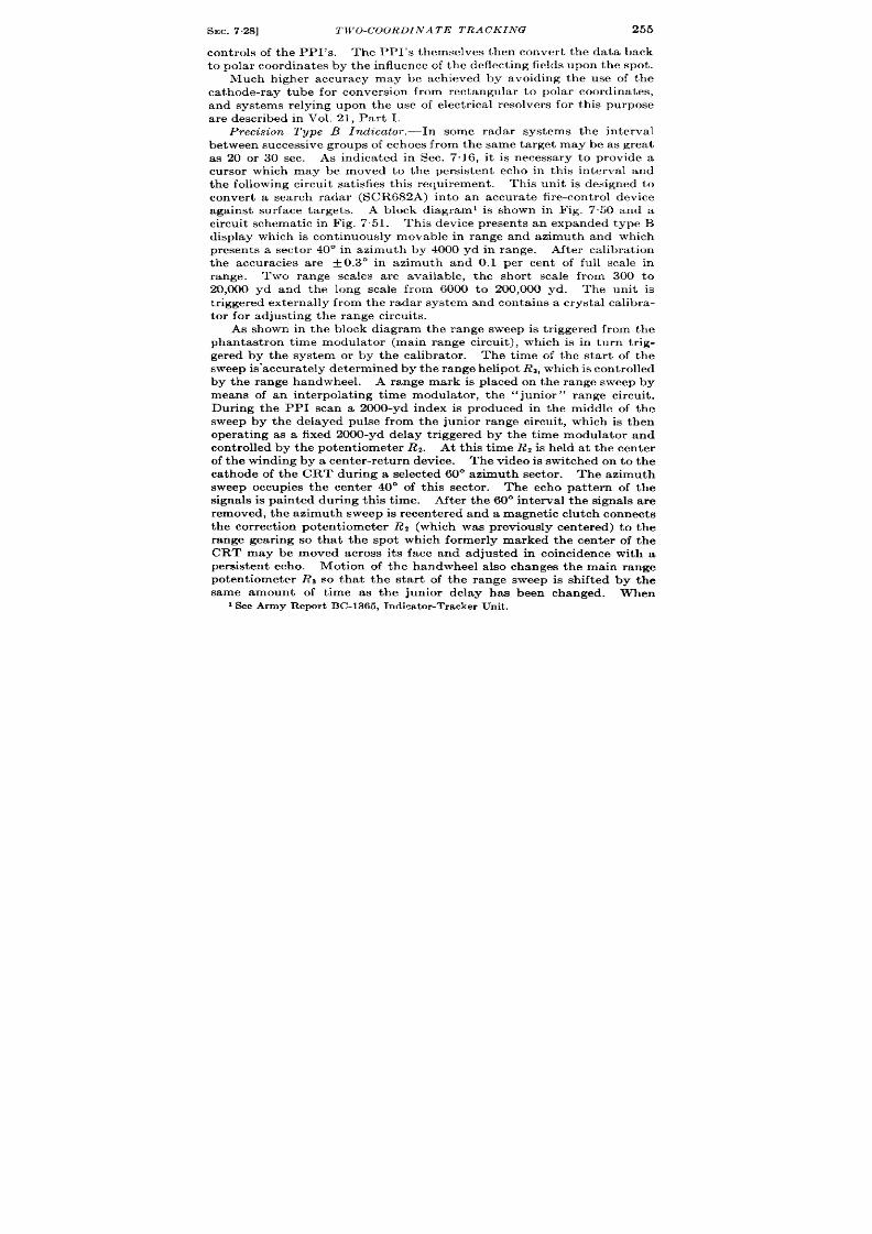
SEC. 7.28]
TWO-COORDIN AT E T RACKING
25
cont rols of the PPI’s. The PPI’s themselves then conver t the data back
t o polar coordin ates by th e influen ce of t he deflect in g fields u pon th e spot .
Much h igher accuracy may be ach ieved by avoiding the use of the
ca thode-ray tube for conversio from rectangu lar to polar coordina tes,
and systems relying upon the use of elect r ica l resolver s for th is purpose
are descr ibed i Vol. 21, Par t I.
Precision Type B Indica tor .—In some radar systems the in terval
between successive groups of echoes fro the same ta rget maybe as grea t
as 20 or 30 sec. As indica t d in Se . 716, it is necessa ry to provide a
cursor which may be moved to t e persistent echo in th is in terval and
the following cir u it sa t isfies th is requ irement . This unit is designed to
conver t a search radar (SCR682A) in to an accura te fir e-con t rol device
against su r face targets. A block diagram’ is shown in Fig. 7.50 and a
cir cu it sch emat ic in F ig. 7,51.
This device present s an expanded type B
display which is cont inuously movable in range and azimuth and which
presen ts a sec or 40° in zimuth by 4000 yd in range. After ca libra t ion
the accur cies are + 0.3° in azimuth and 0.1 per cen t of full sca le in
20,000 yd and the long scale from 6000 to 200,000 yd. The unit is
t rigger ed extern ally fr om t he rad r system and con ta in s a crys a l ca libra-
tor for adjust ing the range circu it s.
As shown in the block diagram the range sweep is t r iggered from the
phan tast ron t ime modula tor (main range circuit ), which is in turn t r ig-
ger ed by the system or by the calibra tor . The t ime of the star t of the
sweep is-a ccu ra tely det ermin ed by t he r an ge h elipot Rs, wh ich is con tr olled
by the range handwheel. A range mark is placed on the range sweep by
means of an in terpola t ing t ime modula tor , th e ‘~jun ior” range circuit .
Dur ing the PPI scan a 2000-yd index is produced in the middle of the
sweep by the delayed pulse from the jun ior range circuit , which is then
opera t ing as a fixed 2000-yd delay t r igger ed by the t ime modula tor and
con t rolled by the poten t iometer R2. At th is t ime Rz is held at the cen ter
of the winding by a cen ter -ret rn device. The video is switched on to the
cathode of the CRT dur ing a selected 60° azimuth sector .
Th e a zimut h
sweep occupies the cen ter 40° of th is sector . The echo pa t tern of the
signals is pa in ted dur ing this t ime. After the 60° in terva l the signals a re
r em oved, th e azimuth sweep is r ecen ter ed and a magn et ic clu tch con nects
t he cor r ect ion pot en t iomet er R2 (which was reviously cen tered) to the
range gear ing so th t the spot which former ly marked the cen ter of the
CRT may be moved across its face and adjusted in coincidence with a
persisten t echo. Mot ion of the han wheel a lso changes the main range
potentiometer Rs so that the star t of the range sweep is shifted by the
same amount of t ime as the junior delay has been changed. When
1SeeArmy Report BC-1365, Indicator-TrackerUnit.
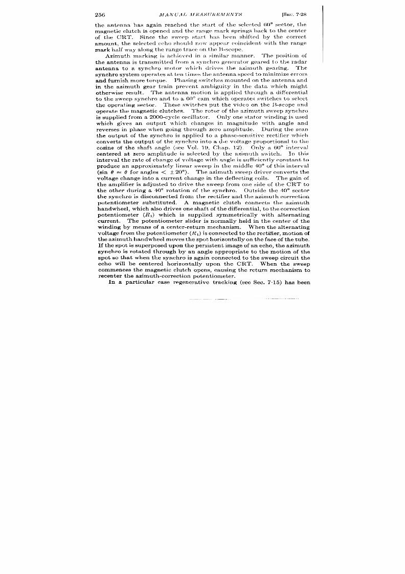
256
MAN UA 1. JII1<ALS(JRL’MI<N7’LS
[SEC. 728
the antenna has again reached the star t of the selected 60° sector , the
magnet ic clu tch is opened and the r t ingc mark spr ings back to the cen ter
of the CRT. Since the sweep stu r t has hccn sh ifted by the cor rect
amount , the sehwtcd echo shoult l no~r appc:w coinciden t \ vith the range
mar k half \ va y along t he r an ge t ra t :c on t he ILscope.
Azimuth marking is ach eved in a similzr mwrner . ‘l’he po it ion of
the an tenna is t ransmit t ed from a synchro genera tor geared to the radar
an tenna to a synchro motor which dr ives the azimuth gear ing.
The
synchro system opera tes a t t cn t imes th e antenna spcml t o minimize er ror s
and furnish more torque. Phasing switches mounted on the an tenna and
in the azimuth gear t ra in preven t ambiguity in the data which might
otherwise resu lt . The an tenna mot ion is applied th rough a differen t ia l
to the sweep synchro and to a 60° cam which opmutcs s\ vitchcs to select
the opera t ing sector . These s~vit rhes pu t the video on the B-scope and
oper at e t he magn et ic clu tch es.
The rotor of the azimuth sweep synchro
i su pplied fr om a 2000 -cycIe oscilla tor .
Only one sta tor winding is used
which gives an outpu t which changes in magnitude with angle and
reverses in phase wh en going through zer o amplitude.
Dur ing the can
the ou tpu t of the synchro is applied to a phase-sensit ive r ct ifier which
conver t s the ou tpu t of the synch ro in to a d-c voltage propor t ional t o the
cosine of the shaft angle (see Vol. 19, Chap. 12). Only a 60° in terval
cen ter ed at zero amplitude is select ed by the azimuth switch .
In this
in terval t he ra te of change f voltage with angle is sufficien t ly constant to
produce an approximately linear sweep in the middle 40° of th is in terval
(sin r?=
d for angles < t 20°).
The azimuth sweep dr iver conver t s t he
voltage change in to a cu r ren t change in the deflect ing coils. The gain of
the ampli ier is adjusted to r ive the sweep from one side of the CRT to
the other dur ing a 40° rota t ion of the synchro. Outside the 40° sector
the synchro is disconnected from the rect ifier and th e azimuth cor rect ion
poten t iometer subst itu ted. A magnet ic clu tch connect s t he azimuth
h andwheel, wh ich a lso dr ives on e sh af t of t he cliffer en tia l, t o t h e cor rect ion
poten t iometer (R J which is supplied symmetr ica lly with alternat ing
current.
The poten t iometer slider is normally held in the cen t er of the
winding by means of a cen te -retu rn mechan ism.
When t he a lt er na tin g
voltage from the poten t iometer (R J is conn ected t o t he rect ifier , mot ion of
the azimuth handwheel moves th e spot hor izonta lly on th e face of t he tube.
If t he spot is superposed upon th e persist en t image of an echo, the azimuth
synchro is rot a t ed th rough by an angle appropr ia te to the mot ion of the
spot so that when the synchro is again connected to the sweep circu it the
echo will be cen ter ed hor izon ta lly upon the CRT. When the sweep
commences the magnet ic clu tch opens, causing the retu rn mechanism to
r ecen t er t h e a zimu th -cor r ect ion pot en t iomet er .
In a par t icu lar case regenera t ive t racking (see Sec. 7.15) has been
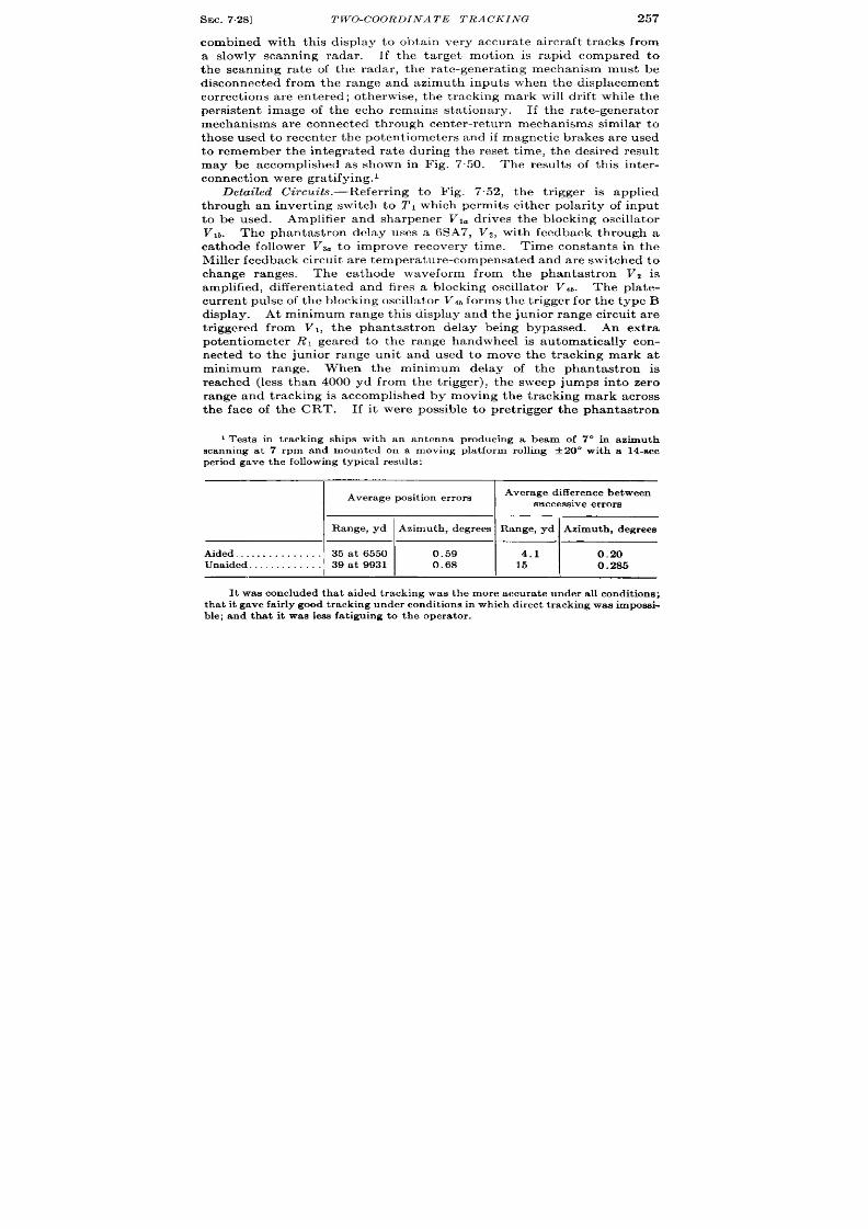
SEC. 728]
TWO-COORDINATE TRACKING
257
combined with this display to obta in very accura te a ircra ft t racks from
a s owly scanning radar . If the t a rget mot ion is rapid compared to
the scanning ra t e of the radar , t he ra te-genera t ing mechanism must be
disconnected from the range and azimuth inputs when the displacement
cor rect ions are en t er ed; otherwise, t he t racking mark will dr ift while the
persisten t image of the echo remains sta t ionary. If t he ra t e-genera tor
mechanisms are connect ed through cen ter -r etu rn mechanisms similar to
those used to recen t er the poten t iomete s and if magnet ic brakes a re used
to remember the in tegra ted ra t e dur ing the reset t ime, the desir ed resu lt
may be accomplished as shown in ig. 7.50. The resu lt s of th is in ter -
con nect ion wer e gr at ifyin g. 1
Detailed Circu it s. pr efer r ing to Fig. 7.52, t he t r igger is applied
through an inver t ing switch to 2’1 which permit s either pola r ity of input
t o be used. Amplifier and sharpener Vl~ dr ives t he blockin g oscilla tor
Vlb. The phantast ron delay uses a 6SA7, V2, with feedback through a
ca thode ollower Vs. to improve recovery t ime.
Time constan t s in the
Miller feedback circuit a re t em pera t ure-com pensa t ed and ar e switched t o
change ranges. The ca thode waveform from the phantast ron Vz is
amplified, differ en tia ted a nd fir es a blockin g oscilla tor V4b.
The plat e-
cu r ren t pu lse of t he block in g oscilla tor V4 b forms the t r igger for the type B
display. At minimum range this display and the junior r ange circu it a re
t r igger ed fr om Vl, t he phantast ron delay being bypassed. An ext ra
potentiometer RI geared to the range handwheel is automat ically con-
nect ed t o the junior r ange unit and used to move the t racking mark at
minimum range.
When the minimum delay of the phantast ron is
r eached (less than 4000 yd from the t r igger ), the sweep jumps into zero
range and t racking is accomplished by moving the t racking mark across
the face of the CRT. If it wer e possible to pret r igge~ the phantast ron
1Tests in t r acking ships with an an tenna producing a beam of 7° in azimuth
scann ing at 7 rpm and mounted on a moving pla t form rolling t 20” with a 14-sec
p er iod ga ve t he followin g t ypica l r esu lt s:
I
Average pos it ion er r or s
I
Average d iffe rence between
success ive errors
I
Range, yd Azimuth , degrees
Range, yd Azimuth , degrees
Aided, . . . . . . . . . . . . . . 35at 6550 0.59
I
4.1
I
0.20
Unaided. . . . . . . . . . . . . 39at 9931 0.68 15
0.285
It wrwcon clu ded th at a ided t ra ckin g wa s t he mor e a ccu ra te u nder a ll con dit ion s;
t ha t it ga ve fa ir ly good t ra ck in g u n der con dit ion s in wh ich dir ect t ra ck in g wa s impa ssi-
ble; and that it was be fa t igu ing to the opera tor .

258
MANUAL MEASUREMEN TS
[SEC.7.28
delay, th is complica t ion wou ld not be necessa ry. The B ga te is formed
by a monostable mult ivibra tor Vb, V6..
The t ra pezoida l sweep is formed
by passing the outpu ts of the mult ivibra tor th rough suitable shaping net -
works to the range sweep dr ivers V7 and V*.
The sweep coils a re con-
nect ed in the ca tho es of the dr ivers since for such a s or t sweep it is
~_J_.-$L$.
ILSI
L’% ~
%
L______ -_-_J
i
.-
q JIJlf
FIG. 752.-Circuit

SEC. 7.28] TWO-COORDINATE TRACKING
259
necessa ry to force current in the la rge inductance of the deflect ing coils.
Ver t ica l center ing volt age is inser ted through t he d-c rest or er VG&
The junior range circuit consist s of a bootst rap sawtooth genera tor
V%, V,oa, which is in it ia ted by the nega t ive B-gate waveform and a diode
amplitude selector VIO~ and amplifier s V9 b and Vlla, driving the block ing
& v,
&
Vg
V)g
q,
“ +400
Range sweep drt.er
Linears ‘-- “-’ ‘..’
~ +250
,
,3
T 1
.
L7~
I I
I
.W— .----
#
:—Lp’ ,p~
verter mm
r.?slcar
+-@ I I I I mm%’
I
220k
2
fll’yl
Iv!
1 , , L r
G
-{
J
q )oLf
of precision B-scope.

260
MA,YUAL MEASUREMENTS [SEC. 7.28
oscilla tor Vllb. Ca re has been taken t o make the minimum delay of this
unit as shor t as possible. The mixer VZO a dds the t racking mark, the
~a libra t ion arks, and the B-ga te.
The sum is then applied to the gr id of
the CRT. The t racking mark for an externa l PPI display is obta ined by
passing t he B-ga te th r ough t he limiter-amplifier V23.
The video amplifier consist s of V2, and VZZ. When posit ive video is
used, on ly V?g is connect ed. When nega t ive video is used, VZ1 dr ives t he
ca thode of VZZ so that the output is in phase with the input . The d-c
r est or er Vlt b is u sed t o st abilize t he zer o-sign al level a pplied t o t he ca th ode
of the CRT. Two in tensity cont rols a r e used to adjust t he ca thode bias
of the CRT and are swit ched by the 60” cam. These two cont rols a re
necessa ry t o make the radar video and the t racking spot appear equally
bright.
The 2000 cps a-c for the azimuth sweep is genera t ed in a two-stage
feedback osc lla tor Vlt. The freque cy is et ermined by resona t ing the
rotor of the azimuth sweep synchro.
A loading network is connect ed
across the sta tors of the synchro to preven t changes in the oscilla tor
amplitude as the synchro rot a tes.
The angle sweep rect ifier (demodu-
lator) V], is a t r iode bidirect ional switch (Vol. 19, Chap. 14). A filt er
removes the residua l a -c component from the sweep waveform. The
a zim ut h-sweep dr iver is a ca th ode-cou pled push-pull amplifier .
As the
azimuth sweep waveform is ver y slow no specia l provisions ar e necessa ry
to compensa t e for the inductance of the deflect ing coils.
The calibra tor is convent iona l. A crysta l oscilla tor Vlti operates
Class C producing pulses in the t r ansformer connect ed in its ca thode cir -
cu it . The other windings in conjunct ion with Vlat , form a blocking
oscilla tor . This is synchron ized at l-to-l ra t io. The 10,000-y d-mark
divider Vlgo is of the pla te-ca t hode-coupled var iety, the synchron izing
sig al being in jected in the gr id circu it . The PRF divider Vl,b is t r ig-
gered on an ext ra winding from the pla te-cur r en t pu lse of the 10,000-yd
divider and opera t es at about 400 cps.
The ca libra t ion marks are mixed
through small condenser s and applied t rough an a t tenua tor to the gr id
of V2M. Pla te-cur rent pu lses a re used because they have no over shoot s
which would blank the PPI.
The indicator has given excellen t per formance. It is possible to reset
the t racking spot on small, isola ted ta rget s to at least 5 per cen t of the
r ise t ime of the video pulse and 5 per cen t of the an tenna beamwidth of the
a ssocia ted r adar set .
The design of the circuit s is st ra igh t forward but not par t icula r ly
economica l of par t s. There seems t o be no par t icu lar good reason for
using a phantast ron t ime modula tor for the main rang unit and a boot -
st rap sawtooth genera tor for the jun ior t ime modula tor . Inst ruct ion of

SEC. 7.29]
INTRODUCTION 261
main tenance personnel cou ld be considerably simplified if both circu it s
were of the same type.
ESPECIALLY ACCURATE TIME-MEASURING SYSTEMS
7.29. In t roduct ion . -In hyperbolic navigat ion systems such as Loran
and Gee it is necessa ry t o measure t ime differen ces with an ext remely high
degree of precision . Measurement of t imes as large as 20,000 psec wit
an accuracy of + ~ ~sec is frequen t ly desirable. In order to conserve
r -f channel space, pu lses r ising as S1OW1 as 10 to 90 per cen t in 100 ~sec
are used. Measurement of these pu lses with the re u isit e accu racy can
only be accomplished by superposit ion methods (see Sec. 7.11). In Loran
the “master” sta t ion t ransmits at a PRF of about 25 cps. The “ slave”
sta t ion rec ives the pu lse delayed by the t ime of propagat ion from one
sta t ion to the other , waits $ per iod (10,000 Wsec) and transmit s a pulse.
The receiving equipment loca ted in the vessel being navigated must
synchron ize its t iming circu it s with the master pu lse and accura tely
measu re the delay between the master and slave received pulses.
A simplified block diagram illust ra t ing the basic method of accura e
t ime-difference measurement is shown in Fig. 7.53. A stable oscilla tor
ser ves as t he t imin g stan dard.
This oscilla tor is con t rollable over a nar -
row frequency range by m nual or automat ic means. A counter chain is
synchron ized with the oscilla tor t o produce a PRF of twice the frequency
t ransmit ted by the ground sta t ions.
A bistable mult ivibra tor circu it
divides th is frequency by 2, producing the fundamenta l PRF of the t rans-
mit t er sta t ions. Since th e slave sta t ion waits ~ per iod after~receiving th e
pu lse from the master sta t ion the two received pulses will appear dur ing
a lt erna t e ha lf cycles of the sca le-of-two.
Th e slow t ype A sweep is sta r ted
with each t rigger from th e cou nt er and lasts for near ly all th e t ime between
t r iggers. A square wave from the mult ivibra tor is applied to a ver t ica l
deflect ing pla te of the CRT so that t he t r ace appears a lternately on two
lines as shown in Fig. 7.54a. An accurate fixed-delay produces a pedesta l
near the beginn ing of the upper t race.
The master sta t ion pulse is
placed upon this pedesta l by adjust ing the frequency of the oscilla tor
un t il t he master pu lse dr ift s on to the pedesta l. If the master pu lse
remains sta t ionary, th e frequ en cy of th e t iming system is then accura tely
synch ron ized with that of the master sta t ion.
A var iable delay (t ime
modula tor) produces a pedesta l on the lower t race. By means of a delay
cont rol th is pedesta l is placed under the slave sta t ion pulse. The long
sweeps do not provide sufficien t t ime discr i inat ion for accurate t ime
measurement . Accordingly expanded sweeps are provided which are
on ly sligh tly lon ger t han t he r eceived pu lses.
Th ese sweeps a re in it ia ted
alt ernately by the fixed and the movable pedesta ls. If the master pu lse
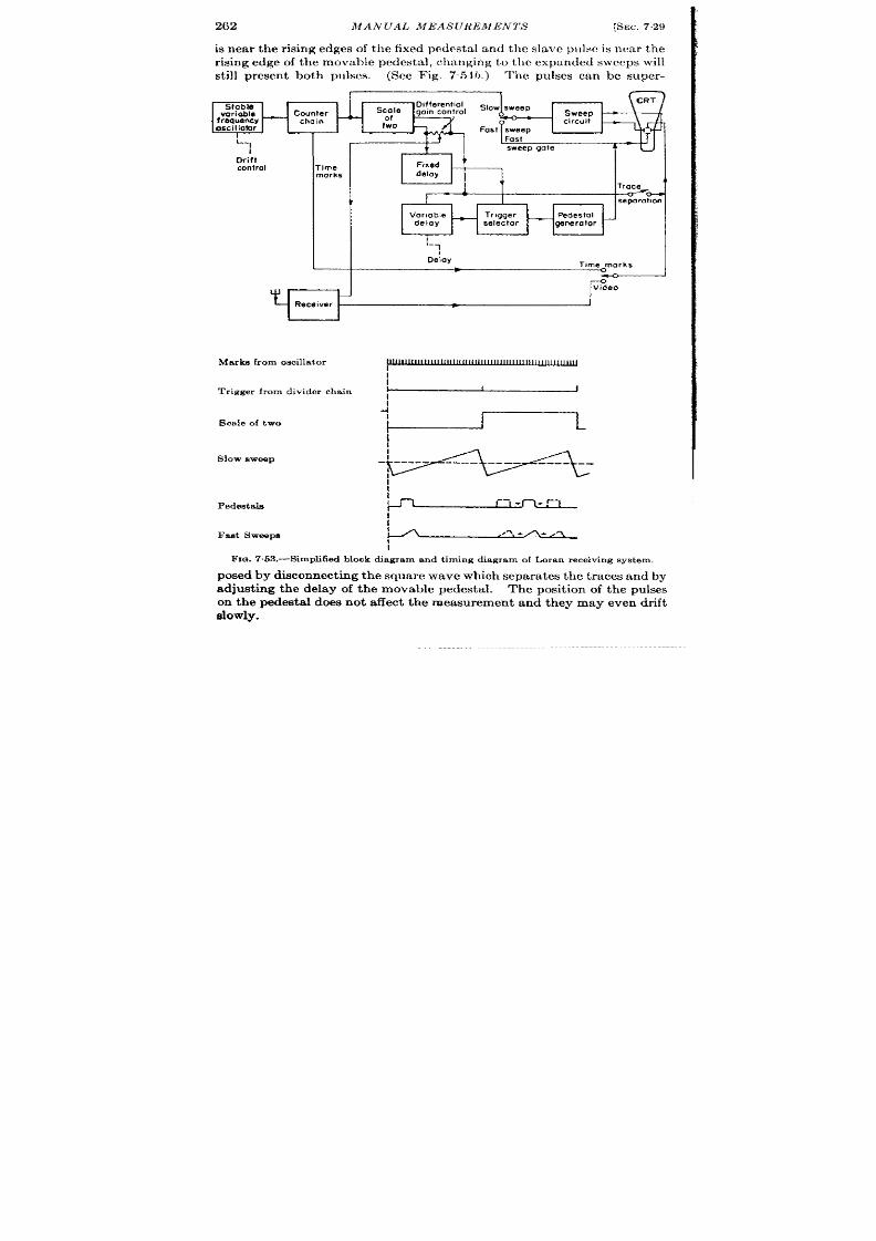
262 MAN UAL MEAS(JREMEN7’S [SEC. 729
is near the r ising edges of the fixed pedesta l and the slave p~ lsc is near the
risin g edge of t he movable pedest al, ch an gin g t o t l~c expa nded sweeps will
st ill presen t both pulses. (See Fig. 754b.) ‘l’he pulses can be super -
L,
Dri’ft
control
Time
marks
Stable
Differeniiol
Al “
cale
Slow sweep
variable
Counter
go,n confrol
Sweep
frequency
—
chain
oscillofor
I:fo
circuit
Fast sweep
I I
Fast
i
sweep gate
Fixed
delay
1.
Trace
0-
-s’’”’””O
-
1
Delay
T#me marks
I
I
Marks from oscillator
Trigger from divider chain
Sca le of two
Slow sweep
Pedeutals
F ed SW6ePE
I
I
1
I
J
-!l
1
J
I_
j
I
I
I
I
I
I
~
I
I
Fm. 7.63.—Simpfi6ed block d iagram and t iming d iagram of Loran receiving sys tem.
-1
posed by discon nect in g th e squ are wave wh ich separa t es t he t races and by
adjust ing the delay of the movable pedesta l. The posit ion of the pu lses
on the pedesta l does not affect the measurement and they may even dr ift
slowly.
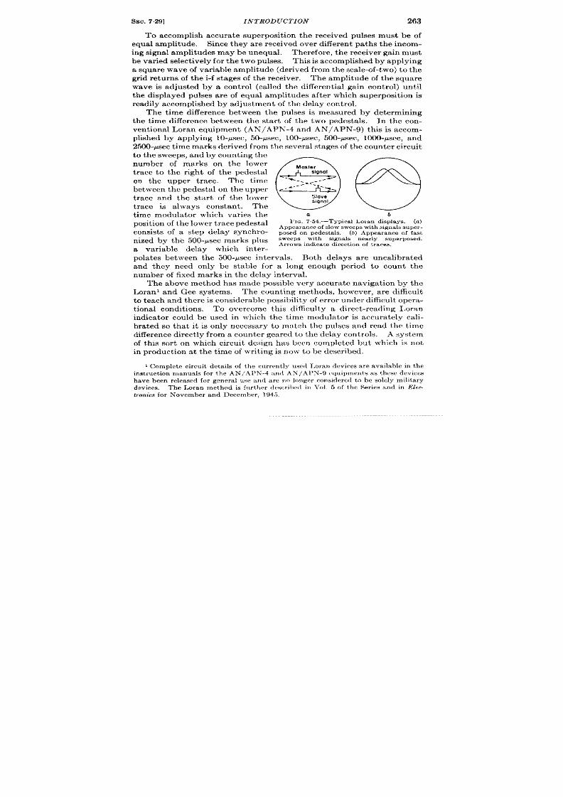
SEC. 7.29] INTRODUCTION
263
To accomplis accura te superposit ion the r eceived ulses must be of
equal amplitude. Since they ar e r eceived over differ en t pa th s t he in com -
ing signal amplitudes may be unequal. Therefor e, the r eceiver gain must
be var ied select ively for t he t wo pulses. This is accomplished by applying
a squar e wa ve of va ria ble amplitude (der ived fr om t he scale-of-t wo) t o t he
gr id returns of the i-f stages of the r eceiver . The mplitude of the square
wave is adjusted by a cont rol (ca lled the clifferent ia l gain cont rol) until
the displayed pulses a re of equal amplitudes a fter which superposit ion is
r eadily accomplished by adjustment of t he delay cont rol.
The t ime differ ence between the pulses is measured by determining
the t ime differ ence between the star t of t e two pedesta ls. In the con-
vent ional Loran equipment (AN/APN-4 and AN/APN-9) th is is accom-
plish ed b a pplyin g 10-psec, 50-Asec, 100-~sec, 500-P sec, 1000-P sec, a nd
2500-u sec t ime mar k der ived fr om t he sever al st ages of t he cou nt er cir cu it
to the sweeps, and by count ing the
number of marks on the lower
t r ace to the r ight of the pedesta l
on the upper t race.
The t ime
between the pedesta l on the upper
t race and the sta r t of the lower
t race is a lways constant . The
t ime modula tor which var ies the
posit ion of t he lower t r ac pedest al
consists of a step delay synchro-
nized by the 500-psec marks plus
a var iable delay which inter -
0
aster
signal
-%. -
.A
#/-:.”-
- A-
-w
Slave
slgnol
a
b
FIG. 754.-Typica l Lor an displays. (a )
Appearance of slow sweepswith signals super-
pos ed on pedes ta ls . (b) Appea r ance of fa st
sweeps with signa ls nea r ly super osed.
Ar rows ind ica t e d ir ect ion of t r aces .
pola tes between the 500-ysec intervals. Both delays a re uncalibra ted
and they need only be stable for a long enough per iod to count the
number of fixed marks in the delay interval.
The above method has made possible very accura te navigat ion by the
Loran’ and Gee systems. The coun t ing methods, however , ar e difficult
t o t ea ch a nd t her e is con sider able possibility of er ror u nder difficult oper a-
t ional condit ions. To overcome this difficulty a direct -reading Loran
indica tor could be used in which the t ime modula tor is accura tely cali-
bra ted so that it is on ly necessa ry to mxtch the pulses and read the t ime
difference direct ly from a counter gear ed to the delay con trols. system
of this sor t on which circuit design has been completed but which is not
in pr oduct ion at the t ime of wr it ing is now to be descr ibed.
1Com plet e circu it det ails of t he cu rr en tly u sed I,or an dcvircs a re a vaila ble in t he
instruction manuals for t he AN/Al’N ”-4 a nd AN /Al’N’-9 equ ipmen ts a s t hese devices
h ave been relea sed for gr nera l usc a nd ar c n o lon ger c n sidcrc(i t o be SOMYmilit ary
devices. The Loran method is fu r ther dmcr ilmd in l’~)1. 5 of the Ser ies and in Elec-
tronics for November a nd Dcccmhcr , 194.5.
264 MANUAL MEASUREMENTS
[SEC. 7.30
7.30. Timing Sequence.—The basic Loran 1 repet it ion frequencies
20
20
may be given by the formulas
2 x (300 – n )
kc,
(400 – n )
kc or
z x ~52~ _ ~, kc where n is any in teger from O to 7 inclusive and cor -
responds to the s at ion number .
These th ree formulas give the exact
repet it ion frequencies for the 20-, 25-, 33&cps bands.
The oscilla t or
frequency is chosen to be 20 kc/see because this is twice the lowest com-
mon mult iple of all the pulse repet it ion frequencies employed. The rea-
son for the factor of 2 will be apparen t later .
It shou ld be noted here
that the repet it ion-frequency formulas give frequenc es whose per iods
vary in steps of 2 X 50 psec in each case.
The two Loran signals will be refer red to as the m ster and the slave
signal. Star t ing with the master and going to the slave signal, the t ime
difference must always be great er than P/2 and less than P where P is the
repet it ion per iod. These signals are displayed on the Loran sweeps.
The slow sweeps are t r iggered at the repet it ion frequencies given ab ve
and display the full cycle. The first half cycle of the complete per iod
appears as an upper t race and the second half cycle as a lower t race.
(For conven ience the first hal cycle will be refer red to as P, and the
second half as P2. ) This then means that if the master stat ion appears
near the beginn ing of the upper t race, the lave stat ion must appear
somewhere on the lower t race.
“ Zero” t ime difference will be refer r ed
to as a t ime difference of exact ly P/2; that is, the master stat ion will
appear on the upper t race direct ly above the slave sta t ion on the lower
trace.
This implies that the t ime durat ion f the upper sweep must , for
all values of N be of exact ly the same as that of the lower sweep, and
since the var ious repet it ion ra tes in any one band are obta ined by remo -
ing 2 x 50 x n psec from the per iod of the 20-, 25-, or 33~-cps repet it ion
frequencies, th is implies that 50 X n psec must be removed from P, and P,
to maintain this symmet ry. This expla ins the reason the formulas in the
first paragraph are writ t en with a 20-kc/scc ra ther than a 10-kc/sec basic
t iming rate. This removal of n X 50 psec is accomplished at the begin-
ning of PI and Pz because of cir cu it considera t ions.
Th e fin al mat ch in g
of the Loran signals is accomplished cm fast sweeps.
The fast sweep on
wh ch the master stat ion pulse ppears occurs near the star t of Pl , and is
fixed in t ime. The fast sweep on which the slave sta t ion appears, how-
ever , may be located in t ime any place in P2, provided, that is, tha t th is
I This device was dcvclopcd at tbc Radia t ion I,abora tory for a irborne use. An
elect r ica l working modd bwi hvcn built find tested, and a fina l model su itable for
fligh t t est was in the process of const ruct ion at the end of the war . A direct-reading
indica tor of quite different design for gh ipboa rd use is in product ion at the Sper ry
Gyroscope Co.
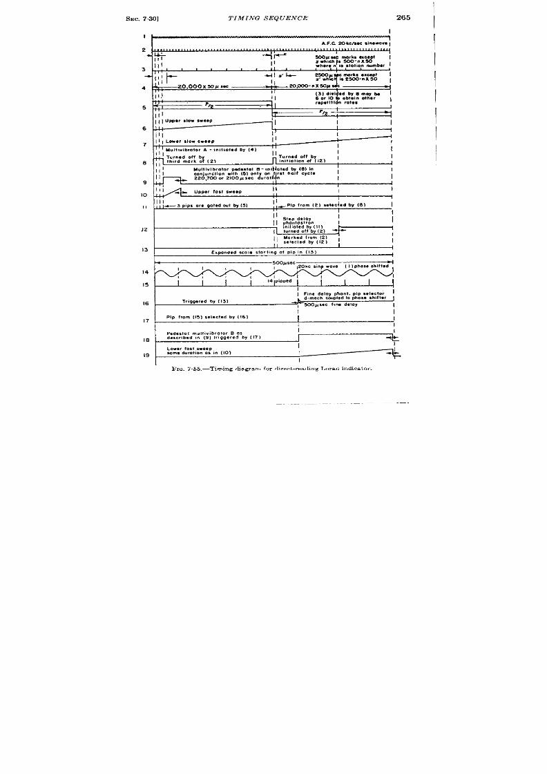
SEC. 7.30]
T IMING S EQUENCE
265
I
+
A.F.C ZOh clm c a in es a va f
4
5
6
7
.9
9
10
II
)2
13
14
15
16
17
18
19
Ill
1’
I
+
II 1Lowerslowseep
[1
I
T;
,
1Multivibrator A - initiated by (4)
11
I
Ill
I
I
II
Turnad off by
I
initiation of (12)
1
4
11;
Mullivibrator pedestal B- ini lat*d by (8) In
I
I
I
II
conjunction with (5) only on f“rst halt CYCI*
J
20,700 or 2100Asec durati n
I
I
l;;
1
upper fast sweep
II
I
I
11
I
Ill
II
I
ill
e 3 pips ore waled out by (5)
,-pip from (2) seleclad by (8)
I
,,
II
I
I
!
I
I
i
Expanded scale starting ot pip in (13)
I
soopsec~
1,
,20kcsinpwave ( I ) phase shifted
~1
1
,
I
I
I
I
I
I I I
I
14 pipped
I
I I
I
I Ffine delay phont. pip selector
i
Triggered by ( 13)
d-mech. wpled to phose shifter
, 500psec fine delay
I
I
I
Plp from (15) selected by (16)
I
I
I
Pedestal m.ltivibro for B as
I
described in (9) triggered by (17)
Lower fost sweep
some duration 0s in (10)
I
I
FIG. 7 .55.—Timing diagram for direct -reading Loran indica tor .

266
MAN UAL MEASUREMENTS
[SEC. 7.30
t ime, measured from the beginning of F’2, is not less than the t ime from
the beginning of P 1 to the beginning of the first fast sweep, It is more
conven ien t to use t iming marks as a t ime reference than the beginning of
each sweep (t he genera t ion of t hese t iming marks will be explain ed lat er ).
Therefore, the first fast sweep is or iginated at a t ime 1500 – n X 50 psec
after the star t of PI, and the delay circuit s which eve tually in it iate the
second fast sweep, a re star ted at a t ime of 500 – n X 50 ~sec af er the
star t of P2.
Refer r ing to Fig. 7.55, line 1 indicates the 20-kc sine wave which is
used as a master-t iming reference.
The frequency of this sine wave is
conixolled by an AFC circu it with reference to the incoming pulse from
the master stat ion (see Chap. 4).
Lin e 2 repr esen ts division by 10 yield-
ing 500-ysec range marks ex ept the first mark fter the star t of each half
pe iod of the repet it ion ra te, th s t ime being equal to 500 – n x 50-Ksec
in each case that is, a division of 10 — n. The marks shown in line 2 are
now divided by 5 in a coun ter that gives an outpu t for eve y fifth mark
of line z, This is sh wn in line 3.
Th se are then applied to a circu it
which gives an outpu t for every sixth , eigh th , or ten th mark shown in line
3. This is indicated in li~e 4. These marks are then used as t r iggers for
a scal -of-two circuit . This gives a square wave as an outpu t whose
recur rence frequency is equal to the Loran repet it ion frequency desired
and is indicated in line 5. It should be noted that th is square wave has
ha lf-cycle symmet ry.
This circuit accoun ts for the factor of 2 in the
denominator of the formula for the repet it ion frequencies. It should be
kept in mind that any of the range marks ment ioned previously are uni-
formly spaced except the first one occurr ing a ter the star t of each half
per iod. Here the t ime interval is n X 50 psec less than the rest of the
ser ies. By the means of these var ious frequency divisions, we have now
obt ain ed a ll t he r epet it ion fr equ en cies r equ ir ed.
Lin e 6 in dic tes t he u pper slow sweep as being st ar t ed at t he beginning
of P1. Line 7 indicates the lower slow sweep being star ted at the begin-
ning of PZ. Line 8 indicates the fixed delay of 1500 – n X 50 ~sec
which init iates the first fast sweep. This is actually a mult ivibra tor
which is tu rned off on the th ird 500-psec mark after the star t of the first
half cycle. On the second half cycle, the step-delay circu it shown in
Line 12 is turned on by the first 500-psec mark, that is, 500 – n X 50 ,usec
after the star t of Pz. This is accomplished ra ther indirect ly. A coinci-
dence tube is included in the circu it which will g ve an output only dur ing
P, and when a 500-Wsecm ark and the rectangu lar pulse shown in line 8 are
coinciden t . This eans a t r igger will be obta in d with the first 500-@ec
mark on the lower sweep. This t r igger then init iates a coarse delay which
in tu rn terminates the delay rectangle shown in line 8 on second half cycle
to preven t fu r ther coincidences.
Line 9 indicates the upper sweep
SEC. 731]
CIRCUIT DETAILS OF LORAN INDICATOR
267
pedesta l being sta r t ed at the t ime 1500 – n X 50 psec after the star t of
the upper slow sweep. The dura t ion of th is pedesta l is 220, 700, or
2100 psec. Line 10 indica tes the actual u per fast sweep which coincides
in t ime to the pedesta l. Line 11 shows the selected t r igger from 2 which
is selected by the waveform of Line 8 in conjunct ion with tha t of Line 5 as
expla ined. Line 12 indica tes the coar se phan tast ron delay. This delay
is sta r t ed at a t ime 500 — n X 50 ~sec after the sta r t of l’z. This delay
is made to select any of the 500-psec marks in the P2 interval a ft er the one
or igina t ing it . This const itu tes a select ion of one ou t of 39,500-psec
marks. The outpu t of the coar se phantast ron-delay circuit , see Line 13,
is used t o in it ia te t he fine delay cir cu it .
The 20-kc/sec sine wave is made
cont inuously phasable and is then used t o gener ate 50-psec t iming marks.
This is indica ted in Lines 14 and 15. The fine delay circuit , a ft er being
init ia ted by the coar se phan tast ron , then selects one of the phase-shifted
50-~sec t iming marks, the con t rol for this delay circuit being coupled to
the phase shift er in such a manner tha t as the delay is incr eased it will
a lways select the same 50-psec t iming mark. The selector pulse is i di-
ca ted on Line 16, and Line 17 indica tes the selected pulse. It should be
noted that th is delay is cont inuous and may. in t roduce any t ime del y
from very near ly O to over 550 ~sec.
Line 18 indica tes the lower sweep
pedesta l which is or igina ted by the cont inuously t ime-modula ted pip of
Line 17. This in turn or igina tes the lower fast sweep as shown in Line 19.
The lower pedesta l and fast sweep ar e ident ica l to those dur ing P,. since
th e delay circu it is in it ia ted 1000 psec sooner a ft er the star t of Pz than
the upper fast sweep is in it ia ted after the star t of P,, t he lower fast sweep
can be brought in to what cor r esponds to “ zero” t ime delay; tha t is, it
occu rs exa ct ly ~ P after the upper fast sweep.
7.31. Circuit Deta ils of Loran Indica tor .—Figure 7.56 is a simplified
block diagram of t he indica tor .
The basic t ime r efer ence is a 20-kc/sec
LC-oscilla tor , with automat ic frequency con t rol. (For deta ils see Chap.
4, Sec. 4.11, ) There a r e two 20-kc/sec outpu t signals supplied by a com-
bina t ion buffer -amplifier and ca thode follower . One of these output s is
fed in to a pulse genera tor , a blocking oscilla tor , which genera tes 50 psec
markers. The ou tpu t of the pulse genera tor is fed into the coun ter cir -
cuit . In the block diagram it is marked as a Frequency Divider dividing
by 400. The divider consists of a step counter chain with feedback, the
fir st coun ter dividing by 10, the second by 5 and a third stage by 6, 8 or
10 depending upon whether the selected PRF is in the 33-, 25-, or 20-cps
group. The coun ter chain is descr ibed in deta il in Sec. 4.11.
The ou tpu t of the coun ter chain t r igger s a bistable mult ivibra tor ,
which produces a symmetr ica l square wave at the repet it ion fr equency.
This is used for t r ace separa t ion on the CRT and as a switching ar range-
men t in t he t rigger -select or a nd pedest al-gen er at or cir cu it s.
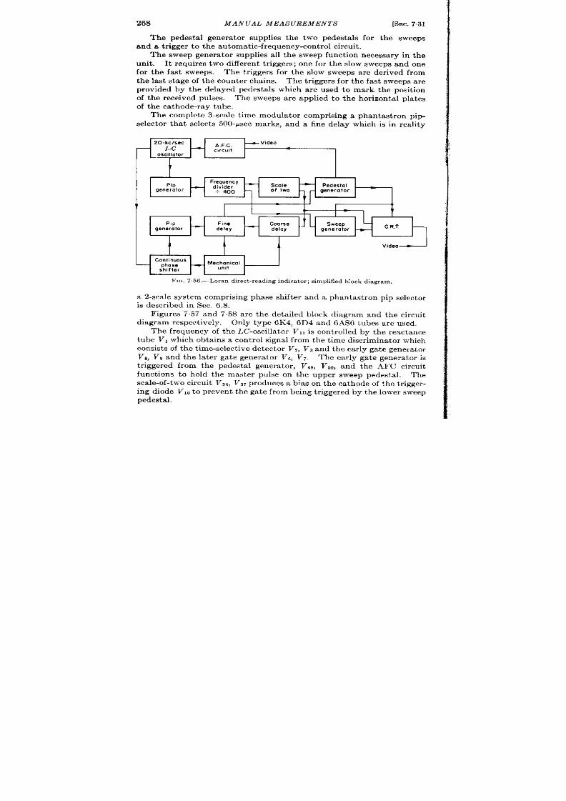
268
MANUAL MEASUREMEN TS [SEC. 7.31
The pedesta l genera tor supplies the two pedesta ls for the sweeps
an d a t rigger t o t he a ut omat ic-fr equ en cy-con tr ol cir cu it .
The sweep genera tor supplies all the sweep unct ion necessa ry in the
unit . It r equires two different t r iggers; one for the slow sweeps and one
for the fast sweeps The t r iggers for the slow sweeps are der ived from
the last stage of the coun ter chains.
The t r iggers for the fast weeps are
provided by the delayed pedesta ls which are used to mark the posit ion
of the r eceived pulses. The sweeps are applied to th hor izonta l pla tes
of the ca thode-ray tube.
The complete 3-scale t ime modula tor compr ising a phantast ron pip-
selector that selects 500-~sec marks, and a fine delay which is in rea lity
20-kclsec
_ Video
L.C
oscillator
I
t
Frequency
Pip
-
— divider
Scale
Pedestal
generator
- 400
of two generator
i
I
(I
T
(
I
Plp Fine
Coarse Sweep
generator
delay
—
delay generator
C R.T.
-
t
11
Video
Continuous
phase
_ Mechanical
shifter
unit
llc, 7.56.—Loran direct-reading indicator; s implified block diagram.
a 2-sca le syst em compr ising phase shifter and a phan ast r on Di~ selector
. .
is descr ibed in ec. 6,8. -
Figures 7.57 and 7.58 are the deta iled block diagram and the circuit
diagram respect ively. Only type 6K4, 6D4 and 6AS6 tubes a re used.
Th e fr equ en cy of t he LC-oscilla tor VI, is con tr olled by t he r ea ct an ce
tube VI which obta ins a con tr o signal fr om the t ime di cr iminator which
consists of th e t ime-select ive det ect or V?, Vs and th e ea rly gat e gen er at or
Vs, VB and the la ter ga te genera tor VG, V7. The ear ly gate genera tor is
t r iggered from the pedesta l genera tor , Vig, Vco, and t ,he M?C circu it
funct ions to hold the master pulse on the upper sweep pedesta l. The
scale-of-two circui t VS6, V~7 produces a bias on the ca thode of the t r igger -
ing diode Vlo to pr even t the ga te from being t r iggered by the lower sweep
pedestal.
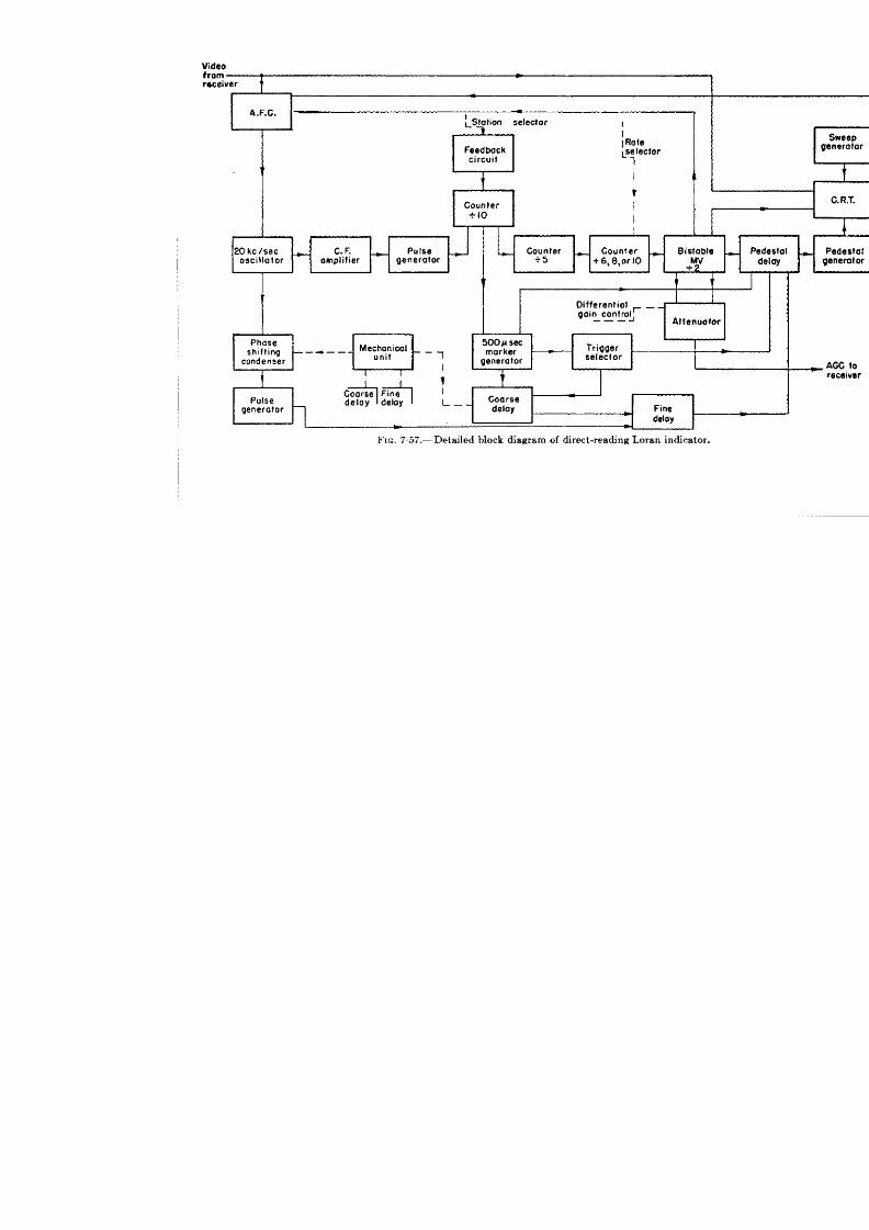
I
t
I

MANUAL MEAS UREMEN TS
[SEC.731
AFC Circuit
300V
:
I
68k
3k-lw
100k
I Qk
,01
001
i?f- ~+
.
...
0k
~
~
~
0.01
D_
v,
.-.
~1 ---
---
---
---
L5k L.,,
100k
001
V8deo
3 ,(
*
N
-I05V
d
ok ;,lk‘~
I
1
X56M
I
R,
Inpul
slop..$
1
30k
0.1
IM 3k
II
51k
i ,-.-.:---.
,ckina Ou
9 * Pwumef
—
<,,> 1 1
—-
1
I I 1
lHU,I lJI#
,
m . -. . -. , .
1
I
500 u Bee.
L h
- - ,.. Triager
i
mar ,--- _ _ ~edfls~ol_O~lO~_Gqn______
-.
306
r
k
91k
/)
10k 180k
91k
47k
~lz,{,ok
m
-,- .
T
Ztu
---
IM33k 91
5;: ~
I
500u SKMark1~
1
}
., ,
AmpI:h:as:sh,lt.r
1. .-,
1
—#
Coors* Oeloy 4k
300V
-., c,.. m .,”.
1
u
u
w
z
FTQ.758.-Loran
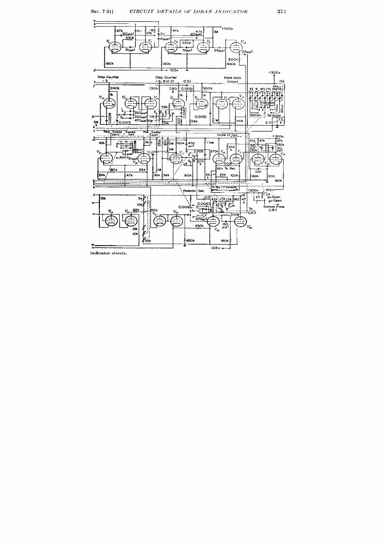
SEC. 731]
CIRCU 1’ DE1’AILS 01’ LORA IN 1)I(:A T OR
271
a
b
c
1 1
K
300k
430k
d
+300V
Slop Counter
Step Counter
Feed bock
+6, .9or10
001 Clrc.,t
15k
J
560k
T
r
+300V
IM
%
24SIAf “--
k
m
7
:~ ‘
I
+
I
-I05V
indicator circui t .

272
MANUAL MEAS UREMEN TS
[SEC. 7.31
To pr even t loa din g t he oscilla tor bu ffer -amplifier V12 is u sed follow-
ing the oscilla tor . This stage supplies two sources of 20-kc sine waves,
one t o the pip-genera t ing circu it and one t o the con t inuous phase-sh ifter
net work.
Th e pu lse-gen er at in g cir cu it , wh ich r eceives it s syn ch ron izin g sign al
in the form of a sine wave from the buffer-amplifier , is a conven t ional
gr id -coupled block ing oscilla tor -.
Large negat ive pulses a re obta ined on
t he pla te of t he blockin g oscillat or wh ich are used as t he init ia t ing t rigger s
for the counter chain , and as 50-Psec markers.
The counter chain following the blocking-oscilla tor pip genera tor
consists of th ree divider stages, their count being 10, 5, and 6, 8, or 10,
respect ively. The first st age produces 500-Psec markers except “X
(referr ing to t iming diagram) which is 500 – n X 50 where n is the
stat ion number . This var ia t ion is due to the feedback circu it , the opera-
t ion of which is expla ined in Sec. 4.11 and in Vol. 19, Chap. 17. The
second stage produces 2500-Psec markers except “X” again which
occurs at 2500 – n X 50 psec. The th ird tage produces repet it ion-ra te
t r iggers of 663, 50, or 40 pps. Again the first count conta ins the “X”
funct ion which is dependen t upon the stat ion number selected.
The design of the gas-filled tube counter s is discussed in Vol. 3,
Chap. 17, and in Sec. 4.11. The feedback circuit which is an integra l
par t of the divider chain is used to obtain the repet it ion ra tes neces-
sary to cor respond to the var ious sta t ion ra tes.
It results in division
by 300 – n; 400 – n or 500 – n when n is the stat ion number . The
operat ion of the counter chain is descr ibed in detail in Sec. 4.11.
In order to obta in a double-t race sweep on the cathode-ray tube a
bis table mult ivibra tor V38, VST (scale-of-t wo) is u sed, which gen er at es a
square wa e at the repet it ion frequency. This square wave is applied
to the ver t ica l deflect ion pla tes of the cathode-ray tube. In this appli-
ca t ion t r igger ing is done on the cathode.
Cathode followers are used t o preven t loading of V~e and V,,. They
supply output s to the different ial receiver gain con t rol, pedesta l delay,
t ra ce epara t ion, and AFC circu it s.
Th e pede ta l delay gen er at or Vzg, VSOperforms severa l funct ions. It
delays the star t of the upper-t race pedesta l unt il aft er the occu r rence
of th ree 500-~sec markers. It genera tes a gate to opera te the t r igger
selector which select s the first 500-psec mark on the lower t race to
t rigger t he coa rse delay.
It is a monostable mult ivibra tor which receives its init ial t r igger
from the output of the last counter stage. on the firs half cycle cor -
responding to the upper t race, the pedesta l delay genera tor terminates
its act ion on the th ird 500-~sec range mark; th is terminat ion is accom-
plished by the following opera t ion : V~Ois normally conduct ing and V2~
SEC. 73 ] CIRCUIT DETAILS OF LORAN INDICATOR
273
nonconduct ing, a nega t ive t r igger on the gr id of Vso st a r ts r egenera t ion .
The gr id of V80 is held nega t ive for a t ime determined by the t ime con-
s an t Cbl, R?o.
The va lue of th is t ime constan t is such tha t when the
500-Asec ma rks a r applied to th e gr id of Vz,, amplified, and applied to the
gr id of V,O, the gr id recover s sufficien t ly to retu rn to the conduct ing
region when the th ird range mark actua tes the gr id. The la te edge of the
pedesta l dela y gen er at or t rigger s t he pedest al gen er at or h en ce su pplyin g
the pedesta l for the upper t race.
In the second half cycle, regenera t ion is in it ia ted by the same means
but the pulse is term na ted after the fir st 500-,usec mark by the nega t ive
ca thode waveform of the coa rse delay which only opera tes dur ing Pz.
Two amplitudes of 500-psec marks a re employed in this process
because as the sta t ions are selected the 500-psec marks move in 50-psec
steps. In order to keep the top pedesta l th ree 500-psec marks from the
s ar t of the sweep the amplitude of the markers applied to the mult i-
vibr at or is ch anged.
The t r igger select or V2~ in it ia tes t he coa rse dela y.
Three pulses are applied simultaneously to differen t elect rodes
of V*8. The 500-psec marks are applied to the ca thode, the pulse from
the pedesta l delay genera tor is applied to the cont rol gr id and the square
wave is applied to the suppressor .
The squa re wave on the suppressor prevents any ou tpu t dur ing the
first half cycle cor responding to the upper t race. Dur ing the second
ha lf cycle it permits the tube to conduct dur ing coincidence with the
other pulses. An outpu t signa l from the pla te is obta ined when a
coincidence between the pedesta l delay genera tors and a 500-~sec mark
occu rs, th is signa l ou tpu t t r iggers the coa rse delay which termina tes the
pedesta l dela y gen er at or t o pr even t fu rt her coin ciden ce.
Th e pedesta l genera tor Vlg, Vso per forms two funct ions. It gen era tes
th ree differen t lengths of pedesta ls for the upper and lower t races. These
are the rectangles which actua te the sweep genera tor for the fast sweeps.
A por t ion of the outpu t of V,, is used to in tensify the t ra e on the CRT
during the fast sweeps. The pedesta l genera tor is a monostable mult i-
vibra tor wh ich is t r iggered in the fol owin g manner .
On the upper t race
the pedesta l genera tor is t r iggered by the falling edge “of the pedesta l
delay genera tor pu lse. To prevent this t r igger from fir ing it on the lower
t race, the square wave is applied to the t r igger selector diode VW. Trig-
ger ing on the lower t race is accomplished by a t r igger from the fine delay
th rough diode VW
The sweep circu it consists of th ree tubes, Val, V32, and VW The same
cir cu it gen er at es t he slow a nd fa st sweeps.
It is a Miller feedba ck cir cu it
comprisin g a pen tode amplifier cou pled t o a t riode differen tia l amplifier .
For slow sweeps the recovery is accomplished by a nega t ive voltage
274
MANUAL MEASUREMEN TS [SEC. 7.31
pulse from the last divider stage which cu ts off the pen tode suppressor .
The sweep condenser is rapidly recharged by the pla te resistor of the
different ia l amplifier . The circuit provides push-pull sweeps which are
capable of a very high duty ra t io.
Switching of the sweep ircuit is accomplished n a differen t manner
dur ing the fast sweeps. Thesupressorof Vssispulsed in to the conduct -
ing region by the pedesta ls from VJY
The ra t e of r ise of the sweep is
ch an ged by swit ch in gt he sweep con den ser .
Th e dur at ions of t he sweeps
are governed by those of the pedesta ls.
The t ime-modula tor circu it which delays the lower pedesta l is a
t hr ee-sca le sy t em which pr odu ces a cont in uously va riable delay. Unlike
the t ime-modulator circu it s in the convent iona l Loran system this t ime
modu la tor is ca libr at ed t o r ea d in m icr osecon ds dir ect ly on a Veeder -Root
counter with an accuracy +0.5 psec of a maximum delay of 20,000 ~sec.
It is descr ibed fully n Sec. 6.8 and compr ises the following units.
1. A coarse-delay st ep phantast ron VAO)VJ 1, VU, and Vqt , which is
sta r t ed by the t r igger selector VW and stopped by a selected
500-psec ma k from V27. The delay is var iable in steps of 500 psec
which cor r espond to the spacing between the 500-psec marks.
2. A fine delay which interpola tes between the 500-~sec marks. This
is a two-scale t ime modula tor comprising a step phantast ron which
is sta r ted from the end of the coa rse delay.
Its act ion is t ermi-
na ted by a select ed, phase-shift ed 500-psec mark. The phase-
sh ift ed mark is der ived from the 20-kc/sec sine wave from the
ca thode of VIZ, shifted in phase by a ph se-shift ing condenser the
outpu t of which is amplified by VWIand conver ted into a pulse by
V19. The phase-shift ed 50-psec mark select ed by the step phan-
tast ron actua tes the pedesta l genera tor th rough VJ s.
Deta ils of the mechanica l unit that con t rols the t ime modulator a re
given in Sec. 6.8. This unit is one of the most impor tant fea tures of the
direct -reading system in tha a lthough the coarse scale is con t rolled by
one handwheel and the fine sca les by another their readings are a lge-
brai a lly added in such a way that the counter read~ the cor r ect tota l
t ime in t er va l.
TECHNIQUES
BY R.
CHAPTER 8
OF AUTOMATIC TIME
I. HULSIZER, AND F. C.
MEASUREMENT
WILLIAMS
INTRODUCTION
8.1. Automa t ic vs. Manual Measurements.—Many a guments have
been advanced, par t icu la r ly a t the beginn ing of radar h istory, on the
rela t ive merit s of manual and automat ic m asurement . Some of the
object ions to automat ic t racking resu lt from the in fer ior performance
of the ear ly automat ic t racking equipment . Fur ther a rgument ar ises
from the ext remely undesirable character ist ics of radar signa ls. In
pu lse-ech o syst em s t he sign als oft en fa de in to t herma l n oise; fu rt hermor e,
u ndesired signals from inter fer ing bject s and ot her radars demand from
t he t ra ckin g mech an ism , eit her h uman or a ut omat ic, discr im in at ion , a ler t-
ness, and judgment . Never theless there a re severa l advantages to be
listed for automat ic t racking which have just ified its inclusion in many
The rapidity of response and higher-accu racy character ist ic of au to-
mat ic cont rol a re of va lue especia lly for h igh-accu racy ant ia ircra ft
radars. Response t imes of ~ to A sec a re rea lizable with au tomat ic
t racking loops, whereas normal opera tor t racking shows response t imes
of one second or grea ter . It might be argued with considerable just ifica -
t ion tha t shor t response t imes a re not requisite for t racking most radar
ta rget s because of low accelera t ions, bu t it is preferable to employ a
fa st -a ct in g t ra ckin g device followed by a con sisten t an d relia ble smoot h-
ing device ra ther than to rely on erra t ic smooth ing by the opera tor .
Timemeasurement opera t ions sta r ted nea r the end of the war on high-
velocity project iles indica te th e inadequacy of human trackin g to follow
accu ra tely su ch h igh velocit ies a nd a cc ler at ion s.
A second favorable aspect of t racking automat ica lly is th e advantage
in weigh t provi ed by elect ron ic t ime measurement as opposed to visua l
mea su rem en t, sin ce visua l mea su remen t implies a t lea st a m et er pr esen ta -
t ion and usua lly a ca thode-ray tube and cer ta in ly a man. A prime
example of th is fea ture is the ARO radar AN/APG-5, which has auto-
mat ic search ing and t racking, and indica tes the approach of a ta rget
with in a cer ta in range simply by a warn ing ligh t .
The following two reasons for au tomat ic t racking a re more genera l
and apply significan t y to the design of appara tus for measur ing t ime
275

276 TECHNIQUES OF A UTOitfA T IC TIME MEASUREMENT [SEC.82
durat ion of var ious phenomena in which t he signal-to-noise ra t io is la rge
enough to require less a t ten t ion and discr iminat ion on the par t of the
opera tor . These are (1) tha t au tomat ic t racking is less fa t iguing for
the opera tor , par t icula r ly when high accuracies are demanded over long
per iods of opera t ion, and (2) that under favorable condit ions, one
opera tor might monitor severa l simultaneous automat ic-t racking opera -
t ions. Such a situa t ion might ar ise with an a ir -t ra ffic-cont rol radar
where each plane car r ies a beacon to be t r iggered by a zen ith search set.
As each plane comes in to the area of cont rol, t r acking ga tes a re set t o
t rack its beacon response unt il t he plane leaves the a ea or lands. One
opera tor could handle severa l such t racking machines, from which data
would be fed automat ica lly to a cen t ra l con t rol sta t ion.
Numerous applicat ions in resea rch or indust r ia l con t rol can be imag-
FE8
.
a
Error
i
Eouol$zing
detector network
e~
Motor
Ampl<tler
control
(U) Conventional servomechanism diagram
8;= input signol 0( moti.a”
eo=Outputmotion
“:;WV=*(”
(b) Block diagram of time-measuring system
FIO. 8.1.—A block diagram of a con-
ven t iona l s ervomechan ism and an au toma t ic
t ir e.+ measur ingys tem.
in ed wher e aut omat ica lly r ecorded
data is desired simultaneously on
the t ime d u rat ion of severa l
phenomena , yet where the cost of
engaging a separa te opera tor for
each measurement might be
prohibitive.
8.2. Genera l Technique of
Automat ic Time Measurement .
The twc basic methods of manual
t ime mea su remen t h ave aut omat ic
analogues.
The fir st , that of con-
ver t ing the t ime dimension in to a
space dimension on a ca thode-
ray-tube display and measur ing
time in t erms of dist an ce, has been
su cessfu lly per formed with the
ai of a pair of adjacen t photo-
elect r ic cells whose differ ence ou t -
put is made to dr ive them along
the direct ion o the t ime base in
accorda ce with the mot ion of the signal (see Vol. 19, Chap. 14).
Th e secon d met hod, t he discr imin at e-demodu lat e t ech nique (Chap. 3),
is usually employed. The process of compar ing the t ime modulat ion
of the echo and the locally modulated pulse is known as t ime discr imina-
t ion (Chap. 3) and yields a voltage or cur ren t which is o era t ed upon to
conver t it in to a form suitable for cont olling the local t ime modulator .
On e immedia te y r ecogn izes t he ubiquit ous a ut om at ic con tr ol mechanism
or servo, where a det ector measures the difference between an unknown
qua t ity and the “f llowing” or servoed quant ity to genera t e an er ror

SEC.8.2]
GENERAL T .ECIIN IQUE 277
signal which acts th rough a con trol device to make the “following”
quant ity equal to the unknown.
Figu re 8.1 illustr ates th is similar ity as
well as in dica tes th e elem en ts of t he t ime-demodu la t ion system.
Th e box la belled” F un ct ion u nit ” per forms t he oper at ion of con ver tin g
the t ime-d scr iminator ou tpu t in to a form suitable for con t rolling the
local t ime demodula tor and may be an amplifier , elect r ica l in t egr a tor ,
r a te servo, or a complex combinat ion of such elements.
This un it
defines the external proper t ies of the system. Sect ions 8.6 to 8.10 will
discu ss t he design of t hese elect rica l or elect romech an ica l oper at or s.
Since the method of con trol hm suc
h a marked effect u pon th e design
of the funct ion unit , th ey will be t r ea ted separa tely depending upon
whether elect r ica lly or mechanica lly con t rolled t ime modula to a re
employed.
El ct r ica lly con t rolled t ime modula tors a re all substant ially single-
sca le, a lthough they may be combined with an accura te fixed-delay
device to make a mult iple-sca le t ime modula tor tha t is con t inuous over a
small in terva l. Good examples of th is pract ice re the AN/APS-15 and
the Brit ish Oboe. As single-sca le devices, these modula tor s a re a t pres-
en t limited in accuracy from 0.1 to 2 per cent of t h eir maximum excu r sion .
Completely elect r ica l t r acking loops are possible which are ligh ter ,
smaller , less expen sive than th eir me hanical analogu es, an d a re capable
of followin g ver y high speeds an d acceler at ion s, and usually of supplyin g
more accura te r ate data .
Mechan ica l t ime modula tor s have the advan tages of enabling the
use of mult iple sca les for h igh accuracy and of supplying data as a
mechan ica l mot ion dir ect ly r at her th an fr om a volt age-follow-u p ser vo.
One difference between mechanical and elect r ica l t ime modula tor s
tha t may be of impor tance in fu tu re t ime-measurement problems in which
high accelera t ions ar e expected is th ir ompara t ive r a te accuracies.
The ra te er ror s in t roduced by the nonlinear it ies of t ime modula tor s
are propor t iona l to the slope of the range er ror plot ted against range.
The mechanica l t ime modula tor s, such as the phase sh ifter , a re accura te
on ly to abou t 0.3 per cen t of a complete revolu t ion whereas th e elect r ica l
t ime modula tors a re capable of linear it ies ten t imes bet t er , and shou ld
ther efore be expected to in t roduce on ly one-ten th as much er ror in to the
t ar get -r at e da ta .
It has been poin ted ou t in Chap. 15 of Vol. 19 tha t with a mult iplicity
of signals a t iine discr iminator must have on ly a limited region of sensi-
t ivity. The consequence of th is rest r ict ion is tha t t ime-measur ing
systems that must t r ack one pulse in a complex group must include some
means for moving its sensit ive region or t ime aper tu re in to coincidence
with the pu lse to be t racked. In radar pract ice th is is termed ta rget -
select ion ; it is usually ach ieved by a sea rch display on a cathode-ray tube

278 TECHNIQUES OF A UTOMA TIC TIME MEASUREMENT [SEC. 8.3
to indica te the rela t ive locat ions of the t ime aper ture and the target
signal, and an on-ta rget indica tor .
Automat ic sea rch circuit s may be
subst itu ted for the display whereupon an automat ic target indi ca t or
would per form the funct ion of stopping the search act ion and locking on
ta rget . The problems of target select ion are discussed in Sees. 8.13 and
8.14.
Another funct ion which the t ime-measur ing system must per form
is tha t of remember ing the last velocity and posit ion of a signal tha t has
faded and of keeping the t racking gates and data ou tput moving at the
last velocity without severe t ransients unt il the signal reappear s. Such
ability is ca lled “velocity memory. ”
Memory t ime is often limited by
the quality of elect r ica l com onent s, and hence an auxilia ry funct ion called
“coast” has been developed whereby the opera tor can th row a switch dis-
connect ing the signal to enable the t racking system to con t inue moving
indefi it ely at the last measured ra te.
This is par t icu lar ly usefu l in radar
applica t ions where the opera t or can observe on suitable indica tors the
approach of in ter fer ing signals and “coast” th rough them. If the func-
t ion has been p r formed proper ly he shou ld be able to reconnect the
t racking loop when the signal again comes into the clear and find the
signal st ill in the t ime aper ture.
Memory provides no immunity from
inter fer ing signals, on ly from fades; coast gives immunity from both .
8.3. Na tu re of Data and Its Effect on Per formance.-Th is topic has
been t rea ted in Chap. 2 and need on ly be summar ized herein . If the
data consists solely of a synchronizing pulse and a t ime-modula ted
pu lse it is on ly n ecessa ry for t he simplest form of aut omat ic t ime-mea su rin g
circu it t o t r igger a sca le-of-two circu it once with the transmit ted pulse
and la ter with the received echo. Measurement of t ime can then be
made by measur ing the average ‘cu r ren t for a fixed recu r rence in terva l,
or y any of severa l available methods.
The immedia te object ion to
this technique is tha t it wou ld be completely confused by mult iple
signals. A technique one step more complex is the method of the
AGL-(T), Sec. 8.17, in which a range gate is made to increase in dura t ion
unt il it includes par t of an echo.
This method has discr iminat ion to
the exten t of select ing on ly the first of severa l pulses. Fur ther methods
of select ing any one of many signals a re discussed in Sees. 8.16, 817,
and 8.18.
A secon d ch ar act er ist ic of the da ta tha t a ffects the t ime-measur ing
accuracy is the receiver bandwidth and the pulse r ise t ime, for the da ta
of Chap. 3 show that range er rors of appreciable magnitude can resu lt
from amplitude modula t ion of the signal if the receiver bandwidth is
inadequate. Signa l modula t ion often resu lts from fading, which can
last as long as severa l seconds and resu lt in er rors both in range and
range ra te. Automat ic ga in con t rol improves this situa t ion . Rapid ga in
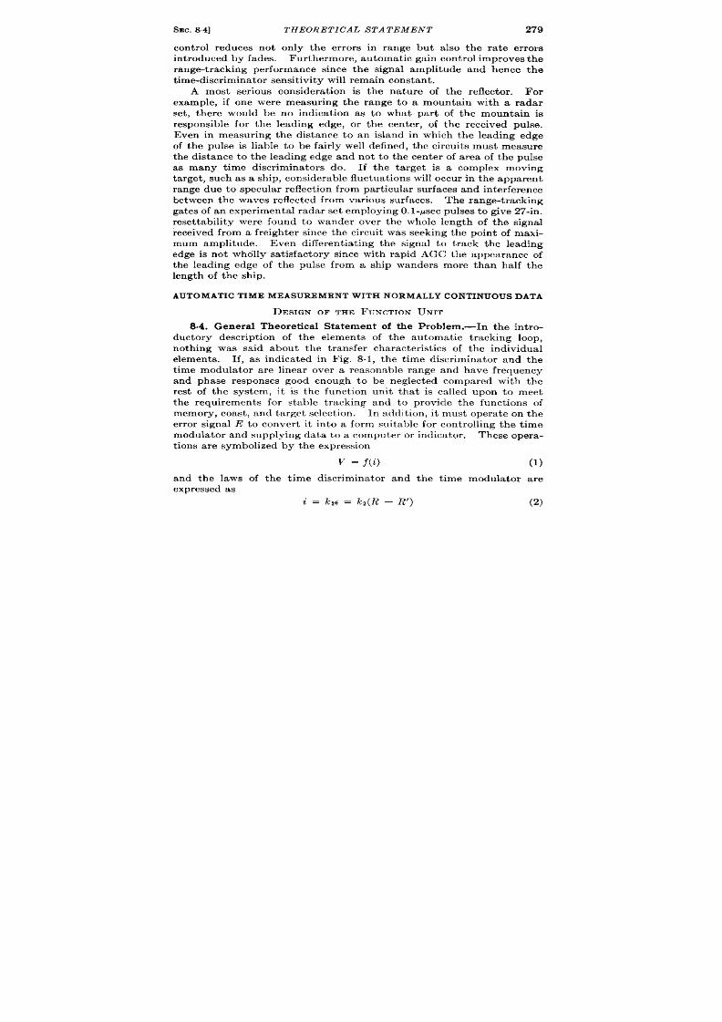
SEC.84] THEORETICAL S TATEMEN T
279
con trol reduces not on ly the er ror s in range but a lso the r a te er ror s
in t roduced by fades. Fur thermor , a tomat ic gain cont rol improves the
range-t racking p r formance since the signal amplitude and hence the
t ime-discr im in at or sen sit ivit y will r emain con st a nt .
A most ser ious considera t ion is the na tu re of the reflector . For
example, if one wer measur ing the range to a mounta in with a radar
set , t er e would be no indica t ion as to what par t of the mounta in is
responsible for the leading edge, or the cen ter , of the received pulse.
Even in measur ing the distance to an island in which the leading edge
of the pulse is liable to be fa ir ly well defined, the circuit s must measure
the distance to the leading edge and not to the cen ter of a rea of the pulse
as many t ime discr imina tors do. If the ta rget is a complex oving
ta rget , such as a ship, consider able fluctuat ions will occu r in t he appar ent
r an ge du e t o specu la r r eflect ion fr om pa rt icu la r su rfa ces a nd in ter fer en ce
bet ween t he waves r eflect ed fr om var ious sur fa ces.
The range-t rack ing
gates of a exper iment al r ada r set employing 0. l-psec pulses t o give 27-in.
reset tability were found to wander over the whole length of the signal
r eceived from a freighter since the circuit was seeking the point of maxi-
mum amplitude. Even different ia t ing the signal to t rack the leading
edge is not wholly sa t isfactory since with rapid AGC the appearance of
the leading edge of the pulse from ship wanders more than half the
length of the ship.
AUTOMATICTIME MEASUREMENTWITH NORMALLYCONTINUOUSDATA
DESIGN OF THE FGNCTION UNIT
8.4. Genera l Theoret ica l Sta tement of the Problem.—In the in t ro-
ductory descr ipt ion of the elements of the automat ic t racking loop,
nothing was said about the t ransfer character ist ics of the individual
elements. If, as indica ted in Fig. 8.1, the t ime discr imina tor and the
t ime modula tor ar e linear over a reasonable range and have frequency
and phase responses good enough to be neglected compared with the
re t of the system, it is the funct ion unit tha t is ca lled upon to meet
the requirement for stable t racking and to rovide the funct ions of
memory, coast , and ta rget select ion . In addit ion , it must opera te on the
er ror signa l E to conver t it in to a form suitable for controlling the t ime
modula tor and supplying data t o a computer or indica tor .
These oper a -
t ions a re symbolized by t he expr ession
v = f(i)
(1)
and the laws of the t ime discr iminator and the t ime modula tor a r e
expr essed a s
i = kzc = kq(R – R’)
(2)
280
TECHNIQUES OF AUTOMATIC TIME MEASUREMENT [SEC. 85
rmd
R’ = k,v
(3)
over their linear r egion of opera t ion .
The symbol R represen ts the
range or instantaneous va lue of the t ime modula t ion of the signal being
R’ similar ly r epresen ts t he t ime modula t ion of the locally
t im e-modu la ted compa rison pu lse.
The cont rol signal of the local t ime
modula tor s represen ted by V and may be either a voltage or a shaft
rot a t ion.
The er ror signal cur r en t i is usually in the form of a cur ren t
that flows only for the dura t ion of the signal being t r acked and hence
consist s of pulses of cur ren t a t the PRF. Since an average cur ren t can
be obta ined by smoothing, it s discont inuous na ture is not important
provided the per iod of the PRF is very shor t compared with the per iods
of fluctuat ion of t he t ime modulat ion .
Qu it e apar t fr om its discont inu -
ous na ture the cur ren t is not immedia tely suitable for cont rolling R’.
For example, if i is made to flow through a resistance to genera t e a
voltage V for cont rolling an elect r ica l t ime modulator , the discr imina tor
cur ren t cou ld be zero for only one value of I?. For all other va lues of
R’ the cur re t i, and hence the difference R – R’ would have to be
differ ent fr om zer o and V would not i dica te the t rue t ime modula t ion R.
It can be argued tha t if kJ k2 is sufficient ly large this er ror would be
negligible, but it is a lso t rue tha t th is condit ion renders proper stabili-
za t ion of the t racking loop possible on ly with a very slow response.
Therefore a funct ion unit tha t rela tes z’ and V in direct propor t ion is
unsatisfactory.
We deduce from this argument thxt one proper ty which the funct ion
unit must have is that t he output V mm have any v:due while it s input i
is zero. Fur thermore, as was mrnt ioucd i Sec. 8.3, t he proper t ies of
posit ion or velocity memory are d(wir :d)lc.
Timsc t \ ro requ irement s
and the knowledge tha t the d:~ta mllst Iw remonal)ly smooth suggest t he
use of one r m or e int egra tors in t jllc funct ion lulit . l?ur ther r r st ,r ict ions
on the funct ion unit a re t ll:lt ~ must not differ from zero t ry n amount
la rger than the dynamic accuracy specifica t ions, and that the t racking
loop be st able.
In the ensuing sect ions, the cpmnt it ies R and R’ will be regarded as
distances r a ther than t imes since it is much easier to discuss velocity
as the ra te of ch nge of distance ~vith t ime than as the ra t e of change of
t im e modu la tion \ vit ,ht im e.
8.5. Single-in tegrator Funct ion lJ nit .-I3y an argument similar to the
one wherein the weakness of t h r propor t iona l funet i on IInit was demon-
st ra ted, it can be seen that m fuuct io~~unit per forming the opera t ion
/
V=} ,idx
(4)
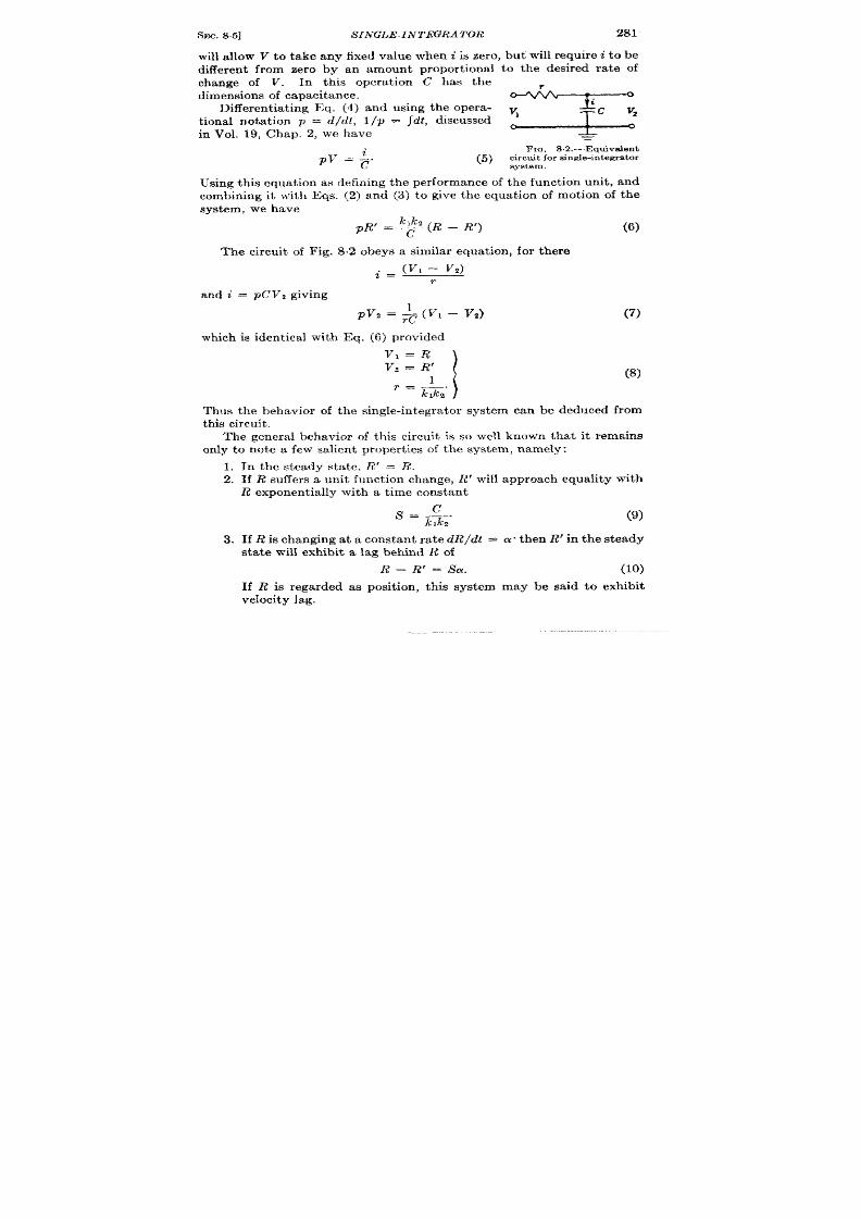
SEC. 85]
SINGLE-INTEGRATOR
281
will allow V to take any fixed va lue when i is zero, but will r equire i t o be
different from zero by an amount propor t iona l to the desired ra te of
change of V. In this opera t ion C has the
d imensions of capacit ance.
Different ia t ing Eq. (4) and using the opera - ~
t iona l not a t ion p = d/dt, 1/p = Jolt) discussed
in Vol. 19, Chap. 2, we have
=
FIG, 82 .-Equ iveJen t
~v = ;.
(5) ci~;~~or sin gle-in tegr at or
Using thk equat ion as defin ing the per formance of the funct ion unit , and
comb ning it with Eqs. (2) and (.3) to give the equat ion of mot ion of the
system, we have
~1~2 (~ _ ~,)
PR’ = ~
(6)
The circuit of Fig. 8.2 obe s a similar equa tion , for there
~ = (v, – “v,)
r
and i = pCVZ giving
pv2 = + (v, – V2)
which is ident ica l with Eq. (6) provided
(7)
(8)
Thus the behavior of the single-in tegra tor system can be deduced from
this circuit .
The genera behavior of this cir u it is so well known that it remains
only to note a few salient proper t ies of the system, namely:
1. In the steady sta te, R’ = R.
2. If R su ffer s a un it fu nct ion ch an ge, R’ will a ppr oa ch equ alit y wit h
R exponent ia lly with a t ime constant
S.&. (9)
3. If R is changing at a constant ra te dR/dt = a. then R’ in t he steady
sta te will exhibit a lag behind R of
If R is r egarded as
velocit y lag.
R–R’=Sa.
(10)
posit ion , th is system may be said to exhibit

282
TECHN IQUES OF A UTOMA TIC TIME MEASUREMENT [SEC. 86
In applying the above discussion to the au tomat ic t racking system,
there are a few remarks tha t can be made concern ing a single in tegra tor
system. If there is actually only one in tegra t ing element , the equa t ion
of the system has no oscilla tory terms and hence needs no addit iona l
componen ts for st abiliza tion .
An in terest ing concept can be der ived
from he fact tha t the t ime constan t of the system is C/lclk*, since
l/klkz then has the dimensions of resistance. Now kl and ka a re the
factors of propor t iona lity of the t ime modula tor and the discr imina tor
respect ive y and may be ca lled the gains of those elements.
Developing
the conce t fu r ther , l/pC may be rega rded as the gain of the in tegra tor .
Hence the factor klk,/pC may be ca lled the over -a ll gain of the th ree
elements, and, refer r ing to Fig. 8.1, the system may be rega rded as an
amplifier with nega t ive feedback where the en t ire ou tpu t is fed back to
the input (b = 1).
Much has been wr it t en on the stabiliza t ion and
design of feedba ck amplifiers a nd on t he a pplica tion of feedba ck amplifier
theory to au tomat ic cont rol sys ems. This t rea tment is used in Vol. 21,
Chap. 9, on automat ic con t rol systems where ea r lier references a re
indica ted. A high ga in factor produces a shor t t ime constan t and fast
response. In addit ion high ga in provides “ t igh t t racking, ” for the
velocity lag is S% from Eq. (10). This is in accord with the conclusions
of n ega tive-feedba ck-amplifier pr act ice -wh er e h igh int erna l ga in resu lts
in wide bandwidth and a la rg reduct ion in over-a ll gain var ia t ions.
The conclusion tha t such a system is uncondit iona lly stable also
agrees with feedback amplifier theory, because the loop ga in factor
klkz/pC has an a t tenua t ion vs. frequency curve tha t never exceeds
– 6db/octave, a sufficien t con dit ion for stability. 1
The system possesses posit ion memory, for , if the incoming signal
fa ils, the funct ion unit cannot dist inguish whether th is is due to the
equ ality of R and R’ or to inopera t ion of the circu it in the absence of a
s gna l; hence, kz in Eq. (6) is effect ively zero and ph?’ = O—that is, the
posit ion of the tracking ga tes R’ become sta t ionary a t its last va lue.
Since the input signa l usua lly moves cont inuously, it appears tha t
posit ion memory in itself is of lit t le va lue unless the fades a re so shor t
th t the misa lignment between signal and ga tes will not exceed the range
aper ture. Even then , the fades or in ter rupt ions in t roduce la rge er rors
in the posit ion and ra te data . Velocity memory is obviously required
if fa des a re expect ed.
8.6. Double-in tegra tor System.—J ust as by making V propor t iona l
to J i dt , V was enabled to assume any fixed va lue without demanding
any input cur ren t i, so by adding to V a componen t propor t iona l to
J fi dt dtj it is enabled to assume any steady ra te of change without
1H. W. Bode, “Rela tion between At ten ua tion a nd P ha se in F eedba ck Amplifier s, ”
B ell S ystem T el. J ., 19, 421-455, J u ly 3, 1940.
I

SEC. 86]
DOUBL -IN TEGRATOR S YS TEM
283
demanding any input cur rent i. Thus if the funct ion unit obeys the
equation
\ H
=} ,idx+~ , ,idsdz, (11)
which can be rewr it t en opera t ionally as
pzv = & (1 + ps)i,
(12)
t hen wit h i zero, p2V will be zero-tha t is, the ra te of change of V can be
constan t a t any value. In this equa t ion as efore, the constant S has the
dimen sion s of t ime.
To see whether the constant s for
the solut ion of the above equat ion
can be chosen to give stable t rack-
ing of R by R’, we combine Eq. (12)
+,
ith Eqs. (2) and (3) to give the ,
equat ion of the system in terms of
R and R’,
FIG. S.3.—Equ iva len t cir~t it of double-
pzR’ = %(1 + p~)(R – R’). (13)
in tegra tor sys tem.
Once aga in , an equ iva len t cir cu it (Fig. 8.3) will help in making clea r
the genera l proper t ies of the syst em. In th is circu it
RE!L!2 (Vl – V*)
i = RLp
(14a)
and
‘i = pcvz.
(14b)
Hence
“ ~,=x’+P$b-z)}
(14C)
wh ich is of the same form as Eq. (13) with
The complet e in t egra l of Eq. (13) is
(15)

284 TECHNIQUES OF A UTOMA TIC TIME ME SUREMENT [SEC.86
It follows from the well-known behavior of the equiva len t circu it
tha t a con t rol system which has a funct ion un it obeying Eq. (12) ill
behave in genera l as a damped resonant circu it of resonan t frequency
(undamped) f= given by
a: = (2?r jn )2 = ~&.
(17)
The damping will be cr it ica l when
SW* = 2, (18)
the circu it being underdamped for lower values of S. Equat ion (13) can
now be wr it t en as
p’R’ = u:(1 + p~)(R – R’).
(19)
This is a lso the equat ion of the circu it of Fig. 8.3 using Eq. (17) and
t h e equ iva len ces (15).
The salien t fea tu res of the system can be deduced from the behavior
of the circu it of Fig. 8.3 and the solut ions of Eq. (14c) by subs itu t ing R
and R’ for VI and Vz.
If R’ is constan t , then in the steady sta te (i.e., when t+ ccR’ = R;
t herefore, t here should be no er ror in R’ for any sta t ic values of R.
If R performs a unit funct ion change, R’ will follow this ch an ge wit h
an overshoot and a number of oscillat ions of decaying amplitude, the
ra te of decay being dependen t on the damping, nd therefore the system
is theoret ica lly capable of stable opera t ion . F igure 8.4 shows typical
examples.
If R t akes on a ra te of change L-X,hen in the steady sta te, i will be con-
stant and R — R’ will become zero as in Fig. 8.5. This predict s zero
velocity lag—i. e., zer o posit ion er ror—as a funct ion of target velocity.
Th e behavior of (R – R’) dur ing th e set t ling-down per iod is shown by th e
cu rves of F ig. 8.5,
If R has a constan t second der ivat ive (accelera t ion) equal to O, then
by solving Eqs. (14) for VI – Vz in terms of VI, we find for t - ~,
V, – V2 = @LC; that is, the system exhibits accelera t ion lag equal to
(k,k,/CS)~.
The final quest ion to be considered is whether or not the system
possesses velocity memory. The condit ion for velocity memory is that
if t he sign al fails, pR’ sh all be con st an t,
It is necessa ry at th is poin t t o
abandon the equivalen t circu it since in the absence of a signal, Eq. (2),
basic t o the analysis, is no longer valid,
Th e disappearan ce of t he signal
is equ ivalen t t o render ing kj = O. Equat ion (13) for the au tomat ic
con t rol syst m, then revea ls the behavior , for with k2 = O, pzR’ = O,
wh ich is t he cr it er ion for velocit y memory.

SEC. 8.6]
DOUBLE-INTEGRATOR SYSTEM
285
In r eview we find that the double-in tegra tor system has an accelera -
t ion lag but no velocity or posit ion lag, tha t it is capable of stable opera -
1.6
I I . I I I 1
1.4 . .
/
1.0
t -
1~ \
~ O.e
0.6
— =
Curve-
-
.~.”
04 .
+ .;:;.– .
4
2.0
0.2
5
3.0
0
0
2
3
4
5 6
FIQ. S.4.—Tran sien t r espon se of double-in t egr a t or sys tem to a s tep funct ion in pos it ion
for sever a l va lu es of damping. Cu r ve 4 shows cr it ica lly damped r esp on se.
t
0.7
I
I
0.6 -
0
Curve (j) WnS z 0.8
0.5 -
@uns = 1.2
@@ns , 1.6
--
@wns = 2.0
7 0.3
-
( $;:;::?
e
@ Uns = 3.0
-.
0.2 -
0. I
o
0.1
0
I 2
3
4
5
6
7
an t
F IG. S.5,—Beh&vior of E -R’ in r es pon se t o a n in st zm tun cmusch ange a in t h e va lu e of
d R/ d l (PR ) for various values of w.”.
Th is i~ t h e r espon se of a double-in t egr a t or Hya t em
characte r it ized by Eq. (19).
t ion, a nd t ha t it possesses velocit y memor y.
(Th is is somet imes r efer r ed
to a s “posit ion a nd velocit y memor y.”)
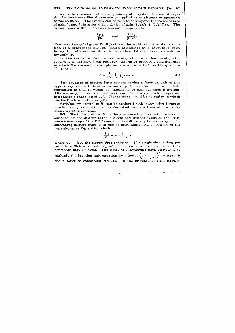
286
TECHN IQUES OF A UTOMA TIC TIME MEASURE ENT [SEC.S7 ‘
‘1
t ive feedback amplifier theory can be applied as an a lterna t ive approach
to the solut ion . The system can be seen to cor respond to two amplifiers
of gain lcl and k~ in ser ies with a device of gain (1/pC) + (1/p%’S . The
over -a ll ga in without feedba ck as t wo component s,
As in the discussion of the single-in tegra tor system, the useful nega- ?
kp%
k,kz
——
and
pc -s ‘
The term k,kZ/pC’S gives 12 db/octave; the addit ion in the above solu-
t ion of a componen t k,k*/pC, which at tenua tes a t 6 db/octave only,
br ings the a t tenua t ion slope to less than 12 db/octave, a condit ion
for s tability.
In the transit ion from a single-in tegra tor to a double-in tegra tor
system it would have been per fect ly natura l to propose a funct ion unit
in which the cur ren t i is simply in tegra ted twice to form the quant ity
V—that is,
H
=& , ~idsdx. (20)
The equat ion of mot ion for a system having a funct ion unit of this
type is equivalent to tha t of an undamped resona tor . The immedia te
conclusion is tha t it would be impossible to stabilize such a system.
Alternat ively, in terms of feedback amplifier theory, each integra t ion
in t roduces a phase lag of 90°. Hence there would be no region in which
th e feedback would be nega tive.
Sa t isfactory cont rol of Ii!’ can be achieved with many other forms of
funct ion unit , but the two so far descr ibed form the basis of most au to-
mat ic t ra ckin g syst em s.
supplied by the discr imina tor is essen t ia lly discont inuous at the PRF.
some smooth ing of the PRF components will usually be necessary. The
smoothing usually consist s of one or more simple RC-smoother s of the
type shown in Fig 8.2 for which
v,
1
—.
VI
1 + pz’,’
where T, = RC, the circu it t ime constan t .
If a single circuit does not
pr ovide su fficien t smoot hing,
addit iona l circu it s with the same t ime
constants may be used. The effect of in t roducing such circu it s is to
mult iply the funct ion unit equat ion by a factor
(1 +’PT)” ‘heren is
the number of smooth ing circuit s.
In the presence -of ‘such circu it s,
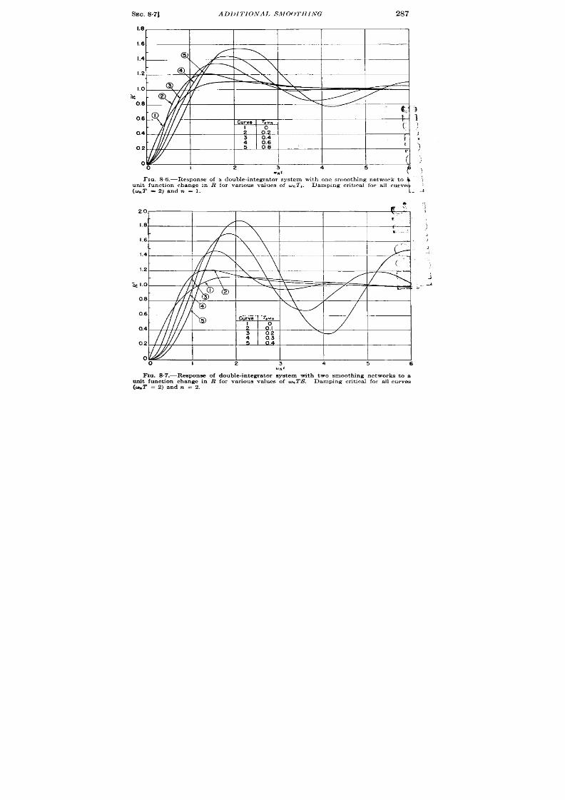
SEC. 8.7]
AD1)l TIONAI, SM(X)TIIING
287
1.8
1.6
1.4
1.2
1.0
k
0.8
)
0.6 1
)
0.4
>
9
0.2
]
o
,.
0
I
2
3 4
5 6.
q“1
\)
FIQ. 86.-Response of a double-int egr ator system with one smooth ing net work to ~ \
u nit fu nct ion ch an ge in R for va riou s va lu es of w.T,.
Dampin g cr it ,ca l for a ll cu rveq
(%T =Z)andn =1.
1. .;
*
2.0
a
1.8
,)
A
1.6
,
j
1.4
1.2
-i
-~ 1.0
A
--
0.8
0.6
0.4
0.2
0
0
I
2 3
4
5
6
F IG. &7.-Respon se of dou ble-in tegr at or syst em wit h two smoot hin g n etwor ks t o a
u nit fu nct ion ch an ge in R for va riou s va lu es of cu nTS. Dampin g cr it ica l for a ll cu rves
(%2’ = 2) and n = 2.
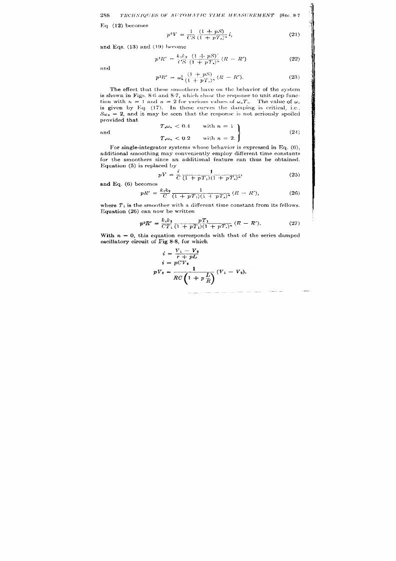
~q. (12) becomes
1 (1 +ps)
P2V = ~$ ([ + ~ql~)
< i>
and Eqs, (13) and (19) hw)mc
im
d
(21)
(23)
The effect tha t these smoothers have on the behavior of th system
is shown in Figs. 8,6 and 87, \ vhicll show the rcsp(mse to unit st ep func-
t ion with n = 1 and n = 2 fo var ious values uf u,,T,. The value of o,,
is given by ]Cq. (17). In these curves the damping is cr it ica l, i.e.,
SO- = 2, an it may be seen tha t the response is not ser iously spo led
pr ovided t ha t
T,un <0.4
with n = 1
and
1
(24)
T,un <0.2 with n = 2.
F or single-in t egra tor systems ~vhose behavior is expressed in Eq. (6),
addit ional smoot hing may conven ient ly em ploy different t im e constant s
for the smoothers since an addit ional fea ture can thus be obta ined.
Equat ion (5) is replaced y
‘v = ; (1 + pT,){l + pT#
and Eq. (6) becomes
1
~ (R – R’),
@’ = %(1 + pT ,)(l + PT~]
(25)
(26)
where TI is the smoother with a different t ime constant from its fellows.
Equat ion (26) can now be writ t en
pTl
(R – R’).
p2R’ = %, (1 + pT, (l + PT.)”
(27)
With n = O, th is equat ion corresponds with t a t of the ser ies damped
oscilla tory cir cuit of Fig 8.8, for which
v, – V2
=
r+pL
i = pcvz
.
pvrz=
%’~’-)
L (VI – v,).
R

SEC. 87]
ADDITIONAL SMOOTHING
Sin ce con st an t dVJdt demands constant i, t he
velocity lag, but the presence of L will in t roduce
velocity memory.
Equat ion 27 withn = O maybe rewrit t en as
289
system will exhibit
a cer ta in amount of
(1 + PTI) R’ = W (R – R’),
for which, whenkz = O, (1 + p!f J pR’ remains. Thesolut ion for this is
Rt = A +Be-+,,
B -$
from wh ich pi?’ = ~ e
Thus any velocity exist ing at t = O decays
exponent ia lly t o zero with a t ime constant TI.
This may be called
t r an sien t velocit y memory.
The resonant frequency of
the circuit is given by
kk
~2_12
n
CT,’
(28)
and damping is cr it ica l when
Tlun = ~,
(29)
t he damping increa sing wit h decreasing T, shown in Fig. 8.9.
When n = 1, the response is as indica ted in Fig. 810, which shows
the unit funct ion response with crit ica l damping for var io s values of
LJnT,, and in Fig. 8.11 for m = 2.
The preceding prese ta t ion has the advantage of having equat ions
of mot ions of automat ic t racking loops in a form that indicates clear ly
the type of funct ion unit necessary
to per form the desired opera t ions.
o
Examples of synthesizing elect r ica l
L
R
1
funct ion units for severa l systems ~
c= :
v,
will be given in the next sect ion .
F e d a ck amplifier t h eor y is pr obably
o
0
more lucid on the mat t er of stab li-
V
FIG. S8,-Equiva len t circu it for
za t ion but does not indica te direct ly ~inde-in tegra tor
system with one
th elect r i c a 1 opera t ions tha t a re smOOth@ netwOrk.
necessary to synthesize the equa t ions.
Fur thermore, in the simple elect r ica l systems tha t a re frequen t ly used,
stabiliza t ion is a seconda ry considera t ion usua lly invest iga ted after the
more fundamen ta l opera t ions of memory and ta rget select ion have been
obta ined. It migh t be advisable in omplex systems to use differen t ia l
equa t ions to indica te the desired opera t ions and then to obta in the
condit ion for stability by t rea t ing the system as a feedback amplifier .
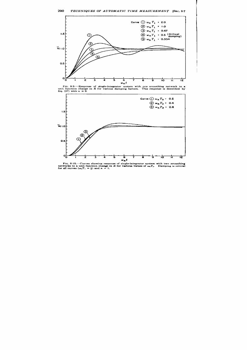
290
TECHNIQUES OF AUTOMATIC TIME MEASUREMENT [SEC. 8.7
curve @ w% T, : 2.o
@ (unT, = I.O
@ unT, = 0.67
I .5 -
@ rJnT1 :0.5 ‘:::~~,
@ un T, :0.334
G1.o -
0.5 -
00 I 2 3 4 5 6 7 8 9 10 I I 1 2
‘nt
FIG. 8 .9 .—Respon s e of s in gle-in tegra tor sys tem with on e smooth in g n etwork to a
u n it fu n ct ion ch an ge in R for va r iou s dampin fa ctors .
Th is r es pon se is descr ibed by
Eq. (27) with n = O.
Curve @ unT8 = 0.2
@ un T, ~ 0.4
@) unT8 = 0.8
I .5 -
-% 1.0 -
0.5 -
a
00123456 789101112
c
‘n :
FIG. 8 . 10 .—Cu rves sh owin g respon s e of s in gle-in tegra tor s ys tem with two smooth in g
n et works to a u n it fu n ct ion ch an ge in R for va r iou s va lu es of &T,. Dampin g is cr it ica l
for a ll cu rves (GTI = ~) an d n = 1 .
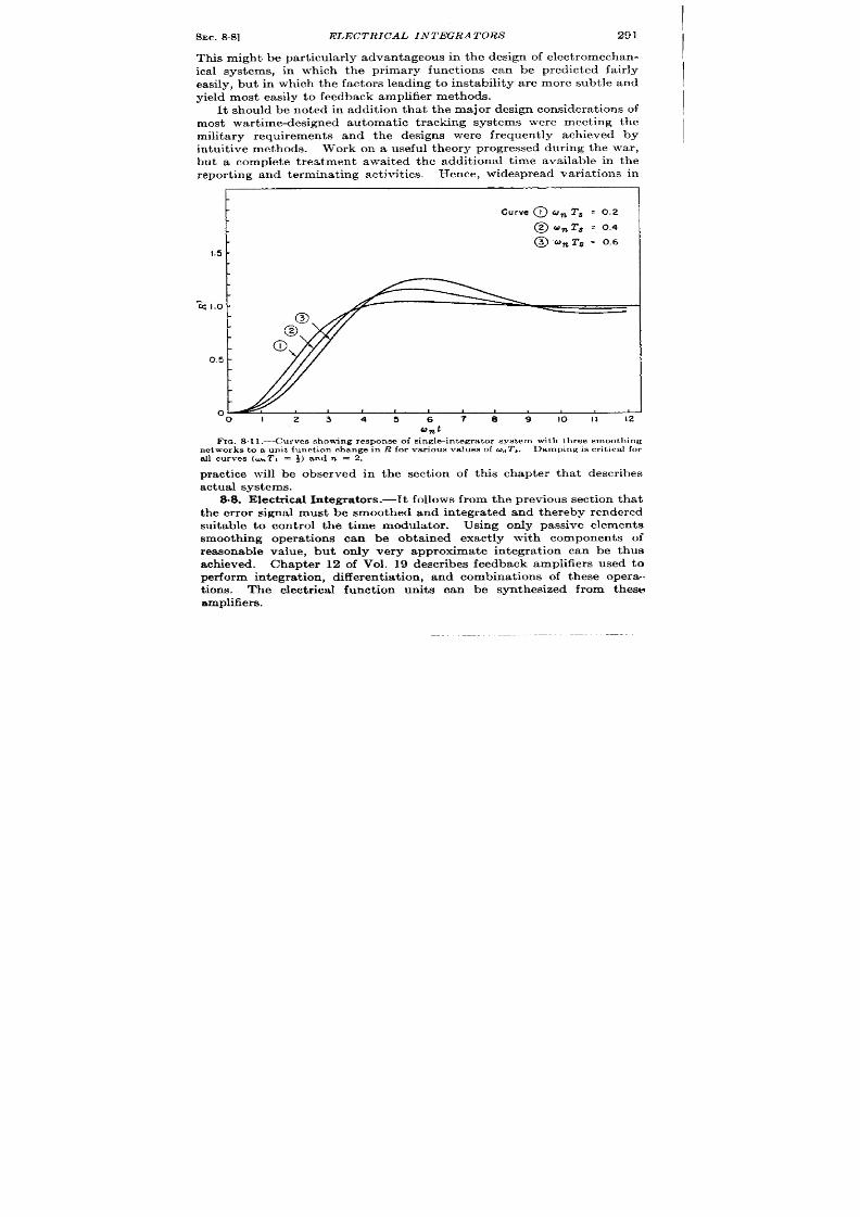
I
6EC. 88]
ELECTRICAL INTEGRATORS 291
This might bepar ticula rly adva nta geous in the design of elect rom ech an-
ica l systems, in which the pr imary funct ions can be predicted fa ir ly
easily, but in which the factor s leading toinstability a r emore subt le and
yield most ea sily t o feedba ck amplifier m et hods.
It should be noted in addit ion tha t the maj or design considera t ions of
most war t ime-designed au tomat ic t racking systems were meet ing the
milita ry requirements and the designs were frequen t l ach ieved by
intu it i~e methods. Work onauseful theory prog essed dur ing the war ,
but a complete t rea tment awaited the addit ional t ime available in the
r epor tin g a nd t ermin at in g a ct ivit ies.
Hence, widespread var ia t ions in
curve @tvn T8 z O.Z
@w. T, =0.4
@um T,z 0.6
1.5 -
-i 1.0 -
0.5 -
0
01 23
45
6789101112
Unt
Fm. 8 .11.—Curves showing response of s ingle-in t egra tor sys t em with th ree smooth ing
networks to a unit funct ion change in R for va r iou s va lu es of u . T,.
Damping is cr it ,ca l for
a ll cu rves (w~TI = f,) andn = 2.
practice will be observed in the sect ion of th is chapter that descr ibes
actual sys tems.
8.8, E lect icd [email protected] follows from theprevious sect ion that
the er ror signal must be smoothed and in tegr a ted and thereby rendered
suitable to con t rol the t ime modula tor . Using only passive elem nts
smooth ing opera t ions can be obta ined exact ly with component s of
reasonable value, but on ly very approximate in t gra t ion can be thus
achieved. Chapter 12 of Vol. 19 descr ibes feedback amplifiers used to
per form integra t ion , differen t ia t ion , and combin t ions of these opera -
t ions. The elect r ica l funct ion units can be synthesized from these
amplifiers.

292 TECHNIQUES OF A UTOMA TIC TIME MEASUREMENT [%c. 88
TABLE 8,1,
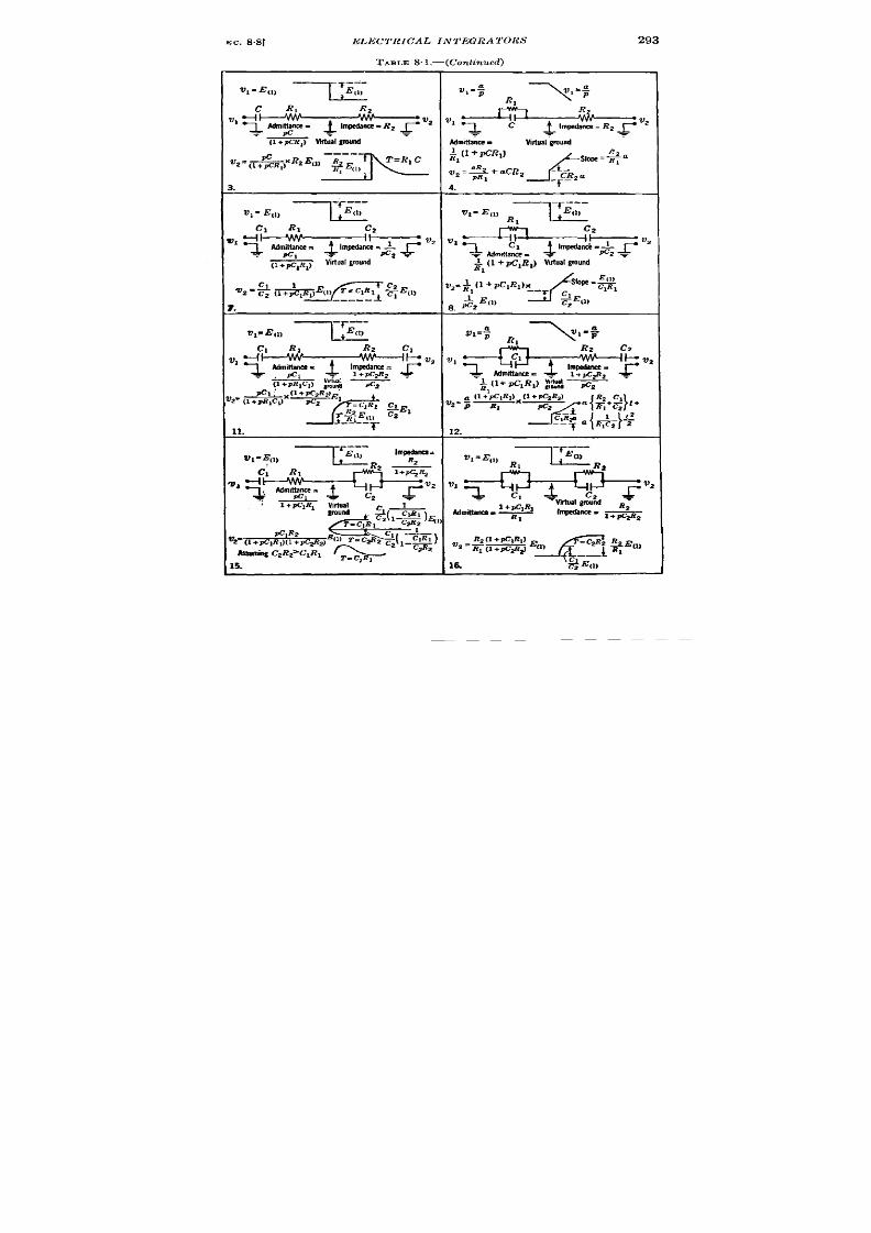
EC. 8.8]
ELECTRICAL INTEGRATORS
293
TABI.E 8. l.—(Cont inued)

294
TECIINIQUES OF A UTOIlf A TIC TIME MEASUREMENT [SEC. 88
In summ ry, the feedback amplifier of Fig. 8.12 is shown ther e to be
similar to the circuit shown in Fig. 813. The “vir tua l ground” is a
ground only in that the act ion of the feedba k amplifier is to hold that
point fixed by supplying a cur r en t through Zz. Within the limits over
which this assumpt ion is valid, the
Amplifier
I
gotn = -A
v,
u
V2
Z2
Fm . S 12.—Feedh ack-amplifier block dia -
grnm.
output voltage can be alcula ted
by assuming that the cur rent
which flows from VI to the vir tua l
ground is equal and opposite to
the cur r en t which flows to the vir -
tua l ground from V2. The trans-
forma tion per formed by t he cir cu it
is the nega t ive of the product of
the admit tance of the input
branch and the impedance of the
outpu t branch. Table 81 shows
the t ransformat ions tha t can be
set up usin~ the more common
combinat ions of resistance and capacitance to replace 21 and 22. The
input admit tance and the ou tpu t impedance are shown in opera t iona l
nota t ion , as well as the response of each circuit to unit funct ions of VI
or dV1/dt. Where the input is in the form of a cur r ent , as it is in most
t ime discr iminators, the diagrams of column (1) a re relevant with RI
omit t ed and i replacing VI/RI.
There a r e numerous other possible a r rangements in which the net -
wor k has one or more componen ts
with one terminal grounded, two
of which ar e shown in Fig. 8.14.
The output voltage o the circuit
in Fig. 8.14a , in which cur re t feed
is used, can be determined by
calcula t ing i, t he cur rent ent er ing
the vir tua l ground, and the out -
pu t can be obta ined as before by
ass ming that the same cur r en t
flows in opposit e sense through
,,=3.
i2= i,
21
v,
L ~,= ~,,,=; ,,
V:uol
.1
ground
FIG. 813.-Equ iva len t cir cu it of feed-
back amplifier usin g gen er al impeda nces
ZI and Z2.
the output -impedance .
These steps ar e as follows for Fig. 8“14a:
il
i3 =
1 + pc]f?l
v, =
Z’1
pc,(l + $K71RJ”
In Fig 8.14b it is the feedback which has a component grounded; her e,
he process is to calcula te it in terms of Vz, and i, in terms of Vl, and

SEC.8.8] ELECTRICAL INTEGRATORS
equ at e t hem a s follows
V2 . v,
i 2 =
R,(2 + PR2C2)
‘%l=K
“R* (2 + p R, C’).
2=T
(b) ~1
1
ground
o
Jo
T
)
1
Fm. 8.14.—Two feedback funct~n un it s having one componen t grounded .
n
Em
J-
=
Fua.816.-Simple integrator cirouit . VI = -RCPVd 1
295
The assumption that the point labelled vir tual ground remains fixed
is valid only for in finite amplifier gain . In the simple in tegra tor circu it
of Fig. 8.1 , two effect s result from fin ite gain .
These can be observed
easily by determin ing to what exten t the input is the der iva t ive of the
output . This is expressed as

296
TECHNIQUES OF A UTOMA TIC TIME MEASIJREMENT [%C. 88
V I = + ,
()
++ _;
or
I
@o)
()
V,=–RCpV, 1+; –+
The first effect is tha t the desired opera t ion , in tegra t ion , is in er ror by a
factor (1 + l/A). Fur thermore, the output is r ela ted a t all t imes to
the input by the addit ion term – VZ/A. Th e followin g example will
show to what exten t these e ror s can be neglected.
Synthesis oj Double Integrator with Smooth ing.—These methods will
now be used to synthesize a circuit of a funct ion unit tha t obeys Eq. (21),
1 (l+ps) .
P’v = m (1 + pT,)
n ‘1
or subs titu t ing klkZ/o~ for CS from Eq. (17),
(A): (1 + ps)i.
P*V = ~, (1 + p~s)”
(21)
(22)
Rewrit ing Eq. (22) for n = 1 in a form suitable for synthesis, one form is
(31)
This equat ion can be synthesized by the circuit of Fig. 8. 14a, and Circuit
8 of Table 8.1 opera t ing in ser ies. F igure 8.16 shows this network for
1
,+--j--&i
W%
ground
o
Fxe. 816.-Equivalen t circu it for Eq. (22) with n = 1.
n = 1. Each term in the equat ion is a r ranged to be below the componen t
that supplies t a t t erm. Equat ions (31) and (22) provide that
CR,C, = ~
1
(32)
R,C, = S.
An alterna t ive form of Eq. (22), this t ime with n = 2 is
v= J--
1
1 + pCR,
1 + pT, x p(c + c’) x
x~x~.
C’CR, R,
l+P~
pc,
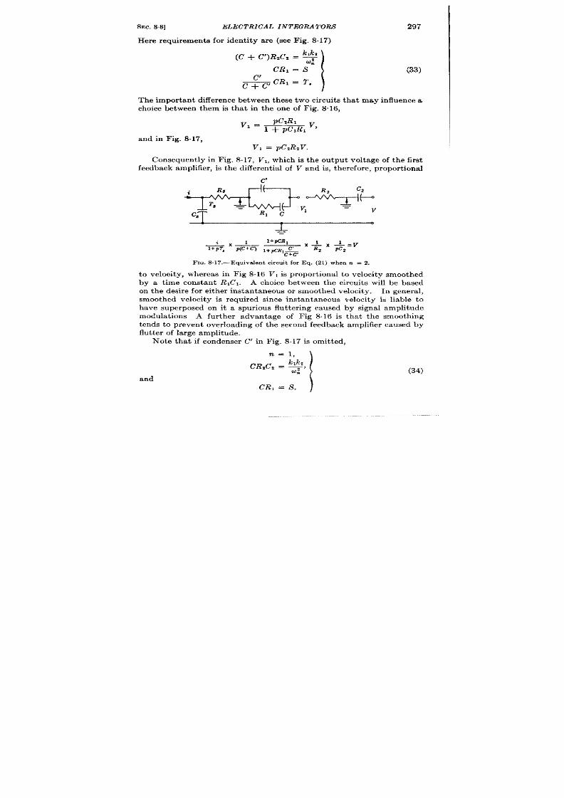
SEC. 8+3]
ELECTRICAL INTEGRATORS
297
Her e requirements for ident ity ar e (see Fig. 8.17)
(c + C’)R,C2 = *
CR, = S
I
(33)
&CR, = T,
Th e impor tant difference between th ese t wo circuit s tha t may influence a
choice between them is tha t in the one of Fig. 8“16,
and in Fig. 8.17,
V, = pCzRzV.
Con sequ en tly in F ig. 8.17, V,, which is the ou tpu t voltage of the first
feedba ck amplifier , is t he differ en tia l of V and is, t h er efor e, p ropor t iona l
&
%
l+PCR,
XL
1 _v
1+pT~
XJ - X-.
P(C+c~ l+pCRIC& R2
pc2
Fm. 8.17.—Equ iva len t cir cu it for Eq. (21) when n = 2.
t velocity, whereas in Fig 8.16 VI is propor t ional to velocity smoothed
by a time constant R, C,. A choice between the circuit s will be based
on t he desir e for eit her in st an ta neou s o smoot hed velocit y.
In g ner al,
smoothed velocity is required since instantaneous velocity is liable to
have superposed on it a spur ious flu t ter ing caused by signal amplitude
modula t ions A fur ther advantage of Fig 8.16 is tha t the smoothing
ten ds t o pr even t over -loading of the secon d feedback amplifier caused by
flu tt er of la r ge amplit ude.
Note that if condenser C’ in Fig. 8.17 is omit ted,
and
(34)
CR, = S.
)
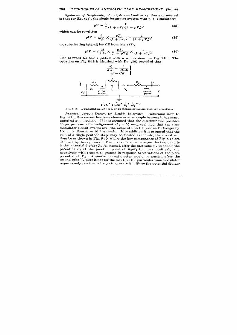
298
TECHNIQUES OF A UTOMA TIC TIME MEASUREMENT [SEC.88
Synth.sxsis of Single-in@rator Syst em .—Anot her syn th esis of in ter est
is tha t for Eq. (25), the single-in tegra tor system with n + 1 smoothers:
1
(25)
~v = (1 + p!r ,)(l + pz’s)”’
which can be rewrit t en
p T1
~’v = *C x (1 + PT1)
x (1 +lPT,)”’
(35)
or , subst itu t ing lcJ c2/~~ for CS from Eq. (17),
pT1
P’v = %$2 x (1 + P~J
x (1 +; T,)”’
(36)
The network for th is equa t ion with n = 1 is shown in Fig 8.18. The
equat ion on Fig. 8.18 is ident ica l with Eq. (36) provided tha t
2
W.
1
_—
klkt
CC,R
S = CR.
I
Fxa.8.1S.—Equiva len t circu it for a s ingfe-in tegra tor sys tem with two smoothers .
Practical Circu it Design for Double In legTa tor .—Return ing n ow t o
Fig. 8.16, this circu it has been chosen as an example becau e it has many
pract ica l applica t ions. If it is a ssumed tha t the discr iminator provides
55 pa per psec of misa lignment (kt = 55 amp/see) and tha t the t ime
modula tor circu it sweeps over the range of O t o 100 .usecas V ch an ges by
100 volt s, t hen kl = 10–8 see/volt.
If in addit ion it is assumed that the
gain of a single pentode stage may be t rea ted as infinite, the circu it will
then be as shown in Fig. 8.19, where the key component s of F ig. .16 a re
denoted by heavy lines. The fir st difference between the two circuit s
is t he pot en tia l divider RZ-R ~, n eeded a ft er t he first tube VA t o enable the
potential EI at t he junct ion poin t of RZ-R3 to ove posit ively and
nega t ively with respect to ground in response to va ria t ions of the pla t e
potent ia l of Vd. A similar poten t iometer would be needed aft er the
second tube l’~ were it not for the fact tha t the par t icu lar t ime modula tor
requ ires only posit ive volt ages t o oper at e it .
Sin ce t he pot en tia l divider

SEC. 8.8]
299
is actually needed to supply on ly RI, t he condenser s C and Cl may be
taken to the pla te of the fir st tube, at the expense of losing direct com-
ar ison with Fig. 8.16 but with considerable pract ica l advantage. The
advan tages a re twofold: (1) since potent ia l var iat ions at the pla te
exceed th ose at V, smaller condenser s can be used, and (2) as the excur -
sions of pla te potent ia l to produce a requ ired ra t e of change of Eg will be
tj
v
-150V
FIQ.S .19.—Actua l cir cu it equiva lent t o cir cu it of F ig. 816.
gre t ly reduced, there will be a reduct ion in any tendency for VA t o
overload.
The modifica t ions to the cir cuit of Fig. 8.19 are shown in Fig. 8.20.
In this figu re the pr imes indica te componen ts whose values requ ir e
modifica t ion-that is, C’, C;, and R/. Thus if C’ is kept equal to C, and
V, is now redefined as the volt age of the fir st pla te (due allowance being
made for it s st eady direct component of about 150 volt s) then C; = Cl,
*
A -105,
FIG. 8.20.—Modificat ion of circui t of Fig. 8 .19.
bu t R; r equ ir es a lt er at ion . Volt age V, is now effect ively halved by the
two r esist or s Rz a nd R~ and the cur ren t due to VI flows throughan wuiva-
len t r es is tance R; + R, hence for equal cu r ren t th rough RI and R; of
Figs. 8.19 and 8.20, with R = Rz,

300 TECHNIQUES OF AUTOMATIC TIME
or
R, – R2
R{ = ~.
MEASUREMENT [SEC.8.8
Bear ing in mind tha t this adjustment will be needed, Fig. 8.19 is the
ea siest figu re t o u se wh en eva lu at in g compon en ts.
Th e r esist an ce R, that may be placed in ser ies with the output of a
pract ical discr imina tor is limited because the cir cu it will not opera te
proper ly if the product of the misalignment cu r rent and output r esistor
amounts to more than a few volt s (Vol. 19, Chap. 14).
As t he misalignm en t (R – R’) in cr ea ses, t he misalignmen t cu rr en t
from the iscr iminator increases linear ly a t fir st unt il a maximum value
i- is r eached. Any fur ther increase in (R – R’) then produces a fall
in output cu r ren t . With the maximum d-c back voltage tha t may be
applied to the discr iminator as f 4 volt s and the maximum misa lignment
cur ren t as 40 pa, R, should not exceed 4 volt s/40 pa or 100 k. The larg-
est va l e of C, tha t may be used is determined by w., and the smallest
va lue depends upon the amount of PRF ri ple that may be tolera t ed on i.
If i-x =
40 pa, the charge en ter ing C, per pulse is 40 pa/650 = 0.0616
pcoulombs, where 650 pps is the PRF. Allowing a fu r ther f 4 v lt s of
discr iminator voltage output to accommodate the r ipple voltage that
th is charge will produce on C., C, >0.0616 pcoulombs/4 volt s z 0.015 ~f.
Hence the minimum value of CSR, with R, = 100 k is 0.0015 sec. Since
T,w should be equal or less than 0.4 for stability,
co._ = ~ = 265 radians/see.
#
The lag t ime constan t T, will not affect the stability of the system for
values of u . less than t in~,,.
Since sm ooth oper at ion is usually desir ed in
spite of the presence of noise and random fading of the signal, much
lower values of U. are usually employed. In a par t icu la case the gates
wer e to t r ack an aircraf echo and to provide ra te measurement in the
range of t 500 mph with a tota l change of i 30 volt s. A value of
u“ = 6(jm = 1 cps) was chosen . To provide the cor r ect sca le of ra t e
measurement , RICZ must be s~ch tha t when
500 x 11
pR’ = plclV = 1.53psec/sec =
3600 ‘
then V, = pR,C,V = 30 volt s .
Hence
Rlc, = ~ = 30k,
pv
1.53’
and with
k, = 1.38 ~sec/v lt s,
RICZ = 27 sec.

SEC. 8.8]
ELECTRICAL INTEGRATORS 301
The la rgest convenien t value for Ct is 4 yf; hence
RI = 6.75 M.
On conver t ing this value to R{ as in Fig. 8-20, where Rz = R = 2.2 M,
it is found that
R; = 4(R,
– RJ = 2.27 M.
With
der ived from Eq. (32), and with k~ equal to 55 pa /see,
~ = 10-’ x 55
27 x 36
= 0.056pf.
The condenser Cl is now chosen to give appropr ia te damping. For
cr it ica l damping [from Eqs. (18) and (32)]
C,R w: = 2.
Hence
c, = &*
or
c, =
2
6.74 X 10° X 6
= o.0495pf.
These values a re per t inen t to Fig. 8.20; the remaining componen ts (i.e.,
the two pla te load re istor s) a re each 50 k. It now remains to check the
assumpt ion that single-stage amplifiers have sufficient gain. Tube k’,
is a high-g~ pentode with a pla te load of 50 k, whose gain A will thus be
about 100. The term 2,/22 in Eq. (30) expresses the desired op ra t ion ,
and 21/22(1 + I/A) differ s from this only by 1 per cent . In addit ion
the term l/A int roduces wha t might be called a posit ion er ror in th is
circ it . In Fig. 8.20, for a par t icular value of V, VI can be called zero,
but as V var ies, VI must a lso vary by (l/A) V, and hence the indica ted
velocity is in er ror by l/A times the indica ted range voltage. In the
system descr ibed, V goes from +50 volts to + 150 voIt s. If the value
of VI for which V = 100 volt s is designated zero velocity, then in the
steady-sta te t racking of a fixed ta rget , the limit ing depar tures of VI from
zero will be t 0.5 volt . Since the swing V, for f 500 mph is +30 volt s,
the velocity may be in er ror because of this t erm by
(0.5/30) X 100 per cent = 1.6 per cent .
Similar er ror s will occur while t racking a moving ta rget , the er ror in
velocit y va ryin g wit h r an ge.

302
TECHNIQUES OF A UTOMA TIC TIME MEASUREMENT [SEC.S8
Alternative I nt egr a tor -s .-Syn thes is of t ime-measu r ing sys tems employ-
ing eit her th e differ en ce in t egr ator or t he bootst r ap integr ator descr ibed
in Vol. 19, Chap. 19 and shown in Figs. 8.21 and 8.22 can be accomplished
by methods similar to those used in the eedback amplifier in tegra tor .
Since the equations for the th ree types of in tegra tor ar e ident ica l except
in the terms expressing the er rors of opera t ion , the choice of any one for
v~
4
---
FIG,S21.-DifTerence integrator .
a par t icular system can be based
on the convenience afforded by
par t icular cir cuit ar ra ngements.
For example, th e fe dba ck ampli-
fier in tegra tor is cer ta in ly the
most simple to employ, for the
input voltage may be refer r ed to
ground or a fixed point , and the
equivalent circ it using the con-
i
R
U2
=
FIG.S.22,—Bootstra p integrat or.
cept of a vir tua l ground is very suitable for the “ elect ron-chming”
type of reasoning. The differ ence in tegra tor has the advantage of
per forming a subtr act ion or compar ison at t he same t im e t ha t it in tegr at es
or smooths, but both it and the bootst rap in tegra tor require a float ing
er ror -signa l genera tor . For th is reason, no par t icular advantage can be
seen for th e bootst r ap integr at or , since it offer s no compensat ing fea t ur e.
It was argued at one t ime that a “cathode-follower” in tegra tor could be
ope a ted at lower gr id cur ren t ,l but , this is a fa lla y, for the circuit is
1The advan tage tha t a st ra igh t ca thode follower has over a d-c amplifier for gr id
cu r ren t is tha t la rge input volt r t gcs can he accepted with a small change in gr id-to-
ca thode bias. The bias can then be rhosc,~ as tha t associa ted with minimum grid
cu rr en t , This a rgumen t does n ot h old h er e for in fa ct mor e gr id swing is r equ ir ed with
th e t r iode th an with th e ~en tode in tegra tor .

SEC. 88] ELECTRICAL INTEGRATORS 303
nothing more than a d-c amplifier . Genera l considera t ions of gr id
cur ren t a r e considered in Vol. 18, Chap. 11. A limita t ion of the differ -
ence integra tor is tha t the value of R is lim it ed by ca th ode-t o-h ea ter
lea kage cu rr en t and t heca thode-to-pla te cu rr en t tha t flows independen t
of gr id bias. Theresist ive elements in thebootst rap in tegra tor and the
feedba ck in tegr at or a re limited only by gr id cur ren t , which is usually
small.
The equa t ion for the difference in tegr ator is
R.c=v=’; (va– v,) – v,
where
R, = ~[r, + (p + I)It].
If we call R = Z, l/pC = Z,, and assume that R, = (y/2)R = (p/2)Z,
and if we let
P
.=
2 “
then
A%= AV.–Vb–V
Z*
v
Hence
This is ident ica l with Eq. (30) for the feedback in tegr a tor
posit ion er ror terms tha t dropped ou t in let t ing R. =
except for the
(~/2)R. T e
design of a t ime-measur ing system using this type of in tegr a tor will be
discussed in Sec. 9.10. It will be noted tha t Z, and Zz cannot take all
forms in this in tegr a tor—for example, ZI = l/@C is impossible.
The equa t ions for the bootst rap in tegra tor a r e similar ly equiva lent
to those for the feedback amplifi r , if 1 /pC = 2?, R = Z,, and if we
remember tha t S, the gain of a ca thode follower , is very near ly unity,
[
(1 – s) @~
V1=~(pRC +l– S)= V,pRC ;+~
1
Making t he a bove su bst it ut ion s,
This equat ion is identica l in na ture with Eq. (30), since S is near ly unity.
Hence all he in tegra tor s a r e seen to have similar ,;ha racter ist ics and
error8.

304
TECHNIQUES OF AUTOMATIC TIME MEASUREMENT [SEC.8.9
8.9. Memory and Coast .—Before complet ing the discussion of elec-
t r ical funct ion unit s, a few r emar ks will be made on methods of obtaining
memory and coast using the circuits descr ibed previously. In discussing
the feedback-amplifier in t egra tor the remark was made severa l t imes
that , if the signal faded, the cur rent from the discr iminator wen t to zero;
then , depending upon the type of circu it , either posit ion or velocity
memory was obtained. This implies two th ings: (1) that if there is
noise presen t , the discr iminator must be per fect ly balanced so that the
presence of noise will not crea te an er ror signal cu r ren t which would
produce either a velocity or an accelerat ion ; and (2) tha t in the absence
of noise, the undesired cur ren ts in the discr iminator due to insulat ion
!sa kage or cu rr en t associat ed with vacu um -tu be elect rodes mu st be small.
Em
RL
Neon
v,
J
+
(a)
V.
Va
J
Neon
I
Vb
=
+
(c)
FXQ,S.23.—Integrators Bhowingmethod of inser t ing a neon-tube disconnector .
Since it is difficult t o maintain balance in the er ror signal discr iminators
and to keep leakage cur rents small, it has been suggested tha t a neon tube
of low oper at in g volt age be pla ced in ser ies wit h t he in tegr at in g con den ser
so tha t cu r ren t will flow into it only when the er r or signal mult iplied by
the gain of the stage becomes larg enough to break down the neon tube.
In the absence of a signal, the unbalance cur ren t and leakage curren t
can usually be kept small enough so that the neon tube will not st r ike.
The cir cu it ar r angements for th is addit ion are shown in Fig. 8.23.
It . is at once evident that the only cir cu it in which the inser t ion of a
neon tube is really appropr ia te is the difference in tegra tor , for in the
ot her t wo c rcuit s th e t ime discr iminator must pr ovide adequate voltage
to over com e the neon-tu be str iking voltage. If th e differ ence in tegra tor
cir cu it is no appropr ia te and yet the cir cuit demands a disconnector , a
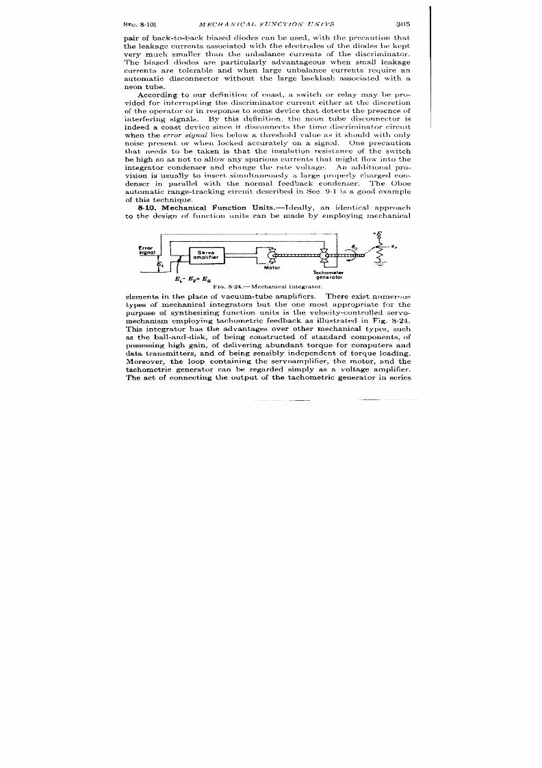
SEC.8.10] MECHAATICAL FUNCTION UN ITS
305
pa ir of back-to-back biased diodes can be used, with the precau t ion tha t
th leakage cur ren ts associa ted with the elect rodes of the diodes be kept
very much s a ller than the unbalance cur ren ts of the discr imina tor .
The biased diodes a re par t icu la r ly advantageous when small l akage
cur ren ts a re tolerable and when large unba lance cur ren ts require an
automat ic disconnector without the la rge backlash associa ted with a
n eon t ube.
According to our defin it ion of coast , a switch or relay may be pro-
vided for in ter rupt ing the discr imina tor cu r ren t either a t th discret ion
of the opera tor or in response to some device tha t detect s the presence of
in terfer ing signa ls. By th is defin it ion , the neon tube disconnector is
indeed a coast device since it disconnects the t ime discr imina tor ircu it
when the err-or signal lies below a threshold va ue as it should with only
noise presen t or when locked accura tely on a signa l.
One p recau tion
tha t needs to be taken is tha t the insula t ion resistance of the switch
be high so as not to a llow any spurious cu rren ts tha t might flow in to the
in tegra tor condenser and change the ra te voltage.
An addit ional pro-
vision is usua lly to inser t simultaneously a la rge proper ly cha rged c n-
denser in para llel with the normal feedback condenser . The Oboe
a utom at ic ra nge-t ra ckin g circu it descr ibed in Sec. 9.1 js a . good example
of t his t echn ique.
to
8.10. Mechanica l Funct ion Units .-Idea llyj an ident ica l approach
the design of funct ion units can be made by employing mechanica l
*E
Error
I
- eo
Servo
ompldiar
Motor
Tachometer
Ei- Eu= Ea
gene rotor
FIO. 8.24.—Mechan ical integrat or.
element s in the place of vacuum-tube amplifier s.
her e exist n t lmer~~us
types of mechan ica l in tegra tor s but the one most appropr ia t e for the
purpose of synthesizing funct ion units is the velocity-con t rolled servo-
mechanism employing tachomet r ic feedback as illust ra ted in Fig. S.21.
This in tegra tor has the advan tages over other mechanical types, such
as the ball-and-disk, of being const ructed of standard componen t s, of
possessing h igh gain , of deliver ing abundant torque for computer s and
data t ra smit ters, and of being sensibly independen t of torque loading.
Moreover , the loop conta in ing the servoamplifier , the motor , and the
tachomet r ic genera t or can be r egarded simply as a volt age amplifier .
The act of connect ing the ou tput of the taclmrnet r ic genera tor in ser ies
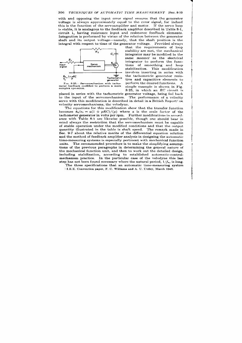
306 TECHNIQUES OF A UTOMA TIC TIME MEASUREMENT [SEC.8.10
with and opposing the input er ror signal ensures that the genera tor
voltage is a lways approximately equal to the er ror signal, for indeed
this is the funct ion of the servoamplifier and motor . If the servo loop
is stable, it is analagous to the feedback amplifier descr ibed in Table 8.1,
circu it 1, having resistance input an resistance feedback elements.
In tegra t ion is per formed by vir tue of the rela t ion bet ween the genera tor
shaft and its ou tput voltage namely, that the shaft posit ion is the
integra l with respect to t ime of the genera t or voltage.
P r ovided a lways
+
00 1+PRC
_=—
ei p
+
Tachometric
generator
FIG. S.25.—Servomechanism with tacho-
met er feedba ck modified t o per form a mor e
complex operation.
tha t the requ irement of loop
stability ar e met , t he mechanical
in tegra tor may be modified in the
same manner as the elect r ica l
in tegra tor to per form the func-
t ions of smooth ing and loop
st abiliza tion . Th is modificat ion
involves inser t ing in ser ies with
the tachomet r ic genera tor resis-
t ive and capacit ive elements to
perform the desired funct ions. A
simple example is shown in Fig,
8.25, in which an RC circu it is
placed in ser ies with the tachom tr ic genera tor voltage, being fed back
to the inpu t of the servomechan ism. The performance of a velocity
servo with this modificat ion is descr ibed in deta il in a Brit ish Repor t l on
velocit y ser vomechan isms, t h e velodyne.
The equat ions for th is modificat ion show that the t ransfer funct ion
becomes O,/e, = a(l + pRC)/(p) where a is the scale fac or of the
t ach omet er gen er at or in volt s per rpm.
Fu rt h er modifica tion s in a ccord-
a ce with Table 8.1 a re likewise possible, though one should bear in
mind always the rest r ict ion that the servomechanism must be capable
of stable opera t ion under the modified condit ions and that the outpu t
quant ity illust rated in the table is shaft speed. The remark made in
Sec. 9.7 abo t the rela t ive merits of the clifferen t ia l equat ion solut ion
and t he meth od of feedback amplifier analysis in design in g t he automat ic
t ime-mea su rin g syst ems is especia lly per tin en t wit h mech an ica l fu nct ion
units.
The recommended procedu re is to make the simplifying assump-
t ions of the previous paragraphs in determin ing the genera l natu re of
the mechanical funct ion unit , and then to work out the detailed design,
including stabilizat ion, according t o established au tomat ic-con trol-
mechanism pract ice. In the par t icular case of the velodyne this last
step has not been found necessary wh ere the natura l per iod, 1/jm, is long.
The three specificat ions that an automat ic t ime-measur ing system
‘ I .E .E . Convent ion paper , F . C. Williamsand A. U. Ut t ley, March 1946.
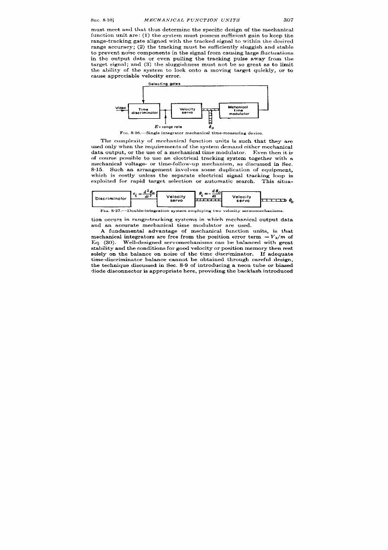
SEC.8.10]
MECHANICAL FUNCTION UNITS
307
must meet and tha t thus det ermine the specific design of the mechanica l
funct ion unit a re: (1) the system must possess sufficient gain to keep the
range-t rac ing ga t e aligned with the t racked signal t o within t he desired
range accuracy; (2) the t acking must be sufficient y sluggish and stable
t o pr even t noise componen ts in t he signal fr om causing la rge fluct ua tions
in the outpu t data or even pulling the t racking pulse away from the
t a rget signal; and (3) the sluggishness must not be so grea t as to limit
ca use a ppr ecia ble velocit y er r or .
Selecting goles
r
Video
7ime
—
Velocity
Me~~#$a I
L u
discriminator
servo
modulator
i
d
E: range rate
80
FIG.8,26.—Single integrator mechanical t ime-measuring device.
t hey are
he complexity of mechanical funct ion unit s is such tha t -
used on ly when t he requ ir em ent s of t he syst em dema nd eit her m echa nical
data outpu t , or the use of a mechanica t ime modulator . Even then it is
of cou se possible to use an elect r ica l t racking system together with a
mechanical volt age- or t ime-follow-up mechanism, as discussed in Sec.
8.15. Such an ar rangement involves some duplicat ion of equipment ,
which is cost ly unless the separat e elect r ica l signal t racking loop is
exploit ed for rapid ta rget select ion or automat ic search . This situa-
~..fi
*.=-S
Discriminator
t
dt 2
Velocity
t
dt
Velocity
servo
?rc<r,,
servo
31
c c
L
000
FIQ.S.27.—Double-integrat ion system employing two veloci ty servomechanisms.
t ion occurs in range-t racking systems in which mechanical ou tpu t data
and an accura te mechanical t ime modula tor a re used.
A fundamental advantage of mechanical funct ion unit s, is that
mechanica l in tegra tors a re fr ee from the posit ion er r or t erm —V2/m of
Eq. (30). Well-designed servomechanisms can be balanced with grea t
st ability and t he condit ion s for good velocit y or posit ion m emor y t hen r est
solely on the balance on noise of the t ime discr imina tor .
If a dequ at e
t ime-discr minator balance cannot be obta ined through careful design,
t he technique discussed in Sec. 8.9 of in t roducing a neon tube or biased
diode &sconnect or is a ppr opr ia t e h er e, pr ovidin g t he ba ckla sh in t rodu ced

308 TECIIKIQL’ES OF A UTOMA TIC T IME MEASUREMENT [SEC.811
does not disturb the stability of the system. Figure 8.26 shows the
block dia gr am of a sin gle-in tegr at or mech an ica l t im e-mea su rin g syst em ,
which possesses posit ion memory only. As is pointed out in Sec. 9.2,
it possesses some velocity memory by vir tue of the smoothing networks
p reced ing the velocity servomechan ism.
Figu e 8.27 shows the block diagram of a double-in tegra t ion system
with velocity memory employing two velocity servos.
Su ch syst em s
have been used for angle-t racking ut not , to the author ’s knowledge, for
range-t racking. This system has the advantage of providing range and
range-ra te d ta direct ly as shaft rota t ions. An alternat ive method is
to use a mechanica l integra tor to in tegra te rang ra te and a feedback-
amplifier int egr at or t o in tegr at e a cceler at ion , as illust ra ted in F ig. 8.28.
I
I
i+
[%
R2 C
I
Gates
t
_——-—_. — —.—
I
Signals
—
—
Fm. 8 .28.—Typica l combina t ion of e lect ron ic and mechan ica l in tegra t ion .
The object ion to th is scheme is that range ra te is not obta ined as a shaft
rotation.
TIME DISCRIMIN.4TORS
8-11. Genera l Consi era t ions.—In the complete t ime-demodula t ion
scheme employing discr imina t ion and demodu la t ion as descr ibed in
Sec. 8.2, the basic process of t ime demodula t ion in its simple form is
per formed by the t ime discr imina tor . It s funct ion is not to indicate
the absolu te value of t ime modu lat ion of th r eceived signal bu t to
indicate on ly the magn itude and sense of the t ime difference between the
locally genera t ed selector -wa eform and the r eceived signa l.
some t ime-discr iminat ion circu it s are con ta ined in Chap. 10 of Vol. 19.
The following sect ions will give severa l circu it s that were used in radar
au tomat ic range-t racking systems.
The first opera t ion is that of t ime select ion—that is, two adj scen t
por t ions of the signal to be t racked must be isola ted from each other and
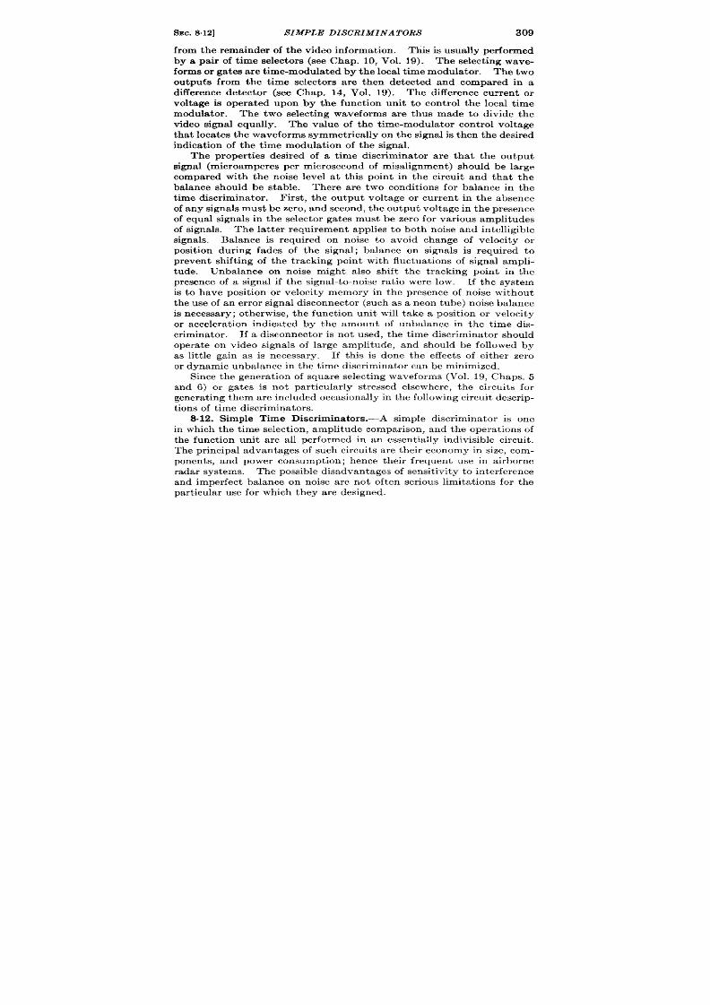
SEC. 8.12]
SIMPLE DISCRIMINATORS
309
from the remainder of the video in formation . This is usually per formed
by a pair of t ime selector s (see Chap. 10, Vol. 19). The select ing wave-
forms or gates are t ime-modula ted by the local t ime modula tor . The two
outputs from the t ime selec ors a re then detected and compared in a
diff rence detector (see Chap. 14, Vol. 19). The difference cur ren t or
volt age is opera ted upon by the funct ion unit to con t rol the local t ime
modula tor . The two select ing waveforms are thus made to divide the
video signal equally. The value of the t ime-modula tor con t rol voltage
th at locates th e waveforms symmetr ica lly on th e signal is t hen th e desired
ndicat ion of the t ime modulat ion of the s gnal.
The proper t ies desired of a t ime discr iminator a re that the ou tpu t
signal (microampere per microsecond of misalignment) shou ld be large
compared with the noise level a t th is poin t in the circu it and that the
balance should be stable. There are two cond t ions for balance in the
ime discr iminator . F irst , the ou tpu t volt age or cur ren t in the absence
of any signals must be zero, and second, the ou tput voltage in the pr esen ce
of equal signals in the selector ga tes must be zer o for var ious amplitudes
of signals. The l t ter requ irement applies to both noise and intelligible
signals. Balance is requ ired on noise to avoid change of velocity or
posit ion dur ing fades of the signal; balance on signals is requ ired to
pr even t sh ift ing of the t racking poin t with fluctuat ions of signal ampli-
ude. Unbalance on noise might also shift the t racking point in the
pr esence of a signal if the signal-to-noise ra t io were low. If the system
s to have posit ion or velocity memory in the presence of noise withou t
the use of an er ror signal disconnector (such as a neon tube) noise balance
s necessary; otherwise, the funct ion unit will take a posit ion or velocity
or accelera t ion indica ted by the amount of un alance in the t ime dis-
cr iminator . If a disconnector is n t used, the t ime discr iminator should
opera te on video signals of large amplitude, and shou l be followed by
as lit t le gain as is necessary.
If th is is done the effects of either zero
or dynamic unbalance in t he t ime discr imin ator can be minimized.
and 6) or gates is not par t icu lar ly st r essed elsewhere, the circu it s for
gen er at in g t hem a re in clu ded occa sion ally in t he followin g cir cu it descr ip-
t ion s of t ime d iscr im ina tor s.
8.12. Simple Time Discr iminators.-A simple discr iminator is one
in which the t ime select ion , amplitude compar ison and the opera t ions of
the funct ion unit are all per formed in an essent ially indivisible circu it .
The pr incipal advan tages of such circuits are their economy in size, com-
ponen ts, and power consumpt ion; hence their fr equen t use in a irborne
radar systems. Th e possible disadvantages of sensit ivity to in ter fer en ce
and imper fect balance on noise are not often ser ious limitat ions for the
par t icu lar u se for wh ich t hey ar e design ed.

310 TECHNIQUES OF A UTOMA TIC T IME MEASUREMENT [SEC.8.12
AGL (T) Discriminator.-The first circuit of this kind to be descr ibed
is the t ime discr imina tor from the AGL (T) Mark I Br it ish Radar .
In this discr im ina tor t he ou tput fr om a single t im e select or is det ect ed
and compared against a reference voltage to tell how much of the t a rget
sign l is coincident with the t racking gate. Although two gates a re
employed in the t ime discr imina tor only one ever coincides with the
ech o (see Fig. 8.29). The waveform of line a is a pre-pulse last ing 20 psec,
a t the end of wh ch the r -f pulse goes out .
Wa veform b shows t he ou tpu t
of a phantastron which is t r iggered fir st a t t ], r ecover s after a t ime t ’, and
Woveform u
Video
via
delay
0.1
i~~
+(
From
stron
screen
pentode detectors
-150V
Fm. S.29.—AGL-(T)t ime-discr iminator circui t and waveforms.
is t r iggered gain a t h to stay on again for a t ime t ’. The length of the
d is the output of an amplifier dr iven by waveform a. Waveform j shows
the output of the receiver . The blank space in the vicinity of tz result s
from a gain-suppression act ion tha t r emoves the transmit ted pulse from
the receiver output . The circu it of F ig. 8.29 shows two ga ted pentode
detectors V, and V2. These tubes a re both ga ted on their cont rol
gr ids by waveform b from the range phantastron, so that space cur ent
flows dur ing the two interva ls t ’ of each recur rence interva l. The sup-
pressors a re ga ted posit ive respect ively by the waveforms a and d so
tha t dur ing the interva l t ’ following t i, V, has both its cont rol gr id and
suppressor gr id on and acts as a pentode-switch detector (st robed diode,
SEC.8.12]
SIMPLE DISCRIMINATORS
311
Vol. 19, Chap. 14) having 100 volt s of screen potent ia l, zero gr id and
suppressor bias. Dur ing th is in t erva l VZ has it s suppressor cu t off.
On the other hand, dur ing the in terva l t ’ following k, VI is off and V2 is
cond ct ing. The con t rol gr ids a re normally biased off to – 10 volt s
and are preven ted from going posit ive by the ser ies gr id resistor . The
suppressor is biased by cur ren t drawn on posit ive swings flowing th rough
R,, so tha t it will a lso automat ica lly adjust it self to a bias of zero volt s
while the g tes are on . The pla te cu r ren t tha t flows in VI on the coin-
cidence of the waveforms a and b is determined by the pla te volt age
tha t is supplied from the video outpu t of the receiver . As indica ted in
line j the receiver ou tpu t dur ing the first ga te is purely noise since it
occur s a t the ext r eme end of the previous r ecur rence in terva l.
When
the two ga tes on VI go off t he condenser Cl is left cha rged with a
volt age propor t iona l t o the average noise dur ing the in terva l t ’. This
volt age deca ys expon en tia lly t hr ou gh R2 t o ground with a t ime constan t
of 47oO ~sec. The PRF is 670 pps. Tube V2 oper t es in a similar
manner . In the condit ion sho\ vn , C2 will cha rge up to a voltage repre-
sen t ing the average of the noise a d tha t por t ion of the video echo wh ch
is in clu ded in t he in ter va l t ’ followin g t z.
If t he two cir cu it s a re iden tica l,
the nega t ive volt age on C2 will be grea ter than tha t on Cl due to the
presence of a signa l in the second gate. In the absence of a signa l the
difference will be zero except for the unbalance caused by the t ime-
va rying gain. With zero output the t ime modula tor is a r ranged to cr eep
ou t in range. Unbalance in the ou tpu t due to var ia t ions of VI and Vz are
reducing by adding 2,2 k in ser ies with the pla te. The charging t ime
constan t thus becomes a t lea t 2.2 psec for a 0.5-psec pulse, ensur ing tha t
the detect or is an average detecto .
The t wo outputs ar e-con nect ed t o a differen t ia l amplifier which feeds
a r ela y ser vomech an ism whose ou tpu t sh aft con tr ols t he r an ge pot en tiom-
et er to adjust the in terva l t ’ to termina te on the fron t edge of the closest
signal. The circu it ay be said to possess the simplicity of a single-ga te
system and the a vantages of a ba lanced double-ga te system. In the
or igina l concept ion of the syst em in which t ime- arying gain was not
used, noise in o e gate balanced the effects of noise in the other . But in
this circu it changes in signa l amplitude \ vould cause the t racking poin t to
sh ift a lthough AGC would minimize th is effect .
Oboe Time Discriminator.—The second simple t ime discr imina tor is
the one used in the Br it ish Oboe Ground Sta t ion tha t au tomat ica lly
t racks the a ircra ft response in range and uses the range voltage either to
keep the a ircra ft on a constan t range course or to provide a bomb-release
signa l, de~endingz upon which of the two ground-st a t ion funct ions the
se~ is’ per~ormin~. “A complete discussion’ of this t racking unit will be
given ~ater in Se;. 8.22. The discr imina tor is shown in Fig. 830. The

312 TECHNIQUES OF A UTOMA TIC TIME MEASUREMENT [SEC. 8.12
beacon response from the a ircraft is fed to the t i e discr iminator from
the cathode follower V2 with a maximum amplitude of 90 volt s, and is
represen ted as waveform c1on Fig. 8“30. The select ing waveforms are
shown as waveforms b and c, and are fo med in the gate genera tor cir cu it
of V1. The gates are not equal in length : the second gate c over laps the
Waveform at GJ,of 1’,
I
I
w
32
Ok
I
-170”
FIG, S30.-Oboe time discriminator.
signal completely and the shor t ga te over laps the fir st half of the long
ga te a s in dica ted.
Th e desir ed discr im in at or ch ar act er ist ic is obt ain ed
from two average detector s ga tcd by these pulses by combining half of
the output of the long gated detector with that of the shor t ga ted detector .
The output of the long gated detector can he employed direct ly for

SEC. 8.12]
SIMP E DISCRIMINATORS
313
sig al amplitude indica t ion and AGC.
Th e cir cu it for a ccomplish in g
th is is shown in Fig. 8.30. The shor t ga te is applibd to the con t rol gr id
of Vs dr iving it posit ive from —170 volts until it draws gr id cur ren t a t
– 150 volts. It s pla te drops until the cathode of Vd comes to ground, a t
which t ime Vd conducts and holds the junct ion of RI and Rz nea r gr ound.
Dur ing the t ime this condit ion holds, the v deo pu lses applied to the
pla te of the diode VS can draw cur ren t and charge Cl. When the gate
tu rns off, the pla te of Vs r ises again and br ings the cathode of Vb up to
+ 150 volts, shu t t ing off the diode. This design aims at making the
cur ren t due to the video pulse independen t of the ga te amplitude and of
tube character ist ics. This is rea lized by using a resistor in ser ies with
the diode and by using the gated tube on ly as a means of br inging the
cathode of the detect ing diode from cutoff to ground. The charge col-
lected on Cl from rect ifica t ion of the video pulses flows through the
smooth ing network RSCZ to provide a smoothed cur ren t .
The tube
VG and the associa ted diodes VT and VE opera te in the same manner ,
ga ted by the long gate and crea t ing a smoothed cur en t propor t ional to
signal amplitude. This cur ren t is la ter inver ted, ha lved, and mixed ith
that from the shor t ga te to provide a discr iminator er ror signal.
SCR-784 Time Discriminator.—A th ird simple discr iminator is one
that was used in the automatic range-t r acking circuit for the SCR-784.’
Here again gat ing and detect ing a re done in the same circuit . One
differ en ce b tween this cir cu it and h e pr eviou s examples is tha t , wh er ea s
previously two separa te detector cur ren ts were der ived to be compared
in a subsequent circuit , in th is circu it advan tage is taken of the fact
tha t the difference between two cur ren ts is desired, and the ga ted rect i-
fier s a ct t o ch ar ge an d disch ar ge a sin gle con den ser simu lta neou sly, form-
ing a difference detector . The er ror signal is the net charge on the
condenser a t the end of th is compet it ive process and no discharging
r sistor is requ ired. This process is similar to the bidirect ional detector
act ion escr ibed in Chap. 14 of Vol. 19. At each occur r ence of the
gates, the voltage of the ou tpu t condenser is adjusted to the elevan t
value, and between pulse it is left charged, thus effect ively conver t ing
pulse amplitude direct ly in to d-c voltage of t e same value. The act ion
is shown in the circuit of Fig. 831.
Th e cath ode follower VI feeds
shor tened video signals direct ly on to the gr id of V2 and to the gr id of Vt
th rough a shor t delay line. The tubes V2 and Vs are connected as
t r iodes and are pla te-ga ted by the nar row tracking ga te. No mally
Vz and Vt a re biased off by voltage der ived from a cathode follower which
follow the ou tpu t er ror signal and keeps the pla te voltage on the gated
tubes approximately independen t of ou tpu t voltage. The presence of a
I War Depar tment Technica l Manual TM1 1-1554, “Radio Set SCR-784 Service
Manual/’
Mar . 1, 1945.

314 TECHNIQUES OF A TOMA TIC TIME MEASUREMENT [SEC. 8.13
signal coinciden t with the ga te on VZ causes cu r ren t to flow to cha rge Cl
and C9, whereas a signa l on the gr id of Va coinciden t with the ga te acts
to discharge Cl and CZ. The sensit ivity is about 150 volts/psec of
misa lignment . In the absence of ga tes and signa ls, Cl and CZ have
only leakage pa ths to ground and hence remain charged. A nega t ive
bias is applied to the ca thodes of V, and V, by a bias ga te and is adjusted
to keep them cu t off for the dura t ion of the pla te ga te unless a video
signa l ap ears. This was necessary to preven t u ba lance cu r ren ts in the
presence of noise, bu t it has the disadvantage of placi g small signa ls a t
2k
.
:-M””n&
1
-L
r-
PG7
-1
t!~j
.3Ps delay
2k
0.01
510
7k
0.01
v
---
---
0.01 ‘--
,hl.
~k 0.01
n
I
1
- ~ O 311s narrow gote
6AG7’s
A
6SN7
O 3MS delayed wdeo
,,
FI . 8.31 .—Time discr imina tor of Rad io Set SCR-7S4.
the low-g- por t ion of the ga ted tube character ist ics, and fur thermore if
AGC is used it fa ils in its purpose en t ir ely, for the AGC brings the noise
up to average signa l heigh t . A more logica l approach wou ld have been
to put a ga in-ba lance con t rol in the circu it t o keep the average charge
delivered to Cl and Cn zero for noise, leaving the gr id bias smaller .
The ca thode follower V4 provides a h igh-impedance input to connect
the er ror signa l to the delay circu it .
A similar t me demodu la tor is
descr ibed in Vol. 19, Chap. 14.
8.13. Time Discr imina tors Consist ing of Separa te Time Selectors and
Detectors.—In the following circu it the act ions of t ime select ion and
detect ion a re sepa ra ted. One consequen t disadvantage is tha t the addi-
t iona l stages increase the var ia t ions in zero and ga in ba lance with tube
changes. It offers the advantage of the same type of compet it ive charg-
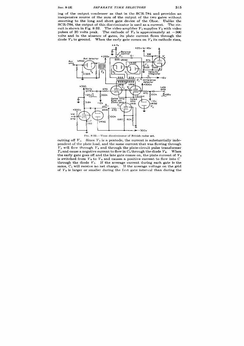
SEC. 8.13]
SEPARATE TIME SELECTORS
315
ing of the output condenser as tha t in the SCR-784 and provides an
inexpensive sou rce of the sum of the output of the two gates withou t
resor t ing to the long and shor t ga te device of the Oboe. Unlike the
SCR-784, the ou tput ofth isdiscr irn ina tor isusedas a cur ren t . Thecir -
cu it isshown in Fig. 8.32. Thevideo amplifier Vlsupplies VZwith video
pulses of 20 volts peak. The cathode of V* is approximately a t –300
volts and in the absence of gates, its pla te cur ren t flows th rough the
diode Vs to ground. hen the ea r ly ga te comes on Vs its a thode r ises,
+4.7V
A
o
25v
—
FIG. S .32.—Time discr imina tor of Br it ish radar set .
cu tt in g off V,. Since V, is a pen tode, th e cu rr en t is substant ially inde-
penden t of the plate load, and the same cur ren t tha t was flowing th rough
V, will flow t hr ou gh V, a nd t hr ou gh t he pla te-cir cu it pu lse t ra nsformer
T, and cause a negat ive cur ren t to flow in Cl th rough the diode V13. When
the ear ly gate goes off and the la te gate comes on , the pla te cu ren t of Vz
is switched from Vs to Vd and causes a posit ive cu r ren t to flow in to C
through the diode V,. If the average cur ren t dur ing each ga te is the
same, Cl will r eceive no net charge. If the average voltage on the gr id
of V2 is la rger or smaller dur ing the fir st ga te in terval than dur ing the

316 TECHNIQUES OF A UTOMA TIC TIME MEASUREMENT [SEC. 813
second gate interval, Cl will take a posit ive or nega t ive net charge,
The condenser Cl is coupled to the low input impedance of a Miller
integrator . This is the discr iminator that provides 55 pA/psec used in
conjunct ion with the funct ion unit evalua ted in Sec. 88. The 16 v It s
tolerance in output voltage, + 4 volt s d-c, and + 4 volt s r ipple, there
allowed is due to the 16-volt spacing between the diode biases.
The
transformer T1 is fed from a high impedance source and is designed as a
cur ren t t ransformer—that is, the secondary cur ren t tends to bear a
fixed ra t io to the pr imary cur ren t independent of output voltage, diode
r esist an ce, or a pplied bia ses.
The potent iometer 1?, takes advantage of
the imperfect ions of the transformer and inser ts more or less resistance
in the two secondar circuits to afford a ga in-balance c nt rol.
The
FIQ. 833.-Time d is cr im ina tor of ANIAPG-15.
quality of the t ransformer can be judged by the fact that a complete
excursion of the poten t iometer changes the balance only by 10 per cent .
The cur ren t tha t flows through V1 is determined by t l~e signal ampli-
tude; thus the cur ren t from the center tap of the plate t ransformer Z’j
flowing through Tt provides pulse output over the whole interva l of the
two gates which can be average-detect ed by the diode Vs for AGC or
amplitude-demodu la t ion purposes .
Employing a cu rr en t t ran sform er in this t ype of dif er ent ia l amplit ude
det ect or circuit offers a solut ion t o the problem of maintaining bala ced
sensit ivity in such a circu t when the output voltage depart s from he
mean of t he diode bias potent ia ls.
The alterna t ive solut ion with a low-
impedance source is to cause the mean diode bias to follow exact ly the
volt age excursions of the output condenser as n the next discr iminator
t o be descr ibed.
SEC. 814] T IME DISCR IMINATORS
317
A second discr iminator tha t per forms the two funct ions of t ime selec-
t ion and det ect ing separa tely and also uses difference-t aking in a con-
denser direct ly is the t ime discr iminator of the ARO (AN/APG-15,
AhT/APG-5) shown in Fig. 833.
Tubes V, and VZ are suppressor -gat ed I
pen todes with the video signal applied to the cont rol gr ids and in er t ing
pu lse t ra nsformer s in t he pla te cir cu it s.
Th e secon da ries of t he in ver tin g
t ransformers feed t r iode det ector s of the type shown in Chap. 14, Vol. 19.
The net charge in Cl is the difference between the charge that flows in
V, and Vd due t o the ear ly- and la te-ga ted video pulses. A difference
det ector usin high impedance t r iodes of the 6SL7 typ to charge 1.0 ~f
for 0.5 psec is cer ta in ly operat ing as an average det ector . The outpu t
sign als fr om t he secon da ries of 2’1 a n d Tz a re m ixed t o, pr ovide a combin ed
pulse for th AGC detector which represent s the signal amplitude dur ing
the whole of the ga t ing in terval.
The bias of V, is fixed, and the bias of
V, is ma in ta ined nea r ly constan t by the ca thode follower V, operating
with a pen tode as a ca thode Ioad as the potent ia l on Cl moves up and
down over a range of 15 volt s.
A balance cont rol in the cathodes of
the ga t ing amplifiers provi(lm bakmcc on equal signals so the volt age
on Cl will not change in the absrnce of signals or in the presence of noise
alone.
8.14. Time Discr iminators with Time Selectors, Pulse St retcher , and
Narrow-band Pulse Amplifica t ion.-An example of this type of dis-
cr iminat ion on which considerable data is available is the circuit used
to supply automat ic r ange t r acking or an exper imenta l radar . Two
a ims wer e pr om in en t in t he t im e-discr im in at or design : m in imum sen sit iv-
ity to in er ference, and accura te posit ion memory and coast .
The fir st it em \ vas ach ieved by decreasing the range aper tu re to
0.4 psec and employing rapid-charging peak det ector s in the t ime dis-
criminator.
Unfor tunat ely the shor t range aper tu re requ ires wide
receiver bandwidth and thus decreases the receiver sensit ivity and
incr ea ses t h e cos t of amplifica t ion .
The second aim was ach icvcd I)y design ing a t ime discr iminator
that would remain bahmced on all t implitodes of noise u to receiver
saturation.
The pr incipal method of achieving g<)fxl I )a l:mcc on noise is t o main-
ta in ext r eme linear ity in the amplifiers and det ectors, which opera te
sepa ra tely on t h e ea rly- a nd l:Lt e-g:~t r(l video.
As is showm in Fig. 834, the sclwt ing ga te is formed in V,, a block ing
oscilla tor using a West ingholls(’ I32- I JW pulse t ransformer t o genera t e
a 0,12 -psec pulse. A 0.1 -Lsrc (Ielay line is employed to provide a la te
ga t e from the ra r ly ga te.
‘1’llc spacing of the ga tes is chosen to keep
I
I
the addit ive outpu t , of the two ga t r t l-vi(lco stages constan t over as wide
a range of misalignment as possil)lc.
It t~lrns ou t tha t th is condit ion
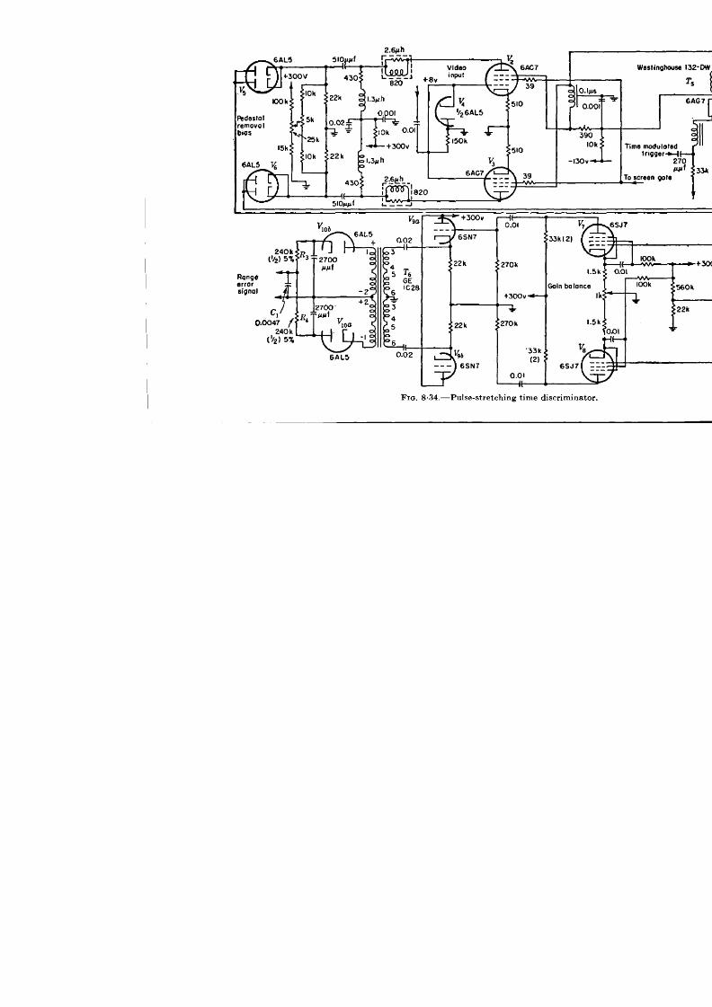
w

SEC. 814]
T IME DISCR IM INATORS
319
p ovides the maximum slope of range-er ror signal vs. r ange er ror . The
video signals of + l-volt level arc amplified to +8 volts in a two-stage
20-Mc/sec video amplifier t o dr ive the gr ids of th e two su ppr essor-ga ted
6AC7 amplifiers, V, and V,. A d-c r est or er V, is supplied. In order to
obtain the maximum gain from the ga ed amplifiers, the screens are
gated from +75 to +150 volts for a 6-psec per iod cen tered on the t rack-
;ng ga tes .
This is necessary because du ring th e t ime that t he suppr essor s
are held at —130 volts the tota l space cur en t flows to the screens, which
would burn up if maintained constant ly at +150 volts.
When the screen is at +75 volts the ca thode bias is small and large
video signals cause gr id cur ren t to flow, which passes to ground thro gh
the low resistance of the diode V,.
The gat ing amplifiers a re fair ly
highly d genera ted to minimize gain var iat ions between the two stages. 1
The net stage gain is about 0.5.
The plate loads of these amplifiers
are designed with shunt and ser ies compensat ion to provide a pulse r ise
t ime (10 to 90 per cent ) of 0.02 psec in the st ray capacitance of the output
circuit of the 6AL5 diodes V6 and V6.
It is unnecessary to provide
low-frequency response after the gat ing stage because there can be no
signals longer than the gate width , hence the small coupling condensers
which permit lower capacity wir ing, a factor highly impor tant in wide-
band video const ruct ion pract ice.
The type 6AL5 diodes were used
because each sect ion has a resistance of 200 ohms, giving 100 ohms for
the pair as the ser ies resistance through which the st ray capacitance from
plates to ground must be charged with a t ime constant of 0.02 psec.
The decay time of this detector is about 10 psec th rough the I-megohm
resistors Rl and Rt. The output of the peak detector s are negat ive
10-~sec tr iangular pulses whose init ia l amplitudes represen t the peak
amplitude of the gated video signals and may now be amplified in narrow-
band amplifiers. This completes the desired opera t ion of rapid peak
detection.
Tubes VT a nd V8 are the narrow-band amplifiers, having a gain of six.
Their bandwidth was chosen as + Me/see to a llow the plate to r ise to an
appreciable fract ion of th e peak of th e t r iangular input pulse and st ill pr o-
vide reasonable gain . Degenera t ion is employed again to reduce the
differ en tia l gain va ria tion s an d t o allow t he amplifier s t o h an dle t he maxi-
mum possible gr id signals withou t depar tu re fr om the linear por tion of the
gr id character ist ics. The cathode followers Vg~ and V~g provide Iow-
im edance ou tpu t to the pulse t ransformers Te and TT, which dr ive the
det ector diodes VIOA and VIO,. The diodes respect ively discharge and
charge Cl through the smoothing resistors RS and Rd.
The n et char ge
on Cl is the range-er ror signal which is fed to the in tegra tor and range-
LThe degenera t ion of this stage is actua lly so high tha t it would probably have
made lit tle differ en ce t o t he ga in if t he scr een s h ad been oper at ed st ea dily a t +75 volt i.

320 TECHNIQUES OF A U OMA TIC TIM 1$ MEASLIIWMENT [~tiC. 814
t r acking servo. Figure 835 shows the rangwcr ror volt age plot t ed against
r an ge er ror ; th e slope is 164 volt s/P sec and t h aper tur e is 0.4/psec.
Th e ga ted amplifier s Vz and V, are biased Class A dur ing the gat ing
interva l. This implies an average plotc cur ren t of about half of peak.
Hence whe the gate comes on the suppressor , the pla te drops to the
zero-signal level. This pedesta l lasts as long as the g:ite is on and is
la rgely r emoved by bia ing off the peak-detect ing diodes. A differ -
ent ia l bias con trol determines the balance of the r ange-er ror signal in
the absence of signal and noise.
In t e presence of noise, the balance is
det ermin ed by t he differ en tia l
Video signal level :1.0 v
without AGC
gain con t rol in the ca thodes of VIT and VIS.
-6
t
L
FIG. 8 ,35.—Error s igna l curve of pulse-s t retch ing t ime discr imina tor ,
The high gain of the servo amplifier following the t ime discr imina tor
makes balance condit ions very cr it ica l. For example the maximum er ror
signal is + 5 volts but in order for the dr ift velocity on noise to be less
than 20 yards/see, the r ange-er ror signal on noise must be less than
0.1 volt , thus requir ing balance to 2 per cent . This was obta ined over
per iods of severa l hours and with values of noise from zero to twice AGC
levels. The pulse outpu t from the ca thode followers Vga and Vgb is
added to provide for AGC a single pulse represen t ing the sum of the
peak amplitudes of the two gated videos.
The reasoning behind the choice of the two t ime-constant detector s
is tha t , since rapid pe k detect ion is desired, it is economical to detect
a t low level in a very small capacitance whose exponen ia lly decaying
outpu t can be amplified with reasonable gain in nar row-band amplifier s

SEC. 8.15]
T IME S ELECTION
321
and redetected at h igh level to provide a d-c er ror signal. One a terna-
t ive would have been to amplify the direct -cu r ren t componen t of the
ou tpu t of diodes Vb an V6. At such a low level, 5 rev/yard, ba lance
er ror s due to dr ift s of the d-c amplifiers would have been in t reduced.
To increase the evel a t th is poin t would require addit ional video ampli-
ficat ion , which for 20-Mc/sec bandwidth and voltages above a few volts
is ver y expen sive. 1
P~eview of the circu it shows that its rea l va lue is the pu lse st r etching
of the peak-detector stage which provides a long voltage pulse from a
sh or t on e.
More effor t might well have been pu t in to increasing the
resistance of the diode ou tpu t circuit than in to providing narrow-band
gain since th subsequent average etect ion is benefited as” much by
incr easin g pulse du ra t ion as by in cr easing pulse amplitude.
8.15. Time Select ion .-In theabsence ofin ter fer ing signals, the t ime
select ion opera t ion cou ld simply divide the recu rr ence in terva l in to two
per io s, t ime before the signal and t ime fter the signal, each per iod
including half the signal as in Figs. 8.36 and 837.
In the presence of mult iple signals, the t ime-select ion process must
reject in formation from all but the desired signal.
In fact , since a 3°
radar beam has an angular aper tu re
of about 600 yd at 10,000 yd, scan- EWIY
T
Goting
ning radar range finder s rely on t ime
go~e
amplifier
sel ct ion or range discr iminat ion to
provide most of the ta rget discr imi- vir feO
Goted video
nation . An advan tage of discr imi-
na t ing in t ime more finely than in
angle is tha t it is a very simple mat ter :$
to extend the t ime aper tu re for search-
+
ing either by scanning in range or by
FIG.S.36.—Blockdiagram of th e time
selectorof a time discriminator.
presen t ing the whole t ime interval on
a CRT display, whereas the problem of expanding an angular aper tu re
from a very nar row beam is a complica ted mechan ical problem involving
eit her h igh -speed sca nn in g or some sor t of beam defocu sin g.
If the ou tpu t of the t ime selector shown in Fig. 8.36 Were put in to an
amplitude compar ison and memory circu it the outpu t er r or signal would
have the form shown in Fig. 837. If on ly one ga te were used, say the
ear ly gate, the ou tpu t would appear as in Fig. 8.38, and is ident ica l
with tha t from the double-gat ing system except that its amplitude is
halved and it has a differen t d-c level. The single-ga te system has been
used for ligh t-weight a irborne fire-con t rol radar s wher e only on e ta rget
I A r ou gh ca lcu la tion a ssumin g video amplifier design con sist en t wit h t he rest of
the system shows a c st of 140 ma for fir st stage of 11 db and 410 ma for second stage
11 db, which wou ld br ing the er ror signa up to a reasonable va lue of 50 mv/yd.

322 TECHNIQUES OF A UTOMA TIC TIME MEASUREMENT [SEC.815
was* expected—for example the AGL-T in Sec. 8.12. The obvious
advantage of the gat ing systems of Figs. 8.37 and 8“38 is tha t no mat ter
where the gates are with r espect to the video signal there exists a sig-
nificant e ror signal: hence no search problem exists for a single target .
FIG.
‘b)~’~~c~g~e~rev:e--!.Errorsgnol
8,37.—Time-selector waveforms and er ror -s igna l curve of a t ime discr imina tor .
Th e disa dva nt age of t he syst em of F ig. 8.38 is t ha t t he t ime-discr im in at ion
techn ique involves match ing the ou tpu t of a single detector against a d-c
level, so tha t th e ou tpu t of the single detector is a funct ion of signal ampli-
tude as well as of its t ime modula t ion; hence the t racking poin t var ies
wit h sign al st ren gt h.
‘l--i--Jn’egoee
%vjrtu~l ind~~
I
Time of front
@)~x-Error@ol
l—
Misalignment of vlrtu.1
index and video
FIG. 8 .3S.-Waveforma and error -e igmd curve of s ingle-ga te t ime discr imina tor .
Mult iple signals requ ire nar row select ing ga tes, th e ga te width and
pu lse width being determined by est imated signal width , separa t ion , and
t e desired resolu t ion . In radar applica t ions the undesired signals are
ground echoes, sea clu t ter , pulses from adjoin ing radar s ts, and in ter -
fer ing target s near the desired one.
Decreasing the range aper t r e
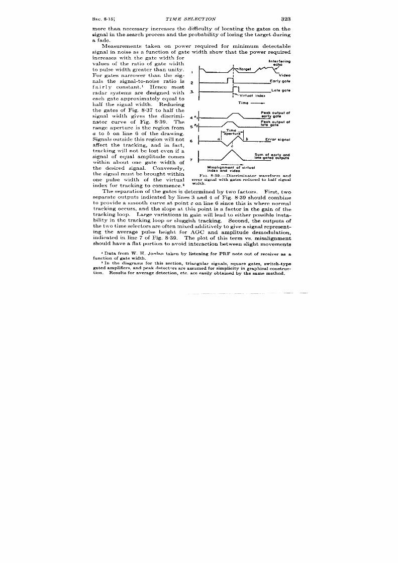
SEC.815]
TIME S ELECTION 323
more than necessary increases the difficu lty of locat ing the gates on the
Bignal in th e sear ch pr ocess and th e probability of losing th e t ar get dur ing
a fa de.
Measurements taken on power require for minimum detectable
signal in noise as a funct ion of ga te width show that the power required
increases with the gate width for
values of the ra t io of ga te width
to pulse width grea ter than unity.
For gates nar rower than the sig-
nals the signal-to-noise ra t io is
fair 1y constan t . 1 Hen e most
radar systems are designed with
each gate approximately equal to
h lf the signal width . Reducing
the gates of Fig. 8.37 to half the
signal width gives the discr imi-
nator cu rve of Fig. 8.39. The
range aper tu re is the region from
a t o b on line 6 of the drawing.
Sign als ou tside t his r egion will n ot
affect the t racking, and in fact ,
t r acking will not be lost even if a
signal of equal amplitude comes
with in about one gate width of
the desir ed signal. Conversely,
the signal must be brough t with in
one pulse width of the vir tual
index for t r acking to commence. Z
Interfering
echo
1
Vid60
n
Eorly gofe
‘“I--+==’ateg
ime _
Peak o fput of
4 %
I
Peak oU?PUt Of
late gate
s e2
Time
$1
aperture
6
a
b Error signal
c
Mieolignment of virtuol
index and video
FIG. S .39.—Discr imina tor waveform and
er r or sign a l wit h ga t ee r educed t o h a lf sign a l
width.
The separat ion of the gates is determined by two ac ors. First , two
separate outputs indica ted by lines 3 and 4 of Fig. 8.39 should combine
to provide a smooth curve at poin t c on line 6 since this is wher e normal
t r acking occur s, and the slope at th is poin t is a factor in the gain of the
t r acking loop. Large var ia t ions in gain will lead to either possible insta-
bility in the t racking loop or sluggish t racking. Second, the ou tputs of
t he two t ime select or s a re oft en m ixed a ddit ively t o give a sign al r epr esen t-
ing the average pulse height for AGC and amplitude demodulat ion ,
indica ted in line 7 of Fig. 8,39. The plot of th is term vs. misalignment
should have a fla t por t ion t o avoid in ter act ion between slight movemen ts
I Da ta fr om W. H . J or da n t ak en by list en in gfor PRF not e ou t of r eceiver a s a
funct ion of gate width.
2In the diagrams for th ig sect ion , t r iangular s igna ls , square ga tes , switch-type
gated amplifiers,and peak detectms ar e assumedfor simplicity in graphicalconst ric-
t ion . Result s for averagedetect ion , e tc. a re eas ily obta ined hy the same method.
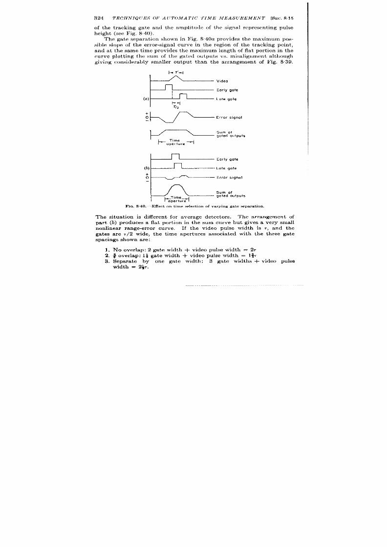
324 TECHNIQUES OF A U7WMA TIC TIME MEASUREMENT [SEC. 81.5
of the t racking ga te and the amplitude of the signal represen t ing pulse
height (see Fig. 840).
The ga te separa t ion shown in Fig. 840a provides the maximum pos-
sible slope of the er ror -signa l curve in the r egion of the t racking point ,
and at the same t ime provides the maximum length of fla t por t ion in the
curve plot t ing the sum of the gated output s vs. misa lignment a lthough
giving considerably smaller outpu t than the a r rangement of Fig. 839,
Video
Early gate
Late gate
K/-’-’r’on”i’n”’
*:’’’OJ-
oper ure
+
o
-1=
rror signal
Sum of
b;:%
gated outputs
Fm. 8.40.—E5ect on t ime select ion of va rying ga t e s epar a t ion .
The situa t ion i differen t for average dete tor s. The ar rangeme t of
par t (b) produces a fl t por t ion in the sum curve but gives a very small
nonlinear r ange-er ror curve. If the video pulse width is 7, and the
ga tes a re , 2 wide, the t ime aper tu res associa ted with the th r ee gate
spacings shown ar e:
1. No over lap: 2 ga te wid h + video pulse width = 27
2. ~ over lap: Ii ga te width + video pulse width = l%
3. Separa te by one ga te width: 3 ga te widths + video pulse
width = 2+.

SEC.8 16] 7’hltGl:7’.Ylil,lcL’ TION 325
An alt erna t ive to genera t ing t l~o adjacen t ga tes i to delay the video
and apply the same gate to Imth gat ing amplifiers as in Fig. 8.41. The
video spt icing of Fig 8“4 I has been ar ranged to provide the maximum
slope of the er ror - ignal cu rve and maximum flat por t ion in the sum
%=
Gof,ng
ampllfler
Tracking
Gated
gate
wdeo
delay
time
Gotmg
amplifier
Z6
FE
ideo
Deloyed video.
Gate
! Vhrtual index
Error signal
I
t#:rA
Fm. 8 .41.—Delnyed video t ime discr imina tor .
cu rve. The associa ted t ime aper ture is the video width plus the ga te
width or ~7, wh ich is considerably smaJ ler than the double-ga te ar range-
ment for the same condit ions.
It is often desir able t o obt ain a wa rn ing of in t er fer in g sign als a ppr oa ch -
ing the t r acking gates.
Nlethods
for accomplish ing th is ~vith ou t -
r igger ga tes will be discussed in
Sec. 917,
One in terest ing but unt r ied
possibilit y is t o in cr ea se t he r an ge
aper t ur e du r in g sea r ch .
One sim -
ple possibility employs a mult i-
ple-va lued ra ther than a switch
char acter ist ic for a t me select or .
If this is done, the ear ly and late
ga t es cou ld h ave sloping fr on t and
Video
Eorly gate
1
Error signal
FIG. 8 .42,—Time eelector with doping ga tes .
ba ck r espect ively t o ext en d t he r an ge a per tu re wit hou t ser iou sly a ffe t in g
thein ter ference reject ion of thenar row square gates (see Fig. 842).
TARGET SELECTION
8.16. Gener al Considera t ions.-In any automat ic t ime-measuremen t
system w ose t ime-select ing waveforms do not cover the whole recur -
r ence in terval, t here exist s the problem of br inging some por t ion of one
of the select ing waveforms in to coincidence with the desir ed signal.
When th is has been done, the t ime discr imina tor by defin it ion will
produce an er ror signal of the cor r ect sense to make the select ing wave-
326 TECHNIQUES OF A UTOMA TIC TIME MJJIAS(JR17AI ENT [~EC. 8.16
forms mov to exact coincidence with the target . l’he lat ter process
will be ca lled “locking on target . ”
If t he process is to be done manually
there are five steps in the opera t ion .
1. Search visually over the displayed range to find a target ,
2. Identify the target as the one desired.
3. Slew the select ing gates toward the target .
4. Note indication of t heir coincidence.
5. Switch t o au tomat ic t r acking and allow the circuit to lock on.
Of these five opera t ions only the last th ree will be discussed i th is
chapter since the first two belong in the t rea tmen t of displays in Vol. 22.
The procedure of automatic target select ion is similar to the manual
process but differs in the following ways. In genera l, searching is tom.
bined with slewing—that is, the method of sear h is to slew the range
gates through the range interval of in terest a t a conven ien t speed until
a ta rget occurs in the gates. 1 In automatic t arget select ion , ta rget
iden tifica t ion and indica t ion of coin ciden ce ar e iden tica l processes, for
the circu it that detects coincidence simultaneously examin s the target
for any elect r ica lly dist inguishable ch aracter ist ics. Upon coin cidence
with a suitable signal, ta rget indicat ion is given and the t racking circuit s
a r e connect ed t o “lock -on .”
There are two applica t ions of automatic t ime-measur ing systems
where it is almost impera t ive for automatic search to be included. One
oc urs when the oper a tor employing the automatic t ime-measur ing
system has many other dut ies—for example, the pilot of a single-sea ter
figh ter plane who is relying on automatic r nge measurements in his
radar to supereleva te his gunsight .
Another example of the need for
automat ic search is a radar system which funct ions to r epor t the presence
of an approaching target . The target select ing circu it would have to
find the target , lock on, measure the sense of it s range ra te, and either
sound a warni g or reject it and cont inue the search ing.
Conditions for Automatic Search .—The quest ion to be answered by the
designer is, “When is it possible to exchange an elabora te CRT display
for an automat ic search cir cu it?”
The answer depends on whether the
desired target can be ident ified lect r ica lly and whether the range gates
can be made to scan withou t missing the targets.
Rega rdin g a utomat ic iden tifica tion , fr equ en tly it is su fficien t th at t he
ta rget desired be always closer in range than any other . The obvious
procedure is to search out in range until a t a rget is found; if none is
I I t s in teres tingto note tha t the inheren t speedof the rangescan is t he speed of
ligh t , because as the ele t ron beam t races ou t the display, it is actua lly present ing
the cou r se of the r -f pulse th rough space.
Persistenceof vision or of CRT screens
BIIowa th e sca n t o be examin ed visua lly in r et rospect at a lower speed.
SEC. 8.16]
T ARGET S ELECT ION
327
encoun tered, then retu rn from maximum to zero range rapidly with the
lock-on cir cu it s inh ibit ed .
P ulse decodin g off er s mor e ela bor at e a ut omat ic t ar get iden tifica tion .
With thk method, a decoder loca ted before the automat ic search circu it s
will elim in at e undesir ed sign als, permit tin g t r ack ing on ly on sa tisfa ct or ily
coded signals. Target select ion may also be made with respect to the
angular posit ion of the target Amplitude modula t ion of the echoes
may be ut ilized for ta rget select ion in a conica l scanning system.
The
antenna scans conica lly, and the pilot of the plane keeps the antenna
axis poin ted a t the desir ed target by means of an opt ica l sight . The
modula t ion—that is, on the axis of the antenna . Since the antenna looks
down at the ear th from the plane, there is only one poin t on the ground
which is on the axis of the antenna.
Many other methods of automatic
ta rget ident fica t ion may be suggested by the par t icu lar need.
The second condit ion , that of ensur ing that the range gates will
cover the desir ed range in terva l withou t missing a target , is somewhat
like an impat ien t boy t rying to mow a lawn rapidly without leaving any
uncut st r ips. F irst , since the signal pulses appear on ly at the PRF, the
ra te of searching in range should not be so large that the range gates
will move more than one range aper ture at each recu r rence in terva l.
Secon d, if t her e is som e likelih ood of signal fa din g, t he r an ge ga tes sh ou ld
over lap each poin t in the range in terva l long enough to a llow the signal
to r eco t ier from a fade dur ing the t ime that the range aper tu re includes
that poin t . Third, if the antenna is being scanned in angle, t e range
search either should move so slowly as to move ou t less than one range
aper tu re dur ing each complete angle scan, or should move so r pidly
as to search ou t the whole range in terva l while the beam moves one
b amwid h. The second alterna t ive conflict s with the fir st two poin ts,
especia lly since most r adar systems are designed to search in angle so
rapidly that only a few (say five) pulses are r eceived from a small t a rget
per angular scan. The four th poin t that causes the ra te of range search
to be decreased is that the coincidence detector is ft en designed to
require more than one pulse to build up enough signal to over r ide or
dkwonnect t he sea rch cir cu it .
This preven ts noise pulses or randomly
occu rr in g in ter fer in g pulses fr om st oppin g t he sea rch .
If the t ime delay
involved in switch ing by relays to t r ack from search is appreciable, the
ga tes should not move away from the target . An equat ion could be
wr it ten showing exact ly the fastest r a te of range search scan in terms of
these five factor s, but the defin it ion of symbols wou ld take more space
than the equat ion would save.
As a pract ica l example, the AN/APG-15 is of in terest . It has a
PRF of 1400 pps and conical scanning ra te of 35 cps, r elays with
328 TECHNIQUES OF AUTOMA TIC TIME MEASUREMENT [SEC. 8.16
O.01-sec closing t ime to disconn ect the sear ch sweep, and a 0.7 psec pulse
with two adjacen t O.7-psec range gates. The range aper tu re is thus
about 2.0 paec, or 320 yd; the maximum search range is 1800 yd. If
there were no con ical scanning, the range gates might move out 320 yd
each recur rence in terval, cover ing the 1800 yd 318 times per second
if negligible flashback time is assumed. With conica l scan, a range scan
of 320 yd in ~ see, or 11,000 yd/sec would just give complete coverage
of the volume swept by the conica l scan .
If the disconnect relay takes
+ sec to close, the gates wil~ h ave moved 110 yd or one-th ird the range
aper tu re between the t ime of detect i g a target and star t ing to lock
on. In the actual system a more conservat ive ra te of 4000 yd/sec was
employed.
N nlinear search ra te or synchron ized range search scans might be
used in par t icular situat ions to emphasize par t icu lar por t ions of space
or to skip por t iona of space.
Rapid search of the type indica ted in the above example is easily
a ccomplish ed in electrical t racking systems where the only limitat ion to
scanning speed and par t icular ly to the speed of flashing back to initial
r ange at the end of the scan is the fact that a large condenser to ground
usually exists at the poin t at which the range con t rol voltage is found.
The low impedances available in thyra t rons or pulsed hard tubes provide
flashbacks of about 100-psec durat ion even with several microfarads
capacitance. In addit ion , the presence of a large condenser fav rs the
pract ice of discharging small condensers in to the range condenser for
in t roducing a “kick” in range to rem ve the gates from an undesired
signal. Seve al methods of scanning and disconnect ing will be shown in
examples t o follow.
Mechanical t r acking systems offer a quite differen t picture. The
greatest obstacle to range search in these systems is the wear on the gear s
and moving par ts tha t would follow from cont inuous scanning in range.
If wear is n ot object ion able, it is st ill usua;ly impossible t o scan th e wh ole
search range in fract ions of a second and decelera te to target velocity
withou t losing the target unless the search range is very limited.
On-target Indicat ion .—The tar get -detect ing circuit is tha t on e wh ich
sh ou ld possess t he maximum possible discr imin at ion sin ce it most closely
simulates the act ion of the opera tor in choosing or reject ing a target .
The simplest method of detect ing the presence of a target signal in
coincidence with the t racking gates is to connect a biased detector to the
output of the t ime selector and set the bias so high tha t on ly signals
large enough to t rack will cause cur ren t to flow. The result ing voltage
can be used to opera te the search-disconnect device and the on-target
indica tors. The major disadvantage f th is system is the pract ice of
compar ing the signal level from a receiver with u t constant level AGC
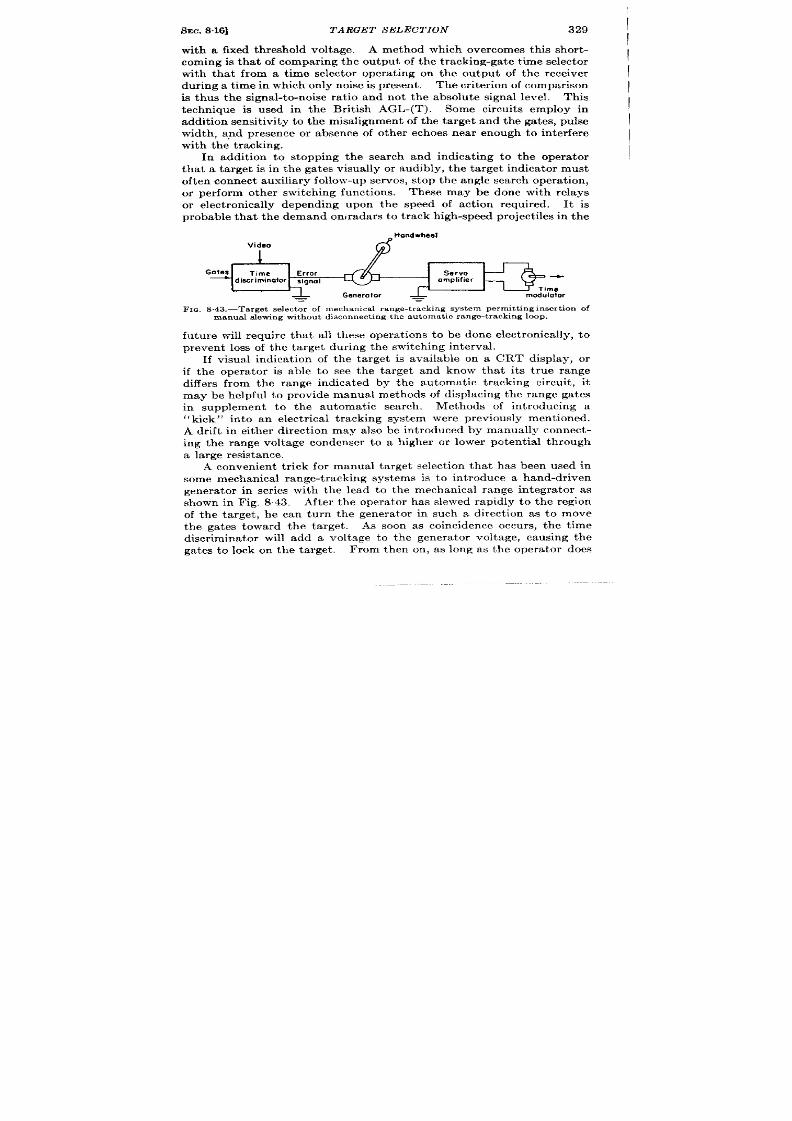
SEC. 8.16]
TARGET S ELECT ION
329
i
with a fixed t hr eshold volt age.
A method -which over comes this shor t -
coming is that of compar ing the ou tpu t of the t racking-ga te t ime selector
\
with tha t from a t ime selector opera t iruz on the output of the r eceiver
dur ing a t ime in which on ly noise is prese~t . The cr it er ion of compar ison
is thus th signa l-to-noise ra t io and not the absolute signal level. This
technique is used in the Br it ish AGL-(T). Some circuits employ in
addit ion sensit ivity to the misa lignment of the ta r get and the ga tes, pulse
width , a ,nd presence or absence of other echoes near enough to in ter fer e
wit h th e t r acking.
In addit ion to stopping the search and indica t ing to the opera tor
that a ta rge is in the gates visually or audibly, the ta rget indica tor must
oft en con nect a uxilia ry follow-u p ser vos, st op t he a ngle sea rch oper at ion ,
or per form ot her swit ch ing fu nct ions.
These may be done with relays
or elect ronica lly depending upon the speed of act ion required
It is
probable that the demand omradars to t ra ck high-speed project iles in the
~ Hand wheel
FIQ. S.43.—Ta rget s elect or of mechan ica l r ange-t r a ck ing sys tem perm it t ing in s er t ion of
manua l s lewing withou t d isconnect ing the au toma t ic r ange -t r ack ing looP .
fu tur e will r equire that all these opera t ions to be done elect ronica lly, t o
pr even t loss of the ta r get du ing the switching interva l.
If visual indica t ion of the ta rget is available on a CRT display, or
if the opera tor is able to see the ta rget and know tha t it s t r ue r ange
differ s from the ange indica ted by the automat ic t racking circu it , it
may be helpful to provide manual meth ds of displacing the range ga tes
in supplement t o the automa ic sea rch. Methods of in t roducing a
‘‘ kick” in to an
A dr ift in either dir ect ion may a lso be in t roduced by manually connect -
ing the range volt age condenser to a h igher or lower poten t ia l t h rough
a la rge r esista nce.
A conven ien t t r ick for manua l ta rget select ion tha t has been used in
some mechan ica l r ange-t r acking syst ms is to in t roduce a hand-dr iven
genera tor in ser ies with the lead to the mechan ica l r ange in t egra tor as
shown in Fig, S.43. Aft er th e opera t or has slewed rapidly to the r egion
of the t a rget , h e can tu rn the genera tor in such a dir ect ion as to move
the ga tes toward the ta rget .
As soon as coincidence occur s, t he t ime
discr imina tor will add a volt age to the genera tor volt age, causing the
ga t ,es t o 10& on th e t a rget . From then on , as long as the opera tor does
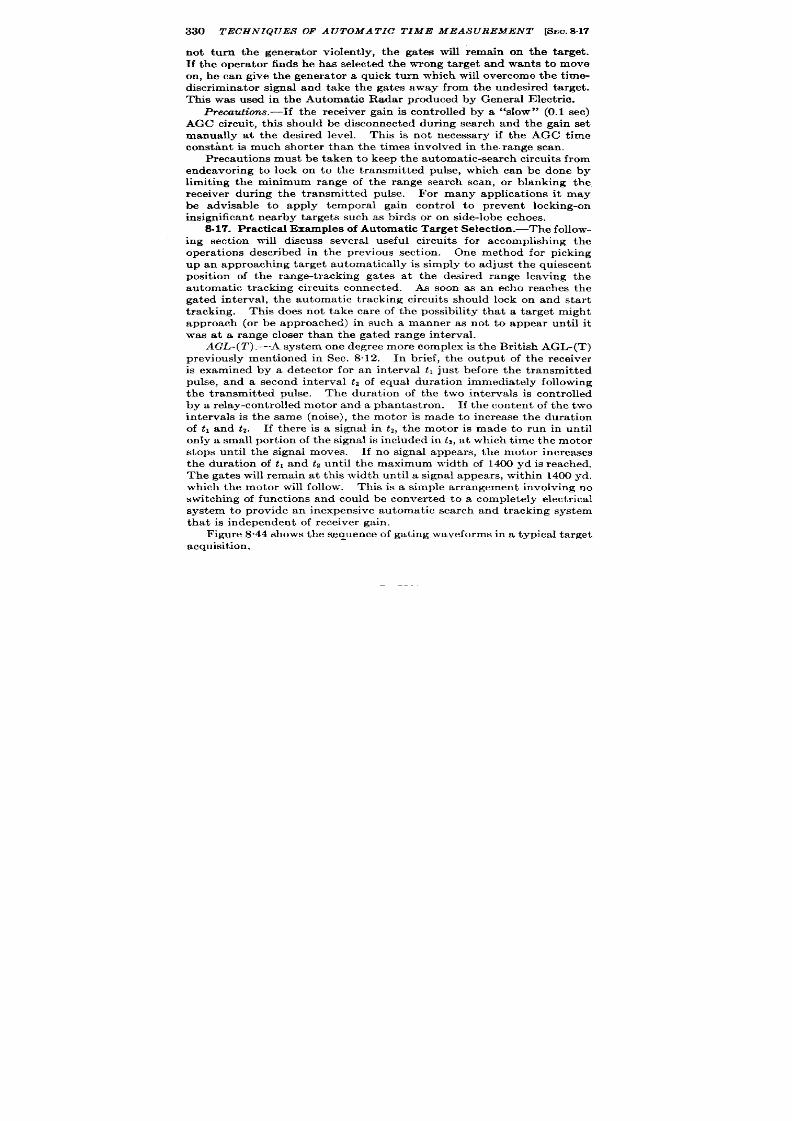
8.17
not tu rn the genera tor violent ly, the ga tes will r emain on the ta rget .
If the opera tor finds he has selected the wrong ta rget and wants to move
on, he can give the genera tor a quick turn which will over c me the t ime
discr imina tor signal and take the gates away from the undesired ta rget .
This was used in the Automat ic Radar produced by Genera l Elect r ic.
Precaut ions.-If the r eceiver gain is cont rolled by a “slow” (0.1 see)
AGC circuit , this should be disconnected dur ing search and the gain set
manually at the desired level.
This is not necessary if the AGC time
constant is much shor ter than the t imes involved in the r ange scan.
Precaut ions must be taken to keep the automat ic-search circu its from
endeavor ing to lock on o he transmit ted pulse, which can be done by
limit ing the minimum range of the range sea rch scan, or blanking the
r eceiver dur ing the t ransmit ted pulse. For many applica t ions it may
be advisable to apply temporal gain con t rol to preven t locking-on
insignificant near by t ar gets such as birds or on side-lobe echoes.
8.17. Pr act ica l E xamples of Au tomat ic Ta rget Select ion .-Th e follow-
ing sect ion will discus severa l useful circuits for accomplish ing the
oper at ions descr ibed in t he pr evious sect ion .
One method for p cking
up an a ppr oa ch in g ta rget au toma t ica lly is simply to adjust the qu iescen t
posit ion of the range-t r acking gates a t the desir ed range leaving the
automat ic t racking circu it s connected. ~ soon as an echo reaches the
ga ted in terva l, the automat ic t racking circu it s shou ld lock on and sta r t
t racking. This does not t ake ca re of the possibility tha t a t a rget migh t
approach (or be approached) in such a manner as not to appear until it
was at a r ange closer than the ga ted range interval.
AGL-(T) .—A system one degr ee mor e complex is t he Brit ish AGL-(T)
pr eviously ment ioned in Sec. 8“12.
In br ief, the output of the r eceiver
is examined by a detector for an in terval h just befor e the t ransmit ted
pulse, and a second interval h of equal dura t ion immedia tely following
the t ransmit ted pulse. The dura t ion of the two interva ls is con trolled
by a relay-con trolled motor and a phantast ron . If the con tent of the two
interva ls is the same (noise), the motor is made to increase the dura t ion
of t , and tz. If there is a signal in t~, the motor is made to run in unt il
on ly a small por t ion of the signal is included in h, a t which t ime the motor
stops unt il the signal moves. If no signal appears, the motor increases
the dura t ion of t , and h until the maximum width of 1400 yd is r ea ch ed.
The ga tes will r emain a t this width unt il a signal appears, with in 1400 yd.
which the motor will follow. This is a simple a r rangement involving no
switching of funct ions and cou ld be conver ted to a completely elect r ica l
system to provide an inexpensive automat ic sea rch and tracking system
that is independen t of r eceiver gain.
Figur e 8.44 shows th e sequen ce of ga ting waveforms in a typica l ta rget
acquisition.
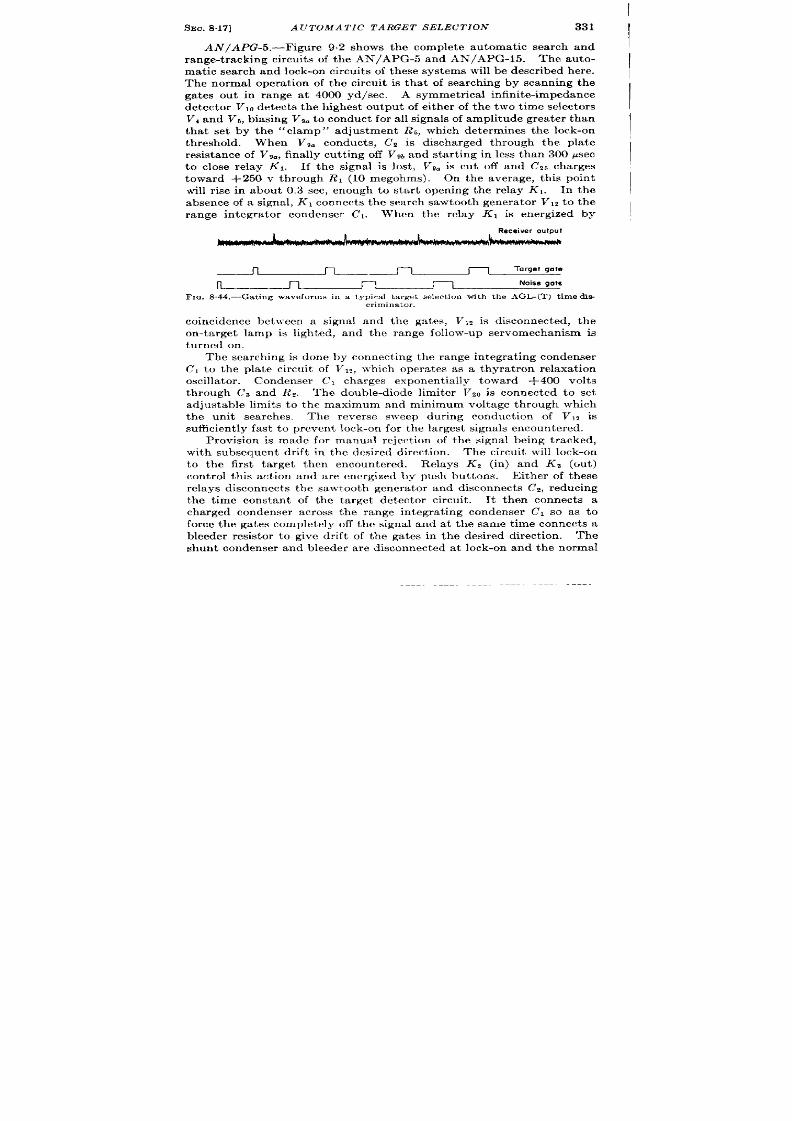
I
SEC. 8.17] AUTO A TIC TARGET SELECTION 331
AN/APG-5.—Figure 9.2 shows the complete au tomat ic search and
range-t racking circu it s of the AN/APG-5 and AN/APG-15. The au to-
mat ic search and lock-on circu its of t hese systems will be descr ibed h ere.
The normal opera t ion of the circu it is that of sea rch ing by scanning the
gates ou t in range at 4000 yd/sec.
A symmet r ica l in fin it e-impedance
detector V,, detect s the h ighest ou tpu t of either of the two t ime selectors
V, and V,, biasing V,. t o con du ct for all signals of amplitude gr ea t er than
that set by the “clamp” adjustment Rs, wh i h det ermin es t he lock-on
threshold. When Vga conduct s, C2 is discharg d th rough the pla te
resistance of Vg~, finally cu t t ing off VW and st r t ing in less than 300 ~sec
to close relay K1. If the signal is lost , Vg. is cu t off an d C25 ch ar ges
toward +250 v through RI (10 megohms). On the average, th is poin t
will r ise in about 0.3 see, enough to star t open ing the relay K1.
In the
a bsen ce of a sign al, KI conn ect s th e search sawtooth gener ator V12 t o th e
When the relay KI is en er gized by
Receiver output
n n
n
n
Target gate
n
n r-1
l-l
Noise gets
FIG. S.44.—Gating waveforms in a t ypica l t ar get select ion wit h t he AGL-(T) t im e dia .
criminator.
coincidence between a signal and the ga tes, V12 is disconnected, the
on -t arget lamp is ligh ted, and the range follow-up servomechan ism is
tu rned on .
The search ing is done by connect in g th e range in tegra t in g conden ser
Cl to the pla te circu it of VIZ, which opera tes as a thyra t ron relaxat ion
oscilla tor . Condenser Cl charges exponen t ia lly toward +400 volt s
th rough C~ an R*. Th e double-diode limiter V.ZiIis con nect ed to set
adjustable limits t o the maximum and minimum voltage through which
the un it sea rches. The reverse sweep dur ing conduct ion of V12 is
su fficien tly fa st t o pr even t lock -on for t he la rgest sign als en cou nt er ed.
Provision is made for manual reject ion of the signal being t racked,
with subsequen t dr ift in th e desired direct ion .
Th e cir cu it will lock -on
to the fir st t arget then encounter ed. Relays K2 (in ) and Ks (ou t )
con t rol th is act ion and are energized by push but tons. E ither of these
relays disconnect s th e sawtooth gener ator and disconnect s Cn, reducing
the t ime constan t of t he t a rget det ector circu it . It then connect s a
charged condenser across the range in tegra t ing condenser (71 so as to
force the gates complet ely off t he signal and at t he same t ime connect s a
bleeder resistor t o give dr ift of the ga tes in the desired direct ion . The
shunt condenser and bleeder a re disconnected at lock-on and the normal
I

332 TECHNIQUES OF A UTOMA TIC TIME MEASUREMENT [SEC.8.17
-150V
$ Out kick
Oiscriminotor
.Ulyto,
=’~~fi:ick
I
6SN7
3EOV A.C.
6V
all
Light
6SN7
68k
+250V
20k
I
‘-150V
Target
68k
Coincidence
de Iector
FK~.8.4&Ear1y ARO au toma t ic sea r ch sys tem,
Electrical
Oela line
time
pulse
modulator
qenerolor
o F E
Video in
I 1
f
t
f
,h
Drift -stop
Ground echo Time selector
detectcr
rejection
for amplitude
detector
demdulotion
t
1
Angle error
indicator
Orift
and AVG
Circuit
FIG.8 .46.—AI Mark VI au tomat ic ta rget -select ion sys tem block diagram.

SEC. 817]
A UTOMA TIC TARGET SELECTION 333
I
I
+1
k
k
0,01
K
vR56
Trigger
from :::
time ---
madulalor
v
IM
V2
Vfl 56
*
---
---
Ik ‘--
I
.IM
1.45h
l“”rl-%-1=4,>46, n
.35M
@
+125.
V1o
—+300,
Tme
—.. ,- .
\]
11
1
10.0023
11 !
M
,7
I
1
J L
1
I
~S@ol
i
t
J
reject,n
-w”
i
0.1 M
-100”
W,!cfl
-15”
5!00
Dr, ff nn!egml.r
Ro,hbOCk CRT
C,rc”(t blackout
Ccfllfol
F’10. 847-AI Mark VI .%utrnnmtic tnviv-t-sel<,rtic,ll circuit.

334 TECHNIQUES OF AUTOMATIC TIME MEASUREMENT [SEC.817
t ime constants a re restored as soon as the bu tton is released. It has
been found desirable to discharge C2 when the con trol u t tons are
depressed. Any desired por t ion of the range out to grea ter than 1800
yd can be searched cont inuously at two or more t imes per second.
One limitat ion to the search speed of this system is the t ime taken
for the relay to” th row from search to t rack posit ion , abou t ten m lli-
seconds. An elect ron ic switch was used in an ear lier model as shown in
Fig. 8.45. The funct ions of manual reject , manual dr ift , au tomatic
search , and automat ic t racking are shown.
Tube Vz acts as a var iable
resistance in ser ies with the pr imary of a filament t r ansformer to light
th e tar get -indica tor lamp with ou t a r elay or power oscilla tor .
A .1. Mark V1.—The ear ly but excellen t Br it ish A.I. Mark VI pro-
vides an example of an automatic search and track system that uses a
Timgudylator
x
/
---
7
D
E
#s
F
c
.-.
0.5 rO67
p sec
variable
) ]
(
L
/
o 2
4
6
8
IJ sec
B Sy chronizing trigger
D Drifl-stop strobe pu se
E Signoi-measuring strobe pulse
F Ground-echo-rejection strobe pulse
X Echo sianol
Fm. S.4&-Gat ingpulsesof MarkVI time discrimina torand ta rgetmlector.
sin gle-ended discr imi a tor and that r ej ct s signals of width gr ea t er than
the t ransmit ted pulse. 1 In this system only qualita t ive range data were
required. Th e hear t of th e oper at ion is th e standard elect r on ic in t egr ator
which provides the search sweep and acts as the funct ion unit in tegra tor ,
as shown in F g. 846.
An elect rica lly con t ro led t ime-modu la tion cir cu it t r igger s a dela y-lin e
pu lse genera tor shown in the circuit of Fig. 8“47 as VI and V,, which
supplies the waveforms shown in Fig. 8.48. The th ree gates D, E, and
F turn on th ree t ime demodulators (st robed pen todes) shown in Fig. 8“47,
which in tu rn con trol the dr ift circuit to determine whether the gates
shall dr ift ou t in range, t r ack a signal, or retu rn to minimum range.
Th e
oper at ion of t he cir cu it is as follows.
The tube Vd is an in tegr at or wh ose
pla te poten t ia l determines the range of the gates D, E, and F. The ra te
of mot ion of the pla te potent ia l is determined by the input voltage to the
I I.E.E. ConventionLectur ette,‘(Automatic Strobes,” March 1946.
SEC. 817] AUTOMATIC TAIWET SELECTION
335
in tegra tor , which is shown as being +10 volts normally. In thequiesccmt
sta te, the pla te will fa ll downto +25volts asin the standard Miller sweep
gen er at or a t which t ime t he dio e VAbWi]]condu ct , dr iving t }le gr id of V8
nega t ive which intu rndr ives the gr id of VT from its normal va lueof —2o
volt s, well below cutoff, t o zero; it s pla te fa lls and pulls the suppressor of
VG from +5 volts dotvn to –40 vo]ts to cu t off it s pla te cur r en t . he
pla te then r ses, br inging the range ga tes in , unt il it is ca l@t by the pla te
of V1O,whose ca thode is held to +125 volts. The pla te of the in tegra tor
VGiscou pled t ot he gr id of V7t hr ou gh a (liffer en tia tin g n et }vor k, h oldin g
tha t tube on dur ing the flashback in order t o keep the suppressor o
VGOff. Other wise, thewhole dr ift -r etur n circuit would stop workingas
soon as the pla te of Vd rose above +25 volts. With th is addit ion , the
suppressor is held off unt il thepla te is caught a t +125 volt s and the gr id
of V7retu rns to elow cutoff. Whenthis happ ns, it spla te r ises, br inging
the suppressor back to +5 volt s, pla te cur ren t star ts t o flow in V6, the
voltage drop in RT dr ives the con t rol gr id of VG n ear ly off (–2 volts)
through Cl as in normal phantast ron act ion , a ft er which the gr id star t s
tor iseto~vards +lOvolts, andthepla te con t inues it s fa ll fr om +125 volt s
to +25volts, sweeping ther ange ga tes from 800t033,800 ft . A simpler
circuit could be designed using the phan tast ron or sanat ron technique
for recycling as escr ibed in Chap. 5of Vol. 19.
The ra te of dr ift or sea rch is determined by the cur r en t flowing in to
the gr id side of Cl, which in turn is determined by the cur r en t flowing
from the +10 volt s tap through R,, and the cur ren t drawn through R2,
and the ga ted pen tode rect ifier V5.
Theavera e ca thode voltage of V,
is
–10 volt s, and its pla te isr etu rned to the gr id of V6 whichis a t –2
volt s ;hence there is +8 volts from pla te to ca thode of VG.
The con t rol
gr id isnormally held at –30volts except when a5.5-psec ga te (E) dr ives
it posit ive. At tha t t ime, the scr een cur r en t r ises sharply, causing a
negat ive step to appear across the 0.45-psec delay line. On reach ing
the end of the line the pulse cu ts off the second cont rol gr id, thus allow-
ing pla te cur ren t to flow for only 0.45 psec of the 5.5 psec that the con t rol
gr id is a ted on. While the scr een and con trol gr ids a re both on, the
pla te will drop to within 1 volt of the cathode, and with no video signals
present , 1.75 ma, (8-l )volts/4000 ohms, will flow. This provides
an average cur rent of 1.05 pa, which subt racts from the cur ren t t o 2.4 ~a
flowing through RI t o give a net cur r en t of 1.35 pa , which is in tegra ted in
Cl to produce a ra te of fa ll of 27 volt s/see (tha t is, a range-sea rch per iod
of 4.3 see). If video signal X appears dur ing the 0.9-Ysec interva l
dur ing which V6 is conduct ing, VK will draw more peak, and hence
average cur ren t away from the gr id side of Cl; in fact , if it draws 2.4 pa
of average cur r en t , the pla te of 1’s will stop moving and the ga tes will
stand st ill, thus locking on the signal. To do this a sign l of standard

336 TECIINIQIJES OF A UTOJrA TIC TIME MEA S 7JREMENT [S .. 817
AGC level, namely 25 volts, must over lap pulse D by about half it s width .
If the signal moves, t he over lap will change and the gates will au to-
mat ica lly t rack as long as a signal is presen t .
If the signal fades, the
cur ren t in VGwill drop to 1.05 pa and the range search will recommence.
If for any eason it is desired to r eject a cer ta in ech after the au to-
mat ic searching has found it and to cont inue the sea rch to grea ter range,
Vb may be put ou t of act ion long enough for the gate to move past the
signal by closing the signal-reject ing switch which cau es a nega t ive
voltage step to be applied to the ou ter con t rol gr id of VS, which then
retu rns to its normal bias as C2 recharges th rough the diode VII and R4, a
t ime constan t of 0.05 see, aft er which the gates can again lock on a
signal. This cor responds to a “ kick” of about 3000 feet .
On -t ar get in dica tion is given t he oper at or by di fer en tia tin g t he r an ge-
search sweep voltage and applying it t o the gr id of Vg, which con t rols
t he in tensity of the angle-error -indicat ing CRT. When the gates are
searching, the der ivat ive is nega t ive and Vg is cu t off. W-hen the ga tes
st op sea rch in g, Ve tu rns on , br inging the CRT spot in tensity up to
normal.
The CRT is preven ted from br ightening dur ing the posit ive-
going flashback by the diode par t of Vg and the smooth ing network RS
and C~.
Reject ion of ground echoes is per formed by “in tegra t ing” the ou tpu t
of 5.5-~sec t ime selector . The first ground-retu rn echo from th is air-
borne set was found to be about 6 psec long; hence the t ime constan t of
the “ in tegra t ing” network was adjusted to discr iminate against a 4-~sec
signal. The t ime selector V? is a heptode gated on the second cont rol
gr id by the waveform F to select the video signals imposed on the first
con t rol gr id. The pla te poten t ia l drops to 10 volts dur ing any coinci-
dence of the ga te F and the signal, pu t t ing a 290-volt drop across the RC’
combination Re, Cd, Cb. After 3.8 ~sec the diode Vd~ conducts charging
C, slight ly. If the long pulse recurs severa l t imes, C, charges up e ough
t o star t the flashback act ion descr ibed ear lier .
The philosophy of t is circu it is in terest ing. I migh t have een
evolved by designing a st ra igh t forward balanced (two-gate) t ime dis-
cr iminator , to feed an in t egra tor whose quiescen t ra te is posit ive ra ther
than zero. As long as the qu iescen t ra te is grea ter than that which
is ever t o be en coun tered from a target , one half of t he t ime discr iminator
is then contr ibu t ing noth ing, and might as well be omit ted. The objec-
t ion to unbalanced t racking of th is type is that the poin t a t which the gate
t racks the signal depends upon the signal amplitude and upon the amount
of noise prese t in the single gate.
For accurate t racking it would be
necessary to have a good AGC circu it or t o use a balanced discr iminator
and an in tegra tor whose quiescen t velocity is normally zero, but which
would be switched to a posit ive ra t e in the absence of a signal. The

SEC.818] S YS TEM PLANN ING
337
unbalanced circuit has two advantages which the AN/APG-5 with its
complicated relay switch ing does not possess: (1) it opera tes in both
t rack and search funct ions with no change in circu it connect ions, and
(2) it eliminates the need for a sawtooth scan genera tor .
SUMMARY
8.18. System Planning.-The previous sect ions of this chapter have
taken up the var ious opera t ions to be per formed by the automat ic t ime-
measur ing system and h~ve given pract ica l circuits.
Cir cu it design for
the individual opera t ions—time discr i inat ion, ta rget select ion , etc.—
mu t be preceded by a block-diagram stage in which the genera l con-
figurat ion of the t racking loop and the na ture of the severa l elements
are determined .
There are five major configura t ions of mechanica l and elect r ica l
elements.
These are shown in Fig. 8.49. The other possibilit ies a re
numerous, but those illust ra ted are the ones of grea test in terest .
It is
assumed tha t velocity memory is required—hence double integrat ion is
used, a lthough for most purposes single integrat ion is adequate. For
simplicity, the in tegra tors indicated are shown without the necessary
stabilizing fea tu res wit hou t which t he loop would be unstable.
Type (a) completely elect r ica l, is typified by the example given in
Sec. 8.8 on systems using electr ical integra tors. An outstanding example
of the fir st type is Brit ish Oboe mouse sta t ion, which uses bot range
and range ra t e as voltages t o compute elect r ica lly t he bomb-release t ime.
Type (b) is ident ical except for the addit ion of a servomechanism which
conver t s voltage into shaft rota t ion for dr iving mechanical computers
or indica tors. Examples of this type are numerous, (AN/ APG-5, etc.,)
pr incipally because of the scarcity of computers taking elect r ica l data .
The third type (c) is ra ther unique in tha t the mechanical follow-up se vo
follows t ime data ra ther than a voltage.
Th e elect ron ic loop supplies t he
features of rapid slew and search for ta rget select ion , and smooth ra te
data ar ising from the inherent ly high slope accuracy obtainable with
elect r i sd t ime-modulat ion circuits .
The sepa r at e t ime-following mechan -
ical loop offers two advantages—it can be disconnected during sea ch
and slew, thus saving wear on itself and the computer-which it dr ives,
and it can employ a mult iple-sca le mechanical t ime modula tor for ra ge
pr ecision , wh ile r et ain in g t he a dva nt ages of a n elect rica l sign al-t ra ckin g
loop. The closest known ex mples of this type are the automat ic range-
t ra ckin g circuits pr oposed for t h SCR-584 by Gener al Elect ric Compan y
and the Radiat ion Labora tory. The first was used in a system called
the Automat ic Radar ---2.---J ‘-- ‘-----’ “--A-’ -- J ‘I- -----3
used in t he SCR-784.
Type (d) is fa ir ly
p l
UUULX2UUy UTtxlel mlcG bl-lc tillu Lue Secvuu was
convent iona l for systems that require mechanical
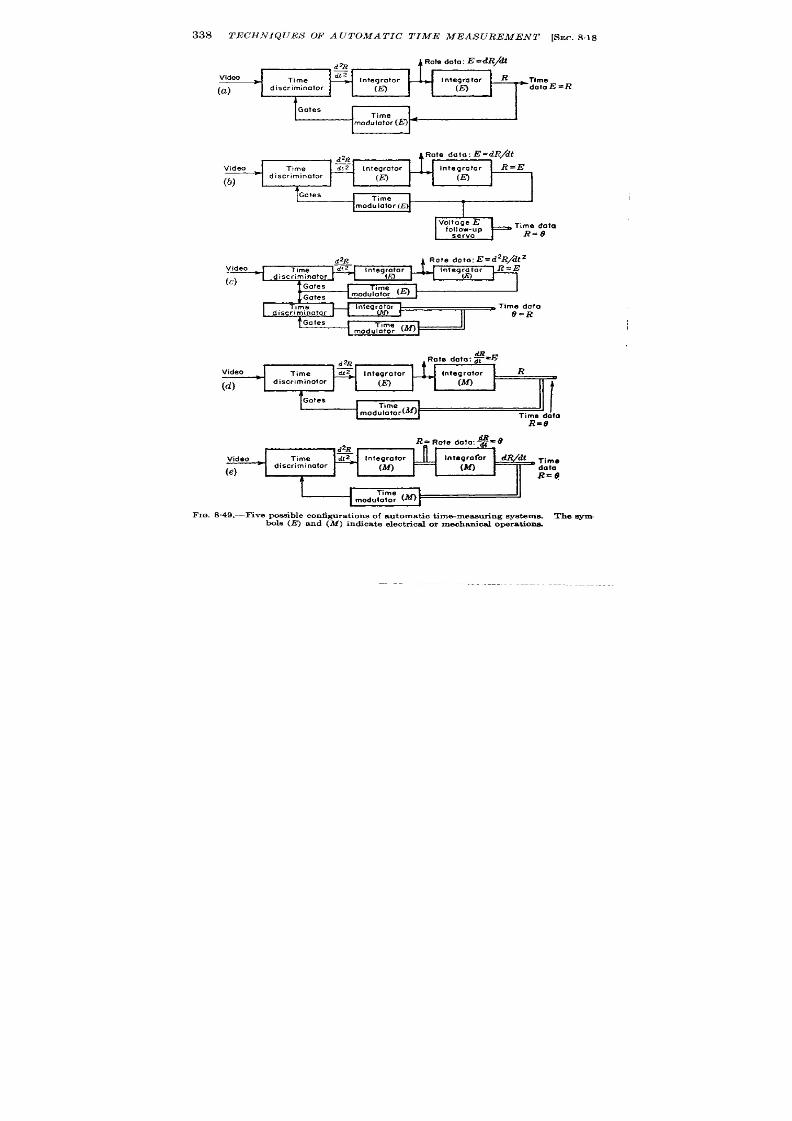
338 TECHNIQUES OF A UTOMA T IC T IME MEASUREME T [SEC.8.18
d%
Videa
z
*
Time
-
Integrator
Time
(a)
discriminator
(h’)
(m
dato E=R
A
I
Video
(c)
d2R
Rote doto:E=d2R / 6?2
i
discriminator
I
T,me
Integrator
~ Time dottz
discriminator
II
O=R
Gates
~ rnod;i~ (ml
Video R
u
(d)
I
Time dato
R=@
‘~’”
m. 8.49.—Five puss ible configu ra t ions of au toma t ic t ime-measu r ing sys t ems. The WM.
bu ls (E ) and (M) indica t e elect r ica l or mechan ica l oper a t ion s.

SEC. 8.18]
SYSTEM PLANNING
339
data ou tput s. The t ime modula tor may be single- or mult iple-scale
depending on the accuracy requ ired. A fifth system is proposed as
having capabilit ies of velocity memory limited only by the balance of the
t ime discr iminator since the mechan ical in tegra tors have no posit ion
error.
The process of determin ing the best configur~t ion for any situat ion
may be illust ra ted by discussing a hypothet ica l example.
The requ irements might be
1,
2.
3.
Maximum tracking range of 140 psec with range data accura te to
f 0.05 per cen t , and the ra te data accura te to 0.05 ~sec/sec for
ra tes of 1 psec/sec—both range and range-ra te data to be in the
form of sh aft r ot at ion s.
Provisions for manual, aided, and au tomat ic t racking.
P rovision s for slewin g at gr eat er th an 18 ~sec/sec.
Since mechanical ou tpu t data a re requ ired, the completely elect r ica l
system is ru led out , and the last system is not considered because of
the problem of stabiliza t ion involved. The accuracy specifica t ion in
range rul s ou t the elect r ica l system with voltage-to-shaft follow-up
sin ce r eliable accu ra cies of 0.05 per cen t a re n ot realizable wit h elect r ica l
t ime modu la t or s.
The field is thus reduced to type (c) or (d). The
advantages of the type (c) system are that it a llows rapid slewing and
sear ch , an d it provides smoot h accu ra te r an ge-ra te dat a fr ee fr om per iodic
er rors . 1
The apparen t disadvan tages are in the complexity and size
involved in employing two oops and the fact that with an elect r ica l in te-
gra tor defin ing the posit ion of the range ga tes they would always even -
tually (in abou t 10 rein ) dr ift t o some quiescen t poin t in range and
would not remain permanent ly at any given range withou t switch ing to
manual opera t ion . For these two reasons, he single-loop mechan ical
system was oft en select ed and has per formed sat isf a ct or il y.
Th e r ea son
for reject ing the two-loop system is never theless open to quest ion. l-
though range is stably defined by a mechanical shaft posit ion which is
per fect ly con ten t t o r emain fixed indefin it ely, t he r an ge r at e is con tr olled
by the balance of the discr iminator and the quiescen t poin t of the elect r i-
cal in tegr at or . Thus, a lth ou gh t her e is n o pr efer red posit ion , it is difficult
to maintain the qu iescen t velocit y at zero. Fur thermore, the range-ra te
accuracy of the system would only be about 2 per cen t , due in pa t to the
cyclic natu re of the range er r r s of a mult i le-scale system.
Similarly,
t he two-loop syst em wou ld be mu ch mor e su it able for a ut omat ic sea rch in g.
If, h owever , t he ra dar is t o be u sed u nder condit ion s of t arget con fu sion an d
in ter ference, au tomat ic search circu its would be useless and manual
1For t h is app lica t ion t he elect r ica l r ange-r a t e da t a wou ld be followed mechan ica lly
in eit her t ype of syst em.

340 TECHNI UES OF A UTOMA TIC TIME MEASUREMENT [SEC. 818
search should be used. Thus the only disadvantage in ta rget select ion
in tr odu ced by t he sin gle-loop syst em is t he low slewin g speeds obta in able
(3000 yd/see).
From this hypothet ica l example, the var ious factor s that en ter into
the concept ion of a t ime-measur ing system can be seen. A compar ison
of all five systems on the basis of the most usual requirements is shown in
Table 82. The column headed “Limit ing Factor” reveals two common
causes of weakness. One is tha t a mechanica l t ime modula tor must be
used to obta in high range accur cy.
The development of a highly pre-
cise elect r ica l t ime modula tor to replace the cur rent ly used capacit ance
or in du ct an ce h ase-shift er s wou ld open t he wa y t o complet ely elect ron ic
precis ion t ime-measu r ing syst ems.
The second weakness ar ises from the
need to supply data as a shaft rota t ion .
The inevitabl t r end of the
futu re toward elect r ica l computer s for high-speed solut i ns will fr ee
t ime-measur ing systems from this addit ional need for incorpora t ing
mechanical elements. But for these two weaknesses, the all-elect r ica l
system of Fig. 848a would represen t the ideal. Fo the present , the
system of Fig. 848c comes closest to the ideal in tha t it has the high
range accuracy of the mult iple-sca le mechanical t ime modula tor , the
ra te accur cy of the elect r ica l t ime modula tor , the facility a t t a rget
select ion of the elect r ica l loop, and supplies mechanical data with a
minimum of wear . Its major disadvantages a re cost and weight .
TABLE82.-COMPARISONOF TRACKINGYSTEMS
Range accuracy. Poor
Rate accuracy. Good
I
Ta rget a cqu isit ion. Good
Speed r at io.......,.. Good
Mechanicaldata , No
Wear . . . . . . . . . . . . . . . G od
J 3conomy. .,, ,, . . . . . . Good
Weight . . . . . . . . . . . . . . Good
b
Poor Good
Good Good
Good Good
Poor Poor
Yes Yes
Good Good
Poor Poor
Poor Poor
de
Good Good
Poor Poor
Poor Poor
Poor Poor
Yes
Yes
Poor Poor
Poor Poor
Poor Poor
Limit ing factor
E lect rica l t im e modu la -
t or (s ”ngle s ca le)
Cyclic er ror s of t ime
modulator
Mechan ica l mot ion
Mechan ica l mot ion
Mechan ica l mot ion
Slewing done mechan-
ically
Mechan ica l e lemen t s
Mechan ica l e lemen t s

CHAPTER 9
SYSTEMS FOR AUTOMATIC TIME AND
POSITION MEASUREMENT
BY R. . HULSIZER, J . V. HOLDAM, AND W. B. JONES
PRACTI AL SYSTEMS FOR AUTOMATIC TIME MEASUREMENT
BY R. I. HULSIZER
In the light of ret rospect ion , every piece of equipment appears
cover ed wit h t he fin ger pr in ts of t he design er .
There is often aa much ar t
as science in the design of pract ical circu it s for per forming a par t icular
operat ion . In addit ion to this factor , the development dur ing the war
was marked by two further diversifying effect s. One was the necessity
of building usefu l military equipment before adequate study and exper i-
ment had led to sat isfactor ily systemat ized theor ies of design, and the
other was the t ime delay in diffusion of improvements in the theor ies of
design . As a result , t he systems for au tomat ic t ime measu ement often
show lit t le similar ity to each other and less resemblance to design based
on an y gen er al pr in ciples n ow available.
Alt hou gh five con figu ra tion s of syst ems wer e pr esen ted in t he pr eviou s
chapter , t he pract ical systems to be discussed are divided in to only two
gr ou ps, t he simple elect rica l and t he simple elect romech anical, for all t he
more complex forms can be der ived from these.
Before a discussion of the more convent iona l systems, two simple
techniques par t icu lar ly adaptable to laboratory measurements will be
ment ioned. The simpler involves the simplest method tha t one can con-
ceiv~the “lean ing gate” system in which a single t ime selector is made
to dr ift in range unt il it in t ersect s enough of a signal to cancel the drift
act ion. This is exemplified by the Brit ish systems, AGL-(T) and A.1.
Mark VIA, both of which have been ment ioned in Chap. 8. These
systems per form with a minimum of circu it s the funct ions of search ,
lock-on , and t rack. They are limited in accuracy since the single-gated
t ime discr iminator is sensit ive t o signal and noise amplitude.
A second technique which is simple and yet capable of ext reme accu-
ra cy is t hat of ph ot ogr aph in g a cir cu la r sweep displ a y“wit h a movie camera
and later plot t ing the data . No t racking circu its a re required and
systemat ic er rors can be removed from the data .
It is, of cou rse, limit ed
t o applicat ions wh er e instan taneous data are not required, as in det ermin-
ing the velocity of t est models of aircraft
341

342
S YSTl lh fS FOR A (J 7’OMA I’IC l’IME M.EASUREMA’ArT [SEC. 91
The demand for instantaneous and accura te data has led to the design
of the conven t ional systems in genera l use.
Th e first group discussed
will be the elect r ica l systems as exemplified by the Br it ish Oboe system
and the ARO (Automat c Range Only), used in the AN/APG-5, AN /APG-
15. The second group are the systems employing mechan ical t ime modu-
la tors direct ly in the t rac ing loop and will be illust ra ted la ter .
9.1. ARO Elect r ica l System.—The t ime dkcr iminator and the au to-
mat c search circu its for th is system have been discussed in Sees. 813
and 8.18 respect ive y; th er efore a br ief descr ipt ion will be adequate here.
In order to illust ra te the design considera t ions, the ch ief subject of dis-
cussion will be the modifica t ions that were made on the ARO Mark I
in a developmen t program aimed at reducing the size, weigh t , power con -
Video
Time
se18ct0r
1= I
Detector
Trigger
Time
4
Gate
-
modulator
generator
Ronge
Time
)i
control
selector
t ‘1
Oe!ectw
Camwtor
voltage
Function
unit
L
+ .JE
Manuel
torget
selector
Receiver
AVC
On- arget
detector
detector
Relay
Sawtcdh
generator
=
Fr~. 9.1.—ARO range syst em block d iagr am, Mark I and Mark II.
sumpt ion, and complexity of the circu its. The resu ltant design was
known as the ARO Mark II or Midget ARO.
The block diagram of the circu it remained unchanged and is shown in
Fig. 9.1. The schemat ic diagram of the ear lier circu it is shown in
Fig. 9.2. The circu it consist s of a delay mult ivibra tor as a t ime modu-
la tor , followed by a blocking oscilla tor t o form the ear ly gate and to
t r igger a similar blocking oscilla tor that forms the la te gate. The t ime
select or s a r e supp ressor -ga t ed 6AC7’S.
Pulse t ransformers in the pla tes
of the t ime selectors inver t the ga ted pulses so that they dr ive two t r iode
det ectors whose difference cur ren t produces a net voltage on the la rge
condenser C,. A ca thode follower with a constan t -cur ren t pen tode aa a
cathode load p ovides the range voltage for the delay mult ivibra tor
and the range followup servomechan ism at low impedance and also

lest gate
Video Oelayed wdeo
*1
;;
,,
II
11
ii
,,
,,
II
,,
P
_ ..
lipper
B buffer
6SN7
lk
. . .
16 k < km
I 5 #l
1,
I Trigger
00:
}-. -___---:
1’
;;;––––--mq
:ollwer
7.
. . .
30k
II Go
Rmoa,
,s IOk ‘“l * :
. . .
.-.
:Uy,l:lnl \
y “<’”41 ;
6SJ7 .nc,,m ,
7
““!1 I
C?CN~;~;:
Hreststom are
2unless other-
,use,ndicoted.
.
L__-––-_--’- _::_____-:_.lw YJ -:_----lwYJ
F IG.92.-ARO Mark I r ange sys tem; dot t ed lin es ind ica t e t h e funct ion a l block s of t h e c r cu it .
They a r e t h e t ime modul at or , ga t e gene ra -
tor , t ime selector s , d iffe rence detector s , funct ion un it , on the top row, t a rge t detector andrange sea rch d isconnect inthen ,idd le , and AGC and
r ange s ea r ch in t h e bot t om row .

344
S YSTEMS FOR A UTOMA TIC TIME MEASUREMENT [%c. 91
provides suitable biases for the t r iode difference detector s. As alre dy
descr ibed in Sec. 8.17 on-ta rget indicat ion is per formed by two “infin ite
impedance” detector s with a common ca thode resistor fed by the two
ga ted signals. The larger signal cen t rols the detector ou tpu t voltage.
If th is voltage exceeds the threshol , it closes a relay which connect s
either a search-sawtooth or manual ta rget -selector on t rol to the range
voltage whenever the signal is below the preset threshold. The AGC
circu it is a th ird in fin it e-impedance detector fed by the sum of the two
“F ro. 9.3.—ARO Ma rk I r an ge u nit (a ) t op view; (b) bot tom view. Dimen sion s: 15% X
994 in .
ga ted video pulses and operat ing a d-c amplifier and an outpu t cathode
follower.
F igure 93 shows the completed Mark I ARO chassis. The useful
area of the chassis is 15+ in . by 9: in ., or 150 in . z
An est imate of power
consumpt ion from the circu it diagram shows about 65 ma from the +400
bus including the regu la ted cu rren t , and 30 ma from the negat ive bus.
F igure 9.4 shows the schema of the Mark II ARO and Fi . 95 shows
the const ructed chassis. The est imated cur ren t dra in is 30 ma from the
posi ive supply and 10 ma from the nega t ive supply. The chassis
pla te has a usefu l size of 1l+ in , by 6* in . or 75 in . z The rela t ive densit ies
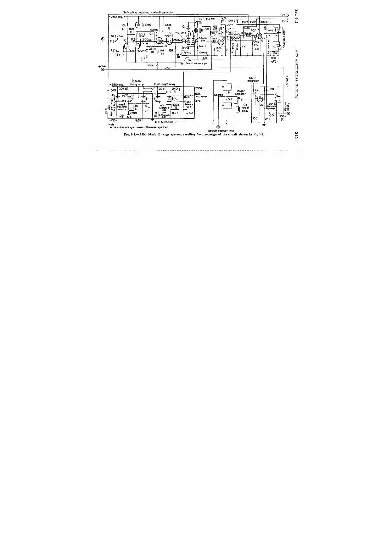
Self- gotmg boofstrop sawtooth generator
.7 =0,,
,
100(l)
1
Note
All resistors ore !Z2w unless olherwise specified.
200 k
50k
&vClevel
47 k
6AK5
($’
Search sowiooth input
Fm. 9.4.—ARO Ma rk I I r a nge s ys tem , r es ult in g fr om r ed es ign of t he cir cu it sh own in F ig 9.2

I
346
SYS TEMS FO12 AUTOMATIC TIME MEASUREMENT [SEC.9.1
of the two const ruct ions give meaning to the size compar ison. As
poin ted out previously, the block diagram remains almost ident ical.
The saving came in simp ifica t ion of t he circuits and use of smaller tubes
.,.
0
G
1
ti
and components If the development of the Mark II had cont inued
longer , 6AL5 diodes and minia ture VR tubes would have been ava ilable
to replace all the la rge tubes used except the 5Y3. A fea ture of not e is
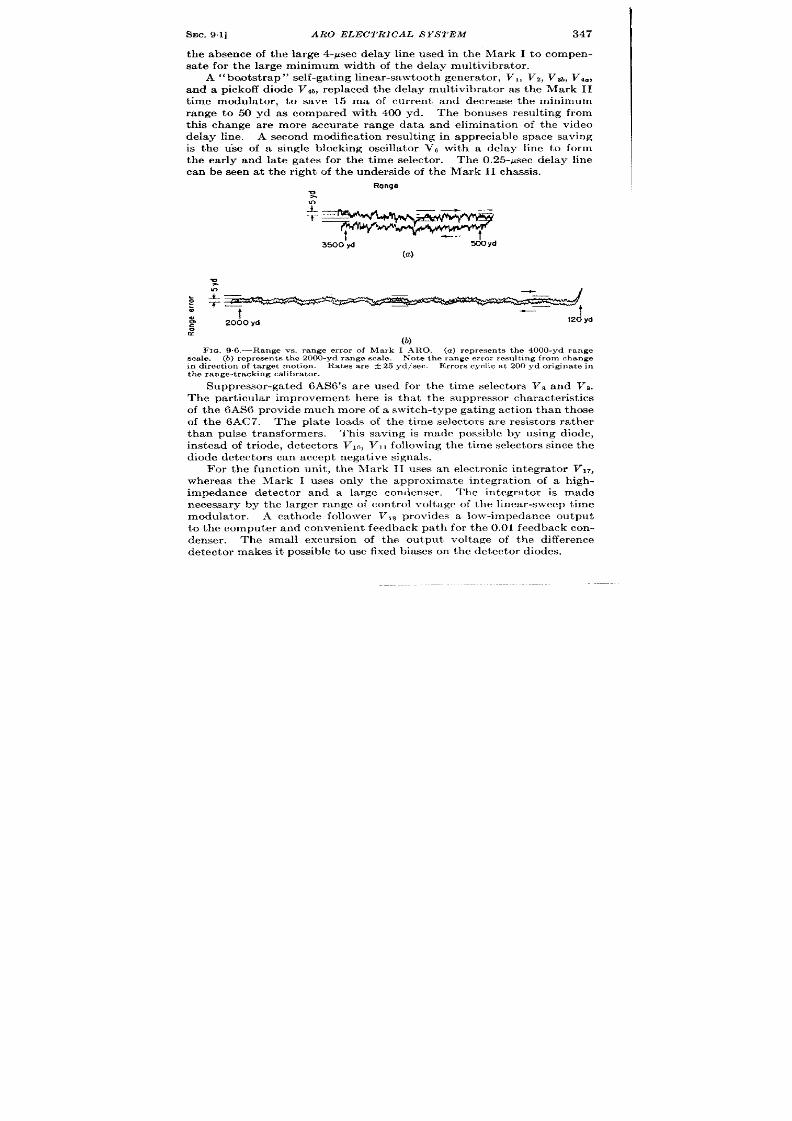
SEC. 9.1]
ARO ELECTRICAL SYSTEM
347
the absence of thela rge4-~sec delay ine used in the Mark I tocompen-
sa te for the large minimum width of the delay mult ivibra tor .
A“bo.ot st ra p” self-ga tin g lin ea r-sawt oot h gen er at or , VI, V2, V3b,V4.,
and apickoff diode Vl~, replaced the delay mult ivibra tor as the Mark II
t ime modula tor . to save 15 ma of cur r e t and decrease the minimum
range to 50 yd as compared with 400 yd. The bonuses result ing from
this change are more accura te range data and eliminat ion of t e video
delay line. A second modifica t ion result ing in appreciable space saving
is the use of a single blocking oscilla tor VC with a delay line to form
the ear ly and la te ga tes for the t ime selector . The 0.25-psec delay line
can be seen at the r ight of the underside of the Mark II chassis.
Range
3500’yd
do yd
(a )
(b)
F IG, 9.6.—Ra nge vs. r an ge er ror of Ma rk I AFtO. (a ) r epr esen ts t he 4000-yd r an ge
s ca le. (b) r ep res en t s t h e 2000-yd r ange s ca le.
Not e t h e r ange er r or r esult ing fr om change
in dir ect ion of t ar get mot ion . Ra tes a re A25 yd/sec.
E r r or s cyclic a t 200 yd or igin a t e in
the range-tracking cal ibrator .
Suppressor -ga ted 6AS6’S are used for the t ime selector s Va and Vg.
The par t icular improvement here is tha t the suppressor character ist ics
of the 6AS6 provide much more of a switch-type gat ing act ion than those
of the 6AC7. The pla te loads of the t ime selector s are resistor s r a ther
than pulse t ransformers. This saving is made possible by using diode,
in st ea d of t riode, det ect or s Vlo, Vll followin g t he t ime select or s sin ce t he
diode det ect or s ca n a ccept negat ive signals.
For the funct ion unit , the Mark 11 uses an elect ronic in tegra tor V17,
whereas the Mark I uses only the approximate in tegra t ion of a high-
impedance det ector and a la rge condenser .
The integr a tor is made
necessa ry by the la rger range of cont rol voltage of the linea r-sweep t ime
modula tor . A cathode follower Vls provides a low-impedance output
to the computer and convenien t feedback path for the 0.01 feedback con-
denser . The small excursion of the output voltage of the difference
det ect or makes it possible t o use fixed biases on t he det ect or diodes.
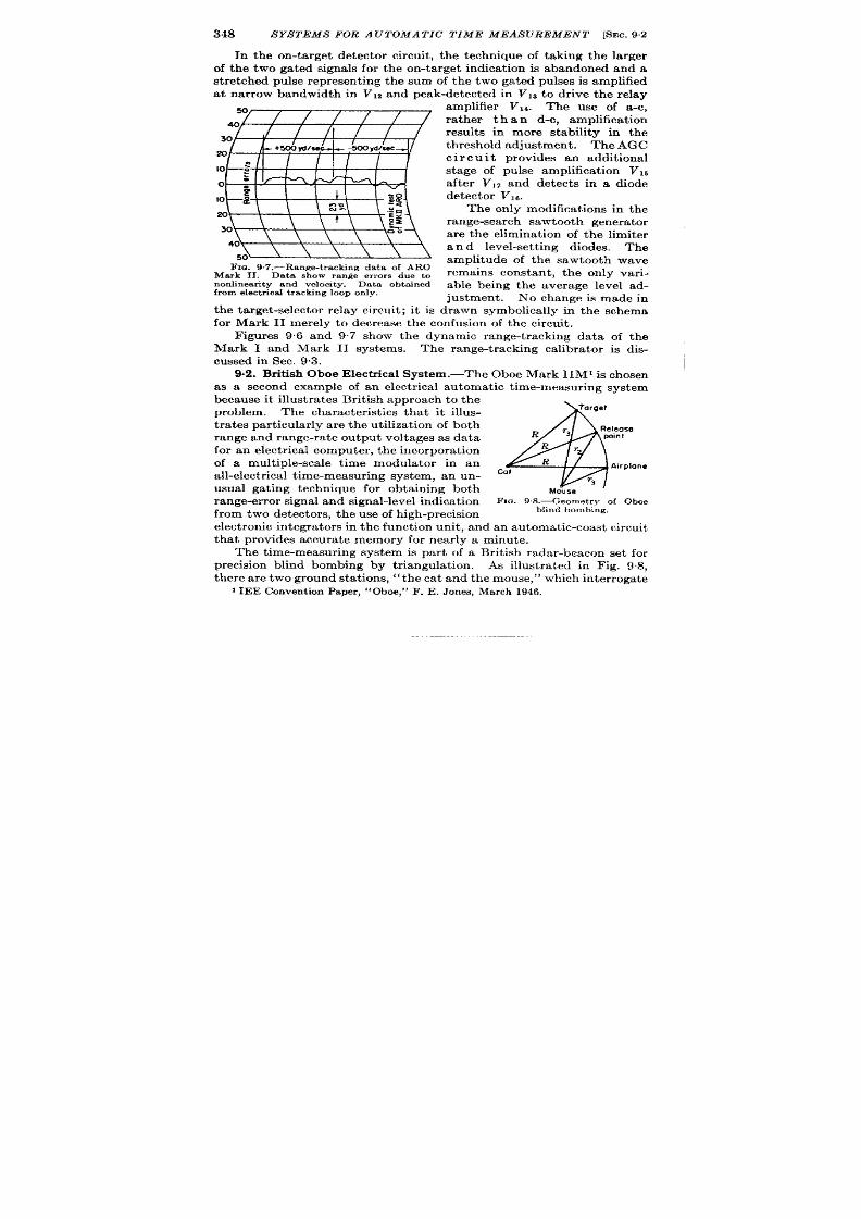
348
SYSTEMS FOR A UTOMA TIC TIME MEASUREMENT [SEC. 92
In the on-t a rget detector circuit , t he technique of taking the la rger
of the two ga ted signals for the on-t a rget indica t ion is abandoned and a
st r et ched pulse represent ing the sum of the t wo gated pulses is amplified
a t na r row bandwidth in VI* and peak-detected in VIS to dr ive the relay
F I . 9.7.—Range-t r ack ing da t a of ARO
Mark II. Data show range er ror s due to
nonhnea r it y and velocit y.
Da ta obt ain ed
from elect r ica l t rack ing loop only.
amplifier V14.
The use of a -c,
ra ther than d-c, amplifica t ion
result s in more stability in the
th reshold adjustment . The AGC
c i r c u i t provides an addit ional
st age of pulse amplifica t ion VIE
a ft er VIZ and det ect s in a diode
detector VIC.
The only modifica t ions in the
r an ge-sea rch sawt oot h gen er at or
a re the eliminat ion of the imiter
a n d level-set t ing diodes.
The
amplitude of the sawtooth wave
remains constant , the only var i-
able being the average level ad-
the ta rget -selector relay circuit ; it is drawn symbolica lly in the schema
for Mark II merely to decrea se the confusion of the circuit .
F igures 9.6 and 97 show the dynamic ange-t racking data of the
Mark I and Mark II systems. The r nge-t racking calibra tor is dis-
cussed in Sec. 9.3.
9.2. Br it ish Oboe Elect r ica System.—The Oboe Mark IIM1 is chosen
as a second example of an elect r ica l automat ic t ime-measur ing system
because it illust ra tes Br it ish approach to the
problem.
The character ist ics tha t it illus-
4
Target
t ra t s par t icu lar ly a re t he ut iliza t ion of both
Release
T3
range and range-ra t e ou tput voltages as data
R
point
for a n elect rica l compu ter , t he in cor por at ion
Rr
of a mult iple-sca le t ime mod la tor in an
R
Arrplone
a ll-elect rica l t im e-m ea su ring syst em , an u n-
Ca l
V3
usual ga t ing techn ique for obta in ing both
M e
range-er ror signa l and s igna l-level indica t ion
FIG. 9+3-Geometry of Oboe
fr om two det ect or s, t h u se of h igh -pr ecision
blind bombing.
elect ron ic in tegr at or s in t he fu nct ion un it , an d a n a ut omat ic-coa st cir cu it
tha t provide accura te memory for nea r ly a minute.
The t ime-measur ing system is pa r t of a Br it ish rada r -beacon set for
precision blind bombing by t r iangula t ion . As illust ra ted in F ig. 98,
there a re two ground sta t ions, “the ca t and the mouse,” which in ter roga te
I IEE Conven t ion Paper ,
‘i Oboe,” F. E. J ones, March 1946.

SEC. 9.2]
OBOE ELECTRICAL SYSTEM 349
a beacon responder in the airplane.
The ca t sta t ion au tomat ica ll
t r ac s the received signal, compares it s range with the distance of the
cat from the ta rget and transmit s a signal t o the pilot to keep him flying
on a circu lar cou r e passing th rough the t arget . The mouse sta t ion
automat ica lly measures the aircraft range and range ra t e which are
compared in a computer to etermine the bomb-release poin t . Repor t s
indicate that the accuracy of range measurement is about five yards, a t
a l ranges ou t to 350 miles, and bombing accuracy is 12 to 25 circu la r
roils. Thehigh precision oft imemodula t ion necessa ry to produce these
resu lts is obta ined by the use of a step delay which select s any one of
E2
i ‘ “ ’ ”I - - - - 4
ntegrator
Fiva-
.& pRF
miIe
CRT grid
Manual ~--6~k2
~ pulse pies cent rol
CRT
1,1 ‘~ 1
,
Torget marker cathode
Five mile
Act iv:efi;ion
Tar et
?
Target
Tmck-
selec!or
mar er
marker ing
phantastron
phantostrm
generator
gate
Manual
/
n.x5
marker
,,
cent rol miles
E,=R
I
(
J 1
Tracking
gate
I
Gole
phontastmn
generator
L
J
1
Short
gate
F- ——----_--__ —___
-----
____
t
I
1
Velocity I
Gafed
I
Integrator
detector
Lo g ~
:
y
gote I
~
-
Goost confrol ~
2
Video
I
Manual mnqe On-;:l:~t I
and coast
1
circuits
amplifier
I
t
I
Time discriminator
I
Manual
L--- —_--–_— ———_— —______ --l
control
FIG. 9.9.—Obcw range-tracking system block diagram.
70 five-mile crysta l-con t rolled markers to form a t r ig er for a t racking
phantast ron that is posit ioned by the t ime discr iminator and works on ly
over a region of 16 miles cen tered on the target .
F igure 9.9 shows the block diagram of the system which can opera te
as either ca t or mouse sta t ion . The top row of blocks shows the t ime
modu la t or . Th e n ecessa ry alignmen t pr ocess for su pplyin g stan dardized
data to the computers is descr ibed in the remainder of th is paragraph .
The t racking-gate phan tast ron con t rol is set at +165 volt s, it s middle
value, and the 5-mile selector and the act ive-region delay phan tast ron
are adjusted to place the t racking-ga te marker a t the range of the ta rget
as determined from maps. This set t ing is made with the use of an
A-scope display that has accura te 5- and l-mile in tensity markers. The
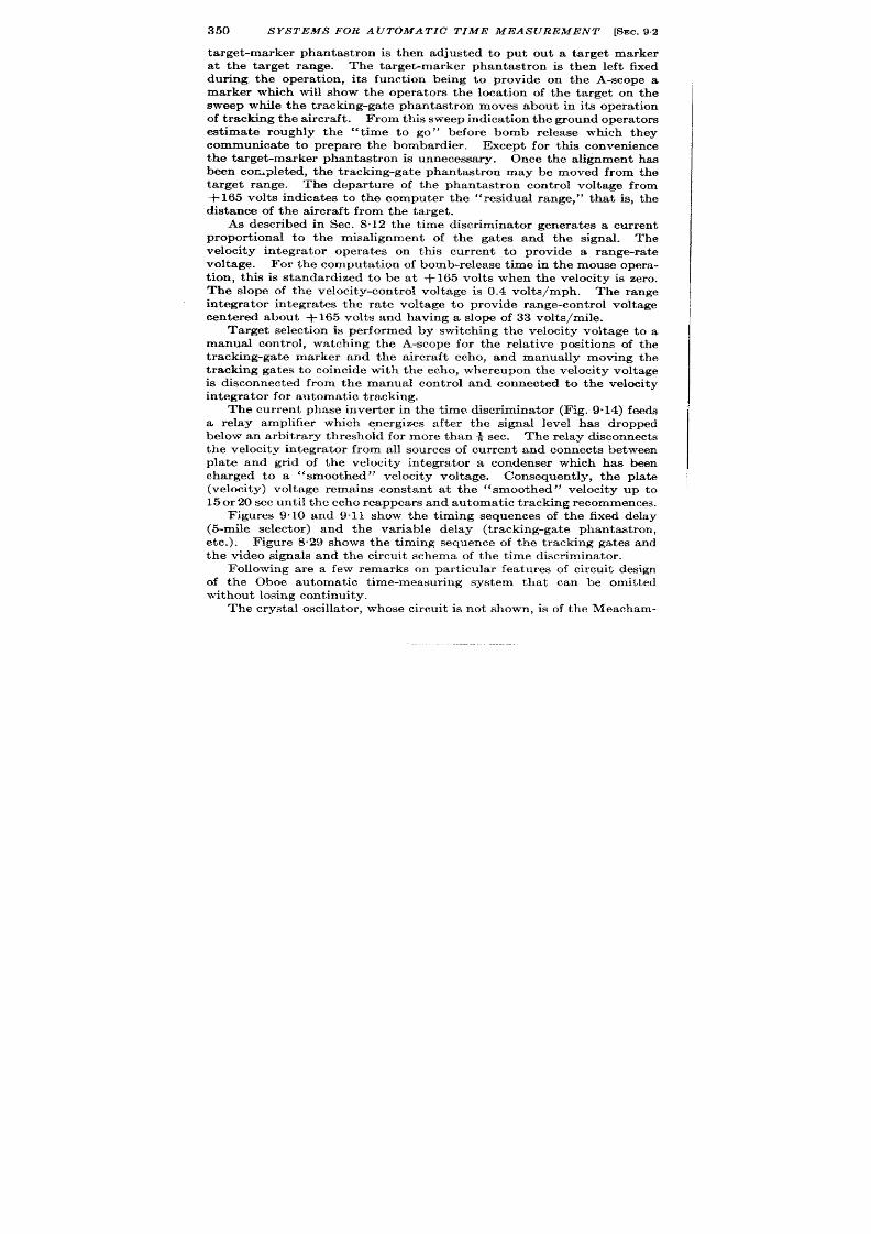
350
S YA5’TEMS FOR A UTOMA TIC TIME MEAS UREMENT [SEC.92
target -marker phantast ron is then adjusted to put ou t a ta rget marker
at the ta rget range. The ta rget -marker phan tast ron is then left fixed
dur ing the opera t ion , it s funct ion being to provide on the A-scope a
marker which will show the opera tors the locat ion of the target on the
sweep while the t racking-gate phan tast ron moves about in its opera t ion
of t racking the aircraft . From this sweep indicat ion the groun d opera tors
est imate roughly the “t ime to go” before bomb release which they
commun cate to prepare the bombardier . Except for th is conven ience
the target -marker phan tast ron is unnecessary. Once the alignment has
been cor -pleted, the t racking-gate phan tast ron may e moved from the
ta rget range. The depar tu re of the phantast ron cont rol voltage from
i-165 volt s indicates to the computer the “residual range,” that is, the
distance of the aircraft from the target .
As descr ibed in Sec. 8.12 the t ime discr iminator genera tes a cur ren t
propor t ional to the misalignment of the gates nd the signal. The
velocity in tegra tor opera tes on this cur ren t to provide a range-ra te
voltage. For th computat ion of bomb-release t ime in the mouse opera -
t ion , th is is standardized to be at +165 volts when the velocity is zero.
The slope of the velocity-con t rol voltage is 0.4 volts/mph. The range
in tegra tor in tegra tes the ra te voltage to provide range-con t rol voltage
cen tered about +165 volts and having a slope of 33 volts/mile.
Target select ion is performed by switch ing the velocity voltage to a
manual con t rol, watching the A-scope for the rela t ive posit ions of the
t racking-gate marker and the aircraft echo, and manually moving the
t racking gates to coincide with the echo, whereu pon th e velocity voltage
is disconnected from the manual con t rol and connected to the velocity
in tegr at or for au toma tic t ra ckin g.
The cur ren t phase inver t er in the t ime discr iminator (Fig. 9.14) feeds
a relay amplifier which energizes after the signal level has dropped
below an arbit rary th reshold for more than ~ sec. The relay disconnect s
the velocity in tegra tor from all source of cur ren t and connect s between
plate and gr id of the velocity in tegra tor a condenser which has been
charged to a
“smoothed” velocity voltage. Consequen t ly, the pla te
(velocity) voltage remains constant a t the “smoothed” velocity up to
15 or 20 sec u nt il t he ech o r ea ppea rs a nd au toma tic t ra ckin g r ecommen ces.
F igures 9.10 and 9.11 show the t iming sequences of the fixed delay
(5-mile selector ) and the var iable delay (t racking-gate phantast ron ,
etc.). F igure 8.29 shows the t iming sequence of th t racking ga tes and
the video signals and the circu it schema of the t ime discr iminator .
Following are a few remarks on par t icu lar fea tu res of circu it design
of the Oboe au tomat ic t ime-measur ing system that can be omit ted
withou t losing con t inu it y.
The crysta l oscilla tor , whose circu it is not shown, is of th e Meacham-
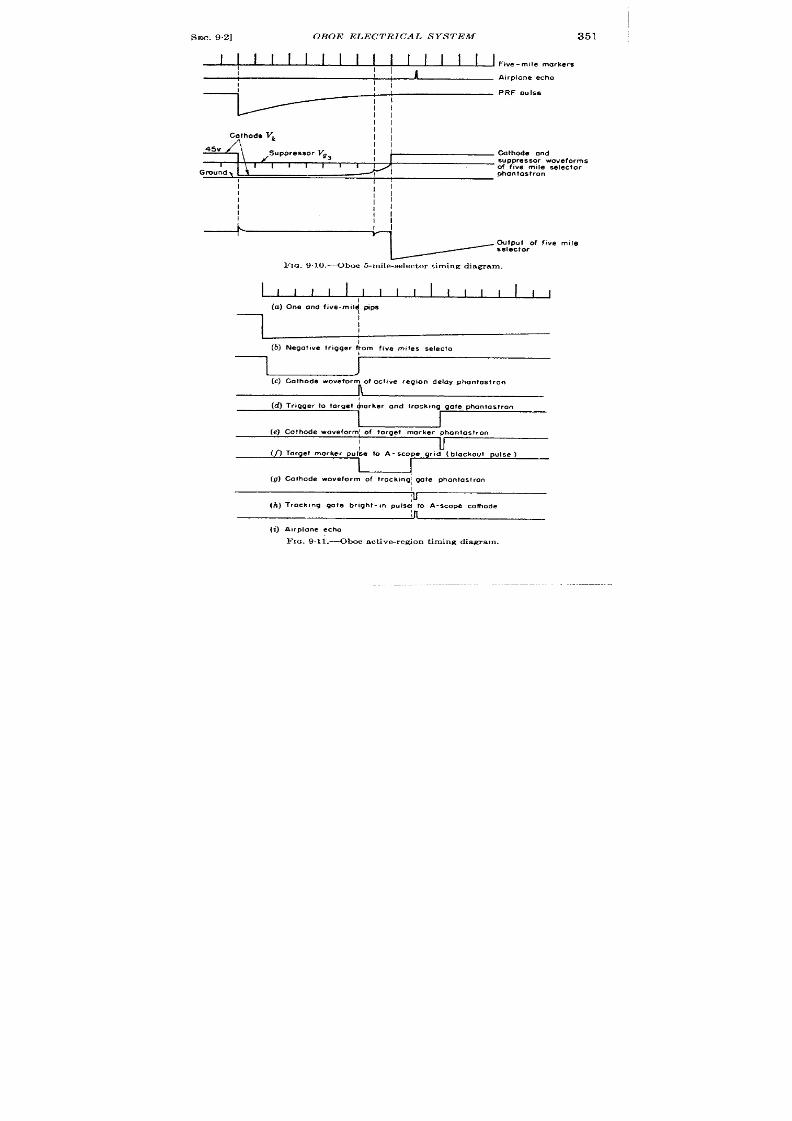
SEC. 9.2]
OBOE ELECTRICAL SYSTEM
351
I 1 I
I
I I I
I I
I
I I
I I
I I
Five-mile markers
I
II
Airplane echo
II
I
P F cmle.e
II
II
II
[
I
I
45V
II
Cathode ond
I
suppressor wove forms
1
\’
I
[ I
I
I
I
{
of five m,le selector
Gmundl
phanfostron
Ii
I
I
1,
I
II
II
I
II
L
I
v
output of f,v~ m,l~
selector
Fm. 9.10,—Oboe 5-mile-selector t iming diagram.
I I I I I
1
I I
1111,11,
1
(a) One and five-mil~ tips
I
(b) Negot,ve trigger ~om five m,!es SeIecIo
r
I
J
(c)Cathode woveform of octnve reg,on delay phontostron
(d) Tr,gger to target $arker ond lrack,ng gate phontastron
I
J
(e) Cathode wove form; of Iorget morker phontosl,on
I
II
u
(n Target morker pu{se to A - scope gr, d ( blackout
pulse )
I
{
(9) Colhode ~oveform of trockmg; gate phantaslron
\
u
(h) Trock ,.g gale bright- ,n p.ls~ to A-scope cathode
(i) A,rplane echo
FIQ. 9.11 .—Oboe active-region t iming diagram,
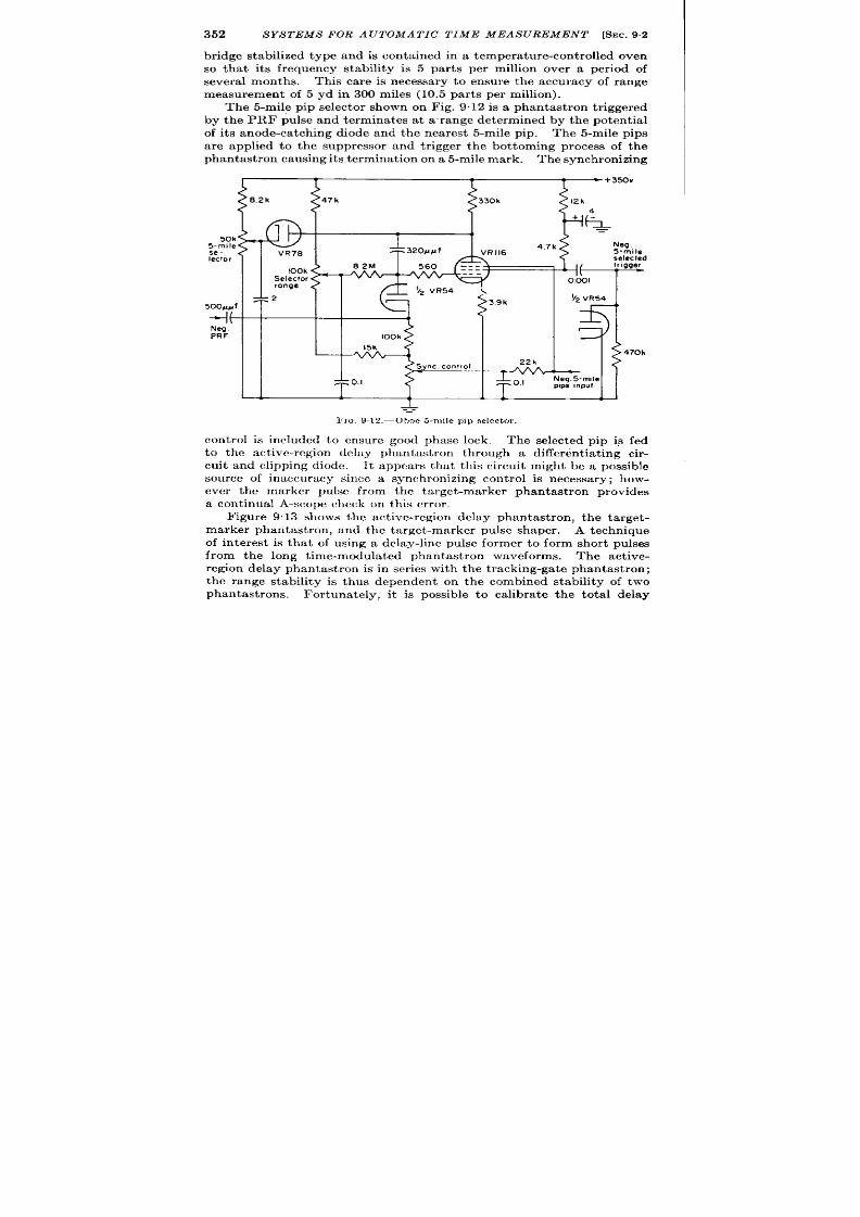
352
SYSTEMS FOR A UTOMA TIC TIME MEASUREMENT [SEC. 9,2
br idge stabilized type and is con ta ined in a tempera tu re-con t rolled oven
so that it s frequency stability is 5 par ts per million over a per iod of
severa l months. This care is necessary to ensure the accuracy of range
measurement of 5 yd in 300 miles (10.5 par ts per million).
The 5-mile pip selector shown on Fig. 9.12 is a phan tast ron t r iggered
by the PRF pulse and terminates at a r ange determined by the poten t ial
of it s anode-catch ing diode and the nearest 5-mile pip. The 5-mile pips
are applied to the suppressor and t r igger the bot toming process of the
ph an tast ron causing its termin at ion on a 5-mile mark. Th e syn chron izin g
47k
50k
5-m,le
se-
Iecto
selected
100k
Selector
range
5ooJl#f
-I(
Neq.
PRF
100k
I
L
1 1
1 1
1
1
~
—
F IG. 912,-Oboe 5-m ile pip selector.
cont rol is included to ensure good phase lock.
The selected pip is
to the act ive-r egion clcloy phantas ron through a differen t ia t ing
fed
cir-
cuit and clipping diode. It appears that th is circu it might be a po~s ble
source of inaccuracy since a synchronizing cont rol is necessary; how-
ever the marker pulse from the target -marker phantast ron provides
a cont inual A-scope check on this er ror .
Figure 9.13 shows the act ive-region delay phan tast ron , the target -
marker phantast ron, and the target -marker pu lse shaper .
A techn ique
of in terest is that of using a delay-line pulse former to form hor t pulses
from the long t ime-modula ted phantast ron waveforms. The act ive-
r egion delay ph an tast ron is in ser ies with t he t racking-gat e phantast ron;
the range stability is thus dependen t on the combined stability of two
phantast rons. For tunately, it is possible to calibrate the tota l delay

Trig er amphfmf Act ive-reqion
Trigger Torget-morh
Torget-mark
.–,– —..—.—–.—
.,
owoy pnonrasrm.n
ompm,er pnOn!Oslrcn
snoper
Stabi lized z50v+
350” +
1
J
I
/1
k
IIIK I
I
1
I I I
I I
1
I
I 1
Active Active
4k
4k 2M
;%? ~:;
39k
39k
-Iov
+
-35V
1
1
-400V
I
43
Trock,ng gote trigger
fiG. 9.13.—Oboe act ive-region delay phantas t ron, target-marker phantas t ron, and target-marker pulse shaper .
I
m
=
-
I
f!Ec. 9.2]
OBOE ELECTRICAL S YSTEM 355
against the cry ta l pips just before the star t of each run so that stability
requ ired of the phan tast rons is of shor t dura t ion only.
In Fig. 9“14 is shown the t racking-gate phan tast ron VT that is of
conven t ional type. Its pla te-ca tch ing diode Vs is con t rolled by the
range in tegra tor which in tu rn is con t rolled either by the velocity tube
or by a manual con t rol, depending on the mode of opera t ion . The pla te
of the phantast ron tube is retu rned to +1000 volts to increase its linear-
ity in the opera t ing range. Insula t ion breakdown of the tube is pr e-
ven ted y the diode VE, which limits the pla te swing to +350 volts.
The limita t ion of having the t ime modula t ion con tinuous over only a
shor t r ange is tolerable for th i par t icu lar system and it permits the
t racking loop to be completely el ct r ica l without reducing the precision
of th e system.
The rest of the circu it s on Fig. 9.14 have to do with the au tomat ic
con t rol of the t ime modula t ion . The t ime discr iminator is discussed in
Sec. 8.12 (Fig 8.29) and is seen to deliver two cur ren ts whose difference
is propor t ional to the misa l gnment of the range gates and the echo.
These curren ts are indica ted as il and iz. When the target is cor r ect ly
loca ted in the gates, iz is twice as large as i, because its ga te is twice as
wide as the shor t ga te and extends over the whole echo, Thus iz is a
t rue ind cat ion of echo in tensity and will not change for small mot ions of
the gate with r espect to the echo. The t racking loop then compares
half the cur ren t due to signal level with the cur ren t from a ga ted detector
wh ich ext en ds over on ly t he fir st por tion of t he sign al an d t im e-modu la tes
the gates to make these two quant it ies equal.
The tube VI is a cu r r en t inver t er .
If the gain of VI is assumed to be
infin ite, it can be said that the gr id of VI remains fixed (a vir tu al gr ou nd
as discussed in Sec. 8.8) and hence the cur ren t flowing in RI must be
equal to and opposite ij. If the voltage at A which produces th is equal
and opposite cur ren t is halved, the cur ren t which flows through Rz, t o a
poten t ia l equal to tha t of the gr id of Vl, must be equal an opposite to
iz/2 sin ce RI equals Rt . This cur ren t –iz/2 is added to il a t the gr id
of th e velocity in tegr ator Vs which in tegra tes the difference cu r ren t to
su pply a velocity voltage Ve. This voltage is in tegra ted in turn by VA
t o form the range voltage which con t rols the phantast ron . he zero-
velocity cont rol Ra adjusts the gr id potent ia l of Vt so that when il = iZ/2,
the pla te of Vs is at +165 volts, the standard for zero velocity. When
i ~ becomes grea ter or less than —i2/2, the pla te poten t ia l of V3 must
change at a ra te which will balance the diffe ence cu r ren t by an equal and
opposite displacement cur ren t th rough Cl. This unbalance of cur ren t s
might be due to mot ion of the ta rget , and the change of the velocity
voltage will ca se the range volt age to move at a ra te which will keep
the t racking gates a ligned on the ta rget . The zero-range con t rol is

356
S YS TEMS FOR A UTOMA TIC TIME MEASUREMENT [SEC.92
adjusted so tha t when the velocity voltage equals +165 volts, the pla te
of V1 is a t +165 volts.
The automat ic-coast per t ion is discussed in the following para-
graph. If the signa l fades, t he velocity volt age will fa ll t o + 165 volt s
with a t ime constan t of severa l seconds.
However , t he pla te of V, will
fa ll and will cause the pla te of V, to fa ll with a t ime constan t such that the
relay will actua te + sec after the signal fades. When the relay energizes,
the th ree switches a round Va th row from the automat ic posit ion to the
coast posit ion During au tomat ic opera t ion , the velocity voltage
charges C2 through a 2-see t ime constan t .
When the switches th row
to coast , th is condenser is connected from pla te to gr id of Vi and all
the sources of cu r ren t are removed.
Since Cz is charged with r espect
to the normal gr id bias of Va, the poten t ia l across C, is closely equal to the
mean poten t ia l difference between the pla te and gr id of Vs over the
preceding two seconds, no cur ren t will flow in to C2, and the pla te must
stay at the smoothed velocity voltage except for leakage cur ren ts.
Dur ing the ~-sec lag befor e the relay th rows, the voltage on C, does not
change appreciably because of the smooth in effects of the in tegra tor
and the smooth ing network . The velocity memory under coast condi-
t ions is good enough to preven t the in t roduct ion of a significant er ror in
bombing under opera t ional condit ions if the echo fades 15 sec befor e
bomb release, provided the pilot maintains constan t velocity. The
advantage of using au tomat ic coast is tha t unbalance of the t ime dis
cr imina tor due to dr ift s in gain or level of any oj the com ponen ts cannot
in tr odu ce a fa lse velocit y sin ce t he t im e discr im in at or is discon nect ed.
It will be recogn ized, of c urse, that leakage c r ren ts in the range
in tegra tor Vi will have as ser ious effect s as those in Va, for it is assumed
that by main tain ing V. constant , the ra te of V, will r emain unchanged.
This can on ly happen if Vi acts as a t rue in tegra tor . The most ser ious
source of leakage cur ren t in th is stage is the 4-~f feedback condenser .
The specifica t ions call for a condenser having 2000-megohm leakage
resistance, and in a la ter model a mica condenser was used.
Ther e a re severa l suggest ions tha t have been made for revising th is
circuit.
One is to replace the target -marker phantast ron and the t rack-
ing-gate phantastron with a single linear sawtooth genera tor and a pair
of” mult ia r” or r egen er at ive amplitude compar ator s of th e t ype descr ibed
in Chap. 5. Another is to select the 5-mile pu lses in a double-va lued
t ime selector ra the than by adding them to the phan tast r n waveform
and amplitude select ing as in the presen t Smile pulse selector .
It is
a lso felt that O.l-mile pu lses would increase the accuracy of calibra t ion
and these cou ld” be obta ined by mult iplying up from the presen t l-mile
pulses. A time discr iminator of the type descr ibed in Sec. 8.13 would be
used but no improvement in the elect r ica l in tegra tor s except the use of

SEC.9.3]
ELECTROMECHAN ICAL S YS TEMS
357
mica conden ser s ca n be for eseen since limit ing condit ions of oper at ion a re
a lready employed .
An inter es ing accessory to the Oboe system is a dynamic t r cking
tester for test ing the automat ic-t r acking opera t ion and calibra t ing the
slope o V. against velocity. It consist s of an elect ron ic in tegr tor
con tr ollin g a ph an ta st ron whose ou tpu t t rigger s a va ria ble-widt h va ria ble-
amplitu de video pu lse gen er at or .
By varying the input volt age to the
integra tor , the dummy signal can be made to move at ra tes from +3o0
mph to —300 mph over any por t ion of the 350-mile range.
The velocity
of the dummy signal can be checked against the accura te range markers
with a stop watch and the velocity voltage calibra ted.
9.3. E ect romechanica l Systems.—The class of systems in which a
mechanic l t ime modula tor is employed in t he pr imar y signa l-following
loop may be ca lled “elect r omechanica l”
and is exemplified pr imar ily by
some of the h igh-precision au tomat ic range-t r acking systems.
These
systems, like the Oboe, r ely on shor t velocity memory (2 see) from the
ir st in tegra tor and some sor t of coast circu it for long-t ime elocity
memory.
The coast circuit s often act t o keep the r a te voltage of the
a ided-t r acking mechanism equa l to the r a te of the ta rget as measured in
au tomat ic t racking. The coas opera t ion then consists of manually or
automat ica lly switching to a ided-t racking mode wher e the cor rect r ate is
a lready set up. The single in tegra tor of the funct ion unit consist s of t e
servomechanism employed t o dr ive the mechanica l t ime modula tor fr om
t he t ime-discr im in at or er r or sign al.
Stabiliza t ion of a double-in tegra tor elect romechan ical loop of th is
type should be a st ra igh t forwar d pr ocess for the servomechanism exper t.
The form of the er ror signal and the scale factor of the mechanica l t ime
modula tor a r e known for each par t icular circuit .
Th e desir ed a cceler a-
t ion proper t ies a re usually defined on the one hand by the width of the
range aper tu r e and the speed with which the ta rget is expected to move
through that aper tur e in the ta rget -se ect ion process, and on the other
hand by the necessa ry lack of response to rapid noise fluctuat ions. The
over -a ll ga in is determined by the maximum tracking speed desired and
the velocity er ror in microseconds permissible a t the maximum tracking
speed. A t rea tment of the design of equalizing networks to meet the
above requirements with t e more complex t ransfer character ist ics of a
mechanic l servomechan ism is presented in Vol. 25 and in Par t II of
vol. 22.
An elect romechanica l system of r ecen t design is shown in Fig. 9.15.
The synchron izer or iginally descr ibed in Chap. 4 per forms the opera t ion
of select ing, once every 330 psec, two Df a t ra in of con t inuously running
163-kc/sec markers. These become the pr et r igger and modula tor t r igger
for a system.

358
SYSTEMS FOR A UTOMA TIC TIME MEASUREMENT [SEC.9.3
The two-scale phase-shifter t ime modula tor employs a condenser
phase-shifter for the fine sca le and a bootst r apped linear sawtooth gen-
era tor with diode pickoff for the coarse sca le. Its design is convent ional
Indic tor Receiver
Modulator range mark I video
1
i
1
r
PRF
Two-scale
— Synchronizer
Time
Equalizing
source
—
~~
phase shifter
time modulafor
“J
~
discriminator
network and
coost circuit
Trigger
Gales
!1
1
6,-R
Role control
—
Servo
Manual
~,s{l~e~m en1
computer
servo
amplifier
trocking and
tracking
I
hand wheel
t
~-&
---4+-
-lit
Slewcontrol
‘2=’-L%5_J
_Electricol conne tion
_ Mechonica! connection
FIG. 9.1 5.—Black diagram of range-t rack ing sye tem.
r
I
/
From lime discriminator
E
‘: :,
~
i
Aided
RancJe error
tochomeier
60 CPS
/
input cathade
Co thode
follower
amplifter
follower I
I
=
Rcmge tachometer feedbock loop
I
Aided
Atided
trocking
Track
adding
Range
‘r::: T
network
IT
‘E! :
[,1 ~
i
tochomefer
Slew
Servo- ]
adding
amplifier 1
1
network
Search
coast
I
= 24
~
Range J
Capacitance
Slew
Range
motor
omplifier
control
tachometer
~ To computer
To range rate serva
:
I
I
I
I
I
To time modulator <-A----J
FIG. 9.16 .—Funct ion unit bIock diagram.
and similar to tha t of Sec. 6.2 and need not be discussed here. The time
discr iminator whose t ime-select ing gates are on ly 0,12 ~ec long (70-yd
aper ture) has been discussed in Sec. 8.12. The t ime discr iminator
deliver s an emor signal of abou t 1 volt per yard of misalignment .

SEC.93]
ELECTROMECHANICAL SYSTEMS
359
In Fig. 9“16is shown the block diagram of the funct ion unit , whose
cir cu it isillustra ted in Figs. 9.17 and 918. Thetwounique featu res are
t he meth od of in t roducing manual displacement dur ing automat ic t rack-
ing and the method of obtain ing aided t r acking and coast . The mixing
circu it s for these two operat ions are ext r acted and redrawn in Fig. 9.19.
Figure 9.19a shows the automat ic-t racking connect ion where R,, R2,
and C form the fir st branch of the equalizing network and Rj leads in to
range servo amplifiers the mixing circuit where the range tachometer
voltage is in t roduced for tachometer feedback. When it is not being
turned, the manual-t racking tachometer obviously does not affect the
+300V
+300V +300V Capacity multiplim
+300”
L
C.F.
Ampllfier
O-c voltage level change
10a =
6SL7-GT
2.2 M
CF. 6SLT
Ica
z=470 N II f
2m
+
-I05V
+300m -X)Ov
-300V
-300V
FIG. 9. 17.—Equ iva len t con den ser of fu nct ion u nit a nd memor y cir cu it . Th is cir cu it
uses p la te -to-gr id feedback to produce with a 10-pf condenser a la rge equiva len t condenser
C’ by ut ilizing the wel l-known Mil!e r e ffect .
circu it per formance, but when it is tur ned it develops acr oss RS a voltage
propor t ional to the ra te at which it is being turned. Since the tachom-
eter -feedback servomechanism is an in tegrator , the range shaft turns in
direct propor t ion to the manual-t racking tachometer and thus gives dis-
placement con trol. Meanwhile th e t ime discr imina tor is st ill oper at ive,
and when the gates reach an echo, it will develop a voltage adding to that
from the manual-t racking tachometer that will hold the gates on target
unt il the opera tor stops turn ing. If he decides the locked-o target
is not the cor rect one, he can pull the gates off the ta rget by a rapid spin
of the hand wheel which will overcome the t ime-discr iminator signal.
This ar rangement , used in conjunct ion with the slewing cont rol shown
in Fig. 9.18, gives excellen t per formance for ta rget select ion .
The
maximum slewing ra te is 5000 yd/sec and the displacement con t rol is
2000 yd/rev.

w
.
-
—
SEC. 93]
ELECTROMECHANICAL SYSTEMS
361
Theconnect ions fora ided t rachng areredrawn in Fig. 9l9b. There
th e t ime-discr iminator signal has been disconnect ed and t he ta chom et er
develops for the displacement component a volt age propor t iona l to the
ra te of t rn ing across the equiva lent 300-pf condenser C’. The t ime
con st an t of in tegr at ion is formed pr in cipa lly” by RI and C“ to be 300 sec.
This gives the t ime in which an established ra te t ill fall off if the opera tor
makes no fur ther cor r ect ions. Since C’ is a lso charged up to the output
voltage of the t ime dkcr imina tor in the automat ic-t r ackhg mode, this
is the t ime in which the velocity memory will fall off if the oper ator pushes
the coast but ton . If the ta rget fades in automat ic t racking and the
opera tor does not push the coast but ton, the established ra te will fall off
with a t ime constant of about 2.7 see, as in Oboe, Sec. 9.2, determined by
R,
R~
6.8 k
3.6 k
Servo
amplifier
T
;;ymal
lime
dwcriminotor
Tachometer
l.Sk
Rz
K)Ok
Manual
Rb
tracking
handwheel
*
(a)
Swvo
omplifiar
w
Hondwheel
100 k
1.8k
Rd
Rz
Monuol
trocking
tachometer
‘5 Tp
(b)
FIG. 9.1 9.—Equa lizing network and manua l-cnn t rol inpu t cir cu it s of r ange-t r a ck ing
syst em , (a ) a ut omat ic con nect ion wit h displa cemen t a ddin g, (b) a ided t ra ck in g con -
nection.
R, and Rz and the output resistance of the ca thode follower VI. Thus
r easona ble fades a re sa t isfa ctor ily handled since t he r esponse speed of t he
AGC circuit is abou ~~ sec. T e aided-t racking t ime constant is ~ see,
with 100 yd/r ev displacement of the handwheel.
It will be noted in Fig. 918 that , following the main equalizing net -
wor k and the tachometer -feedback mixing network, ther e is a smoothing
n etwor k consist in g of R6, RT, and C2 befor e th e 60-cps switch modula tor
(Br own Conver ter ). The servoamplifier is a standard small servoampli-
fier sh own in F ig. 9.20.
The ser vomecha nism mot or is a Diehl FPE-492a
two-phase induct ion motor , and the tachometer s a re Elinco Type B-44.
The motor ra t io is 100 yd/rev.
Th e r an ge-r at e followup ser vomech an ism is similar t o t he r an ge ser vo-
mecha nism except t ha t it is a posit ion , r at her t ha n a r at e ser vomecha nism.
Dynamic-tracking Per formance.—One of the most useful a ids to the
design of a ut omat ic-t ra ckin g mecha nisms of a ny kin d is a dyn amic-t ra ck-


I
S EC. 9.3] ELECTROMECHANICAL SYSTEMS
363
ing tester which will provide a dummy signal whose range and amplitude
var ia t ions will simula te those of a rea l t a rget and which will r ecord
direct ly the difference between the dummy signal range and the range
indicated by the au tomat ic range-t r acking device. Such a device was
SIN
1.0
1.55
Fm. 9.21 .—Dynamic range-t racking tester .
Range error
lKY3yd/in.
3.1
125
1
I I
I
1
1 !
aooo 7000
6000 5000
4000 3000 2000 1000
Ronge in ords
FIG. 9.22 .—VeIocit y e rror s of r ange un it on au toma t ic t r ack ing as a funct ion of s igna l-t o.
noiaa ra t io S/N. Video outpu t = 1 volt .
Ra tes = 400 yd/sec ou t 200 yd/sec in .
built and is shown in Fig. 9.21. It supplies a t ime-modulat ed t r igger
whose range is r ela ted t o by the shaft ou tput of a ra te servomechanism
to with in ~ 1 yard. The ou tput shaft dr ives one input of a differen t ia l,
whose output shaft is in tu rn connected to a long cylindr ica l drum.

364
S YSTEMS FOR A UTOMA TIC TIME MEASUREMENT [SEC.9.3
out k
te
++200yd/
sec~looydh .e ~ - ;:
g~
1-
!
4
I
-100
*200@/ eec ~
8000 7CO0
6000
5000
4000 000
Range in yorde
FIG. 9.23.—Shor t -t ime velocit y memory in au toma tic t ra ckin g of t he r an ge svst em.
Effect of f&fing: signa l off sec. AGC level ~ 1.0 volt . - -
Roles
- 100ydlsec ~-400 @1sec
-\OOyd/sec
~
~-4Wydlsec
+100
Ra lee: +400 ydlsec fllse~ +400 @/see , +100yd/sec ,+400yd/sec , +00 ydlsec
,m~
1000
Range in yards
F IQ. 9,24.—Re8pon se in au toma tic t r ack ing t o velocit y s tep funct ion s. Sign a l-t o-noise
rat io = 200. Video level = 1 volt .
Tyw of Video level
~~hu~lntrol
in volts
I
AGC I .3
Direction of tracking—
AGC
t .0
~~
Monuo I
1.8
‘~
I
1
I 1
1
#
I
8000
70Q0 6000
5000
4000 30CCI
2000
1000
Range in yards
FIG. 9,25.—Automatic tracking performance wit h va r ying vid eo level. Sign a l-t o-nois e
ra t io = 25. All cur ves at ra tes bet ween – 1 0 and – 400 yd/sec.

SEC. 9.3] ELECTROMECHANICAL SYSTEMS
365
When the ou tput shaft of the range-t r acking unit is connected to the
er ror . If a pen is made to move along the length of the drum propor -
t ionally to range, the result ing t race is a plot of range er ror vs. range.
Accelerations:
*20 yd Isec 2
~1
<
~
o
g
I
I I I
1
80Q0 7000
L..-L_-!_-----!
6000 5000 4000
3000 2000
I000
Range in yords
FXG. 9.26.—Aided t rack ing on acce le ra t ing ta rge ts with range-t rack ing cont rols .
.,5
Rotes are
;
in yd/see
~
5
al
100
m
c
1%
I
I I 1 I
8000 7000 6000
5000
4000 3000
2oC0
Ronge in yards
FIG. 9.27.—Response of a ided t r acker to s t ep funct ions of ve locity.
‘z~~:
000 7CX30 60CKl 5000
4000 3000 2000
1000
Range in yards
FIG. 9.28.—Aided t rack ing o a cons tan t -ve locity ta rge t .
The range ra te of the t ime-modula ted t r igger is var iable from + 1200
mph to – 1200 mph. Complete rever sa l of any ra te cou ld be made in
about ~ ec. The outpu t t r igger is used to fire a pulse genera tor which
gates an i-f oscilla tor . The oscilla tor outpu t is amplitude-modulated to
simulate antenna scanning and is fed in to a receiver i-f str ip.
Figures

366
S YS TEMS FOR A UTOMA TIC TIME MEASUREMENT [SEC.9.3
9%2 to 929 show the resu lts of test ing the above range-t racking system
with the dynamic tester . F igure 9.22 shows the velocity er ror s as a func-
t ion of signal-to-noise ra t io and indicates the per icd (1000 yd) and th
amplitude ( ~ 5 yd) of the per iodic range er ror s; no cumulat ive range er r or
.
I
1
g
\
200 ydlsec in B
*4.5e-ec I
I3 .7sec I
Rate:
-200 yd ls ec
8 0 0 0
7000
6000 5000
4000
3000 2000
1000
Ronge in yards
FIG. 9,29.—Coast performance.
is observed. The velocity er ror is indicated b the separa t ion between
traces taken at clifferen t speeds for a given signal level. The largest
separa t on seems to be about 10 yd for the indica ted speeds with signal-
to-noise rat io equal to 1: At th is level, the target was lost several t imes
16-
l.?
.-
4
0
12-
g- ~.
u
;
4.
4
321
Goingout
4- Yordsmisalignment
Av. slope s
3.102 m. lyd
Fm. 9 .30.—Mech an ica l st iffn ess cu r ve of
ran ge-tra cking loop.
at 400 yd/sec. Since the velocity
er ror pr ior to losing the target is
much smaller than the range
aper tu re of 70 yd, it is probable
tha t inadequate smoothing of the
servomechanism respon se was r e-
sponsib e for the failure to keep
the target . The remainder of the
plots show the response to t ran -
sients u nder automat ic and aided-
t racking opera t ion , the effect on
automat ic tr acking o var ying the
video-signal amplitude, and the
effect iveness of the memory and
coast provisions. Figure 9.27 in-
dicates that fades of 1 sec can be
olera ted withou t switching to
coa st . Un der coa st con dit ion s t he allowable t im e of fa des or in ter ru p~ion s
is shown in Fig. 9.29 to vary 3 to 7 sec. The upper curve of Fig. 9.2
indicates that the range of the gates can depar t from the range of the
target by about 25 yd before the target will be lost on return ing to the
a ut omat ic-t ra ck in g mode of oper at ion .
In Fig. 9“30 is shown the sta t ic st t iness o the range-t r acking loop.
SEC. 94]
GENERAL CONSIDERATIONS
367
POSITION ERROR DETECTORS AND INDICATORS
BY J . V. HOLDAM
9.4. Genera l Considera t ions.-There a re two methods of measur ing
the angular posit ion of a ta rget with a single radar system in which the
dependence of in tensity of the received echo on alignment with the beam
axis is u t ilized. One method ut ilizes cont inuou circula r scan in which
a PPI indica t ion is employed. The other employs either conica l scanning
or lobe-switching with the antenna a r ray poin ted cont inuously a t the
ta rget . The fir st method measures the cent er of the signal on the
persistent indica tor by means of observing the ra te of decrease of signal
in t ensity on eit her side of cent er ; on fixed t ar get s it provides accuracies of
100I
,
I 1
so -
I
60 -
70 -
= 60 -
g
30 -
20 -
I
I
10 -
I
L
I
o
t I , I
1 I
1
-5 -4 -3 -2 -1 0 +1 +2 +3 +4 +5
Degrees
Fm. 9 .31 .—Conica l scanning antenna pa t tern , SCR-584.
& of the beam width . (See discussion of the Precision Ranging Indi-
ca tor , Chap. 7.) The second method compa es cont inuously the in ten-
sity of signal received from two similar posit ions on opposite sides of the
beam where the power is decreasing rapidly with angle. Measurements of
simila r accuracy have been found with this method. The basic differenc
between the two systems is that the second provides cont inuous data
with which rapidly moving targets may be followed, whereas the fir st
provides da ta in ter rupted at a per iod equa l to the scan per iod of the
antenna , and hence less suitable for moving targets.
On the other hand,
the first method has th advantage of providing data on many targets
at once.
Conica l scanning radar systems have thus been used extensively for
angular posit ion measurements on moving targets.
One of the impor-
t an t t echniques used in these systems is the method of bta in ing an

368
SYSTEMS FUR A UTOMA TIC TIME MEASUREMENT [SEC. 9.5
er ror signal tha t indica tes the angula r er r or .
The following two sect ion s
will descr ibe this technique. The symbol .$ will be used to represen t
azimuth angle and @for eleva t ion angle.
A widely used radar employing conica l scanning is the SCR-584.
F igur e 9.31 shows its antenna pa t tern .
The SCR-584 employs a single-antenna beam, but it is displaced
from and rota t ed about the axis of the parabolic reflector . When the
ta rget is off the axis of the reflector , the ta rget echo is modulated at the
frequency of rota t ion of the beam about , the axis of the parabola . By a
compar ison of the phase of the signal modula t ion with the geomet r ic
phase of the antenna beam, the dir ect ion of the ta rget from the parab-
oloid axis is determined, and the amplitude of the signal modula t ion is a
m asure of how far the ta rget is off the axis of the parabola . Only if the
ta rget lies within a small cone cen ter ed on the axis of the reflector is the
modula ion of the t a rget echo too small t o be detected. If t he antenna
asse bly is moved to make the modula t ion zero, an accura te determina-
t ion of @ and 0 is made. The beamwidth of the SCR-584 is approxi-
mately 5°, but 1#1nd 0 are determined to bet t er than +.
The type of indica t ion used with precision angle detectors var ies with
the type of applica t ion. The SCR-584 precision angle detector has a
closed-loop servomechanism which opera tes to maintain the parabola
axis in coincidence with the t a rget .
In ot her applicat ions t he pr ecision
angle det ector may cont rol a zer o-cen tered met er (Br it ish 274) or a t ype G
presenta t ion (AN/APG-l 5), and the opera tor becomes a biomechanical
link in the servome hanism loop that posit ons the parabola axis on the
target .
9.5. Design Requir ements.-The design of circuits for the precise
determina t ion of o and 0 is not par t icula r ly cr it ica l provided the rest
of the system is proper ly designed since the measurement employs the
null method of compar ing two signals and making them equal.
Most
systems per form lobe-switching a t r a tes from 30 to 100 cps. It is
impor tan t that the phase shift be carefully cont rolled, tha over loading
be preven ted by good AGC act ion, and tha t t he commuta tor , or phas
discr imina tor , minimize crossta lk etween @ and 0 and be insensit ive to
harmonics of the switching frequency. Fur ther , the antenna must be
designed to minimize harmonics,
t o minimize false modulat ion by
“ pulling” the t ransmit ter as a funct ion of switching phase, and to
maintain a fixed rela t ion between the radar axis and some mechanical
re fe rence line.
Th e con sider at ion s list ed a bove a re in a ddit ion t o pr oblem s con fr on ted
in an radar -system design. They are valid only for systems which
purpor t t o make precision measur ments of 4 and/or 9. They ar ise
from the necessity of making a cr it ica l examinat ion of each echo. For
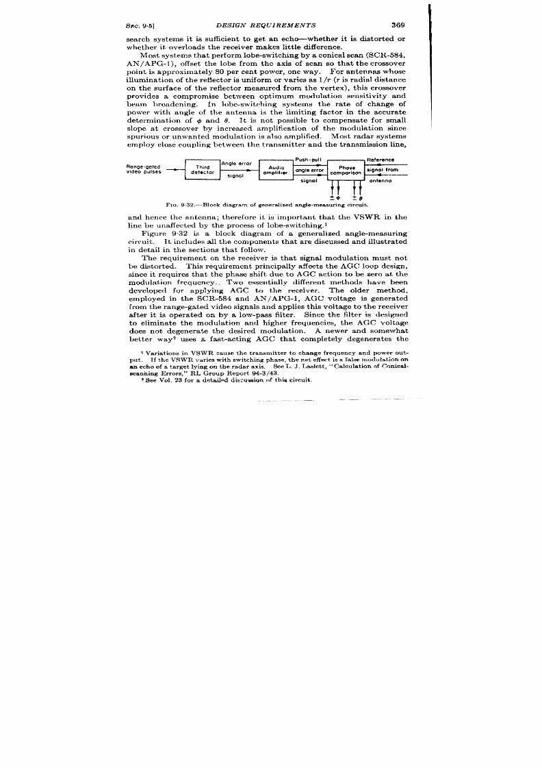
I%c. 95]
DESIGN REQUIREMENTS
369
search systems it is sufficient t o get an echo-whether it is distor ted or
wh et her it over loa ds t he r eceiver m akes lit tle differ en ce.
Most syst em s t ha t per form lobe-swit ch in g by a con ica l sca n (SCR-584,
AN/APG-l ), off set the lobe from the axis of scan so that the crossover
point is approximately 80 per cen t power , one way. For antennas whose
illumination of the r eflector is uniform or var ies as 1/r (r is radia l dist ante
on the sur face of the reflector measured from the ver tex), th is crossover
provides a compromise between optimum modula t ion sensit ivity and
beam b oadening. In lobe-switching systems the ra te of change of
power with angle of the antenna is the limit ing factor in the accura te
determinat ion of @ and 8. It is not possible to compensate for small
slope at crossover by increased amplific t ion of the modula t ion since
spur ious or unwanted modula t ion is a lso amplified. Most radar systems
employ close coupling between t he t r ansmit ter and t he t ransm ssion line,
.
Push -p(d
Angle error
. Reference
Ronge-go!ed
Third
—
video pulses
—
Audio
detector
omplifier
angle error
~omp;:~mn signol from
signol
<
signol
It I(
on~enno
?$’ ?8
FIO, 932 .-Block d iagram of genera lized angle-measu r ing cir cu it .
and hence the antenna; therefore it is impor tant tha t the VSWR in the
line be unaffected by the pr ocess of lobe-switching. 1
Figure 9.32 is a block diagram of a genera lized angle-measur ing
circuit . lt inc udes all the components that a r e discussed and illust ra ted
in deta il in the sect ions tha t follow.
The requirement on the r eceiver is tha t signal modu at ion must not
be distor ted. This requirement pr incipally affects the AGC loop desig ,
since it requires tha t the phase shift due to AGC act ion to be zero at the
modula t ion frequency. Two essent ia lly differ ent methods have been
developed for applyin AGC to the r eceiver . The older method,
employed in the SCR-584 and AN/APG-l, AGC voltage is genera ted
fr om t he r an ge ga ted video signals and applies this volta ge t o th e r eceiver
aft er it is oper a ted on by a low-pass filter . Since the filter is designed
to elimina te the modula t ion and higher frequencies, the AGC voltage
does not degenera te the desi ed odula t ion A newer and somewhat
bet t er wayz uses a fast -act ing AGC that completely degenera tes the
I Var ia t ions in VSWR cause the t ransmit ter to change frequ ency and power ou t -
pu t . If t he VSWR var i s with switch ing phase, the net effect is a fa lse modu la t ion on
an ech o of a ta rget lying on the radar axis.
S ee L, J . La slet t , ‘‘ Ca lcu la t ion of Con ica l-
sca nn in g Er ror s,” RL Gr ou p Repor t 94-3/43.
1 See Vol. 23 for a deta iled diwu aa ion of this circu t.
370
SYSTEMS FOR A UTOMA TIC TZJUE MEASUREMENT [6EC. 9.5
modulat ion in the receiver for modulat ion frequencies up to 300 CPS.
Th modulat ion for the commutator is taken from the AGC voltage
th rough a bandpass filter . The advan tage of the la t ter method is
grea ter protect ion of the r eceiver against over loading from spur ious
modulations.
Both the AGC voltage and the envelope volt age demodula ted video
pulses) are der ived in the range unit , or the range ga te is cabled to a
separa te unit where the AG and er ror voltag s are der ived. Systems
which measure 1#.and @pr ecisely usually a lso m ake a pr ecision measu re-
ment of range; hence a nar row range gate is available for the select ion of
the radar echo of the par t icu lar ta rget whose coordina tes (@, 0) are to be
measured. It is impor tant that the elect ron ic opera t ions per formed on
the signal for the determinat ion of range should n t distor t the signal or
the modula t ion .
This is best assured by using a t r iple-gated video (the
ea r ly and la te gates a re used for range t racking and the middle gate for
AGC and audio (AN/APG-1), the over lapping gates of AI Mk VI, or a
sin gle gate and manual r an ge t racking (SCR-584).
The problem of “detect ing” the gated video pulses is difficu lt . 1
Since all the available informat ion is con ta ined in pulses of very shor t
dura t ion separa ted by interva ls of long dura t ion , the th ird detector must
be designed to make maximum use of the signal while it is available.
The most efficien t detector s developed for th is purpose are the bkiirec-
t ional detector s. z Such circuit s have the unusual and desirable charac-
ter ist ic of instan t ly assum ng the average voltage va ue of each gated
signal while it is presen t , and maintain ing it when the signal is not
present.
Th e pr in cipal r equ ir em en ts on t he audio amplifier following t he th ir d
detector are constant gain and fixed phase shift . These requirements
do not call for special techniques; the only complica t ing factor s a re (1)
the necessity of filter ing the envelope voltage and (2) the change in
mo ulat ion frequency with speed of the lobe-switching motor . Unless
the frequency of lobe-switching is maintained constant , th e audio filter
mus be designed for constant a t tenuat ion and phase shift over the range
of modu la tion fr equ en cy expect ed.
Th e commutator , or phase-discr imin at ion cir cu it , sor ts t he audio in to
+A~ and – Ad and +A@ and – A@componen ts. The requirements on
the commutator a re linear ity at least for small values of audio signal and
isola t ion of 4 and 9 c mponen ts of the audio signal so that the two t rack-
ing axes will not in teract .
The commutat ion should be full-wave and
symmetr ica l to r emove the fundamenta l fr equency from the ou tput and
1The cir cu i wh ich det ect s video sign als t o obt ain GC or audio ie ca lled t h e
“th ird” detector .
ZSee Vol. 19, Chap. 14, of th is ser ies .
SEC. 9.6]
MANUAL TRACKING SYSTEMS
371
t o give minimum response to the large second-ha rmonic component
invar iably in t rodu ced by dissymmetr ies in t he ant enna scanning.
Since the output of thecommuta tor is direct cur ren t (super imposed
on a st ro g but useless second-harmonic component ), it must be con-
nected to d-c amplifiers if the output is not of the proper volt age or power
level for the par t icu lar applica t ion. Since direct -coupled amplifiers a re
avoided wherever possible, commuta tors usua ly opera te a t a high level.
T is has a ser ious disadvantage (but not so ser ious as following the com-
muta tor with direct -coupled amp ifiers) in tha t t s difficult t o opera te a t
h igh audio levels and mainta in a high input impedance at th commu-
ta tor . Gr id current in commuta tor tubes, whether during an “on”
per iod or an “off”
per iod, t ends to react on the final audio dr iver to
cause crosst a lk between the + and O axes.
9.6. Manual Tracking Systems.—In this sect ion a few systems which
provide precise angle measurement on a specia l indica tor a re discussed.
All the systems discussed a re null systems, tha t is, the antenna-poin t ing
is cor rect ed anually by observing a null ndica tor . In each system
discussed the indica tor is a ca thode-ray oscilloscope, but some oth r
syst ems h ave employed zer o-cen ter ed met er s.
AN/APG-15.—Figure 933 is a condensed schema of the angle-
measuring circuit s used in the AN/APG-15 system. This system is a
ligh tweigh t a ir bor ne fir e-con tr ol syst em wh ich permit s blind fir e a ga inst
enemy aircraft . It emplo s automat ic-ranging equipment descr ibed in
Sec. 9“1, and present s rela t ive target bear ing on a small ca thode-ray tube
to enable the gunner to posit ion his guns proper ly.
Th e en velope of t he video r epr esen tin g amplit ude modu la tion is ampli-
fied and filtered, and paraphrased in VI and VZ. The filter between
V, and V, made up of R,, R,, R7, RO, Cs and C, is broadly tuned to
peak at about 0 cps and thus gives good at t enuat ion of the second
harmonic a t 70 cps. The modula t ion volt ages a t the pla te and cathode
of V2 a re equal in magnitude and differ in phase by 180 elect rica l degr ees.
Tubes V~ and V, are fu ll-wave phase-compar ison and amplifier tubes for
6 determinat ion . (The @ circuit s a re not shown but a re similar .) The
phase compar ison takes place by vir tue of conduct ion through Vt and V,
when the gr id and ca thode modula t ions a re in phase. The circuit is
essent ia lly a pha se-det ect or : th e individual t ubes a re a llowed t o conduct
only when the result ing different ia l pla te volt age on the two tubes
conduct ing simultaneously is pr opor t ional t o t he Oor 1#1omponen t of th e
poin t in er ror . (This limita t ion is by vir tue of the switch in the ca thode
circuit mechanical y opera ted by the antenna conica l-scan motor .)
Network RIG’, filters the commuta ted output and V6 amplifies it t o a
level suitable for presenta t ion on a cathode-ray tube. Resistor Rz serves
as a cen ter in g con tr ol.

372
SYSTEMS FOR A UTOMA TIC T IME MEASUREMENT [SEC.9.6
+210V
56k
0.1
35
Cps
angle error
2M
220k
1 I
Mechanical switch on antenna owembly
- I05V
Fm. 9 .33.—Angle -t rack ing circu it s in AN /APG-l 5 , @axis on ly.
+Em
t
1
1
1
+
~Q. 9.34.-Ph aa e-compa r ieon cir cu it in AG~T. @Sr iS o~m

SEC.9.6]
MANUAL TRACKING SYSTEMS
373
In the AN/APG-15 system the conica l-scan ra te is 36 cps. The
AGC filt er is designed to have a charge t ime of ~sec and a discharge
t ime of+ sec; this enables the AGC to hold the average modula t ion below
sa tura t ion in the receiver and not t o dege era t e the modula t ion.
AG~(-T) .—The Brit ish counterpa r t of the AIV/APG-15 employs
a phase-compar ison circuit as shown in Fig. 34. The detect ed modu-
la t ion is mplified to a high level, commuta ted by a mechanica l switch
dr iven by the antenna conica l-scan motor , and direct ly connected
to the ca thode-ray tube. The different ia l voltage is filt ered by RIC~,
and Rz governs the maximum charging ra te of (71. Resistance R4 acts
as a sensit ivity adjustment . The result , in the axis illust ra t ed by Fig.
9.34, is a ver tica l displacement pr opor t ional t o t he amplitude of t he video
modula t ion in phase with the ver t ica l component of the antenna
motion.
SCR-615.—This is a long-range ground-search system with specia l
circu it s for making precise angle measurements. Range t racking is
manual, conica l scanning is mployed only while precise angle measure-
ments are being made, the beamwidth is 4°, and the conica l scan ra te is
24 cps. F igure 9.35 is a schema of the angle-t racking and AGC circuit s.
(These exact circuit s were not in product ion before anufacture was
stopped by the end of the war . )
The phase-compar ing circuit is similar t o the one in the AN/APG-15
equipment , but the ca thodes a re ga ted by a square-wave genera tor ra ther
than by a mechanica l commut at or .
The reference volt age comes from a
two-phase genera t or dr iven synchronously with the antenna . A single
video ga te is used and it is made to coincide in range with the desire
signal by the range-t racking opera tor .
The th ird detect or is of the
type ment ioned in Sec. 9.5. Posit ive video signals and a posit ive range
ga te a re applied to VI; t he gated video signal is applied to the gr id of the
top half of V2. Since the lower half is biased beyond cu toff, the XIO-pPf
condenser Cl cha rges up to the full va lue of the signal, and since there is
no path for discha rge, Cl mainta ins the full cha rge. Immedia tely
preceding the next video signal the “dunking” ga te overcomes the bias
in the lower half of Vz and discharges C .
The next video signal then
charges Cl to it s full va lue, et c. The net resu lt of this sequence of
opera t ion is tha t C I assumes the volt age f each ga ted video signal in
turn .
The funct ion of V~ is t o genera te an AGC pulse tha t will prevent the
signal in the range gate from over loading the receiver .
The input ga te
is of constant amplitud and Vs var ies the output -ga te amplitude as an
inver se funct ion of the potent ia l from the detector .
The a dvanta ge
of ga ted AGC is tha t only the signal under exam nat ion is opera ted on.
Other signals have the advantage of full r eceiver gain.

I
Positive
video
‘1
0.1
Video gate
Boxcar detector
+ 300V
T 1 1
T
ositive
range
gate
0.1
10k
5ooli
50k
50k
Early
50k
lOOk
rongo
>
V2
gate
T,
6SN7
---
0.01
=~q
---
; 100k – J\
20C
:0.1
/J/if
{1
I 6sA7
==:
-..
..-
..-
1,0
m
20k
k ,J
100k
7k 50k
Phase splitter
phase sensitive amplifier
Square wove generator
250.1.
125k
10k
clo5
10k
125k
V3
I ,0
n n~ I
6SN7
---
%2
---
1!3
~+”’-+!‘
v.”.,
+
{M
v,
6SN7
------
200k ~@3k ‘--
T2
%(TI-F
I (l-
=4--u
--l
+
Creference
voltage, #
\
-1 i“c%.t%%e
L-Y’
b.’
ci rcui ts in SCR-615, Oaxis onIY.
w
m

+ 250
I +“ +“
30C
erro
H
S6k
d
7k 47k
0.1 0.1
f-
SN7
1.0
--- ---
IM
1 H
56k
0 . 0 1
H
5k 270k
1
I
1
J
100k
r
T
Centering
Centering
2000V -200w
-., . . .
H
IM
rocus
Irwensjly
FIG. 9.36.—Angle-tracking circuits in Mark 36 radar.
1
4
270 k
\oo#Jd
6SN7
>
470k
---
Single-
phose
reference
generotor

376
SYSTEMS FOR A UTOMA TIC TIME MEASUREMENT [SEC. 97
Phase Comparison on a Circular-trace Cathode-ray Tube .—Th is met hod
of phase compar ison differ s from that of the other s in that a ca thode-ray
tube is used.
The conica l-scan frequency is 30 cps and is accura tely
mainta ned constant by an elect ronic governor (see Fig. 9.36). The
signal being r ange-t r acked is det ect ed and th e envelope filter ed by a sharp
resonant filter (30 cps). It is then divided into four componen ts of equal
magnitude and separa ted in phase by 90 elect r ica l degrees.
These
quadra ture voltages ar e applied to the four deflect ion pla tes of the indi-
ca tor to make the cathode-r y-tube beam prescr ibe a circle on the face; the
radius of the cir cle is propor t ional t o the amount of the er ror , and the
phase of the circular sweep (w th respect to the phase of the conical scan)
is rela ted to the angle between the scan axis and the ta rget .
A re fe rence
genera tor on the antenna furnishes a refer ence voltage which is used to
intensify the indica tor for a small fract ion of the conica l scan and which
mainta ins constant phase with the mechanical rota t ion . Since the er ror
modula t ion can have al possible phase rela t ions with the reference
volta ge, the beam intensifica t ion can occu r a t a ll possible posit ion s of t he
circular sweep. The net result is a coherent rela t ion between the
intensified por t ion of the circular sweep and the rela t ive ta rget bear ing.
The var ious par ts of the circuits in Fig. 9.36 re functionally labeled
to f cilita te understa din the opera t ion . The advantage of a combined
commutator -indica tor of this type is the absence of er ror s due to the
dr ift of d-c amplifier s.
9.7 Automat ic Tracking Systems.—As with manual t racking sys-
tems a few examples of automat ic t racking systems are illustra ted to
oint ou t the var ia t ions in design . The differences between manual and
automat ic opera t ion are obvious; automatic systems are used where the
addit ional weig t , size, and power consumpt ion can be toler a ted and
wh er e t he in cr ea sed a ccu ra cy is essent ia l; a ngle in forma tion in a utoma tic
systems is used in a servomechanism to cor r ect the posit ion of the scan
axis, whereas angle informat ion in manual systems is displayed on a
ca th ode-r ay t ube.
F igu re 9.37 is a sch ema of t he a ngle-t ra ckin g cir cu it s in t he AN/APG-l
a irborne fir e-con t rol syst em .
Posit ive video pulses ar e connected to a delay line which has thr ee
output taps and gives video signals delayed by 1, 1.25, and 1.5 ysec r espec-
t ively. The 1- and 1.5-psec delayed video signals a re ga ted in VI and Vj
y a single ga te, and the outputs of V, and Vz are in the automat ic r ange-
t racking circuit . The 1.25-psec delayed video pulse is gated (again by
the same ga te) in Va and supplies the angle er ror and AGC channels
th rough the common detector V4.
Network RI and Cl filter the AGC
voltage to prevent degenera t ion of the er ror signal.
Th e con tr ol volt age
for the AGC circuit s is used to vary the gain of the i-f stages in the pre-

378
SYSTEMS FOR A UTOMA TIC TIME MEASUREMENT [SEC. 9.8
amplifier and to con trol the amplitude of the screen-sensit izing pulse
going to the receiver . This la t ter cont rol is similar to the one used in the
SCR-615.
Th e ph ase-a dva nce n etwor k FI a asist s in st ab l zin g t he ser vomech a-
nism and is followed by network Rz, R%, C3 which filt er s t h e ou tpu t .
Tube Vb amplifies and paraphrases the angle-er ror signal, and V~
provides balanced amplifica t ion for the two phases. Tubes V, and Vs
are full-wave commutators, the + A@voltages being genera ted at their
cathodes.
The commuta tor is similar t those previously discus~d
except for the fact tha t the reference voltage is in jected in to the pla te
circuit and the commuta ted output is t aken from the ca thodes.
Th e low-
impedance commutat ed d-c er ror signal is power -amplified in Vu and V 10
in an amplidyne to cont rol the speed and direct ion of rota t ion of the
eleva t ion dr ive motor . Tube VII is a n an tih un t amplifier wh ose con nec-
t ion in t he cir cu it sta bilizes t he eleva tion ser vomech an ism .
TRACKING ON GROUPED OR PERIODICALLY INTERRUPTED DATA
BY W. B. JONES AND R. I. HULSIZER
9.8. In t roduct ion .-In the automat ic t ime- and direct ion-measur ing
systems that have been discussed, the radar is engaged constant ly in
obta ining data about a single ta rget . Never theless, as discussed in
Chap. 7, measurements can be made on a single ta rget while the radar
is scanning thr ou gh 360°.
This fact suggest s tha t even while scanning,
a radar set might well obta in sufficien informat ion about a par t icular
t a rget to t rack the ta rget automat ica lly with accuracy. The possibility
of th is eco omy in the use of a radar set gave r ise o the study of auto-
mat ic measur ing systems using grouped data .
Most search radars scan at a constant ra te in azimuth . The radar
obta ins data on a par t icular arget dur ing the small fract ion of the scan
that the radar beam is directed toward the ta rget , tha t i , the data a re
sa id to be “ grouped. ”
The groups of data ar e spaced uniformly in t ime,
if the azimuth accelera t ion measured by the observer ) of the ta rget is
small. Considera t ion has been given to the problem of obta in ing data
from targets th roughout the hemisphere above a ground sta t ion or ahead
of an airplane. All of the proposed hemispher ica l scanners in ter rupt the
PUIWSfr om a single ta rget for such long per iods that t racking is not possi-
le if the ta rget is in mot ion at a ll. If a more simple solu t ion were to
become available the methGds out lined in this sect ion cou ld be extended
t o t h ree dimen sion s.
The PPI is an appropr ia te indica tor with an azimuth scan radar . It
is of impor tan ce that t he oscilloscope scr een ha e a long-per sist ence t ime
constant , for in this w y the indica tor “ remembers” the informat ion
der ived from the data . The PPI remembers the posit ion of a ta rget

SEC. 9.8] INTRODUCTION
379
dur ing the t ime between recept ions of groups of da ta . The idea l meas-
ur ing syst em for t acking radar -observed targets (moving with respect
to the observer ) gives a cont inuous indica t ion of the displacement
of the ta rget . To accomplish this with mall er ror , an automat ic t racking
system opera t ing from grouped data must be capable of learn ing and using
one or more of the ime der iva t ives of the displacement as well as the dis-
placement in order to an t icipa te the mot ion of the t arget du r ing the per i-
ods when no data a re being received.
The pa r t of the automa t ic t racking
system that measu res the t ime der iva t ive and predicts the displace-
men t of the ta rget is the fu ct ion unit .
The number of der iva t ives tha t
the funct ion unit is designed to use is det ermined by the accuracy
desired of the t racking syst em, the quality of the da ta , and the accuracy
of the measur ng reference. In the automat ic t racking systems (using
grouped d ta) which have been developed, it has been found usefu l to
measure and use on]y the first t ime der iva t ive of the displacement (or
velocity) and the displacement of the target . The radar data con ta in
such large er r or s tha t employment of any h igher der iva t ives than the ir st
does not improve the opera t ion of a t racking system. The au tom tic
measu ing systems to be discussed are, therefore, au tomatic t racking
syst em s wit h velocit y m emor y.
There are severa l applica t ions for automat ic t r acking systems oper -
a t ing from gro ped data . Since the radar set is scann ing while collect ing
data for such a t racking system, it follows that one radar can be used
to supply data to many tracking systems and many target s can be
t racked au tomat ica l y and simultaneously. One applica t ion of th is
techn ique is in a irpor t t r affic con t rol w ere many aircraft flying inde-
penden t ly of each other must be t racked. A second s tha t of t racking
the ships in a task for ce or a convoy where it is of impor tance to know the
rela t ive posit ions of sh ips. In these cases, the targets are all of equal
in terest , and usually no very precise in formation abou t any one ta rget is
requ ired. A th ird applica t ion is tha t in which one target in a region is
of paramount in terest , and precise in format ion is requ ired abou t th is
ta rget whereas on ly rough in formation is requ ired about other t argets
in the region . A specific example of th is applica t ion is the case in which
it is desirable to use a search radar for scanning a region and at the same
t ime to use an au tomatic t r acking system opera t ing from the radar data
to give precise enough informat ion about a par t ic lar t arget for accura te
navigat ion con trol. This applica t ion may be in con junct ion with either
a twc- or th ree-dimen sion al scan ning r a ar .
A four th applicat ion is tha t
in which it is desirable to have accura te in formation about two ta rgets
whereas on ly rough in format ion is needed abou t other targets in the
r egion scanned. An example of th is applic t ion is the use of an airborne
search radar to obta in data for t r acking two responder beacons and thus

380
S YS TE S FOR AUTOMATIC TIME MEASUREMENT [SEC. 99
accu ra tely determine th e locat ion of t he airplane.
The beacons can be
t racked au tomat ica lly as two target s migh t be t racked and from the
t racking data a con t inuous indicat ion of the locat ion of the airplane is
made available t o th e navigator .
9.9. Automat ic Time Measuremen t on Grouped Data .-The circu it s
and methods used in au tomat ic t iming devices opera t ing on grouped data
a re very similar t o those in au tomat ic t i ing circu it s opera t ing on
uniformly spa ced da ta except for cer ta in specia l r est rict ion s.
he specia l
opera t ion of the funct ion unit is t o provide cont inuous posit ion and
velocity data in spite of in ter rupt ions in the incoming signal. Hence
it is often called the “memory device. ”
If it is assumed that velocity
memory is provided by the funct ion unit , t here re fou r constan t s that
must be determined as a funct ion of the length of the data per iod T’
nd the t ime between data per iods T.
1. Posit ion learn ing t ime: If t here exist s an er ror in range at the
beginn ing of a par t icu lar data per iod, Z’; for example, maximum
accu racy demands that th is er ror be reduced to zero at least
before the end of T:.
2. Posit ion memory: In velocity-memory systems th is factor is not
a lways obvious, bu t as poin ted out in the descr ipt ion of the boe
range-t racking system in Sec. 9.3, it is not on ly necessa ry to ensu re
that t he velocit y voltage remains constan t for velocity memory,
but a lso that the range ra te produced by constan t velocit y voltage
r emain s con st an t.
The in tegra t ion opera t ion per formed on the
velocit y voltage to produce range voltage must be accurat e a t
least for in tervals of t ime as long as 7’.
3. Velocit y learn ing t ime: If the data a re in ter rupted, t here a re obvi-
ously two methods of obta in ing velocity data . The fir st is t o
measu re ra t e by he change of range dur ing a data per iod; the
second is to measure ra te by the change of range between data
per iods. The first method is impract ica in conven t iona l radar
systems because the data per iods are so shor t that the t a rget does
not move by an amount comparable to the dynamic range er ror
dur ing t he data per iod.
The second method remains if a funct ion
unit has velocity memory. Velocity learn ing implies measur ing
the difference between the t rue range and the range which is pre-
dicted by the funct ion unit by vir tue of it s velocity memory and
cor rect ing the indicated velocity by an amount propor t iona l t o
this er ror . Aided t racking manual with the r i h t t ime constan t
is t he ana logue of th is process.
4. Velocit y memory: The rest r ict ion on velocity memory is that it s
dura t ion be adequate for t ime in tervals equal t o the length of the
data less per iods.

SEC. 99]
TRACKING GROUPED DATA
381
The purpose of th is sect ion is t o examine analyt ically the dep ndence of
these four constan ts on the lengths of T and T’. A summary of the
equat ions applicable to cont inuous t racking shows that for a double-
in tegra t ion system providing velocity memory the following equat ions
from Sees. 84 and 8“6 define th opera t ions of the t ime modulat ion , t i e
discr im inat ion , and double in t egr at ion :
R’ =k,V (8.3)
i = kz(R — R’) = kzc (8.2)
If these th ree equat ions are combined andk, is assumed to be constan t ,
the resu lt is the equat ion of mot ion for the closed t racking loop, in a
form, expressing the dependence in differen t terms than that previously
used,
k,k, , + k,k2e
p’t +T
— = p’R
CA’
(1)
whose solu tion is
c = ae~” + bey’~+ j(p2R ) (2)
where
7 1 , ? ’ 2 —
%$ ’ w&
(3)
and
[/
t
j(p2@ .A
/
t
e-l,t
p2R(x)e–Y~’dz — e~li
‘YQ– 71
0
1
p2R(z)e–Ti=dz . (4)
o
Equat ion (2) holds when it is assumed that data are con t inuously
available. Now, it s necessary to consider the act ion of th is loop when
the data a re grouped. Let T’ be the t ime dur ing which data on R are
available and T the t ime between beginnings of the per iods measured by
T’, and in all cases of in terest here, T is much grea ter (20 t im s or so)
than T’. All analyses will be made assuming t hat T’ and T are cons tan t .
Dur ing the per iods measured by T’, J 3q. (1) holds. On the other hand,
dur ing the per iods measured by T – T’, no data on R are received a
statement that can be represen ted by making k, = O in Eq. (8”2). Thus,
for the per iods measured by T – T’,
p2R ’ = O.
(5)
Solving t his equat ion :
R’=Mt+P
(6)
where M an P a re det ermin ed by t he init ial con dit ion s.
From Eq. (6),
it is eviden t that R’ changes at a constan t ra te dur ing the dataless
periods, M is the init ial ra te of R’, and P is the initial value of R’. This
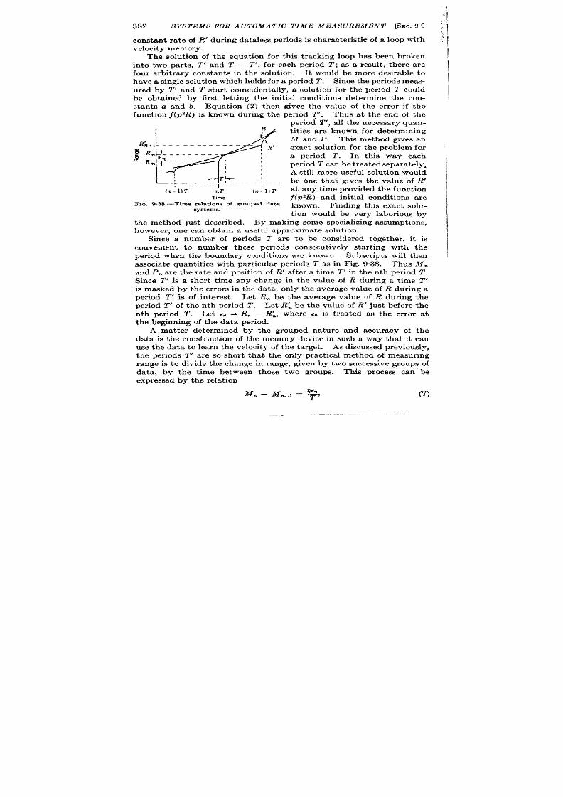
,
382
SYS TEMS FOR A UTOMA TIC TIME MEASUREMENT [SEC. 99
constan t ra te of R’ du ring data less per iods is charact er ist ic of a loop wit h
velocity memory.
The solu t ion of the equat ion for th is t racking loop has been broken
into two par ts, T! and T — T!, for each per iod T; as a result , there are
four arbit rary constan ts in the solut ion . It would be more desirable to
h ave a single solut ion which h olds for a per iod T. Sin ce t he per iods mea s-
ured by T! and T star t coinciden ta lly, a solu t ion for the per iod T could
be obta ined by first let t ing the init ial condit ions determine the con-
stants a and b. Equat ion (2) then gives the value of the er ror if the
function f(p2R) is known during the per iod ~. Thus at the end of the
period T’, all t he n ecessar y quan-
1
4
/
t it ies are known for determining
M and P. This method gives an
R~+,F ____________ - ~
, R’ exact solu t ion for the problem for
~ Rn~t ---------
a Rl:?_____ ,
a per iod T . In this way each
ml t
~
period T can be t r ea t ed sepa ra t ely.
A still mor e u seful solu tion wou ld
T t~ :
be one that gives the value of R’
(n-l)T T IT (n+l]T
at any t ime provided the fun t ion
Time
j(p’l?) and init ial condit ions are
Fm. 9.38.—Timerelat ionsof moupsd data
known. Finding this exact solu -
eystems.
t ion would be very laborious by
the method just descr ibed. By making some specia lizing assumpt ions,
however , one can obta in a useful approximate solut ion.
Since a numb r of per iods T are to be considered together , it is
convenien t to number these per iods consecu t ively star t ing with the
per iod when the boundary condit ions are known. Subscr ipts will then
a ssociat e qu an tit ies wit h pa rt icu lar per iods T as in Fig. 9“38. Thus M.
and Pm are the ra te and posit ion of I?’ aft er a t ime T’ in the n th per iod T.
Since T’ is a shor t t ime any change in the value of R dur ing a t ime T’
is masked by the er rors in th data, on ly the average value of R dur ing a
period T’ is of in terest . Let R. be the average value of R ur ing the
period T’ of the n th per iod T. Let R; be the value of R’ just before the
nth per iod T. Let C*= R. —
R:, where ~n is t rea ted as the er ror a t
the beginning of the data per iod.
A mat ter determined by the grouped nature and accuracy of the
data is the const ruct ion of the memory device in such a way that it can
use the data to learn the velocity of the ta rget . As discussed previously,
the per iods T’ are so shor t that the on ly pract ica l method of measuring
range is to divide the change in range, given by two successive groups of
data, by the t ime between those two groups. This process can be
expr essed by t he r ela tion
Mm – m–l = ~,
(7)

SEC. 9.9]
TRACKING GROUPED DATA
383
where q is a constan t of the order of magnitude of 1 and expresses the
pract ice of allowing the learned velocity t o beinfluenced in a d creasing
mann er from ea rlier data per iods.
In order to measure the range of a ta rget accurately, the constant s
l/C nd I/CA’ of Eq. ( .11) must be adjusted so that c is reduced to a
negligibly small value dur ing the per iods T’. Focusing ou r at t en t ion
on the n th data per iod, Eqs. (8.2) and (8”11) may be combined and
written:
F rom this equat ion
(9)
Now.ks#OonlyfornT <t < nT+ T’. Thus for r zT+ T’ > t > (n+ I) 2’,
(10)
In view of Eqs. (7) and (10), it is eviden t that
W+l’TL1k2’dzd’
is of the order of magnitude of en , and since T’ << T,
By t he a ppr oximat ion R = R. for per iods T’, Eq. (8) becomes
Assuming n ow that Mw_, T’ <<C. and remember ing that e is to be reduc d
to a negligibly small value in the t ime T’, it is eviden t that
Therefore, it is very near ly t rue that
1
/
nT+T’
‘“=~ . .
k,ii~ dx.
(14)

384
SYSTEMS FOR A UTOMA TIC TIME MEASUREMENT [SEC.9.9
I
Hence, combining Eqs. (9), (10), a nd (14):
/
CE. =
k,k,c dx = CS(iMm –
qEncs
M%,) = ~
nT
or
1
s=–”
;
(15)
Equat ion (15) gives a rela t ion which must hold b tween the con-
stants of the memory device in order to have the memory device opera te
as described by Eq. (7). The other condit ion which has been a ssumed
t o be sa tisfied by the t racking loop is hat ~ is r educed to a negligibly
small quant ity in a time T’ when data on R are ava ilable.
How this
condition can be sat is fied, is seen from examining Eq. (2). Since it has
been found conven ien t to measure t from the beginning of the zeroth
period T , Eq. (2) may be wr it t en
E = w“(’-””) + b.e’’(’-”T) + j(P’R)
(16)
where
j(p2R) =
&[e7’(’-””)iTp’R(z)e-7”d’
/
t
—
evl(t–?w)
1
P2R (X)6–Y” dz -
nT
It h~ been assumed tha t R is ver y near ly constan t dur ing all per iods T’;
thus p2R is sma l and f(p9R) is negligibly small, With good a PP roxir na -
tion, therefor e, Eq. (16) can be rewr it t en
~ = ane71(t–nT) + bneW($-nT).
(17)
It is evident that
en = a. + b..
(18)
The other in it ia l condit ion can be obt ined fr om llq. (12), Assuming
tha t ~n -1 is small compa red with the in it ia l r a t e of e in the n th per iod,
de
1
k,k,e~
_ —.
– ~t ~..T – C
(19)
Thus, fr om Eqs. (17) and (1$)),
k,kze.
– — = -rIam + ‘YZbn)
c
(20)
and from qs. (18) and (2o),
_ k,k, + Cy,
a“ – c(y2 – 7,) ‘n

SEC. 99]
and
TRACKING GROUPED DATA
385
~ =Ic,k, +C-y,
.
C( 7 1 – 7 2 ) ‘ “ ”
For,. t o become small in a t ime 2“, either -Y1or 72 (for example, ?’1) must
have a rea l par t which is nega t ive and much smaller than – I/T’. Since
Eq. (15) must be sat isfied and since the rea l par t of 7, must have an
absolu te va lue la rge compared with 1/?”, y 1 and 72 are both real because
from Eqs. (15) and (3)
Ther efor e, IY,1>>174 and the following equa tion is a gOod approxima tion :
k,k,
.yl. —
c
and
~2= –?.
r ,
1
Using these values for Y1 and y~, it follows that a. = E. and b- = O
and therefore,
(21)
fornTSt SnT+ T’.
It is apparen t that it i desirable to make
klkJC approximately equal to 10/T’ or grea t er . If k~kl/C is sutliciently
large, Pm ~ R; + em.
The next st ep is to consider the difference equat ion . The desired
rela t ionsh ips have been found for a grouped data t racking loop:
(22)
k,k2
7,=7=$
1
=S=~T
–%
~
\
F rom t hese equ at ions t he differ en ce equ at ion is obt ain ed:
G+I + (n — l)c. = R+l — 2Rn + En-v (23)
From this difference equat ion, one can find the maximum er ror cmin the
nth per iod, given the maximum er ror in any other per iod. In the case
in which R is changing at a constan t ra te, Eq. (23) bec mes
%+1 + (T
– 1)6. = o.
Solving t h is equa tion ,
c. = CO(I— q)”.

386
SYSTEMS FOR A UTOMA TIC TIME MEASUREMENT [SEC.9.10
In order that the t racking looP may be dynamically stable, it is neces-
sary that 2 > q >0. It is significan t t o note that if n = 1, c. = O for
n >0, This means that t he memory device learns the ra te of R as
measured in the zeroth per iod and since dR/d T is con st an t in t his specia l
case, t here will be no er ror after the zeroth per iod. Because of er ror s
in the data , it has been found bet t er pract ice to make q < 1. With
T < 1, M. is a weigh ted average of ra tes of R measured in the n per iods.
Cr it er ia have now been established for determin ing all the constan ts
of a par t icu lar au tomat ic measur ing system using grouped d ta . The
a ct ion of a r ada r r an ge-t ra ckin g loop is differ en t fr om t he syst em descr ibed
in he equat ion i = lcz(R — R’) = kx, kz is a com%ant when radar data
on a t racked t arget a re being re eived.
In most t ime discr iminators, t he
ou tpu t is propor t ional t o the st rength of the video pulse as well as to the
er ror e. This is a good technique because the h igher the signal is above
noise the more valuable it is as an indicat ion of the ta rget range, and
hence the large video pulses should be given grea ter weigh t . The two
limits on kz from the analysis given are that k,k2/C > l/T’, and that
k,k2/C must be small compared with the PRF in order for the assumpt ion
of con t inuous data dur ing T’ t o h old.
Funct ion units or per forming the opera t ion descr ibed in the Eq.
(8.11) used in this sect ion have been descr ibed in Sec. 86. It shou ld be
noted that the t ime constan t s of the funct ion unit are exact ly defined in
grouped-data t racking applicat ion , according to Eqs. 22. An item of
par t icu lar in terest here is the impor tance of the disconnect ing devices
for r ender ing k2 equal exact ly to zero dur ing the data less per iods.
9.10. Example of Automat ic Range Tracking on Grouped Data .-The
pu rpose of H3X is to t rack automat ica lly the ranges of two separa te fixed
radar beacons from an airplane withou t in ter rupt ing the 3 sec PPI scan
of a microwave radar . Thus the data are un iformly grouped.
The schemat ic diagram of Fig. 9.39 shows one of the t racking loops.
Tube VI is a t r igger amplifier and Vz a blocking oscilla tor . The fir st
sect ion Vs of the t i e discr iminator is ga ted posit ive by a ga te from the
gr id winding of T1. The second sect ion , Vl, is gated by the posit ive
overshoot from the pla te winding. The video is applied to the gr ids
of Vg and Vd and the pulses of cu r ren t which flow while the gates are on
charge the st ray capacitances in the pla te circu it s of Vs and V4. he
carr ier pu lses are removed by the 250 psec. R-C smoothers and the
two voltages are amplified differen t ly first in V5 and V. and again in
V7 and Vs. The difference voltage on the pla te of V~ is coupled capaci-
t ively t o the neon-t be disconn ector and th e bootst rap double in tegra tor
VIO. Capacit ive coupling s permissible since the er ror signal appears
as a modula ted signal a t the scanning frequency. The outpu t of the

I
SEC. 9.10]
TRACKING GROUPED DATA
387
double in tegra tor con t rols a phan tastron t ime modula tor . In the H~X
system t he an gular posit ions of t he radar beacons a re n ear ly constant sin ce
they are a t a grea t distance andmanual adjus mentsa t infrequen t in ter -
!m!mhOn!O-1 -“-”1/ 1
1
L
1 - .s
I
,
Ii
,
1
I
Shun),
J 47k
0.05
50~ X? ::
I%itivamdmwdeo.
VOltuge)
FIG. 9.39.—HsX tracking loop.
va ls su ffice for t h e a zimut h t r ack ing.
Mech an ica lly oper at ed swit ch es a re
used to connect the proper t racking loop when the radar is dir ected
toward the radar beacon being t racked.
l%. 9.40.—HsX t r ack ing dat a r ecord ed on Est er lin e-Angus met er .
I
F igure 9.40 is a graph showing the per formance of one t racking loop.
For th is graph a precision range calibra tor Sec. 9.3 was used to SUPPIY
the video signal. An Ester line-Angus recorder was used to record the
er ror . Thus the graph gives c for the t racking loop as a funct ion of t ime.

388
SYSTEMS FOR A UTOMA TIC TIME MEASUREMENT [SEC.9.10
To inter rupt the data from the calibra tor , a mechanica lly opera ted
switching device was used which switched on the video signal for 0.15 sec
(T’) every 3 sec (2’).
The automat ic loop was star t ed with zero range
er ro and with the range index moving with zero velocity about two
seconds before the first da ta per iod occur red. The simula ted video
signal was moving at a ra te equivalent to a ta rget with a range ra te of
100 yd/sec.
It is seen tha t c fa ls pract ica lly to zero for every data
period T’, but the velocity is never cor rect ly lea rned for the following
reasons. For the H3X memory circuit , q = %(1.3) = 0.58. Since c1 in
this graph is about 200 ydj it would be expected from the theory tha t
CZwould be about 100 yd. In fact it t akes three scans for C. to fa ll to
100 yd and two factor s may cont r ibute to this er ror . One is tha t the
in tegra tor is not per fect ; but this expla ins only a small pa r t of the er ror
because the t ime constant of the in tegra tor is 125 sec. The maj or reason
is tha t an oil-impregnated paper condenser was used as the storage con-
den ser in t he memor y circu it , wh ich beca use of t he dielect ric soa ka ge in tr o-
duced la rge er ror s. When its cha rge is being increased, the condenser
appears to discharge in between data per iods.
Mechanical Devices in Measuring Loop. Often it is conven ient to
have a mechanica l output from an automat ic measur ing system. This
suggests the use of a mechanica lly cont rolled loca l t ime modula tor with
a mechanica l memory device. In the cases tha t have been met in prac-
t ice, it t urns out tha t T’ is approximately 0.1 sec. As it has been poin ted
out , the posit ioning t ime constant of the t racking loop should be shor t
compa re with T’.
It is difficu lt to make a range-t racking loop con-
ta ining mechanica l devices with a t ime constant as shor t as 0.01 sec.
Thus, no cases have ar isen in which a mechanical memory device would
be desirable. Therefore, if a mec anica l output from a range-t racking
circuit is desired, it is bet t er t o have an elect r ic t racking loop and a
sepa ra te servomech an ism de ice t ha t will follow t he elect rica l r an ge da ta.
An alterna t ive is t o t rea t the range er ror signals rec ived dur ing the t imes
T’ from the t ime discr iminator as single bits of data recurr ing at the
scanning frequency, ~. The mechanica l system could then opera te on
these pulses even as the elect r ica l system opera tes on pulses at the PRF.
Exper imenta l data show that the velocity er r or can be decreased to
50 per cent within five pulses of the ca r r ier frequency without damaging
the loop stability. With q = 1, the elect r ica l t racking loop should be
able t o remove t e velocity er ror in one per iod T, but the Ha system
test s showed tha t fluctua t ions in the data required q to be taken enough
smaller tha t the velocity er ror was reduced to 50 per cent in th ree scans.
This is not much super ior to the performance predict ed above for a
mechan ica l t r ack ing syst em .
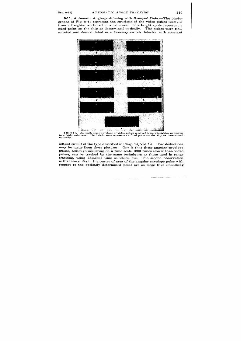
SEC. 9.11]
A UTOMA TIC ANGLE TRACKING
389
9.11. Automat ic Angle-posit ioning with Grouped Data . The photo-
graphs of Fig. 9.41 represen t the envelope of the video pulses received
from a freighter anchored in a calm sea . The br ight spots represen t a
fixed poin t on the ship as determined opt ica lly. The pulses were t ime
selected and demodula ted in a two-way switch det ector with constan t
FIG.9.
in a fairly
optically.
},.”
=
[- ~ ~~
,
9.
.
h“””<
‘- ‘:
, ,,,
>
. . .
[’“ ‘ ‘*:’”’” 1
,,
k
,. -:2-
:-, —
~ ti&&A
41.—Azimuth angle envelope of video pukes r eceived fr om a fr eigi
ca lm sea .
Th e br igh t spot represen ts a fixed poin t on t he dr ip n
lt er a t a nch or
B det erm in ed
ou tput circuit of the t ype descr ibed in Chap. 14, Vol. 19. Two deduct ions
may be made from thes pictures.
One is tha t these angular envelope
pulses, a lthough occur r ing on a t ime sca le 1000 t imes slower than video
pulses, can be t r acked by the same techniques as those used in range
t racking, using adja en t t ime se ector s, etc. The second observa t ion
is tha t the shifts in the cen ter of area of the angular envelope pulse with
r espect to the opt ica lly determined point a re so la rge tha t smoothing
390
SYSTEMS FOR A UTOMA TIC TIME MEASUREMENT [SEC. 9.11
must be carefully per formed. A repor t on data smoothing’ indicates
that a desirable smoother is t he double in tegra tor funct ion unit with one
additional RC smoot hin g sect ion .
It has also been found that the
prefer red method of measur ing the angular posit ion is to compare first
moments of the angula r -envelope pulse ra ther than peak amplitudes or
a rea s. z
1 F. P. CofEn, R. D. Crou t , and F. E. Bothwell, “Data Smoothing, ” RL Repor t
673, Jan . 23, 1945.
aCrout and Bothwell, NDRC Repor t 1*719.
CHAPTER 10
SPECIAL DATA-TRANSMISSION SYSTEMS
BY E. F. MACNICHOL, J R.
INTRODUCTION
Data transmission may be defined as the transmission of useful
information from point to poin t .
Thi includes the whole of wire and
r adio communica tion , facsimile, a nd t elevision ar ts t h a t are beyond the
scope of this book. This chapter will confine it self to a br ief descr ipt ion
of those techniques that are not gen era lly cover ed in t he lit er at ur e
and will discuss several systems in which these techn iques have been
applied. All the systems discussed are designed for remote con t rol or
for telemetering.
Th er e a re t hr ee fu ndamen tal pr oblems in volved:
1. The or igina l data , which may be mechanical, opt ical, chemical,
acoust ical, thermal, etc., must be conver ted in to elect r ica l com-
pon en ts by mean s of su itable tr an sdu cer s (modu la tor s).
2. The elect r ica l components must be conver ted in to a form suitable
f r a ccu ra te t ra nsm ission wit hou t mut ua l in ter fer en ce.
3. The or iginal data must be recovered at the receiv ng end in a form
su itable for u se.
SHORT-DISTANCE WIRE DATA TRANSMISSION
Where distances are shor t , separate wires may be used for t rans
mit t ing the elect r ica l co ponen ts of the data so that Step 2 can be
omit ted. The problem is simplified to the const ruct ion of a suitable
t ransduce at each end.
10.1. Telemeter in g.-Wir e data-transmission systems ar e discus ed
in Vol. 22 specifica lly as met hods of conver tin g a nt en na posit ion in forma -
t ion of radars in to spot displacements on the displays. In th is case the
cathode-ray tube acts as the ou tpu t t r nsducer (demodulator ). Similar
systems are a lso discussed in Par ts I and II of Vol. 21 as computer data
inpu t devices and ser vomechan isms.
The elect romechan ica l modula tors and demodula tors (t ransducers)
used for data transmission are discussed in Vols. 17 and 19. This chapter
will therefore presen t a summary of genera l methods of considerable
391
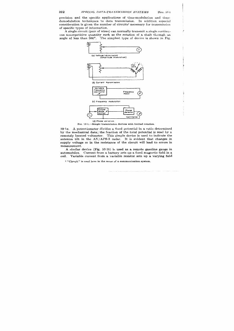
392
SPECIAL DATA-TRANSMIS S ION SYSTEMS
[SEC. 101
precision and the specific applica t ions of t ime-modula t ion and t ime-
demodula t ion techniques to da ta t ransmission. In addit ion especia l
con sidera tion is gi en t he number of circuit s 1 n ecessa ry for t ra nsmission
of specific t ypes of in forma t ion .
A single cir cuit (pa ir of wir es) ca n norma lly t ra nsmit a single cont inu-
ous nonrepet it ive quant ity such as the rot a t ion of a shaft t rough an
angle of less than 360°.
The simplest t ype of device is shown in Fig,
(a) Voltoge transmission
(omplifude modulation)
Ii 1
J
(t.) Current ?onsmission
L
I
(c) Frequency modulation
(d ) Phase variatmn
FIG . 10 I .-s imple t r ansmis sion devices wit h lim it ed rot a t ion .
10 la. A poten t iometer divides a fixed potent ia l in a ra t io determined
by the mechanica l da ta ; t he fract i n of t he tota l potent ia l is read by a
remotely loca t ed voltmeter . This simple device is used to indica te the
antenna t ilt in the AF?/APS-3 radar . It is eviden t that changes in
supply volt age or in the resist ance of the circuit will lead to er rors in
measurement.
A simila r device (Fig. 10. lb) is used as a remote gasoline gauge in
automobiles. Curren t from a ba t t ery se s up a fixed magnet ic field in a
coil. Var iable cur ren t from var iable resistor set s up a varying field
1 (~ u cu it ,! ~ ~~ed h er e in the sense of a communica tion SYSt em .
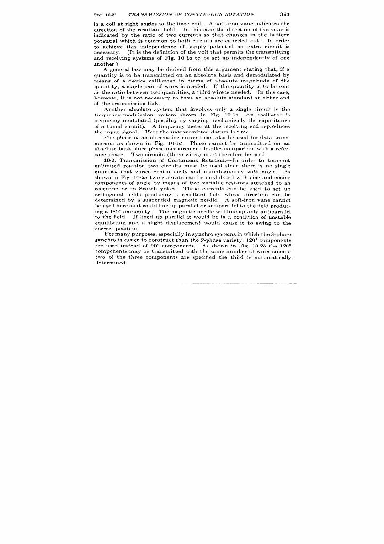
SEC. 102]
TRANSMIS S ION OF CONTINUOUS ROTATION
393
in a coil a t r igh t angles to the fixed coil.
A soft -iron vane indica tes the
direct ion of the resultant field. In th is case the direct ion of the vane is
indicated by the ra t io of two curren ts so that changes in the bat tery
potent ia l which is common to both circu it s are canceled ou t . In order
o achieve th is independence of supply potent ia l an ext ra circu it is
n cessary. (It is the defin it ion of the volt tha t permits the t ransmit t ing
and receiving systems of Fig. 10”la to be set up independent ly of one
anot h er . )
A genera l law may be der ived from this argument sta t ing tha t , if a
quant ity is to be t ransmit ted on an absolu te basis and demodula ted by
means of a device calibra ted in terms of absolute magnitude of the
quan tity, a single pair of wires is needed. If the quant ity is to be sen t
as the ra t io between two quantit ies, a th ird wire is needed. In th is case,
h wever , it is not necessary to have an absolute standard at either end
of t he t ransmission link.
Another absolu te system that involves only a single circu it is the
frequency-modu at ion system shown in Fig. 10. lc. An oscilla tor is
fr equ en cy-modu la ted (possibly by va ryin g mech an ically t he ca pa cit an ce
of a tuned circu it ). A frequency meter a t the receiving end reproduces
the inpu t signal. Here the untransmit ted datum is t ime.
mission as shown in Fig. 10. Id. Phase cannot be t ransmit ted on an
absolute basis sin ce phase measu remen t implies compar ison \ vith a r efer -
ence phase. Two circu it s th ree wires) must therefor e be used.
10.2. Transmission of Cont inuous Rota t ion . -In order to transmit
unlimited rota t ion two circuits mus be used since there is no single
quantity tha t var ie cont inuously and urmml)iguously with angle. As
shown in Fig. 10.2a two cur ren ts can be rnodu la tcd with sine and osine
componen ts of angle by me ns of two var iable resistor s a t tached to an
eccen t r ic or to Scotch yokes. These curren ts can be used to set up
or thogonal fields producing a resu ltant field whose direct ion can be
determined by a suspended magnetic needle. A so t -iron vane cannot
be used h ere as it cou ld line up para llel or ant iparallel to the field produc-
ing a 180° ambigu ity. The magnet ic needle lvill line up on ly antiparallel
to the field. If lined up parallel it wou ld be in a condit ion of unstable
equilibr ium and a slight displacement would cause it to swing to the
cor r ect posit ion .
F or many pu rposes, especia lly in syn ch ro systems in wh ich th e 3-phase
synchro is easier to const ruct than the 2-phase var iety, 120° componen ts
are used instead of 90” componen ts.
As shown in Fig. 102b the 120°
componen ts may be t ransmit ted with the same number of wires since if
two of the th r ee componen ts are specified the th ird is automatically
determined,

394
SPECIAL DATA-TRANSMIS S ION SYS TEMS
[SEC.
102
Devices using compass needles are not capable of very grea t torque
ou tpu t and are easily distu rbed by st ray d-c fields. To produce la rge
torques efficien t ly, h igh magnet ic-flux densit ies a re needed. Only iron-
cor e devices can be used for th is pu rpose and on direct cur ren t these will
su ffer from the effects of residual magnetism. Poten t iometer s or var i-
r4
--tf~--jj
(a) “i-c system using sin-cos components
(b) D-c “selsyn”
(c) 3-phose Syn ChrO
(d )
2- phase synchro
FIG. 10.2.—Devices tha t t ransmit 360”
rotation.
able resistors do not wear well
when used at h igh speeds and
those which will handle la rge cur -
r en ts r equ ir e la rge t or qu es.
Cer-
tain types of elect romechan ica l
modula tor s a n d demodula tor s
over com e th ese object ion s. Th ey
are devices of var iable mutual
in du ct an ce oper at in g on a lt er na t-
ing cur ren t s. As th ey are react ive
elements they do not dissipa te
power un less torque is applied as
con tr ast ed with va ria ble r esist or s
and d -c–oper a t ed elect r omagnet s.
Such devices a r e known gener ica lly
as synchros and are known under
the t rade names of Selsyn , Auto-
syn, Teletorque, Magslip, et c.
There a re a lso a-c–opera ted de-
vices opera t ing on somewhat
differen t pr inciples known as
Magnesyns, Telegons, Microsyns,
et c. (see Vol. 17 and Par t II of
Vol. 21). The common synchro
genera tor has a rotor normally
excit ed with alternat ing cur ren t
a nd t h ree st at or win din gs a rr an ged
120° apar t . The voltage induced
in each sta tor winding is propor -
t ional to the componen t of the
rotor voltage resolved along its
axis, and the constan of propor t ionality is the tu rns ra t io. A synchro
motor is ident ica l to the genera tor except that an eddy-cur r en t damping
device has been added. If the sta tor windings of a gener a tor (t rans-
mit te ) are connected to t e st a tor windings of a motor as shown in
Fig. 10.2c, a resu ltan t field will be s t up along a direct ion para llel to the
direct ion of the rotor of the genera tor . If the rotor of the motor (receiver )

SEC. 103]
FOLLOW-VP SYSTEMS 395
is connected to the same source of a lternat ing cur r ent as the genera tor , a
torque will be developed which posit ions the rotor so that the field it
produces is ant ipara llel to the resultant field due to the sta tor windings.
A torque applied to the motor will produce an equal torque at the
genera tor , Thus asynchro system is a sor t of elect romechanical f exible
shaft.
All the devices previously shown can transmit power in only one
direction.
The synchro system is bid rect ional. It will be noted tha t
four wires ar e required in a synchro system because an a-c ca r r ier is used.
This ext ra cir cuit is n ecessa ry t o t ransmit t he sign of t he r ot or ’s dir ect ion .
A three-wire system might be designed but ther e would be a 180° ambi-
guity. In the d-c system the sign of the rotor posit ion is determined on
an absolute basis by the nor th and south poles of the compass needle.
Synchro systems having two sta tor windings displaced 90° to one
another producing sine and cosine components of t e rotor voltage are
available. These ar e frequent ly used in computa t ion where car tesian
componen ts of an a-c voltage ar e esired but they are ra rely used in data
transmission.
A system using such devi es is shown in Fig, 102d.
It is possible to modula te and demodula te two frequencies, phases,
t ime cliffer en ces, or ot her quantit ies with 90° or 120° componen ts and use
them in transmission of cont inuous rota t ion but these a r e usually used in
follow-up systems t o be descr ibed la ter .
In a synchro system ther e is an er ror in the ou tput propor t ional to the
torque supplied by the motor . The torque must a lso be furnished by
wh at ever dr ives t he gen er at or .
In or der to minimize the dr iving torque,
amplifier s may be used between the sta tor windings of the genera tor and
the mot r . These amplifier s must have very constant gain to minimize
er ror s. Such amplifier s will not decrease the er ror due to loadi g of the
motor.
The er ror can be reduced a much as desired by using the syn-
chros as an element in a follow-up system.
10.3. Follow-up Systems.—Mechanica l data can be most accura tely
t ransmit ted by having an elect romechanica l modu at r a t eith r end of
the wir e link. These modula tor s have ident ica l character ist ics Their
out puts a r subtr acted and t he differ en ce amplified t o cont rol a m ot or tha t
dr ives the input of the second modula tor until the difference approache
zero. The follow-up is a servo system and as such is discussed in Par t II
of vol. 21.
A simple v lt age follow-up is shown in Fig. 10”3; a bat tery voltage is
applied to a potent iometer a t the t ransmit t ing end. The fract ion of the
ba t tery voltage at the poten t iometer slider is compared with that a t the
slider of t he r emot e pot en tiomet er .
A d-c amplifier dr ives a motor that
moves the slider of the r emote poten t iometer unt il the voltages approach
equality. The voltages can be made to approach equality with in any
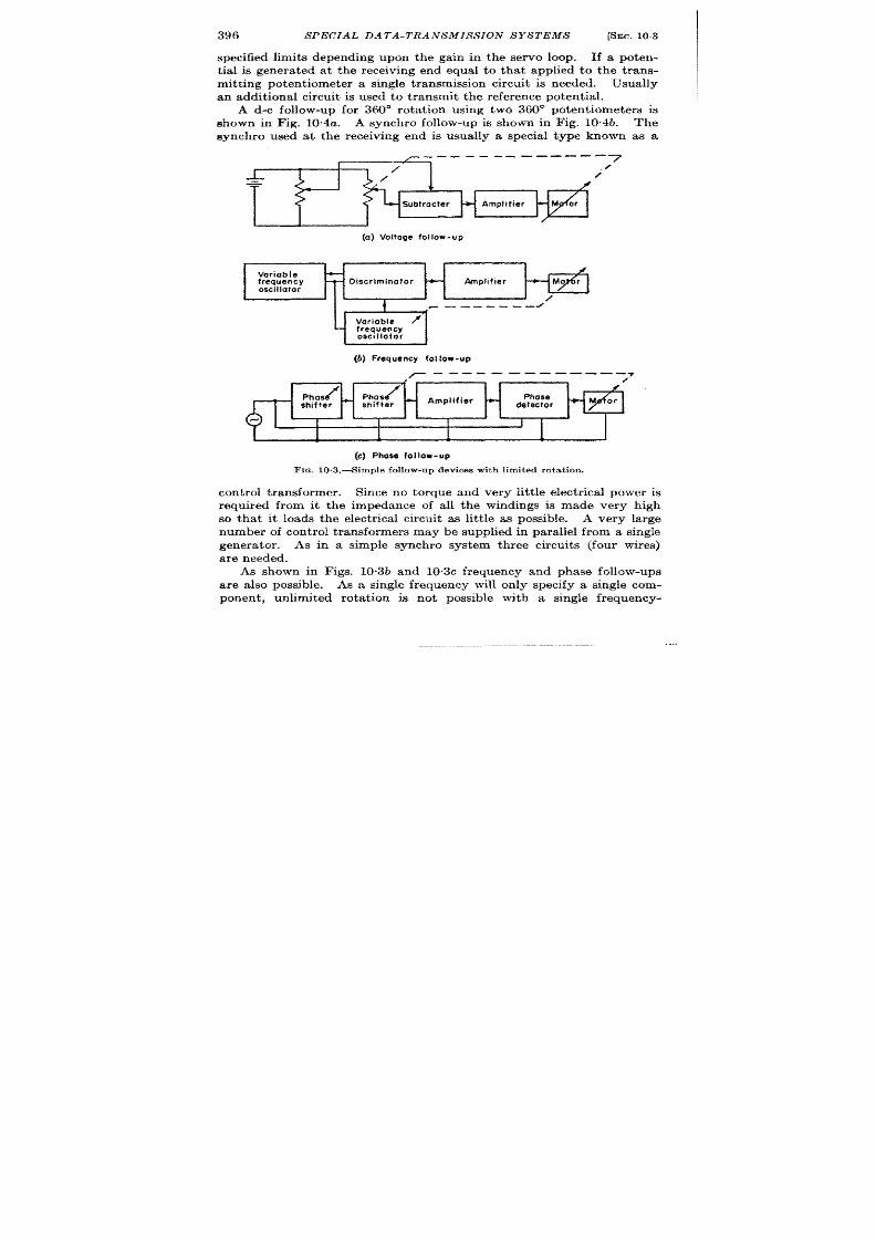
396
SPECIAL DATA-TRANSMIS S ION SYSTEMS
[SEC. 103
specified limits depending upon the gain in the servo loop. If a poten-
t ia l is genera ted a t the receiving end equal to tha t applied to he t rans-
mit t ing potent iometer a single t ransmission circuit is needed. Usually
an addit ional circu it is used t o t ransmit t he refer en ce potent ia l.
A d-c follow-up for 360° rota t ion using two 360” potent iometers is
shown in Fig. 10.4a. A synchro follow-up is shown in Fig. 10.4b. The
synchro used at the receiving end is usually a specia l type known as a
——-. ---- —--- -
r
r
I
7
J_
./
/
=
Subtracter
Amplifier
/
(a) Voltoge follow-up
7
Variable
-
#
frequency
-
Discriminator
*
Amplifier
oscillator
{
/
-— —--- -
/
7
#“
Varioble
/
frequency
oscillator
i
(b) Frequency fot low-up
------ —- —-— -—.7
r -
/
Wse.*
:;::{ ~
I
Amplifier
+
Phose
detector
I
i
I
I
1
[
(G) Phose fOi 10W-Up
FIG. 10.3.—Simple fol low-up devices with limited rotat ion.
cont rol t ransformer . Since no torque and very lit t le elect r ica l power is
required from it the impedance of all the windings is made very high
so tha t it loads the elect r ica l circu it as lit t le as possible. A very large
number of cont rol t ransformers may be supplied in para llel from a single
genera tor . As in a simple synchro system three circuit s (four wires)
a r e needed .
As shown in Figs. 10,3b and 10. c frequency and phase follow-ups
a re also possible. As a single frequency will only specify a single com-
ponent , unlimited rota t on is not possible with a single frequency-

SEC. 104] CHARACTERIS TICS OF THE TRANSMIS S ION CIRCUITS 397
modulated ircu it bu t as frequency is measured on an absolute basis
on ly one circu it is ne essary per quan t ity t ransmit t ed. In the phase
follow-up, phase may be sh ifted cont inuously and unambiguously so that
a sin gle ph ase sh ift will complet ely specify a r ot at ion .
A r efer en ce ph ase
must be t ransmit t ed, however , so that on ly th ree wires are needed, as in
t he d-c selsyn syst em .
10.4. Character ist ics of the Transmission Circu its.-It is eviden t
that in the systems descr ibed above in which amplitude is t ransmit t ed
on an absolu te basis the impedance of the wires must be either negli-
gibly small or constan t . Temper -
a tu re effect s would give er rors. In
T
—-.-——.
T
the systems in which amplitudes
are compared (as in synch ro sys-
tems) rela t ive amplitudes must be
t ransmit ted by the wire lines. As
long as the conductors a re similar , ~
tempera tu re effects will cancel.
(a ) D-c f06 .3w-up
The phase shifts in the lines in a-c
systems must be ident ica l or cor -
Synchro
rect ly compensated since er rors
Qenerofor
will be in t roduced in at tempt ing
to compare the magnitudes of a -c
poten t ia ls which are not in phase.
In t he ph ase follow-u p, var ia t ion of
the amplitudes of the two compo-
nen s will not lead to er ror s in cor -
rect ly designed equipment , bu t t he
rela t ive pha e shifts n the t rans-
constan t . The frequency follow-
up i unique in that neither ampli-
‘Motor
tude c h a n g es nor phase-sh ift
(b) Synchro follow-up
/
variations (if their per iod is long
FrcI . 11).4-FoUOW-UP sys tems tha t t r ans-
compared to the car r ier per iod)
t it 360°rota t ion .
will effect t h e a ccu r acy.
In long lines, direct t ransmission of synchro or other amplitude-
modu la t ed informat ion is usually n ot feasible du e t o ch an ges in amplitu de
and phase down the lines. Car r ier systems that a re ident ica l with the
c-w methods descr ibed in radio data t ransmission may be used sat is-
factor ily. The pulse m thods to be descr ibed would not usually be
operable because of the large bandwidth requ ired.
Pu lse methods can
be u sed if pr oper ly t ermin at ed coaxia l cables a re employed.

.
398
SP CIAL DATA-TRANSMISSION SYSTEMS
[SEC. 10.5
TABLE 10.1.—SUMMARYOF WIEE TZLEHETEEINGYSTEMS
Voltage tran smission,Fig. 10 la
Voltage or cur ren tcompar ison.
Fr equencymodulation, Fig. 10.1(
Pha semodulation, Fig. 10ld.
D-c “Selsyn ,” F ig. 102a. . . . .
D-c sin-cos, Fig. 102a.
3-phase synchro, Fig. 10.2c.
2-phasesynchro, F ig. 102d . . .
Voltage follow-up, Fig. 103Q.
Fr equency follow-up, Fig. 10.3h
Phase follow-up Fig. 10.3c.,. . . .
Synchro ollow-up , Fig. 10.4d . .
No. of cir -
cuits for N
quantities
N
N+l
N
N+l
2 for >360’
2 for > 36&
3 for >360’
3 for >360<
N + 1 if r ef.
voltage
transmitted
N
{
N+l
2 for >360
3 for >360’
E xten t of
rotation
Limited
Limited
Limited
Limited
Unlimited
Unlimited
Unlimited
Unlimited
Limited
Limited
Unlimited
Unlimited
[s er ror
caused
JYcOm-
mon
level
;hangei
No
No
No
No
No
No
No
No
No
No
No
1
re
errors
caused
IY diff-
erential
level
chan-
ges ?
Yes
No /
No i
Yes
Yes
Yes
Yes
Yes
No
No
Yes
)0 r ela -
tive
phsse
shifts
cause
2rrors?
Yes if
ac is
used
No
Yes
. . . . .
Yes
Yes
Yes if
ac is
used
I fo
Yes
Yes
RADIO DATA TRANSMISSION
10.5. In t roduct ion .-If a quan t ity is t o be t ransmit t ed accurately by
radio it must be conver t ed to a form in which fading and in ter ference
do not have a first -order effect . If severa l quant it ies a re to be t rans-
mit t ed (for example, two quant it ies specifying shaft posit ion) a separa te
nonin ter fer ing channel must be provided for each component . F re-
quency-modula ted c-w systems and t ime-modula ted pulse systems are
both suitable. Both systems permit limi ing to minimize the effect s of
amplitude var ia t ions. In c-w systems each componen of the elect r ica l
informat ion-amplitude, phase, or frequency—modulate’ an alternat ing
cur ren t known as a ‘‘ sub car r ier .”
Channel separat ion is ac ieved by
using a differen t frequency for each subcarr ier .
The subcarr iers are
mixed and the outpu t of the mixer frequency-modula tes a car r ier which
is then transmit t ed. If addit ional in ter ference reject ion is desired, the
subcar r iers may modula t in termedia te car r ier s that finally modula te
the t ransmit t ed car r ier . In the receiving equ ipment the subcarr iers a re
recovered by demodulat ion of the carr ier and separa ted by fi ter ing.
They are then demodula ted and combined and the or iginal is recovered
by the same means used in wire systems. The techn iques involve the
—.
.-.

SEC. 10.5]
RADIO DATA TRANSMIS SION
399
TABLE 1O.2.—CHARACTERISTXCSF VARIOUS DAT.ATRANSMISSIONSYSTEMS
Discuss d in Chaps. 10 and 11
System
Pulse r emot e con t rol
system
Radiosonde (a i rborm
t r ansmit t er , gr oum
receiver)
Omnid ir ect iona l bea -
con (gr ou nd t ra ns-
m it t er , a ir bor n e r e.
ceiver)
Time-modu la t ed s in e
cosin e r ela y ra da l
system
P ba se-sh ift ed pu lse
r ela y r ada r syst em
(Ground-to-ground
r ela y) jit t er ed puh
r ela y r ada r syst en
C-W-FM rela y SYS
tern(airbornetran
mit t er , sh ip o]
ground receiver)
Met hod of
;hannel separa t ion
\ ix or seven differ -
en t a udio t on es
r ime-sequence (de-
t ermined by alt i-
tude)
r im e-sequ en ce se-
lection
r im e-sequ en ce se-
lection
r im e-sequ en ce se-
lection
Time-sequ en ce se-
lection
F requ en cy sepam
t ion of video pulses
c-w subca r rier am
audio sub-subca r
r ier . Tr igger s an
vid eo sign als of 01
pos it e pola r it y
Meth od of t ra ns-
mit t ing te lemeter -
ing informat ion
h -off r elay con t r ol
by frequency-selec
t ive relays, t ones
t ransmit ted as
time-modulated
pulse
hequency-modu-
Ia ted a udio t on e
‘ulse width and
phase modu la t ion
rime-modulated
pu lses ca r rying s in
and cosine of an .
t enna d ir ect ion
‘base -sh ift ed pu ls t
t r a in , phase shifi
dir ect ly pr opor -
t iona l to an ten ru
direction
l?ime-modulated
pu lse ca r r ie r , mod
u la t ion fr equenc~
pr opor tion al t o a r
t enna speed. An
gle ma rks indica t (
un ique an tenna
posit ion bu t syn
ch ron iza t ion mus
be ach ieved b:
hand
Amplitude of twl
audio t ones p ropo
t iona l to sine ant
cosin e of an tcn n
angle.
Th ir d t or
for level set tin g
Interference
re ject ion devices
Five-pulse code
None
Ver y a ccu ra te PRF
selector , pu lse-
wid th selector
Tr ip le -pulse coding ,
n a r row ga t es
Tr ip le -pulse coding
Tr ip le -pulse coding
h Ta rr ow filters for
sllbcar r ier and
tones. In su ffi-
cien t p rot ect ion for
triggers
400
SPECIAL DATA-TRANSMISSION SYSTEMS
[SEC. 10.6
use of oscilla t or s, amplit ude modu la t or s, fr equ ency modu la t or s, fr equ ency
conver ter s, amplifier s, filt er s, a nd amplit ude a nd fr equ en cy demodu la tor s
of typ s convent iona lly used in the communica t ions ar t .
In pulse systems each element of the data t ime-modula tes a pulse
by varying either it s idth or it s spacing with respect t o another pulse.
Ch annel sepa ra tion is a ccomplish ed by t ra nsm it tin g t he pu lses in sequ en ce.
In ter ference reject ion is provided y t ansmit t ing each pulse in the form
of a mu lt iplepu ls e
“code” group tha t is decoded by a sequence of t ime
selectors in the receiving equipment . Pulse systems are composed of
PRF oscilla tors, genera tor s of grouped pulses, t ime selectors, and t ime
modula tors and demodula tors as well as the more convent iona compon-
ent s. These systems somet imes resemble an art ificia l rada r system in
wh ich a rt ificia lly t im e-modu la ted pulses r epla ce t he movin g ech oes.
Relay r da r systems are used to t ransmit video and antenna posit ion
signals to remotely loca ted display devices. They conta in wideband
channels for the t ransmission of video signals and the sweep t r iggers
(usually coded). The antenna posit ion may be t ransmit t ed as a sequence
of t imemodula ted pulses dur ing an unused por t ion of the pulse-recur-
rence in terva l or it may be sent on a sepa ra te r -f ca r r ier or subca rr ier in
t he form of pulses or c-w compon en ts.
To be useful t he bea ring informa -
t ion must be accura te t o + 5° or bet t er so tha t the telemeter ing circuit s
must be ca refu lly design ed.
In remotecont rol systems the informat ion is usually of low precision .
It is oft en confined to switching opera t ions actua ted y the presence or
absence of a pulse or audio t on e.
Medium-precis ion t elemet er ing sys tems
are est illust ra t ed by the radiosonde which is ccura te only for a shor t
t ime aft er ca libra t ion. The Brit ish omnidirect ional beacon is included
as an example of pulse data-t ransmission system although it is funda-
menta lly a naviga t ional a id.
The charac er ist ics of the data-t ransmission systems t o be descr ibed
in deta il a re summarized in Table 10.2.
10s6. A P ulse Remot e con tr ol Syst em .—Th e t ra nsm it ted in f orma tion
consist s of five coded pulses a t a PRF of 715 pps. The fir st four pulses
a re for designa t ing a par t icu lar receiver , and the fifth pulse is t ime-
modula ted in accordance with one of six audio tones which represen t the
t ransmit t ed data . At the designa ted eceiver , a beacon replies to the
four th pulse provided the fifth pulse is a lso correct ly posit ioned and is
modula ted a t a frequency corresponding to one of the con t rol tones, thus
repor t ing back to the t ransmit t ing sta t ion tha t cont rol has been estab-
lished. A “neut ra l” t one is provided to actua te the beacon for checking
the communica t ion circuit . Width modula t ion of the reply pulse on
receipt of a cont rol tone is a lso employed to signify tha t the con t rol is
responding. The pulses a re 0.2 psec wide and their sepa ra t ion is var iable
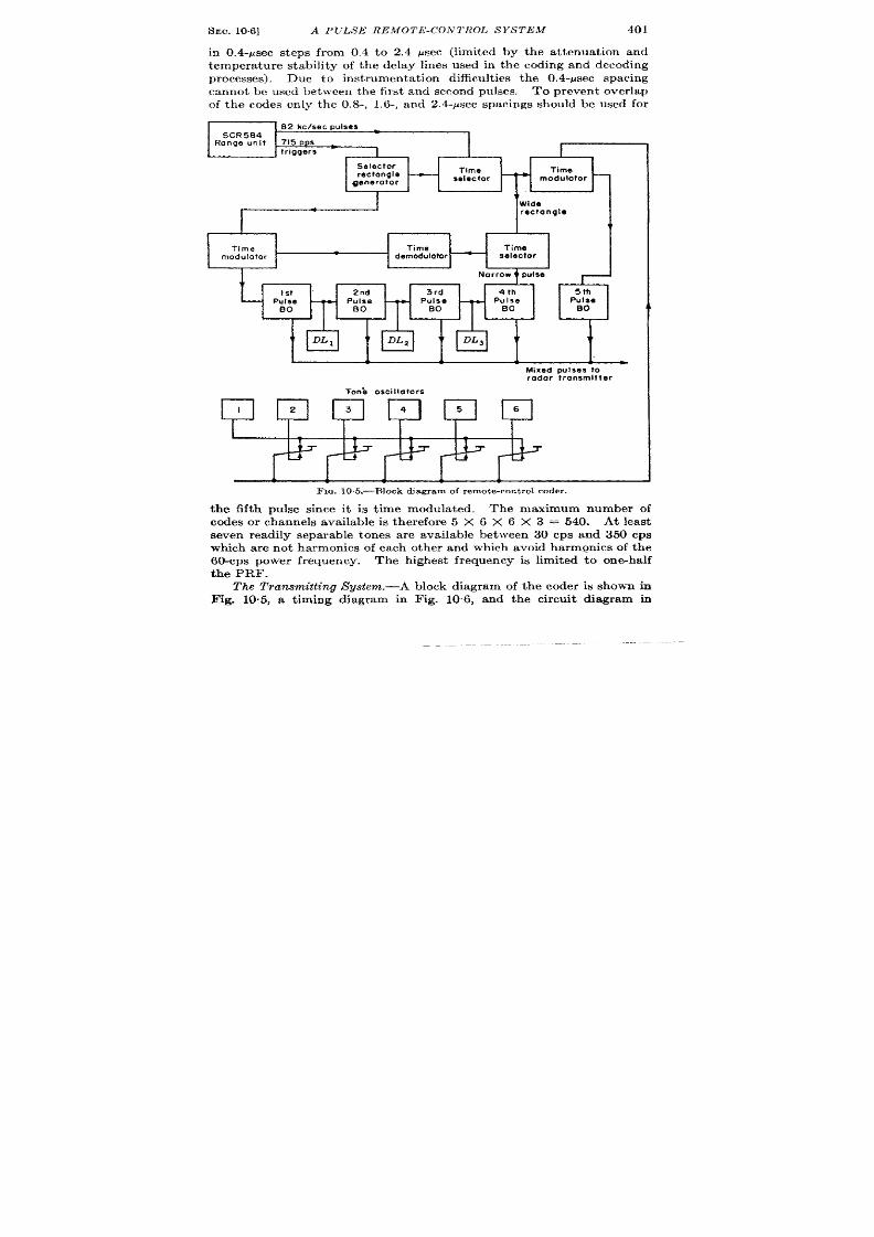
SEC. 10.6] A I’ULS E REMOT E-CON 1’ROI> S YS TEM
401
in 0.4-Psec steps fro 0.4 to 2.4 ~sec (limited by the a t tenua t ion and
temperature stability of the delay lines used in the coding and decoding
processes). Due to inst rumenta t ion difficu lt ies the 0.4-psec spacing
cannot be used between the first and second pulses.
To pr even t over la p
of the codes only the 0.8-, 1.6-, and 2 4-psec spacings should be used for
Mixed pulses to
radar Ironsmltter
FIG. 105.-Block d iagram of remote-con t rol coder .
the fifth pulse since it is t ime modula ted. The maximum number of
codes or channels available is therefore 5 X 6 X 6 X 3 = 540. At least
seven readily separable tones are available between 30 cps and 350 cps
which a re not harmonics of each other and which a oid harm~nics of the
60-cps power frequency. The highest frequency is limited to one-ha lf
the PRF.
The Transmitting System.—A
Fig. 10.5, a t iming diagram in
block diagram of the coder is shown in
Fig. 10.6, and the circuit diagram in
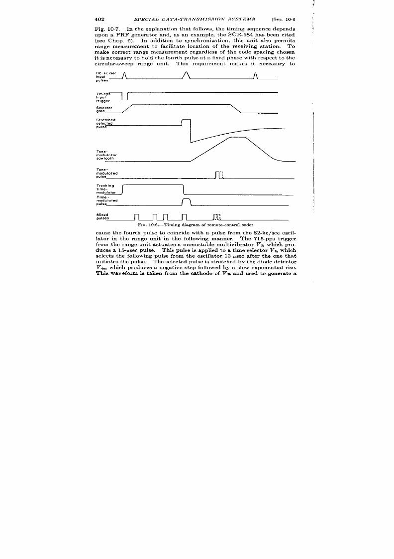
402
SPECIAL DATA-TRANSMISSION SYSTEMS
[SEC. 10.6
Fig. 10.7. In the explanat ion that follows, the t iming sequence depends
upon a PRF genera tor and, as an example, the SCR-584 has been cited
(see Chap. 6). In addit ion to synchronizat ion , this unit also permits
range measurement to facilita te loca t ion of the rece ving stat ion . To
make cor rect range measurement regardless of the code spacing chosen
it is necessary to hold the four th pulse a t a fixed phase with respect to the
circular -sweep range unit . This requirement makes it necessary to
S2-hc/sec
input
A A
pulses
Selector
gate
Stretched
selected
pulse
Tone-
modulator
sawtooth
Tone -
moduloted
-1
pulse
I
Tracking
time-
modulator
1
Time-
modulated
pulse
Mixed
pulses
n
n n n
FIG. 10 .6 .—Thning diagram of remote-cont rol coder .
cause the four th pulse to coincide with a pulse from the 8>kc/sec oscil-
la tor in the range unit in the f llowing manner . The 71&pps t r igger
from the range unit actua tes a monostable mult ivibra tor VZ, which pro-
duces a 1fi-psec pulse. This pulse is applied to a t ime selector Vs, which
selects the following pulse from the oscilla tor 12 ysec after the one that
init ia tes the pulse. The selected pulse is st retched by the diode detector
V~, which produces a negat ive step followed by a slow exponent ia l r ise.
This waveform is taken from the cathode of Va and used to genera te a
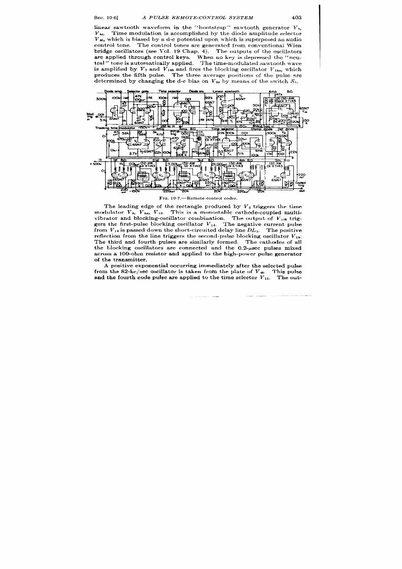
SEC. 10.6]
A PU SE REMOTE-CONTROL SYSTEM
403
linear sawtooth w veform in the 1‘bootst rap” sawtooth genera tor V~,
Vu. Time modula t ion is accomplished by the diode amplitude selector
V*, which is biased by a d-c potent ia l upon which is superposed an audio
con trol tone. The con trol tones a r e genera ted from convent ional Wien
br idge oscilla tors (see Vol. 19 Chap. 4).
The outputs of the oscilla tor s
a r e applied th rough cont rol keys. When no key is depressed the ‘‘ neu-
t ra l” tone is automat ica lly applied. The t ime-modula ted sawtooth wave
is a plified by VT and VIBband fires the blocking oscilla tor Visa, which
produces the fifth pulse. The th r e average posit ions of the pulse a re
determined by changing the d-c bias on VW by means of the switch S,.
FIG. 10.7.—Remote-contr ol coder.
The leading edge of the rectangle produced by Vz t r iggers the t ime
modulator V,, V,., V~ti. This i a monostable ca thod~coupled mult i-
vibr a tor and block ing-oscilla t or combinat ion .
The output of V,W trig-
ger s t he fir st -pu lse blockin g oscilla tor V1l. The nega t ive cur rent pulse
from V,, is passed down the shor t -circu it ed delay line DL1. The pos it ive
r eflect ion fr om t he lin e t rigger s t he secon d-pu lse blockin g oscilla tor VIs.
The third and four th pulses ar e simil r ly formed. The ca thodes of a ll
the blocking oscilla tor s a r e connected and the O.2-Psec pulses mixed
across a 100-ohm resistor and applied to the high-power pulse genera tor
of t he t ra nsm it ter .
A posit ive expon en tia l occur rin g immedia tely a fter t he selected pu ke
from the 82-kc/see oscilla tor is taken from the pla te of V4b. This pu lse
and the four th code pulse a re applied to the t ime selector V, ~.
The OUG

IA
o
*
Receiver
Video
Time
Time
Time Time
q
ompllfler
selector
Time
selector selector
selector
selector
b
1
0
1
Amplitude
Cathode
Sum
Difference
.
AGC
selector
follower
out put
detector
Difference
out put
1
Beacon
Blocking
-
oscillator
—
Delay
Amplifier
transmitter
-
4
_Activator
J J
J
.
I 1
Filter
Filter Filter Filter
Filter
Filter
2 3
4
5
6
I i
i 4
I i i I
1
Pulee width
J
I
i i
modulator
L
)
v
To controls
FIG. 10,8.—Block diagram of remote-control receiving system.

I
SEC. 10.6]
A PULSE REMOTE-CONTROL SYSTEM 405
pu t of VII is in tegr at ed by VIZb, VOb and app ied as bias to V%. Since Va
is a t ime modula tor the t ime of occur rence of the four th pulse is cont rolled
by this bias. Condit ions are ar ranged so that the four th pulse just
touches the leading edge of t e sawtooth waveform. Since th is edge is
genera t ed by the rear edge of the select ed 82-kc/see oscilla tor pulse, the
four th pulse is const ra i ed to coincide with it . No matter what code
spacing is selected the t ime modula tor will adjust itself un t il the condi-
t ion is fu lfilled. (Foracomplete discussion ofautomat ic r ange-t r acking
systems see Chaps. 8 and 9.)
The Receiving System.—A block diagram of the receiving system is
shown in Fig. 10.8 and circuit diagrams of the decoder and filter c rcuits
FIQ. 109 .-Decoder for r emotecont rol.
in Figs. 10.g and 10.10. Negat ive pulses from the receiver (wh ich hasa
short - imeconstan t second detector ) a re applied to the feedback ampli-
fier V,, V2. The limit level of the receiver is such that 15-volt pulses
appear a t theplat of V*. Theamplifier basagain of four and an ou tpu t
impedance of about 70 ohms. The negat ive pulses are applied to the
ca hodes of the t ime selector s, Vt , V~, VS, Va, and V?.
They are also
applied to the delay line DL,. The pulses t r avel down the line and are
reflected back until they are absorbed by the l-k terminat ing resistor .
They appear a t the gr id o V, at a t ime that is a pulse width less than the
tota l delay t ime. If the second pulse appears on the cathode of V2 at the
same time that the delayed and inver ted first pulse appeam on the gr id,
V, will c nduct . The gr id is connected to a tap ra ther than to the end
of the line because if the negat ive incoming pulse and the posit ive
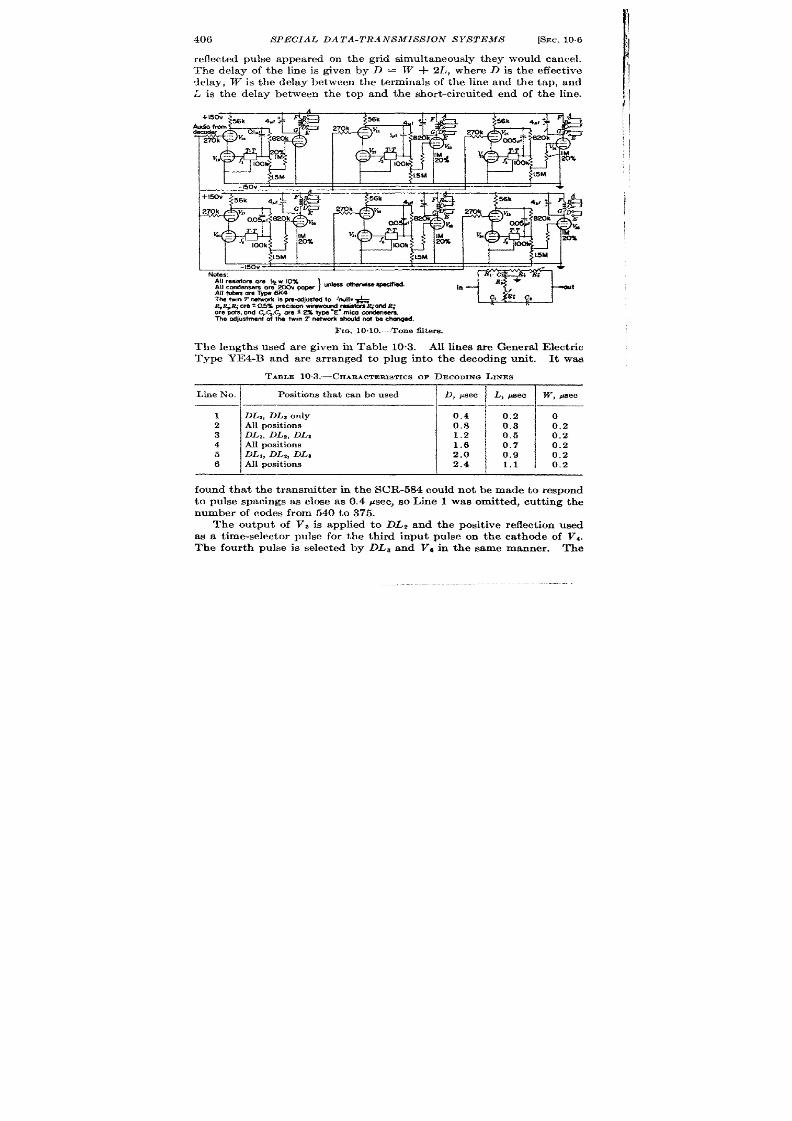
406
SPECIAL DATA-TRANSMISSION SYSTEMS
[SEC. 10.6
The delay of the line is given by D = W + 2L, where D is the effect ive
delay, W is the delay between the terminals of the line and the tap, and
L is the de ay between the top and the shor t -circu it ed end of the line.
The odju~eni ol the twin T netwcrk shouldnot h charqed.
Fm. 10.10.—Tone filters.
The lengths used are given in Table 10.3. All lines are Genera l Elect r ic
Type YE4-B and are ar ranged to plug into the decoding unit . It was
TABLE 1O.3.—CHARACTERISTICSOF DECODINGLINES
Line No. Posi ions that can be used D, psec
L , psec
W , p e.ec
1
DL,, DL~ only 0.4
0.2 0
2 posit ions 0.8 0.3 0.2
3
DL,, DLZ, DL, 1.2 0.5
0.2
4 Al posit ions 1.6 0.7 0.2
5 DL1, DL2, DLs 2.0 0.9
0.2
6 Al positions
2.4 1.1
0,2
found tha t the t ransmit ter in the SCR584 could not be made to respond
to pulse spacings as close as 0.4 psec, so Line 1 was omit ted, cu t t ing the
number of codes from 540 to 375.
The output of V, is applied to DL2 and the posit ive reflect ion used
as a t ime-selector pulse for the third input pulse o the ca thode of V1.
The four th pulse is selected by DLa and Va in the same manner . The
!
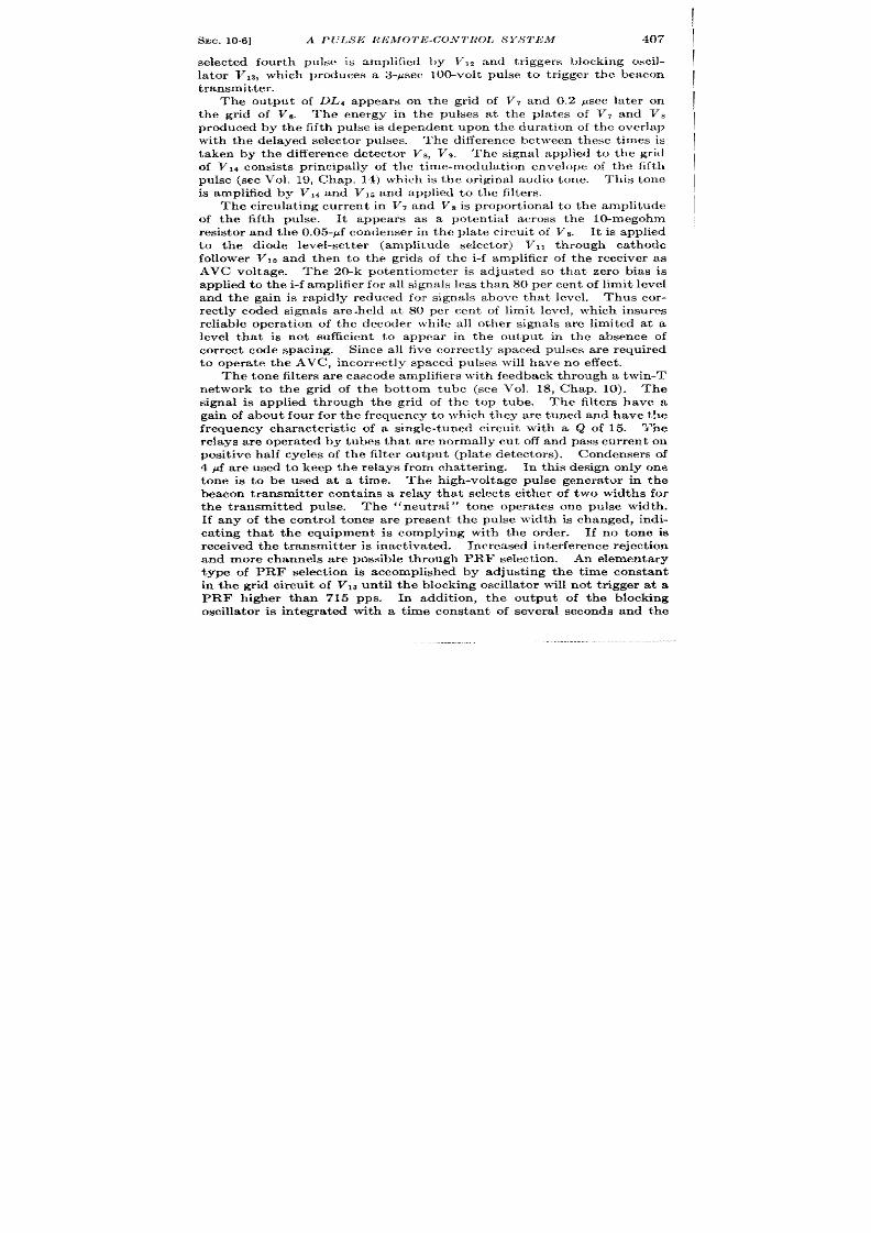
SEC. 10,6]
A PULSE lWMOTE-COJV ROL S YS 1’EM
407
selected four th pulse is amplified by VIZ and t r iggers blocking oscil-
la tor Vls, which produces a 3-psec 100-volt pu lse to t r igger the beacon
transmitter .
The output of DL~ appears on the gr id of VT and 0.2 ~sec la ter on
the gr id of Vs.
The energy in the pulses a t the plates of V7 and V,
produced by the fifth pulse is dependent upon the dura t ion of the over lap
with the delayed s lector pulses.
The difference between these t imes s
t aken by t he cliffer en ce det ect or VB, Vg.
The signal applied to the gr id
of V,l consist s pr incipally of the t ime-modulat ion envelope of the fifth
pulse (see Vol. 19, Chap. 14) which is the or iginal audio tone. This tone
is amplified by V14 a nd V15 and applied to the filters.
The circu la t ing cur ren t in VT and V* is propor t iona l to the amplitude
of the fifth pulse. It appears as a potent ia l across the lo-megohrn
resistor and t he 0.05-~f condenser in the plate circuit of Vs. It is a pplied
to the diode level-set ter (amplitude selector ) VII th rough ca thode
follower V,, and then to the gr ids of the -f amplifier of the eceiver as
AVC voltage. The 20-k poten t iometer is adjusted so that zero bias is
applied t o t he i-f amplifier for all signals less than 80 per cent of limi level
and the gain is rapidly reduced for signals above tha t level. Thus cor -
rect ly coded signals a re -held at 80 per cen t of limit level, which insures
reliable opera t ion of the decoder while all other signals a re limited at a
level tha t is not sufficient to appear in the output in the absence of
cor rect code spacing. Since all five cor rect ly spaced pulses are required
to opera t e the AVC, incor rect ly spaced pulses will have no effect ,
The t on e filter s a re cascode amplifiers with feedback through a twin-T
network to the gr id of the bot tom tube (see Vol. 18, Chap. 10). The
signal is applied through the gr id of the top tube. The filt ers have a
ga in of about four for the frequen y to which they are tuned and have the
frequency character ist ic of a single-tuned circu it with a Q of 15. Yne
relays are opera ted by tubes tha t a re normally cu t off and pass cur ren t on
posit ive half cycles of the filter output (pla te detectors). Condensers of
4 ~f a re used to keep the relays from chat ter ing. In this design only one
tone is to be used at a t ime. The high-voltage pulse genera tor in the
beacon t ansmit ter contains a relay tha t select s ei her of two widths for
the transmit ted pulse. The “neut ra l” tone opera tes one pulse width .
If any of the cont rol tones are present the pulse width is changed, indi-
ca t ing tha t the equipment is complying with the order . If no tone is
r eceived t he t ra nsm it ter is in act iva ted.
Increased in t er ference reject ion
and more channels are possible through PRF select ion ,
An elemen ta ry
type of PRF select ion is accomplished by adjust ing the t ime constan t
in the gr id circu it of Vl~ unt il the blocking oscilla tor will not t r igger a t a
PRF higher than 715 pps. In addit ion , the output of the blo klng
oscilla tor is in tegra t ed with a t ime constan t of severa l seconds and the

408 SPECIAL DATA-TRANSMIS S ION SYSTEMS
[SEC. 10.7
ou tpu t applied to a relay which act ivates the beacon t ransmit ter and the
con trol circuits. Thus, cor rect signals of the cor r ect PRF and code must
be received for a specified length of t ime before the beacon will r eply or
con tr ol ca n be est ablish ed.
10.7. Radiosonde.-Probably the simplest and most compact of all
r adio data transmi sion devices is the radiosond . The U.S. Army
AN/AMT-l weighs only 22o g without bat tery and is designed to be
carr ied aloft by a weather balloon.
It t ransmits tempera tu re, atmos-
pher ic pressure, and humidity to the weather stat ion . The posit ion of
Humidity segments
11
Low reference segments
,-------
_ ~High reference segments
———-—— ——,---——- —---—— —- ——-.
ii
II
Quenching
II
oscillator
R-f
I
Oscillator 1
72 Me/see I
II
+90V
I
I
I
1
I
I
I
I
I
~
I
1
/
1
I
#
I
Modulolor unit
~ ~ Transmitter unit ~
i
I
3V
I
.--_ -___ -------_-_J I———-———— -—=- —-_ J--J
Fm. 10.11.—Radiosonde, AN/ MT-l.
the ba lloon is determined by radio direct ion-finding equipment opera t ing
on the t ransmit ted signa l. A diagram of the AN/AMT-l is shown in
Fig. 10.11. It conta ins a single 3A5 tube. One sect ion acts as an r -f
oscilla tor at 72 Mctsec while the othe sect ion acts as a quenching
(Squegging) oscilla tor wh ich keys the t ransmit ter at an audio-fr equency
rate. he audio frequency is modula ted by changing the gr id resistor
of the quench ing oscilla tor . The change in gr id resistance is accom-
plished in the modu l tor unit . Since three quant it ies must be measured
in sequence, some form of channel-switch ing is needed. Advantage is
taken of the fact tha t as the ba lloon ascends the a tmospher ic pressure
decreases con t inuously at a near ly constan t ra te. The pressure-sensit ive
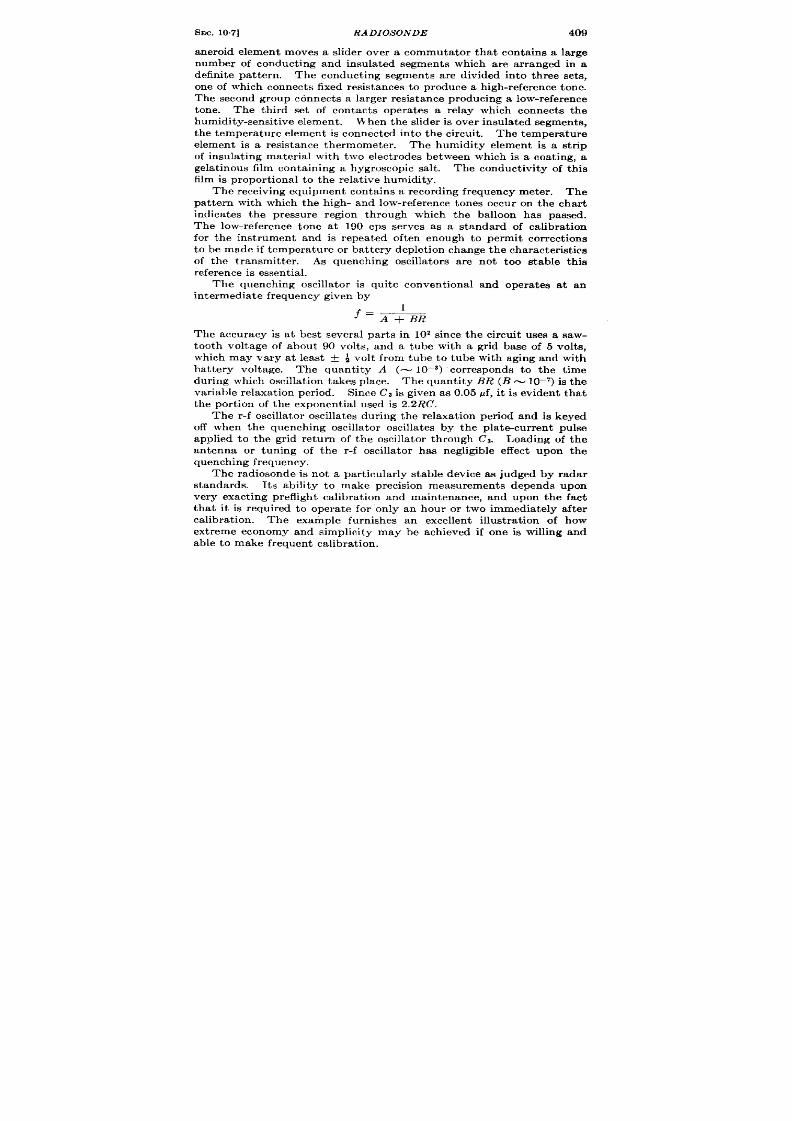
SEC. 10.7] RADZOSONDE 409
aneroid element m ves a slider over a commuta tor tha t conta ins a large
number of conduct ing and insulated segments which are ar ranged in a
defin ite pat tern . The conduct ing segments are divided in to thr ee sets,
on e of wh ich con nect s fixed r esist an ces t o pr odu ce a h igh -r efer en ce t on e.
Th e secon d gr ou p con nect s a la rger r esist an ce pr odu cin g a low-r efer en ce
tone. The th ird set of contacts opera tes a relay which connects the
humid ity-sensit ive elemen t .
Wh en t he slider is over insu lated segmen ts,
the t empera tu re element is connected in to the circu it . The tempera tu re
elemen t is a resistance thermometer . The humidity elemen t is a str ip
of insulat ing mater ia l with two elect rodes between which is a coat ing, a
g lat inous film contain ing a hydroscopic salt . The conduct ivity of this
film is pr opor tion al t o t he r ela tive h um idity.
The receiving equipment contains a recording frequency meter . The
pat t ern with which the high- and low-reference tones occur on the char t
indica tes the pre sure region through which the balloon has passed.
The low-reference tone at 190 cps serves as a standard of calibrat ion
for the inst rument and is repea ted oft en enough to permit cor rect ions
t o be made if t emper atu re or bat t ery deplet ion ch ange th e char acter ist ics
of the t ransmit ter . As quenching oscilla tors are not too stable this
reference is es sen t ia l.
The quenching oscilla tor is quite convent iona l and opera tes at an
in termedia te fr equ en cy given by
1
~= A+BR
The accuracy is at best severa l par t s in 102 since the circu it uses a saw-
tooth volt age of about 90 volt s, and a tube with a gr id base of 5 volt s,
which may vary at least + ~ volt from tube o tube with aging and with
b t tery voltage. The quant ity A (
= 10—a) cor responds to the t ime
dur ing which oscilla t ion takes place. The quant ity BR (B z 10–7) is the
var iable relaxa t ion per iod. Since Ca is given as 0.05 pf, it is eviden t that
the por t ion of the exponent ia l used is 2.2RC.
The r -f oscilla tor oscilla tes dur ing t he relaxat ion per iod and is keyed
off when the quenching oscilla tor oscilla tes by the pla tecur ren t pulse
applied to the gr id return of the oscilla tor through Ca. Loading of the
antenna or tuning of the r -f oscilla tor has negligible effect upon the
quenching frequency.
The radiosonde is not a par t icu lar ly stable device as judged by radar
standards. Its ability to make precision measurements depends upon
very exact ing prefligh t calibrat ion and maintenance, and upon the fact
tha t it is requ ired to opera t e for on ly an hour or two immediately after
calibration.
The example furn ishes an excellen t illust ra t ion of how
ext reme economy and simplicity may be ach ieved if one is willing and
able t o m ake fr equ en t calibr at ion .

410 SPECIAL DA TA-1’RANSMIS S 1ON S YS TEMS
[SEC. 10.8
10.8. A Br it ish Omnidir ect ion al Bea con .—Pulse t ime differ en ces may,
in cer ta in cases, be used to determine angle. L Consider the t ransmit ter
shown in Fig. 10.12. Three antennas a re placed at the ver t ices A, B, C
of a r ight isosceles t r iangle. They are energized in sequence from a
transmit t er tha t is pulsed with a 5kc/sec PRF. The keying sequence is
ABA CA, etc. If pulses were t ransmit ted simultaneously from A and B,
assuming the a irplane to be a long way off, the difference in the t ime of
ar r iva l of pulses sent out simultaneously from .4 and B is (d/c) sin t ?.
{
/
/
/+
/
d!
,//
1
u
0 Cps
——/ ————————
switch
1,
/
frequency
/
1/
——— .— —.
High pewrsr
—
—
Width
5 kclsec
Transmitter
pulse
Pulse
—
-
stable
amplifier
modulator
generotor
oscillator
1: ;
,
50 Cps
—
Mixer
Speech
oscillator
4
omplifier
Ro, 10.12.—Transr tlitt cr of I!bodificd<>fr)l,i[lircctiorlalcmmn,
From A and C the t ime difference is (d/c) cos O, \ vhcre c is the velocity
o propagat ion. In pract ice d is made 500 ft so tha t the maximum t ime
difference will be about ~ Psec.
The pulses a re also width-modula t ed
between he limits of 14 und 1.8 psec with a 50-cps sinusoid synchronous
with t he antenna switching fr equ ency which is used for phase compa rison
in the dcmodu lt it ing c([u ipmcn t .
1t may be replaced by a voice channel
to permit the t ransmission of ~rca thcr and landing inst ruct ion , et c.
A block diagram of the re(ci ing equipment is sho}~n in F ig. 1013.
A local PRF, which is s\ vept over a frequency range of f ~ per cent by
means of an automat ic search dcvicc, is set up in the receiving equip-
1Third Commonwca ll h :LndF jmpir c Confcrencc on Radio for ( ‘ivil Avia t ion , Sum-
mer 1945, Br it ish Cr own Copyr igh t Reser ved.

0
&lGC
1 1 i
41
Ipu
10Msec
pre-
strobe
-El
ulse
stretcher
I
Sawtooth
network
I
Cl
GC
amplifier
Outpu
c
awtooth
generator
ond
omplifler
+
r
1-
idth
demodulator.
———
——
‘El-Tai-
7
ulse
forming
network
L––..–.__––!_!_
—
Losme
1!
w.-J-
1c..r-.at~te& I - l
onuol
:Iomping
I***,-*”, t-’
I
I
—— — —— ——— ——— —— —— ———
—5;ug
1. 1
Timemeasuringhonnel
T – – ~to;ot~f~qu;n~ – 1
f
control
I
I
Search
I ~e:~kh
Time
I
+
Time
Difference
+
sweep
Reactance
5 kc/see
+
I
selector selector
detectm
and
modulotor
oscll lotor
omplitoer
f
L- _-J—
I
I Limiter
Amplifier
I
I
amplifier
I
I Cathode current pulses
~–~–_–____–__._–– -–l. J
FIQ.10.13.—BIock diagram of omnidirect ional bsacon demodulator
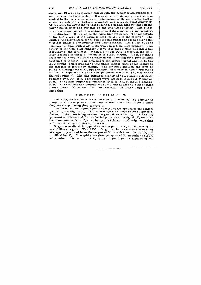
412
SPECIAL DATA-TRANSMIS S ION SYS TEMS
[SEC. 108
ment , and 10-psec pu lses synchron ized with the oscillator are applied to a
t ime-select ive video amplifier .
If a signal en ters dur ing this per iod it is
applied t o t he ear ly t ime select or .
The outpu t of the ear ly t ime selector
is used to act ivate a sawtooth genera tor and a .!i-~sec pulse genera tor .
After ~sec, the sawtooth voltage r ises to a potent ia l that switches off the
ear ly t ime-selector and switches on the la te t imeselector .
The Spsec
pu lse is syn ch ron ou s wit h t he leadin g edge of t he sign al a nd is in depen den t
of it s dura t ion. It is used as the basic t ime reference. The amplitude
of the first ~ ~sec of the signal is used for AVC in the receiver . The
width of the rear por t ion of the pulse is demodula ted nd is applied to the
reference sinusoid demodula tor and voic channel. The 5-psec pu lse is
compared in t ime with a sawtooth wave in a t ime disc nminat or .
Th e
outpu t of the t ime discr iminator is a voltage that is used to con t rol the
frequency of the oscilla tor . When a 5-kc/see PRF is received the oscil-
lator is locked in phase by m ans of th is AFC circu it . When antennas
are switched there is a phase change in the incoming PRF propor t ional
to d sin e or d cos t? The area under the con t rol signal applied to the
AF circuit is propor t ional t o this phase change since phase change is
the in tegral of frequency change. The cont rol signals in the form of
pulses recur r ing with a 200-pps frequency in a pat tern which repea ts at
50 pps are applied to a sine-cosine poten t iometer that is turned to the
desir ed cou rse d’.
The sine ou tpu t is connected to a clamping det ector
opera ted by a 90° (of 50 pps) square wave t imed to include A-B change-
over . The cosine ou tpu t is similarly selected to include the A-C change-
over . The two det ect ed outputs a re a ded and applied to a zero-cen ter
cou rse met er .
No cur ren t ill flow through the meter when o = 0’
sin ce t h en
dsinocos tY+dcos@sin O’ =0.
The 5-kc/see oscillator serves as a phase “ memory” to permit the
compar ison of the phases of the signals from the three antennas since
t hey a re n ot r adiat in g simu lt an eou sly
The posit ive video signals from the receiver a re applied t o the con t rol
gr id of VI (see Fig. 10.14). The 10-psec gate is applied to the suppressor ,
the top of the ga te being estored to ground le el by DIo. Durin the
quiescen t condit ion and for the init ial por t ion of the signal, Vz takes all
the pla te cur ren t from VI since its gr id is held at + 100 volts while that
of V~ is held at +80 volt s by fixed bias.
Negat ive feedback is applied from the pla te of Vz t o the gr id of V,
to stabilize the gain . The AVC voltage for the screen of the receiver
i-f stages is produced from the outpu t of Vz, which is rect ified by DI and
amplified b VS . The gr id-pla te t ime-constant of Vb smooths the AVC
information.
The output of Vz is a lso applied to the ca thode of D2,
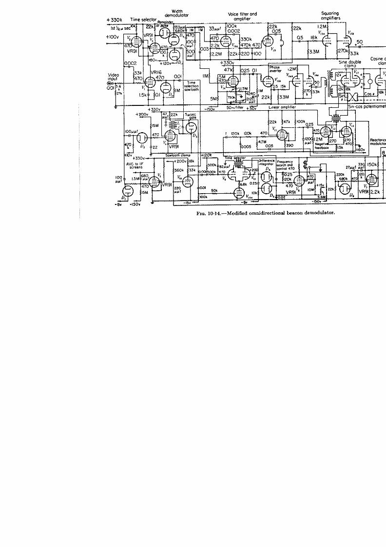

414
SPECIAL DATA-TRANS MIS SION SYSTEMS
[SEC. 10.8
which produces a negat ive exponent ia l ga te of sufficient dura t ion to cu t
off V, for longer than 5 psec. The sudden in ter rupt ion of plate cu rren t
in V 4 by the leading edge of the signal causes shock excita t ion of the
resonan t t ransformer . The diode Ds absorbs the negat ive half cycle of
the oscillat ion so that a single posit ive half cycle of 5-psec durat ion is
produced. The cessat ion of pla te cu rren t also causes a 47-ppf condenser
to charge through the 22-k pla te oad producing a posit ive-going expo-
nent ial r ise. This sawtooth wave raises the gr id of V, unt il it t akes all
the pla te cur ren t of V,, and V, is cut off. s t he n egat ive feedback loop
is now broken , the full video signal is applied to VI) which t hen limits.
The switch-over of cu rren t from 1’, t o Vt occurs after the first $ ysec of
pu lse. P la te cu rren t in V3 charges a 470-g~f condenser th rough D,,
The final poten t ia l reached is determined by the durat ion of the” pu lse.
Th e diode DS holds the init ial poten t ia l on the co denser a t +225 volt s
so that 95 volt s of signal must be presen t before any act ion takes place,
a d small signal will not opera te the width-demodula t ion channel.
Th e amplitu de-modula ted sawt oot h wave con ta in ing t he width -modu la-
t ion envelope is filt ered and applied to the voice channel which has a pass
band star t ing above 50 cps and ending below 5 kc/see but which passes
t he fr equ en cies n ecessa ry for in telligible speech .
The modula ted sawtooth wave is also applied to the 5@cps twin-T
filter V,,, which has a Q of th ree and which reject s the voice frequencies
and the 5-kc/see PRF. The sine-wave output of the filter passes to the
phase in ver ter V,ob; the outpu ts are gr id-limited by Vlti and V,t i. The
coupling t ime constant s and impedances are so chosen that 90° square
waves appear in the pla te circu its of the tubes. The square waves are
applied t o cat hode followers V 15band VI W, w ich dr ive the gr id t rans-
formers of the phase-sensit ive detectors. The detector s VI, and ls
opera te so that each will pass cu r ren t on ly dur ing a quar ter cycle of the
referen ce 50-cps waveform, which s cen tered about the instant of t ransi-
t ion between the relevan t an tennas.
The 5-psec pu lse that is in it ia ted by the leading edge of the signal is
a plied to the gr id of VIOa tu rn ing on space cu rr en t.
A sawtooth wave is
applied to the gr id of Vga and a fixed poten t ia l t o the gr id f ~9b. The
propor t ion of the space cur ren t taken by each half of Vg is determined at
a y instan t by the rela t ive poten t ia l of the two gr ids. As the sawtooth
voltage on the gr id of Vs. increases, less cur ren t will flow in Vgb and more
in VW The difference between these cur ren t s is taken by the pulse
t ransformer connected between the two pla tes. This difference takes
the form of a posit ive puke when cur ren t is great er in V@ followed by a
nega t ive pulse when cur ren t is grea ter in Vgc.
The difference in the
areas of the two pulses is measured by the clifference. det ect r D ~, D g.
(See Vol. 19, Chap. 14. ) The normal opera t ing bias of D, is – 4 volt s.

SEC. 108]
A BRIT ISH OMNIDIRECT IONAL BEACON
415
A bias of – 8 volt s is applied to the pla te of Dg. A Miller in tegra t ing
circu it is a lso u sed with VE to provide smooth ing of the outpu t and a long
memory.
The outpu t of V6 changes the bias on the gr id of the reactance
modu la tor VT, wh ich con tr ols th e fr equ en cy of t he oscilla tor by providin g
a var ia le react ive load across the tuned circu it . Nega t ive feedback is
applied from pla te to gr id of VT through a high-pass network.
The net i
work advances the phase on the gr id by 90° a t the oscilla tor frequency
Since the pla te cu r ren t is 180° ou t of phase with the gr id poten t ia l, a
leading componen t of cur ren t is produced in the pla te circu it which acts
as a capacitance. The a-c voltage applied to the gr id of VT is limited in
amplitude y DG, which is biased by the con t rol poten t ia l. The gr id
voltage and p~a te cu r ren t a re therefore in the form of square waves which
produce an accura tely linear change in the capacitance shunt ing the
tuned circu it . The 2. -k resistance in the ca thode of VI provides cu r r en t
degenera t ion which fu r ther improves the linear ity of the capacitance
change. i
The oscilla tor is of th e con~-en t iona l t ra nsformer-feedback type with
a 1@k resistor in the ca thode circu it . Pulses of ca thode cur ren t a re
taken across this resistor for synchroniza t ion . The amplitude of the
pulses is main ta ined constan t by D,, which is biased a t +60 volts and
which limits the gr id r ise to +60 volts. The pukes dr ive the li iter -
amplifier 1’~~in to gr id cu rren t charging th e 270-pfif coupling conden ser .
At the end of the pulse from the oscilla tor , vlb is cu t off for the t ime taken
for the condenser to recha rge to cu toil b as th rough a 560-k resistor
taken to +200 volts. A 10-psec posit ive pulse is produced in the pla te
circuit.
Par t of th is forms the ga te applied to the suppressor of V,. The
gate k conver ted in to a sawtooth wave by an RC-network. This saw-
tooth wave is applied to the gr id of Vga.
If the phase of the 5-~sec pulse is in advance of the t ime it takes the
sawtooth w ve to go from +120 to +200 volts (the poten t ia l on the
gr id of Vg~), th e posit ive pulse produ ced in th e transformer secon da ry will
be la rger than the nega t ive one. The gr id poten t ia l of VS will r ise so tha t
the pla te poten t ia l will drop, reducing the cur ren t in VT a nd r emovin g
capacity from the tuned circu it .
This will ra ise the frequency of the
oscilla tor which advances the phase of the sawtooth wave.
Th e effect
of this t racking loop is to keep the 5-Psec pulse in the cen ter of the r ise
of the sawtooth wave. The loop is stabilized by the feedback compon-
en ts of Vri.z The constan ts of the loop a re such tha t it will t rack out a
flu ct u at ion in 2 milliseconds.
In the absence of signa ls the 5-kc/see oscilla tor is caused to search
1Williams a nd Kilbu rn , “ Au tomzt ic St robes a nd Recu rr en ce F requ en cy Select or
Par t 11,” I. E. E. Conven t ion Paper , March 1946.
~ See Chap. 8 and F. C. Williams et a l., 10C.m“t .

416
SPECIAL DATA-TRANSMISSION SYSTEMS
[SEC. 108
in fr equ en cy by a r ela xa tion -oscilla tor cir cu it .
‘I’he gr id potent ia l of V~
r ises due to cur rent flowing through a 5.6-megohm resistor r etu rned to
+15 volt s. The pla te runs down linear ly to bot tom by vir t ue of the
Miller feedback. At bot tom, screen cur ren t incr eases, closing the relay
in the screen circuit The suppressor is switched by the relay to – 150
volt s, cu t t ing off pla te cur ren t , and the pla te r ises toward 250 volt s. A
10-megohm resistor in the gr id circu it is a lso switched to – 150 volt s
so tha t when the pla te r ise is complet e the gr id potent ia l fa lls unt il the
r elay opens and the cycle recommences. The sea rch cir cuit sweeps the
oscilla tor fr equency from 4975 to 5025 cps in about 10 sec.
The cont rol pulse from the pla te of V8 is filt er ed and applied to the
feedback amplifier VII, VIZ, Vlsj wh ich is t ra nsformer -cou pled t o t he sin e-
cosine poten t iometer . A 60-volt pulse is pr oduced acro s the poten t iom-
et er when a 3-volt input (the maximum value tha t can be produced by
the antenna switching opera t ion) is applied to the input of the amplifier .
The sine and cosine outpu ts of he poten t iometer a re applied to the t r iode
bidir ect iona l swit ch es V,, and Vlg. Th e differ en ce bet ween t he out put s
of these switches is applied to the zero-cen ter course meter .
A large
capacitance is shunted across the meter to r educe flu t er ing of the needle
caused by the pulses.
Per jornza rwe,-Opera t iona l test s have demonst ra ted a mean er ror of
1° n the bear ing of the plane rela t ive to the ground beacon. This er ror
is equiva lent to a t ime-differ ence er ror of 0.01 ~sec.

CHAPTER 11
RELAY RADAR SYSTEMS
BY E. F. MACNICHOL JR., W. J . JACOBI, AND F. P. COFFIN
TIME-MODULATED SINE-COSINE SYSTEM
BY E. F. MACNICHOL JR. AND W. J . JACOBI
11.1. Pr inciple of Opera t ion.-This system was designed to relay the
PPI picture from n a irborne radar to a fixed sta t ion by:
1. The product ion of an azimuth rota t ion in the remote PPI syn-
chronous with the antenna rota t ion in the radar system and
2. The transmission of the radar t ransmit ter pulse and receiver video
to the remote PPI.
The method of accomplishing (l), is fundamenta lly a “ posit ion”
method; tha t is, the angular posit ion , not the velocity, is r eproduced
~
Bosic
Sine Cosine
Basic
Sine
pulse pulse pulse
pulse pulse
FIG. 11.1.—Time intervals of t ime-modulated sine-cosine system.
In order to do this, t he antenna angle a t the sending end (from a fixed
zero r ference) must be cont inuously and unambiguously specified.
Both the sine and cosine funct ions of the angle are used for this purpose
because either funct ion a lone would not give an unambiguous specifica-
t ion . The process of reproducing the angle involves conver t ing angular
data to elect r ica l data , t ransmit t ing the elect r ica l data to the receiver ,
and conver t ing the electr ica l da ta back to angular da ta a t the receiver .
The limit ing er ror of the over -a ll angular data transmission is approxi-
mately A 3° for a maximum angular speed of 6 rpm.
The elect r ica l informa ion transmit ted is in the form of a system of
pulses. Three pulses are used—the basic pulse, the sine pulse, and the
cosine pulse. If o is the angle to be transmit t d, the interva l between
the basic pulse and the sine pulse is made equal to K + A sin 0 where
K and A a re constants and K > A and the interva l between the sine
pulse an the cosine pulse is made equal to K + A cos 0. These pu lses
and t ime in terva ls a re shown in Fig. 11”1. The basic pulse has a con-
417

418
RELAY RAI)AR SYSTEMS
[SEC. 111
stant repet it ion ra te of 300 pps, and the sine and cosine pulses move as
shown in Fig. ] 1.2.
At the sending end, an Arms resolver produces a lt erna t ing voltages
whose peak values a re pr opor t iona l to the sine and cosine, r espect ively,
of 0. (A nega t ive va lue of the funct ion is indica ted by a reversa l in
phase of the volt~gc. ) These voltages a r e r ect ified by a phase-sensit ive
det ect or , givin g ou tpu t volt ages, A sin O and A cos 0, a dded t o con sta nt
volt ages to give K + A sin o and K + A cos 0. These voltages a r e
impressed on linea r elect r ica l t ime modula tor s.
In more deta il, the
basic pulse genera tor t r igger s the sine t ime modula tor (sawtooth); the
sine pulse is produced after a t ime
i
in terva l propor t iona l t o K + A
\
~-.
sin o; the sine u lse then sta r ts a
\
second delay fr om wh ich the
:
. cosine pu lse is evolved. The
\
th ree pu lses a re mixed befor e
c
\
\
modu la t ng the radio link t rans-
\
mit ter . The device tha t per forms
/
‘.
.-. ”
a ll t h se funct ions is known as the
a: K+Acm f)
“synchronizer. ”
At the receiving nd, the pro-
0
90 1s0
270
360
Oin degrees
cess is essentially reversed in what
hG. 11 .2 .—Sine and cos ine pulses .
is known as the “ decoder . ”
Here
the object is to produce s~.ne-and
cosine-modula ted car r ier voltages ~~hich ar e applied t o the sta tor s of an
Arms r esolver (two-ph ase syn ch ro).
The field th s produced is t r acked
by rota t ing the shaft by means of a servomechan ism.
The synchron izing pulses r eceived from the relay receiver a re sep-
a ra ted by a sequence of t ime selector s, and linear delays a re roduced
cor responding to those in the synchronizer .
The sine pulse is au to-
mat ica lly t r a ked by a system of step ga tes whose posit ion is con t rolled
by a pickoff voltage impressed upon the sine t ime modula tor . The
posit ion of the ga tes is compared with the posit ion of the sine pulse, and
the er ror voltage is used to con t rol an a lt erna t ing-voltage modula tor
w ose output is the desired sine-modula ted car r ier , (A’ sin u’t ) sin 0.
A bidirect ional switch detector , opera t ing from this ca r r ier t ogether
with the constan t volt age K produces the pick-off volt age impressed
upon the linear delay. Thus the t racking loop is completed The
alterna t ing-volt age car r ier adjusts it self unt il the step ga tes coincide
with th e sine pulse, and, since th e sine pulse execu tes a sinusoidal mot ion
the ca r r ier is modula ted in a sinusoidal manner . The cosine pulse i
t r acked in the same fashion as the sine pulse, using similar circuit s, to
produce a cosinusoida lly-modula ted car r ier . The two car r ier s a r e then
I
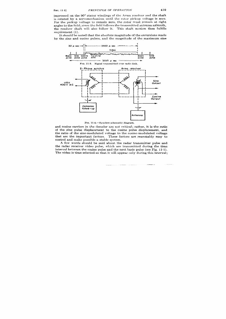
SEC. 11.1]
PRINCIPLE OF OPERATION
419
mpressed on the 90° sta tor windings of the Arms resolver and the shaft
s rota ted by a se vo echanism until the rotor pickup voltage is zero.
For the pickup voltage to remain zero, the rotor must remain at r igh t
a n les t o t he field; sin ce t he field follows t he t ra nsm it ted a nt en na a zimut h,
the resolver shaft will a lso follow i .
This shaft motion then fulfills
r equ ir emen t (l).
It should be noted tha t the absolu te magnitude of the exc rsions made
by the sine and cosine pulses, and the magnitude of the maximum sine
+ 1
II
“~i
J
I
I
I
Bosic %ne cosine ~IW
Basic
Sine
pulse pulse pulse
pulse
pulse
+
3333 # Wc —
FIG. 11.3.—Signa l t ransmit ted over rad io ink .
l15v
400V AC
2- Phase synchro
Arms resolver
r
-—__-—
1
1-
-— —--—---
1
I
BF
]
I
I
I
n
I
I
I
I
I
i
/
Sine
out put
i
I
I
//
I
I
~
1’
U–-J k- —-.
–}-J
&
Cosine
output
n
I
Compass
follow -up
A
El
Antenno
FIG. 11.4.—Synchro schematic diagram.
and cosine ca r r ier s in the decoder a re not cr it ica l; ra ther , it is the ra t io
of the sine pulse displacement to the cosine pulse displacement , and
the ra t io of the sine-modula ted voltage to the cosine-modula ted voltage
tha t a re the impor tant factors. These factors a re reasonably easy to
cont rol and make possible a stable system.
A few words should be said about the radar t ransmit ter pulse and
the radar receiver video pulse, which a re t ransmit ted dur ing the t ime
in terva l between the cosine pulse and the next basic pulse (see Fig. 11. 1).
The video is t ime selected so tha t it will appear only dur ing this interva l;

420
t
RELAY RADAR SYSTEMS
[SEC.11.1
‘sicp’J ’seci~u ’t ~
Smep,pcircul
~------ ----- —--- ——______
SInaclom.
0
do
1
e
%%_ s
I
1------- -–-- —-----------
1
*
f
I
90
J
IF; V,dm in
till
Re
y,
~, y8 v
1 :Qe
v
6AC7 6SN7 6SN7
Gated
6&7
@&h
cod,,
- tub
2470JM
W,d.
*m
L%’
w t.
R,ad &R,,
‘5C, i
.
.
rwcnr
F
40&.
Filter
B,
. ebw u
f
R
45
4oocp9
lb Synchm
sylhan
I I
I
I
P
I
FL
b%lq
To V7~
Trar6f
-b I(a
R.
,yJb, ,
6s;7
R-
S,ne
~
Zem
c,
CImlv
- c,,’a ’a
R.
R S IMsbm R
52
64
& k3111@*
hwt fmm m%+-,
F-4.
l%. 11.6.—Block d ia -

SEC.11.1]
PRINCIPLE OF OPERA Z’1ON
421
--- . ------- —_______
~ ~—Modul.ator tri~circ.its
——i———— ‘ “Q Circu”s +
0
1
I
0+ —
Idbnr
ok
1
m
YE
+ 380v uweg
@
v
5 R:GY
er swply
.
;,
0
I
‘r
gram of synchro~i~er .
%
F Trigqer
Gul
&
ig to mod
L
de&8ync
out
L
W out
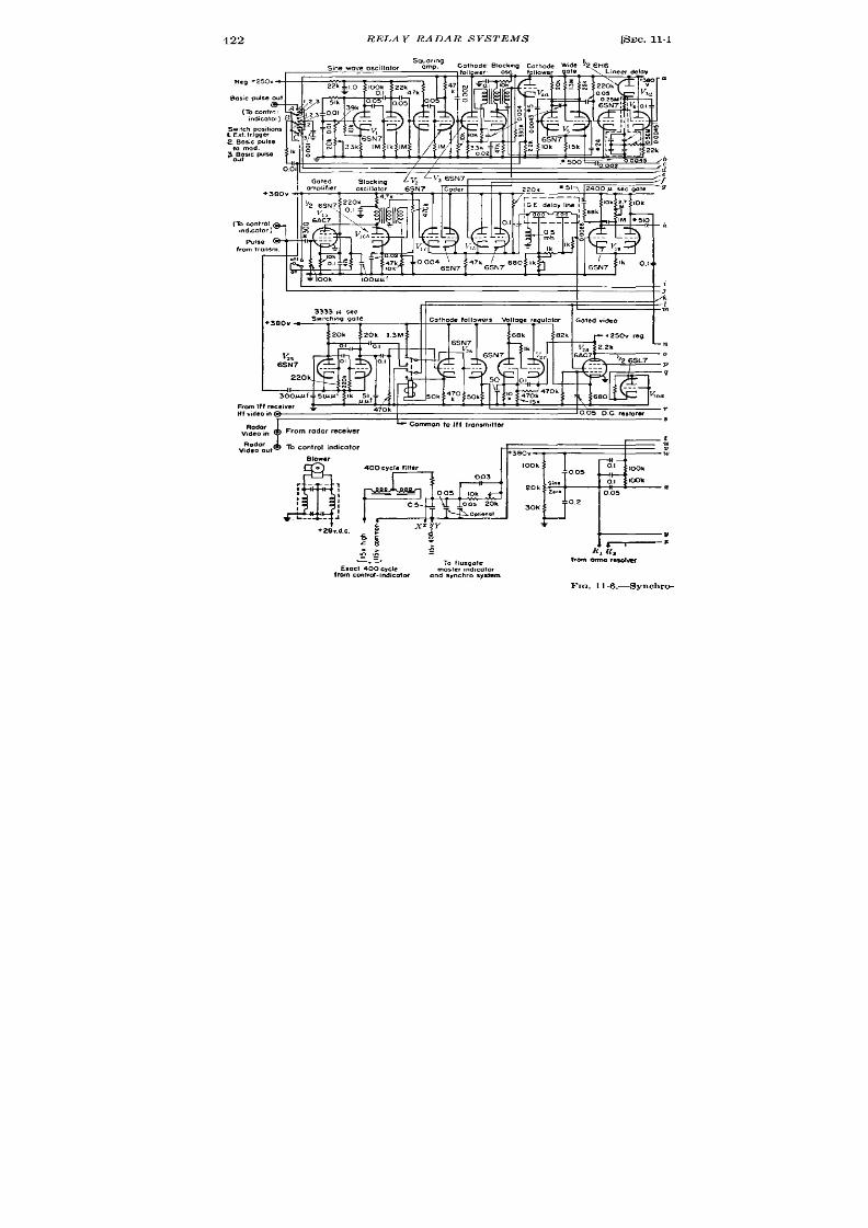
422
RELAY RADAR SYSTEMS
Sq:;;ng
s,newovescillator
Cothode Blo
Reg q250v
R! L f
..
(Tocontr;l A
i“d,coto~ B
‘“L
Swtch posi,ons
L
Ext.Irlgger
2i~:$dwlse
300~slcF&e
l!!
21
3P
Ik ~
0.
[SEC. 11.1
WI
(10cm
mdtcot
I
I
I
1
1
;
q3
R,f-iz=!%!L
I H I r-a “2!“7 P
Rodor
4
b Commonlo Ift Irmmmtler
V,deom
From radar receiver
-z
L-
V
—— z
c=
;
.
4
;;
.
R:Ra
-
TOlqo!e
h om o nn a ,e s4 hw
Exact 4 0 0cycle
Inoster,nd,color
fmn! Cml?,d-indwatof
and synchrosystem
FIG. 11.6.—Synchr 0-

SEC. 11.1]
/4=
PRINCIPLE OF OPERATION
423
W1l
1
1
11 1
\
1 l-l
1
10
11
i]
!Hf
II
I
I
t
8-751Ulf
70 Iff trmsmitter~~
/ /’
~k
22 <Jk+
L1 .
r
d-
bmdSW>~
I
m
I 1 Svnc I
G-bud
t-l
I
Sync-ut
S,”, doub,, dam, U ,.s-. ?,..,,, clam, &
s; f ~ ‘: ~
005
Iooh look
-%%’--
l~o
0,05
z
005
005
001
co,
v
~em 2oh
33
005
.. -
. . . . . .
0 .2
47M
47M
3ok
6SJ7 z !?
v
lok
32**
6SN7
z
ZOk
Sme slope
niaer circuit.

424 RELAY RADAR S YS1’h’MS
[SEC. 112
otherwise it would mix with the synchron izer pu lses (basic pu lse, sine
pu lse, and cosine pulse) and cause displacements of these pulses. The
t ime in terval a llowed for video cor responds to the maximum range of the
radar . F igure 113 shows the complete signal t ransmit ted over the radio
link.
Provision is made in this system for alt ernat ing two types of video
pulses (radar and beacon). Th radar and eacon pulses are t ime-
selected and applied to their respect ive indicators.
The t ime-select ion
process is actua ted by the presence or absence of the radar t ransmit ter
pu lse which is absent wh en beacon signals a re being received.
11.2. The Synchron izer .-The first st ep in angular data t ransmission
is the conversion of angular data to elect r ica l data . In th is system the
angu ar in format ion t o be t ransmit ted is t he posit ion of the radar an tenna
with respect t o t rue nor th . An Arms resolver (two-phase to two-phase
synchro) mechanically geared t o h e antenna, act s as a differen t ia l while a
second syn ch ro (sin gle-ph ase t o two-ph ase) gea red t o t h e flu xga te compa ss
follow- p acts as a genera tor . The synchros are connected elect r ica lly
as shown in Fig. 11.4. The 400-cPs filt er gives the necessary sinusoidal
waveform.
This volt age is impressed on the single-phase sta tor of the
Dieh l Generator . The two-phase rotor of the genera tor is co nect ed
to the two-phase sta tor of t he Arms resolver . The outpu t a lt ernat ing
poten t ia ls A and B of the sta tor windings of the resolver consistof the sine
an d cosin e compon en ts of t h differ en ce between t he an ten na dir ect ion an d
the compass direct ion . Expressed mathemat ica lly, if A sin cd is the input
pot en tia l t o t he Diehl Gen er at or , 81 th e an gle t hr ou gh wh ich t he gen er at or
shaft is tu rned, 02 the angle th ough which the resolver shaft is tu rned,
and both synchros have a l-to-l ra t io th roughout , then ,
Outpu t of A = (A sin at ) sin 0
Outpu t of B = (.4 sin t it ) cos O
where 0 = 62 — 01.
The ext step in t ransmit t ing 0 consist s of phase-detect ing the sine
and cosine voltages from the Arms resolver and adding a const n t
voltage t each . This is done in the sine and cosine bidirect ional switch
det ectors (F ig. 11.5) which produce voltages A sin 8 and -4 cos O. The
con st ant volt a ge K is added to each so that the resu ltan t ou tput s are
K + .4 sin @and K + A cos 0. These are the voltages that a re to be
con ver ted t o t im e in ter vals.
The pulse-forming circu it s a re the next considera t ion. Sta r t ing at
th e upper left -hand corn er of th e block diagram, Fig. 11 “5, and th e circu it
diagram, Fig. 11“6, the basic pu lse repet it ion genera ior produces a pu lse
ever y 3333 ~sec. Th e pu lse st ar ts a va ria ble dela y, (t im e modu la tor ), wh ich
t rigger s t he sin e pu lse gen er at or (blockin g oscilla tor ) a ft er a t im e in ter va l
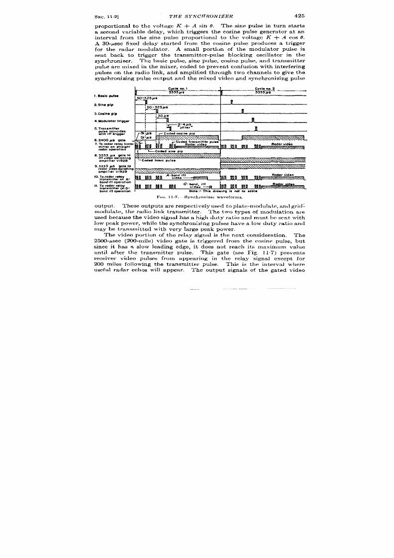
SEC. 11.2]
THE SYNCHRONIZER
425
pr opor tion al t o t he volt age K + .4 sin 0. The sine pulse in turn sta r t s
a second var iable delay, which t r iggers the cosine pulse genera tor at an
in terva l from the sine pulse propor t iona l to the volt age K + A cos O.
A 30-psec fixed delay sta r ted fr m the cosine pulse produces a t r igger
for the radar modulator . A small por t ion of the modula tor pulse is
sen t back to t r igger the t ransmit ter -pulse blocking oscilla tor i the
synchronizer . The basic pulse, sine pulse, cosine pulse, and t ransmit ter
pul~e are mixed in t he mixer , coded t o pr event confusion with in ter fer ing
pulses on the radio link, and amplified through two channels to give the
synchronizing pulse output and the mixed video and synchronizing pulse
4. Modulator t
5. Tronsmitlaf
2.Slna pip
3.Caslna PIP
,~
Nlfl
Raaor vidm
,. ... ”
9.3333 /Is We t o
rador videosw,lching
omplifwr V1929
10.To radar rtiv
tronsrnmer on 4-
bond,11operotwn
II. To radar relay
Irommittar onG-
bond itf operation
FIG, 11 .7. —Synchronizer waveforms.
output . These outputs are respect ively used to plate-modulate, and gr id:
modu lat e, t he r adio link t ra nsm it ter .
The two types of modulat ion are
used because the video signal has a high duty ra t io and must be sent with
low peak power , while the synchronizing pulses have a low duty ra t io and
may be t ransmit ted with very la rge peak power .
The video por t ion of the relay signa is the next considerat ion. The
2500-~sec (200-mile) video ga te is t r iggered from the cosine pulse, bu t
since it has a slow leading edge, it does not reach its maximum value
unt il a fter the t ransmit ter pulse. Th s ga te (see Fig. 117) prevents
rec iver video pulses from appear ing in the relay signal except for
200 miles following t ihe transmit ter pu lse. This is the interva l where
useful radar ethos will appear .
The output signals of the ga ted video

426
RELAY RADAR SYSTEMS [SEC. 113
amplifier s a re m ixed wit h syn ch ron izin g pu lses in on ly t he gr id-modu la t-
ing channel so that the tota l peak r -f power of the video will be less th n
that of th e synchr onizing pulse.
The layout of the deta iled circuit diagram ollows that of the block
diagram and will not be descr ibed in deta il since it conta ins no unusual
features.
11.3. Receiving Equipment .-The. r eceiving equipment for the data-
t ransmission system is known as the “decoder ,” a lthough it per forms
many more funct ions than simply unscrambling the th ree-pip “code”
used for t he synch ronizing pulses.
The decoder ut ilizes the signal from
the relay r eceiver , consist ing of synchronizing pulses and video signals,
to produce a rota t ion synchronous with that a t the t ransmit ter and to
dist r ibute the video signals to the indica tor s in the desired manner .
The decoder may convenient ly be div ded into six par ts:
1. Th e syn ch ron izin g-pu lse sepa ra tor a nd t hr ee-pip decoder .
2. The sequencing circuit s and linear delays.
3. Th e t ime-discr im in at ion cir cu it s.
4. The sine and cosine modula tor s and bidirect iona l switch circuits.
5. The Arms r esolver and ser voamplifier .
6. The video switching and dist r ibut ion cir cuits.
Th e syn ch ron izin g-pu lse sepa ra tor sepa ra tes t he syn ch ron izin g pu lses
from noise and vicleo pu lses. The ecoder produces sin gle pu lses fr om
three-pip-coded synchronizing pulses; these a re known as “decoded
synch ron izing pu ls es. ”
The decoded synchronizing pulses oper ate a sequence of ga tes and
ga ted tubes, (t ime a lector s) which separa te the pulses and init ia te linear
sweeps star t ing with the basic pulse and the sine pulse.
Th ese sweeps a re
similar to those in the synchronizer t ime modula tor s a t the t ransmit t ing
end and are used to demodula te the sine and cosine pulses.
To obta in these voltages, some sor t of t r acking “loop” must be used.
It consists of “step ga te” t racking circuits, which follow the posit ions
of the sine and cosine pulses and, in the process, produce sine and cosine
voltages that a re delivered from modula tors and dr iver s to the Arms
resolver.
Th e video swit ch in g a nd dist ribu tion cir cu it s pr ovide a low-impedance
source of video signals for var ious indica tor s and are used to “switch”
different types of video signals to the appropr ia te indica tor s whenever
th is type of opera t ion is desired.
These circu ts will not be discussed
in deta il.
F igures 11.8 and 11.9 a re block diagrams of the decoder
which may be helpful in following the opera t ion of the circuit s.
11.4. Synchronizing- ulse Decoding Circuits.—Refer to Fig. 11.10.
The posit ive relay r eceiver ou tput enter s the decoder a t a level of 1.5 volts

1
Bo5ic Sine
sine
. puls~~ted — sequence
pul~ub~ed
\
gote
decoded
I
~,~hronizin
*
4
Sine
Narrow
— coincidence
deloy
Amplifier
gata
generator
t I t
I
I
ia&ge)
Amplifier
c1
lifferentio?or
t
‘s
z
_ From double
circuif
\
Inverter
n
othode
follower
m.%
t
a
iode
intergrotor
t
m
iode
infergratof
J
t r
I
J
Amplifier
Coincidence Coincidence
tube
tube
Inverfer
I I
(1
*
sine modulotor)
I
Nofe:Cosine linea r d elq y, step ond norrow
Synchronizing and video
gole generofors,coincidence circuits, stc. ore
signals from receiver
similar to sine circuite.
Fm. 11,8.—Input , decoding, and sine-vol tage ci rcui ts.

428
RELAY RADAR SYSTEMS
[SEC.114
for video and 3 volts for synchron izing pulses through a shor t t ime con-
stan t consist ing of C, and R,. Inuerter VIO inver ts the signals and pro-
vides some limit ing because gr id cu rr en t is drawn on st ron g input signals.
The nega t ive outpu t of V,. is passed through another shor t t ime con-
stant (C’S and Rs) to th gr id of am plifir Vz.
Pos it ive over shoot s
r esult ing from different ia t ion by th e sh or t t ime constants ar e su ppr essed
by the gr id cur ren t drop th rough R,.
Negat ive signa ls a re limited by the
cu toff voltage of the tube; L, pr ovides some h igh -fr eq ency peaking to
From sine memory
Sine
Sine output ~
cathode follower
modulator
voltage to
Cathode
(sine d-c voltage )
circuit
pick off diode
follower
II
ush-
pull
I
Sine
Push -
Sine
Push-
Output
Oouble
amplifier
pull
drjver
—
pull
transformer
clamp
circuit
-}
Sine
zero
ad)uste r
Ampl#fler
tachometer
—
, Push-
1
I– ____, Sine
pull
-1-
i “- G
From cos!ne
~Ll
output transformer
Amplifier
Cosine
Push-
,,
pull
~ ®____ _ ~Arma resolver
I
Power
output
‘“’; ---m~:~:~~f~r”
FIO. 11.9.—Sine modulator and scrvoamplifier circuits .
improve the shape of the synchron izing pulses.
Th e posit ive limited
ou tpu t of V2 is impressed upon the gr~d of the cath od e jollow er V,*, which
dr ives th e decoding delay line.
In t he a bove pr ocess, t he r ela y signals h ave been ” differ en tia ted” twice.
The purpose of th is is to a llow only shor t pulses to be passed; long pulses
of in ter ference or video signals are differen t ia ted to form a posit ive and a
negat ive spike, one of which is later eliminated. The synchronizing
pulses are not ppreciably a ffected by this opera t ion . All signals are
limited well below their peak value so that var ia t ions in signal st r ength
will not a ffect the decoder opera t ion .
Assuming tha t a three-pu lse-coded synchronizing pulse is presen t at
the output of V16, it remains to expla in the act ion of the de oding delay

SEC. 11.5]
SEQUENCING CIRCUITS AND LINEAR DELAYS
429
lines. Note that the decoder coincidence tube V3, is bia sed so t ha t posit ive
signa ls of su fficien t amplitu de must be impr essed simu lt an eou sly u pon it s
The fir st pulse of the
code is designa ted A, the second (3 ~sec la ter ) B, and the third (8 psec
after A) C. (Refer to Fig. 11”11.) At point a , the scr een of l’s, each
pulse appears ith no delay. At point b, across R,S and R l,, ea ch pu lse
a ppea rs dela yed 5 psec; t his occu rs beca use t he win din g-t o-sh ield ca pa ci-
t ance of the 3-~sec delay line t ransmits the pulses tha t leave the 5-psec
line. The” or iginal pulses appear across the terminat ing resistor R 12
delayed 8 psec. The voltage at point c with r espect to ground ther efore
consists of the sum of the voltage at b and that across R lZ
Thus there is
a t riple-coin ciden ce ar ra ngement wher ein th e pulse pot ent ia ls a t a , b, and
between b to c must coincide for V, to conduct . Eigh t microseconds
A
be produced at the pla te of V3. The negat ive gr id bias is adjusted by R,6
to provide the proper th reshold to discr iminate agai st noncoinciding
pulses and against noise. The decoded synchronizing pulses appear a t
t he seconda ry of th e pulse t ra nsformer T1. Resist or Rs pr even ts sh ock-
e cit ed oscilla t ons due to the dist r ibuted inductance and capacitance
of t h e t r an sformer .
11.5. Sequencing Circuits and Linear Delays.—Refer to Fig. 11.10.
The sequencing circuit s may be thought of as an endless chain of t ime
select or s t ha t, wh en oper at in g, sepa ra tes t he va riou s syn ch ron izin g pulses
from each other . The input to the sequence circuits is the decoded
syn ch ron izin g pu lse ou tpu t fr om TI; the outpu t waveform of the sequenc-
ing circu it s consists of the sine pulse, the cosine pulse, and wide gates,
which are used to turn on the sine and cosine linear delays.
The chain begins with the basic pulse gated tube V,. This tube is
biased so that th decoded synchronizing pulses applied to he No. 1
gr id will not be effect ive unless the voltage applied to the No. 3 gr id is
sufficiently positive.
For a moment , let us assume that this is the case
and tha t a posit ive basic pulse occur s.
The pla te of V, will dr op shar ply,
t rigger ing t he mono ta ble mult ivibra tor VS which pr duces the sine
sequ en ce gate. The posit ive ga te produced at the pla te of VE,b is fed
to the cathode jollower Vsa.
This ga te, the “sine gate,”
embraces the per iod of t ime in which the
sine pulse can be expected. It is applied from the ca thode follower to the
screen gr id of the sine pulse gated tube Vg (t ime sele tor ) which also has
posit ive decoded synchron izing pulses applied to it s No. 1 gr id. A specia l
na r row ga te is a lso applied to the No. 3 gr id, but th is can be disregarded
for the moment , the assumpt ion being made tha t the No. 3 gr id has a fixed
posit ive voltage. The ca thode of V, is bia sed posit ively so t ha t t he scr e n
vo tage must be considerably posit ive for a synchron izing pulse to be

430
RELAY RADAR SYSTELWS [SEC.11.5
C)(-II 1 I
85mh 85ml
T
‘“ Tz~’
.-.
0.01
D
FIG. 11.lO.—De-

SEC.11.5]
SEQUENCING CIRCUITS AND LINEAR DELAYS
Ho!
Em ln )!lu l ““1P!
, !* ,’
.,m , .“,p,. >!v.,r.- F“.r-,
,,. ,,. . . . I I
431
t
Y@or @my I Am@fw
Ice.Mckq,.,1!0
L
*
L
L
L
coder oirmdt .
I
>
h
1
MI

432
RELAY RADAR SYSTEMS
[SEC. 115
amplified. Since the screen voltage becomes posit ive shor t ly a fter the
basic pulse, the sine and cosine pulses and the t ransmit ter pu lse cause
conduct ion of the tube and produce nega t ive pulses at the pla te. The sine
ga te lasts 600 Msecbu t on ly t he fir st pu lse r eceived is effect ive.
The first of th ese pu lses, t he sine pulse, t r igger s th e cosine sequence gate
V,O, which is exact ly similar to it s sine coun terpa r t and opera tes in con-
junct ion wit the co ine gated tube to select the cosine and transmit ter
pulses. Since the first of these is the cosine pulse, it t r igger s the video
Cathode
follower
Coin$ci;nco
-L
r
-
—
fL.fidL
FIG.11.1l.—Decod1ng delay line.
blanking gata VIZ, which then lasts for approximately 2500 ~sec. This
except tha t a restorin g cath od e follow er vE ,b is used between the p]a te of the
“a” sect ion and the g id of the “b” sect ion .
Th is is n ecessa ry beca use of
the large du ty ra t io of the gate (see Chap. 5, Vol. 19 of th is ser ies), A
negat ive ga te is thus obta ined from the ca thode of Vs&,wh ich st a rt s sligh t ly
a fter the cosine pulse and lasts until approximately 100 ~sec before the
next basic pu lse can be expected.
This is equ ivalent to a posit ive ga te
star t ing 100 Ysec before the basic pulse and last ing until the cosine pulse,
The ate, therefore, embraces the t ime i terval wherein the basic sine.
cosin e, a nd t ra nsm it ter pu lses occu r.
This posit ive ga te is applied to the
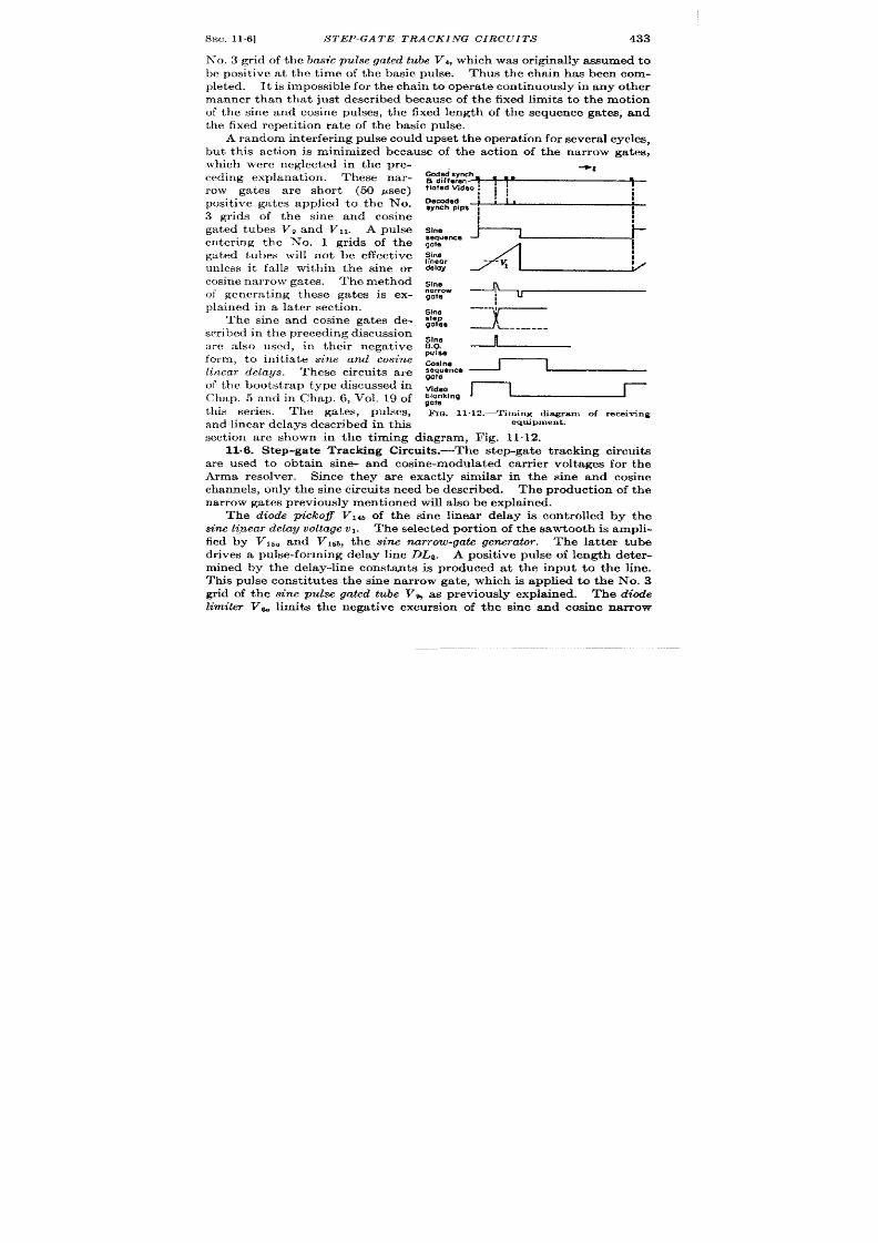
~EC.11.6]
S TEP-GATE TRACKING CIRCUITS 433
No. 3 gr id of t he basic pu lse gated tube Vi, which was or igina lly assumed t o
be posit ive a t the t ime of the basic pulse. Thus the chain has been com-
pleted. It is impossible for the chain to opera t e cont inuously in any other
manner than tha t just descr ibed because of the fixed limits t o the mot ion
of the sine and cosine pulses, the fixed length of the sequence ga tes, and
the fixed repet it ion ra te of the basic pulse.
A r an dom in ter fer in g pu lse cou ld u pset t he oper at ion for sever al cycles,
but th is act ion is minimized because of the act ion of the na rrow gates,
which were neglect ed in the pre-
ced ing exp lana t ion .
These nar-
row gates a re shor t (5o psec)
posit ive ga tes applied to the No.
3 gr ids of the sine and cosine
ga ted t ubes V, and VI,. A pulse
en ter ing the No. 1 gr ids of the
ga ted tubes will not be effect ive
unless it fa lls within the sine or
cosine narrow gates. The method
of genera t ing these gates is ex-
pla ined in a la t er sect ion .
The sine and cosine gates de-
scr ibed in t h e pr eceding discu ssion
a re a lso used, in their nega t ive
form, t o in it ia te
sirw and cosine
linear elay s .
These circuit s a re
of the boot st rap type discussed in
Chap. 5 and in Chap. 6, Vol. 19 of
th is ser ies. The gates, pulses,
and linear de ays descr ibed in this
--1
Ceded synch
13differm- ?
m mm
fiatad Video 1 ! I
I
1
l;,
:
Decoded
1
synch pips i
S&ce ~
:, ~
F IcI. 11.12.—Tlm ing dia gr am of r eceivin g
equipment.
sect ion a re hown in the t iming diagram, F ig. 11.12.
11.6. Step-ga te Tracking Circuit s.-The step-ga te t r acking circuit s
a re used to obta in sine- and cosine-modula ted ca rr ier voltages for the
Arms resolver . Since they are exact ly similar in the sine and cosine
channels, only the sine circuit s nee be descr ibed. The prod ct ion of the
n ar row ga tes pr eviou sly men ti n ed wiU a lso be expla in ed.
The diode pickoff V14b of the sine linear delay is cont rolled by the
sine lt>ear delay voltage V1. The selected por t ion f the sawtooth is ampli-
fied by VIE. a d vl~b, the sine narrow-gate genera tor . The la t t er tube
dr ives a pulse-form ing dela y line DLe. A posit ive pulse of length deter -
mined by the delay-line constant s is produced at the input to the line.
This pulse const itu t es the sine na r row gate, which is applied to the No, 3
gr id of the sine pulse gated tube @ as previously expla ined. The diode
limiter V& limits the nega t ive excursion of the s ne and cosine nar row

434
RELAY RADAR SYSTEMS
[SEC.116
gates before they a re applied to their respect ive ga ted tubes. The
narrow-gate in-sertion circuit VT is a device for “turning off” the nar row
gates whenever too few cosine pulses are obta ined, tha t is, when the nar-
r w gates have become misplaced in t ime, so that the sequence gat ing can
r esume oper at ion . Th e cir cu it of V, is simply a cat hode-follower det ect or ,
which ra ises the poten t ia l of the No. 3 gr ids of Vg and VI 1 which per-
mits opera t ion of the gated tubes in the absence of the nar row gates
wh en ever th e fr equ en cy of cosin e pulses fr om th e com ”n eblocking oscillator
V,t falls below 300 pps. Since the genera t ion of cosine pulses is depend-
en t upon the basic pulse, sine pulse, and cosine pu lse fa iling with in the
in ter va ls det ermin ed by t heir select or ga tes, a con tr ol s n sit ive t o impr oper
a lignmen t is a ch ieved.
Since the pulse-forming delay line is terminated in a resistance less
than its character ist ic impedance, a pulse is produced at its end that has a
lea din g edge h alfwa y between t he lea din g an d tr ailin g edges of t he n ar row-
gate pulse, tha t is, a t the time of the sine pulse. This pulse is “st r etch ed”
step
Gota
330~i:e sec
Basic
pulse pulse
Sosic
pulse
F I . 11.13.—Tim ing dia gr am of sin e-pu lse
s t ep ga t es .
by the step-gak generator V Ida,
wh ich is ca th ode-follower det ec-
tor . The st retched pu lse is am-
plified and shaped by the step
amplifiers VIM and VITOto form a
“step” ga te having a steep edge.
The irwert er V I,. pr odu ces a simi-
lar gate of opposite polar ity.
Refer a t th is poin t to t e t iming
diagram, Fig. 11~13, for the sine
step gates. These gates are char-
a ct er ized by st eep lin ea r edges an d
flat tops and end shor t ly after the closing of the ~ine s~quen e ga~e. As
previously descr ibed th e sine pulse, a fter passing th rou gh th e sine-gated
tu be, in it ia t s t he cosin e selector ga te. Th e r ise of t he co in e gate t rigger s
the sine blocking oscillator V22b.
Tubes V~*, V,~ and V*Oform a t ime d scr iminator which determines
wh eth er th e sine blockin g oscilla tor pulse occu rs befor e or a fter th e t ransi-
t ion of t he st ep ga te wa veform.
Th e memor y ca th ode follower Vzl. is a
bootst r apdouble in tegra tor ’ accept ing the ou tpu t of the t ime discr imi-
nator , and its outpu t voltage is the sine d-c voltage. It will be remem-
bered that the sine voltage v, is con t rolled by the sine d-c ou tpu t so that
the t racking loop s closed and step-gate transit ion is held in coincidence
t vit h t he sin e blockin g oscilla tor pu lse.
In the normal case of constan t velocity rota t ion , the memory fea tu re of
the double in tegra tor nables the receiving Arms resolver to con t inue
1See Chap. 8 and VO1.19, Chap. 14.

SEC.11.7]
BIDIRECTIONAL SWITCH DETECTORS
435
rota t ing fora considerable t ime without appreciable er ror if relay signals
a r e lost t emporar ily. It is par t icu lar ly helpful when the relay signals
a r e fluctua t ing or when bad in t er fer ence is presen t . The t ime constant
R1Oand C1Ois chosen small enough t o permit sect or scan of t he radar , th is
topic will be discussed in a la t er sect ion .
Th e cosin e t im e demodu la tor
oper at es in a similar fashion.
11.7. Modu la tor s a nd Bidir ect iona l Swit ch Det ect or s.—So fa r, a volt -
age has been produced (t he sine d- volt age) which is som ehow indica t ive
of the posit ion of the sine pulse with respect t o the basic pu lse, that is,
of the sine of the ngle being t ransmit ted. Also, another volt age (vl) has
been assumed, but it s product ion has not been expla ined.
The end result of the sine t racking loop is the product ion of a 60-cps
a lterna t ing voltage modulated in amplitude and reversible in phase by
the posit ion of the sine pulse. It is desired tha t th is volt age be zero a t t he
midpoint of the sine pulse excursion (185.4 ysec), tha t it be a maximum
at the maximum delay of the pulse (321.4 psec), and that it be a maximum
in the opposite direct ion a t the minimum delay (49.4 psec). In other
words, an alterna t ing volt age is desir ed which var ies in synchronism with
the sine carrier voltage fr om t he” A” coil of t he t ra nsm it tin g Arms r esolver .
The alternat ing volt age is var ied by the sine d-c voltage in the w“ne
modulator, shown in Fig. 11.14. This consist s of tubes VI and V2. The
60-cps input to the modula tor is obta ined from the t r ansformer 2’,,
wh ich supplies a ppr oxim at ely 100 volt s rm s.
The outpu t signal is ta en
between the point s labeled a and c.
The gr ids of both sect ions of Vz
are held at a fixed voltage det ermined by a divider consist ing of Rg and
R~. The gr ids of Vz are var ied, t h rough an a t tenua tor , by the sine d-c
volt age. The actual con t rol voltage of the modula tor is t he difference
between these two voltages; t he magnitude and direct ion of the alter -
nat ing voltage outpu t a re det ermined by the magnitude and pola r ity of
th is d ifference voltage.
The opera t ion of the modula tor is shown in Fig. 11.15. It can be een
that t he circu it is a fu ll-wave b lanced modula tor tha t depends for it s
act ion upon the var ia t ion of rP with Ev. It has a la rge amount of
ca t hode degenera t ion tha t a llows t he opera t ing level of t he circu it t o va ry
considerably.
The outpu t cur ren t of the modula tor is passed through a symmetr ica l
twin-T filt er in order to eliminate the second harmonic produced as a
resu lt of nonlinear opera t ion of the tubes in the modula tor .
The t ine
amplijizr V~ is a push-pull voltage amplifier , which dr ives the w“ne
driver tube, V,. This push-pu ll ca thode follower has the outpu t t rans-
former T2 in its ca t hode circu it .
The t r ansformer has t wo secondar ies:
one (point s 6 and 7) is a low-impedance source for one sta tor of the receiv-
ing Arms resolver . The other winding (poin t s 4 and 5) is a stepup

436
RELAY RADAR SYS TEMS
[SEC. 11.7
+ 330V
reg.
7
1
7
15V
input
I
r
Smd
m
75V
to
motor
+300v —
reg
r
Cc6d
m
—
%e modulotor tubes
R8 ~~Ok
—
6SN7
47k
00075
00075
—
6SN7
7
~
01
47k
.“4.
-V.%
a
47k
100k
180k
180k
Rg IW
: : IM
1
==00075 ‘
22!/!
—
—
44k
J
b
— t
22k
IM
68k 4W
2
180k :;
IM
—
-
—
m
c
47k 47k
01
180k
0
47k
47k
L.i-io!--#
r
OOk
22(
Error -105
Signal in
\ 100k.
j Iw
—
6SN7
47k
1
?
,~w ‘,::
00075
00075
—
6SN7 01
47k
*
d
47k 180k
180k
lOOk
~‘0.0075 M
Y
Iw
IM
—
1
e
—
44k
22k
22M
6Elk 4W
J
180k::
IM
—
47k
%%..
2
47k
%%-.
o. I
180k 180k
f
—
47k
—
47k
00075
00075
302
.~ ~.c~meter
FIG. 11.14.—Pr ecision

SEC. 11.7]
BIDIRECTIONAL S WITCH DETECTORS
437
Sine
ampllfier
<~
6SL7
a
b
I
c—
3 3k
IF
J
II
IM
680
k : “%’,
22M
v
JULf
—
---
.-.
01
D
1.4
2.2M
330V
CI F
V2 6SL7
o. I
co .. .. . _,
‘33’--w !1!.
I
CosO-cou?
t
IM
L
1.
t A, (+-) I ]
$
30’ ‘“’
I
‘~ 6SN7
I
J
input
,,01 IJ
& 6SL7
,,0 I
—-
1
[
“ b
~ok,wosd-coul
- +290v
-Io’v
!3
0.1
}1
i
J
0.1
10’
w
tubes
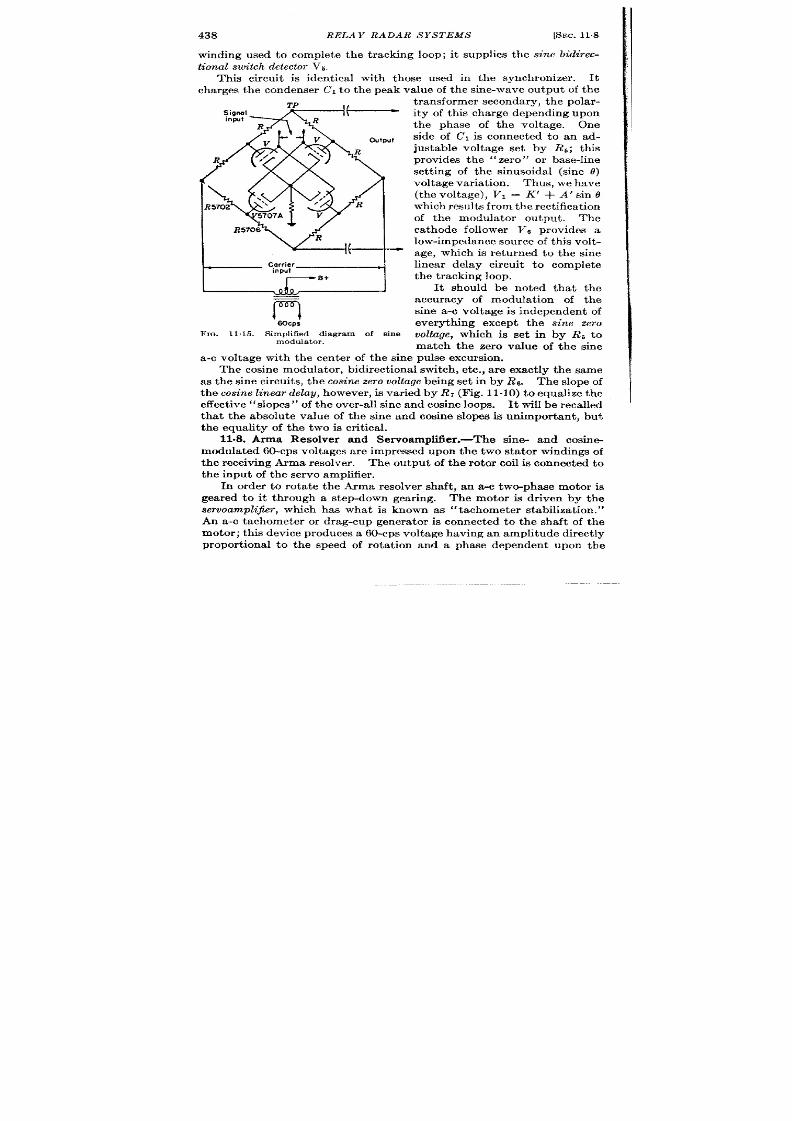
438
RELAY RADAR SYSTEMS
[SEC. 11%
winding used to complete the t rack ng loop; it supplies the sine bidirec-
tional switch detector V5.
This circu it is ident ica l with those used in the synchron izer . It
charges the condenser Cl t o the peak value of the sine-wave ou tput of the
FIG. 11.15.—Simplified dbgram of sine
modulator.
t ra nsformer secon da ry, t he pola r-
ity of this charge depending upon
the phase of the voltage. One
side of Cl is connected to an ad-
justable volt age set by R~; this
provides the ‘‘ zero” or base-li e
set t ing of the sinusoida l (sine @
voltage var ia t ion. Thus, we have
(the voltage), VI = K’ + A’ sin o
wh ich r esult s fr om the r ect ifica t ion
of the modula tor output . The
ca thode follower VG prov des a
low-impeda nce sou rce of t his volt -
age, which is retu rned to the sine
linear delay circuit t o complete
t he t ra ckin g loop.
It should be noted tha t the
accuracy f modula t ion of the
sine a-c volt age is independen t of
everyth ing except the sine zero
voltuge, which is set in by Rb t o
match the zero va lue of the sine
a-c volt age with the cen ter of the sine pulse excursion .
The cosine modula tor , bidirect ional switch , et c., a re exact ly the same
as th e sine circ it s, t he cosine zero voltage being set in by Re. The slope of
the cos ine linear delay, h owever , is va ried by R7 (Fig. 11-10) t o equ alize t he
effect ive “slopes” of the over-a ll sine and cosine loops. It will be reca lled
tha t the absolu te va lue of the sine and cosine slopes is unimpor tant , but
the equality of the two is cr it ica l.
11.8. Arms Resolver and ServoamplMer .-The sine- and cosine
modula t ed 60-cps volt ages ar e impressed upon t he two sta tor windings of
the receiving Arms resolver . The ou tput of the rotor coil is connected to
t he input of t he ser vo amplifier .
In order to rota t e the Arms resolver shaft , an a-e two-phase motor is
gea red to it through a step-down gear ing. The motor is dr iven by the
servoamplifir, which has what is known as “tachometer stabiliza t ion. ”
An a-c tachometer or drag-cup genera tor is connected to the shaft of the
mot or ; this device produces a 60-cps volta ge having an amplitude direct ly
propor t onal t o the speed of rota t ion and a phase dependen t upon the

SEC.11.9]
direct ion of rota t ion . The
PERFORMANCE
439
phase of this voltage is adjusted so that it
is the same as that of the er ror volt age.
Th~ tacho-meter voltage is
impressed upon one gr id of VT (a double t r iode), and the er r or voltage is
impressed upon the other gr id.
This stage is a different ia l amplifir,
which dr ives another stage of voltage amplifica t ion employing Vs. This
stage in turn dr ives the push-pull po er output stage ( Vg and VI O). The
mot or excita tion is t aken fr om t he secon da ry of t he output t r ansformer .
For equilibr ium condit ions to result , the motor must turn at such a
velocit y that t he ta chom eter volta ge will equal t he er ror volt age in magni-
tude and direct ion . When the t ransmit ted azimuth is constant , t e
er ror voltage is zero and the velocity is zero.
The system actually
oscilla tes, or “hun ts,”
slight ly t o over com e sta tic fr ict ion difficult ies.
When the antenna azimuth is varying at a constant ra te, an er ror voltage
is produced sufficient to equal the tachometer voltage produced by the
speed of the motor rota t ion . The gain of the servomechanism is la rge
enough so that the maximum er ror voltage r equ ir ed will r epresen t a lag
less t ha n 3°.
Advantages of th is type of servomechanism, also known as
a “velocity servomechanism,” are sta ted in Vol. 21 Par t II.
1109. Per formance-In relay systems in which the t ransmit ter or the
r eceiver is mobile a la rge amount of fading may occur . The receiver con-
ta ins cir cuit s for decodin g t he th ree-pulse code and applying t he out pu t n
to an AGC circuit so that near ly constant signal st rength is mainta ined.
F or discussion of t he r ela y link see Vol. 1, Chap. 17, of th is ser ies.
The effect s of fading are mi imized by the double in tegra t ion in the
sine and cosine t racking circuit s and by the tachometer feedback in the
servo system. The nar row ga tes that protect the sine and cosine pulse
circuits permit fa lse t r igger ing in a very much rest r ict e t ime interval.
The video blanking gate pr otect s the basic pulse in a similar fashion. The
t r iple coding of a ll syn ch ronizing pulses and of t he r eceiver AGC circuitsl
causes r eject ion of a ll single-pulse in ter fer ence t hough this in t er fer en ce
may over load the r eceiver and cause the loss of the desired signals.
Occasiona lly sever al unsynchronized radars will cause in ter ference by
accidenta lly forming the cor rect code gr oup and this can not be avoided.
The effect s of in ter fer ence are to cause rough opera t ion or “spoking” of
the PPI. Thermal noise will pass the decoder if the signals ar e too weak
to opera te the AGC, though smooth opera t ion has been obta ined with
syn ch ron izin g pu lses on ly twice t he RMS amplit ude of t herma l n oise.
1The t r iple code by it self does not give sufficien tp rot ect ion to the AGC in the
presenceof man y str ong interferingsignals.
The A C t ime cons tan t muet be near ly
1 sec. to preven t degenera t ionof s igna leof long dura t ion . In ter fer ingpukes even
t hough t hey act ua t e t h e code on ly once ea ch second will hold t h e AGC below the
des ir edlevel. It ha s been found tha t onsider able improvemen t is obt a ined if t he
AGCis derivedfrom th e cosinepulseonly sinceth is pulseis protectedby th e sequenced
ga teand it s na r rowga te in add it ion to it s t r ip le cod ing.
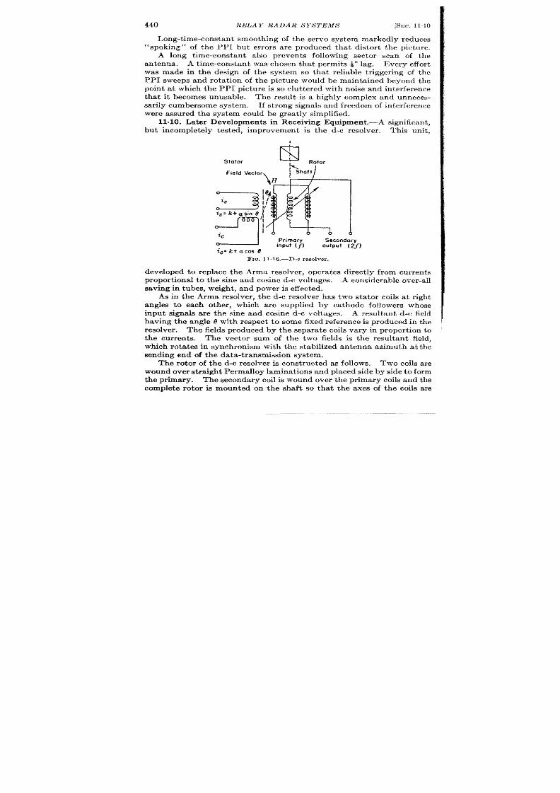
440
RELAY RADAR S YS TEMS
[SEC, 11.10
Long-t ime-const ant smooth ing of the servo system markedly r educes
“spoking” of the PPI but er ror s are produced that distor t the picture.
A long t ime-constan t also p reven t s following sector scan of the
antenna. A t ime-constan t was chosen that permits ~“ lag. Every effort
wa s made in the design of the system so t ha t r elia ble t rigger in g of the
PPI sweeps and r ot a tion of the pict u re wou ld be main ta in e beyond the
point a t which the PPI ictu re is so clu t t ered with noise and interference
tha t it becomes unusable. The result is a h ighly complex and unneces-
sar ily cumbersome system. If st rong signals and fr eedom of in ter ference
were assured the system cou ld be grea t ly simplified.
but incompletely tested, improvemen is the d-c resolver . This unit ,
Stafor
r
Isl
Rotor
Field Vecto
D
L
%~=k+asin O
g
~c
Primary
Secondary
input (~)
output ( 2J)
tc=k+acos 0
Fx~. 11.16.—D-c resolver.
developed to replace the Arms resolver , opera t es direct ly from curren ts
propor t iona l to the sine and cosine d-c voltages. A considerable over -a ll
saving in tubes, weight , and power is effect ed.
As in the Arms resolver , the d-c resolver has two sta tor coils at r igh t
angles to each other , wh ic a re supplied by ca thode follower s whose
input signals a re the sine a d cosine d-c voltages. A resu ltant d-c field
having the angle 0 with respect to some fixed referenc is prod ced in the
resolver . The fields produced by the separa te coils va ry in propor t ion to
the cur ren ts. The vector sum of the two fields is the resultan t field,
wh ich rota tes in synchronism with the stabilized antenna azimuth a t the
sending end of the da ta -t ransmission system.
The rotor of the d-c resolver is const ructed as follows. Two coils a re
wound over st ra igh t Permalloy lamin t ions and placed side by side to form
the pr imary. The secondary coil is wound over the pr imary coils and the
complet e rotor is mounted on the shaft so that the axes of the coils a re
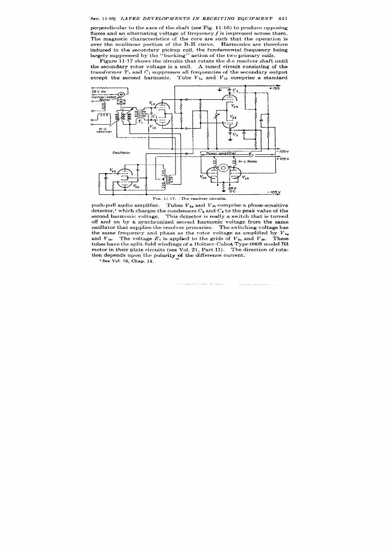
SEC. 1110] LATER DEVELOPMENTS IN RECEIVING EQUIPMENT 441
perpen icu la r to the axes of the shaft (see Fig. 11. l(l) o produce opposing
fluxes and an alterna t ing voltage of fr equency f is impressed across them.
The magnet ic character ist ics of the core are such that the opera t ion is
o er the non linear por t ion of the B-H curve.
Harmonics are therefore
induced in the seconda ry pickup coil, the fun amenta l fr equency being
la rgely suppressed by the “bucking” act ion of the two pr imary coils.
F igure 11.17 shows the circu it s that rota te the d-c resolver sh ft un t il
the secondary rotor volt age is a null.
A tuned circu it consist ing of the
transformer T, and Cl suppresses all frequencies of the sec ndary ou tput
except the second harmonic. Tube Vla and Vlb compr ise a standard
—
I I
D-C
[[
‘lb
L
! A
resolver
Oscilloior
~Ll
,
I Power omolifier L.
I-I05V
&
,,
v
.“
L
---
v
4b
FIG. 11.17.—D-c resolver circuits.
pu sh -pu ll au dio amplifier . Tu bes Vza a nd vzb compr ise a ph ase-sen sit ive
detector ,’ which charges the condenser s C7Zand C’S to the peak va lue of the
second harmonic voltage This detector is rea lly a switch that is t urned
off and on by a synch ronized second harmonic voltage from the same
oscilla tor tha t supplies the resolver pr imar ies. The switch ing volt age has
the same frequency and phase as the rotor volt age as amplified by Vla
and V,~. Th e voltage E, is applied to the gr ids of V~a and Vw. These
tubes h ave t he split -field windings of a Holtzer -Cabot Type 0S08 model B3
motor in their pla te circuit s (see Vol. 21, Par t II). The direct ion of rota-
t ion depen ds u pon ‘th e polar ity of th e differ en ce cur ren t.
] See Vol. 19, Chap. 14.
*

442
RELAY RADAR SYSTEMS
[SEC, 11.11
The servo design has not been completely test ed and the necessa ry
st abiliza tion cir cu it s a r e om it t ed.
PHASE-MODULATED PULSE SYSTEM
BY E. F., MACNICHOL J R. AND E. P. COFFIN, J R.
11.11. In t roduct ion .-One method of t r~nsmit t ing angular informa-
t ion between two remote sta t ions involves the use of two sine waves hav-
ing the same frequency but differ ing in phase.’
One of the sine waves is
used as a reference with respect t o which the phase of the other is meas-
u red. If the phase of the second sine wave is adjusted in such a manner
tha t the elect r ica l phase angle measured in degrees is made equal to the
angle to be t r nsmit ted, we have a defin ite represen ta t ion of the angle by
the use of two sine waves. hese two sine waves having been formed at
the t ransmit t ing sta t ion a re now transmit ted to the receiving sta t i n over
separa te channels by means of a radio or wire link where the phase angle
of the phase-shifted sine wave with respect to the reference sine wave is
detect ed and displayed as angular informat ion in an appropr ia te manner .
This method of t ransmission of angular informat ion forms the basis of the
ca pa cit y ph ase-sh ift er syst em a s will be seen la ter .
11.12. Pulse Representa t ion of Phase-modula ted Sinusoids.—It is
n ot n ecessa ry t o t ra nsmit t he act ua l sin e wa ves t hem selves; inst ea d gr ou ps
Pulses
I
~
w-
IQ. IllU .-Simple r rpr esr nt at ion of a im waves by r nwmwof pu l~es.
of pulses can be t ransmit ted from which the sine waves CW be recon-
st ruct ed a t t he r eceiving sta t io .
T e reason for doing this will become
apparent la ter . This represent t ion of sine waves by means of pulses can
be accomplished in severa l ways but perh ps the simplest is shown in F ig.
11.18.
Here very shor t pulses of about 1 psec dura t ion a re t ransmit t d a t the
times t o , t l , k , corresponding to every other zero poin t of the sine wave.
Since there a re two zero points in each complete cycle of the sine wave, it
is necessary to dist inguish between them.
The pulses a re arbit ra r ily
t ransmit ted at only those zero poin s a t which the slope of the sine wave is
posit ive. Hence, we have a unique representa t ion of the sine wave by
1See Chap. 10.
SEC.
11.13]
DIS CUS S ION OF PHASE-SHIFTER S YS TEM
443
means of th ese pulses which are separa ted by equal t ime in terva ls.
The
t ransmission of pulses tha t a re shor t compared to their spacing insures
tha t the rela t ive phases of the waveforms a re preserved. On the other
hand, if sine waves a re t ransmit ted any distor t ion in waveforms dur ing
transmission will produce an appa rent change in phase.
At the receiving sta t ion the or igina l sine wave must be reconst ructed
from the received group of pulses. One way of doing th is is to let ne of
the pulses t r igger off a pu lsed scilla tor—a device tha t produces a sine-
wave oscilla t ion whose phase with respect to the t r igger ing pu lse is a lways
constan t (see Vol. 19, Chap. 4 of th is ser ies). The frequency of th is
pulsed oscilla tor is made equal to the fr equency of the or igina l sine wave.
Since the phase of the output of the pu lsed oscilla tor is a lways const an t
with respect to th e t r igger ing pu lse, it will a lso be constant with respec to
the or iginal sine wave. Hence, by phase shift ing the ou tpu t of the pulsed
oscilla tor by means of a linear n etwork until the zer o poin ts with posit ive
slope of the resu ltant sine wave coincide with the received pu lses, we can
produce a sine wave that will be exact ly in phase with the or igina l one.
Since it is inconven ien t to adjust the frequ ency of the pu lsed oscilla tor to
exact ly that of the or igina l sine wa e, i will be necessa ry to stop it every
few cycles and let the next pulse restar t it in order to mainta in an accura te
ph ase lock wit h t he or igin al sin e wa ve. 1
The problem of transmit t ing two
separa te sine waves over two separa te channels has been r edu ced to that of
t ransmit t ing two separa te groups of pulses over two separa te channels.
The n ext sect ion shows th ese two groups of pulses can be t ransmit ted over
a sin gle ch annel wit hou t a ny con fu sion .
11.13. Discussion of Phase-shifter System.—A timing diagram of the
system is shown in Fig. 11.19, and a block diagram in Fig. 11.20
A “basic” pu lse is gen er at ed by a blockin g oscilla tor wh ose r epet it ion
p r iod is 1“. This pu lse t r igger s off a 16 kc/see pulsed oscilla tor . The
ou tpu t sinusoid of th is pu lsed oscilla tor is then shifted in phase by means
of a phase-sh ift ing condenser by an amount equal to the angle to be
t ransmit ted so that any t ransien ts have had t ime to die ou t , pulses a re
formed at ever y ot her zer o poin t of t he ph ase-sh ift ed sin e wa ve as descr ibed
above for four complete oscilla t ions. There is now a group of four equi-
distant pulses. After severa l more cycles, th e pu lsed oscilla tor is tu rned
I If a stable PRF wer e a va ila ble a t t he t ra nsmit ter t he ph ase-sh ift ed oscilla tior w
could be produced at a mult iple of th is frequency. The compar ison with the bas~c
~u lse is per formed in a manner simila r to tha t used in the Brit ish Omnidirect iona l
Beacon (Chap. 10) and in the direct -reading Loran indica tor (Chap. 4), Having an
accu ra t e PRF at the receiver wou ld permit the use of ve y na r row gates to protec
t he ba sic pu lse, in dica tor t rigger , a nd AGC fr om in ter fer en ce.
2 See Chaps. 4, 5, 6, and Vol. 19, Chap. 4,

444 RELAY RADAR SYSTEMS
[SEC. 11.13
off and is then ret r iggered by the next basic pu lse and the whole process
repeat s. These pu lses plus the or iginal “ basic” pu lse a re then trans.
it t ed over a single channel t o the receiving sta t ion where they are con-
ver ted in to an gular in format ion by t he followin g m et hod.
When the basic pulse is received it t r iggers a pulsed oscilla tor that is
iden tica l wit h t he on e in t he t ra nsm it ter .
Th e ou tpu t wa veform is sh ift ed
T
Pulses corresponding to zero points of
‘hose “’’ted ““e ‘“”e ~
Basic Basic
pulse
pulse
/
nllllll
t----’+
t-
FIG. 11.19.—Operat ion of phase-shifted pulse system.
in phase as in the t ransmit t er by means of a phase-sh ift ing condenser .
The phase-sh ift ed sine wave is then compared with the group of fou r
pulses as they are received and caused to t ack them in a manner analo-
gous to the process of au tomat ic t ime demodula t ion (see Chap. 8).
Details of the Transmitting Equipment.—A
circ it diagram of the
synchron izer is shown in I?ig. 11.21.
The system t r igger is simula ted
~ Anglo
Pulsed
oscillolor
by t he blockin g oscilla t or V,..
The overshoot of the t r igger is applied
t o th e ou tpu t pulse blockin g oscilla tor V12. th rough t he amplifier Vlzb. A
l-psec pu lse is formed which is applied to the coding network through the
ca thode follower Vlob. The network is similar t o that used in the sine-
cosine system and forms a t r iple code with 3-psec and 5-psec spacing.
The cat hode follower V,t applies the code group to the t ransmit ter
th rough a terminated cable. A negat ive gate is produced by the ga te

,
.

446
RELAY RA DAR SYSTEMS @EC. 11.13
mult ivibrat r VZ. A negat ive gat e is produced wh ch allows the pulsed
oscilla tor V3 to opera t e for approximately 8 cycles.
The pulsed wave
t rain is applied direct ly to one plate of a phase-sh ift ing condenser that
rot a tes with the antenna. The wave t rain is also applied to the phase
split t er V4 thereby advancing the phase 120° and then to Vs, which
advances the phase another 120°.
The output wave form of the phase
split t ers a re applied t o t e oth er inputs of th e phase-shift ing condenser so
(a)
(El)
(c)
FIG. 11.22.—Phase.shifted pukw system performan ce.
that a rot at ing elect rost a t ic field is set up. The phase-shifted output of
t he con den ser is amplified by VG and n ega tive h alf-cycles select ed by VT.
a r e amplified by t ’Tb, and differ en t ia t ed by t he t r an sformer .
The nega t ive
ga te fr om VZ is a lso applied to V8a, which init ia tes a posit ive sawt oot h
wa veform. Th e differen tia ted pulse der ived fr om t he phase-shift ed wa ve
train is applied to the cont rol gr id of VI,.
Four pulses are selected by t he
gat e from Vg which is supplied to the suppressor gr id of VII. The gate is
init ia ted by adding the pulses from the t ransformer to the sawtooth wave

SEC. 11.13]
DISCUS S ION OF PHASE-SHIFTER SYSTEM
447
from Vti and passing the sum through the amplitude sel ctor , Vw. The
ga te is init ia ted by the thh-d phase-sh ifted pulse, which , when added to
the sawtooth , appears in the outpu t of the amplitude selector . The ga te
select s the four th , fifth , sixth , and seventh pulses, which a re accu ra tely
spa ced beca use t he tra nsient s h ave disa ppea red fr om t he pu lsed wa ve tra in
by the t ime they a re produced. The selected pulses are applied to Vlti
and coded in a manner iden t ical to the bas c pulse.
F igu re 11.22. sh ows
the appearance of the group of pulses a fter they have passed through the
r ela y lin k.
Details of Rem”ving Equipmen .—The outpu t of he receiver is taken
from a 70-ohm termina ted cable at 3 volts peak as sho n in Fig. 11.23.
It is amplified by VI. and the video signa l is applied to the indica tor
through V20. The synchronizing pulses a re amplified by VZ and differ -
en t ia ted by the inductance in the pla te circu it .
They a re fu r ther ampli-
fied and limited by V~ and applied to the decoding line. The fir st two
pulses are added on the gr id of VA and the th ird pulse dr ives the screen
posit ive. If the code is cor rect a pulse appe rs in the pla te circu it and is
inver ted by the t ransformer . It is amplified by V, which t r iggers the
mult ivibra tor Ve. Tubes V,, VT, VS, and V~ form a pulsed oscilla tor
phase-sh ifter circu it which is iden t ica l t o tha t in the synch ronizer , The
outpu t waveform of the phase sh ifter is amplified by Vlo and Vll and
a pplied t o t he r ids of t he ph ase discr im in ator (pha se-sen sit ive det ect or )
VM The pulses tha t a re presen t in the outpu t of the decoding circu it
wh en t he pu lsed oscilla tor is ru nn in g a re select ed by Vl, and fir e t h e block -
ing oscillator V,,.. The ou tpu t of the blocking oscilla tor is applied to
the pla tes of the phase detector .
If t he r eceived pu lses over la p posit ive
ha lf cycles of the phase-sh ifted wave t a in , the memory circu it of the
detector will cha rge posit ively.
If t hey over la p n ega tive h alf-cycles t hey
will cha rge nega t ively. The outpu t of the detector is applied as an er ror
signa l to the servomechanism, which dr ives the phase sh ifter so tha t the
received pulses a re a lways coinciden t with tbe zer o poin t of the sine wave.
An unusual type of servomechanism is used. With the selector switch sl
in Posit ion 1 it opera tes in a convent iona l manner .
The er ror signa l is
modula ted a t 60 cps by a Brown Conver ter .
The modula ted car r ier is
filtered by Vle which is a form of Wien bridge oscilla tor with ga in too low
to susta in oscilla t ion . The posit ive feedback loop of the Wien br idge
occurs from the pla te of Visa th rough a ser ies RC-combina t ion to the gr id
of V,%. A shunt RC-combina t ion is in para llel with th is gr id. The
loop is completed back to VIGa through the common ca thode resistor .
(This select ive circu it should be replaced by a twin T feedback select ive
amplifier . See Vol. 18, Chap. 10,) The filtered outpu t is amplified
bY V,,, V,,, and V,, and applied to o e phase of a Diehl 2-phase motor .
Stabiliza t ion is supplied by th e” phase a dva nce” circu it V16b which passes
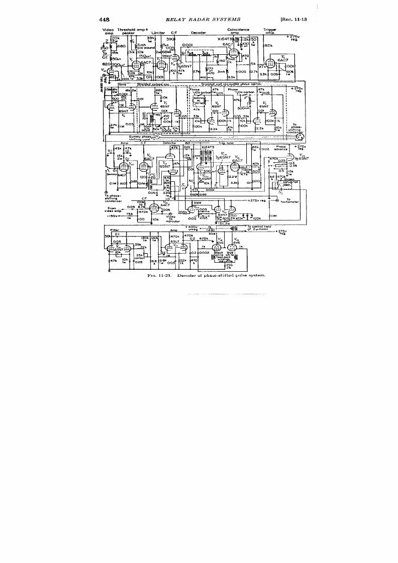
448
RE AY RADAR SYSTEMS
[SEC. 11-13
Video Threshold amn+
l%incidence
Trim-
-&
12k
“amp
Waker ‘
Li iter C.F Ceder
amp. Oxp
+ 275V
reg.
00,01
.
. .
TO phOse-
“’% “q 4004002
~1
shd t tnq
CF
10
condenser
{
+ 275v reg.
To
100k
From
video amp
75k
-150 V- ,W
i~ .
;IIM
100k
Fm. 11,23.—Decoder of phase-sh ifted pulse sys tem.

I
SEC. 11.13]
DISCUS S ION OF PIIASE-SHIJ ’TER S YS TEM
449
h igh -fr equ en cy compon en ts of t he d-c er ror sign al with ou t a tten ua tion a nd
p rovides la r ge a t tenua tion for t h e low-fr equencies.
When the selec or s~vitcb is in l’osit ion 2 a circu it with the following
pr oper ties is a ct iva ted.
The servom chxn ism when presen ted with
in forma tion \ vill “lea rn ” t he r at e a t \ vh ich it mu st follow th at in form at ion
in a t ime wh ich is a dju st able.
If t he sign al disa ppea rs it \ vill“ r emember ”
this ra te for an adjustable t ime which can be made very long. In effect
th is circu it provides smooth ing of rota t ion , which is readily adjustable
t o fit differ en t oper at in g con dit ion s.
The resu lts a re ach ieved qua lita-
t ively as follows. Tube Vi,. provides a capacitance in the gr id circu it
which is amplified by the gain of the tube. This capacitance, wh ich is
much la rger than could be conven ien t ly obta ined with a rea l capacitor
having small leakage, const itu tes the “ memory. ” Tube V,, provides
“ phase advance” for stabi iza t ion and tachometer feedback is used so
tha t the ra te a t which the motor turns is propor t iona l to the poten t ia l a t
the ca thmic of V22. As the pulses move an er ror signa l is produced across
t he “m emor y” circu it .
The motor turns at a speed that keeps th is small
misa lignment constant . lf the signal fades, cha rge is stored in the mem-
ory circu it causing the motor to co t inue to turn a t the same speed unt il
th e signal rea ppea rs or un t il lea ka ge discharges th e m emory circu it . This
is a form of double-in tegra tor system and has basic proper t ies similar to
those of Chap. 8.
Compet it ive test s have indica ted tha t the phase-sh ifter system
opera ted as well as the sine-cosine system in the presence of noise and
in ter ference in spite of the fact tha t the phase-sh ifter system was not
prot ect ed by a PRF se ector or nar row ga tes a lthough these cou ld be
added wit h lit tle difficu lt y.
Also, the number of components is smaller
a nd t he con st ru ct ion is simpler th an wit h t he sin e-cosin e system .
It is not necessa ry for the frequencies of the pulsed o cilla tors in the
transmit t ing and receiving ystem to be exact ly equa l since they a re
resta r ted e ery PRF cycle. Differences as grea t as 10 per cen t appea r to
ha ve n o effect ; thus th e tun ed circu its for th ese oscilla tors may be fa ctory
preset . The phase-sh ift ing br idges a re a ligned by means of a dummy
condenser , having no rotor pla te, which is built in to the system.
This
a lignment is the only one tha t is necessa ry and cor responds to the zero
and slope adjustments of the t ime modula tors in the sine-cosine system.
Typica l per formance is shown by the photographs of the PPI of th
r eceivin g system in F ig. 11.22b.
Angle marks of 10° spacing have been
t ransmit ted over the link in place of video signa ls. Comparison of the
marks with the illumina ted prot ractor indica tes the cyclic er ror , which
has a peak amplitude of + 4°. F igure 11 .22c shows the per formance of
t he system in t he pr esen ce of st ron g u nsyn ch ron ized pu lse in ter fer en ce.

450
RELAY RADAR S YST1<MS
[SEC. 11.14
SIMPLIFIED RELAY RADAR SYSTEM FOR CONSTANT-SPEED ROTATION
BY E. F. MACNI HOJ ,, ,J n.l
11.14. In t roduct ion.-The system t o be descr ibed is suitable for poin t -
t o-poin t oper at ion wh er e fadin g is n ot en cou nt ered and wh er e t he an tenna
of the adar rota tes a t near ly constan t speed so that it is unnecessary to
t ransmit the an tenna posit ion at one-speed. As shown in Fig. 1124 the
radar t ransmit ter pu lse in it i~tes a ser ies of synchron izing pul es in the
codes. This code group is delayed 10 usec with respect to the t ransmit t er
pulse and occupies an interval of 22 psec.
The use of th is in terval by the
syn ch ron izin g pulses resu lts in t he su ppression of t he first 30 psec of video
1-- ?%% --l I I
I
I
I
i
i
~
!
I
HI
1
I
I
,
I
I
1
III
1HI
1111
Switching
Y Swit~~in’g /’
pulse
pulse absent
Jitter Switching
Sy~. pulse\
pulse
pulse
7
2Xsec–
-
- —
1
t
.
-4 B sec- “- ‘
1 !
16 M sec —
1 I
I A sec pulses
FIG. 11.24.—Informat ion pulses.
signals from the radar . In pract ice this in terval is filled solidly with
“ round clu t t er , ” thus the loss is not ser ious.
The first th ree pulses in
the group, spaced 2 and 4 psec apar t , form a code to prot ect the indicator
t r igger and the in format ion pulses.
The four th pu lse is jit t ered its own
widt h by an alt er nat in g-cu rren t signal der ived from an a ltern at or r ot at ing
in synchron ism with the an tenna.
The frequency produced by the alternator is 60 cps when the an tenna
is tu rn ing at 4 rpm. The alternator frequency is therefore propor t ional
to the an tenna speed. A switching p lse is produced 16 ~sec after the
occu rr en ce of t he th ird pulse in t he code.
Th is pu lse, wh ich a ppea rs ever y
th ird cycle of the PRF, opera tes an elect ron ic switch that inser ts video
signal from another radar in to the relay link.
Thus the link can be used
t o t ransmit video signals from two separa te radar sets. The video signals,
synchron izing pulses, and range and angle marks are combined in the
1Based on mater ia lcontr ibuted by L. Bess.

SEc. 1115]
DETAILS OF THE SYSTEM
451
video mixer and t ransmit ted.
The received signals a r e decoded, sup
plying a t r igger for the indicators a ft er the third pulse. The jit t ered
pulse is t ime-demodula ted and t he resu lt ing a-c signal is filt ered, ampli-
fied. and used to dr ive a synchronous motor , which rota t es at the same
speed as the a lterna tor dr iven by the an tenna.
The motor dr ives a
synchro system through a gea r reduct ion .
The synchro system rota tes
at t he same speed as he antenna.
Alignment bet ween the radar pictu re
and the relayed pictu re is accomplished manually with refer ence to the
angle marks that a r e t ransmit ted along with the video pictu re.
Once
alignment has been ach iev d it is mainta ined by the system.
11015. Deta ils of the System Coder .—Refer to Fig. 11.25. The
posit ive radar system tr igger is ap lied through S1 and inver t ed by VW
t o t rigger t he delay mult ivibr at or V1. Th e 10-psec r ect an gle pr odu ced
by V, is differ en tia ted by T , and the pulse formed by the tra iling edge
t r iggers the blocking oscilla tor VzO which produces a 0.75-psec pulse.
This pulse is delayed by L, and ret r iggers V,a through Vza after 2 gsec.
Blocking bias is built up across Cd aft er these two pulses so that Vti will
not r et r igger a fter the second pulse. The output from the ca thode of
Vu is delayed by Lq a d t r iggers V3. wh ich pr odu ces a not her 0.75-psec
pulse. The nega t ive sawtooth volt age in the bias circuit of V% operates
the switch tube VW in it ia t ing a posit ive sawtooth voltage in the pla te
cir cu it . Th e amplitu de select or Vaa t rigger s blockin g oscilla t or Vu after
a delay determined by the ca thode bias of V4a and the slope of the saw-
tooth waveform.
The bias voltage is modula ted by the outpu t of the
a lterna tor whic is seared to the antenna . This a lterna tor is a size-
synchro with d-c excita t ion on the rotor . It s ou tpu t potent ia l is ampli-
fied by Vti. Thus the pulse from V4 b is delayed 8 ~sec and t im~modu-
Ia ted f 0.5 psec. The pulse from V,a synchronizes t he 3 t o 1 frequency
divider V7 b t hr ou gh t he ca th ode follower V,.. The outpu t of t he divider
is t ransmit ted to the switch ing circu it s in the video-mixing unit th rough
V~. The nega t ive pulse in the pla te circu it of V% t r avels down L4 and is
r eflected back as a posit ive pulse after 16 ~sec when it ret r igger s Vu
through V%. The cur ren t pulses from the ca thodes of Vti, V~, and Vti
are mixed and applied to the gr id circu it of V6j which is a blockiw Oscil-
la ter tha t produces accura tely rectangula r pulses of 20 volt s amplitude
and 1 psec durat ion with r ise and fall t imes of 0.1 psec across the 75-ohm
termina ted output cable. This circuit is designed t have very rapid
recovery so tha t it can be t r iggered by all the pulses in the group. The
line La is used to det ermine the durat ion of the outpu t pulses that a re
t ransmit ted t o the video mixing unit .
The Vid o Mizing Unit .—Refer to Fig. 11“26. The two video inputs
a re app:ied to the “a” sect ion of the mixing tubes Vt and Va. Tubes V1~
and VI* are d c restorers. The respect ive angle marks are applied to the

r
----
RI
R,
+300V
Utah
Note: 011reeostors are )2w
Utah
~
470 k
Utah
10k2w . ~, X-124 T-2
unless otherwise stated.
~ X-124 T-2
100k
~, X -124T -2
m
.= -’ .- R. . . . . .
‘ka--4JEG
it”-?
--
.
Vm !-f,
6SN7 6SN7
R, CI
0.01
kR
‘w 10’Ok
:60
rlir
--
c’
6SN;
0.005
R,
22k
R,
68k
P,
Iw
20’
h
..
.
L,
6SN7
4L15
R,
Ik
0’01
R,. R,,
10k Ik
-I05V
t
l—
ii
.. .
6SN7
j
/ / T
;>Ok ‘Gt C,
R,, 500uIIt
68k
!!
--
[
,
240MM!
R,
5(
Iw
I I
1
1 1 1
1
T
rig.”2
R.
s,
220
F
R,, c,.
;7 33k
{
0.005
R, ,
~
$7k -
R, $
30k
50
Y
.
~
6SN7
c,,
0001
R, ,
Ik
Q7 k
RS
—
R,,
100’
2W
A.c. in~ul
$
..-
5a
,SN7
+300V
R2,
R.
T , X.:%2 R
z.
g 1
u 7 ‘*
.
150k
10k
31 1
Imk
2W
2W
6
rdggefnput
v. Vc
24
cl,
v
;, 6SN7
0.01
6S;7’ o~ol
6S;7
..-
---
---
,, R
R,,
L,
v,,
WI
1’
s.
8US
1’
I : f:k ;~.
=:;;., R
~
%’] Rn
33k
5:
47\k
w
002’ Rw
I
220” -Iw
-I05V
Fm. 11.25 .—Coderof s impli fi ed re lay radar .
1
,
I003
Rm
33k
*
2?
00k
a
,, 002
Utah
T, X-1241-2
R,, uk L,
425mh
4 26
R,, lk IUS
v,
,,, 6AC7
.-.
s,
% fik’
To 75
I
—
Termmated cable
/
Rm
13k 51k
R Iw
ohms
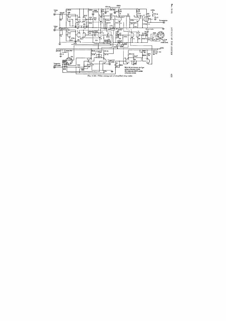
+Yxlv
1.5k.2w, .-
Video
G
Video
&
-L,
If
001
~ 240k
Ill
240k A@e
‘m
morks#l
m
‘“F
.
1 1 I
/1 4mk I
otor
/
I
1
I
5k-lw
5k-lw
I I L L 1
1
!2 k
1
m
0k
ml
a2k-2w
82 k
I50# f
k 2W
~
EOk
---
. . .
47
N
Note: All r esistances ore ~ w
unless otherwise stated
All tubes ore 6SN7’S unless
olherwise sloled
(mule&ton
z = - -
~!2k-2w
Fwa.11.26.—V1deo mixing unit of simplified relay radar.

454
RELAY RADAR SYSTEMS
[SEC. 11.15
“b” sect ions. The ca thodes of Vz and Vs are connected to the cathodes
of the t ime selector tubes V4Cand VSO respect ively. These tubes have
a common pla te circuit . The bistable mult ivibra tor Vs (sca le of 2)
swit ch es t he gr ids of V~ and VFa so that video current from one input cir-
cuit or the other , but not both, will reach the pla te circuit . The mult i-
vibra tor is t r iggered on the grid of the “a” sect ion by the t r igger pulse
from the coder , and on t e ca thode by the switching pulse. When the
switching pulse is present the video signal from input 2 is t ransmit t ed;
when it is absent t he video signal from input 1 is t ransmit ted since t he ‘‘ a ‘’
sect ion is held off by t r igger 1 applied to the cathode. The common out-
put current of Vq~and V5~ is applied to the gr id of V4b. A time-selective
switching circuit is formed by VW and Vf,b which have a common pla te
circu it . The synchronizing pulses are applied to the gr id of Vm wh ile t h e
ca t hodes of Vu and Vu a re swit ch ed by t he monost able mult ivibr at or Vo.
A gate, which lasts about 35 psec, is formed after the input t r igger and per-
mits synchronizing pulses t o reach th output circuit . At all other t imes
the selected video signal is applied to the t ransmit t er . Range marks a re
mixe with the video through VW The mixed output is applied to the
t ra nsm it ter t h rough t he amplifier VS. a nd ca th ode follower VT.
The Decoder . -Refer t o Fig. 11.27. Posit ive 2-volt signals from the
relay receiver are passed through a 1~-psec t ime-constant and applied to
the gr id of VIC which is init ia lly conduct ing since Vllb k cutoff. I he shor t
t ime-constant removes long in ter fer ing pulses tha t would otherwise
opera te the decoder . The pulses a re amplified to 8 volt s and applied to
the gr id of the limiter Vz which cuts oil at – 4 olt s, yielding an output of
+70 volt s. The pulses are applied to the gr id of V~c which dr ives L ~.
Par t of each pulse is delayed by L, and par t appears direct ly in the output
across a 430-ohm resistor . When the correct code group is t ransmit ted
he dela yed first pulse adds t o the undelayed second pulse t o over com e t he
bias on the gr id of Vs. The output pulse of V, is delayed by L, and
appears on the cathodes of Vi. If the grids of the two se t ions of V’ a re
at the same potent ia l, equal and opposit e fluxes a re set up in the t rans-
former and no output appears. If V,. is cut off by the third pulse in the
code group appear ing in the pla te circuit of Vti, an unbalanced curr ent
will be produced in the t ransformer ; and a voltage, induced on the gr id
of V6S, will in it ia t e regenera t ion .
This t ube acts as a blocking oscilla tor
and produces a t r igger for the indica tors. The gr id-bias waveform cuts
off t he switch tube V* and star t s a sawtooth waveform. The amplitude
selector V~ fir es t he block ing oscilla t or VW a fter an 8-psec delay. The
ca th ode pu lse is dela yed by L3, amplified by VT., and fed ba ck t o t ermina te
the puls . Two l-psec rectangular ga tes sepa ra ted by 1 ~sec a re pro-
duced by Va and V,c. These gates a re applied to the gr ids of the t ime
selectors V* a d Vti respectively.
The “jit tered” pulse conta in ing the

+ 150v~
+300r~_
33k
500
lOOk
56k
Iw
2W
Iw
~wh
I@
17 ii’
.cm5
I II
ik
5CX3 IOk
~lk
nnnc
II
f&w
w
2k ~00
ml
0.01
Ik ,k IOOk
33k
Mi
----
ol >
.01
s Ik
10k 430 2/
2
~
l!!!%j
“. “ .,
6SN7
v
,0
v=
----- ----
4.s ~, vu
~
. . .
)OQ5
100k
$
T6SN7 I r
J-L
a
Ind
rig’s
10k ~0
150
t
#t’J
00k
6SN7
6SN7
+ --- ---v-
01 “n
1& T150
I
pill
&
3k
00k
2
“ . I
b
1
t
10k
1
1
II
Nols: All res!stom
ore ~w unless
otherwise stated,
-!
250
ky-i~
330k
100k
1
1
220
-I05V
1
“001 2
FIG.11.27.—Decoder of s implified relay radar .
)k
3

*
-L-EL
—
—
B
1
i
---
v
2a
470k ,k
56 k
*
50 mh
2 .2k Iw
!
look
I
I
I
!
1
-105. 2,rJ
,,
1.5k 2W =
V5
&a
0.1
Vb-le ~-:
70 k
3
470k
200 k
500
470k
220h
330k
24k
Video from
1
0
-I_
decoder —
—
--105”
VideO out
FIG.11.28.—Video separator of s impl ified relay radar
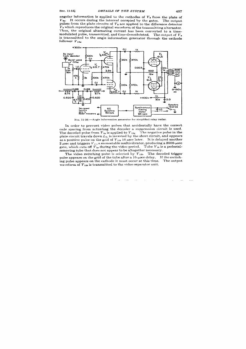
SEC. 11.15] DETAILS OF THE SYSTEM
457
angular information is applied to the ca thodes of V~ from the pla te of
V%. It occur s dur ing the in t rva l occupied by the gates. The ou tpu t
pulses from the pla te circu it s of Vs are applied to the difference de ector
V. wh ich r epr odu ces t he or igin al wa veform of t he t ra nsm it tin g a lt er na tor .
Thus, the or iginal alternat ing cur ren t has been conver t ed to a t ime-
modulated pulse, t ransmit ted, and t ime-demo’dulated. The outpu t of V~
is t ransmit ted to the angle informat ion genera tor th rough the ca thode
follower Vlb.
FIG. 11.29.—Angle informat ion generator for s implified relay radar .
In order to pr event video pulses tha t accidentally have the cor rect
code spacing from actuat ing the decoder a suppression cir cu it is used.
Th e decoded pu lse fr om Vs. is applied t o V1z~. The negative pulse in the
plate circu it t ravels down Lb, is inver ted by t he sh or t circu it , and appear s
as a posit i e pulse on the gr id of VIO~16 ~sec later.
It is delayed an oth er
2 psec a nd t rigger s VII, a monost a ble mult ivibr at or , pr oducing a 3000-psec
gate, which cuts off V,. dur ing the video er iod. Tube Vm is a Pedesta l-
removing tube that does not appear to be a ltogether necessary.
The video switching pulse is selected by V12b. The decoded trigger
pulse appears on the gr id of the tube aft er a 16-psec delay. I the switch-
ing pulse appears on the ca thode it mus occur a t th is t ime.
Th e ou tpu t
waveform of VIM is t r ansmit ted to the video separa tor unit .

458
RELAY RADAR SYSTEMS
[SEC. 11,16
The Video Separator .-Refe t o Fig. 11 “28. Negat ive video signals are
applied to the cathodes of Vz~ and Via of the video separa tor from V7b
in the decoder . The switch ing waveforms on the gr ids are der ived from
the bistable mult ivibra tor V* which opera tes in a manner ident ical t o that
in the video mixer . Tube Vla is turned off by the indicator t r igger and
turned on by the switch ing pulse when it appears. Tubes V% and VW are
pedesta l-removing tubes, which draw the same quiescen t cur ren t s as Vti
and Vb. The output signals of channel 1 is amplified by V% and app lied
to the ou tpu t line by V5. Video 2 is handled similarly by Vu and Va.
The Angle Information Genera tor .—Refer t o Fig. 1129. The de odu-
la ted a-c from the decoder is applied to a bandpass filt er having a pass
band of 30 to 90 cps. This filt er permit s a var iat ion in an tenna speed of
2 to 6 rpm. The output is amplified by a convent ional audio amplifier
V,, V,, Va, Vi and applied to a synchronous clock motor which rota tes the
syn ch ro t ha t dr ives t he in dica tor s.
Test s of the system have shown that it will opera t e sa t isfactor ily in the
pr esen c of a r ea son able amount of pu lse in ter fer en ce wit hou t a ppr ecia ble
dr ift of the pat t ern for a per iod of severa l hours. It is simpler to align,
opera te, and maintain than the systems previously descr ibed since the
wave shape of the ou tput pulse is not cr it ica l and slight maladjustment of
the t ime modula tor and demodula tor has negligible effect due to the fact
that data are t ransmit t ed at 900-speed (~ per tu rn).
C-W RELAY WDAR SYSTEM
BY E. F. MACNICHOL, J R.
This relay radar system uses sinusoida lly modu la ted audio-frequency
tones for angle data transmission.
(It is designated as AN/ART-18
an AN/ARR-17. ) In this system three audio sub-subcar r iers are used
to specify the angular posit ion of the antenna . These frequency-modula te
a 2-Me/see subcar r ier , wh ich is addit ively mixed with the radar video and
synchroniza t ion pulses to devia te a car r ier of approximately 100 me/se?.
In the receiving system th video pulses and subcarr iers are separa ted in to
the appropr ia te channels by filters and demodula t e to give d-c voltages
propor t iona to the sine and cosine of the antenna posit ion . These could
be used to provide a shaft rota t ion as in the pulsed sine-cosine system but
as the equipment is now d signed the voltages are used to modula te linear
t ime base componen ts for a fixed coil ME PPI (see Vol. 22).
11,16. Genera l Descr ipt ion of Transmit ter Funct ions.-A block dia-
gram of the transmit t ing equipment is shown in Fig. 11.30. A synchro
ha ing a single-phase rotor and two-phase stator is geared to the antenna
at l-speed. The stator windings a re excit ed by an 885-cps oscilla tor
and a 2250-cps oscilla tor respect ive y. The rotor outpu t , therefore,
conta ins a componen t at 885 cps of amplitude El sin e and another of
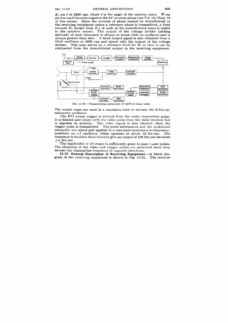
SEC. 11.17]
GENERAL DESCRIPTION 459
E, cos e at 2250 cps, where 6 is the angle of the synchro rotor . W.~en
sin 0 or cos Obecomes nega tive th e AC rever ses phase (see Vol. 19, Chap. 12
of th is ser ies). Since the rever sa l of phase annot be demodula ted in
the receiving equipme t urdess a reference phase is transmit ted, a fixed
amount Ez (larger than El) of each of the unmodulated tones is added
to the synchro outpu t . The ou tpu t of the voltage divider (adding
network) of each frequency is always in phase with its oscilla t r and is
always grea ter than zero. A fixed ou tpu t signal is also obta ined from a
third oscilla tor a t 5090 cps and mixed with the output of the voltage
divider . This tone serves as a reference lev l for E, so tha t it can be
subtracted from the demodula ted ou tpu t in the receiving equipment .
~’:’’’”’:’r’ l-A+l
--–-–––
I
Reoctance
2 Mc
mcdulotor
OscllIO*U
Gothode
50S0
follower
oscllIatw
follower
Fm. 11.30.—Transmit t ing equipmen t of ART-1 8 relay rada r .
The mixed tones are used in a reactance tube to devia te the 2-Me/see
subcarr ier oscilla tor .
The PPI sweep t r igger is der ived from the radar t ransmit ter pulse.
It is limited and mixed with the video pulse from the radar receiver but
is opposite in polar ity. The video signal is also blanked when the
t r igger pulse is t ransmit ted. The pulse informat ion and the modula ted
subcarr ier are mixed and applied to a reactance modula tor to frequency-
modula te an r -f oscilla tor which opera tes a t about 12 Me/see.
Th e
fr equ en cy is doubled th ree t imes t o give an ou tpu t of 100 Me/see devia ted
*4 Me/see.
The bandwidth of all stages is sufficient ly grea t to pass I-psec pulses.
The identit ies of the video and tr igger pulses are preserved since they
devia te t he tr an smit ter fr equ en cy in opposit e dir ect ion s.
11.17. Genera l Descr ipt ion of Receiving Equipment .-A block dia-
gram of the receiving equipment is shown in Fig. 11.31. The receiver

s
L

SMC.11.18] DETAILS OF THE SYSTEM
461
is a conven t ional superheterody e with a pass band of 8 Me/see and
follows th e genera l pr inciples discussed in Vol. 23 of th is ser ies. The out -
~u t of the r eceiver consist of the modula ted 2-Me/see subcar r ier and
video and t r igger pu lses. These are sor t ed out and applied to the
indicator tube in the separa tor unit .
The subcar r ier is filt ered ou t and
amplified in the subcar r ier amplifier , limited, and demodula ted. The
th ree audio tones are separa ted by means of bandpass filter s. The 885-
and 2250-cps modula ted tones are demodula ted and applied to cathode
followers. The 5090-cps tone is filt ered and demodula ted. The demodu-
la ted d-c ou tpu t of the 5090-cPs tone is subt racted from each of the
demodula ted sine and cosine ou tpu ts to remove the level due to the
fixed a-c componen t . The subt racted outpu t poten t ia ls a re now d-c
voltages E sin O and E cos 0 which are symmet r ica l with r espect t o
ground. These voltages are applied to the charging resistors of the
hor izon ta l and ver t ica l sweep genera tors. The outpu t voltages of these
sweep genera tor s a re amplified and used to dr ive the fixed deflect ing
coils of the PPI. To a fir st approximat ion the slopes of the sweeps are
propor t ional t o the voltages applied to the charging resistor s. The
elect ron beam of the CRT is deflected in the direct ion of the resu ltan t
field produced in the two deflect ing coils. The two components of the
field a re propor t ional t o the amplitudes of the sawtooth waveforms,
which are a ways in the ra t io of sin 8 and cos 0. Thus the spot will
sweep radially ou tward in the direct ion t?.
The receiver ou tpu t is a so amplified in the video amplifier which
has insufficien t bandwidth to pass very much of the 2-.Mc/sec subcarr ier .
A biased amplifier and blocking oscilla tor separa tes the synchron izing
pulse from the video pulse of opposite polar ity. The synchron izing pulse
opera tes a wide gate (rectangle genera tor ) that opera tes the pu lsed
range-mark oscilla tor . The pu lsed sinusoid genera ted by this o~cilla tor
is limited and differen ia ted to produce range marks, which are then
mixed with the video pulses.
These pulses a re amplified fu r ther and
applied to the gr id of the indica tor .
No at tempt is made t o remove
th e synchron izing pu lse from th e video channel since it appears before th e
sweep has star ted. The rectangle fro the ga te mult ivibra tor is limited
and used to in tensify the CRT during the sweep.
It is a lso used to cu t
off the clamp t bes producing the sweep component .
11.18. Deta ils of the System. The Mixer Un it .—Refer t o F ig. 11.32.
Th e t on e oscilla tors ar e of t he con ven tion al RC ph ase-sh ift va riet y u sin g
3-sect ion h igh -pass n etwor ks (see Vol. 19 , Chap. 4 of th is ser ies). They
are mounted in an oven whose tempera tu re is thermosta t ica lly con -
t rolled. The resistor network that adds the fixed a-c level from each
sta tor input is also in the oven since it is ext remely importan t that the
ra t io of synchro ou tpu t poten t ia l t o the fixed component of the audio
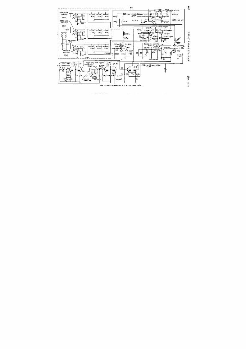
—--
-.
—--—
-—— ———-—-— —-———
I 2250 cycle cothode
1
~885 cycle cathode follower
~6SN7
330k
I
I
330k
1220k
I
l--
I
i W90 cycle
I
oscillator
%
33k
I 6SH7 ~ ‘;-
1
1 2250 cy le
I
oscillator
\ ‘ ‘k 025
i
6SH7
F
+ 26v
E
. . .
27(-
---
---
/
}
I
I
,
I \
1-“
-- - 1
I
I
5090 Cycl ‘-- ‘--
I
FT!!r5t
“
34
+
‘k
025
)ermostot
D“c
I
4
II
1 b
I
.——.-...
i%’=
3
27k
-.
-.
---
L— + I05V
885 Lycle
T
*
oscillator
2.7k
6Sli7
L
0.25
L_____ -___”–– –~%________A–– A & ~ ~
-V’de”’’’’’gg
——.
v,,,
,.,
I M 470 4.7M ~Blonking
LL. I II
‘“?
b+
~6~N7
,W f
Ik
1
+
I
+
+ +
FIG. 11.32.—Mixer un it of ART-18 re lay rada r.
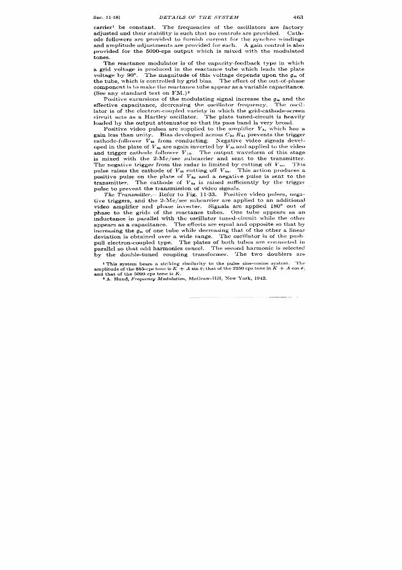
SEC. 11.18]
DETAILS OF THE SYSTEM
463
car r ier ’ be onstan t . The frequencies of the oscilla tor s a re factory
adjusted and their stability is such that no con t rols a re provided. Cath-
ode followers a re provided to furn ish cur r en t for the synchro windings
and amplitude adjustments are provided for each . A gain cont rol is a lso
provided for the 5090-cps ou tpu t which is mixed with the modula ted
tones.
The react ance modula tor is f the capacity-feedback type in which
a gr id voltage is produced in the reactance tube which leads the pla te
voltage by 90°. The magnitu e of th is voltage depends upon the g~ of
the tube, which is con t rolled by gr id bias. The effect of the ou t -of-phase
componen t is t o make t he reactance tube appear as a var iable capacitance.
(See any standard text on FM.)2
Posit ive excursions of the modula t ing signal increase the g- and the
effect ive capacit ance, decreasing the oscilla tor frequency. The oscil-
la t or is of t he elect ron -cou pled var iet y in wh ich t he r id-ca th ode-screen
circu it acts as a Har t ley oscilla tor . The pla te tuned-circu it is heavily
loaded by the ou tpu t a t t enuator so that it s pass band is very broad.
Posit ive video pulses a re supplied to the amplifier Vs, which has a
gain less than unity. Bias developed across Cs, R4, preven ts the t r igger
ca t hode-follower VW, fr om conduct ing.
Negat ive video signals devel-
oped in the pla te of V& a re aga in inver ted by V8b ad applied to the video
and t rigger ca th ode follower V 10.
The outpu t waveform of th is stage
is mixed with the 2-Me/see subcarr ier and sen t t o the t ransmit ter .
The negat ive t r igger from the radar is limited by cu t t ing off Vg~. This
pu lse ra ises the cathode of V9b cut t ing off Va~. This ac tion p roduces a
posit ive pu lse on the pla te of V8. and a negat ive pu lse is sen t t o the
transmit ter .
The cathode of VS. is ra ised sufficien t ly by t e t r igge]
pu lse to preven t the t ransmission of video signals.
The Transmit ter . —Refer to Fig. 1133. Posit ive video pulses, nega -
t ive t r iggers, and the 2-Me/see subcarr ier are applied to an addit ional
video amplifier and phase inver ter .
Signals are applied 180” ou t of
phase to” the gr ids of the react ance tubes. One tube appears as an
inductance in parallel with the oscilla tor tuned-circu it while the othel
appea rs as a capacitance, The effects a re equa l and opposit e so tha t by
increasing the g~ of one tube while decreasing tha t of the other a linea r
devia t ion is obta ined over a wide range. The oscilla tor is of the push-
para llel so that odd harmonics cancel.
The second harmon ic is selected
by the double-tuned coupling t ransformer . The two doublers are
The
amplit ude of t he 885-cps t on e is K + A sin .9;tha t of the 2250 cps tone in K + A cos 8;
and tha t of the 5090 cps tone is K.
2A. Hund, l’r equ en c~ Modu la tion , McGr aw-H ill, N ew Yor k, 1942.

464
RELAY RADAR SYSTEMS
[SEC. 11.18
convent iona l Class C amplifiers with double-tuned t r ansformers select -
ing the second harmonic present in their pla t e current s.
The power
t?.m
k
w
0,?
#
0.1
Inverter
. . . .
0.!
IM
;% ‘M
2.2k
T
-“’--i
0
I@h
Modulation
I control
32
[
I
I
Gi%---
~1.El%l
.
lid
amplifier
6.8k S
& 0.25
FIG. 11.33.—Transmit ter of ART-18 re lay radar .
amplifier uses pentodes in a push-pull circuit .
Since the shielding in
the 4E27 tubes is excellent , no neu~ra liza t ion is used. A peak dete~tor
and discr iminator a re provided for monito ing the t ransmit ter output .

I
I
~
I
I
,
i
I
I
,
ii
II
II
,,
ii
II
II
,,
ii
II
II
,,
ii
II
II
,,
R.EAn
6AK5
O.cmluuf
220
120
ICO 56
56
56
)Mfer
v
1 . . .
. . .
---
* ‘~:wmwR%
160
--I_
-+=2iA
+“ ” ” ” ” ” ’ ‘“’k
mplifier coik?
I*
—-
‘9
/.
/
B%d
I
switch
m ,Mgf
l-w
video output 47
{
Vddeooutput 47
Video output
~, Video output
Cr,u<
~ - y%%.z.ooc,s []g -,
11
+ 10
1
w
~wuw
~wf 5001WfJL.0.vernier ccnlrol
]Lvoltoge reg.lotor
vR!05
500)44+ f
[ *G
All condensers in f d om e n t c ir cw t 5 00 Jw f
n
1*
1*
‘-%-’%l
I
I
FIG. 1134.—Receiver of ARR-17 re lay radar .
+
m
CD
— —— —— —— ——

466
RELAY RADAR SYSTEMS
[SEC. 1118
All tuned circu it s a re overcoupled and Q values made low to permit
the required 8-Me/see pass band.
The Receiver .—Refer t o Fig. 11.34. The preamplifier , con ver ter , and
loca l oscilla tor use 6AK5’s. The antenna and conver ter tuned circu it s
a re factory preset . A t r immer condenser is provided to cont rol the LO
frequency. The LO voltage is mixed with the signa l and in jected into
the gr id circu it of the conver ter . The i-f stages a re 6AK5’s. Eight a re
used and are ar ranged in staggered pairs a t 55 and 6 Me/see with a
ga in of 10 each, giving an effect ive band width of 8 Mc, AGC is applied
to the gr ids of the th ird and four th stages.
Two limiters a re used. Limit ing takes place by rect ifica t ion in the
gr id cir cuit of each tube (see Vol. 19, Chap. 9 “of this ser ie ). The bias
developed decreases the average pla te cur ren t in each tube. The bias
developed by the fir st limiter is a lso used as the AGC cont rol voltage.
The t ime ccnstan t in the AGC circu it is kept to a minimum so tha t h igh-
level pulsed in ter fer ence will suppress the desir ed c-w ca rr ier for as shor t
a t ime as possible (much less than the PRF of any pulsed system likely
t o be encoun ter ed ).
The discr imina tor , which follows the second limiter , is of the con-
vent iona l type (see Vol. 23). Four 6AK5’s a re used as an output
ca thode follower to present a 75-ohm output impedance to the cable
leadlng to the sepa ra tor unit .
The Separa tor Unit .—Refer to Fig. 1135. The composite signal from
the receiver consist s of posit ive video signa l, nega t ive t r iggers, and the
2-Me/see frequency-modula ted subcar r ier . The subca r r ier is selected
and amplified by two 6AK5 stages and gr id-limited by two addit ion l
stages. Bias developed in the fir st limiter gr id circu it is applied to the
gr ids of the preceding amplifier as AGC. A discr imina tor centered at
2 Me/see d modula tes the subcar r ier . Aft er amplifica t ion the mixed
audio tones ar e sepa ra ted by double-tuned t ra nsformers, passed through
individua l ga in cont rols, and amplified fu ther by 6V6 Class A power
amplifiers.
The 885- and 2250-cps tones a re demodula ted by fu ll-wave peak
rect ifiers, which a re ar ranged to provide phase inversion to dr ive the
gr ids of the output ca thode followers in opposite dir ect ions. The
5090-cps tone is demodula ted in a peak half-wave voltage doubler whose
output potent ia ls a re r por iona l to the average level o the car r ier
and a re used to subtract a d-c va lue from the output signa l of the 885
and 2250 cps demodula tor s. Thus d-c voltages a re obta in d which a re
propor t iona l to sin e and cos 8 and va ry symmetr ica lly with respect to
ground. These voltages a re applied to each of the four sweep networks
and their magnitudes determine the ra tes of r ise of the sweep sawtooth
waveforms w en the clamp tu es are ga ted off. The sweep networks

SEC. 11.18]
DETAILS OF THE S YS TEM
467
are arranged in pairs, two for the hor izontal sweep and two for the
ver t ica l sweep. The networks in each pair a re supplied with con t rol
voltages of opposite phase so that a p sit ive and a negat ive sawtooth
waveform are produced by each pair .
They are amplified by the 6L6 GA
power amplifiers and applied to the cen ter-t apped deflect ing coils.
Cen ter ing is accomplished by adjust ing the voltage to which one of each
pair of clamp tubes is retu rned. 1
The video and t r igger p lses are amplified and inve ted by V,,
yielding posit ive t r iggers and negat ive video pulses. The t r gger pulse
is applied to the gr id of the synchronizing signal ic -off tube Vi.. This
amplitude selector is caused to conduct nly by posit i e pulses larger
than a value set by the bias divider in the gr id circuit . The nega t ive
pulse produced in the pla te circuit by the t r igger is coupled to the plate
of the blocklng oscilla tor V~b. Coupling through the t ransformer
cau ses V4* t o con du ct an d in it iat e r egen er at ion .
The blocking-oscillator
pu lse t rigger s t he ga te mu lt ivibr at or , wh ich is of t he con ven tion al divider -
coupled type with one stable sta te. (See Vol. 19, Chaps 5 and 6 of
this ser ies for descr ipt ion s of t he act ion of t he mult ivibrat or and blockin g
oscilla tor . ) The rect ngle in it ia ted by the t r igger is slight ly longer
than the sweep length desired. A gang switch switches the condensers
in the mult ivibrator and the sawtooth genera tor and the tuned circuits
in the range-mark genera tor so that the gate length , sweep speed, and
range-mark spacing are appropr ia te for the range chosen. The ca thode
follower Vleb dr ives the cable to the indicator where the negat ive gate
pulse is applied to the cathode of the CRT. The negat ive gate is also
used to cut off Vli~, producing a t ra in of damped oscilla t ions in the
tuned circuit (see Chap. 4 and Vol. 19, Chap. 4 of th is ser ies). The
posit ive excursions of the wave train are limited by gr id cur ren t in v~ib.
The negat ive h alf-cycles a re st eepen ed and in ver t ed by V14b. Addit ional
squ arin g is a ccomplish ed by V15Cso that the ou tpu t of th is tube is prac-
t ica lly a square wave. On the longest range energy is fed back to L4
from the plate of Vlt i t o maintain the amplitude of the oscillat ions of the
tuned circu it . Since on the shor ter ranges the Q of the co ls is sufficien t ,
the damping is not object ionable. Tube vlsb normally draws gr id cur-
r en t t h rough R8C. It is rapidly cu t off by the square wave applied to its
gr ids, xcit ing a cr it ica lly damped oscilla t ion in L~. The peak of th is
oscilla t ion is select ed and fu rt her amplified by V16a. Th e n egat ive ou tpu t
of th is tube is mixed with the video in the gr id circu it of the second video
amplifier V2. The method of producing range marks used in this inst ru -
ment appears to be ext remely wasteful of tubes and cur ren t .
Five
t r iode sect ions are used when three or a t most four would sufice. All
of the tube sect ions but one draw a large average plate curren t .
I F or dia cuzzion of th e two-wa y clamp see Vol. 19, Chap. 3 of th is ser ies.
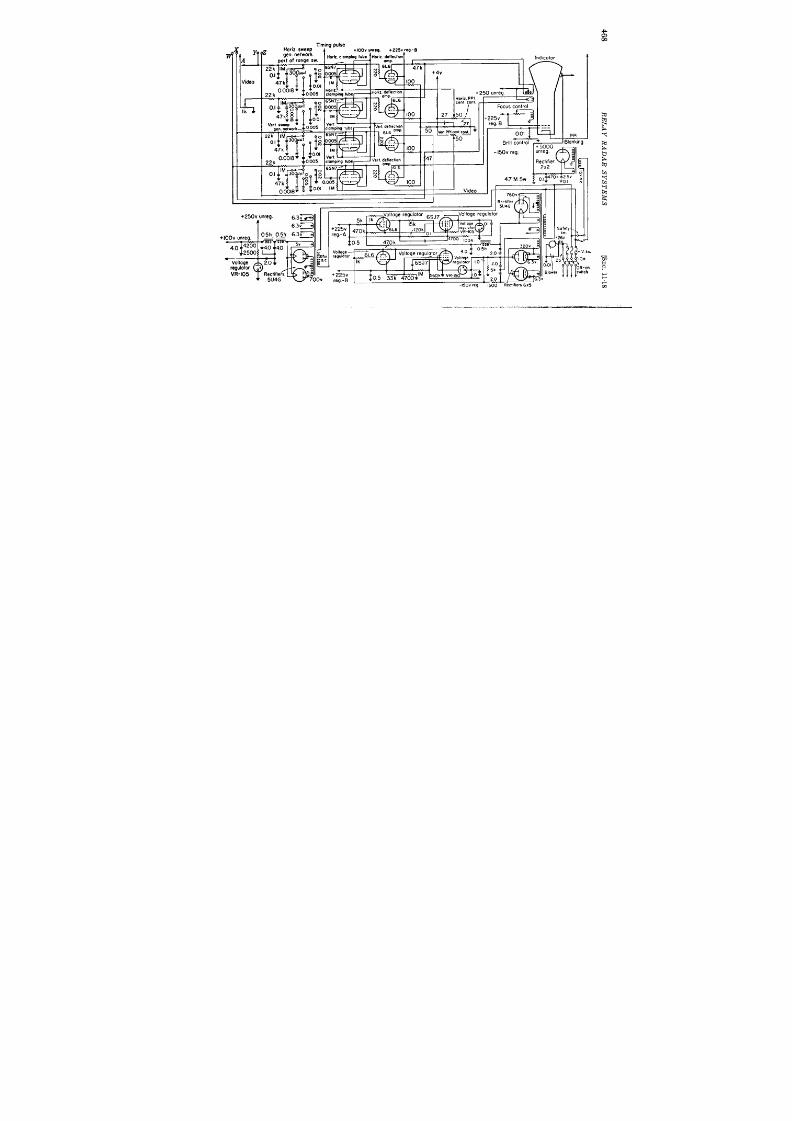
111
l iming pulse
!9 4
+100” “nrmg, +225. reg. -B
~11’i
nglube Hwiz deflectwn
mnp,
Indicator
6L6
47k 11-
1 1-
l’=aQQ—lJ———J—J
Uuulo- - -
I
I
.,. C”
r
I
1
I
SOfetj
,. .
L
.
.

Me .ultiwbabx Rangemarkgeneml.a Ranqanm ,k Ra w- e ma rk amp
-ER---l- ,
OW
PPIb!ank,”g
---- ---
Vdw
q
I
I
w
N
vb62
3.8 cdhcde
olbd
FIG. 11 .35.-S epar a t or of ARR-17 r el ay r ada r .
k-
50 k
12 k
.%
I
I
I
I
I
I
I
I
I
31-1-i
0 1M
6SN7
p _O lM
Ulf
---
470
RELAY RADAR SYSTEMS
[SEC.1119
Tube Va amplifies and inver ts the mixed video pulses and range
marks, which a re applied to the gr id of the CRT through the ca thode
follower Vs.
well designed and ext remely simple to opera te, having a minimum of
cont rols. It is not complica ted elect ronica lly and is light in weight and
not bulky. The system performs sa t isfactor ily over land and water
and at a ll t imes will provide a usable radar pictu re up to a range of at
least 100 miles if the receiving antenna locat ion is 50 ft or h igher above
the water line and f opt ica l line of sight t ransmission is mainta ined.
It was determined tha t the minimum signal st rength tha t would st ill
p ovide a usable picture is in the order of 20 pv.
“Any inter ference with in about 6 mc of the i-f fr equency of the
receiver will cause considerable distor t ion and c mplete fa ilure of the
rece ived presenta t ion .
(This is not an in her en t limit at ion of t he syst em sin ce pr oper sh ielding
of the i-f circuit s wou ld remove such in ter ference. )
“In ter fer en ce will a lso be exper ien ced on t he opera ting channels wh en
other (c-w) equipment or ground sea rch radars which opera te on the
same or adjacent frequencies a re opera t ing in the same vicinity as the
receiving locat ion.
“ Considerable r ipple and dktor t ion of the received pictu re will
resu lt if the rada r system pulse repet it ion frequency or ha rmonics of
the pulse repet it ion frequency are with in plus or minus 50 cycles of any
of the t h ree audio frequencies. ” 1
The accuracy is as good as tha t of
the AN/APS-2 Radar tha t supplied the signals for the system (bet t er
than ~ 50).
1This sect ion is abstractedfrom
“Final Report on AN/ARR-17 and AN/ART-18
Equipments ,Radar Repeat -back Radio Link ,” Navy Dept . Bu. Aero., Ju ly 14, 1945.
DELAY
12.1.
CHAPTER 12
AND CANCELLATION OF RECURRENT WAVE TRAINS
BY H. B. HUNTINGTON, W SELOVE, AND D. GALE
Int roduct ion . The l’und;on .-The purpose of these chapters is
t o discu ss a technique whereby a volt age V which var ies with t ime tcan
b delayed by an in terval D and then subtracted from itself. Expressed
an lyt ica lly, the funct ion is V(t + D) — V(t). If V(t) is per iodic in t
of per iod D, the cancella t io is complete; bu t if the voltage wave t ra in
repea ts itself only approximately from one interva l of dura t ion D to the
next , th is technique will indica te the existence of such var ia t ions as
migh t otherwise pass unnot iced. In th is way smal changes in the
repet it ive voltage, whether in amplitude or in phase, can be separa ted
an amplified to give informati n concern ing their re a t ive size and dis-
t r ibu tion in t ime.
In many tech nica l fields th e execu tion of th e fun ct ion descr ibed above
will bean asset . Quite cer ta in ly, considerable use can and will be found
for a techn ique tha t accomplishes it . It is not feasible, however , to
discuss here its genera l applicat ions and fu tu re possible development .
Although these techn iques wer developed for a specia l purpose, th is in
no way invalida tes their genera l usefulness. The possibility of cancel-
la t ion of pulse tra ins has been ment ioned in Chap. 2 as a method for
speed determinat ion . In fact , pract ica l applicat ion of th is technique
has been made in the precise measurement of the velocity o propagat ion
for su per son ic waves in m ercu ry.
The Inst rument .—One technique to accomplish delay and cancella -
t ion involves the use of storage tubes, a subject that is t r ea ted in full in
Vol. 19, Chap. 21 of th is ser ies. Br iefly the act i n may be descr ibed by
saying that the storage tubes reta in the volt age V(t as a pat tern of
charge laid on the surfac of an insula tor by a scanning elect ron beam.
The stored informat ion is made available a t a la ter t ime by a second
scanning of the beam. Within th is genera l fr amework severa l very
differen t procedures show promise. The device offer s considerable
in tr insic flexibility in that it can be adapted immedia tely to any value
of t he dela y D. Th e pr oject is as a wh ole, h owever , in t he developmen ta l
stage.
Anothe technique tha t employs a supersonic delay devicel to delay
I
471

472 CANCELLATION OF RECURRENT WAVE TRAINS [SEC.121
the wave t ra in for the in terva l D is discu ssed her e.
The act ion of super-
sonic delay lines is t r ea ted i Vol. 19, Chap. 23. Its rela t ion to the other
Dalayed channel
~–––
——.———————
1 Cancellation ompllfier
r
I
————— .
I
I Delayed 1 I
Input
~
channel
; ;)
~ omplifier I
t
————— J
Line
~ ~a~c~l;i;nT r ‘-– 7
,irwl+ ~1 ,::3 :” p +
driver
————— ~
L ‘~”~’flcy! ~ L–__J
~ U;daa#d i
t
I
~~mpllfier 1 ,
I
--- — — ___________
Undelayed chonnel
Fm. 12.1 .—Delay and cance lla t ion device .
component s in the unit tha t per forms delay and cancellat ion is indica ted
in the block diagram of Fig. 12.1.
From the block diagram the funct ional in terdependence of the sub-
ject mat ter t r ea ted respect ively in each of the next four sect ions becomes
FIG. 12.2.—Delay line completely assembled.
evident . The first t rea t s the delay line; the second, the line dr iver ;
the third, the cancella t ion amplifier ; and the four th , the cont rol of the
epet it ion ra te. In the cancell t ion amplifier provision is made for

SEO. 12.1]
INTRODUCTION 473

474
CANCELLA TZON OF RECURRENT WAVE TRAINS [SEC. 12.1
match ing the bandwidths of the delayed and undelayed channels, and
t he subt ract ion is per formed. Th e video sect ion amplifies t he u ncan celed
residue. The repet it ion ra te refers to the repet it ive wave tra ins. It is,
of cou rse, impor tan t t o t ake measur es t o insur e t hat t he r epet it ion in terval
equals t he delay t ime.
The requirem nt and limita t ions of such a system (Fig. 12.1) can be
discussed only br iefly here and will form the basis for more detailec
SEC.12.2]
INTRODUCTION
475
t rea tmen t in la ter chapter s. In par t icular , the value of the delay can
e as long as severa l milliseconds, though the delay device for such t imes
as 3 msec or more may become unwieldy. These delays a re essent ia lly
fixed or only var iable over one per cen t or so, according to prment
~
mechan ica l des ign .
The concept of degree of cancella t ion is an impor tant one for the
under st an din g of su bsequ en t ch apt er s.
The quant ity is used as a figure
of mer it for the delay and cancella t ion unit as a whole.
It is obta ined
y feeding an exact ly repet it ive wave tra in (usually a ser ies of single
square pulses) in to the delay and cancella t ion unit . The ra t io of the
amplitude of the cancelled residue to the amplitudes of the wave tra ins
efore cancell t ion gives the degree of cancella t ion. One per cent or
0 db down represen ts very good per formance and is often arbit rar ily
chosen as a design goal.
Two impor tant stability considera t ions a re involved in maintaining
the delay t ime equal to the repet it ion in terval, and in keeping the ampli-
!
tudes in the two channels the same size. The former problem is par-
t icu la rly t rou blesome sin ce t he on ic velocit y is a fu nct ion of t emper at ur e.
It will be shown la ter (in Chap. 16) that the two t ime intervals must
agr ee to about Th ~sec to achieve cancella t ion of 1 per cent of a pulse
with r ise t ime of about one psec.
Beca use of t he amplifier stability r equir ements, elect r on ica lly r egu -
la ted supplies a re gen er ally u sed for pla te a nd scr een volt ages t hr ou gh ou t.
The easiest way to insure tha t the same degree of cancella t ion holds
throughout the dynamic range of the input signal is to requ ire that both
the delayed and undelayed channels be kept accura tely linear over the
same range. Under these condit ions the net uncanceled residues will be
pr opor tion al t o per iod-t o-per iod ch an ges in n ea rly r epet it ive wa ve tr ains.
For some applica t ions th s fea ture is an advantage.
waveforms is shown with it s components in Figs. 12.2 to 12.5.
THE DELAY LINE
BY H. B. HUNTINGTON
DESIGN OF DELAY LINE FOR CANCELLATION
12.2. In t rodu t ion .-Chapter 23, Vol. 19 of th is ser ies on superson i
delay lines expla ins the fundamen ta l pr inciple of the device and to wha t
uses it has been pu t . Many of the theoret ica l and emiempir ica l con-
sidera t ions svh ich en ter in to its design have been developed in a recen t
jou rn al a rt icle.’
In the Componen t s’ Handbook, Chap. 7, Vol. 17 of
1 (fU lt r ason ic “Dela y Lin es I,”
H. B. Hun t ington , A. G. Emslie, and V. W.
Hughes; “ Ult ra sonic Delay Lines I I ,” A. G. Emslie, H. B. Hunt ington , H. Shapiro,
and A. E. Benfield. Par t I in the J . oj the Fnzn .klin nst , J anua ry 1948; Par t II to
be published .
476 CANCELLATION OF RECURRENT WAVE TRAINS [SEC.12.3
this ~r ies, the impor tant formulas have been collected in abbrevia ted
form and an at t empt has been made to show how these rela t ions should
be applied to actual delay-line design .
In genera l, the delay-line engin eer has to meet cer ta in specifica t ions
of an elect r ica l na ture. Usually there will be the delay t ime, the band-
width , and the pulse width of the signals. To mee these specifica t ions
h has the choice of the following parameters: the t ransmit t ing medium,
the car r ier frequency, 1 the dimensions of the pie oelect r ic crysta l, the
line geomet ry, and the mechanica l tolerances. Some of these parameters
a re a lready limited by the considera t ions t rea ted in Vol. 17. There the
emphasis was mainly on building lines tha t would give, for constan t
bandwidth and given dr iving condit ions, the maximum output . The
same con sidera tion s also a pply h er e but t he a ssocia ted ca ncella tion in tr o-
duces addit iona l complica t ions .
he new requirements fa ll mainly in to
t hr ee ca tegor ies: ech o elimin at ion, bandpass sh apin g, a nd equ aliza tion of
delay t ime with repet it ion in terva l.
Each of these requirements is dis-
cussed in turn in the next th ree sect ions.
12.3. Echo Elimina t ion.- ne very importan t requirement for a
delay device tha t is employed as par t of a cancella t ion unit is tha t it
gives for every input signal on ly one output signal a t the t ime of expected
delay and no other appreciable signal a t any other t ime. This means
tha t any accessory signa ls such as can easily ar ise in a supersonic device
from mult iple echoes must be kept below a cer ta in rela t ive level—for
example, the 40 db down tha t has been ment ioned before as an arbit ra ry
design goa l. In par t icular , considera t ion must a lways be given to the
possibility tha t some of the energy in the supersonic pulse may be
reflect ed on ce fr om t he r ece ver crysta l, on ce fr om th e tra nsm it t er cryst al,
and return to give an unwanted signal a t the receiver crysta l.
Th is will
be hencefor th refer r ed to as the “echo of t r iple delay,” since it appears
a t the receiver at a delayed t ime three t imes as long as the wanted delay.
Actua lly there may be a ser ies of such echoes appear ing at t imes tha t a re
odd mult iples of the design delay.
There a re two fundamentally differ -
en t approaches to the problem of reducing these echoes.
The first approach is to reduce the reflect ion a t the crysta l surface by
absorbing energy in to the crysta l backing. To do this the acoust ic
impedance of the mediumz in contact with the back side of the crysta l
must match the acoust ic impedance of the transmit t ing medium closely
enough so tha t the reflect ion coefficien t is 0.1 or less.
The impedances
1It has a lready b en poin ted out in Vol. 19, Chap. 23 of th is ser ies tha t , from the
ver y n at ur e of t he dela y lin e, a ca rr ier fr equ en cy is n ecessa ry for t he fa it hfu l pr eser va -
t ion of the wave t rain.
~ Th e a cou st ic im peda nce of t he cr yst al does n ot en ter if t he cr yst al t hickn ess ie a n
odd n umber of h alf wa velen gt hs, wh ich is t he con dit ion for r eson an ce.
SEC.12.3]
ECHO ELI MINATION
477
can be matched exact ly by backing the crysta l with the same fluid as
that used for the t ransmit t ing medium, or , in the case of a mercury-
filled delay line, the crysta ls can be soldered to lead or t in , both of which
match mercury ra ther sa t isfactor ily. The const ruct ional and mechan-
ical problems a ssocia t ed with t he absorbing backing a re t rea ted in Vol. 17,
Sec. 7.2 of this ser ies. It should be poin ted out that it is not su~cient
to t r nsmit t he energy into the crysta l backing, but the beam must either
be absorbed or d spersed in t he backing mater ia l t o preven t it s emergence
intact a t a la ter t ime. Because of its grea t er absorpt ion lead is preferable
to t in , From the formulas given in Vol. 17, Sec. 7.2 one n tes that t he
loss ar ising from mismatch at the crysta ls is increased from 3 to 6 db
wh en a n a ir -ba cked cr yst al (wh ich sh ou ld be t ot ally r eflect in g) is r epla ced
by one with a per fect ly absorbing backing. A crysta l tha t is suppor ted
by a dry metal elect rode is in effect a ir -backed since it is in contact
with the metal a t only a few point s and only a very thin layer of air is
needed t o afford a complete mismatch.
The second approach to the problem of eliminat ing the mult iple
echoes is to rely on the at tenuat ion in t ransit t o reduce the reflected
energy to the requ ired level. In thk connect ion it is possible to use
reflect ing dry elect rodes. By its na ture thk approach is bet t er suited
to the lines of longer delay, 1000 psec or more. A loss of about 20 db
per t ransit is needed if t he “echo of t r iple delay” is to be reduced suffi-
cient ly. Thk loss might be cont r ibu ted from severa l sources. Actual
a t t enuat ion in the t ransmit t ing medium is made up of two par t s the
free-space at tenuat ion and the tubular a t t enuat ion. From the formulas
given in Vol. 17, Sec. 7.1 of this ser ies one notes that t he free-space
at tenuat ion var ies direct ly as the square of the frequency and the tubular
a t t enuat ion direct ly as the square root of the frequency and inversely as
the inner diameter of the tube that conta ins the t ransmit t ing medium, 1
A third source of at tenuat ion will ar ise for “folded lines” at the reflect ors.
These reflectors a re usually set a t r igh t angles to one another and a t 45°
to the path of the beam. They serve to bend the beam back on itself
th rough a parallel pipe. Even though the mater ia l of the solid reflectors
is so chosen tha t t e cr it ica l angle for t ransmission into the solid is less
than 45°, som e loss usually appea rs at t hese su rfa ces (see Vol. 17, Sec. 7.3).
Last ly, successive mult iple echoes may be reduced by a small degree of
misalignment , which has only a minor effect on the direct supersonic
signal.
The eliminat ion of mult iple echoes by loss in t ransit then depends
on t he followin g combin at ion of design pa ramet er s: t ra nsm it tin g medium,
car r ier frequency, tube diameter , line geomet ry, and mechanical toler -
1The form ula for th e tubular a t ten ua tion h old on ly wh en t here is good son ic con -
tact between the t ransmit t ing medium and the tube all,

478
CANCELLATION OF RECURRENT WAVE TRAINS [&ZC.12.3
ancea . Of these the choice of t ransmit t ing medium is likely to be
limited by the demand for bandwidth , a discussed in Sec. 12.4. More-
over , many media are ruled ou t because of excessive at tenuat ion . A
paragraph on each of the other parameter s is her e included to indica te
to what exten t one is rest r ict ed in the respect ive choic s.
Though the ca r r ier frequency also en ter s in to bandwidth considera-
t ions, it is impor tan t to choose a value that will give about the requ ired
at tenuat ion in transit . In connect ion with the choi e of ca r r ier fre-
quency, it should be ment ioned that , where the cancellat ion takes place
after rect ifica t ion of the modula ted car r ier , the ca r r ier frequency must
be high enough to insure a sufficient number of cycles per pulse to
r eproduce the envelope with adequate accuracy ir respect ive of car r ier
phase. Exper iments by W. Selove have shown that th is number is
approximately seven for the degree of cancella t ion of 40 db with a pulse
whose r ise t ime is ~ the pu lse length .
As an example, one would not use
In the choice of the t be diameter , space and weigh t can be reduced
by using a smaller bore. There is a lso another reason , which will become
apparent in the next sect ion on bandwidth , why tubular a t tenuat ion is
pr efer a ble t o fr ee-spa ce a tt enuat ion .
On th e ot her h an d,’ opt imum-loss
bandwidth resu lt s when the capacitance of the act i e crysta l area
equals the st ray capacitance. (This holds if the l ad resistor s at t rans-
mit ter and receiver a re small compared with the impedance of the t rans-
ducer s, which is genera lly the case.) Too small a tube bore means too
small an act ive area and, for condit ions well r emoved from the opt imum,
this causes ser ious impedance mismatch . Another reason for aVOi&ng
t oo small a tube diameter is tha t it may in t roduce velocity dispersion
among the frequency componen ts of the pu lse with result ing pu lse dis-
tortion.
Su ch an effect h as been obser ved for dela y lin es u sin g a 5-Me/see
beam through 24 ft of mercury inside tubes about a half-inch in diameter .
In a delay line using a 10-Mc/sec beam through 16 ft of mercury inside
tubes ~ in . in diameter , no appreciable deter iora t ion of the pulse was
observed. The case of propagat ion down a tube with the boundary
condit ions of vanishing pressu re at the wall has been analyzedz and it
has been shown that the distor t ion shou ld depend essent ia lly on a
parameter
()
‘,Ad
.y=
YX
where Af is the pu lse bandwidth , jO the car r ier frequency, A the wave-
ength , d the length of path , and A the area of the tube cross sect ion .
1H. B. Hun t ington , et a l., op. cit .; a lso Vol. 17, Sec. 6.4, of this ser ies.
~ In forma tion obt ain ed fr om H. J . McSkim in of t he Bell Teleph on e La bor at or ies,
Mur ray Hill, N. Y.

SEC. 124]
BANDPASS SHAPING
479
In the mat ter of line geomet ry the space requir ements play an
impor tant role in determining in to how many sect ions the pa th of the
beam isto be bent . Once thenumber ofreflector s has been decided, one
can expect in genera l a loss of about one to three decibel per reflect ion
from a fine ground sur face in computing the a t tenua t ion to be expected
in t ransit . Pract ica lly no loss has been observed on reflect ion from
polished sur faces or m oder ately rou gh sur fa ces (see Vol. 17, Sec. 7.3).
To r edu ce mult iple ech oes by m isa lignm ent in volves eit her ext rem ely
precise machining or provision for adjustment after assembly. Neither
is to be recommended. Moreover , we have a lready ment ioned tha t pulse
shape often suffers in tubes tha t a re misa lign d.
12.4. Bandpass Shaping.—To accomplish a high degr ee of cancella -
t ion it is desirable to match closely the pass bands of the delayed and
undelayed channels. Consequent ly, one wishes to reduce to a minimum
any distor t ion in amplitude response in t roduced by the delay line. It
is desirable, therefore, to make the pass band of the delay line as fla t as
possible in the region of the pass band of the channels.
The r esponse of th e crysta l, exclusive of the circu it tha t resona tes out
the crysta l capacity, has been t rea t ed in some deta il and the case of the
crysta l in contact with the same medium on both sides is covered by a
par t icu la r ly simple formula . 1 The Q for this case is given by
Q.~~
accoust ic impedance of p iezoelect r ic ma ter ia l
a ccou st ic impeda nce of t ra nsm it tin g medium
where one is using the nth harmonic of the fundamenta l frequency of
the crysta l. In genera l, t o obta in a low Q one must employ a trans.
mit t ing medium of high acoust ic impedance.
For this reason most of
ou r work has been with mercury (though water is per fect ly sa t isfactory
for systems of small over -a ll bandwidth). If mercury is used, the
demands of bandwidth a llow considerable la t itude in the ch oice of ca rr ier
frequency.
As can be seen from the formula quoted above for Q, the bandwidth
for a fixed frequency var ies inversely as the harmonic n tha t s em ployed.
Also it requires n t imes the voltage to produce the same ou put when the
n th ha rmonic r epla ces t he fundament al.
Ha rmonic oper at ion is r ecom -
mended only a t those frequencies for which a crysta l vibra t ing i the
fundamental would be too thin for conv nien t m anufacture and handling.
The frequency response of the quar tz t ransmit t ing in to mercu ry is
rela t ively fla t i the region of resonance.
Theory’ indica tes tha t , for
a ir -backed quar tz, the response should be even sligh t i y fla t ter than for
quar tz with mercury on both sides.
Considera ble use has a lready been
I H. B. Hunt ington , et a l., “Ult rasonic Delay Lines I“ Sec. B.
ZH. B. Hunt ington , et a l., op. cit .

480
CANC’ELLA TION OF RECURRENT WAVE TRAINS [SEC. 12.5
made of th is fla tness to employ crysta ls whose undamped resonance
frequency lay just ou tside the pass band of the cancella t ion un it . For
example it was possible to use a 26-Me/see crysta l ith a 30-Mc/sec
car r ier without su ffer ing any appreciable band-pass distor t ion over a
&Mc/sec bandwidth . There was an advan tage in using s ch crysta ls
since it had been found that occasionally even heavily damped crysta ls
exh ibited peaks or dips in t eir pass band at the exact fr equency of their
fr ee resonance. (It is su rmised tha t these effects a re perhaps the resu lts
of small bubbles or dust par t icles between the quar tz and mercury.)
The appearance of either peaks or dips in the pass band of the cancella t ion
un it wou ld cause a marked deter iora t ion in per formance.
The delay line, however , does in t roduce one unavoidable source of
bandpass distor t ion in the frequency dependence of its a t t enuat ion . n
this score the tubular a t t enua t ion, which var ies as the square root of the
frequency, is easier t o compensa te than t he fr ee space at tenuat ion, which
var ies as the square of the frequency. The elect ron ic techniques by
which this compensa t ion is accomplished ar e discussed in Sec. 12.19.
12.6. Equaliza t ion of Delay Time with Repet it ion Interva l.-The
pu rpose of t his sect ion is t o t rea t t he mech an ica l complica tion s in tr odu ced
into delay-line design by some of the methods for equaliza t ion of delay
t im e wit h r epet it ion in ter va l.
The complica t ions are of two sor t s: those
that make it possible to vary line delay over a small range, and those that
provide addit ional delay channels to regulate t he per iod of the t r igger
that init ia tes th r epet it ive wave t ra ins.
At presen t there are two techniques (Vol. 17, Sec. 7.3 of this ser ies)
in use for making var iable mercury delay lines that can be used in the
field. I one the posit ion of a crysta l or r eflector is con t rolled by a
mechanical dr ive. Par t of the coupling shaft is actually immersed in the
mercury and a packing cell preven t s leakage of the flu id. For mercury an
eilect ive packing gland is made of linear threads dipped in ceresine wax
and t igh tly compr essed ar ound t he shaft .
The s econd t echn ique involves
a bellows con st ru ct ion t ha t a llows t he dr ivin g mech an ism t o be complet ely
outside that space occupied by the t ransmit t ing medium.
Sta in les s s teel
bellows are available for use with mercury, but should, perhaps, be
in ter na lly la cqu er ed t o pr even t mer cu ry con tamin at ion .
The simplest provision for an addit ional delay channel t o regu la te the
t r igger is t o supplY a near ly duplicate delay line that is placed n the
same thermal environment as the signal delay line.
This t r igger line
actually must be shor t er by about a microsecond to allow t ime for ampli-
fica t ion and t r igger ing. An advantage of this a r rangement is that it
involves no addit ional design. The disadvantages are t he increased space
and weigh t demands and the problem of maintaining the t ransmit t ing
medium in the two lines a t the same tempera ture.

SEC.12.6]
MERCURY LINES
481
A modifica t ion of th is scheme has been to use half-length lines for
t r igger genera t ion and then to coun t down in frequency by a factor of 2.
Another var ia t ion of th is scheme is to employ a quar ter -length line and
use the same crysta l for transmission and recept ion .
When this was
t r ied, however , the mult iple reflect ions ar r iving with random phase at
n ear ly th e same t ime as su ccessive t r igger s gave consider able difficu lty.
This was cause for some surpr ise as it had been est imated that the
mult iple echoes would be 8 to 10 db b low their actua l va lue. The
est imate had been based on a small reflect ion coefficien t from a steel
mir ror placed normal to the path of the eam. Apparen t ly the sur face-
ground steel was not sufficient ly smooth to give good acoust ic con tact
over the sur face; consequen t ly the simple theo y. is inapplicable. The
half- and quar ter -length lines were designed to be par t of the same
mechanica l unit as the signal delay line and were fed from the same mer-
cu r y r eser voir .
This fea tu re increased the compactness of the device
and fac lita ted t he equ alizat ion of temper at ure bet ween signal and t r igger
lines.
It is not necessary, however , to use two separa te delay lines, and a
th ird crysta l (Vol. 17, Sec. 7.2 of th is ser ies) for c n t rol of repet it ion ra te
can be inser ted. Here a reflect ing block, placed a lit t le in fron t of the
receiving crysta l and at 45° to the path of the beam, reflects a fract ion
of the energy th rough 90° to a th ird crysta l set in a r ecess in the tube wall.
The posit ion of the re lector block may be var ied, if so requ ired, to adjust
slight ly the t r igger delay to insure synchron iza t ion .
This scheme
involves pract ica lly no addit ional spac or weigh t requirements but does
complica te the const ruct ion of the end assembly. Since the paths for
signal and t r igger are a lmost iden t ica l tempera tu re, considera t ions no
longer en ter . Some provision must be made to preven t large signals from
tr igger ing the repet it ion -ra te genera tor . This can be done in a var iety
of ways. One possible solu t ion would be to use separa te car r ier frequen-
cies from a broadband t ransmit ter for signal and t r igger on opposite sides
of the resonan t crysta l fr equency.
The receiving circuit at the th ird
crysta l is then maintained nar row enough to exclude signal pulses.
EXAMPLES OF DELAY DESIGN
12.6. Mercury Lines.-The mechanica l and elect r ica l proper t ies of
severa l mercury delay lines have already been t rea ted with considerable
deta il in Vol. 17, Chap. 7 of th is ser ies. The discussion here will be
limited to those aspects that have been t rea ted genera lly in the fir st par t
of th is ch apt er .
The delay device in t roduced in Sec. 12.1 (see Fig. 12.2) opera tes at a
ca r r ier frequency of 15-Mc/sec and gives a delay of 1000 ~sec. The
signal pa th t raver ses four sect ions of tubing (ID of ~ in. ) which are in ter -
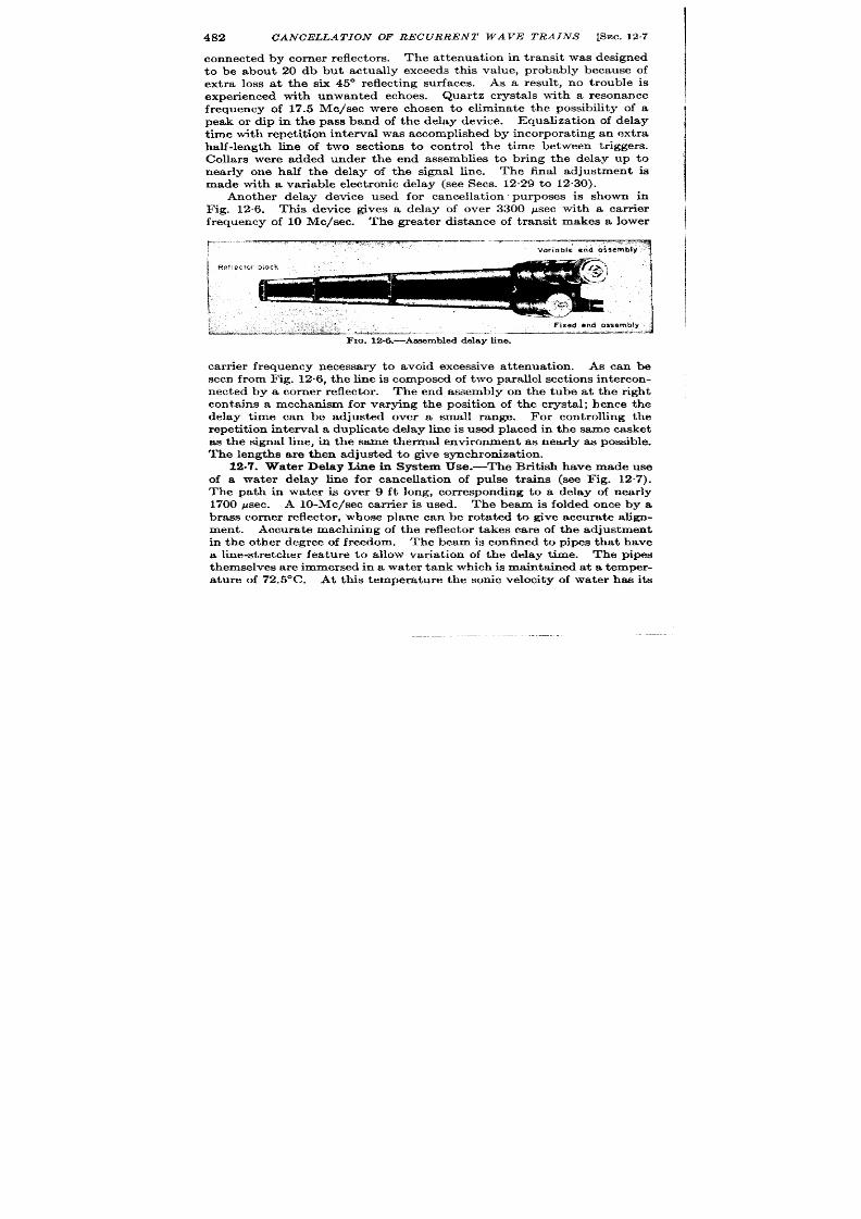
482
CANCELLATION OF RECURRENT WAVE TRAINS [SEC.12.7
I
connected by corner reflector s. The at tenua ion in transit as designed
to be about 20 db but actually exceeds th is value, probably because of
ext r a loss a t the ix 45° reflect ing sur faces.
As a result , no t rouble is
exper ienced with unwanted echoes.
Quar tz crysta ls with a resonance
fr equency of 17.5 Me/see wer e chosen to eliminate the possibility of a
peak or dlp in the pass band of the delay device. Equaliza t ion of delay
t ime wit h r epet it ion inter va l was accomplished by in cor por at ing an extr a
half-length line of two sect ions to on t rol the t ime between t r iggers.
Collar s were added under the end assemblies to br ing the delay up to
near ly one half the delay of the signal line. The fina l adjustment is
made with a var iable elect ron ic delay (see Sees. 12.29 to 12. 0).
Another delay device used for cancella t ion purposes is shown in
Fig. 12.6. This device gives a delay of over 3300 psec with a car r ier
frequency of 10 Me/see. The grea ter distance of t ransit makes a lower
;.... . ..-~
—..-”------
..—---- ---- ,.. . . . ..S:
.“. ...
Voriob ie en d a ssem bly
I
car r ier frequency necessa ry to avoid excessive at tenuat ion . As can be
seen fr om Fig. 12.6, th e line is composed of t wo par allel sect ions in ter con-
nected by a corner reflector . The end assembly on the tube at the r ight
conta ins a mechanism for varying the posit ion of the crysta l; hence the
delay t ime can be adjusted over a small range. For cont rolling the
repet it ion interval a duplica te delay line is used placed n the same casket
as the signal line, in the same thermr d environment as near ly as possible.
The length s a re then a djusted t o give synchroniza tion .
12.7. Water Delay Line in System Use.—The Brit ish have made use
of a water delay line for cancella t ion of pulse t ra ins (see Fig. 12.7).
The pa th in water is over 9 ft long, cor r esponding to a delay of near ly
1700 psec. A 10-Mc/sec a r r ier is used. The beam is folded once by a
brass corner r eflector , whose plane can be rota ted to give accura te align-
ment . Accura te machining of the r eflector takes c re of the adjustment
in the other degr ee of fr eedom.
The beam is confined to pipes that have
a line-st retcher fea tu re to allow var ia t ion of the delay t ime. The pipes
themselves a re immersed in a water tank which is mainta ined a t a temper -
a tu re of 72.5°C. At this t empera tur e the sonic velocity of water has it s

SEC.12.7]
WATER DELAY LINE IN SYSTEM USE
483
Fm. 12.7.—Water delay line: (a ) line a ssembled ; (b ) line, cove r r emoved; (c) line-s tr et cher
cons truct ion and reflector block ; (d ) crys ta l moun t , d is as sembled .

484
CANCELLATION OF RECURRENT WAVE TRAINS [SEC. 128
maximum value so that difficult ies with conduct ion cur ren ts and refrac-
t ion effect s a re gr ea tly r edu ced.
Moreover , the at tenuat ion in water is
much lower at h igher tempera tu res than at room condit ions.
The end
assemblies conta in ing the crysta l mou ts a re a t t ached to the waif of the
tank.
The a t tenuat ion in the water is considerable so that the mult iple
r eflected echoes a re completely lost . On the other hand, much bet ter
coupling is possible to water than in mercury, which makes up for the
increased los in the t ransmit t ing medium.
Ba ndwidt h is n ecessa rily
much nar rower and this limits the discr iminat ion of the system to longer
pulses. With in th is fundamenta limita t ion the cancella t ion problem is
somewhat simpler . For one thing the pass band is nar row enough so
tha t the var ia t ion of a t tenuat ion with frequency will have lit t le effect .
The line-st retch r adjustment of the guiding tubes allows the opera tor
to set the delay t ime to agree with the repet it ion interva l. Once syn-
chron iza t ion is ach ieved it should be mainta ined. At least the constant -
tempera tu re delay line can be expected to hold the del y fixed.
12.8. Possibility of Using Delays in Sof.ids.-Although liquids have
been employed on all actual system applica t ion so far , there has been a
resea rch program in progress to invest iga te the possibilit ies of delays in
solids.1 The use of liquids involves cer ta in mechanical problems, such as
leakage, breakage, and air bubbles. With mercury considerable t rouble
has been exper ienced with mechanical impur it ies and meta l amalgams
which formed slowly. The effect s of aging and mechanical shocks and
of var ia t ions in pr essur e have been discussed in Vol 17, Sec. 7 “6. Beca use
of these difficult ies with liquids it has been thought that a delay in a solid
medium would be well wor th developing for a cancella t ion system.
The
pr imary int r insic difficulty with delays in solids ar ises from the fact tha t
sonic velocit ies a r e th ree to five t imes tha t encounter ed in liquids. This
means not only tha t the delay pa th must be longer by such a factor , but
a lso tha t th final beam spread will be increased by the square of this
factor . This comes about because the angular spread of the beam is
propor t iona l t o the wavelength , or the velocity. A secondary int r insic
difficulty ar ises from the fact tha t in the solid thr ee sonic modes can be
propagated as compared to the single compressiona l mode in the liquid.
As a result the t ransfer of energy from one mode to the others is a compli-
ca t ing possibility tha t may occur whenever the beam is incident on a
sur face across which ther e is a discont inuity in sonic proper t ies. In
addit io t o these in tr insic difficult ies ther e a re severa l problems in tech-
n iqu e a nd pr epa ra tion of mater ia ls.
Th e met hod of applying th e crysta ls
t o the solid in such a way as to secure good acoust ic contact is a case in
1For complet e det a ils on th is p rogram a t Radia t ion Labora tory see D. L. Aren -
berg, “SupersonicSolidDelayLhm,” RL Report No. 932.

SEC.12.8]
POS S IBILITY OF US ING DELAYS IN SOLIDS 485
point . Moreover , superson ic beams of high frequencies a re easily scat -
ter ed in solids (1) by precipita ted impur it ies, ( ) byresidual str esses, and
(3) bythepolycrysta l of thesubstance it self. Inaddit ion specimens of
numerous glasses having none of these defects showed considerable
in t r ins ic a t tenuat ion .
Such ifficult ies as those discussed above are not impor tan t in the
building of shor t supersonic solid delays (less than 25 psec), which have
already been successfu lly developed and used (see Vol. 17, Sec. 7.7).
Recen t ly the use of a solid delay has been shown to be pract ical for
cancella t ion applicat ion and will be t rea ted here in some detail.
~ Receiving crystal
@
f
/
\
\
*,..
\
Transmitting crystal
— Compression I mode
------ Transverse mode
FIG. 12.8 .—Two-dimensiona l sound path in fused quar tz b lock .
By far the most su itable mater ia l so far invest iga t ed for th is pu rpos
is fused silica , or fused quartz as it is commonly ca lled. Its int r insic
a t tenua t ion is very low, as might be expected from the high Q of crystal
quartz. It can be procu red commercia lly very pure and rela t ively strain-
free. Usua lly there are, however , some str iae or small bubbles appear ing
th roughout which have undoubtedly some scat ter ing effect . The Ge -
era l Elect r ic Company is equ ipped to make disks 10 in . in diameter and
a few inche8 thick. When one of these disks is polished and viewed
between crossed polaroids, there is 8ome evidence of birefr ingence, but on
the whole these pieces are remarkably homogeneous and isot ropic. The
at tenuat ion in transit is low enou h so that it is di5cult to measure
accura tely. For solids there is reason to believe that a t tenuat ion in a
re ion far from any resonance should be linear with fr quency.
486 CANCELLATION OF RECURRENT WAVE TRAINS [SEC.12.8
The presen t t echn ique is t o fix the crysta ls to the quar tz with a th in
la yer of melt ed pa ra flin .
If considerable ca r e is exer cised to exclude all
dir t and bubbles and if a ll excess wax is pressed ou t from under the
crysta l, a fa ithful reprod ct ion of microsecond pulses can be ach ieved at
15 Me/see. This means the t ransducer has adequate bandwidth , near ly
as large as tha t obta ined by the use of mercury.
For a quar tz crysta l
loaded down by fused quar tz on one side, one would expect a Q of about
one. Actually, a bandwidth of 34 Me/see at a ca r r ier frequency of
15 Me/see has been measured.
At least two schemes have been conceived to preven t the supersonic
beam from be ng roken up into ar ious modes on reflect ion . One of
these is ca lled the “ tw~dimensional path. ” The design calls for cut t ing
the disks in to near ly square r ectangles with facets a t two of the corners
cu t a t 45° to the sides, (see Fig. 12.8). Two or th ree such designs have
already been tr ied ou t and one has proved very successful. The second
scheme calls for a three-dimensional path for the beam in the quar tz and
r equ ir es con sider able explan at ion for adequa te pr esen ta t ion .
The design
calls for facet s on the cor ners cut a t compound angles and requ ires specia l
equipment . There a re excellent prospects tha t fu ture results with the
“ threedmensiona l pa th”
will be at least as good as those a lready
obta ined with the “two-dimensiona l path . ”
For every homogeneous solid ther e is an internal angle of incidence
for the compressiona l beam at which complete ransfer from the com-
pressiona l to t ransverse mode takes place on reflect ion . For tmately,
for fused quar tz th is angle fa lls a t near ly 45°. Direct use of th is fact is
made in the design of the “two-dimensiona l paths. ” Following the path
t raced in Fig. 12.8 (wher e the compressional mode is represen ted by a full
line and t raverse propagat ion is shown by dot ted lines) we see that the
beam sta r ts init ia lly from the 45° facet in the compressional mode as
excited by an X-cut crysta l, crosses the block, and on st r iking the quar tz-
a ir in t er face is r eflect ed in t he t ra nsver se mode.
Beca use of t he differ en t
velocit ies in t he t wo modes, th e angle of r eflect ion differ s fr om t he a ngle of
incidence. On the next reflect ion the beam st r ikes outside the cr it ica l
angle for excit ing the compressional mode and the beam is tota lly
r eflected. At the th ird reflect on a situa t ion appears that is ident ica l
with the first reflect ion except for r ever sa l in t ime.
Con sequ en tly, t he
beam is t ransformed from transverse to compr ssiona l vibra t ion. This
cycle repea ts every th r ee reflect ions and eventua lly the beam in the
compressiona l mode st r ikes the receiving crysta l a t normal incidence.
There is then a family of such paths dist inguished by the value of n
where 3n gives the number of r eflect ions.
The ra t io of block length to
block width determines which path is used. Figure 12.8 shows the case
for n = 5, and this is the case that has given the most successful result s.
The delay with such a block is over 400 ysec.
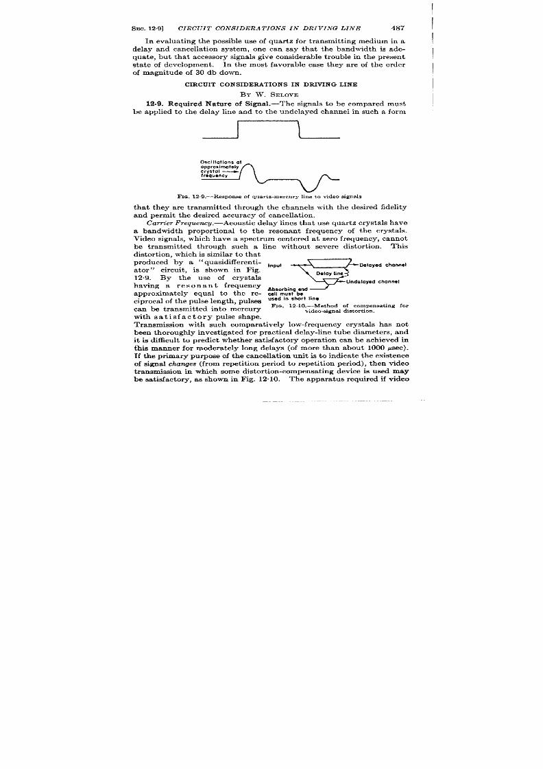
SEC. 12.9]
CIRCUIT CONS IDERATIONS IN DRIVING LINE
487
In evalua t ing the possible use of quar tz for t ransmit t ing medium in a
delay and cancella t ion system, one can say tha t the bandwidth is ade-
quate, but tha t accessor y signals give considerable t rouble in t he present
sta te of development . In the most favorable case they are of the order
of magnitude of 30 db down.
CIRCUIT CONSIDE~TIONS IN DRIVING LINE
BY W. SELOVE
12.9. Required Nature of Signal.-The signals to be compared must
be applied to the delay line and to the undelayed channel in su h a form
I
‘-
Fro.12,9 .—Response of quar tz-mercury line to v ideo s igna ls
tha t they are t ransmit ted through the channels with the desired fidelity
and p rmit t he desir ed a ccu ra cy of can cellat ion .
Cam”er F requ emy.—Acou st ic dela y lines t ha t u se qu ar tz cr yst als h ave
a bandwidth propor t ional to the resonant frequency of the crysta ls.
Video signals, which have a spect rum centered at zero frequency, cannot
be t ran mit ted through such a line without severe dktor t i n . This
distor t ion, which is similar t o tha t
produced by a ‘‘ quasidiff erent i-
ator”
circuit , is shown in Fig.
12.9. By the use of crysta ls
having a resonant frequency
approximately equal to the re-
cipr oca l of t he pulse len gt h, pulses
can be t ransmit ted into mercury
with sa t isfactory pulse shape.
Input
9
Delayed channel
Delay line
Undelayed channel
Absorbing end
cell must be
used in short line
Fm. 12. 10.—Meth od of com pen sa tin g for
video signa l distortion.
Transmission with ‘such compara t ively low-frequency crysta ls has not
been t horoughly inv st iga ted for pract ica l delay-line tube diameters, and
t is di ficult to predict whether sa t isfactory opera t ion can be achieved in
this manner for modera tely long delays (of more than about 1000 Psec).
If the pr imary purpose of the cancella t ion unit is t o indica te the existence
of s igna l changes (from repet i ion per iod t o repet it ion per iod), then video
t ransmission in which some distor t ion-compensa t ing device is used may
be sa t isfactory, as shown in Fig. 12”10.
The appara tus equired if video

488 CANCELLATION OF RECURRENT WAVE TRAINS [SEC. 129
signals are to be transmitted directly is considerably simpler than the
apparatus for the commonly used car r ier -frequency signa ls.
Signa ls may be delayed without distor t ion in an elect romechan ica l
delay line by t ransmit t ing them as car r ier -fr equency signa ls and by
using a sufficien t ly h igh car r ier frequency to obta in the necessary band-
width . (Other factors affect ing the choice of car r ier fr equency are
discussed in Sec. 12.2. ) This is the method which has been used
exclusively.
cam”er Level. —Figure 1211 represents an amplitude-modula ted signa l
Maximum excursion
Maximum voltaga
Em ,
\
~~;;d.lation Voltoge
-!
~-l
I
—-
1 r -
J
I––––-__.
i–-i AlI vollages
or e peak
FIG. 12.11.—Modulated-carrier signal.
common ly u sed for mer cu ry dela y-
line transmission . This sect ion
con siders th e requir emen ts on the
magnitude of the unmodula ted
carr ier level Eo. Specifica lly, it
must be determined whether EO
can be so small tha t the modula-
t ion envelope has zer o amplitude
for some signals or in the absence
of signals. This quest ion s of
in terest because a complex array
of equipment may be requ ired to
ensure that the modulat ion en-
velope never as zero amplitude. The p oblem of ‘‘ adding” a car r ier
level to signals is t r ea ted in Sec. 12.10
The factor which determines whether the modulat ion envelope may
ever have zero amplitude is the method of cancellat ion used in the cancel-
lat ion amplifier . The possible methods are two: ‘‘ car r ier -fr equency
cancellat ion” or cancellat ion of th e individual car r ier -fr equ en cy cycles
in the signals, and
“envelope cancella t ion”
of t he det ect ed modu la tion
envelope of the signals. (These methods are defined in Sec. 12.18. ) If
car r ier -fr equency cancellat ion is used, it is of no consequence whether
th e modulat ion en velope ever has zer o amplitude; but in en velope cancei.
la t ion , accu ra te cancellat ion r equir es ident ical envelope reproduct ion
in the delayed-channel and undelayed-channel detectors.
Identical
response can be guaran teed only if the minimum voltage Eti applied to
t he det ect or is su fficien tly la rge t o a void t he n on lin ear r espon se wh ich an y
det ect or exh ibit s for su fficien tly small sign als. For envelope cancella tion ,
t her efor e, th e car rier level should be somewhat higher than th e maximum
negat ive modula t ion .
An ot her fa ct or a ffect in g t he ch oice of ca rr ier level, a lth ou gh gen er ally
less impor tant than the preceding one, is the in teract ion of the car r ier
level with the pulse distor t ion caused by the var ia t ion of delay-line
a tenuat ion with frequency, This var ia t ion may be great enough in

SEC. 12.10]
CIRCUIT CONS IDERAT IONS IN DRIVING LINE
489
some cases to distor t the pass band of the delayed channel in the manner
shown in Fig. 12.12. A pass band such as tha t of Fig. 12. 12c is sa id to
have
‘‘ semisingl+sideband” transmission. The amount of distor t ion
produced by a semisingle-sideband system depends on the effect ive per -
centage modula t ion; the low r the ra t io of E~~ to EO (see Fig. 12”11), the
lower the distor t ion .1 This reason for a high car r ier level s not very
impor tant , however , since compensa t ion for the delay-line distor t ion of
the pass band is usually in t roduced for other reasons (see Sec. 12”19).
It should also be noted tha t in many cases the delay-line bandpaas
(0)
(b)
(c)
F IG. 12,12.—Dist or t ion of pass ban d of dela yed ch an nel. (a ) Typica l paw ban d of
delayed channel exclu s ive of delay line.
(b) P ossible t ra nsit ion ch ar act er ist ic of dela y
line. (c) Combined Pass han d of (a ) and (b).
dist or tion is so small t ha t t he possibilit y of sem isin gle-sideband dist or tion
can be n eglect ed.
12.10. Met hod of Obtaining Requ ir ed Type of Signal. Video Signah.
If the signals to be compared a re video signals, they must be conver ted
to a car r ier frequency. The next severa l sect ions of this chapter descr ibe
the design considera t ions for an appropr ia te con ver ter .
Carrier-jTequerwy Signals.-The signa ls to be compared may be
car r ier -frequency pulses. It may be possible to apply such signals
direct ly to the delay line as follows:
1. In car r ier -fr equent y cancella t ion, if the ca rr ier -fr equency cycles
of unchanging signals have the same phase (i.e., with respect to the
t im in g sign al or t rigger ) in su ccessive r epet it ion per iods.
2. In envelope cancella t ion, if the car r ier level is not zero. (If the
car r ier fr equency of the pulses is not suitable for delay-line trans-
mission, a frequenc conver ter may be used, subject to the pr in-
ciples discu ssed in Sec. 12.12.)
If envelope cancella t ion is to be sed and the ca r r ier level is zero, the
signals cannot be applied dir ect ly to the line. There a re two techniques
which may be used to obta in the requir ed signa l: the ca r r ier -frequency
signals may be detect ed and the result ing video signals used with a
modula t d car r ier genera tor , or a ca r r ier may be added. Suitable
method of adding a car r ier will now be considered.
1 See H. E. Kallmann and R. E . Spencer , Proc. I. R .E ., 12, 557–561 (1940).

490 CANCELLATION OF RECURRENT WAVE TRAINS [SEC. 12.10
A car r ier from a source independen t of the source of signals cannot
be added to the signals because such addit ion will conver t nonchanging
sign als, wh ich sh ou ld ca ncel, in to ch an gin g sign als, wh ich will n ot ca ncel.
Thk conversion occurs because, even though the amplitude of a ulse
may not chan ge in successive r epet it ion per iods, a fluctuat ing signal will
resu lt if the phase angle between th is pulse and the car r ier changes in
‘“’s” r-w-
“’:”C’’
Pulse out of
with corrier
Fm. 12.
c
hosenlEE~=’o%’~
(c)
(d )
13.—Fluctua t ion resu lt ing from addit ion of noncohe ren t pu lse and ca r r ie r.
su ccessive r epet it ion per iods, as sh own in F ig. 12”13. F igu re 12”14 sh ows
the genera l form of coheren t -phase techn ique-either the c-w genera tor ,
which suppfies the ca rr ier level, can be made to cont rol the phase of the
pulse-signal source or the pulse can be made to con t rol the phase of the
c-w genera tor . 1 The “device” of Fig. 12.14 is the device, whose varying
character ist ics in successive repet it ion per iods r e t o be invest iga ted by
Fm.
I I
12.14.—Coheren t -phase technique. Arrow A, coh er en ce of CW
B, coher ence of puls e by CW.
by
Arrow
t he cancella t ion circuit . Becau se th k device gener ally transmits signals
with some delay, th e c-w gen er at or must h ave a cer ta in degr ee of stability
in order that its phase will be coheren t even with delayed signals (if they
are nonchanging, of course). Cor respondingly, addit ion of the outputs
of th e phase-coherent , stable c-w gen er at or and t he “device” can pr ovide
a sensit ive means of determining whether the t ime delay in the la t ter
va r ies in su ccessive r epet it ion per iods.
I
I
I
I A typical cir cu it of a““coheren t oscilla tor ”
a nd ot her per tin en t in forma tion ca n
be found in Chap. 22, Vol. 23.
SEC. 12.12]
CIRCUIT CONSIDERATIONS IN DRIVING LIN
491
CARRIER GENERATOR AND MODULATOR UNIT
Th e followin g fou r sect ion s a re con cer ned specifically with a un it t ha t
conver ts video signals t o modulated-car r ier signals su itable for a system
using envelope cancella t ion . Much of the mater ial included, however , is
applicable to systems using car r ier -frequency cancella t ion or having
information su pplied in t he form of ca rr ier -fr equ en cy signals.
The modulated-car rie~genera tor unit of the system shown in Fig. 12.4
is refer r ed to frequent ly for examples of the pr inciples discussed. A
circu it diagram of th is unit is g ven in Fig. 12.15.
12.11. Oscilla tor .-Th e oscilla tor of a modu la ted-ca rr ier -gen er at or
for envelope cancella t ion is a simple device. The frequency stability
requir ed is only that which will keep signals in the pass band of the
following circuits. The amplitude must be stable enough to preven t
spur ious fluctua t ions. Sa t isfactory stability can genera lly be obtained
by t he u se of a r egu la ted pla te- an d scr een -volt age su pply, as is common ly
n ecessa ry on a ll t ubes a ffect in g sign als befor e cancella tion .
Oscilla tor circu it s are discussed in detail elsewhere in th is ser ie . 1
Any of the usual circu it s is sa t isfactory. The modulat ion technique
recommended in the next sect ion requires only small oscilla tor output ,
a lthough it may be convenient to have push-pull output .
If the stage following the oscilla tor is the modula tor , a t ten t ion must be
given to the problem of prevent ing the modulat ing signals from undesir -
ably a ffect ing the oscilla t or .
12.12. Modu lat ion .—Modulat ion of t he ca rr ier must be accomplish ed
in such a way tha t the modulat ion envelope (a) is constan t for a signal
whose amplitude does not change from one repet it ion to the next , (b)
reproduces changes in a modulat ing signal with the desired linear ity of
incrementa l response (usually linear ity of bet ter than 10 per cent is
unnecessary), and (c) reproduces signals with the desir ed r ise t ime.
Requirement (c) determines the minimum permissible bandwidth of the
modulat ing circu it s, and (a) necessita tes fr eedom fr om any “t ransien t”
effects.
Modulation Transien ts.—An undesirable t ransien t effect can occur
if the modulat ing signal contains frequency components in the car r ier -
frequency region which appear in the modulator output . If such car ier -
frequency components are present , a t ransient signal that has a defin ite
phase with respect to the modulat ing signal at approximately the car r ier
frequency will exist . The frequency spect rum of the transien t will
depend on the frequency spect rum of the modulat ing signal and on the
pass band of the circu it s th rough which the transient passes. If the
modulat ing signal is approximately a step funct ion and if the circu it s
1
Vol. 19, Chap. 4.
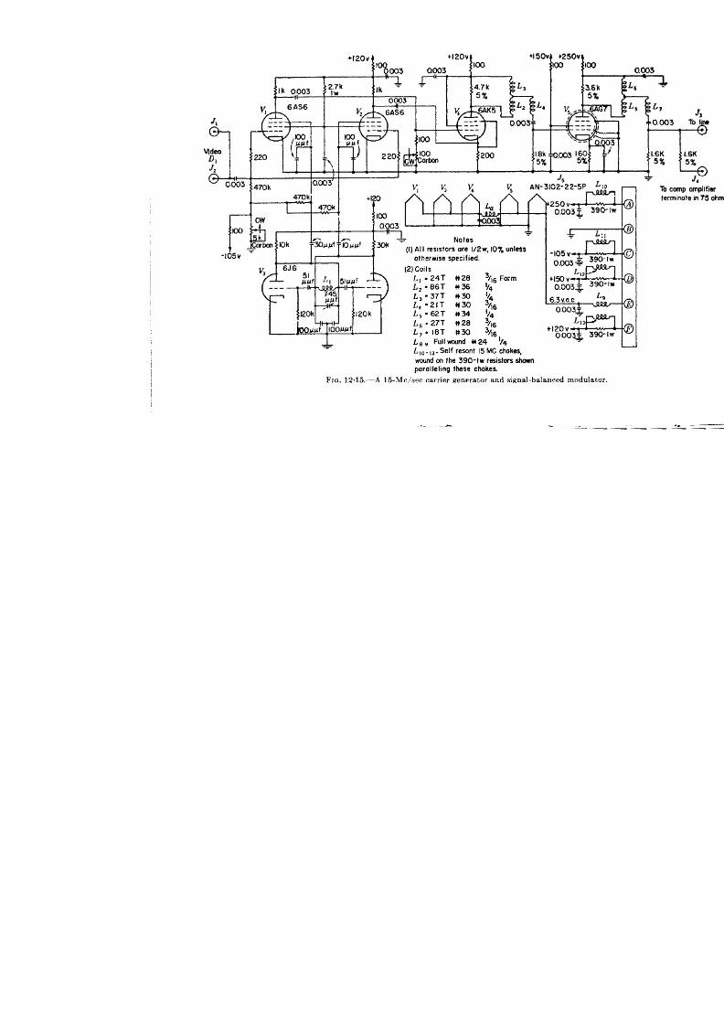
1
I
-
J
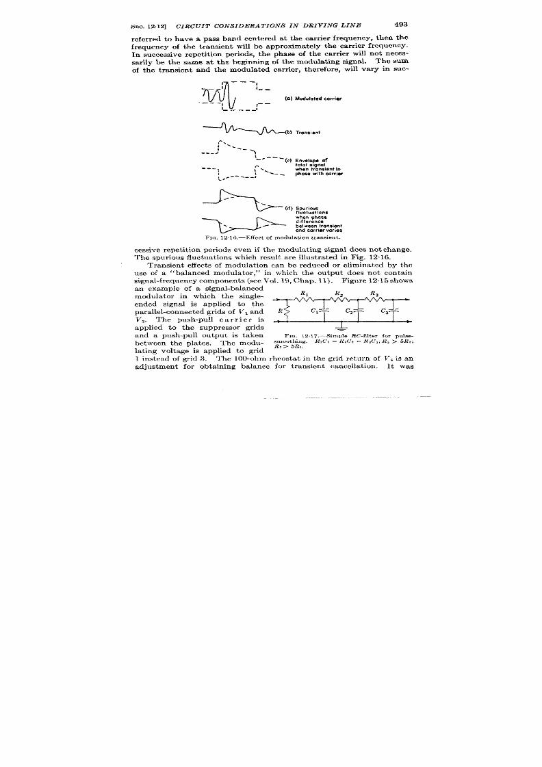
SEO. 12.12]
CIRCUIT CONSIDERATIONS IN DRIVING, LINE
493
refer r ed to have a pass band cen ter ed at the car r ier frequency, then the
frequency of the t ransien t will be approximately the ca r r ier frequency.
I successive repet it ion per iods, the phase of the ca r r ier will not neces-
sar ily be the same at the beginn ing of the modula t ing signal. The sum
o the transient and the modula ted car r ier , therefore, will vary in suc-
---
M
I
-.
:
I
.-
(IZ) Modulated carrl~r
---
I
I
--
I
---- -
#
,-.
1
‘___
---/
\
\
‘“ -‘- (c) Envelope of
.-
totol signal
---,
I ~,
when !ronslent In
,
I
-- -
phase with cdrrie
-----J
t*.-
Spurious
fluctuations
when phase
difference
between transient
and carrier voriee
FIG. 12.16.—Effect of modula t ion t rans ien t .
cessive repet it ion per iods even if the modulat ng signal does not change.
The spur ious fluctuat ions which resu lt a re illust ra ted in Fig. 1216.
Transient effects of modula t ion can be reduced or eliminated by the
use of a “balanced modula tor , “ in which the ou tpu t does not con ta in
signal-f requ en cy componen ts (see Vol. 19, Chap. 11). F igu re 12.15 sh ows
an example of signal-ba lanced
modula tor in which the single-
ended signal is applied to the
pa r allel-connect ed gr ids of Vi and
V,. The push-pull c a r r i e r is
applied to the suppressor gr ids
-
=
and a push-pull ou tpu t s taken
FIG. 12.17.—SimpleM’-filter for pulse-
smoothing. R,C, = RZCZ = lt#23; R3 > 5R3;
between the pla tes. The modu- ~,> 5B,,
lat ing voltage is applied to gr id
1 instead of gr id 3. The 100-ohm rheosta t in the gr id retu rn of Vt is an
adjustmen t for obta in ing balance for t ransien t cancella t ion .
It was
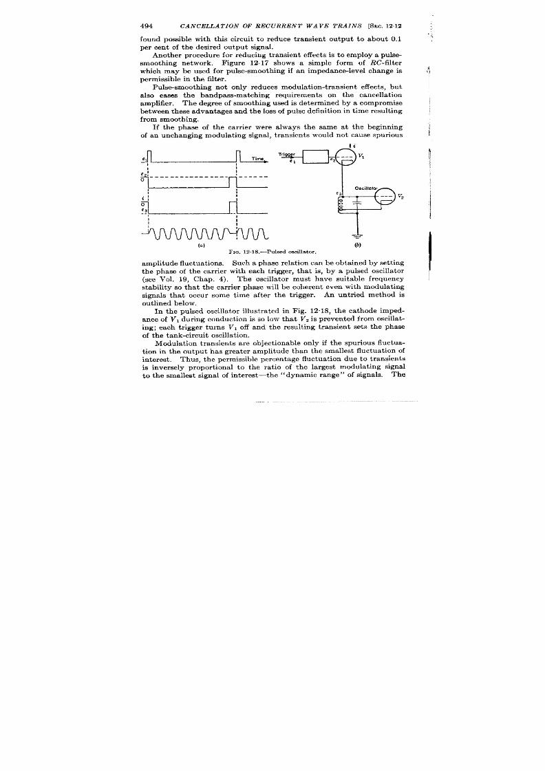
494
CANCELLATION OF RECURRENT WAVE TRAINS [SEC. 1212
found possible with this circu it to r educe transien t ou tput to about 0.1
per cen t of the desired outpu t signal.
An other procedur e for reducing t ransient effects is to employ a pulse-
smooth ing network. F igure 12.17 shows a simple form of RC-filter
which may be used for pulse-smoothing if an impedance-level change is
permissible in t he filt er .
Pu lse-smooth ing not only redu ces modulat ion-t ransient effect s, bu t
a lso eases the bandpass match ing requ irements on the cancella t ion
amplifier . The degree of smooth ing used i determined by a compromise
bet ween t hese a dva nt ages and t he loss of pu lse definit ion in t ime r esu lt ing
from smooth ing.
If the phase of t e car r ier were always the same at the beginning
of an unchanging modulat ing signal, t r ansient s would not cause spur ious
}i
el
I
1
1“ me --v’
em! ------------ ---- *------
>Ii
:
.!
I
%1
I
o
e3
.-
1
1
I
I
I
I
(a)
FIG. 12.18.—Puked oscillator.
k
scillator
e3
--– V*
amplitude fluctuat ions. Such a phase rela t ion can be obta ined by set t ing
the ph se of the car r ier with each t r igger , that is, by a pulsed oscilla tor
(see Vol. 19, Chap. 4). The oscilla tor must have suitable frequency
stability so tha t the car r ier phase will be coheren t even with modulat ing
signals that occu r some t ime after the t r igger . An unt r ied method is
ou t lined below.
In the pulsed oscilla tor illust ra ted in Fig. 12.18, the ca thode mped-
an ce of VI during conduct ion is so low tha t Vz is preven ted from oscilla t -
ing; each t r igger turns VI off and the resu lt ing transien t set s the phase
of t h e t a nk -cir cu it oscilla t ion .
Modula t ion transients a re object ionable only if the spur ious fluctua-
t ion in the ou tpu t has grea ter amplitude than the smallest fluctua t ion of
interest.
Thu s, t he permissible per cen ta ge fluctu at ion du e t o t ra nsients
is inversely propor t iona l to the ra t io of the la rgest modulat ing signal
to the smallest signal of in terest—the “dynamic range” of signa s. The

SEO. 12.14] CIRCUIT CONSIDERATIONS IN DRIVING LINE
495
rela t ive effect of t ransien ts can therefor e be reduced by cmhpression
of th edyn ar oic r an ge of signals. Ra nge compr essicin isdistmssed fu rth er
I
in Sees. 1215and 12.16.
I
Modu lat i n m et hods a re discu ssed elsewh er e in con sider able det ail-l
12.13. Amplifica t ion .-Weak sigrds must be delivered by the delay
line at sufficient ly h igh level to preven t their discernibility from being
impa ir ed by n oise pr odu ced in t he ca ncella tion amplifier .
Th e maximum
voltage requ ired to dr ive the delay line depends on the line at tenuat ion
an th e dyn amic r an ge of signals t ran smit ted. If an oscilla tor -modula tor
combinat ion cannot deliver sufficient ou tput , car r ier -fr equency am-
plificat ion must be u se .
Amplifica t ion may be used between the oscilla tor and modula tor (if
they are separa te) or following the modula tor . he advan tages of the
former method are that the amplifiers need not be wideband and that
isola t ion is provide bet een the oscilla tor and modula tor . The pos-
sible disadvan tages of the method are tha t if the modula t ion is per -
formed at “high level” it may be slight ly non inear owing to cu toff or
gr id cur ren t in the modula tor , and amplificat ion of th e modula t ing signal
may be requ ired. The possible nonlinear ity is genera lly small, and
linear ity is necessary for obtain ing balanced opera t ion . The unit shown
in Fig. 12.15 exemplifies the use of low--level modulat ion in a signal-
ba la nced modu la tor followed by wideba nd amplifica tion .
12s14. Outpu t Circu it .—It will often be necessary that the ou tpu t
cir cu it h ave th e gr ea t est possible gain-ban width pr odu ct (wh er e “gain”
is used to mean “t ransfer impedance”) in order to obta in sufficient ly
high delay-line ou tpu t signal. The con trollable factor s which affect the
gain -bandwidth product are ota l shunt capacitance of the ou tpu t circu it
and the complexity of the circu it ,
I order to decr ease the shunt capacitance of the circu it and to avoid
!
he ecessity of a long connect ing cable, the ou tpu t tube shou ld be located
physica lly near the delay-line input terminal. It is assumed here tha t if
h igh-efficiency coupling is desired, any connect ing cable used will a t
effect ively as a pure shunt capacitance because it is shor t compared
with a ca r r ier -fr equency wavelength and is not terminated in it s charac-
ter ist ic impedance. Opera t ion with character ist ic-impedance termina-
t ion of t he cable is n ot gen era lly used if h igh -efficien cy cou pling is desir ed
because such opera t ion , a lthough it has the advantage that an arbit r ar ily
long cable can be used, cannot genera lly provide so high efficiency as
oth er coupling methods. 2
The required coupling efficiency determines the complexity of the
couplin g cir cu it , which will or dinar ily be eit her a sin gle-tu ned or dou ble-
1See Vol. 19, Chap. 11 of this ser ies.
2 A trea tmen t of cable-termina t ion methods is to be found in Vol. 23, Chap. 7.
496
CANCELLATION OF RECURRENT WAVE TRAINS [SEC. 12.15
t un ed cir cu it .
T e former is simpler to const ruct and adjust , and is
mor e t oler an t of va ria tions in cir cuit ca pa cit an ce th at , m ay occu r wh en t he
delay line or out u t tube is changed, but double-tuned circuits can
pr ovide gr ea t er ga in -bandwidt h pr odu ct .
Sligh t m ist un in g of t his cir cu it
is r ela t ively unimpor tant beca use it a ffect s bo h the undelayed signa l and
t he dela yed sign al equ ally.
The si nals supplied t o th e undela yed and ‘delayed channels should be
ident ica l. This ident ity can be guaranteed by obta in ing the signa l for
t he un dela yed cha nnel fr om a fr equ en cy-in sensit ive volt age divider a t t he
input crysta l of the delay line.
The load resistance for the output
circu it an be used convenien t ly as such a divider and the signal t rans-
mit ted to the undelayed channe through a termina ted low-impedance
line.
The circu it shown in Fig. 12.15 uses a double-tun d output circu it ,
loaded on the seconda ry side only. T e voltage divider used to feed
the undelayed c annel is loca ted in the modula ted-ca r r ier–genera tor
chassis r a ther than a t the delay-line crysta l.
This procedure is sat is-
factory in thi circu it because the cable from the voltage divider to the
crysta l is ver y shor t com pa red with a wa velength a t car rier frequency and
therefore acts essen t ia lly as a pure shunt capacitance. The output tube
and cir cuit in this unit provide a maximum output of about 10 volt s
rms, with an output -circu it bandwidth of about 6 Me/see for a delay-line
crysta l capacitance of about 30 ppf and a cable capacitance of about
5 ppf.
DYNAMIC-RANQECOMPRESSION
12.16. Definit ion an d Adva nt ages of Compr ession .—It has been st at ed
in Sec. 12.12 tha t th e difficulty of som e design problem s depends direct ly
on the dynamic range of signals, tha t is, on the ra t io of the la rgest signal
to the smallest ignal of in terest . This sect ion and the following one
a re concerned with methods for r educing the dynamic range of signa ls
without appreciably affect ing fluctua t ions from repet it ion per iod to
repet it ion per iod .
he advantages to be ga ined by the use of compression a re as follows:
1. The cancella t ion quality n ed not be so high. Cancella t ion must
be so good tha t uncanceled residues f om nonch nging signals a re
smaller than the smallest desir ed fluctua t ions of in terest .
If the
ra t io of the la rgest to the smallest signal is r educed, less accura te
cancella t ion is r equ ir ed.
2. The maximum voltage required to dr ive the delay line is smaller .
F or a given maximum ava lable voltage, th er efor e, the per cent age
modula t ion can be reduced, or for a given maximum available
voltage, onger delays (with more a t tenua t ion) can be used.
I
I
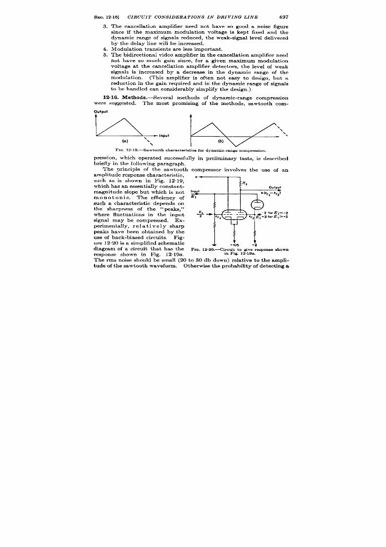
SEO. 12.16]
CIRCU T CONSIDERATIONS IN DRI VINQ LINE
497
3.
4.
5.
The cancella t ion amplifier need not have so good a noise figure
since if the maximum modula t ion volt age is kept fixed and the
dynamic ra nge of signals r edu ced, th e weak-signal level delivered
by the delay line will be increased.
Modula tion t ra nsient s a re less impor ta nt .
Th e bidir ect ion al video amplifier in t he ca ncella tion amplifier n eed
not have so much gain since, for a given maximum modula t ion
volt age a t the cancella t ion amplifier detector s, the level of weak
signals is increased by a decrease in the dynamic range of the
modula t ion. (This amplifier is oft en not easy to design , but a
reduct ion in the gain required and in the dynamic range of signals
t o be handled can considerably simplify t he design .)
12.16. Methods.-Severa l methods of dynamic-range compression
were suggest d. The most promising of the methods, sawtooth com-
Output
&lnput lZ!lZ!l\.
(a) ‘\\ (b)
Fm.
12. 19.—Sawtoot characteristics for dynamic-range compression.
pression , which opera ted successfully in preliminary t ests, is descr ibed
br iefly in t he followin g pa ra gr aph .
The or inciple of the sawtooth compressor involves the use of an
amplitude response character is t ic,
such as is shown in Fig. 12.19,
wh ich ha s a n essen tia lly con st an t-
magnitude slope but which is not
monotonic. The efficiency of
such a character ist ic depends on
the sharpness of the ‘‘ peaks,”
where fluctua t ions in the input
signal may be compressed. Ex-
per imenta lly, r e 1a t i v e 1y sharp
peaks have been obta ined by the
use of back-biased circuit s. F ig-
u re 12.20 is a simplified sch emat ic
diagram of a circuit tha t has the
response shown in Fig. 12.19a .
4. - 1“05
-2
F IG. 12.20.—Cir cu it t o give r espon se shown
in F ig. 12.19a .
T e rms noise shou ld b; small (2o to 30 db down) rela t ive to the ampli-
tude of the sawtooth waveform. Otherwise the probability f detect ing a

498
CAN ELLATION OF RECURRENT WAVE TRAINS [SEC. 12.17
change in signal amplitude is poor because a shift fr om one sawtooth
wave to nother may give an amplitude change that is less than noise.
CANCELLATIONAMPLIFIERS
BY W. SELOVE
12017. In t roduct ion .-Subt r act ion of successive waveforms and,
cancella t ion of their nonchanging par t s t ake place in the cancella t ion
amplifier . This un it usua lly consist s of fou r pr incipa l sect ions: a ca r r ier -
fr equency amplifier in the delayed channel and one in the undelayed
channel, a subt ract ion circu it , and a video sect ion for handling the si na ls
rema in ing a ft er cancella t ion (see Fig. 12. 1).
For per fect cancella t ion , the delayed and undelayed channels must
h ave iden t ica l over -a ll fr eq ency response and linea r it y character ist ics.
Specia l a t t en t ion must somet imes be given to secu r ing h igh -efficiency
coupling between the delay line and the cancella t ion amplifier .
Specia l r equ ir emen t s a re usua lly imposed on the video sect ion by the
na tu re of the signa ls to be handled.
Noncanceling signa ls maybe bidir ec-
t iona l (see Vol. 19, Chap. 11), and the maximum uncanceled signa l may
be very much la rger than the smallest uncanceled signa l of in t erest . In
some cases, efficien t u t iliza t ion of noncanceling signa ls requir es their
fu ll-wave r ect ifica t ion .
The cancella t ion amplifier may also include specia l fea tu res and
circu it s to provide au toma t ic adjustment of cancella t ion and ga in
controls.
12.18. Cancella t ion Methods.-There a re two methods of cancella -
t ion tha t may be used (see Sec. 12.9). Even though the cancella t ion
amplifier is very much simpler for the ca r r ier -fr equency method, envelope
cancella t ion is the on ly method tha t has been used. The reason is to be
found in the sta ility requ iremen ts on the repet it ion ra te. For envelope
can cella t ion , t he r epet it ion per iod must be “jit t er fr ee” to a fract ion of a
pulse length (see Sec. 12.28); for ca r rier -frequency cancella t ion , it must
be jit t e -free to a fract ion of a car r ier -cycle per iod, which requ ires a
considerably higher degree of stability. At the pulse lengths used, it
has been readily possible to obta in the necessa ry stability for envelope
cancel a t ion but not for ca r r ier -fr equency cancella t ion .
For future
applica t ions, h owever , ca rr ier -fr equen cy ca ncella t ion may be feasible;
it is t her efor e, a ppr opr ia te t o con sider h er e h ow t he ca ncella tion -ampli-
fier requirements a re a ffected by the cancella t ion method, even though
the circuits t r ea ted in deta il in the following sect ions a re those suitable
pr ima rily for envelope cancella t ion .
P recision en velope ca ncella tion r equ ir es t ha t t he en velope be lin ea rly
reproduced a t the ou tput s of the delayed and undelayed channels. Since

SEC. 12.19] CANCELLATION AMPLIFIERS
499
t he output circuit s consist of detectors, a modera tely high output signal
level is necessary to ensure linear envelope reproduct ion . To obta in a
suitably high signal level, considerable gain in the delayed-channel
amplifier will usua lly be required because signals are usually delivered
by the delay line a t compara t ively low level. For car r ier -frequency
cancella t ion, however , no gain wha tsoever is necessary before cancella -
t ion, and passive elements may be used for subt ract ion . In envelope
cancella tion , noncancelin g sign als a r e bidir ect ion al. In ca rr ier -fr equency
cancella t ion, although noncanceling signals can appear with either
“posit ive” or
“negat ive” phase, the detected signals will const itu te
unidirect ional video signals. The difficu lt ies of handling bidirect ional
video signals ar e discussed at grea ter lengt h in Sees. 12”25 t o 12”27.
CARRIER-FREQUENCY CHANNELS AND CANCELLATION CIRCU IT
1 .19. Pass Band. Genera l TheoW.—For per fect cancella t ion , the
delayed and undelayed channels must a ffect signa l iden t ica lly.’ It
will genera lly become easier to approach th is condit ion as the effect of
the channels on the signa l is reduced, wh ich is accomplished by increa sing
the bandwidth s of the channels.
The effect ive shape of the delayed or undelayed signal is determined
by t he over -a ll syst em bandwidt h.
The dela yed a nd un dela yed cha nn els
of the delay-and-cancella t ion unit (see Fig. 12”4) will a ffect this shape
lit t le, and a small unbalance in the channels will therefore not be ser ious
if the channel bandwidths are large compared to the over-a ll syst em
bandwidth. A factor of 2 will probably be a sa t isfactory compromise
with the number of tubes required.
Bandpass Compen.sut ion .-In order that the delayed and undelayed
channels may have essen tia lly iden tica l fr equ ency r espon se, c mpen sa tio
must often be provided (1) for the frequency response of the delay line,
and (2) for the difference in the number of tuned stages of amplifica t ion
required in the two hannels.
The t ransmission at t enuat ion of a liquid delay line increases with
frequency; for a round tube of length 1 and diamet er d, t h e a t tenua t ion
(db) is given by
where kl and kz are constants for a given medium, 1 is the length, and j
is frequency (see Sec. 12.2). In many cases, the var ia t ion of delay-line
a t tenuat ion over the delayed-channel pass band s so grea t as to distor t
this pass band severely. For example, for the 1000-psec mercury line
1For ener a l in format ion app licable t o t h e dee ign of t h e ca r rier -fr equency channela ,
t he r ea der i.qr efer red t o Vol. 23.
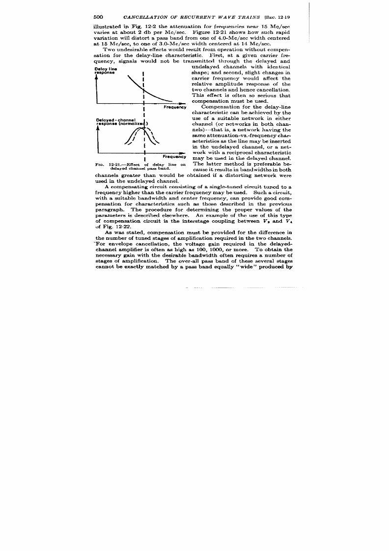
500 CANCELLATION OF RECURRENT WAVE TRAINS [SEC. 1219
illust ra ted in Fig. 12.2 the a t tenuat ion for frequencies near 15 Me/see
va r ies a t about 2 db per Me/see. F igure 12,21 shows how such rapid
var ia t ion will distor t a pass band from one of 4.O-Mc/sec width cen tered
a t 15 Me/see, t o one of 3.O-Mc/sec width cen tered at 14 Me/see.
Two un desir able effect s wou ld r esu lt fr om oper at ion wit hou t compen -
sa t ion for the delay-line character ist ic. F irst , a t a given ca r ier fr e-
quency, signals would not be t ransmit t ed through the delayed and
C)eloy line
,r%=
I
Frequency
I
Deloyed-chonnel
response (norrnolize .)
1A
/>
J’ l:,
/
I
I
-
I
Frequency
FIG. 12.21 .—Effect of delay line on
delayed channel pass band.
undelayed channels with ident ica l
shape; and second, slight changes in
ca r r ier fr equency would a ffect the
rela t ive amplitude response of the
two channels a nd hence cancella t ion .
This e fect is oft en so ser ious tha t
compensa t ion must be u ed.
Compensa tion for t he dela y-line
ch ara ct er ist ic can be a ch ieved by t he
use of a suitable network in either
channel (or networks in both chan-
nels)—tha t is, a network having the
same a t tenua t ion -vs.-fr equency cha r-
a cter ist ics as t he line ma ybe in ser t ed
in the undelayed channel, or a net -
wor k wit h a r ecipr oca l ch ar act er ist ic
may be used in the delayed channel.
The la t ter method is preferable be-
cause it resu lt s in bandwidths in bot h
channels grea t er than would be obta ined if a dktor t ing network were
used in the undelayed channel.
A compensa t ing circuit consist ing of a singletu ed circuit tuned to a
frequency h igher than the ca r r ier frequency may be used. Such a circuit ,
with a suitable bandwidth and cen t er frequency, can provide good com-
pensa t ion for character ist ics such as tho.w descr ibed in the previous
pa ragraph. The procedure for determining the proper values of the
pa ramet er s is descr ibed elsewh er e.
An example of the use of th is type
of compensat ion circuit is the in terst age coupling between Va and Vt
of F ig. 12.22.
As was sta t ed, compensa t ion must be provided for the difference in
the number of tuned stages of amplifica t ion required in the two channels.
‘For envelope cancella t ion , the volt age gain required in the delayed-
channel amplifier is oft en ae high as 100, 1000, or more. To obta in the
necessary gain with the desirable bandwidth oft en requires a number of
st a es of amplifica t ion . The over -a ll pass band of these severa l st ages
cannot be exact ly matched by a pass band eqt ia lly “wide” produced by
SEC. 12.20]
CANCELLATION AMPLIFIERS 501
the smaller number of stages needed to supply the necessa ry gain in the
undelayed channel amplifier . The matching is poorest if the bandwidth
of the undelayed channel is reduced by a single “narrowing” circu it to a
value approximately equal t o the andwidth of the delayed channel; yet
such a simple method of compensat ion is often sat isfactory if highly
accurate cancellat ion is not requ ired, if the numbers of tubes in the
channels do not differ by more than one or two, and especia l y if the
ch an ne ba ndwidt hs a re la rge compa red t o t he over -a ll syst em ba ndwidt h.
A more in t r ica te method of compensat ion is to employ addit ional
tuned circuits in the undelayed channel which w ll help give a more
exa ct duplica te of t he over -a ll frequ en cy r espon se of t he delayed chan n l.
The ext ra circuits requ ired in the undelayed channel may be connected
by at tenuat ion units s in Figs. 12.22 and 12.23.
If ident ica l numbers of stages are used in both channels the unde-
layed-channel amplifier will have far more available gain-bandwidth
product than is necessary. The at tenuat ion units ensure that this
amplifier does not have so much gain as to make the noise in its input
circu it con t r ibu te appreciably to the over -a ll noise.
In the circu it of
Fig. 12.22, these measures consist of the reduct ion of gain in the in ter -
sta te circuits of VT–E and VS.-9, by the use of what might be c ile~
“n ar row-band r esist or s, ”
resistors pa ra lleled by fixed-t uned cir cu it s, wit h
const an ts ch osen t o give pr oper bandwidth .
12.20. Linear ity.-For accurate envelope cancella t ion the modula-
t ion envelope of signals must be linear ly reproduced at the detectors.
F igure 12.24 (cf. Fig. 12.1 1) illust rates how, for linear reproduct ion , the
minimum amplitude of the modula t ion envelope must not be so small as
to fall in he nonlinear response region of the detectors, and how the
maximum amplitude of the envelope must not be so large as to cause
nonlinear opera t ion of any of the amplifiers. Measures that may be
taken to obtain a linear-response region large enough to accommodate
the modula t ion en velope are (1) reduct ion of the percen tage modula t ion
represen ted by signals and (2) increase of the maximum distor t ion less
ou tpu t voltage of the carr ier -channel ou tpu t amplifiers. 1 The maximum
distor t ionless outpu t voltage for an outpu t tube may be increased by an
increase in the load impedance of the ou tpu t circu it bu t a t the expense
of t he ban widt h.
In pract ice, the signals in the final stages of the c rr ier -frequency
channels may be so large as to make operat ion not st r ict ly linear .
Rough
compensat ion for slight nonlinear ity may be obta ined by operat ing the
last two stages in one channel under condit ions ident ica l with those of the
last two stages in the other channel.
1Dynamic-range compression, discussed in Sees. 12.15 and 12.16, is useful for
reduction of percent agemodulation.

“
%
-
T
%
I
6
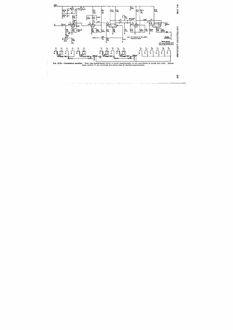
+250
1
18k
4 ?k
47 k
I&”
4.7k
10%
10%
:%
I--P
k 130
PI
L
5k
:25
1
m 5%
3. ,- &v
,k 001
+
%?”
(w
Iok 1“
91k
Ccfh
10%
-I&w
&%*l
‘z”v~ao
No!el r es is ta s o re ). p u n le ss
o the rwi se no ted
v, v, v, K v. K
v, v. v,
1
f+at.srchoku
2 8 t wn s * 2 6en n meled
.- . . .
L-..
1
1
I
I I% 12.22 .-Cance ll at i0n ampli fie r .
N ot e: t his d ou ble -t un ed cir cu it is t u ned exp er im en t ally t o t he ca pa cit an ce of cr ys ta l a n d ca ble. I nd uct i
a n tes ma rk ed (“) a r e un cr it ica l, bu t ot h er s mu st b e ch eck ed exp er imen t a lly .

504
12.21.
CANCELLA TZON OF RECURRENT WAVE TRAINS [SEC. 1221
Gain. Gain Control. —Gain cont rol is genera lly required in
both channels to accommodate the largest expect~d var i t ions in tube
t ra nsconduct an ces and, in t he dela yed ch annel, t o a ccommoda te va ria tion s
in delay-line at tenuat ion . This cont rol should be loca ted ear ly in the
F[a. 12.23—Isolationofsinde-tun edcircuitsby at tenu at ionpad.
amplifiers so that signals do not become large enough, before reaching
t he gain -con tr olled sta ge or stages, t o oper at e t ubes n on lin ea rly.
For the undelayed channel, asimple andsat isfactory method of gain
con tr ol con sist s of a low-impeda nce, n on in du ct ive pot en tiomet er (pr efer -
fmoc:w
I
N#nsr
I Owrloodingof
mspon99
I
cnrrier-frquency
1
omplifk
I
I
k- pm~r:
1 COrriw-fmquancy
I
,WW - nomplit.deot
I del y Mm
,
Modulation
anvolopa
Tim, I
Fm. 12.24.—Modula t ion enve lope condi-
t ion for lin ea r r epr odu ct ion .
ably carbon), which can serve as
both a gain con t rol and an input
cable terminat ion . This type of
con tr ol is illust rated in Fig. 12.22.
F or sever al r eason s (see Vol. 23),
gr id-bias gain con tr ol is usu ally u sed
in the delayed channel, usually on
the fir st two stages. When the de-
la yed-ch annel amplifier is design ed,
the required gain should be chosen
so that the gain-cont r lled stages
will not be normally oper at ed at such
reduced gain as to affect adver sely
the signal-t -noise ra t io of signals
passing through thk channel. Possi-
ble impairment of th is signal-to-
noise rat io can occur in two ways.
Fh-st , t h e ga in of t h e ga in -con tr olled
stages may be set so low that noise
produced in the following stage pro-
duces an output comparable to that of weak signals. Second, if tube
noise in the fir st stage is comparable to the level ther of weak signals,
the signal-to-noise rat o will be impaired if this stage is operat ed at too
low gain, because gr id-gain cont rol decreases the gain of a tube faster
than it ecreases its noise. It is for th is second reason tha t it may be
desirable to apply gain-cont rol bias to more than one stage.
In pr act ice t he gain con tr ol of each ch ann el is adju st ed t o give appr oxi-
mately the cor rect value of detected-car r ier voltage, and then either

SEC. 12.21]
CANCELLATION AMPLIFIERS
505
con trol is used t o adjust t he final ba lance or best cancella t ion .
F or ver y
accura te cancella t ion it may be necessa ry to set the gain to within 1 per
cen t of the cor rect va lue; therefore the gain con t rol used for cancella t io
adjustment must be smoothly and finely adjustable.
Stabilization. —Since
back for gain stabiliza t ion, stabiliza t ion of the rela t ive gains of the two
charnels depends upon the use of ident ica l numbers of tubes in the two
channels. This method is u ed in the circuit of Fig. 12”22,’ and has
+
~F&t
channel 2
FIQ. 12.25.—Gain-%cbilLmtion circuit,
proved fa ir ly sa t isfactory. The gains of the two channels have remained
equal for severa l hours with in 2 or 3 per cen t over t empera tu re ranges of
30° c.
A stabiliza t ion method tha t can be used alt erna t ively or in addit ion
to the use of ident ica l numbers of tubes is automat ic gain cont rol (AGC).
Automat ic-ga in-cont rol volt age can be applied either on the basis of the
ca ncella tion -cir cu it ou tpu t pr odu ced by an unchanging test signal or , in
envelope cancella t ion , on the basis of the output of the detector s cor -
r esponding t o t he ca rr ier amplitude.
The first of these methods is gen-
era lly complica ted and will not be discussed here.
1 It will be seen that th ere is actua lly on e more tube in the delayed channel than in
t he undelayed channel. In the circu it used, h owever , V, has a volt age ga in of u nit y,
ess en t ia lly independen t of it s t r an sconduct ance; h ence st abiliza tion aga in st ch anges in
it s t r an sconduct ance is unneces sa r y, a nd for st abiliza t ion pu rpos es V; is n ot cou nt ed as
a tu be.
506
CANCELLATION OF RECURRENT WAVE TRAINS [SEC. 1222
It is clear tha t any AGC circuit used for ca r r ier -amplitude stabiliza-
t ion should have a response t ime tha t is l ng compared t o the pulse length
u sed; ot herwise, in dividu al modu la tion sign als will be somewhat demodu -
la ted. Even if the AGC circuit has a t ime constant very long compared
to the repet it ion per iod, undesirable effect s can occur if the AGC tends
to keep the average outpu t level of eaeh channel constant . If the ca r r ier
is modula ted with unidirect ional signals obta ined, for example, from a
radar system, the average volt age level a t each detector is likely to vary
as the direct ion of the rada beam is var ied; an AGC that tends to keep
the average output level of each channel constant would in th is case vary
the absolu te va lue of compa ison-amplifier ga in as the beam is moved.
Such a gain var ia t ion will not occur if the AGC system tends merely
to keep the output levels of the two channels ba lanced against each other ,
without rega rd to their absolute values.
F igure 12.25 is a simplified
schemat ic diagram of a proposed AGC circuit which should give level
balance stabiliza t io to this type of output . If Rz is high compared to
the ca thode impedance of Vz~ or V2b, VZ Will operat a s a differ en tia l
amplifier (see Vol. 19, Chap. 9), responding only to a difference in the
rect ified outp t s of VI and Vs. The RI and l?; provide a means for
adjust ing the channel outputs to the proper va lue and for init ia l ba lance.
This AGC circuit opera tes only as a stabilizer and not as absolu te cont rol
for cancellation.
12.22. Detect ion .-The detector in each channel must reproduce the
modula t ion envelope as fa ithfully s possible. In order tha t the det ect or
ou tput may depend as lit t le as possible on the phase of the ca r r ier cycles
within t he en velope, fu ll-wave det ect ion is used ra ther than half-wave.
Detect or design is discussed in det il in Chap. 7, Vol. 23 of th is ser ies,
but a few points will be ment ioned here, with the detect or circuit in
Fig. 12.22 as an example. Germanium crysta ls a re super ior t o elect ronic
tube rect ifiers because of the lower shunt capacitance and lower forward
resist ance of the crysta ls. It is advantageous to use a high load-resist -
ance detector to obta in high-efficiency detect ion and good linear ity.
The low capacit ance of a crysta l r ect ifier not only permit s the use of a
high load-resist ance detect or but a lso makes it possible o obta in a high
gain-bandwidth product in the ca rr ier -frequency output circuit , thus
reducing the danger of nonlinear opera t ion in the ca r r ier -frequency
ou tpu t amplifier .
Th e pu sh-pu ll ca rr ier -fr equ en cy ou tpu t n ecessa ry for fu ll-wa ve det ec-
t ion can be obta ined with either a t ransformer or phase split t er . The
former method has the advantage tha t the balance of the two halves of
each detect or is not dependen t on any amplifiers; the la t t er method
has the advantages tha t magnet ic coupling is not required and tha t
a high degree of symmet ry can be obta ined for h igh ca rr ier frequencies

SEC. 1224]
CANCELLATION AMPLIFIERS
507
(30 Me/see and h igher ) more easily than with a t ransformer . The circuit
of Fig. 12.22 uses phase split ters for car rier -frequ en t y ou tpu t amplifiers.
Th e 1.5-ppf con den ser used in each of th e 6J 6 phase split ters is a n eut ra liz-
ing condenser .
12.23. Cancella t ion Circu it .-The signals from the delayed and
un delayed channels should be can celed—i.e., su bt racted from each ot her
—at the ear li st possible poin t in the cancellat ion amplifier because,
genera lly, all stages before cancella t ion must be linear whereas those
Following’cancella~ion need not be.
For envelope cancella t ion , the
ear liest possible point is the ou t -
put of the detector s. The circu it
of Fig. 12.22 uses a simple can-
cellat ion cir cu it or differ en ce de-
t ector (see Vol. 19, Chap. 14)
which is closely symmetr ica l for
the two channels. A simplified
circu t is shown in Fig. 12.26.
Rectifiers D, and D, pr ovide d-c
retu rns for each other . The ou t-
put of the circu it consists of a
Delayed
ch a nn el +
3
“ I
I? l (R1 -R2 )
—
= —
output
R2
Undelayed
channel
4 ‘2
I
v
FIG. 12.26.—Simplified cancella t ion circui t
posit ive r ect ified compon en t pr odu ced a cr oss Rt by th e delayed ch an nel,
plus a nega t ive rect ified componen t produced across RI by the unde-
layed channel.
12.24. Coupling to Delay Line.—In or der to obta in delay-line ou tpu t
su fficien tly high so th at can cella t ion-amplifier n oise is u nimpor tant , th e
cir cu it cou pling th e delay line t o th e dela ed-ch an nel amplifier must h ave
as high a gain -bandwidth product as possible (cf. Sec. 12.14).
As in the case of the circu it at the inpu t end of the delay line, a maxi-
mum gain-bandwidth product can be obta ined with least complexity by
locat ing the first stage of the delaye channel physically close to th (
delay-line ou tpu t terminal and thus eliminat ing a connect ing cabl or a t .
least min imizing it s length . Any connect ing cable, if opera ted un ter -
minated, should be shor t compared to a wavelength (i. e ., a t carrier
frequency) not only to minimize shunt capacity but to avoid the in t ro-
duct ion of a t ransfer -impedance character ist ic tha t may not be easy to
duplica te in th e u nd layed channel.
Un like t he situ at ion at the input end of the line, however , not too
high a pr ice in fineness of adjustment can be paid for a high gain-band-
width product because the frequency response of the delayed channel
must be kept as near ly as possible like that of the undelayed channel.
Thus, a dou ble-t un ed cir cu it loa ded on ly on one s ide shou ld not be used
if sat isfac t or y oper at ion can possibly be obta ined with less cr it ica l

508 CANCELLATION OF RECURRENT WAVE TRAINS [SEC. 12.25
circuits.
This rest r ict ion holds even though a circu it loaded on the tube
side not only has a higher gain-bandwidth product than a double-tuned
circuit loaded on both sides but a lso presents lower impedance t o the tube,
t hu s decr ea sing noise.
In connect ion with obtaining delay-line output la rge compared to the
can cella tion-amplifier noise, it is a ppr opr ia te t o m en tion t he possibilit y
of reducing this noise to a minimum by the use of a “low noise” input
circu it in t he dela yed cha nnel.
In Fig. 12$22 VI and Vz comprise such a
circuit , the opera t ion of which is discussed in deta il in Vol. 23 Chap. 5
of t his ser ies.
If t he ent ire cancella t ion amplifier cannot be placed physica lly close
to the delay-line output , the advantages of having the fir st stage of the
delayed channel so loca ted can be rea lized by using a preamplifier
mounted at the line. Such a preamplifier would in genera l be connected
to the rest of the cancella t ion amplifier by a low-impedance cable and
would have a volt age gain of 2 or 3.
The use of a terminated high-impedance (about 100@ohm) connect -
ing cable having a suitable amount of t ime delay (perhaps 0.2 psec)
offers the a t t ract ive possibility that a par t icular ly simple method of
repet it ion-ra t e cent r ol can be used (see Sec. 12.30). A possible object ion
to the use of such a cable, however , is tha t at the usual ca r r ier frequencies
of 10 Me/see to 30 Me/see it might have an obj act ionable amount of
attenuation.
VIDEO SECTION
12s2 . Requ irements of Video Sect ion .-In a typica l envelope cancel-
la t ion amplifier , noncanceling signa ls may produce video ou tpu ts a t the
cancella t ion poin t of plus or minus 1 to 100 mv. It is conven ien t to have
a maximum ou tput of one volt or so to a low-impedance line and th is s
obta ined by a video ga in of approxima tely 1000.
As in any video amplifier in wh ich the la rgest signa l occu r r ing is much
larger than the smallest signa l of in terest , ca re must be taken to preven t
la rge signa ls from “blocking”
the amplifier --tha t is, from producing a
response tha t would reduce the likelihood tha t a small signa l closely
following a la rge one will be discern ible.
Methods of design ing nonblock-
ing video amplifiers a re discussed in deta il elsewhere, 1 but some mater a l
will be presen ted. Here, the video signa ls have a la rge dynamic range.
Moreover bidirect iona l video is somewhat more difficult to handle than
t he mor e common un idirect iona l video.
12.26. Amp fifier for Bidir ct ional Video.—Let us review briefly the
cause of the difficu lty in the design of a nonblocking video amplifier for
signals of large dynamic range and consider the applicability to bidirec-
1Vol. 18, Sees. 5.8 a nd 10.4.
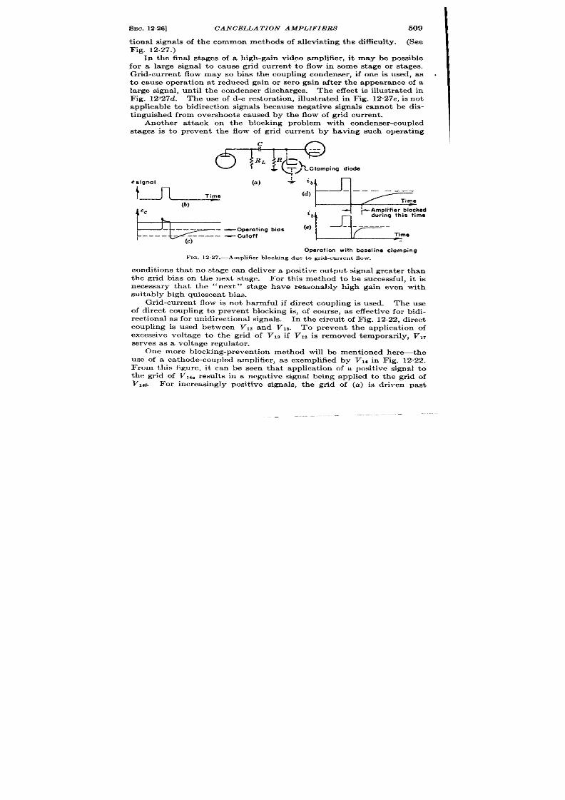
SEC. 12.26]
CANCELLATION AMPLIFIERS 509
I
t .ional signals of the common methods of a llevia t ing the difficulty. (See
Fig. 12.27.)
In the final stages of a high-gain video amplifier , it may be possible
for a la rge signal t o cause gr id ur r en t to flow in some stage or stages.
Gr id-cur ren t flow may so bias the coupling condenser , if one is used, as
to cause opera t ion at r educed gain or zero gain after the appearance of a
large signal, unt il the condenser discharges. The effect is illust ra ted in
Fig. 12’27d The use of d-c restora t ion , illust ra ted in Fig. 12.27e, is not
applicable to bidirect ion signals because nega t ive signals cannot be dis-
t inguished from overshoot s caused by the flow of gr id cur ren t .
Another a t tack on the blocking problem with condenser -coupled
stag s is to pr even t the flow of gr id ur rent by having such opera t ing
Operation with baseline clomping
FIG. 12.27.—Amplifie r b locking due to gr id-cur ren t flow.
condit ions that no stage can deliver a posit ive ou tput signal gr ea ter than
the gr id bias on the next stage.
For th is method to be successful, it is
necessa ry that the “next”
stage have reasonably high gain even with
suitably high quiescent bi s.
Gr id-cur ren t flow is not harmful if direct coupling is used. The use
of direct coupling to preven t blocking is, of course, as effect ive for bidi-
r ect ion al a s for u nidir ect ion al sign als.
In the circu it of Fig. 12.22, direct
coupling is used between VIZ and Vls.
To preven t the applica t ion of
excessive voltage to the gr id of Vls if V 12 is r emoved t empor a rilyy, VIT
ser ves as a volt age r egu la tor .
One more blocking-prevent ion method will be ment ioned here--the
use of a ca thode-coupled amplifier , as exemplified by VIA in Fig. 12.22.
From this figure, it can be seen that applica t ion of a posit ive signal to
the gr id of V,4. results in a nega t ive signal being applied to the gr id of
Vlti. For increasingly posit ive signals, the gr id of (a) is dr iven past
I

510
CANCELLATION OF RECURRENT WAVE TRAINS [SEC. 12.27
cutoff, and the cathode volt age then
“ follows” the gr id of (b) so closely
that a very large posit ive signal is requ ired to make the gr id of (b)
posit ive wi h respect to the ca thode. It may be noted that a phase
split ter was used in thk par t icu lar unit a much to provide push-pull out -
put for t he following video r ect ifier a s for it s nonover loading cha ract er is tic.
A few words about the coupling t ime constants in the bidirect ional
video amplifier are appropr iate here. Long time constants are unneces-
sary, because noncanceling signals will not generally produce long
unidirect ional outputs. Very shor t t ime constants are to be avoided
because they may cause over shoots of an undesirable nature; in par -
t icu lar , t ime constan ts of approximately 5 to 10 pulse lengths can cause
mult iple over sh oots if sever al cascaded stages h ave such t ime constants.
Mult iple over shoots are par t icu lar ly undesirable if video rect ifica t ion
is used (see Sec. 12.27). The use of a shor t t ime constan t , of approxi-
mately a pulse length , at the input to the bidir ect ional video amplifier
has the advantage that in termedia tely long t ime constan ts can be used
afterwards without t rouble from mult iple over shoots. 1 If modera tely
long t ime constants (of about 50 pulse lengths) are used up to the last
in ter stage circu it and a shor t t ime constant is used at the last in ter stage
cir cuit , the gr d-cur rent flow in the last stage can be made unimpor tan t
by the use of a gr id resistor (R n Fig. 12.27a), whose value is small
.,
com ar d to the conduct ing value of the tube gr id-ca thode resistance.
2.27. Video Rect ificat ion .-It is
l+yp
’ C1 Rectifier
V*
VI
---
I
Rz
R3 ~C2
I
=
FIG. 12.2S .—Elemen t s of video rect ifier .
often desir ed to observe the ou tpu t
of these devices on an oscillo-
scope.
If the noncanceling out -
put signals are to be presen ted on
a deflect ion -modu lat ion os c i 110-
scope, the bidirect ional form in
which th ese signals are delivered
by the cancella t ion circu it is
sa t isfactory. Bu t if an in tensity-
modulated oscilloscope is to be
used, signals of one polar ity will
be much more visible than those
of the other ; in this case, it will probably be desirable to rect ify the
bidir ect ion al video sign al for unidir ect ion al pr esen ta tion .
If rect ifica t ion is to be used, over shoot s must be carefu lly avoided in
the bidir ect ional video amplifier because an over shoot will produce a
rect ified output ident ica with that of a signal. Par t icu lar ly to be avoided
a re moder at ely lon g t ime-con st an t over sh oot s or mult iple over sh oot s.
The push-pull outpu t necessary f r fu ll-wave rect ifica t ion can be
obtained with a t r ansformer or a vacuum-tube phase inver ter .
Th e
1&e Chap. 10, Vol. 18.

SEC. 12.28]
REPETITION-RATE ONTROL
511
la t ter wasused in the circu it of Fig. 12”22 because it has excellen t non-
over loa din g pr oper ties as well a s pu sh -pu ll ou tpu t.
Th e elem en ts of a con den ser-cou pled video rect ifier a re sh own in Fig.
12.28. The following factors determine the circuit constan ts and oper -
a t ing condit ions :
1. The applied signal voltage must be la rge enough to provide the
desir ed lin ea rit y of r espon se t o t he sm allest sign als of in ter est .
2. Res is tance Rs must be small enough to make the t ime constan t
RSC2 sa t isfactor ily shor t ; the decay t ime of a signal applied with
zer o fa ll-t ime t o th e r ect ifier depen ds on this t ime con stan t.
3. To preven t much rect ified voltage from appear ing across Cl, Rz
sh ou ld be su fficien tly sm aller t ha n Rt. Any such volt age acts as
ba ck b~as on th e rect ifier nd thu s preven ts wea k signals fr om bein g
t ra nsm it ted t hr ou gh t he r ect ifier .
4. In order not to cha rge up appreciably dur ing a signal, Cl must be
sufficien t ly la rge. Any such charging produces blocking of the
r ect ifier -th at is r edu ces it s sen sit ivity t o an immedia tely follow-
ing signa l.
5. It is necessa ry that RI be as large as is consisten t with the requ ired
pla te volt age on VI.
REPETITION-WTE CONTROL
BY D. GALE
In order to obta in cancella t ion of wave forms by delay methods, very
cr it ica l requ iremen ts must be met by the recu rrence ra te of signals. In
th is ch apt er t hese r equ ir em en ts a nd t he va riou s m et hods of fu lfillin g t hem
are discussed.
12.28. Repet it ion-ra te Requirements.—The block diagram in
Fig. 12.29 presen t s a genera l picture of a delay and cancella t ion device
(s ee F ig. 12.1).
A sign al will, in gen er al, exper ien ce a t im e dela y wh en pa ss n g t hr ou gh
any of the blocks of the diagram.
Thus DO is the delay of the line dr iver ,
D, t ha t of t he dela yed ch an nel amplifier , Dt tha t of the undelayed chan-
nel, and D tha t of the line.
The repet it ion ra te is f,, and 2’, equal to l/~,, is the repet it ion in terva l
or t ime in terval between signals.
Consider a signal a t the input t er -
minal a t t ime t .
Aft er passing th rou gh th e delayed ch ann el it will a r riv~
at the subt racter a t the t ime
t,=t+Do+D+D1.
The next signal, a r r iving at the inpu t terminal t seconds la t er and passing
th rough the undelayed channel, will a r r ive at the subt racter a t the t ime
t*=t+T+Do+ D*.
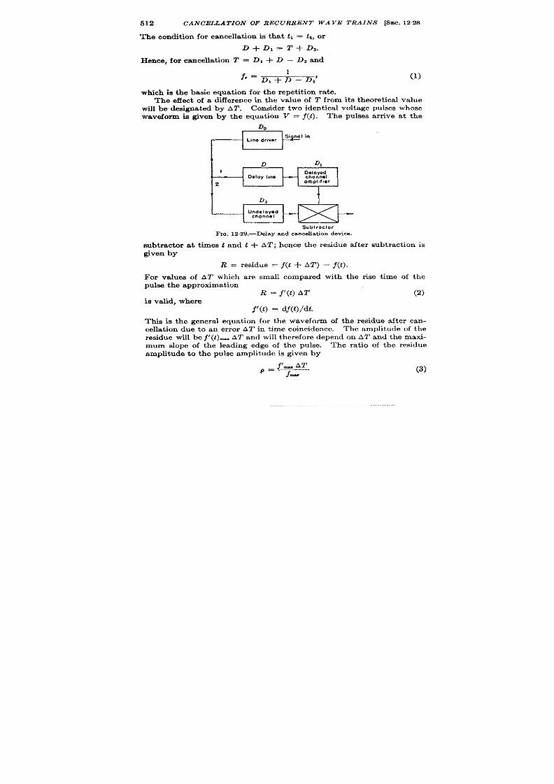
512 CANCELLATION OF RECURRENT WAVE TRAINS [SEC. 12.28
The condit ion for cancella t ion is tha t ti= tz,r
D+D,=T+D2.
Hence, for cancella t ion T = D, + D – Dz and
f,= 1
D,+ D–D:
(1)
which is the basic equat ion for the repet it ion ra te.
The effect of a difference in the value of T fr om its t heoret ica l va lue
will be designated by AT. Consider two ident ica l volt age pulses whose
waveform ia given by the equat ion V = f(t ). The pulses a r r ive a t the
Subtroctor
Fm. 12.29.—Delay and cance lla t ion device .
subt racter a t t imes
t
and
t+ AT; hence the residue a ft er subt ract ion is
given
by
R = r esidue = j(t-tAZ’)
For va lues of AT which are small compared
pu ls e t he approxima t ion
R = j’(t) AT
is valid, where
f’(t) dj(t)/dt.
- j(t).
with the r ise t ime of the
(2)
This is the genera l equat ion fo the waveform of the residue a ft er can-
cella t ion due to an er ror AT in t ime coincidence.
The amplitude of the
residue will be j’ (t)-
AT and will therefore depend on AT and the maxi-
mum slope of the leading edge of the pulse. The ra t io of the residue
amplitude to the pulse amplitude is given by
(3)
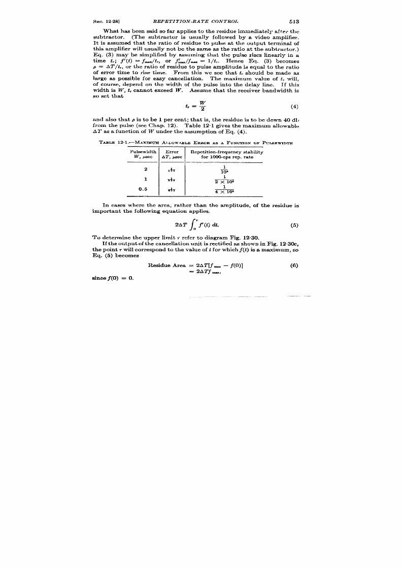
SEC. 1228]
REPETITION -RATE CONTROL
513
What has been said so far applies to the residue immediately af ter the
subt racter . (The subt racter is usuall followed by a video amplifier .
It is assumed that the ra t io of residue to pulse at the ou tput terminal of
th is amplifier will usually not be the same as the ra t io at the subt racter . )
Eq. (3) may be simplified by assuming that the pulse r ises linear ly in a
t ime t ,;
Y(t ) = f_/t ,, or f~/j_ = l/L. Hence Eq. (3) becomes
P = AT/~r, or the ratio of res idue to pulse amplitude id equal to the ra t io
of er ror t ime to r ise t ime. From this we see that t . should be made as
large as possible for easy cancella t ion . The maximum value of t , Will,
of course, depend on the width of the pulse in to the de ay line. If th is
width is W, t, cannot exceed W. Assume that the receiver bandwidth is
so set tha t
(4)
and also that p is to be 1 per cen t ; that is, the residue is to be down 40 dh
from the pulse (see Chap. 12). Table 12”1 gives the maximum allowabh;
AT as a funct ion of W under the assumption of Eq. (4).
TABLE 12. 1.—MAXIMUM ALLOWABLEERROR AS A FUNCTIONOF PULSE WIDTH
Pulsewidth Er ror
Repet i t ion-frequency s tability
W, *ec
AT , psec
for 1000-cps r ep. r at e
1
2 x 10⁶
0.5
I
A
I
1
4 x 10⁶
In cases where the area, ra ther than the amplitude, of the residue is
impor ta nt t he followin g equ at ion a pplies.
/
2AT ; j’(t)?.
(5)
To determine the upper limit r r efer to diagram Fig. 12.30.
If th e ou tpu t of th e cancella t ion unit is rect ified as shown in Fig. 12.30c,
the poin t r will cor respond to the value of t for which j(t) is a maximum, so
Eq. (5) becomes
Residue Area = 2AT[~_ – ~(0)]
(6)
= 2ATf-,
since j(0) = O.

514
CANCELLATION OF RECURRENT WAVE TRAINS [SEC. 12.29
The str iki g th ing about Eq. (6) is that the residue area is independent
of pulse shape, 1 depending only on the maximum amplitude of the pulse,
an d in pa rt icu la r it is in depen den t of r ise t im e or amplifier bandwidth .
This is ment ioned here to illust rate that th 40-db figure for residue
amplitude is just an arbit rary value for cancella t ion . The 40-db cr iter ion
(a )
+
(b)
m
(c)
FXQ.
12 .30 .—Pulae cance lla t ion : (4 ) pu lses ,
(b) reeidue, (c) rect i fied reeiduee.
of cancella t ion has meaning only
if the r ise t ime is under stood to be
a defin it e fr act ion of pu lse len gt h.
There are two ways in which
the repet it ion-in erval er r or can
exceed the maximum allowable
value for AT; by slow dr ift s in f,,
D,, D,, Ds or D (see Fig. 12.29) or
by jit ter , that is, by change of
delay t ime from one repet it ion
cycle to the next in j, or the D’s.
Because of th slow dr ifts as well
as because of th e toler ances on the
sonic-line de ay t ime, it is nec s-
sary in all the methods to be dis-
cussed, except that explained in
Sec. 12.31, to have a t ime cancel-
la t ion con t rol that will be a man-
ual adjustment on the repet it ion
frequency o on one of the de-
lays. This on t r 01 generally
forms an essent ial a r t of any
cancella t ion sys tem.
Repet it ion -r at e con tr ol syst em s fall in to two ca tegor ies: stable oscil-
la tors and line-synchronized oscilla t r s. The former are oscilla tors
designed with a special view to minimizing the effects of slow dr ift and
jit ter . The linmynchronized oscilla tor is one in which the sonic delay
line itself, or a similar lin e, is u sed t o set t he r epet it ion in ter va l.
12.29. Manual Cont rol of PRF.-If a crystal-cont roll+ osci la tor and
frequency divider (see Chap. 4) is used, then mechanical adjustment of
the length of the sonic li e is necessary, and, in fact , has been used in
sever a l pr a ct ica l syst ems.
An LC-oscilla tor is sh own h er e.
The r ange over which the fr equen cy
cont rol must opera te will depend on the maximum expected dr ift in all
dela ys and on oscilla tor fr equ en cy.
By far the larger of these effect s will
1‘I%eforegoingan alysis is valid only if the original (uncanceled)puke haa a con-
t inuous aud fin ite fir s t der iva t iveand only a s inglemaximum. Thesecondit ions ~
generallyaatiefied.

SEC. 12.301 REPETITION-RATE CONTROL
515
be the change in the sonic-line delay with tempera ture. The velocity
of sonic waves in mercury var ies by 1 par t in 3300 for a change in tem-
pera ture of 1°C, so if a maximum tempera tu re va ria t ion of 50° is ant ici-
pa ted the tota l delay t ime may vary by 1.5 per cent and if an a llowance
for ot her drift s is made the oscilla tor frequency would have t o be variable
over a range of 2 per cent . The block diagram (Fig. 12.31) illust ra tes the
opera t ion of the circuit , and a deta iled circuit diagram is given in F ig.
12.32. The output of a 32-kc/see LC-oscilla tor is applied to a stable
amplit ude compa ra tor wh ose ou tpu t syn ch ron izes a blockin g-oscilla tor
chain which divides by 48 to 300 cps. Time select ion is employed to
ensure phase stability. (See Chap. 4 and Vol. 19, Chaps. 10 and 16.)
32 kclsec
Squa re a
3:1 3: I
Oscillator
—
PC:;;?
—
Frequency
divider
I t
Block
. COin~i;&e
4:1 3:1
-
Frequency
osci Ilotor
-
Frequency
divider
divider
FIG. 12,31.—Stab1e trigger generator.
12.30. Line Synchron ized Methods.-A number of methods for repet i-
t ion-ra t e con t rol have been proposed in which the delay t ime of t e sonic
line it self is used t o set t he repet it io in terva l and manual con trol is unnec-
essa ry. The pr inciple of opera t ion of such a device involves sending a
specia l t iming pulse down the sonic line, amplifying it as it comes ou t of
the line, genera t ing a t r igger from the pulse, and once more sending this
t r igger down the line. This circu la t ing t r igger will then act as the recur -
rence-ra t e oscilla to . The block diagram is given in F ig. 12.33.
The desired repet it ion in terva l, from the fundamenta l formula , is
and the per iod or the circula t ing t r igger is
T’=Dl+Da+ D,.
Thus, for per fect ca ncella tion ,
T’ = T,
or
D,= D,i-D, i-D4.
(7)
The delay n the t r igger pulse amplifier ~t can be made very small.
This delay plus D2 will usua lly be of the order of D, and will approximate ly

o.
Fm. 12.32.—Trigger-generator circuit .
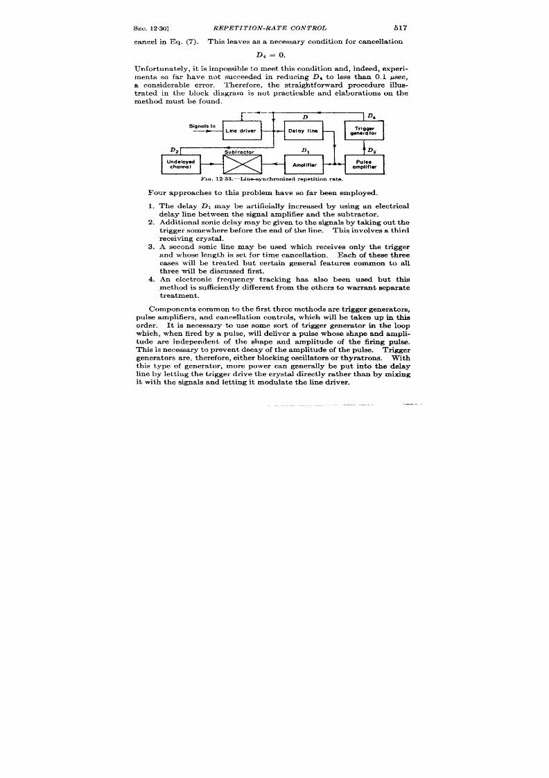
SEC. 12.30]
REPETIT ION -RATE CON TROL
517
cancel in Eq. (7). This leaves as a necessary condit ion for cancella t ion
D, = o.
Unfor tuna te y, it is impossible to m eet this condit ion and, indeed, exper i-
ments s fa r have not succeeded in reducing Dd to less than 0.1 psec,
a considerable er ror . Therefore, the st ra igh t forward procedure illus-
t r a ted in the block diagram is not pract icable and elabora t ions on the
method must be found.
.—-—
I
t,
D
Signals [n
Line driver *
Delay line
D2
Undelayed
channel
omplifler
FIG. 1233.-L in&Bynchron ized repe t it ion ra te.
Four approaches to thk problem have so far een employed.
1.
2.
3.
4.
The delay may be ar t ificia lly increased by using an elect r ica l
delay line between the signa l amplifier and the subtr acter .
Addit iona l sonic delay may be given to the signa ls by taking out the
t r igger somewher before the end of the line. This involves a third
rece iving crys ta l.
A second sonic line may be used which receives only the t r igger
and whose length is set for t ime cancella t ion.
Each of these three
cas s will be t rea t ed but cer ta in genera l fea tures common to all
t hr ee will be discu ssed fir st .
n elect ron ic fr equency t r ackhg has a lso been used but this
method is sufficient ly differen t from the other s t o war ran t separ ate
treatment .
Com ponents common t o t he fir st t hr ee m ethods a re t r igger gener ators,
pulse amplifiers, and cancella t ion cont rols, which will be taken up in th is
order . It is necessa ry to use some sor t of t r igger genera tor in the loop
which, when fired by a pul e, will deliver a pulse whose shape and ampli-
tude a re independent of the shape and amplitude of the fir ing pulse.
This is necessary to prevent decay of the amplitude of the pulse. Tr igger
genera tor s are, therefore, either blocking oscilla tor or thyra t rons. With
thk type of genera tor , more power can genera lly be put in to the delay
line by let t ing the t r igger dr ive the crysta l direct ly ra ther than by mixing
it with the signals and let t ing it modula te the line dr iver .

518
CANCELLATION OF RECURRENT WAVE TRAINS [SEC. 12.30
The t r igger genera tor must have two addit iona l proper t ies. It must
be self-sta r t ing. That is, it must be capable of fr ee running a t some fre-
quency lower than the repet it ion ra te so tha t an init ia l pu lse will occu r .
This also ensures tha t if for some reason the t r igger genera tor fails to fir e
on a pulse it will eventua lly fire aga in automat ica lly. Self-sta r t ing is
easily achieved with astable circuits (Vol. 19, Chaps. 5 and 6). It is a lso
necessary tha t only one t r igger a t a t ime be a llowed t o circu la te a round the
loop. As the cir cuit stands, if an addit ional pulse should somehow be
picked up by the amplifier , it would cont inue t o circula te around the loop.
This danger can be avoided if the t r igger genera tor , having once fired,
will not fir e again for a t least half of the desired repet it ion in terva l (see
,
*
Line
Sonic line
-
Carrier
driver
amplifier
I
I
J!
Electrical
.%btractor -
delay line
FIG. 12.34 .—Proposed sys tem for us ing e lect r ica l delay line .
Vol. 19, Chap. 16). If the amplitude of the tr igger ing s gnal is limited,
then it is possible to adjust the recovery t ime constan t of either of these
circuit s so tha t they will not be able to refir e for a t ime T/2. For ext r eme
reliability, however , a blanking gat of dura t ion T/2 should be applied to
t h e pu lse amplifier .
The pulse amplifier will genera lly consist of severa l stages of gain a t
the pulse car r ier , a detector , and video amplifier . The number of stages
n eeded will va ry wit h t he a tten ua tion pr oper ties of t he lin e a nd ba ndwidth
requir ements; 40 to 50 db of ga in a re usually requir ed. If the addit iona l
elect r ica l delay line is used in the signal channel, it is desirable to keep
the delay as shor t as possible; hence a broad-band pulse amplifier is used.
The cancella t ion con t rol may be either mechanica l or elect ronic. In
the former case it consists of a means for varying the physica l length of the
sonic or elect r ica l delay line and will be considered la ter . The elect ronic
method makes use of some sor t of t ime modula tor (see Chaps. 6 and 7).
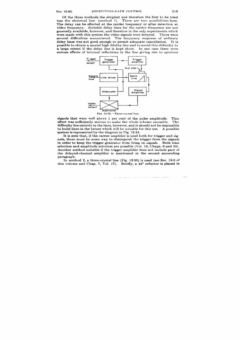
SEC. 12%3]
REPETITION -RA TE CON TROL 519
Of the th ree methods the simplest and therefore the fir st t o be t r ied
was the elect r ica l line (method 1).
There are two possibilit ies here.
The delay can be effected at the ca r r ier requency or a ft er detect ion at
video frequency. Suitable delay lines for the ca r r ier fr equency are not
gen er ally ava ila ble, h owever , a nd t her efor e in t he on ly exper im en ts which
were made with th is system the video signals were delayed.
Th er e wer e
sever a l difficu lt ies encoun t er ed .
The frequency response of ordina ry
delay lines was not good enough to permit adequate cancella t ion . It is
possible t o bta in a specia l high fidelitv line and t o avoid th is difficulty t o
; la rge extent if
ser iou s effect s of
the- delay l~n is kept shor t . In one case there ~rere
in terna l reflect ions in the line giving r ise to spurious
Trigger
Trigger Trigger.
output
generotor
omplifier
3rd xtol
SignoIs
Sonic
Line driver
line
line
v
\t
Attenuator
Signal
Amplifier
t
Video
output
Subtracter
FIG. 1235.-Three-orystal line.
signals tha t were well above 1 per cen t of the pulse amplitude. This
effect was sufficient ly ser ious t o make the whole scheme unusable. The
difficu lt y lies en tir ely in t he lin es, h owev r , a nd it sh ou ld n ot be impossible
t o build lines in the future which will be suitable for this use.
A possible
system is r epr esent ed by t he diagram in F ig. 12.34.
It is seen tha t , if the a r r ier amplifier is used both for t r igger and sig-
na ls, there must be some way to dist inguish the t r igger from the signals
in order t o keep the t r igger genera tor from fir ing on signals. Both t ime
Another method suitable if the t r igger amplifier does not include par t of
the delayed-channel amplifier is ment ioned in the second succeeding
paragraph.
In method 2, a three-crysta l l ne
th is volume and Chap. 7, Vol. 17).
(F ig. 12.35) is used (see Sec. 12.5 of
Br iefly, a 45° reflector is placed in

520
CANCELLATION OF RECURRENT WAVE TRAINS [SEC. 1230
the line just before the receiving crysta l and a second receiving crysta l is
placed on the wall of the line opposit e the reflector . The posit ion of the
r eflect or is adjustable; the delay may, t her efor e, be ar ied.
Here, aga in, one must k ep signals from fir ing the t r igger genera tor
and t ime and amplitude select ion may be used as before.
Another s cheme
is that of car r ier -fr equency discr iminat ion in which the t rigger amplifier
is tuned to a frequency different from hat of the signals. The delay Lne
will genera lly pass frequency components over such a broad band that
sa t isfactory response can be obta ined through the t r igger amplifier even
if it is tuned 15 or 20 per cent away from the 10-Mc/sec carr ier fr equency
of the signals, for example, a t 8 Me/see.
In method 3 a separa te line is used for set t ing the repet it ion ra te.
Although it is more cumbersome than the three-crysta l line this method
may have the advantage of mechanica l simplicity. It has been used
with both mechanica l and elect r ica l cancellat ion cont rol. The lines a re
placed close to the signal line so tha t the effect s of t empera ture on both
lines will be ident ica l. In pract ce, a t r igger line equal in delay t ime to
the signal line has been used as well as a half length plus a 2-to-1 fre-
quency divider in t he t rigger circuit (see Sec. 12.5).
A problem that comes up both in connect ion with this line and with
the thre>crysta l line is that of mult iple reflect ion. Unless absorbing
end cells are used, the t r igger will be part ia lly reflected at the receiving
crystal, t ransmit t ed back down the line, and will a r r ive a t a lmost the
same t ime that the succeeding t r igger enter s the line. This reflect ion may
be only 10 db down from the new t r igger .
Sin ce t he t rigger s a re a ppr oxim -
ately pulsed sine waves they may either add or subt ract in accordance
with their rel t ive phase. This rela t ive phase will depend on the delays
in the t rigger amplifier and gen er at or , and these delays, par t icular ly with
elect r onic t ime-cancella t ion cont rol, will in turn depend on t he ra te of r ise
of the pulse, hence the pulse amplitude. The following situa t ion might ,
therefore; ar ise. The delay in the t r igger genera tor may increase by a
small amount , and thus change t he rela t ive phase of t rigger and r eflect ion
in such a way as to decrease the output t r igger amplitude. This, in turn ,
would slight ly increase t he t rigger genera tor delay on successive repet i-
tions.
This eilect could easily produce jit t er in the repet it ion ra te sufE-
cient to impair cancella t ion appreciably. A means of avoiding this
difficu lty, if absorbing end cells are not used, is to put an addit ional
elect rica l delay in the t rigger loop equal in t ime t o t he length of t he t r igger
pulse dura t ion. In this way the second reflect ion will have been reflected
from the t ransmit t ing crysta l before the succeeding t r igger has entered
he line, hence they will not occur simultaneously and add together .
F igure 12.36 is a circu it diagram of the unit shown in Fig. 12.5. Thk
t r igger genera tor is used with a t r igger dtday line separa te from, and half
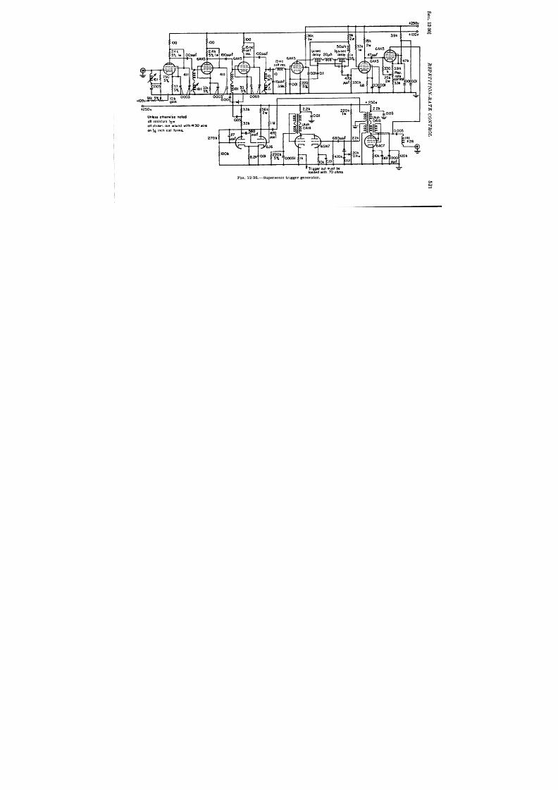
i
,
+2SOU
? Tr igger out must be
*
loaded with 70 ohms
FIG. 12.36.—Supersotic trigger generator.
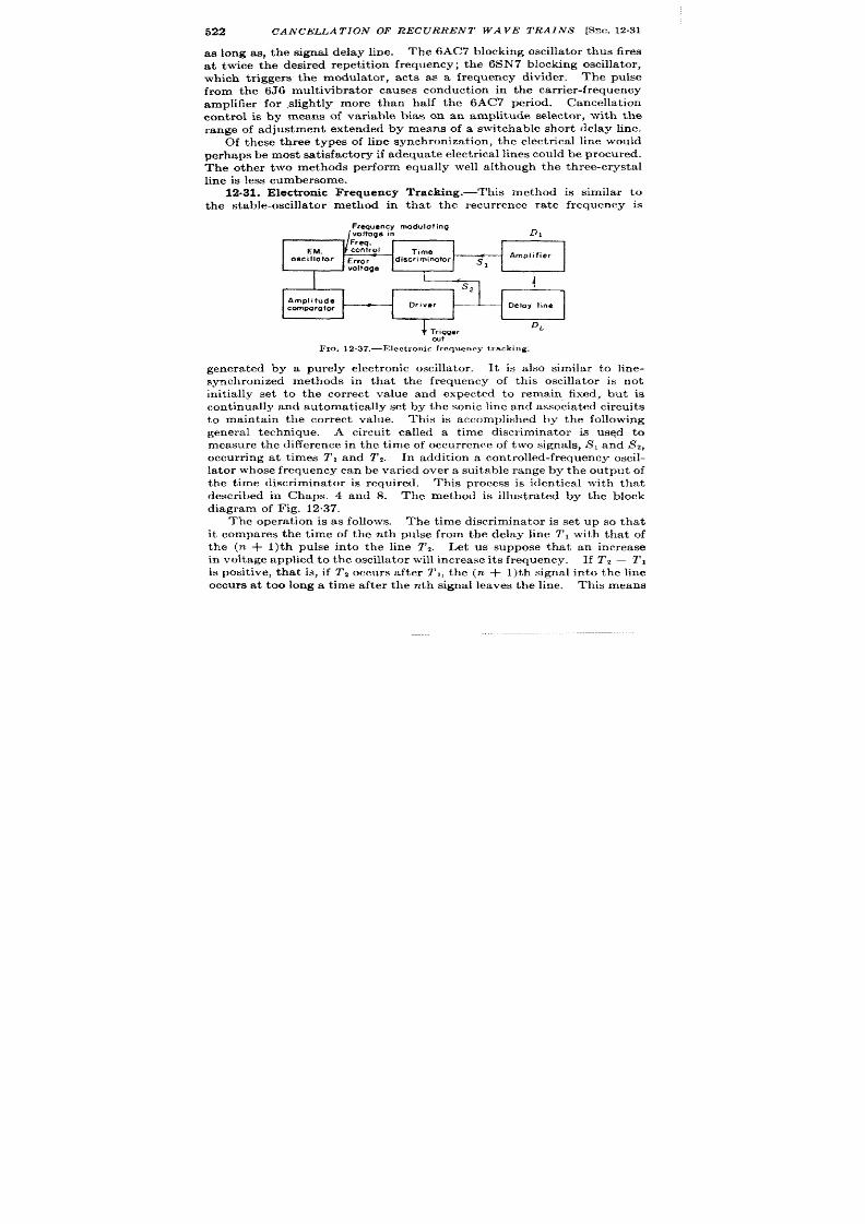
522
CANCELLATION OF RECURRENT WAVE TRAINS
as long as, the signal delay line.
Th e 6AC7 blockin g oscilla tor t hu s fir es
at twice th e desir ed r epet it ion fr equ ency; th e 6SI’J 7 blockin g oscilla tor ,
which t r iggers the mod la tor , acts as a frequency divider . The pulse
from the 6J 6 mult ivibrator causes conduct ion in the car r ier -fr equency
amplifier for ,slight ly more than half the 6A~ per iod. Cancellat ion
con t rol is by means of var iable bias oh an amplitude selector , with the
range of adjustment extended by means of a switchable shor t elay line.
Of these th ree types of line synch ron iza t ion , th e elect r ica l line wou ld
per ha ps be most sa tisfa ct or y if a dequ at e elect rica l lin es cou ld be pr ocu red.
The other two methods per form equally well a lthough the th ree-crysta l
lin e is less cumber some.
12.31. Elect ron ic Frequency Tracking.-This method is similar to
the stable-oscilla tor method in that the r ecur rence ra te frequency is
Frequency modulating
voltoge in
D,
Freq.
EM.
control
Time
OsclllOtOr Error
discriminator j
Ampl, fier
1
. Voltoge
*
ou t
Fm. 12.37.—Electronic frequency tracking.
genera ted by a purely elect ron ic oscilla tor . It is a lso similar to line-
synchron ized methods in tha t the frequency of th is oscilla tor is not
in it ia lly set to the cor rect value and expected to remain fixed, but is
con tin ually a nd a utoma tically set by t he son ic lin e a nd a ssociat ed cir cu its
to maintain the cor r ect value. This is accomplished by he following
gener a l t echn ique
A circu it ca lled a t ime discr iminator is used to
measure the difference in the t ime of occu rrence of two signals, SI and S2,
occur r ing at t imes 1’, and T*. In addit ion a con t rolled-frequency oscil-
la tor whose frequency can be var ied over a suitable range by the ou tpu t of
th e t ime discr iminator is r equ ir ed.
This process is ident ica l with tha t
descr ibed in Chaps. 4 and 8. The method is illust rated by the block
diagram of Fig. 12.37.
The opera t ion is as follows. The t ime discr iminator is set up so that
it compares the t ime of the nth pulse from the delay line T* with that of
the (n + l)th pulse in to the line T2.
Let us suppose tha t an increase
in volt age applied t o t h e oscilla tor will in cr ea se it s fr equency.
If Tz – T ,
is posit ive, th at is, if Tz occurs after T,, the (n + l)th signal in o the line
occurs a t too long a t ime after the nth signal leaves the line.
Th is means
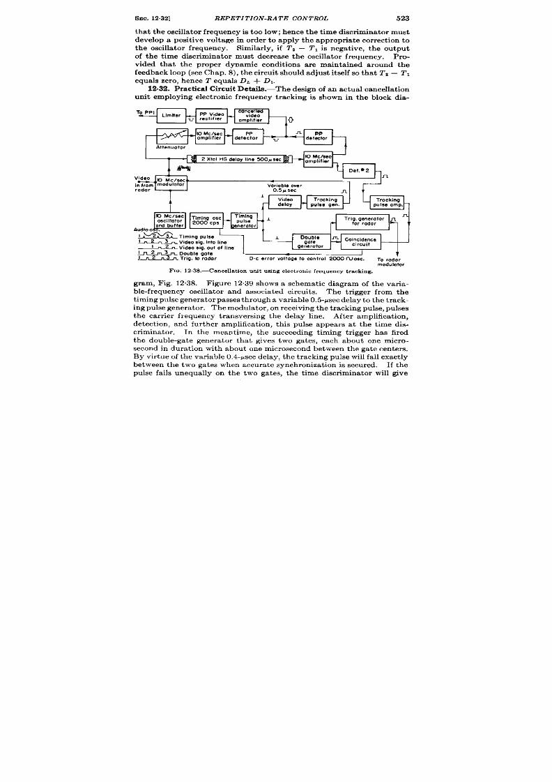
SEC. 12.32] REPETITION-RATE CONTROL
523
t ha t t he oscilla tor fr equ ency is t oo low; h en ce t he t im e discr imina tor must
develop a posit ive voltage in order to apply the appropr ia t e cor rect ion to
the osc lla tor frequency. Similar ly, if TZ – !f’Iis negat ive, t he output
of the t ime discr iminator must decrease the oscilla tor frequency. Pro-
vided tha t the proper dynamic condit ions are maintained around the
feedba ck loop (see Chap. 8), the circuit should adjust it self so tha t Tz – TI
equals zer o, h en ce T equals DL + D,.
unit employing elect ronic frequency t racking is shown in the block dia-
To PPI
n
v
PP
detector
Attenuator
s
2 Xtal HGdelay line 500#sec
10 Mclsec
amplifier
n
Variable over
radar 0.5 P sec
n
A
Video Tracking
1
delay
pulse gen.
EJ
o Mc /see
Timing osc
n
oscillator
2000 Cps
and buffer
1f
Audio o
1, 2
Timing pulse
l_2n3
A
Double
- Video sig, into Ii”e
1 “2”
gate
Video sig. out of line
generator
ln2m3
n Double gate
I
I “2
T
Pan
Trig. to rodor D-c error voltoge to control 2000 fuosc.
To rado r
modulator
FIG. 12.38.—Cancella t ion uni t u~ingelectronic frequency tracking.
gram, Fig. 12.38. F igure 12.39 shows a schemat ic iagram of the var i-
able-frequency oscilla tor and associa ted circuit s. The t r igger from the
t im ing pu lse gen er a tor pa sses t hr ough a va ria ble 0.5-psec dela y t o t h e t r ack -
in g pu lse gen er at or . Th e modu la tor , on r eceivin g t he t ra ckin g pu lse, pu lses
the car r ier frequency t ransversing the delay line. After amplificat ion,
detect ion , and fur ther amplificat ion, this pulse appears at the t ime dis-
cr iminator . In the meant ime, the succeeding t iming t r igger has fired
the double-ga te genera tor tha t gives two gates, each about one micro-
secon in dura t ion with about one microsecond between t he gat e cent ers.
By vir tu e of t he va ria ble 0.4-psec dela y, t he t ra ckin g pu lse will fa ll exa ct ly
between the two gates when accura te synchroniza t ion is secured. If the
pulse falls unequally on the two gates, the t ime discr iminator will give
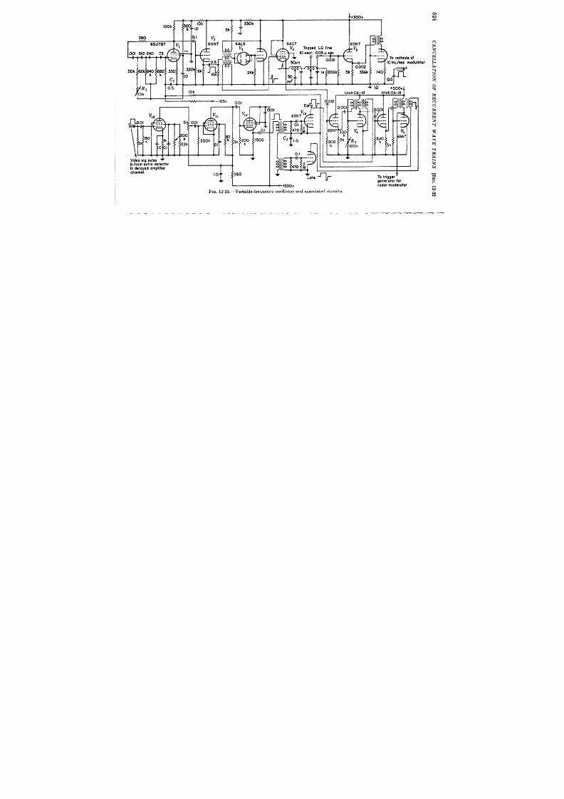
T-m luul ‘ 9 . , } II
J oy \ I
6k 140:
U-# aj+ ~+
u
##t
v.
10
~lOk I
10k
+300V4
q
UI
Vid~o sig. pulse +
(ofrom extra detector
~hg:e~ed ampl if ier
>
I .0
}01
F
y2
---
---
---
~
~ 2:0 I500
60
n
EOT’ k
Il&
~ 6SN7Y3
7
0.1 ‘--
470 ;
fah OAz18
Utah OA-18
4001
0.001
,
To trigger
t
generotor for
+.300.
radarmoderotor
FIG. 12.39.—Variable-frequency oscillator and associated circuits.
i
_.. —

SEC. 1232]
REPETITION-RATE CON TROL
525
out an er ror volt age tha t will in rease or decrease the var iabl frequency
a ccor din g t o t he ph ase differ en ce between t he oscilla tor a nd t he dela y-lin e
output . F inally the sine wave from the oscilla tor cont rols the t iming
The most impor tant component in this t iming channel is the variable-
frequency oscilla tor . Th oscilla tor must be very free from jit t er if
ca ncella tion is t o be main ta in ed.
In t his inst an ce a low-fr equ en cy pha se-
shift ‘oscilla tor using an IW-feedback was employed (see Vol. 19, Chap.
4). It has the advantages of simplicity and sensit ivity to cont rol for a
por t ion of a cycle and gr id goes posit ive and loads down the las network
element . By changing the d-c volt age on the gr id one can alter the frac-
t ion of cycle for which this occurs and thereby cont rol the frequency. A
range of ~ 1 volt from the coincidence circuit gives a varia t ion of f 75 cps,
which is s fficien t to make d-c amplifica t ion unnecessary. Var iat ion of
t h e r esist an ce R, in one of he network branches serves to adjust the
oscilla tor frequency to approximately 2000 cps. Once the system is
locked on the t racking signal, its opera t ion can be checked by varying
RI and observing t ha t t he d-c volt age va ries a ccor dingly.
The double gate is genera ted by two blocking oscilla tors. The act ion
of the second is in it ia ted by the overshoot of the first . Each ga te is
slight ly over 1 psec in dura t ion and roughly of 150 volt s amplitude.
These gates a re applied to the pla tes of a twin t r iode in the t ime-dis-
cr iminator circuit (see Vol. 19, Chap. 14). 1 When the t racking pulse is
equally dist r ibuted between the gates, the cha rge on Cl remains constant
and a st eady repet it ion ra t e is established.
There are two main advantages to this method of cont rol. The first
is that all dr ift s in any of the delays of the cancellat ion loop are auto-
matically compensated. The only dr ift tha t might disturb cancella t ion
would be dr ift in the t ime detector it self.
T e second advantage of the
method is tha t it involves no addit ional mechanica l parts, as do all
t h e ot h er lin e syn ch ron ized met hods discu ssed. It s disa dva nt ages a re t he
st r ingent j t ter requirements on the oscilla tor and the rela t ively la rge
n umber of t ubes r equ ir ed as compa red wit h ot her m et hods.
1 It is not necessary in th is c~n cella tion u nit to em ploy a ny bla nkin g device on t he
t ra ckin g pu lse amplifier beca use t he r ada r ech oes a re n ot of su fficien t size t o a ffect t he
t iming channel.

GLOSSARY
~putude compar ison .-The pr ocess of in dica tin g t h e in st an t of equalit y of t h e
amplitudesof two WAVEFORKSby a sharp puke or step. It may also be defied
a s t h e pr oces s of d et erm in in g t h e a bscissa of a WATWFOEM,iven it s or din at e.
=plit ide t lsc_ator .—A c~cuit wh ich ~dicates the equalityof the amplitudesof
two WAVEFORMSr t h e s en se a nd a pp roxima te magn it u de of t h e in equ alit y.
u p~t ude select ion .—Th e pr ocess Of s elect ion f all va lu es of t he in pu t wa ve gr ea ter
or less t ha n a given amplit ude or lyin g between two amp lit udes.
a st sble.-Refer rin g t o cir cu it wit h t wo qu asi-st able st at es.
Th e cir cu it gen er a tes
a con tin uou s t rain of wa ves a nd r equ ir es n o t rigger t o execu te a com plet e cycle.
bist able.—Refer rin g t o a cir cu it wit h t wo st able st at es. Two t rigger s a re r equ ir ed t o
pu t t he cim uit t hr ou gh on e com plet e cycle.
blockin g oscilla tor .-A t ra nsformer -cou pled feedba ck oscillat or in wh ich t he pla te
cu rr en t is permit ted t o low for on e-h alf cycle, a ft er wh ich bia s is gen er at ed in t he
gr id cir cu it t o p reven t fu r th er oscilla tion .
bot tom in g.-Th e pr ocess of defin in g t he pot en tia l a t t he pla te of a pen tode by oper at -
ing below the knee of the EP/ ZP ch ar act er ist ic. A sim ila r effect exist s in t riodes
wit h posit ive gr id d rive.
ca tching diode.-A diode used to limit the excur sion of potent ia l at some poin t
in a cir cu it . The term is usually used to r efer to the t erminat ion at a given
.
level of a n expon en tia l r ise t owa rd a h igh er pot en tia l.
clsm pin g.-Th e pr ocess of con nect in g som e poin t of a n et wor k t o a desir ed pot en tia l
for cer ta in per iods of t ime. This term has been la rgely replaced by the term
SWITCHING.
clipping. -Awm1’ru DE SELECTION between bounds. The outpu t has a fla t t op or
fla t bot tom or bot h.
d-c r est or at ion .-A a tegor y of t he general pr ocess of level set tin g. It r efer s pa rt icu -
la rly t o br in gin g eit h er t h e pea k posit ive or pea k n ega tive va lu e of t he WAVEFORM
to some des ired leve l.
delay cir cu it .-A cir cu it wh ich is used to delay by a cer t ain t ime the star t of the
op er a tion of a n ot h er cir cu it .
delay device.—A device wh ich accepts as its input a WAVEFORM f(t) and gives as it s
d
ou tpu t a WAVEFORM(t — A) wh er e A is posit ive.
.!$
dem odu la tion (or det ect ion ) .—Th e pr ocess by wh ich in forma tion is obt ain ed fr om
a modu la ted WAVEF~RM abou t the signal impar ted to the WAVEFORMin
modulation.
d iffer en ce det ect or .—A det ect or cir cu it in wh ich t h e ou t pu t r ep res en t s t h e d iffer en ce
of t he pea k amplit udes or a rea s of t he in pu t WAVEFORMS. Th e in pu t WAVEFORMS
need not be simult an eou s.
flip -flop .-C0 lloqu ia lism for k roNosTDLE circu it .
fr ee-runn ing.-COl10 quia lism for AsTDLE.
fr equ en cy discr im in at or .—A cir cu it wh ich in dica tes t he equ alit y of t he fr equ en cy of
two WAVEFORMSr t h e s en se a n d a pp roxima te magn it u de of t h e in equ alit y.
fun ct ion u nit .—The unit tha t con trols t he exter na l pr oper ties of automat ic r an ge-
t ra ck in g equ ipmen t a nd p rovid es t be n ecess ar y ba nd sh ap in g for st abilit y.
527
528
GLOSSARY
ga tin g w.a veform .=A WAVEFOE~(somet imes ca lled t h e “ga te”) a pplied t o t h e con t rol
poin t of a circu it in such a way as to a lter the mode of opera t ion of the circu it
while the WAVEFOHMs applied.
jit ter .-Sm all r apid va ria tions in a WAVEFORMdu e t o m ech an ica l dist ur ba nces or t o
ch an ges in t he su pply volt ages, in t he ch ar act er ist ics of compon en ts, et c.
lockover circu it .-Colloquia lism for a BMTABLEcircu it .
r r dcr ophor dcs .-Jm”rm t due t o mech an ica l dist ur ba nces, r efer r in g especia lly t o t ubes.
Miller circu it .-A circu it which employs negat iv feedback from the ou tpu t to the
in pu t of a n amplifier t hr ou gh a con den ser .
modrda t ion .-The process by which some character ist ic of a WAVEFORM is va r ied in
a ccordan ce with a s ign a l.
monost able.—Ref er rin g t o a cir cu it wit h on e st able a nd on e qu asi-st able st at e.
Th e
cir cu it r equ ir es on e t rigger t o per form a complet e cycle.
mu It isr .-A d iod e-con t rolled r egen er a tive amplit u de compa ra t or .
The name refers
t o a cer ta in cir cu it con figu r at ion .
mult ivibr at or .-A t ~vo-t ube r egen er at ive device wh ich ca n exist in eit her of two st able
or quasi-stable states an d ca n ch ange rapidly fr om on e state to t he oth er .
qu asi differ en tia tion (in tegr at ion ) .-Appr oxim at e differ en tia tion (in tegr at ion ) by a
simple circui t .
phantast ron .-A cer ta in type of one-tube re axa t ion oscilla tor employing Miller
feedba ck t o gen er at e a lin ea r t im in g wAvEFom{.
pulse.—A
IVAVEFORM
WhOSe u ra tion is sh or t compa red t o t he t im e sca le of in ter est
a nd wh ose in it iol an d fina l va lues are t he mme.
rundown-The linem fa ll of pla te voltage in a \ Iiller sweep grmera tor .
sa na ph sn t.-A cir cu it in termedia te between SANATRONand rIrAN’rAs’rrmN.
sa na tr on .-A va ria tion of t he FHANTASTRONmployin g a secon d t ube for gen er at in g
t h e ga t in g waveform .
s ca le-of-two cir cu it .-A colloqu ia lism for
BISTABI,E cir cu it .
s elector .—A circu it s electing on ly th ~t port ion of a WAVEFORM havin g cer t a in cha rac-
t er ist icsof amplit ude, fr equ en cy, ph ase, or t ime of occu r rcn ec.
select or pu lse.—A pu lse u sed t o a ct ua te a t im e select or .
shaping.—The process of m odifyin g the sh npc of a wa veform . The pr ocess is ca lled
“lin ea r” or “n on lin c:w” zccor din g m t h e cir cu it clrmcn ts a rc lin ea r or n on lin cu .
sign al. -An elect rica l orm rr h zn ic:d qu an tit y wh ich convcys in t clligr ncc.
swit ch det ect or .—A det ect or ~vh ich ext ra ct s in forma tion fr om t he in pu t wa veform
only a t instan ts dctcr minrd by a select or pldse.
swit ch in g. —’~h econn er t io n ottwo poin ts of a n etwor k a t con tr oll~blc in st an tsof t ime.
An altern at ive t er m is 17T,AMI>1NG.
t ime compa rison .-Th epr occssof in dica tin g t h e amplit u de of a w,iv~:~oRMa t agiver r
instant.
t ime demodu la t ion .—The process by which informat ion is oh ta incd from a t imc-
m odu la t ed wa ve abou t t he signa l im par t ed to th e wa ve in TI.ME MODULATION.
t ime discr imina tor .-A circu it which indicn testhc t ime cqua lityof two event s or th e
sen se a nd a ppr oxim at e magn it ude of t he in equ alit y.
t ir nem odula t ion . -kfodula t ion in wh ich t he t ime of a ppcm anceof a defin it e por tion
of a WAVEFORM,mea su r ed wit h r espect t o a r efer en ce t ime, is va r ied in a ccor da n ce
wit h a sign al.
t racking. -The processor causing an index to follow the var ia t ion of a quant ity by
means of a n in ver se-feedba ck (s er vo) loop.
waveform .—A cu r r en t or volt age considered as a funct ion of t ime in a rectangu la r
coord ina te sys tem.

Index
A
A-scope, 215
A-scope presen ta t ion , used in Brit ish
CMH syst em , 238-243
Accu r acy t est s, 129
(See a lso E r ror )
AFC, 267
. FC cir cu it , 96
AGC, 279
ga ted , 373
AGL-T, Br it ish , 330
pha se compa r ison cir cu it in , 372
AGL-(T) discr imin ator , 278, 3 0, 322,
330, 341, 373
AI Mark VI, 334, 370
AI Ma rk VI a ut om at ic t ar get -select ion
circu it , 333
AI Ma rk VI a ut om at ic t ar get -select ion
syst em block dia gr am , 332
AI Mark VI t ime discr iminator and
t a rget s elect or , 334
AI Mark VIA, 341
Alt imet er , ba r omet r ic, 163, 164
SCR-718, 163, 219
Amplifiers, cancella t ion , 498
pu lse-forming, 72
squ ar in g, 70, 72, 110
Amplit u de compa r at or , 144
d iod e, 73, 151, 173
r egener a t ive, 73, 74
wit h RC-in pu t, 75
s inusoid , 145
Amplitu de compar ison , 71, 75, 76, 107,
110, 142-175
d iode, 108
Amplit ude-compa r is on cir cu it , 75, 109
Amplitude select ion , elect r ica l, 221
Amplit u de select or , ca t hod e-r a y t ube a s,
220
AN /APA-30 ba llist ic compu t er , 247
529
AN/APG-1, 369, 370
an gle-tr ackingcircuits in, 376, 377
AN/APG5 range ca libr a tor , 10!3,275,
317, 331, 337, 342
(S,. a isoARO)
AN/APG-13A Falcon radar, 223, 224
AN/APG-15, 17, 327, 331, 342, 368,
371, 373
time discriminatorof, 316
AN/APN-3, Shoran, 157
pu lse-selectioncircuits of, 159
AN/APN+ 263
AN/APN-9, 263
AN/APS-3, 248, 392
blocking-oscillat orPRF genera torof, 78
AN/APS-4, 248
AN/APS-10 radar , revised model of, 91
AN/APS-10synchronizer,91,169,172,248
proposed,92, 94
timingdiagram of, 93
AN/APS-15 pulsegenerat or,165
AN/APS-15 ra ngeunit, 120,164169,277
block diagram of, 164
AN/APS-15 ra nge-un itwaveform s,165
AN/APS-15 ten-mile pulse selector, 167
AN/APS-15 ten-toane divider, 166
AN/APS-15 time modulator, 167
AN/APs-15 twenty-five-to-one divider
generatingPRF pulses , 166
AN/ARR-17, 458
AN /ART-18, 458
Angle-posit ion ing, au tomat ic, with
gr ou ped da ta , 389
A/R r an ge ecope, 256-B, 76
A/R-scope, 231–238
Ar en ber g, D. L., 484
Arms r es olver , 418, 438
Midget , 342
ARO (AN/APG5), 342
ARO elect r ica l sys tem, 342-348
ARO Mark I, 342
ARO Mark I range system, 343
530 ELECTRON C TIME MEASUREMENTS
ARO Mark I range unit , 344
ARO Mark II, 342, 345
ARO r ada r, 275, 317, 342
ARO r an ge syst em , 342
ASII, a vy Rada r, 216
Automat ic angle t racking (see Angle-
Positioning)
Au t nn ,a tic r a nge t r ack in g (s ee Tr ack in g)
Au tosyn , 394
B
Ba llist ic compu t er , 142
B-s cope, s ys tems u sing J -s cope wit h , 243-
246
AN /APA 30, 247
BC-1365, In dica t or -Tr a ck er Unit , 255
Beacon , omnid ir ect iona l, 36
Br it ish , 400 , 410-416
r ada r, 33
I Ir ll Telephone Labor a tor ies , 142
Bendix sir -m ilea ge un it , 251
Bendix Air -pos it ion Ind ica t or , 251
Blocking oscilla t or , 75, 76, 78-80, 151,
167, 317
500-yd (328-kc/s ee), 110
low-impedance , 91
Block ing@scilla t or d ivid er s, 83, 110, 165
Block in g+scilla t or PRF gen er a tor , 78
of AN/APs.3, 78
Blocking-oscilla tor pulse genera tor , 70,84
Block ing-oscilla tor volt age pu lses , 78
Bode, H. W., 282
Boot st ra p double in tegr at or , 386
Boot s tr ap linea r -sawtooth gene ra tor , 151,
358
Boot st ra p self-ga tin g lin ea r-sawt oot h
gene ra tor , 347
Boot st ra p t ime-modu la t ion cir cu it , 128
Boot et r ap t r iangle gener a t or , 125-131
Bot hwell, F. E., 390
Br it ish AGL-T, 330
Br it ish Mark II ASV, 216
Br it is h Oboe, (s ee Oboe)
Br it ish omnidirect iona l beacon, 400,410-
416
Br it ish 274 met er , 368
Br own Conver ter , 361, 447
c
Ca libr at or , Model III, 87–89
Ca thode follower s, 130
Ca t hode-r a y t ube, a s amplit u de select or ,
220
Ca th ode-r ay t ube displa ys, 64
Ca t hode waveform , 105
Chann el sepa ra t ion , 398, 400
Circu it , 392
CMH systcm, Br it ish , A-scope pre-
sen t at ion u sed in , 238–243
Coa st , 278, 304
Code group , mu lt ip le-puls e, 400
Coder , 451
CoSin , F. P., 390
Coher ence, ext er n a l, 20
in t er n al, 18
Coil a ssembly, Helmholt z, 137
Cole, A. D., 120
Compara tor , 135-137
amplit ude (s ee Amplit ude compa r a tor )
double -t r iode, 116
cath ode-couplecl, 116-118
mu lt ia r (s ee Mu lt ia r compa r a t or )
r egener a t ive amplit ude, 356
Compa r a tor cir cu it , double-t r iode, 118
Componen t cha ract er is tics , 5&62
Compress ion , dynamic-r ange , 496
Conden ser ph a se sh ift er , 358
Conden ser syst em , 3-ph a se, 172
Con ica l s cann ing, 367, 368
(h nica l-sca nn in g a nt en na pa tt er n, SCR-
584, 367
Cont inuous-wave sys tem, 7, 16-18
Coun ter divider s, 102
Coun t er s, 102
sca le~f-two, 154
et ep , ga s-filled t ube, 100
Crou t , R. D., 390
Cr yst al oscilla tor , 71, 83, 153
Claw C, 75
80.86-kc/see , 164
pu lsed , 238
t r iode, 83
80.86-kc/see , 93
t ri-t et , 8S
Crys ta l r ect ifier , germanium , 91
Cryst a ls , r eceiving, 135
t ra nsm it tin g, 135
Cu r ren t t r an sformer , 316
Cu r sor s, 178
C-w syst ems, fr equency-modula t ed , 398
Cycle mat ch in g, 11

INDEX 531
D
Da ta , gr ouped,
or per iodica lly in t er -
rupted, t rackingon, 378
intermittent,28, 29
aided tra ckingwith, 247–251
Data tran smission,phase for, 393
ra dio, 398
short-distancewire,391
Data -tr an smissionsystems, special,391–
416
various, cha ra cter isticsof, 399
Decca, 34
Decoder, 426, 454
Decoding circuits, synchr onizing-pulse,
426-429
Delay lines, supersonic (see Supersonic
delay lines)
variable, 132
Delay mu ltivihr ator, 131, 140,342, 347
coarse-scale,162
Delay phanta atron,Oboe active-region,
353
Delay ta nk, supersonic,132-135, 140
Delay-ta nk time-modulat ionsystem, 132
Delays,linear,429-433
Demodulat ion,time modulation and, 5-7
Demodulat ors,391, 400
Detectors, position err or, 367
Dieh l FPE-492a two-pha se induct ion
motor, 361
Diehl Generat or,424
Diode amplitude compara tor , 71, 125-
131, 153
Disconnector,304
neon tube, 386
Distan cemeasur ement,accur acyof, 32
Divider circuit, sinusoidal, 158
Dividers, bl ckingascilla tor , 83, 110,
165
coun t er , 102
ph an tsst ron , 104
pulse-frequency, mult ivibra tore SS, 154
oppler , pu lsed, 20
oppler fr equ en cy, 17
ouble+ca le syst em , 49
umon t 25&B A/R oscilloscope, 89,231
l!A
Elect romechan ica l sys tems , 357-366
E lect r on ic ma rk s, movable, 222-225
E lin co Type B-44 t ach omet er s, 361
E rr or , cyclic, 141
gr os s, 156
lim it ing, 113
pr obable, 113
r es et , 192
s lope, 114
of t im e m ea su rem en t, 40
in t ime-mea su remen t cir cu it s, 120
in u su al sa na tr on cir cu it , 124
zero 114
F
F alcon r ada r, AN /APG-13A, 223-231
Fa r nbor ough , 482
Feedback amplifier , n ega t ive, 117
4-P se pu lses, 78
5(LP s ec pu lses , 96
Fink, D. G., 89
Follow-up sys tems , 395-397
F redr ick, A. H ., 119
F r equ en cy divider s, 88, 102, 267
amplitude-comparison
multivibrator,
147
wit h in ject ion feedba ck , 100
pu ls e, 83
s inusoida l, 160
Frequency d ivis ion , 81-87
F r equ en cy modu la t ion , 5, 393
and demodula t ion , 13–15
F requ en cy st abilit y, 77, 78, 80, 110
F r equency t r ack ing, elect r on ic, 522
F un ct ion u nit , 277, 279, 280
mechanical , 305-308
G
Ga t e, s elect in g, 151
Ga te gen er a tor , pu lse-select in g, 6-P a ec,
152
Ga te gen er a tor m r dt ivibr at or , 117
Gee; 34, 261
Gee-H , 30
Gen er al E lect ric Au tom at ic Ra da r, 337
Gen er a l E lect r ic Company, 337, 485
Gen er al Elect ric Type YE4-B lin es, 44)6
(lener a t .or e, angle in forma t ion , 458
Dieh l, 424
of ‘grouped puls es , 400
532
ELECTRONIC TIME MEASUREMENTS
Gener a tor s, lin ea r -s awtoot h , boot st r ap,
151, 358
boot st r ap self -ga t ing, 347
pos it ive-feedback , 225
lin ea r sweep, 153
ma rker (s ee Ma rker gener a t or s)
phant a st r on -ga t e, 104
r an ge-mar k, 69
t r iangle, boot s tr ap, 125–131
t r igger , mu lt ip le-fr equency, 81
Gon iometer , 240
in du ct an ce, 158, 161
phase-modu ls ting, 154
Gostyn , E., 88
Gr ayson , H ., 482
Gr ou nd t ra ck, 23
Gr ou nd, vir tu al, 294, 295
Ground-pos it ion ind ica tor , 251
H
H,X, 119
(See al .o AN/APS-15)
H,X r an ge phantast ron , 122
H,X range unit , 120, 123
H,X t ime modula tor , 121
H,X, 386-388
Hand Radar Set , 243
Helmholt z coil a ssembly, 137
Hewlit t -Packa rd oscilla tor , 140
Hite, G., 125
Holdam, J . V., 120
Holtzer -Cabot Type 0808 model B3
mot or , 441
HR radar system, 163
Hughes, V. W., 125
H ybr id t im e a nd ph ase discr im in at or , 97
Hyperbolic n aviga t i n sys tems, 261
I
I ndica t ion , on -t a rget , 328
Ind ica t or , Air -pos it ion , Bendix, 251
ground-pos it ion , 251
p lan -pos it ion (ace PPI)
posit ion er r or , 367
pr ecision t ype B, 255
r ada r, 108
typs M, 223
In dica tor -Tr ack er Unit BC-1365, 25
Indices, ltK)-184
In dices, fixed, 181
for m an ua l t im e m ea su rem en t, 215
movable, 182
t r ack ing, 183
In du ct ion mot or , two-ph ase, DieLd FPE -
492a , 361
Inject ion feedback d ivid er for Oboe PRF ,
103-107
In tegr a tor , boot st ra p, 302, 303
diffe rence , 302, 303
double, boot st r ap , 386
electr ical , 291–303
Oboe, 354
electromechanical , 252
elect ron ic, 347, 357
feedback amplifier , 302, 303
mechanica l, 305
Miller (s ee Miller in t egra tor )
In t er fer ence reject ion , 400
J
J-scope, 21&-2 19
syst ems u sing, wit h B-s cope, 243–246
wit h PPI, 243–246
J it ter , 78
J ones, F. F., 348
J ordan , V’. H., 323
Juxt aposit ion , 186, 188, 1W196
Kallman, H. E., 489
L
Lwlet t , L. J ., 369
LC~scilla tor , 107, 13 .%137
pu ls ed, 108
2Wkc/see, 96
328-kc/see , 110
LC-stabilizat ion, 83
L nea r it y, 114
Lobe-switching, 367
Lora n, 11, 34, 173, 181, 261
La r an au t oma tic-fr equency-t r ack ing cir -
cu it , ligh tweigh t , 97
bran feedback PRF divider , direct -
r eading, ligh tweigh t , 101
Loran indica tor , circu it deta ils of, 267–274
ligh tweigh t, dir ect -r ea din g, 96, 169-
174
INDEX
I
bran PRF gen er at or , dir ect -r ea din g,
lightweight , 1CW103
Loran r epet it ion fr equencies , 264
Lor an t ime discr im in at or , ligh tweigh t,
au tomat ic-f requency-cont rol circu it ,
98
Loran t im -discr iminator t iming dia-
gram, 99
Loran t ime modu la t or , direct -reading,
ligh tweight block and timing dia -
gram of, 169
ph ase modu la tor of, 170
Loran t im ing sequence, 264-267
M
M-scope, 225
McGrath , S., 120
McSkimin , H. J ., 478
Magnesyns, 394
Mags lip , 394
Mark I ARO, 344
r an ge vs. r an ge er r or of, 347
Mark II ARO, 344
Mark II ASV, Br it ish , 216
Mark IIM, Oboe, 348
Mark 36 radar , angle-t racking circuits
in , 375
Ma rker gen er at or s, gr ou ped, 106
s ingle-fr equency, 107, 108
mult ip le -fr equency, 81
s ingle-frequency, 81
20-mile , 85
Ma rk er s, gr ouped, mu lt iple-fr equ en cy,
109, 110
Ma st er st at ion , 261
ME PPI, 458
Mea ch am r an ge u nit , 142-147
Measu r emen t s, manua l, 176-274
h femory, 304
posit ion , 282, 3S0
velocity (see Velocity memory)
Memor y t im e, 278
Micr o-H , 30
Microsynaj 394
Mile, n au tica l, 103
st at ut e, 103
2000-yd , 103
Miller feedba ck , 131
Miller feedba ck t im e modu la tor , 114
Miller in t egra tor , 114-116
h igh-ga in , 140
mult is tage , 116–118
self-gat ing, 118-124
Miller in tegr at or tmplifier , 117
Mixer u nit , 461
Mixin g u nit , video, 45 I
Model SJ radar range cir cu it , 134
Model 111 ca libr a tor , 87–89
Modula tor , elect romechan ica l, 391
zer o-r a n e t r igger for , 95
Modu la t or t rigger , 91
Mu lt ia r compa ra tor , 114-116, 124, 356
Mult ip le-s ca le sys tems, 61, 219
Mult ivibr a tor , 80
delay (see Delay mult ivi r a tor )
ga te gen er at or , 117
monos table, 144
1OO-Psee, 97
a s pu ls e- r equ en cy divider , 154
scale-of-two, 84
symmet r ica l, 80
as PRF genera tor , 80
unsymmet rica l monost a ble, 94
Mu lt ivibra tor PRF gen er at or , Ml
N
533
Navy Radar ASB, 216
0
O-ph ase a dju stmen t, 73
Oboe, 168, 277, 315, 350, 357
Oboe a ct ive-r egion dela y ph an ta str on ,
353
Oboe a ct ive-r egion t im in g dia gr am , 351
Oboe blin d bombin g, geom et ry of, 348
Oboe elect r ica l in t egr a tor s, 354
Oboe elect r ica l s yst em , Br it ish , 34*357
Oboe 5-m ile p ip select or , 352
Oboe gr ound st at ion , Br it ish , 1!33, 311
Oboe Mark IIM, 348
Oboe mou se st at ion , 337
Oboe PRF, in ject ion feedback divider
for , 10*IO7
Oboe PRF divider , 103
Oboe rang~tracking system block dia-
gr am , 349
Oboe t im e discr im in at or , 311, 312
On-ta rge t ind ica t ion , 3’28
534 ELECTRONIC TIME MEASUREMENTS
100-P sec mult it ibr at or , 97
Oscilla t ion s, bu ildup of, 38
Oscilla tor , 107
block ing (see Blockhg oscilla t or )
coh er en t, 11
crys ta l (see Chys ta l oscilla tor )
crysta l -controlled, 141
Hewlit t -P a ckar d, 140
in st abilit y of, 77
IX’- (see LC-oscillator)
pulsed, 107, 109, 142, 144, 145, 148,
229
quench ing, 79
wit h a ir -cor e t ra nsform er , 79
r andom , p recis e s ynch r on iza t ion of, 99
R(7-, 70
RC s ine-wave , 80
re laxa t ion (see Relaxa t ion oscilla tor )
SCR-268, 137
s ine-wave , Class C, crys ta l-con t rolled,
81 .94-kc/secj 76
crys t al-c n t rolled 163.88-kc/s ee, 72
squegging, 79
two independent , precise system of
synch r on iza t ion for , 99
var iable-frequency, 137–140
Wien -br idge, 70, 139
Oscilla t or r ange cir cu it s, s inusoidal, 135
Oscilloscope, Dumon t 2 6-B A/R, 89,231
P
P ha nt ast ron , 95, 106, 118, 120, 164, 167,
168, 171, 349, 350, 352, 355-357
microphonics e ffect s in , 123
puls e-s elect ing, 94, 171, 173
t emper at ur e compen sa tion o , 123
Pha nt ast ron a ccu ra cy, 122
Pha nt ast ron ca th ode waveform , 105
Phant a st r on delay, componen t va r ia t ions
u pon , effect of, 123
?h an ta st ron divider , 104
Phan t ast r on -ga t e gener a tor , 104
Pha nt ast ron oper at ion , 121
Pha ae demodu la tion , 5
Phase-&scr imina tor , 155
hybr id t ime and, 97
Phase modula t ion , 142–175
and demodu la t ion , 7–13
of t im ing, 57
Phas e-modu la t ion network, 158
Phase-mod ,u la t ion range un it , two-sca le,
143
P ha se-modu la tion syst em , t hr ee-sca le,
157-161
Pha se modu la tor , 135-137, 145
conden ser , 142, 144, 150, 1,51
t im e modu la tor , 170
mechan ica l, 168
3-phase condenser , 170
Phase shift er , 238
condenser , 358
magnet ic, 137
Phase-s hift er syst em , discu ssion of, 443-
449
Photoe lect r i c ce lls , 276
Pos it ion er r or det ect or s, 367
Pos it ion er r or indica t or s, 367
Posit ion-finding, 29
Pos it ion lea r ning t ime, 380
Posit ion memor y, 282, 380
Potentiometer,
expon en t ia lly t aper ed,
142, 146, 153
linear range, 151
sine-cosine, 252
360°, 396
PPI, ME, 458
wit h mech an ica l sca le, 219
puls ed range-mark cir cu it des igned for ,
107
syst ems u sing J -s cope wit h , 243–246
PPI r an ge-m ar ker cir cu it , 108
Precis ion Range Ind ica tor , block d iagr am
of, 148
t im in g dia gr am of, 148
Precision ranging indica tor , precise
pu lsed, r an ge-m ar ker cir cuit fr om ,
108
P recision t ype B in dica tor , 255
PRF divider ph an ta st ron , ca th ode wa ve-
form of, 105
scr een waveform of, 105
PRF divider s, 85
Oboe, 103
PRF gen er at ion , 78
PRF gen er at or s, 69
blocking~sci lfa tor (see Blocking-nsci l-
la tmr PRF gener a t or )
Lor an (see Lor an PRF gen er at or )
mu lt it ibr a t .or , 80

535
PRF gener a t or s, s ymmet r ica l mu lt ivibr a -
tor as, 80
syn ch r on iza t ion by, 45
PRF oscilla tor s, 400
P ropaga t ion -t ime cir cu it s, 141
Pulse divider , ten-t oa re, 165
P ulse gen er at or , AN/AP&15, 165
b lock ing-oscilla tor , 70, 84
delay-line, 107
r -f, syn ch r on iza tion by, 43
Pu ls e r emot e-con t r ol sys tem , 40G408
Pulse select ion , 87-89, 160
Pu lse-select ion cir cu it s, of AN /APN-3,
Shor a n, 159
Pulse select or , 8%95, 146, 153, 171
t en -m ile, AN /APS-15, 167
t ime modu la tor an d, 146
Pu lse syst em , pha se-modu la t ed, 442
t ime-modula t ed , 398
Pu lse t r an sformer , 78
1 2-D W, Wes tinghouse, 317
Pu lses, 0.12-P see, 317
4-I J see, 78
50w see, 96
gr ouped , gen er a tor of, 400
t ime-modula t ed , 400
R
R-ga te, 233
R-sweep , 233
Ra da r bea con s, 33
Ra da r in dica tor , 108
Ra da r set , Br it ish , t im e discr im in at or of,
315
Ra da r syn ch ron izer , 71
Radar systems, 31
R, 163, 243 .
relay (seeRelay radar systems)
Radioeonde,408
Range, two-scale,238
Range ca libra tor , AN/APG-5 (see AN/
APG-5 ra nge calibrator)
Range-ma rk cir cu it , pu lsed, d esigned
for PPI, 107
Range-markgenerators,69
Range-markmixer,83
Range-marker circu it , pu lsed , p recise,
fr am p recision r anging indica t or ,
108
pulsed LC, 108
Range-ma rker gener a t ion , 78
Ra nge mar ks, fixed, 229
Range t ra ck in g, a ut omat ic, 168
on gr ou ped da ta , 38&388
Range-t ra ck in g ser voamplifier cir cu it ,
362
Range-t r ack in g t est er , dyn amic, 363
(See also Tracking tester , dy-
namic)
Ra nge u nit , Mea ch am , 142-147
phase -modu la t ion , two-sca le, 143
on rada r systems, ca libra t ion of un i-
ver sa l in st rumen t for , 102
two-sca le, 143
Wu rzbu r g, 163
Ranging ind ica tor , p recis ion , 147-153
RC-in pu t, r egen er at ive amplit ude com -
pa ra tor wit h, 75
RC-oscilla tor , 70
RC-s ine-wave oscilla tor , 80
RCA, In du st ry Ser vice D vision , 15
Rea ct an ce t ube, 96, 97
Receive r, 466
ga in con tr ol of, 41
va r ia t ion of delay with signal ampli-
tude in , 41
Receiver bandwit h , 39
Receiver dela y t im e, 40
Receiver ga t e, 163
Receiving equ ipmen t , 426
sequ en ce of t im e select or s in , 400
Recorder , Es te rline-Angus , 387
Recover y t im e of cir cu it , 116
Rect a ngle gen er a tor , va ria ble-widt h , u se
of, t o p roduce t ime-modula t ed t r ack -
in g in dex, 222
Reed, H. J ., 119
Re axa t ion oscilla tor , 107
ga s-t et r ode, 76, 77
Rela y r ada r syst ems, 400, 417-470
C-W, 458
per formance of, 470
p er formance in , 439
simplified , for con st an tip eed rot a tion ,
450
Repet it ion -r a t e con t r ol, 511
Reset er ror , 192
Reset in ter va l, 194
Resolver , d -c, 440
Respon se t imes, 275
Rise t ime, 39

536 ELIICTM)NIC TI rIl MEA SIJRllMENT
s
Sana tr on , p recis ion , 124
s imple, 124
Sa na tron cir cu it , u su al, ermr sin , 124
Sca le coordina t ion by fr equency divis ion ,
153–155
Scann ing, con ica l, 367, 368
SCR-2680scilla t or , 137
SCR-268 r ada r, 135
SCR-584 radar , 89, 161, 163, 337, 368-
370, 406
con ica l sca nn in g a nt en na pa tt er n, 367
SCR-584 cir cu la r -sweep t ime modula t or ,
161
block dia gr am of, 162
SCR-615, 373, 378
angle-t r a ck ing cir cu it s in , 374
SCR-682A r ada r, 255
SCR-718 a lt imet er , 163,219
SCR-784 t ime discr imina tor , 313-315,
337
Scr een waveform , 105
Sea rch cir cu it s, a ut omat ic, 278
Selsyn , 394
Sepa ra tor u nit , 466
Sequencing circuit s , 42%433
Servoamplifier , 438
Servomechan ism, r ange follow-up, 33 I
ve locity, 252
wit h velocit y memor y, 449
Sh or an ,30, 161
Sickles Compa ny, F. W., 88
Sign al a nd in dex, su per posit ion of, 195–
198
S ine-cos in e sys tem , t ime-modula t ed , 417
Sin e-wa ve t ra ck in g, 15$157, 242
Single-scale circui ts, 111-141
compa r ison of, 140, 141
S inu soid s, pha se-modula t ed , puls e r ep r e-
sen ta tion of, 442
Sla ve st at ion , 261
spa cin g, 400
Specificat ion, 51
Spee , blin d, 19
gr ou nd, 21, 24
Speed measu r emen t s, 16-24
a ccu ra cy of, 32
Spen cer , R. E., 489
St ep in ter pola tion , 168
S tep -in t erpola t ion t ime modula t ion , 164
S tor age t ~lh r, 99
Suha sscmh]y, 170, 174
fa ult y, 170
Suhca r r icr , 398
Super son ic dela y lin es, mer cu r y, 481
solid, 484–487
water , 482–484
Sweep , cir cu la r, 81, 99, 142, 168, 1S4, 341
displa ys in , 161
exponen t ia l, 2 5
Sweep gener a t or , exponen t ia l, 144
Synch r o syst ems, 393
Synchroniza t ion , 42-47
by a ut omat ic-fr equ en cy t ra ckin g, 95-
100
pr ecise, of r a ndom oscilla tor s, 99
precise system for two independen t
oscilla tors , 99
by PRF genera tor , 45
r emot e con tr ol of, 46
by r -f pu lse gen er at or , 43
Synch ron izer , 81-83, 87, 90, 424-426
AN /AP&10 (see AN /APS-10 syn ch ro-
nizer)
aut omat ic-f requency-tra cking,
block
dia gr am of, 96
r ada r, 71
T
Tachomet er feedba ck , 359
Ta ch omet er s, I!lin co Type B-44, 361
Ta rget in dica tion , 326
Ta rget in dica tor , a ut omat ic, 278
Ta rget select ion , 277, 278, 325
au toma tic, 326, 33&337
manua l, 329
Telecommunica t ions Resea rch Establish-
m en t, 310
Telegona , 394
Telemetering, 391–393
Telet orque, 394
Temper a tu r e ch anges, 141
Tempera tu re coe fficient s , 141
delay-line , 108
Test oscilloscope, TS-1OO, 89
3DP -1, 219
Time a per tu re, 2 7
Time demodula t ion , 62-64
Time d is cr im ina tion , 62–64, 276
Time discr im in at or , 95, 97, 308, 309, 356

INDEX
537
Time discr imina tor , of AN/APG 15, 316
of Brit ish ra da r set , 315
Oboe, 311, 312
pulse-s t retch ing, 318
SCR-784, 313-315, 337
with t ime selectors, pu lse st retcher ,
a n d n a rr ow-ba nd pu lse amplifica -
t ion, 317–321
Time-marker genera tor , delay-line , super -
son ic, 108
Time ma rkers, 81
Time mar ks, elect ron ic, 219
Time measurement ,
automatic, on
grouped dat a , 380-386
er ror of, 40
man ua l, 6xed in dices for , 215
mova ble t ra ckin g mar ks for , 220
med ium-p recision , in r ada r s, 141
Tim~mea su r emen t cir cu it s, er r or s in , 120
Tlm*mesa ur in g syst em s, a ut omat ic, five
poss ible con figu ra t ions of, 338
espmia lly a ccu r at e, 261
Time modu la tion , 4, 47–50
a nd demodu la tion , 5-7
double-scale, 58-61
elect r ica l con t rol of, 168
mult ip l~sca le , 48-50
single=scale, 47, 55-58
s tep-in te rpola t ion , 164
Tim emodu la tion cir cu it , boot st ra p, 128
non linea r , 112
Tim c+modu la tion system, dela y-ta nk,
132
three-sca le , 169
Tim e modu la tor , 146, 171, 400
AN/APSL15, 167
cir cu la r -sweep , SCR-584, 161
block dia gr am of, 162
H X, 121
linear-sweep, 152
Lor an (see Lor an t ime modu la t or )
Miller feedback , 114
mult ip a ca le, 174
a nd pu lse select or , 146
two-sca le , 71, 170
Time select ion , 62-, 321–325
Time select or s, 400
pen t od e, 88
sequ en ce of, in r eceivin g equ ipm en t,
400
Tming standa ;ds, 50
Tr ack in g, a ided, 200, 203, 206
wit h in termit ten t da ta , 247–251
velocit y ser vomechan ism for , 250
au toma tic, 202
au toma t ic fr equency, synch ron iza t ion
by, 95-1oo
dir ect , 200, 202, 22o
on grouped or p er iod ica lly in t er r up ted
da ta , 378
wit h in term it ten t data , 247
linear-t ime-cons tan t , 201
memory-poin t , 201, 207
r egener a tive, 201, 210, 256
s ine-wave (ace Sine-wave t rack ing)
two-coordinate , 251–261
ve locit y, 200, 203
Track ing cir cu it s, s tep -ga t e, 433-435
Tr a ck ing indices, 183
t ime-modu la t ed , u se of va r iable -wid th
rectangle genera tor ta produce,
222
Tracking marks, movable, for manua l
t ime mea su remen t, 220
Tr ack in g met hods, 2~
Tr ack in g syst em s, compa rison of, 340
manual, 371–376
Tr ack in g t est er , dyn am ic, 357, 361
Tr an sformer , a ir -cor e, qu en ch in g oscil-
la tor with , 79
Transmission,
of con t inuou s r ot a tion ,
393-395
360° r ot a tion , 397
Transmission devices, simple, with
lim it ed r ot a tion , 392
Tr ansm it ter , 463
Tr igger gen er at im , mult iple-fr equ en t y,
81
Tr igger s, d ela yed , 78
Tr iode coin cid ence t ube, 95
Tr iodes, ba seles s submin ia tu re, 91
TS-1OO tes t oscilloscope, 89, 218
Tube, st or age, 107
submin ia tu re, 170
va cu um (gee Va cuum t ube)
Tu be ch an ges, 141
Tu be dr ift s, 141
274 met er , Br it ish , 368
Type G pr esen ta tion , 368
Type J display, 180
wit h movable in dex, 220
ELECTRONIC TIME MEASUREMENTS
Type M display, 180
Type M indicator , 223
Type 0808 model B3 motor , Holtzer -
Ca bot , 441
Type YE4-B lin es, Gen er al E lect ric, 406
u
Utt ley, A. U., 306
v
Vaou um tube, 51
effect s of mechan ica l shock
on, 52
and t ime, 52
Velocit y lea rn in g t im e, 380
Velocit y m emor y, 278, 284, 380
ser vomechan ism wit h , 449
Velocit y s ervomechan ism, 252
for a ided t ra ckin g, 250
Vibr a t ion s, 141
Video m ixin g u nit , 451
Vid eo s ep ar a tor , 458
Voltage pu lses , b lock ing-oscilla tor , 78
Vo tage-s awtooth cir cu it s, 141
w
Wave tra in s, r ecu rr en t, can cella t ion of,
471-527
delay of, 471-527
Westinghouse132-DWpulsetransformer,
317
Width, 400
Wien-bridge oscillator, 70, 139
Williams,F. C., 306
Wurzburgrangeuni t , 163
z
Zero ad jus tment ,
73
Zero ca libr a t ion , 45
Zer o cor rect ion , 46, 93, 94
Zer o-r a nge t r igger , for modula t or , !?.5
Zero-set t ing, 168