mission concept study - national academies
TRANSCRIPT

JPL RMA Enceladus Study 1
Planetary Science Decadal SurveyJPL Rapid Mission Architecture (RMA)
Enceladus Study Final Report
Science Champion: John Spencer ([email protected])
NASA HQ POC: Curt Niebur ([email protected])
May 2010
Planetary Science Decadal SurveyJPL Rapid Mission Architecture (RMA)
Enceladus Study Final Report
Science Champion: John Spencer ([email protected])
NASA HQ POC: Curt Niebur ([email protected])
April 2010 www.nasa.gov
Mission Concept Study
National Aeronautics and Space Administration

JPL RMA Enceladus Study i
Data Release, Distribution, and Cost Interpretation Statements This document is intended to support the SS2012 Planetary Science Decadal Survey.
The data contained in this document may not be modified in any way.
Cost estimates described or summarized in this document were generated as part of a preliminary, first-order cost class identification as part of an early trade space study, are based on JPL-internal parametric cost modeling, assume a JPL in-house build, and do not constitute a commitment on the part of JPL or Caltech. Costs are rough order of magnitude based on architectural-level input and parametric modeling and should be used for relative comparison purposes only. These costs are not validated for budgetary planning purposes.
Cost reserves for development and operations were included as prescribed by the NASA ground rules for the Planetary Science Decadal Survey. Unadjusted estimate totals and cost reserve allocations would be revised as needed in future more-detailed studies as appropriate for the specific cost-risks for a given mission concept.

JPL RMA Enceladus Study ii
Planetary Science Decadal Survey Mission Concept Study Final Report
Study Participants ......................................................................................................... v
Acknowledgments ........................................................................................................ vi
Executive Summary .................................................................................................... vii
1. Scientific Objectives ............................................................................................ 1
Science Questions and Objectives ............................................................................................... 1
Science Traceability ...................................................................................................................... 5
2. High-Level Mission Concept ............................................................................... 8
Overview ....................................................................................................................................... 8
Concept Maturity Level ................................................................................................................. 8
Technology Maturity ...................................................................................................................... 9
Key Trades .................................................................................................................................. 13
3. Technical Overview ............................................................................................ 17
Instrument Payload Description .................................................................................................. 17
Flight System .............................................................................................................................. 19
Concept of Operations and Mission Design ................................................................................ 22
Planetary Protection .................................................................................................................... 26
Risk List ...................................................................................................................................... 27
4. Development Schedule and Schedule Constraints ......................................... 30
High-Level Mission Schedule ...................................................................................................... 30
Technology Development Plan ................................................................................................... 30
Development Schedule and Constraints ..................................................................................... 30
5. Mission Life-Cycle Cost ..................................................................................... 32
Costing Methodology and Basis of Estimate .............................................................................. 32
Cost Estimates ............................................................................................................................ 32
6. Science Value ..................................................................................................... 35

JPL RMA Enceladus Study iii
7. Integrated Assessment and Conclusions ........................................................ 36
Integrated Assessment Results .................................................................................................. 36
Enceladus Orbiter Concepts with Payload Enhancements and Secondary Elements ............... 39
Sample Return Architectures ...................................................................................................... 40
Key Risk Findings ....................................................................................................................... 41
Key Technology Findings ............................................................................................................ 42
Future Considerations ................................................................................................................. 43
Figures Figure 1-1. Cassini Imaging Science Subsystem (ISS) image shows multiple simultaneous plumes
coming from extended “tiger stripe” fractures. ........................................................................... 1
Figure 1-2. Data from the Cassini Composite Infrared Spectrometer (CIRS) instrument
shows plumes in the south polar region are associated with elevated temperatures,
which are concentrated at the tiger stripe fractures. ................................................................. 2
Figure 1-3. Cassini ISS image shows the interaction between Enceladus and the E-ring. .......................... 2
Figure 1-4. Plume measurements show necessary elements for biotic material. ........................................ 3
Figure 2-1. Enceladus Key Architecture Trades Matrix .............................................................................. 15
Figure 2-2. Enceladus Architecture Trade Tree .......................................................................................... 16
Figure 3-1. Estimated Masses by Architecture with Margin ........................................................................ 21
Figure 3-2. Clockwise from the Top Left: Typical Earth to Saturn Trajectory, Rhea Portion
of Leveraging Tour (~1 yr), Dione Portion of Leveraging Tour (~6 mo), and
Fully Stable Frozen Orbit ......................................................................................................... 23
Figure 3-3. Mission Timelines ..................................................................................................................... 24
Figure 3-4. Architectures Ranked by Mission and Implementation Risks ................................................. 29
Figure 5-1. Architecture-Specific Estimated Cost by Project Category, NASA Ground Rules.
Does not include technology maturation or multi-mission facilities costs. .............................. 33
Figure 7-1. Integrated Assessment of Science Value vs. Cost with Risk Indicators .................................. 37
Tables Table 1-1. Proposed Observation Objectives for Enceladus ........................................................................ 4
Table 1-2. Science Traceability Matrix .......................................................................................................... 6
Table 2-1. Concept Maturity Level Definitions .............................................................................................. 8
Table 2-2. Estimated TRLs of Candidate Instruments .................................................................................. 9
Table 3-1. Instrument Payload Description Allocation by Architecture ....................................................... 18
Table 3-2. Architecture Characteristics Matrix—Flight Element View ........................................................ 19
Table 3-3. Mission Data Assessment ......................................................................................................... 25

JPL RMA Enceladus Study iv
Table 4-1. Key Phase Durations ................................................................................................................. 30
Table 6-1. Science Value Matrix ................................................................................................................. 35
Table 7-1. Architecture Parameters and Results Summary ....................................................................... 38
Table C-1. Full Architecture Characteristics Matrix .................................................................................... 48
Table C-2. Science Linkages Matrix ........................................................................................................... 49
Table D-1. Risk Definitions .......................................................................................................................... 51
Table D-2. Mission Risks by Architecture, I ................................................................................................ 52
Table D-3. Mission Risks by Architecture, II ............................................................................................... 53
Table D-4. Implementation Risks by Architecture, I .................................................................................... 54
Table D-5. Implementation Risks by Architecture, II ................................................................................... 55
Appendices
A. Acronyms
B. References and Bibliography
C. Specific Architectural Analyses and Assessments
D. Risk Definitions and Risks by Architecture

JPL RMA Enceladus Study v
Study Participants Role Participant Affiliation
RMA Study Team Study Lead/Architect Mark Adler Jet Propulsion Laboratory Team Lead/Facilitator Robert Moeller Jet Propulsion Laboratory Science/Payloads Bill Smythe Jet Propulsion Laboratory Sys Eng: Top-Level Robert Shotwell Jet Propulsion Laboratory Sys Eng: Analyst Bjorn Cole Jet Propulsion Laboratory Mission Design Nathan Strange Jet Propulsion Laboratory Mission Design Stas Petropoulos Jet Propulsion Laboratory Sys Eng: Risk Deb Chattopadhyay Jet Propulsion Laboratory Sys Eng: Integration Joan Ervin Jet Propulsion Laboratory Sys Eng: Integration Elizabeth Deems Jet Propulsion Laboratory DS RMA Studies Manager Chet Borden Jet Propulsion Laboratory Sample Return Specialist Peter Tsou Jet Propulsion Laboratory
Satellites Panel Science Champion John Spencer Southwest Research Institute NASA HQ POC Curt Niebur NASA Headquarters Science Tom Spilker Jet Propulsion Laboratory Science Chris McKay Ames Research Center Science Hunter Waite Southwest Research Institute Science Francis Nimmo University of California, Santa Cruz
JPL SS 2012 PSDS Lead Kim Reh Jet Propulsion Laboratory

JPL RMA Enceladus Study vi
Acknowledgments The team would like to thank the following individuals for their valuable contributions:
• Luther Beegle
• Erick Sturm
• John Elliott
• Jairus Hihn
This research was carried out at the Jet Propulsion Laboratory, California Institute of Technology, under a contract with the National Aeronautics and Space Administration.
Copyright 2010. All rights reserved.

JPL RMA Enceladus Study vii
Executive Summary At the request of the Satellites Panel of the Planetary Science Decadal Survey, a Rapid Mission Architecture (RMA) study of possible missions to Saturn’s moon Enceladus was conducted at the Jet Propulsion Laboratory (JPL) in January and February of 2010. Fifteen mission architectures were examined that spanned a broad range of potential science return and total estimated mission cost. This report documents the findings of that study.
The study found that several high science value mission concepts to Enceladus to explore, in particular, the source and nature of its intriguing plumes exist in the $1.5B to $2B range (all costs are in FY15 dollars with reserves per the NASA Decadal Survey ground rules [1]). Those mission concepts include both Enceladus orbiters with very capable instrument complements and Enceladus plume sample returns that would preserve the collected water-ice particles. The study also found that if there were an approved Titan orbiter flagship mission, such a mission could be augmented for approximately $0.6B with a larger launch vehicle, more propellant, an additional instrument, and longer operations to enable that spacecraft to become an Enceladus orbiter after completing its mission at Titan.
All of those mission concepts appear to be feasible for a new start in the 2013 to 2022 decade. However, the Enceladus sample return options would incur greater development risk than the orbiter options due to planetary protection requirements on the returned sample and the associated technology developments. Also, although a dedicated Enceladus sample return would have very high science value, the first Enceladus orbiter would have even higher science value at a comparable cost. The consideration of benefit versus cost and development risk makes an orbiter more attractive for the first mission to focus on Enceladus.
Small Enceladus landers were also considered in the Enceladus mission architectures. Small landers could provide significant science benefit at modest cost increments. However, it was found that designing a lander for Enceladus would incur very high development and mission risk due to a lack of knowledge of the surface characteristics at the scale of the lander. The information that Cassini is gathering is not sufficient for this purpose. In order to enable a later mission to deliver Enceladus landers, it would be essential for an earlier Enceladus mission to include measurement objectives for the characterization of the surface to permit the design and qualification of lander systems.
A key science risk to any Enceladus mission is the possibility that the plumes may be inactive during the encounter. This is considered to be a low probability, since the data and models indicate that the plumes have been active for at least a few hundred years. Even if the plumes are inactive, Saturn’s E-ring consists of already-ejected Enceladus plume material with a lifetime of many decades, and would be used as a surrogate. While some science objectives would be lost due to the inability to observe the plume processes in action and due to the long space exposure of the E-ring material, many of the objectives would be recovered through sampling of the E-ring material for both the orbital and the sample return architectures in this low-probability event.
Nuclear power would be enabling for Enceladus orbiter architectures, and it would be the lowest cost alternative for flyby and sample return architectures, assuming adequate Plutonium availability.
These Enceladus mission concepts are enabled by recently developed innovative trajectories that would make use of Titan, Rhea, Dione, and Tethys gravity assists to reduce the time and propellant required to arrive at Enceladus, to perform multiple flybys of Enceladus for plume investigation and sampling, and then either to enter Enceladus orbit for the orbiter missions or to leave the Saturn system and return to Earth for the sample return missions. [2, 3, 4].
This RMA study brought the studied architectures to Concept Maturity Level (CML) 3, which is sufficient for relative comparisons of cost, benefit, and risk. Individual architectures would need to be brought to higher maturity levels before strong assertions could be made about the absolute cost, benefit, and risk, as would be needed for program planning decisions.

JPL RMA Enceladus Study 1
1. Scientific Objectives Science Questions and Objectives A mission to Saturn’s moon, Enceladus, would have an overarching goal of assessing the life potential of Enceladus. The plumes of Enceladus appear to erupt continuously, providing access to fresh samples from the subsurface. The Cassini mission has begun characterizing the plumes on Enceladus. Among the more salient discoveries are: 1) Enceladus has plumes (Figure 1-1); 2) the plumes originate from the “tiger stripe” fractures of the southern pole (Figure 1-2); 3) the plumes are persistent over time scales of years; 4) the tiger stripe fractures are relatively warm (Figure 1-2); 5) the plume particles create Saturn’s E-ring (Figure 1-3); and 6) the plume contains the basic necessities for biotic material, including the elements C, H, O, N, warmth, and quite likely liquid H2O (Figure 1-4).
Figure 1-1. Cassini Imaging Science Subsystem (ISS) image shows multiple simultaneous plumes coming from extended “tiger stripe” fractures.

JPL RMA Enceladus Study 2
Figure 1-2. Data from the Cassini Composite Infrared Spectrometer (CIRS) instrument shows plumes in the south polar region are associated with elevated temperatures, which are concentrated at the tiger stripe fractures.
Figure 1-3. Cassini ISS image shows the interaction between Enceladus and the E-ring.

JPL RMA Enceladus Study 3
Figure 1-4. Plume measurements show necessary elements for biotic material. Measurements of the plume from Cassini demonstrate that the elements necessary for biotic activity (CHON) are available and that at least short chain hydrocarbons are present. A more advanced mass spectrometer would be needed for complete characterization of organic material in the plume.
The natural progression for studying Enceladus’s plumes would include understanding the underlying source of heat driving the plumes, measuring the molecular composition of the plumes, and understanding the physical and temporal characteristics of plume dynamics. This would require mission capabilities that are not available to the Cassini spacecraft, including: 1) entering an orbit around Enceladus to map the gravity and magnetic fields, the detailed geology, and the subsurface structure; 2) measurements of the molecular composition of macro molecules, the length of carbon chains, the degree of saturation of carbon/carbon bonds, isotopic ratios, and chirality of molecules, and the composition of the ice grains; 3) measurements of the temporal and spatial variation of the plumes and of heat flow; 4) slower flybys to improve plume sampling and surface mapping; and 5) potential collection and return of samples for high precision (and adaptive) analyses in laboratories.
The Enceladus mission concepts studied here would enable these requisite measurements. New instrumentation targeted specifically for the Enceladus environment would include a Gas Chromatography-Mass Spectrometer (GCMS) to extend the mass range and resolution for the compositional experiments and provide more detailed molecular characterization, a thermal imager to provide improved heat flow and temperature measurements, a laser altimeter, and a ground-penetrating radar for examining the subsurface structure associated with the plumes. The mission architectures would all include slower flybys (while approaching orbit of Enceladus) and ample opportunity to map the surface of Enceladus.
There are two operational phases common to most of the mission architectures that would be essential to achieving science objectives: 1) slow flybys over the active south pole from Saturn orbit and 2) near-circular mapping orbits. The circular orbits would have an inclination of 60 degrees (for stability); therefore, the first phase would be critical for observing the tiger-stripe region (south of 75 degrees south) in detail. Sample return architectures would use additional flybys to pump back out in place of the orbital phase. Sample return architectures in this study do not include the slow flyovers, and would have minimum flyby speeds near 2 km s-1, in order to maximize penetration into the aerogel while minimizing heating.
The characterization of Enceladus has been subdivided into a set of proposed science objectives (note the penultimate objective would include a Titan-related goal of opportunity that would arise before Enceladus orbit insertion):
JPL RMA Enceladus Study 4
1. What is the nature of Enceladus’s cryovolcanic activity, including conditions at the plume source, the nature of the energy source, delivery mechanisms to the surface, and mass loss rates?
2. What is the internal structure and chemistry (particularly organic chemistry) of Enceladus, including the presence and chemistry of a global or regional subsurface ocean?
3. What is the nature of Enceladus’s geological history, including tectonism, viscous modification of the surface, and other resurfacing mechanisms?
4. How does Enceladus interact with the rest of the Saturnian system?
5. Surface geological processes on Titan (using a small near infrared [NIR] camera to take advantage of the Titan flybys and the other mid-sized icy satellites)
6. Surface characterization for future landing sites
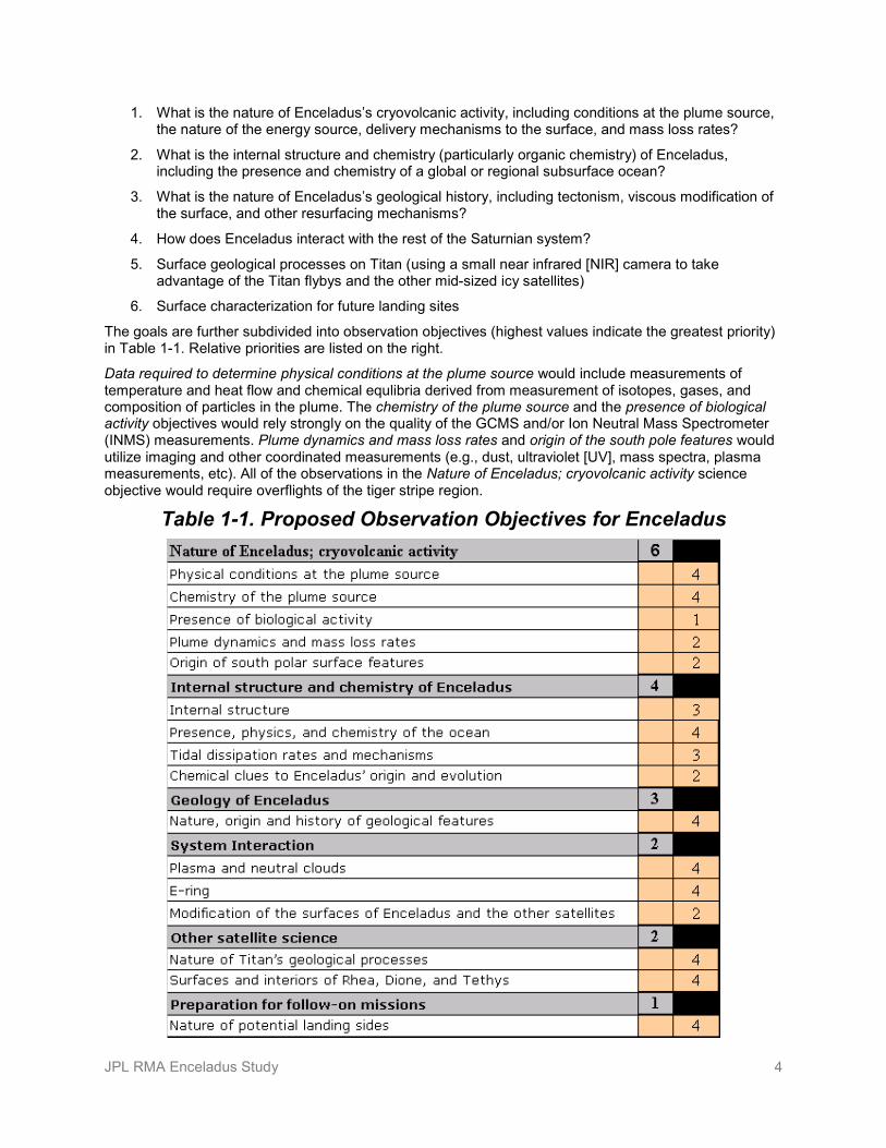
The goals are further subdivided into observation objectives (highest values indicate the greatest priority) in Table 1-1. Relative priorities are listed on the right.
Data required to determine physical conditions at the plume source would include measurements of temperature and heat flow and chemical equlibria derived from measurement of isotopes, gases, and composition of particles in the plume. The chemistry of the plume source and the presence of biological activity objectives would rely strongly on the quality of the GCMS and/or Ion Neutral Mass Spectrometer (INMS) measurements. Plume dynamics and mass loss rates and origin of the south pole features would utilize imaging and other coordinated measurements (e.g., dust, ultraviolet [UV], mass spectra, plasma measurements, etc). All of the observations in the Nature of Enceladus; cryovolcanic activity science objective would require overflights of the tiger stripe region.
Table 1-1. Proposed Observation Objectives for Enceladus
JPL RMA Enceladus Study 5
Most of the observations associated with the internal structure and chemistry of Enceladus and with the geology of Enceladus would require near-circular orbits and precision navigation to investigate the geophysics of Enceladus, particularly induced fields associated with conductive oceans and deformation and heating associated with tides. The exceptions are observations of chemical clues to Enceladus’s origin that would require sampling the plume. A sample return would be particularly beneficial for this class of observation so that microphysical evidence could be examined in detail to yield clues to the origin and evolution of Enceladus.
System interaction observations would be addressed in all mission phases. Measurements of the E-ring would provide additional proxy measurements of activity and products of the Enceladus plumes.
The most challenging measurements would include tidal strain, evidence for biotic and pre-biotic materials, and sample return. The expected amplitude of tidal strain on the shape of Enceladus is no more than factor of three greater than the achievable measurement precision, so the signal-to-noise ratio (SNR) of that measurement would be challenging to determine. Tidal changes in the gravitational field would be more easily detected. Plume density is very low, providing very small amounts of material during plume for analysis with the GCMS, though Cassini has shown that sensitivity is more than adequate for INMS analysis. There is considerable uncertainty on how best to acquire and preserve potential returned samples. The long return flight times might provide samples sufficient time to metamorphose; returning cryo-quenched samples would be technologically difficult, and acquiring samples of volatiles with aerogels would be challenging (a positive view of sampling volatiles with aerogels is found in [5]). Volatiles could also be captured by other techniques such as continuous deposition in a matrix material on a substrate. Additionally, planetary protection issues might make the technical aspects of sample return extremely difficult.
Science Traceability The science traceability matrix (see Table 1-2 on the following page) was provided by the science team for this study. The science traceability provides the major proposed objectives and resource requirements that drove the study.
In addition, the proposed science objectives, instrumentation, and mission/spacecraft requirements are summarized in the science linkages matrix in Appendix C.

JPL RMA Enceladus Study 6
Table 1-2. Science Traceability Matrix

JPL RMA Enceladus Study 7

JPL RMA Enceladus Study 8
2. High-Level Mission Concept Overview Four classes of potential Enceladus mission architectures were considered: 1) Enceladus flyby, which would consist only of flybys of Enceladus, including flying through the plumes; 2) Enceladus orbiters, which would also conduct Enceladus plume fly-throughs but then insert into Enceladus orbit; 3) Enceladus sample returns, which would conduct Enceladus plume fly-throughs to collect samples and then deliver those samples to Earth; and 4) Titan–Enceladus Connection, which is a class of missions that would piggyback on or extend a proposed Titan explorer flagship mission to encounter Enceladus.
Within those classes, 41 mission architectures were considered. Of those, 15 were evaluated for estimated science value, cost, and risk: one Enceladus flyby, nine Enceladus orbiters, four Enceladus sample returns, and one Titan–Enceladus connection. The Enceladus orbiter architectures differed in their instrument suites, mission duration, and secondary payloads (free flyers, impactors, and landers). The Enceladus sample return mission concepts varied in the sample collection speed, the preservation of temperature on return, the instrument suite, and the power source (nuclear versus solar). The single Titan–Enceladus connection architecture did not deploy a separate Enceladus spacecraft but, rather, augmented the Titan flagship mission spacecraft by adding propulsion capability and operations time to depart Titan orbit and enter Enceladus orbit.
The mission architectures selected for evaluation were chosen to span a range of cost and science return. They included architectures in the cost range of interest ($1.5B to $2B), as well as more capable and higher cost flagship-class architectures.
Concept Maturity Level This JPL RMA study is a CML 3 trade space study, as defined in Table 2-1.
Table 2-1. Concept Maturity Level Definitions Concept
Maturity Level Definition Attributes CML 6 Final Implementation
Concept Requirements trace and schedule to subsystem level, grassroots cost, V&V approach for key areas
CML 5 Initial Implementation Concept
Detailed science traceability, defined relationships and dependencies: partnering, heritage, technology, key risks and mitigations, system make/buy
CML 4 Preferred Design Point Point design to subsystem level mass, power, performance, cost, risk
CML 3 Trade Space Architectures and objectives trade space evaluated for cost, risk, performance
CML 2 Initial Feasibility Physics works, ballpark mass and cost CML 1 Cocktail Napkin Defined objectives and approaches, basic architecture
concept
This study used the JPL RMA team and process initially developed at JPL in 2007 as the approach for the architectural trade space assessment [6]. For a CML 3 JPL RMA study, the objective is to explore and evaluate a broad trade space of alternative mission and system architectures that respond to the science objectives, priorities, and constraints identified by the science panel members participating in the study. In conducting the study, the assessments complied with the Decadal Survey study ground rules [1] established by NASA Headquarters. The JPL RMA team used the JPL RMA process to evaluate science value, cost, risk, and performance impacts; address programmatic issues (e.g., launch timing and cost class); and synthesize results and recommendations. The mission architectures selected for these JPL

JPL RMA Enceladus Study 9
RMA CML-3 assessments were evaluated at an architectural level of fidelity sufficient to allow relative assessment of key metrics and characteristics between mission architectures and to enable identification of promising mission candidates for follow-on point-design studies.
Technology Maturity
Instruments The instrument types studied were generally high technology readiness level (TRL), high-heritage instruments assessed as analogues from the New Horizons and Cassini missions. Additional information regarding the instruments can be found in the Instrument Payload Description section. Table 2-2 summarizes the estimated TRLs of various example instruments considered. It is natural to assume that by the time a Saturn/Enceladus mission were to be undertaken in the next decade, technology and instruments would have evolved. This study makes no assumptions about such evolution.
Table 2-2. Estimated TRLs of Candidate Instruments
Example Primary Element Instruments TRL Instrument Analogy /
Heritage Mission Heritage
Medium Angle Camera (MAC) 8+ Ralph/MVIC New Horizons Mass Spectrometer (MS) 5 mod. INMS Cassini Dust Analyzer 5 (new) -- Thermal Imager (TI) 6 Diviner LRO Laser Altimeter (LR) 8+ MOLA MGS Radio Science with Celestial Mechanics (RSCM) 8+ RS exp. Cassini Narrow Angle Camera (NAC) 8+ LORRI New Horizons Gas Chromatograph (GC) 4 (new) -- Magnetometer (MAG) 8+ MAG Galileo Near Infrared Imager (NIR) 8+ VIMS/Ralph Cassini/NH UV Imager (UVI) 8+ UVSI Cassini Ground Penetrating Radar (GPR) 7+ MARSIS Mars Express Plasma Package 7+ PEPSSI New Horizons 2 micron Titan Camera (TTMI) 5 mod. Ralph New Horizons Synthetic Aperture Radar (SAR) (X-Band) 7 RADAR Cassini
Example Secondary Element Instruments Aerogel Collector 5 aerogel exp. Stardust Seismometer 6 VBB (IPGP) -- Magnetometer 8 MAG Galileo Camera (site imaging) 8 Hazcam MER Accelerometers 8 (engineering) -- Camera (plume monitoring) 8 Pancam MER Camera (microscopic imaging) 6 MI MSL Mass Spectrometer (MS) 5 mod. INMS Cassini Dual Gas Chromatograph (GCxGC) 4 (new) -- Chem Package 3 (new) -- LIght Detection and Ranging (LIDAR) 6 mod. LOLA LRO HighRes Spectroscopy (MWIR) 6 mod. CIRS Cassini Temperature Sensors 8+ (engineering) --

JPL RMA Enceladus Study 10
Flight and Ground Systems Out of the large number of spacecraft and ground system technologies that were considered and traded in the study, several specific key technologies and infrastructure elements were found to be enabling to accomplish the mission science and/or significantly enhancing to reduce mass, power, or mission duration, thereby reducing cost for the mission architectures studied.
Power Advanced Stirling radioisotope generators (ASRGs) were chosen as the primary radioisotope power source (RPS) for all architectures, except for architecture 5b (solar-powered Saturn orbiter with sample return). Nuclear power was determined to be enabling for the Enceladus orbiter architectures and the soft lander (with 6+ months’ surface operations) to meet the desired science objectives and resulting power loads within an acceptable cost and risk posture. However, some solar powered options could exist for some very low-duty cycle, power-constrained architectures at increased cost risk and performance risk over nuclear power with additional development and mission risks. Architecture 5b was studied as an example of such an architecture. Multi-mission radioisotope thermoelectric generators (MMRTGs) were also considered, but plutonium availability was perceived as a major concern. Therefore, the ASRG was chosen to minimize the quantity of plutonium required by the architectures, with the added benefit of reduced mass and cost relative to the MMRTGs.
ASRGs are currently at or nearly at TRL 6, and there is an ongoing specific NASA technology program supporting further development and lifetime testing of ASRGs for near-term mission infusion. ASRGs are at a high level of development maturity and would be ready for flight in the mission timeframe of these architectures. Lifetime of the Stirling engines, single-engine failure, or temporarily stopping operation to reduce jitter for imaging still require additional development and testing. The availability of plutonium (Pu) is a separate issue, but current programmatic plans identify targeted funding for acquisition of Pu specifically for this class of missions in the next decade.
Systems requiring high power solar arrays, e.g., for solar electric propulsion (SEP), could potentially significantly reduce mass using large “Ultraflex” solar arrays. Such arrays were demonstrated on the Phoenix mission at the 2m class. Larger scaled-up versions (5m class) are in qualification now for the Orion program. There are several additional customers for these arrays as well, and it is expected that they will be available (TRL 6+) in the mission timeframe of these mission concepts. However, they are currently below TRL 6 at these size scales. Ultraflex technology was assumed for Architecture 4a.
For architectures where the large solar array system is also assumed as the primary S/C power source at Saturn, some technology development would be required to build them to withstand the high velocity particulate environment of the Enceladus plumes. Therefore, for Architecture 5b, several concepts were explored to evaluate options for making standard rigid solar array construction robust to this level of particulate impacts, through increased facesheet thickness, to injection of energy absorbing material in the interstitial honeycomb, to addition of a carbon fiber barrier on the undersides of the arrays. Such options are at TRL 2–3, and the optimal solution would be the result of further detailed technology trades. Note also that radioisotope heater units (RHUs) are assumed by all
Propulsion
system designs; therefore, there are no savings assumed for nuclear safety launch approval as a possible benefit of avoiding the use of RPSs.
Solar electric propulsion (SEP) was considered for all architectures. While SEP could provide some compelling enhancements, it was found to not be enabling for most architectures. Most architectures converged using chemical bipropellant systems without SEP. SEP was required in Architecture 4a and opportunistically incorporated in Architecture 5b given the already large solar arrays needed for solar power in that architecture. Although not selected for most architectures, SEP could be significantly enhancing to reduce launch vehicle (LV) costs (e.g., converging on the equivalent of an Atlas V class LV rather than Delta IV-Heavy class). SEP is also an enhancement available to all architectures (even those already converging on an Atlas V class LV) that would result in increased delivered mass or reduced flight time at modest increase in cost. All missions would still rely on standard chemical bipropellant systems to

JPL RMA Enceladus Study 11
perform the higher-thrust Saturn orbit insertion (SOI) and to perform orbit maintenance and maneuvering while in the Saturn system. Therefore, the trade involves augmenting the existing chemical system with a secondary electric propulsion system and requisite high power production capability.
SEP as a system-level technology has been flight demonstrated in deep-space missions (e.g., NASA’s DS-1 and Dawn) and is at TRL 8–9. These were the basis for the trajectory analyses. Several newer thruster technologies are under qualification that would also support this class of missions, including the NASA Evolutionary Xenon Thruster (NEXT) ion thruster, a deep-space qualified version of the XIPS ion thruster from L-3 and the high power BPT series of Hall Effect thrusters from Aerojet. These would all provide enhanced performance evolutions and should continue to be studied and fully qualified as part of the NASA technology development program to support future missions of this class.
The challenge with using SEP for transit to Saturn comes from the size of the solar arrays (and hence inertial effects) in combination with the plume environment that would be encountered after arrival. Typical array sizes considered ranged from 15 kW to 30 kW at 1 AU. Due to power reduction with increased distance from the Sun, SEP would only be used during flight in the inner solar system, not at Saturn. This results in a design trade, whereby the arrays would be either jettisoned prior to arrival (as in the SEP stage for Architecture 4a), would be shielded from particulate impact (as in Arch. 5b), or would be designed to be re-stowed (which was not selected as it would be a new low-TRL technology and would require significant effort and increased mass for the array systems).
Deep Space Telecommunications Earth communications for these potential missions are designed around a Ka band capability that is expected at all Deep Space Network (DSN) stations in the timeframe of these studied mission concepts. It is anticipated that both Ka band downlink and Ka band uplink capabilities will be present at all three DSN sites, at a minimum of two 34m antennas per site. Total link throughput estimates were based upon the regular arraying of two of these antennas together to achieve the required performance. Arraying 34m DSN antennas is not specifically a new technology, but it is an important infrastructure capability currently still in development as part of the replacement plan for the larger 70m antennas. While this capability has been demonstrated, it is not currently an operational mode, nor is it yet present at all three DSN stations as would be required. Furthermore, this system relies on a spacecraft Ka band amplifier that operates at 50 W RF (TRL 4). Currently available, space-qualified Ka band power amplifiers are in the 10 W class only. Reflectors for the architectures studied assumed a 3m diameter high gain antenna. Though not selected, improved gain could be achieved through the use of a deployable antenna, for instance a 6m deployable, which is currently a commercial off-the-shelf (COTS) item (TRL 7, TRL 5 for Ka), and several have been demonstrated for use at Ka band, though none are currently “qualified” at Ka band. For missions that would also use X band for radio science (gravity measurements) or sounding radar instruments, it might be possible to use a dual feed with this deployable reflector for the benefit of both applications. This would also result in potentially lower mass and reduced requirements on the power of an SSPA or radar transmitter.
Landers and Secondary Elements Several key technologies were identified that would be required to enable the soft lander and hard landers studied. First, the touchdown event for both lander types would be driven by the unknown conditions of the Enceladus surface. The strength of this surface may range anywhere from that of extremely loose, cold, incohesive snow in the < 1kPa shear stress levels, up to relatively hard surfaces approaching that of solid water ice (several MPa). This uncertainty is due to the water-based geysers observed in the lower hemisphere of Enceladus and the resulting “snow” that covers the surface. This surface snow may remain totally incohesive or, under the influence of solar and other radiation sources, may sinter and form much more rigid structure. Landing systems must be designed to cover this range. In the lowest stress case, landing loads must be distributed over large areas to keep surface pressures very low. To achieve reasonable sizes for load distribution, landing velocities less than ~1.5 m/s for the soft lander and less than ~10 m/s for hard landers are desired.

JPL RMA Enceladus Study 12
One approach considered for sizing would use broad but thin “parachute-like” landing pads (TRL 2). The resulting size of parachutes used for spreading this surface pressure would be in the 3–4 meter range. The device itself would have a parachute-like material deployed with a tensioning system to keep the material taught, taking the surface loads up through the lander. In the case of the soft lander, the lander would come to rest on this surface. In the hard lander case, this surface would be on top and the lander itself would rest in the “snow” underneath. For the hard landers, there would be conductive elements in the parachute structure that would be used for RF communications to the orbiter for data relay. Each of the two landing systems would also require the ability to withstand or absorb larger loads commensurate with solid ice surface, such as spring-loaded or crushable material in the lander legs, as included on the Phoenix lander mission.
Consideration must also be applied to uncertain surface conditions, such as slopes and rocks that the landing system must tolerate. There is insufficient data on Enceladus surface properties at lander scales to adequately assess this, or to presently select landing sites that would be free of these hazards. Additional lander technologies would include methods of active hazard detection and avoidance (e.g., for the soft lander). There is significant work under way to develop and qualify radar, lidar, and passive optical methods for performing this function. These systems would also be used to provide ground truth for both horizontal and vertical velocity as well as altitude. This is a significant challenge for a combined sensor package that would serve all these functions, as well as the recognition algorithms required for detection and avoidance computations. Currently, this capability is estimated at TRL 3, although use of radar for altitude and velocity by itself is at TRL 6+. Optical methods might be preferred due to the uncertain reflectance and absorption of radio waves by loose or sintered snow. Future studies should examine these landing and hazard avoidance issues in more detail.
To service these proposed landers, low power relay radio systems would be required. The current mass and power levels for the Electra or Electra Lite 450 MHz systems would be prohibitive. The proposed orbiter altitude and range would be relatively low and, thus, it is expected that radios with less than 1-W transmit power would be sufficient. This is not a challenging technology development, but it is currently unavailable (TRL 3–4). Target mass and power would be less than 400 grams and less than 1 W.
Flight processing capabilities are also being enhanced through the extended use of Field Programmable Gate Arrays (FPGAs) that operate at significantly lower power than classical Floating Point Units (FPUs). Pushing more of the system’s operation into these lower power devices helps to offload the need for extremely fast, high power FPUs, which consume significant power. Several of the mission architectures evaluated included secondary elements such as free-flying magnetometers or hard landers, which would be even more power- and lifetime-constrained than the primary orbiter, likely operating off of primary batteries until they failed. These would be designed to operate completely from FPGA-based controllers. These FPGAs (TRL 5) must also be qualified for modest to high radiation levels (Total Ionizing Dose in the 10s to 100 krad level). Radiation tolerance is currently a technology driver for these FPGAs.
Planetary Protection and Sample Return See the Planetary Protection section for the driving considerations. Current qualified sterilization methods require the exposure of the flight hardware to greater than 125°C temperatures for 50 hours (or higher temperatures and shorter durations), referred to as Dry Heat Microbial Reduction (DHMR). Alternate methods are being explored using oxygen plasmas and peroxides (TRL 4–5), but none of these techniques is currently approved. Those items not exposed to this baking due to materials limitations must be hermetically sealed (or high efficiency particulate air [HEPA] filter contained) and their exterior cleaned with alcohol until measured microbe limits are below threshold. This puts significant design and material constraints on the proposed landers, as well as handling challenges, and also would require the subsequent use of a biobarrier around these landers to maintain this level of sterilization as they are integrated onto a “dirtier” spacecraft. The biobarrier required would be dependent upon the geometry of the lander it is intended to contain and would likely require a method of deployment. The material selection, installation and processing, and high reliability deployment of these biobarriers would be a technology and engineering effort to develop (TRL 3).
Sample return missions would require that samples be collected such that all exposed elements during the sample collection process are contained within a hermetic containment system and any parts not

JPL RMA Enceladus Study 13
maintained in this container could be subsequently sterilized (TRL 2). This subsequent sterilization could be the exposure of the entry vehicle backshell to sufficiently high temperatures during re-entry that it would meet the necessary criteria. The hermetically sealed container must be closed in a manner that guarantees positive containment (TRL 3), and it is expected that verification of this integrity must be demonstrated before Earth return would be approved. This might be through positive pressure within the container as measured through strain gauges external to the container. Furthermore, this container must be demonstrated to survive in the event of a landing on a rocky or artificial hard surface. Thus, it must be surrounded with puncture-resistant barriers as well as energy-absorbing material to reduce impact loads on the container. A desire for science benefit is to maintain the sample below 250 K at all times (to keep water below freezing), and it is expected that this could be achieved passively through the orientation of the Earth Return Vehicle (ERV) in the anti-sun direction during cruise, along with use of phase change material surrounding the sample to withstand re-entry heating until the sample is recovered. Also, qualification of aerogel would be required for the collection of larger particles at lower velocities than Stardust, along with preservation of ice in the collection event. The design and qualification of the sample collection and containment system is a significant technology development (TRL 3). Further, such a “restricted” sample return would require significant development for a sample-receiving facility that would protect as well as isolate samples, along with protocols for clearing samples of biohazard potential.
Enceladus sample return missions would also require the use of carbon phenolic heatshields to withstand the heat loads they would experience. These missions would be in the 16–18-km/s Earth entry velocity range, as compared to Stardust at 12.5 km/s and proposed Mars Sample Return at 11.4 km/s. Energy at return varies as velocity squared; therefore, heatshields necessary for this class of mission would experience the highest heat fluxes at Earth to date. Carbon phenolic heatshields are not a new technology and, in fact, were previously developed by the Department of Defense for Earth re-entry vehicles. However, the production of carbon phenolic has been discontinued for decades and this technology would need to be resurrected (TRL 4) as well as the detailed material properties and testing re-established. Work is already underway to redevelop carbon phenolic for proposed Venus entry missions.
Autonomy All Enceladus architectures must rely on some autonomy (TRL 4) due to the one-way light time (OWLT) limits. Enceladus orbiters in particular must have a significant amount of onboard autonomy to ensure the planetary protection requirements would be maintained at all times, even during low altitude passes and during excursions over the southern hemisphere where orbits are unstable. This level of autonomy does not currently exist in spacecraft of this type and would need to be developed and thoroughly tested for these missions. This would also enable reduced mission operations costs during the long cruise periods to and from Saturn.
Key Trades The main objectives of the tradespace exploration were to 1) brainstorm and capture preliminary architecture and trade space options, 2) identify key trade space elements, 3) perform focused brainstorming of architecture options and trades, and 4) filter out key trade space elements based on preliminary science, cost, and risk impacts in the key architecture trades matrix (Figure 2-1). In this study, the trade space includes a wide selection of architectures, from the lowest-cost Saturn orbiter with multiple Enceladus flybys to a fully instrumented high-performance orbiter. Care was taken, however, to include a large number of missions with lower costs.
Key Architecture Trades Matrix The key architecture trades matrix, which captures all of the elements with their sub-options, can be seen in Figure 2-1. The items in blue are the trade dimension (flight element, instrument, cruise duration, etc.), and the boxes to the right of the blue boxes are the sub-options in each trade dimension. Items grayed out were a product of the brainstorming sessions and were briefly assessed, but they were not analyzed in detail after the primary architectures were selected to proceed to integrated assessment. Sub-options

JPL RMA Enceladus Study 14
were filtered out based on qualitative reasoning and quick quantitative assessments from the study team, including items that were too costly, did not have enough science value, had too low of a TRL, were too complicated or risk-prone, etc.
Items not highlighted (standard beige boxes with blue text) were considered for use in the architectures, but they are not highly preferred. Lastly, items highlighted in green were the preferred options for use in the selected architectures, but they were not necessarily the only option considered or the final option chosen. As shown, this matrix documents traded elements throughout the lifecycle of the study, from brainstorming to integrated assessment of architectures. The key architecture trades matrix aided in developing and filtering the initial list of possible architectures.
Architecture Trade Tree Figure 2-2 illustrates the architecture trade tree. This tree summarizes the types of architectures first considered and the possible sub-options. The trade tree does not show every possible architectural combination, focusing instead on options of greatest interest.
All sub-options highlighted in green are architectures that were selected for integrated assessment. This set of 15 architectures encompasses the primary trades that the science and RMA teams wanted to pursue in more detail. The architectures and their specifications will be discussed later in the Flight System section. For the architectures that were not selected, the reasons included higher cost (e.g., exceeding a perceived cost target), lower science value for the cost (or similar science value for higher cost), and/or higher risk (for similar science value). The selected architectures represent the science team’s priorities and diversity in mission scope.
The primary flight element for all selected architectures was an orbiter. The primary types of architectures examined include variations on a Saturn orbiter, an Enceladus orbiter, and a Saturn orbiter with Enceladus plume sample return. Enceladus orbiter architectures encompass the bulk of the tradespace with variations on a simple orbiter, simple orbiter with secondary elements, and a high performance orbiter. The trajectories for these architectures do not vary significantly within each major architectural type. Rather, in an attempt to capture variances in the science value and cost, the payload suite and secondary elements are the primary differentiators. The sample return mission concepts focus on trading aspects of the sample collection/preservation.
The trades examined in this study were tuned to explore the driving parameters in this type of mission connected to cost (e.g., selection of simple payloads and operations); mass (such as payload and flight elements); and the trajectory (time of flight, mission duration, and geometry about the objects). These areas and possible ways to further improve them, such as launch vehicle or upper stage choice, instrument/component mass and lifetime, and propulsion system types or techniques, deserve further attention and analysis in future, more-detailed studies beyond this architectural-level study.

JPL RMA Enceladus Study 15
Figure 2-1. Enceladus Key Architecture Trades Matrix

JPL RMA Enceladus Study 16
Figure 2-2. Enceladus Architecture Trade Tree

JPL RMA Enceladus Study 17
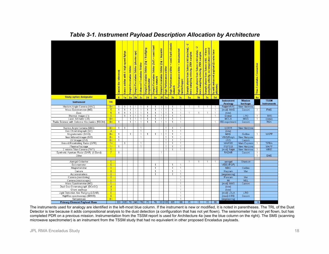
3. Technical Overview Instrument Payload Description The science team provided desired sets of instruments for each architecture (Table 3-1). The GCxGC+MS instrument, the ground penetrating radar, the laser altimeter, and the thermal imager represent large enhancements in capability for measuring Enceladus relative to the Cassini instrument set. Other instruments such as the imager and radio science would provide large science enhancements over Cassini by virtue of improved observing conditions in Enceladus orbit and in slow south polar flybys. A set of suggested instruments was developed for landed assets as well. Some of the instruments for landers still have very low TRLs.
The instrument set from the Titan Saturn System Mission (TSSM) Study [7] was used for Architecture 4a, with enhancements to add measurements critical to the Enceladus mission. There is excellent agreement in capabilities that would be required for many of the instruments common to the two missions.
For sample collection, the optimum collection speed for aerogels is about 2 km/s. This speed represents an optimum point between maximizing the velocity for penetration into the aerogel and minimizing the velocity effect on heating. Independent covers would be needed to separate the collection surfaces for multiple collection episodes. Plume gasses could be acquired with continuous deposition and adsorption onto plates with special coatings.
The GCxGC would use a thermal modulator between columns to freeze out the sample (from elution through the first column) to then drive it into the second column (with heat). The modulator operates on a timescale of seconds.
JPL RMA Enceladus Study 18
Table 3-1. Instrument Payload Description Allocation by Architecture
The instruments used for analogy are identified in the left-most blue column. If the instrument is new or modified, it is noted in parentheses. The TRL of the Dust Detector is low because it adds compositional analysis to the dust detection (a configuration that has not yet flown). The seismometer has not yet flown, but has completed PDR on a previous mission. Instrumentation from the TSSM report is used for Architecture 4a (see the blue column on the right). The SMS (scanning microwave spectrometer) is an instrument from the TSSM study that had no equivalent in other proposed Enceladus payloads.
JPL RMA Enceladus Study 19
Flight System Flight system architectures were developed during brainstorming sessions and organized using qualitative methods. Quantitative analysis was then applied to those concepts that appeared to best meet the study objectives. This analysis provides preliminary metrics for representative architectures that then provide insights into the contours of the trade space. Consistent with an architecture-level study, detailed design and optimization necessary to provide precise evaluations of subsystem-level properties were not conducted as part of this study.
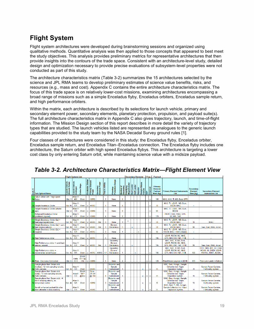
The architecture characteristics matrix (Table 3-2) summarizes the 15 architectures selected by the science and JPL RMA teams to develop preliminary estimates of science value benefits, risks, and resources (e.g., mass and cost). Appendix C contains the entire architecture characteristics matrix. The focus of this trade space is on relatively lower-cost missions, examining architectures encompassing a broad range of missions such as a simple Enceladus flyby, Enceladus orbiters, Enceladus sample return, and high performance orbiters.
Within the matrix, each architecture is described by its selections for launch vehicle, primary and secondary element power, secondary elements, planetary protection, propulsion, and payload suite(s). The full architecture characteristics matrix in Appendix C also gives trajectory, launch, and time-of-flight information. The Mission Design section of this report describes in more detail the variety of trajectory types that are studied. The launch vehicles listed are represented as analogues to the generic launch capabilities provided to the study team by the NASA Decadal Survey ground rules [1].
Four classes of architectures were considered in this study: the Enceladus flyby, Enceladus orbiter, Enceladus sample return, and Enceladus Titan–Enceladus connection. The Enceladus flyby includes one architecture, the Saturn orbiter with high speed Enceladus flybys. This architecture is targeting a lower cost class by only entering Saturn orbit, while maintaining science value with a midsize payload.
Table 3-2. Architecture Characteristics Matrix—Flight Element View

JPL RMA Enceladus Study 20
The Enceladus orbiters class captures 9 of the 15 architectures examined. There are three subclasses within it: simple orbiter, simple orbiter with secondary elements, and high performance orbiters. The simple orbiter subclass focuses on the impacts of the variations in the payload suite and the length of the science operations duration. The simple orbiter with secondary elements subclass is built from the simplest orbiter and varies the types and quantity of secondary elements such as impactors, landers, and free-flyers. The high performance orbiter subclass captures the higher performance end of the architectural trade space. The proposed orbiter itself has a large and highly capable payload suite while the options with secondary elements include an orbiter with multiple small hard landers and an orbiter with a soft lander with hazard avoidance.
The Titan–Enceladus connection class captures the design space for potentially augmenting a proposed mission. In this case, the architecture assumes a Titan orbiter flagship mission with increased propulsion capability and additional propellant such that the orbiter could leave Titan and enter Enceladus orbit.
The Enceladus sample return class explores the tradespace of Enceladus plume sample return missions from Saturn orbit. The four architectures in this class examine the impacts of sample collection velocity, sample temperature control, spacecraft power system, propulsion, and enhanced remote-sensing payload.
Flight Element Analogies Since this is a low CML study, design effort was applied only where absolutely necessary. Primary flight elements had a large amount of recent work to draw upon for first-order mass estimates. The soft lander and sample return capsule also have been the topic of recent study and flight, so they too had available data. The freeflying magnetometer, impactor, and simple landers required some basic design work before mass estimates could be developed. In each case, the analogy work was used to develop a basis for spacecraft dry mass, which was then incorporated with mission design results to size a spacecraft and determine its wet mass.
Masses for the primary flight elements were based upon recent work at JPL. Scaling laws were applied to structural and propulsion elements, while avionics, thermal, telecom, and power masses were taken from analogous spacecraft. Architectures 1a, 2x (less 2c), and 5x were based upon the Juno project in their avionics, structural, and propulsion subsystem masses. Adjustments were made to eliminate the radiation vault and re-mass a nuclear rather than solar power subsystem. The telecommunications subsystem was modeled with flagship-class mission analogies. Architectures 3x were based upon the TSSM concept in the most recent Outer Planet Flagship Mission study. The reason for that analogy is that flown flagship missions, such as Cassini, were developed too long ago to be useful. The only modifications made to the mass from these analogies were scaling the propulsion and structural masses to account for increased spacecraft size due to propellant increases.
The soft lander was based upon a Phoenix-type lander with an ASRG assumed for power and slightly less massive structure and propulsion system due to the low gravity of Enceladus. These reduced masses were converted into scaling factors to account for the fact that the soft lander would carry twice the landed payload as the Phoenix mission required.
The sample return capsule was based on the Stardust re-entry vehicle, with adjustments made for a different collection mechanism, planetary protection requirements, and the higher entry velocity at Earth.
The simple lander and the magnetometer had their masses estimated on the basis of their chief parts. For the simple lander, these parts were the batteries, sized to last for two weeks on surface, avionics, and a snowshoe to land on Enceladus. The freeflying magnetometer was estimated to be essentially a magnetometer with battery and very simple radio within a small container (10–20-cm diameter).
In doing the simple lander mass estimation, it became clear that the Enceladus surface was highly unknown in fine-scale terrain and in the strength of snow in the area around the plume ejection sites. The strength of the snow was assumed to be very low, and so a solid rocket motor fired by a timer was incorporated into the simple lander in order to reduce impact velocities and therefore sinkage. Any future study on landers for Enceladus should attempt to bracket the snow strength through observation, experiment, and modeling.

JPL RMA Enceladus Study 21
The solar power system of Architecture 5b merits additional description. Since the solar panels would be retained during sample collection, they would have to be resistant to hypervelocity impacts from micrometer-scale particles. A strengthened solar panel structure was posited to account for this, which reduced the specific energy at Earth by roughly 20%. This led to a very heavy solar array, which led to a need to incorporate electric propulsion into the architecture in order to be able to use the Option 5 launch vehicle.
Mass Results The estimated masses for the architectures are presented in Figure 3-1. The plot shows a top-level breakout of the masses of each architecture. The main flight element forms the bottom of each stack in the stacked column plot, first with the dry mass, then the required propellant mass and the payload mass on top. Carried elements are then added as a wet mass since only the soft lander has a significant propellant load. In the cases where electric propulsion is employed, these masses form the very top of the stack.
In Figure 3-1, Architecture 4a is presented differently than the others. The base concept from the TSSM report is shown as a single mass value in grey, and below this mass are the different categories of mass that must be added in order to complete the transfer from Titan to Enceladus. As would be expected, the great majority of this is propellant. At CML 3, it is very likely that further optimization opportunities are available to reduce this mass. But, as shown, this adds 1.5 metric tons of propellant to the original TSSM concept and is 1 metric ton more than Cassini carried. This is due to a post-SEP total delta-V requirement of 3.6 km/s in order to also perform an Enceladus mission.
All other architectures use launch vehicles with capabilities corresponding to the Atlas V family, including 5b, which is the most massive. SEP would enable 5b to keep its mass low enough for this to be possible. However, it should be noted that the use of solar power at Saturn makes this architecture very sensitive to power requirements; it is currently sized for 200-W spacecraft total power at Saturn.
Architecture 5c shows a large reduction in required mass relative to other sample return architectures by not leveraging as far into the Saturnian system as the others. The 4-km/s flyby would save a very significant amount of delta-V when compared to the 2-km/s flyby mission design.
Architecture 3c utilizes a lower delta-V mission design than 3a and 3b by using a longer time-of-flight trajectory to Saturn. This trajectory was chosen so that the total mass of the launch stack could by launched by an Atlas V launch vehicle.
0.0
1000.0
2000.0
3000.0
4000.0
5000.0
6000.0
7000.0
8000.0
9000.0
1a 2a 2b 2c 2d 2e 2f 3a 3b 3c 4a 5a 5b 5c 5d
Mas
s (k
g)
TSSM Base
SEP Stage Dry Mass
SEP Propellant
Carried Element Wet Mass
Main FE Payload Mass
Main FE Propellant
Main FE Dry Mass
*4a is baseline mission mass plus increment due to added Titan-Enceladus transfer requirements
Figure 3-1. Estimated Masses by Architecture with Margin

JPL RMA Enceladus Study 22
Architectures 2a, 2d, 2e, and 2f show a progression of increasing carried and payload masses causing the propellant, propellant tanks, and supporting structure to also increase in mass. Each of these architectures has a mission that would require 2.6 km/s in delta-V and thus has a noticeable sensitivity to increased dry mass.
All of the above Enceladus architectures benefit from mission designs that would use low-propellant techniques to maximize the mass delivered into or near Enceladus orbit.
Flight System Analysis Conclusions All architectures except for Architecture 4a are compatible with an Atlas V class launch vehicle and have propellant loads within historical experience. The technology approach to achieve these masses is feasible, based on prior experience, using a power source that is expected to be available by project start and electric propulsion currently in advanced development.
The set of architectures gives a good representation of the spectrum of ambition with which one can approach missions to Enceladus, ranging from a simple flyby spacecraft to sample return and orbiters with very capable instrument packages. The spectrum also shows the minimal size of a spacecraft required simply to reach Saturn orbit, which is Architecture 1a. From a mass perspective, this marks the minimum “buy-in” for a mission targeting Enceladus with any reasonable level of science return.
Concept of Operations and Mission Design
Mission Design For the 15 mission architectures examined, all would launch on Atlas V-class vehicles, except for the augmentation of the Titan flagship mission concept. The augmentation to that mission would bump it up from an Atlas V-class to a Delta IV-Heavy-class launch vehicle. They all would launch in the range of calendar years 2021 to 2023. This timeframe is not favorable for Jupiter gravity assists. All architectures would make use of flybys of the inner planets in order to get to Saturn (Figure 3-2). The time en route to Saturn varied from 8 to 9.5 years, except for the solar-electric propulsion sample return mission concept (5b), which would get there in 6.6 years. All of the missions would insert into Saturn orbit.
Once in the Saturn system, most of the architectures would take 3 to 3.5 years to complete a leveraging tour to lower the V∞ at Enceladus for either orbit insertion or low velocity sample collection, including a departing pump-up for the sample return concepts. The two exceptions are the Enceladus flyby and the high-velocity sample return architectures (1a and 5c), which would make use of Titan gravity assists to flyby Enceladus for about one year.
The leveraging tour (Figure 3-2) would use many gravity assists from Saturn’s moons Titan, Rhea, Dione, and Tethys to lower the apochron of the Saturn orbit and, thus, the V∞ at Enceladus. [3, 8, 9]. This recently developed approach would reduce the total ∆V to get into Enceladus orbit from 6.3 km/s for the most direct approach to 2.3 km/s using the leveraging tour, at a cost of three years of operations. This dramatic reduction in ∆V would enable these missions to Enceladus.
The Enceladus orbiters would then insert into orbit and conduct a one-year science mission, except for the lowest cost orbiter (2b), which would conduct a six-month science mission. The orbiters would be disposed of on the surface of Enceladus (see the Planetary Protection section).
Enceladus orbits were assumed to have an inclination of 50°, which was recently found to be fully stable orbit and which would provide visibility of the poles (Figure 3-2) [2, 10]. Polar orbits at Enceladus are unstable, but short excursions to polar orbits of a week or two would be possible with good knowledge of the gravity field obtained while in the 50° orbit. Most of the direct plume science would be conducted during the Enceladus flybys before entering orbit about Enceladus.

JPL RMA Enceladus Study 23
Figure 3-2. Clockwise from the Top Left: Typical Earth to Saturn Trajectory, Rhea Portion of Leveraging Tour (~1 yr), Dione Portion of Leveraging Tour (~6 mo), and Fully Stable Frozen Orbit
Architectures with Enceladus landers and impactors would deliver those elements from Enceladus orbit. Those vehicles would provide their own ∆V and guidance for de-orbit and impact velocity reduction. The delivery errors of the landers were not examined for this study, so if Enceladus landers are to be considered in a later, more detailed study, that error analysis would need to be performed to validate the concepts.
The proposed Enceladus sample return mission would depart Saturn at the end of the leveraging tour and would take 4.5 to 5.5 years to return to Earth. At Earth, the entry vehicle containing the samples was assumed to target the Utah Test and Training Range, where it would be recovered by helicopter during its parachute descent. The spacecraft would divert from Earth impact and be disposed of in solar orbit.
The delivery error of the Earth Entry Vehicle (EEV) was not examined in detail and would be highly dependent on the scheme used to ensure that the spacecraft which carries hitchhiking Enceladus plume material would not impact the Earth (see the Planetary Protection section). A future Enceladus sample return mission study would need to perform the associated navigation analyses in order to validate the approach.
The total mission durations varied from 10 to 16 years. Sixteen years is an upper limit set by the assumed ASRG lifetime. Total estimated chemical ∆V’s for the missions were 2.7 km/s for most of the orbiters and 2.8 to 3.4 km/s for the sample returns. The ∆V added to the Titan mission in order to get to and operate at Enceladus (4a) was 1.3 km/s. The total ∆V estimated for the Enceladus flyby mission (1a) was 2.0 km/s.

JPL RMA Enceladus Study 24
In addition, 4a and 5b used SEP for the transit to Saturn, using 23 kW @ 1 AU and 20 kW @ 1 AU systems, respectively.
Concept of Operations: Sequence and Data Volume The mission design for Enceladus has features common to all architectures: Saturn orbit insertion (SOI) and a series of Saturnian moon flybys to pump down toward an Enceladus orbit (Enceladus orbit or, optionally, sampling then pumping back up to escape toward Earth). Enceladus orbiting missions could include slow polar passes as optional excursions at the end of the orbital mission. The mission timelines are shown in Figure 3-3 and described in the full architecture characteristics matrix in Appendix C.
The pump-down phases would provide slow flybys with relative velocities in the range of 2–6 km/s. A 2-km/s velocity would provide optimum sampling for aerogel, fast enough to achieve good penetration of the aerogel by plume particles and slow enough to mitigate heating alteration of the captured particles.
A straw set of data acquisition activities suitable for fulfilling the proposed science goals was defined to allow assessment of on-board data storage and data return issues. The telecommunications downlink assessment (Table 3-3) assumed a 3-meter, high-gain antenna at Ka-band (single polarization), 50-W radiated power, and a DSN receiving array of two 34 meter dishes. The estimated downlink data rate is ~78 kbps (before accounting for overhead or compression) to 2 arrayed DSN 34m antennas. The assessment demonstrated that all architectures have sufficient telemetry margins to meet the proposed science objectives. Instruments that would produce the largest data volumes are present in all architectures, so the assessment is relevant across all architectures.
Figure 3-3. Mission Timelines

JPL RMA Enceladus Study 25
Table 3-3. Mission Data Assessment Mission Data Plan (Orbital) Compression: 2 Track Hours/Day: 8
Resolution (meters /
pix)
Number of
Bands Number of
Observations Fractional Coverage
Uncompressed Bits
Return Time
(days) Global Panchromatic Map 20 1 1 1.00 3.19E+10 8.10 Global Stereo Map 50 2 1 1.00 1.02E+10 2.59 Global Radar Map 100 600 1 0.01 7.67E+09 1.94 Global Color Map 100 4 1 1.00 5.11E+09 1.30 Global NIR Map 500 512 1 1.00 2.62E+10 6.63 Global Thermal Map 500 6 2 1.00 6.13E+08 0.16 Global Phase Function Map 1000 4 5 1.00 2.56E+08 0.06 Subtotal -- -- -- -- 8.20E+10 20.79
S. Pole Panchromatic Map 5 1 2 1.00 5.12E+10 12.98 S. Pole Stereo Map 10 2 1 1.00 1.28E+10 3.25 S. Pole Radar Map 10 600 1 0.01 3.84E+10 9.74 S. Pole Color Map 50 4 2 1.00 2.05E+09 0.52 S. Pole NIR Map 50 512 1 1.00 1.31E+11 33.23 S. Pole Thermal Map 20 6 10 1.00 9.60E+10 24.34 S. Pole Phase Function Map 100 4 4 1.00 1.02E+09 0.26 Hi-res S. Pole Panchromatic Samples 0.5 1 1 0.05 1.28E+11 32.45 Subtotal -- -- -- -- 4.61E+11 116.76 Years
Fields and Particles 1 -- -- -- 3.15E+11 79.95
Mission total
8.58E+11 217.50

JPL RMA Enceladus Study 26
Some enhanced opportunities beyond the science baseline exist:
• It would be possible to return a 1-m/pixel map of the entire moon in less than a year. Images at this resolution on Mars increased knowledge of the geology and current activity dramatically and would likely do the same for Enceladus.
• “Hovering” over the south pole region would allow time-lapse imaging of the plumes and more extensive sampling with the GCMS.
Planetary Protection The interest in a mission dedicated to Enceladus stems in large part from its potential as a habitat for life. There is a possibility of a propitious mix of liquid water, essential chemicals, and energy just below the surface. This leads naturally to planetary protection considerations, since that environment may not be just habitable, but in fact inhabited. As a result, there would be planetary protection requirements placed on missions that have the potential to impact Enceladus, as well as missions that would return samples of Enceladus to Earth.
From communications with the NASA Planetary Protection Officer (PPO) with regard to this study, missions that land on or that are expected to impact Enceladus (such as orbiters that are disposed of on the surface) would be Category IV. An Enceladus sample return mission would be Category V, Restricted Earth Return.
Category IV requires a 10-4 or lower probability of introducing a single viable Earth organism into a liquid water body. This could be accomplished by either sterilizing the orbiter so that there are no viable organisms at that level of probability or by meeting the probability requirement with an impacting, unsterilized orbiter. This study took the latter approach, which would avoid the expense of sterilization. The rationale is that there are only limited portions of the surface of Enceladus that would have access to the putative liquid water under the surface. All such areas are south of about 55° S latitude, where the surface has been recently modified. North of 55° S, the surface is believed to be at least tens of millions of years old, with large regions exceeding a billion years in age, so it is not connected to the liquid water environment. This makes the region below 55° S analogous to the “special regions” identified for planetary protection considerations at Mars. For this study, the Enceladus orbit is at 50° inclination. Therefore, even if an impact were accidental, resulting from a spacecraft failure, it would miss the special region if failure occurred after orbit insertion. For failures before orbit insertion, possible collisions with other larger moons and the small fractional area of the Enceladus south polar region would reduce the probability of impacting the special region. For an intentional disposal impact, it would be targeted to the oldest, more than 1 billion years old, portion of the surface. (There is an option discussed in this report to temporarily put the orbiter into a polar orbit. That would require a probabilistic assessment to assure that it would not overburden the 10-4 probability budget.)
It should be noted that the PPO doubted that this strategy would work based on her experience with other missions. In that case, an Enceladus orbiter would incur a $100M to $200M cost impact to implement a full-spacecraft sterilization. This cost could be lower if a previous mission to, for example, Mars or Europa was required to perform a full-spacecraft sterilization. (The last time such a sterilization was performed was for the Viking landers in the mid-‘70s.) An evaluation of the probability was out of scope for this level of study, so further work is needed in a subsequent, more-detailed Enceladus orbiter study.
The small, detached landers, which would be targeted for the special region, would be sterilized at the system level. The cost estimates for the architectures with those landers take that into account.
A Category V Restricted Earth Return would impose very strict requirements on the likelihood of Earth’s environment being exposed to Enceladus material before it could be analyzed in specialized laboratories on Earth to deem it safe for release. The mission must assure, to a high degree, that Earth’s biosphere could not be exposed to any Enceladus material before examination in the laboratory. As a result, the project would require that:
1. The Earth Entry Vehicle would not inadvertently release the samples into Earth’s environment, even in adverse landing conditions.

JPL RMA Enceladus Study 27
2. There is no hitchhiking Enceladus material whatsoever on the outside of the EEV (“breaking the chain of contact”), or that such material would be sterilized by the Earth entry.
3. The spacecraft that would deliver the EEV is assured to not impact the Earth with hitchhiking Enceladus material.
Furthermore, there would need to be a special receiving facility for the samples on Earth that could either implement a to-be-defined protocol for certifying the samples as safe for release, sterilize the samples, or perform all the sample analyses required to meet the science objectives of the mission within that facility. In any case, that facility would be required to make the same strict assurances of no inadvertent exposure of Earth’s environment to the Enceladus samples. Development of the facility would have to begin as much as a decade before the return of the samples due to the extensive regulatory and facility certification requirements.
These requirements on a sample return mission would add significantly to the cost, complexity, development risk, and mission risk. For this study, the approaches and cost estimates from Mars Sample Return (MSR) mission studies were used, since they had to deal with the same requirements, including those for the sample receiving facility on Earth. There are key differences from MSR that would require further study, which include breaking the chain of contact when the EEV departs the carrier spacecraft, since it is inevitable that the spacecraft would have plume material on it, placing that spacecraft temporarily on an Earth impact trajectory to deliver the EEV, and diverting to dispose of the carrier spacecraft in solar orbit or by impact on the Moon.
An interesting architecture that was not examined in detail is an E-ring sample return. The E-ring comes directly from the Enceladus plumes. It is believed that this would avoid the restricted Earth return requirements entirely since the E-ring material consists of very small particles that have been sterilized by radiation and solar UV, but would still net a significant fraction of the science that could be had from fresh plume samples. This was evaluated in the context of an E-ring sample as a backup to plume samples if the plumes were inactive upon arrival. An E-ring sample return as the baseline would be a lower cost and much lower development risk approach to meet some portion of the science objectives of the sample return options examined in this study.
Risk List During the course of the RMA study, risks were identified that might impact the successful completion of one or more architecture concepts. These risks were captured, reviewed, and evaluated for their likelihood of occurrence and impact. Risks were then aggregated at the architecture level for cross-comparison of relative risk levels across the architectures.
Both implementation risks and mission risks were addressed. An implementation risk is defined as a risk involving a negative event that occurs prior to flight operations. Consequences of these risks involve the use of resource margins (i.e., mass, power, cost, and schedule). A mission risk is defined as a risk involving a negative event that occurs during flight operations. Consequences of these risks involve reductions to mission science value (i.e., complete mission failure, loss of X% of science information, etc.). (See Appendix D, Table D-1, for definitions of individual risk categories.)
The following key risks were identified that impact the study architectures:
• Uncertainty regarding availability of plutonium-238. Since most of the architectures chosen use ASRGs as the primary power source, the potential unavailability of sufficient 238Pu in the future is considered a major programmatic risk.
• Spacecraft reliability due to long total mission durations and critical events late in the mission (e.g., SOI, Earth Orbit Insertion [EOI], sample return). Many system aspects would demand thorough reliability testing and modeling due to the long mission durations considered (up to 16 years).
• Implementation impacts of planetary protection requirements, including forward and back contamination risks. For forward contamination mitigation, Enceladus landers were assumed to be sterilized (e.g., system-level dry heat) in order to demonstrate low probability of interaction of secondary landed elements with liquid water on Enceladus. Orbiters, however, were assumed not to

JPL RMA Enceladus Study 28
be sterilized since they would use trajectories and control to reliably (within a 10-4 requirement) dispose of the orbiters. Back contamination could potentially occur due to a contaminated EEV or the inadvertent release of sample at Earth. It was assumed that the design includes an EEV that would be sealed off from the Earth return vehicle (ERV), reducing the risk of contamination of the EEV by plume particles. A new sample receiving facility (Cat. V restricted Earth return for samples) on the ground might need to be developed. There is currently no such facility for restricted Earth return samples, so a new facility might need to be built for this mission. If a Mars sample return mission development precedes an Enceladus sample return mission development, then much of that risk would be retired.
• Plumes are not active when the mission arrives at Enceladus. E-ring samples were deemed an acceptable mitigation. There is a potential risk of E-ring samples also needing planetary protection. However, UV and radiation exposure over time in the E-ring might be sufficient to sterilize any potential biological material.
• Small seismic network rough lander architectures might not meet landing precision or velocity requirements. Uncertainties in both the Enceladus terrain and in the lander concepts at this architecture-level assessment could result in increased cost to provide a more controlled landing system.
Considering the full set of architectures evaluated, there were a number of attributes that contributed to increased overall risk. For those architectures having a significant increase in the payload, additional integration and operational complexity would be introduced. Architectures carrying landers as secondary elements have increased complexity for development and operations, along with large uncertainties about the terrain in potentially scientifically interesting locations on Enceladus. The sample return architectures would entail additional planetary protection risks as well as critical events and deployments late in the mission lifetime.
Mitigation of major mission risks became an inherent part of the study’s mission concept development approach. Therefore, there were no risks that remained identified as a red mission risk. Implementation risks were also judged not to have any red risks (i.e., leading to complete consumption of project cost, schedule, or performance margins). A primary driver in this result is due to the NASA HQ Decadal Survey ground rules [1] assumed for this study (i.e., very high 50% cost reserves for Phases A–D). There was judged to be a low likelihood that overrun of the entire cost reserve (more than $500M for many of the architectures) would occur in order to reduce a single risk.
The following examples illustrate how potentially significant risks identified during the study were addresses in order to mitigate potential red risks.
• Risk of spacecraft damage due to impact of large plume or E-ring particles was partially mitigated by adding spacecraft shielding.
• Risk associated with ASRG lifetime uncertainty was partially mitigated by keeping prime mission durations to within 16 years. Limiting the prime mission duration reduced the risk of data or mission loss resulting from insufficient power. Some (reduced) risks and uncertainties remain due to long mission duration.
• Risk for sample return architectures of receiving no substantive mission science return after waiting ~15 years for the spacecraft to return to Earth. One sample return architecture was added (Architecture 5d) that would carry limited remote-sensing instrumentation to enable early science observations at Enceladus.
• Risks are associated with transitioning from stable to unstable polar orbit (to drop off landers/seismometers). The transition might be difficult if the Enceladus gravity field is not sufficiently characterized. Mitigation would be for orbiter to conduct orbital reconnaissance prior to lander deployment, perform limited retargeting for landers, and for landers to have on board propulsion.
• All architectures have assumed the number of ASRGs sized to meet the single point failure (SPF) policy on the primary spacecraft. If the loss of half of an ASRG (one of the two Stirling generators in an ASRG) would not degrade performance below the point where the mission could still continue,

JPL RMA Enceladus Study 29
then that configuration meets the SPF policy. Otherwise, an additional ASRG would be required. In addition, it was assumed that vibration issues could be mitigated with a temporary stall mode described in the ASRG functional description from NASA. Future studies and lifetime testing might identify alternative risk mitigation approaches.
Potentially, some of these risks could be promoted to higher levels of risk as more is learned. For example, the risk of multiple ASRG failures could be possible during such long missions. Currently, reliability estimates for ASRGs are uncertain. Until ASRGs are tested for use in long duration missions, further research into long-duration ASRG reliability is needed. It is recommended that future studies and lifetime testing should be considered to characterize reliability and potential failure modes.
Individual mission and implementation risks for each architecture (see Appendix D for individual risk ratings by architecture) were aggregated to architecture-level risk rankings, sorted lexicographically based on number of risks in each category as shown in Figure 3-4. These results indicate a range from small/moderate to significant (subject to further risk mitigation). There are no architecture-level risks identified as red since the architectures include major mitigations as part of the mission concepts developed. Further, there are no light green (minimal) architecture-level risk rankings since all architectures would involve at least small to moderate risks.
The architectures with the highest mission risk are the Enceladus orbiter architectures having secondary landed elements and the sample return architectures. The most significant mission risk for landers (soft lander, seismometer) would be due to the unknown Enceladus terrain. The mission risk is the loss of the landers or reduced mission science during operations. For sample return architectures, the primary risks arise from critical deployments late in mission life and planetary protection concerns.
Implementation risks are highest for the following:
• Sample return architectures (due to planetary protection requirements and new developments, e.g., for capture mechanism and sample return thermal/pressure control system);
• Orbiter architectures with secondary landed elements (due to potentially very high impact of planetary protection requirements and new developments, e.g., lander design for variable terrain/low temperature environments); and the
• Titan flagship mission concept modified to achieve Enceladus orbital science goals.
Reduction in Mission
Return/Consumption of Margin
Small to moderate
Minimal
Moderate
Significant
Mission failure/OverrunArch Red Yellow Green2e 0 4 123b 0 4 123c 0 4 125a 0 3 95d 0 3 95b 0 3 85c 0 3 74a 0 2 82c 0 2 73a 0 2 72d 0 1 102f 0 1 92a 0 1 82b 0 1 81a 0 1 5
Architecture RankingMission Risk
Arch Red Yellow Green5a 0 5 65d 0 5 65b 0 4 63c 0 4 44a 0 4 25c 0 3 83b 0 3 52e 0 3 42c 0 2 43a 0 2 42d 0 2 32f 0 2 32a 0 2 32b 0 2 31a 0 1 4
Implementation Risk Architecture Ranking
Figure 3-4. Architectures Ranked by Mission and Implementation Risks
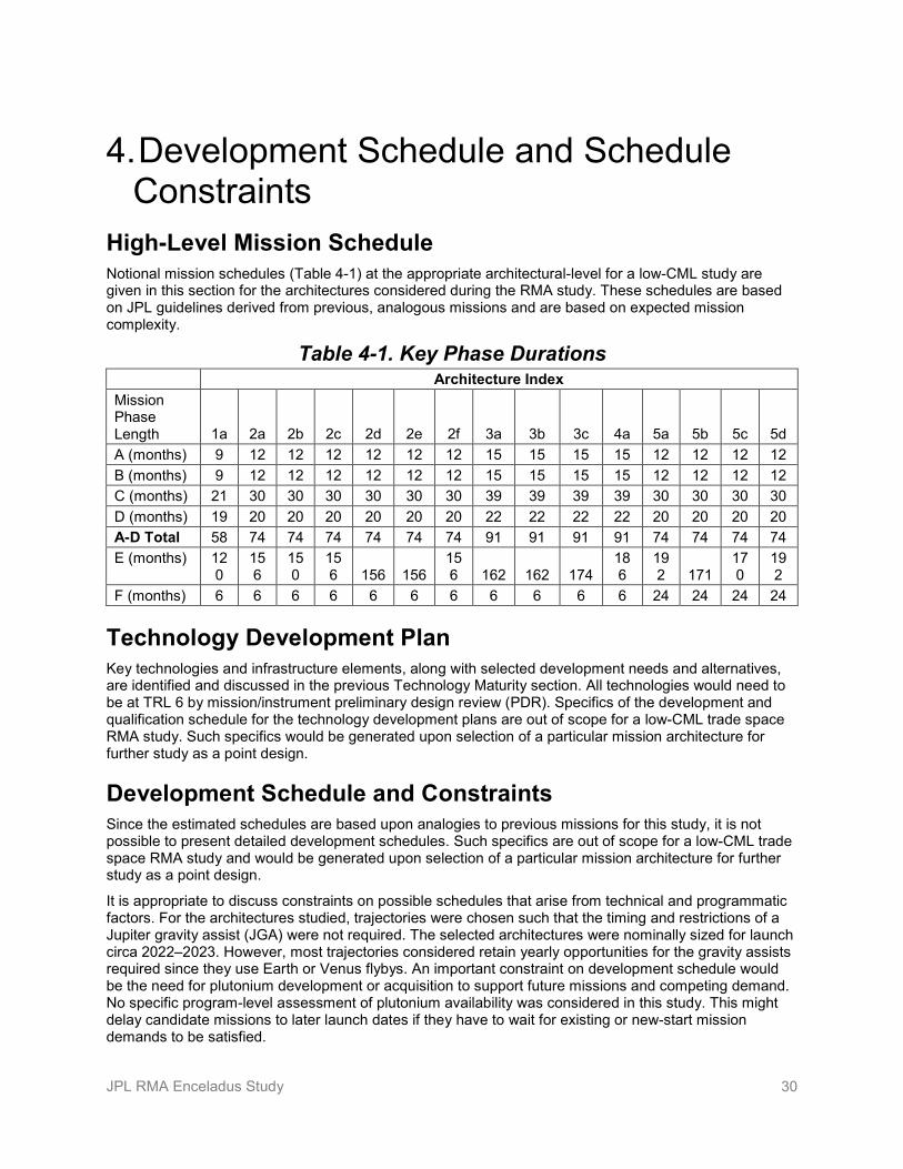
JPL RMA Enceladus Study 30
4. Development Schedule and Schedule Constraints
High-Level Mission Schedule Notional mission schedules (Table 4-1) at the appropriate architectural-level for a low-CML study are given in this section for the architectures considered during the RMA study. These schedules are based on JPL guidelines derived from previous, analogous missions and are based on expected mission complexity.
Table 4-1. Key Phase Durations Architecture Index
Mission Phase Length 1a 2a 2b 2c 2d 2e 2f 3a 3b 3c 4a 5a 5b 5c 5d A (months) 9 12 12 12 12 12 12 15 15 15 15 12 12 12 12 B (months) 9 12 12 12 12 12 12 15 15 15 15 12 12 12 12 C (months) 21 30 30 30 30 30 30 39 39 39 39 30 30 30 30 D (months) 19 20 20 20 20 20 20 22 22 22 22 20 20 20 20 A-D Total 58 74 74 74 74 74 74 91 91 91 91 74 74 74 74 E (months) 12
0 156
150
156 156 156
156 162 162 174
186
192 171
170
192
F (months) 6 6 6 6 6 6 6 6 6 6 6 24 24 24 24
Technology Development Plan Key technologies and infrastructure elements, along with selected development needs and alternatives, are identified and discussed in the previous Technology Maturity section. All technologies would need to be at TRL 6 by mission/instrument preliminary design review (PDR). Specifics of the development and qualification schedule for the technology development plans are out of scope for a low-CML trade space RMA study. Such specifics would be generated upon selection of a particular mission architecture for further study as a point design.
Development Schedule and Constraints Since the estimated schedules are based upon analogies to previous missions for this study, it is not possible to present detailed development schedules. Such specifics are out of scope for a low-CML trade space RMA study and would be generated upon selection of a particular mission architecture for further study as a point design.
It is appropriate to discuss constraints on possible schedules that arise from technical and programmatic factors. For the architectures studied, trajectories were chosen such that the timing and restrictions of a Jupiter gravity assist (JGA) were not required. The selected architectures were nominally sized for launch circa 2022–2023. However, most trajectories considered retain yearly opportunities for the gravity assists required since they use Earth or Venus flybys. An important constraint on development schedule would be the need for plutonium development or acquisition to support future missions and competing demand. No specific program-level assessment of plutonium availability was considered in this study. This might delay candidate missions to later launch dates if they have to wait for existing or new-start mission demands to be satisfied.

JPL RMA Enceladus Study 31
For sample return mission concepts, the development of sample return receiving facilities would need to begin approximately ten years before the samples land, due to the regulatory and facility certification requirements.

JPL RMA Enceladus Study 32
5. Mission Life-Cycle Cost Since the RMA study considered multiple mission concepts within a single architecture-level study, the costs presented here are highly preliminary and intended to give an impression of the range of potential missions to the Saturnian system, Enceladus orbit, Enceladus surface, and Enceladus sample return. Costs are rough order of magnitude based on architectural-level input and parametric modeling and should be used for relative comparison purposes only. These costs are not validated for budgetary planning purposes.
Costs presented in this section can be used to develop a relative ranking of potential missions by cost and to “bin” them into general cost classes. For example, it would be appropriate to think of costs at relative levels of ~$1.0B, ~$1.5B, ~$2.0B, etc., as appropriate for a low-CML study.
Costing Methodology and Basis of Estimate The costs reported in this section have been developed using a JPL internal parametric model. This model has been created and maintained with the purpose of generating preliminary estimates of cost at the early concept stage. It is best used as a rough estimator of costs, consistent with the level of fidelity of the mission concepts being evaluated.
The parametric model used has roughly 50 inputs for the full mission that are applied to all aspects, including management, systems engineering, payload, science, mission design, and the flight system. The flight system itself has roughly 3–5 inputs per subsystem, including mass. Therefore, the model gives some consideration to each major part of the mission, although it does so without looking deeply into any one of them.
All cited costs are consistent with the NASA-specified Decadal Survey ground rules [1]. The NASA ground rules specifies that all mission concepts would account costs in fiscal year 2015 (FY15) dollars and apply 50% reserves for Phases A–D and 25% reserves on Phases E–F. Additionally, where specific hardware or service costs relevant to the mission architectures studied were cited in the ground rules (e.g., for launch vehicles), those NASA-specified costs were used directly in the cost modeling.
For this study, the model was used with information developed during the RMA study for each of the architectures considered. Where required, selected additional information was compiled from previous study data or subject-matter experts’ preliminary estimates.
Cost Estimates The costs presented are intended to give a rough-order, architectural-level assessment of feasible mission costs rather than to provide detailed estimates for any given concept. The costs for the set of mission concepts are primarily used to understand the relative impacts of various architectural aspects.
Figure 5-1 provides cost estimates for each of the architectures considered in this study, with costs broken out by general project area. Each column contains a set of stacked blocks that represent each of the major project areas. The shaded bands in the background represent $0.5B “bins” into which each architecture falls. It is also important to note that these costs represent the project-specific costs only, and do not include technology maturation or multi-mission facility construction (for sample return mission concepts and needs driven by Planetary Protection requirements). These costs and their bookkeeping are explained in detail toward the end of this section.
The first thing to note on this plot is the presence of separate blocks for planetary protection and sample handling for the appropriate architectures. These blocks are separate because they are the least certain of all contributions to the estimate. They also contain their own reserves of 50% and do not contribute to the “reserves” category within this plot. Each of these have been estimated by JPL subject-matter experts.
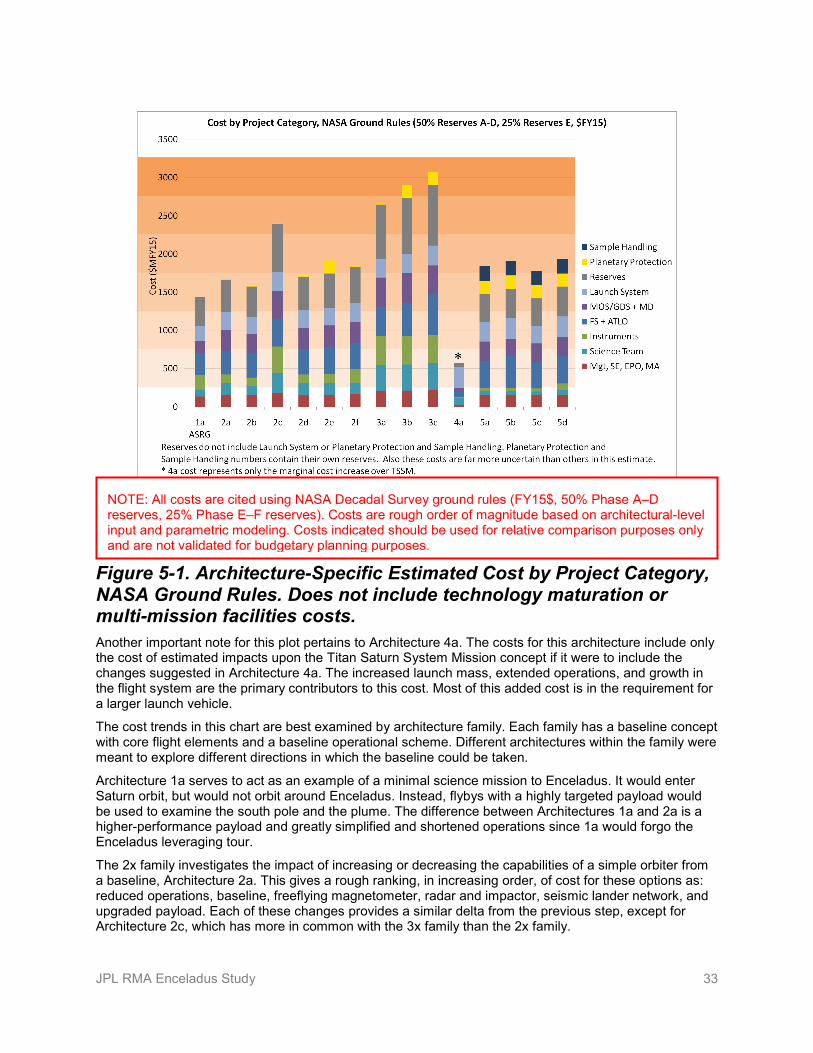
JPL RMA Enceladus Study 33
Figure 5-1. Architecture-Specific Estimated Cost by Project Category, NASA Ground Rules. Does not include technology maturation or multi-mission facilities costs. Another important note for this plot pertains to Architecture 4a. The costs for this architecture include only the cost of estimated impacts upon the Titan Saturn System Mission concept if it were to include the changes suggested in Architecture 4a. The increased launch mass, extended operations, and growth in the flight system are the primary contributors to this cost. Most of this added cost is in the requirement for a larger launch vehicle.
The cost trends in this chart are best examined by architecture family. Each family has a baseline concept with core flight elements and a baseline operational scheme. Different architectures within the family were meant to explore different directions in which the baseline could be taken.
Architecture 1a serves to act as an example of a minimal science mission to Enceladus. It would enter Saturn orbit, but would not orbit around Enceladus. Instead, flybys with a highly targeted payload would be used to examine the south pole and the plume. The difference between Architectures 1a and 2a is a higher-performance payload and greatly simplified and shortened operations since 1a would forgo the Enceladus leveraging tour.
The 2x family investigates the impact of increasing or decreasing the capabilities of a simple orbiter from a baseline, Architecture 2a. This gives a rough ranking, in increasing order, of cost for these options as: reduced operations, baseline, freeflying magnetometer, radar and impactor, seismic lander network, and upgraded payload. Each of these changes provides a similar delta from the previous step, except for Architecture 2c, which has more in common with the 3x family than the 2x family.
NOTE: All costs are cited using NASA Decadal Survey ground rules (FY15$, 50% Phase A–D reserves, 25% Phase E–F reserves). Costs are rough order of magnitude based on architectural-level input and parametric modeling. Costs indicated should be used for relative comparison purposes only and are not validated for budgetary planning purposes.

JPL RMA Enceladus Study 34
The 3x family investigates a very capable core spacecraft with and without different in-situ elements. It is important to note that planetary protection costs in this context are the costs of sterilizing the landed elements, since they would be sent to special regions on Enceladus. The main cost upper for Architecture 3b is the need for planetary protection, while 3c has roughly equal cost increases for planetary protection and lander cost relative to 3a.
The 5x family investigates variants on a potential sample return. Architecture 5a assumes a nuclear-powered sample return concept with 2-km/s sampling velocity and temperature control for the sample. Architecture 5b is the result of a series of cost uppers and reductions on the spacecraft, relative to 5a. The solar power system would be less expensive than one that is nuclear-powered, but it would also increase the cost of the structural system and require a larger launch vehicle. Electric propulsion was used in this architecture, which also increased the cost slightly, but was offset by the reduction in operations costs due to a shorter flight time. Architecture 5c keeps the same flight hardware as 5a but would not slow the spacecraft relative to Enceladus as much. This leads to some savings in operations and might serve as an attractive option to pushing costs further in later studies. Finally, 5d adds some capability to the carrier flight element in order to increase remote imaging science. This does not substantially grow the spacecraft but greatly increased instrument costs lead to a moderate cost increase over Architecture 5a.
Two of the secondary flight elements were costed based on subject matter expert estimates rather than the parametric model: the simple landers and free flying magnetometers. Each of these estimates were taken in $FY10 and inflated to $FY15. The simple landers were estimated by JPL experts to have rough-order costs of $15M non-recurring engineering, $5M recurring build, and a $5M for the ejection mechanism aboard the spacecraft. The freeflying magnetometers were estimated with a $5M engineering cost, $5M per unit cost, and a $5M deployer cost. All of these hardware costs are reflected in the chart in Figure 5-1.
Planetary protection and sample curation were also costed based on the estimates of internal subject-matter experts. The chief planetary protection cost considered was that of performing a dry-heat microbial reduction on the relevant flight hardware. For Architectures 2e, 3b, and 3c, this would be all lander hardware. For the sample return canister, this would simply be the inside of the collection system, with the rationale that the science of finding life would be similarly affected for a sample as it would for the Enceladus special region. Further, while the sample return canister would not be as expensive to sterilize as the landers, it would take additional effort to ensure that the flight system hardware “breaks the chain” of contact between the Enceladus plume and exposed re-entry surfaces.
Sample curation costs were estimated by internal subject-matter experts as the costs for a sample curation facility, ground operations, and added project management due to a sample return. These costs were included in the mission architecture costs in Figure 5-1. In addition, the cost of quarantine and general handling facilities would need to be considered, but these costs were judged to be part of a larger, multi-mission capability and are not included in the cost estimates presented here. The ground operations, project management, and sample curation cost applied to the architectures is $170M FY15, which includes a 50% reserve. Note that these sample curation reserves are included within the “Sample Handling” bar in the cost stack in Figure 5-1, rather than in the “Reserves” bar. The multi-mission quarantine and general handling facilities (e.g., a sample receiving facility) were not included in the mission architecture costs but were estimated by internal subject-matter experts to cost roughly $340M FY15.
The costs of technology maturation to Technology Readiness Level six are not included in the cost estimates shown in Figure 5-1. This impacts the landed architectures for development or redevelopment of planetary protection techniques for a special region of Enceladus. Since hazard avoidance was notionally considered for the soft lander, that would be another potential technology development. Sample returns from Enceladus would require development of techniques to properly curate the samples and to ensure compliance with a restricted Earth return in terms of planetary protection requirements. Further, process redevelopment to enable carbon phenolic heatshields for sample return architectures might need to be undertaken. One final area of development would be in long-life qualification for sample return missions from Enceladus.
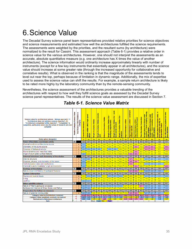
JPL RMA Enceladus Study 35
6. Science Value The Decadal Survey science panel team representatives provided relative priorities for science objectives and science measurements and estimated how well the architectures fulfilled the science requirements. The assessments were weighted by the priorities, and the resultant sums (by architecture) were normalized to the result for Cassini. This assessment approach (Table 6-1) provides a relative order in science value for the various architectures. However, one should not interpret the assessments as an accurate, absolute quantitative measure (e.g. one architecture has X times the value of another architecture). The science information would ordinarily increase approximately linearly with number of instruments (except for a few key instruments that essentially appear in all architectures), and the science value should increase at some greater rate (through the increased opportunity for collaborative and correlative results). What is observed in the ranking is that the magnitude of the assessments tends to level out near the top, perhaps because of limitation in dynamic range. Additionally, the mix of expertise used to assess the science value can shift the results. For example, a sample return architecture is likely to be rated more highly by the laboratory community than by the remote-sensing community.
Nevertheless, the science assessment of the architectures provides a valuable trending of the architectures with respect to how well they fulfill science goals as assessed by the Decadal Survey science panel representatives. The results of the science value assessment are discussed in Section 7.
Table 6-1. Science Value Matrix

JPL RMA Enceladus Study 36
7. Integrated Assessment and Conclusions This section summarizes the assessments by the combined science and RMA team of the 15 specific mission architectures selected for integrated mission analysis. The analysis results highlight candidate missions of interest through the evaluation of the selected mission architectures for cost, science value, and risk. In addition, key findings are discussed about the major architectural types, technologies, risks, and potential areas for further study.
Integrated Assessment Results Figure 7-1 and Table 7-1 provide an integrated view of the key science value, cost, and risk figures of merit to enable assessment of relative benefits and impacts of the architectures. The costs should be used for relative comparison purposes only and are not validated for budgetary planning purposes. The risks identified in the study were aggregated to provide both overall mission risk and implementation risk rankings represented as two color-coded symbols, as labeled in the figure and table. Note that no architectures had green risk symbols to indicate minimal aggregate risks. The lowest risk architectures’ data symbols in the plot are yellow-green, indicating small to moderate aggregate risks.

JPL RMA Enceladus Study 37
Small to moderate
Minimal
Moderate
Significant
Mission failure/Overrun
Risk LegendMission Risk (Left‐hand color of data symbols): reduction in science return
Implementation Risk (Right‐hand color of symbols):consumption of project margins (cost, schedule, perf.)
1a Enc. Flyby
2a Simple Enc. Orbiter
2b Simple Enc. Orbiter Short Ops
2c Enhanced Enc. Orbiter
2d Simple Enc. Orbiter Freeflying Mag
2e Simple Enc. Orbiter Small Landers
2f Simple Enc. Orbiter Impactor
3a High‐Perf Enc. Orbiter
3b High‐Perf Enc. Orbiter Small Landers
3c High‐Perf Enc. Orbiter Smart Lander
4a Titan‐Enceladus Connection
5a Enc. Sample Return
5b Enc. Sample Return Solar/SEP
5c Enc. Sample Return 4 km/s
5d Enc. Sample Return Extra Payload
0 500 1000 1500 2000 2500 3000 3500 40000
0.5
1
1.5
2
2.5
3
Cost ($MFY15)
Relative
Science Value
1a
2a2b
2c
2d
2e2f
3a
3b3c
4a
5a5b
5c
5d
* 4a cost represents only the marginal cost increase over the TSSM concept.
*
Cost in $FY15, with NASA Ground Rules (50% Phase A‐D, 25% E‐F Reserves)
Figure 7-1. Integrated Assessment of Science Value vs. Cost with Risk Indicators
NOTE: All costs are cited using NASA Decadal Survey ground rules (FY15$, 50% Phase A–D reserves, 25% Phase E–F reserves). Costs are rough order of magnitude based on architectural-level input and parametric modeling. Costs indicated should be used for relative comparison purposes only and are not validated for budgetary planning purposes.
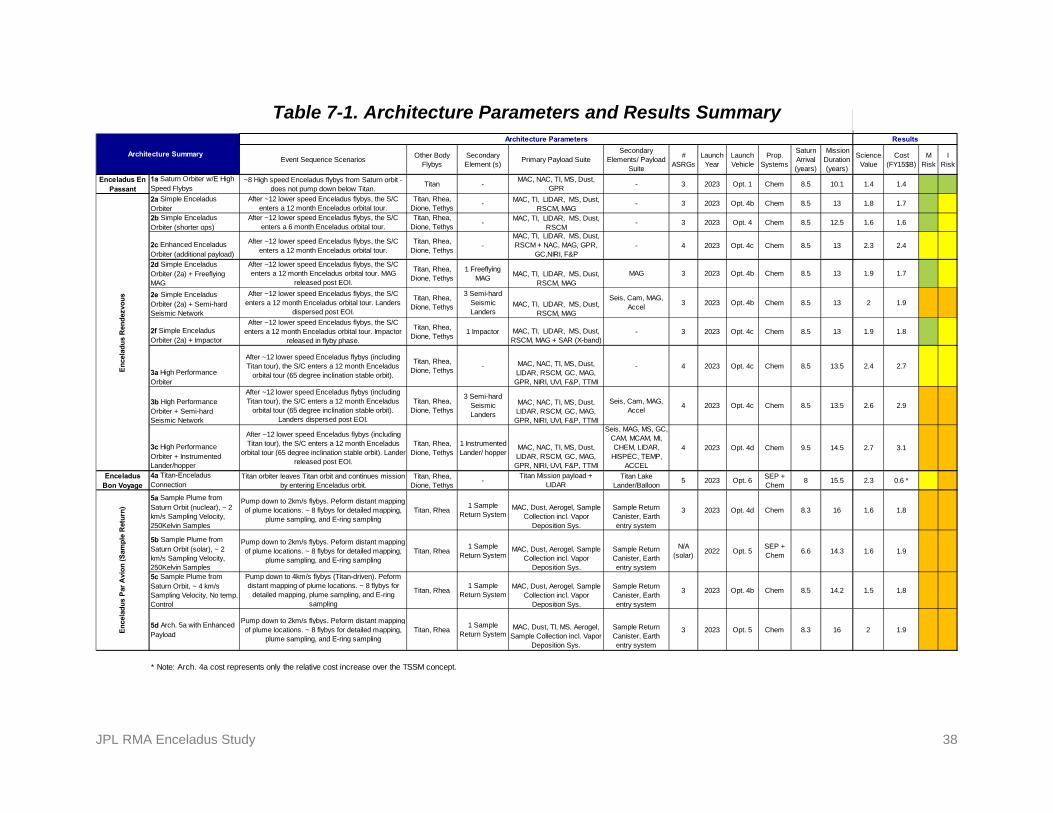
JPL RMA Enceladus Study 38
Table 7-1. Architecture Parameters and Results Summary
Event Sequence ScenariosOther Body
FlybysSecondary Element (s)
Primary Payload SuiteSecondary
Elements/ Payload Suite
# ASRGs
Launch Year
Launch Vehicle
Prop. Systems
Saturn Arrival (years)
Mission Duration (years)
Science Value
Cost (FY15$B)
M Risk
I Risk
1a Saturn Orbiter w/E High Speed Flybys
~8 High speed Enceladus flybys from Saturn orbit - does not pump down below Titan.
Titan -MAC, NAC, TI, MS, Dust,
GPR- 3 2023 Opt. 1 Chem 8.5 10.1 1.4 1.4
2a Simple Enceladus Orbiter
After ~12 lower speed Enceladus flybys, the S/C enters a 12 month Enceladus orbital tour.
Titan, Rhea, Dione, Tethys
- MAC, TI, LIDAR, MS, Dust, RSCM, MAG
- 3 2023 Opt. 4b Chem 8.5 13 1.8 1.7
2b Simple Enceladus Orbiter (shorter ops)
After ~12 lower speed Enceladus flybys, the S/C enters a 6 month Enceladus orbital tour.
Titan, Rhea, Dione, Tethys
-MAC, TI, LIDAR, MS, Dust,
RSCM- 3 2023 Opt. 4 Chem 8.5 12.5 1.6 1.6
2c Enhanced Enceladus Orbiter (additional payload)
After ~12 lower speed Enceladus flybys, the S/C enters a 12 month Enceladus orbital tour.
Titan, Rhea, Dione, Tethys
-MAC, TI, LIDAR, MS, Dust, RSCM + NAC, MAG, GPR,
GC,NIRI, F&P- 4 2023 Opt. 4c Chem 8.5 13 2.3 2.4
2d Simple Enceladus Orbiter (2a) + Freeflying MAG
After ~12 lower speed Enceladus flybys, the S/C enters a 12 month Enceladus orbital tour. MAG
released post EOI.
Titan, Rhea, Dione, Tethys
1 Freeflying MAG
MAC, TI, LIDAR, MS, Dust, RSCM, MAG
MAG 3 2023 Opt. 4b Chem 8.5 13 1.9 1.7
2e Simple Enceladus Orbiter (2a) + Semi-hard Seismic Network
After ~12 lower speed Enceladus flybys, the S/C enters a 12 month Enceladus orbital tour. Landers
dispersed post EOI.
Titan, Rhea, Dione, Tethys
3 Semi-hard Seismic Landers
MAC, TI, LIDAR, MS, Dust, RSCM, MAG
Seis, Cam, MAG, Accel
3 2023 Opt. 4b Chem 8.5 13 2 1.9
2f Simple Enceladus Orbiter (2a) + Impactor
After ~12 lower speed Enceladus flybys, the S/C enters a 12 month Enceladus orbital tour. Impactor
released in flyby phase.
Titan, Rhea, Dione, Tethys
1 Impactor MAC, TI, LIDAR, MS, Dust, RSCM, MAG + SAR (X-band)
- 3 2023 Opt. 4c Chem 8.5 13 1.9 1.8
3a High Performance Orbiter
After ~12 lower speed Enceladus flybys (including Titan tour), the S/C enters a 12 month Enceladus
orbital tour (65 degree inclination stable orbit).
Titan, Rhea, Dione, Tethys
- MAC, NAC, TI, MS, Dust, LIDAR, RSCM, GC, MAG, GPR, NIRI, UVI, F&P, TTMI
- 4 2023 Opt. 4c Chem 8.5 13.5 2.4 2.7
3b High Performance Orbiter + Semi-hard Seismic Network
After ~12 lower speed Enceladus flybys (including Titan tour), the S/C enters a 12 month Enceladus
orbital tour (65 degree inclination stable orbit). Landers dispersed post EOI.
Titan, Rhea, Dione, Tethys
3 Semi-hard Seismic Landers
MAC, NAC, TI, MS, Dust, LIDAR, RSCM, GC, MAG, GPR, NIRI, UVI, F&P, TTMI
Seis, Cam, MAG, Accel
4 2023 Opt. 4c Chem 8.5 13.5 2.6 2.9
3c High Performance Orbiter + Instrumented Lander/hopper
After ~12 lower speed Enceladus flybys (including Titan tour), the S/C enters a 12 month Enceladus
orbital tour (65 degree inclination stable orbit). Lander released post EOI.
Titan, Rhea, Dione, Tethys
1 Instrumented Lander/ hopper
MAC, NAC, TI, MS, Dust, LIDAR, RSCM, GC, MAG, GPR, NIRI, UVI, F&P, TTMI
Seis, MAG, MS, GC, CAM, MCAM, MI, CHEM, LIDAR,
HISPEC, TEMP, ACCEL
4 2023 Opt. 4d Chem 9.5 14.5 2.7 3.1
4a Titan-Enceladus Connection
Titan orbiter leaves Titan orbit and continues mission by entering Enceladus orbit.
Titan, Rhea, Dione, Tethys
-Titan Mission payload +
LIDARTitan Lake
Lander/Balloon5 2023 Opt. 6
SEP + Chem
8 15.5 2.3 0.6 *
5a Sample Plume from Saturn Orbit (nuclear), ~ 2 km/s Sampling Velocity, 250Kelvin Samples
Pump down to 2km/s flybys. Peform distant mapping of plume locations. ~ 8 flybys for detailed mapping,
plume sampling, and E-ring samplingTitan, Rhea
1 Sample Return System
MAC, Dust, Aerogel, Sample Collection incl. Vapor
Deposition Sys.
Sample Return Canister, Earth entry system
3 2023 Opt. 4d Chem 8.3 16 1.6 1.8
5b Sample Plume from Saturn Orbit (solar), ~ 2 km/s Sampling Velocity, 250Kelvin Samples
Pump down to 2km/s flybys. Peform distant mapping of plume locations. ~ 8 flybys for detailed mapping,
plume sampling, and E-ring samplingTitan, Rhea
1 Sample Return System
MAC, Dust, Aerogel, Sample Collection incl. Vapor
Deposition Sys.
Sample Return Canister, Earth entry system
N/A (solar)
2022 Opt. 5SEP + Chem
6.6 14.3 1.6 1.9
5c Sample Plume from Saturn Orbit, ~ 4 km/s Sampling Velocity, No temp. Control
Pump down to 4km/s flybys (Titan-driven). Peform distant mapping of plume locations. ~ 8 flybys for
detailed mapping, plume sampling, and E-ring sampling
Titan, Rhea 1 Sample
Return SystemMAC, Dust, Aerogel, Sample
Collection incl. Vapor Deposition Sys.
Sample Return Canister, Earth entry system
3 2023 Opt. 4b Chem 8.5 14.2 1.5 1.8
5d Arch. 5a with Enhanced Payload
Pump down to 2km/s flybys. Peform distant mapping of plume locations. ~ 8 flybys for detailed mapping,
plume sampling, and E-ring samplingTitan, Rhea
1 Sample Return System
MAC, Dust, TI, MS, Aerogel, Sample Collection incl. Vapor
Deposition Sys.
Sample Return Canister, Earth entry system
3 2023 Opt. 5 Chem 8.3 16 2 1.9
* Note: Arch. 4a cost represents only the relative cost increase over the TSSM concept.
Results
Enceladus En Passant
En
cela
du
s P
ar A
vio
n (
Sam
ple
Ret
urn
)
Architecture Summary�
Architecture Parameters
En
cela
du
s R
end
ezvo
us
Enceladus Bon Voyage

JPL RMA Enceladus Study 39
As seen in these results, a variety of interesting lower relative cost missions were identified within the $1.5B to $2B cost range in a roughly continuous spectrum. This cost range is spanned by orbiters of increasing payload capability, including secondary element payloads. Architectures 2x, 3x, and 5d follow a roughly linear trend of increasing relative science value with commensurately increasing cost. This results in a scientifically compelling set of missions across the cost bins but no immediately obvious stand-outs from the general trend for those architectures.
However, the consideration of benefit versus cost and development risk makes an Enceladus orbiter more attractive for the first mission to focus on Enceladus. Although a dedicated Enceladus sample return would have very high science value, the first Enceladus orbiter would have even higher science value at a comparable cost with lower risk.
Sample return missions would incur higher costs and higher implementation and mission risks than the simple Enceladus orbiter (2a) due largely to the uncertainties in planetary protection impacts and, to a lesser extent, increased mission durations. However, the hybrid sample return concept with flyby instrumentation (5d) is an interesting architecture at around $2B and is also in family with the general science value versus cost trend. This highest benefit-to-cost sample return mission concept adds remote-sensing instruments to the sample return, thereby addressing many of the orbital science objectives during flybys. The sample return architectures without such added instrumentation (5a, 5b, and 5c) showed a somewhat lower relative science value-to-cost ratio than the Enceladus orbiters, due to the high value of first-time orbital science at Enceladus.
A noteworthy architectural option would be to augment a proposed flagship mission to Titan to enable that mission to leave Titan orbit and enter Enceladus orbit. Architecture 4a identified a low incremental cost of ~$0.6B, including a transition from Atlas V class to Delta IV-Heavy class launch vehicle, for such an enhancement. This result suggests that there might be a relatively low cost “mission of opportunity” by augmenting a potential future flagship mission such as the Titan Saturn System Mission (TSSM). Such modifications to a mission would have to take place very early in the project formulation stage to incorporate the architectural changes to transition from Titan to Enceladus orbit and minimize overall project impacts. This architecture would cost effectively achieve the proposed Enceladus science objectives; however, since this would preclude extended operations at Titan, the potential reduction in Titan science would have to be weighed against this benefit.
Effectively, much of the total mission cost for all of these architectures would be consumed just to get the spacecraft and an acceptable payload to the Saturnian system. Recent developments in trajectory tour design and leveraging maneuvers would enable very efficient pumpdown trajectories that greatly reduce the propellant load and would enable the Enceladus orbiter and plume sample return mission concepts. Thus, the added costs would be relatively small (compared to the total mission cost) to augment a Saturn orbiter mission with Enceladus orbit insertion, modest payload enhancements, or small secondary flight system elements. This suggests that the added observational capabilities of going into Enceladus orbit would likely be worth the relatively small cost impact for the associated increase in science value.
It is also important to note why all of the mission architectures resulted in relatively long mission durations (~10–16 years). Across the set of concepts, longer mission durations were used to reduce total mass and cost by accommodating trajectories with extended flight times to Saturn and the ~3 year trajectory leveraging tour. These longer flight times enabled significant reductions in the propellant required for SOI, tour delta-V, and EOI. The resulting reduction in overall flight system mass also resulted in the selection of smaller (and cheaper) launch vehicles. In some cases, these longer flight times were enabled by the assumed total ASRG lifetime of 17 years (1 year pre-launch for fueling and 16 years post-launch, per agreement with the NASA HQ Decadal Survey POC). The long-life reliability of ASRGs and validity of such assumptions should be a topic of further review in future detailed studies.
Enceladus Orbiter Concepts with Payload Enhancements and Secondary Elements In addition to the simple payload Enceladus orbiter concepts (2a and 2b), various augmentations were examined to investigate the benefits and impacts of additional instrumentation, secondary element

JPL RMA Enceladus Study 40
payloads, and high-performance orbiter architectures. Instrument payload enhancements (e.g., 2c and 3a) to the Enceladus orbiter would add science value relative to the simple Enceladus orbiter alone (2a and 2b) but with associated cost increases that keep them from departing the general trend of relative science value versus cost.
Augmenting the Enceladus orbiter missions with in-situ secondary elements and lander payloads would provide unique science opportunities but with associated impacts. Architectures 2d (adding the free-flying magnetometer) and 2f (adding the impactor and SAR) would provide notable added science along with modest cost impacts and very little added risk. Additionally, the potential benefits of adding lander payloads (2e, 3b, and 3c) include compelling in-situ science but would come at the expense of additional cost risk and mission risk. However, the additional mission risks for deployed secondary elements are mostly decoupled from the science of the primary orbiter element. Thus, a loss of a secondary element (e.g., a lander) would still result in most of the mission science objectives being achieved by the primary orbiter.
Independent of cost, the highest science value architectures are 3b and 3c. This result is due to the high-performance payload augmented by the seismic network of hard landers in 3b or the soft lander in 3c. In-situ landers on Enceladus would provide high value science observational platforms. However, lander design would be very challenging with the limited knowledge from Cassini’s observations of Enceladus’s surface. Many uncertainties about surface properties will remain even after Cassini’s extended mission, suggesting that priority be placed on landing site characterization during the first dedicated Enceladus mission, in anticipation of a possible later mission with Enceladus landers.
Opportunities exist for landing site characterization, and several of the selected architectures were defined with such observations in mind. Architecture 2f would include an impactor and synthetic aperture radar (SAR) to characterize surface and shallow subsurface properties. Other architectures (1a, 2c, and 3a/b/c) would include ground penetrating radar without an impactor, and most would provide meter-resolution surface imaging. In addition to providing the targeted science (seismometry and magnetometry), Architectures 2e and 3b (with small hard landers) could use the rough landing event to measure selected surface characteristics in the tiger stripe regions. However, the risk of being unable to communicate with the lander from a stable orbit would be higher. This might drive the architecture to fly unstable (but controllable) polar orbits to achieve favorable telecom conditions.
Sample Return Architectures Enceladus provides a unique environment with active plumes ejecting samples that could be acquired directly from Enceladus flybys. This would enable unique sample return science (at much lower costs than would be required for a surface sample return) without requiring the demands and increased costs of orbiting Enceladus, landing, sampling, and ascending.
While sample return would provide compelling and unique science, it would miss opportunities otherwise achieved by the Enceladus orbiters. The set of science objectives defined by the science team for this study span a global study of Enceladus. Further, an Enceladus orbital mission has not yet flown, so an orbiter with global access rates very highly in science value. At other destinations such as Mars, where several orbital missions have flown, such orbital science would provide lower additional value and sample return would have a higher relative science value. While sample return architectures would provide very good data on plume chemistry and the possible presence of pre-biological or biological activity, Enceladus orbiter architectures and their more capable instrumentation would perform well in achieving a broader set of the science team’s objectives for Enceladus while still providing valuable chemistry information from in-situ plume or surface analysis. In addition, some chemistry goals, such as study of chemical disequilibrium, or very volatile species, might be better addressed by in-situ measurements than by a sample return.
However, a noticeable increase in science value for the sample return architectures occurs for Architecture 5d. Architecture 5d would augment the remote-sensing payload used by the other sample return options, thereby better addressing the combination of remote sensing objectives and sample return as a relatively cost-effective augmentation to 5a. Also, the majority of the science value for the sample return architectures is predicated on return of the samples (very little due to observations while in the

JPL RMA Enceladus Study 41
Saturnian system). Architecture 5d reduces this risk to the science return since its enhanced payload would enable broader science in the Saturnian system and would do so much earlier in the mission than returning the sample to Earth.
Surprisingly, changing from architectures with samples maintained within 250 Kelvin and slower 2-km/s plume flyby velocities to architectures without temperature control and faster 4-km/s flybys results in only a very small decrease in relative cost (at the architectural level of assessment of this study). This suggests that temperature control would likely be a favorable option for an Enceladus plume sample return architecture.
Nonetheless, the sample return architectures would include higher implementation, mission, and cost risks than the orbiter-only architectures. Increased risks to potential cost growth include planetary protection and sample handling requirements. These cost risks could shift the sample return architectures to the right in the science value versus cost plot.
Key Risk Findings Several cross-cutting and key risks were identified across many of the architectures. Concern remains over the uncertainty regarding availability of plutonium-238 for the radioisotope power source (RPS). This is discussed further in the ASRGs discussion in the Key Technology Findings section. Another risk area spanning the set of architectures is spacecraft reliability due to long total mission durations and critical events late in the mission (e.g., SOI, EOI, and sample return). Many system and subsystem aspects would demand careful parts selection, thorough testing, and modeling to ensure the requisite reliability.
It is also unlikely, but possible, that the plumes would not be active when the mission arrived at Enceladus. Observations and analyses indicate that the plumes have been active for at least 300 years, but it is unknown whether this activity has been steady-state or episodic on smaller time scales. However, it was noted that finding that the plumes are not active would itself be an interesting scientific discovery, and much of the orbital science would not depend on the plumes being active. The impact would be more pronounced for any sample return architectures, but the science team advised that collecting E-ring samples would be an acceptable mitigation. The long lifetimes of E-ring particles ensure that they would be available for sampling for many decades to come. The E-ring samples might also require planetary protection for return. However, UV and radiation exposure over time in the E-ring might be sufficient to sterilize any potential biological material.
Across all architectures, planetary protection requirements have uncertainties in their potential implementation impacts. PP requirements directly impact how the mission trajectories and systems are implemented. Overall, PP results in cost risks that should be examined further in more detailed, future studies.
After consideration of the rough probability of contaminating the active south polar region where contamination of subsurface liquid would be most likely, this study made the assumption that the orbiters would not have to be sterilized because the orbiters would use trajectories and control to reliably dispose of the orbiters (within a 10-4 probability requirement), for example, on ancient and inactive regions of Enceladus’s surface. If this assumption is shown to be unsupportable after further detailed study, this could result in a significant cost impact. Enceladus landers are assumed to be sterilized (e.g., system-level dry heat), but assumptions on cost and technology development are uncertain, so notable cost risk remains.
After discussion with the NASA Planetary Protection Office, this study assumed Category V restricted Earth return for the plume samples, which implies strict requirements on the probability of inadvertent release of material at Earth. No mission has ever done this, so cost growth risk could be high. If a Mars sample return mission development precedes an Enceladus sample return mission development, then much of that risk would be retired. However, if the proposed Mars sample return is not from “restricted” regions, then some key risks would remain. The sample return architectures must also “break the chain of contact” with Enceladus, and the sample containers must not break open upon return, even in off-nominal return scenarios. These requirements could result in unaccounted ripple effects on the rest of the system to accommodate sample collection, sealing, etc. There is also a risk to the development of a receiving facility that would require the development of an acceptable technique to qualify the samples as

JPL RMA Enceladus Study 42
releasable. The samples must be certified as not a bio-hazard before release. Alternatively, all science must be conducted within the facility, which would be more expensive and restrictive.
In addition, risk remains that the small seismic network hard lander architectures (2e and 3b) might not meet landing precision or velocity requirements. Uncertainties in both the Enceladus terrain and in the lander concepts at this architecture-level assessment could result in increased cost to provide a more controlled landing system. The soft lander in Architecture 3c assumes propulsive control and hazard avoidance for terminal descent to mitigate some of this risk, but terrain uncertainties are still an issue.
In general, the following changes over the span of architectures resulted in increased risk, as follows:
Significant increase in the payload (introduces additional integration and operational complexity)
Transition from single-element architectures to multi-element architectures with landers (introduces additional complexities for development and operations as well as uncertainties about terrain)
Transition to sample return architectures (introduces additional planetary protection risks and critical events and deployments late in the mission)
Key Technology Findings A number of key technologies were identified for the architectures examined in this study. Details of these technologies are discussed in the earlier Technology Maturity section, but some highlights are summarized below.
Nuclear power was determined to be enabling for the Enceladus orbiter architectures and the soft lander (with 6+ months’ surface operations) to meet the desired science objectives and resulting power loads within an acceptable cost and risk posture. However, some solar powered options could exist for some very low-duty cycle, power-constrained architectures at increased cost over nuclear power with additional development and mission risks. Architecture 5b was studied as an example of such an architecture.
Therefore, most of the selected architectures assume the use ASRGs as the primary power source. The potential unavailability of sufficient plutonium-238 in the future is a major programmatic concern. ASRGs significantly reduce the amount of plutonium required relative to MMRTGs but represent a new technology with associated risks, pending future flight demonstration and long-lifetime testing. MMRTGs remain fallback alternatives to ASRGs, but they come at significant increase in plutonium required and power subsystem mass. The number of ASRGs that would be required for the architectures were sized to meet the single point failure (SPF) policy on the primary orbiter spacecraft. However, given the nature of this architecture-level study and the limited ASRG lifetime data available, it is not clear if the sparing approach taken in this study is sufficient. For example, if failure modes are systematic, it is possible that sparing might not mitigate a late-mission failure. Additional characterization and description of ASRG failure modes and probabilities would be helpful for future studies. Further testing and modeling data is needed.
Solar power for the sample return concept did not show a cost benefit over nuclear. In fact, solar power (Architecture 5b) would cost a little more than RPS power (Architecture 5a). Architecture 5b suggests that solar-powered architectures would be possible but only with significant operational constraints and very high sensitivity to mass growth of the solar power system, and subsequently the overall spacecraft. Solar-powered Enceladus mission architectures might be candidate alternatives to RPS power, but only for architectures with very low power demands (e.g., minimal instrumentation, low duty cycles, and reduced total bus power as in the sample return architectures).
Moreover, any solar-powered architecture would have an extremely high total launch mass sensitivity to power required in the Saturn system. This is due to the significant reduction in solar flux at Saturn distances and exacerbated by the reduced specific power (W/kg) of the large solar arrays due to the need to shield against plume and E-ring particle impacts. This introduces significant mass growth risk to any Enceladus mission architectures considering using solar power. Further, risks from impacts during plume and E-ring flybys would only grow with solar array size. Attitude control would also become particularly challenging with the inertias that would result from such large arrays, resulting in science observing
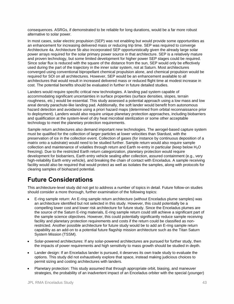
JPL RMA Enceladus Study 43
consequences. ASRGs, if demonstrated to be reliable for long durations, would be a far more robust alternative to solar power.
In most cases, solar electric propulsion (SEP) was not enabling but would provide some opportunities as an enhancement for increasing delivered mass or reducing trip time. SEP was required to converge Architecture 4a. Architecture 5b also incorporated SEP opportunistically given the already large solar power arrays required for the solar primary power source in that architecture. SEP is a relatively mature and proven technology, but some limited development for higher power SEP stages could be required. Since solar flux is reduced with the square of the distance from the sun, SEP would only be effectively used during the part of the trajectory in the inner solar system, not at Saturn. Most architectures converged using conventional bipropellant chemical propulsion alone, and chemical propulsion would be required for SOI on all architectures. However, SEP would be an enhancement available to all architectures that would result in increased delivered mass or reduced flight time at modest increase in cost. The potential benefits should be evaluated in further in future detailed studies.
Landers would require specific critical new technologies. A landing pad system capable of accommodating significant uncertainties in surface properties (surface densities, slopes, terrain roughness, etc.) would be essential. This study assessed a potential approach using a low mass and low areal density parachute-like landing pad. Additionally, the soft lander would benefit from autonomous hazard detection and avoidance using a priori hazard maps (determined from orbital reconnaissance prior to deployment). Landers would also require unique planetary protection approaches, including biobarriers and qualification at the system-level of dry heat microbial sterilization or some other acceptable technology to meet the planetary protection requirements.
Sample return architectures also demand important new technologies. The aerogel-based capture system must be qualified for the collection of larger particles at lower velocities than Stardust, with the preservation of ice in the collection event. Collection of gases (for instance by continuous deposition of a matrix onto a substrate) would need to be studied further. Sample return would also require sample collection and maintenance of volatiles through return and Earth re-entry in particular (keep below H2O freezing). Due to the restricted Earth return categorization, planetary protection would require development for biobarriers, Earth entry vehicle sealing after collection, assured containment (e.g., very high-reliability Earth entry vehicle), and breaking the chain of contact with Enceladus. A sample receiving facility would also be required that would protect as well as isolates the samples, along with protocols for clearing samples of biohazard potential.
Future Considerations This architecture-level study did not get to address a number of topics in detail. Future follow-on studies should consider a more thorough, further examination of the following topics:
E-ring sample return: An E-ring sample return architecture (without Enceladus plume samples) was an architecture identified but not selected in this study. However, this could potentially be a compelling lower cost and lower risk architecture for future study. Since the Enceladus plumes are the source of the Saturn E-ring materials, E-ring sample return could still achieve a significant part of the sample science objectives. However, this could potentially significantly reduce sample receiving facility and planetary protection requirements and costs if the return could be classified as non-restricted. Another possible architecture for future study would be to add an E-ring sample return capability as an add-on to a potential future flagship mission architecture such as the Titan Saturn System Mission (TSSM).
Solar-powered architectures: If any solar-powered architectures are pursued for further study, then the impacts of power requirements and high sensitivity to mass growth should be studied in depth.
Lander design: If an Enceladus lander is pursued, it deserves its own trade study to evaluate the options. This study did not exhaustively explore that space, instead making judicious choices to permit sizing and costing architectures with landers.
Planetary protection: This study assumed that through appropriate orbit, biasing, and maneuver strategies, the probability of an inadvertent impact of an Enceladus orbiter with the special (younger)

JPL RMA Enceladus Study 44
region of Enceladus and subsequent contamination of liquid water could meet a 10-4 probability requirement. If that requirement could not be met, then the entire orbiter would need to be sterilized, incurring a significant cost increase. Future work should elaborate and assess strategies to avoid having to sterilize the orbiter and also assess the impact of having to sterilize the orbiter if this proves necessary.
Sample collection, preservation, and handling: The details of the sample collection for particles and gases would require further design analysis to assure that the system would preserve the relevant aspects of the samples for study on Earth. This study concluded that maintaining 250-K temperature and pressurizing the container to 1 atm N2 would be sufficient. This needs to be analyzed and verified.
Earth Entry Vehicle (EEV): The details of sealing the Enceladus material inside the EEV and assuring no hitchhiking material from Enceladus is on the outside of the EEV at the time of Earth entry would be challenging, and the mass and cost impacts of those requirements need further consideration.
Long-lifetime reliability analysis and identification of key failure modes for critical spacecraft components, e.g., ASRGs.
Overall, this study found that a variety of compelling science missions to Enceladus could be achieved within reasonable cost levels. Due to the relatively linear science value versus cost relationship, it is possible to further examine several key missions that each have potential descope options available (should those descopes become necessary) while still achieving a robust science floor. Furthermore, it was observed that for previously uncharacterized or relatively unknown environments, missions which provide global coverage and multiple sources of data are of equal or potentially higher value than a sample return mission. This was not inherently obvious from the outset. After further consideration of risks, costs, and science team discussions, a simple-payload Enceladus orbiter (a variant on Architecture 2a or 2b) appears to be the most appealing mission architecture for further study.

JPL RMA Enceladus Study 45
Appendix A. Acronyms ASRG Advanced Stirling Radioisotope
Generator SAR synthetic aperture radar
BOL beginning of life SEP solar electric propulsion
CIRS Composite Infrared Spectrometer SNR signal-to-noise ratio
CML Concept Maturity Level SOI Saturn orbit insertion
COTS commercial off-the-shelf SPF single point failure
DHMR Dry Heat Microbial Reduction TRL Technology Readiness Level
DSN Deep Space Network TSSM Titan Saturn System Mission
EEV Earth Entry Vehicle UV ultraviolet
EOI Earth Orbit Insertion
ERV Earth Return Vehicle
FPGA Field Programmable Gate Array
FPU Floating Point Unit
FY fiscal year
GCMS Gas Chromatography-Mass Spectrometer
GCxGC Dual Gas Chromatograph
HEPA high efficiency particulate air
INMS Ion Neutral Mass Spectrometer
ISS Imaging Science Subsystem
JGA Jupiter Gravity Assist
JPL Jet Propulsion Laboratory
LV launch vehicle
MMRTG multi-mission radioisotope thermoelectric generators
MSR Mars Sample Return
NEXT NASA Evolutionary Xenon Thruster
NIR near infrared
OWLT one-way light time
PDR Preliminary Design Review
POC point of contact
PPO Planetary Protection Officer
RF RHU
radio frequency radioisotope heater unit
RMA Rapid Mission Architecture
RPS radioisotope power source

JPL RMA Enceladus Study 46
Appendix B. References and Bibliography References [1] National Aeronautics and Space Administration. Ground Rules for Mission Concept Studies in
Support of Planetary Decadal Survey, Revision 2. Released 10 November 2009.
[2] Russell, R.P. and M. Lara. “On the Design of an Enceladus Science Orbit,” AIAA/AAS Astrodynamics Specialist Conference and Exhibit, Honolulu, Hawaii, AIAA 2008-7072, August 2008.
[3] Strange, N.J. and R.P. Russell. “Leveraging Flybys of Low Mass Moons to Enable an Enceladus Orbiter.” AAS 09-435.
[4] Strange, N.J., T. Spilker, D. Landau, T. Lam, D. Lyons, and J. Guzman. “Mission Design for the Titan Saturn System Mission Concept.” AAS 09-356.
[5] Elsila, J.E., D.P. Glavin, J.P. Dworkin. “Cometary glycine detected in samples returned by Stardust.” Meteoritics and Planetary Science 44, 1323–133, 2009.
[6] Spilker, T.R., R.C. Moeller, C.S. Borden, W.D. Smythe, R.E. Lock, J.O. Elliott, J.A. Wertz, and N.J. Strange. “Analysis of Architectures for the Scientific Exploration of Enceladus.” IEEEAC paper #1644, 2009 IEEE Aerospace conference. March 2009.
[7] National Aeronautics and Space Administration, and European Space Agency. Titan Saturn System Mission NASA/ESA Joint Summary Report. January 15, 2009.
[8] Campagnola, S., N.J. Strange, and R.P. Russell. “A Fast Tour Design Method Using Non-Tangent V-infinity Leveraging Transfers.” AAS Paper 10-164, AAS Spaceflight Mechanics Meeting, San Diego, CA, February 2010.
[9] Campagnola, S. and R.P. Russell. “The Endgame Problem Part A: V-Infinity Leveraging Technique and the Leveraging Graph.” AAS Paper 09-224, AAS Space Flight Mechanics Meeting, Savannah, GA, February 2009.
[10] Casotto, S., S. Padovani, R.P. Russell, M. Lara. “Detecting a Subsurface Ocean from Periodic Orbits at Enceladus.” Poster P23B-1366, AGU 2008 Fall Meeting, San Francisco, CA, December 15–19, 2008.
Bibliography Alexander, C. and E. Turtle. Cassini–Huygens Mission to Saturn 4th Anniversary CHARM, part 2. July
2008.
“Comet Surface Sample Mission Study.” Prepared for NASA’s Planetary Science Division by the Johns Hopkins University Applied Physics Laboratory, SDO-11998, April 2008.
European Space Agency. TSSM In Situ Elements. ESA-SRE(2008)4, February 12, 2009.
Hurford, T.A., B. Buratti, A. Coustenis, A. Dombard, R. Greenberg, H. Hussmann, M. Kirchoff, C. Porco, A. Rymer. “The Case for an Enceladus New Frontiers Mission.” September 15, 2009.
Jet Propulsion Laboratory. Titan and Enceladus $1B Mission, Feasibility Study Report. Prepared for NASA’s Planetary Science Division, JPL D-37401 B, January 30, 2007.
NASA GSFC. Enceladus Flagship Mission Concept Study. Prepared for NASA's Planetary Science Division, August 29, 2007.
Spencer, J.R., A.C. Barr, L.W. Esposito, P. Helfenstein, A.P. Ingersoll, R. Jaumann, C.P. McKay, F. Nimmo, and J. HunterWaite. “Chapter 21: Enceladus: An Active Cryovolcanic Satellite.” Saturn from

JPL RMA Enceladus Study 47
Cassini–Huygens, M. Dougherty et al. (eds.), DOI 10.1007/978-1-4020-9217-6_21, Springer Science+Business Media B.V. 2009.
Tsou, P., D.E. Brownlee, I. Kanic,C. Sotin, L.J. Spilker, N. Strange, J. Vellinga. White Paper for the National Academies Planetary Science Decadal Survey. “A case for an Enceladus Flyby Sample Return, LIFE.”

JPL RMA Enceladus Study 48
Appendix C. Specific Architectural Analyses and Assessments
Table C-1. Full Architecture Characteristics Matrix

JPL RMA Enceladus Study 49
Table C-2. Science Linkages Matrix

JPL RMA Enceladus Study 50

JPL RMA Enceladus Study 51
Appendix D. Risk Definition and Risks by Architecture
Table D-1. Risk Definitions
Levels Mission Risk Implementation Risk
Impact Likelihood of Occurrence Impact Likelihood of
Occurrence
5
Mission failure Very high, >25%
Consequence or occurrence is not repairable without engineering (would require >100% of margin)
Very high, ~70%
4
Significant reduction in mission return (~25% of mission return still available)
High, ~25% All engineering resources will be consumed (100% of margin consumed)
High, ~50%
3
Moderate reduction in mission return (~50% of mission return still available)
Moderate, ~10%
Significant consumption of engineering resources (~50% of margin consumed)
Moderate, ~30%
2
Small reduction in mission return (~80% of mission return still available)
Low, ~5% Small consumption of engineering resources (~10% of margin consumed)
Low, ~10%
1
Minimal (or no) impact to mission (~95% of mission return still available)
Very low, ~1% Minimal consumption of engineering resources (~1% of margin consumed)
Very low, ~1%

JPL RMA Enceladus Study 52
Table D-2. Mission Risks by Architecture, I
Risk # Risk Name Sat
urn
Orb
iter
w/
E h
igh
spee
d f
lybys
Sim
ple
Ence
ladus
Orb
iter
Sim
ple
Ence
ladus
Orb
iter
(s
hor
ter
ops)
Enhan
ced E
nce
ladus
Orb
iter
Sim
ple
Ence
ladus
Orb
iter
+
fre
efly
ing m
ag
Sim
ple
Ence
ladus
Orb
iter
+se
mi-
har
d s
eism
ic
net
wor
k
Sim
ple
Ence
ladus
Orb
iter
+
im
pac
tor
Hig
h p
erfo
rman
ce o
rbit
er
Hig
h p
erfo
rman
ce+
sem
i-har
d s
eism
ic n
etw
ork
Hig
h p
erfo
rman
ce +
in
stru
men
ted
lander
/hop
per
TS
SM
lea
ves
Tit
an o
rbit
an
d e
nte
rs E
nce
ladus
orbit
to
con
tinue
mis
sion
Sam
ple
plu
me
from
S
aturn
orb
it,
2km
/s -
N
ucl
ear,
tem
p c
ontr
olS
ample
plu
me
from
S
aturn
orb
it,
2 k
m/s
, S
olar
, te
mp c
ontr
olS
ample
plu
me
from
S
aturn
orb
it,
4 k
m/s
, no
tem
p c
ontr
ol
5a
w/
enhan
ced p
aylo
ad
1a 2a 2b 2c 2d 2e 2f 3a 3b 3c 4a 5a 5b 5c 5d
2Planetary Protection - Sample return abort if planetary protection compliance of sample capsule or entry vehicle could not be verified before earth-entry
Y (2,4)
Y (2,4)
Y (2,4)
Y (2,4)
11Spacecraft might be damaged due to impact of large particles in the plume or the E-ring
G (1,3)
G (2,3)
G (2,3)
G (2,3)
G (2,3)
G (2,3)
G (2,3)
G (2,3)
G (2,3)
G (2,3)
G (2,3)
G (1,4)
G (1,4)
G (1,4)
G (1,4)
12 Large solar panels might be damaged when flying through the plumesG
(2,3)
15Failure to meet the thermal and pressure control requirements of the sample during transit from Enceladus to Earth
G (1,3)
G (1,3)
G (1,2)
17Sample canister might not be retrieved in time to maintain sample thermal requirements at landing site
G (1,3)
G (1,3)
G (1,2)
G (1,2)
25 Lander lifetime insufficient to complete science objectivesG
(2,2)
26Seismometer sensitivity and lifetime inadequate to detect enough events to complete science objectives
G (4,1)
G (4,1)
29 Plume ejecta might fall on lander/seismometer affecting operationsY
(3,2)Y
(3,2)Y
(3,2)
30Landers/seismometers might land in an undesirable location and orientation for relay to orbiter
G (2,1)
G (2,1)
G (2,2)
31Landers/seismometers might not be adequately coupled to the Enceladus surface for seismic experiments
G (3,1)
G (3,1)
G (3,1)
33Lander contamination of landing site (thrusters) might compromise landed operations
G (2,2)
34Unknown terrain at landing site might lead to loss of landers on impact or reduction in lander science due to unexpected terrain characteristics
Y (4,2)
Y (4,2)
Y (3,2)
44 Failure of an ASRG in flight resulting in reduced powerG
(2,1)G
(2,1)G
(2,1)Y
(2,4)G
(2,1)G
(2,1)G
(2,1)Y
(2,4)Y
(2,4)Y
(2,4)G
(2,1)G
(2,1)G
(2,1)G
(2,1)

JPL RMA Enceladus Study 53
Table D-3. Mission Risks by Architecture, II
Risk # Risk Name Sat
urn
Orb
iter
w/
E h
igh
spee
d f
lybys
Sim
ple
Ence
ladus
Orb
iter
Sim
ple
Ence
ladus
Orb
iter
(s
hor
ter
ops)
Enhan
ced E
nce
ladus
Orb
iter
Sim
ple
Ence
ladus
Orb
iter
+
fre
efly
ing m
ag
Sim
ple
Ence
ladus
Orb
iter
+se
mi-
har
d s
eism
ic
net
wor
k
Sim
ple
Ence
ladus
Orb
iter
+
im
pac
tor
Hig
h p
erfo
rman
ce o
rbit
er
Hig
h p
erfo
rman
ce+
sem
i-har
d s
eism
ic n
etw
ork
Hig
h p
erfo
rman
ce +
in
stru
men
ted
lander
/hop
per
TS
SM
lea
ves
Tit
an o
rbit
an
d e
nte
rs E
nce
ladus
orbit
to
con
tinue
mis
sion
Sam
ple
plu
me
from
S
aturn
orb
it,
2km
/s -
N
ucl
ear,
tem
p c
ontr
olS
ample
plu
me
from
S
aturn
orb
it,
2 k
m/s
, S
olar
, te
mp c
ontr
olS
ample
plu
me
from
S
aturn
orb
it,
4 k
m/s
, no
tem
p c
ontr
ol
5a
w/
enhan
ced p
aylo
ad
1a 2a 2b 2c 2d 2e 2f 3a 3b 3c 4a 5a 5b 5c 5d
45ASRG vibrations and electromagnetic field might interfere with sensitive instruments
G (1,1)
G (1,1)
G (1,1)
G (1,1)
G (1,1)
G (1,1)
G (1,1)
G (1,1)
G (1,1)
G (2,2)
G (1,1)
47 ASRG single converter failure resulting in large undamped vibrationsG
(2,1)G
(2,1)G
(2,1)G
(2,1)G
(2,1)G
(2,1)G
(2,1)G
(2,1)G
(2,1)G
(2,1)G
(2,1)G
(2,1)G
(2,1)G
(2,1)
48 Spacecraft component reliability issues due to long mission lifetimeY
(3,3)Y
(3,3)Y
(3,3)Y
(3,3)Y
(3,3)Y
(3,3)Y
(3,3)Y
(3,3)Y
(3,3)Y
(3,3)Y
(3,3)Y
(3,3)Y
(3,3)Y
(3,3)Y
(3,3)
51 Sample capsule parachute failureG
(1,1)G
(1,1)G
(1,1)G
(1,1)
52Critical deployments/separations late in the mission (such as separation of secondary elements at Enceladus, or earth entry vehicle on earth return) might fail
G (2,1)
G (2,2)
G (2,1)
G (2,2)
G (2,2)
Y (3,4)
Y (3,4)
Y (3,4)
Y (3,4)
53Failure of steerable gimbaled antenna might result in loss of orbiter science return
G (1,1)
G (1,1)
G (1,1)
G (1,1)
G (1,1)
G (1,1)
G (1,1)
G (1,1)
G (1,1)
G (1,1)
56Inability of mission operations to support many satellite flybys in a short time for leveraging pumpdown phase of trajectory
G (2,1)
G (2,1)
G (2,1)
G (2,1)
G (2,1)
G (2,1)
G (2,1)
G (2,1)
G (2,1)
G (2,1)
G (2,1)
G (2,1)
G (2,1)
57Sample captured in aerogel might not be sufficient to satisfy science objectives e.g., volatiles not captured properly or retained in sample capture system, or no organics captured
G (2,3)
G (2,3)
G (2,3)
G (2,3)
61 Plumes may be inactive during the science missionG
(2,2)G
(2,2)G
(2,2)G
(2,2)G
(2,2)G
(2,2)G
(2,2)G
(2,2)G
(2,2)G
(2,2)G
(2,2)G
(2,3)G
(2,3)G
(2,3)G
(2,3)
63Laser altimeter resolution might not be sufficient to observe flexing of the Enceladus surface
G (4,1)
G (4,1)
G (4,1)
G (4,1)
G (4,1)
G (4,1)
G (4,1)
G (4,1)
G (4,1)
G (4,1)
68Loss of a seismometer in the network might result in failure to address seismometry objectives
Y (3,2)
G (3,1)
70Free flying magnetometer might impact the spacecraft on the way down to Enceladus surface
G (2,3)
76Fault or damage to Titan/Enceladus orbiter during Titan portion of mission might lead to complete loss of Enceladus science
Y (2,4)
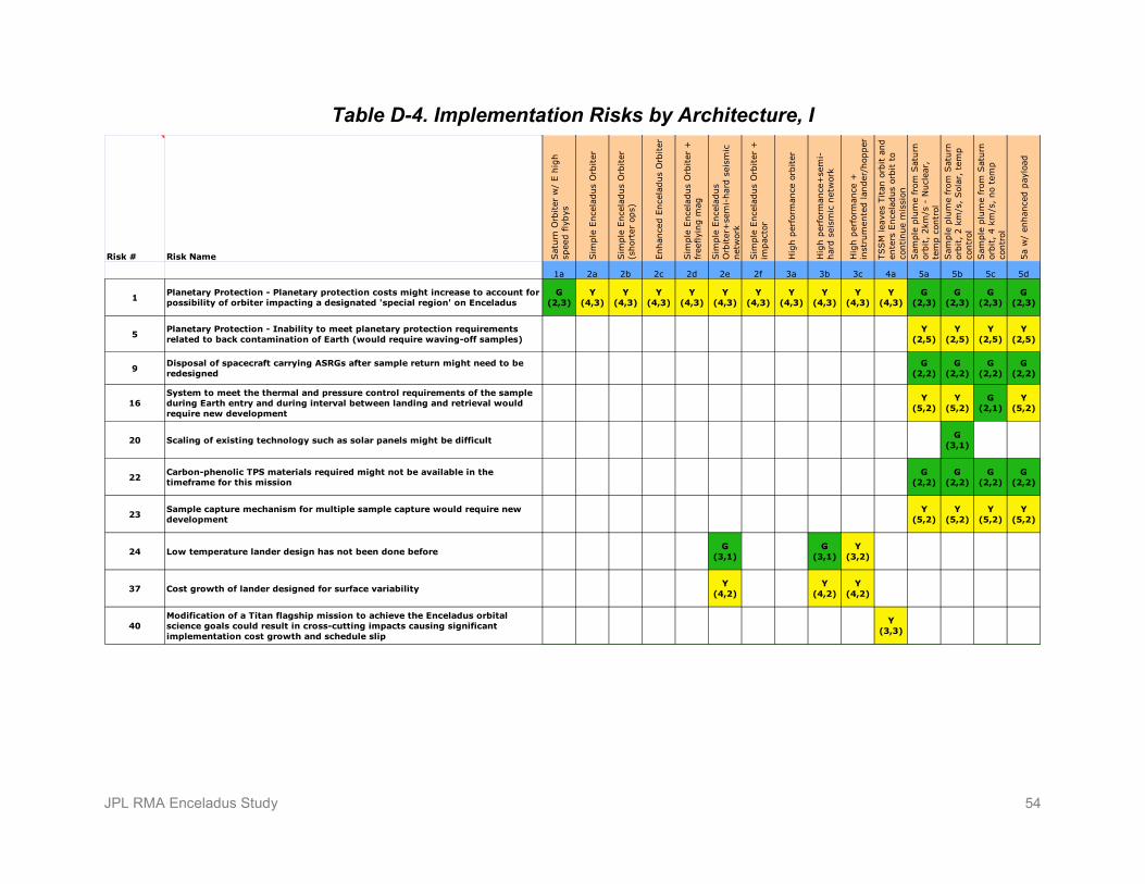
JPL RMA Enceladus Study 54
Table D-4. Implementation Risks by Architecture, I
Risk # Risk Name Sat
urn
Orb
iter
w/
E h
igh
spee
d f
lybys
Sim
ple
Ence
ladus
Orb
iter
Sim
ple
Ence
ladus
Orb
iter
(s
hor
ter
ops)
Enhan
ced E
nce
ladus
Orb
iter
Sim
ple
Ence
ladus
Orb
iter
+
free
flyi
ng m
ag
Sim
ple
Ence
ladus
Orb
iter
+se
mi-
har
d s
eism
ic
net
wor
k
Sim
ple
Ence
ladus
Orb
iter
+
impac
tor
Hig
h p
erfo
rman
ce o
rbit
er
Hig
h p
erfo
rman
ce+
sem
i-har
d s
eism
ic n
etw
ork
Hig
h p
erfo
rman
ce +
in
stru
men
ted lan
der
/hop
per
TS
SM
lea
ves
Tit
an o
rbit
and
ente
rs E
nce
ladus
orbit
to
conti
nue
mis
sion
Sam
ple
plu
me
from
Sat
urn
or
bit
, 2km
/s -
Nucl
ear,
te
mp c
ontr
olS
ample
plu
me
from
Sat
urn
or
bit
, 2 k
m/s
, S
olar
, te
mp
contr
olS
ample
plu
me
from
Sat
urn
or
bit
, 4 k
m/s
, no
tem
p
contr
ol
5a
w/
enhan
ced p
aylo
ad
1a 2a 2b 2c 2d 2e 2f 3a 3b 3c 4a 5a 5b 5c 5d
1Planetary Protection - Planetary protection costs might increase to account for possibility of orbiter impacting a designated 'special region' on Enceladus
G (2,3)
Y (4,3)
Y (4,3)
Y (4,3)
Y (4,3)
Y (4,3)
Y (4,3)
Y (4,3)
Y (4,3)
Y (4,3)
Y (4,3)
G (2,3)
G (2,3)
G (2,3)
G (2,3)
5Planetary Protection - Inability to meet planetary protection requirements related to back contamination of Earth (would require waving-off samples)
Y (2,5)
Y (2,5)
Y (2,5)
Y (2,5)
9Disposal of spacecraft carrying ASRGs after sample return might need to be redesigned
G (2,2)
G (2,2)
G (2,2)
G (2,2)
16System to meet the thermal and pressure control requirements of the sample during Earth entry and during interval between landing and retrieval would require new development
Y (5,2)
Y (5,2)
G (2,1)
Y (5,2)
20 Scaling of existing technology such as solar panels might be difficultG
(3,1)
22Carbon-phenolic TPS materials required might not be available in the timeframe for this mission
G (2,2)
G (2,2)
G (2,2)
G (2,2)
23Sample capture mechanism for multiple sample capture would require new development
Y (5,2)
Y (5,2)
Y (5,2)
Y (5,2)
24 Low temperature lander design has not been done beforeG
(3,1)G
(3,1)Y
(3,2)
37 Cost growth of lander designed for surface variabilityY
(4,2)Y
(4,2)Y
(4,2)
40Modification of a Titan flagship mission to achieve the Enceladus orbital science goals could result in cross-cutting impacts causing significant implementation cost growth and schedule slip
Y (3,3)
JPL RMA Enceladus Study 55
Table D-5. Implementation Risks by Architecture, II
Risk # Risk Name Sat
urn
Orb
iter
w/
E h
igh
spee
d f
lybys
Sim
ple
Ence
ladus
Orb
iter
Sim
ple
Ence
ladus
Orb
iter
(s
hor
ter
ops)
Enhan
ced E
nce
ladus
Orb
iter
Sim
ple
Ence
ladus
Orb
iter
+
free
flyi
ng m
ag
Sim
ple
Ence
ladus
Orb
iter
+se
mi-
har
d s
eism
ic
net
wor
k
Sim
ple
Ence
ladus
Orb
iter
+
impac
tor
Hig
h p
erfo
rman
ce o
rbit
er
Hig
h p
erfo
rman
ce+
sem
i-har
d s
eism
ic n
etw
ork
Hig
h p
erfo
rman
ce +
in
stru
men
ted lan
der
/hop
per
TS
SM
lea
ves
Tit
an o
rbit
and
ente
rs E
nce
ladus
orbit
to
conti
nue
mis
sion
Sam
ple
plu
me
from
Sat
urn
or
bit
, 2km
/s -
Nucl
ear,
te
mp c
ontr
olS
ample
plu
me
from
Sat
urn
or
bit
, 2 k
m/s
, S
olar
, te
mp
contr
olS
ample
plu
me
from
Sat
urn
or
bit
, 4 k
m/s
, no
tem
p
contr
ol
5a
w/
enhan
ced p
aylo
ad
1a 2a 2b 2c 2d 2e 2f 3a 3b 3c 4a 5a 5b 5c 5d
42 Uncertainty in ASRG launch approval costs resulting from near-earth flyby G
(2,2)G
(2,2)G
(2,2)G
(2,2)G
(2,2)G
(2,2)G
(2,2)G
(2,2)G
(2,2)G
(2,2)G
(2,2)G
(2,2)G
(2,2)G
(2,2)
43 Inability to execute mission as designed due to unavailability of plutoniumY
(2,4)Y
(2,4)Y
(2,4)Y
(2,4)Y
(2,4)Y
(2,4)Y
(2,4)Y
(2,4)Y
(2,4)Y
(2,4)Y
(2,4)Y
(2,4)Y
(2,5)Y
(2,5)
46Extended ASRG preparation/fueling lead time might result in launch date impact and reduced mission duration/reliability
G (2,3)
G (2,3)
G (2,3)
G (2,3)
G (2,3)
G (2,3)
G (2,3)
G (2,3)
G (2,3)
G (2,3)
Y (3,3)
Y (3,3)
G (2,3)
Y (3,3)
49 Increase in cost for qualification of components for long missionsG
(4,1)G
(4,1)G
(4,1)G
(4,1)G
(4,1)G
(4,1)G
(4,1)G
(4,1)G
(4,1)G
(4,1)G
(4,1)G
(4,1)G
(4,1)G
(4,1)G
(4,1)
71Gas Chromatograph instrument might not be developed to the desired performance and cost at the time of the mission
G (3,1)
G (3,1)
G (3,1)
G (3,1)
72 Development cost of sample receiving facility on the ground might increaseG
(2,2)G
(2,2)G
(2,2)G
(2,2)
78High mass growth sensitivity of solar powered architectures to power requirements growth
Y (3,2)