minivac 601 - book ii, iii & iv
TRANSCRIPT

BOOKS...II .III .IV
SCIENTIFICDEVELOPMENT W hat is a Digital Computer?
CORPORATION How Computers Make Logical DecisionsWatertown How Computers do Arithmetic
Mass.


M I N I V A C 601
BOOKS ll- ll l- IV
S C IEN T IF IC DEVELO PM EN T CORP.W ATERTOW N, MASS.

The M inivac M anual was prepared and edited by the staff of
Scientific Development Corporation
First Printing— August, 1961
EX LIBRIS ccapitalia.net
Copyright ( c ) 1961 by Scientific Development Corporation, 372 M ain Street, W atertown, Massachusetts

C O N T E N T S
BOOK II: WHAT IS A DIGITAL COMPUTER?Preface 1
1. INTRODUCTION 12. BASIC COMPUTER FUNCTIONS A N D M IN IV A C 601 5
The Basic Input Function 5The Basic Storage Function 7The Basic Processing Function 12The Basic O utput Function 15
3. EXPANSION OF THE BASIC FUNCTIONS 16Input Media and Codes 16Storage Media and Codes 21Processing Techniques 24O utput Media and Codes 25
4. COMMERCIAL COMPUTER EQUIPMENT 27Input Units 27Storage Units 30Output Units 29
5. COMPUTERS OF TOMORROW 30APPENDIX: D ig ita l and Analogue Computers 32
BOOK III: HOW COMPUTERS MAKE LOGICAL DECISIONSPreface 35
1. BASIC OPERATIONS 35The Operation "A N D " 35The Operation "O R " 38The Operation "N O T " 39The Operation "EITHER BUT NOT BO TH" 41
2. RELAYS FOR MORE FLEXIBLE T H IN K IN G 42The Relay A N D c ircu it 43The Relay OR c ircu it 43The Relay NOT c ircu it 44The Relay EITHER BUT NOT BOTH c ircu it 44
3. T H IN K IN G A N D DECISION-MAKING 44Boolean A lgebra 44Decision-Making w ith Insu ffic ien t Inform ation 47Sim ulation 48Thoughts About T h inking 49
4. SOME COMPUTER PROBLEMS 50A M ind Reading Program 50Q uantity Recognition 54A Problem Involving Three Girls 57The Farmer, the Goose, the Corn and the W o lf 60The Television Problem 63
i

BOOK IV: HOW COMPUTERS DO ARITHMETIC1. THE BINARY NUMBER SYSTEM 67
How Numbers A re Represented in the Binary System 67Building a Single Input Flip-Flop w ith Carry 68Experiment 1: A Three-B it Binary Counter 71Experiment 2: Counter A rithm e tic 73Experiment 3: Universal Counter A rithm e tic 73
2. B INAR Y AD D IT IO N 74Rules fo r Binary Add ition 74Experiment 4: A H alf-Adder w ith Carry 75Experiment 5: A Full Adder 76Experiment 6: A Three-B it Adder 77
3. HOW COMPUTERS SUBTRACT 78Two's Complement A rithm etic 78Experiment 7: A Three-Bit Subtractor 78
4. COMPUTER M ULTIPLIC ATIO N 79Binary M u ltip lica tion 79Experiment 8: The Shifting Operation 80M u ltip lica tion by Numbers Other Than Powers o f Two 81Experiment 9: The Accum ulator 81
5. DIVISION ON A COMPUTER 82Binary Division 82Experiment 10: Division 83
6. CONVERSIONS 84Experiment 11: Decimal to Binary Converter 84Experiment 12: Binary to Decimal Converter 85
APPENDIX: Autom atic Shift Register 86Two-Bit Adder w ith Autom atic Decimal Conversion 87

BOOK II
What is a Digital Computer?
PREFACE
This is the second in a series of books using M IN I VAC 601 to explore the world o f "e lectron ic bra ins". In w riting th is book, the authors have assumed tha t the reader is fa m ilia r w ith the inform ation contained in the firs t book o f th is series and understands the operation o f the components o f M IN IV A C 601.
The basic question which th is book was w ritten to answer is "W h a t is a d ig ita l computer?" In order to answer th is question it is necessary to examine the functions and forms o f modern high-speed d ig ita l computer systems. This book describes the m ajor characteristics o f modern computer systems and compares the functions performed by the components o f the M IN IV A C 601 w ith those performed by s im ilar parts in a large scale d ig ita l computer.
I. INTRODUCTION
In order to function as a d ig ita l computer a machine or combination of machines must be able to handle inform ation or "d a ta " in an orderly manner. It must be able to receive in form ation as " in p u t" from the outside world. Once received, th is in form ation must be "processed" by the computer, and the result o f the processing must be "rem em bered" or "s to red " fo r fu ture use. A fte r an answer has been obtained, it must be communicated back to the outside world as "o u tp u t." Thus a general purpose d ig ita l computer is made up o f four basic units:
The input un it The processing un it The storage un it The output unit.
The basic units are connected together like this:
FLOW CHART OF COMPUTER OPERATION
Input Unit
In form ation about a particu lar problem must be given to the computer before any operation can be performed. Input in form ation may be o f two kinds.

(1) Data: The numbers or coded in form ation to be used in calculation are called input data. These numbers may represent physical measurements, m athem atical relationships, or conditions o f a " lo g ic a l" decision-making problem.
(2) Instructions: The computer must be instructed to perform specific operations in a defin ite sequence. Input in form ation which directs the computer to perform certain operations and to handle the data in a specified way is called the instructions.
Input in form ation is supplied to M IN I VAC 601 through the binary input pushbuttons and the decimal input-output rotary switch. Instructions are communicated to M IN IV A C 601 by w iring on the computer console a "p rog ram " which instructs the computer to perform certain operations. The binary input pushbuttons are designed to communicate zeros and ones to the computer and the decimal input-output rotary switch is designed to communicate decimal numbers to the computer.
A large scale d ig ita l computer, such as the IBM 7090 illustrated later in this section, may receive input in form ation d irectly through pushbuttons s im ila r to those used on M IN IV A C 601 or it may receive input in form ation through punched cards or magnetic tape. Some computers receive input in form ation through punched paper tape; others receive direct input in form ation through a typewriter-like un it called a "fle xo w rite r".
Later in this book, each type o f input un it found on a large electronic data processing machine w ill be discussed and compared w ith the input devices o f M IN IV A C 601.
Processing Unit
The processing un it o f a d ig ita l computer performs four m ajor functions:
(1) Control: the processing un it controls the operations o f the computer system and in terconnects the input, output and storage units. A ll calculations, operations, and inform ation transfe r are accomplished under "c o n tro l" o f the processing unit.
(2) Decision-Making: the processing un it is able to perform comparisons which are the basis o f a ll computer decision-making. By comparing two numbers or symbols w ith each other and determ in ing whether or not they are equal, the computer decides upon a course o f action.
(3) A rithm etic : in the processing un it o f a d ig ita l computer a ll normal arithm etic functions are performed. These operations are actually done in a part o f a processing un it known as the "a rith m e tic u n it" which is designed to perform addition, subtraction, m u ltip lica tion and division.
(4) Logic: the processing un it o f most high-speed d ig ita l computers is equipped to perform various " lo g ic a l" operations through which conclusions of a non-arithm etic type may be reached. Just as arithm etic operations provide the steps by which the solution to a mathematical problem is reached, the logical operations provide the steps in a "reason ing" process.
The th ird book in th is series, How Computers Make Logical Decisions, describes the nature of logical operations and decision-making functions through demonstration on M IN IV A C 601. The nature o f arithm etic operations performed in the processing un it o f large computers is demonstrated in detail in the Book IV: How Computers Do Arithmetic.
The processing un it o f M IN IV A C 601 is made up o f six relays and the rotary switch. The relays and the rotary switch are used to provide control, make decisions, and perform basic a rith metic and logical operations.
The processing units o f most large scale d ig ita l computers use advanced electronic components to perform the functions demonstrated by the relays and rotary switch on the M IN IV A C 601. The circuits o f the processing un it in these machines use germanium or silicon transistors and diodes which are designed to perform m illions o f operations in one second.
In this book the im portant features and operating characteristics o f the processing un it o f a modern electronic data processing machine are described. The processing un it o f the M IN IV A C 601 is examined as a basic illustra tion o f the functions o f the processing un it o f a modern d ig ita l computer.
2

The Storage Unit
In order to function e ffic ien tly , a d ig ita l computer must be able to "s to re " or "rem em ber" data fo r use in processing and computation. Input in form ation is "re a d " into storage under contro l o f the processing un it and called from storage as it is required fo r use by the processing unit.
In the course o f a normal high-speed d ig ita l computer program, the processing un it o f the computer follows a series o f instructions which are stored in the storage un it using data which is also stored in the storage unit. In form ation obtained during calculations performed is stored temporarily in the storage un it fo r use a t a later time.
A computer uses a storage un it in much the same way tha t we use a piece of paper when solving a long division problem. The partia l answers to the long division problem are tem porarily stored (w ritten) on the paper un til the complete answer is obtained. S im ilarly, the partia l answers to the computer's problem are held in storage un til the complete answer has been obtained. The answer which is to be communicated by the computer to the outside world as "o u tp u t" may also be stored in the storage un it un til it is sent by the processing un it from storage to the output device.
Several d iffe ren t methods o f storage are used in modern computer systems to enable the machine to "rem em ber" instructions, data, partia l and fina l results o f calculations, and output inform ation. In smaller machines and the M IN I VAC 601, the processing un it is also used fo r storage. The relays o f M IN IV A C 601 supply the major source o f operating storage. These "m em ory u n its " o f the M IN IV A C 601, although smaller than those found in commercial computers, demonstrate the way in which inform ation is stored in a d ig ita l computer.
The decimal input-output un it also serves as a storage device during the operation o f some programs. The rotary switch remains in a particu lar position un til it is moved and thus enables M IN IV A C 601 to "rem em ber" a decimal number.
Large scale d ig ita l computers may use relays for storage and, in th is case, be identical to the M IN IV A C 601. Among the most popular storage devices in use today are the coincident-current magnetic core, magnetic drum, and magnetic disc storage units. These storage systems are all used fo r "operating storage"— temporary data storage within the computer while a program is being " ru n " . Other storage media are used to store data and instructions fo r longer periods of tim e and to save data and instructions outside the computer. These "pe rm anen t" storage media include magnetic tape, paper tape and punched cards. Each o f these storage methods w ill be discussed later in th is book and the relays and rotary switch o f the M IN IV A C 601 w ill be used to illustrate the theory and operation o f each type o f modern storage device.
Output Unit
O utput in form ation generated by a d ig ita l computer is communicated to the outside world to present the answer to a problem or to describe the operations o f the computer. O utput media used in modern d ig ita l computer systems include magnetic and paper tape, and punched cards. Some aux ilia ry output units convert numerical output obtained from the computer to charts, graphs, photographic displays, and numbers or letters on a printed page. The great diversity o f output devices which have been developed fo r use w ith the modern high-speed d ig ita l computer makes it possible fo r in form ation to be presented by the computer in almost any form in which it is desired.
The output devices o f the M IN IV A C 601 are the binary output lights and the decimal input- output rotary switch. When operated w ith the motor, the rotary switch becomes an output device, since the motor may be controlled by the processing un it o f the M IN IV A C 601 and caused to stop w ith the pointer indicating the number which is to be communicated as output in form ation. When the b inary output lights are used, output in form ation is communicated in a special b inary code discussed in detail in Book IV. Modern electronic data processing machines also have binary output lights fo r d irect communication o f in form ation from the computer using the same binary code employed by M l NI VAC 601.
Large scale d ig ita l computers employ ou tpu t units using media previously discussed in conjunction w ith input units. Media employed fo r both input and output purposes include magnetic tape, paper tape, punched cards and data transmission links.
Various output units are discussed in detail later in th is book and the output devices o f the M IN IV A C 601 are used to illustra te the nature of each type o f output unit.
3

INPUT INPUTA N D
OUTPUT
INPUT-OUTPUTA ND
SECONDARY STORAGE
STORAGEA N D
PROCESSING
INPUT-OUTPUTA N D
SECONDARY STORAGE
OUTPUT
IBM 7090 DATA PROCESSING SYSTEM
SECONDARYSTORAGE
INPUT
OUTPUTSTORAGE
ANDPROCESSING
INPUT-OUTPUT
M IN IV A C 601
4

2. BASIC COMPUTER FUNCTIONS A ND M IN IV A C 601
The Basic Input Function
Human Input Functions
The input function can be considered in terms o f the activities o f a human being who, having no previous tra in ing in mathematics, is asked to perform a division problem. Consider th is person s itting at a table w ith pencil and paper in hand. Input information is a ll in form ation which must be communicated to the person before he can perform the division problem.
First, he must be given two numbers— the data. He must be given the number which is to be divided (the dividend) and the number by which the dividend is to be divided (the divisor). In addition to th is data input the person, since he knows nothing about a rithm etic , must be to ld how to proceed w ith the numbers which he has received as data in order to obtain the answer. In short, the person must be given instructions on how to proceed to solve the problem. The instructions must be very detailed. They must te ll him how to handle each number and how to proceed through each step o f the process o f division.
A basic computer which has not been equipped w ith any operating circuits is in much the same position as the man who has never heard o f arithm etic. Under such circumstances the computer, like the man, must be given very detailed in form ation about how to proceed through the problem. Fortunately, a d ig ita l computer can be equipped w ith circuits which give it a su ffic ien t "know ledge" o f the rules o f arithm etic so tha t given the divisor and the dividend, it can be told simply "d iv id e " and it w ill proceed to obtain an answer.
Forms of Input
As has already been noted, input in form ation may be o f two kinds: instructions and data. Both kinds o f in form ation may be communicated to the computer in d iffe ren t ways. Most large computers are equipped to receive input in form ation from several d iffe ren t media. For example, the IBM 7090 computer system is able to receive inform ation from punched cards and from magnetic tape.
Inform ation presented in each o f the media may be communicated in several d iffe ren t codes. Data may be presented as decimal in form ation using the characters 0, 1 ,2 , 3, 4, 5, 6, 7, 8, and 9. Inform ation in th is form is communicated to M IN IV A C 601 w ith the rotary switch.
Both data and instructions may be communicated to the computer using a "b in a ry " code based on the two-valued (zero and one) code referred to in Book I. The binary number system is discussed in detail in Book IV. For the purposes o f discussion in this book we w ill only need remember tha t binary codes involve only two characters, zero and one, while decimal codes use the ten characters noted above.
M IN IV A C 601 Input Units
Input in form ation is communicated to M IN IV A C 601 through the two input devices located on the console.
Binary input is communicated using the six binary input pushbuttons according to the convention:
Button up = zero (0)Button down = one (1)
For example, the binary number "1 0 1 " (5) is communicated to M IN IV A C by pushing down pushbuttons 4 and 6 while leaving pushbuttons 1, 2, 3, and 5 up. The largest binary number which can be communicated to M IN IV A C 601 is 111111 (63).
Decimal in form ation is communicated using the decimal input d ial and the pointer o f the rotary switch. To give M IN IV A C a decimal number as input, the pointer is turned so tha t it points at the desired d ig it. The decimal input capabilities o f the M IN IV A C 601 are lim ited to the numbers from zero through fifteen.
5

The fo llow ing two experiments illustra te communication to M IN IV A C in Binary and Decimal. Each experiment uses the relays to store (remember) the inform ation communicated to the computer.
EXPERIMENT t | BINARY INPUT
This experiment uses M IN IV A C 601 to demonstrate how a d ig ita l computer receives binary input data and instructions. The binary number "o n e " is given to the computer by pushing a pushbutton down. The binary number "z e ro " is given to the computer by leaving a pushbutton up. The instruction to forget a ll previous data (to "c le a r" the memory) is given to the computer by pushing pushbutton 6.
The program and c ircu it drawing fo r th is experiment are:
1 - 2 - 3 - 4 - 5 -
1 X /2 X 6 Z / 6 + 2 H / 1 H 2 G /2 C 4 Y /4 G2 X / 3 X 6 Y /5 H 1Y /1G 2 F / 2 — 4 G /4C3 X / 4 X 5 H /4 H 1G/1C 3 Y /3 G 4 F / 4 —4 X / 5 X 4 H /3 H 1F / 1 — 3 G /3C 5 Y /5 G5 X / 6 Y 3 H /2 H 2 Y /2 G 3 F /3 — 5G /5C
1. Turn power ON. Push pushbutton l and release. This transm its a "o n e " to section 1 o f M IN IVAC. The "o n e " is remembered by relay 1. Relay ligh t 1 comes ON to indicate tha t a "o n e " is
being remembered (stored). Data has been communicated from the operator to M IN IV A C 601 by pushing BINARY INPUT pushbutton 1.
2. Do NOT push pushbutton 2. This leaves a "z e ro " in section 2 o f M IN IV A C 601. The "ze ro " continues to be remembered by relay 2. Relay ligh t 2 remains OFF to indicate tha t a "z e ro " is being remembered (stored).
3. Do NOT push pushbutton 3. This leaves a "z e ro " in section 3. Relay ligh t 3 remains OFF to indicate tha t a "z e ro " is being remembered.
4. Push pushbutton 4 to transm it a "o n e " to section 4. Relay ligh t 4 comes ON to indicate tha ta "o n e " is being remembered by section 4.
5. Push pushbutton 5 to transm it a "o n e " to section 5. Relay ligh t 5 comes ON to indicate tha ta "o n e " is being remembered by section 5.
The binary number 10011 (19) has been communicated to M IN IV A C 601 by using the BINARYINPUT pushbuttons. This input data is now being remembered (stored) in the firs t five sections o fthe computer.6. Push pushbutton 6 and release. This action instructs the computer to forget all previous data.
A ll relay lights go OFF, and the previous number is forgotten ("c lea red" from the memory).
6

7. The computer is now ready to receive another binary number from the operator. Make up another number yourself and communicate it to the computer by using the BINARY INPUT pushbuttons.
EXPERIMENT 2: DECIMAL INPUT
This experiment demonstrates how M IN IV A C 601 may receive decimal input data and instructions. A decimal number is communicated to the computer by turn ing the DECIMAL INPUT- OUTPUT knob to the desired number and pushing pushbutton 5 to instruct the computer to remember the selected number. Another instruction— to forget a ll previous data— is given to the computer by pushing pushbutton 6.The program and c ircu it diagram fo r th is experiment are:
1 - 2 - 3 - 4 - 5 -
1 H /2 H 6 Z / 6 + I F / 1 — 3G /3C D 5 /5 G2 H /3 H 6 Y / 5 X D 2 /2 G 3 F / 3 - 5G /5C3 H /4 H 5 Y /D 1 6 2 G /2C D 4 /4G 5 F /5 —4 H / 5 H D 1 /1 G 2 F / 2 — 4 G /4C5 H / 6 Y 1G/1C D 3 /3 G 4 F /4 —
1. Turn power ON. Turn the DECIMAL INPUT-OUTPUT knob to number 4 and push pushbutton5. This transm its the number " fo u r " to the computer. Relay ligh t 4 comes ON to indicate tha t a " fo u r " is being stored. Data has been communicated from the operator to M IN IV A C 601 by tu rn ing the DECIMAL INPUT-OUTPUT knob to the desired number and by instructing the computer to remember the selected number by pushing pushbutton 5.
When decimal data is remembered by the computer, the relay lights have a d iffe ren t meaning than when binary data is being remembered. W ith binary data, the ligh t ON represents a data "o n e " and the ligh t OFF represents a data "ze ro ". W ith decimal data, the number being remembered corresponds w ith the section (1-6) which has a relay ligh t ON.2. Push pushbutton 6 and release. This action instructs the computer to forget all previous data,
and relay ligh t 4 goes OFF. The computer is now ready to receive another decimal number (1-5) from the operator. Select another number yourself (between 1 and 5) and communicate it to the computer using the DECIMAL INPUT-OUTPUT.
The Basic Storage Function
Three types o f storage are used in most high-speed data processing machines. These are:
Internal storage Secondary storage External storage.
7

Internal storage, which is fo r our purposes the most im portant, is storage available in a storage un it connected d irectly to the processing un it of the computer in such a way tha t the processing un it has "im m edia te access" to the inform ation. Secondary storage refers to storage units in which the inform ation is available to the processing un it but in which, due to the nature o f the storage unit, it is available only a fte r some delay. The difference between internal and secondary storage in thus the difference between immediate and delayed access to inform ation.
External storage refers to storage in a media outside the computer system. External storage is thus accomplished by com municating the inform ation to be stored out o f the computer as "o u tp u t" and then saving this in form ation in "externa l storage" on the output media.
Human Storage Functions
The storage function can be clearly seen in the analogy of the human being w ith pencil and paper. In this case, the paper is the external storage system, and the pencil is the output device through which inform ation is communicated from the human being to the external storage media. Internal and secondary storage are d iff ic u lt to distinguish in the human case since we as human beings have only one storage system available fo r our use— the human brain. Inform ation retained in the brain while the problem is being worked is probably best thought of as held in internal storage.
M IN IV A C 601 Storage
M IN IV A C 601 is equipped w ith internal storage in the form of the six relays which also serve as a part o f the processing un it o f the computer. The processing un it o f M IN IV A C does not have direct access to external storage. The human operator can supply external storage by w riting inform ation down on a sheet of paper when it is communicated to him through the output devices o f M IN IV A C and later return th is in form ation to the computer through the input devices as it is required.
Before examining the storage units o f M IN IV A C 601 and larger d ig ita l computers in more detail, it is necessary to consider the general form in which inform ation is stored in a d ig ita l computer.
The Binary Nature of Storage
Just as inform ation is communicated to the computer and processed by it in a binary form, it must be stored in binary form.
The reason for th is use o f the simple two-character (0 and 1) rather than the more complicated ten-character (0-9) decimal system in the computer can be realized by exam ining thedecimal input device. Using the rotary switch mechanism involves many d iffe ren t physical positions which must be communicated by the switching system to the computer. The mechanism used to do this involves physical motion and several moving parts. In addition, the rotary switch system requires more than a second to go from zero to nine.
In contrast to the decimal system, the binary input button involves only one moving part and, since it has only two physical positions, is simpler in construction and can be moved from one position to another in a fraction o f a second.
Thus, fo r the reasons o f sim plic ity, effic iency and speed aptly demonstrated by the comparison between the decimal input switch and the binary input button, large computers handle all processing and storage using a binary system. Thus the basic element o f storage in a computer is a binary " b i t " which may have the value o f 0 or 1.
The Structure of Storage
In any storage system, the bits are arranged into words consisting o f a specified number of bits. Storage w ith in the computer is handled in words. Each storage location— called a "re g is te r" contains one word of data and has a location number associated w ith it so tha t it is possible to iden tify a register and store inform ation in or ca ll in form ation from tha t register.
The storage system o f a large computer m ight be thought o f as a large number o f boxes w ith
8

each box identified by a number indicating its location in the series o f boxes, w ith each box just the righ t size to hold a specified number o f bits o f data. The actual form o f these storage registers varies w ith the machine.
Secondary Storage: Slide Switches
The six slide switches of M IN IV A C 601 are used to supply secondary storage. These switches are operated m anually and are used to store b inary inform ation according to the convention:
switch righ t = 0 switch le ft = 1
The follow ing experiment illustrates secondary storage in M IN IV A C .
EXPERIMENT 3: SECONDARY STORAGE
This experiment uses M IN IV A C 601 to demonstrate how a d ig ita l computer remembers inform ation which is not required immediately by storing the inform ation in SECONDARY STORAGE. The slide switches are used as secondary storage fo r M IN IV A C 601. The operator transfers data to the SECONDARY STORAGE by m anually operating the slide switches.
1S 1T
1. Turn power ON. Move slide switch to the left. L ight l comes ON to indicate tha t a "o n e " (binary data) is being stored in SECONDARY STORAGE, Section 1. The SECONDARY STORAGE slide switch continues to remember "o n e " un til it is instructed to remember a "z e ro " by the operator.
2. Move slide switch 1 to the right. L igh t 1 goes OFF to indicate tha t a "ze ro " (binary data) is now being stored in SECONDARY STORAGE, Section 1.
Most large d ig ita l computers autom atica lly transfer data at very high speeds to secondary storage. Modern computers may use punched cards, punched paper tape, magnetic tape, and other special devices fo r secondary storage.Secondary and external storage are required by d ig ita l computers because there is not enough capacity in the storage-processing un it to store a ll the inform ation required by some problems. Excess inform ation which is not required im m ediately is transferred to secondary or external storage. External storage fo r a d ig ita l computer is s im ila r to the file cabinet which some people keep in the basement. Some papers may be thrown away, but there is not room enough in the desk upstairs to keep a ll items which must be filed. "A c tiv e " inform ation, which is used frequently, is kept close at hand in the desk and "d ead " in form ation, which is used infrequently, is kept in a f ile cabinet in the basement. Secondary storage in th is case would be inform ation required only occasionally, but im portant enough to be kept close by. This inform ation m ight be kept in the back o f a desk drawer, or perhaps in a cabinet several steps from the desk.
Internal Storage— Relays as Memory
Before going on to the more complicated forms o f storage used in large computers, we w ill tu rn again to M IN IV A C 601 and examine the storage system used to provide memory fo r this small computer. Storage or "m em ory" fo r M IN IV A C is supplied by the 6 relays. These relays can be used to store or "rem em ber" six binary bits. As indicated above, a large computer may have storage capacity fo r 36 binary bits in each o f its storage registers. Thus the storage capacity of M IN IV A C 601 w ith its 6 -b it register is one-sixth tha t o f a register in the 36-b it machine.
As noted above, in a large computer each storage register is identified by a location number.
9

In the case o f M IN IV A C 601 it w ill not be necessary to consider th is problem o f memory location identifica tion , since we are dealing w ith only one storage register.
W ith the exception o f the distinctions noted above, the basic function ing o f the storage system in M IN IV A C 601 exactly duplicates the function ing o f the storage system in a larger computer. Thus, the larger computer may be thought o f as simply an extension o f many M IN IVAC 601's lined up in a row and interconnected. To duplicate the storage capacity o f the IBM 7090 computer system, fo r instance, would require 192,000 M IN IV A C 601 Computers in combination.
In the discussion o f the operation o f the relay in Book I, the relay was used as a switch operated by a pushbutton. It was noted tha t the relay could be used to indicate the two-valued binary code by considering the relay OFF to be storing or remembering a '0 'while the relay ON was thought o f as remembering '1 '. The relay ligh t could be used to indicate when the relay was storing a M ' (ligh t on) or a '0 ' (ligh t o ff). This simple c ircu it may be thought o f as a manual memory: as long as the pushbutton is being held DOWN, the relay remembers a one. W hen the pushbutton is released, the relay forgets the one and starts remembering a zero. The relay in th is c ircu it is a memory element controlled by the pushbutton.
1 + / 1 Y 1 + / 1 H 1 X /1 C 1— / I F 1 G /1A 1 B/T —
M A N U A L RELAY MEMORY CIRCUIT
A more e ffic ien t memory un it would be achieved i f it were possible to make the relay remain in the DOW N or 1 position once it was signaled to go to th is position by the pushbutton. Such a c ircu it would enable the relay to remember a 1 once it had been signaled by pushing the pushbutton to " fo rg e t 0 and start remembering 1".
The manual memory relay c ircu it above can be easily m odified to achieve this by using one of the switches o f the relay to continue to supply current to the coil o f the relay a fte r the pushbutton has been released. M aking use o f th is relay switch, the pushbutton w ill in itia lly supply current to the relay. Once current is supplied to the relay coil, the relay w ill close and a second path fo r the current w ill be supplied through the norm ally open switch o f the relay. W ith th is c ircu it wired, the relay becomes "se lf- lo ck in g " in the 1 position.
7 - f - / l V 7 4-/1H 1 X /1 C1— / I F 1G /1A I B / 1 — 1 C /1 A
SELF-LOCKING RELAY MEMORY CIRCUIT
10

The evident d iff ic u lty w ith th is self-locking relay memory c ircu it is tha t, although the relay w ill now remember a 1 once it is to ld to remember 1, it cannot forget 1 unless the current to the computer is turned o ff. The next step in build ing a usable memory un it is obviously to m odify the c ircu it so tha t the relay can forget 1 and start remembering 0 again.
As an in itia l step in the direction o f programming such a c ircu it, a second pushbutton may be used to supply a means o f disconnecting power from the relay c ircu it. Using th is c ircu it, pushbutton 1 w ill be used as in the self-locking memory c ircu it to supply current to the relay coil and to cause the relay to stop remembering 0 and start remembering 1.
Pushbutton 2 w ill be used to cause the relay to stop remembering 1 and begin remembering0. As indicated below, this program uses the norm ally closed contacts o f pushbutton 2 and the norm ally open contacts o f pushbutton 1. The self-locking connection used in the previous c ircu it is retained.
TW O-BUTTON RELAY MEMORY CIRCUIT
The two-button or "tw o in p u t" memory c ircu it provides a workable memory element which satisfies the condition tha t it be able to remember a 1 or a 0 on signal. The weakness in th is c ircu it is tha t a d iffe ren t signal is required to te ll the memory c ircu it to forget 0 and to begin remembering 1 than is used to te ll it to forget remembering 1 and recommence remembering 0. Pushbutton 1 serves as the "fo rg e t 0 remember 1 " signal and pushbutton 2 provides the "fo rg e t 1 remember 0 " signal.
It would be particu la rly desirable if we could obtain a memory c ircu it which would respond to a single signal such that, if the c ircu it were remembering 1, it would forget 1 and start remembering 0. In short, it would be desirable to have a "s ing le -inpu t memory c ircu it" .
The Single Input "Flip-Flop"
Before programming M IN IV A C 601 for a single-input memory c ircu it a comment on term inology is in order. An exam ination o f the operation o f the two-button relay memory c ircu it w ill show tha t as the contents o f the memory are changed, the relay goes firs t ON and then OFF, changing from one position to another. The switching motion o f the relay has caused engineers to refer to th is type o f c ircu it as a " f l ip - f lo p " and the two-button relay memory c ircu it above is known as a "tw o-inpu t f lip -flo p ".
So, the c ircu it which we are now seeking is a "s ing le input f lip - f lo p ." The c ircu it and program below are fo r a single input flip -flop . Once this c ircu it has been programmed on M IN IV A C 601, pushing one pushbutton w ill signal the computer to remember a 1 or a 0. If the relays are remembering a 1, pushing pushbutton 1 w ill signal them to " fo rg e t 1 and start remembering 0 " . If the relays are remembering a 0, pushing pushbutton 1 w ill signal them to "stop remembering 0 and start remembering 1". L ight 1 w ill be ON when the flip -flo p is remembering a 1, and w ill be OFF when the flip -flo p is remembering a 0.

1— /IB1— /1 C 1A/1E 1E/2G 1F/2F 1 H /1 F 1 G /1 Y 1Y /1 + I X / 1J 1J /2H 2J /2E 2 E /2 A 2 B /2 —2— /2 C
In Book IV, the single input f lip -flo p w ill be used to provide the memory necessary to enable the computer to count and to perform various mathem atical operations. For the purposes o f this discussion o f computer storage, it is necessary only to note tha t th is single input flip -flo p has the characteristics o f the basic element o f a computer memory system. It is able to remember a 1 or a 0 and to “ change its m ind " when signaled to do so.
The Basic Processing Function
The detailed operations of the processing un it are discussed in Books III and IV. In th is discussion, it is su ffic ien t to note tha t the processing un it performs two basic kinds o f operations.
(1) It controls the flow o f in form ation w ith in the computer. The processing un it "d irects t ra f f ic " w ith in the computer, sending in form ation from the input un it to storage, from storage to the various calcu la ting units w ith in the processing unit, and from processing to output or storage. In one sense, the processing un it m ight be thought o f as the bookkeeper o f the computer. It keeps track o f and handles the placement o f a ll data.
(2) It does a ll calculations. The processing un it is the calculator o f the computer. In the processing un it a rithm etic data is m odified and "decis ions" are made. Instructions to the computer d irecting it to perform operations on data are carried out. A ll other units o f the computer are used to fac ilita te transmission and storage o f in form ation. Only the processing un it actively modifies or uses data. The other units o f the computer are passive w ith respect to the data.
Human Processing
The function o f the processing un it can be visualized in terms o f the division problem discussed earlier. Once the human operator has the divisor and dividend w ritten on paper and has been given the list o f instructions for perform ing the division, his actions are analogous to those of a processing unit. He w ill fo llow the instructions, acting upon his data, un til he reaches the fina l answer.
The processing un it o f a computer acts just like the human operator just mentioned after receiving both instructions and data. In a sense then, the processing un it is the work center o f the computer.
M IN IV A C 601 Processing
Processing in M IN IV A C 601 is accomplished using logical c ircu its to duplicate arithm etic and decision functions. Relays are used as switching devices and the ir operation is controlled by instructions communicated to M IN IV A C by means o f the program wired on the computer console. During the "execu tion" o f a program, the processing section o f M IN IV A C 601 controls the operation o f the computer. The program wired on the computer console indicates to the processing section what operation it is to perform and the processing section controls the other units o f the com
12

puter— obtaining in form ation when it is required from input sources and com m unicating the fina l answer to the output units.
The fo llow ing experiments illustra te some of the basic functions which a computer can perform , using the processing un it in various ways.
EXPERIMENT 4: CONTROLThis experiment uses M IN IV A C 601 to demonstrate how the processing un it controls the
computer's operations. The rotary switch is controlled by the Processing Unit.
5 + / 5 Y5 X /5 C5 F / 5 -5 + / 5 H5G /6C6 F /6 —6 + / 6 H6G /D 1 7D 1 8 / M -
Turn power ON. Push pushbutton 5. This energizes relay 5 (turns it ON) and causes current to flow through the switch contacts o f relay 5 to relay 6. Pushbutton 5 controls relay 5. Relay 5 in tu rn controls relay 6. Relay 6 controls the operation o f the motor.
The motor is controlled by relay 6 which is part o f the Processing Unit. Relay 6 is controlled by relay 5 o f the Processing Unit. Relay 5 is controlled by Binary Input pushbutton 5. The operator supplies the Input by pushing pushbutton 5. The program wired on the computer console gives the instruction:
I f pushbutton 5 is DOW N, tu rn relay 5 ON.If relay 5 is ON, tu rn relay 6 ON.If relay 6 is ON, tu rn motor ON.
In a more complicated program, the relay could be controlled by other relays or switches as the result o f some calculation or series o f events.
This a b ility o f a d ig ita l computer to control its own operations perm its the computer to autom atica lly make a whole series o f calculations a t high speed w ithout d irect operator command.
EXPERIMENT 5: DECISION M A K IN GThis experiment uses M IN IV A C 601 to demonstrate how the Processing U nit o f a computer
can make decisions based on rules given by the programmer. Two binary numbers are compared and the computer decides whether or not the numbers are equal.
1 + / 1 H1 H /1 L1L/1X1 Y /1 CI F / 1 —1 X /2 X2 Y /2 C2 F / 2 —1J /2H2 J /2 K1 K /2 L2 K /3 C3 F /3 —
1 3

1. Transfer the decision rule to the computer by w iring the program onto the console. Pushbuttons 1 and 2 w ill represent the numbers to be compared. Relay 3 w ill indicate the computer's decision. If the numbers are equal, relay 3 w ill come ON. I f the numbers are NOT equal, relay 3 w ill go OFF. (Note: a pushbutton UP represents zero; a pushbutton DOWN represents 1.)
2. Turn power ON. Relay 3 comes ON because both numbers are zero.
3. Push pushbutton 1. Relay 3 goes OFF because the numbers are no longer equal. (The firs t number is now 1; the second number is 0. )
4. Push pushbutton 2 while holding down pushbutton 1. Once again the numbers are equal (both are 1) and relay 3 comes ON.
5. Release pushbutton 1 while holding down pushbutton 2. Relay 3 goes OFF because the numbers are not equal.
This decision rule can be programmed w ithout using relays 1 and 2, in which case the pushbutton contacts perform the processing function. Since the relays have twice as many contacts as the pushbuttons and can be e lectrica lly operated, they are considerably more versatile than the pushbutton contacts. For this reason, relays are used to perform the processing function in a ll but the simplest programs.
EXPERIMENT 6: ARITHM ETIC
This experiment demonstrates how the Processing U n it o f a d ig ita l computer may be used to perform arithm etic calculations. Two numbers (0 or 1) are added together and the answer is ind icated by the Binary O utput lights.
1 + / 1 H1 H /1 L1L/1Y1 Y /2 Y2 Z /2 C2 F / 2 -1 X /1 CIF /1 —1G/2G2 H / 2 A2 B /2 —1N / 2 K 1 K /2 N 2 L /1 A IB /1 —
1. Transfer the rules o f addition to the computer by w iring the program onto the console. Pushbuttons 1 and 2 w ill represent the numbers to be added. L ight 1 ON w ill represent an answer o f 1; ligh t 2 ON w ill represent an answer o f 2; NO lights on w ill represent an answer o f 0.(Note: a pushbutton UP represents 0; a pushbutton DOWN represents 1)
2. Turn power ON. No lights come on because the input numbers are both zero: 0 + 0 = 0
3. Push pushbutton 1. L ight 1 comes ON: 1 + 0 = 1
4. Push pushbutton 2 while holding pushbutton 1 down. L igh t 2 comes ON: 1 + 1 = 2
5. Release pushbutton 1 while holding pushbutton 2 down. L ight 1 comes ON: 0 + 1 = 1.
14

The Basic Output Function
The output function is basically the communication of the processing unit's results to the outside world. Through the output un it, in form ation about the problem or the operation o f the computer is obtained from the computer.
Human Output Functions
In terms o f the previously discussed human analogy, output is obtained from the human being when the answer is w ritten on the paper (output media) by the pencil (output unit) which is controlled by the human being (processing unit). In the case o f the human being, the output device is used to communicate both partia l in form ation from the human processing un it during computation o f the problem and to display fina l answers upon completion.
M IN IV A C 601 Output Units
O utput in form ation is obtained from M IN IV A C 601 using two output devices: the BINARY OUTPUT lights and the DECIMAL OUTPUT mechanism. Inform ation is "re a d " from the binary output ligh t by interpreting a ligh t which is on as communicating a " 1 " and a ligh t which is o ff as com m unicating a " 0 " .
O utput in form ation is "re a d " from the decimal output mechanism of M IN IV A C 601 by noting the number a t which the pointer knob is pointing.
An example o f Binary O utput is given in experiment 6. The Binary O utput lights were used to indicate the answer to a simple addition problem.
The fo llow ing experiment illustrates the use o f the rotary switch fo r Decimal Output.
EXPERIMENT 7: DECIMAL OUTPUT
This experiment demonstrates how a computer delivers decimal output in form ation to the operator. The rotary switch (Decimal Output) is controlled through the slide switches (Secondary Storage) to communicate to the operator the contents o f Secondary Storage.
6Z
1 R /D l 3S/4S 6 R /D 6 6 Y / 6 +1S/2S 4 R /D 4 6S /D 192 R /D 2 4S/5S D 1 8 /D 1 62S/3S 5 R /D 5 D 1 6 /M —3 R /D 3 5S/6S D 1 7 /6 X
1. Set all slide switches in the RIGHT position. The slide switches w ill represent the numbers 1 through 6. To place a number in secondary storage, the appropriate slide switch w ill be
15

moved to the LEFT position. Pushbutton 6 w ill be used to give the computer the instruction:Indicate number in Secondary Storage using Decimal O utput rotary switch.
2. Turn power ON. Move slide switch 4 to the LEFT position. This places the number 4 in Secondary Storage.
3. Push pushbutton 6. This instructs the computer to communicate the contents o f Secondary Storage to the operator. The rotary switch turns to 4 on the Decimal Input-Output dial. The number 4 is the Decimal Output.
4. Move slide switch 4 to the RIGHT position and select another number to be placed in Secondary Storage. Again, push pushbutton 6 to instruct the computer to communicate the contents o f Secondary Storage through Decimal Output.
3. EXPANSION OF THE BASIC COMPUTER FUNCTIONS
Input Media and Codes
Lim ited amounts o f in form ation can be communicated d irectly to a large computer through its console. This direct input in form ation may be either binary or decimal in form , depending upon the operating characteristics o f the machine, and is norm ally communicated through switches on the main console o f the computer. In some situations direct communication is obtained through the use o f a " fle xo w rite r" which is a typewriter-1 ike device which, in addition to p rin ting characters on a w ritten page, transm its a coded representation o f the characters to the computer fo r interpretation.
Direct Console Input
In the photograph o f the 7090 console below the input buttons used to provide d irect binary input in form ation to the IBM 7090 computer are visible. The function ing o f these buttons is comparable to the operation o f the binary input buttons on the M IN IV A C 601 Console. W hen a particu la r button is pressed down, it represents a one in tha t position and when the button is in the normal or up position, it represents a zero in tha t position.
IBM 7090 CONSOLE
In the photograph o f the IBM 650 Computer console below, the input switches which communicate input in form ation in decimal rather than binary form are indicated. The operation of
16

these switches is s im ilar to the operation o f the decimal input switch on the M IN IV A C 601 Console. To communicate a decimal number to the IBM 650, the appropriate switches are turned so tha t the desired decimal number is indicated by the switches.
IBM 650 CONSOLE
In addition to d irect console input in the binary and decimal form using the same coding system employed w ith the M IN IV A C 601, large commercial computers have several other forms o f input. Basic input media in addition to d irect console input are: punched cards, punched tape, and magnetic tape.
Punched Card Input
Punched cards are perhaps the most common medium fo r communication w ith a computer. Inform ation is "recorded" on the cards by means o f a small hole punched in a particu la r location on a card in accordance w ith a coding plan which the machine has been programmed to "u n derstand". As the machine "reads" a card, it obtains in form ation by sensing the presence or absence o f holes in each o f a number o f locations. The inform ation obtained from the reading o f the card is then translated into electronic inform ation fo r processing and storage w ith in the computer.
17

Alpha-Numeric Card Code
The standard alpha-numeric code is summarized in the photograph below. The numbers zero through nine are coded as a single punch in a vertical column. The alphabetic characters and symbols are represented by two punches in a single vertical column.
Communication using the standard alpha-numeric input card code is lim ited to 80 characters (numbers, letters, or special characters) per card. The use o f "b in a ry " codes greatly increases the amount o f in form ation which may be communicated using a single card.
As noted earlier, although the punch itse lf is a binary variable— a variable which can have only two values, either 0 or 1— the use of the binary punch in conjunction w ith the alpha-numeric code creates a situation where only one variable value may be communicated in each vertical column. In a sense, th is is s im ila r to the lim ita tion imposed by the decimal input d ial on the M IN IV A C 601. A lthough a t any location the pointer is e ither pointing a t the number or is not pointing a t tha t number (corresponding to the punch either being in a particu la r location or not being in tha t location) m eaningful in form ation can only be communicated by considering a ll 16 locations in which the pointer might be. This corresponds to considering a ll 12 positions in a given vertical column on a card in which a punch might be located.
PRINTED BY THE 2 6 —PRINTING CARD PUNCH
— 0 1 2 3 4 5 6 7 6 9
•I « 11 112 2 23 3 3 3 | jj
4 4 4 4 4 |
5 5 5 5 5 5| I 6666666 77777777 • 8888888 311 9 9 9 9 9 9 9 9 9 91> I I 1 I I I I I I R 9 9 9 9 9 9 9 9 9 9 91
U M i i a u u n a n a a
2
33
4 4 4
55 5 5 9 8 6 6 6 7 7 7 7 7 7 8868886 9 9 9 9 9 9 9 9a a n a a a n a ' a a a a a a a
ABCDEFGHIJKLMNOPQRSTUVUXYZ
III000 Mtt 11
2 2 2 2
3 3 3 3 3
4 4 4 4 4 4 1 )
5 5 5 5 5 5 5666666667 7 7 7 7 7 7 7 78888888881
34 4
5 5 5 6 6 6 6
7 7 7 7 7 888888 9 9 9 9 9 9 9
IBM DATA PROCESSING tilpSod I I I I I I I I I
M
I III I O'fl ooooooooooooooo| ooooooq| | oooooo|a a a a a a a a a n a a M a a a a a a n a a M a a n a a a T i n n i i nn111ii11111111111111niii 11111 n i i 2 2 2 2 2 2 2 2 2 2 2 2 | 2 2 2 2 2 2 2 2 2 2 2 2 | | 2 2 2 2 2 2 2 2
3 3 3 3 3 3 3 3 3 3 3 3 3 3 3 3 3 1 3 3 3 3 3 1 3 3 3 3 3 3 3 3 3 3 3
4 4 4 4 4 4 4 4 4 4 4 4 4 | 4 | 4 4 4 4 4 4 4 4 4 4 4 4 4 4 44 4 4 4
S 5 S 5 S 5 S S 5 S 5 5 5 5 5 5 5 5 5 5 5 5 5 5 | 5 5 S | 5 S 5 5 S 5
6 6 6 6 6 S 6 6 6 6 6 6 6 6 6 6 6 6 6 6 6 6 | 6 6 6 6 6 6 6 6 6 6 6 6
7 7 1 7 7 7 1 7 J 7 J 7 7 7 1 7 7 7 7 7 | J 1 1 7 J 7 7 7 | 7 7 7 7 7 l l l l l l l l l l l l l l l l l l l l l l l l l l l l l l l l l l l 9 I I I I I I I I I 9 | I 9 I I I I I 9 I | I I I I I | 9 9 I I I I I42 43 44 454* 47 « « l SI S H H H R D IR R III1 D H B N 17 HU 7t 71 73 73 74
PRINTED - BY THE 26
PRINTING CARD PUNCH
ALPHA-NUM ERIC CARD SS
Binary Card Codes
As was noted earlier, the b inary number system is discussed in detail a t the beginning of Book IV and, fo r our purposes a t th is tim e, it is necessary only to remember tha t a binary code is one made up o f only two characters (0 and 1). Since the binary code is made up o f only zeros and ones it is unnecessary to consider the location o f the punch in a vertica l column in order to know the value o f the binary digit communicated by the punch. The presence o f a punch communicates a one and where there is no punch a zero is communicated. Since there can be only zeros and ones in a binary code all in form ation which could be communicated about the value o f a particu lar b inary d ig it is communicated simply by the presence or absence o f a hole in a particu la r location on the card.
The length o f a binary number or "w o rd " (i.e., the number o f b inary characters in the number or word) can vary. For example, the number labeled (A) below is a fou r-d ig it b inary number or word and the number labeled (B) is a ten-d ig it binary number or word.
(A)(B)
10100000001010
The card below is an input card prepared using a binary code. On th is card binary in form ation is represented in twenty-four 36-d ig it words occupying positions in columns 1 through 36 and 37 through 72 respectively in 12 rows. This is a "row b ina ry" card.
18

* ‘+ + | + + + ' + + + H - + + l + + + ] + + + | + + 4 j + + + 4 - + + j + + + [ f | + ( i | | | i + + | + + + M - + - H + + + l + + + j + + + | + + + | + + + J f + + f * - + + i + | ' t j + + 4 | ^ + + + + + + +
looit: 2 3| l 1 * 2 2 § 3 3
| « 4
i s 5
1st
1:7 7
0 9 9s
j_ _ _ I _ J ______
0 o o!g o o|o o o!o o oio o o4 5 6 ' 7 3 9*3 0 II 12:13 14 13.16 17 19
1 1 i'll l [ l 1 1 1 1 1,1 1 1 I I 1 I
2 2 212 2 212 2 2 '2 2 212 2 2I I
3 3 313 3 3 3 3 3|3 3 3)3 3 3
4 4 4 ^ 4 4 I4 4 4t4 4 4>4 4 41
5 5 5 5 5 5j5 9 5 j5 5 5|5 5 5
6 6 5'6 6 g |e 6 8'o 6 6 6 S 6I I
7 7 7'7 7 7 7 7 7*7 7 7l7 7 7 7 7 7 I ' l l
88
9 9 919 9 919 9 9 9 9 9'9 9 94 9 4 | 7 I I p * II 1 2 1131)4 15 |1 l i t 11
0 0 0 19 20 21
1 1 12 2 2
g g fe j+ fl0 0 0,0 0 o'o 0 010 I 0|0 I I
22 23 24.23 26 27)26 29 30 |31 32 33 34 35 36
1 1 1 , 1 1 1 j i 1 i n | i ; i 1 1 2 2 2l2 2 2l2 2 2,2 21||| |
I 1 .3 3 3 3 3)3 3 3j3 3 3| 3 3 | j | 3 1
4 4 4 4 4 4^ 4 4?4 4 4<4 4 | I 4 1 1I I
5 5 5 5 5 5 J5 5 5 I5 5 5|5 5 | I5 5 1
I I I6 6 6 6 6 6<6 6 6|S 6 6 6 6 G |||I I I
7 7 7|7 7 7,7 7 7I7 7 7 | 7 1
I I
9 0 032 39 39
| l 1
2 2 2 2 2 2l2 2 2 2 2 2l2 2 2,2 2 2 2 2 2I 1 I
3 3 3 3 3 3i3 3 3>3 3 3|3 3 3 !3 3 3 3 3 3 1 , 1
I I
I I I0 0 0,0 0 0|0 0 0|0 0 o'o 0 040 41 42.43 44 45,44 47 46,49 50 5 l ls 2 S3 54
14 4 5 5 5
1 1 1'1 1 1,1 1 1,1 1 111 1 1I
0 0 0 55 54 57
1 1 1
I ’ I4 4 4,4 4 414 4 4,4 4 414 4 4
1 I5 5 515 5 515 5 515 5 5,5 5 5
I IT
J | J
9 6 6 8 6 6 6 6 6 1 6 6 6 1 6 6 8'8 6 6 6 6 6
7 7 7 7 7 7]7 7 7|7 7 7,7 7 7|7 7 7 7 7 7 7 7 7|7 7 717 7 7'7 7 7 j | |
o| u a U|0
9 9 9 9 9 919 9 919 9 9>9 9 9'9 9 | 9 9 9 9 9 9|9 9 9l9 9 919 9 919 8 9 9 9 9 9 9 919 9 9<9 9 9'9 9 9191 9 9 9 9 9 9 9 9 922 23 24(25 26 27 |28 29 3 0 p i 32 33 |M 39 36 p ? 38 39[40 41 42 |43 44 45 |4 6 47 46 |4 6 90 91)92 S3 5* 55 96 97 |56 96 6 0 |6 t 62 63 |6 4 65 88 |67 16 66 |7 0 71 72jl-------------------------------
j— — r | - | | -1 i i 1
0 0 0|0 0 o'o 0 0 0 1 0| 0 054 59 50,51 42 43l«4 65 84 67 64 69 |7 0 71 72
1 1 i , i i i h 1 1 h 11 n 11i i i
2 2 2,2 2 212 2 2121 2|2 2 2I I
3 3 3 3 3 3i3 3 3.3 3
4 4 4
8 8 8
I I
J H I4 4 4 J4 4 4 J4 4 4!4 4 1 ^ 4 4
5 5 5 5 5 5 J5 5 5*5 5 5|5 5 1 ’5 1 5
6 6 6'6 6 6'S 6 6'6 6 1'6 6 6 I
■ 8 8
DOOOOOOO13 74 7 5 7 4 7 7 7 4 7 9 8 0
111111112 2 2 2 2 2 2 2
3 3 3 3 3 3 3 3
4 4 4 4 4 4 4 4
5 5 5 5 5 5 5 5
6 6 6 8 6 6 6 6777777778 8 8 8 8 8 8 8
13 74 79 74 77 74 79 40
ROW BINARY CARD
In place o f punching binary inform ation in horizontal rows as in the row binary card code, inform ation may be punched along the vertical columns o f the card. Twelve binary dig its can be punched in each vertica l column. Thus, in the case o f a 36-d ig it word length, three vertica l columns are required using the column binary code to communicate the in form ation contained on one above in row binary form.
IBM L I IS 0 7 F O R M I 2 I - N - 2
COLUM N BINARY CARD
The Binary Nature of Input
It is im portant to note tha t a ll input in form ation is read from a card as 36-d ig it b inary words. Once the inform ation has been read into the computer, it can be interpreted by the computer in accordance w ith any code tha t the computer has been programmed to understand. Thus, standard alpha-num eric code cards, row binary cards and column binary cards are a ll read into the computer by the same process. However, once the in form ation is in the computer, it is interpreted by the program prepared fo r the computer so th a t the computer can "understand" the inform ation communicated according to the appropriate code on the input card.
The im portant point to remember in th is context is th a t all communication to the computer is actua lly binary communication. Any non-binary form o f in form ation is read by the computer as i f it
19

were binary inform ation and then interpreted " in b in a ry " so tha t the computer can "understand" the inform ation.
Since M IN IV A C 601 operates in the same manner as a large computer, it must also be given inform ation in b inary form . This is the reason for the six binary input buttons on the M IN IV A C console. W hen non-binary inform ation is to be supplied to the computer as, fo r example, when using the decimal input dia l, M IN IV A C 601 w ill be programmed to interpret this non-binary inform ation and to store and process the non-binary inform ation in binary form.
In Book IV a program is given fo r conversion from decimal to binary. (See Decimal to Binary Converter— Book IV.)
Paper Tape Input
In a manner s im ilar to tha t in which inform ation is communicated on a punched card, in fo rmation on paper tape is communicated by punching holes in predetermined locations according to various codes. The machine reading a paper tape, as the machine reading a punched card, interprets the presence or absence o f a hole in a particu la r location as binary inform ation. Using paper tape it is possible to communicate inform ation made up o f any number o f characters to the machine as one continuous record.
The photograph below illustrates the use o f the "8 channel" code, one o f several coding systems used to communicate in form ation on paper tape. This system is analogous to the alphanumeric code described above fo r use w ith the punched card. The nature o f th is code can be easily determined by exam ining the photograph. It should be noted tha t the smaller dots appearing along the center o f the paper tape are analogous to the sprocket holes on the edge o f movie film . These small holes are used to move the paper tape past the reading point in the paper tape-reading machine.
A B C D E F G H I J K L M N O P Q R S T U V W X Y Z O 2 3 4 5 6 7 8 9 ■ /& i . 0 % ♦ H 5IScLQ-Q.Q-£ujt/>LLJ</H JnmiE I _ -
X- • • • • • • • • • • • • • • • • • • •( ) - • • • • • • • • • • • • • • • • • • •CHECK—* • • • • • • • • • • • • •8—* • • • • • • • •
TTTTII • I • • I • •• •• • • • • • •M T I • • • • • i i • • • • •
• •• •
• M i l l I • • • • • • •• • •• • • • • • • • • • • • • • • • • • • • • •4 —* • • • • • • • • • • • • • • • •2—* • • • • • • • • • • • • • • • •1—• • • • • • • • • • • • • • • • • • • •
• • • • • • • • • • • • • •• • • • • • • • • • • • • •• • • • • • • • • •
EIGHT CHANNEL PAPER TAPE CODE
Magnetic Tape Input
M agnetic Tape input systems d iffe r from those discussed above in tha t in form ation is recorded on a plastic recording tape s im ila r to tha t used in home tape recorders. In the case o f magnetic tape, in form ation is coded as magnetic "m a rks " on the tape rather than as holes in the tape. A m ajor advantage o f magnetic tape is th a t the magnetic in form ation recorded on the tape can be erased and the tape can be re-recorded and used many times.
A second advantage o f the magnetic tape is th a t the magnetic tape can be read at a much higher speed than the paper tape in a much smaller physical space than is required using either the punched card or the paper tape. Specifically, the same amount o f in form ation (3,336 characters) can be recorded on forty-two punched cards or on one inch o f magnetic tape (high density).
The photograph below illustrates the use o f a seven-bit alpha-numeric code recorded on magnetic tape. Using this code, a character is represented by the presence or absence o f magnetic marks in specified positions across the w idth o f the tape.
Binary inform ation may also be recorded on magnetic tape using a 36 b it code s im ila r to tha t discussed fo r use in connection w ith the punched card. The 36-b it word on magnetic tape is recorded in six consecutive columns on the tape. A lthough seven positions are available on the tape, one position is reserved for inforrrtation used in checking the re liab ility o f the reading and w riting operation.
20

0123456789 AtCDEFGHIJK LMNOfOR S T UVWXYZ %i§
Zone
Numerical
STORAGE M EDIA A N D CODES
'Bi-Stable" Elements
In the firs t section o f th is book we examined the memory element o f the M IN IV A C 601. Now we are ready to examine the way in which the same function is performed by d iffe ren t elements in larger computers. In every case, the function ing o f the memory element in a large computer is identica l to the function ing o f a relay serving as a memory element in the M IN IV A C 601. The memory element is, in every case, capable o f m ain ta in ing one o f two positions un til it is signaled to change positions. Such a two-valued element which can remain in e ither o f two positions un til an action outside the element causes it to change to the other position is called a "b i-s ta b le " device. It is a device which can stay (is stable) in e ither o f two positions (the p re fix " b i- " indicates two). The photograph below illustrates several bi-stable devices discussed in th is book.
"0" State ■I" StateIBM PUNCHED CARD
/ L .......0
MAGNETIC CORE
RELAY OR SWITCH
TUBE OR TRANSISTOR
ELECTRICAL PULSES
J 1
BI-STABLE ELEMENTS
21

Large Computer Storage
The actual form o f bi-stable elements which make up the storage register in large computers varies w ith the machine. However, three basic types o f storage are presently in popular use. These are:
magnetic core storage magnetic drum storage magnetic disc storage.
Magnetic Core Storage
The elements o f magnetic core storage are small, donut-shaped rings o f ferro-m agnetic materia l. These small memory elements, one hundredth o f an inch in diameter, can be magnetized in a few m illionths o f a second and w ill retain the ir magnetism indefin ite ly.
By passing current through a wire going through the center o f the donut-shaped ring, it is possible to magnetize the magnetic core memory element. The direction of the magnetic fie ld set up w ith in the core is determined by the the direction o f current flow through the wire. The magnetic core is thus a bi-stable element having two states o f polarization representing a 0 and a 1.
Just as in the M IN IV A C several relays may be used together to represent a series o f zeros and ones, so in a computer using magnetic core memory, series o f magnetic core elements may be combined to create a binary word. A 36-b it b inary word is thus remembered by 36 separate magnetic core elements, each of which may be magnetized in either direction.
When using the M IN IV A C relay memory element, the "s ta te " or position o f the relay was "re a d " on the ligh t attached to the relay switch. The ligh t ON indicated tha t the relay was remembering a one and the ligh t OFF indicated tha t the relay was remembering a zero. The ligh t was used to "sense" the position o f the relay.
MAGNETIC CORE PLANE
22

Reading o f the contents of a magnetic core element is accomplished by a "sensing" process. One such sensing process works as follows:
The magnetic core element is forced into the zero direction by a current pulse. If the element is storing a one, the change in direction o f polarization induces a pulse in a "sensing w ire ." I f the element is storing a zero, there is no change in the direction of polarization, so there is no pulse.
This reading process, however, "destroys" the inform ation content o f the magnetic core element. If the inform ation must be retained a fte r reading, a special device which w ill replace the in form ation as it is read must be used.
The preceding photograph shows a m atrix made up of many thousand magnetic core elements which together remember hundreds o f thousands o f binary bits in a large computer.
Magnetic Drum Storage
Although the magnetic core provides a much faster means o f storing inform ation, some computers use a magnetic drum fo r storage. The magnetic drum is a steel cylinder coated w ith materia l s im ilar to tha t used on magnetic recording tape. This material can be magnetized w ith a number o f small magnetic "spots" in much the same manner in which inform ation is recorded on magnetic tape. The drum rotates a t a constant speed and inform ation is "w ritte n o n " or "read fro m " the magnetic spots by a recording head in much the same manner tha t in form ation is recorded or played back from a tape recording.
In the magnetic drum there is a problem o f identify ing the location on the drum which is to be read in order to obtain the inform ation desired a t a particu la r point in time. Through a sequencing system, each storage location on the drum is specified by a given address (so tha t a particu lar location may be determined) in order to obtain or store inform ation at tha t point on the magnetic drum.
Writing on a Reading from aDrum Drum
23

Because transmission o f in form ation can occur only when a particu la r location is passing under the recording or play back head, the tim e required to obtain inform ation from the magnetic drum or to record inform ation in a particu la r location on the drum is greater than tha t required to obtain inform ation from the magnetic core.
Magnetic Disc Storage
The magnetic disc uses a process s im ila r to tha t used w ith the magnetic drum. Inform ation is recorded on discs which look much like standard phonograph records. The discs are stacked in an array surrounding a central spindle in a mechanism which operates very much like an ordinary juke box.
Inform ation is read into or out o f the discs by means of an arm which is able to enter into the stack o f records and read from or w rite on either side o f a particu la r disc. It is im portant to remember tha t the recording on the disc is a magnetic recording. So tha t although these records appear to be much like the ordinary phonograph records, the recording process is one involving magnetic spots.
Other Forms of Storage
Although the various forms o f storage described above are those most commonly encountered in commercial computers, other forms o f storage are used to a lim ited degree.
Binary in form ation is sometimes stored in an electric capacitor w ith the polarization o f the capacitor determ ining whether the b it stored is a one or a zero. In magnetic recording, the presence o f a magnetic spot was taken to indicate a 1 and the absence a 0; in the capacitor the presence o f extra electrons is taken to indicate a 1 and the absence o f electrons a 0.
Cathode ray tubes are also used for storage. W hen these devices are used, a point on the screen o f the tube is used as the memory element. A charged point represents a 1 and the absence of a charge indicates a 0.
W hen acoustic delay lines are used as storage elements the binary state o f the element is determ ined by the presence or absence of an ultrasonic v ibration in a flu id . The presence o f the vibration indicates a 1, its absence a 0.
External Storage
The storage media discussed above are a ll used fo r internal and secondary storage. External storage involves media associated w ith the output units and w ill be discussed in the next section. A t th is tim e it is su ffic ien t to note tha t three m ajor types o f external storage are encountered in the modern d ig ita l computer system. These are magnetic tape, punched cards and paper tape.
PROCESSING TECHNIQUES
Large Computer Processing
Processing w ith in a high-speed d ig ita l computer is accomplished using electronic circuits analogous w ith those used in the M IN IV A C 601. W ith some large scale computers the instructions are communicated using a program board in which instructions are wired in a manner s im ila r to the wired programming o f the M IN IV A C . In most high-speed d ig ita l computers, various operations which can be performed by the processing un it are permanently wired into the computer and the computer is programmed to perform a particu la r operation (to choose a particu la r wired circu it) when a specific code is given as an instruction. A computer, m ight fo r example, be programmed to choose an addition c ircu it when it encounters the instruction "0 1 " and to choose a subtraction c ircu it when it encounters the instruction "0 2 ."
W hen coded instructions are used in a large d ig ita l computer, the numbers representing the coded instruction may be stored in the storage un it o f the computer just as data is stored. W hen this is done, the processing un it is directed to certain registers of the storage un it to obtain num bers which are interpreted as instructions and to other registers to obtain numbers which are in terpreted as data. W hen this process is followed, the computer is said to be operating under control
24

of a "stored program ." In one sense then, the M IN IV A C 601 or any other wire-programmed computer may be said to be operating under control of a stored program. In the case o f the num erically coded instruction machine, the program is stored as numbers in the storage un it while in the case o f the wire-programmed machine the instructions are stored in the connections wired on the programming panel o f the computer.
Electronic circuits used in the high-speed d ig ita l computers use components which are d if fe rent in form from those used on the M IN IV A C 601. The functions which they perform , however, are s im ila r to the operations o f the relays and rotary switch o f the M IN IV A C 601, and the M IN IV A C components o ffe r the particu la r advantage o f being completely visible so tha t the ir operation can be easily viewed. It is easy to see the switching action o f a relay on the M IN IV A C 601 but impossible to see the s im ila r function ing o f a transistor or magnetic core element.
The processing un it o f the computer is the central control instrum ent o f the computer system. The processing un it is usually associated w ith the "m a in fra m e " o f the computer and d irect comm unication w ith the processing un it is provided fo r the operator through the switches and lights of the computer console.
The Binary Nature of Processing
The processing un it o f most large computers operates only in binary. Just as the relays used fo r processing on the M IN IV A C are capable o f dealing only w ith zeros and ones, the processing systems o f larger computers work only in binary code.
Since inform ation is communicated to the machine in other than binary form , it must be coded in binary form according to a system which w ill perm it the machine to recognize it as numeric, alphabetic, or special character in form ation. This binary coding o f non-binary in form ation is often accomplished using a Binary Coded Decimal or "B C D " code rather than using the binary equivalents o f the decimal number (see firs t section o f Book IV). The fo llow ing chart provides a summary o f the representation o f alphabetic, numeric and special characters according to the Binary Coded Decimal System.
THE BINARY CODED DECIMAL SYSTEM USED FOR PROCESSING
Character BCD Code Char. BCD Code Char. BCD Code Char. BCD Codeblank 110 000 A 010 001 N 100 101 + 010 000
1 000 001 B 010 010 O 100 110 — 100 0002 000 010 C 010 011 P 100 111 / 110 0013 000 011 D 010 100 Q 101 000 = 001 0114 000 100 E 010 101 R 101 001 - 001 1005 000 101 F 010 110 S 110 010 011 0116 000 110 G 010 111 T 110 011 ) 011 1007 000 111 H 011 000 U 110 100 $ 101 0118 001 000 1 011 001 V 110 101 * 101 1009 001 001 J 100 001 w 110 110 111 0110 000 000 K 100 010 X 110 111 ( 111 100
+ 0 011 010 L 100 011 Y 111 000- 0 101 010 M 100 100 z 111 001
In Book III o f th is series the decision-making function o f the processing un it is discussed, and examples o f the operation o f the processing un it as a decision-making device are provided. Book III also contains a detailed discussion o f the logical operations which enable the processing un it to function as a "Reasoning" device. In Book III you w ill discover how M IN IV A C 601 is able to duplicate many o f the functions o f human reason which are norm ally considered proof o f a human being's ab ility to " th in k ."
OUTPUT MEDIA A ND CODES
Direct Output
Just as binary inform ation may be given directly to the computer using input buttons on the computer console, b inary output may be obtained d irectly from the computer through lights s im ila r to the binary output lights o f the M IN IV A C 601. W hen binary output lights are used, the
25

code already established for use w ith the M IN IV A C 601 is employed. A ligh t ON indicates a " 1 " ; a ligh t OFF indicates a " 0 . "
A photograph below shows the direct output lights on the console o f the IBM 7090 computer. You w ill notice tha t there are 37 lamps in the row o f output lights o f the 7090 computer. These are used to display the contents o f the 36 binary "b its " in a 7090 storage register. The fa r le ft ligh t indicates the sign o f the number when the lights are displaying a binary number. The "sign ind ica to r" ligh t ON represents minus; the ligh t OFF represents plus.
DATA PROCESSING SYSTEM |
Large Computer Output Units
O utput in form ation may be obtained from a high-speed d ig ita l computer using lights and physical indicators s im ila r to the binary output lights and decimal output d ial of the M IN IV A C . W hen output devices o f th is type are employed, they are generally used only to obtain lim ited operating data from the computer and are usually located on the computer console.
More extensive output in form ation is norm ally obtained using a "p r in te r" un it in which a typew riter-like device produces typewritten pages of numbers or other w ritten inform ation. The prin ter may be connected d irectly to the processing un it o f the computer in which case in form ation is communicated d irectly from the processing un it to the printer. The prin ter may also be connected to a un it which is able to "re a d " one o f the other output media (for example magnetic tape or punched cards). In th is second case, output in form ation fo r p rin ting is actua lly transm itted from the computer on another media through another output un it and then transformed into printed m aterial away from the main computer.
The discussion o f coding and media undertaken while discussing input units is also applicable to the output situation. In essence the output device is simply a machine which reverses the process o f the input device. In the case o f magnetic tape, the input and output devices are actually in the same physical unit. The same equipment is used to record and to play back the inform ation on magnetic tape.
The un it used to reverse the process o f the card reader is the card punch un it and the paper tape reader has a complementary paper punch unit. W ith both the paper tape and card punch,
26

a series o f dies are used to punch holes in the tape or card in the location corresponding to coded inform ation sent to the punch un it from the processing un it of the computer.
The cathode ray tube output un it which is used to display output in a form which has no counterpart in the input sequence should be noted. This television-like display un it provides an "ana log " in the form o f a p ictoria l representation o f inform ation. A photograph of a Cathode Ray Tube output un it appears in the next section o f this book.
4. COMMERCIAL COMPUTER EQUIPMENT
This section of the book contains photographs of equipment m anufactured by the In ternational Business M achine Corporation to perform each of the four m ajor computer functions. These photographs are included to enable you to become fa m ilia r w ith the appearance o f units perform ing the various functions which we have discussed.
Card Input Equipment
Input in form ation for use by a computer system may be prepared on a card punch of the type illustrated below. The machine in the photograph is the IBM 026 Card Punch which punches cards using the IBM A lpha-numeric Input Card Code.
The cards to be punched are placed in the hopper on the righ t hand side of the 026 and fed through the machine to the punching station. The operator, using the keyboard of the machine, punches the card in much the same way tha t he would type a letter using a typewriter. The space bar a t the bottom of the keyboard is used to move the card under the punch dies w ithout punching. W hen a key is pressed, a hole is punched in the card in the particu lar column under the punch dies at the tim e the key is pushed. The 026 also prints above the column which has been punched the
27

I
number or le tter represented by the punches. An example o f a card prepared by an 026 card punch is shown below.
/ hiBCDEFGHi JKLMNOPQRST'JVWXYZ 1234567390 = » $ . -< * > + MINIVAC 601/ l l l l l l l l l I I I I I I I
l l l l l l l l l I I I Ioooooaooooooaoooooooo||||||||ooooooooooooa|ooooo|ooo|oooaooooooo|oooo|oooooooooo1 1 3 4 5 I 7 I I 70 II 1113 MW I1 17 I I I I 30 21 31 23 34 35 38 37 78 29 30 31 31 33 34 35 3G37 % 394041 474344 45 45 47 4141 50 31 52 515(55 31 57 31 39 40 614743 M IS 14 IT 48 49 70 71 7773 74 78 76 77 71 71 M
t1t|l111111l|l111111111111111111l|l11111111111111111111111111111l|l11l|l11111111 Z 2 2 2 | 2 2 2 Z Z 2 2 2 | 2 2 2 2 2 2 2 | 2 2 2 2 2 2 Z 2 2 2 2 2 | 2 2 2 2 2 2 2 2 2 2 2 2 2 2 2 2 2 2 2 2 2 2 2 2 2 2 2 2 2 2 2 2 2 2 2 2 2 2 2 2 2 2 2 2 2
3 3 3 3 3 | 3 3 3 3 3 3 3 3 | 3 3 3 3 3 3 3 | 3 3 3 3 3 3 3 3 3 3 3 3 | 3 3 3 3 3 3 3 3 3 3 3 | | | | 3 3 3 3 3 3 3 3 3 3 3 3 3 3 3 | 3 3 3 3 3 3 3 3 3 3 3 3 3
4 4 4 4 4 4 | 4 4 4 4 4 4 4 4 | 4 4 4 4 4 4 4 | 4 4 4 4 4 4 4 4 4 4 4 4 | 4 4 4 4 4 4 4 4 4 4 4 4 4 4 | | | | 4 4 4 4 4 | 4 4 4 4 4 4 4 4 4 4 4 4 4 4 4 4 4 4 4
S 5 5 5 5 5 5 | 5 S 5 5 5 5 5 S | 5 5 S 5 5 5 5 | 5 5 5 S 5 5 5 5 5 S 5 5 | 5 5 5 5 5 5 5 5 5 S 5 5 S 5 5 S 5 5 5 5 S 5 5 5 | 5 | 5 5 5 5 5 5 S 5 5 5 5 5 5 5 S
6 6 S 6 6 S 6 G | 6 6 6 6 6 6 6 6 | 6 6 G G 6 6 G | 6 G 6 6 6 6 6 6 6 6 6 6 | 6 6 6 6 G 6 6 6 6 6 6 6 6 6 6 6 6 6 6 6 6 6 6 6 6 G 6 6 6 | 6 6 6 6 6 6 6 6 G G 6
7 7 7 7 7 7 7 7 7 | 7 7 7 7 7 7 7 7 | 7 7 7 7 7 7 7 | 7 7 7 7 7 7 7 7 7 7 7 7 | 7 7 7 7 7 7 7 7 7 7 7 7 7 7 7 7 / 7 7 7 7 7 7 7 7 7 7 7 7 7 7 7 7 7 7 7 7 7 7 7
8 8 8 8 8 8 8 8 8 8 | 8 8 8 8 8 8 8 8 | 8 8 8 8 8 8 8 | 8 8 8 8 B 8 8 8 8 8 8 8 | B 8 8 8 8 8 | | | | | | | | 8 8 8 8 8 8 8 8 8 S 8 B 8 8 8 8 8 8 8 8 8 B 8 8 8
9 9 9 9 9 9 9 9 9 9 9 | 9 9 9 9 9 9 9 9 | 9 9 9 9 9 9 9 | 9 9 9 9 9 9 9 9 9 9 9 9 | . 9 9 9 9 9 9 9 9 9 9 9 9 9 9 9 9 9 9 9 | 9 | 9 9 9 9 9 9 9 9 9 9 9 9 9 9 9 9I 2 3 4 8 • 7 I t t 0 111213141S tlt7U1l202122232482l 27 2l2l3031323334333l 37 3 in 4 0 4t 42 43 44 4S 46 47 4l4S90 91 9293MSSSB57MS9 80 61 82 63 64 65KI76l8BT0 71 72 73 74 7S7l 77 7l7SIO
________________ I»M 8081
INPUT CARD PREPARED ON THE 026 CARD PUNCH
Once the input in form ation has been punched onto the card, the card can be read by the card reader o f the computer. The photograph below illustrates the IBM 7500 card reader used in conjunction w ith a high-speed d ig ita l computer. The mechanism o f the card reader includes two sets o f "re a d in g " brushes. Inform ation from the card is read beginning w ith the firs t 36 locations in the "n in e " or bottom row of the card. A fte r the firs t 36 locations o f the "n in e " row have been read, the next 36 locations are read. The last e ight locations (columns 73-80) are not norm ally used fo r input in form ation but are reserved fo r sequencing inform ation used to iden tify a particu lar card.
For a 72 column read cycle, each corresponding row starting w ith the "n in e " (bottom) row is divided into two 36 column "w ords". Thus the machine reads twenty-four 36-d ig it b inary words in the order indicated in the illustra tion below.
UnusedC o l u m n s
/
/ © © 12-Row
© m 11-Row
0 0 0 0 0 0 0 0 0 0 0 0 0 0 0 0 0 © 0 0 0 0 0 0 0 0 0 0 0 0 0 0 D 0 G 0 0 0 0 0 0 0 0 0 0 0 0 0 0 0 0 0 0 0 0 0 0 0 0 0 0 6 0 0 0 0 0 0 0 0 0 0 0 0 0 0 0 0
1 1 1 1 1 1 1 1 1 1 1 1 1 1 1 1 1 @ 1 1 1 1 1 1 1 1 1 1 1 1 1 1 1 1 1 1 1 1 1 1 1 1 1 1 1 1 1 1 1 1 1 1 0 1 1 1 1 1 1 1 1 1 1 1 1 1 1 1 1 1 i i i i i i i i
2 2 2 2 2 2 2 2 2 2 2 2 2 2 2 2 2 <Ts) 2 2 2 2 2 2 2 2 2 2 2 2 2 2 2 2 2 2 2 2 2 2 2 2 2 2 2 2 2 2 2 2 2 2 0 2 2 2 2 2 2 2 2 2 2 2 2 2 2 2 2 2 2 2 2 2 2 2 2 2
3 3 3 3 3 3 3 3 3 3 3 3 3 3 3 3 3 0 3 3 3 3 3 3 3 3 3 3 3 3 3 3 3 3 3 3 3 3 3 3 3 3 3 3 3 3 3 3 3 3 3 3 0 3 3 3 3 3 3 3 3 3 3 3 3 3 3 3 3 3 3 3 3 3 3 3 3 3
4 4 4 4 4 4 4 4 4 4 4 4 4 4 4 4 4 0 4 4 4 4 4 4 4 4 4 4 4 4 4 4 4 4 4 4 4 4 4 4 4 4 4 4 4 4 4 4 4 4 4 4 0 4 4 4 4 4 4 4 4 4 4 4 4 4 4 4 4 4 4 4 4 4 4 4 4 4
5 5 5 5 5 5 5 5 5 5 5 5 5 5 5 5 5 ® 5 5 5 5 5 5 5 5 5 8 5 5 5 5 5 5 5 5 5 5 5 5 5 5 5 5 5 5 5 5 5 5 5 5 0 5 5 5 5 5 5 5 5 5 5 5 5 5 5 5 5 5 5 5 5 5 5 5 5 5
5 6 6 6 6 6 6 6 6 6 6 6 6 6 6 6 6 0 6 6 6 6 6 6 6 6 6 6 6 6 6 6 6 6 6 6 6 6 6 6 6 6 6 6 6 6 6 6 6 6 6 6 0 6 6 6 6 6 6 6 6 6 6 6 6 6 6 6 6 6 6 6 6 6 6 6 6 6
7 7 7 7 7 7 7 7 7 7 7 7 7 7 7 7 7 0 7 7 7 7 7 7 7 7 7 7 7 7 7 7 7 7 7 7 7 7 7 7 7 7 7 7 7 7 7 7 7 7 7 7 0 7 7 7 7 7 7 7 7 7 7 7 7 7 7 7 7 7 7 7 7 7 7 7 7 7
8 8 8 8 8 8 8 8 8 8 8 6 6 8 8 8 8 0 8 6 8 8 8 8 8 8 8 8 8 8 8 8 8 8 8 8 8 8 8 8 8 8 8 8 8 8 8 8 8 8 8 8 0 8 8 8 8 8 8 8 8 8 8 8 8 8 8 8 8 8 88888888
9 9 9 9 9 9 9 9 9 9 9 9 9 9 9 9 9 0 9 9 9 9 9 9 9 9 9 9 9 9 9 9 9 9 91 2 3 4 5 6 7 8 9 10 31 12 13 14 15 16 17 18 19 20 21 2 2 2 3 2 4 25 2 6 2 7 2 8 2 9 30 31 32 33 3 4 3 5 3 6
9 9 9 9 9 9 9 9 9 9 9 9 9 9 9 9 9 0 9 9 9 9 9 9 9 9 9 9 9 9 9 9 9 9 937 38 3 9 4 0 41 4 2 4 3 4 4 4 5 4 6 4 7 4 8 4 9 50 51 5 ? 53 54 55 5 6 57 58 59 60 61 62 6 3 6 4 6 5 6 6 6 7 68 69 70 71 72
9 9 9 9 9 9 9 971 74 75 7 6 77 76 79 80
THE SEQUENCE FOLLOWED W HEN READING 72 COLUMNS OF INFORM ATION FROM A N INPUT CARD
28

Input-Output Units
The photographs below illustra te IBM card, tape, and prin ter units.W hen cards are read by the card reader, they are placed in the hopper at the fron t o f the
reader. During the read cycle they pass under the read brushes and out into the hopper on top of the unit.
The magnetic tape un it both reads and writes on magnetic tape. This un it is thus a combined input-output device.
The equipment used to read paper tape operates, as does the card reading equipment, by interpreting the holes in the paper tape as b inary inform ation. Once th is in form ation is read it is interpreted according to a program previously supplied to the machine. As in the punched cards, a hole is read as a one and the absence o f a hole as a zero.
IBM 962 Tape Punch IBM 729 IV Magnetic Tape Unit IBM 1403 Prihter
IBM 382 Paper Tape Reader IBM 7500 Card Reader IBM 7550 Card Punch
IBM 780 C RT Display
29

Storage Units
Units employing magnetic core, magnetic drum and magnetic disc storage media are illustrated below.
CORE STORAGE U N IT
5. COMPUTERS OF TOMORROW
Although computer technology has already reached levels of performance beyond im agination only a decade ago, technological progress in the coming years promises to open new horizons fo r these amazing machines.
The capabilities o f these machines o f tomorrow can be forecast from the capacities o f the most advanced computer systems being operated today. An example is the IBM "S tretch System" illustrated below. The "S tre tch '" has an internal memory capacity o f more than 16 m illion b inary bits. The speed o f th is system is such tha t i t requires only 2 micro-seconds fo r "S tre tch " to add two numbers and store the results.
The research laboratories of computer m anufacturers throughout the country are working now on computer systems w ith greater capacity, greater speed and more e ffic ien t design. Every day, the men and women involved in th is new and exciting fie ld put computers to work on new problems, in d iffe ren t areas. The development o f the computer is making possible the e ffic ien t handling o f vast amounts o f data and the solution o f problems in science, engineering and business.
DRUM STORAGE U N IT
DISC STORAGE U N IT
30

IBM 7030 STRETCH SYSTEM

APPENDIXDIGITAL AND ANALOGUE COMPUTERS
Throughout th is manual, a ll discussion o f computers refers to digital computers. There are in use, however, many computers whose basis of operation is completely d iffe rent. These are analogue computers. Both types of computers are capable o f perform ing sim ilar types o f operations and can serve sim ilar functions.
The difference between digital and analogue computer systems is basically a difference in the method the system uses to handle inform ation. The analogue computer handles inform ation as a continuously varying signal while the d ig ita l computer handles inform ation in discreet form.
The follow ing sketch illustrates graphically the difference between continuous and discreet representation:
tThe solid line represents the value o f a function as it changes over time. This is a continuous
function; tha t is, there is a value fo r the function at every point in time. This representation can be handled by an analogue machine.
The vertical bars also represent the value of the function as it changes over time. However, the function exists only a t the d istinct points in tim e represented by the bars; the function is not defined between these points. As the points in tim e are chosen closer and closer together, a line connecting the ends o f the bars w ill approach the continuous curve.
The reason fo r this difference in form o f in form ation is essentially because o f a difference in the type o f components which go into the systems. The analogue computer uses mechanical or electrical components to represent relationships. An analogue computer m ight, fo r example use a rotating shaft w ith various shaft positions corresponding to values o f a variable. Or, an analogue computer could use an electric capacitor— which is capable o f storing electrons— with various levels o f charge on the capacitor corresponding to values o f a variable.
The d ig ita l computer, on the other hand, uses various components to represent specific values o f a variable. The d ig ita l computer can, fo r example, use the two positions o f a relay (on or o ff) to represent two d istinct values o f the variable.
As an example o f how the two systems d iffe r in operation, consider the problem of adding two pounds o f salt plus three pounds o f salt:
To solve this problem as an analogue machine would, we would do the following:
1. Set a scale to read zero2. Pour 2 pounds o f salt onto the scale (the scale indicator would clim b as the salt was be
ing poured onto it).3. Pour 3 more pounds o f salt onto the scale (once again, the scale indicator would clim b
as the salt was being poured onto it).4. For the answer, we would read the fin a l result on the scale: 2 + 3 = 5.
32

I f we wished to do this on an analogue machine, we would let amperes o f current represent pounds o f salt. That is, we would use numbers o f amps o f current as analogues o f the numbers o f pounds o f salt. W e would then do the follow ing:
1. Set an ammeter to zero2. Send 2 amps o f current through the ammeter3. Send 3 more amps o f current through the ammeter4. Read the fina l result on the ammeter: 2 + 3 = 5
To solve the same problem as a d ig ita l machine would, we would firs t have our salt in one- pound blocks. W e would select 2 blocks, then 3 more blocks. Then we would observe tha t there were a to ta l of 5 blocks.
To solve th is problem on a d ig ita l machine, we would program the machine to add and give the machine the numbers 2 and 3. The machine would then give the answer 5.
The basic difference between the machine can be summarized as follows:
An analogue machine accepts quantities A d ig ita l machine accepts numbers
33


How Computers Make Logical Decisions
BOOK III
PREFACEIn Books I and II the general operating characteristics o f the M IN IV A C 601 and large com
mercial computers were examined. Emphasis was placed on the nature and function o f components which are combined to make up a computer system. This book assumes a basic knowledge o f the functions o f the components o f d ig ita l computer systems such as would be obtained from reading Books I and II.
In this book attention is focused on the process and techniques by which computers are able to perform operations which we m ight describe as th ink ing . There is a great deal o f question as to whether computers actua lly " th in k " . Discussion o f th is question is deferred un til later in th is book a fte r you have done some of the experiments. M ost o f what we speak o f as " th in k in g " is a process o f searching memory or the environment fo r facts and making decisions based on those facts. In this book you w ill learn how computers make decisions based on such facts. The concepts associated w ith computer logic and the techniques which computers use to solve problems and make decisions w ill be explored in some detail.
1. BASIC OPERATIONSAs you have undoubtedly come to realize, the modern-day computer performs practica lly all
o f its operations using the zeros and ones o f a binary code. In Books I and II the reason fo r this use o f b inary coding was explained w ith reference to the "b i-s tab le " elements used fo r control, processing and storage in large scale computers and the M IN IV A C 601.
In the experiments which you have already performed, the lights were interpreted as a 1 when they were ON and a 0 when they were OFF; the pushbuttons indicated a 0 when they were UP and a 1 when DOW N; the relays stored a 1 when they were ON and a 0 when OFF. Through your experience w ith the lights, pushbuttons and relays, you should be well acquainted w ith the on-o ff (0-1) nature o f the d ig ita l computer.
As indicated above, th is book explores the logical operations used by a d ig ita l computer and examines how computers " th in k " and make decisions. Logical operations, as a ll other computer functions, are performed using the 0's and 1 's o f the binary code. The nature o f th is " th in k in g " process can best be demonstrated w ith some simple examples.
The Operation "A N D "
In beginning to examine computer thought processes, it may be helpfu l to use examples in order to develop some basic logical elements. These can then be used to solve more complicated and sophisticated problems.
As an example o f a logical operation, consider the fo llow ing series o f statements:
A. I f I go outdoorsand
B. I f it is rainingthen
C. I w ill get wet.
Here we have three ideas which combine in a " lo g ic a l" way to produce a conclusion which, according to the rules which we use fo r th ink ing , is " tru e " . In order to convey the basic characteristics o f th is com bination o f ideas to the computer, we must find a way to represent the basic relationships which lin k the three sentences in the example above using the 0-1 binary code w ith which the computer is able to work.
35

Let us look a t the sentences again. There are three statements related in such a way tha t the th ird statement can be arrived at as a valid conclusion, given the inform ation supplied by the firs t two sentences. To put it another way, if the firs t two statements are " tru e " , then the relationships between the firs t two sentences and the th ird sentence are such tha t the th ird sentence must also be true. On the other hand, neither the firs t sentence nor the second sentence alone leads to a logical conclusion.
In order to make this point obvious, we m ight restate the three statements above in the fo llowing form :
A. If it is true tha tI go outdoors
AN DB. If it is true tha t
it is raining THEN
C. It w ill be true tha tI w ill get wet.
If we now ignore the content o f the three sentences and look only a t the relationships which exist between A, B, and C we can state the general condition that
If A is true AN D
If B is true THEN
C is true.
The relationship link ing statements A and B w ith statement C establishes an exclusive set o f conditions which w ill be satisfied only when statement A and statement B are both true. It fo llows from the above that:
If A is false AN D
If B is true THEN
C is falseor,
If A is true AN D
If B is false THEN
C is false.
To relate the contents o f these logical statements to the binary coding system used by the computer, the fo llow ing relationships may be defined.
1 = true0 = false (not true)
Using this coding system and remembering tha t (a) pushing button DOWN indicates as 1, leaving it UP indicates a 0, and tha t (b) a ligh t ON indicates a 1, a ligh t OFF indicates a 0, we can program the computer so tha t the true or false conditions fo r statements A and B can be given to the computer as input and the computer w ill give us the condition o f the th ird statement as true or false output:
1 + / 1 Y 1 X/2Y 2 X / 3 A 3 B /3 —
COMPUTER REPRESENTATION OF THREE STATEMENTS
36

Using the c ircu it above, pushbutton 1 w ill be used to communicate the true or false condition of statement A and pushbutton 2 w ill be used to communicate the condition of statement B. If pushbutton 1 is DOW N and pushbutton 2 is UP, statement A w ill be true and statement B w ill be false. When both pushbuttons are held down, both statements A and B w ill be indicated as true. In summary:
Up or O ff
Down or On
PUSHBUTTON 1 PUSHBUTTON 2 LIGHT 3
Statement A Statement B Statement Cis false is false is false
Statement A Statement B Statement Cis true is true is true
Pushbutton— Light Equivalents
Using the c ircu it and representation indicated above, pushing both pushbutton 1 and pushbutton 2 indicates to the computer tha t both statements A and B are true— it is true tha t I am going outside and it is true tha t it is raining. The computer then indicates that, given the in form ation which we have provided as input, it can indicate tha t statement C must also be true— it is true tha t I w ill get wet.
This c ircu it is an example o f a basic relationship which w ill be found in computer handling o f many logical problems. Certain inform ation about the relationships between the elements (statements) in the logical problem is supplied to the computer by a program. We supplied this inform ation about the relationship between statement A, statement B, and statement C by w iring the c ircu it indicated onto the console o f the M IN IV A C . Once the computer has this in form ation— once the computer is "program m ed"— it is ready to use the inform ation about statements A and B to reach a conclusion about statement C. The program tells the computer tha t both statements A and B must be true for statement C to be true. Therefore both pushbutton 1 and pushbutton 2 must be pushed before ligh t 3 comes ON.
This simple combination o f three statements demonstrates one o f the basic operations which a computer must be able to perform if it is to solve logical problems. This operation is called "A N D ". Statements A and B must both be true for statement C to be true.
Just as symbols are used as a shorthand to represent the ideas in arithm etic ( " + " represents the idea o f addition) symbols are used to represent the operations involved in solving logical problems. In the case of the concept AN D the symbol X is used as a symbol:
X = AN D
Thus, the relationships between statements A, B and C may be stated as:
A X B = C
Using this notation, in combination w ith the defin itions of 1 and 0 as true and false (nottrue) respectively, the conditions expressing the relationships link ing the three statementsabove can be expressed as:
1 X 1 = 1 0 X 1 = 0 1 X 0 = 0 0 X 0 = 0
The equals sign (= ) in these equations may be read as "T H E N " rather than as "equa ls". The relationships expressed by each o f the four logical statements above are:
37

A. If 1 go outAN D
B. If it is raining (1 X 1 = 1)C. 1 w ill get wet.
A. If 1 do not go outA N D
B. If it is raining (O X 1 = 0)THEN
C. 1 w ill not get wet
A. If 1 go outAN D
B. If it is not raining ( 1 X 0 = 0)THEN
C. 1 w ill not get wet.
A. If 1 do not go outA N D
B. If it is not raining ( 0 X 0 = 0)THEN
C. 1 w ill not get wet.
In the program fo r the computer representation o f the three statements, the condition " I go o u t" is represented by pushbutton 1 and the statement " I t is ra in ing " is represented by pushbutton 2. The ligh t represents the statement " I w ill get w et". Remembering tha t a 1 means tha t a pushbutton is DOWN or a ligh t is ON and a 0 indicates tha t the pushbutton is in UP and tha t the ligh t is OFF, we developed a computer program based on the four equations above.
The Operation "OR"
Just as arithm etic uses several d iffe ren t kinds o f operations (addition, subtraction, division, m ultip lica tion) to solve arithm etic problems, the solution o f logical problems s im ila rly involves the use o f several d iffe ren t logical operations. W e are now fa m ilia r w ith one o f these operations— the operation "A N D " represented by the symbol X.
A second operation o f basic importance is the "O R " operation. Just as the "A N D " operation represents the idea o f two things both being true, the "O R " operation represents the idea o f either o f two or more things being true.
Using an example s im ila r to our previous three statements, we can consider the following:
A. If I stand in the rainOR
B. If I stand in the showerTHEN
C. I w ill get wet
Logical representation o f the relationships between these three statements may be summarized using the symbol + to mean "O R ".
+ = OR
And the relationships between the statements may be stated as:
A + B = C
These relationships can be represented to the computer using the fo llow ing program:
38

1Z
1 + / 1 Y 1 Y /2 Y 2 X / 1 X 2 X / 3 A 3 B /3 —
COMPUTER REPRESENTATION OF THREE "O R " STATEMENTS
This program establishes the condition o f the three statements w ith pushbutton l representing statement A , pushbutton 2 representing statement B and ligh t 3 representing statement C. W hen pushbutton 1 is pushed, statement A is indicated as true. W hen pushbutton 2 is pushed, statement B is indicated as true. W hen ligh t 3 is ON, statement C is indicated as true.
"A N D " and "OR"
The concepts o f "A N D " and "O R " can, o f course, be combined to express somewhat more complicated conditions fo r a logical problem. You may wish to experiment w ith some circuits representing the conditions o f various combinations o f "A N D " and "O R " relationships. As an example o f one such combination, consider a combination o f the two sets o f statements used separately fo r the "A N D " and "O R " examples thus far:
A. If I go outsideAN D
B. I f it is rainingOR
C. If I stand under the showerTHEN
D. I w ill get wet.
This combination o f relationships may be expressed symbolically as:
A X B + C = D
The program and c ircu it representing th is set o f relationships in indicated below. Pushbutton 1 is used to represent statement A , pushbutton 2 to represent statement B, pushbutton 3 to represent statement C and ligh t 4 to represent statement D.
1Z 2Z
1 + / 1 Y 1 Y /3 Y I X / 2 Y 2 X / 3 X 3 X / 4 A 4 B /4 —
COMPUTER REPRESENTATION OF "A N D " AN D "O R " STATEMENTS
The Operation "N O T"
The logical operations defined thus fa r have each represented a concept which was basic to the development o f logical reasoning. The "A N D " operation represents the concept o f combination. The "O R " operation represents the concept o f alternative. The "N O T " operation represents an equally im portant, but somewhat d iffe ren t concept.
39

In the case o f "A N D " , we were concerned w ith things happening together. In the case of "N O T ", we are concerned w ith the reverse o f the "A N D " situation. The "N O T " operation is used to deal w ith the concept tha t something w ill happen if something else does not happen.
Returning to the fa m ilia r example concerning the wetness o f rain, consider the follow ing series o f statements;
A. I f is it ra ining AN D
If I am NOT under cover THEN
I wi 11 get wet
The program and c ircu it representing th is set o f relationships is given below. Pushbutton 1 is used to represent statement A, pushbutton 2 to represent statement B, and ligh t 3 to represent statement C:
B.
C.
1 + / 1 Y I X / 2 Y 2 Z / 3 A 3 B /3 —
1Z 2Z 3B 3 -
1 + 1Y 1X 2Y 2X
COMPUTER REPRESENTATION OF THREE "N O T " STATEMENTS
Using the norm ally closed contacts o f pushbutton 2, we are able to represent the concept "N O T ". L ight 3 comes ON if pushbutton is pushed and pushbutton 2 is NOT pushed.
Symbolically, the concept NOT is represented by a line over a symbol. For example,
Z = 1
Thus, the relationship between the statements above may be stated as:
A X "B = C
"A N D ", "OR" and "N O T"The examples used to demonstrate the three operations discussed thus fa r can be combined
fu rthe r to create a program representing the fo llow ing series of related statements:
A. I f it is rainingAN D
B. I am outsideAN D
C. If I am not under coverOR
D. I f I am in the showerTHEN
E. I w ill get wetIn the fo llow ing program, statement A is represented by pushbutton 1, statement B is repre
sented by pushbutton 2, statement C is represented by bushbutton 3, statement D is represented by pushbutton 4, and statement E is represented by ligh t 5.
1 —|— /1Y1 X /2 Y2 X / 3 Y3 Z / 5 A1 Y /4 Y4 X / 5 A5 B /5 —
40

Symbolically, the set o f relationships may be expressed as:
A X B X C + D = E
Note tha t the norm ally open contacts o f pushbuttons 1, 2 and 4 are used, while pushbutton 3 is wired using the norm ally closed contacts.
The Operation "EITHER BUT NOT BOTH"
As we begin dealing w ith more complicated circuits, it becomes desirable to express concepts which are somewhat more involved than the simple combinations o f "A N D " , "O R " and "N O T " considered above. The "EITHER BUT NOT BO TH" concept provides an example o f such a case. The idea to be expressed in this concept can be illustrated w ith reference to our ever-present wetness problem:
A. I f I tu rn on the hot water OR
B. If I tu rn on the cold water THEN
C. I wi 11 have to step out o f the shower.
Converting this series o f statements into a program fo r the M IN IV A C , we have the follow ing program and circu it:
1 + / 1 Y 1 Z /2 X I X / 2 Z 2 Y /3 A 3B /3—
Pushbutton 1 is used to represent statement A, pushbutton 2 to represent statement B, and ligh t 3 to represent statement C. The program uses the contacts so tha t i f either pushbutton 1 or pushbutton 2 is pushed, ligh t 3 w ill come ON. L igh t 3 w ill NOT come on i f both pushbuttons 1 and 2 are pushed.
Expressing these relationships symbolically requires the use o f two statements, each expressing a condition which m ight exist:
1. Statement A , but NOT statement B, may be true:
A X B
2. Statement B, but NOT statement A , may be true:
A X B
Since either o f the above is permissible, the entire set of relationships may be stated as:
( A X B ) + ( A X B) = C
A Short Summary
It may be helpfu l to review b rie fly the four logical operations which have been demonstrated thus fa r using the pushbuttons and lights:
41

The concept "AND"
A B c
The concept "OR"
A + B = C
The concept "N O T"
~A- B
A
The concept "EITHER BUT NOT BOTH"
(A X B ) + (A X B ) = C
2. RELAYS FOR MORE FLEXIBLE THINKINGIn Book II we discovered tha t the relays could be used to supply an effective binary storage
system fo r the M IN IV A C 601. A t tha t tim e it was also indicated tha t the relays would play an im portant part in the processing operations o f the computer. As you program more complicated problems on the M IN IV A C , you w ill find tha t the relay is an extremely versatile component. In more complicated circuits, the relays w ill be used to perform a ll the basic logical functions demonstrated using the pushbuttons and lights in the earlier section. In fact, a single relay w ill, in some situations, be used to represent two or more logical operations at one time.
The fo llow ing programs demonstrate the use o f the relays to perform the basic "A N D ", "O R ", "N O T ", and "EITHER BUT NOT BO TH" functions already developed using the pushbuttons and lights.
42

The Relay A ND Circuit
The follow ing c ircu it and program represent the condition tha t i f relay 1 is ON (= 1 ) AN D relay 2 is ON (= 1 ) then ligh t 3 w ill be ON (— 1). Symbolically, A X B = C:
1 + / 1 Y1X /1 C1 F / 1 -2 + / 2 Y2 X /2 C2 F /2 —1 + / 1 H2 + / 2 H2 G /3 A3 B /3 —
THE RELAY A N D CIRCUIT
In this c ircu it, pushbutton 1 is used to control relay 1 and pushbutton 2 to control relay 2. Pushing pushbutton 1 causes relay 1 to close by providing current to the coil o f relay 1. In a s im ila r manner, pushbutton 2 controls the flow o f current to the coil o f relay 2. The norm ally open contacts o f the two relays are used to e ffect the "A N D " condition. L ight 3 indicates when the "A N D " condition is met— both relay 1 and relay 2 are closed (ON).
The Relay OR Circuit
The program and c ircu it below use two relays to establish the conditions fo r the "O R " relationship. Using this program, if either relay 1, controlled by pushbutton 1, or relay 2, controlled by pushbutton 2, are ON, then ligh t 3 w ill come ON indicating tha t the OR condition is met. Symbolically, the condition is represented by the expression:
A + B = C
1 + / 1 Y1 X /1 CIF /1 —2 + / 2 Y2 X /2 C2 F /2 —1 + / 1 H1G /3A2 + / 2 H2 G /3 A3 B /3 —
THE RELAY OR CIRCUIT
The Relay NOT Circuit
The c ircu it and program below represent the NOT condition expressed in the form tha t if relay 1 is not energized (is not ON) ligh t 2 w ill come ON. Symbolically, th is may be stated:
A = B
43

1 -4-/1Vi x/ i c1 F / 1 -1 + / 1 H1J /2A2 B /2 —
THE RELAY NOT CIRCUIT
The Relay EITHER BUT NOT BOTH CircuitThe c ircu it and program below represent the EITHER BUT NOT BOTH condition using relays
1 and 2 controlled by pushbuttons 1 and 2 respectively. The symbolic representation for this cond ition is:
(A X B) + (A X B) = C
1 + / 1 Y1 X / 1 C1 F / 1 -1 -4- /1H 1J/2G 1G/2J2 + / 2 Y 2 X / 2 C 2 F / 2 — 2 H /3 A 3 B /3 —
3. THINKING AND DECISION-MAKINGBoolean Algebra
The operations w ith which you are now fa m ilia r are the basic operations o f Boolean Algebra. Just as addition and subtraction are basic to ordinary algebra, AN D and OR are basic to Boolean Algebra.
Boolean Algebra was introduced in 1847 by George Boole, an English m athem atician and logician. Boole's system was developed to provide a "shorthand" fo r the system of logic o rig in a lly set fo rth by Aristotle. Aristotle 's system dealt w ith statements which were either true or false.
Only recently has Boolean Algebra become an im portant mathematical fie ld. Because of its effic iency for handling any single-valued function w ith only two possible states, Boolean A lgebra has become the basic language used to deal w ith the switching circuits which are basic to modern computers. The application o f the operations and techniques o f Boolean Algebra to switching circuits was firs t suggested in 1938 by Dr. Claude Shannon o f the Massachusetts Institu te o f Technology. It was Dr. Shannon's orig inal development work which led to the M IN IVAC 601.
The value o f Boolean Algebra becomes particu la rly apparent when complex logical problems must be organized fo r presentation to a computer, or when it is desirable to s im p lify an involved
44

c ircu it. For the purposes o f this manual, the fo llow ing brie f introduction to Boolean algebra is su ffic ien t:
Basic concepts
The two-state system:
Boolean Algebra requires tha t any variable have only two possible states. Thus:
a statement may be TRUE or FALSE, a c ircu it may be CLOSED or OPEN a switch may be ON or OFF.
Representation and Notation:
Let: 0 = false, OFF, OPEN 1 = true, ON, CLOSED
O n-off electrical circuits provide a graphic picture o f the basic concepts o f Boolean algebra. Consider the fo llow ing c ircu it diagram:
A
Switch A is shown in the OPEN (no current flow ing) position. In notational form then,
A = 0
means: switch A is OPEN. S im ilarly, B = 1 means "sw itch B is CLOSED" (that is, current is flow ing through switch B).
Basic Operations:
AN D;
consider two switches— A and B— connected in series:
A B
For the entire system to be ON, current must flow through both switch A and switch B. Using the notation that:
X means AN D
and Z represents the entire system then,
A X B = Z
There are four possible states fo r the system; these possible states may be listed in a truth table:
A B z
0 0 01 0 00 1 01 1 1
45

( it may be helpfu l at th is point to refer back to the orig inal discussion o f the A N D c ircu it to see a verbal representation o f the tru th table).
OR:
Consider two switches (— A and B— ) connected in parallel:
For the system to be ON, current may flow through either switch A or switch B. Using the nota tion that:
+ means OR
then,
A + B = Z
The tru th table fo r th is condition:
A B z
0 0 00 1 111
01
11
NOT:
This operation stands for the opposite state or condition. The notation is a line over the symbol. Thus:
A means "n o t A "
or, in the binary system:
T = 0 0 = 1
The two negation relationships are known as the complementarity laws:
1) A X A = 0 A + A - I
graphically:
a a
1) A X A = 0
46

2) A + A = 1
Mathematical laws:
the commutative law:
1) A + B = B + A2) A X B = B X A
the associative law
1) A + (B + C) = (A + B) + C2) A X (B X C) = (A X B) X C
the d istributive law:
(A X B) + (A X C) = A X ( B + C)
graphically:
(A X B) + (A X C) = A X (B + C)
(The distributive law is particu la rly useful fo r c ircu it s im plification).
Decision-Making with Insufficient Information
In the preceding section of this book, the basic elements o f computer logic were discussed. Using these basic operations (the operations o f Boolean Algebra) complex logical problems can be analyzed and solved in much the same way tha t complex mathem atical problems are solved using the basic arithm etic tools— addition, subtraction, m u ltip lica tion and division.
The fina l section o f this book is devoted to a series o f logical, decision-making, problems. Each problem w ill be considered in some detail and each step in the solution of the problem w ill be discussed. The basic operations developed in the preceding sections w ill be applied to each problem to obtain a computer program fo r the solution o f the problem.
M IN IV A C 601, just like a large d ig ita l computer, can be used to solve any logical problem if the follow ing two requirements are met:
1) if the computer has su ffic ien t capacity fo r a ll conditions of the problem.2) if the computer is given suffic ien t in form ation fo r the solution o f the problem.
47

The firs t requirement— suffic ien t capacity— can generally be met by using a computer o f a size appropriate to the problem. Theoretically, at least, any logical problem can eventually be solved on a computer i f the computer is large enough.
The second requirement— suffic ien t in form ation— must be met i f the computer is to produce a solution to a logical problem. A computer cannot guess. I f a ll in form ation about a particu lar problem is not available, assumptions about the missing inform ation must be made and presented to the computer. The computer w ill then be able to solve the problem, basing its solution on the facts and assumptions it has been given. W ithou t su ffic ien t in form ation— either in the form of facts or assumptions— a computer cannot reach a solution to a problem. But then, neither can a person.
For an example o f a problem to be solved w ith insu ffic ien t in form ation, let us return to the problem of raining and wetness. Given only the fact tha t it is ra ining outside, we cannot reach a conclusion as to whether or not we are wet; nor can a computer be programmed to determine whether or not we are wet. The inform ation is insuffic ient.
However, i f we assume tha t A) we are outside and B) we are not under cover, then we can conclude tha t we are wet. On the other hand, i f we assume tha t A) we are inside or B) we are under cover, then we can conclude tha t we are not wet. Therefore, i f we do not have su ffic ien t in form ation, we can make assumptions about our problem and arrive a t a series o f conclusions. S im ilarly, we can program a computer w ith both the in form ation and the assumption to yield conditional answers.
Fact: It is ra ining outside.
Assumptions Conclusions
1 am outsideAN D 1 am wet
1 am not under cover
1 am insideOR 1 am not wet
1 am under cover
When analyzing a problem fo r computer solution, the distinction between fact and assumption must always be kept in mind. Otherwise, the solution w ill be incorrect and /o r incomplete.
Simulation
Complex problems fo r which a tria l-and-error solution would be too costly or time-consuming are often simulated on a computer. W hen a computer sim ulation is used, the conditions of the problem are presented to the computer and alternative solutions are tried. W hen the desired simulated result is achieved, the method o f solution or the actual simulated solution can be applied to the real world situation.
For example, computer sim ulation is used effective ly to test the strength o f a rocket design under the conditions o f outer space— without actua lly build ing the design or sending it into space. The rocket design is programmed onto a computer as a series of complex mathematical re lationships in terms o f geometrical shape, resistance to fric tion , reaction to pressure, and many other im portant details. Once this in form ation has been given to the computer, the computer is considered to be a "s im ulated rocket".
To test the design, the engineers and scientists communicate varying conditions to the "s im ulated rocket", and the computer communicates back the results o f the conditions. For instance, the "s im ulated rocket" may be given a series o f accelerations; the results of these accelerations w ill be a series o f data which, when properly interpreted, w ill show what happened to the various parts o f the rocket. S im ilarly, various m aterials can be tested under outer space conditions.
The result o f a sim ulation as involved as a rocket design is a vast amount o f in form ation which must be care fu lly interpreted and analyzed before the fina l answer can be achieved.
48

For a simple example o f some o f the advantages and problems o f a computer sim ulation, let us return to the rainstorm. And, let us now assume tha t we are wearing a new suit. The problem confronting us is, o f course, to stay dry. W e could easily enough stay inside, but tha t would be im practical. On the other hand, we could step outside— which would be fine unless it is raining. Obviously, we do not want to stay inside; but a t the same time, we do not want to risk getting our new suit wet.
Using sim ulation, we can try various solutions to our problem w ithout risking getting wet. Then we can analyze the results o f the sim ulation and find the best plan o f action.
Problem: I must not get wet Possible Solutions:
A. I can stay insideB. I can go outdoorsC. I can wear a raincoatD. I can carry an umbrella
We must now fin d the results of each possible solution:
Possible Solutions
A. Stay insideB. Go outdoors
C. W ear a raincoatD. Carry an umbrella
Results
I w ill not get wetI w ill not get wet i f it is not rain ing or i f I am un
der cover.I w ill not get wet I w ill not get wet
This is the form in which computer results o f a sim ulation generally appear. It is le ft to the persons involved to select the best possible solution. To choose the best possible solution, both the solution and the result must be considered. For instance, these are our alternatives and w ith them are other factors which w ill influence our fina l decision:
Alternatives
A. Stay inside.B. Go outdoors.C. W ear a raincoat.D. Carry an umbrella.
Results
I w ill not get wet.I may not get wet. I w ill not get wet.I w ill not get wet.
Other Factors
have an appointm ent I must keep, cannot a ffo rd a new suit, do not have a raincoat, feel s illy carrying an umbrella.
A t th is point, it is up to each o f us to decide on a best possible solution. A lte rna tive B is not the best possible solution, nor is a lternative C— each w ill probably cost us money. This leaves a choice between A and D. I f the appointment must be kept, then the only a lternative le ft is D. A lthough we w ill feel s illy carrying an umbrella, th is is the best possible solution to our problem— a solution which we have achieved w ithout ruining a suit in the process.
Real problems are, o f course, much more complex than our simple example. However, our example had the same advantage as a large-scale sim ulation: we tested various situations before actua lly try ing them out, and thus saved ourselves the expense o f replacing the item under test if one o f our solutions was incorrect. That is, we now know tha t we w ill not get the new suit wet when we go outdoors because we w ill be carrying an umbrella.
O f course, we had to have the possible solutions in m ind before we could try them out. This is one o f the d ifficu ltie s o f a sim ulation technique: to find the best possible solution, a ll possible solutions must be tried. It is up to the persons involved in the problem to determ ine the alternatives. The computer w ill yield the results o f each a lternative, and then it is once again up to the persons involved to decide upon the best possible a lternative.
Thoughts About Thinking
Before using M IN IV A C 601 to solve problems which require reasoning and solution, we m ight pause fo r a moment to th in k about thinking.
'th o u g h t" fo r
49

Does a computer really " th in k "? If by " th in k " we mean does the computer fo llow a series of steps which are logically related and which lead the computer to the solution o f a problem, our answer must be yes. In th is sense, the computer de fin ite ly does " th in k " .
If, on the other hand, we consider th ink ing in the sense o f creative human thought in which ideas or thoughts are conceived, the computer does not " th in k " . The computer does not "kn o w " what it is th ink ing . It has no consciousness. A computer must (at least in itia lly ) be programmed to perform each step in the solution o f a problem. It can do only what the computer operator or programmer tells it to do. A lthough we may not know the solution to a problem, we can decide on the steps which should be taken to reach the solution and can communicate these steps to the computer.
The reason tha t the computer can solve the problem which we may not be able to is tha t the computer remembers each step in detail and does not become "confused". W h ile we are ta lk ing about the fourth step in a problem, we may have forgotten some detail o f the firs t step which is necessary in order to arrive a t the correct solution. The computer w ill not forget.
The point o f th is comment is tha t the computer must be programmed w ith absolute accuracy. The computer does not know what it is to do; it has no way o f judging when it has made a mistake. It w ill simply fo llow the instructions it is given (by programming) and arrive a t the conclusion which is the result o f fo llow ing these steps.
You may have noted the comment tha t the computer must, at least initially, be to ld each operation which it is to do. The word " in it ia l ly " must be used because a computer can be programmed to program itself. Tha t is, a computer can be given instructions fo r fo llow ing a series o f steps or operations which w ill enable it to generate more instructions which it can then perform . A computer, once it has been given such a series o f instructions and has been provided w ith additional instructions which enable it to "eva lua te " the conclusions which it reaches — to determ ine whether the solutions reached meet previously supplied crite ria— can begin to " le a rn " concepts and relationships which the person o rig ina lly programming it did not know or, a t least, d id not communicate to it.
In many ways, the process by which a computer is educated— or taught to th in k— is s im ilar to tha t used to teach a child. The computer and child must both be taught to gain in fo rm ation from the ir environment, to in terpret it, and to use the inform ation in association w ith data drawn from past experience to arrive a t conclusions about a given situation or the solution to a particu la r problem.
As you consider the programs which must be given to M IN IV A C 601 to enable it to solve the problems and riddles in the fo llow ing section, consider the inform ation you would have to give a person who had never before solved a problem to enable him to duplicate the performance o f the computer.
As human beings, we can do many things; but we sometimes forget tha t many people and much experience have gone into the teaching process through which we have received and stored in our memories the data and instructions which enable us to deal w ith our environment.
4. SOME COMPUTER PROBLEMS
A Mind Reading Program
As an in itia l example o f the use o f logical operation to reach a decision, consider the fo llow ing situation:
I f a person th inks o f a number between 0 and 7, is it possible, by asking three "yes-no" questions, to determ ine the number o f which he is th inking?
This problem can, in fact, be solved w ithout resorting to mind reading. Through a careful choice o f questions we can elim inate a ll but the correct answer through a series o f successive logical operations. The three questions which provide the key to the problem are:
A. Is the number greater than 3?B. W hen the number is divided by 4, is the remainder greater than 1? (For example, i f
6 is divided by 4 the answer is 1 plus a remainder o f 2; s im ilarly, 1 divided by 4 gives an answer o f 0 plus a remainder o f 1.)
50

C. Is the number odd?
The process followed in solving th is problem can be analyzed using a flow chart. This chart indicates each step in the decision process and shows the sequence which leads to the fina l result. A flow chart fo r the solution o f th is problem appears below:
The flow chart shows tha t question A — is the number greater than 3— separates the possible numbers into two groups: those greater than 3 (4, 5, 6, 7) and those not greater than 3 (0,1, 2, 3). Question B then separates each o f these groups into two groups, and question C determines which number in the appropriate set is not excluded— in other words, determines the number o f which the person was th inking.
The conditions fo r each o f the numbers can be expressed as logical operations as follows: Let:
A = the number is greater than 3 A = the number is not greater than 3B = the remainder is greater than 1 B = the remainder is not greater than 1 C = the number is odd C = the number is not odd.
Using these defin itions, we can express the conditions for each o f the possible numbers as follows:
A X B X C _ = 7 A X B X C ~ = 6 A X B X C = 5 A X B X 'C 'r r 4
A X B X C = 3 A X B X C = 2 A X B X C = 1 A X B X CT = 0
To program the problem for solution on a computer, each relationship is connected into a c ircu it representing the equation. Then these c ircu it representations o f the equations must be combined fo r a complete program.
The circuits fo r the individual equations are simply combinations o f the AN D and NOT c ircuits. For example, the c ircu it representation fo r an answer o f 5 would be:
51
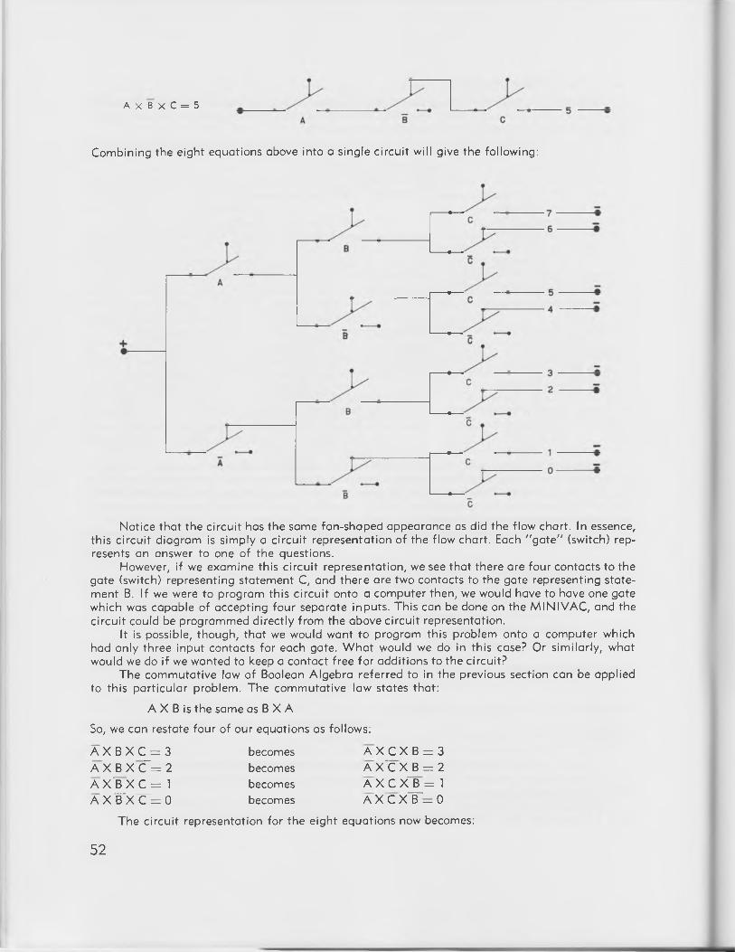
A X B X C = 5
Combining the eight equations above into a single c ircu it w ill give the following:
Notice that the c ircu it has the same fan-shaped appearance as did the flow chart. In essence, th is c ircu it diagram is simply a c ircu it representation o f the flow chart. Each "g a te " (switch) represents an answer to one o f the questions.
However, i f we examine this c ircu it representation, we see tha t there are four contacts to the gate (switch) representing statement C, and there are two contacts to the gate representing statement B. If we were to program this c ircu it onto a computer then, we would have to have one gate which was capable o f accepting four separate inputs. This can be done on the M IN IV A C , and the c ircu it could be programmed d irectly from the above c ircu it representation.
It is possible, though, th a t we would want to program this problem onto a computer which had only three input contacts fo r each gate. W ha t would we do in th is case? Or s im ilarly, what would we do i f we wanted to keep a contact free fo r additions to the circuit?
The commutative law o f Boolean Algebra referred to in the previous section can be applied to th is particu lar problem. The comm utative law states that:
A X B is the same as B X A
So, we can restate four o f our equations as follows:
A X B X C j= 3 A X J 3 X C T = 2 A X B X C = 1a x T x ^ o
becomesbecomesbecomesbecomes
A X C X B = 3 AX~CXJ3 = 2 A X C X B = 1 A X 'C X T r z O
The c ircu it representation for the eight equations now becomes:
52

This is a simple example o f the m anipulation o f circuits which professional programmers do to f i t a logical solution to the capabilities o f a particu la r computer. Some complex logical problems can be programmed for computer solution only by making maximum use o f the computer's capacity in this fashion.
W e shall use a program based on this la tte r c ircu it representation for solving the problem on M IN IV A C 601. The slide switches w ill be used fo r data input and data storage; the relays w ill be used for processing and operating storage; the rotary switch w ill be used for output. A pushbutton w ill be used for the instruction: move fina l answer from operating storage (relays) to output (rotary switch).
In summary then, the rules for using the "M in d Reading Program" are:Let:
Slide Switch 4 represent the answer to question A Slide Switch 5 represent the answer to question BSlide Switch 6 represent the answer to question C.
A slide switch LEFT indicates a YES answer; a slide switch RIGHT indicates a NO answer. The questions are:
A (slide switch 4): Is the number greater than 3?B (slide switch 5): W hen the number is divided by 4, is the remainder greater than 1 ?C (slide switch 6): Is the number odd?
A fte r the answer to each question has been communicated to the computer through the slide switches, pushing pushbutton 6 w ill instruct the computer to indicate the fina l answer on the decimal input-output dial.
A program for the solution of this problem follows:
53

5 V /4 S 5U /5C 6 T /5 L4 R /4 A 5F/6F M + /6 Y4 B / 4 - 6 F / 6 - 6 X /D 1 75 C /5 A M —/D 1 8 D 16/D 195 B /5 - D 1 8 /4 V D 0 /6N6C /6 A 4U /6S D 1 /6K6 B /6 - 4W /5S D2/6J6 X /6 V 5R /6H D 3/6G6 V /5 V 5 T /6 L D 4 /5 N6U /6C 6R /5H D5/5J
D6/5KD7/5G
To use the program:
1. Ask a friend to th in k o f any number between 0 and 7.2. Ask this person to answer "ye s" or "n o " to the fo llow ing questions about the number:
A. Is the number greater than 3?B. When the number is divided by 4 , is the remainder greater than 1 ?C. Is the number odd? ©
3. Indicate the answers to the questions as follows:If the answer to question A is YES, move slide switch 4 to the LEFT.If the answer to question A is NO, move slide switch 4 to the RIGHT.If the answer to question B is YES, move slide switch 5 to the LEFT.If the answer to question B is NO, move slide switch 5 to the RIGHT.If the answer to question C is YES, move slide switch 6 to the LEFT.If the answer to question C is NO, move slide switch 6 to the RIGHT.
4. Push pushbutton 6. The pointer knob o f the rotary switch w ill tu rn to the number your friend was th ink ing of.
Book V I— M IN IV A C GAMES— includes a varia tion on this "M in d Reading Program" which uses names in place o f numbers.
Quantity Recognition
As a fu rthe r example o f the use o f logical operations, let us consider how a computer could be programmed to recognize quantities. The problem w ill be to instruct the computer to determine the number o f slide switches which are ON (in the LEFT position) regardless o f which slide switches are used.
Q uantity recognition circuits have many applications in computer logic. They can be used, fo r instance, to perform additions, to indicate the results o f a game or a vote (win, lose, draw) or to give d irect count fo r a qua lity control system. Q uantity recognition circuits of th is type are based on what mathematicians call a "sym m etric function la ttice ". For our purposes, we may consider the c ircu it as a series o f "yes-no" decisions.
Slide switches 2 through 6 w ill be used to provide input: a slide switch LEFT is ON, a slide switch RIGHT is OFF. Lights 1 through 6 w ill be used fo r output according to the follow ing convention:
L ight 1 ON indicates tha t 1 switch is ON L ight 2 ON indicates tha t 2 switches are ON L ight 3 ON indicates tha t 3 switches are ON L ight 4 ON indicates tha t 4 switches are ON L ight 5 ON indicates tha t 5 switches are ON Light 6 ON indicates tha t No switches are ON.
To program the computer fo r quantity recognition, we w ill firs t describe the possible conditions as a series o f logical expressions:
54

Let:
A = the condition tha t slide switch 2 is ON B = the condition tha t slide switch 3 is ON C = the condition tha t slide switch 4 is ON D = the condition tha t slide switch 5 is ON E = the condition tha t slide switch 6 is ON
Then, A = the condition tha t slide switch 2 is OFF, and so on.Each o f the various combinations o f switches which yield a particu lar answer must now be
stated and then converted to a c ircu it and a program. For example, the case in which ligh t 6 comes ON— indicating tha t no switches are on— can only be expressed as:
A X B X C X D X f = light 6 ON
However, the possibilities fo r ligh t 1 coming ON— indicating tha t one switch is ON— must be stated as five separate expressions:
A X B X C X D X T = light 1 ON A X B ^ X C "X D X F = light 1 ON A X fX C ^ X D X E _ = light 1 ON A X F X £ X D X F = light 1 ON A X B X C X D X E —: light 1 ON
Sim ilarly, there w ill be ten separate expressions fo r the possible conditions fo r ligh t 2 to come ON— indicating tha t two switches are ON, ten expressions fo r ligh t 3, five expressions fo r ligh t 4 and the single expression
A X B X C X D X E = ligh t 5 ON
The program and c ircu it fo r the complete solution must f i t all o f the conditions o f the problem as stated in the 32 logical expressions o f a ll possible cases. The fu ll c ircu it may be represented as follows:
55

A
You w ill notice tha t this representational c ircu it has a lattice shape. Moreover, it is e lectrica lly symmetrical about the lower-left to upper-right diagonal. Hence the mathem atical phrase "sym m etric function la ttice " referred to earlier. This c ircu it representation shows the conditions A and A, etc., as separate switches. In the actual program, o f course, both conditions fo r a given switch w ill be wired onto a single switch using the normally-open and normally-closed contacts fo r the A and A etc., conditions respectively.
An exam ination o f the c ircu it representation shows tha t fo r conditions C, D, and E (corresponding to slide switches 4, 5 and 6) more contacts are required than are available on M IN IV A C 601. Howover, by using the relays and contro lling them by the slide switches, we w ill be able to meet the requirements of the problem.
The fina l program fo r the solution o f the quantity recognition problem appears below. This program is based on the c ircu it representation above and uses the relays to supply the required additional contacts.
56

Program for Quantity Recognition:
1 B / l — 6 F /6 - 5 A /2G 5R /6H 5 K /4 N2 B /2 — 6 + /6 S 4 A /2 K 5 W /6 L 5G/4J3 B /3 — 6S /4V 3 A /2 N 4 T /6 K 4 N /3 H4 B /4 — 4 V /3 V 2 A /2 T 4R/6J 4 J /2 L5 B /5 — 3 V /2 V 1A/3J 6 N /5 L 4G /2H6 B /6 — 2U /2C 6 A /3 N 6J/5H 4K /2S2F/3F 2C /3C 6 T /5 V 6G /4H 3 J /3 K3F /4F 3U /4C 6R/5S 6 K /4 L 3G /2T4F/5F 4C /5C 5 U /5 T 5 J /4 K 2 J /2 K5F/6F 4U /6C 5U /4S 5 N /3 L 2 N /2 R
To use this program:
1. Set slide switches 2 through 6 to the RIGHT (the slide switches are now OFF).2. Turn power ON. L ight 6 w ill come ON ind ica ting tha t NO switches are ON.3. Set any two o f the slide switches 2 through 6 to the LEFT. L ight 2 w ill come ON indicating tha t two switches are ON.4. Set a ll switches to the RIGHT again. Once again, ligh t 6 w ill come ON indicating tha t NO switches are ON.5. Select various combinations o f switches and note tha t in each case the output lights ind icate how many switches are ON (to the LEFT). There are 120 possible combinations o f switches, and in each case M IN IV A C 601 w ill recognize how many switches are ON, regardless o f which switches are used.
A Problem Involving Three Girls
Logical riddles provide apt illustrations o f problems which can be programmed for computer solution. For many riddles, there are two basically d iffe ren t methods fo r handling the computer solution: the computer can be programmed w ith the conditions o f the problem so tha t various solutions may be tried and the computer w ill indicate whether or not the attempted solutions are correct; or, the computer can be programmed to give the fina l solution to the problem immediately.
As an example o f a logical riddle, consider the follow ing inform ation about three girls named Camille, Sara and Wanda:
If Sara shouldn't, then W anda would. It is impossible tha t the statements "Sara should" and "C am ille could n o t" can both be true. I f W anda would, then Sara should and Camille could. Given this inform ation, the problem is:
Is the conclusion "C am ille C ould" valid? More simply, we are asked, "Can C am ille"?
As we have mentioned, there are two methods o f handling this problem. W e can now follow either one o f the two possible methods to solve the problem.
1. W e can represent the conditions o f the problem as logical expressions, convert these expressions into the appropriate c ircu it and program, and program the computer w ith the conditions so tha t by try ing various solutions the computer w ill indicate to us whether or not our solutions are correct. In th is case, tru th or error are expressed in Boolean algebra statements which are d irectly transferred to the computer's contacts. The computer w ill then test each o f our a ttempted solutions against the logical conditions and indicate whether or not the solution is correct. Because o f the d irect Boolean nature o f th is method, we shall refer to th is method as the " Boolean" method o f solution.2. W e can represent the conditions o f the problem as logical expressions, convert these expressions into the appropriate c ircu it and program, and program the computer w ith the conditions so tha t the computer w ill au tom atica lly give us the fina l solution to the problem. In th is case, the logical expressions are transferred to contact networks which w ill force the relays to comply w ith the conditions o f the problem. W hen this program is turned on, the computer w ill autom atica lly seek the correct answer. Because o f the problem conditions which have been programmed onto
57

the computer, only the correct result w ill be perm itted and this result w ill be communicated to the operator. W e shall refer to this method as the "automatic" method o f solution.
The basic difference between the two methods can be compared w ith the d ifference between a thermometer and a thermostat. A thermometer (the analogy o f the "B oo lean" solution) w ill determ ine the temperature and indicate what it is. A thermostat (the analogy o f the "a u to m a tic " solution) w ill not only determine the temperature, but w ill also attem pt to "co rre c t" the temperature to match the temperature which has been "program m ed" into it. For instance, if the temperature were 65°F and we had set a therm ostat fo r 68°, the fo llow ing would occur fo r a thermometer and a thermostat:
1. The thermometer would indicate tha t the temperature was 65°F. It would be up to us to do something about the fac t tha t it was 3° cooler than what we wanted.2. The therm ostat would determ ine tha t the tem perature was 65°F and would autom atically tu rn up the furnace un til the temperature reached 68°F.Essentially then, the "Boo lean" method o f solution indicates tru th or error; the "a u to m a tic " m ethod o f solution determines the correct solution and indicates a fina l result.
Returning now to the problem of the three g irls, we w ill firs t represent the problem conditions as logical expressions, since both methods require this step. We w ill then develop programs for solution by each o f the two methods.
Logical Expressions for the Problem Conditions
From the conditions of the problem, we can see tha t there are only two possible situations fo r each girl:
Cam ille could or could not Sara should or should not W anda would or would not
W hatever other conditions may exist, we can be sure tha t there are only two possible conditions for each girl.
W e can therefore represent the possible conditions fo r each g irl by the fo llow ing convention:
Cam ille could Cam ille could not Sara should Sara should not W anda would W anda would not
There are two ways to set up the logical expressions for each problem condition. W e can set up e ither a " tru th sta tem ent" or an "e rro r statem ent". A " tru th sta tem ent" describes the permissible conditions; an "e rro r s ta tem ent" describes the conditions which are not permissible. The two statements are, o f course, complementary.
The problem conditions can be stated as:
If Sara shouldn't, then W anda would:
S X W = error or S + W = tru th
It is impossible tha t the statements "Sara should" and "C am ille could n o t" can both be true:
C X S = error or C + S = tru th
If W anda would ,then Sara should and C am ille could:
W X (S + C) = error or W - f (C X S) = tru th
C _ =c = s _ = s = w = W -
58

"Boolean solution"
Because it is simpler in this case, we w ill set up a program for the "B oo lean" solution from the three "error" expressions above. Slide switches 1, 2 and 3 w ill be used to provide the contacts for Cam illa, Sara and W anda respectively. L ight 3 w ill be used as the error indicator. Since there are three error conditions and only two contacts fo r ligh t 3, we w ill use the "C om m on" term inals to provide the necessary extra contacts. (The notation for a connection to a common term inal is "1 com ", "2 com ," etc.)
The c ircu it diagram and program fo r the "B oo lean" solution of the problem appear below. Each o f the logical expressions fo r the problem conditions can easily be traced on the c ircu it d iagram.
Slide switch 1 represents Camille Slide switch 2 represents Sara Slide switch 3 represents Wanda
A slide switch LEFT indicates the positive condition: Cam ille could, Sara should, W anda would. A slide switch RIGHT indicates the negative condition: Cam ille could not, Sara should not, W anda would not.
L igh t 3 ON represents an error.
1 + / 2 S 2 S /3 V 2 T /3 S 3 T / 3 com 2R/1S I T / 3 com 3 U / 2 V 2 V / 1 V 1W/2W 2 W / 3 com 3 A /3 com 3 B /3 —
PROGRAM A N D CIRCUIT— BOOLEAN SOLUTION
To use the program fo r the "Boo lean" solution:Turn power ON. Using slide switches 1, 2 and 3, try various combinations o f "Sara should",
"C am ille could n o t", etc. un til the error ligh t ( ligh t 3) goes OFF. I f the power is ON and ligh t 3is OFF, slide switches 1, 2 and 3 are indicating a correct solution to the problem. (Note: fo r somelogical riddles there is more than one complete solution)The problem to be solved is "Can C am ille?" To discover whether or not "C am ille can", the conditions o f the other girls must also be considered.
"Automatic" Solution:
The program and c ircu it diagram fo r the "a u to m a tic " solution are based on the truth expressions stated above. The relays are programmed so tha t they are forced to fo llow a ll o f the problem conditions to yield the fina l result. The relay ind icator lights w ill be used to indicate the solution:
Relay ligh t 1 w ill indicate the condition of Camille Relay ligh t 2 w ill indicate the condition o f Sara Relay ligh t 3 w ill indicate the conditon o f Wanda
A relay ligh t ON w ill indicate the positive condition; a relay ligh t OFF w ill indicate the negative condition.
59

Since there is a possibility o f more than one correct solution, pushbuttons 1, 2 and 3 are wired in so tha t additional in form ation may be entered.
Pushbutton 1 represents Camille Pushbutton 2 represents Sara Pushbutton 3 represents Wanda
A pushbutton UP transm its no additional in form ation to the computer. A pushbutton DOWN, however, supplies the positive condition (Cam ille could, Sara should, W anda would).
W hen the power is turned ON, a correct solution w ill immediately appear in the relay indicator lights. By pushing a pushbutton, we may enter additional positive inform ation about a girl. The relay indicator lights w ill then indicate the correct solution to the problem w ith the added inform ation.
1 4 - / 1 V1Y /2Y2 Y /3 Y1X/1C2X /2C3X/3C2 K /1 X2L /2 +2 N /3C3G/1H1H/1C1G/2C3 H /3 +1F/2F2F/3F3 F / 3 -
To use the program for the "au tom atic solution:
Turn power ON. The solution to the problem appears in the relay indicator lights. A relay indicator ligh t ON represents the positive condition: Cam ille could, Sara should, W anda would. A relay indicator ligh t OFF represents the negative condition.
To add positive inform ation about a g irl, push the appropriate pushbutton. The relay ind icator lights w ill indicate the new solution, given this additional inform ation.
The Farmer, the Goose, the Corn and the W olf
A t one tim e or another you have probably come across the problem of the farm er w ith a rowboat who has to cross a river in order to reach his home on the opposite shore. The farm er has w ith him a goose, some corn, and a wolf. The farm er wants to bring both animals and the corn home w ith him, but the boat is small and w ill hold only one of the three objects, in addition to the farm er, a t any one time. The real problem facing the farm er is tha t i f he leaves the goose and the w olf alone, the w olf w ill eat the goose. And, i f he leaves the corn and the goose alone, the goose w ill eat the corn.
The farm er's problem provides an excellent example o f the advantages o f sim ulation solution. The farm er wants to get across the river w ith all three o f his possessions, and solution o f his problem by tria l-and-error in the real world could be expensive fo r him. Should he make a mistake, he could lose both the goose and the corn.
However, i f the farm er has access to a computer, he can simulate his problem on the computer and try out various solutions un til he reaches the righ t one. In th is way, the farm er can use a tria l-and-error method w ithout any danger o f actua lly losing either his goose or his corn.
60

To solve the farm er's problem on the M IN I VAC, we w ill state the problem as a series o f logical expressions. These relationships w ill then be converted to c ircu it representations and the conditions of the problem w ill be programmed onto the computer fo r solution.The Basic Conditions:
The farm er's problem can be stated as three basic conditions:A. The goose and the w olf cannot be le ft alone w ithout the farmer.B. The goose and the corn cannot be le ft alone w ithout the farmer.C. The boat w ill hold only one object in addition to the farmer.
The firs t two conditions— A and B— can be expressed as logical statements as follows:Let:
F represent the presence o f the farm erF~ represent the absence o f the farm erG represent the presence o f the gooseG represent the absence o f the gooseW represent the presence of the wolfW represent the absence o f the wolfC represent the presence o f the cornC represent the absence o f the cornE represent an error (loss o f one o f the farm er's possessions)
Then:Condition A (the goose and the w olf cannot be le ft alone) can be expressed as:
G X W X F + G X W X F = E Condition B (the goose and the corn cannot be le ft alone) can be expressed as:
G X C X F + G X C X F = E
Condition C (the size lim ita tion of the boat) need not be stated as a logical expression. The fina l program w ill include appropriate c ircu itry so tha t i f the boat is overloaded, only one object w ill be recognized as being in the boat w ith the farmer.Programming the Simulation:
The two problem conditions— A and B— can be combined as follows: F X G X (W -f- C) + F X G X ( W + G = EThis is the error condition which must be programmed onto the computer. W e w ill program the computer so tha t i f either error condition is met, an "a la rm " ligh t (or an "e rro r" light) w ill come on.
I f we had only to program the error condition, the program would be a simple one, and this
F X G X ( W + C) + F X G X ( W + C) = E
CIRCUIT REPRESENTATION
61

However, th is c ircu it represents only the processing and output portions o f this program. We must also provide means o f input and storage for the various solutions which we w ill a ttem pt. By w iring in the slide switches and pushbuttons fo r inpu t and storage, and using the relays fo r processing and the lights fo r output, we w ill be able to program the entire problem fo r computer solution.
W e shall use the follow ing conventions in the program:
An output ligh t ON represents an object at home.A relay indicator ligh t ON represents an object across the river.A slide switch LEFT represents an object in the boat.A slide switch RIGHT represents an object not in the boat.L ight 5 ON represents the condition: "W o lf eats goose".L igh t 6 ON represents the condition: "Goose eats corn".Pushbutton 6 represents moving the boat towards home.Pushbutton 1 represents moving the boat from home.
The fo llow ing components w ill be used to represent the objects in the problem:
O utput L ight Relay Slide Switch
Farmer 1 1 1
Goose 2 2 2
W o lf 3 3 3
Corn 4 4 4
Program fo r the solution o f the Farmer's problem:
1 A /1 J 1U /2 V 2 N /3 N 3 N /4 N 5 B / 5 -1 B / l — 1V /1 X 2 W /3 V 3 W /4 V 6 B /6 —1C/1G 1 X /6 X 3A /3J 4A /4J 6 Y /6 —1 E/1 U 1Y/1 + 3 B /3 - 4 B / 4 -1F/2F 2A /2J 3C /3G 4C /4G1H /2H 2 B /2 - 3E/3U 4E/4U1K /2K 2E/2U 3F/4F 4 F / 4 -1K/1 + 2C /2G 3 H /4 H 4 H /4 +1L /2L 2F/3F 3 K /4 K 4 L /6 A1N /3 K 2 H /3 H 3 L /5 A
To use the program:
1. Turn power ON. M anually push relays 1 through 4 to the LEFT. The relay indicator lights w ill come ON to indicate tha t a ll objects are across the river. Move slide switches 1 through 4 to the RIGHT.
2. Place the farm er in the boat by m oving slide switch 1 to the LEFT. (The farm er must be in the boat or the boat w ill not move)
3. Choose another object and place it in the boat by pushing the appropriate slide switch to the LEFT.
4. Move the boat across the river by pushing pushbutton 6. If lights 5 and 6 remain OFF, no error has been made.
5. Continue moving the boat back and fo rth across the river w ith the d iffe ren t objects un til a ll four objects are a t home (output lights 1 through 4 are ON.) Do not forget to remove objects from the boat when they have reached the other side (by moving the slide switch to the RIGHT)
62

6. If an error is made, reset the computer by setting slide switches 1 through 4 to the RIGHT and m anually setting relays 1 through 4 to the LEFT.
The Television Problem
As a fina l example o f a problem which can be programmed for computer solution, consider the follow ing:
Barry, his w ife Clara, and the ir children— David, Edward and Francis— are at home. It is 8:00 in the evening.
1. If Barry is watching television, so is his wife.2. Either Edward or Francis, or both, are watching television.3. Either Clara or David, but not both, is watching television.4. Edward and David are either both watching or both not watching television.5. I f Francis is watching television, then Barry and Edward are also watching television.
W ho is watching television?
This problem provides an excellent example o f a problem which is complicated enough to be confusing to a person attem pting to solve it. The problem conditions and the details o f the relationships are d iff ic u lt to remember. Because o f its confusion-proof memory, the computer can easily handle a problem o f th is type.
To solve th is problem, we w ill state the problem conditions as logical expressions and develop the appropriate c ircu it fo r a "Boo lean" solution using a " t r u th " ligh t to te ll us when we have arrived at the correct solution. This w ill, o f course, be a sim ulation technique since we w ill not have to actua lly drop in on the fam ily to find out who is watching television.
Logical expressions fo r the Problem Conditions:Let:
B = the condition tha t Barry is watching television C = the condition tha t Clara is watching television D §g the condition tha t David is watching television E = the condition tha t Edward is watching television F m the condition tha t Francis is watching television
Then:B = the condition tha t Barry is NOT watching television, etc.
And: T = tru th (permissible condition)
1. If Barry is watching television, so is his wife:
"B + C = T
2. Either Edward or Francis, or both, are watching television:
E + F = T
3. Either Clara or David, but not both is watching television:
C X D + C X D = T
4. Edward and David are either both watching or both not watching television:
E X D + I X D = T
5. If Francis is watching television, then Barry and Edward are also watching television:
T + ( BXE) = T
Each o f these expressions can be represented as logical circuits in the follow ing manner:
63

1. B + C = T
T ---------------------•
2. E + F = T
3. C X D + C X D = T
4. E X D + E X D = T
5. F + ( BXE) = T
64

The Program fo ra "B oo lean" Solution:To convert the representational c ircu its to a program, we w ill use the fo llow ing convention: Let:
Slide switch 1 represent Barry Slide switch 2 represent Clara Slide switch 3 represent David Slide switch 4 represent Edward Slide switch 5 represent Francis
A slide switch LEFT indicates tha t the person is watching television; a slide switch RIGHT indicates tha t the person is NOT watching television.L ight 4 w ill indicate the correct solution: ligh t 4 ON indicates tha t the solution represented by the slide switches is CORRECT; ligh t 4 OFF indicates th a t the solution is NOT CORRECT.The complete program fo r the "Boo lean" Solution is:
1U/1S 2 W /3 U 4 B / 4 -1S/2S 3R/4R 4 U /5 V1T/2R 3S /3V 4 U /1 V2 R /2 V 3 T /4 T 4 V /4 +2 U /3 W 4A /4S 5 W /1 U
To use the program:Set slide switches 1 through 5 to the LEFT (th is indicates tha t no one is watching television).
Turn power ON. By moving slide switches 1 through 5, try various solutions to the problem. L ight 4 w ill come ON only when the correct solution has been indicated.
65


BOOK IV
How Computers Do Arithmetic
1. THE BINARY NUMBER SYSTEM
In the previous books, we have frequently made use of the two-valued binary code. W e have seen tha t th is is a convenient representation for the on-o ff nature o f the computer's components. Let us now consider the binary number system which is basic to the function ing o f a computer system.
How Numbers Are Represented in the Binary System
A ll o f us have been taught to th in k in the decimal number system. The decimal system has ten d iffe ren t symbols— zero through nine— which can be used alone and in com bination to represent numerical concepts. The binary system, however, uses only two d iffe ren t symbols— zero and one — to represent the same numerical concepts.
Let us consider a three-d ig it decimal number: fo r example, 547. W e know tha t th is actua lly means 500 plus 40 plus 7— or 5 times 100 plus 4 times 10 plus 7 times 1. In other words, we know tha t the right-most d ig it represents the number of l 's (units) in a number, the next d ig it to the le ft represents the number of 10's in the number, the next d ig it to the le ft represents the number o f 100's in the number, and so on.
Now let us see why this is so. Suppose we start counting from 0. W e go 0, 1, 2, 3, 4, 5, 6, 7, 8, 9. Now we have used up all of the symbols available in the decimal system. To continue, we must invent a method for handling numbers greater than 9. W e do th is by placing a 1 to the le ft and a 0 in the fa r righ t position (called the "low order position") so tha t we now have " 1 0 " which represents one ten and no ones. S im ilarly, if we reach 99— which represents 9 tens and 9 ones— and then add one more we must invent a method for handling numbers larger than 99. We do this by placing a 1 to the le ft and 0's in the two low order positions, giving 100— 1 times 100 plus 0 times 10 plus 0 times 1.
So we have a simple rule fo r form ing any number system: when we run out of symbols in the low order position, we place a 1 in the next higher position and return the low order position to 0. Notice what this means: i f we have 70 symbols, the low order position represents l 's ; the next high order position represents 10's; the next high order position represents 100's; and so on. Each tim e we move one position to the le ft the "w e ig h tin g " o f tha t position is ten times as great as the "w e ig h tin g " o f the position to the right.
Now notice tha t i f we had only 5 symbols— 0, 1, 2, 3, 4,— to w rite the next higher number (5) we would have to place a 1 in the le ft position and a 0 in the righ t to represent one 5 and no l's .
The binary system is actua lly simpler than the decimal system. W e count 0, 1 and then we have run out o f symbols. So the next symbol (to represent 2) must be 10 representing one 2 and no l's . Three is w ritten 11, representing one times 2 plus one times 1. Once again, we have run out o f symbols. To w rite 4 we must write 100, representing 1 times 4 plus 0 times 2 plus 0 times 1.
Thus the rule fo r form ing numbers in the binary system is: the low-order d ig it represents l's , the next le ft d ig it represents 2's, the next le ft d ig it represents 4's, and so forth . Let us now count from 0 to 10 in binary numbers:
67

:im al Binary0 01 12 103 114 1005 1016 1107 1118 10009 1001
THE FIRST TEN BINARY NUMBERS A N D THEIR DECIMAL EQUIVALENTS
Notice tha t each tim e we add 1 to a b inary number— every tim e we count from one number to the next— the fa r righ t position changes, e ither from a 0 to a 1, or from a 1 to a 0. And, i f the right-m ost position is a 1 and 1 is added, the right-most position changes from a 1 to a 0 and the next le ft position also changes— either from a 1 to a 0 or from a 0 to a 1.
Since a computer works in the binary system, it must then be capable o f changing— either from a 1 to a 0, or from a 0 to a 1, i f it is to perform arithm etic. W e have already become acquainted w ith a program which perm its the computer to do just this— the single-input flip -flo p described in Book II.
Building a Single-Input Flip-Flop W ith Carry
However, to perform arithm etic the computer must also be able to "c a rry ". That is, i f the computer is to add 1 and 1 in binary, it must be able to indicate tha t the solution is: "1 and 1 are 0 and carry I ” . As a basic c ircu it to perform arithm etic then, we w ill need a "s ing le -inpu t flip -flo p w ith ca rry".
In developing the single-input flip -flo p in Book II, we firs t bu ilt a "tw o-inpu t f lip - f lo p " (see "Tw o-Input Mem ory Relay C irc u it"— Book II.) This two-input flip -flo p used only one relay which remembered either a zero or a one, depending upon which it had last been instructed to remember. To make this two-input f lip -flo p "change its m ind ," we had only to instruct it to remember the other number by pushing the appropriate pushbutton. However, to make the two-input flip -flo p change, we have to know at what state it is in a t this moment in order to make it change.
The single-input flip -flop , however, does the changing autom atica lly by using a second relay to remember the state the flip -flo p is currently in just long enough to allow the firs t relay (which is actually remembering the 1 or the 0) to change. By using a second relay, then, we no longer need to know what state the flip -flo p is in a t th is moment in order to make it change. W e merely instruct the computer to change, and it does so autom atically because o f the single-input flip -flo p which is programmed onto it.
Let us go over again the functions o f the two relays o f the single-input flip -flop :W hen the pushbutton is pushed, relay A instructs relay B to go to the same state relay A is
in a t th is moment. W hen the pushbutton is released, relay B instructs relay A to move to the opposite state. Relay A does the actual remembering; relay B assists relay A when it is necessary for relay A to change.
To build a single-input flip -flo p on the M IN IV A C , we w ill begin w ith two relays wired to be self holding. (That is, each relay w ill remain in position once it is set.) The program fo r th is is:
5 + /5 H 6G /6F5 H /6 H 5C /6C5G /5F 6 C /6 -
W e w ill now add to the program so tha t when pushbutton 6 is pushed, relay 6 w ill go to the same state th a t relay 5 is in. This w ill require the fo llow ing additional connections:
6 8

6H/6Y6X /5L
5K/6F5N/6E
Again we w ill add to the program so tha t when pushbutton 6 is released, relay 5 w ill go to the opposite state from relay 6:
6 Z /6 L6K /5E6 N /5 F
And fina lly , we w ill add an indicator ligh t to show what state the flip -flo p is in:
6 G /6 A 6 B / 6 -
W e now have a s ing le -inpu t-flip -flop programmed on M IN IV A C . The c ircu it diagram for thisis:
However, our single-input flip -flo p s till cannot be used fo r a rithm etic : it does not provide a "ca rry s igna l". Tha t is, it does not n o tify us when it has changed from 1 to zero. And, since all contacts on both relays are used, we cannot arrange fo r a carry signal by merely adding connections.
The solution to th is d iff ic u lty is to build a d iffe ren t version of the single-input flip -flo p — one which leaves contacts free fo r the programming of a carry signal. The version o f the flip -flo p which we w ill use d iffe rs from the previous one in another respect as well. The stable states o f the flip - flop when the pushbutton is up are either both relays ON or both relays OFF. For this program, ligh t 5 is used to indicate the state o f the flip -flop . L ight 6 is used only to provide a path for current when relay 6 is "shorted-ou t" (OFF); ligh t 6 is not used as an indicator in th is program. The program and c ircu it diagram fo r th is flip -flo p are:
69

S © - g . 5 - 6, » © a — . s -
Program:5 + / 5 G5 H /5 F5 F /6F5 C /6C6 C /6 —5 J /6 H6G /5E
6J /6E6 E /6 A6 B /6 —5 H / 5 A5 B /5 —6 + / 6 Y6 X /6 H
SINGLE-INPUT FLIP-FLOP— SECOND VERSION
We now have a single-input flip -flo p w ith contacts free for a carry signal. W ith the power OFF, program this f lip -flo p on your M IN IV A C 601. Then:
1. Turn power ON. Notice tha t both relays 5 and 6 are OFF.2. Push and release pushbutton 6. Notice tha t both relays 5 and 6 are now ON.3. Push pushbutton 6, but do not release. Notice tha t relay 5 is OFF; relay 6 is ON. W e want a
carry signal to occur NOW.To add the carry signal, we w ill add the connections:
5G /5N5 L /6 L
6 K /4 A4 B / 4 -
Light 4 w ill now indicate tha t a carry is tak ing place.W e now have a basic computer arithm etic device— the single-input flip -flo p w ith carry. The
c ircu it diagram looks like this:
- • 6 -
6 + *~ 6Y 6X
CIRCUIT FOR SINGLE-INPUT FLIP-FLOP W IT H CARRY
70

W e can use single-input flip -flops as "b u ild in g blocks" fo r more complex arithm etic devices. For example, three flip -flops can be wired together on your M IN IV A C to produce a counter which operates as follows:
6
pushbutton 6
.OP •
As pushbutton 6 is pushed and released again and again, th is device w ill store in binary code the number o f times the pushbutton has been pushed. The follow ing chart shows what happens to each stage o f the counter as the pushbutton is pushed and released, pushed and released: (the chart is read from righ t to left).
Flip-FlopA
Carry B to A
Flip-FlopB
Carry C to B
Flip-FlopC
Pushbuttoncarry
TimesPushed
0 NO 0 NO 0 UP 00 NO 0 NO 1 DOW N
0 NO 0 NO 1 UP 10 NO 1 YES 1 DOW N
0 NO 1 NO UP 20 NO 1 NO 1 DOW N
0 NO 1 NO 1 UP 31 YES 1 YES 1 DOWN
1 NO 0 NO UP 41 NO 0 NO 1 DOW N
1 NO 1 NO 1 UP 51 NO 1 YES 1 DOWN
1 NO 1 NO UP 61 NO 1 NO 1 DOWN
1 NO 1 NO 1 UP 71 YES 1 YES 1 DOW N
0 NO 0 NO 0 UP 0 or 8
BINARY COUNTER— SEQUENCE OF OPERATIONS
This counter, shown in the preceding block diagram, can be b u ilt on the M IN IV A C as the follow ing experiment demonstrates:
Experiment 1: A Three-Bit Binary Counter
In th is Experiment we w ill build a counter and use it to see how the binary number system works.
A counter can be made up o f any number o f s ingle-input flip -flops w ith carry. One flip -flo p is required fo r each b it to be handled by the counter. Because the M IN IV A C 601 has six relays, we
71
Light 4 Light 5
IFLIP-FLOP carry
A B to A
1FLIP-FLOP carry
B C to B
Ligh
JFLIP-
C
F

w ill be able to build a three-b it counter (using two relays fo r each flip -flop ). This counter w ill allow us to count from 0 to 8.
The c ircu it diagram which follows is fo r the m iddle b it (or " 2 " b it) o f the counter. The "h igh o rder" and "low order" bits (that is, the " A " b it and the " 1 " bit) are identical except tha t no "ca rry o u t" is required fo r the high order b it and the "ca rry in " to the low order b it is supplied through pushbutton 6. The program fo r the entire counter is given below w ith the c ircu it diagram fo r the m iddle stage:
Full program fo r Binary Counter:
1A /2E 2 C /3 C 3 J /6 K 5 F /5 HI B / 1 — 2E/2J 3 L /4 L 5 G / 5 +1C /2C 2 F /4 A 3 N / 4 H 5 J /6 H1E/2G 3 A /6 E 4 B /4 — 5 J /6 X1F/2F 3 B /3 — 4 C /5 C 5 L /6 L1F /1H 3 C /4 C 4E/4J 5 N / 6 H1G/1 + 3E /4G 4 F /5 A 6 A /6 F1J /2H 3 F /3 H 5 B /5 — 6 B /6 —1J /4K 3 F /4 F 5 C /6 C 6 C /6 —2 A /4 E 3 G /3 + 5E /6G 6E/6J2 B /2 — 3 J /4 H 5F /6 F 6 Y / 6 +
Procedure:
1. Turn power ON. Push pushbutton 6 and release. Binary output lights 4, 5 and 6 w ill read OFF, OFF, ON or 001. The Binary Counter is displaying a 1.2. Push pushbutton 6 again and release. Binary output lights 4, 5 and 6 w ill now read OFF, ON, OFF or 010. The Binary Counter is now displaying a 2.3. Push and release pushbutton 6 several times. Each tim e a fte r releasing the pushbutton, note the b inary number displayed in lights 4, 5 and 6. Compare your numbers w ith the table o f binary numbers on page 66.
You w ill notice th a t the counter repeats a fte r it has reached 7. This is a result o f the fa c t tha t the counter is made up o f 3 flip -flops. Each flip -f lo p has 2 stable states (0 or 1), so the combination of 3 flip -flops has 23 or 8 stable states. These 8 stable states represent the binary numbers 0 through 7.
As you push pushbutton 6 several times, notice tha t the low order f lip -flo p (represented by ligh t 6) changes each tim e the pushbutton is pushed and released. The low order f lip -flo p represents 1 's (units). The next flip -flo p to the le ft (represented by ligh t 5) changes every other tim e the pushbutton is pushed and released. This f lip -flo p represents 2's. And o f course, the high order
72

f lip -flo p (represented by ligh t 4) changes every fou rth tim e the pushbutton is pushed and released; the high order flip -flo p thus represents 4's.
You w ill notice tha t the m iddle f lip -flo p changes on a regular basis; it changes every tim e the low order flip -flo p changes from 1 to 0. The high order flip -flo p behaves s im ilarly— it changes every tim e the m iddle flip -flo p changes from 1 to 0.
Referring again to the table o f binary numbers, we can see tha t th is is a characteristic of binary numbers: adding 1 to a b inary number changes the low order b it— either from 0 to 1 or from 1 to 0. A ll other, higher order, bits change i f and only if the b it to the righ t is changing from 1 to 0.
Leave the Binary Counter on the M IN IV A C for Experiment 2.
Experiment 2: Counter Arithmetic
It is possible to perform additions very s im ply on a Binary Counter. W e have already seen tha t it is possible to add 1 to the number in the counter merely by pushing and releasing pushbutton 6. This technique can easily be extended to any number which can be represented on the counter.
For example, to add 2 and 3: push and release pushbutton 6 twice; the counter w ill display the binary number 2. Now push the pushbutton 3 more times and the counter w ill display the answer— the binary number 5. This is exactly what would have happened had you just pushed the pushbutton 5 times.
This is one way in which an addition can be performed in a computer and is, in fact, a common method fo r handling certain kinds o f addition problems.
A t th is point your counter should be displaying binary 5. Now push button 6 five more times. The pushbutton has now been pushed ten tim es, and the counter should display binary equivalent o f decimal 10. However, b inary 10 is a fou r-b it number (1010). Since we have only three bits in our counter, we would expect to see only the low order three bits o f the number displayed. The b it pattern fo r the binary equivalent o f decimal 10 is 1010. The counter w ill display 010.
Experiment 3: Universal Counter Arithmetic
It is possible to wire the Binary Counter so tha t it w ill count down as well as up. In this way, both additions and subtractions can be performed. The program below gives the necessary m od ifications to the Binary Counter from experiments 1 and 2:
M od ify the program from Experiment 1 as follows:
Remove the connections:
6K /3J4 K /1 J
Add the connections:
3 K /6 W 5 N /6 N3 N /4 N 5 K /6 T6R /6 K 6S/3J4 K /6 U 6V /1J
Procedure:
1. Build the counter or, i f you have the counter from experiments 1 and 2 programmed, make the necessary modifications. I f slide switch 6 is LEFT, the counter w ill count UP; if slide switch 6 is RIGHT, the counter w ill count DOWN.2. Subtract 4 from 7 as follows:
a. Move slide switch 6 to the LEFT.b. Enter the larger number (7) by pushing pushbutton 6 the correct number o f times. The
counter is now displaying the larger number.
73

c. Move slide switch 6 to the RIGHT.d. Enter the smaller number (4) by pushing pushbutton 6. The counter is now displaying the
answer: 7 — 4 = 3.Note: addition is carried out exactly as in experiment 2 when slide switch 6 is LEFT.
2. BINARY ADDITIO N
Rules for Binary Addition
Let us add together two binary numbers: 11 010 (26) and 11100 (28):
1101011100
starting from the low order (right-most) bit:0 plus 0 equals 0.1 plus 0 equals 1.0 plus 1 equals 1.1 plus 1 equals 0 and carry 1.1 plus 1 plus carry 1 equals 1 and carry 1.The answer is:
11010 11100
110110As you can see, the addition tables fo r b inary arithm etic are very simple. They are:
0 0 1 1+ 0 +_]_ + 0 -M
0 1 1 10
The problem above illustrates how a b inary adder fo r a computer must work. Each b it of the adder must be able to accept three inputs:
a. the firs t number to be addedb. the second number to be added.c. a carry from the b it to the right.
Each b it o f the adder must also be able to yield two outputs:a. the sumb. the carry.Let us call the three inputs " A " , "B " , and "ca rry in " ; and let us call the two outputs "su m "
and "ca rry ou t". Notice tha t the sum w ill equal 1 i f and only i f e ither one or three o f the inputs is1. Carry out w ill equal 1 if and only i f e ither two or three o f the inputs are 1.
I f we restrict the input to only A and B, we can build the fo llow ing table showing inputs and outputs o f an adder:
A B Carry Out Sum
0 0 0 0
0 1 0 1
1 0 0 1
1 1 1 0
74

The c ircu it which actua lly performs this operation is called a "ha lf-adder w ith ca rry". A h a lfadder w ith carry is a device w ith two inputs and two outputs such tha t the sum w ill equal 1 i f and only i f one and only one o f the inputs is 1. In other words, the sum c ircu it is an EITHER BUT NOT BOTH circu it. The fo llow ing experiment illustrates the operation of a half-adder w ith carry.
Experiment 4: A Half-Adder with CarryIn th is experiment we w ill build and test a simple half-adder w ith carry. The c ircu it and pro
gram are:
Program:5 A /6 U5 B / 5 -6A /6 S6 B / 6 -
6 R /6 Z6 T / 6 X6 T / 6 V6 Y / 6 +
The entire program requires one pushbutton, one slide switch and two lights. The slide switch represents input A ; the pushbutton represents inpu t B. The lights represent the two outputs: ligh t 6 represents the sum; ligh t 5 represents carry out.
Procedure:1. Turn power ON. Move slide switch 6 to the RIGHT: input A is now 0. Do not push pushbutton6: input B is 0. L ight 5 and 6 are OFF: sum is 0 and carry out is 0.2; Push pushbutton 6 and hold it down. Input B is now 1. L ight 6 comes ON, indicating th a t the sum is I , This is equivalent to the m athem atical statement: 0 + 1 = 1.3. Release pushbutton 6 and move slide switch 6 to the LEFT. Input A is now 1; input B is 0. L ight 6 comes ON, indicating tha t the sum is 1:1 + 0 = 1 .4. W ith the slide switch LEFT, push pushbutton 6. L ight 6 goes OFF and ligh t 5 comes ON.This represents the m athem atical statement: 1 + 1 = 0 and carry 1.
I f we now have three inputs (A, B, and carry in) and two outputs, the table o f values looks like this:
Carry In Carry Out Sum
75

The c ircu it which actua lly performs th is operation is called a " fu l l adder w ith ca rry ", and is made up of two half-adders as follows:
SUM
Like the single-input flip -flo p w ith carry, the half-adder w ith carry is a basic computer c ircuit. Half-adders can be used as "bu ild ing b locks" fo r more complex arithm etic devices— an example o f which is the fu ll adder.
Experiment 5: A Full Adder
In this experiment we w ill m odify the c ircu it o f experiment 4 to build a fu ll adder. A fu ll adder is made up o f two half-adders and a simple OR c ircu it. The c ircu it and program fo r a fu ll adder are:
5A /6U5B/5—5C/6S5F/5—5G/6J5 H / 5 +5J/6G6A /6H6B/6—6J/6L6K/6U6R/6Z6 T /6 X6 T /6 V6 Y / 6 +
76

Relay 6 represents a carry in from a previous stage. Relay 5 represents the sum of inputs A and B; this sum w ill be added to the carry in to give the sum for the fu ll adder. Notice tha t a carry signal may come from either o f two places: either from the half-adder representing the slide switch and pushbutton (input A and input B), or from the half-adder representing the carry in (relay 6) and the sum of the input (relay 5). Either half-adder can produce a carry signal.
Procedure:
1. Turn power ON. Move slide switch 6 to the RIGHT; Input A is 0. Do not push pushbutton 6; input B is 0. Relay 6 is OFF; carry in is 0. Lights 5 and 6 are OFF. This is equivalent to the m athem atical expression: 0 + 0 + 0 = 0.2. Move slide switch 6 to the LEFT; input A is now 1. L ight 6 comes ON: 1 + 0 + 0 = 1 .3. M anually move relay 6 to the le ft to indicate tha t carry in is 1. L ight 6 goes OFF and ligh t 5 comes ON: 1 + 0 + 1 = 0 and carry 1.4. T ry other combinations o f inputs by moving slide switch 6, pushing pushbutton 6, and /o r m anually moving relay 6.
W e have now seen how two half-adders can be combined to produce a fu ll adder. Full adders can in tu rn be used as build ing blocks fo r adders capable o f accepting greater inputs and yie lding greater outputs. The follow ing experiment illustrates the combination o f three fu ll adders to produce a "th ree -b it adder".
Experiment 6: A Three-Bit Adder
In th is experiment we w ill build a device which is capable o f adding together two 3-b it b inary numbers and displaying a result o f not more than 4 binary bits. The program fo r the 3-b it adder is:
2 C /3G 3 L /4 X 5 K / 6 W2 F /3F 4 A / 4 V 5 L /6 A2G/4S 4 B /4 — 5 N /6 U2 H / 4 Y 4E/5F 5 R /6 T2 K / 4 W 4F/5S 5 T /6 R2 L / 2 + 4 G /5 U 5 T / 5 V2 N /4 U 4 H / 4 N 5 Y / 6 V3 A /M 1 0 4 K /5 Z 6B /6 —3 B /3 — 4 L /5 A 6E /6 —3 C /4G 4 N / 5 X 6 G /6R3F/4E 4 Y / 5 Y 6 H / 6 X3 G /3 N 5 B /5 — 6 J /6 K3 H / 4 Z 5 C /6 K 6 L /6 Z3 J /4 T 5F/6E 6 N / 6 T3 K /4 R 5G/6S 6 V / 6 Y3 K /M 1 0 5 H / 5 + 6 Y / 6 +
The three fu ll adders which make up th is c ircu it are very much like the single adder o f experiment 5. However, the c ircu it has been m odified s ligh tly so tha t three adders use only five relays. The high order stage o f the adder is wired so tha t the carry from it is displayed by ligh t 3. This allows us to display a 4 -b it result w ith a 3-b it adder.
Procedure:
1. Turn power ON. Enter a binary number in the adder using slide switches 4, 5 and 6. For example, to enter binary 4 (100) set slide switch 4 LEFT, slide switch 5 RIGHT and slide switch 6 RIGHT.2. Enter another b inary number using pushbuttons 4, 5 and 6. For example, to enter binary 5 (101) push button 4 and 6; do not push pushbutton 5.3. The answer w ill be displayed in binary output lights 3, 4, 5 and 6. For example, i f lights 3 and 6 are ON and lights 4 and 5 are OFF, the answer is 1001 (9).
77

3. HOW COMPUTERS SUBTRACT
W e have now discussed two methods o f computer addition. The firs t method was a counter which was dependent upon the number o f times an input button had been pushed. The second method used three fu ll adders w ith carry which allowed us to enter two 3-b it numbers s im ultaneously.
Two's Complement Arithmetic
Sim ilarly, there are two methods o f computer subtraction. The simpler method is the "down counter" demonstrated in experiment 3. However, in spite o f its sim plic ity, the down counter is seldom used in a computer. The more common method o f subtraction used in computers is called "tw o 's complement a rithm e tic ". Two's complement arithm etic in the binary system is the same as ten's complement arithm etic in the decimal system.
Two's complement arithm etic in the binary system works as follows: the subtractor is "com plemented". This means tha t every 1 is replaced by a 0, and every 0 is replaced by a 1. The complemented subtractor and the subtrahend are then added. I f a carry occurs out o f the high order position, it is added to the low order position. The resulting sum is the proper d ifference between the two numbers.
As an example, let us subtract b inary 4 from binary 13. W e firs t w rite down 1101 (13) and below it we w rite 1011— which is the complement o f 0100 (4):
13 1101 ^ 1101- 4 - 0 1 0 0 1011
decimal binary complemented subtractor
We now add in the usual binary manner except tha t if a carry occurs out o f the high order b it, we w ill add it to the low order bit:
1 1 0 1 1 0 1 1
J _ 0 1 0
1 0
© 1 1 0 0 1
A great advantage o f two's complement arithem etic is the fac t tha t there is an autom atic bookkeeping method fo r indicating the sign o f the result. If a carry occurs out o f the high order position, the subtraction has resulted in a positive number. On the other hand, i f the carry does not occur, the result is a negative number.
The experiment which follows illustrates the operation o f two's complement subtraction on the M IN IV A C .
Experiment 7. A Three-Bit Subtractor
In th is experiment we w ill program the M IN IV A C to perform subtraction by the two's complement method. This w ill be done by m odifying the three-bit adder o f experiment 6 as follows:
The carry out from the high order stage (represented by the wire connected to ligh t 3) w ill be connected to the carry in o f the low order stage. In th is way, i f a high order carry occurs it w ill be read into the low order stage, just as was illustra ted above.
The adder w ill also be m odified so tha t the subtractor is autom atica lly complemented. To build the three-bit subtractor, make the fo llow ing changes to the program from experiment 6:
78

REMOVE these connections:
3 A /M 10 4 K /5 Z3 L /4 X 6 H /6 X3 H /4 Z 6 L /6 Z4 N /5 X
Now ADD these connections:
6F /M 1 0 4 K /5 X3 L /4 Z 6C /6F3 H /4 X 6 H /6 Z4 N /5 Z 6 L /6 X
To use the program:The subtractor is used in the same manner as was the adder.A three-bit binary number (the subtrahend) is entered on slide switches 4, 5, and 6. The subtractor is then entered on pushbutton 4, 5 and 6. The answer w ill be displayed in the binary output lights.
I f we attem pt to subtract a larger number from a smaller number, we w ill have an incorrect answer. This condition can be detected by observing the carry in relay o f the low order stage. I f this relay fa ils to pull in when the subtraction takes place, we have attempted an incorrect subtraction.An example:To subtract binary 2 (010) from binary 5(101):1. Enter the subtrahend (101) by moving slide switches 4 and 6 to the LEFT, leaving slide switch 5 RIGHT.2. Enter the subtractor (010) by pushing pushbutton 5 DOW N and leaving pushbuttons 4 and 6 UP. W e need not enter the complemented subtractor; the program autom atica lly complements the subtractor.3. The answer appears in the binary output lights: ligh t 4 is OFF, and lights 5 and 6 are ON. This is read as 011, which is b inary 3 : 5 — 2 = 3.Had we attempted to enter binary 7 (111) in the pushbuttons, relay 6— the carry in relay for the low order stage— would not have pulled in and the answer displayed in the output lights would be incorrect.
4. COMPUTER MULTIPLICATION
Binary Multiplication
In the decimal number system we can m u ltip ly by ten merely by placing a zero to the righ t o f the number. S im ilarly, in the binary system we can m u ltip ly by two by placing a zero to the righ t o f the number.
To m u ltip ly in the binary system, we need only remember tha t:
0 X 0 = 0 0 X 1 = 01 X 0 = 0 1 X 1 = 1
and:
10 (2) X 1 = 10(2)100 (4) X 1 = 100 (4)
1000 (8) X 1 = 1000 (8), etc.
In order to m u ltip ly in the binary system on a computer we w ill need a device known as a shift register. A sh ift register shifts each b it o f a number one space to the le ft which, o f course, rep-
79

resents m u ltip lica tion by two. M u ltip lica tion by 4 is accomplished by sh ifting le ft twice; m u ltip lication by 8 is accomplished by sh ifting le ft three times, and so on.
The fo llow ing experiment demonstrates how a computer can m u ltip ly using a manual shift register.
Experiment 8: The Shifting Operation
In th is experiment we w ill m u ltip ly and divide numbers by powers of two by m anually sh ifting the numbers righ t and left. The device which we w ill use for th is operation is called an accumulator. In th is experiment, we w ill be concerned only w ith its sh ifting abilities.
The program fo r the accum ulator is:
1 A / I S 2 H / 4 Y 3 T /4 R 5 L /6 A1 B / 1 — 2 K / 4 W 4 A / 4 V 5 N /6 U1C /3U 2 L / 2 + 4 B /4 — 5 R /6 T1F/2F 2L /2S 4E /5F 5 T /6 R1 G /2 W 2 N / 4 U 4F/5S 5 T / 5 V1 H /2 A 2 S /2 V 4 G /5 U 5 Y / 6 V1J /2U 3A /3 S 4 H / 4 N 6 B / 6 -1 K /1 T 3 B /3 — 4 K /5 Z 6 C /M 1 01L/2R 3 C /4 G 4 L /5 A 6E /6 —1 N /1 R 3F /4E 4 N / 5 X 6G /6R1 N /2 T 3 G /3 N 4 Y / 5 Y 6 H / 6 X1U /M 1 0 3 H / 4 Z 5 B /5 — 6 J /6 K1 V /1 T 3 J /3 R 5 C /6 K 6 L /6 Z2 B /2 — 3 J /4 T 5F/6E 6 N / 6 T2 C /3G 3 K /4 R 5G/6S 6 V / 6 Y2 F /3 F 3 L /4 X 5 H / 5 + 6 Y / 6 +2G/4S 3 V / 3 T 5 K / 6 W
To m u ltip ly by two, we w ill perform a le ft shift operation as follows:1. Enter a binary number by setting the slide switches appropriately. (A slide switch RIGHT represents 0 ; a slide switch LEFT represents 1.) The number is now displayed in the binary output lights.2. Beginning a t the le ft end o f the console, set slide switch 1 to whatever position slide switch 2 is in; set slide switch 2 to whatever position slide switch 3 is in; set slide switch 3 to whatever position slide switch 4 is in. Continue un til slide switches 1 through 5 are in the positions tha t slide switches 2 through 6 were previously in. Set slide switch 6 to zero. The result w ill be displayed in the binary output lights.
To m u ltip ly by four, enter a binary number on the slide switches and perform two consecutive le ft sh ift operations. To m u ltip ly by eight, enter a three-bit b inary number in slide switches 4, 5 and 6 and perform three consecutive le ft sh ift operations.To divide by two, we w ill perform a right shift operation as follows:
1. Enter a binary number by setting the slide switches appropriately. (Note: it is usually more convenient to move the binary point— which corresponds to the decimal point— to the le ft fo r division. For instance, we m ight place the binary point between slide switches 3 and 4, in which case the dividend would be entered on slide switches, 1, 2 and 3.)2. Beginning a t the right end o f the console, set slide switch 6 to whatever position slide switch 5 is in; set slide switch 5 to whatever position slide switch 4 is in. Continue un til slide switches 2 through 6 are in the positions slide switches 1 through 5 were previously in. Set slide switch 1 to zero. The result w ill be displayed in the binary output lights. A nyth ing to the right o f the binary point is remainder.To divide by four, enter a binary number and perform two consecutive righ t sh ift operations. To divide by eight, enter a binary number and perform three consecutive righ t sh ift operations.
This manual sh ift register demonstrates m u ltip lica tion and division by powers o f two on an accumulator. Large d ig ita l computers perform shifts exactly like these, but the sh ifting is done autom atically. (See appendix to Book IV: Autom atic Sh ift Register).
Leave th is program wired on your M IN IV A C fo r experiment 9.
80

Multiplication by Numbers other than Powers of Two
M ultip lica tion in the binary system can be done exactly as it is in the decimal system by m ultip ly ing by each b it o f the m u ltip lie r and adding. For example:
1011 l_l
1011 1011
100001
This same operation can also be done in a s ligh tly d iffe ren t manner. For instance, let us m u ltip ly 111 (7 )X 110 (6)
Let:
1 1 1 = M u ltip licand 110 = M u ltip lie r
Then: 111 X 110 = ?
First, we m u ltip ly the m ultip licand by the left-most b it o f the m ultip lie r:
1 1 1 X1 = 111
Now, we sh ift le ft one by adding a 0 to the right:
1110
To this, we add the product o f the m ultip licand and the second left-most b it o f the m u ltip lie r:
1110 1 1 1 X1 = 111
10101
Once again, we sh ift le ft one by adding a 0 to the right:101010
Again, we add the product o f the m ultip licand and the next left-most b it o f the m ultip lie r:
101010 1 1 1 X 0 = 000
101010
which is the fina l result:
111 X 1 1 0 = 101010o r 7 X 6 = 42
M u ltip lica tion on a computer is carried out in just th is fashion, using an accumulator. The accum ulator acts just like a piece of paper on which we record the steps which were illustrated above. The fo llow ing experiment demonstrates m u ltip lica tion on a computer using an accumulator.
Experiment 9: The Accumulator
W ithou t changing the program from experiment 8 we w ill now perform m u ltip lica tion by numbers other than powers o f two. M u ltip lica tions w ill be performed by successive additions and shifts.
81

The accumulator, which is wired on the console from experiment 8, is a device which is capable of perform ing both additions and shifts.
As an example, le us m ultip ly :
6 X 10 or in binary: 110 X 1010.Let: 110 = M u ltip licand
1010 = M u ltip lie r
The left-m ost b it o f the m u ltip lie r is 1, so we w ill enter into the accumulator:
110 X 1 or 110.
W e w ill do this by pushing the appropriate pushbuttons (in this case, pushbuttons 4 and 5.) The slide switches should a ll be RIGHT.As we push the pushbuttons, the output lights display the number— 000110. Record this number on a piece o f paper and release the pushbuttons.Enter the number which you recorded in the slide switches and perform a le ft sh ift one bitas described in experiment 8. The output lights w ill now read 001100.The next left-most b it o f the m u ltip lie r is 0. We w ill add nothing to the accumulator, but w ill sh ift le ft one bit. The output lights now show 011000.The next left-m ost b it o f the m u ltip lie r is 1, so we w ill add— through the pushbuttons:
1 1 0 X 1 or 110
The output lights now show 011110. Record th is number on a piece o f paper and release the pushbuttons. Enter the number which you just recorded in the slide switches and sh ift le ft one bit. The output lights now show 11100.The low order b it o f the m u ltip lie r is 0, so it is not necessary to add anything more into theaccumulator. The binary output lights now show the fina l result: 11100 or 60.
110 X 1010 = 111100 o r 6 X 10 = 60
Select other numbers and m u ltip ly them on the accumulator. The lim it o f th is accum ulator is 111111 (63).
5. DIVISION ON A COMPUTER
Binary Division
Division in the binary system is performed exactly as in the decimal system. For example, to divide 11011 (27) by 101 (5):
W
101 | 11011 101
111 101
10
11011 — 101 = 101 plus a remainder o f 10 or
27 -r- 5 = 5 plus a remainder o f 2.
82

Perform ing th is sequence o f operations on a computer can, however, be d iff ic u lt. In fact, many computers have no provision fo r autom atic division. For such a computer, a subroutine is w ritten so tha t the computer can carry out the individual steps of a division. That is, the computer is given a program of instructions which, when followed, perm it the computer to divide.
The follow ing experiment demonstrates the steps involved in certain types o f computer d iv ision. The actual program required is a combination sh ift register and subtractor.
Experiment 10: Division
This experiment demonstrates division on the M IN IV A C w ith your help. The program and c ircu it diagram fo r a combination sh ift register and subtractor which w ill allow us to divide are:
1 A /1 V 2 F /3 F 3 G /3 N 4 H / 4 N1 B / l — 2 L /2 + 3 K /M 1 0 4S /4 +1R /3K 2 R /3 T 3 R /6G 5 A /5 R1S/2G 2S/4F 3S/5G 5 B / 5 -1T/3J 2 T /3 R 3 T /6 N 5 C /6 K1 U /2 N 2 T / 2 V 3 U /5 N 5F/6E1 W /2 K 2 U /4 G 3 V / 3 Y 5 H / 5 +1 X /3 H 2 X /4 K 3 W /5 K 5 S / 5 +1 Y /2 H 2 Y /6 S 3 X /6 L 6 A /6 R1 Y /2 Y 2 Z / 4 N 3 Y / 3 + 6 B /6 —1 Z /3 L 3 A /5 L 3 Z /6 H 6E /6 —2 A /4 L 3 B /3 — 4 A /4 R 6 F / M 1 02 B /2 — 3 C /4 G 4 B / 4 — 6 J /6 K2C /3G 3F/4E 4E/5F 6 S / 6 +
W e w ill now divide 011011 (27) by 101 (5) as follows:W rite the dividend on a piece o f paper, w ith a vertical line between the th ird and fourth digits. The vertica l line is always placed so tha t the divisor is greater than whatever is to the le ft of the line. Now w rite the divisor under the le ft end o f the dividend:
011 O il
101
Place the dividend on the slide switches. The dividend is now displayed in the output lights as 011011.The divisor is greater than the left-most three bits o f the dividend. Therefore, sh ift le ft one bit.W e now have:
110 110
101
Subtract the divisor from the dividend by entering the divisor on pushbuttons 1, 2 and 3. The result w ill appear in the output lights:
110 110
101
001 110
Place this result in the slide switches. Since the subtraction proceeded properly, we w ill add 1 to the low order b it and place this new result in the slide switches:
83

001
To go on to the next step, sh ift le ft one b it and again w rite the divisor below the left-most three bits:
O il 110
101
The divisor is greater than the left-most three bits. Therefore, we w ill sh ift le ft one bit:
111 100
101W e can now subtract by entering the divisor in pushbuttons 1, 2 and 3 and entering the result on the slide switches:
111 100
101
010 100
Since the subtraction proceeded properly, we w ill add 1 to the low order b it to yield:
010 101
The division has now been completed: There have been as many shifts le ft as there were bits to the righ t of the vertical line. The answer is to the righ t o f the vertical line; the remainder is to the le ft o f the vertical line:
remainder answer 010 101
11011 H- 101 = 101 plus a remainder o f 10. or
27 5 = 5 plus a remainder o f 2.
6. CONVERSIONS
Since computers work in the b inary system and we generally work in the decimal system, an im portant function o f a computer is conversion between the two systems. The fo llow ing experiments give the programs fo r conversions between the binary and decimal systems.
Experiment 11. Decimal to Binary Converter
Conversion from decimal to binary is a pa rticu la rly im portant function fo r input devices. There are two methods fo r conversion commonly in use in large d ig ita l computers. The firs t method is a counting scheme which is particu la rly suitable fo r conversion o f numbers on a punched card. W ith th is method the computer generates a binary number on the basis o f the length o f tim e which elapses before a decimal code is observed.
As an example o f how the counting method works, consider the follow ing:
84

A card is fed through a card reader at a constant rate o f speed. W hen the edge o f the card is detected in the reader, the counter in the computer comes on. W hen a punch in the card is detected, the counter goes o ff and a b inary number corresponding to the decimal number punched on the card is displayed in the counter. This method depends on the tim e lapse between the card edge and the punch.
It is possible to build a converter of this type for the M IN IV A C , using the rotary switch to actuate a counter. Since you are fa m ilia r w ith the rotary switch mechanism and a counter, you w ill be able to build such a device yourself.
The second method fo r conversion from decimal to binary is essentially a decoding scheme. In this method, the computer is programmed to recognize a decimal number by the location o f the input pulse; a series of d irect contacts then convert th is pulse to the appropriate binary number.
The follow ing program mechanizes such a method. Setting the rotary switch to any number from 0 through 10 w ill cause the equivalent binary number to appear in the output lights.Program for Decimal to Binary Converter:
1E /D 10 3 B /3 — 4 H /4 L 6 B /6 —1F/2F 3E /D 7 4 H /5 H 6E /D 31 G/3com 3 F /4 F 4K /4com 6 F /6 —1 H /1 L 3G /6E 5A /5com 6G/6com1K /6K 3 H /3 L 5 B /5 — 6 H /6 L1L /2L 3 K /4 K 5E /D 5 6 H / 6 +2E /D 9 3 L /4 L 5F /6F 6K/5com2 F /3 F 4A /4com 5G /6G D 1 / 6com2G /5G 4 B /4 — 5 H /5 L D 2/5com2 H /2 L 4E /D 6 5K/4com D 4/4com2 H /3 H 4 F /5 F 5 L /6 L D 8/3com2K /3com 4G/5com 6A /6com D 1 6 /M +3A /3com
To use the Decimal to Binary Converter:Enter any decimal number from 0 through 10 by tu rn ing the rotary switch to the desired posi
tion. The binary equivalent o f the decimal number w ill appear in the binary output lights. (A ligh t ON represents 1; a ligh t OFF represents 0.)
Experiment 12: Binary to Decimal ConverterConversion from binary to decimal is generally handled by a " tre e " c ircu it (For an example
o f a " tre e " c ircu it, see the M ind Reading Program o f Book III.)W ith a " tre e " c ircu it, each com bination o f switches energizes one and only one term inal of
the rotary switch. The rotary switch is programmed so tha t when it turns to the energized term inal it w ill stop. Thus, setting a binary number in the slide switches w ill result in the same number being displayed on the rotary switch.
Program fo r Binary to Decimal Converter:
1C /4R 2 K /3 L 4 C /5 C 5K /D 11F/2F 2 L /4 W 4 F /5 F 5 N /D 01G /6H 2 N /4 L 4 G /D 1 3 5S/6S1 H /5 U 3 C /6 R 4 J /D 1 2 6 F /6 —1J/5H 3 C /4 C 4 K /D 9 6G /D 71K /6L 3 F /4 F 4 N /D 8 6 J /D 61 L /5 W 3G /D 1 5 4 S /4 + 6 K /D 51 N /5 L 3J /D 1 4 4S /5S 6 N /D 42 C /5 R 3 K /D 1 1 5 C /6 C 6 X /D 1 72 F /3 F 3 N /D 1 0 5 F /6 F 6 Y / 6 +2 G /3 H 3 U /4 V 5G /D 3 D 1 6 /D 1 92 H /4 U 3 V /3 — 5J /D 2 D 1 8 /M —2 J /4 H 3 W /5 V
To use the Binary to Decimal Converter:Enter any binary number from 0 through 1 5 on slide switches 3 through 6. Push pushbutton
6. The rotary switch w ill indicate the decimal equivalent o f the binary number.
85

APPENDIX
Automatic Shift Register
The sh ift register which was previously discussed can be ''au tom ated '' so tha t the computer w ill carry out the instruction: SHIFT LEFT ONE BIT whenever the rotary switch d ial is turned. A lthough this is a more convenient method o f shifting-as opposed to m anually operating the slide switches— you can see tha t it uses many more contacts.
The program fo r the entire six-b it autom atic sh ift register follows, w ith a c ircu it diagram for the middle two bits:
C IRCUIT DIAGRAM: MIDDLE TW O BITS OF AU TO M ATIC SHIFT REGISTER
Program fo r fu ll s ix-b it autom atic sh ift register:
1 A /1 X 3 A / 3 X 5 A / 5 X1 B / l — 3 B /3 — 5 B /5 —1C/2C 3 C /4 C 5 C /6 C1E/2N 3 E /4 N 5 E /6 N1F/1G 3F /3G 5F /5G1F/2K 3 F /4 K 5F /6 K1 G /1X 3 G /3 X 5 G /5 X1 H /2 H 3 H /4 H 5 H /6 H1L/D1 3 L /D 3 5 L /D 51 Y /2 Y 3 Y / 4 Y 5 Y / 6 Y2 A / 2 X 4 A / 4 X 6 A / 6 X2 B /2 — 4 B /4 — 6 B /6 —2 C /3 C 4 C /5 C 6 C /6 —2 E /3 N 4 E /5 N 6E /D 72 F /2G 4F /4 G 6F /6G2 F /3 K 4 F /5 K 6 G /6 X2 G /2 X 4 G /4 X 6 H / 6 +2 H /3 H 4 H /5 H 6 L /D 62 L /D 2 4 L /D 4 6 Y /D 1 62 Y / 3 Y 4 Y / 5 Y D 1 6 / M +
8 6

To use the automatic shift register:
Enter a binary number in the sh ift register by pushing and releasing the appropriate pushbuttons. The number w ill appear in the output lights.
Shift LEFT one b it by slowly tu rn ing the rotary switch d ial one complete revolution. The shifted b inary number w ill now appear in the output lights.
To sh ift le ft more than one b it simply tu rn the rotary switch dial the desired number of revolutions.
Two-Bit Adder with Automatic Decimal Conversion
The follow ing program is given as an example o f the combination of basic computer arithm etic circuits. A two-bit adder is combined w ith binary-to-decimal converter so tha t when two 2-b it b inary numbers are added together the sum is shown on the decimal output dial.The program fo r the two-bit adder w ith autom atic decimal conversion is:
1C /4H 3J /D 3 5 U /5 Z1F/2F 3 K /D 6 5 W / 5 X1G /3H 3 N /D 2 5 Y /6 V1H /6G 4 A /5 R 6 A /6 C1 J /2H 4 A /4 K 6 B /6 —1K /3L 4 B /4 — 6 C /6 V1L/6J 4 C /5 V 6 F /6 —1 N /2 L 4 F /5 F 6 H / 5 —2 C /4 K 4G/5J 6 S /6 W2 C /3 C 4 H / 5 A 6 U /6 Z2 F /3 F 4J /5G 6 W / 6 X2 G /D 5 4L /4J 6 Y / 6 +2J/D1 5 B / 5 - D 1 6 /D 1 92 K /D 4 5 C /6R D 1 7 /M +2 N /D O 5F/6F D 1 8 / M —3 F/4 F 5 H / 5 +3 G /D 7 5 S /5 W
To use the program:Enter a 2 -b it b inary number in slide switches 5 and 6.Enter a second 2-b it binary number on pushbuttons 5 and 6.The rotary switch d ial w ill tu rn to the decimal sum of the numbers. (Binary output lights 4, 5 and 6 w ill display the sum in binary.)
87

M IN IVA C 601 AND THE M IN IVA C MANUAL
ARE PRODUCTS OF:
CORPORATION
372 Main Street, Watertown, Massachusetts