minivac controller · minivac controller models 929-0190, 929-0290, 929-0191, 929-0291 manuale di...
TRANSCRIPT
MiniVac Controller Models
929-0190, 929-0290, 929-0191, 929-0291
Manuale di Istruzioni Bedienungshandbuch Notice de mode d’Emploi User Manual
87-900-049-01 (H) 01/2012
MiniVac Controller User Manual/ 87-900-049-01 (H)
Notices © Agilent Technologies, Inc. 2012
No part of this manual may be reproduced in any form or by any means (including electronic storage and retrieval or translation into a foreign language) without prior agreement and written consent from Agilent Technologies, Inc. as governed by United States and international copyright laws.
Manual Part Number Publication Number: 87-900-049-01 (H)
Edition Edition 01/2012
Printed in ITALY
Agilent Technologies Italia S.p.A.
Vacuum Products Division
Via F.lli Varian, 54
10040 Leinì (TO)
ITALY
Warranty The material contained in this document is provided “as is,” and is subject to being changed, without notice, in future editions. Further, to the maximum extent permitted by applicable law, Agilent disclaims all warranties, either express or implied, with regard to this manual and any information contained herein, including but not limited to the implied warranties of merchantability and fitness for a particular purpose. Agilent shall not be liable for errors or for incidental or consequential damages in connection with the furnishing, use, or performance of this document or of any information contained herein. Should Agilent and the user have a separate written agreement with warranty terms covering the material in this document that conflict with these terms, the warranty terms in the separate agreement shall control.
Technology Licenses The hardware and/or software described in this document are furnished under a license and may be used or copied only in accordance with the terms of such license.
Restricted Rights Legend If software is for use in the performance of a U.S. Government prime contract or subcontract, Software is delivered and licensed as “Commercial computer software” as defined in DFAR 252.227-7014 (June 1995), or as a “commercial item” as defined in FAR 2.101(a) or as “Restricted computer software” as defined in FAR 52.227-19 (June 1987) or any equivalent agency regulation or
contract clause. Use, duplication or disclosure of Software is subject to Agilent Technologies’ standard commercial license terms, and non-DOD Departments and Agencies of the U.S. Government will receive no greater than Restricted Rights as defined in FAR 52.227-19(c)(1-2) (June 1987). U.S. Government users will receive no greater than Limited Rights as defined in FAR 52.227-14 (June 1987) or DFAR 252.227-7015 (b)(2) (November 1995), as applicable in any technical data.
Trademarks Windows and MS Windows are U.S. registered trademarks of Microsoft Corporation.
Safety Notices
A CAUTION notice denotes a hazard. It calls attention to an operating procedure, practice, or the like that, if not correctly performed or adhered to, could result in damage to the product or loss of important data. Do not proceed beyond a CAUTION notice until the indicated conditions are fully understood and met.
A WARNING notice denotes a hazard. It calls attention to an operating procedure, practice, or the like that, if not correctly performed or adhered to, could result in personal injury or death. Do not proceed beyond a WARNING notice until the indicated conditions are fully understood and met.
WARNING
CAUTION
MiniVac Controller
MiniVac Controller User Manual / 87-900-049-01 (H) 3/70
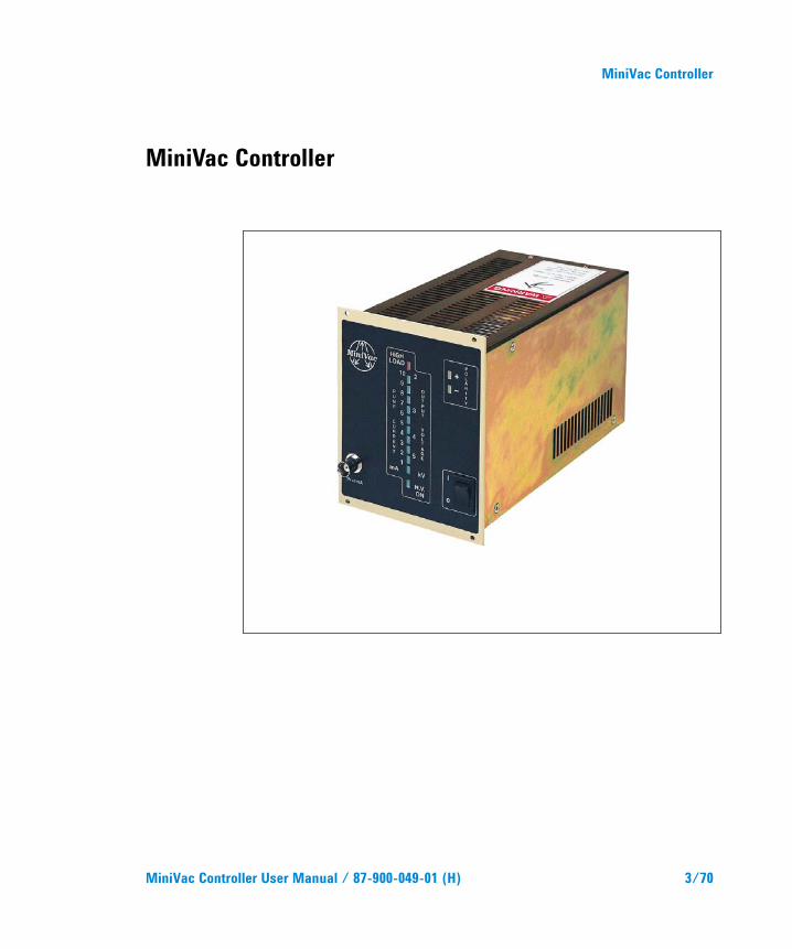
MiniVac Controller

MiniVac Controller
4/70 MiniVac Controller User Manual / 87-900-049-01 (H)
Contents
MiniVac Controller User Manual / 87-900-049-01 (H) 5/70
Contents
1 Istruzioni per l’uso 9
Informazioni generali 10
Immagazzinamento 11
Preparazione per l'installazione 11
Installazione 12
Uso 13
Procedure di uso 16
Manutenzione 17
Smaltimento 18
2 Gebrauchsanleitung 19
Allgemeines 20
Lagerung 21
Vor der Installation 21
Installation 22
Gebrauch 23
Bedienung 26
Wartung 27
Entsorgung 28
Contents
6/70 MiniVac Controller User Manual / 87-900-049-01 (H)
3 Mode d’emploi 29
Indications Generales 30
Preparation pour l'installation 31
Installation 32
Utilisation 33
Procedures d'utilisation 36
Entretien 37
Mise au rebut 38
4 Instructions for Use 39
General Information 40
Storage 41
Preparation for Installation 41
Installation 42
Use 43
Use Procedure 46
Maintenance 47
Disposal 48
5 Technical Information 49
Minivac Description 50
Controller Outline 56
Installation 56
Operation 61
Contents
MiniVac Controller User Manual / 87-900-049-01 (H) 7/70
Maintenance 63
Controller Spares and Accessories 64
Controller to Vacion Pump Cables 64

Contents
8/70 MiniVac Controller User Manual / 87-900-049-01 (H)
MiniVac Controller User Manual
9/70
1 Istruzioni per l’uso Informazioni generali 10 Immagazzinamento 11 Preparazione per l'installazione 11 Installazione 12 Uso 13 Comandi, Indicatori e Connettori del Controller 13 Procedure di uso 16 Interlock 16 Avvio della pompa 16 Accensione del Controller 16 Avvio della Pompa 17 Arresto della Pompa 17 Manutenzione 17 Smaltimento 18 Traduzione delle istruzioni originali
1 Istruzioni per l’uso Informazioni generali
10/70 MiniVac Controller User Manual / 87-900-049-01 (H)
Informazioni generali Questa apparecchiatura è destinata ad uso professionale. L'utilizzatore deve leggere attentamente il presente manuale di istruzioni ed ogni altra informazione addizionale fornita dalla Agilent prima dell'utilizzo dell'apparecchiatura. La Agilent si ritiene sollevata da eventuali responsabilità dovute all'inosservanza totale o parziale delle istruzioni, ad uso improprio da parte di personale non addestrato, ad interventi non autorizzati o ad uso contrario alle normative nazionali specifiche. Il MiniVac è un alimentatore ad alta tensione e bassa potenza, utilizzato per alimentare le pompe Ioniche.
Nei paragrafi seguenti sono riportate tutte le informazioni necessarie a garantire la sicurezza dell'operatore durante l'utilizzo dell'apparecchiatura. Informazioni dettagliate sono fornite nella sezione "Technical Information".
Questo manuale utilizza le seguenti convenzioni:
ATTENZIONE! I messaggi di attenzione sono visualizzati prima di procedure che, se non osservate, potrebbero causare danni all'apparecchiatura.
AVVERTENZA!
I messaggi di avvertenza attirano l'attenzione dell'operatore su una procedura o una pratica specifica che, se non eseguita in modo corretto, potrebbe provocare gravi lesioni personali.
NOTA Le note contengono informazioni importanti estrapolate dal testo.
Istruzioni per l’uso Immagazzinamento
1
MiniVac Controller User Manual / 87-900-049-01 (H) 11/70
Immagazzinamento Durante il trasporto e l'immagazzinamento dei MiniVac devono essere soddisfatte le seguenti condizioni ambientali:
temperatura: da -20 °C a +70 °C
umidità relativa: 0 – 95 % (non condensante)
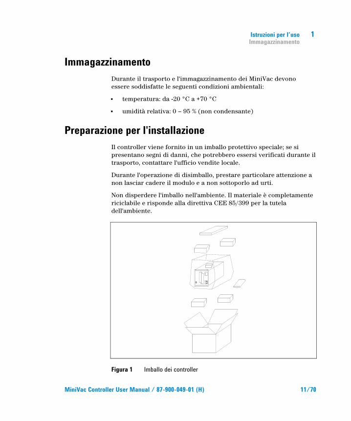
Preparazione per l'installazione Il controller viene fornito in un imballo protettivo speciale; se si presentano segni di danni, che potrebbero essersi verificati durante il trasporto, contattare l'ufficio vendite locale.
Durante l'operazione di disimballo, prestare particolare attenzione a non lasciar cadere il modulo e a non sottoporlo ad urti.
Non disperdere l'imballo nell'ambiente. Il materiale è completamente riciclabile e risponde alla direttiva CEE 85/399 per la tutela dell'ambiente.
Figura 1 Imballo dei controller
1 Istruzioni per l’uso Installazione
12/70 MiniVac Controller User Manual / 87-900-049-01 (H)
Ogni controller giunge dalla Agilent predisposto per una certa tensione di alimentazione:
il modello 929-0190 KINGS type High voltage connector (120 Vac, 50 – 60 Hz)
il modello 929-0191 FISCHER type High voltage connector (120 Vac, 50 – 60 Hz)
il modello 929-0290 FISCHER type High voltage connector (220 Vac, 50 – 60 Hz)
il modello 929-0291 KINGS type High voltage connector (220 Vac, 50 – 60 Hz)
Installazione
AVVERTENZA!
Il controller è fornito di un cavo di alimentazione a tre fili con una spina di tipo approvato a livello internazionale. Utilizzare sempre questo cavo di alimentazione ed inserire la spina in una presa con un adeguato collegamento di massa onde evitare scariche elettriche.
All'interno del controller si sviluppano alte tensioni che possono recare gravi danni o la morte. Prima di eseguire qualsiasi operazione di installazione o manutenzione del controller scollegarlo dalla presa di alimentazione.
NOTA Il controller deve essere installato all'interno di un apposito rack. In ogni caso occorre che l'aria di raffreddamento possa circolare liberamente intorno all'apparato. Non installare e/o utilizzare il controller in ambienti esposti ad agenti atmosferici (pioggia, gelo, neve), polveri, gas aggressivi, in ambienti esplosivi o con elevato rischio di incendio.
Istruzioni per l’uso Uso
1
MiniVac Controller User Manual / 87-900-049-01 (H) 13/70
Durante il funzionamento è necessario che siano rispettate le seguenti condizioni ambientali:
temperatura: da 0 °C a +45 °C
umidità relativa: 0 – 95 % (non condensante).
Per il collegamento del controller con la relativa pompa utilizzare il cavo specifico del controller stesso.
Per gli altri collegamenti e l'installazione degli accessori opzionali, vedere la sezione "Technical Information".
Uso In questo paragrafo sono riportate le principali procedure operative. Per ulteriori dettagli e per procedure che coinvolgono collegamenti o particolari opzionali, fare riferimento al paragrafo "Use" della sezione "Technical Information".
Prima di usare il controller effettuare tutti i collegamenti elettrici e pneumatici e fare riferimento al manuale della pompa collegata.
Comandi, Indicatori e Connettori del Controller Di seguito sono illustrati sia il pannello frontale che quello posteriore con le interconnessioni.
Per maggiori dettagli fare riferimento alla sezione "Technical Information".
1 Istruzioni per l’uso Uso
14/70 MiniVac Controller User Manual / 87-900-049-01 (H)
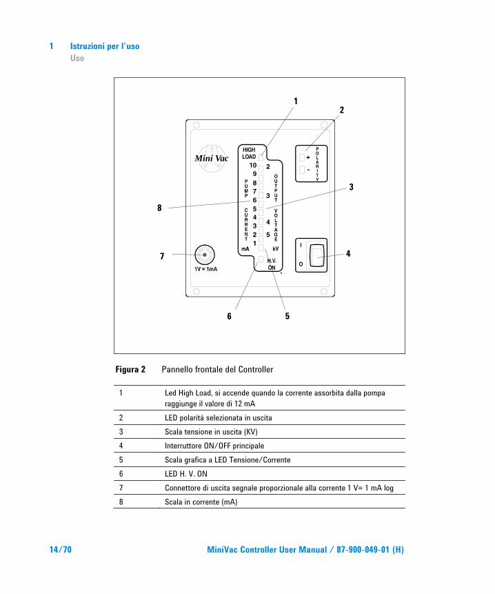
Figura 2 Pannello frontale del Controller
1 Led High Load, si accende quando la corrente assorbita dalla pompa raggiunge il valore di 12 mA
2 LED polarità selezionata in uscita 3 Scala tensione in uscita (KV) 4 Interruttore ON/OFF principale 5 Scala grafica a LED Tensione/Corrente 6 LED H. V. ON 7 Connettore di uscita segnale proporzionale alla corrente 1 V= 1 mA log 8 Scala in corrente (mA)
Mini Vac
1 2
3
4
5 6
7
8
Istruzioni per l’uso Uso
1
MiniVac Controller User Manual / 87-900-049-01 (H) 15/70
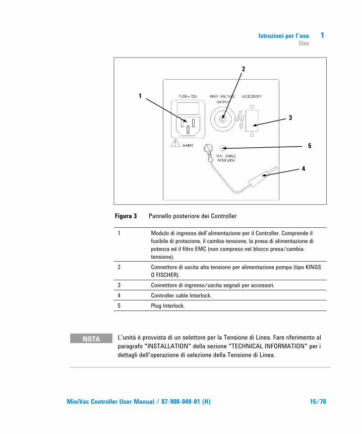
Figura 3 Pannello posteriore dei Controller
1 Modulo di ingresso dell’alimentazione per il Controller. Comprende il fusibile di protezione, il cambia-tensione, la presa di alimentazione di potenza ed il filtro EMC (non compreso nel blocco presa/cambia-tensione).
2 Connettore di uscita alta tensione per alimentazione pompa (tipo KINGS O FISCHER).
3 Connettore di ingresso/uscita segnali per accessori. 4 Controller cable Interlock. 5 Plug Interlock.
NOTA L'unità è provvista di un selettore per la Tensione di Linea. Fare riferimento al paragrafo "INSTALLATION" della sezione "TECHNICAL INFORMATION" per i dettagli dell'operazione di selezione della Tensione di Linea.
1
2
3
4
5
1 Istruzioni per l’uso Procedure di uso
16/70 MiniVac Controller User Manual / 87-900-049-01 (H)
Procedure di uso
Interlock L’Interlock è un dispositivo di sicurezza progettato dalla Agilent per proteggere l’operatore dai gravi danni provocati dall’alta tensione presente sul connettore di alimentazione della pompa.
L’uso del controller è inteso con cavo alta tensione provvisto di Interlock.
Qualora il cliente voglia rinunciare, per applicazioni particolari, al cavo HV con interlock Si rende disponibile il cavo di interlock del controller (4).
Avvio della pompa Per far partire la pompa è necessario:
1. Collegare la pompa al controller tramite l’apposito cavo HV.
2. Collegare l’Interlock del cavo HV al plug (5), se il cavo HV è sprovvisto del cavo di interlock collegare il cavo di interlock del controller (4) al plug (5).
3. Accendere il controller.
Accensione del Controller Per accendere il controller portare l’interruttore principale in posizione ON dopo aver inserito il cavo di alimentazione nella presa di rete.
Istruzioni per l’uso Manutenzione
1
MiniVac Controller User Manual / 87-900-049-01 (H) 17/70
Avvio della Pompa La pompa si avvia solo se il controller è acceso e la pompa è connessa al connettore di uscita. Per ulteriori informazioni fare riferimento alla sezione “Technical Information”.
Arresto della Pompa Per arrestare la pompa portare in posizione OFF l’interruttore principale posizionato sul pannello frontale.
Manutenzione I controller della serie MiniVac non richiedono alcuna manutenzione. Qualsiasi intervento deve essere eseguito da personale autorizzato.
In caso di guasto è possibile usufruire del servizio di riparazione Agilent o del "Agilent advance exchange service", che permette di ottenere un controller rigenerato in sostituzione di quello guasto.
AVVERTENZA!
Prima di effettuare qualsiasi intervento sul controller scollegare il cavo di alimentazione.
NOTA Il connettore di richiusura fornito con l’unità, ha i pin 3 e 7 cortocircuitati (Remote ON/OFF). Per poter accendere l’HV è necessario montare questo connettore se non è connesso un contatto di Remote Interlock.
1 Istruzioni per l’uso Smaltimento
18/70 MiniVac Controller User Manual / 87-900-049-01 (H)
NOTA L’unità è settata in fabbrica con polarità di uscita negativa. Per un eventuale cambio far riferimento al paragrafo “Output Polarity Selection”.
Qualora un controller dovesse essere rottamato, procedere alla sua eliminazione nel rispetto delle normative nazionali specifiche.
Smaltimento Significato del logo "WEEE" presente sulle etichette. Il simbolo qui sotto riportato è applicato in ottemperanza alla direttiva CE denominata "WEEE". Questo simbolo (valido solo per i paesi della Comunità Europea) indica che il prodotto sul quale è applicato, NON deve essere smaltito insieme ai comuni rifiuti domestici o industriali, ma deve essere avviato ad un sistema di raccolta differenziata. Si invita pertanto l'utente finale a contattare il fornitore del dispositivo, sia esso la casa madre o un rivenditore, per avviare il processo di raccolta e smaltimento, dopo opportuna verifica dei termini e condizioni contrattuali di vendita.
MiniVac Controller User Manual
19/70
2 Gebrauchsanleitung Allgemeines 20 Lagerung 21 Vor der Installation 21 Installation 22 Gebrauch 23 Steuerungen, Anzeigen und Anschlüsse
des Controllers 23 Bedienung 26 Interlock 26 Inbetriebnahme der Pumpe 26 Einschalten des Controllers 26 Pumpenstart 27 Pumpenstopp 27 Wartung 27 Entsorgung 28 Übersetzung der Originalanleitungen
2 Gebrauchsanleitung Allgemeines
20/70 MiniVac Controller User Manual / 87-900-049-01 (H)
Allgemeines Dieser Apparat ist für Fachbetriebe bestimmt. Vor Gebrauch sollte der Benutzer dieses Handbuch sowie alle weiteren mitgelieferten Zusatzdokumentationen genau lesen. Bei - auch nur teilweiser - Nichtbeachtung der enthaltenen Hinweise, unsachgemäßem Gebrauch durch ungeschultes Personal, nicht autorisierten Eingriffen und Mißachtung der einheimischen, hier zur Geltung kommenden Bestimmungen übernimmt die Firma Agilent keinerlei Haftung. Der MiniVac ist ein Hochspannungsnetzgerät niedriger Leistung, das zur Versorgung von Ionenpumpen verwendet wird.
In den folgenden Abschnitten sind alle erforderlichen Informationen für die Sicherheit des Bedieners bei der Anwendung des Geräts aufgeführt. Detaillierte technische Informationen sind im Anhang "Technical Information" enthalten.
In dieser Gebrauchsanleitung werden Sicherheitshinweise folgendermaßen hervorgehoben:
VORSICHT! Die Vorsichtshinweise vor bestimmten Prozeduren machen den Bediener darauf aufmerksam, daß bei Nichteinhaltung Schäden an der Anlage entstehen können.
WARNUNG!
Die Warnhinweise lenken die Aufmerksamkeit des Bedieners auf eine bestimmte Prozedur oder Praktik, die bei unkorrekter Ausführung schwere Verletzungen hervorrufen können.
HINWEIS Die Hinweise enthalten wichtige Informationen, die aus dem Text hervorgehoben werden.
Gebrauchsanleitung Lagerung
2
MiniVac Controller User Manual / 87-900-049-01 (H) 21/70
Lagerung Beim Transport und bei der Lagerung der Controller müssen folgende klimatische Verhältnisse eingehalten werden:
Temperatur: von -20 °C bis +70 °C
Relative Luftfeuchtigkeit: 0-95 % (nicht kondensierend)
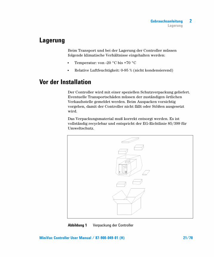
Vor der Installation Der Controller wird mit einer speziellen Schutzverpackung geliefert. Eventuelle Transportschäden müssen der zuständigen örtlichen Verkaufsstelle gemeldet werden. Beim Auspacken vorsichtig vorgehen, damit der Controller nicht fällt oder Stößen ausgesetzt wird.
Das Verpackungsmaterial muß korrekt entsorgt werden. Es ist vollständig recyclebar und entspricht der EG-Richtlinie 85/399 für Umweltschutz.
Abbildung 1 Verpackung der Controller
2 Gebrauchsanleitung Installation
22/70 MiniVac Controller User Manual / 87-900-049-01 (H)
Alle Agilent-Controller sind für eine bestimmte Anschlußspannung ausgelegt:
das Modell 929-0190 KINGS type High voltage connector (120 Vac, 50 – 60 Hz)
das Modell 929-0191 FISCHER type High voltage connector (120 Vac, 50 – 60 Hz)
das Modell 929-0290 FISCHER type High voltage connector (220 Vac, 50 – 60 Hz)
das Modell 929-0291 KINGS type High voltage connector (220 Vac, 50 – 60 Hz)
Installation
WARNUNG!
Der Controller wird mit einem 3-adrigen Netzkabel geliefert, das mit einem den internationalen Normen entsprechenden Stecker ausgerüstet ist. Es sollte immer dieses Netzkabel benutzt werden, das an eine korrekt geerdete Steckdose anzuschließen ist, um Stromentladungen zu vermeiden. Im Inneren des Controllers entstehen hohe Spannungen, die schwere Schäden verursachen und lebensgefährlich sein können. Vor jedem Montage- bzw. Wartungseingriff muß deshalb der Netzstecker gezogen werden.
HINWEIS Der Controller kann auf einen Tisch oder ein Gestell montiert werden. In beiden Fällen muß auf die ungehinderte Zirkulation der Kühlluft im Bereich des Geräts geachtet werden. Der Controller darf nicht in Umgebungen installiert u/o benutzt werden, die Witterungseinflüssen (Regen, Frost, Schnee), Staub und aggressiven Gasen ausgesetzt sind und in denen Explosions- und erhöhte Brandgefahr besteht.
Gebrauchsanleitung Gebrauch
2
MiniVac Controller User Manual / 87-900-049-01 (H) 23/70
Beim Betrieb müssen folgende Umgebungs-bedingungen eingehalten werden:
Temperatur: von +0 °C bis +45 °C
Relative Luftfeuchtigkeit: 0 - 95 % (nicht kondensierend).
Für den Anschluß des Controllers an die Pumpe muß das zum Controller gehörende Kabel benutzt werden.
Andere Anschlüsse und die Installation optionalen Zubehörs ist im Abschnitt “Technical Information” beschrieben.
Gebrauch In diesem Kapitel sind die wichtigsten Betriebsvorgänge aufgeführt. Für weitere Hinweise bezüglich Anschlüsse und Montage des bestellbaren Zubehörs siehe Kapitel "Use" im Anhang zu "Technical Information".
Vor Benutzung des Controllers sämtliche elektrischen und pneumatischen Anschlüsse ausführen, und die Betriebsanleitung der angeschlossenen Pumpe durchlesen.
Steuerungen, Anzeigen und Anschlüsse des Controllers
Nachstehend werden dass Bedienfeld des Controllers sowie die Anschlußfelder beschrieben.
Für weitere Einzelheiten siehe "Technical Information".
2 Gebrauchsanleitung Gebrauch
24/70 MiniVac Controller User Manual / 87-900-049-01 (H)
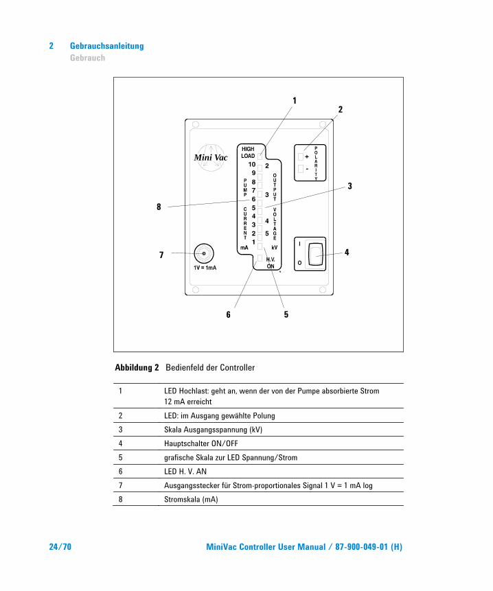
Abbildung 2 Bedienfeld der Controller
1 LED Hochlast: geht an, wenn der von der Pumpe absorbierte Strom 12 mA erreicht
2 LED: im Ausgang gewählte Polung 3 Skala Ausgangsspannung (kV) 4 Hauptschalter ON/OFF 5 grafische Skala zur LED Spannung/Strom 6 LED H. V. AN 7 Ausgangsstecker für Strom-proportionales Signal 1 V = 1 mA log 8 Stromskala (mA)
Mini Vac
1 2
3
4
5 6
7
8
Gebrauchsanleitung Gebrauch
2
MiniVac Controller User Manual / 87-900-049-01 (H) 25/70
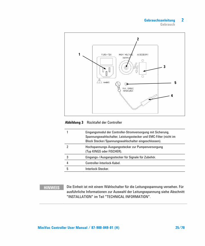
Abbildung 3 Rücktafel der Controller
1 Eingangsmodul der Controller-Stromversorgung mit Sicherung, Spannungswahlschalter, Leistungsstecker und EMC-Filter (nicht im Block Stecker/Spannungswahlschalter eingeschlossen).
2 Hochspannungs-Ausgangsstecker zur Pumpenversorgung (Typ KINGS oder FISCHER).
3 Eingangs-/Ausgangsstecker für Signale für Zubehör. 4 Controller-Interlock-Kabel. 5 Interlock-Stecker.
HINWEIS Die Einheit ist mit einem Wählschalter für die Leitungsspannung versehen. Für ausführliche Informationen zur Auswahl der Leitungsspannung siehe Abschnitt "INSTALLATION" im Teil "TECHNICAL INFORMATION".
1
2
3
4
5
2 Gebrauchsanleitung Bedienung
26/70 MiniVac Controller User Manual / 87-900-049-01 (H)
Bedienung
Interlock Interlock ist eine von Agilent entworfene Sicherheits-vorrichtung, um den Bediener vor schweren Schäden zu schützen, die durch die Hochspannung am Stromversorgungsstecker der Pumpe hervorgerufen werden können.
Der Controller muss mit dem Hochspannungskabel mit Interlock zum Einsatz kommen.
Falls der Auftraggeber bei besonderen Verwendungen auf das Hochspannungskabel mit Interlock verzichten wollen sollte, kann das Interlock-Kabel des Controllers (4) verwendet werden.
Inbetriebnahme der Pumpe Um die Pumpe zu starten, müssen vorher folgende Schritte durchgeführt werden:
1. Mit Hilfe des dafür vorgesehenen Hochspannungs-kabels die Pumpe an den Controller anschließen
2. Interlock des Hochspannungskabels mit dem Stecker (5) verbinden, falls das Hochspannungs-kabel keinen Interlock haben sollte, das Interlock-Kabel des Controllers (4) mit dem Stecker (5) verbinden.
3. Controller einschalten.
Einschalten des Controllers Zum Einschalten des Controllers genügt es, das Netzkabel an die Steckdose anzuschließen.
Gebrauchsanleitung Wartung
2
MiniVac Controller User Manual / 87-900-049-01 (H) 27/70
Pumpenstart Die Pumpe startet nur, wenn der Controller eingeschaltet und die Pumpe am Ausgangsstecker angeschlossen ist. Weitere Informationen finden sich im Abschnitt “Technical Information”.
Pumpenstopp Zum Stoppen der Pumpe muß der Hauptschalter auf dem Bedienfeld auf OFF gesetzt werden.
Wartung Die Controller der MiniVac Serie brauchen keinerlei Wartung. Alle Eingriffe dürfen nur von autorisiertem Personal vorgenommen werden.
Bei Defekten kann der Reparatur Service von Agilent oder der "Agilent Advance Exchange Service" in Anspruch genommen werden, der den defekten Controller durch ein Austauschgerät ersetzt.
WARNUNG!
Vor jedem Eingriff am Controller muß der Netzstecker gezogen werden.
HINWEIS Bei dem mit der Einheit gelieferte Abschluss-Stecker sind die Stifte 3 und 7 kurzgeschlossen (Remote ON/OFF).
Falls kein Remote Interlock Kontakt angeschlossen ist, kann die Hochspannung nur angeschaltet werden, wenn dieser Stecker montiert ist.
2 Gebrauchsanleitung Entsorgung
28/70 MiniVac Controller User Manual / 87-900-049-01 (H)
HINWEIS Fabrikseitig ist die Einheit mit negativer Ausgangspolung eingestellt. Soll das geändert werden, den Absatz “Output Polarity Selection” zu Rate ziehen.
Eine eventuelle Verschrottung muß unter Einhaltung der einschlägigen landesüblichen Vorschriften erfolgen.
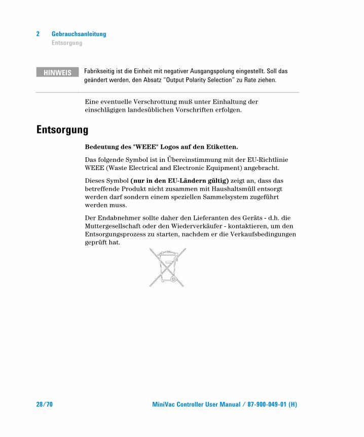
Entsorgung Bedeutung des "WEEE" Logos auf den Etiketten.
Das folgende Symbol ist in Übereinstimmung mit der EU-Richtlinie WEEE (Waste Electrical and Electronic Equipment) angebracht.
Dieses Symbol (nur in den EU-Ländern gültig) zeigt an, dass das betreffende Produkt nicht zusammen mit Haushaltsmüll entsorgt werden darf sondern einem speziellen Sammelsystem zugeführt werden muss.
Der Endabnehmer sollte daher den Lieferanten des Geräts - d.h. die Muttergesellschaft oder den Wiederverkäufer - kontaktieren, um den Entsorgungsprozess zu starten, nachdem er die Verkaufsbedingungen geprüft hat.
MiniVac Controller User Manual
29/70
3 Mode d’emploi Indications Generales 30 Emmagasinage 31 Preparation pour l'installation 31 Installation 32 Utilisation 33 Commandes, Indicateurs et Connecteurs
du Contrôleur 33 Procedures d'utilisation 36 Interlock 36 Démarrage de la pompe 36 Mise sous tension du Contrôleur 36 Mise en marche de la Pompe 37 Arrêt de la Pompe 37 Entretien 37 Mise au rebut 38 Traduction de la mode d’emploi originale
3 Mode d’emploi Indications Generales
30/70 MiniVac Controller User Manual / 87-900-049-01 (H)
Indications Generales Cet appareillage a été conçu en vue d'une utilisation professionnelle. L'utilisateur doit lire attentivement cette notice d'instructions ainsi que toute autre indication supplémentaire fournie par Agilent, avant l'utilisation de l'appareil. Agilent décline toute responsabilité quant au: non-respect total ou partiel des instructions pour l’utilisation, mauvais usage par du personnel non formé, opérations non autorisées usage contraire aux réglementations nationales spécifiques.
MiniVac est un alimentateur à haute tension, faible puissance, conçu pour alimenter les pompes ioniques.
Les paragraphes suivants donnent toutes les indications nécessaires pour garantir la sécurité de l'opérateur pendant l'utilisation de l'appareillage. Des renseignements plus détaillés se trouvent dans la section "Technical Information".
Cette notice utilise les signes conventionnels suivants:
ATTENTION! Les messages d'attention apparaissent avant certaines procédures qui, si elles ne sont pas observées, pourraient endommager sérieusement l'appareillage.
AVERTISSEMENT!
Les messages d'avertissement attirent l'attention de l'opérateur sur une procédure ou une manoeuvre spéciale qui, si elle n'est pas effectuée correctement, risque de provoquer de graves lésions.
NOTE Les notes contiennent des renseignements importants, isolés du texte.
Mode d’emploi Preparation pour l'installation
3
MiniVac Controller User Manual / 87-900-049-01 (H) 31/70
Emmagasinage Pendant le transport et l'emmagasinage des Mini Vac contrôleurs, il faudra veiller à respecter les conditions environnementales suivantes:
Température: de - 20 °C à + 70 °C
Humidité relative: 0 – 95 % (non condensante).
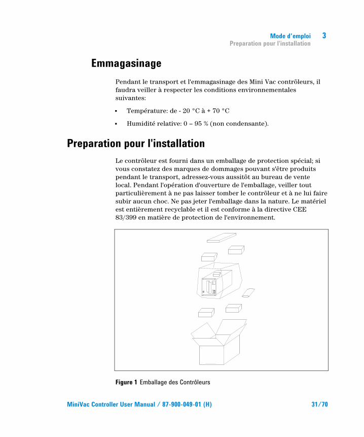
Preparation pour l'installation Le contrôleur est fourni dans un emballage de protection spécial; si vous constatez des marques de dommages pouvant s'être produits pendant le transport, adressez-vous aussitôt au bureau de vente local. Pendant l'opération d'ouverture de l'emballage, veiller tout particulièrement à ne pas laisser tomber le contrôleur et à ne lui faire subir aucun choc. Ne pas jeter l'emballage dans la nature. Le matériel est entièrement recyclable et il est conforme à la directive CEE 83/399 en matière de protection de l'environnement.
Figure 1 Emballage des Contrôleurs
3 Mode d’emploi Installation
32/70 MiniVac Controller User Manual / 87-900-049-01 (H)
Chaque contrôleur est fourni par Agilent prééquipé pour une certaine tension d'alimentation:
Modèle 929-0190 KINGS type High voltage connector (120 Vac, 50 – 60 Hz)
Modèle 929-0191 FISCHER type High voltage connector (120 Vac, 50 – 60 Hz)
Modèle 929-0290 FISCHER type High voltage connector (220 Vac, 50 – 60 Hz)
Modèle 929-0291 KINGS type High voltage connector (220 Vac, 50 – 60 Hz)
Installation
AVERTISSEMENT!
Le contrôleur est doté d'un câble d'alimentation à trois fils avec une fiche du type approuvé au niveau international. Utiliser toujours ce câble d'alimentation et introduire la fiche dans une prise pourvue d'un branchement approprié à la masse, afin d'éviter toute décharge électrique. A l'intérieur du contrôleur se développent de hautes tensions qui peuvent provoquer de graves dommages et même la mort. Avant d'effectuer toute opération d'installation ou d'entretien du contrôleur, le débrancher de la prise d'alimentation.
NOTE Le contrôleur doit être installé dans une baie prévue à cet effet. Il est en tout cas nécessaire que l'air de refroidissement puisse circuler librement à l'intérieur de l'appareil. Ne pas installer et/ou utiliser le contrôleur dans des milieux exposés aux agents atmosphériques (pluie, gel, neige), aux poussières, aux gaz de combat ni dans des milieux explosifs ou à risque élevé d'incendie.
Mode d’emploi Utilisation
3
MiniVac Controller User Manual / 87-900-049-01 (H) 33/70
Pendant le fonctionnement, il est nécessaire de respecter les conditions environnementales suivantes:
Température: 0 °C à + 45 °C
Humidité relative: 0 – 95 % (non condensante).
Pour la connexion du contrôleur à la pompe correspondante, utiliser le câble du contrôleur prévu à cet effet.
Pour les autres connexions et pour l'installation des accessoires en option, voir la section "Technical Information".
Utilisation Ce paragraphe décrit les principales procédures de fonctionnement. Pour tout autre complément d’information et pour les procédures concernant des connexions ou des éléments en option, se reporter au paragraphe "Use" de la section "Technical Information".
Avant d'utiliser le contrôleur, effectuer toutes les connexions électriques et pneumatiques et se référer à la notice de la pompe connectée.
Commandes, Indicateurs et Connecteurs du Contrôleur
La figure ci-après représente le tableau de commande du Contrôleur et les tableaux d'interconnexion.
Pour de plus amples détails, se reporter à la section "Technical Information".
3 Mode d’emploi Utilisation
34/70 MiniVac Controller User Manual / 87-900-049-01 (H)
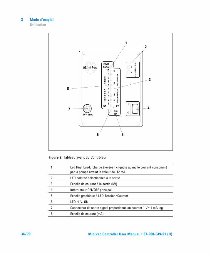
Figure 2 Tableau avant du Contrôleur
1 Led High Load, (charge élevée) il clignote quand le courant consommé par la pompe atteint la valeur de 12 mA
2 LED polarité sélectionnée à la sortie 3 Echelle de courant à la sortie (KV) 4 Interrupteur ON/OFF principal 5 Échelle graphique à LED Tension/Courant 6 LED H. V. ON 7 Connecteur de sortie signal proportionné au courant 1 V= 1 mA log 8 Echelle de courant (mA)
Mini Vac
1 2
3
4
5 6
7
8
Mode d’emploi Utilisation
3
MiniVac Controller User Manual / 87-900-049-01 (H) 35/70
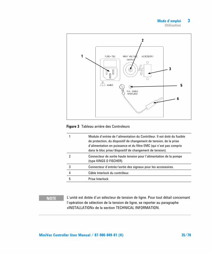
Figure 3 Tableau arrière des Controleurs
1 Module d’entrée de l’alimentation du Contrôleur. Il est doté du fusible de protection, du dispositif de changement de tension, de la prise d’alimentation en puissance et du filtre EMC (qui n’est pas compris dans le bloc prise/dispositif de changement de tension).
2 Connecteur de sortie haute tension pour l’alimentation de la pompe (type KINGS O FISCHER).
3 Connecteur d’entrée/sortie des signaux pour les accessoires. 4 Câble Interlock du contrôleur. 5 Prise Interlock.
NOTE L’unité est dotée d’un sélecteur de tension de ligne. Pour tout détail concernant l’opération de sélection de la tension de ligne, se reporter au paragraphe «INSTALLATION» de la section TECHNICAL INFORMATION.
1
2
3
4
5
3 Mode d’emploi Procedures d'utilisation
36/70 MiniVac Controller User Manual / 87-900-049-01 (H)
Procedures d'utilisation
Interlock L’Interlock est un dispositif de sécurité conçu par Agilent pour protéger l’opérateur contre les sérieux dommages provoqués par la présence de haute tension au niveau du connecteur d’alimentation de la pompe.
Il est entendu que le câble de haute tension du contrôleur est équipé de l’Interlock.
Si le client ne souhaite pas utiliser le câble HV avec interlock sur certaines installations, le câble d’interlock du contrôleur (4) est disponible.
Démarrage de la pompe Pour mettre la pompe en marche, il faut :
1. Relier la pompe au contrôleur à l’aide du câble HV réservé à cet effet.
2. Brancher l’Interlock du câble HV sur la prise (5) ; si le câble HV n’est pas équipé du câble d’interlock, brancher le câble d’interlock du contrôleur (4) sur la prise (5).
3. Allumer le contrôleur.
Mise sous tension du Contrôleur Pour mettre le contrôleur sous tension, il suffit de mettre l’interrupteur principal sur ON après avoir branché le câble d'alimentation sur la prise du réseau.
Mode d’emploi Entretien
3
MiniVac Controller User Manual / 87-900-049-01 (H) 37/70
Mise en marche de la Pompe La pompe démarre uniquement si le contrôleur est allumé et la pompe est reliée au connecteur de sortie. Pour d’ultérieurs renseignements se référer à la section “Technical Information”.
Arrêt de la Pompe Pour arrêter la pompe, mettre l’interrupteur principal situé sur le tableau avant sur OFF.
Entretien Les contrôleurs de la série MiniVac ne requièrent aucun entretien. Toute intervention doit être effectuée par du personnel autorisé.
En cas de panne, il est possible de faire appel au service de réparation Agilent ou au "Agilent advance exchange service", qui permet d’obtenir un contrôler régénéré à la place de celui en panne.
AVERTISSEMENT!
Avant d'effectuer toute intervention sur le contrôleur, débrancher le câble d'alimentation.
NOTE Le connecteur de fermeture fourni avec l’unité a les pins 3 et 7 en court circuit (Remote ON/OFF).
Pour pouvoir allumer l’HV il faut monter ce connecteur si un contact de Remote Interlock n’est pas branché.
3 Mode d’emploi Mise au rebut
38/70 MiniVac Controller User Manual / 87-900-049-01 (H)
NOTE L’unité est assignée à l’usine avec polarité de sortie négative. Pour un changement éventuel, se référer au paragraphe “Output Polarity Selection”.
Si un contrôleur doit être mis au rebut l’éliminer conformément aux réglementations nationales en la matière.
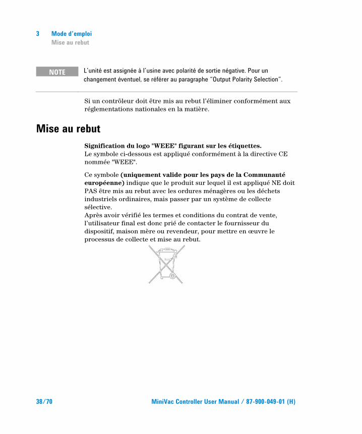
Mise au rebut Signification du logo "WEEE" figurant sur les étiquettes. Le symbole ci-dessous est appliqué conformément à la directive CE nommée "WEEE".
Ce symbole (uniquement valide pour les pays de la Communauté européenne) indique que le produit sur lequel il est appliqué NE doit PAS être mis au rebut avec les ordures ménagères ou les déchets industriels ordinaires, mais passer par un système de collecte sélective. Après avoir vérifié les termes et conditions du contrat de vente, l’utilisateur final est donc prié de contacter le fournisseur du dispositif, maison mère ou revendeur, pour mettre en œuvre le processus de collecte et mise au rebut.
MiniVac Controller User Manual
39/70
4 Instructions for Use General Information 40 Storage 41 Preparation for Installation 41 Installation 42 Use 43 Controller Controls, Indicators and Connectors 43 Use Procedure 46 Interlock 46 Start-Up of the Pump 46 Controller Start-up 46 Starting the Pump 47 Pump Shutdown 47 Maintenance 47 Disposal 48 Original Instructions
4 Instructions for Use General Information
40/70 MiniVac Controller User Manual / 87-900-049-01 (H)
General Information This equipment is destined for use by professionals. The user should read this instruction manual and any other additional information supplied by Agilent before operating the equipment. Agilent will not be held responsible for any events occurring due to non-compliance, even partial, with these instructions, improper use by untrained persons, non-authorised interference with the equipment or any action contrary to that provided for by specific national standards. The MiniVac is a high voltage and low power feeder used to feed the ionic pumps.
The following paragraphs contain all the information necessary to guarantee the safety of the operator when using the equipment. Detailed information is supplied in the section "Technical Information".
This manual uses the following standard protocol:
CAUTION! The caution messages are displayed before procedures which, if not followed, could cause damage to the equipment.
WARNING!
The warning messages are for attracting the attention of the operator to a particular procedure or practice which, if not followed correctly, could lead to serious injury.
NOTE The notes contain important information taken from the text.
Instructions for Use Storage
4
MiniVac Controller User Manual / 87-900-049-01 (H) 41/70
Storage When transporting and storing the MiniVacs, the following environmental requirements should be satisfied:
temperature: from -20 °C to + 70 °C
relative humidity: 0 – 95 % (without condensation)
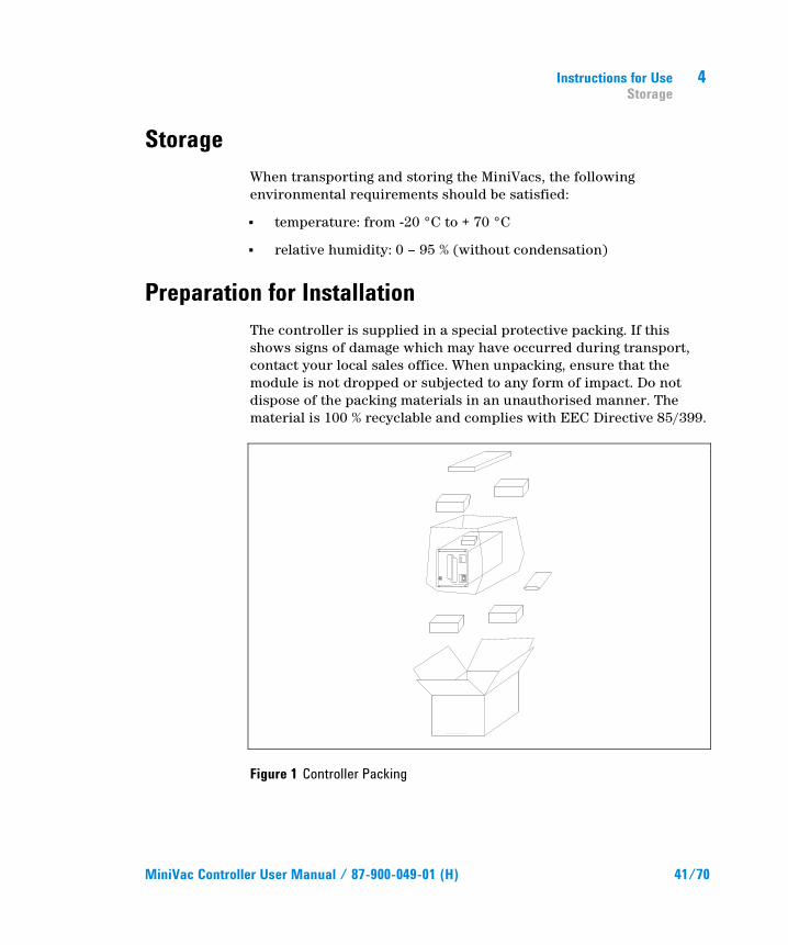
Preparation for Installation The controller is supplied in a special protective packing. If this shows signs of damage which may have occurred during transport, contact your local sales office. When unpacking, ensure that the module is not dropped or subjected to any form of impact. Do not dispose of the packing materials in an unauthorised manner. The material is 100 % recyclable and complies with EEC Directive 85/399.
Figure 1 Controller Packing
4 Instructions for Use Installation
42/70 MiniVac Controller User Manual / 87-900-049-01 (H)
Each controller is factory set for a specific power supply:
Model 929-0190 KINGS type High voltage connector (120 Vac, 50 – 60 Hz)
Model 929-0191 FISCHER type High voltage connector (120 Vac, 50 – 60 Hz)
Model 929-0290 FISCHER type High voltage connector (220 Vac, 50 – 60 Hz)
Model 929-0291 KINGS type High voltage connector (220 Vac, 50 – 60 Hz)
Installation
WARNING!
The controller is equipped with a 3-wire power cord and plug (internationally approved) for user's safety. Use this power cord and plug in conjunction with a properly grounded power socket to avoid electrical shock.
High voltage developed in the controller can cause severe injury or death. Before servicing the unit, disconnect the input power cable.
NOTE The controller must be installed inside a rack module, but it must be positioned so that free air can flow through the holes. Do not install or use the controller in an environment exposed to atmospheric agents (rain, snow, ice), dust, aggressive gases, or in explosive environments or those with a high fire risk.
Instructions for Use Use
4
MiniVac Controller User Manual / 87-900-049-01 (H) 43/70
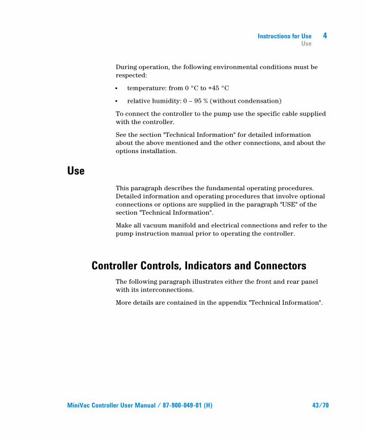
During operation, the following environmental conditions must be respected:
temperature: from 0 °C to +45 °C
relative humidity: 0 – 95 % (without condensation)
To connect the controller to the pump use the specific cable supplied with the controller.
See the section "Technical Information" for detailed information about the above mentioned and the other connections, and about the options installation.
Use This paragraph describes the fundamental operating procedures. Detailed information and operating procedures that involve optional connections or options are supplied in the paragraph "USE" of the section "Technical Information".
Make all vacuum manifold and electrical connections and refer to the pump instruction manual prior to operating the controller.
Controller Controls, Indicators and Connectors The following paragraph illustrates either the front and rear panel with its interconnections.
More details are contained in the appendix "Technical Information".
4 Instructions for Use Use
44/70 MiniVac Controller User Manual / 87-900-049-01 (H)
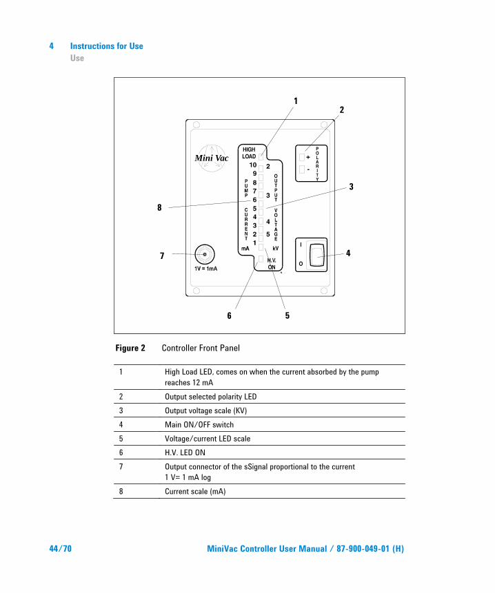
Figure 2 Controller Front Panel
1 High Load LED, comes on when the current absorbed by the pump reaches 12 mA
2 Output selected polarity LED 3 Output voltage scale (KV) 4 Main ON/OFF switch 5 Voltage/current LED scale 6 H.V. LED ON 7 Output connector of the sSignal proportional to the current
1 V= 1 mA log 8 Current scale (mA)
Mini Vac
1 2
3
4
5 6
7
8
Instructions for Use Use
4
MiniVac Controller User Manual / 87-900-049-01 (H) 45/70
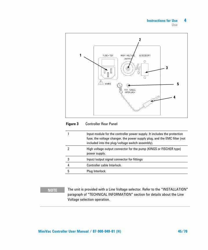
Figure 3 Controller Rear Panel
1 Input module for the controller power supply. It includes the protection fuse, the voltage changer, the power supply plug, and the EMC filter (not included into the plug/voltage switch assembly).
2 High voltage output connector for the pump (KINGS or FISCHER type) power supply.
3 Input/output signal connector for fittings 4 Controller cable Interlock. 5 Plug Interlock.
NOTE The unit is provided with a Line Voltage selector. Refer to the "INSTALLATION" paragraph of "TECHNICAL INFORMATION" section for details about the Line Voltage selection operation.
1
2
3
4
5
4 Instructions for Use Use Procedure
46/70 MiniVac Controller User Manual / 87-900-049-01 (H)
Use Procedure
Interlock The Interlock is a safety device designed by Agilent to protect the operator against serious injury caused by the high voltage present on the pump power connector.
The controller is intended to be used with a HV cable furnished with Interlock.
If the customer does not wish to use the HV cable with interlock for particular application requirements, the interlock cable of the controller (4) is available.
Start-Up of the Pump To start the pump:
1. Connect the pump to the controller using the specific HV cable.
2. Connect the Interlock of the HV cable to the plug (5); if the HV cable is without the interlock cable, connect the interlock cable of the controller (4) to the plug (5).
3. Switch on the controller.
Controller Start-up To start-up the controller, turn the main switch to ON, after plugging the power cable into a suitable power source.
Instructions for Use Maintenance
4
MiniVac Controller User Manual / 87-900-049-01 (H) 47/70
Starting the Pump The pump is activated only if the controller is powered on and the pump itself is connected to the output connector. For further information refer to the “Technical Information” section.
Pump Shutdown To shutdown the pump, turn the main switch placed on the front panel to OFF.
Maintenance The MiniVac series controllers do not require any maintenance interventions. Any intervention must be performed by authorised personnel only.
When a fault has occurred it is possible to use the Agilent repair service or the “Agilent advance exchange service”, that allows to obtain a regenerated controller replacing the faulty one.
WARNING!
Before carrying out any work on the controller, disconnect it from the supply.
NOTE Pins 3 and 7 on the loopback plug provided with the unit are short circuited (Remote ON/OFF). This loopback plug must be fitted to power on the HV unless a Remote/Interlock contact is connected.
4 Instructions for Use Disposal
48/70 MiniVac Controller User Manual / 87-900-049-01 (H)
NOTE The unit is factory set with a negative output polarity. Refer to the section “Output Polarity Selection” for instructions on how to change the output polarity.
If a pump is to be scrapped, it must be disposed of in accordance with the specific national standards.
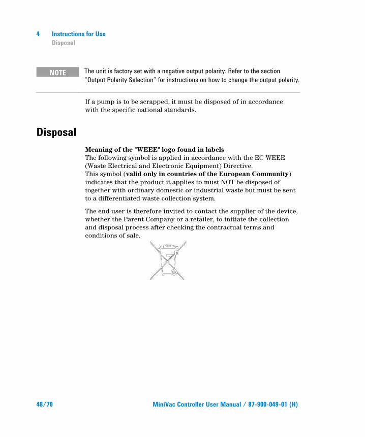
Disposal Meaning of the "WEEE" logo found in labels The following symbol is applied in accordance with the EC WEEE (Waste Electrical and Electronic Equipment) Directive. This symbol (valid only in countries of the European Community) indicates that the product it applies to must NOT be disposed of together with ordinary domestic or industrial waste but must be sent to a differentiated waste collection system.
The end user is therefore invited to contact the supplier of the device, whether the Parent Company or a retailer, to initiate the collection and disposal process after checking the contractual terms and conditions of sale.
MiniVac Controller User Manual
49/70
5 Technical Information Minivac Description 50 Controller Specifications 54 Controller Outline 56 Installation 56 Line Voltage Change Over 57 Output Polarity Selection 58 Input/Output Interconnections 59 Pump Connection 60 Operation 61 Pressure Determination 62 Power Failure 62 Remote Control Mode Operation 62 Maintenance 63 Troubleshooting 63 Controller Spares and Accessories 64 Controller to Vacion Pump Cables 64 Original Instructions
5 Technical Information Minivac Description
50/70 MiniVac Controller User Manual / 87-900-049-01 (H)
Minivac Description The MiniVac controller is a quarter rack solid state power supply with self protection features, which generates high voltage using high frequency switching technology.
The MiniVac ion pump controller is designed to operate any type of ion pumps: Diode, Differential Diode, Triode and StarCell.
The MiniVac controller is a very compact and light unit capable of powering any size of pump at different operating pressure.
Small pumps (up to 8 l/s) can be operated at any pressure up to 1 x 10⁻³ mbar.
Medium pumps (20 l/s to 60 l/s) can be operated at any pressure up to 1 x 10⁻⁵ mbar/Torr (continuous operation).
Large pumps (120 l/s to 400 l/s) can be operated at any pressure up to 2 x 10⁻⁶ mbar/Torr (continuous operation). Medium/larger ion pumps must first be started with an appropriate control unit and pumped to a sufficiently low pressure where the current demand is below 8 mA.
The MiniVac controller is designed to withstand continuous operation at short circuit condition, without any damage to the ion pump or to the controller itself.
The MiniVac controller is available in four versions, which differ in the factory-set input voltage and in the high voltage output connector type.
Model 929-0190 KINGS type High voltage connector (120 Vac, 50/60 Hz)
Model 929-0191 FISCHER type High voltage connector (120 Vac, 50/60 Hz)
Model 929-0290 FISCHER type High voltage connector (220 Vac, 50/60 Hz)
Model 929-0291 KINGS type High voltage connector (220 Vac, 50/60 Hz)
A voltage change over allows to select different operating voltages.
Technical Information Minivac Description
5
MiniVac Controller User Manual / 87-900-049-01 (H) 51/70
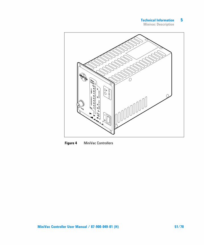
Figure 4 MiniVac Controllers
5 Technical Information Minivac Description
52/70 MiniVac Controller User Manual / 87-900-049-01 (H)
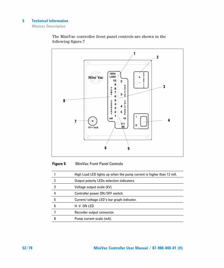
The MiniVac controller front panel controls are shown in the following figure.7
Figure 5 MiniVac Front Panel Controls
1 High Load LED lights up when the pump current is higher than 12 mA. 2 Output polarity LEDs selection indicators. 3 Voltage output scale (kV). 4 Controller power ON/OFF switch. 5 Current/voltage LED's bar graph indicator. 6 H. V. ON LED. 7 Recorder output connector. 8 Pump current scale (mA).
Mini Vac
1 2
3
4
5 6
7
8
Technical Information Minivac Description
5
MiniVac Controller User Manual / 87-900-049-01 (H) 53/70
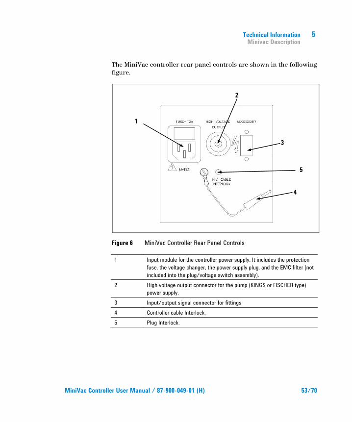
The MiniVac controller rear panel controls are shown in the following figure.
Figure 6 MiniVac Controller Rear Panel Controls
1 Input module for the controller power supply. It includes the protection fuse, the voltage changer, the power supply plug, and the EMC filter (not included into the plug/voltage switch assembly).
2 High voltage output connector for the pump (KINGS or FISCHER type) power supply.
3 Input/output signal connector for fittings 4 Controller cable Interlock. 5 Plug Interlock.
1
2
3
4
5
5 Technical Information Minivac Description
54/70 MiniVac Controller User Manual / 87-900-049-01 (H)
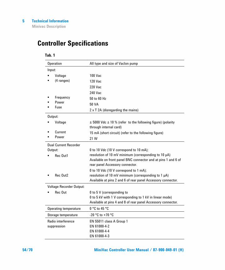
Controller Specifications Tab. 1
Operation All type and size of VacIon pump Input: Voltage (4 ranges) Frequency Power Fuse
100 Vac 120 Vac 220 Vac 240 Vac 50 to 60 Hz 50 VA 2 x T 2A (disregarding the mains)
Output: Voltage
Current Power
± 5000 Vdc ± 10 % (refer to the following figure) (polarity through internal card) 15 mA (short circuit) (refer to the following figure) 21 W
Dual Current Recorder Output: Rec Out1
Rec Out2
0 to 10 Vdc (10 V correspond to 10 mA); resolution of 10 mV minimum (corresponding to 10 µA) Available on front panel BNC connector and at pins 1 and 6 of rear panel Accessory connector. 0 to 10 Vdc (10 V correspond to 1 mA); resolution of 10 mV minimum (corresponding to 1 µA) Available at pins 2 and 6 of rear panel Accessory connector.
Voltage Recorder Output: Rec Out
0 to 5 V (corresponding to 0 to 5 kV with 1 V corresponding to 1 kV in linear mode) Available at pins 4 and 8 of rear panel Accessory connector.
Operating temperature 0 °C to 45 °C Storage temperature -20 °C to +70 °C Radio interference suppression
EN 55011 class A Group 1 EN 61000-4-2 EN 61000-4-4 EN 61000-4-3
Technical Information Minivac Description
5
MiniVac Controller User Manual / 87-900-049-01 (H) 55/70
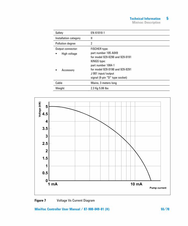
Safety EN 61010-1 Installation category II Pollution degree 2 Output connector: High voltage
Accessory
FISCHER type: part number 105 A049 for model 929-0290 and 929-0191 KINGS type: part number 1064-1 for model 929-0190 and 929-0291 J 001 input/output signal (9-pin "D" type socket)
Cable Mains, 3 meters long Weight 2.3 Kg 5.06 lbs
Figure 7 Voltage Vs Current Diagram
5 Technical Information Controller Outline
56/70 MiniVac Controller User Manual / 87-900-049-01 (H)
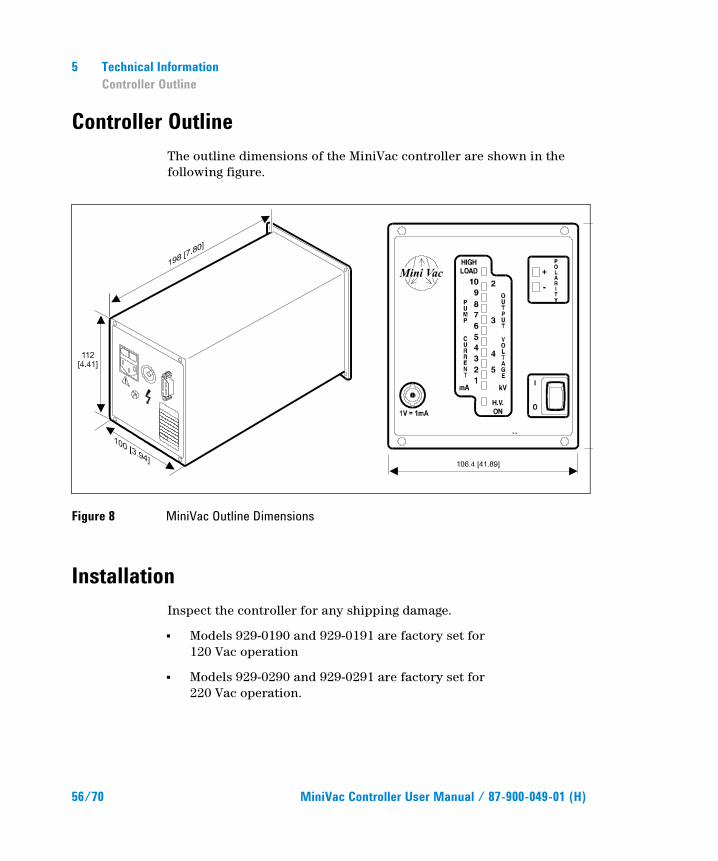
Controller Outline The outline dimensions of the MiniVac controller are shown in the following figure.
Figure 8 MiniVac Outline Dimensions
Installation Inspect the controller for any shipping damage.
Models 929-0190 and 929-0191 are factory set for 120 Vac operation
Models 929-0290 and 929-0291 are factory set for 220 Vac operation.
Technical Information Installation
5
MiniVac Controller User Manual / 87-900-049-01 (H) 57/70
WARNING!
The MiniVac controller is equipped with a 3-wire power cord and plug (internationally approved) for user's safety. Use this power cord and plug in conjunction with a properly grounded power socket to avoid electrical shock. High voltage developed in the controller can cause severe injury or death. Before servicing the unit, disconnect the input power cable.
NOTE The MiniVac controller can be used as a bench unit or as a rack module, but it must be positioned so that free air can flow through the holes.
Line Voltage Change Over If a change in line voltage operation is desired, proceed as follows:
1. Unplug the power cord from the controller rear panel socket.
2. On the power entry module (rear panel), check back door for voltage selector set.
3. Using a small screwdriver, pull out the voltage selector and fuses.
4. Select the operating voltage, then firmly insert the voltage selector and fuses in place.
5. Check voltage selector window for correct set and connect the power cord.
6. For Line Voltage between 200 and 230 Vac set the voltage selector to 220 Vac; for Line Voltage higher than 230 Vac set the voltage selector to 240 Vac.
5 Technical Information Installation
58/70 MiniVac Controller User Manual / 87-900-049-01 (H)
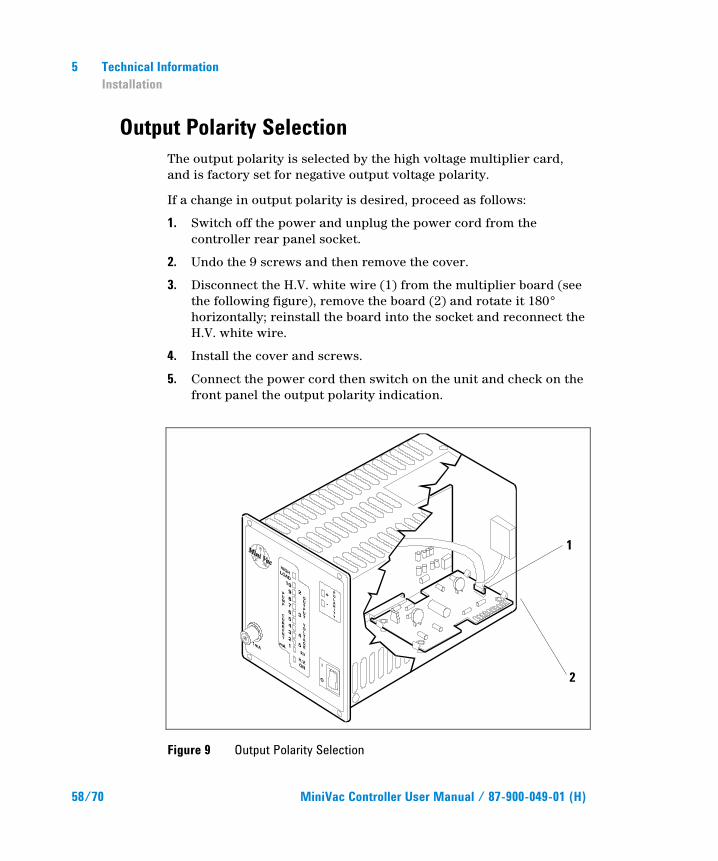
Output Polarity Selection The output polarity is selected by the high voltage multiplier card, and is factory set for negative output voltage polarity.
If a change in output polarity is desired, proceed as follows:
1. Switch off the power and unplug the power cord from the controller rear panel socket.
2. Undo the 9 screws and then remove the cover.
3. Disconnect the H.V. white wire (1) from the multiplier board (see the following figure), remove the board (2) and rotate it 180° horizontally; reinstall the board into the socket and reconnect the H.V. white wire.
4. Install the cover and screws.
5. Connect the power cord then switch on the unit and check on the front panel the output polarity indication.
Figure 9 Output Polarity Selection
1
2
Technical Information Installation
5
MiniVac Controller User Manual / 87-900-049-01 (H) 59/70
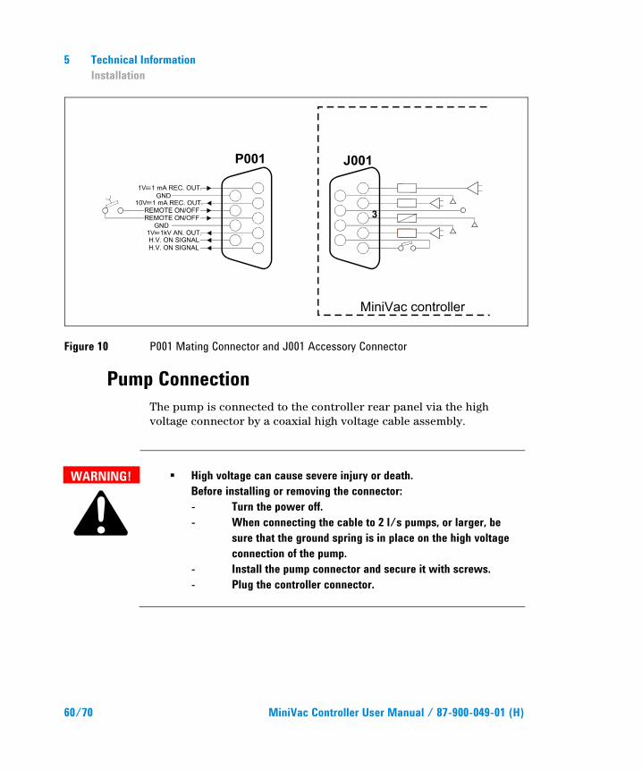
Input/Output Interconnections All input/output signals are accessible at J001 accessory connector. With the provided P001 mating connector make the connections with AWG 24 (0.2 mm2) - or smaller wire - to the pins indicated in the following figure to obtain the desired capability.
Input Signals
Pin 3-7 Remote high voltage ON/OFF or high voltage interlock; requires a permanent closed pin contact.
NOTE Pin 3-7 must be shorted to allow the high voltage output if no remote/interlock contact is connected.
Output Signals
Pin 1-6 Current recorder output 1 (pin 1 signal out, pin 6 ground). The output voltage 0 to + 10 Vdc is proportional to the pump current 0 to 10 mA (e.g. 10 Vdc correspond to 10 mA). The resolution is 10 mV minimum (corresponding to 10 µA).
The front panel REC.OUT connector is a duplicate of this signal on a BNC connector. Pin 2-6 Current recorder output 2 (pin 2 signal out, pin 6
ground). The output voltage 0 to + 10 Vdc is proportional to the pump current 0 to 1 mA (e.g. 10 Vdc correspond to 1 mA). The resolution is 10 mV minimum (corresponding to 1 µA).
Pin 4-8 Voltage recorder output (pin 4 signal out, pin 8 ground).
The output voltage 0 to 5 V is proportional to the controller high voltage output 0 to 5 kV (e.g. 1 V corresponds to 1 kV in linear mode).
Pin 5-9 High voltage indication contact. This pure contact (which
carries 1 A at 250 Vac and 0.2 A at 30 Vdc) is open when the high voltage is off and closes when the high voltage in on.
5 Technical Information Installation
60/70 MiniVac Controller User Manual / 87-900-049-01 (H)
Figure 10 P001 Mating Connector and J001 Accessory Connector
Pump Connection The pump is connected to the controller rear panel via the high voltage connector by a coaxial high voltage cable assembly.
WARNING!
High voltage can cause severe injury or death. Before installing or removing the connector: - Turn the power off. - When connecting the cable to 2 l/s pumps, or larger, be sure that the ground spring is in place on the high voltage connection of the pump. - Install the pump connector and secure it with screws. - Plug the controller connector.
Technical Information Operation
5
MiniVac Controller User Manual / 87-900-049-01 (H) 61/70
Operation Make all vacuum manifold and electrical connections and refer to the ion pump instruction manual prior to operating the MiniVac controller.
NOTE The accessory P001 connector should be left in position including the jumper between pin 3 and 7 if no external connection has been made.
For small ion pumps, up to 8 l/s:
with a roughing pump, establish a rough pressure suitable to start the ion pump.
For medium ion pump (20 l/s to 60 l/s): establish a pressure lower than 10-5 mbar/ Torr.
For large ion pumps (120 l/s to 400 l/s): establish a pressure lower than 2 x 10⁻⁶ mbar/Torr.
CAUTION! Before plugging in the controller power cable, be sure that the selected operating voltage matches the power source to avoid equipment damage.
1. Plug the controller power cable into a suitable power source.
2. Place the ON/OFF switch in the ON position.
3. Monitor the VacIon pump current and the controller high voltage output by watching the LED lit, then read the corresponding current/voltage value (e.g.: if the third LED is increasing its brightness it means that the pump current is between 2 and 3 mA and the high voltage output is between 5 and 4 kV).
4. If only the first LED of the bar graph is lit, the current drawn by the pump is less than 1 mA and the voltage output is 5 kV.
5. If ten LEDs are lit, the current drawn by the pump is 10 mA and the voltage output is 2 kV.
6. For the correct determination of the voltage value, use the voltage vs current diagram shown in the figure “MiniVac Controller Rear Panel Controls”.
5 Technical Information Operation
62/70 MiniVac Controller User Manual / 87-900-049-01 (H)
Pressure Determination Pressure at the inlet flange of a VacIon pump is proportional to the current drawn by the pump.
To determine the pressure of the inlet flange of the VacIon pump, determine the pump current displayed on the front panel or read the recorder output (especially for current lower than 1 mA), and find the corresponding pressure value from the current vs pressure curve of the relevant VacIon pump.
Power Failure In the event of a power failure (momentary or long period) the controller is switched off. When power is restored, the controller will automatically restart.
Remote Control Mode Operation It is possible to remotely switch onb and off the high voltage using a permanent contact connected to pins 3 and 7 of J001 accessory connector with the mains power ON/OFF switch to ON.
Technical Information Maintenance
5
MiniVac Controller User Manual / 87-900-049-01 (H) 63/70
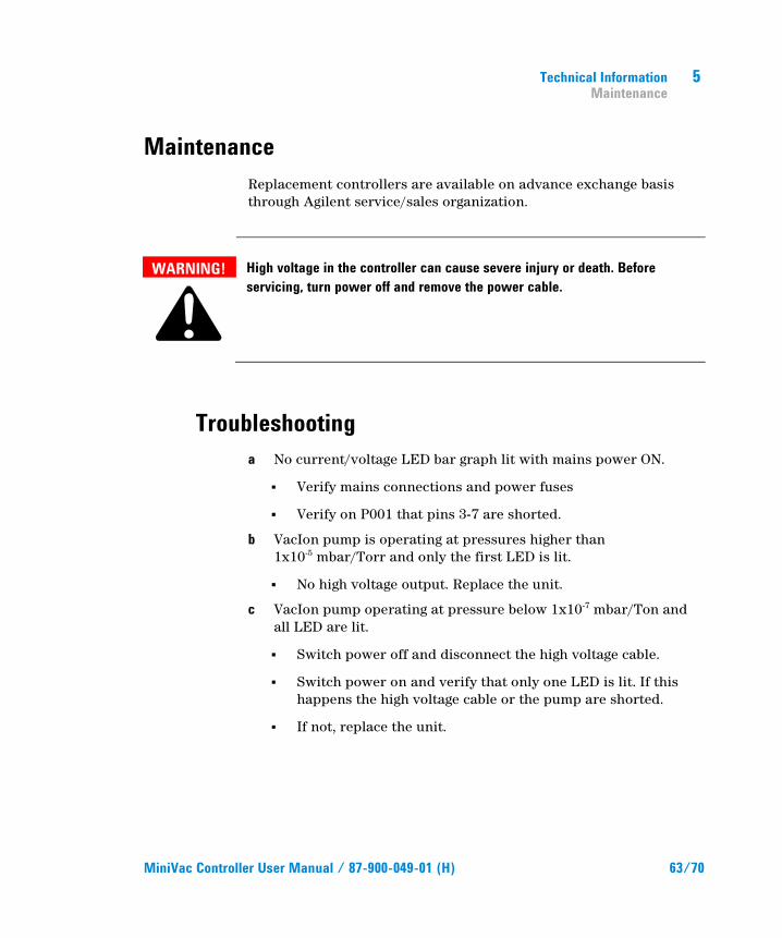
Maintenance Replacement controllers are available on advance exchange basis through Agilent service/sales organization.
WARNING!
High voltage in the controller can cause severe injury or death. Before servicing, turn power off and remove the power cable.
Troubleshooting a No current/voltage LED bar graph lit with mains power ON.
Verify mains connections and power fuses
Verify on P001 that pins 3-7 are shorted.
b VacIon pump is operating at pressures higher than 1x10⁻⁵ mbar/Torr and only the first LED is lit.
No high voltage output. Replace the unit.
c VacIon pump operating at pressure below 1x10⁻⁷ mbar/Ton and all LED are lit.
Switch power off and disconnect the high voltage cable.
Switch power on and verify that only one LED is lit. If this happens the high voltage cable or the pump are shorted.
If not, replace the unit.
5 Technical Information Controller Spares and Accessories
64/70 MiniVac Controller User Manual / 87-900-049-01 (H)
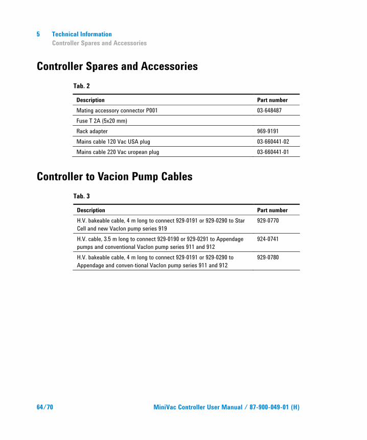
Controller Spares and Accessories Tab. 2
Description Part number Mating accessory connector P001 03-648487 Fuse T 2A (5x20 mm) Rack adapter 969-9191 Mains cable 120 Vac USA plug 03-660441-02 Mains cable 220 Vac uropean plug 03-660441-01
Controller to Vacion Pump Cables Tab. 3
Description Part number H.V. bakeable cable, 4 m long to connect 929-0191 or 929-0290 to Star Cell and new VacIon pump series 919
929-0770
H.V. cable, 3.5 m long to connect 929-0190 or 929-0291 to Appendage pumps and conventional VacIon pump series 911 and 912
924-0741
H.V. bakeable cable, 4 m long to connect 929-0191 or 929-0290 to Appendage and conven-tional VacIon pump series 911 and 912
929-0780
Request for Return Form Sales and Service Offices
United States Agilent Technologies Vacuum Products Division 121 Hartwell Avenue Lexington, MA 02421 - USA Tel.: +1 781 861 7200 Fax: +1 781 860 5437 Toll-Free: +1 800 882 7426
India Agilent Technologies India Pvt. Ltd. Vacuum Products Division G01. Prime corporate Park, 230/231, Sahar Road, Opp. Blue Dart Centre, Andheri (East), Mumbai – 400 099.India Tel: +91 22 30648287/8200 Fax: +91 22 30648250 Toll Free: 1800 113037
Southeast Asia Agilent Technologies Sales Sdn Bhd Vacuum Products Division Unit 201, Level 2 uptown 2, 2 Jalan SS21/37, Damansara Uptown 47400 Petaling Jaya, Selangor, Malaysia Tel : +603 7712 6106 Fax: +603 6733 8121
Benelux Agilent Technologies Netherlands B.V. Vacuum Products Division Herculesweg 8 4338 PL Middelburg The Netherlands Tel.: +31 118 671570 Fax: +31 118 671569 Toll-Free: 00 800 234 234 00
Italy Agilent Technologies Italia S.p.A. Vacuum Products Division Via F.lli Varian 54 10040 Leini, (Torino) - Italy Tel.: +39 011 997 9111 Fax: +39 011 997 9350 Toll-Free: 00 800 234 234 00
Taiwan Agilent Technologies Taiwan Limited Vacuum Products Division (3F) 20 Kao-Shuang Rd., Pin-Chen City, 32450 Taoyuan Hsien , Taiwan, R.O.C. Tel. +886 34959281 Toll Free: 0800 051 342
Canada Central coordination through: Agilent Technologies Vacuum Products Division 121 Hartwell Avenue Lexington, MA 02421 - USA Tel.: +1 781 861 7200 Fax: +1 781 860 5437 Toll-Free: +1 800 882 7426
Japan Agilent Technologies Japan, Ltd. Vacuum Products Division 8th Floor Sumitomo Shibaura Building 4-16-36 Shibaura Minato-ku Tokyo 108-0023 - Japan Tel.: +81 3 5232 1253 Fax: +81 3 5232 1710 Toll-Free: 0120 655 040
UK and Ireland Agilent Technologies UK, Ltd. Vacuum Products Division 6 Mead Road Oxford Industrial Park Yarnton, Oxford OX5 1QU – UK Tel.: +44 (0) 1865 291570 Fax: +44 (0) 1865 291571 Toll free: 00 800 234 234 00
China Agilent Technologies (China) Co. Ltd Vacuum Products Division No.3, Wang Jing Bei Lu, Chao Yang District Beijing, 100102, China Tel: +86 (0)10 64397888 Fax: +86 (0)10 64391318 Toll free: 800 820 3278
Korea Agilent Technologies Korea, Ltd. Vacuum Products Division Shinsa 2nd Bldg. 2F 966-5 Daechi-dong Kangnam-gu, Seoul Korea 135-280 Tel: +82 (0)2 3452 2455 Fax: +82 (0)2 3452 3947 Toll free: 080 222 2452
Other Countries Agilent Technologies Italia S.p.A. Vacuum Products Division Via F.lli Varian 54 10040 Leini, (Torino) - Italy Tel.: +39 011 997 9111 Fax: +39 011 997 9350 Toll-Free: 00 800 234 234 00
France Agilent Technologies France Vacuum Products Division 7 Avenue des Tropiques Z.A. de Courtaboeuf - B.P. 12 91941 Les Ulis cedex - France Tel.: +33 (0) 1 69 86 38 84 Fax: +33 (0) 1 69 86 29 88 Toll free: 00 800 234 234 00
Mexico Agilent Technologies Vacuum Products Division Concepcion Beistegui No 109 Col Del Valle C.P. 03100 – Mexico, D.F. Tel.: +52 5 523 9465 Fax: +52 5 523 9472
Customer Support & Service
NORTH AMERICA: Toll Free: 800 882 7426, Option 3 [email protected] EUROPE: Toll Free: 00 800 234 234 00 [email protected] PACIFIC RIM: please visit our website for individual office information http://www.agilent.com Worldwide Web Site, Catalog and Order On-line: www.agilent.com Representative in most countries 1/12
Germany and Austria Agilent Technologies Sales & Services GmbH & Co. KG Vacuum Products Division Lyoner Str. 20 60 528 Frankfurt am Main GERMANY Tel: +49 69 6773 43 2230 Fax: +49 69 6773 43 2250
Singapore Agilent Technologies Singapore Pte. Ltd, Vacuum Products Division Agilent Technologies Building, 1 Yishun Avenue 7, Singapore 768923 Tel : (65) 6215 8045 Fax : (65) 6754 0574
© Agilent Technologies, Inc. 2012 Printed in ITALY 01/2012 Publication Number: 87-900-049-01 (H)