minimoog operation manual
TRANSCRIPT

8/6/2019 Minimoog Operation Manual
http://slidepdf.com/reader/full/minimoog-operation-manual 1/18
Minimoog Operation Manual
http://www.oldschool-sound.com Page 1
the
minimoog
synthesizer
operation manual
MOOG MUSIC INC.
Academy Street (P.O. Box 131)
Williamsville, NY 14221
A GUIDE TO THE OPERATION OF THE MINI MOOG MODEL D
contents
• introduction• basic mini moog features• audio, control, and timing signals• setting up the instrument• output section• oscillator bank• controllers• modulation mix• other controllers• mixer• modifiers• filter and filter contour• loudness contour• accessories• options• s-trigger• left-hand controller
• tuning procedures

8/6/2019 Minimoog Operation Manual
http://slidepdf.com/reader/full/minimoog-operation-manual 2/18
Minimoog Operation Manual
http://www.oldschool-sound.com Page 2
introduction
An electronic music synthesizer is a musical instrument whose circuitry can be
interconnected and set up in a large variety of ways to produce a broad spectrum of
musical sounds. The component circuit controls and interconnections of the Mini
Moog Synthesizer are arranged in a logical and convenient way which is ideal for live
performance.
The purpose of this manual is to acquaint you with the component circuitry of the Mini
Moog and the operation of each of the controls and switches regulating the
generators, modifiers, and control devices involved in the synthesizing of a musical
sound. After proceeding step by step through the instructions outlined below, you
should be ready to begin using your instrument creatively and efficiently.
basic mini moog features
The Mini Moog contains the basic components and features to be found on larger,
studio-oriented synthesizers. Its five sound sources include three oscillators for the
production of pitched tones, one noise source for the production of unpitched sounds,
and one microphone preamplifier for the introduction of live signals. Mixer controls
are available for balancing these signals.Sound modifiers include a lowpass filter and an amplifier, both of which have their
own contour generators. The control devices include a 44-note keyboard for use by
the right hand, and two wheel controls and two switches for use by the left hand.
Provision is made at the rear of the instrument for connecting external controlling
devices such as sequencers, foot pedals, and two-dimensional (joystick) controllers.
These may be used to control volume, pitch, and filter characteristic. Timing signals
may also be introduced to trigger the contour generators.
audio, control, and timing signals
Sound travels through the Mini Moog circuitry in the form of electrical signals which
are called AUDIO signals. These audio signals are generated by the five sound
sources, and after undergoing extensive modification emerge as the output signal. It
is this signal, amplified, which is translated into sound by your speaker system.
8/6/2019 Minimoog Operation Manual
http://slidepdf.com/reader/full/minimoog-operation-manual 3/18
Minimoog Operation Manual
http://www.oldschool-sound.com Page 3
There are two other types of signals which are not heard directly as sound, but
instead are used to influence the way in which the generating and modifying circuitry
performs:
CONTROL signals are used to change the pitches of the oscillators, thecharacteristics of the filter, and the amount of amplification by the amplifier. These
control signals are responsible for all of the musically significant changes and
contours in the musical sounds produced by the Mini Moog.
TIMING signals come from the keyboard (or from an external source) and are used to
trigger, or start off, the contours which open and close the filter and amplifier. A
timing signal begins whenever a key on the keyboard is depressed, and stops when
all keys are released. Timing signals are used to initiate and terminate musicalsounds, whereas control signals are used to shape and change these sounds while
they occur.
setting up the instrument
Place the instrument at a convenient level for playing and secure the Front Panel in
the "up" position by means of the metal bracket underneath.
1. Set all switches in the off position (left-hand or bottom half depressed).
2. Referring to Fig. 1, below, set all of the control knobs as indicated.
3. Plug the power cord into any conventional 117 Volt A.C. outlet.
4. Two 6' patch-cords are supplied with the Mini Moog. If you are using a portable,
guitar-type amplifier, run the cord with the phone plug at each end from the LOW
level MAIN OUTPUT jack on the rear connector strip of the Mini Moog to an input on
your amplifier. If you are using a monitor amplifier, you will need to use the other
cord. Plug the phone plug end into the HIGH level MAIN OUTPUT jack of the
synthesizer, and run the small phono-plug at the other end into the high level input of
the monitor amplifier (or into the line level input of a tape recorder).
The following sections of this guide will be devoted to a systematic description of
individual control functions in relation to the synthesizer's component circuits.
8/6/2019 Minimoog Operation Manual
http://slidepdf.com/reader/full/minimoog-operation-manual 4/18
Minimoog Operation Manual
http://www.oldschool-sound.com Page 4
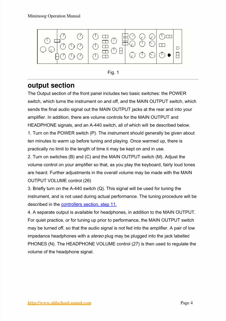
Fig. 1
output section
The Output section of the front panel includes two basic switches: the POWER
switch, which turns the instrument on and off, and the MAIN OUTPUT switch, which
sends the final audio signal out the MAIN OUTPUT jacks at the rear and into your
amplifier. In addition, there are volume controls for the MAIN OUTPUT and
HEADPHONE signals, and an A-440 switch, all of which will be described below.
1. Turn on the POWER switch (P). The instrument should generally be given about
ten minutes to warm up before tuning and playing. Once warmed up, there is
practically no limit to the length of time it may be kept on and in use.
2. Turn on switches (B) and (C) and the MAIN OUTPUT switch (M). Adjust the
volume control on your amplifier so that, as you play the keyboard, fairly loud tones
are heard. Further adjustments in the overall volume may be made with the MAIN
OUTPUT VOLUME control (26)
3. Briefly turn on the A-440 switch (Q). This signal will be used for tuning the
instrument, and is not used during actual performance. The tuning procedure will be
described in the controllers section, step 11.
4. A separate output is available for headphones, in addition to the MAIN OUTPUT.
For quiet practice, or for tuning up prior to performance, the MAIN OUTPUT switch
may be turned off, so that the audio signal is not fed into the amplifier. A pair of low
impedance headphones with a stereo plug may be plugged into the jack labelled
PHONES (N). The HEADPHONE VOLUME control (27) is then used to regulate the
volume of the headphone signal.

8/6/2019 Minimoog Operation Manual
http://slidepdf.com/reader/full/minimoog-operation-manual 5/18
Minimoog Operation Manual
http://www.oldschool-sound.com Page 5
Front Panel Diagram
oscillator bank
This group of circuits contains three separate and independent oscillators. Each
oscillator produces a waveform which repeats regularly, thereby giving rise to a tone
of definite pitch. The audio signal outputs of the three oscillators are activated by
turning on mixer switches (C), (E), and (G). Since switch (C) is now on, we are
hearing the output of oscillator 1, which is the top row of controls (4, 5, and 12).
1. The RANGE switch (4) determines the pitch range in which the oscillator functions.
Press down a key in the middle of the keyboard, and turn the RANGE switch through
its 6 positions. You will hear that all positions except the lowest are separated by one
octave. The LO position produces sub-audio clicks which may be used for rhythmic
effect. Return the switch to its 8´ position.
2. The WAVEFORM switch (5) selects one of six waveforms, each of which has a
different overtone spectrum, and therefore produces a different basic tone quality.
From left to right, the available waveforms are: triangular, sawtooth-triangular,
sawtooth, square, wide rectangular, and narrow rectangular. (Oscillator 3 substitutes
a reverse sawtooth for the sawtooth-triangular.)
Hold a key down and run the WAVEFORM switch through its positions, noticing how
the tone quality changes. The triangular waveform has the least harmonic content;
the narrow rectangular has the most. Generally your ear will be your best guide in
deciding which waveform to use for a particular quality.

8/6/2019 Minimoog Operation Manual
http://slidepdf.com/reader/full/minimoog-operation-manual 6/18
Minimoog Operation Manual
http://www.oldschool-sound.com Page 6
3. The VOLUME control (12) adjusts the amount of Oscillator 1 signal which is fed to
the mixer, while switch (C) instantly turns the oscillator on or off. Oscillators 2 and 3
may be heard by turning on switches (E) and (G) respectively, and their relative
volumes may be adjusted with VOLUME controls (13) and (14).4. FREQUENCY controls (7 and 10) are found only on Oscillators 2 and 3. These
controls raise or lower the pitch of their oscillator by as much as a major sixth with
respect to Oscillator 1. To hear this, turn on switches (C) and (E), turn off (G), and
depress a key. Adjust control (7) until the pitches of Oscillators 1 and 2 are nearly in
unison. As you move up and down the keyboard, the pitches of the two oscillators will
move together. Now turn control (7) clockwise while depressing a key, until a perfect
fifth is made. Once again, this interval will remain constant as you play different noteson the keyboard. Any intervals within the range of the oscillators may be set up
simply by setting the RANGE switches and FREQUENCY controls appropriately.
5. By turning off the OSCILLATOR 3 CONTROL switch (B), Oscillator 3 may be
disconnected from the control of the keyboard. To observe this, turn off switches (B),
(C), and (E), and turn on switch (G). The pitch of the oscillator will not change as
different keys are struck. You will also observe that Oscillator 3's FREQUENCY
control has a much wider range when switch (B) is off. If you hold down one key and
turn control (10) through its range, you will hear a frequency sweep of 6 octaves
rather than one octave.
controllersThis section will demonstrate the use of the controls located to the left of the
Oscillator Bank (used in tuning and setting up a sound), as well as the keyboard and
the manual controls on the panel to its left (used during performance). All of these
controls have an effect on the oscillators' pitches, while the Modulation Mix and
keyboard may also be used to control the filter.
modulation mix
Oscillator 3, unlike Oscillators 1 and 2, is available as a control signal in addition to
functioning as an audio signal. As a control signal, it may be mixed with the output of
the Noise Source using the MODULATION MIX control (3) and introduced whenever
the performer wishes, using the MODULATION wheel (29). The procedure described
below will familiarize you with the use of the Modulation Mix in controlling the pitch of Oscillator 1:

8/6/2019 Minimoog Operation Manual
http://slidepdf.com/reader/full/minimoog-operation-manual 7/18
Minimoog Operation Manual
http://www.oldschool-sound.com Page 7
1. Turn off switch (B), so that the pitch of Oscillator 3 is not affected by the keyboard.
2. Turn off switch (G) and turn on switch (C). Now you are hearing Oscillator 1, but
not Oscillator 3, when a key is depressed.
3. Set Oscillator 3's RANGE switch (9) to the LO position, its FREQUENCY control(10) to mid (0) position, and its WAVEFORM switch (11) to the triangular (extreme
left) setting. This produces a very low frequency triangular waveform which oscillates
only a few times a second.
4. Set the MODULATION MIX control to 0, so that its signal is that of Oscillator 3.
Turn on the OSCILLATOR MODULATION SWITCH (A). This switch directs the
Modulation Mix signal to control the oscillators' pitches.
5. The slowly varying output voltage of Oscillator 3 is now going through theMODULATION wheel (29) at the left of the keyboard, and from there may be applied
to periodically change the oscillators' pitches (we will hear its effect on Oscillator 1).
The MODULATION wheel is in effect a level control for the Modulation Mix. Slowly
move the MODULATION wheel back and forth with your left hand while holding down
a key with your right hand. The position of the Modulation wheel will determine the
amount of variation you hear in the pitch of Oscillator 1.
6. Change the setting of Oscillator 3's FREQUENCY control and notice the resulting
increase and decrease in the speed of the modulation
7. Change the setting of Oscillator 3's WAVEFORM switch and you will notice the
change in the shape of the modulation. You should actually be able to hear the
contours of the different waveforms the alternation of high and low tones in the
square wave, the repeated upward glissandi of the sawtooth, etc.
8. The setting of the MODULATION MIX control determines the proportions of the
mixture of Oscillator 3 and Noise Source. As you slowly turn this control clockwise,
you will hear less periodic modulation and more random modulation.
9. Before continuing, defeat the oscillator modulation by turning off switch (A).
other controllers
10. The PITCH wheel (28), located next to the MODULATION wheel to the left of the
keyboard, is used to bend the pitch determined by the keyboard (as much as half an
octave up or down) when the performer wishes to introduce expressive nuances to
individual notes during performance. Depress a key, and move the PITCH wheel

8/6/2019 Minimoog Operation Manual
http://slidepdf.com/reader/full/minimoog-operation-manual 8/18
Minimoog Operation Manual
http://www.oldschool-sound.com Page 8
back and forth with your left hand. Notice that you can reset the control by feel a
detent mechanism holds it in its normal center position.
11. The TUNE control (1) is used to tune up the Mini Moog oscillators to the pitch of
the ensemble in which it is being used, or to its A-440 reference tone. Check to seethat switch (C) is on, and notice that, when a key is depressed, the pitch moves up
and down by a few tones as the TUNE control is turned through its range. Make sure
the PITCH wheel is in its center position, and turn on the A-440 switch (Q). Depress
an A key on the keyboard, and adjust the TUNE control so that the two A's are in
tune with each other. Turn off the A-440. The other two oscillators may now be tuned
to Oscillator 1 using their FREQUENCY controls.
12. The GLIDE control (2) regulates the amount of portamento, or glide, heardbetween pitches as first one key and then another is depressed. This control is
activated by turning on the GLIDE switch (R). Setting the GLIDE control at various
levels, play a scale or arpeggio, first with the GLIDE switch on, then using the switch
to introduce glide selectively between certain notes only. Notice that the further to the
right control (2) is set, the longer it will take a tone to move from one pitch to the next.
13. Finally, the KEYBOARD itself functions as a controller. It produces a control
signal which varies according to the position of the key struck. If more than one key is
held down, only the lowest one has effect. The control output of the KEYBOARD is
permanently connected to Oscillators 1 and 2. Switch (B) couples it to Oscillator 3.
Switches (K) and (L) couple it to the filter, and are discussed in the modifiers section,
step 8. The KEYBOARD also produces a timing signal each time a key is depressed.
This will be discussed in the modifiers section in connection with filter and loudness
contour controls.
mixer Audio signals produced by the three oscillators, noise source, and microphone
preamplifier are combined and balanced by the Mixer section's switches and volume
controls. It is this composite signal, the output of the mixer, which is then modified by
the filter and loudness contour controls and appears as the audio output signal of the
Mini Moog.
1. The OSCILLATOR VOLUME controls (12, 13, and 14) are used to regulate the
relative levels of the audio signals produced by the three oscillators. Switches (C),

8/6/2019 Minimoog Operation Manual
http://slidepdf.com/reader/full/minimoog-operation-manual 9/18
Minimoog Operation Manual
http://www.oldschool-sound.com Page 9
(E), and (G) instantly turn the individual audio signals on and off. Switch (G) does not
affect the control signal produced by Oscillator 3 via the Modulation Mix. The
operation of these controls and switches has been discussed earlier.
2. The EXTERNAL INPUT VOLUME control (15) is connected to a microphonepreamplifier. The input to this preamplifier is the phone jack on the rear panel labelled
EXT. SIGNAL INPUT. Any sort of high impedance microphone signal or sound
source may be fed into this input. This includes guitar microphone, voice microphone,
wind instrument microphone, tape recorder output, radio, etc. Control (15) is adjusted
so that the OVERLOAD light blinks on and off occasionally when loud sounds come
through the external input. Switch (D) feeds this source into the mixer.
3. The NOISE VOLUME control (16) regulates the level of the signal produced by theNoise Source. This source generates a random waveform producing pitch-less
sound. Two colors of noise are available white, or high-pitched, and pink, or low-
pitched. These are selected by the Noise Quality switch (H), labelled WHITE/PINK.
As an audio signal, the Noise Source may be fed into the mixer by turning on switch
(F). As a control signal, it is available through the Modulation Mix, as described in the
controllers section.
modifiersThe Modifiers section of the front panel features controls for the two sound modifiers,
the Filter and the Loudness Contour, which respectively shape the overtone content
and loudness/time contour of the audio signal as it passes through the modifying
circuitry from the mixer. In order to hear the effect of these controls, begin by setting
the controls in the oscillator and mixer sections as follows:
Control Setting
Oscillator MODULATIONSWITCH (A)
off
Oscillator 1 RANGE (4) 16 ́
Oscillator 1 WAVEFORM (5) narrow rectangular (extreme right)
Oscillator 1 VOLUME (12) 7
Oscillator 1 MIXER switch (C) on
Other mixer switches (D, E, F, G) off
Switches (J) (K) (L) off
The controls on the Modifiers section should still be set as shown in Fig. 1 of the
section titled setting up the instrument .
8/6/2019 Minimoog Operation Manual
http://slidepdf.com/reader/full/minimoog-operation-manual 10/18
Minimoog Operation Manual
http://www.oldschool-sound.com Page 10
filter and filter contour
The Mini Moog features a wide-range lowpass filter. This filter attenuates, or cuts out,
those frequency components of an audio signal which lie above a variable cutoff
frequency, while passing those components which lie below it.
1. The CUTOFF FREQUENCY control (17) is used to set the filter's cutoff frequency.
Hold down a key and turn this control first clockwise, then counter-clockwise. You will
hear the tone become more shrill and then more muted, as the higher overtones are
first allowed to pass and then attenuated. If control (17) is moved all the way to the
left, the entire signal will be cut out.
2. The AMOUNT OF CONTOUR control (19) determines the amount of filter contour
applied to the filter's cutoff frequency. Each time a key is depressed, a contour
generator attached to the filter is actuated, and sends a control signal to the filter.
The control signal rises at one rate, then falls at a second rate, and finally levels off at
a certain level. This results in a corresponding rise, fall, and leveling off of the filter
cutoff frequency, which we call the filter contour .
Set the CUTOFF FREQUENCY to -2 and repeatedly depress and hold down a key
while setting the AMOUNT OF CONTOUR at various levels. The more this control is
turned up, the greater will be the increase and decrease in the brightness of each
note. Controls (17) and (19) have an additive effect on the cutoff frequency.
3. The ATTACK TIME control (20) determines the duration of the initial segment of
the filter contour. The initial rise of the filter cutoff frequency can be as short as 10
milliseconds or as long as 10 seconds. (The frequency at which the contour begins is
determined by control (17), while the peak which it reaches is determined by controls
(17) and (19) combined.) Repeatedly depress a key while varying the setting of the
ATTACK TIME control from left to right. You will hear the brightness of the note
increase sharply at first, and then more gradually as the attack time increases.
4. The DECAY TIME control (21) determines the duration of the second segment of
the contour, the fall from the initial peak to the sustain level. The range of this control
is about the same as that of the previous control. Set the DECAY TIME control at
various levels moving slowly from left to right, while repeatedly depressing a key. At
first you will hear the brightness drop sharply after the initial attack; the drop will
become more gradual as the decay time increases.

8/6/2019 Minimoog Operation Manual
http://slidepdf.com/reader/full/minimoog-operation-manual 11/18
Minimoog Operation Manual
http://www.oldschool-sound.com Page 11
5. The SUSTAIN LEVEL control (22) determines the frequency at which the contour
levels off after the initial rise and fall. The frequency of the sustain level can be as
high as the initial peak, in which case there is no decay after the initial rise, or it can
be as low as the frequency at which the contour began. To hear this most effectively,set the filter controls for CUTOFF FREQUENCY of -2, high AMOUNT OF
CONTOUR, and medium DECAY TIME. Now repeatedly depress and hold down a
key while setting control (22) at various levels. Set at 0, the contour decay effectively
wipes out the signal; set in the middle, the brightness levels off at a frequency
somewhere below the initial peak, and set at 10, the brightness of the note rises to
an initial peak and remains there.
6. The EMPHASIS control (18) introduces a sharp resonance in the response of thefilter at the cutoff frequency. The effect of this control can be heard very easily. To
observe it, turn the AMOUNT OF CONTOUR fully to the left to shut off the contour
signal, and turn the EMPHASIS control to 7. Depress a key, and turn the CUTOFF
FREQUENCY control slowly throughout its range. You should hear the individual
overtones of the oscillator waveform being emphasized one by one as the resonance
passes over them. Now set the CUTOFF FREQUENCY to about -2, turn the
AMOUNT OF CONTOUR all the way up, and repeatedly hold down a key while
changing the settings of controls (20), (21), and (22). Notice how the filter contour is
now heard as a sweep of the overtone series when (20) and (21) are turned up to
about 7 seconds and (22) is set low.
We have seen how the filter cutoff frequency may be controlled manually and using
the filter contour controls. These are in addition to other means of controlling the
filter.
7. The MODULATION MIX (3) of Oscillator 3 and the Noise Source may be used to
modulate the filter cutoff frequency in exactly the same way it is employed to
modulate the pitches of the oscillators. To direct the Modulation Mix to the filter, the
FILTER MODULATION switch (J) must be turned on. Then the MODULATION wheel
(29) can be moved forward with the left hand to introduce the desired amount of
modulation as the keyboard is played with the right hand. To test this, turn (18) and
(19) all the way down and set (17) to about 1 or 2. Make sure that the Oscillator
Modulation switch (A) and Osc. 3 Control Switch (B) are off, and turn on switch (J).
8/6/2019 Minimoog Operation Manual
http://slidepdf.com/reader/full/minimoog-operation-manual 12/18
Minimoog Operation Manual
http://www.oldschool-sound.com Page 12
Set the MODULATION MIX control all the way to the left. Oscillator 3's RANGE
switch should be set to LO. You will observe as you did when applying the
Modulation Mix to the oscillators that the modulation contour depends on the settings
of the FREQUENCY and WAVEFORM controls of Oscillator 3. A more complexsound can be made by adding the effects of controls (18) and (19).
8. The two KEYBOARD CONTROL switches (K) and (L) apply the control signal
produced by the keyboard to move the filter cutoff frequency up and down. This is
important in setting up a sound, for if there is no keyboard control of the filter, the
higher notes on the keyboard will sound duller than the lower ones, having more of
their overtones attenuated. To observe the effect of these switches, turn off Oscillator
1 (C) and the Filter Modulation switch (J), and set control (17) to 0. Turn on theNOISE SOURCE (F) and set the Noise Quality switch (H) to WHITE. This feeds white
noise through filter and amplifier. Turn on switches (K) and (L) and play up and down
the keyboard. You will hear the brightness of the white noise increase and decrease
according to the position of the key which you have depressed. Switch (K) couples a
small amount of keyboard control; switch (L) couples a larger amount. When (K) and
(L) are both on, the filter cutoff frequency moves in full response to the keyboard
control signal.
NOTE:
When the EMPHASIS control is set to 10, the filter breaks into oscillation, and
produces a pure sine wave tone. It thus is available as a sixth sound source within
the Mini Moog. The pitch of this additional oscillator may be controlled by the five
other controls on the keyboard. The sixth sound source may be used alone or mixed
with the other sound sources to achieve a variety of complex effects.
To hear the sixth sound source alone, set up the instrument as follows:
Control Setting
All Mixer switches (C,D,E,F,G) off
Filter Modulation switch (J) off
Keyboard Control switches (K & L) on
Cutoff Frequency (17) -2
Emphasis (18) 10
Amount of Contour (19) 0
Now hold down or repeatedly strike a key, while experimenting with the following
means of controlling pitch:

8/6/2019 Minimoog Operation Manual
http://slidepdf.com/reader/full/minimoog-operation-manual 13/18
Minimoog Operation Manual
http://www.oldschool-sound.com Page 13
1. Manually, using CUTOFF FREQUENCY control.
2. Using Filter Contour Controls (19-22).
3. Using the Modulation Mix (see step 7 above).
4. Using the Keyboard. Differently tempered scales will result from different settings of
(K) and (L).
loudness contour
The volume of the audio signal which passes through the Modifiers section of the
Mini Moog is contoured by the Loudness Contour controls. These controls are
connected to a contour generator which supplies a control signal to the amplifier. Like
the filter contour signal, the loudness contour signal is composed of three segments
initial rise, decay, and sustain level. Each time a key is struck, the contour generator
is activated, and a note is shaped according to the settings of the contour controls.
9. The ATTACK TIME control (23) determines the duration of the initial rise in volume
to a peak. Turn off the Noise Source (F) and turn on Oscillator 1 (C). Move control
(23) back and forth while repeatedly pressing down a key. Notice the different
qualities which a note takes on as a sharp attack becomes a slow crescendo.
10. The DECAY TIME control (24) determines the duration of the drop in volume from
the initial peak to the sustain level. The decay can be sharp or gradual.
11. The SUSTAIN LEVEL control (25) determines the volume level at which the
contour levels off after attack and decay. Set at 0, no sustain level is heard. Set at 5,
the contour diminishes to a low volume. Set at 10, no drop in volume is heard after
the initial peak is reached.
12. Finally, a DECAY switch (S) to the left of the keyboard allows the sound to fade
out at the decay time set by control (24), rather than immediately upon release of a
key. This final decay then, takes effect after the sustain level segment of the contour.
To review the phases of the overall loudness contour: a key is first pressed down.
This produces an initial rise in volume, a decay, and a leveling off. The key is then
lifted, and the sound is either cut off immediately, or if the DECAY switch is on, fades
at the rate set by control (24). Turning on the DECAY switch can impart a life-like
quality to notes which seem to terminate too abruptly.
13. For sustained sounds and textures, a SHORTING PLUG is provided with the Mini
Moog. If this plug is inserted in the TRIGGER INPUT jack at the rear of the
instrument, the filter and loudness contours will be triggered and remain at the
sustain level. The mixer output will then be amplified at a sustained volume whether

8/6/2019 Minimoog Operation Manual
http://slidepdf.com/reader/full/minimoog-operation-manual 14/18
Minimoog Operation Manual
http://www.oldschool-sound.com Page 14
or not a key is held down. The keyboard will continue to provide a control signal for
determining the oscillators' pitches and the filter's cutoff frequency, according to the
settings of switches (B), (K), and (L).
STANDARD ACCESSORIES SHIPPED WITH MINI-D SYNTHESIZER
1. Mini brochure & 1971 Catalog
2. Mini Instruction Manual
3. Warrantee (Reg. Postcard)
4. Shorting S-Trig Plug
5. "Back Panel Adjustment" Pamphlet
6. 6' Phone Cord
7. 6' Phone - Phono Cord
8. Optional Accessories List
6/12/71
70-014
OPTIONAL ACCESSORIES NOW AVAILABLE
FOR USE WITH MINI MOOG MODEL D
1. 958 FOOT PEDAL
This controller can be used to control the volume of the output, pitch of the
oscillators, or the cutoff frequency of the filter (timbre). Up to three may be used
simultaneously to control all of these functions.
2. 959 X-Y CONTROLLER
This "joystick" simultaneously controls any two of the functions mentioned above. For
instance, it can be used to produce vowel-like sounds by controlling the filter and
pitch.
3. SEQUENTIAL CONTROLLER SYSTEM
• 960 Sequencer
• 961 Interface (optional)
• 962 Sequential Switch (optional)
• 910 Power Supply for above units
• Cabinet (portable or walnut console)
This system will automatically and simultaneously control all three functions (pitch,
timbre, and volume) in a repeating eight-event sequence. It also triggers the contour
generators at the onset of each event. The 962 allows one to extend a sequence of

8/6/2019 Minimoog Operation Manual
http://slidepdf.com/reader/full/minimoog-operation-manual 15/18
Minimoog Operation Manual
http://www.oldschool-sound.com Page 15
one function to up to 24 events (example: 24 note repeating bass line). The 961
extends flexibility in triggering the contour generators and can be used to
synchronize the MINI MOOG with external equipment (example: tape recorded click
track). AVAILABLE SOON
1. FOOT SWITCH
A pair of these will allow the performer to engage momentarily GLIDE and DECAYfunctions. With a different plug, the foot switch will supply an external S-Trigger.
2. DUAL FOOT PEDAL
Essentially this device will contain two 958 Foot Pedals for simultaneous control of
timbre and volume.
July, 1971
70-016
S-TRIG PLUG FOR MINI MOOG MODEL D
When inserted, this plug keeps the contour generators "on" continuously. It can be
wired to an accessory foot switch for manual external triggering of notes.
WIRING OF SWITCH TO S-TRIG PLUG
July, 1971
70-018
LEFT HAND CONTROLLER
EXTERNAL CONTROL OF GLIDE AND FINAL DECAY.
The rocker switches in the left hand controller section have replaced the momentary
push buttons used previously. Jacks have been added so that the performer can
connect foot switches to engage GLIDE and DECAY functions. R. A. Moog will soon
make these momentary switches available as an accessory.
With no external switch connected and the GLIDE switch turned off there will be no
portamento. When the GLIDE switch is turned on the pitch will glide between notes at
a rate set by control (2) (see controllers section, paragraph 12). When the performer
connects the external foot switch, he can momentarily engage portamento when the
8/6/2019 Minimoog Operation Manual
http://slidepdf.com/reader/full/minimoog-operation-manual 16/18
Minimoog Operation Manual
http://www.oldschool-sound.com Page 16
GLIDE switch is off by depressing the switch button. The foot switch has no effect if
the GLIDE switch is already on.
The external control of the DECAY function works in an analogous fashion.
To prevent confusion of the external foot switch cords with input and output audioand control voltage cords, the jacks for DECAY and GLIDE are 0.206" dia. instead of
0.250" dia. The jacks mate with Switchcraft S-260 plugs instead of ordinary 1/4"
phone plugs.
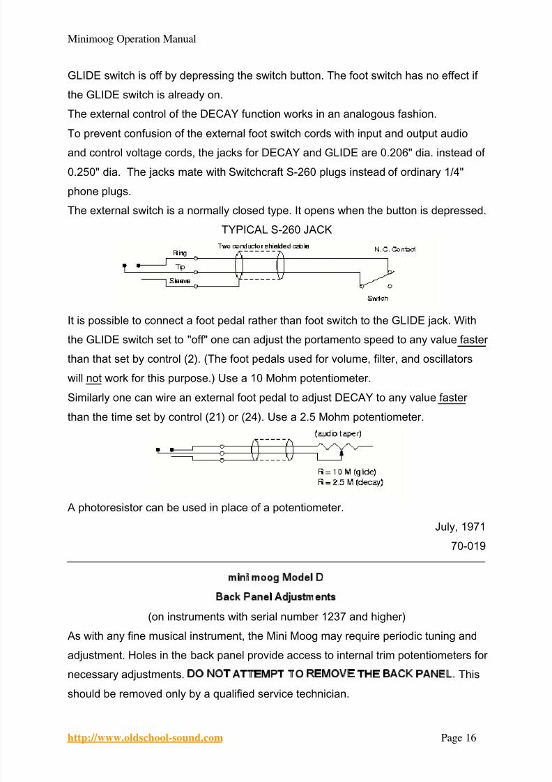
The external switch is a normally closed type. It opens when the button is depressed.
TYPICAL S-260 JACK
It is possible to connect a foot pedal rather than foot switch to the GLIDE jack. With
the GLIDE switch set to "off" one can adjust the portamento speed to any value faster
than that set by control (2). (The foot pedals used for volume, filter, and oscillators
will not work for this purpose.) Use a 10 Mohm potentiometer.
Similarly one can wire an external foot pedal to adjust DECAY to any value faster
than the time set by control (21) or (24). Use a 2.5 Mohm potentiometer.
A photoresistor can be used in place of a potentiometer.
July, 1971
70-019
mini moog Model D
Back Panel Adjustments
(on instruments with serial number 1237 and higher)
As with any fine musical instrument, the Mini Moog may require periodic tuning and
adjustment. Holes in the back panel provide access to internal trim potentiometers for
necessary adjustments. DO NOT ATTEMPT TO REMOVE THE BACK PANEL. This
should be removed only by a qualified service technician.
8/6/2019 Minimoog Operation Manual
http://slidepdf.com/reader/full/minimoog-operation-manual 17/18
Minimoog Operation Manual
http://www.oldschool-sound.com Page 17
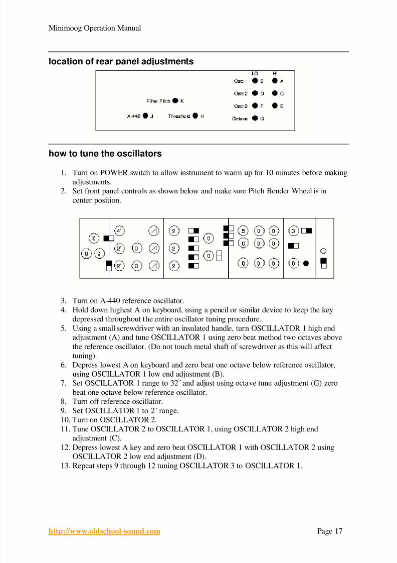
location of rear panel adjustments
how to tune the oscillators
1. Turn on POWER switch to allow instrument to warm up for 10 minutes before making
adjustments.2. Set front panel controls as shown below and make sure Pitch Bender Wheel is in
center position.
3. Turn on A-440 reference oscillator.
4. Hold down highest A on keyboard, using a pencil or similar device to keep the key
depressed throughout the entire oscillator tuning procedure.
5. Using a small screwdriver with an insulated handle, turn OSCILLATOR 1 high endadjustment (A) and tune OSCILLATOR 1 using zero beat method two octaves above
the reference oscillator. (Do not touch metal shaft of screwdriver as this will affect
tuning).
6. Depress lowest A on keyboard and zero beat one octave below reference oscillator,
using OSCILLATOR 1 low end adjustment (B).7. Set OSCILLATOR 1 range to 32´ and adjust using octave tune adjustment (G) zero
beat one octave below reference oscillator.8. Turn off reference oscillator.
9. Set OSCILLATOR 1 to 2´ range.
10. Turn on OSCILLATOR 2.
11. Tune OSCILLATOR 2 to OSCILLATOR 1, using OSCILLATOR 2 high end
adjustment (C).
12. Depress lowest A key and zero beat OSCILLATOR 1 with OSCILLATOR 2 usingOSCILLATOR 2 low end adjustment (D).
13. Repeat steps 9 through 12 tuning OSCILLATOR 3 to OSCILLATOR 1.

8/6/2019 Minimoog Operation Manual
http://slidepdf.com/reader/full/minimoog-operation-manual 18/18
Minimoog Operation Manual
http:// oldschool so nd com P 18
how to tune the filter
(This is factory set and rarely, if ever, needs adjustment)
1. Set the front panel controls as shown below:
2. Insert S-TRIG Shorting Plug supplied with the instrument.3. Adjust filter resonance threshold adjustment (H) until tone is barely audible.4. Turn FILTER EMPHASIS control on front panel to 10.
5. Turn on A-440 reference oscillator.6. Tune filter resonance to A-440 tone using filter pitch adjustment (K).
4/12/72