operation manual -...
TRANSCRIPT
Cat.No. W226--E1--7
Programmable Controllers
SYSMACCQM1
OPERATION MANUAL
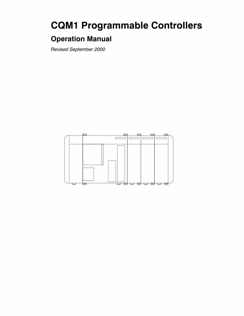
CQM1 Programmable ControllersOperation ManualRevised September 2000
!
!
!
v
Notice:OMRON products are manufactured for use according to proper procedures by a qualified operatorand only for the purposes described in this manual.
The following conventions are used to indicate and classify precautions in this manual. Always heedthe information provided with them. Failure to heed precautions can result in injury to people or dam-age to property.
DANGER Indicates an imminently hazardous situation which, if not avoided, will result in death orserious injury.
WARNING Indicates a potentially hazardous situation which, if not avoided, could result in death orserious injury.
Caution Indicates a potentially hazardous situation which, if not avoided, may result in minor ormoderate injury, or property damage.
OMRON Product ReferencesAll OMRON products are capitalized in this manual. The word Unit is also capitalized when it refersto an OMRON product, regardless of whether or not it appears in the proper name of the product.
The abbreviation Ch, which appears in some displays and on some OMRON products, often meansword and is abbreviated Wd in documentation in this sense.
The abbreviation PC means Programmable Controller and is not used as an abbreviation for any-thing else.
Visual AidsThe following headings appear in the left column of the manual to help you locate different types ofinformation.
Note Indicates information of particular interest for efficient and convenient operationof the product.
1, 2, 3... 1. Indicates lists of one sort or another, such as procedures, checklists, etc.
OMRON, 1993All rights reserved. No part of this publication may be reproduced, stored in a retrieval system, or transmitted, in anyform, or by any means, mechanical, electronic, photocopying, recording, or otherwise, without the prior written permis-sion of OMRON.
No patent liability is assumed with respect to the use of the information contained herein. Moreover, because OMRON isconstantly striving to improve its high-quality products, the information contained in this manual is subject to changewithout notice. Every precaution has been taken in the preparation of this manual. Nevertheless, OMRON assumes noresponsibility for errors or omissions. Neither is any liability assumed for damages resulting from the use of the informa-tion contained in this publication.
TABLE OF CONTENTS
vii
PRECAUTIONS xi. . . . . . . . . . . . . . . . . . . . . . . . . . . . . . . . .1 Intended Audience xii. . . . . . . . . . . . . . . . . . . . . . . . . . . . . . . . . . . . . . . . . . . . . . . . . . . . . . . . . . .2 General Precautions xii. . . . . . . . . . . . . . . . . . . . . . . . . . . . . . . . . . . . . . . . . . . . . . . . . . . . . . . . . .3 Safety Precautions xii. . . . . . . . . . . . . . . . . . . . . . . . . . . . . . . . . . . . . . . . . . . . . . . . . . . . . . . . . . .4 Operating Environment Precautions xii. . . . . . . . . . . . . . . . . . . . . . . . . . . . . . . . . . . . . . . . . . . . .5 Application Precautions xiii. . . . . . . . . . . . . . . . . . . . . . . . . . . . . . . . . . . . . . . . . . . . . . . . . . . . . .6 Conformance to EC Directives xiv. . . . . . . . . . . . . . . . . . . . . . . . . . . . . . . . . . . . . . . . . . . . . . . . .
SECTION 1Introduction 1. . . . . . . . . . . . . . . . . . . . . . . . . . . . . . . . . . . .1-1 Overview 2. . . . . . . . . . . . . . . . . . . . . . . . . . . . . . . . . . . . . . . . . . . . . . . . . . . . . . . . . . . . . .1-2 System Configuration 3. . . . . . . . . . . . . . . . . . . . . . . . . . . . . . . . . . . . . . . . . . . . . . . . . . . . .1-3 CQM1 Features 3. . . . . . . . . . . . . . . . . . . . . . . . . . . . . . . . . . . . . . . . . . . . . . . . . . . . . . . . .
SECTION 2Units and Installation 5. . . . . . . . . . . . . . . . . . . . . . . . . . . .2-1 CPU Unit 6. . . . . . . . . . . . . . . . . . . . . . . . . . . . . . . . . . . . . . . . . . . . . . . . . . . . . . . . . . . . . .2-2 Power Supply Unit 18. . . . . . . . . . . . . . . . . . . . . . . . . . . . . . . . . . . . . . . . . . . . . . . . . . . . . . .2-3 I/O Units 20. . . . . . . . . . . . . . . . . . . . . . . . . . . . . . . . . . . . . . . . . . . . . . . . . . . . . . . . . . . . . . .2-4 PC Assembly and Installation 24. . . . . . . . . . . . . . . . . . . . . . . . . . . . . . . . . . . . . . . . . . . . . .2-5 Wiring and Connections 26. . . . . . . . . . . . . . . . . . . . . . . . . . . . . . . . . . . . . . . . . . . . . . . . . . .2-6 Unit Specifications 40. . . . . . . . . . . . . . . . . . . . . . . . . . . . . . . . . . . . . . . . . . . . . . . . . . . . . . .
SECTION 3The LSS, SSS, SYSMAC-CPT,and Programming Consoles 73. . . . . . . . . . . . . . . . . . . . .
3-1 LSS Capabilities 74. . . . . . . . . . . . . . . . . . . . . . . . . . . . . . . . . . . . . . . . . . . . . . . . . . . . . . . . .3-2 SSS Capabilities 75. . . . . . . . . . . . . . . . . . . . . . . . . . . . . . . . . . . . . . . . . . . . . . . . . . . . . . . . .3-3 SYSMAC-CPT Precautions 82. . . . . . . . . . . . . . . . . . . . . . . . . . . . . . . . . . . . . . . . . . . . . . . .3-4 Compatible Programming Consoles 83. . . . . . . . . . . . . . . . . . . . . . . . . . . . . . . . . . . . . . . . .3-5 Preparation for Operation 84. . . . . . . . . . . . . . . . . . . . . . . . . . . . . . . . . . . . . . . . . . . . . . . . . .3-6 Programming Console Operations 86. . . . . . . . . . . . . . . . . . . . . . . . . . . . . . . . . . . . . . . . . . .
SECTION 4Troubleshooting 111. . . . . . . . . . . . . . . . . . . . . . . . . . . . . . . . .4-1 Introduction 112. . . . . . . . . . . . . . . . . . . . . . . . . . . . . . . . . . . . . . . . . . . . . . . . . . . . . . . . . . . .4-2 Programming Console Operation Errors 113. . . . . . . . . . . . . . . . . . . . . . . . . . . . . . . . . . . . . .4-3 Programming Errors 113. . . . . . . . . . . . . . . . . . . . . . . . . . . . . . . . . . . . . . . . . . . . . . . . . . . . . .4-4 User-defined Errors 114. . . . . . . . . . . . . . . . . . . . . . . . . . . . . . . . . . . . . . . . . . . . . . . . . . . . . .4-5 Operating Errors 115. . . . . . . . . . . . . . . . . . . . . . . . . . . . . . . . . . . . . . . . . . . . . . . . . . . . . . . . .4-6 Troubleshooting Flowcharts 117. . . . . . . . . . . . . . . . . . . . . . . . . . . . . . . . . . . . . . . . . . . . . . . .
AppendicesA Standard Models 125. . . . . . . . . . . . . . . . . . . . . . . . . . . . . . . . . . . . . . . . . . . . . . . . . . . . . . . . . . .B Battery Service Life 129. . . . . . . . . . . . . . . . . . . . . . . . . . . . . . . . . . . . . . . . . . . . . . . . . . . . . . . . .C SYSMAC-CPT Precautions 131. . . . . . . . . . . . . . . . . . . . . . . . . . . . . . . . . . . . . . . . . . . . . . . . . . .
Glossary 133. . . . . . . . . . . . . . . . . . . . . . . . . . . . . . . . . . . . . . .Index 149. . . . . . . . . . . . . . . . . . . . . . . . . . . . . . . . . . . . . . . . . .Revision History 153. . . . . . . . . . . . . . . . . . . . . . . . . . . . . . . . .
ix
About this Manual:
The CQM1 is a compact, high-speed Programmable Controller (PC) designed for advanced controloperations in systems requiring from 16 to 256 I/O points per PC. There are twomanuals describing thesetup and operation of the CQM1: TheCQM1 Operation Manual (this manual) and the CQM1 Program-ming Manual. Also available is the CQM1-series Dedicated I/O Units Operation Manual.
This manual describes the system configuration and installation of the CQM1 and provides an basicexplanation of operating procedures for the ProgrammingConsoles and introduces the capabilities of theLadderSupportSoftware (LSS)andSYSMACSupportSoftware (SSS).Read thismanual first toacquaintyourself with the CQM1.
TheCQM1 Programming Manual provides detailed descriptions of the CQM1s programming functions.The Ladder Support SoftwareOperationManual and theSYSMACSupport Software OperationManual:C-series PCs provides descriptions of LSS and SSS operations for the CQM1 and C-series PCs. UseVersion-3 LSS or a later version for CQM1 operation.
Please read this manual carefully and be sure you understand the information provide before attemptingto install and operate the CQM1.
Section 1 gives a brief overview of the steps involved in developing of a CQM1 System, describes thepossible system configurations, and describes the CQM1s special features and functions.
Section 2 describes the Units that go together to create a CQM1 PC and provides information on switchsettings, installation, and hardwaremaintenance. Technical specifications of the Units are also provided.
Section 3 describes LSS/SSS capabilities, how to connect the Programming Console, and how to per-form the various Programming Console operations.
Section 4 describes how to diagnose and correct the hardwareand software errors that can occur duringPC operation.
The Appendix provides tables of CQM1 Units and related products.
WARNING Failure to read and understand the information provided in this manual may result inpersonal injury or death, damage to the product, or product failure. Please read eachsection in its entirety and be sure you understand the information provided in the sectionand related sections before attempting any of the procedures or operations given.
!
xi
PRECAUTIONS
This section provides general precautions for using the Programmable Controller (PC) and related devices.
The informationcontained in this section is important for the safeandreliableapplicationof theProgrammableCon-troller. Youmust read this section andunderstand the information containedbefore attempting to set upor operate aPC system.
1 Intended Audience xii. . . . . . . . . . . . . . . . . . . . . . . . . . . . . . . . . . . . . . . . . . . . . . . . . . . . . . . . . . .2 General Precautions xii. . . . . . . . . . . . . . . . . . . . . . . . . . . . . . . . . . . . . . . . . . . . . . . . . . . . . . . . . .3 Safety Precautions xii. . . . . . . . . . . . . . . . . . . . . . . . . . . . . . . . . . . . . . . . . . . . . . . . . . . . . . . . . . .4 Operating Environment Precautions xii. . . . . . . . . . . . . . . . . . . . . . . . . . . . . . . . . . . . . . . . . . . . .5 Application Precautions xiii. . . . . . . . . . . . . . . . . . . . . . . . . . . . . . . . . . . . . . . . . . . . . . . . . . . . . .6 Conformance to EC Directives xiv. . . . . . . . . . . . . . . . . . . . . . . . . . . . . . . . . . . . . . . . . . . . . . . . .
!
!
!
!
!
!
6Conformance to EC Directives
xii
1 Intended AudienceThis manual is intended for the following personnel, whomust also have knowl-edge of electrical systems (an electrical engineer or the equivalent).• Personnel in charge of installing FA systems.• Personnel in charge of designing FA systems.• Personnel in charge of managing FA systems and facilities.
2 General PrecautionsThe user must operate the product according to the performance specificationsdescribed in the operation manuals.Before using theproduct under conditionswhichare not described in themanualor applying the product to nuclear control systems, railroad systems, aviationsystems, vehicles, combustion systems, medical equipment, amusementmachines, safety equipment, andother systems,machines, and equipment thatmay have a serious influence on lives and property if used improperly, consultyour OMRON representative.Make sure that the ratings and performance characteristics of the product aresufficient for the systems, machines, and equipment, and be sure to provide thesystems, machines, and equipment with double safety mechanisms.This manual provides information for programming and operating the Unit. Besure to read this manual before attempting to use theUnit and keep this manualclose at hand for reference during operation.
WARNING It is extremely important that a PC and all PC Units be used for the specifiedpurpose and under the specified conditions, especially in applications that candirectly or indirectly affect human life. You must consult with your OMRONrepresentative before applying a PC System to the above-mentionedapplications.
3 Safety Precautions
WARNING Donot attempt to takeany Unit apart while the power is being supplied. Doing somay result in electric shock.
WARNING Do not touch any of the terminals while the power is being supplied. Doing somay result in electric shock.
WARNING Do not attempt to disassemble, repair, or modify any Units. Any attempt to do somay result in malfunction, fire, or electric shock.
Caution Tighten the screws on the terminal block of the AC Power Supply Unit to thetorque specified in the manual. Loose screws may result in burning or malfunc-tion.
4 Operating Environment Precautions
Caution Do not operate the control system in the following locations:
• Locations subject to direct sunlight.• Locations subject to temperatures or humidity outside the range specified inthe specifications.
!
!
!
!
5Application Precautions
xiii
• Locations subject to condensation as the result of severe changes in tempera-ture.
• Locations subject to corrosive or flammable gases.• Locations subject to dust (especially iron dust) or salts.• Locations subject to exposure to water, oil, or chemicals.• Locations subject to shock or vibration.
Caution Take appropriate and sufficient countermeasureswhen installing systems in thefollowing locations:
• Locations subject to static electricity or other forms of noise.• Locations subject to strong electromagnetic fields.• Locations subject to possible exposure to radioactivity.• Locations close to power supplies.
Caution The operating environment of the PCSystem can have a large effect on the lon-gevity and reliability of the system. Improper operating environments can lead tomalfunction, failure, and other unforeseeable problemswith the PC System. Besure that the operating environment is within the specified conditions at installa-tion and remains within the specified conditions during the life of the system.
5 Application PrecautionsObserve the following precautions when using the PC System.
WARNING Always heed these precautions. Failure to abide by the following precautionscould lead to serious or possibly fatal injury.
• Always connect to a groundof 100Ω or less when installing theUnits. Not con-necting to a ground of 100 Ω or less may result in electric shock.
• Always turn OFF the power supply to the PC before attempting any of the fol-lowing. Not turning OFF the power supply may result inmalfunction or electricshock.• Mounting or dismounting Power Supply Units, I/O Units, CPU Units,Memory Cassettes, or any other Units.
• Assembling the Units.• Setting DIP switches or rotary switches.• Connecting or wiring the cables.• Connecting or disconnecting the connectors.
Caution Failure to abide by the following precautions could lead to faulty operation of thePC or the system, or could damage the PC or PCUnits. Always heed these pre-cautions.
• Fail-safe measures must be taken by the customer to ensure safety in theevent of incorrect, missing, or abnormal signals caused by broken signal lines,momentary power interruptions, or other causes.
• Interlock circuits, limit circuits, and similar safety measures in external circuits(i.e., not in the Programmable Controller) must be provided by the customer.
• Always use thepowersupply voltagespecified in themanual. An incorrect volt-age may result in malfunction or burning.
• Take appropriate measures to ensure that the specified power with the ratedvoltage and frequency is supplied. Be particularly careful in places where thepower supply is unstable. An incorrect power supplymay result inmalfunction.
6Conformance to EC Directives
xiv
• Install external breakers and take other safetymeasures against short-circuit-ing in externalwiring. Insufficient safetymeasures against short-circuitingmayresult in burning.
• Do not apply voltages to the Input Units in excess of the rated input voltage.Excess voltages may result in burning.
• Do not apply voltages or connect loads to the Output Units in excess of themaximum switching capacity. Excess voltage or loads may result in burning.
• Disconnect the functional ground terminal when performing withstand voltagetests. Not disconnecting the functional ground terminal may result in burning.
• Install and wire theUnit properly as specified in themanual. Improper installa-tion of the Unit may result in malfunction.
• Be sure that all the mounting screws, terminal screws, and cable connectorscrews are tightened to the torque specified in the relevant manuals. Incorrecttightening torque may result in malfunction.
• Leave the label attached to the Unit when wiring. Removing the label mayresult in malfunction.
• Remove the label after the completion of wiring to ensure proper heat dissipa-tion. Leaving the label attached may result in malfunction.
• Use crimp terminals for wiring. Do not connect bare stranded wires directly toterminals. Connection of bare stranded wires may result in burning.
• Double-check all the wiring before turning ON the power supply. Incorrect wir-ing may result in burning.
• Mount the Unit only after checking the terminal block completely.• Be sure that the terminal blocks, Memory Units, expansion cables, and otheritems with locking devices are properly locked into place. Improper lockingmay result in malfunction.
• Check the user program for proper execution before actually running it on theUnit. Not checking the program may result in an unexpected operation.
• Confirm that noadverseeffectwill occur in thesystembeforeattemptinganyofthe following. Not doing so may result in an unexpected operation.• Changing the operating mode of the PC.• Force-setting/force-resetting any bit in memory.• Changing the present value of any word or any set value in memory.
• Do not pull on the cables or bend the cables beyond their natural limit. Doingeither of these may break the cables.
•When replacingparts, be sure to confirm that the rating of a newpart is correct.Not doing so may result in malfunction or burning.
• Before touchingaUnit, be sure to first touchagroundedmetallic object inorderto discharge any static built-up. Not doing somay result inmalfunction or dam-age.
6 Conformance to EC DirectivesThe CQM1 PCs comply with EC Directives. To ensure that the machine ordevice inwhichaCQM1PC is used complieswithECDirectives, thePCmust beinstalled as follows:
1, 2, 3... 1. The PC must be installed within a control panel.2. Reinforced insulation or double insulation must be used for the DC powersupplies used for the communications and I/O power supplies.
3. PCs complying with EC Directives also conform to the Common EmissionStandard (EN50081-2). When a PC is built into a machine, however, noisecan be generated by switching devices using relay outputs and cause the
5Application Precautions
xv
overallmachine to fail tomeet theStandard. If this occurs, surge killersmustbe connected or other measures taken external to the PC.
The following methods represent typical methods for reducing noise, andmay not be sufficient in all cases. Required countermeasures will varydepending on the devices connected to the control panel, wiring, the config-uration of the system, and other conditions.
Determining if Countermeasures Are RequiredRefer to EN50081-2 for more details.
Countermeasures are not required if the frequency of load switching for thewhole system including the PC is less than 5 times per minute.
Countermeasures are required if the frequency of load switching for the wholesystem including the PC is more than 5 times per minute.
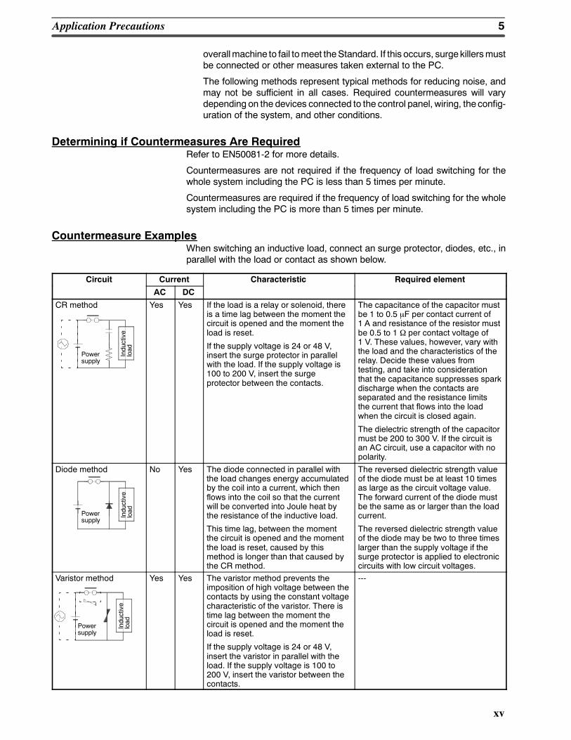
Countermeasure ExamplesWhen switching an inductive load, connect an surge protector, diodes, etc., inparallel with the load or contact as shown below.
Circuit Current Characteristic Required element
AC DC
CR method
Powersupply
Inductive
load
Yes Yes If the load is a relay or solenoid, thereis a time lag between the moment thecircuit is opened and the moment theload is reset.
If the supply voltage is 24 or 48 V,insert the surge protector in parallelwith the load. If the supply voltage is100 to 200 V, insert the surgeprotector between the contacts.
The capacitance of the capacitor mustbe 1 to 0.5 µF per contact current of1 A and resistance of the resistor mustbe 0.5 to 1 Ω per contact voltage of1 V. These values, however, vary withthe load and the characteristics of therelay. Decide these values fromtesting, and take into considerationthat the capacitance suppresses sparkdischarge when the contacts areseparated and the resistance limitsthe current that flows into the loadwhen the circuit is closed again.
The dielectric strength of the capacitormust be 200 to 300 V. If the circuit isan AC circuit, use a capacitor with nopolarity.
Diode method
Powersupply
Inductive
load
No Yes The diode connected in parallel withthe load changes energy accumulatedby the coil into a current, which thenflows into the coil so that the currentwill be converted into Joule heat bythe resistance of the inductive load.
This time lag, between the momentthe circuit is opened and the momentthe load is reset, caused by thismethod is longer than that caused bythe CR method.
The reversed dielectric strength valueof the diode must be at least 10 timesas large as the circuit voltage value.The forward current of the diode mustbe the same as or larger than the loadcurrent.
The reversed dielectric strength valueof the diode may be two to three timeslarger than the supply voltage if thesurge protector is applied to electroniccircuits with low circuit voltages.
Varistor method
Powersupply
Inductive
load
Yes Yes The varistor method prevents theimposition of high voltage between thecontacts by using the constant voltagecharacteristic of the varistor. There istime lag between the moment thecircuit is opened and the moment theload is reset.
If the supply voltage is 24 or 48 V,insert the varistor in parallel with theload. If the supply voltage is 100 to200 V, insert the varistor between thecontacts.
---
6Conformance to EC Directives
xvi
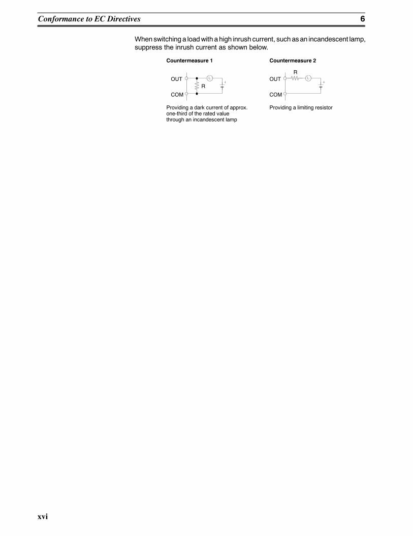
Whenswitchinga loadwith ahigh inrush current, suchasan incandescent lamp,suppress the inrush current as shown below.
OUT
COM
ROUT
COM
R
Countermeasure 1
Providing a dark current of approx.one-third of the rated valuethrough an incandescent lamp
Countermeasure 2
Providing a limiting resistor
1
SECTION 1Introduction
This section gives a brief overview of the steps involved in developing of a CQM1 System, describes the possible systemconfigurations, and describes the CQM1s special features and functions.
1-1 Overview 2. . . . . . . . . . . . . . . . . . . . . . . . . . . . . . . . . . . . . . . . . . . . . . . . . . . . . . . . . . . . . .1-2 System Configuration 3. . . . . . . . . . . . . . . . . . . . . . . . . . . . . . . . . . . . . . . . . . . . . . . . . . . . .1-3 CQM1 Features 3. . . . . . . . . . . . . . . . . . . . . . . . . . . . . . . . . . . . . . . . . . . . . . . . . . . . . . . . .
2
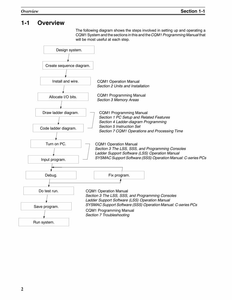
1-1 OverviewThe following diagram shows the steps involved in setting up and operating aCQM1Systemand the sections in this and theCQM1ProgrammingManual thatwill be most useful at each step.
Design system.
Create sequence diagram.
Install and wire.
Allocate I/O bits.
Draw ladder diagram.
Code ladder diagram.
Turn on PC.
Input program.
Debug.
Do test run.
Save program.
Run system.
CQM1 Operation ManualSection 2 Units and Installation
CQM1 Programming ManualSection 1 PC Setup and Related FeaturesSection 4 Ladder-diagram ProgrammingSection 5 Instruction SetSection 7 CQM1 Operations and Processing Time
CQM1 Operation ManualSection 3 The LSS, SSS, and Programming ConsolesLadder Support Software (LSS) Operation ManualSYSMACSupport Software (SSS) OperationManual: C-series PCs
CQM1 Operation ManualSection 3 The LSS, SSS, and Programming ConsolesLadder Support Software (LSS) Operation ManualSYSMACSupport Software (SSS) OperationManual: C-series PCsCQM1 Programming ManualSection 7 Troubleshooting
Fix program.
CQM1 Programming ManualSection 3 Memory Areas
Overview Section 1-1
3
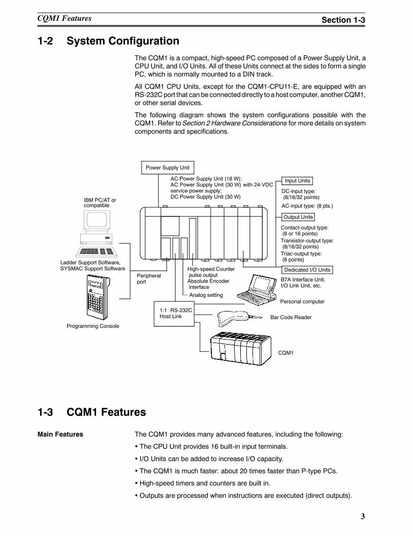
1-2 System ConfigurationThe CQM1 is a compact, high-speed PC composed of a Power Supply Unit, aCPU Unit, and I/O Units. All of these Units connect at the sides to form a singlePC, which is normally mounted to a DIN track.
All CQM1 CPU Units, except for the CQM1-CPU11-E, are equipped with anRS-232Cport that canbe connecteddirectly toahost computer, anotherCQM1,or other serial devices.
The following diagram shows the system configurations possible with theCQM1. Refer toSection 2Hardware Considerations for more details on systemcomponents and specifications.
IBM PC/AT orcompatible
Dedicated I/O Units
Output Units
DC-input type:(8/16/32 points)
AC-input type: (8 pts.)
1:1 RS-232CHost Link Bar Code Reader
Peripheralport
Personal computer
CQM1
Programming Console
Ladder Support Software,SYSMAC Support Software
Power Supply Unit
AC Power Supply Unit (18 W);AC Power Supply Unit (30 W) with 24-VDCservice power supply;DC Power Supply Unit (30 W)
Input Units
Contact-output type:(8 or 16 points)Transistor-output type:(8/16/32 points)
B7A Interface Unit,I/O Link Unit, etc.
High-speed Counterpulse outputAbsolute EncoderinterfaceAnalog setting
Triac-output type:(8 points)
1-3 CQM1 Features
Main Features The CQM1 provides many advanced features, including the following:
• The CPU Unit provides 16 built-in input terminals.
• I/O Units can be added to increase I/O capacity.
• The CQM1 is much faster: about 20 times faster than P-type PCs.
• High-speed timers and counters are built in.
• Outputs are processed when instructions are executed (direct outputs).
CQM1 Features Section 1-3
4
Interrupts The CQM1 supports three types of interrupts:
• Input Interrupts
Input interrupts are used to process input signals from an external devicethat are shorter than the program execution time. Input signals with a pulsewidth as short as 0.1 ms can be used.
• Scheduled Interrupts
Scheduled interrupts can be performed using a high-speed interval timer.
• High-speed Counter Interrupts
Single-phase pulses up to 5 kHzand two-phasepulses up to 2.5 kHz canbeinput. High-speed counter interrupts canbe combinedwith pulse outputs forapplications such as motor control. The CQM1-CPU43-EV1 andCQM1-CPU44-EV1 can accept single-phase pulses up to 50 kHz and two-phasepulses up to 25 kHz. Thehigh-speed counter (absolute encoder inputfor the CPU44-EV1) has two points added.
Pulse Output Function Pulses up to 1 kHz can be output from Output Unit contacts. TheCQM1-CPU43-EV1 has two dedicated ports for outputting 50 kHz pulses.
Communications A peripheral port and RS-232C port are available and are used to communicatewith external devices using the following methods.
• Host Link
The CQM1 using the host link can communicate with a personal computerand Programmable Terminal using host link commands.
• RS-232C
The CQM1 using the RS-232C can read data from a bar code reader ormeasurement device and output data to a printer.
• 1-to-1 Link
A data link can be created with a data area in another CQM1 to monitor theother PCs status and synchronize processes controlled by the PCs.
Analog Setting Function TheCQM1-CPU42-EV1 provides volume controlswith four channels for adjust-ing analog settings.
Convenient I/O Instructions A single instruction can be used to input or output data, simplifying the program.
• The TEN KEY INPUT instruction can be used to read 8-digit BCD data inputfrom a ten-key.
• TheHEXADECIMALKEY INPUT instruction can beused to read 8-digit hexa-decimal key input data from I/O Units.
• The DIGITAL SWITCH instruction can be used to read 4 or 8-digit BCD datafrom digital switches.
• The 7-SEGMENT DISPLAY OUTPUT instruction can be used to output 4 or8-digit data to 7-segment displays.
Macros TheMACRO instruction can be used to call and execute subroutines, designat-ing the I/Oword for thesubroutine asanargument.Usinganargument tospecifya subroutine I/O words allows subroutines to be used more easily in differentlocations, simplifying the program.
Differentiation Monitoring Up to now, differentiation monitoring was available only in top-of-the-line PCs.Differentiationmonitoring indicates when a bit goes fromOFF toONor fromONtoOFF. It can beused tomonitor the status of inputs or bits that turn onand off invery short intervals.
CQM1 Features Section 1-3
5
SECTION 2Units and Installation
This section describes the Units that go together to create a CQM1PCand provides information on switch settings, installa-tion, and hardware maintenance. Technical specifications of the Units are also provided.
2-1 CPU Unit 6. . . . . . . . . . . . . . . . . . . . . . . . . . . . . . . . . . . . . . . . . . . . . . . . . . . . . . . . . . . . . .2-1-1 CPU Unit Components 7. . . . . . . . . . . . . . . . . . . . . . . . . . . . . . . . . . . . . . . . . . . . .2-1-2 DIP Switch 8. . . . . . . . . . . . . . . . . . . . . . . . . . . . . . . . . . . . . . . . . . . . . . . . . . . . . .2-1-3 Indicators 9. . . . . . . . . . . . . . . . . . . . . . . . . . . . . . . . . . . . . . . . . . . . . . . . . . . . . . .2-1-4 PC Modes 10. . . . . . . . . . . . . . . . . . . . . . . . . . . . . . . . . . . . . . . . . . . . . . . . . . . . . . .2-1-5 Dimensions and Weights 11. . . . . . . . . . . . . . . . . . . . . . . . . . . . . . . . . . . . . . . . . . .2-1-6 Memory Cassette 11. . . . . . . . . . . . . . . . . . . . . . . . . . . . . . . . . . . . . . . . . . . . . . . . .2-1-7 Battery Replacement 13. . . . . . . . . . . . . . . . . . . . . . . . . . . . . . . . . . . . . . . . . . . . . .2-1-8 Programmable Controller Power Interruptions 14. . . . . . . . . . . . . . . . . . . . . . . . . .2-1-9 Analog Setting Function 15. . . . . . . . . . . . . . . . . . . . . . . . . . . . . . . . . . . . . . . . . . .2-1-10 Pulse I/O Function 15. . . . . . . . . . . . . . . . . . . . . . . . . . . . . . . . . . . . . . . . . . . . . . . .2-1-11 ABS Interface Function 17. . . . . . . . . . . . . . . . . . . . . . . . . . . . . . . . . . . . . . . . . . . .
2-2 Power Supply Unit 18. . . . . . . . . . . . . . . . . . . . . . . . . . . . . . . . . . . . . . . . . . . . . . . . . . . . . . .2-2-1 Power Supply Unit Components 18. . . . . . . . . . . . . . . . . . . . . . . . . . . . . . . . . . . . .2-2-2 Dimensions 18. . . . . . . . . . . . . . . . . . . . . . . . . . . . . . . . . . . . . . . . . . . . . . . . . . . . . .2-2-3 Selecting a Power Supply Unit 18. . . . . . . . . . . . . . . . . . . . . . . . . . . . . . . . . . . . . .
2-3 I/O Units 20. . . . . . . . . . . . . . . . . . . . . . . . . . . . . . . . . . . . . . . . . . . . . . . . . . . . . . . . . . . . . . .2-3-1 Maximum No. of I/O Units and I/O Points 21. . . . . . . . . . . . . . . . . . . . . . . . . . . . .2-3-2 Terminal Block Type 21. . . . . . . . . . . . . . . . . . . . . . . . . . . . . . . . . . . . . . . . . . . . . .2-3-3 Connector Type 22. . . . . . . . . . . . . . . . . . . . . . . . . . . . . . . . . . . . . . . . . . . . . . . . . .2-3-4 CQM1-OC224 Dimensions 22. . . . . . . . . . . . . . . . . . . . . . . . . . . . . . . . . . . . . . . . .2-3-5 Standard Dimensions 23. . . . . . . . . . . . . . . . . . . . . . . . . . . . . . . . . . . . . . . . . . . . . .
2-4 PC Assembly and Installation 24. . . . . . . . . . . . . . . . . . . . . . . . . . . . . . . . . . . . . . . . . . . . . .2-4-1 Connecting PC Components 24. . . . . . . . . . . . . . . . . . . . . . . . . . . . . . . . . . . . . . . .2-4-2 DIN Track Installation 25. . . . . . . . . . . . . . . . . . . . . . . . . . . . . . . . . . . . . . . . . . . . .
2-5 Wiring and Connections 26. . . . . . . . . . . . . . . . . . . . . . . . . . . . . . . . . . . . . . . . . . . . . . . . . . .2-5-1 AC Power Supply Unit Wiring 26. . . . . . . . . . . . . . . . . . . . . . . . . . . . . . . . . . . . . .2-5-2 DC Power Supply Unit Wiring 27. . . . . . . . . . . . . . . . . . . . . . . . . . . . . . . . . . . . . .2-5-3 Wiring Precautions for Ground Wires 28. . . . . . . . . . . . . . . . . . . . . . . . . . . . . . . . .2-5-4 I/O Unit Wiring 29. . . . . . . . . . . . . . . . . . . . . . . . . . . . . . . . . . . . . . . . . . . . . . . . . .2-5-5 Compliance with EC Directives 33. . . . . . . . . . . . . . . . . . . . . . . . . . . . . . . . . . . . .2-5-6 Cable Preparation (Connector Type) 35. . . . . . . . . . . . . . . . . . . . . . . . . . . . . . . . . .2-5-7 Cable Preparation (Pulse Output and ABS Interface) 36. . . . . . . . . . . . . . . . . . . . .2-5-8 Peripheral Port Connection 37. . . . . . . . . . . . . . . . . . . . . . . . . . . . . . . . . . . . . . . . .2-5-9 RS-232C Port 38. . . . . . . . . . . . . . . . . . . . . . . . . . . . . . . . . . . . . . . . . . . . . . . . . . . .
2-6 Unit Specifications 40. . . . . . . . . . . . . . . . . . . . . . . . . . . . . . . . . . . . . . . . . . . . . . . . . . . . . . .2-6-1 Power Supply Units 40. . . . . . . . . . . . . . . . . . . . . . . . . . . . . . . . . . . . . . . . . . . . . . .2-6-2 CPU Unit Specifications 40. . . . . . . . . . . . . . . . . . . . . . . . . . . . . . . . . . . . . . . . . . .2-6-3 Pulse Input Port (CQM1-CPU43-EV1) 42. . . . . . . . . . . . . . . . . . . . . . . . . . . . . . . .2-6-4 ABS Interface Port (CQM1-CPU44-EV1) 48. . . . . . . . . . . . . . . . . . . . . . . . . . . . .2-6-5 24-VDC Inputs (Built into CPU Unit) 51. . . . . . . . . . . . . . . . . . . . . . . . . . . . . . . . .2-6-6 12-VDC Input Units 53. . . . . . . . . . . . . . . . . . . . . . . . . . . . . . . . . . . . . . . . . . . . . . .2-6-7 12 to 24-VDC and 24-VDC Input Units 55. . . . . . . . . . . . . . . . . . . . . . . . . . . . . . .2-6-8 24-VDC Input Units 56. . . . . . . . . . . . . . . . . . . . . . . . . . . . . . . . . . . . . . . . . . . . . . .2-6-9 AC Input Units 58. . . . . . . . . . . . . . . . . . . . . . . . . . . . . . . . . . . . . . . . . . . . . . . . . . .2-6-10 Contact Output Units 59. . . . . . . . . . . . . . . . . . . . . . . . . . . . . . . . . . . . . . . . . . . . . .2-6-11 Transistor Output Units 61. . . . . . . . . . . . . . . . . . . . . . . . . . . . . . . . . . . . . . . . . . . .
6
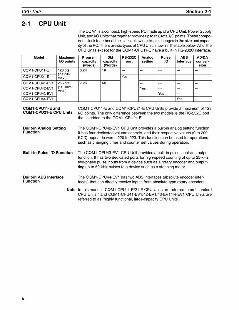
2-1 CPU UnitThe CQM1 is a compact, high-speedPCmade up of a CPUUnit, Power SupplyUnit, and I/OUnits that together provideup to 256 total I/Opoints. Thesecompo-nents lock together at the sides, allowing simple changes in the size and capac-ity of the PC. There are six types of CPUUnit, shown in the table below. All of theCPU Units except for the CQM1-CPU11-E have a built-in RS-232C interface.
Model MaximumI/O points
Programcapacity(words)
DMcapacity(Words)
RS-232Cport
Analogsetting
PulseI/O
ABSinterface
AD/DAconver-sion
CQM1-CPU11-E 128 pts(7 Units
3.2K 1K --- --- --- --- ---
CQM1-CPU21-E(7 Unitsmax.) Yes --- --- --- ---
CQM1-CPU41-EV1 256 pts 7.2K 6K --- --- --- ---
CQM1-CPU42-EV1
p(11 Unitsmax )
Yes --- --- ---
CQM1-CPU43-EV1max.)
--- Yes --- ---
CQM1-CPU44-EV1 --- --- Yes ---
CQM1-CPU11-E and CQM1-CPU21-E CPU Units provide a maximum of 128I/O points. The only difference between the two models is the RS-232C portthat is added to the CQM1-CPU21-E.
The CQM1-CPU42-EV1 CPU Unit provides a built-in analog setting function.It has four dedicated volume controls, and their respective values (0 to 200BCD) appear in words 220 to 223. This function can be used for operationssuch as changing timer and counter set values during operation.
The CQM1-CPU43-EV1 CPU Unit provides a built-in pulse input and outputfunction. It has two dedicated ports for high-speed counting of up to 25-kHztwo-phase pulse inputs from a device such as a rotary encoder and output-ting up to 50-kHz pulses to a device such as a stepping motor.
The CQM1-CPU44-EV1 has two ABS interfaces (absolute encoder inter-faces) that can directly receive inputs from absolute-type rotary encoders.
Note In this manual, CQM1-CPU11-E/21-E CPU Units are referred to as standardCPU Units, and CQM1-CPU41-EV1/42-EV1/43-EV1/44-EV1 CPU Units arereferred to as highly functional, large-capacity CPU Units.
CQM1-CPU11-E andCQM1-CPU21-E CPU Units
Built-in Analog SettingFunction
Built-in Pulse I/O Function
Built-in ABS InterfaceFunction
CPU Unit Section 2-1
7
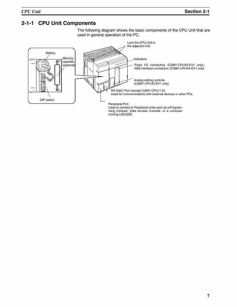
2-1-1 CPU Unit ComponentsThe following diagram shows the basic components of the CPU Unit that areused in general operation of the PC.
Lock the CPU Unit tothe adjacent Unit.
Indicators
RS-232C Port (except CQM1-CPU11-E)Used for communications with external devices or other PCs.
Peripheral PortUsed to connect to Peripheral Units such as a Program-ming Console, Data Access Console, or a computerrunning LSS/SSS.
DIP switch
Battery
Memorycassette(optional) Pulse I/O connectors (CQM1-CPU43-EV1 only);
ABS interface connectors (CQM1-CPU44-EV1 only)
Analog setting controls(CQM1-CPU42-EV1 only)
CPU Unit Section 2-1
8
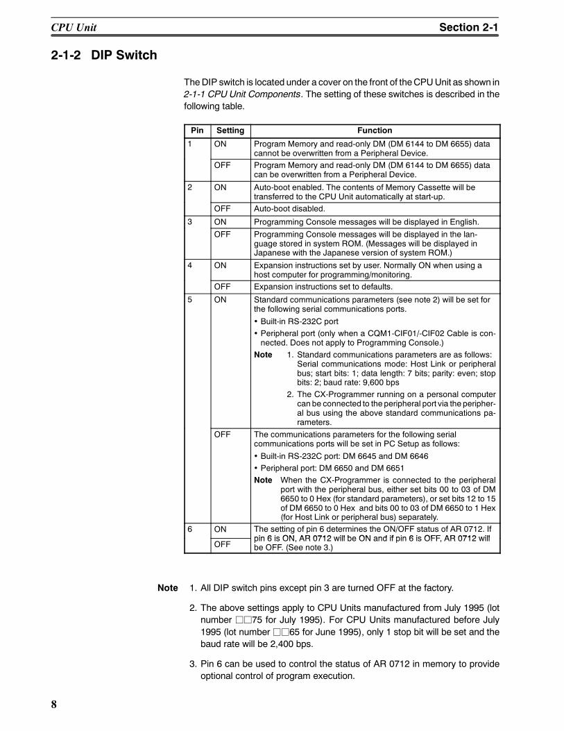
2-1-2 DIP Switch
TheDIP switch is located under a cover on the front of theCPUUnit as shown in2-1-1 CPU Unit Components. The setting of these switches is described in thefollowing table.
Pin Setting Function
1 ON Program Memory and read-only DM (DM 6144 to DM 6655) datacannot be overwritten from a Peripheral Device.
OFF Program Memory and read-only DM (DM 6144 to DM 6655) datacan be overwritten from a Peripheral Device.
2 ON Auto-boot enabled. The contents of Memory Cassette will betransferred to the CPU Unit automatically at start-up.
OFF Auto-boot disabled.
3 ON Programming Console messages will be displayed in English.
OFF Programming Console messages will be displayed in the lan-guage stored in system ROM. (Messages will be displayed inJapanese with the Japanese version of system ROM.)
4 ON Expansion instructions set by user. Normally ON when using ahost computer for programming/monitoring.
OFF Expansion instructions set to defaults.
5 ON Standard communications parameters (see note 2) will be set forthe following serial communications ports.
• Built-in RS-232C port• Peripheral port (only when a CQM1-CIF01/-CIF02 Cable is con-nected. Does not apply to Programming Console.)
Note 1. Standard communications parameters are as follows:Serial communications mode: Host Link or peripheralbus; start bits: 1; data length: 7 bits; parity: even; stopbits: 2; baud rate: 9,600 bps
2. The CX-Programmer running on a personal computercan be connected to the peripheral port via the peripher-al bus using the above standard communications pa-rameters.
OFF The communications parameters for the following serialcommunications ports will be set in PC Setup as follows:
• Built-in RS-232C port: DM 6645 and DM 6646• Peripheral port: DM 6650 and DM 6651Note When the CX-Programmer is connected to the peripheral
port with the peripheral bus, either set bits 00 to 03 of DM6650 to 0 Hex (for standard parameters), or set bits 12 to 15of DM 6650 to 0 Hex and bits 00 to 03 of DM 6650 to 1 Hex(for Host Link or peripheral bus) separately.
6 ON The setting of pin 6 determines the ON/OFF status of AR 0712. Ifpin 6 is ON AR 0712 will be ON and if pin 6 is OFF AR 0712 will
OFFpin 6 is ON, AR 0712 will be ON and if pin 6 is OFF, AR 0712 willbe OFF. (See note 3.)
Note 1. All DIP switch pins except pin 3 are turned OFF at the factory.
2. The above settings apply to CPU Units manufactured from July 1995 (lotnumber jj75 for July 1995). For CPU Units manufactured before July1995 (lot numberjj65 for June 1995), only 1 stop bit will be set and thebaud rate will be 2,400 bps.
3. Pin 6 can be used to control the status of AR 0712 in memory to provideoptional control of program execution.
CPU Unit Section 2-1
9
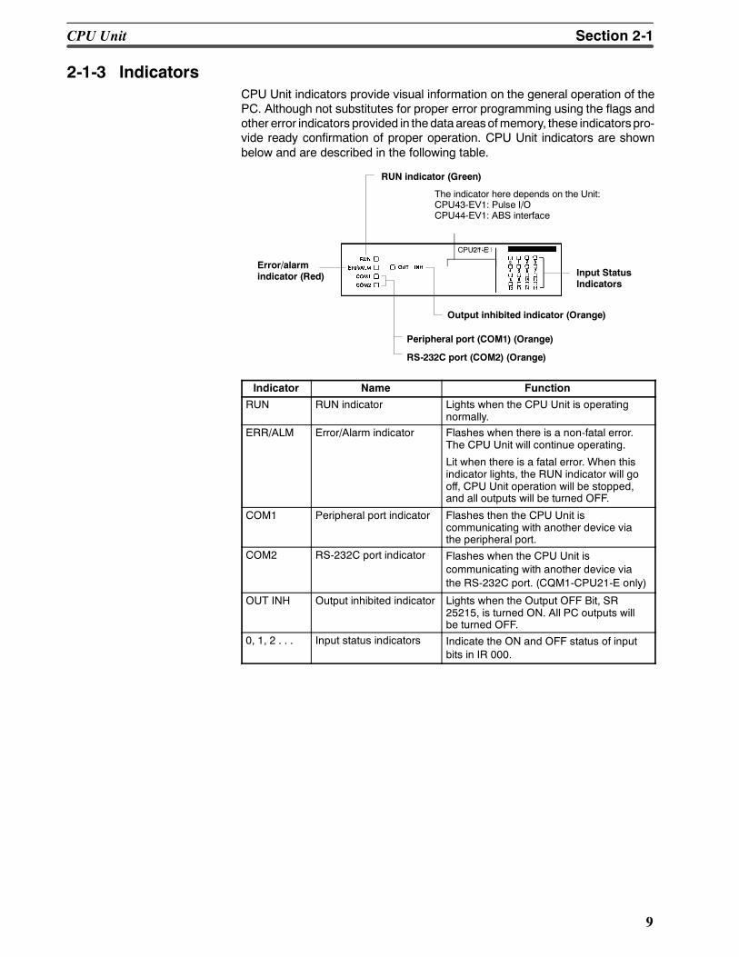
2-1-3 IndicatorsCPU Unit indicators provide visual information on the general operation of thePC. Although not substitutes for proper error programming using the flags andother error indicators provided in thedata areasofmemory, these indicatorspro-vide ready confirmation of proper operation. CPU Unit indicators are shownbelow and are described in the following table.
Input StatusIndicators
RUN indicator (Green)
Error/alarmindicator (Red)
Peripheral port (COM1) (Orange)
RS-232C port (COM2) (Orange)
Output inhibited indicator (Orange)
CPU21-E
The indicator here depends on the Unit:CPU43-EV1: Pulse I/OCPU44-EV1: ABS interface
Indicator Name Function
RUN RUN indicator Lights when the CPU Unit is operatingnormally.
ERR/ALM Error/Alarm indicator Flashes when there is a non-fatal error.The CPU Unit will continue operating.
Lit when there is a fatal error. When thisindicator lights, the RUN indicator will gooff, CPU Unit operation will be stopped,and all outputs will be turned OFF.
COM1 Peripheral port indicator Flashes then the CPU Unit iscommunicating with another device viathe peripheral port.
COM2 RS-232C port indicator Flashes when the CPU Unit iscommunicating with another device viathe RS-232C port. (CQM1-CPU21-E only)
OUT INH Output inhibited indicator Lights when the Output OFF Bit, SR25215, is turned ON. All PC outputs willbe turned OFF.
0, 1, 2 . . . Input status indicators Indicate the ON and OFF status of inputbits in IR 000.
CPU Unit Section 2-1
10
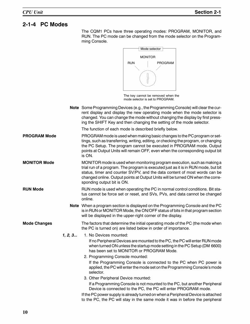
2-1-4 PC ModesThe CQM1 PCs have three operating modes: PROGRAM, MONITOR, andRUN. The PC mode can be changed from the mode selector on the Program-ming Console.
RUN
MONITOR
PROGRAM
Mode selector
The key cannot be removed when themode selector is set to PROGRAM.
Note SomeProgrammingDevices (e.g., theProgrammingConsole)will clear the cur-rent display and display the new operating mode when the mode selector ischanged. You can change the modewithout changing the display by first press-ing the SHIFT Key and then changing the setting of the mode selector.
The function of each mode is described briefly below.
PROGRAM Mode PROGRAMmode isusedwhenmakingbasic changes to thePCprogramorset-tings, suchas transferring, writing, editing, or checking theprogram, or changingthe PC Setup. The program cannot be executed in PROGRAM mode. Outputpoints at Output Units will remain OFF, even when the corresponding output bitis ON.
MONITOR Mode MONITORmode is usedwhenmonitoring programexecution, suchasmakingatrial run of a program. The program is executed just as it is in RUNmode, but bitstatus, timer and counter SV/PV, and the data content of most words can bechanged online. Output points at Output Units will be turnedONwhen the corre-sponding output bit is ON.
RUN Mode RUNmode is used when operating the PC in normal control conditions. Bit sta-tus cannot be force set or reset, and SVs, PVs, and data cannot be changedonline.
Note When a program section is displayed on the Programming Console and the PCis inRUNorMONITORMode, theON/OFF status of bits in that programsectionwill be displayed in the upper-right corner of the display.
Mode Changes The factors that determine the initial operating mode of the PC (the mode whenthe PC is turned on) are listed below in order of importance.
1, 2, 3... 1. No Devices mounted:If noPeripheralDevices aremounted to thePC, thePCwill enterRUNmodewhen turnedONunless the startupmodesetting in thePCSetup (DM 6600)has been set to MONITOR or PROGRAM Mode.
2. Programming Console mounted:If the Programming Console is connected to the PC when PC power isapplied, thePCwill enter themodeset on theProgrammingConsolesmodeselector.
3. Other Peripheral Device mounted:If a ProgrammingConsole is not mounted to the PC, but another PeripheralDevice is connected to the PC, the PC will enter PROGRAM mode.
If thePCpower supply is already turnedonwhenaPeripheralDevice isattachedto the PC, the PC will stay in the same mode it was in before the peripheral
CPU Unit Section 2-1
!
11
device was attached. If the Programming Console is connected, the PC willenter the mode set on the Programming Consoles mode selector once thepassword has been entered.
2-1-5 Dimensions and Weights
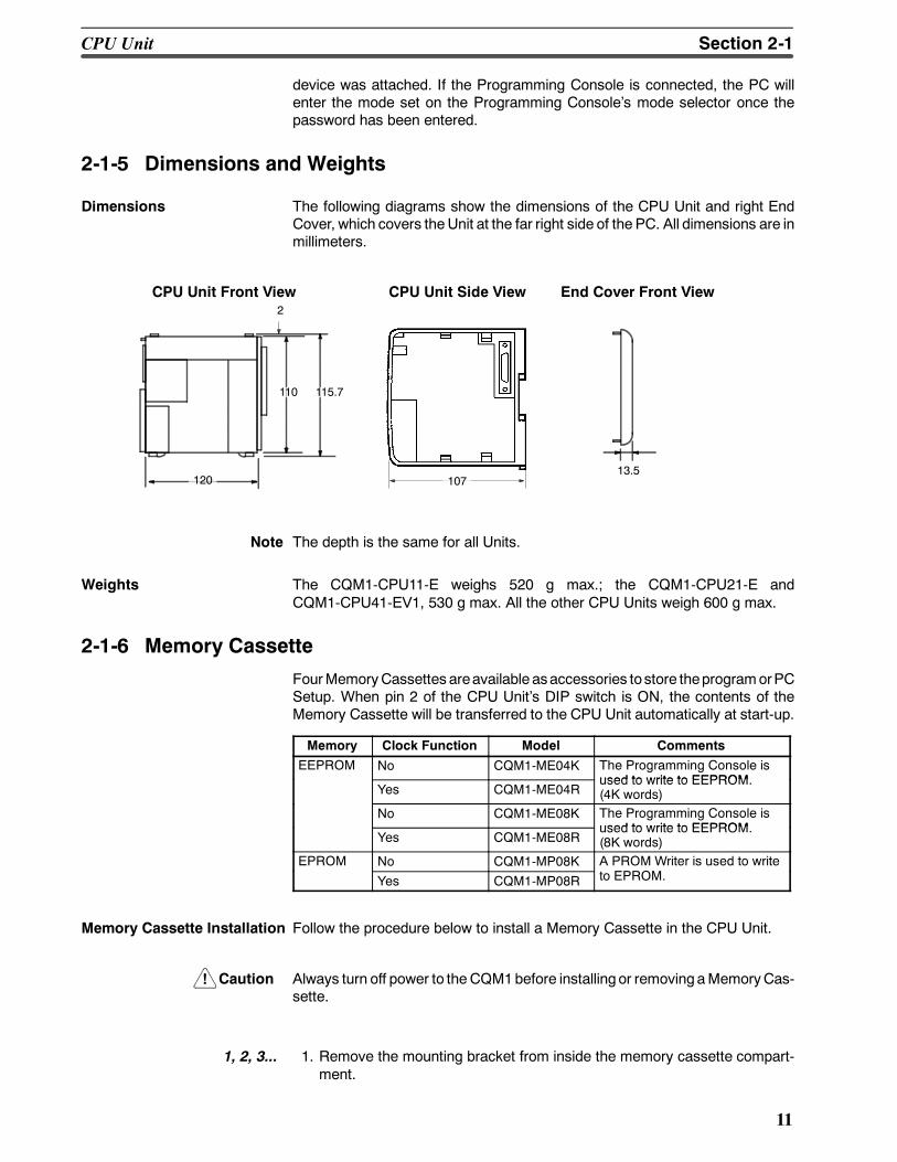
Dimensions The following diagrams show the dimensions of the CPU Unit and right EndCover, which covers theUnit at the far right side of the PC. All dimensions are inmillimeters.
CPU Unit Front View CPU Unit Side View End Cover Front View
110 115.7
120
2
13.5107
Note The depth is the same for all Units.
Weights The CQM1-CPU11-E weighs 520 g max.; the CQM1-CPU21-E andCQM1-CPU41-EV1, 530 g max. All the other CPU Units weigh 600 g max.
2-1-6 Memory Cassette
FourMemoryCassettes areavailable asaccessories tostore theprogramorPCSetup. When pin 2 of the CPU Units DIP switch is ON, the contents of theMemory Cassette will be transferred to the CPU Unit automatically at start-up.
Memory Clock Function Model Comments
EEPROM No CQM1-ME04K The Programming Console isused to write to EEPROM
Yes CQM1-ME04Rused to write to EEPROM.(4K words)
No CQM1-ME08K The Programming Console isused to write to EEPROM
Yes CQM1-ME08Rused to write to EEPROM.(8K words)
EPROM No CQM1-MP08K A PROM Writer is used to writeOYes CQM1-MP08R to EPROM.
Memory Cassette Installation Follow the procedure below to install a Memory Cassette in the CPU Unit.
Caution Always turn off power to theCQM1before installing or removingaMemoryCas-sette.
1, 2, 3... 1. Remove the mounting bracket from inside the memory cassette compart-ment.
CPU Unit Section 2-1
!
12
2. Slide the Memory Cassette into theCPUUnit on the tracks provided. Pressthe Memory Cassette in so that the connectors fit securely.
Memory cassette
3. Replace the bracket as shown below and tighten the screw.
Mounting bracket
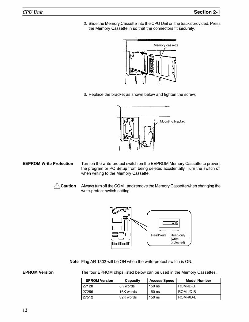
EEPROM Write Protection Turn on the write-protect switch on the EEPROM Memory Cassette to preventthe program or PC Setup from being deleted accidentally. Turn the switch offwhen writing to the Memory Cassette.
Caution Always turn off theCQM1and remove theMemory Cassettewhen changing thewrite-protect switch setting.
Read/write Read-only(write-protected)
Note Flag AR 1302 will be ON when the write-protect switch is ON.
EPROM Version The four EPROM chips listed below can be used in the Memory Cassettes.
EPROM Version Capacity Access Speed Model Number
27128 8K words 150 ns ROM-ID-B
27256 16K words 150 ns ROM-JD-B
27512 32K words 150 ns ROM-KD-B
CPU Unit Section 2-1
!
13
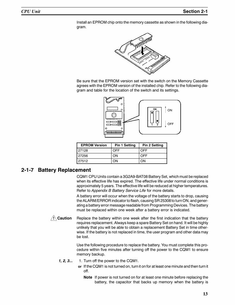
Install an EPROMchip onto the memory cassette as shown in the following dia-gram.
Be sure that the EPROM version set with the switch on the Memory Cassetteagrees with the EPROM version of the installed chip. Refer to the following dia-gram and table for the location of the switch and its settings.
ON
OFF
EPROM Version Pin 1 Setting Pin 2 Setting
27128 OFF OFF
27256 ON OFF
27512 ON ON
2-1-7 Battery ReplacementCQM1CPUUnits contain a 3G2A9-BAT08BatterySet, whichmust be replacedwhen its effective life has expired. The effective life under normal conditions isapproximately 5 years. The effective life will be reduced at higher temperatures.Refer to Appendix B Battery Service Life for more details.A battery error will occur when the voltage of the battery starts to drop, causingtheALARM/ERROR indicator to flash, causingSR25308 to turnON, andgener-ating abattery errormessage readable fromProgrammingDevices. Thebatterymust be replaced within one week after a battery error is indicated.
Caution Replace the battery within one week after the first indication that the batteryrequires replacement. Always keep a spare Battery Set on hand. It will be highlyunlikely that you will be able to obtain a replacement Battery Set in time other-wise. If the battery is not replaced in time, the user program and other datamaybe lost.
Use the following procedure to replace the battery. You must complete this pro-cedure within five minutes after turning off the power to the CQM1 to ensurememory backup.
1, 2, 3... 1. Turn off the power to the CQM1.or If theCQM1 is not turnedon, turn it on for at least oneminute and then turn it
off.
Note If power is not turned on for at least one minute before replacing thebattery, the capacitor that backs up memory when the battery is
CPU Unit Section 2-1
!
14
removedwill not be fully charged andmemorymay be lost before thenew battery is inserted.
2. Open the compartment on the upper left of theCPUUnit and carefully drawout the battery.
3. Remove the battery connector.
4. Connect thenewbattery, place it into the compartment, and close the cover.
The battery error will automatically be cleared when a new battery is inserted.
WARNING Never short-circuit the battery terminals; never charge the battery; neverdisassemble the battery; and never heat or incinerate the battery. Doing any ofthesemay cause thebattery to leak, burn, or rupturing resulting in injury, fire, andpossible loss of life or property.
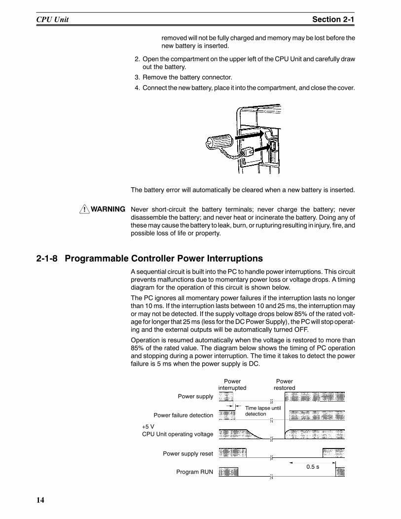
2-1-8 Programmable Controller Power InterruptionsA sequential circuit is built into the PC to handle power interruptions. This circuitprevents malfunctions due to momentary power loss or voltage drops. A timingdiagram for the operation of this circuit is shown below.
The PC ignores all momentary power failures if the interruption lasts no longerthan 10ms. If the interruption lasts between 10 and 25ms, the interruptionmayor may not be detected. If the supply voltage drops below 85% of the rated volt-age for longer that 25ms (less for theDCPowerSupply), thePCwill stopoperat-ing and the external outputs will be automatically turned OFF.
Operation is resumed automatically when the voltage is restored to more than85% of the rated value. The diagram below shows the timing of PC operationand stopping during a power interruption. The time it takes to detect the powerfailure is 5 ms when the power supply is DC.
0.5 s
Power supply
Powerinterrupted
Powerrestored
Power failure detection
+5 VCPU Unit operating voltage
Power supply reset
Program RUN
Time lapse untildetection
CPU Unit Section 2-1
!
15
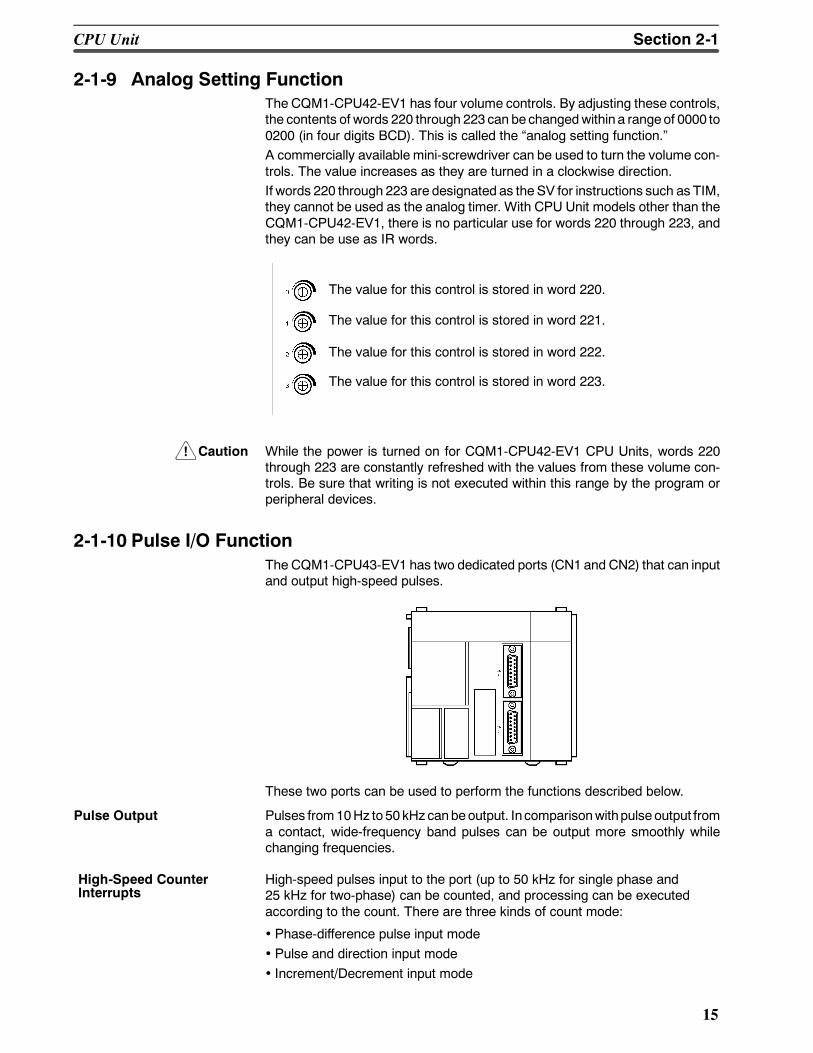
2-1-9 Analog Setting FunctionThe CQM1-CPU42-EV1 has four volume controls. By adjusting these controls,the contents of words 220 through 223can bechangedwithin a rangeof 0000 to0200 (in four digits BCD). This is called the analog setting function.A commercially available mini-screwdriver can be used to turn the volume con-trols. The value increases as they are turned in a clockwise direction.If words 220 through 223 are designated as the SV for instructions such as TIM,they cannot be used as the analog timer. With CPU Unit models other than theCQM1-CPU42-EV1, there is no particular use for words 220 through 223, andthey can be use as IR words.
The value for this control is stored in word 220.
The value for this control is stored in word 221.
The value for this control is stored in word 222.
The value for this control is stored in word 223.
Caution While the power is turned on for CQM1-CPU42-EV1 CPU Units, words 220through 223 are constantly refreshed with the values from these volume con-trols. Be sure that writing is not executed within this range by the program orperipheral devices.
2-1-10 Pulse I/O FunctionThe CQM1-CPU43-EV1 has two dedicated ports (CN1 and CN2) that can inputand output high-speed pulses.
These two ports can be used to perform the functions described below.
Pulse Output Pulses from10Hz to 50 kHz canbeoutput. Incomparisonwithpulse output froma contact, wide-frequency band pulses can be output more smoothly whilechanging frequencies.
High-speed pulses input to the port (up to 50 kHz for single phase and25 kHz for two-phase) can be counted, and processing can be executedaccording to the count. There are three kinds of count mode:
• Phase-difference pulse input mode• Pulse and direction input mode• Increment/Decrement input mode
High-Speed CounterInterrupts
CPU Unit Section 2-1
!
16
Caution The following instructions cannot beusedwhen theCQM1-CPU43-EV1 is set tohigh-speed counter mode by PC Setup (DM 6611): PLS2 and ACC mode 0.
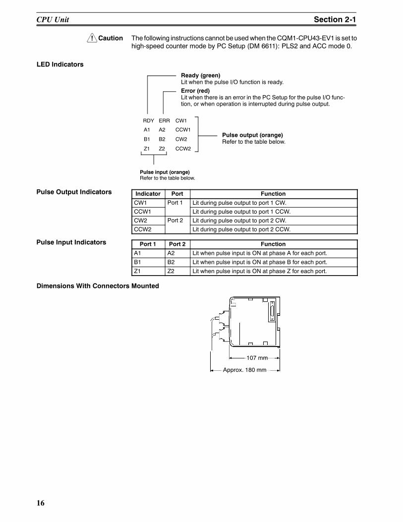
LED Indicators
Ready (green)Lit when the pulse I/O function is ready.Error (red)Lit when there is an error in the PC Setup for the pulse I/O func-tion, or when operation is interrupted during pulse output.
RDY ERR CW1
CCW1
CW2
CCW2
A2
B2
Z2
A1
B1
Z1
Pulse output (orange)Refer to the table below.
Pulse input (orange)Refer to the table below.
Indicator Port Function
CW1 Port 1 Lit during pulse output to port 1 CW.
CCW1 Lit during pulse output to port 1 CCW.
CW2 Port 2 Lit during pulse output to port 2 CW.
CCW2 Lit during pulse output to port 2 CCW.
Port 1 Port 2 Function
A1 A2 Lit when pulse input is ON at phase A for each port.
B1 B2 Lit when pulse input is ON at phase B for each port.
Z1 Z2 Lit when pulse input is ON at phase Z for each port.
Dimensions With Connectors Mounted
107 mm
Approx. 180 mm
Pulse Output Indicators
Pulse Input Indicators
CPU Unit Section 2-1
17
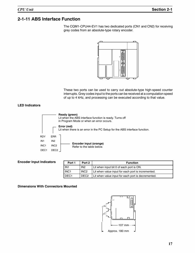
2-1-11 ABS Interface Function
The CQM1-CPU44-EV1 has two dedicated ports (CN1 and CN2) for receivinggrey codes from an absolute-type rotary encoder.
These two ports can be used to carry out absolute-type high-speed counterinterrupts. Grey codes input to theports canbe received at a computation speedof up to 4 kHz, and processing can be executed according to that value.
LED Indicators
Ready (green)Lit when the ABS interface function is ready. Turns offin Program Mode or when an error occurs.
Error (red)Lit when there is an error in the PC Setup for the ABS interface function.
RDY ERR
IN1
INC1
DEC1
Encoder input (orange)Refer to the table below.
IN2
INC2
DEC2
Port 1 Port 2 Function
IN1 IN2 Lit when input bit 0 of each port is ON.
INC1 INC2 Lit when value input for each port is incremented.
DEC1 DEC2 Lit when value input for each port is decremented.
Dimensions With Connectors Mounted
107 mm
Approx. 180 mm
Encoder Input Indicators
CPU Unit Section 2-1
18
2-2 Power Supply UnitThere are three AC Power Supply Units available, the CQM1-PA203, theCQM1-PA206, and theCQM1-PA216, and oneDC, theCQM1-PD026. Select aPower Supply Unit that matches the current consumption of the system.
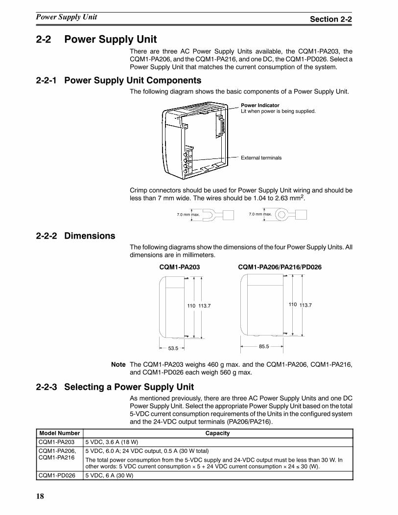
2-2-1 Power Supply Unit ComponentsThe following diagram shows the basic components of a Power Supply Unit.
Power IndicatorLit when power is being supplied.
External terminals
Crimp connectors should be used for Power Supply Unit wiring and should beless than 7 mm wide. The wires should be 1.04 to 2.63 mm2.
7.0 mm max.7.0 mm max.
2-2-2 DimensionsThe following diagrams show the dimensions of the four PowerSupply Units. Alldimensions are in millimeters.
CQM1-PA203 CQM1-PA206/PA216/PD026
53.5 85.5
110 113.7 110 113.7
Note The CQM1-PA203 weighs 460 g max. and the CQM1-PA206, CQM1-PA216,and CQM1-PD026 each weigh 560 g max.
2-2-3 Selecting a Power Supply UnitAs mentioned previously, there are three AC Power Supply Units and one DCPower Supply Unit. Select the appropriate Power Supply Unit based on the total5-VDC current consumption requirements of theUnits in the configured systemand the 24-VDC output terminals (PA206/PA216).
Model Number Capacity
CQM1-PA203 5 VDC, 3.6 A (18 W)
CQM1-PA206,CQM1-PA216
5 VDC, 6.0 A; 24 VDC output, 0.5 A (30 W total)
The total power consumption from the 5-VDC supply and 24-VDC output must be less than 30 W. Inother words: 5 VDC current consumption × 5 + 24 VDC current consumption × 24 ≤ 30 (W).
CQM1-PD026 5 VDC, 6 A (30 W)
Power Supply Unit Section 2-2
19
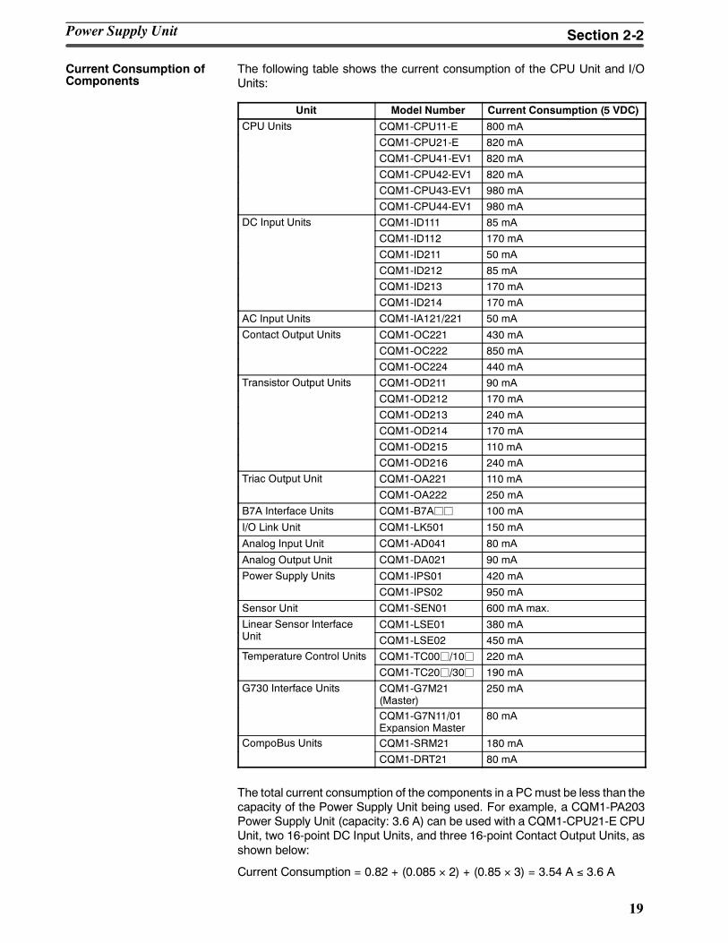
The following table shows the current consumption of the CPU Unit and I/OUnits:
Unit Model Number Current Consumption (5 VDC)
CPU Units CQM1-CPU11-E 800 mA
CQM1-CPU21-E 820 mA
CQM1-CPU41-EV1 820 mA
CQM1-CPU42-EV1 820 mA
CQM1-CPU43-EV1 980 mA
CQM1-CPU44-EV1 980 mADC Input Units CQM1-ID111 85 mAp
CQM1-ID112 170 mA
CQM1-ID211 50 mA
CQM1-ID212 85 mA
CQM1-ID213 170 mA
CQM1-ID214 170 mA
AC Input Units CQM1-IA121/221 50 mA
Contact Output Units CQM1-OC221 430 mAp
CQM1-OC222 850 mA
CQM1-OC224 440 mATransistor Output Units CQM1-OD211 90 mAp
CQM1-OD212 170 mA
CQM1-OD213 240 mA
CQM1-OD214 170 mA
CQM1-OD215 110 mA
CQM1-OD216 240 mATriac Output Unit CQM1-OA221 110 mAp
CQM1-OA222 250 mA
B7A Interface Units CQM1-B7Ajj 100 mA
I/O Link Unit CQM1-LK501 150 mA
Analog Input Unit CQM1-AD041 80 mA
Analog Output Unit CQM1-DA021 90 mA
Power Supply Units CQM1-IPS01 420 mApp y
CQM1-IPS02 950 mA
Sensor Unit CQM1-SEN01 600 mA max.
Linear Sensor Interface CQM1-LSE01 380 mAUnit CQM1-LSE02 450 mATemperature Control Units CQM1-TC00j/10j 220 mAp
CQM1-TC20j/30j 190 mAG730 Interface Units CQM1-G7M21
(Master)250 mA
CQM1-G7N11/01Expansion Master
80 mA
CompoBus Units CQM1-SRM21 180 mAp
CQM1-DRT21 80 mA
The total current consumption of the components in a PCmust be less than thecapacity of the Power Supply Unit being used. For example, a CQM1-PA203Power Supply Unit (capacity: 3.6 A) can be used with a CQM1-CPU21-E CPUUnit, two 16-point DC Input Units, and three 16-point Contact Output Units, asshown below:
Current Consumption = 0.82 + (0.085 × 2) + (0.85 × 3) = 3.54 A ≤ 3.6 A
Current Consumption ofComponents
Power Supply Unit Section 2-2
20
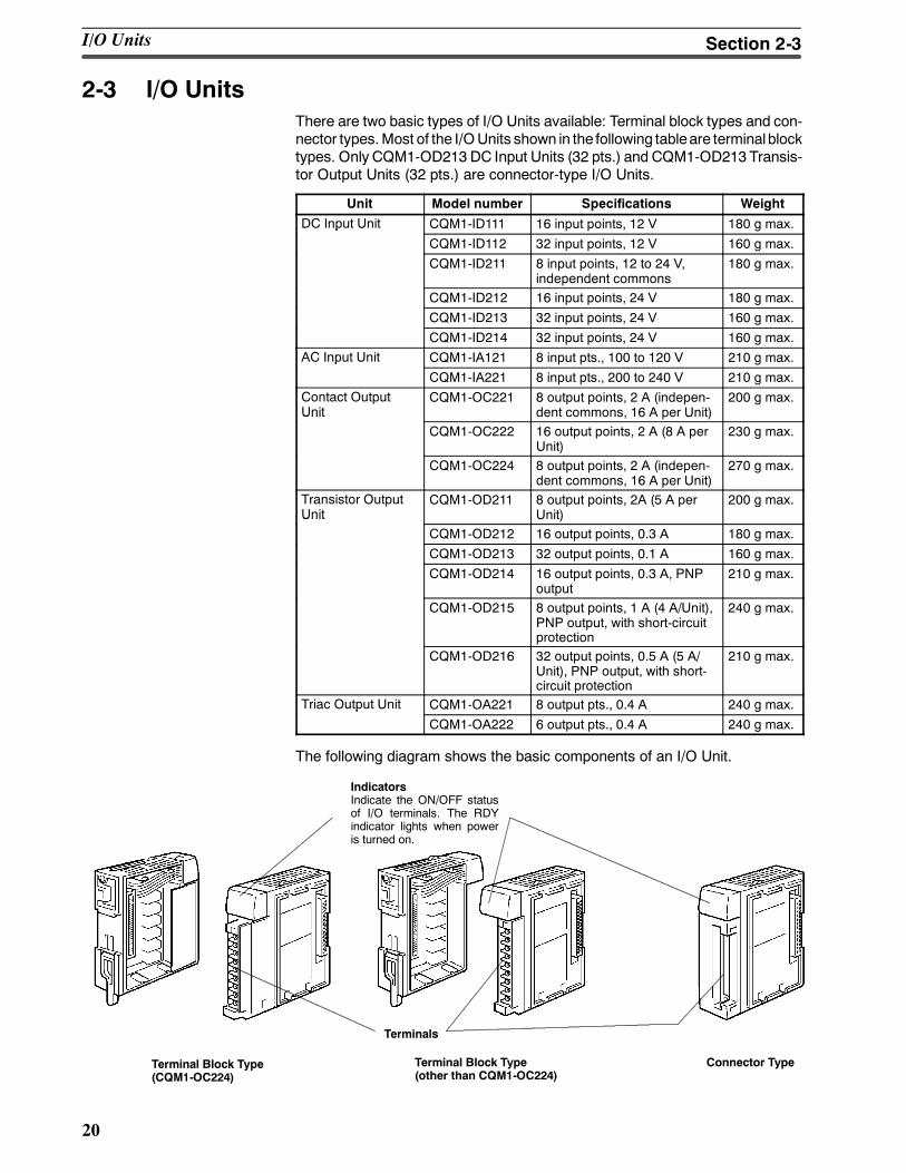
2-3 I/O UnitsThere are two basic types of I/O Units available: Terminal block types and con-nector types.Most of the I/OUnits shown in the following tableare terminalblocktypes. Only CQM1-OD213 DC Input Units (32 pts.) and CQM1-OD213 Transis-tor Output Units (32 pts.) are connector-type I/O Units.
Unit Model number Specifications Weight
DC Input Unit CQM1-ID111 16 input points, 12 V 180 g max.p
CQM1-ID112 32 input points, 12 V 160 g max.
CQM1-ID211 8 input points, 12 to 24 V,independent commons
180 g max.
CQM1-ID212 16 input points, 24 V 180 g max.
CQM1-ID213 32 input points, 24 V 160 g max.
CQM1-ID214 32 input points, 24 V 160 g max.AC Input Unit CQM1-IA121 8 input pts., 100 to 120 V 210 g max.p
CQM1-IA221 8 input pts., 200 to 240 V 210 g max.Contact OutputUnit
CQM1-OC221 8 output points, 2 A (indepen-dent commons, 16 A per Unit)
200 g max.Unit
CQM1-OC222 16 output points, 2 A (8 A perUnit)
230 g max.
CQM1-OC224 8 output points, 2 A (indepen-dent commons, 16 A per Unit)
270 g max.
Transistor OutputUnit
CQM1-OD211 8 output points, 2A (5 A perUnit)
200 g max.Unit
CQM1-OD212 16 output points, 0.3 A 180 g max.
CQM1-OD213 32 output points, 0.1 A 160 g max.
CQM1-OD214 16 output points, 0.3 A, PNPoutput
210 g max.
CQM1-OD215 8 output points, 1 A (4 A/Unit),PNP output, with short-circuitprotection
240 g max.
CQM1-OD216 32 output points, 0.5 A (5 A/Unit), PNP output, with short-circuit protection
210 g max.
Triac Output Unit CQM1-OA221 8 output pts., 0.4 A 240 g max.p
CQM1-OA222 6 output pts., 0.4 A 240 g max.
The following diagram shows the basic components of an I/O Unit.
IndicatorsIndicate the ON/OFF statusof I/O terminals. The RDYindicator lights when poweris turned on.
Terminals
Terminal Block Type(other than CQM1-OC224)
Connector TypeTerminal Block Type(CQM1-OC224)
I/O Units Section 2-3

21
2-3-1 Maximum No. of I/O Units and I/O PointsThe maximum number of I/O and Special I/O Units that can be connected andthemaximum number of I/O points that can be controlled are listed in the follow-ing table. Previousmodels (without a V1 suffix) are also included for reference.
CPU Unit Max. No. of Units Max. No. of I/O points
CQM1-CPU11/21-E 7 Units max. 128 pts (8 words) max.
CQM1-CPU4j-EV1 11 Units max. 256 pts (16 words) max.
CQM1-CPU4j-E 192 pts (12 words) max.
CPU Unit
Pow
erSupplyUnit
CQM1-CPU11/21-E:7 Units max.
CQM1-CPU4j-E/EV1: 11 Units max.
Model Max. No. of I/O points I/O points onCPU Unit
I/O and Special I/O Units
CQM1-CPU11/21-E 128 pts max. (8 words) 16 pts (1 word) 7 Units max./CQM1-CPU11/21-E
p ( ) p ( )(16 pts/Unit x 7 Units = 7 words)
CQM1-CPU41-EV1 256 pts (16 words) 11 Units max./O S /OCQM1-CPU42-EV1
p ( )max. (I/O or Special I/O Units can be
connected until the total numberCQM1-CPU43-EV1
connected until the total numberof words for I/O and Special I/O
CQM1-CPU44-EV1of words for I/O and Special I/OUnits is 15 words or less)
(CQM1-CPU41-E) 192 pts (12 words) 11 Units max.
(CQM1-CPU42-E)
p ( )max. (16-pt Units x 11 Units =
11 words max )(CQM1-CPU43-E)
11 words max.)
(CQM1-CPU44-E)
Note When the number of I/O points for the CQM1 exceeds the maximum number ofI/O points specified above, an I/O UNIT OVERmessage will be displayed andoperation will stop. Operation will not stop, however, if the number of I/O Unitsexceeds the maximum number of I/O Units specified above for theCQM1-CPU4j-EV1 as long as the maximum number of I/O points is notexceeded. Be sure to confirm that thenumber ofUnitsmounteddoes not exceedthe specified maximum number of I/O Units.
2-3-2 Terminal Block TypeThe I/O Units terminal blocks are removable. Be sure that the connector tabsare locked in the vertical position, as shown in the following diagram. Althoughthe terminal block position of theCQM1-OC224 is different, the removalmethodis the same.
I/O Units Section 2-3
!
22
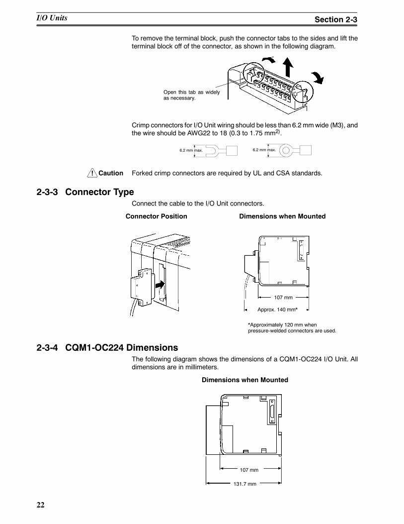
To remove the terminal block, push the connector tabs to the sides and lift theterminal block off of the connector, as shown in the following diagram.
Open this tab as widelyas necessary.
Crimp connectors for I/O Unit wiring should be less than 6.2 mmwide (M3), andthe wire should be AWG22 to 18 (0.3 to 1.75 mm2).
6.2 mm max.6.2 mm max.
Caution Forked crimp connectors are required by UL and CSA standards.
2-3-3 Connector TypeConnect the cable to the I/O Unit connectors.
Connector Position Dimensions when Mounted
107 mm
Approx. 140 mm*
*Approximately 120 mm whenpressure-welded connectors are used.
2-3-4 CQM1-OC224 DimensionsThe following diagram shows the dimensions of a CQM1-OC224 I/O Unit. Alldimensions are in millimeters.
Dimensions when Mounted
107 mm
131.7 mm
I/O Units Section 2-3
23
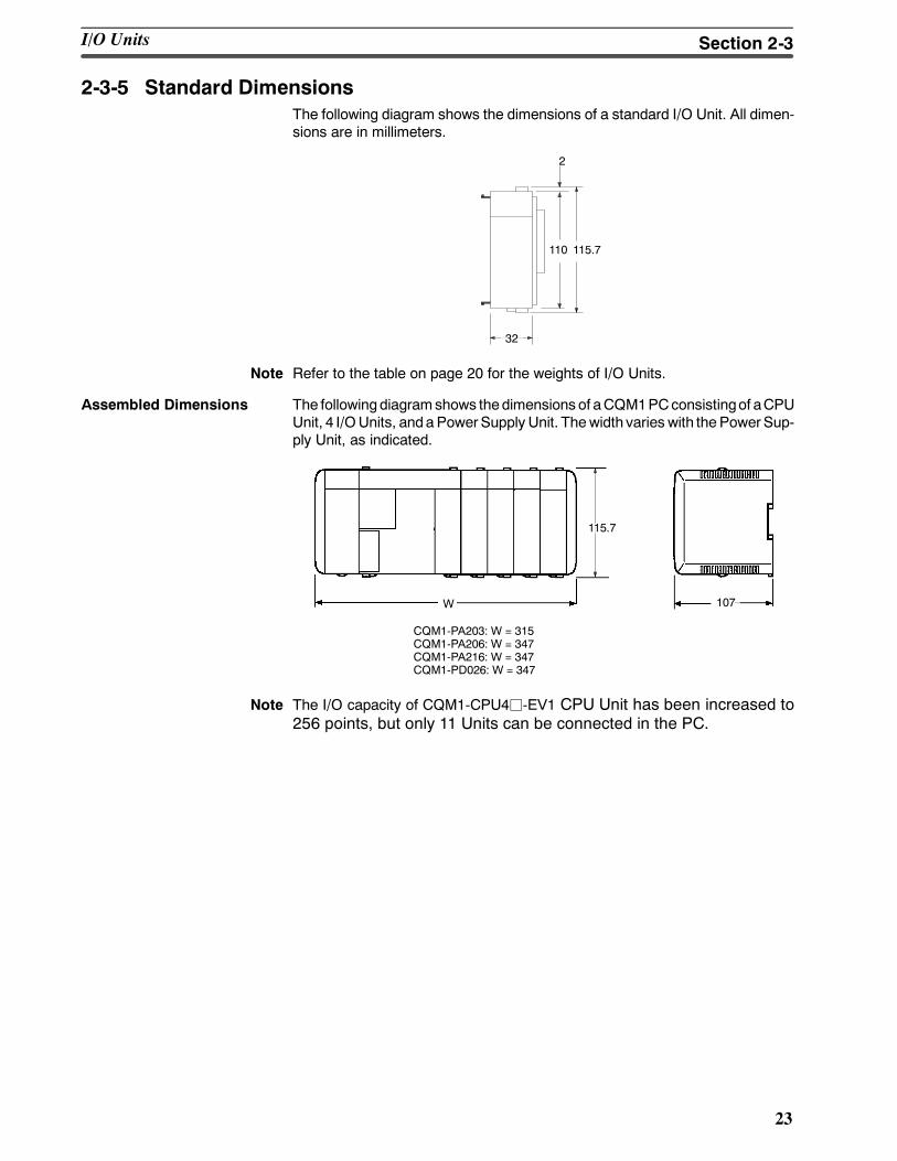
2-3-5 Standard DimensionsThe following diagram shows the dimensions of a standard I/O Unit. All dimen-sions are in millimeters.
110 115.7
2
32
Note Refer to the table on page 20 for the weights of I/O Units.
Assembled Dimensions The followingdiagramshows thedimensions of aCQM1PCconsistingof aCPUUnit, 4 I/OUnits, anda PowerSupply Unit. Thewidth varies with the PowerSup-ply Unit, as indicated.
CQM1-PA203: W = 315CQM1-PA206: W = 347CQM1-PA216: W = 347CQM1-PD026: W = 347
W 107
115.7
Note The I/O capacity of CQM1-CPU4j-EV1 CPU Unit has been increased to256 points, but only 11 Units can be connected in the PC.
I/O Units Section 2-3
24
2-4 PC Assembly and InstallationThis section describes how to assemble the Units that make up the CQM1 PCand install the PC on a DIN Track.
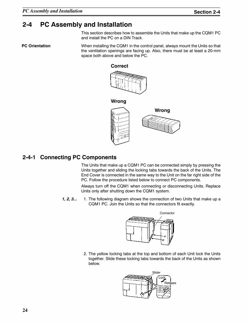
When installing the CQM1 in the control panel, always mount the Units so thatthe ventilation openings are facing up. Also, there must be at least a 20-mmspace both above and below the PC.
Correct
Wrong
Wrong
2-4-1 Connecting PC ComponentsThe Units that make up a CQM1 PC can be connected simply by pressing theUnits together and sliding the locking tabs towards the back of the Units. TheEnd Cover is connected in the same way to the Unit on the far right side of thePC. Follow the procedure listed below to connect PC components.
Always turn off the CQM1 when connecting or disconnecting Units. ReplaceUnits only after shutting down the CQM1 system.
1, 2, 3... 1. The following diagram shows the connection of two Units that make up aCQM1 PC. Join the Units so that the connectors fit exactly.
Connector
2. The yellow locking tabs at the top and bottom of each Unit lock the Unitstogether. Slide these locking tabs towards the back of the Units as shownbelow.
Lock
Release
Slider
PC Orientation
PC Assembly and Installation Section 2-4
!
25
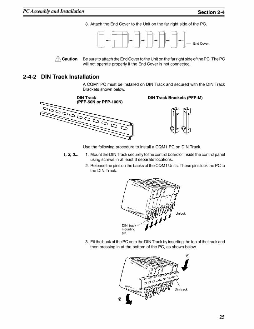
3. Attach the End Cover to the Unit on the far right side of the PC.
End Cover
Caution Besure to attach theEndCover to theUnit on the far right sideof thePC. ThePCwill not operate properly if the End Cover is not connected.
2-4-2 DIN Track InstallationA CQM1 PC must be installed on DIN Track and secured with the DIN TrackBrackets shown below.
DIN Track(PFP-50N or PFP-100N)
DIN Track Brackets (PFP-M)
Use the following procedure to install a CQM1 PC on DIN Track.
1, 2, 3... 1. Mount theDINTrack securely to the control board or inside the control panelusing screws in at least 3 separate locations.
2. Release the pins on thebacks of theCQM1Units. Thesepins lock the PC tothe DIN Track.
DIN trackmountingpin
Unlock
3. Fit the back of thePConto theDINTrack by inserting the top of the track andthen pressing in at the bottom of the PC, as shown below.
Din track
PC Assembly and Installation Section 2-4
!
26
4. Lock the pins on the backs of the CQM1 Units.
DIN track mounting pin
5. Install a DIN Track Bracket on each side of the PC. To install a bracket, hookthe bottom of the Bracket on the bottom of the track, rotate the Bracket tohook the topof theBracket on the topof the track, and then tighten thescrewto lock the Bracket in place.
DIN Track Brackets
2-5 Wiring and ConnectionsThis section provides basic information onwiring the Power Supply Unit and I/OUnits, and on connecting Peripheral Devices.
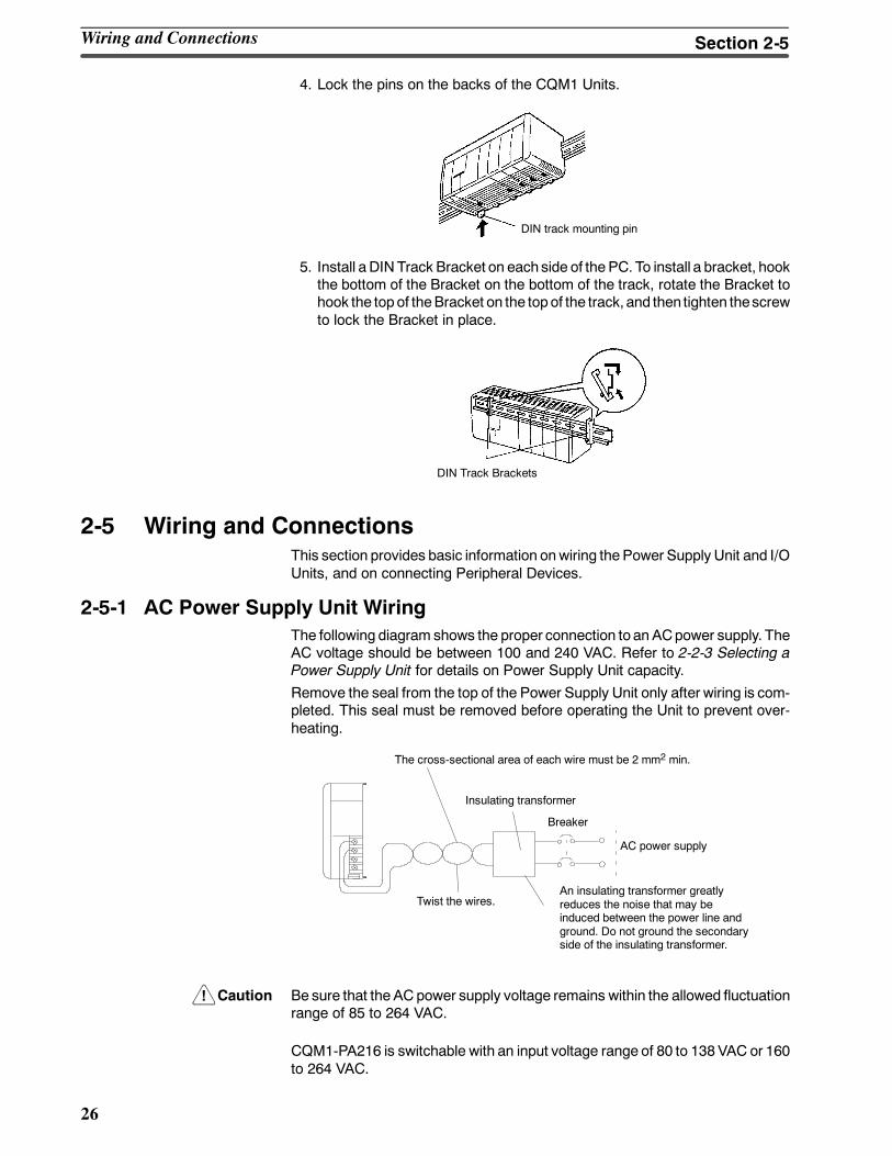
2-5-1 AC Power Supply Unit WiringThe following diagram shows the proper connection to an ACpower supply. TheAC voltage should be between 100 and 240 VAC. Refer to 2-2-3 Selecting aPower Supply Unit for details on Power Supply Unit capacity.
Remove the seal from the top of the Power Supply Unit only after wiring is com-pleted. This seal must be removed before operating the Unit to prevent over-heating.
An insulating transformer greatlyreduces the noise that may beinduced between the power line andground. Do not ground the secondaryside of the insulating transformer.
The cross-sectional area of each wire must be 2 mm2 min.
Twist the wires.
Insulating transformer
Breaker
AC power supply
Caution Be sure that the AC power supply voltage remains within the allowed fluctuationrange of 85 to 264 VAC.
CQM1-PA216 is switchable with an input voltage range of 80 to 138VAC or 160to 264 VAC.
Wiring and Connections Section 2-5
!
!
!
27
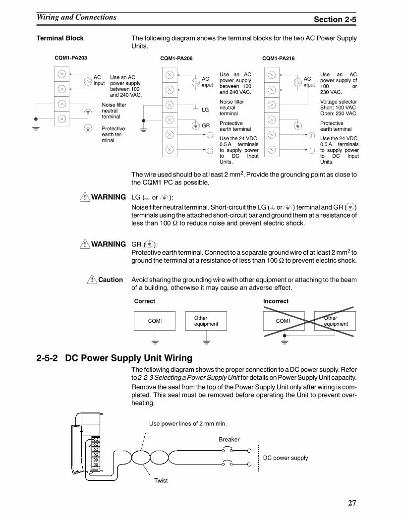
Terminal Block The following diagram shows the terminal blocks for the two AC Power SupplyUnits.
CQM1-PA203
LG
GR
CQM1-PA206
ACinput
Use an ACpower supplybetween 100and 240 VAC.
Use the 24 VDC,0.5 A terminalsto supply powerto DC InputUnits.
ACinput
Use an ACpower supplybetween 100and 240 VAC.
Noise filterneutralterminal
Protectiveearth ter-minal
Noise filterneutralterminal
Protectiveearth terminal
CQM1-PA216
ACinput
Use an ACpower supply of100 or230 VAC.
Use the 24 VDC,0.5 A terminalsto supply powerto DC InputUnits.
Voltage selectorShort: 100 VACOpen: 230 VAC
Protectiveearth terminal
Thewire used should be at least 2 mm2.Provide the grounding point as close tothe CQM1 PC as possible.
WARNING LG ( or ):Noise filter neutral terminal. Short-circuit the LG ( or ) terminal andGR ( )terminals using the attached short-circuit bar and ground them at a resistanceofless than 100 Ω to reduce noise and prevent electric shock.
WARNING GR ( ):Protective earth terminal. Connect to a separate groundwire of at least 2mm2 toground the terminal at a resistance of less than 100Ω to prevent electric shock.
Caution Avoid sharing the groundingwire with other equipment or attaching to the beamof a building, otherwise it may cause an adverse effect.
CQM1 Otherequipment CQM1 Other
equipment
Correct Incorrect
2-5-2 DC Power Supply Unit WiringThe followingdiagramshows theproper connection to aDCpower supply.Referto2-2-3SelectingaPowerSupplyUnit for details onPowerSupplyUnit capacity.Remove the seal from the top of the Power Supply Unit only after wiring is com-pleted. This seal must be removed before operating the Unit to prevent over-heating.
DC power supply
Use power lines of 2 mm min.
Twist
Breaker
Wiring and Connections Section 2-5
!
!
!
!
28
Caution Be sure that theDCpower supply voltage remains within the allowed fluctuationrange of 20 to 28 VDC.
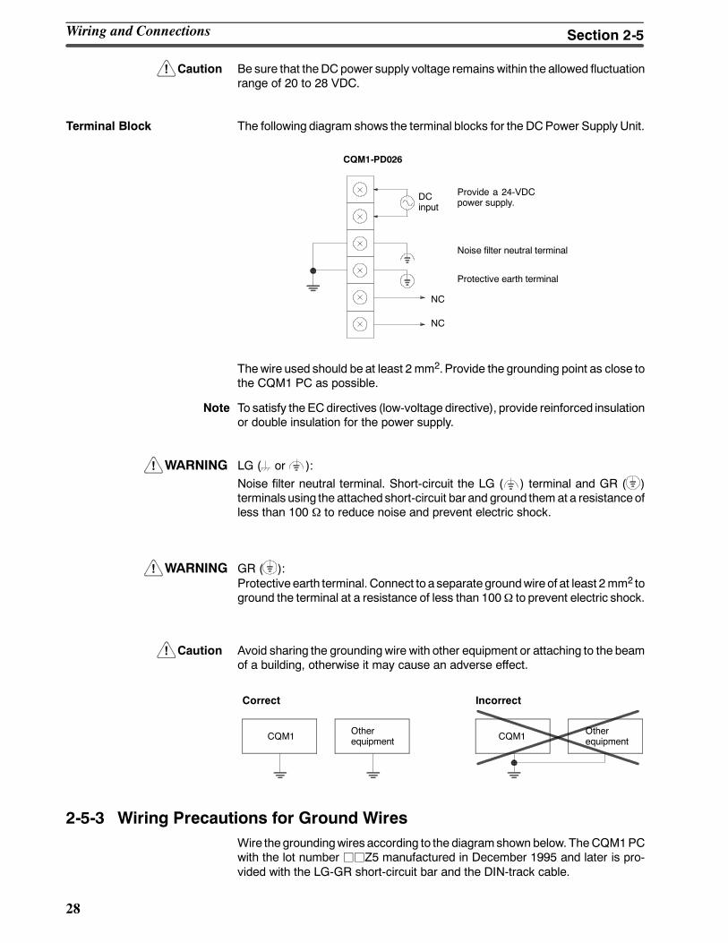
Terminal Block The following diagram shows the terminal blocks for the DCPower Supply Unit.
CQM1-PD026
DCinput
Provide a 24-VDCpower supply.
NC
NC
Noise filter neutral terminal
Protective earth terminal
Thewire used should be at least 2 mm2.Provide the grounding point as close tothe CQM1 PC as possible.
Note To satisfy the EC directives (low-voltage directive), provide reinforced insulationor double insulation for the power supply.
WARNING LG ( or ):Noise filter neutral terminal. Short-circuit the LG ( ) terminal and GR ( )terminals using the attached short-circuit bar and ground them at a resistanceofless than 100 Ω to reduce noise and prevent electric shock.
WARNING GR ( ):Protective earth terminal. Connect to a separate groundwire of at least 2mm2 toground the terminal at a resistance of less than 100Ω to prevent electric shock.
Caution Avoid sharing the groundingwire with other equipment or attaching to the beamof a building, otherwise it may cause an adverse effect.
CQM1 Otherequipment CQM1 Other
equipment
Correct Incorrect
2-5-3 Wiring Precautions for Ground WiresWire thegroundingwires according to the diagramshown below. TheCQM1PCwith the lot number jjZ5 manufactured in December 1995 and later is pro-vided with the LG-GR short-circuit bar and the DIN-track cable.
Wiring and Connections Section 2-5
!
!
29
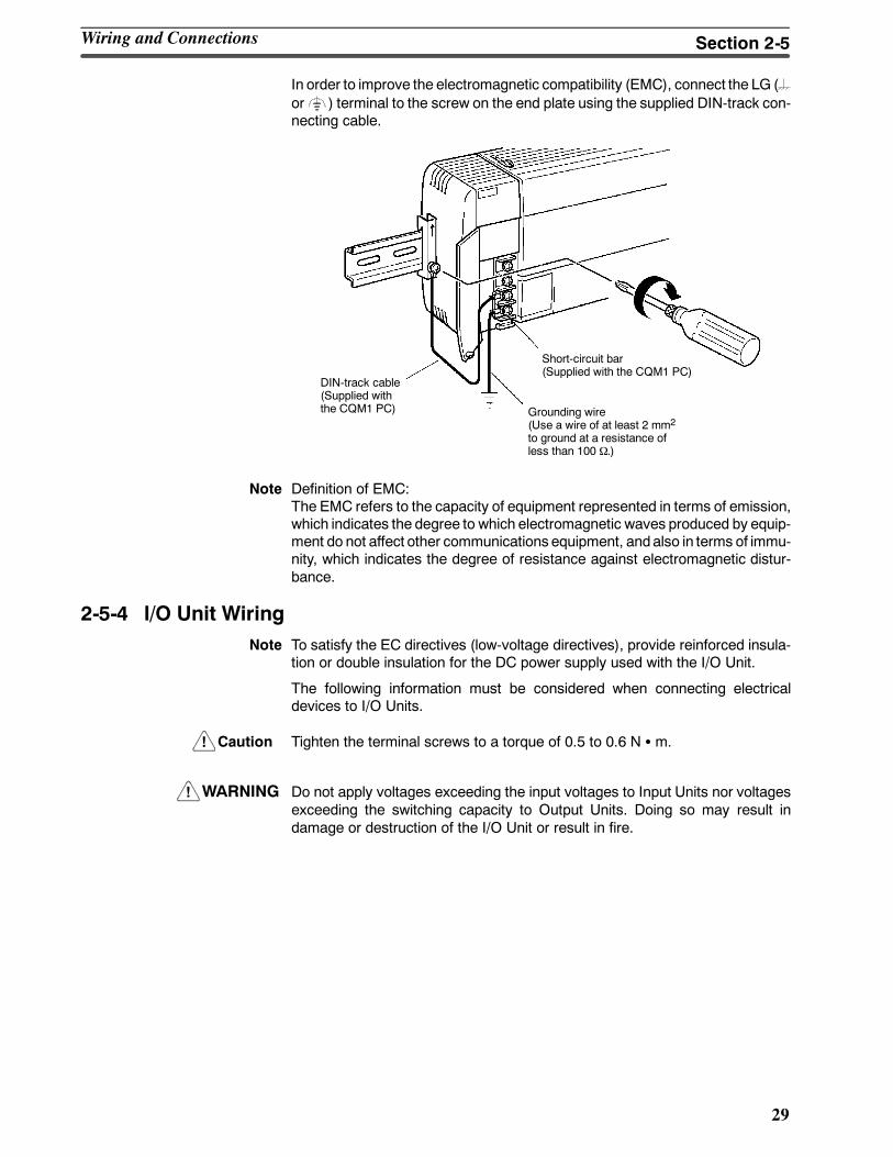
In order to improve the electromagnetic compatibility (EMC), connect the LG (or ) terminal to the screw on the end plate using the supplied DIN-track con-necting cable.
DIN-track cable(Supplied withthe CQM1 PC)
Short-circuit bar(Supplied with the CQM1 PC)
Grounding wire(Use a wire of at least 2 mm2
to ground at a resistance ofless than 100 Ω.)
Note Definition of EMC:The EMC refers to the capacity of equipment represented in terms of emission,which indicates the degree to which electromagnetic waves produced by equip-ment do not affect other communications equipment, andalso in terms of immu-nity, which indicates the degree of resistance against electromagnetic distur-bance.
2-5-4 I/O Unit WiringNote To satisfy the EC directives (low-voltage directives), provide reinforced insula-
tion or double insulation for the DC power supply used with the I/O Unit.
The following information must be considered when connecting electricaldevices to I/O Units.
Caution Tighten the terminal screws to a torque of 0.5 to 0.6 N S m.
WARNING Do not apply voltages exceeding the input voltages to Input Units nor voltagesexceeding the switching capacity to Output Units. Doing so may result indamage or destruction of the I/O Unit or result in fire.
Wiring and Connections Section 2-5
30
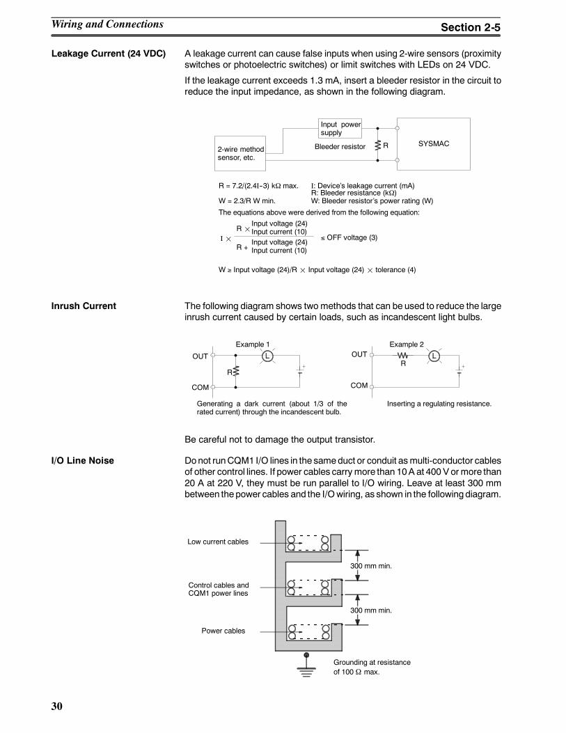
Leakage Current (24 VDC) A leakage current can cause false inputs when using 2-wire sensors (proximityswitches or photoelectric switches) or limit switches with LEDs on 24 VDC.
If the leakage current exceeds 1.3 mA, insert a bleeder resistor in the circuit toreduce the input impedance, as shown in the following diagram.
R SYSMAC
Input powersupply
Bleeder resistor2-wire methodsensor, etc.
R = 7.2/(2.4I--3) kΩ max.
W = 2.3/R W min.
I: Devices leakage current (mA)R: Bleeder resistance (kΩ)W: Bleeder resistors power rating (W)
The equations above were derived from the following equation:
W ≥ Input voltage (24)/R¢ Input voltage (24)¢ tolerance (4)
I¢R¢
Input voltage (24)Input current (10)
R +Input voltage (24)Input current (10)
≤ OFF voltage (3)
Inrush Current The following diagram shows twomethods that can be used to reduce the largeinrush current caused by certain loads, such as incandescent light bulbs.
R
OUT
COM
OUT
COM
R
Example 1 Example 2
Generating a dark current (about 1/3 of therated current) through the incandescent bulb.
Inserting a regulating resistance.
Be careful not to damage the output transistor.
I/O Line Noise Donot runCQM1 I/O lines in the sameduct or conduit asmulti-conductor cablesof other control lines. If power cables carrymore than 10A at 400 Vormore than20 A at 220 V, they must be run parallel to I/O wiring. Leave at least 300 mmbetween thepower cables and the I/Owiring, as shown in the followingdiagram.
Low current cables
Control cables andCQM1 power lines
Power cables
300 mm min.
300 mm min.
Grounding at resistanceof 100 Ω max.
Wiring and Connections Section 2-5
!
31
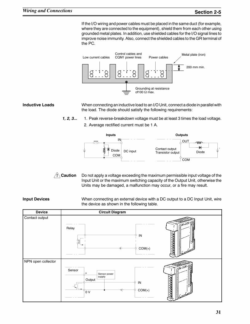
If the I/O wiring andpower cablesmust beplaced in the sameduct (for example,where they are connected to the equipment), shield them from each other usinggroundedmetal plates. In addition, use shielded cables for the I/O signal lines toimprove noise immunity. Also, connect the shielded cables to theGR terminal ofthe PC.
200 mm min.
Grounding at resistanceof100 Ω max.
Metal plate (iron)Low current cables
Control cables andCQM1 power lines Power cables
Inductive Loads Whenconnecting an inductive load to an I/OUnit, connect a diode in parallelwiththe load. The diode should satisfy the following requirements:
1, 2, 3... 1. Peak reverse-breakdown voltage must be at least 3 times the load voltage.
2. Average rectified current must be 1 A.
IN
COM
OUT
COM
Diode DC inputContact outputTransistor output Diode
Inputs Outputs
Caution Do not apply a voltage exceeding the maximum permissible input voltage of theInput Unit or the maximum switching capacity of the Output Unit, otherwise theUnits may be damaged, a malfunction may occur, or a fire may result.
Input Devices When connecting an external device with a DC output to a DC Input Unit, wirethe device as shown in the following table.
Device Circuit Diagram
Contact output
IN
COM(+)
Relay
NPN open collector
0 V
+
IN
COM(+)
SensorSensor powersupply
Output
Wiring and Connections Section 2-5
32
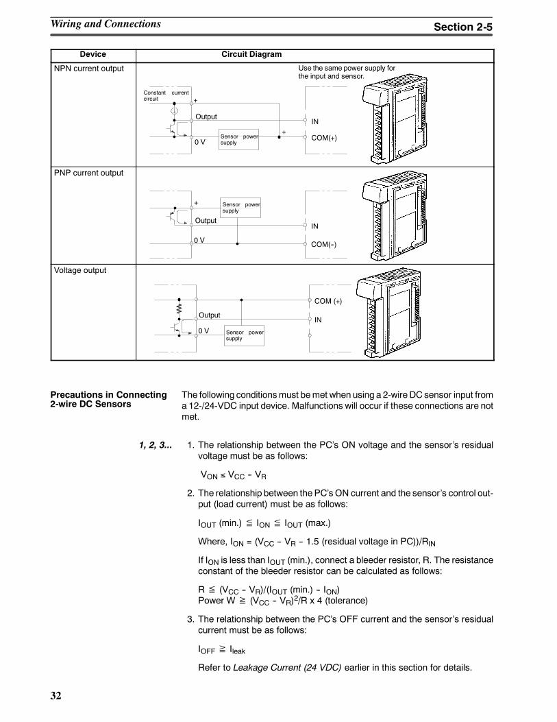
Device Circuit Diagram
NPN current output
Sensor powersupply0 V
+
IN
COM(+)
Constant currentcircuit
Output
Use the same power supply forthe input and sensor.
+
PNP current output
Sensor powersupply
COM(--)0 V
IN
+
Output
Voltage output
Sensor powersupply
IN
COM (+)
0 V
Output
The following conditionsmust bemet when using a 2-wire DC sensor input froma 12-/24-VDC input device. Malfunctions will occur if these connections are notmet.
1, 2, 3... 1. The relationship between the PCs ON voltage and the sensors residualvoltage must be as follows:
VON ≤ VCC -- VR
2. The relationship between the PCs ON current and the sensors control out-put (load current) must be as follows:
IOUT (min.) ≦ ION ≦ IOUT (max.)
Where, ION = (VCC -- VR -- 1.5 (residual voltage in PC))/RIN
If ION is less than IOUT (min.), connect a bleeder resistor, R. The resistanceconstant of the bleeder resistor can be calculated as follows:
R ≦ (VCC -- VR)/(IOUT (min.) -- ION)Power W ≧ (VCC -- VR)2/R x 4 (tolerance)
3. The relationship between the PCs OFF current and the sensors residualcurrent must be as follows:
IOFF ≧ Ileak
Refer to Leakage Current (24 VDC) earlier in this section for details.
Precautions in Connecting2-wire DC Sensors
Wiring and Connections Section 2-5
33
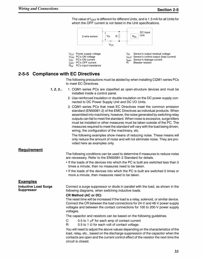
The value of IOFF is different for different Units, and is 1.3mA for all Units forwhich the OFF current is not listed in the Unit specifications.
VR
VCC
R RIN2-wire sensor
DC InputUnit
VCC: Power supply voltageVON: PCs ON voltageION: PCs ON currentIOFF: PCs OFF currentRIN: PCs input impedance
VR: Sensors output residual voltageIOUT: Sensors control output (load current)Ileak: Sensors leakage currentR: Bleeder resistor
2-5-5 Compliance with EC DirectivesThe following precautions must be abided by when installing CQM1-series PCsto meet EC Directives.
1, 2, 3... 1. CQM1-series PCs are classified as open-structure devices and must beinstalled inside a control panel.
2. Use reinforced insulation or double insulation on the DC power supply con-nected to DC Power Supply Unit and DC I/O Units.
3. CQM1-series PCs that meet EC Directives meet the common emissionstandard (EN50081-2) of the EMCDirectives as individual products. Whenassembled intomachinery, however, the noise generatedby switching relayoutputs can fail tomeet the standard.Whennoise is excessive, surge killersmust be installed or other measures must be taken outside of the PC. Themeasures required tomeet the standardwill vary with the load beingdriven,wiring, the configuration of the machinery, etc.The following examples show means of reducing noise. These means willonly reduce the amount of noise and will not eliminate noise. They are pro-vided here as examples only.
RequirementThe following conditions can be used to determine if measures to reduce noiseare necessary. Refer to the EN50081-2 Standard for details.• If the loads of the devices into which the PC is built are switched less than 5times a minute, then no measures need to be taken.
• If the loads of the devices into which the PC is built are switched 5 times ormore a minute, then measures need to be taken.
ExamplesConnect a surge suppressor or diode in parallel with the load, as shown in thefollowing diagrams, when switching inductive loads.CR Method (AC or DC)The reset time will be increased if the load is a relay, solenoid, or similar device.Connect the CR between the load connections for 24-V and 48-V power supplyvoltages and between the contact connections for 100 to 200-V power supplyvoltages.The capacitor and resistors can be based on the following guidelines.C: 0.5 to 1 µF for each amp of contact currentR: 0.5 to 1 Ω for each volt of contact voltage.You will need to adjust the above values depending on the characteristics of theload, relay, etc., based on the discharge suppression of the capacitor when thecontacts are open and the current control effect of the resistor the next time thecircuit is closed.
Inductive Load SurgeSuppressor
Wiring and Connections Section 2-5
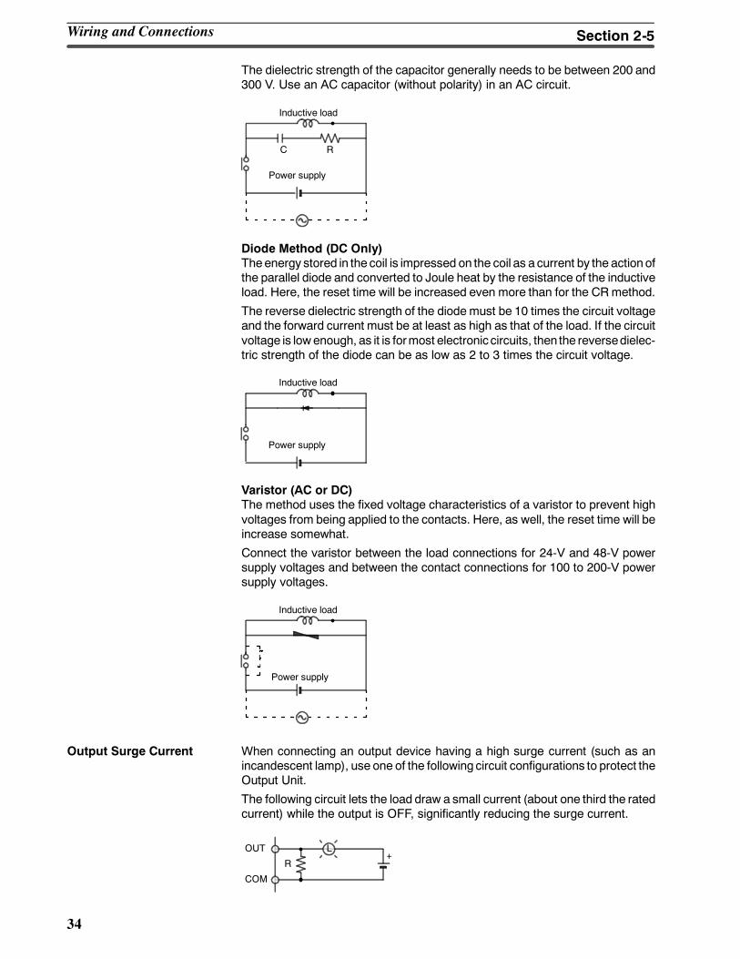
34
The dielectric strength of the capacitor generally needs to be between 200 and300 V. Use an AC capacitor (without polarity) in an AC circuit.
Inductive load
C R
Power supply
Diode Method (DC Only)Theenergy stored in the coil is impressed on the coil as a current by the action ofthe parallel diode and converted to Joule heat by the resistance of the inductiveload. Here, the reset time will be increased even more than for the CRmethod.
The reverse dielectric strength of the diode must be 10 times the circuit voltageand the forward current must be at least as high as that of the load. If the circuitvoltage is lowenough, as it is formost electronic circuits, then the reversedielec-tric strength of the diode can be as low as 2 to 3 times the circuit voltage.
Inductive load
Power supply
Varistor (AC or DC)The method uses the fixed voltage characteristics of a varistor to prevent highvoltages from being applied to the contacts. Here, as well, the reset time will beincrease somewhat.
Connect the varistor between the load connections for 24-V and 48-V powersupply voltages and between the contact connections for 100 to 200-V powersupply voltages.
Inductive load
Power supply
Output Surge Current When connecting an output device having a high surge current (such as anincandescent lamp), use one of the following circuit configurations to protect theOutput Unit.
The following circuit lets the load draw a small current (about one third the ratedcurrent) while the output is OFF, significantly reducing the surge current.
OUT
COM
L
R+
Wiring and Connections Section 2-5
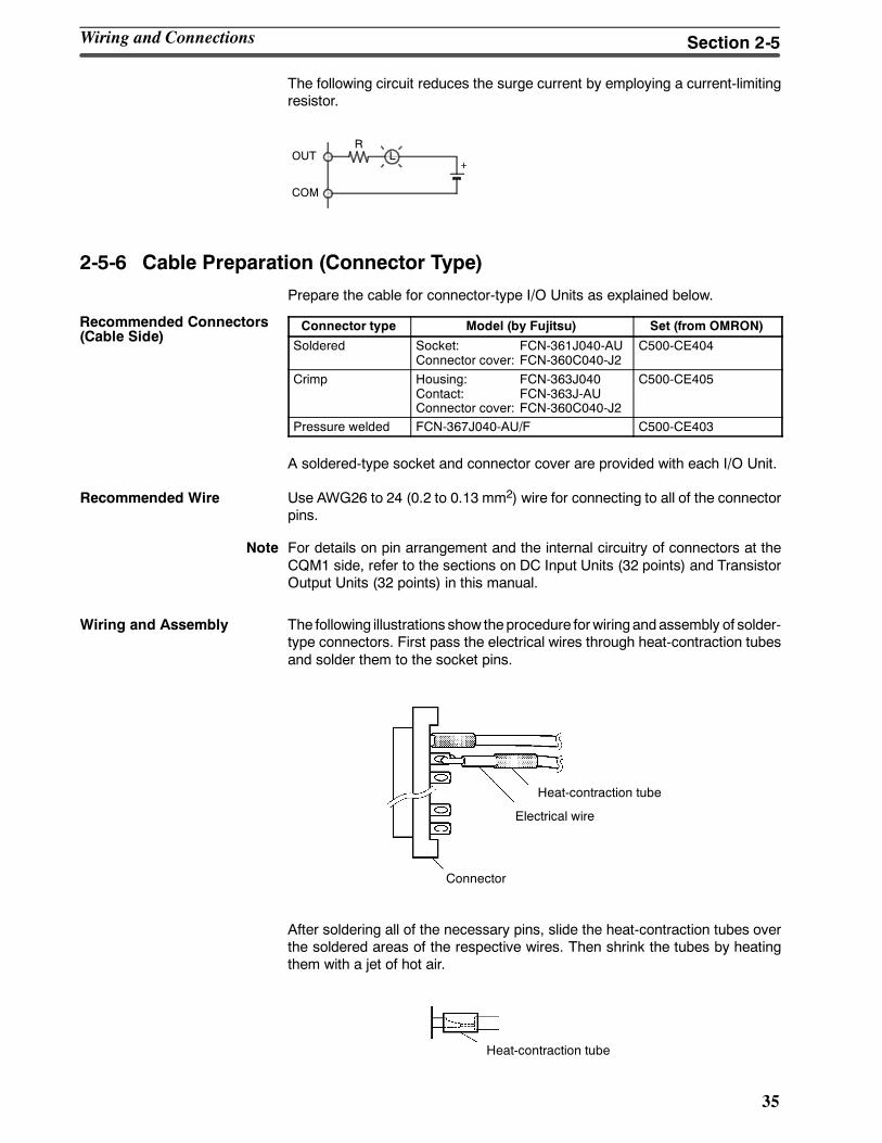
35
The following circuit reduces the surge current by employing a current-limitingresistor.
LOUT
COM
+
R
2-5-6 Cable Preparation (Connector Type)
Prepare the cable for connector-type I/O Units as explained below.
Connector type Model (by Fujitsu) Set (from OMRON)
Soldered Socket: FCN-361J040-AUConnector cover: FCN-360C040-J2
C500-CE404
Crimp Housing: FCN-363J040Contact: FCN-363J-AUConnector cover: FCN-360C040-J2
C500-CE405
Pressure welded FCN-367J040-AU/F C500-CE403
A soldered-type socket and connector cover are provided with each I/O Unit.
Recommended Wire Use AWG26 to 24 (0.2 to 0.13 mm2) wire for connecting to all of the connectorpins.
Note For details on pin arrangement and the internal circuitry of connectors at theCQM1 side, refer to the sections on DC Input Units (32 points) and TransistorOutput Units (32 points) in this manual.
Wiring and Assembly The following illustrations show theprocedure forwiring andassembly of solder-type connectors. First pass the electrical wires through heat-contraction tubesand solder them to the socket pins.
Heat-contraction tube
Electrical wire
Connector
After soldering all of the necessary pins, slide the heat-contraction tubes overthe soldered areas of the respective wires. Then shrink the tubes by heatingthem with a jet of hot air.
Heat-contraction tube
Recommended Connectors(Cable Side)
Wiring and Connections Section 2-5

36
Finally, assemble the socket and connector cover as shown below.
Connector coverSmall screws (3)
Small screws (2)
Socket
Nuts (3)
Nuts (2)
Connector lock screw
Cable clamp
2-5-7 Cable Preparation (Pulse Output and ABS Interface)Dedicated ports are required for the pulse I/O (CQM1-CPU43-EV1 only) andABS interface (CQM1-CPU44-EV1 only) functions. Follow the procedureexplained here to prepare cable for these ports.
Use the following products or equivalents for the connector on the cable side.
Socket: XM2D-1501 (OMRON)
Hood: XM2S-1511 (OMRON)
Cable Use shielded twisted-pair wire for the cable.
Note For details on pin arrangement and the internal circuitry of connectors at theCQM1 side, refer to the sections on CQM1-CPU43-EV1 andCQM1-CPU44-EV1 CPU Units in this manual.
Wiring and Assembly The following illustrations show the procedure for wiring and assembly of theconnectors. First pass the signal wires through heat-contraction tubes and sol-der them to the socket pins.
1 mm
Soldering iron
Fold back the shield.
Heat-contraction tubeInner diameter: 1.5 mm, l = 10
After soldering all of the necessary pins, slide the heat-contraction tubes overthe soldered areas of the respective wires. Then shrink the tubes by heatingthem with a jet of hot air.
Heat-contraction tube
Applicable Connectors(Cable Side)
Wiring and Connections Section 2-5
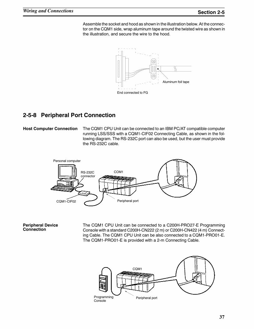
37
Assemble the socket and hoodas shown in the illustration below. At the connec-tor on the CQM1 side, wrap aluminum tape around the twisted wire as shown inthe illustration, and secure the wire to the hood.
End connected to FG
Aluminum foil tape
2-5-8 Peripheral Port Connection
Host Computer Connection The CQM1CPU Unit can be connected to an IBM PC/AT compatible computerrunning LSS/SSS with a CQM1-CIF02 Connecting Cable, as shown in the fol-lowing diagram. The RS-232C port can also be used, but the user must providethe RS-232C cable.
Personal computer
CQM1-CIF02
RS-232Cconnector
COM1
Peripheral port
The CQM1 CPU Unit can be connected to a C200H-PRO27-E ProgrammingConsole with a standard C200H-CN222 (2 m) or C200H-CN422 (4 m) Connect-ing Cable. The CQM1 CPU Unit can be also connected to a CQM1-PRO01-E.The CQM1-PRO01-E is provided with a 2-m Connecting Cable.
CQM1
Peripheral portProgrammingConsole
Peripheral DeviceConnection
Wiring and Connections Section 2-5
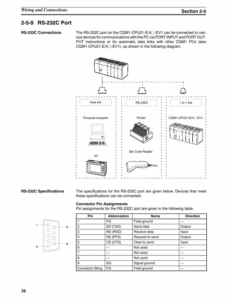
38
2-5-9 RS-232C Port
RS-232C Connections The RS-232C port on the CQM1-CPU21-E/4j-EV1 can be connected to vari-ous devices for communications with the PC via PORT INPUTandPORTOUT-PUT instructions or for automatic data links with other CQM1 PCs (alsoCQM1-CPU21-E/4j-EV1), as shown in the following diagram.
Personal computer
PT
Bar Code Reader
Printer CQM1-CPU21-E/4j-EV1
RS-232CHost link 1 to 1 link
RS-232C Specifications The specifications for the RS-232C port are given below. Devices that meetthese specifications can be connected.
Connector Pin AssignmentsPin assignments for the RS-232C port are given in the following table.
Pin Abbreviation Name Direction
1 FG Field ground ---
2 SD (TXD) Send data Output
3 RD (RXD) Receive data Input
4 RS (RTS) Request to send Output
5 CS (CTS) Clear to send Input
6 --- Not used. ---
7 --- Not used. ---
8 --- Not used. ---
9 SG Signal ground ---
Connector fitting FG Field ground ---
Wiring and Connections Section 2-5
5
1
9
6
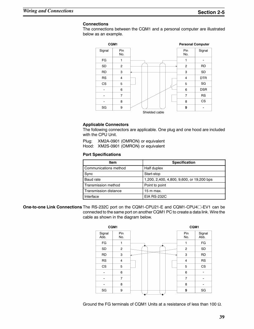
39
ConnectionsThe connections between the CQM1 and a personal computer are illustratedbelow as an example.
1
2
3
4
5
6
FG
SD
RD
RS
CS
--
--
--
SG
7
8
9
1
2
3
4
5
6
7
8
9
SD
RD
RS
CS
DSR
SG
--9
DTR
CQM1 Personal Computer
SignalPinNo.
Signal PinNo.
Shielded cable
--
Applicable ConnectorsThe following connectors are applicable. One plug and one hood are includedwith the CPU Unit.
Plug: XM2A-0901 (OMRON) or equivalentHood: XM2S-0901 (OMRON) or equivalent
Port Specifications
Item Specification
Communications method Half duplex
Sync Start-stop
Baud rate 1,200, 2,400, 4,800, 9,600, or 19,200 bps
Transmission method Point to point
Transmission distance 15 m max.
Interface EIA RS-232C
One-to-one Link Connections The RS-232C port on the CQM1-CPU21-E and CQM1-CPU4j-EV1 can beconnected to the same port on another CQM1 PC to create a data link. Wire thecable as shown in the diagram below.
1
2
3
4
5
6
FG
SD
RD
RS
CS
--
--
--
SG
7
8
9
1
2
3
4
5
6
7
8
9
FG
SD
RD
RS
CS
--
--
SG9
CQM1 CQM1
SignalAbb.
PinNo.
SignalAbb.
PinNo.
--
Ground the FG terminals of CQM1 Units at a resistance of less than 100 Ω.
Wiring and Connections Section 2-5
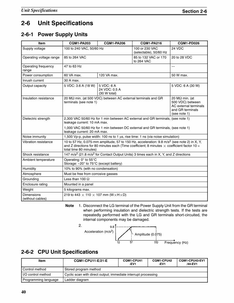
40
2-6 Unit Specifications
2-6-1 Power Supply Units
Item CQM1-PA203 CQM1-PA206 CQM1-PA216 CQM1-PD026
Supply voltage 100 to 240 VAC, 50/60 Hz 100 or 230 VAC(selectable), 50/60 Hz
24 VDC
Operating voltage range 85 to 264 VAC 85 to 132 VAC or 170to 264 VAC
20 to 28 VDC
Operating frequencyrange
47 to 63 Hz ---
Power consumption 60 VA max. 120 VA max. 50 W max.
Inrush current 30 A max.
Output capacity 5 VDC: 3.6 A (18 W) 5 VDC: 6 A24 VDC: 0.5 A(30 W total)
5 VDC: 6 A (30 W)
Insulation resistance 20 MΩ min. (at 500 VDC) between AC external terminals and GRterminals (see note 1)
20 MΩ min. (at500 VDC) betweenAC external terminalsand GR terminals(see note 1)
Dielectric strength 2,300 VAC 50/60 Hz for 1 min between AC external and GR terminals, (see note 1)leakage current: 10 mA max.
1,000 VAC 50/60 Hz for 1 min between DC external and GR terminals, (see note 1)leakage current: 20 mA max.
Noise immunity 1,500 Vp-p, pulse width: 100 ns to 1 μs, rise time: 1 ns (via noise simulation)
Vibration resistance 10 to 57 Hz, 0.075-mm amplitude, 57 to 150 Hz, acceleration: 9.8 m/s2 (see note 2) in X, Y,and Z directions for 80 minutes each (Time coefficient; 8 minutes¢ coefficient factor 10 =total time 80 minutes)
Shock resistance 147 m/s2 (21.8 m/s2 for Contact Output Units) 3 times each in X, Y, and Z directions
Ambient temperature Operating: 0° to 55°CStorage: --20° to 75°C (except battery)
Humidity 10% to 90% (with no condensation)
Atmosphere Must be free from corrosive gasses
Grounding Less than 100 Ω
Enclosure rating Mounted in a panel
Weight 5 kilograms max.
Dimensions(without cables)
219 to 443¢ 110¢ 107 mm (W¢H¢D)
Note 1. Disconnect the LG terminal of the Power Supply Unit from the GR terminalwhen performing insulation and dielectric strength tests. If the tests arerepeatedly performed with the LG and GR terminals short-circuited, theinternal components may be damaged.
2.
Acceleration (m/s2)Amplitude (0.075)
Frequency (Hz)
9.8
2-6-2 CPU Unit Specifications
Item CQM1-CPU11-E/21-E CQM1-CPU41-EV1
CQM1-CPU42-EV1
CQM1-CPU43-EV1/44-EV1
Control method Stored program method
I/O control method Cyclic scan with direct output; immediate interrupt processing
Programming language Ladder diagram
Unit Specifications Section 2-6
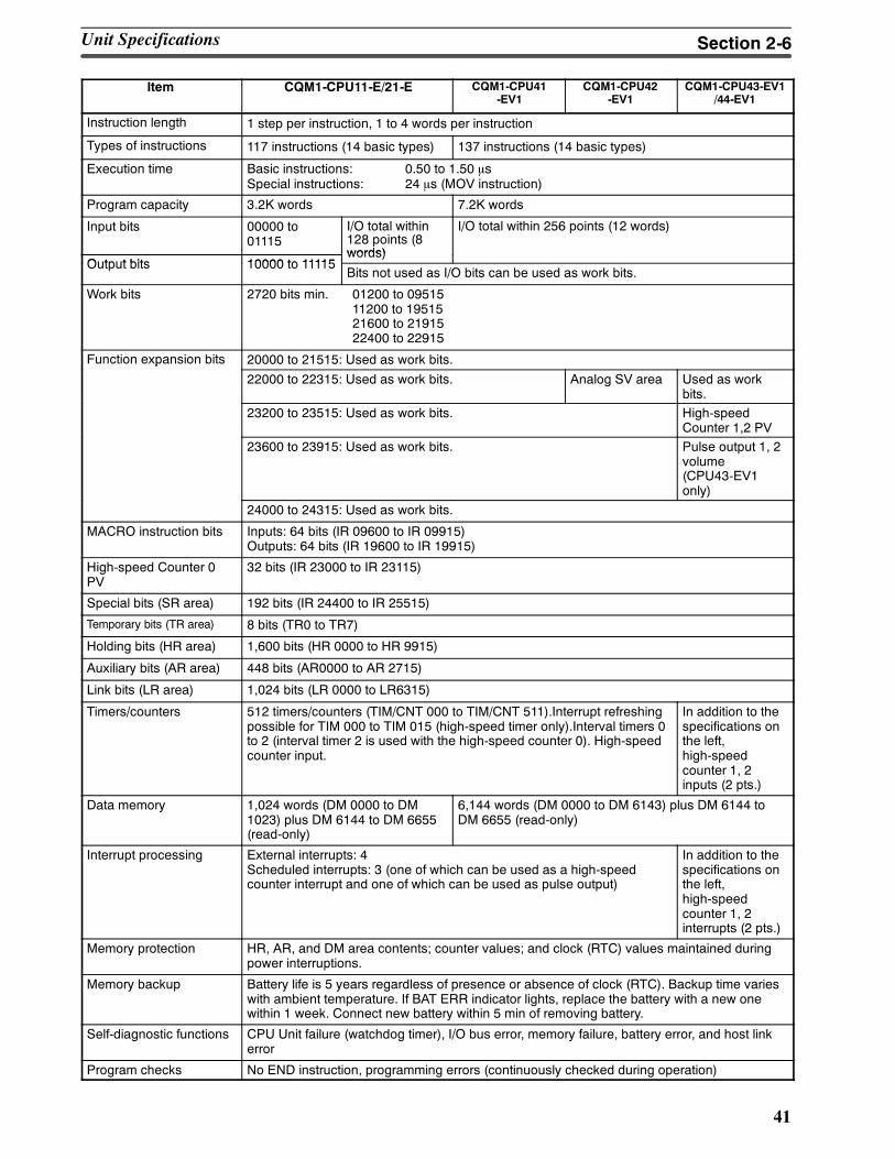
41
Item CQM1-CPU43-EV1/44-EV1
CQM1-CPU42-EV1
CQM1-CPU41-EV1
CQM1-CPU11-E/21-E
Instruction length 1 step per instruction, 1 to 4 words per instruction
Types of instructions 117 instructions (14 basic types) 137 instructions (14 basic types)
Execution time Basic instructions: 0.50 to 1.50 μsSpecial instructions: 24 μs (MOV instruction)
Program capacity 3.2K words 7.2K words
Input bits 00000 to01115
I/O total within128 points (8words)
I/O total within 256 points (12 words)
Output bits 10000 to 11115words)
Output bits 10000 to 11115Bits not used as I/O bits can be used as work bits.
Work bits 2720 bits min. 01200 to 0951511200 to 1951521600 to 2191522400 to 22915
Function expansion bits 20000 to 21515: Used as work bits.p
22000 to 22315: Used as work bits. Analog SV area Used as workbits.
23200 to 23515: Used as work bits. High-speedCounter 1,2 PV
23600 to 23915: Used as work bits. Pulse output 1, 2volume(CPU43-EV1only)
24000 to 24315: Used as work bits.
MACRO instruction bits Inputs: 64 bits (IR 09600 to IR 09915)Outputs: 64 bits (IR 19600 to IR 19915)
High-speed Counter 0PV
32 bits (IR 23000 to IR 23115)
Special bits (SR area) 192 bits (IR 24400 to IR 25515)
Temporary bits (TR area) 8 bits (TR0 to TR7)
Holding bits (HR area) 1,600 bits (HR 0000 to HR 9915)
Auxiliary bits (AR area) 448 bits (AR0000 to AR 2715)
Link bits (LR area) 1,024 bits (LR 0000 to LR6315)
Timers/counters 512 timers/counters (TIM/CNT 000 to TIM/CNT 511).Interrupt refreshingpossible for TIM 000 to TIM 015 (high-speed timer only).Interval timers 0to 2 (interval timer 2 is used with the high-speed counter 0). High-speedcounter input.
In addition to thespecifications onthe left,high-speedcounter 1, 2inputs (2 pts.)
Data memory 1,024 words (DM 0000 to DM1023) plus DM 6144 to DM 6655(read-only)
6,144 words (DM 0000 to DM 6143) plus DM 6144 toDM 6655 (read-only)
Interrupt processing External interrupts: 4Scheduled interrupts: 3 (one of which can be used as a high-speedcounter interrupt and one of which can be used as pulse output)
In addition to thespecifications onthe left,high-speedcounter 1, 2interrupts (2 pts.)
Memory protection HR, AR, and DM area contents; counter values; and clock (RTC) values maintained duringpower interruptions.
Memory backup Battery life is 5 years regardless of presence or absence of clock (RTC). Backup time varieswith ambient temperature. If BAT ERR indicator lights, replace the battery with a new onewithin 1 week. Connect new battery within 5 min of removing battery.
Self-diagnostic functions CPU Unit failure (watchdog timer), I/O bus error, memory failure, battery error, and host linkerror
Program checks No END instruction, programming errors (continuously checked during operation)
Unit Specifications Section 2-6
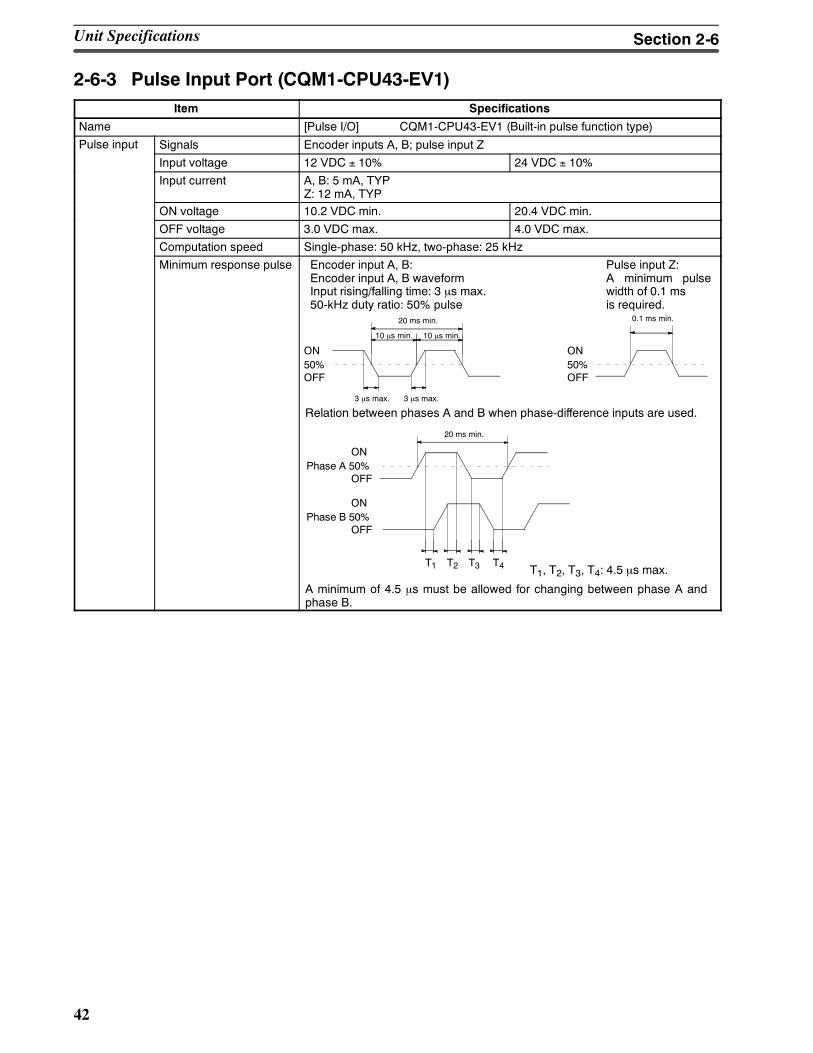
42
2-6-3 Pulse Input Port (CQM1-CPU43-EV1)Item Specifications
Name [Pulse I/O] CQM1-CPU43-EV1 (Built-in pulse function type)
Pulse input Signals Encoder inputs A, B; pulse input Zp
Input voltage 12 VDC ± 10% 24 VDC ± 10%
Input current A, B: 5 mA, TYPZ: 12 mA, TYP
ON voltage 10.2 VDC min. 20.4 VDC min.
OFF voltage 3.0 VDC max. 4.0 VDC max.
Computation speed Single-phase: 50 kHz, two-phase: 25 kHz
Minimum response pulse Encoder input A, B:Encoder input A, B waveformInput rising/falling time: 3 µs max.50-kHz duty ratio: 50% pulse
Pulse input Z:A minimum pulsewidth of 0.1 msis required.
10 µs min. 10 µs min.
3 µs max. 3 µs max.
Relation between phases A and B when phase-difference inputs are used.
A minimum of 4.5 µs must be allowed for changing between phase A andphase B.
T1, T2, T3, T4: 4.5 µs max.
ON
OFF50%
20 ms min.
ON
OFF50%
0.1 ms min.
ON
OFFPhase A 50%
20 ms min.
T1 T2 T3 T4
ON
OFFPhase B 50%
Unit Specifications Section 2-6
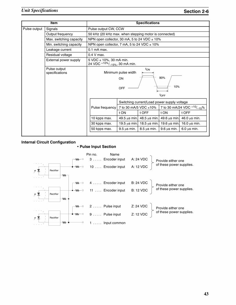
43
Item Specifications
Pulse output Signals Pulse output CW, CCWp
Output frequency 50 kHz (20 kHz max. when stepping motor is connected)
Max. switching capacity NPN open collector, 30 mA, 5 to 24 VDC ± 10%
Min. switching capacity NPN open collector, 7 mA, 5 to 24 VDC ± 10%
Leakage current 0.1 mA max.
Residual voltage 0.4 V max.
External power supply 5 VDC ± 10%, 30 mA min.24 VDC +10%/--15%, 30 mA min.
Pulse outputspecifications Minimum pulse width
Switching current/Load power supply voltage
Pulse frequency 7 to 30 mA/5 VDC ±10% 7 to 30 mA/24 VDC +10/--15%
t ON t OFF t ON t OFF
10 kpps max. 49.5 µs min. 48.5 µs min. 49.6 µs min. 46.0 µs min.
30 kpps max. 19.5 µs min. 18.5 µs min. 19.6 µs min. 16.0 µs min.
50 kpps max. 9.5 µs min. 8.5 µs min. 9.6 µs min. 6.0 µs min.
ON
OFF
90%
10%
tON
tOFF
Internal Circuit Configuration• Pulse Input Section
Pin no. Name3 Encoder input A: 24 VDC. . . . . Provide either one
of these power supplies.
Rectifier
Rectifier
Rectifier10 Encoder input A: 12 VDC. . . .
4 Encoder input B: 24 VDC. . . . .
11 Encoder input B: 12 VDC. . . .
2 Pulse input Z: 24 VDC. . . . .
9 Pulse input Z: 12 VDC. . . . .
1 Input common. . . . .
Provide either oneof these power supplies.
Provide either oneof these power supplies.
Unit Specifications Section 2-6
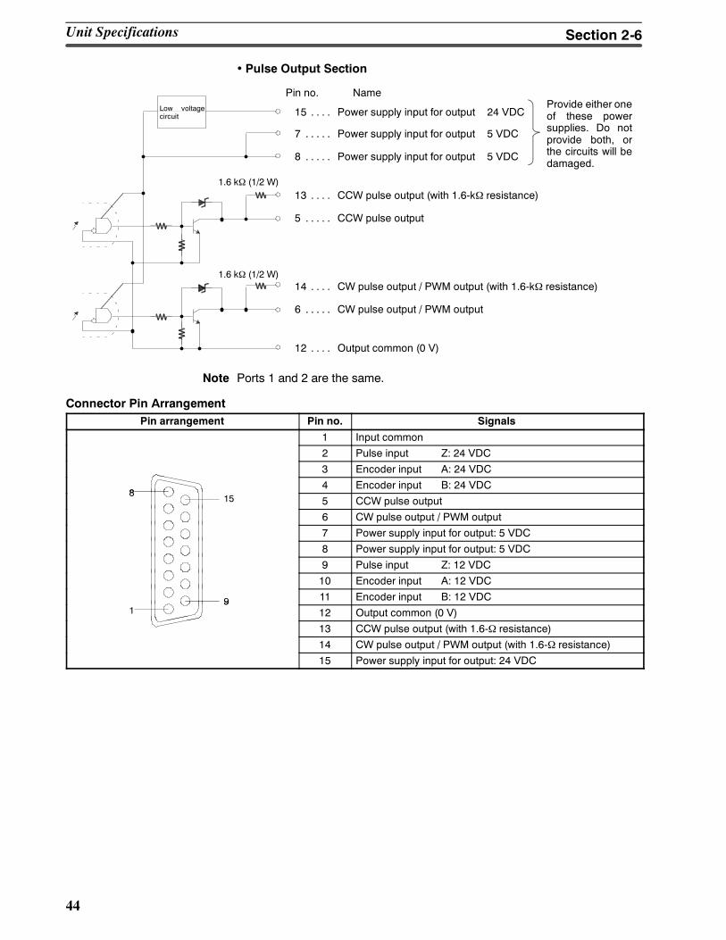
44
• Pulse Output Section
NameProvide either oneof these powersupplies. Do notprovide both, orthe circuits will bedamaged.
Low voltagecircuit
1.6 kΩ (1/2 W)
1.6 kΩ (1/2 W)
Pin no.
15 Power supply input for output 24 VDC. . . .
7 Power supply input for output 5 VDC. . . . .
8 Power supply input for output 5 VDC. . . . .
13 CCW pulse output (with 1.6-kΩ resistance). . . .
5 CCW pulse output. . . . .
14 CW pulse output / PWM output (with 1.6-kΩ resistance). . . .
6 CW pulse output / PWM output. . . . .
12 Output common (0 V). . . .
Note Ports 1 and 2 are the same.
Connector Pin ArrangementPin arrangement Pin no. Signals
1 Input common
2 Pulse input Z: 24 VDC
3 Encoder input A: 24 VDC
84 Encoder input B: 24 VDC
815 5 CCW pulse output
6 CW pulse output / PWM output
7 Power supply input for output: 5 VDC
8 Power supply input for output: 5 VDC
9 Pulse input Z: 12 VDC
10 Encoder input A: 12 VDC
9 11 Encoder input B: 12 VDC1
912 Output common (0 V)
13 CCW pulse output (with 1.6-Ω resistance)
14 CW pulse output / PWM output (with 1.6-Ω resistance)
15 Power supply input for output: 24 VDC
Unit Specifications Section 2-6
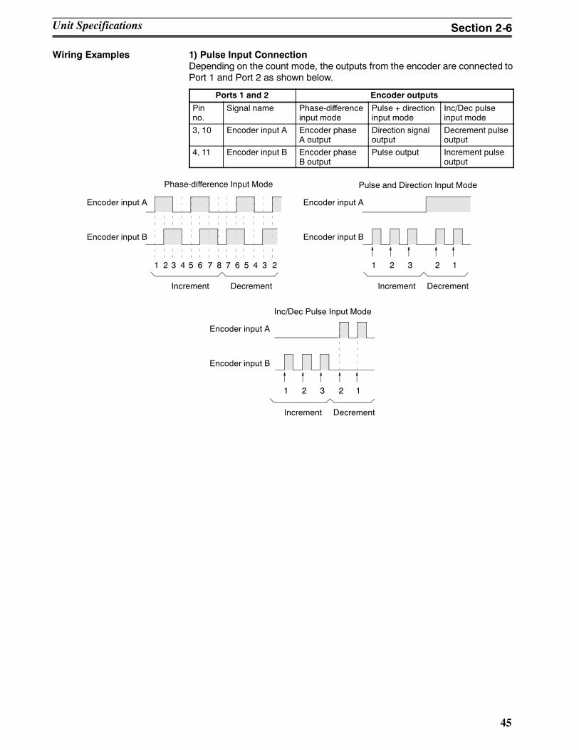
45
Wiring Examples 1) Pulse Input ConnectionDepending on the count mode, the outputs from the encoder are connected toPort 1 and Port 2 as shown below.
Ports 1 and 2 Encoder outputs
Pinno.
Signal name Phase-differenceinput mode
Pulse + directioninput mode
Inc/Dec pulseinput mode
3, 10 Encoder input A Encoder phaseA output
Direction signaloutput
Decrement pulseoutput
4, 11 Encoder input B Encoder phaseB output
Pulse output Increment pulseoutput
Phase-difference Input Mode Pulse and Direction Input Mode
Encoder input A
Encoder input B
Increment Decrement
Inc/Dec Pulse Input Mode
1 2 3 4 5 6 7 8 7 6 5 4 3 2 1 2 3 2 1
Encoder input A
Encoder input B
Increment Decrement
1 2 3 2 1
Encoder input A
Encoder input B
Increment Decrement
Unit Specifications Section 2-6
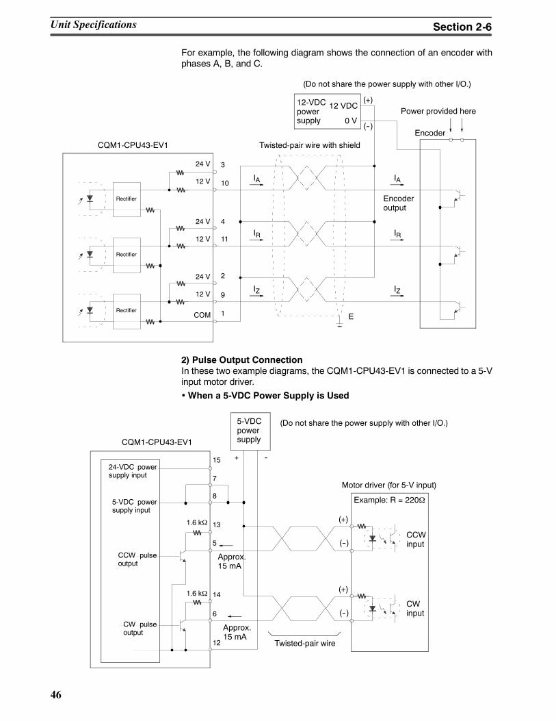
46
For example, the following diagram shows the connection of an encoder withphases A, B, and C.
CQM1-CPU43-EV1
(Do not share the power supply with other I/O.)
Encoder
Power provided here12-VDCpowersupply
Twisted-pair wire with shield
Encoderoutput
Rectifier
Rectifier
Rectifier
24 V
12 V
COM
3
10
4
11
2
9
1
24 V
12 V
24 V
12 V
12 VDC
0 V
E
IA
IR
IZ
IA
IR
IZ
(+)
(--)
2) Pulse Output ConnectionIn these two example diagrams, the CQM1-CPU43-EV1 is connected to a 5-Vinput motor driver.•When a 5-VDC Power Supply is Used
CQM1-CPU43-EV1
(Do not share the power supply with other I/O.)
Motor driver (for 5-V input)
Example: R = 220Ω
CCWinput
CWinput
Twisted-pair wire
5-VDCpowersupply
Approx.15 mA
1.6 kΩ
1.6 kΩ
24-VDC powersupply input
5-VDC powersupply input
CCW pulseoutput
CW pulseoutput
15
7
8
13
5
14
6
12
+ --
Approx.15 mA
(+)
(--)
(+)
(--)
Unit Specifications Section 2-6
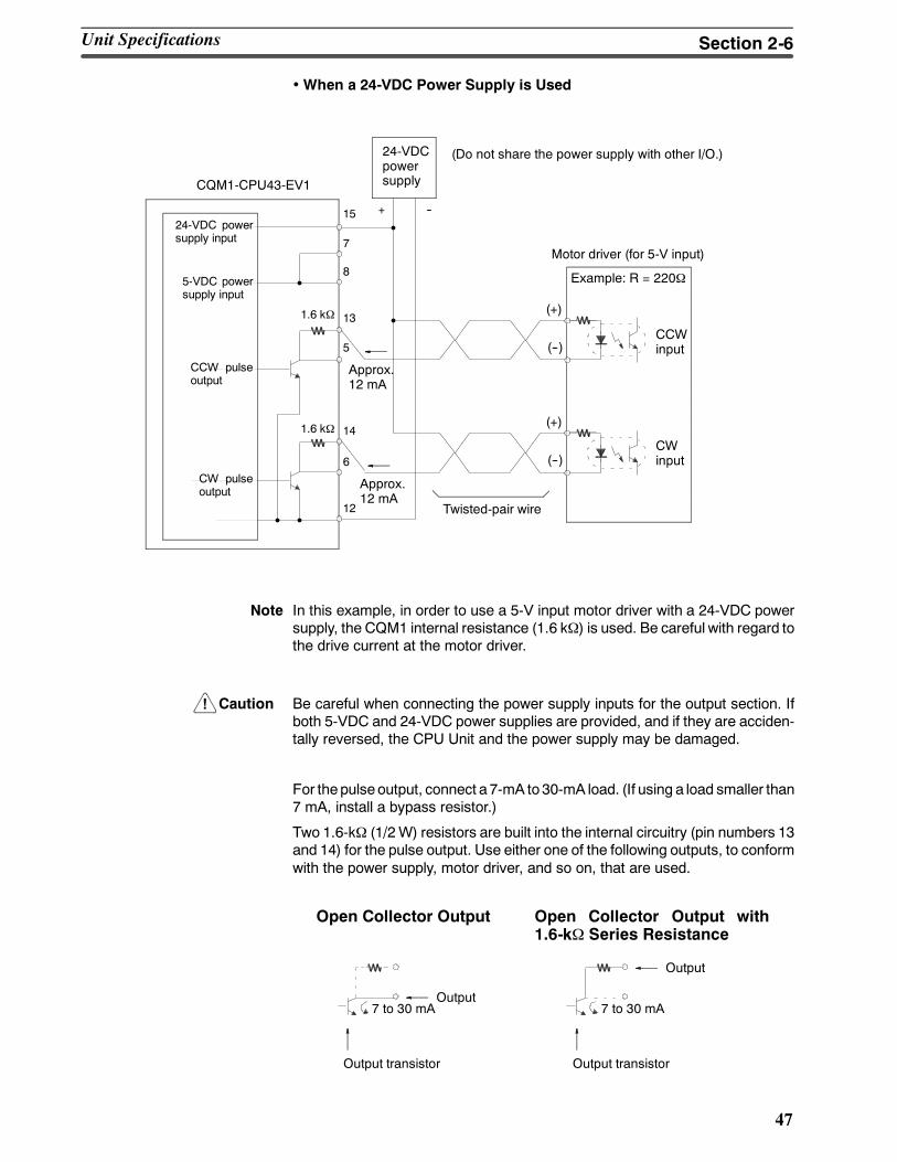
!
47
•When a 24-VDC Power Supply is Used
CQM1-CPU43-EV1
(Do not share the power supply with other I/O.)
Motor driver (for 5-V input)
Example: R = 220Ω
CCWinput
CWinput
Twisted-pair wire
24-VDCpowersupply
Approx.12 mA
1.6 kΩ
1.6 kΩ
24-VDC powersupply input
5-VDC powersupply input
CCW pulseoutput
CW pulseoutput
15
7
8
13
5
14
6
12
+ --
Approx.12 mA
(+)
(--)
(+)
(--)
Note In this example, in order to use a 5-V input motor driver with a 24-VDC powersupply, the CQM1 internal resistance (1.6 kΩ) is used. Be careful with regard tothe drive current at the motor driver.
Caution Be careful when connecting the power supply inputs for the output section. Ifboth 5-VDC and 24-VDC power supplies are provided, and if they are acciden-tally reversed, the CPU Unit and the power supply may be damaged.
For thepulseoutput, connect a 7-mA to30-mA load. (If using a load smaller than7 mA, install a bypass resistor.)
Two 1.6-kΩ (1/2W) resistors are built into the internal circuitry (pin numbers 13and 14) for the pulse output. Use either one of the following outputs, to conformwith the power supply, motor driver, and so on, that are used.
Open Collector Output Open Collector Output with1.6-kΩ Series Resistance
Output7 to 30 mA
Output transistor
Output
7 to 30 mA
Output transistor
Unit Specifications Section 2-6
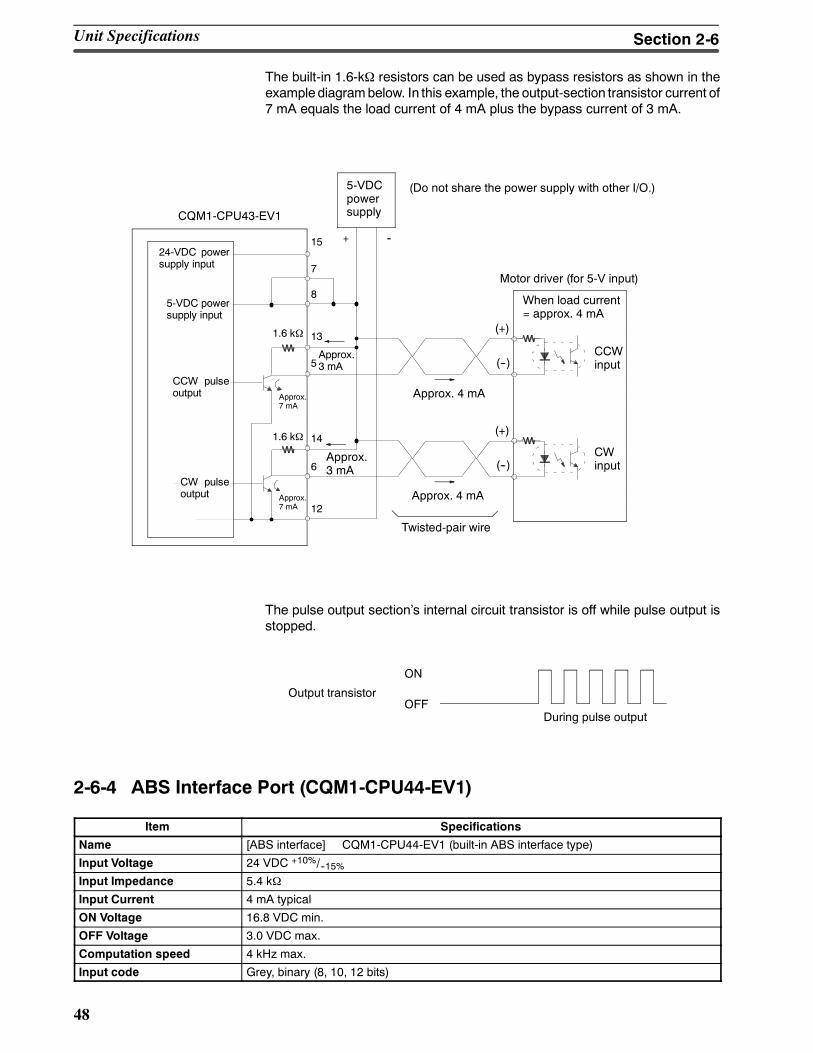
48
The built-in 1.6-kΩ resistors can be used as bypass resistors as shown in theexample diagrambelow. In this example, the output-section transistor current of7 mA equals the load current of 4 mA plus the bypass current of 3 mA.
Approx. 4 mA
Approx. 4 mA
Approx.7 mA
When load current= approx. 4 mA
CQM1-CPU43-EV1
(Do not share the power supply with other I/O.)
Motor driver (for 5-V input)
CCWinput
CWinput
Twisted-pair wire
5-VDCpowersupply
Approx.3 mA
1.6 kΩ
1.6 kΩ
24-VDC powersupply input
5-VDC powersupply input
CCW pulseoutput
CW pulseoutput
15
7
8
13
5
14
6
12
+ --
Approx.3 mA
(+)
(--)
(+)
(--)
Approx.7 mA
The pulse output sections internal circuit transistor is off while pulse output isstopped.
During pulse output
ON
OFFOutput transistor
2-6-4 ABS Interface Port (CQM1-CPU44-EV1)
Item Specifications
Name [ABS interface] CQM1-CPU44-EV1 (built-in ABS interface type)
Input Voltage 24 VDC +10%/--15%Input Impedance 5.4 kΩ
Input Current 4 mA typical
ON Voltage 16.8 VDC min.
OFF Voltage 3.0 VDC max.
Computation speed 4 kHz max.
Input code Grey, binary (8, 10, 12 bits)
Unit Specifications Section 2-6
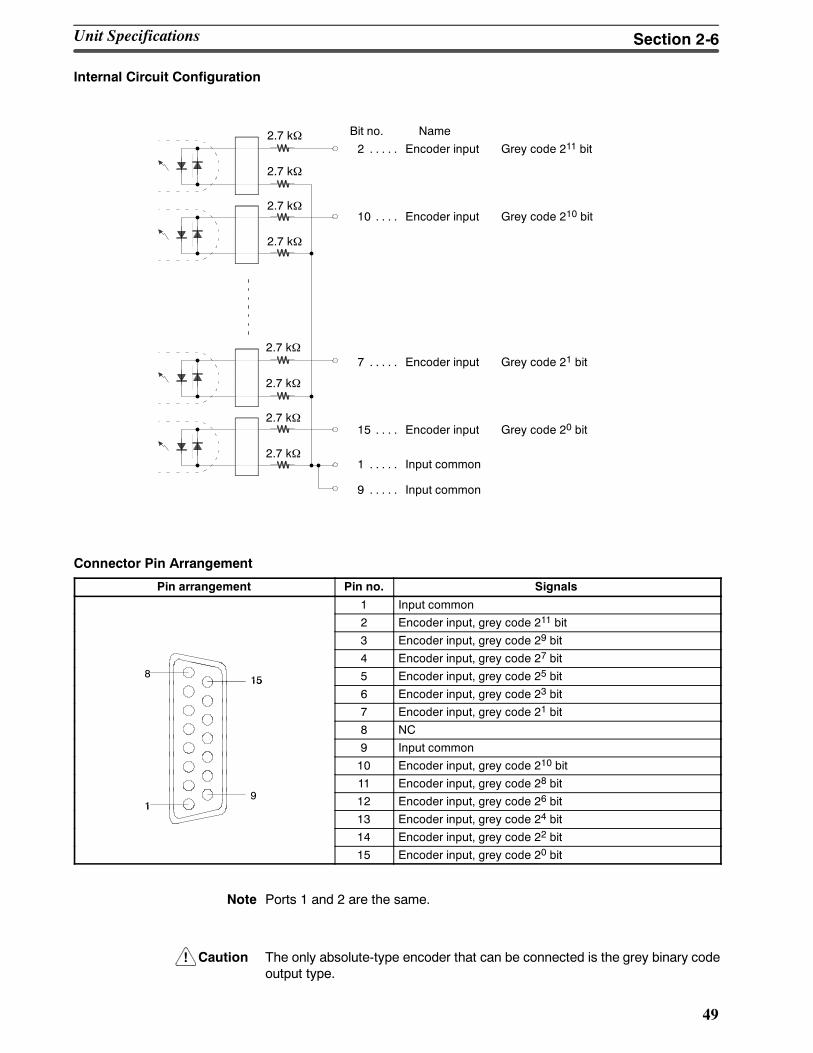
!
49
Internal Circuit Configuration
Bit no. Name
2 Encoder input Grey code 211 bit. . . . .2.7 kΩ
2.7 kΩ
2.7 kΩ
2.7 kΩ
2.7 kΩ
2.7 kΩ
2.7 kΩ
2.7 kΩ
10 Encoder input Grey code 210 bit. . . .
7 Encoder input Grey code 21 bit. . . . .
15 Encoder input Grey code 20 bit. . . .
1 Input common. . . . .
9 Input common. . . . .
Connector Pin Arrangement
Pin arrangement Pin no. Signals
1 Input common
2 Encoder input, grey code 211 bit
3 Encoder input, grey code 29 bit
4 Encoder input, grey code 27 bit8
15 5 Encoder input, grey code 25 bit156 Encoder input, grey code 23 bit
7 Encoder input, grey code 21 bit
8 NC
9 Input common
10 Encoder input, grey code 210 bit
911 Encoder input, grey code 28 bit
19 12 Encoder input, grey code 26 bit1
13 Encoder input, grey code 24 bit
14 Encoder input, grey code 22 bit
15 Encoder input, grey code 20 bit
Note Ports 1 and 2 are the same.
Caution The only absolute-type encoder that can be connected is the grey binary codeoutput type.
Unit Specifications Section 2-6
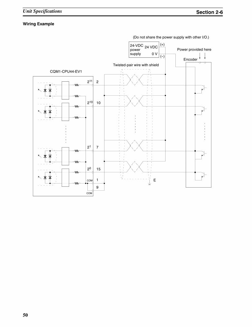
50
Wiring Example
CQM1-CPU44-EV1
(Do not share the power supply with other I/O.)
Encoder
Power provided here24-VDCpowersupply
Twisted-pair wire with shield
24 VDC
0 V
E
(+)
(--)
2
10
7
15
1
9
211
COM
COM
210
21
20
Unit Specifications Section 2-6
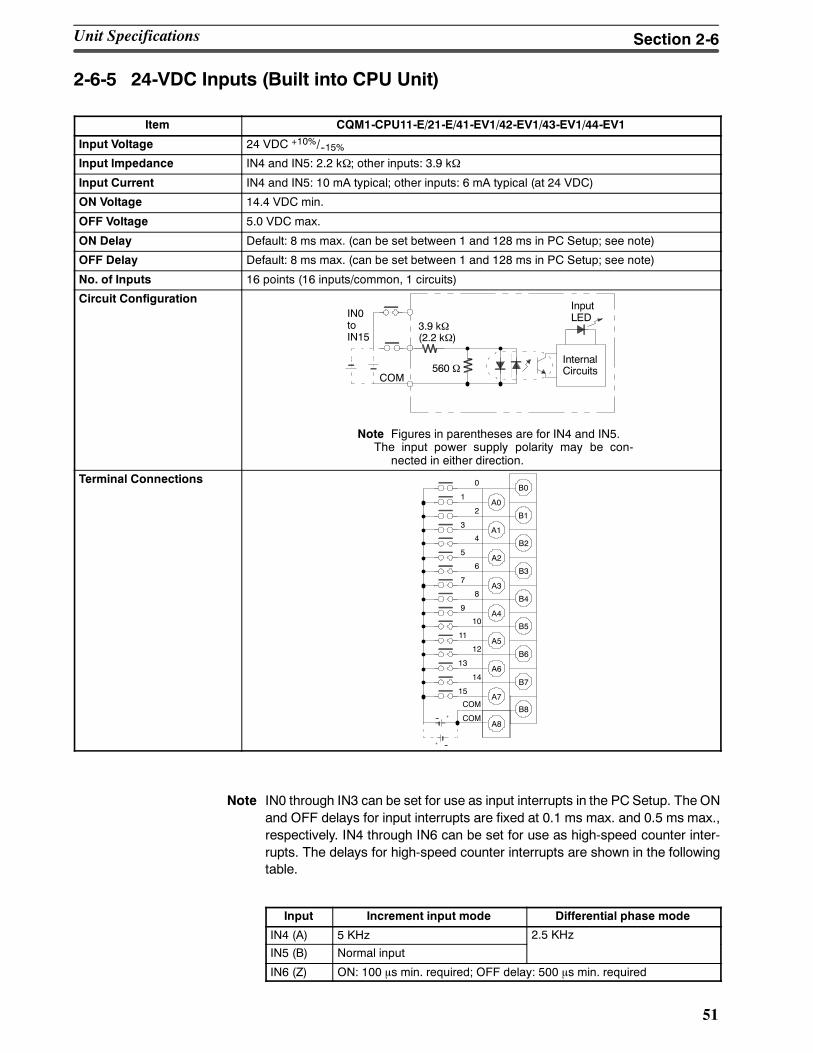
51
2-6-5 24-VDC Inputs (Built into CPU Unit)
Item CQM1-CPU11-E/21-E/41-EV1/42-EV1/43-EV1/44-EV1
Input Voltage 24 VDC +10%/--15%Input Impedance IN4 and IN5: 2.2 kΩ; other inputs: 3.9 kΩ
Input Current IN4 and IN5: 10 mA typical; other inputs: 6 mA typical (at 24 VDC)
ON Voltage 14.4 VDC min.
OFF Voltage 5.0 VDC max.
ON Delay Default: 8 ms max. (can be set between 1 and 128 ms in PC Setup; see note)
OFF Delay Default: 8 ms max. (can be set between 1 and 128 ms in PC Setup; see note)
No. of Inputs 16 points (16 inputs/common, 1 circuits)
Circuit ConfigurationIN0toIN15
COM
3.9 kΩ(2.2 kΩ)
InputLED
InternalCircuits560 Ω
Note Figures in parentheses are for IN4 and IN5.The input power supply polarity may be con-
nected in either direction.
Terminal ConnectionsB0
0
1A0
B12
3A1
B24
5A2
B36
7A3
B48
9A4
B510
11A5
B612
13A6
B714
15A7
B8COM
A8COM--
--
Note IN0 through IN3 can be set for use as input interrupts in the PC Setup. The ONand OFF delays for input interrupts are fixed at 0.1 ms max. and 0.5 ms max.,respectively. IN4 through IN6 can be set for use as high-speed counter inter-rupts. The delays for high-speed counter interrupts are shown in the followingtable.
Input Increment input mode Differential phase mode
IN4 (A) 5 KHz 2.5 KHz
IN5 (B) Normal input
IN6 (Z) ON: 100 μs min. required; OFF delay: 500 μs min. required
Unit Specifications Section 2-6
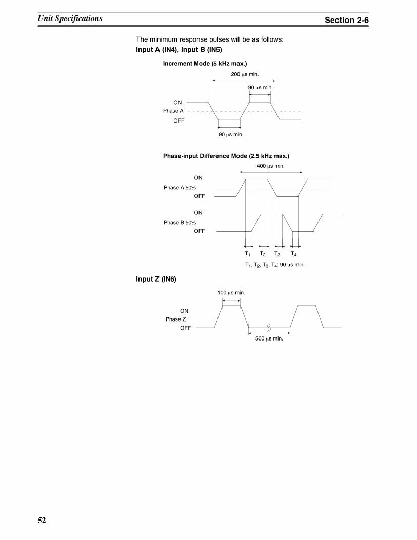
52
The minimum response pulses will be as follows:Input A (IN4), Input B (IN5)
Increment Mode (5 kHz max.)
200 µs min.
90 µs min.
90 µs min.
Phase-input Difference Mode (2.5 kHz max.)
400 µs min.
T1, T2, T3, T4: 90 µs min.
ON
OFF
ON
OFF
Phase A 50%
T1 T2 T3 T4
ON
OFF
Phase B 50%
Phase A
Input Z (IN6)
100 µs min.
500 µs min.
ON
OFF
Phase Z
Unit Specifications Section 2-6
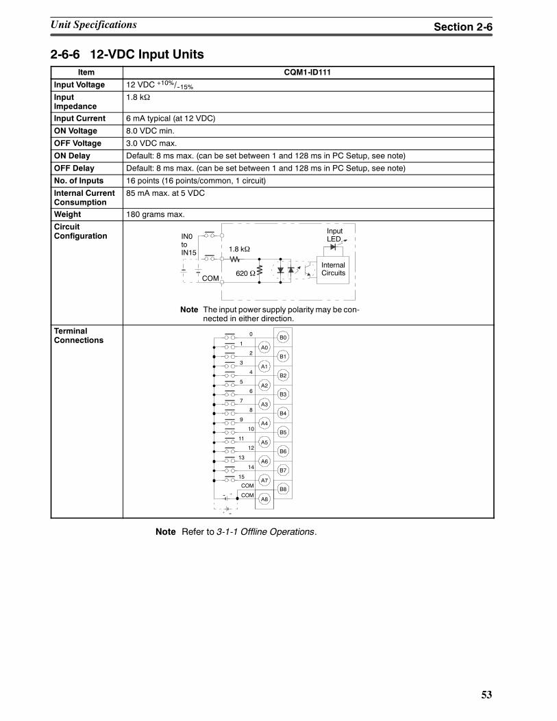
53
2-6-6 12-VDC Input UnitsItem CQM1-ID111
Input Voltage 12 VDC +10%/--15%InputImpedance
1.8 kΩ
Input Current 6 mA typical (at 12 VDC)
ON Voltage 8.0 VDC min.
OFF Voltage 3.0 VDC max.
ON Delay Default: 8 ms max. (can be set between 1 and 128 ms in PC Setup, see note)
OFF Delay Default: 8 ms max. (can be set between 1 and 128 ms in PC Setup, see note)
No. of Inputs 16 points (16 points/common, 1 circuit)
Internal CurrentConsumption
85 mA max. at 5 VDC
Weight 180 grams max.
CircuitConfiguration IN0
toIN15
COM
1.8 kΩ
InputLED
InternalCircuits620 Ω
Note The input power supply polarity may be con-nected in either direction.
TerminalConnections B0
0
1A0
B12
3A1
B24
5A2
B36
7A3
B48
9A4
B510
11A5
B612
13A6
B714
15A7
B8COM
A8COM--
--
Note Refer to 3-1-1 Offline Operations.
Unit Specifications Section 2-6
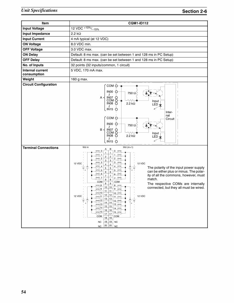
54
Item CQM1-ID112
Input Voltage 12 VDC +10%/--15%Input Impedance 2.2 kΩ
Input Current 4 mA typical (at 12 VDC)
ON Voltage 8.0 VDC min.
OFF Voltage 3.0 VDC max.
ON Delay Default: 8 ms max. (can be set between 1 and 128 ms in PC Setup)
OFF Delay Default: 8 ms max. (can be set between 1 and 128 ms in PC Setup)
No. of Inputs 32 points (32 inputs/common, 1 circuit)
Internal currentconsumption
5 VDC, 170 mA max.
Weight 160 g max.
Circuit Configuration
750 Ω
2.2 kΩ
COM
IN00
IN07COMIN08
IN15
A
Inter-nalCircuitCOM
IN00
IN07COMIN08
IN15
B750 Ω
2.2 kΩ
InputLED
InputLED
Terminal Connections
The polarity of the input power supplycan be either plus orminus. The polar-ity of all the commons, however, mustmatch.The respective COMs are internallyconnected, but they all must be wired.
4 4
5 5
6 6
7 7
8 8
9 9
11 11
12 12
13 13
14 14
15 15
16 16
17 17
18 18
3 3
2 2
19 19
20 20
1 10
1
2
3
4
5
6
7
9
10
11
1213
14
15
COM
COM
0
1
2
3
4
5
6
7
10 108
NC
COM
COM
NC
NC
NC
9
10
11
12
13
14
15
8
A B
+ +
12 VDC12 VDC
+
12 VDC
+
12 VDC
Wd m Wd (m+1)
Unit Specifications Section 2-6
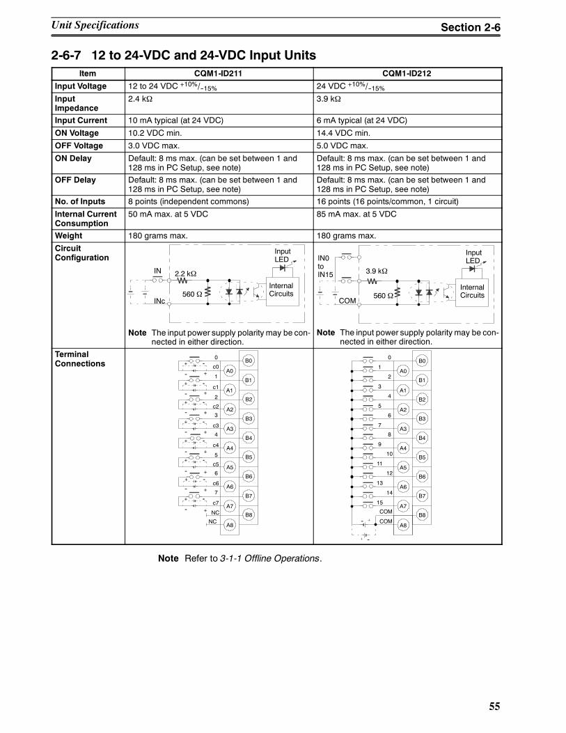
55
2-6-7 12 to 24-VDC and 24-VDC Input UnitsItem CQM1-ID211 CQM1-ID212
Input Voltage 12 to 24 VDC +10%/--15% 24 VDC +10%/--15%InputImpedance
2.4 kΩ 3.9 kΩ
Input Current 10 mA typical (at 24 VDC) 6 mA typical (at 24 VDC)
ON Voltage 10.2 VDC min. 14.4 VDC min.
OFF Voltage 3.0 VDC max. 5.0 VDC max.
ON Delay Default: 8 ms max. (can be set between 1 and128 ms in PC Setup, see note)
Default: 8 ms max. (can be set between 1 and128 ms in PC Setup, see note)
OFF Delay Default: 8 ms max. (can be set between 1 and128 ms in PC Setup, see note)
Default: 8 ms max. (can be set between 1 and128 ms in PC Setup, see note)
No. of Inputs 8 points (independent commons) 16 points (16 points/common, 1 circuit)
Internal CurrentConsumption
50 mA max. at 5 VDC 85 mA max. at 5 VDC
Weight 180 grams max. 180 grams max.
CircuitConfiguration
INc
IN 2.2 kΩ
InputLED
InternalCircuits560 Ω
Note The input power supply polarity may be con-nected in either direction.
IN0toIN15
COM
3.9 kΩ
InputLED
InternalCircuits560 Ω
Note The input power supply polarity may be con-nected in either direction.
TerminalConnections B00
A0
B1
c0
A1
B2
1
A2
B33
A3
B44
A4
B55
A5
B66
A6
B77
A7
B8
A8
c1
2
c2
c3
c4
c5
c6
c7
NC
NC
+ --
-- +
+--
--
--
--
--
--
--
+
+
+
+
+
+
+ --
+ --
+ --
+ --
+ --
+ --
+ --
B00
1A0
B12
3A1
B24
5A2
B36
7A3
B48
9A4
B510
11A5
B612
13A6
B714
15A7
B8COM
A8COM--
--
Note Refer to 3-1-1 Offline Operations.
Unit Specifications Section 2-6
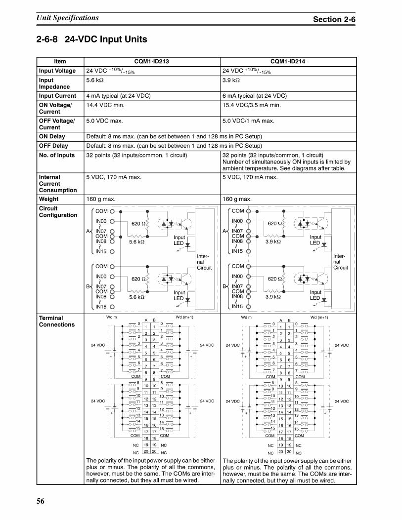
56
2-6-8 24-VDC Input Units
Item CQM1-ID213 CQM1-ID214
Input Voltage 24 VDC +10%/--15% 24 VDC +10%/--15%InputImpedance
5.6 kΩ 3.9 kΩ
Input Current 4 mA typical (at 24 VDC) 6 mA typical (at 24 VDC)
ON Voltage/Current
14.4 VDC min. 15.4 VDC/3.5 mA min.
OFF Voltage/Current
5.0 VDC max. 5.0 VDC/1 mA max.
ON Delay Default: 8 ms max. (can be set between 1 and 128 ms in PC Setup)
OFF Delay Default: 8 ms max. (can be set between 1 and 128 ms in PC Setup)
No. of Inputs 32 points (32 inputs/common, 1 circuit) 32 points (32 inputs/common, 1 circuit)Number of simultaneously ON inputs is limited byambient temperature. See diagrams after table.
InternalCurrentConsumption
5 VDC, 170 mA max. 5 VDC, 170 mA max.
Weight 160 g max. 160 g max.
CircuitConfiguration
620 Ω
5.6 kΩ
COM
IN00
IN07COMIN08
IN15
A
Inter-nalCircuitCOM
IN00
IN07COMIN08
IN15
B620 Ω
5.6 kΩ
InputLED
InputLED
620 Ω
3.9 kΩ
COM
IN00
IN07COMIN08
IN15
A
Inter-nalCircuitCOM
IN00
IN07COMIN08
IN15
B620 Ω
3.9 kΩ
InputLED
InputLED
TerminalConnections
The polarity of the input power supply can be eitherplus or minus. The polarity of all the commons,however, must be the same. The COMs are inter-nally connected, but they all must be wired.
4 4
5 5
6 6
7 7
8 8
9 9
11 11
12 12
13 13
14 14
15 15
16 16
17 17
18 18
3 3
2 2
19 19
20 20
1 10
1
2
3
4
5
6
7
9
10
11
1213
14
15
COM
COM
0
1
2
3
4
5
6
7
10 108
NC
COM
COM
NC
NC
NC
9
10
11
12
13
14
15
8
A B
+ +
24 VDC24 VDC
+
24 VDC
+
24 VDC
Wd m Wd (m+1)
Unit Specifications Section 2-6
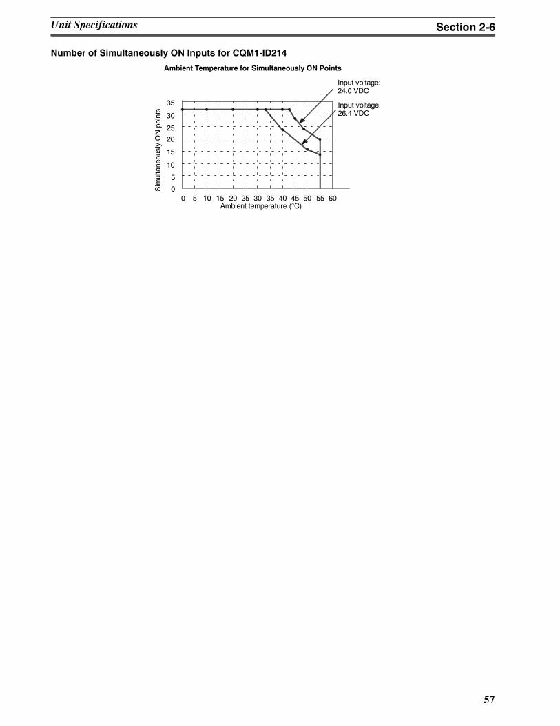
57
Number of Simultaneously ON Inputs for CQM1-ID214
5
0
10
15
20
25
30
35
20 30 40 50 6055453525155 100
Input voltage:24.0 VDC
Ambient temperature (°C)
Input voltage:26.4 VDC
Ambient Temperature for Simultaneously ON Points
SimultaneouslyONpoints
Unit Specifications Section 2-6
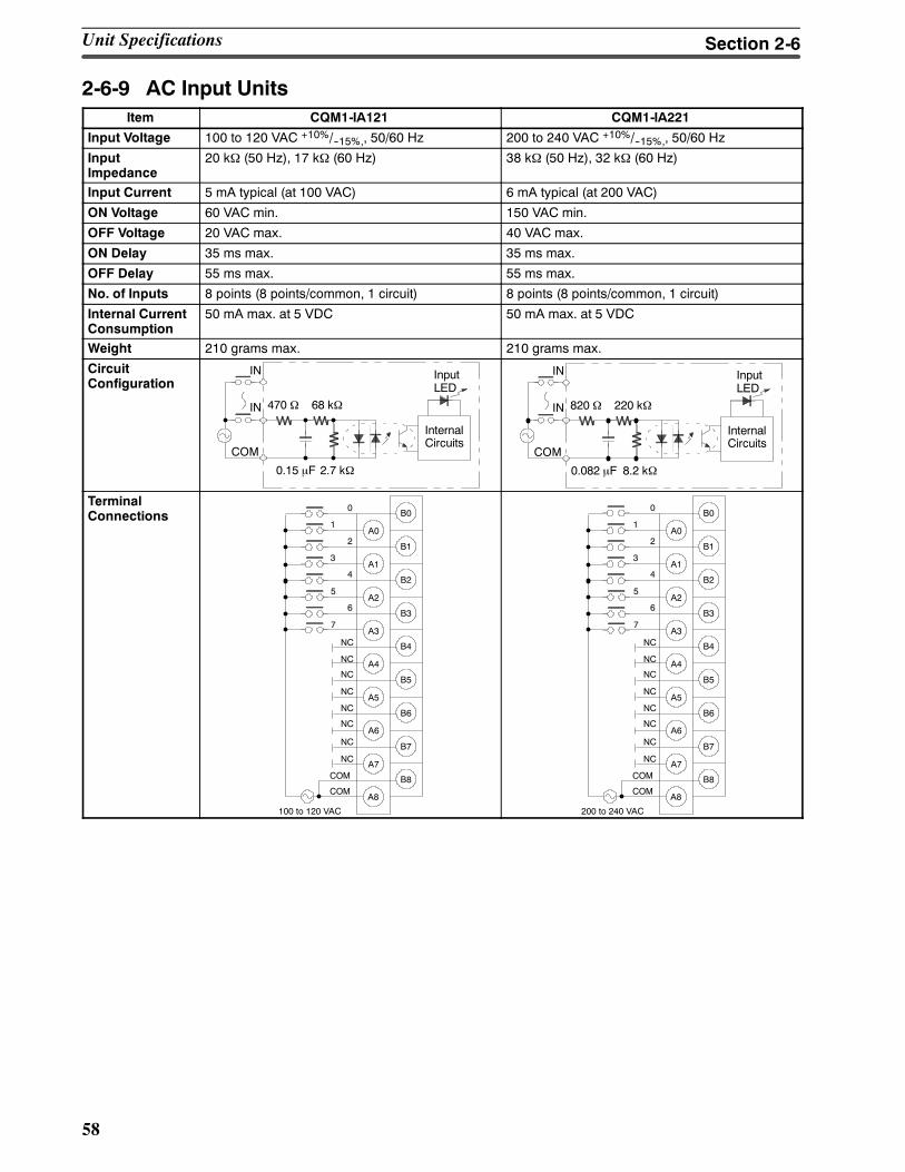
58
2-6-9 AC Input UnitsItem CQM1-IA121 CQM1-IA221
Input Voltage 100 to 120 VAC +10%/--15%,, 50/60 Hz 200 to 240 VAC +10%/--15%,, 50/60 Hz
InputImpedance
20 kΩ (50 Hz), 17 kΩ (60 Hz) 38 kΩ (50 Hz), 32 kΩ (60 Hz)
Input Current 5 mA typical (at 100 VAC) 6 mA typical (at 200 VAC)
ON Voltage 60 VAC min. 150 VAC min.
OFF Voltage 20 VAC max. 40 VAC max.
ON Delay 35 ms max. 35 ms max.
OFF Delay 55 ms max. 55 ms max.
No. of Inputs 8 points (8 points/common, 1 circuit) 8 points (8 points/common, 1 circuit)
Internal CurrentConsumption
50 mA max. at 5 VDC 50 mA max. at 5 VDC
Weight 210 grams max. 210 grams max.
CircuitConfiguration
COM
470 Ω
InputLED
InternalCircuits
2.7 kΩ0.15 µF
IN
IN 68 kΩ
COM
820 Ω
InputLED
InternalCircuits
8.2 kΩ0.082 µF
IN
IN 220 kΩ
TerminalConnections B00
1A0
B12
3A1
B24
5A2
B36
7
B4
A4
B5
A5
B6
A6
B7
A7
B8
A8
A3
COM
NC
NC
NC
NC
NC
NC
NC
NC
COM
100 to 120 VAC
B00
1A0
B12
3A1
B24
5A2
B36
7
B4
A4
B5
A5
B6
A6
B7
A7
B8
A8
A3
COM
NC
NC
NC
NC
NC
NC
NC
NC
COM
200 to 240 VAC
Unit Specifications Section 2-6
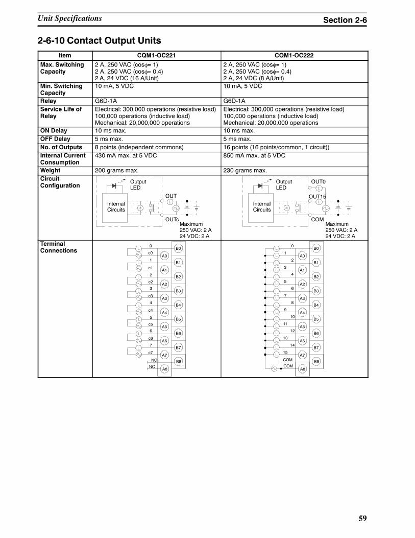
59
2-6-10 Contact Output UnitsItem CQM1-OC221 CQM1-OC222
Max. SwitchingCapacity
2 A, 250 VAC (cosφ= 1)2 A, 250 VAC (cosφ= 0.4)2 A, 24 VDC (16 A/Unit)
2 A, 250 VAC (cosφ= 1)2 A, 250 VAC (cosφ= 0.4)2 A, 24 VDC (8 A/Unit)
Min. SwitchingCapacity
10 mA, 5 VDC 10 mA, 5 VDC
Relay G6D-1A G6D-1AService Life ofRelay
Electrical: 300,000 operations (resistive load)100,000 operations (inductive load)Mechanical: 20,000,000 operations
Electrical: 300,000 operations (resistive load)100,000 operations (inductive load)Mechanical: 20,000,000 operations
ON Delay 10 ms max. 10 ms max.OFF Delay 5 ms max. 5 ms max.No. of Outputs 8 points (independent commons) 16 points (16 points/common, 1 circuit))Internal CurrentConsumption
430 mA max. at 5 VDC 850 mA max. at 5 VDC
Weight 200 grams max. 230 grams max.CircuitConfiguration
OUT
OutputLED
InternalCircuits
OUTcMaximum250 VAC: 2 A24 VDC: 2 A
OUT0OutputLED
InternalCircuits
COMMaximum250 VAC: 2 A24 VDC: 2 A
OUT15
TerminalConnections B0
A0
B1
A1
B2
A2
B3
B4
A4
B5
A5
B6
A6
B7
A7
B8
A8
A3
NC
NC
0
c0
1
3
4
5
6
7
c1
2
c2
c3
c4
c5
c6
c7
B00
1A0
B12
3A1
B24
5A2
B36
7
B48
9A4
B510
11A5
B612
13A6
B714
15A7
B8
A8
A3
COM
COM
Unit Specifications Section 2-6
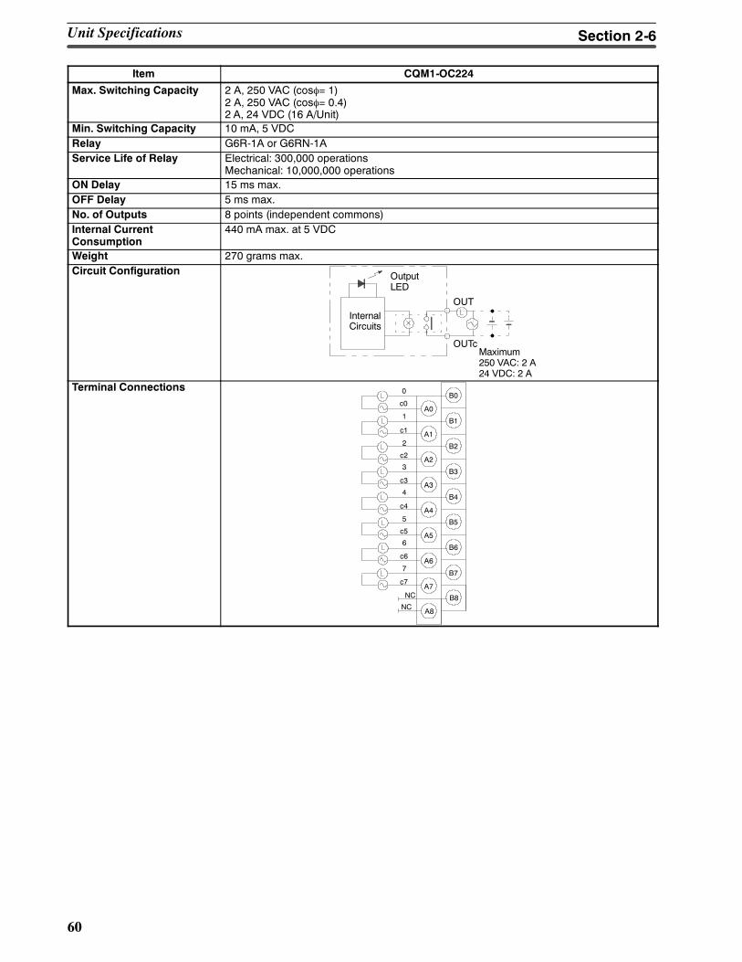
60
Item CQM1-OC224
Max. Switching Capacity 2 A, 250 VAC (cosφ= 1)2 A, 250 VAC (cosφ= 0.4)2 A, 24 VDC (16 A/Unit)
Min. Switching Capacity 10 mA, 5 VDCRelay G6R-1A or G6RN-1AService Life of Relay Electrical: 300,000 operations
Mechanical: 10,000,000 operationsON Delay 15 ms max.OFF Delay 5 ms max.No. of Outputs 8 points (independent commons)Internal CurrentConsumption
440 mA max. at 5 VDC
Weight 270 grams max.Circuit Configuration
OUT
OutputLED
InternalCircuits
OUTcMaximum250 VAC: 2 A24 VDC: 2 A
Terminal ConnectionsB0
A0
B1
A1
B2
A2
B3
B4
A4
B5
A5
B6
A6
B7
A7
B8
A8
A3
NC
NC
0
c0
1
3
4
5
6
7
c1
2
c2
c3
c4
c5
c6
c7
Unit Specifications Section 2-6
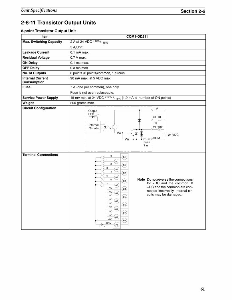
61
2-6-11 Transistor Output Units8-point Transistor Output Unit
Item CQM1-OD211
Max. Switching Capacity 2 A at 24 VDC +10%/--15%5 A/Unit
Leakage Current 0.1 mA max.
Residual Voltage 0.7 V max.
ON Delay 0.1 ms max.
OFF Delay 0.3 ms max.
No. of Outputs 8 points (8 points/common, 1 circuit)
Internal CurrentConsumption
90 mA max. at 5 VDC max.
Fuse 7 A (one per common), one only
Fuse is not user replaceable.
Service Power Supply 15 mAmin. at 24 VDC +10% /--15% (1.9 mA¢ number of ON points)
Weight 200 grams max.
Circuit Configuration
to
+V
Fuse7 A
OUT0
OutputLED
InternalCircuits
COM
OUT07
24 VDC
Terminal ConnectionsB0
0
1A0
B12
3A1
B24
5A2
B36
7
B4
A4
B5
A5
B6
A6
B7
A7
B8
A8
A3
COM--
NC
NC
NC
NC
NC
NC
NC
NC
+DC
Note Donot reverse the connectionsfor +DC and the common. If+DC and the common are con-nected incorrectly, internal cir-cuits may be damaged.
Unit Specifications Section 2-6
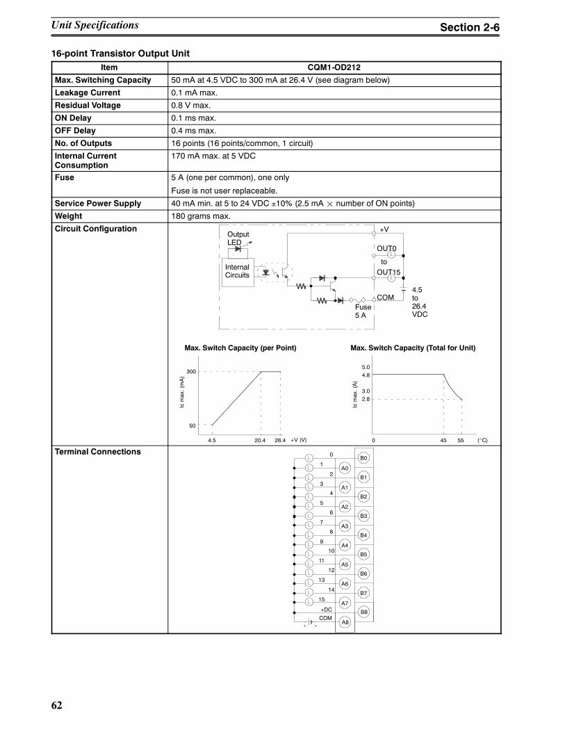
62
16-point Transistor Output UnitItem CQM1-OD212
Max. Switching Capacity 50 mA at 4.5 VDC to 300 mA at 26.4 V (see diagram below)
Leakage Current 0.1 mA max.
Residual Voltage 0.8 V max.
ON Delay 0.1 ms max.
OFF Delay 0.4 ms max.
No. of Outputs 16 points (16 points/common, 1 circuit)
Internal CurrentConsumption
170 mA max. at 5 VDC
Fuse 5 A (one per common), one only
Fuse is not user replaceable.
Service Power Supply 40 mA min. at 5 to 24 VDC ±10% (2.5 mA¢ number of ON points)
Weight 180 grams max.
Circuit Configuration
to
+V
Fuse5 A
OUT0
OutputLED
InternalCircuits
COM
OUT15
4.5to26.4VDC
4.5 20.4 26.4 0 45 55
300
50
5.04.8
3.02.8
Max. Switch Capacity (per Point)
+V (V)
Icmax.(mA)
Max. Switch Capacity (Total for Unit)
(_C)
Icmax.(A)
Terminal ConnectionsB0
0
1A0
B12
3A1
B24
5A2
B36
7
B48
9A4
B510
11A5
B612
13A6
B714
15A7
B8
A8
A3
COM--
+DC
Unit Specifications Section 2-6
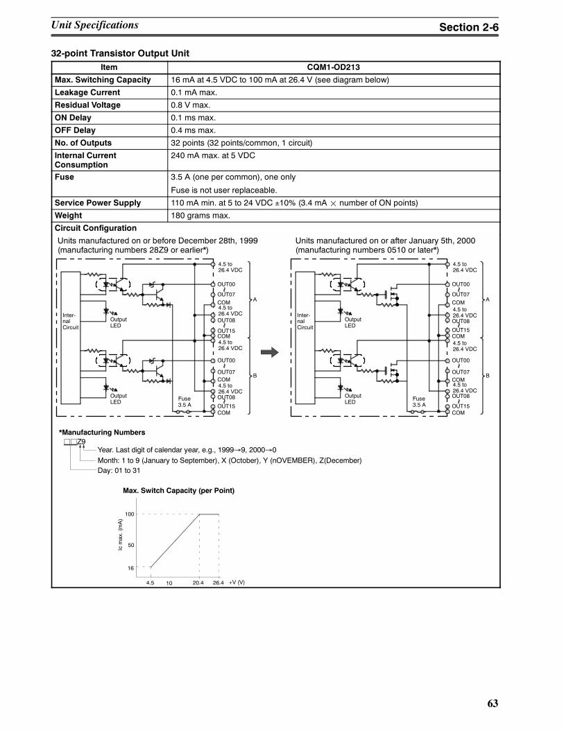
63
32-point Transistor Output UnitItem CQM1-OD213
Max. Switching Capacity 16 mA at 4.5 VDC to 100 mA at 26.4 V (see diagram below)
Leakage Current 0.1 mA max.
Residual Voltage 0.8 V max.
ON Delay 0.1 ms max.
OFF Delay 0.4 ms max.
No. of Outputs 32 points (32 points/common, 1 circuit)
Internal CurrentConsumption
240 mA max. at 5 VDC
Fuse 3.5 A (one per common), one only
Fuse is not user replaceable.
Service Power Supply 110 mA min. at 5 to 24 VDC ±10% (3.4 mA¢ number of ON points)
Weight 180 grams max.
Circuit Configuration
Units manufactured on or before December 28th, 1999(manufacturing numbers 28Z9 or earlier*)
Units manufactured on or after January 5th, 2000(manufacturing numbers 0510 or later*)
Fuse3.5 A
OutputLED
OUT00
OUT07COM A
OUT08
OUT15COM
Inter-nalCircuit
4.5 to26.4 VDC
4.5 to26.4 VDC
OUT00
OUT07COM
B
OUT08
OUT15COM
4.5 to26.4 VDC
4.5 to26.4 VDC
OutputLED Fuse
3.5 A
OutputLED
OUT00
OUT07COM A
OUT08
OUT15COM
Inter-nalCircuit
4.5 to26.4 VDC
4.5 to26.4 VDC
OUT00
OUT07COM
B
OUT08
OUT15COM
4.5 to26.4 VDC
4.5 to26.4 VDC
OutputLED
4.5 20.4 26.4
100
16
Max. Switch Capacity (per Point)
+V (V)
Icmax.(mA)
50
10
*Manufacturing NumbersjjZ9
Year. Last digit of calendar year, e.g., 1999→9, 2000→0Month: 1 to 9 (January to September), X (October), Y (nOVEMBER), Z(December)Day: 01 to 31
Unit Specifications Section 2-6
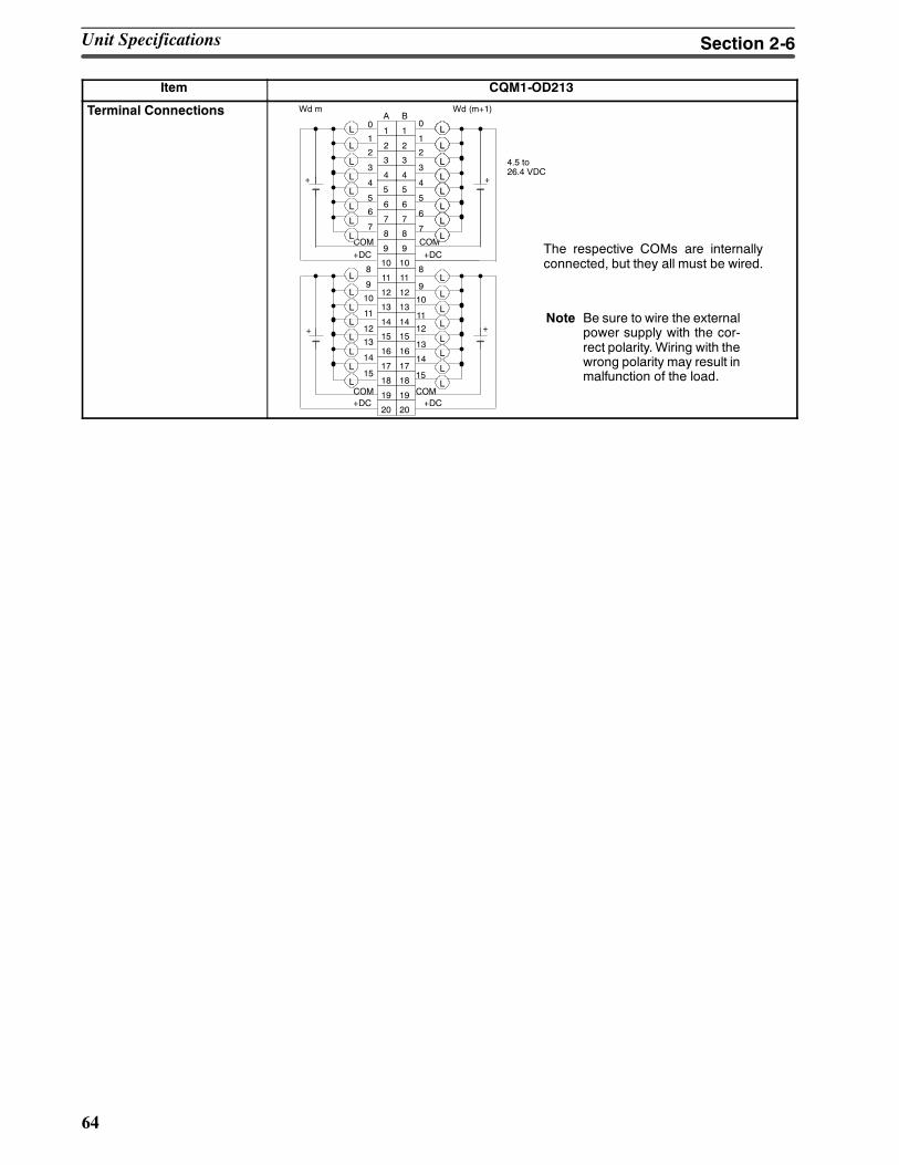
64
Item CQM1-OD213
Terminal Connections
The respective COMs are internallyconnected, but they all must be wired.
4 4
5 5
6 6
7 7
8 8
9 9
11 11
12 12
13 13
14 14
15 15
16 16
17 17
18 18
3 3
2 2
19 19
20 20
1 10
1
2
3
4
5
6
7
8
9
10
1112
13
14
COM
COM
0
1
2
3
4
5
6
7
10 10
COM
8
9
10
11
12
13
14
A B
+ +
++
Wd m Wd (m+1)
L
L
L
L
L
L
L
L
L
L
L
L
L
L
L
L
L
L
L
L
L
L
L
L
L
L
L
L
L
L
L
L
L
L
L
L
L
L15
LCOM
L
4.5 to26.4 VDC
+DC +DC
+DC +DC
15
Note Be sure to wire the externalpower supply with the cor-rect polarity. Wiring with thewrong polarity may result inmalfunction of the load.
Unit Specifications Section 2-6
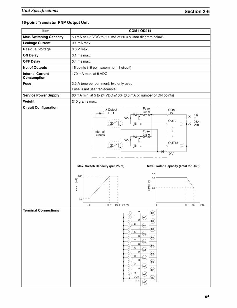
65
16-point Transistor PNP Output Unit
Item CQM1-OD214
Max. Switching Capacity 50 mA at 4.5 VDC to 300 mA at 26.4 V (see diagram below)
Leakage Current 0.1 mA max.
Residual Voltage 0.8 V max.
ON Delay 0.1 ms max.
OFF Delay 0.4 ms max.
No. of Outputs 16 points (16 points/common, 1 circuit)
Internal CurrentConsumption
170 mA max. at 5 VDC
Fuse 3.5 A (one per common), two only used.
Fuse is not user replaceable.
Service Power Supply 60 mA min. at 5 to 24 VDC ±10% (3.5 mA¢ number of ON points)
Weight 210 grams max.
Circuit Configuration
4.5 20.4 26.4 0 39 55
300
50
5.04.8
3.6
Max. Switch Capacity (per Point)
+V (V)
Icmax.(mA)
Max. Switch Capacity (Total for Unit)
(_C)
Icmax.(A)
+V
OUT0
OutputLED
InternalCircuits
COM
OUT15
4.5to26.4VDC
(+)
(--)
Fuse3.5 A
0 V
Fuse3.5 A
Terminal Connections
--
B00
1A0
B12
3A1
B24
5A2
B36
7
B48
9A4
B510
11A5
B612
13A6
B714
15A7
B8
A8
A3
COM+
0 V
Unit Specifications Section 2-6
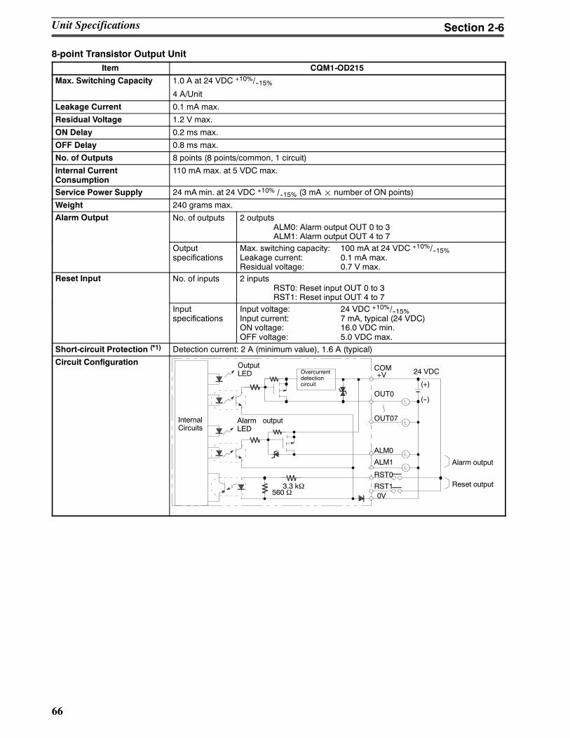
66
8-point Transistor Output UnitItem CQM1-OD215
Max. Switching Capacity 1.0 A at 24 VDC +10%/--15%4 A/Unit
Leakage Current 0.1 mA max.
Residual Voltage 1.2 V max.
ON Delay 0.2 ms max.
OFF Delay 0.8 ms max.
No. of Outputs 8 points (8 points/common, 1 circuit)
Internal CurrentConsumption
110 mA max. at 5 VDC max.
Service Power Supply 24 mAmin. at 24 VDC +10% /--15% (3 mA¢ number of ON points)
Weight 240 grams max.
Alarm Output No. of outputs 2 outputsALM0: Alarm output OUT 0 to 3ALM1: Alarm output OUT 4 to 7
Outputspecifications
Max. switching capacity: 100 mA at 24 VDC +10%/--15%Leakage current: 0.1 mA max.Residual voltage: 0.7 V max.
Reset Input No. of inputs 2 inputsRST0: Reset input OUT 0 to 3RST1: Reset input OUT 4 to 7
Inputspecifications
Input voltage: 24 VDC +10%/--15%Input current: 7 mA, typical (24 VDC)ON voltage: 16.0 VDC min.OFF voltage: 5.0 VDC max.
Short-circuit Protection (*1) Detection current: 2 A (minimum value), 1.6 A (typical)
Circuit Configuration
+V
OUT0
OutputLED
InternalCircuits
COM
OUT07
(+)
(--)
Alarm outputLED
Overcurrentdetectioncircuit
560 Ω3.3 kΩ
ALM0
ALM1
RST0
24 VDC
RST10V
Alarm output
Reset output
Unit Specifications Section 2-6
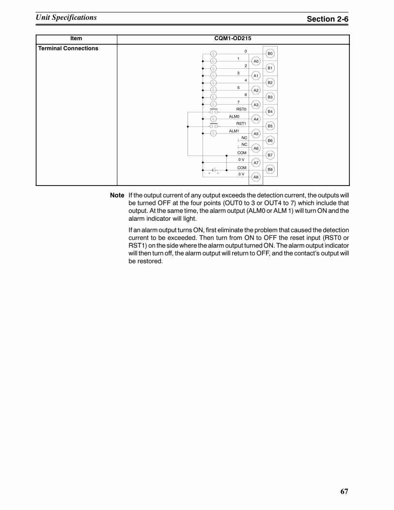
67
Item CQM1-OD215
Terminal ConnectionsB00
1A0
B12
3A1
B24
5A2
B36
7
B4RST0
ALM0A4
B5RST1
ALM1A5
B6
A6
B7
A7
B8
A8
A3
0 V
COM
0 V
COM
NC
NC
--
Note If the output current of any output exceeds the detection current, the outputswillbe turned OFF at the four points (OUT0 to 3 or OUT4 to 7) which include thatoutput. At the same time, the alarm output (ALM0 or ALM 1) will turnONand thealarm indicator will light.
If an alarmoutput turnsON, first eliminate theproblem that caused thedetectioncurrent to be exceeded. Then turn from ON to OFF the reset input (RST0 orRST1) on the sidewhere thealarmoutput turnedON. Thealarmoutput indicatorwill then turn off, the alarm output will return toOFF, and the contacts output willbe restored.
Unit Specifications Section 2-6
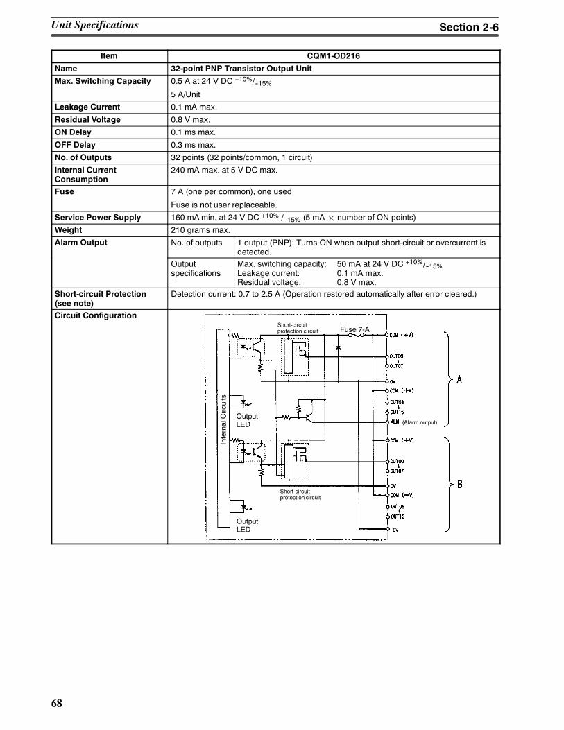
68
Item CQM1-OD216
Name 32-point PNP Transistor Output Unit
Max. Switching Capacity 0.5 A at 24 V DC +10%/--15%5 A/Unit
Leakage Current 0.1 mA max.
Residual Voltage 0.8 V max.
ON Delay 0.1 ms max.
OFF Delay 0.3 ms max.
No. of Outputs 32 points (32 points/common, 1 circuit)
Internal CurrentConsumption
240 mA max. at 5 V DC max.
Fuse 7 A (one per common), one used
Fuse is not user replaceable.
Service Power Supply 160 mAmin. at 24 V DC +10% /--15% (5 mA¢ number of ON points)
Weight 210 grams max.
Alarm Output No. of outputs 1 output (PNP): Turns ON when output short-circuit or overcurrent isdetected.
Outputspecifications
Max. switching capacity: 50 mA at 24 V DC +10%/--15%Leakage current: 0.1 mA max.Residual voltage: 0.8 V max.
Short-circuit Protection(see note)
Detection current: 0.7 to 2.5 A (Operation restored automatically after error cleared.)
Circuit Configuration
OutputLED
Short-circuitprotection circuit
OutputLED
Short-circuitprotection circuit
Fuse 7-A
(Alarm output)
InternalCircuits
Unit Specifications Section 2-6
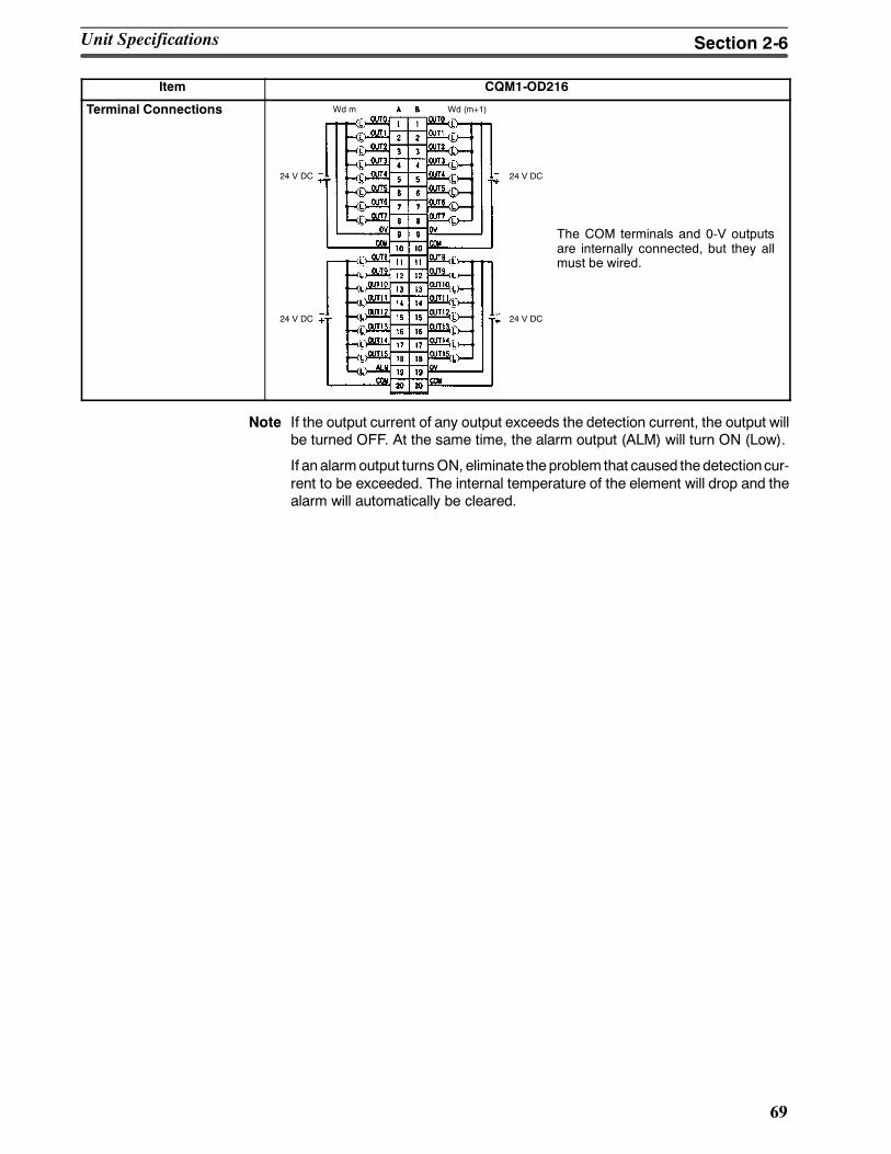
69
Item CQM1-OD216
Terminal Connections
The COM terminals and 0-V outputsare internally connected, but they allmust be wired.
Wd m Wd (m+1)
24 V DC
24 V DC
24 V DC
24 V DC
Note If the output current of any output exceeds the detection current, the output willbe turned OFF. At the same time, the alarm output (ALM) will turn ON (Low).
If an alarmoutput turnsON, eliminate theproblem that caused thedetectioncur-rent to be exceeded. The internal temperature of the element will drop and thealarm will automatically be cleared.
Unit Specifications Section 2-6
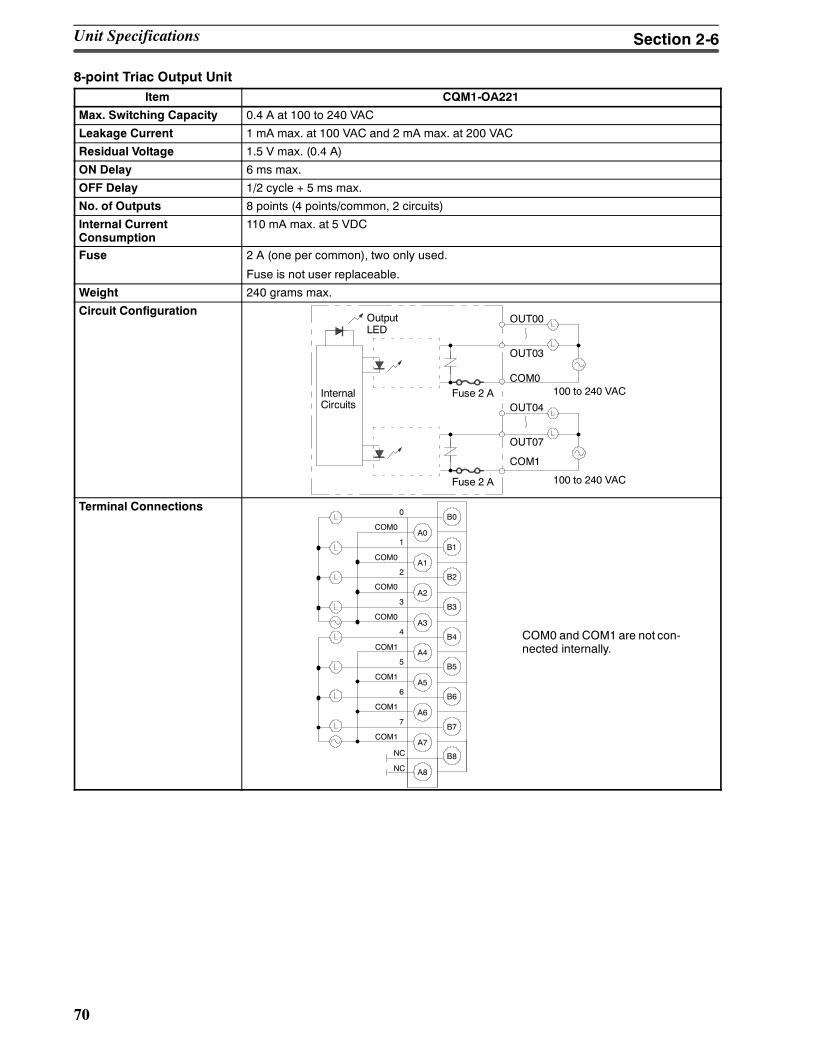
70
8-point Triac Output UnitItem CQM1-OA221
Max. Switching Capacity 0.4 A at 100 to 240 VAC
Leakage Current 1 mA max. at 100 VAC and 2 mA max. at 200 VAC
Residual Voltage 1.5 V max. (0.4 A)
ON Delay 6 ms max.
OFF Delay 1/2 cycle + 5 ms max.
No. of Outputs 8 points (4 points/common, 2 circuits)
Internal CurrentConsumption
110 mA max. at 5 VDC
Fuse 2 A (one per common), two only used.
Fuse is not user replaceable.
Weight 240 grams max.
Circuit ConfigurationOUT00Output
LED
InternalCircuits
OUT03
Fuse 2 A 100 to 240 VAC
OUT04
OUT07
Fuse 2 A 100 to 240 VAC
COM0
COM1
Terminal Connections
COM0 and COM1 are not con-nected internally.
B00
COM0A0
B11
COM0A1
B22
A2
B33
B44
COM1A4
B55
COM1A5
B66
COM1A6
B77
COM1A7
B8
A8
A3
NC
NC
COM0
COM0
Unit Specifications Section 2-6
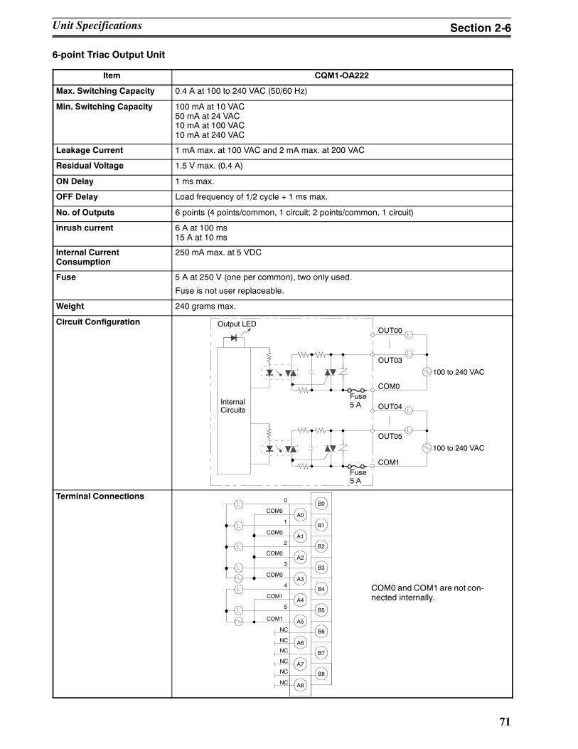
71
6-point Triac Output Unit
Item CQM1-OA222
Max. Switching Capacity 0.4 A at 100 to 240 VAC (50/60 Hz)
Min. Switching Capacity 100 mA at 10 VAC50 mA at 24 VAC10 mA at 100 VAC10 mA at 240 VAC
Leakage Current 1 mA max. at 100 VAC and 2 mA max. at 200 VAC
Residual Voltage 1.5 V max. (0.4 A)
ON Delay 1 ms max.
OFF Delay Load frequency of 1/2 cycle + 1 ms max.
No. of Outputs 6 points (4 points/common, 1 circuit; 2 points/common, 1 circuit)
Inrush current 6 A at 100 ms15 A at 10 ms
Internal CurrentConsumption
250 mA max. at 5 VDC
Fuse 5 A at 250 V (one per common), two only used.
Fuse is not user replaceable.
Weight 240 grams max.
Circuit ConfigurationOUT00
Output LED
InternalCircuits
OUT03
Fuse5 A
100 to 240 VAC
COM0
OUT04
OUT05
Fuse5 A
100 to 240 VAC
COM1
Terminal Connections
COM0 and COM1 are not con-nected internally.
B00
COM0A0
B11
COM0A1
B22
A2
B33
B44
COM1A4
B55
A5
B6
A6
B7
COM1
A7
B8
A8
A3
NC
NC
COM0
COM0
NC
NC
NC
NC
Unit Specifications Section 2-6
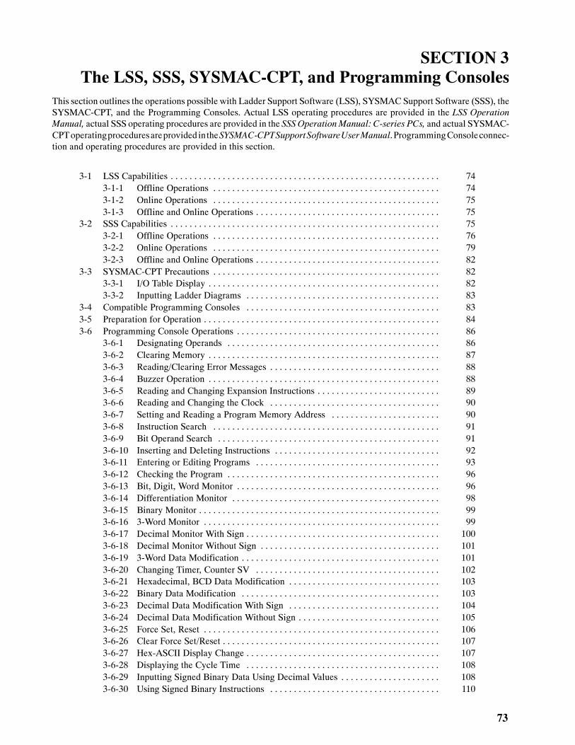
73
SECTION 3The LSS, SSS, SYSMAC-CPT, and Programming Consoles
This section outlines the operations possible with Ladder Support Software (LSS), SYSMAC Support Software (SSS), theSYSMAC-CPT, and the Programming Consoles. Actual LSS operating procedures are provided in the LSS OperationManual, actual SSS operating procedures are provided in the SSS OperationManual: C-series PCs, and actual SYSMAC-CPToperatingproceduresareprovided intheSYSMAC-CPTSupportSoftwareUserManual.ProgrammingConsoleconnec-tion and operating procedures are provided in this section.
3-1 LSS Capabilities 74. . . . . . . . . . . . . . . . . . . . . . . . . . . . . . . . . . . . . . . . . . . . . . . . . . . . . . . . .3-1-1 Offline Operations 74. . . . . . . . . . . . . . . . . . . . . . . . . . . . . . . . . . . . . . . . . . . . . . . .3-1-2 Online Operations 75. . . . . . . . . . . . . . . . . . . . . . . . . . . . . . . . . . . . . . . . . . . . . . . .3-1-3 Offline and Online Operations 75. . . . . . . . . . . . . . . . . . . . . . . . . . . . . . . . . . . . . . .
3-2 SSS Capabilities 75. . . . . . . . . . . . . . . . . . . . . . . . . . . . . . . . . . . . . . . . . . . . . . . . . . . . . . . . .3-2-1 Offline Operations 76. . . . . . . . . . . . . . . . . . . . . . . . . . . . . . . . . . . . . . . . . . . . . . . .3-2-2 Online Operations 79. . . . . . . . . . . . . . . . . . . . . . . . . . . . . . . . . . . . . . . . . . . . . . . .3-2-3 Offline and Online Operations 82. . . . . . . . . . . . . . . . . . . . . . . . . . . . . . . . . . . . . . .
3-3 SYSMAC-CPT Precautions 82. . . . . . . . . . . . . . . . . . . . . . . . . . . . . . . . . . . . . . . . . . . . . . . .3-3-1 I/O Table Display 82. . . . . . . . . . . . . . . . . . . . . . . . . . . . . . . . . . . . . . . . . . . . . . . . .3-3-2 Inputting Ladder Diagrams 83. . . . . . . . . . . . . . . . . . . . . . . . . . . . . . . . . . . . . . . . .
3-4 Compatible Programming Consoles 83. . . . . . . . . . . . . . . . . . . . . . . . . . . . . . . . . . . . . . . . .3-5 Preparation for Operation 84. . . . . . . . . . . . . . . . . . . . . . . . . . . . . . . . . . . . . . . . . . . . . . . . . .3-6 Programming Console Operations 86. . . . . . . . . . . . . . . . . . . . . . . . . . . . . . . . . . . . . . . . . . .
3-6-1 Designating Operands 86. . . . . . . . . . . . . . . . . . . . . . . . . . . . . . . . . . . . . . . . . . . . .3-6-2 Clearing Memory 87. . . . . . . . . . . . . . . . . . . . . . . . . . . . . . . . . . . . . . . . . . . . . . . . .3-6-3 Reading/Clearing Error Messages 88. . . . . . . . . . . . . . . . . . . . . . . . . . . . . . . . . . . .3-6-4 Buzzer Operation 88. . . . . . . . . . . . . . . . . . . . . . . . . . . . . . . . . . . . . . . . . . . . . . . . .3-6-5 Reading and Changing Expansion Instructions 89. . . . . . . . . . . . . . . . . . . . . . . . . .3-6-6 Reading and Changing the Clock 90. . . . . . . . . . . . . . . . . . . . . . . . . . . . . . . . . . . .3-6-7 Setting and Reading a Program Memory Address 90. . . . . . . . . . . . . . . . . . . . . . .3-6-8 Instruction Search 91. . . . . . . . . . . . . . . . . . . . . . . . . . . . . . . . . . . . . . . . . . . . . . . .3-6-9 Bit Operand Search 91. . . . . . . . . . . . . . . . . . . . . . . . . . . . . . . . . . . . . . . . . . . . . . .3-6-10 Inserting and Deleting Instructions 92. . . . . . . . . . . . . . . . . . . . . . . . . . . . . . . . . . .3-6-11 Entering or Editing Programs 93. . . . . . . . . . . . . . . . . . . . . . . . . . . . . . . . . . . . . . .3-6-12 Checking the Program 96. . . . . . . . . . . . . . . . . . . . . . . . . . . . . . . . . . . . . . . . . . . . .3-6-13 Bit, Digit, Word Monitor 96. . . . . . . . . . . . . . . . . . . . . . . . . . . . . . . . . . . . . . . . . . .3-6-14 Differentiation Monitor 98. . . . . . . . . . . . . . . . . . . . . . . . . . . . . . . . . . . . . . . . . . . .3-6-15 Binary Monitor 99. . . . . . . . . . . . . . . . . . . . . . . . . . . . . . . . . . . . . . . . . . . . . . . . . . .3-6-16 3-Word Monitor 99. . . . . . . . . . . . . . . . . . . . . . . . . . . . . . . . . . . . . . . . . . . . . . . . . .3-6-17 Decimal Monitor With Sign 100. . . . . . . . . . . . . . . . . . . . . . . . . . . . . . . . . . . . . . . . .3-6-18 Decimal Monitor Without Sign 101. . . . . . . . . . . . . . . . . . . . . . . . . . . . . . . . . . . . . .3-6-19 3-Word Data Modification 101. . . . . . . . . . . . . . . . . . . . . . . . . . . . . . . . . . . . . . . . . .3-6-20 Changing Timer, Counter SV 102. . . . . . . . . . . . . . . . . . . . . . . . . . . . . . . . . . . . . . .3-6-21 Hexadecimal, BCD Data Modification 103. . . . . . . . . . . . . . . . . . . . . . . . . . . . . . . .3-6-22 Binary Data Modification 103. . . . . . . . . . . . . . . . . . . . . . . . . . . . . . . . . . . . . . . . . .3-6-23 Decimal Data Modification With Sign 104. . . . . . . . . . . . . . . . . . . . . . . . . . . . . . . .3-6-24 Decimal Data Modification Without Sign 105. . . . . . . . . . . . . . . . . . . . . . . . . . . . . .3-6-25 Force Set, Reset 106. . . . . . . . . . . . . . . . . . . . . . . . . . . . . . . . . . . . . . . . . . . . . . . . . .3-6-26 Clear Force Set/Reset 107. . . . . . . . . . . . . . . . . . . . . . . . . . . . . . . . . . . . . . . . . . . . . .3-6-27 Hex-ASCII Display Change 107. . . . . . . . . . . . . . . . . . . . . . . . . . . . . . . . . . . . . . . . .3-6-28 Displaying the Cycle Time 108. . . . . . . . . . . . . . . . . . . . . . . . . . . . . . . . . . . . . . . . .3-6-29 Inputting Signed Binary Data Using Decimal Values 108. . . . . . . . . . . . . . . . . . . . .3-6-30 Using Signed Binary Instructions 110. . . . . . . . . . . . . . . . . . . . . . . . . . . . . . . . . . . .
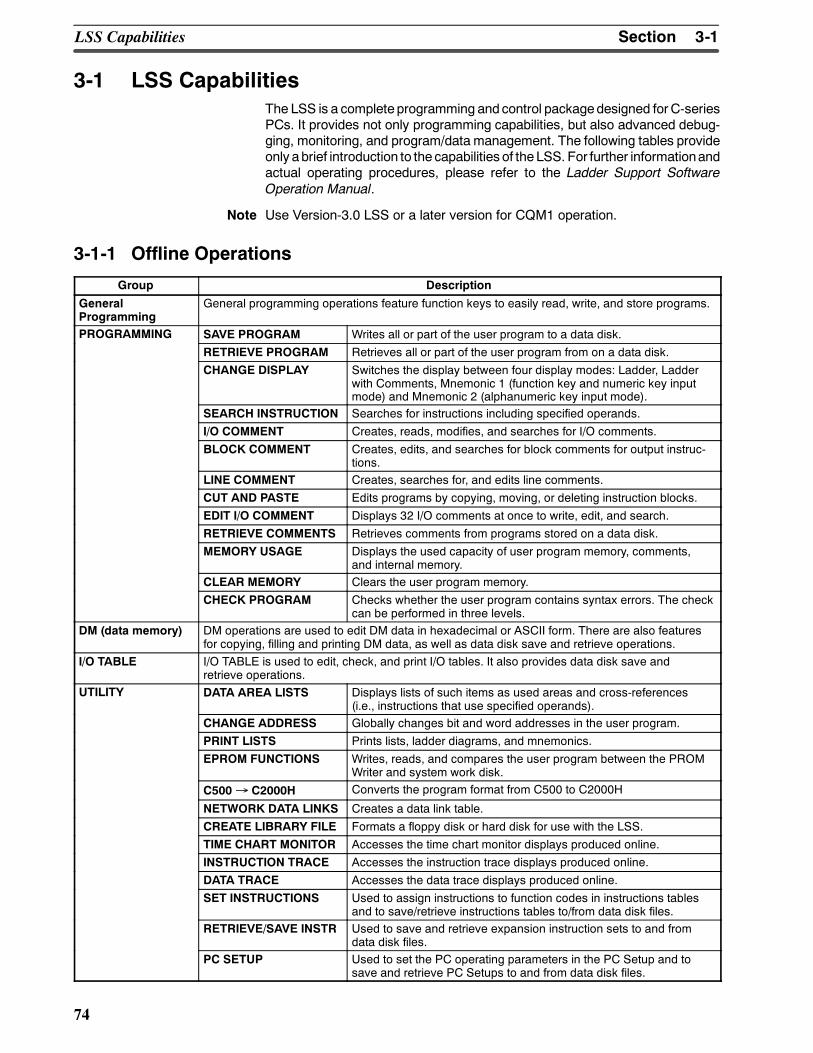
3-1SectionLSS Capabilities
74
3-1 LSS CapabilitiesThe LSS is a complete programming and control packagedesigned forC-seriesPCs. It provides not only programming capabilities, but also advanced debug-ging, monitoring, and program/data management. The following tables provideonly abrief introduction to the capabilities of theLSS. For further informationandactual operating procedures, please refer to the Ladder Support SoftwareOperation Manual.
Note Use Version-3.0 LSS or a later version for CQM1 operation.
3-1-1 Offline Operations
Group Description
GeneralProgramming
General programming operations feature function keys to easily read, write, and store programs.
PROGRAMMING SAVE PROGRAM Writes all or part of the user program to a data disk.
RETRIEVE PROGRAM Retrieves all or part of the user program from on a data disk.
CHANGE DISPLAY Switches the display between four display modes: Ladder, Ladderwith Comments, Mnemonic 1 (function key and numeric key inputmode) and Mnemonic 2 (alphanumeric key input mode).
SEARCH INSTRUCTION Searches for instructions including specified operands.
I/O COMMENT Creates, reads, modifies, and searches for I/O comments.
BLOCK COMMENT Creates, edits, and searches for block comments for output instruc-tions.
LINE COMMENT Creates, searches for, and edits line comments.
CUT AND PASTE Edits programs by copying, moving, or deleting instruction blocks.
EDIT I/O COMMENT Displays 32 I/O comments at once to write, edit, and search.
RETRIEVE COMMENTS Retrieves comments from programs stored on a data disk.
MEMORY USAGE Displays the used capacity of user program memory, comments,and internal memory.
CLEAR MEMORY Clears the user program memory.
CHECK PROGRAM Checks whether the user program contains syntax errors. The checkcan be performed in three levels.
DM (data memory) DM operations are used to edit DM data in hexadecimal or ASCII form. There are also featuresfor copying, filling and printing DM data, as well as data disk save and retrieve operations.
I/O TABLE I/O TABLE is used to edit, check, and print I/O tables. It also provides data disk save andretrieve operations.
UTILITY DATA AREA LISTS Displays lists of such items as used areas and cross-references(i.e., instructions that use specified operands).
CHANGE ADDRESS Globally changes bit and word addresses in the user program.
PRINT LISTS Prints lists, ladder diagrams, and mnemonics.
EPROM FUNCTIONS Writes, reads, and compares the user program between the PROMWriter and system work disk.
C500→ C2000H Converts the program format from C500 to C2000H
NETWORK DATA LINKS Creates a data link table.
CREATE LIBRARY FILE Formats a floppy disk or hard disk for use with the LSS.
TIME CHART MONITOR Accesses the time chart monitor displays produced online.
INSTRUCTION TRACE Accesses the instruction trace displays produced online.
DATA TRACE Accesses the data trace displays produced online.
SET INSTRUCTIONS Used to assign instructions to function codes in instructions tablesand to save/retrieve instructions tables to/from data disk files.
RETRIEVE/SAVE INSTR Used to save and retrieve expansion instruction sets to and fromdata disk files.
PC SETUP Used to set the PC operating parameters in the PC Setup and tosave and retrieve PC Setups to and from data disk files.
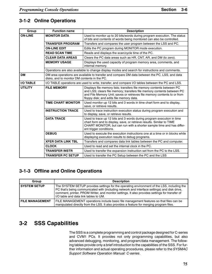
3-6SectionProgramming Console Operations
75
3-1-2 Online Operations
Group Function name Description
ON-LINE MONITOR DATA Used to monitor up to 20 bits/words during program execution. The statusof bits and contents of words being monitored can also be controlled.
TRANSFER PROGRAM Transfers and compares the user program between the LSS and PC.
ON-LINE EDIT Edits the PC program during MONITOR mode execution.
READ SCAN TIME Reads and displays the scan/cycle time of the PC.
CLEAR DATA AREAS Clears the PC data areas such as HR, CNT, AR, and DM (to zero).
MEMORY USAGE Displays the used capacity of program memory area, comments, andinternal memory.
Operations are also available to change display modes and search for instructions and comments.
DM DM area operations are available to transfer and compare DM data between the PC, LSS, and datadisks, and to monitor DM contents in the PC.
I/O TABLE I/O TABLE operations are used to write, transfer, and compare I/O tables between the PC and LSS.
UTILITY FILE MEMORY Displays file memory lists; transfers file memory contents between PCand LSS; clears file memory; transfers file memory contents between PCand File Memory Unit; saves or retrieves file memory contents to or fromfloppy disk; and edits file memory data.
TIME CHART MONITOR Used monitor up 12 bits and 3 words in time chart form and to display,save, or retrieve results.
INSTRUCTION TRACE Used to trace instruction execution status during program execution andto display, save, or retrieve results.
DATA TRACE Used to trace up 12 bits and 3 words during program execution in timechart form and to display, save, or retrieve results. Similar to TIMECHART MONITOR, but can run with a shorter sample time and has differ-ent trigger conditions.
DEBUG Used to execute the execution instructions one at a time or in blocks whiledisplaying execution results to debug programs.
XFER DATA LINK TBL Transfers and compares data link tables between the PC and computer.
CLOCK Used to read and set the internal clock in the PC.
TRANSFER INSTR Used to transfer the expansion instruction set from the PC to the LSS.
TRANSFER PC SETUP Used to transfer the PC Setup between the PC and the LSS
3-1-3 Offline and Online Operations
Group Description
SYSTEM SETUP The SYSTEM SETUP provides settings for the operating environment of the LSS, including thePC thats being communicated with (including network and interface settings) and disk drive,comment, printer, PROM Writer, and monitor settings. It also provides settings for transfer ofI/O table and data link tables to UM.
FILE MANAGEMENT FILE MANAGEMENT operations include basic file management features so that files can bemanipulated directly from the LSS. It also provides a feature for merging program files.
3-2 SSS Capabilities
TheSSS is a complete programmingand control packagedesigned forC-seriesand CVM1 PCs. It provides not only programming capabilities, but alsoadvanced debugging, monitoring, and program/data management. The follow-ing tables provide only a brief introduction to the capabilities of the SSS. For fur-ther information and actual operating procedures, please refer to the SYSMACSupport Software Operation Manual: C-series.
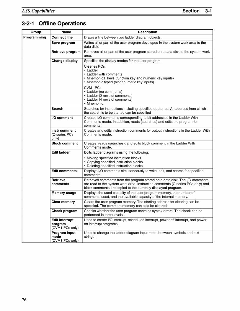
3-1SectionLSS Capabilities
76
3-2-1 Offline OperationsGroup Name Description
Programming Connect line Draws a line between two ladder diagram objects.g g
Save program Writes all or part of the user program developed in the system work area to thedata disk.
Retrieve program Retrieves all or part of the user program stored on a data disk to the system workarea.
Change display Specifies the display modes for the user program.
C-series PCs• Ladder• Ladder with comments• Mnemonic F keys (function key and numeric key inputs)• Mnemonic typed (alphanumeric key inputs)
CVM1 PCs• Ladder (no comments)• Ladder (2 rows of comments)• Ladder (4 rows of comments)• Mnemonic
Search Searches for instructions including specified operands. An address from whichthe search is to be started can be specified
I/O comment Creates I/O comments corresponding to bit addresses in the Ladder WithComments mode. In addition, reads (searches) and edits the program forcomments.
Instr comment(C-series PCsonly)
Creates and edits instruction comments for output instructions in the Ladder WithComments mode.
Block comment Creates, reads (searches), and edits block comment in the Ladder WithComments mode.
Edit ladder Edits ladder diagrams using the following:
• Moving specified instruction blocks• Copying specified instruction blocks• Deleting specified instruction blocks
Edit comments Displays I/O comments simultaneously to write, edit, and search for specifiedcomments.
Retrievecomments
Retrieves comments from the program stored on a data disk. The I/O commentsare read to the system work area. Instruction comments (C-series PCs only) andblock comments are copied to the currently displayed program.
Memory usage Displays the used capacity of the user program memory, the number ofcomments used, and the available capacity of the internal memory.
Clear memory Clears the user program memory. The starting address for clearing can bespecified. The comment memory can also be cleared
Check program Checks whether the user program contains syntax errors. The check can beperformed in three levels.
Edit interruptprogram(CVM1 PCs only)
Used to create I/O interrupt, scheduled interrupt, power off interrupt, and poweron interrupt programs.
Program inputmode(CVM1 PCs only)
Used to change the ladder diagram input mode between symbols and textstrings.
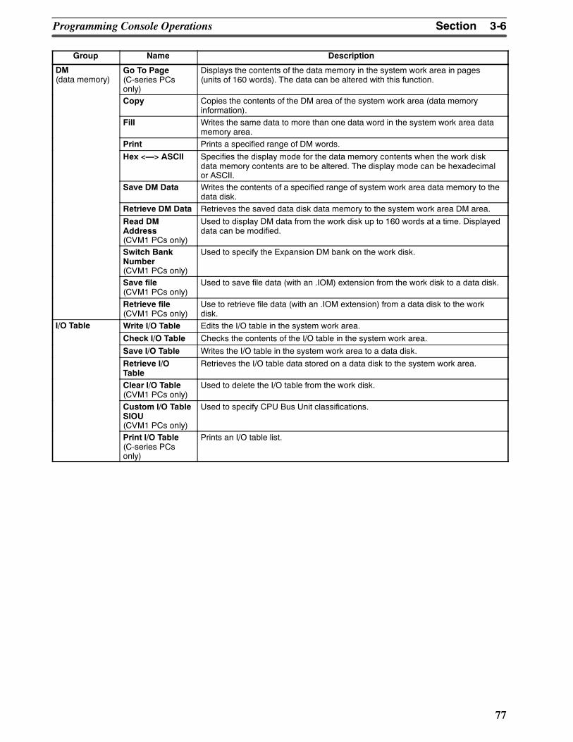
3-6SectionProgramming Console Operations
77
Group DescriptionName
DM(data memory)
Go To Page(C-series PCsonly)
Displays the contents of the data memory in the system work area in pages(units of 160 words). The data can be altered with this function.
Copy Copies the contents of the DM area of the system work area (data memoryinformation).
Fill Writes the same data to more than one data word in the system work area datamemory area.
Print Prints a specified range of DM words.
Hex <> ASCII Specifies the display mode for the data memory contents when the work diskdata memory contents are to be altered. The display mode can be hexadecimalor ASCII.
Save DM Data Writes the contents of a specified range of system work area data memory to thedata disk.
Retrieve DM Data Retrieves the saved data disk data memory to the system work area DM area.
Read DMAddress(CVM1 PCs only)
Used to display DM data from the work disk up to 160 words at a time. Displayeddata can be modified.
Switch BankNumber(CVM1 PCs only)
Used to specify the Expansion DM bank on the work disk.
Save file(CVM1 PCs only)
Used to save file data (with an .IOM) extension from the work disk to a data disk.
Retrieve file(CVM1 PCs only)
Use to retrieve file data (with an .IOM extension) from a data disk to the workdisk.
I/O Table Write I/O Table Edits the I/O table in the system work area./
Check I/O Table Checks the contents of the I/O table in the system work area.
Save I/O Table Writes the I/O table in the system work area to a data disk.
Retrieve I/OTable
Retrieves the I/O table data stored on a data disk to the system work area.
Clear I/O Table(CVM1 PCs only)
Used to delete the I/O table from the work disk.
Custom I/O TableSIOU(CVM1 PCs only)
Used to specify CPU Bus Unit classifications.
Print I/O Table(C-series PCsonly)
Prints an I/O table list.
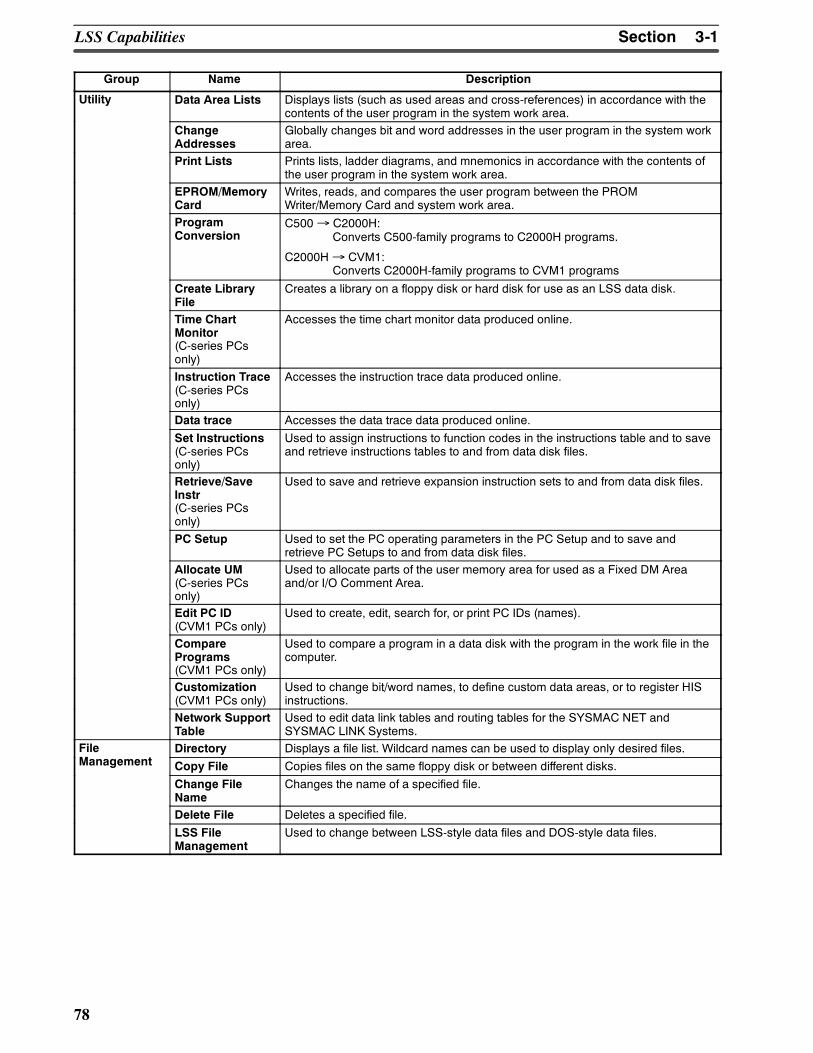
3-1SectionLSS Capabilities
78
Group DescriptionName
Utility Data Area Lists Displays lists (such as used areas and cross-references) in accordance with thecontents of the user program in the system work area.
ChangeAddresses
Globally changes bit and word addresses in the user program in the system workarea.
Print Lists Prints lists, ladder diagrams, and mnemonics in accordance with the contents ofthe user program in the system work area.
EPROM/MemoryCard
Writes, reads, and compares the user program between the PROMWriter/Memory Card and system work area.
ProgramConversion
C500→ C2000H:Converts C500-family programs to C2000H programs.
C2000H→ CVM1:Converts C2000H-family programs to CVM1 programs
Create LibraryFile
Creates a library on a floppy disk or hard disk for use as an LSS data disk.
Time ChartMonitor(C-series PCsonly)
Accesses the time chart monitor data produced online.
Instruction Trace(C-series PCsonly)
Accesses the instruction trace data produced online.
Data trace Accesses the data trace data produced online.
Set Instructions(C-series PCsonly)
Used to assign instructions to function codes in the instructions table and to saveand retrieve instructions tables to and from data disk files.
Retrieve/SaveInstr(C-series PCsonly)
Used to save and retrieve expansion instruction sets to and from data disk files.
PC Setup Used to set the PC operating parameters in the PC Setup and to save andretrieve PC Setups to and from data disk files.
Allocate UM(C-series PCsonly)
Used to allocate parts of the user memory area for used as a Fixed DM Areaand/or I/O Comment Area.
Edit PC ID(CVM1 PCs only)
Used to create, edit, search for, or print PC IDs (names).
ComparePrograms(CVM1 PCs only)
Used to compare a program in a data disk with the program in the work file in thecomputer.
Customization(CVM1 PCs only)
Used to change bit/word names, to define custom data areas, or to register HISinstructions.
Network SupportTable
Used to edit data link tables and routing tables for the SYSMAC NET andSYSMAC LINK Systems.
File Directory Displays a file list. Wildcard names can be used to display only desired files.Management Copy File Copies files on the same floppy disk or between different disks.
Change FileName
Changes the name of a specified file.
Delete File Deletes a specified file.
LSS FileManagement
Used to change between LSS-style data files and DOS-style data files.
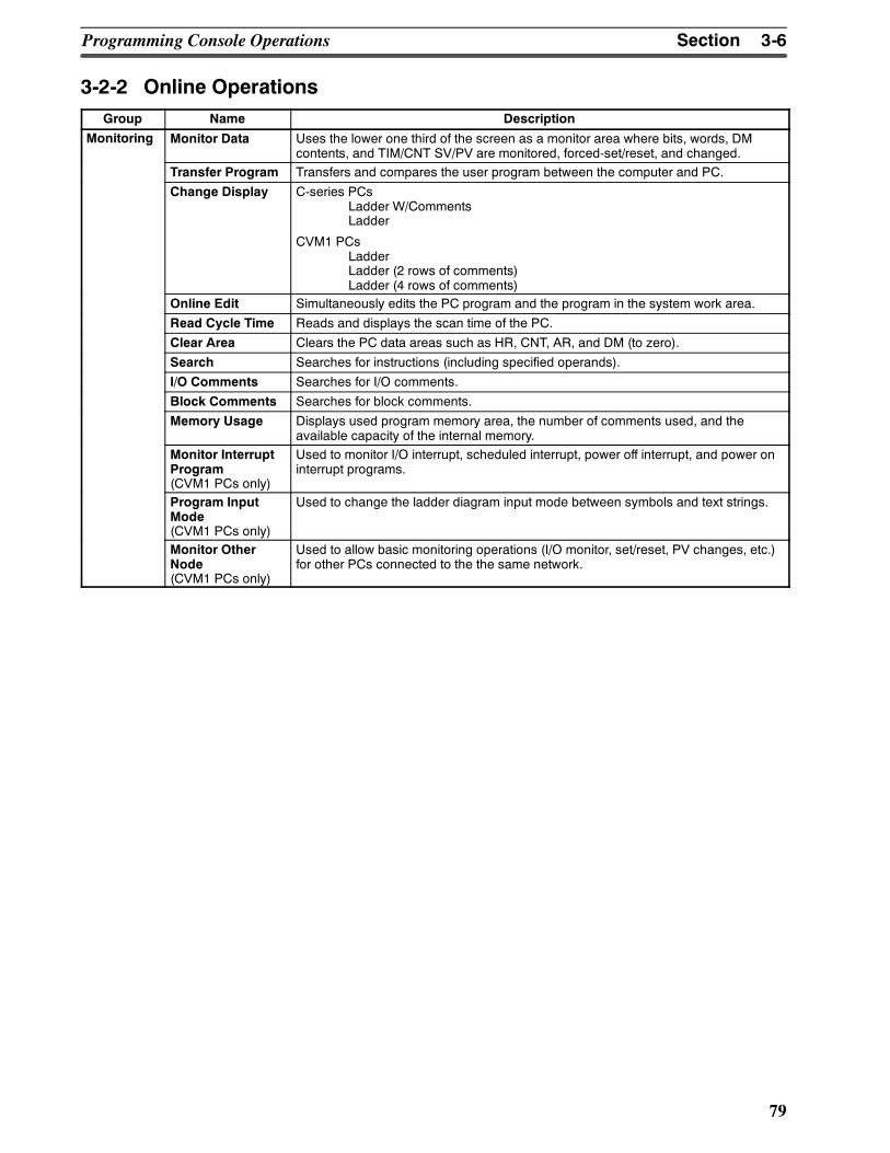
3-6SectionProgramming Console Operations
79
3-2-2 Online OperationsGroup Name Description
Monitoring Monitor Data Uses the lower one third of the screen as a monitor area where bits, words, DMcontents, and TIM/CNT SV/PV are monitored, forced-set/reset, and changed.
Transfer Program Transfers and compares the user program between the computer and PC.
Change Display C-series PCsLadder W/CommentsLadder
CVM1 PCsLadderLadder (2 rows of comments)Ladder (4 rows of comments)
Online Edit Simultaneously edits the PC program and the program in the system work area.
Read Cycle Time Reads and displays the scan time of the PC.
Clear Area Clears the PC data areas such as HR, CNT, AR, and DM (to zero).
Search Searches for instructions (including specified operands).
I/O Comments Searches for I/O comments.
Block Comments Searches for block comments.
Memory Usage Displays used program memory area, the number of comments used, and theavailable capacity of the internal memory.
Monitor InterruptProgram(CVM1 PCs only)
Used to monitor I/O interrupt, scheduled interrupt, power off interrupt, and power oninterrupt programs.
Program InputMode(CVM1 PCs only)
Used to change the ladder diagram input mode between symbols and text strings.
Monitor OtherNode(CVM1 PCs only)
Used to allow basic monitoring operations (I/O monitor, set/reset, PV changes, etc.)for other PCs connected to the the same network.
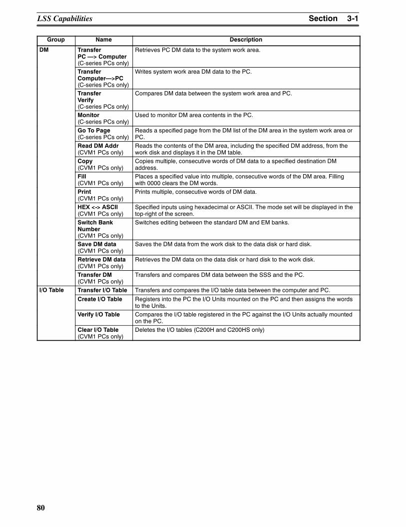
3-1SectionLSS Capabilities
80
Group DescriptionName
DM TransferPC > Computer(C-series PCs only)
Retrieves PC DM data to the system work area.
TransferComputer>PC(C-series PCs only)
Writes system work area DM data to the PC.
TransferVerify(C-series PCs only)
Compares DM data between the system work area and PC.
Monitor(C-series PCs only)
Used to monitor DM area contents in the PC.
Go To Page(C-series PCs only)
Reads a specified page from the DM list of the DM area in the system work area orPC.
Read DM Addr(CVM1 PCs only)
Reads the contents of the DM area, including the specified DM address, from thework disk and displays it in the DM table.
Copy(CVM1 PCs only)
Copies multiple, consecutive words of DM data to a specified destination DMaddress.
Fill(CVM1 PCs only)
Places a specified value into multiple, consecutive words of the DM area. Fillingwith 0000 clears the DM words.
Print(CVM1 PCs only)
Prints multiple, consecutive words of DM data.
HEX <-> ASCII(CVM1 PCs only)
Specified inputs using hexadecimal or ASCII. The mode set will be displayed in thetop-right of the screen.
Switch BankNumber(CVM1 PCs only)
Switches editing between the standard DM and EM banks.
Save DM data(CVM1 PCs only)
Saves the DM data from the work disk to the data disk or hard disk.
Retrieve DM data(CVM1 PCs only)
Retrieves the DM data on the data disk or hard disk to the work disk.
Transfer DM(CVM1 PCs only)
Transfers and compares DM data between the SSS and the PC.
I/O Table Transfer I/O Table Transfers and compares the I/O table data between the computer and PC./
Create I/O Table Registers into the PC the I/O Units mounted on the PC and then assigns the wordsto the Units.
Verify I/O Table Compares the I/O table registered in the PC against the I/O Units actually mountedon the PC.
Clear I/O Table(CVM1 PCs only)
Deletes the I/O tables (C200H and C200HS only)
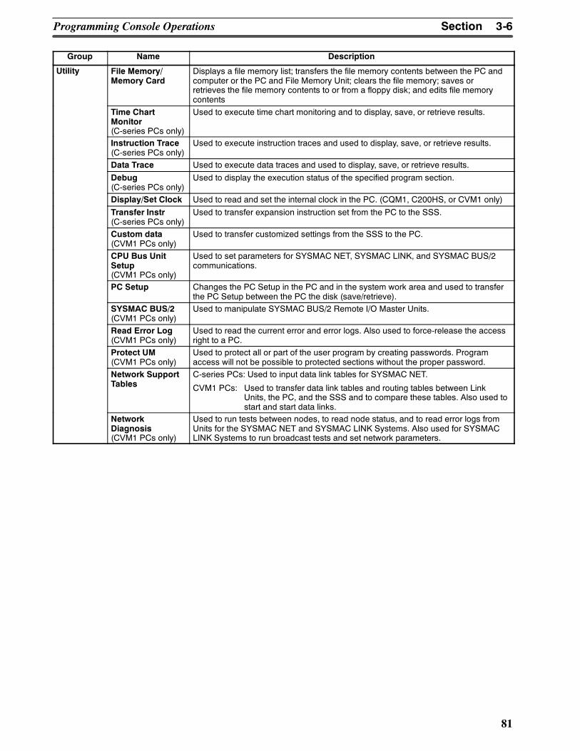
3-6SectionProgramming Console Operations
81
Group DescriptionName
Utility File Memory/Memory Card
Displays a file memory list; transfers the file memory contents between the PC andcomputer or the PC and File Memory Unit; clears the file memory; saves orretrieves the file memory contents to or from a floppy disk; and edits file memorycontents
Time ChartMonitor(C-series PCs only)
Used to execute time chart monitoring and to display, save, or retrieve results.
Instruction Trace(C-series PCs only)
Used to execute instruction traces and used to display, save, or retrieve results.
Data Trace Used to execute data traces and used to display, save, or retrieve results.
Debug(C-series PCs only)
Used to display the execution status of the specified program section.
Display/Set Clock Used to read and set the internal clock in the PC. (CQM1, C200HS, or CVM1 only)
Transfer Instr(C-series PCs only)
Used to transfer expansion instruction set from the PC to the SSS.
Custom data(CVM1 PCs only)
Used to transfer customized settings from the SSS to the PC.
CPU Bus UnitSetup(CVM1 PCs only)
Used to set parameters for SYSMAC NET, SYSMAC LINK, and SYSMAC BUS/2communications.
PC Setup Changes the PC Setup in the PC and in the system work area and used to transferthe PC Setup between the PC the disk (save/retrieve).
SYSMAC BUS/2(CVM1 PCs only)
Used to manipulate SYSMAC BUS/2 Remote I/O Master Units.
Read Error Log(CVM1 PCs only)
Used to read the current error and error logs. Also used to force-release the accessright to a PC.
Protect UM(CVM1 PCs only)
Used to protect all or part of the user program by creating passwords. Programaccess will not be possible to protected sections without the proper password.
Network SupportTables
C-series PCs: Used to input data link tables for SYSMAC NET.
CVM1 PCs: Used to transfer data link tables and routing tables between LinkUnits, the PC, and the SSS and to compare these tables. Also used tostart and start data links.
NetworkDiagnosis(CVM1 PCs only)
Used to run tests between nodes, to read node status, and to read error logs fromUnits for the SYSMAC NET and SYSMAC LINK Systems. Also used for SYSMACLINK Systems to run broadcast tests and set network parameters.
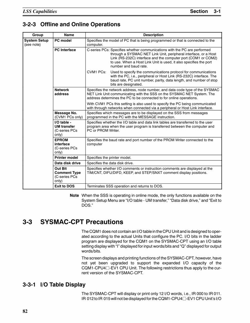
3-1SectionLSS Capabilities
82
3-2-3 Offline and Online Operations
Group Name Description
System Setup(see note)
PC model Specifies the model of PC that is being programmed or that is connected to thecomputer.(see note)
PC Interface C-series PCs: Specifies whether communications with the PC are performedthrough a SYSMAC NET Link Unit, peripheral interface, or a HostLink (RS-232C) interface and the computer port (COM1 or COM2)to use. When a Host Link Unit is used, it also specifies the portnumber and baud rate.
CVM1 PCs: Used to specify the communications protocol for communicationswith the PC, i.e., peripheral or Host Link (RS-232C) interface. Thebaud rate, PC unit number, parity, data length, and number of stopbits are designated.
Networkaddress
Specifies the network address, node number, and data code type of the SYSMACNET Link Unit communicating with the SSS on the SYSMAC NET System. Theaddress determines the PC to be connected to for online operations.
With CVM1 PCs this setting is also used to specify the PC being communicatedwith through networks when connected via a peripheral or Host Link interface.
Message No.(CVM1 PCs only)
Specifies which messages are to be displayed on the SSS from messagesprogrammed in the PC with the MESSAGE instruction.
I/O table -UM transfer(C-series PCsonly)
Specifies whether the I/O table and data link tables are transferred to the userprogram area when the user program is transferred between the computer andPC or PROM Writer.
EPROMinterface(C-series PCsonly)
Specifies the baud rate and port number of the PROM Writer connected to thecomputer
Printer model Specifies the printer model.
Data disk drive Specifies the data disk drive.
Out BitComment Type(C-series PCsonly)
Specifies whether I/O comments or instruction comments are displayed at theTIM/CNT, DIFU/DIFD, KEEP, and STEP/SNXT comment display positions.
Exit to DOS Terminates SSS operation and returns to DOS.
Note When the SSS is operating in online mode, the only functions available on theSystem Setup Menu are I/O table - UM transfer, Data disk drive, and Exit toDOS.
3-3 SYSMAC-CPT PrecautionsTheCQM1does not contain an I/O table in theCPUUnit and isdesigned tooper-ated according to the actual Units that configure the PC. I/O bits in the ladderprogram are displayed for the CQM1 on the SYSMAC-CPT using an I/O tablesetting displaywith I displayed for input words/bits and Q displayed for outputwords/bits.
The screendisplays andprinting functions of theSYSMAC-CPT, however, havenot yet been upgraded to support the expanded I/O capacity of theCQM1-CPU4j-EV1 CPU Unit. The following restrictions thus apply to the cur-rent version of the SYSMAC-CPT.
3-3-1 I/O Table DisplayThe SYSMAC-CPT will display or print only 12 I/O words, i.e., IR 000 to IR 011.IR 012 to IR 015will not bedisplayed for theCQM1-CPU4j-EV1CPUUnits I/O
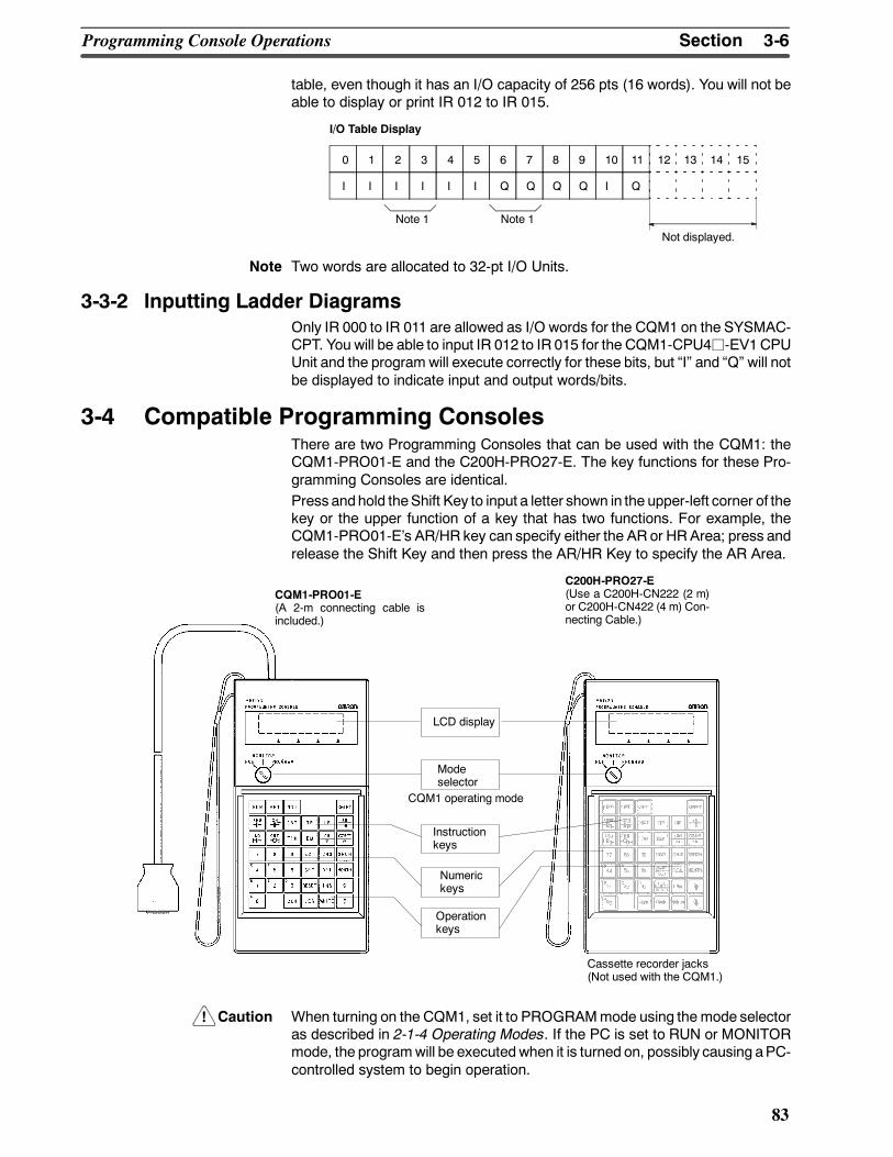
!
3-6SectionProgramming Console Operations
83
table, even though it has an I/O capacity of 256 pts (16 words). You will not beable to display or print IR 012 to IR 015.
0 1 2 3 4 5 6 7 8 9 10 11 12 13 14 15
I I I I I I Q Q Q Q I Q
I/O Table Display
Not displayed.
Note 1 Note 1
Note Two words are allocated to 32-pt I/O Units.
3-3-2 Inputting Ladder DiagramsOnly IR 000 to IR 011 are allowed as I/O words for the CQM1 on the SYSMAC-CPT. You will be able to input IR 012 to IR 015 for the CQM1-CPU4j-EV1CPUUnit and the program will execute correctly for these bits, but I and Q will notbe displayed to indicate input and output words/bits.
3-4 Compatible Programming ConsolesThere are two Programming Consoles that can be used with the CQM1: theCQM1-PRO01-E and the C200H-PRO27-E. The key functions for these Pro-gramming Consoles are identical.Press andhold theShift Key to input a letter shown in the upper-left corner of thekey or the upper function of a key that has two functions. For example, theCQM1-PRO01-Es AR/HR key can specify either the AR or HRArea; press andrelease the Shift Key and then press the AR/HR Key to specify the AR Area.
CQM1-PRO01-E(A 2-m connecting cable isincluded.)
C200H-PRO27-E(Use a C200H-CN222 (2 m)or C200H-CN422 (4 m) Con-necting Cable.)
LCD display
Modeselector
CQM1 operating mode
Instructionkeys
Numerickeys
Operationkeys
Cassette recorder jacks(Not used with the CQM1.)
Caution When turning on the CQM1, set it to PROGRAMmode using the mode selectoras described in 2-1-4 Operating Modes. If the PC is set to RUN or MONITORmode, the programwill be executedwhen it is turned on, possibly causing aPC-controlled system to begin operation.
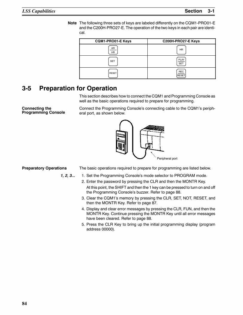
3-1SectionLSS Capabilities
84
Note The following three sets of keys are labeled differently on the CQM1-PRO01-Eand the C200H-PRO27-E. The operation of the two keys in each pair are identi-cal.
CQM1-PRO01-E Keys C200H-PRO27-E Keys
AR
HRHR
SET PLAY
SET
RESETREC
RESET
3-5 Preparation for OperationThis section describes how to connect theCQM1andProgrammingConsole aswell as the basic operations required to prepare for programming.
Connect the Programming Consoles connecting cable to the CQM1s periph-eral port, as shown below.
Peripheral port
Preparatory Operations The basic operations required to prepare for programming are listed below.
1, 2, 3... 1. Set the Programming Consoles mode selector to PROGRAM mode.2. Enter the password by pressing the CLR and then the MONTR Key.At this point, the SHIFT and then the 1 key can be pressed to turn on and offthe Programming Consoles buzzer. Refer to page 88.
3. Clear the CQM1s memory by pressing the CLR, SET, NOT, RESET, andthen the MONTR Key. Refer to page 87.
4. Display and clear error messages by pressing the CLR, FUN, and then theMONTR Key. Continue pressing the MONTR Key until all error messageshave been cleared. Refer to page 88.
5. Press the CLR Key to bring up the initial programming display (programaddress 00000).
Connecting theProgramming Console
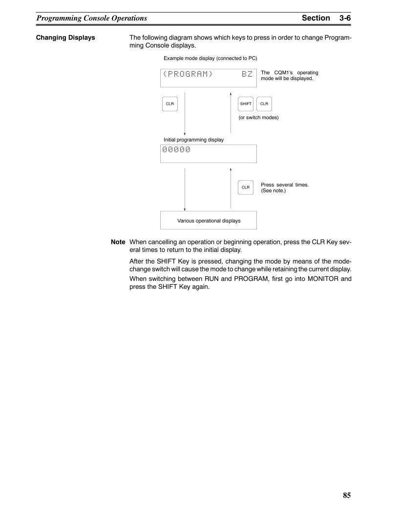
3-6SectionProgramming Console Operations
85
Changing Displays The following diagram shows which keys to press in order to change Program-ming Console displays.
Example mode display (connected to PC)
The CQM1s operatingmode will be displayed.
Initial programming display
Press several times.(See note.)
(or switch modes)
Various operational displays
PROGRAM BZ
CLR SHIFT CLR
CLR
00000
Note When cancelling an operation or beginning operation, press the CLR Key sev-eral times to return to the initial display.
After the SHIFT Key is pressed, changing the mode by means of the mode-change switchwill cause themode to changewhile retaining the current display.When switching between RUN and PROGRAM, first go into MONITOR andpress the SHIFT Key again.
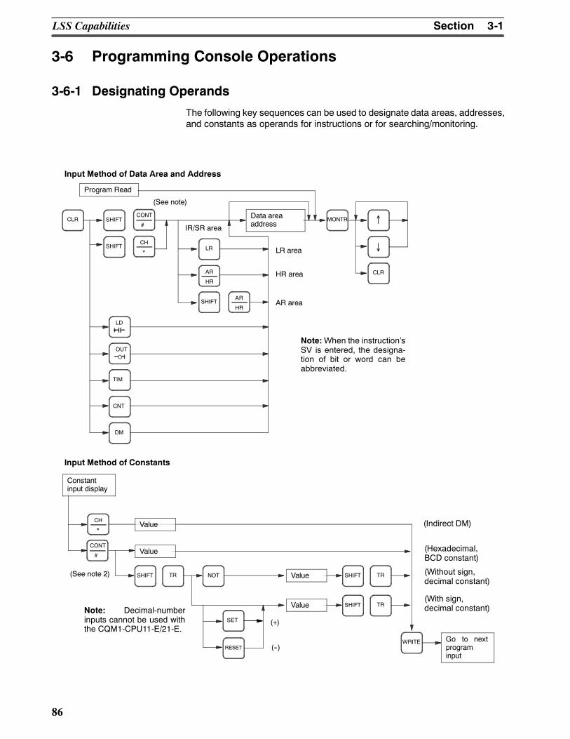
3-1SectionLSS Capabilities
86
3-6 Programming Console Operations
3-6-1 Designating Operands
The following key sequences can be used to designate data areas, addresses,and constants as operands for instructions or for searching/monitoring.
Program Read
CLR SHIFTCONT
#
CH
*SHIFT LR
AR
HR
SHIFTAR
HR
MONTR ↑
↓
CLR
LD
OUT
TIM
CNT
DM
Data areaaddress
HR area
AR area
Input Method of Data Area and Address
Input Method of Constants
(See note)
Note:When the instructionsSV is entered, the designa-tion of bit or word can beabbreviated.
CH
*
CONT
#(Hexadecimal,BCD constant)
(Without sign,decimal constant)
(With sign,decimal constant)
(Indirect DM)
SET
SHIFT TR NOT
RESET
SHIFT TRValue
SHIFT TRValue
Value
(+)
(--)
(See note 2)
WRITE
Value
Constantinput display
Go to nextprograminput
Note: Decimal-numberinputs cannot be used withthe CQM1-CPU11-E/21-E.
IR/SR area
LR area
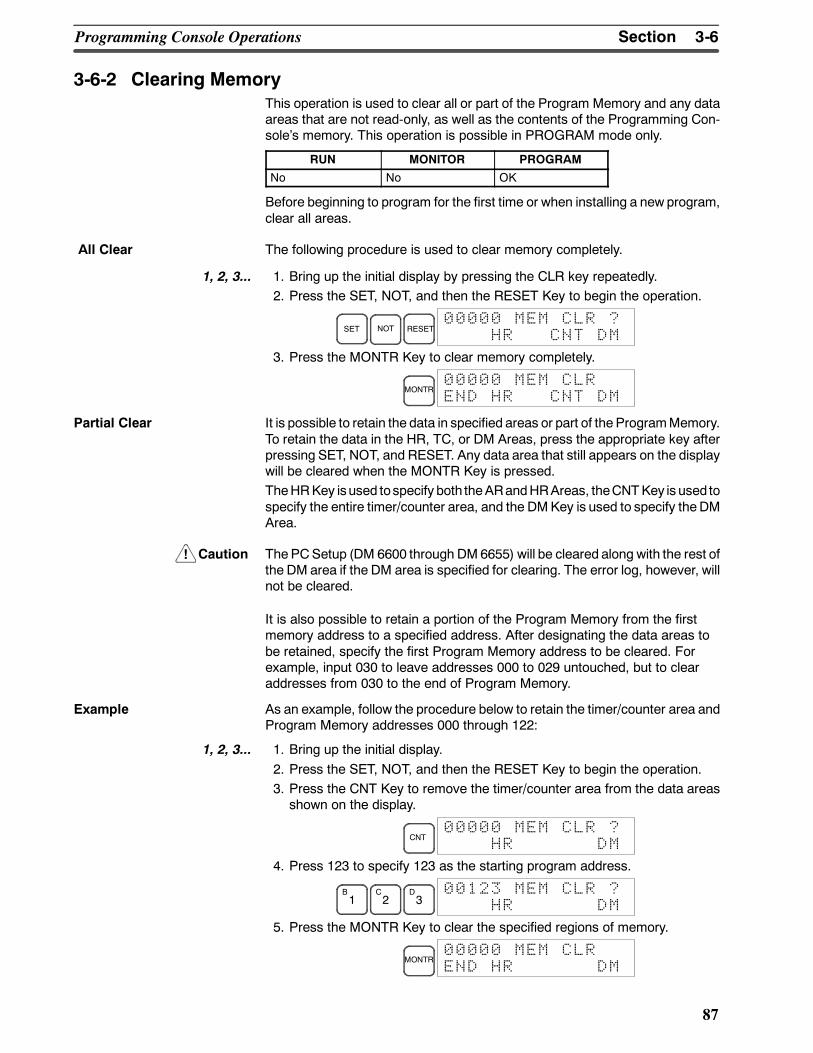
!
3-6SectionProgramming Console Operations
87
3-6-2 Clearing MemoryThis operation is used to clear all or part of the Program Memory and any dataareas that are not read-only, as well as the contents of the Programming Con-soles memory. This operation is possible in PROGRAM mode only.
RUN MONITOR PROGRAM
No No OK
Before beginning to program for the first time or when installing a new program,clear all areas.
The following procedure is used to clear memory completely.
1, 2, 3... 1. Bring up the initial display by pressing the CLR key repeatedly.2. Press the SET, NOT, and then the RESET Key to begin the operation.
SET NOT RESET00000 MEM CLR ?
HR CNT DM
3. Press the MONTR Key to clear memory completely.
MONTR00000 MEM CLREND HR CNT DM
Partial Clear It is possible to retain the data in specified areas or part of the ProgramMemory.To retain the data in the HR, TC, or DM Areas, press the appropriate key afterpressing SET, NOT, and RESET. Any data area that still appears on the displaywill be cleared when the MONTR Key is pressed.TheHRKey isused tospecify both theARandHRAreas, theCNTKey is used tospecify the entire timer/counter area, and the DMKey is used to specify theDMArea.
Caution ThePCSetup (DM 6600 through DM6655) will be cleared along with the rest ofthe DM area if the DM area is specified for clearing. The error log, however, willnot be cleared.
It is also possible to retain a portion of the Program Memory from the firstmemory address to a specified address. After designating the data areas tobe retained, specify the first Program Memory address to be cleared. Forexample, input 030 to leave addresses 000 to 029 untouched, but to clearaddresses from 030 to the end of Program Memory.
Example As an example, follow the procedure below to retain the timer/counter area andProgram Memory addresses 000 through 122:
1, 2, 3... 1. Bring up the initial display.2. Press the SET, NOT, and then the RESET Key to begin the operation.3. Press the CNT Key to remove the timer/counter area from the data areasshown on the display.
CNT00000 MEM CLR ?
HR DM
4. Press 123 to specify 123 as the starting program address.
B1
C2
D3
00123 MEM CLR ?HR DM
5. Press the MONTR Key to clear the specified regions of memory.
MONTR00000 MEM CLREND HR DM
All Clear
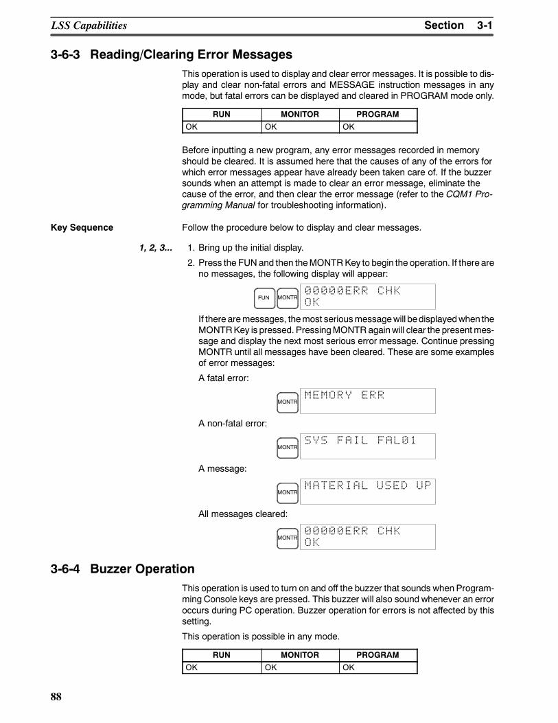
3-1SectionLSS Capabilities
88
3-6-3 Reading/Clearing Error MessagesThis operation is used to display and clear error messages. It is possible to dis-play and clear non-fatal errors and MESSAGE instruction messages in anymode, but fatal errors can be displayed and cleared in PROGRAM mode only.
RUN MONITOR PROGRAM
OK OK OK
Before inputting a new program, any error messages recorded in memoryshould be cleared. It is assumed here that the causes of any of the errors forwhich error messages appear have already been taken care of. If the buzzersounds when an attempt is made to clear an error message, eliminate thecause of the error, and then clear the error message (refer to the CQM1 Pro-gramming Manual for troubleshooting information).
Key Sequence Follow the procedure below to display and clear messages.
1, 2, 3... 1. Bring up the initial display.
2. Press the FUNand then theMONTRKey to begin the operation. If there areno messages, the following display will appear:
FUN MONTR00000ERR CHKOK
If there aremessages, themost seriousmessagewill bedisplayedwhen theMONTRKey is pressed. PressingMONTRagainwill clear the presentmes-sage and display the next most serious error message. Continue pressingMONTR until all messages have been cleared. These are some examplesof error messages:
A fatal error:
MONTRMEMORY ERR
A non-fatal error:
MONTRSYS FAIL FAL01
A message:
MONTRMATERIAL USED UP
All messages cleared:
MONTR00000ERR CHKOK
3-6-4 Buzzer OperationThis operation is used to turn on and off the buzzer that sounds whenProgram-ming Console keys are pressed. This buzzer will also sound whenever an erroroccurs during PC operation. Buzzer operation for errors is not affected by thissetting.
This operation is possible in any mode.
RUN MONITOR PROGRAM
OK OK OK
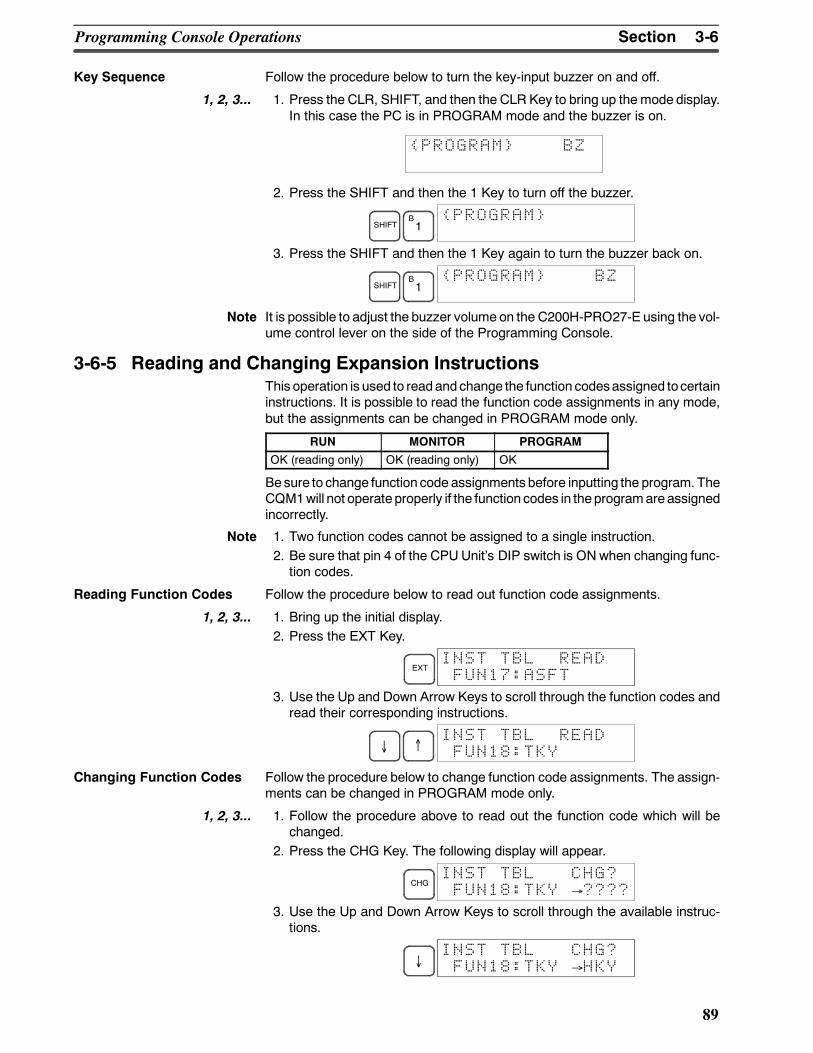
3-6SectionProgramming Console Operations
89
Key Sequence Follow the procedure below to turn the key-input buzzer on and off.
1, 2, 3... 1. Press the CLR, SHIFT, and then the CLR Key to bring up the mode display.In this case the PC is in PROGRAM mode and the buzzer is on.
PROGRAM BZ
2. Press the SHIFT and then the 1 Key to turn off the buzzer.
SHIFTB1
PROGRAM
3. Press the SHIFT and then the 1 Key again to turn the buzzer back on.
SHIFTB1
PROGRAM BZ
Note It is possible to adjust the buzzer volume on the C200H-PRO27-E using the vol-ume control lever on the side of the Programming Console.
3-6-5 Reading and Changing Expansion InstructionsThis operation is used to readand change the function codesassigned tocertaininstructions. It is possible to read the function code assignments in any mode,but the assignments can be changed in PROGRAM mode only.
RUN MONITOR PROGRAM
OK (reading only) OK (reading only) OK
Besure to change function code assignments before inputting the program. TheCQM1will not operate properly if the function codes in theprogramareassignedincorrectly.
Note 1. Two function codes cannot be assigned to a single instruction.2. Be sure that pin 4 of the CPUUnits DIP switch is ONwhen changing func-tion codes.
Reading Function Codes Follow the procedure below to read out function code assignments.
1, 2, 3... 1. Bring up the initial display.2. Press the EXT Key.
EXTINST TBL READFUN17:ASFT
3. Use the Up and Down Arrow Keys to scroll through the function codes andread their corresponding instructions.
↓ ↑FUN18:TKY
INST TBL READ
Changing Function Codes Follow the procedure below to change function code assignments. The assign-ments can be changed in PROGRAM mode only.
1, 2, 3... 1. Follow the procedure above to read out the function code which will bechanged.
2. Press the CHG Key. The following display will appear.
CHGFUN18:TKY →????
INST TBL CHG?
3. Use the Up and Down Arrow Keys to scroll through the available instruc-tions.
↓ FUN18:TKY →HKYINST TBL CHG?
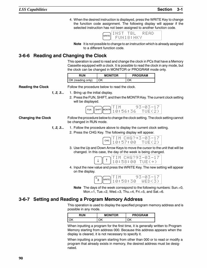
3-1SectionLSS Capabilities
90
4. When the desired instruction is displayed, press the WRITE Key to changethe function code assignment. The following display will appear if theselected instruction has not been assigned to another function code.
WRITEINST TBL READFUN18:HKY
Note It is not possible to change to an instructionwhich is already assignedto a different function code.
3-6-6 Reading and Changing the ClockThis operation is used to read and change the clock in PCs that have aMemoryCassette equipped with a clock. It is possible to read the clock in any mode, butthe clock can be changed in MONITOR or PROGRAM mode only.
RUN MONITOR PROGRAM
OK (reading only) OK OK
Reading the Clock Follow the procedure below to read the clock.
1, 2, 3... 1. Bring up the initial display.2. Press the FUN, SHIFT, and then theMONTRKey. The current clock settingwill be displayed.
FUN SHIFT MONTRTIM 93-03-1710:56:36 TUE(2)
Changing the Clock Follow theprocedurebelow to change the clocksetting. Theclock settingcannotbe changed in RUN mode.
1, 2, 3... 1. Follow the procedure above to display the current clock setting.2. Press the CHG Key. The following display will appear.
CHGTIM CHG?~3-03-1710:57:00 TUE(2)
3. Use the Up and Down Arrow Keys to move the cursor to the unit that will bechanged. In this case, the day of the week is being changed.
↓ ↑TIM CHG?93-03-1710:58:00 TUE(~)
4. Input the new value and press theWRITE Key. The new setting will appearon the display.
D3 WRITE
TIM 93-03-1710:58:30 WED(3)
Note The days of the week correspond to the following numbers: Sun.=0,Mon.=1, Tue.=2, Wed.=3, Thu.=4, Fri.=5, and Sat.=6.
3-6-7 Setting and Reading a Program Memory AddressThis operation is used to display the specified program memory address and ispossible in any mode.
RUN MONITOR PROGRAM
OK OK OK
When inputting a program for the first time, it is generally written to ProgramMemory starting from address 000. Because this address appears when thedisplay is cleared, it is not necessary to specify it.
When inputting a program starting from other than 000 or to read or modify aprogram that already exists in memory, the desired address must be desig-nated.
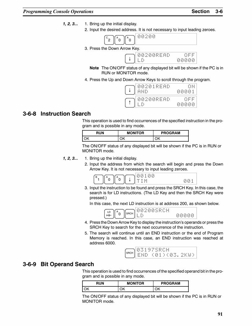
3-6SectionProgramming Console Operations
91
1, 2, 3... 1. Bring up the initial display.2. Input the desired address. It is not necessary to input leading zeroes.
C2
A0
A0
00200
3. Press the Down Arrow Key.
↓00200READ OFFLD 00000
Note The ON/OFF status of any displayed bit will be shown if the PC is inRUN or MONITOR mode.
4. Press the Up and Down Arrow Keys to scroll through the program.
↓00201READ ONAND 00001
↑00200READ OFFLD 00000
3-6-8 Instruction SearchThis operation is used to find occurrences of the specified instruction in the pro-gram and is possible in any mode.
RUN MONITOR PROGRAM
OK OK OK
The ON/OFF status of any displayed bit will be shown if the PC is in RUN orMONITOR mode.
1, 2, 3... 1. Bring up the initial display.2. Input the address from which the search will begin and press the DownArrow Key. It is not necessary to input leading zeroes.
B1
A0
A0 ↓
00100TIM 001
3. Input the instruction to be found and press the SRCH Key. In this case, thesearch is for LD instructions. (The LD Key and then the SRCH Key werepressed.)In this case, the next LD instruction is at address 200, as shown below.
LD A0 SRCH
00200SRCHLD 00000
4. Press theDownArrowKey to display the instructions operands or press theSRCH Key to search for the next occurrence of the instruction.
5. The search will continue until an END instruction or the end of ProgramMemory is reached. In this case, an END instruction was reached ataddress 6000.
SRCH03197SRCHEND (01)(03.2KW)
3-6-9 Bit Operand SearchThis operation is used to find occurrences of the specified operand bit in thepro-gram and is possible in any mode.
RUN MONITOR PROGRAM
OK OK OK
The ON/OFF status of any displayed bit will be shown if the PC is in RUN orMONITOR mode.
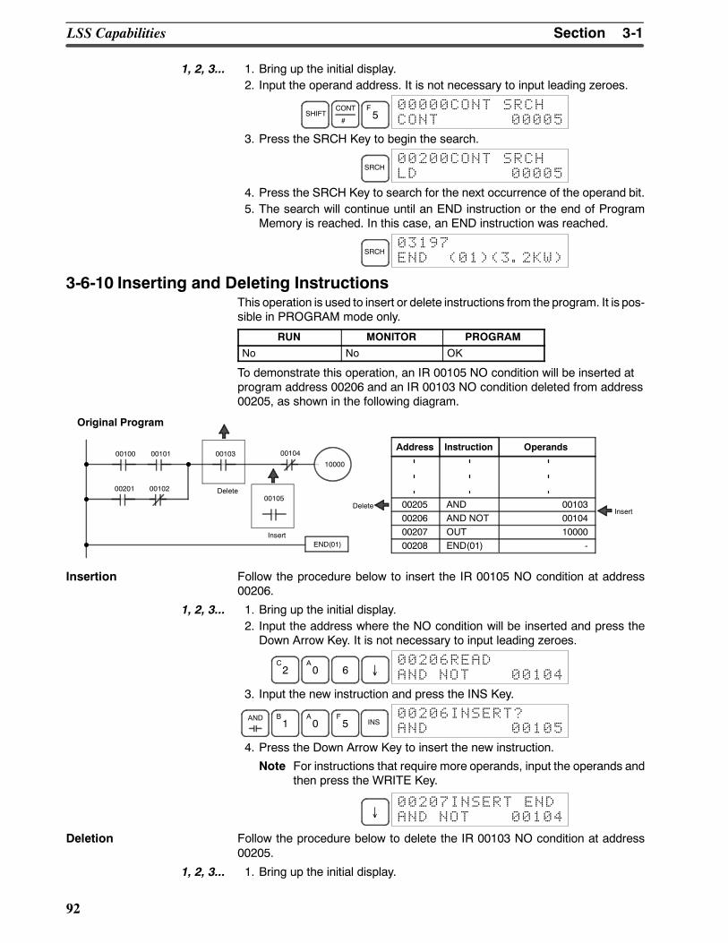
3-1SectionLSS Capabilities
92
1, 2, 3... 1. Bring up the initial display.2. Input the operand address. It is not necessary to input leading zeroes.
SHIFTCONT
#
F5
00000CONT SRCHCONT 00005
3. Press the SRCH Key to begin the search.
SRCH00200CONT SRCHLD 00005
4. Press the SRCH Key to search for the next occurrence of the operand bit.5. The search will continue until an END instruction or the end of ProgramMemory is reached. In this case, an END instruction was reached.
SRCH03197END (01)(3.2KW)
3-6-10 Inserting and Deleting InstructionsThis operation is used to insert or delete instructions from the program. It is pos-sible in PROGRAM mode only.
RUN MONITOR PROGRAM
No No OK
To demonstrate this operation, an IR 00105 NO condition will be inserted atprogram address 00206 and an IR 00103 NO condition deleted from address00205, as shown in the following diagram.
0010400100 00103
00105
00101
00201
END(01)
00102
10000
Delete
Insert
Original Program
Address Instruction Operands
00205 AND 0010300206 AND NOT 0010400207 OUT 1000000208 END(01) -
DeleteInsert
Insertion Follow the procedure below to insert the IR 00105 NO condition at address00206.
1, 2, 3... 1. Bring up the initial display.2. Input the address where the NO condition will be inserted and press theDown Arrow Key. It is not necessary to input leading zeroes.
C2
A0 6 ↓
00206READAND NOT 00104
3. Input the new instruction and press the INS Key.
AND B1
A0
F5 INS
00206INSERT?AND 00105
4. Press the Down Arrow Key to insert the new instruction.
Note For instructions that require more operands, input the operands andthen press the WRITE Key.
↓00207INSERT ENDAND NOT 00104
Deletion Follow the procedure below to delete the IR 00103 NO condition at address00205.
1, 2, 3... 1. Bring up the initial display.
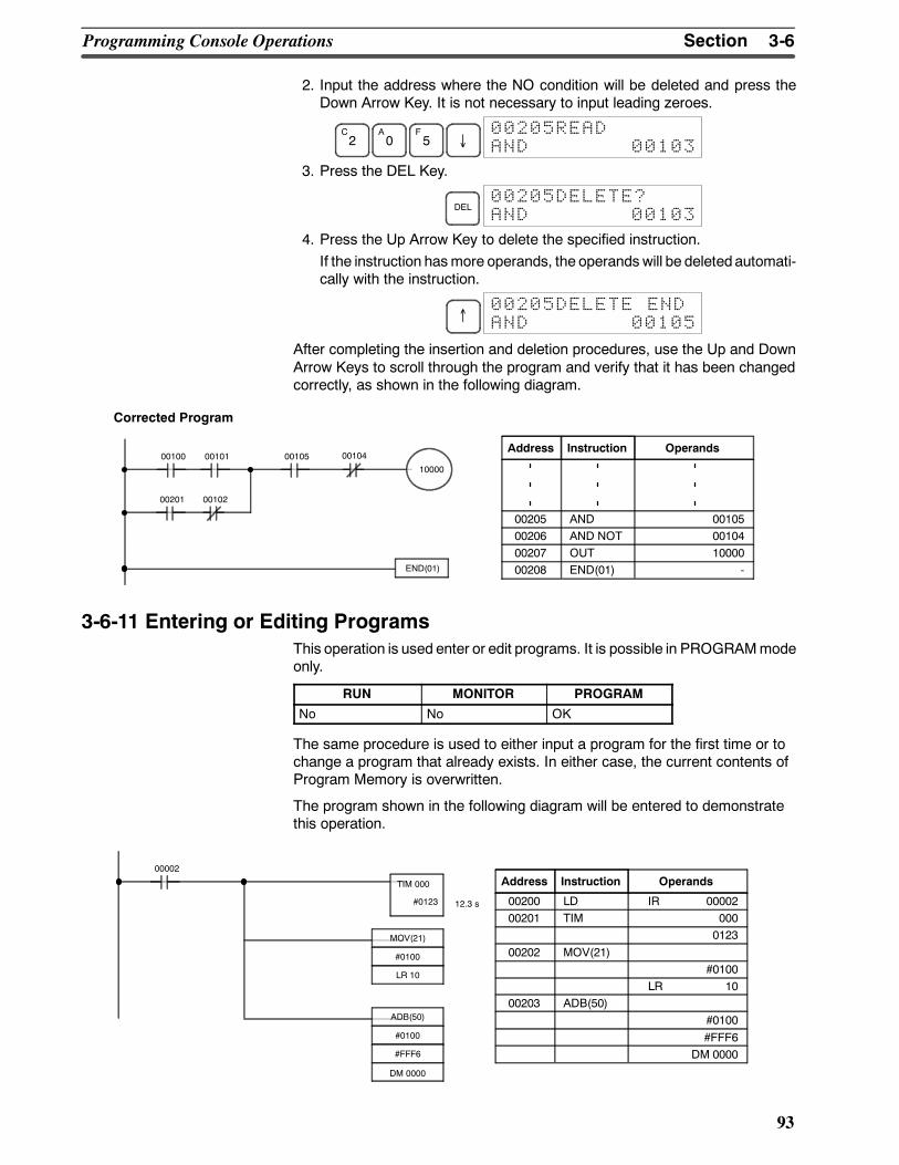
3-6SectionProgramming Console Operations
93
2. Input the address where the NO condition will be deleted and press theDown Arrow Key. It is not necessary to input leading zeroes.
C2
A0
F5 ↓
00205READAND 00103
3. Press the DEL Key.
DEL00205DELETE?AND 00103
4. Press the Up Arrow Key to delete the specified instruction.If the instruction hasmore operands, the operands will be deletedautomati-cally with the instruction.
↑00205DELETE ENDAND 00105
After completing the insertion and deletion procedures, use the Up and DownArrow Keys to scroll through the program and verify that it has been changedcorrectly, as shown in the following diagram.
0010400100 0010500101
00201
END(01)
00102
10000
Corrected Program
Address Instruction Operands
00205 AND 0010500206 AND NOT 0010400207 OUT 1000000208 END(01) -
3-6-11 Entering or Editing ProgramsThis operation is used enter or edit programs. It is possible in PROGRAMmodeonly.
RUN MONITOR PROGRAM
No No OK
The same procedure is used to either input a program for the first time or tochange a program that already exists. In either case, the current contents ofProgram Memory is overwritten.
The program shown in the following diagram will be entered to demonstratethis operation.
00002
00200 LD IR 0000200201 TIM 000
012300202 MOV(21)
#0100LR 10
00203 ADB(50)#0100#FFF6
DM 0000
MOV(21)
#0100
LR 10
TIM 000
#0123 12.3 s
ADB(50)
#0100
#FFF6
DM 0000
Address Instruction Operands
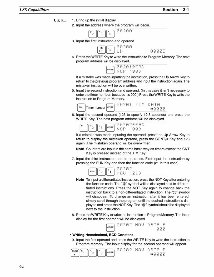
3-1SectionLSS Capabilities
94
1, 2, 3... 1. Bring up the initial display.2. Input the address where the program will begin.
C2
A0
A0
00200
3. Input the first instruction and operand.
LD C2
00200LD 00002
4. Press theWRITEKey to write the instruction to ProgramMemory. The nextprogram address will be displayed.
WRITE00201READNOP (00)
If a mistake was made inputting the instruction, press the Up Arrow Key toreturn to the previous program address and input the instruction again. Themistaken instruction will be overwritten.
5. Input the second instruction and operand. (In this case it isnt necessary toenter the timer number, because its 000.) Press theWRITEKey to write theinstruction to Program Memory.
TIM Timer number WRITE00201 TIM DATA
#0000
6. Input the second operand (123 to specify 12.3 seconds) and press theWRITE Key. The next program address will be displayed.
B1
C2
D3 WRITE
00202READNOP (00)
If a mistake was made inputting the operand, press the Up Arrow Key toreturn to display the mistaken operand, press the CONT/# Key and 123again. The mistaken operand will be overwritten.
Note Counters are input in the same basic way as timers except the CNTKey is pressed instead of the TIM Key.
7. Input the third instruction and its operands. First input the instruction bypressing the FUN Key and then the function code (21 in this case).
FUNC2
B1
00202MOV (21)
Note To input a differentiated instruction, press theNOTKey after enteringthe function code. The @ symbol will be displayed next to differen-tiated instructions. Press the NOT Key again to change back theinstruction back to a non-differentiated instruction. The @ symbolwill disappear. To change an instruction after it has been entered,simply scroll through the program until the desired instruction is dis-played and press theNOT Key. The @ symbol should be displayednext to the instruction.
8. Press theWRITEKey to write the instruction to ProgramMemory. The inputdisplay for the first operand will be displayed.
WRITE00202 MOV DATA A
000
•Writing Hexadecimal, BCD Constant9. Input the first operand and press the WRITE Key to write the instruction toProgram Memory. The input display for the second operand will appear.
CONT
#
B1
A0
A0 WRITE
00202 MOV DATA B#0000
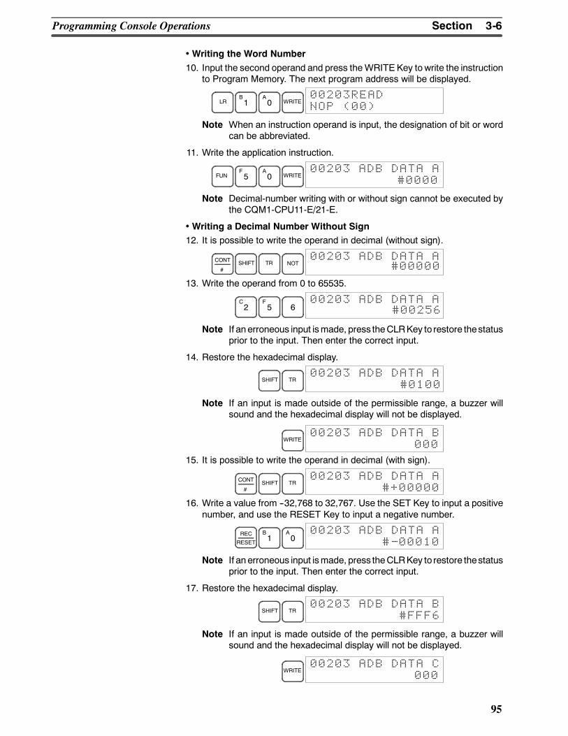
3-6SectionProgramming Console Operations
95
•Writing the Word Number10. Input the second operand and press theWRITEKey to write the instruction
to Program Memory. The next program address will be displayed.
LRB1
A0 WRITE
00203READNOP (00)
Note When an instruction operand is input, the designation of bit or wordcan be abbreviated.
11. Write the application instruction.
FUNF5
A0 WRITE
00203 ADB DATA A#0000
Note Decimal-number writing with or without sign cannot be executed bythe CQM1-CPU11-E/21-E.
•Writing a Decimal Number Without Sign12. It is possible to write the operand in decimal (without sign).
CONT
#SHIFT TR NOT
00203 ADB DATA A#00000
13. Write the operand from 0 to 65535.
C2
F5 6
00203 ADB DATA A#00256
Note If an erroneous input ismade, press theCLRKey to restore thestatusprior to the input. Then enter the correct input.
14. Restore the hexadecimal display.
SHIFT TR00203 ADB DATA A
#0100
Note If an input is made outside of the permissible range, a buzzer willsound and the hexadecimal display will not be displayed.
WRITE00203 ADB DATA B
000
15. It is possible to write the operand in decimal (with sign).
CONT
#SHIFT TR
00203 ADB DATA A#+00000
16. Write a value from --32,768 to 32,767. Use the SET Key to input a positivenumber, and use the RESET Key to input a negative number.
REC
RESET
B1
A0
00203 ADB DATA A#-00010
Note If an erroneous input ismade, press theCLRKey to restore thestatusprior to the input. Then enter the correct input.
17. Restore the hexadecimal display.
SHIFT TR00203 ADB DATA B
#FFF6
Note If an input is made outside of the permissible range, a buzzer willsound and the hexadecimal display will not be displayed.
WRITE00203 ADB DATA C
000
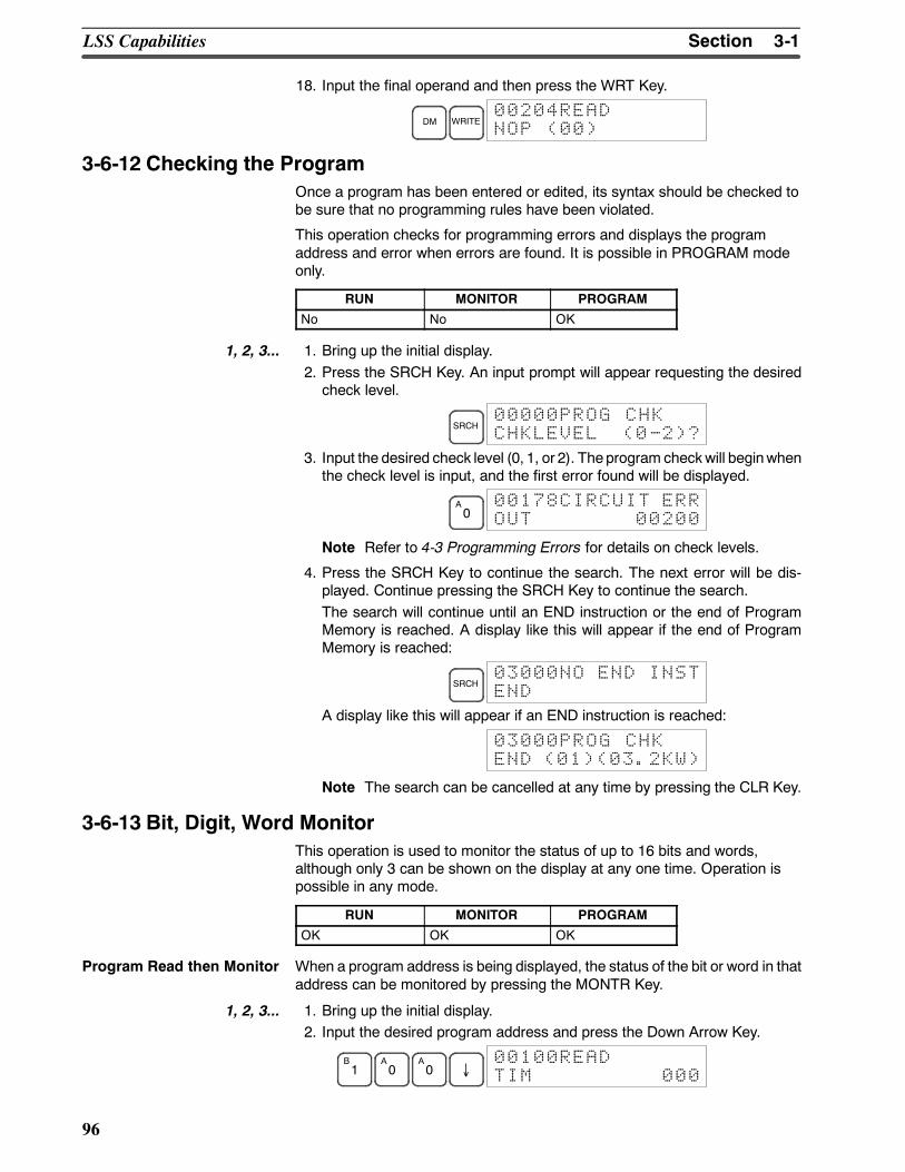
3-1SectionLSS Capabilities
96
18. Input the final operand and then press the WRT Key.
DM WRITE00204READNOP (00)
3-6-12 Checking the ProgramOnce a program has been entered or edited, its syntax should be checked tobe sure that no programming rules have been violated.
This operation checks for programming errors and displays the programaddress and error when errors are found. It is possible in PROGRAM modeonly.
RUN MONITOR PROGRAM
No No OK
1, 2, 3... 1. Bring up the initial display.2. Press the SRCH Key. An input prompt will appear requesting the desiredcheck level.
SRCH00000PROG CHKCHKLEVEL (0-2)?
3. Input the desired check level (0, 1, or 2). Theprogram checkwill beginwhenthe check level is input, and the first error found will be displayed.
A0
00178CIRCUIT ERROUT 00200
Note Refer to 4-3 Programming Errors for details on check levels.
4. Press the SRCH Key to continue the search. The next error will be dis-played. Continue pressing the SRCH Key to continue the search.The search will continue until an END instruction or the end of ProgramMemory is reached. A display like this will appear if the end of ProgramMemory is reached:
SRCH03000NO END INSTEND
A display like this will appear if an END instruction is reached:
03000PROG CHKEND (01)(03.2KW)
Note The search can be cancelled at any time by pressing the CLR Key.
3-6-13 Bit, Digit, Word MonitorThis operation is used to monitor the status of up to 16 bits and words,although only 3 can be shown on the display at any one time. Operation ispossible in any mode.
RUN MONITOR PROGRAM
OK OK OK
Program Read then Monitor When a program address is being displayed, the status of the bit or word in thataddress can be monitored by pressing the MONTR Key.
1, 2, 3... 1. Bring up the initial display.2. Input the desired program address and press the Down Arrow Key.
B1
A0
A0 ↓
00100READTIM 000
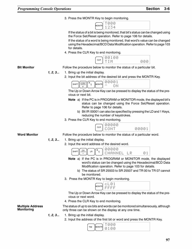
3-6SectionProgramming Console Operations
97
3. Press the MONTR Key to begin monitoring.
MONTRT0001234
If the status of a bit is beingmonitored, that bits status canbe changedusingthe Force Set/Reset operation. Refer to page 106 for details.If the status of a word is beingmonitored, that words value can be changedusing theHexadecimal/BCDDataModificationoperation. Refer to page103for details.
4. Press the CLR Key to end monitoring.
CLR00100TIM 000
Bit Monitor Follow the procedure below to monitor the status of a particular bit.
1, 2, 3... 1. Bring up the initial display.2. Input the bit address of the desired bit and press the MONTR Key.
SHIFT CONT
#
B1 MONTR
00001^ ON
The Up or Down Arrow Key can be pressed to display the status of the pre-vious or next bit.
Note a) If the PC is in PROGRAM orMONITORmode, the displayed bitsstatus can be changed using the Force Set/Reset operation.Refer to page 106 for details.
b) Bit IR 00001can alsobe specified by pressing the LDand 1Keys,reducing the number of keystrokes.
3. Press the CLR Key to end monitoring.
CLR00000CONT 00001
Word Monitor Follow the procedure below to monitor the status of a particular word.
1, 2, 3... 1. Bring up the initial display.2. Input the word address of the desired word.
SHIFT CH
*LR
B1
00000CHANNEL LR 01
Note a) If the PC is in PROGRAM or MONITOR mode, the displayedwords status can be changed using the Hexadecimal/BCD DataModification operation. Refer to page 103 for details.
b) The status of SR 25503 to SR 25507 and TR 00 to TR 07 cannotbe monitored.
3. Press the MONTR Key to begin monitoring.
MONTRcL01FFFF
The Up or Down Arrow Key can be pressed to display the status of the pre-vious or next word.
4. Press the CLR Key to end monitoring.
The status of up to six bits andwordscanbemonitored simultaneously, althoughonly three can be shown on the display at any one time.
1, 2, 3... 1. Bring up the initial display.2. Input the address of the first bit or word and press the MONTR Key.
TIM MONTRT0000100
Multiple AddressMonitoring
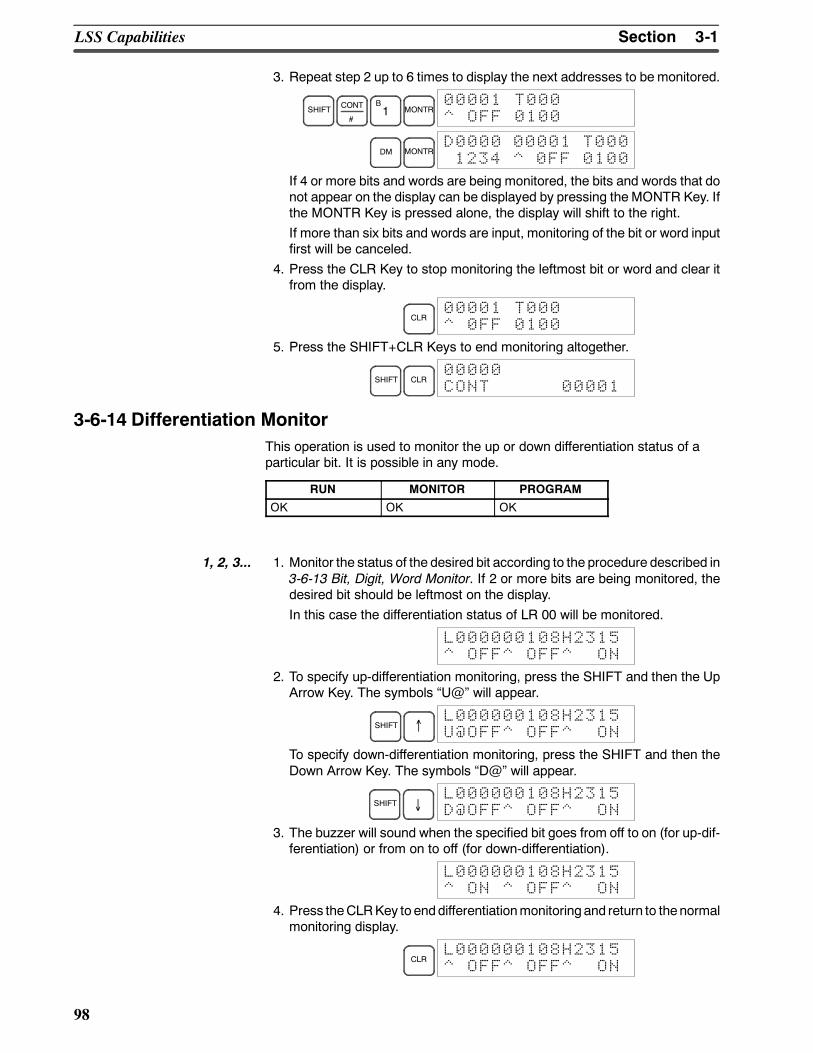
3-1SectionLSS Capabilities
98
3. Repeat step 2 up to 6 times to display the next addresses to be monitored.
SHIFT CONT
#
B1 MONTR
00001 T000^ OFF 0100
DM MONTRD0000 00001 T0001234 ^ 0FF 0100
If 4 or more bits and words are being monitored, the bits and words that donot appear on the display can be displayed by pressing the MONTR Key. Ifthe MONTR Key is pressed alone, the display will shift to the right.If more than six bits and words are input, monitoring of the bit or word inputfirst will be canceled.
4. Press the CLR Key to stop monitoring the leftmost bit or word and clear itfrom the display.
CLR00001 T000^ 0FF 0100
5. Press the SHIFT+CLR Keys to end monitoring altogether.
SHIFT CLR00000CONT 00001
3-6-14 Differentiation MonitorThis operation is used to monitor the up or down differentiation status of aparticular bit. It is possible in any mode.
RUN MONITOR PROGRAM
OK OK OK
1, 2, 3... 1. Monitor the status of the desired bit according to the procedure described in3-6-13 Bit, Digit, Word Monitor. If 2 or more bits are being monitored, thedesired bit should be leftmost on the display.In this case the differentiation status of LR 00 will be monitored.
L000000108H2315^ OFF^ OFF^ ON
2. To specify up-differentiation monitoring, press the SHIFT and then the UpArrow Key. The symbols U@ will appear.
SHIFT ↑L000000108H2315U@OFF^ OFF^ ON
To specify down-differentiation monitoring, press the SHIFT and then theDown Arrow Key. The symbols D@ will appear.
SHIFT ↓L000000108H2315D@OFF^ OFF^ ON
3. The buzzer will sound when the specified bit goes from off to on (for up-dif-ferentiation) or from on to off (for down-differentiation).
L000000108H2315^ ON ^ OFF^ ON
4. Press theCLRKey to enddifferentiationmonitoring and return to thenormalmonitoring display.
CLRL000000108H2315^ OFF^ OFF^ ON
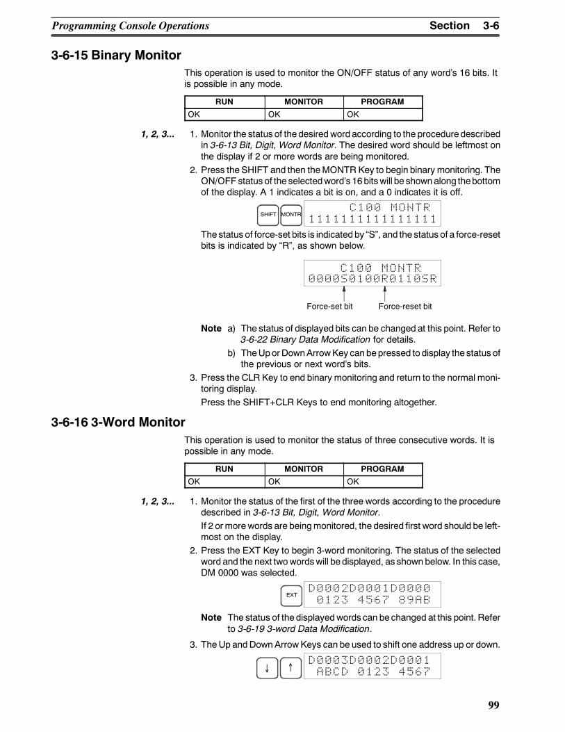
3-6SectionProgramming Console Operations
99
3-6-15 Binary MonitorThis operation is used to monitor the ON/OFF status of any words 16 bits. Itis possible in any mode.
RUN MONITOR PROGRAM
OK OK OK
1, 2, 3... 1. Monitor the status of thedesiredwordaccording to the proceduredescribedin 3-6-13 Bit, Digit, Word Monitor. The desired word should be leftmost onthe display if 2 or more words are being monitored.
2. Press the SHIFT and then theMONTR Key to begin binary monitoring. TheON/OFF status of the selectedwords 16bitswill be shownalong thebottomof the display. A 1 indicates a bit is on, and a 0 indicates it is off.
SHIFT MONTRC100 MONTR
1111111111111111
Thestatus of force-set bits is indicatedby S, and the status of a force-resetbits is indicated by R, as shown below.
Force-set bit
0000S0100R0110SR
Force-reset bit
C100 MONTR
Note a) The status of displayed bits can be changed at this point. Refer to3-6-22 Binary Data Modification for details.
b) TheUporDownArrowKey canbepressed to display the status ofthe previous or next words bits.
3. Press the CLR Key to end binary monitoring and return to the normal moni-toring display.Press the SHIFT+CLR Keys to end monitoring altogether.
3-6-16 3-Word MonitorThis operation is used to monitor the status of three consecutive words. It ispossible in any mode.
RUN MONITOR PROGRAM
OK OK OK
1, 2, 3... 1. Monitor the status of the first of the three words according to the proceduredescribed in 3-6-13 Bit, Digit, Word Monitor.If 2 or morewords are beingmonitored, the desired first word should be left-most on the display.
2. Press the EXT Key to begin 3-word monitoring. The status of the selectedword and the next twowordswill be displayed, as shown below. In this case,DM 0000 was selected.
EXTD0002D0001D00000123 4567 89AB
Note The status of thedisplayedwords can be changed at this point. Referto 3-6-19 3-word Data Modification.
3. TheUp andDownArrowKeys can be used to shift one address up or down.
↓ ↑D0003D0002D0001ABCD 0123 4567
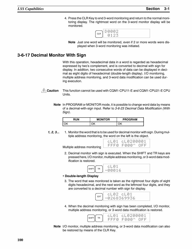
!
3-1SectionLSS Capabilities
100
4. Press theCLRKey to end 3-wordmonitoring and return to the normalmoni-toring display. The rightmost word on the 3-word monitor display will bemonitored.
CLRD00020123
Note Just one word will be monitored, even if 2 or more words were dis-played when 3-word monitoring was initiated.
3-6-17 Decimal Monitor With SignWith this operation, hexadecimal data in a word is regarded as hexadecimalexpressed by twos complement, and is converted to decimal with sign fordisplay. In addition, two consecutive words of data can be displayed in deci-mal as eight digits of hexadecimal (double-length display). I/O monitoring,multiple address monitoring, and 3-word data modification can be used dur-ing execution.
Caution This function cannot be used with CQM1-CPU11-E and CQM1-CPU21-E CPUUnits.
Note In PROGRAMorMONITORmode, it is possible to change word data bymeansof a decimal-with-sign input. Refer to 3-6-23 Decimal Data Modification (WithSign).
RUN MONITOR PROGRAM
OK OK OK
1, 2, 3... 1. Monitor theword that is to beused for decimalmonitor withsign. Duringmul-tiple address monitoring, the word on the left is the object.
Multiple address monitoring
cL01 cL0200001FFF0 F000^ OFF
2. Decimal monitor with sign is executed. When the SHIFT and TR keys arepressedhere, I/Omonitor,multiple addressmonitoring, or3-worddatamod-ification is restored.
SHIFT TRcL01
-00016
• Double-length Display
3. The word that was monitored is taken as the rightmost four digits of eightdigits hexadecimal, and the next word as the leftmost four digits, and theyare converted to a decimal number with sign for display.
EXTcL02 cL01
-0268369936
4. When the decimal monitoring with sign has been completed, I/O monitor,multiple address monitoring, or 3-word data modification is restored.
SHIFT TRcL01 cL0200001FFF0 F000^ OFF
Note I/O monitor, multiple address monitoring, or 3-word data modification can alsobe restored by means of the CLR Key.
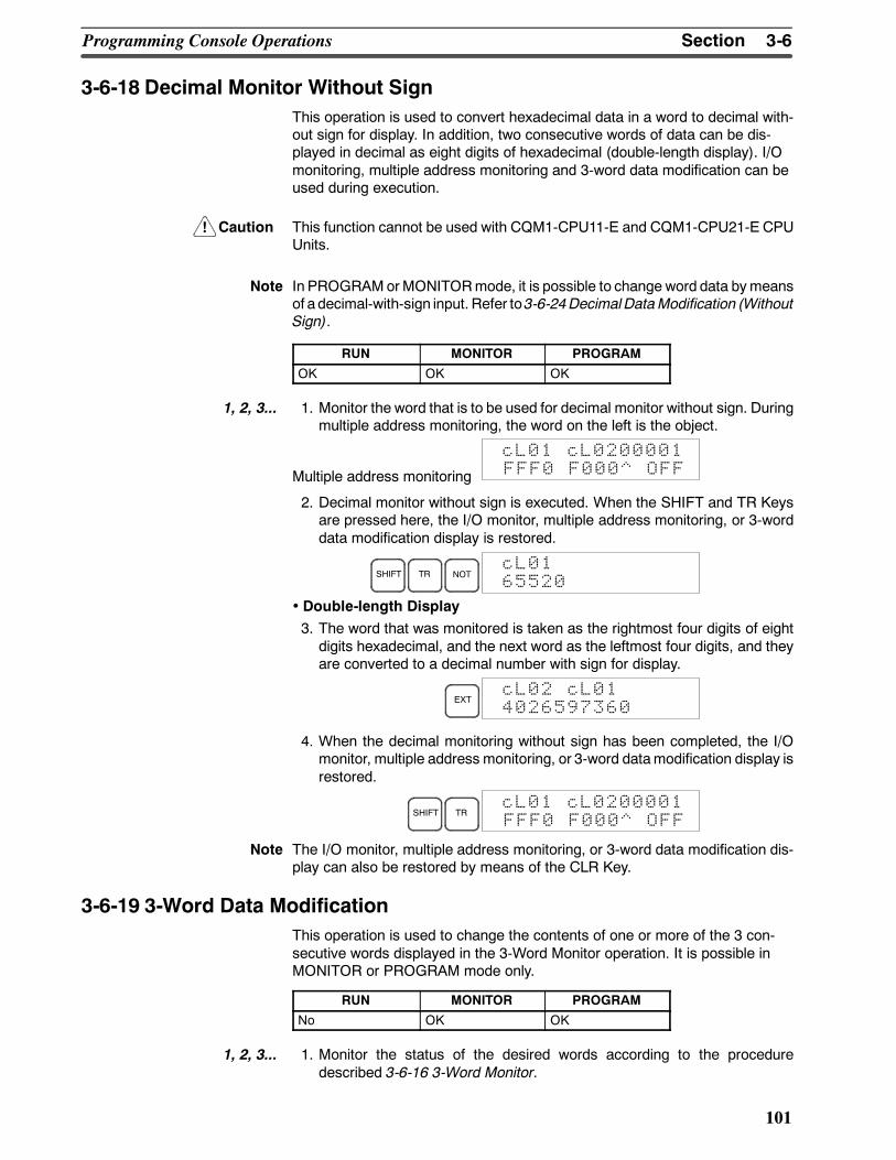
!
3-6SectionProgramming Console Operations
101
3-6-18 Decimal Monitor Without SignThis operation is used to convert hexadecimal data in a word to decimal with-out sign for display. In addition, two consecutive words of data can be dis-played in decimal as eight digits of hexadecimal (double-length display). I/Omonitoring, multiple address monitoring and 3-word data modification can beused during execution.
Caution This function cannot be used with CQM1-CPU11-E and CQM1-CPU21-E CPUUnits.
Note In PROGRAMorMONITORmode, it is possible to change word data bymeansof a decimal-with-sign input. Refer to3-6-24DecimalDataModification (WithoutSign).
RUN MONITOR PROGRAM
OK OK OK
1, 2, 3... 1. Monitor the word that is to be used for decimal monitor without sign. Duringmultiple address monitoring, the word on the left is the object.
Multiple address monitoring
cL01 cL0200001FFF0 F000^ OFF
2. Decimal monitor without sign is executed. When the SHIFT and TR Keysare pressed here, the I/O monitor, multiple address monitoring, or 3-worddata modification display is restored.
SHIFT TR NOTcL0165520
• Double-length Display3. The word that was monitored is taken as the rightmost four digits of eightdigits hexadecimal, and the next word as the leftmost four digits, and theyare converted to a decimal number with sign for display.
EXTcL02 cL014026597360
4. When the decimal monitoring without sign has been completed, the I/Omonitor, multiple address monitoring, or 3-word datamodification display isrestored.
SHIFT TRcL01 cL0200001FFF0 F000^ OFF
Note The I/O monitor, multiple address monitoring, or 3-word data modification dis-play can also be restored by means of the CLR Key.
3-6-19 3-Word Data ModificationThis operation is used to change the contents of one or more of the 3 con-secutive words displayed in the 3-Word Monitor operation. It is possible inMONITOR or PROGRAM mode only.
RUN MONITOR PROGRAM
No OK OK
1, 2, 3... 1. Monitor the status of the desired words according to the proceduredescribed 3-6-16 3-Word Monitor.
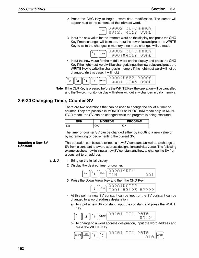
3-1SectionLSS Capabilities
102
2. Press the CHG Key to begin 3-word data modification. The cursor willappear next to the contents of the leftmost word.
CHGD0002 3CHCHANG?0123 4567 89AB
3. Input the new value for the leftmost word on the display and press theCHGKey ifmore changeswill bemade. Input thenewvalueandpress theWRITEKey to write the changes in memory if no more changes will be made.
B1 CHG
D0002 3CHCHANG?0001 4567 89AB
4. Input the new value for the middle word on the display and press the CHGKey if the rightmost wordwill be changed. Input thenew valueand press theWRITE Key to write the changes in memory if the rightmost wordwill not bechanged. (In this case, it will not.)
C2
D3
E4
F5 WRITE
D0002D0001D00000001 2345 89AB
Note If the CLRKey is pressed before theWRITEKey, the operationwill be cancelledand the 3-word monitor display will return without any changes in data memory.
3-6-20 Changing Timer, Counter SVThere are two operations that can be used to change the SV of a timer orcounter. They are possible in MONITOR or PROGRAM mode only. In MON-ITOR mode, the SV can be changed while the program is being executed.
RUN MONITOR PROGRAM
No OK OK
The timer or counter SV can be changed either by inputting a new value orby incrementing or decrementing the current SV.
This operation can be used to input a new SV constant, as well as to change anSV from a constant to aword address designation and visa verse. The followingexamples show how to input a newSV constant and how to change the SV froma constant to an address.
1, 2, 3... 1. Bring up the initial display.2. Display the desired timer or counter.
TIMB1 SRCH
00201SRCHTIM 001
3. Press the Down Arrow Key and then the CHG Key.
↓ CHG00201DATA?T001 #0123 #????
4. At this point a new SV constant can be input or the SV constant can bechanged to a word address designationa) To input a new SV constant, input the constant and press the WRITE
Key.
B1
C2
E4 WRITE
00201 TIM DATA#0124
b) To change to a word address designation, input the word address andpress the WRITE Key.
SHIFT CH
*
B1
A0
00201 TIM DATA010
WRITE
Inputting a New SVConstant
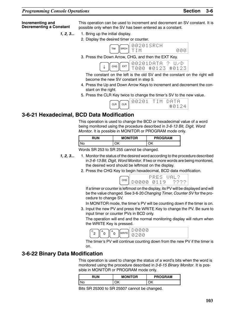
3-6SectionProgramming Console Operations
103
This operation can be used to increment and decrement an SV constant. It ispossible only when the SV has been entered as a constant.
1, 2, 3... 1. Bring up the initial display.2. Display the desired timer or counter.
TIM SRCH00201SRCHTIM 000
3. Press the Down Arrow, CHG, and then the EXT Key.
↓ CHG EXT00201DATA ? U/DT000 #0123 #0123
The constant on the left is the old SV and the constant on the right willbecome the new SV constant in step 5.
4. Press the Up and Down Arrow Keys to increment and decrement the con-stant on the right.
5. Press the CLR Key twice to change the timers SV to the new value.
CLR CLR00201 TIM DATA
#0124
3-6-21 Hexadecimal, BCD Data ModificationThis operation is used to change the BCD or hexadecimal value of a wordbeing monitored using the procedure described in 3-6-13 Bit, Digit, WordMonitor. It is possible in MONITOR or PROGRAM mode only.
RUN MONITOR PROGRAM
No OK OK
Words SR 253 to SR 255 cannot be changed.
1, 2, 3... 1. Monitor the status of thedesiredwordaccording to the proceduredescribedin 3-6-13 Bit, Digit, WordMonitor. If two or morewords are beingmonitored,the desired word should be leftmost on the display.
2. Press the CHG Key to begin hexadecimal, BCD data modification.
CHGPRES VAL?
D0000 0119 ????
If a timer or counter is leftmost on thedisplay, its PVwill be displayed andwillbe the value changed. See 3-6-20Changing Timer, Counter SV for the pro-cedure to change SV.In MONITOR mode, the timers PV will be counting down if the timer is on.
3. Input the new PV and press the WRITE Key to change the PV. Be sure toinput timer or counter PVs in BCD only.The operation will end and the normal monitoring display will return whenthe WRITE Key is pressed.
C2
A0
A0 WRITE
D00000200
The timers PV will continue counting down from the new PV if the timer ison.
3-6-22 Binary Data ModificationThis operation is used to change the status of a words bits when the word ismonitored using the procedure described in 3-6-15 Binary Monitor. It is pos-sible in MONITOR or PROGRAM mode only.
RUN MONITOR PROGRAM
No OK OK
Bits SR 25300 to SR 25507 cannot be changed.
Incrementing andDecrementing a Constant
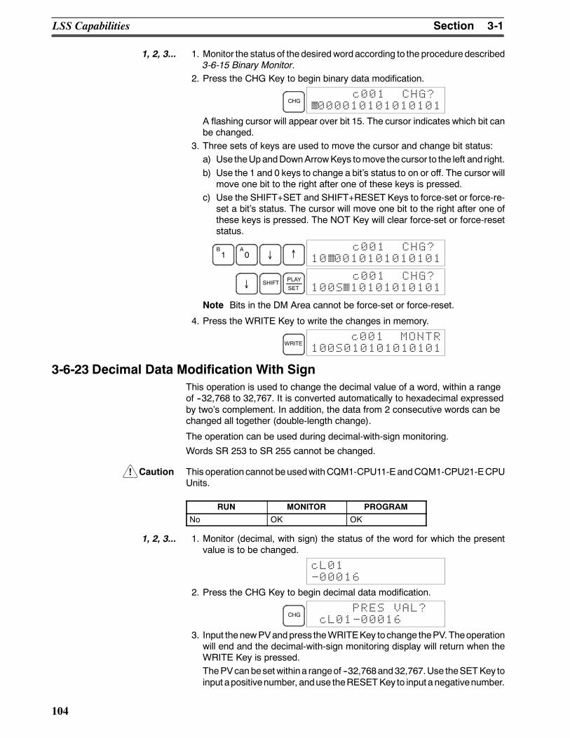
!
3-1SectionLSS Capabilities
104
1, 2, 3... 1. Monitor the status of thedesiredwordaccording to the proceduredescribed3-6-15 Binary Monitor.
2. Press the CHG Key to begin binary data modification.
CHGc001 CHG?
000010101010101
A flashing cursor will appear over bit 15. The cursor indicates which bit canbe changed.
3. Three sets of keys are used to move the cursor and change bit status:a) Use theUpandDownArrowKeys tomove the cursor to the left and right.b) Use the 1 and 0 keys to change a bits status to on or off. The cursor will
move one bit to the right after one of these keys is pressed.c) Use the SHIFT+SET and SHIFT+RESET Keys to force-set or force-re-
set a bits status. The cursor will move one bit to the right after one ofthese keys is pressed. The NOT Key will clear force-set or force-resetstatus.
B1
A0 ↓ ↑
c001 CHG?10 0010101010101
↓ SHIFT PLAY
SET
c001 CHG?100S 10101010101
Note Bits in the DM Area cannot be force-set or force-reset.
4. Press the WRITE Key to write the changes in memory.
WRITEc001 MONTR
100S010101010101
3-6-23 Decimal Data Modification With SignThis operation is used to change the decimal value of a word, within a rangeof --32,768 to 32,767. It is converted automatically to hexadecimal expressedby twos complement. In addition, the data from 2 consecutive words can bechanged all together (double-length change).
The operation can be used during decimal-with-sign monitoring.
Words SR 253 to SR 255 cannot be changed.
Caution This operation cannot beusedwithCQM1-CPU11-EandCQM1-CPU21-ECPUUnits.
RUN MONITOR PROGRAM
No OK OK
1, 2, 3... 1. Monitor (decimal, with sign) the status of the word for which the presentvalue is to be changed.
cL01-00016
2. Press the CHG Key to begin decimal data modification.
CHGPRES VAL?
cL01-00016
3. Input thenewPVandpress theWRITEKey tochange thePV. Theoperationwill end and the decimal-with-sign monitoring display will return when theWRITE Key is pressed.ThePVcanbeset withina rangeof --32,768and32,767.Use theSETKey toinput apositivenumber, anduse theRESETKey to input a negativenumber.
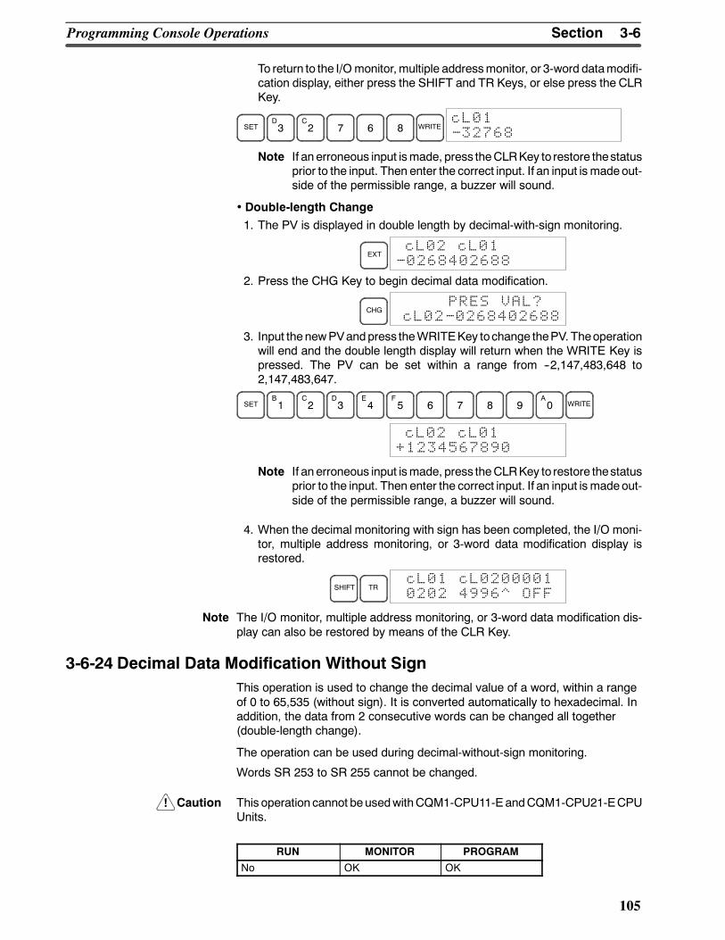
!
3-6SectionProgramming Console Operations
105
To return to the I/Omonitor,multiple addressmonitor, or 3-word datamodifi-cation display, either press the SHIFT and TR Keys, or else press the CLRKey.
SETD3
C2 7 6 8 WRITE
cL01-32768
Note If an erroneous input ismade, press theCLRKey to restore thestatusprior to the input. Then enter the correct input. If an input is madeout-side of the permissible range, a buzzer will sound.
• Double-length Change1. The PV is displayed in double length by decimal-with-sign monitoring.
EXTcL02 cL01
-0268402688
2. Press the CHG Key to begin decimal data modification.
CHGPRES VAL?
cL02-0268402688
3. Input thenewPVandpress theWRITEKey tochange thePV. Theoperationwill end and the double length display will return when the WRITE Key ispressed. The PV can be set within a range from --2,147,483,648 to2,147,483,647.
SETB1
C2
D3
E4
F5 6 7 8 9
A0 WRITE
cL02 cL01+1234567890
Note If an erroneous input ismade, press theCLRKey to restore thestatusprior to the input. Then enter the correct input. If an input is madeout-side of the permissible range, a buzzer will sound.
4. When the decimal monitoring with sign has been completed, the I/O moni-tor, multiple address monitoring, or 3-word data modification display isrestored.
SHIFT TRcL01 cL02000010202 4996^ OFF
Note The I/O monitor, multiple address monitoring, or 3-word data modification dis-play can also be restored by means of the CLR Key.
3-6-24 Decimal Data Modification Without SignThis operation is used to change the decimal value of a word, within a rangeof 0 to 65,535 (without sign). It is converted automatically to hexadecimal. Inaddition, the data from 2 consecutive words can be changed all together(double-length change).
The operation can be used during decimal-without-sign monitoring.
Words SR 253 to SR 255 cannot be changed.
Caution This operation cannot beusedwithCQM1-CPU11-EandCQM1-CPU21-ECPUUnits.
RUN MONITOR PROGRAM
No OK OK
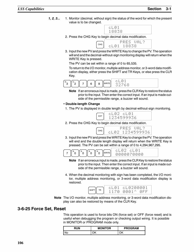
3-1SectionLSS Capabilities
106
1, 2, 3... 1. Monitor (decimal, without sign) the status of the word for which the presentvalue is to be changed.
cL0118838
2. Press the CHG Key to begin decimal data modification.
CHGPRES VAL?
cL01 18838
3. Input thenewPVandpress theWRITEKey tochange thePV. Theoperationwill endand thedecimal-without-signmonitoring display will return when theWRITE Key is pressed.The PV can be set within a range of 0 to 65,535.To return to the I/Omonitor,multiple addressmonitor, or 3-word datamodifi-cation display, either press the SHIFT and TR Keys, or else press the CLRKey.
D3
C2 7 6 8 WRITE
cL0132768
Note If an erroneous input ismade, press theCLRKey to restore thestatusprior to the input. Then enter the correct input. If an input is madeout-side of the permissible range, a buzzer will sound.
• Double-length Change1. The PV is displayed in double length by decimal-without-sign monitoring.
EXTcL02 cL011234599936
2. Press the CHG Key to begin decimal data modification.
CHGPRES VAL?
cL02 1234599936
3. Input thenewPVandpress theWRITEKey tochange thePV. Theoperationwill end and the double length display will return when the WRITE Key ispressed. The PV can be set within a range of 0 to 4,294,967,295.
7A0
A0
A0
A0 WRITE
cL02 cL010000070000
Note If an erroneous input ismade, press theCLRKey to restore thestatusprior to the input. Then enter the correct input. If an input is madeout-side of the permissible range, a buzzer will sound.
4. When the decimal monitoring with sign has been completed, the I/O moni-tor, multiple address monitoring, or 3-word data modification display isrestored.
SHIFT TRcL01 cL02000011170 0001^ 0FF
Note The I/O monitor, multiple address monitoring, or 3-word data modification dis-play can also be restored by means of the CLR Key.
3-6-25 Force Set, ResetThis operation is used to force bits ON (force set) or OFF (force reset) and isuseful when debugging the program or checking output wiring. It is possiblein MONITOR or PROGRAM mode only.
RUN MONITOR PROGRAM
No OK OK
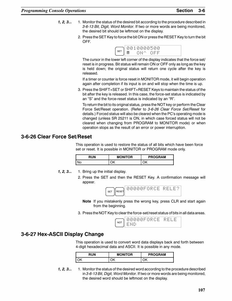
3-6SectionProgramming Console Operations
107
1, 2, 3... 1. Monitor the status of the desired bit according to the procedure described in3-6-13 Bit, Digit, Word Monitor. If two or more words are being monitored,the desired bit should be leftmost on the display.
2. Press theSETKey to force thebit ONor press theRESETKey to turn thebitOFF.
SET0010000500^ ON^ OFF
The cursor in the lower left corner of the display indicates that the force set/reset is in progress. Bit status will remainONor OFF only as longas the keyis held down; the original status will return one cycle after the key isreleased.
If a timer or counter is force reset in MONITORmode, it will begin operationagain after completion if its input is on and will stop when the time is up.
3. Press the SHIFT+SET or SHIFT+RESETKeys tomaintain the status of thebit after the key is released. In this case, the force-set status is indicated byan S and the force-reset status is indicated by an R.
To return thebit to its original status, press theNOT key or perform theClearForce Set/Reset operation. (Refer to 3-6-26 Clear Force Set/Reset fordetails.) Forced status will also be clearedwhen the PCs operatingmode ischanged (unless SR 25211 is ON, in which case forced status will not becleared when changing from PROGRAM to MONITOR mode) or whenoperation stops as the result of an error or power interruption.
3-6-26 Clear Force Set/ResetThis operation is used to restore the status of all bits which have been forceset or reset. It is possible in MONITOR or PROGRAM mode only.
RUN MONITOR PROGRAM
No OK OK
1, 2, 3... 1. Bring up the initial display.
2. Press the SET and then the RESET Key. A confirmation message willappear.
SET RESET00000FORCE RELE?
Note If you mistakenly press the wrong key, press CLR and start againfrom the beginning.
3. Press theNOTKey to clear the force-set/reset status of bits inall dataareas.
NOT00000FORCE RELEEND
3-6-27 Hex-ASCII Display ChangeThis operation is used to convert word data displays back and forth between4-digit hexadecimal data and ASCII. It is possible in any mode.
RUN MONITOR PROGRAM
OK OK OK
1, 2, 3... 1. Monitor the status of thedesiredwordaccording to the proceduredescribedin 3-6-13 Bit, Digit, WordMonitor. If two or morewords are beingmonitored,the desired word should be leftmost on the display.
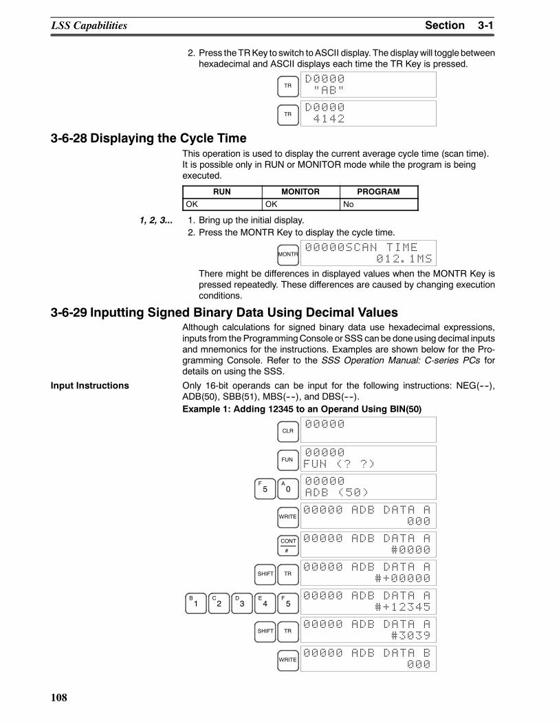
3-1SectionLSS Capabilities
108
2. Press theTRKey to switch toASCII display. The displaywill toggle betweenhexadecimal and ASCII displays each time the TR Key is pressed.
TRD0000AB
TRD00004142
3-6-28 Displaying the Cycle TimeThis operation is used to display the current average cycle time (scan time).It is possible only in RUN or MONITOR mode while the program is beingexecuted.
RUN MONITOR PROGRAM
OK OK No
1, 2, 3... 1. Bring up the initial display.2. Press the MONTR Key to display the cycle time.
MONTR00000SCAN TIME
012.1MS
There might be differences in displayed values when the MONTR Key ispressed repeatedly. These differences are caused by changing executionconditions.
3-6-29 Inputting Signed Binary Data Using Decimal ValuesAlthough calculations for signed binary data use hexadecimal expressions,inputs from the ProgrammingConsole or SSS canbe doneusing decimal inputsand mnemonics for the instructions. Examples are shown below for the Pro-gramming Console. Refer to the SSS Operation Manual: C-series PCs fordetails on using the SSS.
Input Instructions Only 16-bit operands can be input for the following instructions: NEG(----),ADB(50), SBB(51), MBS(----), and DBS(----).Example 1: Adding 12345 to an Operand Using BIN(50)
CLR00000
FUN00000FUN (? ?)
F5
A0
00000ADB (50)
WRITE00000 ADB DATA A
000
CONT
#
00000 ADB DATA A#0000
SHIFT TR00000 ADB DATA A
#+00000
B1
C2
D3
E4
F5
00000 ADB DATA A#+12345
SHIFT TR00000 ADB DATA A
#3039
WRITE00000 ADB DATA B
000
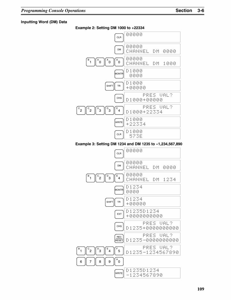
3-6SectionProgramming Console Operations
109
Inputting Word (DM) Data
Example 2: Setting DM 1000 to +22334
CLR00000
DM00000CHANNEL DM 0000
B1
A0
A0
A0
00000CHANNEL DM 1000
MONTRD10000000
SHIFT TRD1000+00000
CHGPRES VAL?
D1000+00000
C2
C2
D3
D3
E4
PRES VAL?D1000+22334
WRITED1000+22334
CLRD1000573E
Example 3: Setting DM 1234 and DM 1235 to --1,234,567,890
CLR00000
DM00000CHANNEL DM 0000
B1
C2
D3
E4
00000CHANNEL DM 1234
MONTRD12340000
SHIFT TRD1234+00000
EXTD1235D1234+0000000000
CHGPRES VAL?
D1235+0000000000
REC
RESET
PRES VAL?D1235-0000000000
B1
C2
D3
E4
F5
PRES VAL?D1235-1234567890
6 7 8 9A0
WRITED1235D1234-1234567890
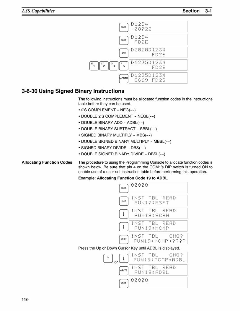
3-1SectionLSS Capabilities
110
CLRD1234-00722
CLRD1234FD2E
DMD0000D1234
FD2E
B1
C2
D3
F5
D1235D1234FD2E
MONTRD1235D1234B669 FD2E
3-6-30 Using Signed Binary InstructionsThe following instructions must be allocated function codes in the instructionstable before they can be used.
• 2S COMPLEMENT -- NEG(----)
• DOUBLE 2S COMPLEMENT -- NEGL(----)
• DOUBLE BINARY ADD -- ADBL(----)
• DOUBLE BINARY SUBTRACT -- SBBL(----)
• SIGNED BINARY MULTIPLY -- MBS(----)
• DOUBLE SIGNED BINARY MULTIPLY -- MBSL(----)
• SIGNED BINARY DIVIDE -- DBS(----)
• DOUBLE SIGNED BINARY DIVIDE -- DBSL(----)
Allocating Function Codes The procedure to using the Programming Console to allocate function codes isshown below. Be sure that pin 4 on the CQM1s DIP switch is turned ON toenable use of a user-set instruction table before performing this operation.
Example: Allocating Function Code 19 to ADBL
CLR00000
EXTINST TBL READFUN17:ASFT
↓INST TBL READFUN18:SCAN
↓INST TBL READFUN19:MCMP
CHGINST TBL CHG?FUN19:MCMP~????
Press the Up or Down Cursor Key until ADBL is displayed.
↑or
↓INST TBL CHG?FUN19:MCMP~ADBL
WRITEINST TBL READFUN19:ADBL
CLR00000
111
SECTION 4Troubleshooting
This section describes how to diagnose and correct the hardware and software errors that can occur during PC operation.
4-1 Introduction 112. . . . . . . . . . . . . . . . . . . . . . . . . . . . . . . . . . . . . . . . . . . . . . . . . . . . . . . . . . . .4-2 Programming Console Operation Errors 113. . . . . . . . . . . . . . . . . . . . . . . . . . . . . . . . . . . . . .4-3 Programming Errors 113. . . . . . . . . . . . . . . . . . . . . . . . . . . . . . . . . . . . . . . . . . . . . . . . . . . . . .4-4 User-defined Errors 114. . . . . . . . . . . . . . . . . . . . . . . . . . . . . . . . . . . . . . . . . . . . . . . . . . . . . .4-5 Operating Errors 115. . . . . . . . . . . . . . . . . . . . . . . . . . . . . . . . . . . . . . . . . . . . . . . . . . . . . . . . .
4-5-1 Non-fatal Errors 115. . . . . . . . . . . . . . . . . . . . . . . . . . . . . . . . . . . . . . . . . . . . . . . . . .4-5-2 Fatal Errors 116. . . . . . . . . . . . . . . . . . . . . . . . . . . . . . . . . . . . . . . . . . . . . . . . . . . . . .
4-6 Troubleshooting Flowcharts 117. . . . . . . . . . . . . . . . . . . . . . . . . . . . . . . . . . . . . . . . . . . . . . . .
!
112
4-1 IntroductionPC errors can be divided broadly into the following four categories:
1, 2, 3... 1. Program Input ErrorsThese errors occur when inputting a program or attempting an operationused to prepare the PC for operation.
2. Programming ErrorsThese errors will occur when the program is checked using the ProgramCheck operation.
3. User-defined ErrorsThere are three instructions that the user can use to define his own errors ormessages. The instructions will be executed when a particular condition(defined by the user) has occurred during operation.
4. Operating ErrorsThese errors occur after self-diagnostic program execution has beenstarted.a) Non-fatal Operating Errors
PC operation and program execution will continue after one or more ofthese errors have occurred.
b) Fatal Operating ErrorsPC operation and program execution will stop and all outputs from thePC will be turned OFF when any of these errors have occurred.
ThePCs indicatorswill indicatewhenaPCerror hasoccurredandanerrormes-sage or code will be displayed on the ProgrammingConsole or host computer ifone is connected. The error code is also contained in SR 25300 to SR 25307.For the most recent errors, both the type of error and time of occurrence will berecorded in the PCs error log area (DM 6570 to DM 6599). Details are providedin the CQM1 Programming Manual.There are flags and other information provided in the SR and ARareas that canbe used in troubleshooting. Details are provided in the CQM1 ProgrammingManual.
Note In addition to the errors described above, communications errors can occurwhen the PC is part of a Host Link System. Refer to the CQM1 ProgrammingManual for details.
Caution Expansion instructions (those assigned to function codes 17, 18, 19, 47, 48, 60to 69, 87, 88, and 89) are not subject to program checks. Program checks alsodonot cover DM1024 toDM6143 for PCs that donot support this part of theDMarea (e.g., CQM1-CPU11-EandCQM1-CPU21-E). Datawill not bewritten evenif these areas are specified and data read from these areas will always be0000.
Introduction Section 4-1
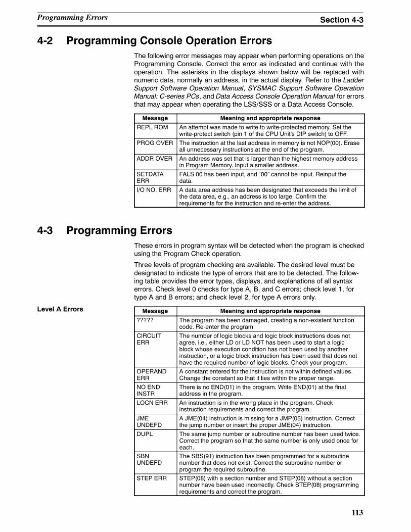
113
4-2 Programming Console Operation ErrorsThe following error messages may appear when performing operations on theProgramming Console. Correct the error as indicated and continue with theoperation. The asterisks in the displays shown below will be replaced withnumeric data, normally an address, in the actual display. Refer to the LadderSupport Software Operation Manual, SYSMAC Support Software OperationManual: C-series PCs, and Data Access Console Operation Manual for errorsthat may appear when operating the LSS/SSS or a Data Access Console.
Message Meaning and appropriate response
REPL ROM An attempt was made to write to write-protected memory. Set thewrite-protect switch (pin 1 of the CPU Units DIP switch) to OFF.
PROG OVER The instruction at the last address in memory is not NOP(00). Eraseall unnecessary instructions at the end of the program.
ADDR OVER An address was set that is larger than the highest memory addressin Program Memory. Input a smaller address.
SETDATAERR
FALS 00 has been input, and 00 cannot be input. Reinput thedata.
I/O NO. ERR A data area address has been designated that exceeds the limit ofthe data area, e.g., an address is too large. Confirm therequirements for the instruction and re-enter the address.
4-3 Programming ErrorsThese errors in program syntax will be detected when the program is checkedusing the Program Check operation.
Three levels of program checking are available. The desired level must bedesignated to indicate the type of errors that are to be detected. The follow-ing table provides the error types, displays, and explanations of all syntaxerrors. Check level 0 checks for type A, B, and C errors; check level 1, fortype A and B errors; and check level 2, for type A errors only.
Message Meaning and appropriate response
????? The program has been damaged, creating a non-existent functioncode. Re-enter the program.
CIRCUITERR
The number of logic blocks and logic block instructions does notagree, i.e., either LD or LD NOT has been used to start a logicblock whose execution condition has not been used by anotherinstruction, or a logic block instruction has been used that does nothave the required number of logic blocks. Check your program.
OPERANDERR
A constant entered for the instruction is not within defined values.Change the constant so that it lies within the proper range.
NO ENDINSTR
There is no END(01) in the program. Write END(01) at the finaladdress in the program.
LOCN ERR An instruction is in the wrong place in the program. Checkinstruction requirements and correct the program.
JMEUNDEFD
A JME(04) instruction is missing for a JMP(05) instruction. Correctthe jump number or insert the proper JME(04) instruction.
DUPL The same jump number or subroutine number has been used twice.Correct the program so that the same number is only used once foreach.
SBNUNDEFD
The SBS(91) instruction has been programmed for a subroutinenumber that does not exist. Correct the subroutine number orprogram the required subroutine.
STEP ERR STEP(08) with a section number and STEP(08) without a sectionnumber have been used incorrectly. Check STEP(08) programmingrequirements and correct the program.
Level A Errors
Programming Errors Section 4-3
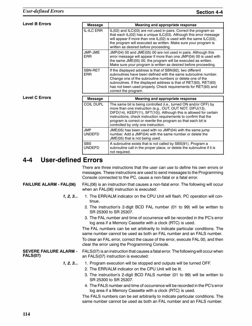
114
Message Meaning and appropriate response
IL-ILC ERR IL(02) and ILC(03) are not used in pairs. Correct the program sothat each IL(02) has a unique ILC(03). Although this error messagewill appear if more than one IL(02) is used with the same ILC(03),the program will executed as written. Make sure your program iswritten as desired before proceeding.
JMP-JMEERR
JMP(04) 00 and JME(05) 00 are not used in pairs. Although thiserror message will appear if more than one JMP(04) 00 is used withthe same JME(05) 00, the program will be executed as written.Make sure your program is written as desired before proceeding.
SBN-RETERR
If the displayed address is that of SBN(92), two differentsubroutines have been defined with the same subroutine number.Change one of the subroutine numbers or delete one of thesubroutines. If the displayed address is that of RET(93), RET(93)has not been used properly. Check requirements for RET(93) andcorrect the program.
Message Meaning and appropriate response
COIL DUPL The same bit is being controlled (i.e., turned ON and/or OFF) bymore than one instruction (e.g., OUT, OUT NOT, DIFU(13),DIFD(14), KEEP(11), SFT(10)). Although this is allowed for certaininstructions, check instruction requirements to confirm that theprogram is correct or rewrite the program so that each bit iscontrolled by only one instruction.
JMPUNDEFD
JME(05) has been used with no JMP(04) with the same jumpnumber. Add a JMP(04) with the same number or delete theJME(05) that is not being used.
SBSUNDEFD
A subroutine exists that is not called by SBS(91). Program asubroutine call in the proper place, or delete the subroutine if it isnot required.
4-4 User-defined ErrorsThere are three instructions that the user can use to define his own errors ormessages. These instructions are used to sendmessages to the ProgrammingConsole connected to the PC, cause a non-fatal or a fatal error.
FAILURE ALARM - FAL(06) FAL(06) is an instruction that causes a non-fatal error. The following will occurwhen an FAL(06) instruction is executed:
1, 2, 3... 1. The ERR/ALM indicator on the CPU Unit will flash. PC operation will con-tinue.
2. The instructions 2-digit BCD FAL number (01 to 99) will be written toSR 25300 to SR 25307.
3. The FAL number and time of occurrence will be recorded in the PCs errorlog area if a Memory Cassette with a clock (RTC) is used.
The FAL numbers can be set arbitrarily to indicate particular conditions. Thesame number cannot be used as both an FAL number and an FALS number.To clear an FAL error, correct the cause of the error, execute FAL 00, and thenclear the error using the Programming Console.
FALS(07) is an instruction that causes a fatal error. The followingwill occurwhenan FALS(07) instruction is executed:
1, 2, 3... 1. Program execution will be stopped and outputs will be turned OFF.2. The ERR/ALM indicator on the CPU Unit will be lit.3. The instructions 2-digit BCD FALS number (01 to 99) will be written toSR 25300 to SR 25307.
4. The FALS number and time of occurrencewill be recorded in the PCs errorlog area if a Memory Cassette with a clock (RTC) is used.
The FALS numbers can be set arbitrarily to indicate particular conditions. Thesame number cannot be used as both an FAL number and an FALS number.
Level B Errors
Level C Errors
SEVERE FAILURE ALARM -FALS(07)
User-defined Errors Section 4-4
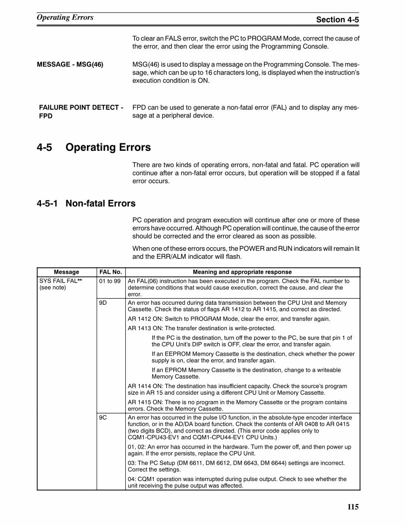
115
To clear an FALS error, switch the PC to PROGRAMMode, correct the cause ofthe error, and then clear the error using the Programming Console.
MESSAGE - MSG(46) MSG(46) is used to display amessage on the ProgrammingConsole. Themes-sage, which can be up to 16 characters long, is displayedwhen the instructionsexecution condition is ON.
FPD can be used to generate a non-fatal error (FAL) and to display any mes-sage at a peripheral device.
4-5 Operating Errors
There are two kinds of operating errors, non-fatal and fatal. PC operation willcontinue after a non-fatal error occurs, but operation will be stopped if a fatalerror occurs.
4-5-1 Non-fatal Errors
PC operation and program execution will continue after one or more of theseerrors haveoccurred. AlthoughPCoperationwill continue, the causeof theerrorshould be corrected and the error cleared as soon as possible.
When one of these errors occurs, thePOWERandRUN indicatorswill remain litand the ERR/ALM indicator will flash.
Message FAL No. Meaning and appropriate response
SYS FAIL FAL**(see note)
01 to 99 An FAL(06) instruction has been executed in the program. Check the FAL number todetermine conditions that would cause execution, correct the cause, and clear theerror.
9D An error has occurred during data transmission between the CPU Unit and MemoryCassette. Check the status of flags AR 1412 to AR 1415, and correct as directed.
AR 1412 ON: Switch to PROGRAM Mode, clear the error, and transfer again.
AR 1413 ON: The transfer destination is write-protected.
If the PC is the destination, turn off the power to the PC, be sure that pin 1 ofthe CPU Units DIP switch is OFF, clear the error, and transfer again.
If an EEPROM Memory Cassette is the destination, check whether the powersupply is on, clear the error, and transfer again.
If an EPROM Memory Cassette is the destination, change to a writeableMemory Cassette.
AR 1414 ON: The destination has insufficient capacity. Check the sources programsize in AR 15 and consider using a different CPU Unit or Memory Cassette.
AR 1415 ON: There is no program in the Memory Cassette or the program containserrors. Check the Memory Cassette.
9C An error has occurred in the pulse I/O function, in the absolute-type encoder interfacefunction, or in the AD/DA board function. Check the contents of AR 0408 to AR 0415(two digits BCD), and correct as directed. (This error code applies only toCQM1-CPU43-EV1 and CQM1-CPU44-EV1 CPU Units.)
01, 02: An error has occurred in the hardware. Turn the power off, and then power upagain. If the error persists, replace the CPU Unit.
03: The PC Setup (DM 6611, DM 6612, DM 6643, DM 6644) settings are incorrect.Correct the settings.
04: CQM1 operation was interrupted during pulse output. Check to see whether theunit receiving the pulse output was affected.
FAILURE POINT DETECT -FPD
Operating Errors Section 4-5
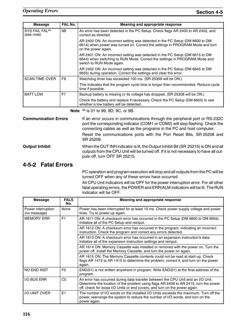
116
Message Meaning and appropriate responseFAL No.
SYS FAIL FAL**(see note)
9B An error has been detected in the PC Setup. Check flags AR 2400 to AR 2402, andcorrect as directed.
AR 2400 ON: An incorrect setting was detected in the PC Setup (DM 6600 to DM6614) when power was turned on. Correct the settings in PROGRAM Mode and turnon the power again.
AR 2401 ON: An incorrect setting was detected in the PC Setup (DM 6615 to DM6644) when switching to RUN Mode. Correct the settings in PROGRAM Mode andswitch to RUN Mode again.
AR 2402 ON: An incorrect setting was detected in the PC Setup (DM 6645 to DM6655) during operation. Correct the settings and clear the error.
SCAN TIME OVER F8 Watchdog timer has exceeded 100 ms. (SR 25309 will be ON.)
This indicates that the program cycle time is longer than recommended. Reduce cycletime if possible.
BATT LOW F7 Backup battery is missing or its voltage has dropped. (SR 25308 will be ON.)
Check the battery and replace if necessary. Check the PC Setup (DM 6655) to seewhether a low battery will be detected.
Note ** is 01 to 99, 9D, 9C, or 9B.
Communication Errors If an error occurs in communications through the peripheral port or RS-232Cport the corresponding indicator (COM1 or COM2) will stop flashing. Check theconnecting cables as well as the programs in the PC and host computer.Reset the communications ports with the Port Reset Bits, SR 25208 andSR 25209.
Output Inhibit When theOUT INH indicator is lit, theOutput Inhibit Bit (SR 25215) isON andalloutputs from theCPUUnit will be turned off. If it is not necessary to have all out-puts off, turn OFF SR 25215.
4-5-2 Fatal ErrorsPCoperation and programexecutionwill stop andall outputs from thePCwill beturned OFF when any of these errors have occurred.All CPUUnit indicators will be OFF for the power interruption error. For all otherfatal operating errors, the POWERandERR/ALM indicators will be lit. TheRUNindicator will be OFF.
Message FALSNo.
Meaning and appropriate response
Power interruption(no message)
None Power has been interrupted for at least 10 ms. Check power supply voltage and powerlines. Try to power-up again.
MEMORY ERR F1 AR 1611 ON: A checksum error has occurred in the PC Setup (DM 6600 to DM 6655).Initialize all of the PC Setup and reinput.AR 1612 ON: A checksum error has occurred in the program, indicating an incorrectinstruction. Check the program and correct any errors detected.AR 1613 ON: A checksum error has occurred in an expansion instructions data.Initialize all of the expansion instruction settings and reinput.AR 1614 ON: Memory Cassette was installed or removed with the power on. Turn thepower off, install the Memory Cassette, and turn the power on again.AR 1615 ON: The Memory Cassette contents could not be read at start-up. Checkflags AR 1412 to AR 1415 to determine the problem, correct it, and turn on the poweragain.
NO END INST F0 END(01) is not written anywhere in program. Write END(01) at the final address of theprogram.
I/O BUS ERR C0 An error has occurred during data transfer between the CPU Unit and an I/O Unit.Determine the location of the problem using flags AR 2408 to AR 2415, turn the poweroff, check for loose I/O Units or end covers, and turn on the power again.
I/O UNIT OVER E1 The number of I/O words on the installed I/O Units exceeds the maximum. Turn off thepower, rearrange the system to reduce the number of I/O words, and turn on thepower again.
Operating Errors Section 4-5
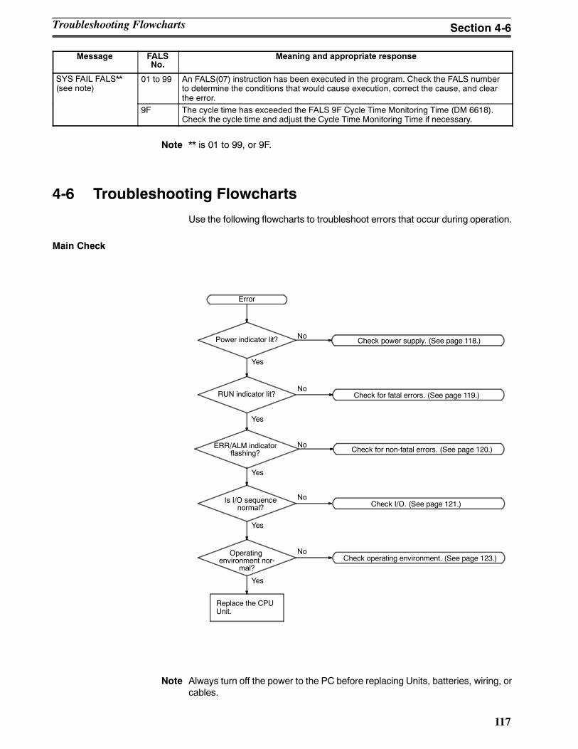
117
Message Meaning and appropriate responseFALSNo.
SYS FAIL FALS**(see note)
01 to 99 An FALS(07) instruction has been executed in the program. Check the FALS numberto determine the conditions that would cause execution, correct the cause, and clearthe error.
9F The cycle time has exceeded the FALS 9F Cycle Time Monitoring Time (DM 6618).Check the cycle time and adjust the Cycle Time Monitoring Time if necessary.
Note ** is 01 to 99, or 9F.
4-6 Troubleshooting Flowcharts
Use the following flowcharts to troubleshoot errors that occur during operation.
Main Check
Check for non-fatal errors. (See page 120.)
Error
Replace the CPUUnit.
Power indicator lit?
RUN indicator lit?
ERR/ALM indicatorflashing?
Is I/O sequencenormal?
Operatingenvironment nor-
mal?
Check for fatal errors. (See page 119.)
Check I/O. (See page 121.)
Check operating environment. (See page 123.)
Yes
Check power supply. (See page 118.)No
No
No
No
No
Yes
Yes
Yes
Yes
Note Always turn off the power to the PC before replacing Units, batteries, wiring, orcables.
Troubleshooting Flowcharts Section 4-6
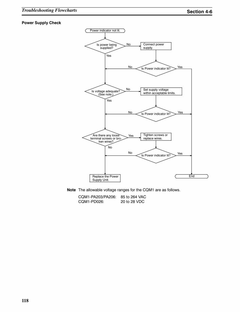
118
Power Supply Check
Power indicator not lit.
Replace the PowerSupply Unit.
Is power beingsupplied?
Is voltage adequate?(See note.)
Are there any looseterminal screws or bro-
ken wires?
Connect powersupply.
Is Power indicator lit?
Set supply voltagewithin acceptable limits.
Is Power indicator lit?
Tighten screws orreplace wires.
End
Yes
No
No Yes
YesNo
No
NoIs Power indicator lit?
Yes
No
Yes
Yes
Note The allowable voltage ranges for the CQM1 are as follows.
CQM1-PA203/PA206: 85 to 264 VACCQM1-PD026: 20 to 28 VDC
Troubleshooting Flowcharts Section 4-6
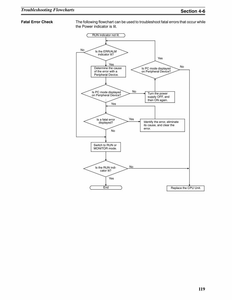
119
Fatal Error Check The following flowchart can be used to troubleshoot fatal errors that occur whilethe Power indicator is lit.
Identify the error, eliminateits cause, and clear theerror.
Is the ERR/ALMindicator lit?
Determine the causeof the error with aPeripheral Device.
End
RUN indicator not lit.
Replace the CPU Unit.
Is PC mode displayedon Peripheral Device?
Turn the powersupply OFF, andthen ON again.
Switch to RUN orMONITOR mode.
No
Yes
Is a fatal errordisplayed?
Is PC mode displayedon Peripheral Device?
No
Yes
Yes
No
Is the RUN indi-cator lit?
No
Yes
Yes
No
Troubleshooting Flowcharts Section 4-6
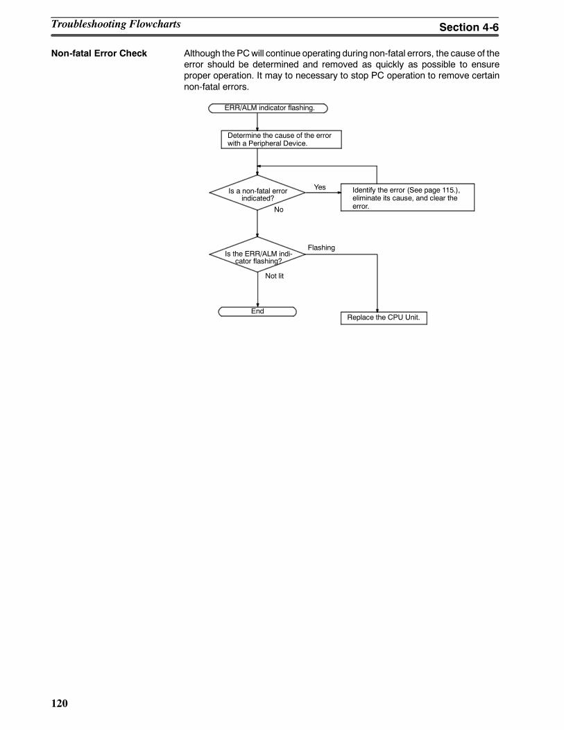
120
Non-fatal Error Check Although the PCwill continue operating during non-fatal errors, the cause of theerror should be determined and removed as quickly as possible to ensureproper operation. It may to necessary to stop PC operation to remove certainnon-fatal errors.
Identify the error (See page 115.),eliminate its cause, and clear theerror.
ERR/ALM indicator flashing.
Is a non-fatal errorindicated?
Is the ERR/ALM indi-cator flashing?
Replace the CPU Unit.End
Determine the cause of the errorwith a Peripheral Device.
No
Yes
Flashing
Not lit
Troubleshooting Flowcharts Section 4-6
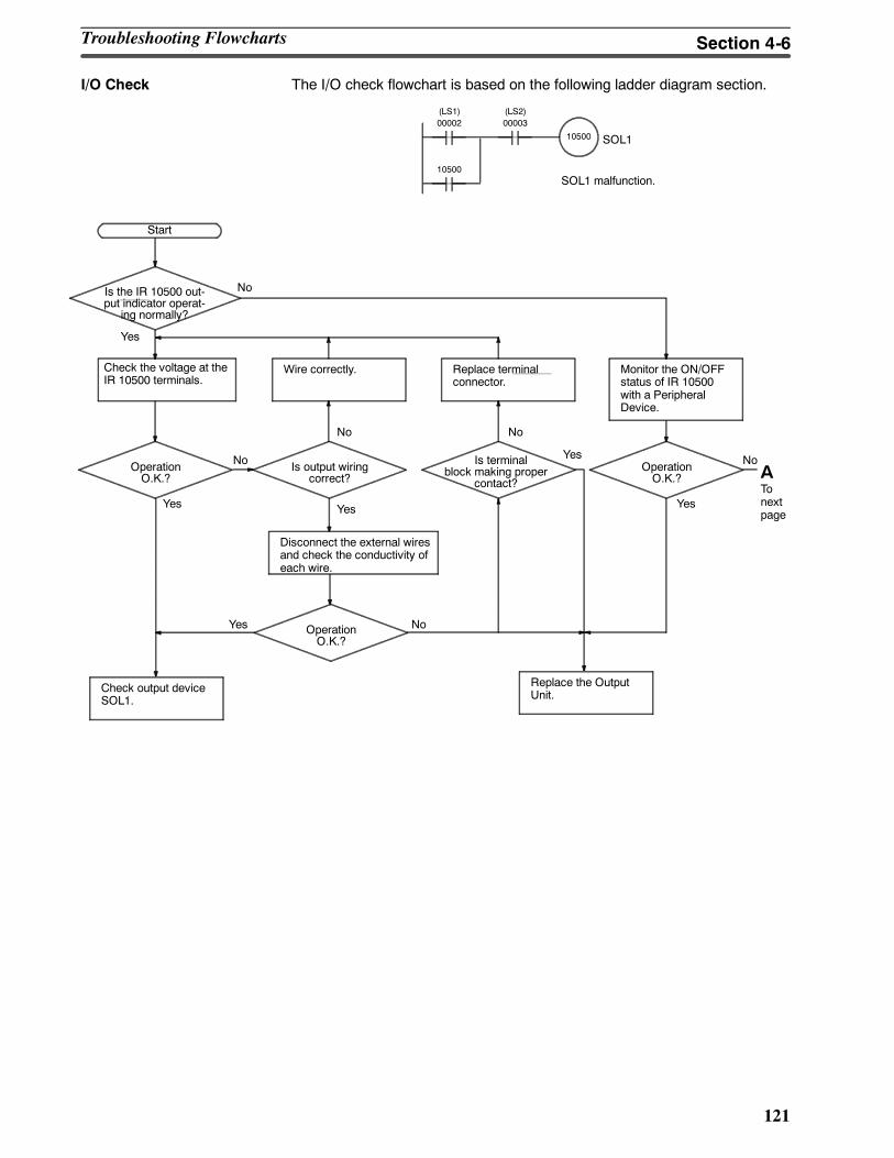
121
I/O Check The I/O check flowchart is based on the following ladder diagram section.
10500
00002(LS1)
00003(LS2)
SOL1 malfunction.
SOL1
10500
Yes
Monitor the ON/OFFstatus of IR 10500with a PeripheralDevice.
NoIs the IR 10500 out-put indicator operat-
ing normally?
Check the voltage at theIR 10500 terminals.
Wire correctly. Replace terminalconnector.
OperationO.K.?
Start
Is output wiringcorrect?
Is terminalblock making proper
contact?
Disconnect the external wiresand check the conductivity ofeach wire.
No
Yes
Check output deviceSOL1.
OperationO.K.?
Replace the OutputUnit.
Yes
No
No
Yes No
OperationO.K.?
NoYes
Yes
ATonextpage
Troubleshooting Flowcharts Section 4-6
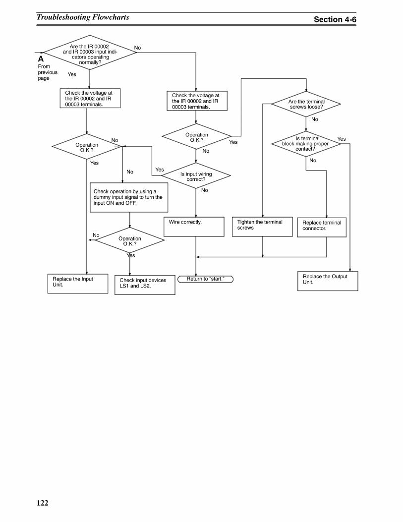
122
Yes
Check the voltage atthe IR 00002 and IR00003 terminals.
Check operation by using adummy input signal to turn theinput ON and OFF.
No
Replace the InputUnit.
Are the terminalscrews loose?
OperationO.K.?
Wire correctly.
Is input wiringcorrect?
Tighten the terminalscrews
Replace terminalconnector.
Is terminalblock making proper
contact?
Check input devicesLS1 and LS2.
Return to start.
Are the IR 00002and IR 00003 input indi-
cators operatingnormally?
OperationO.K.?
Replace the OutputUnit.
OperationO.K.?
Yes
Yes
Yes
Yes
No
No
No
No
No
No
Yes
No
Check the voltage atthe IR 00002 and IR00003 terminals.
AFrompreviouspage
Troubleshooting Flowcharts Section 4-6
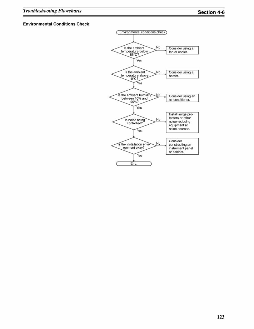
123
Environmental Conditions Check
Consider using afan or cooler.
Is the ambienttemperature below
55°C?
Is the ambienttemperature above
0°C?
Is noise beingcontrolled?
Is the installation envi-ronment okay?
Consider using aheater.
Consider using anair conditioner.
Install surge pro-tectors or othernoise-reducingequipment atnoise sources.
Considerconstructing aninstrument panelor cabinet.
End.
Yes
No
Yes
No
No
No
No
Yes
Yes
Yes
Is the ambient humiditybetween 10% and
90%?
Environmental conditions check
Troubleshooting Flowcharts Section 4-6
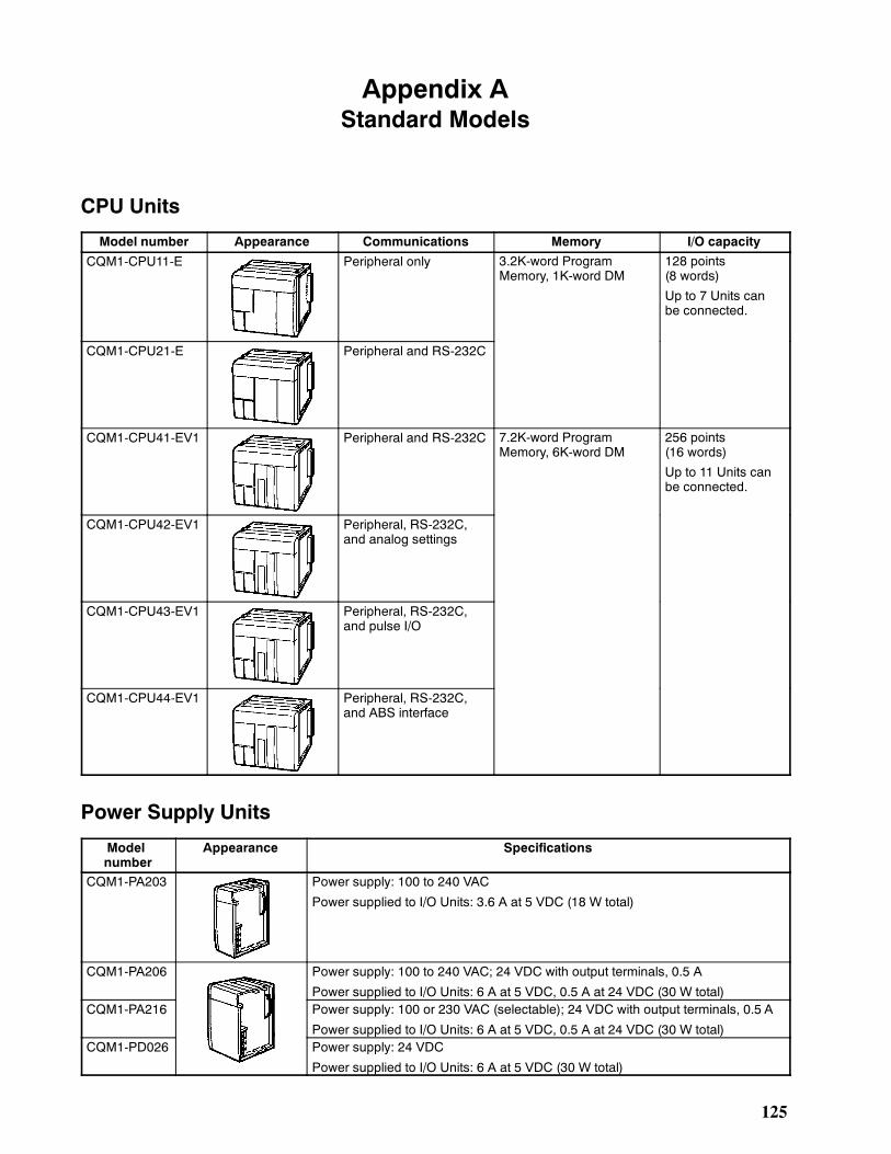
125
Appendix AStandard Models
CPU Units
Model number Appearance Communications Memory I/O capacity
CQM1-CPU11-E Peripheral only 3.2K-word ProgramMemory, 1K-word DM
128 points(8 words)
Up to 7 Units canbe connected.
CQM1-CPU21-E Peripheral and RS-232C
CQM1-CPU41-EV1 Peripheral and RS-232C 7.2K-word ProgramMemory, 6K-word DM
256 points(16 words)
Up to 11 Units canbe connected.
CQM1-CPU42-EV1 Peripheral, RS-232C,and analog settings
CQM1-CPU43-EV1 Peripheral, RS-232C,and pulse I/O
CQM1-CPU44-EV1 Peripheral, RS-232C,and ABS interface
Power Supply Units
Modelnumber
Appearance Specifications
CQM1-PA203 Power supply: 100 to 240 VAC
Power supplied to I/O Units: 3.6 A at 5 VDC (18 W total)
CQM1-PA206 Power supply: 100 to 240 VAC; 24 VDC with output terminals, 0.5 A
Power supplied to I/O Units: 6 A at 5 VDC, 0.5 A at 24 VDC (30 W total)CQM1-PA216 Power supply: 100 or 230 VAC (selectable); 24 VDC with output terminals, 0.5 A
Power supplied to I/O Units: 6 A at 5 VDC, 0.5 A at 24 VDC (30 W total)CQM1-PD026 Power supply: 24 VDC
Power supplied to I/O Units: 6 A at 5 VDC (30 W total)
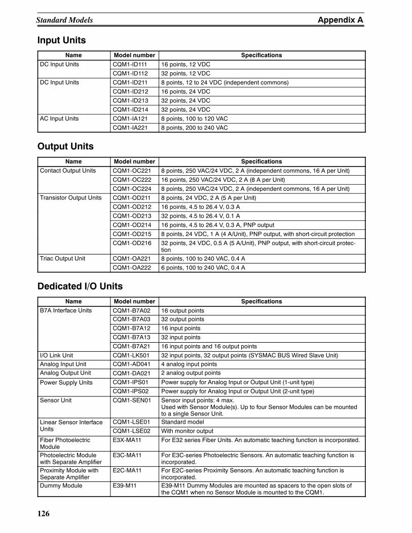
Appendix AStandard Models
126
Input UnitsName Model number Specifications
DC Input Units CQM1-ID111 16 points, 12 VDCp
CQM1-ID112 32 points, 12 VDCDC Input Units CQM1-ID211 8 points, 12 to 24 VDC (independent commons)p
CQM1-ID212 16 points, 24 VDC
CQM1-ID213 32 points, 24 VDC
CQM1-ID214 32 points, 24 VDCAC Input Units CQM1-IA121 8 points, 100 to 120 VACp
CQM1-IA221 8 points, 200 to 240 VAC
Output UnitsName Model number Specifications
Contact Output Units CQM1-OC221 8 points, 250 VAC/24 VDC, 2 A (independent commons, 16 A per Unit)p
CQM1-OC222 16 points, 250 VAC/24 VDC, 2 A (8 A per Unit)
CQM1-OC224 8 points, 250 VAC/24 VDC, 2 A (independent commons, 16 A per Unit)Transistor Output Units CQM1-OD211 8 points, 24 VDC, 2 A (5 A per Unit)p
CQM1-OD212 16 points, 4.5 to 26.4 V, 0.3 A
CQM1-OD213 32 points, 4.5 to 26.4 V, 0.1 A
CQM1-OD214 16 points, 4.5 to 26.4 V, 0.3 A, PNP output
CQM1-OD215 8 points, 24 VDC, 1 A (4 A/Unit), PNP output, with short-circuit protection
CQM1-OD216 32 points, 24 VDC, 0.5 A (5 A/Unit), PNP output, with short-circuit protec-tion
Triac Output Unit CQM1-OA221 8 points, 100 to 240 VAC, 0.4 Ap
CQM1-OA222 6 points, 100 to 240 VAC, 0.4 A
Dedicated I/O UnitsName Model number Specifications
B7A Interface Units CQM1-B7A02 16 output pointsCQM1-B7A03 32 output points
CQM1-B7A12 16 input points
CQM1-B7A13 32 input points
CQM1-B7A21 16 input points and 16 output points
I/O Link Unit CQM1-LK501 32 input points, 32 output points (SYSMAC BUS Wired Slave Unit)Analog Input Unit CQM1-AD041 4 analog input pointsAnalog Output Unit CQM1-DA021 2 analog output points
Power Supply Units CQM1-IPS01 Power supply for Analog Input or Output Unit (1-unit type)pp yCQM1-IPS02 Power supply for Analog Input or Output Unit (2-unit type)
Sensor Unit CQM1-SEN01 Sensor input points: 4 max.Used with Sensor Module(s). Up to four Sensor Modules can be mountedto a single Sensor Unit.
Linear Sensor Interface CQM1-LSE01 Standard modelUnits CQM1-LSE02 With monitor output
Fiber PhotoelectricModule
E3X-MA11 For E32 series Fiber Units. An automatic teaching function is incorporated.
Photoelectric Modulewith Separate Amplifier
E3C-MA11 For E3C-series Photoelectric Sensors. An automatic teaching function isincorporated.
Proximity Module withSeparate Amplifier
E2C-MA11 For E2C-series Proximity Sensors. An automatic teaching function isincorporated.
Dummy Module E39-M11 E39-M11 Dummy Modules are mounted as spacers to the open slots ofthe CQM1 when no Sensor Module is mounted to the CQM1.
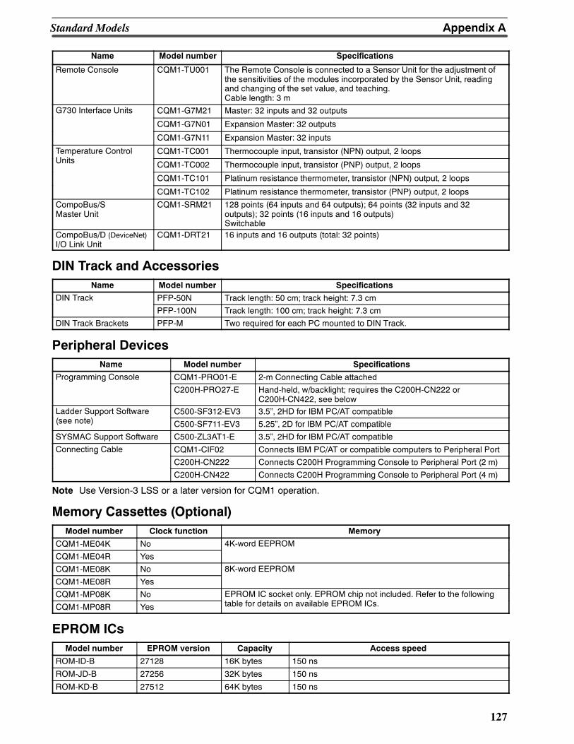
Appendix AStandard Models
127
Name SpecificationsModel number
Remote Console CQM1-TU001 The Remote Console is connected to a Sensor Unit for the adjustment ofthe sensitivities of the modules incorporated by the Sensor Unit, readingand changing of the set value, and teaching.Cable length: 3 m
G730 Interface Units CQM1-G7M21 Master: 32 inputs and 32 outputs
CQM1-G7N01 Expansion Master: 32 outputs
CQM1-G7N11 Expansion Master: 32 inputs
Temperature ControlU it
CQM1-TC001 Thermocouple input, transistor (NPN) output, 2 loopspUnits CQM1-TC002 Thermocouple input, transistor (PNP) output, 2 loops
CQM1-TC101 Platinum resistance thermometer, transistor (NPN) output, 2 loops
CQM1-TC102 Platinum resistance thermometer, transistor (PNP) output, 2 loops
CompoBus/SMaster Unit
CQM1-SRM21 128 points (64 inputs and 64 outputs); 64 points (32 inputs and 32outputs); 32 points (16 inputs and 16 outputs)Switchable
CompoBus/D (DeviceNet)I/O Link Unit
CQM1-DRT21 16 inputs and 16 outputs (total: 32 points)
DIN Track and AccessoriesName Model number Specifications
DIN Track PFP-50N Track length: 50 cm; track height: 7.3 cm
PFP-100N Track length: 100 cm; track height: 7.3 cm
DIN Track Brackets PFP-M Two required for each PC mounted to DIN Track.
Peripheral DevicesName Model number Specifications
Programming Console CQM1-PRO01-E 2-m Connecting Cable attachedg g
C200H-PRO27-E Hand-held, w/backlight; requires the C200H-CN222 orC200H-CN422, see below
Ladder Support Software C500-SF312-EV3 3.5, 2HD for IBM PC/AT compatiblepp(see note) C500-SF711-EV3 5.25, 2D for IBM PC/AT compatible
SYSMAC Support Software C500-ZL3AT1-E 3.5, 2HD for IBM PC/AT compatible
Connecting Cable CQM1-CIF02 Connects IBM PC/AT or compatible computers to Peripheral Portg
C200H-CN222 Connects C200H Programming Console to Peripheral Port (2 m)
C200H-CN422 Connects C200H Programming Console to Peripheral Port (4 m)
Note Use Version-3 LSS or a later version for CQM1 operation.
Memory Cassettes (Optional)Model number Clock function Memory
CQM1-ME04K No 4K-word EEPROM
CQM1-ME04R Yes
CQM1-ME08K No 8K-word EEPROM
CQM1-ME08R Yes
CQM1-MP08K No EPROM IC socket only. EPROM chip not included. Refer to the followingf O CCQM1-MP08R Yes
y p gtable for details on available EPROM ICs.
EPROM ICsModel number EPROM version Capacity Access speed
ROM-ID-B 27128 16K bytes 150 ns
ROM-JD-B 27256 32K bytes 150 ns
ROM-KD-B 27512 64K bytes 150 ns
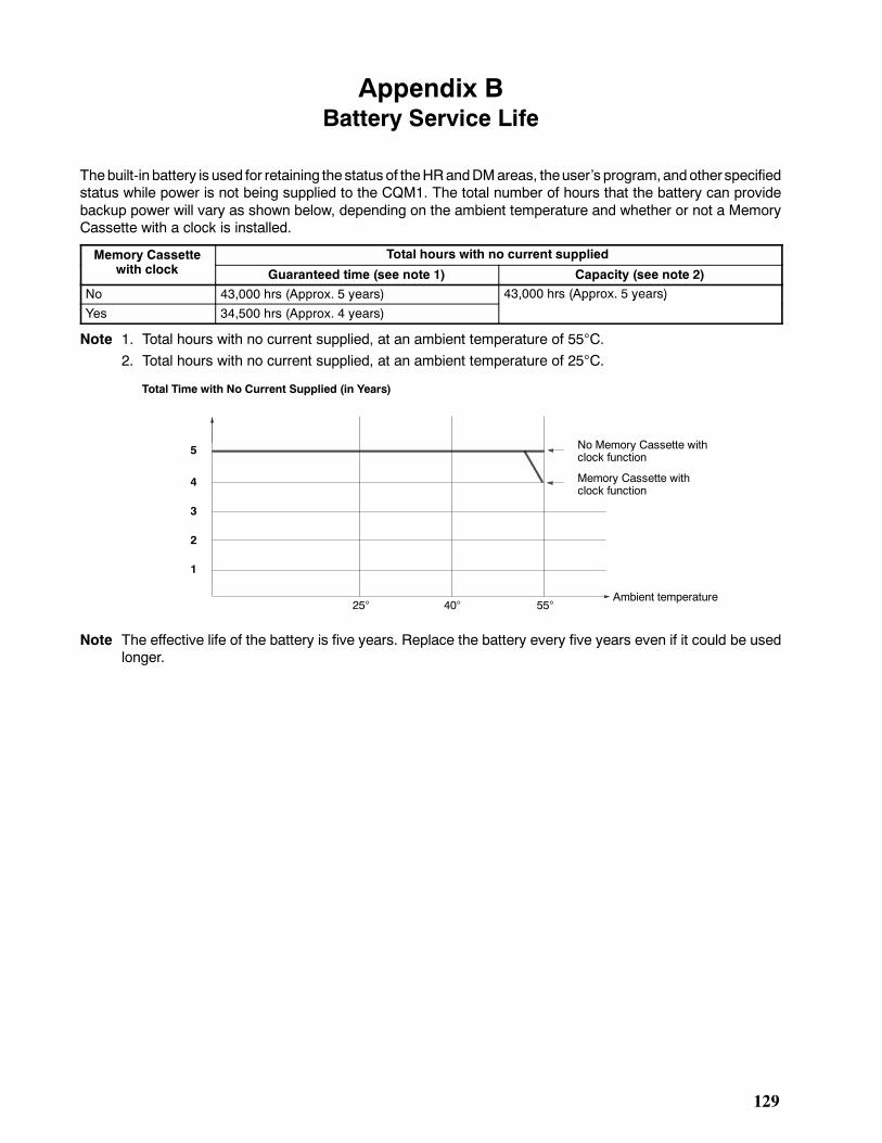
129
Appendix BBattery Service Life
Thebuilt-in battery is used for retaining the status of theHRandDMareas, theusers program,andother specifiedstatus while power is not being supplied to the CQM1. The total number of hours that the battery can providebackup power will vary as shown below, depending on the ambient temperature and whether or not a MemoryCassette with a clock is installed.
Memory Cassette Total hours with no current suppliedywith clock Guaranteed time (see note 1) Capacity (see note 2)
No 43,000 hrs (Approx. 5 years) 43,000 hrs (Approx. 5 years)
Yes 34,500 hrs (Approx. 4 years)
, ( pp y )
Note 1. Total hours with no current supplied, at an ambient temperature of 55°C.2. Total hours with no current supplied, at an ambient temperature of 25°C.
1
2
3
4
5
Total Time with No Current Supplied (in Years)
No Memory Cassette withclock function
Memory Cassette withclock function
Ambient temperature25° 40° 55°
Note The effective life of the battery is five years. Replace the battery every five years even if it could be usedlonger.
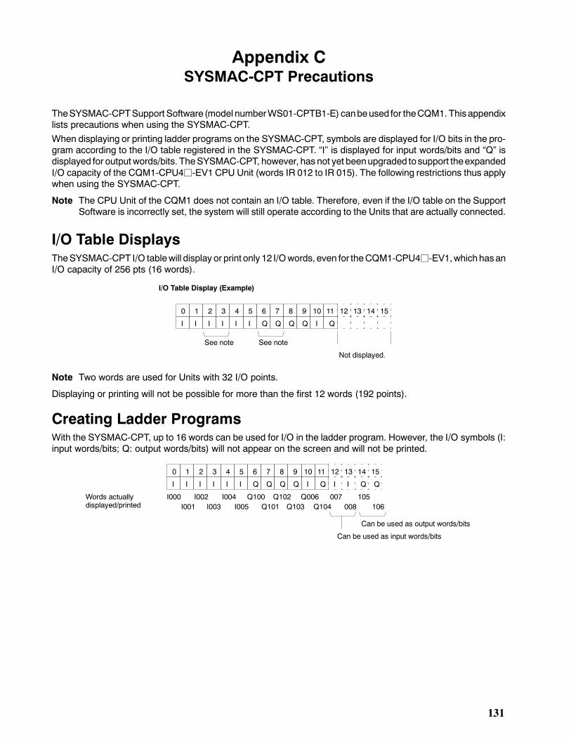
131
Appendix CSYSMAC-CPT Precautions
TheSYSMAC-CPTSupport Software (model numberWS01-CPTB1-E) canbeused for theCQM1. Thisappendixlists precautions when using the SYSMAC-CPT.When displaying or printing ladder programs on the SYSMAC-CPT, symbols are displayed for I/O bits in the pro-gram according to the I/O table registered in the SYSMAC-CPT. I is displayed for input words/bits and Q isdisplayed for output words/bits. TheSYSMAC-CPT, however, has not yet beenupgraded tosupport theexpandedI/O capacity of the CQM1-CPU4j-EV1 CPU Unit (words IR 012 to IR 015). The following restrictions thus applywhen using the SYSMAC-CPT.
Note The CPU Unit of the CQM1 does not contain an I/O table. Therefore, even if the I/O table on the SupportSoftware is incorrectly set, the system will still operate according to the Units that are actually connected.
I/O Table DisplaysTheSYSMAC-CPT I/O tablewill display or print only 12 I/Owords, even for theCQM1-CPU4j-EV1,whichhasanI/O capacity of 256 pts (16 words).
0
I
1
I
2
I
3
I
4
I
5
I
6
Q
7
Q
8
Q
9
Q
10
I
11
Q
12 13 14 15
See note See note
Not displayed.
I/O Table Display (Example)
Note Two words are used for Units with 32 I/O points.
Displaying or printing will not be possible for more than the first 12 words (192 points).
Creating Ladder ProgramsWith the SYSMAC-CPT, up to 16 words can be used for I/O in the ladder program. However, the I/O symbols (I:input words/bits; Q: output words/bits) will not appear on the screen and will not be printed.
0
I
1
I
2
I
3
I
4
I
5
I
6
Q
7
Q
8
Q
9
Q
10
I
11
Q
12
I
13
I
14
Q
15
Q
I000 I002 I004 Q100 Q102 Q006 007 105I001 I003 I005 Q101 Q103 Q104 008 106
Can be used as input words/bits
Can be used as output words/bits
Words actuallydisplayed/printed
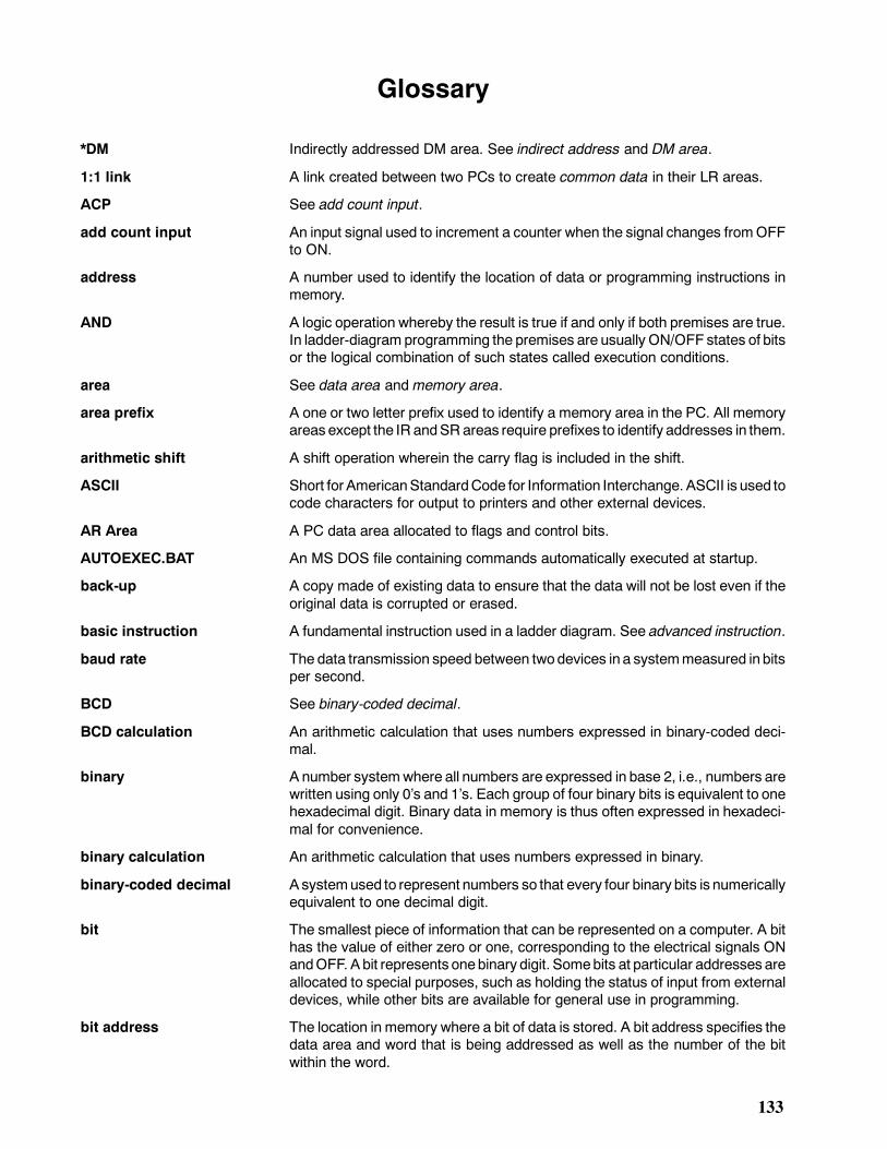
133
Glossary
*DM Indirectly addressed DM area. See indirect address and DM area.
1:1 link A link created between two PCs to create common data in their LR areas.
ACP See add count input.
add count input An input signal used to increment a counter when the signal changes fromOFFto ON.
address A number used to identify the location of data or programming instructions inmemory.
AND A logic operation whereby the result is true if and only if both premises are true.In ladder-diagram programming the premises are usually ON/OFF states of bitsor the logical combination of such states called execution conditions.
area See data area and memory area.
area prefix A one or two letter prefix used to identify a memory area in the PC. All memoryareas except the IR andSRareas require prefixes to identify addresses in them.
arithmetic shift A shift operation wherein the carry flag is included in the shift.
ASCII Short for AmericanStandardCode for Information Interchange. ASCII is used tocode characters for output to printers and other external devices.
AR Area A PC data area allocated to flags and control bits.
AUTOEXEC.BAT An MS DOS file containing commands automatically executed at startup.
back-up A copy made of existing data to ensure that the data will not be lost even if theoriginal data is corrupted or erased.
basic instruction A fundamental instruction used in a ladder diagram. See advanced instruction.
baud rate The data transmission speed between twodevices in a systemmeasured in bitsper second.
BCD See binary-coded decimal.
BCD calculation An arithmetic calculation that uses numbers expressed in binary-coded deci-mal.
binary A number systemwhere all numbers are expressed in base 2, i.e., numbers arewritten using only 0s and 1s. Each group of four binary bits is equivalent to onehexadecimal digit. Binary data in memory is thus often expressed in hexadeci-mal for convenience.
binary calculation An arithmetic calculation that uses numbers expressed in binary.
binary-coded decimal Asystemused to represent numbers so that every four binary bits is numericallyequivalent to one decimal digit.
bit The smallest piece of information that can be represented on a computer. A bithas the value of either zero or one, corresponding to the electrical signals ONandOFF. Abit represents onebinary digit. Somebits at particular addresses areallocated to special purposes, such as holding the status of input from externaldevices, while other bits are available for general use in programming.
bit address The location in memory where a bit of data is stored. A bit address specifies thedata area and word that is being addressed as well as the number of the bitwithin the word.
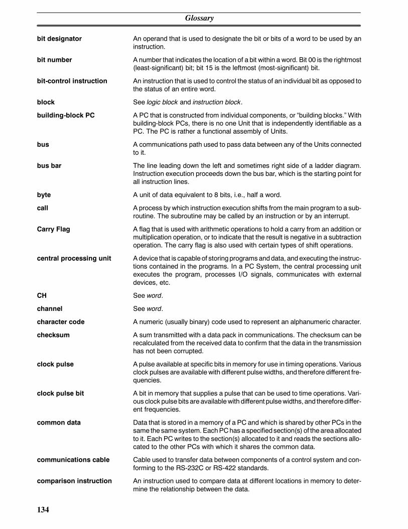
Glossary
134
bit designator An operand that is used to designate the bit or bits of a word to be used by aninstruction.
bit number A number that indicates the location of a bit within a word. Bit 00 is the rightmost(least-significant) bit; bit 15 is the leftmost (most-significant) bit.
bit-control instruction An instruction that is used to control the status of an individual bit as opposed tothe status of an entire word.
block See logic block and instruction block.
building-block PC A PC that is constructed from individual components, or building blocks. Withbuilding-block PCs, there is no one Unit that is independently identifiable as aPC. The PC is rather a functional assembly of Units.
bus A communications path used to pass data between any of the Units connectedto it.
bus bar The line leading down the left and sometimes right side of a ladder diagram.Instruction execution proceeds down the bus bar, which is the starting point forall instruction lines.
byte A unit of data equivalent to 8 bits, i.e., half a word.
call A process by which instruction execution shifts from themain program to a sub-routine. The subroutine may be called by an instruction or by an interrupt.
Carry Flag A flag that is used with arithmetic operations to hold a carry from an addition ormultiplication operation, or to indicate that the result is negative in a subtractionoperation. The carry flag is also used with certain types of shift operations.
central processing unit Adevice that is capable of storing programsanddata, andexecuting the instruc-tions contained in the programs. In a PC System, the central processing unitexecutes the program, processes I/O signals, communicates with externaldevices, etc.
CH See word.
channel See word.
character code A numeric (usually binary) code used to represent an alphanumeric character.
checksum A sum transmitted with a data pack in communications. The checksum can berecalculated from the received data to confirm that the data in the transmissionhas not been corrupted.
clock pulse A pulse available at specific bits inmemory for use in timing operations. Variousclock pulses are available with different pulsewidths, and therefore different fre-quencies.
clock pulse bit A bit in memory that supplies a pulse that can be used to time operations. Vari-ous clock pulsebits are availablewith different pulsewidths, and thereforediffer-ent frequencies.
common data Data that is stored in a memory of a PC and which is shared by other PCs in thesame the samesystem. EachPChas a specifiedsection(s) of theareaallocatedto it. Each PCwrites to the section(s) allocated to it and reads the sections allo-cated to the other PCs with which it shares the common data.
communications cable Cable used to transfer data between components of a control system and con-forming to the RS-232C or RS-422 standards.
comparison instruction An instruction used to compare data at different locations in memory to deter-mine the relationship between the data.
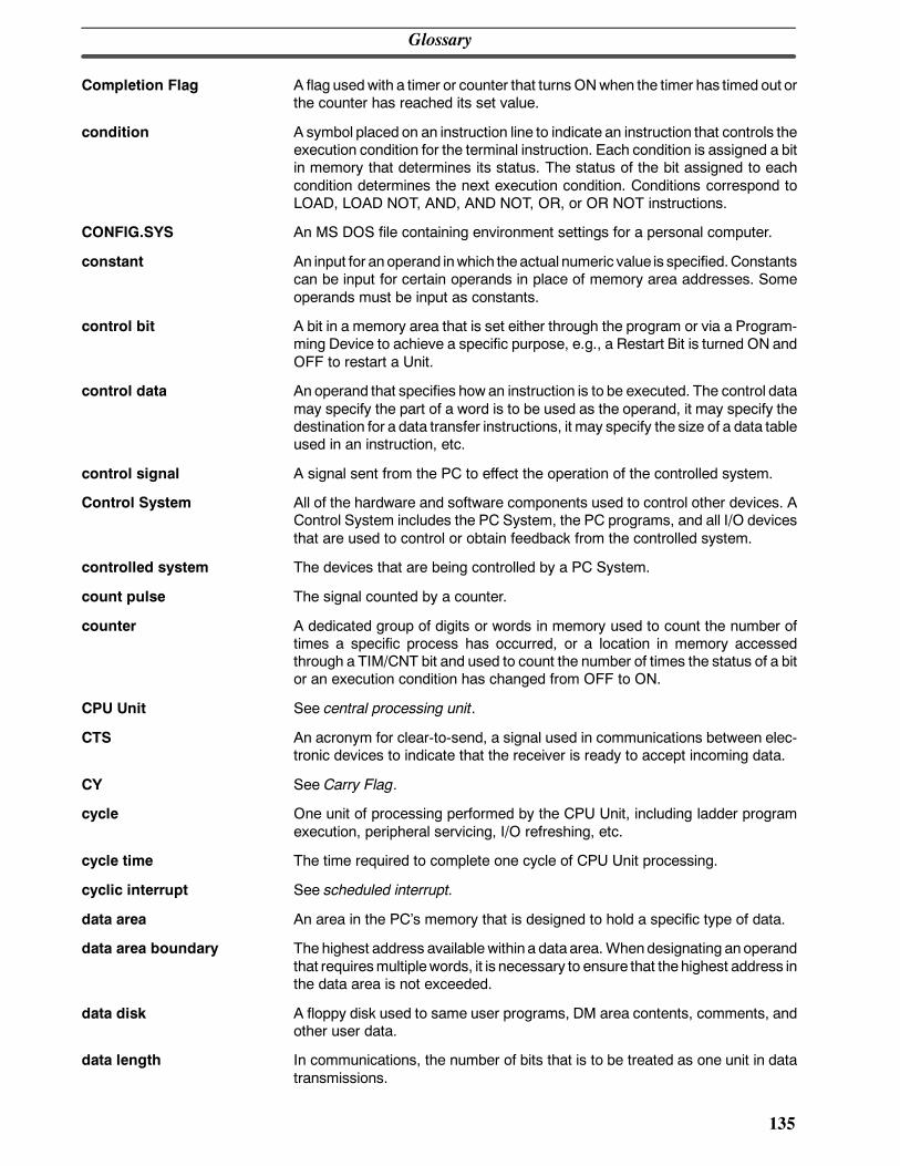
Glossary
135
Completion Flag A flag usedwith a timer or counter that turns ONwhen the timer has timed out orthe counter has reached its set value.
condition A symbol placed on an instruction line to indicate an instruction that controls theexecution condition for the terminal instruction. Each condition is assigned a bitin memory that determines its status. The status of the bit assigned to eachcondition determines the next execution condition. Conditions correspond toLOAD, LOAD NOT, AND, AND NOT, OR, or OR NOT instructions.
CONFIG.SYS An MS DOS file containing environment settings for a personal computer.
constant An input for anoperand inwhich theactual numeric value is specified.Constantscan be input for certain operands in place of memory area addresses. Someoperands must be input as constants.
control bit A bit in a memory area that is set either through the program or via a Program-ming Device to achieve a specific purpose, e.g., a Restart Bit is turned ON andOFF to restart a Unit.
control data An operand that specifies how an instruction is to be executed. The control datamay specify the part of a word is to be used as the operand, it may specify thedestination for a data transfer instructions, it may specify the size of a data tableused in an instruction, etc.
control signal A signal sent from the PC to effect the operation of the controlled system.
Control System All of the hardware and software components used to control other devices. AControl System includes the PC System, the PC programs, and all I/O devicesthat are used to control or obtain feedback from the controlled system.
controlled system The devices that are being controlled by a PC System.
count pulse The signal counted by a counter.
counter A dedicated group of digits or words in memory used to count the number oftimes a specific process has occurred, or a location in memory accessedthrough a TIM/CNT bit and used to count the number of times the status of a bitor an execution condition has changed from OFF to ON.
CPU Unit See central processing unit.
CTS An acronym for clear-to-send, a signal used in communications between elec-tronic devices to indicate that the receiver is ready to accept incoming data.
CY See Carry Flag.
cycle One unit of processing performed by the CPU Unit, including ladder programexecution, peripheral servicing, I/O refreshing, etc.
cycle time The time required to complete one cycle of CPU Unit processing.
cyclic interrupt See scheduled interrupt.
data area An area in the PCs memory that is designed to hold a specific type of data.
data area boundary The highest address available within a data area.Whendesignating anoperandthat requiresmultiplewords, it is necessary to ensure that thehighest address inthe data area is not exceeded.
data disk A floppy disk used to same user programs, DM area contents, comments, andother user data.
data length In communications, the number of bits that is to be treated as one unit in datatransmissions.
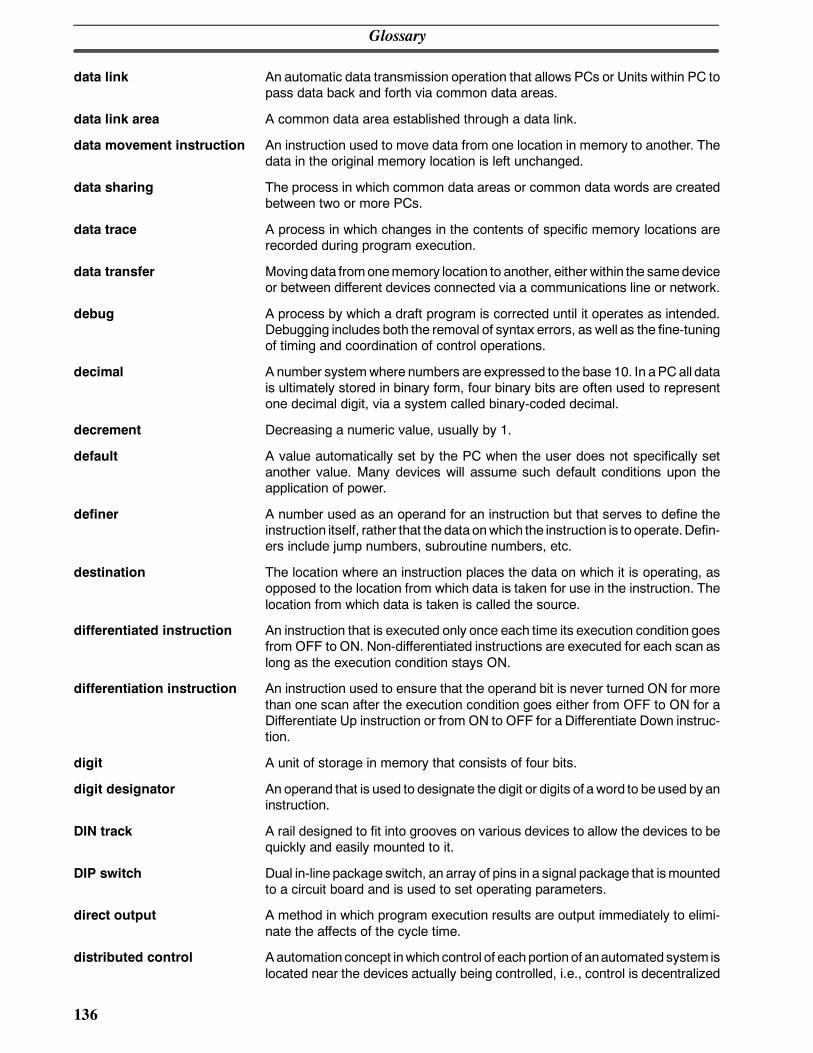
Glossary
136
data link An automatic data transmission operation that allows PCs or Units within PC topass data back and forth via common data areas.
data link area A common data area established through a data link.
data movement instruction An instruction used to move data from one location in memory to another. Thedata in the original memory location is left unchanged.
data sharing The process in which common data areas or common data words are createdbetween two or more PCs.
data trace A process in which changes in the contents of specific memory locations arerecorded during program execution.
data transfer Movingdata fromonememory location to another, either within the samedeviceor between different devices connected via a communications line or network.
debug A process by which a draft program is corrected until it operates as intended.Debugging includes both the removal of syntax errors, as well as the fine-tuningof timing and coordination of control operations.
decimal A number systemwhere numbers are expressed to the base 10. In aPC all datais ultimately stored in binary form, four binary bits are often used to representone decimal digit, via a system called binary-coded decimal.
decrement Decreasing a numeric value, usually by 1.
default A value automatically set by the PC when the user does not specifically setanother value. Many devices will assume such default conditions upon theapplication of power.
definer A number used as an operand for an instruction but that serves to define theinstruction itself, rather that thedata onwhich the instruction is to operate.Defin-ers include jump numbers, subroutine numbers, etc.
destination The location where an instruction places the data on which it is operating, asopposed to the location from which data is taken for use in the instruction. Thelocation from which data is taken is called the source.
differentiated instruction An instruction that is executed only once each time its execution condition goesfrom OFF to ON. Non-differentiated instructions are executed for each scan aslong as the execution condition stays ON.
differentiation instruction An instruction used to ensure that the operand bit is never turned ON for morethan one scan after the execution condition goes either from OFF to ON for aDifferentiate Up instruction or from ON to OFF for a Differentiate Down instruc-tion.
digit A unit of storage in memory that consists of four bits.
digit designator An operand that is used to designate the digit or digits of a word to beused by aninstruction.
DIN track A rail designed to fit into grooves on various devices to allow the devices to bequickly and easily mounted to it.
DIP switch Dual in-line package switch, an array of pins in a signal package that ismountedto a circuit board and is used to set operating parameters.
direct output A method in which program execution results are output immediately to elimi-nate the affects of the cycle time.
distributed control Aautomation concept inwhich control of eachportion of anautomated system islocated near the devices actually being controlled, i.e., control is decentralized
Glossary
137
and distributed over the system. Distributed control is a concept basic to PCSystems.
DM area A data area used to hold only word data. Words in the DM area cannot beaccessed bit by bit.
DM word A word in the DM area.
downloading The process of transferring a program or data from a higher-level or host com-puter to a lower-level or slave computer. If a Programming Device is involved,the Programming Device is considered the host computer.
EEPROM Electrically erasable programmable read-only memory; a type of ROM in whichstored data can be erased and reprogrammed. This is accomplished using aspecial control lead connected to the EEPROM chip and can be done withouthaving to remove the EEPROM chip from the device in which it is mounted.
electrical noise Randomvariations of oneormoreelectrical characteristics suchas voltage, cur-rent, and data, which might interfere with the normal operation of a device.
EPROM Erasable programmable read-only memory; a type of ROM inwhich storeddatacan be erased, by ultraviolet light or other means, and reprogrammed.
error code A numeric code generated to indicate that an error exists, and something aboutthe nature of the error. Some error codes are generated by the system; othersare defined in the program by the operator.
Error Log Area An area used to store records indicating the time and nature of errors that haveoccurred in the system.
even parity A communication setting that adjusts the number of ON bits so that it is alwayseven. See parity.
event processing Processing that is performed in response to an event, e.g., an interrupt signal.
exclusive NOR A logic operationwhereby the result is true if bothof thepremises are trueorbothof the premises are false. In ladder-diagram programming, the premises areusually the ON/OFF states of bits, or the logical combination of such states,called execution conditions.
exclusive OR A logic operation whereby the result is true if one, and only one, of the premisesis true. In ladder-diagram programming the premises are usually the ON/OFFstates of bits, or the logical combination of such states, called execution condi-tions.
execution condition The ON or OFF status under which an instruction is executed. The executioncondition is determined by the logical combination of conditions on the sameinstruction line and up to the instruction currently being executed.
execution cycle Thecycle used to execute all processes requiredby theCPUUnit, includingpro-gram execution, I/O refreshing, peripheral servicing, etc.
execution time The time required for the CPU Unit to execute either an individual instruction oran entire program.
extended counter A counter created in a program by using two or more count instructions in suc-cession. Such a counter is capable of counting higher than any of the standardcounters provided by the individual instructions.
extended timer A timer created in a program by using two or more timers in succession. Such atimer is capable of timing longer than any of the standard timers provided by theindividual instructions.
Glossary
138
FA Factory automation.
factory computer A general-purpose computer, usually quite similar to a business computer, thatis used in automated factory control.
FAL error An error generated from the user program by execution of an FAL(06) instruc-tion.
FALS error An error generated from the user program by execution of an FALS(07) instruc-tion or an error generated by the system.
fatal error An error that stops PC operation and requires correction before operation cancontinue.
FCS See frame checksum.
flag Adedicatedbit inmemory that is set by thesystem to indicate some typeof oper-ating status. Some flags, such as the carry flag, can also be set by the operatoror via the program.
flicker bit A bit that is programmed to turn ON and OFF at a specific frequency.
floating-point decimal A decimal number expressed as a number (themantissa) multiplied by a powerof 10, e.g., 0.538 x 10--5.
force reset Theprocess of forcibly turningOFFabit via a programmingdevice. Bits areusu-ally turned OFF as a result of program execution.
force set The process of forcibly turning ONa bit via a programming device. Bits are usu-ally turned ON as a result of program execution.
forced status The status of bits that have been force reset or force set.
frame checksum The results of exclusive ORing all data within a specified calculation range. Theframe checksum can be calculated on both the sending and receiving end of adata transfer to confirm that data was transmitted correctly.
function code A two-digit number used to input an instruction into the PC.
hardware error Anerror originating in thehardware structure (electronic components) of thePC,as opposed to a software error, which originates in software (i.e., programs).
header code A code in an instruction that specifies what the instruction is to do.
hexadecimal A number system where all numbers are expressed to the base 16. In a PC alldata is ultimately stored in binary form, however, displays and inputs on Pro-gramming Devices are often expressed in hexadecimal to simplify operation.Eachgroupof four binary bits is numerically equivalent to one hexadecimal digit.
host computer A computer that is used to transfer data to or receive data from a PC in a HostLink system. The host computer is used for data management and overall sys-tem control. Host computers are generally small personal or business comput-ers.
host interface An interface that allows communications with a host computer.
host link An interface connecting a PC to a host computer to enable monitoring or pro-gram control from the host computer.
HR area A memory area that preserves bit status during power interrupts and used aswork bits in programming.
I/O bit Abit inmemory used to hold I/O status. Input bits reflect the status of input termi-nals; output bits hold the status for output terminals.
Glossary
139
I/O capacity The number of inputs and outputs that a PC is able to handle. This numberranges from around one hundred for smaller PCs to two thousand for the largestones.
I/O delay Thedelay in time fromwhenasignal is sent to anoutput towhen the status of theoutput is actually in effect or the delay in time from when the status of an inputchanges until the signal indicating the change in the status is received.
I/O device A device connected to the I/O terminals on I/O Units. I/O devices may be eitherpart of the Control System, if they function to help control other devices, or theymay be part of the controlled system.
I/O interrupt An interrupt generated by a signal from I/O.
I/O point The place at which an input signal enters the PC System, or at which an outputsignal leaves the PC System. In physical terms, I/O points correspond to termi-nals or connector pins on a Unit; in terms of programming, an I/O points corre-spond to I/O bits in the IR area.
I/O refreshing The process of updating output status sent to external devices so that it agreeswith the status of output bits held inmemory andof updating input bits inmemoryso that they agree with the status of inputs from external devices.
I/O response time The time required for an output signal to be sent from the PC in response to aninput signal received from an external device.
I/O Unit TheUnits in aPC that arephysically connected to I/Odevices to input andoutputsignals. I/OUnits include Input Units andOutput Units, eachofwhich isavailablein a range of specifications.
I/O word A word in the IR area that is allocated to a Unit in the PC System and is used tohold I/O status for that Unit.
IBM PC/AT or compatible A computer that has similar architecture to, that is logically compatible with, andthat can run software designed for an IBM PC/AT computer.
increment Increasing a numeric value, usually by 1.
indirect address An address whose contents indicates another address. The contents of thesecond address will be used as the actual operand.
initialization error An error that occurs either in hardware or software during the PC Systemstartup, i.e., during initialization.
initialize Part of the startup process whereby some memory areas are cleared, systemsetup is checked, and default values are set.
input The signal coming from an external device into the PC. The term input is oftenused abstractly or collectively to refer to incoming signals.
input bit A bit in the IR area that is allocated to hold the status of an input.
input device An external device that sends signals into the PC System.
input point The point at which an input enters the PC System. Input points correspondphysically to terminals or connector pins.
input signal Achange in the status of a connection entering thePC. Generally an input signalis said to exist when, for example, a connection point goes from low to high volt-age or from a nonconductive to a conductive state.
install The preparation necessary to use a program or software package, such as theLSS or SSS, on a computer.
Glossary
140
instruction A direction given in the program that tells the PC of the action to be carried out,and the data to be used in carrying out the action. Instructions can be used tosimply turn a bit ON or OFF, or they can perform much more complex actions,such as converting and/or transferring large blocks of data.
instruction block A group of instructions that is logically related in a ladder-diagram program. Alogic block includes all of the instruction lines that interconnect with each otherfrom one or more line connecting to the left bus bar to one or more right-handinstructions connecting to the right bus bar.
instruction execution time The time required to execute an instruction. The execution time for any oneinstruction can vary with the execution conditions for the instruction and theoperands used in it.
instruction line A group of conditions that lie together on the same horizontal line of a ladder dia-gram. Instruction lines can branch apart or join together to form instructionblocks. Also called a rung.
interface An interface is the conceptual boundary between systems or devices and usu-ally involves changes in the way the communicated data is represented. Inter-face devices perform operations like changing the coding, format, or speed ofthe data.
interlock A programmingmethod used to treat a number of instructions as agroup so thatthe entire group can be reset together when individual execution is not required.An interlockedprogramsection is executed normally for anONexecution condi-tion and partially reset for an OFF execution condition.
interrupt (signal) A signal that stops normal program execution and causes a subroutine to be runor other processing to take place.
interrupt program A program that is executed in response to an interrupt.
inverse condition See normally closed condition.
JIS An acronym for Japanese Industrial Standards.
jump A type of programming where execution moves directly from one point in a pro-gram to another, without sequentially executing any instructions in between.
jump number A definer used with a jump that defines the points from and to which a jump is tobe made.
ladder diagram (program) A form of program arising out of relay-based control systems that uses circuit-type diagrams to represent the logic flow of programming instructions. Theappearance of the program is similar to a ladder, and thus the name.
ladder diagram symbol A symbol used in drawing a ladder-diagram program.
ladder instruction An instruction that represents the conditions on a ladder-diagram program. Theother instructions in a ladder diagram fall along the right side of the diagram andare called terminal instructions.
Ladder Support Software A software package installed on a IBM PC/AT or compatible computer to func-tion as a Programming Device.
least-significant (bit/word) See rightmost (bit/word).
LED Acronym for light-emitting diode; a device used as for indicators or displays.
leftmost (bit/word) The highest numbered bits of a group of bits, generally of an entire word, or thehighest numbered words of a group of words. These bits/words are often calledmost-significant bits/words.
Glossary
141
link A hardware or software connection formed between two Units. Link can refereither to a part of the physical connection between two Units or a software con-nection created to data existing at another location (i.e., data links).
load The processes of copying data either from an external device or from a storagearea to an active portion of the system such as a display buffer. Also, an outputdevice connected to the PC is called a load.
logic block A group of instructions that is logically related in a ladder-diagram program andthat requires logic block instructions to relate it to other instructions or logicblocks.
logic block instruction An instruction used to locally combine the execution condition resulting from alogic block with a current execution condition. The current execution conditioncould be the result of a single condition, or of another logic block. ANDLoad andOR Load are the two logic block instructions.
logic instruction Instructions used to logically combine the content of two words and output thelogical results to a specified result word. The logic instructions combine all thesame-numbered bits in the twowords andoutput the result to the bit of the samenumber in the specified result word.
LR area A data area that is used in data links.
LSS See Ladder Support Software.
main program All of a program except for subroutine and interrupt programs.
mark trace A process in which changes in the contents of specific memory locations arerecorded during program execution.
masked bit A bit whose status has been temporarily made ineffective.
masking Covering an interrupt signal so that the interrupt is not effective until themask isremoved.
megabyte A unit of storage equal to one million bytes.
memory area Any of the areas in the PC used to hold data or programs.
message number A number assigned to a message generated with the MESSAGE instruction.
mnemonic code A form of a ladder-diagram program that consists of a sequential list of theinstructions without using a ladder diagram.
MONITOR mode A mode of PC operation in which normal program execution is possible, andwhich allowsmodification of data held inmemory. Used formonitoring or debug-ging the PC.
most-significant (bit/word) See leftmost (bit/word).
NC input An input that is normally closed, i.e., the input signal is considered to be presentwhen the circuit connected to the input opens.
negative delay Adelay set for a data trace inwhich recordingdata begins before the trace signalby a specified amount.
nesting Programming one loop within another loop, programming a call to a subroutinewithin another subroutine, or programming one jump within another.
NO input An input that is normally open, i.e., the input signal is considered to be presentwhen the circuit connected to the input closes.
noise interference Disturbances in signals caused by electrical noise.
Glossary
142
nonfatal error A hardware or software error that produces a warning but does not stop the PCfrom operating.
normal condition See normally open condition.
normally closed condition A condition that produces an ON execution condition when the bit assigned to itis OFF, and an OFF execution condition when the bit assigned to it is ON.
normally open condition A condition that produces an ON execution condition when the bit assigned to itis ON, and an OFF execution condition when the bit assigned to it is OFF.
NOT A logic operation which inverts the status of the operand. For example, ANDNOT indicates an AND operation with the opposite of the actual status of theoperand bit.
OFF The status of an input or output when a signal is said not to bepresent. TheOFFstate is generally representedby a lowvoltageor by non-conductivity, but canbedefined as the opposite of either.
OFF delay The delay between the time when a signal is switched OFF (e.g., by an inputdevice or PC) and the time when the signal reaches a state readable as anOFFsignal (i.e., as no signal) by a receiving party (e.g., output device or PC).
offset Apositive or negative valueadded to a base value suchas anaddress to specifya desired value.
ON Thestatus of an input or output whenasignal is said to be present. TheONstateis generally represented by a high voltage or by conductivity, but can be definedas the opposite of either.
ON delay The delay between the time when an ON signal is initiated (e.g., by an inputdevice or PC) and the time when the signal reaches a state readable as an ONsignal by a receiving party (e.g., output device or PC).
one-shot bit A bit that is turnedONor OFF for a specified interval of timewhich is longer thanone scan.
one-to-one link See 1:1 link.
online edit The process of changed the program directly in the PC from a ProgrammingDevice. Online editing is possible in PROGRAM or MONITOR mode. In MON-ITOR mode, the program can actually be changed while it is being
operand The values designated as the data to be used for an instruction. An operand canbe input as a constant expressing the actual numeric value to be used or as anaddress to express the location in memory of the data to be used.
operand bit A bit designated as an operand for an instruction.
operand word A word designated as an operand for an instruction.
operating modes One of three PCmodes: PROGRAMmode,MONITORmode, andRUNmode.
operating error An error that occurs during actual PC operation as opposed to an initializationerror, which occurs before actual operations can begin.
OR A logic operation whereby the result is true if either of two premises is true, or ifboth are true. In ladder-diagramprogramming thepremisesare usuallyON/OFFstates of bits or the logical combination of such states called execution condi-tions.
output The signal sent from the PC to an external device. The term output is often usedabstractly or collectively to refer to outgoing signals.
Glossary
143
output bit A bit in the IR area that is allocated to hold the status to be sent to an outputdevice.
output device An external device that receives signals from the PC System.
output point The point at which an output leaves the PC System. Output points correspondphysically to terminals or connector pins.
output signal A signal being sent to an external device. Generally an output signal is said toexist when, for example, a connectionpoint goes from low tohighvoltageor froma nonconductive to a conductive state.
overflow The state where the capacity of a data storage location has been exceeded.
overseeing Part of the processing performed by the CPU Unit that includes general tasksrequired to operate the PC.
overwrite Changing the content of a memory location so that the previous content is lost.
parity Adjustment of the number of ON bits in a word or other unit of data so that thetotal is always an even number or always an odd number. Parity is generallyused to check theaccuracy of data after being transmitted by confirming that thenumber of ON bits is still even or still odd.
parity check Checking parity to ensure that transmitted data has not been corrupted.
PC See Programmable Controller.
PC configuration The arrangement and interconnections of theUnits that are put together to forma functional PC.
PC System With building-block PCs, all of the Units connected up to, but not including, theI/O devices. The boundaries of a PC System are the PC and the program in itsCPU Unit at the upper end; and the I/O Units at the lower end.
PCB See printed circuit board.
PC Setup A group of operating parameters set in the PC from a Programming Device tocontrol PC operation.
Peripheral Device Devices connected to a PC System to aid in system operation. Peripheraldevices include printers, programming devices, external storage media, etc.
peripheral servicing Processing signals to and from peripheral devices, including refreshing, com-munications processing, interrupts, etc.
port A connector on a PC or computer that serves as a connection to an externaldevice.
positive delay A delay set for a data trace in which recording data begins after the trace signalby a specified amount.
Power Supply Unit AUnit that connected to a PC that provides power at the voltage required by theother Units.
present value Thecurrent value registered in a device at any instant during its operation. Pres-ent value is abbreviated as PV. Theuse of this term is generally restricted to tim-ers and counters.
printed circuit board A board onto which electrical circuits are printed for mounting into a computer orelectrical device.
PROGRAM mode Amode of operation that allows inputting and debugging of programs to be car-ried out, but that does not permit normal execution of the program.
Glossary
144
Programmable Controller A computerized device that can accept inputs from external devices and gener-ate outputs to external devices according to a program held in memory. Pro-grammable Controllers are used to automate control of external devices.Although single-unit Programmable Controllers are available, building-blockProgrammable Controllers are constructed from separate components. SuchProgrammable Controllers are formed only when enough of these separatecomponents are assembled to form a functional assembly.
programmed alarm Analarmgivenas a result of executionof an instruction designed to generate thealarm in the program, as opposed to one generated by the system.
programmed error An error arising as a result of the execution of an instruction designed to gener-ate the error in the program, as opposed to one generated by the system.
programmed message Amessage generated as a result of execution of an instruction designed to gen-erate themessage in the program, as opposed to one generated by the system.
Programming Console The portable form of Programming Device for a PC.
Programming Device A Peripheral Device used to input a program into a PC or to alter or monitor aprogram already held in the PC. There are dedicated programming devices,such as Programming Consoles, and there are non-dedicated devices, such asa host computer.
PROM Programmable read-only memory; a type of ROM into which the program ordata may be written after manufacture, by a customer, but which is fixed fromthat time on.
prompt Amessage or symbol that appears on a display to request input from the opera-tor.
protocol The parameters and procedures that are standardized to enable two devices tocommunicate or to enable a programmer or operator to communicate with adevice.
PV See present value.
RAM Random access memory; a data storage media. RAMwill not retain data whenpower is disconnected.
RAS An acronym for reliability, assurance, safety.
read-only area Amemory area fromwhich the user can read status but to which data cannot bewritten.
refresh The process of updating output status sent to external devices so that it agreeswith the status of output bits held inmemory andof updating input bits inmemoryso that they agree with the status of inputs from external devices.
relay-based control The forerunner of PCs. In relay-based control, groups of relays are intercon-nected to formcontrol circuits. In aPC, theseare replacedby programmable cir-cuits.
reserved bit A bit that is not available for user application.
reserved word Aword inmemory that is reserved for a special purposeandcannot beaccessedby the user.
reset The process of turning a bit or signal OFF or of changing the present value of atimer or counter to its set value or to zero.
response code A code sent with the response to a data transmission that specifies how thetransmitted data was processed.
Glossary
145
response format A format specifying the data required in a response to a data transmission.
response monitoring time The time a device will wait for a response to a data transmission before assum-ing that an error has occurred.
Restart Bit A bit used to restart part of a PC.
result word A word used to hold the results from the execution of an instruction.
retrieve The processes of copying data either from an external device or from a storagearea to an active portion of the system such as a display buffer. Also, an outputdevice connected to the PC is called a load.
retry The process whereby a device will re-transmit data which has resulted in anerror message from the receiving device.
return The process by which instruction execution shifts from a subroutine back to themain program (usually the point from which the subroutine was called).
reversible counter A counter that can be both incremented and decremented depending on thespecified conditions.
reversible shift register A shift register that can shift data in either direction depending on the specifiedconditions.
right-hand instruction See terminal instruction.
rightmost (bit/word) The lowest numbered bits of a group of bits, generally of an entire word, or thelowest numbered words of a group of words. These bits/words are often calledleast-significant bits/words.
rising edge The point where a signal actually changes from an OFF to an ON status.
ROM Read only memory; a type of digital storage that cannot be written to. A ROMchip is manufactured with its program or data already stored in it and can neverbe changed. However, the program or data can be read as many times asdesired.
rotate register A shift register in which the data moved out from one end is placed back into theshift register at the other end.
RS-232C interface An industry standard for serial communications.
RUN mode The operating mode used by the PC for normal control operations.
rung See instruction line.
scan The process used to execute a ladder-diagram program. The program isexamined sequentially from start to finish and each instruction is executed inturn based on execution conditions.
scan time See cycle time.
scheduled interrupt An interrupt that is automatically generated by the system at a specific time orprogram location specified by the operator. Scheduled interrupts result in theexecution of specific subroutines that can be used for instructions that must beexecuted repeatedly at a specified interval of time.
SCP See subtract count input.
seal See self-maintaining bit.
self diagnosis A process whereby the system checks its own operation and generates awarn-ing or error if an abnormality is discovered.
Glossary
146
self-maintaining bit Abit that is programmed tomaintain either anOFFor ONstatus until set or resetby specified conditions.
series A wiring method in which Units are wired consecutively in a string.
servicing Theprocesswhereby thePCchecks a connector orUnit to see if special proces-sing is required.
set The process of turning a bit or signal ON.
set value The value from which a decrementing counter starts counting down or to whichan incrementing counter counts up (i.e., the maximum count), or the time fromwhich or for which a timer starts timing. Set value is abbreviated SV.
shift input signal An input signal whose OFF to ON transition causes data to be shifted one bit.
shift register Oneormorewords inwhichdata is shifted aspecified numberof units to the rightor left in bit, digit, or word units. In a rotate register, data shifted out one end isshifted back into theother end. In other shift registers, newdata (either specifieddata, zero(s) or one(s)) is shifted into one end and the data shifted out at theother end is lost.
signed binary Abinary value that is stored inmemory alongwith abit that indicateswhether thevalue is positive or negative.
software error An error that originates in a software program.
software protect Ameans of protecting data from being changed that uses software as opposedto a physical switch or other hardware setting.
source (word) The location fromwhich data is taken for use in an instruction, as opposed to thelocation to which the result of an instruction is to be written. The latter is calledthe destination.
special instruction An instruction input with a function code that handles data processing opera-tions within ladder diagrams, as opposed to a basic instruction, which makes upthe fundamental portion of a ladder diagram.
SR area A memory area containing flags and other bits/words with specific functions.
SSS See SYSMAC Support Software.
store The process of recording a program written into a display buffer permanently inmemory.
subroutine A group of instructions placed separate from the main program and executedonly when called from the main program or activated by an interrupt.
subroutine number A definer used to identify the subroutine that a subroutine call or interrupt acti-vates.
subtract count input An input signal used to decrement a counter when the signal changes fromOFFto ON.
SV See set value.
switching capacity The maximum voltage/current that a relay can safely switch on and off.
synchronous execution Execution of programs and servicing operations in which program executionand servicing are synchronized so that all servicing operations are executedeach time the programs are executed.
syntax The form of a program statement (as opposed to its meaning).
Glossary
147
syntax error An error in the way in which a program is written. Syntax errors can includespelling mistakes (i.e., a function code that does not exist), mistakes in specify-ing operands within acceptable parameters (e.g., specifying read-only bits as adestination), and mistakes in actual application of instructions (e.g., a call to asubroutine that does not exist).
SYSMAC Support Software A software package installed on a IBM PC/AT or compatible computer to func-tion as a Programming Device.
system configuration The arrangement in which Units in a System are connected. This term refers tothe conceptual arrangement and wiring together of all the devices needed tocomprise the System.
system error Anerror generatedby the system, as opposed to one resulting fromexecution ofan instruction designed to generate an error.
system error message An error message generated by the system, as opposed to one resulting fromexecution of an instruction designed to generate a message.
system setup Operating environment settings for a Programming Device, e.g., the LSS orSSS.
terminal instruction An instruction placed on the right side of a ladder diagram that uses the finalexecution conditions of an instruction line.
timer A location in memory accessed through a TIM/CNT bit and used to time downfrom the timers set value. Timers are turned ON and reset according to theirexecution conditions.
TR area Adata areaused to store execution conditions so that they canbe reloaded laterfor use with other instructions.
TR bit A bit in the TR area.
trace Anoperationwhereby theprogram is executedand the resulting data is stored toenable step-by-step analysis and debugging.
trace memory A memory area used to store the results of trace operations.
transfer The process of moving data from one location to another within the PC, orbetween the PC and external devices. When data is transferred, generally acopy of the data is sent to the destination, i.e., the content of the source of thetransfer is not changed.
transmission distance The distance that a signal can be transmitted.
trigger A signal used to activate some process, e.g., the execution of a trace operation.
trigger address An address in the program that defines the beginning point for tracing. Theactual beginningpoint canbealtered from the triggerby definingeither apositiveor negative delay.
UM area Thememory areaused to hold theactive program, i.e., the program that is beingcurrently executed.
Unit In OMRON PC terminology, the word Unit is capitalized to indicate any productsold for a PC System. Most of the names of these products end with the wordUnit.
unit number A number assigned to some Units to facilitate identification when assigningwords or other operating parameters.
unmasked bit A bit whose status is effective. See masked bit.
Glossary
148
unsigned binary A binary value that is stored in memory without any indication of whether it ispositive or negative.
uploading The process of transferring a program or data from a lower-level or slave com-puter to a higher-level or host computer. If a Programming Devices is involved,the Programming Device is considered the host computer.
watchdog timer A timer within the system that ensures that the scan time stays within specifiedlimits. When limits are reached, either warnings are given or PC operation isstopped depending on the particular limit that is reached.
WDT See watchdog timer.
word A unit of data storage in memory that consists of 16 bits. All data areas consistsof words. Some data areas can be accessed only by words; others, by eitherwords or bits.
word address The location in memory where a word of data is stored. A word address mustspecify (sometimes by default) the data area and the number of theword that isbeing addressed.
work area A part of memory containing work words/bits.
work bit A bit in a work word.
work word A word that can be used for data calculation or other manipulation in program-ming, i.e., a work space in memory. A large portion of the IR area is alwaysreserved for work words. Parts of other areas not required for special purposesmay also be used as work words.
write protect switch A switch used to write-protect the contents of a storage device, e.g., a floppydisk. If the hole on the upper left of a floppy disk is open, the information on thisfloppy disk cannot be altered.
write-protect A state in which the contents of a storage device can be read but cannot bealtered.
149
Index
AABS, specifications, 48
ABS interface function, 6, 17
absolute encoder interfaces. See ABS interface function
AC Input Units, specifications, 58
analog setting function, 4, 6, 15
ASCII, converting displays, Programming Console, 107
assembly, PC, 24
Bbattery, service life, 129
Battery Set, replacement, 13
binary data, modifying, Programming Console, 103
bit status, force-set/reset, Programming Console, 106
bits, searching, Programming Console, 91
buzzer operation, Programming Console, 88
Ccheck levels, program checks, 113
checking, program syntax, Programming Console, 96
clearing, memory areas, Programming Console, 87
clock, 11reading and changing, Programming Console, 90
communication errors, 116
configuration, 3
Contact Output Units, specifications, 59
counters, changing SV, Programming Console, 102
CPU Unit, 7components, 7dimensions, 11indicators, 9specifications, 40weight, 11
CPU Units, standard models, 125
CQM1-OC224, dimensions, 22
current consumption, 19
cycle time, displaying, Programming Console, 108
Ddata, modifying, Programming Console, 101102, 103, 104,
105
date, reading and changing, Programming Console, 90
DC Input Units, specifications, 53, 55, 56
decimal data with sign, modifying, Programming Console, 104
decimal data without sign, modifying, Programming Console,105
Dedicated I/O Units, standard models, 126
differentiated instructions, entering, 94
dimensionsassembled PC, 23CPU Unit, 11CQM1-OC224, 22End Plate, 11I/O Units, 22, 23
DIN Track, 127
DIP switch, 8
displaysconverting between hex and ASCII, Programming Console,
107cycle time, Programming Console, 108
EEC Directives, xiv, 33
EEPROM, write protection, 12
EMC, 29
encoder input indicators, 17
End Cover, dimensions, 11
EPROM chips, 12installation, 12
EPROM ICs, 127
error log area, 114
errorscommunications, 116fatal, 116general, 112non-fatal, 115programming, 113Programming Console operations, 113reading/clearing messages, Programming Console, 88types, 112user-defined errors, 114
expansion instructions, reading and changing, ProgrammingConsole, 89
Index
150
FFAL(06), 114
FALS(07), 114
features, 3
force resetting, Programming Console, 106
force setting, Programming Console, 106
force-set/resetclearing, Programming Console, 107Programming Console, 106
function codes, reading and changing, Programming Console,89
G--Hground, precautions, 27, 28
grounding, during PC installation, 31
hexadecimal data, converting displays, Programming Console,107
II/O line noise, 30
I/O Unitcomponents, 20types, 20
I/O Unitsdimensions, 22, 23models, 20terminal block removal, 21weight, 20
indicatorsCPU Unit. See CPU Unit indicatorsencoder input, 17pulse input, 16pulse output, 16
inductive loads, 31
input devices, wiring, 31
Input Units, standard models, 126
inrush current, 30
installation, DIN Track, 25
instructionsinserting and deleting, Programming Console, 92searching, Programming Console, 91
interrupts, 4
LLadder Support Software. See LSS
leakage current, 30
LEDs. See CPU Unit, indicators
LSS, 74connecting, 37
Mmaintenance, battery replacement, 13
memory areasclearing, Programming Console, 87partial clear, 87
Memory Cassette, installation, 11
Memory Cassettes, 11, 127
mode selector, Programming Console, 10
modifyingbinary data, Programming Console, 103data, Programming Console, 101decimal data with sign, Programming Console, 104decimal data without sign, Programming Console, 105hexadecimal/BCD data, Programming Console, 103SV, Programming Console, 102
MONITOR mode, description, 10
monitoring3-word monitor, Programming Console, 99100binary monitor, Programming Console, 99decimal monitor with sign, Programming Console, 100decimal monitor without sign, Programming Console, 101differentiation monitor, Programming Console, 98status, Programming Console, 96
MSG(46), 115
N--Onoise, 30
one-to-one link, wiring, 39
operating modes, PC, 10
Output Units, standard models, 126
outputs, turning OFF, 116
PPeripheral Devices, 127
peripheral port, 4connecting devices, 37
power cables, 30
power interruptions, Programmable Controller, 14
power supply, wiring, precautions, 28
Power Supply Unitscomponents, 18dimensions, 18specifications, 40standard models, 125
Index
151
precautions2-wire sensors, 32general, xiground, 27, 28SYSMAC-CPT, 82, 131
program, automatic transfer, 11
Program Memory, setting address and reading content, Pro-gramming Console, 9091
PROGRAM mode, description, 10
programmingchecks for syntax, Programming Console, 96errors, 113inserting and deleting instructions, Programming Console,
9293searching, Programming Console, 9192setting and reading a memory address, Programming Con-
sole, 90
Programming Consoleconnecting, 37connecting to PC, 84designating operands, 86displays, 85keys, 83mode selector, 10models, 83
programschecking, check levels, 113entering and editing, Programming Console, 93
pulse I/O function, 4, 6, 15
pulse input, specifications, 42
pulse input indicators, 16
pulse output indicators, 16
RRS-232C port, 4, 6connecting devices, 38one-to-one link, 39
specifications, 38, 39wiring example, 39
RUN mode, description, 10
Ssearchinstruction, Programming Console, 91operands, Programming Console, 9192
sensors, 2-wire sensors, precautions, 32
signed binary data, inputting using decimal values, 108
signed binary instructions, using, 110
specificationsABS, 48AC Input Units, 58Contact Output Units, 59CPU Unit, 40CPU Unit inputs, 51DC Input Units, 53, 55, 56Power Supply Units, 40pulse input, 42Units, 40
SSS, 75
status, monitoring, Programming Console, 96
SV, modifying, Programming Console, 102
switches, DIP. See DIP switch
syntax, checking the program, Programming Console, 96
SYSMAC Support Software. See SSS
SYSMAC-CPT, precautions, 82, 131
system configuration, 3
Ttime, reading and changing, Programming Console, 90
timers, changing SV, Programming Console, 102
Transistor Output Unit, specifications, 61
troubleshooting, 117
Wweight, CPU Unit, 11
wiringAC Power Supply Units, 26DC Power Supply Units, 27I/O Units, 29precautionsinductive load surge suppressor, 33output surge current, 34
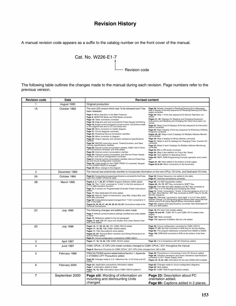
153
Revision History
A manual revision code appears as a suffix to the catalog number on the front cover of the manual.
Cat. No. W226-E1-7
Revision code
The following table outlines the changes made to the manual during each revision. Page numbers refer to theprevious version.
Revision code Date Revised content1 August 1993 Original production
1A October 1993 The new LSS version which was to be released soonhasbeen released.Page 3: Minor alteration to the Main Features.Page 9: MONITOR Mode and RUN Mode corrected.Page 10: Table comments corrected.Page 18:Diagrams and note corrected for Power Supply UnitWiring.Page 19:Surge current changed to inrush current. Correctionsmadeto the diagram text and to I/O Line Noise text.Page 20: Minor correction to middle diagram.Page 21: Circuit diagrams corrected.Page 22: Peripheral Device Connection rewritten.Page 23: Minor correction to diagram.Page 25: Output capacity and vibration resistance specificationsclarified.Page 26: MACRO instruction words, Timers/Counters, and Datamemory specifications clarified.Page 28: Internal current consumption clarified, CQM1-ID212 Termi-nal Connections corrected, and note added.Page 29: Internal current consumption clarified.Page 30: Internal current consumption and Service Power Supplyclarified, and Circuit Configuration corrected.Page 31: Internal current consumption clarified, Service Power Sup-ply and Circuit Configuration corrected.Page 36: Cable length for the CQM1-PRO01-E corrected. Keypadfor the C200H-PRO27-E changed.Page 38: Minor change to the diagram.
Page 39: Header changed to Reading/Clearing Error Messages.Step 2 display of the key sequence for Reading/Clearing Error Mes-sages corrected.Page 40: Step 1 of the key sequence for Buzzer Operation cor-rected.Pages 41, 42: Displays for Reading and Changing ExpansionInstructions and Reading and Changing the Clock have been cor-rected.Page 43: Steps 3 and 5 displays of the key sequence for InstructionSearch corrected.Page 45: Step 5 display of the key sequence for Entering or EditingPrograms corrected.Pages 48, 49: Steps 3 and 5 displays for Multiple Address Monitor-ing corrected.Page 49: Step 2 display for Binary Monitor corrected.Page 51: Steps 3 and 4b displays for Changing Timer, Counter SVcorrected.Page 52: Steps 3 and 5 displays for Multiple Address Monitoringcorrected.Page 53: Bits in SR words corrected.Page 54: Step 2 text addition for Force Set, Reset.Page 58: Text addition to Operating Errors.Page 59: REPL ROM Programming Console operation error rewrit-ten.Pages 61, 62: Note added to the bottom of both pages.Pages 63 to 65: Minor corrections to the flowcharts.
2 December 1993 The manual was extensively rewritten to incorporate information on the new CPUs, I/O Units, and Dedicated I/O Units.
2A October 1994 Page34:Computational speed specifications corrected for thePulseInput Port (CQM1-CPU43-E) table.
Page 35: Output frequency row added to the table.Page 47: Terminal connections corrected.
2B March 1995 Pages 2, 3, 7, 29, 87: SYSMAC Support Software (SSS) added.Page 15: The 1 kHz corrected to 4 kHz in the first sentence of2-1-10 ABS Interface Function.Page 13: A section on Programmable Controller Power Instructionsadded.Page 17: New Dedicated I/O Units added.Page 33: Data for Types of Instructions, Input Bits, Output Bits, andWork Bits corrected.Page 40:Computational speed changed from 1 kHz corrected to 4kHz in the table.Pages 43, 45, 46, 47, 48, 49, 50, 52, 53, 55: Corrections made to theTerminal Connections.
Page 59: 3-2 SSS Capabilities added.Pages 65, 74, 75: SET Key corrected to SHIFT Key.Page 66: Text after the table deleted and SET Key corrected toSHIFT Key in 3-4-6 Reading and Changing the Clock.Page 73: 6 bits corrected to 16 bits in the first sentence of 3-4-13Bit, Digit, Word Monitor. SET Key corrected to SHIFT Key for the BitMonitor sequence.Page 84: DM data corrected to word data in 3-4-27 Hex-ASCIIDisplay Change. 3-5-29 Inputting Signed Binary Data Using DecimalValues and 3-5-30 Using Signed Binary Instructions added.Page 101:Output Units specifications corrected. New Dedicated I/OUnits and SSS added.
2C July 1995 The following changes and additions were made.Page 7: Default communications settings modified and notes addedto table.Page 12: Reference added to the top paragraph.Pages 17 and 110: DC Input Unit models and Linear Sensor Inter-face Units added.
Page 18: DC Input Unit models added.Pages 45 and 46 : CQM1-ID111 and CQM1-ID112 added (newpages).Page 102: Note corrected.Page 115: Appendix B Battery Service Life added.
2D July 1996 Pages 16, 17, 20, 23, 32, 111: CQM1-PA216 added.Pages 17, 18, 59, 112: CQM1-OA222 added.Pages 17, 113: DeviceBus/S Units added.Pages 23, 24: Terminal Block rewritten and Wiring Precautions forGround Wires added.Page 51: Circuit configuration corrected for CQM1-OD211.
Page 56: Circuit configuration corrected for CQM1-OD215.Pages 77, 83: Set Key corrected to Shift Key for the top display.Page 80: The program addresses corrected from 00202 to 00203.Page 105: ERR/ALM corrected to RUN at the bottom of the flow-chart.
3 April 1997 Pages 17, 18, 19, 52, 116: CQM1-OC224 added. Page 28: 2-5-5 Compliance with EC Directives added.
4 June 1997 CQM1-CPU4j-E CPU Unit model numbers changed to CQM1-CPU4j-EV1 throughout the manual.Page 6: Maximum I/O points for CQM1-CPU4j-EV1 CPU Units changed from 192 to 256.
5 February 1999 PRECAUTIONS sectionaddedbeforeSection 1.AppendixC SYSMAC-CPT Precautions added.Page 20: Changes made to 2-3-1 Maximum No. of I/O Units and I/OPoints.
Page 30: Precautions in Connecting 2-wire DC Sensors added.Page 38: Vibration resistance and shock resistance specificationscorrected in 2-6-1 Power Supply Units.Pages 18, 19, 54, 120: Information for the new C200H-ID214 added.
6 February 2000 Page xiv: Application precautions information added.Page 7: Information added to table.Pages 18, 19, 122: Information about CQM1-OD216 added totables.
Page 62: Changes made to circuit configuration diagrams.Page 63: Note added.Page 67: CQM1-OD216 specifications added.
7 September 2000 Page xiii:Wording of information onmounting and dismounting Unitschanged.
Page 23: Description about PCorientation added.Page 86: Captions added in 2 places.