mini clubman. owner's manual. · help protect the environment. "..." control display...
TRANSCRIPT

OWNER'S MANUAL.MINI CLUBMAN.
LINK:CONTENT & A-Z
Online Edition for Part no. 01402666575 - VI/19

Online Edition for Part no. 01402666575 - VI/19

WELCOME TO MINI.
OWNER'S MANUAL.MINI CLUBMAN.
Thank you for choosing a MINI.The more familiar you are with your vehicle, the better control you will haveon the road. We therefore strongly suggest:Read this Owner's Manual before starting off in your new MINI. It containsimportant information on vehicle operation that will help you make full use ofthe technical features available in your MINI. The manual also containsinformation designed to enhance operating reliability and road safety, and tocontribute to maintaining the value of your MINI.Any updates made after the editorial deadline can be found in the appendix ofthe printed Owner's Manual for the vehicle.Get started now. We wish you driving fun and inspiration with your MINI.
3Online Edition for Part no. 01402666575 - VI/19

TABLE OF CONTENTS
NOTESInformation............................................................................................................................10
QUICK REFERENCEEntering.................................................................................................................................. 20
Set-up and use.......................................................................................................................24
On the road............................................................................................................................ 27
AT A GLANCECockpit.................................................................................................................................... 38
Central Information Display (CID)..................................................................................42
General settings................................................................................................................... 47
Owner's Manual media.......................................................................................................56
CONTROLSOpening and closing........................................................................................................... 60
Seats, mirrors, and steering wheel.................................................................................79
Transporting children safely............................................................................................ 90
Driving.................................................................................................................................... 95
Displays................................................................................................................................ 120
Lights.................................................................................................................................... 136
Safety.....................................................................................................................................142
Driving stability control systems.................................................................................162
Driving comfort................................................................................................................. 167
Climate control...................................................................................................................187
Interior equipment............................................................................................................196
Storage compartments.....................................................................................................204
Cargo area............................................................................................................................208
4Online Edition for Part no. 01402666575 - VI/19

DRIVING TIPSThings to remember when driving.............................................................................. 216
Saving fuel...........................................................................................................................220
ENTERTAINMENTGeneral information......................................................................................................... 228
Tone.......................................................................................................................................230
Radio..................................................................................................................................... 232
Audio.....................................................................................................................................240
COMMUNICATIONTelephone............................................................................................................................ 246
MINI Connected................................................................................................................ 250
MOBILITYRefueling..............................................................................................................................256
Fuel........................................................................................................................................258
Wheels and tires................................................................................................................260
Engine compartment........................................................................................................280
Engine oil.............................................................................................................................283
Coolant..................................................................................................................................287
Maintenance....................................................................................................................... 289
Replacing components.................................................................................................... 291
Breakdown assistance..................................................................................................... 301
Care........................................................................................................................................309
REFERENCETechnical data.................................................................................................................... 316
Appendix..............................................................................................................................319
License Texts and Certifications..................................................................................320
Everything from A to Z....................................................................................................328
5Online Edition for Part no. 01402666575 - VI/19

© 2019 Bayerische Motoren WerkeAktiengesellschaftMunich, GermanyReprinting, including excerpts, only with the written consent of BMW AG, Munich.US English ID5 VI/19, 07 19 490Printed on environmentally friendly paper, bleached without chlorine, suitable for recycling.
6Online Edition for Part no. 01402666575 - VI/19

7Online Edition for Part no. 01402666575 - VI/19

8
Online Edition for Part no. 01402666575 - VI/19

NOTES
Information ................................................................................................ 10
9Online Edition for Part no. 01402666575 - VI/19

Information
Using this Owner's Manual
OrientationThe fastest way to find information on aparticular topic is by using the index.
An initial overview of the vehicle is pro-vided in the first chapter.
Updates made after the editorialdeadlineDue to updates after the editorial deadline,differences may exist between the printedOwner's Manual and the Integrated Owner'sManual in the vehicle.
Notes on updates can be found in the ap-pendix of the printed Owner's Manual forthe vehicle.
Additional sources of informa-tion
Service centerA service center will be glad to answerquestions at any time.
InternetVehicle information and general informa-tion on MINI, e.g., on technology, are availa-ble on the Internet: www.mini.jp.
Vehicle information and general informa-tion on MINI, e.g., on technology, are availa-ble on the Internet: www.miniusa.com.
MINI Motorer’s Guide appThe Owner's Manual is available in manycountries as an app for iOS or Android inthe respective Store.
MINI Driver’s Guide WebDriver’s Guide Web shows the most suita-ble information for the selected vehicle. Ifpossible, only equipment and functions thatare actually installed in the vehicle will beexplained. Driver’s Guide Web can be dis-played in any current browser.
Symbols and displays
Symbols in the Owner's Manual
Sym-bol
Meaning
Precautions that must befollowed in order to avoid thepossibility of injury to yourselfand to others as well as seriousdamage to the vehicle.
Measures that can be taken tohelp protect the environment.
"..." Control Display texts used toselect individual functions.
Action stepsAction steps to be carried out are presentedas a numbered list. The steps must be car-ried out in the defined order.
1. First action step.
2. Second action step.
EnumerationsEnumerations without mandatory order oralternative possibilities are presented as alist with bullet points.
– First possibility.
Seite 10
NOTES Information
10Online Edition for Part no. 01402666575 - VI/19
– Second possibility.
Symbols on vehicle components This symbol on a vehicle component
indicates that further information on thecomponent is available in the Owner'sManual.
Vehicle features and options
This Owner's Manual describes all modelsand all standard, country-specific and op-tional equipment that is offered in themodel series. Therefore, this Owner'sManual also describes and illustrates fea-tures and functions that are not available ina vehicle, for example because of the se-lected optional features or the country-spe-cific version.
This also applies to safety-related functionsand systems.
When using these functions and systems,the applicable laws and regulations must beobserved.
For any options and equipment not descri-bed in this Owner's Manual, refer to theSupplementary Owner's Manuals.
Your dealer’s service center is happy to an-swer any questions that you may haveabout the features and options applicable toyour vehicle.
Status of the Owner's Manual
Basic informationThe manufacturer of your vehicle pursues apolicy of constant development that is con-ceived to ensure that our vehicles continueto embody the highest quality and safetystandards. In rare cases, therefore, the fea-
tures described in this Owner's Manual maydiffer from those in your vehicle.
Updates made after the editorialdeadlineDue to updates after the editorial deadline,differences may exist between the printedOwner's Manual and the Integrated Owner'sManual in the vehicle.
Notes on updates can be found in the ap-pendix of the printed Owner's Manual forthe vehicle.
For Your Own Safety
ManufacturerThe manufacturer of this MINI is Bayeri-sche Motoren Werke Aktionengesellschaft,BMW AG.
Intended useHeed the following when using the vehicle:
– Owner's Manual.
– Information on the vehicle. Do not re-move stickers.
– Technical vehicle data.
– The traffic, speed, and safety laws wherethe vehicle is driven.
– Vehicle documents and statutory docu-ments.
WarrantyYour vehicle is technically configured forthe operating conditions and registrationrequirements applying in the country offirst delivery, also known as homologation.If your vehicle is to be operated in a differ-ent country it might be necessary to adaptyour vehicle to potentially differing operat-ing conditions and registration require-ments. If your vehicle does not comply with
Seite 11
Information NOTES
11Online Edition for Part no. 01402666575 - VI/19

the homologation requirements in a certaincountry you may not be able to lodge war-ranty claims for your vehicle there. Furtherinformation on warranty is available from aservice center.
Maintenance and repairsAdvanced technology, for instance the useof modern materials and high-performanceelectronics, requires suitable maintenanceand repair work.
The manufacturer of your vehicle recom-mends that you entrust corresponding pro-cedures to a MINI dealer’s service center. Ifyou choose to use another service facility,the manufacturer of your vehicle recom-mends use of a facility that performs work,e.g., maintenance and repair, according toMINI specifications with properly trainedpersonnel, referred to in the Owner'sManual as "another qualified service centeror repair shop".
If work is performed improperly, for in-stance maintenance and repair, there is arisk of subsequent damage and relatedsafety risks.
Improperly performed work on the vehiclepaint can lead to a failure or malfunction ofcomponents, e.g., the radar sensors, andthereby result in a safety risk.
Parts and accessoriesThe manufacturer of your vehicle recom-mends the use of parts and accessory prod-ucts approved by the manufacturer of theMINI.
Approved parts and accessories, and adviceon their use and installation are availablefrom a MINI dealer's service center.
MINI parts and accessories were tested bythe manufacturer of the MINI for theirsafety and suitability in MINI vehicles.
The manufacturer of your vehicle warrantsgenuine MINI parts and accessories.
The manufacturer of your vehicle does notevaluate whether each individual productfrom another manufacturer can be usedwith MINI vehicles without presenting asafety hazard, even if a country-specific of-ficial approval was issued. The manufac-turer of your vehicle does not evaluatewhether these products are suitable forMINI vehicles under all usage conditions.
California Proposition 65 WarningFor vehicles sold in California, the law re-quires vehicle manufacturers to provide thefollowing warning:
Warning
Engine exhaust and a wide variety of Au-tomobile components and parts, includingcomponents found in the interior furnish-ings in a vehicle, contain or emit chemi-cals known to the State of California tocause cancer and birth defects and repro-ductive harm. In addition, certain fluidscontained in vehicles and certain productsof component wear contain or emit chemi-cals known to the State of California tocause cancer and birth defects or other re-productive harm. Battery posts, terminalsand related accessories contain lead andlead compounds. Batteries also containother chemicals known to the State of Cali-fornia to cause cancer. Wash your handsafter handling. Used engine oil containschemicals that have caused cancer in labo-ratory animals. Always protect your skinby washing thoroughly with soap and wa-ter. For more information go towww.P65Warnings.ca.gov/passenger-ve-hicle.
Seite 12
NOTES Information
12Online Edition for Part no. 01402666575 - VI/19

Warning
Operating, servicing and maintaining apassenger vehicle or off-highway motorvehicle can expose you to chemicals in-cluding engine exhaust, carbon monoxide,phthalates, and lead, which are known tothe State of California to cause cancer andbirth defects or other reproductive harm.To minimize exposure, avoid breathing ex-haust, do not idle the engine except asnecessary, service your vehicle in a well-ventilated area and wear gloves or washyour hands frequently when servicingyour vehicle. For more information go towww.P65Warnings.ca.gov/passenger-ve-hicle.
Service and warrantyWe recommend that you read this publica-tion thoroughly. Your vehicle is covered bythe following warranties:
– New Vehicle Limited Warranty.
– Rust Perforation Limited Warranty.
– Federal Emissions System Defect War-ranty.
– Federal Emissions Performance War-ranty.
– California Emission Control System Lim-ited Warranty.
Detailed information about these warrantiesis listed in the Service and Warranty Infor-mation Booklet for US models or in the War-ranty and Service Guide Booklet for Cana-dian models.
Your vehicle has been specifically adaptedand designed to meet the particular operat-ing conditions and homologation require-ments in your country and continental re-gion in order to deliver the full drivingpleasure while the vehicle is operated underthose conditions. If you wish to operateyour vehicle in another country or region,
you may be required to adapt your vehicleto meet different prevailing operating con-ditions and homologation requirements.You should also be aware of any applicablewarranty limitations or exclusions for suchcountry or region. In such case, please con-tact Customer Relations for further informa-tion.
MaintenanceMaintain the vehicle regularly to sustainthe road safety, operational reliability andthe New Vehicle Limited Warranty.
Specifications for required maintenancemeasures:
– MINI Maintenance system.
– Service and Warranty Information Book-let for US models.
– Warranty and Service Guide Booklet forCanadian models.
If the vehicle is not maintained according tothese specifications, this could result indamaging the vehicle. Such damage is notcovered by the MINI New Vehicle LimitedWarranty.
Data memory
General informationElectronic control devices are installed inthe vehicle. Electronic control units processdata they receive from vehicle sensors, self-generate or exchange with each other. Somecontrol units are necessary for the vehicleto function safely or provide assistance dur-ing driving, for instance driver assistancesystems. Furthermore, control units facili-tate comfort or infotainment functions.
Information about stored or exchanged datacan be requested from the manufacturer ofthe vehicle, in a separate booklet, for exam-ple.
Seite 13
Information NOTES
13Online Edition for Part no. 01402666575 - VI/19

Personal referenceEach vehicle is marked with a unique vehi-cle identification number. Depending on thecountry, the vehicle owner can be identifiedwith the vehicle identification number, li-cense plate and corresponding authorities.In addition, there are other options to trackdata collected in the vehicle to the driver orvehicle owner, for instance via utilizedservices.
Operating data in the vehicleControl units process data to operate the ve-hicle.
For example, this includes:
– Status messages for the vehicle and itsindividual components, e.g., wheel rota-tional speed, wheel speed, deceleration,transverse acceleration, engaged safetybelt indicator.
– Ambient conditions, e.g., temperature,rain sensor signals.
The processed data is only processed in thevehicle itself and generally volatile. Thedata is not stored beyond the operating pe-riod.
Electronic components, e.g. control unitsand ignition keys, contain components forstoring technical information. Informationabout the vehicle condition, component us-age, maintenance requirements events orfaults can be stored temporarily or perma-nently.
This information generally records the stateof a component, a module, a system, or theenvironment, for instance:
– Operating states of system components,for instance, fill levels, tire inflationpressure, battery status.
– Malfunctions and faults in importantsystem components, for instance lightsand brakes.
– Responses by the vehicle to special sit-uations such as airbag deployment orengagement of the driving stability con-trol systems.
– Information on vehicle-damagingevents.
The data is required to perform the controlunit functions. Furthermore, it also servesto recognize and correct malfunctions, andhelps the vehicle manufacturer to optimizevehicle functions.
The majority of this data is volatile and isonly processed within the vehicle itself.Only a small share of data is stored in eventor fault memories based on an event.
When servicing, for instance during repairs,service processes, warranty cases, and qual-ity assurance measures, this technical infor-mation can be read out from the vehicle to-gether with the vehicle identificationnumber.
A dealer’s service center or another quali-fied service center or repair shop can readout the information. The socket for OBD On-board Diagnosis required by law in the ve-hicle is used to read out the data.
The data is collected, processed, and usedby the relevant organizations in the servicenetwork. The data documents technical con-ditions of the vehicle, helps with the identi-fication of the fault, compliance with war-ranty obligations and quality improvement.
Furthermore, the manufacturer has productmonitoring duties to meet in line with prod-uct liability law. To fulfill these duties, thevehicle manufacturer needs technical datafrom the vehicle. The data from the vehiclecan also be used to check customer claimsfor warranty and guaranty.
Fault and event memories in the vehicle canbe reset when a dealer’s service center oranother qualified service center or repairshop performs repair or servicing work.
Seite 14
NOTES Information
14Online Edition for Part no. 01402666575 - VI/19

Data entry and data transfer intothe vehicle
General informationDepending on the vehicle equipment, com-fort and individual settings can be stored inthe vehicle and modified or reset at anytime.
For example, this includes:
– Settings for the seat and steering wheelpositions.
– Suspension and climate control settings.
If necessary, data can be transferred to theentertainment and communication systemof the vehicle, for instance via smartphone.
This includes the following depending onthe respective equipment:
– Multimedia data such as music, films orphotos for playback in an integratedmultimedia system.
– Address book data for use in conjunc-tion with an integrated hands-free sys-tem or an integrated navigation system.
– Entered navigation destinations.
– Data on the use of Internet services.
This data can be stored locally in the vehicleor is found on a device that has been con-nected to the vehicle, e.g., a smartphone,USB stick or MP3 player. If this data isstored in the vehicle, it can be deleted atany time.
This data is only transmitted to third partiesupon personal request as part of the use ofonline services. The transmission dependson the selected settings for the use of theservices.
Incorporation of mobile devicesDepending on the vehicle equipment, mo-bile devices connected to the vehicle, for in-stance smartphones, can be controlled viathe vehicle control elements.
The sound and picture from the mobile de-vice can be played back and displayedthrough the multimedia system. Certain in-formation is transferred to the mobile de-vice at the same time. Depending on thetype of incorporation, this includes, for in-stance position data and other general vehi-cle information. This optimizes the way inwhich selected apps, for instance navigationor music playback, work.
There is no further interaction between themobile device and the vehicle, such as ac-tive access to vehicle data.
How the data will be processed further isdetermined by the provider of the particularapp being used. The extent of the possiblesettings depends on the respective app andthe operating system of the mobile device.
Services
General informationIf the vehicle has a wireless network con-nection, this enables data to be exchangedbetween the vehicle and other systems. Thewireless network connection is realized viaan in-vehicle transmitter and receiver unitor via personal mobile devices brought intothe vehicle, for instance smartphones. Thiswireless network connection enables 'onlinefunctions' to be used. These include onlineservices and apps supplied by the vehiclemanufacturer or by other providers.
Services from the vehiclemanufacturerWhere online services from the vehiclemanufacturer are concerned, the corre-sponding functions are described in the ap-propriate place, for instance the Owner'sManual or manufacturer's website. The rele-vant legal information pertaining to dataprotection is provided there too. Personaldata may be used to perform online serv-ices. Data is exchanged over a secure con-
Seite 15
Information NOTES
15Online Edition for Part no. 01402666575 - VI/19
nection, for instance with the IT systems ofthe vehicle manufacturer intended for thispurpose.
Any collection, processing, and use of per-sonal data above and beyond that needed toprovide the services must always be basedon a legal permission, contractual arrange-ment or consent. It is also possible to acti-vate or deactivate the data connection as awhole. That is, with the exception of func-tions and services required by law such asAssist systems.
Services from other providersWhen using online services from other pro-viders, these services are the responsibilityof the relevant provider and subject to theirdata privacy conditions and terms of use.The vehicle manufacturer has no influenceon the content exchanged during this proc-ess. Information on the way in which per-sonal data is collected and used in relationto services from third parties, the scope ofsuch data, and its purpose, can be obtainedfrom the relevant service provider.
Event Data Recorder EDR
This vehicle is equipped with an event datarecorder EDR. The main purpose of an EDRis to record, in certain crash or near crash-like situations, such as an air bag deploy-ment or hitting a road obstacle, data thatwill assist in understanding how a vehicle’ssystems performed. The EDR is designed torecord data related to vehicle dynamics andsafety systems for a short period of time,typically 30 seconds or less.
The EDR in this vehicle is designed to re-cord such data as:
– How various systems in your vehiclewere operating.
– Whether or not the driver and passen-ger safety belts were fastened.
– How far, if at all, the driver was depress-ing the accelerator and/or brake pedal.
– How fast the vehicle was traveling.
This data can help provide a better under-standing of the circumstances in whichcrashes and injuries occur.
EDR data is recorded by your vehicle only ifa nontrivial crash situation occurs; no datais recorded by the EDR under normal driv-ing conditions and no personal data, for in-stance name, gender, age, and crash loca-tion, are recorded.
However, other parties, such as law enforce-ment, could combine the EDR data with thetype of personally identifying data routinelyacquired during a crash investigation.
To read data recorded by an EDR, specialequipment is required, and access to the ve-hicle or the EDR is needed. In addition tothe vehicle manufacturer, other parties,such as law enforcement, that have the spe-cial equipment, can read the information ifthey have access to the vehicle or the EDR.
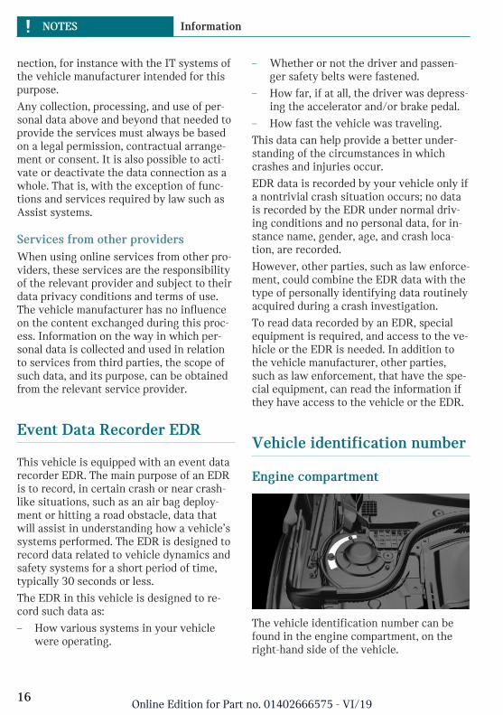
Vehicle identification number
Engine compartment
The vehicle identification number can befound in the engine compartment, on theright-hand side of the vehicle.
Seite 16
NOTES Information
16Online Edition for Part no. 01402666575 - VI/19

Windshield
The vehicle identification number can alsobe found behind the windshield.
Reporting safety defects
For US customersThe following only applies to vehiclesowned and operated in the US.
If you believe that your vehicle has a defectwhich could cause a crash or could cause in-jury or death, you should immediately in-form the National Highway Traffic SafetyAdministration NHTSA, in addition to noti-fying MINI of North America, LLC, P.O. Box1227, Westwood, New Jersey 07675-1227,Telephone 1-800-831-1117.
If NHTSA receives similar complaints, itmay open an investigation, and if it findsthat a safety defect exists in a group of ve-hicles, it may order a recall and remedycampaign.
However, NHTSA cannot become involvedin individual problems between you, yourdealer, or MINI of North America, LLC.
To contact NHTSA, you may call the VehicleSafety Hotline toll-free at 1-888-327-4236(TTY: 1-800-424-9153); go to http://www.safercar.gov; or write to: Administra-tor, NHTSA, 400 Seventh Street, SW.,Washington, DC 20590. You can also obtain
other information about motor vehiclesafety from http://www.safercar.gov
For Canadian customersCanadian customers who wish to report asafety-related defect to Transport Canada,Defect Investigations and Recalls, may callthe toll-free hotline 1-800-333-0510. Youcan also obtain other information about mo-tor vehicle safety from http://www.tc.gc.ca/roadsafety.
Seite 17
Information NOTES
17Online Edition for Part no. 01402666575 - VI/19

18
Online Edition for Part no. 01402666575 - VI/19

QUICK REFERENCE
Entering ...................................................................................................... 20Set-up and use ........................................................................................... 24On the road ................................................................................................. 27
19Online Edition for Part no. 01402666575 - VI/19

Entering
Opening and closing
Buttons on the vehicle key
1 Unlocking
2 Locking
3 Open split doors
4 Panic mode
Unlocking the vehiclePress the button on the vehicle key.
Depending on the settings, either only thedriver's door or all vehicle access points areunlocked.
If only the driver's door is unlocked, pressthe button on the vehicle key again to un-lock the other vehicle access points.
Press and hold the button on the ve-hicle key after unlocking.
The windows and the glass sunroof areopened, as long as the button on the vehiclekey is pressed.
Locking the vehiclePress the button on the vehicle key.
All vehicle access points are locked.
Buttons for the central lockingsystem
Overview
Buttons for the central locking system.
Locking
Pressing the button locks the vehi-cle if the front doors are closed.
Unlocking
Pressing the button unlocks the ve-hicle.
Panic modeYou can trigger the alarm system if you findyourself in a dangerous situation.
Press the button on the vehicle keyand hold for at least 3 seconds.
To switch off the alarm: press any button.
Comfort Access
ConceptThe vehicle can be accessed without operat-ing the vehicle key.
Carrying the vehicle key with you, e.g., inyour pants pocket, is sufficient.
Seite 20
QUICK REFERENCE Entering
20Online Edition for Part no. 01402666575 - VI/19

The vehicle automatically detects the vehi-cle key when it is in close proximity or inthe car's interior.
Unlocking the vehicle
On the driver's or front passenger's doorhandle, press the button.
Locking the vehicle
On the driver's or front passenger's doorhandle, press the button.
Opening the split doors with no-touchactivation
Concept
The split doors can be opened with no-touchactivation using the vehicle key you are car-rying.
Performing the foot movement
1. Stand in the middle behind the vehicleat approx. one arm's length away fromthe rear of the vehicle.
2. Wave a foot under the vehicle in the di-rection of travel and immediately pull itback.
Split Doors
Opening
– Unlock the vehicle and use the button inthe handle to completely open first theright side, arrow 1, and then the left sideof the split doors, arrow 2.
– Press and hold the button on thevehicle key for approx. 1 secondto open the right side of the split
doors.
Press and hold the button on the vehiclekey again for approx. 1 second to openthe left side of the split doors.
Depending on the setting, the doors may beunlocked.
ClosingClosing the split doors manually.
Seite 21
Entering QUICK REFERENCE
21Online Edition for Part no. 01402666575 - VI/19

Displays and control elements
In the vicinity of the steeringwheel
1 Low beams, fog lights
2 High beams, headlight flasher, turn sig-nal
3 Instrument cluster
4 Wiper system
Indicator/warning lights
Instrument clusterThe indicator/warning lights can light up ina variety of combinations and colors.
Several of the lights are checked for properfunctioning and light up temporarily whenthe engine is started or the ignition isswitched on.
Driver's door
1 Safety switch
2 Power windows
3 Exterior mirrors
All around the selector lever
1 Selector lever
2 Controller with buttons
3 Parking brake
Central Information Display (CID)
ConceptThe Central Information Display (CID) com-bines the functions of a multitude ofswitches. These functions can be operatedvia the Controller.
Seite 22
QUICK REFERENCE Entering
22Online Edition for Part no. 01402666575 - VI/19

Controller
General information
The buttons can be used to open the menusdirectly. The Controller can be used to se-lect menu items and enter the settings.
Buttons on the Controller
Button Function
Press once: calls up the mainmenu.
Press twice: open recently usedmenus.
Opens the previous display.
Opens the Options menu.
Open the Audio menu.
Opens the Phone menu.
Seite 23
Entering QUICK REFERENCE
23Online Edition for Part no. 01402666575 - VI/19

Set-up and use
Seats, mirrors, and steeringwheel
Manually adjustable seats
1 Forward/backward
2 Thigh support
3 Height
4 Backrest tilt
Electrically adjustable seats
1 Memory function
2 Lumbar support
3 Backrest tilt
4 Forward/backward, height, seat tilt
Adjusting the head restraint
Height
– To raise: push the head restraint up.
– To lower: press the button, arrow 1, andpush the head restraint down.
Adjusting the exterior mirrors
1 Adjusting
2 Selecting a mirror, Automatic Curb Mon-itor
3 Folding in and out
Seite 24
QUICK REFERENCE Set-up and use
24Online Edition for Part no. 01402666575 - VI/19

Adjusting the steering wheel
In four directions
1. Fold the lever down.
2. Move the steering wheel to the prefer-red height and angle to suit your seatingposition.
3. Fold the lever back up.
Memory function
ConceptThe following settings can be stored and, ifnecessary, retrieved using the memoryfunction:
– Seat position.
– Exterior mirror position.
Storing1. Switch on the ignition.
2. Set the desired position.
3. Press the button. The LED in thebutton lights up.
4. Press the desired button 1 or 2 on theseat while the LED is illuminated. TheLED goes out.
Calling up settingsThe stored position is called up automati-cally.
Press the desired button 1 or 2.
The procedure stops when a seat adjust-ment switch or one of the memory buttonsis pressed.
Once underway, adjustment of the seat po-sition on the driver's side is disabled after ashort while.
Infotainment
Radio
Control elements
1 Changing the waveband
2 Changing the entertainment source
3 Sound output on/off, volume
4 Changing the station/track
5 Programmable memory buttons
Pairing the mobile phoneAfter the mobile phone is paired once withthe vehicle, the mobile phone can be oper-ated using the Central Information Display(CID), the steering wheel buttons and spo-ken instructions.
1. "My MINI"
2. "System settings"
3. "Mobile devices"
4. "Connect new device"
The vehicle's Bluetooth name is dis-played on the Control Display.
Seite 25
Set-up and use QUICK REFERENCE
25Online Edition for Part no. 01402666575 - VI/19

5. To perform additional steps on the mo-bile phone, refer to the mobile phoneowner's manual: e.g., search for or con-nect the Bluetooth device or a new de-vice.
The Bluetooth name of the vehicle ap-pears on the mobile phone display. Se-lect the Bluetooth name of the vehicle.
6. Depending on the mobile device, a con-trol number is displayed or the controlnumber must be entered.
– Compare the control number dis-played on the Control Display withthe control number on the display ofthe device.
Confirm the control number on thedevice and on the Control Display.
– Enter and confirm the same controlnumber on the device and via theCentral Information Display (CID).
The device is connected and displayedin the device list.
The mobile phone is connected and will ap-pear at the top of the list of mobile phones.
Using the phone
Accepting a callIncoming call can be accepted via the Cen-tral Information Display (CID) or the buttonon the steering wheel.
Via the Central Information Display (CID)
"Accept"
Via the button on the steering wheel
Press the button.
Dialing a number1. "Communication"
2. "Dial number"
3. Select the numbers individually.
4. Select the symbol.
Seite 26
QUICK REFERENCE Set-up and use
26Online Edition for Part no. 01402666575 - VI/19

On the road
Driving
Starting and stopping the engine
Ignition on/off
– On: press the Start/Stopbutton.
Most of the indicator/warning lights light up fora varied length of time.
– Off: press the Start/Stop button again.
All indicator lights go out.
– Radio-ready state: when the ignition isswitched off, press the ON/OFF buttonon the radio or when the engine is run-ning, press the Start/Stop button.
Some electronic systems/power con-sumers remain ready for operation.
Start/stop engine
Steptronic transmission: starting
1. Depress the brake pedal.
2. Engage selector lever position P or N.
3. Press the Start/Stop button.
Manual transmission: starting
1. Depress the brake pedal.
2. Press on the clutch pedal and shift toneutral.
3. Press the Start/Stop button.
Steptronic transmission: switching off
1. When the vehicle is stationary, applythe parking brake.
2. Engage selector lever position P.
3. Press the Start/Stop button.
Manual transmission: switching off
1. With the vehicle at a standstill, pressthe Start/Stop button.
2. Shift into first gear or reverse.
3. Set the parking brake.
Auto Start/Stop function
Steptronic transmission: switches the en-gine off automatically while stationary tosave fuel. The engine starts automaticallywhen the brake pedal is released.
Manual transmission: switches the engineoff automatically while stationary to savefuel. As soon as the clutch pedal is de-pressed, the engine starts automatically.
Parking brake
SettingPull the switch.
The LED and indicator light light up.
ReleasingManual transmission: press the switchwhile the brake pedal is pressed.
Steptronic transmission: press the switchwhile the brake is pressed or selector leverposition P is set.
The LED and indicator light go out.
The parking brake is released.
Manual transmission
ShiftingWhen shifting into 5th or 6th gear, pushthe gearshift lever to the right in order to
Seite 27
On the road QUICK REFERENCE
27Online Edition for Part no. 01402666575 - VI/19

prevent inadvertent shifting into the 3rd or4th gear.
Reverse gearSelect only when the vehicle is stationary.
To overcome the resistance push the gear-shift lever dynamically to the left and en-gage reverse gear with a forward shiftingmovement.
Steptronic transmission
Selector lever positionsParking position P.
R is reverse.
Neutral N.
Drive mode D.
Engage selector lever position P or R onlywhen the vehicle is stationary.
To prevent the vehicle from creeping afteryou select a drive mode or reverse, maintainpressure on the brake pedal until you areready to start.
Selector lever lockA lock prevents an inadvertent change fromselector lever position P to another selectorlever position and, depending on the trans-mission version, inadvertent switching toselector lever position P or R.
To release the lock: with the brake pedal de-pressed, press the button on the front orside of the selector lever.
Steptronic transmission, Sport andmanual mode
Sport program:
Press the selector lever to the left from se-lector lever position D.
Manual mode:
– To shift down: press the selector leverforward.
– To shift up: pull the selector lever rear-wards.
High beams, headlight flasher, turnsignal, roadside parking light
High beams, headlight flasher
Push the lever forward or pull it backward.
– High beams on, arrow 1.
The high beams light up when the lowbeams are switched on.
– High beams off/headlight flasher, ar-row 2.
Seite 28
QUICK REFERENCE On the road
28Online Edition for Part no. 01402666575 - VI/19

Turn signal
– On: press the lever past the resistancepoint.
– Off: lightly tap the lever to the resist-ance point.
– Off: press the lever past the resistancepoint in the opposite direction.
– Triple turn signal activation: lightly tapthe lever up or down.
– Brief signaling: press the lever to the re-sistance point and hold it there for aslong as you want the turn signal to flash.
Canada: roadside parking light
To illuminate the vehicle on one side.
– On: with the ignition switched off, pressthe lever either up or down past the re-sistance point for approx. 2 seconds.
– Off: briefly press the lever to the resist-ance point in the opposite direction.
Lights and lighting
Light functions
Symbol Function
Front fog lights.
Automatic headlight control.
Lights off.
Daytime running lights.
Parking lights.
Low beams.
Instrument lighting.
Wiper system
Switching the wipers on/off and briefwipe
Switching on
Press the lever up until the desired positionis reached.
– Resting position of the wipers: posi-tion 0.
Seite 29
On the road QUICK REFERENCE
29Online Edition for Part no. 01402666575 - VI/19

– Rain sensor: position 1.
– Normal wiper speed: position 2.
– Fast wiper speed: position 3.
Brief wipe and switching off
Press the lever down.
– Switching off: press the lever down untilit reaches its standard position.
– Brief wipe: press the lever down fromthe standard position.
Rain sensor
Activating/deactivating
To activate: press the lever up once from itsstandard position, arrow 1.
To deactivate: press the lever back into thestandard position.
Set interval or sensitivity of the rainsensor
Turn the thumbwheel on the wiper lever.
Cleaning the windshield
Pull the lever.
Canada: wiper system
Switching the wipers on/off and briefwipe
Switching on
Tap up the lever or press it past the resist-ance point.
Seite 30
QUICK REFERENCE On the road
30Online Edition for Part no. 01402666575 - VI/19

– Normal wiper speed: tap up once.
– Fast wiper speed: tap up twice or taponce beyond the resistance point.
Brief wipe and switching off
Press the lever down.
– To switch off fast wipe: press downtwice.
– To switch off normal wipe: press downonce.
– Brief wipe: press down once.
Rain sensor
Activating/deactivating
Press the button on the wiper lever.
Set interval or sensitivity of the rainsensor
Turn the thumbwheel on the wiper lever.
Cleaning the windshield
Pull the lever.
Climate control
Air conditioner
Button Function
Temperature.
Air conditioning.
Recirculated-air mode.
Seite 31
On the road QUICK REFERENCE
31Online Edition for Part no. 01402666575 - VI/19

Button Function
Controls the air flow,manual.
Controls the air distributionmanually.
Windshield defroster.
Automatic climate control
Button Function
Temperature.
Air conditioning.
Maximum cooling.
AUTO program.
Recirculated-air mode.
Automatic recirculated-aircontrol AUC/recirculated-air mode.
Controls the air flow,manual.
Air distribution, manual.
Button Function
Defrosts and defogs thewindows.
Windshield defroster.
Rear window defroster.
Refueling
Refueling
Fuel cap1. To open the fuel filler flap, press on the
rear edge, arrow. The fuel filler flapopens.
2. Turn the fuel cap counterclockwise.
3. Place the fuel cap in the bracket at-tached to the fuel filler flap.
GasolineFor the best fuel efficiency, the gasolineshould be sulfur-free or very low in sulfurcontent.
Refuel only with unleaded gasoline withoutmetallic additives.
Information on the recommended fuel gradecan be found in the Owner's Manual.
Seite 32
QUICK REFERENCE On the road
32Online Edition for Part no. 01402666575 - VI/19

Wheels and tires
Tire inflation pressure specifications
The tire inflation pressure values can befound on the sign on the door pillar.
Checking the tire inflation pressureRegularly check the tire inflation pressureand correct it as needed:
– At least twice a month.
– Before embarking on an extended trip.
After correcting the tire inflationpressureReinitialize the Flat Tire Monitor.
Reset the Tire Pressure Monitor.
Electronic oil measurement
RequirementsA current measured value is available afterapprox. 30 minutes of driving. During ashorter trip, the status of the last, suffi-ciently long trip is displayed.
Displaying the engine oil levelOn the radio:
1. Press the button.
2. "Vehicle Info"
3. "Vehicle status"
4. "Engine oil level"
The engine oil level is displayed.
Adding engine oil
General informationSwitch off the ignition and safely park thevehicle before engine oil is added.
Adding
Only add engine oil when the message isdisplayed in the instrument cluster.
Observe the quantity to be added in themessage.
Take care not to add too much engine oil.
Observe recommended engine oil types.
Providing assistance
Hazard warning flashers
The button is located above the Control Dis-play.
Seite 33
On the road QUICK REFERENCE
33Online Edition for Part no. 01402666575 - VI/19

Breakdown assistance
MINI Roadside AssistanceThis service can be reached around theclock in many countries.
1. "MINI Connected"
2. "MINI Assist"
3. "MINI Roadside Assistance"
The contact to the MINI Roadside Assis-tance is established.
A telephone number is displayed, ifneeded. Select to dial the telephonenumber on a connected mobile phone.
Seite 34
QUICK REFERENCE On the road
34Online Edition for Part no. 01402666575 - VI/19

Seite 35
On the road QUICK REFERENCE
35Online Edition for Part no. 01402666575 - VI/19

36
Online Edition for Part no. 01402666575 - VI/19

AT A GLANCE
Cockpit ........................................................................................................ 38Central Information Display (CID) ...................................................... 42General settings ....................................................................................... 47Owner's Manual media ........................................................................... 56
37Online Edition for Part no. 01402666575 - VI/19

Cockpit
Vehicle features and options
This chapter describes all standard, country-specific and optional features offered withthe series. It also describes features that arenot necessarily available in your vehicle, for
instance, due to the selected options orcountry versions. This also applies to safety-related functions and systems. When usingthese functions and systems, the applicablelaws and regulations must be observed.
In the vicinity of the steering wheel
1 Power windows 74
2 Exterior mirror operation 87
3 Buttons of the central locking sys-tem 65
4 Lights
Front fog lights 139
Light switch 136
Lights off
Daytime running lights 138
Parking lights 136
Low beams 136
Seite 38
AT A GLANCE Cockpit
38Online Edition for Part no. 01402666575 - VI/19

Automatic headlight con-trol 137
Cornering light 138
High-beam Assistant 138Instrument lighting 140
5 Steering wheel buttons, left
Camera-based cruise controlon/off 167
Cruise control on/off 174
Cruise control: to store thespeed
Pausing, continuing cruisecontrol
Cruise control: increase speed
Cruise control: reduce speed
Camera-based cruise control:reduce distance
Camera-based cruise control:increase distance
6 Steering column stalk, left
Turn signal 102
High beams, head-light flasher 102
High-beam Assistant 138
Roadside parking lights 137
Onboard Computer 130
7 Instrument cluster 120
8 Steering column stalk, right
Wipers 103
Wiper on Canadian mod-els 107Rain sensor 104
Rain sensor on Canadian mod-els 108Cleaning windows 105
Rear window wiper in Cana-dian models 105
Rear window wiper 105
Clean the rear window 105
9 Steering wheel buttons, right
Telephone 246
Confirm the selection 130
Selection back 130
Selection next 130
Increase volume
Reduce volume
Seite 39
Cockpit AT A GLANCE
39Online Edition for Part no. 01402666575 - VI/19

10 Horn, entire surface 11 Adjusting the steering wheel 89
12 Unlocking the hood 281
In the vicinity of the center console
1 Hazard warning system 301
Intelligent Safety 153
2 Control Display 42
3 Radio/Multimedia
4 Glove compartment 204
5 Climate control 187
6 PDC Park Distance Con-trol 176
Rearview camera 179
Parking assistant 182Auto Start/Stop func-tion 98
Start/stop the engine andswitch the ignition on/off 95DSC Dynamic Stability Control 162
MINI Driving Modesswitch 164
Seite 40
AT A GLANCE Cockpit
40Online Edition for Part no. 01402666575 - VI/19

7 Steptronic transmission selectorlever 112
Manual transmission selectorlever 111
8 Controller with buttons 44
9 Parking brake 101
In the vicinity of the roofliner
1 Emergency Request,SOS 302
2 Indicator light, front-seat pas-senger airbag 145
3 Reading lights 140
4 Ambient light 140
5 Panoramic glass sunroof 76
6 Interior lights 140
Seite 41
Cockpit AT A GLANCE
41Online Edition for Part no. 01402666575 - VI/19

Central Information Display (CID)
Vehicle features and options
This chapter describes all standard, country-specific and optional features offered withthe series. It also describes features that arenot necessarily available in your vehicle, forinstance, due to the selected options orcountry versions. This also applies to safety-related functions and systems. When usingthese functions and systems, the applicablelaws and regulations must be observed.
Concept
The Central Information Display (CID) com-bines the functions of a multitude ofswitches. These functions can be operatedvia the Controller.
Safety information
Warning
Operating the integrated information sys-tems and communication devices whiledriving can distract from traffic. It is pos-sible to lose control of the vehicle. There isa risk of accident. Only use the systems ordevices when the traffic situation allows.As warranted, stop and use the systemsand devices while the vehicle is stationary.
Input and display
Letters and numbersDepending on the menu, you can switch be-tween entering upper and lower case let-ters, numbers and characters:
Symbol Function
or
Change between capital andlower-case letters.
Insert blank space.
Use voice activation.
Confirm entry.
Without navigation system Select the symbol.
Entry comparisonWhen entering names and addresses, thechoice is narrowed down with every letterentered and letters may be added automati-cally.
Entries are continuously compared withdata stored in the vehicle.
Only those letters are offered during entryfor which data is available.
Activating/deactivating thefunctionsSeveral menu items are preceded by acheckbox. The checkbox indicates whetherthe function is activated or deactivated. Se-lecting the menu item activates or deacti-vates the function.
Function is activated.
Function is deactivated.
Seite 42
AT A GLANCE Central Information Display (CID)
42Online Edition for Part no. 01402666575 - VI/19

Status information
General informationThe status field can be found in the upperarea of the Control Display. Status informa-tion is displayed in the form of symbols.
Radio
Symbol Meaning
HD Radio station is being re-ceived.
Satellite radio is switched on.
Telephone
Symbol Meaning
Incoming or outgoing call.
Missed call.
Signal strength of cellular net-work.
Symbol flashes: network search.
Cellular network is not available.
Roaming is active.
SMS text message received.
Message received.
Reminder.
Sending not possible.
Entertainment
Symbol Meaning
Bluetooth audio.
USB audio interface.
Other symbols
Symbol Meaning
Check Control message.
The sound output has beenswitched off.
Checking the current vehicle po-sition.
Control elements
Overview
1 Control Display
2 Controller with buttons
Control Display
General informationTo clean the Control Display, follow the careinstructions, refer to page 312.
In the case of very high temperatures onthe Control Display, for instance due to in-tense solar radiation, the brightness may bereduced down to complete deactivation.Once the temperature is reduced, for in-stance through shade or air conditioning,the normal functions are restored.
Seite 43
Central Information Display (CID) AT A GLANCE
43Online Edition for Part no. 01402666575 - VI/19
Safety information
NOTICE
Objects in the area in the front of the Con-trol Display can shift and damage the Con-trol Display. There is a risk of damage toproperty. Do not place objects in the areain front of the Control Display.
Switching on/off automaticallyThe Control Display is switched on automat-ically after unlocking.
In certain situations, the Control Display isswitched off automatically, for instance ifno operation is performed on the vehicle forseveral minutes.
Switching on/off manuallyThe Control Display can also be switched offmanually.
1. Press the button.
2. "Turn off control display"
Press the Controller or any button on theController to switch it back on again.
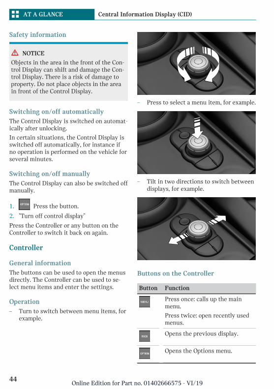
Controller
General informationThe buttons can be used to open the menusdirectly. The Controller can be used to se-lect menu items and enter the settings.
Operation– Turn to switch between menu items, for
example.
– Press to select a menu item, for example.
– Tilt in two directions to switch betweendisplays, for example.
Buttons on the Controller
Button Function
Press once: calls up the mainmenu.
Press twice: open recently usedmenus.
Opens the previous display.
Opens the Options menu.
Seite 44
AT A GLANCE Central Information Display (CID)
44Online Edition for Part no. 01402666575 - VI/19

Button Function
Open the Audio menu.
Opens the Phone menu.
Operating via the Controller
Opening the main menuPress the button.
The main menu is displayed.
All Central Information Display (CID) func-tions can be called up via the main menu.
Selecting menu itemsHighlighted menu items can be selected.
1. Turn the Controller until the desiredmenu item is highlighted.
2. Press the Controller.
Changing between displaysAfter a menu item is selected, for instance"System settings", a new display appears.
– Move the Controller to the left.
The current display closes and the previ-ous display is shown.
– Press the button.
The previous display re-opens.
– Move the Controller to the right.
The new display opens.
An arrow indicates that additional displayscan be opened.
Opening recently used menusThe recently used menus can be displayed.
Press the button twice.
Opening the Options menuPress the button.
The "Options" menu is displayed.
The menu consists of various areas:
– Control options for the selected mainmenu, for instance for "Media/Radio".
– If applicable, further operating optionsfor the selected menu, for instance "Savestation".
Changing settingsSettings, such as brightness, can be entered.
Via the Central Information Display (CID):
1. "My MINI"
2. "System settings"
3. "Displays"
4. "Control display"
5. "Brightness at night"
Seite 45
Central Information Display (CID) AT A GLANCE
45Online Edition for Part no. 01402666575 - VI/19

6. Turn the Controller until the desired set-ting is displayed.
7. Press the Controller.
Entering letters and numbers
Input1. Turn the Controller: select letters or
numbers.
2. : confirm entry.
Deleting
Symbol Function
Press the Controller: deleteletters or number.
or
Hold the Controller down: de-lete all letters or numbers.
Using alphabetical listsFor alphabetical lists with more than 30 en-tries, the letters for which there is an entryare displayed at the left edge.
1. Turn the Controller to the left or rightquickly.
All letters for which there are entriesare displayed on the left edge.
2. Select the first letter of the desired en-try.
The first entry of the selected letter isdisplayed.
Programmable memory but-tons
General informationThe Central Information Display (CID) func-tions can be stored on the programmablememory buttons and called up directly, for
instance radio stations, phone numbers, andmenu entries.
Settings are stored for the driver profilecurrently used.
Storing a function1. Select the function via the Central Infor-
mation Display (CID).
2. Press and hold the desired but-ton, until a signal sounds.
Executing a functionPress the button.
The function will work immediately.This means, for instance that the number isdialed when a phone number is selected.
Displaying the key assignmentTouch buttons with finger. Do not weargloves or use objects.
The button assignment is displayed at thetop edge of screen.
Deleting the button assignments1. Press buttons 1 and 6 simultaneously
for approx. 5 seconds.
2. "OK"
Seite 46
AT A GLANCE Central Information Display (CID)
46Online Edition for Part no. 01402666575 - VI/19

General settings
Vehicle features and options
This chapter describes all standard, country-specific and optional features offered withthe series. It also describes features that arenot necessarily available in your vehicle, forinstance, due to the selected options orcountry versions. This also applies to safety-related functions and systems. When usingthese functions and systems, the applicablelaws and regulations must be observed.
Language
Setting the languageVia the Central Information Display (CID):
1. "My MINI"
2. "System settings"
3. If necessary, "Language"
4. "Language:"
5. Select the desired setting.
The setting is stored for the driver profilecurrently used.
Time
Setting the timeVia the Central Information Display (CID):
1. "My MINI"
2. "System settings"
3. "Date and time"
4. "Time:"
5. Turn the Controller until the desiredhours are displayed.
6. Press the Controller.
7. Turn the Controller until the desired mi-nutes are displayed.
8. Press the Controller.
Setting the time formatVia the Central Information Display (CID):
1. "My MINI"
2. "System settings"
3. "Date and time"
4. "Time format:"
5. Select the desired setting.
The setting is stored for the driver profilecurrently used.
Date
Setting the dateVia the Central Information Display (CID):
1. "My MINI"
2. "System settings"
3. "Date and time"
4. "Date:"
5. Turn the Controller until the desired dayis displayed.
6. Press the Controller.
7. Make the settings for the month andyear.
Seite 47
General settings AT A GLANCE
47Online Edition for Part no. 01402666575 - VI/19

Setting the date formatVia the Central Information Display (CID):
1. "My MINI"
2. "System settings"
3. "Date and time"
4. "Date format:"
5. Select the desired setting.
The setting is stored for the driver profilecurrently used.
Setting the units of measure-ment
You can set the units of measurement forsome values, for example, consumption, dis-tances and temperature.
Via the Central Information Display (CID):
1. "My MINI"
2. "System settings"
3. "Units"
4. Select the desired menu item.
5. Select the desired setting.
The setting is stored for the driver profilecurrently used.
Activating/deactivating thedisplay of the current vehicleposition
ConceptIf vehicle tracking has been activated, thecurrent vehicle position can be displayed inthe MINI Connected app.
Activating/deactivatingVia the Central Information Display (CID):
1. "My MINI"
2. "Vehicle settings"
3. "Vehicle tracking"
4. "Vehicle tracking"
5. Select the desired setting.
Activating/deactivatingpopup windows
For some functions, popup windows are dis-played automatically on the Control Display.Some of these popup windows can be acti-vated or deactivated.
Via the Central Information Display (CID):
1. "My MINI"
2. "System settings"
3. "Pop-ups"
4. Select the desired setting.
The setting is stored for the driver profilecurrently used.
Control Display
BrightnessVia the Central Information Display (CID):
1. "My MINI"
2. "System settings"
3. "Displays"
4. "Control display"
5. "Brightness at night"
6. Turn the Controller until the desiredbrightness is set.
7. Press the Controller.
Seite 48
AT A GLANCE General settings
48Online Edition for Part no. 01402666575 - VI/19

The setting is stored for the driver profilecurrently used.
Depending on the light conditions, thebrightness settings may not be clearly visi-ble.
ScreensaverIf no entries are made via the Central Infor-mation Display (CID), a screensaver can bedisplayed after an adjustable time.
Via the Central Information Display (CID):
1. "My MINI"
2. "System settings"
3. "Displays"
4. "Control display"
5. "Screensaver"
6. Select the desired setting.
The setting is stored for the driver profilecurrently used.
Messages
ConceptThe menu centrally displays all messages ar-riving in the vehicle in list form.
General informationThe following messages can be displayed:
– Traffic messages.
– Check Control messages.
– Service requirements messages.
– Messages from the vehicle manufac-turer.
Messages are additionally displayed in thestatus field.
Retrieving messagesVia the Central Information Display (CID):
1. "Notifications"
2. Select the desired message.
The respective menu is opened, where themessage is displayed.
Deleting messagesAll messages, except Check Control mes-sages or messages from the vehicle manu-facturer, can be deleted from the list.
Check Control messages or messages fromthe vehicle manufacturer are displayed aslong as they are relevant.
Via the Central Information Display (CID):
1. "Notifications"
2. Select the desired message.
3. Press the button.
4. "Delete this notification" or "Delete allnotifications"
AdjustingThe following settings can be adjusted:
– Select the applications, from which mes-sages will be permitted.
– Sort the messages according to date orpriority.
Via the Central Information Display (CID):
1. "My MINI"
2. "System settings"
3. "Notifications"
4. Select the desired setting.
Seite 49
General settings AT A GLANCE
49Online Edition for Part no. 01402666575 - VI/19

Data protection
Data transfer
ConceptThe vehicle offers various functions whichrequire data to be transferred to MINI or aservice provider. The data transfer can bedeactivated for some functions.
General informationWith data transfer deactivated, the respec-tive function cannot be used.
Only make these settings while stationary.
Activating/deactivatingFollow the instructions on the Control Dis-play.
Via the Central Information Display (CID):
1. "My MINI"
2. "System settings"
3. "Data privacy"
4. Select the desired setting.
Deleting personal data in thevehicle
ConceptDepending on the usage, the vehicle storespersonal data, such as stored radio stations.This personal data can be permanently de-leted via the Central Information Display(CID).
General informationDepending on the vehicle equipment, thefollowing data is deleted:
– Driver profile settings.
– Stored radio stations.
– Stored programmable memory buttons.
– Travel and Onboard Computer informa-tion.
– Phone book.
Altogether, the deletion of the data can takeup to 15 minutes.
Functional requirementData can only be deleted while stationary.
Deleting dataNote and follow the instructions on the Con-trol Display.
Via the Central Information Display (CID):
1. Switch on the ignition.
2. "My MINI"
3. "System settings"
4. "Data privacy"
5. "Delete personal data"
6. "Delete personal data"
7. "OK"
8. Exit and lock the vehicle.
The deletion process takes 15 minutes tocomplete.
If not all data was deleted, repeat the dele-tion.
Canceling deletionStart the engine to cancel deletion of thedata.
Connections
ConceptVarious connection types are available forusing mobile devices in the vehicle. Theconnection type to select depends on themobile device and the desired function.
Seite 50
AT A GLANCE General settings
50Online Edition for Part no. 01402666575 - VI/19

General informationThe following overview shows possiblefunctions and the suitable connection typesfor them. The scope of functions depends onthe mobile device.
Function Connec-tion type
Making calls via the hands-free system.
Using phone functions viathe Central Information Dis-play (CID).
Bluetooth.
Playing music from thesmartphone or the audioplayer.
Bluetoothor USB.
USB storage device:
Playing music.
USB.
The following connection types require one-time pairing with the vehicle:
– Bluetooth.
Paired devices are automatically recognizedlater on and connected to the vehicle.
Safety information
Warning
Operating the integrated information sys-tems and communication devices whiledriving can distract from traffic. It is pos-sible to lose control of the vehicle. There isa risk of accident. Only use the systems ordevices when the traffic situation allows.As warranted, stop and use the systemsand devices while the vehicle is stationary.
Compatible devices
General informationMalfunctions may occur with devices notlisted or deviating software versions.
Displaying the vehicle identificationnumber and software part numberWhen looking for compatible devices, youmay have to state the vehicle identificationnumber and the software part number.These numbers can be displayed in the ve-hicle.
Via the Central Information Display (CID):
1. "My MINI"
2. "System settings"
3. "Mobile devices"
4. "Settings"
5. "Bluetooth® info"
6. "System information"
Bluetooth connection
Functional requirements– Compatible device, refer to page 51,
with Bluetooth interface.
– The vehicle key is in the vehicle.
– The device is ready for operation.
– Bluetooth is activated on the device andin the vehicle, refer to page 51.
– Bluetooth presettings, such as visibility,may be required on the device; refer tothe owner's manual of the device.
Switching on BluetoothVia the Central Information Display (CID):
1. "My MINI"
2. "System settings"
3. "Mobile devices"
Seite 51
General settings AT A GLANCE
51Online Edition for Part no. 01402666575 - VI/19

4. "Settings"
5. "Bluetooth®"
Pairing the mobile device with thevehicleVia the Central Information Display (CID):
1. "My MINI"
2. "System settings"
3. "Mobile devices"
4. "Connect new device"
5. Select the functions for which the de-vice will be used:
– "Telephone"
– "Bluetooth® audio"
The vehicle's Bluetooth name is dis-played on the Control Display.
6. On the mobile device, search for Blue-tooth devices in the vicinity.
The Bluetooth name of the vehicle ap-pears on the mobile device display.
Select the Bluetooth name of the vehi-cle.
7. Depending on the mobile device, a con-trol number is displayed or the controlnumber must be entered.
– Compare the control number dis-played on the Control Display withthe control number on the display ofthe device.
Confirm the control number on thedevice and on the Control Display.
– Enter and confirm the same controlnumber on the device and via theCentral Information Display (CID).
The device is connected and displayedin the device list.
If connection was not successful: Fre-quently Asked Questions, refer to page 52.
Frequently Asked QuestionsAll requirements are met and all requiredsteps were completed in the specified order.Despite that, the mobile device does notfunction as expected.
In this case, the following explanations canhelp:
Why could the mobile phone not be pairedor connected?
– There are too many Bluetooth devicesconnected to the mobile phone or vehi-cle.
In the vehicle, delete Bluetooth connec-tions with other devices.
Delete all known Bluetooth connectionsfrom the device list on the mobile phoneand start a new device search.
– The mobile phone is in power-save modeor has only a limited remaining batterylife.
Charge the mobile phone.
Why does the mobile phone no longer re-act?
– The applications on the mobile phone donot function anymore.
Switch the mobile phone off and onagain.
– Possibly too high or too low ambienttemperatures for mobile phone opera-tion.
Do not subject the mobile phone to ex-treme ambient temperatures.
Why can phone functions not be used viathe Central Information Display (CID)?
– The mobile phone may not be properlyconfigured, for instance as Bluetooth au-dio device.
Connect the mobile phone with the tele-phone function.
Why are no or not all phone book entriesdisplayed or why are they incomplete?
Seite 52
AT A GLANCE General settings
52Online Edition for Part no. 01402666575 - VI/19

– Transmission of the phone book entriesis not yet complete.
– It is possible that only the phone bookentries of the mobile phone or the SIMcard are transmitted.
– It may not be possible to display phonebook entries with special characters.
– It may not be possible to transmit con-tacts from social networks.
– The number of phone book entries to bestored is too high.
– Data volume of the contact too large, forinstance due to stored information suchas notes.
Reduce the data volume of the contact.
– A mobile phone is only connected as anaudio source.
Reconfigure the mobile phone and con-nect it with the telephone function.
How can the phone connection quality beimproved?
– The strength of the Bluetooth signal onthe mobile phone can be adjusted, de-pending on the mobile phone.
If all points in this list have been checkedand the required function is still not availa-ble, contact the hotline, a dealer’s servicecenter or another qualified service center orrepair shop.
USB connection
General informationMobile devices with a USB port are con-nected to the USB interface.
– Mobile phones.
– Audio devices with USB port, for in-stance MP3 players.
– USB storage devices.
Common file systems are supported.FAT32 and exFAT are the recommendedformats.
A connected USB storage device will besupplied with charge current via the USBinterface if the device supports this. Followthe maximum charge current of the USB in-terface.
USB interfaces with data transfer can beused to play the music files via USB Audio.
Follow the following when connecting:
– Do not use force when plugging the con-nector into the USB interface.
– Use a flexible adapter cable.
– Protect the USB storage device againstmechanical damage.
– Due to the large number of USB storagedevices available on the market, it can-not be guaranteed that every device isoperable on the vehicle.
– Do not expose USB storage devices toextreme environmental conditions, suchas very high temperatures; refer to theowner's manual of the device.
– Due to the many different compressiontechniques, proper playback of the me-dia stored on the USB storage devicecannot be guaranteed in all cases.
– To ensure proper transmission of thestored data, do not charge a USB storagedevice via the onboard socket, when itis connected to the USB interface.
– Depending on how the USB storage de-vice is being used, settings may be re-quired on the USB storage device, referto the owner's manual of the device.
Not compatible USB media:
– USB hard drives.
– USB hubs.
– USB memory card readers with multipleslots.
– HFS-formatted or NTFS-formatted USBstorage devices.
– Devices such as fans or lamps.
Seite 53
General settings AT A GLANCE
53Online Edition for Part no. 01402666575 - VI/19

Functional requirementCompatible device, refer to page 51, withUSB interface.
Connecting the deviceConnect the USB storage device using asuitable adapter cable to a USB interface,refer to page 202.
The USB storage device is connected to thevehicle and displayed in the device list.
Managing mobile devices
General information– After one-time pairing, the devices are
automatically recognized and recon-nected when the ignition is switched on.
– The data stored on the SIM card or inthe mobile phone is transferred to thevehicle after recognition.
– For some devices, certain settings maybe necessary, for instance authorization,see owner's manual of the device.
Displaying the device listAll devices paired and/or connected withthe vehicle are displayed in the device list.
Via the Central Information Display (CID):
1. "My MINI"
2. "System settings"
3. "Mobile devices"
A symbol indicates, for which function a de-vice is used.
Symbol Function
"Telephone"
"Bluetooth® audio"
Configuring the deviceFunctions can be activated or deactivatedfor paired and connected devices.
Via the Central Information Display (CID):
1. "My MINI"
2. "System settings"
3. "Mobile devices"
4. Select the desired device.
5. Select the desired setting.
If a function is assigned to a device, thefunction will be deactivated where appro-priate for a device that is already connectedand the device will be disconnected.
Disconnecting the deviceThe device's connection to the vehicle isdisconnected.
The device remains paired and can be con-nected again, refer to page 54.
Via the Central Information Display (CID):
1. "My MINI"
2. "System settings"
3. "Mobile devices"
4. Select device.
5. "Disconnect device"
Connecting the deviceA disconnected device can be reconnected.
Via the Central Information Display (CID):
1. "My MINI"
2. "System settings"
3. "Mobile devices"
4. Select device.
5. "Connect device"
The functions that were assigned to the de-vice before disconnecting are assigned tothe device when it is reconnected. The func-tions may be deactivated on a device al-ready connected.
Seite 54
AT A GLANCE General settings
54Online Edition for Part no. 01402666575 - VI/19

Deleting the deviceVia the Central Information Display (CID):
1. "My MINI"
2. "System settings"
3. "Mobile devices"
4. Select device.
5. "Delete device"
The device is disconnected and removedfrom the device list.
Seite 55
General settings AT A GLANCE
55Online Edition for Part no. 01402666575 - VI/19

Owner's Manual media
Vehicle features and options
This chapter describes all standard, country-specific and optional features offered withthe series. It also describes features that arenot necessarily available in your vehicle, forinstance, due to the selected options orcountry versions. This also applies to safety-related functions and systems. When usingthese functions and systems, the applicablelaws and regulations must be observed.
General information
You can use the following media formats tocall up the content in the Owner's Manual:
– Printed Owner's Manual, refer topage 56.
Printed Owner's Manual
ConceptThe printed Owner's Manual describes allstandard, country-specific, and optional fea-tures offered with the series.
General informationThe Owner's Manual for Navigation, Enter-tainment, and Communication can be ob-tained as a printed book from the servicecenter.
Supplementary Owner's ManualsAlso follow the Supplementary Owner'sManuals, which are included in addition tothe onboard literature.
Seite 56
AT A GLANCE Owner's Manual media
56Online Edition for Part no. 01402666575 - VI/19

Seite 57
Owner's Manual media AT A GLANCE
57Online Edition for Part no. 01402666575 - VI/19

58
Online Edition for Part no. 01402666575 - VI/19

CONTROLS
Opening and closing ................................................................................ 60Seats, mirrors, and steering wheel ..................................................... 79Transporting children safely ................................................................ 90Driving ........................................................................................................ 95Displays .................................................................................................... 120Lights ........................................................................................................ 136Safety ......................................................................................................... 142Driving stability control systems ..................................................... 162Driving comfort ...................................................................................... 167Climate control ....................................................................................... 187Interior equipment ................................................................................ 196Storage compartments ......................................................................... 204Cargo area ................................................................................................ 208
59Online Edition for Part no. 01402666575 - VI/19

Opening and closing
Vehicle features and options
This chapter describes all standard, country-specific and optional features offered withthe series. It also describes features that arenot necessarily available in your vehicle, forinstance, due to the selected options orcountry versions. This also applies to safety-related functions and systems. When usingthese functions and systems, the applicablelaws and regulations must be observed.
Vehicle key
General informationThe vehicle is supplied with two vehiclekeys with integrated key.
Each vehicle key contains a replaceable bat-tery, refer to page 63.
Depending on the equipment and countryversion, various settings, refer to page 71,can be configured for the button functions.
A personal driver profile, refer to page 70,for each vehicle key is stored in the vehicle.
To provide information on maintenance re-quirements, the service data is stored in thevehicle key, refer to page 289.
To prevent possible locking in of the vehiclekey, take the vehicle key with you when ex-iting the vehicle.
Safety information
Warning
People or animals in the vehicle can lockthe doors from the inside and lock them-selves in. In this case, the vehicle cannotbe opened from the outside. There is a risk
of injury. Take the vehicle key with you sothat the vehicle can be opened from theoutside.
Warning
Unlocking from the inside is only possiblewith special knowledge.
Persons who spend a lengthy time in thevehicle while being exposed to extremetemperatures are at risk of injury or death.Do not lock the vehicle from the outsidewhen there are people in it.
Warning
Unattended children or animals in the ve-hicle can cause the vehicle to move andendanger themselves and traffic, for in-stance due to the following actions:
– Pressing the Start/Stop button.
– Releasing the parking brake.
– Opening and closing the doors orwindows.
– Engaging selector lever position N.
– Using vehicle equipment.
There is a risk of accidents or injuries. Donot leave children or animals unattendedin the vehicle. Take the vehicle key withyou when exiting and lock the vehicle.
Seite 60
CONTROLS Opening and closing
60Online Edition for Part no. 01402666575 - VI/19

Overview
1 Unlocking
2 Locking
3 Open split doors
4 Panic mode
UnlockingPress the button on the vehicle key.
Depending on the settings, refer topage 71, the following access points areunlocked.
– Driver's door and fuel filler flap.
Press the button on the vehicle keyagain to unlock the other vehicle accesspoints.
– All doors, the split doors, and fuel fillerflap.
In addition, the following functions are exe-cuted:
– Unlocking is confirmed by the turn sig-nals and the horn. This function must beactivated in the settings, refer topage 71.
– The settings stored in the driver profile,refer to page 70, are applied.
– The driver's seat is set to the last posi-tion saved in the driver's profile. Thisfunction must be activated in the set-tings, refer to page 71.
– The interior lights, refer to page 140,and the MINI logo projection areswitched on, provided that the interiorlights were not switched off manually.
– Depending on the settings, the welcomelight and headlight courtesy delay fea-ture, refer to page 137, are switched on.
– Exterior mirrors folded through conven-ient closing are folded open.
– The alarm system, refer to page 72, isswitched off.
The light functions may depend on the am-bient brightness.
Convenient openingPress and hold the button on the ve-hicle key after unlocking.
The windows and the glass sunroof areopened, as long as the button on the vehiclekey is pressed.
Locking1. Close the driver's door.
2. Press the button on the vehiclekey.
The following functions are executed:
– All doors, the split doors, and the fuelfiller flap are locked.
– Locking is confirmed by the turn signalsand the horn. This function must be ac-tivated in the settings, refer topage 71.
– The alarm system, refer to page 72, isswitched on.
If the engine or ignition is still switched onwhen you lock the vehicle, the vehicle hornhonks twice. In this case, the engine or ig-nition must be switched off by means of theStart/Stop button.
Seite 61
Opening and closing CONTROLS
61Online Edition for Part no. 01402666575 - VI/19

With Comfort Access: convenientclosing
Safety information
Warning
With convenient closing, body parts canbe jammed. There is a risk of injury. Makesure that the area of movement of thedoors is clear during convenient closing.
Closing
Press and hold the button on the ve-hicle key in the area close to the ve-hicle.
The windows and the glass sunroof areclosed, as long as the button on the vehiclekey is pressed.
The exterior mirrors are folded in.
Switch on interior lights andcourtesy light
Press the button on the vehicle keywith the vehicle locked.
The MINI logo projection is also switchedon.
These functions are not available if the inte-rior lights were switched off manually.
The light functions may depend on the am-bient brightness.
After locking, wait 10 seconds before press-ing the button again.
Split Doors
General informationTo avoid locking the vehicle key in the vehi-cle, do not place the remote control in thecargo area.
Depending on the vehicle equipment andcountry version, it is possible to specifywhether the split doors can be opened withthe vehicle key and how the vehicle doorswill respond to this. To perform settings, re-fer to page 71.
When the trailer socket is in use, the splitdoors cannot be opened with the vehiclekey or with the button in the car's interior.
Safety information
Warning
Body parts can be jammed when operatingthe split doors. There is a risk of injury.Make sure that the area of movement ofthe split doors is clear during opening andclosing.
NOTICE
The split doors swivel back and to the sidewhen they open. There is a risk of damageto property. Make sure that the area ofmovement of the split doors is clear duringopening and closing.
NOTICE
Sharp-edged or pointed objects can hit thewindows and heat conductors while driv-ing. There is a risk of damage to property.Cover the edges and ensure that pointedobjects do not hit the windows.
Opening
1. Press the button on the vehiclekey for approx. 1 second.
The right side of the split doors opens.
2. Press the button on the vehiclekey again for approx. 1 second.
Seite 62
CONTROLS Opening and closing
62Online Edition for Part no. 01402666575 - VI/19

The left side of the split doors opens.
Panic modeYou can trigger the alarm system if you findyourself in a dangerous situation.
– Press the button on the vehiclekey and hold for at least 3 sec-onds.
– Briefly press the button on the vehiclekey three times in succession.
To switch off the alarm: press any button.
Replacing the battery1. Remove the integrated key from the ve-
hicle key, refer to page 65.
2. Slide the integrated key into the open-ing and raise the cover.
The battery compartment is accessible.
3. Slide the integrated key in the cover ofthe battery compartment and raise thecover.
4. Push battery in the direction of the ar-row using a pointed object and lift itout.
5. Insert a type CR 2032 battery with thepositive side facing up.
6. Insert lid and cover.
7. Push the integrated key into the vehiclekey until it engages.
Have old batteries disposed of by adealer’s service center or anotherqualified service center or repair
shop or take them to a collection point.
Additional vehicle keysAdditional vehicle keys are available from aservice center or another qualified servicecenter or repair shop.
Loss of vehicle keysA lost vehicle key can be blocked and re-placed by a dealer’s service center or an-other qualified service center or repairshop.
Malfunction
General informationA Check Control message is displayed.
Vehicle key recognition by the vehicle maymalfunction under the following circum-stances:
Seite 63
Opening and closing CONTROLS
63Online Edition for Part no. 01402666575 - VI/19

– The battery of the vehicle key is dis-charged. For replacing the battery, referto page 63.
– Interference of the radio connectionfrom transmission towers or otherequipment with high transmittingpower.
– Shielding of the vehicle key due to metalobjects.
Do not transport the vehicle key to-gether with metal objects.
– Interference of the radio connectionfrom mobile phones or other electronicdevices in direct proximity to the vehi-cle key.
Do not transport the vehicle key to-gether with electronic devices.
– Interference of radio transmission by acharging process of mobile devices, forinstance charging of a mobile phone.
In the case of interference, the vehicle canbe unlocked and locked from the outsidewith the integrated key, refer to page 64.
Starting the engine via emergencydetection of the Vehicle key
It is not possible to start the engine if thevehicle key has not been detected.
Proceed as follows in this case:
1. Hold the vehicle key against the markon the steering column as shown. Payattention to the display in the instru-ment cluster.
2. If the vehicle key is detected:
Start the engine within 10 seconds.
If the vehicle key is not recognized, slightlychange the position of the vehicle key andrepeat the procedure.
Frequently Asked QuestionsWhat precautions can be taken to be able toopen a vehicle with an accidentally lockedin vehicle key?
– The options provided by the RemoteServices of the MINI Connected app in-clude the ability to lock and unlock a ve-hicle.
This requires an active MINI Connectedcontract and the MINI Connected appmust be installed on a smartphone.
– Unlocking the vehicle can be requestedvia the MINI Connected Call Center.
An active MINI Connected contract isrequired.
Integrated key
General informationThe driver's door can be locked and un-locked without the vehicle key using theintegrated key.
Safety information
Warning
Unlocking from the inside is only possiblewith special knowledge.
Persons who spend a lengthy time in thevehicle while being exposed to extremetemperatures are at risk of injury or death.Do not lock the vehicle from the outsidewhen there are people in it.
Seite 64
CONTROLS Opening and closing
64Online Edition for Part no. 01402666575 - VI/19

NOTICE
The door lock is permanently joined withthe door. The door handle can be moved.When pulling the door handle with theintegrated key inserted, paint or theintegrated key can be damaged. There is arisk of damage to property. Remove theintegrated key before pulling the outsidedoor handle.
Removing
Press the button, arrow 1, and pull out theintegrated key, arrow 2.
Locking/unlocking via the doorlock1. Remove lid on the door lock.
To do this, slide the integrated key intothe opening from below and remove thelid.
2. Unlock or lock the door lock using theintegrated key.
The other doors must be unlocked or lockedfrom the inside.
Alarm systemThe alarm system is not switched on if thevehicle is locked with the integrated key.
The alarm system is triggered when thedoor is opened, if the vehicle has been un-locked via the door lock.
Buttons for the central lockingsystem
General informationIn the event of a severe accident, the vehi-cle is automatically unlocked. The hazardwarning system and interior lights come on.
Overview
Buttons for the central locking system.
LockingPress the button with the frontdoors closed.
– The fuel filler flap remains unlocked.
– The vehicle is not secured against theftwhen locking.
Seite 65
Opening and closing CONTROLS
65Online Edition for Part no. 01402666575 - VI/19

UnlockingPress the button.
Opening
– Press button to unlock the doorstogether, and then pull the door handleabove the armrest.
– Front doors: pull the door handle on thedoor to open the door. The other doorsremain locked.
– Back doors: pull twice on the door han-dle on the door to be opened; the firsttime unlocks the door, the second timeopens it. The other doors remain locked.
Comfort Access
ConceptThe vehicle can be accessed without operat-ing the vehicle key.
Carrying the vehicle key with you, e.g., inyour pants pocket, is sufficient.
The vehicle automatically detects the vehi-cle key when it is in close proximity or inthe car's interior.
General informationComfort Access supports the followingfunctions:
– Unlocking and locking the vehicle.
– Convenient closing.
– Opening split doors.
– Open split doors with no-touch activa-tion.
This function is not available in vehicleswith a trailer hitch.
Functional requirements– To lock the vehicle, the vehicle key must
be outside of the vehicle near the doors.
– The next unlocking and locking cycle isnot possible until after approx. 2 sec-onds.
Unlocking
On the driver's or front passenger's outerdoor handle, press the button.
Depending on the settings, refer topage 71, only the driver's door and thefuel filler flap may be unlocked. Unlikewhen unlocking with the vehicle key, press-ing the button on the outer door handleagain does not unlock the other vehicle ac-cess points. Rather, the vehicle is lockedagain.
If the vehicle was locked automatically afterdriving off or with the button of the centrallocking system from the inside, note the fol-lowing: if a door on a locked vehicle isopened from the inside with the dooropener, pressing the button on the outerdoor handle will first lock the vehicle again.To unlock, the button on the outer door han-dle must be pressed again.
Seite 66
CONTROLS Opening and closing
66Online Edition for Part no. 01402666575 - VI/19

Locking
On the driver's or front passenger's outerdoor handle, press the button.
Convenient closing
Safety information
Warning
With convenient closing, body parts canbe jammed. There is a risk of injury. Makesure that the area of movement of thedoors is clear during convenient closing.
Closing
Press and hold down the button on the driv-er's or front passenger's outer door handle.
In addition to locking, the windows andglass sunroof will be closed.
The exterior mirrors are folded in.
Open split doors
General informationIf the split doors are opened via Comfort Ac-cess, locked doors are not unlocked.
To avoid locking the vehicle key in the vehi-cle, do not place the vehicle key in the cargoarea.
Safety information
Warning
Body parts can be jammed when operatingthe split doors. There is a risk of injury.Make sure that the area of movement ofthe split doors is clear during opening andclosing.
NOTICE
The split doors swivel back and to the sidewhen they open. There is a risk of damageto property. Make sure that the area ofmovement of the split doors is clear duringopening and closing.
NOTICE
Sharp-edged or pointed objects can hit thewindows and heat conductors while driv-ing. There is a risk of damage to property.Cover the edges and ensure that pointedobjects do not hit the windows.
Seite 67
Opening and closing CONTROLS
67Online Edition for Part no. 01402666575 - VI/19

Opening
First press button in right-hand handle, ar-row 1, then press button in left-hand han-dle, arrow 2.
Opening the split doors with no-touch activation
ConceptThe split doors can be opened with no-touchactivation using the vehicle key you are car-rying. Two sensors detect a forward-di-rected foot motion in the center of the areaat the rear of the vehicle and the split doorsopen.
This function is not available in vehicleswith trailer hitch.
General informationTo avoid locking the vehicle key in the vehi-cle, do not place the vehicle key in the cargoarea.
If the vehicle key is in the sensor area, thesplit doors may open or close inadvertentlyif you unintentionally move your foot or if afoot movement is detected.
The sensor has an approximate range of5 ft/1.50 m extending from the rear of thevehicle.
If the split doors are opened with no-touchactivation, locked doors are not unlocked.
Contactless opening of the split doors mustbe activated in the settings.
Safety information
Warning
During no-touch activation, vehicle partsmay be touched, such as the hot exhaustgas system. There is a risk of injury. Whenmoving your foot, make sure you have afirm stance and do not touch the vehicle.
Warning
Body parts can be jammed when operatingthe split doors. There is a risk of injury.Make sure that the area of movement ofthe split doors is clear during opening andclosing.
NOTICE
The split doors swivel back and to the sidewhen they open. There is a risk of damageto property. Make sure that the area ofmovement of the split doors is clear duringopening and closing.
Adjusting1. "My MINI"
2. "Vehicle settings"
3. "Doors/Key"
4. "Tailgate"
5. Select the desired setting:
"Open by foot movement"
Contactless opening of the split doors isswitched on or off.
Performing the foot movement1. Stand in the middle behind the vehicle
at approx. one arm's length away fromthe rear of the vehicle.
Seite 68
CONTROLS Opening and closing
68Online Edition for Part no. 01402666575 - VI/19

2. Wave a foot under the vehicle in the di-rection of travel and immediately pull itback. With this movement, the leg mustpass through the ranges of both sensors.
Opening1. Perform the foot movement described
earlier.
The right side of the split doors opens.
2. After complete opening of the right side,make a second foot movement in orderto open the left side of the split doors.
Before the opening, the hazard warning sys-tem flashes.
MalfunctionVehicle key recognition by the vehicle maymalfunction under the following circum-stances:
– The battery of the vehicle key is dis-charged. For replacing the battery, referto page 63.
– Interference of the radio connectionfrom transmission towers or otherequipment with high transmittingpower.
– Shielding of the vehicle key due to metalobjects.
Do not transport the vehicle key to-gether with metal objects.
– Interference of the radio connectionfrom mobile phones or other electronic
devices in direct proximity to the vehi-cle key.
Do not transport the vehicle key to-gether with electronic devices.
Wet or snowy conditions may disrupt thelocking request recognition function on thedoor handles.
In the case of a malfunction, unlock andlock the vehicle using the buttons of the ve-hicle key or use the integrated key, refer topage 64.
Split Doors
General informationTo avoid locking the vehicle key in the vehi-cle, do not place the remote control in thecargo area.
Depending on the vehicle equipment andcountry version, it is possible to specifywhether the split doors can be opened withthe vehicle key and how the vehicle doorswill respond to this. To perform settings, re-fer to page 71.
When the trailer socket is in use, the splitdoors cannot be opened with the vehiclekey or with the button in the car's interior.
Safety information
Warning
Body parts can be jammed when operatingthe split doors. There is a risk of injury.Make sure that the area of movement ofthe split doors is clear during opening andclosing.
Seite 69
Opening and closing CONTROLS
69Online Edition for Part no. 01402666575 - VI/19

NOTICE
The split doors swivel back and to the sidewhen they open. There is a risk of damageto property. Make sure that the area ofmovement of the split doors is clear duringopening and closing.
NOTICE
Sharp-edged or pointed objects can hit thewindows and heat conductors while driv-ing. There is a risk of damage to property.Cover the edges and ensure that pointedobjects do not hit the windows.
Opening from the outside
– Without Comfort Access: unlock vehicle.
With Comfort Access: unlock the vehi-cle or have the vehicle key with you.
Use the button in the handle to com-pletely open first the right side, arrow 1,and then the left side of the split doors,arrow 2.
– Press and hold the button on thevehicle key for approx. 1 second.
Depending on the setting, the doors mayalso be unlocked. Unlocking with the ve-hicle key, refer to page 62.
The right side of the split doors opens.
Press and hold the button on thevehicle key again for approx.1 second.
The left side of the split doors opens.
Opening from the insideWith Steptronic transmission:
With the vehicle stationary, pressthe button in the driver's floor area.
If the vehicle is locked, selector lever posi-tion P must be engaged first.
With manual transmission:
With the vehicle stationary, pressthe button in the driver's floor area twice inquick succession.
The right split door opens. Press buttonagain to open the left split door as well.
ClosingTo close the split doors, first close the leftside, then the right side.
Driver profiles
ConceptIn the driver profiles, individual settings forseveral drivers can be stored and called upagain when required.
General informationThere are three driver profiles with whichpersonal vehicle settings can be stored. Ev-ery vehicle key has been assigned one ofthese driver profiles.
If the vehicle is unlocked using the vehiclekey, the assigned personal driver profile willbe activated. All settings stored in thedriver profile are automatically applied.
If several drivers use their own vehiclekeys, the vehicle will apply the personal set-tings as it is being unlocked. These settingsare also restored, if the vehicle has been
Seite 70
CONTROLS Opening and closing
70Online Edition for Part no. 01402666575 - VI/19

used in the meantime by a person with adifferent vehicle key.
Changes to the settings are automaticallystored in the driver profile currently acti-vated.
Functional requirementsFor the system to be able to identify thedriver profile associated to a particulardriver, the detected vehicle key must beclearly allocated to the driver.
This is the case when:
– The driver is only carrying his or herown vehicle key.
– The driver unlocks the vehicle.
– The driver gets into the vehicle throughthe driver's door.
AdjustingThe settings for the following systems andfunctions are stored in the active profile.The scope of storable settings depends oncountry and equipment.
– Unlocking and locking.
– Lights.
– Radio.
– Instrument cluster.
– Programmable memory buttons.
– Volumes, tone.
– Control Display.
– Climate control.
– PDC Park Distance Control.
– Rearview camera.
– MINI Driving Modes.
– Intelligent Safety.
– Driver's seat position, exterior mirrorposition.
Both the positions saved via the seatmemory and the last position set aresaved.
System limitsA clear assignment between the vehicle keyand driver may not be possible in the fol-lowing cases, for example.
– The passenger unlocks the vehicle withhis or her own vehicle key, but anotherperson is driving.
– The driver unlocks the vehicle via Com-fort Access and has multiple vehiclekeys with him or her.
– The driver changes, but the vehicle isnot locked and unlocked.
– Multiple vehicle keys are located out-side of the vehicle.
Adjusting
General informationDepending on the package and country ver-sion, various settings are available for thevehicle key functions.
These settings are stored for the driver pro-file, refer to page 70, currently used.
Unlocking
DoorsVia the Central Information Display (CID):
1. "My MINI"
2. "Vehicle settings"
3. "Doors/Key"
4. "Driver's door" or "All doors"
5. Select the desired setting:
– "Driver's door only"
Only the driver's door and the fuelfiller flap are unlocked. Pressingagain unlocks the entire vehicle.
– "All doors"
The entire vehicle is unlocked.
Seite 71
Opening and closing CONTROLS
71Online Edition for Part no. 01402666575 - VI/19

Split doorsVia the Central Information Display (CID):
1. "My MINI"
2. "Vehicle settings"
3. "Doors/Key"
4.
The text next to the symbol indicatesthe current setting.
5. Select the desired setting:
– "Split Rear Doors"
Only the split doors are opened.
– "Split Rear Doors and door(s)"
The split doors are opened and thedoors unlocked.
– "Split doors open only when thevehicle has first been unlocked"
The vehicle must be unlocked beforethe split doors can be used with thevehicle key.
– "Button lock"
It is not possible to use the splitdoors via the vehicle key.
Depending on the vehicle equipment andcountry version, this setting may not be of-fered.
Automatic lockingVia the Central Information Display (CID):
1. "My MINI"
2. "Vehicle settings"
3. "Doors/Key"
4. Select the desired setting:
– "Lock automatically"
The vehicle locks automatically aftera while if no door is opened after un-locking.
– "Lock after starting to drive"
The vehicle locks automatically afteryou drive off.
Automatic unlockingVia the Central Information Display (CID):
1. "My MINI"
2. "Vehicle settings"
3. "Doors/Key"
4. "Unlock at end of trip"
After the engine is switched off bypressing the Start/Stop button, thelocked vehicle is automatically un-locked.
Confirmation signals from thevehicleVia the Central Information Display (CID):
1. "My MINI"
2. "Vehicle settings"
3. "Doors/Key"
4. Deactivate or activate the desired con-firmation signals.
– "Flash for lock/unlock"
Unlocking is signaled by two flashes,locking by one.
– With alarm system:
"Acoustic signal for lock/unlock"
Unlocking is signaled by one honk ofthe horn.
Alarm system
General informationWhen the vehicle is locked, the vehiclealarm system reacts to the followingchanges:
– Unauthorized opening of a door, thehood or the split doors.
Seite 72
CONTROLS Opening and closing
72Online Edition for Part no. 01402666575 - VI/19

– Movements in the car's interior.
– Changes in the vehicle tilt, for instance,during attempts at stealing a wheel orwhen towing the vehicle.
– Disconnected battery voltage.
– Improper use of the socket for OnboardDiagnosis.
– Locking the vehicle while a device isconnected to the socket for the OBD On-board-Diagnosis. For socket for the OBDOnboard Diagnosis, refer to page 290.
The alarm system signals these changes vis-ually and acoustically:
– Acoustic alarm:
Depending on local regulations, theacoustic alarm may be suppressed.
– Visual alarm:
By flashing the exterior lighting.
Overview
Indicator light on the interior mirror.
Switching on/offWhen you unlock and lock the vehicle, ei-ther with the vehicle key or via Comfort Ac-cess, the alarm system is switched off andon at the same time.
Opening the doors with the alarmsystem switched onThe alarm system is triggered when a dooris opened if the door was unlocked usingthe integrated key in the door lock.
Switching off the alarm, refer to page 74.
Opening the split doors with thealarm system switched onThe split doors can be opened even whenthe alarm system is switched on.
After the split doors are closed, they arelocked and monitored again when the doorsare locked. The hazard warning systemflashes once.
Panic modeYou can trigger the alarm system if you findyourself in a dangerous situation.
– Press the button on the vehiclekey and hold for at least 3 sec-onds.
– Briefly press the button on the vehiclekey three times in succession.
To switch off the alarm: press any button.
Signals of the indicator lights– The indicator light flashes briefly every
2 seconds:
The alarm system is switched on.
– Indicator light flashes for approx.10 seconds, then it flashes briefly every2 seconds:
Interior motion sensor and tilt alarmsensor are not active, as doors, hood, orsplit doors are not correctly closed. Cor-rectly closed access points are secured.
When the still open access points areclosed, the interior motion sensor andtilt alarm sensor will be switched on.
Seite 73
Opening and closing CONTROLS
73Online Edition for Part no. 01402666575 - VI/19

– The indicator light goes out after un-locking:
The vehicle has not been tampered with.
– The indicator light flashes after unlock-ing until the engine ignition is switchedon, but no longer than approx. 5 mi-nutes:
An alarm has been triggered.
Tilt alarm sensorThe tilt of the vehicle is monitored.
The alarm system responds in situationssuch as attempts to steal a wheel or whenthe vehicle is towed.
Interior motion sensorThe windows and the glass sunroof must beclosed for the system to function properly.
Avoiding unintentional alarms
General informationThe tilt alarm sensor and interior motionsensor can trigger an alarm, although no un-authorized action occurred.
Possible situations for an unwanted alarm:
– In automatic vehicle washes.
– In duplex garages.
– During transport on trains carrying ve-hicles, at sea or on a trailer.
– With animals in the vehicle.
– When the vehicle is locked after start offueling.
The tilt alarm sensor and the interior mo-tion sensor can be switched off in such sit-uations.
Switching off the tilt alarm sensor andinterior motion sensor
Press the button on the vehicle keywithin 10 seconds as soon as thevehicle is locked.
The indicator light lights up for approx.2 seconds and then continues to flash.
The tilt alarm sensor and interior motionsensor are switched off until the vehicle islocked again.
Switching off the alarm– Unlock the vehicle with the vehicle key.
– Unlock the vehicle with the integratedremote control or switch on the ignitionusing the emergency detection of re-mote control, refer to page 63.
– With Comfort Access: if you have thevehicle key with you, unlock the vehicleusing the button on the driver's side orpassenger side door.
Power windows
General informationIf an accident of a certain severity occurs,the windows are automatically closed ex-cept a gap.
Safety information
Warning
When operating the windows, body partsand objects can be jammed. There is a riskof injury or risk of damage to property.Make sure that the area of movement ofthe windows is clear during opening andclosing.
Seite 74
CONTROLS Opening and closing
74Online Edition for Part no. 01402666575 - VI/19

Overview
Power windows.
Safety switch.
Opening
– Press the switch to the resistancepoint.
The window opens while the switch isbeing held.
– Press the switch beyond the resist-ance point.
The window opens automatically. Press-ing the switch again stops the motion.
Convenient opening with the vehicle key,refer to page 61.
Closing
– Pull the switch to the resistancepoint.
The window closes while the switch isbeing held.
– Pull the switch beyond the resist-ance point.
The window closes automatically if thedoor is closed. Pulling the switch againstops the motion.
Convenient closing with the vehicle key, re-fer to page 62.
Closing via Comfort Access, refer topage 67.
Jam protection system
ConceptThe jam protection prevents objects or bodyparts becoming jammed between the doorframe and window while a window is beingclosed.
General informationIf resistance or a blockage is detected whilea window is being closed, the closing actionis interrupted.
The window opens slightly.
Safety information
Warning
Accessories on the windows such as an-tennas can impact jam protection. There isa risk of injury. Do not install accessoriesin the area of movement of the windows.
Closing without the jam protectionsystemIn case of danger from the outside or if icemight prevent normal closing, proceed asfollows:
1. Pull the switch past the resistancepoint and hold it there.
The window closes with limited jam pro-tection. If the closing force exceeds aspecific threshold, closing is inter-rupted.
Seite 75
Opening and closing CONTROLS
75Online Edition for Part no. 01402666575 - VI/19

2. Pull the switch past the resistancepoint again within approx. 4 secondsand hold it there.
The window closes without jam protec-tion.
Safety switch
General informationThe safety switch can be used to preventchildren, for instance from opening andclosing the rear windows using theswitches in the rear.
If an accident of a certain severity occurs,the safety function is switched off automati-cally.
Switching on/off
Press the button.
The LED lights up if the safety func-tion is switched on.
Malfunction
General informationIn certain situations a window can only beoperated to a limited extent.
– After a power failure during the openingor closing process, the a window canonly be operated to a limited extent. Thesystem must be initialized in this case.
– The power window motors are equippedwith overheating protection. If a win-dow is opened and closed several timeswithin a short period of time, the over-heating protection switches the motoroff temporarily. Depending on the de-gree of overheating, it may only be pos-sible to close the window or it may notbe possible to operate it at all.
In this case: allow the power windowmotor to cool down.
Initializing the systemThe system can be initialized when the ve-hicle is stationary and the engine is run-ning.
During initialization, the affected windowcloses without jam protection.
Warning
When operating the windows, body partsand objects can be jammed. There is a riskof injury or risk of damage to property.Make sure that the area of movement ofthe windows is clear during opening andclosing.
1. Open the affected window completely.
2. Pull the switch to the resistancepoint and hold.
The window closes.
3. Continue holding the switch pulledto the resistance point.
The window opens and closes once ortwice after approx. 15 seconds, depend-ing on the vehicle's equipment.
4. Release switch.
Panoramic glass sunroof
General informationIn the event of a severe accident, the glasssunroof is automatically closed.
Seite 76
CONTROLS Opening and closing
76Online Edition for Part no. 01402666575 - VI/19

Safety information
Warning
Body parts can be jammed when operatingthe glass sunroof. There is a risk of injury.Make sure that the area of movement ofthe glass sunroof is clear during openingand closing.
Overview
Tilting the glass sunroofPress back the switch up to orbeyond the resistance pointand release it.
The glass sunroof is raised.
Opening glass sunroof
When the glass sunroof is closed
Press the switch back beyondthe resistance point and re-lease it twice.
The glass sunroof is opened.
Pressing the switch againstops the motion.
With the glass sunroof completelyraised
– Slide switch back to the re-sistance point and hold.
The glass sunroof isopened as long as theswitch is pressed.
– Press the switch back beyond the resist-ance point and release it.
The glass sunroof is opened.
Pressing the switch again stops the mo-tion.
Comfort positionIn some models, the wind noises in the car'sinterior are lowest when the glass sunroofis not fully open. In these models, the auto-matic function initially only opens the glasssunroof up to this comfort position.
Pressing the switch again opens the glasssunroof fully.
Closing glass sunroof
With the glass sunroof open– Slide switch forward to the
resistance point and hold.
The glass sunroof is closedas long as the switch ispressed and stops in theraised position.
– Press the switch forward beyond the re-sistance point and release it.
The glass sunroof is closed and stops inthe raised position.
Pressing the switch again stops the mo-tion.
– Press the switch forward beyond the re-sistance point and release it twice.
The glass sunroof is closed.
Seite 77
Opening and closing CONTROLS
77Online Edition for Part no. 01402666575 - VI/19

Pressing the switch again stops the mo-tion.
With the glass sunroof completelyraised
Press the switch forward be-yond the resistance point andrelease it.
The glass sunroof is closed.
Jam protection system
ConceptThe jam protection prevents objects or bodyparts from becoming jammed between theroof and glass sunroof while the glass sun-roof is closing.
General informationIf resistance or a blockage is detected whilethe glass sunroof is being closed, the clos-ing action is interrupted.
The glass sunroof opens slightly.
Closing without the jam protectionsystemIf there is an external danger, proceed asfollows:
1. Push the switch forward past the resist-ance point and hold it.
The glass sunroof closes with limitedjam protection. If the closing force ex-ceeds a specific threshold, closing is in-terrupted.
2. Push the switch forward again past theresistance point and hold until the glass
sunroof closes without jam protection.Make sure that the closing area is clear.
Initializing after a powerinterruptionAfter a power failure during the opening orclosing process, the glass sunroof can onlybe operated to a limited extent. The systemmust be initialized in this case. MINI rec-ommends having this work performed onlyby a dealer's service center or another quali-fied service center or repair shop.
Seite 78
CONTROLS Opening and closing
78Online Edition for Part no. 01402666575 - VI/19
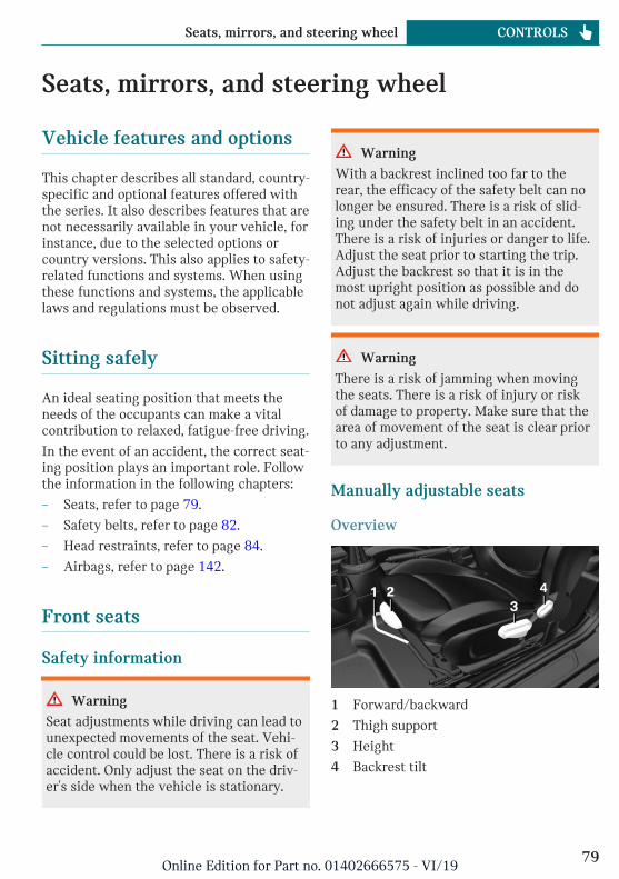
Seats, mirrors, and steering wheel
Vehicle features and options
This chapter describes all standard, country-specific and optional features offered withthe series. It also describes features that arenot necessarily available in your vehicle, forinstance, due to the selected options orcountry versions. This also applies to safety-related functions and systems. When usingthese functions and systems, the applicablelaws and regulations must be observed.
Sitting safely
An ideal seating position that meets theneeds of the occupants can make a vitalcontribution to relaxed, fatigue-free driving.
In the event of an accident, the correct seat-ing position plays an important role. Followthe information in the following chapters:
– Seats, refer to page 79.
– Safety belts, refer to page 82.
– Head restraints, refer to page 84.
– Airbags, refer to page 142.
Front seats
Safety information
Warning
Seat adjustments while driving can lead tounexpected movements of the seat. Vehi-cle control could be lost. There is a risk ofaccident. Only adjust the seat on the driv-er's side when the vehicle is stationary.
Warning
With a backrest inclined too far to therear, the efficacy of the safety belt can nolonger be ensured. There is a risk of slid-ing under the safety belt in an accident.There is a risk of injuries or danger to life.Adjust the seat prior to starting the trip.Adjust the backrest so that it is in themost upright position as possible and donot adjust again while driving.
Warning
There is a risk of jamming when movingthe seats. There is a risk of injury or riskof damage to property. Make sure that thearea of movement of the seat is clear priorto any adjustment.
Manually adjustable seats
Overview
1 Forward/backward
2 Thigh support
3 Height
4 Backrest tilt
Seite 79
Seats, mirrors, and steering wheel CONTROLS
79Online Edition for Part no. 01402666575 - VI/19

Forward/backward
Pull the lever and slide the seat in the de-sired direction.
After releasing the lever, move the seat for-ward or back slightly making sure it en-gages properly.
Height
Pull the lever up or press it down as often asneeded to reach the desired height.
Backrest tilt
Pull the lever, and apply your weight to thebackrest or lift it off, as necessary.
Lumbar supportThe curvature of the seat backrest can beadjusted in a way that it supports the lum-bar region of the spine. The lower back andthe spine are supported for upright posture.
Turn the wheel in order to increase or de-crease the curvature.
Electrically adjustable seats
General informationThe current seat position can be stored us-ing the memory function, refer to page 86.
Overview
1 Memory function
2 Lumbar support
3 Backrest tilt
4 Forward/backward, height, seat tilt
Seite 80
CONTROLS Seats, mirrors, and steering wheel
80Online Edition for Part no. 01402666575 - VI/19

Forward/backward
Push switch forward or backward.
Height
Push switch up or down.
Seat tilt
Move switch up or down.
Backrest tilt
Move switch forward or backward.
Lumbar support
Concept
The curvature of the seat backrest can beadjusted in a way that it supports the lum-bar region of the spine. The lower back andthe spine are supported for upright posture.
Adjusting
– Press the front/rear sec-tion of the button:
The curvature is in-creased/decreased.
– Press the upper/lower sec-tion of the button:
The curvature is shiftedup/down.
Seite 81
Seats, mirrors, and steering wheel CONTROLS
81Online Edition for Part no. 01402666575 - VI/19
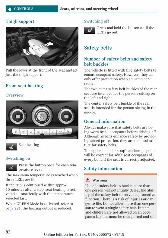
Thigh support
Pull the lever at the front of the seat and ad-just the thigh support.
Front seat heating
Overview
Seat heating
Switching on
Press the button once for each tem-perature level.
The maximum temperature is reached whenthree LEDs are lit.
If the trip is continued within approx.15 minutes after a stop, seat heating is acti-vated automatically with the temperatureselected last.
When GREEN Mode is activated, refer topage 221, the heating output is reduced.
Switching off
Press and hold the button until theLEDs go out.
Safety belts
Number of safety belts and safetybelt bucklesThe vehicle is fitted with five safety belts toensure occupant safety. However, they canonly offer protection when adjusted cor-rectly.
The two outer safety belt buckles of the rearseat are intended for the persons sitting onthe left and right.
The center safety belt buckle of the rearseat is intended for the person sitting in themiddle.
General informationAlways make sure that safety belts are be-ing worn by all occupants before driving off.Although airbags enhance safety by provid-ing added protection, they are not a substi-tute for safety belts.
The upper shoulder strap's anchorage pointwill be correct for adult seat occupants ofevery build if the seat is correctly adjusted.
Safety information
Warning
Use of a safety belt to buckle more thanone person will potentially defeat the abil-ity of the safety belt to serve its protectivefunction. There is a risk of injuries or dan-ger to life. Do not allow more than one per-son to wear a single safety belt. Infantsand children are not allowed on an occu-pant's lap, but must be transported and se-
Seite 82
CONTROLS Seats, mirrors, and steering wheel
82Online Edition for Part no. 01402666575 - VI/19

cured in designated child restraint sys-tems.
Warning
The efficacy of safety gear, includingsafety belts, can be limited or lost whensafety belts are fastened incorrectly. Anincorrectly fastened safety belt can causeadditional injuries, for instance in theevent of an accident or during braking andevasive maneuvers. There is a risk of inju-ries or danger to life. Make sure that alloccupants are wearing safety belts cor-rectly.
Warning
With a rear backrest that is not locked, theprotective function of the middle safetybelt is not guaranteed. There is a risk ofinjuries or danger to life. If you are usingthe middle safety belt, lock the wider rearseat backrest.
Warning
The efficacy of safety gear, includingsafety belts, may not be fully functional orfail in the following situations:
– The safety belts or safety belt bucklesare damaged, soiled, or changed inany other way.
– Belt tensioners or belt retractorswere modified.
Safety belts can be imperceptibly damagedin the event of an accident. There is a riskof injuries or danger to life. Do not modifysafety belts, safety belt buckles, belt ten-sioners, belt retractors or belt anchors andkeep them clean. Have the safety beltschecked after an accident at the dealer’s
service center or another qualified servicecenter or repair shop.
Correct use of safety belts– Wear the safety belt twist-free and tight
to your body over your lap and should-ers.
– Wear the safety belt deep on your hipsover your lap. The safety belt may notpress on your stomach.
– Do not rub the safety belt against sharpedges, or guide it or jam it in acrosshard or fragile objects.
– Avoid thick clothing.
– Re-tighten the safety belt frequently up-ward around your upper body.
Buckling the safety belt1. Guide the safety belt slowly over
shoulder and hip to put it on.
2. Insert the tongue plate into the safetybelt buckle. The safety belt buckle mustengage audibly.
Unbuckling the safety belt1. Hold the safety belt firmly.
2. Press the red button in the belt buckle.
3. Guide the safety belt back into its roll-up mechanism.
Seite 83
Seats, mirrors, and steering wheel CONTROLS
83Online Edition for Part no. 01402666575 - VI/19

Safety belt reminder for driver'sseat and front passenger seat
Display in the instrument cluster
The indicator light lights up and asignal sounds. Make sure that thesafety belts are positioned correctly.
The safety belt reminder can also be acti-vated if objects are placed on the front pas-senger seat.
Front head restraints
Safety information
Warning
A missing protective effect due to re-moved or not correctly adjusted head re-straints can cause injuries in the head andneck area. There is a risk of injury.
– Before driving, install the removedhead restraints on the occupied seats.
– Adjust the head restraint so its centersupports the back of the head at asclose to eye level as possible.
– Adjust the distance so that the headrestraint is as close as possible to theback of the head. Adjust the distancevia the backrest tilt as needed.
Warning
Body parts can be jammed when movingthe head restraint. There is a risk of injury.Make sure that the area of movement isclear when moving the head restraint.
Warning
Objects on the head restraint reduce theprotective effect in the head and neckarea. There is a risk of injury.
– Do not use seat or head restraint cov-ers.
– Do not hang objects, for instanceclothes hangers, directly on the headrestraint.
– Only use accessories that have beendetermined to be safe for attachmentto a head restraint.
– Do not use any accessories, for in-stance pillows, while driving.
Adjusting the height: John CooperWorks sport seatThe height of the head restraints cannot beadjusted.
Adjusting the height
– To lower: press the button, arrow 1, andpush the head restraint down.
– To raise: push the head restraint up.
After setting the height, make sure that thehead restraint engages correctly.
Removing: John Cooper Workssport seatThe head restraints cannot be removed.
Seite 84
CONTROLS Seats, mirrors, and steering wheel
84Online Edition for Part no. 01402666575 - VI/19

RemovingOnly remove the head restraint if no onewill be sitting in the seat in question.
1. If necessary, fold the rear seat backrestforward.
2. Pull head restraint up as far as possible.
3. Press the button, arrow 1, and pull thehead restraint out completely.
InstallingProceed in the reverse order to install thehead restraint.
Rear head restraints
Safety information
Warning
A missing protective effect due to re-moved or not correctly adjusted head re-straints can cause injuries in the head andneck area. There is a risk of injury.
– Before driving, install the removedhead restraints on the occupied seats.
– Adjust the head restraint so its centersupports the back of the head at asclose to eye level as possible.
– Adjust the distance so that the headrestraint is as close as possible to theback of the head. Adjust the distancevia the backrest tilt as needed.
Warning
Body parts can be jammed when movingthe head restraint. There is a risk of injury.Make sure that the area of movement isclear when moving the head restraint.
Warning
Objects on the head restraint reduce theprotective effect in the head and neckarea. There is a risk of injury.
– Do not use seat or head restraint cov-ers.
– Do not hang objects, for instanceclothes hangers, directly on the headrestraint.
– Only use accessories that have beendetermined to be safe for attachmentto a head restraint.
– Do not use any accessories, for in-stance pillows, while driving.
Adjusting the height
– To lower: press the button, arrow 1, andpush the head restraint down.
– To raise: push the head restraint up.
After setting the height, make sure that thehead restraint engages correctly.
Seite 85
Seats, mirrors, and steering wheel CONTROLS
85Online Edition for Part no. 01402666575 - VI/19

Fold down
– To fold down: press the button, arrow 1,and press down the head restraint, ar-row 2.
– Forward: fold the head restraint towardthe front as far as it will go. Make surethat the head restraint engages cor-rectly.
RemovingOnly remove the head restraint if no onewill be sitting in the seat in question.
1. Fold down the rear seat backrest, referto page 211, in question.
2. Pull head restraint up against the resist-ance.
3. Press the button, arrow 1, and pull thehead restraint out completely.
InstallingProceed in the reverse order to install thehead restraint.
Memory function
ConceptThe following settings can be stored and, ifnecessary, retrieved using the memoryfunction:
– Seat position.
– Exterior mirror position.
General informationDifferent settings can be assigned to twomemory locations.
The adjustment of the lumbar support is notstored.
Safety information
Warning
There is a risk of jamming when movingthe seats. There is a risk of injury or riskof damage to property. Make sure that thearea of movement of the seat is clear priorto any adjustment.
Warning
Using the memory function while drivingcan lead to unexpected movements of theseat. Vehicle control could be lost. There isa risk of accident. Only retrieve the mem-ory function when the vehicle is station-ary.
Seite 86
CONTROLS Seats, mirrors, and steering wheel
86Online Edition for Part no. 01402666575 - VI/19
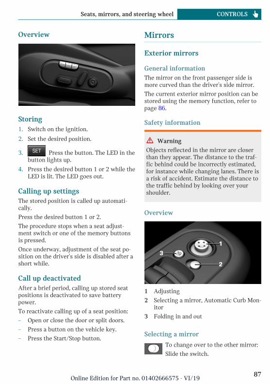
Overview
Storing1. Switch on the ignition.
2. Set the desired position.
3. Press the button. The LED in thebutton lights up.
4. Press the desired button 1 or 2 while theLED is lit. The LED goes out.
Calling up settingsThe stored position is called up automati-cally.
Press the desired button 1 or 2.
The procedure stops when a seat adjust-ment switch or one of the memory buttonsis pressed.
Once underway, adjustment of the seat po-sition on the driver's side is disabled after ashort while.
Call up deactivatedAfter a brief period, calling up stored seatpositions is deactivated to save batterypower.
To reactivate calling up of a seat position:
– Open or close the door or split doors.
– Press a button on the vehicle key.
– Press the Start/Stop button.
Mirrors
Exterior mirrors
General informationThe mirror on the front passenger side ismore curved than the driver's side mirror.
The current exterior mirror position can bestored using the memory function, refer topage 86.
Safety information
Warning
Objects reflected in the mirror are closerthan they appear. The distance to the traf-fic behind could be incorrectly estimated,for instance while changing lanes. There isa risk of accident. Estimate the distance tothe traffic behind by looking over yourshoulder.
Overview
1 Adjusting
2 Selecting a mirror, Automatic Curb Mon-itor
3 Folding in and out
Selecting a mirror
To change over to the other mirror:
Slide the switch.
Seite 87
Seats, mirrors, and steering wheel CONTROLS
87Online Edition for Part no. 01402666575 - VI/19

Adjusting electrically
Press the button.
The mirror movement follows thebutton movement.
MalfunctionIn case of an electrical malfunction, adjustthe mirror by pressing the edges of the mir-ror glass.
Folding in and out
NOTICE
Depending on the vehicle width, the vehi-cle can be damaged in vehicle washes.There is a risk of damage to property. Be-fore washing, fold in the mirrors by handor with the button.
Press the button.
Folding is only possible up to a speed of ap-prox. 15 mph/20 km/h.
Folding the mirrors in and out is helpful inthe following situations:
– In vehicle washes.
– On narrow roads.
Mirrors that were folded in are folded outautomatically at a speed of approx.25 mph/40 km/h.
Automatic heatingBoth exterior mirrors are automaticallyheated as needed and when the ignition isswitched on.
Automatic dimming featureThe exterior mirror on the driver's side isautomatically dimmed. Photocells in thecar's interior mirror, refer to page 89, areused to control this.
Automatic Curb Monitor, exteriormirror
ConceptIf reverse gear is engaged, the mirror glasson the front passenger side is tilted down-ward. This improves your view of the curband other formatting issue - low-lying ob-stacles when parking, for instance.
Activating
1. slide the switch to the driver'sside mirror position.
2. Engage selector lever position R.
DeactivatingSlide the switch to the passenger's side mir-ror position.
Interior mirror, manually dimmable
Flip lever
To reduce the blinding effect of the interiormirror, flip the lever forward.
Seite 88
CONTROLS Seats, mirrors, and steering wheel
88Online Edition for Part no. 01402666575 - VI/19

Turn knob
Turn the knob to reduce the blinding effectby the interior mirror.
Interior mirror, automatic dimmingfeature
Overview
Photocells are used for control:
– In the mirror glass.
– On the back of the mirror.
Functional requirements– Keep the photocells clean.
– Do not cover the area between the inte-rior mirror and the windshield.
Steering wheel
Safety information
Warning
Steering wheel adjustments while drivingcan lead to unexpected steering wheelmovements. Vehicle control could be lost.There is a risk of accident. Adjustng thesteering wheel while the vehicle is sta-tionary only.
Adjusting
1. Fold the lever down.
2. Move the steering wheel to the prefer-red height and angle to suit your seatingposition.
3. Fold the lever back up.
Seite 89
Seats, mirrors, and steering wheel CONTROLS
89Online Edition for Part no. 01402666575 - VI/19

Transporting children safely
Vehicle features and options
This chapter describes all standard, country-specific and optional features offered withthe series. It also describes features that arenot necessarily available in your vehicle, for
instance, due to the selected options orcountry versions. This also applies to safety-related functions and systems. When usingthese functions and systems, the applicablelaws and regulations must be observed.
The right place for children
Safety information
Warning
Unattended children or animals in the ve-hicle can cause the vehicle to move andendanger themselves and traffic, for in-stance due to the following actions:
– Pressing the Start/Stop button.
– Releasing the parking brake.
– Opening and closing the doors orwindows.
– Engaging selector lever position N.
– Using vehicle equipment.
There is a risk of accidents or injuries. Donot leave children or animals unattendedin the vehicle. Take the vehicle key withyou when exiting and lock the vehicle.
Always transport children in therear seat
General informationAccident research shows that the safestplace for children is in the rear seat.
Transport children younger than 13 years ofage or shorter than 5 ft/150 cm only in therear seat in suitable child restraint systemsdesigned for the age, weight and size of the
child. Children 13 years of age or older mustwear a safety belt as soon as a suitable childrestraint system can no longer be used dueto their age, weight, or size.
Safety information
Warning
The safety belt cannot be fastened cor-rectly on children shorter than 5 ft,150 cm without suitable additional childrestraint systems. The efficacy of safetygear, including safety belts, can be limitedor lost when safety belts are fastened in-correctly. An incorrectly fastened safetybelt can cause additional injuries, for in-stance in the event of an accident or dur-ing braking and evasive maneuvers. Thereis a risk of injuries or danger to life. Se-cure children shorter than 5 ft, 150 cm us-ing suitable child restraint systems.
Children on the front passengerseat
General informationBefore using a child restraint system on thefront passenger seat, ensure that the front,knee, and side airbags on the front passen-ger side are deactivated. For automatic de-
Seite 90
CONTROLS Transporting children safely
90Online Edition for Part no. 01402666575 - VI/19

activation of front-seat passenger airbags,refer to page 144.
Safety information
Warning
Active front-seat passenger airbags can in-jure a child in a child restraint systemwhen the airbags are activated. There is arisk of injury. Make sure that the front-seat passenger airbags are deactivated andthat the PASSENGER AIRBAG OFF indica-tor light lights up.
Warning
The stability of the child restraint systemis limited or compromised with incorrectseat adjustment or improper installation ofthe child seat. There is a risk of injuries ordanger to life. Make sure that the child re-straint system fits securely against thebackrest. If possible, adjust the backresttilt for all affected backrests and correctlyadjust the seats. Make sure that seats andbackrests are securely engaged or locked.If possible, adjust the height of the headrestraints or remove them.
Installing child restraint sys-tems
General informationPay attention to the specifications of thechild restraint system manufacturer whenselecting, installing, and using child re-straint systems.
Safety information
Warning
The protective effect of child restraint sys-tems and their fastening systems whichhave been damaged or exposed to an acci-dent can be limited or lost. A child cannotbe properly restrained in the event of anaccident or braking and evasive maneu-vers. There is a risk of injuries or dangerto life.
Do not use child restraint systems whichhave been damaged or exposed to an acci-dent.
If a child restraint system and its fasten-ing system has been damaged or exposedto an accident, have these systemschecked and replaced by the dealer's serv-ice center or another qualified service cen-ter or repair shop.
Warning
The stability of the child restraint systemis limited or compromised with incorrectseat adjustment or improper installation ofthe child seat. There is a risk of injuries ordanger to life. Make sure that the child re-straint system fits securely against thebackrest. If possible, adjust the backresttilt for all affected backrests and correctlyadjust the seats. Make sure that seats andbackrests are securely engaged or locked.If possible, adjust the height of the headrestraints or remove them.
Seite 91
Transporting children safely CONTROLS
91Online Edition for Part no. 01402666575 - VI/19

On the front passenger seat
Deactivating airbags
Warning
Active front-seat passenger airbags can in-jure a child in a child restraint systemwhen the airbags are activated. There is arisk of injury. Make sure that the front-seat passenger airbags are deactivated andthat the PASSENGER AIRBAG OFF indica-tor light lights up.
Before installing a child restraint system inthe front passenger seat, make sure that thefront, knee and side airbags on the frontpassenger side are deactivated.
Deactivate the front-seat passenger airbagsautomatically, refer to page 144.
Seat position and heightBefore installing a child restraint system,move the front passenger seat as far back aspossible and adjust its height to the highestand thus best possible position for the beltand to offer optimal protection in the eventof an accident.
If the upper anchorage of the safety belt islocated in front of the belt guide of the childseat, move the front passenger seat care-fully forward until the best possible beltguide position is reached.
Child seat security
The rear safety belts and the front passen-ger safety belt can be permanently locked tofasten child restraint systems.
Locking the safety belt1. Pull out the belt strap completely.
2. Secure the child restraint system withthe safety belt.
3. Allow the belt strap to be pulled in andpull it tight against the child restraintsystem. The safety belt is locked.
Unlocking the safety belt1. Unbuckle the safety belt buckle.
2. Remove the child restraint system.
3. Allow the belt strap to be pulled in com-pletely.
LATCH child restraint fixingsystem
General informationLATCH: Lower Anchors and Tether for Chil-dren.
Pay attention to the operating and safety in-formation from the child restraint systemmanufacturer when installing and usingLATCH child restraint fixing systems.
Seite 92
CONTROLS Transporting children safely
92Online Edition for Part no. 01402666575 - VI/19

Mounts for the lower LATCHanchorsThe lower anchors may be used to attachthe CRS to the vehicle seat up to a com-bined child and CRS weight of 65 lbs/30 kgwhen the child is restrained by the internalharnesses.
Safety information
Warning
If the LATCH child restraint fixing sys-tems are not correctly engaged, the protec-tive effect of the LATCH child restraintfixing system can be limited. There is arisk of injuries or danger to life. Make surethat the lower anchors are securely en-gaged and that the LATCH child restraintfixing system fits securely against thebackrest.
Position
Symbol Meaning
The corresponding symbolshows the mounts for thelower LATCH anchors.
Seats equipped with loweranchors are marked with apair, (2), of LATCH symbols.
For vehicles equipped witha middle seat:
It is not recommended touse the inner lower anchorsof standard outer LATCHpositions to fasten a childrestraint system on themiddle seat. Use the vehiclesafety belt instead for themiddle seat.
Before installing LATCH childrestraint fixing systemsPull the safety belt away from the area ofthe child restraint system.
Assembly of LATCH child restraintfixing systems1. Install child restraint system, see manu-
facturer's information.
2. Ensure that both LATCH anchors areproperly connected.
Child restraint systems with tetherstrap
Safety information
Warning
If the upper retaining strap is incorrectlyused for the child restraint system, theprotective effect can be reduced. There isa risk of injury. Make sure that the upperretaining strap does not run over sharpedges and is not twisted as it passes theupper anchor.
Warning
If the rear backrest is not locked, the pro-tective effect of the child restraint systemis limited or there is none. In certain situa-tions, for instance braking maneuvers orin case of an accident, the rear backrestcan fold forward. There is a risk of injuriesor danger to life. Make sure that the rearbackrests are locked.
Seite 93
Transporting children safely CONTROLS
93Online Edition for Part no. 01402666575 - VI/19

NOTICE
The anchors for the upper retaining strapsof child restraint systems are only pro-vided for these retaining straps. Whenother objects are mounted, the anchorscan be damaged. There is a risk of damageto property. Only mount child restraintsystems to the upper anchors.
Anchors
The respective symbol shows the an-chor for the upper retaining strap.Seats with an upper top tether are
marked with this symbol. It can be found onthe rear seat backrest or the rear windowshelf.
Routing the retaining strap
1 Direction of travel
2 Head restraint
3 Hook for upper retaining strap
4 Anchor
5 Seat backrest
6 Upper retaining strap
Attaching the upper retaining strap tothe anchor1. Raise the head restraint, if needed.
2. On the rear seat: Guide the upper retain-ing strap between or along both sides of
the supports of the head restraint to theanchor.
3. Attach the hook of the retaining strap tothe anchor on the rear seat.
4. Tighten the retaining strap by pulling itdown.
Locking the doors and win-dows
Doors
Push the locking lever on the rear doors up.
The door can now be opened from the out-side only.
Safety switch for the rearPress the button on the driver'sdoor if children are being trans-ported in the rear.
This locks various functions so that theycannot be operated from the rear: safetyswitch, refer to page 76.
Seite 94
CONTROLS Transporting children safely
94Online Edition for Part no. 01402666575 - VI/19

Driving
Vehicle features and options
This chapter describes all standard, country-specific and optional features offered withthe series. It also describes features that arenot necessarily available in your vehicle, forinstance, due to the selected options orcountry versions. This also applies to safety-related functions and systems. When usingthese functions and systems, the applicablelaws and regulations must be observed.
Start/Stop button
ConceptPressing the Start/Stop buttonswitches the ignition on or offand starts the engine.
Steptronic transmission: theengine starts in selector lever
position P or N with the brake pedal pressedwhen you press the Start/Stop button.
Manual transmission: the engine starts withthe clutch pedal pressed when the Start/Stop button is pressed.
Ignition onManual transmission: press the Start/Stopbutton without stepping on the clutchpedal.
Steptronic transmission: press the Start/Stop button, but do not press on the brakepedal at the same time.
All vehicle systems are ready for operation.
Most of the indicator/warning lights in theinstrument cluster light up for a variedlength of time.
To save battery power when the engine isoff, switch off the ignition and any unneces-sary electronic systems/power consumers.
Ignition offManual transmission: press the Start/Stopbutton again without stepping on the clutchpedal.
Steptronic transmission: shift to selectorlever position P, press the Start/Stop buttonagain without stepping on the brake.
All indicator lights in the instrument clustergo out.
To save battery power when the engine isoff, switch off the ignition and any unneces-sary electronic systems/power consumers.
Safety measuresThe ignition is switched off automatically inthe following situations while the vehicle isstationary and the engine is off:
– When locking the vehicle, even if thelow beams are switched on.
– Shortly before the battery is dischargedcompletely, so that the engine can stillbe started. This function is only availa-ble when the low beams are switchedoff.
– When opening or closing the driverdoor, if the driver's safety belt is un-buckled and the low beams are switchedoff.
– While the driver's safety belt is unbuck-led with driver's door open and lowbeams off.
– When the front doors are opened ifthere is no other person sitting in thefront seats.
Seite 95
Driving CONTROLS
95Online Edition for Part no. 01402666575 - VI/19

– The low beams switch to parking lightsafter some minutes of no use.
Steptronic transmission with a tap-operatedselector lever, refer to page 112: whenswitching off the ignition, the selector leverposition P is engaged automatically if theselector lever position R, D or M/S is en-gaged.
Radio-ready state
General informationIn the radio-ready state, certain power con-sumers remain ready for operation.
ActivatingWith the engine running, press the Start/Stop button.
If the engine is not running and the ignitionis switched on: the system automatically ac-tivates radio-ready state when the door isopened if the lights are switched off or thedaytime running lights are switched on.
Radio-ready state remains active if, for in-stance the ignition is automaticallyswitched off for the following reasons:
– Opening or closing the driver's door.
– Unfastening of the driver's safety belt.
– When automatically switching from lowbeams to parking lights.
Switching off automaticallyThe radio-ready state is switched off auto-matically in the following situations:
– If the driver's or front passenger door isopened when exiting the vehicle, withthe engine switched off manually.
– If the ignition is switched off manuallywith the Start/Stop button.
– After approx. 8 minutes.
– When the vehicle is locked using thecentral locking system.
– Shortly before the battery is dischargedcompletely, so that the engine can stillbe started.
Starting the engine
Safety information
DANGER
If the exhaust pipe is blocked or ventila-tion is insufficient, harmful exhaust gasescan enter into the vehicle. The exhaustgases contain pollutants which are color-less and odorless. In enclosed areas, ex-haust gases can also accumulate outside ofthe vehicle. There is danger to life. Keepthe exhaust pipe free and ensure sufficientventilation.
Warning
An unsecured vehicle can begin to moveand possibly roll away. There is a risk ofaccident. Before exiting, secure the vehi-cle against rolling.
In order to ensure that the vehicle is se-cured against rolling away, follow the fol-lowing:
– Set the parking brake.
– On uphill grades or on a downhillslope, turn the front wheels in the di-rection of the curb.
– On uphill grades or on a downhillslope, also secure the vehicle, for in-stance with a wheel chock.
NOTICE
In the case of repeated starting attemptsor repeated starting in quick succession,the fuel is not burned or is inadequatelyburned. The catalytic converter can over-
Seite 96
CONTROLS Driving
96Online Edition for Part no. 01402666575 - VI/19

heat. There is a risk of damage to property.Avoid repeated starting in quick succes-sion.
Gasoline engineDepending on the motorization, the fulldrive power may not be available for ap-proximately 30 seconds after starting theengine. In this case, the vehicle will not ac-celerate as usual.
Steptronic transmission
Starting the engine1. Depress the brake pedal.
2. Engage selector lever position P or N.
3. Press the Start/Stop button.
The ignition is activated automatically for abrief time and is stopped as soon as the en-gine starts.
Manual transmission
Starting the engine1. Depress the brake pedal.
2. Press on the clutch pedal and shift toneutral.
3. Press the Start/Stop button.
The ignition is activated automatically for abrief time and is stopped as soon as the en-gine starts.
Engine stop
Safety information
Warning
Unattended children or animals in the ve-hicle can cause the vehicle to move andendanger themselves and traffic, for in-stance due to the following actions:
– Pressing the Start/Stop button.
– Releasing the parking brake.
– Opening and closing the doors orwindows.
– Engaging selector lever position N.
– Using vehicle equipment.
There is a risk of accidents or injuries. Donot leave children or animals unattendedin the vehicle. Take the vehicle key withyou when exiting and lock the vehicle.
Warning
An unsecured vehicle can begin to moveand possibly roll away. There is a risk ofaccident. Before exiting, secure the vehi-cle against rolling.
In order to ensure that the vehicle is se-cured against rolling away, follow the fol-lowing:
– Set the parking brake.
– On uphill grades or on a downhillslope, turn the front wheels in the di-rection of the curb.
– On uphill grades or on a downhillslope, also secure the vehicle, for in-stance with a wheel chock.
Seite 97
Driving CONTROLS
97Online Edition for Part no. 01402666575 - VI/19

Steptronic transmission
Switching off the engine1. When the vehicle is stationary, apply
the parking brake.
2. Engage selector lever position P.
3. Press the Start/Stop button.
The engine is switched off.
The radio-ready state is switched on.
Manual transmission
Switching off the engine1. With the vehicle at a standstill, press
the Start/Stop button.
The engine is switched off.
The radio-ready state is switched on.
2. Shift into first gear or reverse.
3. Set the parking brake.
Auto Start/Stop function
ConceptThe Auto Start/Stop function helps savefuel. The system switches off the engineduring a stop, for instance in traffic conges-tion or at traffic lights. The ignition remainsswitched on. The engine starts automati-cally for driving off.
After each engine start using the Start/Stopbutton, the Auto Start/Stop function isready and is activated at speeds faster thanabout 3 mph/5 km/h.
Depending on the selected driving mode, re-fer to page 164, the system is automaticallyactivated or deactivated.
Engine stop
Functional requirementsThe engine is switched off automaticallyduring a stop under the following condi-tions:
Manual transmission:
– Neutral is engaged and the clutch pedalis not pressed.
– The driver's safety belt is buckled or thedriver's door is closed.
Steptronic transmission:
– The selector lever is in selector lever po-sition D.
– The brake pedal remains depressedwhile the vehicle is stopped.
– The driver's safety belt is buckled or thedriver's door is closed.
In order to be able to release the brakepedal, engage the selector lever in positionP. The engine remains off.
To continue driving depress the brakepedal. When a gear is engaged, the enginestarts automatically.
The air flow from the air conditioner is re-duced when the engine is switched off.
Steptronic transmission: manualengine stopDepending on the vehicle equipment andcountry version, the engine can be switchedoff manually, if the engine was not switchedoff automatically when the vehicle stopped:
– Press the brake pedal forcefully againfrom the current pedal position.
– Engage selector lever position P.
If all functional preconditions are fulfilled,the engine switches off.
Seite 98
CONTROLS Driving
98Online Edition for Part no. 01402666575 - VI/19

Displays in the instrument cluster
The display indicates that theAuto Start/Stop function isready for an Automatic enginestart.
The display indicates that theconditions for an automaticengine stop have not beenmet.
Functional limitationsThe engine is not switched off automaticallyin the following situations:
– External temperature too low.
– The external temperature is high and au-tomatic climate control is running.
– The car's interior has not yet beenheated or cooled to the required level.
– The engine is not yet at operating tem-perature.
– The wheels are at a sharp angle or thesteering wheel is being turned.
– After driving in reverse.
– Fogging of the windows when the auto-matic climate control is switched on.
– The vehicle battery charge is very low.
– At higher elevations.
– The hood is unlocked.
– The parking assistant is activated.
– Stop-and-go traffic.
– Selector lever in selector lever positionR, N or M/S.
Starting the engineThe engine starts automatically under thefollowing conditions:
– Manual transmission: clutch pedal ispressed.
– Steptronic transmission: by releasingthe brake pedal.
After the engine starts, accelerate as usual.
Safety modeAfter the engine switches off automatically,it will not start again automatically if anyone of the following conditions are met:
– The driver's safety belt is unbuckled andthe driver's door is open.
– The hood was unlocked.
Some indicator lights light up for a variedlength of time.
The engine can only be started via theStart/Stop button.
Functional limitationsEven if driving off was not intended, the de-activated engine starts up automatically inthe following situations:
– Excessive warming of the car's interiorwhen the air conditioning is switchedon.
– The steering wheel is turned.
– Steptronic transmission: change fromselector lever position D to R, N or M/S.
– Steptronic transmission: change fromselector lever position P to R, N, D orM/S.
– The vehicle begins rolling.
– Fogging of the windows when the auto-matic climate control is switched on.
– The vehicle battery charge is very low.
– Excessive cooling of the car's interiorwhen the heating is switched on.
– Manual transmission: low brake vacuumpressure; this can occur, for instance ifthe brake pedal is depressed a numberof times in succession.
Seite 99
Driving CONTROLS
99Online Edition for Part no. 01402666575 - VI/19

Intelligent Auto Start/Stop functionDepending on the vehicle equipment andcountry-specific version, the vehicle fea-tures a variety of sensors for assessing thetraffic situation. The Intelligent Auto Start/Stop function uses this information to adaptto various traffic situations in a proactivemanner.
For instance, this applies to the followingsituations:
– If a situation is detected in which thestopping time is expected to be veryshort, the engine is not switched off au-tomatically. A message appears on theControl Display, depending on the situa-tion.
– If a situation is detected in which thevehicle needs to drive off immediately,the engine is started automatically.
The function may be restricted if the navi-gation data is invalid, outdated or not avail-able, for example.
Switching the system on/off
Using the button
Press the button.
– LED comes on: auto Start/Stop functionis deactivated.
The engine is started during an auto-matic engine stop.
The engine can only be stopped orstarted via the Start/Stop button.
– LED goes out: auto Start/Stop functionis activated.
Switching off the vehicle during anautomatic engine stopDuring an automatic engine stop, the vehi-cle can be switched off permanently, for in-stance when leaving it.
Steptronic transmission:
1. Engage selector lever position P.
2. Press the Start/Stop button. The ignitionis switched off. The Auto Start/Stopfunction is deactivated.
3. Set the parking brake.
Manual transmission:
1. Press the Start/Stop button. The ignitionis switched off. The Auto Start/Stopfunction is deactivated.
2. Shift into first gear or reverse.
3. Set the parking brake.
Engine start as usual via Start/Stop button.
Automatic deactivationIn certain situations, the Auto Start/Stopfunction is deactivated automatically forsafety reasons, for instance if no driver isdetected.
MalfunctionThe Auto Start/Stop function no longerswitches off the engine automatically. ACheck Control message is displayed. It ispossible to continue driving. Have the sys-tem checked by a dealer's service center oranother qualified service center or repairshop.
Seite 100
CONTROLS Driving
100Online Edition for Part no. 01402666575 - VI/19

Parking brake
ConceptThe parking brake is used to prevent the ve-hicle from rolling when it is parked.
Safety information
Warning
An unsecured vehicle can begin to moveand possibly roll away. There is a risk ofaccident. Before exiting, secure the vehi-cle against rolling.
In order to ensure that the vehicle is se-cured against rolling away, follow the fol-lowing:
– Set the parking brake.
– On uphill grades or on a downhillslope, turn the front wheels in the di-rection of the curb.
– On uphill grades or on a downhillslope, also secure the vehicle, for in-stance with a wheel chock.
Warning
Unattended children or animals in the ve-hicle can cause the vehicle to move andendanger themselves and traffic, for in-stance due to the following actions:
– Pressing the Start/Stop button.
– Releasing the parking brake.
– Opening and closing the doors orwindows.
– Engaging selector lever position N.
– Using vehicle equipment.
There is a risk of accidents or injuries. Donot leave children or animals unattendedin the vehicle. Take the vehicle key withyou when exiting and lock the vehicle.
Overview
Parking brake
Setting
With a stationary vehicle
Pull the switch.
The LED lights up.
The indicator light lights up red. Theparking brake is set.
Depending on the stopping situation, theparking brake is engaged automatically.
Steptronic transmission: in some parkingsituations, the parking brake is automati-cally engaged, when selector lever posi-tion P is engaged. In these cases, the park-ing brake is released automatically whenyou leave the selector lever position P.
While drivingTo use as emergency brake while driving:
Pull the switch and hold it. The vehiclebrakes hard while the switch is beingpulled.
The indicator light lights up red, asignal sounds and the brake lightslight up.
A Check Control message is displayed.
Seite 101
Driving CONTROLS
101Online Edition for Part no. 01402666575 - VI/19

If the vehicle is decelerated to a completestop, the parking brake is engaged.
Releasing
Releasing manually1. Switch on the ignition.
2. Manual transmission: press theswitch while the brake pedal is pressed.
Steptronic transmission: press theswitch while the brake is pressed or se-lector lever position P is set.
The LED and indicator light go out.
The parking brake is released.
Automatic release in cars withSteptronic transmissionFor automatic release, step on the accelera-tor pedal.
The LED and indicator light go out.
The parking brake is automatically releasedwhen you step on the accelerator under thefollowing conditions:
– Engine on.
– Drive mode engaged.
– Driver buckled in and doors closed.
Automatic release in cars with manualtransmissionDrive off as usual. The parking brake disen-gages when the clutch pedal is released.
The LED and indicator light go out.
Under the following conditions, the parkingbrake is automatically released:
– Engine on.
– Gear engaged.
– Driver buckled in and doors closed.
– Engine power is sufficient to drive off.
MalfunctionIf the parking brake fails or malfunctions,secure the vehicle against rolling before ex-iting.
A Check Control message is displayed.
Secure the vehicle against rolling away, forinstance with a wheel chock, after existingthe vehicle.
After a power failure
Re-activating the parking brake1. Switch on the ignition.
2. Press the switch while stepping onthe brake pedal or selector lever posi-tion P is set.
It may take several seconds for the brake tobe reactivated. Some mechanical sounds as-sociated with this process are normal.
The indicator light in the instrumentcluster goes out as soon as the park-ing brake is ready for operation.
Turn signal, high beams, head-light flasher
Turn signal
Using turn signals
Press the lever past the resistance point.
Seite 102
CONTROLS Driving
102Online Edition for Part no. 01402666575 - VI/19

Canada: the lever returns into its startingposition after actuation. To switch off man-ually, slightly tap the lever to the resistancepoint.
Triple turn signal activationLightly tap the lever up or down.
The triple turn signal duration can be ad-justed.
Via the Central Information Display (CID):
1. "My MINI"
2. "Vehicle settings"
3. "Lighting"
4. "Exterior lighting"
5. "One-touch turn signal"
6. Select the desired setting.
Settings are stored for the profile currentlyused.
Signaling brieflyPress the lever to the resistance point andhold it there for as long as you want theturn signal to flash.
MalfunctionUnusually rapid flashing of the indicatorlight indicates that a turn signal bulb hasfailed.
High beams, headlight flasherPush the lever forward or pull it backward.
– High beams on, arrow 1.
The high beams light up when the lowbeams are switched on.
– High beams off/headlight flasher, ar-row 2.
Wiper system
General informationDo not use the wipers if the windshield isdry, as this may damage the wiper blades orcause them to become worn more quickly.
Safety information
Warning
If the wipers start moving in the foldedaway state, body parts can be jammed ordamage may occur to parts of the vehicle.There is a risk of injury or risk of damageto property. Make sure that the vehicle isswitched off when the wipers are in thefolded away state and the wipers arefolded in when switching on.
NOTICE
If the wipers are frozen to the windshield,the wiper blades can be torn off and thewiper motor can overheat when switchingon. There is a risk of damage to property.
Seite 103
Driving CONTROLS
103Online Edition for Part no. 01402666575 - VI/19

Defrost the windshield prior to switchingthe wipers on.
Switching on
Press the lever up until the desired positionis reached.
– Resting position of the wipers, posi-tion 0.
– Intermittent operation or rain sensor,position 1.
– Normal wiper speed, position 2.
– Fast wiper speed, position 3.
When travel is interrupted with the wipersystem switched on: when travel continues,the wipers resume at their previous speed.
Switching off and brief wipe
Press the lever down.
– Switching off: press the lever down untilit reaches its standard position.
– Brief wipe: press the lever down fromthe standard position.
The lever automatically returns to its in-itial position when released.
Interval mode or rain sensor
ConceptThe rain sensor automatically controls thetime between wipes depending on the in-tensity of the rainfall.
General informationThe sensor is located on the windshield, di-rectly in front of the interior mirror. With-out the rain sensor, the frequency of thewiper operation is preset.
Safety information
NOTICE
If the rain sensor is activated, the wiperscan accidentally start moving in vehiclewashes. There is a risk of damage to prop-erty. Deactivate the rain sensor in vehiclewashes.
Activating
Press the lever up once from its standardposition, arrow 1.
Wiping is started.
The LED in the wiper lever is illuminated.
In frosty conditions, wiper operation maynot start.
Seite 104
CONTROLS Driving
104Online Edition for Part no. 01402666575 - VI/19

DeactivatingPress the lever back into the standard posi-tion.
Setting the frequency or sensitivity ofthe rain sensor
Turn the thumbwheel.
With deactivated rain sensor: set the inter-val.
With activated rain sensor: set the rain sen-sor sensitivity.
Up: short interval or high sensitivity of therain sensor.
Down: long interval or low sensitivity of therain sensor.
Windshield washer system
Safety information
Warning
The washer fluid can freeze onto the win-dow at low temperatures and obstruct theview. There is a risk of accident. Only usethe washer systems, if the washer fluidcannot freeze. Use washer fluid with anti-freeze, if needed.
NOTICE
When the washer fluid reservoir is empty,the wash pump cannot work as intended.There is a risk of damage to property. Donot use the washer system when thewasher fluid reservoir is empty.
Cleaning the windshield
Pull the lever.
The system sprays washer fluid on thewindshield and activates the wipers briefly.
Windshield washer nozzlesThe washer jets are automatically heatedwhenever the ignition is switched on.
Rear window wiper
Overview
Switching onTurn the outer switch upward.
Seite 105
Driving CONTROLS
105Online Edition for Part no. 01402666575 - VI/19

– Resting position of the wiper, posi-tion 0.
– Intermittent mode, arrow 1. When re-verse gear is engaged, the systemswitches to continuous operation.
Clean the rear windowTurn the outer switch in the desired direc-tion.
– In resting position: turn the switchdownward, arrow 3. The switch auto-matically returns to its idle positionwhen released.
– In intermittent mode: turn the switchfurther, arrow 2. The switch automati-cally returns to its interval positionwhen released.
The function is deactivated if the washerfluid reservoir level is low.
Fold-away position of the wipers
ConceptThe fold-away position enables the wipersto be folded away from the windshield.
General informationHelpful when changing the wiper blades orunder frosty conditions, for instance.
Safety information
Warning
If the wipers start moving in the foldedaway state, body parts can be jammed ordamage may occur to parts of the vehicle.There is a risk of injury or risk of damageto property. Make sure that the vehicle isswitched off when the wipers are in thefolded away state and the wipers arefolded in when switching on.
NOTICE
If the wipers are frozen to the windshield,the wiper blades can be torn off and thewiper motor can overheat when switchingon. There is a risk of damage to property.Defrost the windshield prior to switchingthe wipers on.
Folding away the wipers1. Switch the ignition on and off again.
2. Press and hold the wiper lever down, un-til the wipers stop in a close to verticalposition.
3. Fold the wipers all the way away fromthe windshield.
Folding down the wipersAfter the wipers are folded back down, thewiper system must be reactivated.
1. Fold the wipers back down onto thewindshield.
2. Switch on the ignition.
Seite 106
CONTROLS Driving
106Online Edition for Part no. 01402666575 - VI/19

3. Push wiper lever down. Wipers returnto their resting position and are readyagain for operation.
Canada: wiper system
General informationDo not use the wipers if the windshield isdry, as this may damage the wiper blades orcause them to become worn more quickly.
Safety information
Warning
If the wipers start moving in the foldedaway state, body parts can be jammed ordamage may occur to parts of the vehicle.There is a risk of injury or risk of damageto property. Make sure that the vehicle isswitched off when the wipers are in thefolded away state and the wipers arefolded in when switching on.
NOTICE
If the wipers are frozen to the windshield,the wiper blades can be torn off and thewiper motor can overheat when switchingon. There is a risk of damage to property.Defrost the windshield prior to switchingthe wipers on.
Switching on
Tap up the lever or press it past the resist-ance point.
– Normal wiper speed: tap up once.
– Fast wiper speed: tap up twice or taponce beyond the resistance point.
The lever automatically returns to its initialposition when released.
Switching off and brief wipe
Press the lever down.
– To switch off from fast wiper speed:press down twice.
– To switch off from normal wiper speed:press down once.
– Brief wipe: press down once.
The lever automatically returns to its initialposition when released.
Seite 107
Driving CONTROLS
107Online Edition for Part no. 01402666575 - VI/19

Interval mode or rain sensor
ConceptThe rain sensor automatically controls thetime between wipes depending on the in-tensity of the rainfall.
General informationThe sensor is located on the windshield, di-rectly in front of the interior mirror. With-out the rain sensor, the frequency of thewiper operation is preset.
Safety information
NOTICE
If the rain sensor is activated, the wiperscan accidentally start moving in vehiclewashes. There is a risk of damage to prop-erty. Deactivate the rain sensor in vehiclewashes.
Activating/deactivating
Press the button on the wiper lever.
Wiping is started.
The LED in the wiper lever is illuminated.
In frosty conditions, wiper operation maynot start.
If a journey is interrupted with the rain sen-sor switched on: if the trip is resumedwithin approx. 15 minutes, the rain sensoris automatically activated again.
Setting the frequency or sensitivity ofthe rain sensor
Turn the thumbwheel.
With deactivated rain sensor: set the inter-val.
With activated rain sensor: set the rain sen-sor sensitivity.
Up: short interval or high sensitivity of therain sensor.
Down: long interval or low sensitivity of therain sensor.
Windshield washer system
Safety information
Warning
The washer fluid can freeze onto the win-dow at low temperatures and obstruct theview. There is a risk of accident. Only usethe washer systems, if the washer fluidcannot freeze. Use washer fluid with anti-freeze, if needed.
NOTICE
When the washer fluid reservoir is empty,the wash pump cannot work as intended.There is a risk of damage to property. Donot use the washer system when thewasher fluid reservoir is empty.
Seite 108
CONTROLS Driving
108Online Edition for Part no. 01402666575 - VI/19

Cleaning the windshield
Pull the lever.
The system sprays washer fluid on thewindshield and activates the wipers briefly.
Windshield washer nozzlesThe washer jets are automatically heatedwhenever the ignition is switched on.
Rear window wiper
Overview
Switching onTurn the outer switch upward.
– Resting position of the wiper, posi-tion 0.
– Intermittent mode, arrow 1. When re-verse gear is engaged, the systemswitches to continuous operation.
Clean the rear windowTurn the outer switch in the desired direc-tion.
– In resting position: turn the switchdownward, arrow 3. The switch auto-matically returns to its idle positionwhen released.
– In intermittent mode: turn the switchfurther, arrow 2. The switch automati-cally returns to its interval positionwhen released.
The function is deactivated if the washerfluid reservoir level is low.
Fold-away position of the wipers
ConceptThe fold-away position enables the wipersto be folded away from the windshield.
General informationHelpful when changing the wiper blades orunder frosty conditions, for instance.
Safety information
Warning
If the wipers start moving in the foldedaway state, body parts can be jammed ordamage may occur to parts of the vehicle.There is a risk of injury or risk of damageto property. Make sure that the vehicle isswitched off when the wipers are in thefolded away state and the wipers arefolded in when switching on.
NOTICE
If the wipers are frozen to the windshield,the wiper blades can be torn off and thewiper motor can overheat when switchingon. There is a risk of damage to property.Defrost the windshield prior to switchingthe wipers on.
Seite 109
Driving CONTROLS
109Online Edition for Part no. 01402666575 - VI/19

Folding away the wipers1. Switch the ignition on and off again.
2. Press the wiper lever up past the pointof resistance and hold it for approx.3 seconds, until the wipers remain in anearly vertical position.
3. Fold the wipers all the way away fromthe windshield.
Folding down the wipersAfter the wipers are folded back down, thewiper system must be reactivated.
1. Fold the wipers back down onto thewindshield.
2. Switch on the ignition.
3. Push wiper lever down. Wipers returnto their resting position and are readyagain for operation.
Washer fluid
General informationAll washer nozzles are supplied from onereservoir.
Use a mixture of tap water and windshieldwasher concentrate. If desired, a windshieldwasher concentrate containing antifreezecan be used.
Recommended minimum fill quantity:0.2 US gal/1 liter.
Safety information
Warning
Some antifreeze agents can contain harm-ful substances and are flammable. There isa risk of fire and a risk of injury. Followthe instructions on the containers. Keepantifreeze away from ignition sources. Donot refill operating materials into differentbottles. Store operating materials out ofreach of children.
United States: the washer fluid mixture ra-tio is regulated by the U.S. EPA and manyindividual states; do not exceed the allow-able washer fluid dilution ratio limits thatapply. Follow the usage instructions on thewasher fluid container.
Use of BMW’s Windshield Washer Con-centrate or the equivalent is recom-mended.
Warning
Washer fluid can ignite and catch fire oncontact with hot engine parts. There is arisk of injury or risk of damage to prop-erty. Only add washer fluid when the en-gine is cooled down. Next, fully close thelid of the washer fluid reservoir.
Seite 110
CONTROLS Driving
110Online Edition for Part no. 01402666575 - VI/19

NOTICE
Silicon-containing additives in the washerfluid for the water-repelling effect on thewindows can lead to damage to the wash-ing system. There is a risk of damage toproperty. Do not add silicon-containing ad-ditives to the washer fluid.
NOTICE
Mixing different windshield washer con-centrates or antifreeze can damage thewashing system. There is a risk of damageto property. Do not mix different wind-shield washer concentrates or antifreeze.Follow the information and mixing ratiosprovided on the containers.
Overview
The washer fluid reservoir is located in theengine compartment.
MalfunctionThe use of undiluted windshield washerconcentrate or alcohol-based antifreeze canlead to incorrect readings at temperaturesbelow +5 ℉/-15 ℃.
Manual transmission
Safety information
Warning
An unsecured vehicle can begin to moveand possibly roll away. There is a risk ofaccident. Before exiting, secure the vehi-cle against rolling.
In order to ensure that the vehicle is se-cured against rolling away, follow the fol-lowing:
– Set the parking brake.
– On uphill grades or on a downhillslope, turn the front wheels in the di-rection of the curb.
– On uphill grades or on a downhillslope, also secure the vehicle, for in-stance with a wheel chock.
NOTICE
When shifting to a lower gear, excessivespeeds can damage the engine. There is arisk of damage to property. When shiftinginto 5th or 6th gear, press the gearshiftlever to the right.
Schematic diagram
– 1 – 6: forward gears
– R: reverse
Seite 111
Driving CONTROLS
111Online Edition for Part no. 01402666575 - VI/19

Shifting
General informationDepending on the engine installation, theengine speed during a shifting operation isadjusted automatically as required for har-monious and dynamic gear shifting.
Reverse gearSelect only when the vehicle is stationary.
To overcome the resistance push the gear-shift lever dynamically to the left and en-gage reverse gear with a forward shiftingmovement.
Rolling or pushing the vehicleIn some situations, the vehicle is to rollwithout its own power, for instance in a ve-hicle wash, or be pushed.
1. Switch on the ignition.
2. Press on the clutch pedal and shift outof a forward gear or reverse.
3. Release the parking brake.
Steptronic transmission
ConceptThe Steptronic transmission combines thefunctions of an automatic transmission withthe possibility of manual shifting, if needed.
Safety information
Warning
An unsecured vehicle can begin to moveand possibly roll away. There is a risk ofaccident. Before exiting, secure the vehi-cle against rolling.
In order to ensure that the vehicle is se-cured against rolling away, follow the fol-lowing:
– Set the parking brake.
– On uphill grades or on a downhillslope, turn the front wheels in the di-rection of the curb.
– On uphill grades or on a downhillslope, also secure the vehicle, for in-stance with a wheel chock.
Selector lever version
General informationDepending on the vehicle equipment, atransmission with either a latching selectorlever or a tap-operated selector lever is in-stalled.
Transmission with a latching selectorlever
The selector lever positions P, R, N, and Dare selected by moving the selector leverinto the respective selector lever position.The selector lever engages in the selectorlever positions.
Seite 112
CONTROLS Driving
112Online Edition for Part no. 01402666575 - VI/19

Transmission with a tap-operatedselector lever
The selector lever positions P, R, N, and Dare selected by tapping the selector leverforward or back. The selector lever automat-ically returns to the center position whenreleased.
Selector lever position P is engaged auto-matically, refer to page 113, in certain sit-uations.
Selector lever positions
Drive mode DSelector lever position for normal vehicleoperation. All gears for forward travel areactivated automatically.
R is reverseEngage selector lever position R only whenthe vehicle is stationary.
Neutral NThe vehicle may be pushed or roll withoutengine power in selector lever position N,for instance in vehicle washes, refer topage 115.
Parking position P
General information
Selector lever position, for instance forparking the vehicle.
The transmission blocks the drive wheels inselector lever position P.
Engage selector lever position P only whenthe vehicle is stationary.
Before exiting the vehicle, make sure thatselector lever position P is set. Otherwise,the vehicle may begin to move.
Automatic parking position for atransmission with a tap-operated selectorlever
Selector lever position P is engaged auto-matically in situations such as the follow-ing:
– After the engine is switched off whenthe vehicle is in the radio-ready state,refer to page 96, or when the ignition isswitched off, refer to page 95, while se-lector lever position R, D or M/S is en-gaged.
– If the driver's safety belt is unbuckled,the driver's door is opened, and thebrake pedal is not pressed while the ve-hicle is stationary and selector lever po-sition D, M/S or R is engaged.
– After the ignition has been switched offwhile selector lever position N is en-gaged.
Engaging selector lever positions:with a latching selector lever
General informationTo prevent the vehicle from creeping afteryou select a drive mode, maintain pressureon the brake pedal until you are ready tostart.
Functional requirementsThe selector lever can only be taken out ofselector lever position P if the ignition is onor the engine is running.
Seite 113
Driving CONTROLS
113Online Edition for Part no. 01402666575 - VI/19

Engaging selector lever position D, N,R, or PWith the vehicle stationary, depress thebrake pedal before shifting out of selectorlever position P or N; otherwise, the shiftblock will not be deactivated and the shiftcommand will not be executed.
A selector lever lock prevents the followingfaulty operation:
– Unintentional shifting into selectorlever position P or R.
– Unintentional shifting from selectorlever position P into another selectorlever position.
1. To release the selector lever lock: withthe brake pedal depressed, press thebutton on the front of the selector lever.
2. Move the selector lever into the desiredposition.
Engaging selector lever positions:with a tap-operated selector lever
General informationTo prevent the vehicle from creeping afteryou select a drive mode, maintain pressureon the brake pedal until you are ready tostart.
Functional requirementsOnly when the brake pedal is depressed is itpossible to change from selector lever posi-tion P to another selector lever position.
Depending on the transmission version, theengine may have to be running too.
The selection lever position P cannot bechanged until all technical requirements aremet.
Engaging selector lever position D, N,RA selector lever lock prevents the followingfaulty operation:
– Unintentional shifting into selectorlever position R.
– Unintentional shifting from selectorlever position P into another selectorlever position.
1. Press and hold the button to release theselector lever lock.
2. With the driver's safety belt fastened,briefly push the selector lever in the de-sired direction, past a resistance point,
Seite 114
CONTROLS Driving
114Online Edition for Part no. 01402666575 - VI/19

if needed. The selector lever automati-cally returns to the center position whenreleased.
Engaging selector lever position P
Press button P.
Rolling or pushing the vehicle
General informationIn some situations, the vehicle is to rollwithout its own power for a short distance,for instance in a vehicle wash, or be pushed.
Engaging selector lever position N:with a latching selector lever1. Switch on the ignition.
2. If necessary, release the parking brake.
3. Depress the brake pedal.
4. Touch the selector lever lock and en-gage selector lever position N.
5. Release brake.
The vehicle can roll.
If there is a malfunction, you may not beable to change the selector lever position.
Manually unlock the transmission lock, ifneeded, refer to page 118.
Engaging selector lever position N:with a tap-operated selector lever1. Start the engine while pressing on the
brake pedal.
2. If necessary, release the parking brake.
3. Depress the brake pedal.
4. Touch the selector lever lock and en-gage selector lever position N.
5. Switch the engine off.
In this way, the ignition remainsswitched on, and a Check-Control mes-sage is displayed.
The vehicle can roll.
NOTICE
Selector lever position P is automaticallyengaged when the ignition is switched off.There is a risk of damage to property. Donot switch ignition off in vehicle washes.
Irrespective of the ignition, the selectorlever position P is automatically engaged af-ter approx. 15 minutes.
If there is a malfunction, you may not beable to change the selector lever position.
Electronically unlock the transmission lock,if needed, refer to page 118.
KickdownKickdown is used to achieve maximum driv-ing performance. Step on the acceleratorpedal beyond the resistance point at the fullthrottle position.
Seite 115
Driving CONTROLS
115Online Edition for Part no. 01402666575 - VI/19

Sport program M/S
ConceptThe shifting points and shifting times in theSport program are designed for a sportierdriving style. The transmission, for instanceshifts up later and the shifting times areshorter.
Activating the Sport program
Press the selector lever to the left from se-lector lever position D.
The engaged gear is displayed in the instru-ment cluster, for instance S1.
The sport program of the transmission is ac-tivated.
Ending the Sport programPush the selector lever to the right.
D is displayed in the instrument cluster.
Manual mode M/S
ConceptManual gear-shifting is possible in manualmode.
Activating manual mode1. Press the selector lever to the left from
selector lever position D, arrow 1.
2. Push the selector lever forward or pull itbackward, arrows 2.
Manual mode M/S becomes active and thegear is changed.
The engaged gear is displayed in the instru-ment cluster, for instance M1.
Shifting– To shift down: press the selector lever
forward.
– To shift up: pull the selector lever rear-wards.
The Steptronic transmission continuesshifting automatically in certain situations,for instance when certain engine speed lim-its are reached.
With a tap-operated selector lever: whenM2 is set manually while the vehicle is sta-tionary, the transmission will no longershift back to M1. This shifting behavior isretained until you engage M1 manually orexit M.
Avoiding automatic upshiftingOnce a particular engine speed is attained,M/S manual mode is automatically up-shifted as needed.
MINI John Cooper Works: once particularengine speeds are attained, upshifting is not
Seite 116
CONTROLS Driving
116Online Edition for Part no. 01402666575 - VI/19

automatically performed in M/S manualmode.
For vehicles with Steptronic Sport transmis-sion, automatic shift operations are not per-formed if one of the following conditions ismet:
– DSC is deactivated.
– TRACTION is activated.
In addition, there is no downshifting forkickdown.
With the appropriate transmission version,the lowest possible gear can be selected bysimultaneously activating kickdown and op-erating the left shift paddles. This is notpossible by switching briefly via the shiftpaddles from selector lever position D tomanual mode M/S.
Ending the manual modePush the selector lever to the right.
D is displayed in the instrument cluster.
Shift paddles for Steptronic Sporttransmission
ConceptThe shift paddles on the steering wheel al-low you to shift gears quickly while keepingboth hands on the steering wheel.
General information
Shifting
Gears will only be shifted at appropriate en-gine and road speeds, for instance down-shifting is not possible if the engine speedis too high.
Short-term manual mode
In selector lever position D, actuating ashift paddle switches into manual modetemporarily.
After conservative driving in manual modewithout acceleration or shifting via the shiftpaddles for a certain amount of time, thetransmission switches back to automaticmode.
It is possible to switch into automatic modeas follows:
– Pull and hold right shift paddle.
– In addition to the briefly pulled rightshift paddle, briefly pull the left shiftpaddle.
Continuous manual mode
In selector lever position S, actuating a shiftpaddle switches into manual mode perma-nently.
Shifting
– To shift up: briefly pull right shift pad-dle.
– To shift down: briefly pull left shift pad-dle.
– The lowest possible gear can be selectedby pulling and holding the left shift pad-dle.
The selected gear is briefly displayed in theinstrument cluster, followed by the currentgear.
Seite 117
Driving CONTROLS
117Online Edition for Part no. 01402666575 - VI/19

Displays in the instrument clusterThe selector lever position isdisplayed, for example P.
Releasing the transmission lockmanually: with a latching selectorleverIf the selector lever is locked in selectorlever position P despite the ignition beingswitched on, the brake pedal being de-pressed and the button on the selector leverbeing pressed, the transmission lock can beunlocked manually:
Before unlocking the transmission lockmanually, set the parking brake to preventthe vehicle from rolling away.
1. Loosen the selector lever sleeve, to-gether with the lower retaining ring,from the center console. To do so, pullthe retaining ring upward at the rearedge.
2. Lift the sleeve. Unplug the cable connec-tor, if needed.
3. Using the screwdriver from the onboardvehicle tool kit, refer to page 291, press
the yellow release lever downward, seearrow.
4. Press the button on the front of the se-lector lever and move the selector leverback slightly.
Release the release lever.
5. Bring the selector lever into the desiredposition.
For additional information, see the chapteron tow-starting and towing.
Releasing the transmission lockelectronically: with a tap-operatedselector lever
General informationElectronically unlock the transmission lockto maneuver vehicle from a danger area.
Before unlocking the transmission lock, setthe parking brake to prevent the vehiclefrom rolling away.
Engaging selector lever position NUnlocking is possible, if the starter can spinthe engine.
1. Press and hold down brake pedal.
2. Press the Start/Stop button. The startermust audibly start.
3. Press the button on the selector lever,arrow 1, and press and hold the selectorlever into selector lever position N, ar-
Seite 118
CONTROLS Driving
118Online Edition for Part no. 01402666575 - VI/19

row N, until selector lever position N isdisplayed in the instrument cluster.
A Check Control message is displayed.
4. Release the selector lever.
5. Release brake, as soon as the starterstops.
6. Maneuver the vehicle from the dangerarea and secure it against moving on itsown.
For additional information, see the chapteron tow-starting and towing.
Steptronic Sport transmission:Launch Control
ConceptLaunch Control enables optimum accelera-tion on surfaces with good traction underdry surrounding conditions.
General informationThe use of Launch Control causes prema-ture component wear since this functionrepresents a very heavy load for the vehicle.
Do not use Launch Control during thebreak-in, refer to page 216, period.
Do not turn the steering wheel when driv-ing away with Launch Control.
Functional requirementsLaunch Control is available as soon as theengine and transmission are at operatingtemperature.
Depending on the external temperature anddriving style, the engine and transmissionrequire an interrupted trip of up to30 miles/50 km in order to reach the oper-ating temperature needed for Launch Con-trol.
Start with launch controlWhile the engine is running:
1. Press button and select SPORTwith the MINI Driving Modes switch.
The instrument cluster displays TRAC-TION in combination with SPORT. TheDSC OFF indicator light lights up.
2. Engage selector lever position S.
3. With the left foot, forcefully press downon the brake.
4. Step on the accelerator pedal beyond theresistance point at the full throttle posi-tion, kickdown.
A flag symbol is displayed in the instru-ment cluster.
5. The starting engine speed adjusts.Within 3 seconds, release the brake.
Repeated use during a tripAfter Launch Control has been used, thetransmission must cool down for approx.5 minutes before Launch Control can beused again.
After using Launch ControlTo increase vehicle stability, activate DSCDynamic Stability Control again.
System limitsAn experienced driver may be able to ach-ieve better acceleration values in DSC OFFmode.
Seite 119
Driving CONTROLS
119Online Edition for Part no. 01402666575 - VI/19

Displays
Vehicle features and options
This chapter describes all standard, country-specific and optional features offered withthe series. It also describes features that arenot necessarily available in your vehicle, for
instance, due to the selected options orcountry versions. This also applies to safety-related functions and systems. When usingthese functions and systems, the applicablelaws and regulations must be observed.
Instrument cluster
Overview
1 Tachometer 125
2 Indicator/warning lights
3 Speedometer
4 Fuel gauge 125
5 Display/reset miles 125
6 Electronic displays 121
Seite 120
CONTROLS Displays
120Online Edition for Part no. 01402666575 - VI/19

Electronic displays
1 Driver assistance systems
Messages, for instance Check Control
Time 126
External temperature 126
Selection lists 130
Total miles/trip odometer 125
Onboard Computer 130
2 Selector lever position 112
Gear shift indicator 128
3 MINI Driving Modes switch sta-tus 164
Check Control
ConceptThe Check Control system monitors func-tions in the vehicle and notifies you of mal-functions in the monitored systems.
General informationA Check Control message is displayed as acombination of indicator or warning lightsand text messages in the instrument cluster.
In addition, an acoustic signal may be out-put and a SMS text message may appear onthe Control Display.
Indicator/warning lights
General informationThe indicator/warning lights can light up ina variety of combinations and colors.
Several of the lights are checked for properfunctioning and light up temporarily whenthe engine is started or the ignition isswitched on.
Seite 121
Displays CONTROLS
121Online Edition for Part no. 01402666575 - VI/19

Red lights
Safety belt reminder
Indicator light flashes or is illumi-nated: safety belt on the driver orpassenger side is not buckled. The
safety belt reminder can also be activated ifobjects are placed on the front passengerseat.
Make sure that the safety belts are posi-tioned correctly.
Airbag system
Airbag system and belt tensionermay not be working.
Have the vehicle checked immedi-ately by a dealer's service center or anotherqualified service center or repair shop.
Parking brake
The parking brake is set.
For releasing the parking brake, re-fer to page 102.
Brake system
Braking system impaired. Continueto drive moderately.
Have the vehicle checked immedi-ately by a dealer's service center oranother qualified service center orrepair shop.
Approach control warning
Indicator light illuminates: advancewarning is issued, for example whenthere is the impending danger of a
collision or the distance to the vehicleahead is too small.
Increase the distance.
Indicator light flashes: acute warning of theimminent danger of a collision when the ve-hicle approaches another vehicle at a rela-tively high differential speed.
Intervene by braking or make an evasivemaneuver.
Person warning
If a collision with a detected personis imminent, the symbol lights upand a signal sounds.
Orange lights
Active Cruise Control
The number bars shows the selecteddistance from the vehicle drivingahead.
Camera-based cruise control, refer topage 167.
Vehicle detection, Active Cruise Control
Indicator light illuminates: a vehiclehas been detected ahead of you.
Indicator light flashes: the condi-tions are not adequate for the system towork.
The system was deactivated but applies thebrakes until the driver actively resumescontrol of the vehicle by pressing on thebrake pedal or accelerator pedal.
Yellow lights
Anti-lock Braking System ABS
The Brake Assistant function maynot activate. Avoid abrupt braking.Take the longer braking distanceinto account.
Have the system immediatelychecked by a dealer's service center
Seite 122
CONTROLS Displays
122Online Edition for Part no. 01402666575 - VI/19

or another qualified service center or repairshop.
DSC Dynamic Stability Control
The indicator light flashes: DSC con-trols the drive and braking forces.The vehicle is stabilized. Reduce
speed and modify your driving style to thedriving circumstances.
The indicator light lights up: DSC has mal-functioned.
Have the system checked by a dealer's serv-ice center or another qualified service cen-ter or repair shop.
DSC, refer to page 162.
DSC Dynamic Stability Control isdeactivated or DTC Dynamic TractionControl is activated
DSC is deactivated or DTC is acti-vated.
DSC, refer to page 162, and DTC, re-fer to page 163.
Flat Tire Monitor FTM
The Flat Tire Monitor signals a lossof tire inflation pressure in a tire.
Reduce your speed and stop cau-tiously. Avoid sudden braking and steeringmaneuvers.
Flat Tire Monitor, refer to page 150.
Tire Pressure Monitor TPM
The indicator light lights up: the TirePressure Monitor reports a low tireinflation pressure or a flat tire. Fol-
low the information in the Check Controlmessage.
The indicator light flashes and then contin-uously lights up: no flat tire or loss of tireinflation pressure can be detected.
– Interference caused by systems or devi-ces with the same radio frequency: afterleaving the area of the interference, thesystem automatically becomes activeagain.
– TPM was unable to complete the reset.Reset the system again.
– A wheel without TPM wheel electronicsis mounted: have it checked by a deal-er’s service center or another qualifiedservice center or repair shop as needed.
– Malfunction: have the system checkedby a dealer’s service center or anotherqualified service center or repair shop.
Tire Pressure Monitor, refer to page 146.
Steering system
Steering system may not be working.
Have the system checked by a deal-er's service center or another quali-
fied service center or repair shop.
Emissions
– The warning light lights up:
Emissions are deteriorating.Have the vehicle checked as soonas possible.
– The warning light flashes under certaincircumstances:
This indicates that there is excessivemisfiring in the engine.
Reduce the vehicle speed and have thesystem checked immediately; otherwise,serious engine misfiring within a briefperiod can seriously damage emissioncontrol components, in particular thecatalytic converter.
Socket for Onboard Diagnosis, refer topage 290.
Seite 123
Displays CONTROLS
123Online Edition for Part no. 01402666575 - VI/19

Green lights
Turn signal
Turn signal switched on.
Unusually rapid flashing of the indi-cator light indicates that a turn sig-
nal bulb has failed.
Turn signal, refer to page 102.
Parking lights, headlight
Parking lights or headlights areswitched on.
Parking lights/low beams, headlightcontrol, refer to page 136.
Front fog lights
Front fog lights are switched on.
Front fog lights, refer to page 139.
High-beam Assistant
High-beam Assistant is switched on.
High beams are switched on and offautomatically depending on the traf-
fic situation.
High-beam Assistant, refer to page 138.
Cruise control
The system is switched on. It main-tains the speed that was set usingthe control elements on the steering
wheel.
Blue lights
High beams
High beams are switched on.
High beams, refer to page 103.
Hiding Check Control messages
Press the button on the turn signal lever.
Continuous displaySome Check Control messages are displayedcontinuously and are not cleared until themalfunction is eliminated. If several mal-functions occur at once, the messages aredisplayed consecutively.
The messages can be hidden for approx.8 seconds. After this time, they are dis-played again automatically.
Temporary displaySome Check Control messages are hiddenautomatically after approx. 20 seconds. TheCheck Control messages are stored and canbe displayed again later.
Displaying stored Check ControlmessagesVia the Central Information Display (CID):
1. "My MINI"
2. "Vehicle status"
3. "Check Control"
4. Select the SMS text message.
Seite 124
CONTROLS Displays
124Online Edition for Part no. 01402666575 - VI/19

Display
Check Control
At least one Check Control messageis displayed or stored.
SMS text messagesSMS text messages in combination with asymbol in the instrument cluster explain aCheck Control message and the meaning ofthe indicator/warning lights.
Supplementary SMS text messagesAdditional information, such as on thecause of an error or the required action, canbe called up via Check Control.
With urgent messages the added text willbe automatically displayed on the ControlDisplay.
Depending on the Check Control message,further help can be selected.
Via the Central Information Display (CID):
1. "My MINI"
2. "Vehicle status"
3. "Check Control"
4. Select the desired text message.
5. Select the desired setting.
Messages after trip completionCertain messages displayed while drivingare displayed again after the ignition isswitched off.
Fuel gauge
The arrow beside the fuelpump symbol shows whichside of the vehicle the fuelfiller flap is on.
Vehicle tilt position may causethe display to vary.
Information on refueling, refer to page 256.
The yellow indicator light illumi-nates, once the fuel reserve isreached.
Tachometer
Always avoid engine speeds in the redwarning field. In this range, the fuel supplyis reduced to protect the engine.
Odometer and trip odometer
ConceptThe total mileage driven and the mileagedriven since the last reset are displayed inthe instrument cluster.
Reset the trip odometerPress the button.
– The odometer is displayedwhen the ignition isswitched off.
– When the ignition isswitched on, the trip od-ometer is reset.
Seite 125
Displays CONTROLS
125Online Edition for Part no. 01402666575 - VI/19

External temperature
General informationIf the indicator drops to +37 ℉/+3 ℃, a sig-nal sounds.
A Check Control message is displayed.
There is an increased risk of ice on roads.
Safety information
Warning
Even at temperatures above +37 ℉/+3 ℃there can be a risk of icy roads, for in-stance on bridges or shady sections of theroad. There is a risk of accident. Modifyyour driving style to the weather condi-tions at low temperatures.
DisplayThe external temperature isdisplayed in the instrumentcluster.
Time
The time is displayed in theinstrument cluster.
The time can be set via theCentral Information Display(CID).
Date
The date is displayed in the in-strument cluster.
The date can be set via theCentral Information Display(CID).
Range
General informationWhen the remaining range is low:
– A Check Control message is displayedbriefly.
– The remaining range is shown on theOnboard Computer.
– With a dynamic driving style, for in-stance fast cornering, the engine func-tion is not always ensured.
The Check Control message appears contin-uously below a range of approx.30 miles/50 km.
Safety information
NOTICE
With a driving range of less than30 miles/50 km the engine may no longerhave sufficient fuel. Engine functions arenot ensured anymore. There is a risk ofdamage to property. Refuel promptly.
DisplayThe current range is displayedin the instrument cluster.
Seite 126
CONTROLS Displays
126Online Edition for Part no. 01402666575 - VI/19

Displaying the cruising rangeVia the Central Information Display (CID):
1. "My MINI"
2. "System settings"
3. "Displays"
4. "Instrument panel"
5. "Range"
Current consumption
ConceptDisplays the current fuel consumption.Check whether you are currently driving inan efficient and environmentally-friendlymanner.
Displaying the currentconsumptionVia the Central Information Display (CID):
1. "My MINI"
2. "System settings"
3. "Displays"
4. "Instrument panel"
5. "Current consumption"
Service requirements
ConceptThe function displays the service require-ments and the corresponding maintenancescopes.
General informationAfter the ignition is switched on the instru-ment cluster briefly displays available driv-
ing distance or time to the next scheduledmaintenance.
A service advisor can read out the currentservice requirements from your vehicle key.
Display
Detailed information on servicerequirementsMore information on the type of service re-quired may be displayed on the Control Dis-play.
Via the Central Information Display (CID):
1. "My MINI"
2. "Vehicle status"
3. "Service required"
Required maintenance procedures andlegally mandated inspections are dis-played.
4. Select an entry to call up detailed infor-mation.
Symbols
Symbols Description
No service is currently re-quired.
The deadline for scheduledmaintenance or a legallymandated inspection is ap-proaching.
The service deadline has al-ready passed.
Entering appointment datesEnter the dates for the mandatory vehicleinspections.
Make sure that the vehicle's date and timeare set correctly.
Seite 127
Displays CONTROLS
127Online Edition for Part no. 01402666575 - VI/19

Via the Central Information Display (CID):
1. "My MINI"
2. "Vehicle status"
3. "Service required"
4. "Vehicle inspection"
5. "Date:"
6. Select the desired setting.
Automatic Service RequestData regarding the service status or legallymandated vehicle inspections is automati-cally transmitted to your dealer’s servicecenter before your vehicle is due for serv-ice.
You can check when your dealer’s servicecenter was notified.
Via the Central Information Display (CID):
1. "My MINI"
2. "Vehicle status"
3. Move the Controller to the left.
4. "Teleservice Call"
Gear shift indicator
ConceptThe system recommends the most efficientgear for the current driving situation.
General informationDepending on the vehicle equipment andcountry version, the gear shift indicator isactive in the manual mode of the Steptronictransmission and with manual transmission.
Suggestions to shift up or down are dis-played in the instrument cluster.
Manual transmission: displaying
Example Description
Efficient gear is set.
Shift into efficient gear.
Steptronic transmission: displaying
Example Description
Efficient gear is set.
Shift into efficient gear.
Speed Limit Info
Speed Limit Info
ConceptSpeed Limit Info shows the current maxi-mum permitted speed in the instrumentcluster.
General informationThe camera at the base of the interior mir-ror detects traffic signs at the edge of theroad as well as variable overhead sign posts.Traffic signs with extra symbols for wetroad conditions, etc., are also detected andcompared with the vehicle's onboard data,such as from the rain sensor, and will bedisplayed depending on the situation.
Without a navigation system, the system issubject to limitations imposed by technol-ogy. Traffic signs with speed limitations aredetected and displayed only. Speed limita-
Seite 128
CONTROLS Displays
128Online Edition for Part no. 01402666575 - VI/19

tions due to entering or exiting towns, high-way signs, etc. are not displayed. Speed lim-its with extra text characters are alwaysdisplayed.
Safety information
Warning
The system cannot serve as a substitutefor the driver’s personal judgment in as-sessing visibility and traffic situation.There is a risk of accident. Adjust drivingstyle to traffic conditions. Watch trafficclosely and actively intervene where ap-propriate.
Overview
Camera
The camera is installed near the interiormirror.
Keep the windshield in front of the interiormirror clean and clear.
DisplaySpeed Limit Info is displayed via the On-board Computer.
Press button on the turn signal lever severaltimes, if needed.
Speed Limit Info is displayed on the InfoDisplay in the instrument cluster.
Speed Limit Info
The last speed limit detected.
Without a navigation systemthe traffic signals are grayedout after curves or longerstretches of roadway.
Without navigation system:no speed limit or cancellationis detected.
System limitsThe system may not be fully functional andmay provide incorrect information in thefollowing situations:
– In heavy fog, wet conditions, or snow-fall.
– When signs are fully or partially con-cealed by objects, stickers or paint.
– When driving very close to the vehiclein front of you.
– When driving toward bright lights orstrong reflections.
– When the windshield in front of the in-terior mirror is fogged over, dirty or cov-ered by a sticker, etc.
Seite 129
Displays CONTROLS
129Online Edition for Part no. 01402666575 - VI/19
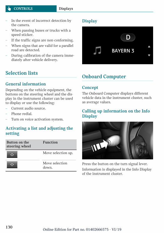
– In the event of incorrect detection bythe camera.
– When passing buses or trucks with aspeed sticker.
– If the traffic signs are non-conforming.
– When signs that are valid for a parallelroad are detected.
– During calibration of the camera imme-diately after vehicle delivery.
Selection lists
General informationDepending on the vehicle equipment, thebuttons on the steering wheel and the dis-play in the instrument cluster can be usedto display or use the following:
– Current audio source.
– Phone redial.
– Turn on voice activation system.
Activating a list and adjusting thesetting
Button on thesteering wheel
Function
Move selection up.
Move selectiondown.
Display
Onboard Computer
ConceptThe Onboard Computer displays differentvehicle data in the instrument cluster, suchas average values.
Calling up information on the InfoDisplay
Press the button on the turn signal lever.
Information is displayed in the Info Displayof the instrument cluster.
Seite 130
CONTROLS Displays
130Online Edition for Part no. 01402666575 - VI/19

Information at a glance
Info Display
Repeatedly pressing the but-ton on the turn signal levercalls up the following informa-tion in the Info Display:
– Range.
– GREEN Info.
When GREEN Mode is activated.
– Average consumption, fuel.
– Current consumption, fuel.
– Average speed.
– Date.
– Engine temperature display.
– Speed Limit Info.
– Vehicle speed.
The unit of some information can bechanged.
Setting units, refer to page 48.
Selecting informationDepending on the vehicle equipment, youcan select what information from the On-board Computer can be displayed on theInfo Display of the instrument cluster.
Via the Central Information Display (CID):
1. "My MINI"
2. "System settings"
3. "Displays"
4. "Instrument panel"
5. Select the desired setting.
Settings are stored for the profile currentlyused.
Information in detail
RangeDisplays the estimated cruising range avail-able with the remaining fuel.
The range is calculated based on your driv-ing style over the last 20 miles/30 km.
GREEN infoThe achieved range extension may be dis-played as a bonus range.
Average consumptionThis is calculated for the period while theengine is running.
The average consumption is calculated forthe distance traveled since the last reset bythe Onboard Computer.
Average speedPeriods in which the vehicle is parked withthe engine manually stopped are not in-cluded in the calculation of the averagespeed.
Resetting average values
Press and hold the button on the turn signallever.
Seite 131
Displays CONTROLS
131Online Edition for Part no. 01402666575 - VI/19

Engine temperature display
Concept
Displays the current engine temperature,based on a combination of coolant and en-gine oil temperature. As soon as the opti-mum operating temperature has been at-tained, the indicator is in the centerposition.
General information
If the engine oil or coolant, and thus the en-gine, become too hot, a Check Control mes-sage is displayed too.
When the engine temperature is toohigh, a red indicator light is dis-played.
When the engine oil temperature istoo high, a red indicator light is dis-played.
To check the coolant level, refer topage 287.
Display
Speed Limit InfoSpeed Limit Info shows the current maxi-mum permitted speed in the instrumentcluster.
Onboard Computer on the ControlDisplay
ConceptThe Onboard Computer displays differentvehicle data on the Control Display, such asaverage values.
General informationTwo types of Onboard Computers are availa-ble on the Control Display:
– "Onboard info": average values, such asthe consumption, are displayed. The val-ues can be reset individually.
– "Trip computer": the values deliver anoverview of a specific route and can bereset as often as necessary.
Calling up the Onboard Computer ortrip computerVia the Central Information Display (CID):
1. "My MINI"
2. "Driving information"
3. "Onboard info" or "Trip computer"
Resetting the Onboard ComputerVia the Central Information Display (CID):
1. "My MINI"
2. "Driving information"
3. "Onboard info"
4. "Consumption" or "Speed"
5. "OK"
Resetting the trip computerVia the Central Information Display (CID):
1. "My MINI"
2. "Driving information"
3. "Trip computer"
Seite 132
CONTROLS Displays
132Online Edition for Part no. 01402666575 - VI/19

4. Move the Controller to the left, ifneeded.
– "Reset": all values are reset.
– "Automatic reset": all values arereset approx. 4 hours after the vehi-cle has come to a standstill.
5. If necessary, "OK"
Driving Excitement
ConceptOn the Control Display, sport instrumentscan be displayed, and the vehicle state canbe checked before the use of the SPORTprogram.
Sport instruments
General informationOn the Control Display, values for powerand torque are displayed.
Displaying sport instrumentsVia the Central Information Display (CID):
1. "My MINI"
2. "Technology in action"
3. "Sport displays"
4. "Sports instruments"
Via MINI Driving Modes switch:
1. Activate SPORT.
2. "Sport displays"
3. "Sports instruments"
Speed warning
ConceptA speed limit can be set that when reachedwill cause a warning to be issued.
General informationThe warning is repeated if the vehicle speedexceeds the set speed limit again, after ithas dropped below it by 3 mph/5 km/h.
AdjustingVia the Central Information Display (CID):
1. "My MINI"
2. "Vehicle settings"
3. "Speed warning"
4. "Warning at:"
5. Turn the Controller until the desiredspeed is displayed.
6. Press the Controller.
Activating/deactivatingVia the Central Information Display (CID):
1. "My MINI"
2. "Vehicle settings"
3. "Speed warning"
4. "Speed warning"
Setting your current speed as thespeed warningVia the Central Information Display (CID):
1. "My MINI"
2. "Vehicle settings"
3. "Speed warning"
4. "Select current speed"
Seite 133
Displays CONTROLS
133Online Edition for Part no. 01402666575 - VI/19

LED ring on the central in-strument cluster
ConceptThe LED ring displays light animations torepresent specific functions.
Basic displaysBasic functions, for instance the tachome-ter, can be set to be displayed continually ifso desired.
Event displaysFunctions that are only displayed tempora-rily, for instance the volume or temperaturesettings, can be set as event displays.
Several vehicle assistance functions canalso be displayed on the LED ring. This dis-play corresponds with the displays of thefunction in the respective display.
Example: tachometerLike the tachometer in the instrument clus-ter, the light animations of the tachometer'sbasic display show the current RPMs andthe respective RPM warning thresholds.
Display
– Arrow 1: current RPM.
– Arrow 2: prewarning field.
– Arrow 3: warning field.
Switching on/off LED ringVia the Central Information Display (CID):
1. "My MINI"
2. "System settings"
3. "Displays"
4. "Center Instrument"
5. "Center Instrument"
Adjusting the LED ringVia the Central Information Display (CID):
1. "My MINI"
2. "System settings"
3. "Displays"
4. "Center Instrument"
5. "Basic display" or "Event display"
6. Select the desired setting.
Setting the brightnessThe brightness can be adjusted when nightlighting is active in the instrument cluster.
Via the Central Information Display (CID):
1. "My MINI"
2. "System settings"
3. "Displays"
4. "Center Instrument"
5. "Brightness at night"
6. Turn the Controller until the desiredbrightness is set.
7. Press the Controller.
The setting is stored for the driver profilecurrently used.
Seite 134
CONTROLS Displays
134Online Edition for Part no. 01402666575 - VI/19
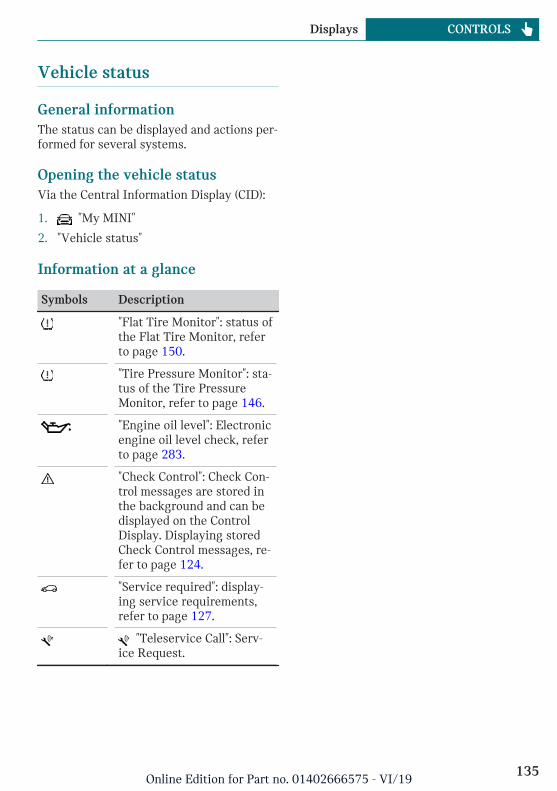
Vehicle status
General informationThe status can be displayed and actions per-formed for several systems.
Opening the vehicle statusVia the Central Information Display (CID):
1. "My MINI"
2. "Vehicle status"
Information at a glance
Symbols Description
"Flat Tire Monitor": status ofthe Flat Tire Monitor, referto page 150.
"Tire Pressure Monitor": sta-tus of the Tire PressureMonitor, refer to page 146.
"Engine oil level": Electronicengine oil level check, referto page 283.
"Check Control": Check Con-trol messages are stored inthe background and can bedisplayed on the ControlDisplay. Displaying storedCheck Control messages, re-fer to page 124.
"Service required": display-ing service requirements,refer to page 127.
"Teleservice Call": Serv-ice Request.
Seite 135
Displays CONTROLS
135Online Edition for Part no. 01402666575 - VI/19

Lights
Vehicle features and options
This chapter describes all standard, country-specific and optional features offered withthe series. It also describes features that arenot necessarily available in your vehicle, forinstance, due to the selected options orcountry versions. This also applies to safety-related functions and systems. When usingthese functions and systems, the applicablelaws and regulations must be observed.
Overview
Switches in the vehicle
The light switch element is located next tothe steering wheel.
Symbol Function
Front fog lights.
Automatic headlight control.
Cornering light.
Lights off.
Daytime running lights.
Symbol Function
Parking lights.
Low beams.
Instrument lighting.
Parking lights, low beams androadside parking lights
General informationPosition of switch: , ,
If the driver's door is opened when the igni-tion is switched off, the exterior lighting isautomatically switched off.
Parking lightsPosition of switch:
The vehicle is illuminated on all sides.
Do not use the parking lights for extendedperiods; otherwise, the battery may becomedischarged and it would then be impossibleto start the engine.
When parking, switch on the one-sidedroadside parking light, refer to page 137.
Low beamsPosition of switch:
The low beams light up when the ignition isswitched on.
Seite 136
CONTROLS Lights
136Online Edition for Part no. 01402666575 - VI/19

Canada: roadside parking light
ConceptThe vehicle can be illuminated on one side.
Switching on
With radio-ready state switched off, pressthe lever either up or down past the resist-ance point for approx. 2 seconds.
Switching offBriefly press the lever to the resistancepoint in the opposite direction.
Welcome lights and headlightcourtesy delay feature
Welcome lights
General informationDepending on the vehicle equipment andthe ambient brightness, individual lightfunctions may be switched on briefly whenthe vehicle is unlocked.
Activating/deactivatingPosition of switch: ,
Via the Central Information Display (CID):
1. "My MINI"
2. "Vehicle settings"
3. "Lighting"
4. "Exterior lighting"
5. "Welcome lights"
The setting is stored for the driver profilecurrently used.
Headlight courtesy delay feature
General informationThe low beams stay lit for a short while ifthe headlight flasher is switched on afterthe vehicle's radio-ready state is switchedoff.
Setting the durationVia the Central Information Display (CID):
1. "My MINI"
2. "Vehicle settings"
3. "Lighting"
4. "Exterior lighting"
5. "Pathway lighting"
6. Set length of time.
The setting is stored for the driver profilecurrently used.
Automatic headlight control
ConceptThe low beams are switched on and off au-tomatically depending on the ambientbrightness, for example in tunnels, in twi-light or if there is precipitation.
General informationA blue sky with the sun low on the horizoncan cause the lights to be switched on.
ActivatingPosition of switch:
Seite 137
Lights CONTROLS
137Online Edition for Part no. 01402666575 - VI/19

The indicator light in the instrument clusteris illuminated when the low beams areswitched on.
System limitsThe automatic headlight control cannotserve as a substitute for your personal judg-ment of lighting conditions.
For example, the sensors are unable to de-tect fog or hazy weather. In these situa-tions, switch the lights on manually.
Daytime running lights
General informationPosition of switch: , ,
The daytime running lights light up whenthe ignition is switched on. After the igni-tion is switched off, the parking lights lightup in position .
Activating/deactivatingIn some countries, daytime running lightsare mandatory, so it may not be possible todeactivate the daytime running lights.
Via the Central Information Display (CID):
1. "My MINI"
2. "Vehicle settings"
3. "Lighting"
4. "Exterior lighting"
5. Select the desired setting.
Settings are stored for the currently usedvehicle key.
Cornering light
General informationPosition of switch:
In tight curves, for instance on mountain-ous roads or when turning, an additional,cornering light is switched on that lights upthe inside of the curve when the vehicle ismoving below a certain speed.
The cornering light is automaticallyswitched on depending on the steering an-gle or, where applicable, the use of turn sig-nals.
When driving in reverse, the corneringlights may be automatically switched on re-gardless of the steering angle.
Adaptive headlight range con-trol
The adaptive headlight range control fea-ture balances out acceleration and brakingprocesses as well as the vehicle load condi-tions in order to avoid dazzling oncomingtraffic. Illumination of the road is optimized.
High-beam Assistant
ConceptThe high-beam Assistant detects other traf-fic participants early on and automaticallyswitches the high beams on or off depend-ing on the traffic situation.
General informationThe high-beam Assistant ensures that thehigh beams are switched on, whenever thetraffic situation allows. In the low speedrange, the high beams are not switched onby the system.
The system responds to light from oncom-ing traffic and traffic driving ahead of you,and to ambient lighting, for instance intowns and cities.
Seite 138
CONTROLS Lights
138Online Edition for Part no. 01402666575 - VI/19

The high beams can be switched on and offmanually at any time.
Activating/deactivating
Position of switch, depending on the vehicleequipment: ,
Press the button on the turn signal lever.
The indicator light in the instrumentcluster is illuminated when the lowbeams are switched on.
The headlights are automatically switchedbetween low beams and high beams.
The blue indicator light in the instru-ment cluster lights up when the sys-tem switches on the high beams.
The high-beam Assistant is deactivatedwhen manually switching the high beamson and off, refer to page 103.
To reactivate the high-beam Assistant,press the button on the turn signal lever.
System limitsThe high-beam Assistant cannot serve as asubstitute for the driver's personal judg-ment of when to use the high beams. In sit-uation that require this, therefore switch offmanually.
The system is not fully functional in the fol-lowing situations, and driver interventionmay be necessary:
– In very unfavorable weather conditions,such as fog or heavy precipitation.
– When detecting poorly-lit road userssuch as pedestrians, cyclists, horsebackriders and wagons; when driving closeto train or ship traffic; or at animalcrossings.
– In tight curves, on hilltops or in depres-sions, in crossing traffic or half-ob-scured oncoming traffic on highways.
– In poorly-lit towns and cities or in thepresence of highly reflective signs.
– When the windshield in front of the in-terior mirror is fogged over, dirty or cov-ered with stickers, etc.
Fog lights
Front fog lights
ConceptThe front fog lights work alongside the lowbeams to illuminate a wider area of theroadway.
Functional requirementThe low beams must be switched on beforeswitching on the front fog lights.
Switching on/off
Press the button.
The green indicator light lights up ifthe front fog lights are switched on.
If the automatic headlight control, refer topage 137, is activated, the low beams willcome on automatically when you switch onthe front fog lights.
When the high beams or headlight flasherare activated, the front fog lights are notswitched on.
Seite 139
Lights CONTROLS
139Online Edition for Part no. 01402666575 - VI/19

Instrument lighting
Functional requirementThe parking lights or low beams must beswitched on to adjust the brightness.
AdjustingAdjust the brightness with thethumbwheel.
Interior lights
General informationDepending on the equipment, the interiorlights, footwell lights, entry lights, and cour-tesy lights are controlled automatically.
The thumbwheel for the instrument lightingcontrols brightness of some of these fea-tures.
Overview
1 Interior lights
2 Reading lights
3 Ambient light
Switching the interior lights on/offPress the button.
To switch off permanently: press the buttonand hold for approx. 3 seconds.
Switching the reading lights on andoff manually
Press the button.
The reading lights are located in the frontnext to the interior light.
Ambient light
General informationDepending on the equipment version, light-ing can be adjusted for some lights in thecar's interior.
Changing color
Push the switch forward or back:manual color change.
Press the switch forward or back-ward and hold for approx. 3 seconds,until the ambient light illuminates
several times: automatic color change. Pushthe switch again to end color changes.
Setting the brightnessDepending on the equipment, the bright-ness of the ambient light can be adjustedvia the thumbwheel for the instrumentlighting or on the Control Display.
Via the Central Information Display (CID):
1. "My MINI"
2. "Vehicle settings"
3. "Lighting"
4. "Interior lighting"
Seite 140
CONTROLS Lights
140Online Edition for Part no. 01402666575 - VI/19

5. "Brightness"
6. Adjust the brightness.
Seite 141
Lights CONTROLS
141Online Edition for Part no. 01402666575 - VI/19

Safety
Vehicle features and options
This chapter describes all standard, country-specific and optional features offered withthe series. It also describes features that arenot necessarily available in your vehicle, for
instance, due to the selected options orcountry versions. This also applies to safety-related functions and systems. When usingthese functions and systems, the applicablelaws and regulations must be observed.
Airbags
1 Front airbag, driver
2 Front airbag, front passenger
3 Head airbag
4 Side airbag
5 Knee airbag
Front airbagsFront airbags help protect the driver andthe front passenger by responding to frontalimpacts in which safety belts alone wouldnot provide adequate protection.
Side airbagIn the event of a side impact, the side air-bag protects the side of the body in thechest and lap area.
Seite 142
CONTROLS Safety
142Online Edition for Part no. 01402666575 - VI/19
Head airbagIn the event of a side impact, the head air-bag protects the head.
Ejection MitigationThe head airbag system is designed as anejection mitigation countermeasure to re-duce the likelihood of ejections of vehicleoccupants through side windows duringrollovers or side impact events.
Knee airbagThe knee airbag protects the legs in theevent of a frontal impact.
Protective effectAirbags are not triggered in every impactsituation, for instance in less severe acci-dents or rear-end collisions.
Information on optimum effect of theairbags
Warning
If the seat position is incorrect or the de-ployment area of the airbags is impaired,the airbag system cannot provide protec-tion as intended and may cause additionalinjuries due to triggering. There is a riskof injuries or danger to life. Follow the in-formation on achieving the optimum pro-tective effect of the airbag system.
– Keep a distance from the airbags.
– Always grasp the steering wheel on thesteering wheel rim. Hold your hands atthe 3 o'clock and 9 o'clock positions, tokeep the risk of injury to your hands orarms as low as possible when the airbagis triggered.
– Make sure that the front passenger issitting correctly, i.e., keeps his or her
feet and legs in the floor area and doesnot support them on the dashboard.
– Make sure that occupants keep theirheads away from the side airbag.
– There should be no additional persons,animals or objects between an airbagand a person.
– Dashboard and windshield on the frontpassenger side must stay clear - do notattach adhesive labels or coverings anddo not attach brackets or cables, for in-stance for GPS devices or mobilephones.
– Do not apply adhesive materials to theairbag cover panels, do not cover themor modify them in any way.
– Do not use the cover of the front airbagon the front passenger side as a storagearea.
– Do not attach slip covers, seat cushionsor other objects to the front passengerseat that are not specifically suited forseats with integrated side airbags.
– Do not place seat cushions or other ob-jects on the front seats that are not spe-cifically suited for seats with integratedside airbags.
– Do not hang pieces of clothing, such asjackets, over the backrests.
– Never modify either the individual com-ponents or the wiring in the airbag sys-tem. This also applies to steering wheelcovers, the dashboard, and the seats.
– Do not remove the airbag system.
Even when you follow all instructions veryclosely, injury from contact with the airbagscannot be fully ruled out in certain situa-tions.
The ignition and inflation noise may lead toshort-term and, in most cases, temporaryhearing impairment in sensitive occupants.
Vehicle modifications for a person with dis-abilities may affect the air bag system; con-
Seite 143
Safety CONTROLS
143Online Edition for Part no. 01402666575 - VI/19

tact MINI Customer Relations for further in-formation.
Warnings and information on the airbagsare also found on the sun visors.
Functional readiness of the airbagsystem
Safety information
Warning
Individual components can be hot aftertriggering of the airbag system. There is arisk of injury. Do not touch individualcomponents.
Warning
Improperly executed work can lead to fail-ure, malfunction or unintentional trigger-ing of the airbag system. In the case of amalfunction, the airbag system might nottrigger as intended despite the accidentseverity. There is a risk of injuries or dan-ger to life. Have the airbag systemchecked, repaired, dismantled and scrap-ped by a dealer’s service center or anotherqualified service center or repair shop.
Correct function
When the ignition is switched on,the warning light in the instrumentcluster lights up briefly and thereby
indicates the operational readiness of theentire airbag system and the belt tensioner.
Airbag system malfunctioning– Warning light does not come on when
the ignition is switched on.
– The warning light lights up continu-ously.
Automatic deactivation of thefront-seat passenger airbags
ConceptThe system reads if the front passenger seatis occupied by measuring the human body'sresistance.
Front, knee, and side airbag on the frontpassenger's side are activated or deacti-vated.
General informationBefore transporting a child on the front pas-senger seat, refer to the safety informationand instructions for children on the frontpassenger seat, see Children.
Safety information
Warning
To ensure the front-seat passenger airbagfunction, the system must be able to de-tect whether a person is sitting in thefront passenger seat. The entire seat cush-ion area must be used for this purpose.There is a risk of injuries or danger to life.Make sure that the front passenger keepshis or her feet in the floor area.
Malfunction of the automaticdeactivation systemWhen transporting older children andadults, the front-seat passenger airbags maybe deactivated in certain sitting positions.In this case, the indicator light for the front-seat passenger airbags lights up.
In this case, change the sitting position sothat the front-seat passenger airbags are ac-tivated and the indicator light goes out.
If it is not possible to activate the airbags,have the person sit in the rear.
Seite 144
CONTROLS Safety
144Online Edition for Part no. 01402666575 - VI/19

To enable correct recognition of the occu-pied seat cushion.
– Do not attach covers, cushions, ball matsor other items to the front passengerseat unless they are specifically deter-mined to be safe for use on the frontpassenger seat.
– Do not place any electronic devices onthe front passenger seat if a child re-straint system is to be installed on it.
– Do not place objects under the seat thatcould press against the seat from below.
– No moisture in or on the seat.
Indicator light for the front-seatpassenger airbags
The indicator light for the front-seat passen-ger airbags indicates the operating state ofthe front-seat passenger airbags.
The light indicates whether the airbags areeither activated or deactivated.
– The indicator light lightsup when a child is properlyseated in a child restraintsystem or when the seat isempty. The airbags on thefront passenger side arenot activated.
– The indicator light does not light upwhen, for instance a correctly seatedperson of sufficient size is detected onthe seat. The airbags on the front pas-senger side are activated.
Detected child restraint systemsThe system generally detects childrenseated in a child restraint system, particu-larly in child restraint systems required byNHTSA at the point in time when the vehi-cle was manufactured. After installing achild restraint system, make sure that theindicator light for the front-seat passengerairbags lights up. This indicates that thechild restraint system has been detectedand the front-seat passenger airbags are notactivated.
Strength of the driver's and front-seat passenger airbagThe explosive power that activates driver's/front-seat passenger airbags very much de-pends on the positions of the driver's/frontpassenger seat.
To maintain the accuracy of this functionover the long-term, calibrate the front seatsas soon as a relevant Check Control mes-sage is displayed.
Calibrating the front seats
Warning
There is a risk of jamming when movingthe seats. There is a risk of injury or riskof damage to property. Make sure that thearea of movement of the seat is clear priorto any adjustment.
An appropriate Check Control message isdisplayed.
1. Move the respective seat all the way for-ward.
2. Move the respective seat forward again.The seat moves forward briefly.
3. Readjust the seat to the desired posi-tion.
Seite 145
Safety CONTROLS
145Online Edition for Part no. 01402666575 - VI/19

The calibration procedure is completedwhen the Check Control message disap-pears.
If the message continues to be displayed,repeat the calibration.
If the message does not disappear after a re-peat calibration, have the system checkedas soon as possible.
Tire Pressure Monitor TPM
ConceptThe system monitors tire inflation pressurein the four mounted tires. The system warnsyou if there is a significant loss of pressurein one or more tires.
General informationSensors in the tire valves measure the tireinflation pressure and, depending on themodel, the tire temperature.
Further information and instructions on us-ing the system can also be found under Tireinflation pressure, refer to page 260.
Functional requirementsThe following conditions must be met forthe system; otherwise, reliable flagging of aloss of tire inflation pressure is not assured:
– After a tire or wheel replacement, a re-set was performed with the correct tireinflation pressure.
– After the tire inflation pressure was ad-justed to a new value, a reset was per-formed.
– Wheels with TPM wheel electronics.
Status display
Current statusThe system status can be displayed on theControl Display, e.g., whether or not the sys-tem is active.
Via the Central Information Display (CID):
1. "My MINI"
2. "Vehicle status"
3. "Tire Pressure Monitor"
The current status is displayed.
Additional informationThe current tire inflation pressures are dis-played too. The values shown are instanta-neous measurements and may vary depend-ing on driving style or weather conditions.
Resetting the systemVia the Central Information Display (CID):
1. "My MINI"
2. "Vehicle status"
3. "Tire Pressure Monitor"
4. Start the engine but do not drive off.
5. Reset the tire inflation pressure using"Perform reset".
6. Drive away.
The following is displayed: "Resetting TirePressure Monitor…".
After a travel time of several minutes, theset tire inflation pressures are accepted asreference values. The resetting process iscompleted automatically while driving.
After a successfully completed reset, the fol-lowing is displayed: "Tire Pressure Monitoractive. See label for recommendedpressures.".
Seite 146
CONTROLS Safety
146Online Edition for Part no. 01402666575 - VI/19

You may interrupt this trip at any time.When you continue the reset resumes auto-matically.
Messages
General informationA low tire inflation pressure may cause theDSC Dynamic Stability Control to beswitched on.
Safety information
Warning
A damaged regular tire with low or miss-ing tire inflation pressure impacts han-dling, such as steering and braking re-sponse. Run-flat tires can maintain limitedstability. There is a risk of accident. Do notcontinue driving if the vehicle is equippedwith normal tires. Follow the informationon run-flat tires and continued drivingwith these tires.
If a tire inflation pressure check isrequired
Message
A symbol with a Check Control message ap-pears on the Control Display.
Symbol Possible cause
The system has detected awheel change, but no reset wasdone.
No reset was performed for thesystem. The system issues awarning based on the tire infla-tion pressures stored during thelast reset.
Inflation was not carried out ac-cording to specifications.
The tire inflation pressure hasfallen below the level of the lastreset.
Measure
1. Check the tire pressure and correct asneeded.
2. Reset the system.
If the tire inflation pressure is too low
Message
A yellow warning light is illuminatedin the instrument cluster.
In addition, a symbol with a Check Controlmessage appears on the Control Display.
Symbol Possible cause
There is a tire inflation pressureloss.
No reset was performed for thesystem. The system issues awarning based on the tire infla-tion pressures stored during thelast reset.
Measure
1. Reduce your speed and drive moder-ately. Do not exceed a speed of80 mph/130 km/h.
Seite 147
Safety CONTROLS
147Online Edition for Part no. 01402666575 - VI/19

2. At the next opportunity, for instance gasstation, check and correct the tire infla-tion pressure in all four tires, if neces-sary.
3. Reset the system.
If there is a significant loss of tireinflation pressure
Message
A yellow warning light is illuminatedin the instrument cluster.
In addition, a symbol with the affected tireappears in a Check Control message on theControl Display.
Symbol Possible cause
There is a flat tire or a majorloss in tire inflation pressure.
No reset was performed for thesystem. The system issues awarning based on the tire infla-tion pressures stored during thelast reset.
Measure
1. Reduce your speed and stop cautiously.Avoid sudden braking and steering ma-neuvers.
2. Check whether the vehicle is fitted withnormal tires or run-flat tires.
Run-flat tires, refer to page 269, are la-beled with a circular symbol containingthe letters RSC marked on the tire'ssidewall.
Actions in the event of a flat tire
Normal tires1. Identify the damaged tire.
To do this, check the tire inflation pres-sure in all four tires, for instance usingthe tire pressure gage of a flat tire kit.
If the tire inflation pressure in all fourtires is correct, the Tire Pressure Moni-tor may not have been reset. In thiscase, perform the reset.
If the tire inflation pressure in all fourtires is correct, the Flat Tire Monitormay not have been initialized. In thiscase, initialize the system.
If identification of flat tire damage isnot possible, please contact a dealer’sservice center or another qualified serv-ice center or repair shop.
2. Repair the flat tire, e.g., with a flat tirekit or by changing the wheel.
Use of sealant, for instance from the flat tirekit, may damage the TPM wheel electronics.In this case, have the electronics checkedand replaced at the next opportunity.
Run-flat tires
Safety information
Warning
Your vehicle handles differently with arun-flat tire with no or low inflation pres-sure; for instance, your lane stability whenbraking is reduced, braking distances arelonger and the self-steering properties willchange. There is a risk of accident. Drivemoderately and do not exceed a speed of50 mph/80 km/h.
Maximum speed
You may continue driving with a damagedtire at speeds up to 50 mph/80 km/h.
Seite 148
CONTROLS Safety
148Online Edition for Part no. 01402666575 - VI/19

Continued driving with a flat tire
If continuing to drive with a damaged tire:
1. Avoid sudden braking and steering ma-neuvers.
2. Do not exceed a speed of50 mph/80 km/h.
3. Check the tire inflation pressure in allfour tires at the next opportunity.
If the tire inflation pressure in all fourtires is correct, the Tire Pressure Moni-tor may not have been reset. In thiscase, perform the reset.
Possible driving range with adepressurized tire
The distance for which it may be possible todrive safely varies depending on how thevehicle is loaded and used, e.g., speed, roadconditions, external temperature. The driv-ing range may be less but may also be moreif an economical driving style is used.
If the vehicle is loaded with an averageweight and used under favorable conditions,the distance for which it may be safe todrive may be up to 50 miles/80 km.
Vehicle handling with damaged tires
Vehicles driven with a damaged tire willhandle differently, potentially leading toconditions such as the following:
– Greater likelihood of swerving offcourse.
– Longer braking distances.
– Changed self-steering properties.
Modify your driving style. Avoid abruptsteering maneuvers or driving over obsta-cles, for instance curbs or potholes.
Final tire failure
Vibrations or loud noises while driving canindicate the final failure of a tire.
Reduce speed and stop; otherwise, pieces ofthe tire could come loose and cause an acci-dent.
Do not continue driving. Contact a dealer’sservice center or another qualified servicecenter or repair shop.
System limits
TemperatureThe tire inflation pressure depends on thetire's temperature.
Driving or exposure to the sun will increasethe tire's temperature, thus increasing thetire inflation pressure.
The tire inflation pressure is reduced whenthe tire temperature falls again.
These circumstances may cause a warningwhen temperatures fall very sharply.
Sudden tire pressure lossThe system cannot indicate sudden serioustire damage caused by external circumstan-ces.
Failure performing a resetThe system does not function properly if areset has not been carried out, for instancea flat tire is reported though tire inflationpressures are correct.
MalfunctionThe yellow warning light flashes andis then illuminated continuously. ACheck Control message is displayed.
It may not be possible to identify tire pres-sure losses.
Examples and recommendations in the fol-lowing situations:
– A wheel without TPM wheel electronics,for instance an emergency wheel, ismounted: have it checked by a dealer’s
Seite 149
Safety CONTROLS
149Online Edition for Part no. 01402666575 - VI/19

service center or another qualified serv-ice center or repair shop as needed.
– Malfunction: have system checked by adealer’s service center or another quali-fied service center or repair shop.
– The system was unable to complete thereset. Perform a system reset again.
– Interference caused by systems or devi-ces with the same radio frequency: afterleaving the area of the interference, thesystem automatically becomes activeagain.
Declaration according to NHTSA/FMVSS 138 Tire Pressure MonitoringSystemEach tire, including the spare (if provided)should be checked monthly when cold andinflated to the inflation pressure recom-mended by the vehicle manufacturer on thevehicle placard or tire inflation pressure la-bel. (If your vehicle has tires of a differentsize than the size indicated on the vehicleplacard or tire inflation pressure label, youshould determine the proper tire inflationpressure for those tires.) As an added safetyfeature, your vehicle has been equippedwith a tire pressure monitoring system(TPMS) that illuminates a low tire pressuretelltale when one or more of your tires issignificantly under-inflated. Accordingly,when the low tire pressure telltale illumi-nates, you should stop and check your tiresas soon as possible, and inflate them to theproper pressure. Driving on a significantlyunder-inflated tire causes the tire to over-heat and can lead to tire failure. Under-infla-tion also reduces fuel efficiency and tiretread life, and may affect the vehicle's han-dling and stopping ability. Please note thatthe TPMS is not a substitute for proper tiremaintenance, and it is the driver's responsi-bility to maintain correct tire pressure, evenif under-inflation has not reached the levelto trigger illumination of the TPMS low tire
pressure telltale. Your vehicle has also beenequipped with a TPMS malfunction indica-tor to indicate when the system is not oper-ating properly. The TPMS malfunction indi-cator is combined with the low tire pressuretelltale. When the system detects a mal-function, the telltale will flash for approxi-mately one minute and then remain contin-uously illuminated. This sequence willcontinue upon subsequent vehicle start-upsas long as the malfunction exists. When themalfunction indicator is illuminated, thesystem may not be able to detect or signallow tire pressure as intended. TPMS mal-functions may occur for a variety of rea-sons, including the installation of replace-ment or alternate tires or wheels on thevehicle that prevent the TPMS from func-tioning properly. Always check the TPMSmalfunction telltale after replacing one ormore tires or wheels on your vehicle to en-sure that the replacement or alternate tiresand wheels allow the TPMS to continue tofunction properly.
Flat Tire Monitor FTM
ConceptThe system detects tire inflation pressureloss on the basis of rotation speed differen-ces between the individual wheels whiledriving.
In the event of a tire inflation pressure loss,the diameter and therefore the rotationalspeed of the corresponding wheel changes.The difference will be detected and reportedas a flat tire.
The system does not measure the actual in-flation pressure in the tires.
Seite 150
CONTROLS Safety
150Online Edition for Part no. 01402666575 - VI/19

Functional requirementsThe following conditions must be met forthe system; otherwise, reliable flagging of aloss of tire inflation pressure is not assured:
– After a tire or wheel replacement, an ini-tialization was performed with the cor-rect tire inflation pressure.
– After the tire pressure was adjusted to anew value, an initialization was per-formed.
Status displayThe current status of the flat tire monitorcan be displayed, for instance whether theRPA is active.
Via the Central Information Display (CID):
1. "My MINI"
2. "Vehicle status"
3. "Flat Tire Monitor"
The status is displayed.
Initialization requiredAn initialization must be performed in thefollowing situations:
– After the tire inflation pressure hasbeen adjusted.
– After a tire or wheel replacement.
Performing initializationWhen initializing, the set tire inflationpressures serve as reference values in orderto detect a flat tire. Initialization is startedby confirming the tire inflation pressures.
Do not initialize the system when drivingwith snow chains.
Via the Central Information Display (CID):
1. "My MINI"
2. "Vehicle status"
3. "Flat Tire Monitor"
4. Start the engine but do not drive off.
5. Start the initialization with: "Performreset".
6. Drive away.
The initialization is completed while driv-ing, which can be interrupted at any time.
The initialization automatically continueswhen driving resumes.
Messages
General informationWhen a flat tire is indicated, DSC DynamicStability Control is switched on, if needed.
Safety information
Warning
A damaged regular tire with low or miss-ing tire inflation pressure impacts han-dling, such as steering and braking re-sponse. Run-flat tires can maintain limitedstability. There is a risk of accident. Do notcontinue driving if the vehicle is equippedwith normal tires. Follow the informationon run-flat tires and continued drivingwith these tires.
Indication of a flat tire
A yellow warning light is illuminatedin the instrument cluster.
In addition, a symbol with a Check Controlmessage appears on the Control Display.
Symbol Possible cause
There is a flat tire or a majorloss in tire inflation pressure.
Seite 151
Safety CONTROLS
151Online Edition for Part no. 01402666575 - VI/19

Measure1. Reduce your speed and stop cautiously.
Avoid sudden braking and steering ma-neuvers.
2. Check whether the vehicle is fitted withnormal tires or run-flat tires.
Run-flat tires, refer to page 269, are la-beled with a circular symbol containingthe letters RSC marked on the tire'ssidewall.
Actions in the event of a flat tire
Normal tires1. Identify the damaged tire.
To do this, check the tire inflation pres-sure in all four tires, for instance usingthe tire pressure gage of a flat tire kit.
If the tire inflation pressure in all fourtires is correct, the Tire Pressure Moni-tor may not have been reset. In thiscase, perform the reset.
If the tire inflation pressure in all fourtires is correct, the Flat Tire Monitormay not have been initialized. In thiscase, initialize the system.
If identification of flat tire damage isnot possible, please contact a dealer’sservice center or another qualified serv-ice center or repair shop.
2. Repair the flat tire, e.g., with a flat tirekit or by changing the wheel.
Use of sealant, for instance from the flat tirekit, may damage the TPM wheel electronics.In this case, have the electronics checkedand replaced at the next opportunity.
Run-flat tires
Safety information
Warning
Your vehicle handles differently with arun-flat tire with no or low inflation pres-sure; for instance, your lane stability whenbraking is reduced, braking distances arelonger and the self-steering properties willchange. There is a risk of accident. Drivemoderately and do not exceed a speed of50 mph/80 km/h.
Maximum speed
You may continue driving with a damagedtire at speeds up to 50 mph/80 km/h.
Continued driving with a flat tire
If continuing to drive with a damaged tire:
1. Avoid sudden braking and steering ma-neuvers.
2. Do not exceed a speed of50 mph/80 km/h.
3. Check the tire inflation pressure in allfour tires at the next opportunity.
If the tire inflation pressure in all fourtires is correct, the Flat Tire Monitormay not have been initialized. In thiscase, initialize the system.
Possible driving range with adepressurized tire
The distance for which it may be possible todrive safely varies depending on how thevehicle is loaded and used, e.g., speed, roadconditions, external temperature. The driv-ing range may be less but may also be moreif an economical driving style is used.
If the vehicle is loaded with an averageweight and used under favorable conditions,
Seite 152
CONTROLS Safety
152Online Edition for Part no. 01402666575 - VI/19

the distance for which it may be safe todrive may be up to 50 miles/80 km.
Vehicle handling with damaged tires
Vehicles driven with a damaged tire willhandle differently, potentially leading toconditions such as the following:
– Greater likelihood of swerving offcourse.
– Longer braking distances.
– Changed self-steering properties.
Modify your driving style. Avoid abruptsteering maneuvers or driving over obsta-cles, for instance curbs or potholes.
Final tire failure
Vibrations or loud noises while driving canindicate the final failure of a tire.
Reduce speed and stop; otherwise, pieces ofthe tire could come loose and cause an acci-dent.
Do not continue driving. Contact a dealer’sservice center or another qualified servicecenter or repair shop.
System limitsThe system could be delayed or malfunctionin the following situations:
– A natural, even tire inflation pressureloss in all four tires will not be recog-nized. Therefore, check the tire inflationpressure regularly.
– Sudden serious tire damage caused byexternal circumstances cannot be recog-nized in advance.
– When the system has not been initial-ized.
– When driving on a snowy or slipperyroad surface.
– Sporty driving style: spinning tractionwheels, high lateral acceleration (drift-ing).
– When driving with snow chains.
Intelligent Safety
ConceptIntelligent Safety enables central operationof the driver assistance systems.
The intelligent safety systems can help pre-vent an imminent collision.
– Approach control warning with Citylight braking function, refer topage 154.
– Daytime pedestrian collision mitigation,refer to page 158.
Safety information
Warning
The system cannot serve as a substitutefor the driver’s personal judgment in as-sessing visibility and traffic situation.There is a risk of accident. Adjust drivingstyle to traffic conditions. Watch trafficclosely and actively intervene where ap-propriate.
Warning
Indicators and warnings cannot serve as asubstitute for the driver’s personal judg-ment. Due to its limits, the system may notissue warnings or reactions, or these maybe issued late or in a manner that is notconsistent with their normal use. There isa risk of accident. Adjust driving style totraffic conditions. Watch traffic closelyand actively intervene where appropriate.
Seite 153
Safety CONTROLS
153Online Edition for Part no. 01402666575 - VI/19

Warning
Due to system limits, individual functionscan malfunction during tow-starting/towing with the Intelligent Safety systemsactivated. There is a risk of accident.Switch all Intelligent Safety systems offprior to tow-starting/towing.
Overview
Button in the vehicle
Intelligent Safety button
Switching on/offSome Intelligent Safety systems are auto-matically active after every departure. SomeIntelligent Safety systems activate accord-ing to the last setting.
Press button briefly:
– The menu for the IntelligentSafety system is displayed. Thesystems are individuallyswitched off according to theirrespective settings.
– LED lights up orange or goes out respec-tive to their individual settings.
Adjust the settings as needed. The individ-ual settings are stored for the driver profilecurrently in use.
Press button again:
– All Intelligent Safety systemsare switched on.
– The LED lights up green.
Hold down button:
– All Intelligent Safety systemsare switched off.
– The LED goes out.
Approach control warningwith city light braking func-tion
ConceptThe system may prevent some accidents. Inthe event of an accident, the system may re-duce impact speed.
The system sounds a warning before an im-minent collision and activates brakes inde-pendently, if needed.
The Brake Assistant function activates andapplies the brakes with limited force andduration.
A camera at the base of the interior mirrorcontrols the system.
The approach control warning is availableeven if cruise control has been deactivated.
With the vehicle approaching another vehi-cle intentionally, the approach control warn-ing and braking are delayed in order toavoid false system reactions.
General informationThe system warns at two levels of an immi-nent danger of collision at speeds from ap-prox. 3 mph/5 km/h. The timing of warn-ings may vary with the current drivingsituation.
Seite 154
CONTROLS Safety
154Online Edition for Part no. 01402666575 - VI/19

Braking is performed at speeds up to ap-proximately 35 mph/60 km/h.
Detection range
Objects that the system can detect aretaken into account.
Safety information
Warning
The system cannot serve as a substitutefor the driver’s personal judgment in as-sessing visibility and traffic situation.There is a risk of accident. Adjust drivingstyle to traffic conditions. Watch trafficclosely and actively intervene where ap-propriate.
Warning
Indicators and warnings cannot serve as asubstitute for the driver’s personal judg-ment. Due to its limits, the system may notissue warnings or reactions, or these maybe issued late or in a manner that is notconsistent with their normal use. There isa risk of accident. Adjust driving style totraffic conditions. Watch traffic closelyand actively intervene where appropriate.
Warning
Due to system limits, individual functionscan malfunction during tow-starting/towing with the Intelligent Safety systemsactivated. There is a risk of accident.Switch all Intelligent Safety systems offprior to tow-starting/towing.
Overview
Button in the vehicle
Intelligent Safety button
Camera
The camera is installed near the interiormirror.
Keep the windshield in front of the interiormirror clean and clear.
Seite 155
Safety CONTROLS
155Online Edition for Part no. 01402666575 - VI/19

Switching on/off
Switching on automaticallyThe system is automatically active after ev-ery driving off.
Switching on/off manually
Press button briefly:
– The menu for the IntelligentSafety system is displayed. Thesystems are individuallyswitched off according to theirrespective settings.
– LED lights up orange or goes out respec-tive to their individual settings.
Adjust the settings as needed. The individ-ual settings are stored for the driver profilecurrently in use.
Press button again:
– All Intelligent Safety systemsare switched on.
– The LED lights up green.
Hold down button:
– All Intelligent Safety systemsare switched off.
– The LED goes out.
Setting the warning timeThe warning time can be set via the CentralInformation Display (CID).
1. "My MINI"
2. "Vehicle settings"
3. "Intelligent Safety"
4. "Warning time"
5. Select the desired setting.
The selected warning time is stored for thedriver profile currently in use.
Warning with braking function
DisplayIf a collision with a vehicle detected in thisway is imminent, a warning symbol appearson the instrument cluster.
Symbol Measure
Symbol lights up red: prewarn-ing.
Brake and increase distance.
Symbol flashes red and anacoustic signal sounds: acutewarning.
Brake and make an evasive ma-neuver, if necessary.
PrewarningThis warning is provided, for instance whenthere is impending danger of a collision orthe distance to the vehicle ahead is toosmall.
If a prewarning is provided, respond bybraking as warranted.
Acute warning with braking functionAn acute warning is displayed when thereis an imminent danger of collision due tothe vehicle approaching another object at ahigh speed.
The driver must intervene actively whenthere is an acute warning. If necessary, thedriver is assisted by a minor automaticbraking intervention in a possible risk ofcollision.
Acute warnings may be provided even whenthere has been no prior warning.
Braking interventionThe warning prompts the driver to inter-vene. During a warning, the maximum brak-ing force is used. In order to activate the
Seite 156
CONTROLS Safety
156Online Edition for Part no. 01402666575 - VI/19
Brake Assistant function, you must applythe brakes quickly and forcefully. If there isa risk of collision, the system may assistwith braking. When the vehicle is travelingat a low speed, the vehicle may come to acomplete stop.
Manual transmission: during a braking in-tervention up to a complete stop, the enginemay be shut down.
The braking intervention occurs only if ve-hicle stability has not been restricted,for instance by deactivating the DSC Dy-namic Stability Control.
The driver may interrupt the braking inter-vention function by stepping on the acceler-ator pedal or by actively moving the steer-ing wheel.
The system’s ability to detect objects maybe limited in some circumstances. Refer tothe information in this Owner’s Manual re-garding the limitations of the system andactively intervene as warranted.
System limits
Safety information
Warning
The system is designed to operate in cer-tain conditions and circumstances. Due toconditions or other factors, the systemmay not respond. There may be a risk ofaccident or risk of damage to property. Ac-tively intervene as warranted. Refer to theinformation in this Owner’s Manual re-garding the scope of the system’s opera-tion and limitations.
Detection rangeThe system's detection potential is limited.
Thus, a system reaction might not come ormight come late.
The following situations may not be de-tected, for example:
– Slow moving vehicles when you ap-proach them at high speed.
– Vehicles that suddenly swerve in frontof you, or sharply decelerating vehicles.
– Vehicles with an unusual rear appear-ance.
– Two-wheeled vehicles ahead of you.
Functional limitationsThe system may not be fully functional inthe following situations:
– In heavy fog, wet conditions, or snow-fall.
– In tight curves.
– If the field of view of the camera or thewindshield is dirty or covered.
– If the driving stability control systemsare deactivated, for instance DSC OFF.
– Up to 10 seconds after the start of theengine via the Start/Stop button.
– During calibration of the camera imme-diately after vehicle delivery.
– If there are constant blinding effects be-cause of oncoming light, for instancefrom the sun low in the sky.
Warning sensitivityThe more sensitive the warning settingsare, the more warnings are displayed.Therefore, there may also be an excess ofpremature or unjustified warnings and reac-tions.
Seite 157
Safety CONTROLS
157Online Edition for Part no. 01402666575 - VI/19

Daytime pedestrian collisionmitigation
ConceptThe system may prevent some accidentswith pedestrians.
When driving at city speeds, the systemwill issue a warning if there is imminentrisk of a collision with pedestrians, and sup-port this with a light braking function.
The camera at the base of the interior mir-ror controls the system.
General informationIn sufficiently bright conditions, the systemissues a warning of a possible risk of colli-sion with pedestrians in the speed rangefrom approx. 6 mph/10 km/h to approx.35 mph/60 km/h
The system reacts to people who are withinthe detection range of the system.
Detection range
The detection area in front of the vehicle isdivided into two areas:
– Central area, arrow 1, directly in front ofthe vehicle.
– Expanded area, arrow 2, to the right andleft of the central area.
A collision is imminent if pedestrians are lo-cated within the central area. A warning isissued about pedestrians who are located
within the extended area only if they aremoving in the direction of the central area.
Safety information
Warning
The system cannot serve as a substitutefor the driver’s personal judgment in as-sessing visibility and traffic situation.There is a risk of accident. Adjust drivingstyle to traffic conditions. Watch trafficclosely and actively intervene where ap-propriate.
Warning
Indicators and warnings cannot serve as asubstitute for the driver’s personal judg-ment. Due to its limits, the system may notissue warnings or reactions, or these maybe issued late or in a manner that is notconsistent with their normal use. There isa risk of accident. Adjust driving style totraffic conditions. Watch traffic closelyand actively intervene where appropriate.
Warning
Due to system limits, individual functionscan malfunction during tow-starting/towing with the Intelligent Safety systemsactivated. There is a risk of accident.Switch all Intelligent Safety systems offprior to tow-starting/towing.
Seite 158
CONTROLS Safety
158Online Edition for Part no. 01402666575 - VI/19

Overview
Button in the vehicle
Intelligent Safety button
Camera
The camera is installed near the interiormirror.
Keep the windshield in front of the interiormirror clean and clear.
Switching on/off
Switching on automaticallyThe system is automatically active after ev-ery driving off.
Switching on/off manually
Press button briefly:
– The menu for the IntelligentSafety system is displayed. Thesystems are individually
switched off according to theirrespective settings.
– LED lights up orange or goes out respec-tive to their individual settings.
Adjust the settings as needed. The individ-ual settings are stored for the driver profilecurrently in use.
Press button again:
– All Intelligent Safety systemsare switched on.
– The LED lights up green.
Hold down button:
– All Intelligent Safety systemsare switched off.
– The LED goes out.
Warning with braking function
DisplayIf a collision with a person detected in thisway is imminent, a warning symbol appearson the instrument cluster.
The red symbol is displayed and asignal sounds.
Intervene immediately by braking ormake an evasive maneuver.
Braking interventionThe warning prompts the driver to inter-vene. During a warning, the maximum brak-ing force is used. In order to activate theBrake Assistant function, you must applythe brakes quickly and forcefully. If there isa risk of collision, the system may assistwith braking. When the vehicle is travelingat a low speed, the vehicle may come to acomplete stop.
Manual transmission: during a braking in-tervention up to a complete stop, the enginemay be shut down.
Seite 159
Safety CONTROLS
159Online Edition for Part no. 01402666575 - VI/19

The braking intervention occurs only if ve-hicle stability has not been restricted,for instance by deactivating the DSC Dy-namic Stability Control.
The driver may interrupt the braking inter-vention function by stepping on the acceler-ator pedal or by actively moving the steer-ing wheel.
The system’s ability to detect objects maybe limited in some circumstances. Refer tothe information in this Owner’s Manual re-garding the limitations of the system andactively intervene as warranted.
System limits
Safety information
Warning
The system is designed to operate in cer-tain conditions and circumstances. Due toconditions or other factors, the systemmay not respond. There may be a risk ofaccident or risk of damage to property. Ac-tively intervene as warranted. Refer to theinformation in this Owner’s Manual re-garding the scope of the system’s opera-tion and limitations.
Detection rangeThe detection potential of the camera is lim-ited.
Thus, a warning might not be issued or beissued late.
The following situations may not be de-tected, for example:
– Partially covered pedestrians.
– Pedestrians that are not detected assuch because of the viewing angle orcontour.
– Pedestrians outside of the detectionrange.
– Pedestrians having a body size less than32 in/80 cm.
Functional limitationsThe system may not be fully functional ormay not be available in the following situa-tions:
– In heavy fog, wet conditions, or snow-fall.
– In tight curves.
– If the field of view of the camera or thewindshield is dirty or covered.
– If the driving stability control systemsare deactivated, for instance DSC OFF.
– Up to 10 seconds after the start of theengine via the Start/Stop button.
– During calibration of the camera imme-diately after vehicle delivery.
– If there are constant blinding effects be-cause of oncoming light, for instancefrom the sun low in the sky.
– When it is dark outside.
PostCrash – iBrake
ConceptIn the event of an accident, the system canbring the vehicle to a halt automaticallywithout intervention by the driver in cer-tain situations. This can reduce the risk of afurther collision and the consequencesthereof.
At standstillAfter coming to a halt, the brake is releasedautomatically. Secure the vehicle againstrolling.
Seite 160
CONTROLS Safety
160Online Edition for Part no. 01402666575 - VI/19

Harder vehicle brakingIn certain situations, it can be necessary tobring the vehicle to a halt more quickly thanthe Brake Assistant allows.
To do this, quickly apply extra force to thebrake. For a brief period, the braking pres-sure will be higher than the braking pres-sure that is achieved by the automatic brak-ing function. This interrupts automaticbraking.
Interrupting automatic brakingIt can be necessary to interrupt automaticbraking in certain situations, for instancefor an evasive maneuver.
Interrupt automatic braking:
– By pressing the brake pedal.
– By pressing the accelerator pedal.
Seite 161
Safety CONTROLS
161Online Edition for Part no. 01402666575 - VI/19

Driving stability control systems
Vehicle features and options
This chapter describes all standard, country-specific and optional features offered withthe series. It also describes features that arenot necessarily available in your vehicle, forinstance, due to the selected options orcountry versions. This also applies to safety-related functions and systems. When usingthese functions and systems, the applicablelaws and regulations must be observed.
Anti-lock Braking System ABS
ABS prevents locking of the wheels duringbraking.
The vehicle maintains its steering powereven during full brake applications, thus in-creasing active safety.
ABS is operational every time you start theengine.
Brake assistant
When you apply the brakes rapidly, this sys-tem automatically boosts the vehicle brak-ing capability to the furthest possible ex-tent. It reduces the braking distance to aminimum during an emergency stop. Thissystem utilizes all of the capabilities pro-vided by the Antilock Brake System ABS.
Do not reduce the pressure on the brakepedal for the duration of the emergencystop.
DSC Dynamic Stability Control
ConceptWithin the physical limits, the system helpsto keep the vehicle on a steady course byreducing engine speed and by applyingbrakes to the individual wheels.
General informationDSC detects the following unstable drivingconditions, for instance:
– Fishtailing, which can lead to oversteer-ing.
– Loss of traction of the front wheels,which can lead to understeering.
Dynamic Traction Control DTC, refer topage 163, is a version of the DSC where for-ward momentum is optimized.
Safety information
Warning
The system cannot serve as a substitutefor the driver’s personal judgment in as-sessing the traffic conditions. Based onthe limits of the system, it cannot inde-pendently react to all traffic situations.There is a risk of accident. Adjust drivingstyle to traffic conditions. Watch trafficclosely and actively intervene where ap-propriate.
Warning
When driving with a roof load, for in-stance with roof-mounted luggage rack,the vehicle's center of gravity is higher,which increases the risk of the vehicle tip-ping in critical driving situations. There
Seite 162
CONTROLS Driving stability control systems
162Online Edition for Part no. 01402666575 - VI/19

may be a risk of accident or risk of damageto property. Do not deactivate DSC Dy-namic Stability Control when driving withroof load.
Indicator/warning lightsThe indicator light flashes: DSC con-trols the drive and braking forces.
The indicator light lights up: DSC hasmalfunctioned.
Deactivating DSC: DSC OFF
General informationWhen DSC is deactivated, driving stabilityis reduced during acceleration and whendriving in curves.
To increase vehicle stability, activate DSCagain as soon as possible.
Deactivating DSC
Press and hold this button but notlonger than approx. 10 seconds, un-til the indicator light for DSC OFF
lights up in the instrument cluster and dis-plays DSC OFF.
DSC is switched off.
Activating DSC
Press the button.
DSC OFF and the DSC OFF indicatorlight go out.
Indicator/warning lightsWhen DSC is deactivated, DSC OFF is dis-played in the instrument cluster.
The indicator light lights up: DSC isdeactivated.
Automatic activationWhen DSC is deactivated, automatic activa-tion occurs in the following situations:
– The vehicle has a flat tire.
– When activating cruise control inTRACTION or DSC OFF mode.
DTC Dynamic Traction Con-trol
ConceptDTC is a version of the DSC Dynamic Stabil-ity Control where forward momentum is op-timized.
The system ensures maximum headway onspecial road conditions, for instance unp-lowed snowy roads or loose road surfaces,but with somewhat limited vehicle stability.
When DTC is activated, the vehicle hasmaximum traction. Driving stability is lim-ited during acceleration and when drivingin curves.
Drive carefully.
You may find it useful to briefly activateDTC under the following special circum-stances:
– When driving in slush or on uncleared,snow-covered roads.
– When driving off from deep snow orloose ground.
– When driving with snow chains.
Deactivating/activating DTCDynamic Traction Control
Activating DTC
Press the button.
Seite 163
Driving stability control systems CONTROLS
163Online Edition for Part no. 01402666575 - VI/19

TRACTION is displayed in the instrumentcluster and the indicator light for DSC OFFlights up.
Deactivating DTC
Press the button again.
TRACTION and the DSC OFF indica-tor light go out.
Performance Control
Performance Control enhances the agility ofthe vehicle.
To increase maneuverability, wheels arebraked individually when a sporty drivingstyle is used.
ALL4
ALL4 is the all-wheel-drive system of yourvehicle. Concerted action by ALL4 and DSCDynamic Stability Control further optimizestraction and driving dynamics. The ALL4all-wheel-drive system variably distributesthe driving forces to the front and rear axlesas demanded by the driving situation androad surface.
Adaptive chassis
ConceptThe tuning of the suspension can bechanged with the system.
The system offers several different pro-grams.
The programs are selected via the MINIDriving Modes switch.
Programs
MID/GREENBalanced tuning of the shock absorbers formore comfort.
SPORTConsistently sporty tuning of the shock ab-sorbers for greater driving agility.
MINI Driving Modes switch
ConceptThe MINI Driving Modes switch helps tofine-tune the vehicle's settings and features.Choose between three different programs.
Pressing the MINI Driving Modes switchwill activate the particular program.
Operating the programs
MINI Driving Modes switch Program
SPORT
MID
GREEN
MIDMID provides balanced tuning.
With each starting operation, MID is acti-vated using the Start/Stop button.
GREEN
ConceptGREEN, refer to page 221, provides consis-tent tuning to maximize range.
Seite 164
CONTROLS Driving stability control systems
164Online Edition for Part no. 01402666575 - VI/19
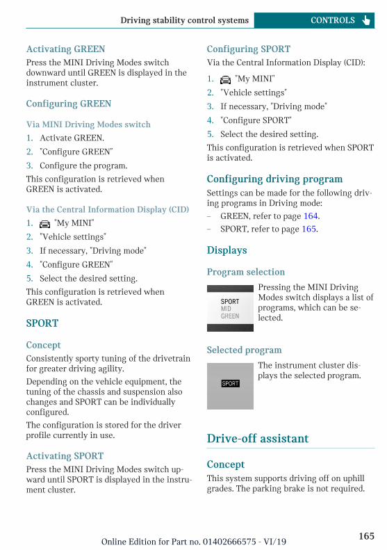
Activating GREENPress the MINI Driving Modes switchdownward until GREEN is displayed in theinstrument cluster.
Configuring GREEN
Via MINI Driving Modes switch
1. Activate GREEN.
2. "Configure GREEN"
3. Configure the program.
This configuration is retrieved whenGREEN is activated.
Via the Central Information Display (CID)
1. "My MINI"
2. "Vehicle settings"
3. If necessary, "Driving mode"
4. "Configure GREEN"
5. Select the desired setting.
This configuration is retrieved whenGREEN is activated.
SPORT
ConceptConsistently sporty tuning of the drivetrainfor greater driving agility.
Depending on the vehicle equipment, thetuning of the chassis and suspension alsochanges and SPORT can be individuallyconfigured.
The configuration is stored for the driverprofile currently in use.
Activating SPORTPress the MINI Driving Modes switch up-ward until SPORT is displayed in the instru-ment cluster.
Configuring SPORTVia the Central Information Display (CID):
1. "My MINI"
2. "Vehicle settings"
3. If necessary, "Driving mode"
4. "Configure SPORT"
5. Select the desired setting.
This configuration is retrieved when SPORTis activated.
Configuring driving programSettings can be made for the following driv-ing programs in Driving mode:
– GREEN, refer to page 164.
– SPORT, refer to page 165.
Displays
Program selection
Pressing the MINI DrivingModes switch displays a list ofprograms, which can be se-lected.
Selected program
The instrument cluster dis-plays the selected program.
Drive-off assistant
ConceptThis system supports driving off on uphillgrades. The parking brake is not required.
Seite 165
Driving stability control systems CONTROLS
165Online Edition for Part no. 01402666575 - VI/19

Driving off with the drive-offassistant1. Hold the vehicle in place with the foot
brake.
2. Release the foot brake and drive offwithout delay.
After the foot brake is released, the vehicleis held in place for approx. 2 seconds.
Servotronic
Servotronic is a speed-dependent powersteering function.
The system provides the steering force withmore support at low speeds than at higherones. This makes it easier to park, for in-stance, and makes steering firmer whendriving at faster speeds.
Furthermore, the steering force adapts ac-cording to the driving program, so that afirm, sporty feel or a comfortable steeringresponse is conveyed.
Seite 166
CONTROLS Driving stability control systems
166Online Edition for Part no. 01402666575 - VI/19

Driving comfort
Vehicle features and options
This chapter describes all standard, country-specific and optional features offered withthe series. It also describes features that arenot necessarily available in your vehicle, forinstance, due to the selected options orcountry versions. This also applies to safety-related functions and systems. When usingthese functions and systems, the applicablelaws and regulations must be observed.
Camera-based cruise control
ConceptUsing this system, a desired speed and adistance to a vehicle ahead can be adjustedusing the buttons on the steering wheel.
The system maintains the desired speed onclear roads. For this purpose, the vehicle ac-celerates or brakes automatically.
If a vehicle is driving ahead of you, the sys-tem adjusts the speed of your vehicle sothat the set distance to the vehicle ahead ismaintained. The speed is adjusted as far asthe given situation allows.
The distance can be adjusted in severalsteps. For safety reasons, it depends on therespective speed.
With the Stop&Go function for Steptronictransmissions: if the vehicle ahead of youbrakes to a halt, and then proceeds to driveagain shortly thereafter, the system is ableto detect this within the given system lim-its.
General informationA camera on the interior mirror is used todetect vehicles driving ahead.
Depending on the settings, the characteris-tics of cruise control many change in cer-tain ranges.
Safety information
Warning
The system cannot serve as a substitutefor the driver’s personal judgment in as-sessing the traffic conditions. Based onthe limits of the system, it cannot inde-pendently react to all traffic situations.There is a risk of accident. Adjust drivingstyle to traffic conditions. Watch trafficclosely and actively intervene where ap-propriate.
Warning
The desired speed can be incorrectly ad-justed or called up by mistake. There is arisk of accident. Adjust the desired speedto the traffic conditions. Watch trafficclosely and actively intervene where ap-propriate.
Warning
Risk of accident due to too high speed dif-ferences to other vehicles, for instance inthe following situations:
– When fast approaching a slowly mov-ing vehicle.
– Vehicle suddenly swerving into ownlane.
Seite 167
Driving comfort CONTROLS
167Online Edition for Part no. 01402666575 - VI/19

– When fast approaching standing ve-hicles.
There is a risk of injuries or danger to life.Watch traffic closely and actively inter-vene where appropriate.
Warning
An unsecured vehicle can begin to moveand possibly roll away. There is a risk ofaccident. Before exiting, secure the vehi-cle against rolling.
In order to ensure that the vehicle is se-cured against rolling away, follow the fol-lowing:
– Set the parking brake.
– On uphill grades or on a downhillslope, turn the front wheels in the di-rection of the curb.
– On uphill grades or on a downhillslope, also secure the vehicle, for in-stance with a wheel chock.
Overview
Buttons on the steering wheel
Button Function
Cruise control on/off, refer topage 169.
Store/maintain speed, refer topage 169.
Pause cruise control, refer topage 169.
Continue cruise control with thelast setting, refer to page 170.
Reduce distance, refer topage 170.
Increase the distance, refer topage 170.
Button Function
Increase speed, refer topage 169.
Reduce speed, refer to page 169.
Buttons are arranged according to vehicle'sseries, optional features and country speci-fications.
Camera
The camera is installed near the interiormirror.
Keep the windshield in front of the interiormirror clean and clear.
Functional requirements
Speed rangeThe system is best used on well-constructedroads.
The system is functional at speeds begin-ning at approx. 20 mph/30 km/h.
With the Stop&Go function for Steptronictransmissions: the system can also be acti-vated while the vehicle is stationary.
The max. speed that can be set is85 mph/140 km/h.
Manual transmission: Active Cruise Controlis interrupted below a speed of approx.20 mph/30 km/h. The system does notbrake to a stop.
Seite 168
CONTROLS Driving comfort
168Online Edition for Part no. 01402666575 - VI/19

Switching on/off and interruptingcruise control
Switching on
Press the button on the steeringwheel.
Display in the instrument clusterlights up.
Display in the instrument clusterlights up. The current speed isadopted as desired speed and dis-
played with symbol.
Cruise control is active and maintains theset speed.
DSC Dynamic Stability Control is switchedon, if necessary.
Switching offWith the Stop&Go function for Steptronictransmissions: when switching off whilestationary, depress the brake pedal simulta-neously.
Press the button on the steeringwheel.
The displays go out. The stored desiredspeed is deleted.
Interrupting manually
Press the button on the steeringwheel.
With the Stop&Go function for Steptronictransmissions: when interrupting while sta-tionary, depress the brake pedal simultane-ously.
Interrupting automaticallyThe system is automatically interrupted inthe following situations:
– When the driver applies the brakes.
– Manual transmission: when the clutchpedal is depressed for a few seconds orreleased while a gear is not engaged.
– If selector lever position N is set.
– Dynamic Traction Control DTC is acti-vated or DSC Dynamic Stability Controlis deactivated.
– If DSC Dynamic Stability Control inter-venes.
– If the detection range of the camera isimpaired, for instance by soiling, heavyprecipitation or glare effects from thesun.
– Manual transmission: if the vehicle infront decelerates below a speed of ap-prox. 20 mph/30 km/h.
– With the Stop&Go function for Step-tronic transmissions: following a sta-tionary period of approx. 3 seconds, af-ter the vehicle was braked to a stop bythe system.
Setting the speed
Maintaining/storing the speedPress or button in the interruptedstate.
When the system is switched on, the cur-rent speed is maintained and stored as thedesired speed.
The stored speed is displayed on thesymbol.
DSC Dynamic Stability Control isswitched on, if necessary.
The speed can also be stored as follows:
Press the button.
Seite 169
Driving comfort CONTROLS
169Online Edition for Part no. 01402666575 - VI/19

Changing the speed or button: press until the desired
speed is set.
If active, the displayed speed is stored andthe vehicle reaches the stored speed whenthe road is clear.
– or button: each time it is pressedto the point of resistance, the desiredspeed increases or decreases by approx.1 mph/1 km/h.
– or button: each time it is pressedpast the resistance point, the desiredspeed changes by a maximum of 5 mph/10 km/h.
or button: hold down to repeat theaction.
Adjusting the distance
Safety information
Warning
The system cannot serve as a substitutefor the driver’s personal judgment. Due tothe system limits, braking can be late.There may be a risk of accident or risk ofdamage to property. Be aware to the trafficsituation at all times. Adjust the distanceto the traffic and weather conditions andmaintain the prescribed safety distance,possibly by braking.
Reduce distance
Press the button repeatedly untilthe desired distance is set.
The set distance is briefly displayedin the left part of the instrumentcluster.
Increase the distance
Press the button repeatedly untilthe desired distance is set.
The set distance is briefly displayedin the left part of the instrumentcluster.
Continuing cruise control
General informationAn interrupted cruise control can be contin-ued by calling up the stored speed.
Make sure that the difference between cur-rent speed and stored speed is not too largebefore calling up the stored speed. Other-wise, unintentional braking or acceleratingmay occur.
In the following cases, the stored speedvalue is deleted and cannot be called upagain:
– When the system is switched off.
– When the ignition is switched off.
Calling up the stored speed anddistance
Press the button with the system in-terrupted. Cruise control is contin-ued with the stored values. The se-
lected distance is briefly displayed in theInfo Display.
Switching distance control on/off
Safety information
Warning
The system does not react to traffic driv-ing ahead of you, but instead maintainsthe stored speed. There may be a risk ofaccident or risk of damage to property. Ad-
Seite 170
CONTROLS Driving comfort
170Online Edition for Part no. 01402666575 - VI/19

just the desired speed to the traffic condi-tions and brake as needed.
Switching distance control offDistance control can be switched off and onwhen driving with cruise control activated.
Press and hold this button.
Or:
Press and hold this button.
The indicator light in the instrumentcluster lights up.
To switch distance control back on, pressone of the two buttons again briefly.
After changing over distance control, aCheck Control message is displayed.
Displays in the instrument cluster
Desired speed and stored speed
In addition to the indicator light, thedesired speed is displayed in the InfoDisplay.
– Display lights up green: system is active,the display indicates the desired speed.
– Display lights up orange: system is in-terrupted, the display indicates thestored speed.
– No display: system is switched off.
If no speed is indicated, it is possible thatthe conditions necessary for operation arenot currently fulfilled.
Distance to vehicle ahead of youSelected distance from the vehicle drivingahead is briefly displayed in the left handportion of the Info Display.
Distance display
Distance 1
Distance 2
Distance 3
Distance 4
This value is set automatically af-ter the system is switched on.
Detected vehicle
Symbol lights up orange:
A vehicle has been detected ahead ofyou.
With the Stop&Go function for Step-tronic transmissions:
Rolling bars: the detected vehiclehas driven away.
ACC does not accelerate. To accelerate, acti-vate ACC as follows:
– By briefly pressing the acceleratorpedal.
– By pressing the RES CNCL button.
– By pressing the or button.
Indicator/warning lights
Symbol flashes orange:
The conditions are not adequate forthe system to work.
The system was deactivated but applies thebrakes until you actively resume control bypressing on the brake pedal or acceleratorpedal.
Seite 171
Driving comfort CONTROLS
171Online Edition for Part no. 01402666575 - VI/19

Symbol flashes red and a signalsounds:
Brake and make an evasive maneu-ver, if necessary.
The system has been interrupted ordistance control is temporarily sup-pressed because the accelerator
pedal is being pressed; a vehicle was not de-tected.
Distance control is temporarily sup-pressed because the acceleratorpedal is being pressed; a vehicle was
detected.
System limits
Detection range
The detection capacity of the system andthe automatic braking capacity are limited.
Two-wheeled vehicles for instance mightnot be detected.
DecelerationThe system does not decelerate in the fol-lowing situations:
– For pedestrians, cyclists or similarlyslow-moving road users.
– For red traffic lights.
– For cross traffic.
– For oncoming traffic.
– Unlit vehicles or vehicles with nonwork-ing lighting at night.
Swerving vehicles
A vehicle driving in front of you is not de-tected until it is completely within the samelane as your vehicle.
If a vehicle driving ahead of you suddenlyswerves into your lane, the system may notbe able to automatically restore the selecteddistance. It may not be possible to restorethe selected distance in certain situations,including if you are driving significantlyfaster than vehicles driving ahead of you,for instance when rapidly approaching atruck. When a vehicle driving ahead of youis reliably detected, the system requeststhat the driver intervene by braking andcarrying out evasive maneuvers, if needed.
With the Stop&Go function forSteptronic transmissions: driving offIn some situations, the vehicle cannot driveoff automatically; for example:
– On steep uphill grades.
– In front of bumps in the road.
In these cases, press on the acceleratorpedal.
Seite 172
CONTROLS Driving comfort
172Online Edition for Part no. 01402666575 - VI/19

Cornering
If the desired speed is too high for a curve,the speed is reduced slightly, althoughcurves cannot be anticipated in advance.Therefore, drive into a curve at an appropri-ate speed.
The system has a limited detection range.Situations can arise in tight curves where avehicle driving ahead will not be detectedor will be detected very late.
When you approach a curve the system maybriefly report vehicles in the next lane dueto the bend of the curve. If the system de-celerates you may compensate it by brieflyaccelerating. After releasing the acceleratorpedal the system is reactivated and controlsspeed independently.
WeatherThe following restrictions can occur underunfavorable weather or light conditions:
– Poorer vehicle recognition.
– Short-term interruptions for vehiclesthat are already recognized.
Examples of unfavorable weather or lightconditions:
– Wet conditions.
– Snowfall.
– Slush.
– Fog.
– Glare.
Drive attentively, and react to the currenttraffic situation. If necessary, intervene ac-tively, for instance by braking, steering orevading.
Engine powerThe desired speed may not be maintainedon uphill grades if engine power is insuffi-cient.
MalfunctionA Check Control message is displayed if thesystem fails or was automatically deacti-vated.
The system may not be fully functional inthe following situations:
– When an object was not correctly de-tected.
– In heavy fog, wet conditions, or snow-fall.
– In tight curves.
– If the field of view of the camera or thewindshield is dirty or covered.
– When driving toward bright lights.
– Up to 20 seconds after the start of theengine, via the Start/Stop button.
– During calibration of the camera imme-diately after vehicle delivery.
Seite 173
Driving comfort CONTROLS
173Online Edition for Part no. 01402666575 - VI/19
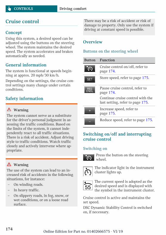
Cruise control
ConceptUsing this system, a desired speed can beadjusted using the buttons on the steeringwheel. The system maintains the desiredspeed. The system accelerates and brakesautomatically as needed.
General informationThe system is functional at speeds begin-ning at approx. 20 mph/30 km/h.
Depending on the settings, the cruise con-trol settings many change under certainconditions.
Safety information
Warning
The system cannot serve as a substitutefor the driver’s personal judgment in as-sessing the traffic conditions. Based onthe limits of the system, it cannot inde-pendently react to all traffic situations.There is a risk of accident. Adjust drivingstyle to traffic conditions. Watch trafficclosely and actively intervene where ap-propriate.
Warning
The use of the system can lead to an in-creased risk of accidents in the followingsituations, for instance:
– On winding roads.
– In heavy traffic.
– On slippery roads, in fog, snow, orwet conditions, or on a loose roadsurface.
There may be a risk of accident or risk ofdamage to property. Only use the system ifdriving at constant speed is possible.
Overview
Buttons on the steering wheel
Button Function
Cruise control on/off, refer topage 174.
Store speed, refer to page 175.
Pause cruise control, refer topage 174.
Continue cruise control with thelast setting, refer to page 175.
Increase speed, refer topage 175.
Reduce speed, refer to page 175.
Switching on/off and interruptingcruise control
Switching on
Press the button on the steeringwheel.
The indicator light in the instrumentcluster lights up.
The current speed is adopted as thedesired speed and is displayed withthe symbol in the instrument cluster.
Cruise control is active and maintains theset speed.
DSC Dynamic Stability Control is switchedon, if necessary.
Seite 174
CONTROLS Driving comfort
174Online Edition for Part no. 01402666575 - VI/19

Switching off
Press the button on the steeringwheel.
The displays go out. The stored desiredspeed is deleted.
Interrupting manually
When active, press the button onthe steering wheel.
Interrupting automaticallyThe system is automatically interrupted inthe following situations:
– When the driver applies the brakes.
– If the clutch pedal is depressed for a fewseconds or released while a gear is notengaged.
– If the gear engaged is too high for thecurrent speed.
– If selector lever position N is set.
– Dynamic Traction Control DTC is acti-vated or DSC Dynamic Stability Controlis deactivated.
– If DSC Dynamic Stability Control inter-venes.
Setting the speed
Maintaining/storing the speedPress or button in the interruptedstate.
When the system is switched on, the cur-rent speed is maintained and stored as thedesired speed.
The stored speed is displayed in the instru-ment cluster.
DSC Dynamic Stability Control is switchedon, if necessary.
The speed can also be stored as follows:
Press the button.
Changing the speed or button: press until the desired
speed is set.
If active, the displayed speed is stored andthe vehicle reaches the stored speed whenthe road is clear.
– or button: each time it is pressedto the point of resistance, the desiredspeed increases or decreases by approx.1 mph/1 km/h.
– or button: each time it is pressedpast the resistance point, the desiredspeed changes by a maximum of 5 mph/10 km/h.
– or button: pressing it to the re-sistance point and holding it acceleratesor decelerates the vehicle without re-quiring pressure on the acceleratorpedal. After the button is released, thevehicle maintains its final speed. Press-ing the switch beyond the resistancepoint causes the vehicle to acceleratemore rapidly.
Continuing cruise control
General informationAn interrupted cruise control can be contin-ued by calling up the stored speed.
Make sure that the difference between cur-rent speed and stored speed is not too largebefore calling up the stored speed. Other-wise, unintentional braking or acceleratingmay occur.
Calling up the stored speed
Press the button on the steeringwheel.
The stored speed is reached again and main-tained.
Seite 175
Driving comfort CONTROLS
175Online Edition for Part no. 01402666575 - VI/19

Displays in the instrument cluster
Indicator light
Depending on how the vehicle isequipped, the indicator light in theinstrument cluster indicates whether
the system is switched on.
Desired speed and stored speed
The desired speed is displayed to-gether with the symbol.
– Display lights up green: system isactive, the display indicates thedesired speed.
– Display lights up orange: system is in-terrupted, the display indicates thestored speed.
– No display: system is switched off.
If no speed is indicated, it is possible thatthe conditions necessary for operation arenot currently fulfilled.
System limits
Engine powerThe desired speed is also maintained down-hill, but may not be maintained on uphillgrades if engine power is insufficient.
PDC Park Distance Control
ConceptPDC is a support when parking. The systemdetects objects behind the vehicle. If the ve-hicle is equipped with front PDC, objects infront of the vehicle are detected too. Ob-jects that you are approaching slowly are in-dicated by signal tones and a visual display.
General informationThe ultrasound sensors for measuring thedistances are located in the bumpers.
The delete range, depending on obstaclesand environmental conditions, is approx.6 ft/2 m.
An acoustic warning is first given in the fol-lowing situations:
– By the front middle sensors and the twocorner sensors at approx. 24 in/60 cmfrom the object.
– By the rear middle sensors at ap-prox. 5 ft/1.50 m from the object.
– When a collision is imminent.
Safety information
Warning
The system cannot serve as a substitutefor the driver’s personal judgment in as-sessing the traffic conditions. There is arisk of accident. Adjust driving style totraffic conditions. Watch traffic and vehi-cle surroundings closely and actively in-tervene where appropriate.
Warning
Due to high speeds when PDC Park Dis-tance Control is activated, the warning canbe delayed due to physical circumstances.There is a risk of injury or risk of damageto property. Avoid approaching an objecttoo fast. Avoid driving off fast while PDCPark Distance Control is not yet active.
Seite 176
CONTROLS Driving comfort
176Online Edition for Part no. 01402666575 - VI/19

Overview
With front PDC: button in vehicle
Park assistance button
Ultrasound sensors
Ultrasound sensors of thePDC, for instance in the bump-ers.
Functional requirementsEnsure full functionality:
– Do not cover sensors, for instance withstickers, bicycle racks.
– Keep the sensors clean and unob-structed.
Switching on/off
Switching on automaticallyThe system switches on automatically in thefollowing situations:
– If selector lever position R is engagedwhen the engine is running.
The rearview camera also switches on.
– With front PDC: when obstacles are de-tected behind or in front of the vehicleby PDC and the speed is slower than ap-prox. 2.5 mph/4 km/h.
With front PDC: automatic activation on ob-stacle detection can be switched off. Via theCentral Information Display (CID):
1. "My MINI"
2. "Vehicle settings"
3. "Parking"
4. "Automatic PDC activation": dependingon the vehicle equipment.
5. "Automatic PDC activation"
The setting is stored for the driver pro-file currently used.
Automatic deactivation duringforward travelThe system switches off when a certaindriving distance or speed is exceeded.
Switch the system back on, if needed.
With front PDC: switching on/offmanually
Press the park assistance button.
– On: the LED lights up.
– Off: the LED goes out.
The rearview camera image is displayed ifthe reverse gear is engaged when pressingthe park assistance button.
Warning
Signal tonesAn intermittent tone indicates when the ve-hicle is approaching an object. For instance,if an object is detected to the left rear of thevehicle, a signal tone sounds from the leftrear speaker.
The shorter the distance to the object, theshorter the intervals.
If the distance to a detected object is lessthan approx. 10 inches/25 cm, a continuoustone is sounded.
Seite 177
Driving comfort CONTROLS
177Online Edition for Part no. 01402666575 - VI/19

With front PDC: if objects are simultane-ously located both in front of and behindthe vehicle, an alternating continuous sig-nal is sounded.
The signal tone is switched off, when selec-tor lever position P is engaged on vehicleswith Steptronic transmission.
VolumeThe ratio of the PDC signal tone volume tothe entertainment volume can be adjusted.
1. "My MINI"
2. "System settings"
3. "Tone"
4. "Volume settings"
5. "PDC"
6. Set the desired value.
The setting is stored for the driver profilecurrently used.
Visual warningThe approach of the vehicle to an object canbe shown on the Control Display. Objectsthat are farther away are already displayedon the Control Display before a signalsounds.
A display appears as soon as Park DistanceControl (PDC) is activated.
The range of the sensors is represented incolors: red, green and yellow.
When the image of the rearview camera isdisplayed, the switch can be made to PDC:
"Rear view camera"
System limits
Safety information
Warning
The system is designed to operate in cer-tain conditions and circumstances. Due toconditions or other factors, the systemmay not respond. There may be a risk ofaccident or risk of damage to property. Ac-tively intervene as warranted. Refer to theinformation in this Owner’s Manual re-garding the scope of the system’s opera-tion and limitations.
Limits of ultrasonic measurementUltrasonic measuring might not functionunder the following circumstances:
– For small children and animals.
– For persons with certain clothing, for in-stance coats.
– With external interference of the ultra-sound, for instance from passing vehi-cles or loud machines.
– When sensors are dirty, iced over, dam-aged or out of position.
– If cargo protrudes.
– Under certain weather conditions suchas high relative humidity, wet condi-tions, snowfall, extreme heat, or strongwind.
– With tow bars and trailer couplings ofother vehicles.
– With thin or wedge-shaped objects.
– With moving objects.
– With elevated, protruding objects suchas ledges or cargo.
– With objects with corners and sharpedges.
Seite 178
CONTROLS Driving comfort
178Online Edition for Part no. 01402666575 - VI/19

– With objects with a fine surface struc-ture such as fences.
– For objects with porous surfaces.
– Low objects already displayed, for in-stance curbs, can move into the blindarea of the sensors before or after a con-tinuous tone sounds.
False warningsThe system may issue a warning under thefollowing conditions even though there isno obstacle within the detection range:
– In heavy rain.
– When sensors are very dirty or coveredwith ice.
– When sensors are covered in snow.
– On rough road surfaces.
– On uneven surfaces, such as speedbumps.
– In large buildings with right angles andsmooth walls, for instance in under-ground garages.
– In automatic vehicle washes.
– Due to heavy exhaust.
– Due to other ultrasound sources, for in-stance sweeping machines, high pres-sure steam cleaners or neon lights.
The malfunction is signaled by a contin-uous tone alternating between the frontand rear speakers. As soon as the mal-function due to other ultrasound sourcesis no longer present, the system is againfully functional.
With front PDC: to reduce false alarms,switch off automatic PDC activation on ob-stacle detection, for instance in vehiclewashes; see Switching on/off.
MalfunctionA Check Control message is displayed in theinstrument cluster.
Red symbol is displayed, and therange of the sensors is dimmed onthe Control Display.
PDC has failed. Have the system checked bya dealer's service center or another qualifiedservice center or repair shop.
Rearview camera
ConceptThe rearview camera provides assistance inparking and maneuvering backwards. Thearea behind the vehicle is shown on theControl Display.
Safety information
Warning
The system cannot serve as a substitutefor the driver’s personal judgment in as-sessing the traffic conditions. There is arisk of accident. Adjust driving style totraffic conditions. Watch traffic and vehi-cle surroundings closely and actively in-tervene where appropriate.
Overview
Depending on the vehicle equipment:button in the vehicle
Seite 179
Driving comfort CONTROLS
179Online Edition for Part no. 01402666575 - VI/19

Park assistance button
Camera
The camera lens is located between the li-cense plate lights.
The image quality may be impaired by dirt.If necessary, clean the camera lens.
Switching on/off
Switching on automaticallyThe system is switched on automatically ifselector lever position R is engaged whenthe engine is running.
Automatic deactivation duringforward travelThe system switches off when a certaindriving distance or speed is exceeded.
Switch the system back on, if needed.
Depending on the vehicle equipment:switching on/off manually
Press the park assistance button.
– On: the LED lights up.
– Off: the LED goes out.
The parking assistance functions are shownon the Control Display.
Switching the view via the CentralInformation Display (CID)If the rearview camera view is not dis-played, change the view via the Central In-formation Display (CID):
"Rear view camera"
The rearview camera image is displayed.
Display on the Control Display
Functional requirement– The rearview camera is switched on.
– Split doors are completely closed.
– Keep the recording range of the cameraclear.
Protruding cargo or carrier systems andtrailers that are not connected to atrailer power socket can lead to malfunc-tions.
Activating assistance functionsMore than one assistance function can beactive at the same time.
– Parking aid lines
"Parking aid lines"
Lanes and turning radius lines are indi-cated.
– Obstacle marking
"Obstacle marking"
Obstacles are marked, depending on thevehicle equipment.
Seite 180
CONTROLS Driving comfort
180Online Edition for Part no. 01402666575 - VI/19

Pathway lines
Pathway lines can be superimposed on theimage of the rearview camera.
Pathway lines help you to estimate thespace required when parking and maneu-vering on level roads.
Pathway lines depend on the current steer-ing angle and are continuously adjusted tothe steering wheel movements.
Turning radius lines
Turning radius lines can be superimposedon the image of the rearview camera.
Turning radius lines show the course of thesmallest possible turning radius on a levelroad.
Only one turning radius line is displayed af-ter the steering wheel is turned past a cer-tain angle.
Obstacle marking
Depending on the vehicle equipment, obsta-cle markings can be faded into the image ofthe rearview camera.
The colored thresholds of the obstacle mark-ings match the markings of the PDC ParkDistance Control.
Parking using pathway and turningradius lines1. Position the vehicle so that the turning
radius lines lead to within the limits ofthe parking space.
Seite 181
Driving comfort CONTROLS
181Online Edition for Part no. 01402666575 - VI/19

2. Turn the steering wheel to the pointwhere the pathway line covers the cor-responding turning radius line.
Display settings
BrightnessWith the rearview camera switched on:
1. Select the symbol.
2. Turn the Controller until the desired set-ting is reached and press the Controller.
ContrastWith the rearview camera switched on:
1. Select the symbol.
2. Turn the Controller until the desired set-ting is reached and press the Controller.
System limits
Detection of objectsVery low obstacles or high, protruding ob-jects such as ledges may not be recognizedby the system.
Depending on the vehicle equipment, someassistance functions also consider data fromthe PDC Park Distance Control.
Follow the notes in the PDC Park DistanceControl chapter.
The objects displayed on the Control Dis-play may be closer than they appear. There-
fore, do not estimate the distance from theobjects on the display.
The bumper of the vehicle is not visible inthe camera picture. Therefore do not drivecloser toward an obstacle than shown bythe marks in the camera picture, even if thecamera picture still shows a gap betweenthe vehicle and the obstacle.
Parking assistant
Concept
This system assists the driver in parkingparallel to the road.
General informationParking assistant handling is divided intothree steps:
– Switching on and activating.
– Parking space search.
– Parking.
Ultrasound sensors measure parking spaceson both sides of the vehicle.
The parking assistant calculates the bestpossible parking line and takes control ofsteering during the parking procedure.
System status and instructions on requiredactions are displayed on the Control Dis-play.
A component of the parking assistant is thePDC Park Distance Control.
Seite 182
CONTROLS Driving comfort
182Online Edition for Part no. 01402666575 - VI/19

Safety information
Warning
The system cannot serve as a substitutefor the driver’s personal judgment in as-sessing the traffic conditions. Based onthe limits of the system, it cannot inde-pendently react to all traffic situations.There is a risk of accident. Adjust drivingstyle to traffic conditions. Watch trafficclosely and actively intervene where ap-propriate.
NOTICE
The parking assistant can steer the vehicleover or onto curbs. There is a risk of dam-age to property. Watch traffic closely andactively intervene where appropriate.
The safety information of the PDC Park Dis-tance Control applies in addition.
Overview
Button in the vehicle
Park assistance button
Ultrasound sensors
The ultrasound sensors for measuring park-ing spaces are located on the wheel hous-ing.
Functional requirements
Ultrasound sensorsEnsure full functionality:
– Do not cover sensors, for instance withstickers.
– Keep the sensors clean and unob-structed.
For measuring parking spaces– Maximum speed while driving forward
approx. 22 mph/35 km/h.
– Maximum distance to row of parked ve-hicles: 5 ft/1.5 m.
Suitable parking space– Gaps behind an object that has a min.
length of 5 ft/1.5 m.
– Gap between two objects with a mini-mum length of approx. 5 ft/1.5 m.
– Min. length of gap between two objects:your vehicle's length plus approx.3.3 ft/1.0 m.
– Minimum depth: approx. 5 ft/1.5 m.
For parking– Doors and split doors are closed.
Seite 183
Driving comfort CONTROLS
183Online Edition for Part no. 01402666575 - VI/19

– The parking brake is released.
– When parking in parking spaces on thedriver's side, the corresponding turn sig-nal must be switched on.
Switching on and activating
Switching on with the button
Press the park assistance button.
The LED lights up.
The current status of the parking spacesearch is indicated on the Control Display.
Parking assistant is activated automati-cally.
Switching on with reverse gearShift into reverse.
The current status of the parking spacesearch is indicated on the Control Display.
To activate: "Parking Assistant"
Display on the Control Display
System activated/deactivated
Symbol Meaning
Gray: the system is not availa-ble.
White: the system is availablebut not activated.
The system is activated.
Parking space search and systemstatus
– Symbol P on the vehicle image: the park-ing assistant is activated and the park-ing space search is active.
– Control Display shows suitable parkingspaces at the edge of the road next tothe vehicle symbol. When the parkingassistant is active, suitable parkingspaces are highlighted.
– The parking procedure isactive. Steering controlhas been taken over bysystem.
– Parking space search is always activewhenever the vehicle is moving forwardslow and straight, even if the system isdeactivated. When the system is deacti-vated, the displays on the Control Dis-play are shown in gray.
Parking using the parking assistant
Parking
1. Press the park assistance button orshift into reverse gear to switch on theparking assistant, refer to page 184. Ac-tivate the parking assistant, if needed.
Parking assistant is activated.
2. Pass the row of parked vehicles at aspeed of up to approx. 22 mph/35 km/h
Seite 184
CONTROLS Driving comfort
184Online Edition for Part no. 01402666575 - VI/19

and at a distance of maximum5 ft/1.5 m.
The status of the parking space searchand possible parking spaces are dis-played on the display, refer to page 184.
3. Follow the instructions on the display.
The best possible parking position willcome after gear change on the station-ary vehicle - wait for the automaticsteering wheel move.
The end of the parking procedure is in-dicated on the display.
4. Adjust the parking position yourself, ifneeded.
Interrupting manuallyThe parking assistant can be interrupted atany time:
– Press the park assistance button.
– "Parking Assistant"
Interrupting automaticallyThe system is interrupted automatically inthe following situations:
– If the driver grasps the steering wheelor takes over steering.
– If a gear is selected that does not matchthe instruction on the display.
– If the vehicle speed exceeds approx.6 mph/10 km/h.
– Possibly on snow-covered or slipperyroad surfaces.
– If a maximum number of parking at-tempts or the time taken for parking isexceeded.
– If the PDC Park Distance Control dis-plays clearances that are too small.
– When switching into other functions ofthe radio.
A Check Control message is displayed.
ResumingAn interrupted parking procedure can becontinued, if needed.
Reactivate the parking assistant, refer topage 184, and follow the instructions on thedisplay.
Switching offThe system can be switched off as follows:
– Press the park assistance button.
– Switching off the ignition.
System limits
Safety information
Warning
The system is designed to operate in cer-tain conditions and circumstances. Due toconditions or other factors, the systemmay not respond. There may be a risk ofaccident or risk of damage to property. Ac-tively intervene as warranted. Refer to theinformation in this Owner’s Manual re-garding the scope of the system’s opera-tion and limitations.
No parking assistanceThe parking assistant does not offer assis-tance in the following situations:
– In tight curves.
Functional limitationsThe system may not be fully functional inthe following situations:
– On bumpy road surfaces such as gravelroads.
– On slippery ground.
Seite 185
Driving comfort CONTROLS
185Online Edition for Part no. 01402666575 - VI/19
– With accumulations of leaves/snow inthe parking space.
– With a mounted emergency wheel.
– With ditches or edges, for instance anedge of a port.
Limits of ultrasonic measurementUltrasonic measuring might not functionunder the following circumstances:
– For small children and animals.
– For persons with certain clothing, for in-stance coats.
– With external interference of the ultra-sound, for instance from passing vehi-cles or loud machines.
– When sensors are dirty, iced over, dam-aged or out of position.
– If cargo protrudes.
– Under certain weather conditions suchas high relative humidity, wet condi-tions, snowfall, extreme heat, or strongwind.
– With tow bars and trailer couplings ofother vehicles.
– With thin or wedge-shaped objects.
– With moving objects.
– With elevated, protruding objects suchas ledges or cargo.
– With objects with corners and sharpedges.
– With objects with a fine surface struc-ture such as fences.
– For objects with porous surfaces.
– Low objects already displayed, for in-stance curbs, can move into the blindarea of the sensors before or after a con-tinuous tone sounds.
– The parking assistant may identify park-ing spaces that are not suitable for park-ing.
Tire sizeThe parking position may vary dependingon the tire size.
MalfunctionA Check Control message is displayed.
The parking assistant failed. Have the sys-tem checked by a dealer's service center oranother qualified service center or repairshop.
Seite 186
CONTROLS Driving comfort
186Online Edition for Part no. 01402666575 - VI/19

Climate control
Vehicle features and options
This chapter describes all standard, country-specific and optional features offered withthe series. It also describes features that arenot necessarily available in your vehicle, forinstance, due to the selected options orcountry versions. This also applies to safety-related functions and systems. When usingthese functions and systems, the applicablelaws and regulations must be observed.
Interior air quality
The air quality in the vehicle is improved bythe following components:
– Emission tested passenger compart-ment.
– Microfilter.
– Air conditioning system to control thetemperature, air flow and recirculated-air mode.
Depending on the equipment specification:
– Microfilter/activated-charcoal filter.
– Automatic climate control.
– Parked-car ventilation.
Air conditioner
1 Air distribution settings 2 Air flow
Seite 187
Climate control CONTROLS
187Online Edition for Part no. 01402666575 - VI/19

3 Temperature
4 Seat heating, right 82
5 Air conditioning
6 Recirculated-air mode
7 Rear window defroster
8 Windshield defroster
9 Seat heating, left 82
Climate control functions in detail
Switching the system on/off
Switching on
Set any air flow.
Switching off
Turn the wheel for air flow allthe way to the left.
Temperature
Concept
The system heats or cools, depending on theset temperature.
Adjusting
Turn the wheel to set the de-sired temperature.
Air conditioning
Concept
The air in the car's interior will be cooledand dehumidified and, depending on thetemperature setting, warmed again.
The car's interior can only be cooled withthe engine running.
Switching on/off
Press the button.
The LED is illuminated with air con-ditioning switched on.
Depending on the weather, the windshieldmay fog up briefly when the engine isstarted.
The air conditioner produces condensationwater, refer to page 219, that will exit frombelow the vehicle.
Recirculated-air mode
Concept
You may react to unpleasant odors or pollu-tants in the immediate environment by tem-porarily suspending the supply of outsideair. The system then recirculates the airflow within the vehicle.
Operation
Press the button:
The LED is illuminated when recir-culated-air mode is switched on. The supplyof outside air is shut off.
When recirculated-air mode is switched off,fresh air is directed into the vehicle's inte-rior.
To prevent window condensation, recircu-lated-air mode switches off automatically af-ter a certain amount of time, depending onthe external temperature.
With constant recirculated-air mode, the airquality in the car's interior deteriorates andwindow fogging increases.
Seite 188
CONTROLS Climate control
188Online Edition for Part no. 01402666575 - VI/19
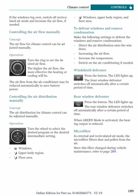
If the windows fog over, switch off recircu-lated-air mode and increase the air flow, ifneeded.
Controlling the air flow manually
Concept
The air flow for climate control can be ad-justed manually.
Operation
Turn the ring to set the de-sired air flow.
The higher the air flow, themore effective the heating orcooling will be.
The air flow from the air conditioner may bereduced automatically to save batterypower.
Controlling the air distributionmanually
Concept
The air distribution for climate control canbe adjusted manually.
Operation
Turn the wheel to select thedesired program or the desiredintermediate setting.
– Windows.
– Upper body region.
– Floor area.
– Windows, upper body region, andfloor area.
To defrost windows and removecondensationMake the following settings to defrost thewindows and remove condensation:
– Direct the air distribution onto the win-dows.
– Increasing the air flow.
– Increase the temperature.
– Switch on the air conditioning if needed.
Windshield defroster
Press the button. The LED lights up.
The front window defrosterswitches off automatically after a certainperiod of time.
Rear window defroster
Press the button. The LED lights up.
The rear window defroster switchesoff automatically after a certain period oftime.
When GREEN Mode is activated, the heat-ing output is reduced.
MicrofilterIn external and recirculated-air mode, themicrofilter filters dust and pollen from theair.
Have this filter changed during vehiclemaintenance, refer to page 289.
Seite 189
Climate control CONTROLS
189Online Edition for Part no. 01402666575 - VI/19

Automatic climate control
1 Temperature, left
2 Display
3 Air flow, AUTO intensity
4 AUTO program
5 Air distribution, manual
6 Display
7 Temperature, right
8 Seat heating, right 82
9 Maximum cooling
10 Air conditioning
11 Recirculated-air mode
12 Rear window defroster
13 Windshield defroster
14 To defrost windows and remove conden-sation
15 Seat heating, left 82
Climate control functions in detail
Switching the system on/off
Switching on
Set any air flow.
Switching off
Turn wheel for air flow to theleft until the control switchesoff.
Temperature
Concept
The automatic climate control achieves theset temperature as quickly as possible, if
Seite 190
CONTROLS Climate control
190Online Edition for Part no. 01402666575 - VI/19

necessary by using the maximum cooling orheating power, and then keeps it constant.
Adjusting
Turn the wheel to set the de-sired temperature.
Do not rapidly switch between differenttemperature settings. The automatic climatecontrol will not have sufficient time to ad-just the set temperature.
Air conditioning
Concept
The air in the car's interior will be cooledand dehumidified and, depending on thetemperature setting, warmed again.
The car's interior can only be cooled withthe engine running.
Switching on/off
Press the button.
The LED is illuminated with air con-ditioning switched on.
Depending on the weather, the windshieldmay fog up briefly when the engine isstarted.
The cooling function is switched on auto-matically with the AUTO program.
When using the automatic climate control,condensation water, refer to page 219, de-velops and drains underneath the vehicle.This is normal.
Maximum cooling
Concept
The system is set to the lowest temperature,maximum air flow and recirculated-airmode.
General information
The function is available with external tem-peratures beyond approx. 32 ℉/0 ℃ andwith the engine running.
Air flows out of the vents to the upper bodyregion. The vents need to be open for this.
The air flow can be adjusted with the pro-gram active.
Switching on/off
Press the button.
The LED is illuminated with thesystem switched on.
The system is set to the lowest temperature,optimum air flow and air circulation mode.
AUTO program
Concept
The AUTO program cools, ventilates orheats the car's interior automatically.
The air distribution and temperature arecontrolled automatically depending on thetemperature in the car's interior and the de-sired temperature setting including the se-lected intensity of the air flow.
Switching on/off
Press the button.
The LED is illuminated with theAUTO program switched on.
Depending on the selected temperature,AUTO intensity and outside influences, the
Seite 191
Climate control CONTROLS
191Online Edition for Part no. 01402666575 - VI/19

air is directed to the windshield, side win-dows, upper body, and into the floor area.
Point the side vents toward the side win-dows.
The following features are switched on au-tomatically with the AUTO program:
– The air conditioning, refer to page 191.
To switch off the program: press the buttonagain or manually adjust the air distribu-tion.
Intensity
With the AUTO program activated, the au-tomatic intensity control can be changed.
Turn the ring to set the de-sired intensity from soft to in-tensive.
The set intensity is displayed via the posi-tion of the illuminated LED segment.
Automatic recirculated-air control/recirculated-air mode
Concept
The automatic recirculated-air control AUCrecognizes odors or pollutants in the out-side air. The outside air supply is shut offand the interior air is recirculated.
General information
If the system is activated, a sensor detectspollutants in the outside air and controls theshut-off automatically.
If the system is deactivated, outside air con-tinuously flows into the car's interior.
With constant recirculated-air mode, the airquality in the car's interior deteriorates andwindow fogging increases.
You may react to unpleasant odors or pollu-tants in the immediate environment by tem-
porarily suspending the supply of outsideair. The system then recirculates the airflow within the vehicle.
Switching on/off
Press button repeatedly to select anoperating mode:
– LEDs off: outside air flows in continu-ously.
– Left LED on, automatic recirculated-aircontrol: a sensor detects pollutants inthe outside air and shuts off automati-cally.
– Right LED on, recirculated-air mode: thesupply of outside air into the vehicle ispermanently blocked.
To prevent window condensation, recircu-lated-air mode switches off automatically af-ter a certain amount of time, depending onthe external temperature.
If windows are fogged over, switch off therecirculating mode and press the AUTO but-ton. Make sure that air can flow to thewindshield.
Adjusting the air flow manually
Concept
The air flow for climate control can be ad-justed manually.
General information
To adjust the air flow manually switch offAUTO program first.
Operation
Turn the ring to set the de-sired air flow.
Seite 192
CONTROLS Climate control
192Online Edition for Part no. 01402666575 - VI/19

The manually adjusted air flow is displayedvia illuminated LED segments.
The air flow of the automatic climate con-trol may be reduced automatically to savebattery power.
Adjusting the air distributionmanually
Concept
The air distribution for climate control canbe adjusted manually.
Operation
Press the button repeatedly to se-lect a program:
– Windows, upper body region, and floorarea.
– Upper body region and floor area.
– Floor area.
– Windows and floor area.
– Windows.
– Windows and upper body region.
– Upper body region.
To defrost windows and removecondensation
Concept
Ice and condensation are quickly removedfrom the windshield and the front side win-dows.
Switching on/off
Press the button.
The LED is illuminated with thesystem switched on.
Ice and condensation are quickly removedfrom the windshield and the front side win-dows.
The air flow can be adjusted with the pro-gram active.
If there is window condensation, switch onthe air conditioning too.
Windshield defroster
Press the button. The LED lights up.
The front window defrosterswitches off automatically after a certainperiod of time.
Rear window defroster
Press the button. The LED lights up.
The rear window defroster switchesoff automatically after a certain period oftime.
When GREEN Mode is activated, the heat-ing output is reduced.
Microfilter/activated-charcoal filterIn external and recirculated-air mode, themicrofilter/activated charcoal filter filtersdust, pollen, and gaseous pollutants out ofthe air.
Have this filter changed during vehiclemaintenance, refer to page 289.
Ventilation
SettingThe air flow directions can be individuallyadjusted:
– Direct ventilation:
The air flow is directly pointed onto theperson. The air flow heats or cools no-ticeably, depending on the adjusted tem-perature.
– Indirect ventilation:
Seite 193
Climate control CONTROLS
193Online Edition for Part no. 01402666575 - VI/19

If the vents are fully or partly closed, theair is directly routed into the car's inte-rior.
Front ventilation
– Turn knob for continuous opening andclosing of the vents.
– Swivel the vents to alter the direction ofthe vent flow, arrows.
Ventilation in the rear
– Lever for changing the air flow direc-tion, arrow 1.
– Thumbwheel for variable opening andclosing of the vents, arrow 2.
Parked-car ventilation
ConceptThe parked-car ventilation ventilates thecar's interior and lowers its temperature, ifneeded.
General informationThe parked-car ventilation can be switchedon and off directly or by using two presetactivation times. The system remainsswitched on for 30 minutes.
The parked-car ventilation system is oper-ated via the Central Information Display(CID).
Functional requirements– Direct operation: vehicle is in radio-
ready state.
– Direct operation or preset activationtime: does not depend on external tem-perature.
– Battery is sufficiently charged.
If parked-car ventilation is switched on,the vehicle battery will be discharged.Thus, limit the maximum activation timeto save the vehicle battery. The systemwill be available again after the engineis started or after a short trip.
– Make sure that the vehicle's date andtime are set correctly.
– Open the vents to allow air to flow out.
Switching on/off directlyVia the Central Information Display (CID):
1. "My MINI"
2. "Vehicle settings"
3. If necessary, "Climate functions"
4. "Activate comfort ventilation now"
The symbol on the automatic climatecontrol flashes if the system is switched on.
Preselecting the activation timeVia the Central Information Display (CID):
1. "My MINI"
2. "Vehicle settings"
Seite 194
CONTROLS Climate control
194Online Edition for Part no. 01402666575 - VI/19

3. If necessary, "Climate functions"
4. "Comfort ventilation"
5. Select the desired activation time.
6. Set the desired time.
Activating the activation timeVia the Central Information Display (CID):
1. "My MINI"
2. "Vehicle settings"
3. If necessary, "Climate functions"
4. "For start time at:"
Activate the desired activation time.
The symbol on the automatic climatecontrol lights up when the activation time isactivated.
The symbol on the automatic climatecontrol flashes when the system has beenswitched on.
The system will only be switched on withinthe next 24 hours. After that, it needs to bereactivated.
Seite 195
Climate control CONTROLS
195Online Edition for Part no. 01402666575 - VI/19

Interior equipment
Vehicle features and options
This chapter describes all standard, country-specific and optional features offered withthe series. It also describes features that arenot necessarily available in your vehicle, forinstance, due to the selected options orcountry versions. This also applies to safety-related functions and systems. When usingthese functions and systems, the applicablelaws and regulations must be observed.
Integrated Universal RemoteControl
ConceptThe integrated Universal Remote Control inthe interior mirror can operate up to 3 func-tions of remote-controlled systems such asgarage door drives, barriers, or lighting sys-tems.
General informationThe Integrated Universal Remote Controlreplaces up to 3 different hand-held trans-mitters. To operate the remote control, thebuttons on the interior mirror must be pro-grammed with the desired functions. Thehand-held transmitter for the particular sys-tem is required in order to program the re-mote control.
Before selling the vehicle, delete the storedfunctions for the sake of security.
If possible, do not install the antenna of theremote-controlled system, e.g. the garagedoor drive, near metal objects to ensure thebest possible operation.
Safety information
Warning
The operation of remote-controlled sys-tems with the integrated universal remotecontrol, such as the garage door, may re-sult in injury, for example, body parts be-coming jammed in a garage door. There isa risk of injury or risk of damage to prop-erty. Make sure that the area of movementof the respective system is clear duringprogramming and operation. Also followthe safety information of the hand-heldtransmitter.
CompatibilityIf this symbol is printed on the pack-aging or in the owner's manual of thesystem to be controlled, the system
is generally compatible with the integratedUniversal Remote Control.
Additional questions are answered by:
– A dealer's service center or anotherqualified service center or repair shop.
– www.homelink.com on the Internet.
HomeLink is a registered trademark of Gen-tex Corporation.
Seite 196
CONTROLS Interior equipment
196Online Edition for Part no. 01402666575 - VI/19

Overview
1 LED
2 Programmable keys
3 Hand-held transmitters of the system
Programming
General informationThe battery of the hand-held transmittermust be fully charged at the time of pro-gramming to ensure an optimal range of theintegrated universal remote control.
1. Switch on the ignition.
2. Initial setup:
Press and hold the two outer buttons onthe interior mirror simultaneously forapproximately 10 seconds until the LEDflashes green rapidly. This erases all pro-gramming of the buttons on the interiormirror.
3. Press the interior mirror button to beprogrammed. The LED on the interiormirror will slowly begin flashing orange.
4. Hold the hand-held transmitter for thesystem to be used approx. 1 to 12 in/2.5to 30 cm away from the buttons on theinterior mirror. The required distancedepends on the hand-held transmitter.
5. Press and hold the button of the desiredfunction on the hand-held transmitter.
Canada: if programming with the hand-held transmitter was interrupted, hold
down the interior mirror button and re-peatedly press and release the hand-heldtransmitter button for 2 seconds.
6. – The LED lights up green: program-ming completed.
Release the button.
– The LED flashes fast: programmingis not complete.
Press the button on the interior mir-ror for 2 seconds and release. Per-form this procedure three times tocomplete the programming proce-dure.
If the integrated universal remotecontrol remains nonoperational, con-tinue with the special features forchange code wireless systems.
– LED does not flash green after60 seconds: programming not com-pleted.
Repeat steps 3 to 6.
To program other functions on other but-tons, repeat steps 3 to 5.
Special feature of the rolling codewireless systemIf you are unable to operate the system af-ter repeated programming, please check ifthe system to be controlled features a roll-ing code radio system.
Refer to the owner's manual for the system.
For systems with a rolling code radio sys-tem, the integrated Universal Remote Con-trol and the system also have to besynchronized.
Please read the owner's manual to find outhow to synchronize the system.
Synchronizing is easier with the aid of asecond person.
Seite 197
Interior equipment CONTROLS
197Online Edition for Part no. 01402666575 - VI/19

Synchronizing the universal remote controlwith the system:
1. Park the vehicle within range of the re-mote-controlled system.
2. Program the relevant button on the inte-rior mirror as described.
3. Locate and press the synchronizing but-ton on the system being programmed,e.g. at the garage gate. You have approx.30 seconds for the next step.
4. Hold down the programmed button onthe interior mirror for approximately3 seconds and then release it. If neces-sary, repeat this step up to three timesin order to finish synchronization. Oncesynchronization is complete, the pro-grammed function will be carried out.
Reprogramming individual buttons1. Switch on the ignition.
2. Press and hold the interior mirror but-ton to be programmed.
3. As soon as the LED on the interior mir-ror flashes orange after approx. 20 sec-onds, release the button.
4. Hold the hand-held transmitter for thesystem to be used approx. 1 to 12 in/2.5to 30 cm away from the buttons on theinterior mirror. The required distancedepends on the hand-held transmitter.
5. Press and hold the button of the desiredfunction on the hand-held transmitter.
Canada: if programming with the hand-held transmitter was interrupted, holddown the interior mirror button and re-peatedly press and release the hand-heldtransmitter button for 2 seconds.
6. The LED can light up in different ways.
– The LED lights up green: the pro-gramming procedure is completed.
Release the button.
– The LED flashes fast: the hand-heldtransmitter was detected but pro-gramming is not complete.
Press the button on the interior mir-ror for 2 seconds and release. Per-form this procedure three times tocomplete the programming proce-dure.
If the integrated universal remotecontrol remains nonoperational, con-tinue with the special features forchange code wireless systems.
– LED does not flash green after60 seconds: programming not com-pleted.
Repeat steps 3 to 6.
If the programming procedure is not com-pleted, the previous programming will re-main unchanged.
Operation
Warning
The operation of remote-controlled sys-tems with the integrated universal remotecontrol, such as the garage door, may re-sult in injury, for example, body parts be-coming jammed in a garage door. There isa risk of injury or risk of damage to prop-erty. Make sure that the area of movementof the respective system is clear duringprogramming and operation. Also followthe safety information of the hand-heldtransmitter.
The system, such as the garage door, can beoperated using the button on the interiormirror while the engine is running or whenthe ignition is started. To do this, hold downthe button within receiving range of thesystem until the function is activated. Theinterior mirror LED stays lit while the wire-less signal is being transmitted.
Seite 198
CONTROLS Interior equipment
198Online Edition for Part no. 01402666575 - VI/19

Deleting stored functionsAll stored functions will be deleted. Thefunctions cannot be deleted individually.
Press and hold the two outer buttons on theinterior mirror simultaneously for approxi-mately 10 seconds until the LED on the in-terior mirror flashes green rapidly.
Digital compass
Overview
1 Control button
2 Mirror display
Mirror displayThe point of the compass is displayed in themirror when driving straight.
Operating conceptVarious functions can be called up by press-ing the control button with a pointed object,such as the tip of a ballpoint pen or similarobject. The following setting options aredisplayed in succession, depending on howlong the control button is pressed:
– Pressed briefly: turns display on/off.
– 3 to 6 seconds: compass zone setting.
– 6 to 9 seconds: compass calibration.
– 9 to 12 seconds: left/right-hand steeringsetting.
– 12 to 15 seconds: language setting.
Setting the compass zonesSets the particular compass zones on the ve-hicle so that the compass operates correctly;refer to World map with compass zones.
Seite 199
Interior equipment CONTROLS
199Online Edition for Part no. 01402666575 - VI/19

World map with magnetic zones
Procedure1. Press and hold the control button for ap-
prox. 3 to 4 seconds. The number of theset compass zone appears in the mirror.
2. To change the zone setting, press thecontrol button quickly and repeatedlyuntil the number of the compass zonethat corresponds with your location ap-pears in the mirror.
The set zone is stored automatically. Thecompass is ready for use again after approx-imately 10 seconds.
Calibrating the digital compassThe digital compass must be calibrated inthe event of the following:
– The wrong compass point is displayed.
– The point of the compass displayed doesnot change despite changing the direc-tion of travel.
– Not all points of the compass are dis-played.
Procedure1. Make sure that there are no large metal-
lic objects or overhead power lines nearthe vehicle and that there is sufficientroom to drive around in a circle.
2. Set the currently applicable compasszone.
3. Press and hold the control button for ap-prox. 6 to 7 seconds so that "C" appearson the display. Next, drive in a completecircle at least once at a speed of no morethan 4 mph/7 km/h. If calibration is suc-cessful, the "C" is replaced by the pointsof the compass.
Left/right-hand steeringThe digital compass is already set for rightor left-hand steering at the factory.
Setting the languagePress and hold the control button for ap-prox. 12 to 13 seconds. Briefly press the
Seite 200
CONTROLS Interior equipment
200Online Edition for Part no. 01402666575 - VI/19

control button again to switch betweenEnglish "E" and German "O".
Settings are stored automatically after ap-proximately 10 seconds.
Sun visor
Glare shieldTo provide protection against glare, fold thesun visor down or pivot it to the side.
Vanity mirrorA vanity mirror is located in the sun visorbehind a cover.
When the cover is opened, the mirror light-ing switches on.
Ashtray/cigarette lighter
Overview
The ashtray is located in one of the frontalcup holders, the cigarette lighter above it inthe center console.
AshtrayIn order to empty the ashtray, remove theashtray from the cup holder.
Cigarette lighter
Safety information
Warning
Contact with the hot heating element orthe hot socket of the cigarette lighter cancause burns. Flammable materials can ig-nite if the cigarette lighter falls down or isheld against the objects. There is a risk offire and injuries. There is a risk of damageto property. Take hold of the cigarettelighter by its handle. Make sure that chil-dren do not use the cigarette lighter.
NOTICE
If metal objects fall into the socket, theycan cause a short circuit. There is a risk ofdamage to property. Replace the cigarettelighter or socket cover again after usingthe socket.
Operation
Push in the cigarette lighter.
The cigarette lighter can beremoved as soon as it popsback out.
Sockets
ConceptThe lighter socket can be used as a socketfor electrical equipment while the ignitionis switched on or the engine is running.
General informationThe total load of all sockets must not exceed140 watts at 12 volts.
Seite 201
Interior equipment CONTROLS
201Online Edition for Part no. 01402666575 - VI/19

Do not damage the socket by using non-compatible connectors.
Safety information
Warning
Devices and cables in the unfolding area ofthe airbags, such as portable navigationdevices, can hinder the unfolding of theairbag or be thrown around in the car's in-terior during unfolding. There is a risk ofinjury. Make sure that devices and cablesare not in the airbag's area of unfolding.
NOTICE
Battery chargers for the vehicle batterycan work with high voltages and currents,which means that the 12 volt on-boardnetwork can be overloaded or damaged.There is a risk of damage to property. Onlyconnect battery chargers for the vehiclebattery to the starting aid terminals in theengine compartment.
NOTICE
If metal objects fall into the socket, theycan cause a short circuit. There is a risk ofdamage to property. Replace the cigarettelighter or socket cover again after usingthe socket.
In the center console
Remove the cover or cigarette lighter.
In the cargo area
The socket is located on the right side inthe cargo area.
USB interface
ConceptMobile devices with a USB port can be con-nected to the USB interface.
General informationFollow the information regarding the con-nection of mobile devices to the USB inter-face in the section on USB connections, re-fer to page 53.
Seite 202
CONTROLS Interior equipment
202Online Edition for Part no. 01402666575 - VI/19
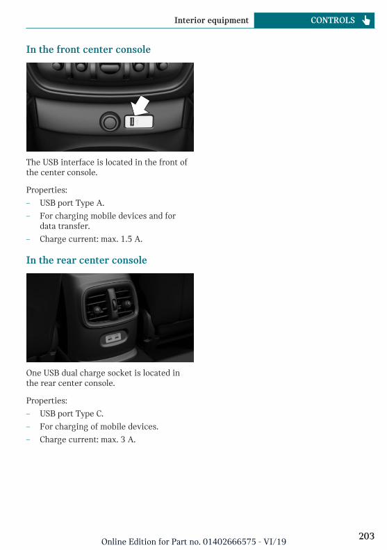
In the front center console
The USB interface is located in the front ofthe center console.
Properties:
– USB port Type A.
– For charging mobile devices and fordata transfer.
– Charge current: max. 1.5 A.
In the rear center console
One USB dual charge socket is located inthe rear center console.
Properties:
– USB port Type C.
– For charging of mobile devices.
– Charge current: max. 3 A.
Seite 203
Interior equipment CONTROLS
203Online Edition for Part no. 01402666575 - VI/19

Storage compartments
Vehicle features and options
This chapter describes all standard, country-specific and optional features offered withthe series. It also describes features that arenot necessarily available in your vehicle, forinstance, due to the selected options orcountry versions. This also applies to safety-related functions and systems. When usingthese functions and systems, the applicablelaws and regulations must be observed.
Safety information
Warning
Loose objects or devices with a cable con-nection to the vehicle, for instance mobilephones, can be thrown into the car's inte-rior while driving, for instance in theevent of an accident or during braking andevasive maneuvers. There is a risk of in-jury. Secure loose objects or devices witha cable connection to the vehicle in thecar's interior.
NOTICE
Anti-slip pads such as anti-slip mats candamage the dashboard. There is a risk ofdamage to property. Do not use anti-slippads.
Overview
The following storage compartments areavailable in the car's interior:
– Glove compartment on the front passen-ger side.
– Compartments in the doors.
– Storage compartment in the center arm-rest.
– Storage compartment in front of the cupholders.
– Clothes hooks
– Storage compartments in the cargo area.
– Storage tray in the center console.
– Pockets on the backrests of the frontseats.
Glove compartment
Safety information
Warning
Folded open, the glove compartment pro-trudes in the car's interior. Objects in theglove compartment can be thrown into thecar's interior while driving, for instance inthe event of an accident or during brakingand evasive maneuvers. There is a risk ofinjury. Always close the glove compart-ment immediately after using it.
Seite 204
CONTROLS Storage compartments
204Online Edition for Part no. 01402666575 - VI/19

Opening
Pull the handle.
The light in the glove compartmentswitches on.
ClosingFold up the cover.
Compartments in the doors
General informationThere are storage compartments in thedoors.
Safety information
Warning
Breakable objects, such as glass bottles orglasses, can break in the event of an acci-dent or a braking or evasive maneuver.Broken glass can be scattered in the car'sinterior. There is a risk of injury or risk ofdamage to property. Do not use any break-able objects while driving. Only stowbreakable objects in closed storage com-partments.
Center armrest
General informationTwo storage compartments are located inthe center armrest.
Opening
Upper storage compartment: press button,arrow 1, and fold the center armrest up, ar-row 2.
Lower storage compartment: press button,arrow 1, and fold the center armrest up, ar-row 2.
Seite 205
Storage compartments CONTROLS
205Online Edition for Part no. 01402666575 - VI/19

Cup holders
Safety information
Warning
Unsuitable containers in the cup holdersmay damage the cup holders or be thrownabout the car’s interior in the event of anaccident, an evasive maneuver, or forcefulbraking. Spilled liquids can distract fromthe traffic conditions and lead to an acci-dent. Hot drinks can damage the cupholder or lead to scalding. There is a riskof injury or risk of damage to property. Donot force objects into the cup holder. Uselightweight, shatterproof, and sealablecontainers. Do not transport hot bever-ages.
Front
In the center console.
Rear
General informationThe cup holder is located in the center arm-rest.
Pull the center armrest forward at the strap.
To open: press the button.
To close: push both covers back in, one afterthe other.
Safety information
NOTICE
With an open cup holder, the center arm-rest cannot be folded back up. There is arisk of damage to property. Press back thecovers before the center armrest is foldedup.
Clothes hooks
General informationThe clothes hooks are located above therear doors.
Safety information
Warning
Clothing articles on the clothes hooks canobstruct the view while driving. There is arisk of accident. When suspending cloth-ing articles from the clothes hooks, ensurethat they will not obstruct the driver'sview.
Seite 206
CONTROLS Storage compartments
206Online Edition for Part no. 01402666575 - VI/19

Warning
Improper use of the clothes hooks can leadto a risk of objects flying about duringbraking and evasive maneuvers. There is arisk of injury and risk of damage to prop-erty. Only hang lightweight objects, for in-stance clothing articles, from the clotheshooks.
Seite 207
Storage compartments CONTROLS
207Online Edition for Part no. 01402666575 - VI/19
Cargo area
Vehicle features and options
This chapter describes all standard, country-specific and optional features offered withthe series. It also describes features that arenot necessarily available in your vehicle, forinstance, due to the selected options orcountry versions. This also applies to safety-related functions and systems. When usingthese functions and systems, the applicablelaws and regulations must be observed.
Loading
Safety information
Warning
High gross weight can overheat the tires,damage them internally and cause a sud-den drop in tire inflation pressure. Drivingcharacteristics may be negatively im-pacted, reducing lane stability, lengthen-ing the braking distances and changingthe steering response. There is a risk ofaccident. Pay attention to the permittedload capacity of the tires and never exceedthe permitted gross weight.
Warning
Loose objects or devices with a cable con-nection to the vehicle, for instance mobilephones, can be thrown into the car's inte-rior while driving, for instance in theevent of an accident or during braking andevasive maneuvers. There is a risk of in-jury. Secure loose objects or devices with
a cable connection to the vehicle in thecar's interior.
Warning
Improperly stowed objects can shift andbe thrown into the car's interior, for in-stance in the event of an accident or dur-ing braking and evasive maneuvers. Vehi-cle occupants can be hit and injured. Thereis a risk of injury. Stow and secure objectsand cargo properly.
NOTICE
Fluids in the cargo area can cause damage.There is a risk of damage to property.Make sure that no fluids leak in the cargoarea.
NOTICE
The cargo floor panel is designed for a par-ticular maximum weight. Weight that istoo high and that is selective can damagethe cargo floor panel. There is a risk ofdamage to property. Do not exceed themaximum load of the cargo area floor andevenly distribute the cargo across thecargo area floor.
The maximum load is 881 lbs / 440 kg.
Steps for Determining Correct LoadLimit1. Locate the statement “The combined
weight of occupants and cargo should
Seite 208
CONTROLS Cargo area
208Online Edition for Part no. 01402666575 - VI/19

never exceed XXX kg or XXX lbs” onyour vehicle’s placard.
2. Determine the combined weight of thedriver and passengers that will be ridingin your vehicle.
3. Subtract the combined weight of thedriver and passengers from XXX kg orXXX lbs
4. The resulting figure equals the availableamount of cargo and luggage load ca-pacity. For example, if the “XXX”amount equals 1,400 lbs and there willbe five 150 lbs passengers in your vehi-cle, the amount of available cargo andluggage load capacity is 650 lbs (1,400 -750 (5 x 150) = 650 lbs)
5. Determine the combined weight of lug-gage and cargo being loaded on the ve-hicle. That weight may not safely exceedthe available cargo and luggage load ca-pacity calculated in Step 4.
6. If your vehicle will be towing a trailer,load from your trailer will be transferredto your vehicle. Consult this manual todetermine how this reduces the availa-ble cargo and luggage load capacity ofyour vehicle.
Load
The maximum load is the sum of the weightof the occupants and the cargo.
The greater the weight of the occupants,the less cargo that can be transported.
Stowing and securing cargo– Cover sharp edges and corners on the
cargo.
– Heavy cargo: stow as far forward as pos-sible, directly behind and at the bottomof the rear passenger seat backrests.
– Very heavy cargo: when the rear seat isnot occupied, secure each of the outersafety belts in the opposite buckle.
– If necessary, fold down the rear back-rests to stow large cargo.
– Do not stack cargo above the top edge ofthe backrests.
Lashing eyes in the cargo area
With cargo area partition net: to secure thecargo there are six lashing eyes in the cargoarea.
Attach load securing aids, such as lashingstraps, tensioning straps, draw straps orcargo nets, to the lashing eyes in the cargoarea.
Seite 209
Cargo area CONTROLS
209Online Edition for Part no. 01402666575 - VI/19

Cargo cover
Safety information
Warning
Loose objects or devices with a cable con-nection to the vehicle, for instance mobilephones, can be thrown into the car's inte-rior while driving, for instance in theevent of an accident or during braking andevasive maneuvers. There is a risk of in-jury. Secure loose objects or devices witha cable connection to the vehicle in thecar's interior.
Closing
NOTICE
A cargo cover hooked in incorrectly cancause damage. There is a risk of damage toproperty. Hook the cargo cover on bothsides.
Pull out the cargo cover, arrow 1, and hookboth sides into the brackets, arrow 2.
Opening
Warning
A cargo cover that snaps back quickly canjam body parts or cause damage. There is arisk of injury or risk of damage to prop-erty. Do not let the cargo cover snap backinto place.
Pull over the cargo cover and hook into thebrackets on both sides.
RemovingFor storing bulky objects the cargo covercan be removed.
Press the release button, arrow 1, and pullthe cargo cover out towards the rear, ar-row 2.
InstallingSlide the cargo cover in until it engages onboth sides with an audible click.
Storage compartments in thecargo area
Side storage compartmentsStorage compartments are located on theleft and right sides.
Seite 210
CONTROLS Cargo area
210Online Edition for Part no. 01402666575 - VI/19

Storage compartments in the splitdoorsThere are storage compartments in the splitdoors.
Multi-function hook
Warning
Improper use of the multi-function hookscan lead to a risk of objects flying aboutduring braking and evasive maneuvers,for example. There is a risk of injury andrisk of damage to property. Only hanglightweight objects, such as shoppingbags, from the multi-function hooks. Onlytransport heavy luggage in the cargo areaif it has been appropriately secured.
A multi-function hook is available on theright side of the cargo area.
Enlarging the cargo area
ConceptThe cargo area can be enlarged as follows:
– The rear seat backrests can be foldeddown.
– The rear seat backrests can be movedinto an upright loading position usingthe cargo setting.
General informationThe rear seat backrest is divided into twoparts at a ratio of 60 to 40. The left rear seatbackrest is connected to the center section.
With through-loading system: the rear seatbackrest is divided into three parts at a40-20-40 ratio. The side rear seat backrestsand the center section can be folded downseparately.
The rear seat backrests can be folded downfrom the rear.
Safety information
Warning
Danger of jamming with folding down thebackrests. There is a risk of injury or riskof damage to property. Make sure that thearea of movement of the rear backrest andthe of the head restraint is clear prior tofolding down.
Warning
If a rear seat backrest is not locked, unse-cured cargo can be thrown about the car’sinterior; for instance, in the event of an ac-cident, braking or an evasive maneuver.There is a risk of injury. Make sure thatthe rear seat backrest is locked after fold-ing it back.
Warning
With a rear backrest that is not locked, theprotective function of the middle safetybelt is not guaranteed. There is a risk ofinjuries or danger to life. If you are usingthe middle safety belt, lock the wider rearseat backrest.
Seite 211
Cargo area CONTROLS
211Online Edition for Part no. 01402666575 - VI/19

Warning
The stability of the child restraint systemis limited or compromised with incorrectseat adjustment or improper installation ofthe child seat. There is a risk of injuries ordanger to life. Make sure that the child re-straint system fits securely against thebackrest. If possible, adjust the backresttilt for all affected backrests and correctlyadjust the seats. Make sure that seats andbackrests are securely engaged or locked.If possible, adjust the height of the headrestraints or remove them.
Warning
Body parts can be jammed when movingthe head restraint. There is a risk of injury.Make sure that the area of movement isclear when moving the head restraint.
Folding down the rear seatbackrest from the rear1. Before the rear seat backrest is folded
down, fold in the center head restraint ifnecessary.
2. Press the switch and pull the rear seatbackrest forward.
Cargo position
ConceptThe rear seat backrests can be moved intoan upright loading position.
Adjusting1. Release the backrest, and tilt it forward.
2. Fold the frame up until it engages.
3. Fold back and engage the rear seatbackrest.
Folding down the center section1. Fold in the middle head restraint.
2. Press the switch and pull the center sec-tion forward.
Folding back the backrestFold up the backrest and press it into thelatch. Make sure that the safety belt is notcaught behind the backrest or in betweenthe backrest and the rear seats.
Seite 212
CONTROLS Cargo area
212Online Edition for Part no. 01402666575 - VI/19

Variable cargo area floor
ConceptWith the variable cargo area floor, the cargoarea can be configured corresponding totransport requirements.
General informationFollow instructions on securing cargo, referto page 208.
Removing the cargo floor panel1. Fold the rear part of the cargo floor
panel upward.
2. Grasp the cargo floor panel in the rearand fold slightly upward.
3. Pull the cargo floor panel backward fromthe brackets.
Proceed in the reverse order to reinstall thecargo area floor.
Folded up position
Safety information
Warning
Improper use of the variable cargo floorpanel can lead to a danger of objects flyingabout during braking and evasive maneu-vers. There is a risk of injury and risk ofdamage to property.
– Do not use the variable cargo floorpanel to separate the cargo area andcar's interior in the sense of a parti-tion net.
– Only use the variable cargo floorpanel in the folded-up position whenthe backrests are folded up andlocked.
– Fold down the variable cargo floorpanel before driving off.
– Always secure cargo against shifting,using straps, belts and lashing eyes,for instance.
Fold up the cargo floor panelFold the rear part of the cargo floor panelupward.
Fold up the cargo floor panel and press be-hind the locks on the left and right, arrow.You've reached the maximum cargo height.
Seite 213
Cargo area CONTROLS
213Online Edition for Part no. 01402666575 - VI/19

214
Online Edition for Part no. 01402666575 - VI/19

DRIVING TIPS
Things to remember when driving .................................................. 216Saving fuel ............................................................................................... 220
215Online Edition for Part no. 01402666575 - VI/19

Things to remember when driving
Vehicle features and options
This chapter describes all standard, country-specific and optional features offered withthe series. It also describes features that arenot necessarily available in your vehicle, forinstance, due to the selected options orcountry versions. This also applies to safety-related functions and systems. When usingthese functions and systems, the applicablelaws and regulations must be observed.
Breaking-in period
General informationMoving parts need to begin working to-gether smoothly.
The following instructions will help you toachieve a long vehicle life and good effi-ciency.
During break-in, do not use the LaunchControl, refer to page 119.
Safety information
Warning
Due to new parts and components, safetyand driver assistance systems can reactwith a delay. There is a risk of accident.After installing new parts or with a newvehicle, drive conservatively and inter-vene early if necessary. Observe the break-in procedures of the respective parts andcomponents.
Engine, transmission, and axledrive
Up to 1,200 miles/2,000 kmDo not exceed the maximum engine androad speed:
– For gasoline engine 4,500 rpm and100 mph/160 km/h.
Avoid full load or kickdown under all cir-cumstances.
From 1,200 miles/2,000 kmThe engine and vehicle speed can graduallybe increased.
TiresTire traction is not optimal due to manufac-turing circumstances when tires are brand-new; they achieve their full traction poten-tial after a break-in time.
Drive conservatively for the first200 miles/300 km.
Brake systemBrake discs and brake pads only reach theirfull effectiveness after ap-prox. 300 miles/500 km. Drive moderatelyduring this break-in period.
ClutchThe function of the clutch reaches its opti-mal level only after a distance driven of ap-prox. 300 miles/500 km. During this break-in period, engage the clutch gently.
Following part replacementThe same break-in procedures should be ob-served if any of the components mentioned
Seite 216
DRIVING TIPS Things to remember when driving
216Online Edition for Part no. 01402666575 - VI/19

above have to be renewed in the course ofthe vehicle's operating life.
General driving notes
Closing split doors
Safety information
Warning
An open split door protrudes from the ve-hicle and can endanger occupants andother road users or damage the vehicle inthe event of an accident, braking or eva-sive maneuvers. In addition, exhaustfumes may enter the car's interior. Thereis a risk of injury or risk of damage toproperty. Do not drive with split doorsopen.
Driving with the split doors openIf nevertheless you need to drive with splitdoors open:
– Close all windows and the glass sunroof.
– Greatly increase the air flow from thevents.
– Drive moderately.
Hot exhaust gas system
Warning
During driving operation, high tempera-tures can occur underneath the vehiclebody, for instance caused by the exhaustgas system. If combustible materials, suchas leaves or grass, come in contact withhot parts of the exhaust gas system, thesematerials can ignite. There is a risk of in-jury or risk of damage to property. Do notremove the heat shields installed andnever apply undercoating to them. Make
sure that no combustible materials cancome in contact with hot vehicle parts indriving operation, idle or during parking.Do not touch the hot exhaust gas system.
Mobile communication devices inthe vehicle
Warning
Vehicle electronics and mobile phones caninfluence one another. There is radiationdue to the transmission operations of mo-bile phones. There is a risk of injury orrisk of damage to property. If possible, inthe car's interior use only mobile phoneswith direct connections to an exterior an-tenna in order to exclude mutual interfer-ence and deflect the radiation from thecar's interior.
HydroplaningOn wet or slushy roads, a wedge of watercan form between the tires and road sur-face.
This phenomenon is referred to as hydro-planing. It is characterized by a partial orcomplete loss of contact between the tiresand the road surface, ultimately undermin-ing your ability to steer and brake the vehi-cle.
Driving through water
General informationWhen driving through water, follow the fol-lowing:
– Drive through calm water only.
– Drive through water only if it is notdeeper than maximum 9.8 inches/25 cm.
– Drive through water no faster thanwalking speed, up to 3 mph/5 km/h.
Seite 217
Things to remember when driving DRIVING TIPS
217Online Edition for Part no. 01402666575 - VI/19

Safety information
NOTICE
When driving too quickly through toodeep water, water can enter into the en-gine compartment, the electrical system orthe transmission. There is a risk of damageto property. When driving through water,do not exceed the maximum indicated wa-ter level and the maximum speed for driv-ing through water.
Braking safely
General informationThe vehicle is equipped with ABS as astandard feature.
Perform an emergency stop in situationsthat require such.
Steering is still responsive. You can stillavoid any obstacles with a minimum ofsteering effort.
Pulsation of the brake pedal and soundsfrom the hydraulic circuits indicate thatABS is in its active mode.
Objects in the area around the pedals
Warning
Objects in the driver's floor area can limitthe pedal distance or block a depressedpedal. There is a risk of accident. Stow ob-jects in the vehicle such that they are se-cured and cannot enter into the driver'sfloor area. Use floor mats that are suitablefor the vehicle and can be safely attachedto the floor. Do not use loose floor matsand do not layer several floor mats. Makesure that there is sufficient clearance forthe pedals. Ensure that the floor mats are
securely fastened again after they were re-moved, for instance for cleaning.
Driving in wet conditionsWhen roads are wet, salted, or in heavyrain, gently press the brake pedal every fewmiles.
Ensure that this action does not endangerother traffic.
The heat generated during braking driesbrake discs and brake pads and protectsthem against corrosion.
In this way braking efficiency will be avail-able when you need it.
Hills
General information
Drive long or steep downhill gradients inthe gear that requires least braking effort.Otherwise, the brakes may overheat and re-duce brake efficiency.
You can increase the engine's braking effectby shifting down, going all the way to firstgear, if needed.
Safety information
Warning
Light but consistent brake pressure canlead to high temperatures, brakes wearingout and possibly even brake failure. Thereis a risk of accident. Avoid placing exces-sive stress on the brake system.
Warning
In idle state or with the engine switchedoff, safety functions, for instance enginebraking effect, braking assistance andsteering assistance, may not be available.There is a risk of accident. Do not attempt
Seite 218
DRIVING TIPS Things to remember when driving
218Online Edition for Part no. 01402666575 - VI/19

to drive in idle state or with the engineswitched off.
Brake disc corrosionCorrosion on the brake discs and contami-nation on the brake pads are increased bythe following circumstances:
– Low mileage.
– Extended periods when the vehicle isnot used at all.
– Infrequent use of the brakes.
– Aggressive, acidic, or alkaline cleaningagents.
Corrosion buildup on the brake discs willcause a pulsating effect on the brakes intheir response - generally this cannot becorrected.
Condensation water under theparked vehicleWhen using the automatic climate control,condensation water develops and collectsunderneath the vehicle.
Ground clearance
NOTICE
If the ground clearance is insufficient, e.g.,curbs or underground garage entrances,contact with vehicle parts, e.g., spoiler,and the underbody may occur. There is arisk of damage to property. Ensure thatthere is sufficient ground clearance availa-ble.
Roof-mounted luggage rack
General informationInstallation only possible with roof rack.
Roof racks are available as special accesso-ries.
SecuringFollow the installation instructions of theroof rack.
LoadingBecause roof-mounted luggage racks raisethe vehicle's center of gravity when loaded,they have a major effect on vehicle handlingand steering response.
Therefore, note the following when loadingand driving:
– Do not exceed the approved roof/axleloads and the approved gross vehicleweight.
– Be sure that adequate clearance is main-tained for tilting and opening the glasssunroof.
– Distribute the roof load uniformly.
– The roof load should not extend past theloading area.
– Always place the heaviest pieces on thebottom.
– Secure the roof luggage firmly, for in-stance using ratchet straps.
– Drive cautiously and avoid sudden ac-celeration and braking maneuvers. Takecorners gently.
Driving on racetracks
Higher mechanical and thermal loads duringracetrack operation lead to increased wear.This wear is not covered by the warranty.The vehicle is not designed for use in motorsports competition.
Seite 219
Things to remember when driving DRIVING TIPS
219Online Edition for Part no. 01402666575 - VI/19

Saving fuel
Vehicle features and options
This chapter describes all standard, country-specific and optional features offered withthe series. It also describes features that arenot necessarily available in your vehicle, forinstance, due to the selected options orcountry versions. This also applies to safety-related functions and systems. When usingthese functions and systems, the applicablelaws and regulations must be observed.
General information
The vehicle contains advanced technologiesfor the reduction of consumption and emis-sion values.
Fuel consumption depends on a number ofdifferent factors.
The implementation of certain measures,driving style and regular maintenance caninfluence fuel consumption and environ-mental impact.
Remove unnecessary cargo
Additional weight increases fuel consump-tion.
Remove attached parts follow-ing use
Remove auxiliary mirrors, roof-mounted orrear luggage racks which are no longer re-quired following use.
Attached parts on the vehicle impair theaerodynamics and increase the fuel con-sumption.
Close the windows and glasssunroof
Driving with the glass sunroof and windowsopen results in increased air resistance andraises fuel consumption.
Tires
General informationTires can affect consumption in variousways, for instance tire size may influenceconsumption.
Check the tire inflation pressureregularlyCheck and, if needed, correct the tire infla-tion pressure at least twice a month and be-fore starting on a long trip.
Low tire inflation pressure increases rollingresistance and thus raises fuel consumptionand tire wear.
Drive away without delay
Do not wait for the engine to warm-upwhile the vehicle remains stationary. Startdriving right away, but at moderate enginespeeds.
This is the fastest way for the cold engineto reach its operating temperature.
Seite 220
DRIVING TIPS Saving fuel
220Online Edition for Part no. 01402666575 - VI/19

Look well ahead when driving
Driving smoothly and proactively reducesfuel consumption.
Avoid unnecessary acceleration and brak-ing.
By maintaining a suitable distance to thevehicle driving ahead of you.
Avoid high engine speeds
Driving at low engine speeds lowers fuelconsumption and reduces wear.
If necessary, observe the vehicle's gear shiftindicator, refer to page 128.
Use coasting conditions
When approaching a red light, take yourfoot off the accelerator and let the vehiclecoast to a halt.
For going downhill take your foot off the ac-celerator and let the vehicle roll.
The flow of fuel is interrupted while coast-ing.
Switch off the engine duringlonger stops
Switching off the engineSwitch off the engine during longer stops,for instance at traffic lights, railroad cross-ings or in traffic congestion.
Auto Start/Stop functionThe Auto Start/Stop function of the vehicleautomatically switches off the engine dur-ing a stop.
If the engine is switched off and then re-started rather than leaving the engine run-ning constantly, fuel consumption and emis-sions are reduced. Savings can begin withina few seconds of switching off the engine.
In addition, fuel consumption is also deter-mined by other factors, such as drivingstyle, road conditions, maintenance or envi-ronmental factors.
Switch off any functions thatare not currently needed
Functions such as seat heating and the rearwindow defroster require a lot of energyand consume additional fuel, especially incity and stop-and-go traffic.
Switch off these functions if they are notneeded.
Have maintenance carried out
Have the vehicle maintained regularly toachieve optimal vehicle efficiency and serv-ice life. MINI recommends that mainte-nance work be performed by a MINI servicecenter.
Also note the MINI maintenance systems,refer to page 289.
GREEN Mode
ConceptGREEN Mode supports a driving style thatsaves on consumption. For this purpose, theengine control and comfort features, for in-stance the climate control output, are ad-justed.
For Steptronic transmission:
Seite 221
Saving fuel DRIVING TIPS
221Online Edition for Part no. 01402666575 - VI/19

Under certain conditions the engine is auto-matically decoupled from the transmissionin the D selector lever position. The vehiclecontinues traveling with the engine idlingto reduce consumption. The D selector leverposition remains engaged.
In addition, context-sensitive instructionsare displayed to assist with an efficientdriving style.
The achieved extended range is displayed inthe instrument cluster as bonus range.
General informationThe system includes the following functionsand displays:
– GREEN bonus range, refer to page 223.
– GREEN tip, driving instruction, refer topage 223.
– GREEN climate control, refer topage 222.
– Coasting driving condition, refer topage 224.
Activating GREEN ModePress the MINI Driving Modesswitch downward untilGREEN is displayed in the in-strument cluster.
Configuring GREEN
Via MINI Driving Modes switch1. Activating GREEN Mode.
2. "Configure GREEN"
3. Select the desired setting.
Via the Central Information Display(CID)1. "My MINI"
2. "Vehicle settings"
3. If necessary, "Driving mode"
4. "Configure GREEN"
5. Select the desired setting.
Activating/deactivating the functionsThe following functions can be activated/deactivated:
– "GREEN speed warning"
– "GREEN climate control"
– "Coasting"
Settings are stored for the driver profilecurrently used.
GREEN Limit– Activate the GREEN Limit:
"GREEN speed warning":
A GREEN tip is displayed if the speed ofthe set GREEN Limit is exceeded.
– Setting the speed for the GREEN Limit:
"Tip at:"
Select the desired speed.
GREEN climate controlClimate control is set to be efficient.
By making a slight change to the set tem-perature, or adjusting the rate of heating orcooling of the car's interior consumptioncan be economized.
The power output to the seat heater and ex-terior mirror is reduced.
CoastingEfficiency can be optimized by disengagingthe engine and coasting, refer to page 224,with the engine idling.
This function is only available in GREENMode.
Deactivate the function to use the brakingeffect of the engine when traveling down-hill.
Seite 222
DRIVING TIPS Saving fuel
222Online Edition for Part no. 01402666575 - VI/19

GREEN potential savingsShows potential savings with the currentsettings in percentages.
Display in the instrument cluster
GREEN bonus range
A modified driving style helpsyou extend your driving range.
The range extension can bedisplayed as the bonus rangein the instrument cluster.
The bonus range is shown in the range dis-play.
The bonus range is automatically reset ev-ery time the vehicle is refueled.
– Green display: efficient driving style.
– Gray display: modify driving style, forinstance by backing off the acceleratorpedal.
Efficiency display
A bar display in the instru-ment cluster indicates yourcurrent driving efficiency.
Mark in the left area, arrow 1:display for energy recovered
by coasting or when braking.
Mark in the right area, arrow 2: displaywhen accelerating.
The efficiency of your driving style isshown by the position of the mark:
– Mark inside the green range: efficientdriving style.
– Mark outside the green range: modifydriving style, for example by backing offthe accelerator.
GREEN tip, driving instruction
The GREEN tip indicates that your drivingstyle can be modified to be more efficient,for example by backing off the accelerator.
Activating/deactivating the displayActivate information relating to the drivingstyle and GREEN tips in the instrumentcluster using the Central Information Dis-play (CID):
1. "My MINI"
2. "System settings"
3. "Displays"
4. "Instrument panel"
5. "GREEN info"
GREEN tip, symbolsAn additional symbol and text instructionsare displayed.
Symbol Measure
For an efficient driving style,look well ahead when driving,accelerate conservatively, anddelay accelerating.
Reduce speed to the selectedGREEN speed.
Steptronic transmission:
Switch from M/S to D and avoidmanual shift interventions.
Seite 223
Saving fuel DRIVING TIPS
223Online Edition for Part no. 01402666575 - VI/19

Symbol Measure
Manual transmission:
Follow the shift instructions.
Manual transmission:
Engage neutral for an enginestop.
Coasting
ConceptThe function helps to conserve fuel.
To do this, under certain conditions the en-gine is automatically decoupled from thetransmission when selector lever position Dis set. The vehicle continues traveling withthe engine idling to reduce consumption.Selector lever position D remains engaged.
This driving condition is referred to ascoasting.
As soon as you step on the brake or acceler-ator pedal, the engine is automatically cou-pled again.
General informationCoasting is a component of the GREEN driv-ing mode.
Coasting is automatically activated whenthe GREEN driving mode is called via theMINI Driving Modes switch, refer topage 164.
A proactive driving style helps the driver touse the function often and supports the effi-cient effect of coasting.
Functional requirementsThe function is available in the speed rangefrom approx. 15 mph/25 km/h up to100 mph/160 km/h.
– Accelerator pedal and brake pedal arenot operated.
– The selector lever is in selector lever po-sition D.
– Engine and transmission are at operat-ing temperature.
– With a camera in the area of the interiormirror: the system does not detect anyvehicles ahead of you.
Operation via shift paddles
Concept
Depending on your vehicle's equipment, thecoasting mode can be influenced with theshift paddles.
Activating/deactivating coasting via shiftpaddles
1. Shift to the highest gear by pulling theright shift paddle.
2. To activate coasting mode, actuate theright shift paddle again.
To deactivate, actuate the left shift paddle.
Display
Display in the instrument cluster
The bar display below thetachometer is filled in greenand the mark appears at thezero point. The tachometershows the idle speed.
System limitsThe function is not available if one of thefollowing conditions applies:
– DSC OFF and TRACTION are activated.
– Cruise control is activated.
– If driving in the dynamic limit range.
– If driving on steep uphill or downhillgrades.
Seite 224
DRIVING TIPS Saving fuel
224Online Edition for Part no. 01402666575 - VI/19

– The battery charge state is temporarilytoo low.
– The vehicle electrical system is drawingexcessive current.
Seite 225
Saving fuel DRIVING TIPS
225Online Edition for Part no. 01402666575 - VI/19

226
Online Edition for Part no. 01402666575 - VI/19

ENTERTAINMENT
General information .............................................................................. 228Tone ........................................................................................................... 230Radio .......................................................................................................... 232Audio ......................................................................................................... 240
227Online Edition for Part no. 01402666575 - VI/19

General information
Vehicle features and options
This chapter describes all standard, country-specific and optional features offered withthe series. It also describes features that arenot necessarily available in your vehicle, forinstance, due to the selected options orcountry versions. This also applies to safety-related functions and systems. When usingthese functions and systems, the applicablelaws and regulations must be observed.
Control elements
1 Waveband/satellite radio
2 Change entertainment sources
3 Sound output on/off, volume
4 Changing the station/track
5 Programmable memory buttons
Sound output
Safety information
Warning
A high sound output volume can damageyour hearing. There is a risk of injury. Donot adjust the volume too high.
Volume and sound output– Turn the button to adjust the vol-
ume.
– Press the button to switch off thesound output. Pressing the but-ton again restores the previousvolume setting.
Audio recording playback is stopped duringmuting.
Entertainment sources
General informationPossible entertainment sources:
– Radio, refer to page 232.
– USB audio, refer to page 240.
– Bluetooth audio, refer to page 240.
Changing the entertainment sourceOn the radio:
1. Press the button.
A list of all currently available entertain-ment sources is displayed.
Seite 228
ENTERTAINMENT General information
228Online Edition for Part no. 01402666575 - VI/19

2. Press the button again to selectan entertainment source.
Via the Central Information Display (CID):
1. "Media/Radio"
A list of all possible entertainment sour-ces is displayed.
2. Select the desired entertainment source.
Via the button on the Controller:
1. Press the button.
The most recently selected entertain-ment source is played.
2. Press the button again.
A list of all currently available entertain-ment sources is displayed.
3. Select the desired entertainment source.
Adjusting the selection list ofentertainment sourcesIt is possible to select which entertainmentsources are displayed in the selection list.The entertainment source currently beingplayed cannot be removed from the selec-tion list.
1. "Media/Radio"
A list of all possible entertainment sour-ces is displayed.
2. "Personalize menu"
3. Select the desired setting.
Seite 229
General information ENTERTAINMENT
229Online Edition for Part no. 01402666575 - VI/19

Tone
Vehicle features and options
This chapter describes all standard, country-specific and optional features offered withthe series. It also describes features that arenot necessarily available in your vehicle, forinstance, due to the selected options orcountry versions. This also applies to safety-related functions and systems. When usingthese functions and systems, the applicablelaws and regulations must be observed.
General information
The settings are stored in the currentlyused driver profile.
Treble, bass, balance, andfader
1. "Media/Radio"
2. "Tone"
3. Select the desired setting:
– "Treble": treble adjustment.
– "Bass": depth adjustment.
– "Balance": left/right volume distribu-tion.
– "Fader": front/rear volume distribu-tion.
4. To adjust: turn the Controller.
5. To store: press the Controller.
Volume equalization
ConceptAn automatic increase of the volume can beset to compensate for the increasing drivingnoises at higher speeds.
Set automatic volume increase1. "Media/Radio"
2. "Tone"
3. "Volume settings"
4. Select the desired setting:
– "Speed volume": ratio of entertain-ment volume to speed.
– "PDC": ratio of the volume of the PDCsignal tone to the entertainment vol-ume.
The basic setting ensures that thesignal tone is audible at any volume.
– "Gong": ratio of the volume of thesignal tone, for instance for safetybelt reminder, to the entertainmentvolume.
The basic setting ensures that thesignal tone is audible at any volume.
– "Microphone": sensitivity of the mi-crophone during a phone call.
The setting is adjusted while callingand is stored for the mobile phoneused.
– "Speakers": volume of the loudspeak-ers during a phone call.
Audio recording playback is stoppedduring muting.
The setting is adjusted while callingand is stored for the mobile phoneused.
Seite 230
ENTERTAINMENT Tone
230Online Edition for Part no. 01402666575 - VI/19

Reset the tone settings
The tone settings are reset to the factorysettings.
1. "Media/Radio"
2. "Tone"
3. "Reset"
Seite 231
Tone ENTERTAINMENT
231Online Edition for Part no. 01402666575 - VI/19

Radio
Vehicle features and options
This chapter describes all standard, country-specific and optional features offered withthe series. It also describes features that arenot necessarily available in your vehicle, forinstance, due to the selected options orcountry versions. This also applies to safety-related functions and systems. When usingthese functions and systems, the applicablelaws and regulations must be observed.
General information
The settings are stored in the currentlyused driver profile.
AM/FM station
General informationDepending on the vehicle equipment andcountry version, it may not be possible toreceive AM stations.
Radio Data System RDS
ConceptRDS broadcasts additional information,such as the station name, in the FM wave-band.
It is recommended to switch on RDS.
Switching on/off1. "Media/Radio"
2. "FM"
3. Press the button.
4. "RDS"
Selecting a station1. "Media/Radio"
2. "FM" or "AM"
The last station listened to will beplayed and the station list displayed.
3. Select the desired station.
Changing the stationOn the radio:
Press the left or right button.
The previous or next station from the list ofstations is played.
Storing a station
General informationA symbol on the highlighted channel indi-cates whether the channel has already beenstored.
Symbol Meaning
Station is not stored.
Station is already stored.
Storing the station being played1. "Media/Radio"
2. "FM" or "AM"
3. Move the Controller to the left.
4. "Save station"
The storage list is displayed.
5. Select the desired memory location.
Seite 232
ENTERTAINMENT Radio
232Online Edition for Part no. 01402666575 - VI/19

Storing a station that is not beingplayed1. "Media/Radio"
2. "FM" or "AM"
3. Highlight the desired station.
4. Press the Controller and hold until thestorage list is displayed.
5. Select the desired memory location.
The stations can also be stored on the pro-grammable memory buttons, refer topage 46.
Selecting a station manuallyStation selection via the frequency.
1. "Media/Radio"
2. "FM" or "AM"
3. Move the Controller to the left.
4. "Manual search"
5. To select the frequency: turn the Con-troller.
6. To store the frequency: press the Con-troller.
Renaming a stationWhen storing a station with RDS signal, theRDS information transferred during storingis accepted as the station name. The stationname can be changed.
1. "Media/Radio"
2. "FM"
3. Select the desired station.
4. Press the button.
5. "Rename to:"
If necessary, wait until the name of thedesired station appears.
6. Press the Controller to store this name.
Additional station information
ConceptIf a radio station broadcasts radio text orradio text plus, this information can be dis-played, for instance the track or performerof the music. Availability, content and se-quence are set by the radio station.
Displaying additional stationinformation1. "Media/Radio"
2. "FM"
3. Select the desired station.
4. Press the button.
5. "Station info"
HD Radio™ reception
ConceptMany radio stations broadcast both analogand digital signals.
General informationWhen setting a station with a digital signal,it may take a few seconds before the stationplays in digital quality.
Information about HD Radio stations whosestation name ends with ...HD or with ...HD1:
In areas in which the station is not continu-ously received in digital mode, the playbackswitches between analog and digital recep-tion. In this case, switch off digital radio re-ception.
Information about HD Radio multicast sta-tions whose station name endswith ...HD2, ...HD3, ...:
In areas in which the station is not continu-ously received in digital mode, there may beinterruptions of the audible signal lasting
Seite 233
Radio ENTERTAINMENT
233Online Edition for Part no. 01402666575 - VI/19

several seconds. The duration of the inter-ruption depends on the reception.
Activating/deactivating digital radioreception1. "Media/Radio"
2. "FM" or "AM"
Depending on the vehicle equipmentand country version, it may not be possi-ble to receive AM stations.
3. Press the button.
4. "HD Radio reception"
This symbol is displayed in the statusline when the audio signal is digital.
Displaying additional informationSome stations broadcast additional informa-tion on the current track, such as the nameof the artist.
1. "Media/Radio"
2. "FM" or "AM"
Depending on the vehicle equipmentand country version, it may not be possi-ble to receive AM stations.
3. Select a station.
4. Press the button.
5. "Station info"
License conditionsHD Radio Technology manu-factured under license from
iBiquity Digital Corporation. U. S. and For-eign Patents. HD Radio™ and the HD, HDRadio, and “Arc” logos are proprietarytrademarks of iBiquity Digital Corp.
Satellite radio
General informationBefore a channel can be played, you mustsubscribe to it via telephone. Several chan-nels can be combined into specified pack-ages.
Managing a subscription
General informationIn order to enable or unsubscribe fromchannels, you must have reception. It isusually at its best when you have an unob-structed view of the sky. The channel nameis displayed in the status line.
Enabling channels1. "Media/Radio"
2. "Satellite radio"
3. Press the button.
4. "Show subscription info"
The phone number and identificationnumber of the radio are displayed.
5. Call the phone number to have the chan-nel enabled.
You can unsubscribe from the channelsagain via this phone number.
Unsubscribing from channels1. "Media/Radio"
2. "Satellite radio"
3. Press the button.
4. "Show subscription info"
The phone number and identificationnumber of the radio are displayed.
5. Call the phone number to cancel yoursubscription to the channel.
Seite 234
ENTERTAINMENT Radio
234Online Edition for Part no. 01402666575 - VI/19

Selecting channelsYou can only listen to enabled channels.
1. "Media/Radio"
2. "Satellite radio"
The last channel played will be playedback and the channel list displayed.
3. Select the desired channel from thechannel list.
To display information about the selectedchannel:
1. Highlight a channel.
2. Press the button.
3. "Channel information"
Adjusting display of the channellistThe display of the playback list can be ad-justed.
1. "Media/Radio"
2. "Satellite radio"
3. Move the Controller to the left.
4. "Change view"
5. Select the desired display:
– "Channel"
The name of the channel will be dis-played.
– "Artist"
The name of the artist playing willbe displayed.
– "Titles"
The name of the track playing will bedisplayed.
Changing the channelPress the button on the radio.
The next and/or previous channel from thechannel list is played.
Storing a channel1. "Media/Radio"
2. "Satellite radio"
A symbol on the highlighted channel indi-cates whether the channel has already beenstored.
Symbol Meaning
Channel is not stored.
Channel is already stored.
To store the channel played:
1. Move the Controller to the left.
2. "Save station"
The storage list is displayed.
3. Select the desired memory location.
Or:
1. Highlight the played channel.
2. Press the Controller.
The storage list is displayed.
3. Select the desired memory location.
To store a channel other than the oneplayed:
1. Highlight the desired channel.
2. Press the Controller and hold until thestorage list is displayed.
3. Select the desired memory location.
Or:
1. Highlight the desired channel.
2. Press the button.
3. "Save in presets"
The storage list is displayed.
4. Select the desired memory location.
Seite 235
Radio ENTERTAINMENT
235Online Edition for Part no. 01402666575 - VI/19
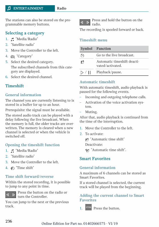
The stations can also be stored on the pro-grammable memory buttons.
Selecting a category1. "Media/Radio"
2. "Satellite radio"
3. Move the Controller to the left.
4. "Category"
5. Select the desired category.
The subscribed channels from this cate-gory are displayed.
6. Select the desired channel.
Timeshift
General informationThe channel you are currently listening to isstored in a buffer for up to an hour.
Prerequisite: the signal must be available.
The stored audio track can be played with adelay following the live broadcast. Whenthe memory is full, the older tracks are over-written. The memory is cleared when a newchannel is selected or when the vehicle isswitched off.
Opening the timeshift function1. "Media/Radio"
2. "Satellite radio"
3. Move the Controller to the left.
4. "Time shift"
Time shift forward/reverseWithin the stored recording, it is possibleto jump to any point in time.
Press the button on the radio orturn the Controller.
You can jump to the next or the previoustrack.
Press and hold the button on theradio.
The recording is spooled forward or back.
Timeshift menu
Symbol Function
Go to the live broadcast.
Automatic timeshift deacti-vated/activated.
/ Playback/pause.
Automatic timeshiftWith automatic timeshift, audio playback ispaused for the following events.
– Incoming and outgoing telephone calls.
– Activation of the voice activation sys-tem.
– Muting.
After that, audio playback is continued fromthe time of the interruption.
1. Move the Controller to the left.
2. To activate:
"Automatic time shift"
Deactivate:
"Automatic time shift".
Smart Favorites
General informationA maximum of 6 channels can be stored asSmart Favorites.
If a stored channel is selected, the currenttrack will be played from the beginning.
Adding the current channel to SmartFavorites
1. Press the button.
Seite 236
ENTERTAINMENT Radio
236Online Edition for Part no. 01402666575 - VI/19
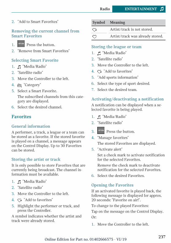
2. "Add to Smart Favorites"
Removing the current channel fromSmart Favorites
1. Press the button.
2. "Remove from Smart Favorites"
Selecting Smart Favorite1. "Media/Radio"
2. "Satellite radio"
3. Move the Controller to the left.
4. "Category"
5. Select a Smart Favorite.
The subscribed channels from this cate-gory are displayed.
6. Select the desired channel.
Favorites
General informationA performer, a track, a league or a team canbe stored as a favorite. If the stored favoriteis played on a channel, a message appearson the Control Display. Up to 30 Favoritescan be stored.
Storing the artist or trackIt is only possible to store Favorites that arecurrently being broadcast. The channel in-formation must be available.
1. "Media/Radio"
2. "Satellite radio"
3. Move the Controller to the left.
4. "Add to favorites"
5. Highlight the performer or track, andpress the Controller.
A symbol indicates whether the artist andtrack were already stored.
Symbol Meaning
Artist/track is not stored.
Artist/track was already stored.
Storing the league or team1. "Media/Radio"
2. "Satellite radio"
3. Move the Controller to the left.
4. "Add to favorites"
5. "Add sports information"
6. Select the type of sport desired.
7. Select the desired team.
Activating/deactivating a notificationA notification can be displayed when a se-lected favorite is being played.
1. "Media/Radio"
2. "Satellite radio"
3. Press the button.
4. "Manage favorites"
The stored Favorites are displayed.
5. "Activate alert"
Set a check mark to activate notificationfor the selected Favorites.
Remove the check mark to deactivatenotification for the selected Favorites.
6. Select the desired Favorites.
Opening the FavoritesIf an activated favorite is played back, thefollowing message is displayed for approx.20 seconds: "Favorite on air!".
To change to the played Favorites:
Tap on the message on the Control Display.
Or:
1. Move the Controller to the left.
Seite 237
Radio ENTERTAINMENT
237Online Edition for Part no. 01402666575 - VI/19

2. "Favorite alert"
Select the symbol while the message isshown.
The displayed favorite is played.
When the message disappears, the list ofchannels that is currently playing one of thestored Favorites can be displayed.
1. Move the Controller to the left.
2. "Category"
3. Select the Favorites list.
The channels that are currently playinga favorite are displayed.
4. Select the channel that you would like tochange to.
Deleting Favorites1. "Media/Radio"
2. "Satellite radio"
3. Press the button.
4. "Manage favorites"
The stored Favorites are displayed.
5. Highlight the desired favorites.
6. Press the button.
7. "Delete entry"
Traffic Jump
General informationTraffic and weather information for a se-lected region is broadcast every few mi-nutes.
Selecting a region1. "Media/Radio"
2. "Satellite radio"
3. Press the button.
4. "Configure jump"
5. Select the desired region.
Activating/deactivating Traffic JumpYou must have reception in order to acti-vate or deactivate.
1. "Media/Radio"
2. "Satellite radio"
3. Press the button.
4. "Configure jump"
5. "Jump to:"
Place a check mark to activate TrafficJump.
Information for the selected region isbroadcast as soon as it is available.
Remove the check mark to deactivateTraffic Jump.
Channel magazineIn the channel magazine, the current andsubsequent program for each channelbooked is displayed.
1. "Media/Radio"
2. "Satellite radio"
3. Move the Controller to the left.
4. "SiriusXM program guide"
Automatic updateAbout twice a year, Sirius performs an up-date of the channel names and positions.The update takes place automatically andmay take several minutes.
System limits– Reception may not be available in some
situations, such as under certain envi-ronmental or topographical conditions.The satellite radio has no influence onthis.
Seite 238
ENTERTAINMENT Radio
238Online Edition for Part no. 01402666575 - VI/19

– Graphical contents can be received un-der certain circumstances.
– The signal may not be available in tun-nels or underground garages next to tallbuildings or near trees, mountains orother powerful sources of radio interfer-ence.
Stored stations
General informationUp to 40 stations can be stored.
Selecting a station1. "Media/Radio"
2. "Presets"
3. Select the desired station.
Deleting a station1. "Media/Radio"
2. "Presets"
3. Highlight the station you want to delete.
4. Press the button.
5. "Delete entry"
Seite 239
Radio ENTERTAINMENT
239Online Edition for Part no. 01402666575 - VI/19

Audio
Vehicle features and options
This chapter describes all standard, country-specific and optional features offered withthe series. It also describes features that arenot necessarily available in your vehicle, forinstance, due to the selected options orcountry versions. This also applies to safety-related functions and systems. When usingthese functions and systems, the applicablelaws and regulations must be observed.
General information
Music tracks, audio books, and podcasts canbe played back. Sound is played backthrough the vehicle loudspeakers.
Settings are stored for the driver profilecurrently used.
Depending on the vehicle equipment, thefollowing audio sources can be used:
Symbol Meaning
USB storage device.
Bluetooth audio.
USB storage device
Playable formatsPopular audio formats such as MP3, AAC orWMA can be played.
Apple iPod/iPhoneThe music search and playback of AppleiPod/iPhone are supported.
Audio player and storage mediawith USB portInformation on all music tracks, for instanceartist, genre or track, as well as playbacklists, are transmitted into the vehicle. Thismay take some time, depending on the USBstorage device, file size, and number oftracks.
During the transfer, the tracks can be calledup via the file directory.
The information for approx. 10,000 trackscan be stored in the vehicle.
Music tracks with integrated Digital RightsManagement DRM cannot be played.
Selecting the USB storage deviceInformation on the USB interface, refer topage 202.
1. Connect the USB storage device to theUSB interface.
The adapter cable supplied with the USBstorage device would be ideal.
2. "Media/Radio"
3. "USB"
Or:
Select the name of the USB storage de-vice.
Further playback descriptions, refer topage 241.
Bluetooth audio
General information– Playback of music files on external devi-
ces such as audio devices or mobilephones via Bluetooth.
Seite 240
ENTERTAINMENT Audio
240Online Edition for Part no. 01402666575 - VI/19
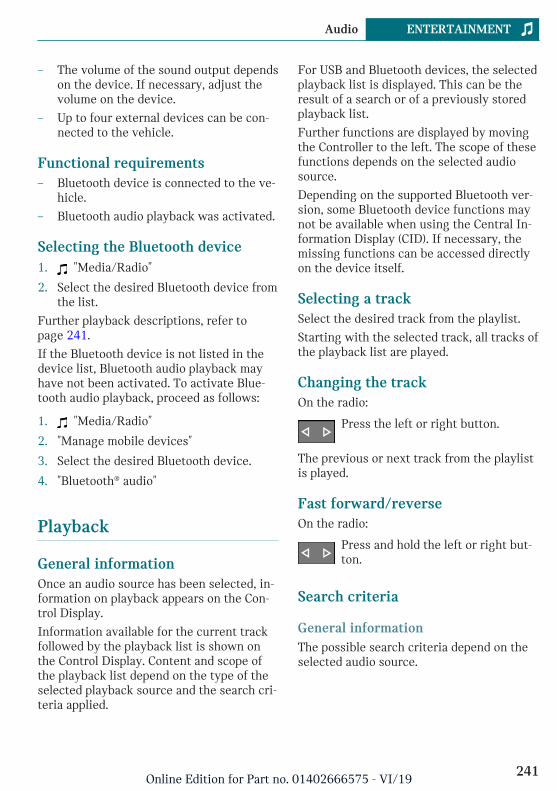
– The volume of the sound output dependson the device. If necessary, adjust thevolume on the device.
– Up to four external devices can be con-nected to the vehicle.
Functional requirements– Bluetooth device is connected to the ve-
hicle.
– Bluetooth audio playback was activated.
Selecting the Bluetooth device1. "Media/Radio"
2. Select the desired Bluetooth device fromthe list.
Further playback descriptions, refer topage 241.
If the Bluetooth device is not listed in thedevice list, Bluetooth audio playback mayhave not been activated. To activate Blue-tooth audio playback, proceed as follows:
1. "Media/Radio"
2. "Manage mobile devices"
3. Select the desired Bluetooth device.
4. "Bluetooth® audio"
Playback
General informationOnce an audio source has been selected, in-formation on playback appears on the Con-trol Display.
Information available for the current trackfollowed by the playback list is shown onthe Control Display. Content and scope ofthe playback list depend on the type of theselected playback source and the search cri-teria applied.
For USB and Bluetooth devices, the selectedplayback list is displayed. This can be theresult of a search or of a previously storedplayback list.
Further functions are displayed by movingthe Controller to the left. The scope of thesefunctions depends on the selected audiosource.
Depending on the supported Bluetooth ver-sion, some Bluetooth device functions maynot be available when using the Central In-formation Display (CID). If necessary, themissing functions can be accessed directlyon the device itself.
Selecting a trackSelect the desired track from the playlist.
Starting with the selected track, all tracks ofthe playback list are played.
Changing the trackOn the radio:
Press the left or right button.
The previous or next track from the playlistis played.
Fast forward/reverseOn the radio:
Press and hold the left or right but-ton.
Search criteria
General informationThe possible search criteria depend on theselected audio source.
Seite 241
Audio ENTERTAINMENT
241Online Edition for Part no. 01402666575 - VI/19

Searching for track informationThe following search criteria refer to thedata stored in the track information.
1. Move the Controller to the left.
2. "Media search"
3. Select the desired setting:
– "Search"
All the tracks containing the searchstring are displayed. Entering morecharacters will continue to narrowdown the search results.
Tilt the Controller to the right to dis-play the list of results.
– "Genres"
A list of all available genres is dis-played.
Select a genre to display all respec-tive artists.
– "Artists"
A list of all available artists is dis-played.
Select an artist to display all respec-tive albums and tracks.
– "Albums"
A list of all available albums is dis-played.
Select an album to display all respec-tive tracks.
– "Titles"
A list of all available tracks is dis-played.
4. Select album, if needed.
5. Select the track at which the playback isgoing to begin.
The search for artists and titles can also beselected directly.
1. Move the Controller to the left.
2. "Artists" or "Titles"
Tracks where the selected search criterionis not stored are summarized under "un-known". Tracks without track informationcan only be found via the directory struc-ture.
Search playlists1. Move the Controller to the left.
2. "Media search"
3. "Playlists"
A list of all available playback lists isdisplayed.
4. Select the playback list.
5. Select the track at which the playback isgoing to begin.
Information on playback appears on theControl Display. A playback list is cre-ated from the search results.
Search audio books and podcastsDepending on the USB storage device andequipment, separate audio book and podcastsearches are possible.
1. Move the Controller to the left.
2. "Media search"
3. Select the desired setting:
– "Podcasts"
A list of all available podcasts is dis-played.
– "Audio books"
A list of all available audio books isdisplayed.
4. Select the track at which the playback isgoing to begin.
Information on playback appears on theControl Display. A playback list is cre-ated from the search results.
Seite 242
ENTERTAINMENT Audio
242Online Edition for Part no. 01402666575 - VI/19
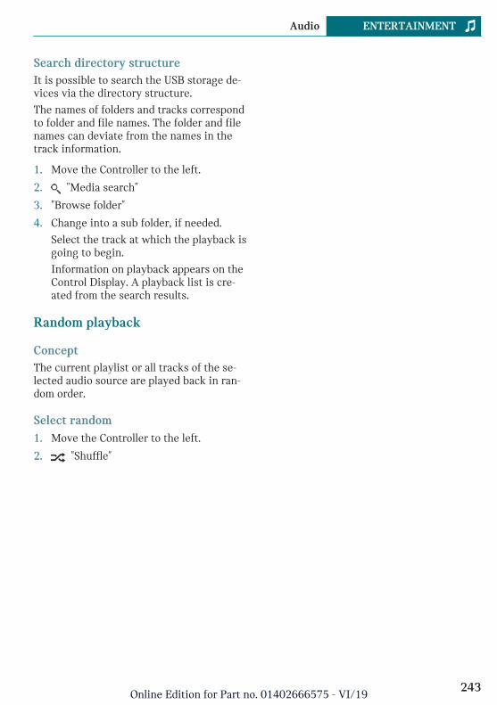
Search directory structureIt is possible to search the USB storage de-vices via the directory structure.
The names of folders and tracks correspondto folder and file names. The folder and filenames can deviate from the names in thetrack information.
1. Move the Controller to the left.
2. "Media search"
3. "Browse folder"
4. Change into a sub folder, if needed.
Select the track at which the playback isgoing to begin.
Information on playback appears on theControl Display. A playback list is cre-ated from the search results.
Random playback
ConceptThe current playlist or all tracks of the se-lected audio source are played back in ran-dom order.
Select random1. Move the Controller to the left.
2. "Shuffle"
Seite 243
Audio ENTERTAINMENT
243Online Edition for Part no. 01402666575 - VI/19

244
Online Edition for Part no. 01402666575 - VI/19

COMMUNICATION
Telephone ................................................................................................. 246MINI Connected ..................................................................................... 250
245Online Edition for Part no. 01402666575 - VI/19

Telephone
Vehicle features and options
This chapter describes all standard, country-specific and optional features offered withthe series. It also describes features that arenot necessarily available in your vehicle, forinstance, due to the selected options orcountry versions. This also applies to safety-related functions and systems. When usingthese functions and systems, the applicablelaws and regulations must be observed.
Telephone functions
General informationMobile phones can be connected to the ve-hicle via Bluetooth. Pair and connect themobile phone with the vehicle, refer topage 51.
At high temperatures, the charge functionof the mobile phone can be limited whereappropriate and functions are no longer exe-cuted.
Do not operate a mobile phone that is con-nected to the vehicle on the mobile phonekeypad, as this may lead to a malfunction.
When the mobile phone is used via the ve-hicle, refer to the owner's manual of the mo-bile phone.
Safety information
Warning
Operating the integrated information sys-tems and communication devices whiledriving can distract from traffic. It is pos-sible to lose control of the vehicle. There isa risk of accident. Only use the systems or
devices when the traffic situation allows.As warranted, stop and use the systemsand devices while the vehicle is stationary.
Incoming callIf the number of the caller is stored in thephone book and is transmitted by the net-work, the name of the contact is displayed.Otherwise, only the phone number is dis-played.
Accepting a callIncoming calls can be answered in severalways.
– Via Central Information Display (CID):
"Accept"
– /
Press the corresponding button on thesteering wheel.
Rejecting a call"Reject"
Ending a call– Via Central Information Display (CID):
"End call"
– /
Press the corresponding button on thesteering wheel.
Last callsThe last outgoing, missed, and incomingcalls are transferred to the vehicle.
Displays1. "Communication"
Seite 246
COMMUNICATION Telephone
246Online Edition for Part no. 01402666575 - VI/19

2. "Recent calls"
3. The 20 last calls are displayed.
Filtering call list1. "Calls:"
2. Select the desired setting.
Selecting number from listSelect from list. Call is established via themobile phone.
To cancel: "End call"
Active calls
Adjusting the volumeTurn the volume button on the radio duringthe call, until the desired volume is reached.The setting is stored for the driver profilecurrently used.
Automatic volume equalization1. "My MINI"
2. "System settings"
3. "Tone"
4. "Volume settings"
5. "Microphone" or "Speakers"
6. To adjust: turn the Controller.
7. To store: press the Controller.
Dialing a number1. "Communication"
2. "Dial number"
3. Enter the numbers.
4. Select the symbol.
Holding, resumingAn active call can be put on hold and re-sumed later on.
– "Hold/Resume"
Call is put on hold.
– "Hold/Resume"
Call is resumed.
Muting the microphoneWhen a call is active, the microphone canbe muted.
"Microphone"
The muted microphone is automatically ac-tivated:
– When a new connection is established.
– When switching between call parties.
DTMF suffix dialingDTMF suffix dialing can be used for gainingaccess to network services or for control-ling devices, for instance to make a remoteinquiry of an answering machine. TheDTMF code is needed for this purpose.
1. "Keypad dialing"
2. Enter DTMF code.
Calls with multiple parties
General informationYou can switch between calls or connecttwo calls to a single conference call. Thesefunctions must be supported by the mobilephone and service provider.
Accepting a call while speaking toanother partyIf a second call comes in during an ongoingcall, a call waiting signal sounds where ap-propriate.
"Accept"
The call is accepted and the existing call isput on hold.
Seite 247
Telephone COMMUNICATION
247Online Edition for Part no. 01402666575 - VI/19

Establishing a second callAn additional call can be established while acall is active.
1. "Contacts"
2. Select new number.
The call is started and the first call is puton hold.
Switching between two calls, hold callYou can switch between two calls.
1. Establish two calls.
2. "Resume"
The call on hold is resumed.
Establishing a conference callTwo calls can be connected to a single tele-phone conference call. The calls must bemade from the same mobile phone.
1. Establish two calls.
2. "Conference call"
Hands-free system
General informationCalls that are being made on the hands-freesystem can be continued on the mobilephone and vice versa.
From the mobile phone to the hands-free systemCalls that were begun outside of the Blue-tooth range of the vehicle can be continuedon the hands-free system with standby stateor the ignition switched on. The vehicle keymust be located in the vehicle for this towork.
Depending on the mobile phone, the systemautomatically switches to the hands-freesystem.
If the system does not switch over automat-ically, follow the instructions on the displayof the mobile phone. Refer also to the own-er's manual of the mobile phone.
From the hands-free system to themobile phoneCalls that are made on the hands-free sys-tem can in some cases be continued on themobile phone; this depends on the mobilephone.
Follow the instructions on the display of themobile phone. Refer also to the owner'smanual of the mobile phone.
Contacts
General informationContacts from the mobile phone are trans-ferred and displayed. Contact pictures canbe displayed, if the mobile phone supportsthis function.
Displaying all contacts1. "Communication"
2. "Contacts"
The contacts are listed in alphabeticalorder. Depending on the number of con-tacts, contact search and quick searchare offered.
Contact searchContact search is available with more than30 contacts.
1. "Search"
2. Enter the letters.
The hits are displayed on the right side.
3. Move the Controller to the right.
4. Select the contact to display it.
Seite 248
COMMUNICATION Telephone
248Online Edition for Part no. 01402666575 - VI/19

Quick search in listsQuick search is available starting from30 contacts. All letters, for which there areentries, are displayed in alphabetical orderon the left of the Control Display.
1. Turn the Controller to the left or rightquickly.
All letters, for which contacts are stored,are displayed on the left.
2. Select the first letter of the desired con-tact.
The first entry of the selected letter isdisplayed.
Sorting contactsContact names can be displayed in a differ-ent order. Depending on how the contactswere stored on the mobile phone, the sort-ing order of the contacts may differ fromthe selected sorting order.
1. Press the button.
2. "Sort contacts"
3. "Last name" or "First name"
Voice command responseA connected smartphone can be used viavoice operation.
Activate voice command response on thesmartphone for this purpose.
Button onthe steeringwheel
Function
Press the button for atleast 3 seconds. Voicecommand response is acti-vated on the smartphone.
The symbol indicates that the voicecommand response is active. Depending
on your vehicle's optional features, the sym-
bol can be displayed on the Control Display,in the instrument cluster or on the Head-upDisplay.
Seite 249
Telephone COMMUNICATION
249Online Edition for Part no. 01402666575 - VI/19

MINI Connected
Vehicle features and options
This chapter describes all standard, country-specific and optional features offered withthe series. It also describes features that arenot necessarily available in your vehicle, forinstance, due to the selected options orcountry versions. This also applies to safety-related functions and systems. When usingthese functions and systems, the applicablelaws and regulations must be observed.
Safety information
Warning
Operating the integrated information sys-tems and communication devices whiledriving can distract from traffic. It is pos-sible to lose control of the vehicle. There isa risk of accident. Only use the systems ordevices when the traffic situation allows.As warranted, stop and use the systemsand devices while the vehicle is stationary.
Teleservices
ConceptTeleservices are services that help to main-tain vehicle mobility.
General informationThe offering depends on the equipment ver-sion of the vehicle and the country-specificvariant.
For further information on the availableservices, the vehicle manufacturer recom-
mends contacting a service center or cus-tomer support.
Teleservices can comprise the followingservices:
– Service Request, refer to page 250.
– Teleservice Report, refer to page 251.
– Teleservice Battery Guard, refer topage 251.
– Your dealer’s service center, refer topage 251.
– Roadside Assistance, refer to page 301.
Requirements– Active MINI Connected contract or
equipment version with intelligentemergency call.
– Cellular network reception.
– Ignition or standby state is switched on.
Service Request
Automatic Service RequestThe Teleservice data on the vehicle's serv-ice requirements is sent automatically tothe service center by MINI prior to theservice deadline. If feasible, the service cen-ter will contact the customer about arrang-ing a service appointment.
This way, the dealer’s service center canplan the necessary work in advance. Thisshortens the duration of the service ap-pointment.
Manual Service Request
Concept
Using a manually initiated Service Request,data on the vehicle's service requirementsis directly sent by MINI to the service cen-
Seite 250
COMMUNICATION MINI Connected
250Online Edition for Part no. 01402666575 - VI/19

ter. If possible, the service center will con-tact you to arrange a service appointment.
General information
A Service Request can be started via aCheck Control message, refer to page 121.
Carry out service registration via the CheckControl message: "Service request".
Starting a Service Request
1. "MINI Connected"
2. "MINI Assist"
3. "Teleservice Call"
Last Service Request
Concept
The last Service Request, for instance thelast report to the dealer’s service center, canbe displayed on the Control Display.
Displaying the last Service Request
Check to see when the last Service Requestwas transmitted.
1. "My MINI"
2. "Vehicle status"
3. Move the Controller to the left.
4. "Teleservice Call"
Teleservice Report
ConceptTransmits technical data that is evaluatedfor the ongoing development of MINI prod-ucts from the vehicle to MINI in regular in-tervals, if needed.
General informationThe Teleservice Report is free of charge andis activated in vehicles that meet the follow-ing requirements:
– Certain technical requirements are met.
– Active MINI Connected contract.
– Equipped with intelligent emergencycall.
Neither personal data nor position data istransmitted.
Teleservice Battery Guard
ConceptIf the battery charge state falls below cer-tain values, MINI will inform you or yourdealer’s service center directly in definedcases or the next time the vehicle is started.
General informationIf necessary and possible, the dealer's serv-ice center will contact you to arrange aservice appointment.
The Battery Guard Teleservice is availableon a country-specific basis and under thefollowing conditions:
– Certain technical requirements are met.
– Active MINI Connected contract.
– To receive information from the BatteryGuard Teleservice, your contact datamust be stored in the MINI Connectedcustomer portal.
Your dealer’s service center
ConceptThe preset service center is displayed and ispossible to contact the service center.
General informationTo use Service Partner management in thevehicle, log in with the MINI Connected ac-cess data in the MINI Connected customerportal. In addition, your vehicle must be as-signed to your account in the MINI Con-nected customer portal.
Seite 251
MINI Connected COMMUNICATION
251Online Edition for Part no. 01402666575 - VI/19

Displaying service centersThe service center that is currently as-signed to the vehicle is displayed as a con-tact in the vehicle.
1. "MINI Connected" or "Communication"
2. "MINI Assist"
3. "Your service center" or select servicepartner management if necessary.
The assigned service center is displayedalong with all its contact information.
Depending on the vehicle equipment, thefollowing functions are available in a con-tact:
– Call contact.
Updating MINI Assist
ConceptStarts the manual update of all servicesavailable in the vehicle.
Updating services1. "MINI Connected"
2. Press the button.
3. "Update MINI Services"
Customer support
ConceptContact customer support for informationon all aspects of your vehicle.
Calling customer support1. "MINI Connected"
2. "MINI Assist"
3. "Customer support"
The customer support is displayed and avoice connection is established. If a
voice connection is not established, dialthe number manually.
Seite 252
COMMUNICATION MINI Connected
252Online Edition for Part no. 01402666575 - VI/19

Seite 253
MINI Connected COMMUNICATION
253Online Edition for Part no. 01402666575 - VI/19

254
Online Edition for Part no. 01402666575 - VI/19

MOBILITY
Refueling .................................................................................................. 256Fuel ............................................................................................................ 258Wheels and tires .................................................................................... 260Engine compartment ............................................................................ 280Engine oil ................................................................................................. 283Coolant ...................................................................................................... 287Maintenance ........................................................................................... 289Replacing components ......................................................................... 291Breakdown assistance .......................................................................... 301Care ............................................................................................................ 309
255Online Edition for Part no. 01402666575 - VI/19

Refueling
Vehicle features and options
This chapter describes all standard, country-specific and optional features offered withthe series. It also describes features that arenot necessarily available in your vehicle, forinstance, due to the selected options orcountry versions. This also applies to safety-related functions and systems. When usingthese functions and systems, the applicablelaws and regulations must be observed.
General information
Follow the fuel recommendation, refer topage 258, prior to refueling.
Safety information
NOTICE
With a driving range of less than30 miles/50 km the engine may no longerhave sufficient fuel. Engine functions arenot ensured anymore. There is a risk ofdamage to property. Refuel promptly.
Fuel cap
Opening1. To open the fuel filler flap, press on the
rear edge, arrow. The fuel filler flapopens.
2. Turn the fuel cap counterclockwise.
3. Place the fuel cap in the bracket at-tached to the fuel filler flap.
Seite 256
MOBILITY Refueling
256Online Edition for Part no. 01402666575 - VI/19
Closing
Warning
The retaining strap of the fuel cap can bejammed and crushed during closing. Thecap cannot be correctly closed. Fuel or fuelvapors can escape. There is a risk of injuryor risk of damage to property. Pay atten-tion that the retaining strap is not jammedor crushed when closing the cap.
1. Fit the cap and turn it clockwise untilyou clearly hear a click.
2. Press on the fuel filler flap until it en-gages.
Emergency unlockingIt may be necessary in certain situations tounlock the fuel filler flap manually, for in-stance with an electrical fault.
Have fuel filler flap unlocked by a dealer’sservice center or another qualified servicecenter or repair shop.
Follow the following when re-fueling
General informationWhen refueling, insert the filler nozzlecompletely into the filler pipe. Lifting up thefuel pump nozzle during refueling causes:
– Premature switching off.
– Reduced return of the fuel vapors.
The fuel tank is full when the filler nozzleclicks off the first time.
Make sure that the fuel cap is closed prop-erly after refueling, otherwise the emissionswarning light may light up.
Follow safety regulations posted at the gasstation.
Safety information
NOTICE
Fuels are toxic and aggressive. Overfillingof the fuel tank can damage the fuel sys-tem. Painted surfaces may be damaged bycontact with fuel. Escaping fuel can harmthe environment. There is a risk of damageto property. Avoid overfilling.
Seite 257
Refueling MOBILITY
257Online Edition for Part no. 01402666575 - VI/19

Fuel
Vehicle features and options
This chapter describes all standard, country-specific and optional features offered withthe series. It also describes features that arenot necessarily available in your vehicle, forinstance, due to the selected options orcountry versions. This also applies to safety-related functions and systems. When usingthese functions and systems, the applicablelaws and regulations must be observed.
Fuel recommendation
General informationDepending on the region, many gas stationssell fuel that has been customized to winteror summer conditions. Fuel that is availablein winter, for instance helps make a coldstart easier.
Gasoline
General informationFor the best fuel efficiency, the gasolineshould be sulfur-free or very low in sulfurcontent.
Fuels that are marked on the gas pump ascontaining metal must not be used.
Fuels with a maximum ethanol content of25 %, i. e. E10 or E25, may be used for refu-eling.
Ethanol should meet the following qualitystandards:
US: ASTM 4806–xx
CAN: CGSB-3.511–xx
xx: comply with the current standard ineach case.
Safety information
NOTICE
Even small quantities of the wrong fuel orwrong fuel additives can damage the fuelsystem and engine. Furthermore, the cata-lytic converter is permanently damaged.There is a risk of damage to property. Donot refuel or add the following in the caseof gasoline engines:
– Leaded gasoline.
– Metallic additives, for instance man-ganese or iron.
Do not press the Start/Stop button afterrefueling with the wrong fuel. Contact adealer’s service center or another qualifiedservice center or repair shop.
NOTICE
Incorrect fuels can damage the fuel systemand the engine. There is a risk of damageto property. Do not use fuels with a higherpercentage of ethanol than recommended.Do not refuel with fuels containing metha-nol, e.g. M5 to M100.
NOTICE
Fuel that does not comply with the mini-mum quality can compromise engine func-tion or cause engine damage. There is arisk of damage to property. Do not fill withfuel that does not comply with the mini-mum quality.
Seite 258
MOBILITY Fuel
258Online Edition for Part no. 01402666575 - VI/19

CAUTION
The use of poor-quality fuels may result inharmful engine deposits or damage. Addi-tionally, problems relating to drivability,starting and stalling, especially under cer-tain environmental conditions such ashigh ambient temperature and high alti-tude, may occur.
If drivability problems are encountered,we recommend switching to a high qualitygasoline brand and a higher octane grade— AKI number — for a few tank fills. Toavoid harmful engine deposits, it is highlyrecommended to purchase gasoline fromTop Tier retailers.
Failure to comply with these recommenda-tions may result in the need for unsched-uled maintenance.
Recommended fuel gradeMINI recommends AKI 91.
John Cooper Works:
MINI recommends AKI 93.
Refuel with this gasoline to achieve therated performance and consumption values.
Minimum fuel gradeMINI recommends AKI 89.
John Cooper Works:
If you use gasoline with this minimum AKIRating, the engine may produce knockingsounds when starting at high external tem-peratures. This has no effect on the enginelife.
Seite 259
Fuel MOBILITY
259Online Edition for Part no. 01402666575 - VI/19

Wheels and tires
Vehicle features and options
This chapter describes all standard, country-specific and optional features offered withthe series. It also describes features that arenot necessarily available in your vehicle, forinstance, due to the selected options orcountry versions. This also applies to safety-related functions and systems. When usingthese functions and systems, the applicablelaws and regulations must be observed.
Tire inflation pressure
General informationThe tire characteristics and tire inflationpressure influence the following:
– The service life of the tires.
– Road safety.
– Driving comfort.
– Fuel consumption.
Safety information
Warning
A tire with too little or no tire inflationpressure may heat up significantly andsustain damage. This will have a negativeimpact on aspects of handling, such assteering and braking response. There is arisk of accident. Regularly check the tireinflation pressure, and correct it asneeded, for instance twice a month and be-fore a long trip.
Tire inflation pressurespecifications
In the tire inflation pressure tableThe tire inflation pressure table, refer topage 261, contains all tire inflation pres-sure specifications for the specified tiresizes at the ambient temperature. The tireinflation pressure values apply to tire sizesapproved by the manufacturer of the vehiclefor the vehicle type.
To identify the correct tire inflation pres-sure, please note the following:
– Tire sizes of your vehicle.
– Maximum permitted driving speed.
Checking the tire inflation pressure
General informationTires heat up while driving. The tire infla-tion pressure increases with the tire tem-perature.
Tires have a natural, consistent loss of tireinflation pressure.
The displays of inflation devices may under-read by up to 0.1 bar/2 psi.
Checking using tire inflation pressurespecifications in the tire inflationpressure tableThe tire inflation pressure specifications inthe tire inflation pressure table only relateto cold tires or tires at the same tempera-ture as the ambient temperature.
Only check the tire inflation pressure levelswhen the tires are cold, i.e.:
– Driving range of max. 1.25 miles/2 kmhas not been exceeded.
Seite 260
MOBILITY Wheels and tires
260Online Edition for Part no. 01402666575 - VI/19

– If the vehicle has not moved again for atleast 2 hours after a trip.
1. Determine the intended tire inflationpressure levels for the mounted tires.
2. Check the tire inflation pressure in allfour tires, using a pressure gage, for ex-ample.
3. Correct the tire inflation pressure if theactual tire inflation pressure deviatesfrom the intended tire inflation pres-sure.
4. Check whether all valve caps arescrewed onto the tire valves.
After correcting the tire inflationpressureFor run-flat tires: reinitialize run-flat tires.
For the Tire Pressure Monitor TPM: resetthe Tire Pressure Monitor TPM.
Checking the tire inflation pressure ofthe emergency wheelAlso check the tire inflation pressure of theemergency wheel in the cargo area regu-larly, and correct it as needed.
Tire inflation pressures up to100 mph/160 km/hFor speeds of up to 100 mph/160 km/h andfor optimum driving comfort, note the pres-sure values in the tire inflation pressure ta-ble, refer to page 261, and adjust as neces-sary.
These pressure values can also be found onthe tire inflation pressure label on the driv-er's door pillar.
Do not exceed a speed of 100 mph/160 km/h.
Tire pressure values up to100 mph/160 km/h
COOPER, COOPER ALL4
Tire size Pressure specifica-tions in bar/PSI
Specificationsin bar/PSI withcold tires
205/55 R 16 91V A/S
225/45 R 17 91V A/S
205/55 R 16 91W
205/55 R 16 91H M+S
225/45 R 17 91H M+S
2.2 / 32 2.2 / 32
Seite 261
Wheels and tires MOBILITY
261Online Edition for Part no. 01402666575 - VI/19

Tire size Pressure specifica-tions in bar/PSI
225/45 R 17 94Y XL
225/40 R 18 92Y XL
225/40 ZR 1892 Y XL
195/60 R 16 89H M+S
195/55 R 17 92H XL M+S
225/40 R 18 92V XL M+S
2.4 / 35 2.4 / 35
235/35 R 19 91Y XL
205/45 R 18 90H XL M+S
2.6 / 38 2.6 / 38
Emergencywheel
T 125/70 R 1798 M
Speed up to a max. of50 mph / 80 km/h
4.2 / 60
COOPER S, COOPER S ALL4
Tire size Pressure specificationsin bar/PSI
Specificationsin bar/PSI withcold tires
225/45 R 1791 V A/S
225/45 R 1794 Y XL
225/45 R 1791 H M+S
2.4 / 35 2.4 / 35
Tire size Pressure specificationsin bar/PSI
225/40 R 1892 Y XL
225/40 ZR 1892 Y XL
235/35 R 1991 Y XL
195/55 R 1792 H XL M+S
225/40 R 1892 V XL M+S
2.6 / 38 2.6 / 38
205/45 R 1890 H XL M+S
2.7 / 39 2.7 / 39
Emergencywheel
T 125/70 R 1798 M
Speed up to a max. of50 mph / 80 km/h
4.2 / 60
JOHN COOPER WORKS
Tire size Pressure specificationsin bar/PSI
Specificationsin bar/PSIwith cold tires
225/40 R 1892 Y XL
235/35 R 1991 Y XL
225/40 R 1892 V XL M+S
2.6 / 38 2.6 / 38
205/45 R 1890 H XL M+S
2.7 / 39 2.7 / 39
Seite 262
MOBILITY Wheels and tires
262Online Edition for Part no. 01402666575 - VI/19

Tire inflation pressures at max.speeds above 100 mph/160 km/h
Warning
In order to drive at maximum speeds in ex-cess of 100 mph/160 km/h, please ob-serve, and, if necessary, adjust tire pres-sures for speeds exceeding 100 mph/160 km/h from the relevant table on thefollowing pages. Otherwise, tire damageand accidents could occur.
For speeds over 100 mph/160 km/h and foroptimum driving comfort, note the pressurevalues in the tire inflation pressure table,refer to page 263, and adjust as necessary.
Tire inflation pressure values over100 mph/160 km/h
COOPER, COOPER ALL4
Tire size Pressure specifica-tions in bar/PSI
Specifications inbar/PSI withcold tires
205/55 R 16 91V A/S
225/45 R 17 91V A/S
205/55 R 16 91W
205/55 R 16 91H M+S
225/45 R 17 91H M+S
225/45 R 17 94Y XL
225/40 R 18 92Y XL
225/40 ZR 1892 Y XL
2.4 / 35 2.4 / 35
Seite 263
Wheels and tires MOBILITY
263Online Edition for Part no. 01402666575 - VI/19

Tire size Pressure specifica-tions in bar/PSI
195/60 R 16 89H M+S
195/55 R 17 92H XL M+S
225/40 R 18 92V XL M+S
235/35 R 19 91Y XL
205/45 R 18 90H XL M+S
2.8 / 41 2.8 / 41
Emergencywheel
T 125/70 R 1798 M
Speed up to a max. of50 mph / 80 km/h
4.2 / 60
COOPER S, COOPER S ALL4
Tire size Pressure specificationsin bar/PSI
Specificationsin bar/PSI withcold tires
225/45 R 1791 V A/S
225/45 R 1794 Y XL
225/45 R 1791 H M+S
225/40 R 1892 Y XL
225/40 ZR 1892 Y XL
235/35 R 1991 Y XL
195/55 R 1792 H XL M+S
2.8 / 41 2.8 / 41
Tire size Pressure specificationsin bar/PSI
205/45 R 1890 H XL M+S
3.0 / 44 3.0 / 44
225/40 R 1892 V XL M+S
3.2 / 46 3.2 / 46
Emergencywheel
T 125/70 R 1798 M
Speed up to a max. of50 mph / 80 km/h
4.2 / 60
JOHN COOPER WORKS
Tire size Pressure specificationsin bar/PSI
Specificationsin bar/PSIwith cold tires
225/40 R 1892 Y XL
235/35 R 1991 Y XL
2.8 / 41 2.8 / 41
205/45 R 1890 H XL M+S
3.0 / 44 3.0 / 44
225/40 R 1892 V XL M+S
3.2 / 46 3.2 / 46
Tire identification marks
Tire size205/45 R 17 84 V
205: nominal width in mm
45: aspect ratio in %
R: radial tire code
17: rim diameter in inches
84: load rating, not for ZR tires
Seite 264
MOBILITY Wheels and tires
264Online Edition for Part no. 01402666575 - VI/19

V: speed rating, before the R on ZR tires
Maximum tire loadMaximum tire load is the maximum permis-sible weight for which the tire is approved.
Locate the maximum tire load on the tiresidewall and the Gross Axle Weight Rating– GAWR – on the certification label on thedriver’s door pillar. Divide the tire load by1.1. It must be greater than one-half of thevehicle’s Gross Axle Weight Rating –GAWR. Note, front vs. rear GAWR and tireloads, respectively.
Speed letter
Designation Maximum speed
Q up to 100 mph/160 km/h
R: up to 106 mph/170 km/h
S up to 112 mph/180 km/h
T up to 118 mph/190 km/h
H up to 131 mph/210 km/h
V up to 150 mph/240 km/h
W up to 167 mph/270 km/h
Y up to 186 mph/300 km/h
Tire Identification NumberDOT-Code: DOT xxxx xxx 2119
xxxx: manufacturer code for the tire brand
xxx: tire size and tire design
2119: tire age
Tires with DOT codes meet the guidelinesof the U.S. Department of Transportation.
Tire age
RecommendationRegardless of the tire tread, replace tires atleast every 6 years.
Manufacture dateYou can find the manufacture date of thetire on the tire's sidewall.
Designation Manufacture date
DOT … 2119 21st week, 2019
Uniform Tire Quality GradingQuality grades can be found where applica-ble on the tire sidewall between treadshoulder and maximum section width.
E.g.: Treadwear 200; Traction AA; Tempera-ture A
DOT Quality GradesTreadwear
Traction AA A B C
Temperature A B C
All passenger vehicle tires must conform toFederal Safety Requirements in addition tothese grades.
TreadwearThe treadwear grade is a comparative ratingbased on the wear rate of the tire whentested under controlled conditions on aspecified government test course. E.g., atire graded 150 would wear one and one-half, 1 g, times as well on the governmentcourse as a tire graded 100. The relativeperformance of tires depends upon the ac-tual conditions of their use, however, andmay depart significantly from the norm dueto variations in driving habits, service prac-tices and differences in road characteristicsand climate.
TractionThe traction grades, from highest to lowest,are AA, A, B, and C.
Those grades represent the tire's ability tostop on wet pavement as measured under
Seite 265
Wheels and tires MOBILITY
265Online Edition for Part no. 01402666575 - VI/19

controlled conditions on specified govern-ment test surfaces of asphalt and concrete.A tire marked C may have poor traction per-formance.
The traction grade assigned to this tire isbased on straight-ahead braking tractiontests, and does not include acceleration,cornering, hydroplaning, or peak tractioncharacteristics.
TemperatureThe temperature grades are A, the highest,B, and C, representing the tire's resistanceto the generation of heat and its ability todissipate heat when tested under controlledconditions on a specified indoor laboratorytest wheel. Sustained high temperature cancause the material of the tire to degenerateand reduce tire life, and excessive tempera-ture can lead to sudden tire failure. Thegrade C corresponds to a level of perform-ance which all passenger car tires mustmeet under the Federal Motor VehicleSafety Standard No. 109. Grades Band Arepresent higher levels of performance onthe laboratory test wheel than the minimumrequired by law.
Warning
The temperature grade for this tire is es-tablished for a tire that is properly inflatedand not overloaded. Excessive speed, un-derinflation, or excessive loading, eitherseparately or in combination, can causeheat buildup and possible tire failure.
RSC – Run-flat tiresRun-flat tires, refer to page 269, are labeledwith a circular symbol containing the let-ters RSC marked on the sidewall.
M+SWinter and all-season tires with better coldweather performance than summer tires.
Tire tread
Summer tiresDo not drive with a tire tread of less than0.12 in/3 mm, otherwise there is an in-creased risk of hydroplaning.
Winter tiresDo not drive with a tire tread of less than0.16 in/4 mm, as such tires are less suitablefor winter operation.
Minimum tread depth
Wear indicators are distributed around thetire's circumference and have the legally re-quired minimum height of 0.063 in-ches/1.6 mm.
The positions of the wear indicators aremarked on the tire sidewall with TWI, TreadWear Indicator.
Seite 266
MOBILITY Wheels and tires
266Online Edition for Part no. 01402666575 - VI/19

Tire damage
General informationInspect your tires regularly for damage, for-eign objects lodged in the tread, and treadwear.
Driving over rough or damaged road surfa-ces, as well as debris, curbs and other obsta-cles can cause serious damage to wheels,tires and suspension parts. This is morelikely to occur with low-profile tires, whichprovide less cushioning between the wheeland the road. Be careful to avoid road haz-ards and reduce your speed, especially ifyour vehicle is equipped with low-profiletires.
Indications of tire damage or other vehiclemalfunctions:
– Unusual vibrations.
– Unusual tire or running noises.
– Unusual handling such as a strong ten-dency to pull to the left or right.
Damage can be caused by the following sit-uations, for instance:
– Driving over curbs.
– Road damage.
– Tire inflation pressure too low.
– Vehicle overloading.
– Incorrect tire storage.
Safety information
Warning
Damaged tires can lose tire inflation pres-sure, which can lead to loss of vehicle con-trol. There is a risk of accident. If tire dam-age is suspected while driving,immediately reduce speed and stop. Havewheels and tires checked. For this pur-pose, drive carefully to the nearest dealer’sservice center or another qualified service
center or repair shop. Have vehicle towedor transported as needed. Do not repairdamaged tires, but have them replaced.
Warning
Tires can become damaged by driving overobstacles, e.g., curbs or road damage, athigh speed. Larger wheels have a smallertire cross-section. The smaller the tirecross-section, the higher the risk of tiredamage. There is a danger of accidents andproperty damage. If possible, avoid drivingover objects or road conditions that maydamage tires, or drive over them slowlyand carefully.
Changing wheels and tires
Mounting and wheel balancingHave mounting and wheel balancing carriedout by a dealer’s service center or anotherqualified service center or repair shop.
Wheel and tire combination
General informationYou can ask the dealer's service center oranother qualified service center or repairshop about the correct wheel/tire combina-tion and wheel rim versions for the vehicle.
Safety information
Warning
Wheels and tires which are not suitablefor your vehicle can damage parts of thevehicle, for instance due to contact withthe body due to tolerances despite thesame official size rating. There is a risk ofan accident. The manufacturer of your ve-
Seite 267
Wheels and tires MOBILITY
267Online Edition for Part no. 01402666575 - VI/19
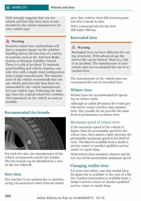
hicle strongly suggests that you usewheels and tires that have been recom-mended by the vehicle manufacturer foryour vehicle type.
Warning
Incorrect wheel/tire combinations willhave a negative impact on the vehicle'shandling and on the function of a varietyof systems, such as the Anti-lock BrakeSystem or Dynamic Stability Control.There is a risk of accident. To maintaingood handling and vehicle response, useonly tires with a single tread configurationfrom a single manufacturer. The manufac-turer of the vehicle recommends that youuse wheels and tires that have been rec-ommended by the vehicle manufacturerfor your vehicle type. Following tire dam-age, have the original wheel/tire combina-tion remounted on the vehicle as soon aspossible.
Recommended tire brands
For each tire size, the manufacturer of thevehicle recommends certain tire brands.The tire brands can be identified by a staron the tire sidewall.
New tiresTire traction is not optimal due to manufac-turing circumstances when tires are brand-
new; they achieve their full traction poten-tial after a break-in time.
Drive conservatively for the first200 miles/300 km.
Retreaded tires
Warning
Retreaded tires can have different tire cas-ing structures. With advanced age theservice life can be limited. There is a riskof an accident. The manufacturer of yourvehicle does not recommend the use of re-treaded tires.
The manufacturer of the vehicle does notrecommend the use of retreaded tires.
Winter tiresWinter tires are recommended for operat-ing on winter roads.
Although so-called all-season M+S tires pro-vide better winter traction than summertires, they usually do not provide the samelevel of performance as winter tires.
Maximum speed of winter tiresIf the maximum speed of the vehicle ishigher than the permissible speed for thewinter tires, then attach a label showing thepermissible maximum speed in the field ofview. The label is available from a dealer'sservice center or another qualified servicecenter or repair shop.
With winter tires mounted, observe and donot exceed the permissible maximum speed.
Changing runflat tiresFor your own safety, use only runflat tires.No spare tire is available in the case of a flattire. Further information is available from adealer's service center or another qualifiedservice center or repair shop.
Seite 268
MOBILITY Wheels and tires
268Online Edition for Part no. 01402666575 - VI/19

Rotating wheels between axlesDifferent wear patterns can occur on thefront and rear axles depending on individualdriving conditions. The tires can be rotatedin pairs between the axles to achieve evenwear. Further information is available froma dealer's service center or another qualifiedservice center or repair shop. After rotating,check the tire pressure and correct, ifneeded.
Storing tires
Tire inflation pressureDo not exceed the maximum tire inflationpressure indicated on the side wall of thetire.
StorageStore wheels and tires in a cool, dry anddark place.
Always protect tires against all contact withoil, grease, and solvents.
Do not leave tires in plastic bags.
Remove dirt from wheels or tires.
Run-flat tires
ConceptRun-flat tires permit continued driving un-der restricted conditions even in the eventof a complete loss of tire inflation pressure.
General informationThe wheels are composed of tires that areself-supporting to a limited degree.
The support of the sidewall allows the tireto remain drivable to a restricted degree inthe event of a tire inflation pressure loss.
Follow the instructions for continued driv-ing with a flat tire.
Safety information
Warning
Your vehicle handles differently with arun-flat tire with no or low inflation pres-sure; for instance, your lane stability whenbraking is reduced, braking distances arelonger and the self-steering properties willchange. There is a risk of accident. Drivemoderately and do not exceed a speed of50 mph/80 km/h.
Label
The tires are marked on the tire sidewallwith RSC Run-flat System Component.
Repairing a flat tire
Safety measures– Park the vehicle as far away as possible
from passing traffic and on solid ground.
– Switch on the hazard warning system.
– Secure the vehicle against rolling awayby setting the parking brake.
– Turn the steering wheel until the frontwheels are in the straight-ahead posi-tion and engage the steering wheel lock.
– Have all vehicle occupants get out of thevehicle and ensure that they remain out-
Seite 269
Wheels and tires MOBILITY
269Online Edition for Part no. 01402666575 - VI/19

side the immediate area in a safe place,such as behind a guardrail.
– If necessary, set up a warning triangleat an appropriate distance.
Mobility System
ConceptWith the Mobility System, minor tire dam-age can be sealed temporarily to enable con-tinued travel. To accomplish this, sealant ispumped into the tires, which seals the dam-age from the inside.
General information– Follow the instructions on using the
Mobility System found on the compres-sor and sealant container.
– Use of the Mobility System may be inef-fective if the tire puncture measures ap-prox. 1/8 inches/4 mm or more.
– Contact a dealer's service center or an-other qualified service center or repairshop if the tire cannot be made drivable.
– Do not remove foreign bodies that havepenetrated the tire. Only remove foreignobjects if they are visibly protrudingfrom the tire.
– Pull the speed limit sticker off the seal-ant container and apply it to the steer-ing wheel.
– The use of a sealant can damage theTPM wheel electronics. In this case,have the TPM wheel electronics re-placed at the next opportunity.
– The compressor can be used to checkthe tire inflation pressure.
Overview
StorageThe Mobility System is in a bag on the leftside of the cargo area.
Sealant container
– Sealant container, arrow 1.
– Filling hose, arrow 2.
Observe use-by date on the sealant con-tainer.
Compressor
1 Sealant container unlocking
2 Sealant container holder
3 Tire pressure gage
4 Reduce tire inflation pressure button
5 On/off switch
6 Compressor
7 Connector/cable for socket
8 Connection hose
Seite 270
MOBILITY Wheels and tires
270Online Edition for Part no. 01402666575 - VI/19

Safety measures– Park the vehicle as far away as possible
from passing traffic and on solid ground.
– Switch on the hazard warning system.
– Secure the vehicle against rolling awayby setting the parking brake.
– Turn the steering wheel until the frontwheels are in the straight-ahead posi-tion and engage the steering wheel lock.
– Have all vehicle occupants get out of thevehicle and ensure that they remain out-side the immediate area in a safe place,such as behind a guardrail.
– If necessary, set up a warning triangleat an appropriate distance.
Filling the tire with sealant
Safety information
DANGER
If the exhaust pipe is blocked or ventila-tion is insufficient, harmful exhaust gasescan enter into the vehicle. The exhaustgases contain pollutants which are color-less and odorless. In enclosed areas, ex-haust gases can also accumulate outside ofthe vehicle. There is danger to life. Keepthe exhaust pipe free and ensure sufficientventilation.
NOTICE
The compressor can overheat during ex-tended operation. There is a risk of dam-age to property. Do not run the compres-sor for more than 10 minutes.
Filling1. Shake the sealant container.
2. Pull filling hose completely out of thecover of the sealant container. Do notkink the hose.
3. Slide the sealant container into theholder on the compressor housing, en-suring that it engages audibly.
Seite 271
Wheels and tires MOBILITY
271Online Edition for Part no. 01402666575 - VI/19

4. Screw the filling hose of the sealant con-tainer onto the tire valve of the non-working wheel.
5. With the compressor switched off, in-sert the plug into the power socket in-side the vehicle.
6. With the ignition switched on or the en-gine running, switch on the compressor.
Let the compressor run for max. 10 minutesto fill the tire with sealant and achieve atire inflation pressure of approx. 2.5 bar.
While the tire is being filled with sealant,the tire inflation pressure may sporadicallyreach approx. 5 bar. Do not switch off thecompressor at this point.
Checking and adjusting the tireinflation pressure
Checking1. Switch off the compressor.
2. Read the tire inflation pressure on thetire pressure gage.
To continue the trip, a tire inflation pres-sure of at least 2 bar must be reached.
Removing and stowing the sealantcontainer1. Unscrew the filling hose of the sealant
container from the tire valve.
2. Press the red unlocking device.
3. Remove the sealant container from thecompressor.
4. Wrap and store the sealant container insuitable material to avoid dirtying thecargo area.
Minimum tire inflation pressure is notreached1. Pull the connector out of the power
socket inside the vehicle.
2. Drive 33 ft/10 m forward and back todistribute the sealant in the tire.
3. Screw the connection hose of the com-pressor directly onto the tire valve stem.
Seite 272
MOBILITY Wheels and tires
272Online Edition for Part no. 01402666575 - VI/19

4. Insert the connector into the powersocket inside the vehicle.
5. With the ignition switched on or the en-gine running, switch on the compressor.
If a tire inflation pressure of at least2 bar cannot be reached, contact yourdealer's service center or another quali-fied service center or repair shop.
If a tire inflation pressure of at least2 bar is reached, see Minimum tire infla-tion pressure is reached.
6. Unscrew the connection hose of thecompressor from the tire valve.
7. Pull the connector out of the powersocket inside the vehicle.
8. Stow the Mobility System in the vehicle.
Minimum tire inflation pressure isreached1. Unscrew the connection hose of the
compressor from the tire valve.
2. Pull the connector out of the powersocket inside the vehicle.
3. Stow the Mobility System in the vehicle.
4. Immediately drive approx.5 miles/10 km to ensure that the sealantis evenly distributed in the tire.
Do not exceed a speed of50 mph/80 km/h.
If possible, do not drive at speeds lessthan 12 mph/20 km/h.
Adjustment1. Stop at a suitable location.
2. Screw the connection hose of the com-pressor directly onto the tire valve stem.
3. Insert the connector into the powersocket inside the vehicle.
4. Correct the tire inflation pressure to atleast 2.0 bar.
– Increase tire inflation pressure: withthe ignition switched on or the en-gine running, switch on the com-pressor.
– Reduce tire inflation pressure: pressthe button on the compressor.
5. Unscrew the connection hose of thecompressor from the tire valve.
6. Pull the connector out of the powersocket inside the vehicle.
7. Stow the Mobility System in the vehicle.
Continuing the tripDo not exceed the maximum permissiblespeed of 50 mph/80 km/h.
Seite 273
Wheels and tires MOBILITY
273Online Edition for Part no. 01402666575 - VI/19

Reinitialize the Flat Tire Monitor, refer topage 150.
Reset the Tire Pressure Monitor, refer topage 146.
Replace the nonworking tire and the sealantcontainer of the Mobility System promptly.
Snow chains
Safety information
Warning
With the mounting of snow chains on un-suitable tires, the snow chains can comeinto contact with vehicle parts. There maybe a risk of accident or risk of damage toproperty. Only mount snow chains on tiresthat are designated by their manufactureras suitable for the use of snow chains.
Warning
Insufficiently tight snow chains may dam-age tires and vehicle components. Theremay be a risk of accident or risk of damageto property. Make sure that the snowchains are always sufficiently tight. Re-tighten as needed according to the snowchain manufacturer's instructions.
Fine-link snow chainsThe manufacturer of the vehicle recom-mends the use of fine-link snow chains. Cer-tain types of fine-link snow chains havebeen tested by the manufacturer of the ve-hicle and recommended as road-safe andsuitable.
Information regarding suitable snow chainsis available from a dealer’s service center oranother qualified service center or repairshop.
UseUse only in pairs on the front wheels, equip-ped with the tires of the following size:
– 195/60 R 16.
– 195/55 R 17.
Follow the snow chain manufacturer's in-structions.
Do not initialize the Flat Tire Monitor aftermounting snow chains, as doing so may re-sult in incorrect readings.
Do not reset the Tire Pressure Monitor TPMafter mounting snow chains, as doing somay result in incorrect readings.
When driving with snow chains, briefly ac-tivate Dynamic Traction Control DTC, ifneeded.
Maximum speed with snow chainsDo not exceed a speed of 30 mph/50 km/hwhen using snow chains.
Changing wheels/tires
General informationWhen using run-flat tires or a flat tire kit, awheel does not always need to be changedimmediately when there is a loss of tire in-flation pressure due to a flat tire.
If needed, the tools for changing wheels areavailable as accessories from a dealer’sservice center or another qualified servicecenter or repair shop.
Safety information
DANGER
The vehicle jack is only provided for short-term lifting of the vehicle for wheelchanges. Even if all safety measures areobserved, there is a risk of the raised vehi-
Seite 274
MOBILITY Wheels and tires
274Online Edition for Part no. 01402666575 - VI/19

cle falling, if the vehicle jack tips over.There is a risk of injuries or danger to life.If the vehicle is raised, do not lie under thevehicle and do not start the engine.
DANGER
Supports such as wooden blocks under thevehicle jack reduce the capacity of the ve-hicle jack to bear weight. They have thepotential to exert too much strain on thevehicle jack, causing it to tip over and thevehicle to fall. There is a risk of injuries ordanger to life. Do not place supports underthe vehicle jack.
Warning
The jack, issued by the vehicle manufac-turer, is provided in order to perform awheel change in the event of a breakdown.The jack is not designed for frequent use;for example, changing from summer towinter tires. Using the jack frequently maycause it to become jammed or damaged.There is a risk of injury and risk of damageto property. Only use the jack to attach anemergency or spare wheel in the event ofa breakdown.
Warning
On soft, uneven or slippery ground, for ex-ample snow, ice, tiles, etc., the vehicle jackcan slip away. There is a risk of injury. Ifpossible, change the wheel on a flat, solid,and slip-resistant surface.
Warning
The vehicle jack is optimized for liftingthe vehicle and for the jacking points onthe vehicle only. There is a risk of injury.Do not lift any other vehicle or cargo usingthe vehicle jack.
Warning
If the vehicle jack is not inserted into thejacking point provided for this purpose,the vehicle may be damaged or the vehiclejack may slip when it is being cranked up.There is a risk of injury or risk of damageto property. When cranking up the vehiclejack, ensure that it is inserted in the jack-ing point next to the wheel housing.
Warning
A vehicle that is raised on a vehicle jackmay fall off of the jack if lateral forces areexerted on it. There is a risk of injury andrisk of damage to property. While the ve-hicle is raised, do not exert lateral forceson the vehicle or pull abruptly on the vehi-cle. Have a stuck wheel removed by a deal-er’s service center or another qualifiedservice center or repair shop.
Securing the vehicle against rolling
General informationThe vehicle manufacturer recommends toadditionally secure the vehicle against roll-ing away when changing a wheel.
Seite 275
Wheels and tires MOBILITY
275Online Edition for Part no. 01402666575 - VI/19

On a level surface
Place wheel chocks or other suitable objectsin front and behind the wheel that is diago-nal to the wheel to be changed.
On a slight downhill gradient
If you need to change a wheel on a slightdownhill grade, place chocks and other suit-able objects, for instance a rock, under thewheels of both the front and rear axlesagainst the rolling direction.
Lug bolt lock
ConceptThe wheel lug bolts have a special coding.The lug bolts can only be released with theadapter which matches the coding.
OverviewThe adapter of the lug bolt lock is located inthe onboard vehicle tool kit, refer topage 291.
– Lug bolt, arrow 1.
– Adapter, arrow 2.
Unscrewing1. Attach the adapter to the lug bolt.
2. Unscrew the lug bolt.
3. Remove the adapter after unscrewingthe lug bolt.
Screwing on1. Attach the adapter to the lug bolt. If
necessary, turn the adapter until it fitson the lug bolt.
2. Screw on the lug bolt. The tighteningtorque is 140 Nm.
3. Remove the adapter and stow it afterscrewing on the lug bolt.
Preparing the vehicle– Park the vehicle on solid and non-slip
ground at a safe distance from traffic.
– Switch on the hazard warning system.
– Set the parking brake.
– Engage a gear or move the selector leverto position P.
– As soon as permitted by the traffic flow,have all vehicle occupants get out of thevehicle and ensure that they remain out-side the immediate area in a safe place,such as behind a guardrail.
Seite 276
MOBILITY Wheels and tires
276Online Edition for Part no. 01402666575 - VI/19

– Depending on the vehicle equipment,get wheel change tools and, if necessary,the emergency wheel from the vehicle.
– If necessary, set up a warning triangleor portable hazard warning light at anappropriate distance.
– Secure the vehicle additionally againstrolling.
– Loosen the lug bolts a half turn.
Jacking points for the vehicle jack
The jacking points for the vehicle jack arelocated at the marked positions.
Jacking up the vehicle
Warning
Hands and fingers can be jammed whenusing the vehicle jack. There is a risk ofinjury. Comply with the described handposition and do not change this positionwhile using the vehicle jack.
1. Hold the vehicle jack with one hand, ar-row 1, and grasp the vehicle jack crankor lever with your other hand, arrow 2.
2. Insert the vehicle jack into the rectan-gular recess of the jacking point closestto the wheel to be changed.
Seite 277
Wheels and tires MOBILITY
277Online Edition for Part no. 01402666575 - VI/19

3. Extend the vehicle jack by turning thevehicle jack crank or lever clockwise.
4. Take your hand away from the vehiclejack as soon as the vehicle jack is underload and continue turning the vehiclejack crank or lever with one hand.
5. Make sure that the vehicle jack footstands vertically and at a right angle be-neath the jacking point.
6. Make sure that the vehicle jack footstands vertically and perpendicularly be-neath the jacking point after extendingthe vehicle jack.
7. Crank the vehicle up, until the vehiclejack is with the entire surface on the
ground and the relevant wheel is maxi-mum 1.2 inches/3 cm above ground.
Mounting a wheelMount one emergency wheel only, as re-quired.
1. Unscrew the lug bolts.
2. Remove the wheel.
3. Put the new wheel or emergency wheelon and screw in at least two lug bolts ina crosswise pattern until hand-tight.
If non-original light-alloy wheels of thevehicle manufacturer are mounted, theaccompanying lug bolts may have to beused as well.
4. Hand-tighten the remaining lug boltsand tighten all lug bolts well in a cross-wise pattern.
5. Turn the vehicle jack crank counter-clockwise to retract the vehicle jack andlower the vehicle.
6. Remove the vehicle jack and stow it se-curely.
After the wheel change1. Tighten the lug bolts crosswise. The
tightening torque is 101 lbs ft/140 Nm.
2. Stow the nonworking wheel in the cargoarea, if necessary.
The nonworking wheel cannot be storedunder the cargo floor panel because ofits size.
3. Check tire inflation pressure at the nextopportunity and correct as needed.
4. Reinitialize the Flat Tire Monitor.
Reset the Tire Pressure Monitor TPM.
5. Check to make sure the lug bolts aretight with a calibrated torque wrench.
6. Have the damaged tire replaced at thenearest dealer's service center or an-
Seite 278
MOBILITY Wheels and tires
278Online Edition for Part no. 01402666575 - VI/19

other qualified service center or repairshop.
Emergency wheel
ConceptIn the event of a flat tire, the emergencywheel can be used in place of the wheelwith the defective tire. The emergencywheel is only intended for temporary useuntil the defective tire/wheel has been re-placed.
General informationMount one emergency wheel only.
Also check the tire inflation pressure of theemergency wheel in the cargo area regu-larly, and correct it as needed.
Safety information
Warning
The emergency wheel has particular di-mensions. When driving with an emer-gency wheel, changed driving propertiesmay occur, for instance reduced lane sta-bility when braking, longer braking dis-tance, and changed self-steering proper-ties in the limit area. There is a risk ofaccident. Drive moderately and do not ex-ceed a speed of 50 mph/80 km/h.
Overview
The emergency wheel and the wheel changetools are located in the cargo area under thecargo floor panel.
Removing the emergency wheel1. Pull up and remove the cargo floor
panel.
2. Unscrew the butterfly screw.
3. Remove the retaining plate or the cover.
4. Where applicable, remove the holderand the trailer hitch.
5. Remove the jacking point and the toolholder on the left next to the emergencywheel.
6. Slide the emergency wheel to the leftand remove it.
Inserting the emergency wheel1. Insert the emergency wheel on the left
and slide it to the right.
2. Where applicable, mount the holder andthe trailer hitch.
3. Attach the retaining plate or the cover.
4. Screw on and tighten the butterflyscrew.
5. Insert and secure the jacking point andthe tool holder on the left next to theemergency wheel.
6. Insert the cargo floor panel.
Seite 279
Wheels and tires MOBILITY
279Online Edition for Part no. 01402666575 - VI/19

Engine compartment
Vehicle features and options
This chapter describes all standard, country-specific and optional features offered withthe series. It also describes features that arenot necessarily available in your vehicle, for
instance, due to the selected options orcountry versions. This also applies to safety-related functions and systems. When usingthese functions and systems, the applicablelaws and regulations must be observed.
Overview
1 Filler neck for washer fluid
2 Vehicle identification number
3 Oil filler neck
4 Jump-starting, positive terminal
5 Jump-starting, negative terminal
6 Coolant reservoir
Seite 280
MOBILITY Engine compartment
280Online Edition for Part no. 01402666575 - VI/19

Hood
Safety information
Warning
Improperly executed work in the enginecompartment can damage vehicle compo-nents and impair vehicle functions. Thereis a risk of an accident and damage toproperty. Have work in the engine com-partment performed by a dealer’s servicecenter or another qualified service centeror repair shop.
Warning
The engine compartment accommodatesmoving components. Certain componentsin the engine compartment can also movewith the vehicle switched off, for instancethe radiator fan. There is a risk of injury.Do not reach into the area of moving parts.Keep articles of clothing and hair awayfrom moving parts.
Warning
There are protruding parts, for instancelocking hook, on the inside of the hood.There is a risk of injury. If the hood isopen, pay attention to protruding partsand keep clear of these areas.
Warning
An incorrectly locked hood can open whiledriving and restrict visibility. There is arisk of accident. Stop immediately and cor-rectly close the hood.
Warning
Body parts can be jammed when openingand closing the hood. There is a risk of in-jury. Make sure that the area of movementof the hood is clear during opening andclosing.
NOTICE
Folded-away wipers can be jammed whenthe hood is opened. There is a risk of dam-age to property. Make sure that the wiperswith the wiper blades mounted are foldeddown onto the windshield before openingthe hood.
NOTICE
When the hood is closed, it must engageon both sides. Pressing again can damagethe hood. There is a risk of damage toproperty. Open the hood again and thenclose it energetically. Avoid pressingagain.
Opening the hood1. Pull lever, arrow 1.
Hood is unlocked.
2. After the lever is released, pull the leveragain, arrow 2.
Hood can be opened.
Seite 281
Engine compartment MOBILITY
281Online Edition for Part no. 01402666575 - VI/19
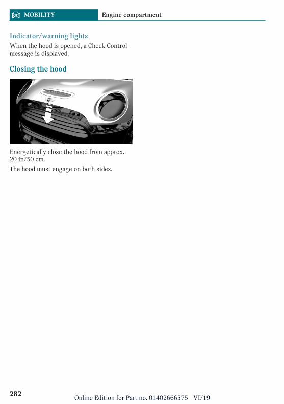
Indicator/warning lightsWhen the hood is opened, a Check Controlmessage is displayed.
Closing the hood
Energetically close the hood from approx.20 in/50 cm.
The hood must engage on both sides.
Seite 282
MOBILITY Engine compartment
282Online Edition for Part no. 01402666575 - VI/19

Engine oil
Vehicle features and options
This chapter describes all standard, country-specific and optional features offered withthe series. It also describes features that arenot necessarily available in your vehicle, forinstance, due to the selected options orcountry versions. This also applies to safety-related functions and systems. When usingthese functions and systems, the applicablelaws and regulations must be observed.
General information
The engine oil consumption is dependent onyour driving style and driving conditions.
Therefore, regularly check the engine oillevel after refueling by taking a detailedmeasurement.
The engine oil consumption can increase inthe following situations, for instance:
– Sporty driving style.
– Break-in of the engine.
– Idling of the engine.
– With use of engine oil types that areclassified as not suitable.
Different Check Control messages appear,depending on the engine oil level.
Safety information
NOTICE
An engine oil level that is too low causesengine damage. There is a risk of damageto property. Immediately add engine oil.
NOTICE
Too much engine oil can damage the en-gine or the catalytic converter. There is arisk of damage to property. Do not add toomuch engine oil. When too much engineoil is added, have the engine oil level cor-rected by a dealer’s service center or an-other qualified service center or repairshop.
Electronic oil measurement
General informationThe electronic oil measurement has twomeasuring principles:
– Monitoring.
– Detailed measurement.
When making frequent short-distance tripsor using a dynamic driving style, for in-stance when taking curves aggressively,regularly perform a detailed measurement.
Monitoring
ConceptThe engine oil level is monitored electroni-cally while driving and can be shown on theControl Display.
If the engine oil level is outside its permis-sible operating range, a Check Control mes-sage is displayed.
A red indicator light indicates thatthe engine oil pressure is too low.
Seite 283
Engine oil MOBILITY
283Online Edition for Part no. 01402666575 - VI/19

Functional requirementsA current measured value is available afterapprox. 30 minutes of normal driving.
Displaying the engine oil levelVia the Central Information Display (CID):
1. "My MINI"
2. "Vehicle status"
3. "Engine oil level"
The engine oil level is displayed.
System limitsWhen making frequent short-distance tripsor using a dynamic driving style, it may notbe possible to calculate a measured value.In this case, the measured value for the last,sufficiently long trip is displayed.
Detailed measurement
ConceptThe engine oil level is checked when the ve-hicle is stationary and displayed via a scale.
If the engine oil level is outside its permis-sible operating range, a Check Control mes-sage is displayed.
General informationDuring the measurement, the idle speed isincreased somewhat.
Functional requirements– Vehicle is parked in a horizontal posi-
tion.
– Manual transmission: shift lever in neu-tral position, clutch and accelerator ped-als not depressed.
– Steptronic transmission: selector leverin selector lever position N or P and ac-celerator pedal not depressed.
– Engine is running and is at operatingtemperature.
Performing a detailed measurementVia the Central Information Display (CID):
1. "My MINI"
2. "Vehicle status"
3. "Engine oil level"
4. "Measure engine oil level"
5. "Start measurement"
The engine oil level is checked and dis-played via a scale.
Adding engine oil
General informationOnly add engine oil when the message isdisplayed in the instrument cluster. Thequantity to be added is indicated in themessage displayed in the instrument clus-ter.
Only add suitable types of engine oil, referto page 285.
Safely park the vehicle and switch off theignition before adding engine oil.
Take care not to add too much engine oil.
Safety information
Warning
Operating materials, for instance oils,greases, coolants, fuels, can contain harm-ful ingredients. There is a risk of injuriesor danger to life. Follow the instructionson the containers. Avoid the contact of ar-ticles of clothing, skin or eyes with operat-ing materials. Do not refill operating mate-rials into different bottles. Store operatingmaterials out of reach of children.
Seite 284
MOBILITY Engine oil
284Online Edition for Part no. 01402666575 - VI/19

NOTICE
An engine oil level that is too low causesengine damage. There is a risk of damageto property. Immediately add engine oil.
NOTICE
Too much engine oil can damage the en-gine or the catalytic converter. There is arisk of damage to property. Do not add toomuch engine oil. When too much engineoil is added, have the engine oil level cor-rected by a dealer’s service center or an-other qualified service center or repairshop.
OverviewThe oil filler neck is located in the enginecompartment, refer to page 280.
Adding engine oil1. Open the hood, refer to page 281.
2. Open the lid counterclockwise.
3. Add engine oil.
4. Close the lid.
Engine oil types to add
General informationThe engine oil quality is critical for the lifeof the engine.
Only add the types of engine oil which arelisted.
Safety information
NOTICE
Oil additives can damage the engine.There is a risk of damage to property. Donot use oil additives.
NOTICE
Incorrect engine oil can cause malfunc-tions in the engine or damage it. There is arisk of damage to property. When select-ing an engine oil, make sure that the en-gine oil has the correct oil rating.
Suitable engine oil typesAdd engine oils that meet the following oilrating standards:
Gasoline engine
BMW Longlife-01 FE.
BMW Longlife-14 FE+.
BMW Longlife-17 FE+.
Alternative engine oil typesIf an engine oil suitable for continuous useis not available, up to 1 US quart/liter of anengine oil with the following oil rating canbe added:
Seite 285
Engine oil MOBILITY
285Online Edition for Part no. 01402666575 - VI/19

Oil rating
API SL.
API SM.
API SN.
Viscosity gradesWhen selecting an engine oil, make surethat the engine oil belongs to one of the fol-lowing viscosity grades:
Viscosity grades
SAE 0W-20.
SAE 0W-30.
More information about suitable oil ratingsand viscosity grades of engine oils can berequested from a dealer’s service center oranother qualified service center or repairshop.
Engine oil change
NOTICE
Engine oil that is not changed in timelyfashion can cause increased engine wearand thus engine damage. There is a risk ofdamage to property. Do not exceed theservice data indicated in the vehicle.
The vehicle manufacturer recommends thatyou have a dealer's service center or an-other qualified service center or repair shopchange the engine oil.
Seite 286
MOBILITY Engine oil
286Online Edition for Part no. 01402666575 - VI/19

Coolant
Vehicle features and options
This chapter describes all standard, country-specific and optional features offered withthe series. It also describes features that arenot necessarily available in your vehicle, forinstance, due to the selected options orcountry versions. This also applies to safety-related functions and systems. When usingthese functions and systems, the applicablelaws and regulations must be observed.
General information
Coolant consists of water and additives.
Not all commercially available additives aresuitable for the vehicle. Information aboutsuitable additives is available from a deal-er’s service center or another qualified serv-ice center or repair shop.
Safety information
Warning
With the engine hot and the cooling sys-tem open, coolant can escape and lead toscalding. There is a risk of injury. Onlyopen the cooling system with the enginecooled down.
Warning
Additives are harmful and incorrect addi-tives can damage the engine. There is arisk of injury and risk of damage to prop-erty. Do not allow additives to come into
contact with skin, eyes or articles of cloth-ing. Use suitable additives only.
Coolant level
CheckingThere are yellow Min and Max marks in thecoolant reservoir.
1. Let the engine cool.
2. Open the hood, refer to page 281.
3. Turn the lid of the coolant reservoirslightly counterclockwise to allow anyexcess pressure to dissipate, then openit.
4. Open the coolant reservoir lid.
Seite 287
Coolant MOBILITY
287Online Edition for Part no. 01402666575 - VI/19

5. The coolant level is correct if it lies be-tween the minimum and maximummarks in the filler neck.
6. Close the lid.
Adding1. Let the engine cool.
2. Open the hood, refer to page 281.
3. Turn the lid of the coolant reservoirslightly counterclockwise to allow anyexcess pressure to dissipate, then openit.
4. Open the coolant reservoir lid.
5. If the coolant is low, slowly add coolantup to the specified level; do not overfill.
6. Close the lid.
7. Have the cause of the coolant loss elimi-nated as soon as possible.
Disposal
Comply with the relevant environ-mental protection regulations whendisposing of coolant and coolant ad-
ditives.
Seite 288
MOBILITY Coolant
288Online Edition for Part no. 01402666575 - VI/19

Maintenance
Vehicle features and options
This chapter describes all standard, country-specific and optional features offered withthe series. It also describes features that arenot necessarily available in your vehicle, forinstance, due to the selected options orcountry versions. This also applies to safety-related functions and systems. When usingthese functions and systems, the applicablelaws and regulations must be observed.
MINI maintenance system
The maintenance system indicates requiredmaintenance measures, and thereby pro-vides support in maintaining road safetyand the operational reliability of the vehicle.
In some cases, scopes and intervals of themaintenance system may vary according tothe country version. Replacement work,spare parts, fuels and lubricants, and wearmaterials are calculated separately. Furtherinformation is available from a dealer's serv-ice center or another qualified service cen-ter or repair shop.
Condition Based Service CBS
ConceptSensors and special algorithms take into ac-count the driving conditions of the vehicle.CBS uses these to calculate the need formaintenance.
The system makes it possible to adapt theamount of maintenance corresponding toyour user profile.
General informationInformation on service requirements, referto page 127, can be displayed on the radio.
Service data in the vehicle keyInformation on the required maintenance iscontinuously stored in the vehicle key. Thedealer’s service center can read this dataout and suggest an optimized maintenancescope for the vehicle.
Therefore, hand the service advisor the ve-hicle key with which the vehicle was drivenmost recently.
Storage periodsStorage periods during which the vehiclebattery was disconnected are not taken intoaccount.
If this occurs, have a dealer's service centeror another qualified service center or repairshop update the time-dependent mainte-nance procedures, such as checking brakefluid and, if necessary, changing the engineoil and the microfilter/activated-charcoalfilter.
Service and Warranty Infor-mation Booklet for US modelsand Warranty and ServiceGuide Booklet for Canadianmodels
Please consult your Service and WarrantyInformation Booklet for US models andWarranty and Service Guide Booklet forCanadian models for additional informationon service requirements.
Seite 289
Maintenance MOBILITY
289Online Edition for Part no. 01402666575 - VI/19

The manufacturer of your vehicle recom-mends that maintenance and repair be per-formed by a service center or another quali-fied service center or repair shop. Recordsof regular maintenance and repair workshould be retained.
Socket for OBD Onboard Diag-nosis
General informationDevices connected to the OBD socket trig-ger the alarm system when the vehicle islocked. Remove any devices connected atthe OBD socket before locking the vehicle.
Safety information
NOTICE
The socket for Onboard Diagnosis is an in-tricate component intended to be used inconjunction with specialized equipment tocheck the vehicle’s primary emissions sys-tem. Improper use of the socket for On-board Diagnosis, or contact with thesocket for Onboard Diagnosis for otherthan its intended purpose, can cause vehi-cle malfunctions and creates risks of per-sonal and property damage. Given the fore-going, the manufacture of your vehiclestrongly recommends that access to thesocket for Onboard Diagnosis be limited toa dealer's service center or another quali-fied service center or repair shop or otherpersons that have the specialized trainingand equipment for purposes of properlyutilizing the socket for Onboard Diagnosis.
Position
There is an OBD socket on the driver's sidefor checking the primary components in thevehicle's emissions.
Emissions– The warning light lights up:
Emissions are deteriorating.Have the vehicle checked as soonas possible.
– The warning light flashes under certaincircumstances:
This indicates that there is excessivemisfiring in the engine.
Reduce the vehicle speed and have thesystem checked immediately; otherwise,serious engine misfiring within a briefperiod can seriously damage emissioncontrol components, in particular thecatalytic converter.
Seite 290
MOBILITY Maintenance
290Online Edition for Part no. 01402666575 - VI/19

Replacing components
Vehicle features and options
This chapter describes all standard, country-specific and optional features offered withthe series. It also describes features that arenot necessarily available in your vehicle, forinstance, due to the selected options orcountry versions. This also applies to safety-related functions and systems. When usingthese functions and systems, the applicablelaws and regulations must be observed.
Vehicle tool kit
The bag containing the onboard vehicle toolkit is located beneath the cargo floor panel.
After use, secure the bag with the onboardvehicle tool kit on a lashing eye again.
Wiper blades
Safety information
NOTICE
The window may sustain damage if thewiper falls onto it without the wiper bladeinstalled. There is a risk of damage toproperty. Hold the wiper firmly when
changing the wiper blade. Do not fold orswitch on the wiper without a wiper bladeinstalled.
NOTICE
Folded-away wipers can be jammed whenthe hood is opened. There is a risk of dam-age to property. Make sure that the wiperswith the wiper blades mounted are foldeddown onto the windshield before openingthe hood.
Replacing the front wiper blades1. To change the wiper blades, fold up the
wiper arms.
2. Fold up and hold the wiper arm firmly.
3. Press button, arrow 1, and pull out thewiper blade, arrow 2.
4. Attach a new wiper blade. The wiperblade must engage audibly.
5. Fold down the wiper arm.
Seite 291
Replacing components MOBILITY
291Online Edition for Part no. 01402666575 - VI/19

Replacing rear wiper blades1. Fold up and hold the wiper arm firmly.
2. Turn the wiper blade all the way back.
3. Push the wiper blade out of the fasten-ing by continuing to turn it all the way.
4. Insert the new wiper blade by followingthe steps in reverse order. The wiperblade must engage audibly.
5. Fold down the wiper arm.
Light and bulb replacement
General information
Lights and bulbsLights and bulbs make an essential contri-bution to vehicle safety.
The manufacturer of the vehicle recom-mends that you have appropriate work per-formed by a dealer’s service center or an-other qualified service center or repair shopif you are unfamiliar with it or if it has notbeen described here.
A spare light box is available from a dealer'sservice center or another qualified servicecenter or repair shop.
Follow the safety information, refer topage 292.
Light-emitting diodes (LEDs)Some items of equipment use light-emittingdiodes installed behind a cover as a lightsource. These light-emitting diodes are re-lated to conventional lasers and are offi-cially designated as Class 1 light-emittingdiodes.
Follow the safety information, refer topage 292.
Safety information
Lights and bulbs
Warning
Bulbs can get hot during operation. Con-tact with the bulbs can cause burns. Thereis a risk of injury. Only change bulbs afterthey have cooled off.
Warning
Work on switched-on lighting systems cancause short circuits. There is a risk of in-jury or risk of damage to property. Whenworking on the lighting system, switch offthe lights in question. If necessary, heedthe bulb manufacturer's instructions.
NOTICE
Dirty bulbs have a reduced service life.There is a risk of damage to property. Donot hold new bulbs with your bare hands.Use a clean cloth or something similar, orhold the bulb by its base.
Seite 292
MOBILITY Replacing components
292Online Edition for Part no. 01402666575 - VI/19

Light-emitting diodes (LEDs)
Warning
Intensive brightness can irritate or dam-age the retina of the eye. There is a risk ofinjury. Do not look directly into the head-lights or other light sources. Do not re-move the LED covers.
Headlight glassCondensation can form on the inside of theheadlight glass in cool or humid weather.When driving with the lights switched on,the condensation evaporates after a shorttime. The headlight glass does not need tobe changed.
If despite driving with the headlightsswitched on, increasing humidity forms, forinstance water droplets in the light, havethe headlights checked.
Headlight settingThe headlight adjustments can be affectedby changing lights and bulbs. After theheadlight adjustment was changed, have itchecked and, if necessary, corrected by adealer’s service center or another qualifiedservice center or repair shop.
Front halogen lights, bulbreplacement
Overview
Halogen headlights
1 Low beams/high beams
2 Turn signal
Low beams/high beamsFollow the general instructions on lightsand bulbs, refer to page 292.
55-watt bulb, HB2.
1. Open the hood, refer to page 281.
2. Turn the lid counterclockwise, arrow,and remove.
3. Pull off the connector.
Seite 293
Replacing components MOBILITY
293Online Edition for Part no. 01402666575 - VI/19

4. Unclip spring clip, arrow, and fold down.
5. Remove the bulb from the headlighthousing.
6. Insert the new bulb and install the coverin the reverse order.
Turn signalFollow the general instructions on lightsand bulbs, refer to page 292.
24-watt bulb, PWY24W.
1. Turn the steering wheel.
2. Turn the lid counterclockwise, arrow 1,and remove.
3. Unscrew the inner cover counterclock-wise, and remove it.
4. Pull bulb holder out of the bulb housing;if needed, loosen it with small tiltingmovements if possible.
5. Pull the bulb out of the fixture.
6. Insert the new bulb and install the coverin the reverse order.
LED front lights, bulb replacementAll lights feature LED technology.
In the case of a malfunction, contact a deal-er's service center or another qualified serv-ice center or repair shop.
LED front fog lightsThese front fog lights are made using LEDtechnology. In the case of a malfunction,contact a dealer's service center or anotherqualified service center or repair shop.
Seite 294
MOBILITY Replacing components
294Online Edition for Part no. 01402666575 - VI/19

Tail lights, bulb replacement
Overview
1 Tail lights in split doors
2 Tail lights in bumpers
3 License plate light
4 Center brake light
Tail lights in split doorsNote the safety information on lights andbulbs, refer to page 292.
Overview
1 Turn signal
2 Tail lights
3 Rear fog light
4 Reversing lights
Turn signals
21-watt bulbs, P21W.
1. Open the split doors.
2. Remove left or right cover. If necessary,it is then possible to pry the cover offusing a screwdriver or a similar plastictool.
3. Press the latches together upward, ar-row 1, and remove the bulb holder.
Loosen the plug connector, arrow 2, onthe bulb holder.
4. Remove the bulb holder from the open-ing.
Seite 295
Replacing components MOBILITY
295Online Edition for Part no. 01402666575 - VI/19

5. Press the nonworking bulb, arrow 1,gently into the socket, turn counter-clockwise and remove.
6. Proceed in the reverse order to insertthe new bulb and attach the bulb holder.Make sure that the bulb holder engagesin all fasteners.
Rear fog lights/reversing lights
21-watt bulbs, P21W.
1. Open the split doors.
2. Remove left or right cover.
3. Press the latches together in the direc-tion of the arrow, arrow 1, and removethe bulb holder.
Loosen the plug connector, arrow 2, onthe bulb holder.
4. Remove the bulb holder from the open-ing.
5. Press the nonworking bulb gently intothe socket, turn counterclockwise andremove.
– Arrow 2: rear fog lights.
– Arrow 3: reversing light
6. Proceed in the reverse order to insertthe new bulb and attach the bulb holder.Make sure that the bulb holder engagesin all fasteners.
Tail lights in split doors, Union JackAll lamps in the split doors feature LEDtechnology.
In the case of a malfunction, contact a deal-er's service center or another qualified serv-ice center or repair shop.
Tail lights in bumpersFollow the general instructions on lightsand bulbs, refer to page 292.
Seite 296
MOBILITY Replacing components
296Online Edition for Part no. 01402666575 - VI/19

In addition, the tail lights in the bumper as-sume the functions of the brake light, taillight and turn signals, if the split doors areopen.
Overview
1 Tail lights/brake lights/turn signal
2 Brake lights/turn signals
Tail lights/brake lights/turn signal
21-watt bulbs, P21W.
1. Press out cover below the tail light.
2. Remove the screwdriver from the on-board vehicle tool kit.
3. Pull the screwdriver blade from the han-dle and place it on the recessed-headscrew head in the bumper.
4. Attach the screw driver handle with theslot to the blade, arrow 1.
5. Loosen screw in the bumper, arrow 2.
6. Pull tail light from the bumper.
Seite 297
Replacing components MOBILITY
297Online Edition for Part no. 01402666575 - VI/19

7. Turn the bulb holder counter-clockwiseand remove nonworking bulb.
8. To insert the new bulb and install thetail light, proceed in reverse order of re-moval. Make sure that the bulb holdersits tight in the tail light.
Central brake light and license platelightsFollow the general instructions on lightsand bulbs, refer to page 292.
The lights feature LED technology. In thecase of a malfunction, contact a dealer'sservice center or another qualified servicecenter or repair shop.
Side turn signal, bulb replacementFollow the general instructions on lightsand bulbs, refer to page 292.
Bulbs:
– With white lens: WY5W.
1. Open the hood. The covers of the sideturn signal lights are on the left andright next to the hinges of the hood.
2. Loosen nuts of the cover by hand and re-move the cover.
3. Turn the bulb socket counterclockwiseand remove.
4. Replace the bulb.
5. To insert the new bulb, proceed in re-verse order of removal. Insert the nutsof the cover and press down.
Seite 298
MOBILITY Replacing components
298Online Edition for Part no. 01402666575 - VI/19
Vehicle battery
General informationThe battery is maintenance-free.
More information about the battery can berequested from a dealer's service center oranother qualified service center or repairshop.
Safety information
Warning
Vehicle batteries that are not compatiblecan damage vehicle systems and impairvehicle functions. There is a risk of an ac-cident and damage to property. Only vehi-cle batteries that are compatible with yourvehicle type should be installed in your ve-hicle. Information on compatible vehiclebatteries is available at your dealer’s serv-ice center.
Register the battery to the vehicleThe manufacturer of the vehicle recom-mends that you have a service center or an-other qualified service center or repair shopregister the vehicle battery to the vehicleafter the battery has been replaced. Oncethe battery has been registered again, allcomfort features will be available withoutrestriction and any Check Control messagesdisplayed which relate to comfort featureswill disappear.
Charging the battery
General informationMake sure that the battery is always suffi-ciently charged to guarantee that the bat-tery remains usable for its full service life.
A discharged battery is indicated bya red indicator light.
Charge the battery in the following situa-tions:
– When the inspection glass on the top ofthe battery is black.
– When the take-off performance is insuf-ficient.
The following circumstances can have anegative effect on the performance of thebattery:
– Frequent short-distance drives.
– The vehicle is not used for more than amonth.
Safety information
NOTICE
Battery chargers for the vehicle batterycan work with high voltages and currents,which means that the 12 volt on-boardnetwork can be overloaded or damaged.There is a risk of damage to property. Onlyconnect battery chargers for the vehiclebattery to the starting aid terminals in theengine compartment.
Charging the batteryCharge the battery only when the engine isoff and via the starting aid terminals, referto page 304, in the engine compartment.
Power failureAfter a power loss, some equipment needsto be newly initialized or individual settingsupdated, for example:
– Memory function: store the positionsagain.
– Time: update.
– Date: update.
Seite 299
Replacing components MOBILITY
299Online Edition for Part no. 01402666575 - VI/19

– Glass sunroof: initialize the system.
Disposing of old batteriesHave old batteries disposed of by adealer’s service center or anotherqualified service center or repair
shop or take them to a collection point.
Maintain the filled battery in an upright po-sition for transport and storage. Secure thebattery so that it does not tip over duringtransport.
Fuses
Safety information
Warning
Incorrect and repaired fuses can overloadelectrical lines and components. There is arisk of fire. Never attempt to repair ablown fuse. Do not replace a nonworkingfuse with a substitute of another color oramperage rating.
Accessing the fusesThe fuses are located in the glove compart-ment.
1. Open the glove compartment.
2. Swing the cover down, arrow.
Information on the fuse types and locations,as well as the positions of any other fuseboxes, is available on the Internet:www.mini.com/fusecard.
Where applicable, information on the fusetypes and locations is also found on a sepa-rate sheet in the fuse box.
Replacing fusesThe vehicle manufacturer recommends thatyou have a dealer's service center or an-other qualified service center or repair shopreplace the fuses.
Seite 300
MOBILITY Replacing components
300Online Edition for Part no. 01402666575 - VI/19

Breakdown assistance
Vehicle features and options
This chapter describes all standard, country-specific and optional features offered withthe series. It also describes features that arenot necessarily available in your vehicle, forinstance, due to the selected options orcountry versions. This also applies to safety-related functions and systems. When usingthese functions and systems, the applicablelaws and regulations must be observed.
Hazard warning flashers
The button is located above the Control Dis-play.
The red light in the button flashes when thehazard warning flashers are activated.
Warning triangle
Depending on the equipment version, thewarning triangle is located in the cargo areaor under the cargo floor panel.
First-aid kit
General informationSome of the articles have a limited servicelife.
Check the expiration dates of the contentsregularly and replace any expired itemspromptly.
StorageThe first-aid kit is located in the cargo area.
MINI Roadside Assistance
ConceptMINI Roadside Assistance can be contactedif assistance is needed in the event of abreakdown.
General informationIn the event of a breakdown, data on the ve-hicle's condition is sent to the vehicle man-ufacturer.
There are various ways of making contact.
– Via a Check Control message, refer topage 121.
– Calling with a mobile phone.
Requirements– Active MINI Connected contract or
equipment version with intelligentemergency call.
– Cellular network reception.
– The ignition is switched on.
Seite 301
Breakdown assistance MOBILITY
301Online Edition for Part no. 01402666575 - VI/19

StartingIf the vehicle is equipped with Teleservices,support is offered through Teleservice Diag-nosis.
Via the Central Information Display (CID):
1. "MINI Connected"
2. "MINI Assist"
3. "MINI Roadside Assistance"
The contact to the Roadside Assistanceof the manufacture is established.
A telephone number is displayed, ifneeded. Select to dial the telephonenumber on a connected mobile phone.
Teleservice DiagnosisTeleservice Diagnosis enables the wirelesstransmission of detailed vehicle data that isimportant for vehicle diagnosis. This data istransmitted automatically.
Teleservice HelpDepending on the country, the TeleserviceHelp enables a more in-depth diagnosis ofthe vehicle via wireless transmission.
You can launch Teleservice Help by re-questing it through the Service Specialist.
1. Park the vehicle in a safe place.
2. Set the parking brake.
3. Control Display is switched on.
4. "Teleservice Help"
The driving ability of the vehicle can be re-stored for specific functions.
If this is not possible, further measures willbe initiated, for instance Roadside Assis-tance will be informed.
Emergency Request
Intelligent emergency call
ConceptIn case of an emergency, an Emergency Re-quest can be triggered automatically by thesystem or manually.
General informationOnly press the SOS button in an emergency.
The Intelligent Assist system establishes aconnection with the MINI Response Center.
For technical reasons, the Emergency Re-quest cannot be guaranteed under unfavora-ble conditions.
Overview
SOS button in the roofliner
Functional requirements– The ignition is switched on.
– The Assist system is functional.
– If the vehicle is equipped with intelli-gent emergency call: the SIM cardintegrated in the vehicle has been acti-vated.
Automatic triggeringUnder certain conditions, for instance if theairbags trigger, an Emergency Request isautomatically initiated immediately after an
Seite 302
MOBILITY Breakdown assistance
302Online Edition for Part no. 01402666575 - VI/19
accident of corresponding severity. Auto-matic Collision Notification is not affectedby pressing the SOS button.
Manual triggering1. Press the cover briefly to open it.
2. Press the SOS button until the LED atthe button lights up green.
– The LED is illuminated green when anEmergency Request has been initiated.
If the situation allows, wait in your vehi-cle until the voice connection has beenestablished.
– The LED flashes green when a connec-tion to the MINI Response Center hasbeen established.
The MINI Response Center then makescontact with you and takes further stepsto help you.
Even if you are unable to respond, theMINI Response Center can take furthersteps to help you under certain circum-stances.
For this, data is transmitted to the MINIResponse Center which serve to deter-mine the necessary rescue measures.For instance, the current position of thevehicle, if it can be established.
If you can no longer hear the MINI Re-sponse Center through the loudspeakers,the hands-free system, for instance, maybe broken. However, the MINI ResponseCenter may still be able to hear you.
The MINI Response Center ends the Emer-gency Request.
Jump-starting
General informationIf the battery is discharged, the engine canbe started using the battery of another vehi-
cle and two jumper cables. Only use jumpercables with fully insulated clamp handles.
Safety information
DANGER
Contact with live components can lead toan electric shock. There is a risk of inju-ries or danger to life. Do not touch anycomponents that are under voltage.
Warning
If the jumper cables are connected in theincorrect order, sparking may occur. Thereis a risk of injury. Pay attention to the cor-rect order during connection.
NOTICE
In the case of body contact between thetwo vehicles, a short circuit can occur dur-ing jump-starting. There is a risk of dam-age to property. Make sure that no bodycontact occurs.
Preparation1. Check whether the battery of the other
vehicle has a voltage of 12 volts. Thevoltage information can be found on thebattery.
2. Switch off the engine of the assistingvehicle.
3. Switch off any electronic systems/powerconsumers in both vehicles.
Seite 303
Breakdown assistance MOBILITY
303Online Edition for Part no. 01402666575 - VI/19

Starting aid terminals
The starting aid terminal in the engine com-partment acts as the battery's positive ter-minal.
Open the cover of the starting aid terminal.
The body ground or a special nut acts as thebattery negative terminal.
Connecting the cablesTo prevent personal injury or damage toboth vehicles, adhere strictly to the follow-ing procedure.
1. Pull off the lid of the starting aid termi-nal.
2. Attach one terminal clamp of the posi-tive jumper cable to the positive termi-nal of the battery, or to the correspond-ing starting aid terminal of the vehicleproviding assistance.
3. Attach the terminal clamp on the otherend of the cable to the positive terminalof the battery, or to the corresponding
starting aid terminal of the vehicle to bestarted.
4. Attach one terminal clamp of the nega-tive jumper cable to the negative termi-nal of the battery, or to the correspond-ing engine or body ground of assistingvehicle.
5. Attach the second terminal clamp to thenegative terminal of the battery, or tothe corresponding engine or bodyground of the vehicle to be started.
Starting the engineNever use spray fluids to start the engine.
1. Start the engine of the assisting vehicleand let it run for several minutes at anincreased idle speed.
2. Start the engine of the vehicle that is tobe started in the usual way.
If the first starting attempt is not suc-cessful, wait a few minutes before mak-ing another attempt in order to allow thedischarged battery to recharge.
3. Let both engines run for several mi-nutes.
4. Disconnect the jumper cables in the re-verse order.
Check the battery and recharge, if needed.
Tow-starting and towing
Safety information
Warning
Due to system limits, individual functionscan malfunction during tow-starting/towing with the Intelligent Safety systemsactivated. There is a risk of accident.Switch all Intelligent Safety systems offprior to tow-starting/towing.
Seite 304
MOBILITY Breakdown assistance
304Online Edition for Part no. 01402666575 - VI/19

Steptronic transmission withdriven front axle: transporting thevehicle
General informationThe vehicle must not be towed if the frontwheels are touching the ground.
Safety information
NOTICE
The vehicle can be damaged when towingthe vehicle with a lifted rear axle. There isa risk of damage to property. Have vehicletransported only with lifted front axle oron a loading platform.
Pushing the vehicleTo remove a broken-down vehicle from thedanger area, it can be pushed for a shortdistance.
For rolling or pushing the vehicle, refer topage 115.
Tow truck
Your vehicle should be transported with atow truck with a so-called lift bar or on aflat bed.
NOTICE
The vehicle can become damaged whenlifting and securing it.
There is a risk of damage to property.
– Lift the vehicle using suitable means.
– Do not lift or secure the vehicle by itstow fitting, body parts, or suspensionparts.
Steptronic transmission with ALL4:transporting the vehicle
General informationThe vehicle is not permitted to be towed.
Pushing the vehicleTo remove a broken-down vehicle from thedanger area, it can be pushed for a shortdistance.
For rolling or pushing the vehicle, refer topage 115.
Tow truck
The vehicle should only be transported on aloading platform.
NOTICE
The vehicle can become damaged whenlifting and securing it.
There is a risk of damage to property.
– Lift the vehicle using suitable means.
– Do not lift or secure the vehicle by itstow fitting, body parts, or suspensionparts.
Seite 305
Breakdown assistance MOBILITY
305Online Edition for Part no. 01402666575 - VI/19

Manual transmission
Towing or pushing the vehicleA broken-down vehicle can be towed orpushed.
For rolling or pushing the vehicle, refer topage 112.
NOTICE
If manual unlocking of the parking brakeis not possible, the vehicle cannot bemoved or towed. There is a risk of damageto property. The vehicle should only betransported on a loading platform.
Follow the following instructions:
– Make sure that the ignition is switchedon; otherwise, the low beams, tail lights,turn signals, and wipers may be unavail-able.
– Do not tow the vehicle with the rearaxle tilted, as the front wheels couldturn.
– When the engine is stopped, there is nopower assist. Consequently, more forceneeds to be applied when braking andsteering.
– Larger steering wheel movements arerequired.
– The towing vehicle must not be lighterthan the vehicle being towed; otherwise,it will not be possible to control the ve-hicle's response.
– Do not exceed a towing speed of30 mph/50 km/h.
– Do not exceed a towing distance of30 miles/50 km.
Tow truck
With driven front axle
Your vehicle should be transported with atow truck with a so-called lift bar or on aflat bed.
NOTICE
The vehicle can become damaged whenlifting and securing it.
There is a risk of damage to property.
– Lift the vehicle using suitable means.
– Do not lift or secure the vehicle by itstow fitting, body parts, or suspensionparts.
With ALL4
Have your vehicle transported on a flatbedsurface only
Seite 306
MOBILITY Breakdown assistance
306Online Edition for Part no. 01402666575 - VI/19

NOTICE
The vehicle can be damaged when towingthe vehicle with a single lifted axle. Thereis a risk of damage to property. The vehi-cle should only be transported on a loadingplatform.
NOTICE
The vehicle can become damaged whenlifting and securing it.
There is a risk of damage to property.
– Lift the vehicle using suitable means.
– Do not lift or secure the vehicle by itstow fitting, body parts, or suspensionparts.
Towing other vehicles
General informationSwitch on the hazard warning system, de-pending on local regulations.
If the electrical system has failed, clearlyidentify the vehicle being towed by placinga sign or a warning triangle in the rear win-dow.
Safety information
Warning
If the approved gross vehicle weight of thetowing vehicle is lighter than the vehicleto be towed, the tow fitting can tear off orit will not be possible to control the vehi-cle's response. There is a risk of accident.Make sure that the gross vehicle weight ofthe towing vehicle is heavier than the ve-hicle to be towed.
NOTICE
If the tow bar or tow rope is attached in-correctly, damage to other vehicle partscan occur. There is a risk of damage toproperty. Correctly attach the tow bar ortow rope to the tow fitting.
Tow barThe tow fittings used should be on the sameside on both vehicles.
Should it prove impossible to avoid mount-ing the tow bar at an offset angle, please fol-low the following:
– Maneuvering capability is limited goingaround corners.
– The tow bar will generate lateral forcesif it is secured with an offset.
Tow ropeWhen starting to tow the vehicle, makesure that the tow rope is taut.
Use nylon ropes or straps, which will enablethe vehicle to be towed without jerking.
Tow fitting
General information
The screw-in tow fitting should always becarried in the vehicle.
The tow fitting can be screwed in at thefront or rear of the vehicle.
Seite 307
Breakdown assistance MOBILITY
307Online Edition for Part no. 01402666575 - VI/19

The tow fitting and the onboard vehicle toolkit, refer to page 291, are together in thecargo area.
Use of the tow fitting:
– Use only the tow fitting provided withthe vehicle and screw it all the way in.
– Use the tow fitting for towing on pavedroads only.
– Avoid lateral loading of the tow fitting,for instance do not lift the vehicle by thetow fitting.
Safety information
NOTICE
If the tow fitting is not used as intended,there may be damage to the vehicle or tothe tow fitting. There is a risk of damageto property. Follow the notes on using thetow fitting.
Screw thread for tow fitting
Threaded holes for the tow fitting are lo-cated in the front and rear of the vehicle onthe right side with respect to the directionof travel.
Press on the mark on the edge of the coverto push it out.
Tow-starting
Steptronic transmissionDo not tow-start the vehicle.
Tow-starting the engine is not possible dueto the Steptronic transmission.
Have the reasons for the starting difficultiescorrected by a dealer’s service center or an-other qualified service center or repairshop.
Manual transmissionIf possible, do not tow-start the vehicle butstart the engine by jump-starting, refer topage 303. If the vehicle is equipped with acatalytic converter, only tow-start while theengine is cold.
1. Switch on the hazard warning systemand comply with local regulations.
2. Switch on the ignition, refer to page 95.
3. Engage third gear.
4. Have the vehicle tow-started with theclutch pedal pressed and slowly releasethe pedal. After the engine starts, imme-diately press on the clutch pedal again.
5. Stop at a suitable location, remove thetow bar or rope, and switch off the haz-ard warning system.
6. Have the vehicle checked by a dealer'sservice center or another qualified serv-ice center or repair shop.
Seite 308
MOBILITY Breakdown assistance
308Online Edition for Part no. 01402666575 - VI/19

Care
Vehicle features and options
This chapter describes all standard, country-specific and optional features offered withthe series. It also describes features that arenot necessarily available in your vehicle, forinstance, due to the selected options orcountry versions. This also applies to safety-related functions and systems. When usingthese functions and systems, the applicablelaws and regulations must be observed.
Washing the vehicle
General informationRegularly remove foreign objects such asleaves in the area below the windshieldwhen the hood is raised.
Wash your vehicle frequently, particularlyin winter. Intense soiling and road salt candamage the vehicle.
Steam jets or high-pressurewashers
Safety information
NOTICE
When cleaning with high-pressure wash-ers, components can be damaged due tothe pressure or temperatures being toohigh. There is a risk of damage to property.Maintain sufficient distance and do notspray too long continuously. Follow theoperating instructions for the high-pres-sure washer.
Distances and temperature– Maximum temperature: 140 ℉/60 ℃.
– Minimum distance from sensors, cam-eras, seals: 12 inches/30 cm.
– Minimum distance from glass sunroof:31.5 in/80 cm.
Automatic vehicle washes
Safety information
NOTICE
Improper use of automatic vehicle washescan cause damage to the vehicle. There isa risk of damage to property. Follow thefollowing instructions:
– Give preference to cloth vehiclewashes or those that use soft brushesin order to avoid paint damage.
– Avoid vehicle washes with guide railshigher than 4 in/10 cm to avoid dam-age to the chassis.
– Observe the tire width of the guiderail to avoid damage to tires and rims.
– Fold in exterior mirrors to avoid dam-age to the exterior mirrors.
– With rod antenna: unscrew the rodantenna to avoid rod antenna break-age.
– Deactivate the wiper and, if neces-sary, rain sensor to avoid damage tothe wiper system.
Driving into a vehicle wash with amanual transmissionIn vehicle washes, the vehicle must be ableto roll freely.
Seite 309
Care MOBILITY
309Online Edition for Part no. 01402666575 - VI/19

Rolling or pushing the vehicle, refer topage 112.
Driving into a vehicle wash with aSteptronic transmissionIn vehicle washes, the vehicle must be ableto roll freely.
Rolling or pushing the vehicle, refer topage 115.
Some vehicle washes do not permit personsin the vehicle. The vehicle cannot be lockedfrom the outside when in selector lever po-sition N. A signal is sounded when an at-tempt is made to lock the vehicle.
Driving out of a vehicle washEnsure that the vehicle key is in the car.
Start the engine, refer to page 96.
HeadlightsDo not rub wet headlights dry and do notuse abrasive or acidic cleaning agents.
Soak areas that have been dirtied, for in-stance from insects, with shampoo andwash off with water.
Thaw ice with de-icing spray; do not use anice scraper.
After washing the vehicleAfter washing the vehicle, apply the brakesbriefly to dry them; otherwise, braking ac-tion can be reduced. The heat generatedduring braking dries brake discs and brakepads and protects them against corrosion.
Completely remove all residues on the win-dows, to minimize loss of visibility due tosmearing and to reduce wiper noises andwiper blade wear.
Vehicle care
Vehicle care products
General informationMINI recommends using vehicle care andcleaning products from MINI. Suitable careproducts are available from a dealer’s serv-ice center or another qualified service cen-ter or repair shop.
Safety information
Warning
Cleansers can contain substances that aredangerous and harmful to your health.There is a risk of injury. When cleaningthe interior, open the doors or windows.Only use products intended for cleaningvehicles. Follow the instructions on thecontainer.
Vehicle paint
General informationRegular care contributes to driving safetyand value retention. Environmental influen-ces in areas with elevated air pollution ornatural contaminants, such as tree resin orpollen can affect the vehicle's paintwork.Tailor the frequency and extent of your ve-hicle care to these influences.
Aggressive substances such as spilled fuel,oil, grease or bird droppings, must be re-moved immediately to prevent the finishfrom being altered or discolored.
Matte finishOnly use cleaning and care products suita-ble for vehicles with matte finish.
Seite 310
MOBILITY Care
310Online Edition for Part no. 01402666575 - VI/19

Leather careRemove dust from the leather regularly, us-ing a cloth or vacuum cleaner.
Otherwise, particles of dust and road grimechafe in pores and folds, and lead to in-creased wear and premature degradation ofthe leather surface.
To guard against discoloration, such as fromclothing, clean leather and provide leathercare roughly every two months.
Clean light-colored leather more frequentlybecause soiling on such surfaces is substan-tially more visible.
Use leather care products; otherwise, dirtand grease will gradually break down theprotective layer of the leather surface.
Upholstery material care
General informationVacuum the upholstery regularly with avacuum cleaner.
If upholstery is very dirty, for instance withbeverage stains, use a soft sponge or micro-fiber cloth with a suitable interior cleaner.
Clean the upholstery down to the seams us-ing large sweeping motions. Avoid rubbingthe material vigorously.
Safety information
NOTICE
Open Velcro® fasteners on articles ofclothing can damage the seat covers.There is a risk of damage to property. En-sure that any Velcro® fasteners are closed.
Caring for special components
Light-alloy wheelsWhen cleaning the vehicle, use only neutralwheel cleaners having a pH value from 5 to9. Do not use abrasive cleaning agents orsteam jets above 140 ℉/60 ℃. Follow themanufacturer's instructions.
Aggressive, acidic or alkaline cleaningagents can destroy the protective layer ofadjacent components, such as the brakedisc.
After cleaning, apply the brakes briefly todry them. The heat generated during brak-ing dries brake discs and brake pads andprotects them against corrosion.
Chrome surfacesCarefully clean components such as the ra-diator grille or door handles with plenty ofwater, possibly with shampoo added, partic-ularly when they have been exposed to roadsalt.
Rubber componentsEnvironmental influences can cause surfacesoiling of rubber parts and a loss of gloss.Use only water and suitable cleaning agentsfor cleaning.
Treat especially worn rubber parts with rub-ber care agents at regular intervals. Whencleaning rubber seals, do not use any sili-con-containing vehicle care products in or-der to avoid damage or noises.
Fine wood partsClean fine wood facing and fine wood com-ponents only with a moist rag. Then drywith a soft cloth.
Seite 311
Care MOBILITY
311Online Edition for Part no. 01402666575 - VI/19

Plastic components
NOTICE
Cleansers that contain alcohol or solvents,such as lacquer thinners, heavy-dutygrease removers, fuel, or such, can damageplastic parts. There is a risk of damage toproperty. Clean with a microfiber cloth.Dampen the cloth lightly with water, ifneeded.
Clean with a microfiber cloth.
Dampen the cloth lightly with water, ifneeded.
Do not soak the roofliner.
Safety belts
Warning
Chemical cleansers can destroy the safetybelt webbing. Missing protective effect ofthe safety belts. There is a risk of injuriesor danger to life. Use only a mild soapy sol-ution for cleaning the safety belts.
Dirty belt straps impede the reeling actionand thus have a negative impact on safety.
Use only a mild soapy solution, with thesafety belts clipped into their buckles.
Safety belts should only be allowed to re-tract if they are dry.
Carpets and floor mats
Warning
Objects in the driver's floor area can limitthe pedal distance or block a depressedpedal. There is a risk of accident. Stow ob-jects in the vehicle such that they are se-cured and cannot enter into the driver'sfloor area. Use floor mats that are suitablefor the vehicle and can be safely attached
to the floor. Do not use loose floor matsand do not layer several floor mats. Makesure that there is sufficient clearance forthe pedals. Ensure that the floor mats aresecurely fastened again after they were re-moved, for instance for cleaning.
Floor mats can be removed from the car'sinterior for cleaning.
If the floor carpets are very dirty, clean witha microfiber cloth and water or a textilecleaner. To prevent matting of the carpet,rub back and forth in the direction of travelonly.
Sensor/camera lensesTo clean sensors and camera lenses, use acloth moistened with a small amount ofglass detergent.
Displays/Screens
NOTICE
Chemical cleansers, moisture or fluids ofany kind can damage the surface of dis-plays and screens. There is a risk of dam-age to property. Clean with a clean, anti-static microfiber cloth.
NOTICE
The surface of displays can be damagedwith improper cleaning. There is a risk ofdamage to property. Avoid pressure that istoo high and do not use any scratchingmaterials.
Clean with a clean, antistatic microfibercloth.
Long-term vehicle storageWhen the vehicle is shut down for longerthan three months, special measures must
Seite 312
MOBILITY Care
312Online Edition for Part no. 01402666575 - VI/19

be taken. Further information is availablefrom a dealer's service center or anotherqualified service center or repair shop.
Seite 313
Care MOBILITY
313Online Edition for Part no. 01402666575 - VI/19

314
Online Edition for Part no. 01402666575 - VI/19

REFERENCE
Technical data ......................................................................................... 316Appendix .................................................................................................. 319License Texts and Certifications ...................................................... 320Everything from A to Z ........................................................................ 328
315Online Edition for Part no. 01402666575 - VI/19
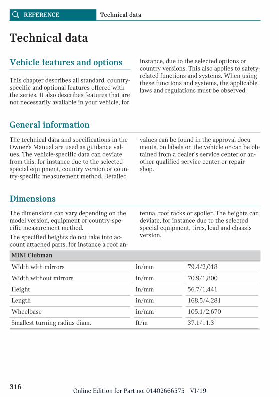
Technical data
Vehicle features and options
This chapter describes all standard, country-specific and optional features offered withthe series. It also describes features that arenot necessarily available in your vehicle, for
instance, due to the selected options orcountry versions. This also applies to safety-related functions and systems. When usingthese functions and systems, the applicablelaws and regulations must be observed.
General information
The technical data and specifications in theOwner's Manual are used as guidance val-ues. The vehicle-specific data can deviatefrom this, for instance due to the selectedspecial equipment, country version or coun-try-specific measurement method. Detailed
values can be found in the approval docu-ments, on labels on the vehicle or can be ob-tained from a dealer’s service center or an-other qualified service center or repairshop.
Dimensions
The dimensions can vary depending on themodel version, equipment or country-spe-cific measurement method.
The specified heights do not take into ac-count attached parts, for instance a roof an-
tenna, roof racks or spoiler. The heights candeviate, for instance due to the selectedspecial equipment, tires, load and chassisversion.
MINI Clubman
Width with mirrors in/mm 79.4/2,018
Width without mirrors in/mm 70.9/1,800
Height in/mm 56.7/1,441
Length in/mm 168.5/4,281
Wheelbase in/mm 105.1/2,670
Smallest turning radius diam. ft/m 37.1/11.3
Seite 316
REFERENCE Technical data
316Online Edition for Part no. 01402666575 - VI/19

Weights
MINI Cooper Clubman
Approved gross vehicle weight
Manual transmission lbs/kg 4,255/1,930
Steptronic transmission lbs/kg 4,321/1,960
Load
Manual transmission lbs/kg 939/426
Steptronic transmission lbs/kg 952/432
Approved front axle load
Manual transmission lbs/kg 2,172/985
Steptronic transmission lbs/kg 2,227/1,010
Approved rear axle load
Manual transmission lbs/kg 2,194/995
Steptronic transmission lbs/kg 2,194/995
MINI Cooper S Clubman
Approved gross vehicle weight
Manual transmission lbs/kg 4,266/1,935
Steptronic transmission lbs/kg 4,343/1,970
Load
Manual transmission lbs/kg 893/405
Steptronic transmission lbs/kg 944/428
Approved front axle load
Manual transmission lbs/kg 2,249/1,020
Steptronic transmission lbs/kg 2,337/1,060
Approved rear axle load
Manual transmission lbs/kg 2,138/970
Steptronic transmission lbs/kg 2,172/985
Seite 317
Technical data REFERENCE
317Online Edition for Part no. 01402666575 - VI/19

MINI Cooper Clubman ALL4
Approved gross vehicle weight lbs/kg 4,431/2,010
Load lbs/kg 871/395
Approved front axle load lbs/kg 2,304/1,045
Approved rear axle load lbs/kg 2,238/1,015
MINI Cooper S Clubman ALL4
Approved gross vehicle weight lbs/kg 4,519/2,050
Load lbs/kg 922/418
Approved front axle load lbs/kg 2,370/1,075
Approved rear axle load lbs/kg 2,260/1,025
MINI John Cooper Works Clubman ALL4
Approved gross vehicle weight lbs/kg 4,564/2,070
Load lbs/kg 917/416
Approved front axle load lbs/kg 2,414/1,095
Approved rear axle load lbs/kg 2,271/1,030
Capacities
MINI Clubman
Fuel tank, approx. US gal/liters 13.2/50.0
Observe further information on fuel quality,refer to page 258.
Seite 318
REFERENCE Technical data
318Online Edition for Part no. 01402666575 - VI/19

Appendix
Any updates to the Owner's Manual of thevehicle are listed here.
Updates made after the edito-rial deadline
The following chapters were updated in theprinted version of the Owner's Manual afterthe editorial deadline for the IntegratedOwner's Manual in the vehicle had closed:
– Replacing components: Light and bulbreplacement: Front halogen lights, bulbreplacement.
Seite 319
Appendix REFERENCE
319Online Edition for Part no. 01402666575 - VI/19

License Texts and Certifications
Headunit
Brazil
Este equipamento opera em caráter secun-dário, isto é, não tem direito a proteção con-tra interferência prejudicial, mesmo de esta-ções do mesmo tipo, e não pode causarinterferência a sistemas operando emcaráter primário.
Europe
European Union: Declaration ofConformity
Hereby, Alpine Electronics , Inc. declaresthat the radio equipment type BIS01 is incompliance with Directive 2014/53/EU.The full text of the EU declaration of con-formity is avallable at the following internetaddress: http://www.alpine.com/e/research/
Technical information
Frequency Band: 2.5 GHz
Output Power : 8 dBm
Manufacturer and Address
Manufacturer: Alpine Electronics, Inc.
Address: 20-1, Yoshima Industrial Park,Iwaki, Fukushima 970-1192 Japan
Phone: +81-246-36-4111
БългарскиС настоящото Alpine Electronicsдекларира, че този типрадиосъоръжение BIS01 е всъответствие с Директива 2014/53/ЕС.Цялостният текст на ЕС декларацията засъответствие може да се намери наследния интернет адрес: http://www.alpine.com/e/research/
ČeštinaTímto Alpine Electronics prohlašuje, že typrádiového zařízení BIS01 je v souladu sesměrnicí 2014/53/EU. Úplné znění EUprohlášení o shodě je k dispozici na této in-ternetové adrese: http://www.alpine.com/e/research/
DanskHermed erklærer Alpine Electronics, at radi-oudstyrstypen BIS01 er i overensstemmelsemed direktiv 2014/53/EU. EU-overensstem-melseserklæringens fulde tekst kan findespå følgende internetadresse: http://www.alpine.com/e/research/
DeutschHiermit erklärt Alpine Electronics, dass derFunkanlagentyp BIS01 der Richtlinie2014/53/EU entspricht. Der vollständige
Seite 320
REFERENCE License Texts and Certifications
320Online Edition for Part no. 01402666575 - VI/19

Text der EU-Konformitätserklärung ist un-ter der folgenden Internetadresse verfüg-bar: http://www.alpine.com/e/research/
EestiKäesolevaga deklareerib Alpine Electronics,et käesolev raadioseadme tüüp BIS01vastab direktiivi 2014/53/EL nõuetele. ELivastavusdeklaratsiooni täielik tekst on kät-tesaadav järgmisel internetiaadressil:http://www.alpine.com/e/research/
EnglishHereby, Alpine Electronics declares that theradio equipment type BIS01 is in compli-ance with Directive 2014/53/EU. The fulltext of the EU declararation of conformity isavilable at the following internet ad-dress :http://www.alpine.com/e/research/
EspañolPor la presente, Alpine Electronics declaraque el tipo de equipo radioeléctrico BIS01es conforme con la Directiva 2014/53/UE.El texto completo de la declaración UE deconformidad está disponible en la direcciónInternet siguiente: http://www.alpine.com/e/research/
ΕλληνικήΜε την παρούσα ο/η Alpine Electronics,δηλώνει ότι ο ραδιοεξοπλισμός BIS01 πληροίτην οδηγία 2014/53/ΕΕ. Το πλήρες κείμενοτης δήλωσης συμμόρφωσης ΕΕ διατίθεταιστην ακόλουθη ιστοσελίδα στο διαδίκτυο:http://www.alpine.com/e/research/
FrançaisLe soussigné, Alpine Electronics, déclareque l'équipement radioélectrique du typeBIS01 est conforme à la directive2014/53/UE. Le texte complet de la déclara-tion UE de conformité est disponible à
l'adresse internet suivante: http://www.alpine.com/e/research/
HrvatskiAlpine Electronics ovime izjavljuje da jeradijska oprema tipa BIS01 u skladu s Dir-ektivom 2014/53/EU. Cjeloviti tekst EU iz-jave o sukladnosti dostupan je na sljedećojinternetskoj adresi: http://www.alpine.com/e/research/
ÍslenskaHér, Alpine Electronics lýsir yfir að radíó-búnaður gerð BIS01 er í samræmi við tilski-pun 2014/53 / ESB. The fullur texti af ESBdeclararation á samræmi er avilable á eftir-farandi veffangi: http://www.alpine.com/e/research/
ItalianoIl fabbricante, Alpine Electronics , dichiarache il tipo di apparecchiatura radio BIS01 èconforme alla direttiva 2014/53/UE. Il testocompleto della dichiarazione di conformitàUE è disponibile al seguente indirizzo Inter-net: http://www.alpine.com/e/research/
LatviskiAr šo Alpine Electronics deklarē, ka radioie-kārta BIS01 atbilst Direktīvai 2014/53/ES.Pilns ES atbilstības deklarācijas teksts irpieejams šādā interneta vietnē: http://www.alpine.com/e/research/
LietuviųAš, Alpine Electronics, patvirtinu, kad radijoįrenginių tipas BIS01 atitinka Direktyvą2014/53/ES. Visas ES atitikties deklaracijostekstas prieinamas šiuo interneto adresu:http://www.alpine.com/e/research/
NederlandsHierbij verklaar ik, Alpine Electronics, dathet type radioapparatuur BIS01 conform is
Seite 321
License Texts and Certifications REFERENCE
321Online Edition for Part no. 01402666575 - VI/19

met Richtlijn 2014/53/EU. De volledigetekst van de EU-conformiteitsverklaring kanworden geraadpleegd op het volgende inter-netadres: http://www.alpine.com/e/research/
MaltiB'dan, Alpine Electronics, niddikjara li danit-tip ta' tagħmir tar-radju BIS01 huwa kon-formi mad-Direttiva 2014/53/UE. It-testkollu tad-dikjarazzjoni ta' konformità tal-UEhuwa disponibbli f'dan l-indirizz tal-Internetli ġej: http://www.alpine.com/e/research/
MagyarAlpine Electronics igazolja, hogy a BIS01 tí-pusú rádióberendezés megfelel a2014/53/EU irányelvnek. Az EU-megfelelő-ségi nyilatkozat teljes szövege elérhető akövetkező internetes címen: http://www.alpine.com/e/research/
NorskErklærer herved Alpine Electronics at radio-utstyr typen BIS01 er i samsvar med direk-tiv 2014/53 / EU. Den fullstendige teksten iEU declararation samsvars er avilable påfølgende internettadresse: http://www.alpine.com/e/research/
PolskiAlpine Electronics niniejszym oświadcza, żetyp urządzenia radiowego BIS01 jestzgodny z dyrektywą 2014/53/UE. Pełnytekst deklaracji zgodności UE jest dostępnypod następującym adresem internetowym:http://www.alpine.com/e/research/
PortuguêsO(a) abaixo assinado(a) Alpine Electronicsdeclara que o presente tipo de equipamentode rádio BIS01 está em conformidade com aDiretiva 2014/53/UE. O texto integral dadeclaração de conformidade está disponível
no seguinte endereço de Internet: http://www.alpine.com/e/research/
RomânăPrin prezenta, Alpine Electronics declară cătipul de echipamente radio BIS01 este înconformitate cu Directiva 2014/53/UE.Textul integral al declarației UE de confor-mitate este disponibil la următoarea adresăinternet: http://www.alpine.com/e/research/
SlovenskoAlpine Electronics potrjuje, da je tip radi-jske opreme BIS01 skladen z Direktivo2014/53/EU. Celotno besedilo izjave EU oskladnosti je na voljo na naslednjem splet-nem naslovu: http://www.alpine.com/e/research/
SlovenskýAlpine Electronics týmto vyhlasuje, že rádi-ové zariadenie typu BIS01 je v súlade sosmernicou 2014/53/EÚ. Úplné EÚ vyhláse-nie o zhode je k dispozícii na tejto interne-tovej adrese: http://www.alpine.com/e/research/
SuomiAlpine Electronics vakuuttaa, että radiolai-tetyyppi BIS01 on direktiivin 2014/53/EUmukainen. EU-vaatimustenmukaisuusva-kuutuksen täysimittainen teksti on saata-villa seuraavassa internetosoitteessa:http://www.alpine.com/e/research/
SvenskaHärmed försäkrar Alpine Electronics attdenna typ av radioutrustning BIS01 över-ensstämmer med direktiv 2014/53/EU. Denfullständiga texten till EU-försäkran omöverensstämmelse finns på följande webba-dress: http://www.alpine.com/e/research/
Seite 322
REFERENCE License Texts and Certifications
322Online Edition for Part no. 01402666575 - VI/19
Japan
Mexico
La operación de este equipo está sujeta a lassiguientes dos condiciones:
(1) es posible que este equipo o dispositivono cause interferencia perjudicial y
(2) este equipo o dispositivo debe aceptarcualquier interferencia, incluyendo la quepueda causar su operación no deseada.
Russia, Kazakhstan, Belarus
South Korea
해당 무선설비는 전파혼신 가능성이 있으므로 인명안전과 관련된 서비스는 할 수없습니다
A 급 기기 (업무용 방송통신기자재)
이 기기는 업무용(A 급) 전자파적합기기로서 판매자
또는 사용자는 이 점을 주의하시기 바라며, 가정외의
지역에서 사용하는 것을 목적으로 합니다.
Taiwan本產品符合低功率電波輻射性電機管理辦法 第十二條、第十四條等條文規定
1.
經型式認證合格之低功率射頻電機,非經許可,公司、商號或使用者均不得擅自變更頻率、加大功率或變更原設計之特性及功能。
Low Power radio frequency electric machi-nery was qualified by Type Approval, notget permission from authority; the company,business or user can’t arbitrarily changefrequency, increase power or modify featureor function of original design.
2.
低功率射頻電機之使用不得影響飛航安全及干擾合法通信;經發現有干擾現象時,應立即停用,並改善至無干擾時方得繼續使用。
前項合法通信,指依電信法規定作業之無線電通信。
Seite 323
License Texts and Certifications REFERENCE
323Online Edition for Part no. 01402666575 - VI/19

低功率射頻電機須忍受合法通信或工業、科學及醫療用電波輻射性電機設備之干擾。
Use of low power radio frequency electricmachinery can’t affect flight safety and in-terfere with legal communication; once dis-cover the interfered phenomenon, it shouldstop immediately and improve to no inter-ference and then could continue to use.
The preceding legal communication is radiocommunication which follows Telecommu-nication Act to operate.
Low power radio frequency electric machi-nery must tolerate interference from legalcommunication or electric machinery appa-ratus of industry, science and medical radia-tion.
USA, Canada
USA (FCC) and Canada (IC)Register model name:BIS01
Product code: RB00010A
FCC CAUTIONChanges or modifications not expressly ap-proved by the party responsible for compli-ance could void the user’s authority to oper-ate the equipment. This transmitter mustnot be co-located or operated in conjunctionwith any other antenna or transmitter. Thisdevice complies with part 15 of FCC Rulesand Industry Canada’s licence-exempt RSSs.Operation is subject to the following twoconditions: (1) this device may not causeharmful interference, and (2) this devicemust accept any interference received, in-cluding interference that may cause unde-sired operation.
Le présent appareil est conforme à la partie15 des règles de la FCC et aux normes desCNR d'Industrie Canada applicables aux ap-pareils radio exempts de licence. L'exploita-tion est autorisée aux deux conditions sui-
vantes : (1) l'appareil ne doit pas produire debrouillage, et (2) l'appareil doit accepter toutbrouillage subi, même si le brouillage estsusceptible d'en compromettre le fonc-tionnement.
This equipment complies with FCC/IC radi-ation exposure limits set forth for an uncon-trolled environment and meets the FCCradio frequency (RF) Exposure Guidelinesand RSS-102 of the IC radio frequency (RF)Exposure rules. This equipment has verylow levels of RF energy that is deemed tocomply without maximum permissive expo-sure evaluation (MPE). (產)
Cet équipement est conforme aux limitesd’exposition aux rayonnements énoncéespour un environnement non contrôlé et re-specte les règles les radioélectriques (RF)de la FCC lignes directrices d'exposition etd’exposition aux fréquences radioélectri-ques (RF) CNR-102 de l’IC. Cet équipementémet une énergie RF très faible qui est con-sidérée comme conforme sans évaluation del’exposition maximale autorisée (MPE). (產)
Zambia
Information regarding OpenSource Software Licenses
The “IwIP – A Lightweight TCP/IP stack”included in some products is licensed underthe “BSD licence”. A copy of that license inthe English original version with a copy-
Seite 324
REFERENCE License Texts and Certifications
324Online Edition for Part no. 01402666575 - VI/19

right notice, a disclaimer of warranty, andan exclusion of liability is included below.Copyright (c) 2001-2004 Swedish Instituteof Computer Science. All rights reserved.Redistribution and use in source and binaryforms, with or without modification, arepermitted provided that the following condi-tions are met: 1. Redistributions of sourcecode must retain the above copyright no-tice, this list of conditions and the followingdisclaimer. 2. Redistributions in binary formmust reproduce the above copyright notice,this list of conditions and the following dis-claimer in the documentation and/or othermaterials provided with the distribution. 3.The name of the author may not be used toendorse or promote products derived fromthis software without specific prior writtenpermission. THIS SOFTWARE IS PRO-VIDED BY THE AUTHOR ``AS IS`` AND ANYEXPRESS OR IMPLIED WARRANTIES, IN-CLUDING, BUT NOT LIMITED TO, THE IM-PLIED WARRANTIES OF MERCHANTA-BILITY AND FITNESS FOR A PARTICULARPURPOSE ARE DISCLAIMED. IN NOEVENT SHALL THE AUTHOR BE LIABLEFOR ANY DIRECT, INDIRECT, INCIDEN-TAL, SPECIAL, EXEMPLARY, OR CONSE-QUENTIAL DAMAGES (INCLUDING, BUTNOT LIMITED TO, PROCUREMENT OFSUBSTITUTE GOODS OR SERVICES; LOSSOF USE, DATA, OR PROFITS; OR BUSINESSINTERRUPTION) HOWEVER CAUSED ANDON ANY THEORY OF LIABILITY,WHETHER IN CONTRACT, STRICT LIABIL-ITY, OR TORT (INCLUDING NEGLIGENCEOR OTHERWISE) ARISING IN ANY WAYOUT OF THE USE OF THIS SOFTWARE,EVEN IF ADVISED OF THE POSSIBILITYOF SUCH DAMAGE.
Remote Control
MexicoCOFETEL: RLVBHEID13–0912
Marca: Hella
Modelo (s): IDGNG1
La operación de este equipo está sujeta a lassiguientes dos condiciones:
(1) es posible que este equipo o dispositivono cause interferencia perjudicial y
(2) este equipo o dispositivo debe aceptarcualquier interferencia, incluyendo la quepueda causar su operación no deseada.
USA/CanadaFCC § 15.19 Labelling requirements
This device complies with Part 15 of theFCC Rules and with Industry Canada li-cence-exempt RSS. Operation is subject tothe following two conditions:
(1) This device may not cause harmful inter-ference, and
(2) this device must accept any interferencereceived, including interference that maycause undesired operation.
FCC § 15.21 Information to user
Changes or modifications not expressly ap-proved by the party responsible for compli-ance could void the user's authority to oper-ate the equipment.
Le présent appareil est conforme aux CNRd'Industrie Canada applicables aux appareilsradio exempts de licence. L'exploitation estautorisée aux deux conditions suivantes :
(1) l'appareil ne doit pas produire de brouil-lage, et
(2) tl'utilisateur de l'appareil doit acceptertout brouillage radioélectrique subi, mêmesi le brouillage est susceptible d'en compro-mettre le fonctionnement.
FCC § 15.19 Labelling requirements
Seite 325
License Texts and Certifications REFERENCE
325Online Edition for Part no. 01402666575 - VI/19
This device complies with Part 15 of theFCC Rules and with Industry Canada li-cence-exempt RSS. Operation is subject tothe following two conditions:
(1) This device may not cause harmful inter-ference, and
(2) this device must accept any interferencereceived, including interference that maycause undesired operation.
FCC § 15.21 Information to user
Changes or modifications not expressly ap-proved by the party responsible for compli-ance could void the user's authority to oper-ate the equipment.
Tire Pressure Monitoring Sys-tem
CanadaIC: 7812D-TIS07
Operation is subject to the following twoconditions:
(1) this device may not cause harmful inter-ference, and
(2) this device must accept any interferencereceived, including interference that maycause undesired operation.
USAFCC ID: KR5TIS-07
This device complies with Part 15 of theFCC Rules. Operation is subject to the fol-lowing two conditions:
(1) this device may not cause harmful inter-ference, and
(2) this device must accept any interferencereceived, including interference that maycause undesired operation.
Transmitter/Receiver
MexicoIFETEL: RLVCOA213-1447
A2C35029700
Continental Automotive GmbH
Siemensstrasse 12
93055 Regensburg
Germany
Para su uso en México, la operación de esteequipo está sujeta a las siguientes dos con-diciones:
(1) es posible que este equipo o dispositivono cause interferencia perjudicial y
(2) este equipo o dispositivo debe aceptarcualquier interferencia, incluyendo la quepueda causar su operación no deseada.
Canada/USAModel: A2C35029700
IC: 7812D-35029700
This device complies with Industry Canadalicense-exempt RSS standard(s). Operationis subject to the following two conditions:
(1) this device may not cause harmful inter-ference, and
(2) this device must accept any interferencereceived, including interference that maycause undesired operation.
Le présent appareil est conforme aux CNRd'Industrie Canada applicables aux appareilsradio exempts de licence. L'exploitation estautorisée aux deux conditions suivantes :
(1) l'appareil ne doit pas produire de brouil-lage, et
(2) l'utilisateur de l'appareil doit acceptertout brouillage radioélectrique subi, mêmesi le brouillage est susceptible d'en compro-mettre le fonctionnement.
Model: A2C35029700
Seite 326
REFERENCE License Texts and Certifications
326Online Edition for Part no. 01402666575 - VI/19

FCC ID:KR5A2C35029700
This device complies with Part 15 of theFCC Rules. Operation is subject to the fol-lowing two conditions:
(1) This device may not cause harmful inter-ference, and
(2) this device must accept any interferencereceived, including interference that maycause undesired operation.
Seite 327
License Texts and Certifications REFERENCE
327Online Edition for Part no. 01402666575 - VI/19

Everything from A to Z
Index
A
A/C button, see Air conditioning 191 ABS, Antilock Brake System 162 Acceleration Assistant, see Launch Con-
trol 119 Accessories and parts 12 ACC, see Camera-based cruise control 167 Activated-charcoal filter 193 Activation times, parked-car ventila-
tion 194 Active Cruise Control, see Camera-based
cruise control 167 Active Guard, see Intelligent Safety 153 Adaptive chassis 164 Additives, engine oil types 285 Adjustments, steering wheel 89 After washing vehicle 310 Airbags 142 Airbags, indicator and warning light 144 Air circulation, see Recirculated-air
mode 188, 192 Air conditioner 187 Air conditioning 188, 191 Air distribution, manual 189, 193 Air flow, air conditioner 189 Air flow, automatic climate control 192 Air pressure, tires 260 Air vents, see Ventilation 193 Alarm system 72 Alarm triggering 72 Alarm, unintentional 74 ALL4 164 All-season tires, see Winter tires 268 All-wheel drive, see ALL4 164 AM/FM station 232 Antifreeze, washer fluid 110 Antilock Brake System, ABS 162 Anti-slip control, see DSC 162 Anti-theft protection, lug bolts 276
Approach control warning with city lightbraking function 154
Approved axle load 317 Ash tray 201 Assistance when driving off 165 Audio 240 Audio playback, Bluetooth 240 Audio playback, pause 228 AUTO intensity 192 Automatic climate control 190 Automatic Curb Monitor 88 Automatic deactivation, front-seat passen-
ger airbags 144 Automatic headlight control 137 Automatic locking 72 Automatic recirculated-air control 192 Automatic Service Request 250 Automatic transmission with Step-
tronic 112 Automatic unlocking 72 Automatic vehicle wash 309 AUTO program, automatic climate con-
trol 191 AUTO program, intensity 192 Auto Start/Stop function 98 Auto washing 309 Average consumption 131 Average speed 131 Axle loads, weights 317
B
Backrest curvature, see Lumbar sup-port 80, 81
Backrest, seats 79 Balance, sound settings 230 Band-aids, see First-aid kit 301 Bass, sound settings 230 Battery, disposing of 300 Battery Guard, Teleservice 251
Seite 328
REFERENCE Everything from A to Z
328Online Edition for Part no. 01402666575 - VI/19

Battery, vehicle 299 Being towed, see Tow-starting and tow-
ing 304 Belts, safety belts 82 Beverage holder, cup holder 206 Blocking, power window 76 Bluetooth audio 240 Bluetooth connection 51 Bonus range, GREEN Mode 223 Bottle holder, see Cup holder 206 Brake assistant 162 Brake discs, break-in 216 Brake pads, break-in 216 Braking, information 218 Breakdown assistance 301 Break-in 216 Brightness of Control Display 48 Bulb replacement 292 Bulb replacement, front 293, 294 Bulb replacement, rear 295 Bulb replacement, side 298 Bulbs and lights 292 Button, SOS 302 Button, Start/Stop 95 Bypassing, see Jump-starting 303
C
California Proposition 65 Warning 12 Camera-based assistance systems, see Intel-
ligent Safety 153 Camera-based cruise control 167 Camera lenses, care 312 Camera, rearview camera 180 Can holder, see Cup holder 206 Care, displays 312 Care, vehicle 310 Care, washing the vehicle 309 Cargo area 208 Cargo area, adapting size 213 Cargo area door, see Split doors 69 Cargo area, enlarging 211 Cargo area, loading 209 Cargo area, storage compartments 210 Cargo cover 210 Cargo position, rear seat backrest 211
Cargo, stowing and securing 209 Cargo straps 209 Carpet, care 312 Catalytic converter, see Hot exhaust gas
system 217 CBS Condition Based Service 289 Center armrest 205 Center console 40 Central Information Display (CID) 42 Central instrument cluster, LED ring 134 Central locking system, unlocking, from in-
side 65 Central screen, see Control Display 43 Changes, technical, see For Your Own
Safety 11 Changing parts 291 Changing wheels 274 Changing wheels/tires 267 Chassis number, see Vehicle identification
number 16 Check Control 121 Checking the oil level electronically 283 Children, seating position 90 Children, transporting safely 90 Child restraint system 90 Child restraint system LATCH 92 Child restraint systems, mounting 91 Child safety locks 94 Child seat, mounting 91 Child seats 90 Chrome parts, care 311 Cigarette lighter 201 Cleaning, displays 312 Climate control 187, 190 Clothes hooks 206 Coasting 224 Coasting with engine decoupled, coast-
ing 224 Coasting with idling engine 224 Combination switch, see Turn signals 102 Combi switch, see Wiper system 103, 107 Comfort Access 66 Compartments in the doors 205 Compass 199 Compatible devices, see Suitable devi-
ces 51
Seite 329
Everything from A to Z REFERENCE
329Online Edition for Part no. 01402666575 - VI/19

Compressor 270 Computer, see Onboard Computer 130 Condensation on windows 193 Condensation under the vehicle 219 Condition Based Service CBS 289 Conference, see Calls with multiple par-
ties 247 Configuring driving program 165 Confirmation signal 72 Connecting device 50 Connecting mobile phone 50 Connecting smartphone 50 Connecting telephone 50 Connections 50 Consumption, see Average consump-
tion 131 Consumption, see Current consump-
tion 127 Contacts 248 Continued driving with a flat tire 149, 152 Control Display 43 Control Display, settings 47 Controller 44 Control systems, driving stability 162 Convenient closing 62 Convenient opening 61 Coolant 287 Cooling, maximum 191 Cooling system 287 Cornering light 138 Corrosion on brake discs 219 Cosmetic mirror 201 Coupling, see Pairing 50 Courtesy lights during unlocking 61 Courtesy lights with the vehicle locked 62 Cruise control 174 Cruise control, active 167 Cruise control with distance control, see
Camera-based cruise control 167 Cruise control without distance control, see
Cruise control 174 Cruising range 126 Cup holder 206 Current consumption 127 Customer support 252
D
Damage, tires 267 Data memory 13 Data protection, settings 50 Data, technical 316 Date 47 Date display 126 Daytime pedestrian collision mitiga-
tion 158 Daytime running lights 138 DCC, see Cruise control 174 Defrosting, see Defrosting the win-
dows 189 Defrosting, see Windows, defrosting 193 Defrosting the windows 189 Deleting personal data 50 Deletion of personal data 50 Device list 50 Digital clock 126 Digital compass 199 Digital radio, see HD Radio reception 233 Dimensions 316 Dimmable exterior mirrors 88 Dimmable interior mirror 89 Direction indicator, see Turn signals 102 Display and input 42 Display, electronic, instrument cluster 121 Display, engine temperature 132 Display, GREEN Mode 221 Display lighting, see Instrument light-
ing 140 Displays 120 Displays, care 312 Disposal, coolant 288 Disposal, vehicle battery 300 Distance control, see PDC 176 Drive-off assistant 165 Drive-off assistant, see DSC 162 Driver assistance, see Intelligent
Safety 153 Driver profiles 70 Driving Dynamics Control, see MINI Driv-
ing Modes switch 164 Driving Excitement, SPORT 133 Driving instructions 0
Seite 330
REFERENCE Everything from A to Z
330Online Edition for Part no. 01402666575 - VI/19

Driving instructions, break-in 216 Driving mode, GREEN 221 Driving modes 164 Driving notes, general 217 Driving on racetracks 219 Driving stability control systems 162 Driving tip, GREEN tip 223 Driving tips 217 Drying air, see Air conditioning 188, 191 DSC Dynamic Stability Control 162 DTC Dynamic Traction Control 163 Dynamic damping, see Adaptive chas-
sis 164 Dynamic Stability Control DSC 162 Dynamic Traction Control DTC 163
E
Easy Opener 68 Electronic displays, instrument cluster 121 Electronic oil measurement 283 Electronic Stability Program ESP, see
DSC 162 Emergency release, fuel filler flap 257 Emergency Request 302 Emergency service, see Breakdown assis-
tance 301 Emergency unlocking, transmission
lock 118 Emergency wheel, compact wheel, see
Emergency wheel 279 Energy control 127 Engine, automatic Start/Stop function 98 Engine, automatic switch-off 98 Engine compartment 280 Engine compartment, working in 281 Engine coolant 287 Engine idling when driving, coasting 224 Engine oil 283 Engine oil, adding 284 Engine oil change 286 Engine oil filler neck 284 Engine oil types to add 285 Engine start, jump-starting 303 Engine start, see Starting the engine 96 Engine stop 97
Engine temperature, display 132 Entering a vehicle wash 309 Entertainment, control elements 228 Entertainment source, changing 228 Equipment, interior 196 Error displays, see Check Control 121 ESP Electronic Stability Program, see
DSC 162 Exchanging wheels/tires 267 Exhaust gas system 217 Exiting a vehicle wash 309 Exterior mirror, automatic dimming fea-
ture 88 Exterior mirrors 87 Exterior mirrors, Automatic Curb Moni-
tor 88 Exterior mirrors, malfunction 88 External start 303 External temperature display 126 External temperature warning 126 Eyes for securing cargo 209
F
Fader, sound settings 230 Failure message, see Check Control 121 False alarm, see Unintentional alarm 74 Fan, see Air flow 189, 192 Fastening safety belts, see Safety belts 82 Filler neck for engine oil 284 Filter, see Microfilter 189 Filter, see Microfilter/activated-charcoal fil-
ter 193 Fine wood, care 311 First-aid kit 301 Flat tire, changing wheels 274 Flat Tire Monitor FTM 150 Flat tire, repairing 269 Flat tire, Tire Pressure Monitor TPM 146 Flat tire, warning light 147, 151 Flooding 217 Floor carpet, care 312 Floor mats, care 312 FM/AM station 232 Fogged up windows 189
Seite 331
Everything from A to Z REFERENCE
331Online Edition for Part no. 01402666575 - VI/19

Fold-away position, windshield wip-ers 106, 109
Fold back rear seat backrests 211 Foot brake 218 For Your Own Safety 11 Front airbags 142 Front fog lights 139 Front fog lights, LED, bulb replace-
ment 294 Front-seat passenger airbags, automatic de-
activation 144 Front-seat passenger airbags, indicator
light 145 Front seats 79 FTM Flat Tire Monitor 150 Fuel 258 Fuel cap 256 Fuel filler flap 256 Fuel gauge 125 Fuel quality 258 Fuel recommendation 258 Fuel, tank capacity 318 Fuse 300
G
Garage door opener, see Integrated Univer-sal Remote Control 196
Gasoline 258 Gear shift indicator 128 General driving notes 217 General settings 47 Glare shield 201 Glass sunroof, initialize the system 78 Glass sunroof, see Panoramic glass sun-
roof 76 Glove compartment 204 Gong, volume equalization 230 GPS geolocation, vehicle position 48 GREEN bonus range 223 GREEN Mode 221 GREEN - program, driving dynamics 164 GREEN tip, driving tip 223 Gross vehicle weight, approved 317 Ground clearance 219
H
Halogen headlights 293 Handbrake, see Parking brake 101 Hand-held transmitter, alternating
code 197 Hands-free system 248 Hazard warning flashers 301 HD Radio 233 Head airbag 143 Headlight control, automatic 137 Headlight courtesy delay feature 137 Headlight flasher 103 Headlight glass 293 Headlights, care 310 Head restraints, front 84 Head restraints, rear 85 Heavy cargo, stowing cargo 209 High-beam Assistant 138 High beams 103 High beams/low beams, see High-beam As-
sistant 138 Hills 218 Hill start assistant, see Drive-off assis-
tant 165 Holder for beverages 206 HomeLink, see Integrated Universal Remote
Control 196 Homepage 10 Hood 281 Horn 38 Hot exhaust gas system 217 Hotline, see Customer support 252 Hydroplaning 217
I
Ice warning, see External temperaturewarning 126
Icy roads, see External temperature warn-ing 126
Identification marks, tires 264 Identification number, see Vehicle identifi-
cation number 16 Ignition off 95
Seite 332
REFERENCE Everything from A to Z
332Online Edition for Part no. 01402666575 - VI/19

Ignition on 95 Illuminated ring, central instrument clus-
ter 134 Indication of a flat tire 147, 151 Indicator light, see Check Control 121 Individual air distribution 189, 193 Individual settings, see Driver profiles 70 Inflation pressure, tires 260 Inflation pressure warning, tires 150 Info Display, see Onboard Computer 130 Information 10 Initialize, Tire Pressure Monitor TPM 146 Initializing, Flat Tire Monitor FTM 151 Input and display 42 Instrument cluster 120 Instrument cluster, electronic displays 121 Instrument lighting 140 Integrated key 64 Integrated Universal Remote Control 196 Intelligent Auto Start/Stop function 100 Intelligent emergency call 302 Intelligent Safety 153 Intended use 11 Intensity, AUTO program 192 Interior equipment 196 Interior lights 140 Interior lights during unlocking 61 Interior lights with the vehicle locked 62 Interior mirror 87 Interior mirror, automatic dimming fea-
ture 89 Interior mirror, compass 199 Interior mirror, manually dimmable 88 Interior motion sensor 74 Internet site 10 Interval display, service requirements 127 Interval mode 104, 108 In the vicinity of the center console 40 In the vicinity of the roofliner 41 In the vicinity of the steering wheel 38 iPod/iPhone 240
J
Jacking points for the vehicle jack 277 Jam protection system, glass sunroof 78
Jam protection system, windows 75 Jump-starting 303
K
Keyless Go, see Comfort Access 66 Key, see Integrated key 64 Key, see Vehicle key 60 Kickdown, Steptronic transmission 115 Knee airbag 143
L
Label on recommended tires 268 Label, runflat tires 269 Language, on the Control Display 47 Lashing eyes 209 LATCH child restraint fixing system 92 Launch Control 119 Leather, care 311 LED ring, central instrument cluster 134 LEDs, light-emitting diodes 292 Letters and numbers, entering 46 Light 136 Light-alloy wheels, care 311 Light-emitting diodes, LEDs 292 Lighter 201 Lighting 136 Light replacement 292 Light replacement, front 293, 294 Light replacement, rear 295 Light replacement, side 298 Lights and bulbs 292 Light switch 136 List of all messages 49 Load 209 Loading 208 Loading position 211 Location, vehicle position 48 Locking, automatic 72 Locking, from inside 65 Locking, see Opening and Closing 60 Locking, settings 71 Low beams 136
Seite 333
Everything from A to Z REFERENCE
333Online Edition for Part no. 01402666575 - VI/19

Low beams, automatic, see High-beam As-sistant 138
Lower back support 81 Lower back support, mechanical 80 Lug bolt lock 276 Luggage rack, see Roof-mounted luggage
rack 219 Lumbar support 81 Lumbar support, mechanical 80
M
Maintenance 289 Maintenance requirements 289 Maintenance, service requirements 127 Maintenance system, MINI 289 Make-up mirror 201 Malfunction displays, see Check Con-
trol 121 Manual air distribution 189, 193 Manual air flow 189, 192 Manual brake, see Parking brake 101 Manual mode, transmission 116 Manual operation, fuel filler flap 257 Manual operation, PDC Park Distance Con-
trol 177 Manual operation, rearview camera 180 Manual transmission 111 Manufacturer of the MINI 11 Matte finish 310 Maximum cooling 191 Maximum speed, display 128 Maximum speed, winter tires 268 Measurement, units of 48 Mechanical key 64 Media of the Owner's Manual 56 Medical kit 301 Memory function 86 Menu in instrument cluster 130 Menus, Central Information Display
(CID) 45 Messages 49 Messages, see Check Control 121 Microfilter 189, 193 MID - program, driving dynamics 164 MINI driving modes 164
MINI logo projection during unlocking 61 MINI maintenance system 289 Minimum tread, tires 266 MINI Teleservices 250 Mirrors 87 Mirror, see Memory function 86 Mobile communication devices in the vehi-
cle 217 Mobile phone 246 Mobile phone, operation 246 Mobility System 270 Modifications, technical, see For Your Own
Safety 11 Moisture in headlight 293 Monitor, see Control Display 43 Mounting of child restraint systems 91 MP3 player, see Audio 240 Multifunction steering wheel, buttons 38
N
Neck restraints, front, see Head re-straints 84
Neck restraints, rear, see Head re-straints 85
Neutral cleaner, see Wheel cleaner 311 New wheels and tires 267 No-touch opening the split doors 68
O
OBD Onboard Diagnostics 290 Obstacle marking, rearview camera 181 Octane rating, see Recommended fuel
grade 259 Odometer 125 Oil 283 Oil, adding 284 Oil change 286 Oil change interval, service require-
ments 127 Oil filler neck 284 Oil types to add, engine 285 Onboard Computer 130 Onboard Diagnostics OBD 290
Seite 334
REFERENCE Everything from A to Z
334Online Edition for Part no. 01402666575 - VI/19

Onboard literature, printed 56 Onboard vehicle tool kit 291 On-call service, see Breakdown assis-
tance 301 Opening and Closing 60 Opening, from inside 65 Operating concept Central Information Dis-
play (CID) operating concept 42 Operating menus, Central Information Dis-
play (CID) 42 Operation via the Controller 45 Optional equipment 11 Outside air, see Automatic recirculated-air
control 192 Owner's Manual, printed 56
P
Paint, vehicle 310 Panic alarm, see Panic mode 73 Panic mode 73 Panoramic glass sunroof 76 Parallel parking assistant 182 Park Distance Control PDC 176 Parked-car ventilation 194 Parked vehicle, condensation 219 Parking aid, see PDC 176 Parking assistant 182 Parking brake 101 Parking lights 136 Parts and accessories 12 Passenger's side mirror, tilting 88 Pathway lines, rearview camera 181 Pause, audio playback 228 PDC Park Distance Control 176 Performance Control 164 Personal profile, see Driver profiles 70 Phone conference, see Calls with multiple
parties 247 Plastic, care 312 PostCrash — iBrake 160 Power failure 299 Power windows 74 Pressure, tires 260 Pressure warning, tires 150 Printed onboard literature 56
Profiles, see Driver profiles 70 Programmable memory buttons, Central In-
formation Display (CID) 46 Protective function, glass sunroof 78 Protective function, windows 75 Push-and-turn reel, see Controller 44
R
Racetrack operation 219 Radiator fluid 287 Radio 232 Radio, adjusting the volume 228 Radio, control elements 228 Radio Data System RDS 232 Radio, muting 228 Radio-ready state 96 Radio, see Changing the entertainment
source 228 Radio, tone settings 230 Rain sensor 104, 108 Ratchet straps 209 RDS Radio Data System 232 Rear lights 295 Rearview camera 179 Rear window defroster 189, 193 Rear window wiper, operation 105, 109 Recirculated-air filter 193 Recirculated-air mode 188, 192 Recommended fuel grade 259 Recommended tire brands 268 Refueling 256 Remaining range 126 Remote control, universal 196 Renaming a station 233 Replacing parts 291 Replacing the battery, vehicle key 63 Replacing wheels/tires 267 Reporting safety malfunctions 17 RES CNCL button, see Camera-based cruise
control 167 RES CNCL button, see Cruise control 174 Reserve warning, see Range 126 Reset, Tire Pressure Monitor TPM 146 Retreaded tires 268
Seite 335
Everything from A to Z REFERENCE
335Online Edition for Part no. 01402666575 - VI/19
Roadside Assistance, see Breakdown assis-tance 301
Roadside parking lights 137 Rolling code hand-held transmitter 197 RON recommended fuel grade 259 Roofliner 41 Roof-mounted luggage rack 219 RSC Runflat System Component, see Runflat
tires 269 Rubber components, care 311 Runflat tires 269
S
Safe braking 218 Safety belt reminder for driver's seat and
front passenger seat 84 Safety belts 82 Safety belts, care 312 Safety locks, doors, and windows 94 Safety switch, windows 76 Safety systems, airbags 142 Satellite radio 234 Saving fuel 220 Screen, see Control Display 43 Screwdriver 291 Sealant, see Mobility System 270 Seat heating, front 82 Seating position for children 90 Seat, see Memory function 86 Seats, front 79 Securing cargo 209 Selection list in instrument cluster 130 Sensors, care 312 Service and warranty 13 Service Request 250 Service requirements, Condition Based
Service CBS 289 Service requirements, display 127 Servotronic 166 SET button, see Camera-based cruise con-
trol 167 SET button, see Cruise control 174 Settings, locking/unlocking 71 Settings, mirrors 87 Settings on the Control Display 47
Shift gate rotary switch 164 Shift paddles on the steering wheel 117 Side airbag 142 Signaling, horn 38 Signals when unlocking 72 Sitting safely 79 Size 316 Slide/tilt glass roof 76 Smartphone, operation 246 SMS text messages, supplementary 125 Snow chains 274 Socket 201 Socket, OBD Onboard Diagnostics 290 SOS button 302 Sound output 228 Spare tire, see Emergency wheel 279 Speed, average 131 Speed Limit Info 128 Speed Limit Info, Onboard Computer 132 Speed limits, display 128 Speed Volume, volume equalization 230 Speed warning 133 Split doors 69 Split doors, opening with no-touch activa-
tion 68 Split doors via remote control 62 Sport displays 133 SPORT program, driving dynamics 165 Sport program, transmission 116 Stability control systems 162 Standard equipment 11 Start/stop, automatic function 98 Start/Stop button 95 Starting the engine 96 Station, AM/FM 232 Stations, stored 239 Station, storing 232 Status information, Central Information Dis-
play (CID) 43 Status of Owner's Manual 11 Status, vehicle 135 Steering assistance 166 Steering wheel, adjusting 89 Steptronic Sport transmission, see Step-
tronic transmission 112
Seite 336
REFERENCE Everything from A to Z
336Online Edition for Part no. 01402666575 - VI/19
Steptronic Sport transmission with doubleclutch, see Steptronic transmission 112
Steptronic transmission 112 Steptronic transmission with double clutch,
see Steptronic transmission 112 Stopping the engine 97 Storage compartments 204 Storage, tires 269 Storing the vehicle 312 Stowing and securing cargo 209 Suitable devices 51 Suitable mobile phones 51 Summer tires, tread 266 Sun visor 201 Supplementary Owner's Manuals 56 Supplementary SMS text messages 125 Switch for driving dynamics 164 Switching calls, see Calls with multiple par-
ties 247 Switch, see Cockpit 38 Symbols 10
T
Tachometer 125 Tailgate, see Split doors 69 Tail lights 295 Technical changes, see For Your Own
Safety 11 Technical data 316 Telephone 246 Telephone conference, see Calls with multi-
ple parties 247 Telephone, operation 246 Teleservice Battery Guard 251 Teleservice Report 251 Teleservices 250 Temperature, air conditioner 188 Temperature, automatic climate con-
trol 190 Temperature display for external tempera-
ture 126 Temperature, engine 132 Terminal, starting aid 304 Theft alarm system, see Alarm system 72 Thigh support 82
Through-loading system 211 Tilt alarm sensor 74 Tilting, passenger's side mirror 88 Time 47 Tire damage 267 Tire identification marks 264 Tire inflation pressure 260 Tire inflation pressure monitor, see
FTM 150 Tire pressure 260 Tire Pressure Monitor TPM 146 Tire repair kit, see Mobility System 270 Tires, changing 267 Tire sealant, see Mobility System 270 Tires, everything on wheels and tires 260 Tires, runflat 269 Tire tread 266 Tone 230 Tools 291 Total vehicle weight 317 Towing 304 Tow-starting 304 TPM Tire Pressure Monitor 146 Traction control 163 TRACTION driving mode, driving dynam-
ics 163 Transmission lock, electronic unlock-
ing 118 Transmission lock, releasing manually 118 Transmission, manual transmission 111 Transmission, see Steptronic transmis-
sion 112 Transporting children safely 90 Tread, tires 266 Treble, sound settings 230 Trip computer 132 Triple turn signal activation 103 Trip odometer 125 Trip recorder, see Trip odometer 125 Turning radius lines, rearview camera 181 Turn signal, front 293, 294 Turn signal, indicator light 124 Turn signal, side 298 Turn signals, operation 102 Turn signals, rear, bulb replacement 295
Seite 337
Everything from A to Z REFERENCE
337Online Edition for Part no. 01402666575 - VI/19
U
Unintentional alarm 74 Units of measurement 48 Universal remote control 196 Unlocking, automatic 72 Unlocking, see Opening and Closing 60 Unlocking, settings 71 Updates made after the editorial dead-
line 11 Upholstery care 311 USB audio interface 240 USB connection 53 USB interface, position in vehicle 202 USB port, see USB interface 202 Used battery, disposing of 300 Use, intended 11
V
Vanity mirror 201 Vehicle battery 299 Vehicle, break-in 216 Vehicle care 310 Vehicle care products 310 Vehicle features and options 11 Vehicle identification number 16 Vehicle jack 277 Vehicle key, additional 63 Vehicle key, loss 63 Vehicle key, malfunction 63 Vehicle key, opening/closing 60 Vehicle key, replacing the battery 63 Vehicle key, see Vehicle key 60 Vehicle paint 310 Vehicle position, vehicle location 48 Vehicle status 135 Vehicle storage 312 Vehicle wash 309 Vehicle wash, automatic 309 Vehicle, washing 309 Ventilation 193 Ventilation, see Parked-car ventilation 194 VIN, see Vehicle identification number 16 Voice command response 249
Volume equalization 230
W
Warning and indicator lights, see CheckControl 121
Warning displays, see Check Control 121 Warning messages, see Check Control 121 Warning triangle 301 Warranty 11 Washer fluid 110 Washer nozzles, windshield 105, 109 Washing the vehicle 309 Water on roads 217 Weights 317 Welcome lights 137 Welcome lights during unlocking 61 Wheel cleaner 311 Wheels, changing 267 Wheels, everything on wheels and
tires 260 Wheels, Flat Tire Monitor FTM 150 Wheels, Tire Pressure Monitor TPM 146 Windows, powered 74 Windshield cleaning system 103, 107 Windshield defroster 189, 193 Windshield washer fluid 110 Windshield washer nozzles 105, 109 Windshield wipers, fold-away posi-
tion 106, 109 Windshield wipers, see Wiper sys-
tem 103, 107 Winter storage, care 312 Winter tires, suitable tires 268 Winter tires, tread 266 Wiper blades, replacing 291 Wiper fluid 110 Wiper system 103, 107 Wood, care 311 Word match concept, navigation 42 Wrench 291
Y
Your dealer's service center 251
Seite 338
REFERENCE Everything from A to Z
338Online Edition for Part no. 01402666575 - VI/19

01402666575 ue
*BL266657500J*


California Proposition 65Warning
For vehicles sold in California:
Online Edition for Part no. 01402666575 - VI/19
MINI MOTORER'S GUIDE APP.
Your customized information about the vehicle in an app.Optimized for smartphones & tablets. Can be used offline.
01402666575 ue
*BL266657500J*
Online Edition for Part no. 01402666575 - VI/19