mine subsidence mahoning valley - kb home
TRANSCRIPT
MINE SUBSIDENCE
AND THE HISTORY OF COAL MINING
IN THE MAHONING VALLEY
A Senior Thesis submitted in partial fulfillment of the requirement for the degree
Bachelor of Science in Geology
By
Mark S. Tochtenhagen
Thesis Advisor
The Ohio State University 1985
Russell O. Utgard Department of Geology and Mineralogy

TABLE OF CONTENTS
ACKNOWLEDGEMENT. ABSTRACT ........ . I. INTRODUCTION.
Problem •... Purpose and Scope.
II. STRATIGRAPHY .. Designation .•
Distribution •• Stratigraphic Location.
III. The Pottsville OCCURRENCE AND
Group ... PALEOENVIRONMENT ..
IV.
v.
The Unconformity .... The Sharon #1 Coal ••
CLASSIFICATION OF THE Type and Use. Quality ......•
SHARON
The Mineral Ridge Field •. MINING METHODS .•..•..••.
The Way Into the Mine .• Room and Pillar Mines ••
COAL ..
VI. MINING HISTORY OF THE MAHONING VALLEY •.
VII.
Economic Geology. Production ...•...• THE EFFECT TODAY. Problem. Answers.
The Role of VIII. TYPES OF
Ann G. Harris. SUBSIDENCE.
Factors .......... . Drift Subsidence .. Slope Subsidence .. Shaft Subsidence.
Room and Tunnel Subsidence .•.
ii
iv v
1
3
3 3
3 7
8
8
8
13
13
13
16 18
18
22
27
27
27
29 29 29 30 32 32 32 33
33 34
IX. FILED REPORTS. . . . . . . . . . ..... . . . . . . The Foster #1 Shaft .•. ..... The Foster/Crane Shaft •• . . . . . . . Veach and Burnett Mine .. Subsidence Over Rooms and Tunnels ••
X. CONCLUSION REFERENCES ..
APPENDIX A APPENDIX B. APPENDIX C ..
AND RECOMMENDATIONS.
iii
. . . . . . . .....
........ . . . . 36
36
37 37 38 40
42 44 45
46

ACKNOWLEDGEMENTS
Ann G. Harris is currently Associate Professor of Geo
logical Sciences at Youngstown State University. She is a
member of the American Institute of Professional Geologists
and serves as Consulting Geologist to the mine subsidence
problem for the State of Ohio. She is responsible for ad
vising on the history, geology, and proper stabilization
techniques for abandoned underground mines and entryways
throughout the Mahoning Valley. She also is helping the
state determine the outcrop pattern and elevation of the
Sharon coal throughout the area.
Much thanks is to be given to Ann Harris for her help,
concern, and encouragement; without it this paper would not
be able to reveal the full impact of this problem.
Additional thanks go to my thesis advisor Dr. Russell
O. Utgard for his professional guidance and to my parents
for making my education possible.

ABSTRACT
Abandoned underground coal mines and their entryways are
a potential danger to public landowners due to the improper
sealing and mining methods incorporated upon the closure of
mining operations in the late 1800 1 s. A study of the Mahoning
Valley coal field (Trumbull and Mahoning Counties) was made to
determine the causes of mine subsidence, an increasing problem
that has plagued the area since 1977. Coal mining thrived in
this area from the mid to late 1800 1 s and the mines were loc
ated in the Sharon #1 coal.
The objective was to study mine subsidence in the Mahoning
Valley which led to a study of the history and geology of coal min
ing in the area. Evidence was found that the Sharon coal ex-
ists as a basin coal restricted to subsurface valleys and low
lands that were created by the pre-Pennsylvanian erosion.
This restrictio~ made the Sharon coal very difficult to mine
but the high quality of the coal yielded high profits. The
coal was used as a furnace fuel in local blast furnaces for
the smelting of iron ores and was therefore a major reason
for the develcprr.ent of the steel industry throughout the Mah-
oning Valley.
The state is now providing funding for the reclamation
of these abandoLed mines and entryways. The state is also
making an effort to locate the Sharon coal's outcrop pattern
and elevation in order that_proper advise can be given to
building programs so they are not in jeopardy of subsidence
damages. Consulting geologist to the program, Ann G. Harris,
v

is involved in state efforts to secure this area from sub
sidence problems. She remarks that the program has had
very successful results but adds that there is a need for
more state funding to go to each stabilization job and to
do more test drilling to find the outcrop pattern of the
Sharon #1 coal.
vi

I. INTRODUCTION
Problem
Increased underground mine subsidence is a major problem
throughout the Mahoning Valley. Subsidence is occurring over
drift, slope, and shaft entryways and over the rooms and tun
nels of abandoned underground coal mines. The subsidence
began in 1977 when a shaft entryway collapsed claiming the
garage of a Youngstown resident. In August of 1977 the fed
eral government passed a bill which allocated funds to stabil
ize land that has been damaged by previous mining operations.
In the Mahoning Valley the main goals of this program are:
1. The stabilization of abandoned underground
entryways and mines.
2. Determining the outcrop pattern of the Sharon
coal throughout the area.
The subsidence problem is accelerated because very few
records or maps of the past mining operations were kept.
People have built their homes over past mining areas without
knowledge and are now in danger of subsidence damages.
Purpose and Scope
The purpose of this paper was to investigate the mine
subsidence problem in the Mahoning Valley. This lead to a
study of the history and geology of the coal mining operations
that flourished in the Mahoning Valley 100 years ago. A geo
logical study was necessary to understand the nature of the
1

Sharon coal. Its elevation, distribution, area extent, and
its outcrop pattern are discussed. A historical study of the
mining operation is necessary to understand the methods used
to mine this coal. Reasons as to why the coal was mined,
what it was used for, and how much was mined will also be
discussed, The main objective of this report is to analyze
why there is a subsidence problem, what is being done about
it, and how it is being done. Recommendations as to addition
al needs for this program will also be cited.
2

II. STRATIGRAPHY
Designation
The Sharon #1 coal is the lowest member of the 11 numer
ically designated coal seams of the Ohio coal field (Fig. 1).
These numerical designations were introduced by Newberry (1874:
130) in 1874 for convenience. He numbered those seams which
are of mineable importance, all others occur only locally
within certain strata of the state.
Distribution
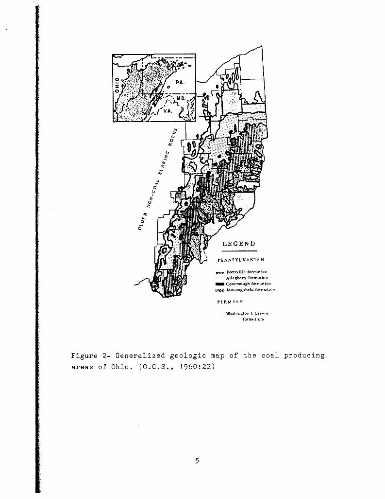
The Sharon #1 coal lies in the northeastern portion of
the Ohio coal field (Fig. 2). It thins southward into the
basin of the Ohio coal field but is only of mineable impor
tance to the seven northeastern counties of Mahoning, Trum
bull, Portage, Summit, Stark, Medina, and Wayne. Although
a single field of small extent, comparable to the Sharon's
horizon, is located in Jackson County (Southern Ohio) its
actual progression into the Great Appalachain Coal-Field is
problematic (Orton, 1884:157).
Stratigraphic Location
The Sharon coal is a member of the Pottsville Group, the
first forming rocks of the Pennsylvanian System (Fig. 3). The
upper boundary of the Sharon coal is the base of the Scioto
ville clay with the lower boundary being the Sharon conglom
erate. The upper boundary of the Pottsville Group is the top
of the Homewood sandstone and the lower boundary is the base
of the Sharon conglomerate, which is an unconformity.
3

Scale (Feet)
0
100
200
300
400
500
z 0 foe z ......
= rn < a";
< ..J lzl -.: < 0 z 0 z 0 ::2
<
.
•
~
COAL RESOURCES OF OHIO
Washington
Waynesburg (No. 11)
Uniontown (No. 10)
Meigs Creek (No. 9) (Sewickley)
Redstone (No. Ba) (Pomeroy) Pittsburgh (No. 8)
(Ames) Harlem
Anderson or Bakerstown
Wilgus
Mahoning
Upper Freeport (No. 7)
Lower Freeport (No. 6a)
Middle Kittanning (No. 6)
Lower Kittanning (No. 5)
Clarion (No. 4a)
Brookville (No. 4) Tionesta Bedford
Upper Mercer
Lower Mercer
Quakertown (No. 2)
Sharon (No. 1)
Figure 1- Generalized geologic section of Ohio coals.
(O.G.S., 1960:24)
4
Q;' .., Q ...
0
LEGEND
PENNSYLVANIAN
....,....,. Pottsville formation
Alleght>ny formation
- Conl'maugh f01'nu1tio11
!~:,.;!~ Monongohp)a formution
PERMIAN
Washington t Gret"nt"'
formotiom
Figure 2- Generalized geologic map of the coal producing
areas of Ohio. (O.G.S., 1960:22)
5

PcH11lu•iu ....
Allc1hu1. . . .
llppt't Frc:C"port No. 7. .. .. .. .. Coal, pa1eh1 ...
Cl.1y 111d 1halc .. , ........ . UpiM'r Freeport ... l.1mt"1tonr and nurly 1halt' Uohvar., ..... , . , . Cu.al, local, thin .. ,
Bol~var. ... .. . . .• . Cby, ll1nt ind plu11c .•• Upper Freepon.. . Shale or und1100(' J.o..,cr Freeport, Ro1cn Coal, patchy., ...... .
Lcwer Freepon .. . to .. er F ruport .. . Upper Kittaonin1.
f!~:.::!~·~·., .... . Shale or unduone .... . ('o•I, 1e:ldoni prueot Shale: and uad1tone.
\\'uhington11illc ("\'dlow Kiduy ore:) ...... ,, ... , .. Shale, m1rinc ...... , .. M1ddlC' Kiuanninr No. e. . . . . . . . . . . . Coal, peni1tent ....•....
Salf'm .......... , ReJ Kidner ore .. . Suatbl.Hf ........ .
qay, ailiceou1 ....... , .. . L1mu1one, impure, loc1l. . ....... , Shain, 1iliceou1 ...•.••• , .•.•. , ..••• Coal, 10<.al .••.••.•.•.•.•.•.• ,,
Od. Hill,., ••• ,.. Clay, flint and plutic ................ , ...•. , . Sh1lt1, 1ilict"ou1 ........... ..
Hamdt'n,.. .. • . . • . l..imutone:, un1te1dy, m1rine f.o•cr KittanDia1 No. 6 ......••. ,, , Coil. .......••..•.....•
01y, plutic .. ········ .. Lawrence ......... Coal, 1haly, loc1I .••• ,,
Cl1y, flint and plutic Kittanning ...... Shalt: ind und11onc. Ferriferoua .. ,. ,, . Orr, irrtcular ... Vi:nrort ..• , ••. , • • l.imt1tone:, marint: ..•.. Scr1.1b1r•11., .. , , . . Coal, 1rlJom pruent
Shale, carbon1ce:ou1 .. . Clarion No. h.,.. Co.al, pudiy,, ..... .
0 0 . "i2" 0 a -- --
6 .. . 0 .. 83 39
2 e ··~· I 0 e
26 0 I 0
10 0
············· 18
0
e ·a· e H 10 0
e 0 . , .. 0 13 0
0
' 0 2 . "2i" . , .. a 0 e ----0 0
Can1ry ..• , ..••.. Cl1rion .......... .
Clay, flint 1nd plutic Ore, very local S1nd11ont, iru•f1'1.1l1r. Coal, very local
g .. "i7
PoU1Yillc .. ,.
Vt'inte:n ....... ,,
Zaletki.. ,. , • ,, •• , Flint, impure, marine 011n, •••••••• ,. • Coil, l0<:al. ... ,.,., •.
Sh1le: and Hnduone. Putn1m Hill., ••• , I imt"llone, marine .. Broohille No. 4. t:o~I. 11uJy
l't.y, pla11ic, ..•.• , Homr•ood .. ,, .. , Shale or unJnonc .. "I 1ont1ta No. 3b ... Coal, lc.ul
tlpptr Mucer, li111: Red Block. lipper Mrrcer BeJlord . . : ••
Sud Block. .•
er.,, pla11ic ... Sb.alt: and "anduonc
Ore, irrt11:ul1r . J.imu1one or flint Coal, patchy., ..... .
Cl.a1, 1iliceou1 .... , . Shale and und11one, Orr, 1ihct"ou1, local .. Shale and 1111d1tonc
1lrper Mercer No. 3a ... , , , .•. , , Coal, local
Clay, 1iliceou1, plutic .............. . Shale and undatone ................... , .. ,
Lower Mercer. Lt tie Red l!iiod:,. Ou, Kidnrr .
Shale, 1ili1.cou1 ...•• ,, ••• Lower Mercer .. ,., Llme11one, 1tcady, m1rioe M1Jdle Mercer ...• Coal, 11cady, thin ...... ,,.
Flint Ridre ...... . ~~r; :i!ir!~'ct.':~l:!~c:::: :: :: :: .. :: :: :: :: :: :: :: :: :: :: :: :: :: : Coal, thin, loc1I ... , .•.........
a.,, plauic ind flint ...•.•..........•.......•.•.. Shale ind und1tone .. , ..... , ..
Borr- ....•••.•...
Lowrr Mercer
Ore and limutonc, marine ..... . Sh•le, 1ihccou1 ...... , ..... , . , •.....
No. 3 ........ . Coal, 1tcady, tbia .. , •••.....................• , ........... .
Clay, 1iliceoua ...... , , . , ••....... , . , , .....•.......•...•..... Shale and aandttonc .....
Lowrllville, Pove:rty Run .•..•• LimutonC' or ore:, n11rinc. V1nd1.1tcn ....•• , • Cua I, th111, 11n1tcad1 .••• ,
~~r; ~':~u.~~d~~~~~::::::::: Bear Run........ C.:oal, local..
C11y, 1iliceou1. Connoqurne .. in1 or M11111lon. Shalt or 11nd11oot: ........... , .. , •...... , ...•..
(.la..tuoN, .SdNJ /Uod, ind Ltiuoht ore1 ia iaternl) Qualtrrto•n No. 2 Coal, patchy ..
Hucltlebcrrr ......
GUiinu Fowl ..•••.
Anthony ..
Clay, 1iltceou• Sh1le 1nJ unduonc. (·oal, thin, local .....
C1a1, 1iliceou1 ....... ,
t)~:~('1o::t~~~~~~~::::. Sha le, •" 1, 1iliceou1 ... Co.al, thin .......... .
Sciotoville:. . . . . • . . C11y, flint ind plauic .~ . Shalt: and undttone ...
Sharon ...... ,.... Orr, loe1I, manne Sha Ir, 1iliceou1 ..•••••.•. ,
Shuori No. 1. Coal, patchy ...•.•... , .. ,
Sharon ...•..... ,. Harri1on., •....•.
Clay, impure ........ , .. .
~~~1;io1~~'r:~~~·pi:~~~ 1.~~ '. Ort:, local, impure, manne
25
' 2
' JO 1
6 2'
3 II
a 23
2 17
I
a 12
' 20
2 a
10 1
& 0
0 0
0 0 0
0 0 0
0 0
' 8 0
0 0 e e 0
0 0
3 g 0 e e 0 e 0 0 & 0
0 0
0 0
0
0
0 0 a 0 0 3 g 3
0 0 0 0
Figure 3- Stratigraphic section of Pottsville Group. 1960:22)
6
u 0 ..
----
32
----.. ia .. .. 0 ..
----
18
.... 9 .. 0
...... ...... ----
ii . e ..
. ·29·.
·20·
----29
----... i7 ..
3
----iii" a
2M
(O.G.S.,

Total thickness of Pottsville strata is reported to be
~56 feet but it is frequently much less as it occurs in the
Mahoning Valley. Oil well records from Columbiana County
have reported the maximum thickness of the Pottsville Group
to be approximately 200 feet (Stout, 1924:51).
The Pottsville Group
The Pottsville Group of the Mahoning Valley consists of
sandstones, clays, iron ores, coals, and limestones. Of these
rock types it is the sandstones and shales which dominate.
They show notable variations both horizontally and vertically
and commonly grade into one another over short distances. The
Sharon conglomerate which occupies the base of the Pottsville
strata in the Mahoning Valley shows the greatest variation.
It lies only in the basins or valleys that were created by
the pre-Pennsylvanian erosion and is often truncated against
these hills before it can rise to any considerable height.
The dominant limestone in the ~rea is the Lower Mercer lime
stone. "It is by far the most persistent, uniform, and easily
recognized unit in the Youngstown region (Stephenson, 1933:
79). 11 It maintains a rather constant thickness of about two
feet six inches and provides the best correlation datum
throughout the Mahoning Valley. Of the 11 or 12 local coals
found in the Mahoning Valley it is only the Sharon coal that
maintains the quality and thickness needed for mining.
Because it lies in the lower Pottsville it is greatly affect
ed by the pre-Pennsylvanian erosion and therefore occupies
only the basins and lowlands of adjacent hills (Stephenson,
1933).
7

III. OCCURRENCE AND PALEOENVIRONMENT
The Unconformity
In the Mahoning Valley the base of the Sharon conglom
erate represents the Pennsylvanian-Mississippian unconform
ity. The extent of the pre-Pennsylvanian erosion in the
Mahoning Valley has been reported by Stephenson (1933:50)
to reduce the Mississippian strata by about 350 feet of its
original 800 feet. This erosion produced great relief in
the form of hills and valleys (Fig. 4). The erosion pro
foundly affected the deposition of the lower most members of
the Pottsville Group and in turn accounts for approximately
100 feet thickness variation of total Pottsville strata
throughout the valley (Stephenson, 1933:59). An excellent
example showing this variation is provided by Brant and
DeLong (1960:31) where they reported the Sharon conglom
erate of Trumbull County to "vary in thickness from a few
feet to about 60 feet." This erosional topoeraphic varia
tion also had a profound effect on the deposition of the
member in study, the Sharon #1 coal.
The Sharon #1 Coal
The depositional character of the Sharon coal is best
described as a 11 basin 11 coal confined to the valleys and low
lands created by the pre-Pennsylvanian erosion. The total
area of these basins varies considerably but an average dis
tribution of 200 acres has been reported by Orton (1884:156).
The thickness variations and lateral distribution of these
basins has best been described by Orton (1884:156).
8

Figure 4- Pennsylvanian-Mississippian Unconformity, Wayne
County. (G.s.o., 1921:92 & 94)
9
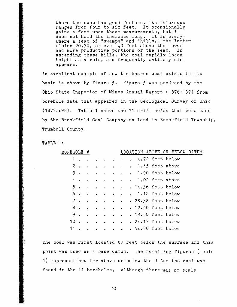
Where the seam has good fortune, its thickness ranges from four to six feet. It occasionally gains a foot upon these measurements, but it does not hold the increase long. It is everywhere a seam of "swamps" and "hills," the latter rising 20,30, or even 40 feet above the lower and more productive portions of the seam. In ascending these hills, the coal rapidly loses height as a rule, and frequently entirely disappears.
An excellent example of how the Sharon coal exists in its
basin is shown by figure 5. Figure 5 was produced by the
Ohio State Inspector of Mines Annual Report (1876:137) from
borehole data that appeared in the Geological Survey of Ohio
(1873:498). Table 1 shows the 11 drill holes that were made
by the Brookfield Coal Company on land in Brookfield Township,
Trumbull County.
TABLE 1 :
BOREHOLE # LOCATION ABOVE OR BELOW DATUM
1 . 4.72 feet below
2 . 1. 45 feet above
3 . 1. 90 feet below
4 . 1. 02 feet above
5 . . 14.36 feet below
6 . 1 • 1 2 feet below
7 . . 28.38 feet below
8 . . 12.50 feet below
9 . . 13.50 feet below
10 . . 24.13 feet below
11 . . 54.30 feet below
The coal was first located 80 feet below the surface and this
point was used as a base datum. The remaining figures (Table
1) represent how far above or below the datum the coal was
found in the 11 boreholes. Although there was no scale
10

Figure 5- Basinal characteristic of Sharon #1 coal. (S.M.I.,
1876:137)
1. Shaded portion indicates mined area of 60 acres that has produced excellent quality coal.
2. Numbers 1 through 16 indicate area where no coal was located in borings.
3. Dashed lines indicate area where coal thinned and was unable to mine.
Figure 6- Plat of Crawford, Davis, & Co. 's Mine, Hubbard Township.
(G.S.O., 1873:496)
1 1
provided for figure 5, it represents the discontinuity of
the Sharon coal well. Another good example showing the_
characteristics of the Sharon coal is provided by the Craw
ford, Davis, and Co.'s mine of Hubbard Township, Trumbull
County (Fig. 6). Although this plat is only a rough sketch
of the whole mine it displays the sinuosity of the Sharon
coal very well. If a cross-section of the plat were made
it would probably be very similar to figure 5 showing that
the unshaded portions of the plat occupied the areas where
the subsurface basins began to rise up the hills resulting
in the Sharon coal to thin out or become truncated.
12
IV. CLASSIFICATION OF THE SHARON COAL
Type and Use
Ohio bituminous coals of the late 1800 1 s were classifi
ed as open-burning (furnace coals), cementing coals (coking
coals), or cannel coals. The Sharon #1 coal is classified
as as opening-burning or furnace coal because of its ability
not to coke or adhere inside the blast furnace. Throughout
the mid to late 1800 1 s it was used in raw state in blast
furnaces for the manufacture of iron. "As it occurs in the
Mahoning Valley, it is a type and standard of the class to
which it belongs, and is one of the best furnace fuels known,
half the iron produced in the state (1874) being made with it
(Newberry, 1874:123)." The Middle Kittanning #6 coal of
Steubenville being the only other coal in the lower coal
measures of this character.
Quality
The quality of the Sharon coal was the main cause for
its extensive mining in the 1800 1 s particularly in the
Mahoning Valley where it has its best development (Newberry,
1874:132). In the Mahoning Valley the Sharon coal is referred
to as the Brier Hill coal and is said to be superior to the
coal of all other areas (S.I.M.,1875:25). It is here that
the Sharon coal has received the name "Block coal" because
it is very compact and mines in large rectangular blocks.
Because of its block character larger quantities of lump
13
and nut coal was able to be mined over slack. In 1891 Mahoning
and Stark counties reported approximately six times more lump
and nut coal over slack (R.O.M.I.,1891 :9). This statistic
alone was of utmost importance to the early miners because
they were often paid higher premiums for lump and nut coal
because slack was of no real use at the time.
The chemical analysis of the Sharon coal also accounts
for its high ranking. In general, coals which have low values
of sulphur, ash,and moisture and high values of fixed carbon
and volatile combustibles are more valuable. The following
chemical analysis of the Brier Hill coal of Youngstown is
provided (Orton, 1884:120).
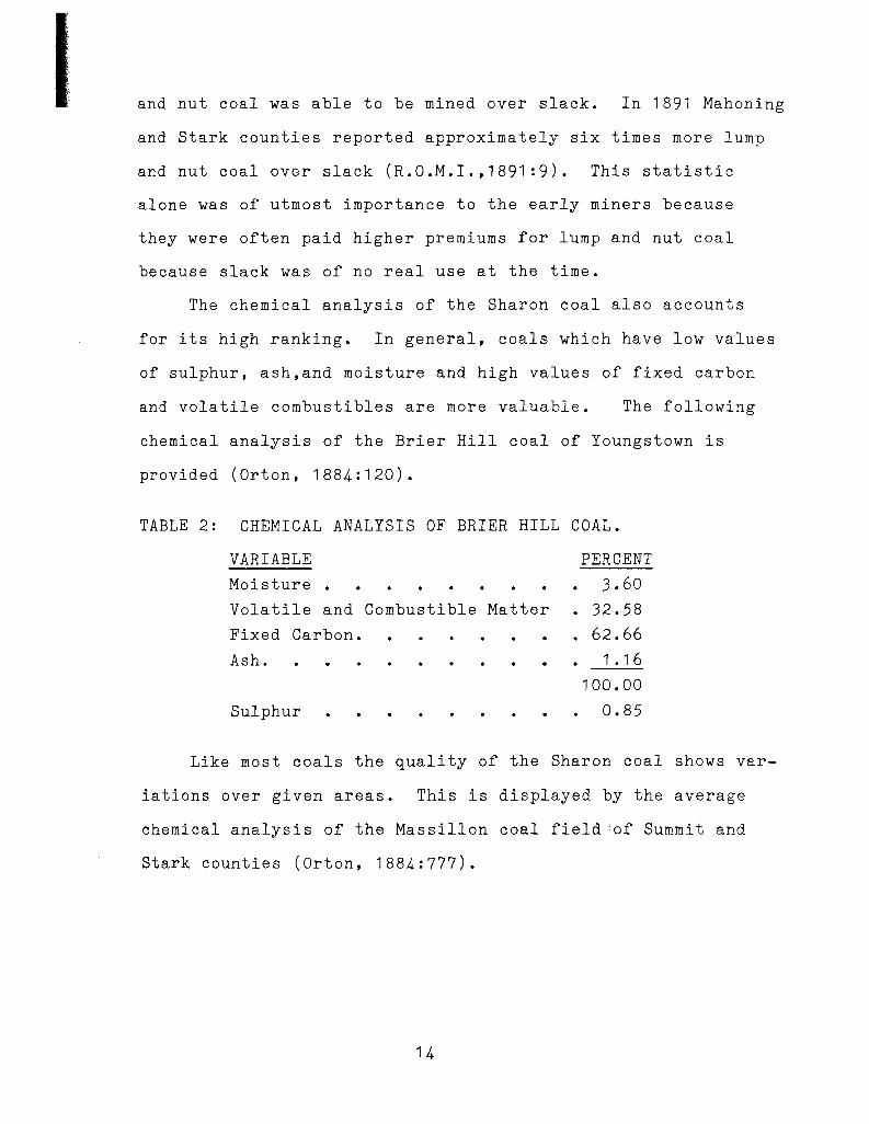
TABLE 2: CHEMICAL ANALYSIS OF BRIER HILL COAL.
VARIABLE
Moisture •
Volatile and Combustible Matter
Fixed Carbon.
Ash.
Sulphur
PERCENT
3.60 • 32.58
. 62.66 1 • 1 6
100.00
0.85
Like most coals the quality of the Sharon coal shows var
iations over given areas. This is displayed by the average
chemical analysis of the Massillon coal field 'of Summit and
Stark counties (Orton, 1884:777).
14

TABLE 3: CHEMICAL ANALYSIS OF MASSILLON COAL.
VARIABLE
Moisture •
Volatile and Combustible Matter
Fixed Carbon.
Ash.
Sulphur
PERCENT
5.50
37.00
53.50
4.00
100.00
1.10
Although the amount of ash and sulphur is higher than that of
the Brier Hill coal it is by no means inferior in quality.
It is of open-burning character and its analysis shows that
it deserves ranking among the very best coals of the state.
The Massillon coal has long been used as a successful fuel
in local blast furnaces for the smelting of iron ore (Orton,
1884:778).
For means of comparison a chemical analysis has been pro
vided for the Flint Ridge #4 cannel coal (Newberry, 1874:142).
It is mined in Coshocton County and is described as a cannel
coal of "good" quality.
TABLE 4: CHEMICAL ANALYSIS OF FLINT RIDGE CANNEL COAL.
VARIABLE
Moisture •
Volatile and Combustible Matter
Fixed Carbon.
Ash.
Sulphur
PERCENT
2.60
40.20
44.00
13.20
100.00
1.34
Cannel coals are chiefly used as household fuels, they are
15

usually denser and homogeneous in texture, but not well adapt
ed for coking or furnace fuels due to high values of ash and
sulphur.
The Mineral Ridge Field
The greatest degree of local variation observed within
the Sharon coal is found in the mines of Mineral Ridge, loc-
ated just northwest of Youngstown. A generalized section of
the mineral Ridge mining field appears below.
TABLE 5: SECTION OF MINERAL RIDGE COAL FIELD (Orton, 1884:174).
TYPE THICKNESS VARIATION
1 • Mineral Ridge Coal, Coking . 0' to 4'
2. Black band Iron Ore 0' to 1 I
3. Black Slate, called "Wide Awake" . 0' to 2'
4. Block Coal, Open-Burning. 6" to 2.5 1
The lowest bench is recognized as the block coal of the
Mahoning Valley. Although its thickness never exceeds 2.5
feet it maintains its superior quality much the same as the
Brier Hill coal of Youngstown (S.M.I.,1876:133).
Moving up in section the Wide Awake black slate is found.
It varies in thickness from zero to two feet and is always
present whenever the Blackband ore is found.
The next zone encountered is the Blackband iron ore. It
varies in thickness but reaches a maximun thickness of 12 inch-
es when found in the central portions of the coal basin. When
this iron ore is mined in the basin it yields a ton of ore per
ton of coal but one ton of iron ore per three tons of coal is
16
its overall average (S.M.I., 1876:134). The Blackband iron
ore has proved to be an important element in the economic
resources of the Mahoning Valley. This iron ore is used
with "the rich ores of Lake Superior making a very special
brand of iron known in the market as 'American Scotch' (S.M.I.,
1876:134)." The Blackband alone was the most important ele
ment in the Mineral Ridge mining field and if it were not
for its presence most of the mines in the area would have
closed and not opened up again (Orton, 1884:174).
The uppermost zone is the Mineral Ridge coking coal.
It varies in thickness from zero to four fee~ and is of a
very different grade than that of the block coal found below.
It is much softer and more impure and often exhibits a slight
cementing character (Orton, 1884:174).
17

V. MINING METHODS
The Way Into the Mine
There were three methods of making an entrance into the
Mahoning Valley coal mines during the 1800 1 s. These methods,
classified as drift, slope, and shaft entryways, are still
in use today and represent a common means for all types of
mining. There are many variables considered in choosing the
proper entryway but the most general ones are listed as:
1 • Depth to the coal seam.
2. Regional dip.
3. Geologic structure.
4. Water conditions.
Drift entryways are most common in areas where the coal
bed crops out on the surface. They are the simplest and least
expensive way of making an entrance into a coal mine because
no bedrock has to be penetrated. Typical dimensions of a
drift entryway are 10 feet in width for one track (15-18 if
two tracks are desired) and seven feet in height. With these
dimensions the entryway is cut into the siCTe of the hill
through the exposed coal seam (Fig. 7). Water conditions
and regional dip are the main variables that determine the
position of the drift entryway. A position is chosen where
the floor of the entrance has a constant upward grade so the
water that accumulates will flow out by gravitation and the
loaded cars are hauled out more easily. "In this method
there is no expense for removing earth or for cutting through
18

Figure 7- Generalized drift entryway. (Green, 1889:80)
Figure 8- Generalized slope entryway.
1 9

rock, nor any cost at any time of pumping water or of hoisting
coal (Green, 1889:82)."
*slope entryways are tunnels, with the same dimensions
as drifts, that are cut into bedrock to get to the mineable
coal. They are bored at right angles to the dip of the coal
seam with a pitch of 25 to 35 degrees (Fig. 8). Slopes are
usually not opened where the coal lies at a depth exceeding
150 feet from the surface because it is more costly to sink
the entrance and deliver the coal (S.I.M., 1884:20). Prior
to sinking the slope it is essential that the regional dip
and geologic structure be known in order to make the slope
as short as possible. Since slope entryways do not allow
water to flow out by gravitation, pumps must be incorpor
ated to keep the mine dry. Timbering around slope entrances
is also necessary to support bedrock walls from cave-ins.
Shaft entryways are vertical tunnels having rectangular
dimensions in the range of nine by 18 feet (Fig. 9). They
are most common in areas where the coal seams lie horizon-
tally and are at depths exceeding 150 feet. In the initial
stages of sinking a shaft topsoils are the first zone to be
cut through. When bedrock is reached a cribbing, made from
railroad ties, is constructed above the bedrock to the sur
face to add surface stability and to keep the soils from
falling down the shaft. Cutting through bedrock is done
by blasting until the coal seam is reached. Shaft entry
ways are the most expensive method used to reach the mine-
*--see Photos 4 & 5.
20

Figure 9- Generalized shaft entryway. (Green, 1889:90)
21

able coal because sophisticated water pumping systems and
elevators must be provided (Green, 1889:88). Shaft entry
ways in the Mahoning Valley range from 25 to 200 feet but
maximum depths of 260feet have been reported (Harris, 1985).
Throughout the Mahoning Valley shaft entryways seem to
have been the most popular followed by slope then drift.
Table 5 summarizes the types of entryways made from the
years 1879 through 1886, a time in this region when coal
mining was at a high.
TABLE 5: TYPE OF ENTRYWAYS IN MAHONING VALLEY (1879-1886).
# of Drift # of Slo:ee # of Shaft Total
Mahoning County 3 8 21 32
Trumbull County 2 14 1 5 31
---Data compiled from reports, (1879-1886).
Ohio State Inspector of Mines Annual
Shafts were most popular in this area because the depth
to the Sharon coal often exceeds 150 feet. The different
types of entryways have been critically analyzed because they
present the major problem in the Mahoning Valley today, and
will be discussed fully in the following sections.
Room and Pillar Mines
During the 1800 1 s the most common method of underground
mining was the room and pillar method. In this method rooms
of coal were mined out and pillars of coal were left stand-
ing to support the roof. The variables which govern the size
22

of the rooms and the thickness of the pillars are listed below.
1. Depth to coal seam.
2. Condition of the roof and floor (soft or strong).
3. Nature of the coal.
As the depth to the coal seam increased pillar thick-
ness should also increase to support the weight of the over-
lying strata. Relatively deep mines will call for pillar
thickness to range from four to six yards where shallower
mines are on the order of two to three yards (S.I.M., 1884:27).
Rooms are generally the same size as the pillars provided a
sturdy roof and floor are present. With this plan at least
50% of total coal is mined, the remaining percentage needed
for roof support (Harris, 1982). Greater yields are obtained
when overlying bedrock is sparse because the volume of the
rooms can be increased while pillar thickness is decreased.
The condition of the roof and floor are also important
variables that determine pillar and room size. "If the pave-
ment is soft, and the coal and roof strong, pillars of extra
size must be left, to prevent the pillars sinking into the
pavement and producing a creep (Roy, 1884:306)." The opposite
will occur if a soft roof is present.
Since the supporting pillars are cut from the coal, the
nature of the coal is an important factor to be considered.
When the coal is soft, or has open backs and cutters, thick-
er pillars must be made or the pressure from the overlying
bedrock will cause the pillars to break off at the backs
23
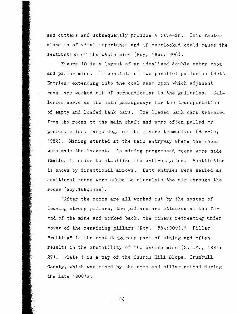
and cutters and subsequently produce a cave-in. This factor
alone is of vital importance and if overlooked could cause the
destruction of the whole mine (Roy, 1884: 306).
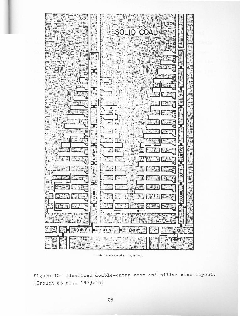
Figure 10 is a layout of an idealized double entry room
and pillar mine. It consists of two parallel galleries (Butt
Entries) extending into the coal seam upon which adjacent
rooms are worked off of perpendicular to the galleries. Gal
leries serve as the main passageways for the transportation
of empty and loaded bank cars. The loaded bank cars traveled
from the rooms to the main shaft and were often pulled by
ponies, mules, large dogs or the miners themselves (Harris,
1982). Mining started at the main entryway where the rooms
were made the largest. As mining progressed rooms were made
smaller in order to stabilize the entire system. Ventilation
is shown by directional arrows. Butt entries were sealed as
additional rooms were added to circulate the air through the
rooms (Roy,1884:328).
"After the rooms are all worked out by the system of
leaving strong pillars, the pillars are attacked at the far
end of the mine and worked back, the miners retreating under
cover of the remaining pillars (Roy, 1884:309)." Pillar
"robbing" is the most dangerous part of mining and often
results in the instability of the entire mine (S.I.M., 1884;
27). Plate 1 is a map of the Church Hill Slope, Trumbull
County, which was mined by the room and pillar method during
the late 1800 1 s.
24
- Direc11on of air movement
Figure 10- Idealized double-entry room and pillar mine layout.
(Crouch et al., 1979:16)
25

The way into the mines and the room and pillar method
have been described so the reader will be familiar with their
construction when they are referred to in the following sec
tions. These various mining methods were at full tilt in the
mid to late 1800 1 s and it is because of them a subsidence pro
blem now exists within the Mahoning Valley.
26
VI. MINING HISTORY OF THE MAHONING VALLEY
Economic Geology
Coal mining began in the Mahoning Valley around the 1830 1 s
with the opening of one of its first mines in the Weathersfield
Mineral Ridge area (1835),Trumbull County (Sharrow, no date).
In the following years coal mining thrived and many people
settled in the area to mine the valuable coal and Blackband
iron ore. Because the coal was such an excellent fuel for
blast furnace use it provided for the development of the steel
industry throughout the Mahoning Valley. Evidence of this
development is provided by a historical report written by
J. C. Sharrow (no date), a Mineral Ridge resident:
The settlement of Mineral Ridge followed closely on the centering of attention to a coal mine opened in Weathersfield and Ohltown and it was not long until larger mines were opened at Mineral Ridge. The starting of the mines brought many people to Mineral Ridge; with the opening of the mines came the railroads (built in 1857).
In 1858 Jonathan Warner in company with James Woods of Pittsburgh erected the first furnace in Mineral Ridge. It was known as the Ashland Furnace and was built for the purpose of manufacturing pig iron from the coal and blackband ore.
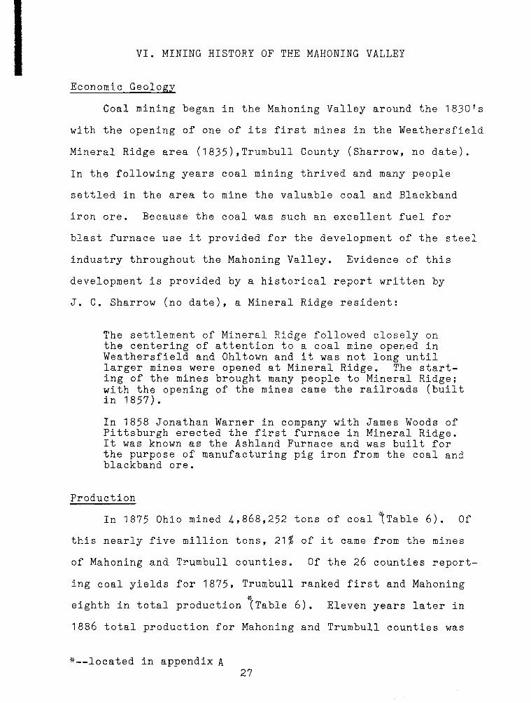
Production
In 1875 Ohio mined 4,868,252 tons of coal ~Table 6). Of
this nearly five million tons, 21% of it came from the mines
of Mahoning and Trumbull counties. Of the 26 counties report-
ing coal yields for 1875, Trumbull ranked first and Mahoning
* eighth in total production (Table 6). Eleven years later in
1886 total production for Mahoning and Trumbull counties was
*--located in appendix A 27

only 501,571 tons, down 50% from 1875. "The loss' in Trumbull
County, both in tonnage and miners, is largely attributable
to some of her largest producing mines having been worked out
and abandoned during the year (S.I.M., 1887:19)." This de-
crease continued and by 1905 the production ranking of
Mahoning County was 21 and that of Trumbull 29 out of the
29 counties reporting for the year. By 1913 the Ohio Coal
Mining Commission reported (1913:9):
The days of coal mining this seam are about over and the deposits now being mined are nearly exhausted and there is no considerable body of this coal of a thickness sufficient to make mining worth while which has not already been attacked.
28

VII. THE EFFECT TODAY
Problem
The Mahoning Valley was reminded of its mining history
in 1977 when the floor of a double car garage fell into a
230 foot deep shaft. During the next few years the subsi
dence problem progressed and by 1982 more than 30 mine en
trances had collapsed. The problem still exists today with
subsidence occurring over shaft, slope, and drift entryways.
Subsidence over rooms is not a major problem yet but will
become one in the future as supporting pillars grow weak
and start to collapse (Harris, 1982).
Local residents have no knowledge as to the location
of these entryways and mines because very few mining rec
ords were kept. Homes which were built unknowingly over
or adjacent to mining areas are in great danger today due
to the increased subsidence. Because of the ignorance of
some, building permits were issued to contractors where
known mining operations had taken place. These contractors
then constructed individual homes and housing projects in
these areas because it was ''convenient", and now these homes
are in great danger (Harris, 1982).
Answers
On August 3, 1977 Public Law 95.87 (Surface Mining Con
trol and Reclamation Act) was passed by congress. Title IV
Abandoned Mine Reclamation of this act allocated the establish
ment of a self-supporting trust fund within the U. S. Treasury
29

''to restore lands ravaged by uncontrolled mining operations
in the past (CQ Almanac, 1977:618)."
In the Mahoning Valley this bill "provided for the fill
ing of voids and the sealing of abandoned tunnels, shafts and
entryways, and reclamation of other surface impacts of mining
(CQ Almanac, 1977:619)." Unfortunately, federal funding and
homeowners insurance do not provide for property damages
caused by subsidence to public landowners.
The Role of Ann G. Harris
Ann Harris is an Associate Professor of Geological Sci
ences at Youngstown State University. She became involved
in mine subsidence after the collapse of the first mine shaft
(Foster #1) in 1977. In addition to her teaching profession
she also works for the state as consulting geologist to the
subsidence problem (Harris, 1985).
When a mine stabilizing job is approved by the state,
engineering firms are hired to do the necessary work. Hiring
is done by competitive bidding and Ann Harris is responsible
for providing the background information so each firm can
analyze the materials needed to make their bid. She then
accompanies the firm to the job to advise when questions are
raised concerning the the stabilization procedure (Harris,
1985).
The state with the help of Ann Harris is also making an
effort to locate the Sharon coal throughout the Mahoning
Valley. This is done by exploration drill teams (Photo 1).
30

The drilling teams travel throughout the valley taking core
samples (Photo 2). If the horizon of the Sharon coal is
located it is then mapped and the team moves on to another
position. Drilling is done to determine the Sharon coats
elevation and outcrop pattern throughout the valley. This
important information is needed in order to map the mined
areas so new building programs are not in danger of subsid
ence damages (Harris, 1985).
31
VIII. TYPES OF SUBSIDENCE
Factors
There are many factors affecting subsidence over entry-
ways and mines. The most common ones are listed below and
their relationship to the type of subsidence will be comment-
ed on (Harris, 1985).
1. Depth to mine.
2. Type and amount of cover (Bedrock and soil).
3. Tunnel and mine height.
4. Roof and floor conditions.
5. Extent of pillar "robbing".
6. Method of sealing openings.
7. Time.
8. Condition of man-made supports.
Drift Subsidence
Subsidence over drift entryways are most common on the
hillside which was penetrated. When a drift entryway becomes
weak superincumbent strata develop stress cracks and joints
and eventually cave-in follows forming large concave up dish
shaped impressions on the hillside face. Factors effecting
drift entry subsidence are type and amount of cover, condi-
tions of man-made supports, and time. Drift entryways were
often timbered at the hillside face for roof support (Fig. 7).
As time progressed the weight of the overlying strata was
often too much for the timber supports and subsidence occur-
red. The type of roof is also a factor. If a shale roof is
present, subsidence usually follows because shale roofs are
very weak (Harris, 1982).
32

Slope Subsidence
Usually all the factors listed above contribute to slope
subsidence, the most prominent being type and amount of cover.
When there is little cover over the slope entryway surface
loading and time contribute to its subsidence. Roads were
often built over these shallow entryways and as time progress
es subsidence eventually occurs causing sections of the road
to be engulfed. The type of bedrock is another important
factor. As shown in figure 8, slope entryways cut through
bedrock zones. When a weak zone such as shale is cut through
subsidence usually follows and, if depth is shallow, surface
features will be present (Harris, 1982).
Shaft Subsidence
Shaft subsidence is the most common type found in the
Mahoning Valley and "is potentially the most dangerous (Harris,
1982)." Factors which contribute to shaft subsidence are
method of sealing the entryway and time. The main cause for
shaft subsidence is improper filling techniques incorporated
upon the closure of the mining operations around the turn
of the century. These vertical shafts, sometines as deep
as 250 feet, were filled with trash, garbage, and waste mat
erial from the mine. In some cases even cars (two 1921 Model
A Fords) were used as fill material as was discovered in the
Foster/Crane Shaft. Wooden railroad ties were then placed
directly over the cribbing and the pit around the shaft was
then filled in with topsoil and graded. The subsidence
33
problem exists today because the timbers and garbage within
the mine have rotted away creating voids which cause the sur
face to subside and cave in. Water conditions within the mine
have also accelerated this process by washing fill material
into the lateral tunnels (Harris, 1982).
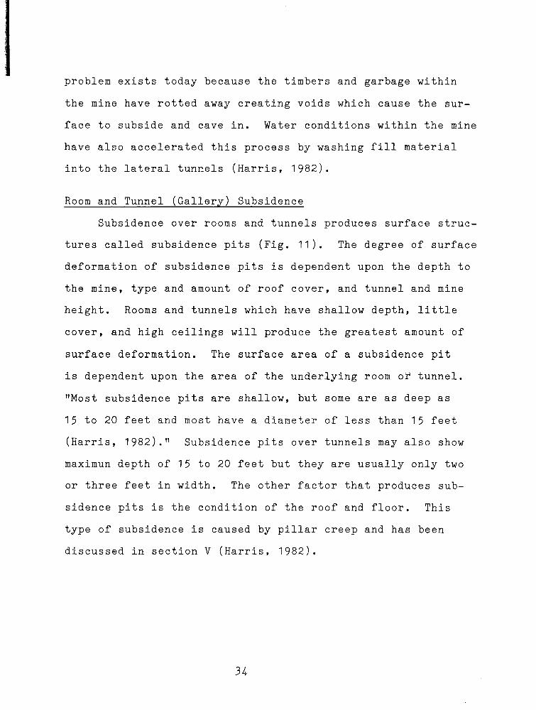
Room and Tunnel (Gallery) Subsidence
Subsidence over rooms and tunnels produces surface struc
tures called subsidence pits (Fig. 11). The degree of surface
deformation of subsidence pits is dependent upon the depth to
the mine, type and amount of roof cover, and tunnel and mine
height. Rooms and tunnels which have shallow depth, little
cover, and high ceilings will produce the greatest amount of
surface deformation. The surface area of a subsidence pit
is dependent upon the area of the underlying room or tunnel.
"Most subsidence pits are shallow, but some are as deep as
15 to 20 feet and most have a diameter of less than 15 feet
(Harris, 1982)." Subsidence pits over tunnels may also show
maximun depth of 15 to 20 feet but they are usually only two
or three feet in width. The other factor that produces sub
sidence pits is the condition of the roof and floor. This
type of subsidence is caused by pillar creep and has been
discussed in section V (Harris, 1982).
34

Figure 11- A subsidence pit over a room in the middle of a
proposed road for a subdivision. (Harris, 1982)
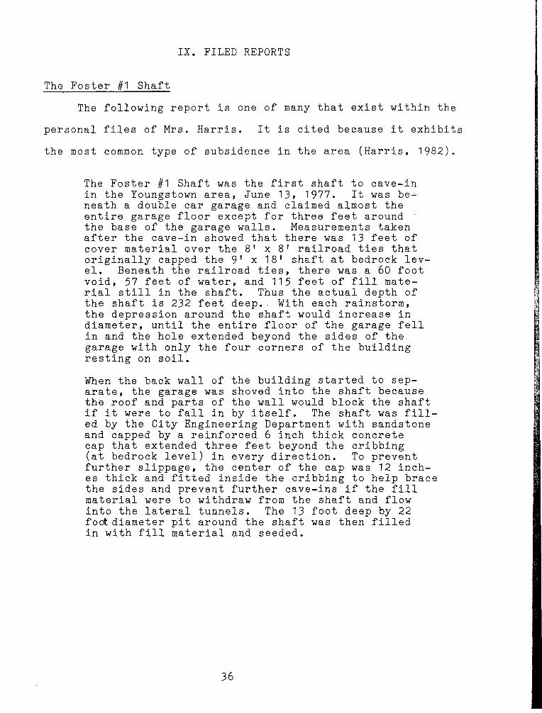
IX. FILED REPORTS
The Foster #1 Shaft
The following report is one of many that exist within the
personal files of Mrs. Harris. It is cited because it exhibits
the most common type of subsidence in the area (Harris, 1982).
The Foster #1 Shaft was the first shaft to cave-in in the Youngstown area, June 13, 1977. It was be~ neath a double car garage and claimed almost the entire garage floor except for three feet around the base of the garage walls. Measurements taken after the cave-in showed that there was 13 feet of cover material over the 8 1 x 8 1 railroad ties that originally capped the 9 1 x 18 1 shaft at bedrock level. Beneath the railroad ties, there was a 60 foot void, 57 feet of water, and 115 feet of fill material still in the shaft. Thus the actual depth of the shaft is 232 feet deep .. With each rainstorm, the depression around the shaft would increase in diameter, until the entire floor of the garage fell in and the hole extended beyond the sides of the garage with only the four corners of the building resting on soil.
When the back wall of the building started to separate, the garage was shoved into the shaft because the roof and parts of the wall would block the shaft if it were to fall in by itself. The shaft was filled by the City Engineering Department with sandstone and capped by a reinforced 6 inch thick concrete cap that extended three feet beyond the cribbing (at bedrock level) in every direction. To prevent further slippage, the center of the cap was 12 inches thick and fitted inside the cribbing to help brace the sides and prevent further cave-ins if the fill material were to withdraw from the shaft and flow into the lateral tunnels. The 13 foot deep by 22 foot diameter pit around the shaft was then filled in with fill material and seeded.
36
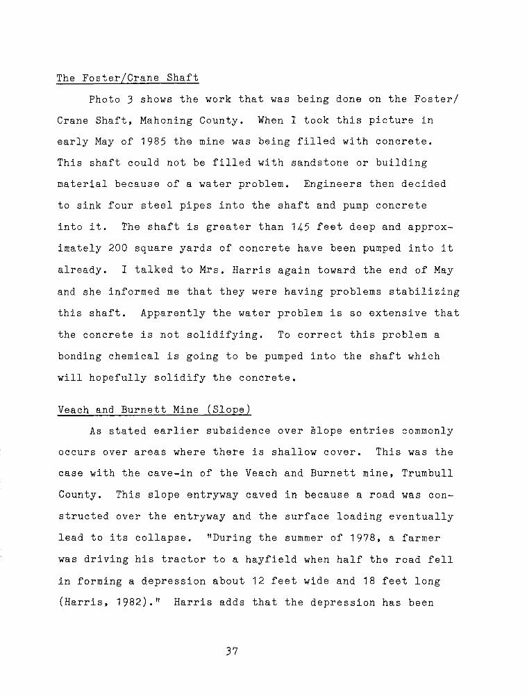
The Foster/Crane Shaft
Photo 3 shows the work that was being done on the Foster/
Crane Shaft, Mahoning County. When I took this picture in
early May of 1985 the mine was being filled with concrete.
This shaft could not be filled with sandstone or building
material because of a water problem. Engineers then decided
to sink four steel pipes into the shaft and pump concrete
into it. The shaft is greater than 145 feet deep and approx
imately 200 square yards of concrete have been pumped into it
already. I talked to Mrs. Harris again toward the end of May
and she informed me that they were having problems stabilizing
this shaft. Apparently the water problem is so extensive that
the concrete is not solidifying. To correct this problem a
bonding chemical is going to be pumped into the shaft which
will hopefully solidify the concrete.
Veach and Burnett Mine (Slope)
As stated earlier subsidence over slope entries commonly
occurs over areas where there is shallow cover. This was the
case with the cave-in of the Veach and Burnett mine, Trumbull
County. This slope entryway caved in because a road was con
structed over the entryway and the surface loading eventually
lead to its collapse. "During the summer of 1978, a farmer
was driving his tractor to a hayfield when half the road fell
in forming a depression about 12 feet wide and 18 feet long
(Harris, 1982)." Harris adds that the depression has been
37

stabilized but since there is no history or maps available on
this mine it is "not known how extensive this mine is, nor the
amount or type of cover (1982). 11
Subsidence Over Rooms and Tunnels
As stated earlier subsidence over rooms and tunnels forms
surface features called subsidence pits (Fig. 11). These sub
sidence pits are starting to become a major problem in the
area due to increased surface loading and weakening of pillars.
An example of the damage of room subsidence can be seen in
figure 12. This house is located in Neshannock Township,
Mercer County, Pennsylvania. The room beneath the house has
collapsed causing the house to lean about one foot out of
plumb. The subsidence seems to have stabilized and no add
itional leaning has been reported (Harris, 1982).
38

Figure 12- Subsidence over a tunnel has C<;l._u.sed this house in
Neshannock Township, Mercer County, Pennsylvania to lean about
one foot out of plumb. (Harris, 1982)
39
X. CONCLUSION AND RECOMMENDATIONS
Conclusions
1. The Sharon coal is a basin coal. It is a non-continuous
coal seam which is restricted to subsurface valleys and low
lands.
2. The cause of the Sharon coa~s discontinuity was the eros
ion from the Pennsylvanian-Mississippian Unconformity.
J. The very high quality of the Sharon coal was the main
reason for its extensive mining during the mid to late 1800 1 s
throughout the Mahoning Valley.
4. This coal is classified as open-burning and was used as
a furnace fuel for the smelting of iron ores.
5. The Blackband iron ore of the Mineral Ridge coal field
was a main reason for the extensive mining in that region.
6. Drift, Slope, and Shaft entryways were used to get to the
coal mines during the 1800 1 s.
7. There are many factors which contribute to the subsidence
over these entryways some of which can be traced back to the
carelessness of the mining operations which existed during
the 1800 1 s.
8. Room and Pillar mines were the most common type of coal
mines during the 1800's.
9. Subsidence over rooms and tunnels can be attributed to
the weakening of the pillars due to robbing and surface
loading. Other contributing factors which lead to subsi
dence pits are depth to the mine, roof and floor conditions,
and the nature of the coal•
40
11. Funding for abandoned mine reclamation is provided by
The Surface Mining Control and Reclamation Act of 1977.
12. Due to the success of this program approximately 35
abandoned entryways and rooms have been stabilized since
1977.
13. Drilling teams have also added to the success of this
program by locating the Sharon coal outcrop pattern and
elevation throughout the Mahoning Valley. This information
is necessary to advise building developers so they are not
in danger of subsidence damages.
Recommendations
The following recommendations were obtained from the
last interview that I had with Ann Harris, late May of 1985.
1. State policy has limited the funding of each stabilization job
to $50,000 per job. Funding should be more in some cases
because each job varies in character.
2. There is a need for more test drilling than the program
has allocated. This is needed to:
a.) Eliminate large areas where the Sharon coal is not located.
b.) Get an exact elevation of the Sharon coal when it is located.
3. There is a need for subsurface video equipment to observe
the conditions of the rooms, pillars, and tunnels of aban
doned underground coal mines.
41

REFERENCES
Brant, R.A., and DeLong, R.M., 1960, Coal Resources of Ohio:
Ohio Division of Geological Survey, Bull. 58, p.245.
Congressional Quarterly Almanac, 1977, Surface Mining Control
and Reclamation Act of 1977.
Conrey, G.W., 1921, Geology of Wayne County: Geological Sur
vey of Ohio, Bull. 24, p.155.
Crouch, T.M., Collins, H.R., and Helgesen, J.O., 1979, Aban
doned Subsurface Coal Mines As a Source of Water for
Coal Conversion in Eastern Ohio. p.59, un-published.
Geological Survey of Ohio, 1873, v.1, pt.1, p.680.
Green, Homer., 1889, Coal and the Coal Mines: Boston and New
York, Houghton Mifflin Company., p.246.
Harris, A.G., 1982, Papers Presenten Before the Abandoned Mine
Reclamation Symposium, November 3-4-5, 1982: Ohio Univer
sity, un-published •
~~~~~-
. , 1985, Personal Interviews, May 1985.
Newberry, J.S., 1874, The Carboniferous System: Report of the
Geological Survey of Ohio, v.2, pt.1, p.701.
Ohio Coal Mining Commission, Report of, 1913: Columbus: F.J.
Heer Printing Co., p.70.
Orton, Edward.,1884, The Carboniferous System: Report of the
Geological Survey of Ohio, v.5, p.1124 •
~~~~~~~
. , 1884, The Stratigraphical Order of the Lower
Coal Measures of Ohio: Report of the Geological Survey
of Ohio, v.5, p.1124
Report of the Ohio Mine Inspector, 1892, Seventeenth Annual
Report of the Chief Inspector of Mines for the Year 1891,
p.311.
Roy, Andrew., 188~, Coal Mining In Ohio: Report of the Geo
logical Survey of Ohio, v.5, p.1124.
Sharrow, J.C., no-date, Mineral Ridge Historical Data: un
published, p.5.
S.I.M., 1875, First Annual Report of the State Inspector of
Mines to the Governor of the State of Ohio, for the year
1874, Columbus: Nevins and Myers, 1875. p.88 .
~~-
. , 1884, Ninth Annual Report for the Year 1883, p.128.
--~-
., 1887, Twelfth Annual Report for the Year 1886, p.145.
S. M. I., 1876, Third Annual Report of the State Mine Inspector
to the Governor of the State of Ohio, for the Year 1876
p.196.
Stephenson, E.L., 1933, The Geology of the Youngstown Region:
Masters Thesis, Ohio State University., p.129.
Stout, Wilber., and Lamborne, R.E., 1924, Geology of Columbiana
County: Geological Survey of Ohil, Bull. 28, p.408.
43

YEA
R
1875 1880
1883 1884
1885 1886
1887 1888
1890
1891
1894 1897
1899 1900
1905
MA
HO
NIN
G
CO
. 2
71
,68
9
34
7,6
35
2
23
,74
0
24
1,5
99
27
5,9
44
31
3,0
40
27
2,3
49
23
1,0
35
2
28
,76
1
23
2,3
46
9
7,0
62
92
,28
3
74
,30
9
10
9,3
48
1
17
,07
4
·-'-"'•··-~·--
TRUM
BULL
CO
.
74
9,0
59
6
73
,20
6
43
7,6
12
2
57
,68
3
26
4,5
17
18
8,5
31
16
7,9
89
15
7,8
26
10
5,3
33
64
,17
3
33
,13
7
10
,83
8
11
,05
9
19
,18
1
3,5
91
APPEN
DIX
A
# CO
UN
TIES R
EPOR
TING
26
30
24 27
27
28
28
27 28
27 ? ? ?
30
29
RANK M
O TR
8 1
8 2
12 6
14 11
10 12
9 15
12 16
13 17
13 18
? 2
2
? ?
,,·.~~~::•>'l',-'.~~~lil!lllllll!ll!JRIBllll!lll!!!lllll•lllllllllllllllllllllllll
STATE
PRO
DU
CTIO
N
4,8
68
,25
2
7,0
00
,00
0
8,2
29
,42
9
7,6
50
,06
2
7,8
16
,17
9
8,4
35
,21
1
10
,30
1,7
08
10
,91
0,9
46
11
,78
8,8
59
13
,05
0,1
87
11
,91
0,2
19
?
? 1
2,4
48
,82
2
? ?
15
,90
8,9
34
17
24 1
9,4
26
,64
9
21 29
25
,83
4,6
57
TAB
LE 6:
Pro
du
ctio
n
of
co
al
mined
in
Mahoning
& T
rum
bu
ll co
un
ties,
their
ran
kin
g,
and
en
tire sta
te
pro
du
ctio
n
from
th
e
years
18
75
-19
05
. C
om
piled
from
: O
hio S
tate
In
specto
r o
f Mines
An
nu
al R
ep
orts,
from
the
years
1875
to
19
05
.
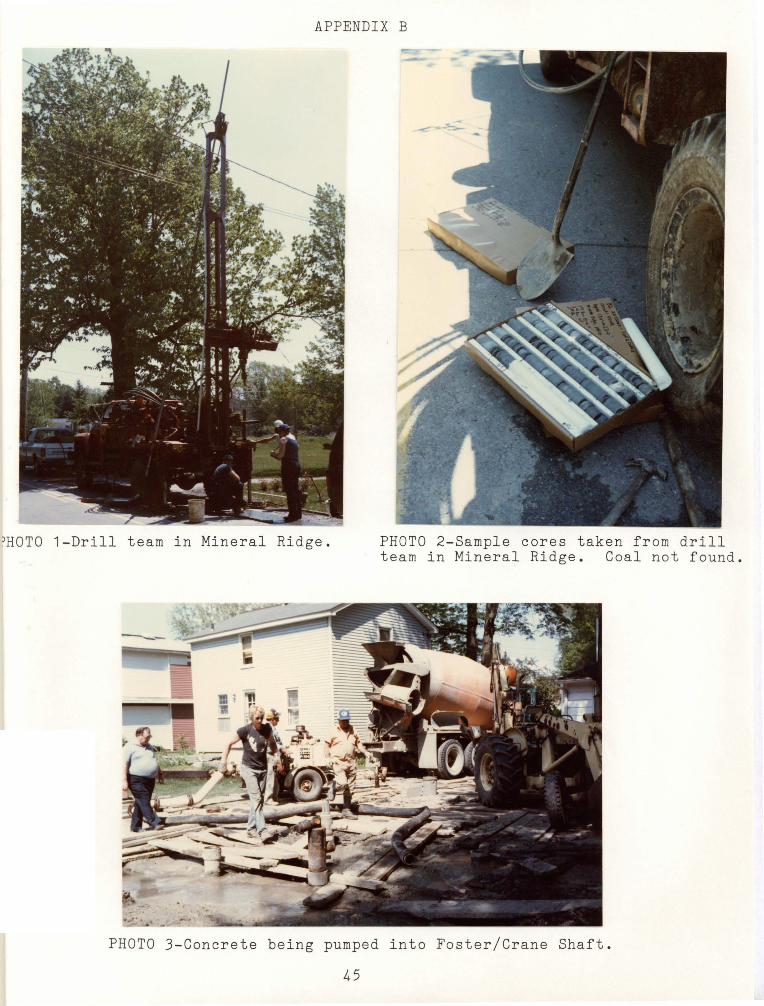
APPENDIX B
)HOTO 1-Drill team in Mineral Ridge. PHOTO 2-Sample cores taken from drill team in Mineral Ridge. Coal not found.
PHOTO 3-Concrete being pumped into Foster/Crane Shaft.
45
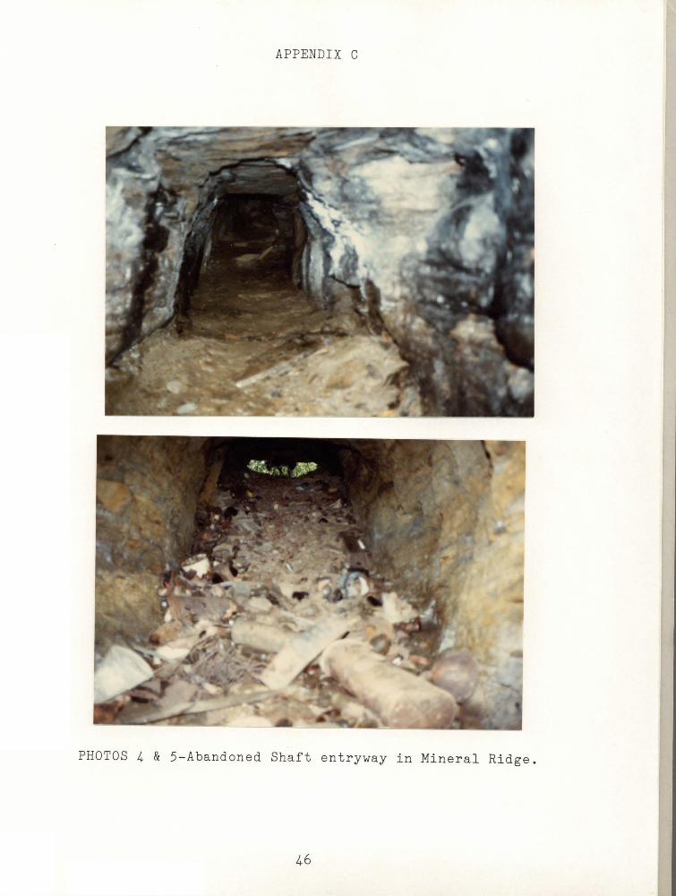
APPENDIX C
PHOTOS 4 & 5-Abandoned Shaft entryway in Mineral Ridge.
46