military curricula · this course contains both teacher and student materials. the printed...
TRANSCRIPT

e
ED 184 11137
TITLEJINsT*ZION
SPOSb- ILIENC/
PUB; DATEMOTE
EDRS.PRICEDESCRIPT.ORS
IDENT IFIER S
ABSTRACTThis teaching guide,
. workbook are designed for self- or gr; and knowledge areas needed for.ewing
one of s number. of military-deielopedfor adaptstion too Vocational. instructin a civilian setting. The instructorstudent qualitative require.ments andcriterion objectives, duration of theneeled..Student saterials include obj.referencese-and actitities or writtentrainina includes structural atd functiming, adjustment, troufileshooting msewing macpines used in the repair ofmateriali. (MEN) ,
DOMINI? MOSE4
. g ..
CR1024
Eilitary Curricula tor Vocational 8 TechnicalEducation. Sewing Machine'Maintenance 18-3.Ohio State Oniv., Columbus. Wational Center forResearch in Vocat5cmal EduCation.; Technical TrainingCenter, Chanute APB, Iil. ,
Baceau of OcCupatibnal and Adult Education OMER/DE', ..Raihingtom, D.C.Oct 78110p.
101/PC05 Plfts Postage.Behavioral Object!ves. ourse Descriptions;Curri:Cultm Guides;.*E uipment Maintehance:JlighSchools: Learning Act s: *Machine Repaireris;Postsecondary EhucatiOn: ade and IhdustriO.Education: VOralooksMilitary401arriculum Prole a *Sewing MachiMe'Repairers
jlf
student s y guide, and stadentoup-paced. instruction ih skill,maintenance. They-constitutecurriculum paCkages selectedioá and curriculum developmentmaterials include an outline ofa plan of instruction detailjaag.lessons and support materials .
eqtives, information"(text),exereises. The scope of
tional features, inspection,alfunctions, aid overhaul of'parachutes, fabricr'and leatkor
* Reproductions supplied by EDRS-are the best that can pe faille *
* from the original document. *
****************************#*******************Ic*******************. r . ..

XJ
414
I A
41.
Military Curriculafo. Vocational &Technical Educatim
44.
.41
. Ip.
SEWING 44ACHINENMAINTENAKE
18-3
N TIONAL UNTERARCIIIN VOCATIONAL EDUCATION.(fl11(1`,TAT( uNio R(,IT

_
This mikitery technicql trainin4 course hes keen selected and adapted'by
The Center for Vocationairgducation for "Trial Xeplemeptation of a*Model Systemto Provide Military Curriculum Materialoa for_Use in Vocational. and Technical
EduceAion," a project sponsored by the Bureau'of Ocaipational and Adult Ediscat,ion,.
U.S.IEepartment of Health,.Education, and,Welfare, *
v.

MILITAIef mammal mramAis
The military-developed curriculum materiaTh ixT'this course
package were selected by the National Center for Research in
Vocational Education Military Curriculum Projectfor dissem-ination to the six regional Curriculum CoordinaticniCeriters and
other instructional materials agencies. Mei:impose ofdisseminating these.00urses was tomake curriariaminoterials&veloped by the military more accessible to.vocattionaleducators in the civilian'setting. .
3
, The oourse netexials 4vre aoguired, evaluated by projectstaff and practitioners in the figld, and prepared for
dissemination. Materials which were specific to.the nilitary
%ere deleted; copyrightxximaterials wre either omitted or appro-,
val for their use was obtained. These 'bourse packages containcurriculum resource materials-which can be adapted to support
vocational instruction and curxiculumdWvelopmept.
Ab

MilitaryCurriculum Materials .
dissemination is . .
an activity to increase the acceisibility ofmilitary-developed curriculum materials tovocational and tdchnical edaators.
This project,4funded by the U.S. Office ofEducation, includes the identification andacquisition of curriculr thaterials in printform from the Coast Air Force,Army, Marine Corps anitf,
7
Access to military curr t4uri materi'als isprovided through a "Joirlt emorandum ofUnderstanding" between U.S. Office ofEducatio'n and the Depart*ntf Defense.
The acquired materials are Hwed by.staffand subject matter specia4 t. and oursesdeemed aPplicable to vocatiOnal t1Ø tech-nical education are selected rissdfrination.
The National Cilketer for -Resitesch 4nVocational Education is the U\$.:Df fice ofEducation's designated represanicative toacquire the materials and condUqt Ole projectactivities.
Projact Staff: .
A
Wesley E. Budke h.D., Direc1tpNatibnarCenier Glearinghouse
Shirley A. Chase, Ph.D.-Project Director
What MaterialsAre A101able?
One hundred twenty:courses on microfiche(thirteen in paper forM) and descriptions ofeach have been provided to the vothtionalCa.riculum Coordination c.nters and otherinstructiol materials.agencies for dissemi-
,nation.
Course materials include plogrammed ".
instruction, curriculum outlines, instructorguides, student workbooks and technicalmanuals.
The 120 courses represent the followingsixteen vocational subject areas:
Agriculture, AvikionBuilding&ConstructionTrades
ClericalOccupatiOns
CommunicationsDrafting
/ElectronicsEngine Mechanics
Food ServiceHealthHeating & Air_ConditioningMachine ShopManagement 13t
SupervisionMeteoro logy &
NavigationPhotographyPublic Service
The number of courses and the sutject areasrepresented will expand as additional mate-rials with application to vocational andtechnical education are identified.and selectedfor dissemination..., .
How Can These.Materiais Be Obtained?
}-mwt.
iContact the Curriculum Coordinati n Centerin your region for information on btainingmaterials (e.g., availability and cost). -Theywill respbnd to your request directly or referyou to an instructional materials agencycloser to you:, .
I.. . ,
CURRICULUM COORDINAlION CENTERS
EAST CENTRALRebecca S. DouglassDirector100 North First StreetSpringfield& L 62777217/782-0759
MIDWESTRobert PattonDirector1515 West Sixth Ave.Stillwater, OK 74704405/377,0
NORTHEASTJoseph F. Kelly, Ph.D.Director225 West State StreetTrenton, NJ 08625609/292.6562
NORTHWESTWilllim DanielsDiredorBuilding 17Airdustrial ParkOlympia, WA 98504206/753-0879
SOUTHEASTJames F. Shill, Ph.D.DirectorMississippi State University
Drawer DXMississippi State, MS 39762
601/325-250 ,
WESTERNLawrence F. H. Zane, Ph.D.Director1776 University Ave.Ho ulu, HI 96822
/948q834
The National-CenterMissionf Statement
4
The National Center fiw Research in0Vocational Education's mission is to increasethe ability of diverse/agencies, institutions,and organizations t solve educational prbbkferns relating to in ividual career planning,preparation, and Orogression. The NationalCenter fulfills it mission by:
Generating knowledge through research/
/Developing educatiorial programs andprodcts
/' ,
Eluating individual program needsarid outcomes
Installing educational programs and/ produas
Operating information systems andservices
Conducting leadership development andtraining `programs
FOft FORTNER INFORMATION ABOUTMilitary Ctirriculum Materials
WRITE OR CALLProgram information OfficeThe National Centerfor Research in Vocational,
EducationThe Ohio State University .1960 Kenny Road, COlumbus, Ohio 43210Telephone: 614/486-3655 or Toll Free.800/
8484815 within the continental U.S.(except Ohio)
4,
iI
srl
Military CurricuiumMaterials for
Vocational and .
Technical Education
Information and fieldServices Division
The N Howl! Center for fie-searchin Vocational Education

s
Allow
SEWING, MACHINE MAINTENANCE
C3AZR42753
Classroom Course
minttqpictby;
United States Air Force
Dovelopment sodReview Detest
October 1978,
18-3
OomiestiomlAmat
Tdxtiles an4 Clothing
Targat Audiancosi,
Grades 11- - Adult
Print Pages: 98
Microfiche:
Availability: 40CuiriculAbOCoordinatioriCenters
Contents:
Block
Seling Macitine
Maintenance,
I Ig
0 I.
X Materials are recommended but not.provided.
or
4
A -
THE NATIONAL CENTER
FOR RESEARCH IN VOCATIONAL EDUCATION' TM Ohio State Univenalty
map l(anny RoadColumbus, ONO 432'(614) 4664655

C3A2R 42753
Course Description:
This course contains both teacher and student materials. The printed insteuctormaterials ipclude an outline of student qualitative requfrements and a plan- of'instruction detailing th_e. units of instruction, criterion objectives,, durationof the lessons, and support materials needed. Student materials follqw the planof instruction. Both thp, student workbook and study guide,begin each lesson withobjective6.
The materiaris designed fdr self- or group-paced instruclion. -Most of thematerials can be adapted for individualized instruction.
a
'
a
4

3
.Classroom Course'18-3
SEWING MACHINE MAINTENANCE(USAF C3A2R42753)
Table of Contents
Page
Plan of Instruction 1
Workbooi 23
Study Guide 74
Topics
Shop Procedures & Safety Initructions
Structural & Functional Features of31-15 Sewing Machines
Timing,'Adjustment andMajor Overhaul of the-31-15 SewinkMachine
Troubleshooting of Class 31-15 SewingManhin'e
, .
POI Workbook Stucty Oul.de
Stiuctural 15( Functional Features of the111W,Series SeWing Machine 11
.Inspection, Timing & Adjustment of 111W'Series Sawing Machines , . 13
rhau1 of the 11IW Series SewingMach= 15
Troubleshooting the IIIW Series SewingMachine 17
Structural & Functional Fealures of§pecial Sewing MachineS' 19
0
Inspection, Timing, & Adjustment-ofSpecial Sewing Machines 21
I
25
.23
76
79
'31 84
34 85
36 86
40 90
58 92
66 94'
68- 95
: 97

t
(
POI C3AER42753 000
(PVS Code CEL)
Ss.
ytAN OF INSTRUCTION
(Technical Training),
SEWING MACHINE MAINTEMANCE
If
CHANUTE TECHNICAL TRAINING CENTER
10 October 1978-Effectiqe 10 October 1978 yith class mon-

DEPARTMENT OF I'd AIR FORCEHeadquartere, Air Training C9mmandRandolph Air Force-Base, texas 78148
dik
SEWING MACHINE MAINTENANC
-
CTS 52-b3AZR42753 000(PDS Code CXL)
,.25 July 1978
tor .
1. Purpose. Thia ceuria training standard as prescri4bed in ATCR 52t17:
.
a; Establishes the taska, knowledgea, and.proliciéncy leyel of -
trainllsii to be provided-bY,coimse C3A2R42753 000: SewinAllachine Maintenance,4 Its
ProVides the-basisfor,the developmene of mbie detailed taintng,
Materisls.and objectives and trainingr evaluation instruments for e courso..
2. *Course Description. -The course covered by this itandard is designed to
provlde training for Air Force maintenance personnel, AFSC 42753 73, in the
skills and knowledges necessary to perforp sewilkmacyine'maintenance. The
scope of training includes otructural ond fUncti6nal features, inspection,
timing, adjustment, troubleshooting"malfunctiona, and overlu441 of sewing
machines used in the repair of parathutes, fabrit.and leather materials.
e
N0TEt Trainees entering this course at a level beioW that specified in
AFM 50-5, or other establishid.prerequisitel,' cannot be expected
-to,achieve-the levels imdicated.
3. :Qualitative Requirements-. Attachment 1 contains the list 0 tasks,
knowledges, and koficiency referenced in paragraph I.
omments and recommendations are invited concerning
and graduatei, (UR 50-38). Use-this crs awe .
orrespondence to ATC/TT, Randolph APB, Texas 78148.,-
4. Recommendations.quality of ATC traininreference-and address
OFFICIAL
15. S. WEART, IISAF
Director of Admilkistration
JOHN W. ROBERTS, General, USAF
Commander
1 AttachmentQualitative RequireMents
This supersedes CTS CH52 2ASR.58251 000, 10 June, 1975. (
Group OFR: 3346 TCHTG/TTKLOPR & Apprdval Date: CTTC/TTGXW, 31 August 1978
DISTRIBUTION: X
AAC/DPT-2; ADCOM/DEXTF-2; 'AFAFCIRMH-1; AFCS/DPATE--2; Ant/DiMTT-.1;
APRES/TSSR-1; AFSC/DPAT-1; ATC/DPAE0-1; ATC/TTQC-1; AU/DPAT-3;
CINCPACAF/DPATM-1; QINCSAC/DPAT-2; CINCUSAFE/DPAT-3; MAC/DPATJ-4;
NGB/DPT-1; TAC/DPPTT-2; U§AF:SS/DPAC-2;,Chanutkl, 3340 TCRTG-25;
TTGXW-2; TTGXRJ-1;-TTS-1.
tyri 1 3
It
4
I

a.
ATC
/
QUALITATIVE REQUIREiENTS
dTS 52-C3AZR42 53 000
t PROFIC.
4ENCY CODE KEY. ,
SCALEVALUE
DEFINITION: The Ind leave!'Au..----,--iir -,Z vi
4 ..1x 2 ...4 >I- ° ila
Iseerr0.
Con do simple pelts fSise feels. Needs, to be told or shown hew to do meet of ie.. task.
(tXTREMELY LIMITED) , -
2
ts.. s-et pests. May not eet lesei demand6uCon de most parts of the teak. Needs help °My on horde m
speed or iccurecy. (PARTIALLY PROFICIEN?) -
so Coil do ell perte-of the task. Need. only a spot chech-otscontpletod work. Meets:minimum localdemends to. speed end accuracy.. (COMPETENT)
Con de the complete ask euickly'and eceuretely. Can t.e I or show ethers low rdde tho took... .
(HIGHLY PROFICIENT)p.
..
irit.,
te 2 1.1
o. .
Celt ;some porte, tools, ,end simple facts' about Or task. (NOMENCLATURR .'is
.Cen determine step by step Irrecedures for doinv.the teals. (PROCEDURES)
a v
0 laZ 'kr
v
cC an explain why and when the task must be done .nd why each step is naisiod. o.-
(OPERATING PRINCIPLES)Nk)
d ten predict. identify, :nd resolve problems-ebout f teals. (COMPLETE THEORY)
L.A
U n ....su Lir "a
ge St ILO
M 0 -Ir z. ke
A Con identify kiosk facts end terms *bout the subject. (FACTS)
a
.
Con xplain relationship of basic facts and state general principles aboUt the pubject. (PRINCIPLES)
.Ceti analyse feats end principles and drew conclusions about the sulsject. 1ANALYSIS) .
-
D. Can elyete conditions &id make armor !Noisier's abeir, the subject. (EVALUATION)
# -- EXPLANATIONS -. .
A task knowledge ace!. value anoy be Jsed-olone at with a task performanc scil value to define a level of knowledgelot a specific task. (Examples b and lb) ' '
s,
A ublect knowledge scare valu iv used alone to define% ley.. Of knewletkie fel a subject not ditectly related to anysoscille lash, cor 't of CI subiscf common to Several. !milts. *
- This moth , 5 osed alon inst id of a scale value to show that no oroAcieney training is provided in the course, at that
no pralicroncy is requited ot this skill levl. a
X This mots is used *Ione in course columns te thaw that trainfng is net given due to limitations in resources.,
.
k
Tasks, Knowledge and Proficiency Level1. Locate Structural and"FunCtional Featurep2. Practice Safety Precautions3. Inspect Sewl* Machines -
4. Troubleshoot Sewing Machine MalfunctionS5. Make Minor and Periodic. Ad justmeInts Related, to
Operational MaintenanceTime Sewing-Machines
. Perform Major OVerhaul
Attaoliment 1 2
roomJ AN 711 LH'
PREVIOUS EDITION IS OWSOLETE. REPIACESATC FORM 23A, JAN 73. WHICH IS DISOLETE,
4 .3c3c3C3c
3c3c3c
4
CTS/TENTATIVE STS PROFICIENCY CODE REY a

-e
DEPARTMENT OF THEChanute TechnicalChanute Air .Force
41,
AIR FO-RtE % PLA1%FTraining-Center (ATC)Base, Illinois 61868
.FOREWORD. 8
INSTRUCTrON C3AZR42753 000(PDS Code CXL)
10 October 1974 !
-1. pURPOSE! This publicltion'ie the plah'of instructiOn (POI)'when_ the.pages showq on Page A,are bOnild.into a single document, ,Tis POI prescribes-fthequalitative requiremenes for Course Number 3AZR42753 01141), Sewing M4chihe'
. ;Maintenance, in;terms of criterion objectives and teaching steps pres-ented by'units of instr.uction and shows chiration, correlatiorrwith-the:training peandard,and support materials and gwidahce. 'When separated into units of inistruction,
it.becomes Part-I of the lesson. ilan. This POI was. developed under the Ivo-.
. visions of ATCR 52-7, Plans_of Insz. 'X
uction end Lesson Plans.. .
2. C6IIRSE DESIGN/DESCRIPTION: e instiFuctional design.for this,course is
Group Pacing. The course trains.Air Force personnel wbo possess AF,SC 42753/73
or equivaleil civilian experitnce, in the skills and knokoledges neaessary to
..eperform sewing.2achine maintenance. Training ipcludes striuctural and lunctional
features; inspection, timing, adjustment; troubleshooting malfunations, and
overhaul of sewing machines used in the ripai; of parachutes, EtOric and
leather materials. In addition, MT training is provided-on commander's calls/
briefings, Ftc.
.3. tRAINING EQUIPMENT. The number shown in parentheses after equipment listedis Training Equipment-under SUPPORT MATERIALS AND GUIDANCE is the planned
number of students assigned to each diluipment unit. *
a4. -REFERENCE. This plan of Instruction is based on Course Train ng Standard
.
3AZR42753 000, AS PM, and Course Chart 3AZR42753 000,Sr
FOR THE COMMANDER
THOMAS J. OSe Colonel, USAFCommande 3340 Technicil Training
Group
Supersedes Plan of Instruction.2ASR58251, 23 July 1975.
OPR: 3340 Technical Training,GroupDISTRIBUTION: Liited.on Page A'
15"
,
.11
NOTE: PAGE / I PLAN OF INS7RtIcTIONAvss/Na;' HOWE Ye*. ALL ellereRIAL IS INCLIIPett.

.
1=10MWITierriti. P 11 itantucT1 /LESSON PLAN FM
. s, :1.1 -
.
m -
Sewing MachineMaiptenance
..414.44.nor.441.4410......1.1%.,
Structural
a* Giv,et;and an applic4functional fs'atspecif icat ions
,
..
'
.
,
..
.
veil -," TEN.
4
and Functional Features of the 31-15 Siwing (Machine.. .
.
a riass .31 sewidg =thine, i.diagram of ;he machine,e te.chnkcal ptiblication, locate structural andrda of tf?e apwing machine IMI technical publication
., ATS : 1 s:. PC ,, -
- .
.. e
...
. ..
, °. . .
s.
.
,
.. ,
..
tik .- ,."
t%
.-.
.* .
-
,
-0
.,
. ,
4 -
. i
,
,
.
.
,
..
P
--'
,
1
6
,
t
.
SUP ERN/1SOR APP ROYAL 0 F L ESSON P AN (P ART-11) i
SfONATURE AND DATE SIGN.TUIE AND DATE4,
-
-
PL. AN OF INSTRUCTION NURSER
C3AZR42753 000,..
DATE
10 Qct 1978AGE NO.
-..
3
Ac FORM 133
OCT 75 PREVIOUS EMT OM IS ORSOL EYE
PLAN OF INS RUCTIOWLEASON PLAN PART I (Contirs:tation.Shoo)
'COURSE CONTENT
SUPPORT MATERIALS AND GUIDANCE
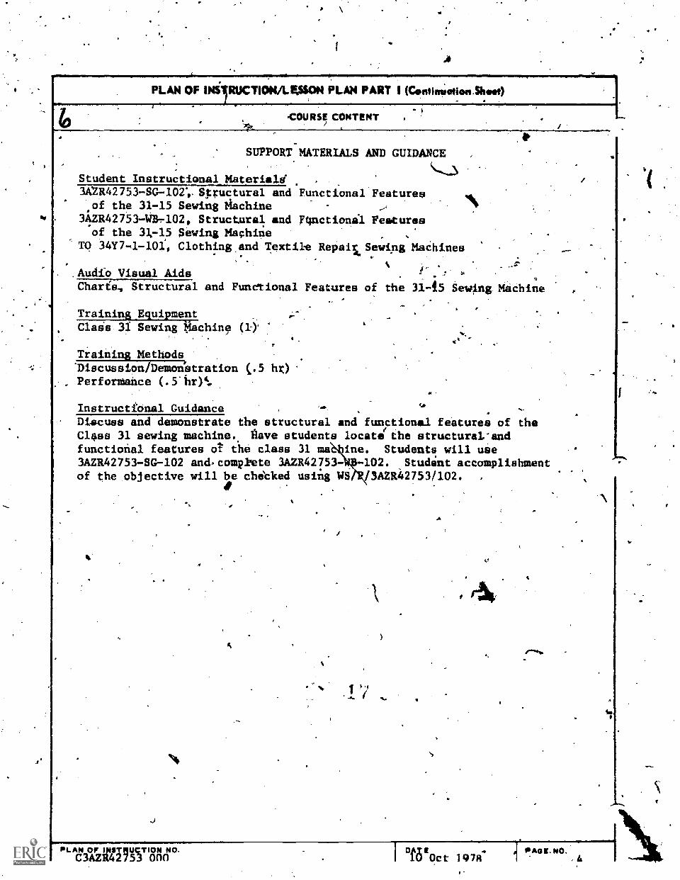
Student Instructional_Materiald3AU42753-SG-104 Spructural and Functional Featuresof the 31-15 Sewing Machine
3AZR4275341-r102, Structural and F4nctional Featuresof the 31-15 Sewing Mach4je
TO 34Y7-1-10I, Clothing.and Textil-e Repais6Sewijng MaChines
.Audio Visual Aids% -r
I.
Charfs, Structural and Functional Features of the 31-15 Sewing. Medhine
Training_EquipmentClase31 Sewing tiachine
.tt
Training Methods'Discussion/Demoldstration (.5 hr)PerforMance
Instructional Guidance .
Discuss and demonstrate the structural and functional features of theClass 31 sewing machine.. Rave students locate the structural-andfunctional features ot the class 31 ma ine. Students will use3AZR42753-SG-102 and.compliete 3AZR42753- 102. Student accomplishmentof the objective will be chicked usiilg WS1V3AZR427531102. ,
1
PLAN OF WTENCTION NO.O3AZR42753 000
, A
°MtOct1978:----T
kPAOLNO.

S.
- . PLAN OF NST1UCTION4.1ELION PLAN PAII ,
counsivrrLE
. Sewi4 Machidt Mainte\lance
NUM OF INIITRUCTOMi'
t i
- a'. I RS *7 T -3 T TIME
. ,
3, Inspection, Timing, AdjustMent, and MAjor Overhaul of the31-15-Sewing Machine
, _._.....
,---,La. Given" a class 31 sewing machine, applicable technicalpublication, and handtoola, inspeit,' time, and adjust the cladU ,
31 sewing machinA IAV specifications in die techniCal publicatidit,while obser4-ing_ All safety precautions. 'STS: 2, 3, 5, 6Meils; PC. . .
,
,. .
h.: GiVen a class 31 sewing machine, applicable technicalpublication, and handtools, overhaul the class 31 sewing machimAIAW specifications lititad in the'technical publication, -wiiile
observing all safety precautions. CTS: 2, 3, 5, 6, 7 '
Metis:- PC -
.
. ...
!ic.
..
.. .,
l
,
. .
..
44
A,. 1
%
n
a ./
f P%
-...,
. ,
*. ,
. .
-
.
8
.
8
_
t.
1
,
.
.
,
n
.
7
5UP KRVISOR APPRQVAL OF L ESSON PL AN (P ART I
S (MATURE AND CATE SIDNATURE AND DATE
-
. .
PLAN OF INSTRUCTION NUMIBER
C3/1,442753 Oon
DATE
le Oct_ 14704
PAGE NO.
c ,ATC "" 1339CT 75
rob'
PREVIOUS EDITION IVISOLETE
-
PLAN OF INSIRUC4T1011-(SON PLAN PART 4 (Cfattinuation Shoo)
H5,CURSE 'CONTENT
SUPPOME MATERIALS AND GUIDANCE.
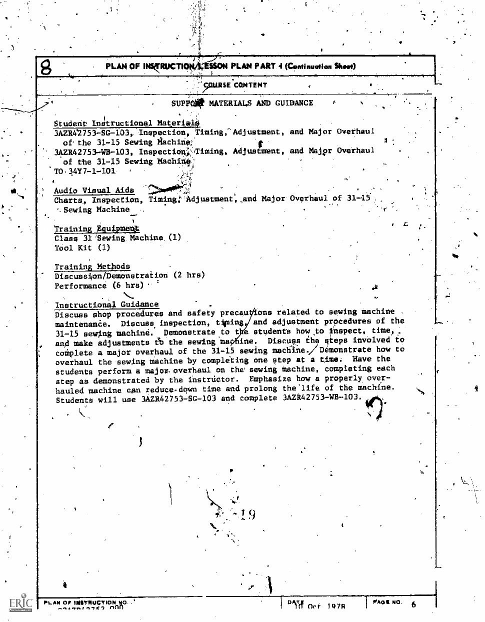
Studerit Ir4tructional Materiali3AZIW2753-SG-1.03, Inspection, Timing,-Adjustment,of-the 31-15 Sewing 8Schit*. f
3AZR42753-WB-103, Inspectio4:liming, Anjustment,of the 31-15 Sewing Machi4#
TO-10'7-1-101.
Audio Visual AidsCharts4 Inspection,%Sewing Machine
and Major
and Majpr
Overhaul
Overhaul
TimingAdjustment Atind Major Overhaul of 3145..
Training Equipme*Class 31'Sewing Machine.(1)Tool Kit (1)
Training MethodsDiscussion/Demonstraiion (2 hrs)
Performance (6 hrs)
Instructional GuidanceDiscuss shop procedures and safety precau ons related to sewing machine .
maintenanCe. Discuss. inspection, tieing and adjustment procedures of the
31-15 sewing machine. Demonstrate,to t e students how to fnspect, time?,
and make adjustments eb the sewing ma ine. Discuss the steps involved to
coiplete a major overhaul of the 31-15 sewing machIne. Demonstrate how to
overhaul the sewing machine by compliting one step at a time. Have the
students perform a major.overhaul on the sewing machine, completing each
step aa demonstrated by the instructor. Emphasize how a properly over-
hauled machine can reduce,down time and prolong the'life of the machine.
Students will use 3AZR42753-SG-103 and complete 3AZR42753-WB-103.
.2
LAN Or INSTRUCTIONflflfl
)\st
In Ori. 1Q7,1PrAOS NO. 6

'Re
a.
PLANOFINSTRUCTIONA.ISSONPLANPART 1.
i., .,
Sowing Machine Maintenance ''itt.ocx NUMMI
/ SeYing Yhchine Maint nce.
,-
. COU031! CONTENT 2. TWO
4. Troubieshooting the 31-15 SewinuMachine-a. .
. a. Given applicable technical'publicati4p, handtools,.and e '
claas 31 sewing tachitie containing five malfunetions, use trouble.-- .
shooting proce4ures.LW the ;echnical publication to correct four;of.the,five malfunotions in'tht dewing machiqp, while.obsarving allsafetTyrecautione. CS: 2,414 Mead:, PC ,-
,. .
---..,
. .
,
..
,.
.
,. .
. . . ..
.
4.
.
.
..
..
. .
.
;f i a.4a 7 . .
. * . .\
a
- .'s,, .
' .....
- -.
44.
.
-- .
I
. sailloft.
a
aI '
...
.. .. ,
...
..
v
,
r ,
i
'3
.
_
.
.
,
SUP RVISOR APPROVAL Of L ESSON PLAN (PART II)SIOATUU AND DATE SIGNATURE AND DAY
,
PL AN OF INSTRUCTION NUMIERG3AZR42753 000
CATE
10 Oct 1978AOC NO.
7
ATC "n" 133 +, PREVIOUS EDITION IS COMPLETEOCT TS
fl<di)
a

It
4
/0 'PLAN OF INSTRUCTIO*LESSON PART I (Continuation Shwa)
COURSE CONTENT
PORT MATERIALS AND GUIDANCE
Student rials3AZR42753-SG-404, Tro leshooting the 31-15 Sewing Machine3AZR42753-WB-104, Trpubleshootiag the 31-15 Sewing Machine3AZR42753-R0-104, Troublealopting the,31-15 Sesang MadhineTO 34Y7-1-101
Audio Vfsual Aids,
Charts, Troubleshooting of the 31-15 Sewing Machine...,
TrOning Equipmenttlass 31 Sewing Machine (1)
.
Tnol Kit,(1) . .%
..
C-,
Training MethodsDiscussion (khr),Pirformance (2.hrs)
k
Instructional Guidance
Discuss malfunctions'that frequently occur during operation of the.class',31-15 sewing ma'chine. Illace troubleshooting malfUnctions in tha machineithat are listed in43AZR42753-110-104. Have the studentS resolve mechanicalproblems placed in the sewid6 machine by ehe instructor.. Emphasize hawproper troubleshooting procedures can conserve time, money,'and materials.Students will use 3AZR42752-SG-104 and complete 3AZR42753-WB-104.
4
4
PI,AN OF INETBRICTION NO.C3AZR42753 000 I DAT Oct 197R
PAPE NO.a 1

. .11114.11TRUCTION/LASSONPLAN MITI.
. ,
.... .
Sewing Machine Maintenance1
L.,0ex sokI
*LOCK TITLE,
.
Sewing Machine Maintenanpe .
Minn MITER T .- . . TIME
,-4,
S. 'Structural and Functional Feature& of the 111W Series SewihgMachine '
_'-:,
.
a. Given a 111W-s-elies sewing Machine,- a diagramsof themachine, and'an applicable techhical publication; locate Imructuraland functional features of the sewing machins LOW'technical pulilica.-tion specificatiops. CTS: 1 Mias: .PC
.
1 ..
-
..
.
. .
.
N.
... ,
.
, .,
.
.... ip,
.,
.
,.
,
14
..
.
....... . .. _
- ..
,.. ,
...
. .
..
, .
1.
_
.
.
,
.
.
.,
.
,
_
c
..SUP'ERVISOR APPROVAL. OF L ESSON P AN (P ART I )
-4
SIGNATURE AND DATE SIONATVRE AND DATE..
.
..
,
. .
F INSTRUCTION N4iIIE R .
C3 42753 9.00
()ATE
10 Oct 1978PPIOE NO.
9.
FORMOCT 7,11 PREVIOUS EDITION IsOPIOLETE
9 0N.

Pk. AN.OF INSTRUCT)014/LESSON PLAN-PART I (Continuation %Etat)
COURSE4ONTENT
'SUPPORT MATERIALS AND GUIDANCE6.4'
Student Instructional Materials,3A4R427537SG-105, Structural* and FunctiOnal Features of the 111W
15e.wing Machine3AZi427.53-143-105, Structural and Funciidifal Features of the IIIW
.Seping MachineTO 34Y7-1-101
Audio Visual Aids.
Charts, Structual and Functional* Features of 111W Series Sewing Machine A
Training EquipmentClass 1I1W Sewing Machine (I)Trainer, Sewing Machine, 2680 (6) .
Training MethodsDiscussion (.5 hr.).
Performance (.5 hr),
InstrUctional GuidanceUse trainer.to demonstrate the structural and functional features of
.the-111W series sewing machine. Have students locate the.slructural
and functiotial features of the sewing machine. Students wirl use
3AZR42753-SG-105:and Complete 3AZR4.2753-WB-105. Student accomplishment-
of.the Objective will be cheated using,WS/P/3AZR42753/105-
0
6
PL. AN*OF INSTRUCTION NO.1 `
No.Oct 1978,
'PARA1Q
'1C3AZR42753 000 ,

- PLAN OP N TRUCTION/LESSON P PART... i
-, ,Sewing Mehine Maintenance 13L6C1( wagtail'
'
ato-cor TITLWSewing elachine Maintenance
--------4rr7r---"lhiE. CONTENT'
I6. Inspection, Timing and Adjustment of ihe' 111W Series Sewing
Machine .
-
a. Giv-gma class 111W sewing machine,.Applicable technical .
. publication and handtools, inspect, time, and adjust the 111W sewingmachine IAW specifications in the technical publication, while'obderving all safety precautions. CTS: 2, 3, 5, 6 Mess: PC
,
A- . .
A
.
. .
1
i.
..'
.---,'
...
,
.
.
. 1 e -
'.
N .
.
-.
*
. .
,
N
.
,
.
,
.
8
.
SUPEkVISOR APPROVAL OF LEss)s PLAN (PART 11)itowATuir Alqz DATE SIGNATURE AND DATE
..
.. --
-
PL AN OF INS T RUCTION. NURSE DATE
C3AZR42753 000 Ar
10 Oct 1978
P AG
11
N.
ATC r"m 133OCT-TSPREVIOUS EOM ON IS ORIOLITE

/4- PLAN OF INSTRUCTION/LESSON PLAN PART I (Continuation Sheot)
COURSE CONTENT
SUPPORT MATERIALS AND GUIDANCE
Student Instructtosial Materia3AZR42753-SG-106, Inspection,111W Series Sewing Mhchine
3aR42753-WB-106, inspection,111W Series Sewing Machine
TO 34Y7-I-101
le .
Timing, and Adjustment of the
Timing, and Adjustisent of the
Audio Visual AidsCharts, Inspection, Timing, and Adjustment of 111W Series SewingMachine )
Trainina EquipmentClass 111W Sewing Machine (1)Trainer, Sewing Machine, 2680 (6)Tool Kit (1)
Training:MethodsDiscussion/Demon at. ion 2 hrs)
Performance (6,h
Instruction Gu dance-UsImg the trai er, discuss and demonstrate the inspection, timing, Andadjusiment step of the 111W series sewing machine. ,Have the etudentsperform preventive maIntenance add the three timing steps on the class111W sewing ioachine. Students wild use 3AZI142753-SG-106 and complete3AZR42753-WB-106. a
nor.
"Aaamny?tir °Mkt 1978 WAGENO.12

PLAN OPINSTRUCTION/L PLAN PART I .
_ Sewing Mathine MaintenancesLocK NUM11104 ---=-ImerlTrnr::--7
Sewing Machine Maintenande -
.
. , . . _7. Major Overhaul of ebe 111W Series Sewing Machine- ,
0 .
a. Given a IIIW series sewing mpchine, applicable.technicalpublication, and handtoois, perform a maSor-overhaul of the 111Waeries sew,ing machine IAW.specifications stated. ilit the technical,publication, while observing all safety precautions.
2, 5 6, '7 Mess: PC.
. ,_
.
,
_
.
, ...
.
.
. .,
.
..
. .... _
..
_- el. -. -4° e
CI.
r .
.'. 6
0 ..O.
.
'5 I
e
; .. .
..1.
, . -. . e 1.:
. .se
...
.
e .
%
\ et
.
..
N
.
* ..
. .,
.f.
%
.I
* ''. a
.
,
.
'1
.
.
.
.
' 15
.
.
0
.
.
.
v
:
-,
.
.
F '
SUPERVISOR APPROVAL OF L MON PI.AN PA T II _
SIGNATURE AND DAT SIGNATUAIE AND DATE... .
.-1. .
. 1.
.,
PLAN OF INSTRUCTION NUMB R
C3AZR42753 000.
.
.
DA
,10 Ott 1978
PAGE
13
O.
ATC """ 133OCT 75 PREVIOUS tOIflOPd is ONISOLITE
t"

4
9
IF
PLAN OF INSTRUCTION/LESSON PLAN-PART I (Centinmatiri Sksei)
COURSE CONTEgt ".
I
PLA OP1 STA TO NOAtai427n A
4HUTORT.MATERIALS AND GUIDANCE
Student Instructional Materiais.1A2R42753-SG.,-107, Major. Overhaul of the Class 111W Series Sewing Ma hines
qlAZR42753-WB-107, Major Overhaul of the Class 111W,Series Sewing hine3AZR42753-110-107,' Overhaul of the Class 11IW Series Sewing Machine3AZR42753-110-107AMajor Overhaul of the Class 111KSeries Sewing MachineTO 34117-1-101
Audiqyisual Aida /.
Xbarts, Major-Overhaul of the Class 111W Series Sewing MJEichple
Training EquipmentClasa. 111W Sewing. Machine (1)Trainer, 07Ing, Machine, 2680 (6)Toql Kit (1)
Training MethodsDiscussion/Demonstration hrs)
Performance (11 hrs).
Instructional GuidanceUse trainer to discuss and demonstrate the st.gps.inyolved in perfotiMing,.major overhaul of the class 111W sewidg machine, Hav the studentSComplete-an overhaul of the sewing machine, Completing each step eidemonstrated by the instructor. Stress how a Properly overhauledmachine can conserve'time, and\materia1. .Studentwwill use 3A2R42753-
SG-107, 3A2R42753-H0-107A, an comp1ete.3A2R42751413-107.
fe
fre
I0Oct, 1978,OATV PAGE NO.
14
S.
A

PLAN OF INSTRUCTION/LE PLAN PART 1
./ Sewing Machine Maintenance
NUM E, Iv ..
Sewing Machine Maintenaace
-- NU COMYENT TIME
.8. Troubleshooting the 111W Serres 'Sewing Mac lade
s
. .
.
a. Given applicable technical publication, haidtools, and .a
111W aeries sewing machide containing five malfunctions, use trouble-shooting grocedures IAW the technical publication to correct four ofthe five malfuncl...ions In the, sewing machine, while obaerving allsafety precau-tions. CTS: 2, 4 Maas: PC
. ),
. -. .
..
_, *
.
_..
.
....
.
'
.
r
4.Cr
. S
f
... '
0 'e
ee A
i%
e
'-
. ,'
e
i4
,
' .A
- .
.
6
-
.
..
.
'
n
SUP ERVI SO R APP NO V AL 0 F I. ESSON PL AN(P A
SIGNATURE AND DATE SIGNATURE 4ND DATE
..t
..
PLAN OF INSTRUCTION MEER.
C3AZR42753 000
!DATE
10 Oct 19784
PAGE NO.
15 .ATC '°"" 133OCT 71 .
PlikEVIOLLIFIPOSON Is 011110LETIL

PLAN OF INSTRUCTION/LESSON PLAN PART I (tentinuation Runt)
COURSE CONTENT
SUPPORT MATERIALS AND GUIDANCE
-4\Student Instructional Materials3AZR42753-SG-108, Trnubleshooting the Class 111W Sewing Machine3AZR4453-WB-108, Troubleshooting the Class 111W Sewing Machine3AZR42753-H0-108, Troubleshooting the Class 111W 'Sewing MachiReTO 34Y7-1-101
Audio Visual AidsCharts, Troubleshootina Class.111W Sewing Machine
Training EquipmentClass 111W Sewinz Machine (1)Trainer, Sewina Hachine, 2680'(6)Toolkit (1) .
Training MethodsDiscussion (1 hr)Performance (5 hrs)
Instructional GuidanceUsing the trainer, demonstrate proper troubleshooting procOures forthe IIIW sewing machine. Have studenes remove Mechanical problems
placed An the sawing machine by the instructor. Students will use-3AZR42/53-SG-108, 3AZR42753-H0-108, and complete 3aR42753-WB-108.
9 9
""eirziMincl'8titr. clEIEOct 1978 MA" NO. 16

I
'Som.
%owe
PLANOPI $T U TON/LESSON PLAN PART r. ,
,
. .. ,: :_
, . .. .
Sewing Machine Maintenance
CIRS .
. TIMEAl
9. Structural and Funckonal Features of Special Sewing Machines
a, Given specral purpose sewing machines, diagrams' of tll .
machines, and applicable technical publications, locate thestructural and functional features of the special purpost sewingmachines IAW technical publication specifications.
.
t .
.
.
.
.
.
,.
, ..
.
.
I
\
.
.,_
..
..
...
-
.
\
..
.
,
.
.
.
.
.
. 4
3
.
-
,
.
./
-. ERVISOR APPROVAL OF L ESSON PLAN PART II)SIGATUU AND DATE SIGNATURE AND DATE
,
..
. .
,
L AN OF INSTRUCTION NURSEG3AZR42753 000
DATE RADE NO.
10 Oct 1978 17'
ATC F"' 133OCT Ti PRIMICOUS sollow s 011111OLETZ
31)

4.0 PLAN OF INSTRUCTION/LESSON PLAN PART (Continuation Shoe)
COURSE CONTENT
SUPPORT MATERIALS AND GUIDANCE
Student Instructional Materials.3AZR42753-SG-109, Structural and Functional Features of Special
Sewing Machines3AZR42753-WB-109, Structural and Functional Features of Special
Sewing MaChinesTO 34Y7-1-101TO 34Y7-2-1, Singer Sewing Machtne 7-33TO,34Y7-9-1, Singer Sewing Machine-17W15Catalog Number low Union Special Industrial Sewing Machine
Audio Visual AidsCharts, Structural and Functional Featufes.of Special Purpose
Sewing Machines
Training EquipmentClass 7-33 Sewing Machine (1)
Class 17W15 Sewing_Machine (6)Clash 47W70 Sewing Machine (6)Class-61800H Union Special Sewing Machine (1)
Trainins MethodsDisc9ssion/Demonstration (1 hr)
,Performance (2 hrs)
o .
Instructional GuidanceDiscuss-and demonstrate structural and functional featurearof the
special purpose.sewing machines. Explain needles and threackuss,needle size, varieties, and threading the machine head. Have studentslocate the structural and functional features of the sewing machines.Students will. use 3AZR42753-SG-109 and complete 3AZR42753-W2-109.Studer! accomplishment of the objective will be checked using
WS/Pf3AZR42753/109.
PL A643nitti7W 18864° IDf6EOrt 14714PAQIE PIO.
114

1.,
PLAN r INSTRUCT ON ESSON PLAN A.
Sewing-Machine Maintenance l'olVL CI( Num
hSewing Machine MaIntenance ,
2 Tikt aCOLNie CONTENT
10. Inspection, Timing, and Adjustment of Spebial Sewing Machines
a. Given special:13u pose sewing machines, applicable
technical publications, ancNhpdtools, inspect, time, 'and,adjustthe sewing machines IAW specifications in the technical publi-cations, while observing all safety precautions. CTS: 2, 3, 5,8Meas: PC .
.
,
.
.
..
.
,
.
.
,
. .
.
Ili .
,
7
,
.
.
. -
,
SUPERVISOR APPROVAL OF LESSON PLAN (PART II)5 GOATURE AND DA I SIGOIATURIII AND DATE
. .
.#;IAN OF INSTRUCTION NUI401("4-C3AZR427.53 000
DATE
10 Oct 1978PAO E NO.
19
'ATC "" 133OCT TS PREVIOUS 110111ON ORSOLETE

442 PLAN OF INSTRUCTION/LESSON PLAN PART 1 (Cosithwation 5410
COURSE CONTENT
SUPPORT MATERIALS AND GUIDANCE
Student Instructional Materials3AZR42/53-SG-110, Inspection, Timing,Sewing Machines
3AZR42753-WB-110, Inspection, Timing,Sewing Machines
TO 34Y7-4-101TO 34Y7-2-2,TO 34Y7-9-1.Catalog Numbei' 101k
Audio, Vipual Aideel
Charts, Inspection, Timing, and Adjustment of Special Purpose 'SewingMachines
and Adjustment of Speciel
and Adjustment of Special
Training Equipment-Class 7-33 Sewing Machink(l)Class 17W15 Sewing Machine (6)Class 47W70 Sewing Machine (6) (
Class 6180011 Union Special.Sewing Machine (1)Toolkit (1) ,
a
Training MethodsDiscussion/Demonstration (1 hr)Performance (6 hrs)
,
Instructional,GuidanceDiscuss and demonstrate the inspection, timing, and adjustment stepsfor the special sewing machines. Have the students complete theinspection, timing, and adjustmen steps on the special sewing machines.Students will use 3A2R42753-SG-110 and complete.3AZR42753-WB-110.
11% Course Critique and Graduatio
12. PMD: End of Course Appointments Land PredepartureSafety Bifefing
PLAk Or imirritucTIoN NO.C3AzR42753 000 Irkt 1978
1 PAW( No.20

3,1z4t. 44.17S3'STUDY GUIDE 9019151t50.06.-SG-100
TWS
DISTRIBUTION: XTWA - 100; TTOC - 2
4C°
Technical iraining.
Sewing Machine Maintenance
SEWING MACHINE MAINTENANCE
7 August 1972
tE '1* *
gtr
Gt
CHANUTE TECHNICAL TRAINING CENTER (ATC)
c Designed For ATC Ceuerso the
.00 NOT US! ON THE JOIle
3 4

fadi
75 Training Publications are designed for Ar course use only. They are updated as necessary.for training purposes, but are not to be used on the job ass afiLthoritative references in pref-erence to Technical_Orderkor other official publications.
.10
-a
CONTENTS.
UNIT TITLE PAGE
101 Course Orientation 1
S.
102 Shop Procedures and Safety Precauiions / ' 5
103 Structural and Functional Features of 9
31-15 Sewing Machines
104 Inspection, Timing, Adjustment and- MajoiOverhaul of the 31-15 Sewing Machines
105 Troubleshooting of Class 31-15 SewingMachines
106 Strudtural and Functional Features ofthe 111W-Sewing Machines
107 Lmspection, Timing and Adjustment of111W Series Sewing Madhines
108 Major Overhaul of the Class 111W Series&owing Machines
109 Troubleshooting Class'111W Sewing _
Machines
110
15
17'
19
23
25
27
Structural and Function Features of 7-33, .29
17W15, 47W70 and 61800H Sewing Machines
111 Laspection, Timing-and Adjustment of the 7-33,171415,-47W70 and 61890H Sewing MaChines
Jj
31\
August 1969 25NOTE: PACES ill OF Srtill ciip ARe frussfev ;
frlowEVER "941- 11i/47FR/oil_ hivccuPED.

Life Support Systems Branch 2ft5e1900emtew102
Chanute AFB, Illinois
OBJECTIVES
SHOP PROCEDURES ARD SAFETY FRED:MIMS
v
Upon completing this unit of instructions you will be ableato perform shop procedures and safety precautions during operation
.and/or maintenance of Sewing machlnes.
INTRODUCTION
When operating and/or performing maintenance on sewing machines,
it is very,impOrtant to you and everyone concerned that good
safe practices and shop procedures be followed.
The most important possession you have is your life and
well being. It should not be jeopardized in any way..
INFORMATION
Many of our activities during eadh day are filled with accidents
waiting torhappen. Most accidents can be prevented if we plan
our habits and routines with safety in mind.. So let's pee what
we individually can do to live a longer and less painful life.
Perhaps the best place'to start this study.of safety is with
good housekeeping habits.
GOOD HOUSEKEEPING IS THE FIRST LAW OF ACCIDENT PIEVENTION
Some people are recognized for their neatness. Everything
they have is tidy. Everythinng they do is neat end orderly. Neatness
is a part of them. On the other hand, some of us constantly
look like we,slept in out uniforms, like we were miles from the
nearest barber, likeour work area is an auto cemetiry. How
we appear to others and haw we do things reflects our inner
personalities. We have standards which are the result of our
home environment. We carry such standards into every phase of
life. All of our actions reflect our upbringing. Standards
are adjustable - they can be learned. In fact, that's just what
we are attempting in this course you are takini to cover theacceptable standards that are to be followed when operating and/or
performing maintenance on sewing machines.
SAFETY PRECAUTIONS TO RDLLOW WHEN USING ORPERFORMING.MAINTENANCE ON SLWING MACHINES
The following precautions should be observed while performing
maintenance or operating sewing machines in order to prevent
injury to the operator or damage.to the madhines.
KEEP THE FINGERS OUT FROM UNDER THE PRESSER FOOT/FEET WOLE
THE MOTOR IS RUNNING.
5
36
749
4.

77 DO NOT OPERATE THE MACHINE WITHOUT MATERIAL UNDER THE PRESSERFOOT/ FEET, AS THIS WILL DULL THE FEED DOG.
DO NOT CHANGE THE BOBBIN WHILE THE MOTOR IS RUNNING.
BE SURE THE BED SLIDES ARE CLOSED BEFORE OPERATING THE MACHIp.AS THE FINGERS OR THE MATERIAL MAY COME IN CONTACT WITH THg ROTARYHOOK AND SERIOUS pAMAGE MAY BE THE/RESULT.
KEEP THE FINGERS AT THE SIDE OF THE MEEDLE., NOT TN FRONT.
HOLD /i0TH THE NEEDLE AND BOBBIN THREADS TAUT WHEN STARTINGTO SEW.
WHEN WINDING A BOBBIN, BE- CERtAIN' THAT THE PRESfER FOOT/FEETIS/ARE RAISED AND THAT THE NEEDLE IS NOT THREAVD. f
DO NOT START SEWING UNTIL THE MOTOR HAS HAD SUFFICIENT TIMETO ATTAIN FULL SPEED.
DO NOT TRy TO PUSH OR PULL THE MATERIAL AS IT iS' BEfljG 'FED
THROUGH THE MACHINE. THE NEEDLE WILL BEND OR. BREAK.S.
OPERATE THE MACHINE AT A LOW RATE OF SPEED TO AVOID-MAKINGLINES THAT ARE NOT STRAIGHT. .
BE SURE TO TURN THE MOTOR SWITCHMFF ANY TIME YOU LEAVETHE MACHINE.
DO NOT TURN THE BALANCE WHEEL BACKWARD A FULL TURN OR THETHREAD WILL BREAK.
USE THE PROPER TYPE OF THREAD AND CORRECT SIZE AND CLASSOF NEEDLES.
WHEN TILTING THE MACHINE HEAD BACK, BE SURE THAT IT LIESswam AGAINST THE MACHINE HEADREST PIN. INJURY TO YOUR HANWMAY RESULT IF THE MACHINE HEAD FALLS P3RWARD. KEEP YOUR HANMSAWAY FROM THE EDGE OF THE OPENING WHILE THE,HEAD 1$ BACK.
BE CAREFUL NOT TO PLACE 1HE FINGERS UNDER THE NEEDLE AFTERTHE SWITCH HAS MEN TURNED OFF, BECAUSE THE MOTOR TAKES A LONGTIME TO RUN DOWN AND COULD IN.TURE THE OPERATOR IN'SUCH A SITUATION.
SHOP HAZARDS
Shop safety begins with shop layout. If the Survival EquipmentShop is set up in accordance with the proper technical manualsand official Air Force Diffinitive Drawings plus sound localstandirds, safety is built In.
Accidents do occur in the Survival Equipment Shop - thedirect cause is human.carelessness. A few causes are listed
'here.
3 "46

1. Failure to'maintain orderly racks and storage shelves,
resulting; in objects falling on someone.
2. Tripping over things on the floor.
3. Improper lifting.
4. _Unintentionally hitting others with objects.
$. Failing to use proper guards on machines, such as our
electrical fabric cutter.
6. Improper grounded electrical equipment.
7. Using tools improperly. Make sure the ne?essary tools
and equipment are Included in the work area.
Many -men have needlessly auffered permanent injury or died
because spmebody else "needed'a laugh. ,Horseplay has notusiness
in'productive work areas.
REFERENCES
TO 34Y7-1-1D1, Clothing and Textile Repair Sewing Machines,
Book One, Part Two.
-e
7
es
79
-°.14

11-.19
3fim 4e2.?Life Support Systems Branch .?A&R54-140-,-SG-1.0
,5-3
Chanute AFB, Illinois
STRUCTURAL AND FUNCTIONAL FEATURES OF31-15 SEWING MACHINES
I
06JECTIVES
Upon"completing this unit of instruction, you 4111 he ableto analyze and identify tke itructural and ftinctional featuredof the Class 31-15 Sewing: Machines.
ftes
INTRODUCTION
The 31-15 sewing machine is smaller and lighter than mostof the.other machines used in Survival Equipment Shops. The
manufacturer calls the 31-13 a "tailoring" madhine which-givesa clue to the-type of material it is designed to sew. It id
used to sew and repair clothing, uniforms, shirts, flying clothing,skirts, underkear,1jackets, light.tentage and similar materials.
These many uses shouldNbake it obvious that every one concernedwith operating or maintaining the sewing machine must have someknowledge of how the machine works.
INFORMATION
PREPARATION AND OPERAIION OF MACHINE
A good,repairman must know more thail just haa to turn his
madhines on andpff. Hh must knaw certain structural features.,of his machine and ho4 it functions to do the job required.
-Funptiona1 Features
The Class 31 Machine makes the US standard lockstitch,at
a maximum recommended speed of 2200 stitches-per minute. It
had an oscillating shuttle which operates in.an upright posttion
and is equipped with a drop feed which moves the material through
thetchine from front to back as it sews. The front of the
k meal ne is that Ode neareat the operator as be is in the position
to sew.
NEEDLES. It is very important that the propex needle be
used to insure-good machine operation. The selection of needles
by class, variety and size for different machines and.materials
is necessary in order to eliminate thread'breakage, needle breakage,
,skipped stitches and fraying.of the thread.
Needles for the various machine clpasea are selected and
ordered by needle number and size. The'needle numbers consist :
of a class number and a variety number separated by an "X"; for
example; the class 16X87 variety needles are used in Class 31
Machines. The Class. XX (16) describes the shank, figure 1, and
the variety number (87) describes the length and type of point
9
3 9
SHANK KLASS)
NOTE1 THE SIZE OF THENEEDLE INDICATES THFGAGE /DIAMETER) Of THELOWER HALF . Of THENEEDLE AND THE SIZE
Of THE EYE
, VA ale TY
A
LONGGROOVt
SHORIGROOVE 16 I
' itPOINT
Figure 1. Sewing A4ehine_Needles.
A C LOTH f dINT
I TWIST POINT
DIAMOND PdINT
Figure 2. Openings Made ByNeedle Pqn,ts.
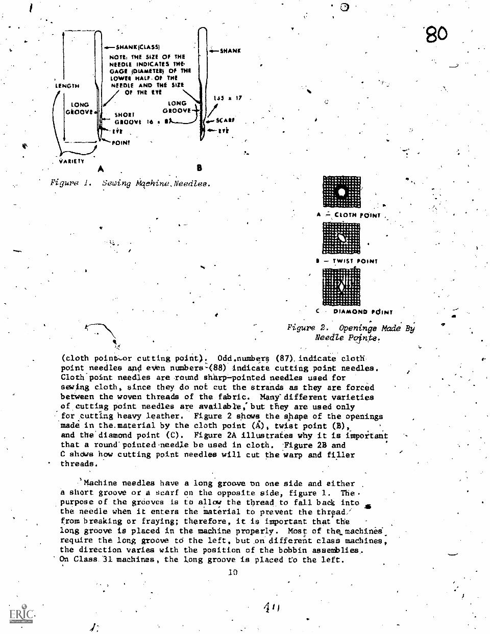
(cloth pointa.,,or cutting poirit): Odd.numbera (87), indicate clothpoint needles and eVen numbers-(88) indicate cutting point needles.Cloth'point needles are round sharppointed needles used forseatng cloth, since they do not cut the strands as they are forcedbetween the woven threads of the fabric. Many'different varietiesof cutting point needles are available:but they are used only
..for cutting heavy leather. Figure 2 shows the shape of the openingsmade in the.msterial by the cloth point (X), twist point (B),_and the'diamond point (C). Figure 2A illustrates why it is importantthat a roundspointed,needle be used in cloth. :Figure 2B andC shows how cutting point needles will cut the warp and fi.11erthreads.
.3Machine needles have a long groove Dn one side and eithera short groove or a scarf on the opposite side, figure 1. The.
.purpose of the grooves is to allow the threaelto fall batk intothe needle when it enters the material to prevent the thiyadifrom breaking or fraying; therefore, it is important that thelong groove is placed in the mathine properly. Most of the machineirequire the long groove to the left, buton different class madhines,the direction varies with the position of the bobbin asseniblies.On Class:31 machines, the long groove is placed Co the left.
10
110
so

81
41.
. 31-15 &wing hdchine-(Front View).
44
Needles are sized by the diameter or gage oT the needle,figure 1 and the needle eye. The selecticon of the correct sizeneedfe is determined by the size and type of thread 'and material
used. The thread mutit'pass freely through the eye of the liesdle
in ordertto prevent thread fraiing or breaking. The sizes of,the 16X87 needles range fram size 14 to 23; however, most sewingb'perations required.May be accomplished hy using ,sizes 18 through
The needle size nuMber increases with the diamete4.of then edle; thirefore, size.18 needles are used for lighter weight
materials than size 22.
The condition pf the point should. be Checked before starting
to.sew. A dull round needle acts the same as a cutting needle.It will cut or pull threads and may weaken the seam. The condition
'of the needle may be checked by gliding the fingernair over the
point. If it icratches or caephes the nail, the needle should
be replaced with a new one. The technical order forathe iachinewill give instruttions of a more detailed nathre.
TUNCTIONS OF PARTS OF MACHINE. Figure 3 'shows the location
of the operating parts of the 31-15 sewing machine. Refer tothis figure'to identify-the parts of the list that follows. The'
names and the functiOns of Vle main parts -of the Class 31 machine
aree
I L

, a. Needle liar: Holds the needle and alao carries thethread In the vacillating shuttle where the lockstitc'h is
torld"
b. Thread Takeup Lever:thread after the rockstitch iaand pulls enough thread from t
Removes the slack in the needleformed At.the 'oscillating shuttle
tikspool to make the next stitch."
' r
c. Pressure Regulating Thumb Screw: Regulates the pressure-a-ma the preaser'foot to make suffiCient pressyre needed-to holddie-material securely.
d. Faceplate: Covers and protects the mechanism of thevresser foot and needle bar.
e. Eyelets: Guides the thread from:the takeup lever to 'the needle.
. yresser Bar: Holds the presser foot.
g. rresser Footr Holds presser on the material 4,7 le tbk...machine is formle.gthe stitch.
h. .Shuttle Race Slide: Covers the shuttle race ssembly.
I. Throat Plate: Surrounds.the feed do/ and keeps thematerial from.slipping after/the Sted dog has been adlusted tothe proper height.
j. Slack Thread Reelator: Regulates the slack in.thethread when the 'needle is desceAding.
k. Tenslon Assetbly.: Regulated the tension on'the needlethread so that the locystitch day be adjugted properly.
1. Thread Takeup.$prineF Removes 'sufficient sle fromhe needlethread when the needle is descending to pre ent 'the
froM pplittin6te tc.pread..41
m. Thread Retainer: Retevee sufficient slack from the. . -
needle thread when the needle-is descending to prevent the needlefrom splitting its thread..
n. Arm Spool Pin and-Thread Eyelets: Used-fo lacing,,'stall dp0918 of thread on-the maChine or for.giading Tad as
. .
- it coaes ffrOm the large cones. -
0. Balance Wheel: Provides a connedtion between the-drivingunitfand the sewing machine head.
feed LFeed Regulator: Used to regulate the length of the
rmine the number of stitches per inch.
q. Model Nimber: Number indicating the machine modelor the class, place of manufacture and modifieations of the maChine.
2
Atr.
. /10ALAw

tea
Serial Number: Manufacturer's serial number oi the
madhiner
a. Feed Dog: Feeds the materials through the machine.
t. Presser Bar Hahd 14ft: Hand lever for lifting the
presser foot.
REFERENCES
,
4*
TO 34Y7-1-10l, Clothingand Textile Repair Sewing Machines
ea.
3
el
1 3.
a

3 Az tt. 442-757.?
Life Support Systems Branch 24416015e-4-sc-103Chanute AFB, Illinois
INSPECTION, TIMING, ADJUSTMENT AND MAJOROVEKHAUL OFw.THE 31-15 StWING MACHINES
OBJECTIVES
Upon completing this unit of instruction you will be able 6inspect, time, adjust, and overhaul Class 31-15 Sewing Machines.
INFORMATION
1. Detailed information ,conceriting inspection of compc;nentaof the sewing machine for se,rviceable condition and Procedureson when preventive maintenance is to be performed. Study TO34Y7-1 -101, Book Ong Part Two Section III, and Part Three SectionsX and XI.
2. Step by step, procedures for.accomplishing the.follawingitens listed concerning the 31-15 Sewing Machities. Study TO34Y7-1-101, Book One Part Two Section VI, and Pait Three SectionXIII Paragraphs 46 thru 49.
Timing Needle with Shuttle
. ..
Timing Feed Dog with Needle-. .
..,4.
Adjusting,Stvtches per Inch
i.
Adjusting F id Dog
4
3: Detailed pr cedures for overhaul of the sewing machineconsisting of disasse ly and reassembly of the folloWing itemslisted on 31-15 Sewing. Machines. Stay TO 34Y7-1-101, Book 04Part Three Section XIII Paragraphs 50 thru 52, and Part Five-lectlon XV Paragraph 55.
Face Assembly
Shuttle Race Assembly.
Thread Tension Cpntroller
REFERENCES
34Y7-1-101, Clothing arrd Textile Repair Sewing Machines
15
.1

es
t.
3.42g 442Life Support Systeum Branch M1*543159--6-SG-1Of
Chanute AFB, Illinois
TROUBLESHOOTING OF CLASS 31-15. .SEWING MACHINES
OBJECIiVES
When you kave completed this study guide you will be able
to determine and remove malfunctions that frequently occur when
operating the 31-15 Sewing Machine.
INFORMATION6
General troubleshooting information which chn be of lelp
in determining And reuoving the causes of trouble that may develop
in the madhine. Read TO 34Y7 -101, Book One,. Fart Three, SectiOn
XII.
REFERENCES
TO 34Y7-1-101, Clothing and TeUtili Repair Sewing Machines
SN.
17 .
I

.71teityd#4..,
Life SUPport Systems.aranch. 2*9160150.6-SG-10(
Chanute APB, Illinois
STRUCTURAL AND FUNCTIONAL. FEATURESOF THE IIIW SEWING MACHINES
OBJECTIVE-,1
lipon completing tide unit of instruction, youwill be able
to analyze and identify the structural and functional features
of the Class 11114.teries Sewing Machines.
INTRODUCTION
Class 111 Sewing Machines are one-line (single needle) lockstitch
mathines designed to sew medium weight materiala and are capable
of sewing at a speed of approximately 2900 stitchee per,minute.
A lockstitch machine is the only type of zyichine used in making
strong and durable finished'seams. With each individual stitdh
a half,of a squere knot is formed.in the bobbin aesembly by a
rotary hook on the-111 machines. This high speed machine.is
used for sewing heavy textiles, webbing, tentage, upholstery,
and flat leather articles.
INFORMATION
Sewing machines are identified by symbols which are located
on the upright arm of the machine head. Each symbol is made
uf two or three parts. In the case of the 111 class of machine,
the 111 specifies the machine class. The second part denotes
the place of manufacture. The third part (152, 153, or 155)
determines the number,of modifications or improvements made on
this class of machine. The 111 also designates the machine as
a single needle (one line) machine. A 112 madhineiis a two needle
(two line) machine.
There are various feedidg mechanisms used on sewing machines.
Some 111 machines are equipped with a compOun feed alone,,auch
as the 111W151, and others are equipped with combination of
compound feed and alternating presser feet such as the 111;4152
-and 111W155. The varaws feeding.mechanisussmost commonly used. J.
on machines are: 4
Needle Feed.: The needle alone moves the materialthe regular
length of a stitch, while the presser foot holds te material
in place on the'throat plate.5
Drop Feed: The feed dog moves the material the regulatedlength of a stitch while the presser foot holds theAmaterial
against the feed dog.
Compound Feed: Consists 'of the needle feed and the drop
feed. Some compound feed machines are equipped with alternating
presser feet. The alternating presser is an additional presserfoot which holds the material alternately with the Compound feed.
This type of feed is used on-class 111 machines.
19
16

9
12
13
1,
p
,
a4>
'ro,4,ct
re" 4
Sew.ng kaehine Read, Tipe 1flW1.5Z;.
1 .0
1..table Tdp.2. Opening in. Table Tap for
. Sewing Mad ne Head.3. Tool and read Drawer.4. Adjustah e Sewing Machine Stand.5. Adjuatab e Sewing. Machine
Motor with Clutch.6. Extension.Clutch Arm.
Mot'ol.pc1 Atttrd
Motor wit-ch.
Treadle' Wurch Foot pidal.011Drioan.,Machineyodt Knee LiftingLever. .
12.. Oil Om 4F4wket.
Figure 5. Class 111 Maa6ine L'e44/4.i.
20/.147".

31Y
Figure 4 shows a class 111 machine head and its featureS,and table 6-11ists the functions of theleatures.
Figure 5 shwa a class 111 machine stand and its features.
NAME1. Thread Take-Up Lever
2. Vibrating Presser-BarTension Regulating Screw
Lifting Presser-Bar TensionResulatin& Screw
4. Arm Cap
FUNCTIONPulls the needle thread against thetension disc after the lock stitch isformed at the'rotary.hook (16) and pulla
. sufficient thresd -from the spool to make.the nett stitch.Regulates the pressure on the pressurefoot (13). Only sufficient pressure isto hold the 'material securelRegulates the pressure on the alternating.presser foot (15).Enables the operator to make the int.ernai
adjustments and protects the inside fromdust.Indicates the number.of st tches perinch which is bein made,b the machin
t 88
. Feed Indicating Disc
. Balance Wheel
7. Arm-And-Hook Driving-ShaftConnection Belt
8. Face Plate
Provides a connection between the drivingunit and the sewinAmachine head.Connect the-upper arstlact with thehook-drivi shaft. '7
Covers and protectS the me anism,of hetwo_presser feet and needle bar (lb.
9. Needle-Thread Lubricatdi Lubricates the t5-read when sewingleather. LLubrication of thethreadprevents it from fraying and;ireventsthe needle f;om becoming hot,When.sewing
10. Needle-Thread Tension Regulates the tension on the :needle
thread solthat-the lock stitch may be
adjusted properly'.
11. Needle-Thread Controller Removes sufficient,slack from the needle
Spring-Assembly thread when the needle is descending toprevent the needle from splitting the
thread.Holds the needle and carries the thread'to the rotary hook (16) where the lock
stitch is formed.
12. Needle Bar
13. Vi sting Presser-Foot Holds the material iA place while thealtexnating presser foot (15) rises to
make another stitch.
14. Feed Dos,
15. Alternattng Presser-Foot
Feeds the material fram the Under side.Holds the material in place while thevibrating puesser foot (13) and.feeddog (14) go forward ta get materialfor the next.stitch.
16. Rotary-Hook Assembly Contains the mechanism which forms thelook stitch by using the needle andbobbin threads.
Tablc 1. Featuren of the C ans 111 Machtne and Their Functions.
21

16A: Bobbin Contains the. lower thread used informin he lock stitch.
ldg the bobbin case in the lockassembl'.
16B. Bobbin-Case Retainer-HookGib
lttc. Needle -Deflecting HookWasher
Holds the bobbin, case in the lockassembl
17. Throat:Plate
18 18A, Bed Slides
19. Feed Indicator ?flinger
Surrounds the feed dog and keeps the.material frau slipping after the feeddog has-been adjustcd to the, properheight.'Covers the feed eccentric and .rotaryhook asseday .on each side of. thethroat late..
. Used in connection with the feed.indi-cater td regulate the'nUmber of stitcheser indh desired.
204 Safety:-Clutch Lock ,Stud
.21. Bobbfn-Case Opener
.Re-engagesj the needle with the hook.-driving gissembly after clearing a
_a thread jam.Prevents thread from jjamming .underneaththe throat plate on the bobbin casebase.. .
-22. Rotary-Hook SaddleComplr
The rotary hook ,(16) is_ operated bythe spiral driving pinion gear (22)which in turn is operaed by -the..hook drivisIg gear lboated an thehook drivin sh-aft .
24. Rotary-Hook and Connection tilted to time the anti shaft 1wIth he'Telt han ook drivin tihaf t .
Table.1. Features .4. the 'Class 111:10dhiise.and (cort'd).
'REFERENCE
Study TO-34Y7-1-101
22
4.

Life Support Systems pranchChanuti
INSPECTION, TIMING, AND'ADJUSTMENTOF,111W SERIES SEWING MACHINES
OBJECTIVES
on comp tion of this unit of instruction you %All be able
to.in pect, ti and adjust the Class'111W Series Sewing Machines,
yAiziewisik646144)-4-sG-io
INTRO
The Class 111W Series Sewing Machines require periodic inspections._
prior to ancl.during actual operation of,the maChines. The Dreventive
maintenanbe procedures are performed to keep-the sewing machine
in serviceable condition for maximum perfermance du ng operation
of-the machines.
INFORMATION
PERFORMING INSPECTION TIMING STEPS
Each technician is required to know certain maintenance procedures.
The following inspection.timing steps and adjustments will be
used to maintain the sewing machine in working condition. There
are three inspection timing steps; each step.should be completed
in sequence.
Timing Arrows
Alignment of the arrows is the first tfming step. It is
necessary to time the arrow on the collar of the hook driving
shaft with the arrow on the timing plate so the fabric is not
fed through the machine until the needle is above the fabric.
Raising and Lowering the Needle Bar (
This is the second timing step. The needle bar must be set
to proper length to complete proper timing procedures. There
are two small marks 1 7/8 inches above the bottom of the needle
her which are 3/32 inches apart on the li1W152, 153, and 154 sewing
machines; 2 1/8 inches above the bottom of the needle bar on the
111W155 sewing machines.
The top mark indicates the length of the needle bar. This
procedure will position the needle bar at the proper specified
X rength so the lock stitch may be formed during operation. If'
the needle bar is not marked, use a needle bar "T" gauge of local
manufacture.
The lower mark on the needle bar indicates the distance the
needle bar travels on its upward stroke', as the hook passes the
needle. The hook point should pass approximately 1/16 inch above
the top of the needle eye. In this position, the hook will pick23
/

CiI
l up the needle thread and begin to form the lock stitch.
./14;!ing Hook with Needle
This is the third timing step. The point of the hook willbe appro)4mate1y 1/16" above the.top of the eye of the needlewhen correctly timed. Timing the rotary hook sometimed can beaccomplised by moving the hook driving gear left or rightojocenter theAmint of the rotary hook on the needle. However, iftiming canriot be aecomplished as stated above, the 'rotary-hookasseMbly should be removed and reinstalled.
PERFORMING ADJUSTMENTS
Raising or Loiering Feed Dog
.The feed is raised or lawere&as required to make it stand,a distance of 4 full tooth above the throat when the feed dogis at its higheSt position.
Adjust Presser liars
The-lifting and vibrating presser bars are adjusted so thatthey are spaced 19/64th inches apart on the 111W152, 153, and154 Sewing Machines and 21/64th apart on the 111W155 Sewing Machines.Adjusting the space betWeen the preaser bars is to be accomplishedwith the machine set to sew zero stitches.per inch.
Adjust Relative Lift of Presser Feet
When the vibrating and lifting presser feet are correctlyadjusted, both feet will alterriately rise an equal distance duringthe walking motion of the presser feet.
Adjusting the Tension Assembly and Controll-er Spring4.1110
This asseMbly is composed of two separate tension control .
devices. The upper tension asseMbW may be adjusted to applytensiOn to the needle thread; the lower thread controller assemblyhas a.spring which is used to remove slack cfrom the needle thread.
The tension asseMbly may be adjusted by the thumb nut onthe tension stud. The thread controller is adjusted by.setting
:tension on'the spring and alignment of the spring stof).
REFERENCES
Study
TO 34Y7-1.-l0l, Clothing and Textile Repair Sewing Machines',Book Two Part Three
51
arar

t .
Life Support Systems Branch 4,
Chanute AFB, Illinois v \
. .
OBJECTIVES
3Ar-44.2.7.5a
**SKAR-Se--4P7SG-al
,MANDR OVERHAUL OF THE CLASS 111WSERIES StEWING MACHINES
Upon completion of this unit of instruction you will.be Able toperform major overhaul of the Class 111W Series Sewing Machines.
INTRODUCTION
Major overhaul of the 111W Series,Sewing Machines requiresd complete disassembly and reasseMbly of major components of themachines. Components *bat may require disassembly and- reassemblywhen performing major ovrhaul are:
FACE ASSEMBLY
UPPER SHAFTS
gOOK DRIVING
FEED DRIVING
stun.\
ROCK SHAFT
TENSION AND THRAAD CONTROLLER ASSEMBLY
4INFORMATION
The face assembly consists olg the lifting presser bar, vibrafingpresser.bar, needle bar.rock frame, and thread take-up lever assemblies.
The up -shafts consists of Oae arm shaft, lifting roCkshaft, and,nese le bar rock frame rock shaft.
/. The hook driving shaft assembly containo the hook drivinggear pulley, timing collar, hodk driving shaft lock ratchet, feeddriving eccepftric, feed driving connection, hook driving gear,and feed lifting cam.
a.
VIP
Components of the fed driving, rock shaft are feed bar, feeddriving crank, and rotary hook saddle.
kdad TO 3417-1-101, Book Two, Part Ftve, Sction XV for detailedinstructions concerning disasseMbly and reassetbly,of the faceassembly, upper shafts, hook driving shaft, and feed driving rockshaft asseMblies....
The tension controller assembly consists of tension,ehumbnut and spring; tension release washer-and disc (two each); tensionrelease plunger; 'stud, andrelease lever.
25
52'

. The thread controller asseMbly'consists of ihp thread controllerthumb nut, spring, atud, disk and spring stop..
Read TO 34Y7-1-,101, Book Two, Part Three, Section KJI, Paragraph119 for step by step proce4ures coymerning disassethbly -and reassemblyof the thread and tension controllers. ,
REFERENCES
TO 34Y7-1-101, Clothing'and Textile Repair Sewing Machines
26
1
0.

4
1Life Support Systems ArandhChanute AFB, Illinois
litzic 4ealheitSitt5e-6-SG-101f
TROUBUSHOOTING CLASS IIIW SEWING MACHINES
OBJECTIVES
,When you have completed this'study guide you will be,able
to determine and remove mallunctions that frequently occur when'
operating the 1I1W series sewing .machine.-
INFORMATION
General troubleshooting inforbation which can be of help
in.determining and removing the causes of trouble that may-develop
in,the machine, read 2ASR58150,-6 -AO -109 and TO 34Y7 -1 -101,'Book
Two Part Three Section XII Paragraph 108.
REFERENCES
TO 3017-1-101, Clothinvand Textile "Repair Sewing Machines

Life Support. System BrandhChanute APB, Illinois
zezies.wri /of'124175fl.64-4-SG7148
. -
STRUCTURAL AND FUNCTIONAL FEATURES OF7-33, 17W15, 47W70, and ,51800H SEWING,MACHINES
I.
OBJECTIVES
-Upon completion of this unit of'instruction you will.be-gbleto identify and aiialyze structural and functional featuria of
the 7,-33, 17W15 474170 and 6180011 aewing madhines.
INTRODUCTION-. v
IThe 7-33, 17W14, 47W70, and 618008 Sewing Machines are designed
to do a specific job\l. Although the structnral and functional .
features are sindiar\on all sewing madhines, Ahch has some.features. that differ film others. .
.
INFORMATION
cLAss 7-33 SEWI.NG MACHINE
The 7-33 sewing machine 4.5 % single neddle, lock stitch'madhinedesigned for sewing heavy canvas land weAting. It is equippedwithloirop feed, alternating presser feet and-an oscillating shuttle.
Stitch regulatiOn ranges in length fram 2 to 8 stitches, per
indh. Matipum speed is 550 stitdhee per minute. Needleesusedon the 7-33 are, class and variety 7X1 .or 7X5 for sewing cloth
and 7X2 or 7X6 for sewing leather. Needle sizes range from *ice
.16 to size 31.
Study TO .34Y7-2-1 for inforMation concerning struttural andtune ional features of the 7-33 sewing sachine.
CLASS 17W15 SEWING MACHINE$
The 17W15 seuagg machine is a zig zag machine designed for'seizing. 'ends of small and'medium size'ropes and iewing parachutesuspension line on or'in a parachute canopy. It is a single 'needle,
lock stitch machine with a vibrating needle and a transverse (verrical,
with bobbin facing front of machine) rotary hook.#
Th'e forward stitch and the sideway throw may be adjustedItth the sideway throw adjusted to a maximuM length of 1/4 inch.
_he maximum recommended speed is'1,000 stitches per minute. Needles
used on the machine are, class and,variety 134X1, sizes 10 to26.
Study TO 34Y7-9-1 for information'concerning,structural andfunctional features of the 17W15 sewing Inachine.
r
Jib
29 t-

CLASS 47W70 SEWIt,G MACH6E
The model 47W70 sewing machine is a darning machine designedfor repairing clothing, parachutes, etc. Included in the designis a round bed designed.for sewing tubular articles of clothing.
A roNtry hook, works in conjunction with a single needle toform the lqsk-stitch. Operators must move the material hack andforth under the needle as the 47W70 has no feeding mechanism.Needles used on the machine are, claws.and variety 126X3, sizes10 to 44,-
7
Study TO 34Y7-,1-101 Book Three, Part One and Two-bar informationconcerning structural and functional features of the 47W70 DarningMachine.
GLASS 63800H UNION SPECIAL SiNING. MACHINE
The 61800H union special sewing machinemedium, and heavy duty work. It is a &Inglemachine with compound feed,and a rotary hookprovided with an oil reservoir for automaticrotary hook assembly. Manual lubrication of_assembly is re9uired.
Length of the stitch may berecommended &peed is 4000 R.P.M.are, type 182dA, sizes 044, 048,
is designed for light,needle, lock stitch
. 1The machine islubrication of the .the head and face
adjuated as necessary and maximumNeedles used 81111.the machine
054, 060 and 061.
Study Catalog 101R, gnion Special Industrial manual bar informationconcerning structural and functional featuers of the ()MOH UnionSpecial Eiewing machine.
REFEgNCES
TO 34117-1-.10l, Clothing and Textile Repair Sewing Machines-
TO 34Y722T1 Singer Sewing MAchine, .7-33
TO 34Y779 -1, §inger Sewing Machine, 17W15
Catalog number 101R, Union Special Industrial Sewiag itachineManual ,
IPS
30
4
Life Support Systems pranehChatham AFB, Illinois
°- INSPECTION, TIMING, AND ADJUSTMENT OF THE7-33, 17W15, 47W70, and 61800H SEWING MACHIlp
OBJECTIVES
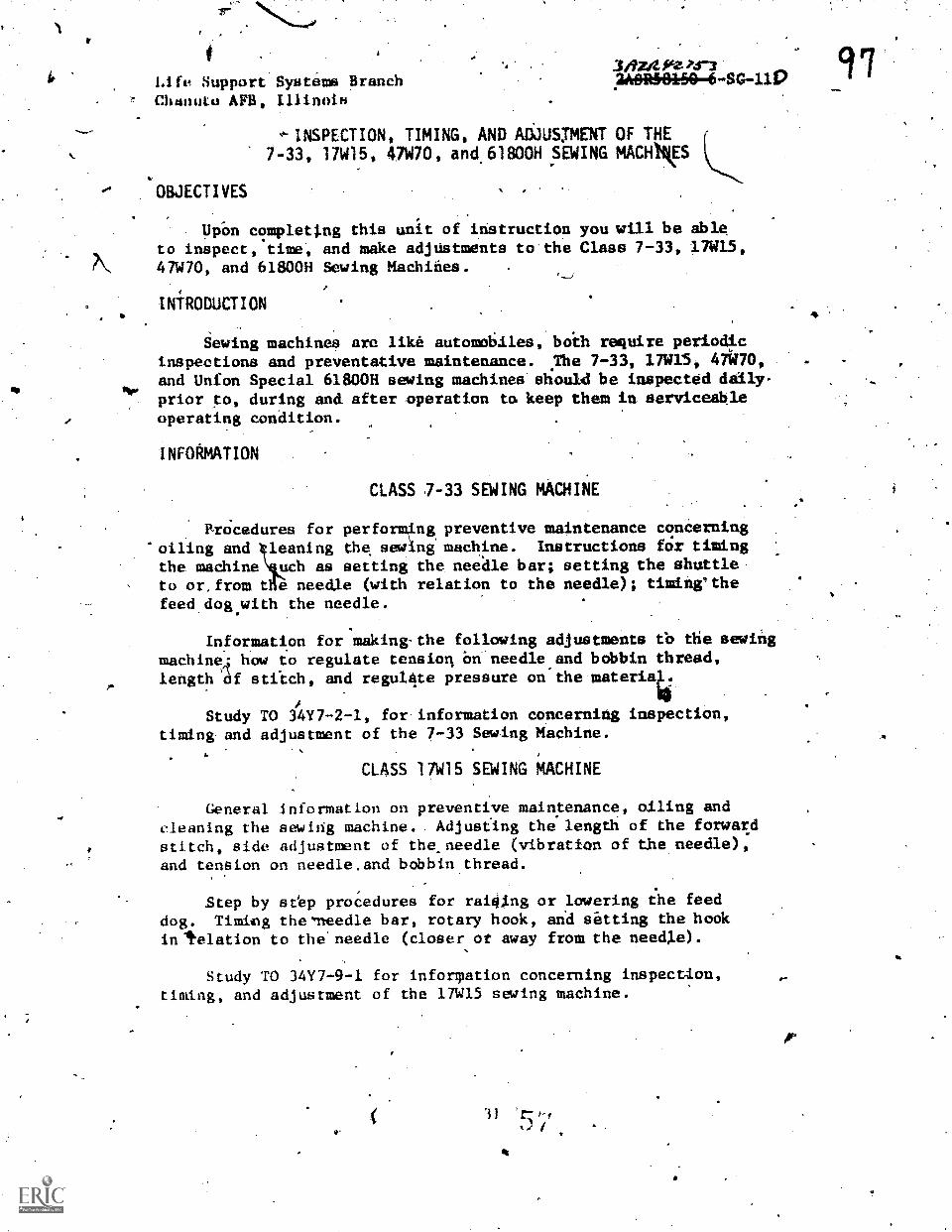
3/AZIZIAZP.r3.2AORMA*60-6-SG-111)
Up-on cc!mplettng this unit of instruction you will be ableto inspect, time, and make adjUstments to the Class 7-33, 17W15,47W70, and 6180011 Sewing Machines.
iNfRODUCTION
Sewing machines are like automobiles, both require periodicinspections and preventative maintenance. The 7-33, 17W15, 47k70,and Unfon Special 61800H sewing machines stiould be inspected daily-
ftrprior to, during and after operation to keep them in serviceableoperating condition.
INFOAMATION
CLASS 7-33 SEWING MACHIiE
Brocedures for performing preventive maintenance concerning'oiling and leaning the sewing machine. Instructions fdr timing
the machine uch as setting the nee'dle bar; setting the shuttle-, to or.from t e needle (with relation to the needle); timing'the
feed dog.with the needle.
Information for making-the following adjustments tb the sewingmachinef; how to regulate tensiort bn-needle,and bobbin thread,length af stitch, and regul4te pressure on the materia4
Study TO 34117-2-1, for information concerning inspection,timing- and adjustment of the 7-33 Sewing Machine.
CLASS 17W15 SEWING MACHINE
General information on preventive maintenance oiling and
cleaning the sewing machine. . Adjusfing the length of the forwacdstitch, side adjustment of theeneedle (vibration of the needle),and tension on needle,and bobbin thread.
Step by seep procedures for raiSing or lowering the feed
dog. Timimg the'lleedle bar, rotary hook, and sitting the hookin'telation to the'needle (closer or away from the need).e).
Study TO 34Y7-9-1 for inforTation concerning inspection,timing, and adjustment of the 17W15 sewing machine.
97

98CLASS.47W70 SEWING MACHINE
General information concerning preventive maintenance andoiling procedures for Ihe sewing machine.
Step by step procedures for timing the machine consisting"of timing hook with needle, raising or lowering the needle bar,setting hook to or from,needle, and adjusting the thread controller.
Study TO 31Y7-1-101, Book Three, Part Three for informationconcerning inspection, timing, and adjustment of the 47W70 sewingmadhine.
f
CLASS 61800H UNION SPECIAL SEWING MACHINE
General information concerning preventive maintenance andoiling procedures for the Union Specigrl Sewing Machine.
Step by step procedures for timing the madhine consistingof setting the needle' bare timing the hook; setting the feed dogheight. Adjusting hook opener,finger and thread controller spring.
Study Catalog NUMber 101R, information concerning inspection,'timing, and adjustment of Class 61800h Uffion Special Sewing Mathine.
REFERENCES
TO 34Y7-1-101, Clothing and Textile Repair Sewing Machine's
TO" 34Y7-2-1, Singer Sewing Machine 7-33
TO 34Y7-9-1, Singer Sewing Machine 17W15
Catalog,NuMber 101R1 Union Special Industrial Sewing MaChine
`N.
32 -
Art,It 11 qinibli

6
pasmans tun NAN
DISTR1BUT N: X
TWS 10 ; TTOC -
lftzt44.23-jWORKBOOK **9169193.-6-4B-100
Techni.cal Training
Sewing Machine Maintenance
SEWING MACHINE MAINTENANCE
10 August 1972
CHANUTE TECHNICAL TRAINING CENTER (ATC)
Designed For ATC Course Us.
DO NOT USE OM THE-JOIS
eAV

124 Training Publications are designed for ATC course use only. They are updated as hecessaryfor training purposei, but are 'not,to be used on the Job as authoritative references in pref-erence.toecbnica1 Orders or other official publications. 4-
CONTENTS
TITLE PAGE
102 . Shop. Procedures and Safety Precautions 1
103 Strtictural And Functional Features of 3
31-15 Sewi!ng MaChines
104 Inuection, Timing Adjustment-and Major 7\Overhau1.of the 31-15 Sewing'Machines
105 Troubleshooting of the 31-15 SeWi,ng Machines 11.
A
106 Structural and Functional Feattives of the .13
111W Series Sewing Machine
107 Irispettion Timing and Adjuatment of 1111W Series Sewing Machines
108 Major Overhaul of'the Class 111W Series Sewing 35
Machine
109 Troub,1eshooting of IIIW Series Sewing Machine 43 .
110 - Structural ansl Functional Features of 7-33,17W15, 47W70, and 6180011 Sewing Mathines
1 1
August1969
Inspettion, Timing, and Adjustment of the 7-33,17W15, 47W70 4nd,6180011 Sewing Machinep.0
4
45
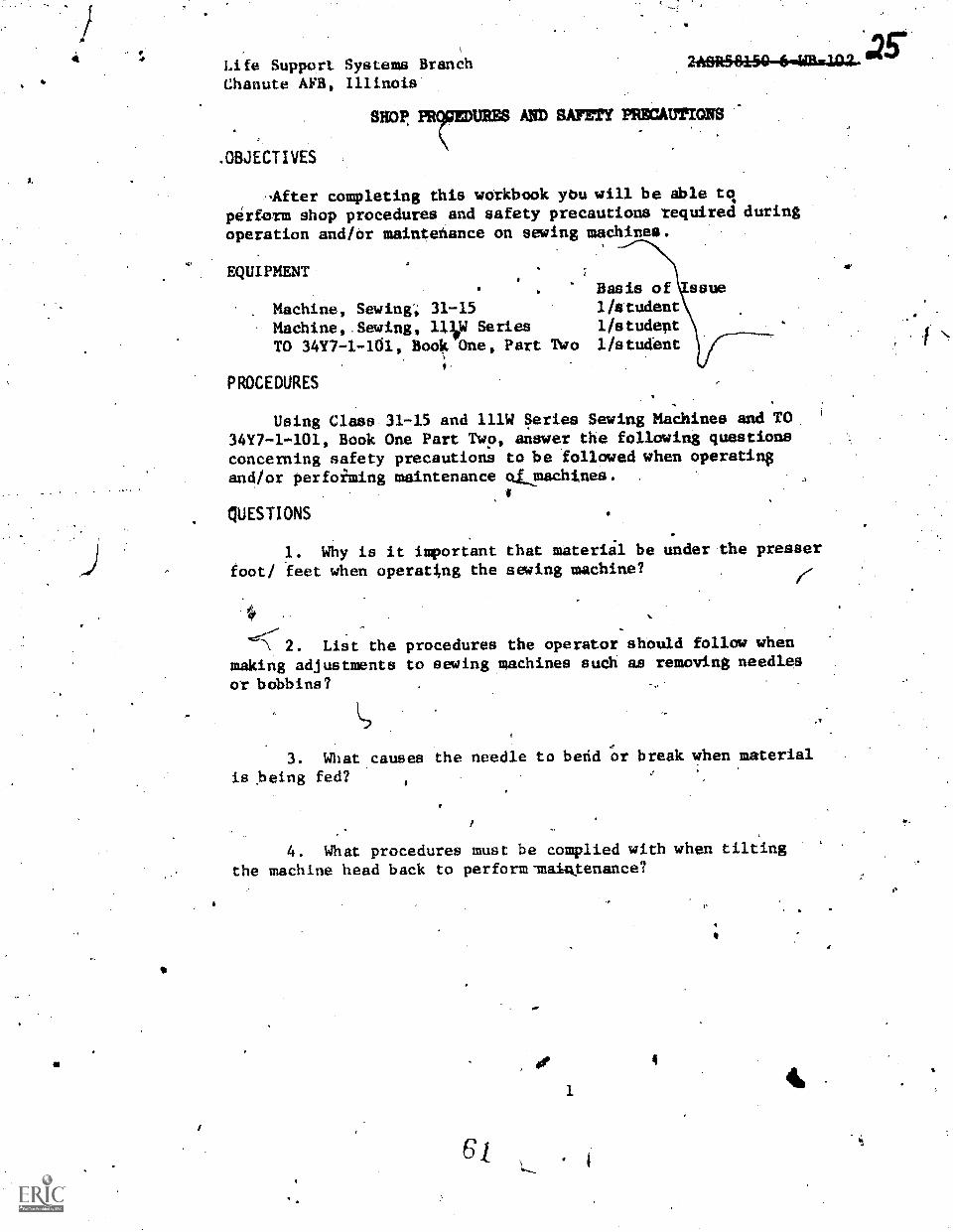
Life Support Systems BranchChanute AFB, Illinois'
SHOP,
.OBJECTIVES
AO SAFETY PRECAUTIONS
-After completing this wOrkbook ybu will be dble toperform shop procedures and safety precautions required duringoperation and/dr maintehance on sewing maChines.
EQUIPMENT
Machine, Sewing; 31-15Madhine,.Sewing, 11lop SeriesTO 34Y7-1-161, Book One, Part Two
PROCEDURES
Basis of1/student1/studept1/student
Using Class 31-15 and 111W Series Sewing Machines and TO3417-1-101, Book One Part Two, answer the following questionsconcerning safety precautions to be followed when operatin$
and/or perfoiming maintenance cams:chines.
QUESTIONS
1. Why is it important that materiil be under the presserfoot/ feet when operating the sewing machine?
<2. List the procedures the operator should follow whenmaking adjustments to sewing machines such as removing needles
or bobbins? -
3. What causes the needle to befid or break when material
is being fed?
4. What procedures must be complied with when tiltingthe machine head back to perform-maintenance?
ar
1
4
(
.35*

43
/2 5. List five shop hazards that contribute to accidentsn.the Survival Equipment Shop?
a.1r
b.
C.
d.
.e.
REFERENCES
2ASR58150-6-SC-102, Shop Procedures and Saiety Precaittions
TO 3410-1-101, Clothing.and'Textile Repair §evii9g Machines
1.
nk-
li
414

Life Support Systems BranchChanute AFB, Illinois
OBJECTIVES
3,444 itO:AS)2ASR38MI46'-WB
STRUCTURAL AND FUKTIONAL FEATURESOF 31-15 SEWTNG MACHINES
When you havs completed this workbook you wIll be able to identify-structural and functional features of the Class 31-15 sewingmachines.
EQUIPMENT. Basis of Issue
Machine, Seding, 31-15 listudent .
PROCEDURES
Using Class 31-15 Sewing Machines, study guide, workbook,and TO 34Y7-1-101, list the structural and functional featuresof the sewing machine head,by identifying the parts in-figure1 and filling in the blank spaces provided.
(?Identify ieneral sewing machine data applicable io varioustypes of sewing machines, Table 1.
tIF
3

4-
4
Figure 1. Structural and. Functional Features of 31-15 Sewimg Machines.
1. 13.
,2. 14.
3. 15.
4. gik 16.
5. 17.
6.. 18.
7.. 19..
8. ase
g
10.
11.
12,
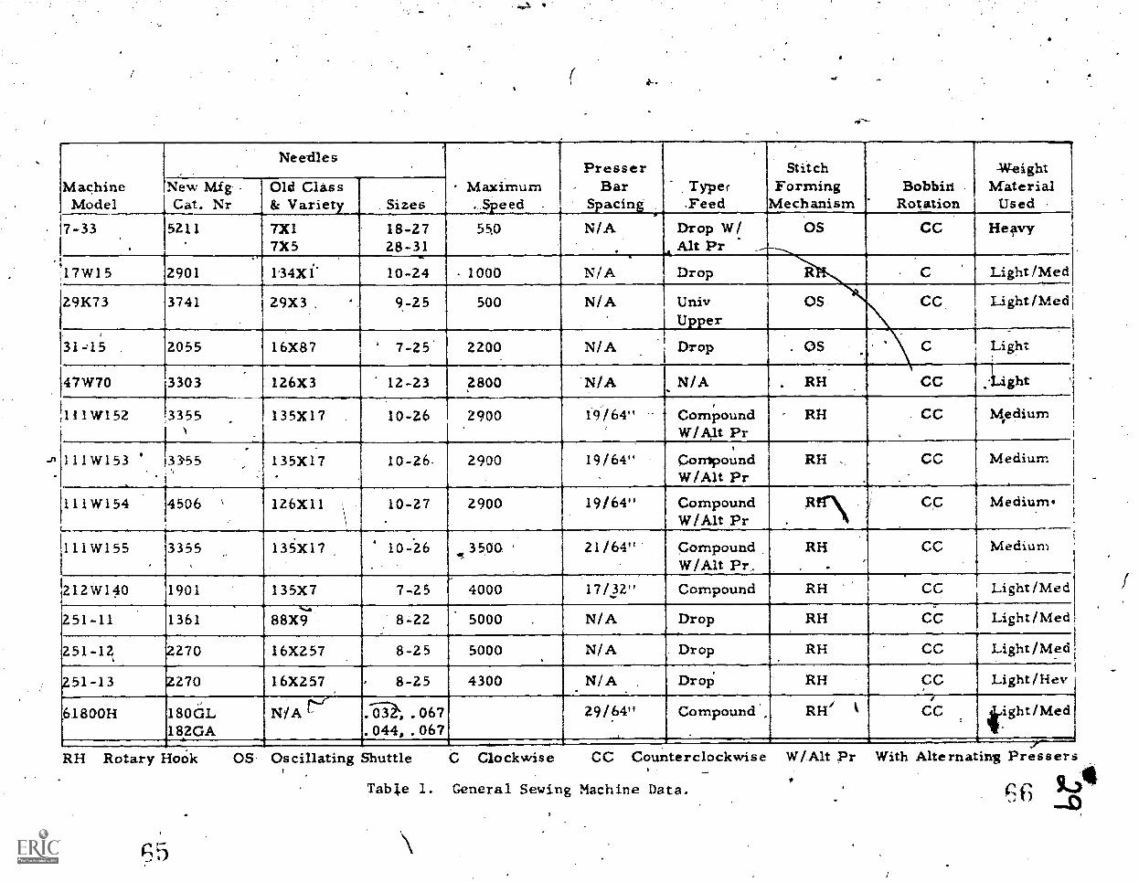
MachineModel
Needles
Maximum, S.eed
Presser- Bar
S.acin,::
.
Typer,Feed
StitchForming
MechanismBobbin
Rotation
-WeightMaterial
Used .
New MigCat. Nr
Old Class& Variet Sizes
7-33.
5211 7X17X5
18-2728-31
55.0
4
N/A Drop W/Alt Pr
OS CC Heavy
17W15 2901 134X1- 10-24 1000 N/A Drop R C Light/Med
291i73 3741 29X3 , 9-25 500 N/A UnivUpper
OS CC Light/Med
,
31-,15 2055 16X87 7-25 2200 N/A .1 Drop . OS Light
47W70 3303 126X3 12-23 2800 N/A - N/A . RH CC ght
111W152 3355N
135X17 10-26 2900- 4
19/64",
t
CompoundW/Alt Pr
RH CC Kedium
111W153 ' 33'55 135X17 10-26, 2900 19/64" CompoundW/Alt Pr
RH .
_ .
CC Medium
111W154 4506 \ 126X11 10-27 2900 19/64" CompoundW/Alt Pr
CC Medium.
111W155 3355 136)07 10-26 3500 ' 21/64" CompoundW/Alt Pr,.
RH CC Medium
212W140 1901 135X7 7-25 4000 17/_32" Compound RH CC Light/Med
251-11 1361.....
88X9 8-22 5000 . N/A Drop RH CC Light /Med
251-1 270 16X257 8-25 5000 N/A Drop RH CC Light/Med
251-13 270 16X257 8-25 4300 N/A , Drop; RH CC Light/Hey
,61800H 180GL18.20A
N/A V .--ii, .067.044, .067
29/64" Compound' RH/ CC tight/Med
RH Rotary HoOk OS Oscillating Shuttle C Clockwise CC Counterclockwise
Tabl.e 1. General Sewing Machine Data.
W/Alt Prf
With Alternating Pressers
9j111,) .4)
30State the functions of the following parts of the 31-15 SewingMachine.
1. Thread Take-up iever.
2. Presser Foot,
3. Throat Plate:
4. 'Slack Thread Regulator.
5. Tension Asseubly.
6. Balante Whtel.
7; Feed Regulator.
Fee,d Dog.
5-

..r
11.
Life Support Systems BrandhChanute APB, Illinois
OBJECTIVES
qdestionsthe.Class
216R58160-64111,1411,
iNSPECTION, TIMING, ADJUSTMENT AND MAJOROVERHAUL OF THE 31-15 SEWING MACHINES
you hipre completed this workbook you will be able to answerconcerning inspection, timing, adjustment, and overhaul of
31-15 Sewing Machines IAW technicil publications.
'EQUIPMENT
None
PROCEDURES.
c.
Exercise 1 *
Write the answevto ihe following questions concerning .
inspection, timing, and making adjustments to the sewing machine.
1. After removing a tiew machine from its crate, what
should it be inspected firsi?
2. When is preventive maintenance performed on die 31-15?
."1
3. What is used to lubricate the 31-15?
5
4. Howpoften should the 31-15 be oiled when in constant'use?
5. Describe how to complete the two timing steps on the 3l,715?
b.
What type of feed mechanism does the 31-15 haVe,
4*

,
7.4 What is the difference between the needle-eye and-the shuttle point When the machine is properly timed'i
8. What type flaid is Tecommended for cleaning sewing-machines?
a
Describe the proper position Of the feed dog mechanismwhen it is adjus,t,ed proPerly?
10. .Explain the procpduies involved in timing,the feeddog.with the needle?
11. What is the proper height of 'the feed dog? .
12. How do, you ad ust the 31:15 sewing machine to sewt 1 pngest stitch?.i4
Exercise. 2
Write Lhe answers to the folrawing.,questions concerningmajor 'overhaul of the 31-15 'seWing mac:lane.-
, 1 What three .ma.jor assembliei make up the faceI
assemlayof the -15 sewing machine?
a.
011:b
List the. five (5)- components that are attached to the ditpresser bar assenialy on the 31-15.sewing machine?
'1.
d.
e.
.M0
8
e
a

6
e.
3. Ih* L the thread take-up lever held in position in 33the face assembly of the 31-15 sewing machine?
4. What is the most important thing to remember aboutthe cap screw that secures the thread take-up leVer?
5. When replacing che needle bar assembly, what is thefirst step that must be accomplished?'
6. With the preaser.foot raised to the "up" positionand the needle bar timed and lowered to the lowest position,the presser bar should be adjusted towallow how. muCh clearancebetween the bottoni of the needle bar thread guide and the topof the presser foot?,
7. What position should the needle bar be in when removingthe shuttle race assembly from the sewin& machine?
8. Describe the position of theto the bed of the,sewing machine) whenthe shuttle race Nabsembly?
shuttle driver.(in relation'retlioving or installing
9. What will cause.the point'.of the shuttle body to clip.tisie,needle when ins.talled in the sewing machine?
10. Where is the bobblin case position plate Intutalledon the shuttle race body? .%
Neo.
3
*kw

o
ftp
if
't
30,44*4-751Life PupporttSystems Branch 2141051460-4-
Chanute AFB, Illinois
TROUBLESHOOTING OF THE 31-15 SEWING MACHINES
*OBJECTIVES
After you have completed this.worWbook you will be,ableto resolve mechanical problems that frequently ocEur during
sewing machine operation.
EQUIPMENT
Machine, Sewing, 31-15
PROCEPRES
a
Basis of Issue1/student
1Using Class 31-15 Sewing Machines, study guide, workbook,
and TO 34Y7-1-101, Book One; Part Three, Section XII, answerthe following questions concerning troUbleshooting malfunctionsthat-occur on the sewing machines.
QUESTIONS
4
1. List five(5) prpl;able causes for needle breakage?
a.
b.
.d.
e.,
m00%
2. What are the results most likely to be when you aresewing.and the presser foot is loose or out of line?
3. What causes the needle to strike the shuttle race
cap on the 31-15 sewing machine?
4. What must be done to prevent the feed dog from striking
the throat plate?
11

G.
5. Explain what would_happen-if the operator leaves.thefeed regulator thumb scrod loose when operating the sewing xachine?
6. What%is mast likely to happen if .0e thread or bobbintension is too tight when sewing on the 31-15 sewing mathine?
7. Explain why it is important to temove sharp edgesfrom the shuttle, bobbin, bobbin case or needles?
8. What,adjustment is made to prevent the skipping ofstitches?
9. How is the needle installed in the sewing machine?
10. Descrtbe what wou1&inost likely happen if the bObbincase.
1
MA,

Life Support Sytqemo Branch.Chanute AFB, Illinois
.4
STRUCTURAL AND FUNCTIONAL FEATURESDF THE 11IW SERIES,SEWING MACHINE
When you have completed this worktook you will be able.to identify the structural ind functional features of the 111W*series sewing madhines.
EQUIPMENTBasis Of Isdue,.
Machine, Sewing Class 111W 1/student
PROCEDURES ft
UsJig class 111W sewing madhine, study guide,.workbook"and TO 34Y7-1-101, list the structural and functional features%of the sewing madhine head and sewing maChine stand*by identifyingthe partd in figures 2 and 3.-
Write the answers to questions pertaining to the' structuraland fUnctional features of the class 111W seriqp dewing madhinein eFercise 2.
13
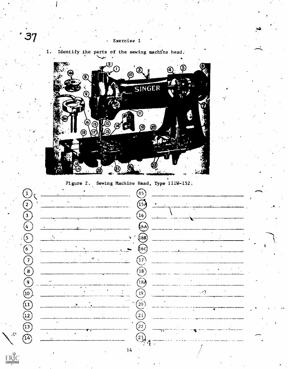
- Exercise 1
1. Identify the parts of the sewing machfne head.
It*
11
Ea
15.
Figure 2. Sewing Machine Head Type 111W-152.
14

jdentify the pirts of the sewing machine 'stand.
Figure 3. Sewing Machine S.tan
15
a,

39 Exercise 2
1. What type of stitch does.theeclass III sewing machinesew3
2. What parts of the machine are used to form the stitch?
Explain what the machine symbol means.
- 4. What-typeeding mechanism does t.he 111W152'and the111W155 use?
5. What part of the Ole does the term "class" refertos? A
to?6. What part, of the needle does the terml"variety" refer',
7. What class and variety needle is used in the 111W152sewing machine?
S. Wherd'is the stitch regulating kutton located on the111W152 Sewing machine?
9. What is the function of the safety clutch?
10. What is thevfunction of the thread con rojler sTring?
16
PP
0."N

Life SUpporf Systems BrancbChanute AF14'illinoi.s
OBJECTIVES
JAWK V; fa .1'blretSe'6-WB-1011
INSPECTION TIMING AND ADJUSTMEN)
OF IIIW StRIESZWING MACHINES
After completing this workbook you will be able to inspect,
time and adjust the cl ss 111W swing machine.
EQUIPMENT.
Madhine, Sewing; 111W
Handtools
Series
Can, SWing Madhine, Oil.&oth, Lint FieeContainer, Parts ,
PROCEDURES
Basis of IssueI/student1/student112 studentsI/student1/student
' Using a class 111W sewing machine,.study guide, workbook
and TO 34Y7-1-101, perform the inspection, preventive maintenance,
timing and adjustment steps.
Cleaning
CLASS I.11 SEWING MACHiNE MAINTtN4NCE
- Exercise 1
1. Clean ihe madhine head, oil 'pan, madhine stand, and
motor casing with a clean lint free Cloth.
2. Clean the hard to reach parte of 4he machine with
a medium soft bristle brush.
Ltibricating'
1. Wipe oil holes and surroundimg'surfaces clean before
oiling.
2. Oil the moving parts 'indicated by arrows in figure
4 twice daily with mineral oil.that has a low pour point. Use
one to three drops of oil at each oilidg
, Add oil to oil well (figure 5-Was.needed to lUbricatet
the upper hook bearing.
4. 011 the felt pad (figure 5-B) On.th*e side of the bobbin
case when needed. When the pad is light gFeen,it needs oil.
When the pad is wet it is nearly black. This pad lUbricates
the hook rdce. A
7 1
#
17. .
.V#

UNDER HEAD
END
Figure 4. (lining Points an the ill Sewing.Machine.
Figure 5. Hook Race andBearing Lubrication:
18

5. If the thread lubricator is used, fill the reservoir
to 1/8 ineh below the filler hole.
Changing a Needle
1. Turn the balance wheel until the needle reaches its
highest position.
2. Loosen the, setscrew (figure 1()A) in.the needle bar .
and remove the needle.
3. Replace the needle in the.needle bar and insert itas far as it will go. The long groove of the needle must face
the left side of the machine. .
4. Tighten the setscrew (figure 10A).
Setting Feed Indicating Disk
1.. Set the machine to sew 8 stitChes per inch gs described
in exercise titled "Setting Satches Pe Indh."
2. Sew a scrap of material for a few inches.
Figure 6. Checking StitchesPer
Use a rule and count the actual nuMber of stitches per inch
being sewn. Place the first etitch at the edge of the rule
A and count the stitches as shown in figure 6.. If the actual
count and the number in the hole in the madhine arm are the .
same, the feed indicating disk is properly set. If the actual
colont is different, set the indicator disk.
4. To set the indicator disk, loosen the arm capscrew
Aand slide back the arm cap an the top of the madhine head, exposing
the feed indicating disk with numbers engraved on the edge.
5. Loosen the.indicator dtsk setscrew with 1/8" widecabinet screwdriveV until the disk will turn only when finger
pressure is applied;
19
)
44,1
of
;1'

4543 6. Turn e indicating disk with the fingers untilth
nunber indicating the ictual number of stitches now beingappears in the indicator opening in the head casting.
k
7. Tighten the indicating disk setScrew.
8.4. keset the machine to 'sew 8 stitches per inch.:
9. Check the accuracy of your setting by sewingand rountingthe stitches.,
thesewn
10. If your setting is not correct, repeat steper 4 through7 and recheck.
Exercise 2
Machipe Timing Part Alignment of Arrowsy
1._ "rilt the machine ba-ck, on its. hinges.
2. Turn balance wheel toward. operator, (in same directionit turns when machine is sewing) until thread take-up leverreaches its highest position.
Figure 7. Removal-of Arm Shaft ConnectionBelt from Lower Pulley
3. Check alignment,of arrows A and B.in figure 8.
20
4.
f

4
0a
W
.r4
I.
Figure 8._ Alignment of ArroWb.
4. If arrows are not in line, remove connection belt
from lower pulley, figure 7.
ms_
la
A. Collar B. Plate
A0ii, Shaft Connection
t Cji? ming. evf1ar and Hate.,
si.
C.
.

5: Turncollar, figuretiming plate.'
ft
N.
Figure 10. Marks on the Needle Barof the 111W152 Sewing MaChine.
ro
WIER NAV/
LOIRM max
4
4Distance, SetweemUpset ald Lowy,illerh, foil!
lower pulley by hand until the arrow, on timingis in direct line with arrow, figure 8B on
6. -Replace connection belt by hand. After replacing.belt, give balance wheel' a' full turn and check arrows again.Arrows sometimeS slip out of line when replacing belt.
Part ?A - Setting a Marked Needle 'Bar ,
1. Loosen screw holding needle (figure 10A) on, needle'bar.
2. Insert needle up into needle bar as far as it willgo with the long groove to the left. Check class of needle'for specific machine, with which you are working. See needlechart.
3. Tighten screw.
4. Loosen screw on faceplate and turn plate up. Do notmove the plate -until:the screw is loosened.
224

a
0 E-,,,s32
w4.
gu re 11.
M
;
Sett4ng-ehe Needle Bar.
.5. Tighteh screw on facepLate. '
6. Turn balance wheel so that screw (tigure'llB)jsts4 lowest pOsition and it,n the ;recess of t,he needle bar--tocker.
/frame. f>
"
7. Loosen screw 'and adjust the needle bar.- The positionof, the alignment marks on't,he needle bar is shown in figureW. Align the n'eedle bar.so that thevper mark is first ,visibleat the edge of the needle bar rocker frame (figure 11C).. It,is imperative that the needle eye be- in a parallel line-4iththe length a the Machine. If it. 1.s not directly in alignment,'the machine will skip stitches or may not sew at
7
a
74
23
IC
.7\
l
7, Tiihten screw (fipre I1B).
9. Inspect by rechecking procedure 1 tirough 8 co see thatsetting of the needle bar'Is'cortecit.
Part2B - Setting an Unim:a.1-ked Needle Bar
/-
If -the needle bar is unmarked, the needle hits to be synchronize&witeh the rotary hook in order to locate the sproper position forthe needle.bar.
1. RemoVe'needle from the-machine ind inspect for properclass by refprring to needle charts 0
2. Inspect needle for sharpness 111 slidfng fingernail over.point. .
Inspeet straightness:of needle by' rolling on flat surface. -t0
4. Insert proper elase-of needle into,needle, bar. Be sure needleis inserted as far as ft will sp,into needle bar before tightening scrpwand.the eye and the scarf correctly located.
5.. Remove throat plate and feed1/4)og.
/-*
6. Turn the balance wheel-tOward you until the point of the rotari7hoo1c cOmes around in position in dl.rect line-mith the needW.With rotary hddk in this position, screw (figurp. 11B) bein position for loosening.
7. Looser, screw (figure 11B).
.1
8. Adjuspeedle bar so that needle eye:will-be 1/16 ibell* the point of the rotary hook.
hand.
9. Tighten (figure'llB).
10. Check proper adjustment by_turning balance Wbeel by
11. Replace feed dog and throht plate.
Part, 3 Timi ng the Rotary Hook1
Ph
When the 1oWer mark on the needle bar is just visible atthe end of the needle bar housing on the upward stroke of Cheneedle'the point of the rotary hook should be as cloile as poeeikleto the needlg and 1/16 inch above the eye oi" the needle.
/
/Remove the throat plate anefeed dbg.
MO.
24
.r
0.
4
.
k's

litrik B
A. Needle Guard Washer:B. Rotary Hook. .
C. Bobbin Case Retainerkook Gib.0. G roove .
MIM
Figure' 12.. Rotary Hook Asseubly.
2. Turn halabce wheel full turn until the hook point is
as close to the neecile (wiin the .scarf) This preventsoot center of needle, The point of the rotary hook s uld run
th
.the point of the hook from- cutting into the thre The needle.
guard washer (figure 12A) prevents the rotary ho6k from striking
.the needle by pushing the needle point .slightly out of the path
of the hook.
Tilt mach ne head back On hinges.
a
11#
.rasa*
Figure -1/ Adjustment\of Roary Hook.
2 5
)
?0 '#41. AA-

49 4. Loosen screw (figure 13A).
5. Move the hook saddle to the right'about 1/8 inch by'tapping with end of screwdriver handle,.
6. Tighten screws (figure 13A).
7. Turn balance wheel by hanA. Observe relative locationf hook point with needle.-
8. Loosen sciews (figure 13A).
9.. Adjust hook saddle so that point of hook is correctdistance from needle.
10. Check correct distance of 'rotary hook from needle byturning balance wheel by hand. The needle guard washer (figure12AI) 'should just barely strike the side of the needle and'deflectthe needle enoUgh to allow the point of the rdrary hook to passthrough the scarf of the needle When the lower mark on the needlebar is even with the housing on the up stroke of the needle, therotary hoOk'point shomad be as close as poissible to ehe needleand 1/16 inch above tle'neelep.eye.
11. Retave lifting presser foot and bobbin case opening'lever.
A E r .
Figare Underneath Vibew hawingHook SadOle, Hook Driving Pi ion, and
Feed Dog Adjustment.
12. Remove screws A and a, figure 14 in hook driving pinion.
13. ,Remove rotary hook aSsembly.

Figure 15. Hook Saddle ComponentBobbin Case Opener I.ver Link.
14. Remove bobbin case opener lever link, (figure 15).
15% Center hookfdrFing gear (figure 14E),
16.. Turn balance wheel until lower mark On needle bar Is
,-wen w.ith the housing on the up stroke of neagle.
. Replace pinion gear (figure 14E).. Space between screwRoleii of pinion gear should be centered on bottop bushing screw
of hoPok saddle.
18. Inoert rotary hook asseMbly in bottom of saddle asseMbly
and pinion gear. %
, 19. Turn balance wheel until needle bar4s at highest point.
20. Remove rotary hook as,seMbly froVottom of saddle.
21. Attach bobbin cse. operier lever link to fotary hook.
22. Insert rotary hook properly from top of machine. Be
certain that a small hole on lever link is slipped over post'(figure
-16).
23. Turn balance wheel until lower mark on needle bar becomes
even with housing on up 'stroke of needle.
24. Turn rotary hook with fingers until point bdcomes even
with needle.
25. Check in left scrod hole of pinion gear:for groove. (figure
I2D) on rotary hook. If)gfoove is not in hole; a mistake.has been
made in one of the preceding timing steps.
-26. Insert se/ in pilibn gear. .Screw with rouna end should
be in hole that is ovor groove.
27. Give balance wheel a full turn and recheck hook point
and needle eye.
7
C.
I.
50

51
111
Figure 16. BOok Saddle Assembly.
2.8. Loosen screws in back of driving.gear and move gearslightly tO right if hook point is slow, OF-gTIght,ly to left ifhook poine is fast.
29. Tighten screws.
30. Check hook point and needle.
31. :I.,Continue to adjust4 driving gear to left or right until
hook point' is timed perfe'ctly with needle.
32. Replace parts on machine in the following o'rder: leeddog, throat plate, opener lever; ana pregsér foot.
Exercise 34 ,
Setting the.Feed Dog
When feed,dog is. at it's .highest
full tooth above the throat plate.
Ar`
28
position it shC)urd show a
"-
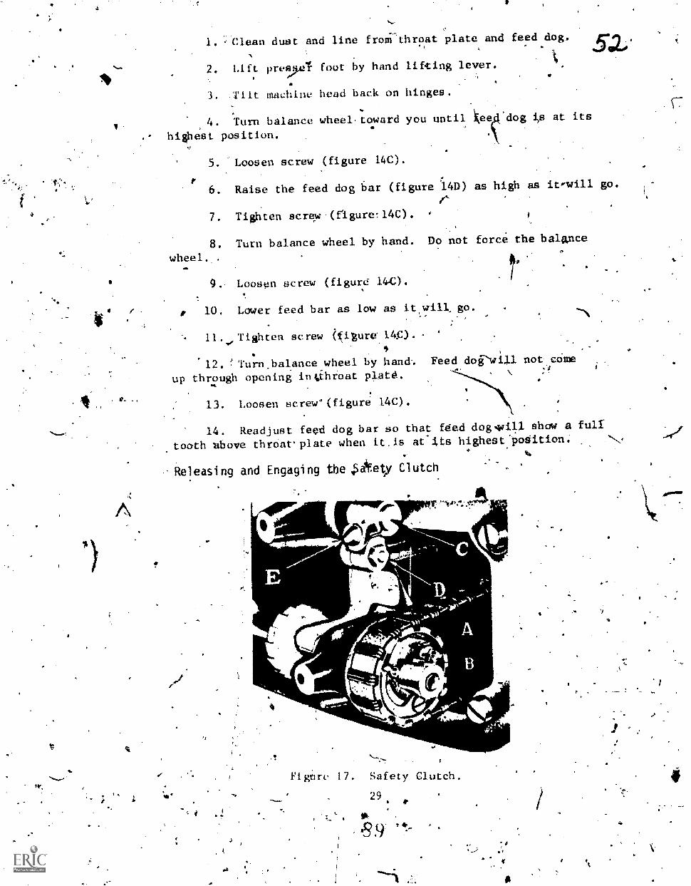
b.
,Clean dust and line frollithroat plate and feed dog.42.0*
2. Lift pre,ul foot by hand lifting lever.
3. TIlt machine head back on hinges.
4. Turn balance wheel.toward you until ee 'dog at its
hi est position.
5. Loosen screw (figure 14C).
6. Raise the feed dog bar (figure 14D) as high as itwill go.ft.
7. Tighten screw.(figure!14C).
8. Turn balance wheel by hand. Do not force the balance
wheel. .
411111
O.. Loosen screw (figure 140.
10. Lower feed bar as low as it will go.
11.s., Tighten screw igure 140.
12. Turn.balance.wheel by hand.. Feed doPwill not came
up through opening in;xhroat plate.
13. Loosen screve(figure 14C).
14. Readjust feed dog bar so that fe7ed dog.will show a full
tooth ubove thrOat.plate when it.is at"lts highest:pwiition.
-Releasing and Engaging the iSatety Clutch
"/A'...1/401Pw- ar*""re--
f
-6`74rc
r
Fignre 17. Safety Clutch.
29

.53 1r; To disengage the safety clutch, tilt the machine head backon its hinges to make the locking lever accessible..
2. Disengage the lockieg-lever (figure 17A) by forcing it up outof the notch.(figure 17B) with a large screwdriver.
3. Turn the'balance wheel by hand. The hook shaft willnot turn with the clutch.disengaged.
To engage the safety clutdh, turn the balance wheelaway from you to line up the locking lever and the notch.
5. Use tile plunger bUtton and engage the clutch. If itdoes not engage, a latge screwdriver may be used to move the.lockinglever into the notch.
Exercise 4
Adjustment of Presser Bars and,Needle Bar
1. Hold down, stitch-length indicator plunge,r and regulatemachine to zero stitches per inch, by turning balance wheel RCKWARD
, until it locks.
2. Lift plunger and check feed dog. There should be nomovement in tlre feed dog to front or back when balance wheel isturned forward.
3. Set ne'edle point even with the top of the throat.plate.
Lower the presser foot.
5. Check the distahce-betweenvibrating and alternatingpre4ser feet with a-bar gauge being sure that the gauge touchesonly the curved surface.of both.presser bar3.. The distance'between'presser bars should,be 19/64" on the 111W152, 111W153, 'and 111W154.On. a 111W155, the distance?sholuld be 21/64". If adjustment isnee.ded, use,a heavy sere driver to loosen the feed driving crankpitch screw, with the gauge inserted between'the alternating presserbar and the vibrating pressure bar., Hold both bars tightly against
it.gauge and tighten thd screw. $-.
6. With the machine set at zero(0) stitches pe'r inch and!the needle point even with the top of the throat plate, check'the position of the rock shaft crank. It should be parallel with
ft the bed-of the' machine. If it is not parallel witH the bea ofthe machine, loosen the pinelkespw (figure 17E) and adjust thecrank (figure 17C..and,D) parallel to the ''bpttom surface of thebed of the sewing machine and tighten the pincla screw. *
-
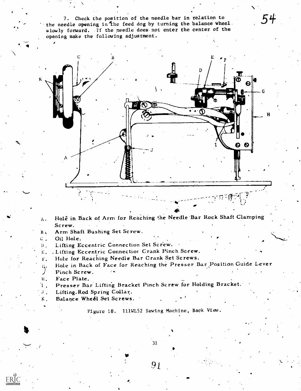
4
N.
N
7. Check the position of the needle bar in relation tothe needle opening inlhe feed dog by turning the balance wheel,slowly forward. If the needle does not enter the center of theopening make the following adjustment.
5i.
r-I, '
4011
A . Hole in Back of Arm for ReaChing the Needle 'Bar Rock Shaft ClampingScrew.
B Arm Shaft Bushing Set Screw.Oil Hole.
D . Lifting Eccentric Connection Set Screw.E . , Lifting Eccentric Connectior Crank Pinch, Screw.F . Hole for Reaching Needle Bar Crank Set Screws.
Hole in Back of Face for Reaching the Presser Bar.Position Guide LeverPinch Screw.
ti. Face Plate.Presser Bar Lifting Bracket Pinch Screw for Holding Bracket.
J. Lifting,Rod Sp.ringK Balance Whetil Set Screws.
,4
Figure 18. 111.WL52 Sewing -Machine, Back View.
31
- .
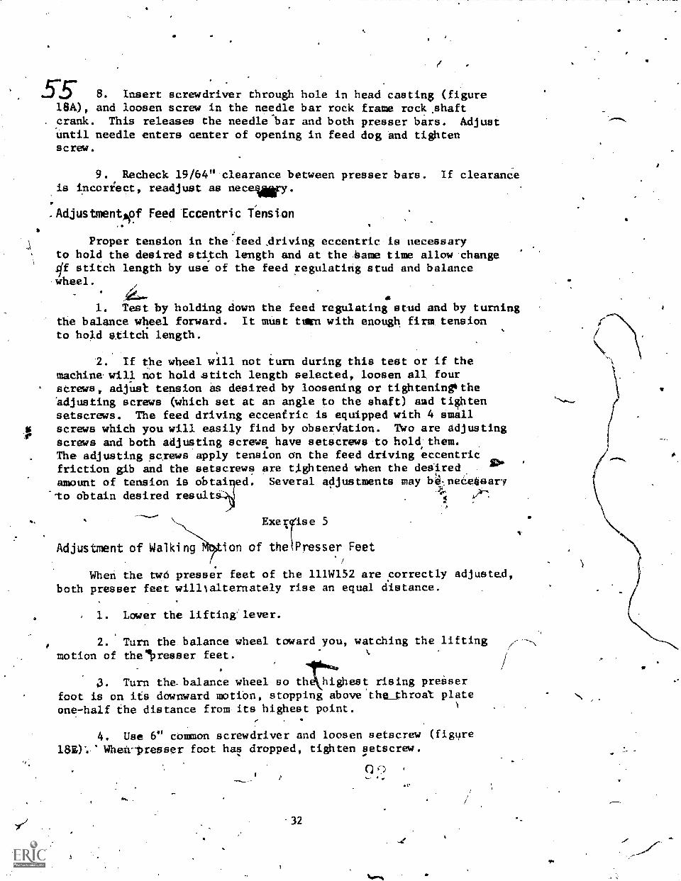
55 8. Insert screwd.river through hole in head casting (figure18A), and loosen screw in the needle bar rock frame rock .shaft
. crank. This releases the needle bar and both presser bars. Adjustuntil needle enters center of opening in feed dog and tightenscrew.
44.
9. Recheck 19/64" clearance between presser bars. If clearandeis incoriect, readjust as necefy.
.Adjustmentsof Feed Eccentric Tension
Proper tension in the feed Ariving eccentric is necessaryto hold the desired stitch length and at the litame time allow change#f stitch length by use of the feed regulating stud and balancewheel.
1. Test by holding down the feed regulating stud and by turningthe balance wheel forward. It must tgWn with enough firm tensionto h0.d stitcli length.
2. If the wheel will not turn during this test or if themachine will not hold stitch length selected, loosen all fourscrews, adjust tension as desired by loosening or tighteninetheadjusting screws (which set at an angle to the shaft) and tightensetscrews. The feed driving eccentric is equipped with 4 smallscrews which you will easily find by obser4ation. Two are adjustingscrews and both adjusting screws have setscrews to hold,them.The adjusting screws apply tension on the feed driving eccentric
'friction gib and the setscrews are tishtened when the deairedamount of tension is obtai ed. Several adjustments may b4neeSsaryTo obtain desired result
Exerse 5
AdjUStMent Of Walking on of thePresser Feet
When the two presser feet of the lllWl52 are correctly adjusted,both presser feet willtalternately rise an equal distance.
1. Lower the lifting lever.
2. Turn the balance wheel toward you, watching the liftingmotion of theikresser feet.
3.
a
Turn the-balance wheel so th highest rising preiserfoot is on ifs downward motion, stopping above the_throat plateone-half the distance from its highest point.
4. Use 6'' common screwdriver and loosen setscrew (figure
When-presser foot has dropped, tighten eetscrew.
a^
32
t.

,a
5. Turn the balance wheel and check-valking Movement of t
presser feet.
6. lf both presSer feet do not rise an equ'al distance,
readjust as neces1;ary.-
Adjustment of Presser Foot Lift
1. To obtain maxihum lift for heavy fabric or thick seams,. .
put both pressure feet at their lowest point of movement touching
the throat plate.
2. Loosen lifting bar bracket screw (figure 181). This .
may.require a firm-thrust and it may be necessary to lay the blade
of your largebt screWdriver horizontally on tot of the bracket
and exert downward pressure with the'hands. Do not use a hammer.
3. RetightelvscFew (figure 181).
4. Remove faceplate ,(figure I8H).
5. Loosen *le lifting eccentric connection crank pinch
screw (figure 18E).
6. Adjust the relative lift by rocking the lifting bell
crank link (figure 11E) with your fingers until the desired lift
is obtained.
7. Retighten.the pinch screw (figure 11E).
Adjustment,of Thread Controller Spring
1. To adjust tension of the contrdller spring, loosen the
back setscrew and w44th a screwdriver, turn the slotted bolt counter-
clockwise to increase tension and clockwise to decrease tension
on the spring.
2 Retighten the back setscrew.
3. If the hook on the spring is set too hiel or_too low, loosen
the front setscrew and turn the heavy disk to left or right to ,
get spring 1(lop at desired height.,
4. Retighten the frontliptscrew.
Inspection of Tension° Disks
J. Remove knurled nut'which holds tension disks in place
on th.e thread tension bracket and remove the spring and disks
carefully and fay them out so they May be returned in the same
order.
4.
33
4

57 2. Inspect the disks for roughness or for grooves worh..by theneedle thread.
3. If grooves are present the disks should be replIced.Fine crocus cloth may remove any other rougbnees.
4.. Reasseuble in reverse order -of disassembly.
STANDARD OF 'PERFORMANCE, Hake` sure that- the small pin insidethe hollow tension stud on which the disks rest is not missing.Its movementin reurving disk tension wben the presser bar liftis up may be detectikby' raising abd lowering the hand lift slowly.
_Inspection for Proper Posilion'of Parts on ,Hoi* Drivtng Shaft, ,.
. 1. 'check . for proper position:Ai. Setscrew if it !41.4iikiartast-that. a r9uxid ended setscrew be iteed; 'it will be
on the collar or pert where it is., neecieCi.. -*O'er* inSerta rdund ended setscrew unli* thei 14-.0 a, gtvglre' in ..MiAshaf.p,,,,
,
2;1 Check the arm sheft connectioil belt timigcMLar, markredwith the arrow, -A, figure 8 to make si,Ve it,is' not reire"the hook driving stift and phat the S'etscrew i'ection
of shaft.
Or,
f'
3. Check the marked setscrew on the ',safety 'clutch, pulley .
(figure 17) to make sure the setscrew engages a gray* cut inthe hook
V

Life Support Systems Branch.Chanute AFB, Illinois
do 3424 4Qs.7.e3 /0724#6R50+30i-WB-teft-
MAR OVERHAUL O,F THL. CLASS 111W SERIES SEWING MACHINE4 4*
OBJECTIVES
58
4
Upon completion of this workbook you will b'emble to identifythe components of the makeir easemblies requiring disassembly andreassembly when performinelu.ajor overhaul on the 111W aeries Sewingmachine.
EQUIPMENT
Machine .setling 111W Series.
PRQ,CEOURES
.13as1s of Issuelistudent
Using 'clatia 111W series sewing machine, studli guide, workbook,handomta, charts and TO 34Y7-1-101, list dre component parts ofthe:major asseubliea of2the sewing machine by.idenVfying the'parts in figuies 19 through 25 and iu the blank spaces
aproyided. I
e
35
95- 4.
4

59 Exercise 1
'Figure 19. 111W Face Assenb1y.
1. 14.%
2., 15.
3. * 16.
4. 17.
5.
6. 19.
7. 20.
8. 21.
9. 22.
10. 23.
Q
11. 24.
12. .25.
26,
36

4. .
P.
s
Exercise
......
t. . ,
2,JkL.,11_1....Tomomme
' Figure 20. Needle Bat Rock Frame; lllh es, Sewing Machine
4 .
7.
:
4...= 4. 1441 ff.
-*
to
S.
a
4f

a
Exerc. isle- 3
_Figure 21. Arm Shaft Asaa 1t 111W Series. Sewing Mafhine.t
1. 4 .
2.
3. 6.
93
Me*

11
Exercise4 4
Ffigure 22. Ne1d e Bar Rack FriligeRock.Shait-Aaselably
Series Sewinellachine..
7. \
e
11.
39
9,9
8.
9.
10.,
11.
12..
.13.
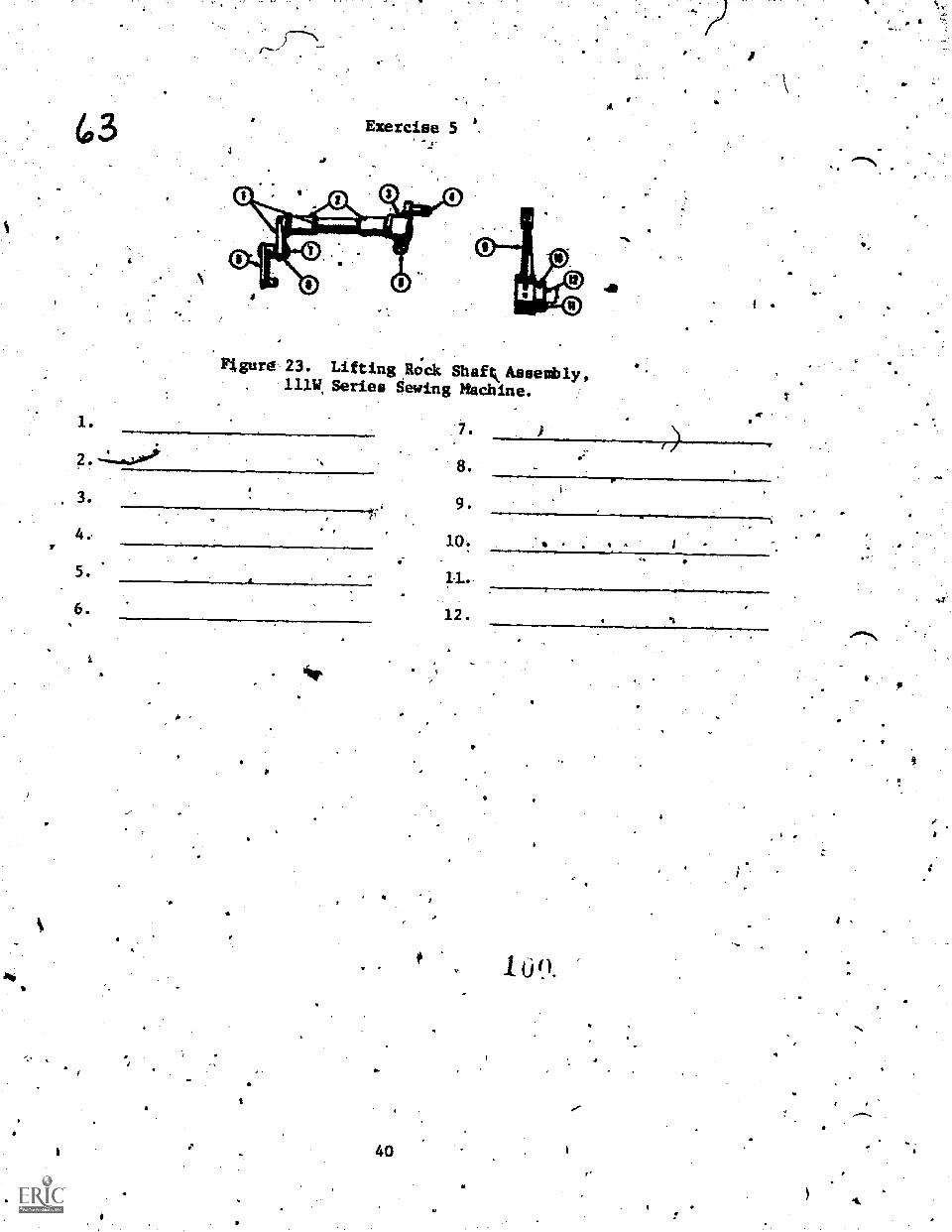
43
1.
Exercise 5A
Figur6 23. Lifting Eock Shaftk Assembly,11).W, Series Sewing Machine.
3.
4.,
5.
6.
A
44.
a
40
7.
8.
9,
10:
1L.
12.
100.
4
*L.

'Figure 24. kook ariving Shaft pnd Feed Drilring Rock111W Series Sewing MiChine..
aft Assemblies,
9.
10.
11.
12.
1
14
15.
2. \
4.
5.
6. ,0 I
7.
8.
r
. 41
'S

reedit.
r
3.
4.
5.
6.
7.
8.
9.
10.
4Exercilie 7
4
Figure 25. Tensiorl and Thread Controller Assembly111W Series Sewing Machine.'
2
."it?
42
11.
12.
13.
14.
15.
16:
17.
18.
19.
20.
102

Life Support Sysiems BtanchChanute AM, Illinois
68JECTIVES
3#42.4.94-74,26916{459-4-10-4110 .
.TROUBLESHUOTING OF IIIW SERIES,SEWING MACHINE
After you have completed this workbook you will'be able toresolve mechaniCalproblems.that frequently occui during swingmachine operat.ion.
EQUIPMENT.' 4 BasAs of Issue.
A
M4chine, Sewing 11114-Series listudvt--,
. PROCEDURES, ,
,
Using clasg 111W series sewing machine, study guide., mprkilook,,handout and TO 34Y7-1-101., Book Two, Part Three;'Section XII,Paragraph...108, answer'the following queations cOnceraing troubleshooti!Igmalfunctions that may.ocCur on the sewing machine. : . . .c'
'fe
QUESfIONS
1. List Tive,probable causes for needle thread breakageduring sewiiig machitte operation. \
2. What are the probable results of the rotary hook beingset too far away from the needle?
a.
b. -
3. What are the probable results of Operdtor failure tohold needle.and bobbin thread when starting td sew?
a.
b.
' 43'
93
S.

4,7 4. What is the probable cat:se.of a swing machine sewingbaclowards?
5. W4 \action mus\be taken,in the event* f-safety clutchdisengages
\
. 6. Wat ta the probable result Of using the.wrong typepil for 1ubx.icaton or allowing an accumulation of dirt and gritin the sewinimaghine?
What is the probable cause cif material damaged,by scuffing?
* .
8. What action, must be taken if a rotary hook deflectingiirasher is bent?
..9. What is the probable result,o.f needle thread slipping
out of the tension disks?4
10. What,aâtion must be taken if the needle is not in aliglrent'with the rotary hook?
4.
eibm
*
44 .
104
a

0.ife Support\Chanute. AFB
,OBJECTIVES.
Systetia Branch
Illinois
STRUCTURAL AND FUNCTIONAL4EATURES OF 7-33,1705,47W70, AND 61800M SEWING MACHINES
301444M ID,2041641115004-0 .
48
After,completion of this workbook you will be able to identify-and.analyze structural and fukctional features, of die 7-33, 17015,
47070 and 6180011 sewingwachines.,
EQUirMENT
None
%PROtEDURES
' Complete.ttie following exercises concerning structural andfunctional featureslor Class.7-13, 17015, 47W70, and 6180011 .sewin
machines.
- Pole
Exekcise i
1. What typeleed does the 7-33 sewing machine hava?
41.
Z. What class'and variety it'eedle doe9 the 7-33 require
wilen.sewing lerliher?
3. What type stitCh formi4 mechanism doits the 7-33 use?
'41 s
4*. Explain 'the. operation of the feeding mechanisni on the 7-33.
;
'What position:should the needle bar be in when'removing the
-4
bobb the 7-33 sewidg machine?
Exercise 2 f, 0
0 *
.1.. What is he imictIon of the.pitnian'Connection on Chel7WI5Sewing machine?
45

0/ 2. How id the fordard motion oi the stitch adjusted onthe 17W15 sewing mwxhine?
.1. Wht.laas, and variety Ophle is used ou.the 111,115' sewing'1 ,machine'?
I.
4. What is the longest riossi!)le stiich formed by the sidewaythrow on the 17W15 sewing machine?
5s What type stitch forminglseehanism does the 17W15 sewtrigmachine use?
ixrci.see,
, 1. Why is the 47W7O`sewing machine desigaed with no feedingmechaniim?
Ti
A ;2; The 4707Q has,two different length.beds, when would you
use the.short bed?
.
, .
What type stitdh formin mechanism doei the 47W70 uset
4. Whit is theluactiod-of the fiend o. khee lift lever on the47W70 sewing macliine?
. .
5;' What class and variety needle is used on the 47W70 sewingmaChine?
46
if)
,.1r. I. .
4r
I.

4
/. WhatAs. the masimum size ,tord that may be-used on the
6180.0ll sewing maChine1.
.x
2. What part of theietpwing machine is lubricated itAttomatically
from the oil reservoir on the 6180011 sewlng Machine?
3. What type, needle is Used on the 6180011 sewing niachinet)'.
4. What type Work is the 6180011 sewing madhine designed
. to sew?
5.. In what direction does the bobbin rotge on the.61800H
. .sewing liachine?:
A :1
woo.
-r
. 1.01
1_ 97
47
.

C. ' r
;
a.
Life Support Systems Branch .Chanute AFB Illinois
'OBJECTIVES',
.: :.,.
T..S.
1 - ._Upon Completing this unit of inifiructioni you'will be able,to inspect, -.time and 'make adjustments tta,CLaSs 7-33.9 I7W15, .47100..
3,f7.t.fir?rj2*Sitt0160-6r-WB-1110
_INSPECTION, TIMING,-AND ADJUSTMENT OFIHE7-331 171415, 47W70 AND 61800H SEWING MACHINES
and 6180011'Sewing,Michijaes.
EQUIPMENT
None'
P ROCEDURESA'
Complete the follochng exercises for Class 7-33,'.111115,. 47W70 "r.and 61801311 Sewing Machines.
Emerciee
Class 7-33 Sewing Maithine
4..
1, Descri e the steps that are to -ike complied with to fiethe needle bar?. , 4w-
2 ',Explain how the shuttle i* adjusted for prOpqr clearancebetWeen the shuttle point and the needle? . .
,
. 3. How should the feed dog bi timed to couplete its feedingaction in relation to the..thread take-up rever?
t .
41"
44' Why should all parts of the 7-33 which are in moveableContact be,'oiled?
. 5. Explain the steps that must be performed to time the. feed dog? . - t
.... .. . a,
;
11.
cclass 17X15 Sewing'Machines
Exercise 2b
ri r: Which 'mark on the needle bar sliould be :just visible
whgn thV neeale bAr is at its.lowest position?
1 pi
. .
2. The point of the.hook will be centered on the nealeow far .above the eye of the niedle whai timedit,, "
.,
. . N
. .
Explain how'. o set a no.r tree
r
bar wh1ch, have nkTarks
0
How far Apart are the maiks oil a maikad needle bar?4,
S.
I. .
5.- Describ0 e the fourth 'timing step t'ci be accomPlisbed when
timing the book. lo
,
. ,
6. Explain how i2e0pet the Point of thell k farther from-'
the needle?,
,
..
,. .*. . .
.7. What does ,the first timing atep consist of when timihg,
the rotary "look? ,
1. 4.
EXercise 3
Class' 47W70 Sewi.ng Mschi ne%,
1:'.,Describe the position that the pointtof.the rotari ifook
should be in when tile-needle bar rises 3132 ofsam inch'from iisr
lowest position.
CA
fe
50
elde
f
ee.a.
!Pe
1,
,
f
2. how do you set in unmarked needle-bar to get the needleiWproper time with the rotary hook?
114
3. Explain the procedures to-follow for setting the tiook
.to'or frod. the needle?
'
kI.ak
. .
4. What adjustment Must bp maddat-the'point of.the hookfaila to catch the thread when properlp timed with the needle?
c
Txercise'4
-Class els* Union Special-Sewing Machines .
,..
t
1. Why are there two sets of tiiing lines on needle bars- ,.
for 6180011 sewing tachinee?.4
2. What is ttie factory specified distance forppacing need e.
bar and presser bari?
I. v
(' 3.. How should e needle.bar bit.positioned before setting
ithë dfstance between needle bar and presser bar.
4. What is the,apprOximate height of the feed dog teeth' -
above.the throat plate at its highest point of travel?-
5. Approximately how far should --t>'ioint of the rotary
hook be abommrthe needle eye wten torrectly timed?
How pi timing of the hook with"the needle dcéomplished?
"44,444
1a
14 Aril. 11. It 24M1