mil-hdbk-701 - military handbook blocking, bracing and ... · pdf filemil-hdbk-701 military...
TRANSCRIPT

MIL-HDBK-701 Military Handbook
Blocking, Bracing and Skidding of Industrial Plan Equipment for Shipment and Storage
MIL-HDBK-701 - Military Handbook Blocking, Bracing and Skidding of Industrial Plan Equipment for
Shipment and Storage
Subject/Scope: This handbook is applicable to all shipments of IPE controlled by the Department of Defense except as specifically exempted or when a waiver is obtained from DIPEC-SQ.
Keywords: Skid, runner, equipment, blocking, header, beam, machine, load, skid, secure, reusable, runners, beam, mounting¸ securing¸ holddown, base, shipment, auxiliary, weight, length, bolt, bearing, block, wood, bracing, requirement, mil, steel, skidding, handling, shipping, outrigger, standard, heavy, motor, protection, carrier, preserved, government, plywood, transportation, saddle, handbook, member, disassembly, pack, surface, box, standard, military, defense, specification, container, stability, lifting, assemblies, fragile, treating, construction, lumber, barrier, constructed, reinforce, handbooks, material, package, freight, federal, air, fabricate
Published: 9/30/1989
Text in blue boxes such as this one is instructional and is intended to assist you in understanding the document.
Text in red boxes such as this explains changes made to the document by The Wooden Crates Organization.
Red text has been added to the document or modifies the document since its final version was officially published.
Soft Conversion of Imperial to Metric
Conversions, when made, consider materials that are available in metric or imperial sizes rather than converting sizes exactly. For example: Panelboard (plywood) in the US is typically 4 feet X 8 feet (1220 x 2440 mm) while panelboard in metric countries is typically 1200 X 2400 mm. Since the
standard was developed based on readily available materials these variations in material sizes could not have been practically considered.
This document has been converted to allow for better understand and easier navigation between documents.
Although this document may be retired by the original publisher, it may still be useful in understanding the subject matter.
If you identify any errors or inaccuracies in this document, please contact us at [email protected]
Efforts have been taken to preserve the credits of the original writer(s) when available.
Under Section 5 of the United States Copyright Act and in accordance with FAR 52.227-14 the original contents of this document is noncopyright. Modifications to this document are the property of The Wooden Crates Organization and this version of this document may not be modified without written permission of WoodenCRATES org, LLC.
U.S. Department of Defense. U.S. Government Work (17 USC §105). Foreign Copyrights may apply.
© Copyright WoodenCRATES org, LLC, All Rights Reserved. May be distributed freely but not modified.

MIL-HDBK-701C Military Handbook Blocking, Bracing and Skidding of Industrial Plan Equipment for Shipment & Storage
ii
MIL-HDBK-701C
30 SEPTEMBER 1989
SUPERSEDING
MIL-HDBK-701B
4 March 1983
Military Handbook
Blocking, Bracing and Skidding
of
Industrial Plant Equipment
For Shipment and Storage
AMSC N/A
DISTRIBUTION STATEMENT A. Approved for public release; distribution is unlimited.
AREA PACK

MIL-HDBK-701C Military Handbook Blocking, Bracing and Skidding of Industrial Plan Equipment for Shipment & Storage
iii
FOREWORD
1. This military handbook is approved for use by all Departments and Agencies of the Department of Defense.
2. Beneficial comments (recommendations, additions, deletions) and any pertinent data which may be of use in improving this document should be addressed to: Defense Industrial Plant Equipment Center, ATTN: DIPEC-SSG, 2163 Airways Blvd., Memphis, TN 38114-5051, by using the self-addressed Standardization Document Improvement Proposal (DD Form 1426) appearing at the end of this document or by letter.
3. This handbook should be used in conjunction with MIL-STD-107 when preparing industrial plant equipment (IPE) for shipment and handling. Included herein are procedures for the selection and application of the DOD owned Reusable type skids, requirements for the design and fabrication of skids produced from wood materials, and requirements for loading, blocking and bracing of IPE in motorized vehicles for domestic shipment. In this revision, new procedures have been added for ordering the DOD owned Reusable skids. Deleted from the handbook were all instructions for preparing IPE for rail shipment, soft metric conversions of dimensions and features, and all references to military standard numbers for skid components.

MIL-HDBK-701C Military Handbook Blocking, Bracing and Skidding of Industrial Plan Equipment for Shipment & Storage
iv
CONTENTS 1. SCOPE. ................................................................................................................................... 1
1.1. Purpose. .............................................................................................................................. 1
1.2. Scope. ................................................................................................................................. 1
2. APPLICABLE DOCUMENTS .................................................................................................... 1
2.1. Government documents. ..................................................................................................... 1
2.1.1 Specifications, standards, and handbooks. ................................................................... 1
2.1.2 Other Government documents, drawings, and publications. ......................................... 2
2.2. Non-Government publications. ........................................................................................... 3
2.3. Order of Precedence. .......................................................................................................... 3
3. DEFINITIONS .......................................................................................................................... 4
3.1. Accompanying equipment. ................................................................................................. 4
3.2. Basic item. .......................................................................................................................... 4
3.3. Blocking and securing for skidding. ................................................................................... 4
3.4. Blocking and bracing for shipment. ................................................................................... 4
3.5. Buttress blocking. ............................................................................................................... 4
3.6. Cube. ................................................................................................................................... 4
3.7. Disassembly. ....................................................................................................................... 4
3.8. DOD Reusable skid. ........................................................................................................... 4
3.9. Gross weight. ...................................................................................................................... 5
3.10. Inch-pound units. .............................................................................................................. 5
3.11. Metric units. ...................................................................................................................... 5
3.12. Skid. .................................................................................................................................. 5
4. GENERAL REQUIREMENTS ................................................................................................... 5
4.1. Protection of industrial plant equipment (IPE). .................................................................. 5
4.1.1 DOD Reusable skids. ..................................................................................................... 6

MIL-HDBK-701C Military Handbook Blocking, Bracing and Skidding of Industrial Plan Equipment for Shipment & Storage
v
4.1.2 Wood skids. .................................................................................................................... 6
4.2. Continuity of preservation. ................................................................................................. 6
4.3. Wood and plywood. ............................................................................................................. 6
4.3.1 Wood. .............................................................................................................................. 6
4.3.2 Plywood. ......................................................................................................................... 7
4.4. Weight limitations. .............................................................................................................. 7
4.5. Measurement system. ......................................................................................................... 7
5. DETAIL REQUIREMENTS........................................................................................................ 7
5.1. Disassembly, blocking, and securing for skidding. ........................................................... 7
5.1.1 Disassembly. .................................................................................................................. 7
5.1.1.1 Components to be removed. ........................................................................................ 7
5.1.1.1.1 Counterweights. ........................................................................................................ 8
5.1.1.1.2 Large size equipment. ............................................................................................... 8
5.1.2 Blocking and securing. ................................................................................................... 8
5.1.2.1 Blocking. ...................................................................................................................... 8
5.1.2.2 Securing. ...................................................................................................................... 9
5.1.2.3 Securing devices. ........................................................................................................ 9
5.1.2.3.1 Tie rod type. .............................................................................................................. 9
5.1.2.3.2 Tie rod yoke type. ................................................................................................... 10
5.1.2.3.3 Cable securing device. ........................................................................................... 10
5.1.3 Application of blocking and securing. ......................................................................... 10
5.1.3.1 Nonsubstantially supported components. ................................................................ 10
5.1.3.2 Movable components. ................................................................................................ 11
5.1.3.3 Unsupported columns. .............................................................................................. 11
5.1.3.4 Equipment with leg or end frame type bases. ........................................................... 14
5.1.3.5 Tailstocks and movable heads. ................................................................................. 14

MIL-HDBK-701C Military Handbook Blocking, Bracing and Skidding of Industrial Plan Equipment for Shipment & Storage
vi
5.1.3.6 Tables and other components. .................................................................................. 14
5.1.3.7 Ballscrew drives. ....................................................................................................... 14
5.1.3.8 Counterweights. ......................................................................................................... 15
5.1.3.9 Doors and drawers. .................................................................................................... 15
5.1.3.10 Handwheels. ............................................................................................................. 15
5.1.3.11 Surface plate shipments. ......................................................................................... 15
5.1.3.12 Oversize and overweight IPE. .................................................................................. 19
5.1.3.13 Waiver of skidding requirements. ............................................................................ 19
5.1.3.14 Waiver of rail transportation requirements. ............................................................ 19
5.2. Skidding requirements. ..................................................................................................... 19
5.2.1 Equipment not required to be skidded. ........................................................................ 19
5.2.2 Design. .......................................................................................................................... 20
5.2.2.1 Width and length. ....................................................................................................... 20
5.2.3 Load positioning. .......................................................................................................... 20
5.2.3.1 Top heavy equipment. ............................................................................................... 20
5.2.4 Load securing. .............................................................................................................. 24
5.2.4.1 Basic item. ................................................................................................................. 24
5.2.4.1.1 Use of leveling screw bolt holes............................................................................. 24
5.2.4.2 Accompanying equipment. ........................................................................................ 24
5.2.5 DOD Reusable skids. ................................................................................................... 27
5.2.5.1 DOD Reusable skid types. ........................................................................................ 27
5.2.5.2 Skid sizes. .................................................................................................................. 27
5.2.5.3 Type I skid. ................................................................................................................ 27
5.2.5.3.1 Skid components. ................................................................................................... 28
5.2.5.3.2 Type I skid components arrangement. ................................................................... 28
5.2.5.3.3 Selection of skid component arrangements. .......................................................... 31

MIL-HDBK-701C Military Handbook Blocking, Bracing and Skidding of Industrial Plan Equipment for Shipment & Storage
vii
5.2.5.3.3.1 Obtaining Type I skid components. ..................................................................... 36
5.2.5.3.4 Assembly hardware. ............................................................................................... 36
5.2.5.3.5 Load securing hardware. ........................................................................................ 37
5.2.5.4 Type II skid. ............................................................................................................... 38
5.2.5.4.1 Type II skid components. ........................................................................................ 38
5.2.5.4.2 Selection of skid component arrangements. .......................................................... 38
5.2.5.4.2.1 Obtaining Type II Skid Components. ................................................................... 44
5.2.5.4.3 Assembly hardware. ............................................................................................... 44
5.2.5.4.4 Load securing hardware. ........................................................................................ 45
5.2.6 Design requirements for wood skids. .......................................................................... 45
5.2.6.1 Design. ....................................................................................................................... 48
5.2.6.1.1 Load bearing runners. ............................................................................................ 48
5.2.6.1.2 Outrigger runners. .................................................................................................. 48
5.2.6.1.3 Header members. .................................................................................................... 48
5.2.6.1.4 Flooring. .................................................................................................................. 48
5.2.6.1.5 Diagonal bracing. .................................................................................................... 48
5.2.6.1.6 Length and width. ................................................................................................... 49
5.2.6.2 Fabrication. ................................................................................................................ 51
5.2.6.2.1 Runners. .................................................................................................................. 51
5.2.6.2.1.1 Spliced runners. ................................................................................................... 52
5.2.6.2.1.2 Laminated runners. .............................................................................................. 52
5.2.6.2.2 Headers. .................................................................................................................. 52
5.2.6.2.3 Flooring. .................................................................................................................. 52
5.2.6.2.4 Diagonal bracing. .................................................................................................... 52
5.2.6.3 Load securing. ........................................................................................................... 53
5.3. Buttress blocking. ............................................................................................................. 53

MIL-HDBK-701C Military Handbook Blocking, Bracing and Skidding of Industrial Plan Equipment for Shipment & Storage
viii
5.3.1 Carrier equipment. ........................................................................................................ 53
5.3.2 Planning, loading, blocking, and bracing. ................................................................... 69
5.3.3 Handling during loading and unloading. ...................................................................... 69
5.3.4 Shipment by open conveyance..................................................................................... 70
5.3.5 Motor carrier shipments. .............................................................................................. 70
5.3.5.1 Motor carrier equipment. ........................................................................................... 71
5.3.5.2 Open-top and closed trailers. .................................................................................... 71
5.3.5.3 Flat bed and lowboy trailers. ..................................................................................... 71
5.4. Instructions for the protection of specific types of IPE. .................................................. 72
5.4.1 Examples of blocking, bracing and skidding. .............................................................. 72
5.4.1.1 Boring and Turning Machine, Vertical, King Machine Tool Division, American Steel Foundries, Model Heavy Duty 36 inch (Figure 31). .................................................................. 73
5.4.1.2 Broaching Machine, Hydraulic, Surface, Double Ram, Cincinnati Milacron – Model 10-66 (Figure 32). ..................................................................................................................... 75
5.4.1.3 Drilling Machine, Radial, Hettner Bohrmaschinenfabrick Co., Model HR-50 (Figure 33). 77
5.4.1.4 Drilling Machine, Vertical, Michigan Spec. Machine CO., Model Hydrolo (Figure 34). . 79
5.4.1.5 Gear Shaper, External and Internal, Fellows Gear Shaper Co. Model 61 A (Figure 35). ................................................................................................................................... 81
5.4.1.6 Grinding Machine, Crankshaft, Web, Contour, Landis Tool Company--Model Type DH (Figure 36). ............................................................................................................................... 83
5.4.1.7 Honing Machine, Internal, Vertical, Barnes Drill Co., Model 224 (Figure 37). ........... 84
5.4.1.8 Lathe, Chucking, Bullard Co., Model D (Figure 38). .................................................. 86
5.4.1.9 Lathe Turret, Ram, Morey Machinery Co. Model 5 (MB) (Figure 39). ......................... 88
5.4.2 Furnaces. ...................................................................................................................... 89
5.4.2.1 Blocking. .................................................................................................................... 89
5.4.2.1.1 Ceramic fiber insulation. ........................................................................................ 89
5.4.2.1.2 Skidding. ................................................................................................................. 89

MIL-HDBK-701C Military Handbook Blocking, Bracing and Skidding of Industrial Plan Equipment for Shipment & Storage
ix
FIGURES
Figure 1: Tie rod type securing device. ..................................................................................... 9
Figure 2: Tie rod yoke securing device. .................................................................................. 11
Figure 3: Blocking and securing nonsubstantially supported and movable components. .... 13
Figure 4: Reinforcing unsupported columns. .......................................................................... 14
Figure 5: Reinforcing leg and end frame type bases. ............................................................. 16
Figure 6: Reinforcing leg and end frame type bases. ............................................................. 17
Figure 7: Blocking movable components. ............................................................................... 18
Figure 8: Safety clearance. ...................................................................................................... 21
Figure 9: Horizontal skidding for top-heavy and overheight equipment. ............................... 22
Figure 10: Skids for stability of top-heavy equipment. ........................................................... 23
Figure 11: Holddowns for equipment without bolt holes. ....................................................... 25
Figure 12: Holddowns for shipment without bolt holes. ......................................................... 25
Figure 13: Holddowns for equipment without bolt holes. ....................................................... 26
Figure 14: Maximum holddown point spacing. ........................................................................ 26
Figure 15: Arrangement A - Basic Type I skid comprising two header beams, and two load bearing runner beams each with two mounting plates. .......................................................... 29
Figure 16: Arrangement B - Basic Type I reusable skid plus two outrigger runner beams and two auxiliary tie bars, showing hardware set applicable to all arrangements. ....................... 30
Figure 17: Arrangement C - Basic Type I skid plus two auxiliary tie bars, two outriggers, and center loadbearlng runner beam with mounting plates. ......................................................... 31
Figure 18: Load securing and shipping package, Type I and Type II DOD reusable skids. ... 38
Figure 19: Type II DOD reusable skid. ..................................................................................... 39
Figure 20: Load securing, Type II reusable skids. ................................................................. 47
Figure 21: Skid assembly , wood skids. .................................................................................. 51
Figure 22: Determining the number of runners. ...................................................................... 51
Figure 23: Flooring and diagonal bracing for equipment with leg or end frame type bases. . 62
Figure 24: Flooring and diagonal bracing for equipment with leg or end frame type bases. . 63

MIL-HDBK-701C Military Handbook Blocking, Bracing and Skidding of Industrial Plan Equipment for Shipment & Storage
x
Figure 25: Skidding clearances. .............................................................................................. 64
Figure 26: Bolting and beveling of skid runners. .................................................................... 65
Figure 27: Spliced wood runners. ............................................................................................ 66
Figure 28: Laminated wood runners. ....................................................................................... 67
Figure 29: Damage to unsupported machine base. ................................................................. 68
Figure 30: End buttress blocking. ........................................................................................... 69
Figure 31: Boring and turning machine. .................................................................................. 73
Figure 32: Broaching machine. ................................................................................................ 75
Figure 33: Drilling machine, radial. ......................................................................................... 77
Figure 34: Drilling machine, vertical. ...................................................................................... 79
Figure 35: Gear shaper. ........................................................................................................... 81
Figure 36: Grinding machine, crankshaft. ............................................................................... 83
Figure 37: Honing machine. ..................................................................................................... 84
Figure 38: Lathe chucking. ...................................................................................................... 86
Figure 39: Lathe turret. ............................................................................................................ 88
Figure 40: Internal blocking of brick lined furnace. ................................................................ 90
Figure 41: Upper view, center of furnace blocking. ................................................................ 91
Figure 42: View along left side of furnace blocking. ............................................................... 92
Figure 43: Upper view, right skid, of furnace blocking. .......................................................... 93
Figure 44: Internal blocking of brick lined furnace. ................................................................ 94
Figure 45: Internal blocking of laboratory oven. ..................................................................... 95
Figure 46: Internal blocking of box-type, heat treating furnace. ............................................ 96
Figure 47: Internal blocking of box-type, heat treating furnace. ............................................ 97
Figure 48: Internal blocking of box-type, heat treating furnace. ............................................ 98
Figure 49: Results of shipment without internal blocking in furnace. .................................... 99
Figure 50: Results of incomplete internal blocking in furnace. ............................................ 100

MIL-HDBK-701C Military Handbook Blocking, Bracing and Skidding of Industrial Plan Equipment for Shipment & Storage
xi
Figure 51: Runner or header beam. ....................................................................................... 107
Figure 52: Cross beam. .......................................................................................................... 108
Figure 53: Runner or header beam. ....................................................................................... 108
Figure 54: Mounting plate. ..................................................................................................... 109
Figure 55: Accessory beam. .................................................................................................. 109
Figure 56: Auxiliary tie bar. ................................................................................................... 110
Figure 57: Headless Straight Pin. .......................................................................................... 110
Figure 58: Tie Down Plate. ..................................................................................................... 111
Figure 59: Hexagon head bolt. ............................................................................................... 111
Figure 60: Tee head bolt. ....................................................................................................... 111
Figure 61: Square washer. ..................................................................................................... 112
Figure 62: Plain Stud. ............................................................................................................ 112
Figure 63: Tee nut. ................................................................................................................. 113
Figure 64: Cotter Pin. ............................................................................................................. 113
Figure 65: Hexagon head nut. ................................................................................................ 113
Figure 66: Capscrew. ............................................................................................................. 114
Figure 67: Bolt Carriage......................................................................................................... 114
Figure 68: Flat round washer. ................................................................................................ 114
Figure 69: Lock washer.......................................................................................................... 115
Figure 70: Saddle tee nut. ...................................................................................................... 115
Figure 71: Saddle. .................................................................................................................. 116
Figure 72: Spacer. .................................................................................................................. 116
Figure 73: Socket Fork Lift. ................................................................................................... 117

MIL-HDBK-701C Military Handbook Blocking, Bracing and Skidding of Industrial Plan Equipment for Shipment & Storage
xii
TABLES
TABLE I. Block size requirements when used in compression. ................................................ 9
TABLE II. Tie rod type securing device requirements. ............................................................ 11
TABLE III. Tie rod yoke type securing device. ........................................................................ 13
TABLE IV. Minimum number of holddown points for equipment weight. ............................... 29
TABLE IX. Holddown sizes, type II skids. ................................................................................ 53
TABLE V. Holddown bolt sizes – Type I skids. ........................................................................ 41
TABLE VI. Accessory beam loading (each beam). .................................................................. 46
TABLE VII. Load capacity of DOD Type II Skid crossbeam. .................................................... 49
TABLE VIII. - Type II skid assembly hardware sets ................................................................. 51
TABLE X. Load bearing runner requirements for equipment with leg or end frame type bases............................................................................................................................................... 60
TABLE XI. Load bearing runner requirements for equipment with flush mounting, circular pedestal, or double column type bases. .............................................................................. 62
TABLE XII. Holddown bolts wood skids. ................................................................................. 65
TABLE XIII. Skids: Diagonals and floor members. .................................................................. 65
TABLE XIV. Buttress blocking requirements. .......................................................................... 65
TABLE XV. Components and part numbers. Type I DOD reusable skids. ............................ 109
TABLE XVI. Components and prt numbers. Type II DOD reusable skids. ............................ 111
MIL-HDBK-701C Military Handbook Blocking, Bracing and Skidding of Industrial Plan Equipment for Shipment & Storage
xiii
APPENDIX
10. GENERAL ......................................................................................................................... 102
10.1. Scope............................................................................................................................. 102
10.2. Policy. ............................................................................................................................ 102
20. APPLICABLE DOCUMENTS .............................................................................................. 102
20.1. Government documents. ............................................................................................... 102
20.1.1 Specifications, standards, and handbooks. ............................................................. 102
20.1.2 Other Government documents, drawings, and publications. ................................... 102
30. DEFINITIONS .................................................................................................................... 102
30.1. Definitions used in this appendix. ................................................................................ 102
40. GENERAL REQUIREMENTS .............................................................................................. 102
40.1. Contents of tables. ........................................................................................................ 102
40.2. Drawings. ...................................................................................................................... 103

MIL-HDBK-701C Military Handbook Blocking, Bracing and Skidding of Industrial Plan Equipment for Shipment & Storage
1
1. SCOPE
1.1. Purpose
This handbook covers approved methods of blocking, bracing, skidding, and associated procedures used for the protection of industrial plant equipment (IPE) for shipment and handling. Encompassed in the term IPE is a wide range of equipment such as machine tools, welding equipment, electronic systems, furnaces, and ovens. It is not practical to cover each classification individually. For clarity and simplicity, the fundamental principles provided herein have been structured around machine tools and should be extrapolated to other type IPE as required.
1.2. Scope
This handbook is applicable to all shipments of IPE controlled by the Department of Defense except as specifically exempted (see 5.2.1) or when a waiver is obtained from DIPEC-SQ (see 5.1.3.13 and 5.1.3.14).
2. APPLICABLE DOCUMENTS
2.1. Government documents
2.1.1 Specifications, standards, and handbooks
The following specifications, standards, and handbooks form a part of this document to the extent specified herein. Unless otherwise specified, the issues of these documents shall be those listed in the issue of the Department of Defense Index of Specifications and Standards (DODISS) and supplement thereto, cited in the solicitation.
SPECIFICATIONS
FEDERAL
NN-P-530 - Plywood Flat Panels.
PPP-S-760 - Strapping Nonmetallic (and connectors).
QQ-S-781 - Strapping, Steel and Seals.
PPP-T-60 - Tape, Packaging, Waterproofed.
MILITARY
MIL-PRF-121 - Barrier Material, Greaseproofed, Waterproofed, Flexible.
MIL-S-9968 - Skid Components, Aluminum, Reusable.
MIL-PRF-22191 - Barrier Material, Transparent, Flexible, Heat Sealable.

MIL-HDBK-701C Military Handbook Blocking, Bracing and Skidding of Industrial Plan Equipment for Shipment & Storage
2
MIL-F-80258 - Furnace, Heat Treating, Electric, Natural Atmosphere, Box Type.
MIL-PRF-81705 - Barrier Material, Flexible, Electrostatic Free, Water Vapor Proofed, Heat Sealable.
STANDARDS
FEDERAL
FED-STD-376 - Preferred Metric Units for General Use by the Federal Government.
MILITARY
MIL-STD-107 - Preparation and Handling of Industrial Plant Equipment for Shipment and Storage.
MIL-STD-731 - Quality of Wood Members for Containers and Pallets.
MIL-STD-2073-1 - DOD Material Procedures for Development and Application of Packaging Requirements.
(Unless otherwise indicated, copies of Federal and military specifications, standards, and handbooks are available from the Naval Publications and Forms Center, (ATTN: NPODS), 5801 Tabor Avenue, Philadelphia, PA 19120-5099.)
2.1.2 Other Government documents, drawings, and publications
The following other Government documents, drawings, and publications form a part of this document to the extent specified herein. Unless otherwise specified, the issues are those cited in the solicitation.
CODE OF FEDERAL REGULATIONS (CFR)
U. S. DEPARTMENT OF LABOR, OCCUPATIONAL SAFETY AND HEALTH ADMINISTRATION (OSHA)
29 CFR 1910 - Occupational Safety and Health Standards
46 CFR 146 - Shipping
49 CFR 100-199 - Transportation
(Application for copies should be addressed to the Superintendent of Documents, U. S. Government Printing Office, Washington, DC 20402-0001.)
DLAM 4215.1/AR 700-43/NAVSUP Pub 5009/AFM 78-9 Management of Defense Owned Industrial Plant Equipment.

MIL-HDBK-701C Military Handbook Blocking, Bracing and Skidding of Industrial Plan Equipment for Shipment & Storage
3
DLAM 4215.2 - Operational Manual for Storage/Maintenance of Industrial Plant Equipment
DLAR 4500.3/NAVSUP Pub 444 (Rev)/AFM 75-21 MCO P4600.14A Joint Military Traffic Management Regulation
(Application for copies should be addressed to the Director, Defense Logistics Agency, ATTN: DLA-XPD, Cameron Station, Alexandria, VA 22302-6100.)
2.2. Non-Government publications
The following documents form a part of this document to the extent specified herein. Unless otherwise specified, the issues of the documents which are DoD adopted shall be those listed in the issue of the DODISS cited in the sol icitation. Unless otherwise specified, the issues of the documents not listed in the DODISS are the issues of the documents cited in the solicitation.
AMERICAN SOCIETY FOR TESTING AND MATERIALS (ASTM)
ASTM E380 - Standard for Metric Practice (DOD adopted).
(Application for copies should be addressed to the American Society for Testing and Materials, 1916 Race St., Philadelphia, PA 19103-1187.)
AMERICAN NATIONAL STANDARD INSTITUTE (ANSI)
ANSI/IEEE 268 - Metric Practice (DOD adopted).
(Application for copies should be addressed to the American National Standards Institute, ATTN: Sales Dept., 1430 Broadway, New York, NY 10018-3363.)
NATIONAL MOTOR FREIGHT TRAFFIC ASSOCIATION, INC.
National Motor Freight Classification
(Application for copies should be addressed to the American Trucking Association, Inc., 2200 Mill Road, Alexandria, VA 22314-4677.)
2.3. Order of Precedence
In the event of a conflict between the text of this handbook and the references cited herein, the text of this handbook shall take precedence. Nothing in this document, however, supersedes applicable laws and regulations unless a specific exemption has been obtained.

MIL-HDBK-701C Military Handbook Blocking, Bracing and Skidding of Industrial Plan Equipment for Shipment & Storage
4
3. DEFINITIONS
3.1. Accompanying equipment
Attachments, accessories, auxiliary equipment, or components removed from the basic item of equipment and shipped with it, usually on the same skid.
3.2. Basic item
An end item of equipment being prepared for shipment or handling.
3.3. Blocking and securing for skidding
The application of wood or plywood blocking to support nonsubstantially supported components, or the application of securing devices for immobilizing movable components. Blocking and securing for skidding is also referred to as internal blocking.
3.4. Blocking and bracing for shipment
The application of wood, plywood, or mechanical devices to prevent movement of the skidded load or movement of the skid within the carrier. Blocking and bracing for shipment is also referred to as external blocking.
3.5. Buttress blocking
Blocking secured to the skid and against the base of the basic item to prevent movement of the load on the skid.
3.6. Cube
The volume of space occupied by the unit under considerat ion computed multiplying overall exterior length, width, and height. For shipping purposes, cube is expressed to the nearest tenth of a cubic foot.
3.7. Disassembly
The removal of nonsubstantially supported, fragile, or movable components from the basic item of equipment.
3.8. DOD reusable skid
DOD reusable skids are assembled from the inventory of reusable skid components obtained from, and returned to DIPEC.

MIL-HDBK-701C Military Handbook Blocking, Bracing and Skidding of Industrial Plan Equipment for Shipment & Storage
5
3.9. Gross weight
The combined weight of a skid or container and the load.
3.10. Inch-pound units
Inch-pound units are a system of measures based on the yard and pound commonly used in the United States of America and defined by the National Institute of Standards and Technology. Inch-pound units having the same names in other countries may differ in magnitude.
3.11. Metric units
Metric units are a system of basic measures which are defined by the International System of Units based on “Le Systeme International d’Units (SI)”, of the International Bureau of Weights and Measures. These units are described in ASTM E 380 and ANSI/IEEE 268.
3.12. Skid
A supporting base upon which equipment is mounted for stability, damage protection, and ease of handling. In this handbook a skid is a complete structure as distinguished from the two or three strips sometimes added to the bottom of a crate or box.
4. GENERAL REQUIREMENTS
4.1. Protection of industrial plant equipment (IPE)
IPE shall be prepared for shipment in accordance with DIPEC shipping Instructions. Protection of IPE from damage during shipment and handling is of paramount importance to preserve its capability of being immediately productive, while avoiding costly repairs or reprocessing. IPE shipments shall be preserved and packed in accordance with MIL-STD-107. Equipment shall also be provided with the following protection:
a. Blocking and bracing to prevent movement of the skidded load on or within the carrier’s equipment (see 5.3).
b. Blocking to protect nonsubstantially supported components, and securing when not removed (see 5.1.2).
c. Buttress blocking to prevent movement of the basic item of equipment on the skid (see 5.3.2).
d. Necessary disassembly to protect nonsubstantially supported fragile or movable components which cannot be economically supported as mounted (see 5.1.1).
e. Skidding to give added stability, damage protection, and ease of handling (see 5.2).
f. Shrouding to protect the load from environmental elements.
MIL-HDBK-701C Military Handbook Blocking, Bracing and Skidding of Industrial Plan Equipment for Shipment & Storage
6
4.1.1 DOD reusable skids
IPE prepared for shipment within the continental United States (U.S.), by any mode of transportation, or placed in any form of storage (except standby-in-place) weighing 42,000 pounds or less, shall be provided with the DOD reusable type skids in- accordance with the requirement of this handbook.
4.1.2 Wood skids
IPE prepared for overseas shipment shall be provided with the wooden type skids. IPE weighing 1,000 pounds or more with lengths exceeding the DOD reusable skid length limitation specified in paragraph 5.2.5.3 and 5.2.5.4 shall be skidded on wood skids for domestic and overseas shipment. New procurement IPE, remanufactured IPE, and rebuilt IPE already on wooden skids shall not be reskidded on the DOD reusable skids. Standby-in-place IPE shall be skidded on wood skids. IPE of weights exceeding 42,000 pounds shall be skidded on wood skids designed and constructed in accordance with the requirements specified in paragraphs 5.2.6 through 5.2.6.3, and figures 21 through 28 in this handbook. IPE weighing less than 1,000 pounds shall be palletized or boxed.
4.2. Continuity of preservation
Care shall be exercised that preservatives are not removed from preserved surfaces by or during operations required herein. Areas with discontinuous preservation shall be recoated with the same type of preservative. Where blocking or bracing comes in contact with preserved areas, greaseproof paper conforming to MIL-B-121, Grade A, Type I, or approved commercial material shall be inserted with double thickness at points of contact. Barrier material shall be secured in place with tape conforming to PPP-T-60, Type IV.
4.3. Wood and plywood
Wood or plywood shall be used alone or in combination for blocking and bracing. Wood or plywood blocking and bracing members shall bear against only those parts of the packed item capable of withstanding the applied dynamic force or against blocking pads or pressure strips that adequately distribute those forces. Wood or plywood blocking and bracing should be designed to permit easy removal without damage to the item.
4.3.1 Wood
Wood used for blocking, bracing and skids shall conform to MIL-STD-731. Wood material used in the manufacture of skid runners, cross members, flooring, and other highly stressed members shall conform to MIL-STD-731, table III or IV, class 1. Blocks, cleats, and other moderately stressed members shall conform to MIL-STD-731, table III or IV, class 2. Other members shall be selected in accordance with the applicable requirements of MIL-STD-731. Wood species of all members specified herein, shall be bark and disease free.
MIL-HDBK-701C Military Handbook Blocking, Bracing and Skidding of Industrial Plan Equipment for Shipment & Storage
7
4.3.2 Plywood
Plywood used for blocking and bracing shall conform to NN-P-530, Group A, Grade 3-4 or Type II, Group B, C, D, interior with exterior glue.
4.4. Weight limitations
Whenever design considerations limit the gross weight of individual items of equipment, a maximum gross weight limit shall be stated in the contract or shipping order.
4.5. Measurement system
In this handbook, all measurements, dimensions, sizes, and capacities are given in inch-pound units. These measurements may be converted to metric units through the use of the conversion factors and methods specified in FED-STD-376 or IEEE-380.
5. DETAIL REQUIREMENTS
5.1. Disassembly, blocking, and securing for skidding
IPE often has Nonsubstantially supported components such as overhanging machining heads, and movable components such as sliding tables. Such components cannot withstand the stress and strain of shipping and handling without damage protection. Damage protection shall be provided by removing and skidding these components, or by blocking and securing them in place.
5.1.1 Disassembly
Disassembly for damage protection is required only when IPE has Nonsubstantially supported or movable components which can be protected from damage more economically and with less difficulty by removing them for shipment. Determination of the need for disassembly shall be based on whether removal, mounting on the skid, and subsequent reassembly with the basic unit is less costly than blocking and securing the components in place, and whether technically qualified personnel will be available for disassembly and reassembly. Care should be exercised to avoid disassembly when the functional capability of the equipment may be impaired by removal and reassembly of components, or when special tools, calibration, or manufacturer’s personnel will be required for reassembly. Do not disassemble on, a wholesale basis.
5.1.1.1 Components to be removed
Equipment components shall be removed when they project outside the profile of the basic item and protection in place is uneconomical. Good shipping practice requires that components also be removed to reduce the total cubic volume to be shipped. Nonsubstantially supported heavy components such as motors and pumps, fragile or small components (such as gages or tooling), attachments, and accessories shall be considered for removal. Removed components that are fragile, small, or difficult to skid, shall be boxed in accordance with Level B packing requirements of MIL-STD-107. Disassembled bolts, nuts, pins, and washers shall be inserted in
MIL-HDBK-701C Military Handbook Blocking, Bracing and Skidding of Industrial Plan Equipment for Shipment & Storage
8
the proper location in one of the mating components and secured to prevent loss. Components that require reassembly in the exact location from which removed shall be match-marked prior to removal. Mating components which are match-marked shall be provided with identifying tags. When removing components, connecting wiring, piping, or tubing shall never be cut, but shall be disconnected at established separation points (junction boxes, terminals and fittings).
5.1.1.1.1 Counterweights
Counterweights which can be removed without disassembling the equipment shall be removed. Counterweights which cannot be removed shall be blocked in place to relieve the load on the supporting devices and secured to prevent movement in any direction.
5.1.1.1.2 Large size equipment
Large size equipment such as long bed type lathes, deep hole drills, and large size metal planers are susceptible to distortion during handling and shipping. Such equipment should be disassembled and the components skidded.
5.1.2 Blocking and securing
Nonsubstantially supported, fragile, or movable components that are not removed shall be supported and restrained in place by blocking and securing. Failures to block, brace, and secure these components for shipment and handling has resulted in more damage to IPE than any other single cause.
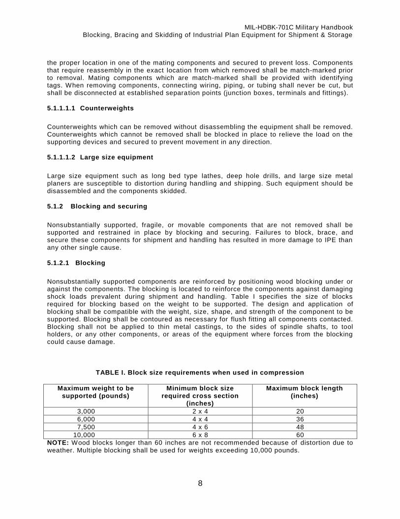
5.1.2.1 Blocking
Nonsubstantially supported components are reinforced by positioning wood blocking under or against the components. The blocking is located to reinforce the components against damaging shock loads prevalent during shipment and handling. Table I specifies the size of blocks required for blocking based on the weight to be supported. The design and application of blocking shall be compatible with the weight, size, shape, and strength of the component to be supported. Blocking shall be contoured as necessary for flush fitting all components contacted. Blocking shall not be applied to thin metal castings, to the sides of spindle shafts, to tool holders, or any other components, or areas of the equipment where forces from the blocking could cause damage.
TABLE I. Block size requirements when used in compression
Maximum weight to be supported (pounds)
Minimum block size required cross section
(inches)
Maximum block length (inches)
3,000 2 x 4 20
6,000 4 x 4 36
7,500 4 x 6 48
10,000 6 x 8 60
NOTE: Wood blocks longer than 60 inches are not recommended because of distortion due to weather. Multiple blocking shall be used for weights exceeding 10,000 pounds.

MIL-HDBK-701C Military Handbook Blocking, Bracing and Skidding of Industrial Plan Equipment for Shipment & Storage
9
5.1.2.2 Securing
Movable components shall be immobilized by securing them to stationary and substantially supported components of the equipment. Movable components subject to applied loads of 100 pounds or less may be secured by binding with metal banding, wire, or similar techniques. Movable components subject to applied loads exceeding 100 pounds shall be secured by securing devices of the type specified in 5.1.2.3. Corners of components contacted by metal banding or wire shall be protected by suitable cushioning material.
5.1.2.3 Securing devices
The tie rod type and the tie rod yoke type securing devices are the approved means for immobilizing movable components and securing IPE to the skids.
5.1.2.3.1 Tie rod type
The tie rod type securing device is illustrated in figure 1. Steel rod diameter is determined by the weight of the load in accordance with table II. The metal plates shall be approximately 4 inches square or 3 inches in diameter, and shall be in accordance with the thickness specified in table II.
Figure 1: Tie rod type securing device
MIL-HDBK-701C Military Handbook Blocking, Bracing and Skidding of Industrial Plan Equipment for Shipment & Storage
10
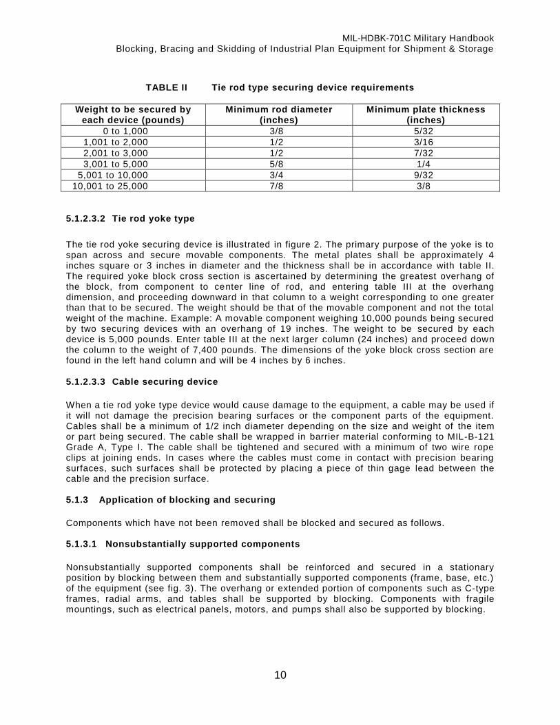
TABLE II Tie rod type securing device requirements
Weight to be secured by each device (pounds)
Minimum rod diameter (inches)
Minimum plate thickness (inches)
0 to 1,000 3/8 5/32
1,001 to 2,000 1/2 3/16
2,001 to 3,000 1/2 7/32
3,001 to 5,000 5/8 1/4
5,001 to 10,000 3/4 9/32
10,001 to 25,000 7/8 3/8
5.1.2.3.2 Tie rod yoke type
The tie rod yoke securing device is illustrated in figure 2. The primary purpose of the yoke is to span across and secure movable components. The metal plates shall be approximately 4 inches square or 3 inches in diameter and the thickness shall be in accordance with table II. The required yoke block cross section is ascertained by determining the greatest overhang of the block, from component to center line of rod, and entering table III at the overhang dimension, and proceeding downward in that column to a weight corresponding to one greater than that to be secured. The weight should be that of the movable component and not the total weight of the machine. Example: A movable component weighing 10,000 pounds being secured by two securing devices with an overhang of 19 inches. The weight to be secured by each device is 5,000 pounds. Enter table III at the next larger column (24 inches) and proceed down the column to the weight of 7,400 pounds. The dimensions of the yoke block cross section are found in the left hand column and will be 4 inches by 6 inches.
5.1.2.3.3 Cable securing device
When a tie rod yoke type device would cause damage to the equipment, a cable may be used if it will not damage the precision bearing surfaces or the component parts of the equipment. Cables shall be a minimum of 1/2 inch diameter depending on the size and weight of the item or part being secured. The cable shall be wrapped in barrier material conforming to MIL-B-121 Grade A, Type I. The cable shall be tightened and secured with a minimum of two wire rope clips at joining ends. In cases where the cables must come in contact with precision bearing surfaces, such surfaces shall be protected by placing a piece of thin gage lead between the cable and the precision surface. 5.1.3 Application of blocking and securing
Components which have not been removed shall be blocked and secured as follows. 5.1.3.1 Nonsubstantially supported components
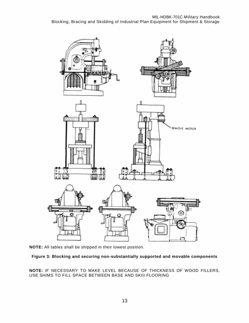
Nonsubstantially supported components shall be reinforced and secured in a stationary position by blocking between them and substantially supported components (frame, base, etc.) of the equipment (see fig. 3). The overhang or extended portion of components such as C-type frames, radial arms, and tables shall be supported by blocking. Components with fragile mountings, such as electrical panels, motors, and pumps shall also be supported by blocking.

MIL-HDBK-701C Military Handbook Blocking, Bracing and Skidding of Industrial Plan Equipment for Shipment & Storage
11
5.1.3.2 Movable components
Movable components shall be secured in a stationary position by applying securing devices as illustrated in figure 3. Movable components such as traveling columns, sliding tables, and operating heads shall be locked in place by the locking mechanisms provided with the equipment. However, these mechanisms do not provide adequate locking security and shall be augmented by the specified securing devices. Components that are vertically movable shall be lowered to rest on blocking and be secured in position. Components that are horizontally movable shall be secured in a position which is centered on the equipment (see fig. 3). 5.1.3.3 Unsupported columns
Unsupported columns shall be reinforced by positioning snug fitting filler blocks between the skid and the recessed portion of the base of the equipment. The thickness of filler blocks shall be accurately sized to avoid placing undue stress on the base when the holddown bolts are tightened (see fig. 4). When shims are used with a filler block, they shall support the same area as the filler block.
1 Tie rod 2 Yoke block 3 Metal plate 4 Washer 5 Nut
Figure 2: Tie rod yoke securing device

MIL-HDBK-701C Military Handbook Blocking, Bracing and Skidding of Industrial Plan Equipment for Shipment & Storage
12
TABLE III Tie rod yoke type securing device
Yoke block
nominal cross
section size
(inches)
Overhang of yoke block from component to rod (inches).
6 12 18 24 30 36 48 60
2 x 4 2,200 1,100 730 550 440 365 275 220
4 x 4 12,000 6,000 4,500 3,000 2,400 2,000 1,500 1,500
4 x 6 29,500 14,800 9,900 7,400 5,900 4,900 3,700 2,900
6 x 8 86,000 43,000 28,700 21,600 7,200 14,400 10,800 8,600
MIL-HDBK-701C Military Handbook Blocking, Bracing and Skidding of Industrial Plan Equipment for Shipment & Storage
13
NOTE: All tables shall be shipped in their lowest position.
Figure 3: Blocking and securing non-substantially supported and movable components NOTE: IF NECESSARY TO MAKE LEVEL BECAUSE OF THICKNESS OF WOOD FILLERS, USE SHIMS TO FILL SPACE BETWEEN BASE AND SKIII FLOORING

MIL-HDBK-701C Military Handbook Blocking, Bracing and Skidding of Industrial Plan Equipment for Shipment & Storage
14
NOTE: Equipment shown mounted on wooden skid. When mounted on DOD reusable skids, the same reinforcing technique is required except that the blocking shall be bolted to the skid components.
Figure 4: Reinforcing unsupported columns 5.1.3.4 Equipment with leg or end frame type bases
Equipment with non-substantially supported leg or end frame type bases shall be reinforced in accordance with one of the techniques illustrated in figure 5 and 6. 5.1.3.5 Tailstocks and movable heads
The tailstocks of lathes and movable heads of other equipment with spindles shall be secured by compressing blocking between the spindle housing and fixed head with a tie rod type securing device through a hollow spindle. When the equipment is provided with a solid spindle, a tie rod yoke type securing device shall be used (see fig. 7). 5.1.3.6 Tables and other components
Tables or other components moving on ball bearings or other types of high efficiency, low friction ball, or roller bearing mechanisms shall be blocked, cushioned, or removed and all components treated in such a manner that neither the way surfaces nor the anti -friction devices will be subjected to damage (see MIL-STD-107). When practicable, tables more than 6 feet long should be removed from the basic unit, packed separately and skidded with the basic unit. The bearing preload shall be relieved. 5.1.3.7 Ballscrew drives
For machine elements driven by recirculating ballscrews, the ball nut shall be disconnected from the element and secured. The machine element involved shall be treated in accordance with 5.1.3.4 or 5.1.3.6 as applicable.

MIL-HDBK-701C Military Handbook Blocking, Bracing and Skidding of Industrial Plan Equipment for Shipment & Storage
15
5.1.3.8 Counterweights
Counterweights shall be blocked in a manner that will release all tension from supporting cables, chains, and springs and secured to prevent movement in any direction. 5.1.3.9 Doors and drawers
In addition to the locking mechanisms or catches provided, doors and drawers shall also be secured by metal banding or fiber reinforced tape. When metal banding is used the surfaces contacted shall be protected by suitable cushioning material. Care shall be exercised to avoid over tensioning metal banding that could disfigure a component. Nylon strapping conforming to PPP-S-760, Type III may be utilized for domestic shipment. 5.1.3.10 Handwheels
In addition to the locking mechanisms provided, handwheels, levers, and cranks shall also be secured in position by common annealed wire, metal banding, conforming to QQ-S-781 or nylon strapping conforming to PPP-S-760, Type III. 5.1.3.11 Surface plate shipments
Heavy surface plates made of material such as granite, cast iron, or steel shall be removed from supporting bases and secured with tie bars directly to the skid with the working surface up. The base should be inverted on top of the surface plate and secured to the skid. The top and bottom surfaces of the surface plate shall be protected with plywood or other suitable cushioning material.

MIL-HDBK-701C Military Handbook Blocking, Bracing and Skidding of Industrial Plan Equipment for Shipment & Storage
16
NOTE: Equipment shown mounted on wooden type skid. When equipment is mounted on the DOD reusable skids, the same reinforcing technique is required except that the blocking shall be bolted to the skid components.
Figure 5: Reinforcing leg and end frame type bases

MIL-HDBK-701C Military Handbook Blocking, Bracing and Skidding of Industrial Plan Equipment for Shipment & Storage
17
NOTE: For equipment mounted on wooden skids only.
Figure 6: Reinforcing leg and end frame type bases

MIL-HDBK-701C Military Handbook Blocking, Bracing and Skidding of Industrial Plan Equipment for Shipment & Storage
18
Figure 7: Blocking movable components

MIL-HDBK-701C Military Handbook Blocking, Bracing and Skidding of Industrial Plan Equipment for Shipment & Storage
19
5.1.3.12 Oversize and overweight IPE
When either special routing or disassembly is required to permit transportability of items shipped directly to storage, DIPEC-OIM shall be contacted to determine maximum permissible ingress dimensions at destination. DIPEC-OIM shall also be contacted prior to shipment of any item which has an individual shipping piece weighing more than 40,000 pounds. Dimensions of the shipment including weight, height, width, and length and shipping dates shall be furnished to DIPEC-OIM when the IPE is prepared for shipment. 5.1.3.13 Waiver of skidding requirements
Many items, due to their basic construction may be shipped safely, conveniently, and more economically without skidding. This includes items with heavy, durable or solid bases and disassembled components of comparable nature, such as presses, press frames, anvils, machine bases, and similar items. In the preparation of equipment for shipment to a using activity the skidding requirement may be waived or reduced, provided the protection afforded will meet or exceed the minimum requirements, assure safe arrival at dest ination, and facilitate removal, handling and placement in location by shipping and receiving activities. When it is determined to be more economical or otherwise in the best interests of the Government to ship equipment without skidding or with a lower level than that specified herein, a specific request will be made to DIPEC-STS for authorization for deviation. 5.1.3.14 Waiver of rail transportation requirements
IPE shall not be shipped by rail transportation, except when a waiver is obtained from DIPEC -SQ. Whenever oversize or overweight IPE is required to be shipped via rail transportation, the shipping activity shall provide DIPEC-SQ with a written request. When a waiver is granted for rail shipment, blocking, bracing and skidding of IPE in rail car shipment shall be accomplished in accordance with the American Association of Railroad Publications as follows:
a. Open top carloading manual: (1) Section 1 - General Rules Governing the Loading of Commodities on Open Top
Cars. (2) Section 4 - Rules Governing the Loading of Miscellaneous Commodities, including
Machinery on Open Top Cars. b. Pamphlet No. 21 - Rules Regulating the Preparation and Safe Loading of Machinery in
Closed Cars and Protection of Equipment. c. Circular No. 42H General Rules Governing Loading of Carload Shipment of
Commodities in Closed Cars.
5.2. Skidding requirements
With the exception of the type equipment specified in 5.2.1, all IPE being shipped or handled shall be skidded. Skidding is required to provide added stability, damage protection, and ease of handling. The skids provided shal l be selected from the DIPEC inventory of DoD reusable skids or be constructed of wood in accordance with the design and fabrication requirements for wooden skids specified herein. 5.2.1 Equipment not required to be skidded
Many items of IPE due to construction, configuration, weight fragility, and size, may be shipped more economically, conveniently, and safely without skidding. This includes items not

MIL-HDBK-701C Military Handbook Blocking, Bracing and Skidding of Industrial Plan Equipment for Shipment & Storage
20
exceeding 1,000 pounds in weight which can be protected from mechanical and physical damage by boxing, crating, palletization or protected as specified in 5.1.3.13. Equipment packaged in accordance with MIL-STD-107, paragraphs 5.2 though 5.2.3 does not require skidding in accordance with the requirements herein. In the preparation of other equipment fo r shipment to a using activity, the requirements cited in the applicable shipping instructions may be waived or reduced provided the protection afforded will assure safe arrival at the destination and provide safe removal, handling, and placement in location by both the shipping and receiving activities. When it is determined to be cost effective or otherwise more economical to the Government to ship equipment without skidding, or skidding other than specified in shipping instructions, a specific request wi ll be submitted thorough the appropriate channels to DIPEC-SQ for approval (see 5.1.3.13). 5.2.2 Design
The skid design shall include an arrangement of parallel runner members held together by cross members, headers, or other components as required to provide a mounting base which elevates the load not less than 3-1/2 inches and not more than 14 inches. The configuration of the skid shall be rectangular or square as viewed from the top. 5.2.2.1 Width and length
The required length and width of the skid is based primarily on the length and width of the load plus a 2 inch safety clearance on each side and end of the load (see fig. 8). The length and width of the skid shall be increased as required to accommodate equipment accompanying the basic item on the skid (see 5.2.3) top-heavy equipment (see 5.2.3.1), or buttress blocking (see 5.3.2). When the addition of accompanying equipment results in exceeding the DOD reusable skid size or weight limitations, deteriorating the shipping or handling characteristics of the skidded load, or exceeding any of the carrier’s load limitations, accompanying equipment shall be skidded separately. 5.2.3 Load positioning
With the exception of equipment described in 5.2.3.1, all IPE shall be skidded in an upright position. The load shall be positioned on the skid with the longer side of the basic item positioned parallel to the runner members. Accompanying equipment should be positioned on either side of the basic item. When configurations permit, accompanying equipment shall be positioned in available spaces under the basic item for added damage protection. Not less than 2 inches of clearance shall be provided between the basic item and accompanying equipment. 5.2.3.1 Top heavy equipment
Top heavy equipment and items with height exceeding normal shipping limitations shall be skidded in a horizontal position, when design and configuration permits (see fig. 9). Top heavy equipment requiring upright skidding due to design or structural weakness may require skid size exceeding the standard in order to maintain stability during handling and shipment. The length and width of the skid for top heavy equipment shall be not less than twice the height of the center of gravity of the item above the mounting surface (see fig. 10).

MIL-HDBK-701C Military Handbook Blocking, Bracing and Skidding of Industrial Plan Equipment for Shipment & Storage
21
Figure 8: Safety clearance

MIL-HDBK-701C Military Handbook Blocking, Bracing and Skidding of Industrial Plan Equipment for Shipment & Storage
22
Figure 9: Horizontal skidding for top-heavy and overheight equipment

MIL-HDBK-701C Military Handbook Blocking, Bracing and Skidding of Industrial Plan Equipment for Shipment & Storage
23
Figure 10: Skids for stability of top-heavy equipment

MIL-HDBK-701C Military Handbook Blocking, Bracing and Skidding of Industrial Plan Equipment for Shipment & Storage
24
5.2.4 Load securing
5.2.4.1 Basic item
The basic item of equipment shall be secured by bolting it to the skid utilizing the bolt holes of each holddown point provided in the base or frame. Equipment not provided with bolt holes, or equipment being skidded in a horizontal position, shall be secured to the skid by securing devices of the type indicated in 5.1.2.3, or by securing devices and blocking methods shown in figures 9, 11, 12 or 13. Equipment skidded in a horizontal position shall be secured to the skid at points along the item that are sufficiently rigid for supporting the load. Each corner of the base of upright skidded equipment shall be secured to the skid with a holddown point located not more than 12 inches from the corner on either end or side of the base (see fig. 14). Holddown point spacing along the end of the base shall be not more than 6 feet. Holddown point spacing along the side of the base shall not be more than 8 feet. The minimum number of holddown points required for equipment weights are indicated in table IV. The minimum size and type of holddown bolts required are indicated in the paragraphs for the type DOD reusable skid selected or the wood skid being constructed. When the size of the bolt holes in the equipment base is larger than the required holddown bolt size, either sleeves or bolts of larger sizes shall be used to assure snug fits. When the bolt holes are smaller than the required holddown bolt sizes, the number of holddown points shall be increased to compensate. 5.2.4.1.1 Use of leveling screw bolt holes
In the absence of adequate holddown holes, leveling screw bolt holes may be utilized for holddown points. When utilized, the threads of the leveling screw holes shall be protected by a lead sleeve after removal of the leveling screw. The leveling bolts and locknuts which are removed shall be placed in a bag made from material conforming to MIL-B-121, Grade A, Type II, Class 1, and secured to the casting or packed with the accompanying equipment. When feasible, the leveling bolt and locknut shall accompany the basic equipment. When the base is furnished with hollow leveling screws, they shall be backed off flush with the underside of the base and the locknut set. A lead protective sleeve is also required inside the hollow leveling screws. 5.2.4.2 Accompanying equipment
Accompanying equipment shall be secured to DOD reusable skids by bolting either directly to the skid or by use of tie bar type securing devices. Accompanying equipment shall be secured to wood skids by bolting, metal banding or other methods of equal strength that will assure safe shipment of equipment. Accompanying equipment bolted to skids shall be secured at not less than 4 holddown points.

MIL-HDBK-701C Military Handbook Blocking, Bracing and Skidding of Industrial Plan Equipment for Shipment & Storage
25
Figure 11: Holddowns for equipment without bolt holes
Figure 12: Holddowns for shipment without bolt holes

MIL-HDBK-701C Military Handbook Blocking, Bracing and Skidding of Industrial Plan Equipment for Shipment & Storage
26
NOTE: Deform threads above nut.
Figure 13: Holddowns for equipment without bolt holes
NOTE: Holddown point required not more than 12 inches from each corner on either the end or side of basic item.
Figure 14: Maximum holddown point spacing
MIL-HDBK-701C Military Handbook Blocking, Bracing and Skidding of Industrial Plan Equipment for Shipment & Storage
27
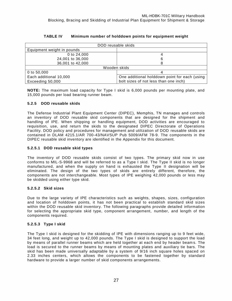
TABLE IV Minimum number of holddown points for equipment weight
DOD reusable skids
Equipment weight in pounds
0 to 24,000 4 24,001 to 36,000 6 36,001 to 42,000 8
Wooden skids
0 to 50,000 4
Each additional 10,000 One additional holddown point for each (using bolt sizes of not less than one inch) Exceeding 50,000
NOTE: The maximum load capacity for Type I skid is 6,000 pounds per mounting plate, and 15,000 pounds per load bearing runner beam. 5.2.5 DOD reusable skids
The Defense Industrial Plant Equipment Center (DIPEC), Memphis, TN manages and controls an inventory of DOD reusable skid components that are designed for the shipment and handling of IPE. When shipping or handling equipment, DOD activities are encouraged to requisition, use, and return the skids to the designated DIPEC Directorate of Operations Facility. DOD policy and procedures for management and utilization of DOD reusable skids are contained in DLAM 4215.1/AR 700-43/NAVSUP Pub 5009/AFM 78-9. The components in the DIPEC reusable skid inventory are identified in the Appendix for this document. 5.2.5.1 DOD reusable skid types
The inventory of DOD reusable skids consist of two types. The primary skid now in use conforms to MIL-S-9968 and will be referred to as a Type I skid. The Type II skid is no longer manufactured, and when the supply on hand is exhausted the Type II designation will be eliminated. The design of the two types of skids are entirely different, therefore, the components are not interchangeable. Most types of IPE weighing 42,000 pounds or less may be skidded using either type skid. 5.2.5.2 Skid sizes
Due to the large variety of IPE characteristics such as weights, shapes, sizes, configuration and location of holddown points, it has not been practical to establish standard skid sizes within the DOD reusable skid inventory. The following paragraphs provide detailed information for selecting the appropriate skid type, component arrangement, number, and length of the components required. 5.2.5.3 Type I skid
The Type I skid is designed for the skidding of IPE with dimensions ranging up to 9 feet wide, 34 feet long, and weight up to 42,000 pounds. The Type I skid is designed to support the load by means of parallel runner beams which are held together at each end by header beam s. The load is secured to the runner beams by means of mounting plates and auxiliary tie bars. The skid has been made universally adaptable by a system of 9/16 inch square holes spaced on 2.33 inches centers, which allows the components to be fastened together by standard hardware to provide a larger number of skid components arrangements.

MIL-HDBK-701C Military Handbook Blocking, Bracing and Skidding of Industrial Plan Equipment for Shipment & Storage
28
5.2.5.3.1 Skid components
The inventory of components for the Type I skid includes runner/header beams, mounting plates, auxiliary tie bars, and hardware. The runner/header beams are utilized for both runner and header members of the skid. 5.2.5.3.2 Type I skid components arrangement
Figures 15, 16, and 17 illustrate three of the most frequently utilized Type I skid component arrangements:
a. Arrangement A (see fig. 15). The basic Type I skid includes four mounting plates, two load bearing runner beams, and two header beams. This arrangement is utilized for equipment which does not have side overhanging components projecting horizontally past the base of the basic item.
b. Arrangement B (see fig. 16). Side overhanging components and equipment accompanying the basic item on the skid are protected from damage by adding outrigger runner beams to the basic skid. This arrangement also has two auxiliary tie bars for added rigidity between adjacent load bearing and outrigger runner beams. Auxiliary tie bars are also utilized to support and secure accompanying equipment to the runner beams.
c. Arrangement C (see fig. 17). Outrigger runner beams do not increase the load capacity of the skid arrangement. This is accomplished only by adding load bearing runner beams to the basic skid.

MIL-HDBK-701C Military Handbook Blocking, Bracing and Skidding of Industrial Plan Equipment for Shipment & Storage
29
Figure 15: Arrangement A - Basic Type I skid comprising two header beams, and two
load bearing runner beams each with two mounting plates.

MIL-HDBK-701C Military Handbook Blocking, Bracing and Skidding of Industrial Plan Equipment for Shipment & Storage
30
Figure 16: Arrangement B - Basic Type I reusable skid plus two outrigger runner beams
and two auxiliary tie bars, showing hardware set applicable to all arrangements.
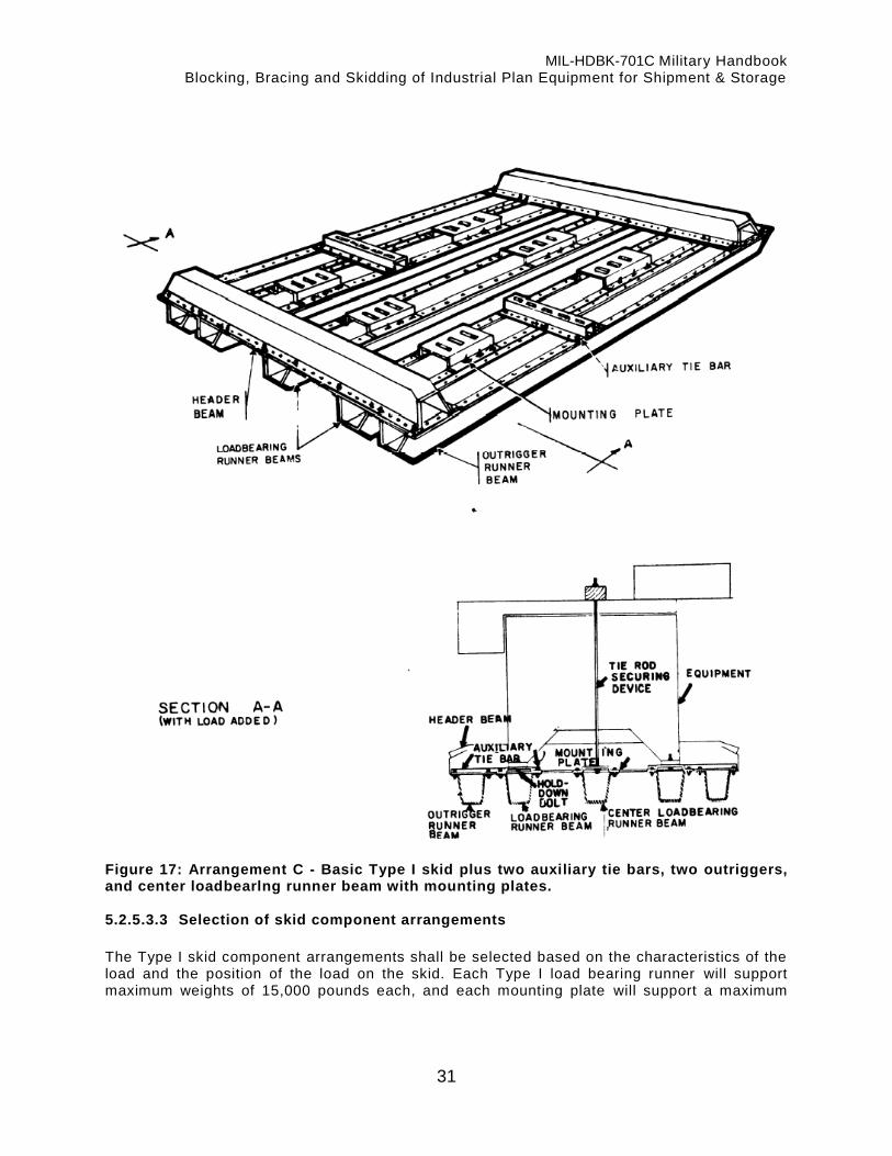
MIL-HDBK-701C Military Handbook Blocking, Bracing and Skidding of Industrial Plan Equipment for Shipment & Storage
31
Figure 17: Arrangement C - Basic Type I skid plus two auxiliary tie bars, two outriggers, and center loadbearlng runner beam with mounting plates. 5.2.5.3.3 Selection of skid component arrangements
The Type I skid component arrangements shall be selected based on the characteristics of the load and the position of the load on the skid. Each Type I load bearing runner will support maximum weights of 15,000 pounds each, and each mounting plate will support a maximum

MIL-HDBK-701C Military Handbook Blocking, Bracing and Skidding of Industrial Plan Equipment for Shipment & Storage
32
load of 6,000 pounds each. Steps 1 through 8 provide detailed information for determining the skid component arrangement required.
STEP 1. Establish the position the load will occupy on the skid (see 5.2.3), and the number and location of holddown points (see 5.2.4).
STEP 2. Determine the number of mounting plates required. Mounting plates are required for securing the basic item of equipment to the runner beams. One mounting plate is required for each holddown point of the basic item.

MIL-HDBK-701C Military Handbook Blocking, Bracing and Skidding of Industrial Plan Equipment for Shipment & Storage
33
STEP 3. Determine the number of runner beams required for accommodating the mounting plates. One runner beam is required for each row of mounting plates.
Runner beam definitions
When provided with mounting plates and positioned under and supporting the base of the basic item, runner beams are considered load bearing. When not provided with mounting plates and positioned on either side of the basic item for the protection of overhanging components or for the support of accompanying equipment, runner beams are considered outriggers.

MIL-HDBK-701C Military Handbook Blocking, Bracing and Skidding of Industrial Plan Equipment for Shipment & Storage
34
STEP 4. Determine the minimum number of load bear ing runner beams required for supporting the weight of the load. The basic skid component arrangement includes two load bearing runner beams each with not less than two mounting plates (two runner beams each with three mounting plates shown in Step 3). The load capacity of Type I Skid is increased up to 42,000 pounds when provided with two additional (center) load bearing runner beams with not less than four mounting plates.
STEP 5. Determine if outrigger runner beams are required. An outrigger runner beam is required on either side of the basic item when that side has overhanging components or accompanying equipment that extends past the base.

MIL-HDBK-701C Military Handbook Blocking, Bracing and Skidding of Industrial Plan Equipment for Shipment & Storage
35
STEP 6. Determine if auxiliary tie bars are required. Two auxiliary tie bars are required for each piece of equipment accompanying the basic item on the skid. When furnished with outrigger runner beams, skids over 6 feet long shall be provided with auxiliary tie bars, uniformly not more than 6 feet apart, between the header beams. Auxiliary tie bars are also utilized for the support of buttress blocking. The length of the auxiliary tie bars shall be as required for the intersection of two runners’ beams. Each tie bar will support a load of up to 1,000 pounds. STEP 7. Header beams. One header beam is required at each end of the skid for holding the runner beams in place.
Width of Skid
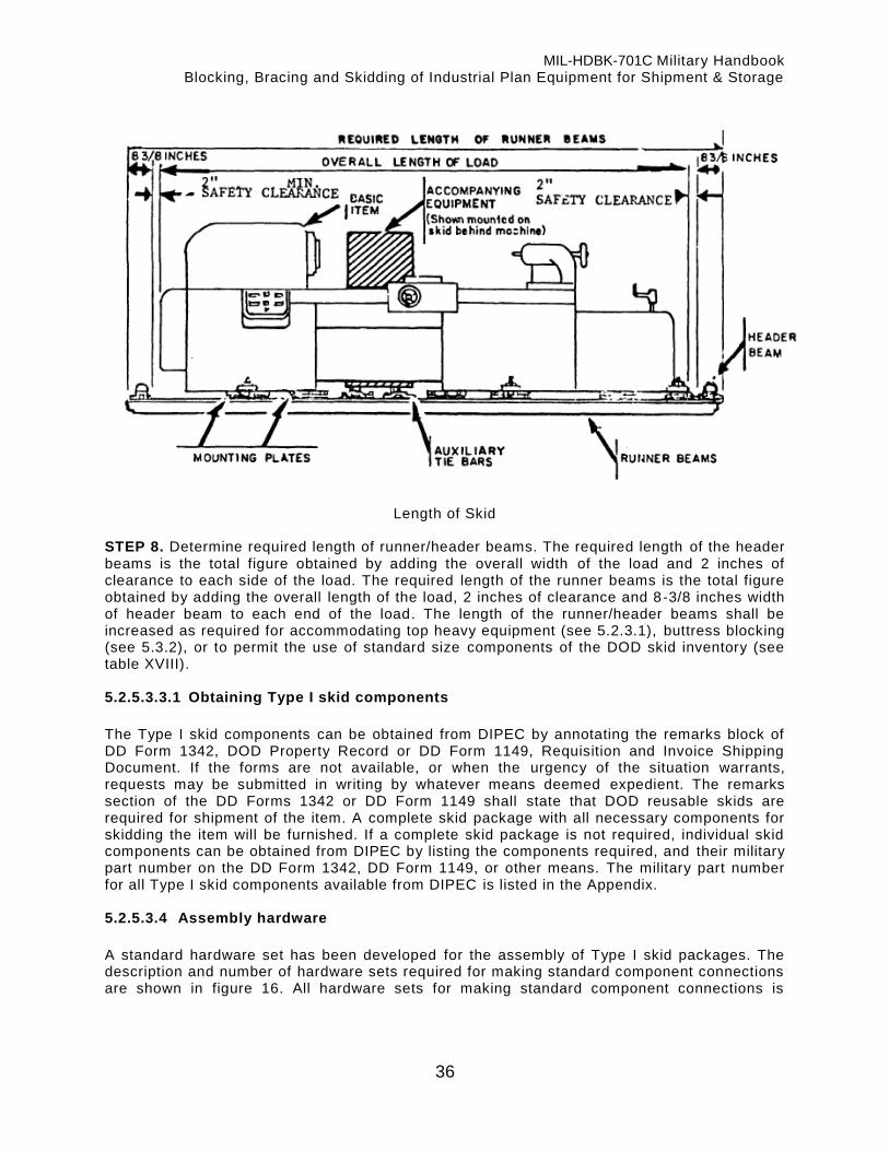
MIL-HDBK-701C Military Handbook Blocking, Bracing and Skidding of Industrial Plan Equipment for Shipment & Storage
36
Length of Skid STEP 8. Determine required length of runner/header beams. The required length of the header beams is the total figure obtained by adding the overall width of the load and 2 inches of clearance to each side of the load. The required length of the runner beams is the total figure obtained by adding the overall length of the load, 2 inches of clearance and 8-3/8 inches width of header beam to each end of the load. The length of the runner/header beams shall be increased as required for accommodating top heavy equipment (see 5.2.3.1), buttress blocking (see 5.3.2), or to permit the use of standard size components of the DOD skid inventory (see table XVIII). 5.2.5.3.3.1 Obtaining Type I skid components
The Type I skid components can be obtained from DIPEC by annotating the remarks block of DD Form 1342, DOD Property Record or DD Form 1149, Requisition and Invoice Shipping Document. If the forms are not available, or when the urgency of the situation warrants, requests may be submitted in writing by whatever means deemed expedient. The remarks section of the DD Forms 1342 or DD Form 1149 shall state that DOD reusable skids are required for shipment of the item. A complete skid package with all necessary components for skidding the item will be furnished. If a complete skid package is not required, individual skid components can be obtained from DIPEC by listing the components required, and their military part number on the DD Form 1342, DD Form 1149, or other means. The military part number for all Type I skid components available from DIPEC is listed in the Appendix. 5.2.5.3.4 Assembly hardware
A standard hardware set has been developed for the assembly of Type I skid packages. The description and number of hardware sets required for making standard component connections are shown in figure 16. All hardware sets for making standard component connections is

MIL-HDBK-701C Military Handbook Blocking, Bracing and Skidding of Industrial Plan Equipment for Shipment & Storage
37
expendable and accountability will not be maintained by DIPEC. Local procurement shall be initiated for expendable hardware items as specified in the Appendix. 5.2.5.3.5 Load securing hardware
A hex nut, two flat washers, one lock washer, and a standard steel step bolt of the minimum size specified in Table V are required for securing each holddown point of the load (basic item and accompanying equipment) to the mounting plate and auxiliary tie bars (see fig. 18). The required length of the step bolts is obtained by adding one inch (combined thickness of hardware, material of mounting plates or auxiliary tie bars and clearance) to the thickness of the mounting base. See 5.2.4 for the minimum number of holddown points required. When the load is not provided with adequate holddown holes, the step bolts shall be replaced by equal capacity securing devices of the type indicated in 5.1.2.3 and 5.2.4.1. All load securing hardware packages will be furnished by the shipping activity.
TABLE V. Holddown bolt sizes – Type I skids
Weight of load, pounds Bolt size required, minimum, inches
0 to 4,000 * 1/2
4,001 to 12,000 * 5/8
12,001 to 24,000 * 3/4
24,001 to 36,000 ** 3/4
36,001 to 42,000 *** 3/4
* Based on 4 holddown bolts. ** Based on 6 holddown bolts. *** Based on 8 holddown bolts.
Type II Skid
a. Stack beams in the following order: 1. Runner beams 2. Header beams 3. Cross beams 4. Accessory beams
b. Retain adequate hardware to secure saddle to runner beams. c. Place remaining hardware in a suitable size fabricated box; then lay boxed hardware on
top of stacked beams and band securely.

MIL-HDBK-701C Military Handbook Blocking, Bracing and Skidding of Industrial Plan Equipment for Shipment & Storage
38
Figure 18: Load securing and shipping package, Type I and Type II DOD reusable skids
5.2.5.4 Type II skid
The Type II skid (see Fig. 19) is designed for skidding IPE of dimensions ranging up to 8 feet wide, 36 feet long, and weights up to 42,000 pounds. The skid is designed to secure the load by means of parallel crossbeams and accessory beams which are supported at each end by runner beams. The Type II skid design includes T -slots in the skid members which are used in conjunction with special hardware for connecting intersecting beams at any desired position. 5.2.5.4.1 Type II skid components
The inventory of components for the Type II skid includes crossbeams, runner/header beams, accessory beams, and hardware. The runner/header beams are utilized for both runner and header members of the skid. Harvey type S1 skid components, when practical, shall be cut to fit the runners and headers members of the Universal Type II skid. 5.2.5.4.2 Selection of skid component arrangements
The Type II skid component arrangements shall be selected based on the characteristics of the load (number and location of holddown points, weight, dimensions, etc.) and the position of the load on the skid. Steps 1 through 7 provide detailed information for determining the skid component arrangement required.

MIL-HDBK-701C Military Handbook Blocking, Bracing and Skidding of Industrial Plan Equipment for Shipment & Storage
39
Figure 19: Type II DOD reusable skid
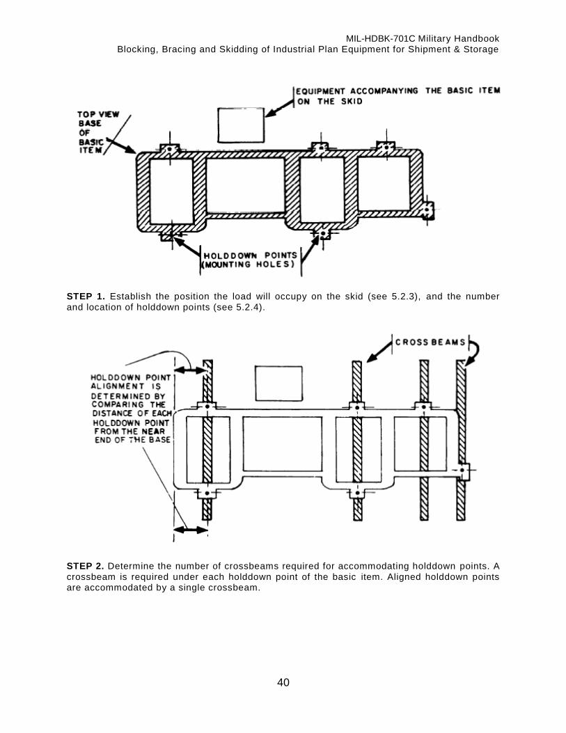
MIL-HDBK-701C Military Handbook Blocking, Bracing and Skidding of Industrial Plan Equipment for Shipment & Storage
40
STEP 1. Establish the position the load will occupy on the skid (see 5.2.3), and the number and location of holddown points (see 5.2.4).
STEP 2. Determine the number of crossbeams required for accommodating holddown points. A crossbeam is required under each holddown point of the basic item. Aligned holddown points are accommodated by a single crossbeam.

MIL-HDBK-701C Military Handbook Blocking, Bracing and Skidding of Industrial Plan Equipment for Shipment & Storage
41
STEP 3. Determine the number of runner beams required. Two runner beams are required for supporting the crossbeam at each end. Type II skid widths exceeding 7 feet or IPE with weak mounting bases shall be provided with not less than one additional (center) runner beam.
STEP 4. Determine if accessory beams are required. Each piece of accompanying equipment shall be supported and secured to the skid by not less than two accessory beams. Accessory beams are also utilized for the support of buttress blocking. The load capacity for accessory beams is provided in Table VI.

MIL-HDBK-701C Military Handbook Blocking, Bracing and Skidding of Industrial Plan Equipment for Shipment & Storage
42
TABLE VI Accessory beam loading (each beam)
Unsupported Span (feet) Maximum Load (Pound)
2-1/2 1,000 3 900 4 755 4-1/2 675 5 550 6 500 6-1/2 450 7 390
STEP 5. Header beams. Each end of the Type II skid shall be provided with a header beam.
Width of Skid

MIL-HDBK-701C Military Handbook Blocking, Bracing and Skidding of Industrial Plan Equipment for Shipment & Storage
43
Length of Skid STEP 6. Determine required length of skid members. The required length of crossbeams, header beams, and accessory beams is the total figure obtained by adding the overall width of the load and a 2 inch safety clearance to both sides of the load. The required length of runner beams is obtained by adding the overall length of the load to twice the 2 inches of clearance and the 3-1/8 inches (width of the header beam). The length of the skid mem bers shall be increased as required for accommodating top heavy equipment (see 5.2.3.1), buttress blocking (see 5.3.2) or to permit the use of standard size components of the DOD skid inventory (see tables XVIII and XIX). STEP 7. Determine minimum number of crossbeams required. The minimum number of crossbeams required for supporting the load is determined from table VII in accordance with the following example:
EXAMPLE
1. Weight of load. 15,000 lbs. 2. Width of load base in contact with crossbeam. (X on
table VII) 2-1/2 ft.
3* Skid width which is overall width of machine including overhang, handles, and accessories, plus clearances (Y on table VII.)
5 ft.
4. Locate on table VII the value for 2-1/2 feet width and 5 feet 1ength. This is the load capacity per crossbeam--
7,000 lbs.
5. Divide the weight of the machine (step 1) by the crossbeam allowable load (step 4) to find the minimum number of crossbeams required. (Any fraction requires an additional crossbeam).
15,000 = 2.15 7,000 (use 3 crossbeams)

MIL-HDBK-701C Military Handbook Blocking, Bracing and Skidding of Industrial Plan Equipment for Shipment & Storage
44
TABLE VII. Load capacity of DOD Type II Skid crossbeam
Machine Base Width (X)
Skid width – length of crossbeam (Y)
2 ft. 6 in. 3 ft.
3 ft. 6 in. 4 ft.
4 ft. 6 in. 5 ft.
5 ft. 6 in. 6 ft.
6 ft. 6 in. 7 ft.
7 ft. 6 in. 8 ft.
2 ft. 15,0
00 15,0
00 15,0
00 15,0
00 9,00
0 6,00
0 4,00
0 3,00
0 2,20
0 1,70
0 1,30
0 1,10
0
2-1/2 ft.
– – – 15,0
00 15,0
00 15,0
00 12,0
00 7,00
0 4,70
0 3,30
0 2,40
0 1,90
0 1,40
0 1,20
0
3 ft. – – – – – – 15,0
00 15,0
00 15,0
00 9,50
0 5,70
0 3,90
0 2,80
0 2,00
0 1,60
0 1,30
0
3-1/2 ft.
– – – – – – – – – 15,0
00 15,0
00 13,0
00 7,70
0 4,60
0 3,20
0 2,30
0 1,80
0 1,40
0
4 ft. – – – – – – – – – – – – 15,0
00 15,0
00 11,0
00 6,00
0 4,00
0 2,80
0 2,00
0 1,60
0
4-1/2 ft.
– – – – – – – – – – – – – – – 15,0
00 15,0
00 9,00
0 5,10
0 3,40
0 2,30
0 1,80
0
5 ft. – – – – – – – – – – – – – – – – – – 15,0
00 15,0
00 8,00
0 4,50
0 2,90
0 2,00
0
5-1/2 ft.
– – – – – – – – – – – – – – – – – – – – – 15,0
00 14,0
00 7,00
0 4,00
0 2,40
0
6 ft. – – – – – – – – – – – – – – – – – – – – – – – – 15,0
00 13,0
00 6,00
0 3,30
0
6-1/2 ft.
– – – – – – – – – – – – – – – – – – – – – – – – – – – 15,0
00 12,0
00 5,00
0
7 ft. – – – – – – – – – – – – – – – – – – – – – – – – – – – – – – 15,0
00 10,5
00
7-1/2 ft.
– – – – – – – – – – – – – – – – – – – – – – – – – – – – – – – – – 15,0
00
8 ft. – – – – – – – – – – – – – – – – – – – – – – – – – – – – – – – – – 15,0
00
5.2.5.4.2.1 Obtaining Type II Skid Components
The Type II skid components can be obtained from DIPEC by annotating the “Remarks” block of the DD Form 1342, DOD Property Record or DD Form 1149, Requisition and Invoice Shipping Document. If approved forms are not available, or when the urgency of the si tuation warrants, requests may be submitted in writing by whatever means deemed expedient. The remarks block of DD Form 1342 shall state that skids are required for shipment of the item. A complete skid package with all necessary components for skidding th e item will be furnished. If a complete skid package is not required, individual skid components can also be obtained from DIPEC by listing the components required and their DIPEC Identification number on the DD Form 1342, DD Form 1149, or other means. The DIPEC Identification number for all Type II skid components available from DIPEC is listed in the Appendix. 5.2.5.4.3 Assembly hardware
The standard hardware sets in table VIII have been developed for assembly of DOD Type II skids. The hardware sets are used for making standard component connections as shown in figure 20. Assembly hardware sets for making standard component connections are automatically supplied when Type II skid components are ordered from DIPEC.
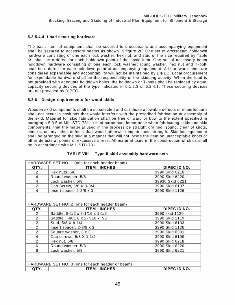
MIL-HDBK-701C Military Handbook Blocking, Bracing and Skidding of Industrial Plan Equipment for Shipment & Storage
45
5.2.5.4.4 Load securing hardware
The basic item of equipment shall be secured to crossbeams and accompanying equipment shall be secured to accessory beams as shown in figure 20. One set of crossbeam holddown hardware consisting of one each lock washer, hex nut, and stud of the size required by Table IX, shall be ordered for each holddown point of the basic item. One set of accessory beam holddown hardware consisting of one each lock washer; round washer, hex nut and T -bolt, shall be ordered for each holddown point of accompanying equipment. All hardware items are considered expendable and accountability will not be maintained by DIPEC. Local procurement for expendable hardware shall be the responsibility of the skidding activity. When the load is not provided with adequate holddown holes, the holddown or T -bolts shall be replaced by equal capacity securing devices of the type indicated in 5.1.2.3 or 5.2.4.1. These securing dev ices are not provided by DIPEC. 5.2.6 Design requirements for wood skids
Wooden skid components shall be so selected and cut those allowable defects or imperfections shall not occur in positions that would interfere with the prescribed fabrication or assembly of the skid. Material for skid fabrication shall be free of warp or bow to the extent specified in paragraph 5.3.5 of MIL-STD-731. It is of paramount importance when fabricating skids and skid components, that the material used in the process be straight grained, sound, clear of knots, checks, or any other defects that would otherwise impair their strength. Skidded equipment shall be arranged on the skid in a manner that will not locate the item on unacceptable knots or other defects at points of excessive stress. All material used in the construction of skids shall be in accordance with MIL-STD-731.
TABLE VIII Type II skid assembly hardware sets
HARDWARE SET NO. 1 (one for each header beam)
QTY. ITEM INCHES DIPEC ID NO.
2 Hex nuts, 5/8 3990 Skid 6218
4 Round washer, 5/8 3990 Skid 6220
4 Lock washer, 5/8 39930 Skid 6221
2 Cap Screw, 5/8 X 3-3/4 3990 Skid 6107
4 Insert spacer 2-3/8 x 3 3990 Skid 1126
HARDWARE SET NO. 2 (one for each header beam)
QTY. ITEM INCHES DIPEC ID NO.
2 Saddle, 8-1/2 x 3-1/16 x 1-1/2 3990 skid 1120
2 Saddle T-nut, 8 x 2-7/16 x 7/8 3990 Skid 1119
2 Stud, 5/8 X 6-1/4 3990 Skid 6103
2 Insert spacer, 2-3/8 x 3 3990 Skid 1126
2 Square washer, 3 x 3 3990 Skid 6301
4 Cap screws, 5/8 X 1 1/2 3990 Skid 6109
2 Hex nut, 5/8 3990 Skid 6218
6 Round washer, 5/8 3990 Skid 6220
6 Lock washer, 5/8 3990 Skid 6221
HARDWARE SET NO. 3 (one for each header or beam)
QTY. ITEM INCHES DIPEC ID NO.

MIL-HDBK-701C Military Handbook Blocking, Bracing and Skidding of Industrial Plan Equipment for Shipment & Storage
46
2 l-Bolt, 1/2 X 3-1/2 3990 Skid 6105
2 Hex Nut, 1/2 3990 Skid 6219
2 Round Washer, 1/2 3990 Skid 6601
2 Lock washer, 1/2 3990 Skid 6602
HARDWARE SET NO. 4 (one for each center runner beam to connect to two header beams)
QTY. ITEM INCHES DIPEC ID NO.
2 Lock washer, 5/8 3990 Skid 6221
2 Stud T-nut 3990 Skid 6302
2 Round washer, 5/8 3990 Skid 6220
2 Cap Screw, 5/8 X 2-1/4 3990 Skid 6110
2 Insert spacer 2-3/8 x 3 3990 Skid 1126
HARDWARE SET NO. 5 (one for each center runner at each crossbeam)
QTY. ITEM INCHES DIPEC ID NO.
1 T-nut 3990 Skid 6302
1 Cap screw, 5/8 x 1-1/2 3990 Skid 6109
1 Round washer, 5/8 3990 Skid 6220
1 Lock washer, 5/8 3990 Skid 6221

MIL-HDBK-701C Military Handbook Blocking, Bracing and Skidding of Industrial Plan Equipment for Shipment & Storage
47
Accessory Beam Holddown
Figure 20: Load securing, Type II reusable skids
TABLE IX Holddown sizes, type II skids
Weight of load (pounds)
Stud size required minimum (inches)
0 to 4,000 * 1/2
4,001 to 12,000 * 5/8
12,001 to 24,000 * 5/8
24,001 to 30,000 ** 5/8
30,001 to 42,000 *** 5/8
* Based on 4 holddown bolts. ** Based on 6 holddown bolts. *** Based on 8 holddown bolts.

MIL-HDBK-701C Military Handbook Blocking, Bracing and Skidding of Industrial Plan Equipment for Shipment & Storage
48
5.2.6.1 Design
The skid design shall include an arrangement of parallel runner members held together by flooring and header members, as shown in figure 21. The required number and size of the components, along with the required length and width of the skid, is based on the characteristics of the load (weight, dimensions, configuration, number and location of holddown points, in the skid construction materials and methods) and positi on of the load on the skid (see 5.2.3). 5.2.6.1.1 Load bearing runners
Runners positioned under and supporting the base of the basic item of IPE are considered load bearing members. A load bearing runner is required under each holddown point of the basic item required by 5.2.4.1. Aligned holddown points are accommodated by a single runner (see figure 22). The minimum number and cross-sectional size of load bearing runners required is established in table X for equipment with leg or end-frame type bases and table XI for equipment with flush mounting, circular pedesta l, or double column type bases. 5.2.6.1.2 Outrigger runners
Runners positioned on either side of the basic item of equipment for protection of overhanging components or support of accompanying equipment is considered outriggers. An outrigger runner is required on either side of the basic item when that side has overhanging components or accompanying equipment that extends past the base of the basic item (see figure 22). Outrigger runners shall be the same size (cross-section and length) and type of construction, as the load bearing runners. 5.2.6.1.3 Header members
One header member is required at each end of the skid for hold ing the runners in place. Header members shall be the same cross-sectional size and construction as the runner members, except 4 in. x 4 in. runners shall use 4 in. x 6 in. wide headers i f required to have two bolts. 5.2.6.1.4 Flooring
With the exception of skids for equipment with leg or end-frame type base, all skids shall be floored to cover not less than 60 percent of the area between the header members. Skids up to 1,000 pound capacity shall be floored with lumber of a nominal thickness of not less than one inch. All other skids shall be floored with lumber of a nominal thickness of not le ss than 2 inches (see fig. 23). 5.2.6.1.5 Diagonal bracing
Skids for equipment with leg or end-frame type bases shall be partially floored, and diagonal braced, with lumber of the cross-sectional sizes required by table XIII. Skids up to 5,000 pounds capacities shall be floored and diagonally braced to comply with figure 23. Skids exceeding 5,000 pounds capacity shall be floored and diagonally braced to comply wi th figure 24.

MIL-HDBK-701C Military Handbook Blocking, Bracing and Skidding of Industrial Plan Equipment for Shipment & Storage
49
5.2.6.1.6 Length and width
The required length and width of the skid, which is based on the length and width of the load, is established in accordance with figure 25. The dimensions established shall be increased only as required for accommodating equipment accompanying the basic item on the skid (see 5.2.3), top heavy equipment (see 5.2.3.1), or buttress blocking ( see 5.3.2). The dimension established for the length of the skid is the result of the required length of the runner members. The dimension established for the width of the skid is the result of the required length of the flooring and header members.

MIL-HDBK-701C Military Handbook Blocking, Bracing and Skidding of Industrial Plan Equipment for Shipment & Storage
50
1. Through bolts–Use two bolts through each skid member (runner 8 header) 2. Bevel cut–1/3 thickness of runner 3. Header member–Same width and thickness as runner 4. Floor member 5. Outrigger runner 6. Outline of machine base 7. Anchor bolt on machine base–Snug bolt fit through machine base, flooring and runner 8. Load bearing runner
1. Nut 2. Flat washer 3. Machine base 4. Cement coated nail 5. Floor member 6. Runner 7. Header member 8. Holddown bolt, basic item 9. Header member bolt 10. Bevel cut 45
o (degrees)
11. Countersunk

MIL-HDBK-701C Military Handbook Blocking, Bracing and Skidding of Industrial Plan Equipment for Shipment & Storage
51
12. Bolt head 13. Flat washer
Figure 21: Skid assembly, wood skids
Load bearing runners. A load bearing runner is required under each holddown point of the basic item. Aligned holddown points are accommodated by a single runner. The skid shall be fabricated with the load bearing runners centered on the holddown holes of the basic item. When the holddown holes are insufficient or nonexistent, the two outer load bearing runners shall be centered on the two outer edges of the base with the remaining load bearing runners required (see tables IV and V) equally spaced between the two. Outrigger runners. An outrigger runner is required on either side of the basic item when that side has overhanging components or accompanying equipment that extends beyond the edge of the base.
Figure 22: Determining the number of runners 5.2.6.2 Fabrication
The skid shall be fabricated in accordance with figures 21 through 28 and the requirements below. 5.2.6.2.1 Runners
All runners shall be equal in length and cross-sectional dim-, and whenever possible, shall be solid, one-piece beams. When solid beams are not available, spliced runners in accordance with 5.2.6.2.1.1 or laminated runners in accordance with 5.2.6.2.1.2 are acceptable substitutes. The runners shall be beveled on each end from the bottom edge, one-third the height, at a 45 degree angle (see fig. 26).

MIL-HDBK-701C Military Handbook Blocking, Bracing and Skidding of Industrial Plan Equipment for Shipment & Storage
52
5.2.6.2.1.1 Spliced runners
Spliced runners shall be constructed in accordance with figure 27 with one splice per runner located at a point one-third the distance from either end of the beam. The spliced joints of adjacent runners shall be positioned at opposite ends. The skid shall be assembled with the bolt heads of the spliced joints positioned on the bottom of the runners. The equipment weight values of tables X and XI for establishing the minimum number of load bearing runners required are decreased by 50 percent when spliced runners are used. 5.2.6.2.1.2 Laminated runners
Laminated runners shall be constructed in accordance with figure 28 with the nominal thickness of each lamination not less than 2 inches. Laminations shall be on a vertical plane only, and the overall width shall be not less than that required for solid runners. If laminations of sufficient length are not available, lamination joints shall be staggered not less than 4 ft. apart, and the number of laminations shall be that required to provide not less than the width computed for solid runners, plus one additional lamination. Laminations shall be bolted and nailed with 1/2 inch diameter carriage bolts and 10d nails. Bolts shall be spaced on 12 inch centers, staggered 2 inches from top and bottom of runner. The 10d nails shall be driven into each lamination during assembly. The heads of nuts and bolts shall not be countersunk. Bolt and nail heads shall be drawn tight to the runner face. Cut washers shall be used under the nuts. All nuts shall be on the same face of the assembled runner. 5.2.6.2.2 Headers
The headers shall be solid, one-piece beams. The headers shall be secured to the runners at right angles by two bolts at each point of intersection with a runner. For safety in handling and storage, headers shall not project beyond the outside edge of the outermost runners. Requirements for bolt spacing, bolt size, and header spacing are indicated in figure 26. Countersinking of bolt heads on the floor bearing side of the runners shall be accomplished to such a depth that the bolt head will not contact the floor. 5.2.6.2.3 Flooring
Skid platforms shall be floored with boards which are all of identical thickness, and of the width required by table XIII. Variations in thickness of flooring lumber shall be avoided because they can result in the rupture of base castings due to unequal distribution of weight which causes stress points. Flooring shall be positioned so that each machine holddown bolt or device will be centered on a floor member. Insufficient flooring results in breakage of plant equipment at unsupported points, (see figure 29). To facilitate handling and securing by sling, cable, or chains, a 2 inch clearance shall be maintained between the header and the first floor member, (see figure 21). Flooring shall be secured at each intersection with a runner member with three cement coated nails. The nails shall be of sufficient length to extend through the flooring not less than 1-3 inches into the runner. There shall be no knots at fastening points. Floor members to which the basic item or accompanying equipment is secured shall be bolted to adjacent runners. 5.2.6.2.4 Diagonal bracing
Diagonal bracing shall be nailed at each intersection with skid runners and with other diagonal bracing (see table XVII and figure 23). When the skid assembly does not provide a center runner, a scab shall be placed underneath the center of the skid platform at the juncture of the

MIL-HDBK-701C Military Handbook Blocking, Bracing and Skidding of Industrial Plan Equipment for Shipment & Storage
53
diagonals, (see figure 24). This scab member shall have the same cross section as the diagonals and be of sufficient length to allow not less than 12 inches between the end of the scab and the nearest bolt. Two 1/2 inch carriage bolts shall be used to secure each diagonal and the center cross member to the scab member. When the configuration of the machine does not permit diagonal bracing, the skid platform shall be completely floored. 5.2.6.3 Load securing
Standard steel carriage, machine or step bolts of sizes specified in table XII, along with flat washers and nuts, are required for securing the basic item of equipment to wood skids. The basic item shall be secured to the skid by bolting each holddown point of the base, to a load bearing runner through floor members as shown in figure 21 (see 5.2.4) for the minimum number of holddown points required. In order to provide snug fits, the holddown bolt holes of the runners and floor members shall be no greater than 1/16 inch larger than the bolt sizes. Holddown bolt heads shall be countersunk in the runners in order that no portion projects below the bottom of the runner. Equipment accompanying the basic item on the skid shall be secured to the skid by bolting, metal banding, or other methods of equal strength that will assure safe shipment.
5.3. Buttress blocking
All IPE shipped on skids shall be buttress blocked to reinforce the holddown points and to prevent movement of the equipment on the skid. This should be accomplished by securing blocking to the skid and against the base of the basic item at locations adjacent to each holddown point (see figure 30). Where blocking or bracing contacts the item, greaseproof paper conforming to MIL-B-121 Grade A, Type 1, MIL-B-22191 Type 11, aluminum foil conforming to QQ-A-1876 or approved commercial material shall be inserted with double thickness between the item and the buttress blocking. Barrier material shall be secured in place with tape conforming to PPP-T-60 Type IV. End buttress blocking extends from the item to the header members, and prevents movement of the basic item in a direction parallel to the skid runners. Side buttress blocking prevents movement in a direction perpendicular to the skid runners. Buttress blocking is required for IPE based on shipping condition s in accordance with table XIV. 5.3.1 Carrier equipment
Equipment furnished by the carriers shall be thoroughly inspected to detect the presence of corrosive residue from previous shipments. Evidence of corrosive substances such as salt, sulphur, or carbide would justify rejection of the equipment. Carrier equi pment accepted for loading shall have sound and reasonably smooth floors with substant ial intermediate floor support.

MIL-HDBK-701C Military Handbook Blocking, Bracing and Skidding of Industrial Plan Equipment for Shipment & Storage
54
TABLE X. Load bearing runner requirements for equipment with leg or end frame type bases
Runner size cross section depth x width nominal inches
Number of load bearing runners
Distance between legs or frames
3 ft. 4 ft. 6 ft 8 ft. 10 ft. 12 ft. 14 ft. 16 ft. 20 ft. 24 ft. 30 ft. 36 ft. 40 ft.
pounds
pounds
pounds
pounds
pounds
pounds
pounds
pounds
pounds
pounds
pounds
pounds
pounds
4 x 4 2 4,250 3,250 2,000 1,500 1,250 ----- ----- ----- ----- ----- ----- ----- ----- 3 6,250 4,750 3,000 2,250 1,750 ----- ----- ----- ----- ----- ----- ----- ----- 4 8,500 6,250 4,250 3,250 2,500 ----- ----- ----- ----- ----- ----- ----- ----- 5 10,50
0 8,000 5,250 4,000 3,250 ----- ----- ----- ----- ----- ----- ----- -----
6 12,000
9,500 6,250 4,750 3,750 ----- ----- ----- ----- ----- ----- ----- -----
4 x 6 2 6,500 5,000 3,200 2,250 2,000 1,650 1,400 1,200 ----- ----- ----- ----- ----- 3 10,00
0 7,500 5,000 3,750 3,000 2,475 2,100 1,800 ----- ----- ----- ----- -----
4 13,000
10,000 6,500 5,000 4,000 3,300 2,800 2,400 ----- ----- ----- ----- -----
5 16,500
12,500 8,000 6,000 5,000 4,125 3,500 3,000 ----- ----- ----- ----- -----
6 20,000
15,000 10,000 7,500 6,000 4,950 4,200 3,650 ----- ----- ----- ----- -----
6 x 6 2 ----- 11,750 7,750 5,250 4,750 3,900 3,200 2,900 2,370 ----- ----- ----- ----- 3 ----- 17,500 11,750 8,750 7,000 5,800 4,800 4,350 3,500 ----- ----- ----- ----- 4 ----- 23,500 15,750 11,750 9,500 7,800 6,400 5,800 4,700 ----- ----- ----- ----- 5 ----- 29,500 20,000 15,000 11,750 9,700 8,000 7,250 5,900 ----- ----- ----- ----- 6 ----- 35,000 23,000 17,500 14,000 11,60
0 9,000 8,700 7,000 ----- ----- ----- -----
8 x 6 2 ----- 20,000 14,500 10,000 8,750 7,000 5,700 5,000 4,350 3,500 ----- ----- -----

MIL-HDBK-701C Military Handbook Blocking, Bracing and Skidding of Industrial Plan Equipment for Shipment & Storage
55
Runner size cross section depth x width nominal inches
Number of load bearing runners
Distance between legs or frames
3 ft. 4 ft. 6 ft 8 ft. 10 ft. 12 ft. 14 ft. 16 ft. 20 ft. 24 ft. 30 ft. 36 ft. 40 ft.
pounds
pounds
pounds
pounds
pounds
pounds
pounds
pounds
pounds
pounds
pounds
pounds
pounds
3 ----- 30,000 22,000 16,500 13,050 11,000
8,500 7,500 6,525 5,500 ----- ----- -----
4 ----- 40,000 29,000 22,000 17,400 14,000
11,400
10,000
8,700 7,000 ----- ----- -----
5 ----- 50,000 36,500 26,500 21,750 18,000
14,200
12,500
10,875
9,000 ----- ----- -----
6 ----- 60,000 44,000 33,000 26,100 22,000
17,000
15,000
13,050
11,000
----- ----- -----
8 x 8 2 ----- 28,000 18,500 14,000 11,500 9,250 8,000 7,000 5,700 4,600 3,800 3,000 2,800 3 ----- 42,000 27,500 21,000 17,250 13,75
0 12,00
0 10,50
0 8,250 6,900 5,700 4,500 4,200
4 ----- 56,000 37,000 28,000 23,000 18,500
16,000
14,000
11,000
9,200 7,600 6,000 5,600
5 ----- 70,000 46,000 35,000 28,750 23,000
20,000
17,500
13,750
11,500
9,500 7,500.
7,000
6 ----- 84,000 55,000 42,000 34,500 27,500
24,000
21,000
16,500
13,800
11,400
9,000 8,400
10 x 8 2 ----- 42,500 28,000 21,000 18,000 14,00
0 12,00
0 10,50
0 9,000 7,000 6,000 4,650 4,500
3 ----- 63,500 42,000 35,000 27,000 21,000
18,000
15,000
13,500
10,500
9,000 7,000 6,750
4 ----- 85,000 56,000 42,500 36,000 28,000
24,000
21,000
18,000
14,000
12,000
9,300 9,000
5 ----- 106,000
70,000 52,500 45,000 35,000
30,000
26,000
22,500
17,500
15,000
11,650
11,000

MIL-HDBK-701C Military Handbook Blocking, Bracing and Skidding of Industrial Plan Equipment for Shipment & Storage
56
Runner size cross section depth x width nominal inches
Number of load bearing runners
Distance between legs or frames
3 ft. 4 ft. 6 ft 8 ft. 10 ft. 12 ft. 14 ft. 16 ft. 20 ft. 24 ft. 30 ft. 36 ft. 40 ft.
pounds
pounds
pounds
pounds
pounds
pounds
pounds
pounds
pounds
pounds
pounds
pounds
pounds
6 ----- 127,000
84,000 63,000 54,000 42,000
36,000
31,000
27,000
21,000
18,000
14,000
13,000
10 x 10
2 ----- 54,000 35,000 27,000 23,000 17,500
15,000
13,500
11,500
8,750 7,650 5,800 5,500
3 ----- 80,000 52,000 40,000 34,500 26,200
22,500
20,000
17,250
13,200
11,500
8,700 8,400
4 ----- 108,000
70,000 54,000 46,000 35,000
30,000
27,000
23,000
17,500
15,300
11,500
10,000
5 ----- 134,000
87,500 67,000 57,500 43,700
37,500
33,500
28,750
21,800
19,000
14,500
13,000
6 ----- 160,000
105,000
80,000 69,000 52,500
45,000
40,000
34,500
26,000
23,000
17,500
16,500
12 x 10
2 ----- ----- 50,000 38,000 33,000 25,000
22,000
19,000
15,600
12,500
11,000
8,300 8,000
3 ----- ----- 75,000 57,000 49,500 37,500
33,000
28,500
24,570
18,250
16,500
12,500
12,000
4 ----- ----- 100,000
76,000 66,000 50,000
44,000
38,000
33,000
25,000
22,000
16,600
16,000
5 ----- ----- 125,000
95,000 82,500 62,500
55,000
47,500
41,600
31,000
27,500
20,000
20,000
6 ----- ----- 150,000
114,000
99,000 75,000
66,000
57,000
49,500
36,500
33,000
25,000
24,000
12 x 12
2 ----- ----- ----- 46,000 39,000 30,500
26,000
23,000
19,500
15,250
13,000
10,200
9,500

MIL-HDBK-701C Military Handbook Blocking, Bracing and Skidding of Industrial Plan Equipment for Shipment & Storage
57
Runner size cross section depth x width nominal inches
Number of load bearing runners
Distance between legs or frames
3 ft. 4 ft. 6 ft 8 ft. 10 ft. 12 ft. 14 ft. 16 ft. 20 ft. 24 ft. 30 ft. 36 ft. 40 ft.
pounds
pounds
pounds
pounds
pounds
pounds
pounds
pounds
pounds
pounds
pounds
pounds
pounds
3 ----- ----- ----- 69,000 58,500 45,750
39,000
34,500
29,200
22,900
19,500
15,250
14,000
4 ----- ----- ----- 92,000 78,000 61,000
52,000
46,000
39,000
30,500
26,000
20,300
19,000
5 ----- ----- ----- 115,000
97,000 76,250
65,000
57,500
48,500
38,500
32,500
25,400
24,000
6 ----- ----- ----- 138,000
117,000
91,000
78,000
69,000
58,500
45,000
58,000
30,500
29,000
TABLE XI Load bearing runner requirements for equipment with flush mounting, circular pedesta l, or double column
type bases
Runner size cross section depth x width nominal inches
Number of load bearing runners
Length of equipment
3 ft. 4 ft. 6 ft. 8 ft. 10 ft. 12 ft. 14 ft. 16 ft. 20 ft. 24 ft. 30 ft. 36 ft. 40 ft.
pounds
pounds
pounds
pounds
pounds
pounds
pounds
pounds
pounds
pounds
pounds
pounds
pounds
4 x 4 2 9,500 6,500 2,000 1,500 1,250 ----- ----- ----- ----- 3 12,50
0 9,500 5,000 2,250 1,750 ----- ----- ----- -----
4 17,00 12,50 9,500 5,000 4,000 3,OOO ----- ----- -----

MIL-HDBK-701C Military Handbook Blocking, Bracing and Skidding of Industrial Plan Equipment for Shipment & Storage
58
Runner size cross section depth x width nominal inches
Number of load bearing runners
Length of equipment
3 ft. 4 ft. 6 ft. 8 ft. 10 ft. 12 ft. 14 ft. 16 ft. 20 ft. 24 ft. 30 ft. 36 ft. 40 ft.
pounds
pounds
pounds
pounds
pounds
pounds
pounds
pounds
pounds
pounds
pounds
pounds
pounds
0 0 5 25,00
0 16,00
0 10,50
0 8,000 6,500 4,750 ----- ----- -----
6 37,000
19,000
12,500
9,500 7,500 6,000 ----- ----- -----
4 x 6 2 13,00
0 10,00
0 6,500 5,000 2,000 ----- ----- ----- -----
3 25,000
15,000
10,000
7,500 5,000 ----- ----- ----- -----
4 39,000
25,000
13,000
10,000
8,000 6,000 5,000 2,500 -----
5 50,000
37,500
16,000
12,000
1O,O10
8,000 7,000 6,000 -----
6 60,000
45,000
25,000
15,000
12,000 10,000 8,000 7,500 -----
6 x 6 2 ----- 25,00
0 15,00
0 6,500 6,000 4,000 ----- ----- ----- ----- ----- ----- -----
3 ----- 50,000
25,000
17,500
14,000 12,000 10,000
8,000 7,000 ----- ----- ----- -----
4 ----- ----- 47,000
25,000
20,000 16,000 13,000
10,000 8,500 7,500 3,330 ----- -----
5 ----- ----- ----- 45,000
35,000 28,000 16,500
14,500 12,000 9,500 5,800 3,200 -----
6 ----- ----- ----- ----- 42,000 35,000 20,000
17,500 14,000 11,000
7,000 4,000 3,600

MIL-HDBK-701C Military Handbook Blocking, Bracing and Skidding of Industrial Plan Equipment for Shipment & Storage
59
Runner size cross section depth x width nominal inches
Number of load bearing runners
Length of equipment
3 ft. 4 ft. 6 ft. 8 ft. 10 ft. 12 ft. 14 ft. 16 ft. 20 ft. 24 ft. 30 ft. 36 ft. 40 ft.
pounds
pounds
pounds
pounds
pounds
pounds
pounds
pounds
pounds
pounds
pounds
pounds
pounds
8 x 6 2 ----- ----- 43,00
0 33,00
0 20,000 15,000 12,00
0 10,000 67,500 5,000 3,000 ----- -----
3 ----- ----- ----- 50,000
39,000 25,000 18,000
15,000 12,500 10,000
8,000 ----- -----
4 ----- ----- ----- ----- 50,000 40,000 30,000
20,000 17,000 13,500
11,000
----- -----
5 ----- ----- ----- ----- 62,000 50,000 45,000
32,000 21,000 16,500
13,500
11,500
10,000
6 ----- ----- ----- ----- 75,000 60,000 54,000
47,500 38,000 30,000
20,000
13,500
12,500
8 x 8 2 ----- ----- 50,00
0 41,00
0 34,000 28,000 20,00
0 14,000 11,000 9,000 7,400 3,200 -----
3 ----- ----- ----- 60,000
50,000 42,000 36,000
26,500 17,000 13,500
11,000
7,500 5, 000
4 ----- ----- ----- 82,000
68,000 56,000 48,000
38,000 28,000 18,000
15,000
12,500
10,000
5 ----- ----- ----- ----- 84,000 70,000 60,000
47,000 42,000 31,500
18,000
15,500
14,000
6 ----- ----- ----- ----- 100,000
84,000 72,000
57,000 50,000 37,000
30,000
22,500
17,000
10 x 8 2 ----- ----- ----- 65,00
0 54,000 44,000 38,00
0 33,000 27,000 18,00
0 12,00
0 18,00
0 14,00
0 3 ----- ----- ----- 97,50
0 71,000 66,000 57,00
0 50,000 41,000 32,50
0 26,00
0 30,00
0 27,00
0

MIL-HDBK-701C Military Handbook Blocking, Bracing and Skidding of Industrial Plan Equipment for Shipment & Storage
60
Runner size cross section depth x width nominal inches
Number of load bearing runners
Length of equipment
3 ft. 4 ft. 6 ft. 8 ft. 10 ft. 12 ft. 14 ft. 16 ft. 20 ft. 24 ft. 30 ft. 36 ft. 40 ft.
pounds
pounds
pounds
pounds
pounds
pounds
pounds
pounds
pounds
pounds
pounds
pounds
pounds
4 ----- ----- ----- 30,000
108,000
88,000 76,000
67,000 53,000 42,000
35,000
37,500
30,400
5 ----- ----- ----- ----- 125,000
110,000
95,000
83,000 66,000 53,000
43,500
45,000
40,500
6 ----- ----- ----- ----- 142,000
132,000
14,000
100,000
82,000 64,000
52,000
----- -----
10 x 10
2 ----- ----- ----- ----- 66,000 56,000 48,000
43,000 34,000 28,000
15,000
12,500
11,500
3 ----- ----- ----- ----- 99,000 94,000 72,000
63,000 51,000 42,000
34,000
25,000
21,000
4 ----- ----- ----- ----- 132,000
112,000
96,000
84,000 68,000 55,000
45,000
35,000
30,000
5 ----- ----- ----- ----- 165,000
155,000
20,000
104,000
85,000 68,000
56,000
44,000
37,500
6 ----- ----- ----- ----- 198,000
188,000
44,000
126,000
102,000
84,000
68,000
53,000
45,000

MIL-HDBK-701C Military Handbook Blocking, Bracing and Skidding of Industrial Plan Equipment for Shipment & Storage
61
TABLE XII. Holddown bolts wood skids
Weight to be supported (pounds) Bolt size required (inches)
0 to 7,500 5/8
7,501 to 25,000 ¾
25,001 to 50,000 1
50,001 and over One additional holddown point for each bolt sizes of not less than 1 inch as specified in table IV
TABLE XIII. Skids: Diagonals and floor members
Weight of equipment (pounds) Minimum nominal size of diagonals and flooring (inches)
0 to 5,000 2 x 6
5,001 to 25,000 2 x 8
25,001 to 50,000 2 x 10
50,001 and over 2 x 12
TABLE XIV. Buttress blocking requirements
Buttress blocking required
Minimum size buttress blocks, inches nominal
Shipping condition Each end of equipment
Each side of equipment
Truck and other type shipments not listed herein
All Equipment over 20,000 lbs
0 thru 10,000 lbs 2 x 4 over 10,000 lbs 4 x 4
Air Not required Not required N/A
Poor holddown arrangement
All All 0 thru 10,000 lbs 2 x 4 over 10,000 lbs 4 x 4

MIL-HDBK-701C Military Handbook Blocking, Bracing and Skidding of Industrial Plan Equipment for Shipment & Storage
62
Figure 23: Flooring and diagonal bracing for equipment with leg or end frame type bases

MIL-HDBK-701C Military Handbook Blocking, Bracing and Skidding of Industrial Plan Equipment for Shipment & Storage
63
Figure 24: Flooring and diagonal bracing for equipment with leg or end frame type bases

MIL-HDBK-701C Military Handbook Blocking, Bracing and Skidding of Industrial Plan Equipment for Shipment & Storage
64
Figure 25: Skidding clearances

MIL-HDBK-701C Military Handbook Blocking, Bracing and Skidding of Industrial Plan Equipment for Shipment & Storage
65
Runner & Header Depth x Width
A B C D Bolt Size
4 x 4 1-1/4 3 2 1 1/2
4 x 6 1-1/4 3 2 1 5/8
6 x 6 – 6 x 8 1-7/8 3-1/4 1-3/4 1-1/2 5/8
8 x 6 2-1/2 3-7/8 2-3/8 1-1/2 5/8
8 x 8 2-1/2 3-7/8 1-7/8 2 5/8
10 x 10 3-1/4 4-3/4 2-3/4 2 3/4
12 x 10 4 5-1/2 3-1/2 2 3/4
12 x 12 4 5-1/2 3-1/2 2 3/4
Note: All dimensions shown are in inches
Figure 26: Bolting and beveling of skid runners

MIL-HDBK-701C Military Handbook Blocking, Bracing and Skidding of Industrial Plan Equipment for Shipment & Storage
66
Figure 27: Spliced wood runners

MIL-HDBK-701C Military Handbook Blocking, Bracing and Skidding of Industrial Plan Equipment for Shipment & Storage
67
Figure 28: Laminated wood runners

MIL-HDBK-701C Military Handbook Blocking, Bracing and Skidding of Industrial Plan Equipment for Shipment & Storage
68
Figure 29: Damage to unsupported machine base
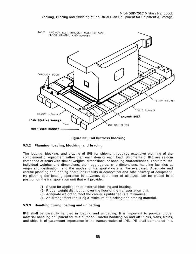
MIL-HDBK-701C Military Handbook Blocking, Bracing and Skidding of Industrial Plan Equipment for Shipment & Storage
69
Figure 30: End buttress blocking 5.3.2 Planning, loading, blocking, and bracing
The loading, blocking, and bracing of IPE for shipment requires extensive planning of the complement of equipment rather than each item or each load. Shipments of IPE are seldom comprised of items with similar weights, dimensions, or handling characteristics. Therefore, the individual weights and dimensions, their aggregates, skid dimensions, handling facilities at origin and destination, and the modes of transportation shall be evaluated. Adequate and careful planning and loading operations results in economical and safe delivery of equipment. By planning the loading operation in advance, equipment of all sizes can be placed in a position on the transportation unit that will provide:
(1) Space for application of external blocking and bracing. (2) Proper weight distribution over the floor of the transportation unit. (3) Adequate weight to meet the carrier’s published rate minimums. (4) An arrangement requiring a minimum of blocking and bracing material.
5.3.3 Handling during loading and unloading
IPE shall be carefully handled in loading and unloading. It is important to provide proper material handling equipment for this purpose. Careful handling on and off trucks, v ans, trains, and ships is of paramount importance in the transportation of IPE. IPE shall be handled in a

MIL-HDBK-701C Military Handbook Blocking, Bracing and Skidding of Industrial Plan Equipment for Shipment & Storage
70
manner that will protect both the skid assembly and the equipment to the maximum extent possible. The following precautions shall be taken:
a. When lifting the skid assembly with cranes or other overhead lifting devices, lifting eyes and holes incorporated in the equipment for this purpose shall be used when available. Extreme care shall be exercised to assure that devices used in lifting are attached to points of the equipment having adequate structural strength to permit proper lifting.
b. When it is necessary to use lifting cables or slings to lift a skid, spreader bars shall be used to prevent contact between the cables and the skidded equipment.
c. Ensure that cables placed under wood skids bite into the wood sufficiently to retain the cable in position. When lifting DOD reusable skids, the cable shall be held in position at each appropriate lifting point by a properly placed chain or cable choker.
d. When using forklift trucks for handling skidded equipment, care shall be exercised to avoid rupture of the skid floor or damage to the skidded equipment. Equal care shall be taken to prevent damage to the skid members.
e. When IPE weighing 30,000 pounds or more is skidded on reusable skids, it should not be pulled or dragged.
5.3.4 Shipment by open conveyance
IPE being shipped by open conveyance shall be shrouded in accordance with paragraph 5.4.2 of MIL-STD-107. 5.3.5 Motor carrier shipments
The rules, regulations and methods pertaining to loading, blocking and bracing for motor shipment of IPE are limited to those published in freight classifications and tariffs. In general, these publications contain the minimum requirements pertinent to the methods of packing, shipment, and handling, such as loose, skidded, boxed, or crate items. Specific uniform guidance such as that furnished by Association of American Railroads governing the loading of equipment on open and closed car, is not provided by the motor carrier industry. The application of the principles and recommended methods of the Association of American Railroad Publication, with the exceptions noted below, to the loading of motor carrier equipment will result in carrier acceptance, and under the normal hazards of truck transportation, will provide damage free movement. The requirements specified below shall be followed when IPE is loaded on motor carrier transportation units:
a. Items shall be prepared for shipment in accordance with DIPEC shipping instructions, as necessary, to meet applicable carrier requirements.
b. Loading of items on carrier equipment shall be in accordance with the applicable tariff and/or appropriate regulatory directive, and in the absence of same, in accordance with instructions of the carrier’s representative.
c. Securing of loads shall be by means of approved tie-down devices giving due consideration to the item(s) as they are prepared from shipment, carrier equipment being used, and instructions of the carrier’s representative. If no blocking and bracing is accomplished, this fact should be indicated on the Government’s Bill of Lading or other official shipping documents.
d. If the IPE has a high center of gravity (top-heavy equipment), it shall be given special attention when securing it to the carrier’s equipment to eliminate hazards inherent in transporting this type of IPE (see 5.2.3.1).
e. The responsible transportation officer for the shipping activity should provide accurate weight information on shipping documents, bills of lading, and related papers. When exact weights are unknown, estimated weights shall be used in accordance with the

MIL-HDBK-701C Military Handbook Blocking, Bracing and Skidding of Industrial Plan Equipment for Shipment & Storage
71
Joint Military Traffic Management Regulation, DLAR 4500.3/AR55-355/NAVSUPPUB 444 (Rev.)/AFM75-2/MCO P4600.14A.
5.3.5.1 Motor carrier equipment
The selection of motor carrier equipment, dimensions, weights, hand ling facilities, and the type of IPE equipment to be shipped must be considered. Use of shock -mitigated equipment, such as air ride trailers, air ride vans, and electronic vans shall be considered for shipment of delicate equipment such as machine control units of numerically controlled machines (see Section 5 of MIL-STD-107). Due to the many types of carrier equipment available for loading, additional general requirements shall be considered when l oading motor carrier equipment.
a. Motor carriers are making wide use of “high cube -electronic van” type trailers. This trailer is similar to the standard “dry freight” trailer except the floor of the trailer is divided into two levels. The frame of the trailer drops approximately 13 -1/2 inches behind the coupler area. The forward section of the floor is normally 8 feet in length from the front of the trailer to the face of the drop. Drop frame trailers are normally 45 feet in overall length. The useable length of the floor behind t he drop is approximately 36 feet. The forward floor area can be utilized with items approximately 7 feet in length or less, since 12 inches are required for blocking. Items on skids exceeding 7 feet in length shall not be loaded in the forward floor of the trailer. Skids placed on the forward section of the trailer must be properly supported; therefore, overhanging loads are not permitted. The useable length of the floor behind the drop area is reduced to approximately 34 feet due to space used for block ing and bracing.
b. The heavy or specialized carriers which specialize in transporting of extremely large and heavy items make wide use of “flat bed” and “lowboy” type trailers for transporting IPE. The use of this service is particularly advantageous since carrier equipment is designed for movement of IPE and other types of heavy equipment. The lowboy is especially adaptable for loading and handling equipment with a high center of gravity.
c. The flat bed and lowboy types of trailers utilized by heavy equipment carriers provide accessibility for loading, blocking, and bracing. Equipment loaded on these types of transporters requires protection from the elements by shrouding (see MIL-STD-107).
d. Lowboy type trailers are similar in length to flat bed, electronic van, and standard dry freight trailers. The loading area of this type of trailer is reduced by the drop frame at the front and in some instances over the rear wheels.
5.3.5.2 Open-top and closed trailers
The positioning of skid assemblies on open-top and closed trailers shall be in a manner which will provide equal weight distribution to the right and left sides of the trailer. Items shall be loaded in a manner that will make maximum use of the floor space available and at the same time, reduce the amount of blocking and bracing materials used. Side movement is very hazardous, since corners, curves, and pitch of the road bed place a great thrust on the upper extremities of the load. Except equipment with high center of gravity, cross trailer blocking and side blocking of the skid runners are sufficient to complete blocking and bracing of motor carries shipments in closed or Open-top equipment. 5.3.5.3 Flat bed and lowboy trailers
IPE items shall be positioned on flat bed and lowboy type trailers as specified by the carrier’s representatives, and secured in accordance with applicable tariff and regulating directives. In

MIL-HDBK-701C Military Handbook Blocking, Bracing and Skidding of Industrial Plan Equipment for Shipment & Storage
72
the absence of the above, IPE shall be positioned in accordance with instructions of the carrier’s representative. This is especially important in securing of top heavy equipment (see 5.2.3.1).
5.4. Instructions for the protection of specific types of IPE
5.4.1 Examples of blocking, bracing and skidding
The skidding of IPE frequently presents problems due to size, weight, configuration, fragility or a combination of these factors. Paragraphs 5.4 .1.1 through 5.4.1.9 provide specific data on a broad range of basic types of equipment. Figures 32 through 46 provide a det ailed description of the applicable blocking, bracing, and skidding. Adherence to methods presented will provide the required degree of protection at minimum cost. Application to equipment not specifically covered herein shall be based upon the data for the item most representative, or upon a composite derived by combining the appropriate characteristics of m ore than one item of equipment.

MIL-HDBK-701C Military Handbook Blocking, Bracing and Skidding of Industrial Plan Equipment for Shipment & Storage
73
Figure 31: Boring and turning machine 5.4.1.1 Boring and Turning Machine, Vertical, King Machine Tool Division, American
Steel Foundries, Model Heavy Duty 36 inch (Figure 31)
a. Approximate weight. Machine 21,300 lbs. -- Skid -- 406 lbs.
b. Skid size. 8 ft. x 8-1/2 ft.
c. Skid parts list.

MIL-HDBK-701C Military Handbook Blocking, Bracing and Skidding of Industrial Plan Equipment for Shipment & Storage
74
Quantity Item Description Photo Reference No.
6 Runner, 8-1/2 ft. ............................................ 1 2 Header, 8 ft. .................................................. 4 8 Mounting Plates ............................................. 2 4 Tie, Bar, auxiliary, 3 ft. ................................... 5
d. Mounting. The machine is mounted on a Type I DOD reusable skid consisting of
components identified in the parts list above. Eight mounting plates are attached to the load bearing runners with standard 1/2 inch step bolts using flat and lock washers with each. The machine is secured to six of the mounting plates with standard 3/4 inch carriage bolts. The other two mounting plates are used under the machine base for support only. Two 3 foot auxiliary tie bars are attached to each side of the skid assembly located between the load bear ing and outrigger runner beams.
e. Internal blocking. The boring mill side head is supported by a 4 inch x 6 inch block (item 7) cut to length. The turret and slide assembly is supported by a wooden block assembly (item 8) consisting of one 2 inch x 6 inch x 30 inch block bolted to the ta ble T-slot, one 4 inch x 6 inch x 8 inch block under the turret, and one 2 inch x 4 inch x 5 inch block under the tool holder. The cross rail is supported by one 4 inch x 6 inch x 21 inch wooden block (not visible) placed between the underside of the cross rail and machine base casting directly behind the turret and table. Horizontal movement of the turret slide assembly on the cross rail is prevented by wooden frame assemblies. On the right hand side of the turret slide, frame assembly consists of two, 2 inch x 4 inch x 44 inch blocks (items 9 and 10) and two 1 inch x 3 inch x 22 inch blocks (items 11 and 12). The frame assembly is held in place by one steel band (item 17) applied around the wooden frame and the cross rail. The side head counterweight is secured to the skid by a 4 inch x 4 inch x 30 inch block (item 18) and two, 1/2 inch diameter steel rods (item 19). A 4 inch x 4 inch x 20 inch block (item 20) is secured to the skid with two 1/2 inch carriage bolts which prevents the counterweight from shif ting lengthwise on the skid. Three, 2 inch x 6 inch x 32 inch wooden blocks are fastened to the skid under the counterweight.
f. Parts and accessories. The push button station, guards, wrenches, leveling screws, counterbalance cables, chuck jaws, coolant motor, side head counterbalance bracket with sheaves, rear rail counterbalance arm, and counterbalance weight with hook have been cleaned, preserved and packed in wooden boxes conforming to Table VII of MIL -STD-2073-1, marked and shipped separately from the basic skid. The main drive motor is secured to skid on the opposite sides of the machine by bolting it to two, 2 inch x 6 inch x 36 inch wooden blocks and securing the blocks to the basic skid.
g. Buttress blocking. Figure 31 shows the machine buttress blocked for motorized
shipment. Buttress blocking (item 6) consists of 4 inch x 6 inch blocks cut to fit between the machine base and header members and secured to load bearing runner beams. Side buttress blocking (not shown) is also required.

MIL-HDBK-701C Military Handbook Blocking, Bracing and Skidding of Industrial Plan Equipment for Shipment & Storage
75
Figure 32: Broaching machine 5.4.1.2 Broaching Machine, Hydraulic, Surface, Double Ram, Cincinnati Milacron –
Model 10-66 (Figure 32).
a. Approximate weight. Machine--23,800 lb. Skid--358 lb.
b. Skid size. 6 ft. x 16 ft.
c. Skid parts list.
Quantity Item Description Photo Reference No.
4 Runner, 16 ft. ............................................. 2 2 Header, 6 ft. ............................................... 1 2 Mounting Plates ......................................... 3

MIL-HDBK-701C Military Handbook Blocking, Bracing and Skidding of Industrial Plan Equipment for Shipment & Storage
76
d. Mounting. The machine is skidded in a horizontal position because of the high center of gravity. The machine is mounted on a Type I DOD reusable skid consisting of components identified in the parts list above. The machine is mounted on three pieces of lumber (item 4) which are placed crosswise on the runner beams. The base end of the machine is secured to the skid with two 1 inch diameter rods (item 5) bolted into machine holddown holes and the skid runners. The opposite end is secured to the skid assembly by two straps and 1 inch (rod assemblies (item 6) hooked into the machine top and bolted to two mounting plates (not visible) secured to loading bearing runners. The mounting plates are attached to load bearing runners with standard 1/2 inch step bolts using flat and lock washers.
e. Internal blocking. None required.
f. Parts and accessories. The hydraulic drive and coolant motors have been removed from the machine, cleaned, preserved, in a container conforming to table VII of MIL -STD-2073-1 and packed, marked, and shipped separately.
g. Buttress blocking. Figure 32 shows the machine blocked for shipment. Buttress blocking (item 7) on the base end consists of a 6 inch x 8 inch wooden block, cut to fit, and bolted to runners between machine base and header beam. The machine guard is placed on the opposite end of the skid assembly and yoked with a horizontal 2 inch x 4 inch yoke assembly (item 8). Side buttress blocking (not shown) is also required.

MIL-HDBK-701C Military Handbook Blocking, Bracing and Skidding of Industrial Plan Equipment for Shipment & Storage
77
Figure 33: Drilling machine, radial 5.4.1.3 Drilling Machine, Radial, Hettner Bohrmaschinenfabrick Co., Model HR-50
(Figure 33)
a. Approximate weight. Machine - 10,900 lbs. -- Skid - 285 lbs.
b. Skid size. 6 ft. x 10 ft.
c. Skid parts list.
MIL-HDBK-701C Military Handbook Blocking, Bracing and Skidding of Industrial Plan Equipment for Shipment & Storage
78
Quantity Item Description Photo Reference No.
4 Runner, 10 ft. ................................................ 2 2 Header, 6 ft. .................................................. 5 4 Mounting Plates. ........................................... 1 2 Tie Bar, Auxiliary, 2 ft. ................................... 6
d. Mounting. The machine is mounted on a type I skid consisting of components in above
parts list. Four mounting plates are attached to the load bearing runners with standard 1/2 inch step bolts (item 3) using flat and lock washers on each. The machine is secured to the mounting plates with four standard carriage bolts (item 4). A two inch auxiliary tie bar (item 6) is secured between load bearing and outrigger runner beams on each side of the skid assembly. The dimensions and overhanging parts of the machine would permit mounting on a two-runner skid assembly, however the two additional runners are added to provide base stability.
e. Internal blocking. The overhanging arm (item 7) and machine head (itemed) are supported by two blocking assemblies: a 4 inch x 6 inch wooden block assembly (item 11) and a metal-A-Frame assembly (item 12). The wooden block assembly consists of two 4 inch x 6 inch x 32 inch horizontal blocks, two 4 inch x 6 inch x 39 inch vertical blocks and one 2 inch x 4 inch x 42 inch wooden diagonal. The A-frame has two steel members bolted through the arm with one 3/4 inch x 11 inch bolt, and the frame assembly bolted to the bed with two 3/4 inch x 4 inch bolts. The machine head (item 8) is blocked to the machine column (item 10) by a horizontal yoke assembly (item 13) consisting of two 4 inch x 6 inch x 32 inch wooden yoke blocks and two 1/2 inch x 66 inch rods. A 3 inch x 7 inch x 7 inch wooden block (item 14) is placed between the machine head (item 8) and the column (item 10).
f. Parts and accessories. The coolant well covers, spanner wrench, coolant nozzle, grease guns, and counterweights are cleaned, preserved, and packed in a container (item 15) conforming to Table VII of MIL-STD-2073-1, and attached to basic skid with a vertical yoke assembly (item 16).
g. Buttress blocking. Figure 33 shows the machine buttress blocked for shipment. Buttress blocking (items 17 and 18) consists of four 4 inch x 6 inch wooden blocks cut to fit between machine base and header members and secured to load bearing runner beams.

MIL-HDBK-701C Military Handbook Blocking, Bracing and Skidding of Industrial Plan Equipment for Shipment & Storage
79
Figure 34: Drilling machine, vertical 5.4.1.4 Drilling Machine, Vertical, Michigan Spec. Machine CO., Model Hydrolo (Figure
34)
a. Approximate weight. -- Machine - 13,960 lbs.
b. Skid size. -- 6 ft. x 10 ft.
c. Skid Darts list.
MIL-HDBK-701C Military Handbook Blocking, Bracing and Skidding of Industrial Plan Equipment for Shipment & Storage
80
Quantity Item Description Photo Reference No. 4 Runner, 10 ft. 1 2 Header, 6 ft. 2 6 Mounting Plates 3 2 Auxiliary Tie Bar 2 ft. 4
d. Mounting. The machine is mounted on a Type I DOD reusable type skid consisting of
components identified above. Six mounting plates are secured to the load bearing runners with standard 1/2 inch step bolts using flat and lock washers. The machine is secured to the mounting plates with 3/4 inch carriage bolts at t he four corners of the base casting. The center section rests on the other two mounting plates. The machine’s leveling screws have been backed off with the lower edge clear of the mounting plate surfaces. An auxiliary tie bar is attached between the load bearing and outrigger runners on each side of the assembly.
e. Internal blocking. The drill head is lowered to rest on a T-fire retardant wood block assembly (item 5) under the head, arid a square wooden block assembly (item 6) has been placed under the drill head ways. The counterweight and drive motor have been removed from the drill and placed on two crosswise pieces of lumber (item 7). The motor has been secured with hold down bolts, and the counterweight is blocked on all sides with 4 inch fire retardant blocks items (8-10) and vertically yoked (item 11).
f. Parts and accessories. The hydraulic and coolant motors have been cleaned, preserved, and shipped unshrouded in their operating positions. The electrical and electronic control panel shall be removed and cleaned and packed in a container conforming to Table VII of MIL-STD-2073-1 packed and shipped with the basic unit.
g. Buttress blocking. Figure 34 shows the machine has been buttress blocked for motorized shipment. Buttress blocking shall consist of two 4 inch x 6 inch fire retardant wooden blocks, not visible on the opposite end of the skid assembly.

MIL-HDBK-701C Military Handbook Blocking, Bracing and Skidding of Industrial Plan Equipment for Shipment & Storage
81
Figure 35: Gear shaper 5.4.1.5 Gear Shaper, External and Internal, Fellows Gear Shaper Co. Model 61 A (Figure
35)
a. Approximate weight. Machine - 7,500 lb. -- Skid - 160 lb.

MIL-HDBK-701C Military Handbook Blocking, Bracing and Skidding of Industrial Plan Equipment for Shipment & Storage
82
b. Skid size. 4 ft. x 6 ft.
c. Skid parts list.
Quantity Item Description Photo Reference No.
2 Runner, 6 ft. 13
2 Header, 4 ft. 14
2 Crossbeam, 4 ft. 15
2 Accessory Beam, 4 ft. 16
d. Mounting. The gear shaper is mounted on a Type II DOD reusable type skid consisting
of components identified above. The front of the gear shaper is secured to the crossbeams with two T-nut and 5/8 inch stud assemblies. To provide the third and fourth holddown points, two S-type clamps have been fabricated from 1/2 inch x 2-1/2 inch steel. One clamp is mounted over the machine base and secured to the crossbeam T-nut with a 5/8 inch steel rod (item 9). The other clamp is mounted over the opening in the machine base and secured to the runner beam T-nut with 5/8 inch over steel rod (item 10). L-shaped brackets are secured at the four corners of the machine base with 5/8 inch bolt into crossbeam T-nut (item 12).
e. Internal blocking. The cutter spindle saddle has been centered/ one 2 inch x 4 inch wooden block (item 1) is inserted between the worm shaft housing and saddle, and one 2 inch x 4 inch wooden block (item 2) between the feed gear box and saddle. Each block is secured by nailing 2 inch x 3 inch wood strips over the top and front side of the block. Cutter spindle lowered to rest on 2 inch x 4 inch wooden block (item 3). The spindle saddle has been blocked with 4 inch x 4 inch wood blocks (item 4), with metal banding around the spindle, and one 4 inch x 6 inch wood block (item 5) cut out to butt against the lower end of the work spindle and formed to the contour of the base casting to eliminate lateral movement of the apron. One 2 inch x 4 inch wood block is mounted under the base (item 6) with a 1/2 inch steel rod extending through the block (item 5) and through the work spindle. One 4 inch x 4 inch wood block, with 3/4 inches hole drilled for the adjusting screw, was placed under the motor mount (item 7). The motor mount base is secured with U-type clamp under the adjusting screw nut and extending under the machine base (item 8).
f. Parts and accessories. The main drive motor has been cleaned, preserved shrouded and shipped in place. Guards, covers, change gears, handles, and brackets are cleaned, preserved, and packed in a container conforming to Table VII of MIL -STD-2073-1. The container is not attached to the basic skid.
g. Buttress blocking. Figure 35 shows the machine has been buttress blocked for motorized shipment. Buttress blocking consists of four 4 inch x 6 inch wooden blocks (item 11) cut to fit and mounted on the accessory beams located between the machine base and headers.
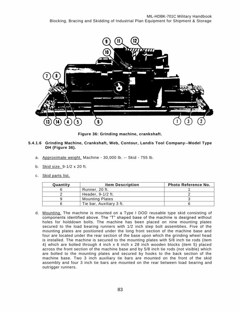
MIL-HDBK-701C Military Handbook Blocking, Bracing and Skidding of Industrial Plan Equipment for Shipment & Storage
83
Figure 36: Grinding machine, crankshaft. 5.4.1.6 Grinding Machine, Crankshaft, Web, Contour, Landis Tool Company--Model Type
DH (Figure 36).
a. Approximate weight. Machine - 30,000 lb. -- Skid - 755 lb.
b. Skid size. 9-1/2 x 20 ft.
c. Skid parts list.
Quantity Item Description Photo Reference No.
6 Runner, 20 ft. 1
2 Header, 9-1/2 ft. 2
9 Mounting Plates 3
6 Tie bar, Auxiliary 3 ft. 6
d. Mounting. The machine is mounted on a Type I DOD reusable type skid consisting of
components identified above. The “T” shaped base of the machine is designed without holes for holddown bolts. The machine has been placed on nine mounting plates secured to the load bearing runners with 1/2 inch step bolt assemblies. Five of the mounting plates are positioned under the long front section of the machine base and four are located under the rear section of the base upon which the grinding wheel head is installed. The machine is secured to the mounting plates with 5/8 inch tie rods (item 4) which are bolted through 4 inch x 6 inch x 28 inch wooden blocks (item 5) placed across the front section of the machine base and by 5/8 inch tie rods (not visible) which are bolted to the mounting plates and secured by hooks to the back section of the machine base. Two 3 inch auxiliary tie bars are mounted on the front of the skid assembly and four 3 inch tie bars are mounted on the rear between load bearing and outrigger runners.

MIL-HDBK-701C Military Handbook Blocking, Bracing and Skidding of Industrial Plan Equipment for Shipment & Storage
84
e. Internal blocking. Horizontal movement of the table is prevented by a 5/8 inch diameter tie rod (not visible), extending under the table and bolted through two 4 inch x 6 inch x 19 inch wooden blocks (item 7) installed across the ends of the machine bed. Spacer blocks (item 8) are installed between the wooden block and the table ends. The table, which rests on flat and “V” ways on the machine base is secured to prevent vertical movement by a wooden block 4 inch x 6 inch x 40 inch (item 9), secured against the surface of the table (item 10) with two 5/8 inch diameter tie rods. The grinding wheel head is secured on the machine bed ways by a wooden block 4 inch x 6 inch x 45 inch (item 11) which rests on the top side of the grinding wheel head and secured by two 5/8 inch diameter tie rods against two vertical wooden blocks 4 inch x 6 inch x 30 inch (item 12). Lateral movement of the wheel head is prevented by two 4 inch x 6 inch blocks and 5/8 inch diameter tie rods (not visible).
f. Parts and accessories. The work grinding wheel and coolant motors have been cleaned, preserved, and shipped unshrouded in their original positions. The hydraulic motor is shipped shrouded in its original mounting. The splash guard, hydraulic tank guard, work rest guard, and table end guard are cleaned, preserved, and attached to runners on rear of skid with the vertical yoke assemblies.
g. Buttress blocking. Figure 36 shows the machine has been buttress blocked for motorized shipment. Buttress blocking consists of a 4 inch x 6 inch crosswise bl ock (item 14) at each end of the base casting. The crosswise block is reinforced by 4 inch x 6 inch lengthwise wooden blocks (item 13) to the header beams. Side buttress blocking (not shown) is required.
Figure 37: Honing machine 5.4.1.7 Honing Machine, Internal, Vertical, Barnes Drill Co., Model 224 (Figure 37)
a. Approximate weight. Machine - 7,600 lb. -- Skid - 332 lb.
b. Skid size. 6-1/2 ft. x 12 ft.

MIL-HDBK-701C Military Handbook Blocking, Bracing and Skidding of Industrial Plan Equipment for Shipment & Storage
85
c. Skid Darts list.
Quantity Item Description Photo Reference No. 4 Runner, 12 ft. 2 and 11 2 Header, 6-1/2 ft. 6 4 Mount Plates 10 2 Tie Bar, Auxiliary, 3 ft. 4
d. Mounting. The machine is mounted on a Type I DOD reusable type skid consisting of
components identified above. Due to height and weight distribution, the machine is skidded in a horizontal position. Wooden column supports (item 1) consisting of two 6 inch x 6 inch x 78 blocks and one 2 inch x 6 inch x 78 inch block, are attached to the outrigger runners with four 1/2 inch diameter carriage bolts. A base support block (item 3), 2 inch x 8 inch x 78 inch is secured to outrigger runners with four 1/2 inch carriage bolts. A 3 inch auxiliary tie bar is secured on each side of the skid assembly between the outrigger and intermediate runners. Four mounting plates are attached to the intermediate runners with standard 1/2 inch diameter step bolts. The honing machine is secured to the mounting plates with two hold down assemblies consisting of 4 inch x 6 inch x 36 inch wooden blocks (item 12) and 3/4 inch rods (item 13). Four wooden side blocks 2 inch x 8 inch x 16 inch (item 9) are nailed in position on top of the column supports and abutted to the machine column, two on each side of the machine.
e. Internal blocking. Horizontal movement of the honing workhead is prevented by one 4 inch x 4 inch wooden block cut to length and placed between machine table and workhead and two 2 inch x 2 inch wooden blocks (item 15) cut to leng th and placed between the guide brackets and workhead. The wooden blocks are held in position by steel bands placed around the machine column.
f. Parts and accessories. The workhead drive motor has been cleaned, preserved, shrouded, and shipped attached to wooden deck board 2 inch x 16 inch x 20 inch (item 16) and bolted to the skid runners. The hydraulic pump and coolant pump motors are cleaned, preserved, shrouded and shipped in their original operating positions. The auxiliary honing head, filter, booster pump, tool holders, pressure tank, and cranks are cleaned, preserved, and packed in containers conforming to Table VII of MIL-STD-2073-1.
g. Buttress blocking. Figure 37 shows the machine has been buttress blocked for motorized shipment. The end block, 4 inch x 4 inch x 65 inch (item 5) is bolted to intermediate runners with two 1/2 inch carriage bolts between the header and the machine base. A 4 inch x 6 inch block (item 7) is placed against the top of the machine base and secured to runners with six 1/2 inch carriage bolts. Two additional 4 inch x 8 inch blocks (item 8) cut to length are placed between the column support block and the inside buttress block (item 7), and bolted to the outrigger runner s with 1/2 inch carriage bolts.

MIL-HDBK-701C Military Handbook Blocking, Bracing and Skidding of Industrial Plan Equipment for Shipment & Storage
86
Figure 38: Lathe chucking 5.4.1.8 Lathe, Chucking, Bullard Co., Model D (Figure 38)
a. Approximate Weight -- Machine - 38,000 lb.
b. Skid Size. -- 9-1/2 ft. x 10 ft.
c. Skid Parts List.

MIL-HDBK-701C Military Handbook Blocking, Bracing and Skidding of Industrial Plan Equipment for Shipment & Storage
87
Quantity Item Description Photo Reference No.
5 Runner, 10 ft. 9
2 Header, 9 1/2 ft. 2
6 Mounting Plates 1
4 Auxiliary Tie Bars, 3 ft. 3
d. Mounting. The machine is mounted on a Type I DOD reusable type aluminum skid
consisting of components identified above. The length and width of the skid assembly has been extended beyond standard clearance requirements to provide stability needed to accommodate access in machine height. Six mounting plates are s ecured to load bearing runners with 1/2 inch step bolts using flat and lock washers. The lathe is secured to the mounting plates with carriage bolts. Two accessory tie bars are placed on each side of the skid assembly between the load bear ing and outrigger runner beams.
e. Internal blocking. Vertical motion of the tool heads (item 5) is prevented by 4 inch x 12 inch wooden blocks (item 6) on top 4 inch x 4 inch x 6 inch wooden blocks (item 12) on the bottom of the column with the top and bottom blocks banded. Upper oil guards (item 4 and 7) and base guards (items 8) are also secured by steel banding.
f. Parts and Accessories. The coolant and lube motors have been cleaned, preserved, shrouded, and shipped in their original mountings. The main drive motors and gea r reducer units are preserved, cleaned, and shipped separately. Counter weights, chip pan, bed plates, control box assembly, counter weight chain, springs, coolant pipes, and guards are cleaned, pre- served, and packaged in a container conforming to Table VII, MIL-STD-2073-1.
g. Buttress Blocking. Figure 38 shows the machine has been buttress blocked for motorized shipment. Buttress blocking shall consists of 4 inch x 5 inch wooden blocks (item 11) located between the machine base and the header and 4 inch x 6 inch blocks (items 10) abutted to the machine base and secured to the outrigger runner beams.

MIL-HDBK-701C Military Handbook Blocking, Bracing and Skidding of Industrial Plan Equipment for Shipment & Storage
88
Figure 39: Lathe turret 5.4.1.9 Lathe Turret, Ram, Morey Machinery Co. Model 5 (MB) (Figure 39)
a. Approximate Weight. Machine - 7,300 lbs.
b. Skid Size. 6 inch x 10 inch
c. Skid Parts List.
Quantity Item Description Photo Reference No.
4 Runner, 10 ft. 4 2 Header, 6 ft. 5 4 Mounting Plates 6 2 Auxiliary Tie Bar 2 ft 3
d. Mounting. The machine is mounted on a Type I DOD reusable type skid consisting of
components identified above. Four mounting plates have been secured to load bearing runner beams with 1/2 inch step bolts using flat and lock washers. The lathe is secured

MIL-HDBK-701C Military Handbook Blocking, Bracing and Skidding of Industrial Plan Equipment for Shipment & Storage
89
to the mounting plates with four carriage bolts (item 9). Auxiliary tie bars are placed between the load bearing and outrigger runners on each side of the assembly.
e. Internal Blocking. Horizontal motion of the turret and cross slide has been prevented t e tie rod assembly (item 1) and wooden blocks (item 2) 2 inch x 4 inch x 12 inch and (item 7) 2 inch x 6 inch x 12 inch. The assembly is composed of two 1/4 inch x 4 inch end plates, one 1/2 inch diameter x 72 inch tie rod and two 1/2 inch nuts. The back chip guard is secured by a steel band (item 8).
f. Parts and accessories. The main drive, lube and coolant motors have been cleaned, preserved, and shipped in original mounting positions. The coolant motor has been shrouded. The feed pipe, stands, tie up bar, guide, nose pieces and guards are cleaned, preserved and packed in a container conforming to Table VII of MIL-STD-2073-1.
g. Buttress Blocking. Figure 39 shows the machine prepared for motorized shipment. 5.4.2 Furnaces
Furnaces shall be shipped with the fire bricks intact whenever practical. Bricks or refractory linings shall be cribbed or shored to the maximum extent possible to prevent cracking or falling out during transit from user to user, storage to user, user to storage or from any other means of transfer. When the bricks or lining is no longer serviceable, it sha ll be removed and discarded before shipment. 5.4.2.1 Blocking
The interior surfaces containing bricks shall be lined with plywood. The plywood shall conform to NN-P-530 and shall be applied in direct contact with the entire bricked area. Blocking shall be applied against the plywood in a manner that will provide the maximum protection throughout the transit period. Lumber used for blocking and bracing shall conform to MIL -STD-731 and shall be bark and disease free.
a. Figures 40 through 50 illustrate the basic principles utilized in blocking and bracing brick lined furnaces for shipment. (Note the substantial construction necessar y for this type of equipment.)
b. Figures 50 and 51 illustrate the damage to furnaces shipped without blocking and bracing or by utilizing incorrect procedures.
c. Motorized shipment should be utilized for the shipment of furnaces whenever possible. 5.4.2.1.1 Ceramic fiber insulation
Furnaces in storage, awaiting repair of firewall, shall be reinsulated with ceramic fiber insulation in accordance with MIL-F-80258. Refractory and reinsulation shall consist of ceramic fiber material conforming to the above mentioned specification. When t he furnace is reinsulated with ceramic fiber, it will eliminate the need for extra material and labor for blocking and bracing materials. 5.4.2.1.2 Skidding
Furnaces shall be skidded on heavy duty skids constructed in accordance with Figures 21 through 28 in conjunction with the requirements of paragraphs 5.2.6.2.1 through 5.2.6.3. Not

MIL-HDBK-701C Military Handbook Blocking, Bracing and Skidding of Industrial Plan Equipment for Shipment & Storage
90
less than 3 inch high forklift entry shall be used to facilitate safe loading and ease of handling. Cross members shall be bolted. Furnaces shall be bolted down through load bearing members. Skidded members shall be adequately protected. All four sides shall be marked with instructions indicating “Fragile, Do Not Drop” and “Handle with Care”.
Figure 40: Internal blocking of brick lined furnace

MIL-HDBK-701C Military Handbook Blocking, Bracing and Skidding of Industrial Plan Equipment for Shipment & Storage
91
Figure 41: Upper view, center of furnace blocking

MIL-HDBK-701C Military Handbook Blocking, Bracing and Skidding of Industrial Plan Equipment for Shipment & Storage
92
Figure 42: View along left side of furnace blocking

MIL-HDBK-701C Military Handbook Blocking, Bracing and Skidding of Industrial Plan Equipment for Shipment & Storage
93
Figure 43: Upper view, right skid, of furnace blocking

MIL-HDBK-701C Military Handbook Blocking, Bracing and Skidding of Industrial Plan Equipment for Shipment & Storage
94
Figure 44: Internal blocking of brick lined furnace

MIL-HDBK-701C Military Handbook Blocking, Bracing and Skidding of Industrial Plan Equipment for Shipment & Storage
95
Figure 45: Internal blocking of laboratory oven
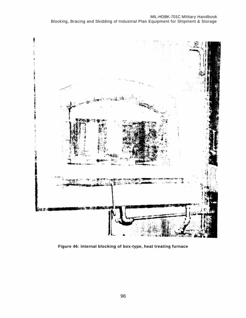
MIL-HDBK-701C Military Handbook Blocking, Bracing and Skidding of Industrial Plan Equipment for Shipment & Storage
96
Figure 46: Internal blocking of box-type, heat treating furnace

MIL-HDBK-701C Military Handbook Blocking, Bracing and Skidding of Industrial Plan Equipment for Shipment & Storage
97
Figure 47: Internal blocking of box-type, heat treating furnace

MIL-HDBK-701C Military Handbook Blocking, Bracing and Skidding of Industrial Plan Equipment for Shipment & Storage
98
Figure 48: Internal blocking of box-type, heat treating furnace

MIL-HDBK-701C Military Handbook Blocking, Bracing and Skidding of Industrial Plan Equipment for Shipment & Storage
99
Figure 49: Results of shipment without internal blocking in furnace
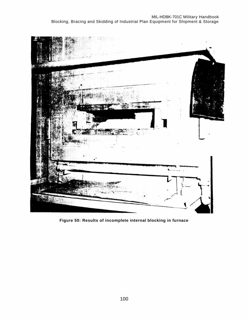
MIL-HDBK-701C Military Handbook Blocking, Bracing and Skidding of Industrial Plan Equipment for Shipment & Storage
100
Figure 50: Results of incomplete internal blocking in furnace

MIL-HDBK-701C Military Handbook Blocking, Bracing and Skidding of Industrial Plan Equipment for Shipment & Storage
101
Custodians Army - AL Navy - SH Air Force - 99 DLA – DH Review Activities: Army - AL, SH Navy - SH, YD Air Force - 99 DLA - DH User Activities: Navy - SA, MC, YD Preparing Activity: DLA-IP Project Number: PACK-0846

MIL-HDBK-701C
APPENDIX
102
DOD REUSABLE SKID COMPONENTS
10. GENERAL
10.1. Scope
This Appendix identifies DOD reusable skid components with corresponding part numbers which shall be used for ordering components of either the Type I or Type II skids, whether they are used separately or as part of a skid assembly. This Appendix is a mandatory part of the handbook. The information contained herein is intended for compliance.
10.2. Policy
Policy for the management and utilization of DOD reusable type skids to include the requirements for transportation, funding, requisitioning, and returning skid components, is provided in Defense Logistics Manual DLAM 4215.1.
20. APPLICABLE DOCUMENTS
20.1. Government documents
20.1.1 Specifications, standards, and handbooks
The following documents form a part of this appendix to the extent specified. MILITARY SPECIFICATIONS MIL-S-9968 - Skid Components, Aluminum, Reusable.
(Application for copies should be addressed to the Superintendent of Documents, U.S. Government Printing Office, Washington, DC 20402-0001.)
20.1.2 Other Government documents, drawings, and publications
The following other Government documents form a part of this appendix to the extent specified. DLAM 4215.1 - Management of Defense Owned Industrial Plant Equipment.
(Application for copies should be addressed to the Director, Defense Logistics Agency, ATTN: DLA-XPD, Cameron Station, Alexandria, VA 22302-6100.)
30. DEFINITIONS
30.1. Definitions used in this appendix
No definitions are required for this appendix.
40. GENERAL REQUIREMENTS
40.1. Contents of tables
Table XV is a listing of components and part numbers for the Type I DOD reusable skids. Type I skid components are specifically identified and defined in MIL -S-9968. Table XVI is a listing of components and part numbers for the Type II DOD reusable skids.
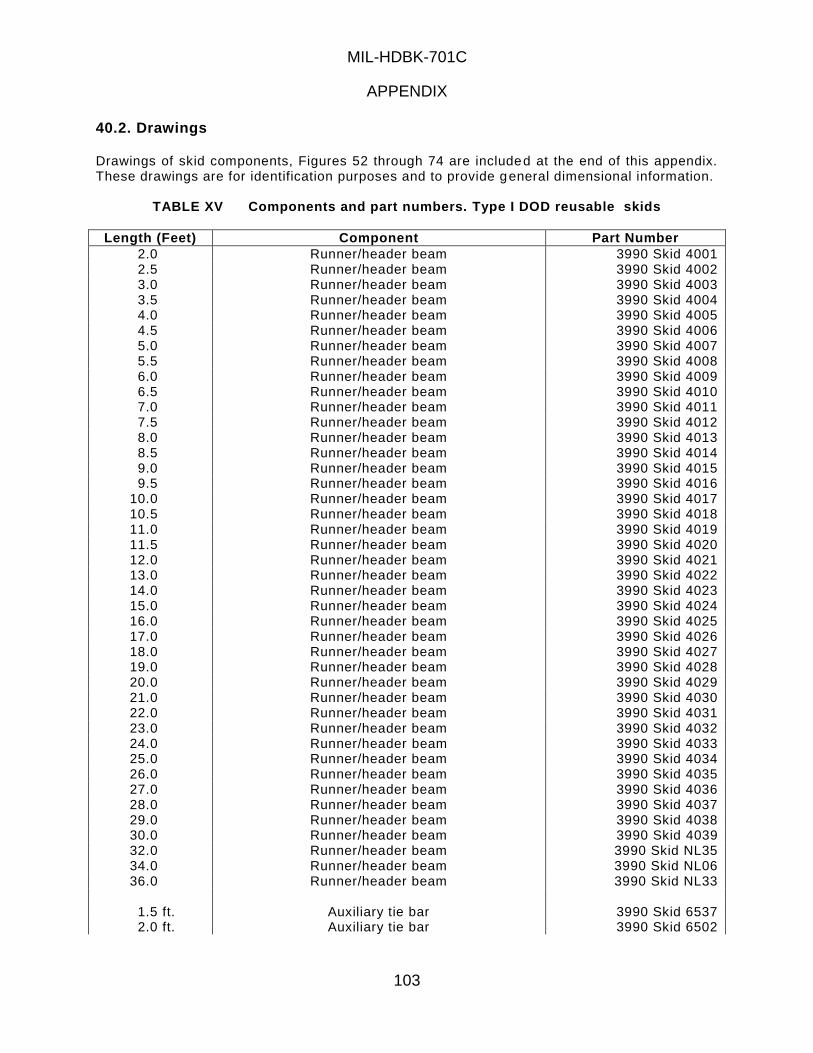
MIL-HDBK-701C
APPENDIX
103
40.2. Drawings
Drawings of skid components, Figures 52 through 74 are included at the end of this appendix. These drawings are for identification purposes and to provide general dimensional information.
TABLE XV Components and part numbers. Type I DOD reusable skids
Length (Feet) Component Part Number
2.0 Runner/header beam 3990 Skid 4001 2.5 Runner/header beam 3990 Skid 4002 3.0 Runner/header beam 3990 Skid 4003 3.5 Runner/header beam 3990 Skid 4004 4.0 Runner/header beam 3990 Skid 4005 4.5 Runner/header beam 3990 Skid 4006 5.0 Runner/header beam 3990 Skid 4007 5.5 Runner/header beam 3990 Skid 4008 6.0 Runner/header beam 3990 Skid 4009 6.5 Runner/header beam 3990 Skid 4010 7.0 Runner/header beam 3990 Skid 4011 7.5 Runner/header beam 3990 Skid 4012 8.0 Runner/header beam 3990 Skid 4013 8.5 Runner/header beam 3990 Skid 4014 9.0 Runner/header beam 3990 Skid 4015 9.5 Runner/header beam 3990 Skid 4016
10.0 Runner/header beam 3990 Skid 4017 10.5 Runner/header beam 3990 Skid 4018 11.0 Runner/header beam 3990 Skid 4019 11.5 Runner/header beam 3990 Skid 4020 12.0 Runner/header beam 3990 Skid 4021 13.0 Runner/header beam 3990 Skid 4022 14.0 Runner/header beam 3990 Skid 4023 15.0 Runner/header beam 3990 Skid 4024 16.0 Runner/header beam 3990 Skid 4025 17.0 Runner/header beam 3990 Skid 4026 18.0 Runner/header beam 3990 Skid 4027 19.0 Runner/header beam 3990 Skid 4028 20.0 Runner/header beam 3990 Skid 4029 21.0 Runner/header beam 3990 Skid 4030 22.0 Runner/header beam 3990 Skid 4031 23.0 Runner/header beam 3990 Skid 4032 24.0 Runner/header beam 3990 Skid 4033 25.0 Runner/header beam 3990 Skid 4034 26.0 Runner/header beam 3990 Skid 4035 27.0 Runner/header beam 3990 Skid 4036 28.0 Runner/header beam 3990 Skid 4037 29.0 Runner/header beam 3990 Skid 4038 30.0 Runner/header beam 3990 Skid 4039 32.0 Runner/header beam 3990 Skid NL35 34.0 Runner/header beam 3990 Skid NL06 36.0 Runner/header beam 3990 Skid NL33
1.5 ft. Auxiliary tie bar 3990 Skid 6537 2.0 ft. Auxiliary tie bar 3990 Skid 6502

MIL-HDBK-701C
APPENDIX
104
Length (Feet) Component Part Number
2.5 ft. Auxiliary tie bar 3990 Skid 6503 3.0 ft. Auxiliary tie bar 3990 Skid 6504 3.5 ft. Auxiliary tie bar 3990 Skid 6505 4.0 ft. Auxiliary tie bar 3990 Skid 6506 4.5 ft. Auxiliary tie bar 3990 Skid 6507 5.0 ft. Auxiliary tie bar 3990 Skid 6508 2.0 ft. Auxiliary tie bar 3990 Skid 6538 2.5 ft. Auxiliary tie bar 3990 Skid 6539 3.0 ft. Auxiliary tie bar 3990 Skid 6540 3.5 ft. Auxiliary tie bar 3990 Skid 6541 4.0 ft. Auxiliary tie bar 3990 Skid 6542 4.5 ft. Auxiliary tie bar 3990 Skid 6543 5.0 ft. Auxiliary tie bar 3990 Skid 6544 5.5 ft. Auxiliary tie bar 3990 Skid 6545 6.0 ft. Auxiliary tie bar 3990 Skid 6546 6.5 ft. Auxiliary tie bar 3990 Skid 6547 7.0 ft. Auxiliary tie bar 3990 Skid 6548 7.5 ft. Auxiliary tie bar 3990 Skid 6549 8.0 ft. Auxiliary tie bar 3990 Skid 6550 8.5 ft. Auxiliary tie bar 3990 Skid 6551 9.0 ft. Auxiliary tie bar 3990 Skid 6552 9.5 ft. Auxiliary tie bar 3990 Skid 6553
10.0 ft. Auxiliary tie bar 3990 Skid 6554
10.0 in. Mounting plate 3990 Skid NL07 11.5 in. Mounting plate 3990 Skid 6501
Bolt, carriage, square neck, steel, cadmium
plated, 1/2 13NC x 1-1/4 in. lg 3990 Skid 6584
Nut, hexagon head, steel, cadmium plated, 1/2 13NC x 13/16 in. across flats x 7/16 in. thick
3990 Skid 6585
Washer, flat, round, steel, cadmium plated, 17/32 in. ID x 1-3/8 in. 0D x 1/8 in. thick
3990 Skid 6601
Washer, lock, steel, cadmium plated, 1/2 in. ID x 7/8 in. 0D x 5/32 in. thick
3990 Skid 6602
Washer, lock, steel, cadmium plated, 7/8 in. ID x 1-3/4 in. 0D x 5/32 in. thick
3990 Skid 6603
TABLE XVI Components and part numbers. Type II DOD reusable skids
Length (Feet) Component Part Number 2.0 Runner/header beam 3990 Skid NL37 2.5 Runner/header beam 3990 Skid 1001 3.0 Runner/header beam 3990 Skid 1002 3.5 Runner/header beam 3990 Skid 1003 4.0 Runner/header beam 3990 Skid 1004 4.5 Runner/header beam 3990 Skid 1005 5.0 Runner/header beam 3990 Skid 1006 5.5 Runner/header beam 3990 Skid 1007 6.0 Runner/header beam 3990 Skid 1008 6.5 Runner/header beam 3990 Skid 1009

MIL-HDBK-701C
APPENDIX
105
Length (Feet) Component Part Number 7.0 Runner/header beam 3990 Skid 1010 7.5 Runner/header beam 3990 Skid 1011 8.0 Runner/header beam 3990 Skid 1012 8.5 Runner/header beam 3990 Skid 1013 9.0 Runner/header beam 3990 Skid 1014 9.5 Runner/header beam 3990 Skid 1015
10.0 Runner/header beam 3990 Skid 1016 10.5 Runner/header beam 3990 Skid NL30 11.0 Runner/header beam 3990 Skid 1017 11.5 Runner/header beam 3990 Skid NL21 12.0 Runner/header beam 3990 Skid 1013 13.0 Runner/header beam 3990 Skid 1019 14.0 Runner/header beam 3990 Skid 1020 15.0 Runner/header beam 3990 Skid 1021 16.0 Runner/header beam 3990 Skid 1022 17.0 Runner/header beam 3990 Skid 1023 18.0 Runner/header beam 3990 Skid 1024 19.0 Runner/header beam 3990 Skid 1025 20.0 Runner/header beam 3990 Skid 1026 21.0 Runner/header beam 3990 Skid 1027 22.0 Runner/header beam 3990 Skid 1028 23.0 Runner/header beam 3990 Skid 1029 24.0 Runner/header beam 3990 Skid 1030 25.0 Runner/header beam 3990 Skid 1031 26.0 Runner/header beam 3990 Skid 1032 27.0 Runner/header beam 3990 Skid 1033 28.0 Runner/header beam 3990 Skid 1034 29.0 Runner/header beam 3990 Skid 1035 30.0 Runner/header beam 3990 Skid 1036 31.0 Runner/header beam 3990 Skid 1037 32.0 Runner/header beam 3990 Skid 1038 33.0 Runner/header beam 3990 Skid 1039 34.0 Runner/header beam 3990 Skid 1040 35.0 Runner/header beam 3990 Skid 1041 36.0 Runner/header beam 3990 Skid 1042
2.0 Cross beam 3990 Skid NL09 2.5 Cross beam 3990 Skid 1072 3.0 Cross beam 3990 Skid 1073 3.5 Cross beam 3990 Skid 1074 4.0 Cross beam 3990 Skid 1075 4.5 Cross beam 3990 Skid 1076 5.0 Cross beam 3990 Skid 1077 5.5 Cross beam 3990 Skid 1078 6.0 Cross beam 3990 Skid 1079 6.5 Cross beam 3990 Skid 1080 7.0 Cross beam 3990 Skid 1081 7.5 Cross beam 3990 Skid 1082 8.0 Cross beam 3990 Skid 1083
2.0 Accessory beam 3990 Skid NL38 2.5 Accessory beam 3990 Skid 6201

MIL-HDBK-701C
APPENDIX
106
Length (Feet) Component Part Number 3.0 Accessory beam 3990 Skid 6202 3.5 Accessory beam 3990 Skid 6203 4.0 Accessory beam 3990 Skid 6204 4.5 Accessory beam 3990 Skid 6205 5.0 Accessory beam 3990 Skid 6206 5.5 Accessory beam 3990 Skid 6207 6.0 Accessory beam 3990 Skid 6208 6.5 Accessory beam 3990 Skid 6209 7.0 Accessory beam 3990 Skid 6210 7.5 Accessory beam 3990 Skid 6211 8.0 Accessory beam 3990 Skid 6212
Stud, plain, steel, cadmiurn plated, 1/2-
13NC x 6-1/4 in. lg. 25-32 in. threaded one end, 4-23/32 in. threaded other end.
3990 Skid 6101
Stud, plain, steel, cadmium plated, 1/2-13NC x 12 in. lg. 25/32 in. threaded one end, 10-15/32 in. threaded other end.
3990 Skid 6102
Stud, plain, steel, cadmium plated, 5/8-11NC x 6-1/4 in. lg. 7/8 in. threaded one end, 3-7/8 in. threaded other end.
3990 Skid 6103
Stud, plain, steel, cadmium plated, 5/8-11NC x 12 in. lg. 7/8 in. threaded one end, 9-5/8 in. threaded other end.
3990 Skid 6104
Bolt, tee head, steel, cadmium plated 1/2-13NC x 3-1/2 in. lg.
3990 Skid 6105
Screw, cap, hexagon head, steel, cadmium plated 5/8-11NC x 3-3/4 in. lg.
3990 Skid 6107
Screw, cap, hexagon head, steel, cadmium plated 5/8-11NC x 3-1/2 in. lg.
3990 Skid 6108
Screw, cap, hexagon head, steel, cadmium plated, 5/8-11NC x 1-1/2 in. lg.
3990 Skid 6109
Screw, cap, hexagon head, steel, cadmium plated, 5/8-11NC x 2-1/4 in. lg.
3990 Skid 6110
Screw, cap, hexagon head, cadmium plated, 5/8-11NC x 2-1/2 in. lg.
3990 Skid 6111
Nut, hexagon head, steel, cadmium plated 5/8-11NC x 15/16 in. across flats x 9/16 in. thick.
3990 Skid 6218
Nut, hexagon head, steel, cadmium plated, 1/2-13NC x 7/8 in. across flats x
3990 Skid 6219

MIL-HDBK-701C
APPENDIX
107
Length (Feet) Component Part Number 1/2 in. thick
Washer, flat, round, steel, cadmium plated, 5/8 in. ID x 1-3/4 in. 0D x 1/8 in. thick
3990 Skid 6220
Washer, lock, steel, cadmium plated, 5/8 in. ID x 1-1/16 in. 0D x 3/16 in. thick.
3990 Skid 6221
Washer, square, steel, cadmium plated, 3 in. lg. x 3 in. W x 1/4 in. H.
3990 Skid 6301
Nut, tee, wheel, cadmium plated, 2-1/2 in. lg. x 2-7/16 in. W x 7/8 in H.
3990 Skid 6302
Washer, flat, round, steel cadmium plated, 17/32 in. ID x 1-3/8 in. 0D x 1/8 in. thick.
3990 Skid 6601
Washer, lock, steel, cadmium plated, 1/2 in. ID x 7/8 in. 0D x 5/32 in. thick.
3990 Skid 6602
Washer, lock, steel, cadmium plated, 7/8 in. ID x 1-3/4 in. 0D x 5/32 in. thick.
3990 Skid 6603
Nut, saddle steel, cadmium plated, 8 in. lg. x 2-7/16 in. W x 7/8 in. H.
3990 Skid 1119
Saddle, 8-1/2 in. lg. x 3-1/16 in. W x 1-1/2 in. H.
3990 Skid 1120
Spacer insert, 3-1/16 in. lg. x 2-3/8 W x 21/32 in. H.
3990 Skid 1126
Figure 51: Runner or header beam

MIL-HDBK-701C
APPENDIX
108
Type II DOD Reusable Skid
A B C D E Part No.
2 to 36 ft. 3-1/8 in. 4-1/2 in 1-1/2 in. 2 in. 3990 Skid NL37
thru 1042
Figure 52: Cross beam
Type II DOD Reusable Skid
A B C D Part No.
2 to 10 ft. 3-1/8 in. 3-5/16 in 1-1/2 in. 3990 Skid NL09
thru 1087
Figure 53: Runner or header beam
Type I DOD Reusable Skid
A B Part No.
2 ft. to 36 ft. 5-3/4 in. 3990 Skid 4001
thru NL35

MIL-HDBK-701C
APPENDIX
109
Figure 54: Mounting plate
Type I DOD Reusable Skid
Part No.
3990 Skid 6501
Figure 55: Accessory beam
Type II DOD Reusable Skid
A Part No.
2 ft. to 10 ft. 3990 Skid NL38 thru 6212

MIL-HDBK-701C
APPENDIX
110
Figure 56: Auxiliary tie bar
Type I DOD Reusable Skid
A Part No.
1-1/2 ft. to 10 ft. 3990 Skid 6537 thru 6554
Figure 57: Headless Straight Pin
Type I DOD Reusable Skid
Part No.
3990 Skid 4073

MIL-HDBK-701C
APPENDIX
111
Figure 58: Tie Down Plate
Type I DOD Reusable Skid
Part No.
3990 Skid 4074
Figure 59: Hexagon head bolt
Type I DOD Reusable Skid
Part No.
3990 Skid 4070
Figure 60: Tee head bolt

MIL-HDBK-701C
APPENDIX
112
Type II DOD Reusable Skid
A Part No.
3-1/2 3990 Skid 6105
Figure 61: Square washer
Type II DOD Reusable Skid
A B C Part No.
3 in. 3 in. 1/4 in 3990 Skid 6301
Figure 62: Plain Stud
Type II DOD Reusable Skid
A B Part No.
6-1/4 in. 12 in.
6-1/4 in. 12 in.
1/2-13 NC 1/2-13 NC 5/8-11 NC 5/8-11 NC
3990 Skid 6101 3990 Skid 6102 3990 Skid 6103 3990 Skid 6104
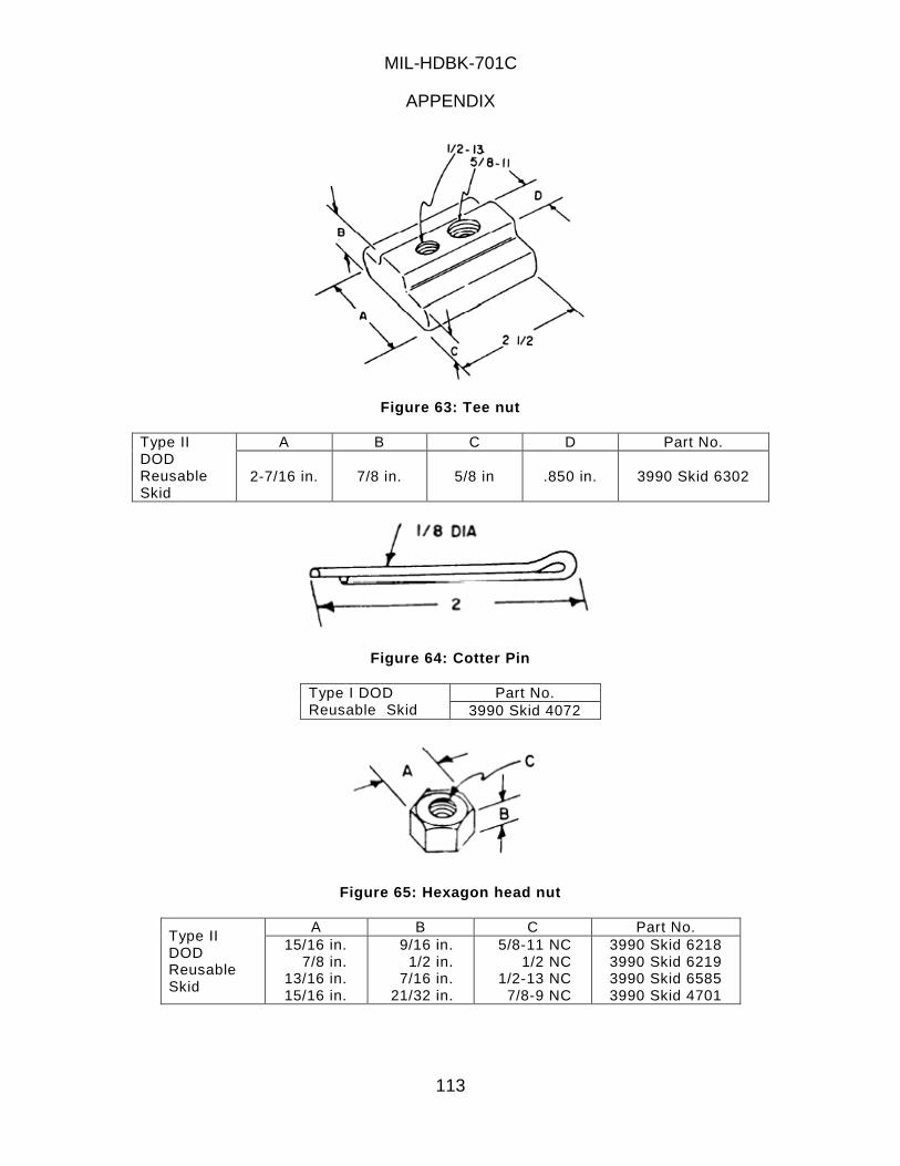
MIL-HDBK-701C
APPENDIX
113
Figure 63: Tee nut
Type II DOD Reusable Skid
A B C D Part No.
2-7/16 in. 7/8 in. 5/8 in .850 in. 3990 Skid 6302
Figure 64: Cotter Pin
Type I DOD Reusable Skid
Part No.
3990 Skid 4072
Figure 65: Hexagon head nut
Type II DOD Reusable Skid
A B C Part No.
15/16 in. 7/8 in.
13/16 in. 15/16 in.
9/16 in. 1/2 in.
7/16 in. 21/32 in.
5/8-11 NC 1/2 NC
1/2-13 NC 7/8-9 NC
3990 Skid 6218 3990 Skid 6219 3990 Skid 6585 3990 Skid 4701

MIL-HDBK-701C
APPENDIX
114
Figure 66: Cap screw
Type II DOD Reusable Skid
A B Part No.
3-3/4 in. 3-1/2 in. 1-1/2 in. 2-1/4 in. 2-1/2 in.
5/8-11 NC 5/8-11 NC 5/8-11 NC 5/8-11 NC 5/8-11 NC
3990 Skid 6107 3990 Skid 6108 3990 Skid 6109 3990 Skid 6110 3990 Skid 6111
Figure 67: Bolt Carriage
Type II DOD Reusable Skid
A Part No.
1-1/4 in. 3990 Skid 6584
Figure 68: Flat round washer

MIL-HDBK-701C
APPENDIX
115
Type II DOD Reusable Skid
A B C Part No.
11/16 in. 1-3/4 in. 1/8 in 3990 Skid 6220
Type I and II 17/32 in. 1-3/8 in. 1/8 in. 3990 Skid 6601
Type I 15/16 in. 1-3/4 in.
1-3/4 in. 3-3/4 in.
9/64 in. 3/16 in.
3990 Skid 4075 3990 Skid 4076
Figure 69: Lock washer
Type II DOD Reusable Skid
A B C Part No.
5/8 in. 1-1/16 in. 3/16 in 3990 Skid 6221
Type I and II 1/2 in. 7/8 in. 5/32 in. 3990 Skid 6601
Type I and II 7/8 in. 1-3/4 in. 5/32 in. 3990 Skid 6603
Figure 70: Saddle tee nut
Type II DOD Reusable Skid
A B C D Part No.
2-7/16 in. 7/8 in. 5/8 in .850 in. 3990 Skid 1119
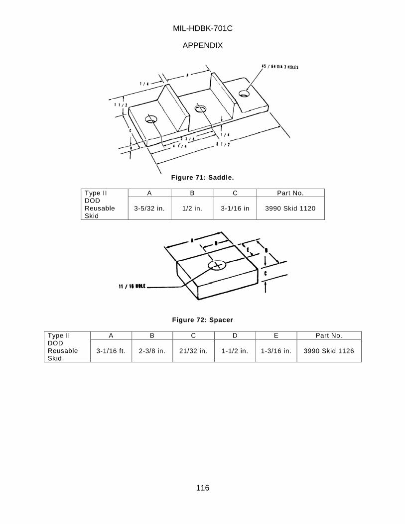
MIL-HDBK-701C
APPENDIX
116
Figure 71: Saddle.
Type II DOD Reusable Skid
A B C Part No.
3-5/32 in. 1/2 in. 3-1/16 in 3990 Skid 1120
Figure 72: Spacer
Type II DOD Reusable Skid
A B C D E Part No.
3-1/16 ft. 2-3/8 in. 21/32 in. 1-1/2 in. 1-3/16 in. 3990 Skid 1126

MIL-HDBK-701C
APPENDIX
117
Figure 73: Socket Fork Lift
Type II DOD Reusable Skid
A Part No.
2-1/2 in. 3990 Skid 1123
* U.S. GOVERNMENT PRINTING OFFICE: 1989-704-034/14265
Instructions and form for submitting changes has been removed.
© Copyright WoodenCRATES org, LLC, All Rights Reserved. May be distributed freely but not modified.