mil-dtl-38999, series iii, tv - mouser electronics amphenol aerospace for more information at...
TRANSCRIPT

20 Contact Amphenol Aerospace for more information at 800-678-0141 • www.amphenol-aerospace.com
AmphenolMIL-DTL-38999, Series III, TV
TABLE OF CONTENTSCombined MIL-DTL-38999 Series I, II, III• Shell Size & Insert Arrangements Availability . . . . . . . . . . . . . . 6-9• Insert Arrangement Drawings . . . . . . . . . . . . . . . . . . . 10-17• Specifications - Contact Ratings, Service Ratings, Finish Data . . . . . 18, 19
MIL-DTL-38999, Series III TV• Performance, Options . . . . . . . . . . . . . . . . . . . . . . 21, 22• Weight Comparison (Composite vs. Metal) . . . . . . . . . . . . . . . 23• Test Data . . . . . . . . . . . . . . . . . . . . . . . . . . . . 24• How to Order (Commercial & Military) . . . . . . . . . . . . . . . . 25-27• How to Order (Boeing BACC63) . . . . . . . . . . . . . . . . . . . 28
Shell Styles:• Crimp Wall Mounting Receptacle TVP00R (D389999/20) /CTVP00R (D38999/20) 29• Crimp Box Mounting Receptacle TVP02R / CTVP02R . . . . . . . . . . 30• Crimp Straight Plug TV06R (D38999/26) / CTV06R (D38999/26) . . . . . . 31• Crimp CLUTCH-LOK™ Straight Plug for High Vibration TV26/MTV26 . . . . 32• Crimp Jam Nut Receptacle TV07R (D38999/24) / CTV07R (D38999/24) . . . 33• Crimp Line Receptacle TV01R / CTV01R . . . . . . . . . . . . . . . 34• Crimp Flange Mounting Plug TV09R . . . . . . . . . . . . . . . . . 35• Hermetic Box Mounting Receptacle TVPS02Y (D38999/21) . . . . . . . . 36• Hermetic Jam Nut Receptacle TVS07Y (D38999/23) . . . . . . . . . . . 37• Hermetic Solder Mounting Receptacle TVSIY (D38999/25),
Hermetic Weld Mounting Receptacle TVSHIY (D38999/27) . . . . . . . . 38• Breakaway Fail-Safe Lanyard Release Plug
D38999/29 & /30 (88-5565 / 91-5565) . . . . . . . . . . . . . . . . 39, 40• Breakaway Fail-Safe How to Order (Military/Commercial) . . . . . . . . 41, 42• Breakaway MIL-STD-1760 Lanyard Release Plug D38999/31 . . . . . . . 43• Breakaway MIL-STD-1760 How to Order (Military). . . . . . . . . . . . 44• Breakaway Hybrid, Low Profile Lanyard Release Plug . . . . . . . . . . 45• Stores Management Type II, Rail Launch (MIL-STD-1760) . . . . . . . . 45
MIL-DTL-38999 Series III Typical Markets:• Military & Commercial Aviation• Military Vehicles• Missiles & Ordnance• C4ISR• Space Applications
AmphenolAerospace
NewFeatured
Other New 38999DualokTM
see page 55 HD38999see page 46

6 Contact Amphenol Aerospace for more information at 800-678-0141 • www.amphenol-aerospace.com
Dualok
III
SJT
38999
PCB
HD
I II
Aquacon
Accessories
Herm/Seal
Fiber Optics
ContactsConnectors
Cables
HIgH SPEED
2648
2M
atrix
2
8372
3 III
5015
2650
0 Py
le
2299
2 C
lass
L
Back
- Sh
ells
Opt
ions
O
ther
sEM
I Filt
erTr
ansi
ent
Crim
p Re
arRe
leas
e M
atrix
Mat
rix|P
yle
AmphenolAerospace
MIL-DTL-27599
Hermetics Contact Size
JT II LJT I TV III IIIJT/LJTSolder
Crimp ClassH
ClassY
TV* Service Rating
Total Contacts
23HD
22D 22M 22 20 16 12 12(Coax)
10(Power)
8(Coax)
8††(Twinax)
7-D2 M 2 27-D3 M 3 37-D4 M 4 4
8-2n P M 2 28-3n X NA P P M 3 39-3n X
9-5★n Grounded 1 18-6 X X P P M 6 69-6 X X P P
9-7n X M 7 79-9n N 9 9
9-22n X I 2 28-35 X P P M 6 69-35 9-35 A35 X P P P8-44 X P P
M 4 49-44 X9-94n ✦ M 2 2
8-97n X M 4 2 28-98 S X P P I 3 39-98 9-98 A98 X X P P P
11-2★ 11-2★ B2 X P** I 2 210-4 3
I 4 411-4 11-4 X S/210-5 X X P P I 5 511-5 11-5 B5 X X P
11-6n S I 6 610-13 X X P/S P/S M 13 1311-13 X X P/S P/S
11-19n N 19 1910-35 X P/S P/S M 13 1311-35 11-35 B35 X P/S P/S P
11-54n X ✦ II 4 410-98 X X P/S P/S I 6 611-98 11-98 B98 X X P/S P/S P10-99 X P P
I 7 711-99 11-99 B99 P X P
12-3 X X ✦ P PII 3 313-3n P
12-4 X X P PI 4 4
13-4★ 13-4★ C4 X X P P P12-8 X X P P
I 8 813-8 13-8 C8 X X P P P
13-13nI, Fiber Optic 4 2** 2
12-22 X P/S P/S M 22 2213-22 X X P/S P/S13-26n 2 M 8 2 613-32n N 32 32
12-35 X P/S P/S M 22 2213-35 13-35 C35 X P/S P/S P13-63n ✦ l 4 2 2
12-98 X X P/S P/S I 10 1013-98 13-98 C98 X X P/S P/S P14-4n 2
I 4 415-4n 15-4n 2 ✦
14-5 X X P PII 5 5
15-5★ 15-5★ D5 X X P P P
MIL-DTL-38999, Series I LJT, II JT, III TV, HDInsert Availability and Identification Chart
Series Series Series Military
X Completely tooled. • Majority of tooling is completed (contact Amphenol Aerospace for availability).✦ Not tooled for 02-R.P Available with Pin contacts onlyS Available with Socket contacts onlyP/S Available with Pin contacts or Socket contacts★ Ground plane proprietary option available. Arrg. 9-5 is exclusively ground plane type. n Not Mil-Qualified.✧ 21-75 is Mil-Qualified with twinax contacts only. Note: MS connector 21-75 is supplied with size 8 twinax. Commercial connector 21-75 is supplied with size 8 coax.
HD designates High Density 38999 Series III insert patterns which use size 23 contacts only. Not rated over 175°C.* Hermetic inserts - solder termination standard. (Contact Amphenol Aerospace for optional PCB or eyelet termination). ** Two size 16 contacts dedicated to fiber optics. See the Fiber Optic section for more information.*** For use in MIL-STD-1760 applications (see pages 43 & 44).† For RG 180/U and RG 195/U cables only.†† Size 8 Coax and Twinax are interchangeable.(2) Not Tooled for RP or 02RE(3) Pin inserts only, not tooled for RP or 02RE (Consult Amphenol Aerospace for avail.)(5) MS Connector 21-79 has provision for two size 8 coax contacts. Coax contacts are not supplied unless specified by customer.

7Contact Amphenol Aerospace for more information at 800-678-0141 • www.amphenol-aerospace.com
II Dualok
III
SJT
38999
I
HD
Fiber Optics
ContactsConnectorsCables
HIgH SPEED
26482M
atrix 2 83723 IIIM
atrix|Pyle5015
Crimp Rear
Release M
atrix
26500 Pyle
22992 C
lass L Back- Shells
Options
Others
EMI Filter
Transient
PCB
Accessories
Aquacon
Herm/Seal
AmphenolAerospace
MIL-DTL-38999, Series I LJT, II JT, III TV, HDInsert Availability and Identification Chart
MIL-DTL-27599
Hermetics Contact Size
JT II LJT I TV III IIIJT/LJTSolder
Crimp Class H
ClassY
TV* Service Rating
Total Contacts
23HD
22D 22M 22 20 16 12 12(Coax)
10(Power)
8(Coax)
8††(Twinax)
14-15 X X P P I 15 14 115-15 15-15 D15 X X P/S P/S P I 15 14 1
14-18 X X P/S P/SI 18 18
15-18 15-18 D18 X X P/S P/S P14-19n X X
I 19 1915-19 15-19 D19 X P P P
14-35 X P PM 37 37
15-35 15-35 D35 X P/S P/S P14-37 X X P P
M 37 3715-37 X X P P
15-55n N 55 5514-68n 2 P P
1 8 815-68n X 3
14-97n X P PI 12 8 4
15-97 15-97 D97 X X P P P17-2 17-2 E2 X ✦ M 39 38 1
16-6 X P PI 6 6
17-6 17-6 E6 X P P P16-8 X X P P
II 8 817-8★ 17-8★ E8 X X P/S P/S P
16-13n 2I 13 13
17-13n 217-22n 17-22★n ✦ Coax 4 2 217-25n 2 M 24 22 2
16-26 X X P/S P/SI 26 26
17-26 17-26 E26 X X P/S P/S P16-35 X P P
M 55 5517-35 17-35 E35 X X P P P
16-42 XM 42 42
17-42n P17-52n X ✦ M 2 2
16-55 X X P/S P/SM 55 55
17-55 X X P/S P/S17-60n X I/Coax 10 8 217-73n N 73 73
16-99 X X P PI 23 21 2
17-99 17-99 E99 X X P P19-ADn X ✦ Inst. 17 16 1
18-11 X X P PII 11 11
19-11★ 19-11★ F11 X X P P P19-18 19-18 F18 2 2 M 18 14 4
18-28 X XI 28 26 2
19-28n 19-28 F28 X P X18-30 X X
I 30 29 119-30n X P
19-31n X M 15 12 1 218-32 X X P/S P/S
I 32 3219-32 19-32 F32 X X P/S P/S P
18-35 X P PM 66 66
19-35 19-35 F35 X P P P18-53 X X
M 53 5319-53n P
18-66 X X P PM 66 66
19-66 X P P19-67n X 3 S S M 67 67
18-68n 2I 18 18
19-68n 19-68 3 S18-96n 2 I 9 9
19-88n N 88 8820-1 X P P
M 79 7921-1 X P/S P/S
Series Series Series Military

8 Contact Amphenol Aerospace for more information at 800-678-0141 • www.amphenol-aerospace.com
Dualok
III
SJT
38999
PCB
HD
I II
Aquacon
Accessories
Herm/Seal
Fiber Optics
ContactsConnectors
Cables
HIgH SPEED
2648
2M
atrix
2
8372
3 III
5015
2650
0 Py
le
2299
2 C
lass
L
Back
- Sh
ells
Opt
ions
O
ther
sEM
I Filt
erTr
ansi
ent
Crim
p Re
arRe
leas
e M
atrix
Mat
rix|P
yle
AmphenolAerospace
MIL-DTL-27599
Hermetics Contact Size
JT II LJT I TV III IIIJT/LJTSolder
Crimp H Y TV* Service Rating
Total Contacts
23HD
22D 22M 22 20 16 12 12(Coax)
10(Power)
8(Coax)
8††(Twinax)
20-2 XM 65 65
21-2n X20-11n 3
I 11 1121-11★ 21-11★ G11 X
20-16 X X P/S P/SII 16 16
21-16★ 21-16★ G16 X X P P P21-25n I 25 2521-27n X I 27 27
21-29n X I 27 19 4 420-35 X P P
M 79 7921-35 21-35 G35 X P/S P/S P20-39 X X P P
I 39 37 221-39 21-39 G39 X X P P P20-41 X X P P
I 41 4121-41 21-41 G41 X X P/S P/S P21-75★ 21-75★✧ G75 2 X N M 4 4 (4) 21-79n 21-79n 2 X II 19 17 2 (5)
21-121n N 121 12122-1 X P/S P/S
M 100 10023-1 X P P22-2 X X P P
M 85 8523-2 X X P P23-6★n 23-6★n P M 6 6
22-14n 2 ✦I 14 14
23-14n 23-14n 2 ✦
22-21 X X P PII 21 21
23-21★ 23-21★ H21 X X P P P22-32 X X P P
I 32 3223-32n X P23-34n X I 34 34
22-35 X P/S P/SM 100 10023-35 23-35 H35 X P P P
22-53n PI 53 5323-53 23-53 H53 X X P/S P/S P
23-54 n X M 53 40 9 422-55 X X P P
I 55 5523-55 23-55 H55 X P23-97n X II 16 1623-99n X II 11 11
23-151 n N 151 15124-1 X P P
M 128 12825-1 X P P24-2 X
M 100 10025-2 X24-4 X P P
I 56 48 825-4 25-4 J4 X P25-7n 25-7 J7 X M Twinax 99 97 2
25-8★ J8 ✦ Twinax 8 825-11*** J11 2 ✦ N 11 2 925-17n ✦ M 42 36 6
24-19n X P PI 19 19
25-19★ 25-19★ J19 X P25-20n 25-20*** J20 2 ✦ N 30 10 13 4 3
MIL-DTL-38999, Series I LJT, II JT, III TV, HDInsert Availability and Identification Chart
X Completely tooled. • Majority of tooling is completed (contact Amphenol Aerospace for availability).✦ Not tooled for 02-R.P Available with Pin contacts onlyS Available with Socket contacts onlyP/S Available with Pin contacts or Socket contacts★ Ground plane proprietary option available. Arrg. 9-5, 26-62 is exclusively ground plane type. n Not Mil-Qualified.✧ 21-75 is Mil-Qualified with twinax contacts only. * Hermetic inserts - solder termination standard. (Contact Amphenol Aerospace for optional PCB or eyelet termination).
HD designates High Density 38999 Series III insert patterns which use size 23 contacts only. Not rated over 175°C.** Two size 16 contacts dedicated to fiber optics. See the Fiber Optic Section for more information.*** For use in MIL-STD-1760 applications (see pages 43 & 44).† For RG 180/U and RG 195/U cables only.†† Size 8 Coax and Twinax are interchangeable.(2) Not Tooled for RP or 02RE(3) Pin inserts only, not tooled for RP or 02RE (Consult Amphenol for avail.)(4) MS connector 21-75 is supplied with size 8 twinax. Commercial connector 21-75 is supplied with size 8 coax.(5) MS Connector 21-79 has provision for two size 8 coax contacts. Coax contacts are not supplied unless specified by customer.
Series Series Series Military

9Contact Amphenol Aerospace for more information at 800-678-0141 • www.amphenol-aerospace.com
II Dualok
III
SJT
38999
I
HD
Fiber Optics
ContactsConnectorsCables
HIgH SPEED
26482M
atrix 2 83723 IIIM
atrix|Pyle5015
Crimp Rear
Release M
atrix
26500 Pyle
22992 C
lass L Back- Shells
Options
Others
EMI Filter
Transient
PCB
Accessories
Aquacon
Herm/Seal
AmphenolAerospace
(Insert arrangements requiring non-standard shells or larger contacts)
X Completely tooled.• Majority of tooling is completed (contact Amphenol Aerospace for availability).✦ Not tooled for 02-R.P Pin inserts only (contact Amphenol Aerospace for socket availability).★ Ground plane proprietary option available. Arrangement 9-5, 25-62 is exclusively ground plane type.n Not Mil-Qualified.* Hermetic inserts - solder termination standard. (Contact Amphenol Aerospace for optional PCB or eyelet termination).** Two size 16 contacts dedicated to fiber optics. See the Fiber Optic section for more information.*** For use in MIL-STD-1760 applications (pgs. 43 & 44).† For RG 180/U and RG 195/U cables only.†† Size 8 Coax and Twinax are interchangeable.Note: 25L-3 and 25L-7 require longer shells.
Select Non-Standard Shell Size
Contact Size
Shell Size-Insert Arrg.
Crimp Hermetics* Service Rating
Total Contacts
Comments 22D 20 16 12
9-2 X I 2 Formerly Pyle 215-4 X II 4 Formerly Pyle 4
15-25 X M 25 Formerly Pyle 22 317-20 X M 20 Formerly Pyle 16 421-12 X I 12 Formerly Pyle 3 921-21 X M/Inst. 41 Improved sealing 32 921-99 X M 16 Formerly Pyle 5 1125-92 X M 101 Formerly Pyle 92 925-97 X M 42 Formerly Pyle 26 3 13
Contact Size
Shell Size- Insert Arrg.
Crimp Hermetics* Service Rating
Total Contacts
22D 20 8 4 0
25-16 X M 8 6 225L-3 X II 3 1 225L-7 X II 7 733-3 X II 3 1 233-5 X II 5 533-6 X II 6 2 437-5 X II 4 4
Select Shell Size - Special Insert Arrangement (Not Mil-Spec Qualified)
MIL-DTL-27599
HermeticsContact Size
JT II LJT I TV III IIIJT/LJTSolder
Crimp H Y TV* Service Rating
Total Contacts
23HD
22D 22M 22 20 16 12 12(Coax)
10(Power)
8(Coax)
8††(Twinax
8Quadrax
24-24 X P PI 24 12 12
25-24★ 25-24★ J24 X P P
25-26n★ ✦ I 25 16 5 424-29 X
I 29 2925-29★ 25-29★ J29 X X
24-35 X P P New128 128
25-35 25-35 J35 X P P P M24-37 X
I 37 3725-37★ 25-37★ J37 X
24-43n 3I 43 23 20
25-43 25-43 J43 X 2 ✦
25-46 25-46 J46 2 ✦ I 46 40 4 224-61 X X P P
I 61 6125-61 25-61 J61 X X P P P
25-62n★ X ✦ I 12 8 425-90 ✦ I 46 40 4 225-187n N 187 18725-F4n X M/I 66 49 13 4
TV Series III
MIL-DTL-38999, Series I LJT, II JT, III TV, HD Insert Availability and Identification Chart
HD designates High Density 38999 Series III insert patterns which use size 23 contacts only. Not rated over 175 °CX Completely tooled. ✦ Not tooled for 02-R.P Pin inserts only (contact Amphenol Aerospace for socket availability).★ Ground plane proprietary option available. Arrg. 9-5, 25-62 is exclusively ground plane type. n Not Mil-Qualified.
Series Series Series Military
- Special Insert Arrangement

10 Contact Amphenol Aerospace for more information at 800-678-0141 • www.amphenol-aerospace.com
Dualok
III
SJT
38999
PCB
HD
I II
Aquacon
Accessories
Herm/Seal
Fiber Optics
ContactsConnectors
Cables
HIgH SPEED
2648
2M
atrix
2
8372
3 III
5015
2650
0 Py
le
2299
2 C
lass
L
Back
- Sh
ells
Opt
ions
O
ther
sEM
I Filt
erTr
ansi
ent
Crim
p Re
arRe
leas
e M
atrix
Mat
rix|P
yle
AmphenolAerospace
Front face of pin inserts illustrated
1
6
11
17
30
A
B
C
D
E
F
A
B
C
DE
F
G
H
A
D
C
B
MIL-DTL-38999, Series I LJT, II JT, III TV, HD Insert Arrangements
A
B
C 12
3
45
61
2
345
67 A
B
51
64
3
21
23
4 A
BC
DC A
B
ABA
BC
D A
B
CD
E
F1
2
3
456
7
8
910
11
1213
12
3
456
7
8
910
11
1213
A
B
CD
E FA
B
CD
E
F
GA
B
C
A
B
C
D
AB
CD
E
FG
H 22
1
20
1
2122
AB
C
DE
F
G
H
JK
AB
CD
EA
BC
D
AB
C
DE
FG
H
J
KL
MN
P
R
A
B
C
D
EFG
H
J
KL
M N
P
RS
T U
AB
C
D
EFGH
J
K
LM
N P
R
ST
U V
1
2131
AB
C
D
EFG
H
JK
L
M
1
11
2131
A
B
C
DE
F
GH
CONTACT LEGEND 8 10 12 16 20 22 22M 22D 23
A
BC
D
E
Shell Size & Insert Arrg. for:
Series II JT 8-2 8-3 8-6 8-35 8-44 8-97 8-98Series I LJT 9-3 9-6 9-7 9-22 9-35 9-44 9-98Series III TV 7-D2 7-D3 7-D4 9-5 9-9 HD 9-35 9-94 9-98Service Rating M M M M M Grounded M M N I M M M M INumber of Contacts 2 3 4 2 3 1 6 7 9 2 6 4 2 2 2 3Contact Size 22D 22D 22D 20 20 8 Twinax 22M 22M 23 20 22D 22 20 22M 20 20
AB
Shell Size & Insert Arrg. for:
Series II JT 10-4 10-5 10-13 10-35 10-98 10-99 12-3Series I LJT 11-2 11-4 11-5 11-6 11-13 11-35 11-98 11-99 13-3Series III TV 11-2 11-4 11-5 11-19 HD 11-35 11-54 11-98 11-99Service Rating I I I I M N M II I I IINumber of Contacts 2 4 5 6 13 19 13 4 6 7 3Contact Size 16 20 20 20 22M 23 22D 22D 20 20 16
Shell Size & Insert Arrg. for:
Series II JT 12-4 12-8 12-22 12-35 12-98 14-4 14-5Series I LJT 13-4 13-8 13-22 13-35 13-98 15-4 15-5Series III TV 13-4 13-8 13-26 13-32 HD 13-35 13-63 13-98 15-4 15-5Service Rating I I M M N M I I I IINumber of Contacts 4 8 22 6 2 32 22 2 2 10 4 5Contact Size 16 20 22M 22D 12 23 22D 16 12 20 12 16
Shell Size & Insert Arrg. for:
Series II JT 14-15 14-18 14-19 14-35 14-37 14-68 14-97Series I LJT 15-15 15-18 15-19 15-35 15-37 15-68 15-97Series III TV 15-15 15-18 15-19 15-35 15-55 HD 15-97Service Rating I I I M M N I INumber of Contacts 14 1 18 19 37 37 55 8 8 4Contact Size 20 16 20 20 22D 22M 23 16 20 16
Shell Size & Insert Arrg. for:
Series II JT 16-6 16-8 16-13Series I LJT 17-2 17-6 17-8 17-13 17-22 17-25Series III TV 17-2 17-6 17-8 17-22Service Rating M I II I Coax MNumber of Contacts 38 1 6 8 13 2 2 22 2
Contact Size 22D 8 Twinax 12 16 16 12 Coax 8 Coax 22D 8 Coax
A
B
D
C
AB
C
D
EF
G
H
J
K
LN M
12
3
4
56
789
10
1112
13 14
15 16
17
1819
20
2122
23
24
B A
AB
C
D
82
197
35 4
6
1 2
3
4
567
89
10 1716
1918
15
1413
1211
1829
32
1
39
16
241731253932
465247
40
5553
1041
HD: High Density HD38999 (use size 23 contacts only)
A
CDE
F B
B A
BC
A A
BC
D

11Contact Amphenol Aerospace for more information at 800-678-0141 • www.amphenol-aerospace.com
II Dualok
III
SJT
38999
I
HD
Fiber Optics
ContactsConnectorsCables
HIgH SPEED
26482M
atrix 2 83723 IIIM
atrix|Pyle5015
Crimp Rear
Release M
atrix
26500 Pyle
22992 C
lass L Back- Shells
Options
Others
EMI Filter
Transient
PCB
Accessories
Aquacon
Herm/Seal
AmphenolAerospace
AB
C
D
E
FGHJ
KL
M
N
P
RS T
U
V
WX
Y
Z
ab
c
Front face of pin inserts illustrated
1
3
4
9
10
16
17
24
25
31
32
39
40
47
46
52
53
55
AB
C
D
E
FGHJ
KL
M
N
P
R
S TU
VWX
YZ
MIL-DTL-38999, Series I LJT, II JT, III TV, HD Insert Arrangements
Shell Size & Insert Arrg. for:
Series II JT 16-26 16-35 16-42 16-55Series I LJT 17-26 17-35 17-42 17-55Series III TV 17-26 17-35 17-52 17-60 17-73 HDService Rating I M M M M I/Coax NNumber of Contacts 26 55 42 2 55 8 2 73Contact Size 20 22D 22 8 Twinax 22M 22D 8 Coax 23
Shell Size & Insert Arrg. for:
Series II JT 16-99 18-11 18-28 18-30Series I LJT 17-99 19-11 19-18 19-28 19-30Series III TV 17-99 19-11 19-18 18-28Service Rating I II M M INumber of Contacts 21 2 11 14 4 26 2 29 1Contact Size 20 16 16 22D 8 Twinax 20 16 20 16
Shell Size & Insert Arrg. for:
Series II JT 18-32 18-35 18-53 18-66Series I LJT 19-32 19-35 19-53 19-66 19-67Series III TV 19-31 19-32 19-35Service Rating M 1 M M M MNumber of Contacts 2 1 12 32 66 53 66 67Contact Size 8 Coax 12 22D 20 22D 22 22M 22M
1
21
31
41
51
6171
79
11
1
31
21
11
41
51
61
65
Shell Size & Insert Arrg. for:
Series II JT 18-68 18-96 20-1 20-2Series I LJT 19-68 21-1 21-2Series III TV 19-88 HD 19-ADService Rating I N I Inst. M IINumber of Contacts 18 88 9 16 1 79 65Contact Size 16 23 12 20 8 Twinax 22M 22
A
B
C
D
E
F
G
H
J
K
L
AB
C
D
E
FG
H
R
JK
LM
N
P
ST
UV
W
X
Y
Za
b
c
d
e
A
BC
EK
M
N
R
S
U
VW
gh
f AB
C
D
E
F
GH
JK
L
M
N
P
R
ST
UV
W
X
YZa
bc
d
ef
gh
j1
2
3
4
9
10
16
17
24
25
33
34
42
43
50
51
57
58
63
64
66
A
B
C
DE
F
G
H
J
K
L
M
N
P
R
S
T
U
AB
C
D
E
FG
HJKL
M
N
PR
S
TU
V
W
XY
Za
b
cd
e
g f
1
3
4
9
10
16
17
24
25
34
35
43
44
51
52
58
59
64
65
67
ABL
CK
DJ
EH
FGR
U
M
T N
S P
A
BH
C
DF
E
G J
1
41
515253
3111
21
1
2
3
4
9
10
2416
1725
33
34
42
43
50
51
57
58
63
64
66
1
21
42
41
31
11
1
3
4
9
10
16
17
2431
2532
39
40
46
47
52
53
55
A
B
1
5
28
9 310
7
6 4
1215 314
13
12
4
5
11 8
710
16
89
A
CONTACT LEGEND 8 10 12 16 20 22 22M 22D 23
1 273
8 15
241625
33
4250
5967
72 73
7166
5849
4132
1
88
84
73
55
31
30
HD: High Density HD38999 (use size 23 contacts only)

12 Contact Amphenol Aerospace for more information at 800-678-0141 • www.amphenol-aerospace.com
Dualok
III
SJT
38999
PCB
HD
I II
Aquacon
Accessories
Herm/Seal
Fiber Optics
ContactsConnectors
Cables
HIgH SPEED
2648
2M
atrix
2
8372
3 III
5015
2650
0 Py
le
2299
2 C
lass
L
Back
- Sh
ells
Opt
ions
O
ther
sEM
I Filt
erTr
ansi
ent
Crim
p Re
arRe
leas
e M
atrix
Mat
rix|P
yle
AmphenolAerospace
1 2
3
45
6
7
8
91011
1213
14
15
16
17
1819
20
2122
24
23
25
2627
1
11
21
31
41
51
6171
79
Front face of pin inserts illustrated
AB
C
D
E
F
GH
JKLM
NP
R
S
TU
V W
XY
Z
a
bc
de
f
gh
ij
k
mn
p
qr
AB
C
D
E
F
G
HJ
KLMN
P
R
S
T
UV
W
XY
Z
a
bc
def
g
h
i
jk
m
npq
r
s
tA
BC
D
AB
C
D
E
FG
H
J
KL
M
N
P
RS
T
U V
A
B
CD
EF
A
BK
CJ LP
MN
DH
EG
F
MIL-DTL-38999, Series I LJT, II JT, III TV, HD Insert Arrangements
Shell Size & Insert Arrg. for:
Series II JT 20-11 20-16Series I LJT 21-11 21-16 21-25 21-27Series III TV 21-11 21-16 21-29Service Rating I II I I INumber of Contacts 11 16 25 27 19 4 4Contact Size 12 16 20 20 20 16 12
AB
C
D
E
F
GHJ
K
L
M
N
PR
S
T
UV
W
XY
Za
b
AB
C
D
E
F
GHJ
K
L
M
N
PR
S
T
U
VW
X
Y
Z
a
b
cd
Shell Size & Insert Arrg. for:
Series II JT 20-35 20-39 20-41Series I LJT 21-35 21-39 21-41 21-75 21-79Series III TV 21-35 21-39 21-41 21-75 21-79Service Rating M 1 I N IINumber of Contacts 79 37 2 41 4 17 (See Note)Contact Size 22D 20 16 20 (See Note) 22D
1
2
3
45
6
7
8
15
16
24
25
34
35
45
46
55
56
66
67
76
77
85
86
93
94
95
9697
98
99
100
1
4
5
11
12
19
20
28
29
38
39
47
48
57
58
66
67
74
75
81
82
85
HD: High Density HD38999 (use size 23 contacts only)Note: MS connector 21-75 is supplied with four size 8 twinax contacts. Commercial connector 21-75 is supplied with four size 8 coax contacts.MS connector 21-79 has provision for two size 8 coax contacts. Coax contacts are not supplied unless specified by customers.
CONTACT LEGEND 8 10 12 16 20 22 22M 22D 23
A
B
C
D
E
F
G
H
J
K
L
A
B
C
D
EF
G
H
J
K
L
M
N
PR
S
Shell Size & Insert Arrg. for:
Series II JT 22-1 22-2 22-14Series I LJT 23-1 23-2 23-6 23-14Series III TV 21-121 HD 23-6Service Rating N M M M INumber of Contacts 121 100 85 6 14Contact Size 23 22M 22 8 Twinax 12
1 5
6 13
232214
32
33 4344 55
56 6667 78
79 89
90 99
100 108
109 116
117 121

13Contact Amphenol Aerospace for more information at 800-678-0141 • www.amphenol-aerospace.com
II Dualok
III
SJT
38999
I
HD
Fiber Optics
ContactsConnectorsCables
HIgH SPEED
26482M
atrix 2 83723 IIIM
atrix|Pyle5015
Crimp Rear
Release M
atrix
26500 Pyle
22992 C
lass L Back- Shells
Options
Others
EMI Filter
Transient
PCB
Accessories
Aquacon
Herm/Seal
AmphenolAerospace
A
B
C
D
E
FG
HJ
K
L
M P
R
S
N
TU
V
W
X
AB
C
D
EF
GH
J
K
L
MN
P R
S
T
U
VWX
Y
Z
a
b
c
d
ef
g
h
j
Shell Size & Insert Arrg. for:
Series II JT 22-21 22-32 22-35Series I LJT 23-21 23-32 23-34 23-35Series III TV 23-21 23-35Service Rating II I I MNumber of Contacts 21 32 34 100Contact Size 16 20 20 22D
Front face of pin inserts illustrated
Shell Size & Insert Arrg. for:
Series II JT 22-53 22-55Series I LJT 23-53 23-55 23-97Series III TV 23-53 23-54 23-55Service Rating I M I IINumber of Contacts 53 40 9 4 55 16Contact Size 20 22D 16 12 20 16
Shell Size & Insert Arrg. for:
Series II JT 24-1 24-2Series I LJT 23-99 25-1 25-2Series III TV 23-151 HDService Rating II N M MNumber of Contacts 11 151 128 100Contact Size 16 23 22M 22
AB
C
D
E
F
GH
J
K
L
M
N
P
RS
TU
VW
X
Y
Zab
cd
ef
g
h
km
np
qr
s
t
A B
uv
wx
y
zA B
CC
DDEE
FF
GGHH
1 23
456
7
89
1011
12131415
1617
18
1920
2122
2324 25
2627
2829
30
3132
3334
35
3637
3839
40
4142
4344
45 46
47
484950
51
52
53
AB
C
D
E
F
G
HJKL
M
N
P
R
S
TU V
WX
Y
Z
a
bc
def
gh
i
j
k
mn
pq
r
s
t
vw
x
yz
AABB
CC
u
DDEEFF
GGHH
AB
CD
E
F
G
HJK
L
M
N
P
R
ST
UV
W
X
YZ
a
b
c
de
f
g
hj
kl
12
34
56
7
8
15
16
24
25
34
35
45
46
55
56
66
67
76
77
85
86
93
94
9596
9798
99
100
AB
C
D
E
FG
H
J
K
L
M
N
P
R
S
A
B
C
DE
F
G
HJ
K
L
1
7
8
14
24
2548
58
59
70
71
81
94
104
105
114
115
121
125
35
15
MIL-DTL-38999, Series I LJT, II JT, III TV, HD Insert Arrangements
CONTACT LEGEND 8 10 12 16 20 22 22M 22D 23
1
2
3
1940 51
73
92
99
100
1 4
5 11
2221
12
3233 44
45 5758 69
70 8283 94
95
130108
140120
147131
107119
141151148
HD: High Density HD38999 (use size 23 contacts only)
14 Contact Amphenol Aerospace for more information at 800-678-0141 • www.amphenol-aerospace.com
Dualok
III
SJT
38999
PCB
HD
I II
Aquacon
Accessories
Herm/Seal
Fiber Optics
ContactsConnectors
Cables
HIgH SPEED
2648
2M
atrix
2
8372
3 III
5015
2650
0 Py
le
2299
2 C
lass
L
Back
- Sh
ells
Opt
ions
O
ther
sEM
I Filt
erTr
ansi
ent
Crim
p Re
arRe
leas
e M
atrix
Mat
rix|P
yle
AmphenolAerospace
14
A
B
C
D
EF
G
HJ
KL
A B
C
D
E
F
G
H
JKL
M
N
P
R
S
T
U
V
W
XY
Z
ab
cd
e
f
gh
km
np
q r st
uv
w
A B
C
D
E
FGH
J
K
L
M
N P
R
ST
U V
A B
C
D
E
F
G
H
J
K
L
M
N
P
R
S
T
U
VWX
Y
Z
1
23
4
5
67
AB
C
D
E
F
GH
JK
L
M
N
P
RS
T
U
VW
X
Y Z
a
1
2
3
4
5
6
78
9
10
11
12
13
14
15
1617
18 19 20
21
222324
25
Front face of pin inserts illustrated
AB
C
D
E
F
GHJ
K
L
M
N
P
RS T
U
V
W
XY
Z
a
b c
d
e
f
1
4
7
8
14
15
24
25
35
36
47
48
58
59
70
71
81
82
93
94
104
105
114
115
121
125
128
Shell Size & Insert Arrg. for:
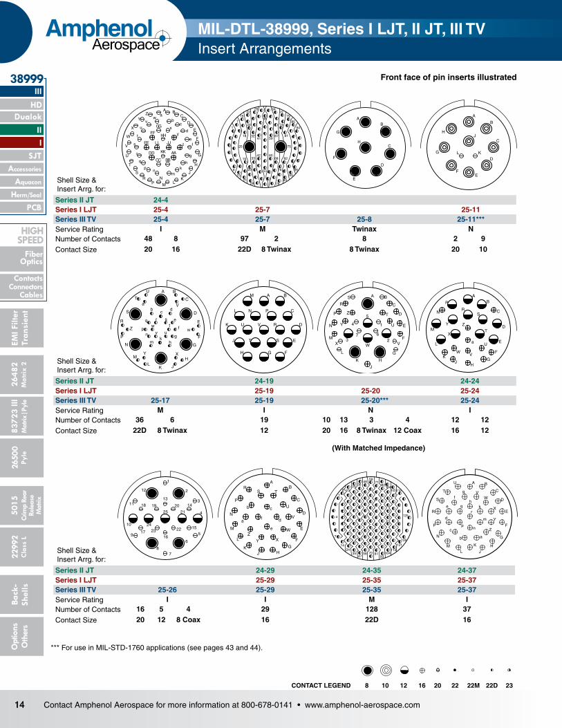
Series II JT 24-19 24-24Series I LJT 25-19 25-20 25-24Series III TV 25-17 25-19 25-20*** 25-24Service Rating M I N INumber of Contacts 36 6 19 10 13 3 4 12 12Contact Size 22D 8 Twinax 12 20 16 8 Twinax 12 Coax 16 12
Shell Size & Insert Arrg. for:
Series II JT 24-29 24-35 24-37Series I LJT 25-29 25-35 25-37Series III TV 25-26 25-29 25-35 25-37Service Rating I I M INumber of Contacts 16 5 4 29 128 37Contact Size 20 12 8 Coax 16 22D 16
(With Matched Impedance)
A B
C
D
E
F
G
HJ
K
LM
N
P
R
S
T
U
VW
X
Y
Z
ab
c
d
e
fg
hk
m
np
qr
MIL-DTL-38999, Series I LJT, II JT, III TV Insert Arrangements
CONTACT LEGEND 8 10 12 16 20 22 22M 22D 23
*** For use in MIL-STD-1760 applications (see pages 43 and 44).
A BC
D
E
F
G
H
J
KL
M
NP
RS
T
U
V
W
X
YZ a
bc
d
ef
g
hk
mn
p
q
r
t
u
vw
x
y
zs JJ
KK
LL
AA
BBCC
DD
EE
FF
GG
HH
1
6
7
15
16
18
19
21
22
24
26
28
29
32
33
41
42
46
53
59
60
64
67
68
72
74
76
78
79
81
82
84
85
93
94
99
25 75
AB
C
D
E
F
G
H
Shell Size & Insert Arrg. for:
Series II JT 24-4Series I LJT 25-4 25-7 25-11Series III TV 25-4 25-7 25-8 25-11***Service Rating I M Twinax NNumber of Contacts 48 8 97 2 8 2 9Contact Size 20 16 22D 8 Twinax 8 Twinax 20 10
15Contact Amphenol Aerospace for more information at 800-678-0141 • www.amphenol-aerospace.com
II Dualok
III
SJT
38999
I
HD
Fiber Optics
ContactsConnectorsCables
HIgH SPEED
26482M
atrix 2 83723 IIIM
atrix|Pyle5015
Crimp Rear
Release M
atrix
26500 Pyle
22992 C
lass L Back- Shells
Options
Others
EMI Filter
Transient
PCB
Accessories
Aquacon
Herm/Seal
AmphenolAerospace
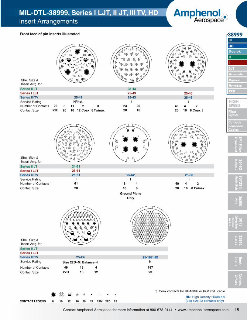
† Coax contacts for RG180/U or RG195/U cable.
AB
C
D
E
F
G
H
JKL
M
N
P
R
S
T
U
V
W
XY
Za
b
cd
e
fgh
k
mn
p
qr
s
tu
v
w
xy
z
AA
Shell Size & Insert Arrg. for:
Series II JT 25-43Series I LJT 25-43 25-46Series III TV 25-41 25-43 25-46Service Rating N/Inst. I INumber of Contacts 22 3 11 2 3 23 20 40 4 2Contact Size 22D 20 16 12 Coax 8 Twinax 20 16 20 16 8 Coax †
A BC
D
E
F
G
H
JK
LMNP
R
S
T
U
V
W
XY
Za
b
c
d
ef
g
h
k
m
n p
q
r
stu
v
w
x
Front face of pin inserts illustrated
Shell Size & Insert Arrg. for:
Series II JT 24-61Series I LJT 25-61Series III TV 25-61 25-62 25-90Service Rating I I INumber of Contacts 61 8 4 40 4 2Contact Size 20 16 8 20 16 8 Twinax
Ground Plane Only
A
B
C
D
E
F
G
H
JKLM
N
a
P
R
S
T
U
V
W
X
Y
Z
b
c
d
efgh
AA
k
q
m
n
p
r
st
u
v
w
xy
z
1
17
18
19
49
35
20
21
22
23
1615
48
59
60 66 64
65
37 50 51 41 42 4331
3038 39 40 29
2726
25
24
54636261
36
325352
4455
56
57
46
3414
13
45
12
11
10
9
8
7
6
5
43
2
33
28
47
58
MIL-DTL-38999, Series I LJT, II JT, III TV, HDInsert Arrangements
D A
C B
18
45
7 2
6 3
AB
C
D
E
F
G
H
J
KLMN
PR
S
T
U
V
W
X
YZa b
c
d
e
f
g
hi
jkmn
p
q
r
s
tu
v
w
x
y
z
BBCC
DD
EE
FF
GG HH
JJ
KK
LL
MM
NN
AA
PP
BP
CN
DM
EL
F
GH
J
K
A
RY
X S
W
Z
T
UV
de
np
q g
ac
bj
k h
ms t
r
i
CONTACT LEGEND 8 10 12 16 20 22 22M 22D 23
Shell Size & Insert Arrg. for:
Series II JTSeries I LJTSeries III TV 25-F4 25-187 HDService Rating Size 22D=M, Balance =I N
Number of Contacts 49 13 4 187Contact Size 22D 16 12 23
1
4 11
212012
32
33 45
46 59
60 72
73 86
87 101
102
142116
155
129
167
143
115128
177176
185
184
187
156
168
3
HD: High Density HD38999 (use size 23 contacts only)

16 Contact Amphenol Aerospace for more information at 800-678-0141 • www.amphenol-aerospace.com
2648
2M
atrix
2
Dualok
III
SJT
38999
8372
3 III
5015
2650
0 Py
le
2299
2 C
lass
L
PCB
Back
- Sh
ells
Opt
ions
O
ther
s
HD
EMI F
ilter
Tran
sien
t
I II
Crim
p Re
arRe
leas
e M
atrix
Mat
rix|P
yle
Accessories
Herm/Seal
Aquacon
Fiber Optics
ContactsConnectors
Cables
HigH Speed
AmphenolAerospace
B A
D
C B
A3
2113
12
11
4
5
6
78
910
1415
1617
181920
2322
21
24
25
A
D
C
B
161514
13
12
11 10
9 8
7 6
5
4
32
1
J
H
G
F
E
K
D
LC
B
A
M
1
2
3
4
56
7
8
9 10 A
B
C
DE
F
G
HJ
11 12
13
14
1516
1718
19
20
2122
23 24
25 26
2728
29
303132
AJ
H
G
F E
D
C
B
M
L
K
S
R P
N
98
100
101
90
7967
57
4624
36
13
5
1
4
1223
3545
56 66 7889
97
2
3
99
M A
L BN
K C
J D
H E
G F
Y W
Xa UZ Vr m
p n ksb
cd
e PR
S
Tjw
hgfu
vt
Shell Size & Insert Arrg. for:Series III TV 9-2 15-4* 15-25 17-20 21-12 21-21Service Rating I II M M I M/Inst.Number of Contacts 2 4 22 3 16 4 3 9 32 9Contact Size 20 16 22D 16 22D 12 20 12 22D 12
Shell Size & Insert Arrg. for:Series III TV 21-99 25-92 25-97Service Rating M M MNumber of Contacts 5 11 92 9 26 3 13Contact Size 22D 12 22D 16 22D 16 12
Front face of pin inserts illustrated
MIL-DTL-38999, Series I LJT, II JT, III TVSpecial Insert Arrangements
NOTE: Some specials shown here were formerly known as Pyle arrangements. Consult Amphenol for how to order information for connectors with these inserts. For further information on special arrangements consult Amphenol Aerospace, Sidney NY.* Pyle 15-4 does not mate with Amphenol Tri-Start 15-4 insert.
CONTACT LEGEND 8 10 12 16 20 22 22M 22D 23*
17Contact Amphenol Aerospace for more information at 800-678-0141 • www.amphenol-aerospace.com
26482M
atrix 2
II Dualok
III
SJT
38999
I
83723 IIIM
atrix|Pyle5015
Crimp Rear
Release M
atrix
26500 Pyle
22992 C
lass L
PCB
Back- Shells
Options
Others
Accessories
Aquacon
HD
EMI Filter
Transient
Herm/Seal
Fiber Optics
ContactsConnectorsCables
HIgH SPEED
AmphenolAerospace
Front face of pin inserts illustrated
CONTACT LEGEND
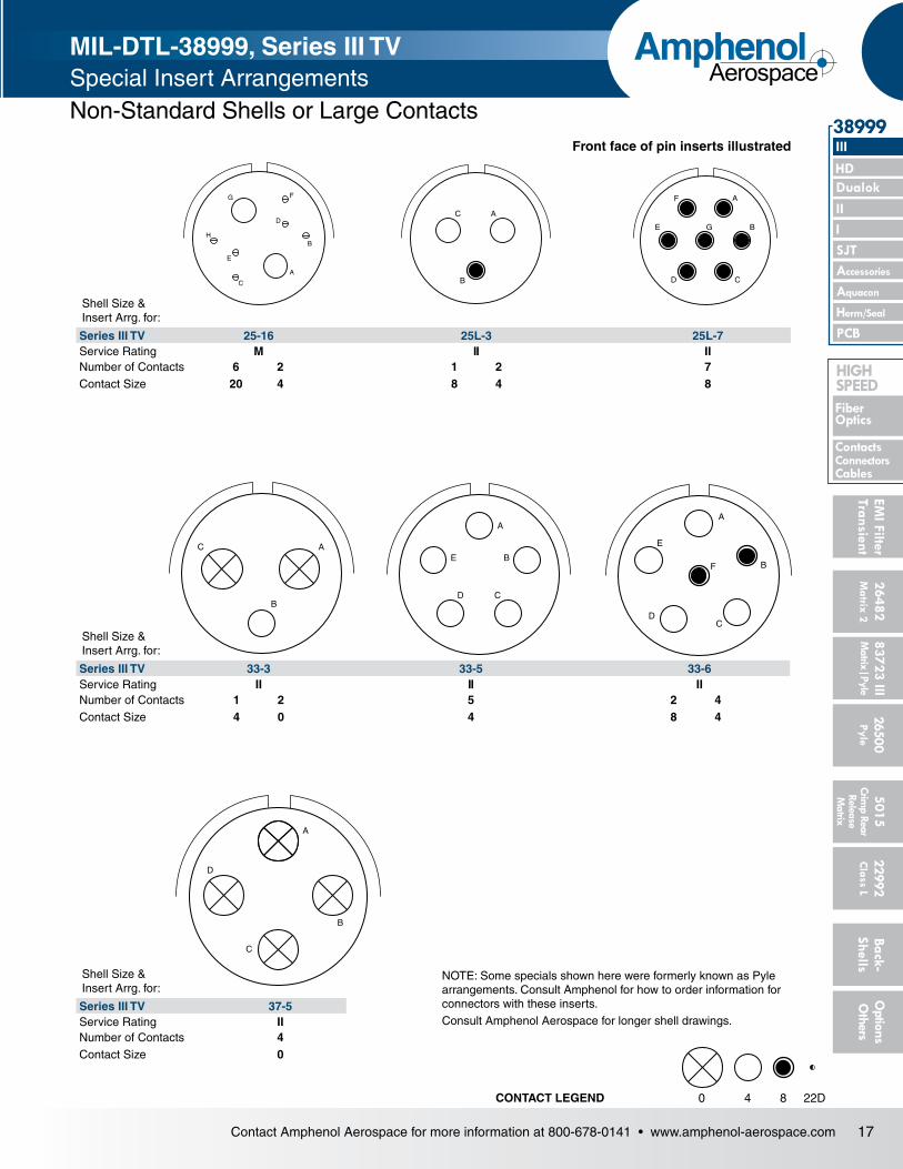
NOTE: Some specials shown here were formerly known as Pyle arrangements. Consult Amphenol for how to order information for connectors with these inserts.Consult Amphenol Aerospace for longer shell drawings.
A
B
C
D
E
FG
H
A
B
C
A
B
CD
E
F
G
B
C A
A
B
CD
E
A
B
CD
E
F
A
B
C
D
840 22D
MIL-DTL-38999, Series III TV Special Insert ArrangementsNon-Standard Shells or Large Contacts
Shell Size & Insert Arrg. for:
Series III TV 25-16 25L-3 25L-7Service Rating M II IINumber of Contacts 6 2 1 2 7Contact Size 20 4 8 4 8
Shell Size & Insert Arrg. for:
Series III TV 33-3 33-5 33-6Service Rating II II IINumber of Contacts 1 2 5 2 4Contact Size 4 0 4 8 4
Shell Size & Insert Arrg. for:
Series III TV 37-5Service Rating IINumber of Contacts 4Contact Size 0

18 Contact Amphenol Aerospace for more information at 800-678-0141 • www.amphenol-aerospace.com
Dualok
III
SJT
38999
PCB
HD
I II
Aquacon
Accessories
Herm/Seal
Fiber Optics
ContactsConnectors
Cables
HIgH SPEED
2648
2M
atrix
2
8372
3 III
5015
2650
0 Py
le
2299
2 C
lass
L
Back
- Sh
ells
Opt
ions
O
ther
sEM
I Filt
erTr
ansi
ent
Crim
p Re
arRe
leas
e M
atrix
Mat
rix|P
yle
AmphenolAerospace
MIL-DTL-38999, Series I LJT, II JT, III TV, HDContact Ratings/ Contact Part Numbers
CONTACT RATING FOR TV III, HD, JT II, LJT I, SJT
*When tested using silver plated wire.
SERVICE RATING**
** Please note that the establishment of electrical safety factors is left entirely in the designer’s hands, since he is in the best position to know what peak voltage, switching surges, transients, etc. can be expected in a particular circuit.
ServiceRating
Suggested Oper. Voltage (Sea Level)
Test Voltage (Sea Level)
Test Voltage 50,000 Ft.
Test Voltage 70,000 Ft Test Voltage 110,000 Ft.
AC (RMS) DCM 400 500 1300 VRMS 550 VRMS 350 VRMS 200 VRMSN 300 450 1000 VRMS 400 VRMS 260 VRMS 200 VRMSI 600 850 1800 VRMS 600 VRMS 400 VRMS 200 VRMSII 900 1250 2300 VRMS 800 VRMS 500 VRMS 200 VRMS
Contact Size
Test Current (Amps) Maximum Millivolt
Drop Crimp*
Maximum Millivolt Drop Crimp Hermetic
Solder* Hermetic*
23 5 3 73 20 85
22M 3 2 45 20 60
22D 5 3 73 8522 5 3 73 20 8520 7.5 5 55 20 6016 13 10 49 20 8512 23 17 42 20 85
10 (Power) 33 NA 33 NA NA8 (Power) 46 NA 26 NA NA
4 80 NA 23 NA NA0 150 NA 21 NA NA
Contact Size
Crimp Well Data Solder Well DataWell
DiameterNormal
Well Depth
Well Diameter
Nominal Well Depth
23 .0345 ± .0010 .141 .0345 ± .0010 .130
22M .028 ± .001 .141 .029 +.004 – .000
22D .0345 ± .0010 .141 .036 +.004 -.000
.094
22 .0365 ± .0010 .141 .036 +.004 -.000
.094
20 .047 ± .001 .209 .044 +.004 -.004
.125
16 .067 ± .001 .209 .078 +.000 -.004
.141
12 .100 ± .002 .209 .116 +.004 -.002
.141
10 (Power) .137 ± .002 .355 NA NA
8 .181 ± .002 .490 NA NA4 .281 ± .002 .490 NA NA0 .453 ± .002 .585 NA NA
MIL-DTL-38999 Series II JT/ Series I LJT/SJT Series CRIMP CONTACTSContact Size JT/LJT/SJT
Pins MS No.JT Socket
MS No.LJT/SJT Sockets
MS No.8 (Coax)* M39029/60-367 NA M39029/59-3668 (Twinax) M39029/90-529** NA M39029/91-53010 (Power) M39029/58-528 NA M39029/56-52712 M39029/58-365 M39029/57-359 M39029/56-35316 M39029/58-364 M39029/57-358 M39029/56-352
MIL-DTL-38999 Series III STANDARD 500 CYCLE CONTACTS FOR TV AND CTV, P & S
MIL-DTL-38999 Series III 1500 CYCLE CONTACTS FOR CTV, CLASSES H & J
Above part numbers include standard 500 cycle finish designation - gold plating over suitable underplate in accordance with SAE AS39029. For other finish variations, consult Amphenol Aerospace. *For use with RG180B/U and RG195A/U cable. For other size 8 coax or optional sizes 12 and 16 coax contacts available for use in Tri-Start connectors, see High Speed Contact section in this catalog or consult Amphenol Aerospace.
** For use with M17/M176-00002 cable. † Optional design - see slash sheet MS39029.For other contact options available for use in Tri-Start connectors (wire wrap, thermocouple, fiber optic), consult Amphenol.
Contact Size CTV Pins CTV SocketsCommercial No. Military No. Supersedes Commercial No. Military No. Supersedes
12 10-597072-2X M39029/107-623 – 10-597073-2X M39029/106-617 –
16 10-597068-2X M39029/107-622 – 10-597069-2X M39029/106-616 –
20 10-597064-2X M39029/107-621 – 10-597065-2X M39029/106-615 –
22D 10-597058-3X M39029/107-620 – 10-597061-2X M39029/106-614 –
Contact Size TV/CTV Pins TV/CTV SocketsMilitary No. Supersedes Military No. Supersedes
8 (Coax)* M39029/60-367 MS27536 M39029/59-366 MS275358 (Power) Contact Factory “ “ “8 (Twinax) M39029/90-529** N/A M39029/91-530 N/A10 (Power) M39029/58-528 N/A M39029/56-527 N/A
12 M39029/58-365 MS27493-12 M39029/56-353 MS27490-1216 M39029/58-364 MS27493-16 M39029/56-352 MS27490-1620 M39029/58-363 MS27493-20 M39029/56-351 MS27490-20
22D M39029/58-360 MS27493-22D M39029/56-348 MS27490-22D4 N/A N/A N/A N/A0 N/A N/A N/A N/A
Contact Size JT/LJT Pins MS No.
JT Socket MS No.
LJT/SJT Sockets MS No.
20 M39029/58-363 M39029/57-357 M39029/56-35122 M39029/58-362 M39029/57-356 M39029/56-35022M M39029/58-361 M39029/57-355 M39029/56-34922D M39029/58-360 M39029/57-354 M39029/56-348
MIL-DTL-38999 Series III SEALING PLUGS
Contact Size Commercial No. Military No.8 (Coax) 10-482099-8 N/A
8 (Twinax) T3-4008-59P N/A
8 (Power) 10-405996-83 MS27488-8-3
10 (Power) T3-4010-59P M85049/81-10
12 10-405996-122 MS27488-12-2
16 10-405996-162 MS27488-16-2
20 10-405996-202 MS27488-20-2
22D 10-405996-222 MS27488-22-2
4 10-405996-43 MS27488-4-3
0 10-405996-03 MS27488-0-3

19Contact Amphenol Aerospace for more information at 800-678-0141 • www.amphenol-aerospace.com
II Dualok
III
SJT
38999
I
HD
Fiber Optics
ContactsConnectorsCables
HIGH SPEED
26482M
atrix 2 83723 IIIM
atrix|Pyle5015
Crimp Rear
Release M
atrix
26500 Pyle
22992 C
lass L Back- Shells
Options
Others
EMI Filter
Transient
PCB
Accessories
Aquacon
Herm/Seal
AmphenolAerospace
FINISH DATA MIL-DTL-38999, Series I LJT, II JTAluminum Shell Components Non-Hermetic
Finish Suffix Indicated Finish Standard for
JT Types Listed Below
Indicated Finish Standard for
LJT Types Listed BelowMilitary Commercial Finish Plus
“SR” SuffixCadmium Plated Nickel Base MS (A) – (SR) JT/JTG/JTL/JTP LJT/LJTP
Anodic Coating (Alumilite) MS (C) (005) (300) JTS/JTPS/JTLS LJTPS/LJTSChromate Treated (Iridite 14-2) (011) (344) JTN/JTPN/JTLN LJTN/LJTPNOlive Drab Cadmium Plate Nickel Base MS (B) (014) (386)
Electroless Nickel MS (F) (023) (424)
Nickel-PTFE Durmalon (038)
Hermetic ConnectorsFinish Suffix Indicated Finish
Standard for JT Types Listed Below
Indicated Finish Standard for
LJT Types Listed BelowMilitary Commercial
Carbon Steel Shell Tin Plated Shell and Contacts
JT( )H / JT( )Y JTL( )H / JTL( )Y
LJT( )Y LJT( )H
Carbon Steel Shell Tin Plated Shell and Gold Plated Contacts
MS (D)
Stainless Steel Shell Gold Plated Contacts MS (E) (162) JTS( )Y JTLS( )Y
LJTS( )Y
MIL-DTL-38999, Series I LJT, II JT, III TVThermocouple Contacts/Sealing Plugs/Finishing Data
FINISH DATA MIL-DTL-38999, Tri-Start Series III TVAluminum Shell Components Non-Hermetic*
Finish Service ClassMilitary Commercial
Anodic Coating (Non-Conductive) C* RX**
Electroless NickelF (Metal)*
RFM (Composite)
Olive Drab Cadmium Plate Nickel BaseW (Metal)*
RWJ (Composite)
Stainless Steel with Nickel Plate (non-firewall) LStainless Steel with Nickel Plate (firewall) S RS
Stainless Steel K RKDurmalon plated T* DT
Zinc-Nickel Plated Z* DZ
Hermetic Shell ComponentsMaterial/Finish Service Class
Military CommercialStainless Steel Y YStainless Steel with Nickel Plate N YN
**Add Suffix (005) to part number.
SEALING PLUGS Series II JT/ I LJTContact Size Commercial No. Military No.
8 (Coax) 10-482099-8 MS27488-8
8 (Twinax) T3-4008-59P N/A
10 (Power) 10-576225 N/A
12 10-405996-122 MS27488-12-2
16 10-405996-162 MS27488-16-2
20 10-405996-202 MS27488-20-2
22 10-405996-222 MS27488-22-2
22M 10-405996-222 MS27488-22-2
22D 10-405996-222 MS27488-22-2
Contact Size Material JT/LJT Pins JT Sockets LJT Sockets
20
Chromel 10-407862-310 10-407863-310 10-407236-310
Alumel 10-407862-320 10-407863-320 10-407865-320
Iron 10-407862-335 10-407863-335 10-407865-335
Constantan 10-407862-342 10-407863-342 10-407865-342
THERMOCOUPLE CONTACTS Series II JT/ I LJT
Partial Listing. If you do not see the contact for your application, consult Amphenol Aerospace.
Contact Size
Pins (II JT/I LJT) Sockets (LJT)Material
Spec Number Pyle Number Spec Number Pyle Number22D M39029/87-472 T3-4022-10P M39029/88-484 T3-4122-10P CHROMEL22D M39029/87-471 T3-4022-10R M39029/88-483 T3-4122-10R ALUMEL20 M39029/87-476 T3-4020-10P M39029/88-488 TS-4120-10P CHROMEL20 M39029/87-475 T3-4020-10R M39029/88-487 T3-4120-10R ALUMEL16 M39029/87-480 T3-4016-10P M39029/88-492 T3-4116-10P CHROMEL16 M39029/87-479 T3-4016-10R M39029/88-491 T3-4116-10R ALUMEL
THERMOCOUPLE CONTACTS PYLE VERSION Series II JT/ I LJT
Above part numbers include standard finish designation - gold plating over suitable underplate in accordance with MIL-DTL-39029. For other finishes, consult Amphenol Aerospace. Note: 22M and 22D contacts are interchangeable. *For use with RG180B/U and RG195A/U cable. For other size 8 coax or optional sizes 12 and 18 coax contacts available for use in JT/LJT connectors, see High Speed Contacts section of this catalog.** For use with 17/M176-00002 cable.
Contact Size Commercial No. 8 (Coax) 10-482099-8
8 (Twinax) 10-482099-8
10 (Power) NA
12 10-405996-012 Yellow
16 10-405996-016 Blue
20 10-405996-020 Red
22 10-405996-022 Black
22M 10-405996-022 Black
22D 10-405996-022 Black
SEALING PLUGS SJT

21Contact Amphenol Aerospace for more information at 800-678-0141 • www.amphenol-aerospace.com
26482M
atrix 2
II Dualok
III
SJT
38999
I
83723 IIIM
atrix|Pyle5015
Crimp Rear
Release M
atrix
26500 Pyle
22992 C
lass L
PCB
Back- Shells
Options
Others
Accessories
Aquacon
HD
EMI Filter
Transient
Herm/Seal
Fiber Optics
ContactsConnectorsCables
HIgH SPEED
AmphenolAerospace
MIL-DTL-38999, Series III TVPerformance
Tri-StartTM MIL-DTL-38999 Series III with Metal Shells - Aluminum, Stainless Steel, Class K Firewall
Composite Tri-Start, Qualified to MIL-DTL-38999, Rev. J
Amphenol ® Tri-Start MIL-DTL-38999* Series III Connec tors offer the highest performance capabilities for both general duty and severe environment applications. Meeting or exceeding MIL-DTL-38999 Series III require ments, the Tri-Start connector with standard metal shells (aluminum or stainless steel with several finish options) offers these features:
• EMIShielding - solid metal-to-metal coupling, grounding fingers, electroless nickel plating, and thicker wall sec tions provide superior EMI shielding capability of 65dB minimum at 10 GHz
• Contact Protection - recessed pins in this 100% scoop-proof connector minimize potential contact damage
• Moisture Resistance - improved interfacial seal design helps prevent electrolytic erosion of contacts
• Corrosion Resistance - shells of stainless steel or cad mium over nickel plating withstand a 500 hour salt spray exposure
• Vibration/Shock - operates under severe high tempera ture vibration, through 200°C
• Firewall Capability - available in a stainless steel shell, class RK, RS
• Lockwiring Eliminated - unique, self-locking, quick cou pling connector eliminates lockwiring
• Quick Coupling - completely mates and self-locks in a 360° turn of the coupling nut
• Inventory Support Commonality - uses standard MIL-DTL-38999 contacts, application tools, insert arrangements
• Electrostatic Discharge Protection (ESD) - protection for sensitive circuitry without diodes, varistors, etc., with the use of the Faraday Cage principle which shunts high voltage, high current discharge events (see page 331)
• Hermetic- air leakage limited to 1 X 10⁻⁷ cm3 per second optional• Qualified Specifications - Stainless Steel qualified to BACC63DB
and BACC63DC specifications
MIL-Qualified to MIL-DTL-38999, Rev. K, the Amphenol® Composite Tri-Start Connector offers a lightweight, cor rosion resistant connector with the same high perfor mance features as its metal counterpart. The Composite Tri-Start Connector also includes the following features:
• Lightweight- 17% – 70% weight savings (17–40% weight savings vs. Aluminum) (60–70% weight savings vs. Stainless steel) See Composite weight comparison chart on page 23.
• Corrosion Resistance - available in standard MIL-DTL-38999 olive drab cadmium (-65°C to 175°C) and electroless nickel plating (-65°C to 200°C), both with- standing 2000 hours of salt spray exposure. The base mate-rial is able to withstand an indefinite exposure to salt spray.
• Durability - 1500 couplings minimum (in reference to connector couplings, not contacts)
• Extended Life Contact - Mil-approved plating process which provides 1500 couplings minimum
• Qualified to BACC63CT and BACC63CU specifications
The Tri-Start option CLUTCH-LOK offers all advantages of stainless steel/Class K firewall for MIL-DTL-38999 Series III connectors, plus a unique clutch design that actually tightens itself under vibration. Features include:
•High degree of differential torque •No settling back to the next ratchet tooth • Completely intermateable with all existing
MIL-DTL-38999 Series III connectors •Offers advantage in inaccessible, hard to reach
areas where mating torque is difficult to apply and complete coupling is not verifiable by inspection
See page 32 for description, 25 – 27 for ordering.
CLUTCH-LOKTM MIL-DTL-38999 Series III High Vibration Connector
* MIL-DTL-38999 Series III supersedes MIL-C-38999 Series III.
Applicable Patents:Tri-StartTM Connector Patent 4,109,990.Composite Connector Patents: 4,268,103; 4,648,670; 4,682,832; 4,703,987.Clutch-Lok® Patent 6,152,753.
Optional Shell Geometries Amphenol offers a number of different shell configurations to fit your needs.
• Deep Reach Shells - For increased panel thickness• Stand-off Flange Shells - For attachments to Printed
Circuit Boards.• Connector with Integral Strain Reliefs
Series III

22 Contact Amphenol Aerospace for more information at 800-678-0141 • www.amphenol-aerospace.com
2648
2M
atrix
2
Dualok
III
SJT
38999
8372
3 III
5015
2650
0 Py
le
2299
2 C
lass
L
PCB
Back
- Sh
ells
Opt
ions
O
ther
s
HD
EMI F
ilter
Tran
sien
t
I II
Crim
p Re
arRe
leas
e M
atrix
Mat
rix|P
yle
Accessories
Herm/Seal
Aquacon
Fiber Optics
ContactsConnectors
Cables
HIgH SPEED
AmphenolAerospace
PerformanceDesigned for PerformanceNumerous advantages in performance capability are designed into the Amphenol Tri-Start Connector. A positive metal to metal coupling design, grounding fingers, and elec troless nickel plating provide superior EMI shielding capabil ity of 65 dB minimum at 10 GHz.Acme threads provide coupling durability. Thicker wall sec tions and a greater coupling surface area improve strength and shock resistance. Blunting of the thread on both the coupling nut and receptacle eliminates cross coupling. The connector quickly mates and self locks in a 360° turn of the coupling nut.Elongated mounting holes permit the Tri-Start Connector to inter-mount with various existing MIL-Spec box or wall mount recep-tacles, giving it a design replacement advantage.Shells of stainless steel or cadmium over nickel plating pre vent severe corrosion. Resistance is tested through expo sure to a 500 hour salt spray. Composite versions provide protection from salt spray exposure for 2000 hours. Other finish options are available; see how to order Tri-Start metal and Tri-Start Composite.
Recessed pins minimize potential contact damage in this 100% scoop-proof connector. In a blind mating application, mating shells cannot “scoop” the pins and cause a shorting or bending of contacts.The design of the Amphenol Tri-Start interfacial seal meets the MIL-DTL-38999 Series III requirements for electrolytic erosion resistance.A rigid dielectric insert with excellent electrical characteris-tics provides durable protection to the contacts. The socket contacts are probe proof, and all contacts are rear remov-able. They are plated in the standard 50 micro inches minimum gold, with 100 micro inches as an option, and are available in standard Tri-Start insert arrangements and special Pyle® insert arrangements in sizes 10 power, 12, 16, 20 and 22D con tacts. Special insert patterns are also available with larger contacts in sizes 4 and 0.
Series III, TV Tri-Start Connectors, offer more versatility & options than any other interconnection family!
High reliability and increased versatility best describe Amphenol MIL-DTL-38999, Series III circular connectors. Originally designed for the harshest of environments and most demanding of applications, Amphenol MIL-DTL-38999 Series III, Tri-Start connectors continue to evolve in pace with the needs of an ever-changing market.
Amphenol Tri-Start connectors can be configured with a number of application specific technologies like High Density HD38999, Dualok, Filters, Hermetics, PC Tails, Fiber Optics, Flex, CLUTCH-LOK, Fail Safe, and contacts. Flexibility aids in design optimization through the combination of different technologies within a common, time-tested, harsh environment connector body.
For more information about options, please call 800-678-0141 or visit www.amphenol-aerospace.com.
MIL-DTL-38999, Series III TVOptions

23Contact Amphenol Aerospace for more information at 800-678-0141 • www.amphenol-aerospace.com
26482M
atrix 2
II Dualok
III
SJT
38999
I
83723 IIIM
atrix|Pyle5015
Crimp Rear
Release M
atrix
26500 Pyle
22992 C
lass L
PCB
Back- Shells
Options
Others
Accessories
Aquacon
HD
EMI Filter
Transient
Herm/Seal
Fiber Optics
ContactsConnectorsCables
HIgH SPEED
AmphenolAerospace
MIL-DTL-38999, Series III TV Weight Comparisons (Composite vs. Metal)
Tri-Start Weight in Ounces (includes contacts)
Depending on the shell style, shell size and contact count, weight savings can range from 17% to 40% compared to standard aluminum product.
All weight measurements are for reference only.
WeightWallMountReceptacle(00•MilitaryD38999/20 JamNutReceptacle(07)•MilitaryD38999/24 Plug(06)•MilitaryD38999/26
Stainless Steel
Aluminum Composite Stainless Aluminum Composite Stainless Steel Aluminum Composite
Pin Socket Pin Socket Pin Socket Pin Socket Pin Socket Pin Socket Pin Socket Pin Socket Pin Socket
9-35 .7216 .7840 .3248 .3777 .2588 .3121 1.1472 1.2096 .4416 .5040 .3489 .4413 1.0736 1.1360 .4236 .4625 .2606 .2994
9-98 .7216 .7776 .2496 .3056 .1664 .2224 1.1472 1.2032 .4416 .4976 .3744 .4640 1.0736 1.1296 .3968 .4624 .2991 .2337
11-35 .9488 1.0800 .3632 .4960 .2753 .4081 1.4304 1.5632 .5936 .7264 .4679 .6007 1.2480 1.3808 .5312 .6389 .3450 .4582
11-98 .9488 1.0620 .3632 .4768 .2753 .3889 1.4304 1.5440 .5936 .7072 .4679 .5815 1.2480 1.3616 .5330 .6283 .3468 .4457
13-8 1.2096 1.3888 .4800 .6592 .3696 .5488 1.9104 2.0896 .7664 .9456 .6560 .8352 1.8048 1.9840 .7936 .9728 .5237 .5952
13-35 1.2160 1.4320 .4864 .7024 .3762 .5922 1.9168 2.1328 .7728 .9888 .6136 .8296 1.8112 2.0272 .8000 .8472 .5301 .6531
13-98 1.2160 1.4016 .4864 .6720 .3762 .5618 1.9168 2.1024 .7728 .9584 .6136 .7992 1.8112 1.9968 .7978 .9856 .5244 .7157
15-5 1.5312 1.7904 .6352 .8944 .5027 .7619 2.3792 2.6384 .9728 1.2320 .7749 1.0341 2.2704 2.5456 .9632 1.1719 .6450 .8467
15-18 1.5456 1.8416 .7760 .9456 .6432 .8128 2.3936 2.6896 .9872 1.2832 .8544 1.1504 2.2848 2.5808 .9776 1.2736 .6594 .8208
15-35 1.5424 1.8768 .6464 .9808 .5139 .8483 2.3904 2.7344 .9840 1.3280 .7861 1.1301 2.2816 2.6256 1.2179 1.3184 .8961 1.0002
17-6 2.1488 2.5904 .9360 1.3776 .7812 1.2228 2.9152 3.3568 1.2336 1.6752 .9940 1.4356 2.5008 3.1024 1.1408 1.7424 .8160 1.4176
17-26 2.1344 2.5600 .9216 1.3472 .7668 1.1924 2.9008 3.3264 1.2192 1.6448 .9796 1.4052 2.4864 2.9120 1.1264 1.3343 .8017 .8062
17-35 2.1360 2.6640 .9232 1.4512 .7684 1.2964 2.9024 3.4304 1.2208 1.7488 .9812 1.5092 2.4880 3.0160 1.1280 1.5497 .8033 1.2144
19-11 2.2592 2.6656 .9696 1.4528 .7925 1.2757 3.4352 3.9184 1.4720 1.9552 1.2033 1.6865 2.9808 3.4640 1.3472 1.8304 .9632 1.4464
19-32 2.1888 2.7264 .9760 1.5136 .7989 1.3365 3.4416 3.9792 1.4784 2.0160 1.2097 1.7473 2.9872 3.5248 1.3536 1.8912 .9696 1.5072
19-35 2.1920 2.8432 .9792 1.6304 .8021 1.4533 3.4448 4.0960 1.4816 2.1328 1.2129 1.8641 2.9904 3.6416 1.3568 2.0080 .9728 1.6240
21-11 2.7456 3.4640 1.3088 2.0272 1.1088 1.8272 3.9712 4.6896 1.8128 2.5312 1.6128 2.3312 3.4448 4.1632 1.7344 2.5312 1.3039 1.8710
21-16 2.6784 3.3168 1.2416 1.8800 1.0422 1.6806 3.9040 4.5424 1.7456 2.3840 1.4505 2.0889 3.3776 4.0160 1.6672 2.3168 1.2352 1.8736
21-35 2.6672 3.4992 1.2304 2.0624 1.0310 1.8630 3.8928 4.7248 1.7344 2.5664 1.4393 2.2713 3.3664 4.1984 1.6560 2.2309 1.2255 1.8003
21-41 2.6768 3.3600 1.2400 1.9232 1.0406 1.7238 3.9024 4.5856 1.7440 2.4272 1.4489 2.1321 3.3760 3.5792 1.6656 1.8688 1.2336 1.4368
23-21 3.0352 3.8624 1.4496 2.2768 1.2279 2.0551 4.2368 5.0640 1.9440 2.7712 1.6368 2.4640 3.7920 4.6192 1.9216 2.7488 1.4637 2.2896
23-35 3.0240 4.0448 1.4384 2.4592 1.2167 2.2375 4.2256 5.2464 1.9328 2.9536 1.6256 2.6464 3.7808 4.8016 1.9104 2.6087 1.4525 2.1507
23-53 2.8992 3.9072 1.4560 2.4816 1.2343 2.2599 4.2432 5.1088 1.9504 2.8160 1.6432 2.5088 3.7984 4.6640 1.9280 2.7936 1.4672 2.2384
25-4 3.4512 4.4800 1.7312 2.8816 1.4864 2.1904 4.8048 5.8272 2.2016 3.2480 1.9568 2.8720 4.2224 5.2496 2.2128 3.2560 1.7133 2.4163
25-19 3.5312 4.7264 1.8112 3.0064 1.5664 2.7616 4.8848 6.0816 2.2816 3.4784 2.0368 3.2336 4.3024 5.4992 2.2928 3.4896 1.7933 2.7058
25-20 3.8190 4.7150 2.0173 3.1125 1.7733 2.8512 5.1430 6.0380 2.4877 3.5421 2.1872 3.2416 4.4350 5.3300 2.2580 3.0182 1.8288 2.8928
25-35 3.4416 4.6656 1.7216 2.9456 1.4776 2.7016 4.7952 6.0192 2.1920 3.4160 1.8915 3.1155 4.2128 5.4368 2.2032 3.4272 1.7037 2.9277
25-61 3.4304 4.4848 1.7282 2.7648 1.4841 2.5208 4.7840 5.8384 2.1808 3.2352 1.8803 2.9347 4.2016 5.2560 2.1920 3.2464 1.6912 2.7456
24 Contact Amphenol Aerospace for more information at 800-678-0141 • www.amphenol-aerospace.com
2648
2M
atrix
2
Dualok
III
SJT
38999
8372
3 III
5015
2650
0 Py
le
2299
2 C
lass
L
PCB
Back
- Sh
ells
Opt
ions
O
ther
s
HD
EMI F
ilter
Tran
sien
t
I II
Crim
p Re
arRe
leas
e M
atrix
Mat
rix|P
yle
Accessories
Herm/Seal
Aquacon
Fiber Optics
ContactsConnectors
Cables
HIgH SPEED
AmphenolAerospace
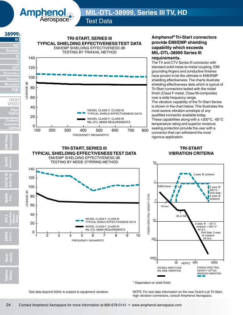
TRI-START, SERIES III TYPICAL SHIELDING EFFECTIVENESS TEST DATA
EMI/EMP SHIELDING EFFECTIVENESS dB TESTING BY TRIAXIAL METHOD
TRI-START, SERIES III TYPICAL SHIELDING EFFECTIVENESS TEST DATA
EMI/EMP SHIELDING EFFECTIVENESS dB TESTING BY MODE STIRRING METHOD
Test data beyond 2GHz is subject to equipment variation.
* Dependant on shell finish
NOTE: For test data information on the new Clutch-Lok Tri-Start, high vibration connectors, consult Amphenol Aerospace.
Amphenol® Tri-Start connectors provide EMI/EMP shielding capability which exceeds MIL-DTL-38999 Series III requirements.The TV and CTV Series III connector with standard solid metal-to-metal coupling, EMI grounding fin gers and conductive finishes have proven to be the ultimate in EMI/EMP shielding effectiveness. The charts illustrate shielding effectiveness data which is typical of Tri-Start connectors tested with the nickel finish (Class F-metal, Class M-composite) over a wide frequency range.The vibration capability of the Tri-Start Series is shown in the chart below. This illustrates the most severe vibration envelope of any qualified connec tor available today.These capabilities along with a +200°C, -65°C temperature rating and superior moisture sealing protection pro vide the user with a connector that can withstand the most rigorous application.
TRI-START VIBRATION CRITERIA
140
120
100
80
60
40
20
0100 200 300 400 500 600 700 800
NICKEL CLASS F, CLASS MTYPICAL SHIELD EFFECTIVENESS DATA
FREQUENCY MEGAHERTZ
NICKEL CLASS F, CLASS MMIL-DTL-38999 REQUIREMENTS
LEA
KA
GE
dB
140
120
100
80
60
40
20
01 2 3 4 5
NICKEL CLASS F, CLASS MMIL-DTL-38999 REQUIREMENTS
NICKEL CLASS F, CLASS MTYPICAL SHIELD EFFECTIVENESS DATA
6 7 8 9 10FREQUENCY GIGAHERTZ
LEA
KA
GE
dB
5 50 500 5000
.0001
.001
.01
.1
1.
10.
10in/sec
.06 in DA.
3 axes @ – 55 C ambient + 200 C* 60 G's (Fail Safe: 3 axes
@ ambient 30 G's)
2 axes @200 C *(Fail Safe:2 axes @ambient)
2 axes @ ambient
6dB/octave
HERTZ
DOUBLE AMPLITUDE(IN) SINE VIBRATION
POWER SPECTRALDENSITY (G2/HZ)RANDOM VIBRATION
PO
WE
R S
PE
CT
RA
L D
EN
SIT
Y G
2 /HZ
˚˚
˚
MIL-DTL-38999, Series III TV, HD Test Data

25Contact Amphenol Aerospace for more information at 800-678-0141 • www.amphenol-aerospace.com
26482M
atrix 2
II Dualok
III
SJT
38999
I
83723 IIIM
atrix|Pyle5015
Crimp Rear
Release M
atrix
26500 Pyle
22992 C
lass L
PCB
Back- Shells
Options
Others
Accessories
Aquacon
HD
EMI Filter
Transient
Herm/Seal
Fiber Optics
ContactsConnectorsCables
HIgH SPEED
AmphenolAerospace
MIL-DTL-38999, Series III TV How to Order (Military and Commercial)
Step 1. Select a Connector Type
Commercial Shell Style Service Class Shell Size– Insert Arrangement
Contact Type Alternate Keying Position
Special Variations
TVPS 00 RF 9-35 P B (XXX)
Military Shell Style Service Class Shell Size– Insert Arrangement
Contact Type Alternate Keying Position
D38999/ 20 J G35 P N
Aluminum 175°C
TV Tri-Start 175°C
TVP Panel mounted receptacle175°C
Easy Steps to build a part number... Tri-Start Series III TV 1. 2. 3. 4. 5. 6. 7.
Step 2. Select a Shell Style
Wall Mount Receptacle (00, 20)
Line Receptacle(01)
Box Mount Receptacle(02, 21)
Straight Plug(06)
Lanyard Release Plug(29, 30, 31)
Jam NutReceptacle(07, 24)
Flange Mounting Plug(09)
Deep Reach Receptacle Consult Amphenol Aerospace
Solder Mount Hermetic Receptacle(I, 25)
COMMERCIAL MILITARY DesignatesTVP, TVPS,
CTVP, CTVPS
TV, CTV
TVS CTVS CLUTCH-LOK
D38999 Military
D38999 Military
Composite
MTV, D38999
CLUTCH-LOK
00 20 20 Wall Mount Receptacle
02 Box Mount Receptacle
21 Box Mount Receptacle Hermetic
01 01 01 Line Receptacle
06 06 06 26 26 Straight Plug
07 07 07 24 24 Jam Nut Receptacle
09 09 Flange Mounted Plug
23 Jam Nut Receptacle Hermetic
I 25 Solder Mount Receptacle Hermetic
HI 27 Weld Mounted Receptacle, (Hermetic) Only
56 56 56 Straight plug with Dualok
26 26 CLUTCH-LOK high vibration straight plug (Class RK only)
29 Lanyard release plug with pin contacts
30 Lanyard release plug with socket contacts
31 Lanyard release plug for MIL-STD-1760 with pin contacts
32 Plug protection cap
33 Receptacle protection cap
Aluminum, Aluminum Bronze & Steel 200°C
TVS 200°C rated
TVPS Panel mounted, 200°C rated receptacle
Composite 175°C
CTV Composite 175°C
CTVP Panel mounted compositereceptacle 175°C
Composite 200°C
CTVS 200°C rated, composite
CTVPS Composite Panelmounted, 200° ratedreceptacle
Steel 200°C
MTV CLUTCH-LOK connector with “MS” stamping (Note: remove dashes in how to order part number whenordering CLUTCH-LOK)
Military-MIS-Spec Market
D38999 Military MIL-DTL-38999 Series III Connector
If you don’t need Mil-Spec MarkedConnector select from the choicesbelow.Next question to help you decide.What Shell Material & Temperaturerating do you need?
Do you need a Mil-Spec marked connector?
26 Contact Amphenol Aerospace for more information at 800-678-0141 • www.amphenol-aerospace.com
2648
2M
atrix
2
Dualok
III
SJT
38999
8372
3 III
5015
2650
0 Py
le
2299
2 C
lass
L
PCB
Back
- Sh
ells
Opt
ions
O
ther
s
HD
EMI F
ilter
Tran
sien
t
I II
Crim
p Re
arRe
leas
e M
atrix
Mat
rix|P
yle
Accessories
Herm/Seal
Aquacon
Fiber Optics
ContactsConnectors
Cables
HIgH SPEED
AmphenolAerospace
MIL-DTL-38999, Series III TV How to Order (Military and Commercial)
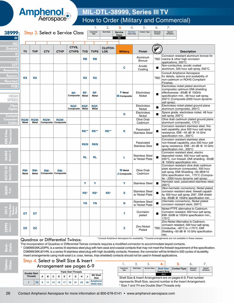
Step 3. Select a Service Class Connector Type
Shell Style Service Class
Shell Size- Insert Arrg.
Contact Type Alternate Position
Special Variations
RX
1. 2. 3. 4. 5. 6. 7.
Step 4. Select a Shell Size & Insert Arrangement see pages 6-9
Connector Type
Shell Style Service Class Shell Size-Insert Arrg.
Contact Type Alternate Position
Special Variations
23-2 P
1. 2. 3. 4. 5. 6. 7.
Shell Size & Insert Arrangement are on pages 6-9. First number represents Shell Size, second number is the Insert Arrangement.
Quadrax or Differential Twinax: The incorporation of Quadrax or Differential Twinax contacts requires a modified connector to accommodate keyed contacts.* D38999/26KJ20PN, is a series III stainless steel plug with twin axial and coaxial contacts that may not meet the firewall requirement of the specification. D38999/26KJ61HN, is a series III stainless steel plug with high durability contacts. However, the connector will be limited to 500 cycles of durability. Insert arrangements using multi-axial (i.e. coax, twinax, triax shielded) contacts should not be used in firewall applications.
* Consult Amphenol Aerospace for availability. **Coaxial arrangements are not available in these classes.
TV TVP CTV CTVPCTVS, CTVPS TVS TVPS
CLUTCH-LOK Military Finish Description
RB RB Aluminum Bronze TBD
Corrosion resistant aluminum bronze for marine & other high corrosion applications, 200°C.
C Anodic Coating n
Non-conductive, anodic coated aluminum, 500 hour salt spray, 200°C.
RX RX RX RX TBD
Consult Amphenol Aerospace for details, options and availability of non-cadmium or ROHS Compliant Finishes.
RF- Composite
RF- Metal
RF- Metal
F-Metal M-Composite
Electroless Nickel n
Electroless nickel plated aluminum (composite) optimum EMI shielding effectiveness –65dB @ 10GHz specification min., 48 hour salt spray, 200°C (Composite-2000 hours dynamic salt spray).
RGF- Composite
RGF- Metal
RGF- Metal
Electroless Nickel n
Electroless nickel plated ground plane aluminum (composite), 200°C
G Electroless Nickel n
Space grade, electroless nickel, 48 hour salt spray, 200°C
RGW- Metal
RGW- Metal
RGW- Composite
RGW- Composite
Olive Drab Cadmium
Olive drab cadmium plated ground plane aluminum (composite), 175°C
RK** RK** RK** K Passivated Stainless Steel n
Corrosion resistant stainless steel, fire-wall capability, plus 500 hour salt spray resistance, EMI –45 dB @ 10 GHz specification min., 200°C
RKN RKN Passivated Stainless Stee n
Corrosion resistant stainless steel, non-firewall capability, plus 500 hour salt spray resistance, EMI –45 dB @ 10 GHz specification min., 200°C
RL RL L Stainless Steel w/ Nickel Plate n
Corrosion resistant steel, electro deposited nickel, 500 hour salt spray, 200°C, non firewall, EMI shielding –65dB @ 10GHz specification min.
RW- Metal
RW- Metal
RW- Composite
RW- Composite
W-Metal J-Composite
Olive Drab Cadmium
Corrosion resistant olive drab cadmium plate aluminum (composite), 500 hour salt spray, EMI Shielding –50 dB@10 GHz specification min., 175°C (Compos-ite - 2000 hours dynamic salt spray).
Y Y Y Stainless Steel nHermetic seal, passivated stainless steel, 200°C
RS* RS* RS* S Stainless Steel w/ Nickel Plate n
(Non-hermetic connectors), Nickel plated, corrosion resistant steel, firewall capabil-ity, 500 hour salt spray, 200°, EMI shield-ing –65dB @ 10GHz specification min.
YN YN N Stainless Steel w/ Nickel Plate n
(Hermetic connectors), Nickel plated corrosion resistant steel, 200°C
DT DT T Durmalon plated n
Nickel-PTFE alternative to Cadmium. Corrosion resistant, 500 hour salt spray, EMI -50dB at 10GHz specification min., 175°C
DZ DZ Z Zinc-Nickel Plated TBD
Zinc-Nickel Alternative to Cadmium, corrosion resistant, 500 hour salt spray, Conductive, –65°C to +175°C, EMI Shielding –50 dB @ 10 GHz specification min.
Double Start Threads
Triple Start Threads
A B C D E F G H JMil Shell
Size
7 7H 9 11 13 15 17 19 21 23 25Amphenol Shell size
RoHSAmphenol
EU/ 2002 / 95 / EC
* Size 7 and 7H are Double Start Threads only

27Contact Amphenol Aerospace for more information at 800-678-0141 • www.amphenol-aerospace.com
26482M
atrix 2
II Dualok
III
SJT
38999
I
83723 IIIM
atrix|Pyle5015
Crimp Rear
Release M
atrix
26500 Pyle
22992 C
lass L
PCB
Back- Shells
Options
Others
Accessories
Aquacon
HD
EMI Filter
Transient
Herm/Seal
Fiber Optics
ContactsConnectorsCables
HIgH SPEED
AmphenolAerospace
Step 6. Select an Alternate Keying PositionKey/Keyway Position
A plug with a given rotation letter will mate with a receptacle with the same rotation letter. The angles for a given connec-tor are the same whether it contains pins or sockets. Master key stays fixed, minor keys rotate. Inserts are not rotated in conjunction with the master key/keyway.
PLUG (front face shown)
RECEPTACLE (front face shown)
MAINKEYWAY
APBSC
BPBSC
DPBSC
CPBSC
˚
˚
˚˚
DRBSC̊ CR
BSC̊
BRBSC̊
ARBSC̊
MAINKEYWAY
MIL-DTL-38999, Series III TV How to Order (Military and Commercial)
Connector Type
Shell Style Service Class Shell Size-Insert Arrg.
Contact Type Alternate Position
Special Variations
P B
1. 2. 3. 4. 5. 6. 7.
Step 7. Special Variations Consult Amphenol Aerospace for variations.
Connector Type
Shell Style Service Class Shell Size-Insert Arrg.
Contact Type Alternate Position
Special Variations
P (xxx)
1. 2. 3. 4. 5. 6. 7.
* An “N” designation is used on D38999 military part number but not on the commercial versions
Designates
P Pin Contacts
S Socket Contacts
H 1500 Cycle Pin Contacts
J 1500 Cycle Socket Contacts
A Same as “P” except supplied less pin Contacts
B Same as “S” except supplied less socket contacts ( A & B designate nonstandard contact applications)
X Eyelet contacts, hermetics only
Step 5. Select a Contact Type
AR°
BR°
AP°
BP°
RECEPTACLE(FRONT FACE SHOWN)
PLUG(FRONT FACE SHOWN)
Size 7 and 7H Dualok Plug and Receptacle
Shell Size
Key & Keyway Arrangement Identification
Letter
AR° or AP° BSC
BR° or BP° BSC
CR° or CP° BSC
DR° or DP° BSC
7, 7H
N* A B C D E
12013280
140155131
240248230275234197
NA NA
9
N* A B C D E
10510280356491
140132118140155131
215248230205234197
265320312275304240
11, 13, and 15
N* A B C D E
951139053
11951
141156145156146141
208182195220176184
236292252255298242
17 and 19
N* A B C D E
8013549666279
142170169140145153
196200200200180197
293310244257280272
21, 23, and 25
N* A B C D E
8013549666279
142170169140145153
196200200200180197
293 310 244 257 280 272
25L, 33, and 37
N* A B C D E
8013549666279
142170169140145153
188188188188188188
293 310 244 257 280 272

28 Contact Amphenol Aerospace for more information at 800-678-0141 • www.amphenol-aerospace.com
2648
2M
atrix
2
Dualok
III
SJT
38999
8372
3 III
5015
2650
0 Py
le
2299
2 C
lass
L
PCB
Back
- Sh
ells
Opt
ions
O
ther
s
HD
EMI F
ilter
Tran
sien
t
I II
Crim
p Re
arRe
leas
e M
atrix
Mat
rix|P
yle
Accessories
Herm/Seal
Aquacon
Fiber Optics
ContactsConnectors
Cables
HIgH SPEED
AmphenolAerospace
Boeing Basic Number
Style Shell Size Shell Finish & Contact
Insert Arrangement
Contact Type
Alternate Keying Position
Ordering Option
BACC63 CT 15 — 19 P N H
Easy Steps to build a part number... Boeing BACC63 CT & CU1. 2. 3. 4. 5. 6. 7. 8.
Step 1. Boeing Number BACC63
Step 2. Select a StyleDesignates
CT Composite Plug
CU Composite Receptacle
Step 3. Shell Size 15
Step 4. Select a Shell Finish & Contact
Designates
C CT Style Only. Cadmium Plated, Grounded
D Cadmium Plated, ungrounded
G Nickel Plated, Grounded
— Nickel Plated, Ungrounded
Step 6. Select a Contact TypeDesignates
P Pin
S Socket
Step 7. Select an Alternate Keying Position
Boeing Basic Number
Style Shell Size
Separator Insert Arrangement
Contact Type
Alternate Keying Position
Ordering Option
BACC63 DB 15 — 19 P N H
BACC63 DC 17 — 8 P N H
Easy Steps to build a part number... Boeing BACC63 DB & DC1. 2. 3. 4. 5. 6. 7. 8.
Step 1. Boeing Number BACC63
Step 2. Select a StyleDesignates
DB Stainless Steel Plug
DC Stainless Steel Receptacle
Step 3. Select a Shell Size
Step 4. Separator
Designates
9-25 Shell Size
Step 5. Insert Arrangements-Consult Amphenol Aerospace for insert arrangements available.
Step 6. Select a Contact TypeDesignates
P Pin
S Socket
Step 7. Select an Alternate Keying Position
Step 8. Ordering Option Designates
H Without Contacts & Seal Plugs
Blank With Contacts & Seal Plugs
Step 8. Ordering Option Designates
H Without Contacts & Seal Plugs
Blank With Contacts & Seal Plugs
Designates
N Normal
A-E Alternates
Designates
15 One Shell Size
Designates
N Normal
A-E Alternates
Designates
— Separator
Boeing BACC63 How to Order
Composite
Stainless Steel
Step 5. Insert Arrangements-Consult Amphenol Aerospace for insert arrangements available.

29Contact Amphenol Aerospace for more information at 800-678-0141 • www.amphenol-aerospace.com
26482M
atrix 2
II Dualok
III
SJT
38999
I
83723 IIIM
atrix|Pyle5015
Crimp Rear
Release M
atrix
26500 Pyle
22992 C
lass L
PCB
Back- Shells
Options
Others
Accessories
Aquacon
HD
EMI Filter
Transient
Herm/Seal
Fiber Optics
ContactsConnectorsCables
HIgH SPEED
AmphenolAerospace
1. 2. 3. 4. 5. 6. 7. 8.
M
M
.005
.13
T4 PLACES
TT4 PLACES
S2 PLACES
2 PLACES
2 PLACES
R1
R2
V THREADAABTHREAD
LL (TV)LL (CTV)1
M (TV)M (CTV)1
L (TV)L (CTV)1
1.240 MAX31.50 MAX
REDBAND†
BLUEBAND†† –A–
Z (TV)Z (CTV)1
.861 MAX21.87 MAX(TV)
.909 MAX23.09 MAX(CTV)
1.037 MAX26.34 MAX(TV)
1.084 MAX27.53 MAX(CTV)
D
VIEW DFOR SIZE 8 TWINAX ONLY,RELATIVE TO
VIEW DFOR SIZE 8 COAXIAL ONLY,RELATIVE TO
–A–
–A–
† Red band indicates fully mated
†† Blue band indicates rear release contact retention system
Millimeters
Inches
All dimensions for reference only Designates true position dimensioning
BACK PANELMOUNTING
FRONT PANELMOUNTING
A1
A2
PANEL HOLE DIMENSIONS
TVP00R (D38999/20) - Crimp, Metal CTVP00R (D38999/20) - Crimp, Composite
Wall Mounting Receptacle
Shell Size
MS Shell Size Code
B Thread Class 2A
0.1P=0.3L-TS (Plated)
L Max. (TV)
L1 Max. (CTV)
M +.000 –.005 (TV)
M1 +.000 –.005 (CTV)
R1 R2
S Max.T
±.008
Z. Max. (TV)
Z1 Max. (CTV)
A1 Back Panel Mount
A2 Front Panel Mount
AA Max. Panel Thick-ness
LL +.006 –.000 (TV)
LL1±.005(CTV)
TT±.008
9 A .6250 .469 .514 .820 .773 .719 .594 .948 .128 .153 .198 .650 .510 .234 .905 .908 .216
11 B .7500 .469 .514 .820 .773 .812 .719 1.043 .128 .153 .198 .800 .620 .234 .905 .908 .194
13 C .8750 .469 .514 .820 .773 .906 .812 1.137 .128 .153 .198 .910 .740 .234 .905 .908 .194
15 D 1.0000 .469 .514 .820 .773 .969 .906 1.232 .128 .153 .198 1.040 .900 .234 .905 .908 .173
17 E 1.1875 .469 .514 .820 .773 1.062 .969 1.323 .128 .153 .198 1.210 1.010 .234 .905 .908 .194
19 F 1.2500 .469 .514 .820 .773 1.156 1.062 1.449 .128 .153 .198 1.280 1.130 .234 .905 .908 .194
21 G 1.3750 .500 .545 .790 .741 1.250 1.156 1.575 .128 .183 .228 1.410 1.250 .204 .905 .904 .194
23 H 1.5000 .500 .545 .790 .741 1.375 1.250 1.701 .154 .183 .228 1.530 1.360 .204 .905 .904 .242
25 J 1.6250 .500 .545 .790 .741 1.500 1.375 1.823 .154 .183 .228 1.660 1.470 .204 .905 .904 .242
Shell Size
MS Shell Size Code
L Max. (TV)
L1 Max. (CTV)
M +.00 –.13 (TV)
M1 +.00 –.13
(CTV)
R1 R2
S Max.
T ±.20
V Thread Metric
Z. Max. (TV)
Z1 Max. (CTV)
A1 Back Panel Mount
A2 Front Panel Mount
AA Max.
LL +.15 –.00 (TV)
LL1±.13
(CTV)TT
±.209 A 11.91 13.06 20.83 19.63 18.26 15.09 24.1 3.25 M12X1-6g 3.89 5.03 16.66 13.11 5.94 22.99 23.06 5.49
11 B 11.91 13.06 20.83 19.63 20.62 18.26 26.5 3.25 M15X1-6g 3.89 5.03 20.22 15.88 5.94 22.99 23.06 4.93
13 C 11.91 13.06 20.83 19.63 23.01 20.62 28.9 3.25 M18X1-6g 3.89 5.03 23.42 19.05 5.94 22.99 23.06 4.93
15 D 11.91 13.06 20.83 19.63 24.61 23.01 31.3 3.25 M22X1-6g 3.89 5.03 26.59 23.01 5.94 22.99 23.06 4.39
17 E 11.91 13.06 20.83 19.63 26.97 24.61 33.7 3.25 M25X1-6g 3.89 5.03 30.96 25.81 5.94 22.99 23.06 4.93
19 F 11.91 13.06 20.83 19.63 29.36 26.97 36.9 3.25 M28X1-6g 3.89 5.03 32.94 28.98 5.94 22.99 23.06 4.93
21 G 12.70 13.84 20.07 18.82 31.75 29.36 40.1 3.25 M31X1-6g 4.65 5.79 36.12 32.16 5.18 22.99 22.96 4.93
23 H 12.70 13.84 20.07 18.82 34.93 31.75 43.3 3.91 M34X1-6g 4.65 5.79 39.29 34.93 5.18 22.99 22.96 6.15
25 J 12.70 13.84 20.07 18.82 38.10 34.93 46.4 3.91 M37X1-6g 4.65 5.79 42.47 37.69 5.18 22.99 22.96 6.15
METAL
TVP 00 RW 9-35 P B (453)TVPS 00 RK X-X X X (XXX)TVPS 00 RF X-X X X (XXX)TVPS 00 RS X-X X X (XXX)CTVP 00 RW X-X X X (XXX)
CTVPS 00 RF X-X X X (XXX)D38999/ 20 X X-X X X NA
ConnectorType
Shell Style
Service Class
Shell Size& Insert Arrg
Contact Type
Alternate Position
Special Variations
To complete, see how to order pages 25-27.
PART #

30 Contact Amphenol Aerospace for more information at 800-678-0141 • www.amphenol-aerospace.com
2648
2M
atrix
2
Dualok
III
SJT
38999
8372
3 III
5015
2650
0 Py
le
2299
2 C
lass
L
PCB
Back
- Sh
ells
Opt
ions
O
ther
s
HD
EMI F
ilter
Tran
sien
t
I II
Crim
p Re
arRe
leas
e M
atrix
Mat
rix|P
yle
Accessories
Herm/Seal
Aquacon
Fiber Optics
ContactsConnectors
Cables
HIgH SPEED
AmphenolAerospace
† Red band indicates fully mated
†† Blue band indicates rear release contact retention system
Consult Amphenol Aerospace for availability of composite box mount receptacles.
Millimeters
Inches
M (TV)M (CTV)
LL (TV)LL (CTV)
1
1
AAB
THREAD
BLUEBAND††
REDBAND†
L (TV)L (CTV)1
Z (TV)Z (CTV)1
M
M
.005
.13
T4 PLACES
TT4 PLACES
S2 PLACES
2 PLACES
2 PLACES
R1
R2
All dimensions for reference only Designates true position dimensioning
BACK PANELMOUNTING
FRONT PANELMOUNTING
A1
A2
PANEL HOLE DIMENSIONS
TVP02R – Crimp, Metal CTVP02R – Crimp, Composite
Box Mounting Receptacle
Shell Size
MS Shell Size Code
B Thread Class 2A
0.1P=0.3L-TS (Plated)
L Max. (TV)
L1 Max. (CTV)
M +.000 –.005 (TV)
M1 +.000 –.005 (CTV)
R1 R2
S Max.
T ±.008
Z. Max. (TV)
Z1 Max. (CTV)
A1 Back Panel Mount
A2 Front Panel Mount
AA Max. Panel Thick-ness
LL +.006 –.000 (TV)
LL1±.005(CTV)
TT±.008
9 A .6250 .205 .250 .820 .773 .719 .594 .948 .128 .153 .198 .650 .510 .234 .905 .908 .216
11 B .7500 .205 .250 .820 .773 .812 .719 1.043 .128 .153 .198 .800 .620 .234 .905 .908 .194
13 C .8750 .205 .250 .820 .773 .906 .812 1.137 .128 .153 .198 .910 .740 .234 .905 .908 .194
15 D 1.0000 .205 .250 .820 .773 .969 .906 1.232 .128 .153 .198 1.040 .900 .234 .905 .908 .173
17 E 1.1875 .205 .250 .820 .773 1.062 .969 1.323 .128 .153 .198 1.210 1.010 .234 .905 .908 .194
19 F 1.2500 .205 .250 .820 .773 1.156 1.062 1.449 .128 .153 .198 1.280 1.130 .234 .905 .908 .194
21 G 1.3750 .235 .280 .790 .741 1.250 1.156 1.575 .128 .183 .228 1.410 1.250 .204 .905 .904 .194
23 H 1.5000 .235 .280 .790 .741 1.375 1.250 1.701 .154 .183 .228 1.530 1.360 .204 .905 .904 .242
25 J 1.6250 .235 .280 .790 .741 1.500 1.375 1.823 .154 .183 .228 1.660 1.470 .204 .905 .904 .242
Shell Size
MS Shell Size Code
L Max. (TV)
L1 Max. (CTV)
M +.00 –.13 (TV)
M1 +.00 –.13
(CTV)
R1 R2
S Max.
T ±.20
Z. Max. (TV)
Z1 Max. (CTV)
A1 Back Panel Mount
A2 Front Panel Mount
AA Max.
LL +.15 –.00 (TV)
LL1±.13
(CTV)TT
±.209 A 5.21 6.35 20.83 19.63 18.26 15.09 24.1 3.25 3.89 5.03 16.66 13.11 5.94 22.99 23.06 5.49
11 B 5.21 6.35 20.83 19.63 20.62 18.26 26.5 3.25 3.89 5.03 20.22 15.88 5.94 22.99 23.06 4.93
13 C 5.21 6.35 20.83 19.63 23.01 20.62 28.9 3.25 3.89 5.03 23.42 19.05 5.94 22.99 23.06 4.93
15 D 5.21 6.35 20.83 19.63 24.61 23.01 31.3 3.25 3.89 5.03 26.59 23.01 5.94 22.99 23.06 4.39
17 E 5.21 6.35 20.83 19.63 26.97 24.61 33.7 3.25 3.89 5.03 30.96 25.81 5.94 22.99 23.06 4.93
19 F 5.21 6.35 20.83 19.63 29.36 26.97 36.9 3.25 3.89 5.03 32.94 28.98 5.94 22.99 23.06 4.93
21 G 5.97 7.11 20.07 18.82 31.75 29.36 40.1 3.25 4.65 5.79 36.12 32.16 5.18 22.99 22.96 4.93
23 H 5.97 7.11 20.07 18.82 34.92 31.75 43.3 3.91 4.65 5.79 39.29 34.93 5.18 22.99 22.96 6.15
25 J 5.97 7.11 20.07 18.82 38.10 34.92 46.4 3.91 4.65 5.79 42.47 37.69 5.18 22.99 22.96 6.15
METAL
TVP 02 RW 9-35 P B (453)TVPS 02 RK X-X X X (XXX)TVPS 02 RF X-X X X (XXX)TVPS 02 RS X-X X X (XXX)CTVP 02 RW X-X X X (XXX)
CTVPS 02 RF X-X X X (XXX)
ConnectorType
Shell Style
Service Class
Shell Size& Insert Arrg
Contact Type
Alternate Position
Special Variations
To complete, see how to order pages 25-27.
PART #

31Contact Amphenol Aerospace for more information at 800-678-0141 • www.amphenol-aerospace.com
26482M
atrix 2
II Dualok
III
SJT
38999
I
83723 IIIM
atrix|Pyle5015
Crimp Rear
Release M
atrix
26500 Pyle
22992 C
lass L
PCB
Back- Shells
Options
Others
Accessories
Aquacon
HD
EMI Filter
Transient
Herm/Seal
Fiber Optics
ContactsConnectorsCables
HIgH SPEED
AmphenolAerospace
1.234 MAX31.34 MAX
1.220 MAX31.00 MAX B THREAD
D
V THREAD
.359 MAX9.12 MAX
.359 MAX9.12 MAX
.591 +.003–.000
15.01 +.08–.00
BLUE BAND†
1.234 MAX31.34 MAX
Q
1.656 MAX42.06 MAX
1.797 MAX45.64 MAX
VIEW DFOR SIZE 8 TWINAX ONLY,RELATIVE TO
VIEW DFOR SIZE 8 COAXIAL ONLY,RELATIVE TO
–A–
–A–
–A–
V THREAD
.591 +.003–.000
15.01 +.08–.00
–A–
QB THREAD
D
BLUE BAND†
† Blue band indicates rear release contact retention system
All dimensions for reference only.
Inches Millimeters
COMPOSITE
TV06R (D38999/26) – Crimp, Metal CTV06R (D38999/26) – Crimp, Composite
Straight Plug
Shell Size
MS Shell Size Code
B Thread 0.1P-0.3L-TS-2B
(Plated) Q Dia. Max.
9 A .6250 .858
11 B .7500 .984
13 C .8750 1.157
15 D 1.0000 1.280
17 E 1.1875 1.406
19 F 1.2500 1.516
21 G 1.3750 1.642
23 H 1.5000 1.768
25 J 1.6250 1.890
Shell Size
MS Shell Size Code Q Max. V Thread Metric
9 A 21.8 M12X1-6g
11 B 25.0 M15X1-6g
13 C 29.4 M18X1-6g
15 D 32.5 M22X1-6g
17 E 35.7 M25X1-6g
19 F 38.5 M28X1-6g
21 G 41.7 M31X1-6g
23 H 44.9 M34X1-6g
25 J 48.0 M37X1-6g
METAL
METAL
TV 06 RW 9-35 P B (453)TVS 06 RK X-X X X (XXX)TVS 06 RF X-X X X (XXX)TVS 06 RS X-X X X (XXX)CTV 06 RW X-X X X (XXX)
CTVS 06 RF X-X X X (XXX)D38999/ 26 X X-X X X NA
ConnectorType
Shell Style
Service Class
Shell Size& Insert Arrg
Contact Type
Alternate Position
Special Variations
To complete, see how to order pages 25-27.
PART #
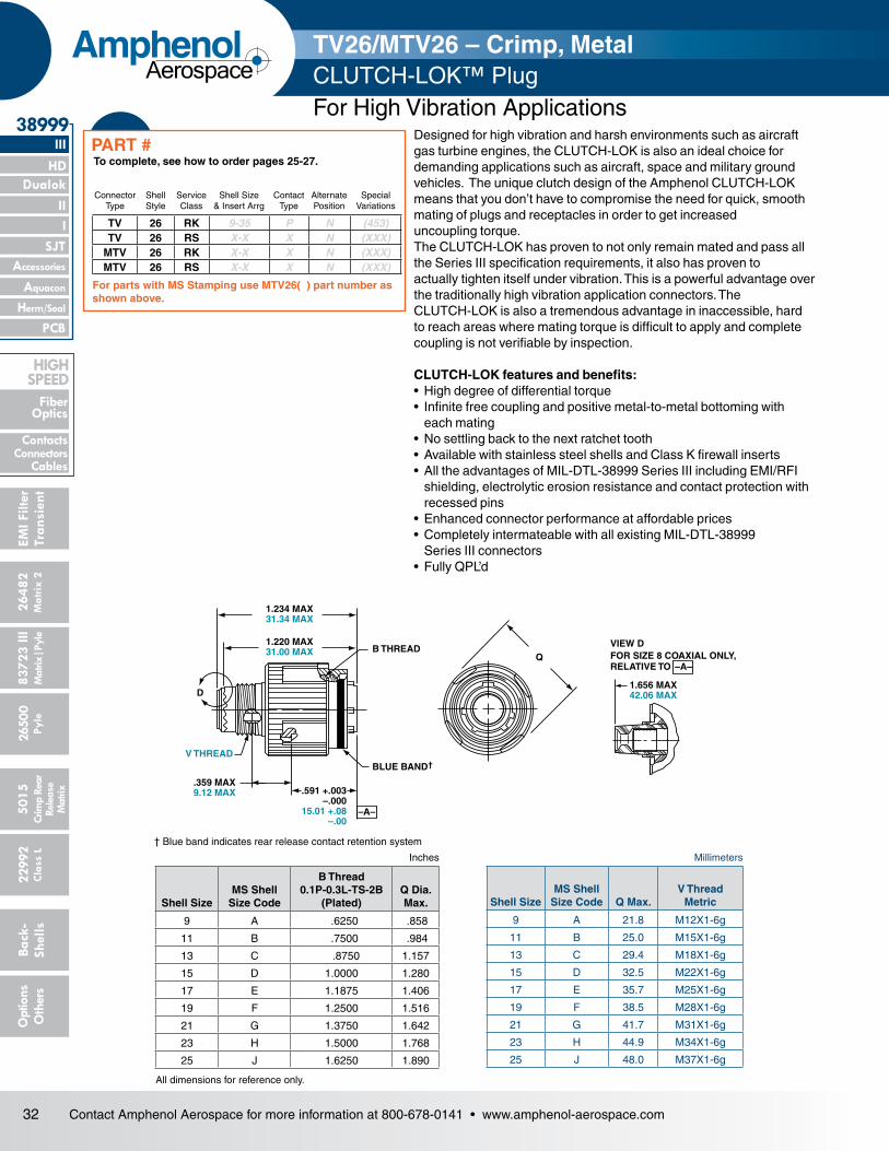
32 Contact Amphenol Aerospace for more information at 800-678-0141 • www.amphenol-aerospace.com
2648
2M
atrix
2
Dualok
III
SJT
38999
8372
3 III
5015
2650
0 Py
le
2299
2 C
lass
L
PCB
Back
- Sh
ells
Opt
ions
O
ther
s
HD
EMI F
ilter
Tran
sien
t
I II
Crim
p Re
arRe
leas
e M
atrix
Mat
rix|P
yle
Accessories
Herm/Seal
Aquacon
Fiber Optics
ContactsConnectors
Cables
HIgH SPEED
AmphenolAerospace
Designed for high vibration and harsh environments such as aircraft gas turbine engines, the CLUTCH-LOK is also an ideal choice for demanding applications such as aircraft, space and military ground vehicles. The unique clutch design of the Amphenol CLUTCH-LOK means that you don’t have to compromise the need for quick, smooth mating of plugs and receptacles in order to get increased uncoupling torque.The CLUTCH-LOK has proven to not only remain mated and pass all the Series III specification requirements, it also has proven to actually tighten itself under vibration. This is a powerful advantage over the traditionally high vibration application connectors. The CLUTCH-LOK is also a tremendous advantage in inaccessible, hard to reach areas where mating torque is difficult to apply and complete coupling is not verifiable by inspection.
CLUTCH-LOK features and benefits:• High degree of differential torque• Infinite free coupling and positive metal-to-metal bottoming with each mating• No settling back to the next ratchet tooth• Available with stainless steel shells and Class K firewall inserts• All the advantages of MIL-DTL-38999 Series III including EMI/RFI shielding, electrolytic erosion resistance and contact protection with recessed pins• Enhanced connector performance at affordable prices• Completely intermateable with all existing MIL-DTL-38999 Series III connectors• Fully QPL’d
† Blue band indicates rear release contact retention system
All dimensions for reference only.
Inches Millimeters
1.234 MAX31.34 MAX
1.220 MAX31.00 MAX B THREAD
D
V THREAD
.359 MAX9.12 MAX .591 +.003
–.00015.01 +.08
–.00
BLUE BAND†
Q
1.656 MAX42.06 MAX
VIEW DFOR SIZE 8 COAXIAL ONLY,RELATIVE TO –A–
–A–
TV26/MTV26 – Crimp, Metal CLUTCH-LOK™ Plug For High Vibration Applications
Shell SizeMS Shell
Size Code
B Thread 0.1P-0.3L-TS-2B
(Plated)Q Dia. Max.
9 A .6250 .858
11 B .7500 .984
13 C .8750 1.157
15 D 1.0000 1.280
17 E 1.1875 1.406
19 F 1.2500 1.516
21 G 1.3750 1.642
23 H 1.5000 1.768
25 J 1.6250 1.890
Shell SizeMS Shell
Size Code Q Max.V Thread
Metric
9 A 21.8 M12X1-6g
11 B 25.0 M15X1-6g
13 C 29.4 M18X1-6g
15 D 32.5 M22X1-6g
17 E 35.7 M25X1-6g
19 F 38.5 M28X1-6g
21 G 41.7 M31X1-6g
23 H 44.9 M34X1-6g
25 J 48.0 M37X1-6g
TV 26 RK 9-35 P N (453)TV 26 RS X-X X N (XXX)
MTV 26 RK X-X X N (XXX)MTV 26 RS X-X X N (XXX)
ConnectorType
Shell Style
Service Class
Shell Size& Insert Arrg
Contact Type
Alternate Position
Special Variations
To complete, see how to order pages 25-27.PART #
For parts with MS Stamping use MTV26( ) part number as shown above.

33Contact Amphenol Aerospace for more information at 800-678-0141 • www.amphenol-aerospace.com
26482M
atrix 2
II Dualok
III
SJT
38999
I
83723 IIIM
atrix|Pyle5015
Crimp Rear
Release M
atrix
26500 Pyle
22992 C
lass L
PCB
Back- Shells
Options
Others
Accessories
Aquacon
HD
EMI Filter
Transient
Herm/Seal
Fiber Optics
ContactsConnectorsCables
HIgH SPEED
AmphenolAerospace
C
H
S2 PLACES
PANEL THICKNESS.062 MIN .125 MAX1.57 MIN 3.18 MAX
BLUE BAND††
.378 MAX9.60 MAX
1.280 MAX32.51 MAX
K REFSHELL SIZES 9/11 –
.871 22.12SHELL SIZES 13/25 –
.878 22.30
.091 MAX2.31 MAX
B THREAD
V THREAD
D
REDBAND†
–A–
.794 MAX20.17 MAX
.940 MAX23.88 MAX
VIEW DFOR SIZE 8 TWINAX ONLY,RELATIVE TO
VIEW DFOR SIZE 8 COAXIAL ONLY,RELATIVE TO
–A–
–A–
† Red band indicates fully mated
†† Blue band indicates rear release contact retention system
★ .059 dia min. 1.5 dia min., 3 lockwire holes Formed lockwire hole design (6 holes) is optional
Millimeters
All dimensions for reference only NOTE: Deep reach receptacles are available for panel thicknesses up to .750 max.
PANEL HOLE DIMENSIONS
JAM NUTD-HOLE
MOUNTING
D1
D2
Inches
TV07R (D38999/24) – Crimp, Metal CTV07R (D38999/24) – Crimp, Composite
Shell Size
MS Shell Size Code
B Thread Class 2A
0.1P-0.3L-TS (Plated) C Max.
D1
+.010 –.000
D2
+.000 –.010
H Hex+.017 –.016
S ±.010
9 A .6250 1.199 .693 .657 .875 1.062
11 B .7500 1.386 .825 .770 1.000 1.250
13 C .8750 1.511 1.010 .955 1.188 1.375
15 D 1.0000 1.636 1.135 1.085 1.312 1.500
17 E 1.1875 1.761 1.260 1.210 1.438 1.625
19 F 1.2500 1.949 1.385 1.335 1.562 1.812
21 G 1.3750 2.073 1.510 1.460 1.688 1.938
23 H 1.5000 2.199 1.635 1.585 1.812 2.062
25 J 1.6250 2.323 1.760 1.710 2.000 2.188
Shell Size
MS Shell Size Code C Max.
D1
+.25 –.00
D2
+.00 –.25
H Hex+.43 –.41
S ±.25
V Thread Metric
9 A 30.45 17.60 16.70 22.23 26.97 M12X1-6g
11 B 35.20 20.96 19.59 25.40 31.75 M15X1-6g
13 C 38.38 25.65 24.26 30.18 34.93 M18X1-6g
15 D 41.55 28.83 27.56 33.32 38.10 M22X1-6g
17 E 44.73 32.01 30.73 36.53 41.28 M25X1-6g
19 F 49.50 35.18 33.91 39.67 46.02 M28X1-6g
21 G 52.65 38.35 37.08 42.80 49.23 M31X1-6g
23 H 55.85 41.53 40.26 46.02 52.37 M34X1-6g
25 J 59.00 44.70 43.43 50.80 55.58 M37X1-6g
Jam Nut Receptacle
TV 07 RW 9-35 P B (453)TVS 07 RK X-X X X (XXX)TVS 07 RF X-X X X (XXX)TVS 07 RS X-X X X (XXX)CTV 07 RW X-X X X (XXX)
CTVS 07 RF X-X X X (XXX)D38999/ 24 X X-X X X NA
ConnectorType
Shell Style
Service Class
Shell Size& Insert Arrg
Contact Type
Alternate Position
Special Variations
To complete, see how to order pages 25-27.
PART #

34 Contact Amphenol Aerospace for more information at 800-678-0141 • www.amphenol-aerospace.com
2648
2M
atrix
2
Dualok
III
SJT
38999
8372
3 III
5015
2650
0 Py
le
2299
2 C
lass
L
PCB
Back
- Sh
ells
Opt
ions
O
ther
s
HD
EMI F
ilter
Tran
sien
t
I II
Crim
p Re
arRe
leas
e M
atrix
Mat
rix|P
yle
Accessories
Herm/Seal
Aquacon
Fiber Optics
ContactsConnectors
Cables
HIgH SPEED
AmphenolAerospace
GG (TV)GG (CTV)1
S (TV)S (CTV)
2 PLACES1
BTHREAD
LL (TV)LL (CTV)1
1M (TV)M (CTV)
.280 MIN FULL THD7.11 MIN FULL THD
L (TV)L (CTV)1
Z (TV)Z (CTV)1
1.240MAX31.50 MAX
V THREAD
D
–A–
REDBAND†
BLUEBAND††
.861 MAX21.87 MAX(TV)
.909 MAX23.09 MAX(CTV)
1.037 MAX26.34 MAX(TV)
1.084 MAX27.53 MAX(CTV)
VIEW DFOR SIZE 8 TWINAX ONLY,RELATIVE TO
VIEW DFOR SIZE 8 COAXIAL ONLY,RELATIVE TO
–A–
–A–
† Red band indicates fully mated
†† Blue band indicates rear release contact retention system
Millimeters
All dimensions for reference only
Inches
TV01R – Crimp, Metal CTV01R – Crimp, Composite
Shell Size
MS Shell Size Code
B Thread 0.1P-0.3L-
TS-2A (Plated)
M +.000 –.005 (TV)
M1
+.000 –.005 (CTV)
L Max. (TV)
L1 Max. (CTV)
S ±.010 (TV)
S1 ±.010 (CTV)
Z Max (TV)
Z1 Max (CTV)
GG ±.010 (TV)
GG1 ±.010 (CTV)
LL +.006 –.000 (TV)
LL1 ±.005 (CTV)
9 A .6250 .820 .773 .469 .514 .675 .635 .153 .198 .812 .699 .905 .908
11 B .7500 .820 .773 .469 .514 .800 .765 .153 .198 .905 .875 .905 .908
13 C .8750 .820 .773 .469 .514 .925 .885 .153 .198 1.093 1.007 .905 .908
15 D 1.0000 .820 .773 .469 .514 1.050 1.100 .153 .198 1.219 1.140 .905 .908
17 E 1.1875 .820 .773 .469 .514 1.238 1.197 .153 .198 1.375 1.229 .905 .908
19 F 1.2500 .820 .773 .469 .514 1.300 1.260 .153 .198 1.469 1.380 .905 .908
21 G 1.3750 .790 .741 .500 .545 1.425 1.385 .183 .228 1.625 1.493 .905 .904
23 H 1.5000 .790 .741 .500 .545 1.550 1.510 .183 .228 1.750 1.626 .905 .904
25 J 1.6250 .790 .741 .500 .545 1.675 1.635 .183 .228 1.875 1.777 .905 .904
Shell Size
MS Shell Size Code
M +.00–.013
(TV)
M1
+.00 –.13
(CTV)L Max.
(TV)
L1 Max. (CTV)
S ±.25 (TV)
S1 ±.010 (CTV)
V Thread Metric
Z Max (TV)
Z1 Max (CTV)
GG ±.25 (TV)
GG1 ±.25 (CTV)
LL +.15 –.00 (TV)
LL1 ±.13
(CTV)
9 A 20.83 19.63 11.91 13.06 17.15 16.13 M12X1-6g 3.89 5.03 20.62 17.75 22.99 23.06
11 B 20.83 19.63 11.91 13.06 20.32 19.43 M15X1-6g 3.89 5.03 22.99 22.22 22.99 23.06
13 C 20.83 19.63 11.91 13.06 23.50 22.47 M18X1-6g 3.89 5.03 27.76 25.57 22.99 23.06
15 D 20.83 19.63 11.91 13.06 26.67 27.94 M22X1-6g 3.89 5.03 30.96 28.95 22.99 23.06
17 E 20.83 19.63 11.91 13.06 31.45 30.40 M25X1-6g 3.89 5.03 34.93 31.21 22.99 23.06
19 F 20.83 19.63 11.91 13.06 33.02 32.00 M28X1-6g 3.89 5.03 37.31 35.05 22.99 23.06
21 G 20.07 18.82 12.70 13.84 36.20 35.18 M31X1-6g 4.65 5.79 41.28 37.92 22.99 22.96
23 H 20.07 18.82 12.70 13.84 39.37 38.35 M34X1-6g 4.65 5.79 44.45 41.30 22.99 22.96
25 J 20.07 18.82 12.70 13.84 42.55 41.53 M37X1-6g 4.65 5.79 47.63 45.13 22.99 22.96
TV 01 RW 9-35 P B (453)TVS 01 RF X-X X X (XXX)CTV 01 RW X-X X X (XXX)
CTVS 01 RF X-X X X (XXX)
ConnectorType
Shell Style
Service Class
Shell Size& Insert Arrg
Contact Type
Alternate Position
Special Variations
To complete, see how to order pages 25-27.
PART #
Line Receptacle

35Contact Amphenol Aerospace for more information at 800-678-0141 • www.amphenol-aerospace.com
26482M
atrix 2
II Dualok
III
SJT
38999
I
83723 IIIM
atrix|Pyle5015
Crimp Rear
Release M
atrix
26500 Pyle
22992 C
lass L
PCB
Back- Shells
Options
Others
Accessories
Aquacon
HD
EMI Filter
Transient
Herm/Seal
Fiber Optics
ContactsConnectorsCables
HIgH SPEED
AmphenolAerospace
BLUEBAND†
G.190 +.010
–.0004.82 +.26
–.00
BTHREAD
Q
.591 +.003–.000
15.01+.08–.00
3.59 MAX9.12 MAX
GG
M.005
M.13
.138-32UNC-2BHELICAL COIL–A–
R
R
1.656 MAX42.06 MAX
1.797 MAX45.64 MAX
VIEW DFOR SIZE 8 TWINAX ONLY,RELATIVE TO
VIEW DFOR SIZE 8 COAXIAL ONLY,RELATIVE TO
–A–
–A–
D
† Blue band indicates rear release contact retention system
Millimeters
All dimensions for reference only Designates true position dimensioning ** Partially tooled. Consult Amphenol Aerospace for availability
Inches
Shell Size
MS Shell Size
Coded
B Thread 0.1P-0.3L-TS-2A
(Plated) G ±.060Q Dia. Max
R GG Dia ±.005
9** A .6250 1.106 .859 1.038 1.838
11 B .7500 1.106 .969 1.115 1.948
13** C .8750 1.106 1.141 1.240 2.124
15 D 1.0000 1.106 1.266 1.327 2.248
17 E 1.1875 1.106 1.391 1.417 2.375
19 F 1.2500 1.356 1.500 1.557 2.495
21 G 1.3750 1.356 1.625 1.624 2.568
23 H 1.5000 1.356 1.750 1.713 2.723
25 J 1.6250 1.356 1.875 1.801 2.848
Shell Size
MS Shell Size
Coded G ±.1.52 Q Dia. MaxR
GG Dia ±.13
9** A 28.09 21.82 26.37 46.69
11 B 28.09 24.62 28.32 49.48
13** C 28.09 28.98 31.50 53.95
15 D 28.09 32.16 33.71 57.10
17 E 28.09 35.33 35.99 60.33
19 F 34.44 38.10 39.55 63.37
21 G 34.44 41.28 41.25 65.23
23 H 34.44 44.45 43.51 69.16
25 J 34.44 47.63 45.75 72.34
TV09R – Crimp, MetalFlange Mounting Plug
TV 09 RW 9-35 P B (453)TVS 09 RF X-X X X (XXX)
ConnectorType
Shell Style
Service Class
Shell Size& Insert Arrg
Contact Type
Alternate Position
Special Variations
To complete, see how to order pages 25-27.
PART #

36 Contact Amphenol Aerospace for more information at 800-678-0141 • www.amphenol-aerospace.com
2648
2M
atrix
2
Dualok
III
SJT
38999
8372
3 III
5015
2650
0 Py
le
2299
2 C
lass
L
PCB
Back
- Sh
ells
Opt
ions
O
ther
s
HD
EMI F
ilter
Tran
sien
t
I II
Crim
p Re
arRe
leas
e M
atrix
Mat
rix|P
yle
Accessories
Herm/Seal
Aquacon
Fiber Optics
ContactsConnectors
Cables
HIgH SPEED
AmphenolAerospace
† Red band indicates fully mated
NOTE: Consult Amphenol Aerospace for availability of non-glass-sealed versions with printed circuit tail contacts.
Millimeters
All dimensions for reference only Designates true position dimensioning
Inches
S2 PLACES
R
R2
1
2 PLACES
2 PLACES
TT4 PLACES
.005
.13
M
M
T4 PLACES
B THREAD
REDBAND†
.250 MAX6.35 MAX
1
.913 +.011–.000
23.19 +.28–.00 .093 +.006
–.0002.36 +.15
–.00
TVPS02Y (D38999/21) – HermeticStainless Steel
Shell SizeMS Shell
Size Coded
B Thread 0.1P-0.3L-TS
(Plated)R1 R2 S
±.010T
±.008TT
±.008
9 A .6250 .719 .594 .938 .128 .216
11 B .7500 .812 .719 1.031 .128 .194
13 C .8750 .906 .812 1.125 .128 .194
15 D 1.0000 .969 .906 1.219 .128 .173
17 E 1.1875 1.062 .969 1.312 .128 .194
19 F 1.2500 1.156 1.062 1.438 .128 .194
21 G 1.3750 1.250 1.156 1.562 .128 .194
23 H 1.5000 1.375 1.250 1.688 .154 .242
25 J 1.6250 1.500 1.375 1.812 .154 .242
Shell SizeMS Shell
Size CodedR1 R2 S
±.25T
±.20TT
±.20
9 A 18.26 15.09 23.83 3.25 5.49
11 B 20.62 18.26 26.19 3.25 4.93
13 C 23.01 20.62 28.58 3.25 4.93
15 D 24.61 23.01 30.96 3.25 4.39
17 E 26.97 24.61 33.32 3.25 4.93
19 F 29.36 26.97 36.53 3.25 4.93
21 G 31.75 29.36 39.67 3.25 4.93
23 H 34.93 31.75 42.88 3.91 6.15
25 J 38.10 34.93 46.02 3.91 6.15
TVPS 02 Y 9-35 P B (453)TVPS 02 YN X-X X X (XXX)
D38999/ 21 X X-X X X NA
ConnectorType
Shell Style
Service Class
Shell Size& Insert Arrg
Contact Type
Alternate Position
Special Variations
To complete, see how to order pages 25-27.
PART #
Box Mounting Receptacle

37Contact Amphenol Aerospace for more information at 800-678-0141 • www.amphenol-aerospace.com
26482M
atrix 2
II Dualok
III
SJT
38999
I
83723 IIIM
atrix|Pyle5015
Crimp Rear
Release M
atrix
26500 Pyle
22992 C
lass L
PCB
Back- Shells
Options
Others
Accessories
Aquacon
HD
EMI Filter
Transient
Herm/Seal
Fiber Optics
ContactsConnectorsCables
HIgH SPEED
AmphenolAerospace
† Red band indicates fully mated
★ . 059 dia min. 1.5 dia min. Formed lockwire hole design (6 holes) is optional.
3 lockwire holes
Millimeters
Inches
All dimensions for reference only
C
H
S2 PLACES
K REF
.200 MAX5.08 MAX
KK
REDBAND†B THREAD
L
PANEL THICKNESS.062 MIN .125 MAX1.57 MIN 3.18 MAX
SHELL SIZES 9/11 – .871 22.12SHELL SIZES 13/25 – .878 22.30
PANEL HOLE DIMENSIONS
JAM NUTD-HOLE
MOUNTING
D1
D2
TVS07Y (D38999/23) – HermeticStainless SteelJam Nut Receptacle
Shell Size
MS Shell Size code
B Thread Class 2A
0.1P-0.3L-TS (Plated) C Max
D1 +.010 –.000
D2 +.000 –.010
H Hex +.017 –.016 L Max S ±.010
KK +.011 –.000
9 A .6250 1.199 .693 .657 .875 .357 1.062 .642
11 B .7500 1.386 .825 .770 1.000 .357 1.250 .766
13 C .8750 1.511 1.010 .955 1.188 .357 1.375 .892
15 D 1.0000 1.636 1.135 1.085 1.312 .357 1.500 1.018
17 E 1.1875 1.761 1.260 1.210 1.438 .357 1.625 1.142
19 F 1.2500 1.949 1.385 1.335 1.562 .381 1.812 1.268
21 G 1.3750 2.073 1.510 1.460 1.688 .381 1.938 1.392
23 H 1.5000 2.199 1.635 1.585 1.812 .381 2.062 1.518
25 J 1.6250 2.323 1.760 1.710 2.000 .381 2.188 1.642
Shell Size
MS Shell Size code C Max D1 +.25 –.00 D2 +.00 –.25
H Hex +.43 –.41 L Max S ±.25
KK +.28 –.00
9 A 30.45 17.60 16.70 22.23 9.07 26.97 16.31
11 B 35.20 20.96 19.59 25.40 9.07 31.75 19.46
13 C 38.38 25.65 24.26 30.18 9.07 34.93 22.66
15 D 41.55 28.83 27.56 33.32 9.07 38.10 25.86
17 E 44.73 32.01 30.73 36.53 9.07 41.28 29.01
19 F 49.50 35.18 33.91 39.67 9.68 46.02 32.21
21 G 52.65 38.35 37.08 42.80 9.68 49.23 35.36
23 H 55.85 41.53 40.26 46.02 9.68 52.37 38.56
25 J 59.00 44.70 43.43 50.80 9.68 55.58 41.71
TVS 07 Y 9-35 P B (453)TVS 07 YN X-X X X (XXX)
D38999/ 23 X X-X X X NA
ConnectorType
Shell Style
Service Class
Shell Size& Insert Arrg
Contact Type
Alternate Position
Special Variations
To complete, see how to order pages 25-27.
PART #
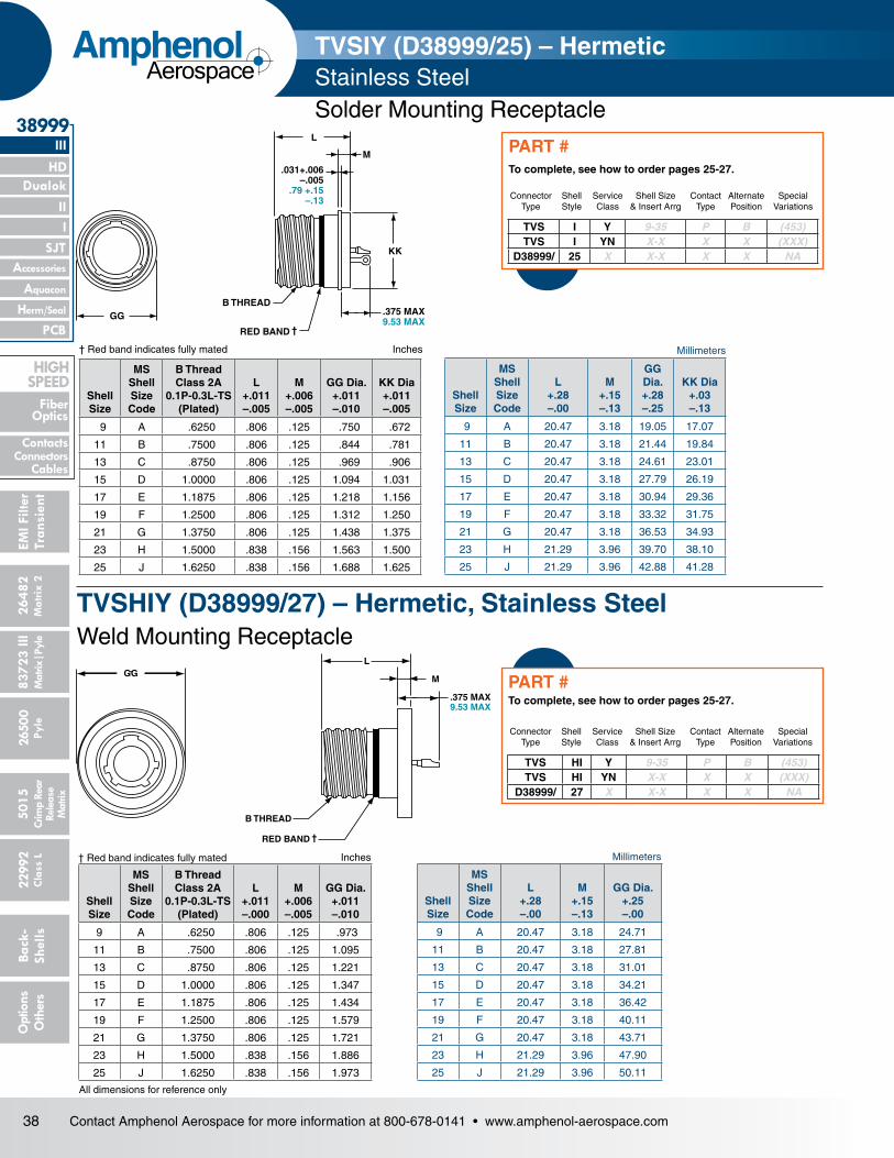
38 Contact Amphenol Aerospace for more information at 800-678-0141 • www.amphenol-aerospace.com
2648
2M
atrix
2
Dualok
III
SJT
38999
8372
3 III
5015
2650
0 Py
le
2299
2 C
lass
L
PCB
Back
- Sh
ells
Opt
ions
O
ther
s
HD
EMI F
ilter
Tran
sien
t
I II
Crim
p Re
arRe
leas
e M
atrix
Mat
rix|P
yle
Accessories
Herm/Seal
Aquacon
Fiber Optics
ContactsConnectors
Cables
HIgH SPEED
AmphenolAerospace
MillimetersInches
All dimensions for reference only
† Red band indicates fully mated
GGB THREAD
RED BAND †
.375 MAX9.53 MAX
KK
M
L
.031+.006–.005
.79 +.15–.13
GG
B THREAD
RED BAND †
L
M
.375 MAX9.53 MAX
MillimetersInches† Red band indicates fully mated
TVSIY (D38999/25) – HermeticStainless Steel Solder Mounting Receptacle
TVSHIY (D38999/27) – Hermetic, Stainless SteelWeld Mounting Receptacle
Shell Size
MS Shell Size Code
B Thread Class 2A
0.1P-0.3L-TS (Plated)
L+.011–.005
M+.006–.005
GG Dia.+.011–.010
KK Dia+.011–.005
9 A .6250 .806 .125 .750 .672
11 B .7500 .806 .125 .844 .781
13 C .8750 .806 .125 .969 .906
15 D 1.0000 .806 .125 1.094 1.031
17 E 1.1875 .806 .125 1.218 1.156
19 F 1.2500 .806 .125 1.312 1.250
21 G 1.3750 .806 .125 1.438 1.375
23 H 1.5000 .838 .156 1.563 1.500
25 J 1.6250 .838 .156 1.688 1.625
Shell Size
MS Shell Size Code
L+.28–.00
M+.15–.13
GG Dia.+.28–.25
KK Dia+.03–.13
9 A 20.47 3.18 19.05 17.07
11 B 20.47 3.18 21.44 19.84
13 C 20.47 3.18 24.61 23.01
15 D 20.47 3.18 27.79 26.19
17 E 20.47 3.18 30.94 29.36
19 F 20.47 3.18 33.32 31.75
21 G 20.47 3.18 36.53 34.93
23 H 21.29 3.96 39.70 38.10
25 J 21.29 3.96 42.88 41.28
Shell Size
MS Shell Size Code
B Thread Class 2A
0.1P-0.3L-TS (Plated)
L+.011–.000
M+.006–.005
GG Dia.+.011–.010
9 A .6250 .806 .125 .973
11 B .7500 .806 .125 1.095
13 C .8750 .806 .125 1.221
15 D 1.0000 .806 .125 1.347
17 E 1.1875 .806 .125 1.434
19 F 1.2500 .806 .125 1.579
21 G 1.3750 .806 .125 1.721
23 H 1.5000 .838 .156 1.886
25 J 1.6250 .838 .156 1.973
Shell Size
MS Shell Size Code
L+.28–.00
M+.15–.13
GG Dia.+.25–.00
9 A 20.47 3.18 24.71
11 B 20.47 3.18 27.81
13 C 20.47 3.18 31.01
15 D 20.47 3.18 34.21
17 E 20.47 3.18 36.42
19 F 20.47 3.18 40.11
21 G 20.47 3.18 43.71
23 H 21.29 3.96 47.90
25 J 21.29 3.96 50.11
TVS HI Y 9-35 P B (453)TVS HI YN X-X X X (XXX)
D38999/ 27 X X-X X X NA
ConnectorType
Shell Style
Service Class
Shell Size& Insert Arrg
Contact Type
Alternate Position
Special Variations
To complete, see how to order pages 25-27.
PART #
TVS I Y 9-35 P B (453)TVS I YN X-X X X (XXX)
D38999/ 25 X X-X X X NA
ConnectorType
Shell Style
Service Class
Shell Size& Insert Arrg
Contact Type
Alternate Position
Special Variations
To complete, see how to order pages 25-27.
PART #
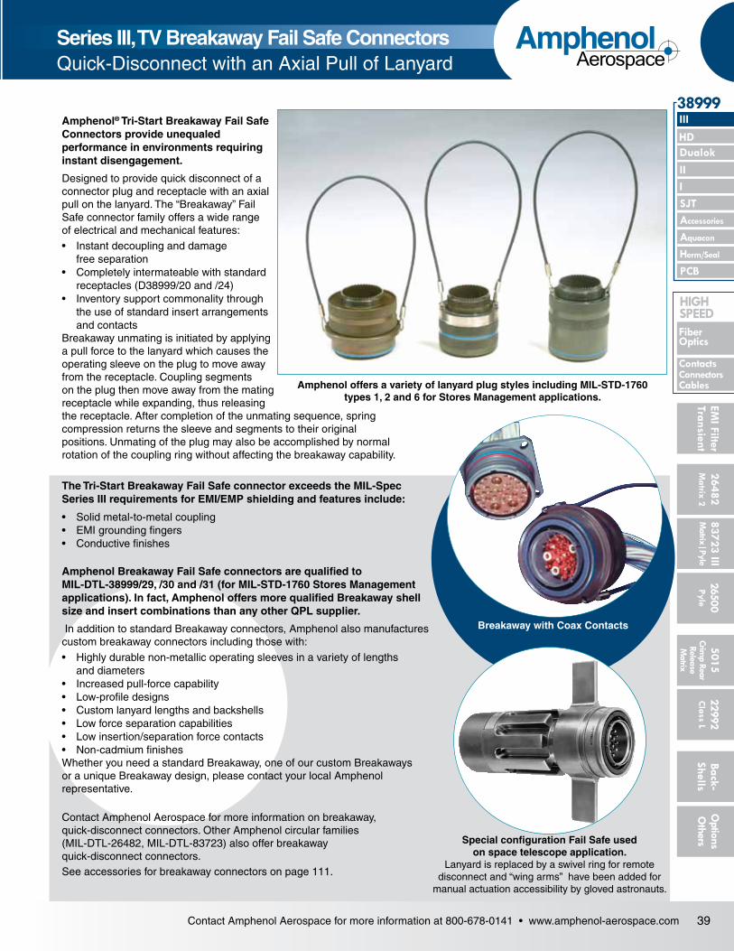
39Contact Amphenol Aerospace for more information at 800-678-0141 • www.amphenol-aerospace.com
26482M
atrix 2
II Dualok
III
SJT
38999
I
83723 IIIM
atrix|Pyle5015
Crimp Rear
Release M
atrix
26500 Pyle
22992 C
lass L
PCB
Back- Shells
Options
Others
Accessories
Aquacon
HD
EMI Filter
Transient
Herm/Seal
Fiber Optics
ContactsConnectorsCables
HIgH SPEED
AmphenolAerospace
Breakaway with Coax Contacts
Amphenol offers a variety of lanyard plug styles including MIL-STD-1760 types 1, 2 and 6 for Stores Management applications.
Series III, TV Breakaway Fail Safe Connectors Quick-Disconnect with an Axial Pull of Lanyard
TYPE 2 TYPE 6 TYPE 1
Amphenol® Tri-Start Breakaway Fail Safe Connectors provide unequaled performance in environments requiring instant disengagement.
Designed to provide quick disconnect of a connector plug and receptacle with an axial pull on the lanyard. The “Breakaway” Fail Safe connector family offers a wide range of electrical and mechanical features:• Instant decoupling and damage
free separation• Completely intermateable with standard
receptacles (D38999/20 and /24)• Inventory support commonality through
the use of standard insert arrangements and contacts
Breakaway unmating is initiated by applying a pull force to the lanyard which causes the operating sleeve on the plug to move away from the receptacle. Coupling segments on the plug then move away from the mating receptacle while expanding, thus releasing the receptacle. After completion of the unmating sequence, spring compression returns the sleeve and segments to their original positions. Unmating of the plug may also be accomplished by normal rotation of the coupling ring without affecting the breakaway capability.
The Tri-Start Breakaway Fail Safe connector exceeds the MIL-Spec Series III requirements for EMI/EMP shielding and features include:
• Solid metal-to-metal coupling• EMI grounding fingers• Conductive finishes
Amphenol Breakaway Fail Safe connectors are qualified to MIL-DTL-38999/29, /30 and /31 (for MIL-STD-1760 Stores Management applications). In fact, Amphenol offers more qualified Breakaway shell size and insert combinations than any other QPL supplier.
In addition to standard Breakaway connectors, Amphenol also manufactures custom breakaway connectors including those with:• Highly durable non-metallic operating sleeves in a variety of lengths
and diameters• Increased pull-force capability• Low-profile designs• Custom lanyard lengths and backshells• Low force separation capabilities• Low insertion/separation force contacts• Non-cadmium finishesWhether you need a standard Breakaway, one of our custom Breakaways or a unique Breakaway design, please contact your local Amphenol representative.
Contact Amphenol Aerospace for more information on breakaway, quick-disconnect connectors. Other Amphenol circular families (MIL-DTL-26482, MIL-DTL-83723) also offer breakaway quick-disconnect connectors.See accessories for breakaway connectors on page 111.
Special configuration Fail Safe used on space telescope application.
Lanyard is replaced by a swivel ring for remote disconnect and “wing arms” have been added for
manual actuation accessibility by gloved astronauts.
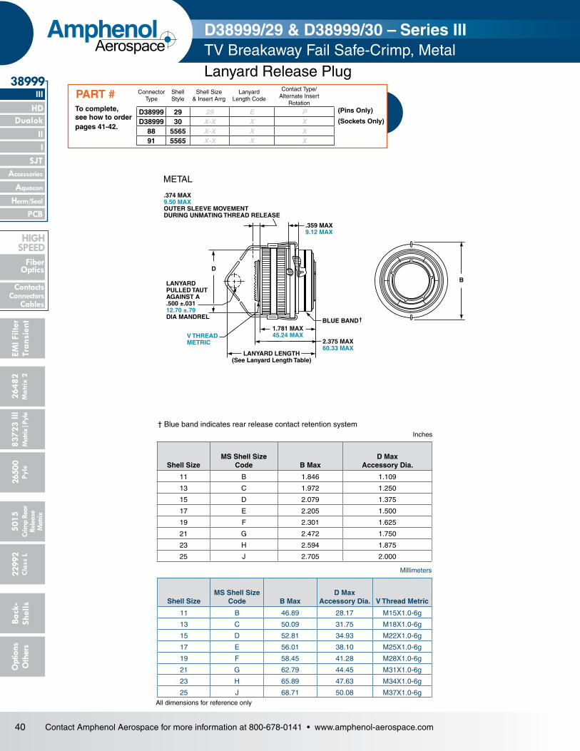
40 Contact Amphenol Aerospace for more information at 800-678-0141 • www.amphenol-aerospace.com
2648
2M
atrix
2
Dualok
III
SJT
38999
8372
3 III
5015
2650
0 Py
le
2299
2 C
lass
L
PCB
Back
- Sh
ells
Opt
ions
O
ther
s
HD
EMI F
ilter
Tran
sien
t
I II
Crim
p Re
arRe
leas
e M
atrix
Mat
rix|P
yle
Accessories
Herm/Seal
Aquacon
Fiber Optics
ContactsConnectors
Cables
HIgH SPEED
AmphenolAerospace
D
.374 MAX9.50 MAXOUTER SLEEVE MOVEMENTDURING UNMATING THREAD RELEASE
LANYARDPULLED TAUTAGAINST A .500 ±.03112.70 ±.79DIA MANDREL
V THREADMETRIC
1.781 MAX45.24 MAX
2.375 MAX60.33 MAX
BLUE BAND †
B
.359 MAX9.12 MAX
LANYARD LENGTH(See Lanyard Length Table)
† Blue band indicates rear release contact retention system
Millimeters
All dimensions for reference only
Inches
D38999/29 & D38999/30 – Series IIITV Breakaway Fail Safe-Crimp, Metal
Shell SizeMS Shell Size
Code B MaxD Max
Accessory Dia.
11 B 1.846 1.109
13 C 1.972 1.250
15 D 2.079 1.375
17 E 2.205 1.500
19 F 2.301 1.625
21 G 2.472 1.750
23 H 2.594 1.875
25 J 2.705 2.000
Shell SizeMS Shell Size
Code B MaxD Max
Accessory Dia. V Thread Metric
11 B 46.89 28.17 M15X1.0-6g
13 C 50.09 31.75 M18X1.0-6g
15 D 52.81 34.93 M22X1.0-6g
17 E 56.01 38.10 M25X1.0-6g
19 F 58.45 41.28 M28X1.0-6g
21 G 62.79 44.45 M31X1.0-6g
23 H 65.89 47.63 M34X1.0-6g
25 J 68.71 50.08 M37X1.0-6g
METAL
Lanyard Release Plug
D38999 29 29 E PD38999 30 X-X X X
88 5565 X-X X X91 5565 X-X X X
ConnectorType
Shell Style
Shell Size& Insert Arrg
Lanyard Length Code
Contact Type/Alternate Insert
RotationTo complete, see how to order pages 41-42.
PART #(Pins Only)
(Sockets Only)

41Contact Amphenol Aerospace for more information at 800-678-0141 • www.amphenol-aerospace.com
26482M
atrix 2
II Dualok
III
SJT
38999
I
83723 IIIM
atrix|Pyle5015
Crimp Rear
Release M
atrix
26500 Pyle
22992 C
lass L
PCB
Back- Shells
Options
Others
Accessories
Aquacon
HD
EMI Filter
Transient
Herm/Seal
Fiber Optics
ContactsConnectorsCables
HigH Speed
AmphenolAerospace
TV D38999/29 & D38999/30 – Series IIIBreakaway Fail Safe Lanyard Release Plug
Commercial Basic Part#
Shell & Insert Arrg. Code
Shell Size- Insert
Arrangement
Military Shell Size- Insert
Arrangement
Service Rating
Total Contacts
Contact Size
22D 20 16 12 12 Coax
8 Coax
8 Twinax
88/91-556508 11-2 N/A I 2 206 11-35 N/A M 13 1307 11-98 N/A I 6 610 13-4 N/A I 4 411 13-8 N/A I 8 814 13-35 N/A M 22 2213 13-98 N/A I 10 1018 15-5 N/A II 5 523 15-15 N/A I 15 14 122 15-18 N/A I 18 1819 15-19 N/A I 19 1920 15-35 N/A M 37 3721 15-97 N/A I 12 8 427 17-6 E-6 I 6 628 17-8 E-8 II 8 829 17-26 E-26 I 26 2630 17-35 E-35 M 55 5531 17-99 E-99 I 23 21 237 19-11 F-11 II 11 1139 19-32 F-32 I 32 3240 19-35 F-35 M 66 6647 21-11 G-11 I 11 1148 21-16 G-16 II 16 1649 21-35 G-35 M 79 7951 21-39 G-39 I 39 37 250 21-41 G-41 I 41 4157 23-21 H-21 II 21 2158 23-35 H-35 M 100 10059 23-53 H-53 I 53 5361 23-54 H-54 M 53 40 9 460 23-55 H-55 I 55 5571 25-4 J-4 I 56 48 866 25-19 J-19 I 19 1974 25-20 J-20 N 30 10 13 4 372 25-24 J-24 I 24 12 1267 25-29 J-29 I 29 2968 25-35 J-35 M 128 12869 25-43 J-43 I 43 23 2073 25-46 J-46 I 46 40 4 2*70 25-61 J-61 I 61 61
Step 2. Select a Specification Sheet Number
DOD Number Prefix
Spec Sheet Number
Service Class Shell Size Insert Arrangement
Lanyard Length Code
Alternate Keying Position
D38999/ 29 F E 35 P N
Easy Steps to build a part number... Military 1. 2. 3. 4. 5. 6. 7.
Step 3. Select a Service Class
Step 4. & 5 Insert Availability
Step 1. DOD Number PrefixD38999/ designates MIL-DTL-38999, Series III, Tri-Start Connector
29 Designates Lanyard Release Plug with pin contacts30 Designates Lanyard Release Plug with socket contacts
FDesignates electroless nickel plated aluminum, optimum EMI shielding effectiveness –65dB@10 GHz specification min., 48 hour salt spray, 200°C
WDesignates corrosion resistant olive drab cadmium plate aluminum, 500 hour extended salt spray, EMI –50dB@10 GHz specification min., 175°C
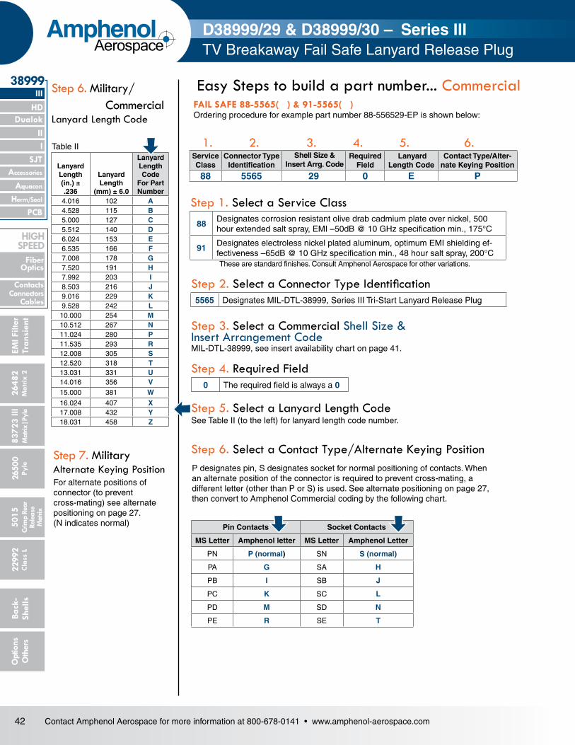
42 Contact Amphenol Aerospace for more information at 800-678-0141 • www.amphenol-aerospace.com
2648
2M
atrix
2
Dualok
III
SJT
38999
8372
3 III
5015
2650
0 Py
le
2299
2 C
lass
L
PCB
Back
- Sh
ells
Opt
ions
O
ther
s
HD
EMI F
ilter
Tran
sien
t
I II
Crim
p Re
arRe
leas
e M
atrix
Mat
rix|P
yle
Accessories
Herm/Seal
Aquacon
Fiber Optics
ContactsConnectors
Cables
HIgH SPEED
AmphenolAerospace
FAIL SAFE 88-5565( ) & 91-5565( )Ordering procedure for example part number 88-556529-EP is shown below:
D38999/29 & D38999/30 – Series IIITV Breakaway Fail Safe Lanyard Release Plug
Lanyard Length (in.) ± .236
Lanyard Length
(mm) ± 6.0
Lanyard Length Code
For Part Number
4.016 102 A4.528 115 B5.000 127 C5.512 140 D6.024 153 E6.535 166 F7.008 178 G7.520 191 H7.992 203 I8.503 216 J9.016 229 K9.528 242 L10.000 254 M10.512 267 N11.024 280 P11.535 293 R12.008 305 S12.520 318 T13.031 331 U14.016 356 V15.000 381 W
16.024 407 X17.008 432 Y18.031 458 Z
Service Class
Connector Type Identification
Shell Size & Insert Arrg. Code
Required Field
Lanyard Length Code
Contact Type/Alter-nate Keying Position
88 5565 29 0 E P
Easy Steps to build a part number... Commercial
1. 2. 3. 4. 5. 6.
These are standard finishes. Consult Amphenol Aerospace for other variations.
Step 1. Select a Service Class
Step 2. Select a Connector Type Identification
Step 3. Select a Commercial Shell Size & Insert Arrangement CodeMIL-DTL-38999, see insert availability chart on page 41.
P designates pin, S designates socket for normal positioning of contacts. When an alternate position of the connector is required to prevent cross-mating, a different letter (other than P or S) is used. See alternate positioning on page 27, then convert to Amphenol Commercial coding by the following chart.
Step 6. Select a Contact Type/Alternate Keying Position
Step 6. Military/ Commercial Lanyard Length Code
Pin Contacts Socket Contacts
MS Letter Amphenol letter MS Letter Amphenol Letter
PN P (normal) SN S (normal)
PA G SA H
PB I SB J
PC K SC L
PD M SD N
PE R SE T
Step 5. Select a Lanyard Length Code See Table II (to the left) for lanyard length code number.
For alternate positions of connector (to prevent cross-mating) see alternate positioning on page 27. (N indicates normal)
Step 7. Military Alternate Keying Position
Table II
Step 4. Required Field
88Designates corrosion resistant olive drab cadmium plate over nickel, 500 hour extended salt spray, EMI –50dB @ 10 GHz specification min., 175°C
91Designates electroless nickel plated aluminum, optimum EMI shielding ef-fectiveness –65dB @ 10 GHz specification min., 48 hour salt spray, 200°C
5565 Designates MIL-DTL-38999, Series III Tri-Start Lanyard Release Plug
0 The required field is always a 0

43Contact Amphenol Aerospace for more information at 800-678-0141 • www.amphenol-aerospace.com
26482M
atrix 2
II Dualok
III
SJT
38999
I
83723 IIIM
atrix|Pyle5015
Crimp Rear
Release M
atrix
26500 Pyle
22992 C
lass L
PCB
Back- Shells
Options
Others
Accessories
Aquacon
HD
EMI Filter
Transient
Herm/Seal
Fiber Optics
ContactsConnectorsCables
HIgH SPEED
AmphenolAerospace
Service Class
Connector Type Identification
Shell Size & Insert Arrg. Code
Required Field
Lanyard Length Code
Contact Type/Alter-nate Keying Position
88 5565 29 0 E P2.008 MAX51.00 MAX
BLUEBAND †
1.687 MAX42.85 MAX
2.030 MAX51.56 MAX
**
.100 MAX2.54 MAXOUTER SLEEVE MOVEMENTDURING UNMATING THREAD RELEASE
2.000 MAX50.80 MAXACCESS.
DIA
LANYARD LENGTH(See Lanyard Length Table)
METRIC THREADM37X1.0-6g0.100R
**2.000 MAX50.80 MAXACCESS.
DIA
.374 MAX9.50 MAXOUTER SLEEVE MOVEMENTDURING UNMATING THREAD RELEASE
.359 MAX9.12 MAX
2.705 MAX68.71 MAX
BLUE BAND †
1.781 MAX45.24 MAX
2.375 MAX60.33 MAX
LANYARD LENGTH(See Lanyard Length Table)
METRICTHREADM37X1.0-6g0.100R
.359 MAX9.12 MAX
TYPE 6 TYPE 2
† Blue band indicates rear release contact retention system ** Lanyard pulled taut against a .500 ± .13 dia. MandrelAll dimensions for reference only
PIN CONTACTS ONLY, SHELL SIZE 25 ONLY
BLUE BAND †
2.000 MAX50.80 MAXACCESS.
DIA
2.008 MAX51.00 MAX
.359 MAX9.12 MAX
METRIC THREADM37X1.0-6g0.100R
.280 MIN7.11 MINFULLTHREAD
LANYARD LENGTH(See Lanyard Length Table)
2.499 MAX63.47 MAX
TYPE 1 (LONGER SHELL)
Pin Contact Data for MIL-STD-1760
A B
C
D
E
F
G
H
J
K
L
M
N
P
R
S
T
U
VWX
Y
Z
1
23
4
5
67
A
B
C
D
EF
G
HJ
KL
INSERT AVAILABILITY FAIL SAFE D38999/31
FOR MIL-STD-1760
25-20 Primary Interface Signal Set
Contact Legend
8 (twinax) 10 (power) 12 (coax) 16 20
25-11 Auxiliary Power Signal Set
*Part number reference. To complete, see how to order page 41.
D38999/31
88-555875/76 91-555875/76
88-558518/19 91-558518/19
T3W-16B25-XXXX
Type 6
Type 2
Type 1
D38999/31 for MIL-STD-1760 – Series IIITV Breakaway Fail Safe – Crimp, MetalLanyard Release Plug
Tri-Start Lanyard Separation Forces
Shell Size
Straight Plug (lbs. max.)
15 Degree Pull (lbs. max.)
25 90 100
Insert ArrangementService Rating
Total Contacts
Contact
20 16 12 (Coax) 8 (Twinax)
25-20 N 30 10 13 4 3
Contacts for 25-20 Pattern
Shell Size
Arrg. Number
Number of
ContactsSize
ContactsService Rating
Contact Location
Standard Contacts
Pin Socket
25 -20
3 8 Twinax A, H, K M39029/90-529 M39029/91-530
4 12 Coax2,3 M39029/28-211 M39029/75-416
W, 5 M39029/102-558 M39029/103-559
13 16 N
C, D, E, F, J, M, N,
P, R, T, U, Y, Z
M39029/58-364 M39029/56-352
10 20 N B, G, L, S, V, X, 1, 4,
6, 7M39029/58-363 M39029/56-351
Insert Arrangement
Service Rating
Total Contacts
Contact Size
20 10 (power)
25-11 N 11 2 9
*To order by Commercial Part numbers consult Amphenol.

44 Contact Amphenol Aerospace for more information at 800-678-0141 • www.amphenol-aerospace.com
2648
2M
atrix
2
Dualok
III
SJT
38999
8372
3 III
5015
2650
0 Py
le
2299
2 C
lass
L
PCB
Back
- Sh
ells
Opt
ions
O
ther
s
HD
EMI F
ilter
Tran
sien
t
I II
Crim
p Re
arRe
leas
e M
atrix
Mat
rix|P
yle
Accessories
Herm/Seal
Aquacon
Fiber Optics
ContactsConnectors
Cables
HIgH SPEED
AmphenolAerospace
HOW TO ORDER - BY MILITARY PART NUMBER FAIL SAFE D38999/31Ordering procedure for example part number D38999/31WE20PN1 is shown below:
1. 2. 3. 4. 5. 6. 7. 8.DOD Number
PrefixSpec Sheet
NumberService Class
Lanyard Length Code
Insert Arrangement
Contact Style Alternate Keying Position
Type Number
D38999/ 31 W E 20 P N 1
Easy Steps to build a part number... Military
1. Select a DOD Number Prefix
2. Specification Sheet Number
Lanyard Length (in.) ±.236
Lanyard Length (mm.) ± 6.0
Lanyard Length Code for Part Number
6.024 153.0 E6.535 166.0 F7.008 178.0 G7.520 191.0 H7.992 203.0 I8.504 216.0 J9.016 229.0 K9.528 242.0 L
7. Alternate Keying Position
D38999/31 for MIL-STD-1760 – Series IIITV Breakaway Fail Safe for Stores ManagementApplications- Lanyard Release Plug
Designates
F
Electroless nickel plated aluminum, optimum EMI shielding effectiveness –65dB @ 10 GHz specification min., 48 hour salt spray, 200°C
W
Corrosion resistant olive drab cadmium plate aluminum, 500 hour extended salt spray, EMI –50dB @ 10 GHz specification min., 175°C
Designates
D38999/MIL-DTL-38999, Series III Tri-Start Connectors
Designates
31Designates Lanyard Release Plug for MIL-STD-1760 with pin contacts
Designates
PReplaces the “no designation” option in the PIN on revision C and earlier revision of the Mil-Spec.
A Designates supplied less contacts.
6. Contact Style – P & A are Valid Options
Designates
N Is required for normal position.
3. Select a Service Class
4. Select a Lanyard Length Code
8. Type Number Type 1, 2 or 6. See drawings on page 43.For accessories for lanyard release plugs see Accessories section.
5. Select an Insert ArrangementOnly 11 or 20 are available contact arrangement numbers. See page 43.
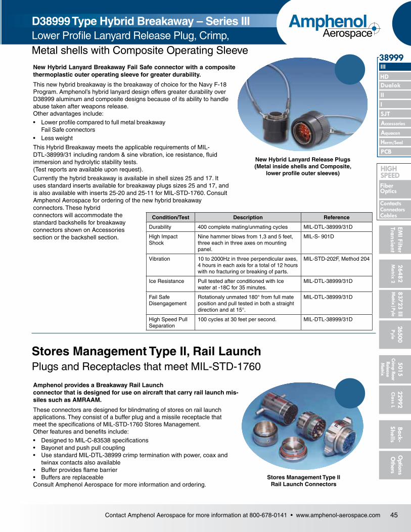
45Contact Amphenol Aerospace for more information at 800-678-0141 • www.amphenol-aerospace.com
26482M
atrix 2
II Dualok
III
SJT
38999
I
83723 IIIM
atrix|Pyle5015
Crimp Rear
Release M
atrix
26500 Pyle
22992 C
lass L
PCB
Back- Shells
Options
Others
Accessories
Aquacon
HD
EMI Filter
Transient
Herm/Seal
Fiber Optics
ContactsConnectorsCables
HIgH SPEED
AmphenolAerospace
D38999 Type Hybrid Breakaway – Series IIILower Profile Lanyard Release Plug, Crimp,Metal shells with Composite Operating SleeveNew Hybrid Lanyard Breakaway Fail Safe connector with a composite thermoplastic outer operating sleeve for greater durability.
This new hybrid breakaway is the breakaway of choice for the Navy F-18 Program. Amphenol’s hybrid lanyard design offers greater durability over D38999 aluminum and composite designs because of its ability to handle abuse taken after weapons release. Other advantages include:• Lower profile compared to full metal breakaway
Fail Safe connectors• Less weight
This Hybrid Breakaway meets the applicable requirements of MIL-DTL-38999/31 including random & sine vibration, ice resistance, fluid immersion and hydrolytic stability tests. (Test reports are available upon request).Currently the hybrid breakaway is available in shell sizes 25 and 17. It uses standard inserts available for breakaway plugs sizes 25 and 17, and is also available with inserts 25-20 and 25-11 for MIL-STD-1760. Consult Amphenol Aerospace for ordering of the new hybrid breakaway connectors. These hybrid connectors will accommodate the standard backshells for breakaway connectors shown on Accessories section or the backshell section.
New Hybrid Lanyard Release Plugs (Metal inside shells and Composite,
lower profile outer sleeves)
Stores Management Type II, Rail LaunchPlugs and Receptacles that meet MIL-STD-1760
Amphenol provides a Breakaway Rail Launch connector that is designed for use on aircraft that carry rail launch mis-siles such as AMRAAM.
These connectors are designed for blindmating of stores on rail launch applications. They consist of a buffer plug and a missile receptacle that meet the specifications of MIL-STD-1760 Stores Management. Other features and benefits include:• Designed to MIL-C-83538 specifications• Bayonet and push pull coupling• Use standard MIL-DTL-38999 crimp termination with power, coax and
twinax contacts also available• Buffer provides flame barrier• Buffers are replaceableConsult Amphenol Aerospace for more information and ordering.
Stores Management Type II Rail Launch Connectors
Condition/Test Description Reference
Durability 400 complete mating/unmating cycles MIL-DTL-38999/31D
High Impact Shock
Nine hammer blows from 1,3 and 5 feet, three each in three axes on mounting panel.
MIL-S- 901D
Vibration 10 to 2000Hz in three perpendicular axes, 4 hours in each axis for a total of 12 hours with no fracturing or breaking of parts.
MIL-STD-202F, Method 204
Ice Resistance Pull tested after conditioned with Ice water at -18C for 35 minutes.
MIL-DTL-38999/31D
Fail Safe Disengagement
Rotationaly unmated 180° from full mate position and pull tested in both a straight direction and at 15°.
MIL-DTL-38999/31D
High Speed Pull Separation
100 cycles at 30 feet per second. MIL-DTL-38999/31D