migmaster 250 - esabna.com - f15-999... · user responsibility this equipment will perform in...
TRANSCRIPT

These INSTRUCTIONS are for experienced operators. If you are not fully familiar with the principlesof operation and safe practices for electric welding equipment, we urge you to read our booklet,"Precautions and Safe Practices for Arc Welding, Cutting and Gouging." Form 52-529. Do NOT permituntrained persons to install, operate, or maintain this equipment. Do NOT attempt to install or operatethis equipment until you have read and fully understand these Instructions. If you do not fullyunderstand these Instructions, contact your supplier for further information. Be sure to read theSafety Precautions on page 2 before installing or operating this equipment.
MIGMASTER 250WELDING PACKAGES
Be sure this information reaches the operator.You can get extra copies through your supplier.
����������
NOTE: This manual is also suitable for use with L-TEC Migmaster 250 package.
INSTRUCTIONS for F-15-087-EAugust, 1997

�
USER RESPONSIBILITY
This equipment will perform in conformity with the description thereof contained in this manual and accompanyinglabels and/or inserts when installed, operated, maintained and repaired in accordance with the instructions provided.This equipment must be checked periodically. Defective equipment should not be used. Parts that are broken, missing,worn, distorted or contaminated should be replaced immediately. Should such repair or replacement becomenecessary, the manufacturer recommends that a telephone or written request for service advice be made to theAuthorized Distributor from whom purchased.
This equipment or any of its parts should not be altered without the prior written approval of the manufacturer. Theuser of this equipment shall have the sole responsibility for any malfunction which results from improper use, faultymaintenance, damage, improper repair or alteration by anyone other than the manufacturer or a service facilitydesignated by the manufacturer.

�
TABLE OF CONTENTS
SECTION NO. PAGE NO.
SECTION 1 - GENERAL SAFETY RULES FOR WELDINGAND CUTTING ........................................................................................................... 4
GENERAL PRECAUTIONS .................................................................................................. 4 PRECAUTION SYMBOL DEFINITIONS ........................................................................ 5
SECTION II - INTRODUCTION ............................................................................................. 6
2.1 GENERAL .................................................................................................................. 62.2 RECEIVING-HANDLING ............................................................................................ 62.3 DESCRIPTION, Available Packages/Contents ........................................................... 62.4 OPTIONAL ACCESSORIES....................................................................................... 72.5 SAFETY ..................................................................................................................... 9
SECTION III - INSTALLATION ............................................................................................. 9
3.1 LOCATION ................................................................................................................. 93.2 ELECTRICAL INPUT CONNECTIONS ...................................................................... 93.3 SECONDARY OUTPUT CONNECTIONS ................................................................ 123.4 TORCH CONNECTIONS ......................................................................................... 123.5 WIRE FEEDER MECHANISM .................................................................................. 123.6 CONNECTION OF THE SHIELD GAS ..................................................................... 133.7 WELDING CABLE CONNECTIONS ......................................................................... 143.8 ASSEMBLE REAR WHEELS ................................................................................... 143.9 INSTALLING OPTIONAL SPOT/STITCH/ANTI-STICK MODULE ............................ 143.10 INSTALLING OPTIONAL DIGITAL METER ............................................................. 14
SECTION IV - OPERATION................................................................................................ 15
4.1 CONTROLS .............................................................................................................. 154.2 PROCESS SETUP ................................................................................................... 164.3 OPERATING PROCEDURES .................................................................................. 19
SECTION V - SERVICE ...................................................................................................... 22
5.1 MAINTENANCE ....................................................................................................... 225.2 INSPECTION AND SERVICE .................................................................................. 225.3 TROUBLESHOOTING.............................................................................................. 23
SECTION VI - PARTS ......................................................................................................... 26
6.1 SPARE PARTS ........................................................................................................ 266.2 REPLACEMENT PARTS .......................................................................................... 266.3 ORDERING .............................................................................................................. 26

�
WARNING: These Safety Precautions are foryour protection. They summarize precautionaryinformation from the references listed in Addi-tional Safety Information section. Before per-
forming any installation or operating procedures, be sure toread and follow the safety precautions listed below as wellas all other manuals, material safety data sheets, labels, etc.Failure to observe Safety Precautions can result in injury ordeath.
PROTECT YOURSELF AND OTHERS --Some welding, cutting, and gougingprocesses are noisy and require earprotection. The arc, like the sun, emitsultraviolet (UV) and other radiation and
can injure skin and eyes. Hot metal can cause burns.Training in the proper use of the processes and equip-ment is essential to prevent accidents. Therefore:
1. Always wear safety glasses with side shields in any workarea, even if welding helmets, face shields, and gogglesare also required.
2. Use a face shield fitted with the correct filter and coverplates to protect your eyes, face, neck, and ears fromsparks and rays of the arc when operating or observingoperations. Warn bystanders not to watch the arc and notto expose themselves to the rays of the electric-arc or hotmetal.
3. Wear flameproof gauntlet type gloves, heavy long-sleeveshirt, cuffless trousers, high-topped shoes, and a weldinghelmet or cap for hair protection, to protect against arcrays and hot sparks or hot metal. A flameproof apron mayalso be desirable as protection against radiated heat andsparks.
4. Hot sparks or metal can lodge in rolled up sleeves,trouser cuffs, or pockets. Sleeves and collars should bekept buttoned, and open pockets eliminated from thefront of clothing
5. Protect other personnel from arc rays and hot sparks witha suitable non-flammable partition or curtains.
6. Use goggles over safety glasses when chipping slag orgrinding. Chipped slag may be hot and can fly far.Bystanders should also wear goggles over safety glasses.
FIRES AND EXPLOSIONS -- Heat fromflames and arcs can start fires. Hot slagor sparks can also cause fires and ex-plosions. Therefore:
1. Remove all combustible materials well away from thework area or cover the materials with a protective non-flammable covering. Combustible materials include wood,cloth, sawdust, liquid and gas fuels, solvents, paints andcoatings, paper, etc.
2. Hot sparks or hot metal can fall through cracks or crevicesin floors or wall openings and cause a hidden smolderingfire or fires on the floor below. Make certain that suchopenings are protected from hot sparks and metal.“
3. Do not weld, cut or perform other hot work until theworkpiece has been completely cleaned so that there areno substances on the workpiece which might produceflammable or toxic vapors. Do not do hot work on closedcontainers. They may explode.
4. Have fire extinguishing equipment handy for instant use,such as a garden hose, water pail, sand bucket, orportable fire extinguisher. Be sure you are trained in itsuse.
SAFETY PRECAUTIONS
11/95
5. Do not use equipment beyond its ratings. For example,overloaded welding cable can overheat and create a firehazard.
6. After completing operations, inspect the work area to makecertain there are no hot sparks or hot metal which couldcause a later fire. Use fire watchers when necessary.
7. For additional information, refer to NFPA Standard 51B,"Fire Prevention in Use of Cutting and Welding Processes",available from the National Fire Protection Association,Batterymarch Park, Quincy, MA 02269.
ELECTRICAL SHOCK -- Contact with liveelectrical parts and ground can cause se-vere injury or death. DO NOT use AC weld-ing current in damp areas, if movement isconfined, or if there is danger of falling.
1. Be sure the power source frame (chassis) is connected tothe ground system of the input power.
2. Connect the workpiece to a good electrical ground.3. Connect the work cable to the workpiece. A poor or
missing connection can expose you or others to a fatalshock.
4. Use well-maintained equipment. Replace worn or dam-aged cables.
5. Keep everything dry, including clothing, work area, cables,torch/electrode holder, and power source.
6. Make sure that all parts of your body are insulated fromwork and from ground.
7. Do not stand directly on metal or the earth while workingin tight quarters or a damp area; stand on dry boards oran insulating platform and wear rubber-soled shoes.
8. Put on dry, hole-free gloves before turning on the power.9. Turn off the power before removing your gloves.
10. Refer to ANSI/ASC Standard Z49.1 (listed on next page)for specific grounding recommendations. Do not mistakethe work lead for a ground cable.
ELECTRIC AND MAGNETIC FIELDS — Maybe dangerous. Electric current flowingthrough any conductor causes localizedElectric and Magnetic Fields (EMF). Weld-ing and cutting current creates EMF aroundwelding cables and welding machines.Therefore:
1. Welders having pacemakers should consult their physi-cian before welding. EMF may interfere with some pace-makers.
2. Exposure to EMF may have other health effects which areunknown.
3. Welders should use the following procedures to minimizeexposure to EMF:A. Route the electrode and work cables together. Secure
them with tape when possible.B. Never coil the torch or work cable around your body.C. Do not place your body between the torch and work
cables. Route cables on the same side of your body.D. Connect the work cable to the workpiece as close as
possible to the area being welded.E. Keep welding power source and cables as far away from
your body as possible.

�
FUMES AND GASES -- Fumes andgases, can cause discomfort or harm,particularly in confined spaces. Donot breathe fumes and gases. Shield-ing gases can cause asphyxiation.Therefore:
1. Always provide adequate ventilation in the work area bynatural or mechanical means. Do not weld, cut, or gougeon materials such as galvanized steel, stainless steel,copper, zinc, lead, beryllium, or cadmium unless positivemechanical ventilation is provided. Do not breathe fumesfrom these materials.
2. Do not operate near degreasing and spraying operations.The heat or arc rays can react with chlorinated hydrocar-bon vapors to form phosgene, a highly toxic gas, andother irritant gases.
3. If you develop momentary eye, nose, or throat irritationwhile operating, this is an indication that ventilation is notadequate. Stop work and take necessary steps to im-prove ventilation in the work area. Do not continue tooperate if physical discomfort persists.
4. Refer to ANSI/ASC Standard Z49.1 (see listing below) forspecific ventilation recommendations.
CYLINDER HANDLING -- Cylinders, ifmishandled, can rupture and violentlyrelease gas. Sudden rupture of cylin-der, valve, or relief device can injure orkill. Therefore:
1. Use the proper gas for the process and use the properpressure reducing regulator designed to operate from thecompressed gas cylinder. Do not use adaptors. Maintainhoses and fittings in good condition. Follow manufacturer'soperating instructions for mounting regulator to a com-pressed gas cylinder.
2. Always secure cylinders in an upright position by chain orstrap to suitable hand trucks, undercarriages, benches,walls, post, or racks. Never secure cylinders to worktables or fixtures where they may become part of anelectrical circuit.
3. When not in use, keep cylinder valves closed. Have valveprotection cap in place if regulator is not connected.Secure and move cylinders by using suitable hand trucks.Avoid rough handling of cylinders.
4. Locate cylinders away from heat, sparks, and flames.Never strike an arc on a cylinder.
5. For additional information, refer to CGA Standard P-1,"Precautions for Safe Handling of Compressed Gases inCylinders", which is available from Compressed GasAssociation, 1235 Jefferson Davis Highway, Arlington,VA 22202.
EQUIPMENT MAINTENANCE -- Faulty or im-properly maintained equipment can causeinjury or death. Therefore:
1. Always have qualified personnel perform the installation,troubleshooting, and maintenance work. Do not performany electrical work unless you are qualified to performsuch work.
2. Before performing any maintenance work inside a powersource, disconnect the power source from the incomingelectrical power.
3. Maintain cables, grounding wire, connections, power cord,and power supply in safe working order. Do not operateany equipment in faulty condition.
4. Do not abuse any equipment or accessories. Keepequipment away from heat sources such as furnaces, wetconditions such as water puddles, oil or grease, corrosiveatmospheres and inclement weather.
5. Keep all safety devices and cabinet covers in position andin good repair.
6. Use equipment only for its intended purpose. Do notmodify it in any manner.
ADDITIONAL SAFETY INFORMATION -- For more infor-mation on safe practices for electric arc welding and
cutting equipment, ask your supplier for acopy of "Precautions and Safe Practices forArc Welding, Cutting and Gouging", Form52-529.
The following publications, which are available from theAmerican Welding Society, 550 N.W. LeJuene Road, Miami,FL 33126, are recommended to you:1. ANSI/ASC Z49.1 - "Safety in Welding and Cutting"2. AWS C5.1 - "Recommended Practices for Plasma Arc
Welding"3. AWS C5.2 - "Recommended Practices for Plasma Arc
Cutting"4. AWS C5.3 - "Recommended Practices for Air Carbon Arc
Gouging and Cutting"5. AWS C5.5 - "Recommended Practices for Gas Tungsten
Arc Welding“6. AWS C5.6 - "Recommended Practices for Gas Metal Arc
Welding"“7. AWS SP - "Safe Practices" - Reprint, Welding Handbook.8. ANSI/AWS F4.1, "Recommended Safe Practices for Weld-
ing and Cutting of Containers That Have Held HazardousSubstances."
This symbol appearing throughout this manual means Atten-tion! Be Alert! Your safety is involved.
The following definitions apply to DANGER,WARNING, CAUTION found throughout thismanual:
Used to call attention to immediate haz-ards which, if not avoided, will result inimmediate, serious personal injury or lossof life.
Used to call attention to potential haz-ards which could result in personal injuryor loss of life.
Used to call attention to hazards whichcould result in minor personal injury.

�
� One (1), Migmaster 250 Power Supply/Wire Feederequipped with a dual-groove feed roll (for .035/.045 wire),a 6'-0" ft. primary input power cable and plug (plug isinstalled for 208/230-V. units only), an input power recep-tacle rated @ 50A./250-V. (packed loose for 208/230-V.input packages only), 10-ft. work cable w/clamp, a 6'-0"shielding gas supply hose w/fittings and running gear w/gas (cylinder) support, as follows:
-- Migmaster 250 for 208/230-Volt input ....P/N 32851-- Migmaster 250 for 208/230/380/400/460/575-Volt
input .......................................................P/N 32852
� One (1), Migmaster 250 Kit as follows:-- 12-ft. Kit .................................................P/N 32993Includes:MT-200cc, ready-to-weld, 12-ft. lg. torchfor .035/.045 wire .......................................P/N 21116R-33-FM-580 Regulator, (F-15-173) ...........P/N 21557Mig Welding Process Handbook .............. P/N 791F18
-- 15-ft. Kit .................................................P/N 32994Includes same accessories as 12-ft. Kit except for torch,which is:MT-200cc, 15-ft. lg. for .035/.045 wire, .......P/N 21117
2.3.2 POWER SUPPLY
The power supply consists of a tapped single phasetransformer, tap selection switches, secondary contactor,single phase full wave rectifier, stabilizing reactor, sloperesistor, filtering capacitors and internal output connec-tions for polarity reversal.
2.3.3 WIRE FEEDER
The wire feeder pushes 0.023, 0.030, 0.035 and 0.045 in.wire at speeds up to 650 IPM. Dynamic braking preventsexcessive wire overrun. A double grooved drive roll(0.035 and 0.045 in.) provides a convenient means ofchanging the setup for either wire size.
The wire feeder is built into the power supply cabinet, andis housed in a compartment separated from the weldingmachine components. Machine ventilation is not drawnthrough this compartment, thus helping to keep the wireand feeding mechanism clean.
II. INTRODUCTION
2.1 GENERAL
This manual has been prepared especially for use infamiliarizing personnel with the design, installation, op-eration, maintenance, and troubleshooting of this equip-ment. All information presented here in should be givencareful consideration to assure optimum performance ofthis equipment.
2.2 RECEIVING-HANDLING
Prior to installing this equipment, clean all packing mate-rial from around the unit and carefully inspect for anydamage that may have occurred during shipment. Anyclaims for loss or damage that may have occurred intransit must be filed by the purchaser with the carrier. Acopy of the bill of lading and freight bill will be furnishedby the carrier on request if occasion to file claim arises.
When requesting information concerning this equipment,it is essential that Part, Serial and Model Numbers of theequipment be supplied.
2.3 DESCRIPTION
The Migmaster 250 is a portable Welding System de-signed for fine wire, (0.023, 0.030, 0.035 and 0.045 in.)welding using the short arc method, as well as for sprayarc aluminum, short arc and spray arc stainless steel andspray arc cored wires. It incorporates a running gear withprovisions for one gas cylinder, and a ST-23A spool-on-gun control.
2.3.1 AVAILABLE PACKAGES AND CONTENTS
The following Migmaster 250 “Consisting of” Packagesare available:
MM-250 for 208/230-V. Input w/12-ft. Kit . P/N 604560MM-250 for 208/230-V. Input w/15-ft. Kit . P/N 604561MM-250 for 208/230/380/400/460/575-V. Input w/12-ft. Kit.............................................................. P/N 604563MM-250 for 208/230/380/400/460/575-V. Input w/15-ft. Kit.............................................................. P/N 604570
Depending on the “primary input voltage” of the MM-250,and the “torch length”, each package includes the follow-ing:

�
2.3.6 RUNNING GEAR
The Migmaster 250 is equipped with a running gear w/swiveled front wheels and a gas cylinder support. Therear wheels are packed loose for shipping, but are easilyinstalled, see Section 3.8.
2.4 OPTIONAL ACCESSORIES
2.4.1 SPOT/STITCH/ANTI-STICK MODULE, P/N32858.
This easy-to-install, plug-in module mounts in place ofthe lower blank cover plate of the upper-right front panellocation in the 250 unit. It enables the operator to use the250 for Spot or Stitch or Continuous welding operations.It also includes an adjustable Anti-Stick feature thatallows you to select various wire burnback times toprevent wire from sticking in the puddle after a weld. Forinstallation, see Section 3.9 and for operating instruc-tions see Section 4.2.
2.3.4 MT-200cc WELDING TORCH (F-15-085),
The lightweight air cooled welding gun included in se-lected systems is supplied complete and ready to weld0.035 in. steel wire. It is built with a one piece serviceconduit and includes a 45 degree gooseneck. Changingthe contact tip to 0.045 in. allows the use of the largerwire.
2.3.5 CONTROLS
The Migmaster 250 System can be used to weld hard andaluminum wire with an optional ST-23A spool-gun torch.An optional spot/stitch control allows a welder to spot orstitch weld within a range of 0.4 to 3.5 seconds. The built-in spool-on-gun adaptors and control, when used inconjunction with the optional ST-23A torch, permits alu-minum wire welding with the machine.
TABLE 1. SPECIFICATIONS
POWER SOURCE MIGMASTER 250
Rated Output 250 Amps @ 27 Volts d.c.Duty Cycle, 208/230V Unit 50% @ 60 Hz.; 40% @ 50 Hz. 208/230/380/400/460/575V Unit 35% for 208 through 400V; 50% for 460 & 575VPrimary Input Single Phase 208/230; 208/230/380/400/460/575 Volts 50 60 HzPrimary Input Amperes 208-71, 230-62, 380-37,400-36, 460-31, 575-25Output Current Range 30 to 280 Amps.Maximum Open Circuit Volts 55 v.d.c.
FEEDER
Feed Type PushWire Sizes Hard & Cored 0.023 inch (.6mm) 0.035 inch (.899mm)
0.030 inch (.762mm) 0.045 inch (1.143mm)Feed Rate 20-650 IPM
MT-200cc TORCH
Cooling AirGooseneck Angle 45 degreesRated 60% Duty Cycle(DCRP) Amps: 200 w/Argon Mixtures, 300 w/CO
2
Conduit Length see section 2.3.1
PHYSICAL
Net Weight *210 lbs (95 Kg.)Height *32.25 inches (819 mm)Width *19.5 inches (495 mm)Depth *40.0 inches (1016 mm)
*Includes running gear & bottle tray.

�
TABLE 2.4.5.1 Recommended MT-200cc Torch Accessories
Wire Contact Tips LinersSize & Type Short (S) Medium (M) Long (L) 10' 12' 15'
Hard Wires & Cored Wires.023" (.6mm) - 20543 999742 999743* - -.030" (.8mm) - 20544 996994 948850 17717 -.035" (.9mm) - 996995 996996 2075237 17718 2075238.045" (1.2mm) 999578 996999 996998 2075237 17718 2075238 ..052" (1.4mm) 948340 2075349 - 2075239 17719 20752401/16" (1.6mm) 948341 996997 - 2075239 17719 2075240
Soft Wires (aluminum).035" (.9mm) - 996995 996996 948862 - -3/64" (1.2mm) 999578 996999 996998 948863 - -
(S) Short contact tips are recommended for proper wire stick out for flux cored wire welding.(M) Medium contact tips are recommended for proper wire stick out in spray transfer Mig
welding.(L) Long contact tips are recommended for good visability and proper wire stick in dip transfer
Mig welding.* Requires support liner for .023" wire. Order P/N 999797.
thirty (30) foot service lines; one is a control cable withamphenol plug, and the other is a gas and power cablewith a screw-on connector. For installation and opera-tion, see Section 4.1.7 and for detailed instruction book-let refer to F-14-353.
2.4.4 TORCH NOZZLES
A No. 8 Nozzle (1/2" I.D.), P/N 998893 to fit the MT-200CC Torch, is included in the Migmaster 250 package.This slip-on type nozzle includes a permanently mountedinsulator/spatter shield. The following standard duty slip-on nozzles, also equipped with the insulator/spattershield, are available:
No. 6 Nozzle, Tapered (3/8" I.D.) ............ P/N 998895No. 10 Nozzle (5/8" I.D.) ......................... P/N 998894No. 12S Spotweld Nozzle (3/4" I.D.) ......... P/N 17316
Additionally, the following heavy-duty slip-on nozzles,also equipped with the insulator/spatter shield, are avail-able:
No. 8 Nozzle (1/2" I.D.) ........................... P/N 999471No. 10 Nozzle (5/8" I.D.) ......................... P/N 999472No. 12 Nozzle (3/4" I.D.) ......................... P/N 999473No. 12 Spot Nozzle (3/4" I.D.) ................ P/N 999625
2.4.5 TORCH/WIRE FEED ACCESSORIES -- SeeTables 2.4.5.1 and 2.4.5.2.
If a Spotwelding operation is to be used, it is recom-mended that you also order a #12S Spotweld Nozzle,P/N 999625.
2.4.2 DIGITAL VOLT/AMMETER MODULE, P/N 32857.
This easy-to-install, plug-in module mounts in place ofthe top blank cover plate of the upper-right front panellocation in the 250 unit. This unique meter modulealternately displays welding voltage and current (of thedial-set welding condition) every 4-seconds. Two L.E.D.’slabeled Amps and Volts provided below the meter win-dows, alternately illuminate to indicate which condition isbeing displayed. The voltage indication is displayed in 1/10-volt increments (e.g.: 20.5), while the current indica-tion is usually displayed in three-whole digits (e.g.: 225).After the torch trigger is released, the meter will continueto flash for 45-seconds the last condition used duringwelding. At the end of this time, the meter will reset tozero. For installation see Section 3.10.
2.4.3 ST-23A SPOOL-ON-GUN TORCH, P/N 19164(see F-14-353).
The Migmaster 250 unit is equipped with a built-in controlfor the ST-23A Spool-On-Gun welding torch. The ST-23A is a high performance, 250 ampere continuous dutyspool-on-gun torch designed for the mig welding pro-cess. It is completely portable (up to 30-ft.), air-cooledand hand operated, and weighs less than three (3)pounds which allows for great maneuverability andoperator convenience. The gun is equipped with two-
Table 2.4.5.2 Guide Tubes/Feed Rolls
Wire Guide Feed Size & Type Tube Roll
Hard Wires - "V" Groove.023" (.6mm) 21163 21155.030" (.8mm) 21164 21155.035" (.9mm) 21165 21156.045" (1.2mm) 21165 21156
Cored Wires - Serrated.030" (.8mm) 21164 21160.035" (.9mm) 21165 21160.045" (1.2mm) 21165 21161.052" (1.4mm) 21166 211611/16" (1.6mm) 21166 21161
Soft Wires (aluminum) - "U" Groove.035" (.9mm) 21167* 211583/64" (1.2mm) 21168* 21158
* Requires support tube. Order P/N 21169

�
‡
ˆ
‡
ˆ
��������
32 ¼
" O
vera
ll
‡
ˆ
2.5 SAFETY
Before the equipment is put into operation, the safetysection at the front of this manual should be readcompletely. This will help avoid possible injury due tomisuse or improper welding applications.
The symbol which precedes safety notes appear-ing throughout this manual means “Attention! Be Alert!Your safety is involved.” The definitions relating to theDANGER, WARNING and CAUTION safety notationsare described at the end of the Safety Section in the frontof this manual -- read them and their specific textreferences carefully.
III. INSTALLATION
3.1 LOCATION (Figure 3.1)
A proper installation site should be selected for thewelding machine, if the unit is to provide dependableservice and remain relatively maintenance free.
A proper installation site permits freedom of air move-ment into and out of the welding machine, and also leastsubjects the unit to dust, dirt, moisture, and corrosivevapors. A minimum of 18 inches (46 cm) unrestrictedspace must be maintained between the welding ma-chine side and rear panels and the nearest obstruction.
The installation site should also permit easy removal ofthe welding machine outer enclosure for maintenancefunctions.
CAUTION: Do not place any filtering device over theintake air passages of the welding ma-chine as this would restrict the volume ofintake air and thereby subject the weldingmachine internal components to an over-heating condition and subsequent failure.Warranty is void if any type of filteringdevice is used.
If a forklift vehicle is used for lifting the unit, be sure thatthe lift forks are long enough to extend completely underthe base.
Do not operate the machine without the runninggear installed.
3.2 ELECTRICAL INPUT CONNECTIONS
It is recommended that a line disconnect switch beinstalled in the input circuit to the welding machine.This would provide a safe and convenient means tocompletely remove all electrical power from thewelding machine whenever it is necessary to performany internal function on the unit. (See Figure 3.2A.)
Before making electrical input connections to thewelding machine, “Machinery Lockout Procedures”should be employed. If the connections are to bemade from a line disconnect switch, the switchshould be padlocked in the off position. If the con-nection is made from a fusebox, remove the fusesfrom the box and padlock the cover in the closedposition. If locking facilities are not available, attacha red tag to the line disconnect switch (or fuse box)to warn others that the circuit is being worked on. Ifthe plug-cap is used, (see 3.2B) remove plug fromreceptacle.
Figure 3.1 Dimensional Drawing

�������������� ��������������
������������������ ��!��"�����#$ ����������%���%&��'('�)������*
���������� ������������������ ��������
�� �� �� ��
�������� ����������� �
�����
���������
����������������
� �� ����!" �#$�
%#&&!����'�#�&�
(��(�����)���(
��������!������������� ���������� ��������� ����������
TABLE 3.1 Input Conductor and Fuse Size
RecommendedFull Primary
Primary Load Input GroundInput Line Fuse Conductor ConductorVolts Amperes Size Size Size
208 71 90 8 8230 62 90 8 8380 37 50 10 10400 36 50 10 10460 31 40 12 12575 25 30 12 12
Only qualified personnel should make thesechanges. Make certain the primary power has beendiscoonnected and all safety procedures have beenfollowed before proceeding with these instructions.
Fig. 3.3A shows the 230v and 208v connections for the208/230 dual voltage model. Change over is made byremoving the right side panel below the wire feed com-partment and switching the primary transformer tap atthe top of the power switch with the unused alternatevoltage tap located next to the main transformer (seeFig. 3.3B). Both voltage taps (the one currently con-nected to the switch and the unused alternate voltage)are marked with the input voltage requirement. All unitsare supplied from the factory connected for the highestvoltage (230 vac). Before switching the voltage taps,verify the actual voltage requirement as well as thecurrent voltage connection to be certain re-connection isnecessary. If voltage tap re-connection is necessary, thefollowing paragraphs cover the procedure to switch thevoltage tap for either 208vac or 230vac input.
������������ ��������� ������
����� �� � � ������� ��� ��� ��� ������� �� ���������� ���� �������� �� ����������������������� ��������� �������!"�����������������#$ �������% ���&� ��������'&���������� ������ ����������� ������������#
����������������� ������������
$ � ���&�������������������(���������% ���&������ � ��� ���� ��� �� ����� ���� ��&����# $ ���&��������������� ����(������)���������������������������*+�)�,��-������&������#
$ ����������� �&��������������������%�&�����������������&������.����� ��"��������$�����#/#$ ����������������.��������������������� ��%����� �� �������&������� � ���� ��%���#)� �������&����������&����� �&������������������������ �������������� �����������#
0��&���#�)���&�������������������� ��%������ 0��&�� �#�1 ���&����� ������ �� � � ��� � ��%���#
$ ������������������������������%���&� ������&������� ������� �� �������&����������%���&��������� �&���&����#$ ����&��������� ������ �&���������������������������&������ ����������������� �&���������������� ���������%�&��������� ����������������.��� �����0��&���#�2����#�3#
)����� ������ �� �������%��� � ���������%�������,������&���'&����������������%,������������� � �� ,�� ������������� ������������ �����4�#�#5���, ������ � ��������, ���&���6������, ��� ��� � ���&���, �������&���7#

When changing the input voltage connections, theunused lead must be insulated and positioned toprevent contact with any other internal componentsof the machine or the machine side panel. The clear-ance between the unused lead and other compo-nents must be at least one inch (see Fig. 3.3B forillustration of the proper position). FAILURE TOINSULATE AND POSITION THIS LEAD PROPERLYWILL CAUSE A SERIOUS SHOCK HAZARD.
Fig. 3.3C - Power Switch Connection
Fig. 3.3B - Position of Alternate Voltage Tap
Figure 3.3A - Primary Reconnections at SwitchFor 208/230 Volt Models
The terminal labeled GRD is connected to the weld-ing machine chassis and is for ground purposesonly. It must be connected to a good electricalground. Do not connect a conductor from the termi-nal labeled GRD to any one of the L1, L2 terminals asthis will result in an electrically hot welding machinechassis.
C CONNECTING FOR 208 VAC INPUT
After the panel is removed, locate the 208 Vac lead (Fig.3.3B) and cut the tie-wrap to remove the insulationsleeving (on early models this lead may have beenwrapped with black electrical tape). Open the insulatingcover around the power switch (Fig. 3.3C.) to expose theterminals and disconnect the 230 Vac lead from the topof the switch as shown in Fig. 3.3A. Insulate the 230 Vaclead that was removed from the power switch withsleeving or approved electrical tape and re-position to asafe area beside the transformer (see Fig. 3.3B), leavinga minimum of one inch clearance from other compo-nents and the side panel.
D CONNECTING FOR 230 VAC INPUT
After the panel is removed, locate the 230 Vac lead (Fig.3.3B) and cut the tie-wrap to remove the insulationsleeving (on early models this lead may have been

�
wrapped with black electrical tape). Open the insulatingcover around the power switch (Fig. 3.3C.) to expose theterminals and disconnect the 208 Vac lead from the topof the switch as shown in Fig. 3.3A. Insulate the 208 Vaclead that was removed from the power switch withsleeving or approved electrical tape and re-position to asafe area beside the transformer (see Fig. 3.3B), leavinga minimum of one inch clearance from other componentsand the side panel.
Connect the proper voltage (208 Vac or 230 Vac) tap tothe power switch and tighten securely. Check all otherleads connected to the power switch for tightness andclearance from internal components before securing theinsulating cover around the power switch. Replace theside panel.
E. Reconnecting from 575 VAC Input
Figure 3.3.1 shows you how to reconnect the "multi-voltage" model from a 575-volt input to any of theremaining available voltage inputs 200 or 380 or 400 or460-volts. These connections are made by unscrewingthe right side panel below the wire feeding compartment,and locating the primary voltage changeover terminalboard handing in the center of the lower compartment.This board contains copper links which must be recon-nected to match the silk-screened voltage designationsfor the input you plan to use (it comes factory-connectedfor a 575-volt input), see Figure 3.3.1.
3.3 SECONDARY OUTPUT CONNECTIONS
The Migmaster 250 Welding System is completely self-contained so that the front panel torch fittings (Euro-typeMT and Spool gun) are internally connected to thewelding polarity (D.C. Reverse or D.C. Straight) via thesecondary output terminals located inside the wire feed-ing compartment (see Fig. 4.1). The machine comes setup for D.C.R.P. welding as described in Section 4.1.3.
3.4 TORCH CONNECTIONS
The torch (MT-200cc), which is supplied as standardequipment with the Migmaster 250 System, is providedwith a euro-type adapter which directly connects to thetorch fitting mounted on the front panel. Line up matchingholes, push on and tighten locking collar. As shippedfrom the factory, the euro or common connector typetorches are set-up for D.C.R.P. welding polarity (seesections 3.3 or 4.1.3). To connect the spool-on-gun torch(ST-23A) see Section 4.2.2.
3.5 WIRE FEEDER MECHANISM
3.5.1 DRIVE ROLLS
The drive roll has two grooves: the small groove feeds0.035 in. diameter wire, the large groove feeds 0.045 in.wire. The groove nearest the gear motor feeds the wire.If the required groove is not in that position:
A. Release the pressure drive roll lever and lift theassembly upward.
B. Remove the two (2) screws holding the drive roll tothe gear.
C. Reverse the drive roll on the drive roll shaft.
D. Replace the screws and tighten.
E. Secure the pressure drive roll assembly.
Figure 3.3.1-Primary Reconnections at VoltageChangeover Terminal Board for 208/230/380/400/460/575Volt Models
PRIMARY VOLTAGE CONNECTION CHART
VOLTAGE CONNECTION NO. OF STRIPS
1 - 2 1
208 6 - 7 1
7 - 8 FLEX
1 - 2 1
230 6 - 7 1
5 - 8 FLEX
380 3 - 7 2
4 - 8 FLEX
400 2 - 6 2
7 - 8 FLEX
460 2 - 6 2
4 - 8 FLEX
575 2 - 3 2
4 - 8 FLEX

�
3.5.2 WELDING WIRE SPOOL
As with any work area, make sure safety glasseswith side shields are worn when handling or chang-ing wire or clipping wire off at the spool or at the endof the torch. Hold onto the wire coming off the spoolwith one hand before clipping. Serious eye injurycan result due to the springiness of the wire whichcan quickly unravel, or a cut wire end which mayshoot across the room.
Install a spool of welding wire on the hub as follows:
A. Unscrew spool nut from hub.B. Place wire spool on hub to rotate clockwise as wire
is unwound; hub pin must engage hole in spool.C. Replace nut.
3.5.3 THREADING WELDING WIRE
A. Turn off power switch.
When the power switch is on, and gun trigger isdepressed, the electrode wire becomes electricallyhot, and the wire feed rolls are activated.
B. Release pressure drive roll assembly and lift upward. Check that proper wire diameter groove is inthe inner position.
CAUTION: Before threading welding wire through cas-ing, make sure chisel point and burrs havebeen removed from wire end to prevent wirefrom jamming in gun casing or liner.
C. Feed the wire from the spool through the inletguide, across the drive roll groove and into gunoutlet guide.
Make sure that the proper “outlet guide tube” is insertedinto the front-panel gun fitting for the size and type of wirebeing used, see Table 2.4.5.2 for wire feed accessories(Section 2.4.5).
To insure proper wire feeding, it is important that the wirebe kept clean and that the drive rolls be periodicallycleaned of any chips or scale that might be carried intothe gun liner and cause sticking.
D. Lower pressure roll assembly and secure. Checkthat the gears mesh. Feed wire through to gun tipwith gun trigger (power ON).
����������������
��������� ��������
f. Attach the gas hose from the rear of the Migmaster250 to the regulator outlet connection (see Fig. 3.6).
g. Slowly open the cylinder valve a fraction of a turn.When the regulator pressure gauge pointer stopsmoving, open the cylinder valve fully.
Fig. 3.6 R-33-FM-580 Regulator
�����������
3.5.4 BRAKE DRAG ADJUSTMENT
Brake disc friction should provide enough drag to keepthe wire spool or core from spinning freely after wire feedstops. If adjustment is required, turn adjusting screwclockwise to increase drag, counterclockwise to de-crease it. Drag should be just low enough to limit wireoverrun.
3.6 CONNECTION OF SHIELDING GAS SUPPLY
The R-33-FM-580 Regulator-Flowmeter is designed foruse with an argon or argon-mix cylinder of shielding gas.It is adjustable for delivering up to 50 cfh through thetorch. To set up the system do the following:
Do Not adapt R-33-FM-580 for use with CO2. Reliefdevice may rupture if CO2 is used with the R-33-FM-580.
a. With the cylinder cap in place CAREFULLY slidethe cylinder of gas onto the Migmaster 250 cylinderrack.
b. Secure the cylinder to the unit, using the chainprovided.
c. Unscrew the cylinder cap.d. Open the cylinder valve slightly, just for an instant,
to blow away any dirt or dust which may have ac-cumulated in the cylinder valve outlet. Be sure tokeep your face away from the valve outletto protect your eyes.
e. Attach the regulator to the cylinder valve, tightenthe union nut securely with a 1-1/8in. open end oran adjustable wrench.

�
Never stand directly in front of or behind the regula-tor when opening the cylinder valve. Always standto one side.
h. Using a leak test solution, such as P/N 998771 (8oz. container) or soapy water, test for leakageabout the cylinder valve stem, the regulator inletconnection, and the hose connections at the regu-lator and at the Migmaster 250 for leakage. Correctany leaks before starting work.
i. If work is to be stopped for a half-hour or more, orthe regulator is to be removed from the cylinder,shut down the regulator as follows:
a. Close the cylinder valve.
b. Release gas from the regulator by closing thetorch trigger lever.
c. When pressure gauge drops to zero, the regu-lator is de-pressurized and shutdown.
j. Each regulator is equipped with a porous metalinlet filter, P/N 71lZ33, pressed into the regulatorinlet nipple. No. regulator should be connected toa cylinder or station valve unless it contains thisfilter. You can replace the filter if you have reasonto do so. To remove a filter refer to the regulatorinstruction literature for details.
k. Regulators in need of repair should be returned toyour Welding Equipment distributor or to an autho-rized Remanufacturing Center.
If welding is performed in a confined area, shieldinggas leaks could result in a buildup of shielding gasconcentration, displacing oxygen, thereby endan-gering personnel enter the area.
3.7 Connect the work clamp solidly to the workpiece orwork table. Clamp onto a bare metal area.
A good electrical connection to the work is essentialto proper welding operation and to prevent electricshock.
Welding cables should be kept as short as possible andbe of adequate current carrying capacity. Resistance ofthe welding cables and connections causes a voltagedrop which is added to the voltage drop of the arc.Excessive cable resistance may result in a reduction ofthe maximum usable current output of the equipment.
The proper operation of this equipment is to a largeextent dependent on the use of welding cables andconnections which are in good condition and of adequatesize.
3.8 ASSEMBLE REAR WHEELS
The unit's running board is factory assembled except forthe rear wheels which are packed loose in the shippingcarton. The rear gear consists of 2-wheels, 4-washers,2-cotter pins, and an axle. To install the gear, do thefollowing:
a. Insert the axle through the holes provided at therear of the gear.
b. Place a washer onto each end of the axle, then slipon the wheels, then add another washer to theoutside of each wheel, and secure the whole as-sembly by inserting a pin in each end of the axle.
c. Remove the existing shipping supports by un-screwing from chassis.
3.9 INSTALLING OPTIONAL SPOT/STITCH/ANTI-STICK MODULE
a. Remove lower blank-cover plate from upper-rightfront panel of power supply -- save the four mount-ing screws.
b. Locate the harness-connected 15-pin plastic plug,P3, inside the mounting cavity. Note that this plugwill have a jumper plug with jumper wires con-nected to it -- remove (and save) the jumper plug.(The jumper plug must be reinstalled if the moduleis ever removed.
c. Connect the 15-pin plug into the matching recep-tacle on the rear of the optional control module. Theplug will only fit one way.
d. Install the control module in place of the blankpanel removed in Step a., using the same fourscrews that you saved.
3.10 INSTALLING OPTIONAL DIGITAL METER
a. Remove the top blank-cover plate from the upper-right front panel of the power supply -- save the fourmounting screws.

�
�# 8������ � ����,���������/�,�����������&��98/������� ���&������� ��%#$ ���&������� � ��:&������&��������������#
�# 2������� �/�,�����&������ ����� ��������,�������� �������� �����������������&��#
�# ;������ ���������&������������ �����.,��������� ����<����#�&���� ������&������ ��%�&� ��#
�����������
������������������ �!� �����"
������#�$���$���%
) ���� ������ ���� �� � � ����� ����� ������"� � �������%��� ���������������#$ ����� ����&����� � ���� � �� � ��������� ���� � ������� �� � �������%�������#
$�������������������%��������������������,��"��5
)# =&������������&���� ���)2#
>�������������&���� ���32#
1# ������������������%����&��#3��������&���� �������� �������� ����&�������% ���,����������������#$ ��������������������&�� �������������������������/������ ���32� ��� ��������%����������������"��#
����&�'����(������������� ������!�������� ���� ������)�����������!�������� "
(������ ������� � �%���� �� ��� �� �&����� ������� �� �� �������� ������������������ ����&�������%���#
$ ��������'����(����(������� ��� ���,����������� �8?>��+3�!;=!��%� �� � ��������������� ������@������������ ������4�� ����� ������������ ��������� 7�������������� �����#;���������������������������&�������:&��������� � �0���(������)�:&���������������������#;��&���������� ��&��������#
���������
�����
����
���
����
� �������
����
����� ��� ���������������� !���"# �� ����!�$� % ���!��� �&��$�' (��)�"��������
*��+�"�
� ��&�����

�
$ � ���'����(��*+,��-��������� ������ �,����������� �%� �� � ��������������� ��@������&������� ������4�� ���7�������������� ����� 4��� �� � ������ ��������������� �7#$ ������%�&������,�&��� � ��������'&����6� � �� ��� ��&�����������4/,�7�� � ������ �����#$ �0���(������<����������� ��� ������������������ ��@�A����.�������#9������� ����� ��� ������������������������� ����� ����������������������������� �&�� ���������������������%� ���#$ ����� �����&����������� ��&��������#
CAUTION: These tap switches carry several hundredamperes, and must not be switched underload, as this will cause the contacts of theswitches to arc.
����.�����*��/�$�*��(�����������
$ ��������%������������� ��������������&������.��������. � �����&��������� � � �����������������%���� ����������#$ ������������&������������� ��� ����� �������4��� ��� �������&��7���������#
$ ��������%�&��&�����������������9?<#4B7���*+=4,7�������������� ���� ������������������,�������� ��� ��� &�� �� �� � � ������� �������%43#2#-#9#��3#2#<#9#7��� �� � ���� ��������������4��0��#�#/7#) ���������� �������%�� �������&������������3#2#-#9#4$?-2!�������������������9���� �����>?-C����������� ���������� ��*����� ��&��&�7#$�����&���3#2#<#9#�����%��&��� �>?-C�������� �9���� ��&��&����� �$?-2!��������������� �*����� ��&��&���������#
�����������������������
-������� �� �������������#*���� ��� �������� ��� ����������������� ������� � ����� �����������������"��� ��� �������� ��&����#$ ���������� � �� �������� ��� � � ��������� ���� ��� �������"����� ��������#
> ��� ������������ ���������� ���������������&�������������� �����#
���������0��1���1� !����������� �2��3�����1�����4���� 5��� ����6� �1���������7���!��8�� ��3���� 0�8��������2�0� ��0���!����9� ��7����
$ ��� �� � &����� ��� ��������������#
$ ��������������'&�������� ��&���,������������� �<����=&�� �� ������� ��� ���� ������������������������������������� ����� ���=����9����#$ �<$,��)$��� 4��<�������#�#�7 ����� ����,��&� ������� ����� ����������� ��� � ����������������0��&���#�#�#
$��������� �&������ � �<$,��)$��� ������������� ����������4�������0��#�#�#�75
)# 9����� �<$3#�<����=&������������������ 4�#/#�7��� ��������<����=&��������#
1# 2������� �<$,��)��������������� ������� ����������� �������2?*$-?8�� � � ���D ����������#
2# -��� �� �� ��������������&������ �=��9�����������4��� ����A����������7&��������.�����������#2������� �<$,��)������������� �� � � ����� ������� &������&����,����.�����������#) ���������� �������%�� ����A�������%�&��&�������������������,&����3#2#-#9#��������������%4��<�������#/#�7#;�9?-$)*$,,)���%��.�&��� ��� ���������&�����������.����� ��������� ��� �<$,��)�������������������,�����������&� ����������������������� ��������&���� ����%������� &�,���#
����:�$��� *��#*��������
>�����������������������%� ����������������,������.������ �����������#$ ���������������������������������% �����������&������;9�#
$ �������������&������� �������� �� � ������������ � ����&� ���� � � ���� ��� ���� � ����������������#$ ������,�����&������� �����4�,/�7���&�����������������������������%��������������������6� � �� ��� ��&������ ������� �����#
����;���*�<�#����(,��������
$ ����,����������������� �������������� �&������ ����,������� ����������������������������������<����������<����=&�# ;� �&�� ������������������� ����� ��������� 4�;=7��� � ��$,���22������������� � �<$,��)4����,��,�&�7���� #
��&�#��������,#
��&�������*��*�-�(����-�$�*��(�$<-�4&==��
-���� ��<�������#�#/��#�#���#�#���#�#�����$�����#�#�#
��&�&���4&.���#���4��4(,���������������4����<�#������

�
��*� �!+,-,-!�!���������*!�'��&�������!��!�� .����
��������� ������ ����� ���������������&����� �����������������������"��#$ �����%������ ���������������&�����.����%����� ����.�������D�E���.F��� ������&����#
$ �����%����������������%� �E����,���.F���������,������ ����������������@������%�#����������#������#$ ���'&��������%������������%��������� �>;-+<9++3)�:&�������������� �����������,� � �� ��� ��������� ����������������������� ���������� ���������%������������'&����#
;��� ��&���� �)���,<���.����&���� ���������������������.��� ��&������� ������������� �)���,<���.���� �&������������6������ ��� �� ����� ������&�����. ���� � � ���� ���� � �����,���. ���� �&������������#<������� �����,���.������E���F������� ��%������� �����,���.����&��#
$ �)���,<���.����&���� �������������� ��������������,2�����&�&�<�������<���� #
��&�.�&�������,�,��$�*��(�-�*��#������
)# 9����� �� ���,����������������� ��E2�����&,�&F��������4�������������7����������������#
1# <��� �E)���,<���.$���F���'&����4���#�#�#/7#
3# 2������� ����D>?-C�������� ����.�����#
+# <�� �������� ��� ������ ��� ���� � ��-)*=+���0;*+)3GH<$�+*$(?8$)=+��,��������,��#
0# $&����� ������������D��������� ���������������������#
;� � ���������<����<���� �)���,<���.����������&�� ����������� �<$,��)�&���%����������&���� ��������������&�����<�������#�#�#
��&�.� �#������� �#��<�����%<����4����>� ���4�����-�*,�
$ �������������������&�������� �����������&�� �������<�����<���� ��2�����&�&������������,����#;��������&������:&�����)���,<���.����&��������� ����& �&�����. ���� �� ��� ��� ���� �������.������ ��&��������������#
$ ����&���������� ������4������<���,<���� >���$����?*��������<���� >���$����?00�����������)���,<���.$�������7������� ���,����������������� �� ����� � �����������������������4<����2�����&�&��<���� 7#0����������������<�������#I6������������������������5
��&�.�������4����>�$�*��(��#������
)���,<���.����&����� ������������%��� �������

�
2# <�� � � E�����F ��� E����F (������ ����������� ������������������ ������������������������������������������������<��,�����#�#�����#�#�#
��&�.�.��#���$�*��(�-�*��#������
)# 9���� � � � ���,������� ������ ���� �� E<���F�������#
1# -������� ����������""����� � �*�#/�<�������*�""��9�*III���#
2# $���� ���������������.�� �������� ��%������ ���""��#
3# <��� �E�����F���E����F ����������������� ,��������������� �<���,<���� >���$�����$�����#������ �� ��.����� ��������������������� ������������ ��������������&��#
+# $��������5
�# 9��� ����� ��""��'&����%��� ���������#)���%���&� ���&���� ���� ���������������������%����� ����� �������������%�������� ��#
�!����&�.�4�� �������������0�(��������8��
��# 9&��� ��������� ������� ��&�����������������%#$ ����������������� ��������������������� ����.����� ������������������,������ ������ ����������<���3#��� �#
���# )����� ���������� ��������� ��������������������� �������������.������� � �����������������������#
)������������������������� ��&� ��� ��%,����������������� � �������&������� ��� �������40��#�#�#�7
��&��������%�$�*��(�-�*��#������
)# 9����� �� ���,����������������� ��E<���� F�������#$ ����� ��������&�����������,��������,������,��������'&������������������������#
1# 1�&������������""��4����������������""��7������������ ����� #
2# <��� ������ ������� ����������?*������ �'&�����%��:&����� �<���,<���� >���$����������J��J� �J�����J&���%DJ�����J�����#$ ������ ��������@�����������������#���,������ ������&����������#��������� ���@��&�������#<��� ������ ������� ����������?00������ �'&�����%��:&����� �<���� >���$������������� �����������#$ ������ ��������@�����������������#��������� ������&����������#��������� ���@�,�&�������#
3# <��� �E�����F���E����F ����������������� �����������������������$�����#�&����2�����&�&>���2�����������5
�# $ ��%���������������4������������ ���������� ���&�������&��7#
��# $ �� ��.����� �����������������#
���# $ ����4����%7�������� ���������������,��#
� # $ ������������ �����������������&��#
+# > ��&���� �<���� ����������������������� ������ ������������ �&���@�������&�/� �,��#��%���� ������� ���""��#)�:&�� ������ �%��� �������������� ������� �������� ��&������&�������%&���� ����� ���� #
#�8� �����5��������� �2���������� !�9����1����4����� �1�� �� �1� � �!!� � ��� ��� ������� � ���!� ������� ��0��1��8� �����2 ��!1�������! ������>�����1��� �1��8�5��0 ���! ����������8����!�������2�!���
0# 3&����� ���������&�� �������������� ��,'&������������<�������#�#�����#�#�#
��&�:�*,�/��/���� �!� ����&�:"
$ ��&�%�%������ ��'&�������� ��������������/����&��������� �� ����������������%����� ���&��&��&�����# $ ��������� %��� � ����� �� ��K �&�%�%���# $ ����� � �� � � �'&������ ��� �� ����%������������������������ ����&���&���� ��%/�#$ � �%��� ��� �� �������� �����������% 4<�� 0��&���#�#�7#

�
Fig. 4.2.5 Duty Cycle Curves
��&�;�'���<�-#���,�'��� �!� ����&�;"
$ �(����)������&� � ��� ��&��&�(������� ���,��������%�� ���&��&��&��������� � ����&(������<������������������� �������������&����� �� #
$ ����&����������������������(���������2&�����������������%�%�������������������� ����������������������������������� ��'&�#
��.��#�����(�#���*,��
��.����#�����(��� �/�#���,�����
2����%��� ��� �������������������� ������%��'&���,������������������������ ����� �<)0+$L<��������� ��������� ����&��#
)����������� ����������5
)# 1���&���� �������������%��� ��������������� ���������%��������������������� � �������������� ��� ������� ��������� �&��������� ��������� ����������&���� � �����#$ � ����������������� �&���� ����&����//4��������&7��/�4�����&7#)��� �� ������� ���� �&��&� �������� ��������������������� ������#*����%�������� �&��������� ������#
1# $ �������������%��� ���������������� ����������� ��� �����&� ����� ������ %,����������� ����� %������������ ������� ��� ��� �� ���������������������,����������#3?*?$����� ���� �����������, ������������������� ����������&��� ����#
2# 3?*?$��&� � �������������""������������������������� � ��� ���������?*5�����������������% ������"�� 4!?$7 ��� ��� ��&� ������%����� ��.#3?*?$������������������&� ���&���������5�������������������� � �������:&���%�#;���%����������������&��� ��������#
3#> �����.���������������������&���������������#$ ������������� �&���������������'&����@%���4������/IK7��� ������� ,���@%������&��������&����#$ ������������� �&��������������@������������������&�������#;�� ��������������������� ��������� �&������������� �����&����������� ����������&#
) ��������.������������������ ����.��������������&�%���&���@%���������������� �� � ������ ������#
3?*?$��������%����������������������#
> ����� ����������������� &�?00��&���%��� ��&�������� ������������.�������� ��������� � ���� � ���������% .��� �������# 2 ��. � ������ �������� ������ �����������������&�����������������#
�������%&�)��+�,���-���.-)�*

�
+# *� ���������� ��'&���������&������������� ��� �������������������%6� �� �������������&�#
0# *� ����������'&������������������������� �&�&��������&������������������������� ��.#C��� ��������������� �����%���������#
=#> ��� ��� ��'&�����������&�����������&��������������������&���%���� ������&�����?00�������� ������������� #
!#>������.&������������ �������������@����.����������&������.�����%��� �������#
;# $&�������������������������:&������������,������������#
��7� ���� �����1��8����!����1����8��1���5��� 4������0��1������ ������� �� ���7��������������������1�9� �6���� ��� ������!���5� ������������!�����1��8����!�� ���0� �� ������1��8����!����1���������������$� ���5� ��� 7���� �0� �1�����1���� ����� �����8��1���5��� ������0��1������ ������� � ���7���
��.�&�#�4$�*��?,��-���
1������������������������ ��������?00�� ��.� ����������5
)# )������%��'&������� � ������������&�,�������#
1# )�� ���������������������������������%��&����������&���%���������#
2#$&������&���%�%����%��������%������ �� ����&��?*#
3#2�������"������������� � ���������������� ��������������� ���������� ����������&���������&����&���������������%������"�����%�&������&���������$�����#�#������#�##
+# <��������������"���������.�������������.� ������ � ��� ��� ���� � �������% � ������� ��&� � �������&������ ��&����#
0# $ ������������������������� �� ��������� ��&��#
=#��.�&��� ��� ������������������������%��������5
�# -��� �����&������&���������������� ������& �������#
�# )���������������� �����������������&�����������#
�# 1����������������&���&����&���������&������ ���&� �%&����������������& #
��.�.���4,#�#���*,�
)# 3��������� ����������%���� ��.�����:����������&��������������������$�����#����&�� �������������������� ����������5
�# 2����(������-�����8?>��+3�!;=!#
�# 0���)��(������<�������/� �&�4� � �� ��� ��&������ � ������ �����7#
�# >���<������������� �&/�4� � �� ��� ��&������ ������� �����7#
1# <��� ����,����������� ��� ��������������,����������<$)*3)-3���������������� � ��$,���22 ���� # 40�� <$,��) <����,?�,=&�����������<�������#�#�7#
2# ;���������<����<���� �)���,<���.2���������&�������������������<�������#�#����������������,����������������������������#
3# ��.�&��� ��$,���22���� ����������� �E>��.F�������������������� ��������&��&���������4�����&���7���� ��������%������#
��5�����0������ �������1������3���1�����1��!���-�3���� ������1��� ��� 5���8� �1���2����������4������� ���� �� ��0��5� � ����� ��� 1�7�� 2���� 0�4�8���2�0� ��� �������!�8��1��1�������� ��������
*������%�%�&������,&����E�� ����������%F6� ������ ����� �������������������� �9?<4B7�&��&������������� �E>��.F�������� �*+=4,7�&��&���������#
0��E����� ��������%F���:&�� ��������6���� ���������*+=4,7�&��&������������E>��.F������� 9?<4B7�&��&���������#
��.���$�*��(��#������
)# $&��9�������� 4��&���7��?*�������,,�������&�������������� ����� ���� #
1# 1������������� ������� ������������ �&���@�������&�/��,��� ��%���� ������� ���""��#)�:&�� ������ �%��� �������������� ������� �������� ��&������&�������%&���� ����� ���� #

�
#�8� �����5��������� �2���������� !�9����1����4����� �1�� �� �1� � �!!� � ��� ��� ������� � ���!� ������� ��0��1��8� �����2 ��!1�������! ������>�����1��� �1��8�5�0 ���! ����������8����!�������2�!��#
2# $������ ������ ���� ����� �� ������������������@������%/��,��#����� ����.�� ������ ����� �������#
3# $ ������������ �&���������������� �:����������� �� �����@������% ��� ��� ������ ����� ��������@�����%I������&�������40���#�#�#/7#
+# $ ����� ����������� ���� ������ ��� ����� �&���������@������%/������� � �������40��#�#�#�#�7#
0# > ������������ � ������������������ �������� ��
&����������� ��%�����������.���� ������� ��������������� ��&��������&��������������,�������#
=#<���������� �������&����������������� ���.�����������%�������& � ����� ����� �����#$ ������ ��������%����������������� ����������������������� �������%�������� �����#
9���� ���� � �� � �>��� <���� ������� ��� ����:&������� ���&�������������������#%�84�7� 6��1����� ���'���!�����!����� ����'���!�������!����������2���8���1���81���8����!�
!# $����� ������������� ������������&��� ����� ����� ����.#> ����� ����'&������&��������������% &�?00������������������&��������� &���� ������������&���#
+,/���%�0����������1�*����!� �"2����2�����1
����%�%3���,��"���4� �"2���� ����5��!�6����

��
SETTINGSHOWN AS:
ArcVoltage
Voltage Range
Wire FeedSpeed
TO SET MACHINE
1.2.3.
4.
Find the thickness of the base plate to be welded.Find the diameter of the filler wire to be used.Find the suggested arc voltage, range and wire feed setting by followingthe wire diameter row across (to the right) and the plate thicknessescolumn down.Set the arc voltage selector switch, voltage range switch and the wirefeed pot to the settings indicated.
Settings were developed using 75% argon - 25% carbon dioxide shielding gas.For 100% carbon dioxide shielding gas, add 2 to the arc voltage setting shown above.
Settings were developed using 98% argon - 2% oxygen shielding gas.
1LOW1.2
2LOW1.3
3LOW2.5
4LOW
3
6LOW4.3
1MED6.5
4MED10
4LOW
3
4LOW3.5
7LOW
4
7LOW4.5
8LOW
5
2MED5.5
3LOW1.8
4LOW
2
6LOW
3
6LOW3.8
1MED
4
2MED4.5
4LOW1.8
5LOW
2
6LOW
2
6LOW2.8
3MED
3
5MED
6
6
6.5
7
6.8
4HIGH8.5
5MED5.5
5MED5.5
6MED
6
6MED
6
8MED
4
8MED
4
2HIGH4.2
2HIGH4.2
WIREDIAMETER
.023"
.030"
.035"
.045"
CARBON STEEL BASE PLATE THICKNESS
SHORT CIRCUITING ARC SPRAY ARC
24 GA. 20 GA. 18 GA. 16 GA. 3/32" 1/8" 3/16" 1/4" 3/32" 1/8" 3/16" 1/4"
MED MED
MIG PROCESS SELECTION GUIDE
�������.6������������<�����1�$�������������
MIG PROCESS SELECTION GUIDE
$ ��'&���������� ������� �� �������4?87��� �����������4$/7�������� �� �������������� ���� � ��������� 42?*7 ���� ������ �� � � ��������������������� �� �����#;�� �� ������������������ ��'&��������������� ����&�������������@������%/�,���#���������������������������#
�������� �
:���-��������
����� ���1��2 ���1��� ������ ������������������8���1����00�� ����� ������������ �����0������ �� ���7��2�0� �����������!���5� ������������ �8� 3���� �1���������0��1��8����!����1�����#����!��1����8� �8���1�����1��8����!����1��������1��� ������������������ ���7������8� �0 �����������0��1�������4�����
����������6�� ��2��1�����!����� ���� ��0��1��������4�������5�� ���� �5�2������ ��3���25����������������7�����1�7��!���������!��� ���@�� ����������1������������� ���� ���� � �0� ����4�������� � ���4� ����������������-������������ � ���� ��1�������2������ ��3���25���5��������1�7��!����1�����0���������
< &�?00 ���������&���%���&���#
$������� ��.�������� ������&�<� �������0��&���#/#
:�&����#��������*���'��
C���+'&������������������������������������������� ���� ������ ��� 4������������ ����7 ��'&���������������������� �� �����&� ���,����&��#
-��&����%� ��.�%������ �� �����&������ ������������������������.��� �����&����#
2 ��.��������� ������� �����������&������������������������#8������������������� �� ����&�����������#
;���������%���������������������������������������������#2 ��.������%���������.����&�������������&����%������� �������&���������+'&������#
$ ����������������������������������������� ����������������%������"��� ����������#;������ �����������������%���������� ���&����������� ������������ �"���#
�0��������������2�������� ���� ������ ������6���� �� ������� 25� �� 2� ��� ��2�� � � �� �� ����1��!� �! ��������� 0������5�����!����� ���������5���� ��� ����0� ������5���������8��1���2� �����2�6�������4�� 6� � � ����7� ��� �������� � ���� �1��36� �����2�0���5�
C��� ����� ����� ��%� ���� �� ��� ��� ������ ������������ �� ��� ���� ���� ������ �% �� ����� ������.#

��
2���� ���� ��� ����� �������� ���� ��� � ���� ���� ����.�%6�����������������%����#
:�&���#�$����,��
:�&��������� ��
;�������������� ��� ��������������������������,���%�%����������&���� �����������#$ �������������������������%�� ����@��&���������������������� ���%� ���������#$ � �&�������������������%����������&���� ������������ �&������� ����&�����&����������� ������ ���#
$ � ����������%������������������������������,�����%�������������������� ���&�����������������������������&�#$ ���&�����������&������ �����.#)�������������������&������������� ���������%����&������������ ����������#)�����%���� ���� ����� �������������#< �&����%����������������%�����������������������������������'&��.�%���� ������� � �����.#$ ��������,���� ����� �&�� �� �� � � ��� �%�� � � � ������� ��� ��� �&�� �� ���.�� ��&���% �� � � ��.����������%��� ����'&������ �������@��&�������#��#���������&�������#��#+@��� ����'&����������� � � ��� ������ ��&��&�� ��� ��% ����. � � ������� ���� � ���� ��� ������ ���'&� ���� ��&�� ������������������������������#
����� ������ ���� ����� ����������������������������������������� �����������!��������"��#��$������������������#����������������#��� ��%����������������#����� ��&
:�&���&� ����-����
)�����������'&�������� ���@ �&����������%�������������������'&������������� �� �&�%�%������� ������#8&�������� ������������ ����������<)+,�����,������������� ��%� ������� #
:�&���.������ ��-�
?����������������&���� ��&���������������&��� �����������������������#$ � �&�������������������%���������&���� ������������ �&������� � ���&�� �� �&� ��� ���� �� � � ����� ���# $ ����������� �������� �� �&�������� ��������������%�������� �&����&������ ������������������#
:�&����� &�� '�����$��� *�� ��*� �����������,���
$ ���, �������&�������������%�/�����&��������� ��&���� �&� ������ �������� ���� � � ����
�����������������#0���&����� ��&����� &����� ����������� ����������������������#
�0�����1����2������������� 5���� �������1���� ���5��1� �0��������1��8����!����1���6����� ���1����1�� ��� ���9��0����������������� ����������
:�&���:��'�4�-#���,��#��������
$ ���� �����'&��������� �� �������#?�������,&�� �� �&�������������������� �� ����������� ������������% �� ��������&��� �� ���� ��������"� � ����������#$ �� ���������������������&����������%����� � � ����������������� � ������� �������� ��#> �����������"������� ��� ����������� ����,�������������������������������#
:�&�&�$��� *�
> ��������������� ���� �������%���.&����������� �����&�����#)��&�&��������� �������%����� �������� ��&�����&��������������������,�������������#
;������ ��������&����%��������� ����� �����,�����������& #) �����&� ������������ ���� � ���,�������� �&����������� ������#)�%��&� �������% ���� � � ����� :&� � � � ���&�&������ ��������� ����%��#
:�.����,���%�����(
;���������'&����������D����.��� �������������,������� � ��.����������������5
)# >�� ���������������?*����� ����������������������'&����������� �&���%� ��.������������������������������ ��������� �� �����������.���#
��� �7���� �1��36� ������� ����1� ���� ����8� �� � �� ��� ��� �������� 8��1� ��6� � � ����������� ��2�� � ������������
1# 2 ��.�����4��������7 ��������������������������������&���������������&�����
���.��������.����������������������&��#
2# ;��������&��������������� ���������������,����5������%�����&���%�������&����0������������&��������4��������� ������������������������7#;�� ���������������������&������ �0������&�$��&��� ������=&����$����;;���� �������������40��&���#/7#

��
:�.���� �-�����*��������,�A
)# 2 ��.���������&�#;�������� ��.� ����������������������������������&�#
1# 2 ��.���������&��%���������������������49?$7���������������#(����������������������;*��� �&�� ��%��������#�(32����,����������������������.���#
2# 2 ��.���������������&��%#$ ���&�������?*���� ��.����� ����#�#�������&�������������I��� ������������������&�������������,���498/7#
3# 9������ ������������ ��.��� ���������������49������7������������������6 �&�� ��%����/����(32���������������������,����������������.���#
:�.�&�*��'������#���,���*+,��-��
)�:&�� ���� ��������&��.���&��������������������&�#3?*?$?(+-$;=!$+*,+M2+<<;(+9-+<,<H-+2)*2)H<+>;-+0++3;*=9-?18+�<#
(��� ������������
$ ��@������ ������ �9���<�������������������,���%����&�����������'&������ ��������%��� �������� ��������������#
-����������� ��������#
:�.�.�������*�'��'��#���-��
> ������������ ���������� �� ��� ������4��� � �����;*7�&������ �������� �H���#
-��5� � ��2��1�����!� ����������� ���� �� �1��� �1���8� � ��������������1�����8� ��� ����������1������������� 5�7���!���@� ������@� �����������81���8� 3��!����B��'C�������������7�����������8��1� ���� ���� ����������6� �@����� 81��� ������!8��1������� �� ��������� ������
*��������3����5� ���� ���������������������5��� ��0�5�����0���6�������� �2�������1���������������������
������������,���%�����(�(,�*
$�*����*����� #���������,� �-*/
/# *�������������������# �# 9�����%���&���������� �������# �# 2 ��.���(��������������%���&�#�# 0�&��%�����������������%���&� �# -�������������������������
����������������� 4$=</7 4$=</7�������%#�# 1���������&�# �# -�������&�#;�������������
�������8,$+2����������� �#
�# *�������������# �# $ ������� �������# �# >���/����&����� ����&�����#;��������������������8,$+2�����,������ �#
�#< �������������������������# �# 2 ��.�������������������'D�#�# ?����������� �# 2 ��.���������#
�# 0���������&�# �# <��>���2��������/# �# -������������������������� �������%#
�# 3������ ���������4�$-/7 �# -��������������4�$-/7#
�# +��������������&�����# �# 9������.���������������# �# 2 ��.���.��������&���������������#
�# 8��������������������# �# 2 ��.�������������#�# >�����������%# �# 2 ��.�����������������%#
�# >�������&��&�(������ �# 8������(������# �# H��������(������#�������&�����������# �# >����������������������� �# H��������������"�#
����#

��
$�*����*����� #���������,� �-*/
�#8�������������# �# 2 ��.�������������������������#
�#3������ �������������.# �# 2 ��.������������������.�����������#
�# <�����%�����&�������� �# $��� �� ��������# �# �� �$��� �������������#���������������# �# 2���������������������%��� �# -�����������������%#
�������&��� ��.��#�# >�����������%# �# 2 ��.�����������������%#
�# 1��������������# �# *�""������������# �# �� �$��� ��""������������������������ �����#
�# 1�����������# �# $��� �� ���������%# �# �� �$��� �������������#
I# H�����������@�� �# ;���������%���������# �# -����������#���������������&#
�# < ������������������� �#<��2��������/�#������#
�# $��� ��""����������������.# �# ��������/���4#���7���������&���6 �������������.#
�#0�&��%���&��������������# �# 2 ��.�������&����6���������&��%����#
�#0�&��%��������� �� �4<?87# �# -������������� �� �#�# >�����������%# �# 2 ��.�������%#
/�#< ��������������� �# 2%������ �� ������# �# $&��������&����������%���������� �� ��&�������&��������� �
���#�# #���&��#�# 2%����������%# �# -����������&�����������#�# 0�&��%���&��������������# �# 2 ��.�������&����6�������
��&��%����#�# 0�&��%��������� �� �# �# -������������� �� �#
//#>����&������. �# 2������������������%��� �# -�����������������%#� ����������# �������&���� ��.��#
/�#>����&�����.���� �# 2�������������# �# 0����%��� ������ �����#����������# �# $��������������.# �# ��������/���4#���7����
�����&���6 ���$��� �&�� ���������.#
�# >��������������# �# ;���������&�������&�������%��:&�������&��.���#
�# 2����������������# �# $������.���/�/��4/#���7��@#-��������������&��%#
�# (��������������� �� # �# )�:&�������#�# 3�� ������&����������%������# �# 2�����������������#
/�#>�������������6����� �# C��.����#���������������&�� �# <����� ���6����������&�����&�����4��� ������&��7# ������# ���������&����#
�# >�������"��������������� �# 0�������"�������� ��������4�&�����.7# �����������&����������&���������
�������������#�# 2�����������# �# -�����������#

��
$�*����*����� #���������,� �-*/
/�#>�������������6 �# ����� �# >�� ��������������/�������*?$�&����� ����������#;� ������4��� ������������&��7# �������������������
�&�������������&��� ��.����������������&���������#
�#9�������� $=</����&�# �# >�� $=</?*��� ������������������/�������()2����� ����&��������#
�# <����9������������49?$7# �# 2 ��.���/C� �����9?$�&������������#
�# 3������ �����������������# �# 2 ��.����� ������49����#�#/�#����#7
/�#>����������������# �# $��� ����������� # �# 2 ��.������&��%��$��� �����������&��6� ��.��������������� ����&�.��E?*F�������#
�# 2-/ �# 2 ��.���������������#
/�#=�������&������� �# =�������� �� ��&�.����# �# $���������������.��������������������������# ������� �� �#
�������
;����#���#����
$��&�������&������������������������� ��� ���������������%� �%����4N7��� �<���.*�#���&����� ����������.����� ���#
;�&��#���-���#����
$ �������������&���������� ��'&�������������%��� ����������������%�����&��������&�������� ���������������#$ ���������������� �����%������&�������������������'&�����%&��4�������� ���������� ��/7#<������������������������������� &��� �� ���.�� ���� � ���� ��&�� ����#$ ��������������,���������������,������ ������%#> ����%��� �������������.��������&�,�����%������� ��&�������������������,���������������#
)���� ��� �������������������������%�������������� � ����� � �%����� #$ �%��%����� ���#?����� ����������%#
;�.���*���(
$��&��������������������������������� �����%���&���+<)1���� ��� ����&�� �� &����� � ��'&������#$���������������������5
�# =� �� ������&������������������'&�����%����� ������'&����#
�# =� ������&��������������������'&��������� �� � ������������&��#
�# ;���������%������ ����������&�����#

��
�������'3���*�!� �������� �1����'��4���������)���2�"
WO
RK
CO
NN
EC
TIO
N
7��+�8�*5���!�#�1������ � 9��1���4�������� 9��1����9��:��4�15���!
,��-./������ �!#!���! �"�� ��&��� 0���" ����� ���� �������#�������!���&!"�"�&� ��!���+ ����'� '����
!�# � ��! �� ��� ��� ���)���#���� ��&��"�&� ��!�� ���&��!�"!���� (��� #��&��� 0���" ����� �
� �������&��#��� ���
1'����

��
WO
RK
CO
NN
EC
TIO
N
�������'���*�!� �������� �1����'��4�������������%���%&��'('��)���2�"
7��+�8�*5���!�#�1�������� 9��1���4�������� 9��1����9��:��4�15���!
,��-./������ �!#!���! �"�� ��&��� 0���" ����� ���� �������#�������!���&!"�"�&� ��!���+ ����'� '�����!�# � ��! �� ��� ��
���)���#���� ��&��"�&� ��!�� ���&��!�"!���� (��� #��&��� 0���" ����� ��� �������&��#��� ���
1'���
PR
IMA
RY
VO
LTA
GE
CO
NN
EC
TIO
N C
HA
RT
VO
LTA
GE
CO
NN
EC
TIO
NN
O. O
F S
TR
IPS
1 -
21
208
6 -
71
7 -
8F
LEX
1 -
21
230
6 -
71
5 -
8F
LEX
380
3 -
72
4 -
8F
LEX
400
2 -
62
7 -
8F
LEX
460
2 -
62
4 -
8F
LEX
575
2 -
32
4 -
8F
LEX

��
�������'���� �"�������� �1����'��4����������)���2�"
1'����

�
�������'%��� ��������� �1����'��4�������������%���%&��'('��)���2�"
1'���

�
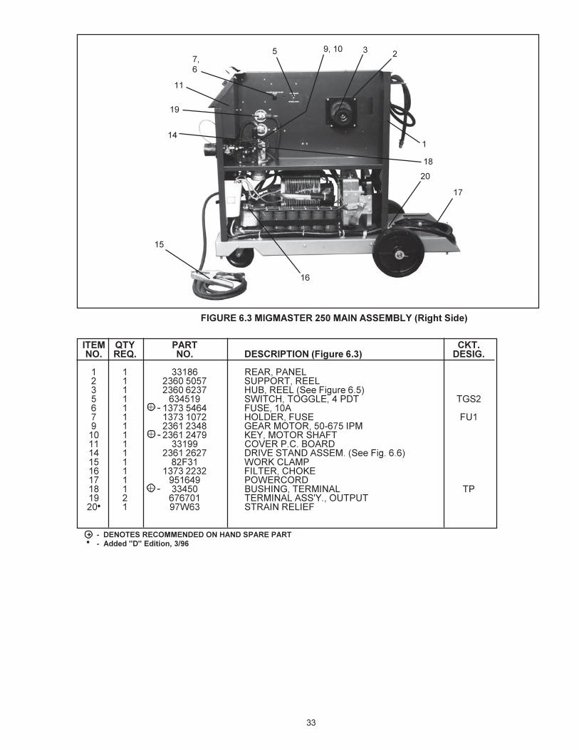
�(,��;���-�(-�����&:=�-�������-��/����0������"
��- ?�/� #��� �>����� �?� ��� *����#������ �!� ��;��" *��(�
/ / ��/�� 1)<+� / ������ ;*<H8)$?-<$)*3?00� / /������� $-)*<0?-�+-��);*,���������� #����� $/
/ ��/�� $-)*<0?-�+-��);*,������,��� #����� $/� / I�/��� ()8(+�<?8+*?;3���(4����/�/�I�7 <?8/
/������� ()8(+�<?8+*?;34������/�I�7� / I�/��� 2?**+2$?-��L�����/�/�I�7
�������� !?<+2?**+2$;?*4������/�I�7� � /������� 2)9)2;$?-/������$���( 2/,�/� � I���I� 2)<$+-�<>;(+8��// � /����I/� >!++8/� � /������� 1H<!;*=/� / I�/��� !)*38+4����/�/�I�7
I���I� !)*38+4����/�I�7/� / �/��� 9#2#1?)-3�<9++32?*$-?8/� / �����/// $+-�;*)818?2C��9$ $1//� / /����I�� �)-C+-�$+-�;*)8/� � I����� -+8)L4����/�/�I�7 C��C�
���/���� -+8)L��93$���()2�/�)/� / /������I 1-;3=+�-+2$;0;+-/I / /������/ 2?*$)2$?-�#��������$���%" C/�� � /������� 1H<1)-E+F<$)�9;*=�/ / II�/�/�� -+<;<$?-���?!����> -��� / ����II�� $+-�;*)8��9?< $1��� � ����/� 2)9;2)$?-#��&�/C( 2I,//�� / /��/���I -+<;<$?-/?!���> -��� / /���/I�I $!+-�?<$)$/��O $</
2��������2I,//���-������������������I�4���������� <�����*�#1I�!�����7����� ��������������%����������#
� �)��
�)�
��)��
�
�
�
����
�)�
��
�+*,2�*%*�3��/4*,5�*��-6478����+!$�������
�
������ '�� ��� ���(��)*)+*,�(�������#�#����������������� ������(������������%������(����� ��%����-��� ��� ���(�./��*)&
�

��
�
�)�
��
�
�)�����)���
�)��
�
�)��
�
)��
�
�
* Photo shows optional Digital Volt/Ammeter Module, P/N 32857, and Spot/Stitch/Anti-Stick Control Module, P/N 32858.• Was 97W63, changed to 950769, 6/95.
�(,��;�&�-�(-�����&:=��/��-�
��- ?�/ #��� �>����� �?� ��� *����#������ �!� ��;�&" *��(�
� / ��/�� 9)*+8�<;3+�-;=!$� / I����IP <$-);*�-+8;+0� � /������� 8)$2!�3??-� / ��/I� 98)$+�2?(+-N� / ���I/ 2?(+-�!;*=+3� / ��/�I 9)*+8�2?*$-?8�<;8C<2-++*+3/� / ��/�� 9)*+8�<;3+�8+0$// / �����I/� 9?$+*$;?�+$+-�;C/� / /������/ C*?1/� / ���/� <>;$2!)<<AL#�<;*=8+9?8+��9?<#/� � ����/�/ C*?1/� / ������ -+2+9$)28+��9;*/� � ����/�/ C*?1/� / ��I�� <>;$2!)<<AL#�<;*=8+9?8+��9?<#/� / I�/��I 98H=�98)<$;2�2�<;Q+/I / ������ )3)9$?-�4<9??8?*=H*7�� / I����/ <>;$2!�$?==8+�/ / �//�� =H;3+$H1+�� / ���/���� 9?>+-8H=�� / ���/��I� )3)9$?-18?2C)<<AL#�� / ���/���� !?H<;*=�)3)9$?-4<$-);=!$7
��
�(,��;�.�-�(-�����&:=�-�������-��/����!1������"
��- ?�/ #��� �>����� �?� ��� *����#������ �!� ��;�." *��(�
/ / ��/�� -+)-�9)*+8� / �������� <H99?-$�-++8� / �������� !H1�-++84<��0��&���#�7� / ����/I <>;$2!�$?==8+��93$ $=<�� / /������� 0H<+�/�)� / /���/��� !?83+-�0H<+ 0H/I / ���/���� =+)-�?$?-���,���;9�/� / ���/���I C+L��?$?-<!)0$// / ��/II 2?(+-9#2#1?)-3/� / ���/���� 3-;(+<$)*3)<<+�#4<��0��#�#�7/� / ��0�/ >?-C28)�9/� / /������� 0;8$+-�2!?C+/� / I�/��I 9?>+-2?-3/� / ����� 1H<!;*=�$+-�;*)8 $9/I � �����/ $+-�;*)8)<<AL#�?H$9H$��� / I�>�� <$-);*-+8;+0
!/ �!! ������!����((�� � !��!� !����!���� �!!����!0 0!��������!1234
���
���
���
�)�
�
�
�
�
�
�
�
� �)� � �

��
����
��- ?�/� #��� �>����� �?� ��� *����#������*�����D�D� ��" *��(�
� � /������� 3;?3+�<;8;2?*�<$-);=!$9?8)-;$L 3/�3�� � /������� ;*<H8)$?-�2?88)-� � /������/ ;*<H8)$?-�<!?H83+-� � /���/�I� >+83�+*$�-+<;<$?-� � /������� 3;?3+�<;8;2?*�-+(+-<+9?8)-;$L 3��3�I / /������� 18)3+�0)*/� / /������� �?$?-�0)* �/
��
� � � ��
�
�(,��;�:�-�(-�����&:=��E���%,��>��
��- ?�/� #��� �>����� �?� ��� *����#������%,��>��" *��(�
�������� -++8!H1C;$4;*28H3+</,�7/ / �������� 1-)C+�3;<2� / �������� !H1�-++8� / �����I�� <9-;*=� / ������/� *H$� / I����/�/ <2-+>�-#!#�#����,/�@#��� / I������� >)<!+-�98);*� / �����I�� >)<!+-��3�� / �������� <H99?-$�-++8I / <!+804-+0#7
��)���
�
)��
�
�
�(,��;���-�(-�����&:=� ���F���#����������>

��
ItemNo.
QtyReq.
PartNo. Description
123456789101112131415161718192021
1111112111111111112511
23612627236126262361238723612475236123852361247023612472236123972361238623612460236124732361246121156236123832361239823612478236124792361248023612384236124622361266223612663
2 ROLL GEARED WIRE DRIVE SYSTEM, CONSISTS OF:PRESSURE ARM ASSY., (incls. 2, 3, 4, 7, 8)AXLE, PRESSURE ROLLPRESSURE ARMCIRCLIP, PRESSURE ROLLPIVOT PINCIRCLIPPRESSURE ROLL, SMOOTHGEARED ADAPTOR, PRESSURE ROLLPRESSURE DEVICE ASSY.LOCATING PININLET GUIDEDRIVE ROLL, .035" - .045"GEARED ADAPTOR DRIVE ROLLFEED ROLL RETAINING SCREWFEED PLATEFEED ROOL KEYMOTOR SHAFT SNAP RING (Not Shown)LOCATING SCREWSCREWSPACER TUBE (Pressure Arm)SPRING PRESSURE ARM
�!� ��;4;��&4���* �7�������

��������������������������������
IF YOU DO NOT KNOW WHOM TO CALL
Telephone: (800) ESAB-123/ Fax: (803) 664-4452/Web: http://www.esab.com
Hours: 7:30 AM to 5:00 PM EST
ESAB Welding & Cutting Products, Florence, SC Welding EquipmentCOMMUNICATIONS GUIDE - CUSTOMER SERVICES
A. CUSTOMER SERVICE QUESTIONS: Telephone (803) 664-5540/Fax: (800) 634-7548Order Entry Product Availability Pricing Hours: 8:30 AM to 5:00 PM ESTOrder Changes Saleable Goods Returns DeliveryShipping Information
B. ENGINEERING SERVICE: Telephone: (803) 664-4416 / Fax : (800) 446-5693Welding Equipment Troubleshooting Hours: 7:30 AM to 5:00 PM ESTWarranty Returns Authorized Repair Stations
C. TECHNICAL SERVICE: Telephone: (800) ESAB-123/ Fax: (803) 664-4452Part Numbers Technical Applications Hours: 8:00 AM to 5:00 PM ESTPerformance Features Technical Specifications Equipment Recommendations
D. LITERATURE REQUESTS: Telephone: (803) 664-5501 / Fax: (803) 664-5548Hours: 7:30 AM to 4:00 PM EST
E. WELDING EQUIPMENT REPAIRS: Telephone: (803) 664-4469 / Fax: (803) 664-5557Repair Estimates Repair Status Hours: 7:30 AM to 3:30 PM EST
F. WELDING EQUIPMENT TRAINING:Telephone: (803)664-4428 / Fax: (803) 664-4476Training School Information and Registrations Hours: 7:30 AM to 4:00 PM EST
G. WELDING PROCESS ASSISTANCE:Telephone: (803) 664-4248 / Fax: (803) 664-4454 Hours: 7:30 AM to 4:00 PM EST
H. TECHNICAL ASST. CONSUMABLES:Telephone: (800) 934-9353 Hours: 7:30 AM to 5:00 PM EST