mig 220 mig 241 congratulate you for buying our topquality welding device. you are - kindly asked to...
TRANSCRIPT

OWNER'S MANUAL
Arc Welding Machines
MIG 220 MIG 241
EN 60 974-1 EN 60 974-10
Dear customer We congratulate You for buying our top-quality welding device. You are kindly asked to carefully read this manual, to assure faultless operation. Take special care in complying with Safety Instructions. SWP – Specialised Welding Products Ltd Hampshire Tel.: + 44 – 1420 588180 Fax: + 44 – 1420 588 184 E-mail: [email protected]


DECLARATION OF CONFORMITY
We, SWP Ltd. declare, that the following machine:
- MIG 241 - MIG 220
is designed and produced according to the following EU - Directives: - Low Voltage Directive, No.: 2006/95/ EEC - EMC Directive, No.: 2004/108/ EEC with their amendments And inspected according to following EU - Norms: - EN 60 974-1 - EN 60 974-10
Any alteration or change to these machines by an unauthorized person makes this Declaration invalid.
08 May 2014 Specialised Welding Products Ltd Unit 1 Farringdon Industrial Centre Farringdon, Nr. Alton Hampshire GU34 3DP ENGLAND
Authorised person …………………………

CONTENTS
1. SAFETY PRECAUTIONS – READ BEFORE USING ........................................................................ 1 SYMBOL USAGE ................................................................................................................................................... 1 ARC WELDING HAZARDS ..................................................................................................................................... 1 ADDITIONAL SYMBOLS FOR INSTALLATION, OPERATION, AND MAINTENANCE ................................................... 4 EMF INFORMATION ............................................................................................................................................. 5 LIMITATIONS OF WARRANTY DECLARATION REGARDING MACHINE USE .............................................................. 6
2. INFORMATION AND FEATURES ........................................................................................................ 7 RATING LABEL .................................................................................................................................................... 7 GENERAL INFORMATION ...................................................................................................................................... 7 SPECIFICATIONS ................................................................................................................................................... 8
3. INSTALLATION ....................................................................................................................................... 9 WORKER AND WORKING AREA PROTECTION ........................................................................................................ 9 TYPICAL MIG PROCESS CONFIGURATION ............................................................................................................. 9 MAINS SUPPLY ..................................................................................................................................................... 9 INSTALLATION OF WIRE REEL ............................................................................................................................. 10 TORCH CONNECTION .......................................................................................................................................... 10 GROUND CONNECTION ....................................................................................................................................... 10 SHIELDING GAS CONNECTION............................................................................................................................. 10
4. OPERATION ........................................................................................................................................... 11 DUTY CYCLE AND OVERHEATING ....................................................................................................................... 11 FRONT PANEL DESCRIPTION ............................................................................................................................... 12 SETTING IN OPERATION ...................................................................................................................................... 13 MIG (GMAW) WELDING .................................................................................................................................. 13 SPOT WELDING ................................................................................................................................................... 13 ADDITIONAL SETTINGS ...................................................................................................................................... 13 OVERLOAD CONTROL ......................................................................................................................................... 13
5. MIG (GMAW) WELDING GUIDELINES ............................................................................................. 14 WORK PIECE PREPARATION ................................................................................................................................ 14 POSITIONING THE WELDING TORCH .................................................................................................................... 15 GUN MOVEMENT DURING WELDING ................................................................................................................... 16 WELDING RESULTS AND TROUBLESHOOTING ..................................................................................................... 17
6. MAINTENANCE ..................................................................................................................................... 21 MAINTENANCE OF ELECTRIC PARTS ................................................................................................................... 21 MAINTENANCE OF WIRE FEEDER AND TORCH ..................................................................................................... 21 CIRCUIT DIAGRAM – MIG 220 PROLINE .......................................................................................................... 22 CIRCUIT DIAGRAM – MIG 241 PROLINE .......................................................................................................... 23 SPARE PARTS – WIRE FEEDER ............................................................................................................................. 24 SPARE PARTS ..................................................................................................................................................... 25

1
1. SAFETY PRECAUTIONS – READ BEFORE USING
Symbol usage
Means Warning! Watch Out! There are possible hazards with this procedure! The possible hazards are shown in the adjoining
symbols. ▲ Marks a special safety message.
This group of symbols means Warning! Watch Out! Possible ELECTRIC SHOCK, MOVING PARTS, and HOT PARTS hazards. Consult symbols and related instructions below for necessary actions to avoid the hazards.
Arc Welding Hazards ▲ The symbols shown below are used
throughout this manual to call attention to and identify possible hazards. When you see the symbol, watch out, and follow the related instructions to avoid the hazard. The safety information given below is only a summary of the more complete safety information found in the Safety Standards. Read and follow all Safety Standards.
▲ Only qualified persons should install,
operate, maintain, and repair this unit. ▲ During operation, keep everybody,
especially children, away.
ELECTRIC SHOCK can kill. Touching live electrical parts can cause fatal shocks or severe burns. The electrode and work circuit is electrically live whenever the output is on.
The input power circuit and machine internal circuits are also live when power is on. In semi-automatic or automatic wire welding, the wire, wire reel, drive roll housing, and all metal parts touching the welding wire are electrically live. Incorrectly installed or improperly grounded equipment is a hazard. • Do not touch live electrical parts. • Wear dry, hoIe-free insulating gloves and body
protection. • Insulate yourself from work and ground using
dry insulating mats or covers big enough to
prevent any physical contact with the work or ground.
• Do not use AC output in damp areas, if movement is confined, or if there is a danger of falling.
• Use AC output ONLY if required for the welding process.
• If AC output is required, use remote output control if present on unit.
• Disconnect input power or stop engine before installing or servicing this equipment. Lockout/tagout input power according to Safety Standards.
• Properly install and ground this equipment according to its Owners Manual and national, state, and local codes.
• Always verify the supply ground — check and be sure that input power cord ground wire is properly connected to ground terminal in disconnect box or that cord plug is connected to a properly grounded receptacle outlet.
• When making input connections attach proper grounding conductor first - double-check connections.
• Frequently inspect input power cord for damage or bare wiring replace cord immediately if damaged — bare wiring can kill.
• Turn off all equipment when not in use. • Do not use worn, damaged, undersized, or
poorly spliced cables. • Do not drape cables over your body. • If earth grounding of the work piece is required,
ground it directly with a separate cable.

2
• Do not touch electrode if you are in contact with the work, ground, or another electrode from a different machine.
• Use only weII-maintained equipment. Repair or replace damaged parts at once. Maintain unit according to manual.
• Wear a safety harness if working above floor level.
• Keep all panels and covers securely in place. • Clamp work cable with good metal-to-metal
contact to work piece or worktable as near the weld as practical.
• Insulate work clamp when not connected to work piece to prevent contact with any metal object.
• Do not connect more than one electrode or work cable to any single weld output terminal.
▲ SIGNIFICANT DC VOLTAGE exists after
removal of input power on inverters. • Turn off inverter, disconnect input power, and
discharge input capacitors according to instructions in Maintenance Section before touching any parts.
FUMES AND GASES can be hazardous. Welding produces fumes and gases. Breathing these fumes and gases can be hazardous to your health.
• Keep your head out of the fumes. Do not breathe the fumes.
• If inside, ventilate the area and/or use exhaust at the arc to remove welding fumes and gases.
• If ventilation is poor use an approved air-supplied respirator.
• Read the Material Safety Data Sheets (MSDSs) and the manufacturers’ instructions for metals, consumables, coatings, cleaners, and degreasers.
• Work in a confined space only if it is well ventilated, or while wearing an air-supplied respirator. Always have a trained watch-person nearby. Welding fumes and gases can displace air and lower the oxygen level causing injury or death. Be sure the breathing air is safe.
• Do not weld in locations near degreasing, cleaning, or spraying operations. The heat and
rays of the arc can react with vapours to form highly toxic and irritating gases.
• Do not weld on coated metals, such as galvanized, lead, or cadmium plated steel, unless the coating is removed from the weld area, the area is well ventilated, and if necessary, while wearing an air-supplied respirator. The coatings and any metals containing these elements can give off toxic fumes if welded.
ARC RAYS can burn eyes and skin. Arc rays from the welding process produce intense visible and invisible (ultraviolet and infrared) rays that can burn eyes and skin. Sparks fly off from the weld.
• Wear a welding helmet fitted with a proper
shade of filler to protect your face and eyes when welding or watching (see Safety Standards).
• Wear approved safety glasses with side shields under your helmet.
• Use protective screens or barriers to protect others from flash and glare; warn others not to watch the arc.
• Wear protective clothing made from durable, flame-resistant material (leather and wool) and foot protection.
WELDING can cause fire or explosion. Welding on closed containers, such as tanks, drums, or pipes, can cause them to blow up. Sparks can fly off from the welding arc. The flying sparks, hot work
piece, and hot equipment can cause fires and burns. Accidental contact of electrode to metal objects can cause sparks, explosion, overheating, or lure. Check and be sure the area is safe before doing any welding. • Protect yourself and others from flying sparks
and hot metal. • Do not weld where flying sparks can strike
flammable material. • Remove all flammables within 35 ft (10.7 m) of
the welding arc. If this is not possible, tightly cover them with approved covers.

3
• Be alert that welding sparks and hot materials from welding can easily go through small cracks and openings to adjacent areas.
• Watch for fire, and keep a fire extinguisher nearby.
• Be aware that welding on a ceiling, floor, bulkhead, or partition can cause fire on the hidden side.
• Do not weld on closed containers such as tanks, drums, or pipes, unless they are properly prepared according to Safety Standards.
• Connect work cable to the work as close to the welding area as practical to prevent welding current from travelling long, possibly unknown paths and causing electric shock and fire hazards.
• Do not use welder to thaw frozen pipes. • Remove stick electrode from holder or cut off
welding wire at contact tip when not in use. • Wear oil-free protective garments such as
leather gloves, heavy shirt, cuffless trousers, high shoes, and a cap.
• Remove any combustibles, such as butane lighter or matches, from your person before doing any welding.
FLYING METAL can injure eyes. • Welding, chipping, wire
brushing, and grinding cause sparks and flying metal. As welds cool, they
can throw off slag. • Wear approved safety glasses with side shields
even under your welding helmet.
BUILDUP OF GAS can injure or kill.
• Shut off shielding gas supply when not in use.
• Always ventilate confined spaces or use approved
air-supplied respirator.
HOT PARTS can cause severe burns. • Do not touch hot parts
bare handed. • Allow cooling period
before working on gun or torch.
MAGNETIC FIELDS can affect pacemakers. • Pacemaker wearers keep
away. • Wearers should consult
their doctor before going near arc welding, gouging, or spot welding operations.
NOISE can damage hearing. Noise from some processes or equipment can damage hearing. • Wear approved ear
protection if noise level is high.
CYLINDERS can explode if damaged. Shielding gas cylinders contain gas under high pressure. If damaged, a cylinder can explode. Since gas cylinders are normally
part of the welding process, be sure to treat them carefully. • Protect compressed gas cylinders from
excessive heat, mechanical shocks, slag, open flames, sparks, and arcs.
• Install cylinders in an upright position by securing to a stationary support or cylinder rack to prevent falling or tipping.
• Keep cylinders away from any welding or other electrical circuits.
• Never drape a welding torch over a gas cylinder.
• Never allow a welding electrode to touch any cylinder.
• Never weld on a pressurized cylinder - explosion will result.

4
• Use only correct shielding gas cylinders, regulators, hoses, and fittings designed for the specific application: maintain them and associated parts in good condition.
• Turn face away from valve outlet when opening cylinder valve.
• Keep protective cap in place over valve except when cylinder is in use or connected for use.
• Read and follow instructions on compressed gas cylinders, associated equipment, and Safety Standards.
Additional Symbols for Installation, Operation, and Maintenance
FIRE OR EXPLOSION hazard. • Do not install or place unit
on, over, or near combustible surfaces.
• Do not install unit near flammables.
• Do not overload building wiring — be sure power supply system is properly sized, rated, and protected to handle this unit.
FALLING UNIT can cause injury. • Use lifting eye to lift unit only,
NOT running gear, gas cylinders, or any other accessories.
• Use equipment of adequate capacity to lift and support
unit. • If using lift forks to move unit, be sure forks are
long enough to extend beyond opposite side of unit.
OVERUSE can cause OVERHEATING • Allow cooling period; follow
rated duty cycle. • Reduce current or reduce
duty cycle before starting to weld again.
• Do not block or filter airflow to unit.
STATIC (ESD) can damage PC boards. • Put on grounded wrist strap
BEFORE handling boards or parts.
• Use proper static-proof bags and boxes to store, move, or
ship PC boards.
MOVING PARTS can cause injury. • Keep away from moving
parts. • Keep away from pinch points
such as drive rolls. WELDING WIRE can cause injury. • Do not press gun trigger until
instructed to do so. • Do not point gun toward any
part or the body, other people, or any metal when threading welding wire.
MOVING PARTS can cause injury. • Keep away from moving
pans such as fans. • Keep all doors, panels,
covers, and guards closed and securely in place.

5
H.F. RADIATION can cause interference. • High frequency (HF,) can
interfere with radio, navigation, safety services, computers, and communications equipment.
• Have only qualified persons familiar with electronic equipment perform this installation.
• The user is responsible for having a qualified electrician promptly correct any interference problem resulting from the installation.
• If notified by the FCC about interference, stop using the equipment at once.
• Have the installation regularly checked and maintained.
• Keep high-frequency source doors and panels tightly shut. Keep spark gaps at correct setting, and use grounding and shielding to minimize the possibility of interference.
ARC WELDING can cause interference. • Electromagnetic energy can
interfere with sensitive electronic equipment such as computers and computer-driven equipment
such as robots. • Be sure all equipment in the welding area is
electromagnetically compatible. • To reduce possible interference, keep weld
cables as short as possible, close together, and down low, such as on the floor.
• Locate welding operation 100 meters from any sensitive electronic equipment.
• Be sure this welding machine is installed and grounded according to this manual.
• If interference still occurs, the user must take extra measures such as moving the welding machine, using shielded cables, using line filters, or shielding the work area.
EMF Information Considerations About Welding And The Effects Of Low Frequency Electric And Magnetic Fields Welding current, as it flows through welding cables, will cause electro-magnetic fields. There has been and still is some concern about such fields, However, after examining more than 500 studies spanning 17 years of research, a special blue ribbon committee of the National Research Council concluded that: "The body of evidence, in the committees judgment, has not demonstrated that exposure to power-frequency electric and magnetic fields is a human-health hazard." However studies are still going forth and evidence continues to be examined. Until the final conclusions of the research are reached, you may wish to minimize your exposure to electromagnetic fields when welding or cutting. To reduce magnetic fields in the workplace, use the following procedures: • Keep cables close together by twisting or taping them. • Arrange cables to one side and away from the operator. • Do not coil or drape cables around your body. • Keep welding power source and cables as far away from operator as practical. • Connect work clamp to work piece as close to the weld as possible.
About Pacemakers: Pacemaker wearers consult your doctor first. If cleared by your doctor, then following the above procedures is recommended.

6
Limitations of warranty declaration regarding machine use
▲ The welding machine(s) described in this manual are designed exclusively for electrical arc welding with shielding gases Argon, CO2
or Ar + CO2 mixture(s) employing MIG or MAG technology. Using this machine for other purpouses is not allowed. Using this machine in opposition with instructions can put the welder in danger. Damage can occur to the welding machine if not operated according to this manual. Failures and accidents due to such actions are not covered by warranty, nor can the producer be held responsible.

7
2. INFORMATION AND FEATURES
Rating Label
General Information
▲ Do not operate or install this equipment without thoroughly reading this manual and the safety precautions contained throughout.
• Save this manual and keep it handy for reference.
• Disconnect mains of the semi-automatic welding machine after finishing work or before a long break.
▲ DO NOT make any modifications to the machine. It may cause changes in the features and deterioration of technical data.
▲ Any adaptations to this machine are prohibited and may void the warranty.
▲ Warranty is void if any damage to the machine is caused by misuse.
• Acceptable range of ambient temperature is from 10—40°C.
• Acceptable range of humidity is 20°C at 95% humidity.
• Specifications may change without previous notice.
8
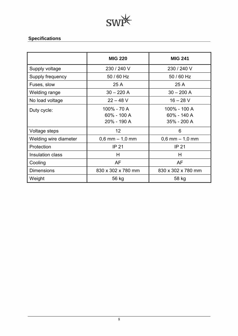
Specifications
MIG 220 MIG 241
Supply voltage 230 / 240 V 230 / 240 V Supply frequency 50 / 60 Hz 50 / 60 Hz Fuses, slow 25 A 25 A Welding range 30 – 220 A 30 – 200 A No load voltage 22 – 48 V 16 – 28 V
Duty cycle:
100% - 70 A 60% - 100 A 20% - 190 A
100% - 100 A 60% - 140 A 35% - 200 A
Voltage steps 12 6 Welding wire diameter 0,6 mm – 1,0 mm 0,6 mm – 1,0 mm Protection IP 21 IP 21 Insulation class H H Cooling AF AF Dimensions 830 x 302 x 780 mm 830 x 302 x 780 mm Weight 56 kg 58 kg

9
3. INSTALLATION
Worker and working area protection Fumes and gases produced by welding are dangerous for your health. Ventilation in workplace must be adequate to remove all harmful fumes and gases but not too strong since it could remove the shielding gas flowing over work piece. Arc welding rays are dangerous for your eyes. The welder must always use helmet with protective glass no. 11 for MIG/MAG. All personal protectives including working clothes, leather apron, gloves, etc. must always be worn when welding or handling the work piece.
Typical MIG process configuration
1……... Main transformer 2……... Wire feeder 3……... Gas tank and supply 4……... Ground cable and wire,
current and gas conduit 5……... Welding torch
Mains supply INPUT primary cable is supplied with machine. Connect the machine to mains according to legislation of the country where machine is being used. Connection can be effected through plug or directly. Supply system should be protected at all times by the fuse stated in technical data section. Connection to mains can be done by authorized, educated person only.

10
Installation of wire reel Open the side cover and unscrew reel brake cover. Mount the reel in such way that one end of wire hangs downwards. Mount brake cover back in position. Cut off the bent end of the wire. Lead the end of the wire trough inlet guide and unclip pressure handle of feed rollers in order to make the work easier. Ensure both wire inlet guide and the feeding rollers groove are aligned. Push the welding wire to the inlet of the torch connection. Replace the pressure handle to reestablish pressure on the wire. If handle pressure is too strong the wire could be transformed - flattened. If the pressure is too low the wire could slip in the feeding groove. Use tension knob to adjust this.
1…….. Feeding rolls 2…….. Pressure roll 3…….. Pressure adjustment 4…….. Wire inlet 5…….. Plate 6…….. Motor 24 / 42 V, 50 W 7......... Pressure arm 8…...... Pressure arm
Torch connection Contact tip must correspond to welding wire diameter. Turn on the machine. Inch the wire through torch outlet by activating the switch located on torch handle.
Ground connection Earth lead with clamp for connection to work piece is in the accessory kit. Connect the plug to the machine and clamp to work piece.
Shielding gas connection Gas hose can be found in the accessory kit. Fasten your gas regulator onto gas bottle then connect it with the machine using supplied gas hose.

11
4. OPERATION
Duty cycle and overheating Duty Cycle is percentage of 10 minutes that unit can weld at rated load without overheating. If unit overheats, thermostat(s) opens, output stops, and cooling fan runs. Wait fifteen minutes for unit to cool. Reduce amperage or duty cycle before welding.
60% Duty Cycle at 140 A.
Overheating
▲ Welding machine must be used according to technical data from this manual. If the machine is overloaded, failures may occur that are not be covered by warranty.

12
Front panel description
1 …........ ON/OFF Switch 2 …........ Welding Voltage setting 3 …........ Selector: 2T, 4T, Spot, Gas test * 4 …........ Wire Feed adjustment 5 …........ Spot time 6 …........ Burn Back adjustment * 7 …........ LED, orange – Overload indication 8 …........ Digital instrument display 9 …........ V-/A-meter switch 10…....... Central connector (EU) 11…....... Ground connector * only on MIG 241 PROLINE model

13
Setting in operation Set the main switch (1) in ON position and welding mode selector (3) to »Gas test«. Adjust the gas flow with regulator. Additionally regulate gas flow during operation. Lower gas flow would affect the welding quality and cause a porous weld while high gas flow results in bigger consumption of gas.
MIG (GMAW) Welding
After selecting the apropriate voltage step with regulation switch (2) choose the »2T« function with selector (3). Set the wire speed with knob (4) according to your welding requirements, material and voltage setting. Welding process starts by pressing the the torch button. For normal welding torch must be held at a certain distance from the welding spot. When placed too far welding area cannot be protected with gas which causes a porous weld. When placed too close welding material and torch components (such as welding tip) can burn out. Before starting the welding it is recommended to make tests and trial runs on scarp material.
Spot welding Set the welding mode selector (3) to »spot welding« and adjust spot time (5) depending on the thickness of material. Spot welding starts by pressing the torch switch. Torch button must remain switched on until the timer breaks off the arc. To start a new cycle, press the torch switch again.
Additional settings (MIG 241 PROLINE only) 4T mode is intended for longer welds. The torch button works as a switch – a tap to start welding and another tap to stop. This function is set by turning selector (3) in position. Burn back setting allows user to set the length of remaining welding wire left out of the nozzle after welding is finished. Use knob (6) to set burn back time. Longer burn back time results in shorter wire stick out and vice versa. Short burn back times equal long wire extension.
Overload control Thermal protection is built in the machine's main transformer. If the machine overheats, thermal fuse will prevent further use and control LED (7) on the front side will light up. In this case the welder must wait until the maxchine's temperature drops to normal. Note the machine must be left switched on for the fan to keep running.

14
5. MIG (GMAW) welding guidelines
Work piece preparation Welding joint describes the welding spot and exact position of work pieces to be welded together. Work piece preparation, groove form and width, material type and thickness, together with certain welding technique all determine joint type. Around the groove work pieces should be dry and clean, free of rust, metallic coating, dirt, colour or grease.
Joint type Groove shape Weld shape Metal thickness [mm]
Work piece spacing [mm]
Square butt joint
single sided
up to 1,5 from 1,5 0 to 2
Square butt joint
double sided 2 to 4 up to 2
V – butt joint
3 to 6 up to 1
3 to 6 up to 1
Square T - joint single sided
from 0,6 -
Square T - joint double sided
from 0,6 -
Lap joint
0,6 to 1,5 -
Edge joint
from 1 -

15
Positioning the welding torch Welding wire is energised when the torch button is pressed. Lower your helmet first and then press the trigger. Wire should be around ½ in past end of nozzle, and tip of wire positioned correctly on seam.
1…….. Hold torch and control trigger with one hand
2…….. Work piece 3…….. Earth clamp 4…….. Electrode extension (Stickout) ¼ to ½
in 5…….. Cradle torch with the other hand and
rest it on work piece
Heat distribution and weld material flow are specific for groove welds and fillet welds. Optimal torch position differs from one to another.
Weld bead shape differs depending on electrode extension when welding fillet welds.

16
Gun movement during welding Weld bead shape as well as penetration and overall joint quality are affected by torch angle, direction of travel, electrode extension, travel speed, thickness of base material, wire feed speed, and voltage.
Using constant parameters welding material deposit and penetration varies with torch travel speed. For adequate penetration to be achieved welding source must provide more power at higher speeds.
Dragging the torch results in deeper penetration and narrower weld. Arc strength prevents slag to enter the molten material. When pushing the torch penetration will be shallower and the weld wider. This movement is suitable for thin plates because of smaller heat input.
1…….. Stringer bead – steady movement along seam
2…….. Wave bead – side to side movement along seam
3…….. Wave patterns Use weave patterns to cover a wide area in one pass of electrode. Normally a single stringer bead is satisfactory for most narrow groove weld joints. However for wide groove weld joints or bridging across gaps, a weave bead or multiple stringer beads work better.

17
Welding results and troubleshooting
GOOD WELD BEAD 1…….. Fine spatter 2…….. Uniform bead 3…….. Moderate crater during welding 4…….. No overlap 5…….. Good penetration into base material
POOR WELD BEAD 1…….. Large spatter deposits 2…….. Rough, uneven bead 3…….. Slight crater during welding 4…….. Bad overlap 5…….. Poor penetration

18
Excessive spatter Scattering of molten metal particles that cool to solid near weld bead.
Possible causes Corrective actions
Wire feed speed too high. Select lower wire feed speed.
Voltage too high. Select lower voltage.
Electrode extension too long. Use shorter electrode extension.
Work piece dirty. Remove all grease, oil, moisture, rust, paint, undercoating, and dirt from work surface before welding.
Insufficient shielding gas at arc. Increase flow of shielding gas at regulator and/or prevent drafts near welding arc.
Dirty welding wire.
Use clean, dry welding wire. Eliminate pickup of oil or lubricant on welding wire from feeder or liner.
Porosity Small cavities or holes resulting from gas pockets in weld material.
Possible causes Corrective actions
Wrong gas. Use welding grade shielding gas; change to different gas.
Welding wire extends too far out of nozzle.
Be sure welding wire extends no more than ½ in beyond nozzle.
Work piece dirty.
Remove all grease, oil, moisture, rust, paint, undercoating, and dirt from work surface before welding. Use a highly deoxidising welding wire (contact supplier).
Insufficient shielding gas at arc.
Increase flow of shielding gas at regulator and/or prevent drafts near welding arc. Remove spatter from gun nozzle. Check gas hoses for leaks. Place nozzle ¼ to ½ in from work piece. Hold gun near bead at end of weld until molten metal solidifies.
Dirty welding wire.
Use clean, dry welding wire. Eliminate pickup of oil or lubricant on welding wire from feeder or liner.

19
Excessive penetration Weld metal melting through base metal and hanging underneath it.
Possible causes Corrective actions
Excessive heat input. Select lower voltage range and reduce wire feed speed. Increase travel speed.
Lack of penetration Shallow fusion between weld metal and base metal.
Possible causes Corrective actions
Improper joint preparation. Material too thick. Joint preparation and design must provide access to bottom of groove while maintaining correct welding wire extension and arc characteristics.
Improper welding technique.
Maintain normal gun angle of 0 to 15 degrees to achieve maximum penetration. Keep arc on leading edge of weld puddle. Be sure welding wire extends no more than ½ in beyond nozzle.
Insufficient heat input.
Select higher wire feed speed and/or select higher voltage range. Reduce travel speed.
Distortion Contraction of weld metal during welding that forces base metal to move.
Possible causes Corrective actions Excessive heat input.
Select lower voltage range and reduce wire feed speed. Increase travel speed. Use restraint (clamp) to hold base metal in position. Make tack welds along joint before starting welding operation. Weld in small segments and allow cooling between welds.

20
Incomplete fusion Failure of weld metal to fuse completely with base metal or a preceding weld bead.
Possible causes Corrective actions
Work piece dirty. Remove all grease, oil, moisture, rust, paint, undercoating, and dirt from work surface before welding.
Improper welding technique.
Place stringer bead in correct location(s) at joint during welding. Adjust work angle or widen groove to access bottom during welding. Momentarily hold arc on groove side walls when using weaving technique. Keep arc on leading edge of weld puddle. Use correct gun angle of 0 to 15 degrees.
Insufficient heat input. Select higher wire feed speed and/or select higher voltage range.
Burn-through Weld metal melting completely through base metal resulting in holes where no metal remains.
Possible causes Corrective actions
Excessive heat input. Select lower voltage range and reduce wire feed speed. Increase and/or maintain steady travel speed.
Incomplete fusion Weld metal that is not parallel and does not cover joint formed by base metal.
Possible causes Corrective actions Welding wire extends too far out of nozzle.
Be sure welding wire extends no more than ½ in beyond nozzle.
Unsteady hand. Support hand on solid surface or use two hands.

21
6. MAINTENANCE
▲ WARNING! Electric shock can be fatal. Intervention inside the machine can only be done by an authorized person. Before any intervention inside the machine, it must be switched off and unplugged from primary supply.
Maintenance of electric parts In order to maintain your machine in perfect condition please follow these recommendations.
• Every 3 months dust accumulated inside the machine should be cleaned. Use compressed air to
do so. Protect the potentiometer, switches, connectors and PCB with plastic bag. • Check all connections in machine every month. • Grounding must be checked and fixed well before use. • Never brush metal in machine direction to prevent metal dust being drawn inside by the fan. This
could damage PCB, connectors or switches. • When you work outside in the field always protect machine against sun. Otherwise the machine
could overheat faster which would result in lower duty cycle.
Maintenance of wire feeder and torch Wire feeder is one of the most stressed machine parts. Please follow the instrustions to keep it running smoothly.
• It is very important that the feeder inlet, rolls and outlet are aligned. Wire should run from the inlet
over feeding rolls to the outlet in a straight line. • Rolls' groove diameter must correspond wire diameter. Carbon steel and stainless steel wire use
V – groove rolls, aluminium and flux core wire use U – groove rolls. • Pressure from upper rolls must be strong enough to prevent wire from slipping inside the groove.
Excessive pressure poses unnecessary stress on rolls and bearings. • When wire slides across rolls, scraps of rolls and wire material are formed and moved around.
Inide the bearings this material works as grinding paper. • Bearings are made of bronze or sintered material. They are softer than steel wire particles and
wear out in time. They must be changed when worn out to maintain the machine's performance. • To extend the rolls' lifetime blow out, clean the rolls and oil feeder bearings weekly.
When moving welding wire carries steel scraps inside torch liner. Steel particles accumulate inside the liner causing higher drag posing more stress on the wire feeder. Eventually the wire starts to slip. Short term solution is to intensify pressure on rolls which shortens the bearings' lifetime. • Avoid increased drag in the liner by blow the inside of torch liner regularly. If the problem remains
change the liner. • Always use the same contact tip and welding wire diameter. • Gas nozzle must be always clean, not spattered. Clean it regularly, before welding or when
needed. Use of protection liquid is recommended.
22
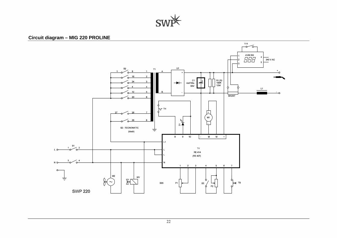
Circuit diagram – MIG 220 PROLINE

23
Circuit diagram – MIG 241 PROLINE
24
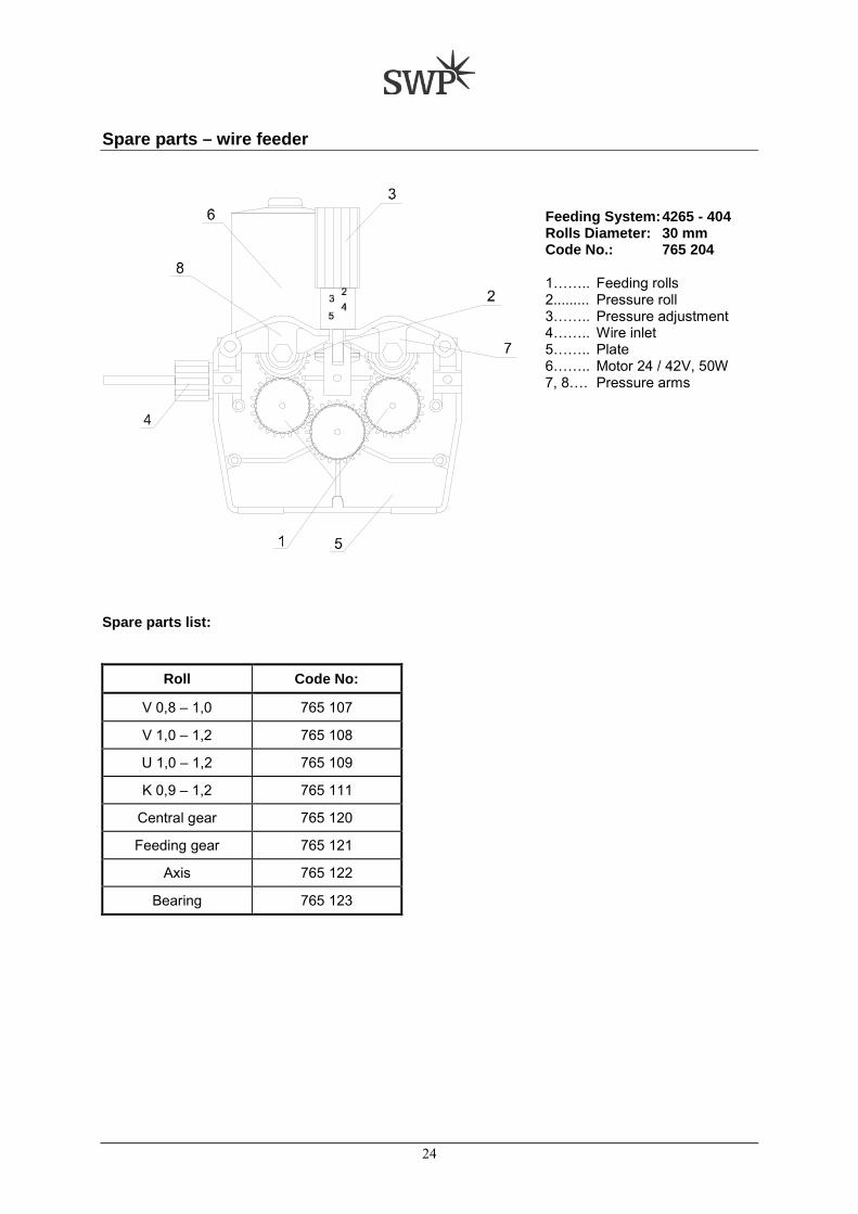
Spare parts – wire feeder
Feeding System: 4265 - 404 Rolls Diameter: 30 mm Code No.: 765 204 1…….. Feeding rolls 2......... Pressure roll 3…….. Pressure adjustment 4…….. Wire inlet 5…….. Plate 6…….. Motor 24 / 42V, 50W 7, 8…. Pressure arms
Spare parts list:
Roll Code No:
V 0,8 – 1,0 765 107
V 1,0 – 1,2 765 108
U 1,0 – 1,2 765 109
K 0,9 – 1,2 765 111
Central gear 765 120
Feeding gear 765 121
Axis 765 122
Bearing 765 123

25
Spare parts

26
Spare parts list: Part MIG 220 MIG 241
1 Main transformer 048 950 041 779
2 Choke 040 009 044 039
3 Auxilliary transformer - 050 164
4 Rectifier 962 276 962 315
5 PCB 975 517 976 917
- Digital V-/A-meter 976 925 976 925
6 On/Off Switch 951 234 951 234
7 Step switch 951 259 951 253
8 Wire feeder with motor 765 032 + 765 181 765 204
9 Poti 1 K 935 117 935 117
10 Spot timer poti 935 723 935 706
11 Poti 100 K - 935 119
12 Selector 3 x 4 - 953 618
13 Fan 120 x 120 – 230 V 974 236 974 236
14 Solenoid valve 955 132 955 131
15 Wire holder 764 978 764 978
16 Central connector (EU) 767 052 767 052
17 Contactor LC1 - D18 - 24 V - 958 411
18 Fuse 4 A Slow 921 330 921 330
19 Wheel, fixed 754 122 754 122
20 Wheel, flexible 754 118 754 118
30 Bottom panel
31 Front panel
32 Back panel
33 Inside panel
34 Binding panel
35 Cabinet
36 Axle
37 Bottle holder
38 Cover, left
39 Cover, right
40 Side panel