midi control unit user manual - organ works manual 1.5.pdf · keyboard and pedalboard switches are...
TRANSCRIPT

MIDI Control Unit User Manual
MCU-1 Version 1.5
Dmbttjd!Pshbo!Xpslt!
Div. of: ARTISAN CLASSIC ORGAN INC.


MIDI CONTROL UNIT MCU-1 CONTENTS _________________________________________________________________________________________________________
_________________________________________________________________________________________________________
MCU-1 Manual (Version 1.5) Issue-3 2009-06-15 2009 CLASSIC ORGAN WORKS 3
MIDI CONTROL UNIT MCU-1
TABLE OF CONTENTS
WARRANTY...................................................................... 5
1. INTRODUCTION.......................................................... 7 DESCRIPTION .................................................................... 7
2. INSTALLATION ......................................................... 11 MOUNTING...................................................................... 11 CONNECTIONS................................................................. 11
3. MIDI SPECIFICATION ............................................. 15 MIDI SOUND SETS.......................................................... 15 MIDI HARDWARE SPECIFICATION .................................. 21
4. MCU PIN FUNCTIONS.............................................. 23 KEYBOARD PINS ............................................................. 23 PEDALBOARD PINS.......................................................... 23 CUSTOM INPUT PINS ....................................................... 23 ANALOG INPUT PINS ....................................................... 24 CUSTOM OUTPUT PINS.................................................... 24
5. MCU CONFIGURATIONS ........................................ 27 INTRODUCTION ............................................................... 27 DEFAULT CONFIGURATION (CONFIG. #1: CFG001.MCU) . 27 CHANGING MIDI CHANNELS (CONFIG. #1 ONLY)........... 28 CONFIGURATIONS FOR AHLBORN ARCHIVE UNITS ......... 32
6. CONFIGURATION SOFTWARE ............................. 43 INTRODUCTION ............................................................... 43 SOFTWARE INSTALLATION.............................................. 43 SOFTWARE STARTUP....................................................... 44 FUNCTIONS OF THE TOOLBARS ....................................... 45 LOAD CURRENT SETTINGS FROM MCU .......................... 47 OPEN PREVIOUSLY SAVED MCU CONFIGURATION......... 49 EDIT THE CONFIGURATION ............................................. 50 FUNCTIONS OF THE TABS ................................................ 52 SAVING CONFIGURATIONS.............................................. 55
7. GM9773 INFORMATION...........................................57 INTRODUCTION................................................................57 USAGE .............................................................................57 DIMENSIONS ....................................................................57 AUDIO .............................................................................57 PIN FUNCTIONS................................................................58 MIDI FEATURES..............................................................58 SPECIAL MIDI CONTROLS...............................................68 CIRCUIT DESCRIPTION.....................................................69 ADDITIONAL INFORMATION.............................................70
8. REFERENCES .............................................................73
9. APPENDIX A: DIP-SWITCH CONFIGURATION .75
10. APPENDIX B: SCHEMATICS.................................79
11. APPENDIX C: MIDI PROTOCOL ..........................91 MIDI PROTOCOL SPECIFICATION ....................................91
12. APPENDIX D: SYSTEM EXCLUSIVE MESSAGES..........................................................................................103
MESSAGES COMMON TO ALL PRODUCTS ........................103 MCU - SPECIAL LAYOUTS .............................................104
13. APPENDIX E: AHLBORN MESSAGES ...............105
14. APPENDIX F: SCPOP MESSAGES ......................113
15. DISCLAIMER ..........................................................119


MIDI CONTROL UNIT MCU-1 WARRANTY _________________________________________________________________________________________________________
_________________________________________________________________________________________________________
MCU-1 Manual (Version 1.5) Issue-3 2009-06-15 2009 CLASSIC ORGAN WORKS 5
MIDI CONTROL UNIT MCU-1
WARRANTY Classic Organ Works warrants the MCU to be free from defects in materials and workmanship under normal use for a period of one year from the delivery date. This warranty applies only if the original purchaser owns the product and the original purchaser has the bill of sale. This warranty explicitly excludes any cables included, which may become defective because of normal wear and tear. The DC wall adaptor is included in the warranty however. In the event of a defect in materials or workmanship, please contact Classic Organ Works immediately. Defects due to shipping should be reported within 15 days for insurance claim purposes. For all other defects, Classic Organ Works will repair the product, replace the product, or refund the purchase price less shipping and handling charges. If repairs are required, the purchaser will be responsible for shipment to Classic Organ Works. Classic Organ Works will be responsible for shipment to return the repaired unit to the customer. In the event that Classic Organ Works determines the product requires repair because of user misuse or regular wear, it will assess a fair repair or replacement fee. The customer will have the option to pay this fee and have the unit repaired and returned, or not pay this fee and have the unit returned un-repaired.
Classic Organ Works will not be liable for consequential, special, indirect, or similar damages or claims including loss of profit or any other commercial damage, and in no event will Classic Organ Works’ liability for any damages to the purchaser or any other person exceed the price paid for the product, regardless of any form of the claim. Classic Organ Works specifically disclaims all other warranties, expressed or implied. Specifically, Classic Organ Works makes no warranty that the product is fit for any particular purpose. This warranty shall be interpreted, and governed by applicable laws in the province of Ontario, Canada. If any provision of this warranty is found void, invalid or unenforceable, it will not affect the validity of the balance of the warranty, which shall remain valid and enforceable according to its terms. In the event any remedy hereunder is determined to have failed of its essential purpose, all limitations of liability and exclusion of damages set forth herein shall remain in full force and effect.


MIDI CONTROL UNIT MCU-1 INTRODUCTION _________________________________________________________________________________________________________
_________________________________________________________________________________________________________
MCU-1 Manual (Version 1.5) Issue-3 2009-06-15 2009 CLASSIC ORGAN WORKS 7
MIDI CONTROL UNIT MCU-1
1. INTRODUCTION
Description Congratulations! You are now the proud owner of the MCU-1 (MIDI Control Unit, MCU). The MCU-1 is a MIDI interface that allows MIDI sound modules to be added to a pipe or electronic organ, or even to create a whole organ through the use of computer-driven virtual organ software such as Hauptwerk™ 1. Designed as a modular unit, it provides a ‘smart’ add-on interface so that organs can be provided with MIDI voices that can be controlled as though they were part of the organ. The MCU is designed for organists, organ enthusiasts, and MIDI users. In particular, organists may connect keyboards, stops, pistons, tuning devices, expression controls, crescendo controls, volume controls and a pedal board to the MCU. Organ enthusiasts with an Ahlborn Archive SeriesTM module2 may use the MCU to control divisions, channel, stops, couplers, combinations, pistons, tremulants, crescendo, expression, Sforzando (Tutti), cancel, set, and tuning. Up to four Archive modules may be controlled simultaneously. By purchasing the optional GM-MIDI module, MIDI users can control channel, voice variation, drumset variation, volume, expression and tuning using the MCU. Furthermore, a convenient MIDI merge feature allows simultaneous control of multiple MIDI devices. An additional 48 output pins are available on the MCU, but they are presently not implemented being reserved for future use. Key-switch information from keyboards, pedalboards, stops, pistons and other switches is converted into MIDI control data. The MCU can support as many as three 61-note keyboards and one 32-note pedalboard.
1 Hauptwerk is a registered trademark of Crumhorn Laboratories Limited, England. 2 Archive Module Series is a registered Trademark of Ahlborn-Galanti Organs, a division of General Music Corporation, Italy.
Keyboard and pedalboard switches are interpreted by the microprocessor in the MCU to generate MIDI messages describing key-switch actions. Thus, a MIDI message details whether a key was pressed or released, the MIDI channel that the information should be transmitted on, and the key number pressed or released. Up to 105 stop and piston switches can be wired to the MCU. The concept of a stop and piston used in the MCU differs somewhat from that used in organ terminology. MIDI was originally developed for electronic music use in synthesizers. It was only a few years ago that organ-builders began adding MIDI capabilities to pipe organs. However, MIDI was not designed for a complex musical instruments such as the organ. Thus, the application of the MIDI standard to the organ is subject to organ-builders’ preferences, and standards are still evolving. On the MCU, stop switches are connected to input pins. When switches such as drawknobs, rocker-tabs, and pushbuttons are activated, the microprocessor identifies the switch action and generates a MIDI message to indicate a switch-on or switch-off. Piston switches are also connected to the input pins. However, when piston switches are activated a MIDI message is sent to select a combination of stops. The piston and stop switches allow the MCU-1 to simultaneously drive up to four Ahlborn Archive Series™ modules that generate pipe-organ voices. In addition, any MIDI-controlled sound module or PC-based synthesizer software may be connected. Typical units would be Hauptwerk virtual organs or Viscount Accupipe CM-100 pipe voice modules. There is also provision for an optional internal plug-in General MIDI sound generator, Classic type GM 9773. Five analog input pins can be configured for volume, expression, tuning and crescendo. By adjusting the analog device, a voltage on the analog input pin is interpreted by the microprocessor. In the case of a volume adjustment, a MIDI message will detail to the

MIDI CONTROL UNIT MCU-1 INTRODUCTION _________________________________________________________________________________________________________
_________________________________________________________________________________________________________
8 MCU-1 Manual (Version 1.5) Issue-3 2009-06-15 2009 CLASSIC ORGAN WORKS
MIDI-controlled device the loudness level of the stop or sound. MIDI messages are also sent for a crescendo adjustment that will gradually add stops to a registration. An expression adjustment will change the volume level in excess of the set volume. A tuning adjustment will change the tuning of the MIDI-controlled device or an Ahlborn Archive unit. The MCU is completely customizable and is shipped with five pre-configurations. The default configuration supports two 61-note keyboards, one 32-note pedalboard, 93 stops, and tuning and expression controls. The other four pre-configurations support various Ahlborn Archive modules. The MCU also includes a compact disc containing the Classic ‘MCUConfig’ software for both Windows and MacIntosh computers. The software allows users to completely customize the MCU to their specifications. With the software, 128 configurations may be programmed into the MCU (123 additional configurations are available if the five pre-configurations are not overwritten). Up to three keyboards, a pedal board, 105 stop and piston switches, and five analog inputs may be configured for Ahlborn Archive modules, General MIDI sound modules, and a MIDI controlled PC-based synthesizer software: Sound Canvas Pipe Organ Project (SCPOPTM). The software
also supports Hauptwerk TM that is computer software simulating an organ and capable of running numerous organ sample sets. MCU configurations are saved as computer files that may be stored in the user’s home computer, or in the MCU. Configurations that are saved on the MCU will not be lost when power is turned off because the memory is non-volatile. These configurations may be selected using a DIP-switch on the MCU. Eventually, users may inexpensively upgrade their software as well as configurations by visiting the Classic Organ Works website at http://www.organworks.com.
Dimensions Width 12.35 inches, 31.4 cm (including mounting flanges 0.50" either side) Height 3.50 inches, 8.89 cm (including connectors) Depth 7.50 inches, 19.5 cm
Weight Fully loaded 7 lbs, 3.2 kg

MIDI CONTROL UNIT MCU-1 INTRODUCTION _________________________________________________________________________________________________________
_________________________________________________________________________________________________________
MCU-1 Manual (Version 1.5) Issue-3 2009-06-15 2009 CLASSIC ORGAN WORKS 9
.
Figure 1: MCU connections


MIDI CONTROL UNIT MCU-1 INSTALLATION _________________________________________________________________________________________________________
_________________________________________________________________________________________________________
MCU-1 Manual (Version 1.5) Issue-3 2009-06-15 2009 CLASSIC ORGAN WORKS 11
MIDI CONTROL UNIT MCU-1
2. INSTALLATION
IMPORTANT READ THIS DOCUMENT BEFORE INSTALLATION
Upon receiving this unit, discard any packing material inside the unit that may have been included to prevent movement of components or wiring during shipping. (For internal access, ensure the unit is disconnected from all power sources. Then undo the eight screws at the edges of the front panel.) As supplied, the unit may be partly loaded depending on the configuration (for instance, the quantity of keyboards).
Mounting The unit is intended to be located near the keyboards within an organ console because of the amount of wiring to those keyboards. It should be placed so that the connections are readily accessible. Four holes are provided in the side flanges so that it may be screwed to the wooden parts of the console. The holes are 0.2-inch diameter and will take up to a #10 screw if necessary. However, since the unit is not heavy, a #6 or #8 screw will be sufficient. The unit may be mounted in any convenient place. Its orientation is not important.
Connections There are three essential connections and two optional connections. The latter will depend on the use of the MCU. The user must connect Power, MIDI, and input connections for keyboards, stops, and/or pistons. RCA Phono jacks, a 3.5mm headphone connector, and a 6-
pin DIN connector for tuning an Ahlborn Archive unit are provided. Cables and hardware for these connections is available separately.
Power The MCU requires between +9V and +15V DC power at a minimum current of 400mA. There are several ways to provide power to the MCU according to the application. 1. If the MCU were to be used as a standalone
unit, the most convenient method of providing power would be to use the supplied 2.1mm ID Co-axial DC wall adaptor.
2. However, if the MCU is to be used as part of an organ, the 4-input terminal block can be connected to an existing organ power supply making power and ground connections.
3. If an output board is present, an alternative power source must be wired to the 2-input terminal block labeled ‘FROM CONSOLE SUPPLY FOR OUTPUTS ONLY’. This extra power source provides the required current to drive high-current outputs such as magnets or lamps. Please note that this output feature is not implemented in the current version of the MCU.
The MCU has features to ensure safe and easy operation. For ease of use, an isolated +12 Volt, DC wall adaptor of either positive or negative polarity may be used. It must have a 2.1mm ID co-axial power jack. A bridge-rectifier is present within the MCU to ensure the proper polarity. A 500mA self-resetting Polyfuse connects the common power supply to all the input boards. Each input board has its own 250mA Polyfuse. In addition, the extra power supply input for the output driver board incorporates a 5A self-resetting

MIDI CONTROL UNIT MCU-1 INSTALLATION _________________________________________________________________________________________________________
_________________________________________________________________________________________________________
12 MCU-1 Manual (Version 1.5) Issue-3 2009-06-15 2009 CLASSIC ORGAN WORKS
Polyfuse to provide over-current protection for the output loads only.
MIDI The MCU has one MIDI input and four MIDI outputs that can be connected to several MIDI devices and/or a personal computer. In the current version of the MCU, all four MIDI OUT connectors produce the same messages. The MIDI IN connector allows another MIDI source to be merged with the MIDI signal from this unit. The MCU has the capability to drive up to four different Ahlborn Archive SeriesTM modules. These can be controlled through the general pistons on an existing organ. Thus, additional stops and sounds on multiple Ahlborn Archive modules may be controlled as though they were part of the organ.
Switch Inputs The MCU can support up to five standard input boards, thus allowing many different configurations. The default configuration (with an internal GM9773 General MIDI sound module) supports two 61-note keyboards, one 32-note pedalboard, 9 ‘stops’ (to select MIDI output channels), 93 pistons, one analog input for expression control, and one analog input for General MIDI fine tuning. The switches and analog inputs may be connected to the appropriate input rows of pins using Molex crimped-pin connectors or mass-termination insulation-displacement connectors (MAS-CON) in multiples of eight pins. Please see the Configuration table for details. For the analog inputs, the user must ensure that there is one connection to Ground, one connection to an appropriate positive voltage (usually +5V), and one connection to an analog input pin. In the
default configuration, ‘ANALOG IN 1’ is used for expression control, and ‘ANALOG IN 4’ is used for General MIDI fine-tuning. Each input row has a 2-pin terminal block for the commons for all switches in that row. The two pins on the terminal block are paralleled.
Temperature sensing/tuning (optional) Due to temperature changes in the operating environment, it may be necessary to adjust the tuning of any connected sound modules. An optional function on the MCU permits temperature sensing and sound module tuning. To use this, an optional temperature-sensing device is plugged into the 3-pin DIN connector labeled ‘TEMP. SENS IN/OUT’. If an Ahlborn Module needs to be tuned, another cable is plugged from the Ahlborn Archive Module to the 6-pin DIN connector labeled ‘AHLBORN OUT’. The MCU produces a voltage signal on the ‘AHLBORN OUT’ port to correct the tuning on the Ahlborn Archive unit. If General MIDI tuning is required, data is sent via the ‘MIDI OUT’ port. Note: The Ahlborn tuning connector has 6-pin at 240°. This is intentional to differentiate it from the MIDI connector with five pins at 180°.
Audio outputs (optional) The MCU is equipped with RCA Phono jacks labeled ‘LINE LEFT’ and ‘LINE RIGHT’, as well as a 3.5mm Stereo Jack. These connectors provide line-level audio output from the optional GM sound module to external audio amplifiers and speakers. The RCA Phono jacks provide 100mV high-impedance output, while the 3.5mm Stereo Jack (for headphones) provides 1.6 Watts output per channel into 4 Ohms.

MIDI CONTROL UNIT MCU-1 INSTALLATION _________________________________________________________________________________________________________
_________________________________________________________________________________________________________
MCU-1 Manual (Version 1.5) Issue-3 2009-06-15 2009 CLASSIC ORGAN WORKS 13
Table 1: Connection Chart
Connection Name Connection Type Hardware Description Required Connections
Power Input 1. Co-ax 2.1mm (either polarity) OR
2. 4-input Terminal Block
9-12V, 400mA minimum
Switches Input Pins, 0.025” Square, 0.3” long, 0.1” pitch. The 2-input terminal blocks are for switch commons in each row.
In groups of 8 pins
MIDI IN Input DIN 5-pin socket 180° Standard MIDI signals MIDI OUT 1-4 Output DIN 5-pin socket 180° Standard MIDI signals
Optional Connections Power Input 2-Input Terminal Block For output drive only (magnets,
pipes, etc.). Use a separate power supply with appropriate current-drive capability (5 Amps maximum) connected via 18AWG (minimum) wire.
Analog Input Pins, 0.025” Square, 0.3” long, 0.1” pitch
‘Analog In 1,2,3’ are for volume and expression. ‘Analog In 4’ is for fine-tuning. ‘Analog In 6’ is for crescendo.
Lamps or Magnets Output Pins, 0.025” Square, 0.3” long, 0.1” pitch
For Future Use. Not available on the current version.
Temperature Sensor Input DIN 3-pin 180° Use temperature-sensing device (sold separately)
Ahlborn Out Output DIN 6-pin socket 240° (Only pins 2 & 3 are wired)
For Ahlborn Archive unit tuning
Line Audio (Left and Right)
Output RCA Phono Jack 100mV high impedance, General MIDI output for the GM9773 module
Headphones Output 3.5mm Stereo Jack 1.6Watts per channel into 4 Ohms for General MIDI output
Software Installation (Windows1 and MacIntosh2 users only) Software installation instructions are described in the ‘MCU Configuration Software’ section of the manual. Note: To use the software, the MCU must be connected to a computer using MIDI. If a MIDI port is not available on your computer, a commercial MIDI adapter for the game port, USB port, or parallel port may be used.
1 Windows is a registered Trademark of the Microsoft Corporation. 2 MacIntosh is a registered Trademark of Apple Computer.

MIDI CONTROL UNIT MCU-1 INSTALLATION _________________________________________________________________________________________________________
_________________________________________________________________________________________________________
14 MCU-1 Manual (Version 1.5) Issue-3 2009-06-15 2009 CLASSIC ORGAN WORKS
Figure 2: External Wiring Schematic for Analog inputs, temperature sensor and Ahlborn tuning cable.
MIDI CONTROL UNIT MCU-1 MIDI SPECIFICATION _________________________________________________________________________________________________________
_________________________________________________________________________________________________________
MCU-1 Manual (Version 1.5) Issue-3 2009-06-15 2009 CLASSIC ORGAN WORKS 15
MIDI CONTROL UNIT MCU-1
3. MIDI SPECIFICATION MIDI (Music Instrument Digital Interface) is a communication system between computer controlled music instruments. MIDI describes all the actions of a musical performance. It was originally developed for music synthesizers but now enjoys a varied range of uses from computer games to electronic organs. MIDI is composed of three components which are the language (protocol), hardware (MIDI connector), and distribution format (MIDI file) [1]. The MIDI language is in binary format and is a uni-directional asynchronous stream of bits at 31.25 kBits per second with 10 bits transmitted per byte. The 10 bits-per-byte consists of a start bit, eight data bits, and a stop bit. In the hardware domain, the MIDI 1.0 Specification (maintained by the MIDI Manufacturers Association) recommends the 5-pin DIN 180° connector. The 5-pin DIN connector is standard and allows MIDI equipment from differing manufacturers to be connected together. Finally, to capture all the details of MIDI onto a hardcopy medium, MIDI files are the standard distribution format. MIDI files are similar to the MIDI language except that each event adds a time-stamp so that MIDI equipment can replicate the timing required to generate accurate performances. [1] MIDI Message information can be found in Appendix-C and Appendix-D.
MIDI Sound Sets General MIDI [2] The MIDI Manufacturers Association (MMA) developed General MIDI (GM) to provide a standard relationship between commands and sounds generated by synthesizers. A serious problem developed as the number of MIDI device manufacturers grew. Every manufacturer associated a different command to a
different sound. Users were confused when they used a command to play a piano sound but ended up with a different sound. To alleviate this confusion, the MIDI Manufacturers Association dictated that commands termed ‘Patch numbers’ would be the standard reference to a sound. A ‘Patch Map’ shows Patch numbers and their respective sounds. In addition, since MIDI transmits using MIDI channels, every MIDI sequence begins by assigning a MIDI channel for each sound that is transmitted. This assignment is termed ‘Program Change’. In addition to standardizing the mapping of patch numbers to their respective sounds, the General MIDI protocol defines a set of capabilities for General MIDI instruments. Included are a General MIDI Sound Set (patch map), a General MIDI Percussion map (maps percussion sounds to note numbers), and a set of General MIDI performance capabilities (number of voices, MIDI messages recognized, etc.). MIDI channels 1-9 and 11-16 are used for chromatic instrument sounds while MIDI channel 10 is used for ‘key-based’ percussion sounds. Furthermore, the 128 program numbers are grouped into related sounds sets. For example, program numbers 1-8 are for piano sounds, 25-32 are guitar sounds, etc. (a chart is shown on the next page). A note number indicates the pitches of the sounds. Note numbers on the ‘key-based’ percussion sounds of MIDI Channel 10 represent different percussion instruments. It should be noted that although sounds may have the same label, they might not necessarily produce the same sound from different manufacturers’ equipment. The sound output depends on the way the sound was made, which is not standard (an ‘Acoustic Grand Piano’ will sound different depending on the way the sound was made). Only the patch numbers and their labels are standardized.

MIDI CONTROL UNIT MCU-1 MIDI SPECIFICATION _________________________________________________________________________________________________________
_________________________________________________________________________________________________________
16 MCU-1 Manual (Version 1.5) Issue-3 2009-06-15 2009 CLASSIC ORGAN WORKS
Table 2: Sound Set Groups [3]
Set Sound 1-8 Piano 9-16 Chromatic Percussion
17-24 Organ 25-32 Guitar 33-40 Bass 41-48 Strings 49-56 Ensemble 57-64 Brass 65-72 Reed 73-80 Pipe 81-88 Synthesizer Lead 89-96 Synthesizer Pad
97-104 Synthesizer Effects 105-112 Ethnic 113-120 Percussive 121-128 Sound Effects
MIDI CONTROL UNIT MCU-1 MIDI SPECIFICATION _________________________________________________________________________________________________________
_________________________________________________________________________________________________________
MCU-1 Manual (Version 1.5) Issue-3 2009-06-15 2009 CLASSIC ORGAN WORKS 17
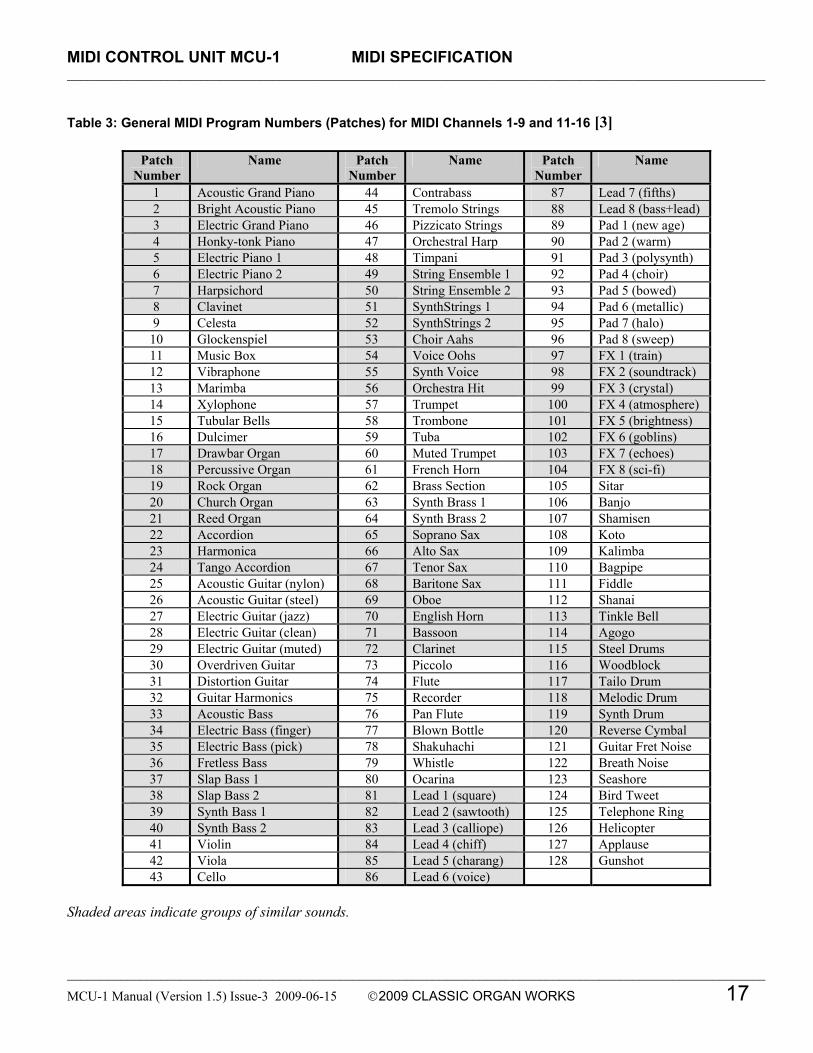
Table 3: General MIDI Program Numbers (Patches) for MIDI Channels 1-9 and 11-16 [3]
Patch Number
Name Patch Number
Name Patch Number
Name
1 Acoustic Grand Piano 44 Contrabass 87 Lead 7 (fifths) 2 Bright Acoustic Piano 45 Tremolo Strings 88 Lead 8 (bass+lead) 3 Electric Grand Piano 46 Pizzicato Strings 89 Pad 1 (new age) 4 Honky-tonk Piano 47 Orchestral Harp 90 Pad 2 (warm) 5 Electric Piano 1 48 Timpani 91 Pad 3 (polysynth) 6 Electric Piano 2 49 String Ensemble 1 92 Pad 4 (choir) 7 Harpsichord 50 String Ensemble 2 93 Pad 5 (bowed) 8 Clavinet 51 SynthStrings 1 94 Pad 6 (metallic) 9 Celesta 52 SynthStrings 2 95 Pad 7 (halo)
10 Glockenspiel 53 Choir Aahs 96 Pad 8 (sweep) 11 Music Box 54 Voice Oohs 97 FX 1 (train) 12 Vibraphone 55 Synth Voice 98 FX 2 (soundtrack) 13 Marimba 56 Orchestra Hit 99 FX 3 (crystal) 14 Xylophone 57 Trumpet 100 FX 4 (atmosphere) 15 Tubular Bells 58 Trombone 101 FX 5 (brightness) 16 Dulcimer 59 Tuba 102 FX 6 (goblins) 17 Drawbar Organ 60 Muted Trumpet 103 FX 7 (echoes) 18 Percussive Organ 61 French Horn 104 FX 8 (sci-fi) 19 Rock Organ 62 Brass Section 105 Sitar 20 Church Organ 63 Synth Brass 1 106 Banjo 21 Reed Organ 64 Synth Brass 2 107 Shamisen 22 Accordion 65 Soprano Sax 108 Koto 23 Harmonica 66 Alto Sax 109 Kalimba 24 Tango Accordion 67 Tenor Sax 110 Bagpipe 25 Acoustic Guitar (nylon) 68 Baritone Sax 111 Fiddle 26 Acoustic Guitar (steel) 69 Oboe 112 Shanai 27 Electric Guitar (jazz) 70 English Horn 113 Tinkle Bell 28 Electric Guitar (clean) 71 Bassoon 114 Agogo 29 Electric Guitar (muted) 72 Clarinet 115 Steel Drums 30 Overdriven Guitar 73 Piccolo 116 Woodblock 31 Distortion Guitar 74 Flute 117 Tailo Drum 32 Guitar Harmonics 75 Recorder 118 Melodic Drum 33 Acoustic Bass 76 Pan Flute 119 Synth Drum 34 Electric Bass (finger) 77 Blown Bottle 120 Reverse Cymbal 35 Electric Bass (pick) 78 Shakuhachi 121 Guitar Fret Noise 36 Fretless Bass 79 Whistle 122 Breath Noise 37 Slap Bass 1 80 Ocarina 123 Seashore 38 Slap Bass 2 81 Lead 1 (square) 124 Bird Tweet 39 Synth Bass 1 82 Lead 2 (sawtooth) 125 Telephone Ring 40 Synth Bass 2 83 Lead 3 (calliope) 126 Helicopter 41 Violin 84 Lead 4 (chiff) 127 Applause 42 Viola 85 Lead 5 (charang) 128 Gunshot 43 Cello 86 Lead 6 (voice)
Shaded areas indicate groups of similar sounds.

MIDI CONTROL UNIT MCU-1 MIDI SPECIFICATION _________________________________________________________________________________________________________
_________________________________________________________________________________________________________
18 MCU-1 Manual (Version 1.5) Issue-3 2009-06-15 2009 CLASSIC ORGAN WORKS
Table 4: General MIDI Percussion Key Map for MIDI Channel 10 [4]
MIDI Key Drum Sound MIDI Key Drum Sound 35 Acoustic Bass Drum 59 Ride Cymbal 2 36 Bass Drum 1 60 Hi Bongo 37 Side Stick 61 Low Bongo 38 Acoustic Snare 62 Mute Hi Conga 39 Hand Clap 63 Open Hi Conga 40 Electric Snare 64 Low Conga 41 Low Floor Tom 65 High Timbale 42 Closed Hi-Hat 66 Low Timbale 43 High Floor Tom 67 High Agogo 44 Pedal Hi-Hat 68 Low Agogo 45 Low Tom 69 Cabasa 46 Open Hi-Hat 70 Maracas 47 Low-Mid Tom 71 Short Whistle 48 Hi-Mid Tom 72 Long Whistle 49 Crash Cymbal 1 73 Short Guiro 50 High Tom 74 Long Guiro 51 Ride Cymbal 1 75 Claves 52 Chinese Cymbal 76 Hi Wood Block 53 Ride Bell 77 Low Wood Block 54 Tambourine 78 Mute Cuica 55 Splash Cymbal 79 Open Cuica 56 Cowbell 80 Mute Triangle 57 Crash Cymbal 2 81 Open Triangle 58 Vibraslap
Ahlborn [5]: The Ahlborn MIDI specification allows additional pipe organ sounds to be played on an existing organ. There are four different Ahlborn Archive modules with 20 different stops each in three separate divisions. The stop list for each module is shown below: For more information on Ahlborn Archive modules, please visit: http://www.ahlbornorgans.com/archive. The messages for controlling Ahlborn Archive modules can be found in Appendix E.
Table 5: Ahlborn Archive Classic Module [6]
Division A Division B Pedal Description Description Description Gemshorn 8' Principal 8' Contre Basse 32'
Gemshorn Celeste 8' Holzgedackt 8' Contre Gambe 16' Flûte à cheminée 8' Flûte Harmonique 8' Contre Bombarde 32'
Koppelflöte 4' Flûte Octaviante 4' Bombarde 16' Plein Jeu IV-V Octave 2' Div. A to Ped. Bombarde 16' Cymbale III Div. B to Ped.
Harmonic Trumpet 8' Tremulant Corno di Bassetto 8' Div. A to Div. B Festival Trumpet 8'
Clarion 4' Tremulant
Div. B to Div. A

MIDI CONTROL UNIT MCU-1 MIDI SPECIFICATION _________________________________________________________________________________________________________
_________________________________________________________________________________________________________
MCU-1 Manual (Version 1.5) Issue-3 2009-06-15 2009 CLASSIC ORGAN WORKS 19
Table 6: Ahlborn Archive Romantic Module [6]
Division A Division B Pedal Description Description Description
Cello 8' Open Diapason 8' Contre Violone 32' Cello Celeste 8' Flauto Mirabilis 8' Contre Gambe 16'
Cornet des Bombardes IV Concert Flute 4' Contre Bassoon 32' Cornopean 16' Quint Flute 2 2/3' Ophicleide 16'
Clarinet 8' Piccolo 2' Div. A to Ped. Orchestral Oboe 8' Vox Humana 8' Div. B to Ped.
French Horn 8' Tremulant Cor Anglais 8' Div. A to Div. B
Tuba Mirabilis 8' Clarion 4' Tremulant
Div. B to Div. A
Table 7: Ahlborn Archive 201 Module [6]
Division A Division B Pedal Description Description Description Bourdon 16' Gedackt 8' Subbass 16' Principal 8' Gamba 8' Octave 8'
Flûte à cheminée 8' Nachthorn 4' Bourdon 8' Unda Maris 8' Cymbale III Posaune 16'
Octave 4' Cornet III Div. A to Ped. Spitzflöte 2' Oboe 8' Div. B to Ped. Nasard 2 2/3' Tremulant
Superoctave 2' Div. A to Div. B Mixture IV Trompete 8' Tremulant
Div. B to Div. A
Table 8: Ahlborn Archive 202 Module [6]
Division A Division B Pedal Description Description Description
Contregambe 16' Bourdon 8' Soubasse 32' Diapason 8' Flûte harmonique 8' Violone 16'
Quintadena 8' Flûte octaviante 4' Contrebombarde 32' Terz 1 3/5' Larigot 1 1/3' Bombarde 16'
Septime 1 1/7' Corno di Bassetto 8' Div. A to Ped. Scharff III Clarion 4' Div. B to Ped.
Bombarde 16' Tremulant Trompette 8' Div. A to Div. B
Tuba Mirabilis 8' Chimes
Tremulant Div. B to Div. A

MIDI CONTROL UNIT MCU-1 MIDI SPECIFICATION _________________________________________________________________________________________________________
_________________________________________________________________________________________________________
20 MCU-1 Manual (Version 1.5) Issue-3 2009-06-15 2009 CLASSIC ORGAN WORKS
HAUPTWERKTM1 [7] The Hauptwerk (German for ‘Great Organ’) system provides a computer simulation of a pipe organ. It produces a realistic organ sound by use of a ‘virtual sampler’ technique. Traditionally, synthesizers (and MIDI) used a small number of samples by recording keys at intervals across the keyboard. In order to simulate all the keys, the samples were time-stretched. Hauptwerk uses a three-to-five-second sample of every pipe in the organ. To accommodate the intensive requirement for memory, a personal computer must be used. With current technology, thousands of individual sample sounds can be stored and recalled when a key is pressed. Thus, the software is able to capture many different and customizable organ configurations and sounds that can be loaded via ‘.organ’ files. The ‘.organ’ file contains information regarding number of stops, pistons, and keyboards in addition to other organ-related details. Hauptwerk was initially designed for use with one MIDI keyboard that would be connected to the personal computer through the sound card game port. When numerous keyboards were required, a MIDI merge box would have to be purchased. This revised MCU not only handles the MIDI merge function but also provides an interface for volume controls, expression controls, stops, pistons, pedalboard, and keyboards. MIDI messages are sent through the MIDI out port to the personal computer where Hauptwerk software translates the MIDI message commands into actions on the virtual organ. A table listing the types of messages sent for the individual functions is shown below.
Table 9: MIDI messages relevant to Hauptwerk
Function MIDI command Keyboards 1. Note on/off
2. Channel number 3. Key number
Pedalboard 1. Note on/off 2. Channel number 3. Key number
Stops Note on/off Pistons Program change Volume Program change Expression Program change Crescendo Program change
For more information, or to download a shareware version of Hauptwerk software, please visit: http://www.crumhorn-labs.com SCPOP2TM Sound Canvas Pipe Organ Project (SCPOP) is a computer program that emulates organ features such as stop changes, keyboard coupling, tremolo, assignable memories, temperament changes, and the ability to choose different reverb settings. All of the features can be accessed using the computer keyboard’s keys like a true organ console. [8] SCPOP requires a Roland Sound Canvas MIDI Expander module and is only compatible with Roland hardware containing the ‘Sound Canvas’ label [9]. The messages used to control SCPOP can be found in Appendix F.
1 Hauptwerk is a registered Trademark of Crumhorn Labs. 2 SCPOP is a registered Trademark of the Roland Corporation.

MIDI CONTROL UNIT MCU-1 MIDI SPECIFICATION _________________________________________________________________________________________________________
_________________________________________________________________________________________________________
MCU-1 Manual (Version 1.5) Issue-3 2009-06-15 2009 CLASSIC ORGAN WORKS 21
MIDI Hardware Specification [1] The only MIDI connector approved by the MIDI Manufacturers Association is a 5-pin 180° DIN connector. There are other ways of connecting devices to send MIDI messages but it is easier to have compatibility between different MIDI devices if there is a standard connector. In connecting a MIDI device to a personal computer, the simplest way is through the MIDI ports of a computer. Due to space limitations of computer circuit boards, most computers are not equipped with a MIDI port. Thus, adapters must be used which connect the MIDI device to another port. The most common port is the computer’s game port that is found on most soundcards. Serial port, parallel port, and USB port adapters are also available. A schematic of the standard 5-pin DIN MIDI connections is shown below:
Figure 3: Schematic of 5-pin 180° DIN connections MIDI Hardware notes: 1. Opto-isolator shown is Sharp PC-900. HP 6N138 or other can be used with changes. 2. Gates “A” are IC or transistor; resistors are 5%. 3. Maximum cable length is fifty feet (15 meters), terminated at each end by a 5-pin 180° male plug (e.g. SWITCHCRAFT 05GM5M). 4. Cable is shielded twisted-pair, with shield connected to pin 2 at both ends. 5. The receiving end has no ground connection (to avoid ground loops between units).


MIDI CONTROL UNIT MCU-1 PIN FUNCTIONS _________________________________________________________________________________________________________
_________________________________________________________________________________________________________
MCU-1 Manual (Version 1.5) Issue-3 2009-06-15 2009 CLASSIC ORGAN WORKS 23
MIDI CONTROL UNIT MCU-1
4. MCU PIN FUNCTIONS Keyboard Pins The keyboard pin connections are located in slots IN1, IN2, and IN3 using pins 1-61. The switches on each keyboard are connected to a switch common (+12V) and to the input pins. When a key is pressed, an electrical signal (+5V to +12V) is applied to a pin on the MCU and read by the processor of the MCU. When a key is released, a pull-down resistor generates an electrical signal equal to ground potential signifying a key-switch off. The keyboard switch inputs generate Channel messages on the MIDI output ports. These messages describe the key number (1-61), whether the key was pressed (note on) or released (note off), and the MIDI channel(s) (1-16) that are being used to transmit the MIDI information. Each keyboard uses a different MIDI channel number.
Pedalboard Pins The pedalboard pin connections are located in slot IN4 using pins 1-32. The switches on the pedalboard are connected to a switch common (+12V) and to the input pins. When a key is depressed, an electrical signal (+5V to +12V) is applied to a pin on the MCU and is read by the processor of the MCU. When a key is released, a pull-down resistor generates an electrical signal equal to ground potential signifying a key-switch off. The pedalboard switch inputs generate Channel messages on the MIDI output ports. These messages describe the key number (1-32), whether the key was pressed (note on) or released (note off), and the MIDI channel(s) (1-16) that are being used to transmit the MIDI information.
Custom Input Pins There are up to 105 custom input pins that can be used to connect pistons, stops, and other switch inputs. Pins 62-64 in slots IN1 to IN3, 33-64 in slot IN4, and 1-64 in slot IN5 are used for these input pins. Normally, the pins 62-64 associated with the keyboards are used to set the MIDI channel for that keyboard, thus leaving 96 others. A connection to a +5V (up to +12V) switch common enables an active high switch input.
MIDI Stops MIDI was originally developed for electronic music use in synthesizers. It was only a few years ago that organ-builders began adding MIDI capabilities to pipe organs. MIDI was not designed for complex musical instruments such as the organ. Thus, the application of the MIDI standard to the organ is subject to organ-builders’ preferences and standards are still evolving. Almost all MIDI expanders have the capability to generate at least 128 sounds or stops (in organ language). The difference is in the control of these sounds. Organs have many switches in the form of drawknobs, rocker-tabs, pushbuttons, etc., allowing organists to turn on and off one sound per switch. However, MIDI expanders lack these switches. The musician using an expander must decide which of the 128 stops will be used because if an organist wanted to access all the sounds on an expander, 128 switches would be required. Of course, not all the sounds are appropriate to organs. Nevertheless, a good many are useful. Having so many switches would be impractical due to space limitations on a console. Furthermore, organists generally prefer to have MIDI stops in each division rather than grouping them all into one division as is often the case in a MIDI expander. The MCU uses MIDI channels to transmit basic stop information while the various sound samples are derived from Ahlborn Archive modules, Hauptwerk, SCPOP, or a GM9773 General MIDI card (all sold

MIDI CONTROL UNIT MCU-1 PIN FUNCTIONS _________________________________________________________________________________________________________
_________________________________________________________________________________________________________
24 MCU-1 Manual (Version 1.5) Issue-3 2009-06-15 2009 CLASSIC ORGAN WORKS
separately). Stop switches (drawknobs, rocker-tabs, or pushbuttons) are connected to the switch inputs on the MCU. When the switch is activated, a MIDI message containing the MIDI channel number (up to 16) and ‘note on’ or ‘note off’ command will be generated.
Pistons Some pistons may be used to control the ‘combination action’, a feature that allows organists to quickly play a combination of sounds by operating several stops at the same time. On the MCU, if an input pin is configured for a combination piston, multiple sounds will be produced by several MIDI channels by sending Program Change message from This differs from the traditional definition of a ‘MIDI piston’ which assigns one MIDI sound to a particular pushbutton using a Patch command. The MCU uses MIDI channels to transmit the combination of sounds data (stops). Piston switches (usually pushbuttons) are connected to the switch inputs on the MCU. When the switch is activated, a MIDI message with a program change command is used which will select the combination of stops.
Analog Input Pins There are up to 5 analog inputs which can be configured for volume or expression (‘ANALOG IN 1,2,3’), tuning (‘ANALOG IN 4’) and crescendo (‘ANALOG IN 6’). Each analog device must be connected to three pins: the analog input pin, a positive voltage (+5V) pin, and a ground potential pin such that the analog input will vary in voltage between 0V and +5V. Depending on the position of the analog device, a voltage will be read by the processor that will determine the appropriate setting. In the case of a volume control, the voltage from the analog device will determine the loudness level.
MIDI Volume (Archive units) A MIDI program change message is sent to change the loudness level of the stop or sound. MIDI volume
messages apply only to Ahlborn Archive modules. Input pins ‘ANALOG IN 1,2,3’ are used for either MIDI volume selection or for MIDI expression depending on the configuration.
MIDI Expression (GM-MIDI modules) A MIDI program change message is sent to set the volume level. The Expression input differs from the Volume input in that the expression input can increase the loudness level in excess of the volume level setting. MIDI expression messages only apply to GM-MIDI modules. Input pins ‘ANALOG IN 1,2,3’ are used for either MIDI volume selection or for MIDI expression depending on the configuration.
MIDI Tuning ‘ANALOG IN 4’ is used for tuning of both General MIDI devices and Ahlborn Archive units. In the case of General MIDI, a MIDI tuning message is sent via the standard MIDI cable. For tuning of the Ahlborn Archive units, the tuning is performed by an analog output pin from the processor of the MCU that connects to the Ahlborn Archive unit via a separate 6-pin DIN tuning cable.
MIDI Crescendo MIDI program change messages derived from a voltage input are sent to add stops to a registration. As the voltage increases, more stops are added. ‘ANALOG IN 6’ is used for Crescendo.
Custom Output Pins This feature is currently not supported on the MCU. In the future, these 48 output pins will be used for driving lamps and/or magnets. Pins 1-48 in slot OUT6 are provided for outputs. These pins generate +12V at a total maximum current of 5A. Each output can continuously drive a 40-Ohm load (or greater).

MIDI CONTROL UNIT MCU-1 PIN FUNCTIONS _________________________________________________________________________________________________________
_________________________________________________________________________________________________________
MCU-1 Manual (Version 1.5) Issue-3 2009-06-15 2009 CLASSIC ORGAN WORKS 25
Figure 4: Block Diagram of MCU connections


MIDI CONTROL UNIT MCU-1 CONFIGURATIONS _________________________________________________________________________________________________________
_________________________________________________________________________________________________________
MCU-1 Manual (Version 1.5) Issue-3 2009-06-15 2009 CLASSIC ORGAN WORKS 27
MIDI CONTROL UNIT MCU-1
5. MCU CONFIGURATIONS Introduction The MCU allows many different ‘configurations’ encompassing both hardware and software. In terms of hardware, the MCU is customizable to fit many organ applications. The MCU supports switch inputs for keyboards, pedalboards and pistons. Expression controls, volume regulation, and tuning controls connect to one of the five function-specific analog inputs. In the future, 48 outputs for lamps or magnets may be driven by adding an optional output board. On the software side, the function of each switch input is customizable. The custom configurations support up to three 61-note keyboards, one 32-note pedalboard, and 105 additional switch inputs. All settings for instrument sounds generated, and MIDI channels used are customizable in two ways. The most convenient is through the use of a personal computer and the included Classic ‘MCUConfig’ software. Either Windows1 or MacIntosh2 computers may be used, as both versions are included on the disc. However if a personal computer is not readily accessible, applications engineers at Classic Organ Works can assist customers to develop custom configurations. In this case, the user must change a chip inside the MCU. Some configurations are pre-programmed while others are programmable and customizable. The pre-programmed configurations are included in the MCU. To edit configurations, the MCU must be connected to a personal computer running Windows or MacIntosh operating system software via a MIDI connection. However, if the computer does not have such connectors, an interface unit can be used. For example,
1 Windows is a registered Trademark of the Microsoft Corporation. 2 MacIntosh is a registered Trademark of the Apple Computer Corporation.
a suitable USB-to-MIDI unit is the M-Audio ‘MIDIman’.
Default Configuration (Config. #1: cfg001.mcu) The MCU is equipped with a default configuration that is pre-programmed and coded into software. It is selected by setting the DIP-switch to ‘0000 0000’ (all switches in the ‘off’ position) or ‘1111 1111’ (all switches in the ‘on’ position). This configuration suits the general user making the MCU a ‘ready to use’ system. The user is required to change the DIP-switch settings if some other configuration is required. The default configuration also serves the purpose of being a diagnostic tool for users with custom configurations. By using the DIP-switch, the user can choose other configurations. The on-board processor reads the DIP-switch settings and compares it with the internal settings. If the DIP-Switch settings have changed, the processor downloads the new configuration from external memory according to the DIP-Switch settings. In the event of a failure of the memory chip containing the custom configurations, the MCU software automatically detects the failure, and switches to use the default configuration. If a user switches between different configurations, and always receives the default configuration, an error is present and needs to be corrected. In the default configuration:
- The DIP-Switch must be set to ‘1111 1111’ or ‘0000 0000’
- IN-5 allows for an additional 64 switch inputs
- IN-3 and OUT-1 slots are not used - Stops are wired to select GM-MIDI voices
(if the optional GM-MIDI module is purchased)
- MIDI Channels may be altered (see Changing MIDI Channels section) via pins 62-64 in the IN1 to IN3 slots. If the pins

MIDI CONTROL UNIT MCU-1 CONFIGURATIONS _________________________________________________________________________________________________________
_________________________________________________________________________________________________________
28 MCU-1 Manual (Version 1.5) Issue-3 2009-06-15 2009 CLASSIC ORGAN WORKS
are unaltered, the keyboard will be on the default MIDI channel as shown in the configuration table.
Note: Ahlborn Archive units use default Channels
1, 2, and 4 for Swell, Great and Pedal, respectively.
The default configuration supports:
- Two 61-note keyboards (manuals) - One 32-note pedalboard - 9 MIDI Channel Selectors - 93 MIDI sound selectors - one analog input for expression regulation - one analog input for General MIDI fine
tuning
Changing MIDI Channels (Config. #1 only) The MIDI Channels can be changed via pins 62-64 on input rows IN1, IN2, and IN4. By changing the MIDI Channel, the user is able to transmit MIDI information on the specified channels for the specified keyboard or pedalboard. By default, Input #1 (IN1) provides MIDI information only on MIDI channel-1, Input #2 (IN2) provides MIDI information only on MIDI channel-2, and Input #4 (IN4) provides MIDI information only on MIDI channel-4. To change these settings, the user may connect pins 62 (selects MIDI channel 1), 63 (selects MIDI channel 2), and 64 (selects MIDI channel 4) to +12 Volts. By doing so, the user specifies the MIDI channel(s) output for the keyboard. Each keyboard is capable of producing MIDI information on up to three channels (1, 2, and 4) at the same time. If the user wishes to return to the default MIDI channels after changing the default channel settings, he/she must first power off the system and then power it on again. Removing the individual switches will not reset the system to the default MIDI channel settings.

MIDI CONTROL UNIT MCU-1 CONFIGURATIONS _________________________________________________________________________________________________________
_________________________________________________________________________________________________________
MCU-1 Manual (Version 1.5) Issue-3 2009-06-15 2009 CLASSIC ORGAN WORKS 29
Table 10: Configuration #1 - Default (file: cfg001.mcu) MCU-1 DIP-Switch setting: ‘0000 0000’ or ‘1111 1111’
Pin Number
Slot-1 IN-1
Slot-2 IN-2
Slot-3 IN-3
Slot-4 IN-4
Slot-5 IN-5
Slot-6 OUT-1
Remarks
Board SIB-4 SIB-4 SIB-4 SIB-4 SIB-4 OUTN-1 Swell Great Choir Pedal Stops Outputs Not Fitted For MCU with GM9773 Not Fitted Keys Keys Keys Keys GM-MIDI Stops 1 C1 C1 C1 C1 Piano 1 (Grand) (Ch 1) 2 C#1 C#1 C#1 C#1 Piano 2 (Bright) (Ch 1) 3 D1 D1 D1 D1 Piano 3 (Elect. Grand) (Ch 1) 4 D#1 D#1 D#1 D#1 Piano 4 (Honky-tonk) (Ch 1) 5 E1 E1 E1 E1 Piano 5 (Elect. 1) (Ch 1) 6 F1 F1 F1 F1 Piano 6 (Elect. 2) (Ch 1) 7 F#1 F#1 F#1 F#1 Harpsichord (Ch 1) 8 G1 G1 G1 G1 Clavinet (Ch 1) 9 G#1 G#1 G#1 G#1 Celesta (Ch 1)
10 A1 A1 A1 A1 Glockenspiel (Ch 1) 11 A#1 A#1 A#1 A#1 Music Box (Ch 1) 12 B1 B1 B1 B1 Vibraphone (Ch 1) 13 C2 C2 C2 C2 Marimba (Ch 1) 14 C#2 C#2 C#2 C#2 Xylophone (Ch 1) 15 D2 D2 D2 D2 Tubular Bells (Ch 1) 16 D#2 D#2 D#2 D#2 Dulcimer (Ch 1)
17 E2 E2 E2 E2 Drawbar Organ (Ch 1) 18 F2 F2 F2 F2 Percussive Organ (Ch 1) 19 F#2 F#2 F#2 F#2 Rock Organ (Ch 1) 20 G2 G2 G2 G2 Church Organ (Ch 1) 21 G#2 G#2 G#2 G#2 Reed Organ (Ch 1) 22 A2 A2 A2 A2 Accordion (Ch 1) 23 A#2 A#2 A#2 A#2 Harmonica (Ch 1) 24 B2 B2 B2 B2 Tango Accordion (Ch 1)
25 C3 C3 C3 C3 Acoustic Guitar (Nylon) (Ch 1) 26 C#3 C#3 C#3 C#3 Acoustic Guitar (Steel) (Ch 1) 27 D3 D3 D3 D3 Elect. Guitar (Jazz) (Ch 1) 28 D#3 D#3 D#3 D#3 Elect. Guitar (Clean) (Ch 1) 29 E3 E3 E3 E3 Elect. Guitar (Muted) (Ch 1) 30 F3 F3 F3 F3 Elect. Guitar (Over driven) (Ch 1) 31 F#3 F#3 F#3 F#3 Elect. Guitar (Distorted) (Ch 1) 32 G3 G3 G3 G3 Elect. Guitar (Harmonics) (Ch 1)

MIDI CONTROL UNIT MCU-1 CONFIGURATIONS _________________________________________________________________________________________________________
_________________________________________________________________________________________________________
30 MCU-1 Manual (Version 1.5) Issue-3 2009-06-15 2009 CLASSIC ORGAN WORKS
Position Slot-1
IN-1 Slot-2 IN-2
Slot-3 IN-3
Slot-4 IN-4
Slot-5 IN-5
Slot-6 OUT-1
Remarks
Board SIB-4 SIB-4 SIB-4 SIB-4 SIB-4 OUTN-1 Swell Great Choir Pedal Stops Outputs Keys Keys Keys
Not fitted Stops
For MCU with GM9773 Stops
For MCU with GM9773 Not Fitted
33 G#3 G#3 G#3 Soprano Sax (Ch 4) Acoustic Bass (Ch 2) 34 A3 A3 A3 Alto Sax (Ch 4) Finger Bass (Ch 2) 35 A#3 A#3 A#3 Tenor Sax (Ch 4) Picked Bass (Ch 2) 36 B3 B3 B3 Baritone Sax (Ch 4) Fretless Bass (Ch 2) 37 C4 C4 C4 Oboe (Ch 4) Slap Bass 1 (Ch 2) 38 C#4 C#4 C#4 English Horn (Ch 4) Slap Bass 2 (Ch 2) 39 D4 D4 D4 Bassoon (Ch 4) Synth. Bass 1 (Ch 2) 40 D#4 D#4 D#4 Clarinet (Ch 4) Synth. Bass 2 (Ch 2) 41 E4 E4 E4 Piccolo (Ch 4) Violin (Ch 2) 42 F4 F4 F4 Flute (Ch 4) Viola (Ch 2) 43 F#4 F#4 F#4 Recorder (Ch 4) Cello (Ch 2) 44 G4 G4 G4 Pan Flute (Ch 4) Contrabass (Ch 2) 45 G#4 G#4 G#4 Blown Bottle (Ch 4) Trem. Strings (Ch 2) 46 A4 A4 A4 Shakuhachi (Ch 4) Pizz. Strings (Ch 2) 47 A#4 A#4 A#4 Whistle (Ch 4) Orch. Harp (Ch 2) 48 B4 B4 B4 Lead 1 (Square) (Ch 4) Tympani (Ch 2)
49 C5 C5 C5 Lead 2 (Sawtooth) (Ch 4) String Ensem. 1 (Ch 2) 50 C#5 C#5 C#5 Lead 3 (Calliope) (Ch 4) String Ensem. 2 (Ch 2) 51 D5 D5 D5 Lead 4 (Chiff) (Ch 4) Synth. Strings 1 (Ch 2) 52 D#5 D#5 D#5 Lead 5 (Charang) (Ch 4) Synth. Strings 2 (Ch 2) 53 E5 E5 E5 Lead 6 (Voice) (Ch 4) Choir Aahs (Ch 2) 54 F5 F5 F5 Lead 7 (Fifth) (Ch 4) Voice Oohs (Ch 2) 55 F#5 F#5 F#5 Lead 8 (Bass+Lead) (Ch
4) Synth. Voice (Ch 2)
56 G5 G5 G5 Pad 1 (Fantasia) (Ch 4) Orchestra Hit (Ch 2)
57 G#5 G#5 G#5 Pad 2 (Warm) (Ch 4) Trumpet (Ch 2) 58 A5 A5 A5 Guitar Fret Noise (Ch 4) Trombone (Ch 2) 59 A#5 A#5 A#5 Breath Noise (Ch 4) Tuba (Ch 2) 60 B5 B5 B5 Seashore (Ch 4) Muted Trumpet (Ch 2) 61 C6 C6 C6 Bird Tweet (Ch 4) French Horn (Ch 2)
62 MIDI Ch-1 MIDI Ch-1 MIDI Ch-1 MIDI Ch-1 Brass Section (Ch 2) 63 MIDI Ch-2 MIDI Ch-2 MIDI Ch-2 MIDI Ch-2 Synth. Brass 1 (Ch 2) 64 MIDI Ch-4 MIDI Ch-4 MIDI Ch-3 MIDI Ch-4 Synth. Brass 2 (Ch 2)
Default MIDI Ch-1 MIDI Ch-2 MIDI Ch-3 MIDI Ch-4

MIDI CONTROL UNIT MCU-1 CONFIGURATIONS _________________________________________________________________________________________________________
_________________________________________________________________________________________________________
MCU-1 Manual (Version 1.5) Issue-3 2009-06-15 2009 CLASSIC ORGAN WORKS 31
Figure 5: MCU Configuration #1 (default) connection diagram.

MIDI CONTROL UNIT MCU-1 CONFIGURATIONS _________________________________________________________________________________________________________
_________________________________________________________________________________________________________
32 MCU-1 Manual (Version 1.5) Issue-3 2009-06-15 2009 CLASSIC ORGAN WORKS
Configurations for Ahlborn Archive Units (Config. # 2, 3, 4, 5)
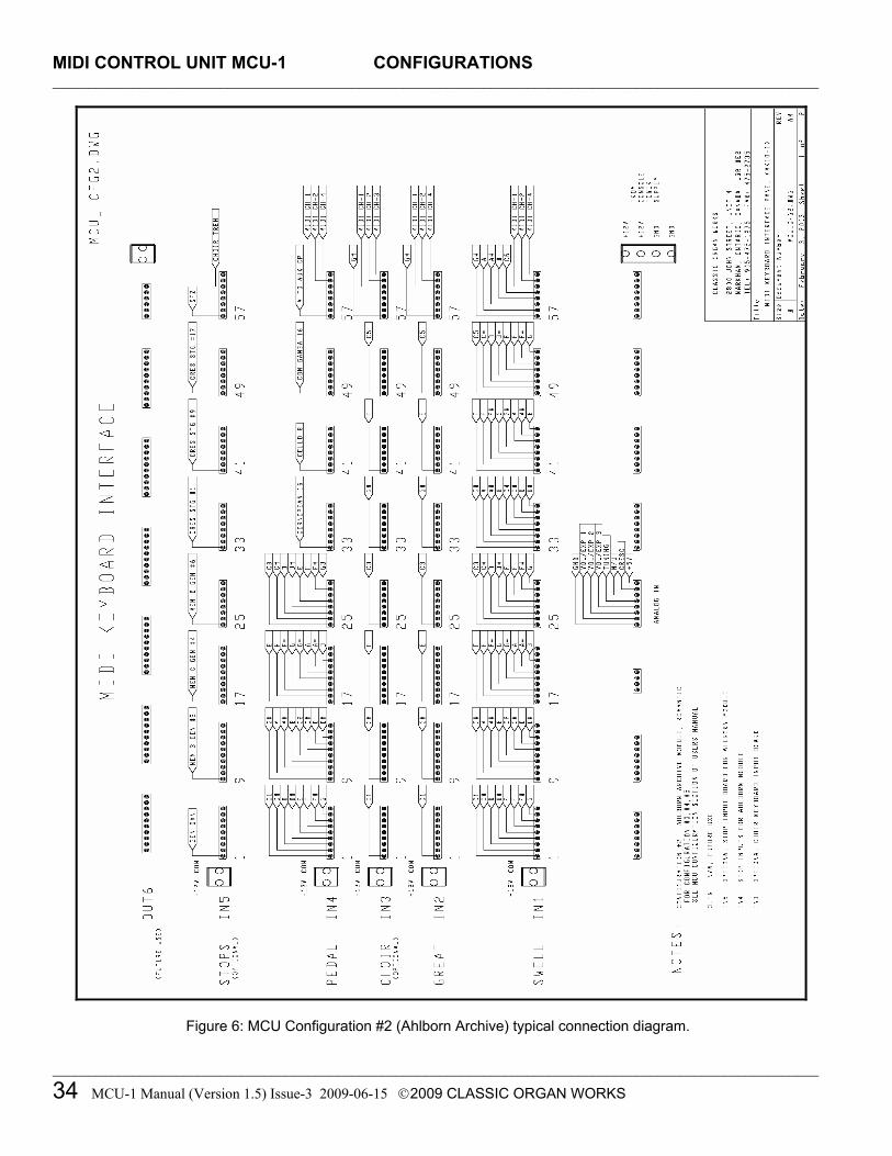
Four pre-programmed configurations are included in the internal EEPROM. These configurations are for users who have Ahlborn Archive modules, or those who anticipate purchasing them. Ahlborn Archive modules are available in four models: Romantic (filename: cfg002.mcu), Classic (filename: cfg003.mcu), Archive 202 (filename: cfg004.mcu), and Archive 201 (filename: cfg005.mcu) [6]. The differences between the four are in the stop lists that generate different tonal palettes. The configuration connection diagram shown on page 38 can be applied to the other Ahlborn modules by associating pins with stop names provided in the other configuration charts.
Table 11: Configuration #2: Ahlborn Archive Module – Romantic (file: cfg002.mcu) MCU-1 DIP-Switch setting: ‘1000 0000’ (Ahlborn MIDI Channels should be set to 1, 2, off, 4, 16)
Pin Number
Slot-1 IN-1
Slot-2 IN-2
Slot-3 IN-3
Slot-4 IN-4
Slot-5 IN-5
Slot-6 OUT-1
Remarks
Board SIB-4 SIB-4 SIB-4 SIB-4 SIB-4 OUTN-1 Swell Great Choir Pedal Stops Outputs Not Fitted Not Fitted Keys Keys Keys Keys
1 C1 C1 C1 Ahlborn - General Cancel 2 C#1 C#1 C#1 Ahlborn - Mem. A Gen. #1 3 D1 D1 D1 Ahlborn - Mem. A Gen. #2 4 D#1 D#1 D#1 Ahlborn - Mem. A Gen. #3 5 E1 E1 E1 Ahlborn - Mem. A Gen. #4 6 F1 F1 F1 Ahlborn - Mem. A Gen. #5 7 F#1 F#1 F#1 Ahlborn - Mem. A Gen. #6 8 G1 G1 G1 Ahlborn - Mem. B Gen. #1
9 G#1 G#1 G#1 Ahlborn - Mem. B Gen. #2 10 A1 A1 A1 Ahlborn - Mem. B Gen. #3 11 A#1 A#1 A#1 Ahlborn - Mem. B Gen. #4 12 B1 B1 B1 Ahlborn - Mem. B Gen. #5 13 C2 C2 C2 Ahlborn - Mem. B Gen. #6 14 C#2 C#2 C#2 Ahlborn - Mem. C Gen. #1 15 D2 D2 D2 Ahlborn - Mem. C Gen. #2 16 D#2 D#2 D#2 Ahlborn - Mem. C Gen. #3
17 E2 E2 E2 Ahlborn - Mem. C Gen. #4 18 F2 F2 F2 Ahlborn - Mem. C Gen. #5 19 F#2 F#2 F#2 Ahlborn - Mem. C Gen. #6 20 G2 G2 G2 Ahlborn - Mem. D Gen. #1 21 G#2 G#2 G#2 Ahlborn - Mem. D Gen. #2 22 A2 A2 A2 Ahlborn - Mem. D Gen. #3 23 A#2 A#2 A#2 Ahlborn - Mem. D Gen. #4 24 B2 B2 B2 Ahlborn - Mem. D Gen. #5
25 C3 C3 C3 Ahlborn - Mem. D Gen. #6 26 C#3 C#3 C#3 Ahlborn - Mem. E Gen. #1 27 D3 D3 D3 Ahlborn - Mem. E Gen. #2 28 D#3 D#3 D#3 Ahlborn - Mem. E Gen. #3 29 E3 E3 E3 Ahlborn - Mem. E Gen. #4 30 F3 F3 F3 Ahlborn - Mem. E Gen. #5 31 F#3 F#3 F#3 Ahlborn - Mem. E Gen. #6 32 G3 G3 G3 Cancel Crescendo

MIDI CONTROL UNIT MCU-1 CONFIGURATIONS _________________________________________________________________________________________________________
_________________________________________________________________________________________________________
MCU-1 Manual (Version 1.5) Issue-3 2009-06-15 2009 CLASSIC ORGAN WORKS 33
Position Slot-1 IN-1
Slot-2 IN-2
Slot-3 IN-3
Slot-4 IN-4
Slot-5 IN-5
Slot-6 OUT-1
Remarks
Keys Keys Keys Not Fitted
Stops Stops Not Fitted
33 G#3 G#3 Cornopean 16' (A) Crescendo Stage #1 / Off 34 A3 A3 Cornet des Bombardes
IV (A) Crescendo Stage #2 / 1
35 A#3 A#3 Tuba Mirabilis 8' (A) Crescendo Stage #3 / 2 36 B3 B3 Clarion 4' (A) Crescendo Stage #4 / 3 37 C4 C4 Orchestral Oboe 8' (A) Crescendo Stage #5 / 4 38 C#4 C#4 Clarinet 8' (A) Crescendo Stage #6 / 5 39 D4 D4 French Horn 8' (A) Crescendo Stage #7 / 6 40 D#4 D#4 Cor Anglais 8' (A) Crescendo Stage #8 / 7
41 E4 E4 Cello 8' (A) Crescendo Stage #9 / 8 42 F4 F4 Cello Celeste 8' (A) Crescendo Stage #10/ 9 43 F#4 F#4 Quint Flute 2 2/3' (B) Crescendo Stage #11/10 44 G4 G4 Piccolo 2' (B) Crescendo Stage #12/11 45 G#4 G#4 Vox Humana 8' (B) Crescendo Stage #13/12 46 A4 A4 Open Diapason 8' (B) Crescendo Stage #14/13 47 A#4 A#4 Flauto Mirabilis 8' (B) Crescendo Stage #15/14 48 B4 B4 Concert Flute 4' (B) Crescendo Stage #16/15
49 C5 C5 Contre Gamba 16' (P) Crescendo Stage #17/16 50 C#5 C#5 Ophicleide 16' (P) Crescendo Stage #18/17 51 D5 D5 Contre Violone 32' (P) Crescendo Stage #19/18 52 D#5 D#5 Contre Bassoon 32' (P) Crescendo Stage #20/19 53 E5 E5 A/P coupler Sw. Division Cancel 54 F5 F5 B to Pd coupler Gt. Division Cancel 55 F#5 F#5 B to A coupler Pedal Division Cancel 56 G5 G5 A to B coupler SET piston
57 G#5 G#5 A to Aux coupler SFZ control 58 A5 A5 B to Aux coupler 59 A#5 A#5 All stops On / Off 60 B5 B5 Swell Tremulant 61 C6 C6 Great Tremulant
62 MIDI Ch-1 MIDI Ch-1 MIDI Ch-1 Choir Tremulant 63 MIDI Ch-2 MIDI Ch-2 MIDI Ch-2 64 MIDI Ch-4 MIDI Ch-4 MIDI Ch-4
Default MIDI Ch-1 MIDI Ch-2 MIDI Ch-4
MIDI CONTROL UNIT MCU-1 CONFIGURATIONS _________________________________________________________________________________________________________
_________________________________________________________________________________________________________
34 MCU-1 Manual (Version 1.5) Issue-3 2009-06-15 2009 CLASSIC ORGAN WORKS
Figure 6: MCU Configuration #2 (Ahlborn Archive) typical connection diagram.

MIDI CONTROL UNIT MCU-1 CONFIGURATIONS _________________________________________________________________________________________________________
_________________________________________________________________________________________________________
MCU-1 Manual (Version 1.5) Issue-3 2009-06-15 2009 CLASSIC ORGAN WORKS 35
Table 12: Configuration #3: Ahlborn Archive Module – Classic (file: cfg003.mcu) MCU-1 DIP-Switch setting: 0100 0000 (Ahlborn MIDI Channels should be set to 1, 2, off, 4, 16)
Pin Number
Slot-1 IN-1
Slot-2 IN-2
Slot-3 IN-3
Slot-4 IN-4
Slot-5 IN-5
Slot-6 OUT-1
Remarks
Board SIB-4 SIB-4 SIB-4 SIB-4 SIB-4 OUTN-1 Swell Great Choir Pedal Stops Outputs Not Fitted Not Fitted Keys Keys Keys Keys
1 C1 C1 C1 Ahlborn - General Cancel 2 C#1 C#1 C#1 Ahlborn – Mem. A Gen. #1 3 D1 D1 D1 Ahlborn – Mem. A Gen. #2 4 D#1 D#1 D#1 Ahlborn – Mem. A Gen. #3 5 E1 E1 E1 Ahlborn – Mem. A Gen. #4 6 F1 F1 F1 Ahlborn - Mem. A Gen. #5 7 F#1 F#1 F#1 Ahlborn - Mem. A Gen. #6 8 G1 G1 G1 Ahlborn - Mem. B Gen. #1
9 G#1 G#1 G#1 Ahlborn - Mem. B Gen. #2 10 A1 A1 A1 Ahlborn - Mem. B Gen. #3 11 A#1 A#1 A#1 Ahlborn - Mem. B Gen. #4 12 B1 B1 B1 Ahlborn - Mem. B Gen. #5 13 C2 C2 C2 Ahlborn - Mem. B Gen. #6 14 C#2 C#2 C#2 Ahlborn - Mem. C Gen. #1 15 D2 D2 D2 Ahlborn - Mem. C Gen. #2 16 D#2 D#2 D#2 Ahlborn - Mem. C Gen. #3
17 E2 E2 E2 Ahlborn - Mem. C Gen. #4 18 F2 F2 F2 Ahlborn - Mem. C Gen. #5 19 F#2 F#2 F#2 Ahlborn - Mem. C Gen. #6 20 G2 G2 G2 Ahlborn - Mem. D Gen. #1 21 G#2 G#2 G#2 Ahlborn - Mem. D Gen. #2 22 A2 A2 A2 Ahlborn - Mem. D Gen. #3 23 A#2 A#2 A#2 Ahlborn - Mem. D Gen. #4 24 B2 B2 B2 Ahlborn - Mem. D Gen. #5
25 C3 C3 C3 Ahlborn - Mem. D Gen. #6 26 C#3 C#3 C#3 Ahlborn - Mem. E Gen. #1 27 D3 D3 D3 Ahlborn - Mem. E Gen. #2 28 D#3 D#3 D#3 Ahlborn - Mem. E Gen. #3 29 E3 E3 E3 Ahlborn - Mem. E Gen. #4 30 F3 F3 F3 Ahlborn - Mem. E Gen. #5 31 F#3 F#3 F#3 Ahlborn - Mem. E Gen. #6 32 G3 G3 G3 Cancel Crescendo

MIDI CONTROL UNIT MCU-1 CONFIGURATIONS _________________________________________________________________________________________________________
_________________________________________________________________________________________________________
36 MCU-1 Manual (Version 1.5) Issue-3 2009-06-15 2009 CLASSIC ORGAN WORKS
Position Slot-1
IN-1 Slot-2 IN-2
Slot-3 IN-3
Slot-4 IN-4
Slot-5 IN-5
Slot-6 OUT-1
Remarks
Keys Keys Keys Not Fitted
Stops Stops Not Fitted
Keys Keys Keys Stops Stops 33 G#3 G#3 Corno di Bassetto 8' (A) Crescendo Stage #1 / Off 34 A3 A3 Plein Jeu IV-V (A) Crescendo Stage #2 / 1 35 A#3 A#3 Clarion 4' (A) Crescendo Stage #3 / 2 36 B3 B3 Festival Trumpet 8' (A) Crescendo Stage #4 / 3 37 C4 C4 Gemshorn Celeste 8' (A) Crescendo Stage #5 / 4 38 C#4 C#4 Koppelflote 4' (A) Crescendo Stage #6 / 5 39 D4 D4 Bombarde 16' (A) Crescendo Stage #7 / 6 40 D#4 D#4 Harmonic Trumpet 8' (A) Crescendo Stage #8 / 7
41 E4 E4 Gemshorn 8' (A) Crescendo Stage #9 / 8 42 F4 F4 Flute a Cheminee 8' (A) Crescendo Stage #10/ 9 43 F#4 F#4 Flute Octaviante 4' (B) Crescendo Stage #11/10 44 G4 G4 Octave 2' (B) Crescendo Stage #12/11 45 G#4 G#4 Cymbale III (B) Crescendo Stage #13/12 46 A4 A4 Principal 8' (B) Crescendo Stage #14/13 47 A#4 A#4 Holzgedackt 8' (B) Crescendo Stage #15/14 48 B4 B4 Flute Harmonique 8' (B) Crescendo Stage #16/15
49 C5 C5 Contre Gamba 16' (P) Crescendo Stage #17/16 50 C#5 C#5 Bombarde 16' (P) Crescendo Stage #18/17 51 D5 D5 Contre Basse 32' (P) Crescendo Stage #19/18 52 D#5 D#5 Contre Bombarde 32' (P) Crescendo Stage #20/19 53 E5 E5 A/P coupler Sw. Division Cancel 54 F5 F5 B to Pd coupler Gt. Division Cancel 55 F#5 F#5 B to A coupler Pedal Division Cancel 56 G5 G5 A to B coupler SET piston
57 G#5 G#5 A to Aux coupler SFZ control 58 A5 A5 B to Aux coupler 59 A#5 A#5 All stops On / Off 60 B5 B5 Swell Tremulant 61 C6 C6 Great Tremulant
62 MIDI Ch-1 MIDI Ch-1 MIDI Ch-1 Choir Tremulant 63 MIDI Ch-2 MIDI Ch-2 MIDI Ch-2 64 MIDI Ch-4 MIDI Ch-4 MIDI Ch-4
Default MIDI Ch-1 MIDI Ch-2 MIDI Ch-4

MIDI CONTROL UNIT MCU-1 CONFIGURATIONS _________________________________________________________________________________________________________
_________________________________________________________________________________________________________
MCU-1 Manual (Version 1.5) Issue-3 2009-06-15 2009 CLASSIC ORGAN WORKS 37
Table 13: Configuration #4: Ahlborn Archive Module – 202 (file: cfg004.mcu) MCU-1 DIP-Switch setting: 1100 0000 (Ahlborn MIDI Channels should be set to 1, 2, off, 4, 16)
Pin Number
Slot-1 IN-1
Slot-2 IN-2
Slot-3 IN-3
Slot-4 IN-4
Slot-5 IN-5
Slot-6 OUT-1
Remarks
Board SIB-4 SIB-4 SIB-4 SIB-4 SIB-4 OUTN-1 Swell Great Choir Pedal Stops Outputs Not Fitted Not Fitted Keys Keys Keys Keys 1 C1 C1 C1 Ahlborn – General Cancel 2 C#1 C#1 C#1 Ahlborn - Mem. A Gen. #1 3 D1 D1 D1 Ahlborn - Mem. A Gen. #2 4 D#1 D#1 D#1 Ahlborn - Mem. A Gen. #3 5 E1 E1 E1 Ahlborn - Mem. A Gen. #4 6 F1 F1 F1 Ahlborn - Mem. A Gen. #5 7 F#1 F#1 F#1 Ahlborn - Mem. A Gen. #6 8 G1 G1 G1 Ahlborn - Mem. B Gen. #1 9 G#1 G#1 G#1 Ahlborn - Mem. B Gen. #2
10 A1 A1 A1 Ahlborn - Mem. B Gen. #3 11 A#1 A#1 A#1 Ahlborn - Mem. B Gen. #4 12 B1 B1 B1 Ahlborn - Mem. B Gen. #5 13 C2 C2 C2 Ahlborn - Mem. B Gen. #6 14 C#2 C#2 C#2 Ahlborn - Mem. C Gen. #1 15 D2 D2 D2 Ahlborn - Mem. C Gen. #2 16 D#2 D#2 D#2 Ahlborn - Mem. C Gen. #3
17 E2 E2 E2 Ahlborn - Mem. C Gen. #4 18 F2 F2 F2 Ahlborn - Mem. C Gen. #5 19 F#2 F#2 F#2 Ahlborn - Mem. C Gen. #6 20 G2 G2 G2 Ahlborn - Mem. D Gen. #1 21 G#2 G#2 G#2 Ahlborn - Mem. D Gen. #2 22 A2 A2 A2 Ahlborn - Mem. D Gen. #3 23 A#2 A#2 A#2 Ahlborn - Mem. D Gen. #4 24 B2 B2 B2 Ahlborn - Mem. D Gen. #5
25 C3 C3 C3 Ahlborn - Mem. D Gen. #6 26 C#3 C#3 C#3 Ahlborn - Mem. E Gen. #1 27 D3 D3 D3 Ahlborn - Mem. E Gen. #2 28 D#3 D#3 D#3 Ahlborn - Mem. E Gen. #3 29 E3 E3 E3 Ahlborn - Mem. E Gen. #4 30 F3 F3 F3 Ahlborn - Mem. E Gen. #5 31 F#3 F#3 F#3 Ahlborn - Mem. E Gen. #6 32 G3 G3 G3 Cancel Crescendo Keys Keys Keys Stops Stops
33 G#3 G#3 Contregambe 16' (A) Crescendo Stage #1 / Off 34 A3 A3 Diapason 8' (A) Crescendo Stage #2 / 1 35 A#3 A#3 Quintadena 8' (A) Crescendo Stage #3 / 2 36 B3 B3 Terz 1 3/5' (A) Crescendo Stage #4 / 3 37 C4 C4 Septime 1 1/7 (A)' Crescendo Stage #5 / 4 38 C#4 C#4 Scharff III (A) Crescendo Stage #6 / 5 39 D4 D4 Bombarde 16' (A) Crescendo Stage #7 / 6 40 D#4 D#4 Trompette 8' (A) Crescendo Stage #8 / 7

MIDI CONTROL UNIT MCU-1 CONFIGURATIONS _________________________________________________________________________________________________________
_________________________________________________________________________________________________________
38 MCU-1 Manual (Version 1.5) Issue-3 2009-06-15 2009 CLASSIC ORGAN WORKS
Position Slot-1
IN-1 Slot-2 IN-2
Slot-3 IN-3
Slot-4 IN-4
Slot-5 IN-5
Slot-6 OUT-1
Remarks
Keys Keys Keys Not fitted
Stops Stops Not Fitted
Keys Keys Keys Stops Stops 33 G#3 G#3 Contregambe 16' (A) Crescendo Stage #1 / Off 34 A3 A3 Diapason 8' (A) Crescendo Stage #2 / 1 35 A#3 A#3 Quintadena 8' (A) Crescendo Stage #3 / 2 36 B3 B3 Terz 1 3/5' (A) Crescendo Stage #4 / 3 37 C4 C4 Septime 1 1/7 (A)' Crescendo Stage #5 / 4 38 C#4 C#4 Scharff III (A) Crescendo Stage #6 / 5 39 D4 D4 Bombarde 16' (A) Crescendo Stage #7 / 6 40 D#4 D#4 Trompette 8' (A) Crescendo Stage #8 / 7
41 E4 E4 Tuba Mirabilis 8' (A) Crescendo Stage #9 / 8 42 F4 F4 Chimes (A) Crescendo Stage #10/ 9 43 F#4 F#4 Bourdon 8' (B) Crescendo Stage #11/10 44 G4 G4 Flute Harmonique 8' (B) Crescendo Stage #12/11 45 G#4 G#4 Flute Octaviante 4' (B) Crescendo Stage #13/12 46 A4 A4 Larigot 1 1/3' (B) Crescendo Stage #14/13 47 A#4 A#4 Corno di Bassetto 8' (B) Crescendo Stage #15/14 48 B4 B4 Clarion 4' (B) Crescendo Stage #16/15
49 C5 C5 Soubasse 32' (P) Crescendo Stage #17/16 50 C#5 C#5 Violone 16' (P) Crescendo Stage #18/17 51 D5 D5 Contrebombarde 32' (P) Crescendo Stage #19/18 52 D#5 D#5 Bombarde 16' (P) Crescendo Stage #20/19 53 E5 E5 A/P coupler Sw. Division Cancel 54 F5 F5 B to Pd coupler Gt. Division Cancel 55 F#5 F#5 B to A coupler Pedal Division Cancel 56 G5 G5 A to B coupler SET piston
57 G#5 G#5 A to Aux coupler SFZ control 58 A5 A5 B to Aux coupler 59 A#5 A#5 All stops On / Off 60 B5 B5 Swell Tremulant 61 C6 C6 Great Tremulant
62 MIDI Ch-1 MIDI Ch-1 MIDI Ch-1 Choir Tremulant 63 MIDI Ch-2 MIDI Ch-2 MIDI Ch-2 64 MIDI Ch-4 MIDI Ch-4 MIDI Ch-4
Default MIDI Ch-1 MIDI Ch-2 MIDI Ch-4

MIDI CONTROL UNIT MCU-1 CONFIGURATIONS _________________________________________________________________________________________________________
_________________________________________________________________________________________________________
MCU-1 Manual (Version 1.5) Issue-3 2009-06-15 2009 CLASSIC ORGAN WORKS 39
Table 14: Configuration #5: Ahlborn Archive Module – 201 (file: cfg005.mcu) MCU-1 DIP-Switch setting: 0010 0000 (Ahlborn MIDI Channels should be set to 1, 2, off, 4, 16)
Pin Number
Slot-1 IN-1
Slot-2 IN-2
Slot-3 IN-3
Slot-4 IN-4
Slot-5 IN-5
Slot-6 OUT-1
Remarks
Board SIB-4 SIB-4 SIB-4 SIB-4 SIB-4 OUTN-1 Swell Great Choir Pedal Stops Outputs Not Fitted Not Fitted Keys Keys Keys Keys
1 C1 C1 C1 Ahlborn - General Cancel 2 C#1 C#1 C#1 Ahlborn - Mem. A Gen. #1 3 D1 D1 D1 Ahlborn - Mem. A Gen. #2 4 D#1 D#1 D#1 Ahlborn - Mem. A Gen. #3 5 E1 E1 E1 Ahlborn - Mem. A Gen. #4 6 F1 F1 F1 Ahlborn - Mem. A Gen. #5 7 F#1 F#1 F#1 Ahlborn - Mem. A Gen. #6 8 G1 G1 G1 Ahlborn - Mem. B Gen. #1
9 G#1 G#1 G#1 Ahlborn - Mem. B Gen. #2 10 A1 A1 A1 Ahlborn - Mem. B Gen. #3 11 A#1 A#1 A#1 Ahlborn - Mem. B Gen. #4 12 B1 B1 B1 Ahlborn - Mem. B Gen. #5 13 C2 C2 C2 Ahlborn - Mem. B Gen. #6 14 C#2 C#2 C#2 Ahlborn - Mem. C Gen. #1 15 D2 D2 D2 Ahlborn - Mem. C Gen. #2 16 D#2 D#2 D#2 Ahlborn - Mem. C Gen. #3
17 E2 E2 E2 Ahlborn - Mem. C Gen. #4 18 F2 F2 F2 Ahlborn - Mem. C Gen. #5 19 F#2 F#2 F#2 Ahlborn - Mem. C Gen. #6 20 G2 G2 G2 Ahlborn - Mem. D Gen. #1 21 G#2 G#2 G#2 Ahlborn - Mem. D Gen. #2 22 A2 A2 A2 Ahlborn - Mem. D Gen. #3 23 A#2 A#2 A#2 Ahlborn - Mem. D Gen. #4 24 B2 B2 B2 Ahlborn - Mem. D Gen. #5
25 C3 C3 C3 Ahlborn - Mem. D Gen. #6 26 C#3 C#3 C#3 Ahlborn - Mem. E Gen. #1 27 D3 D3 D3 Ahlborn - Mem. E Gen. #2 28 D#3 D#3 D#3 Ahlborn - Mem. E Gen. #3 29 E3 E3 E3 Ahlborn - Mem. E Gen. #4 30 F3 F3 F3 Ahlborn - Mem. E Gen. #5 31 F#3 F#3 F#3 Ahlborn - Mem. E Gen. #6 32 G3 G3 G3 Cancel Crescendo

MIDI CONTROL UNIT MCU-1 CONFIGURATIONS _________________________________________________________________________________________________________
_________________________________________________________________________________________________________
40 MCU-1 Manual (Version 1.5) Issue-3 2009-06-15 2009 CLASSIC ORGAN WORKS
Position Slot-1
IN-1 Slot-2 IN-2
Slot-3 IN-3
Slot-4 IN-4
Slot-5 IN-5
Slot-6 OUT-1
Remarks
Keys Keys Keys Not Fitted
Stops Stops Not Fitted
Keys Keys Keys Stops Stops 33 G#3 G#3 Bourdon 16' (A) Crescendo Stage #1 / Off 34 A3 A3 Principal 8' (A) Crescendo Stage #2 / 1 35 A#3 A#3 Flute a cheminee 8' (A) Crescendo Stage #3 / 2 36 B3 B3 Unda Maris 8' (A) Crescendo Stage #4 / 3 37 C4 C4 Octave 4' (A) Crescendo Stage #5 / 4 38 C#4 C#4 Spitzflote 4' (A) Crescendo Stage #6 / 5 39 D4 D4 Nasard 2 2/3' (A) Crescendo Stage #7 / 6 40 D#4 D#4 Superoctave 2' (A) Crescendo Stage #8 / 7
41 E4 E4 Mixture IV (A) Crescendo Stage #9 / 8 42 F4 F4 Trompete 8' (A) Crescendo Stage #10/ 9 43 F#4 F#4 Gedackt 8' (B) Crescendo Stage #11/10 44 G4 G4 Gamba 8' (B) Crescendo Stage #12/11 45 G#4 G#4 Nachthorn 4' (B) Crescendo Stage #13/12 46 A4 A4 Cymbale/Scharff III (B) Crescendo Stage #14/13 47 A#4 A#4 Cornet III (B) Crescendo Stage #15/14 48 B4 B4 Oboe 8' (B) Crescendo Stage #16/15
49 C5 C5 Subbass 16' (P) Crescendo Stage #17/16 50 C#5 C#5 Octave 8' (P) Crescendo Stage #18/17 51 D5 D5 Bourdon 8' (P) Crescendo Stage #19/18 52 D#5 D#5 Posaune 16' (P) Crescendo Stage #20/19 53 E5 E5 A/P coupler Sw. Division Cancel 54 F5 F5 B to Pd coupler Gt. Division Cancel 55 F#5 F#5 B to A coupler Pedal Division Cancel 56 G5 G5 A to B coupler SET piston
57 G#5 G#5 A to Aux coupler SFZ control 58 A5 A5 B to Aux coupler 59 A#5 A#5 All stops On / Off 60 B5 B5 Swell Tremulant 61 C6 C6 Great Tremulant
62 MIDI Ch-1 MIDI Ch-1 MIDI Ch-1 Choir Tremulant 63 MIDI Ch-2 MIDI Ch-2 MIDI Ch-2 64 MIDI Ch-4 MIDI Ch-4 MIDI Ch-4
Default MIDI Ch-1 MIDI Ch-2 MIDI Ch-4

MIDI CONTROL UNIT MCU-1 CONFIGURATIONS _________________________________________________________________________________________________________
_________________________________________________________________________________________________________
MCU-1 Manual (Version 1.5) Issue-3 2009-06-15 2009 CLASSIC ORGAN WORKS 41
Table 15: Configuration #6: Hauptwerk (file: cfg006.mcu) MCU-1 DIP-Switch setting: 1010 0000
Pin Number
Slot-1 IN-1
Slot-2 IN-2
Slot-3 IN-3
Slot-4 IN-4
Slot-5 IN-5
Slot-6 OUT-1
Remarks
Board SIB-4 SIB-4 SIB-4 SIB-4 SIB-4 OUTN-1 Swell Great Choir Pedal Stops Outputs Not Fitted Keys Keys Keys Keys
1 C1 C1 C1 C1 2 C#1 C#1 C#1 C#1 3 D1 D1 D1 D1 4 D#1 D#1 D#1 D#1 5 E1 E1 E1 E1 6 F1 F1 F1 F1 7 F#1 F#1 F#1 F#1 8 G1 G1 G1 G1
9 G#1 G#1 G#1 G#1 10 A1 A1 A1 A1 11 A#1 A#1 A#1 A#1 12 B1 B1 B1 B1 13 C2 C2 C2 C2 14 C#2 C#2 C#2 C#2 15 D2 D2 D2 D2 16 D#2 D#2 D#2 D#2
17 E2 E2 E2 E2 18 F2 F2 F2 F2 19 F#2 F#2 F#2 F#2 20 G2 G2 G2 G2 21 G#2 G#2 G#2 G#2 22 A2 A2 A2 A2 23 A#2 A#2 A#2 A#2 24 B2 B2 B2 B2
25 C3 C3 C3 C3 26 C#3 C#3 C#3 C#3 27 D3 D3 D3 D3 28 D#3 D#3 D#3 D#3 29 E3 E3 E3 E3 30 F3 F3 F3 F3 31 F#3 F#3 F#3 F#3 32 G3 G3 G3 G3

MIDI CONTROL UNIT MCU-1 CONFIGURATIONS _________________________________________________________________________________________________________
_________________________________________________________________________________________________________
42 MCU-1 Manual (Version 1.5) Issue-3 2009-06-15 2009 CLASSIC ORGAN WORKS
Position Slot-1
IN-1 Slot-2 IN-2
Slot-3 IN-3
Slot-4 IN-4
Slot-5 IN-5
Slot-6 OUT-1
Remarks
Keys Keys Keys
Stops Stops Not Fitted
Keys Keys Keys Stops Stops 33 G#3 G#3 G#3 34 A3 A3 A3 35 A#3 A#3 A#3 36 B3 B3 B3 37 C4 C4 C4 38 C#4 C#4 C#4 39 D4 D4 D4 40 D#4 D#4 D#4
41 E4 E4 E4 42 F4 F4 F4 43 F#4 F#4 F#4 44 G4 G4 G4 45 G#4 G#4 G#4 46 A4 A4 A4 47 A#4 A#4 A#4 48 B4 B4 B4
49 C5 C5 C5 50 C#5 C#5 C#5 51 D5 D5 D5 52 D#5 D#5 D#5 53 E5 E5 E5 54 F5 F5 F5 55 F#5 F#5 F#5 56 G5 G5 G5
57 G#5 G#5 G#5 58 A5 A5 A5 59 A#5 A#5 A#5 60 B5 B5 B5 61 C6 C6 C6
62 MIDI Ch-1 MIDI Ch-1 MIDI Ch-1 MIDI Ch-1 63 MIDI Ch-2 MIDI Ch-2 MIDI Ch-2 MIDI Ch-2 64 MIDI Ch-4 MIDI Ch-4 MIDI Ch-4 MIDI Ch-4
Default MIDI Ch-3 MIDI Ch-2 MIDI Ch-4 MIDI Ch-1
MIDI CONTROL UNIT MCU-1 CONFIGURATION SOFTWARE _________________________________________________________________________________________________________
_________________________________________________________________________________________________________
MCU-1 Manual (Version 1.5) Issue-3 2009-06-15 2009 CLASSIC ORGAN WORKS 43
MIDI CONTROL UNIT MCU-1
6. CONFIGURATION SOFTWARE (PC and MAC)
Introduction Users with access to a personal computer can use the Classic ‘MCUConfig’ software (contained in the compact disc) to program additional configurations for the MCU. The software allows users to use existing configuration files, change existing configuration files, and create new configuration files by editing existing ones. Both Windows and MacIntosh versions are substantially the same though differing in appearance. Some configuration files are provided on the CD supplied.
Software Installation The MCU includes a compact disc with software allowing users to create custom configurations. To use the software, the MCU must be connected via MIDI to a personal computer running WindowsTM 1 operating system software (Windows 98, 2000, XP) or System-X on the MacIntoshTM 2. You can use the software without the MCU if all you want to do it to edit or create files on the computer. If a MIDI port is not available on your computer, commercial MIDI adapters for the game port, USB port, or parallel port may be used. A suitable USB-to-MIDI interface unit is the M-Audio ‘MIDIsport 1x1’, which has drivers for both PC and Mac. When the installation CD is placed in the optical drive of your computer (CD drive), the software installation wizard should automatically run. If however, the software installation wizard does not automatically run, follow the steps below:
1 Windows is a registered Trademark of the Microsoft Corporation. 2 MacIntosh is a registered Trademark of the Apple Computer Corporation.
For Windows: 1. Open the ‘Start’ menu and click on ‘Run’. 2. Click on ‘Browse’ and select the optical drive
(CD drive) from the ‘Look-in’ drop-down menu.
3. Locate and click on a file named ‘MCU_Setup.exe’.
4. Follow the instructions in the software installation wizard.
5. Right-click to make a Shortcut for this program.
For MacIntosh: 1. The CD icon will appear on the desktop.
Double-click on the icon to show its contents. 2. Drag all the files to a new folder on the hard
drive. Name it MCU. 3. Double-click on the zipped file among the list
and it will open up into a list of files. 4. Double-click on ‘MCUconfig.app’. 5. Right-click to make an Alias of this program.

MIDI CONTROL UNIT MCU-1 CONFIGURATION SOFTWARE _________________________________________________________________________________________________________
_________________________________________________________________________________________________________
44 MCU-1 Manual (Version 1.5) Issue-3 2009-06-15 2009 CLASSIC ORGAN WORKS
Software Startup After installation, a file titled Classic ‘MCUConfig’ (or ‘MCUConfig.app’ for the MacIntosh) will be created in a folder of the same name (Start menu→ Programs→ Classic MCUConfig). To start using the software, double-click your left mouse button on the file named ‘Classic MCUConfig’. You should briefly see a screen as shown below (the MacIntosh version will say 1.5.1 but is otherwise identical):
Figure 7: Classic MCUConfig software startup screen.
After a few moments the main menu selection will appear:
Figure 8: Classic MCUConfig software main menu. The main menu allows you to select one of two sources for the basic configuration and presents you with a selection window from which you choose a file in the normal manner:
1. Load Current Settings from the MCU: This mode reads from a file in the MCU memory. 2. Open a Previously Saved MCU Configuration: This mode reads from a file stored on your computer.
Both sources allow you to modify the settings and eventually save either back to the MCU or to the computer under a new filename if you so wish.

MIDI CONTROL UNIT MCU-1 CONFIGURATION SOFTWARE _________________________________________________________________________________________________________
_________________________________________________________________________________________________________
MCU-1 Manual (Version 1.5) Issue-3 2009-06-15 2009 CLASSIC ORGAN WORKS 45
Functions of the Toolbars The software has toolbars that contain three main menu functions. Four of these from the File menu are shown as icons while the fifth icon is from the Options menu. MacIntosh icons are similar but more concise. Mac and PC data files are interchangeable:
Figure 9: Toolbars in Classic MCUConfig software (Windows and MacIntosh (right)).
1. File Menu
• Open Previously Saved MCU Configuration – Loads a configuration file (a text file with a ‘.mcu’ extension) from the computer to the Classic MCUConfig software. The user may then edit the file as desired. Keyboard shortcut: Ctrl+O Windows Icon: To begin loading a configuration go to File → Open Previously Saved MCU Configuration, or use the Keyboard shortcut, or icon shown above. A window prompting the user for a filename should appear:
The user can then select the filename and click on the ‘Open’ button or double-click on the filename.
• Save MCU Configuration to File – Saves a configuration file to the computer. All configuration files
have a ‘.mcu’ extension. On the Mac, the default name is ‘data’ and the file will save with a ‘.mcu’ suffix. Keyboard shortcut: Ctrl+S Windows Icon:
To save a configuration file to the computer, go to File → Save MCU Configuration to File, or use the Keyboard shortcut or icon shown above. A window prompting the user for a filename should appear. Give the file a name (no need to type .mcu) and it need not be ‘p#’. It can have any name you wish. Tip: A single click on an existing name will put that name into the box. You can then modify it to save some typing before you save it.
If the configuration uses the same name as a previous configuration, a warning window will ask the user for confirmation in replacing the old file with the newly revised one.

MIDI CONTROL UNIT MCU-1 CONFIGURATION SOFTWARE _________________________________________________________________________________________________________
_________________________________________________________________________________________________________
46 MCU-1 Manual (Version 1.5) Issue-3 2009-06-15 2009 CLASSIC ORGAN WORKS
• Load Current Settings From the MCU – Loads a configuration file from the MCU memory chip. An MCU may contain numerous configuration files that are selectable by changing the DIP-switch, so the software displays an initial configuration number as currently set by the DIP-switch. If a configuration number different from the DIP switch is required, it may be specified by the user in a drop-down menu. Mac-generated data files have a text icon with .mcu extension. Keyboard shortcut: Ctrl+L Windows Icon:
To load a configuration from the MCU memory chip, the user must ensure that the MCU is connected to power and to a computer using a MIDI cable (please see software installation for details on connecting MIDI devices to computers). Then go to File → Load Program Data From MCU, or use the keyboard shortcut or icon as shown above. A window appears attempting to make a connection with the MCU: If a connection is not available, a window will appear as a reminder to make connections to the MCU: If a connection is available, a window will appear and the program will read the DIP-Switch to get the configuration number. The user may change the configuration number to be loaded if desired. After the user has the desired configuration number, pressing ‘OK’ will display a window to confirm the selection:
• Write Program Data to MCU – Saves a configuration file to the MCU memory chip. Typical MCU units will have numerous configuration files so, the configuration number of the current file may be chosen by the user. It will save as a ‘p#’ format but all you have to do is to select a number in the lower box.
Keyboard shortcut: Ctrl+W Windows Icon: To save a configuration to the MCU, go to File → Write Program Data to MCU or, use the keyboard shortcut or icon as shown above. The Software attempts to make a connection to the MCU.
NOTE: The ‘DIP Switch is set to’ field reflects the current DIP Switch setting. Care must be taken when choosing a new ‘Configuration Number’. If a ‘Configuration Number’ already contains settings, writing to the same ‘Configuration Number’ will overwrite this information.
A window should appear to confirm that the contents were written.
2. Options Menu • MIDI I/O Setup – This function shows the current MIDI input and output ports on your PC and they
may be changed using drop-down menus. You must have the drivers installed for the MIDI interface device that you are using. Keyboard shortcut: Ctrl+M Windows Icon:
3. Help Menu • About Classic MCUConfig – This function contains the software title, company and version number.
The current version does not have any actual Help files. Future versions will have proper Help files.

MIDI CONTROL UNIT MCU-1 CONFIGURATION SOFTWARE _________________________________________________________________________________________________________
_________________________________________________________________________________________________________
MCU-1 Manual (Version 1.5) Issue-3 2009-06-15 2009 CLASSIC ORGAN WORKS 47
Load Current Settings from MCU The screen that appears is used to determine the MIDI input and output interface connections to and from the MCU:
Each of the boxes has a pull-down selection from which you can select a suitable interface device if you have the necessary driver file installed. The one shown is for the M-Audio MIDIsport 1x1, which is a 1-In, 1-Out, USB-to-MIDI converter:
Left-click on OK. The computer requests the MCU configuration:
If your MIDI connections are NOT made properly, you will get the following screen:
If all is well, a window appears showing the DIP-Switch as it is currently set:

MIDI CONTROL UNIT MCU-1 CONFIGURATION SOFTWARE _________________________________________________________________________________________________________
_________________________________________________________________________________________________________
48 MCU-1 Manual (Version 1.5) Issue-3 2009-06-15 2009 CLASSIC ORGAN WORKS
You can use the lower drop-down menu to select another DIP-Switch setting from which to load the configuration data. The DIP-Switch in the window will move to show you how to adjust its switches. If this is the one you want, then you should move the switches to match the screen so that you will then work with it again when you next load/save to/from the MCU.
The diagram above shows the DIP-Switch changed to load Program Data number 10. Note that the number in the box is always 1 greater than the sum of the switches. e.g., the switches here show binary number 0000 1001, which is 9 but the box shows 10, because binary numbers start at 0, not 1. Note also that only the first seven switches are used to select any number from 1 to 128. If Switch-8 is put to On, you will get Configuration #1 and the switches will show as all Off even though they may be set otherwise. The number in the upper box will, however, be 128 plus the value of switches 1 to 7, while the upper box will be red. The following window appears briefly:

MIDI CONTROL UNIT MCU-1 CONFIGURATION SOFTWARE _________________________________________________________________________________________________________
_________________________________________________________________________________________________________
MCU-1 Manual (Version 1.5) Issue-3 2009-06-15 2009 CLASSIC ORGAN WORKS 49
Open Previously Saved MCU Configuration The screen that appears is the usual window for loading a file. Double-click on a filename or select the name and click on Open to load it:
Left: a typical Windows Loading screen. Right: a typical MacIntosh loading screen. The first file is Mac-generated, the others were generated by Windows. All will open.

MIDI CONTROL UNIT MCU-1 CONFIGURATION SOFTWARE _________________________________________________________________________________________________________
_________________________________________________________________________________________________________
50 MCU-1 Manual (Version 1.5) Issue-3 2009-06-15 2009 CLASSIC ORGAN WORKS
Edit the Configuration Whichever way you load the configuration file, the configuration then appears as below showing the MIDI Channel settings (for both Windows and MacIntosh):
In this particular file, the first four MIDI channels have been assigned to keyboards according to the Hauptwerk preferred channels, but they could be set differently if some other device must have, say, Channel-1. Opening a drop-down menu under the Input Keyboard item reveals the choice of keyboards that can be assigned to any available MIDI channel. You can assign a keyboard to more than one MIDI channel if you wish to drive multiple sound generators but some channels will be needed for stops and pistons. So unless there is a good reason for multiple channels, use only one. There are only 16 MIDI channels for everything and MIDI stops require one each. Hauptwerk uses one channel for all its stops (or perhaps two if it is a big organ with more than 128 stops). A yellow triangle next to a MIDI channel indicates that it has been assigned to a MIDI stop or other function in the Control Inputs Tab section and that should be changed there to some other channel.
The screen above-right shows a pull-down menu on the Key Offset column. It gives a choice of numbers between +91 and –36 allowing the keyboard pitch to be transposed in semi-tone steps by changing the key number. 0 is normal.

MIDI CONTROL UNIT MCU-1 CONFIGURATION SOFTWARE _________________________________________________________________________________________________________
_________________________________________________________________________________________________________
MCU-1 Manual (Version 1.5) Issue-3 2009-06-15 2009 CLASSIC ORGAN WORKS 51
The next screen shows a pull-down menu for the Analog input with which you want a MIDI Channel to be associated for volume or expression. None is also an option if you do not want either. If the keyboard is associated with more than one MIDI channel, each can be set differently depending on the device being controlled.
The Controller Type gives you only the choice of Volume or Expression for the chosen Analog input. Which one you pick depends on the MIDI sound-generating device the MCU will be driving. Typically, Archive units use Volume (7) while Hauptwerk uses Expression (11). Inputs #1-4 input refer to pins #2-5 on JP-3 of the bottom row. See diagram on page-30 and schematic on page-92. Up to four separate analog inputs may be used for expression shoes or other analog controls. There is also a #6 used for a global tuning control but that is not available in this window. See Functions of the Tabs, 3. General Settings. The next section shows the functions of the other tabs.

MIDI CONTROL UNIT MCU-1 CONFIGURATION SOFTWARE _________________________________________________________________________________________________________
_________________________________________________________________________________________________________
52 MCU-1 Manual (Version 1.5) Issue-3 2009-06-15 2009 CLASSIC ORGAN WORKS
Functions of the Tabs The tabs represent the items that a user needs to specify in a configuration. These tabs, labeled ‘MIDI Channel Config’, ‘Control Inputs’, and ‘General Settings’, are described below:
1. MIDI Channel Settings • Input Keyboard - One of four keyboards (three manual keyboards and one pedalboard) may be
specified to transmit on one or more MIDI channels. Note that a keyboard can transmit on multiple MIDI channels so that more than one sound generator can be used at the same time. Some generators may not have readily-changeable MIDI channels.
• Key Offset - The user may select any offset between +91 and –36 if the keyboard pitch is to be transposed. 0 being no transposition.
• Analog Input & Controller Type - The user may select one of four pin numbers for analog inputs (#1 = ‘Analog In 1’, #2 = ‘Analog In 2’, #3 = ‘Analog In 3’’, #4 = ‘Analog In 4’) associated with the keyboards, e.g., Swell Expression. Analog inputs control the output Volume (7) (for Ahlborn Archive modules) or Expression (11) (for GM-MIDI modules, Hauptwerk, etc.) transmitted on each MIDI channel. Selecting ‘none’ means no analog input controls for that MIDI channel.
2. Control Inputs There are105 inputs that may be used for stops, pistons, and other switch inputs. Double-clicking on the items for a particular pin gives drop-down menus from which the function and its particular parameters may be assigned to that pin.
• Row/Slot - Corresponds to the pin row labels on the MCU panel, starting with the three at the end of each manual keyboard row, then the 32 on the pedal row, finally the whole 64 on Row-5.
• Pin - Corresponds to the pin number (1-64) on the various MCU connectors. • Function - The pins may be specified to control different sound modules:
o Unassigned o Ahlborn Archive unit stops (Romantic, Classic, 201, or 202) o Common Ahlborn Functions/Pistons (couplers, tremulants, all stops on/off, General Cancel,
Memory Level select, Crescendo, Division Cancel, Sforzando, and SET) o MIDI Stop o GM Bank Select MSB o GM Bank Select LSB o Program Change o Note On/Off o CM-100 Stop o CM-100 Trem o CM-100 Cancel
• MIDI Channel - Select channel (1-16) on which to transmit MIDI information. • Parameter - Items that may be selected depending on the function that was specified.
Bear in mind that there are only 16 MIDI channels available for all functions, including keyboards, and that Channel-10 is used for percussive sounds in GM-MIDI.

MIDI CONTROL UNIT MCU-1 CONFIGURATION SOFTWARE _________________________________________________________________________________________________________
_________________________________________________________________________________________________________
MCU-1 Manual (Version 1.5) Issue-3 2009-06-15 2009 CLASSIC ORGAN WORKS 53
Figure 10: MCUConfig software with Pin Config tab selected. Notes on the Parameter selections: Ahlborn Modules: There will be a list of the 20 stops applicable to the particular module from which you choose one stop per pin. The list content depends on the model chosen. Common Ahlborn: These are for couplers, tremulants and other control functions. MIDI Stops: There are four keyboards with which to associate the stops. Be sure that the MIDI stop channels do not clash with any other MIDI channels. Each MIDI stop must have a channel that differs from the keyboard channels. Therefore, there is a practical limit as to how many MIDI stops there can be. MIDI Banks: Each MSB and LSB can be assigned to a MIDI channel (1-16) and a Bank number from 0 to 127. Refer to the MIDI device manual for details. Program Change: Gives a choice of 128 sounds for GM-MIDI or Program Change numbers when used for Hauptwerk. Note On/Off: Gives a choice of 128 keys from C2 to G8 (and is intended for use with MIDI percussions on Channel-10). Can also be used for Hauptwerk. CM-100 modules: There can be up to seven units controlled simultaneously, each with 12 stops. Choose one stop per pin. For Tremulant, the choice is 0 to 127 that sets the depth (the CM-100 has only one tremulant whose speed is preset). CM-100 Cancel has no choices. For Hauptwerk, you need one MIDI channel per keyboard and one (or two) for stops. Pistons could be on another. You would use Program Change or Note On/Off numbers (0-127).

MIDI CONTROL UNIT MCU-1 CONFIGURATION SOFTWARE _________________________________________________________________________________________________________
_________________________________________________________________________________________________________
54 MCU-1 Manual (Version 1.5) Issue-3 2009-06-15 2009 CLASSIC ORGAN WORKS
3. General Settings These globally affect all MIDI devices that may be controlled.
• Tuning Configuration - is specified by the user to tune General MIDI devices, Ahlborn modules, or any other MIDI device. A drop-down menu reveals a choice of input (None, 1-4 or 6). Tick boxes are used to select the method. Note that there is an extra analog input (#6) compared with the earlier volume/expression settings so this can have a unique control just for tuning. There is no #5 in either. The analog input and the temperature sensor will add together if both selected.
Figure 11: MCUConfig software with Fine Tuning Config tab selected.
• Ahlborn Archive Crescendo – A drop-down menu (the same as for tuning) allows the choice of analog input for a Crescendo shoe while another menu allows for choosing the MIDI channel on which to send the Crescendo messages to the Archive unit.

MIDI CONTROL UNIT MCU-1 CONFIGURATION SOFTWARE _________________________________________________________________________________________________________
_________________________________________________________________________________________________________
MCU-1 Manual (Version 1.5) Issue-3 2009-06-15 2009 CLASSIC ORGAN WORKS 55
Saving Configurations
1. Saving to the computer
When you are satisfied with the settings, you may save the configuration back to the MCU under the same file number or as another one of similar format (‘p#’). Alternatively, you can save it to the computer under any name you like. There is no need to include .mcu in the name. The MacIntosh may give the file the name ‘data’ but you can easily change it.
Keyboard shortcut: Ctrl+W. Windows Icon:
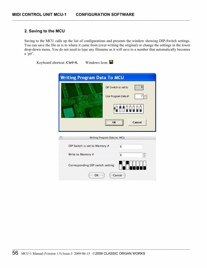
MIDI CONTROL UNIT MCU-1 CONFIGURATION SOFTWARE _________________________________________________________________________________________________________
_________________________________________________________________________________________________________
56 MCU-1 Manual (Version 1.5) Issue-3 2009-06-15 2009 CLASSIC ORGAN WORKS
2. Saving to the MCU
Saving to the MCU calls up the list of configurations and presents the window showing DIP-Switch settings. You can save the file as is to where it came from (over-writing the original) or change the settings in the lower drop-down menu. You do not need to type any filename as it will save to a number that automatically becomes a ‘p#’.
Keyboard shortcut: Ctrl+S. Windows Icon:

MIDI CONTROL UNIT MCU-1 GM-9773 INFORMATION _________________________________________________________________________________________________________
_________________________________________________________________________________________________________
MCU-1 Manual (Version 1.5) Issue-3 2009-06-15 2009 CLASSIC ORGAN WORKS 57
MIDI CONTROL UNIT MCU-1
7. GM9773 INFORMATION
Introduction The GM9773 is a General MIDI Sound Generator board (sold separately) with a single chip on a 2”x2” printed-circuit board. It is a plug-in replacement for EMU and other standard GM MIDI sound modules. It has stereo audio outputs, 38-note polyphony, reverb and chorus [10]. It contains a typical 16-channel GM MIDI sound set with 38-voice polyphony (and two variations), including five variations of percussions on Channel 10.
Usage The GM9773 board requires power from any DC supply providing +5V and +12V at a minimum current of 100mA. If the GM9773 board is purchased with the MCU, it should already be installed. However, if the board was purchased separately and requires installation, ensure that power is removed from whatever unit the board will be plugged into. Extreme caution must be exercised when plugging the connector because of the polarity (Pin-1 is the corner of the board). When plugged in, the card should power on.
Dimensions
Width 2.0 inches, 5.08 cm Height 2.0 inches, 5.08 cm Depth 0.55 inches, 1.4 cm (including connector)
Audio Output Level Full-scale 2Vpp ±200mV Harmonic Distortion –68 dB, 0.04%, for 0dB signal Channel Separation 80 dB Output Impedance 100 Ohms

MIDI CONTROL UNIT MCU-1 GM-9773 INFORMATION _________________________________________________________________________________________________________
_________________________________________________________________________________________________________
58 MCU-1 Manual (Version 1.5) Issue-3 2009-06-15 2009 CLASSIC ORGAN WORKS
Pin Functions 2x13-pin socket for standard 0.1" grid headers with 0.025" square posts.
Table 16: Pin functions of the GM9773
Pin Function Pin Function 1 Audio Ground 2 RESET 3 Audio Ground 4 AUDIO LEFT OUT 5 Audio Ground 6 NC 7 Audio Ground 8 AUDIO RIGHT OUT 9 Audio Ground 10 +12V IN
11 Audio Ground 12 NC 13 NC 14 +Vcc IN (+5V) 15 0V Power Ground 16 NC 17 0V Power Ground 18 +Vcc IN (+5V) 19 0V Power Ground 20 NC 21 0V Power Ground 22 +Vcc IN (+5V) 23 0V Power Ground 24 MIDI IN 25 0V Power Ground 26 NC
Note: Pin-1 is at the corner of the board. NC denotes No Connection.
MIDI Features The following MIDI parameters are presently supported:
Note On, Velocity, Pitch Bend, Program Change, Channel Aftertouch, MIDI Reset, Patch, Voice Variation (Bank) [Main or MT-32 Sound Variation #127], Drumset Variation [Standard, Power, Brush, Orchestra or CM-64/32 (Partial)], Volume, Pan, Expression, Sustain, Sostenuto, Soft Pedal, Tuning, Portamento, Pitch Bend, Reverberation, Chorus, Vibrato.
It should be noted that some of these parameters are not implemented in Classic applications although this unit supports them.

MIDI CONTROL UNIT MCU-1 GM-9773 INFORMATION _________________________________________________________________________________________________________
_________________________________________________________________________________________________________
MCU-1 Manual (Version 1.5) Issue-3 2009-06-15 2009 CLASSIC ORGAN WORKS 59
Table 17: GM9773 Detailed MIDI Implementation Chart [11] MIDI Message Hex Code Description Compatibility NOTE ON
9nh kk vv
MIDI channel n(0 - 15) note ON #kk(1-127), velocity vv(1-127). vv = 0 means NOTE OFF
MIDI
NOTE OFF
8nh kk vv
MIDI channel n(0 – 15) note OFF #kk(1 - 127), vv is don't care. MIDI
PITCH BEND
Enh bl bh
Pitch bend as specified by bh|bl (14 bits). Maximum swing is ±1 tone (power-up). Can be changed using “pitch bend sensitivity”. Center position is 00h 40h.
GM
PROGRAM CHANGE
Cnh pp
Program (patch) change. Specific action on channel 10 (n = 9): select drumset. Refer to sounds /drumset list. Drumsets can be assigned to other channels (see SYSEX MIDI channel-to-part assign and part-to-rhythm allocation)
GM/GS
CHANNEL AFTERTOUCH
Dnh vv
vv pressure value. Effect set using Sys. Ex. 40h 2nh 20h-26hh MIDI
MIDI RESET FFh Reset to power-up condition CTRL 00 Bnh 00h cc Bank select: Refer to sounds list. No action on drumset. GS
CTRL 01
Bnh 01h cc
Modulation wheel. Rate and maximum depth can be set using SYSEX.
MIDI
CTRL 05 Bnh 05h cc Portamento time. MIDI CTRL 06
Bnh 06h cc
Data entry: provides data to RPN and NRPN MIDI
CTRL 07 Bnh 07h cc Volume (default = 100) MIDI CTRL 10 Bnh 0Ah cc Pan (default = 64 center) MIDI CTRL 11 Bnh 0Bh cc Expression (default = 127) MIDI/GM CTRL 64 Bnh 40h cc Sustain (damper) pedal MIDI CTRL 65 Bnh 41h cc Portamento on/off MIDI CTRL 66 Bnh 42h cc Sostenuto pedal MIDI CTRL 67 Bnh 43h cc Soft pedal MIDI CTRL 80
Bnh 50h vv
Reverb program vv = 00h to 07h (default 04h) 00h: Room1 01h: Room2 02h: Room3 03h: Hall1 04h: Hall2 05h: Plate 06h: Delay 07h: Pan delay
DREAM
CTRL 81
Bnh 51h vv
Chorus program vv = 00h to 07h (default 02h) 00h: Chorus1 01h: Chorus2 02h: Chorus3 03h: Chorus4 04h: Feedback 05h: Flanger 06h: Short Delay 07h: FB Delay
DREAM
CTRL 91 Bnh 5Bh vv Reverb send level vv = 00h to 7Fh GS

MIDI CONTROL UNIT MCU-1 GM-9773 INFORMATION _________________________________________________________________________________________________________
_________________________________________________________________________________________________________
60 MCU-1 Manual (Version 1.5) Issue-3 2009-06-15 2009 CLASSIC ORGAN WORKS
GM9773 Detailed MIDI Implementation Chart, Cont’d. MIDI Message Hex Code Description Compatibility CTRL 93 Bnh 5Dh vv Chorus send level vv = 00h to 7Fh GS CTRL 120 Bnh 78h 00h All sound off (abrupt stop of sound on channel n) MIDI CTRL 121 Bnh 79h 00h Reset all controllers MIDI CTRL 123 Bnh 7Bh 00h All notes off MIDI CTRL 126 Bnh 7Eh 00h Mono on MIDI CTRL 127 Bnh 7Fh 00h Poly on (default power-up) MIDI CTRL CC1
Bnh cch vvh
Assignable Controller 1. cc = Controller number (0 - 5Fh), vv = Control value (0 - 7Fh). Control number (cch) can be set on CC1 CONTROLLER NUMBER (Sys. Ex 40 1x 1F). The resulting effect is determined by CC1 controller function (Sys.Ex. 40 2x 40-4A).
GS
CTRL CC2
Bnh cch vvh
Assignable Controller 2. cc = Controller number (00h - 5Fh), vv = control value (0 - 7Fh). Control number can be set on CC2 CONTROLLER NUMBER (Sys.Ex. 40 1x 20). The resulting effect is determined by CC2 controller function (Sys.Ex.40 2x 50-5A).
GS
RPN 0000h
Bnh 65h 00h 64h 00h 06h vv
Pitch bend sensitivity in semitones (default = 2) MIDI/GM
RPN 0001h Bnh 65h 00h 64h 01h 06h vv
Fine tuning in cents (vv = 00 -100, vv = 40h 0, vv = 7Fh +100) MIDI
RPN 0002h
Bnh 65h 00h 64h 02h 06h vv
Coarse tuning in half-tones (vv = 00 -64, vv = 40h 0, vv =7Fh +64)
MIDI
NRPN 0108h
Bnh 63h 01h 62h 08h 06h vv
Vibrate rate modify (vv = 40h -> no modif) GS
NRPN 0109h
Bnh 63h 01h 62h 09h 06h vv
Vibrate depth modify (vv = 40h -> no modif) GS
NRPN 010Ah
BnN 63h 01h 62h 0Ah 06h vv
Vibrate delay modify (vv = 40h -> no modif) GS
NRPN 0120h
Bnh 63h 01h 62h 20h 06h vv
TVF cutoff freq modify(vv = 40h -> no modif) GS
NRPN 0121h
Bnh 63h 01h 62h 21h 06h vv
TVF resonance modify (vv = 40h -> no modif) GS
NRPN 0163h
Bnh 63h 01h 62h 63h 06h vv
Env. attack time modify (vv = 40h ->no modif) GS
NRPN 0164h
Bnh 63h 01h 62h 64h 06h vv
Env. decay time modify (vv = 40h -> no modif) GS
NRPN 0166h
Bnh 63h 01h 62h 66h 06h vv
Env. release time modif (vv = 40h ->no modif) GS
NRPN 18rrh
Bnh 63h 18h 62h rr 06h Vv
Pitch coarse of drum instr. note rr in semitones (vv = 40h -> no modif)
GS
NRPN 1Arrh
Bnh 63h 1Ah 62h rr 06h Vv
Level of drum instrument note rr (vv = 00 to 7Fh) GS
NRPN 1Crrh
Bnh 63h 1Ch 62h rr 06h Vv
Pan of drum instrument note rr (40h = middle) GS
NRPN 1Drrh
Bnh 63h 1Dh 62h rr 06h Vv
Reverb send level of drum instrument note rr (vv = 00 to 7Fh) GS

MIDI CONTROL UNIT MCU-1 GM-9773 INFORMATION _________________________________________________________________________________________________________
_________________________________________________________________________________________________________
MCU-1 Manual (Version 1.5) Issue-3 2009-06-15 2009 CLASSIC ORGAN WORKS 61
GM9773 Detailed MIDI Implementation Chart, Cont’d. MIDI Message Hex Code Description Compatibility NRPN 1Errh
Bnh 63h 1Eh 62h rr 06h Vv
Chorus send level of drum instrument note rr (vv = 00 to 7Fh) GS
NRPN 37xxh
Bnh 63h 37h 62h xx 06h vv
Special Synthesis features controls (see Section 2.3) DREAM
NRPN 38xxhh
Bnh 63h 38h 62h xx 06h vv
3DMIDI control (see Section 2.3) DREAM
Standard SysEx
F0h 7Eh 7Fh 09h 01h F7h
General MIDI reset
GM
Standard SysEx
F0h 7Fh 7Fh 04h 01h 00h ll F7h
Master volume (ll = 0 to 127, default 127) GM
SYSEX
F0h 41h 00h 42h 12h 40h 00h 00h dd dd dd dd xx F7h
Master tune (default dd = 00h 04h 00h 00h) -100.0 to +100.0 Cents. Nibblized data should be used (always four bytes). For example, to tune to +100.0 cents, sent data should be 00h 07h 0Eh 08h
GS
SYSEX
F0h 41h 00h 42h 12h 40h 00h 04h vv xx F7h
Master volume (default vv = 7Fh) GS
SYSEX
F0h 41h 00h 42h 12h 40h 00h 05h vv xx F7h
Master key-shift (default vv = 40h, no transpose) GS
SYSEX
F0h 41h 00h 42h 12h 40h 00h 06h vv xx F7h
Master pan (default vv = 40h, center)
SYSEX
F0h 41h 00h 42h 12h 40h 00h 7Fh 00h xx F7h
GS reset
GS
SYSEX
F0h 41h 00h 42h 12h 40 01h 10h vv1 vv2 vv3 vv4 vv5 vv6 vv7 vv8 vv9 vv10 vv11 vv12 vv13 vv14 vv15 vv16 xx F7h
Voice reserve : vv1 = Part 10 (Default vv = 2) vv2 to vv10 = Part 1 to 9 (Default vv = 2) vv11 to vv16 = Part 11 to 16 (Default vv = 0)
GS
SYSEX
F0h 41h 00h 42h 12h 40h 01h 30h vv xx F7h
Reverb type (vv = 0 to 7), default = 04h 00h: Room1 01h: Room2 02h: Room3 03h: Hall1 04h: Hall2 05h: Plate 06h: Delay 07h: Pan delay
GS
SYSEX
F0h 41h 00h 42h 12h 40h 01h 31h vv xx F7h
Reverb character, default 04h GS
SYSEX
F0h 41h 00h 42h 12h 40h 01h 33h vv xx F7h
Reverb master level, default = 64 GS
SYSEX
F0h 41h 00h 42h 12h 40h 01h 34h vv xx F7h
Reverb time GS
SYSEX
F0h 41h 00h 42h 12h 40h 01h 35h vv xx F7h
Reverb delay feedback. Only if reverb number = 6 or 7 (delays). GS

MIDI CONTROL UNIT MCU-1 GM-9773 INFORMATION _________________________________________________________________________________________________________
_________________________________________________________________________________________________________
62 MCU-1 Manual (Version 1.5) Issue-3 2009-06-15 2009 CLASSIC ORGAN WORKS
GM9773 Detailed MIDI Implementation Chart, Cont’d. MIDI Message Hex Code Description Compatibility SYSEX
F0h 41h 00h 42h 12h 40h 01h 38h vv xx F7h
Chorus type (vv = 0 to 7), default = 02h 00h: Chorus1 01h: Chorus2 02h: Chorus3 03h: Chorus4 04h: Feedback 05h: Flanger 06h: Short delay 07h: FB delay
GS
SYSEX
F0h 41h 00h 42h 12h 40h 01h 3Ah vv xx F7h
Chorus master level, default = 64 GS
SYSEX
F0h 41h 00h 42h 12h 40h 01h 3Bh vv xx F7h
Chorus feedback
GS
SYSEX
F0h 41h 00h 42h 12h 40h 01h 3Ch vv xx F7h
Chorus delay
GS
SYSEX
F0h 41h 00h 42h 12h 40h 01h 3Dh vv xx F7h
Chorus rate
GS
SYSEX
F0h 41h 00h 42h 12h 40h 01h 3Eh vv xx F7h
Chorus depth
GS
SYSEX
F0h 41h 00h 42h 12h 40h 1ph 02h nn xx F7h
MIDI channel to part assign, p is part (0 to 15), nn is MIDI channel (0 to 15, 16 = OFF). This SYSEX allows several parts to be assigned to a single MIDI channel or to mute a part. Part 0, MIDI channel 9 (DRUMS) Part 1 - 9, MIDI channel 0 - 8 (DRUMS) Part 10 - 15, MIDI channel 10 - 15 (DRUMS)
GS
SYSEX
F0h 41h 00h 42h 12h 40h 1ph 15h vv xx F7h
Part-to-rhythm allocation, p is part (0 to 15), vv is 00 (sound part) or 01 (rhythm part). This SYSEX allows a part to play sound or drumset. There is no limitation of the number of parts playing drumset. Default assignment: part 0 plays drums (default MIDI channel 9), all other parts play sound.
GS
SYSEX
F0h 41h 00h 42h 12h 40h 1nh 40h v1 v2 ... v12 xx F7h
Scale tuning, n is MIDI channel (0 to 15), v1 to v12 are 12 semi-tones tuning values (C, C#, D, ... A#, B), in the range -64 (00h) 0 (40h) +63(7Fh) cents. This SYSEX allows non chromatic tuning of the musical scale on a given MIDI channel. Default v1, v2, ... ,v12 = 40h, 40h,...,40h (chromatic tuning). Scale tuning has no effect if the part is assigned to a rhythm channel or if the sound played is not of chromatic type.
GS
SYSEX
F0h 41h 00h 42h 12h 40h 1nh 1Ah vv xx F7h
Velocity slope from 00h to 7Fh (default = 40h) GS
SYSEX
F0h 41h 00h 42h 12h 40h 1nh 1Bh vv xx F7h
Velocity offset from 00h to 7Fh (default = 40h) GS
SYSEX
F0h 41h 00h 42h 12h 40h 1nh 1Fh vv xx F7h
CC1 Controller number (00-5Fh) (default = 10h) GS
SYSEX
F0h 41h 00h 42h 12h 40h 1nh 20h vv xx F7h
CC2 Controller number (00-5Fh) (default = 11h) GS
SYSEX F0h 41h 00h 42h 12h 40h 2nh 00h vv xx F7h
Mod pitch control (-24, +24 semitone) (default = 40h) GS

MIDI CONTROL UNIT MCU-1 GM-9773 INFORMATION _________________________________________________________________________________________________________
_________________________________________________________________________________________________________
MCU-1 Manual (Version 1.5) Issue-3 2009-06-15 2009 CLASSIC ORGAN WORKS 63
GM9773 Detailed MIDI Implementation Chart, Cont’d. MIDI Message Hex Code Description Compatibility SYSEX
F0h 41h 00h 42h 12h 40h 2nh 01h vv xx F7h
Mod tvf cutoff control (default = 40h) GS
SYSEX
F0h 41h 00h 42h 12h 40h 2nh 02h vv xx F7h
Mod Amplitude control (-100% ± 100%) (default = 40h) GS
SYSEX
F0h 41h 00h 42h 12h 40h 2nh 03h vv xx F7h
Mod lfo1 rate control (default = 40h). n is don't care. Rate is common on all channels.
GS
SYSEX
F0h 41h 00h 42h 12h 40h 2nh 04h vv xx F7h
Mod lfo1 pitch depth (0 - 600 cents) (default = 0Ah) GS
SYSEX F0h 41h 00h 42h 12h 40h 2nh 05h vv xx F7h
Mod lfo1 tvf depth (default = 0h) GS
SYSEX
F0h 41h 00h 42h 12h 40h 2nh 06h vv xx F7h
Mod lfo1 tva depth (0 - 100%) (default = 0h) GS
SYSEX
F0h 41h 00h 42h 12h 40h 2nh 10h vv xx F7h
Bend pitch control (-24, +24 semitone) (default = 42h) GS
SYSEX
F0h 41h 00h 42h 12h 40h 2nh 11h vv xx F7h
Bend tvf cutoff control (default = 40h) GS
SYSEX
F0h 41h 00h 42h 12h 40h 2nh 12h vv xx F7h
Bend Amplitude control (-100% ± 100%) (default = 40h) GS
SYSEX
F0h 41h 00h 42h 12h 40h 2nh 14h vv xx F7h
Bend lfo1 pitch depth (0 - 600 cents) (default = 0Ah) GS
SYSEX
F0h 41h 00h 42h 12h 40h 2nh 15h vv xx F7h
Bend lfo1 tvf depth (default = 0h) GS
SYSEX
F0h 41h 00h 42h 12h 40h 2nh 16h vv xx F7h
Bend lfo1 tva depth (0 – 100%) (default = 0h) GS
SYSEX
F0h 41h 00h 42h 12h 40h 2nh 20h vv xx F7h
CAF pitch control (-24, +24 semitone) (default = 40h) GS
SYSEX
F0h 41h 00h 42h 12h 40h 2nh 21h vv xx F7h
CAF tvf cutoff control (default = 40h) GS
SYSEX
F0h 41h 00h 42h 12h 40h 2nh 22h vv xx F7h
CAF Amplitude control (-100% ± 100%) (default = 40h) GS
SYSEX
F0h 41h 00h 42h 12h 40h 2nh 24h vv xx F7h
CAF lfo1 pitch depth (0 - 600 cents) (default = 0Ah) GS
SYSEX
F0h 41h 00h 42h 12h 40h 2nh 25h vv xx F7h
CAF lfo1 tvf depth (default = 0h) GS
SYSEX
F0h 41h 00h 42h 12h 40h 2nh 26h vv xx F7h
CAF lfo1 tva depth (0 - 100%) (default = 0h) GS
SYSEX
F0h 41h 00h 42h 12h 40h 2nh 40h vv xx F7h
CC1 pitch control (-24, +24 semitone) (default = 40h) GS
SYSEX
F0h 41h 00h 42h 12h 40h 2nh 41h vv xx F7h
CC1 tvf cutoff control (default = 40h) GS
SYSEX
F0h 41h 00h 42h 12h 40h 2nh 42h vv xx F7h
CC1 Amplitude control (-100% ± 100%) (default = 40h) GS
SYSEX
F0h 41h 00h 42h 12h 40h 2nh 44h vv xx F7h
CC1 lfo1 pitch depth (0 - 600 cents) (default = 0Ah) GS
SYSEX
F0h 41h 00h 42h 12h 40h 2nh 45h vv xx F7h
CC1 lfo1 tvf depth (default = 0h) GS
SYSEX
F0h 41h 00h 42h 12h 40h 2nh 46h vv xx F7h
CC1 lfo1 tva depth (0 - 100%) (default = 0h) GS
SYSEX
F0h 41h 00h 42h 12h 40h 2nh 50h vv xx F7h
CC2 pitch control (-24, +24 semitone) (default = 40h) GS

MIDI CONTROL UNIT MCU-1 GM-9773 INFORMATION _________________________________________________________________________________________________________
_________________________________________________________________________________________________________
64 MCU-1 Manual (Version 1.5) Issue-3 2009-06-15 2009 CLASSIC ORGAN WORKS
GM9773 Detailed MIDI Implementation Chart, Cont’d. MIDI Message Hex Code Description Compatibility SYSEX
F0h 41h 00h 42h 12h 40h 2nh 51h vv xx F7h
CC2 tvf cutoff control (default = 40h) GS
SYSEX
F0h 41h 00h 42h 12h 40h 2nh 52h vv xx F7h
CC2 Amplitude control (-100% ± 100%) (default = 40h) GS
SYSEX
F0h 41h 00h 42h 12h 40h 2nh 54h vv xx F7h
CC2 lfo1 pitch depth (0 - 600 cents) (default = 0Ah) GS
SYSEX
F0h 41h 00h 42h 12h 40h 2nh 55h vv xx F7h
CC2 lfo1 tvf depth (default = 0h) GS
SYSEX
F0h 41h 00h 42h 12h 40h 2nh 56h vv xx F7h
CC2 lfo1 tva depth (0 - 100%) (default = 0h) GS
Table 18: General MIDI Presets [11] The following are Program numbers for GS-MIDI sounds available on Channels 1–9, 11–16: To select variation: Send CTRL 0 = 0, then Program change.
1 Acoustic Piano 2 Bright Piano 3 Electric Piano 4 Honky tonk piano 5 Rhodes piano 6 Chorus piano 7 Harpsichord 8 Clavinet 9 Celesta 10 Glockenspiel 11 Music Box 12 Vibraphone
13 Marimba 14 Xylophone 15 Tubular bells 16 Dulcimer 17 Hammond Organ 18 Percussive Organ 19 Rock Organ 20 Church Organ 21 Reed organ 22 Accordion 23 Harmonica 24 Tango Accordion 25 Nylon string guitar 26 Steel string guitar 27 Electric Guitar (jazz) 28 Electric Guitar (clean) 29 Electric Guitar (mute) 30 Overdriven Guitar 31 Distorted Guitar 32 Guitar Harmonics 33 Acoustic Bass 34 Electric bass (finger) 35 Electric bass (pick) 36 Fretless bass 37 Slap bass 1 38 Slap bass 2 39 Synth bass 1 40 Synth bass 2 41 Violin 42 Viola 43 Cello 44 Contra Bass 45 Tremolo Strings 46 Pizzicato Strings 47 Orchestral Harp 48 Tympani 49 String Ensemble 1 50 String Ensemble 2 51 Synth Strings 1 52 Synth Strings 2 53 Choir Aahs 54 Voice Ooohs 55 Synth voice 56 Orchestra Hit 57 Trumpet 58 Trombone 59 Tuba 60 Muted Trumpet 61 French Horn 62 Brass Section 63 Synthbrass 1 64 Synthbrass 2 65 Soprano Sax 66 Alto Sax 67 Tenor Sax 68 Baritone Sax 69 Oboe 70 English Horn 71 Bassoon 72 Clarinet 73 Piccolo 74 Flute 75 Recorder 76 Pan Flute 77 Blown Bottle 78 Shakuhachi 79 Whistle 80 Ocarina 81 Synth Lead 1 82 Synth Lead 2 83 Synth Lead 3 84 Synth Lead 4 85 Synth Lead 5 86 Synth Lead 6 87 Synth Lead 7 88 Synth Lead 8 89 Synth Pad 1 90 Synth Pad 2 91 Synth Pad 3 92 Synth Pad 4 93 Synth Pad 5 94 Synth Pad 6 95 Synth Pad 7 96 Synth Pad 8 97 Synth FX 1 98 Synth FX 2 99 Synth FX 3 100 Synth FX 4
101 Synth FX 5 102 Synth FX 6 103 Synth FX 7 104 Synth FX 8 105 Sitar 106 Banjo 107 Shamisen 108 Koto 109 Kalimba 110 Bag Pipe 111 Fiddle 112 Shanai 113 Tinkle Bell 114 Agogo Bells 115 Steel Drum 116 Woodblock 117 Taiko Drum 118 Melodic Drum 119 Synth Drum 120 Reverse Cymbal 121 Guitar Fret Noise 122 Breath Noise 123 Seashore 124 Bird Tweet 125 Telephone Ring 126 Helicopter 127 Applause 128 Gunshot
The SAM9773 chip also has the MT-32 Sound Variation #127 on all of these sounds. Shaded areas denote groups with similar sounds.

MIDI CONTROL UNIT MCU-1 GM-9773 INFORMATION _________________________________________________________________________________________________________
_________________________________________________________________________________________________________
MCU-1 Manual (Version 1.5) Issue-3 2009-06-15 2009 CLASSIC ORGAN WORKS 65
Table 19: MT-32 Sound Variation #127 [11] [All Channels except 10. To select variation, send CTRL 0 = 127, then Program Change. C0= controller 0 value (zero for General MIDI capital sounds)
PC Number
Instrument Name
PC Number
Instrument Name
PC Number
Instrument Name
PC Number
Instrument Name
1 Piano 1 2 Piano 2 3 Piano 3 4 Detuned EP 1 5 E.Piano 1 6 E.Piano 2 7 Detuned EP 2 8 Honky-Tonk 9 Organ 1 10 Organ 2 11 Organ 3 12 Detuned Or. 1
13 Church Org. 2 14 Church Org. 15 Church Org. 16 Accordion Fr. 17 Harpsichord 18 Coupled Hps. 19 Coupled Hps. 20 Clav. 21 Clav. 22 Clav. 23 Celesta 24 Celesta 25 Synth Brass 1 26 Synth Brass 2 27 Synth Brass 3 28 Synth Brass 4 29 Synth Bass1 30 Synth Bass 2 31 Synth Bass 3 32 Synth Bass 4 33 Fantasia 34 Syn Calliope 35 Choir Aahs 36 Bowed Glass 37 Soundtrack 38 Atmosphere 39 Crystal 40 Bagpipe 41 Tinkle Bell 42 Ice Rain 43 Oboe 44 Pan Flute 45 Saw Wave 46 Charang 47 Tubular Bells 48 Square Wave 49 Strings 50 Tremolo Str. 51 Slow Strings 52 Pizzicato Str. 53 Violin 54 Viola 55 Cello 56 Cello 57 Contrabass 58 Harp 59 Harp 60 Nylon-str. Gt 61 Steel-Str. Gt 62 Chorus Gt. 63 Funk Gt. 64 Sitar 65 Acoustic Bs. 66 Fingered Bs. 67 Picked Bs. 68 Fretless Bs. 69 Slap Bs. 1 70 Slap Bs. 2 71 Fretless Bs. 72 Fretless Bs. 73 Flute 74 Flute 75 Piccolo 76 Piccolo 77 Recorder 78 Pan Flute 79 Soprano Sax 80 Alto Sax 81 Tenor Sax 82 Baritone Sax 83 Clarinet 84 Clarinet 85 Oboe 86 English Horn 87 Bassoon 88 Harmonica 89 Trumped 90 Muted Trumpet 91 Trombone 92 Trombone 93 French Horn 94 French Horn 95 Tuba 96 Brass 97 Brass 2 98 Vibraphone 99 Vibraphone 100 Kalimba 101 Tinkle Bell 102 Glockenspiel 103 Tubular Bell 104 Xylophone 105 Marimba 106 Koto 107 Taisho Koto 108 Shakuhachi 109 Whistle 110 Whistle 111 Bottle Blow 112 Pan Flute 113 Timpani 114 Melo Tom 115 Concert BD 116 Synth Drum 117 Melo Tom 118 Taiko 119 Taiko 120 Reverse Cym. 121 Castanets 122 Tinkle Bell 123 Orchestra Hit 124 Telephone 125 Bird 126 Helicopter 127 Bowed Glass 128 Ice Rain
Shaded areas denote groups with similar sounds. Note that the individual sounds differ somewhat from the standard GM-MIDI sounds.

MIDI CONTROL UNIT MCU-1 GM-9773 INFORMATION _________________________________________________________________________________________________________
_________________________________________________________________________________________________________
66 MCU-1 Manual (Version 1.5) Issue-3 2009-06-15 2009 CLASSIC ORGAN WORKS
Drumset Variations (MIDI Channel 10), Cont’d.
* = No sound Blank = Same sound as “Standard Set” [EXC] = Sounds with same EXC number are mutually exclusive
Prog 1:
Standard Set Prog 17: Power set
Prog 41: Brush
Prog 49: Orchestra
Prog 127: CM-64/32 (Partial)
27 - D#1 Closed Hi-Hat * 28 - E1 Pedal Hi-Hat * 29 - F1 Open Hi Hat * 30 - F#1 Ride Cymbal * 31 - G1 * 32 - G#1 * 33 - A1 * 34 - A#1 * 35 - B1 Kick drum2 Jazz BD 2 Kick drum 36 - C2 Kick drum1 Jazz BD 1 Kick drum 37 - C#2 Side Stick Rim Shot 38 - D2 Snare Drum 1 Gated Snare Brush Tap Snare Drum 2 Snare Drum 39 - D#2 Hand Clap Brush Slap Castanets Hand Clap 40 - E2 Snare Drum 2 Brush Swirl Snare Drum 2 Elec Snare Drum 41 - F2 Low Floor Tom Timpani F Acoustic Low Tom 42 - F#2 Closed Hi-Hat [EXC1] Timpani F# Closed Hi-Hat [EXC1] 43 - G2 High Floor Tom Timpani G Acoustic Low Tom 44 - G#2 Pedal Hi-Hat [EXC1] Timpani G# Open Hi-Hat 2 45 - A2 Low Tom Timpani A Acoustic Middle Tom 46 - A#2 Open Hi-Hat [EXC1] Timpani A# Open Hi-Hat 1 [EXC1] 47 - B2 Low-Mid Tom Timpani B Acoustic Middle Tom 48 - C3 Hi Mid Tom Timpani C Acoustic High Tom 49 - C#3 Crash Cymbal 1 Timpani C# Crash Cymbal 50 - D3 High Tom Timpani D Acoustic High Tom 51 - D#3 Ride Cymbal 1 Timpani D# Ride Cymbal 52 - E3 Chinese Cymbal Timpani E * 53 - F3 Ride Bell Timpani F * 54 - F#3 Tambourine Tambourine 55 - G3 Splash Cymbal * 56 - G#3 3 Cowbell Cowbell 57 - A3 Crash Cymbal 2 * 58 - A#3 Vibraslap * 59 - B3 Ride Cymbal 2 * 60 - C4 Hi Bongo 61 - C#4 Low Bongo 62 - D4 Mute Hi Conga 63 - D#4 Open Hi Conga 64 - E4 Low Conga 65 - F4 High Timbale

MIDI CONTROL UNIT MCU-1 GM-9773 INFORMATION _________________________________________________________________________________________________________
_________________________________________________________________________________________________________
MCU-1 Manual (Version 1.5) Issue-3 2009-06-15 2009 CLASSIC ORGAN WORKS 67
Drumset Variations (MIDI Channel 10), Cont’d.
* = No sound Blank = Same sound as “Standard Set” [EXC] = Sounds with same EXC number are mutually exclusive Prog 1:
Standard Set Prog 17:
Power set Prog 41:
Brush Prog 49:
Orchestra Prog 127:
CM-64/32 (Partial) 66 - F#4 Low Timbale 67 - G4 High Agogo 68 - G#4 Low Agogo 69 - A4 Cabasa 70 - A#4 Maracas 71 - B4 Short Whistle [EXC2] 72 - C5 Long Whistle [EXC2] 73 - C#5 Short Guiro [EXC3] Vibra Slap 74 - D5 Long Guiro [EXC3] * 75 - D#5 Claves Claves 76 - E5 Hi Wood Block * 77 - F5 Low Wood Block * 78 - F#5 Mute Cuica [EXC4] * 79 - G5 Open Cuica [EXC4] * 80 - G#5 Mute Triangle [EXC5] * 81 - A5 Open Triangle [EXC5] * 82 - A#5 Applause 83 - B5 * 84 - C6 * 85 - C#6 * 86 - D6 * 87 - D#6 * 88 - E6 Applause * 89 - F6 * 90 - F#6 * 91 - G6 * 92 - G#6 * 93 - A6 * 94 - A#6 Helicopter 95 - B6 * 96 - C7 Gunshot 97 - C#7 * 98 - D7 * 99 - D#7 * 100 - E7 * 101 - F7 * 102 - F#7 Birds 103 - G7 * 104 - g#7 * 105 - A7 * 106 - A#7 Seashore
Note: TO access MIDI #27-35 (which are below the bottom key on the keyboard), transpose down. To access MIDI #97-106 (which are above the top key on the keyboard), transpose up.

MIDI CONTROL UNIT MCU-1 GM-9773 INFORMATION _________________________________________________________________________________________________________
_________________________________________________________________________________________________________
68 MCU-1 Manual (Version 1.5) Issue-3 2009-06-15 2009 CLASSIC ORGAN WORKS
Special MIDI Controls Various features of the SAM9773 are controlled by NRPN MIDI messages.
Table 20: NRPN MIDI Messages [11]
NRPN (High/Low)
Description Power-up Default
3700h Equalizer low band (bass) 0 = -12 dB, 40h = 0 dB, 7Fh = +12 dB 60h 3701h Equalizer med Llw band 0 = -12 dB, 40h = 0 dB, 7Fh = +12 dB 40h 3702h Equalizer med high band 0 = -12 dB, 40h = 0 dB, 7Fh = +12 dB 40h 3703h Equalizer high band (treble) 0 = -12 dB, 40h = 0 dB, 7Fh = +12 dB 60h 3707h Master volume 0 to 7Fh 7Fh 3708h Equalizer low cutoff freq 0 = 0 Hz, 7Fh = 4.7 kHz 0Ch 3709h Equalizer med low cutoff freq 0 = 0 Hz, 7Fh = 4.2 kHz 1Bh 370Ah Equalizer med high cutoff freq 0 = 0 Hz, 7Fh = 4.2 kHz 72h 370Bh Equalizer high cutoff freq 0 = 0 Hz, 7Fh = 18.75 kHz 40h 3713h Clipping mode select 0 = soft clip, 7Fh = hard clip 00h 3715h General MIDI reverb send 0 = no send, 40h = default send, 7Fh = max 40h 3716h General MIDI chorus send 0 = no send, 40h = default send, 7Fh = max 40h 3718h Post-effects applied on GM 0 = Post-effects not applied, 7Fh = Post-effects applied 7Fh 371Ah Post-effects applied on reverb/chorus 0 = Post-effects not applied, 7Fh = Post-effects applied 7Fh 3720h Spatial effects volume 0 = no effect, 7Fh = maximum effect 00h 3722h General MIDI volume 0 to 7Fh 7Fh 3723h General MIDI pan 0 = left, 40h = center, 7Fh = right 40h 372Ch Spatial effects delay 0 = shortest to 7Fh = longest 1Dh 372Dh Spatial effects input 0 = stereo, 7Fh = mono 00h 372Eh Spatial effects output mode 0 = 2-speaker mode, 7Fh = 4-speaker mode 00h 3751h Auto-test. See Auto-Test Section. 3755h Effects on/off. See Section on Configuration NRPN 3755h: Output Mode Select 3757h System Exclusive Device ID 0 to 1Fh, 20h = all accepted 20h 380xh 3DMIDI control, x = MIDI channel 0 = output channel to front speakers,
7Fh = output channel to rear speakers 00h
3810h 3DMIDI global control 0 = output all channels to front speakers, 7Fh = output all channels to rear speakers
00h
3820h 3DMIDI reverb volume front speakers 0 to 7Fh 7Fh 3821h 3DMIDI reverb volume rear speakers 0 to 7Fh 00h 3830h 3DMIDI chorus volume front 0 to 7Fh speakers 7Fh 3831h 3DMIDI chorus volume rear speakers 0 to 7Fh 00h

MIDI CONTROL UNIT MCU-1 GM-9773 INFORMATION _________________________________________________________________________________________________________
_________________________________________________________________________________________________________
MCU-1 Manual (Version 1.5) Issue-3 2009-06-15 2009 CLASSIC ORGAN WORKS 69
Circuit Description
Processor The heart of this board is an Atmel®1 integrated circuit type SAM9773 that is a single-chip Synthesizer with Effects and a Serial Interface. This chip contains a synthesizer, Reverb and Chorus with all the ROM and RAM included and requires only an external Digital-to-Analog converter and power. Built into the chip are a MIDI Control Processor, GM MIDI wave tables, spatial sound effects and stereo equalizers. The chip can generate four audio channels for surround sound but is not used that way in the MCU. The SAM9773 has 38-voice polyphony and outputs with 16-to-20 bit resolution (Set to 16 in this board). The sound set contains the basic 16-channel GM MIDI set as well as some other variations that are accessible by control codes in the MIDI signal. The chip is a surface-mounted type in an 80-lead TQFP package. A crystal of 9.6 MHz is used for the clock oscillator while a filter compensation network stabilizes the phase-locked loop feedback. A TTL-level serial MIDI signal is applied at pin-24 of the Input connector to operate the chip. The codes in this signal affect all controls. The Reset pin is wired out to the Input Socket so that external devices can perform a Reset function if required.
Power Supplies There are two separate power inputs. Pin-10 of the header has +12V which is used to power the audio stages after regulation to +5V by IC3. Pins 14, 18 and 22 have +5V (Vcc) from the digital MIDI source and this is used as the supply for part of the processor, IC1. The core of the processor requires +2.7 Volts that is generated from Vcc by Regulator IC5. Separate ground planes are used for power and audio systems and are linked together by R11 (0 Ohms).
Digital-to-Analog Converter A type TDA1311A digital-to-analog converter changes serial digital 16-bit data to stereo audio. This device contains its own reference supplies and is powered by a single +5 Volt supply. It requires only three input signals to operate — Data, Bit Clock and Word Select (Left or Right) — which come directly from the SAM9773 chip.
Output Amplifiers A dual FET-input operational amplifier, IC4, has unity gain at D.C. and audio frequencies but zero gain for frequencies above the audio band. The two amplifiers also provide buffered low-impedance line-level outputs. R5 and R9 isolate line capacitance while C8 with R4 (and C11 with R8) provide high-pass filtering to attenuate any hum as well as blocking D.C. The audio system has its own 5-volt regulator to ensure clean audio signals.
Low-Pass Filters Each audio output is filtered by a second-order, low-pass, active filter employing a FET-input operational amplifier, to remove clock-rate transients and other high-frequency noise to give clean audio. Two such amplifiers are contained in IC4, a TL062 dual package.
1 Atmel® is a registered Trademark of Atmel Corporation.

MIDI CONTROL UNIT MCU-1 GM-9773 INFORMATION _________________________________________________________________________________________________________
_________________________________________________________________________________________________________
70 MCU-1 Manual (Version 1.5) Issue-3 2009-06-15 2009 CLASSIC ORGAN WORKS
Additional Information
DAC Configuration
Table 21: DAC Configuration [11] DACSEL Configuration GND IIS-format DAC (16 to 22 bits) VCC Sony-format DAC, 16 bits
In this board, this is set to Sony Format, 16 Bits.
Configuration NRPN 3755h: Output Mode Select MIDI message code (in hexadecimal): B0h 63h 37h, B0h 62h 55h, B0h 06h vv
Table 22: Configuration NRPN 3755h (11) 7 6 5 4 3 2 1 0 0 0 0 0 1 OM 0 0
OM: If 0 (default power-on value), spatial effects will be ON. Spatial effect parameters can be controlled using NRPN 3720h (volume), 372Ch (delay time), 372Dh (stereo/mono) and 372Eh (2/4 speaker mode). See Section on Special MIDI Controls. OM: If 1, 3DMIDI™ mode, four-speaker MIDI output. Each MIDI channel can be output to front or rear speakers using NRPN 3800h to 380Fh, reverb and chorus can also be routed.
• NRPN 38xxh = 0h: MIDI channel xxh is front speaker output • NRPN 38xxh = 7Fh: MIDI channel xxh is rear speaker output • NRPN 3810h assign all MIDI channels to front or rear speakers:
– NRPN 3810h = 0h: all MIDI channels are front speaker output – NRPN 3810h = 07Fh: all MIDI channels are rear speaker output
• NRPN 3820h and 3821h control reverb output volume : – NRPN 3820h = 0h to 7Fh: reverb front speaker volume (Default value = 07Fh) – NRPN 3821h = 0h to 7Fh: reverb rear speaker volume (Default value = 0h)
• NRPN 3830h and 3831h control chorus output volume : – NRPN 3830h = 0h to 7Fh: chorus front speakers volume (Default value = 07Fh) – NRPN 3831h = 0h to 7Fh: chorus rear speakers volume (Default value = 0h)
Note: The GM9773 board has only two outputs for stereo.

MIDI CONTROL UNIT MCU-1 GM-9773 INFORMATION _________________________________________________________________________________________________________
_________________________________________________________________________________________________________
MCU-1 Manual (Version 1.5) Issue-3 2009-06-15 2009 CLASSIC ORGAN WORKS 71
Auto-test A built-in auto-test program is included and can be used for board production testing. To start auto-test, send NRPN 3751h = 23h. Sine waveforms at different frequencies will be output to the DAC to indicate the test in progress. Refer to Table below. If ‘PASS’ frequency is detected, the part is functional.
Table 23: Auto-test results [11] Test in Progress Output Frequency On-chip RAM 1.18 kHz On-chip ROM 876 Hz PASS 295 Hz
Instruments Requiring Two Voices
Table 24: Two-layer Instruments [11]
PC Name PC Name 4 Honky-tonk Piano 88 Lead8 (bass + lead)
19 Rock Organ 89 Pad 1 (new age) 22 Accordion (French) 91 Pad 3 (polysynth) 24 Tango Accordion 93 Pad 5 (bowed) 40 Synth Bass 2 94 Pad 6 (metallic) 52 Synth Strings 2 95 Pad 7 (halo) 56 Orchestra Hit 97 FX 1 (rain) 61 French Horn 98 FX 2 (soundtrack) 63 Synth Brass 1 99 FX 3 (crystal) 64 Synth Brass 2 100 FX4 (atmosphere) 81 Lead 1 (square wave) 101 FX 5 (brightness) 82 Lead 2 (saw wave) 102 FX 6 (goblins) 83 Lead 3 (calliope) 104 FX 8 (sci-fi) 84 Lead 4 (chiff) 123 Seashore 85 Lead 5 (charang) 124 Bird 86 Lead 6 (voice) 127 Applause 87 Lead 7 (fifths)


MIDI CONTROL UNIT MCU-1 REFERENCES _________________________________________________________________________________________________________
_________________________________________________________________________________________________________
MCU-1 Manual (Version 1.5) Issue-3 2009-06-15 2009 CLASSIC ORGAN WORKS 73
MIDI CONTROL UNIT MCU-1
8. REFERENCES [1] “What is MIDI” [Online Document], 1995, [cited 2002 December 12], Available HTTP:
http://www.midi.org/about-midi/abtmidi.htm [2] “Tutorial on MIDI and Music Synthesis” [Online Document], 1995, [cited 2002 December 12], Available
HTTP: http://www.midi.org/about-midi/tutorial/tutor.htm [3] “General MIDI Patch Map” [Online Document], [cited 2002 December 16], Available HTTP:
http://www.people.virginia.edu/~pdr4h/gmpatch.html [4] “General MIDI Standards, Table 2 – General MIDI Percussion Key Map” [Online Document], 1998 August 9, [cited 2002 December 16], Available HTTP: http://midistudio.com/Help/GMSpecs_PercMap.htm [5] “Archive Technical Specifications” [Online Document], 2002, [cited 2002 December 17], Available HTTP:
http://www.ahlborn-galanti.com/archive/techspec.html [6] “Archive Stops” [Online Document], 2002, [cited 2002 December 17], Available HTTP:
http://www.ahlborn-galanti.com/archive/stops.html
[7] “Hauptwerk: a Virtual Pipe Organ Project” [Online Document], 2003, [cited 2003 January 6], Available HTTP: http://www.hauptwerk.co.uk
[8] “What is SCPOP?” [Online Document], 2002 December, [cited 2002 December 17], Available HTTP:
http://www.chsinet.via.t-online.de/Project_all.htm [9] Filippo Tigli, “Frequently Asked Questions” [Online Document], 2002 October, [cited 2003 January 7],
Available HTTP: http://www.chsinet.via.t-online.de/faq.htm [10] Classic Organ Works, “GM MIDI Module: GM9773” [Online Document], 2002 May 23, [cited 2003 January
14], Available HTTP: http://www.organworks.com/pdf/gm9773.pdf [11] Atmel Corporation, “SAM9793 User Guide” [Online Document], 2001, [cited 2003 January 14], Available
HTTP: http://www.atmel.ru/Atmel/acrobat/doc1719.pdf [12] “Summary of MIDI Messages” [Online Document], 1995, [cited 2002 December 12],
Available HTTP: http://www.midi.org/about-midi/table1.htm
[13] “Expanded Status Bytes List” [Online Document], 1995, [cited 2002 December 12], Available Http: http://www.midi.org/about-midi/table2.htm
[14] “Summary of Control Change Messages (Data Bytes)” [Online Document], 1995, [cited 2002 December 12], Available HTTP: http://www.midi.org/about-midi/table3.htm
MIDI CONTROL UNIT MCU-1 REFERENCES _________________________________________________________________________________________________________
_________________________________________________________________________________________________________
74 MCU-1 Manual (Version 1.5) Issue-3 2009-06-15 2009 CLASSIC ORGAN WORKS
[15] R. Sung, System Exclusive Message layouts, Classic Organ Works, Markham, Canada: 2002
[16] H. Wemekamp, Classic MIDI Keyboard Interface System Software, Classic Organ Works, Markham, Canada: 2002
[17] B. Tubb, “General MIDI Pipe Organ Emulation” [Online Document], 1998, [cited 2002 December 12],
Available by contacting author at: [email protected]

MIDI CONTROL UNIT MCU-1 APPENDIX-A DIP-SWITCH CONFIGURATION _________________________________________________________________________________________________________
_________________________________________________________________________________________________________
MCU-1 Manual (Version 1.5) Issue-3 2009-06-15 2009 CLASSIC ORGAN WORKS 75
MIDI CONTROL UNIT MCU-1
9. APPENDIX A: DIP-Switch Configuration
Table 25: DIP Switch settings and their corresponding Configuration numbers
Configuration Number
Switch 1
Switch 2
Switch 3
Switch 4
Switch 5
Switch 6
Switch 7
Switch 8
1 (default) 0 0 0 0 0 0 0 0 2 1 0 0 0 0 0 0 0 3 0 1 0 0 0 0 0 0 4 1 1 0 0 0 0 0 0 5 0 0 1 0 0 0 0 0 6 1 0 1 0 0 0 0 0 7 0 1 1 0 0 0 0 0 8 1 1 1 0 0 0 0 0 9 0 0 0 1 0 0 0 0
10 1 0 0 1 0 0 0 0 11 0 1 0 1 0 0 0 0 12 1 1 0 1 0 0 0 0 13 0 0 1 1 0 0 0 0 14 1 0 1 1 0 0 0 0 15 0 1 1 1 0 0 0 0 16 1 1 1 1 0 0 0 0 17 0 0 0 0 1 0 0 0 18 1 0 0 0 1 0 0 0 19 0 1 0 0 1 0 0 0 20 1 1 0 0 1 0 0 0 21 0 0 1 0 1 0 0 0 22 1 0 1 0 1 0 0 0 23 0 1 1 0 1 0 0 0 24 1 1 1 0 1 0 0 0 25 0 0 0 1 1 0 0 0 26 1 0 0 1 1 0 0 0 27 0 1 0 1 1 0 0 0 28 1 1 0 1 1 0 0 0 29 0 0 1 1 1 0 0 0 30 1 0 1 1 1 0 0 0 31 0 1 1 1 1 0 0 0 32 1 1 1 1 1 0 0 0 33 0 0 0 0 0 1 0 0 34 1 0 0 0 0 1 0 0 35 0 1 0 0 0 1 0 0 36 1 1 0 0 0 1 0 0
* DIP-Switch settings: Off = 0, On = 1 * If DIP-Switch 8 is set to ‘1’, the default configuration is selected.

MIDI CONTROL UNIT MCU-1 APPENDIX-A DIP-SWITCH CONFIGURATIONS _________________________________________________________________________________________________________
_________________________________________________________________________________________________________
76 MCU-1 Manual (Version 1.5) Issue-3 2009-06-15 2009 CLASSIC ORGAN WORKS
DIP Switch settings and their corresponding Configuration numbers, Cont’d.
Configuration Number
Switch 1
Switch 2
Switch 3
Switch 4
Switch 5
Switch 6
Switch 7
Switch 8
37 0 0 1 0 0 1 0 0 38 1 0 1 0 0 1 0 0 39 0 1 1 0 0 1 0 0 40 1 1 1 0 0 1 0 0 41 0 0 0 1 0 1 0 0 42 1 0 0 1 0 1 0 0 43 0 1 0 1 0 1 0 0 44 1 1 0 1 0 1 0 0 45 0 0 1 1 0 1 0 0 46 1 0 1 1 0 1 0 0 47 0 1 1 1 0 1 0 0 48 1 1 1 1 0 1 0 0 49 0 0 0 0 1 1 0 0 50 1 0 0 0 1 1 0 0 51 0 1 0 0 1 1 0 0 52 1 1 0 0 1 1 0 0 53 0 0 1 0 1 1 0 0 54 1 0 1 0 1 1 0 0 55 0 1 1 0 1 1 0 0 56 1 1 1 0 1 1 0 0 57 0 0 0 1 1 1 0 0 58 1 0 0 1 1 1 0 0 59 0 1 0 1 1 1 0 0 60 1 1 0 1 1 1 0 0 61 0 0 1 1 1 1 0 0 62 1 0 1 1 1 1 0 0 63 0 1 1 1 1 1 0 0 64 1 1 1 1 1 1 0 0 65 0 0 0 0 0 0 1 0 66 1 0 0 0 0 0 1 0 67 0 1 0 0 0 0 1 0 68 1 1 0 0 0 0 1 0 69 0 0 1 0 0 0 1 0 70 1 0 1 0 0 0 1 0 71 0 1 1 0 0 0 1 0 72 1 1 1 0 0 0 1 0 73 0 0 0 1 0 0 1 0 74 1 0 0 1 0 0 1 0 75 0 1 0 1 0 0 1 0 76 1 1 0 1 0 0 1 0 77 0 0 1 1 0 0 1 0 78 1 0 1 1 0 0 1 0 79 0 1 1 1 0 0 1 0 80 1 1 1 1 0 0 1 0 81 0 0 0 0 1 0 1 0 82 1 0 0 0 1 0 1 0 83 0 1 0 0 1 0 1 0 84 1 1 0 0 1 0 1 0 85 0 0 1 0 1 0 1 0 86 1 0 1 0 1 0 1 0
* DIP-Switch settings: Off = 0, On = 1 * If DIP-Switch 8 is set to ‘1’, the default configuration is selected.

MIDI CONTROL UNIT MCU-1 APPENDIX-A DIP-SWITCH CONFIGURATION _________________________________________________________________________________________________________
_________________________________________________________________________________________________________
MCU-1 Manual (Version 1.5) Issue-3 2009-06-15 2009 CLASSIC ORGAN WORKS 77
DIP Switch settings and their corresponding Configuration numbers, Cont’d.
Configuration Number
Switch 1
Switch 2
Switch 3
Switch 4
Switch 5
Switch 6
Switch 7
Switch 8
87 0 1 1 0 1 0 1 0 88 1 1 1 0 1 0 1 0 89 0 0 0 1 1 0 1 0 90 1 0 0 1 1 0 1 0 91 0 1 0 1 1 0 1 0 92 1 1 0 1 1 0 1 0 93 0 0 1 1 1 0 1 0 94 1 0 1 1 1 0 1 0 95 0 1 1 1 1 0 1 0 96 1 1 1 1 1 0 1 0 97 0 0 0 0 0 1 1 0 98 1 0 0 0 0 1 1 0 99 0 1 0 0 0 1 1 0 100 1 1 0 0 0 1 1 0 101 0 0 1 0 0 1 1 0 102 1 0 1 0 0 1 1 0 103 0 1 1 0 0 1 1 0 104 1 1 1 0 0 1 1 0 105 0 0 0 1 0 1 1 0 106 1 0 0 1 0 1 1 0 107 0 1 0 1 0 1 1 0 108 1 1 0 1 0 1 1 0 109 0 0 1 1 0 1 1 0 110 1 0 1 1 0 1 1 0 111 0 1 1 1 0 1 1 0 112 1 1 1 1 0 1 1 0 113 0 0 0 0 1 1 1 0 114 1 0 0 0 1 1 1 0 115 0 1 0 0 1 1 1 0 116 1 1 0 0 1 1 1 0 117 0 0 1 0 1 1 1 0 118 1 0 1 0 1 1 1 0 119 0 1 1 0 1 1 1 0 120 1 1 1 0 1 1 1 0 121 0 0 0 1 1 1 1 0 122 1 0 0 1 1 1 1 0 123 0 1 0 1 1 1 1 0 124 1 1 0 1 1 1 1 0 125 0 0 1 1 1 1 1 0 126 1 0 1 1 1 1 1 0 127 0 1 1 1 1 1 1 0 128 1 1 1 1 1 1 1 0
* DIP-Switch settings: Off = 0, On = 1 * If DIP-Switch 8 is set to ‘1’, the default configuration is selected.


MIDI CONTROL UNIT MCU-1 APPENDIX-B SCHEMATICS _________________________________________________________________________________________________________
_________________________________________________________________________________________________________
MCU-1 Manual (Version 1.5) Issue-3 2009-06-15 2009 CLASSIC ORGAN WORKS 79
MIDI CONTROL UNIT MCU-1
10. APPENDIX B: Schematics
MKSC-3: MIDI KEYBOARD SCAN COMPUTER The MKSC-3 is the control board for the MCU. At the heart of the MKSC-3 is the Microchip PIC16F877 8-Bit microcontroller. It contains 256 bytes of internal EEPROM memory for storing the default configuration. An external EEPROM chip with 256K-Bits of serial electrically erasable memory is used for storage of additional configurations including those that will be customized by the user. The specific configuration is selected by reading a DIP-switch located on the MCU top panel. Audio outputs for RCA Phono jacks and Stereo Headphone jacks are provided. The RCA Phono jacks provide 100mV high impedance output for GM MIDI output. The stereo headphone jacks provide 1.6 Watts per channel into 4 Ohms for GM MIDI output. Due to a weak GM MIDI output signal, an integrated circuit stereo amplifier magnifies the weak signal for stereo headphone use. The MKSC-3 has one MIDI input and four MIDI outputs. The MIDI outputs transmit in parallel. MIDI outputs and inputs are transmitted via standard 5-pin DIN jacks. There are five analog input pins available which are diode protected and use 10K resistors and a capacitor in a low-pass setting to obtain a voltage reading between 0V and +5V. The on-board processor uses sample and hold circuitry to digitize the voltage reading for functions such as expression, volume and crescendo. An additional analog input is available for tuning. By attaching a temperature sensor, an Ahlborn Archive unit may be tuned. Board power is regulated to +5V by a regulator with a reverse-polarity protection diode on its input. Miscellaneous Inputs:
Analog: 5 inputs at 0-5V 10 k-Ohms For Expression and Crescendo shoes and tuning input (0V and +5V on adjacent header pins)
Digital: 1 input at TTL levels (0-5V). (For future use) GM MIDI: Connections for Classic GM 9773 module, 2x13 header (ribbon type, 0.1"x0.1"). Miscellaneous Outputs: LED Drivers 4 at 0-5V Active-low outputs Maximum current of 20mA (external resistors required) In/Out I2CBuss: (For memory expansion) SCL Output SCA Input Reset Output
SIB-4: Switch Input Board (Maximum 5) The Switch Input Board converts up to 64 active-high (+12V) inputs to an 8x8-matrix system. Eight tri-state octal inverters are used to select eight groups of eight switch-data inputs onto a common octal bus as decided by the outputs of a Binary-to-Octal decoder. This has three address inputs and one Board Select input. The address lines define which one of the eight groups of input switch-data is sent to the output bus while the Board Select determines which one of the five SIB-4 boards will be sending this data. The board has pull-down inputs and high-resistance series resistors to protect against static and excessive input voltages. The power system comprises a 5-volt Zener diode as a regulator.

MIDI CONTROL UNIT MCU-1 APPENDIX-B SCHEMATICS _________________________________________________________________________________________________________
_________________________________________________________________________________________________________
80 MCU-1 Manual (Version 1.5) Issue-3 2009-06-15 2009 CLASSIC ORGAN WORKS
Switch inputs Header pins
Inputs 1-64 in eight groups of 8. Signals 0-12V. +12V = On. Common fused +12V on row Screw-Terminal Block
MKIO-1: MIDI Keyboard Input Output top panel The MKIO-1 is the through-pin top panel of the MCU. The panel has many purposes and is used for mounting internal boards, connecting various external inputs and outputs, and reducing electro-magnetic interference. The panel also provides all the necessary power connections for inputs and outputs of the entire unit. Power is sourced from an external adaptor or via the ‘Console’ Terminal Block. A bridge rectifier allows an external power adaptor of either polarity to be used. Self-resetting polyfuses are used on the inside of the top panel for protection of individual boards. The common supply from the power input is fused at 500 mA to the processor and all input boards. Each input board has an individual fuse at 250 mA from this fused supply. The Output board has its own fuse at 5 Amps from the separate Terminal block. Switch common connections can be made via pin connections or through the 2-input terminal blocks on each input pin row. The outside of the top panel has five DIN 5-pin 180º sockets for interfacing between MIDI devices and the main controller board. A 6-pin 240° DIN socket, with pins 2 & 3 wired, transmits a voltage signal to Ahlborn Archive Units. A 3-pin 180° DIN socket connects a Dallas temperature-sensing device generating digital data for Ahlborn tuning purposes. Audio jacks for stereo headphones and RCA Phono for left and right signals connect audio equipment to the main controller board inside the top panel. Width 12.35 inches, 31.4 cm (including mounting flanges 0.50" either side) Depth 7.50 inches, 19.5 cm Inputs: MIDI In DIN 5-pin Socket receives standard MIDI signals Temperature Sensor DIN 3-pin Socket
Power Co-axial Jack, 2.1mm ID, 9-12V DC, either polarity, 400 mA minimum. Fused at 500mA
Switches Pins, 0.025" Square, 0.3" long, 0.1" pitch. Fused at 250mA Outputs: MIDI 1-4 DIN 5-pin Sockets transmits standard MIDI signals Ahlborn DIN 6-pin Socket for Ahlborn Tuning Line Audio Left & Right RCA Phono Jack providing 100 mV high-impedance for GM MIDI output Headphones 3.5mm Stereo Jack at 1.6 Watts per channel into 4 Ohms for GM MIDI output Lamps or Magnets Pins, 0.025" Square, 0.3" long, 0.1" pitch. Fused at 5A (future use)
GM9773: GM MIDI Module (sold separately) The GM9773 unit consists of a single printed-circuit board with all sound processing and storage in a single chip. It is a Plug-in replacement for standard GM MIDI modules. No special ventilation is necessary however, the GM9773 unit requires +5V and +12V to operate. Stereo audio at line levels is generated. For more information on the GM MIDI Module, please see the GM9773 Information section of this manual.

MIDI CONTROL UNIT MCU-1 APPENDIX-B SCHEMATICS _________________________________________________________________________________________________________
_________________________________________________________________________________________________________
MCU-1 Manual (Version 1.5) Issue-3 2009-06-15 2009 CLASSIC ORGAN WORKS 81
Figure 12: MKSC-3 Circuit Board Silk Screen layer

MIDI CONTROL UNIT MCU-1 APPENDIX-B SCHEMATICS _________________________________________________________________________________________________________
_________________________________________________________________________________________________________
82 MCU-1 Manual (Version 1.5) Issue-3 2009-06-15 2009 CLASSIC ORGAN WORKS
Figure 13: MKSC-3 Schematic

MIDI CONTROL UNIT MCU-1 APPENDIX-B SCHEMATICS _________________________________________________________________________________________________________
_________________________________________________________________________________________________________
MCU-1 Manual (Version 1.5) Issue-3 2009-06-15 2009 CLASSIC ORGAN WORKS 83
Figure 14: MCU Mechanical Drawing

MIDI CONTROL UNIT MCU-1 APPENDIX-B SCHEMATICS _________________________________________________________________________________________________________
_________________________________________________________________________________________________________
84 MCU-1 Manual (Version 1.5) Issue-3 2009-06-15 2009 CLASSIC ORGAN WORKS
Figure 15: MCU Top Panel Board Layout

MIDI CONTROL UNIT MCU-1 APPENDIX-B SCHEMATICS _________________________________________________________________________________________________________
_________________________________________________________________________________________________________
MCU-1 Manual (Version 1.5) Issue-3 2009-06-15 2009 CLASSIC ORGAN WORKS 85
Figure 16: MKIO Schematic (page 1 of 2)

MIDI CONTROL UNIT MCU-1 APPENDIX-B SCHEMATICS _________________________________________________________________________________________________________
_________________________________________________________________________________________________________
86 MCU-1 Manual (Version 1.5) Issue-3 2009-06-15 2009 CLASSIC ORGAN WORKS
Figure 17: MKIO Schematic (page 2 of 2)

MIDI CONTROL UNIT MCU-1 APPENDIX-B SCHEMATICS _________________________________________________________________________________________________________
_________________________________________________________________________________________________________
MCU-1 Manual (Version 1.5) Issue-3 2009-06-15 2009 CLASSIC ORGAN WORKS 87
Figure 18: SIB-4 Circuit Board Layout
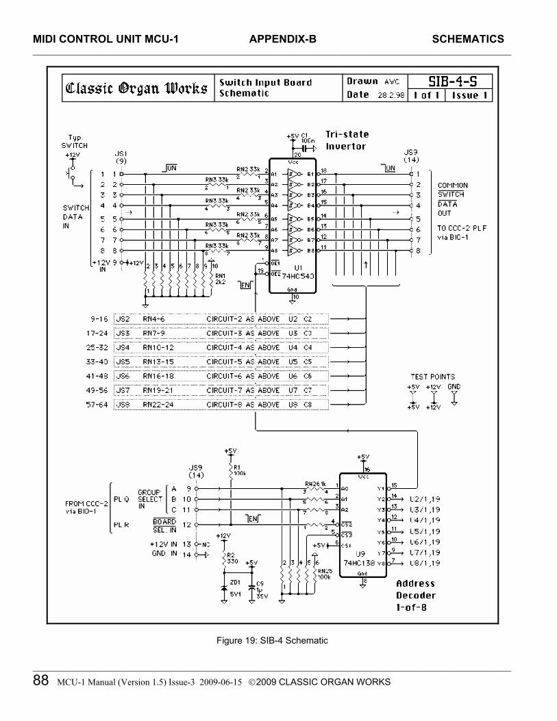
MIDI CONTROL UNIT MCU-1 APPENDIX-B SCHEMATICS _________________________________________________________________________________________________________
_________________________________________________________________________________________________________
88 MCU-1 Manual (Version 1.5) Issue-3 2009-06-15 2009 CLASSIC ORGAN WORKS
Figure 19: SIB-4 Schematic

MIDI CONTROL UNIT MCU-1 APPENDIX-B SCHEMATICS _________________________________________________________________________________________________________
_________________________________________________________________________________________________________
MCU-1 Manual (Version 1.5) Issue-3 2009-06-15 2009 CLASSIC ORGAN WORKS 89
Figure 20: GM9773 Circuit Board Layout

MIDI CONTROL UNIT MCU-1 APPENDIX-B SCHEMATICS _________________________________________________________________________________________________________
_________________________________________________________________________________________________________
90 MCU-1 Manual (Version 1.5) Issue-3 2009-06-15 2009 CLASSIC ORGAN WORKS
Figure 21: GM9773 Schematic

MIDI CONTROL UNIT MCU-1 APPENDIX-C MIDI PROTOCOL _________________________________________________________________________________________________________
_________________________________________________________________________________________________________
MCU-1 Manual (Version 1.5) Issue-3 2009-06-15 2009 CLASSIC ORGAN WORKS 91
MIDI CONTROL UNIT MCU-1
11. APPENDIX C: MIDI Protocol MIDI Protocol Specification [2] MIDI is a convenient method of electronically recording performances and transferring them to a number of audio devices supporting MIDI software and hardware. MIDI files are smaller than their counterparts in the electronic audio music category. In the simplest form, MIDI is a sequence of messages that describe the exact steps that a soundcard plays. The two primary message types are ‘Channel’ and ‘System’.
Channel Messages Channel Messages apply to a specific MIDI channel and include the MIDI channel number in their status byte.
Note On, Note Off, and Velocity messages are transmitted on any of the sixteen logical MIDI channels. The message is sent as three data bytes. The first byte termed the ‘status’ byte indicates the Channel number. The second byte specifies the key number. The third byte specifies the velocity, which is the amount of force, applied to a key, or the volume of the key pressed. Aftertouch is a message that is transmitted to describe the amount of pressure applied to keys after they are pressed to control aspects of sound production such as vibrato. The message is in the form of one data byte specifying the pressure value. Pitch Bend modifies the sound on a given MIDI channel. The message is in the form of two data bytes that specify the position of the pitch wheel. Program Change allows the user to control and change the type of instrument being played
on a given MIDI channel. The message is in the form of one data byte. Control Change allows the user to specify the function of the synthesizer. The message is in the form of two bytes, the first is a Status Byte indicating the controller number, and the second is a data byte indicating the control value. Bank Select expands the number of different instrument sounds that may be selected. A Control Change message usually precedes a Program Change message allowing 16,384 banks of 128 sounds to be played. Mapping of the sounds is dependent upon the manufacturer, which have adopted their own standards. RPN and NRPN are Registered Parameter Number and Non-Registered Parameter Number respectively. These messages allow expansion of the number of controllers available via MIDI. Registered Parameters are numbers assigned for functions like control pitch bend sensitivity and master tuning. Non-Registered Parameters are those that can be assigned by manufacturers to handle other functions.
Channel Mode messages affect the way in which a synthesizer responds to MIDI data. Controller number 121 represents a reset. Channel number 122 represents an enable/disable local control. Channel numbers 124-127 select whether a synthesizer responds to MIDI data on all channels or on one channel only (Omni Mode On or Omni Mode Off). The notes are then played polyphonically or monophonically (Poly Mode and Mono Mode) respectively.

MIDI CONTROL UNIT MCU-1 APPENDIX-C MIDI PROTOCOL _________________________________________________________________________________________________________
_________________________________________________________________________________________________________
92 MCU-1 Manual (Version 1.5) Issue-3 2009-06-15 2009 CLASSIC ORGAN WORKS
System Messages These are messages which are not Channel specific, and thus do not indicate the channel number in their status bytes.
System Common Messages serve to synchronize MIDI equipment (MIDI Time code), select songs (for MIDI equipment with the capability to store and recall a number of different songs), select the playback point (for MIDI equipment with MIDI system real time message recognition), tune internal oscillators, and flag the end of a System Exclusive Message. System Real Time Messages are used to set the playback tempo (timing clock), control the playback start position (start), continue playback (continue), set the stop position (stop), eliminate ‘stuck notes’ (active sensing) in the event of a MIDI cable disconnection, and reset and initialize the equipment receiving a message (system reset). System Exclusive Messages are specific to a manufacturer. Each manufacturer of MIDI equipment is granted a unique identification number by the MIDI Manufacturers Association and forms the first byte of the message. Afterwards, a manufacturer can send data and patch commands.
Running Status In addition to the messages sent between MIDI devices, the MIDI language has a ‘Running Status’ feature which eliminates the delayed effect caused by a large number of musical events occurring ‘simultaneously’. The Running Status does this by omitting the status byte if the current status byte is the same as the previous status byte. Therefore, one byte less is sent which will vacate that byte for other data. Often, to make use of the Running Status feature, the ‘Note On’ message is used for both ‘Note on’ and ‘Note off’ functions. Since the ‘Note On’ and ‘Note Off’ messages have differing status bytes, by making use of a ‘velocity=0’ command in place of the ‘Note Off’ command, running status is utilized.
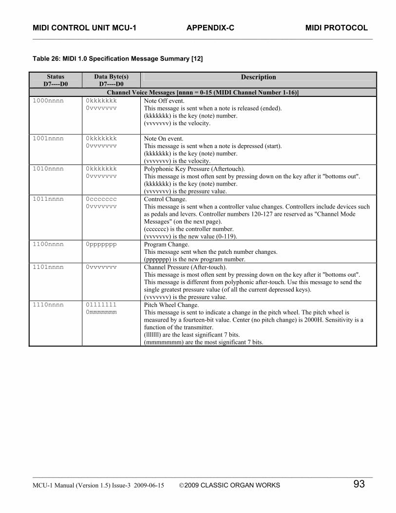
MIDI CONTROL UNIT MCU-1 APPENDIX-C MIDI PROTOCOL _________________________________________________________________________________________________________
_________________________________________________________________________________________________________
MCU-1 Manual (Version 1.5) Issue-3 2009-06-15 2009 CLASSIC ORGAN WORKS 93
Table 26: MIDI 1.0 Specification Message Summary [12]
Status D7----D0
Data Byte(s) D7----D0
Description
Channel Voice Messages [nnnn = 0-15 (MIDI Channel Number 1-16)] 1000nnnn 0kkkkkkk
0vvvvvvv Note Off event. This message is sent when a note is released (ended). (kkkkkkk) is the key (note) number. (vvvvvvv) is the velocity.
1001nnnn 0kkkkkkk 0vvvvvvv
Note On event. This message is sent when a note is depressed (start). (kkkkkkk) is the key (note) number. (vvvvvvv) is the velocity.
1010nnnn 0kkkkkkk 0vvvvvvv
Polyphonic Key Pressure (Aftertouch). This message is most often sent by pressing down on the key after it "bottoms out". (kkkkkkk) is the key (note) number. (vvvvvvv) is the pressure value.
1011nnnn 0ccccccc 0vvvvvvv
Control Change. This message is sent when a controller value changes. Controllers include devices such as pedals and levers. Controller numbers 120-127 are reserved as "Channel Mode Messages" (on the next page). (ccccccc) is the controller number. (vvvvvvv) is the new value (0-119).
1100nnnn 0ppppppp Program Change. This message sent when the patch number changes. (ppppppp) is the new program number.
1101nnnn 0vvvvvvv Channel Pressure (After-touch). This message is most often sent by pressing down on the key after it "bottoms out". This message is different from polyphonic after-touch. Use this message to send the single greatest pressure value (of all the current depressed keys). (vvvvvvv) is the pressure value.
1110nnnn 0lllllll 0mmmmmmm
Pitch Wheel Change. This message is sent to indicate a change in the pitch wheel. The pitch wheel is measured by a fourteen-bit value. Center (no pitch change) is 2000H. Sensitivity is a function of the transmitter. (lllllll) are the least significant 7 bits. (mmmmmmm) are the most significant 7 bits.

MIDI CONTROL UNIT MCU-1 APPENDIX-C MIDI PROTOCOL _________________________________________________________________________________________________________
_________________________________________________________________________________________________________
94 MCU-1 Manual (Version 1.5) Issue-3 2009-06-15 2009 CLASSIC ORGAN WORKS
MIDI 1.0 Specification Message Summary, Cont’d.
Status D7----D0
Data Byte(s) D7----D0
Description
Channel Mode Messages (See also Control Change, previous page) 1011nnnn 0ccccccc
0vvvvvvv Channel Mode Messages. This the same code as the Control Change, but implements Mode control and special message by using reserved controller numbers 120-127. The commands are: All Sound Off. When All Sound Off is received all oscillators will turn off, and their volume envelopes are set to zero as soon as possible. c = 120, v = 0: All Sound Off Reset All Controllers. When Reset All Controllers is received, all controller values are reset to their default values. (See specific Recommended Practices for defaults). c = 121, v = x: Value must only be zero unless otherwise allowed in a specific Recommended Practice. Local Control. When Local Control is Off, all devices on a given channel will respond only to data received over MIDI. Played data, etc. will be ignored. Local Control On restores the functions of the normal controllers. c = 122, v = 0: Local Control Off. c = 122, v = 127: Local Control On All Notes Off. When an All Notes Off is received, all oscillators will turn off. c = 123, v = 0: All Notes Off (See text for description of actual mode commands). c = 124, v = 0: Omni Mode Off. c = 125, v = 0: Omni Mode On c = 126, v = M: Mono Mode On (Poly Off) where M is the number of channels (Omni Off) or 0 (Omni On) c = 127, v = 0: Poly Mode On (Mono Off) (Note: These four messages also cause All Notes Off)
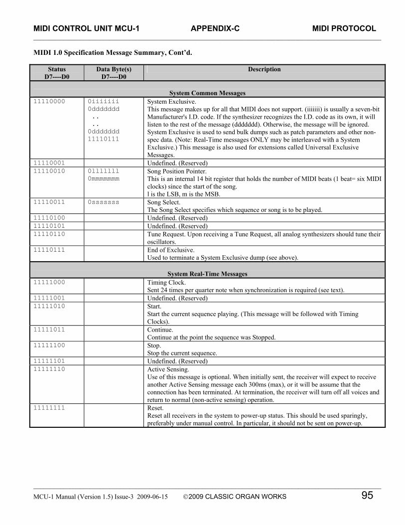
MIDI CONTROL UNIT MCU-1 APPENDIX-C MIDI PROTOCOL _________________________________________________________________________________________________________
_________________________________________________________________________________________________________
MCU-1 Manual (Version 1.5) Issue-3 2009-06-15 2009 CLASSIC ORGAN WORKS 95
MIDI 1.0 Specification Message Summary, Cont’d.
Status D7----D0
Data Byte(s) D7----D0
Description
System Common Messages
11110000 0iiiiiii 0ddddddd .. .. 0ddddddd 11110111
System Exclusive. This message makes up for all that MIDI does not support. (iiiiiii) is usually a seven-bit Manufacturer's I.D. code. If the synthesizer recognizes the I.D. code as its own, it will listen to the rest of the message (ddddddd). Otherwise, the message will be ignored. System Exclusive is used to send bulk dumps such as patch parameters and other non-spec data. (Note: Real-Time messages ONLY may be interleaved with a System Exclusive.) This message is also used for extensions called Universal Exclusive Messages.
11110001 Undefined. (Reserved) 11110010 0lllllll
0mmmmmmm Song Position Pointer. This is an internal 14 bit register that holds the number of MIDI beats (1 beat= six MIDI clocks) since the start of the song. l is the LSB, m is the MSB.
11110011 0sssssss Song Select. The Song Select specifies which sequence or song is to be played.
11110100 Undefined. (Reserved) 11110101 Undefined. (Reserved) 11110110 Tune Request. Upon receiving a Tune Request, all analog synthesizers should tune their
oscillators. 11110111 End of Exclusive.
Used to terminate a System Exclusive dump (see above).
System Real-Time Messages 11111000 Timing Clock.
Sent 24 times per quarter note when synchronization is required (see text). 11111001 Undefined. (Reserved) 11111010 Start.
Start the current sequence playing. (This message will be followed with Timing Clocks).
11111011 Continue. Continue at the point the sequence was Stopped.
11111100 Stop. Stop the current sequence.
11111101 Undefined. (Reserved) 11111110 Active Sensing.
Use of this message is optional. When initially sent, the receiver will expect to receive another Active Sensing message each 300ms (max), or it will be assume that the connection has been terminated. At termination, the receiver will turn off all voices and return to normal (non-active sensing) operation.
11111111 Reset. Reset all receivers in the system to power-up status. This should be used sparingly, preferably under manual control. In particular, it should not be sent on power-up.

MIDI CONTROL UNIT MCU-1 APPENDIX-C MIDI PROTOCOL _________________________________________________________________________________________________________
_________________________________________________________________________________________________________
96 MCU-1 Manual (Version 1.5) Issue-3 2009-06-15 2009 CLASSIC ORGAN WORKS
Table 27: Expanded Status Bytes List (adapted from "MIDI by the Numbers" by D. Valenti, Electronic Musician 2/88) [13]
STATUS BYTE DATA BYTES 1st Byte Value
Binary Hex Dec Function 2nd Byte 3rd Byte
10000000 80 128 Chan 1 Note Off Note Number Note Velocity 10000001 81 129 Chan 2 " (0-127) (0-127) 10000010 82 130 Chan 3 " see " 10000011 83 131 Chan 4 " Table " 10000100 84 132 Chan 5 " 4 " 10000101 85 133 Chan 6 " " " 10000110 86 134 Chan 7 " " " 10000111 87 135 Chan 8 " " " 10001000 88 136 Chan 9 " " " 10001001 89 137 Chan 10 " " " 10001010 8A 138 Chan 11 " " " 10001011 8B 139 Chan 12 " " " 10001100 8C 140 Chan 13 " " " 10001101 8D 141 Chan 14 " " " 10001110 8E 142 Chan 15 " " " 10001111 8F 143 Chan 16 " " " 10010000 90 144 Chan 1 Note on " " 10010001 91 145 Chan 2 " " " 10010010 92 146 Chan 3 " " " 10010011 93 147 Chan 4 " " " 10010100 94 148 Chan 5 " " " 10010101 95 149 Chan 6 " " " 10010110 96 150 Chan 7 " " " 10010111 97 151 Chan 8 " " " 10011000 98 152 Chan 9 " " " 10011001 99 153 Chan 10 " " " 10011010 9A 154 Chan 11 " " " 10011011 9B 155 Chan 12 " " " 10011100 9C 156 Chan 13 " " " 10011101 9D 157 Chan 14 " " " 10011110 9E 158 Chan 15 " " " 10011111 9F 159 Chan 16 " " " 10100000 A0 160 Chan 1 Polyphonic " Aftertouch 10100001 A1 161 Chan 2 Aftertouch " Amount 10100010 A2 162 Chan 3 " " (0-127) 10100011 A3 163 Chan 4 " " " 10100100 A4 164 Chan 5 " " " 10100101 A5 165 Chan 6 " " " 10100110 A6 166 Chan 7 " " " 10100111 A7 167 Chan 8 " " " 10101000 A8 168 Chan 9 " " " 10101001 A9 169 Chan 10 " " " 10101010 AA 170 Chan 11 " " " 10101011 AB 171 Chan 12 " " "

MIDI CONTROL UNIT MCU-1 APPENDIX-C MIDI PROTOCOL _________________________________________________________________________________________________________
_________________________________________________________________________________________________________
MCU-1 Manual (Version 1.5) Issue-3 2009-06-15 2009 CLASSIC ORGAN WORKS 97
Expanded Status Bytes List, Cont’d.
STATUS BYTE DATA BYTES 1st Byte Value
Binary Hex Dec Function 2nd Byte 3rd Byte
10101100 AC 172 Chan 13 " " " 10101101 AD 173 Chan 14 " " " 10101110 AE 174 Chan 15 " " " 10101111 AF 175 Chan 16 " " " 10110000 B0 176 Chan 1 Control/ See See 10110001 B1 177 Chan 2 Mode change Table Table 10110010 B2 178 Chan 3 “ 3 3 10110011 B3 179 Chan 4 “ “ “ 10110100 B4 180 Chan 5 “ “ “ 10110101 B5 181 Chan 6 “ “ “ 10110110 B6 182 Chan 7 " " " 10110111 B7 183 Chan 8 " " " 10111000 B8 184 Chan 9 " " " 10111001 B9 185 Chan 10 " " " 10111010 BA 186 Chan 11 " " " 10111011 BB 187 Chan 12 " " " 10111100 BC 188 Chan 13 " " " 10111101 BD 189 Chan 14 " " " 10111110 BE 190 Chan 15 " " " 10111111 BF 191 Chan 16 " " " 11000000 C0 192 Chan 1 Program Program # NONE 11000001 C1 193 Chan 2 change (0-127) " 11000010 C2 194 Chan 3 " " " 11000011 C3 195 Chan 4 " " " 11000100 C4 196 Chan 5 " " " 11000101 C5 197 Chan 6 " " " 11000110 C6 198 Chan 7 " " " 11000111 C7 199 Chan 8 " " " 11001000 C8 200 Chan 9 " " " 11001001 C9 201 Chan 10 " " " 11001010 CA 202 Chan 11 " " " 11001011 CB 203 Chan 12 " " " 11001100 CC 204 Chan 13 " " " 11001101 CD 205 Chan 14 " " " 11001110 CE 206 Chan 15 " " " 11001111 CF 207 Chan 16 " " " 11010000 D0 208 Chan 1 Channel Aftertouch " 11010001 D1 209 Chan 2 Aftertouch amount " 11010010 D2 210 Chan 3 " (0-127) " 11010011 D3 211 Chan 4 " " " 11010100 D4 212 Chan 5 " " " 11010101 D5 213 Chan 6 " " " 11010110 D6 214 Chan 7 " " " 11010111 D7 215 Chan 8 " " " 11011000 D8 216 Chan 9 " " "

MIDI CONTROL UNIT MCU-1 APPENDIX-C MIDI PROTOCOL _________________________________________________________________________________________________________
_________________________________________________________________________________________________________
98 MCU-1 Manual (Version 1.5) Issue-3 2009-06-15 2009 CLASSIC ORGAN WORKS
Expanded Status Bytes List, Cont’d.
STATUS BYTE DATA BYTES 1st Byte Value
Binary Hex Dec Function 2nd Byte 3rd Byte
11011001 D9 217 Chan 10 " " " 11011010 DA 218 Chan 11 " " " 11011011 DB 219 Chan 12 " " " 11011100 DC 220 Chan 13 " " " 11011101 DD 221 Chan 14 " " " 11011110 DE 222 Chan 15 " " " 11011111 DF 223 Chan 16 " " " 11100000 E0 224 Chan 1 Pitch Pitch Pitch 11100001 E1 225 Chan 2 Wheel wheel Wheel 11100010 E2 226 Chan 3 Control LSB MSB 11100011 E3 227 Chan 4 " (0-127) (0-127) 11100100 E4 228 Chan 5 " " " 11100101 E5 229 Chan 6 " " " 11100110 E6 230 Chan 7 " " " 11100111 E7 231 Chan 8 " " " 11101000 E8 232 Chan 9 " " " 11101001 E9 233 Chan 10 " " " 11101010 EA 234 Chan 11 " " " 11101011 EB 235 Chan 12 " " " 11101100 EC 236 Chan 13 " " " 11101101 ED 237 Chan 14 " " " 11101110 EE 238 Chan 15 " " " 11101111 EF 239 Chan 16 " " " 11110000 F0 240 System Exclusive ** ** 11110001 F1 241 MIDI Time Code Qtr. Frame -see spec- -see spec- 11110010 F2 242 Song Position Pointer LSB MSB 11110011 F3 243 Song Select(Song #) (0-127) NONE 11110100 F4 244 Undefined (Reserved) ? ? 11110101 F5 245 Undefined (Reserved) ? ? 11110110 F6 246 Tune request NONE NONE 11110111 F7 247 End of SysEx (EOX) " " 11111000 F8 248 Timing clock " " 11111001 F9 249 Undefined (Reserved) " " 11111010 FA 250 Start " " 11111011 FB 251 Continue " " 11111100 FC 252 Stop " " 11111101 FD 253 Undefined (Reserved) " " 11111110 FE 254 Active Sensing " " 11111111 FF 255 System Reset " "
** Note: System Exclusive (data dump) 2nd byte= Vendor ID (or Universal Exclusive) followed by more data
bytes and ending with EOX.

MIDI CONTROL UNIT MCU-1 APPENDIX-C MIDI PROTOCOL _________________________________________________________________________________________________________
_________________________________________________________________________________________________________
MCU-1 Manual (Version 1.5) Issue-3 2009-06-15 2009 CLASSIC ORGAN WORKS 99
Table 28: Control Changes and Mode Changes (Status Bytes 176-191)
Adapted from "MIDI by the Numbers" by D. Valenti-Electronic Musician 2/88, updated 1995/1999/2002 by the MIDI Manufacturers Association [14]
Control Number (2nd Byte Value)
3rd Byte Value
Decimal Binary Hex
Control Function
Value Used As 0 00000000 00 Bank Select 0-127 MSB 1 00000001 01 Modulation Wheel or Lever 0-127 MSB 2 00000010 02 Breath Controller 0-127 MSB 3 00000011 03 Undefined 0-127 MSB 4 00000100 04 Foot Controller 0-127 MSB 5 00000101 05 Portamento Time 0-127 MSB 6 00000110 06 Data Entry MSB 0-127 MSB 7 00000111 07 Channel Volume (formerly Main Volume) 0-127 MSB 8 00001000 08 Balance 0-127 MSB 9 00001001 09 Undefined 0-127 MSB
10 00001010 0A Pan 0-127 MSB 11 00001011 0B Expression Controller 0-127 MSB 12 00001100 0C Effect Control 1 0-127 MSB 13 00001101 0D Effect Control 2 0-127 MSB 14 00001110 0E Undefined 0-127 MSB 15 00001111 0F Undefined 0-127 MSB 16 00010000 10 General Purpose Controller 1 0-127 MSB 17 00010001 11 General Purpose Controller 2 0-127 MSB 18 00010010 12 General Purpose Controller 3 0-127 MSB 19 00010011 13 General Purpose Controller 4 0-127 MSB 20 00010100 14 Undefined 0-127 MSB 21 00010101 15 Undefined 0-127 MSB 22 00010110 16 Undefined 0-127 MSB 23 00010111 17 Undefined 0-127 MSB 24 00011000 18 Undefined 0-127 MSB 25 00011001 19 Undefined 0-127 MSB 26 00011010 1A Undefined 0-127 MSB 27 00011011 1B Undefined 0-127 MSB 28 00011100 1C Undefined 0-127 MSB 29 00011101 1D Undefined 0-127 MSB 30 00011110 1E Undefined 0-127 MSB 31 00011111 1F Undefined 0-127 MSB 32 00100000 20 LSB for Control 0 (Bank Select) 0-127 LSB 33 00100001 21 LSB for Control 1 (Modulation Wheel or Lever) 0-127 LSB 34 00100010 22 LSB for Control 2 (Breath Controller) 0-127 LSB 35 00100011 23 LSB for Control 3 (Undefined) 0-127 LSB 36 00100100 24 LSB for Control 4 (Foot Controller) 0-127 LSB 37 00100101 25 LSB for Control 5 (Portamento Time) 0-127 LSB 38 00100110 26 LSB for Control 6 (Data Entry) 0-127 LSB 39 00100111 27 LSB for Control 7 (Channel Volume, formerly Main Volume) 0-127 LSB 40 00101000 28 LSB for Control 8 (Balance) 0-127 LSB 41 00101001 29 LSB for Control 9 (Undefined) 0-127 LSB 42 00101010 2A LSB for Control 10 (Pan) 0-127 LSB 43 00101011 2B LSB for Control 11 (Expression Controller) 0-127 LSB 44 00101100 2C LSB for Control 12 (Effect control 1) 0-127 LSB

MIDI CONTROL UNIT MCU-1 APPENDIX-C MIDI PROTOCOL _________________________________________________________________________________________________________
_________________________________________________________________________________________________________
100 MCU-1 Manual (Version 1.5) Issue-3 2009-06-152009 CLASSIC ORGAN WORKS
Control Changes and Mode Changes, Cont’d.
Control Number (2nd Byte Value)
3rd Byte Value
Decimal Binary Hex
Control Function
Value Used As
45 00101101 2D LSB for Control 13 (Effect control 2) 0-127 LSB 46 00101110 2E LSB for Control 14 (Undefined) 0-127 LSB 47 00101111 2F LSB for Control 15 (Undefined) 0-127 LSB 48 00110000 30 LSB for Control 16 (General Purpose Controller 1) 0-127 LSB 49 00110001 31 LSB for Control 17 (General Purpose Controller 2) 0-127 LSB 50 00110010 32 LSB for Control 18 (General Purpose Controller 3) 0-127 LSB 51 00110011 33 LSB for Control 19 (General Purpose Controller 4) 0-127 LSB 52 00110100 34 LSB for Control 20 (Undefined) 0-127 LSB 53 00110101 35 LSB for Control 21 (Undefined) 0-127 LSB 54 00110110 36 LSB for Control 22 (Undefined) 0-127 LSB 55 00110111 37 LSB for Control 23 (Undefined) 0-127 LSB 56 00111000 38 LSB for Control 24 (Undefined) 0-127 LSB 57 00111001 39 LSB for Control 25 (Undefined) 0-127 LSB 58 00111010 3A LSB for Control 26 (Undefined) 0-127 LSB 59 00111011 3B LSB for Control 27 (Undefined) 0-127 LSB 60 00111100 3C LSB for Control 28 (Undefined) 0-127 LSB 61 00111101 3D LSB for Control 29 (Undefined) 0-127 LSB 62 00111110 3E LSB for Control 30 (Undefined) 0-127 LSB 63 00111111 3F LSB for Control 31 (Undefined) 0-127 LSB 64 01000000 40 Damper Pedal on/off (Sustain) <63 off, >64 on --- 65 01000001 41 Portamento On/Off <63 off, >64 on --- 66 01000010 42 Sostenuto On/Off <63 off, >64 on --- 67 01000011 43 Soft Pedal On/Off <63 off, >64 on --- 68 01000100 44 Legato Footswitch <63 Normal, >64 Legato --- 69 01000101 45 Hold 2 <63 off, >64 on --- 70 01000110 46 Sound Controller 1 (default: Sound Variation) 0-127 LSB 71 01000111 47 Sound Controller 2 (default: Timbre/Harmonic Intensity) 0-127 LSB 72 01001000 48 Sound Controller 3 (default: Release Time) 0-127 LSB 73 01001001 49 Sound Controller 4 (default: Attack Time) 0-127 LSB 74 01001010 4A Sound Controller 5 (default: Brightness) 0-127 LSB 75 01001011 4B Sound Controller 6 (default: Decay Time - see MMA RP-021) 0-127 LSB 76 01001100 4C Sound Controller 7 (default: Vibrato Rate - see MMA RP-021) 0-127 LSB 77 01001101 4D Sound Controller 8 (default: Vibrato Depth - see MMA RP-021) 0-127 LSB 78 01001110 4E Sound Controller 9 (default: Vibrato Delay - see MMA RP-021) 0-127 LSB 79 01001111 4F Sound Controller 10 (default undefined - see MMA RP-021) 0-127 LSB 80 01010000 50 General Purpose Controller 5 0-127 LSB 81 01010001 51 General Purpose Controller 6 0-127 LSB 82 01010010 52 General Purpose Controller 7 0-127 LSB 83 01010011 53 General Purpose Controller 8 0-127 LSB 84 01010100 54 Portamento Control 0-127 LSB 85 01010101 55 Undefined --- --- 86 01010110 56 Undefined --- ---

MIDI CONTROL UNIT MCU-1 APPENDIX-C MIDI PROTOCOL _________________________________________________________________________________________________________
_________________________________________________________________________________________________________
MCU-1 Manual (Version 1.5) Issue-3 2009-06-15 2009 CLASSIC ORGAN WORKS 101
Control Changes and Mode Changes, Cont’d.
Control Number (2nd Byte Value)
3rd Byte Value
Decimal Binary Hex
Control Function
Value Used As 87 01010111 57 Undefined --- --- 88 01011000 58 Undefined --- --- 89 01011001 59 Undefined --- --- 90 01011010 5A Undefined --- --- 91 01011011 5B Effects 1 Depth
(default: Reverb Send Level - see MMA RP-023) (formerly External Effects Depth)
0-127 LSB
92 01011100 5C Effects 2 Depth (formerly Tremolo Depth) 0-127 LSB 93 01011101 5D Effects 3 Depth
(default: Chorus Send Level - see MMA RP-023) (formerly Chorus Depth)
0-127 LSB
94 01011110 5E Effects 4 Depth (formerly Celeste [Detune] Depth) 0-127 LSB 95 01011111 5F Effects 5 Depth (formerly Phaser Depth) 0-127 LSB 96 01100000 60 Data Increment (Data Entry +1) (see MMA RP-018) N/A --- 97 01100001 61 Data Decrement (Data Entry -1) (see MMA RP-018) N/A --- 98 01100010 62 Non-Registered Parameter Number (NRPN) – LSB 0-127 LSB 99 01100011 63 Non-Registered Parameter Number (NRPN) – MSB 0-127 MSB 100 01100100 64 Registered Parameter Number (RPN) – LSB* 0-127 LSB 101 01100101 65 Registered Parameter Number (RPN) - MSB* 0-127 MSB 102 01100110 66 Undefined --- --- 103 01100111 67 Undefined --- --- 104 01101000 68 Undefined --- --- 105 01101001 69 Undefined --- --- 106 01101010 6A Undefined --- --- 107 01101011 6B Undefined --- --- 108 01101100 6C Undefined --- --- 109 01101101 6D Undefined --- --- 110 01101110 6E Undefined --- --- 111 01101111 6F Undefined --- --- 112 01110000 70 Undefined --- --- 113 01110001 71 Undefined --- --- 114 01110010 72 Undefined --- --- 115 01110011 73 Undefined --- --- 116 01110100 74 Undefined --- --- 117 01110101 75 Undefined --- --- 118 01110110 76 Undefined --- --- 119 01110111 77 Undefined --- ---
Note: Controller numbers 120-127 are reserved for Channel Mode Messages, which rather than controlling sound parameters, affect the channel's operating mode.
120 01111000 78 [Channel Mode Message] All Sound Off 0 --- 121 01111001 79 [Channel Mode Message] Reset All Controllers (See MMA RP-015) 0 --- 122 01111010 7A [Channel Mode Message] Local Control On/Off 0 off, 127 on --- 123 01111011 7B [Channel Mode Message] All Notes Off 0 --- 124 01111100 7C [Channel Mode Message] Omni Mode Off (+ all notes off) 0 --- 125 01111101 7D [Channel Mode Message] Omni Mode On (+ all notes off) 0 --- 126 01111110 7E [Channel Mode Message] Poly Mode On/Off (+ all notes off) ** --- 127 01111111 7F [Channel Mode Message] Poly Mode On (+ mono off +all notes off) 0 ---
** Note: This equals the number of channels or zero if the number of channels equals the number of voices in the receiver.
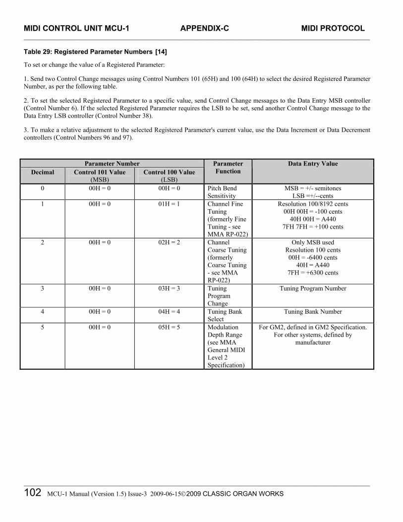
MIDI CONTROL UNIT MCU-1 APPENDIX-C MIDI PROTOCOL _________________________________________________________________________________________________________
_________________________________________________________________________________________________________
102 MCU-1 Manual (Version 1.5) Issue-3 2009-06-152009 CLASSIC ORGAN WORKS
Table 29: Registered Parameter Numbers [14] To set or change the value of a Registered Parameter:
1. Send two Control Change messages using Control Numbers 101 (65H) and 100 (64H) to select the desired Registered Parameter Number, as per the following table.
2. To set the selected Registered Parameter to a specific value, send Control Change messages to the Data Entry MSB controller (Control Number 6). If the selected Registered Parameter requires the LSB to be set, send another Control Change message to the Data Entry LSB controller (Control Number 38).
3. To make a relative adjustment to the selected Registered Parameter's current value, use the Data Increment or Data Decrement controllers (Control Numbers 96 and 97).
Parameter Number Decimal Control 101 Value
(MSB) Control 100 Value
(LSB)
Parameter Function
Data Entry Value
0 00H = 0 00H = 0 Pitch Bend Sensitivity
MSB = +/- semitones LSB =+/--cents
1 00H = 0 01H = 1 Channel Fine Tuning (formerly Fine Tuning - see MMA RP-022)
Resolution 100/8192 cents 00H 00H = -100 cents
40H 00H = A440 7FH 7FH = +100 cents
2 00H = 0 02H = 2 Channel Coarse Tuning(formerly Coarse Tuning - see MMA RP-022)
Only MSB used Resolution 100 cents 00H = -6400 cents
40H = A440 7FH = +6300 cents
3 00H = 0 03H = 3 Tuning Program Change
Tuning Program Number
4 00H = 0 04H = 4 Tuning Bank Select
Tuning Bank Number
5 00H = 0 05H = 5 Modulation Depth Range (see MMA General MIDI Level 2 Specification)
For GM2, defined in GM2 Specification. For other systems, defined by
manufacturer

MIDI CONTROL UNIT MCU-1 APPENDIX-D SYSTEM EXCLUSIVE MESSAGES _________________________________________________________________________________________________________
_________________________________________________________________________________________________________
MCU-1 Manual (Version 1.5) Issue-3 2009-06-15 2009 CLASSIC ORGAN WORKS 103
MIDI CONTROL UNIT MCU-1
12. APPENDIX D: System Exclusive Messages Messages common to all products [15] General Information Identity Request F0 7E dd 06 01 F7
Request the identity and special characteristics of a device. dd selects a particular device in the MIDI chain. dd = 7Fh selects all devices at once.
General Information Identity Reply F0 7E dd 06 02 00 20 1C pp pp mm mm ss ss tt tt F7
dd: identifies the device that is responding. pp pp = 04 03 for MKSC v3 mm mm: gives the organ model number ss ss: identifies the major and minor software revision level, as it affects data format compatibility. tt tt: identifies the major and minor software revision level, as it affects program capabilities. In the case of the MKSC v3, after the tt tt, also pass two bytes indicated the current DIPSWITCH setting

MIDI CONTROL UNIT MCU-1 APPENDIX-D SYSTEM EXCLUSIVE MESSAGES _________________________________________________________________________________________________________
_________________________________________________________________________________________________________
104 MCU-1 Manual (Version 1.5) Issue-3 2009-06-152009 CLASSIC ORGAN WORKS
MCU - Special layouts [15] Config Memory The config memory contains a number of 256-byte blocks, each containing MCU configuration information. The message formats are: F0 00 20 1C dd 04 01 03 aa aa aa ss ss F7
Request Config Memory data. This message should be sent by an external sequencer or by the MCU config application.
dd: identifies the device which is responding. aa aa aa: starting offset (21-bit address) of the config block (packed 7 bits). ss ss: number of bytes of original data to be retrieved (packed 14 bits)
F0 00 20 1C dd 04 01 04 bb bb ss <data, 8-for-7 format> F7
Transfer Config Memory data. This message should be sent from the MCU in response to a request message. dd: identifies the device that is responding. bb bb: block-count within the sequence of saved data blocks' memory data, low-order 7 bits first. The
first message in a restore sequence must have a block-count of 00 00. ss: number of bytes of original data transferred in this block.
data: 8-for-7 coded bytes of data.
F0 00 20 1C dd 04 01 08 bb bb aa aa aa ss <data, 8-for-7 format> F7 Update Config Memory data. The message with subcommand 08 will be generated by the external MCU config application. dd: identifies the device which is responding. bb bb: block-count within the sequence of saved data blocks' memory data, low-order 7 bits first. The first message in a restore sequence must have a block-count of 00 00. aa aa aa: starting offset (21-bit address) of the config block (packed 7 bits). ss: number of bytes of original data transferred in this block. data: 8-for-7 coded bytes of data.
F0 00 20 1C dd 04 01 20 F7 Soft reboot MCU. The message will cause the MCU to resume operation and reload the PIC's EEPROM from the contents of the FLASH ROM as indicated by the DIPSWITCH. dd: identifies the device which is responding.

MIDI CONTROL UNIT MCU-1 APPENDIX-E AHLBORN MESSAGES _________________________________________________________________________________________________________
_________________________________________________________________________________________________________
MCU-1 Manual (Version 1.5) Issue-3 2009-06-15 2009 CLASSIC ORGAN WORKS 105
MIDI CONTROL UNIT MCU-1
13. APPENDIX E: Ahlborn Messages
Table 30: Note On/Off MIDI functions to control Ahlborn Archive sound modules [16]
Slot Pins: Data sent: Off ----> On
Data sent: On ----> Off
Description: Note:
Key On/Off Data IN1 1-61 90 kk 40 90 kk 00 Sw Ahlborn - Note On / Off 1 IN2 1-61 91 kk 40 91 kk 00 Gt Ahlborn - Note On / Off 2 IN3 1-61 92 kk 40 92 kk 00 Ch Ahlborn - Note On / Off 3 IN4 1-32 93 kk 40 93 kk 00 Pd Ahlborn - Note On / Off 4
NOTES: 1) "Swell Channel" defaults to 1 (0h) - usually the Ahlborn "A" division for key On/Off messages. kk = Note
number 0-127 (00h to 7Fh) where 60 (3Ch) = middle "C". Normal (untransposed) output from key inputs 1-61 = 36-96 (24h - 60h). Transposer may shift this down or up in the range of -24 to +31. Input defaults to input row #1 (IN1).
2) "Great Channel" defaults to 2 (1h) - usually the Ahlborn "B" division for key On/Off messages. Input defaults to input row #2 (IN2).
3) "Choir Channel" defaults to 3 (2h) - usually the Ahlborn "AUX" division for key On/Off messages. Input defaults to input row #3 (IN3).
4) "Pedal Channel" defaults to 4 (3h) - usually the Ahlborn "Pedal" division for key On/Off messages. Normal (untransposed) output from key inputs 1-32 = 36-67 (24h - 43h). Transposer may shift this down or up in the range of -24 to +31. Input defaults to input row #4 (IN4).
5) Ahlborn modules respond only in the range - kk = 30-99 (1Eh to 63h) for A and B divisions and kk = 30-70 (1Eh to 46h) for the Pedal division.

MIDI CONTROL UNIT MCU-1 APPENDIX-D SYSTEM EXCLUSIVE MESSAGES _________________________________________________________________________________________________________
_________________________________________________________________________________________________________
106 MCU-1 Manual (Version 1.5) Issue-3 2009-06-152009 CLASSIC ORGAN WORKS
Table 31: Ahlborn Archive ‘ROMANTIC’ sound module commands for stops and couplers [16] (These can be assigned to any input pin in slot 5, to pins 33-64 in slot 4, or to pins 62-64 in slots 1-4.)
Group No. Data sent Off ----> On
Data sent On ----> Off
Description Note
Controller 73 Controller 74 Ahlborn ROMANTIC stops 0 0 Bn 49 00 Bn 4A 00 Pd Contre Gamba 16' 1 1 Bn 49 01 Bn 4A 01 Ophicleide 16' 2 Bn 49 02 Bn 4A 02 Contre Violone 32' 3 Bn 49 03 Bn 4A 03 Contre Bassoon 32' 4 Bn 49 04 Bn 4A 04 A/P coupler 5 Bn 49 05 Bn 4A 05 B to Pd coupler 6 Bn 49 06 Bn 4A 06 A Cornopean 16' 7 Bn 49 07 Bn 4A 07 Cornet des Bombardes IV 8 Bn 49 08 Bn 4A 08 Tuba Mirabilis 8' 9 Bn 49 09 Bn 4A 09 Clarion 4' A Bn 49 0A Bn 4A 0A Orchestral Oboe 8' B Bn 49 0B Bn 4A 0B Clarinet 8' C Bn 49 0C Bn 4A 0C French Horn 8' D Bn 49 0D Bn 4A 0D Cor Anglais 8' E Bn 49 0E Bn 4A 0E Cello 8' F Bn 49 0F Bn 4A 0F Cello Celeste 8' 10 Bn 49 10 Bn 4A 10 B to A coupler 11 Bn 49 11 Bn 4A 11 B Quint Flute 2 2/3' 12 Bn 49 12 Bn 4A 12 Piccolo 2' 13 Bn 49 13 Bn 4A 13 Vox Humana 8' 14 Bn 49 14 Bn 4A 14 Open Diapason 8' 15 Bn 49 15 Bn 4A 15 Flauto Mirabilis 8' 16 Bn 49 16 Bn 4A 16 Concert Flute 4' 17 Bn 49 17 Bn 4A 17 A to B coupler 18 Bn 49 18 Bn 4A 18 A to Aux coupler 19 Bn 49 19 Bn 4A 19 B to Aux coupler
NOTES: 1) n = Channel number used by Ahlborn stop On/Off messages, defaults to 16 (Fh). 2) Controls "A" or "B" division Tremulant on corresponding channel number used by Ahlborn divisions.

MIDI CONTROL UNIT MCU-1 APPENDIX-E AHLBORN MESSAGES _________________________________________________________________________________________________________
_________________________________________________________________________________________________________
MCU-1 Manual (Version 1.5) Issue-3 2009-06-15 2009 CLASSIC ORGAN WORKS 107
Table 32: Ahlborn Archive ‘CLASSIC’ sound module commands for stops and couplers on [16]
Group No. Data sent: Off ----> On
Data sent: On ----> Off
Description Note
Controller 73 Controller 74 Ahlborn CLASSIC stops
3 1A Bn 49 1A Bn 4A 1A Pd Contre Gambe 16' 1 1B Bn 49 1B Bn 4A 1B Bombarde 16' 1C Bn 49 1C Bn 4A 1C Contre Basse 32' 1D Bn 49 1D Bn 4A 1D Contre Bombarde 32' 1E Bn 49 1E Bn 4A 1E A Corno di Bassetto 8' 1F Bn 49 1F Bn 4A 1F Plein Jeu IV-V 20 Bn 49 20 Bn 4A 20 Clarion 4' 21 Bn 49 21 Bn 4A 21 Festival Trumpet 8' 22 Bn 49 22 Bn 4A 22 Gemshorn Celeste 8' 23 Bn 49 23 Bn 4A 23 Koppelflote 4' 24 Bn 49 24 Bn 4A 24 Bombarde 16' 25 Bn 49 25 Bn 4A 25 Harmonic Trumpet 8' 26 Bn 49 26 Bn 4A 26 Gemshorn 8' 27 Bn 49 27 Bn 4A 27 Flute a Cheminee 8' 28 Bn 49 28 Bn 4A 28 B Flute Octaviante 4' 29 Bn 49 29 Bn 4A 29 Octave 2' 2A Bn 49 2A Bn 4A 2A Cymbale III 2B Bn 49 2B Bn 4A 2B Principal 8' 2C Bn 49 2C Bn 4A 2C Holzgedackt 8' 2D Bn 49 2D Bn 4A 2D Flute Harmonique 8'
NOTES: 1) n = Channel number used by Ahlborn stop On/Off messages, defaults to 16 (Fh). 2) Controls "A" or "B" division Tremulant on corresponding channel number used by Ahlborn divisions.

MIDI CONTROL UNIT MCU-1 APPENDIX-D SYSTEM EXCLUSIVE MESSAGES _________________________________________________________________________________________________________
_________________________________________________________________________________________________________
108 MCU-1 Manual (Version 1.5) Issue-3 2009-06-152009 CLASSIC ORGAN WORKS
Table 33: Ahlborn Archive ‘202’ sound module commands for stops and couplers [16]
Group No. Data sent: Off ----> On
Data sent: On ----> Off Description Note
Controller 73 Controller 74 Ahlborn 202 stops:
2E Bn 49 2E Bn 4A 2E Pd Soubasse 32' 1 2F Bn 49 2F Bn 4A 2F Violone 16' 30 Bn 49 30 Bn 4A 30 Contrebombarde 32' 31 Bn 49 31 Bn 4A 31 Bombarde 16' 32 Bn 49 32 Bn 4A 32 A Contregambe 16'
33 Bn 49 33 Bn 4A 33 Diapason 8' 34 Bn 49 34 Bn 4A 34 Quintadena 8' 35 Bn 49 35 Bn 4A 35 Terz 1 3/5' 36 Bn 49 36 Bn 4A 36 Septime 1 1/7' 37 Bn 49 37 Bn 4A 37 Scharff III 38 Bn 49 38 Bn 4A 38 Bombarde 16' 39 Bn 49 39 Bn 4A 39 Trompette 8' 3A Bn 49 3A Bn 4A 3A Tuba Mirabilis 8' 3B Bn 49 3B Bn 4A 3B Chimes 3C Bn 49 3C Bn 4A 3C B Bourdon 8' 3D Bn 49 3D Bn 4A 3D Flute Harmonique 8' 3E Bn 49 3E Bn 4A 3E Flute Octaviante 4' 3F Bn 49 3F Bn 4A 3F Larigot 1 1/3' 40 Bn 49 40 Bn 4A 40 Corno di Bassetto 8' 41 Bn 49 41 Bn 4A 41 Clarion 4'
NOTES: 1) n = Channel number used by Ahlborn stop On/Off messages; defaults to 16 (Fh). 2) Controls "A" or "B" division Tremulant on corresponding channel number used by Ahlborn divisions.

MIDI CONTROL UNIT MCU-1 APPENDIX-E AHLBORN MESSAGES _________________________________________________________________________________________________________
_________________________________________________________________________________________________________
MCU-1 Manual (Version 1.5) Issue-3 2009-06-15 2009 CLASSIC ORGAN WORKS 109
Table 34: Ahlborn Archive ‘201’ sound module commands for stops and couplers [16]
Group No. Data sent: Off ----> On
Data sent: On ----> Off Description Note
Controller 73 Controller 74 Ahlborn 201 stops:
42 Bn 49 42 Bn 4A 42 Pd Subbass 16' 1 43 Bn 49 43 Bn 4A 43 Octave 8' 44 Bn 49 44 Bn 4A 44 Bourdon 8' 45 Bn 49 45 Bn 4A 45 Posaune 16' 46 Bn 49 46 Bn 4A 46 A Bourdon 16' 47 Bn 49 47 Bn 4A 47 Principal 8' 48 Bn 49 48 Bn 4A 48 Flute a Cheminee 8' 49 Bn 49 49 Bn 4A 49 Unda Maris 8' 4A Bn 49 4A Bn 4A 4A Octave 4' 4B Bn 49 4B Bn 4A 4B Spitzflote 4' 4C Bn 49 4C Bn 4A 4C Nasard 2 2/3' 4D Bn 49 4D Bn 4A 4D Superoctave 2' 4E Bn 49 4E Bn 4A 4E Mixture IV 4F Bn 49 4F Bn 4A 4F Trompete 8' 50 Bn 49 50 Bn 4A 50 B Gedackt 8' 51 Bn 49 51 Bn 4A 51 Gamba 8' 52 Bn 49 52 Bn 4A 52 Nachthorn 4' 53 Bn 49 53 Bn 4A 53 Cymbale/Scharff III 54 Bn 49 54 Bn 4A 54 Cornet III 55 Bn 49 55 Bn 4A 55 Oboe 8' 56 Bn 49 7F Bn 4A 7F All stops On / Off Ahlborn Tremulants: 57 Bn 5C 7F Bn 5C 00 Swell Tremulant 2 58 Bn 5C 7F Bn 5C 00 Great Tremulant 2 59 Bn 5C 7F Bn 5C 00 Choir Tremulant 2
NOTES: 1) n = Channel number used by Ahlborn stop On/Off messages, defaults to 16 (Fh). 2) Controls "A" or "B" division Tremulant on corresponding channel number used by Ahlborn divisions.

MIDI CONTROL UNIT MCU-1 APPENDIX-D SYSTEM EXCLUSIVE MESSAGES _________________________________________________________________________________________________________
_________________________________________________________________________________________________________
110 MCU-1 Manual (Version 1.5) Issue-3 2009-06-152009 CLASSIC ORGAN WORKS
Table 35: Ahlborn Archive sound module Piston and Crescendo input functions [16]
Group No. Data sent: Off ----> On
Data sent: On ----> Off
Description Note
A0 CF 20 Ahlborn - General Cancel 1 81 CF 01 Ahlborn - Mem. A Gen. #1 2 82 CF 02 Ahlborn - Mem. A Gen. #2 83 CF 03 Ahlborn - Mem. A Gen. #3 84 CF 04 Ahlborn - Mem. A Gen. #4 85 CF 05 Ahlborn - Mem. A Gen. #5 86 CF 06 Ahlborn - Mem. A Gen. #6 87 CF 07 Ahlborn - Mem. B Gen. #1 ……. etc. 9E CF 1E Ahlborn - Mem. E Gen. #6 E4 CF 64 Cancel Crescendo E5 CF 65 CF 64 Crescendo Stage #1 / Off 3 E6 CF 66 CF 65 Crescendo Stage #2 / 1 E7 CF 67 CF 66 Crescendo Stage #3 / 2 ……. etc. EF CF 6F CF 6E Crescendo Stage #11/10 F7 CF 77 CF 6F Crescendo Stage #12/11 F8 CF 78 CF 77 Crescendo Stage #13/12 ……. etc. FF CF 7F CF 7E Crescendo Stage #20/19
NOTES: 1) Prog#1 (00h) on the Control Channel will actually act as a "Recall Hand Registration", but will correspond to a General
Cancel if hand registration is not used. 2) Ahlborn Archive Modules have 6 Programmable Presets on each of 5 Memory levels, accessed by sending Prog#1-30 (01h -
1Eh). 3) These functions are presumed to be connected to a "shade roller" Crescendo switch, which provides sequential switch
closures and releases. These messages can also be generated by an analog input.

MIDI CONTROL UNIT MCU-1 APPENDIX-E AHLBORN MESSAGES _________________________________________________________________________________________________________
_________________________________________________________________________________________________________
MCU-1 Manual (Version 1.5) Issue-3 2009-06-15 2009 CLASSIC ORGAN WORKS 111
Table 36: Ahlborn Archive sound module additional Piston input commands [16]
Group No. Data sent: Off ----> On
Data sent: On ----> Off Description Note
5A Cn 40 Ahlborn – Division Cancel 1
5E BF 47 46 BF 47 06 SET piston 2
5F BF 47 42 BF 47 02 SFZ control 3
NOTES: 1) Prog. Change 51-85 (32h - 54h) on a Division Channel (1-4) will actually act as a Divisional Cancel. 2) Works with General Pistons to allow their setting via remote (MIDI) control, i.e., press & hold SET, press and release a
General, then release SET, to store a new registration. 3) Should allow for a lamp output for this. In addition, possibly another input function that would act as a "reversible"; i.e.,
push-ON, push-OFF.: 4) n = Channel number used by Ahlborn stop On/Off messages; defaults to 16 (Fh).
Table 37: Ahlborn Archive and other MIDI sound modules Analog input function commands [16]
Input Data sent Function Description Note
‘ANALOG IN 1,2,3’ B0 07 aa Sw Ahlborn – Division Volume 1 ‘ANALOG IN 1,2,3’ B1 07 aa Gt Ahlborn – Division Volume 1 ‘ANALOG IN 1,2,3’ B2 07 aa Ch Ahlborn – Division Volume 1 ‘ANALOG IN 1,2,3’ B3 07 aa Pd Ahlborn – Division Volume 1
‘ANALOG IN 4’ Bn 65 00 64 01 06 xx 26 yy Tuning Tuning and/or Temperature
Sensor 2
‘ANALOG IN 5’ Not used Not used ‘ANALOG IN 6’ CF ss Crescendo Crescendo 3
NOTES: 1) Ahlborn modules use Controller #7 for expression. Outputs on Ahlborn channels (1-4) must be configurable, connecting to
Analog inputs 1-3. aa = volume value from an analog input, where 0<aa<127. 2) Analog input #4 is dedicated to tuning. It should be configurable to allow a temperature sensor to be connected, which would
use 2/3 of the available +/- tuning range, in which case the tuning pot would have reduced sensitivity (1/3). Tuning is sent as a 14-bit value with 7-bit MSB (xx) and 7-bit LSB (yy)
3) "ss" is the Crescendo stage, where Off=64h, Stage#1=65h, #2=66h, etc., #11=6Fh, #12=77h, #13=78h, etc., #20=7Fh.


MIDI CONTROL UNIT MCU-1 APPENDIX-F SCPOP MESSAGES _________________________________________________________________________________________________________
_________________________________________________________________________________________________________
MCU-1 Manual (Version 1.5) Issue-3 2009-06-15 2009 CLASSIC ORGAN WORKS 113
MIDI CONTROL UNIT MCU-1
14. APPENDIX F: SCPOP Messages Table 38: General MIDI Pipe Organ Emulation Upper Manual for SCPOP
(General MIDI patch commands converted from SYSEX messages of SCPOP) [17] Upper Manual [using Parts 1-6]
GM Patch 73 77 78 Volume 110 70 60 Panning R10 L10 0 Reverb 100 100 80
1 Principale 8
Key Shift -12 -12 -12 GM Patch 74 85 Volume 100 80 Panning R15 L15 Reverb 100 100
2 Flauto cuspide 8
Key Shift -12 -12 GM Patch 73 77 78 74 Volume 110 70 60 100 Panning R10 L10 0 0 Reverb 100 100 80 80
3 Principali 16-8
Key Shift -12 -12 -12 -24 GM Patch 73 77 78 74 Volume 105 70 60 95 Panning R10 L10 0 0 Reverb 76 100 80 80
4 Fondi 16-4
Key Shift 0 -12 -12 -24 GM Patch 74 78 74 Volume 90 80 105 Panning R15 L15 0 Reverb 100 100 100
5 Flauti 8-4
Key Shift -12 0 0 GM Patch 73 77 78 74 Volume 110 80 80 95 Panning R10 R10 L10 0 Reverb 115 100 80 80
6 Fondi 16-2
Key Shift 12 -12 -12 -24 GM Patch 74 78 75 Volume 90 85 100 Panning R15 L15 0 Reverb 100 100 105
7 Fondi 8-2
Key Shift -12 0 12

MIDI CONTROL UNIT MCU-1 APPENDIX-F SCPOP MESSAGES _________________________________________________________________________________________________________
_________________________________________________________________________________________________________
114 MCU-1 Manual (Version 1.5) Issue-3 2009-06-152009 CLASSIC ORGAN WORKS
General MIDI Pipe Organ Emulation Upper Manual for SCPOP, Cont’d.
Upper Manual [Using parts 1-6] GM Patch 74 78 75 73 Volume 90 100 95 90 Panning R10 L10 L20 R20 Reverb 100 100 110 100
8 Fondi 8-2-1
Key Shift -12 0 12 24 GM Patch 74 78 76 75 Volume 95 100 95 100 Panning 0 0 R24 L24 Reverb 100 100 100 110
9 Mutazioni 2
Key Shift -12 -12 7 12 GM Patch 74 78 75 76 73 Volume 90 106 90 90 80 Panning 0 L15 R12 L25 R25 Reverb 90 100 100 110 110
10 Mutazioni 1
Key Shift -12 0 0 19 24 GM Patch 76 74 78 75 73 Volume 80 100 105 85 85 Panning 0 R10 L10 L63 R63 Reverb 110 90 90 100 100
11 Mutazioni in Terza
Key Shift 16 -12 -12 12 12 GM Patch 78 79 20 73 76 Volume 100 70 85 80 82 Panning 0 0 0 R20 L20 Reverb 100 90 100 110 100 Chorus 0 3 0 0 0
12 Pienino
Key Shift -12 -12 -12 12 19 GM Patch 74 79 20 73 76 Volume 105 110 110 110 115 Panning L15 R12 R30 0 L30 Reverb 90 90 110 100 110 Chorus 0 3 0 0 0
13 Ripieno Leggero
Key Shift -12 -12 12 0 19 GM Patch 74 20 74 20 21 76 Volume 120 124 112 107 109 100 Panning 0 0 0 L30 R10 R30 Reverb 90 80 90 110 110 0 Chorus 3 0 0 0 0 0
14 Ripieno forte
Key Shift 0 -12 -24 19 7 24 GM Patch 58 20 74 73 59 73 Volume 125 125 110 110 120 110 Panning 0 L24 0 L44 R24 R44 Reverb 85 100 80 100 85 100 Chorus 3 0 0 0 0 0
15 Grand Jeux
Key Shift -12 0 -12 24 0 19

MIDI CONTROL UNIT MCU-1 APPENDIX-F SCPOP MESSAGES _________________________________________________________________________________________________________
_________________________________________________________________________________________________________
MCU-1 Manual (Version 1.5) Issue-3 2009-06-15 2009 CLASSIC ORGAN WORKS 115
General MIDI Pipe Organ Emulation Upper Manual for SCPOP, Cont’d.
Upper Manual [Using parts 1-6] GM Patch 58 20 73 73 70 73 Volume 115 100 95 95 115 90 Panning R12 0 R24 L24 L12 0 Reverb 105 100 103 103 105 100 Reverb 3 0 0 0 0 0
16 Petit Jeux
Key Shift -12 -12 0 7 -12 19 GM Patch 58 70 67 Volume 105 90 120 Panning 2 L20 R20 Reverb 100 100 100
17 Recit des Ances
Key Shift -12 -12 -12 GM Patch 75 75 76 Volume 85 85 45 Panning R63 L63 0 Reverb 115 115 100
18 Salicionale 8
Key Shift 0 0 0 GM Patch 73 77 76 Volume 110 70 60 Panning R10 L10 0 Reverb 100 100 80
19 Principale 8 in Tremolo
Key Shift -12 -12 -12

MIDI CONTROL UNIT MCU-1 APPENDIX-F SCPOP MESSAGES _________________________________________________________________________________________________________
_________________________________________________________________________________________________________
116 MCU-1 Manual (Version 1.5) Issue-3 2009-06-152009 CLASSIC ORGAN WORKS
Table 39: General MIDI Pipe Organ Emulation Lower Manual SCPOP (General MIDI patch commands converted from SYSEX messages of SCPOP) [17]
Lower Manual [using Parts 7-11]
GM Patch 74 74 76 Volume 85 85 80 Panning R63 L63 0 Reverb 103 103 95
1 Flauto Camino 8
Key Shift -12 -12 0 GM Patch 73 76 77 73 Volume 75 80 51 75 Panning R63 0 0 L63 Reverb 90 90 90 90
2 Quintadena 8
Key Shift -12 -12 0 -12 GM Patch 74 76 74 74 Volume 85 75 85 85 Panning L63 R12 R63 L12 Reverb 100 90 100 90
3 Flauti 8-4
Key Shift 0 0 0 -12 GM Patch 74 74 76 Volume 95 85 75 Panning R20 L20 0 Reverb 90 103 80
4 Flauti 16-4
Key Shift -24 0 0 GM Patch 76 73 74 74 Volume 75 82 82 82 Panning L15 R63 L63 R15 Reverb 90 100 100 90
5 Fondi 8-2
Key Shift 0 12 12 -12 GM Patch 73 74 77 73 76 Volume 80 100 90 100 60 Panning L63 R63 0 0 0 Reverb 103 103 103 110 103
6 Fondi 4-2
Key Shift 12 12 12 0 12 GM Patch 76 74 73 74 Volume 80 80 45 100 Panning L15 0 0 R15 Reverb 103 103 80 103
7 Septade
Key Shift 0 24 14 -12 GM Patch 76 74 80 79 80 Volume 90 100 90 100 80 Panning 0 L20 0 R20 0 Reverb 90 100 115 90 100
8 Nazardo
Key Shift 0 0 7 -12 19 GM Patch 74 76 73 Volume 100 100 100 Panning R15 L15 0 Reverb 100 100 105
9 Fondi 8-4-1
Key Shift -12 12 24

MIDI CONTROL UNIT MCU-1 APPENDIX-F SCPOP MESSAGES _________________________________________________________________________________________________________
_________________________________________________________________________________________________________
MCU-1 Manual (Version 1.5) Issue-3 2009-06-15 2009 CLASSIC ORGAN WORKS 117
General MIDI Pipe Organ Emulation Lower Manual SCPOP, Cont’d.
GM Patch 76 73 73 74 73 Volume 105 100 53 100 105 Panning L15 L24 R24 0 R15 Reverb 100 100 90 90 100
10 Sesquialtera
Key Shift 0 7 23 -12 0 GM Patch 76 73 73 74 74 Volume 95 70 70 100 85 Panning L15 L63 R63 R10 0 Reverb 90 100 100 90 100
11 Pienino Flauti
Key Shift 0 24 24 -12 0 GM Patch 73 76 73 73 20 Volume 90 100 90 85 80 Panning 0 0 0 L35 R30 Reverb 100 100 100 100 100
12 Ripieno I
Key Shift -12 0 0 19 12 GM Patch 74 76 73 73 20 Volume 105 120 115 110 105 Panning 0 0 0 L35 R35 Reverb 100 90 110 110 110
13 Ripieno II
Key Shift -12 0 7 24 0 GM Patch 60 70 Volume 110 100 Panning 0 0 Reverb 115 115
14 Cromorno
Key Shift -12 -12 GM Patch 70 74 73 60 73 Volume 120 110 120 127 105 Panning R20 0 0 L20 0 Reverb 103 95 103 103 115
15 Jeux
Key Shift -12 -12 0 -12 19 GM Patch 70 76 73 60 Volume 110 110 125 115 Panning L12 0 0 R12 Reverb 103 100 90 103
16 Jeux Doux
Key Shift -12 -12 -12 -12 GM Patch 73 74 76 Volume 75 75 55 Panning R12 L12 0 Reverb 95 95 95 Chorus 3 0 0
17 Vox Umana 8
Key Shift -12 -12 -12 GM Patch 73 73 76 Volume 85 85 70 Panning R63 L63 0 Reverb 127 127 70
18 Flauto 4 in Tremolo
Key Shift 0 0 0

MIDI CONTROL UNIT MCU-1 APPENDIX-F SCPOP MESSAGES _________________________________________________________________________________________________________
_________________________________________________________________________________________________________
118 MCU-1 Manual (Version 1.5) Issue-3 2009-06-152009 CLASSIC ORGAN WORKS
Table 40: General MIDI Pipe Organ Emulation Pedals SCPOP (General MIDI patch commands converted from SYSEX messages of SCPOP) [17]
Pedals [using parts 12-16]
GM Patch 74 74 73 Volume 95 85 80 Panning 0 R12 L12 Reverb 91 91 91
1 Principale 16
Key Shift -24 -12 -12 GM Patch 73 79 74 Volume 110 110 105 Panning 0 0 0 Reverb 65 80 80
2 Subbasso 16
Key Shift -24 -12 -24 GM Patch 74 74 73 73 76 Volume 90 75 80 100 60 Panning 0 L63 0 R63 0 Reverb 91 91 91 90 90
3 Fondi 16-8
Key Shift -24 -12 -12 -12 0 GM Patch 73 79 74 73 Volume 110 110 105 100 Panning 0 0 0 0 Reverb 65 80 80 80
4 Quintadena
Key Shift -24 -12 -24 0 GM Patch 74 74 73 73 74 Volume 95 90 68 100 95 Panning 0 L36 0 R36 0 Reverb 90 90 90 90 90
5 Fondi 16-4
Key Shift -12 0 -12 0 0 GM Patch 74 74 73 59 65 Volume 90 75 70 80 100 Panning 0 0 0 R12 L12 Reverb 91 91 91 90 90
6 Ancia da 8
Key Shift -24 -12 -12 0 0 GM Patch 74 74 73 20 73 Volume 90 125 80 112 110 Panning 0 0 0 L20 R20 Reverb 105 110 90 110 100
7 Ripieno I
Key Shift 7 -12 -12 -12 12 GM Patch 58 73 74 20 20 Volume 125 90 120 120 120 Panning 0 0 0 L63 R63 Reverb 120 110 115 125 125
8 Ripieno II
Key Shift -12 -12 0 0 0 GM Patch 20 73 73 70 59 Volume 120 90 70 86 115 Panning 0 0 0 L48 R48 Reverb 125 110 100 125 127
9 Tutte le Ancie
Key Shift -12 -12 -12 0 0

MIDI CONTROL UNIT MCU-1 APPENDIX-F SCPOP MESSAGES _________________________________________________________________________________________________________
_________________________________________________________________________________________________________
MCU-1 Manual (Version 1.5) Issue-3 2009-06-15 2009 CLASSIC ORGAN WORKS 119
MIDI CONTROL UNIT MCU-1
15. DISCLAIMER
Information contained in this user manual is proprietary and is provided solely for the use of customer information and service. The information contained herein shall not be duplicated, used or disclosed for design, procurement, manufacturing, or any other purpose, in whole or in part, without the written consent of ARTISAN CLASSIC ORGAN INC. Information contained in this manual does not constitute any legal contract. Although thoroughly edited for correctness, neither Classic Organ Works nor any of their employees makes any warranty, express or implied, or assumes any legal responsibility for the accuracy, completeness, or usefulness of any information. Information is subject to change without notice. The user should visit: http://www.organworks.com for updates. The reporting of any errors discovered by users of this manual would be greatly appreciated. Please contact: [email protected]. For sales information, please contact [email protected].