middle east isoboost energy recovery system east isoboost energy recovery system max shirazi...
TRANSCRIPT

Middle East IsoBoost Energy Recovery System
Max Shirazi
Applications Engineering Director, Energy Recovery Inc., USA

Outline
• Introduction
• Energy Recovery Devices in
CO2 Removal
• Case Studies
• System Reliability
• Conclusions
• Q&A

| Steering the Fertilizer Industry through Challenging Times
Energy Recovery Devices in CO2 Removal Units

| Steering the Fertilizer Industry through Challenging Times
Energy Recovery Devices, RRP or HPRT
“Reverse Running Pumps as Hydraulic Power Recovery Turbines- Sulzer Design and Experience”, Sulzer Pumpen(Deutschland) GMBH
| Steering the Fertilizer Industry through Challenging Times
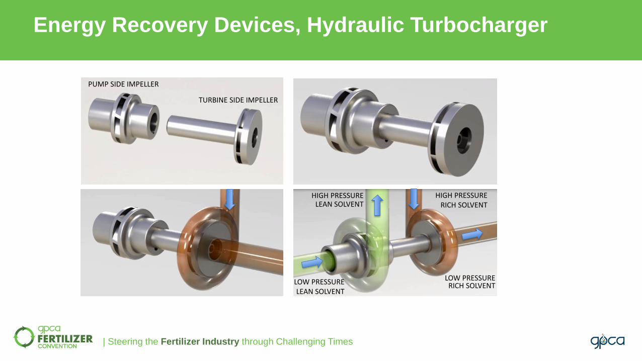
Energy Recovery Devices, Hydraulic Turbocharger
PUMP SIDE IMPELLER
TURBINE SIDE IMPELLER
HIGH PRESSURE LEAN SOLVENT
LOW PRESSURE LEAN SOLVENT
LOW PRESSURE RICH SOLVENT
HIGH PRESSURERICH SOLVENT

| Steering the Fertilizer Industry through Challenging Times
Energy Recovery Devices, Hydraulic Turbocharger
WEAR
RING
• No shafts exiting the casing
• Rotary assembly is a single moving part
• Bearings are self-lubricated by process fluid
• Rotary assembly speed is unconstrained and self-regulating

| Steering the Fertilizer Industry through Challenging Times
Turbocharger as Installed
| Steering the Fertilizer Industry through Challenging Times
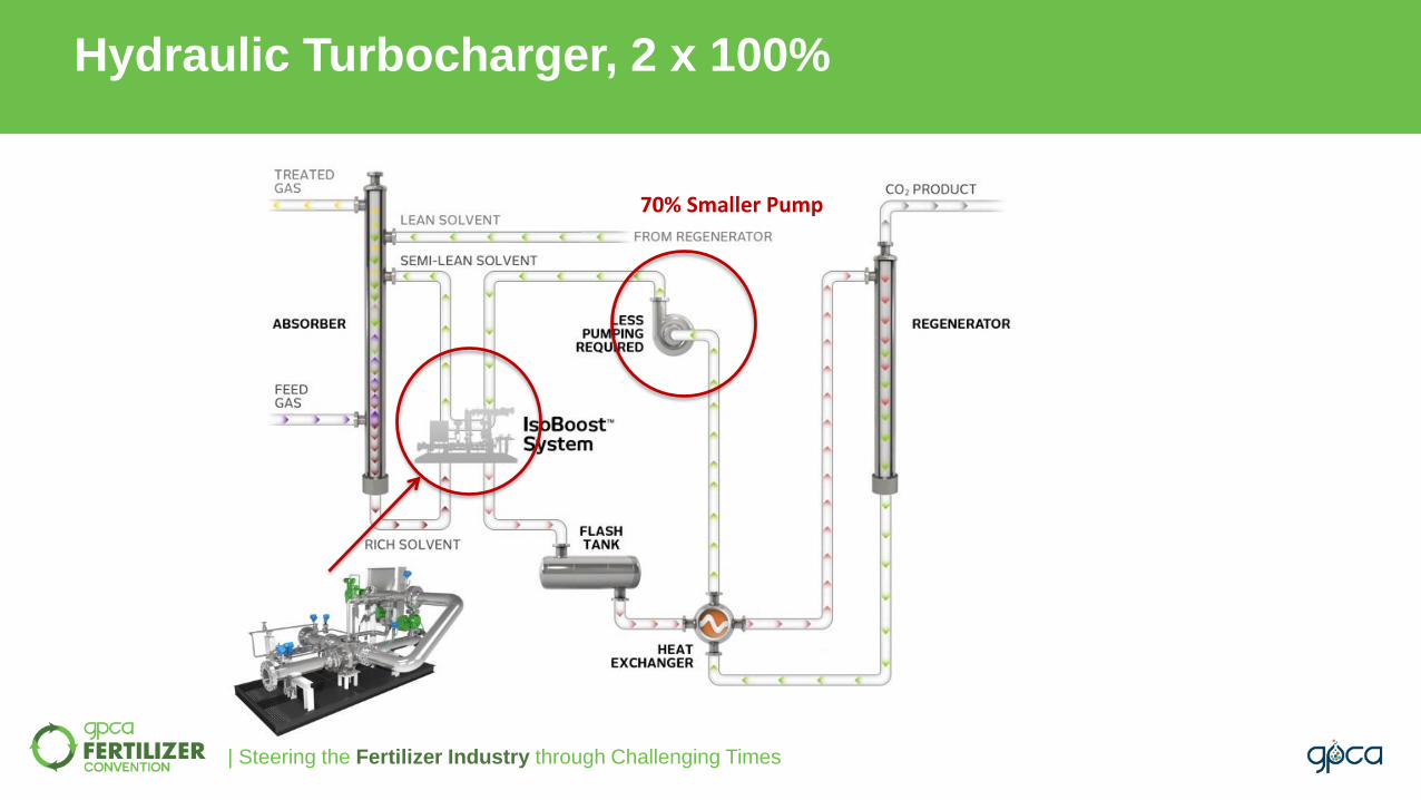
Hydraulic Turbocharger, 2 x 100%
70% Smaller Pump

| Steering the Fertilizer Industry through Challenging Times
Energy Recovery Devices in CO2 Removal Units
Q Solvent fluid flow, m3/hr
∆𝑃 Differential pressure between the contactor and flash tank pressures, bar
𝜀𝑡 Overall hydraulic recovery device efficiency
𝜀𝑝 Solvent circulation pump efficiency
𝜀m Solvent circulation pump electric motor efficiency
36 Conversion factor
𝑃𝑜𝑤𝑒𝑟 𝑆𝑎𝑣𝑖𝑛𝑔𝑠 ( 𝑘𝑊) =𝑄 × ∆𝑃 × 𝜀𝑡𝜀𝑝 × 𝜀𝑚 × 36
𝑃𝑜𝑤𝑒𝑟 𝑆𝑎𝑣𝑖𝑛𝑔𝑠 ( 𝑘𝑊) =1000
𝑚3ℎ𝑟
× 30 𝑏𝑎𝑟 × 70%
80% × 95% × 36
𝑃𝑜𝑤𝑒𝑟 𝑆𝑎𝑣𝑖𝑛𝑔𝑠 𝑘𝑊 = 770 𝑘𝑊Annual Energy Saving @ 0.08 $/kWh = $ 560,000
EXAMPLE:

| Steering the Fertilizer Industry through Challenging Times
CO2 Removal Process, 3 x 50%

| Steering the Fertilizer Industry through Challenging Times
Hydraulic Turbocharger, 3 x 50%
Replaces 1 pump. 50% Energy Saved!
| Steering the Fertilizer Industry through Challenging Times
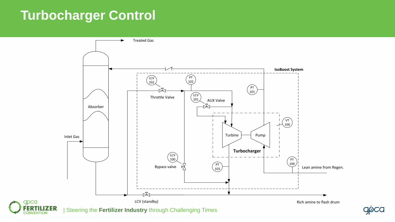
Turbocharger Control
Turbocharger
Turbine Pump
AUX Valve
Rich amine to flash drum
Lean amine from Regen.
PT100PT
103
PT101
PT102
LCV101
LCV102
LCV100
VT100
Throttle Valve
Bypass valve
LCV (standby)
Inlet Gas
Treated Gas
IsoBoost System
Absorber
Absorber

| Steering the Fertilizer Industry through Challenging Times
Level Control Functionality

| Steering the Fertilizer Industry through Challenging Times
Case Study A: MDEA Gas Treating Facility

| Steering the Fertilizer Industry through Challenging Times
Case Study A:
Saving Energy, Less Emissions, More Reliability
• Absorber pressure: 52 bar
• Flash drum pressure: 7 bar
• Amine flow rate: 170 m3/hr
• Reducing required power from 328 kW to 169 kW, ~ 50% reduction
• CO2 emission reduction: 1,000 Tons CO2/ year
• Energy saving: $139,000/ year
• 8 years in service with no failure

| Steering the Fertilizer Industry through Challenging Times
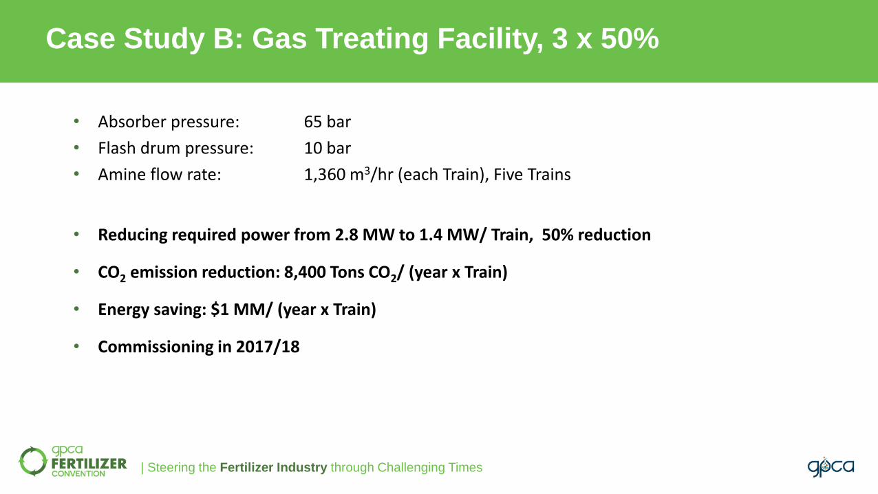
Case Study B: Gas Treating Facility, 3 x 50%
Lean Solvent Circ. Pump B(Standby)
Lean Solvent Circ. Pump A
M
To Rich Solvent Flash Tank
From Solvent Regen.
Turbocharger
Pump out Pump in
Turbine in Turbine out
AUXvalve
IsoBoost System
31
32
16
38
34
39
11 17
15
M
Absorber
Treated Gas
Inlet Gas
14Bypass valve
Throttle valve
LCV (Standby)
12
40
35
13
Min. Circ. Line
33
FCV-1
FCV-2
| Steering the Fertilizer Industry through Challenging Times
Case Study B: Gas Treating Facility, 3 x 50%
• Absorber pressure: 65 bar
• Flash drum pressure: 10 bar
• Amine flow rate: 1,360 m3/hr (each Train), Five Trains
• Reducing required power from 2.8 MW to 1.4 MW/ Train, 50% reduction
• CO2 emission reduction: 8,400 Tons CO2/ (year x Train)
• Energy saving: $1 MM/ (year x Train)
• Commissioning in 2017/18

| Steering the Fertilizer Industry through Challenging Times
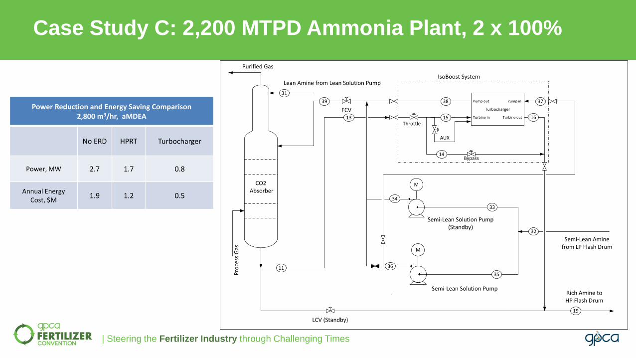
Case Study C: 2,200 MTPD Ammonia Plant, 2 x 100%
• 1 Absorber, HP/ LP Flash
• aMDEA
• 2,800 m3/hr
• HPRT out of serviceSemi-Lean Solution Pump
(Standby)
M
CO2 Absorber
Rich Amine to HP Flash Drum
Semi-Lean Amine from LP Flash Drum
Purified Gas
Pro
cess
Gas
11
32
34
39
FCV
Semi-Lean Solution Pump
Hydraulic Turbine
36
18
Lean Amine from Lean Solution Pump
LCV (Standby)
31
19
Trim Bypass valve
17
12
33
35
M
| Steering the Fertilizer Industry through Challenging Times
Case Study C: 2,200 MTPD Ammonia Plant, 2 x 100%
Power Reduction and Energy Saving Comparison2,800 m3/hr, aMDEA
No ERD HPRT Turbocharger
Power, MW 2.7 1.7 0.8
Annual Energy Cost, $M
1.9 1.2 0.5
E-59
Semi-Lean Solution Pump(Standby)
CO2 Absorber
Rich Amine to HP Flash Drum
Semi-Lean Amine from LP Flash Drum
Purified Gas
Pro
cess
Gas
Turbocharger
Pump out Pump in
Turbine in Turbine out
Bypass
AUX
IsoBoost System
14
15 16
3738
Throttle
11
13
32
33
34
39
FCV
Semi-Lean Solution Pump
36
19
35
Lean Amine from Lean Solution Pump
LCV (Standby)
31
M
M

| Steering the Fertilizer Industry through Challenging Times
Case Study D: 1,200 MTPD Ammonia Plant, 3 x 50%
• 1 Absorber, 2 Strippers
• Potassium Carbonate
• 1,200 m3/hr
• 2 HPRTs
• HPRTs efficiency: 50%

| Steering the Fertilizer Industry through Challenging Times
Case Study D: 1,200 MTPD Ammonia Plant, 3 x 50%
Pump B
SteamTurbine
Pump C (standby)
IsoBoost
M
Steam In
Steam Out
FV-6
Rich. Solvent to Stripper 1
Semi-Lean Solvent
Rich. Solvent to Stripper 2
Semi-Lean Solvent to Absorber
Rich Solvent from Absorber
1
9
2 3
10
14
11
1716
15
6
4
FV 43A
FV 41A
8
FV-3
Power Reduction and Energy Saving Comparison1,200 m3/hr, Benfield
Two HPRTsOne
Turbocharger
MP Steam, ton/hr 7.4 4.5
Annual Energy Cost, $M
1.55 0.95

| Steering the Fertilizer Industry through Challenging Times
Reliability and Flexibility Comparison
Turbine PumpM Turbine Pump
Reverse Running Pump Turbocharger
Courtesy of Shin Nippon Machinery Co., LTD
| Steering the Fertilizer Industry through Challenging Times
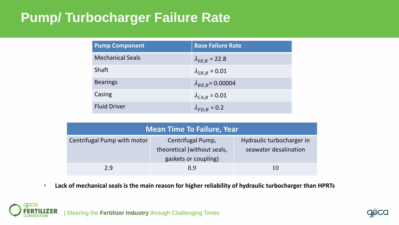
Pump/ Turbocharger Failure Rate
Pump Component Base Failure Rate
Mechanical Seals 𝜆𝑆𝐸,𝐵 = 22.8
Shaft 𝜆𝑆𝐻,𝐵 = 0.01
Bearings 𝜆𝐵𝐸,𝐵= 0.00004
Casing 𝜆𝐶𝐴,𝐵 = 0.01
Fluid Driver 𝜆𝐹𝐷,𝐵 = 0.2
Mean Time To Failure, Year
Centrifugal Pump with motor Centrifugal Pump,
theoretical (without seals,
gaskets or coupling)
Hydraulic turbocharger in
seawater desalination
2.9 8.9 10
• Lack of mechanical seals is the main reason for higher reliability of hydraulic turbocharger than HPRTs
| Steering the Fertilizer Industry through Challenging Times
• Hydraulic Turbochargers provide substantial energy efficiency benefits in CO2 Removal Units.
• The turbocharger design with hydraulic turbine and pump contained in one single-case unit, with no
mechanical seals or shafts exiting the casing, effectively eliminates high maintenance components rendering
the system virtually maintenance free.
• Simple design and fewer components make hydraulic turbochargers far more reliable energy recovery
devices than legacy technologies.
Conclusions

Thank You!www.gpca.org.ae