microwavecombustion andsinteringwithout isostaticpressure/67531/metadc715833/m2/1/high... ·...
TRANSCRIPT

FINAL REPORT
MICROWAVECOMBUSTIONAND SINTERINGWITHOUT
ISOSTATICPRESSURE
Principal Investigator:
M.A.Ebadian, Ph.D.
Prepared for:
U.S. Department of EnergyOffice of Environmental Management
Office of Science and Technology
HEMISPHERICCENTERFORENVIRONMENTALTECHNOLOGY(HCET)FloridaInternationalUniversity,CenterforEngineering&AppfiedSciences
10555WestFlaglerStreet,EAS-21OO,Miami,Florida33174305-348-4238● FAX:(305)348-1852● WorldWideWebSittihttp://www.bcet.firr.edu
Equal Opp@unilyEqual Amss Employerand lnstitW”onJTOO,tia FRS 1-SGG955.8771

.. x_—— — ——.
,
.
DISCLAIMER
This report was prepared as an account ofworksponsored by an agency of the United Statesgovernment. Neither the United States government nor any agency thereof, nor any oftheiremployees, nor any of its contractors, subcontractors, nor their employees makes any warranty,express or implied, or assumes any legal liability or responsibility for the accuracy,completeness, or usefulness of any information, apparatus, product, or process disclosed, orrepresents that its use would not infringe upon privately owned rights. Reference herein to anyspecific commercial product, process, or service by trade name, trademark, manufacturer, orotherwise does not necessarily constitute or imply its endorsement, recommendation, or favoringby the United States government or any other agency thereof. The views and opinions of authorsexpressed herein do not necessarily state or reflect those of the United States government or anyagency thereof.
I
I

DISCLAIMER
Portions of this document may be illegiblein electronic image products. Images areproduced from the best available originaldocument.
MICROWAVE COMBUSTION AND SINTERINGWITHOUT ISOSTATIC PRESSURE
Principal Investigator
M.A. Ebadian, Ph.D.
Hemispheric Center for Environmental TechnologyFlorida International University
Miami, FL 33174
Florida International UniversityCollaborator
N.D.H. Munroe, Ph.D.Hemispheric Center for Environmental Technology
Florida International UniversityMiami, FL 33174
January 1999
Prepared for
U.S. Department of EnergyOffIce of Environmental Management
Office of Science and Technology
Under Grant No.: DE-FG21-95EW55094
..—-
HCET-1997-D031-OOI -04
ACKNOWLEDGMENTS
This report is based on work supported by the U.S. Department of Energy, OffIce ofEnvironmental Management, Office of Science and Technology’s Decontamination andDecommissioning Focus Area, Morgantown Energy Technology Center. The Principal
Investigator, the Florida International University Collaborator, and the students at FloridaInternational University would like to thank Dr. Paul Hart for providing the opportunity to workon this project.
HCET Final Repoti i

\

HCET-1997-D031-OOI -04
TABLE OF CONTENTS
LIST OF FIGURES ......................................................................................................................- i~’
LIST OF TABLES ...........................................................................................................................~'
EXECUTIVE SUMMARY .......................................................................................................... vii
1.0
2.0
3.0
4.0
5.0
6.0
7.0
INTRODUCTION ...............................................................................................................l
1.1 BACKGROUND OF THE PROBLEM ...................................................................l
1.2 PURPOSE OF THIS INVESTIGATION ................................................................2
1.3 LITEIL4TURE REVIEW ........................................................................................~
PROJECT DESCMPTION ..................................................................................................4
2.1 OVERALL PROJECT GOALS ...............................................................................4
2.2 FY 97 ACTIVITIES ................................................................................................~
2.3 FY 98 OBJECTIVES ...............................................................................................~
PROCESS DESCWPTION .................................................................................................7
3.1 FUNDAMENTAL CONCEPTS AND THEOWES ................................................7
3.2 SAFETY AND REGULATORY CONCE~TS ......................................................9
EXPERIMENTAL INVESTIGATION .............................................................................l I
4.1 FIRING TESTS .....................................................................................................l ~
4.2 MEASUREMENT OF PHYSICAL PROPERTIES ..............................................ll
4.3 ANALYSIS OF MINEIL4LOGICAL COMPOSITION .......................................ll
4.4 MEASUREMENT OF DIELECTRIC CONSTANTS ..........................................12
EXPERIMENTAL ~SULTS ...........................................................................................l3
5.1 PHYSICAL PROPERTIES ...................................................................................l3
5.2 MINERALOGICAL DEVELOPMENT ................................................................l7
5.3 MICROWAVE EFFECT .......................................................................................20
5.4 DIELECTRIC CONSTANTS ................................................................................2 I
MAJOR ACCOMPLISHMENTS ......................................................................................26
REFERENCES 79...................................................................................................................
HCET Fjna/ Repoti. . .Ill
—-

HCET-I 997-D031 -001-04
LIST OF FIGURES
Figure 1.
Figure 2.
Figure 3.
Figure 4.
Figure 5
Figure 6.
Figure 7.
Figure 8.
Figure 9.
Figure 10.
Figure 11.
Figure 12.
Figure 13.
Figure 14.
Figure 15.
Figure 16.
Figure 17.
Figure 18.
Figure 19.
Figure 20.
Figure 21.
Figure 22.
Figure 23.
Figure 24.
A schematic flow-chart of the MCVI process . ............................................................ 8
A schematic diagram of the MCVI reactor configuration . .......................................... 9
Weight loss upon sintering of bauxite materials under an airatmosphere with the duration of 1 hour ..................................................................... 13
Weight loss upon sintering of bauxite material for 4 hours in anair atmosphere. .......................................................................................................... Is
Volume contraction upon sintering of bauxite materials under anair atmospherewiththe durationofl hour . .............................................................. 14
Volume contraction upon sintering of bauxite materials for 4 hoursin an air atmosphere. ................................................................................................. 15
Specific gravity upon sintering of bauxite materials for 1 hour in anair atmosphere . .......................................................................................................... 16
Specific gravity upon sintering of bauxite materials for 4 hours inan air atmosphere ....................................................................................................... 16
Corundum developed in the extrudates fired conventionally for l hour . ..................17
Corundum developed in the extrudates fired conventionally for 4hours . ................18
Mullite developed intlleextrudates fired conventionally forl hour . ....................... 18
Mullite developed in the extrudates fired conventionally for 4 hours ....................... 19
Dielectric constant of beneficiated bauxite at different temperatures . ...................... 21
Dielectric constant of capping material at different temperatures 77............................. --
Dielectric constant of tailing pond material at different temperatures . ..................... 22
Dielectric constant of traditional bauxite at different temperatures . ......................... 23
Dielectric constants of the products fired at 5000C. ................................................. 23
Dielectric constants of the products fired at 1100 oC. .............................................. 24
Dielectric constants of the products fired at 1350 oC. .............................................. 24
Dielectric constants of the products fired at 1600 oC. .............................................. 25
The chemical vapor infiltration system experimental setup. ..................................... 27
The assembly of the influent gas stream of the experimental setup . ......................... 27
Theassemblyof the effluentgas stream for the experimental setup . .......................27
Temperature/time process regime. ............................................................................ 28
iv HCET Fins/ Report

HCET-1997-D031-001 -04
LIST OF TABLES
Table 1.
Table 2.
Table 3.
Table 4.
Table 5.
Weight loss of extrudates fired in a variable frequency microwavefirnace at 1350°C for 30 minutes ................................................................................. 14
Volume contraction of extrudates fired in a variable frequency
microwave furnace at 1350°C for 30 minutes .............................................................. 15
Mineralogical development in extrudates fired in a variable frequencymicrowave furnace (0/0) . . . . . . . . . . . . . . . . . . . . . . . . . . . . . . . . . . . . . . . . . . . . . . . . . . . . . . . . . . . . . . . . . . . . . . . . . . . . . . . . . . . . . . . . . . . . . . . . 19
Processing time and electrical energy requirement for the microwavefiring and conventional firing ....................................................................................... ZO
Results for Stage I of the conventional chemical vapor infiltration tests ..................... 28
HCET Final Report v

HCET-1997-D031-001 -04
EXECUTIVE SUMMARY
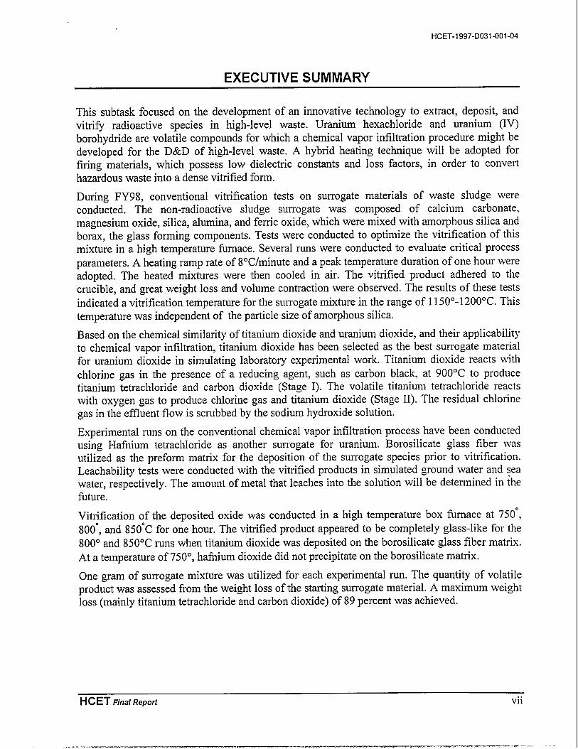
This subtask focused on the development of an innovative technology to extract, deposit, andvitri~ radioactive species in high-level waste. Uranium hexachloride and uranium (IV)borohydride are volatile compounds for which a chemical vapor infiltration procedure might bedeveloped for the D&D of high-level waste. A hybrid heating technique will be adopted forfiring materials, which possess low dielectric constants and loss factors, in order to converthazardous waste into a dense vitrified form.
During FY98, conventional vitrification tests on surrogate materials of waste sludge wereconducted. The non-radioactive sludge surrogate was composed of calcium carbonate,magnesium oxide, silica, alumina, and ferric oxide, which were mixed with amorphous silica andborax, the glass forming components. Tests were conducted to optimize the vitrification of thismixture in a high temperature furnace. Several runs were conducted to evaluate critical processparameters. A heating ramp rate of 8°C/minute and a peak temperature duration of one hour wereadopted. The heated mixtures were then cooled in air. The vitrified product adhered to thecrucible, and great weight loss and volume contraction were observed. The results of these tests
indicated a vitrification temperature for the surrogate mixture in the range of 1150°- 1200°C. Thistemperature was independent of the particle size of amorphous silica.
Based on the chemical similarity of titanium dioxide and uranium dioxide, and their applicabilityto chemical vapor infiltration, titanium dioxide has been selected as the best surrogate materialfor uranium dioxide in simulating laboratory experimental work. Titanium dioxide reacts withchlorine gas in the presence of a reducing agent, such as carbon black, at 900”C to producetitanium tetrachloride and carbon dioxide (Stage I). The volatile titanium tetrachloride reactswith oxygen gas to produce chlorine gas and titanium dioxide (Stage II). The residual chlorinegas in the effluent flow is scrubbed by the sodium hydroxide solution.
Experimental runs on the conventional chemical vapor infiltration process have been conductedusing Hafnium tetrachloride as another surrogate for uranium. Borosilicate glass fiber wasutilized as the preform matrix for the deposition of the surrogate species prior to vitrification.Leachability tests were conducted with the vitrified products in simulated ground water and seawater, respectively. The amount of metal that leaches into the solution will be determined in ~hefiture.
Vitrification of the deposited oxide was conducted in a high temperature box furnace at 750°,
800°, and 850”C for one hour. The vitrified product appeared to be completely glass-like for the800° and 850”C runs when titanium dioxide was deposited on the borosilicate glass fiber matrix.At a temperature of 750°, hafnium dioxide did not precipitate on the borosilicate matrix.
One gram of surrogate mixture was utilized for each experimental run. The quantity of volatileproduct was assessed from the weight loss of the starting surrogate material. A maximum weightloss (mainly titanium tetrachloride and carbon dioxide) of 89 percent was achieved.
HCET Fins/ Repofi vii
—-. —-— -—. —-. —.. .

HCET-1997-D031-001 -04 Microwave Combustion and Sintenng Wthout Isostatic Pressure
1.0 INTRODUCTION
In recent years, interest has grown rapidly in extending the application of microwave energy tothe processing of ceramics, composites, polymers, and other materials. Advances in theunderstanding of microwave/materials interactions will facilitate the production of new ceramicmaterials with superior mechanical properties. One application of particular interest is the use ofmicrowave energy for the mobilization of uranium for subsequent redeposition.
This investigation was conducted in three phases. Phase I (FY96) dealt with the determination ofphysical and chemical properties of fired pre-form matrices. Phase II (FY97) consisted offundamental research on the conventional sintering and microwave sintering of various mixes ofceramics and dielectric constant determination. Phase III (FY98) focused on the microwave-assisted chemical vapor infiltration tests for mobilization and redeposition of radioactive speciesin the mixed sludge waste.
Uranium hexachloride and uranium (IV) borohydride are volatile compounds for which thechemical vapor infiltration procedure might be developed for the separation of uranium.Microwave heating, characterized by an inverse temperature profile within a preformed ceramicmatrix, is utilized for CVI using a carrier gas. Matrix deposition is expected to commence fromthe inside of the sample where the highest temperature is present. The preform matrix materialswhich include aluminosilicate-based ceramics and silicon carbide-based ceramics are allamenable to extreme volume reduction, densification, and verification. Important parametersutilized in microwave sintering, such as frequency, power requirement, soaking temperature, andholding time, would be investigated in order to optimize process conditions for the volatilizationof uranyl species using a reactive carrier gas in a microwave chamber.
1.1 BACKGROUND OF THE PROBLEM
There is growing evidence to support the use of microwave energy in certain industrial processesand continued research and development for its use in many other materials-processingapplications, such as radioactive waste disposal. In contrast to conventional fiu-naces, thematerial to be processed in a microwave fin-nace interacts with the “cold” microwaves instead ofradiant heat.
In the application of mixed waste disposal, conventional heating is inferior to microwaveheating. Conventional joule heating requires electrodes in direct contact with the mixed waste.Electrode corrosion can limit the service life of these smelters. In microwave treatment,microwave energy is absorbed by a large class of waste materials commonly found in many low-level waste streams, such as fabrics, rubber, concrete, metal powders, oxides, nitrides, sulfates,nonmetallic filtering media, water, carbon, and glass. Because microwave energy is absorbeddirectly, it has the considerable advantage of much higher efllciency and faster temperaturecontrol compared to conventional radiant heating. Microwave power can be transmitted throughwave-guides from generators that can be located safely outside a radioactive processing areawhere routine system maintenance can be easily performed. Microwave heating is extremelyflexible in that a wide range of processing temperatures are available in a single system.Microwave disposal systems can be designed to be small enough to be mobilized for on-sitetreatment of radioactive wastes. Heating profiles can be custom-tailored for each application by
HCET Fins/ Repoti 1
. . ——. -—..-— ..

Microwave Combustion and Sintering Wthout Isostatic Pressure HCET-1997-D031-OOI -04
exciting the appropriate microwave field configuration or “mode,” choosing the proper heatingfrequency and material geometry, and understanding how the microwave penetration depth iscontrolled by temperature and material composition of the waste form.
Microwave-assisted chemical vapor infiltration (MCVI), an innovative technique to fabricatefiber-reinforced ceramic composites, has been proposed as a technique for treating radioactivewaste. Uranium hexachloride and uranium (IV) borohydride are volatile compounds for whichthe chemical vapor infiltration procedure might be developed for the separation of uranium. Theradioactive species in mixed waste, after mixing with a reactant gas, produces volatilecompounds in a microwave cavity. These compounds are transported by a carrierh-eactant gasa react tube, where the MCVI will take place. The volatilized uranyl species that is depositedthe ceramic matrix will be vitrified in-situ.
1.2 PURPOSE OF THIS INVESTIGATION
to
in
This project is devoted to the development of an innovative technique for the disposal of mixedwaste utilizing microwave energy. Because most uranium and plutonium components as well asmost fission products have dielectric properties that allow excellent microwave and high-frequency energy coupling, dielectric heating has the potential for application in many processesfor treating hazardous wastes. This technology, whether used on its own or as hybrid inconjunction with a conventional process, has positive features, such as energy efficiency.increased throughput, volume reduction, and reduction of disposal and transportation cost, andprovides a technique not feasible by conventional means. The hazardous waste will be convertedinto a dense, stable, and vitrified form so that it may qualify for eventual off-site disposal. Ifsuccessful, this program will lead to major cost saving for the DOE system.
1.3 LITERATURE REVIEW
Chemical vapor infiltration (CVI) is an attractive technique for introducing matrix materials intofibrous reinforcements as it minimizes stress during processing. Also, when compared to hotpressing, relatively low temperatures are used that limit unwanted chemical attack on thereinforcement. Difficulties associated with CVI processing using conventional heating arepreferential deposition in the substrate’s outer regions leading to pore blockage, long processingtime, non-uniform composite density, high residual porosity, and limitations on substrategeometry.
The use of microwave energy in the CVI processing has received recent attention due to thevolumetric heating and the resultant inverse temperature profile. With the internal region of thesubstrate hot, cool reactant gases penetrate inwardly prior to the onset of the deposition reaction.It should be noted that the inverse temperature gradients could also be established by “seeding”the center (or one side) of the preform with a material that readily absorbs microwave energy.The following advantages of MCVI over the conventional CVI have been well demonstrated byseveral researchers: relatively short processing time, no limitations on the preform geometry,products with spatially uniform and high density, deposition from the inside-out.
2 HCET Fins/ RepoH

HCET-I 997-D031 -001-04 Microwave Combustion and Sintering Wthout Lsostatic Pressure
MCVI has been documented in the fabrication of A1203 fiber/A1203 matrix composites (Skamseret al. 1994) and the SiC fiber/SiC matrix composites (Deepak and Evans 1993; Day et al. 1994).Infiltration of Si3N4 in NicalonTM cloth (Devlin et al. 1993), SiC and Zr02 into reticulated SiCfoam, NicalonTM cloth and Zr02 based porous fiber boards (Yin et al. 1997) were alsoexperimentally demonstrated. Experiments conducted in these reports required the application ofmicrowave radiation at a fixed frequency.
HCET Fins/ Repoti 3
—..---- . . — -— -.. .
Micrvwave Combustion and Sintenng Without Isostatic Pressure
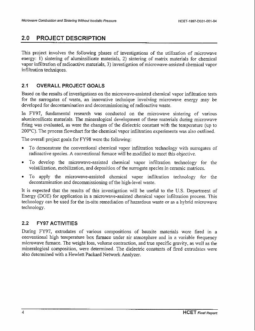
2.0 PROJECT DESCRIPTION
HCET-1997-D031 -001-04
This project involves the following phases of investigations of the utilization of microwaveenergy: 1) sintering of aluminsilicate materials, 2) sintering of matrix materials for chemicalvapor infiltration of radioactive materials, 3) investigation of microwave-assisted chemical vaporinfiltration techniques.
2.1 OVERALL PROJECT GOALS
Based on the results of investigations on the microwave-assisted chemical vapor infiltration testsfor the surrogates of waste, an innovative technique involving microwave energy may bedeveloped for decontamination and decommissioning of radioactive waste.
In FY97, fundamental research was conducted on the microwave sintering of variousaluminosilicate materials. The mineralogical development of these materials during microwavefiring was evaluated, as were the changes of the dielectric constant with the temperature (up to200°C). The process flowchart for the chemical vapor infiltration experiments was also outlined.
The overall project goals for FY98 were the following:
. To demonstrate the conventional chemical vapor infiltration technology with surrogates ofradioactive species. A conventional furnace will be modified to meet this objective.
. To develop the microwave-assisted chemical vapor infiltration technology for thevolatilization, mobilization, and deposition of the surrogate species in ceramic matrices.
. To apply the microwave-assisted chemical vapor infiltration technology for thedecontamination and decommissioning of the high-level waste.
It is expected that the results of this investigation will be useful to the U.S. Department ofEnergy (DOE) for application in a microwave-assisted chemical vapor infiltration process. Thistechnology can be used for the in-situ remediation of hazardous waste or as a hybrid microwavetechnology.
2.2 FY97 ACTIVITIES
During FY97, extrudates of various compositions of bauxite materials were fired in aconventional high temperature box furnace under air atmosphere and in a variable frequencymicrowave furnace. The weight loss, volume contraction, and true specific gravity, as well as themineralogical composition, were determined. The dielectric constants of fired extrudates werealso determined with a Hewlett Packard Network Analyzer.
4 HCET Fins/ Repoti
HCET-1997-D031-OOI -04 Microwave Combustion and Sintenng Without Lsostatic Pressure
FY97 activities included the following:
●
●
●
●
●
●
●
●
●
Determination of the composition of the starting materials by chemical analysis.
Firing the four types of bauxite extrudate~aw bauxite, beneficiated bauxite, tailing pond
material, and capping material-under air atmosphere in a conventional high-temperaturefurnace at 1350°, 1450°, 1550°, and 1600”C for 4 hours and at 1450°, 1550°, 1650°, and 1700”for 1 hour.
Firing the four types of bauxite extrudates in a 1.2KW variable frequency microwave firnace
(VFMF) at a frequency of 5.5-5 .75Ghz with a sweeping rate of 3 seconds at 1100”C for 1minute and at 1350” and 1550”C for 30 minutes.
Determination of the mineralogical composition of the fired products by powder X-raydiffraction (XRD).
In-situ analysis of the changes of the dielectric constant of the four types of materials withthe temperature up to 200”C.
Determination of the dielectric constant of the extrudates that were fired at 500°, 800°, 11000.
1350”, and 1600”C.
Attending the First World Congress on Microwave Processing in Orlando, Florida. onJanuary 5-9, 1997, and presentation of the project in the 32nd Microwave Power symposiumon July 14-16, 1997, in Ottawa, Canada.
Preparation of technical papers for presentation at the following conferences: the 32ndMicrowave Power Symposium (July 14-16, 1997 in Ottawa, Canada) and the SecondInternational Congress on Metallurgy and Materials Technology (October 12-17, 1997, inSao Paulo, Brazil). In addition, a refereed journal paper derived from this project has beenaccepted by the Journal ofkficrowave & Electromagnetic Energy.
A literature search to determine 1) a suitable surrogate for mixed waste, 2) a processing flo}v-chart for the chemical vapor infiltration (CVI) and microwave-assisted chemical vaporinfiltration (MCVI) processes, 3) instrumentation and supplies for conducting preliminaryCVI experiments, 4) suitable carrier gash-eaction gas mixtures, and 4) types of ceranlicmatrix preform.
2.3 FY98 OBJECTIVES
During FY98, investigations focused on the following:
. CONVENTIONAL VITRIFICATION OF THE MIXED WASTE SURROGATE: Preliminaryvitrification tests will be conducted on the conventional high-temperature furnace. Thevolume reduction, heating temperature, time required for vitrification, and the thermal andchemical stability of the products will be evaluated. This information” is essential foraccessing the efficiency of the CVI and MCVI processes.
. CONVENTIONAL CHEMICAL VAPOR INFILTRATION FOR WASTE DISPOSAL: CVIexperiments will be conducted using a conventional fhrnace. The experimental setup todemonstrate the CVI process for treatment of mixed waste will be accomplished at Florida
HCET Final Repoti 5

Microwave Combustion and Sintering Wthouf /sostatjc pressure HCET-1997-D031 -001-04
International University’s Hemispheric Center for Environmental Technology (FIU-HCET).A surrogate of the radioactive species in the mixed waste will be volatilized and mobilizedby a carrier gas and then deposited in a ceramic matrix. The deposited products will bevitrified in the conventional high-temperature furnace.
● MICROWAVE-ASSISTED CHEMICAL VAPOR INFILTRATION FOR WASTE DISPOSAL:Microwave energy will be utilized in the CVI processing to extract and deposit theradioactive species in the mixed waste. The MCVI system will consist of a microwave sourceand cavity, a gas delivery system, a quartz reactor tube with exhaust plumbing and vacuumconnection, pressure control, and a scrubbing unit. The reacting/carrier gas 1) will react withthe radioactive species present in the mixed waste in the volatilization chamber to producevolatile compounds. Reacting/carrier gas 2) will react with the volatile compounds, andinfiltration deposition will proceed within the preform ceramic matrix located inside themicrowave cavity. The products will be vitrified in-situ.
6 HCET Fins/ Repoti
HCET-1997-D031-OOI -04
3.0 PROCESS DESCRIPTION
Microwave Combustion and Sintering Wthout Isostatic Pressure
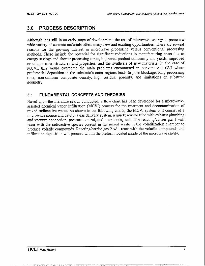
Although it is still in an early stage of development, the use of microwave energy to process awide variety of ceramic materials offers many new and exciting opportunities. There are severalreasons for the growing interest in microwave processing versus conventional processingmethods. These include the potential for significant reductions in manufacturing costs due toenergy savings and shorter processing times, improved product uniformity and yields, improvedor unique microstructure and properties, and the synthesis of new materials. In the case ofMCVI, this would overcome the main problems encountered in conventional CVI wherepreferential deposition in the substrate’s outer regions leads to pore blockage, long processingtime, non-uniform composite density, high residual porosity, and limitations on substrategeometry.
3.1 FUNDAMENTAL CONCEPTS AND THEORIES
Based upon the literature search conducted, a flow chart has been developed for a microwave-assisted chemical vapor infiltration (MCVI) process for the treatment and decontamination ofmixed radioactive waste. As shown in the following charts, the MCVI system will consist of amicrowave source and cavity, a gas delivery system, a quartz reactor tube with exhaust plumbingand vacuum connection, pressure control, and a scrubbing unit. The reacting/carrier gas 1 willreact with the radioactive species present in the mixed waste in the volatilization chamber toproduce volatile compounds. Reacting/carrier gas 2 will react with the volatile compounds andinfiltration deposition will proceed within the preform located inside of the microwave cavity.
HCET Eina/ Report 7
-,.--— ..s.— —Z-X.=..,-.W..r-.. .. . —-—- ——— --- -

Microwave Combustion and Sintering Wjthout /sostatjc pressure HCET-1997-D031-001 .04
Reacting/Carriergas 1 Q
Reacting/Carrier
Q gas 2
8
0
Volatilizationchamber
++
Mass flow controllers
o,;Molecular sieves
o
Pressure transducer
1+ [Reaction tube
Microwave cavity
E o ‘
PowerPyrometer ~ source
II
I
n Scrubber
Figure 1. A schematic flow-chart of the MCVI process.
A schematic diagram of the MCVI reactor is shown in Figure 2. It will consist of a cylindricalmicrowave cavity through which a quartz reactor tube is inserted. A ceramic matrix preform willbe loaded co-axially within the quartz tube. Since the heating configuration produces primarilyradial temperature gradients, deposition is expected to commence at the preform axis and growoutward.
8 HCET fins/ RePoti

HCET-1997-D031-OOI -04
ceramic Matrix
Microwave Combustion and Sintenng Without Isostatic Pressun?
, n Quartz Tube
\
Figure 2. A schematic diagram of the MCVI reactor configuration.
3.2 SAFETY AND REGULATORY CONCERNS
The U.S. Department of Energy (DOE) has numerous regulatory requirements that must befollowed by any DOE operation or contractor working at a DOE site in the United States. Sincethe Microwave Project involves radioactive wastes, the following regulations apply:
● DOE Order 5400.5, Radiation Protection of the Public and the Environment. This orderconstitutes a list of standards and requirements that DOE and its contractors must abide by tooperate the facility while protecting the public, work crews, and the environment againstunnecessary risks from radiation.
● DOE Order 1332.1, Un~orm Reporting System. This order applies to any operation related tothe DOE. It establishes a uniform reporting system for contracts, loans, and loan guaranteesand provides instructions, forms, and procedures for effective management.
● The U. S. Environmental Protection Agency (EPA) was established to reduce and controlpollution by setting standards and enforcing regulatory policy. The regulatory requirementsthat must be followed include the Clean Air Act of 1970 (CAA), the Clean Water Act of1977 (CWA), the Safe Drinking Water Act of 1974 (SDWA), and the Resource Conservationand Recovery Act (RCRA). Other laws that apply to hazardous waste include the ToxicSubstances Control Act of 1976 (TSCA) and the Comprehensive Environmental Response,Compensation, and Liability Act (CERDLA), which addresses the cleanup of hazardouswaste contamination from previous operations.
HCET Fins/ Repoti 9

Microwave Combustion and Sinteiing Wthout Isosfatic pressure HCET-I 997-D031 -001-04
Lambda Technologies provided a Microwave Leak Detector (MLD) to monitor any possiblemicrowave leakage. The MLD is interfaced with an interlock circuitry, which providesimmediate shutdown of the unit if hazardous levels of microwave energy are detected.
The microwave furnace was used in a heavily ventilated laboratory equipped with HEPA-filteredexhaust fume hoods. This reduces the level of metal vapor in the laboratory as well as that of theexhaust fumes released into the atmosphere.
10 HCET Final Repoti

HCET-I 997-D031-OOI-04 Microwave Combustion and Sintering Wthout Lsostatic Pressure
4.0 EXPERIMENTAL INVESTIGATION
Experimental work completed in FY97 included the firing of four types of bauxite materialsunder air atmosphere in a conventional high-temperature firnace and in a variable frequencymicrowave firnace. The weight loss, volume contraction, true specific gravity, as well as themineralogical composition, of the fired products were determined. The dielectric constants of thematerials at various temperatures were also analyzed using a Hewlett-Packard NetworkAnalyzer.
4.1 FIRING TESTS
Bauxite extrudates have been fired at 1450°, 1550°, 1650°, and 1700”C for 1 hour under an airatmosphere. Extrudates were also fired for a duration of 4 hours at 1350°, 1450°, 1550°, and1600”C in an air atmosphere. Two conventional fbrnaces were utilized to conduct the firing.Pellets were preheated to about 800°C in the low-temperature furnace and rapidly transferred to
the high-temperature furnace. The drop in the temperature was estimated to be less than 20°Cduring the transfer. The pellets were then heated at a rate of 5°C/min to the expectedtemperatures in the conventional high-temperature box finmace and held at the requiredtemperature. These pellets were then allowed to cool to room temperature. In order to measurethe physical and mineralogical properties of the sintered specimens, 16 batches of firing testswere conducted.
Microwave firing of bauxite extrudates was conducted in a 1.2 Kw variable frequencymicrowave furnace (VFMF) at a frequency of 5.5-5.75 Ghz with a sweeping rate of 3 secondsat Lambda Technologies, Inc. Three firing regimes were adopted with the microwave furnace.
The first regime involved heating the extrudates to 1100”C and maintaining that temperature for1 minute. The other two regimes involved heating the extrudates up to 1350”C and 1550”C andmaintaining that temperature for 30 minutes, respectively. These tests revealed that with hybridheating using silicon carbide as a susceptor only 20 minutes were required to achieve a firingtemperature. The fired extrudates were found to be void of visible cracks.
4.2 MEASUREMENT OF PHYSICAL PROPERTIES
The weight loss, volume contraction, and true specific gravity of the fired extrudates weremeasured. The weight loss was determined by the difference in the sample before and afterfiring. The dimension of each sample (radius and length) was measured prior to and proceedingthe firing. The volume contraction was then estimated. To determine the true specific gravity, thefired samples were ground to a fine powder so that the individual pieces were too small tocontain pores. The true specific gravity of the powder was determined by means of a specificgravity bottle (pycnometer).
4.3 ANALYSIS OF MINERALOGICAL COMPOSITION
The mineralogical compositions of the fired extrudates were analyzed using powder X-raydiffractometer with an internal standard method. Commercial micron powders of mullite,
HCET Final Repoti 11
-.. -- —...—.——— —— —.—. .. .

Microwave Combustion and Sintenng W7thout /sostatic pressure HCET-1997-D031 -001-04
corundum, and cristobalite were used as the reference materials. Calcium fluoride was applied asthe internal standard material. The internal standard material was mixed with the powders of thefired extrudates in an agate motor. The powders were covered with 10 milliliters of ethyl ether asthe mixing solvent. The slug was stirred with a pestle until the liquid evaporated. Stirringconsiderably increases the degree of mixing. The mixture was exposed under X-ray, and therelative contents of mullite, corundum, and cristobalite were calculated according to thediffraction peaks.
4.4 MEASUREMENT OF DIELECTRIC CONSTANTS
In-situ measurement of the dielectric constants for various bauxite materials was taken using aHewlett Packard Network Analyzer along with a dielectric probe. In order to obtain the readings,the four samples (raw bauxite, beneficiated bauxite, tailing pond material, and capping material)were heated up to 200”C, and then the measurements were taken. A thermocouple was used tomonitor the temperature of the sample while the readings were taken. Three readings at threedistinct temperatures were taken for each of the four samples. This gives a total of twelve curvesto compare with each other. In order to avoid rapid cooling of the sample, the samples werewrapped in an insulating foam.
Ex-situ measurement of the dielectric constants for the extrudates fired at various temperatureswas also taken. Extrudates were heated up to 500°C, 800°C, 11OO°C, 1350°C, and 1600”C.respectively, and held at those temperatures for 1 hour and then cooled down to the ambienttemperature. The measurements were taken at ambient temperature, and three readings weretaken for each of the four samples. A total of 20 curves were generated for comparison ofdielectric properties as a function of firing temperature and frequency.
12 HCET Final Repoti
HCET-1997-D031-OOI -04
5.0 EXPERIMENTAL RESULTS
Microwave Combustion and Sintenng Wthout Isostatic Pressure
The results of the experiments described above are reported in the following sections.
5.1 PHYSICAL PROPERTIES
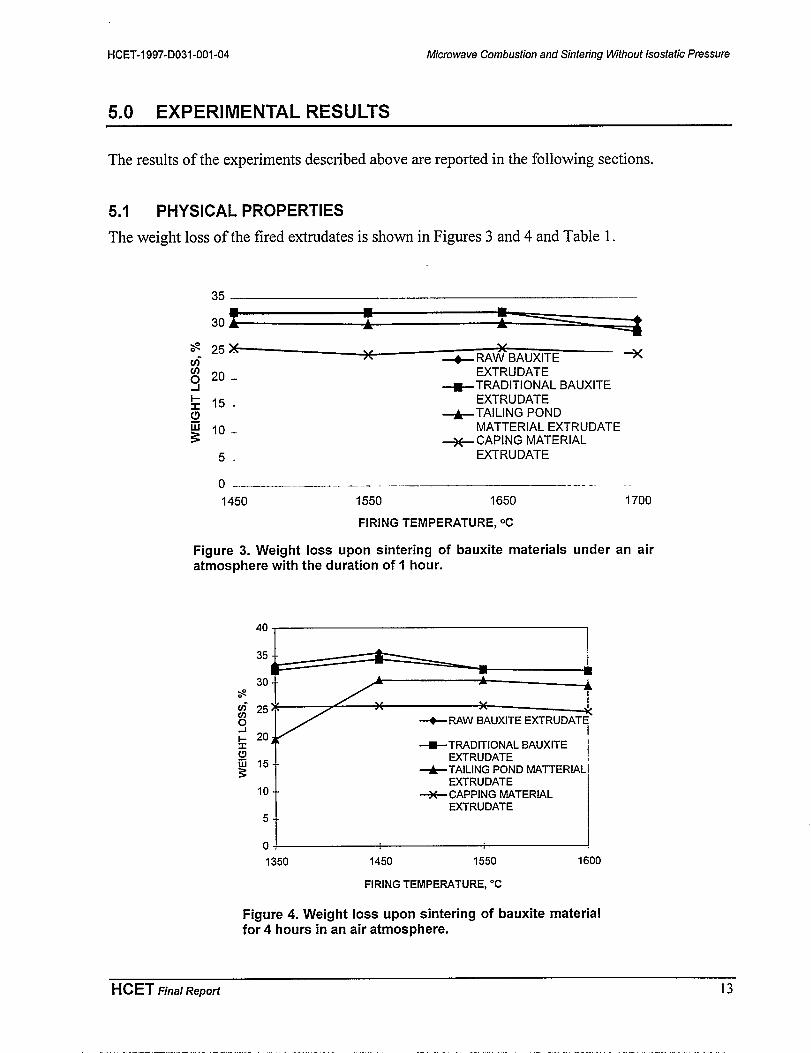
The weight loss of the fired extrudates is shown in Figures 3 and 4 and Table 1.
35
30
$ 25X . v
(J$ A + RAW BAUXITE *
y20. EXTRUDATE
$ 15.-+TRADITIONAL BAUXITE
EXTRUDATEg +TAILING POND~ 10. MATTERIAL EXTRUDATE3 ++ CAPING MATERIAL
5- EXTRUDATE
o– .— .—
1450 1550 1650 1700
FIRING TEMPERATURE, ‘C
Figure 3. Weight loss upon sintering of bauxite materials under an airatmosphere with the duration of 1 hour.
.E==I~- 25*
/ v
CJ4
+RAW BAUXITE EXTRUDATE
* 203x +TRADITIONAL BAUXITE
g 15- -EXTRUDATE
+TAILING POND MAll_ERIAL
10- -EXTRUDATE
+CAPPING MATERIALEXTRUDATE
5T
o
1350 1450 1550 1600
FIRING TEMPERATURE, “C
Figure 4. Weight loss upon sintering of bauxite materialfor 4 hours in an air atmosphere.
HCET Fins/ Reporf 13

Microwave Combustion and Sintering Wjthout /sostatjc pressure
Table 1.Weight loss of extrudates fired in a variable
frequency microwave furnace at 1350”C for 30 minutes
Weight loss (%)
Raw bauxite 32.2
Beneficiated bauxite 32.4
Tailing pond material 30.4
Capping material 25.8
HCET-1997-D031 -001-04
The volume contractions of the fired extrudates are shown in Figures 5 and 6 and Table 2.
80 ---.——.—–. .._._. _
70-
z- 60.0Fo 50<IY + RAW BAUXITE
g 40 EXTRUDATE
50 -R-TRADITIONAL BAUXITEW30. EXTRUDATEz
3 20 --+TAILING POND
g MATERIAL EXTRUDATE
10 -+CAPPING MATERIAL
EXTRUDATE
o .–.
1450 1550 1650 1700
FIRING TEMPERATURE, ‘C
Figure 5. Volume contraction upon sintering of bauxite materialsunder an air atmosphere with the duration of 1 hour.
14 HCET Fins/ Report

HCET-1997-D031-OOI -04 Microwave Combustion and Sintenng Wthout Isostatic Pressure
80
~. 70-z:60– A
~ 50&kJ 400 + RAW BAUXITE EXTRUDATE030.w320.
+TRADITIONAL BAUXITE EXTRUDATE
.+ TAILING POND MATERIAL EXTRUDATE
~ 10.–>
+CAPING MATERIAL EXTRUDATE
o
1350 1450 1550 1600
FIRING TEMPERATURE, “C
Figure 6. Volume contraction upon sintering of bauxite materialsfor 4 hours in an air atmosphere.
Table 2.Volume contraction of extrudates fired in a variable
frequency microwave furnace at 1350”C for 30 minutes
Volume contraction (Yo)
Raw bauxite 39.0
Beneficiated bauxite 41.1
Tailing pond material 41.3
Capping material 32.8
The specific gravity of the fired extrudates is shown in Figures 7 and 8.
HCET Fins/ Repoti 15
.——. .- .- —.. ——— -- ——- —- .. . ---- .

Microwave Combustion end Sintering W7thout Isostatic Pressure HCET-1997-D031 -001-04
4
5 ‘“2 -aK 2-
+RAW BAUXITEEXTRUDATE
c1
Q 1.5 –+TRADITIONAL BAUXITEEXTRUDATE
& +TAILING POND MATERIALEXTRUDATEow 1- +CAPPING MATERIALEXTRUDATEnU-J
0.5-
0
1450 1550 1650
FIRING TEMPERATURE, Co
Figure 7. Specific gravity upon sintering of bauxite materialsfor 1 hour in an air atmosphere.
4.00
-E3.50
~ 3.00
0.00
+ RAW BAUXITE
+ BENEFICIATED BAUXITE
+TAILING POND MATERIAL
+cAPPING MATERIAL
1300 1350 1400 1450 1500 1550 1600 1650
TEMPERATURE, “C
Figure 8. Specific gravity upon sintering of bauxitematerials for 4 hours in an air atmosphere.
Considerable weight loss and volume contraction occurred during the firing of extrudates.Figures 3 and 4 show that the weight loss of beneficiated bauxite (=32.1 Yo)was greater than that
of the capping material (=25.50/0). The weight loss for each type of material was independent ofthe type of firnace used (microwave or conventional) as well as the processing parameters(temperature and time). Figures 5 and 6 show that the volume contraction generally increasedwith increasing firing temperatures. At temperatures of 155O°C and above, beneficiated bauxite
experienced greater volume contraction (up to 67.3’Yo)than that of capping material (=58 .7’Yo).However, the volume contraction of extrudates fired in the microwave furnace was significantlylower than that of extrudates fired conventionally at the same temperature. It should be noted that
16 HCET Fins/ Repoti

HCET-1997-D031-OOI -04 Microwave Combustion and Sintering Wthout Lsostatic Pressure
this observation may have been due to a shorter holding time of 30 minutes in the microwavefurnace as compared to 1 hour and 4 hours, respectively, in the conventional furnace.
Weight loss in the firing of bauxite materials was mainly attributed to the decomposition ofchemically bonded water, whereas volume contraction was primarily due to the mineralogicaltransformation and densification (Takeshita et al. 1993). A significant increase of volumecontraction occurred when the soaking time was prolonged. This indicated that mineralogicaltransformation resulted in densification of the extrudates.
The specific gravity of fired extrudates ranged between 2.97 and 3.51 g/cm3, as indicated byFigures 7 and 8. The change in the specific gravity is indicative of the relative proportions of thephases developed in the fired products. The specific gravity for the corundum, mullite,cristobalite, and amorphous silica are 4.03, 3.03, 2.32, and 2.2 g/cm3’ respectively (Grimshaw197 1). The higher specific gravity of the fired beneficiated bauxite extrudates indicated that ahigher proportion of corundum developed during the firing. This was verified by X-raydiffraction analysis.
5.2 MINERALOGICAL DEVELOPMENT
It was found that all the fired extrudates contained a small amount of cristobalite. The amountsof the corundum and mullite developed in the fired extrudates varied with the firing temperaturesand the soaking time. The results are shown in Figures 9 through 12 and Table 3.
60
40
20
0
1300 1400 1500 1600 1700 1800
Tern perature (“C)
Figure 9. Corundum developed in the extrudates fired conventionally for 1 hour.
HCET Final Repoti 17
.— .—-.

Microwave Combustion and Sintering U4thout Lsostatic Pressure
100
~Raw bauxite
80-g- Benificiated bauxite
*
i: <“t’”a’1=~
6 20
0
HCET-1997-D031-OOI -04
1300 1400 1500 1600 1700
Temperature (oC)
Figure 10. Corundum developed in the extrudates fired conventionally for 4 hours.
-A- Tailing pond material
++ Capping material
1300 1400 1500 1600 1700 1800
Temperature (oC)
Figure 11. Mullite developed in the extrudates fired conventionally for 1 hour.
18 HCET Fins/ Repoti

HCET-1997-D031-OOI -04 Microwave Combustion and Sintering lMthout Isostatic Pressure
~’:-~60 + TailingpondmaterialL
ov I + Capping material
011300 1400 1500
Tern perature (oC)
Figure 12. Mullite developed in the extrudates fired
1600 1700
conventionally for 4 hours.
Table 3.Mineralogical development in extrudates fired in a variable frequency microwave furnace (%)
Corundum Mullite
1100°c 1350”C 1550”C 11Oo”c 1350”C 1550°c
Raw bauxite 57.9 49.3 49.2 8.3 9.3 14.9
Beneficiated bauxite 61.7 53.8 51.1 9.0 9.3 16.8
Tailing pond material 59.1 50.8 39.7 12.2 19.4 19.1
Capping material 25.3 12.8 1.6 34.5 53.8 65.8
* Three firing regimes were: 11OO°Cfor 1 minute, 1350°C for 30 minutes, and 1550°C for 30 minutes.
X-ray diffraction analysis of the fired products revealed that gibbsite was completely convertedto corundum in all extrudates. The predominant crystalline mineral phases in the fired extrudateswere corundum and rnullite. Only minor amounts of cristobalite were detected in all firedextrudates. This may be due to the fact that most of the silica had been consumed in theformation of mullite or existed as glassy phases that are not detectable by XKD.
As expected, the firing of beneficiated bauxite produced the highest content of corundum. Atcertain processing conditions, corundum development in capping material could be completelysuppressed. For example, the higher content of corundum that was found in extrudates fired at11OO°C resulted from complete dehydration of gibbsite and a slower reaction rate for mulliteformation. At 1350”C, the higher rate of mullite formation from corundum and silica resulted ina lower corundum content. However, the highest mullite production occurred in the firing ofcapping material. Approximately 100°/0 conversion to mullite occurred in the firing of capping
HCET Final Report 19
—-----.“-.A-,. ..<.. .. .. . ......n —n- .. . .. ......... .. .,, .”-..... . . . . .. ..... .. .,, >.-. . . . . . ..- ,. . . ~-, .,..,..!.. ,. >----- — ., i-- ---- . .
Microwave Combustion and Sintenng Wthout Isosfatic Pressure HCET-I 997-D031-001 -04
a lower corundum content. However, the highest mullite production occurred in the firing ofcapping material. Approximately 100°/0 conversion to mullite occurred in the firing of cappingmaterial, whereas approximately 20wt0/0 mullite development occurred in the firing ofbeneficiated bauxite. The amount of mullite developed in microwave firing was comparable tothat produced by conventional firing at the same temperature. However, a greater amount ofmullite developed with increased soaking time when extrudates were fired conventional y in ahigh-temperature furnace. The same result is anticipated with a microwave furnace.
5.3 MICROWAVE EFFECT
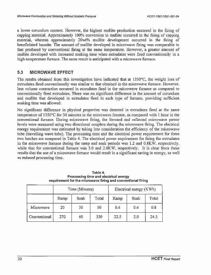
The results obtained from this investigation have indicated that at 1350”C, the weight loss ofextrudates fired conventionally was similar to that obtained in the microwave furnace. However,less volume contraction occurred in extrudates fired in the microwave furnace as compared toconventionally fired extrudates. There was no significant difference in the amount of corundumand mullite that developed in extrudates fired in each type of furnace, providing sufficientsoaking time was allowed.
No significant difference in physical properties was detected in extrudates fired at the sametemperature of 1350°C for 30 minutes in the microwave furnace, as compared with 1 hour in theconventional furnace. During microwave firing, the forward and reflected microwave powerlevels were measured using two directional couplers during the microwave firing. The electricalenergy requirement was estimated by taking into consideration the efficiency of the microwavetube (traveling wave tube). The processing time and the electrical power requirement for thesetwo batches are compared in Table 4. The electrical power requirement for firing the extrudatesin the microwave furnace during the ramp and soak periods was 1.2 and O.8KW, respectively.while that for conventional furnace was 5.0 and 2.0KW, respectively. It is clear from theseresults that the use of a microwave furnace would result in a significant saving in energy, as wellas reduced processing time.
Table 4.Processing time and electrical energy
requirement for the microwave firing and conventional firing
Time (Minutes) Electrical energy (KWh)
Ramp Soak Total Ramp Soak Total
Microwave 20 30 50 0.4 0.4 0.8
Conventional 270 60 330 22.5 2.0 24.5
20 HCET Fhra/ Report

HCET-I 997-D031 -001-04 Microwave Combustion and Sintenng Wthout Lsostatic Pressure
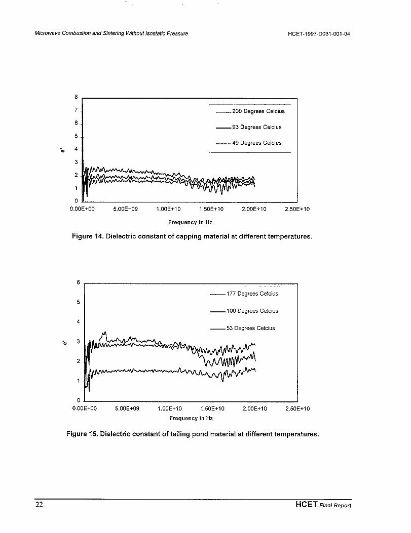
5.4 DIELECTRIC CONSTANTS
The dielectric constants of the materials vary with the temperature and were measured in-situ atthree temperatures, as shown in Figures 13 through 16.
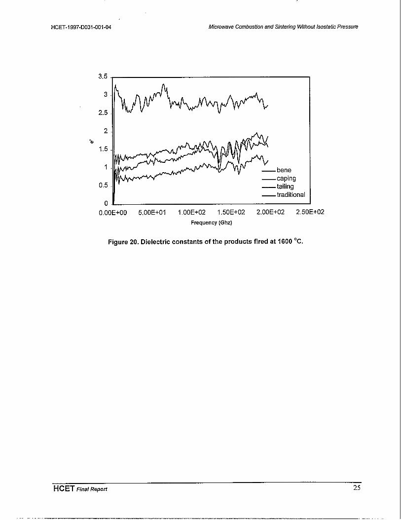
The dielectric properties of extrudates that were fired at temperatures of 500”C, 800°C, 11OO”C,
1350°C, and 1600°C and allowed to cool to ambient conditions before measurement have beendetermined using an HP Network Analyzer with a sample probe. The results are shown inFigures 17 through 20.
The results of the measurement show that below 200”C, the dielectric constant of each type ofmaterial is a function of the temperature and the microwave frequency. The values of thedielectric constants of the materials are around 3. This indicates that these materials do notcouple with the microwave field very well; thus, hybrid heating method, using microwavesusceptor to assist heating, has to be applied.
20 I -— —.—I — 186 Degrees Celcius
15-
-0 I— 96 Degrees Celcius
10 1 —49 DegreesCelcius
HCET Fins/ RePoti 21
-.-— ..-,-—..-.. . .
—5
01’0.00E+OO 5.00E+09 I.00E+IO 1.50E+I0 2.00E+IO 2.50E+I0
Frequency in Hz
Figure 13. Dielectric constant of beneficiated bauxite at different temperatures.
Microwave Combustion and Sintering Wjthout /sostatic pressure
8
7
6
5
-aJ 4
3
2
1
0
HCET-I 997-D031 -001-04
— 200 Degrees Celcius
—93 Degrees Celcius
—49 Degrees Celcius
0.00E+OO 5.00E+09 I.00E+IO 1.5 OE+1O 2. OOE+1O 2.50E+I0
Frequency in Hz
Figure 14. Dielectric constant of capping material at different temperatures,
6
5
4
-a 3
2
1
0
— 177 Degrees Celcius
— 100 Degrees Celcius
— 53 Degrees Celcius
0.00E+OO 5.00E+09 I.00E+IO 1.50E+I0 2.00E+I O 2.50E+I0
Frequency in Hz
Figure 15. Dielectric constant of tailing pond material at different temperatures.
22 HCET Fins/ Report

HCET-1997-D031-OOI -04 Microwave Combustion and Sintenng VMthout Isostatic Pre.%$ure
20 ,
18
16
14
12
“~ 10
8
6
4
2
— 188 DegreesCelcius
— 99 Degrees Celcius
—55 DegreesCdcius
0.00E+OO 5.00E+09 I.00E+IO 1.50E+I0 2.00E+IO 2.50E+I0
Frequency in Hz
Figure 16. Dielectric constant of traditional bauxite at different temperatures.
4.5
4
3.5
3
2.5-0
2
1.5
1
0.5
0
.,.. - —...-=-.T -m-m. . . . ., .--.---.-=-L-. ., .- . ..- . . . . . . . . . . . . . . . . . .,7 . . . . -— ..-. . . . .
—tailing
—traditional
0.00E+OO 5.00E+OI 1.00E+02 1.50E+02 2.00E+02 2.50E+02
Frequency (Ghz)
Figure 17. Dielectric constants of the products fired at 500”C.
HCET Fins/Report 23

Microwave Combustion and Sin ferir,g Wthout Isostatic Pressure
2.5.
2-
1.5
-al1-
0.5-
0.
HCET-I 997-D031-001 -04
—kne
— Caping
—tailing
—traditional
0.00E+cKI5.00E+OI 1.00E+02 1.50E+022.MIE+022.50E+02
Frequency (G@
Figure 18. Dielectric constants of the products fired at1100 “C.
25
2
-~ 1.5
1
0.5 @mtili~
o traciiicd
O.m 5.mlx)l I.mxz I.ECfS@ 2mE!=02 250fwz
Figure 19. Dielectric constants of the products fired at 1350 “C.
24 HCET Fins/ Repoti
HCET-1997-D031-OOI -04
,,
Microwave Combustion and Sintering k14thout Lsostatic Pressure
3.5 ,
3-
2.5-
2.
-01.5-
1-bene
0.5-taping
tailing
—tradi~onal
0.00E+OO 5.00E+OI 1.00E+02 1.50E+02 2.00E+02 2.50E+02
Frequency (Ghz)
Dielectric constants of the products fired at 1600 “C.
HCET Firra/ Report 25
.. . . . ..—-

Microwave Combustion, and Sintering Without /sostatic pressure
6.0 MAJOR ACCOMPLISHMENTS
HCET-I 997-D031-001 -04
A 1.2 KW variable frequency microwave furnace (VFMF), utilizing a frequency of 4.55-4.75GHz, has been used to fire alumino-silicate extrudates at 11OO°C, 1350”C, and 1550°C atLambda Technologies, Inc. For the purpose of comparison, extrudates were also fired in agraphite-lined furnace under helium and in a conventional high-temperature furnace under an
air atmosphere at a series of temperatures (1350°C, 1450”C, 1550°C, 1600°C, 1650”C, and1700°C) for soaking periods of 1 hour and 4 hours, respectively (November 1996 – March1997).
Quantitative analyses of the mineralogical compositions, as well as the determination ofphysical properties such as weight loss, porosity, volume contraction, and specific gravity, ofthe fired products have been accomplished. These results have lead to the conclusion that thefiring of ceramic materials in a microwave furnace can be successfully accomplished with asubstantial saving in energy and processing time (April 1997 – May 1997).
The dielectric constant of four types of alumino-silicate materials were measured in-situ atdifferent temperatures ranging from approximately 40°C to 200”C and at variousfrequencies. Determinations of the dielectric properties of extrudates ex-situ after firing theextrudates to temperatures of 500”C, 800°C, 1100”C, 1350”C and 1600°C and cooling toambient conditions before measurement have also been accomplished (June 1997 – August1997).
Two technical papers have been published and presented at the following conferences: the32nd hlicrowave Power Symposium (July 14-16, 1997, in Ottawa, Canada) and the SecondInternational Congress on Metallurgy and Materials Technology (October 12-17, 1997. inSao Paulo, Brazil). In addition, a refereed journal paper derived from this project has beenaccepted by the Journal of A4icrowave & Electromagnetic Energy (June 1997 – October1997).
A chemical vapor infiltration experimental system setup shown in Figure 21 has beenestablished. The reaction in stage 1 occurs at 550”C within the quartz tube, which is heatedindirectly by the tube furnace. The assembly for the influent gas, which consists of gasregulators, mass flow meters, and an inlet connection to the quartz tube, is shown in Figure22. The effluent gas connection of the quartz tube to the exhaust gas pump/ scrubber unit isshown in Figure 23.
26 HCET Fins/ Report

HCET-1997-D031-OOI -04 Microwave Combustion and Sintenng Wthout Isostatic Pressure
Figure 21. The chemical vapor infiltration systemexperimental setup.
Figure 22. The assembly of the infiuent gas streamof the experimental setup.
Figure 23. The assembly of the effluent gas streamfor the experimental setup.
HCET F]na/ Repoti 27
..-— .:-CJP.T..A-,.,..<. ..... .,‘. ,.-,,.. . .- - -,.- .,v~—,——- --.???Z=-.

Microwave Combustion and Sintering Without Isosfatic pressure HCET-I 997-D031-001 -04
● The efficiency with which volatilization and deposition of surrogate product (assessed fromthe weight loss of the starting surrogate material) occurs was established at approximately89’% efficiency. Theresults ofweight loss ofsurrogate mixtures, which corresponds to theformation of volatile species and carbon dioxide under various conditions, are listed in Table5.
Table 5.Results for Stage I of the conventional chemical vapor infiltration tests
Runs Mole ratio (TiOz:C) Temperature (“C) Time (hours) Weight loss (’?40)
1 1:1 550 4 23
2 1:1 900 3 57
3 1:2 900 3 87
4 1:2 900 2 81
5 1:3 900 3 89
● Determination of the appropriate temperature profile for the CVI process is sholvn in Figure24.
Temperature
[ =1mp on
E
I Soaking Time
Soaking Temperature
Clzoff
Figure 24. Temperature/time process regime.
28 HCET Fins/ Report

HCET-1997-D031-OOI -04 Microwave Combustion and Sintenng Whout Lsostatic Pressure
7.0 REFERENCES
Day, P. S., Skamser, D. J., Jennings, H. M., Johnson, D. L., and Spotz, M. S., 1994, “Fabricationof SiC Matrix Surface Composites by Chemical Vapor Infiltration with MicrowaveHeating: Temperature Effects,” Cerain. Eng. Sci. Proc., 15[5], 908-915.
Deepak and Evans, J. W., 1993, “Mathematical Model for Chemical Vapor Infiltration in aMicrowave-Heated Preform,” J Anz. Ceram. Sot., 76[8], 1924-1929.
Devlin, D. J., Currier, R. P., Barbero, R. S., and Espinoza, B. F., 1993, “Chemical VaporInfiltration with Microwave Heating,” Ceranz. Eng. Sci. Proc., 14[9-1 O], 761-767.
Grimshaw, R. W., 1971, The Cheinistry and Physics of Clays and Allied Ceramic Materials, 4thcd., Ernest Berm Limited, London, p.712.
Munroe, N., A. M. Ebadian, and X. Tan, 1997, “Microwave Sintering and Combustion withoutIsostatic Pressure,” Quarterly Report to DOE.
Ross, W. A., Elmore, M. R., Warner, C. L., Wachter, L. J., Carlson, W. L., and Devries, R. L..Proc. 18th Symp. on Waste Management, Tucson, AZ, March 1-5, Am. Alzicl. Sot..pp.1127-1135.
Skamser, D. J., Day, P. S., Jennings, H. M., Johnson, D. L., and Spotz, M. S., 1994, “HybridMicrowave-Assisted Chemical Vapor Infiltration of Alumina Fiber Composes,” Ceran?.Eng. Sci. Proc., 15[5], 916-923.
Takeshita, M., Matsuda, O., Watari, T., and Torikai, T., 1993, “Sintering and mullite formationfrom kyanite-glass system,” J. Ceram. Sot. Japan, Int. Edition, 101:1276-1280.
Yin, Y., Binner, J., and Cross, T., 1997, “Microwave Assisted Chemical Vapor Infiltration forCeramic Matrix Composites, “ in Microwaves: Theory and Application in MaterialsProcessing Ill Ceramic Transactions, Vol. 80, D. E. Clark, W. H. Sutton and D. A.Lewis, eds., The American Ceramic Society, pp.349-356.
HCET Final Repoti 29
.——..- - ..— —— ...