microwave oven nn-sn790s nn-sa770s -...
TRANSCRIPT
© Panasonic Home Appliances Microwave Oven(Shanghai) Co., Ltd. 2010.
NN-SN790SNN-SA770S
CPH (CANADA)
Microwave Oven
ORDER NO.PHAMOS1002004C1E1
2
NN-SN790S / NN-SA770S
3
NN-SN790S / NN-SA770S
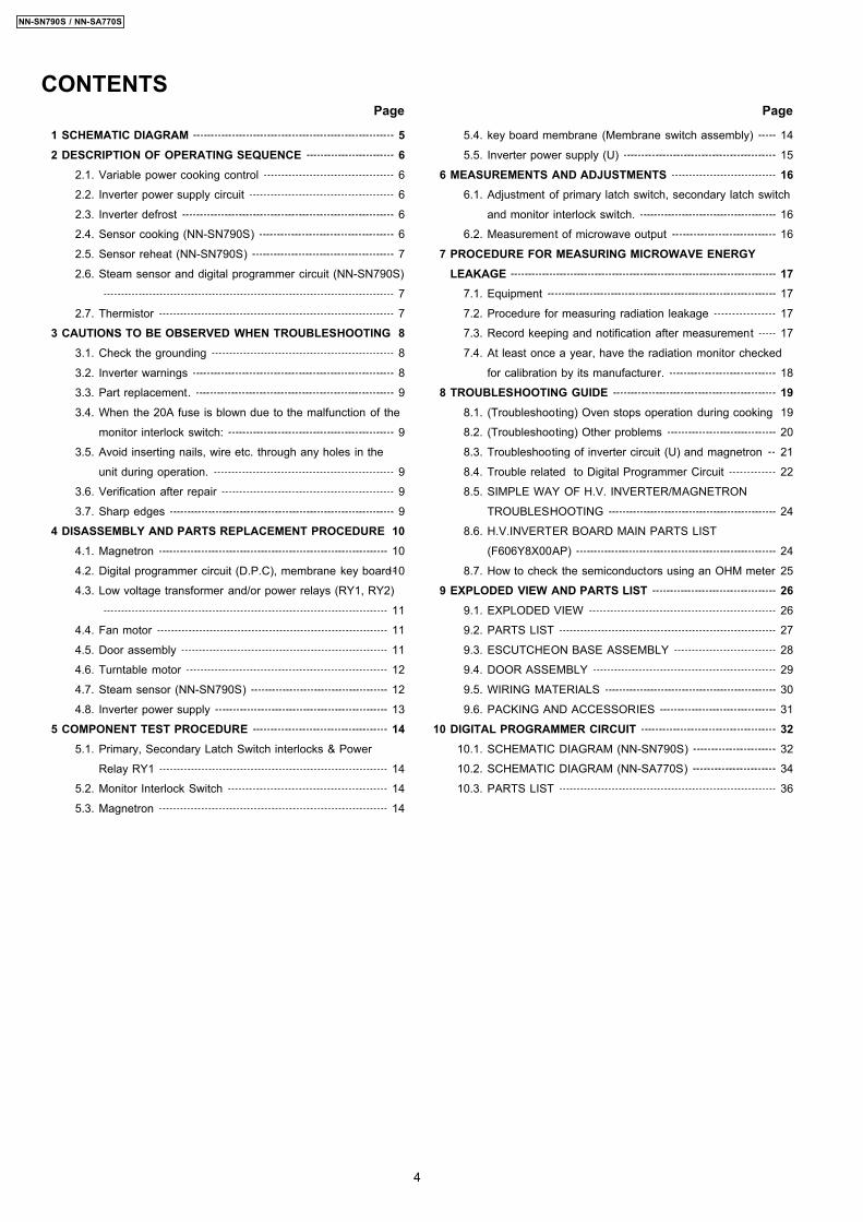
1 SCHEMATIC DIAGRAM 5 2 DESCRIPTION OF OPERATING SEQUENCE 6
2.1. Variable power cooking control 6
2.2. Inverter power supply circuit 6
2.3. Inverter defrost 6
2.4. Sensor cooking (NN-SN790S) 6
2.5. Sensor reheat (NN-SN790S) 7
2.6. Steam sensor and digital programmer circuit (NN-SN790S)
7
2.7. Thermistor 7
3 CAUTIONS TO BE OBSERVED WHEN TROUBLESHOOTING 8 3.1. Check the grounding 8
3.2. Inverter warnings 8
3.3. Part replacement. 9
3.4. When the 20A fuse is blown due to the malfunction of the
monitor interlock switch: 9
3.5. Avoid inserting nails, wire etc. through any holes in the
unit during operation. 9
3.6. Verification after repair 9
3.7. Sharp edges 9
4 DISASSEMBLY AND PARTS REPLACEMENT PROCEDURE 10 4.1. Magnetron 10
4.2. Digital programmer circuit (D.P.C), membrane key board 10
4.3. Low voltage transformer and/or power relays (RY1, RY2)
11
4.4. Fan motor 11
4.5. Door assembly 11
4.6. Turntable motor 12
4.7. Steam sensor (NN-SN790S) 12
4.8. Inverter power supply 13
5 COMPONENT TEST PROCEDURE 14 5.1. Primary, Secondary Latch Switch interlocks & Power
Relay RY1 14
5.2. Monitor Interlock Switch 14
5.3. Magnetron 14
5.4. key board membrane (Membrane switch assembly) 14
5.5. Inverter power supply (U) 15
6 MEASUREMENTS AND ADJUSTMENTS 16 6.1. Adjustment of primary latch switch, secondary latch switch
and monitor interlock switch. 16
6.2. Measurement of microwave output 16
7 PROCEDURE FOR MEASURING MICROWAVE ENERGYLEAKAGE 17 7.1. Equipment 17
7.2. Procedure for measuring radiation leakage 17
7.3. Record keeping and notification after measurement 17
7.4. At least once a year, have the radiation monitor checked
for calibration by its manufacturer. 18
8 TROUBLESHOOTING GUIDE 19 8.1. (Troubleshooting) Oven stops operation during cooking 19
8.2. (Troubleshooting) Other problems 20
8.3. Troubleshooting of inverter circuit (U) and magnetron 21
8.4. Trouble related to Digital Programmer Circuit 22
8.5. SIMPLE WAY OF H.V. INVERTER/MAGNETRON
TROUBLESHOOTING 24
8.6. H.V.INVERTER BOARD MAIN PARTS LIST
(F606Y8X00AP) 24
8.7. How to check the semiconductors using an OHM meter 25
9 EXPLODED VIEW AND PARTS LIST 26 9.1. EXPLODED VIEW 26
9.2. PARTS LIST 27
9.3. ESCUTCHEON BASE ASSEMBLY 28
9.4. DOOR ASSEMBLY 29
9.5. WIRING MATERIALS 30
9.6. PACKING AND ACCESSORIES 31
10 DIGITAL PROGRAMMER CIRCUIT 32 10.1. SCHEMATIC DIAGRAM (NN-SN790S) 32
10.2. SCHEMATIC DIAGRAM (NN-SA770S) 34
10.3. PARTS LIST 36
CONTENTS Page Page
4
NN-SN790S / NN-SA770S
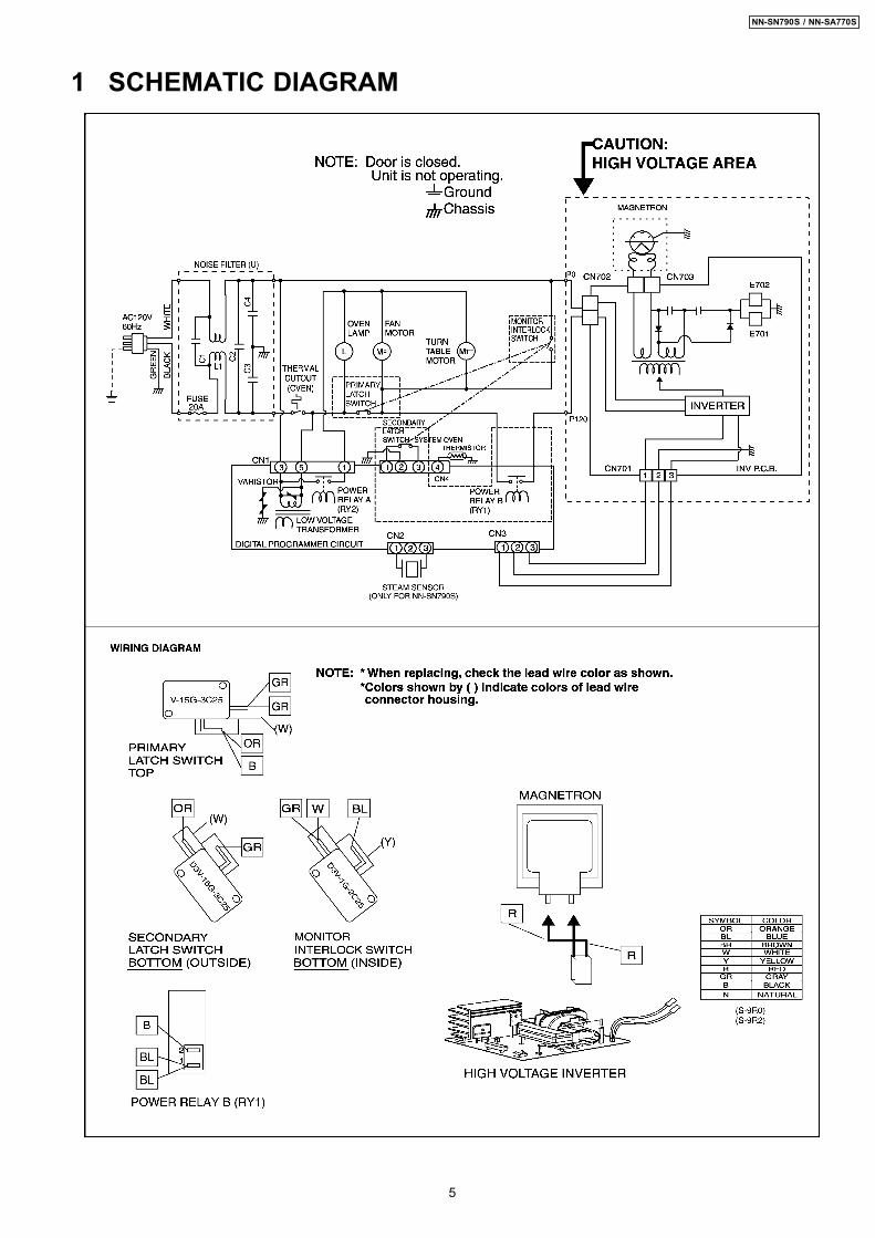
1 SCHEMATIC DIAGRAM
5
NN-SN790S / NN-SA770S
2.1. Variable power cookingcontrol
High Voltage Inverter Power Supply (U) controls output powerby the signal from Digital Programmer Circuit (DPC). Powerrelay always stay on, but PWM (Pulse Width Modulation) signalcontrols microwave output power.NOTE:
The ON/OFF time ratio does not correspond with thepercentage of microwave power since approximately 2seconds are required for heating of magnetronfilament.
Variable Power CookingPOWER SETTING OUTPUT
POWER(%)APPROX.
MANUAL MICROWAVEDUTY
ON(SEC) OFF(SEC)HIGH P10 100% 22 0
P9 90% 22 0P8 80% 22 0
MEDIUM-HIGH P7 70% 22 0MEDIUM P6 60% 22 0
P5 50% 22 0P4 40% 22 0
MEDIUM-LOW P3 30% 22 0P2 20% 15 7P1 10% 8 14
DEFROST P3 30% 22 0
2.2. Inverter power supply circuitThe Inverter Power Supply circuit powered from the linevoltage, 120V 60Hz AC input supplies 4,000V DC to themagnetron tube, and functions in place of the H.V. transformer,the H.V. capacitor and H.V. diode. 1. The AC input voltage 120V 60Hz is rectified to DC voltage
immediately. 2. DC voltage will be supplied to the switching devices called
IGBT. These devices are switched ON-OFF by the 20 to 40kHz PWM (pulse width modulation) signal from themicrocomputer in the DPC.
3. This drives the High voltage transformer to increase voltageup to 2,000V AC.
4. Then the half-wave doubler voltage rectifier circuit,consisting of the H.V. diodes and capacitors, generates thenecessary 4,000V DC needed for the magnetron.
5. Output power of the magnetron tube is always monitored bythe signal output from the current transformer built into theinverter circuit.
6. This signal is fed back to the microcomputer in the DPC todetermine operating conditions and output necessary tocontrol PWM signal to the Inverter Power Supply for controlof the output power.
2.3. Inverter defrostWhen the Auto Control feature is selected and the Start pad istapped: 1. The digital programer circuit determines the power level and
cooking time to complete cooking and indicates theoperating state in the display window. Table shows thecorresponding cooking times for respective serving bycategories.
Inverter Turbo DefrostSELECTED WEIGHT COOKING TIME
1.0 LB 5 min.35 sec.
2. When cooking time in the display window has elapsed, theoven turns off automatically by a control signal from thedigital programmer circuit.
2.4. Sensor cooking (NN-SN790S)Auto sensor cooking without setting a power level or selectinga time. All that is necessary is to select an Auto SensorProgram before starting to cook.Understanding Auto Sensor Cooking
As the food cooks, a certain amount of steam is produced.If the food is covered, this steam builds up and eventuallyescapes from the container. In Auto Sensor Cooking, acarefully designed instrument, called the steam sensorelement, senses this escape of steam. Then, based uponthe Auto Sensor Program selected, the unit willautomatically determine the correct power level and theproper length of time it will take to cook the food.
NOTE:Auto Sensor Cooking is successful with the foods andrecipes found in the Auto Sensor Cooking Guide.Because of the vast differences in food composition,items not mentioned in the Cooking Guide should beprepared in the microwave oven using power selectand time features. Please consult Variable PowerMicrowave Cookbook for procedures.
2 DESCRIPTION OF OPERATING SEQUENCE
6
NN-SN790S / NN-SA770S
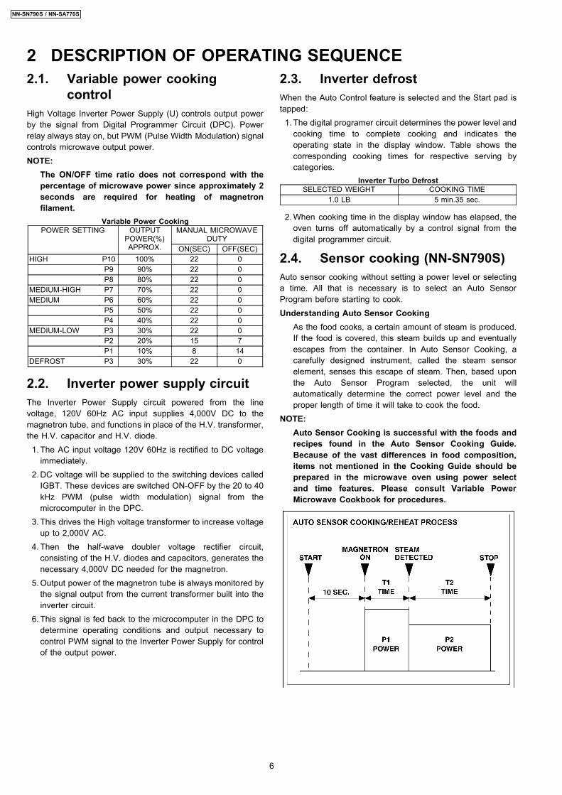
Explanation of the Auto Sensor Cooking process 1. During the first 10 second period there is no microwave
activity. When calculating the T2 time by using theformula below make sure this 10 seconds is subtractedfrom the T1 time. In other words, T1 time starts at theend of the 10 second period.
2. T1 time The total amount of time it takes the microwaveoven to switch to T2 time after the 10 second period.
3. T2 time When the steam escapes from the cookingcontainer placed in the oven, the steam sensor detectsit and the microprocessor calculates the balance ofcooking time. This T2 time is then shown in the displayand begins counting down.Balance of cooking time (T2 time)The balance of cooking time which is called T2 time,can be calculated by the following formula.T2 time (in sec.) = T1 time X K factor
NOTE:Remember, the T1 time starts after the 10 secondperiod. The coefficient K is programmed into themicroprocessor memory and they are listed in thefollowing tables along with the P1 and P2 powers.
NOTE:When "More" or "Less" pad is selected, the K factorvaries resulting in T2 time to be increased or decreased.
Example of calculating the T2 timeExample 1: If the T1 time is measured to be 2 minutes and40 seconds after the 10 second period, and the Autoprogram selected is Oatmeal:T2 = T1 × K= 2 min. and 40 sec. × 0.1= 160sec. × 0.1= 16 sec.
Category P1Power
P2Power
K FactorStandard
Omelet MEDIUM MEDIUM 0.2
2.5. Sensor reheat (NN-SN790S)Auto Sensor Reheat is a quick and easy way to reheatrefrigerated and room temperature foods.Simply press the reheat pad. There is no need to select powerlevel and cooking time.NOTE:
The Auto Sensor Reheat process is same as Auto SensorCooking process.
Category P1Power
P2Power
K FactorStandard
Sensor Reheat HIGH MEDIUM 0.4
2.6. Steam sensor and digitalprogrammer circuit (NN-SN790S)
In order to determine if the steam sensor function of the digitalprogrammer circuit is working, do the following test. 1. Place a water load (150 cc) in the oven. 2. Tap Sensor Reheat pad. 3. Tap Start pad. 4. Steam Sensor detects steam about 1.5 to 4 minutes after
the Start pad is tapped. 5. T1 time cooking automatically switches to remaining time
for cooking (T2). 6. The remaining cooking time (T2) appears in display
window. If the following cooking time appears, SteamSensor function is normal.
T1 TIME T2 TIME (Remainingcooking time)1 Min. 30 Sec. ~ 4 Min. 27 Sec. ~ 1Min.12 Sec.
2.7. ThermistorThe thermistor that is attached to the magnetron detects thetemperature of the magnetron and will stop magnetronoperation when overheating is detected. A normal thermistor´sresistance is 35KΩ to 110KΩ for an ambient temperature rangeof 10-30 degree C.
7
NN-SN790S / NN-SA770S
Unlike many other appliances, the microwave oven is a highvoltage, high current device. Though it is free from danger inordinary use, extreme care should be taken during repair.
CAUTIONServicemen should remove their watches and ringswhenever working close to or replacing the magnetron.
3.1. Check the groundingDo not operate on a two wire extension cord. The microwaveoven is designed to be grounded when used. It is imperative,therefore, to ensure the appliance is properly grounded beforebeginning repair work.
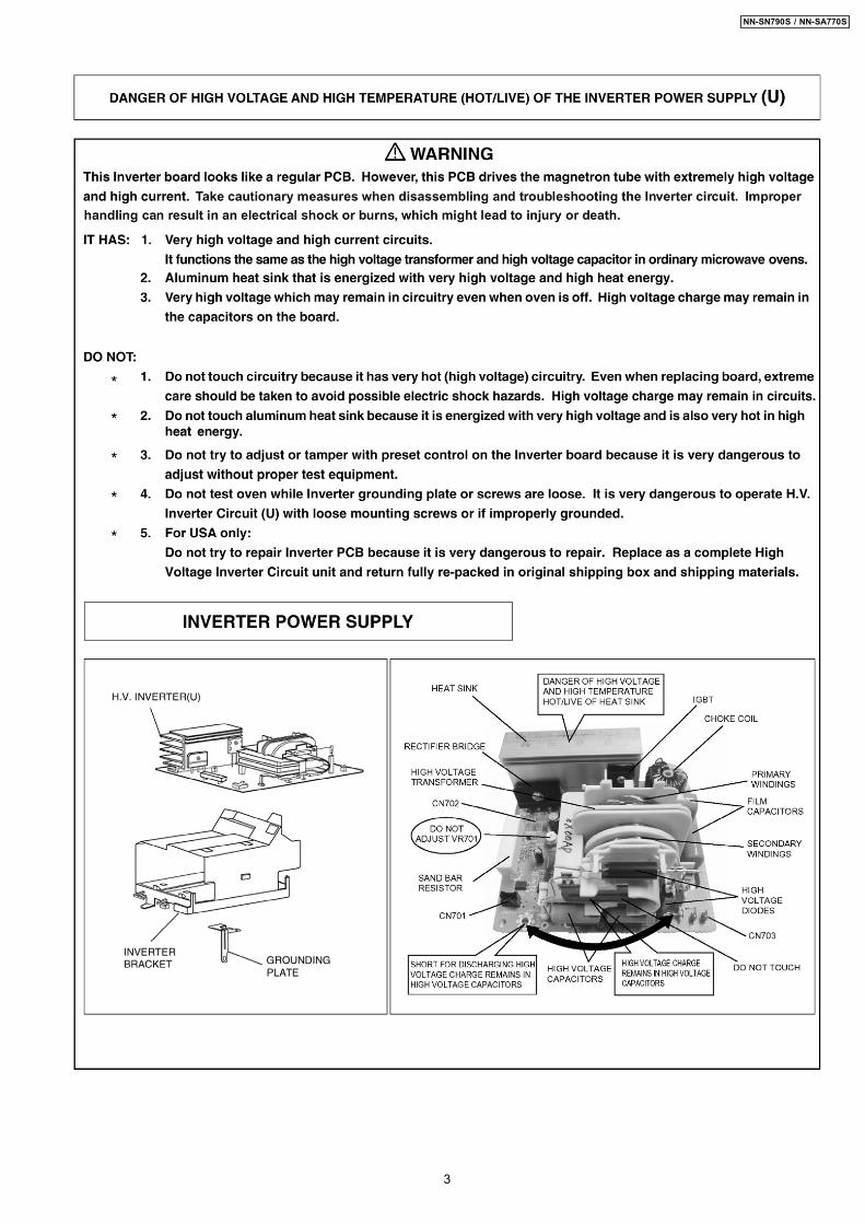
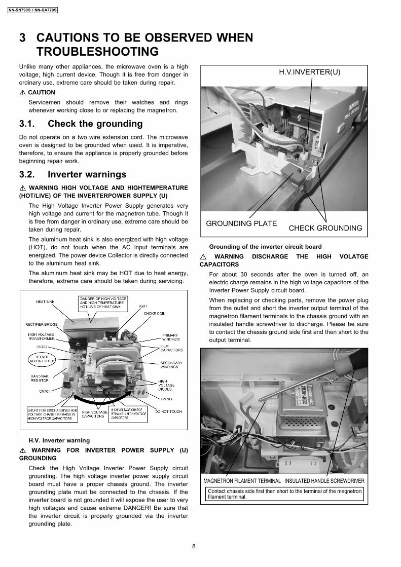
3.2. Inverter warningsWARNING HIGH VOLTAGE AND HIGHTEMPERATURE
(HOT/LIVE) OF THE INVERTERPOWER SUPPLY (U)The High Voltage Inverter Power Supply generates veryhigh voltage and current for the magnetron tube. Though itis free from danger in ordinary use, extreme care should betaken during repair.The aluminum heat sink is also energized with high voltage(HOT), do not touch when the AC input terminals areenergized. The power device Collector is directly connectedto the aluminum heat sink.The aluminum heat sink may be HOT due to heat energy,therefore, extreme care should be taken during servicing.
H.V. Inverter warningWARNING FOR INVERTER POWER SUPPLY (U)
GROUNDINGCheck the High Voltage Inverter Power Supply circuitgrounding. The high voltage inverter power supply circuitboard must have a proper chassis ground. The invertergrounding plate must be connected to the chassis. If theinverter board is not grounded it will expose the user to veryhigh voltages and cause extreme DANGER! Be sure thatthe inverter circuit is properly grounded via the invertergrounding plate.
Grounding of the inverter circuit boardWARNING DISCHARGE THE HIGH VOLATGE
CAPACITORSFor about 30 seconds after the oven is turned off, anelectric charge remains in the high voltage capacitors of theInverter Power Supply circuit board.When replacing or checking parts, remove the power plugfrom the outlet and short the inverter output terminal of themagnetron filament terminals to the chassis ground with aninsulated handle screwdriver to discharge. Please be sureto contact the chassis ground side first and then short to theoutput terminal.
3 CAUTIONS TO BE OBSERVED WHENTROUBLESHOOTING
8
NN-SN790S / NN-SA770S
Discharging the high voltage capacitorsWARNINGThere is high voltage present with high current capabilitiesin the circuits of the primary and secondary windings, chokecoil and heat sinkof the inverter. It is extremely dangerousto work on or near these circuits with the oven energized.DO NOT measure the voltage in the high voltage circuitincluding the filament voltage of the magnetron.WARNINGNever touch any circuit wiring with your hand or with aninsulated tool during operation.
3.3. Part replacement.When troubleshooting any part or component is to be replaced,always ensure that the power cord is unplugged from the walloutlet.
3.4. When the 20A fuse is blowndue to the malfunction of themonitor interlock switch:
WARNINGWhen the 20A 120V fuse is blown due to the malfunction ofthe monitor interlock switch, replace all of the components(primary latch switch, monitor interlock switch and powerrelay RY1). 1. This is mandatory. Refer to “measurements and
adjustments” for the location of these switches. 2. When replacing the fuse, confirm that it has the
appropriate rating for these models. 3. When replacing faulty switches, be sure the mounting
tabs are not bent, broken or deficient in their ability tohold the switches.
3.5. Avoid inserting nails, wire etc.through any holes in the unitduring operation.
Never insert a wire, nail or any other metal object through thelamp holes on the cavity or any holes or gaps, because suchobjects may work as an antenna and cause microwaveleakage.
3.6. Verification after repair 1. After repair or replacement of parts, make sure that the
screws of the oven, etc. are neither loosen or missing.Microwave energy might leak if screws are not properlytightened.
2. Make sure that all electrical connections are tight beforeinserting the plug into the wall outlet.
3. Check for microwave energy leakage. (Refer to procedurefor measuring microwave energy leakage).
CAUTION OF MICROWAVE RADIATION LEAKAGEUSE CAUTION NOT TO BECOME EXPOSED TORADIATION FROM THE MICROWAVE MAGNETRON OROTHER PARTS CONDUCTING MICROWAVE ENERGY.
IMPORTANT NOTICE 1. The following components have potentials above 2000V
while the appliance is operated. • Magnetron • High voltage transformer (Located on inverter (U)) • High voltage diodes (Located on inverter (U)) • High voltage capacitors (Located on inverter (U))Pay special attention to these areas.
2. When the appliance is operated with the door hinges ormagnetron installed incorrectly, the microwave leakagecan exceed more than 5mW/cm2. After repair orexchange, it is very important to check if the magnetronand the door hinges are correctly installed.
3.7. Sharp edgesCAUTIONPlease use caution when disassembling or reassemblinginternal parts. Some exposed edges may be sharp to thetouch and can cause injury if not handled with care.
9
NN-SN790S / NN-SA770S
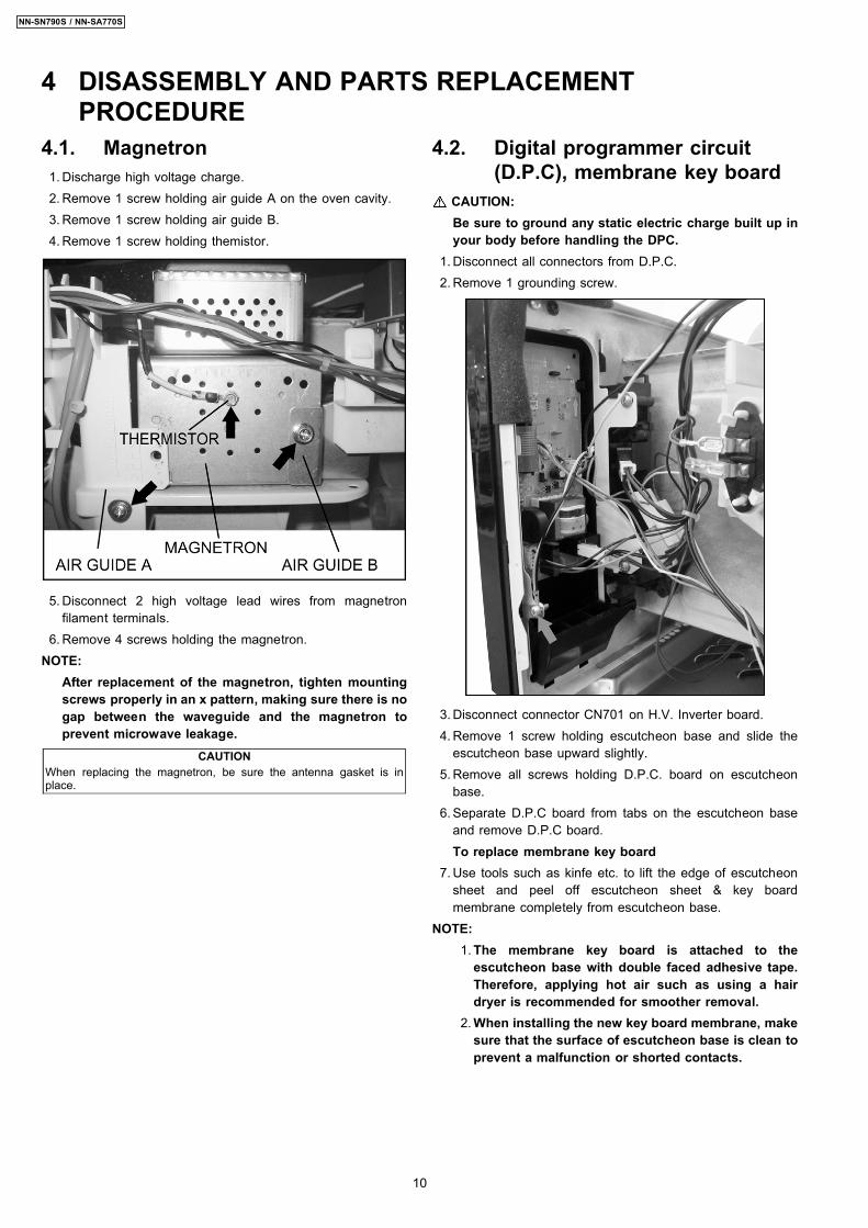
4.1. Magnetron 1. Discharge high voltage charge. 2. Remove 1 screw holding air guide A on the oven cavity. 3. Remove 1 screw holding air guide B. 4. Remove 1 screw holding themistor.
5. Disconnect 2 high voltage lead wires from magnetronfilament terminals.
6. Remove 4 screws holding the magnetron.NOTE:
After replacement of the magnetron, tighten mountingscrews properly in an x pattern, making sure there is nogap between the waveguide and the magnetron toprevent microwave leakage.
CAUTIONWhen replacing the magnetron, be sure the antenna gasket is inplace.
4.2. Digital programmer circuit(D.P.C), membrane key board
CAUTION:Be sure to ground any static electric charge built up inyour body before handling the DPC.
1. Disconnect all connectors from D.P.C. 2. Remove 1 grounding screw.
3. Disconnect connector CN701 on H.V. Inverter board. 4. Remove 1 screw holding escutcheon base and slide the
escutcheon base upward slightly. 5. Remove all screws holding D.P.C. board on escutcheon
base. 6. Separate D.P.C board from tabs on the escutcheon base
and remove D.P.C board.To replace membrane key board
7. Use tools such as kinfe etc. to lift the edge of escutcheonsheet and peel off escutcheon sheet & key boardmembrane completely from escutcheon base.
NOTE: 1. The membrane key board is attached to the
escutcheon base with double faced adhesive tape.Therefore, applying hot air such as using a hairdryer is recommended for smoother removal.
2. When installing the new key board membrane, makesure that the surface of escutcheon base is clean toprevent a malfunction or shorted contacts.
4 DISASSEMBLY AND PARTS REPLACEMENTPROCEDURE
10
NN-SN790S / NN-SA770S
4.3. Low voltage transformerand/or power relays (RY1,RY2)
CAUTION:Be sure to ground any static electric charge built up inyour body before handling the DPC.
1. Replace D.P.C. board.(A) Using solder wick or a desoldering tool and 30Wsoldering iron carefully remove all solder from the terminalpins of the low voltage transformer and/or power relays.
CAUTION:Do not use a soldering iron or desoldering tool ofmore than 30 watts on D.P.C. contacts.
(B) With all the terminal pins cleaned and separated fromD.P.C. contacts, remove the defective transformer/powerrelays, Replace components making sure all terminal pinsare inserted completely resolder all terminal contactscarefully.
4.4. Fan motor 1. Disconnect 2 lead wires from fan motor terminals. 2. Remove 2 screws at location on oven attaching orifice
assembly. 3. Remove orifice assembly from oven assembly. 4. Remove fan blade from the fan motor shaft by pulling it
straight out. 5. Remove 2 screws holding fan motor to orifice.
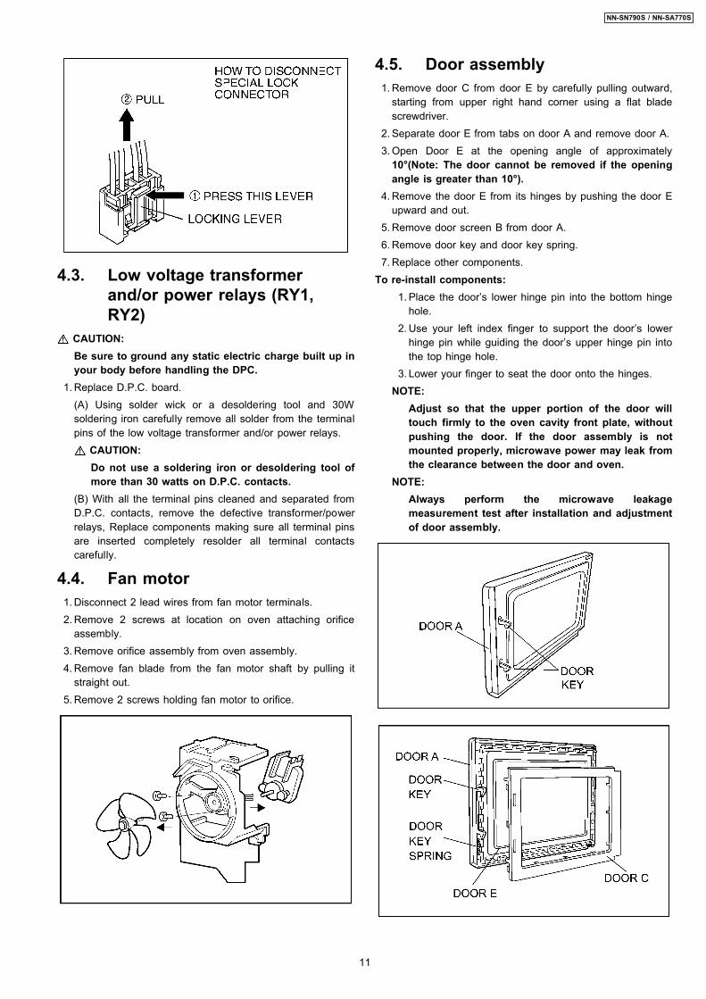
4.5. Door assembly 1. Remove door C from door E by carefully pulling outward,
starting from upper right hand corner using a flat bladescrewdriver.
2. Separate door E from tabs on door A and remove door A. 3. Open Door E at the opening angle of approximately
10°(Note: The door cannot be removed if the openingangle is greater than 10°).
4. Remove the door E from its hinges by pushing the door Eupward and out.
5. Remove door screen B from door A. 6. Remove door key and door key spring. 7. Replace other components.To re-install components:
1. Place the door’s lower hinge pin into the bottom hingehole.
2. Use your left index finger to support the door’s lowerhinge pin while guiding the door’s upper hinge pin intothe top hinge hole.
3. Lower your finger to seat the door onto the hinges.NOTE:
Adjust so that the upper portion of the door willtouch firmly to the oven cavity front plate, withoutpushing the door. If the door assembly is notmounted properly, microwave power may leak fromthe clearance between the door and oven.
NOTE:Always perform the microwave leakagemeasurement test after installation and adjustmentof door assembly.
11
NN-SN790S / NN-SA770S
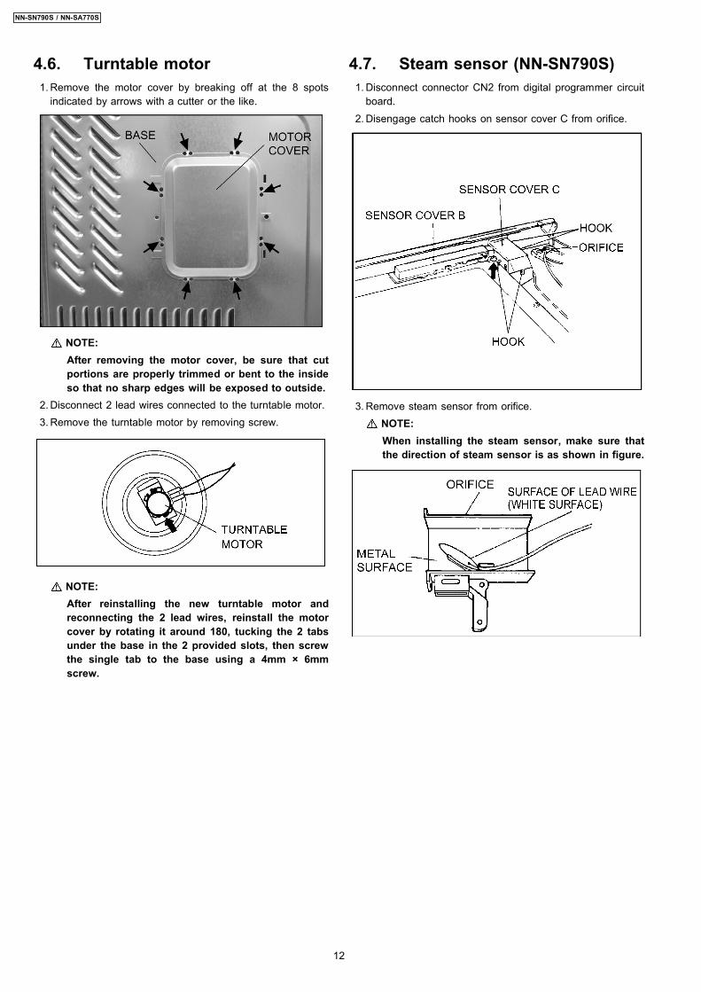
4.6. Turntable motor 1. Remove the motor cover by breaking off at the 8 spots
indicated by arrows with a cutter or the like.
NOTE:After removing the motor cover, be sure that cutportions are properly trimmed or bent to the insideso that no sharp edges will be exposed to outside.
2. Disconnect 2 lead wires connected to the turntable motor. 3. Remove the turntable motor by removing screw.
NOTE:After reinstalling the new turntable motor andreconnecting the 2 lead wires, reinstall the motorcover by rotating it around 180, tucking the 2 tabsunder the base in the 2 provided slots, then screwthe single tab to the base using a 4mm × 6mmscrew.
4.7. Steam sensor (NN-SN790S) 1. Disconnect connector CN2 from digital programmer circuit
board. 2. Disengage catch hooks on sensor cover C from orifice.
3. Remove steam sensor from orifice.NOTE:When installing the steam sensor, make sure thatthe direction of steam sensor is as shown in figure.
12
NN-SN790S / NN-SA770S
4.8. Inverter power supplyCAUTIONS
1. Always leave the grounding plate in place.2. Always securely tighten the ground screw through the bottom of thechassis (base).3. Securely connect 3 lead wire connectors.4. Make sure the heat sink has enough space (gap) from the oven.Take special care not to dress any lead wire over the aluminum heatsink because it is hot.
1. Discharge high voltage charge. 2. Remove the H.V.lead wire from magnetron terminals. 3. Disconnect 2 connectors from CN701 & CN702 on
H.V.Inverter(U). 4. Remove 1 screw holding grounding plate to the base.
5. Bend back 1 locking metal tabs on the base.
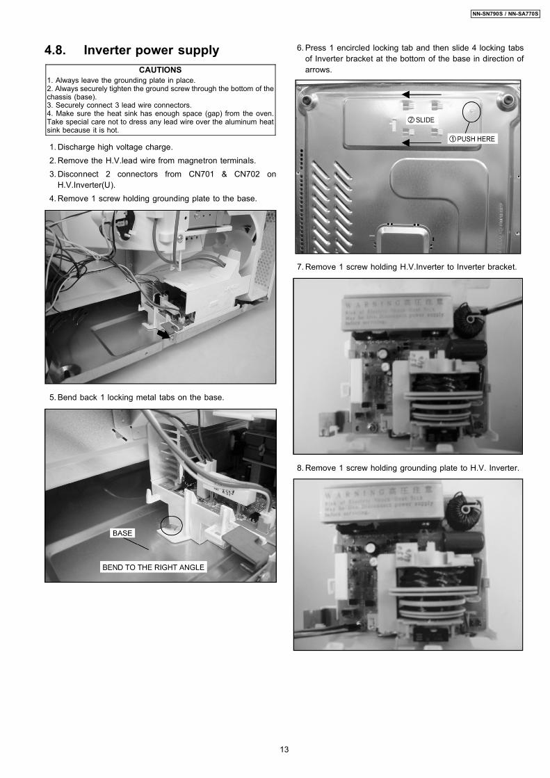
6. Press 1 encircled locking tab and then slide 4 locking tabsof Inverter bracket at the bottom of the base in direction ofarrows.
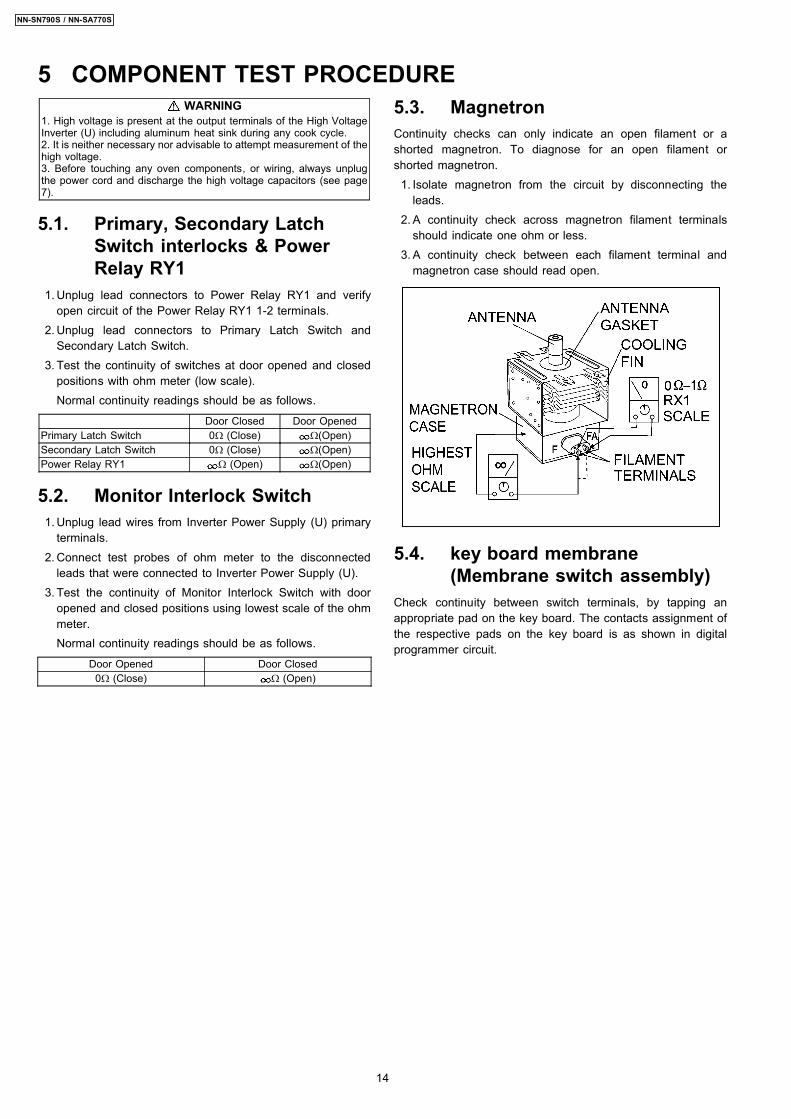
7. Remove 1 screw holding H.V.Inverter to Inverter bracket.
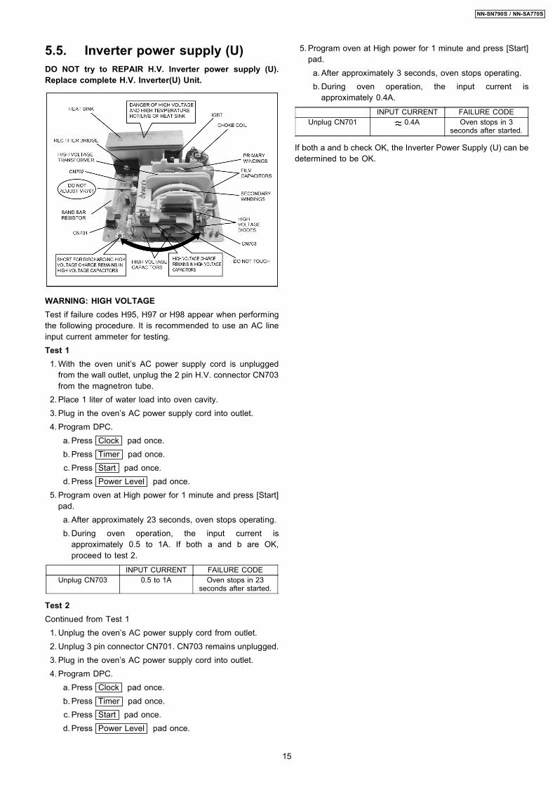
8. Remove 1 screw holding grounding plate to H.V. Inverter.
13
NN-SN790S / NN-SA770S
WARNING1. High voltage is present at the output terminals of the High VoltageInverter (U) including aluminum heat sink during any cook cycle.2. It is neither necessary nor advisable to attempt measurement of thehigh voltage.3. Before touching any oven components, or wiring, always unplugthe power cord and discharge the high voltage capacitors (see page7).
5.1. Primary, Secondary LatchSwitch interlocks & PowerRelay RY1
1. Unplug lead connectors to Power Relay RY1 and verifyopen circuit of the Power Relay RY1 1-2 terminals.
2. Unplug lead connectors to Primary Latch Switch andSecondary Latch Switch.
3. Test the continuity of switches at door opened and closedpositions with ohm meter (low scale).Normal continuity readings should be as follows.
Door Closed Door OpenedPrimary Latch Switch 0Ω (Close) Ω(Open)Secondary Latch Switch 0Ω (Close) Ω(Open)Power Relay RY1 Ω (Open) Ω(Open)
5.2. Monitor Interlock Switch 1. Unplug lead wires from Inverter Power Supply (U) primary
terminals. 2. Connect test probes of ohm meter to the disconnected
leads that were connected to Inverter Power Supply (U). 3. Test the continuity of Monitor Interlock Switch with door
opened and closed positions using lowest scale of the ohmmeter.Normal continuity readings should be as follows.
Door Opened Door Closed0Ω (Close) Ω (Open)
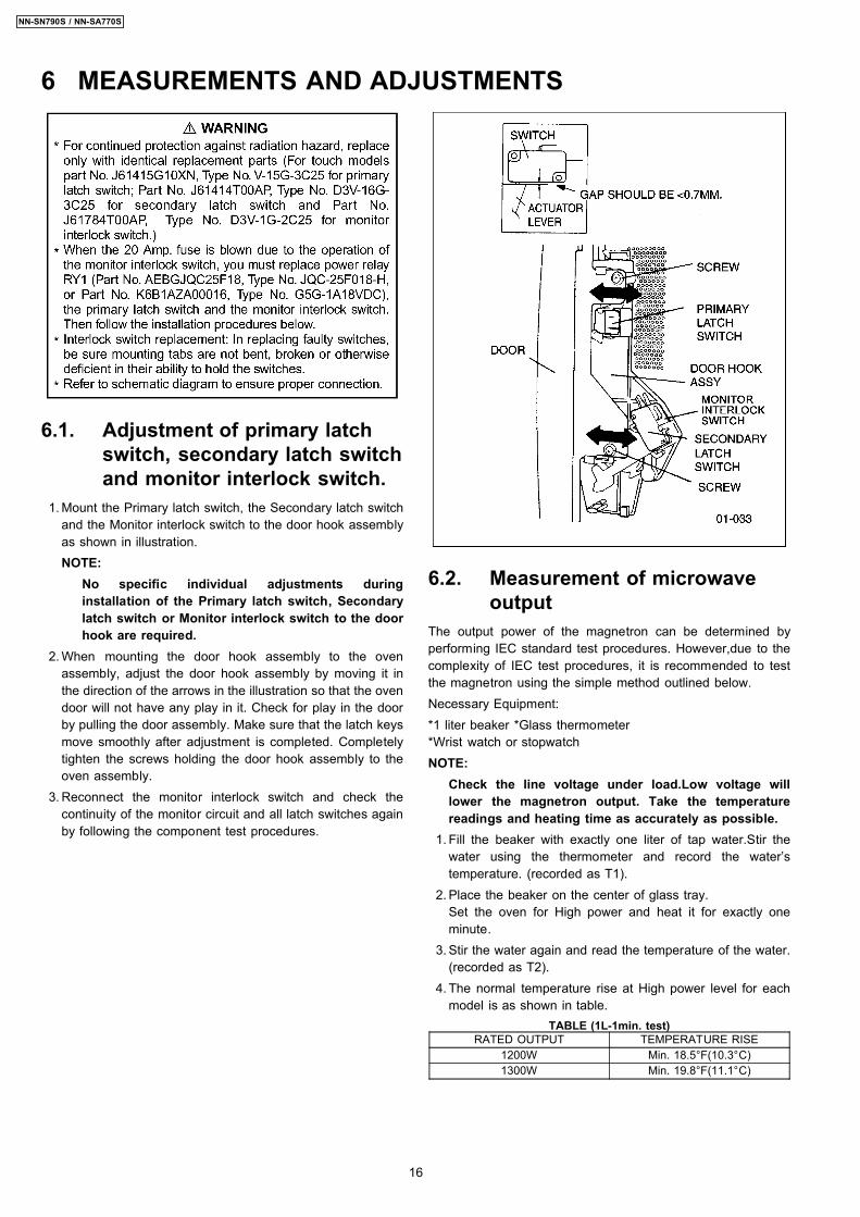
5.3. MagnetronContinuity checks can only indicate an open filament or ashorted magnetron. To diagnose for an open filament orshorted magnetron. 1. Isolate magnetron from the circuit by disconnecting the
leads. 2. A continuity check across magnetron filament terminals
should indicate one ohm or less. 3. A continuity check between each filament terminal and
magnetron case should read open.
5.4. key board membrane(Membrane switch assembly)
Check continuity between switch terminals, by tapping anappropriate pad on the key board. The contacts assignment ofthe respective pads on the key board is as shown in digitalprogrammer circuit.
5 COMPONENT TEST PROCEDURE
14
NN-SN790S / NN-SA770S
5.5. Inverter power supply (U)DO NOT try to REPAIR H.V. Inverter power supply (U).Replace complete H.V. Inverter(U) Unit.
WARNING: HIGH VOLTAGETest if failure codes H95, H97 or H98 appear when performingthe following procedure. It is recommended to use an AC lineinput current ammeter for testing.Test 1 1. With the oven unit’s AC power supply cord is unplugged
from the wall outlet, unplug the 2 pin H.V. connector CN703from the magnetron tube.
2. Place 1 liter of water load into oven cavity. 3. Plug in the oven’s AC power supply cord into outlet. 4. Program DPC.
a. Press Clock pad once. b. Press Timer pad once. c. Press Start pad once. d. Press Power Level pad once.
5. Program oven at High power for 1 minute and press [Start]pad. a. After approximately 23 seconds, oven stops operating. b. During oven operation, the input current is
approximately 0.5 to 1A. If both a and b are OK,proceed to test 2.
INPUT CURRENT FAILURE CODEUnplug CN703 0.5 to 1A Oven stops in 23
seconds after started.
Test 2Continued from Test 1 1. Unplug the oven’s AC power supply cord from outlet. 2. Unplug 3 pin connector CN701. CN703 remains unplugged. 3. Plug in the oven’s AC power supply cord into outlet. 4. Program DPC.
a. Press Clock pad once. b. Press Timer pad once. c. Press Start pad once. d. Press Power Level pad once.
5. Program oven at High power for 1 minute and press [Start]pad. a. After approximately 3 seconds, oven stops operating. b. During oven operation, the input current is
approximately 0.4A.
INPUT CURRENT FAILURE CODEUnplug CN701 0.4A Oven stops in 3
seconds after started.
If both a and b check OK, the Inverter Power Supply (U) can bedetermined to be OK.
15
NN-SN790S / NN-SA770S
6.1. Adjustment of primary latchswitch, secondary latch switchand monitor interlock switch.
1. Mount the Primary latch switch, the Secondary latch switchand the Monitor interlock switch to the door hook assemblyas shown in illustration.NOTE:
No specific individual adjustments duringinstallation of the Primary latch switch, Secondarylatch switch or Monitor interlock switch to the doorhook are required.
2. When mounting the door hook assembly to the ovenassembly, adjust the door hook assembly by moving it inthe direction of the arrows in the illustration so that the ovendoor will not have any play in it. Check for play in the doorby pulling the door assembly. Make sure that the latch keysmove smoothly after adjustment is completed. Completelytighten the screws holding the door hook assembly to theoven assembly.
3. Reconnect the monitor interlock switch and check thecontinuity of the monitor circuit and all latch switches againby following the component test procedures.
6.2. Measurement of microwaveoutput
The output power of the magnetron can be determined byperforming IEC standard test procedures. However,due to thecomplexity of IEC test procedures, it is recommended to testthe magnetron using the simple method outlined below.Necessary Equipment:*1 liter beaker *Glass thermometer*Wrist watch or stopwatchNOTE:
Check the line voltage under load.Low voltage willlower the magnetron output. Take the temperaturereadings and heating time as accurately as possible.
1. Fill the beaker with exactly one liter of tap water.Stir thewater using the thermometer and record the water’stemperature. (recorded as T1).
2. Place the beaker on the center of glass tray.Set the oven for High power and heat it for exactly oneminute.
3. Stir the water again and read the temperature of the water.(recorded as T2).
4. The normal temperature rise at High power level for eachmodel is as shown in table.
TABLE (1L-1min. test)RATED OUTPUT TEMPERATURE RISE
1200W Min. 18.5°F(10.3°C)1300W Min. 19.8°F(11.1°C)
6 MEASUREMENTS AND ADJUSTMENTS
16
NN-SN790S / NN-SA770S
NOTE:The U.S. Government standard is 5 mW/cm2 while in thecustomer’s home. 2mW/cm2 stated here is our ownvoluntary standard. (1mW/cm2 for Canada)
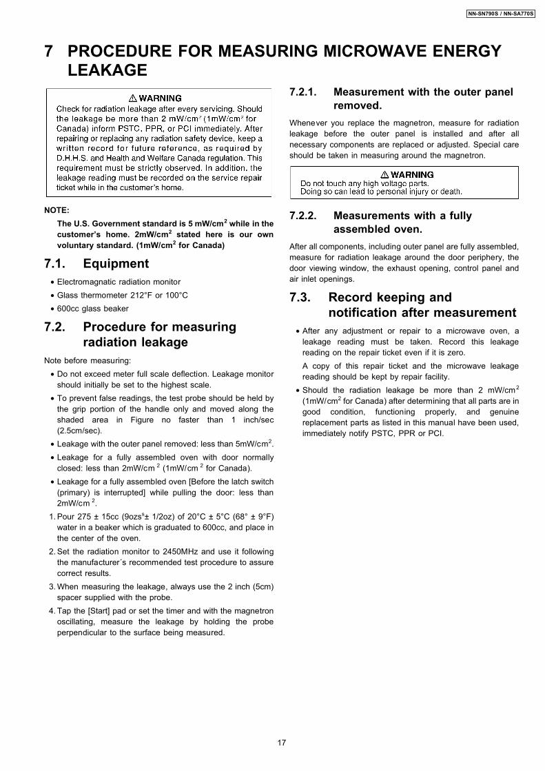
7.1. Equipment • Electromagnatic radiation monitor • Glass thermometer 212°F or 100°C • 600cc glass beaker
7.2. Procedure for measuringradiation leakage
Note before measuring: • Do not exceed meter full scale deflection. Leakage monitor
should initially be set to the highest scale. • To prevent false readings, the test probe should be held by
the grip portion of the handle only and moved along theshaded area in Figure no faster than 1 inch/sec(2.5cm/sec).
• Leakage with the outer panel removed: less than 5mW/cm2. • Leakage for a fully assembled oven with door normally
closed: less than 2mW/cm 2 (1mW/cm 2 for Canada). • Leakage for a fully assembled oven [Before the latch switch
(primary) is interrupted] while pulling the door: less than2mW/cm 2.
1. Pour 275 ± 15cc (9ozss± 1/2oz) of 20°C ± 5°C (68° ± 9°F)water in a beaker which is graduated to 600cc, and place inthe center of the oven.
2. Set the radiation monitor to 2450MHz and use it followingthe manufacturer´s recommended test procedure to assurecorrect results.
3. When measuring the leakage, always use the 2 inch (5cm)spacer supplied with the probe.
4. Tap the [Start] pad or set the timer and with the magnetronoscillating, measure the leakage by holding the probeperpendicular to the surface being measured.
7.2.1. Measurement with the outer panelremoved.
Whenever you replace the magnetron, measure for radiationleakage before the outer panel is installed and after allnecessary components are replaced or adjusted. Special careshould be taken in measuring around the magnetron.
7.2.2. Measurements with a fullyassembled oven.
After all components, including outer panel are fully assembled,measure for radiation leakage around the door periphery, thedoor viewing window, the exhaust opening, control panel andair inlet openings.
7.3. Record keeping andnotification after measurement
• After any adjustment or repair to a microwave oven, aleakage reading must be taken. Record this leakagereading on the repair ticket even if it is zero.A copy of this repair ticket and the microwave leakagereading should be kept by repair facility.
• Should the radiation leakage be more than 2 mW/cm2
(1mW/cm2 for Canada) after determining that all parts are ingood condition, functioning properly, and genuinereplacement parts as listed in this manual have been used,immediately notify PSTC, PPR or PCI.
7 PROCEDURE FOR MEASURING MICROWAVE ENERGYLEAKAGE
17
NN-SN790S / NN-SA770S
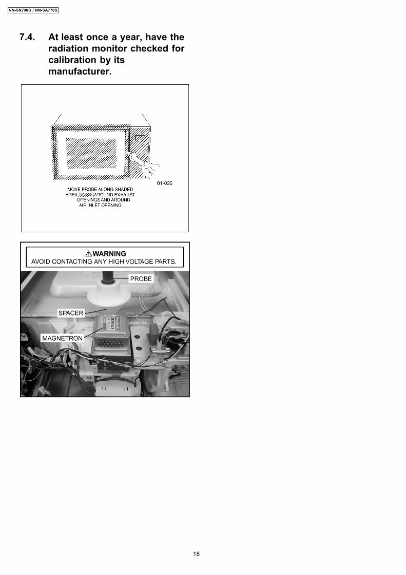
7.4. At least once a year, have theradiation monitor checked forcalibration by itsmanufacturer.
18
NN-SN790S / NN-SA770S
8 TROUBLESHOOTING GUIDEDANGER: HIGH VOLTAGES
1. DO NOT RE-ADJUST PRESET CONTROL on the H.V.Inverter (U). It is very dangerous to repair or adjust without proper test equipmentbecause this circuit generates very large current and high voltage. Operating a misaligned inverter circuit is dangerous.
2. Ensure proper grounding before troubleshooting.3. Be careful of the high voltage circuitry, taking necessary precautions when troubleshooting.4. Discharge high voltage remaining in the H.V.Inverter (U).5. When checking the continuity of the switches or the H.V.Inverter, disconnect one lead wire from these parts and then check continuity with the
AC plug removed. Doing otherwise may result in a false reading or damage to your meter. When disconnecting a plastic connector from aterminal, you must hold the plastic connector instead of the lead wire and then disconnect it, otherwise lead wire may be damaged or theconnector cannot be removed.
6. Do not touch any parts of the circuitry on the digital programmer circuit, since static electric discharge may damage this control panel. Alwaystouch ground while working on this panel to discharge any static charge in your body.
7. 120V AC is present on the digital programmer circuit (Terminals of power relay’s and primary circuit of Digital Programmer Circuit). Whentroubleshooting, be cautious of possible electrical shock hazard.
Before troubleshooting, operate the microwave oven following the correct operating procedures in the instruction manual in orderto find the exact cause of any trouble, since operator error may be mistaken for the oven’s malfunction.
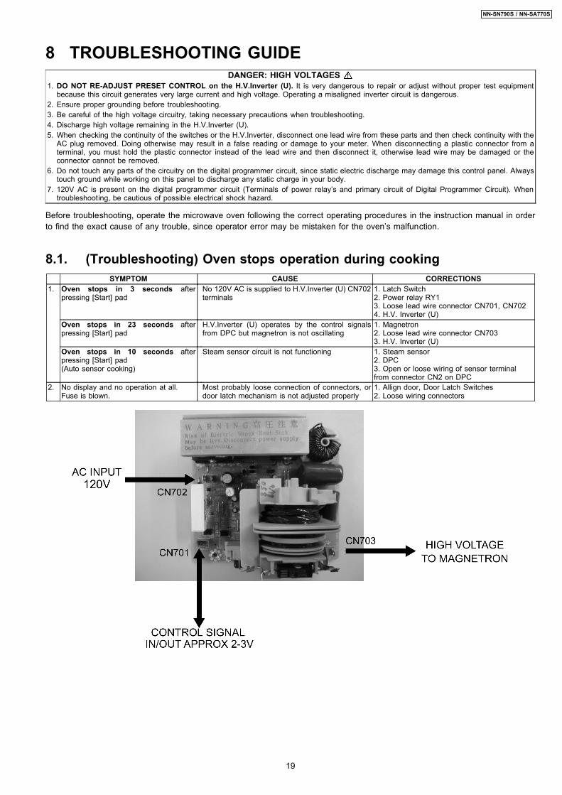
8.1. (Troubleshooting) Oven stops operation during cookingSYMPTOM CAUSE CORRECTIONS
1. Oven stops in 3 seconds afterpressing [Start] pad
No 120V AC is supplied to H.V.Inverter (U) CN702terminals
1. Latch Switch2. Power relay RY13. Loose lead wire connector CN701, CN7024. H.V. Inverter (U)
Oven stops in 23 seconds afterpressing [Start] pad
H.V.Inverter (U) operates by the control signalsfrom DPC but magnetron is not oscillating
1. Magnetron2. Loose lead wire connector CN7033. H.V. Inverter (U)
Oven stops in 10 seconds afterpressing [Start] pad(Auto sensor cooking)
Steam sensor circuit is not functioning 1. Steam sensor2. DPC3. Open or loose wiring of sensor terminalfrom connector CN2 on DPC
2. No display and no operation at all.Fuse is blown.
Most probably loose connection of connectors, ordoor latch mechanism is not adjusted properly
1. Allign door, Door Latch Switches2. Loose wiring connectors
19
NN-SN790S / NN-SA770S
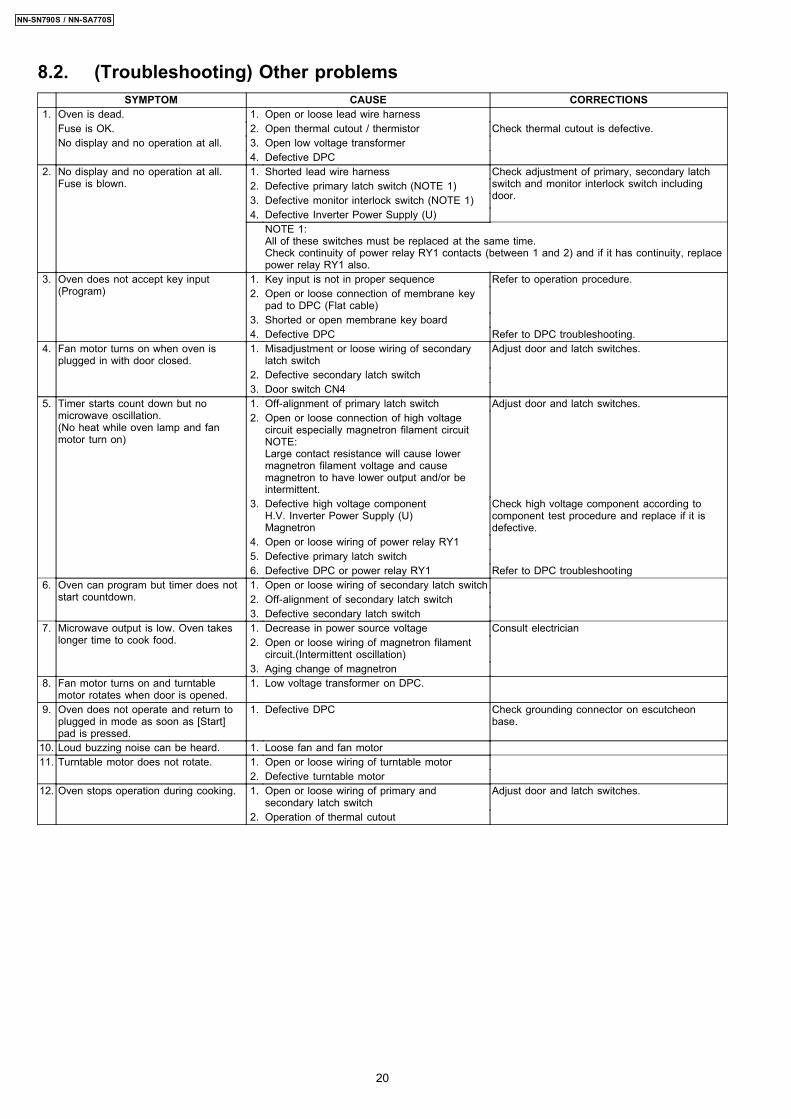
8.2. (Troubleshooting) Other problemsSYMPTOM CAUSE CORRECTIONS
1. Oven is dead. 1. Open or loose lead wire harnessFuse is OK. 2. Open thermal cutout / thermistor Check thermal cutout is defective.No display and no operation at all. 3. Open low voltage transformer
4. Defective DPC2. No display and no operation at all.
Fuse is blown.1. Shorted lead wire harness Check adjustment of primary, secondary latch
switch and monitor interlock switch includingdoor.
2. Defective primary latch switch (NOTE 1)3. Defective monitor interlock switch (NOTE 1)4. Defective Inverter Power Supply (U)
NOTE 1:All of these switches must be replaced at the same time.Check continuity of power relay RY1 contacts (between 1 and 2) and if it has continuity, replacepower relay RY1 also.
3. Oven does not accept key input(Program)
1. Key input is not in proper sequence Refer to operation procedure.2. Open or loose connection of membrane key
pad to DPC (Flat cable)3. Shorted or open membrane key board4. Defective DPC Refer to DPC troubleshooting.
4. Fan motor turns on when oven isplugged in with door closed.
1. Misadjustment or loose wiring of secondarylatch switch
Adjust door and latch switches.
2. Defective secondary latch switch3. Door switch CN4
5. Timer starts count down but nomicrowave oscillation.(No heat while oven lamp and fanmotor turn on)
1. Off-alignment of primary latch switch Adjust door and latch switches.2. Open or loose connection of high voltage
circuit especially magnetron filament circuitNOTE:Large contact resistance will cause lowermagnetron filament voltage and causemagnetron to have lower output and/or beintermittent.
3. Defective high voltage componentH.V. Inverter Power Supply (U)Magnetron
Check high voltage component according tocomponent test procedure and replace if it isdefective.
4. Open or loose wiring of power relay RY15. Defective primary latch switch6. Defective DPC or power relay RY1 Refer to DPC troubleshooting
6. Oven can program but timer does notstart countdown.
1. Open or loose wiring of secondary latch switch2. Off-alignment of secondary latch switch3. Defective secondary latch switch
7. Microwave output is low. Oven takeslonger time to cook food.
1. Decrease in power source voltage Consult electrician2. Open or loose wiring of magnetron filament
circuit.(Intermittent oscillation)3. Aging change of magnetron
8. Fan motor turns on and turntablemotor rotates when door is opened.
1. Low voltage transformer on DPC.
9. Oven does not operate and return toplugged in mode as soon as [Start]pad is pressed.
1. Defective DPC Check grounding connector on escutcheonbase.
10. Loud buzzing noise can be heard. 1. Loose fan and fan motor11. Turntable motor does not rotate. 1. Open or loose wiring of turntable motor
2. Defective turntable motor12. Oven stops operation during cooking. 1. Open or loose wiring of primary and
secondary latch switchAdjust door and latch switches.
2. Operation of thermal cutout
20
NN-SN790S / NN-SA770S
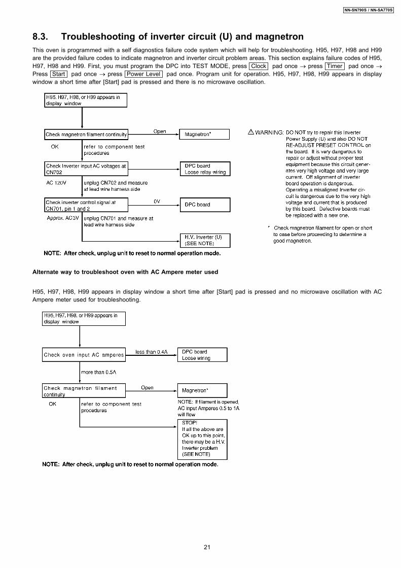
8.3. Troubleshooting of inverter circuit (U) and magnetronThis oven is programmed with a self diagnostics failure code system which will help for troubleshooting. H95, H97, H98 and H99are the provided failure codes to indicate magnetron and inverter circuit problem areas. This section explains failure codes of H95,H97, H98 and H99. First, you must program the DPC into TEST MODE, press Clock pad once → press Timer pad once →
Press Start pad once → press Power Level pad once. Program unit for operation. H95, H97, H98, H99 appears in displaywindow a short time after [Start] pad is pressed and there is no microwave oscillation.
Alternate way to troubleshoot oven with AC Ampere meter used
H95, H97, H98, H99 appears in display window a short time after [Start] pad is pressed and no microwave oscillation with ACAmpere meter used for troubleshooting.
21
NN-SN790S / NN-SA770S
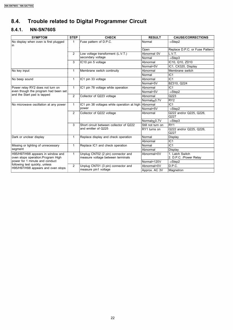
8.4. Trouble related to Digital Programmer Circuit8.4.1. NN-SN760S
SYMPTOM STEP CHECK RESULT CAUSE/CORRECTIONSNo display when oven is first pluggedin
1 Fuse pattern of D.P.C. Normal →Step2
Open Replace D.P.C. or Fuse Pattern2 Low voltage transforment (L.V.T.)
secondary voltageAbnormal 0V L.V.T.Normal →Step3
3 IC10 pin 5 voltage Abnormal IC10, Q10, ZD10Normal=5V IC1, CX320, Display
No key input 1 Membrane switch continuity Abnormal Membrane switchNormal IC1
No beep sound 1 IC1 pin 33 voltage Abnormal IC1Normal=5V BZ310, Q224
Power relay RY2 does not turn oneven though the program had been setand the Start pad is tapped
1 IC1 pin 78 voltage while operation Abnormal IC1Normal=5V →Step2
2 Collector of Q223 voltage Abnormal Q223Normal 0.7V RY2
No microwave oscillation at any power 1 IC1 pin 38 voltages while operation at highpower
Abnormal IC1Normal=5V →Step2
2 Collector of Q222 voltage Abnormal Q222 and/or Q225, Q226,Q227
Normal 0.7V →Step33 Short circuit between collector of Q222
and emitter of Q225Still not turn on RY1RY1 turns on Q222 and/or Q225, Q226,
Q227Dark or unclear display 1 Replace display and check operation Normal Display
Abnormal IC1Missing or lighting of unnecessarysegment
1 Replace IC1 and check operation Normal IC1Abnormal Display
H95/H97/H98 appears in window andoven stops operation.Program Highpower for 1 minute and conductfollowing test quickly, unlessH95/H97/H98 appears and oven stops
1 Unplug CN702 (2 pin) connector andmeasure voltage between terminals
Abnormal=0V 1. Latch Switch2. D.P.C. /Power Relay
Normal=120V →Step22 Unplug CN701 (3 pin) connector and
measure pin1 voltageAbnormal=0V D.P.C.Approx. AC 3V Magnetron
22
NN-SN790S / NN-SA770S
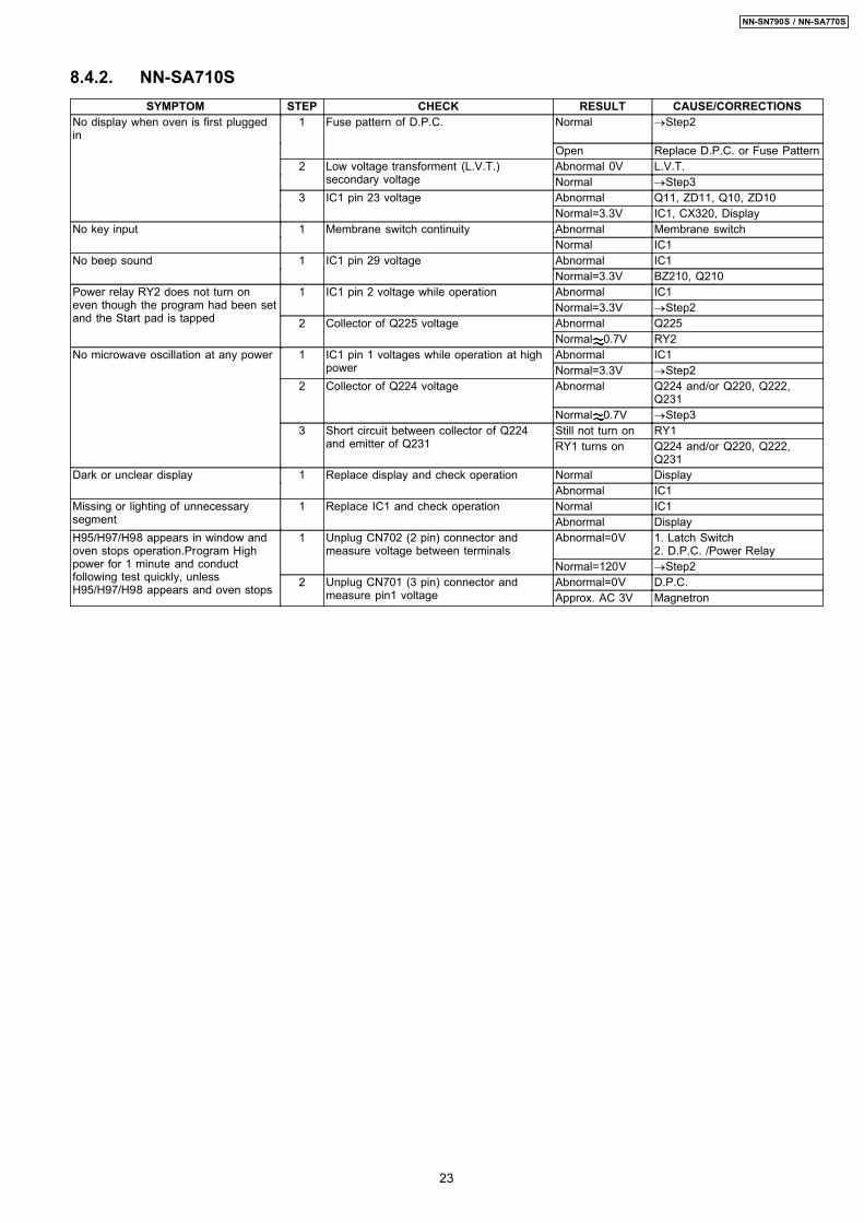
8.4.2. NN-SA710SSYMPTOM STEP CHECK RESULT CAUSE/CORRECTIONS
No display when oven is first pluggedin
1 Fuse pattern of D.P.C. Normal →Step2
Open Replace D.P.C. or Fuse Pattern2 Low voltage transforment (L.V.T.)
secondary voltageAbnormal 0V L.V.T.Normal →Step3
3 IC1 pin 23 voltage Abnormal Q11, ZD11, Q10, ZD10Normal=3.3V IC1, CX320, Display
No key input 1 Membrane switch continuity Abnormal Membrane switchNormal IC1
No beep sound 1 IC1 pin 29 voltage Abnormal IC1Normal=3.3V BZ210, Q210
Power relay RY2 does not turn oneven though the program had been setand the Start pad is tapped
1 IC1 pin 2 voltage while operation Abnormal IC1Normal=3.3V →Step2
2 Collector of Q225 voltage Abnormal Q225Normal 0.7V RY2
No microwave oscillation at any power 1 IC1 pin 1 voltages while operation at highpower
Abnormal IC1Normal=3.3V →Step2
2 Collector of Q224 voltage Abnormal Q224 and/or Q220, Q222,Q231
Normal 0.7V →Step33 Short circuit between collector of Q224
and emitter of Q231Still not turn on RY1RY1 turns on Q224 and/or Q220, Q222,
Q231Dark or unclear display 1 Replace display and check operation Normal Display
Abnormal IC1Missing or lighting of unnecessarysegment
1 Replace IC1 and check operation Normal IC1Abnormal Display
H95/H97/H98 appears in window andoven stops operation.Program Highpower for 1 minute and conductfollowing test quickly, unlessH95/H97/H98 appears and oven stops
1 Unplug CN702 (2 pin) connector andmeasure voltage between terminals
Abnormal=0V 1. Latch Switch2. D.P.C. /Power Relay
Normal=120V →Step22 Unplug CN701 (3 pin) connector and
measure pin1 voltageAbnormal=0V D.P.C.Approx. AC 3V Magnetron
23
NN-SN790S / NN-SA770S
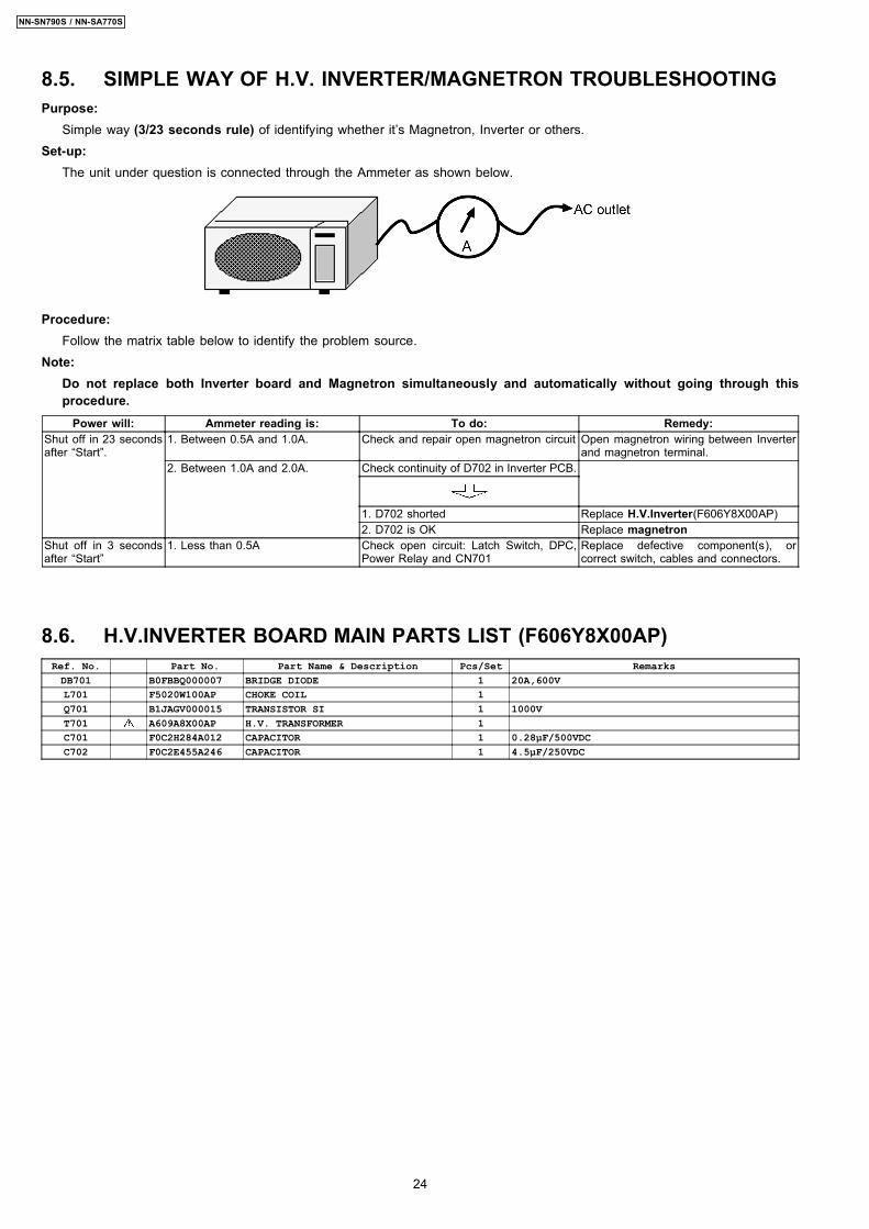
8.5. SIMPLE WAY OF H.V. INVERTER/MAGNETRON TROUBLESHOOTINGPurpose:
Simple way (3/23 seconds rule) of identifying whether it’s Magnetron, Inverter or others.Set-up:
The unit under question is connected through the Ammeter as shown below.
Procedure:Follow the matrix table below to identify the problem source.
Note:Do not replace both Inverter board and Magnetron simultaneously and automatically without going through thisprocedure.
Power will: Ammeter reading is: To do: Remedy:Shut off in 23 secondsafter “Start”.
1. Between 0.5A and 1.0A. Check and repair open magnetron circuit Open magnetron wiring between Inverterand magnetron terminal.
2. Between 1.0A and 2.0A. Check continuity of D702 in Inverter PCB.
1. D702 shorted Replace H.V.Inverter(F606Y8X00AP)2. D702 is OK Replace magnetron
Shut off in 3 secondsafter “Start”
1. Less than 0.5A Check open circuit: Latch Switch, DPC,Power Relay and CN701
Replace defective component(s), orcorrect switch, cables and connectors.
8.6. H.V.INVERTER BOARD MAIN PARTS LIST (F606Y8X00AP)Ref. No. Part No. Part Name & Description Pcs/Set RemarksDB701 B0FBBQ000007 BRIDGE DIODE 1 20A,600VL701 F5020W100AP CHOKE COIL 1Q701 B1JAGV000015 TRANSISTOR SI 1 1000VT701 A609A8X00AP H.V. TRANSFORMER 1C701 F0C2H284A012 CAPACITOR 1 0.28µF/500VDCC702 F0C2E455A246 CAPACITOR 1 4.5µF/250VDC
24
NN-SN790S / NN-SA770S
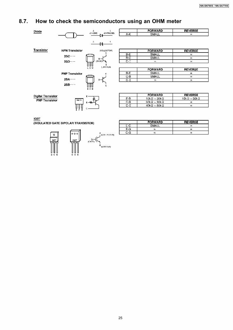
8.7. How to check the semiconductors using an OHM meter
25
NN-SN790S / NN-SA770S
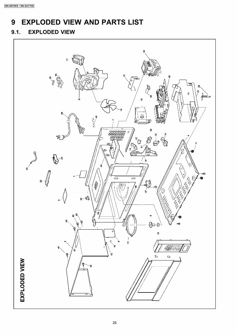
9 EXPLODED VIEW AND PARTS LIST9.1. EXPLODED VIEW
26
NN-SN790S / NN-SA770S
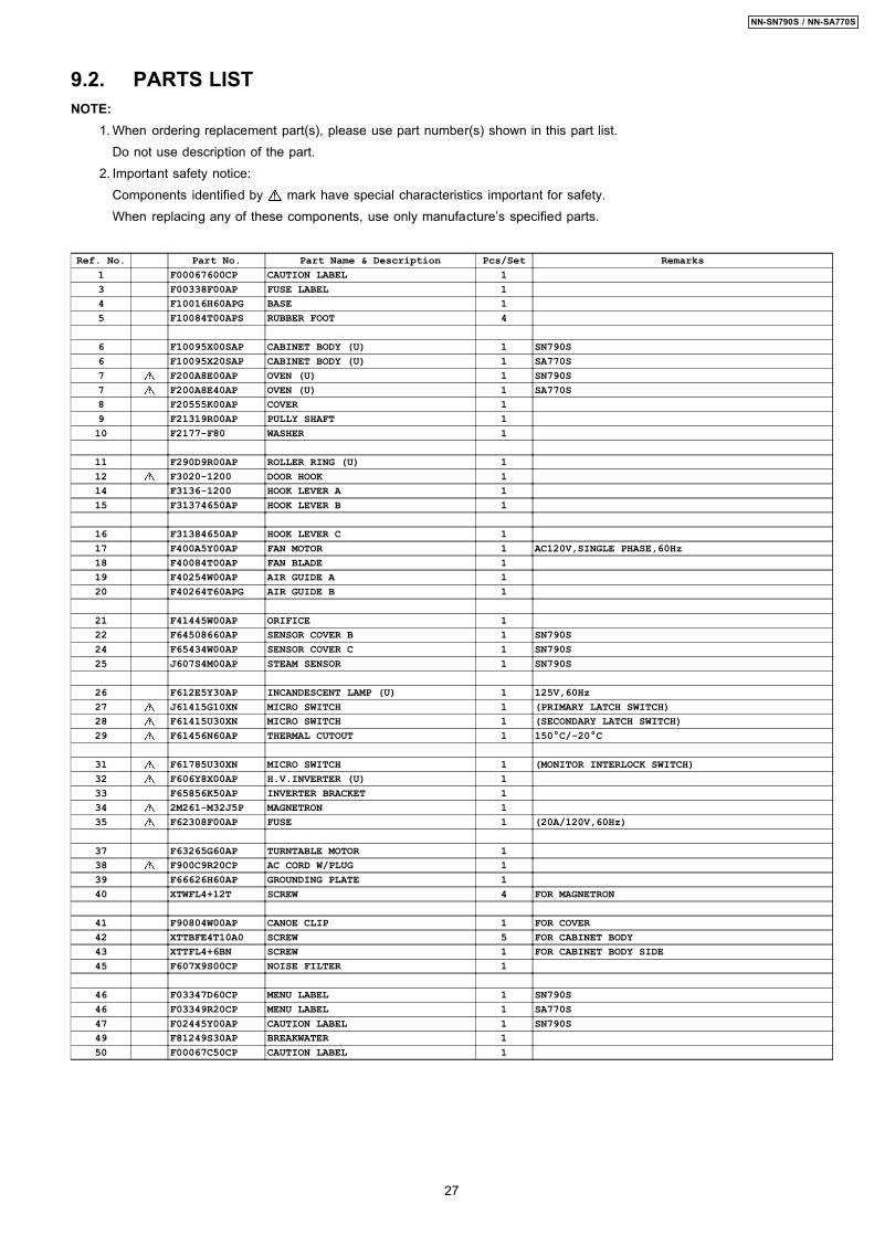
9.2. PARTS LISTNOTE:
1. When ordering replacement part(s), please use part number(s) shown in this part list.Do not use description of the part.
2. Important safety notice:Components identified by mark have special characteristics important for safety.When replacing any of these components, use only manufacture’s specified parts.
Ref. No. Part No. Part Name & Description Pcs/Set Remarks1 F00067600CP CAUTION LABEL 13 F00338F00AP FUSE LABEL 14 F10016H60APG BASE 15 F10084T00APS RUBBER FOOT 4
6 F10095X00SAP CABINET BODY (U) 1 SN790S6 F10095X20SAP CABINET BODY (U) 1 SA770S7 F200A8E00AP OVEN (U) 1 SN790S7 F200A8E40AP OVEN (U) 1 SA770S8 F20555K00AP COVER 19 F21319R00AP PULLY SHAFT 110 F2177-F80 WASHER 1
11 F290D9R00AP ROLLER RING (U) 112 F3020-1200 DOOR HOOK 114 F3136-1200 HOOK LEVER A 115 F31374650AP HOOK LEVER B 1
16 F31384650AP HOOK LEVER C 117 F400A5Y00AP FAN MOTOR 1 AC120V,SINGLE PHASE,60Hz18 F40084T00AP FAN BLADE 119 F40254W00AP AIR GUIDE A 120 F40264T60APG AIR GUIDE B 1
21 F41445W00AP ORIFICE 122 F64508660AP SENSOR COVER B 1 SN790S24 F65434W00AP SENSOR COVER C 1 SN790S25 J607S4M00AP STEAM SENSOR 1 SN790S
26 F612E5Y30AP INCANDESCENT LAMP (U) 1 125V,60Hz27 J61415G10XN MICRO SWITCH 1 (PRIMARY LATCH SWITCH)28 F61415U30XN MICRO SWITCH 1 (SECONDARY LATCH SWITCH)29 F61456N60AP THERMAL CUTOUT 1 150°C/-20°C
31 F61785U30XN MICRO SWITCH 1 (MONITOR INTERLOCK SWITCH)32 F606Y8X00AP H.V.INVERTER (U) 133 F65856K50AP INVERTER BRACKET 134 2M261-M32J5P MAGNETRON 135 F62308F00AP FUSE 1 (20A/120V,60Hz)
37 F63265G60AP TURNTABLE MOTOR 138 F900C9R20CP AC CORD W/PLUG 139 F66626H60AP GROUNDING PLATE 140 XTWFL4+12T SCREW 4 FOR MAGNETRON
41 F90804W00AP CANOE CLIP 1 FOR COVER42 XTTBFE4T10A0 SCREW 5 FOR CABINET BODY43 XTTFL4+6BN SCREW 1 FOR CABINET BODY SIDE45 F607X9S00CP NOISE FILTER 1
46 F03347D60CP MENU LABEL 1 SN790S46 F03349R20CP MENU LABEL 1 SA770S47 F02445Y00AP CAUTION LABEL 1 SN790S49 F81249S30AP BREAKWATER 150 F00067C50CP CAUTION LABEL 1
27
NN-SN790S / NN-SA770S
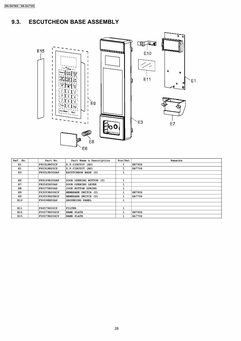
9.3. ESCUTCHEON BASE ASSEMBLY
Ref. No. Part No. Part Name & Description Pcs/Set RemarksE1 F603L9R00CP D.P.CIRCUIT (AU) 1 SN790SE1 F603L9R20CP D.P.CIRCUIT (AU) 1 SA770SE3 F800L9R30SAP ESCUTCHEON BASE (U) 1
E6 F891P9R30SAP DOOR OPENING BUTTON (U) 1E7 F82565X00AP DOOR OPENING LEVER 1E8 F80375K00AP COOK BUTTON SPRING 1E9 F630Y9R00SCP MEMBRANE SWITCH (U) 1 SN790SE9 F630Y9R20BCP MEMBRANE SWITCH (U) 1 SA770SE10 F90098N00AP GROUNDING PANEL 1
E11 F64579S00CP FILTER 1E15 F00079R00SCP NAME PLATE 1 SN790SE15 F00079R20SCP NAME PLATE 1 SA770S
28
NN-SN790S / NN-SA770S
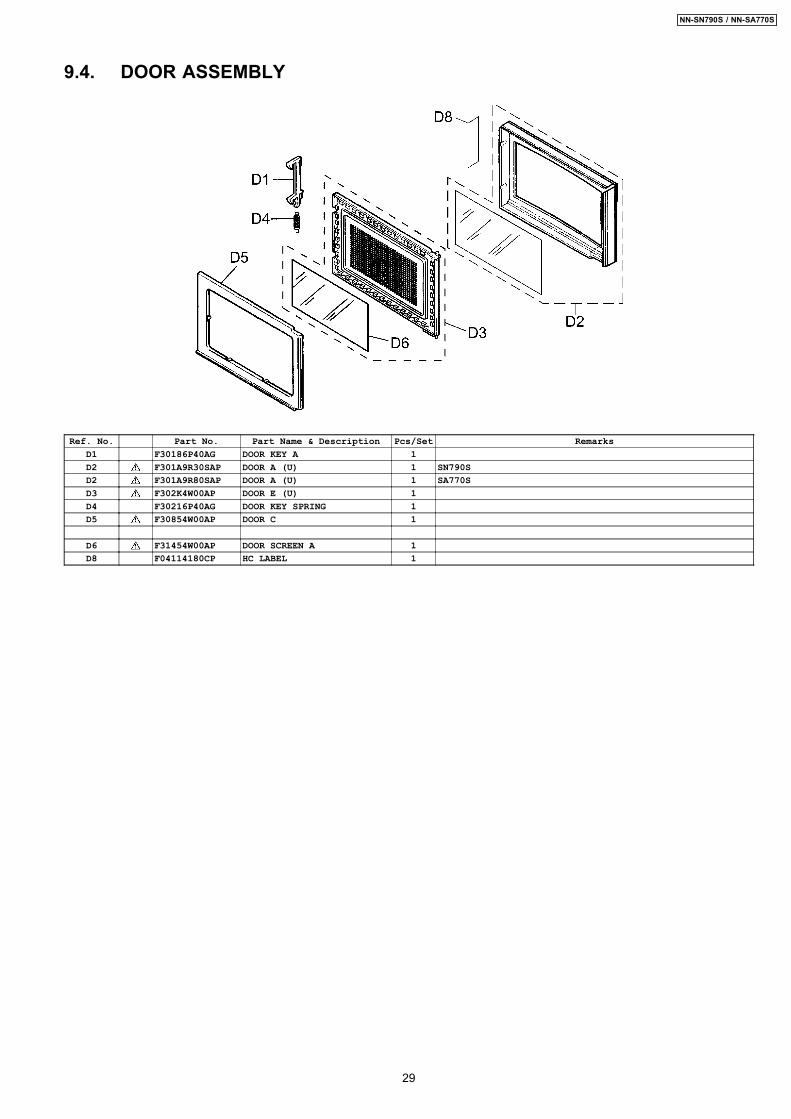
9.4. DOOR ASSEMBLY
Ref. No. Part No. Part Name & Description Pcs/Set RemarksD1 F30186P40AG DOOR KEY A 1D2 F301A9R30SAP DOOR A (U) 1 SN790SD2 F301A9R80SAP DOOR A (U) 1 SA770SD3 F302K4W00AP DOOR E (U) 1D4 F30216P40AG DOOR KEY SPRING 1D5 F30854W00AP DOOR C 1
D6 F31454W00AP DOOR SCREEN A 1D8 F04114180CP HC LABEL 1
29
NN-SN790S / NN-SA770S
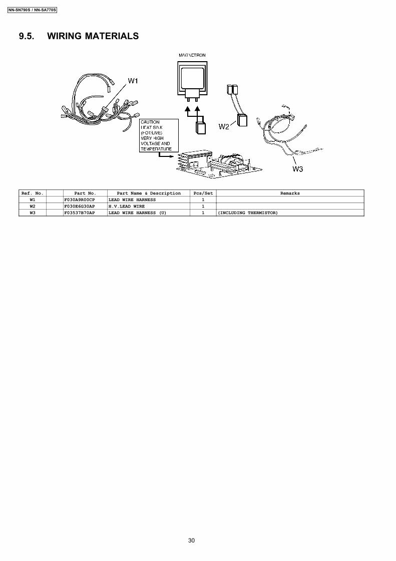
9.5. WIRING MATERIALS
Ref. No. Part No. Part Name & Description Pcs/Set RemarksW1 F030A9R00CP LEAD WIRE HARNESS 1W2 F030E6G30AP H.V.LEAD WIRE 1W3 F03537B70AP LEAD WIRE HARNESS (U) 1 (INCLUDING THERMISTOR)
30
NN-SN790S / NN-SA770S
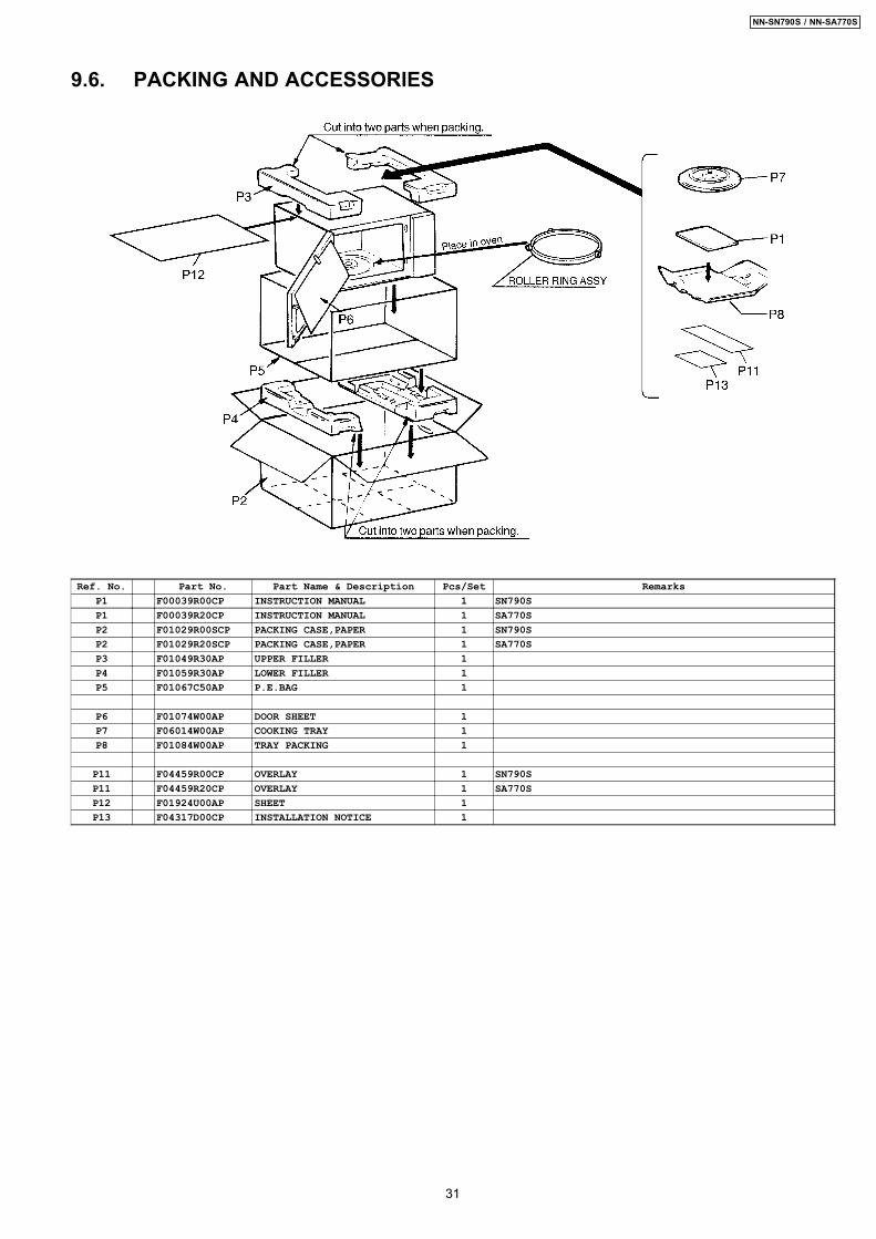
9.6. PACKING AND ACCESSORIES
Ref. No. Part No. Part Name & Description Pcs/Set RemarksP1 F00039R00CP INSTRUCTION MANUAL 1 SN790SP1 F00039R20CP INSTRUCTION MANUAL 1 SA770SP2 F01029R00SCP PACKING CASE,PAPER 1 SN790SP2 F01029R20SCP PACKING CASE,PAPER 1 SA770SP3 F01049R30AP UPPER FILLER 1P4 F01059R30AP LOWER FILLER 1P5 F01067C50AP P.E.BAG 1
P6 F01074W00AP DOOR SHEET 1P7 F06014W00AP COOKING TRAY 1P8 F01084W00AP TRAY PACKING 1
P11 F04459R00CP OVERLAY 1 SN790SP11 F04459R20CP OVERLAY 1 SA770SP12 F01924U00AP SHEET 1P13 F04317D00CP INSTALLATION NOTICE 1
31
NN-SN790S / NN-SA770S
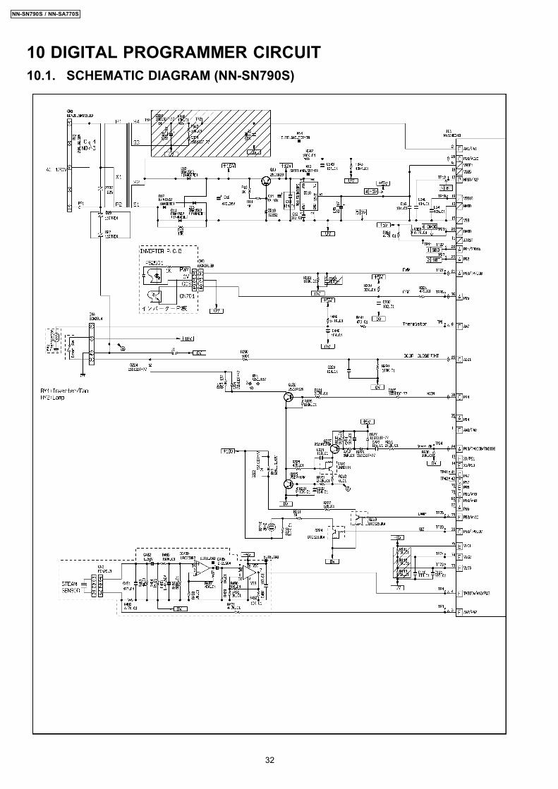
10 DIGITAL PROGRAMMER CIRCUIT10.1. SCHEMATIC DIAGRAM (NN-SN790S)
32
NN-SN790S / NN-SA770S
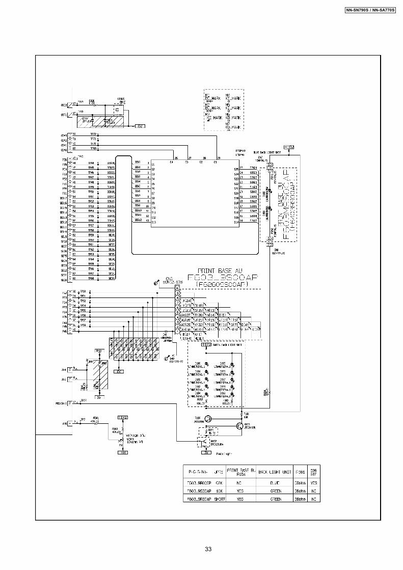
33
NN-SN790S / NN-SA770S
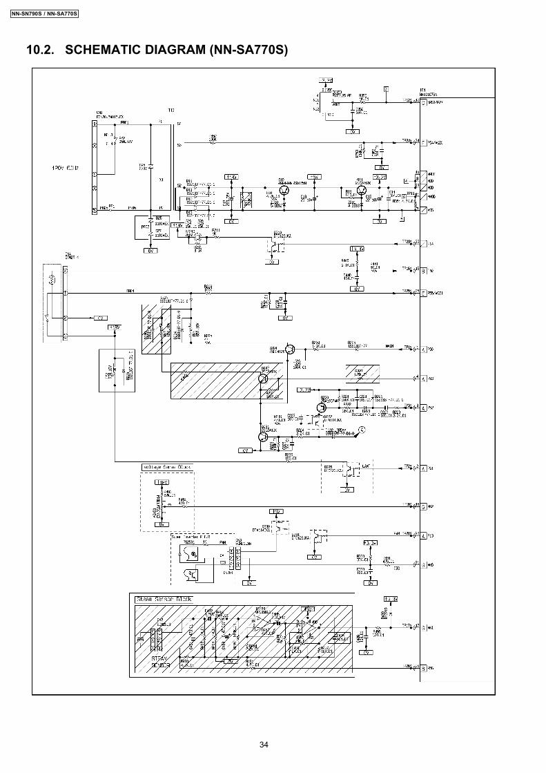
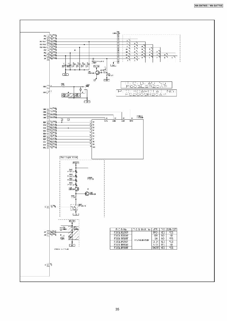
10.2. SCHEMATIC DIAGRAM (NN-SA770S)
34
NN-SN790S / NN-SA770S
35
NN-SN790S / NN-SA770S
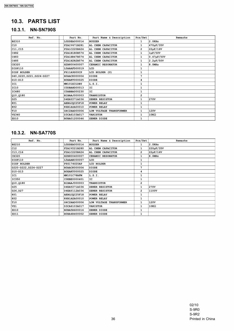
10.3. PARTS LIST10.3.1. NN-SN790S
Ref. No. Part No. Part Name & Description Pcs/Set RemarksBZ310 L0DDEA000014 BUZZER 1 2.0KHzC10 F2A1V471B281 AL CHEM CAPACITOR 1 470µF/35VC11,C15 F2A1C220B624 AL CHEM CAPACITOR 2 22µF/16VC482 F2A1H1R0B574 AL CHEM CAPACITOR 1 1µF/50VC483 F2A1HR47B574 AL CHEM CAPACITOR 1 0.47µF/50VC485 F2A1H2R2B574 AL CHEM CAPACITOR 1 2.2µF/50VCX320 H2B800400007 CERAMIC RESONATOR 1 8.0MHzDISP110 L5AAAFD00019 LCD 1DISP HOLDER F611A9S00CP LCD HOLDER (U) 1D40,D220,D221,D224-D227 B0AACK000004 DIODE 7D10-D13 B0EAKT000025 DIODE 4IC1 MN101E31DBY L.S.I. 1IC10 C0DBAHD00013 IC 1IC480 C0ABBA000230 IC 1Q10,Q180 B1BAAJ000003 TRANSISTOR 2D25 D4EAY271A036 ZENER RESISTOR 1 270VRY1 AEBGJQC25F18 POWER RELAY 1RY2 K6B1AZA00010 POWER RELAY 1T10 G4C2AAD00006 LOW VOLTAGE TRANSFORMER 1 120VVZ340 D3CA6103A017 VARISTOR 1 10KΩZD10 B0BA01200046 ZENER DIODE 1
10.3.2. NN-SA770SRef. No. Part No. Part Name & Description Pcs/Set Remarks
BZ210 L0DDEA000014 BUZZER 1 2.0KHzC12 F2A1V221B280 AL CHEM CAPACITOR 1 220µF/35VC13,C16 F2A1C220B624 AL CHEM CAPACITOR 2 22µF/16VCX320 H2B800400007 CERAMIC RESONATOR 1 8.0MHzDISP110 L5AAAEC00057 LCD 1DISP HOLDER F66174U20AP LCD HOLDER 1D220-D222,D224-D227 B0AACK000004 DIODE 7D10-D13 B0EAKT000025 DIODE 4IC1 MN101C78AFM L.S.I. 1IC350 C0EBE0000401 IC 1Q10,Q180 B1BAAJ000003 TRANSISTOR 2D25 D4EAY271A036 ZENER RESISTOR 1 270VD26,D27 D4EAY112A036 ZENER RESISTOR 2 1100VRY1 AEBGJQC25F18 POWER RELAY 1RY2 K6B1AZA00010 POWER RELAY 1T10 G4C2AAD00006 LOW VOLTAGE TRANSFORMER 1 120VVZ1 D3CA6103A017 VARISTOR 1 10KΩZD10 B0BA5R600016 ZENER DIODE 1ZD11 B0BA4R400002 ZENER DIODE 1
36
NN-SN790S / NN-SA770S
02/10S-9R0S-9R2Printed in China