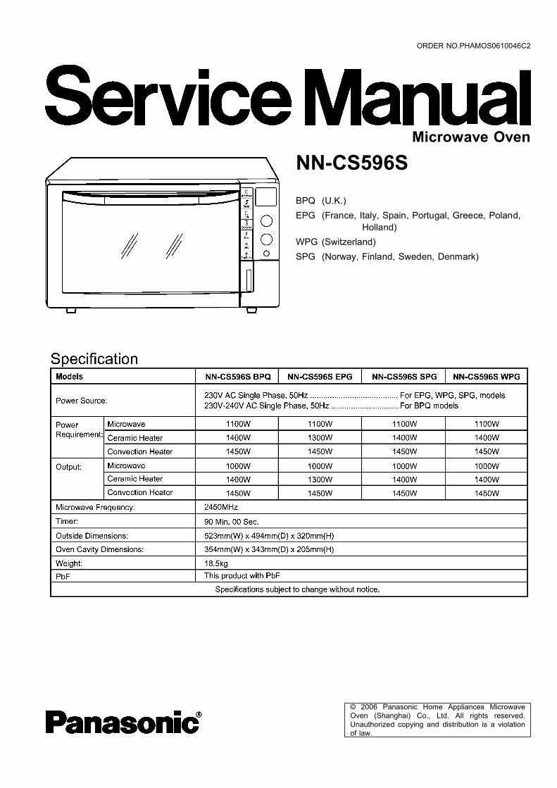
microwave oven nn-cs596s
TRANSCRIPT
© 2006 Panasonic Home Appliances MicrowaveOven (Shanghai) Co., Ltd. All rights reserved.Unauthorized copying and distribution is a violationof law.
NN-CS596SBPQ (U.K.)EPG (France, Italy, Spain, Portugal, Greece, Poland,
Holland)WPG (Switzerland)SPG (Norway, Finland, Sweden, Denmark)
Microwave Oven
ORDER NO.PHAMOS0610046C2
2
NN-CS596S
3
NN-CS596S
1 SCHEMATIC DIAGRAM 5 1.1. BPQ/EPG 5
1.2. WPG/SPG 6
2 DESCRIPTION OF OPERATING SEQUENCE 7 2.1. Variable power cooking control 7
2.2. Inverter power supply circuit NEW H.V. 7
2.3. Auto cooking 7
2.4. Convection & Grill Convection cooking control 7
2.5. Steam function (micro steam) 8
3 CAUTIONS TO BE OBSERVED WHEN TROUBLESHOOTING 9 3.1. Check the grounding 9
3.2. Inverter warnings 9
3.3. Confirm before repair 10
3.4. Part replacement 10
3.5. When the 10A/15A fuse is blown due to the operation of
the short switch 10
3.6. Avoid inserting nails, wire etc. through any holes in the
unit during operation 10
3.7. Confirm after repair 10
3.8. Sharp edges 10
4 DISASSEMBLY AND PARTS REPLACEMENT PROCEDURE 11 4.1. Magnetron 11
4.2. Digital programmer circuit (D.P.C) AU, (D.P.C.) HU,
membrane key board and power relay 12
4.3. Digital programmer circuit (D.P.C.) DU and low voltage
transformer 12
4.4. H.V. Inverter 13
4.5. Upper heaters 13
4.6. Door assembly 14
4.7. Fan motor 14
4.8. Pump 15
4.9. Stir motor 16
4.10. Heater DU (steam heater) 16
4.11. Convection motor and convection heater 17
4.12. Circuit breaker 19
5 COMPONENT TEST PROCEDURE 20 5.1. Primary latch switch (door switch and power relay B)
interlocks 20
5.2. Short switch & monitor 20
5.3. Magnetron 20
5.4. Membrane key board (Membrane switch assembly) 20
5.5. Inverter power supply (U) 21
5.6. Temperature thermistor 21
5.7. Circuit breaker 21
6 MEASUREMENTS AND ADJUSTMENTS 22 6.1. Adjustment of Primary latch switch, Secondary latch
switch and Short switch. 22
6.2. Measurement of microwave output 22
7 TROUBLESHOOTING GUIDE 23 7.1. (Troubleshooting) Oven stops operation during cooking 24
7.2. (Troubleshooting) Other problems 25
7.3. Troubleshooting of inverter circuit (U) and magnetron
NEW H.V. 26
7.4. Simple way of H.V. Inverter/magnetron troubleshooting 27
7.5. How to check the semiconductors using an OHM meter 27
8 EXPLODED VIEW AND PARTS LIST 28 8.1. EXPLODED VIEW 28
8.2. PARTS LIST 29
8.3. WATER TANK ASSEMBLY 30
8.4. ESCUTCHEON BASE ASSEMBLY 31
8.5. DOOR ASSEMBLY 32
8.6. WIRING MATERIALS 32
8.7. PACKING AND ACCESSORIES 33
9 DIGITAL PROGRAMMER CIRCUIT 34 9.1. SCHEMATIC DIAGRAM 34
CONTENTS Page Page
4
NN-CS596S
1 SCHEMATIC DIAGRAM1.1. BPQ/EPG
5
NN-CS596S
1.2. WPG/SPG
6
NN-CS596S

2.1. Variable power cookingcontrol
High Voltage Inverter Power Supply (U) controls output powerby the signal from Digital Programmer Circuit (DPC). Powerrelay always stays ON, but PWM (pulse width modulation)signal controls microwave output power.NOTE:
The ON/OFF time ratio does not correspond with thepercentage of microwave power since approximately 2seconds are required for heating of magnetronfilament.
Variable Power CookingPOWER SETTING OUTPUT
POWER(%)APPROX.
MANUAL MICROWAVEDUTY
ON(SEC) OFF(SEC)HIGH 100% 22 0MEDIUM-HIGH 70% 22 0MEDIUM 55% 22 0MEDIUM-LOW 40% 22 0LOW 20% 13 9DEFROST 30% 17 5
2.2. Inverter power supply circuitNEW H.V.
The Inverter Power Supply circuit powered from the linevoltage, 220-240V 50Hz AC input supplies 4,000V DC to themagnetron tube, and functions in place of the H.V. transformer,the H.V. capacitor and H.V. diode. 1. The AC input voltage 220-240V 50Hz is rectified to DC
voltage immediately. 2. DC voltage will be supplied to the switching devices called
IGBT. These devices are switched ON-OFF by the 20 to 40KHz PWM (pulse width modulation) signal from themicrocomputer in the DPC.
3. This drives the High voltage transformer to increase voltageup to 2,000V AC.
4. Then the half-wave doubler voltage rectifier circuit,consisting of the H.V. diodes and capacitors, generates thenecessary 4,000V DC needed for the magnetron.
5. Output power of the magnetron tube is always monitored bythe signal output from the current transformer built into theinverter circuit.
6. This signal is fed back to the microcomputer in the DPC todetermine operating conditions and output necessary tocontrol PWM signal to the Inverter Power Supply for controlof the output power.
2.3. Auto cookingWhen the Auto Control feature is selected and the Start pad istapped: 1. The digital programer circuit determines the power level and
cooking time to complete cooking and indicates theoperating state in the display window. Table shows thecorresponding cooking times for respective serving bycategories.
2. When cooking time in the display window has elapsed, theoven turns off automatically by a control signal from thedigital programmer circuit.
2.4. Convection & Grill Convectioncooking control
The digital programmer circuit controls the ON-OFF time of theheater in order to control oven cavity temperature. 1. After selecting desired oven cavity temperature of
Convection/Grill Convection (the range of selected oventemp is 100°C-300°C) and pressing [Start] pad, a high levelsignal comes out of the micro computer and applies topower relay (RY5).
2. When RY5 are switched to ON, power source voltage isapplied to the convection heater & upper heater (middleone), and the heaters turn on.
3. The digital programmer circuit senses the oven cavitytemperature through oven temp sensor (thermistor). Whenthe oven temperature reaches the set temperature, DPCstops supplying high level signal to the power relays, andthe heaters turn off.
4. After the convection heater and upper heater (middle one)turn off, the oven temperature will continue increasing for awhile and then decrease as shown in Figure.When the oven temperature drops below the settemperature, the digital programmer circuit senses thesignal and starts supplying a high level signal to RY5 again.NOTE:
a. If only convection heater works, convection motorwould rotate for 5 minute after cooking to cool ovenand electric components.
b. After convection or grill convection cooking, fanmotor rotates for 5 minutes to cool oven and electriccomponents.
2 DESCRIPTION OF OPERATING SEQUENCE
7
NN-CS596S
2.5. Steam function (micro steam)2.5.1. Water SupplyWater in water tank will be pumped out and supply to the steam generation heater located inside back bottom of oven cavity.
2.5.2. OperationWhen pressing [start] pad, oven preheat will start and then water supply begins. It will take 1 minute for preheating. When preheatis completed, it will turn into actual cooking process. During heating, the temperature sensor (Thermistor) located on steam heaterwill monitor steam heater temperature and when it exceeds 100°C, the additional water will be supplied to maintain moisture/steamwithin oven cavity.
8
NN-CS596S
Unlike many other appliances, the microwave oven is a highvoltage, high current device. It is free from danger in ordinaryuse, though extreme care should be taken during repair.CAUTION
Servicemen should remove their watches wheneverworking close to or replacing the magnetron.
3.1. Check the groundingDo not operate on a two wire extension cord. The microwaveoven is designed to be grounded when used. It is imperative,therefore, to ensure the appliance is properly grounded beforebeginning repair work.
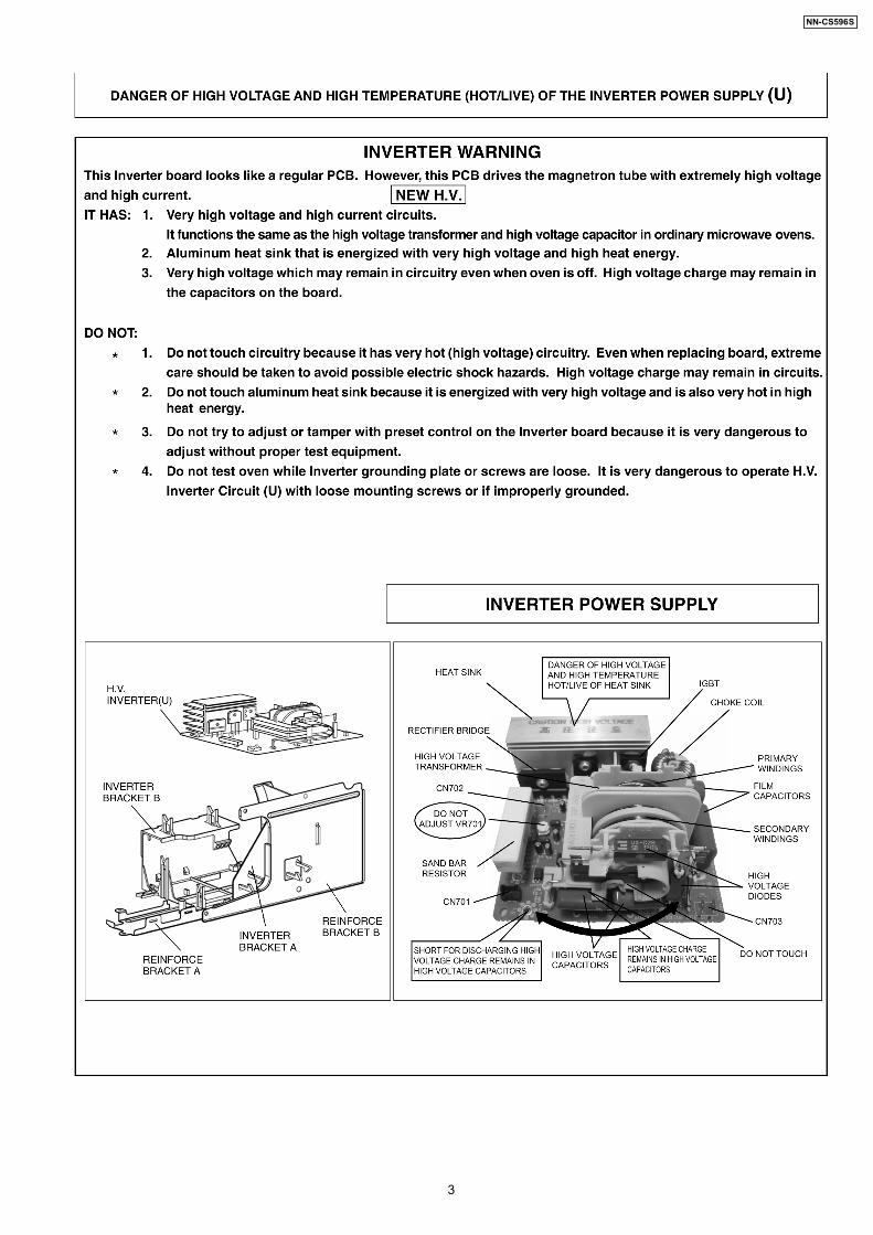
3.2. Inverter warningsDANGER, HIGH VOLTAGE AND HIGH TEMPERATURE(HOT/LIVE) OF THE INVERTER POWER SUPPLY (U)
The High Voltage Inverter Power Supply handles very highvoltage and current for the magnetron tube. Though it isfree from danger in ordinary use, extreme care should betaken during repair.The aluminum heat sink is also energized with high voltage(HOT), do not touch when the AC input terminals areenergized. The power device Collector is directly connectedto the aluminum heat sink.The aluminum heat sink may be HOT due to heat energy,therefore, extreme care should be taken during servicing.
H.V. Inverter warningWARNING FOR INVERTER POWER SUPPLY (U)GROUNDING
Check the High Voltage Inverter Power Supply circuitgrounding. The high voltage inverter power supply circuitboard must have a proper chassis ground. The invertergrounding bracket must be connected to the chassis. If theinverter board is not grounded it will expose the user to veryhigh voltages and cause extreme DANGER! Be sure thatthe inverter circuit is properly grounded via the invertergrounding bracket.
Grounding of the inverter circuit boardWARNING! DISCHARGE THE HIGH VOLATGECAPACITORS
For about 30 seconds after the oven is turned off, anelectric charge remains in the high voltage capacitors in theInverter Power Supply circuit board.When replacing or checking parts, remove the power plugfrom the outlet and short the inverter output terminal of themagnetron filament terminals to the chassis ground with aninsulated handle screwdriver to discharge. Please be sureto touch the chassis ground side first and then short to theoutput terminals.
3 CAUTIONS TO BE OBSERVED WHENTROUBLESHOOTING
9
NN-CS596S
Discharging the high voltage capacitorsWARNING
There is high voltage present with high current capabilitiesin the circuits of the primary and secondary windings, chokecoil and heat sink of the inverter. It is extremely dangerousto work on or near these circuits with the oven energized.DO NOT measure the voltage in the high voltage circuitincluding the filament voltage of the magnetron.
WARNINGNever touch any circuit wiring with your hand or with aninsulated tool during operation.
3.3. Confirm before repair 1. Before repair or replacement of parts, ensure to take out
the water tank from microwave oven. Further more, usedrainage function, to drain the water remaining in the waterpipes and tubes into oven cavity.
2. Wipe up the oven cavity.WARNING
Before beginning repair work, make sure that there is nowater in microwave oven, otherwise the water might invadethe electric parts and will cause short circuit even result inelectric shock.
3.4. Part replacementWhen any part or component is to be replaced, always ensurethat the power cord is removed from the wall outlet.
3.5. When the 10A/15A fuse isblown due to the operation ofthe short switch
WARNINGWhen the 10A/15A 240V fuse is blown due to the operationof the interlock monitor switch, replace all of thecomponents (primary latch switch, short switch and powerrelay B (RY1)). 1. This is mandatory. Refer to “adjustments and
measurements” for the location of these switches. 2. When replacing the fuse, confirm that it has the
appropriate rating for these models. 3. When replacing faulty switches, be sure the mounting
tabs are not bent, broken or deficient in their ability tohold the switches.
3.6. Avoid inserting nails, wire etc.through any holes in the unitduring operation
Never insert a wire, nail or any other metal object through thelamp holes on the cavity or any holes or gaps, because suchobjects may work as an antennaand cause microwave leakage.
3.7. Confirm after repair 1. After repair or replacement of parts, make sure that the
screws of the oven, etc. are neither loosen or missing.Microwave might leak if screws are not properly tightened.
2. Make sure that all electrical connections are tight beforeinserting the plug into the wall outlet.
3. Check for microwave energy leakage. (Refer to procedurefor measuring microwave energy leakage).
CAUTION MICROWAVE RADIATIONUSE CAUTION NOT TO BECOME EXPOSED TORADIATION FROM THE MICROWAVE MAGNETRON OROTHER PARTS CONDUCTING MICROWAVE ENERGY.
IMPORTANT NOTICEThe following components have potentials above 2000Vwhile the appliance is operated.
••••
Magnetron
••••
High voltage transformer (Located on inverter (U))
••••
High voltage diodes (Located on inverter (U))
••••
High voltage capacitors (Located on inverter (U))Pay special attention to these areas.When the appliance is operated with the door hinges ormagnetron installed incorrectly, the microwave leakage canexceed more than 5mW/cm2. After repair or exchange, it isvery important to check if the magnetron and the doorhinges are correctly installed.
IMPORTANT NOTICEAfter repair or replacement of parts, make sure that allthe water pipes and tubes are properly connected,otherwise the water might invade the electric parts andwill cause short circuit even result in electric shock.
3.8. Sharp edgesCAUTION
Please use caution when unpacking, installing or movingthe unit, as some exposed edges may be sharp to the touchand cause injury if not handled with care.
10
NN-CS596S
CAUTION 1. Before repair or replacement of parts, ensure to take out the
water tank from microwave oven.
2. After removing the water tank, select "drainage" function to drainthe water remaining in the water pipes and tubes into oven cavityforcibly. (Operating method: keep pressing [Steam] pad for morethan 2 seconds). Then wipe up the oven cavity.
3. The above procedure is to prevent the water from invading theelectric parts and resulting in short circuit even electric shock.
CAUTIONAfter repair or replacement of parts, make sure that all the water pipesand tubes are properly connected, otherwise the water might invadethe electric parts and will cause short circuit even result in electricshock.
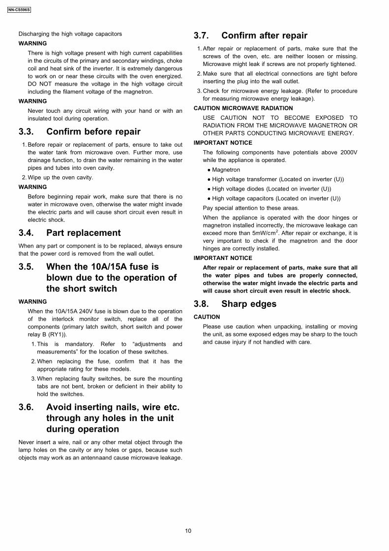
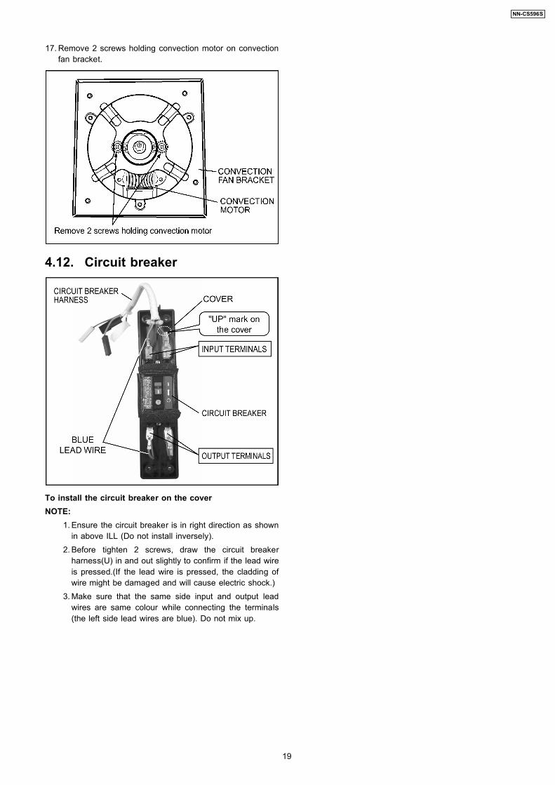
4.1. Magnetron 1. Discharge the high voltage capacitor. 2. Remove 2 screws holding reinforce bracket A on oven
cavity.
3. Remove 2 screws holding reinforce bracket B on ovencavity.
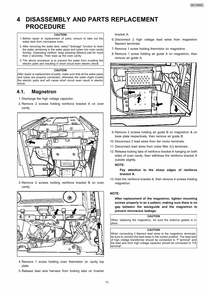
4. Remove 1 screw holding oven thermistor on cavity topplate.
5. Release lead wire harness from locking tabs on inverter
bracket A. 6. Disconnect 2 high voltage lead wires from magnetron
filament terminals. 7. Remove 1 screw holding thermistor on magnetron. 8. Remove 1 screw holding air guide A on magnetron, then
remove air guide A.
9. Remove 2 screws holding air guide B on magnetron & onbase plate respectively, then remove air guide B.
10. Disconnect 2 lead wires from fan motor terminals. 11. Disconnect lead wires from noise filter (U) terminals. 12. Release locking tabs of reinforce bracket A hanging on both
sides of oven cavity, then withdraw the reinforce bracket Aoutside slightly.NOTE:
Pay attention to the sharp edges of reinforcebracket A.
13. Hold the reinforce bracket A, then remove 4 screws holdingmagnetron.
NOTE:After replacement of the magnetron, tighten mountingscrews properly in an x pattern, making sure there is nogap between the waveguide and the magnetron toprevent microwave leakage.
CAUTIONWhen replacing the magnetron, be sure the antenna gasket is inplace.
CAUTIONWhen connecting 2 filament lead wires to the magnetron terminals,be sure to connect the lead wires in the correct position. The lead wireof high volatge transformer should be connected to “F terminal” andthe lead wire from high voltage capacitor should be connected to “FAterminal”.
4 DISASSEMBLY AND PARTS REPLACEMENTPROCEDURE
11
NN-CS596S
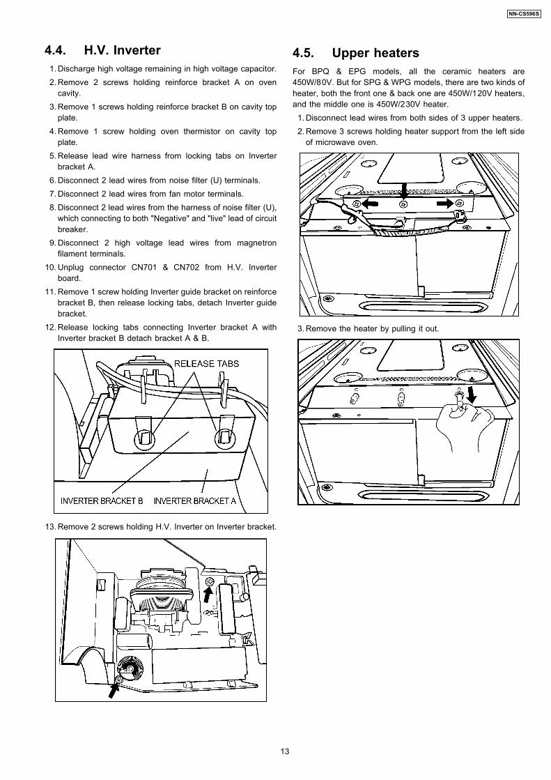
4.2. Digital programmer circuit(D.P.C) AU, (D.P.C.) HU,membrane key board andpower relay
NOTE:Be sure to ground any static electric charge built up onyour body before handling the DPC.
1. Draw out water tank from escutcheon base. 2. Keep pressing [Steam] pad for more than 2 seconds to
drain the water remaining in the water pipes and tubes intooven cavity forcibly.
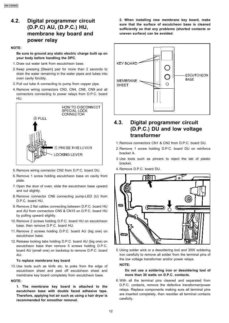
3. Pull out tube A connecting to pump from copper pipe. 4. Remove wiring connectors CN3, CN4, CN8, CN9 and all
connectors connecting to power relays from D.P.C. boardHU.
5. Remove wiring connector CN2 from D.P.C. board DU. 6. Remove 1 screw holding escutcheon base on cavity front
plate. 7. Open the door of oven, slide the escutcheon base upward
and out slightly. 8. Remove connector CN6 connecting pump-LED (U) from
D.P.C. board HU. 9. Remove 2 flat cables connecting between D.P.C. board HU
and AU from connectors CN5 & CN15 on D.P.C. board HUby pulling upward slightly.
10. Remove 2 screws holding D.P.C. board HU on escutcheonbase, then remove D.P.C. board HU.
11. Remove 2 screws holding D.P.C. board AU (big one) onescutcheon base.
12. Release locking tabs holding D.P.C. board AU (big one) onescutcheon base then remove 5 screws holding D.P.C.board AU (small one) on backstop to remove D.P.C. boardAU.To replace membrane key board
13. Use tools such as kinfe etc. to poke from the edge ofescutcheon sheet and peel off escutcheon sheet andmembrane key board completely from escutcheon base.
NOTE:1. The membrane key board is attached to theescutcheon base with double faced adhesive tape.Therefore, applying hot air such as using a hair dryer isrecommended for smoother removal.
2. When installing new membrane key board, makesure that the surface of escutcheon base is cleanedsufficiently so that any problems (shorted contacts oruneven surface) can be avoided.
4.3. Digital programmer circuit(D.P.C.) DU and low voltagetransformer
1. Remove connectors CN1 & CN2 from D.P.C. board DU. 2. Remove 1 screw holding D.P.C. board DU on reinforce
bracket A. 3. Use tools such as pincers to reject the tab of plastic
bracket. 4. Remove D.P.C. board DU.
5. Using solder wick or a desoldering tool and 30W solderingiron carefully to remove all solder from the terminal pins ofthe low voltage transformer and/or power relays.NOTE:
Do not use a soldering iron or desoldering tool ofmore than 30 watts on D.P.C. contacts.
6. With all the terminal pins cleaned and separated fromD.P.C. contacts, remove the defective transformer/powerrelays. Replace components making sure all terminal pinsare inserted completely, then resolder all terminal contactscarefully.
12
NN-CS596S
4.4. H.V. Inverter 1. Discharge high voltage remaining in high voltage capacitor. 2. Remove 2 screws holding reinforce bracket A on oven
cavity. 3. Remove 1 screws holding reinforce bracket B on cavity top
plate. 4. Remove 1 screw holding oven thermistor on cavity top
plate. 5. Release lead wire harness from locking tabs on Inverter
bracket A. 6. Disconnect 2 lead wires from noise filter (U) terminals. 7. Disconnect 2 lead wires from fan motor terminals. 8. Disconnect 2 lead wires from the harness of noise filter (U),
which connecting to both "Negative" and "live" lead of circuitbreaker.
9. Disconnect 2 high voltage lead wires from magnetronfilament terminals.
10. Unplug connector CN701 & CN702 from H.V. Inverterboard.
11. Remove 1 screw holding Inverter guide bracket on reinforcebracket B, then release locking tabs, detach Inverter guidebracket.
12. Release locking tabs connecting Inverter bracket A withInverter bracket B detach bracket A & B.
13. Remove 2 screws holding H.V. Inverter on Inverter bracket.
4.5. Upper heatersFor BPQ & EPG models, all the ceramic heaters are450W/80V. But for SPG & WPG models, there are two kinds ofheater, both the front one & back one are 450W/120V heaters,and the middle one is 450W/230V heater. 1. Disconnect lead wires from both sides of 3 upper heaters. 2. Remove 3 screws holding heater support from the left side
of microwave oven.
3. Remove the heater by pulling it out.
13
NN-CS596S
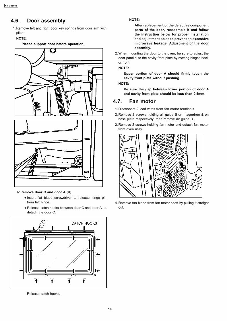
4.6. Door assembly 1. Remove left and right door key springs from door arm with
plier.NOTE:
Please support door before operation.
To remove door C and door A (U)
••••
Insert flat blade screwdriver to release hinge pinfrom left hinge.
••••
Release catch hooks between door C and door A, todetach the door C.
Release catch hooks.
NOTE:After replacement of the defective componentparts of the door, reassemble it and followthe instruction below for proper installationand adjustment so as to prevent an excessivemicrowave leakage. Adjustment of the doorassembly.
2. When mounting the door to the oven, be sure to adjust thedoor parallel to the cavity front plate by moving hinges backor front.NOTE:
Upper portion of door A should firmly touch thecavity front plate without pushing.
NOTE:Be sure the gap between lower portion of door Aand cavity front plate should be less than 0.5mm.
4.7. Fan motor 1. Disconnect 2 lead wires from fan motor terminals. 2. Remove 2 screws holding air guide B on magnetron & on
base plate respectively, then remove air guide B. 3. Remove 2 screws holding fan motor and detach fan motor
from oven assy.
4. Remove fan blade from fan motor shaft by pulling it straightout.
14
NN-CS596S

4.8. Pump 1. Draw out water tank from escutcheon base. 2. Keep pressing [Steam] pad for more than 2 seconds to
drain the water remaining in the water pipes and tubes intooven cavity forcibly.
3. Pull out tube A connecting to pump from copper pipe. 4. Remove all wiring connectors from D.P.C board AU. 5. Remove 1 grounding screw holding on cavity front plate. 6. Open the door of oven, slide the escutcheon base upward
and out slightly. 7. Pull out tube B from inlet of pump. 8. Remove 2 screws holding pump bracket on escutcheon
base.
9. Draw out pump bracket from bottom rail of escutcheonbase.
10. Uplift the afterbody of pump slightly to release the tabs ofpump bracket, then draw out pump.
11. Pull out tube A from outlet of pump.
To install pump 1. Insert pump into pump bracket (Inlet of pump should be
close to harness clasp of pump bracket). 2. Please confirm if it is fitted well after installing.
NOTE:After repairing, when insert copper pipe into tube A,make sure the inserted depth should be no less than9 mm to prevent tube A from slipping.
15
NN-CS596S
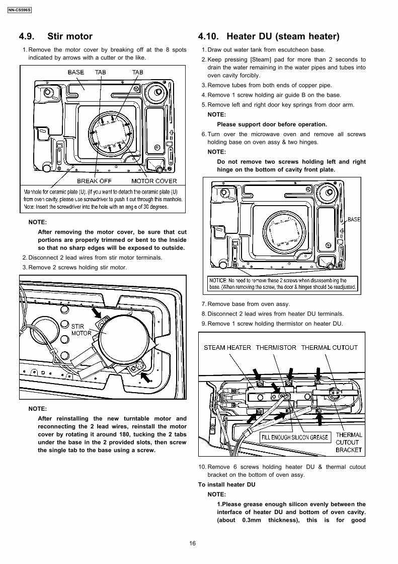
4.9. Stir motor 1. Remove the motor cover by breaking off at the 8 spots
indicated by arrows with a cutter or the like.
NOTE:After removing the motor cover, be sure that cutportions are properly trimmed or bent to the Insideso that no sharp edges will be exposed to outside.
2. Disconnect 2 lead wires from stir motor terminals. 3. Remove 2 screws holding stir motor.
NOTE:After reinstalling the new turntable motor andreconnecting the 2 lead wires, reinstall the motorcover by rotating it around 180, tucking the 2 tabsunder the base in the 2 provided slots, then screwthe single tab to the base using a screw.
4.10. Heater DU (steam heater) 1. Draw out water tank from escutcheon base. 2. Keep pressing [Steam] pad for more than 2 seconds to
drain the water remaining in the water pipes and tubes intooven cavity forcibly.
3. Remove tubes from both ends of copper pipe. 4. Remove 1 screw holding air guide B on the base. 5. Remove left and right door key springs from door arm.
NOTE:Please support door before operation.
6. Turn over the microwave oven and remove all screwsholding base on oven assy & two hinges.NOTE:
Do not remove two screws holding left and righthinge on the bottom of cavity front plate.
7. Remove base from oven assy. 8. Disconnect 2 lead wires from heater DU terminals. 9. Remove 1 screw holding thermistor on heater DU.
10. Remove 6 screws holding heater DU & thermal cutoutbracket on the bottom of oven assy.
To install heater DUNOTE:
1.Please grease enough silicon evenly between theinterface of heater DU and bottom of oven cavity.(about 0.3mm thickness), this is for good
16
NN-CS596S
conductibility.2.Tighten 6 screws and make sure there is no gapbetween heater DU and bottom of oven cavity.3.Do not forget to screw the thermal cutout bracketalong with heater Du.
To install thermistorNOTE:
Before installing thermistor, please fill enoughsilicon grease into the installation hole of heater DUfor good conductibility.
4.11. Convection motor andconvection heater
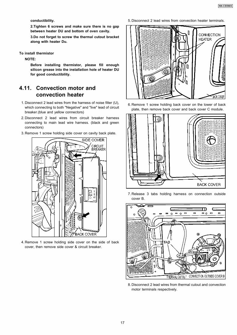
1. Disconnect 2 lead wires from the harness of noise filter (U),which connecting to both "Negative" and "live" lead of circuitbreaker.(blue and yellow connectors)
2. Disconnect 2 lead wires from circuit breaker harnessconnecting to main lead wire harness. (black and greenconnectors)
3. Remove 1 screw holding side cover on cavity back plate.
4. Remove 1 screw holding side cover on the side of backcover, then remove side cover & circuit breaker.
5. Disconnect 2 lead wires from convection heater terminals.
6. Remove 1 screw holding back cover on the lower of backplate, then remove back cover and back cover C module.
7. Release 3 tabs holding harness on connection outsidecover B.
8. Disconnect 2 lead wires from thermal cutout and convectionmotor terminals respectively.
17
NN-CS596S
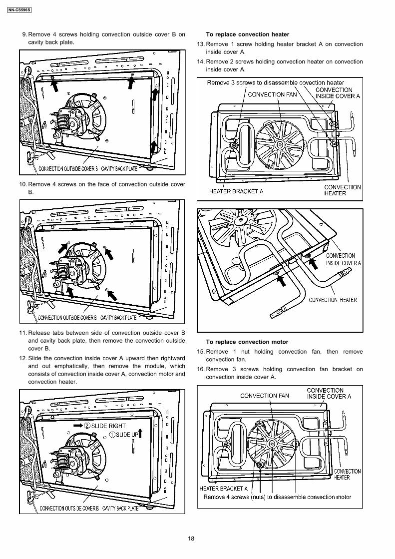
9. Remove 4 screws holding convection outside cover B oncavity back plate.
10. Remove 4 screws on the face of convection outside coverB.
11. Release tabs between side of convection outside cover Band cavity back plate, then remove the convection outsidecover B.
12. Slide the convection inside cover A upward then rightwardand out emphatically, then remove the module, whichconsists of convection inside cover A, convection motor andconvection heater.
To replace convection heater 13. Remove 1 screw holding heater bracket A on convection
inside cover A. 14. Remove 2 screws holding convection heater on convection
inside cover A.
To replace convection motor 15. Remove 1 nut holding convection fan, then remove
convection fan. 16. Remove 3 screws holding convection fan bracket on
convection inside cover A.
18
NN-CS596S
17. Remove 2 screws holding convection motor on convectionfan bracket.
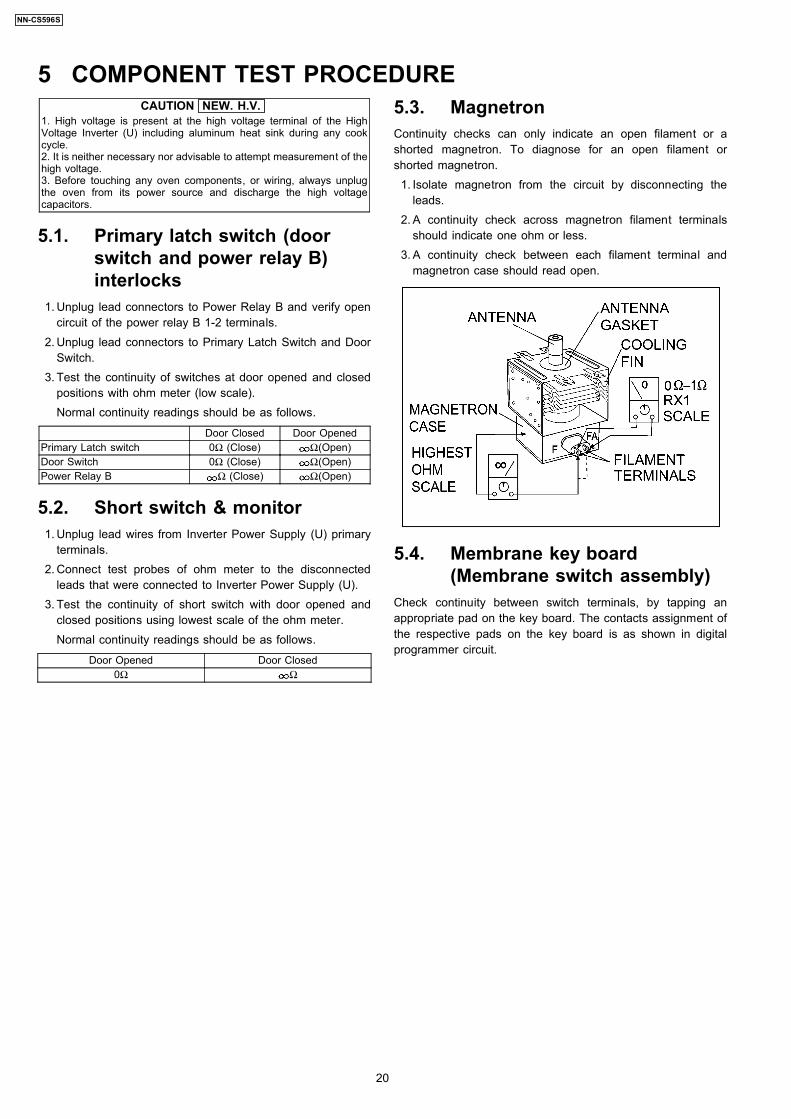
4.12. Circuit breaker
To install the circuit breaker on the coverNOTE:
1. Ensure the circuit breaker is in right direction as shownin above ILL (Do not install inversely).
2. Before tighten 2 screws, draw the circuit breakerharness(U) in and out slightly to confirm if the lead wireis pressed.(If the lead wire is pressed, the cladding ofwire might be damaged and will cause electric shock.)
3. Make sure that the same side input and output leadwires are same colour while connecting the terminals(the left side lead wires are blue). Do not mix up.
19
NN-CS596S
CAUTION NEW. H.V.1. High voltage is present at the high voltage terminal of the HighVoltage Inverter (U) including aluminum heat sink during any cookcycle.2. It is neither necessary nor advisable to attempt measurement of thehigh voltage.3. Before touching any oven components, or wiring, always unplugthe oven from its power source and discharge the high voltagecapacitors.
5.1. Primary latch switch (doorswitch and power relay B)interlocks
1. Unplug lead connectors to Power Relay B and verify opencircuit of the power relay B 1-2 terminals.
2. Unplug lead connectors to Primary Latch Switch and DoorSwitch.
3. Test the continuity of switches at door opened and closedpositions with ohm meter (low scale).Normal continuity readings should be as follows.
Door Closed Door OpenedPrimary Latch switch 0Ω (Close) Ω(Open)Door Switch 0Ω (Close) Ω(Open)Power Relay B Ω (Close) Ω(Open)
5.2. Short switch & monitor 1. Unplug lead wires from Inverter Power Supply (U) primary
terminals. 2. Connect test probes of ohm meter to the disconnected
leads that were connected to Inverter Power Supply (U). 3. Test the continuity of short switch with door opened and
closed positions using lowest scale of the ohm meter.Normal continuity readings should be as follows.
Door Opened Door Closed0Ω Ω
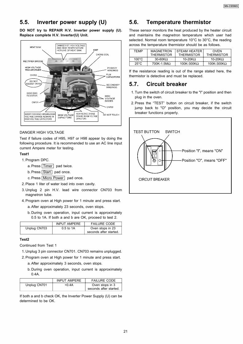
5.3. MagnetronContinuity checks can only indicate an open filament or ashorted magnetron. To diagnose for an open filament orshorted magnetron. 1. Isolate magnetron from the circuit by disconnecting the
leads. 2. A continuity check across magnetron filament terminals
should indicate one ohm or less. 3. A continuity check between each filament terminal and
magnetron case should read open.
5.4. Membrane key board(Membrane switch assembly)
Check continuity between switch terminals, by tapping anappropriate pad on the key board. The contacts assignment ofthe respective pads on the key board is as shown in digitalprogrammer circuit.
5 COMPONENT TEST PROCEDURE
20
NN-CS596S
5.5. Inverter power supply (U)DO NOT try to REPAIR H.V. Inverter power supply (U).Replace complete H.V. Inverter(U) Unit.
DANGER HIGH VOLTAGETest if failure codes of H95, H97 or H98 appear by doing thefollowing procedure. It is recommended to use an AC line inputcurrent Ampere meter for testing.Test1 1. Program DPC.
a. Press Timer pad twice. b. Press Start pad once. c. Press Micro Power pad once.
2. Place 1 liter of water load into oven cavity. 3. Unplug 2 pin H.V. lead wire connector CN703 from
magnetron tube. 4. Program oven at High power for 1 minute and press start.
a. After approximately 23 seconds, oven stops. b. During oven operation, input current is approximately
0.5 to 1A. If both a and b are OK, proceed to test 2.
INPUT AMPERE FAILURE CODEUnplug CN703 0.5 to 1A Oven stops in 23
seconds after started.
Test2Continued from Test 1 1. Unplug 3 pin connector CN701. CN703 remains unplugged. 2. Program oven at High power for 1 minute and press start.
a. After approximately 3 seconds, oven stops. b. During oven operation, input current is approximately
0.4A.
INPUT AMPERE FAILURE CODEUnplug CN701 <0.4A Oven stops in 3
seconds after started.
If both a and b check OK, the Inverter Power Supply (U) can bedetermined to be OK.
5.6. Temperature thermistorThese sensor monitors the heat produced by the heater circuitand maintains the magnetron temperature which user hadselected. Normal room temperature 10°C to 30°C, the readingacross the temperature thermistor should be as follows.
TEMP MAGNETRONTHERMISTOR
STEAM HEATERTHERMISTOR
OVENTHERMISTOR
100°C 30-60KΩ 10-20KΩ 10-20KΩ25°C 700K-1.5MΩ 100K-300KΩ 100K-300KΩ
If the resistance reading is out of the range stated here, thethermistor is detective and must be replaced.
5.7. Circuit breaker 1. Turn the switch of circuit breaker to the "I" position and then
plug in the oven. 2. Press the “TEST” button on circuit breaker, if the switch
jump back to "O" position, you may decide the circuitbreaker functions properly.
21
NN-CS596S
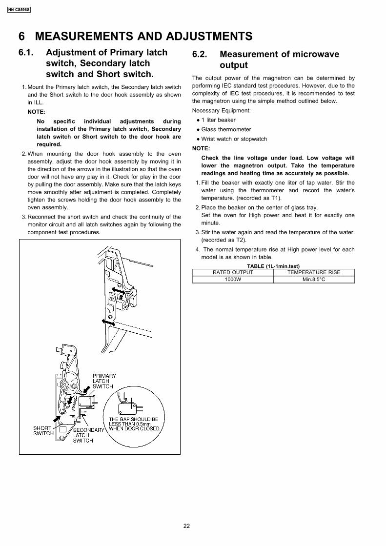
6.1. Adjustment of Primary latchswitch, Secondary latchswitch and Short switch.
1. Mount the Primary latch switch, the Secondary latch switchand the Short switch to the door hook assembly as shownin ILL.NOTE:
No specific individual adjustments duringinstallation of the Primary latch switch, Secondarylatch switch or Short switch to the door hook arerequired.
2. When mounting the door hook assembly to the ovenassembly, adjust the door hook assembly by moving it inthe direction of the arrows in the illustration so that the ovendoor will not have any play in it. Check for play in the doorby pulling the door assembly. Make sure that the latch keysmove smoothly after adjustment is completed. Completelytighten the screws holding the door hook assembly to theoven assembly.
3. Reconnect the short switch and check the continuity of themonitor circuit and all latch switches again by following thecomponent test procedures.
6.2. Measurement of microwaveoutput
The output power of the magnetron can be determined byperforming IEC standard test procedures. However, due to thecomplexity of IEC test procedures, it is recommended to testthe magnetron using the simple method outlined below.Necessary Equipment:
••••
1 liter beaker
••••
Glass thermometer
••••
Wrist watch or stopwatchNOTE:
Check the line voltage under load. Low voltage willlower the magnetron output. Take the temperaturereadings and heating time as accurately as possible.
1. Fill the beaker with exactly one liter of tap water. Stir thewater using the thermometer and record the water’stemperature. (recorded as T1).
2. Place the beaker on the center of glass tray.Set the oven for High power and heat it for exactly oneminute.
3. Stir the water again and read the temperature of the water.(recorded as T2).
4. The normal temperature rise at High power level for eachmodel is as shown in table.
TABLE (1L-1min.test)RATED OUTPUT TEMPERATURE RISE
1000W Min.8.5°C
6 MEASUREMENTS AND ADJUSTMENTS
22
NN-CS596S
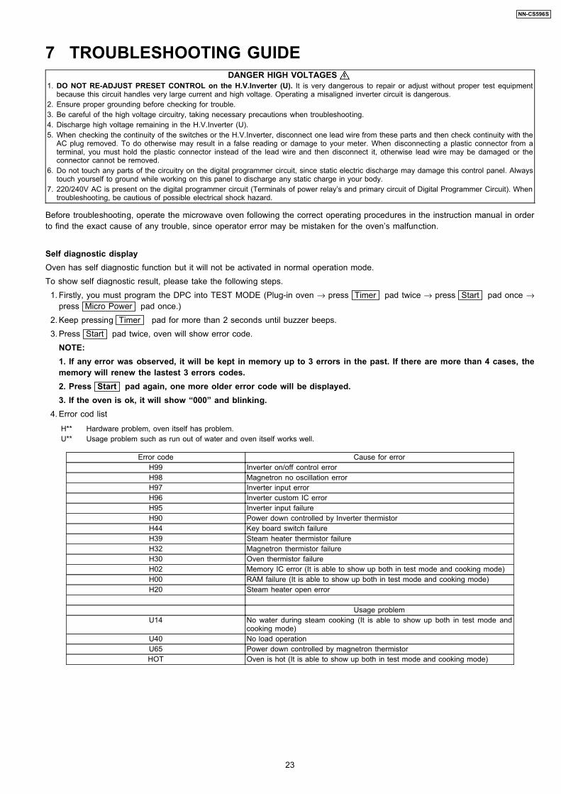
7 TROUBLESHOOTING GUIDEDANGER HIGH VOLTAGES
1. DO NOT RE-ADJUST PRESET CONTROL on the H.V.Inverter (U). It is very dangerous to repair or adjust without proper test equipmentbecause this circuit handles very large current and high voltage. Operating a misaligned inverter circuit is dangerous.
2. Ensure proper grounding before checking for trouble.3. Be careful of the high voltage circuitry, taking necessary precautions when troubleshooting.4. Discharge high voltage remaining in the H.V.Inverter (U).5. When checking the continuity of the switches or the H.V.Inverter, disconnect one lead wire from these parts and then check continuity with the
AC plug removed. To do otherwise may result in a false reading or damage to your meter. When disconnecting a plastic connector from aterminal, you must hold the plastic connector instead of the lead wire and then disconnect it, otherwise lead wire may be damaged or theconnector cannot be removed.
6. Do not touch any parts of the circuitry on the digital programmer circuit, since static electric discharge may damage this control panel. Alwaystouch yourself to ground while working on this panel to discharge any static charge in your body.
7. 220/240V AC is present on the digital programmer circuit (Terminals of power relay’s and primary circuit of Digital Programmer Circuit). Whentroubleshooting, be cautious of possible electrical shock hazard.
Before troubleshooting, operate the microwave oven following the correct operating procedures in the instruction manual in orderto find the exact cause of any trouble, since operator error may be mistaken for the oven’s malfunction.
Self diagnostic displayOven has self diagnostic function but it will not be activated in normal operation mode.To show self diagnostic result, please take the following steps. 1. Firstly, you must program the DPC into TEST MODE (Plug-in oven → press Timer pad twice → press Start pad once →
press Micro Power pad once.) 2. Keep pressing Timer pad for more than 2 seconds until buzzer beeps. 3. Press Start pad twice, oven will show error code.
NOTE:1. If any error was observed, it will be kept in memory up to 3 errors in the past. If there are more than 4 cases, thememory will renew the lastest 3 errors codes.2. Press Start pad again, one more older error code will be displayed.3. If the oven is ok, it will show “000” and blinking.
4. Error cod list
H** Hardware problem, oven itself has problem.U** Usage problem such as run out of water and oven itself works well.
Error code Cause for errorH99 Inverter on/off control errorH98 Magnetron no oscillation errorH97 Inverter input errorH96 Inverter custom IC errorH95 Inverter input failureH90 Power down controlled by Inverter thermistorH44 Key board switch failureH39 Steam heater thermistor failureH32 Magnetron thermistor failureH30 Oven thermistor failureH02 Memory IC error (It is able to show up both in test mode and cooking mode)H00 RAM failure (It is able to show up both in test mode and cooking mode)H20 Steam heater open error
Usage problemU14 No water during steam cooking (It is able to show up both in test mode and
cooking mode)U40 No load operationU65 Power down controlled by magnetron thermistorHOT Oven is hot (It is able to show up both in test mode and cooking mode)
23
NN-CS596S
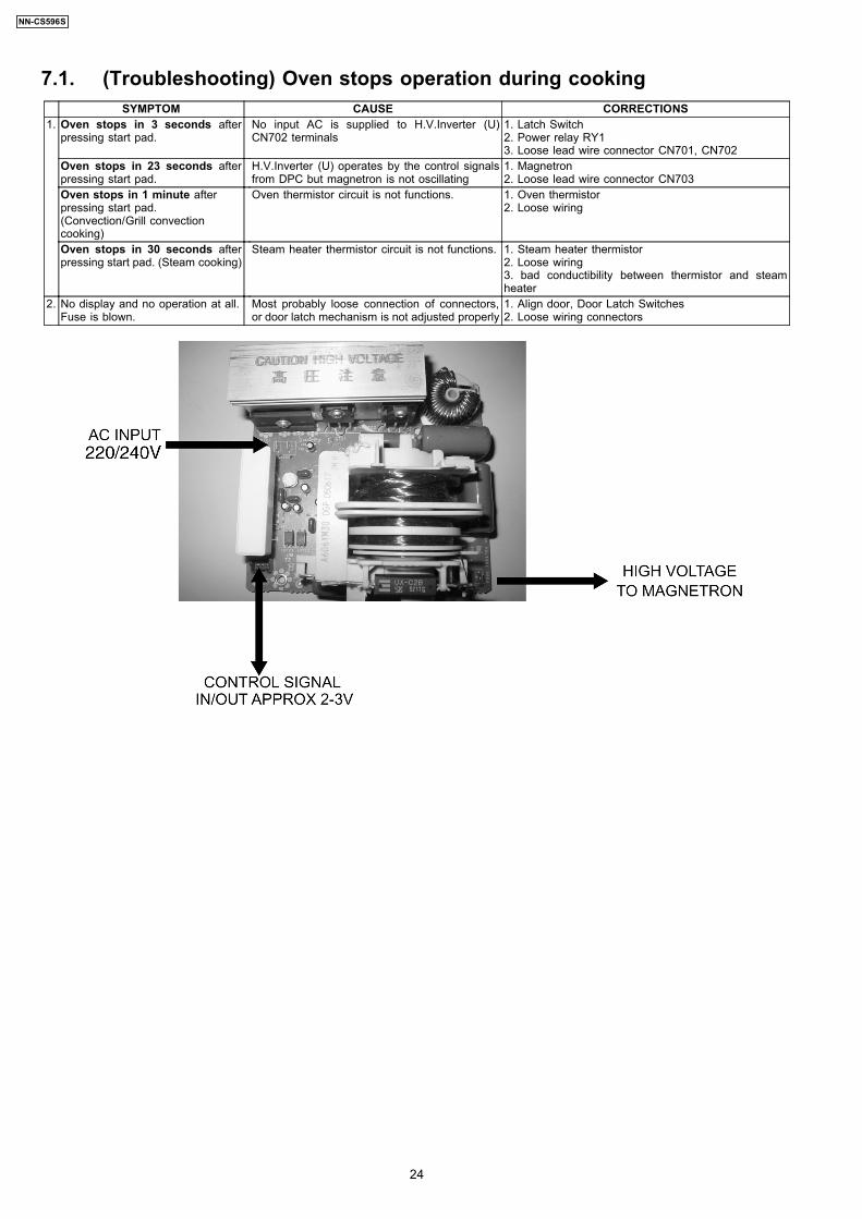
7.1. (Troubleshooting) Oven stops operation during cookingSYMPTOM CAUSE CORRECTIONS
1. Oven stops in 3 seconds afterpressing start pad.
No input AC is supplied to H.V.Inverter (U)CN702 terminals
1. Latch Switch2. Power relay RY13. Loose lead wire connector CN701, CN702
Oven stops in 23 seconds afterpressing start pad.
H.V.Inverter (U) operates by the control signalsfrom DPC but magnetron is not oscillating
1. Magnetron2. Loose lead wire connector CN703
Oven stops in 1 minute afterpressing start pad.(Convection/Grill convectioncooking)
Oven thermistor circuit is not functions. 1. Oven thermistor2. Loose wiring
Oven stops in 30 seconds afterpressing start pad. (Steam cooking)
Steam heater thermistor circuit is not functions. 1. Steam heater thermistor2. Loose wiring3. bad conductibility between thermistor and steamheater
2. No display and no operation at all.Fuse is blown.
Most probably loose connection of connectors,or door latch mechanism is not adjusted properly
1. Align door, Door Latch Switches2. Loose wiring connectors
24
NN-CS596S
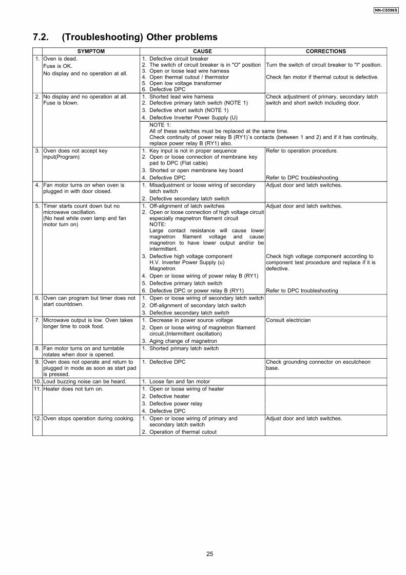
7.2. (Troubleshooting) Other problemsSYMPTOM CAUSE CORRECTIONS
1. Oven is dead. 1.2.3.4.5.6.
Defective circuit breakerThe switch of circuit breaker is in "O" positionOpen or loose lead wire harnessOpen thermal cutout / thermistorOpen low voltage transformerDefective DPC
Turn the switch of circuit breaker to "I" position.
Check fan motor if thermal cutout is defective.
Fuse is OK.No display and no operation at all.
2. No display and no operation at all.Fuse is blown.
1.2.
Shorted lead wire harnessDefective primary latch switch (NOTE 1)
Check adjustment of primary, secondary latchswitch and short switch including door.
3. Defective short switch (NOTE 1)4. Defective Inverter Power Supply (U)
NOTE 1:All of these switches must be replaced at the same time.Check continuity of power relay B (RY1)´s contacts (between 1 and 2) and if it has continuity,replace power relay B (RY1) also.
3. Oven does not accept keyinput(Program)
1.2.
Key input is not in proper sequenceOpen or loose connection of membrane keypad to DPC (Flat cable)
Refer to operation procedure.
3. Shorted or open membrane key board4. Defective DPC Refer to DPC troubleshooting.
4. Fan motor turns on when oven isplugged in with door closed.
1. Misadjustment or loose wiring of secondarylatch switch
Adjust door and latch switches.
2. Defective secondary latch switch5. Timer starts count down but no
microwave oscillation.(No heat while oven lamp and fanmotor turn on)
1.2.
Off-alignment of latch switchesOpen or loose connection of high voltage circuitespecially magnetron filament circuitNOTE:Large contact resistance will cause lowermagnetron filament voltage and causemagnetron to have lower output and/or beintermittent.
Adjust door and latch switches.
3. Defective high voltage componentH.V. Inverter Power Supply (u)Magnetron
Check high voltage component according tocomponent test procedure and replace if it isdefective.
4. Open or loose wiring of power relay B (RY1)5. Defective primary latch switch6. Defective DPC or power relay B (RY1) Refer to DPC troubleshooting
6. Oven can program but timer does notstart countdown.
1. Open or loose wiring of secondary latch switch2. Off-alignment of secondary latch switch3. Defective secondary latch switch
7. Microwave output is low. Oven takeslonger time to cook food.
1. Decrease in power source voltage Consult electrician2. Open or loose wiring of magnetron filament
circuit.(Intermittent oscillation)3. Aging change of magnetron
8. Fan motor turns on and turntablerotates when door is opened.
1. Shorted primary latch switch
9. Oven does not operate and return toplugged in mode as soon as start padis pressed.
1. Defective DPC Check grounding connector on escutcheonbase.
10. Loud buzzing noise can be heard. 1. Loose fan and fan motor11. Heater does not turn on. 1. Open or loose wiring of heater
2. Defective heater3. Defective power relay4. Defective DPC
12. Oven stops operation during cooking. 1. Open or loose wiring of primary andsecondary latch switch
Adjust door and latch switches.
2. Operation of thermal cutout
25
NN-CS596S
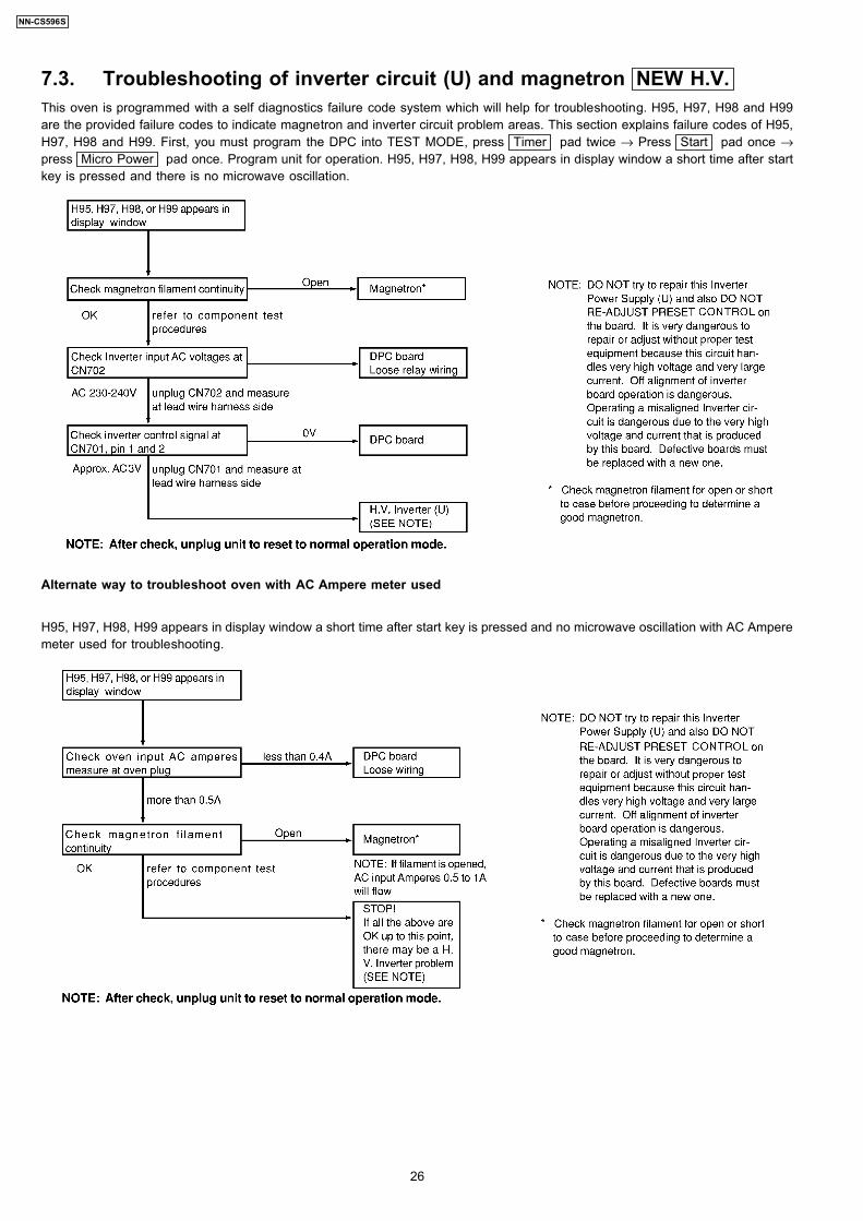
7.3. Troubleshooting of inverter circuit (U) and magnetron NEW H.V.This oven is programmed with a self diagnostics failure code system which will help for troubleshooting. H95, H97, H98 and H99are the provided failure codes to indicate magnetron and inverter circuit problem areas. This section explains failure codes of H95,H97, H98 and H99. First, you must program the DPC into TEST MODE, press Timer pad twice → Press Start pad once →press Micro Power pad once. Program unit for operation. H95, H97, H98, H99 appears in display window a short time after startkey is pressed and there is no microwave oscillation.
Alternate way to troubleshoot oven with AC Ampere meter used
H95, H97, H98, H99 appears in display window a short time after start key is pressed and no microwave oscillation with AC Amperemeter used for troubleshooting.
26
NN-CS596S
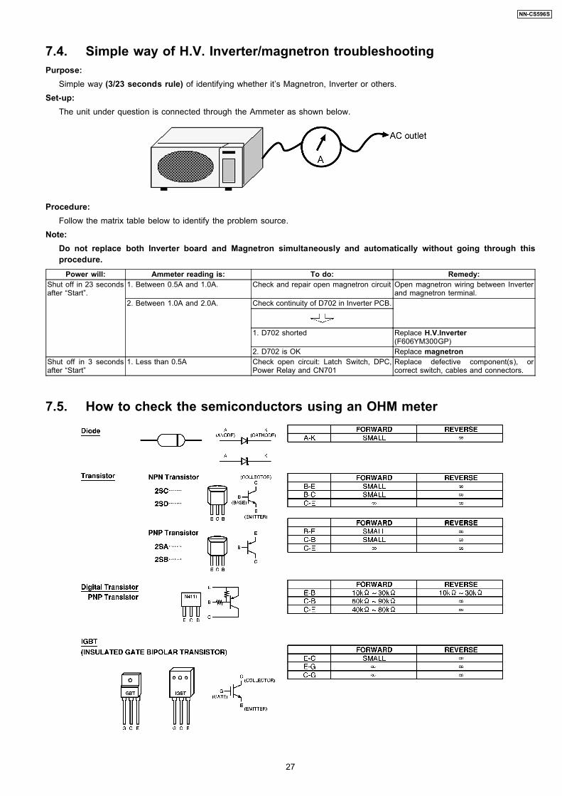
7.4. Simple way of H.V. Inverter/magnetron troubleshootingPurpose:
Simple way (3/23 seconds rule) of identifying whether it’s Magnetron, Inverter or others.Set-up:
The unit under question is connected through the Ammeter as shown below.
Procedure:Follow the matrix table below to identify the problem source.
Note:Do not replace both Inverter board and Magnetron simultaneously and automatically without going through thisprocedure.
Power will: Ammeter reading is: To do: Remedy:Shut off in 23 secondsafter “Start”.
1. Between 0.5A and 1.0A. Check and repair open magnetron circuit Open magnetron wiring between Inverterand magnetron terminal.
2. Between 1.0A and 2.0A. Check continuity of D702 in Inverter PCB.
1. D702 shorted Replace H.V.Inverter(F606YM300GP)
2. D702 is OK Replace magnetronShut off in 3 secondsafter “Start”
1. Less than 0.5A Check open circuit: Latch Switch, DPC,Power Relay and CN701
Replace defective component(s), orcorrect switch, cables and connectors.
7.5. How to check the semiconductors using an OHM meter
27
NN-CS596S
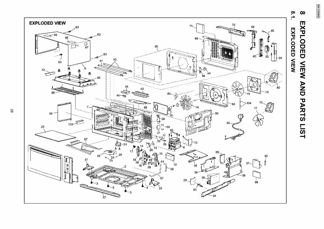
8 EXPLO
DED
VIEWA
ND
PAR
TSLIST
8.1. EXPLO
DED
VIEW
28
NN
-CS596S
8.2. PARTS LISTNOTE:
1. When ordering replacement part(s), please use part number(s) shown in this part list.Do not use description of the part.
2. Important safety notice:Components identified by mark have special characteristics important for safety.When replacing any of these components, use only manufacture’s specified parts.
Ref. No. Part No. Part Name & Description Pcs/Set Remarks
1 Z00064080BP CAUTION LABEL 1 BPQ
1 Z00069000EP CAUTION LABEL 1 EPG,SPG,WPG
2 Z10016Y40XPG BASE 1
3 Z10087J60XP RUBBER FOOT 2
4 Z10084T00AP RUBBER FOOT 1
5 Z1008-1F90 RUBBER FOOT 1
6 Z11556Y40SBP CABINET BODY 1
7 Z200A6Y40BP OVEN 1
9 Z2M261-M32J MAGNETRON 1
10 Z400A7J70MP FAN MOTOR 1
11 Z40085G10XN FAN BLADE 1
12 Z40256Y40BP AIR GUIDE A 1
13 Z40267J70XPG AIR GUIDE B 1
14 Z30977J70XP SPRING 2
15 Z31027J70XP LATCH SWITCH LEVER 1
16 Z31037J70XP DOOR HOOK 1
17 Z31057J70XP LATCH BRACKET 1
18 Z32497J70XP LATCH SWITCH LEVER 1
19 Z612E6Y40BP INCANDESCENT LAMP(U) 1
20 Z60746Y40XPG INCANDESCENT LAMP BRACKET 1
21 Z64377J70XP GLASS 1
22 Z010T6Y40BP CERAMIC PLATE (U) 1 EPG, SPG, WPG
22 Z010T6Y40BN CERAMIC PLATE (U) 1 BPQ
23 Z202K6Y40BPG ANTENNA STIRRER (U) 1
24 Z61447J70XP STIR MOTOR 1
25 Z20197J70XP ANTENNA BRACKET 3
26 Z61425U30XN MICRO SWITCH 1 (V-15G-3C25) (PRIMARY LATCH SWITCH)
27 Z61425180AP MICRO SWITCH 1 (D3V-16G-3C25) (SECONDARY LATCH SWITCH)
28 Z61785180AP MICRO SWITCH 1 (D3V-1G-2C25) (SHORT SWITCH)
29 Z603Y6Y40XP D.P.CIRCUIT (DU) 1
30 Z62304210BP FUSE 1 10A/250V
31 Z692Y6Y40BP NOISE FILTER (U) 1
32 Z45006Y40XP JACKET 1
33 Z900C6Y40BP AC CORD W/PLUG 1 BPQ
33 Z900C6Y40EP AC CORD W/PLUG 1 EPG,SPG
33 Z900C6Y40WP AC CORD W/PLUG 1 WPG
34 Z20347J70XPG INVERTER BRACKET A 1
35 Z2036-1K00 INVERTER BRACKET B 1
36 Z606Y6Y40BP H.V.INVERTER (U) 1
37 Z80236Y40BP DECORATING PLATE (COLLECTOR PAN) 1
38 Z6585-1K00 INVERTER BRACKET A 1
39 Z67637J70XP INVERTER BRACKET B 1
40 Z630G6Y40BP HEATER 2 BPQ,EPG
40 Z630G6Y40SP HEATER 2 SPG,WPG (450W/115V)
41 Z630G6Y40BP HEATER 1 BPQ,EPG
41 Z630F6Y40SP HEATER 1 SPG,WPG (450W/230V)
43 Z611E6Y40BP HEATER (DU) 1 BPQ
43 Z611E6Y40EP HEATER (DU) 1 EPG,SPG,WPG
44 Z61457J70XP THERMAL CUTOUT 2
45 Z66266Y40XPG THERMAL CUTOUT BRACKET 1
46 Z01505R00BP NO TOUCHING LABEL 1 BPQ
48 Z01508G60HP NO TOUCHING LABEL 1 EPG,SPG,WPG
49 Z22377J70XPG LEFT HEATER PANEL 1
50 Z22367J70XPG RIGHT HEATER PANEL 1
51 Z300B7J70XP LEFT HINGE (U) 1
52 Z300U7J70XP RIGHT HINGE (U) 1
55 Z44966Y40XP NOZZLE A 1
56 Z45137J70XP TIE-IN C 1
57 Z92017J70XP COPPER PIPE 1
58 Z46507J70XP TUBE C 1
59 Z92047J70XP TUBE D 1
29
NN-CS596S
Ref. No. Part No. Part Name & Description Pcs/Set Remarks
60 Z03346Y40BP MENU LABEL 1 BPQ
61 Z90717J70XP SUPPORT 1
62 ZTWFA4+12T SCREW 4 FOR MAGNETRON
63 ZTWFA4+12D SCREW 4 FOR CABINET BODY
65 Z202Q6Y40BP UPPER HEATER PANEL 1
66 Z15676Y40XP DRIP PLATE 1
67 Z22776Y40XP LOWER HEATER PANEL 1
68 Z10596Y40EP BACK COVER 1
69 Z10586Y40BP SIDE COVER 1
70 Z10576Y40XP BACK COVER C 1
71 Z40306Y40BP EXHAUST GUIDE D 1
72 Z41706Y40BP HEATER MOUNTING PLATE 1
74 Z22394V00BP CONVECTION FAN BLADE 1
75 Z41594V00BP COOLING FAN BLADE 1
79 Z41806Y40BP CONVECTION FAN BRACKET 1
80 Z490S6Y40XP CONVECTION FAN MOTOR 1
81 Z631D6Y40BP CONVECTION HEATER 1 BPQ
81 Z631D6Y40EP CONVECTION HEATER 1 EPG,SPG,WPG
82 Z64174V00BP HEATER BRACKET A 1
83 Z66796Y40BP CONVECTION INSIDE COVER A 1
85 Z607J6Y40BN CONVECTION ASSEMBLY(BU) 1 (INCLUDING IN CONVECTION OUTSIDE COVER B &ADIABATIC MATERIAL)
86 Z67356Y40XP HEATER PROTECTOR 1
89 Z40276Y40BP INVERTER AIR GUIDE 1
90 Z50586Y40XP BRACKET 1
91 Z50596Y40XP COVER 1
92 Z60586Y40BP CIRCUIT BREAKER 1
93 Z03586Y40BP CIRCUIT BREAKER HARNESS 1
94 Z66286Y40BN THERMAL CUTOUT BRACKET 1
96 Z6331-1T50 FUSE 1 15A/250V
97 Z04906Y40EP ENERGY LABEL 1 EPG
98 Z15607J70ZP ALUMINUM PLATE 1
103 Z11656Y40KT REINFORCE BRACKET E 1
104 Z67576Y40BP HEATER BRACKET D 2
8.3. WATER TANK ASSEMBLY
Ref. No. Part No. Part Name & Description Pcs/Set Remarks
T1 Z060Q6Y40XP WATER TANK (U) 1 (INCLUDING TANK COVER & SEAL)
T2 Z061A6Y40XP WATER TANK 1
T3 Z06116Y40XP TANK COVER 1
T4 Z44247J70XP SEAL 1
30
NN-CS596S
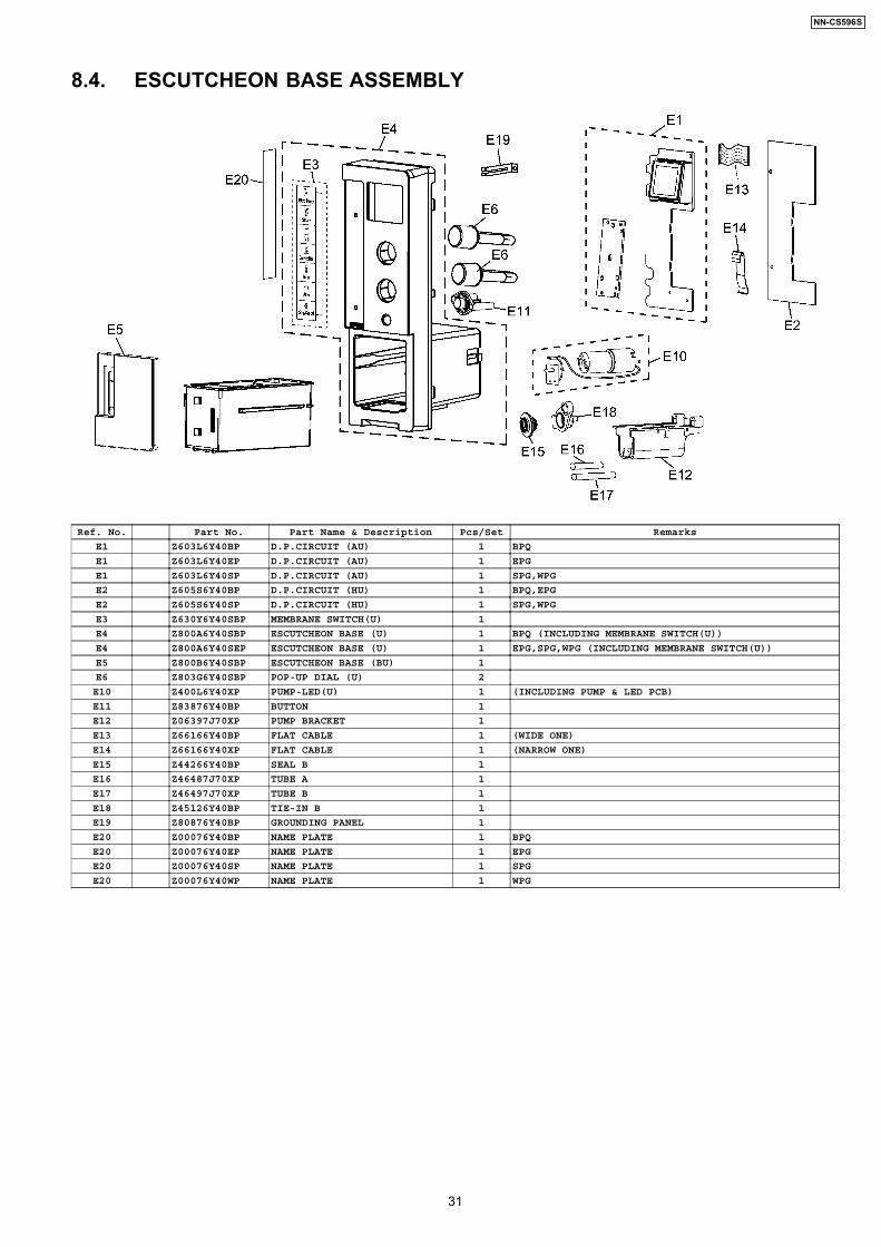
8.4. ESCUTCHEON BASE ASSEMBLY
Ref. No. Part No. Part Name & Description Pcs/Set Remarks
E1 Z603L6Y40BP D.P.CIRCUIT (AU) 1 BPQ
E1 Z603L6Y40EP D.P.CIRCUIT (AU) 1 EPG
E1 Z603L6Y40SP D.P.CIRCUIT (AU) 1 SPG,WPG
E2 Z605S6Y40BP D.P.CIRCUIT (HU) 1 BPQ,EPG
E2 Z605S6Y40SP D.P.CIRCUIT (HU) 1 SPG,WPG
E3 Z630Y6Y40SBP MEMBRANE SWITCH(U) 1
E4 Z800A6Y40SBP ESCUTCHEON BASE (U) 1 BPQ (INCLUDING MEMBRANE SWITCH(U))
E4 Z800A6Y40SEP ESCUTCHEON BASE (U) 1 EPG,SPG,WPG (INCLUDING MEMBRANE SWITCH(U))
E5 Z800B6Y40SBP ESCUTCHEON BASE (BU) 1
E6 Z803G6Y40SBP POP-UP DIAL (U) 2
E10 Z400L6Y40XP PUMP-LED(U) 1 (INCLUDING PUMP & LED PCB)
E11 Z83876Y40BP BUTTON 1
E12 Z06397J70XP PUMP BRACKET 1
E13 Z66166Y40BP FLAT CABLE 1 (WIDE ONE)
E14 Z66166Y40XP FLAT CABLE 1 (NARROW ONE)
E15 Z44266Y40BP SEAL B 1
E16 Z46487J70XP TUBE A 1
E17 Z46497J70XP TUBE B 1
E18 Z45126Y40BP TIE-IN B 1
E19 Z80876Y40BP GROUNDING PANEL 1
E20 Z00076Y40BP NAME PLATE 1 BPQ
E20 Z00076Y40EP NAME PLATE 1 EPG
E20 Z00076Y40SP NAME PLATE 1 SPG
E20 Z00076Y40WP NAME PLATE 1 WPG
31
NN-CS596S
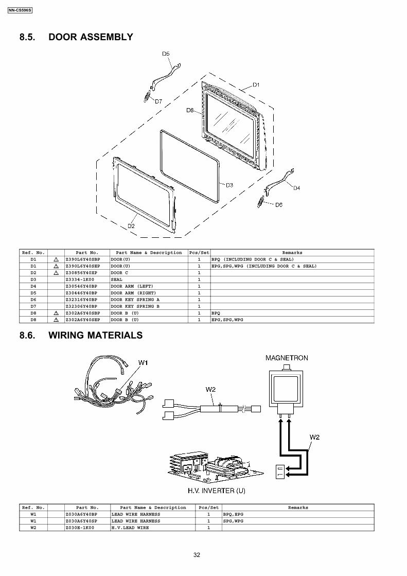
8.5. DOOR ASSEMBLY
Ref. No. Part No. Part Name & Description Pcs/Set Remarks
D1 Z390L6Y40SBP DOOR(U) 1 BPQ (INCLUDING DOOR C & SEAL)
D1 Z390L6Y40SEP DOOR(U) 1 EPG,SPG,WPG (INCLUDING DOOR C & SEAL)
D2 Z30856Y40XP DOOR C 1
D3 Z3334-1K00 SEAL 1
D4 Z30546Y40BP DOOR ARM (LEFT) 1
D5 Z30446Y40BP DOOR ARM (RIGHT) 1
D6 Z32316Y40BP DOOR KEY SPRING A 1
D7 Z32306Y40BP DOOR KEY SPRING B 1
D8 Z302A6Y40SBP DOOR B (U) 1 BPQ
D8 Z302A6Y40SEP DOOR B (U) 1 EPG,SPG,WPG
8.6. WIRING MATERIALS
Ref. No. Part No. Part Name & Description Pcs/Set Remarks
W1 Z030A6Y40BP LEAD WIRE HARNESS 1 BPQ,EPG
W1 Z030A6Y40SP LEAD WIRE HARNESS 1 SPG,WPG
W2 Z030E-1K00 H.V.LEAD WIRE 1
32
NN-CS596S
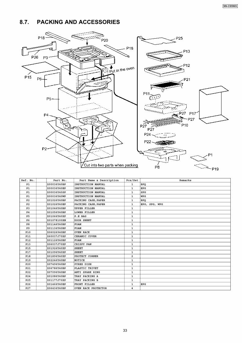
8.7. PACKING AND ACCESSORIES
Ref. No. Part No. Part Name & Description Pcs/Set Remarks
P1 Z00036Y40BP INSTRUCTION MANUAL 1 BPQ
P1 Z00036Y40EP INSTRUCTION MANUAL 1 EPG
P1 Z00036Y40SP INSTRUCTION MANUAL 1 SPG
P1 Z00036Y40WP INSTRUCTION MANUAL 1 WPG
P2 Z01026Y40BP PACKING CASE,PAPER 1 BPQ
P2 Z01026Y40EP PACKING CASE,PAPER 1 EPG, SPG, WPG
P3 Z01046Y40BP UPPER FILLER 1
P4 Z01056Y40BP LOWER FILLER 1
P5 Z01066Y40XP P.E BAG 1
P6 Z01078100XN DOOR SHEET 1
P8 Z01146Y40BP FOAM 1
P9 Z01136Y40BP FOAM 1
P10 Z06026940BP OVEN RACK 1
P11 Z60037J70XP CERAMIC COVER 1
P12 Z01126Y40BP FOAM 1
P13 Z06037J70XP CRISPY PAN 1
P15 Z01926Y40XP SHEET 1
P17 Z01096Y40XP SHEET 1
P18 Z01896Y40XP PROTECT CORNER 2
P19 Z02246Y40BP NOTICE 1
P20 Z07496Y40BP PYREX DISH 1
P21 Z06786Y40BP PLASTIC TRIVET 1
P22 Z07096Y40BP ANTI SPARK RING 1
P24 Z01086Y40BP TRAY PACKING A 1
P25 Z01177J70XP TRAY PACKING B 1
P26 Z01466Y40EP FRONT FILLER 1 EPG
P27 Z06436Y40BP OVEN RACK PROTECTOR 4
33
NN-CS596S
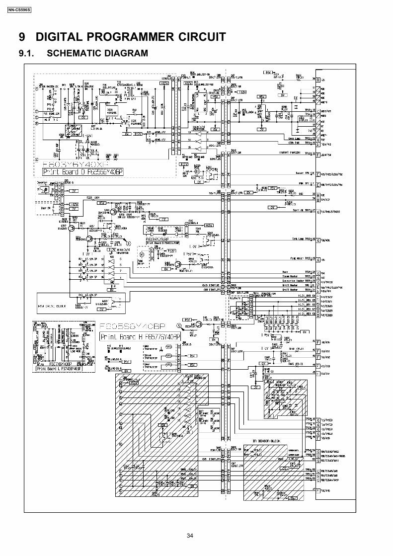
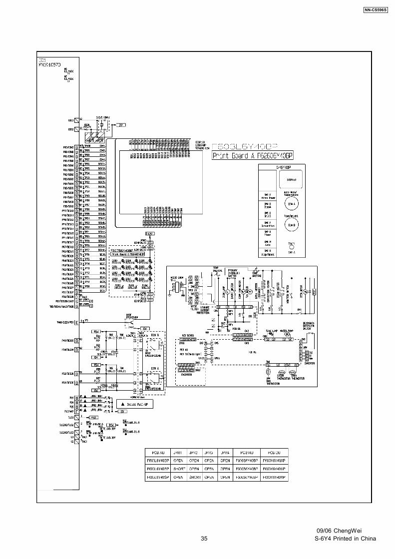
9 DIGITAL PROGRAMMER CIRCUIT9.1. SCHEMATIC DIAGRAM
34
NN-CS596S
35
NN-CS596S
09/06 ChengWeiS-6Y4 Printed in China