microwave generation in pulsed ferrites
TRANSCRIPT

Microwave Generation in Pulsed FerritesH. J. Shaw, B. J. Elliott, K. J. Harker, and A. Karp Citation: Journal of Applied Physics 37, 1060 (1966); doi: 10.1063/1.1708335 View online: http://dx.doi.org/10.1063/1.1708335 View Table of Contents: http://scitation.aip.org/content/aip/journal/jap/37/3?ver=pdfcov Published by the AIP Publishing Articles you may be interested in Quasi-stable microwave envelope pulse propagation in wide ferrite films J. Appl. Phys. 93, 7136 (2003); 10.1063/1.1543892 Highpower microwave pulse generator Rev. Sci. Instrum. 63, 3156 (1992); 10.1063/1.1142569 A highvoltage, shortrisetime pulse generator based on a ferrite pulse sharpener Rev. Sci. Instrum. 59, 2497 (1988); 10.1063/1.1139937 Picosecond microwave pulse generation Appl. Phys. Lett. 38, 470 (1981); 10.1063/1.92407 Pulsed Ferrimagnetic Microwave Generator J. Appl. Phys. 31, S400 (1960); 10.1063/1.1984763
[This article is copyrighted as indicated in the article. Reuse of AIP content is subject to the terms at: http://scitation.aip.org/termsconditions. Downloaded
to ] IP: 128.192.114.19 On: Thu, 18 Dec 2014 12:47:23
JOURNAL OF APPLIED PHYSICS VOLUME 37, NUMBER 3 1 MARCH 1966
Spin Waves and Microwave Applications L. J. V ARNERIN, Chairman
Microwave Generation in Pulsed Ferrites*
H. J. SHAW, B. J. ELLIOTT, K. J. HARKER, AND A. KARPt
Stanford University, Stanford, California
A pulsed magnetic field applied to a magnetically saturated ferrite sample is capable of initiating a coherent precession and of translating upward both the frequency and energy associated with this precession. A coupled circuit resonance can then extract energy from the system at a desired frequency. For large precession amplitude the rise of the pulsed magnetic field up to the bias field level must be nonadiabatic; the precession buildup is described by cOlilputer calculations. To avoid destructive effects of spin-wave buildup, the total risetime of the pulsed magnetic field must be less than a threshold value which depends on the precession angle; this threshold is determined from computer calculations of transient spin-wave growth. Operation within this time allows the precession angle to appreciably exceed the usual steady-state precession threshold set by spin-wave instabilities.
In experiments performed with YIG spheres mounted in an integral circuit element containing a tunable X-band slot rt'sonator and a pulsed field coil, providing pulsed magnetic fields rising beyond 3 kG in approximately 1 nsec, energy in the range of hundreds of W ·nsec has been generated over the X-band frequency range, with pulse widths of the order of 1 nsec. The output pulses have good interpulse phase coherence and are studied in detail using a sampling oscilloscope to observe the instantaneous rf waveforms.
I. INTRODUCTION
I N 1959 it was proposed 1 that a small ferrite sample subjected to a suitable pulsed magnetic field can
constitute a coherent oscillator for the generation of microwave energy. It subsequently developed, however, that a considerable advancement of ferrite theory and technology was needed before real progress could be made with devices of this kind. In the interim, some closely related devices for pulsed frequency translation in ferrites, having less stringent requirements, were studied2-4 and found to perform largely as predicted.4
These devices used a pulsed magnetic field to translate upward the frequency of an essentially cw input signal, used to establish a uniform precession, and were limited to low-power levels by the second-order spin-wave instability. In the present device the pulsed magnetic field starts the initial precession in addition to translating its frequency, and theoretical and experimental results which are summarized below show that the process can be carried out on a time scale which avoids serious degradation of performance due to spin waves. Successful operation of this type of device has been
* Supported by U.S. Army Electronics Command, Fort Monmouth, New Jersey.
t Present address: Stanford Research Institute, Menlo Park, California.
1 R. V. Pound, U.S. Patent No.2 873 370. 2 B. J. Elliott, T. Schaug-Petterson, and H. J. Shaw, J. AppJ.
Phys. 31, 400S (1960). 3 M. R. Stiglitz and F. R. Morganthaler, J. AppJ. Phys. 31,
37 (1960). 4 A. P. Aleksandrov, V. I. Khanin, and E. G. Yashchin, Zh.
Eksperim. i Teor. Fiz. 38, 1334 (1960) [English transl: Soviet Phys.-JETP 11, 960 (1960)].
demonstratedpreviously.5.6 However, the results described here represent an increase in rf output power level of several orders of magnitude over any previously reported results.
II. TRANSIENT BEHAVIOR OF A FERRITE IN A PULSED MAGNETIC FIELD
A. Establishment of Uniform Precession
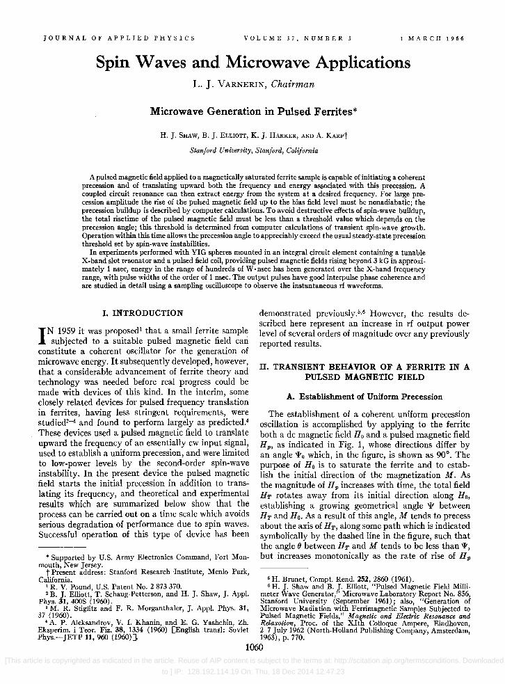
The establishment of a coherent uniform precession oscillation is accomplished by applying to the ferrite both a dc magnetic field Ho and a pulsed magnetic field Hp , as indicated in Fig. 1, whose directions differ by an angle 'ITo which, in the figure, is shown as 90°. The purpose of Ho is to saturate the ferrite and to establish the initial direction of the magnetization M. As the magnitude of H p increases with time, the total field HT rotates away from its initial direction along H o, establishing a growing geometrical angle 'IT between HT and Ho. As a result of this angle, M tends to precess about the axis of HT , along some path which is indicated symbolically by the dashed line in the figure, such that the angle 8 between HT and M tends to be less than 'IT, but increases monotonically as the rate of rise of H p
6 H. Brunet, Compt. Rend. 252, 2860 (1961). 6 H. J. Shaw and B. J. Elliott, "Pulsed Magnetic Field Milli
meter Wave Generator," Microwave Laboratory Report No. 856, Stanford University (September 1961); also, "Generation of Microwave Radiation with Ferrimagnetic Samples Subjected to Pulsed Magnetic Fields," Magnetic and Electric Resonance and Relaxation, Proc. of the XIth Colloque Ampere, Eindhoven, 2-7 July 1962 (North-Holland Publishing Company, Amsterdam, 1963), p. 770.
1060 [This article is copyrighted as indicated in the article. Reuse of AIP content is subject to the terms at: http://scitation.aip.org/termsconditions. Downloaded
to ] IP: 128.192.114.19 On: Thu, 18 Dec 2014 12:47:23
MICROWAVE GENERATION IN PULSED FERRITES 1061
is increased. Taking the magnitude of Hp to be a linear function of time, then to obtain relatively large values of'lt it is necessary that dHpldt be sufficient for HT to become of the order of Ho in a time of the order of one radian at the initial precession frequency -yHo. Also, o attains essentially its full growth (lz (defined as 0 at t= 00) during this time interval, remaining relatively constant as HT continues to grow and'lt approaches 'lto. Values of 01 for arbitrary values of H o, 'lto and dHv/dt have been calculated using the digital computer.7
In the calculations referred to, internal damping of the uniform precession mode due to relaxation mechanisms in the ferrite are neglected, it being assumed that the time intervals involved in the experiment are shorter than the relaxation times for the material. In samples of single-crystal YIG this condition is well satisfied in practice, for experiments of the type to be described below. The assumption that Hp is a linear function of time is also well satisfied in practice, with the exception of a quadratic component in HT near the origin, the effect of which has also been evaluated using the computer.
The function of the pulsed magnetic field may be divided into two parts, the first being an excitation function resulting in establishment of a uniform precession oscillation of relatively high amplitude, and the second being a pumping function through which both the frequency and energy of this precession are increased as a function of time.
After the full growth of the uniform precession angle has been reached, the field H p can, in principle, be increased indefinitelv without appreciable change occurring in the angle {It. This portion of the pulsed field rise accomplishes the pumping function by means of which the frequency and energy associated with the uniform mode are increased. As H p increases in this range, HT approaches Hp in magnitude, and the frequency and energy of the uniform mode become asymptotically proportional to the magnitude of H T •
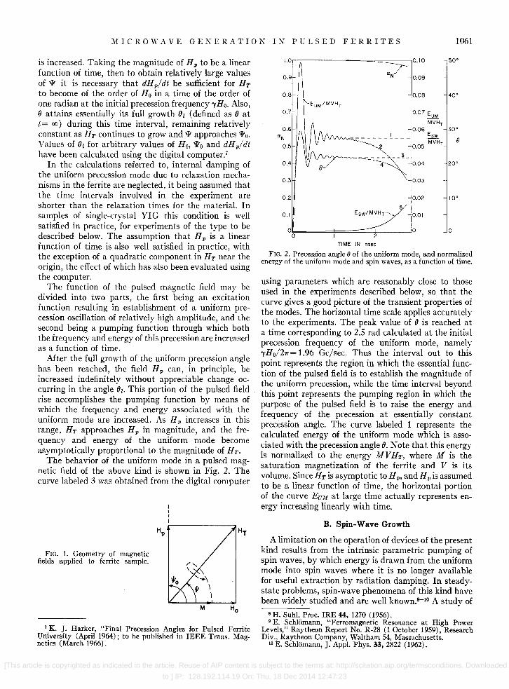
The behavior of the uniform mode in a pulsed magnetic field of the above kind is shown in Fig. 2. The curve labeled 3 was obtained from the digital computer
FIG. 1. Geometry of magnetic fields applied to ferrite sample.
7 K. J. Harker, "Final Precession Angles for Pulsed Ferrite University (April 1964); to be published in IEEE Trans. Magnetics (March 1966).
1.o'r-,---------~====_-0.IO
0.9 -
0.8
0.7 -
0.6 aN
0.5
0.4
0.3
0.2
0.1
0.09
0.08
EUM/MVH T - 0.07 EUM
MVHr 0.06
-------!--- Esw
0.05 MVHr
__ L
8
0.02
Esw/MVH r ______ 0.01
0 2
TIME IN nsee
50'
40'
30'
8
- 20'
10'
0
FIG. 2. Precession angle () of the uniform mode, and normal.ized energy of the uniform mode and spin waves, as a function of time.
using parameters which are reasonably close to those used in the experiments described below, so that the curve gives a good picture of the transient properties of the modes. The horizontal time scale applies accurately to the experiments. The peak value of 0 is reached at a time corresponding to 2.S rad calculated at the initial precession frequency of the uniform mode, namely -yHo/27r= 1.96 Gc/sec. Thus the interval out to this point represents the region in which the essential function of the pulsed field is to establish the magnitude of the uniform precession, while the time interval beyond this point represents the pumping region in which the purpose of the pulsed field is to raise the energy and frequency of the precession at essentially constant precession angle. The curve labeled 1 represents the calculated energy of the uniform mode which is associated with the precession angle O. Note that this energy is normalized to the energy MVHT , where M is the saturation magnetization of the ferrite and V is its volume. Since HT is asymptotic to H p, and H p is assumed to be a linear function of time, the horizontal portion of the curve EU]If at large time actually represents energy increasing linearly with time.
B. Spin-Wave Growth
A limitation on the operation of devices of the present kind results from the intrinsic parametric pumping of spin waves, by which energy is drawn from the uniform mode into spin waves where it is no longer available for useful extraction by radiation damping. In steadystate problems, spin-wave phenomena of this kind have been widely studied and are well known.8- 10 A study of
8 H. Suhl, Proc. IRE 44, 1270 (~956). . 9 E. Schliimann, "Ferromagnetic Resonance at High Power
Levels," Raytheon Report No. R-28 (1 October 1959), Research Div., Raytheon Company, Waltham 54, Massachusetts.
10 E. Schliimann, J. App!. Phys. 33, 2822 (1962).
[This article is copyrighted as indicated in the article. Reuse of AIP content is subject to the terms at: http://scitation.aip.org/termsconditions. Downloaded
to ] IP: 128.192.114.19 On: Thu, 18 Dec 2014 12:47:23
1062 SHAW ET AL.
the mechanisms of spin-wave growth under the present transient circumstances has been made using the digital computer.1l ,I2 In this investigation, the equations of motion for spin-wave modes in a ferrite subjected to linearly rising pulses of magnetic field, for all regions of k space which undergo pumping, are integrated numerically, assuming initial spin-wave excitation at the level corresponding to thermal equilibrium. Again, no restrictions are imposed on the values of Ho, 'Iro, or dHp/dt, and again the equations for the uniform mode are used in completely general form to allow for arbitrary amplitude of the mode. In the spin-wave equations, terms to first order in the spin-wave amplitudes are retained, and all spin-wave back. reaction terms are included in the uniform mode equations. A numerical integration over k space determines the aggregate of spin-wave growth as a function of time, and the energy in the uniform mode as a function of time in the presence of the amplified spin wave.
In Figure 2 the curves labeled 2, 4, and 5 show the results of this process for particular parameter values which are relevant to the present experiments, as given above. Curve 5 indicates the growth of total spin-wave energy as a function of time. The effect of this spinwave growth on the precession angle (J of the uniform mode is indicated by curve 4, and similarly the decrease in uniform mode energy is shown by curve 2, representing energy associated with the uniform mode. We see that these theoretical curves predict that in a time of approximately 2 nsec the energy associated with the uniform mode has been degraded by approximately 10%, by the presence of spin waves, from the value which it would have without spin waves. The uniform mode energy decreases rapidly beyond this point. On this basis, one should design the experiment such that the energy removal by radiation damping of the uniform mode occurs before the elapsed time exceeds 2 nsec.
III. COUPLED CIRCUIT BEHAVIOR
Radiation damping for extraction of energy from the ferrite at the desired frequency is provided by a coupled circuit resonator which is described below. This resonator, and the uniform mode resonance in the YIG sample, constitute a coupled circuit system. As the oscillation frequency of the uniform mode is swept through the resonant frequency of the circuit mode, a transfer of energy to the circuit takes place.
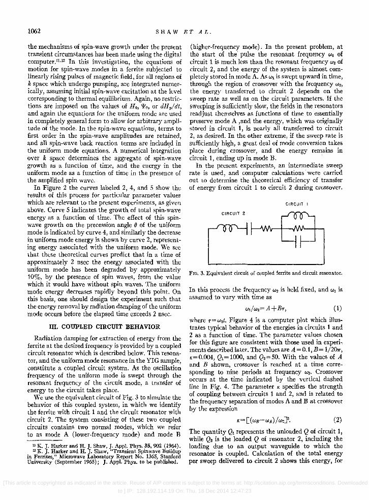
We use the equivalent circuit of Fig. 3 to simulate the behavior of this coupled system, in which we identify the ferrite with circuit 1 and the circuit resonator with circuit 2. The system consisting of these two coupled circuits contains two normal modes, which we refer to as mode A (lower-frequency mode) and mode B
11 K. J. Harker and H. J. Shaw, J. Appl. Phys. 35, 902 (1964). 12 K. J. Harker and H. J. Shaw, "Transient Spinwave Buildup
in Ferrites," Microwave Laboratory Report No. 1365, Stanford University (September 1965) i J. Appl. Phys. to be published.
(higher-frequency mode). In the present problem, at the start of the pulse the resonant frequency Wi of circuit 1 is much less than the resonant frequency W2 of circuit 2, and the energy of the system is almost completely stored in mode A. As WI is swept upward in time, through the region of crossover with the frequency W2,
the energy transferred to circuit 2 depends on the sweep rate as well as on the circuit parameters. If the sweeping is sufficiently slow, the fields in the resonators readjust themselves as functions of time to essentially preserve mode A ,and the energy, which was originally stored in circuit 1, is nearly all transferred to circuit 2, as desired. In the other extreme, if the sweep rate is sufficiently high, a great deal of mode conversion takes place during crossover, and the energy remains in circuit 1, ending up in mode B.
In the present experiments, an intermediate sweep rate is used, and computer calculations were carried out to determine the theoretical efficiency of transfer of energy from circuit 1 to circuit 2 during crossover.
CIRCUIT I
FIG. 3. Equivalent circuit of coupled ferrite and circuit resonator.
In this process the frequency W2 is held fixed, and WI is assumed to vary with time as
(1)
where T=W2t. Figure 4 is a computer plot which illustrates typical behavior of the energies in circuits 1 and 2 as a function of time. The parameter values chosen for this figure are consistent with those used in experi., mentsdescribedlater. The values are A =0.1,B= 1/207r, K=O.004, Ql=1000, and Q2=SO. With the values of A and B shown, crossover is reached at a time corre., sponding to nine periods at frequency W2. Crossover occurs at the time indicated by the vertical dashed line in Fig. 4. The parameter K specifies the strength of coupling between circuits 1 and 2, and is related to the frequency separation of modes A and B at crossover by the expression
(2)
The quantity QI represents the unloaded Q of circuit 1, while Q2 is the loaded Q of resonator 2, including the loading due to an output waveguide to which the resonator is coupled. Calculation of the total energy per sweep delivered to circuit 2 shows this energy, for
[This article is copyrighted as indicated in the article. Reuse of AIP content is subject to the terms at: http://scitation.aip.org/termsconditions. Downloaded
to ] IP: 128.192.114.19 On: Thu, 18 Dec 2014 12:47:23
MICROWAVE GENERATION IN PULSED FERRITES 1063
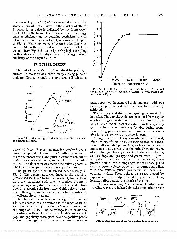
the case of Fig. 4, is 29% of the energy which would be stored in circuit 1 at crossover in the absence of circuit 2, which latter value is indicated by the intersection marked U in the figure. The dependence of this energy transfer efficiency on the coupling coefficient K, with all other parameters as in Fig. 4, is shown in the plot of Fig. 5. While the value of K used with Fig. 4 is comparable to that involved in the experiments below, we note from Fig. 5 that a design using higher coupling coefficients could materially improve the energy transfer efficiency of the coupled circuits.
IV. PULSER DESIGN
The pulsed magnetic field is obtained by passing a current, in the form of a short, steeply rising pulse of high amplitude, through a single-turn coil which is
12.000,--------------;,..."
10.000
8.000
~ w ~ 6.000
o W N
~ 4.000 :;;
~
00 2.000 x 101 NORMALIZED TIME T
FIG. 4. Theoretical energy transfer between ferrite and circuit as a function of time.
described later. Typical magnitudes involved are a current amplitude of some 1.5 kA with a pulse width of several nanoseconds, and pulse rise time of somewhat under 1 nsec in a coil having an inductance of the order of 1 nR. In this section we describe the pulser apparatus which was developed to meet these specifications.
The pulser system is illustrated schematically in Fig. 6. The general approach involves the use of a pressurized spark gap to switch a relatively high voltage on a low-impedance strip line, to produce a current pulse of high amplitude in the strip line, and subsequently steepening the front edge of this pulse by passing it through a second spark gap, which constitutes a nonlinear circuit element.
The charged line section on the right-hand end in Fig. 6 is charged to a dc voltage in the range of 10-20 kV, upon which is superimposed a 60-cps ac voltage in the range of 1-3 kV. The dc voltage is set below the breakdown voltage of the primary (right-hand) spark gap, and gap firing takes place near the positive peaks of the ac voltage, which assures a constant average
0.8
0.7 o ~ a:: 0.6
a:: w 0.5 LL. VI Z <I 0.4 a:: t-
>- 0.3 (!)
a:: w z 0.2 UJ
0.1
0.008 0.016 0.024 0.032
COUPLING COEFFICIENT K
FIG. 5. Theoretical energy transfer ratio between ferrite and circuit as a function of coupling coefficient K, with other parameters as in Fig. 4.
pulse repetition frequency. Stable operation with two pulses per positive peak of the ac waveform is readily achieved.
The primary and sharpening spark gaps are similar in design. The gap electrodes are machined from copper or silver-tungsten matrix such that the radius of curvature of the firing surfaces is greater than their spacing. Gap spacing is continuously adjustable during operation. Both gaps are enclosed in pressure chambers suitable for gas pressures up to some 15 atm.
A large number of experiments were performed, aimed at optimizing the pulser performance as a function of all available parameters, such as characteristic impedance and geometry of the strip lines, the design of strip line junctions, gap electrode shapes, materials, and spacings, and gas type and gas pressure. Figure 7 is typical of curves obtained from sampling scope presentations of the leading edges of both unsharpened and sharpened voltage waves on the output strip line, with the various pulser parameters set near their optimum values. These voltage waves are viewed by tapping across the output line at the point V in Fig. 6, located halfway along the length of the line.
In the system of Fig. 6 all sources of reflection of traveling waves are isolated timewise from other circuit
V PULSED I FIELD I
I
SHARPENING GAP
PRESSURIZED + H V.
GAP,\ " PRIMARY &r -=t J' [2" \~'" 3 I"
Ili'------,--...........J < r ,.,:
I 'L~~t~ED 1 LISDLATING friO- 'tcHARGEDI
,COIL LINE STRIP N2 STRIP I ,- '--'--24''-- . L~~5" ___ ";"4" LI~,_ ~
FIG. 6. Strip-line layout for 7.6.fl pulser (not to scale).
[This article is copyrighted as indicated in the article. Reuse of AIP content is subject to the terms at: http://scitation.aip.org/termsconditions. Downloaded
to ] IP: 128.192.114.19 On: Thu, 18 Dec 2014 12:47:23

1064 SHAW ET AL.
10
5
kV
SHARPENED
2 RANGE OF ERROR
UNSHARPENED
2 nsec.
3 4
FIG. 7. Sharpened and unsharpened voltage waveforms on output strip line.
elements, to avoid reflection errors and to avoid any traveling wave resonance effects.
The middle and output strip line sections have characteristic impedance of 7.6 Q, as there was found to be a broad minimum in over-all pulsed field rise time in the vicinity of this impedance level. These lines are constructed of copper strip of width 2 in. spaced 0.060 in. from a copper ground plane by sheet Mylar dielectric. This spacing avoids nonlinear effects in the dielectric material which were found to be troublesome at insufficient spacing. In the primary gap, nitrogen at a pressure in the vicinity of 100 lb/sq.in. provides a good compromise between rise time and gap voltage drop. Primary gap spacing is typically of the order of 0.020 in. Pressurizing of. this gap improves its switching time by a factor of about 20 over atmospheric-pressure operation. Pressurizing of the sharpening gap was found to provide no improvement of its functioning.
To produce the pulsed magnetic field H p , the pulsed voltage wavefront of Fig. 7 is incident upon a singleturn pulsed field coil which provides essentially a shortcircuit boundary condition at the left-hand end of the output strip line of Fig. 6, so that the final value of coil current is approximately 2Vp/Zo, where V p is the instantaneous magnitude of the incident pulsed voltage wave and Zo the characteristic impedance of the output strip line.
The pulsed field coil is a single-turn loop machined
X-BAND RESONANT SLOT
FIG. 8. Circuit element contammg pulsed field coil and X-band slot resonator.
in a brass fixture as shown in Fig. 8, which combines the pulsed field coil and a coupled rf circuit resonator, which is discussed later, in a single integrated element. The input leads to the loop indicated in the figure are connected directly to the strip line current source, resulting in a pulsed field directed along the axis of the loop. The YIG sample, which is not shown, is located at the center point of the loop.
The loop itself is separated into two halves by means of a transverse saw cut made at the midpoint of its longitudinal axis. These two halves are spaced a finite distance and are parallel-connected with respect to the pulsed driving current.
The unit of Fig. 8 is mounted in an X-band waveguide flange as illustrated in Fig. 9. The flange introduces a shunt path for pulsed currents in parallel with the regular coil path, which is found to decrease the current
STANDARD RECTANGULAR WAVEGUIDE
WAVEGUIDE TURNING SCREW
RESONATOR TUNING SCREW
FIG. 9. X-band waveguide coupling structure.
in the coil by the order of 10%. The interfaces between this flange and external waveguide flanges, with which it mates on both sides, contain sheet Lucite spacers which are essentially transparent to waveguide signals but prevent shorting of pulse current by the external waveguides. Chokes are used to prevent rf leakage between the flanges.
With the dimensions indicated in Fig. 8, the ratio of field to current for field at the center point of the loop is 2.75 kOe/kA. The inductance of this pulsed field coil is approximately one nanohenry which, in the 7.6-Q strip line circuit, has a calculated rise time of 0.13 nsec.
v. CIRCUIT DESIGN
The separation of the pulsed field loop into two halves forms a slot resonator which resonates in the X-band frequency range. The symmetry of this arrangement is such that the normal mode fields of the slot resonator are not coupled to the pulsed field circuit.
[This article is copyrighted as indicated in the article. Reuse of AIP content is subject to the terms at: http://scitation.aip.org/termsconditions. Downloaded
to ] IP: 128.192.114.19 On: Thu, 18 Dec 2014 12:47:23

1\1 I C ROW A V E G ENE R ,\ T I 0:\ I N P U L SED FER R I T E S 1065
The slot resonator, whose rf fields are linearly polarized and are oriented perpendicular to H p, performs the function described above for circuit 2, extracting energy from the YIG sample by radiation damping.
With the coil-resonator assembly mounted in an X-band rectangular waveguide as in Fig. 9, the slot mode is tightly coupled to the TEOl waveguide mode. Also indicated in the figure is a capacitive tuner, consisting of a titanium dioxide disk whose spacing from the slot resonator can be varied, to accomplish tuning of the resonant frequency from approximately 7 to 10 Gc/sec. Control of the coupling between the resonator and the waveguide is afforded by means of an adjustable short located in the waveguide on one side of the resonator, and also by means of the two waveguide tuning screws which are shown.
As has been seen, the function of the present device is to convert energy from the source of the applied magnetic field into rf energy in an output waveguide. The function of the ferrite is to transfer the energy to the waveguide through the medium of the coupled circuit resonator. In this operation the ferrite behaves as a parametrically swept resonator and not as a simple linear transducer of energy in the Fourier components of the field pulse. In this connection, the latter are determined by the rate of rise of the field pulse, which is dictated by the initial precession frequency of the ferrite and by spin-wave buildup times, and is not related to the output frequency of the device. However, in the vicinity of the crossover point where energy transfer takes place, efficient transier requires heavy coupling between the ferrite and the slot resonator, as we have seen from Fig. 5, and it also requires overcoupling between the slot mode and the output waveguide.
Vve can wri te
(3)
where E out is the energy in the rf output pulse, EUM
is the energy associated with the uniform mode, F12 is the energy transfer efficiency between circuits 1 and 2 in the sense of Fig. 5, and F23 is the energy transfer efficiency between the slot resonator and the waveguide, for which we have
(4)
where Q2' and Q2 are the unloaded and loaded Q's of the slot resonator.
The above coefficients are evaluated from cold test measurements. For this purpose the circuit of Fig. 9, with attached waveguides and containing a YIG sample, is mounted in a laboratory magnet and oriented such that the applied field lies along the pulsed coil axis. A frequency-swept refiectometer system looking back into the output waveguide can then view the resonant absorption lines of both the YIG sample and the slot resonator. The minimum frequency separation between the lines as a function of their tuning represents the
rf WAVEFORM
OETECTED WAVEFORM
F1G. 10. rf output pulses. 4~Y) ;:Jsec/div; frequency, 8 Gc/scc.
frequency difference in Eq. (2), and thus determines the coupling coefficient K. Measurements on the slot mode determine its unloaded Q, and also determine its loaded Q versus adjustments of the waveguide-sliding short referred to previously.
VI. EXPERIMENTAL RESULTS
The leading edge of the pulsed field waveform used in the experiments was linear over most of the range up to 3.5 kOe, with a slope of 5 kOe/nsec, together with a small quadratic portion at the start of the pulse. For this waveform the final precession angle predicted by computer calculation, in the absence of spin waves, is 13°.
In operation, the frequency of the rf output signal is controlled primarily by the slot mode tuner, but it is necessary to also track the movable short in the output waveguide, whose proper position is a linear function of frequency. Under these conditions, the output rf pulse train consists of single, largely monochromatic pulses, whose frequency is tunable over the entire tuning range of the slot mode tuner. Figure 10 shows a sampling scope trace of the rf output pulse under these conditions, the upper trace showing the direct X-band rf waveform, while the lower trace is the observed envelope of the rf pulse as viewed on the output of a fast-response crystal detector. In obtaining direct rf waveforms as in the upper trace of the figure, the output of the ferrite generator is sufficient to operate the sampling scope in this manner with some 70 dB of rf attenuation present in the rf transmission system between the generator and the Hewlett-Packard 188A sampling oscilloscope. In this operation the oscilloscope is triggered from a signal derived from a small pick-up loop coupled to the pulsed field Hp. The smooth traces obtained in this way indicate a high degree of rf phase coherence from pulse to pulse in the output of the generator.
Radio-frequency oscilloscope traces of the above type make it possible to study details of the rf output waveshape, eliminating waveform distortions which result when a crystal detector is used and also supplying information not available in the rectified output.
Using a traveling microscope, instantaneous frequency across the rf pulse can be determined from these oscillograms. Instantaneous frequency variations deter-
[This article is copyrighted as indicated in the article. Reuse of AIP content is subject to the terms at: http://scitation.aip.org/termsconditions. Downloaded
to ] IP: 128.192.114.19 On: Thu, 18 Dec 2014 12:47:23

1066 SHAW ET AL.
200,---------------------------____ -.
YIG OIA 48 mil
FREQUENCY - Ge/ •• c
FIG. 11. Variation of rf energy with frequency.
mined by this means, as averaged over half-cycle intervals, were found to lie within the Fourier spectrum bandwidth associated with the rf pulse width. Tunability of the center frequency of the rf output pulse is illustrated in Fig. 11. The total tuning range observed is the same as the mechanical tuning range of the slot resonator mode. The rf energy per pulse is seen to generally increase as frequency increases, which is to be expected since the energy associated with the uniform precession mode in the present pulsing system is proportional to frequency of the mode, as has been seen above. During the measurements in Fig. 11, the pulsed field parameters were not adjusted for maximum rf energy per pulse.
Measured values of Q2' and Q2 for the present apparatus are approximately 300 and 50, respectively, so that Eq. (4) gives F23~0.83. The measured value of the ferrite coupling factor is K~O.OO6, so that from Fig. 5 we have F12~0.38. Thus we obtain Eout/ EUM~0.32.
A YIC sphere diameter of 49 mil has yielded the largest value of rf output energy observed to date, namely 325 W·nsec. Using the above value of Eout/ EUM, we then infer that the energy associated with the uniform mode in the ferrite was 1 kW'nsec, which corresponds to a precession angle of 13°. Measurements on spheres having diameters in the range of 35 to 49 mil yielded the same precession angle, but with lower energies for the smaller diameters.
VII. CONCLUSION
It has been shown that a YIG sample, subjected only to a bias field and a pulsed magnetic field, can generate coherent, high-power microwave pulses having pulse widths of the order of 1 nsec. It has also been established that the precession angle in the sample can exceed the usual limiting angle applying to steady-state YIG devices by an order of magnitude.
ACKNOWLEDGMENTS
The excellent assistance of George Varian with coupled circuit calculations and of John Lawrence with cold-test measurements is gratefully acknowledged.
JOURNAL OF APPLIED PHYSICS VOLUME 37, NUMBER 3 1 MARCH 1966
Microwave Characteristics of Fine-Grain High-Power Garnets and Spinels A. C. BLANKENSHIP AND R. L. HUNTT
Trans-Tech IncOIporated, Gaithersburg, Maryland
One approach in materials engineering to increase the nonlinear power absorption threshold of ferrimagnetic materials is that of reducing the grain size. A program is described wherein this has been successfully carried out. The use of hot pressing techniques provides dense small-grain materials suitable for device construction and evaluation. The method has proven equally successful for both garnet and spinels. An order of magnitude increase in threshold is readily achievable with no increase in low-power insertion loss. Measurement of linewidth (t:..H), gyro magnetic ratio ('Y), dielectric constant (.'), loss tangent (tan 8), saturation magnetization (47rM.) , coercive force (H.), spin-wave linewidth (t:..Hk) , and high-power threshold values are given. The predominant effect of reduced grain size is to increase the spin-wave linewidth (t:..Hk) , which explains the measured increase in threshold. Case histories of application of fine-grain materials in production devices are given as well as laboratory studies of both device performance and t:..H k measurements.
INTRODUCTION
I NVESTIGATION of the effect of polycrystalline grain structure on the nonlinear microwave power
absorption threshold (Perit) of ferrimagnetic material was started in 1959.1 It was observed that a reduction in grain size could increase the nonlinear threshold. It was also apparent that much development work remained if controlled grain size materials were to be
1 Trans·Tech Contract No. DA 36-0395C-78907, Department of the Army, Final Report (1 April 1959-31 December 1960).
made available in useful geometries and quantities, with low enough dielectric loss to make their employment in microwave devices a practical reality.
Continuous studies in this area have resulted in the attainment of these goals. Currently, geometries up to 4.0X 1.5XO.5 in. can be fabricated utilizing hot pressing techniques. Materials having controlled grain sizes down to 1.0 }.t can be prepared. These materials exhibit up to an order of magnitude increase in Perit
over conventionally prepared materials of the same composition. Dielectric loss tangents <0.0005 at 9.3
[This article is copyrighted as indicated in the article. Reuse of AIP content is subject to the terms at: http://scitation.aip.org/termsconditions. Downloaded
to ] IP: 128.192.114.19 On: Thu, 18 Dec 2014 12:47:23