microwave cavities - courses.physics.illinois.edu · agenda •waves in waveguides •standing...
TRANSCRIPT
Microwave
cavitiesPhysics 401, Fall 2015
Eugene V. Colla
Agenda
• Waves in waveguides
• Standing waves and resonance
• Setup
• Experiment with microwave cavity
• Comments on Bragg diffraction experiment
11/2/2015 2
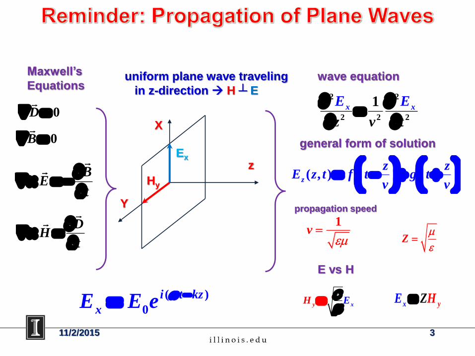
Maxwell’s
Equations uniform plane wave traveling
in z-direction H ┴ E
wave equation
general form of solution
propagation speed
E vs H
( )
0
i t kz
xE E e
Y
X
zEx
Hy
0D
0B
BE
t
DH
t
2 2
2 2 2
1x x
z v
E
t
E
( , )z
z zE z t f t g t
v v
Z
xyH E
yx
E ZH
1v
11/2/2015 3
Y
X
Z
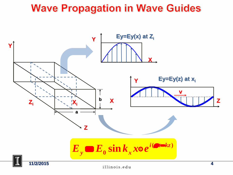
( )
0sin
i t kz
y xE E k x e
X
Y
Zi
Ey=Ey(x) at Zi
Z
Y
Xi
Ey=Ey(z) at xi
v
a
b
11/2/2015 4
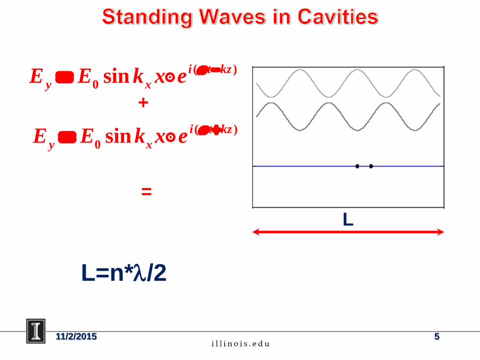
11/2/2015 5
( )
0sin
i t kz
y xE E k x e
( )
0sin
i t kz
y xE E k x e
+
=
L
L=n*l/2
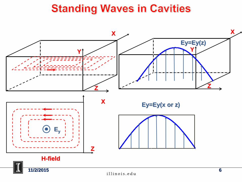
Ey
Z
Z
X
Y
X
H-field
Z
X
YEy=Ey(z)
Ey=Ey(x or z)
11/2/2015 6
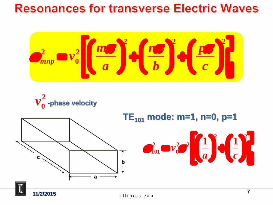
2 2 2
2 2
0mnp
m n pv
a b c
2
0v -phase velocity
TE101 mode: m=1, n=0, p=1
2 2
2 2 2
101 0
1 1v
a c
a
bc
11/2/2015 7
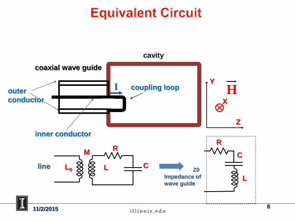
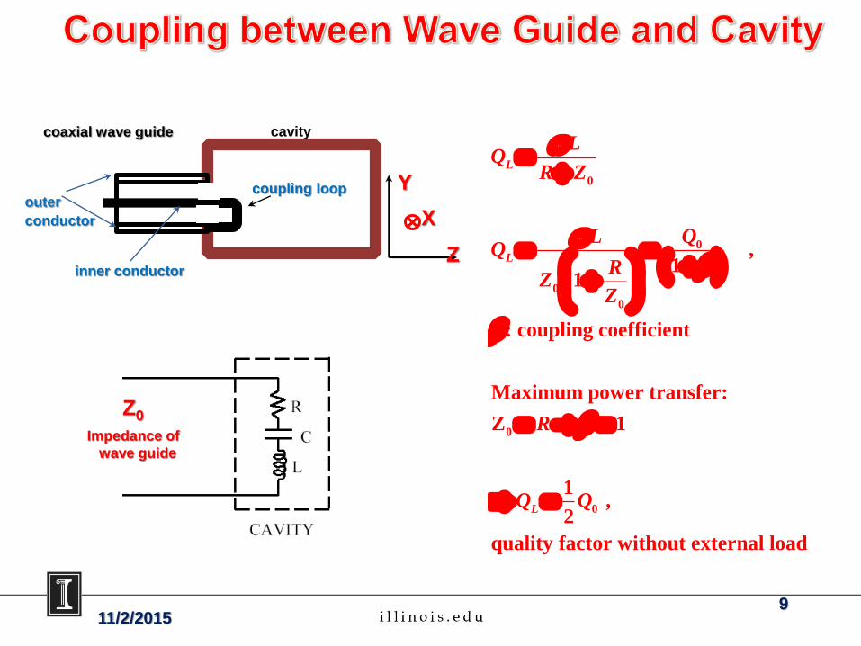
I coupling loop
coaxial wave guide
cavity
inner conductor
outer
conductor
Y
Z
X
MR
CLL0line
R
C
L
Z0
Impedance of
wave guide
11/2/2015 8
H
Z0
Impedance of
wave guide
0
0
0
0
0
0
, 1
1
: coupling coefficient
Maximum power transfer:
Z 1
1 ,
2
quality factor without external load
L
L
L
LQ
R Z
QLQ
RZ
Z
R
Q Q
coupling loop
coaxial wave guide cavity
inner conductor
outer
conductor
Y
Z
X
11/2/20159
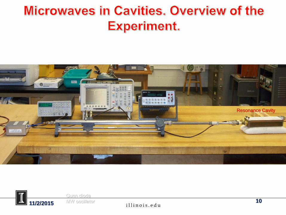
Gunn diode
MW oscillator11/2/2015 10
Resonance Cavity
A
11/2/2015 11
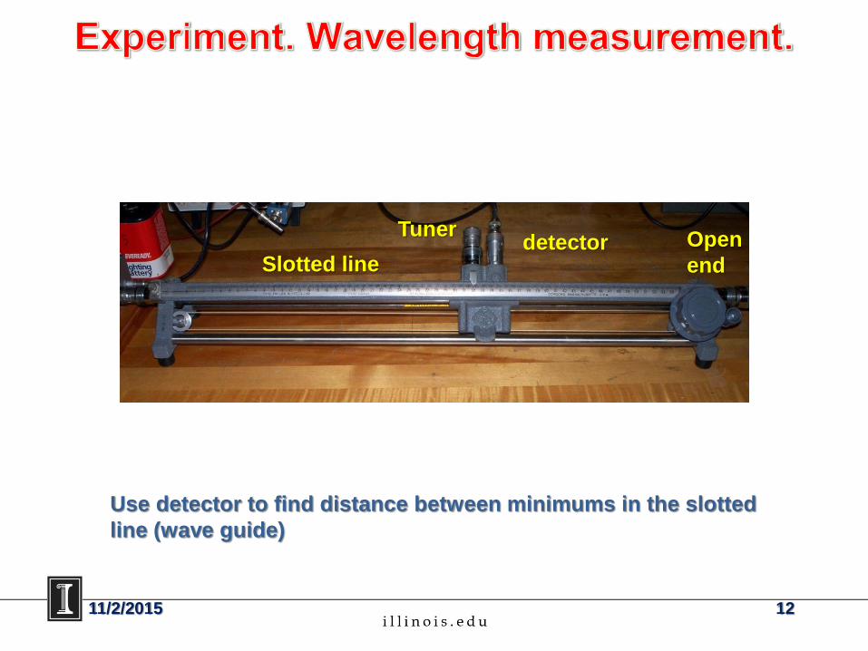
Use detector to find distance between minimums in the slotted
line (wave guide)
Slotted linedetector
TunerOpen
end
11/2/2015 12
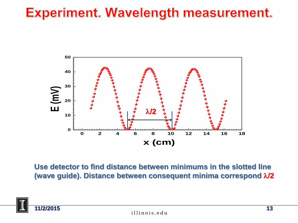
Use detector to find distance between minimums in the slotted line
(wave guide). Distance between consequent minima correspond l/2
0 2 4 6 8 10 12 14 16 180
10
20
30
40
50E
(mV
)
x (cm)
l/2
11/2/2015 13
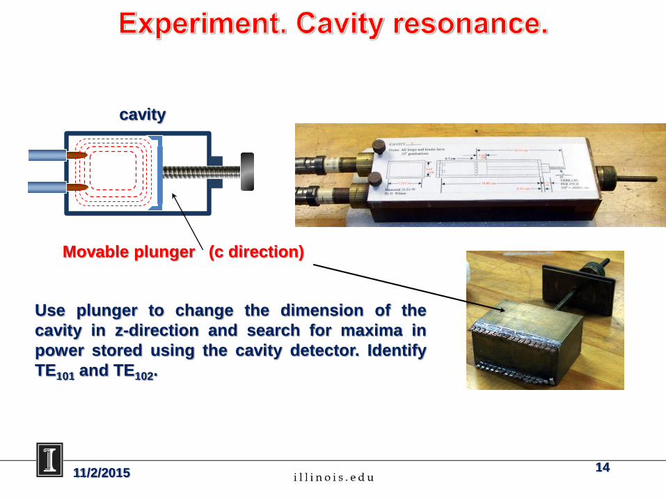
Movable plunger (c direction)
Use plunger to change the dimension of the
cavity in z-direction and search for maxima in
power stored using the cavity detector. Identify
TE101 and TE102.
cavity
11/2/2015 14
11/2/2015 15
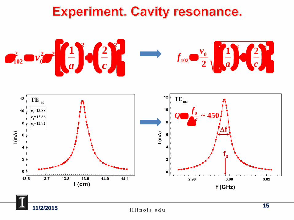
2 2
2 2 2
102 0
1 2v
a c
2 2
0
102
1 2
2
vf
a c
Df
f0
0 ~ 450f
Qf
D
11/2/2015 16
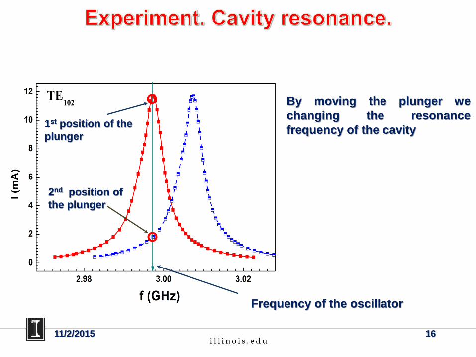
By moving the plunger we
changing the resonance
frequency of the cavity1st position of the
plunger
2nd position of
the plunger
Frequency of the oscillator
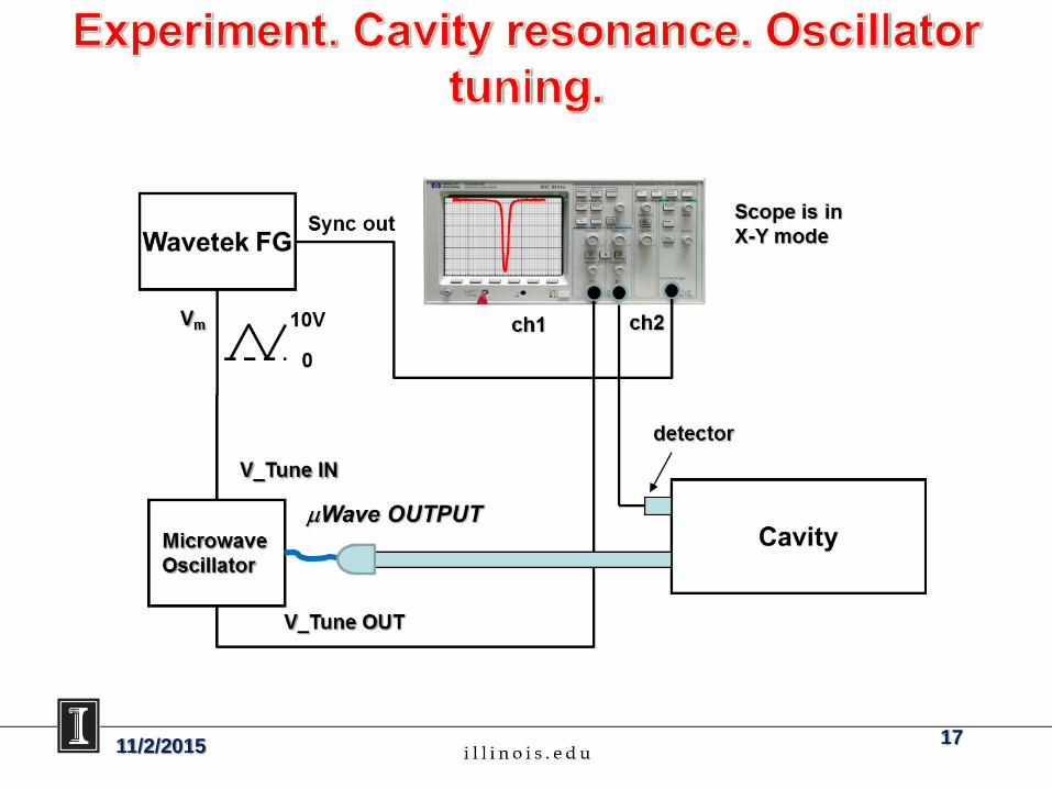
11/2/2015 17
11/2/2015 18
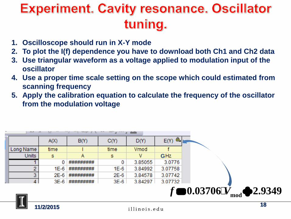
1. Oscilloscope should run in X-Y mode
2. To plot the I(f) dependence you have to download both Ch1 and Ch2 data
3. Use triangular waveform as a voltage applied to modulation input of the
oscillator
4. Use a proper time scale setting on the scope which could estimated from
scanning frequency
5. Apply the calibration equation to calculate the frequency of the oscillator
from the modulation voltage
mod0.03706 2.9349f V
G
11/2/2015 19
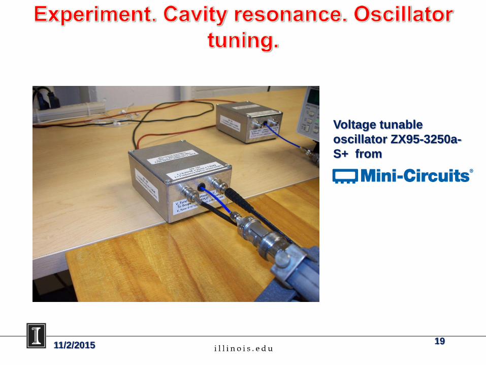
Voltage tunable
oscillator ZX95-3250a-
S+ from
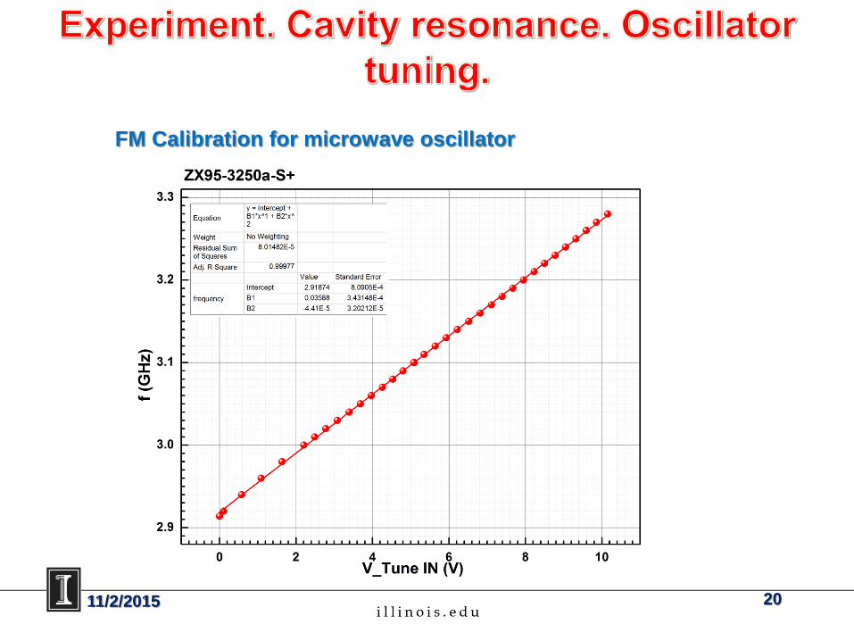
FM Calibration for microwave oscillator
11/2/2015 20

11/2/2015 21
11/2/2015 22
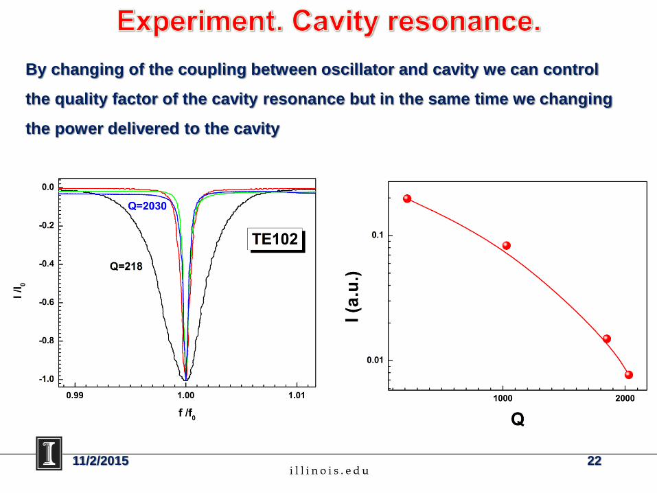
By changing of the coupling between oscillator and cavity we can control
the quality factor of the cavity resonance but in the same time we changing
the power delivered to the cavity
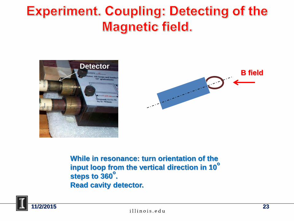
While in resonance: turn orientation of the
input loop from the vertical direction in 10o
steps to 360o.
Read cavity detector.
DetectorB field
11/2/2015 23
0 50 100 150 200 250 300 350
0
2
4
6
8
10
12
I (m
A)
grad)
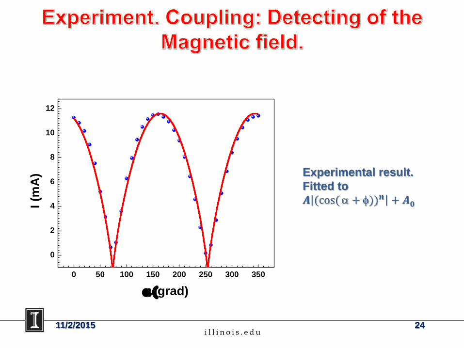
Experimental result.
Fitted to
𝑨 (cos(+ ))𝒏 + 𝑨𝟎
11/2/2015 24
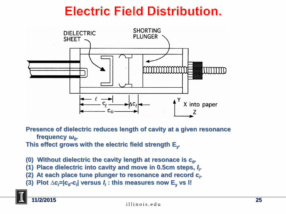
Presence of dielectric reduces length of cavity at a given resonance
frequency ω0.
This effect grows with the electric field strength Ey.
(0) Without dielectric the cavity length at resonace is c0.
(1) Place dielectric into cavity and move in 0.5cm steps, li.
(2) At each place tune plunger to resonance and record ci.
(3) Plot ∆ci=|c0-ci| versus li : this measures now Ey vs l!
11/2/2015 25
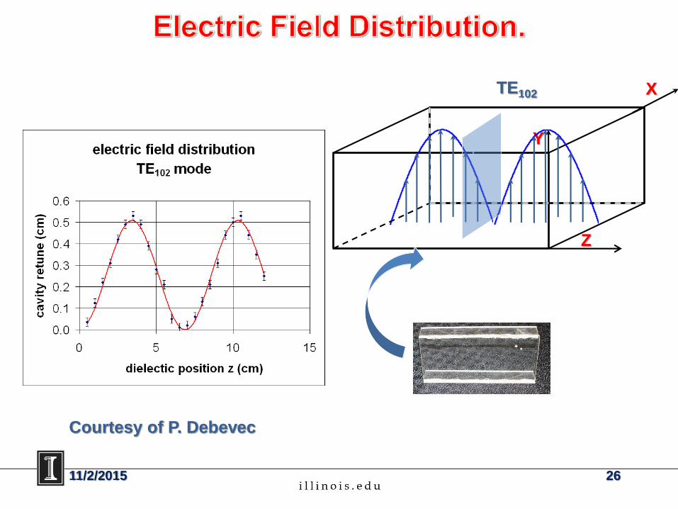
Z
X
Y
TE102
Courtesy of P. Debevec
11/2/2015 26
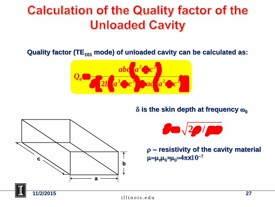
2 2
0 3 3 2 22
abc a cQ
b a c ac a c
Quality factor (TE101 mode) of unloaded cavity can be calculated as:
a
bc
is the skin depth at frequency 0
2 /
– resistivity of the cavity material
r0≈04x107
2711/2/2015
a
bc
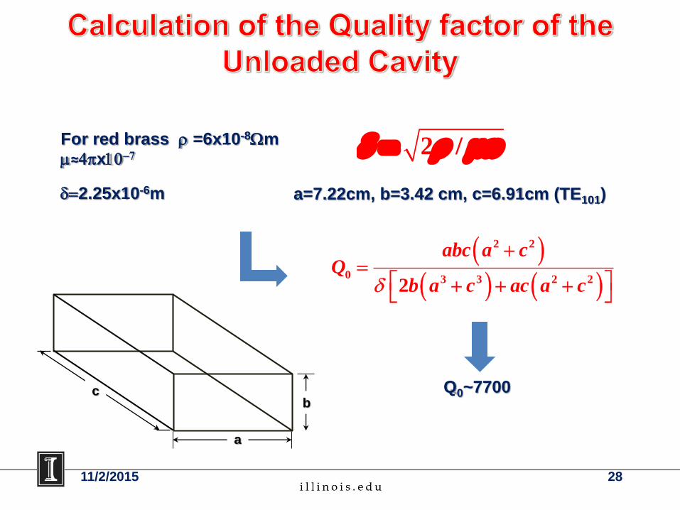
2 / For red brass =6x10⁻⁸m
≈4x10⁷
2.25x10⁻⁶m a=7.22cm, b=3.42 cm, c=6.91cm (TE101)
2 2
0 3 3 2 22
abc a cQ
b a c ac a c
Q0~7700
11/2/2015 28
11/2/2015 29
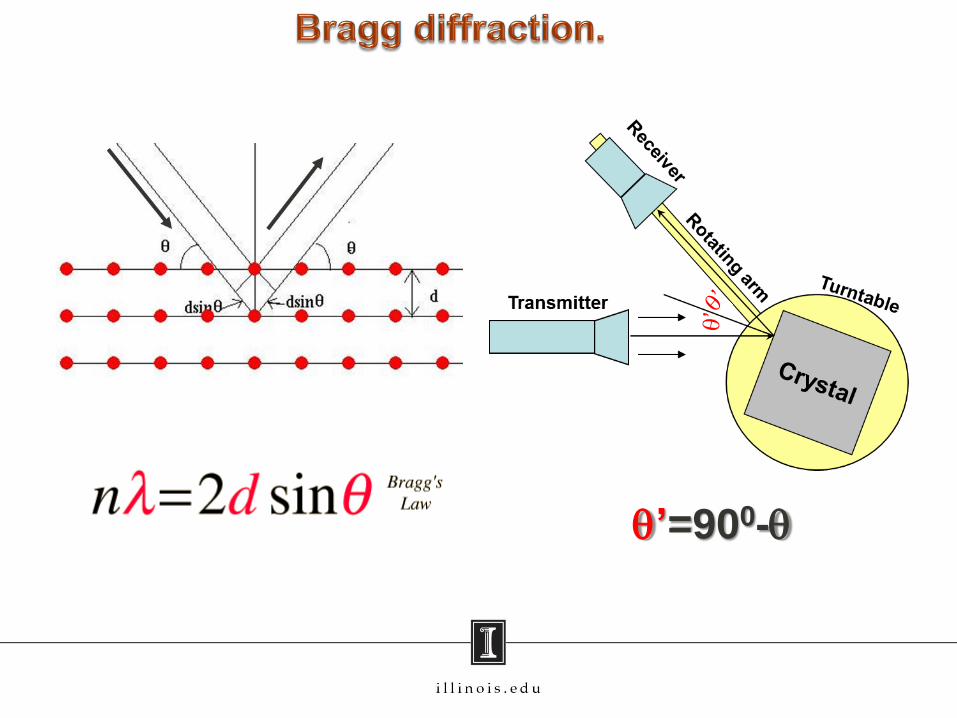
q’=900-q
11/2/2015 30
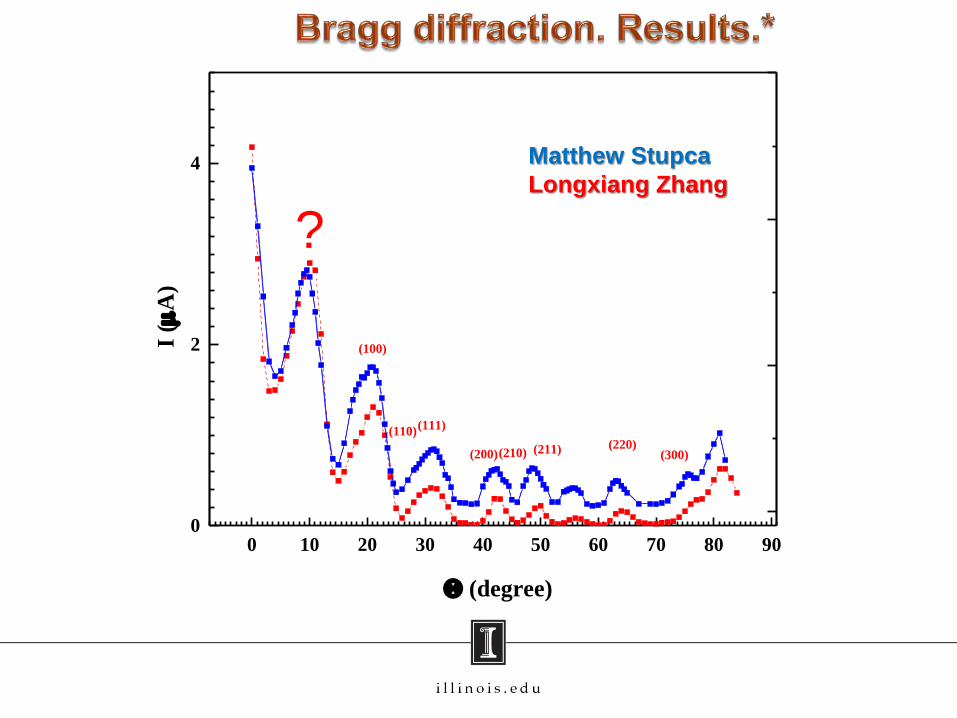
0 10 20 30 40 50 60 70 80 900
2
4
(100)
(110)(111)
(200)(210) (211) (220)(300)
I (
A)
(degree)
Matthew Stupca
Longxiang Zhang
?
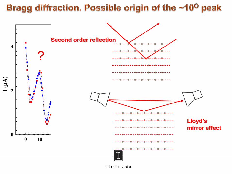
11/2/2015 31
?
Second order reflection
Lloyd’s
mirror effect