microstructural characteristics of cold-sprayed ... .pdfmicrostructural characteristics of...
TRANSCRIPT
Thin Solid Films 416(2002) 129–135
0040-6090/02/$ - see front matter� 2002 Elsevier Science B.V. All rights reserved.PII: S0040-6090Ž02.00631-4
Microstructural characteristics of cold-sprayed nanostructured WC–Cocoatings
R.S. Lima , J. Karthikeyan , C.M. Kay , J. Lindemann , C.C. Berndt *a,1 b b b a,
Department of Materials Science and Engineering, State University of New York at Stony Brook, 306 Old Engineering Building, Stony Brook,a
NY 11794-2275, USAASB Industries, Inc., Barberton, OH 44203-1689, USAb
Received 29 November 2000; received in revised form 19 January 2002; accepted 3 July 2002
Abstract
The cold-spray process was used to prepare nanostructured WC–Co coatings. The coating microstructural characteristics andphase composition were analyzed via optical microscopy, scanning electron microscopy(SEM) and X-ray diffraction(XRD).The morphology and microstructure of the nanostructured WC–Co powder were also analyzed by SEM and XRD. A 10mmthick coating was achieved. The powder particles and coating microhardness were also evaluated and compared. The results showthat there is no degradation of the WC–Co powder during the cold-spray process and well bonded and phase pure WC coatingcan be produced by the cold-spray process.� 2002 Elsevier Science B.V. All rights reserved.
Keywords: Thermal spray; Cold-spray; Coating; Nanostructured WC–Co; Microstructure
1. Introduction
1.1. Nanostructured materials
Nanocrystalline materials(also referred to as nano-structures, nanophase materials, or nanometer-sized crys-talline solids) have crystal sizes of typicallyapproximately 10–1000 A(1–100 nm) in at least one˚dimension. Nanostructured materials come in two gen-eral morphologies:(i) nanolayered materials depositedby physical vapour deposition or electrodeposition pro-cesses and,(ii) nanograined materials, which are usuallyconsolidated from nanostructured powdersw1x.As the grain size becomes smaller, there are an
increasing number of atoms associated with grain bound-ary sites compared to crystal lattice sites. For example,at a grain size of 100 nm, approximately 3% of all
*Corresponding author. Tel.:q1-631-632-8507; fax:q1-631-632-8525.
E-mail address: [email protected](C.C. Berndt).Present address: National Research Council of Canada, 75 De1
Mortagne Boulevard, Boucherville, Que., Canada J4B 6Y4.
atoms are associated with grain boundaries. As the grainsize is reduced to 10 nm, the percentage increases to30; at 5 nm, approximately 50% of all atoms areassociated with the grain boundary sites. The uniqueproperties of nanograined materials are associated withthe fineness of structure as well as the enhanced solu-bility and increasing atomic mobility associated withgrain boundariesw1x.
1.2. Cold-spray processing of nano WC–Co coatings
The cold gas-dynamic process spray method or simplycold-spray is a high-rate material deposition process inwhich small, unmelted powder particles(typically 1–50mm in diameter) are accelerated to velocities on theorder of 600–1000 mys in a supersonic jet of com-pressed gas. Upon impact against a substrate, the solidparticles deform and bond together, rapidly building upa layer of deposited materialw2–5x.Cold-spray was developed in the former Soviet Union
in the mid-1980s. While performing supersonic wind
130 R.S. Lima et al. / Thin Solid Films 416 (2002) 129–135
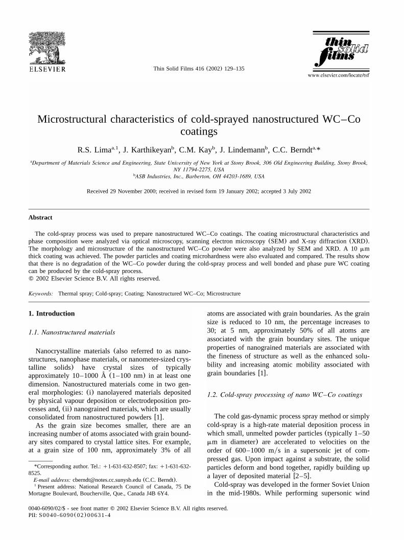
Fig. 1. Schematic of a typical cold-spray system.
tunnel tests with flows containing small tracer particles,scientists observed that above a critical particle velocity(which varies for different materials) there was a tran-sition from particle erosion of a target surface to rapidlyincreasing depositionw2–4x. Based on these phenomena,a spray system was created and an US patent was issuedin 1994 w6x.Fig. 1 shows the schematics of a typical cold-spray
system. In cold-spray, a compressed gas, usually He,N , air or their mixtures, at inlet pressures up to 500 psi2
(3.4 MPa), flows through a converging–diverging noz-zle to develop supersonic gas velocities. The powderparticles are fed into the gas flow immediately beforethe converging section of the nozzle and are acceleratedby the rapidly expanding gasw2–5x.The compressed gas can be introduced at room
temperature, or it can be preheated in order to achievehigher gas flow velocities in the nozzle. Preheat tem-peratures as high as 6008C can be used, but the gasrapidly cools as it expands in the diverging section ofthe nozzle. As a consequence, the dwell time of theparticles in contact with hot gas is brief, and thetemperatures of the solid particles at impact remainsubstantially below the initial gas preheat temperaturew2x.The mechanisms by which the solid-state particles
deform and bond to the substrate or previously depositedlayers has not been well characterized. Though it hasnot yet been demonstrated, plastic deformation maydisrupt thin surface films, such as oxides, and provideintimate conformal contact under high local pressure,allowing bonding to occur. This theory would alsoexplain the observed minimum critical velocity neces-sary to achieve deposition, because sufficient kineticenergy must be available to plastically deform the solidmaterialw2x.
Calculations indicate that the particle kinetic energyat impact is typically much less than the energy requiredto melt the particlew2x. Micrographs of cold-sprayedcoatings suggest that the deposition mechanism is pri-marily a solid-state processw2,3x; i.e. no material meltingoccurs in this process.WC–Co coatings are well known for their use in
wear resistance applicationsw7,8x. The hard WC parti-cles form the major wear-resistant constituent of thesematerials, while the Co binder provides toughness andsupport w8x. Properties such as the hardness, wearresistance, and strength are influenced primarily by theWC grain size and volume fraction, and in the case ofthermal spray coatings, also the porosity, the carbideand binder phase compositionw8x. But due to the hightemperature characteristics of the traditional thermalspray methods, such as, high velocity oxy-fuel(HVOF),plasma spray, detonation-gun, flame spray and highvelocity air-fuel; the WC–Co powder tends to undergoa combination of decarburization, oxidation, reductionby reaction with the H(plasma spray), and dissolutiony2
reaction between the WC and Co during spraying. Thisbehavior results in the formation of hard and brittlephases, such as, W C, W, Co W C(crystalline and2 x y z
amorphoush-phases) and WO w8–12x.3
Due to its low temperatures, the cold-spray process isa new alternative method for spraying not only WC–Co powders but also nanostructured materials. As anadvantage, in cold-spray there is no particle melting andall the nanostructure will be kept intact during theprocess. In contrary, the traditional thermal spray pro-cesses require at least some partial melting of thesprayed material in order to produce adhesionycohesionof the sprayed particles. Any melting of the nanostruc-tured material will cause the resolidified particles tohave the same microstructure as ‘regular’ thermalsprayed particles.No phase transformation occurs during the cold-spray
process since it is a 100% solid-state process; implyingno particle melting. Therefore, oxidation, nitriding,decarburizing and any decomposition in general areavoided in this process. The as-sprayed coating phasecomposition should be the same as the powder phasecomposition.But as it was discussed above, WC can be decom-
posed at temperatures lower than that of its decompo-sition by the reaction of the WC with the Co binder.The compositional ranges of theh-phases(Co W C)x y z
are not fixed and vary with temperature. For example,Co W C exists in the range Co W C to Co W C3 3 3.1 2.9 2.2 3.8
from 1197 to 14278C w8x. These temperatures are higherthan those experienced during cold-spray, where themaximum gas temperature does not exceed 6008C w2x.The gas temperature used during this work was 5408C.The wettability of WC by most binder metals is better
than that of the other carbides and the WC is tougher
131R.S. Lima et al. / Thin Solid Films 416 (2002) 129–135
Table 1Spray parameters
Main gas N2Main gas temperature at the gun(8C) 540Gun pressure(psi) 300Spray distance(mm) 25
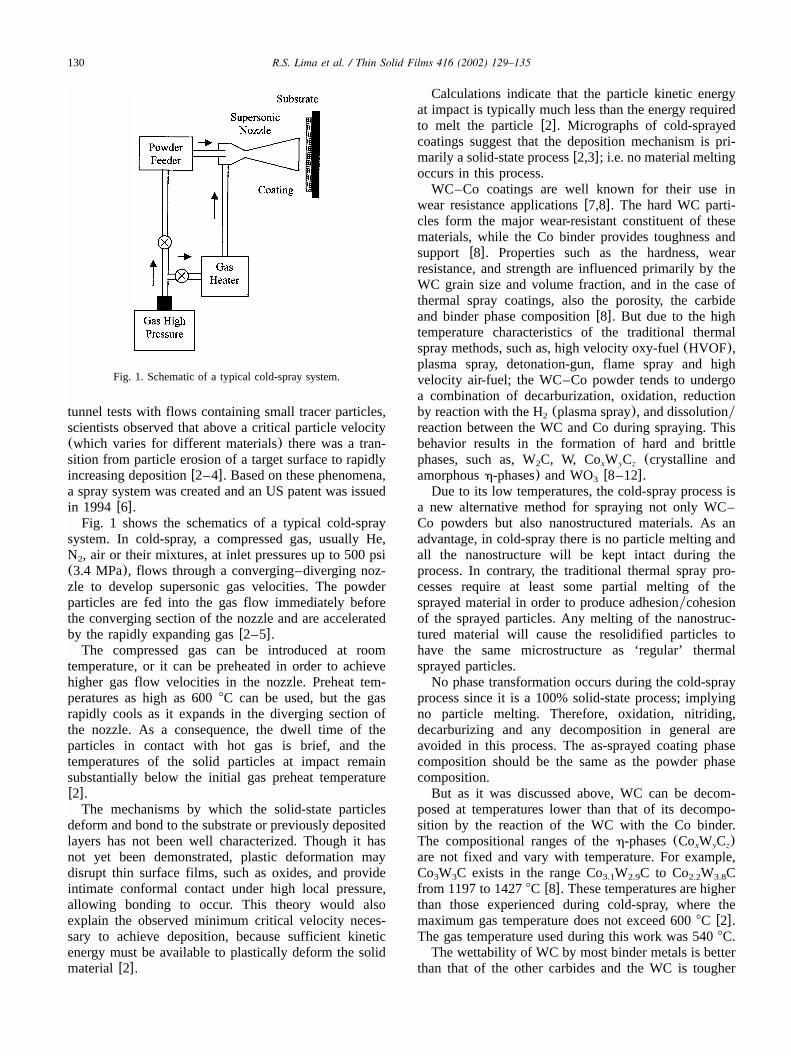
Fig. 2. Typical nanostructured WC–Co particle.
than the other carbides. The nanostructural charactermay improve the mechanical properties of this material.Due to its low temperatures(no WC degradation), thecold-spray process may represent a significant advance-ment to the spraying of nanostructured carbides.The objective of this work is to produce nano WC–
Co coatings by the cold-spray process and investigatethe microstructural characteristics of cold-sprayed WC–Co coatings.
2. Experimental procedure
ASB Industries cold-spray system was built accordingto the design of its Russian inventorsw6x, and was usedfor the study reported in this article. The nanostructuredWC–12%Co Metco AE7923 feedstock(Sulzer-Metco,Westbury, NY) was cold-sprayed on low carbon steelsubstrates. The feedstock particle size varies from 10 to43 mm. The substrates were grit blasted with aluminajust before the deposition. The typical coating thicknesswas 10mm. The spray parameters applied are listed inTable 1.The cross-section of the coating was evaluated by
using an optical microscope(Nikon-Epiphot 200, NikonInc., Melville, NY). The coating and the cross-sectionof the WC–Co feedstock particles were also analyzedby scanning electron microscopy(SEM).The Knoop microhardness measurements were per-
formed at 10 g load for 15 s(Tukon, Instron, Canton,MA) on the coating and feedstock particle cross-sec-tions. In order to measure the feedstock microhardness,the particles were vacuum impregnated with epoxy resinand polished. Knoop indentation was chosen because ithas a shallow penetration when compared to that ofVickers. Therefore, Knoop indentation seems to be moreadequate for performing microhardness measurementsin small volumes, such as, powder particles.X-ray diffraction(XRD) (Model 172a-CuKa, Philips,
Almelo, Netherlands) was used to establish the phasecomposition of the feedstock and coating. XRD wasalso used to estimate the average grain size of thefeedstock and coatingw13–16x. The applicability of thismethod was confirmed by comparing results from trans-mission electron microscopy(TEM) and XRD tech-niques w15,16x. The XRD method assumes that theoverall broadening of XRD peaks comprises two effects:one arising from the small coherent grain size and onearising from the atomic level microstrain; i.e.Ddyd,
whered is the atomic spacing. The peak width resultingfrom a small grain size effect alone can be described bythe Scherrer equationw13,14x:
KlB(2u)s (1)
Dcosu
In Eq. (1), B(2u) is the true broadening of thediffraction line measured at half maximum intensity,also known as full-width at half-maximum;K is aconstant(being taken as 0.9); l is the wavelength ofthe X-ray radiation;D is the mean dimension of thegrains andu is the Bragg angle. Contributions due toKa andKa were deconvoluted by using the Rachinger1 2
correctionw13,14x, and only theKa peak widths were1
used for calculation. XRD of a Si specimen was usedto measure the instrumental broadening, and the Cauchycorrection was used to remove the instrument broadeningto obtain the true crystal broadeningw14x. According toRef. w17x, results from TEM and XRD of aluminafeedstocks showed that the best fit was obtained whenthe Cauchy correction was applied to remove the instru-ment broadening factor. The XRD method can providestructural information regarding mean grain size alongthe entire samplew13–15x, and the penetration distanceof the X-ray beam into the sample can vary from a fewto several micrometers depending on the samplecharacteristics.
3. Results and discussion
3.1. Feedstock morphology and phase composition
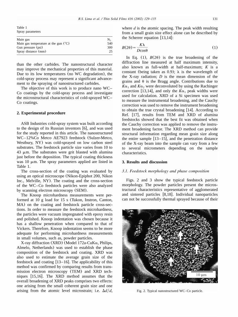
Figs. 2 and 3 show the typical feedstock particlemorphology. The powder particles present the micros-tructural characteristics representative of agglomeratedand sintered particlesw8,18x. Individual nanoparticlescan not be successfully thermal sprayed because of their
132 R.S. Lima et al. / Thin Solid Films 416 (2002) 129–135
Fig. 3. General morphology of the nanostructured WC–Co particles.
Fig. 4. XRD of the nanostructured WC–12%Co powder.
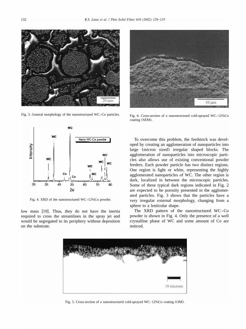
Fig. 6. Cross-section of a nanostructured cold-sprayed WC–12%Cocoating(SEM).
Fig. 5. Cross-section of a nanostructured cold-sprayed WC–12%Co coating(OM).
low mass w19x. Thus, they do not have the inertiarequired to cross the streamlines in the spray jet andwould be segregated to its periphery without depositionon the substrate.
To overcome this problem, the feedstock was devel-oped by creating an agglomeration of nanoparticles intolarge (micron sized) irregular shaped blocks. Theagglomeration of nanoparticles into microscopic parti-cles also allows use of existing conventional powderfeeders. Each powder particle has two distinct regions.One region is light or white, representing the highlyagglomerated nanoparticles of WC. The other region isdark, localized in between the microscopic particles.Some of these typical dark regions indicated in Fig. 2are expected to be porosity presented in the agglomer-ated particles. Fig. 3 shows that the particles have avery irregular external morphology, changing from asphere to a lenticular shape.The XRD pattern of the nanostructured WC–Co
powder is shown in Fig. 4. Only the presence of a wellcrystalline phase of WC and some amount of Co arenoticed.
133R.S. Lima et al. / Thin Solid Films 416 (2002) 129–135
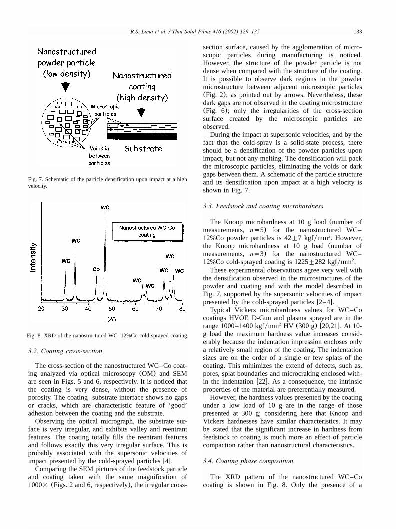
Fig. 7. Schematic of the particle densification upon impact at a highvelocity.
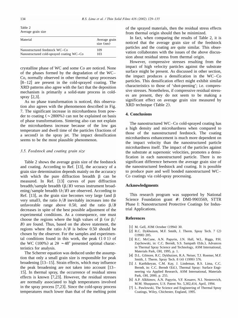
Fig. 8. XRD of the nanostructured WC–12%Co cold-sprayed coating.
3.2. Coating cross-section
The cross-section of the nanostructured WC–Co coat-ing analyzed via optical microscopy(OM) and SEMare seen in Figs. 5 and 6, respectively. It is noticed thatthe coating is very dense, without the presence ofporosity. The coating–substrate interface shows no gapsor cracks, which are characteristic feature of ‘good’adhesion between the coating and the substrate.Observing the optical micrograph, the substrate sur-
face is very irregular, and exhibits valley and reentrantfeatures. The coating totally fills the reentrant featuresand follows exactly this very irregular surface. This isprobably associated with the supersonic velocities ofimpact presented by the cold-sprayed particlesw4x.Comparing the SEM pictures of the feedstock particle
and coating taken with the same magnification of1000= (Figs. 2 and 6, respectively), the irregular cross-
section surface, caused by the agglomeration of micro-scopic particles during manufacturing is noticed.However, the structure of the powder particle is notdense when compared with the structure of the coating.It is possible to observe dark regions in the powdermicrostructure between adjacent microscopic particles(Fig. 2); as pointed out by arrows. Nevertheless, thesedark gaps are not observed in the coating microstructure(Fig. 6); only the irregularities of the cross-sectionsurface created by the microscopic particles areobserved.During the impact at supersonic velocities, and by the
fact that the cold-spray is a solid-state process, thereshould be a densification of the powder particles uponimpact, but not any melting. The densification will packthe microscopic particles, eliminating the voids or darkgaps between them. A schematic of the particle structureand its densification upon impact at a high velocity isshown in Fig. 7.
3.3. Feedstock and coating microhardness
The Knoop microhardness at 10 g load(number ofmeasurements,ns5) for the nanostructured WC–12%Co powder particles is 42"7 kgfymm . However,2
the Knoop microhardness at 10 g load(number ofmeasurements,ns3) for the nanostructured WC–12%Co cold-sprayed coating is 1225"282 kgfymm .2
These experimental observations agree very well withthe densification observed in the microstructures of thepowder and coating and with the model described inFig. 7, supported by the supersonic velocities of impactpresented by the cold-sprayed particlesw2–4x.Typical Vickers microhardness values for WC–Co
coatings HVOF, D-Gun and plasma sprayed are in therange 1000–1400 kgfymm HV (300 g) w20,21x. At 10-2
g load the maximum hardness value increases consid-erably because the indentation impression encloses onlya relatively small region of the coating. The indentationsizes are on the order of a single or few splats of thecoating. This minimizes the extend of defects, such as,pores, splat boundaries and microcraking enclosed with-in the indentationw22x. As a consequence, the intrinsicproperties of the material are preferentially measured.However, the hardness values presented by the coating
under a low load of 10 g are in the range of thosepresented at 300 g; considering here that Knoop andVickers hardnesses have similar characteristics. It maybe stated that the significant increase in hardness fromfeedstock to coating is much more an effect of particlecompaction rather than nanostructural characteristics.
3.4. Coating phase composition
The XRD pattern of the nanostructured WC–Cocoating is shown in Fig. 8. Only the presence of a
134 R.S. Lima et al. / Thin Solid Films 416 (2002) 129–135
Table 2Average grain size
Material Average grainsize(nm)
Nanostructured feedstock WC–Co 109Nanostructured cold-sprayed coating WC–Co 103
crystalline phase of WC and some Co are noticed. Noneof the phases formed by the degradation of the WC–Co, normally observed in other thermal spray processesw8–12x are present in the cold-sprayed coating. TheXRD patterns also agree with the fact that the depositionmechanism is primarily a solid-state process in cold-sprayw2,3x.As no phase transformation is noticed, this observa-
tion also agrees with the phenomenon described in Fig.7. The significant increase in microhardness from pow-der to coating(;2800%) can not be explained on basisof phase transformations. Sintering also can not explainthe microhardness increase because of the low gastemperature and dwell time of the particles(fractions ofa second) in the spray jet. The impact densificationseems to be the most plausible phenomenon.
3.5. Feedstock and coating grain size
Table 2 shows the average grain size of the feedstockand coating. According to Ref.w13x, the accuracy of agrain size determination depends mainly on the accuracywith which the pure diffraction breadthb can bemeasured. In Ref.w13x curves of pure diffractionbreadthysample breadth(byB) versus instrument broad-eningysample breadth(byB) are observed. According toRef. w13x, as the grain size becomes very large(andb
very small), the ratiobyB inevitably increases into theunfavorable range above 0.50, and the ratiobyBdecreases in spite of the best possible adjustment of theexperimental conditions. As a consequence, one mustchoose the regions where the high values ofb (or byB) are found. Thus, based on the above statement, theregions where the ratiobyB is below 0.50 should bechosen by the observer. For the samples and experimen-tal conditions found in this work, the peak(1 0 1) ofthe WC (100%) at 2u ;488 presented optimal charac-teristics for analysis.The Scherrer equation was deduced under the assump-
tion that only a small grain size is responsible for peakbroadeningw13–15x. Strain effects, which may influencethe peak broadening are not taken into accountw13–15x. In thermal spray, the occurrence of residual stresseffects is knownw7,23x. However, the residual stressesare normally associated to high temperatures involvedin the spray processw7,23x. Since the cold-spray processtemperatures much lower than that of the melting point
of the sprayed materials, then the residual stress effectsfrom thermal origin should then be minimized.In fact, when comparing the results of Table 2, it is
noticed that the average grain size of the feedstockparticles and the coating are quite similar. This obser-vation collaborates with the issues of the above discus-sion about residual stress from thermal origin.However, compressive stresses resulting from the
impact of high velocity particles against the substratesurface might be present. As discussed in other section,the impact produces a densification in the WC–Coparticles. This densification effect might exhibit similarcharacteristics to those of ‘shot-peening’; i.e. compres-sive stresses. Nonetheless, if compressive residual stress-es are present, they do not seem to be making asignificant effect on average grain size measured byXRD technique(Table 2).
4. Conclusions
The nanostructured WC–Co cold-sprayed coating hasa high density and microhardness when compared tothose of the nanostructured feedstock. The coatingmicrohardness enhancement is much more dependent onthe impact velocity than the nanostructured particlemicrohardness itself. The impact of the particles againstthe substrate at supersonic velocities, promotes a densi-fication in each nanostructured particle. There is nosignificant difference between the average grain size ofthe nanostructured feedstock and coating. It is possibleto produce pure and well bonded nanostructured WC–Co coatings via cold-spray processing.
Acknowledgments
This research program was supported by NationalScience Foundation grant�: DMI-9903569, STTRPhase I: Nanostructured Protective Coatings for Indus-trial Applications.
References
w1x M. Gell, JOM October(1994) 30.w2x R.C. Dykhuizen, M.F. Smith, J. Therm. Spray Tech. 7(2)
(1998) 205.w3x R.C. McCune, A.N. Papyrin, J.N. Hall, W.L. Riggs, P.H.
Zajchowski, in: C.C. Berndt, S.S. Sampath(Eds.), Advancesin Thermal Spray Science and Technology, ASM International,Materials Park, OH, 1995, p. 1.
w4x D.L. Gilmore, R.C. Dykhuizen, R.A. Neiser, T.J. Roemer, M.F.Smith, J. Therm. Spray Tech. 8(4) (1999) 576.
w5x J. Karthikeyan, C.M. Kay, J. Lindeman, R.S. Lima, C.C.Berndt, in: C.C. Berndt(Ed.), Thermal Spray: Surface Engi-neering via Applied Research, ASM International, MaterialsPark, OH, 2000, p. 255.
w6x A.P. Alkhimov, A.N. Papyrin, V.F. Kosarev, N.I. Nesterovich,M.M. Shuspanov, U.S. Patent No. 5,302,414, April, 1994.
w7x L. Pawlowski, The Science and Engineering of Thermal SprayCoatings, Wiley, Chichester, England, 1995.
135R.S. Lima et al. / Thin Solid Films 416 (2002) 129–135
w8x H.L. de Villiers Lovelock, J. Therm. Spray Tech. 7(3) (1998)357.
w9x H.L. de Villiers Lovelock, P.W. Richter, J.M. Benson, P.M.Young, J. Therm. Spray Tech. 7(1) (1998) 97.
w10x J.R. Fincke, W.D. Swanck, D.C. Haggard, in: C.C. Berndt, S.S.Sampath(Eds.), Thermal Spray Industrial Applications, ASMInternational, Materials Park, OH, USA, 1994, p. 325.
w11x K. Korpiola, P. Vuoristo, in: C.C. Berndt(Ed.), Thermal Spray:Practical Solutions for Engineering Problems, ASM Interna-tional, Materials Park, OH, 1996, p. 177.
w12x C.J. Li, A. Ohmori, Y. Harada, J. Therm. Spray Tech. 5(1)(1996) 69.
w13x H.P. Klug, L.E. Alexander, X-Ray Diffraction Procedures,second ed., Wiley, NY, USA, 1974.
w14x B.E. Warren, X-Ray Diffraction, Dover Publications, Inc, NY,USA, 1990.
w15x H.G. Jiang, M. Ruhle, E.J. Lavernia, J. Mater. Res. 14(2)(1999) 549.
w16x T. Chraska, Ph.D. Thesis, State University of New York atStony Brook, NY, USA, 1999.
w17x T. Ekstron, C. Chatfield, W. Wruss, M. Maly-Schreiber, J.Mater. Sci. 20(1985) 1266.
w18x H.L. de Villiers-Lovelock, S. Luyckx, in: C.C. Berndt(Ed.),Surface Engineering via Applied Research, ASM International,Materials Park, OH, 2000, p. 647.
w19x S. Eidelman, X. Yang, NanoStructured Mater. 9(1997) 79.w20x R. Schwetzke, H. Kreye, J. Therm. Spray Tech. 8(3) (1999)
433.w21x R.C. Tucker, J. Vac. Sci. Tech. 11(4) (1974) 725.w22x J.P. Singh, M. Sutaria, M. Ferber, Ceramic Eng. Sci. Proc. 18
(4b) (1997) 191.w23x S. Kuroda, T. Fukushima, S. Kitahara, Thin Solid Films 164
(1988) 157.