microplane damage model for jointed rock masses · in parallel to form a combined system, the rock...
TRANSCRIPT

INTERNATIONAL JOURNAL FOR NUMERICAL AND ANALYTICAL METHODS IN GEOMECHANICSInt. J. Numer. Anal. Meth. Geomech. 2014; 38:1431–1452Published online 18 March 2014 in Wiley Online Library (wileyonlinelibrary.com). DOI: 10.1002/nag.2257
Microplane damage model for jointed rock masses
Xin Chen1,2,*,† and Zdeněk P. Bažant2
1School of Mechanics and Civil Engineering, China University of Mining and Technology (Beijing), Beijing, 100083, China2Department of Civil and Environmental Engineering, Northwestern University, Evanston, IL 60208, U.S.A.
SUMMARY
The paper presents a new microplane constitutive model for the inelastic behavior of jointed rock masses thattakes into account the mechanical behavior and geometric characteristics of cracks and joints. The basic ideais that the microplane modeling of rock masses under general triaxial loading, including compression, requiresthe isotropic rock matrix and the joints to be considered as two distinct phases coupled in parallel. A jointcontinuity factor is defined as a microplane damage variable to represent the stress-carrying area fraction ofthe joint phase. Based on the assumption of parallel coupling between the rock joint and the rock matrix, theoverall mechanical behavior of the rock is characterized by microplane constitutive laws for the rock matrixand for the rock joints, along with an evolution law for the microplane joint continuity factor. The inelasticresponse of the rock matrix and the rock joints is controlled on the microplane level by the stress–strain bound-aries. Based on the arguments enunciated in developing the new microplane model M7 for concrete, thepreviously used volumetric–deviatoric splits of the elastic strains and of the tensile boundary are avoided.The boundaries are tensile normal, compressive normal, and shear. The numerical simulations demonstratesatisfactory fits of published triaxial test data on sandstone and on jointed plaster mortar, including quintessen-tial features such as the strain softening and dilatancy under low confining pressure, as well as the brittle–ductiletransition under higher confining pressure, and the decrease of jointed rock strength and Young’s modulus withan increasing dip angle of the joint. Copyright © 2014 John Wiley & Sons, Ltd.
Received 21 August 2013; Revised 15 December 2013; Accepted 3 January 2014
KEY WORDS: rock; microplane model; joint; constitutive model; inelastic behavior; damage mechanics;failure; geomaterials
1. INTRODUCTION
Similar to other quasibrittle materials such as concrete, intact rocks exhibit complex nonlinear inelasticbehavior characterized by pressure sensitivity in triaxial tests, strain softening, dilatancy at lowpressures, and brittle–ductile transition at high confinement. Unlike materials such as concrete, thebehavior of rock mass is complicated by the properties and geometry of the preexisting joints.Compared with the intact rock, the rock mass is weaker, more deformable, and highly anisotropic. Inthe microstructure, deformation of rock mass leads to microcrack initiation, propagation andcoalescence, crack opening or closing, and frictional slip on cracks or joints. These mechanisms causestrain-softening behavior, which in turn engenders size effects. The size effects, documented in SouthAfrican mines already half a century ago [1], are, unfortunately, still widely ignored in the practice ofgeomechanics, although they are important for the safety of large scale mining excavations, tunnels andopen excavations, stability of rock slopes, and prediction of rock slides. The strain softening also playsa major role in assessing the effects of explosion, impact, and ground shock.
For larger rock masses, an equivalent continuum model must inevitably be used. Because of strainsoftening, the theory of plasticity is inapplicable. The continuum damage mechanics, by now a classical
*Correspondence to: Xin Chen, School of Mechanics and Civil Engineering, China University of Mining andTechnology (Beijing), Beijing 100083, China.†E-mail: [email protected]
Copyright © 2014 John Wiley & Sons, Ltd.

1432 X. CHEN AND Z. P. BAŽANT
approach, has been adopted widely [2–4], although the material localization instabilities inherent to thestrain-softening aspect of continuum damage mechanics have been ignored in most studies. The basicconcept of continuum damage mechanics was introduced by Kachanov [5] and Rabotnov [6] forsimple one-dimensional problems. A scalar damage variable, which represents the net stress-carryingcross section area fraction and gradually decreases as a result of the growth of microscopic defects(cracks and voids), was introduced to define the effective stress or true stress transmitted across theundamaged part of the cross section (the stress concentrations due to cracks and voids were ignored,for simplicity). A constitutive law for the undamaged part of the material characterizes the relationshipof the effective stress to the strain. The generalization of the Kachanov–Rabotnov’s damage concept foranisotropic damage has turned out to be rather difficult when the modeling was limited to the classicalmacroscopic tensorial approach, see, for example, Carol et al. [7] and Lemaitre et al. [8]. Oneadvantage of the microplane model is that it makes the anisotropic generalization much easier.
The salient feature of the microplane model is that the constitutive law is written in terms of vectorsrather than tensors and that these vectors act on planes of specific orientation. The advantage is thatphysical phenomena with distinct orientation, such as crack opening or frictional slip, can bedirectly reflected in the constitutive law, which facilitates its formulation. Another advantage is thatthe huge vertex effect observed in experiments with a nonproportional loading path in the stressspace can be captured automatically [9, 10]. Since 1983, microplane models have been developedfor concrete [11–15], clays [16], soils [17], rocks [18], orthotropic fiber composites, orthotropicfoam, shape-memory alloy and annulus fibrosus; see [9, 12, 13] for a detailed review.
To provide better insight into the physical mechanism while adhering to the basic framework ofcontinuum damage mechanics, microplane models based on geometric damage were proposed toseparate the independent effect of geometrical characteristic [7, 19]. In these models, the concept ofeffective stress and the hypothesis of strain equivalence were reformulated on the microplane level, andgeometric damage variables could be defined on the microplanes so as to represent a different reductionof the net stress-carrying area fraction in different directions, which is impossible in tensorial models.By adopting a set of damage variables at microplane level and assuming kinematic constraint betweenmacrostrains and microplane strains, and static constraint between effective macro stresses andmicroplane effective stresses, Carol and Bažant [7] obtained a fourth-order macroscopic secant stiffnesstensor for the damaged material, which is a product of the pure geometric damage tensor and thestiffness tensor of the virgin material. By defining a single damage variable on microplanes as anorientation distribution function (ODF) and an effective stress vector on the microplanes, and assumingstatic constraint between macro nominal stresses and microplane nominal stresses, Yang et al. [19]showed that the second-order effective stress tensor of Murakami [20] can be recovered as the second-order fabric tensor of the effective stress vector. Furthermore, they proved that the anisotropic yieldcriteria of damaged materials whose matrix follows von Mises and Drucker–Prager yield criteriapossess the form of the famous Hill criterion [21] and its extension by Liu to pressure-sensitivematerials [22], in which the parameters are related to the fabric tensors of the microplane damage variable.
However, the effective stress concept, characterizing the stress-carrying and stress reductionmechanisms because of cracks and joints, makes sense only for tensile loading. It is not suitable forgeneral triaxial loading and is certainly insufficient for compressive loading. The basic idea of thispaper is that, in order to take into account the stress-carrying capacity of the discontinuities undercompressive load, it is more reasonable to treat the intact rock (the rock matrix), and the rock jointsand cracks, as mechanically distinct phases. This idea is developed in what follows.
2. BASIC HYPOTHESES
Our objective is to construct the constitutive model for the average behavior of a representative volumeelement of a rock mass (Figure 1(a)), including the joints or cracks. We choose the formalism of themicroplane model in which the constitutive model is defined in terms of stress and strain vectorsacting on a generic plane of any orientation, called the microplane. The constitutive model isdefined by the relations between the stresses and strains on the microplane. To characterize theinelastic deformations of rock with softening damage, we introduce the following three hypotheses.
Copyright © 2014 John Wiley & Sons, Ltd. Int. J. Numer. Anal. Meth. Geomech. 2014; 38:1431–1452DOI: 10.1002/nag

Figure 1. (a) A representative volume element of the rock mass, (b) micoplane system of the representativevolume element, (c) the unit vectors on microplane, and (d) parallel coupling of the rock matrix phase and
the rock joint phase on microplane.
MICROPLANE DAMAGE MODEL FOR JOINTED ROCK MASSES 1433
Hypothesis IThe constitutive relations for each microplane capture the effect of only those joints or cracks whoseplane is parallel to the microplane (Figure 1(b)), and the interaction among different sets of joints orcracks is considered implicitly through the correlation of microplanes with various orientations.
Hypothesis IIOn eachmicroplane, the two phases, that is, the rockmatrix and the rock joint, are mechanically connectedin parallel to form a combined system, the rock mass. According to the parallel coupling, the total forceapplied on the combined system (Figure 1(c)) is a sum of the forces acting on the two phases while therelative displacements of these phases are the same (Figure 1(d)). This hypothesis makes it possible todecompose the overall damage softening effect of the microplane system into two parts, one for thegeometric part, which reflects the preexisting geological structure and the progressive cracking process,and the other for the mechanical part, which characterizes the response of the rock joints or cracks.
Hypothesis IIIA kinematic constraint exists between the microplanes and the macroscopic continuum. That is, thestrains on any microplane are the resolved components of the continuum (or macroscopic) straintensor. The kinematic constraint is necessary to ensure the stability of postpeak strain softening [11](the static constraint, in which the microplane stresses are the resolved components of the continuumstress tensor, would not ensure stability[15]).
3. MICROPLANE DAMAGE VARIABLE AND ITS FABRIC TENSORS
Rocks or rock masses commonly contain discontinuities, which are planes of weakness or surfaces ofseparation. They include geological features such as bedding planes, faults, shear zones, joints,
Copyright © 2014 John Wiley & Sons, Ltd. Int. J. Numer. Anal. Meth. Geomech. 2014; 38:1431–1452DOI: 10.1002/nag
1434 X. CHEN AND Z. P. BAŽANT
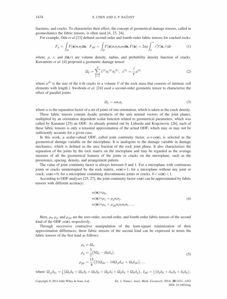
fractures, and cracks. To characterize their effect, the concept of geometrical damage tensors, called ingeomechanics the fabric tensors, is often used [4, 23, 24].
For example, Oda et al.[23] defined second-order and fourth-order fabric tensors for cracked rocks:
Fij ¼ZΩF nð Þninjdn; Fijkl ¼
ZΩF nð Þninjnknldn;F nð Þ ¼ 2πρ
Z ∞
0r3f n; rð Þdr (1)
where, ρ, r, and f(n,r) are volume density, radius, and probability density function of cracks.Kawamoto et al. [4] proposed a geometric damage tensor:
Ωij ¼XNk¼1
λ kð Þni kð Þnj kð Þ; λ kð Þ ¼ l
Va kð Þ (2)
where a(k) is the size of the k-th cracks in a volume V of the rock mass that consists of intrinsic cellelements with length l. Swoboda et al. [24] used a second-order geometric tensor to characterize theeffect of parallel joints:
Ωij ¼ ωninj (3)
where ω is the separation factor of a set of joints of one orientation, which is taken as the crack density.These fabric tensors contain dyadic products of the unit normal vectors of the joint planes,
multiplied by an orientation dependent scalar function related to geometrical parameters, which wascalled by Kanatani [25] an ODF. As already pointed out by Lubarda and Krajcinovic [26], each ofthese fabric tensors is only a tensorial approximation of the actual ODF, which may or may not besufficiently accurate for a given case.
In this work, a scalar-valued ODF, called joint continuity factor, ω =ω(n), is selected as thegeometrical damage variable on the microplane. It is analogous to the damage variable in damagemechanics, which is defined as the area fraction of the rock joint phase. It also characterizes theseparation of the joints by the rock matrix on the microplane and may be regarded as the averagemeasure of all the geometrical features of the joints or cracks on the microplane, such as thepersistence, spacing, density, and arrangement pattern.
The value of joint continuity factor is always between 0 and 1. For a microplane with continuousjoints or cracks uninterrupted by the rock matrix, ω(n) = 1; for a microplane without any joint orcrack, ω(n) = 0; for a microplane containing discontinuous joints or cracks, 0<ω(n)< 1.
According to ODF analyses [25, 27], the joint continuity factor ω(n) can be approximated by fabrictensors with different accuracy:
ω nð Þ≈ρ0;ω nð Þ≈ρ2 ¼ ρijninj;
ω nð Þ≈ρ4 ¼ ρijklninjnknl;…:
(4)
Here, ρ0, ρij, and ρijkl are the zero-order, second-order, and fourth-order fabric tensors of the secondkind of the ODF ω(n), respectively.
Through successive contractive manipulation of the least-square minimization of theirapproximation differences, these fabric tensors of the second kind can be expressed in terms thefabric tensors of the first kind as follows:
ρ0 ¼ Ω0;
ρij ¼325Ωij � Ω0δij� �
;
ρijkl ¼158
21Ωijkl � 14ΩðjlδikÞ þ Ω0Iijkl� �
;…
(5)
where Ω ijð δklÞ ¼ 16 Ωijδkl þ Ωikδjl þ Ωilδjk þ Ωjkδil þ Ωjlδik þ Ωklδij� �
, Iijkl ¼ 13 δijδkl þ δikδjl þ δilδjk� �
.
Copyright © 2014 John Wiley & Sons, Ltd. Int. J. Numer. Anal. Meth. Geomech. 2014; 38:1431–1452DOI: 10.1002/nag

MICROPLANE DAMAGE MODEL FOR JOINTED ROCK MASSES 1435
Here, the fabric tensors of the first kind Ω0, Ωij, and Ωijkl can be calculated from the discrete directionaldata of joints or cracks in a volume of the rock mass:
Ω0 ¼ 12π
ZΩω nð ÞdΩ≈
XNm
μ¼1
wμω μð Þ;
Ωij ¼ 12π
ZΩω nð ÞninjdΩ≈
XNm
μ¼1
wμω μð Þni μð Þnj μð Þ;
Ωijkl ¼ 12π
ZΩω nð ÞninjnknldΩ≈
XNm
μ¼1
wμω μð Þni μð Þnj μð Þn μð Þk n μð Þ
l ;…
(6)
where the integral over the surface of a unit hemisphereΩ is given byZΩ�ð ÞdΩ ¼
Z 2π
0
Z π=2
0�ð Þ sinϕdϕdθ
, ϕ and θ are the spherical angles, Nm is the number of the numerical integration points on a unithemisphere surface, and wμ, ni
(μ), and ω(μ) are the weight, the unit normal vector, and the jointcontinuity factor of the μ-th microplane, respectively.
The integral for a spherical surface is approximated according to the optimal Gaussian integrationformulas. For approximations with 21, 37, and 61 integration points per hemisphere, the unitvectors, and the weights were derived in Bažant and Oh [11].
4. RELATIONS BETWEEN THE MACRO-CONTINUUM AND MICROPLANESTRAINS AND STRESSES
Let σij and εij, i, j= 1, 2, 3 be, respectively, the second-order macroscopic stress and strain tensors, andσi and εi, i=N,L,M, the stress and strain vectors of the rock mass (the combined system) on a genericmicroplane. Here, xi, i= 1, 2, 3, are the global Cartesian coordinates and x ′ i, i =N, L,M, the localCartesian coordinates of the microplane. In the local coordinates, ni, i= 1, 2, 3, is the unit normalvector of the microplane, and mi, li, i = 1, 2, 3, the two orthogonal unit vectors lying within themicroplane, see Figure 1(c). The unit vector mi can be chosen arbitrarily but normal to axis x3,
m1 ¼ n2ffiffiffiffiffiffiffiffiffiffiffiffiffiffiffin21 þ n22
p ;m2 ¼ � n1ffiffiffiffiffiffiffiffiffiffiffiffiffiffiffin21 þ n22
p ;m3 ¼ 0 (7)
while the other unit vector on the microplane, li, can be obtained as the vector product of mi and ni, thatis, l=m× n.
With the assumption of kinematic constraint in Hypothesis III, the microplane strain vector in thecombined system, εi, i=N,L,M, is the projection of macroscopic strain tensor εij,
εN ¼ εijNij; εM ¼ εijMij; εL ¼ εijLij;
Nij ¼ ninj; Mij ¼ 12minj þ mjni� �
; Lij ¼ 12linj þ ljni� �
:(8a; b; c)
The equilibrium between the macroscopic continuum stress and the microplane stresses can beenforced only approximately by a variational principle. This is performed by the principle of virtualwork written for the surface of a unit hemisphere Ω [14],
2π3σijδεij ¼
ZΩσNδεN þ σMδεM þ σLδεLð ÞdΩ: (9)
This leads to the following basic relation between the macrocontinuum stress tensor and themicroplane stresses of the rock mass:
Copyright © 2014 John Wiley & Sons, Ltd. Int. J. Numer. Anal. Meth. Geomech. 2014; 38:1431–1452DOI: 10.1002/nag

1436 X. CHEN AND Z. P. BAŽANT
σij ¼ 32π
ZΩSijdΩ≈6
XNm
μ¼1
wμSμð Þij ; Sij ¼ σNNij þ σMMij þ σLLij (10a; b)
where S μð Þij is the contribution of the μ-th microplane to the stress tensor.
5. DAMAGE-BASED MICROPLANE CONSTITUTIVE LAWS OF THE ROCK
5.1. Parallel coupling of the rock matrix and the rock joint
Let εi(R), εi(J) and σi(R),σi
(J) be, respectively, the microplane strain and stress of the rock matrix and therock joint. According to Hypothesis II, the phases representing the rock matrix and the rock joint arecoupled in parallel on the microplane, which means that the strains of the rock matrix and the rockjoint are the same as those of the rock mass,
εi ¼ εi Rð Þ ¼ εi Jð Þ; i ¼ N; L;M (11)
while the microplane stress of the rock mass is a sum of the stresses in the rock matrix and the rockjoint weighted by their fraction in the combined system, that is,
σi ¼ 1� ωð Þσ Rð Þi þ ωσ Jð Þ
i ; i ¼ N; L;M: (12)
We assume that the aforementioned parallel coupling of the rock and joint phases on themicroplanes holds for both the elastic and inelastic response of the material. To establish themicroplane constitutive law for the combined system, the constitutive laws of these two phases andthe evolution law of the joint continuity factor are required.
5.2. Elastic behavior of the rock matrix and the rock joint
Let EN(K),ET
(K),K=R, J be the normal and shear stiffness constants of the rock matrix or the rock joint,respectively, and let E(K) and v(K),K=R, J be Young’s modulus and Poisson’s ratio of the intact rock orthe joint material on the macrolevel. For a kinematic constraint, the microplane elastic stiffnessconstants can be linked to the elastic constants of the macrocontinuum [28]:
ENKð Þ ¼ E Kð Þ
1� 2v Kð Þ ; ETKð Þ ¼ EN
Kð Þ 1� 4v Kð Þ
1þ v Kð Þ ; K ¼ R; J: (13a; b)
To guarantee nonnegative value for EN(K) and ET
(K), only Poisson’s ratios in the range 0 to 0.25 can bereproduced, which is sufficient for many intact rocks and rock joints. For intact rock whose v is between0.25 and 0.5, such as shale and schist, remedy can be made by coupling the rock matrix in series with anisotropic shear-deformable volumetrically rigid element, see Bažant and Oh [11] and Caner and Bažant [13].
For given increments of the microplane strains ΔεN(K), ΔεL(K), and ΔεM(K), K=R, J, the elastic parts of thenormal and shear stresses of the rock matrix and the rock joint are
σeN
Kð Þ ¼ σoN
Kð Þ þ ENKð ÞΔεN Kð Þ;
σeL
Kð Þ ¼ σoL
Kð Þ þ ETKð ÞΔεL Kð Þ;
σeM
Kð Þ ¼ σoM
Kð Þ þ ETKð ÞΔεM Kð Þ;K ¼ R; J
(14a; b; c)
whereσoNðKÞ,σo
LðKÞ, andσo
MðKÞ are the stored previous microplane normal stress and shear stresses in the
L-directions and M-directions, respectively.
Copyright © 2014 John Wiley & Sons, Ltd. Int. J. Numer. Anal. Meth. Geomech. 2014; 38:1431–1452DOI: 10.1002/nag

MICROPLANE DAMAGE MODEL FOR JOINTED ROCK MASSES 1437
The elastic part of the resultant microplane shear stress of the rock matrix or the rock joint is
σeT
Kð Þ ¼ffiffiffiffiffiffiffiffiffiffiffiffiffiffiffiffiffiffiffiffiffiffiffiffiffiffiffiffiffiffiffiffiffiffiffiffiffiffiffiffiσeL
Kð Þ� �2 þ σeM
Kð Þ� �2q;K ¼ R; J: (15)
5.3. Inelastic behavior of the rock matrix and the rock joint
The inelastic behaviors of the rock matrix and the rock joint can be described by their stress–strainboundaries, which are similar to strain-dependent yield limits. Within the boundaries, the response isassumed to be linear elastic. The advantage of the stress–strain boundary concept is that severalindependent boundaries for different stress components can be defined as functions of differentstrain components. If in numerical algorithm the elastic stress components exceed the correspondingstress boundary, the stresses will be dropped to return the boundary at constant stain. At differentloading steps, different microplanes will reach the stress–strain boundaries, which cause the macrostress–strain curves to vary their slope gradually.
In recent microplane model M7 for concretes [13], the volumetric–deviatoric split of the elasticstrains and of the tensile boundary is abandoned. In this way, previous problems with excessivelateral strains in postpeak extension and with unloading–reloading are now avoided. In M7, thevolumetric–deviatoric split is applied only to the compressive boundary, which is split into thevolumetric one and the deviatoric one. The volumetric compressive normal stress boundary controlsthe strain-hardening behavior under high triaxial confining pressure, which never produces softeningwhile the deviatoric compressive normal stress boundary controls the strain-softening behavior whenthe confinement is weak in at least one direction, as in uniaxial and biaxial compressive loading.
In the present microplane damage model for jointed rock masses, the overall inelastic response ofthe combined system on microplanes is determined by the inelastic response of the rock phase andjoint phase according to their current fraction. The rock matrix is a strain-hardening material thatcan transmit tensile, compressive, and shear stress on microplanes, while the rock joints are muchweaker being able to transmit only compressive and shear stresses on microplanes. The overallstrain-softening behavior of the combined system is due to an increase of the fraction of the rockjoint phase and to its much lower strength relative to that of the rock phase.
To consider the load carrying capacity of the combined system under different stress conditions, thetensile normal, the compressive normal, and the shear stress–strain boundaries of the rock matrix andthe joint may be formulated as follows:
1. Tensile normal stress–strain boundaries of the rock matrix and the rock joint.
The tensile normal stress boundaries of the rock or joint phases limit their respective load carrying capacitieson the microplane. Here, constant tensile strength values are used for both the rock matrix and the rock joint:
σbþN
Rð Þ ¼ T Rð Þ; σbþN
Jð Þ ¼ T Jð Þ (16a; b)
where T(R),T(J) are the tensile strengths of the rock matrix and the rock joint on the microplane, respectively.
2. Compressive normal stress boundaries of the rock matrix and the rock joint.
The compressive normal stress boundary of the rock matrix approximately reflects the effect ofmicrovoids at low confining pressures, and the strength increases because of confinement. It dependson the normal strain and the volumetric strain as follows:
σb�N
ðRÞ ¼ �αT Rð Þ;
α ¼ α0 1þ �εN � εoN� �
= c1ξ1ð Þ� �1:5h i; ξ1 ¼ 1= 1þ tanh �εV � εoV
� �=c2
� �� � (17a; b; c)
where α0 is the ratio of the minimum normal compressive strength to the tensile strength of the rockmatrix on the microplane, εoN ; ε
oV are the normal strain and volumetric strain thresholds of the rock
Copyright © 2014 John Wiley & Sons, Ltd. Int. J. Numer. Anal. Meth. Geomech. 2014; 38:1431–1452DOI: 10.1002/nag

1438 X. CHEN AND Z. P. BAŽANT
matrix, respectively, and c1, c2 are material parameters controlling the dependence of the compressivestress boundary of the rock matrix on normal strain and confinement, respectively.
Due to the waviness of the joint surface, the rock joint cannot entirely close under compression, andso the normal compressive stress cannot be fully transferred. We introduce a variable, β, called the jointmobilization factor, to represent the fraction of compressive strength mobilized by the rock joint. Theboundary must characterize the increase of compressive strength of the rock joint during its gradualclosing, and also its strength increases because of confinement. This can be accomplished as follows:
σb� Jð ÞN ¼ �α0βT Rð Þ;
β ¼ βc 1� e�ξ2� �
; ξ2 ¼ �εNh i= εIo � εIIIoð Þ þ a½ �f g0:5(18a; b; c)
Figure 2. Stress boundaries used in the microplane damage model for rocks: (a) normal stress boundaries ofthe rock matrix, (b) normal stress boundaries of the rock joint, and (c) shear stress boundary of the rock
matrix and the rock joint.
Figure 3. The damage evolution law as exponential function of strain history parameter.
Copyright © 2014 John Wiley & Sons, Ltd. Int. J. Numer. Anal. Meth. Geomech. 2014; 38:1431–1452DOI: 10.1002/nag

MICROPLANE DAMAGE MODEL FOR JOINTED ROCK MASSES 1439
where βc is the maximum value of the joint mobilization factor for the compressive normal strength,εIo, εIIIo are the maximum and minimum principal strains at the beginning of the current step,respectively, and a is a very small value introduced to prevent the overflow error in the calculation.
3. Shear stress-strain boundaries of the rock matrix and the rock joint.
In general, the shear strengths of the rock matrix and the rock joint will increase with the negativenormal stress and the confinement. Similar shear stress–strain boundaries as in microplane modelsM4 [12] and M7 [13] for concrete are adopted here for the rock matrix and the rock joint:
σbTðKÞ ¼ E′T
Kð Þc3⌢σo
NðKÞ � σN
Kð Þ� �E′T
Kð Þ þ c3⌢σo
NðKÞ � σN
Kð Þ� �;⌢σo
NðKÞ ¼ E′T
Kð Þc4 1� εVh i=εoV� �
; E′TKð Þ ¼ E Kð Þ= 1þ v Kð Þ� �
;K ¼ R; J
(19a; b; c)
in which c3 and c4 are material parameters that control the dependence of shear stress–strain boundaryon the normal stress and on the confinement, respectively, and σo
N Rð Þ;σoN Jð Þ are the normal stress
thresholds of the rock matrix and the rock joint, respectively.Because the volumetric strain is the average of the normal strains on all microplanes, the
dependence of stress–strain boundaries on the volumetric strain in the formulation implies theinteraction between microplanes of various orientations.
Figure 4. The flow of calculation between the macrolevel and microlevel with parallel coupling of the twophases on microplane.
Table I. The unit normal vector and the plane dip angle of microplanesμ= 3, 17, 7, 15, and 1.
μ nα1 nα2 nα3 θ (◦)
3 0 0 1 017 0.30895127 0 �0.9510779 187 0.70710678 0 �0.7071068 4515 0.95107787 0 �0.3089513 721 1 0 0 90
Copyright © 2014 John Wiley & Sons, Ltd. Int. J. Numer. Anal. Meth. Geomech. 2014; 38:1431–1452DOI: 10.1002/nag

1440 X. CHEN AND Z. P. BAŽANT
With the following parameter values α0 = 10, βc = 0.5, εoN ¼ 0:0005, εoV ¼ 0:001, c1 = 0.2, c2 = 0.005,c3 = 0.3, and c4 = 0.5, the basic features of the normal and shear stress–strain boundaries of the rockmatrix and the rock joint are shown in Figure 2.
In the explicit computational algorithm, the elastic moduli are used in every time step to obtain theelastic stress increment. If the stress point exceeds the stress–strain boundary, the stress is droppedvertically (at constant strain) to the boundary, which constitutes the inelastic stress increment. Thedrop of microplane normal stress thus occurs at constant microplane strain; then, the drop of shearstress occurs at constant updated normal stress. This is achieved by the equations:
σfN
Kð Þ ¼ max min σeN
Kð Þ;σbþ
NKð Þ
� �;σb�
NKð Þ
� �; K ¼ R; J: (20)
σfT
Kð Þ ¼ min σeT
Kð Þ;σb
TKð Þ
n o; K ¼ R; J: (21)
The final shear stress components in the coordinates of the microplane, σfL
Kð Þ;σf
MKð Þ;K ¼ R; J are
calculated under the assumption of proportionality to their corresponding elastic stress components:
σfL
Kð Þ ¼ σfT
Kð ÞσeL
Kð Þ=σe
TKð Þ; σf
MKð Þ ¼ σf
TKð Þσe
MKð Þ=σe
TKð Þ; K ¼ R; J: (22a; b)
Table II. Material parameters used for the sandstone.
Parameter Meaning Value
E(R) Young’s modulus of the rock matrix 25GPaE(J) Young’s modulus of the rock joint 25GPav(R) Poisson’s ratio of the rock matrix 0.18v(J) Poisson’s ratio of the rock joint 0.18T(R) Microplane tensile strength of the rock matrix 50MPaT(J) Microplane tensile strength of the rock joint 0α0 The ratio of the minimum microplane normal
compressive strength to the microplane tensilestrength of the rock matrix
10
βc The maximum value of the joint mobilizationfactor for normal compressive strength of the rock joint
0.5
ε0V The volumetric strain threshold of the rock matrix 0.001ε0N The normal strain threshold of the rock matrix 0.0005c1 Controls dependence of compressive normal stress
boundary of the rock matrix on normal strain0.2
c2 Controls dependence of compressive normalstress boundary of the rock matrix on volumetric strain
0.005
c3 Controls dependence of shear stress boundaryon the normal stress
0.001
c4 Controls dependence of shear stress boundaryon the confinement
0.05
a1 Controls dependence of damage evolution on historicmaximum positive volumetric strain
0.002
a2 Controls dependence of damage evolution on historicmaximum positive deviatoric strain
0.0025
a3 Controls dependence of damage evolution on historicmaximum shear strain
0.05
q1 Controls rate of damage evolution related to historicmaximum positive volumetric strain
1.5
q2 Controls rate of damage evolution related to historicmaximum positive deviatoric strain
1.5
q3 Controls rate of damage evolution related to historicmaximum shear strain
1
Copyright © 2014 John Wiley & Sons, Ltd. Int. J. Numer. Anal. Meth. Geomech. 2014; 38:1431–1452DOI: 10.1002/nag

MICROPLANE DAMAGE MODEL FOR JOINTED ROCK MASSES 1441
5.4. Evolution law of the joint continuity factor
The nonlinear inelastic behavior of the rock originates not only in the rock matrix but also, and mainly, inthe rock joint. The evolution of the rock joint may be described by the joint continuity factor, whichcharacterizes the cracking process in the rock matrix. It is generally known that, under unconfinedcompression, the rock tends to fail by longitudinal splitting fracture. At moderate lateral confiningpressure, the splitting fracturing tends to be suppressed, and the rock fails along an inclined plane ofcompression–shear. At high enough confining pressure, the rock becomes rather ductile, and the failureoccurs through a network of many small shear fractures. Under uniaxial tension, a tensile mode Ifracture perpendicular to the loading direction typically appears.
Different mechanisms can be discerned in the damage evolution. Under low confinementcompression, and also under uniaxial tension, the initiation and propagation of opening mode cracksare accompanied by accumulation of volumetric expansion and positive deviatoric strains. When theshear stress along the microplane is high, shear cracking proceeds along that plane.
The damage evolution is mainly controlled by the maximum positive values of the volumetric strain,deviatoric strain, and shear strain reached so far on the microplanes. Denoting them as εþh
V ; εþhD ; εhT ,
respectively, one can describe the damage evolution by decaying exponentials of power laws [3, 7]:
ω ¼ 1� e� εþhV =a1ð Þq1þ εþh
D =a2ð Þq2þ εhT=a3ð Þq3½ � (23)
where a1, a2, a3 and q1, q2, q3 are empirical material parameters; εD= εN� εV is the deviatoric strain.
Figure 5. Simulation of the triaxial test of the sandstone from Southwest Germany by Gowd and Rummel[29]: (a) axial stress versus axial strain and(b) axial stress versus volumetric strain.
Copyright © 2014 John Wiley & Sons, Ltd. Int. J. Numer. Anal. Meth. Geomech. 2014; 38:1431–1452DOI: 10.1002/nag

1442 X. CHEN AND Z. P. BAŽANT
Figure 3 gives an example of material damage evolution with increasing strain at differentparameters a, q according to the function ω ¼ 1� e� ε=að Þq .
6. CALIBRATION AND COMPARISON WITH THE TEST DATA
The present microplane damage model for rock was implemented in a FORTRAN materialsubroutine for a finite element program. The flow of calculation between the macrolevel andmicrolevel with parallel coupling of the two phases on microplane is explained in Figure 4. Theoptimal Gaussian integration formula for the surface of a unit sphere with Nm = 37 integrationpoints per hemisphere (derived in [11]) was used to integrate the stress tensor from the stresseson 37 microplanes normal to the radial vectors at these points. For the sake of illustration, wewill later consider the dip angle of the microplane, θ, defined as the angle between themicroplane and axis x1 in the global Cartesian coordinates ox1x2x3. It will be convenient toconsider microplanes μ = 3, 17, 7, 15, and 1, whose unit normal vectors are perpendicular to theaxis x2. Their dip angles are 0°, 18°, 45°,72°, and 90°, respectively, as listed in Table I alongwith their unit vector coordinates.
To calibrate and verify the model, simulations were run to optimally fit the triaxial compression testdata for sandstone from Southwest Germany, as reported by Gowd and Rummel [29], and the uniaxialcompression test data for a jointed plaster mortar, as reported by Kawamoto et al. [4] (the test resultsare shown in all the figures by circle points and the model predictions by continuous curves). Forsimplicity, it was assumed in the simulations that Young’s modulus and Poisson’s ratio of the rockjoint are equal to those of the rock matrix, that is, E(J) =E(R), v(J) = v(R).
Figure 6. The joint continuity factor on microplane versus axial strain: (a) p= 10MPa, (b) p= 30MPa, (c)p= 60MPa, and (d) p= 100MPa.
Copyright © 2014 John Wiley & Sons, Ltd. Int. J. Numer. Anal. Meth. Geomech. 2014; 38:1431–1452DOI: 10.1002/nag

MICROPLANE DAMAGE MODEL FOR JOINTED ROCK MASSES 1443
6.1. Numerical results for a sandstone under triaxial compression
The triaxial compression test of the sandstone by Gowd and Rummel [29] was simulated. Thesandstone taken from SW-Germany was a medium grain sized with subangular to round quartzgrains bedded within a clayey matrix. Below a critical value of axial stress, the rock deformedlinearly and elastically. Further compression led to inelastic deformation. The transition from brittleto ductile deformation occurred at about confining pressure 90MPa.
The simulation led to the material parameters listed in Table II, in which the meaning of eachparameter is briefly indicated.
The curves of the axial stress versus the axial strain and the volumetric strain at confining pressures10, 30, 60, and 100MPa are plotted in Figure 5. The curves document that the model can characterizethe main features of standard triaxial compression tests of intact rock. At low or medium pressuresp= 10, 30, and 60MPa, the stress–strain curves show strain softening and dilatancy, namely, aninelastic expansion relative to the elastic compression in volumetric deformation. The transitionfrom brittle to ductile deformation takes place at confining pressure p= l00MPa, marked by strainhardening and absence of dilatancy. With increasing confinement, the predicted strength increaseswhile volumetric expansion decreases, as exhibited in the experiments.
For illustration, we consider microplanes μ = 3, 17, 7, 15, and 1. The curves of the joint continuityfactors versus axial strain at different confining pressure are depicted in Figure 6. As can be seen,the microplane damage at the same axial strain decreases with the microplane dip angle. As theconfinement increases, the growth of damage on the microplanes gets gradually suppressed as thedip angle becomes higher (μ = 7, 15, and 1).
Figure 7. (a) The volumetric strain versus axial strain and (b) normal stress threshold versus axial strain.
Copyright © 2014 John Wiley & Sons, Ltd. Int. J. Numer. Anal. Meth. Geomech. 2014; 38:1431–1452DOI: 10.1002/nag

1444 X. CHEN AND Z. P. BAŽANT
To clarify the dependence of the stress–strain boundaries on the confinement, Figure 7 depicts thevariation of the volumetric strain and the normal stress thresholds with the axial strain. In thesimulations, due to the same value of the Young’s modulus and Poisson’s ratio, the normal stressthreshold of the rock matrix equals that of the rock joint. For the shear stress boundaries, thecontribution of the normal stress threshold and the normal stress can be related to the two differentmechanisms, that is, the cohesion mechanism and the friction mechanism, respectively. Figure 7(b)shows the model to capture the decrease of cohesion with increasing axial strain at the confiningpressure of p= 10 and 30MPa, which is due to volume expansion at low confinement.
To illustrate how the microplane response of the combined system depends on the two phases, therock matrix and the joint, the strains, and stresses on microplanes μ = 1, 3, and 7 may be investigated.The shear strains on the microplanes μ = 1 and 3 are nearly zero. Figure 8 plots the normal strains onmicroplanes μ= 1 and 3 versus the axial strain. Figure 9 plots the normal and shear strains onmicroplane μ = 7 versus the axial strain. As one can see, except for shear strain on microplane μ= 7at the confining pressure of p = 10MPa, normal strains and shear strains on these microplanesincrease with the axial strain.
Figures 10–12 and Figure 13 plot the normal stress and the shear stress, respectively, versus theaxial strain as exhibited by the rock matrix, the rock joint, and the combined system of microplanesμ = 1, 3, and 7. For microplane μ= 1, the normal stresses of the combined system and the twophases, rock matrix and joints, are compressive. The strain softening exhibited by the normal stressof the combined system under lower confining pressures may be attributed both to a lowercompressive strength of the rock joint and to a gradual increase in the rock joint fraction. Under
Figure 8. The normal strain versus axial strain on microplanes: (a) μ= 1 and (b) μ= 3.
Copyright © 2014 John Wiley & Sons, Ltd. Int. J. Numer. Anal. Meth. Geomech. 2014; 38:1431–1452DOI: 10.1002/nag

Figure 9. The strains on the microplane μ = 7 versus axial strain (a) the normal strain and (b) the shear strain.
MICROPLANE DAMAGE MODEL FOR JOINTED ROCK MASSES 1445
higher confining pressures, the strain-hardening behavior of the combined system may be explained bysuppressed microplane damage growth and by strain-hardening response of the rock matrix.
For microplane μ= 3, the tensile normal stress of the combined system exhibits strain-softeningbehavior at any confining pressure. Doubtless this is due to fast microplane damage growth atvanishing tensile strength of the rock joint.
For microplane μ =7, the normal stresses of the combined system under confining pressuresp=10MPa and p=100MPa exhibit strain softening, while they show strain hardening under confiningpressures p=30MPa and p=60MPa. The shear stresses of the combined system under confiningpressure p= 10MPa and p=30MPa first increase with the axial strain but then decrease fast to a verylow value, while under confining pressures p=60MPa and p= 100MPa, they first increase then keepnearly constant. The decrease of the shear stress of the combined system under confining pressurep=30MPa may be explained by the dominance of the cohesion mechanism over the friction mechanism.
6.2. Numerical results for a jointed plaster mortar under uniaxial compression
The optimum fitting of Kawamoto et al.’s [4] data on the anisotropic behavior of a uniaxiallycompressed plaster mortar with one set of parallel open joints led to the material parameters valueslisted in Table III, in which εoN ; ε
oV ; c2; c3; c4; a1; q1; q2; q3 take the same values as for the sandstone.
Here, in view of the low compressive normal strength of the preexisting open joints, the maximumvalue of the joint mobilization factor, βc, is set to a very small value, 0.01.
Consider first the specimen with one set of joints, and denote the local Cartesian coordinates of the jointplane as ox ′1 x ′2 x ′3. Axis x ′ 1 is chosen to be parallel to the normal of the joint plane, and axis x ′ 2 is chosen
Copyright © 2014 John Wiley & Sons, Ltd. Int. J. Numer. Anal. Meth. Geomech. 2014; 38:1431–1452DOI: 10.1002/nag

Figure 10. The normal stress on the microplane μ= 1 versus axial strain: (a) p= 10MPa, (b) p= 30MPa, (c)p= 60MPa, and (d) p= 100MPa.
Figure 11. The normal stress on the microplane μ= 3 versus axial strain: (a) p= 10MPa, (b) p= 30MPa, (c)p= 60MPa, and (d) p= 100MPa.
1446 X. CHEN AND Z. P. BAŽANT
Copyright © 2014 John Wiley & Sons, Ltd. Int. J. Numer. Anal. Meth. Geomech. 2014; 38:1431–1452DOI: 10.1002/nag

Figure 12. The normal stress on the microplane μ= 7 versus axial strain: (a) p= 10MPa, (b) p= 30MPa, (c)p= 60MPa, and (d) p= 100MPa.
Figure 13. The shear stress on the microplane μ= 7 versus axial strain: (a) p= 10MPa, (b) p= 30MPa, (c)p= 60MPa, and (d) p= 100MPa.
MICROPLANE DAMAGE MODEL FOR JOINTED ROCK MASSES 1447
Copyright © 2014 John Wiley & Sons, Ltd. Int. J. Numer. Anal. Meth. Geomech. 2014; 38:1431–1452DOI: 10.1002/nag

1448 X. CHEN AND Z. P. BAŽANT
to coincide with axis x2 of the global Cartesian coordinates ox1x2x3. The joint plane dip angle θj is defined asthe angle between the joint planes and the axial stress σ1 or the axis x1. For the joint continuity factor, thesecond-order fabric tensor of the second kind may be written in the local coordinates, ρ ′ij, as
ρ′ij ¼ω0 0 0
0 0 0
0 0 0
264
375 (24)
where ω0 is the initial value of the joint continuity factor on the joint plane before loading.
Figure 14. The numerical results for the intact and jointed plaster mortar specimens under uniaxialcompression: (a) axial stress versus axial strain and (b) axial stress versus volumetric strain.
Table III. Material parameters used for the jointed plaster mortar.
E(R) (MPa) E(J) (MPa) v(R) v(J) T(R) (MPa) T(J) (MPa)
1110 1110 0.17 0.17 0.5 0
α0 βc ε0V ε0N c1 c2 c3 c4
5 0.01 0.001 0.0005 0.15 0.005 0.001 0.05
a1 a2 a3 q1 q2 q3
0.002 0.001 0.025 1.5 1.5 1
Copyright © 2014 John Wiley & Sons, Ltd. Int. J. Numer. Anal. Meth. Geomech. 2014; 38:1431–1452DOI: 10.1002/nag

MICROPLANE DAMAGE MODEL FOR JOINTED ROCK MASSES 1449
For simplicity, the joint continuity factor for a penetrating joint is defined as the ratio of the length ofthe joint to the combined length of the joint and the rock bridges [30]. Thus, the value of ω0 for theplaster mortar is 0.45.
With the second kind of fabric tensor, the joint continuity factor on each microplane can beapproximated by
ω μð Þ nð Þ≈ρ′ijn′i μð Þn′j μð Þ: (25)
The uniaxial compression tests of the intact specimen and of the jointed specimens with differentjoint plane angles are simulated. Figure 14 plots the curves of the axial stress versus the axial strainand the volumetric strain. The peak strengths and Young’s moduli of the jointed specimens arenormalized by those of the intact specimen. Figure 15 presents a comparison of the test results withthe unified strength and unified Young’s modulus predicted by the model for the jointed plastermortar. For specimens with joint plane dip angles θj= 0°, 45°, 90°, Figure 16 shows the growth ofthe joint continuity factor with axial strain on the microplanes μ = 1, 3, and 7.
As can be seen, the predicted stress–strain curves exhibit strain softening and dilatancy for theintact as well as the jointed specimens. The predicted unified strengths and Young’s moduli ofthe jointed specimen decrease with the joint dip angle, which agrees with the test results.
Figure 15. (a) Unified strength and (b) unified Young’s moduli versus joint dip angle for the plaster mortarspecimen.
Copyright © 2014 John Wiley & Sons, Ltd. Int. J. Numer. Anal. Meth. Geomech. 2014; 38:1431–1452DOI: 10.1002/nag

Figure 16. The joint continuity factor on microplanes (a) μ= 1 and (b) μ = 3 versus axial strain for the plastermortar specimen.
1450 X. CHEN AND Z. P. BAŽANT
Thesimulation of the anisotropic behavior of the jointed specimen is controlled by the initial valueand evolution of the joint continuity factor, the dip angle of the joint plane with regard tothe loading direction, and the nonlinear response of the rock and the joint. The less satisfactoryagreement of strengths than those of elastic moduli may be caused by the sensitivity of theformer to the other geometrical parameters of the joints, such as spacing and arrangement patterns.
In the proposed microplane damage model for jointed rock masses, there are 20 materialparameters to be identified. They include (i) the elastic parameters of the rock matrix and therock joint, E(R), v(R), E(J), and v(J); (ii) the microplane strength parameters of the rock matrix andthe rock joint, T(R), T(J), α0, βc, εoN , εoV , c1, c2, c3, and c4; and (iii) the damage evolutionparameters of the rock matrix, a1, q1, a2, q2, a3,and q3. For a given rock mass, the elasticparameters can first be estimated through the elastic behavior of the intact rock and the fillingmaterial of the rock joint. Because the microplane strength parameters εoN ; ε
oV ; c1; c2; c3; c4 and the
damage evolution parameters a1, q1, a2, q2, a3, q3 mainly control the shape of the nonlinear stress–strain curve, they can be set the same value for a certain type of rocks. Finally, the remainingstrength parameters T(R), T(J), α0, and βc can be obtained from optimal fitting to the strengths ofthe intact rock or the rock mass under different confining pressure. For jointed rock mass, themost difficult part in the calibration is the formulation of the microplane damage variable as afunction of the geological data of joint sets, such as persistence, spacing, and arrangementpattern. It is generally recognized that joint persistence plays the most important role amongothers in the failure process of the rock mass. However, to consider the influence of the othergeometrical parameters in general, further experiment study is required.
As shown in these simulations, with only 37 integration points, the model can obtain areasonable result in a nonlinear incremental analysis. The procedure of implementation in finiteelement analyses is the same as other microplane models; the basic flowchart can be found inCarol et al.[31].
Copyright © 2014 John Wiley & Sons, Ltd. Int. J. Numer. Anal. Meth. Geomech. 2014; 38:1431–1452DOI: 10.1002/nag

MICROPLANE DAMAGE MODEL FOR JOINTED ROCK MASSES 1451
7. CONCLUSIONS
1. The main conclusion is that, in order to describe with the microplane model the nonlinear damagebehavior of jointed rock under general traixial loading, including compression, the isotropic rockmatrix, and the joints (or cracks), may be considered as two distinct phases that are coupled inparallel (and thus undergo equal overall strains).
2. The inelastic softening behavior can be realistically modeled by introducing the joint continuityfactor as the stress-carrying area fraction. Thus, the model can consider the independent influenceof the geometrical parameters and the mechanical response of discontinuities in rocks.
3. The optimized numerical simulations presented document satisfactory fits of previously pub-lished triaxial test data on sandstone—an intact rock, without joints. The fits reproduce the essen-tial features such as the strain softening and dilatancy under low confining pressure, as well as thebrittle–ductile transition under higher confining pressure.
4. The optimal fitting of previously published data on jointed plaster mortar shows that the salientfeatures such as the decrease of jointed rock strength and of Young’s modulus with an increasingdip angle of the joint can be realistically reproduced.
ACKNOWLEDGEMENTS
The work presented here was supported by the National Science Foundation of China (NSFC) under grantno. 11102224 and by the Fundamental Research Funds for the Central Universities of China under grantno. 2009QL05. The work of the second author was supported by the US National Science Foundation undergrant no. CMMI-1153494 to Northwestern University, which also provided the facilities for the conduct ofresearch.
REFERENCES
1. Bieniawski ZT. The effect of specimen size on compressive strength of coal. International Journal of Rock Mechan-ics and Mining Sciences & Geomechanics Abstracts 1968; 5(4):325–335.
2. Dragon A, Mroz Z. A continuum model for plastic brittle behavior of rock and concrete. International Journal ofEngineering Science 1979; 17(2):121–137.
3. Frantziskonis G, Desai CS. Elastoplastic model with damage for strain softening geomaterials. Acta Mechanica 1987;68(3/4):151–170.
4. Kawamoto T, Ichikawa Y, Kyoya T. Deformation and fracturing behavior of discontinuous rock mass and damagemechanics theory. International Journal for Numerical and Analytical Methods in Geomechanics 1988; 12(1):1–30.
5. Kachanov LM. Time of the rupture process under creep conditions. Izv Akad Nauk SSR, Otd Tekh Nauk 1958;8:26–31.
6. Rabotnov IN. On the equations of state for creep. Progress in Applied Mechanics-The Prager Anniversary 1963;8:307–315.
7. Carol I, Bažant ZP, Prat PC. Geometric damage tensor based on microplane model. Journal of Engineering Mechan-ics, ASCE 1991; 117(10):2429–2448.
8. Lemaitre J, Desmorat R, Sauzay M. Anisotropic damage law of evolution. European Journal of Mechanics A-Solids2000; 19(2):187–208.
9. Brocca M, Bažant ZP. Microplane constitutive model and metal plasticity. Applied Mechanics Reviews, ASME 2000;53(10):265–281.
10. Caner FC, Bažant ZP, Červenka J. Vertex effect in strain-softening concrete at rotating principal axes. Journal ofEngineering. Mechanics, ASCE 2002; 128(1):24–33.
11. Bažant ZP, Oh BH. Microplane model for progressive fracture of concrete and rock. Journal of EngineeringMechanics, ASCE 1985; 111(4):559–582.
12. Bažant ZP, Caner FC, Carol I, Adley MD, Akers SA. Microplane model M4 for concrete: I. Formulation withwork-conjugate deviatoric stress. Journal of Engineering Mechanics, ASCE 2000; 126(9):944–953.
13. Caner FC, Bažant ZP. Microplane model M7 for plain concrete I. Formulation, II. Calibration and verification.Journal of Engineering Mechanics, ASCE 2013; 139:1714–1735.
14. Bažant ZP Microplane model for strain-controlled inelastic behavior. In Mechanics of Engineering Materials Chapter3, Desai CS, Gallagher RH (eds). Wiley: London, 1984; 45–59.
15. Bažant ZP, Oh BH. Microplane model for fracture analysis of concrete structures. Proc., Symp. on the Interaction ofNon-Nuclear Munitions with Structures, held at U.S. Air Force Academy, Colorado Springs, 1983; 49–53.
16. Bažant ZP, Kim JK. Creep of anisotropic clay: microplane model. Journal of geotechnical engineering, ASCE 1986;112(4):458–475.
17. Prat PC, Bažant ZP. Microplane model for triaxial deformation of saturated cohesive soils. Journal of geotechnicalengineering, ASCE 1991; 117(6):891–912.
Copyright © 2014 John Wiley & Sons, Ltd. Int. J. Numer. Anal. Meth. Geomech. 2014; 38:1431–1452DOI: 10.1002/nag

1452 X. CHEN AND Z. P. BAŽANT
18. Bažant ZP, Zi G. Microplane constitutive model for porous isotropic rocks. International Journal for Numerical andAnalytical Methods in Geomechanics 2003; 27(1):25–47.
19. Yang Q, Chen X, Zhou WY. Microplane-damage-based effective stress and invariants. International Journal ofDamage Mechanics 2005; 14(2):179–191.
20. Murakami S. Mechanical modelling of material damage. Journal of Engineering Materials and Technology: ASME1988; 55(2):280–286.
21. Hill R. The Mathematical Theory of Plasticity. Clarendon Press: Oxford, 1950.22. Liu C, Huang Y, Stout MG. On the asymmetric yield surface of plastically orthotropic materials: a phenomenological
study. Acta Materialia 1997; 45(6):2397–2406.23. Oda M, Yamabe T, Ishizuka Y, Kumasaka H, Tada H. Elastic stress and strain in jointed rock masses by means of
crack tensor analysis. Rock Mechanics and Rock Engineering 1993; 26(2):89–112.24. Swoboda G, Shen XP, Rosas L. Damage model for jointed rock mass and its application to tunnelling. Computers
and Geotechnics 1998; 22(3/4):183–203.25. Kanatani K. Distribution of directional data and fabric tensors. International Journal of Engineering Science 1984;
22(2):149–164.26. Lubarda VA, Krajcinović D. Damage tensors and the crack density distribution. International Journal of Solids and
Structure 1993; 30(2):2859–2877.27. Chen X, Yang Q, Qiu KB, Feng JL. An anisotropic strength criterion for jointed rock masses and its application in
wellbore stability analyses. International Journal for Numerical and Analytical Methods in Geomechanics 2008;32(6):607–631.
28. Carol I, Bažant ZP. Damage and plasticity in microplane theory. International Journal of Solids and Structure 1997;34(29):3807–3835.
29. Gowd TN, Rummel F. Effect of confining pressure on the fracture behaviour of a porous rock. International Journalof Rock Mechanics and Mining Science and Geomechanics Abstracts 1980; 17(4):225–229.
30. Jennings JE. A mathematical theory for the calculation of the stability of open cut mines. Proceeding of Symposiumon the Theoretical Background to the Planning of Opening Pit Mines, Johannesburg, 1970; 87–102.
31. Carol I, Prat PC, Bažant ZP. New explicit microplane model for concrete: theoretical aspects and numericalimplementation. International Journal of Solids and Structure 1992; 29(9):1173–1191.
Copyright © 2014 John Wiley & Sons, Ltd. Int. J. Numer. Anal. Meth. Geomech. 2014; 38:1431–1452DOI: 10.1002/nag