microfluidic chaotic stirrer utilizing induced-charge
TRANSCRIPT

University of Pennsylvania University of Pennsylvania
ScholarlyCommons ScholarlyCommons
Departmental Papers (MEAM) Department of Mechanical Engineering & Applied Mechanics
June 2007
Microfluidic chaotic stirrer utilizing induced-charge electro-Microfluidic chaotic stirrer utilizing induced-charge electro-
osmosis osmosis
Hui Zhao University of Pennsylvania
Haim H. Bau University of Pennsylvania, [email protected]
Follow this and additional works at: https://repository.upenn.edu/meam_papers
Recommended Citation Recommended Citation Zhao, Hui and Bau, Haim H., "Microfluidic chaotic stirrer utilizing induced-charge electro-osmosis" (2007). Departmental Papers (MEAM). 105. https://repository.upenn.edu/meam_papers/105
Copyright American Physical Society. Reprinted from Physical Review E, Volume 76, Issue 6, Article 066217, June 2007, 8 pages. Publisher URL: http://dx.doi.org/10.1103/PhysRevE.75.066217
This paper is posted at ScholarlyCommons. https://repository.upenn.edu/meam_papers/105 For more information, please contact [email protected].

Microfluidic chaotic stirrer utilizing induced-charge electro-osmosis Microfluidic chaotic stirrer utilizing induced-charge electro-osmosis
Abstract Abstract Recently, there has been a growing interest in using induced electro-osmosis to pump fluids in microfluidic devices. We show that induced electro-osmosis can also be used to promote stirring and chaotic advection. To this end, we study theoretically a stirrer in which the flow patterns are alternated in time. We first analyze an idealized embodiment of the stirrer that admits a simple analytical solution for the flow patterns. The stirrer consists of a concentric annulus whose outer surface is defined by an array of electrodes that provide a spatially varying potential distribution. The resulting electric field induces quadruple electro-osmotic flow around the inner cylinder. By timewise alternating the potential distribution around the outer cylinder, we induce chaotic advection in the cavity. Subsequently, we carry out numerical simulations for a more realistic design that can be readily constructed, and demonstrate that it is possible to induce chaotic advection also in this case.
Comments Comments Copyright American Physical Society. Reprinted from Physical Review E, Volume 76, Issue 6, Article 066217, June 2007, 8 pages. Publisher URL: http://dx.doi.org/10.1103/PhysRevE.75.066217
This journal article is available at ScholarlyCommons: https://repository.upenn.edu/meam_papers/105

Microfluidic chaotic stirrer utilizing induced-charge electro-osmosis
Hui Zhao and Haim H. Bau*Department of Mechanical Engineering and Applied Mechanics, University of Pennsylvania, Philadelphia, Pennsylvania 19104, USA
�Received 22 February 2007; published 28 June 2007�
Recently, there has been a growing interest in using induced electro-osmosis to pump fluids in microfluidicdevices. We show that induced electroosmosis can also be used to promote stirring and chaotic advection. Tothis end, we study theoretically a stirrer in which the flow patterns are alternated in time. We first analyze anidealized embodiment of the stirrer that admits a simple analytical solution for the flow patterns. The stirrerconsists of a concentric annulus whose outer surface is defined by an array of electrodes that provide a spatiallyvarying potential distribution. The resulting electric field induces quadruple electro-osmotic flow around theinner cylinder. By timewise alternating the potential distribution around the outer cylinder, we induce chaoticadvection in the cavity. Subsequently, we carry out numerical simulations for a more realistic design that canbe readily constructed, and demonstrate that it is possible to induce chaotic advection also in this case.
DOI: 10.1103/PhysRevE.75.066217 PACS number�s�: 47.52.�j, 47.65.�d, 47.63.mf
I. INTRODUCTION
Recently, the use of induced �ac� electro-osmosis has beenproposed as an effective means to pump fluids in microflu-idic systems �1–8�. Induced electro-osmosis is distinct fromthe classical electro-osmosis �9,10�, since it results from theinteraction between the electric field and ions in the electricdouble layer formed by the polarizing effect of the electricfield itself. The intensity of the resulting flow is proportionalto the square of the electric field intensity. At relatively lowfrequencies, the direction of the electric body force is inde-pendent of the direction of the electric field. Thus, unidirec-tional fluid motion can be induced with ac fields, thus avoid-ing many of the complications associated with dc electricfields, such as electrode electrochemistry.
The phenomenon of induced-charge electro-osmosisaround conducting particles has been studied extensively�7,11–18� Only recently has it been recognized that, in theabsence of symmetry, induced electro-osmosis leads to netpumping in conduits �1,16,19� and net forces on particles�19–22�.
Since the Reynolds numbers are typically very low andthe flow is laminar, fluid mixing is a significant challenge inmicrofluidic systems �23�. Aref �24� demonstrated that, whenflow patterns form closed orbits, one can induce Lagrangianchaos and effective stirring by alternating periodically be-tween two or more flow patterns. See also Ottino �25� for alucid review. In this paper, we demonstrate that inducedelectro-osmosis can be used to generate various flow patternsand chaotic advection. In the first part of the paper, wepresent an idealized model which allows us to obtain exactexpressions for the flow patterns. The stirrer consists of aconcentric annulus. The outer surface of the cylinder consistsof an electrode �or an array of electrodes� that forms a spa-tially varying potential. The inner cylinder is conducting. Asa result of the induced electric double layer around the innercylinder, convective cells form in the annulus. By timewise
alternations of the electric potential of the outer cylinder, weinduce chaotic advection in the annulus. Although the abovestirrer design exhibits the basic physics of the process, it isnot readily amenable for fabrication. Therefore, in the secondpart of the paper, we analyze a more realistic device that canbe readily constructed.
II. MATHEMATICAL MODEL
We start with a simple embodiment of the stirrer. Con-sider a concentric annulus. The radii of the inner and outercylinders are, respectively, a and a+b. The annulus is filledwith electrolyte solution of bulk concentration C0 anddielectric constant �. The inner cylinder is electrically con-ducting. The outer cylinder is subjected to a potential distri-bution f���. We use the cylindrical coordinate system �r ,��with its origin at the center of the inner cylinder �Fig. 1�.When the inner, conducting cylinder is subjected to an elec-tric field, it polarizes. The induced surface charges attractcounterions from the electrolyte solution, which, in turn,leads to the formation of an electric double layer. Thethickness of the double layer is the Debye screening length
*Author to whom correspondence should be addressed. Electronicaddress: [email protected]
FIG. 1. Schematic depiction of a stirrer consisting of a concen-tric annulus of inner radius a and outer radius a+b.
PHYSICAL REVIEW E 75, 066217 �2007�
1539-3755/2007/75�6�/066217�8� ©2007 The American Physical Society066217-1
�D=��RT / �2F2C0�, where R is the ideal gas constant, T isthe absolute temperature, and F is the Faraday constant.When C0=10 mM, �D�8 nm. We assume that b�100 �m,b /�D�125, and one can use the thin electric layer approxi-mation.
The electrolyte solution is treated as a conductor, and theelectrical potential in the solution satisfies the Laplace equa-tion
�2� = 0. �1�
We assume that the electric field is too small to induce Fara-daic reactions on the inner cylinder’s surface. Thus, at equi-librium, no current enters the double layer, and on the innercylinder’s surface �r=a�
n� · �� � = 0. �2�
In the above, n� is the outer normal vector to the surface. Onthe outer cylinder’s surface, we impose a potential distribu-tion of the form
��r + b,�� = f��� . �3�
We assume that Faradaic reactions take place at the surfaceof the outer cylinder and that the electrical resistance of theelectric double layer is relatively small so that there is asmall difference between the electrode’s potential and thepotential immediately outside the electric double layer.
Since typically the Reynolds number associated with theelectrokinetic flow is very small, the fluid motion can bedescribed with the Stokes equation
− �� p + ��2u� = 0� �4�
and the continuity equation
�� · u� = 0. �5�
In the limit of the thin-double-layer approximation, theelectric field is coupled with the flow problem through theSmoluchowski slip velocity �7�,
u��a,�� = −���a,��
��� t��a,�� . �6�
In the above, �� t� is the tangential component of the poten-tial’s gradient. Equation �6� is applicable as long as the �potential is not too large, i.e., on the order of the thermalvoltage ��25 mV� or smaller �26,27�.
We assume that the potential of the outer cylinder variesslowly, and we neglect induced electroosmotic flow at thesurface of the outer cylinder:
u��a + b,�� = 0� . �7�
When the approximation �7� is not applicable, one canreadily determine the flow field induced by the electroos-motic flow at the outer cylinder and superimpose it on theflow fields computed later in this paper.
It is convenient to nondimensionalize the various vari-ables. We use the radius of the inner cylinder a as the lengthscale; ���0�2 / ��a� as the velocity scale; and �a2 / ���0
2�
as the time scale. In the above, �0=max f���−min f���. Wedefine the dimensionless radius =r /a and the annulus as-pect ratio �=b /a. 1��1+�.
For concreteness, we consider the case of the electricalpotential on the outer cylinder given by
f��� = A sin�� + �0� . �8�
The electrical potential is
� = A1 + �
1 + �1 + ��2 +1
sin�� + �0� . �9�
To calculate the velocity field, we introduce the streamfunction . satisfies the biharmonic equation
�4 = 0. �10�
The velocity components are related to by
ur =1
r
�
��, u� = −
�
�r. �11�
The boundary conditions on the outer and inner cylinders aregiven by the nonslip condition and the Smoluchowski for-mula �6�, respectively. The general solution for the streamfunction has the form
�r,�� = A1
r2 + B1 + C1r2 + D1r4sin 2�� + �0� . �12�
The constants A1, B1, C1, and D1 are determined by using theappropriate boundary conditions.
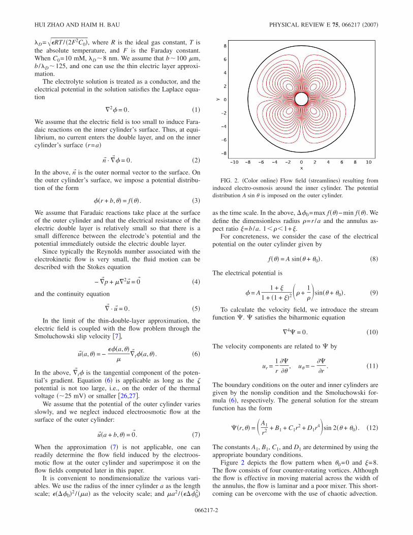
Figure 2 depicts the flow pattern when �0=0 and �=8.The flow consists of four counter-rotating vortices. Althoughthe flow is effective in moving material across the width ofthe annulus, the flow is laminar and a poor mixer. This short-coming can be overcome with the use of chaotic advection.
FIG. 2. �Color online� Flow field �streamlines� resulting frominduced electro-osmosis around the inner cylinder. The potentialdistribution A sin � is imposed on the outer cylinder.
HUI ZHAO AND HAIM H. BAU PHYSICAL REVIEW E 75, 066217 �2007�
066217-2

III. AN IDEALIZED CHAOTIC STIRRER
Aref �24� demonstrated that, by alternating between two�or more� different closed-orbit patterns A and B, one cangenerate Lagrangian chaos. Here, we obtain two such pat-terns by timewise alternations of the potential imposed onthe outer cylinder. In the time interval kT� t�kT+T /2, weimpose the potential �8� with phase angle �0=0 on the outerelectrode. We refer to the corresponding flow field as patternA. In the time interval kT+T /2� t� �k+1�T, we impose thepotential �8� with phase angle �0=� /4. We refer to the cor-responding flow field as pattern B. The time period T is muchlarger than any of the other time constants associated withthe various physical processes that occur in the annulus, suchas the time constant associated with the charging of thedouble layer.
We examine the performance of the stirrer by tracking thetrajectories of passive tracer particles:
dr�
dt= fA�t�u�A + fB�t�u�B. �13�
In the above,
fA�t� = �1 when kT � t � kT + /T/2,
0 when kT + T/2 � t � �k + 1�T ,� �14�
fB�t� = �0 when kT � t � kT + /T/2,
1 when kT + T/2 � t � �k + 1�T ,� �15�
and the subscripts A and B denote, respectively, flow patternsA and B. At time t=0, the particle is located at r�0. T is theswitching time period. k=0,1 ,2 ,3 , . . . is an integer.
The ordinary differential equations �13� with the initialcondition r�0 are nonlinear. We solve these equations with afourth-order Runge-Kutta algorithm �MATLAB programODE45�. We find it convenient to summarize the computa-tional results in the form of stroboscopic images �Poincarésections�. The Poincaré section consists of a record of the
passive tracer particles’ locations at the end of each period T,i.e., �r�kT� ,��kT��, k=0,1 ,2 , . . .. When the pattern in thePoincaré sections is regular and smooth, it implies that thestreamlines have a simple geometric character and the stir-ring is poor. When the pattern of the Poincaré sections isirregular and no or just a few closed trajectories are traced,the flow is deemed to be chaotic and provides good stirring.
Figure 3 depicts the streamlines in the limit of high-frequency switching T→0. The two flow patterns superim-pose to form a well-organized flow. As the period of alterna-tions increases so does the complexity of the flow.
FIG. 3. �Color online� Flow field �streamlines� resulting fromsuperimposing flow patterns A ��0=0� and B ��0=� /4�.
FIG. 4. �Color online� Stroboscopic image �Poincaré section� ofthe trajectory of four passive tracer particles initially positioned atr�0�=1.82, and ��0�=0, � /2, �, and 3� /2. T=2. 5000 periods arerecorded.
FIG. 5. �Color online� Enlarged stroboscopic image �Poincarésection� of the trajectory of a passive tracer particle initially posi-tioned at �r ,��= �1.82,0�. T=4. 5000 periods are recorded.
MICROFLUIDIC CHAOTIC STIRRER UTILIZING… PHYSICAL REVIEW E 75, 066217 �2007�
066217-3
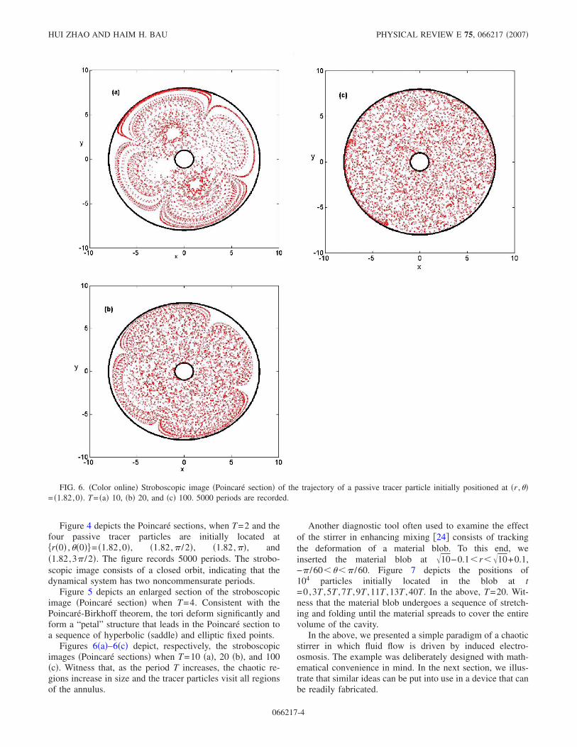
Figure 4 depicts the Poincaré sections, when T=2 and thefour passive tracer particles are initially located at�r�0� ,��0��= �1.82,0�, �1.82,� /2�, �1.82,��, and�1.82,3� /2�. The figure records 5000 periods. The strobo-scopic image consists of a closed orbit, indicating that thedynamical system has two noncommensurate periods.
Figure 5 depicts an enlarged section of the stroboscopicimage �Poincaré section� when T=4. Consistent with thePoincaré-Birkhoff theorem, the tori deform significantly andform a “petal” structure that leads in the Poincaré section toa sequence of hyperbolic �saddle� and elliptic fixed points.
Figures 6�a�–6�c� depict, respectively, the stroboscopicimages �Poincaré sections� when T=10 �a�, 20 �b�, and 100�c�. Witness that, as the period T increases, the chaotic re-gions increase in size and the tracer particles visit all regionsof the annulus.
Another diagnostic tool often used to examine the effectof the stirrer in enhancing mixing �24� consists of trackingthe deformation of a material blob. To this end, weinserted the material blob at �10−0.1�r��10+0.1,−� /60���� /60. Figure 7 depicts the positions of104 particles initially located in the blob at t=0,3T ,5T ,7T ,9T ,11T ,13T ,40T. In the above, T=20. Wit-ness that the material blob undergoes a sequence of stretch-ing and folding until the material spreads to cover the entirevolume of the cavity.
In the above, we presented a simple paradigm of a chaoticstirrer in which fluid flow is driven by induced electro-osmosis. The example was deliberately designed with math-ematical convenience in mind. In the next section, we illus-trate that similar ideas can be put into use in a device that canbe readily fabricated.
FIG. 6. �Color online� Stroboscopic image �Poincaré section� of the trajectory of a passive tracer particle initially positioned at �r ,��= �1.82,0�. T= �a� 10, �b� 20, and �c� 100. 5000 periods are recorded.
HUI ZHAO AND HAIM H. BAU PHYSICAL REVIEW E 75, 066217 �2007�
066217-4

FIG. 7. �Color online� Trajec-tory of a material blob initially lo-cated at �10−0.1�r��10+0.1,−� /60���� /60, when t=0 �a�,3T �b�, 5T �c�, 7T �d�, 9T �e�, 11T�f�, 13T �g�, and 40T �h�. T=20.
MICROFLUIDIC CHAOTIC STIRRER UTILIZING… PHYSICAL REVIEW E 75, 066217 �2007�
066217-5
IV. A PRACTICAL CHAOTIC STIRRER
Our previous example required one to impose a spatiallydistributed potential on the outer surface of the stirrer. Such atask may not be easy. In this section, we describe a devicethat can be readily fabricated. We need, however, to resort tonumerical techniques to calculate the flow patterns.
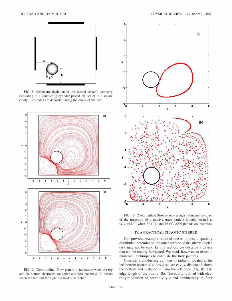
Consider a conducting cylinder of radius a located at theleft bottom corner of a closed square cavity, distance h abovethe bottom and distance w from the left edge �Fig. 8�. Theedge length of the box is 10a. The cavity is filled with elec-trolyte solution of permittivity � and conductivity �. Four
FIG. 8. Schematic depiction of the second stirrer’s geometryconsisting of a conducting cylinder placed off center in a squarecavity. Electrodes are deposited along the edges of the box.
FIG. 9. �Color online� Flow pattern A �a� occurs when the topand the bottom electrodes are active and flow pattern B �b� occurswhen the left and the right electrodes are active.
FIG. 10. �Color online� Stroboscopic images �Poincaré sections�of the trajectory of a passive trace particle initially located at�x ,y�= �2,0� when T=1 �a� and 16 �b�. 2000 periods are recorded.
HUI ZHAO AND HAIM H. BAU PHYSICAL REVIEW E 75, 066217 �2007�
066217-6

electrodes, each with length 6a, are deposited along the cavi-ty’s edges �heavy lines in Fig. 8�. The electrodes’ centers areat the centers of the edges. Only two of the electrodes areactive at any given time. We obtain flow pattern A whenvoltage V0 is imposed on the bottom electrode and voltage−V0 on the top electrodes; and we get flow pattern B whenpotential V0 is imposed on the left electrode and potential−V0 on the right electrode. The conducting cylinder was in-tentionally placed off the cavity’s center to allow the forma-tion of two distinct flow fields when the two electrode pairsare actuated.
The momentum and electrical equations and the corre-sponding boundary conditions are the same as in Sec. II. Theinactive electrodes act like conductors with floating poten-tials �that need to be determined�. We specify on the passiveelectrodes that
� = const and A
��
�ndA = 0. �16�
Due to the complex geometry, analytical solutions are notpossible. Instead, we use the finite element software COMSOL
3.2 to calculate the electrical potentials and the velocity fieldsA and B. Once the velocity fields have been computed, weuse the kinetic equations to trace the trajectories of passivetracer particles. To capture the motion accurately, we use avery fine grid. Figures 9�a� and 9�b� depict flow pattern A�when the bottom and top electrodes are active� and flowpattern B �when the left and right electrodes are on�.
Figures 10�a� and 10�b� depict the stroboscopic images�Poincaré sections� of a passive tracer particle initially lo-cated at �x ,y�= �2,0� when T=1 �a� and 16 �b�, respectively.These figures are a record of 2000 periods. As in Sec. III, asthe period increases so does the complexity of the flow. Thissection demonstrates that chaotic advection can be obtainedin an embodiment of a stirrer that can be readily fabricated.
V. CONCLUSION
Two examples of chaotic stirrers in which fluid flow wasdriven by induced electro-osmosis were presented. The stir-rers do not require any moving parts and are suitable for
applications in microfluidics. The first paradigm consisted ofa stirrer in the shape of a concentric annulus with the outercylindrical surface forming an electrode with spatially andtemporarily controlled potential distribution. The simple ge-ometry allowed us to obtain analytical solutions for the flowfields and investigate in detail the trajectories of passivetracer particles as functions of the period of time alternationsof the electrode’s potential. As the period of alternations in-creased so did the complexity of the flow. At sufficientlyhigh periods, the stirrer exhibited chaotic advection and apassive tracer particle visited nearly the entire volume of thestirrer’s cavity.
Since, in practice, it may not be easy to spatially controlthe electrode’s potential distribution, we investigated a sec-ond paradigm of a stirrer consisting of a conducting cylinderplaced off center in a square cavity equipped with two elec-trode pairs stretched along the outer surfaces of the cavities.Only one pair of electrodes was active at any given point intime. Two different flow patterns were formed by alternatelyactivating the two pairs of electrodes. Due to the complexityof the geometry, these flow patterns were computed numeri-cally with finite elements. By switching periodically betweenthe two pairs of electrodes, the complexity of the flow in-creased until chaotic advection ensued as in the first embodi-ment of the stirrer.
The paper demonstrates that induced electro-osmosis canbe used to facilitate stirring. The stirrer has the advantage ofsimple design and requires only low voltage for operation.The stirrers presented in this paper consisted of a single,cylindrically shaped conducting internal structure. The de-sign can be extended to include arrays of internalstructures—each inducing electro-osmotic flow in its vicin-ity. Another interesting possible extension of the work is theoptimization of the stirrer’s geometry to maximize stirringefficiency.
ACKNOWLEDGMENTS
The work was supported, in part, by the Nano/Bio Inter-face Center �NSF NSEC Grant No. DMR-0425780� and byNSF NIRT Grant No. CBET-0609062.
�1� A. Ramos, H. Morgan, N. G. Green, A. Gonzalez, and A.Castellanos, J. Appl. Phys. 97, 084906 �2005�.
�2� N. G. Green, A. Ramos, A. Gonzalez, H. Morgan, and A.Castellanos, Phys. Rev. E 61, 4011 �2000�.
�3� N. G. Green, A. Ramos, A. Gonzalez, H. Morgan, and A.Castellanos, Phys. Rev. E 66, 026305 �2002�.
�4� A. Gonzalez, A. Ramos, N. G. Green, A. Castellanos, and H.Morgan, Phys. Rev. E 61, 4019 �2000�.
�5� M. Z. Bazant and Y. X. Ben, Lab Chip 6, 1455 �2006�.�6� J. P. Urbanski, T. Thorsen, J. A. Levitan, and M. Z. Bazant,
Appl. Phys. Lett. 89, 143508 �2006�.�7� T. M. Squires and M. Z. Bazant, J. Fluid Mech. 509, 217
�2004�.
�8� L. H. Olesen, H. Bruus, and A. Ajdari, Phys. Rev. E 73,056313 �2006�.
�9� R. J. Hunter, Foundations of Colloid Science �Oxford Univer-sity Press, New York, 2001�.
�10� J. Lyklema, Fundamentals of Interface and Colloid Science.Vol. 2: Solid-Liquid Interfaces �Academic Press, San Diego,CA, 1995�.
�11� A. S. Dukhin, Colloid J. USSR 48, 376 �1986�.�12� A. S. Dukhin and V. R. Murtsovkin, Colloid J. USSR 48, 203
�1986�.�13� N. I. Gamayunov, G. I. Mantrov, and V. A. Murtsovkin, Col-
loid J. 54, 20 �1992�.�14� N. I. Gamayunov, V. A. Murtsovkin, and A. S. Dukhin, Colloid
MICROFLUIDIC CHAOTIC STIRRER UTILIZING… PHYSICAL REVIEW E 75, 066217 �2007�
066217-7
J. USSR 48, 197 �1986�.�15� V. A. Murtsovkin, Colloid J. 58, 358 �1996�.�16� M. Z. Bazant and T. M. Squires, Phys. Rev. Lett. 92, 066101
�2004�.�17� J. A. Levitan, S. Devasenathipathy, V. Studer, Y. X. Ben, T.
Thorsen, T. M. Squires, and M. Z. Bazant, Colloids Surf., A267, 122 �2005�.
�18� T. S. Simonova, V. N. Shilov, and O. A. Shramko, Colloid J.63, 114 �2001�.
�19� T. M. Squires and M. Z. Bazant, J. Fluid Mech. 560, 65�2006�.
�20� E. Yariv, Phys. Fluids 17, 051702 �2005�.
�21� D. Saintillan, E. Darve, and E. S. G. Shaqfeh, J. Fluid Mech.563, 223 �2006�.
�22� H. Zhao and H. H. Bau, Langmuir 23, 4053 �2007�.�23� H. A. Stone, A. D. Stroock, and A. Ajdari, Annu. Rev. Fluid
Mech. 36, 381 �2004�.�24� H. Aref, J. Fluid Mech. 143, 1 �1984�.�25� J. M. Ottino, Kinematics of Mixing: Stretching, Chaos and
Transport �Cambridge University Press, Cambridge, U.K.,1989�.
�26� K. T. Chu and M. Z. Bazant, Phys. Rev. E 74, 011501 �2006�.�27� M. Z. Bazant, M. S. Kilic, B. D. Storey, and A. Ajdari �unpub-
lished�.
HUI ZHAO AND HAIM H. BAU PHYSICAL REVIEW E 75, 066217 �2007�
066217-8