microcontrollers - university of california, berkeleyee100/su10/labs/lab6_report_prelab.pdf ·...
TRANSCRIPT
UC Berkeley, EECS Department B. E. BoserEECS 40/42/100 Lab LAB6: Microcontroller Input/Output UID:
Enter the names and SIDs for you and your lab partner into the boxes below.Name 1 SID 1Name 2 SID 2
Be sure to come very well prepared to this laboratory to complete in three hours (or finish the following week).Type in your code ahead of time (store on the server or a USB key).
Microcontrollers
Microcontrollers are very much slimmed down computers. No disks, no virtual memory, no operating system.Think of them just like other circuit components with the added benefit of being configurable with a program.Because of this microcontrollers can be coaxed to do all sorts of things simply that otherwise would require a largenumber of parts. Simple microcontrollers cost less than a dollar and hence can be used in almost any project.Indeed they can be found in toys, electric tooth brushes, appliances, cars, phones, electronic keys, you name it.
Being programmable also means that they must be programmed. In this lab we concentrate on the electricalinterface of microcontrollers and their use as electronic components. The programs we use are very simple andconsist to a large part of pasting snippets of code together. In fact, much like checking the application notes ofelectronic components for circuits that do what we need, it’s always a good idea to search the web for code thatperforms the job we need or is at least a good starting point. Most of the code snippets shown in these lab guidesare copies of code from the manufacturer’s website. Feel free to improve on the example programs.
Microcontrollers are available from many manufacturers, all with their own advantages (and quirks). In thiscourse we use the MSP430 from Texas Instruments whose strength are low power dissipation and a regular in-struction set.
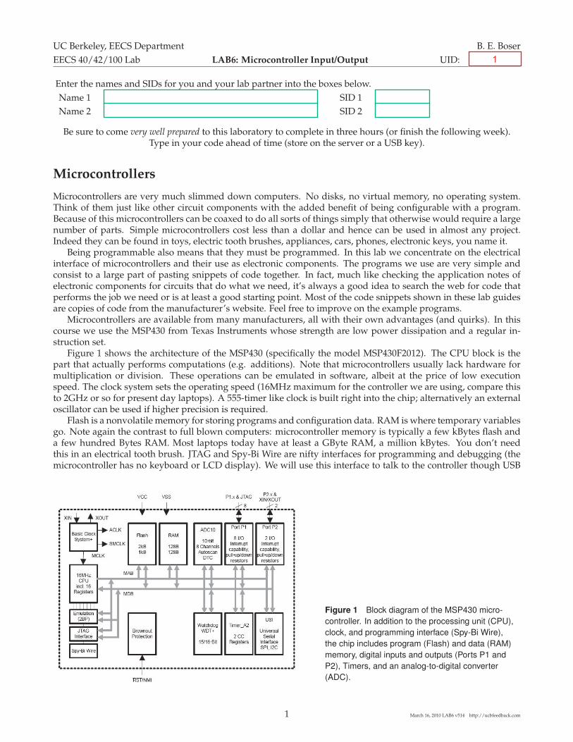
Figure 1 shows the architecture of the MSP430 (specifically the model MSP430F2012). The CPU block is thepart that actually performs computations (e.g. additions). Note that microcontrollers usually lack hardware formultiplication or division. These operations can be emulated in software, albeit at the price of low executionspeed. The clock system sets the operating speed (16MHz maximum for the controller we are using, compare thisto 2GHz or so for present day laptops). A 555-timer like clock is built right into the chip; alternatively an externaloscillator can be used if higher precision is required.
Flash is a nonvolatile memory for storing programs and configuration data. RAM is where temporary variablesgo. Note again the contrast to full blown computers: microcontroller memory is typically a few kBytes flash anda few hundred Bytes RAM. Most laptops today have at least a GByte RAM, a million kBytes. You don’t needthis in an electrical tooth brush. JTAG and Spy-Bi Wire are nifty interfaces for programming and debugging (themicrocontroller has no keyboard or LCD display). We will use this interface to talk to the controller though USB
Figure 1 Block diagram of the MSP430 micro-controller. In addition to the processing unit (CPU),clock, and programming interface (Spy-Bi Wire),the chip includes program (Flash) and data (RAM)memory, digital inputs and outputs (Ports P1 andP2), Timers, and an analog-to-digital converter(ADC).
1 March 16, 2010 LAB6 v514 http://ucbfeedback.com
1

Figure 2 M430F2012 pin diagram. The MSP430 comes in many versions thatinclude different amounts of Flash and RAM memory and combinations of in-put/output ports and other peripherals. Here we use a very small version withonly 14 pin that costs less than a dollar in quantity.
from a desktop computer and program the Flash memory. The Spy-Bi Wire interface is used only for development,once completed the controller works standalone from the program stored in the nonvolatile Flash memory.
The really interesting parts are the peripherals. Ports P1 and P2 are digital I/Os that can be configured asinputs or outputs. They can be used for simple I/O with switches or LEDs; in later labs we will see much moresophisticated uses of this simple interface. The other block we will use is the ADC10, a 10-bit analog-to-digitalconverter that serves as a bridge between the usually analog “real” world and the microcontroller. For examplewe can use it to interface the strain gage circuit designed in an earlier lab to the microcontroller and make a fullblown (simple) balance with display out of the combination!
Figure 2 shows the pinout of the particular MSP430 we are using in this laboratory, the MSP430F2012. It hasonly 14 pins for power (VCC) and ground (GND), the debug interface (TDIO and TCK) and ports P1 and P2.Looking carefully you will observe that there are eight pins for P1 but only two for P2. The other ones don’t fitwith a 14 pin package. There also are no separate pins for the ADC. Instead, digital IO pins can be reprogrammedas ADC inputs as needed. Several dozen MSP430 microcontrollers are available with their main difference beingthe number of pins and the amount of memory. This permits you to start with a small version, and as the projectgrows move to versions with additional memory or pins without having to change the programs developed forthe smaller parts.
Figure 3 Picture of the micro-controller prototyping board usedin this laboratory. In addition tothe MSP430, the board features 8LEDs and resistors with jumpersthat can optionally be connectedto IO port P1. The printed circuitboard (PCB) traces labeled “touchsensor”, together with the adjacentresistor and a simple program al-low the processor to react to fingertouch input.
With only 14 pins we certainly could wire up the microcontroller on a protoboard. The custom board shown inFigure 3 makes wiring even simpler. It also features LEDs for debugging and a touch interface.
In addition to the microcontroller, the board features a header for interfacing with a ribbon cable to the USBinterface which is also supplying power to the board. Three capacitors and a resistor are used for filtering powerand resetting the device after power is applied. These devices are specified by datasheet of the device. A headerstrip on the left side of the board exposes P1 and P2 and power for prototyping.
Alternatively P1 also can be connected to on-board LEDs through jumpers. This of course makes sense only forpins that are configured as digital outputs. Removing a jumper (or setting it on a single pin as shown for P1.3 fornot losing it) makes that port available for other functions such as digital input or the ADC. The rightmost position(VCC) is for monitoring the power supply and always on when power is supplied to the board and the jumper isinserted. Jumper the upper two terminals of J3 as shown to enable power from the USB interface.
2 March 16, 2010 LAB6 v514 http://ucbfeedback.com

Flashing Light
In this laboratory we will familiarize ourselves with the μController board and the MSP430 development tool. Wewill start with writing the notorious “Hello World” example, which for a μController is a blinking light.
a) Connect the μController PCB to the MSP430 USB-Debug-Interface (MSP-FET430UIF). Use a standard USB ca-ble to connect the debug interface to a computer with the “IAR Embedded Workbench IDE” software. Thissoftware is installed on the computers in the laboratory. Alternatively you can download it from the TI websiteand install on your own computer.
b) Start the IAR Embedded Workbench IDE. Choose “Create new project in current workspace”. A dialog withoptions appears. We will write our program in the C language. Expand that choice, click on “main” and thenclick “OK”. The program asks you to name your project. Call it “blink”. Hit enter.
c) Your screen looks as shown below, with a program already partially written.1
d) Before finishing our program we need to configure the tool for the MSP430F2012. Choose the menu “Project→Options. . . ” and click on the “General Options” tab. Set “Device” as shown in the screen below by clicking on the but-ton to the right of the field and navigating the choices.
1The newest version of the software no longer generates this code and the file ������� no longer exists. Please enter the missing statementsyourself and replace ������� by �����������. You need to do this in all your programs.
3 March 16, 2010 LAB6 v514 http://ucbfeedback.com
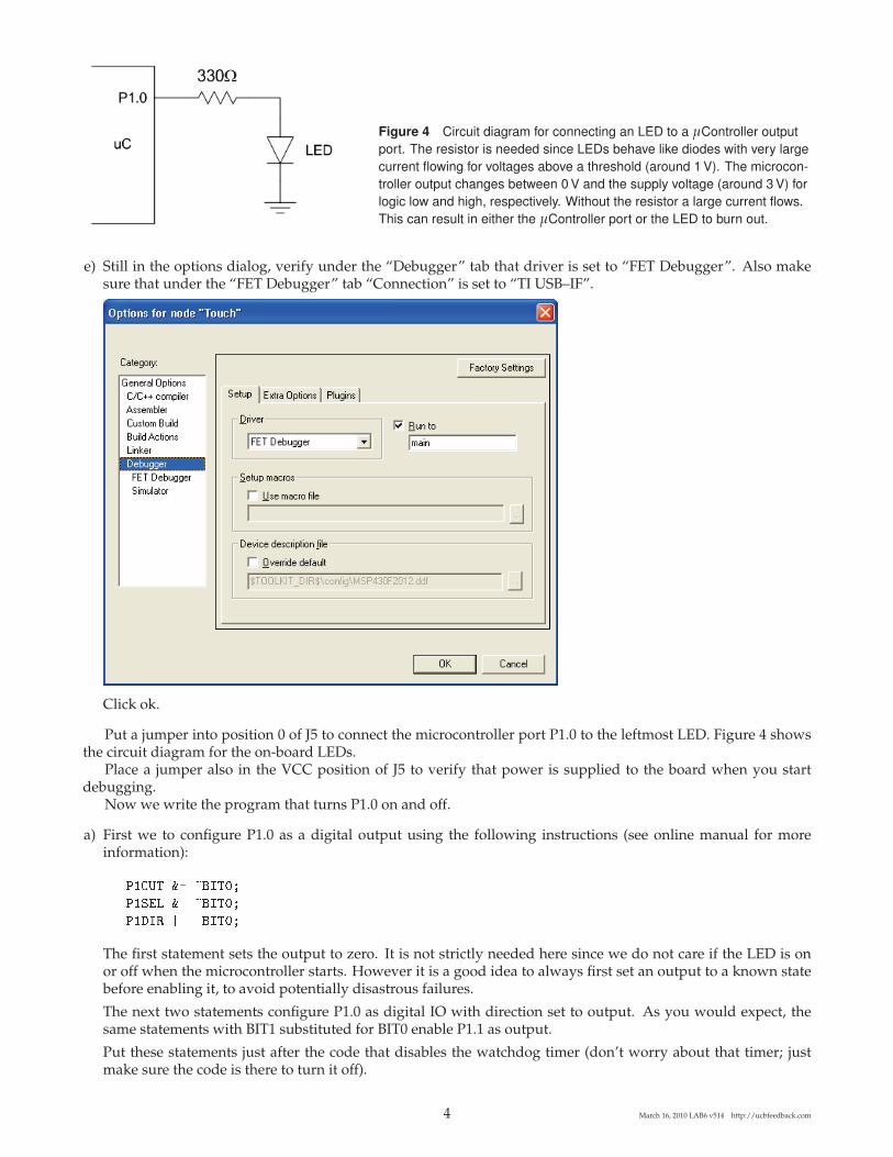
Figure 4 Circuit diagram for connecting an LED to a μController outputport. The resistor is needed since LEDs behave like diodes with very largecurrent flowing for voltages above a threshold (around 1 V). The microcon-troller output changes between 0 V and the supply voltage (around 3 V) forlogic low and high, respectively. Without the resistor a large current flows.This can result in either the μController port or the LED to burn out.
e) Still in the options dialog, verify under the “Debugger” tab that driver is set to “FET Debugger”. Also makesure that under the “FET Debugger” tab “Connection” is set to “TI USB–IF”.
Click ok.
Put a jumper into position 0 of J5 to connect the microcontroller port P1.0 to the leftmost LED. Figure 4 showsthe circuit diagram for the on-board LEDs.
Place a jumper also in the VCC position of J5 to verify that power is supplied to the board when you startdebugging.
Now we write the program that turns P1.0 on and off.
a) First we to configure P1.0 as a digital output using the following instructions (see online manual for moreinformation):
The first statement sets the output to zero. It is not strictly needed here since we do not care if the LED is onor off when the microcontroller starts. However it is a good idea to always first set an output to a known statebefore enabling it, to avoid potentially disastrous failures.
The next two statements configure P1.0 as digital IO with direction set to output. As you would expect, thesame statements with BIT1 substituted for BIT0 enable P1.1 as output.
Put these statements just after the code that disables the watchdog timer (don’t worry about that timer; justmake sure the code is there to turn it off).
4 March 16, 2010 LAB6 v514 http://ucbfeedback.com

b) The following statements set the output low or high, or toggle its state:
����� �� ���� ���� ���
����� �� ��� ���� ����
����� �� ��� ������ ����
Text after is treated as comment and there only for documentation. If you have ever taken a programmingcourse you know that we are supposed to document our code but few of us actually do it. Join the few.
c) The toggle version of the above statements is appropriate for blinking a light. Since we want to do this repeat-edly we enclose the statement in a loop:
��� ���� � �� !��!"�� ��� �"��"��� ���
����� �� ��� ������ ����
# ���$�"� %�!�&�� ��� �"��"��� ���
d) The complete program looks as follows:
e) Compile it by clicking on the right most button in the toolbar. Carefully examine possible error messages(or ignore them and waste lots of time in frustration). A new window pops up:
Click the button (2nd row in the toolbars). When done you can stop the program by clicking or
modify the code and click to recompile and restart with .
f) If everything went right the light turns on but does not blink. At best it is a little dimmer than the power LED.
The reason is that the microcontroller turns the LED on and off a few million times per second, too fast for oureyes to follow.
5 March 16, 2010 LAB6 v514 http://ucbfeedback.com
g) The simplest fix is to give the microcontroller a bit of extra work to slow it down. Microcontrollers are notstudents and hence do not mind. Since we will often have need for such delays, we package this function in asubroutine that we can easily reuse in other programs. Here is the code:
���� �������� ��� ��� �� �
����� � � �� ����
�
calling this code with the following statement
������������
causes the microprocessor to spin 30’000 times in a loop decrementing the variable n.
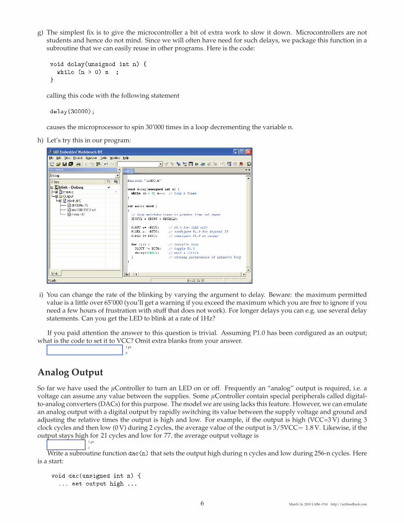
h) Let’s try this in our program:
i) You can change the rate of the blinking by varying the argument to delay. Beware: the maximum permittedvalue is a little over 65’000 (you’ll get a warning if you exceed the maximum which you are free to ignore if youneed a few hours of frustration with stuff that does not work). For longer delays you can e.g. use several delaystatements. Can you get the LED to blink at a rate of 1Hz?
If you paid attention the answer to this question is trivial. Assuming P1.0 has been configured as an output;what is the code to set it to VCC? Omit extra blanks from your answer.
1 pt.
0
Analog Output
So far we have used the μController to turn an LED on or off. Frequently an “analog” output is required, i.e. avoltage can assume any value between the supplies. Some μController contain special peripherals called digital-to-analog converters (DACs) for this purpose. The model we are using lacks this feature. However, we can emulatean analog output with a digital output by rapidly switching its value between the supply voltage and ground andadjusting the relative times the output is high and low. For example, if the output is high (VCC=3 V) during 3clock cycles and then low (0 V) during 2 cycles, the average value of the output is 3/5VCC= 1.8 V. Likewise, if theoutput stays high for cycles and low for , the average output voltage is
1 pt.
1
Write a subroutine function ����� that sets the output high during n cycles and low during 256-n cycles. Hereis a start:
���� ������ ��� ��� �� �
��� ��� ���� �� � ���
6 March 16, 2010 LAB6 v514 http://ucbfeedback.com
21 77

��������
�� � �� � ���
������������
�
Call this function from your main program in an endless loop. Write your completed code into the box below:
1 pt.
4
Test your “DAC” in the laboratory. First verify with the oscillosope that for n=0 the output remains low (whyis there a “glitch” and how could you eliminate it?), and for n=256 the output remains high (except for a briefglitch). Then connect a first order RC filter with R = 10 kΩ and C = 10 nF to the μController output and recordthe voltage vo across the resistor on the oscilloscope. Adjust n such that vo = V and ask the GSI to verify yourresult.
One drawback of this DAC is that it keeps the μController busy and unavailable to do other tasks. A bettersolution uses the μController’s timer combined with a feature called interrupt to implement the delay. With thistechnique, the ��� function can run concurrently with other functions. We will not explore this feature here; pleasecheck the manual and sample programs (see vendor website) for more information.
Bar Graph
Now we will program a function void bar(int n) that turns on LEDs 0 . . . n-1. E.g. the call bar(3) turns on LEDs 0,1, and 2. Here is a start:
���� ���� ������ ��� �� �
�� �� �� �� �!"# $� %&#'( ��� �!"# )� *%&#'(
�� �� �� �� �!"# $� %&#�( ��� �!"# )� *%&#�(
��+����� ���� ��� ,-. � /
�
Write your completed code into the box below:
1 pt.
6
At the start of main, declare a variable i as follows and configure all bits of P1 as outputs (leave the code for thewatchdog timer alone) and write code that spins through the bar graph:
��� +���� ���� �
�
��� � � '(
00 1��� ����2��� ��+�� �� ������� ��+� � � ����
7 March 16, 2010 LAB6 v514 http://ucbfeedback.com
1.3

Figure 5 Circuit for digital push-button input.
Make sure all LED jumpers 0 . . . 7 are inserted and test the program (optional).
Digital Input
Now will modify our code from the last section such that the bar graph advances one position each time a buttonis pressed. We will use P1.7 for the button input. Remove the jumper for LED 7.
Figure 5 shows the circuit for connecting a button to the microcontroller. Normally P1.7 is pulled to VCC(high) by the pull-up resistor Rup. Pressing the button pulls P1.7 low. The circuit is even simpler than this sincethe microcontroller has a built-in Rup, we just need to enable it. So all you need to do is connect a button betweenP1.7 and ground. Here is the code for enabling P1.0 . . . 6 as outputs and P1.7 as an input with the pull-up resistorenabled:
The following statement checks for P1.7 to go low:
Put this into the infinite loop to control the bar graph display.Start your program and verify first with the voltmeter that P1.7 is normally high and turns low when the
button is pressed. When trying the program you will notice that things do not work as expected: when pressingthe button the bar graph does not advance a single position as it should but a random number of positions. Thishas two reasons:
a) Just like human eyes, human hands are pretty slow on a microcontroller timescale. Once the microcontrollerhas found that P1.7 is low and advanced the bar graph, it returns to the top of the loop, and checks again. If itfinds the button still pressed, it advances the bar graph again.
b) Most mechanical switches and buttons have a flaw called prelling: rather than just turning on and off, thebutton turns on and off rapidly in succession until it reaches the final value. The reason is mechanical resonancein the switch.
8 March 16, 2010 LAB6 v514 http://ucbfeedback.com

The first problem can be avoided by inserting a statement that checks that the button has gone back high intothe loop:
����� ����� � ���� � �� ���� ��� ��� �� �� ����
Depending on where exactly you insert the statement the bar graph advances immediately when the button ispushed or only when the button is released.
The solution for the second problem is inserting a delay into the loop. Fortunately we wrote that delay function!Code for bar graph with button:
3 pts.
7
Assuming P1.5 has been configured as an output; what is the code to set it to GND?opt.
2
Build the circuit and verify the operation (optional).
Analog Input
Microcontrollers (and computers in general, for that matter) operate with digital data. However, many “real worldsignals” such as temperature are analog in nature. An analog-to-digital converter is needed to input such signalsinto a microcontroller. Analog-to-digital converters, or ADCs for short, are available as standalone electroniccomponents or built into more complex devices. Fortunately our microcontroller has an ADC built in. In this lab-oratory we will use this ADC to interface the weight scale designed in an earlier laboratory to the microcontrollerand have the bar graph display the number of weights put on the scale.
ADCs compare an analog input vi, e.g. 1.387V, to a reference voltage Vref to produce a digital number repre-senting the ratio of the analog input to the reference rounded to the nearest integer. For example, the ADC in ourmicrocontroller converts analog voltages to digital numbers according to the following equation:
N = round(
1023 × viVref
)(1)
For example, with Vref = 3 V and vi = 1.387 V, N = 473. Negative input voltages and inputs exceeding thereference produce are clipped to zero and 1023, respectively.
The program skeleton below shows the code for using the ADC and configures P1.7 as its input. Conversionresults are automatically stored in the variable ADC10MEM.
��� ����� ���� � �
�� ��� ���!���� ����� �� ������ ���� �"� ��#��
$%�&�' ( $%��$ ) $%�*+'%�
,%&-&�' ( �&*.�� �� ��� �# ,%& �� "�
,%&-&�'- ( �/01.- �� �������!� �# 2&&
) ,%&-�*�.3 �� #�� �� ����
) ,%&-+�� �� ���4�� ,%&
�+5� ( -� �� ��������6�
��0' ( ��� �� ��- ��� 7 ��� ������� +#8 ��� �# ,�
�%/ ( -9��� �� � ����!���� �# �"� "�
9 March 16, 2010 LAB6 v514 http://ucbfeedback.com
VDD R Ctouch Vc
Vc
time
Vdis
VDD
t1 t2 t2'
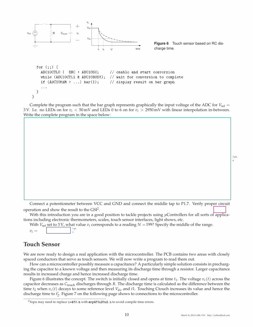
Figure 6 Touch sensor based on RC dis-charge time.
��� ���� �
��� �� �� �� � ����� �� ������ ��� ����� ������� ��
!" �� ���� �� # ���$%�&�� �� !� � ��� ������� �� �� ��'(����
� ����)�) * +++� ������� �� � �(��, ���-�� �� ��� .��("
+++
/
/
Complete the program such that the bar graph represents graphically the input voltage of the ADC for Vref =3 V. I.e. no LEDs on for vi < 50 mV and LEDs 0 to 6 on for vi > 2950 mV with linear interpolation in-between.Write the complete program in the space below:
2 pts.
8
Connect a potentiometer between VCC and GND and connect the middle tap to P1.7. Verify proper circuitoperation and show the result to the GSI2.
With this introduction you are in a good position to tackle projects using μControllers for all sorts of applica-tions including electronic thermometers, scales, touch sensor interfaces, light shows, etc.
With Vref set to 3 V, what value vi corresponds to a reading N = ? Specify the middle of the range.vi =
1 pt.
3
Touch Sensor
We are now ready to design a real application with the microcontroller. The PCB contains two areas with closelyspaced conductors that serve as touch sensors. We will now write a program to read them out.
How can a microcontroller possibly measure a capacitance? A particularly simple solution consists in precharg-ing the capacitor to a known voltage and then measuring its discharge time through a resistor. Larger capacitanceresults in increased charge and hence increased discharge time.
Figure 6 illustrates the concept. The switch is initially closed and opens at time t1. The voltage vc(t) across thecapacitor decreases as Ctouch discharges through R. The discharge time is calculated as the difference between thetime t2 when vc(t) decays to some reference level Vdis and t1. Touching Ctouch increases its value and hence thedischarge time to t′2. Figure 7 on the following page shows to connections to the microcontroller.
2Yopu may need to replace ������� with ����������� to avoid compile time errors.
10 March 16, 2010 LAB6 v514 http://ucbfeedback.com
199
uC
Ctouch1
R=1M�
Ctouch2
P2.6 P2.7
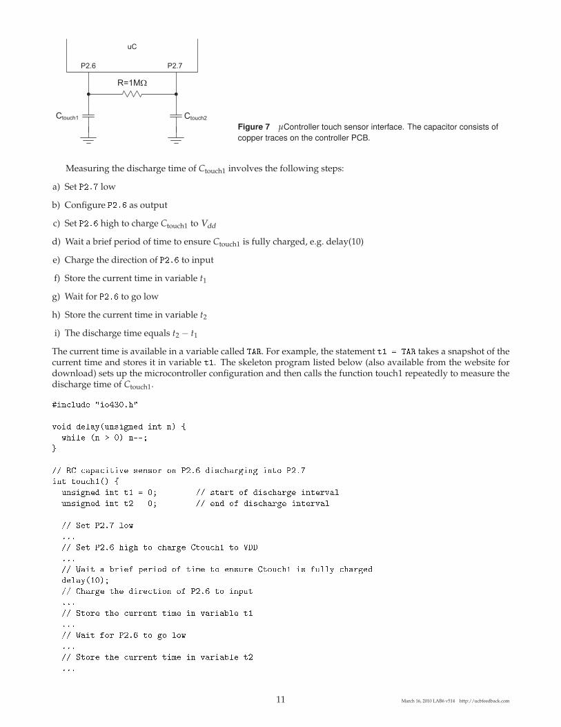
Figure 7 μController touch sensor interface. The capacitor consists ofcopper traces on the controller PCB.
Measuring the discharge time of Ctouch1 involves the following steps:
a) Set ���� low
b) Configure ���� as output
c) Set ���� high to charge Ctouch1 to Vdd
d) Wait a brief period of time to ensure Ctouch1 is fully charged, e.g. delay(10)
e) Charge the direction of ���� to input
f) Store the current time in variable t1
g) Wait for ���� to go low
h) Store the current time in variable t2
i) The discharge time equals t2 − t1
The current time is available in a variable called ���. For example, the statement � ��� takes a snapshot of thecurrent time and stores it in variable . The skeleton program listed below (also available from the website fordownload) sets up the microcontroller configuration and then calls the function touch1 repeatedly to measure thedischarge time of Ctouch1.
� ������ � �������
�� � ��������� ���� � � !
"� �� �� # � �$$%
&
'' �( ��)�� �� �����* �� ���� � ����*� �� �� ����
� ����� !
��� ���� � � �% '' ��* �+ � ����*�� ��*���
��� ���� � � � �% '' ��� �+ � ����*�� ��*���
'' ,� ���� ��"
���
'' ,� ���� � �� � ���*�� (���� � -..
���
'' /� � 0* �+ )�* �� �+ 1� � ����*� (���� � +���� ���*���
������� %
'' (��*�� �� � *�� �� �+ ���� � �)�
���
'' ,�*� �� ��**�� 1� � ��* �0��
���
'' /� +�* ���� � �� ��"
���
'' ,�*� �� ��**�� 1� � ��* �0�� �
���
11 March 16, 2010 LAB6 v514 http://ucbfeedback.com

�� ��� ������� �� � ����� �����
���� ������
�
��� ���������
�� ���� ������� �� � �� ������ �� � ��� ����
� �!�" # � �$� % � �&'" �
�� (� � ����) �����
*!�!�"+ # ",-���.�� �� /��� �� ����
*!�!�"� # !0"*!�.�12&3�
!'!�" # !0" !'.�12&3�
�� ��� �� �� � 0 /�� ������
�0!�" # �0��4".� % 2!.��
�� $� �� /���5�)
$� 67 # 8(//� �� $� ������
$��4" # 8� �� ������ ���
�� ���/���� $� /� �������� �����
$�'9� # 8� �� $� ������ ���
$� 67 # *6�1 % *6�:� �� $� �� ������
$��4" # 8� �� $� �� ������ ��8
$�74; # 8� �� $� ���5�� ������ �������
/� ���� �
�������� ��� � # ���������
�� �����< � �� "4 5 �� = �88> �<��
???
�� ��� ������
���<��88��
�
�
Complete the skeleton program to read touch sensor 1 before the start of the lab.
12 March 16, 2010 LAB6 v514 http://ucbfeedback.com
5 pts.
10
Run your program on the microcontroller. Attach a scope probe (set to 10x attenuation) to the resistor at portP2.6 of the μController and verify that the waveform shows the exponential discharge.
1 pt.
11
Modify the code such that the length of the bar graph is an indication of the presence and size of a finger onthe touch sensor. E.g. no or a single LED lit with no finger present, a few LEDs lit with a small finger or a finger atsome distance from the sensor, and all LEDs lit with the entire touch sensor covered.
Have the GSI verify your result.
13 March 16, 2010 LAB6 v514 http://ucbfeedback.com

Password:
14 March 16, 2010 LAB6 v514 http://ucbfeedback.com

EE 42/100 Lab 6 Microcontroller I/O
Prelab Summary
Name:_____________________________________________________
SID: _______________________________________________________
Answers
0._________________________________________________________
1._________________________________________________________
2._________________________________________________________
3._________________________________________________________