microchemical engineering in practice (dietrich/microchemical) || multiphase reactions
TRANSCRIPT

CHAPTER 20
MULTIPHASE REACTIONS
J. G. E. (HAN) GARDENIERS
20.1 INTRODUCTION
Many of the chemical reactions used in industry today involve multiple phases, such as combinations of a gas and a liquid in which the gas only dissolves to a limited extend, and of two immiscible liquids. In most cases, catalysts are also involved, many of which are introduced in a solid form, for example, as a packed bed of particles, mono- lithic porous structure, or wall coating.
The processes that determine the yield and selectivity of multiphase reactions are, in addition to the intI-insic chemical reaction kinetics, basically the same as those discussed in Chapter 6 for separation units, that is, partitioning of the species of interest between the different phases, and the mass transfer of that species within a single phase. As was also pointed out in Chapter 6, in general, mass transfer limitations are more prominent in the liquid rather than gas phase. Just as in extractions, two principles are of interest to increase mass transfer during the reactions of species present in two immiscible phases: decreasing the distances over which mass transfer has to occur (in addition, also leading to higher concentration gradients), or increasing the contact area available for transfer. A combination of both principles is also feasible.
To understand the different options to enhance or, more generally, to control mass transfer, in the next paragraph two-phase flow diagrams will be described. Of parti- cular interest are the conditions under which specific flow regimes are stable, in order to arrive at well-defined reaction systems. By “well-defined,” it is meant that besides an enhancement of mass transfer, reaction selectivity can also be controlled, by means of the minimization of residence time distribution (RTD). After useful flow regimes are discussed, a number of reaction examples will be given to illustrate the different options.
Microchemical Engineering in Practice. Edited by Thomas R. Dietrich Copyright 0 2009 John Wiley & Sons, Inc.
449

450 MULTIPHASE REACTIONS
20.2 TWO-PHASE FLOW REGIMES
The behavior of flowing two-phase systems is of special interest here because virtually all microreactor systems are of the continuous-flow type. More specifically, almost all microreactors involve microchannels or microstructured fluid ducts through which a gas, liquid, or combination of one or more gases and liquids flows continuously.
Gas-liquid flow in channels of many different dimensions has been studied very intensively over the years for applications in the field of heat exchange (cooling and heating). In this field, a gradual shift can be observed from the use of larger-diameter channels, on the order of 10 to 20mm, to that of channels with diameters close to or even below 100 Fm. The reason for this shift is the same as why microreactor channels have become smaller over the years: The increased surface-to-volume ratio of a smaller channel enables a higher heat flux out of or into the fluid flowing through a microchannel. Kandlikar et al. [ I ] give a very good overview on the topic of heat transfer in mini and microchannels.
In contrast to gas-liquid two-phase flow in microchannels used for cooling purposes, in which the fraction of gas (or rather, evaporated liquid) changes conti- nuously due to boiling after heat uptake when the fluid passes the microchannel, in a gas-liquid two-phase flow microchannel microreactor the fraction of gas is gene- rally constant (in fact, it decreases slightly due to gas consumption in the reaction). This situation compares best to that described in the literature as “adiabatic flow,” which is generally studied by introducing a gas-liquid mixture of specific void frac- tion (i.e., gas volume fraction) into a microchannel, through specially designed inlets to achieve the appropriate mixing of gas and liquid. As the term “adiabatic” indicates, no heat exchange between the fluid and its surroundings is enabled, and therefore the gas and liquid mass fractions will remain constant throughout the length of the micro- channel (note that the volume fractions may change slightly due to an axial pressure gradient which may compress the gas volume more or less, depending on the axial position in the channel). For microchannels with diameters somewhat below 0.5 mm, flow diagrams up to a few mm have the general qualitative appearance shown in Fig. 20.1.
At low liquid superficial velocities, an annular flow pattern is observed, in which the liquid flows as a film along the walls of the channel and the gas flows through the core. In bubbly flow, observed for low gas fractions at moderate velocities, the non- wetting gas flows as small bubbles dispersed in the continuous, wetting liquid. Slug flow, also frequently called “plug,” “segmented,” “bubble train,” “intermittent,” or “Taylor” flow [4] (see also Fig. 6.7 in Chapter 6), is a flow pattern in which gas bubbles span the cross section of the channel. The length of the liquid slugs and gas bubbles is mainly determined by the inlet conditions [4]. At the highest velocities, small satellite bubbles appear at the rear of the slug, eventually leading to aerated slugs and a rather chaotic flow pattern that is called “churn” flow, also known as “dispersed” flow [3]. For high velocities at low liquid fraction, the annular flow pattern consists of a thin wavy liquid film flowing along the wall, sometimes with a mist of gas and entrained liquid in the core.

20.2 TWO-PHASE FLOW REGIMES 6 1
Annular
FIGURE 20.1 are the superficial liquid and gas velocity, respectively.
Typical gas-liquid two-phase flow diagram (adapted from [2, 31). j , and j ,
For detailed descriptions of the different flow patterns, the reader is referred to recent literature; for example, in [5 ] Jensen et al. provide a good overview of recent knowledge on two-phase flow in microchannels. These authors also discuss in detail the very limited amount of information on microchannels with diameters 100 k m and below. Namely, in microchannels with a hydraulic diameter much smaller than the Laplace constant (which scales surface tension to gravitational forces and is on the order of 1 mm for water at atmospheric conditions and room temperature), two-phase flow characteristics become significantly different. For example, due to capillarity effects, bubbly or chum flow is not observed in such small microchannels.
In order to achieve good control over mass transfer conditions and residence time distribution in a microchannel reactor, the two most useful regimes for a gas-liquid two-phase flow system are annular and segmented flow. In the following sections, microreactor examples in which these two flow patterns have been used will be discussed in detail.
Bubbly flow, in principle, may also be useful for gas-liquid microreactors, but generally bubbles that are much smaller than the channel diameter can behave unpre- dictably, tend to stick to channel walls and comers under conditions where liquid wetting is not perfect, or grow and shrink due to collision and agglomeration with other bubbles. Bubble size under such conditions is generally inhomogeneous and difficult to control, and as a result reaction conditions also become uncontrollable. Nevertheless, examples do exist in which this type of flow pattern has been success- fully used for chemistry, for example, in the work of Lob et al., in which a micromixer was used to create a foam with very high void fraction [6]. This example has already been discussed in Chapter 6.

452 MULTIPHASE REACTIONS
The above discussion was concerned with gas-liquid two-phase flow systems. For liquid-liquid (i.e., two immiscible liquids) systems, the information available about flow patterns and their regimes with respect to liquid velocity and the liquid-liquid ratio is limited. Several studies exist on oil-water mixtures with applications in off- shore technology. Figure 20.2 is a flow diagram adapted from the study by Bensakhria et al. on a 25-mm diameter pipe [7], but nearly identical results were found for paraffin-water combinations in tubes of 7-mm diameter [8]. Similar flow patterns as in gas-liquid flow are observed. This diagram includes a regime of stratified flow, due to the fact that gravity plays a role for this large channel diameter ("stratified" in this case means that the fluids separate in two streams, with the denser fluid running on the bottom side of the channel). It can also be observed that the curve is not symmetrical, as one may have expected, but shows only the annular flow situ- ation with a water film on the tube wall and an oil core, but not the inverse situation with an oil film and a water core. This is a happy coincidence discovered a long time ago and helps in transporting the viscous oil with a limited pressure drop along the transporting tubes, since the wall friction is mainly determined by the water.
In microreactor practice in liquid-liquid flow situations, the most utilized flow pattern is that where the two liquids run in parallel streams alongside one another, and interchange occurs at the interface that is essentially flat along the axial direction of the channel; see, for example, [9]. It has to be pointed out, though, that the empirical flow map shown in Fig. 20.2 indicates that such a flow pattern, in general, does not constitute a stable situation. In fact, the two liquid streams when entering the microchannel will either reform to annular flow or break up into dmplets or slugs, depending on the conditions. Due to the interfacial tension between the two liquids, which tends to reduce interfacial area, and the viscous stresses that act to extend and drag the interface downstream, the interface is destabilized. For example, in the case
Water in oil dispersion
Annular
Bubbly
Oil in water Stratified dispersion
jWATER (m/s)
FIGURE 20.2 Typical liquid-liquid (water-oil) two-phase flow d i a g m (adapted from [7]).

20.3 EXAMPLES OF MICROREACTORS BASED ON SEGMENTED FLOW a
of oil and water streams joining at a T-junction, droplets of radius R - h/Ca (with h being the hydraulic diameter of the channel and Ca the capillary number, as defined in Chapter 6) will be formed [lo]. The droplets become smaller for larger Ca, which is equivalent to higher fluid velocity and viscosity (i.e., higher shear), or lower surface tension.
20.3 SEGMENTED FLOW
EXAMPLES OF MICROREACTORS BASED ON
20.3.1 Gas-Liquid Segmented Flow Where the Gas is a Reagent
The most common application of segmented (Taylor) flow in microreactors is the case in which a gas has to react with a component of the liquid. It has been shown that the hydrodynamics of this type of flow allow for good mass-transfer rates from the gas bubbles to the liquid [l 1, 121 and extremely high mass transfer from the gas bubbles to the wall, which contains catalytic coating [ 131.
The main reason for the high mass-transfer rates within the liquid slug is the pre- sence of vortices within the slug (see Chapter 6, Fig. 6.7, and the accompanying text). These vortices enhance mixing within the liquid slug. On the other hand, the mixing of liquid content between the slugs is reduced due to the presence of a gas bubble, in addition to a very thin, stagnant liquid film on the wall at the position of the bubble that connects two consecutive slugs. This film does not allow a large flux of species between the slugs because diffusion through it is the only mechanism of mass trans- port between slugs. However, it allows for a high mass transfer of gas to the surface at the location where the thin layer surrounds the bubble. The thickness of this thin film is inversely proportional to fluid velocity. The best gas transfer is therefore obtained at lower velocity [4].
All this leads to the conclusion that a single Taylor flow-based microchannel can be considered close to an ideal plug flow reactor. Evidence for this was found in residence time distribution studies using tracers, which gave quite narrow tracer exit curves [ 141. These curves had a sharp rise and somewhat dispersed tail, which can be understood from the fact that under the experimental conditions studied, the film may be con- sidered a virtually stagnant zone, and the exchange of the tracer with this zone can never lead to an earlier exit of the tracer than expected, based on the mean velocity of the slug in which the tracer was injected [4]. The tail occurs by the exchange of tracer from its original slug to the stagnant film and from that to the upstream slugs. The effect of different fluidic parameters on RTD in Taylor flow microchannel xxactors has recently been studied by Salman et al. [ 151.
Taylor flow has been used for three-phase (gas-liquid-solid catalyst) applications in monolith reactors. Monoliths are ceramic structures of parallel straight channels with a typical diameter of 1 mm and typical wall thickness of 100 km. Due to the open structure, the pressure drop over the length of the microchannels is low, whereas with the small channels a high surface area is available, which ensures fast mass trans- fer if a thin layer of catalytically active material is deposited on the walls (e.g., by a

454 MULTIPHASE REACTIONS
washcoat process) or if a catalyst is impregnated in the wall material (which has to be porous in that case).
On an industrial scale, monolith reactors are used for the production of hydrogen peroxide by the anthraquinone process [16]. It has been studied at the laboratory scale, for example, for the oxidation of glucose [ 171, dehydrogenation of ethylben- zene [18], and Fischer-Tropsch process [19].
An interesting example of safe chemistry in a microreactor is that of a membrane contactor (see also Chapter 6) in combination with Taylor flow. A multiphase reactor was developed in which the problem of generating explosive mixtures of oxygen and hydrocarbon vapor was eliminated by the introduction of a porous membrane contac- tor that served three functions: (1) continuous oxygen feeding along the reactor length, (2) retention of homogeneous catalyst, (3) separation of oxygen and hydro- carbon streams [20]. The reaction carried out in this reactor was the selective oxi- dation of 1 -butene to methyl-ethyl-ketone by an aqueous Pd2+ heteropoly-anion catalyst. The separation of oxygen and hydrocarbon streams is ensured by a liquid layer at the membrane interface. The hydrophilic carbon membrane was found to remain fully wetted by the water phase. The rate-limiting step was the gas-liquid mass transfer of I-butene in Taylor flow that was established and carefully controlled on the tube side of the membrane. Under these conditions, the concentration of reac- tants in the liquid phase was negligible, which is necessary to obtain separation of the gaseous feed components.
Voloshin et al. tested the feasibility of a continuous plug-flow bioreactor com- posed of a tube made of Teflon through which a culture of Pseudomonas putida was pumped simultaneously with air to provide air bubbles that separated the tubular culture. They compared it with growth in a batch bioreactor and found that when the residence time in the plug-flow bioreactor was greater than the time needed to reach the stationary phase in batch mode, the maximum biomass density reached in both was the same and all benzoate was consumed. The drawbacks for practical application were found to be fluctuations of cell concentration in the outflow cultural liquid due to cell aggregation and adhesion to the tubing wall, and inadequate aeration [46].
A microbubble column, developed by IMM, which is based on Taylor flow, has been discussed in detail already in Chapter 6 [21]. Besides its use for C 0 2 absorption from nitrogen mixtures in a NaOH solution, this system has also been utilized for the direct fluorination of aromatic compounds with fluorine gas [22]. Aromatic direct fluorinations are fast gas-liquid reactions whose rate is expected to be strongly domi- nated by the rate of mass transfer of reactants from the liquid phase to gas-liquid interface. It may be clear from the previous discussion of mass transfer processes in Taylor flow that the internal mixing occurring within the liquid slugs enhances these reactions.
A capillary microreactor for the selective hydrogenation of a,/?-unsaturated aldehydes in an aqueous solution with a dissolved Ru(I1)-catalyst was developed by Onal et al. [48]. The catalyst was thus physically separated from the reactant and product in the organic phase. Hydrogen was used as a reducing agent. Segmented flow was used, with alternating organic and aqueous slugs, with hydrogen gas bubbles in the organic phase. The overall reaction rate was found to be strongly

20.3 EXAMPLES OF MICROREACTORS BASED ON SEGMENTED FLOW 455
dependent on the liquid-liquid mass transfer. By decreasing the diameter of the capillary from 1 to 0.5 mm, the specific surface and internal recirculation in the organic phase increased, leading to better volumetric mass transfer and a 3-fold increase in the global reaction rate.
20.3.2 Gas-Liquid Segmented Flow Where the Gas is Inert
As said in the previous paragraph, a single Taylor flow-based microchannel can be considered close to an ideal plug-flow reactor, with the understanding that mixing within a slug is excellent due to the presence of vortices in the slug, and no back- mixing occurs between consecutive slugs of liquid. These two properties of Taylor flow have attracted attention for its application in the synthesis and coating of nano- particles and nanocrystals.
Nanocrystals of semiconductors or “quantum dots” (see [23] for a review) exhibit a variety of unique size- and shape-dependent physical and chemical properties, for example, a size-dependent fluorescence wavelength. To broaden their application range, semiconductor nanocrystals are often coated with several atomic layers of a different semiconductor, which reduces nonradiative recombination and results in brighter emission, or with a biological tag to make the particles suitable for life science applications.
Their synthesis poses a significant challenge, because robust methods for prepar- ing nanoparticles of homogeneous and predictable size and shape are required. Older synthetic methods rely on a convoluted interplay of kinetic and thermodynamic fac- tors; for example, one widely adopted method consists of rapid nucleation by the injection of a precursor into a hot bulk liquid, followed by growth at a lower temp- erature in the presence of stabilizing surfactants [23]. Specifying the precise con- ditions of such reactions is difficult, and therefore more reliable alternative methods are needed. The intrinsic advantage of microfluidic reaction systems is that temperature and concentration can be changed rapidly and reproducibly on the scale of micrometers and milliseconds, as desired for nanocrystal synthesis, but also more precise control over RTD is achieved when Taylor flow is used.
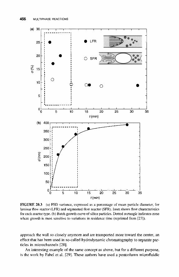
The concept of using gas-separated liquid reactant slugs has been elaborated on by Jensen and coworkers in a number of publications [24-27, 471. These authors used liquid slugs separated by gas bubbles in order to create small containers. Figure 20.3(a) (from [27]) compares the variance of the particle size distribution (PSD) obtained for the growth of silica particles (with a typical size of -500 nm) in a laminar flow reactor and in a slug flow (i.e., Taylor flow) reactor. Due to the para- bolic flow profile, particles that nucleate and grow in regions close to the wall experi- ence a slower velocity and therefore a longer reaction time, so that they grow to be larger. This leads to a larger variance in the PSD. However, this effect is only found for the shorter reaction times, up to 10min. As can be seen in Fig. 20.3(b), in this time period the growth rate is highest and therefore most sensitive to changes in residence time. Another explanation (not discussed by the authors of [27]) for the observation that PSD variance in the laminar flow situation approaches that for slug flow may be the fact that particles, once they have reached a specific size, cannot
456 MULTIPHASE REACTIONS
I I
I I
' 0 I I
I 0. 0 0 0 I
I I I
1 0 - I
5 - I
I I I I I I I I
I - - - - - - - - - - - - J
OO I 5 " I ' I 10 15 I 20 I I ' I " 25 30
I I I
I I I
I 0 LFR
35
I
I 0 SFR 0 :
I I I I I
h
b
t (min)
FIGURE 20.3 (a) PSD variance, expressed as a percentage of mean particle diameter, for laminar flow reactor (LFR) and segmented flow reactor (SFR). Inset shows flow characteristics for each reactor type. (b) Batch growth curve of silica particles. Dotted rectangle indicates zone where growth is most sensitive to variations in residence time (reprinted fiom [27]).
approach the wall so closely anymore and are transported more toward the center, an effect that has been used in so-called hydrodynamic chromatography to separate par- ticles in microchannels [28].
An interesting example of the same concept as above, but for a different purpose, is the work by Fabel et al. [29]. These authors have used a postcolumn microfluidic

20.3 EXAMPLES OF MICROREACTORS BASED ON SEGMENTED FLOW 457
microreactor device that divides the eluent of an HPLC column into fractions by breaking up the liquid stream into analyte slugs separated by air. They have done this in order to reduce the RTD for enzymatic reactions that are used for the identification of compounds with toxic potential. The toxin present in a slug inhibits enzymatic activity in that particular slug, which can be detected through the reduced conversion of substrate that is also present in the liquid. Work has also been done on a porous mullite monolith as a support for enzyme-catalyzed reactions, using gas- liquid Taylor flow [30]. Here, Taylor flow served mainly to establish a narrow RTD and good mixing within the individual liquid slugs. Lactase from Aspergillus oryzae and lipase from Cundidu rugosu were immobilized on the monolith, and activity and stability were compared to those of similarly prepared enzymes on cor- dierite monoliths. The use of high-porosity monoliths yielded more stable and more active bioreactors.
20.3.3 Liquid-Liquid Segmented Flow Microfluidics for Crystallization
In analogy to the previously described method of creating “nanoreactors,” consisting of liquid slugs separated by gas bubbles, Alivisatos and coworkers have used liquid bubbles dispersed in an inert fluid for the preparation of fluorescent nanocrystals. Although the size distribution of nanocrystals was already small in their original work, in which they tuned crystal size by changing reaction time, temperature, and precursor concen- tration in a microfluidic chip [31], in a later publication [32] they further improved the CdSe crystal size distribution by using a perfluorinated carrier fluid in which octa- decene droplets with cadmium and selenium precursors were injected through a flow- focusing nanojet structure with a step increase in channel height. These droplets flowed through a high-temperature (240-300°C) glass microreactor. The authors state that isolating the reaction solution in droplets prevented particle deposition and hydro- dynamic dispersion, allowing the reproducible synthesis of nanocrystals.
Mixing and reaction, including crystallization, in aqueous slugs separated by oil have been studied by Ismagilov and coworkers in a number of publications. These authors do not use the microfluidic system for production, but for the investigation of reaction kinetics and protein crystallization conditions. They have developed microfluidic structures with inlets through which laminar streams of two aqueous sol- utions of reagents with an inert aqueous liquid separating them were continuously injected into a flow of water-immiscible and inert perfluorodecaline in the main microchannel (Fig. 20.4) [33]. In this microchannel, the laminar stream spon- taneously breaks up into a train of plugs (of -0.5 nL) separated by perfluorodecaline. Plugs of three or more reagents may be formed in the same manner. Also, the system allows the user to continuously change the concentrations of reagents in the plugs by controlling the relative flow rates of the reagent streams [34]. Note that the authors of [33] use the term “plug” for the liquid segment that has a meniscus such that the seg- ment approaches droplet shape, so that the liquid in the droplet does not touch the wall. This would be the case for a water segment in an oily substance, in a microchan- nel with a hydrophobic wall (e.g., in PDMS).
A plug or slug moving in a straight channel would generate a steady recirculating flow in that plug or slug. This internal circulation would lead to mixing, but with the

&8 MULTIPHASE REACTIONS
No
FIGURE 20.4 Schematic presentation of microfluidic device in which two aqueous reagents (dark gray) with a separating fluid (light gray) enter a serpentine channel with a flowing immis- cible fluid and form droplets (slugs). Internal recirculation in the slugs is indicated by arrows (from [33]).
risk of regions with no mixing at all. To understand this, one has to transform the two- dimensional pattern in Fig. 6.7 in Chapter 6 into a three-dimensional picture, in which the flow pattern (i.e., in a tubular microchannel) would be cylindrical, with the flow going to the right along the central axis of the channel and to the left all along the wall surface. Thus, there will be a region, forming a ring that surrounds the central axis of the slug, where the liquid does not move at all, and in which therefore no mixing will also occur. The exact flow pattern depends on the shape of the microchannel; in a channel with a rectangular cross section, the circulation pattern would probably more resemble the two-dimensional image in Fig. 6.7 of Chapter 6. And for that case, it would be clear that (in projection) two halves exist within the liquid which basically do not mix, so that axial mixing is inefficient.
From a scan of recent literature, it becomes clear that the circulations within the slug are not yet completely understood, which is the reason why several authors have under- taken flow visualization studies, using particle image velocimetry (PIV) and particle tracking techniques [35, 361. Unfortunately, these techniques were only used to obtain two-dimensional images, more specifically, for a projection of the flow pattern on a symmetry plane going through the middle of a channel. An attempt has been made recently to evaluate the three-dimensional flow patterns and mixing quality arising from them, for plugs moving through a serpentine microchannel like the one shown in Fig. 20.4 [37]. Namely, it has been established that when a plug or slug passes a serpentine, the internal flow pattern is redirected at each bend and mixing is enhanced by an order of magnitude [38]. A scaling argument for the dependence of the mixing time was derived, which reads t w(aw/u)log(Pe), where w(m) is the cross-sectional dimension of the microchannel, a is the dimensionless length of the plug measured relative to w, u (m/s) is the flow velocity, Pe is the Piclet number (Pe = wu/D), and D (m2/s) is the diffusion coefficient of the reagent being mixed. It was experimen- tally found that under favorable conditions, sub-ms mixing could be obtained, which opens a route for studying fast kinetics [33, 341. One further finding is that one favor- able condition for fast mixing by using plugs in a serpentine microchannel is the choice of two liquids that have nearly the same viscosity [37, 391.

20.3 EXAMPLES OF MICROREACTORS BASED ON SEGMENTED FLOW 6 9
As mentioned above, aqueous slugs separated by oil have been employed by Ismagilov and coworkers for the investigation of protein crystallization conditions. The main issue in the field of protein crystallization is finding the exact solution conditions within a large range of possible solution compositions (salts and other additives) and concentrations (e.g., protein supersaturation), temperature, and gradients of all these parameters in space and time (e.g., solvent evaporation rates and cooling rates). The window for the formation of single crystals of the exact crystal structure (one out of potentially many so-called polymorphs) is generally very narrow.
Still, the availability of protein crystals of excellent quality is crucial for deve- lopments in proteomics, as well as in pharmaceutical product development. For proteomics, the most precise technique available at the moment to determine the three-dimensional structures of proteins, in terms of bond distances and angles, is X-ray crystallography (although high-resolution NMR can give similar information, the interpretation of X-ray data is more straightforward). In the pharmaceutical industry, finding a bio-active formulation of a protein-based drug with the appropriate release properties within the human body is an important issue. The key is generally finding a suitable crystal structure for the protein. Besides drug formulation, the purification of proteins at the industrial scale is also of great importance; in that case, finding the appropriate conditions is not tri- vial. Very generally, it can be said that although methods exist which have large predictive value for crystallization conditions [40], in most cases a trial-and-error method is preferred, which involves the screening of a large amount of crystalli- zation conditions per protein.
The latter is exactly what has been done by Ismagilov and coworkers: They have used their microfluidic formulators to define plugs of a specific composition (which differs from plug to plug) and stored these plugs in a microchannel to essentially wait for crystals to form. This is generally done in a two-step procedure, where the first step screens a large number of reagents to identify the appropriate combination that produces protein crystals (this is called “sparse-matrix screening”), while in the second step the concentration of each reagent in the combination is finely screened to grow crystals of diffraction quality (“gradient screening”) [4 1-45]. X-ray diffraction is actually done in the microfluidic chip, which is composed of an amorphous material that does not interfere with these measurements.
20.3.4 Liquid-Liquid Segmented Flow Microreactors for Polymerization and Emulsification
Conventional emulsification equipment like colloid milling machines and rotor-stator systems commonly result in droplets with broad size distributions. For many appli- cations, however, precise droplet-size control of the emulsion within a narrow range is desired, for example, for maintaining the stability of the emulsion and in order to obtain emulsions with new functional roles. Emulsification is also often used as a process step in the fabrication of polymer microspheres. First a polymer solution is emulsified, followed by removal of the solvent through evaporation, by

460 MULTIPHASE REACTIONS
a thermal or UV polymerization step. Occasionally, a polymer melt is emulsified and successively cooled down to solidify the droplets.
Besides the size distribution, another drawback of some of the conventional emul- sification methods is that the energy input during the process is very high, which may result in a temperature rise. The latter is especially undesirable for ingredients for food and pharmaceutical emulsions. An alternative technique is membrane emulsification, which works with low energy input, which is a great advantage over conventional methods [49, 501. In this method, the disperse phase is pressed through the mem- brane, forming droplets in the continuous phase at the other side of the membrane. If the membrane has a narrow pore size distribution and a controlled distance between the pores to avoid coalescence, this process generally will yield monodisperse emul- sions. A very promising but somewhat costly way to manufacture such membranes is by using photolithography and etching techniques; these processes give extremely well-defined pore size and pitch [51].
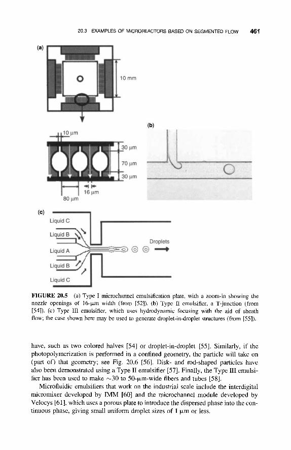
Microchannel emulsification is a recently developed promising approach for pre- paring monodisperse droplets (and beads, see below), with an average size ranging from a few km up to - 100 p m [52,53]. Basically, three main types of microchannel structures are used for emulsification (Fig. 20.5):
Type I could be described as a one-dimensional version of membrane emulsi- fication, that is, the dispersed phase is pressed through an array of nozzles into a microchannel with the continuous phase [52,53]. Alternatively, a laminar mixer structure may be used to create basically the same result [6], a concept that is also useful for generating foams. Type I1 consists of a T-junction at which the dispersed phase is pressed into a continuous stream of the second phase [54]. Due to shearing at the junction, a droplet breaks off at a specific size, which depends on the balance of capillary forces and shear forces. Type I11 is based on hydrodynamic focusing of the dispersed phase between two streams of the continuous phase (or “sheath flow” [54]), which results in what may be described as a two-dimensional annular flow pattern. Either this annular pattern breaks up at some distance downstream of the point where the liquids are joined, by itself due to the shearing effect of the two outer streams on the central stream [55, 561, or the combined stream may be pressed through a nozzle to increase shear forces on the annular flow pattern so that it becomes unstable at a shorter channel distance and breaks up into uniform droplets. This method, more so than the previous other two, also allows the formation of dro- plet-in-droplet structures [55] (also possible with two consecutive T-junctions [59]) or two-color droplets [54].
All these emulsifier types may also be used to manufacture polymer beads, if the droplet contains the monomer precursor mix and a polymerization process is initiated and finalized downstream of the position where the droplet is generated. The latter may be done by UV illumination [53], which, if it is done directly after the point of droplet formation, may also lead to freezing any internal structure that the droplets
20.3 EXAMPLES OF MICROREACTORS BASED ON SEGMENTED FLOW 461
Liquid C I r Droplets
FIGURE 20.5 (a) Type I microchannel emulsification plate, with a zoom-in showing the nozzle openings of 16-km width (from [52]). (b) Type I1 emulsifier, a T-junction (from [54]). (c) Type I11 emulsifier, which uses hydrodynamic focusing with the aid of sheath flow; the case shown here may be used to generate droplet-in-droplet structures (from [55]).
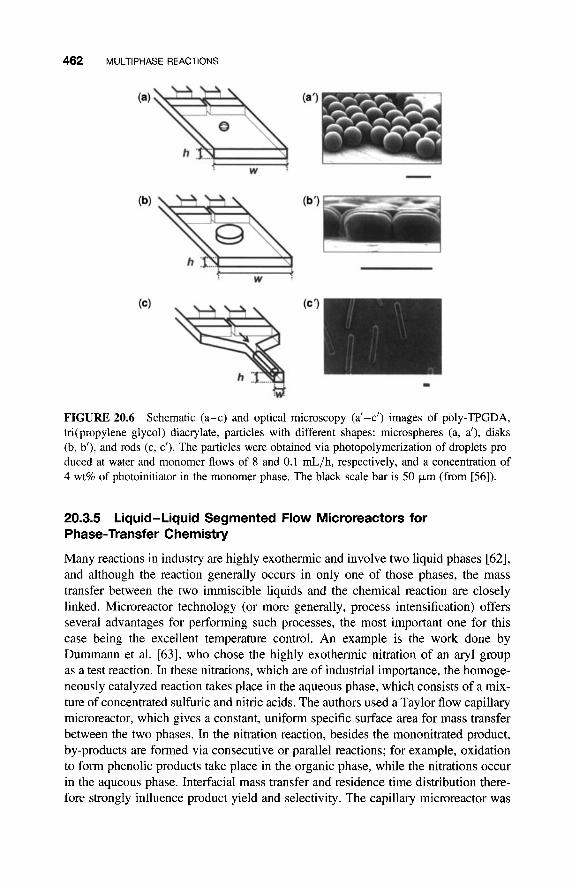
have, such as two colored halves [54] or droplet-in-droplet [%I. Similarly, if the photopolymerization is performed in a confined geometry, the particle will take on (part of) that geometry; see Fig. 20.6 [56]. Disk- and rod-shaped partides have also been demonstrated using a Type I1 emulsifier [57]. Finally, the Type I11 emulsi- fier has been used to make -30 to 50-pm-wide fibers and tubes [58].
Microfluidic emulsifiers that work on the industrial scale include the interdigital micromixer developed by IMM [60] and the microchannel module developed by Velocys [61], which uses a porous plate to introduce the dispersed phase into the con- tinuous phase, giving small uniform droplet sizes of 1 k m or less.
462 MULTIPHASE REACTIONS
FIGURE 20.6 Schematic (a-c) and optical microscopy (a’-c’) images of poly-TPGDA, tri( propylene glycol) diacvlate, particles with different shapes: microspheres (a, a’), disks (b, b’), and rods (c, c’). The particles were obtained via photopolymerization of droplets pro- duced at water and monomer flows of 8 and 0.1 mL/h, respectively, and a concentration of 4 wt% of photoinitiator in the monomer phase. The black scale bar is 50 pm (from [56]).
20.3.5 Liquid-Liquid Segmented Flow Microreactors for Phase-Transfer Chemistry
Many reactions in industry are highly exothermic and involve two liquid phases [62], and although the reaction generally occurs in only one of those phases, the mass transfer between the two immiscible liquids and the chemical reaction are closely linked. Microreactor technology (or more generally, process intensification) offers several advantages for performing such processes, the most important one for this case being the excellent temperature control. An example is the work done by Dummann et al. [63], who chose the highly exothennic nitration of an aryl group as a test reaction. In these nitrations, which are of industrial importance, the homoge- neously catalyzed reaction takes place in the aqueous phase, which consists of a mix- ture of concentrated sulfuric and nitric acids. The authors used a Taylor flow capillary microreactor, which gives a constant, uniform specific surface area for mass transfer between the two phases. In the nitration reaction, besides the mononitrated product, by-products are formed via consecutive or parallel reactions; for example, oxidation to form phenolic products take place in the organic phase, while the nitrations occur in the aqueous phase. Interfacial mass transfer and residence time distribution there- fore strongly influence product yield and selectivity. The capillary microreactor was

20.3 EXAMPLES OF MICROREACTORS BASED ON SEGMENTED FLOW 463
shown to behave like a plug-flow reactor, permitting a high mass transfer between the phases, and also allowed for some definitive conclusions on the mechanism of by- product formation, that is, by-products were mainly formed via parallel reactions. More information about microreactor work on aromatic nitrations can be found in Section 4.3.1 of [64].
The reaction between substances that are present in different phases is often inhibited because of the insolubility of the substances in one of the two immiscible liquids. Instead of looking for an appropriate mutual solvent, which may sometimes be difficult to find, one may also use a process called “phase-transfer catalysis,” a term introduced by Starks [65]. The reaction is enabled by the use of minute amounts of an agent that transfers one reactant across the interface into the other phase so that the reaction can proceed.
Starks has shown that the rates of some displacement, oxidation, and hydrolysis reactions conducted in two-phase systems are dramatically enhanced by the presence of quaternary ammonium and phosphonium salts. These salts are excellent agents for the transport of anions from the aqueous to organic phase, where the anion- tetralkylammmonium complex reacts with the target compound in the organic phase, followed by a transfer of the ammonium salt back to the aqueous phase. In other cases, the mechanism is the transfer of the target organic substance, by ammonium salt, first to the aqueous phase, where it can react to form a water-insoluble substance that falls back to the organic phase. Other mechanisms may also apply [66].
It may be evident that phase transfer processes benefit from a large interfacial area and short diffusion distances, which implies that microreactor technology is extre- mely suitable to perform such reactions. Ueno et al. demonstrated the use of a phase transfer catalyst in a microchannel reactor for the benzylation of ethyl- 2-oxocyclopentane-carboxylate with benzyl bromide in Taylor flow with segments of CH2C12 and NaOH [67]. The reaction in the microreactor was found to be more efficient than that in a round-bottom flask with vigorous stirring. Other examples
the alkylation of malonic ester, also in Taylor flow and with the same solvent com- bination [68], and the Claisen-Schmidt reaction of benzaldehyde with acetone in an ethanol-water combination [69] that was studied in both Taylor flow and stratified flow (i.e., in two parallel streams of the two liquids; see below). Taylor flow was found to give the higher conversion of the two flow types, due to a larger interfacial area.
Ryu and coworkers at Osaka Prefecture University have performed in microre- actors coupling reactions in a two-phase system, of which one phase was an ionic liquid. Ionic liquids are organic salts with melting points under 100°C, often even lower than room temperature. At least one ion has a delocalized charge and one com- ponent is organic, which prevents the formation of a stable crystal lattice. Ionic liquids are employed more and more frequently as substitutes for the traditional organic solvents in chemical reactions, particularly as solvents for transition metal catalysis, for which remarkable improvements have been shown if the organic solvent is replaced by an ionic liquid. The most common ionic liquids are imidazolium and pyridinium derivatives, and phosphonium or tetralkylammonium compounds. Ionic liquids have practically no vapor pressure that facilitates product separation by

464 MULTIPHASE REACTIONS
distillation. For detailed information about the properties and use of ionic liquids, the reader is referred to [70, 711.
Ionic liquids form biphasic systems with many organic product mixtures, which gives rise to the possibility of the convenient extraction and recovery of homogeneous catalysts. The two-phase characteristics of ionic liquid-organic solvent systems also pave the way for the use of microreactors, similarly as was discussed earlier in this chapter. Following this idea, Ryu and coworkers have carried out Sonogashira coup- ling in ionic liquids [72]. In a microflow system containing a micromixer commer- cially available from IMM, Mainz, having 2 x 15 interdigitated channels (with a width of 40 pm and depth of 200 pm), they performed the reaction of iodobenzene with phenylacetylene in the presence of a catalytic amount of PdC12(PPh3)2 in the ionic liquid I-butyl-3-methylimidazolium hexafluorophosphate. The coupling pro- duct, diphenylacetylene, was formed in 93% yield. In another publication [73], the authors used the same micromixer system to perform the Mizoroki-Heck reaction of iodobenzene with butyl acrylate, using the low-viscosity ionic liquid I-butyl- 3-methyl-imidazolium bis(trifluoro-methyl-sulfony1)imide and in the presence of a homogeneous Pd catalyst. For both reactions, efficient catalyst recycling from the microflow system was demonstrated.
In [72,73] no further details about the flow structure in the microreactor are given, but in a more recent publication [74], Ryu et al. examined the applicability of a Taylor flow microfluidic system for the Pd-catalyzed carbonylation of aromatic iodides in the presence of a secondary amine, which is being extensively investigated with regard to single/double carbonylation selectivity. Since CO has limited solubility in ionic liquids, carbonylation selectivity is presumed to be controlled by the diffusion effi- ciency of CO, which can be enhanced by the larger surface area achieved in a Taylor flow concept. It was indeed found that product selectivity was significantly enhanced in the microflow system compared to a batch reactor.
20.4 EXAMPLES OF MICROREACTORS BASED ON OTHER FLOW TYPES
20.4.1 Gas-Liquid
Several examples exist of microreactors with a packed-bed catalyst, thmugh which a two-phase gas-liquid mixture is flown. The basic idea behind such a configuration is to achieve a high catalyst surface area per volume of reactor, but especially in earlier work, no extra attention was paid to also obtaining a well-defined liquid-gas inter- face. The Taylor flow concept will most probably not apply to packed beds, but under well-controlled flow conditions annular flow (also frequently called trickle flow) may be possible. Bubbly flow is a useful concept for packed beds.
In a number of publications, Jensen and coworkers investigated gas-liquid reac- tions with a heterogeneous catalyst in silicon-based microreactors. Two concepts were presented: one in which standard porous catalysts were loaded in a microreactor (either a single microchannel or 10-microchannel array) that had an inlet distribution manifold and a micromachined filter integrated in the microchannels in order to

20.4 EXAMPLES OF MICROREACTORS BASED ON OTHER FLOW TYPES 465
immobilize the catalyst particles [75], and the other a fully micromachined packed- bed reactor made out of silicon [76]. For the latter, a perfectly ordered array of pillars of 50 p,m in diameter was etched into the reactor channels. These pillars were poro- sified and loaded with catalyst using conventional impregnation. Especially in the latter reactor, because of the large specific surface area, the heat losses were so large that even for exothermic reactions, heating and not cooling was required to keep the temperature constant. Mass transfer rates were characterized using the heterogeneous hydrogenation of cyclohexene to cyclohexane over Pt/A1203 catalyst beads in the packed-bed reactor and over Pt impregnated on oxidized porous silicon in the pillar microreactor. Both reactors had similar mass transfer coefficients KLa on the order of 10 per second, which was more than 100 times larger than the values reported for laboratory-scale reactors.
The findings on several other examples of packed-bed gas- liquid microreactors have been published, mainly for the purpose of catalyst testing. One example worth mentioning is the H-cube@ “flow hydrogenator,” which employs the electro- lytic generation of hydrogen gas to be used in hydrogenation reactions [77, 781.
As can be seen in Fig. 20.1, at relatively high gas content of the gas-liquid mix- ture, and relatively high fluid velocities, annular flow develops, at least in the small microchannels discussed in this chapter, where capillay forces keep the liquid along the wall. Annular flow is one type of what is categorized as “stratified flow,” the opposite of “dispersed flow” (e.g., bubbly flow). For most liquid-gas (but also for most liquid- liquid) combinations, gravity starts to play a role in channels larger than N 1 mm. Under similar conditions where annular flow is observed in smal- ler channels, in these larger channels the two fluids become separated, with the lighter fluid (here, the gas) running on top of the denser fluid. This, of course, only holds for horizontally aligned channels; in vertical channels, the situation is somewhat different and annular flow may also be stable in the larger channels.
Annular flow can be considered a desirable and possibly ideal situation for well- defined mass transport in a reacting system, provided that the liquid film thickness is constant or at least well-controlled all over the microchannel length. Not so many examples of microreactors exist in which this type of flow has been used, but one interesting example is the work of Kitamon and coworkers on a microchannel reactor chip for hydrogenation over a Pd catalyst [79]. These authors have used very narrow microchannels in a glass plate with a specific interfacial area of 10,000 to 50,000 m2/ m3, in contrast to the N 100 m2/m3 for conventional reactors. To achieve a microreac- tor that schematically looks like the one in Fig. 20.7(a), they developed a procedure for the immobilization of Pd catalyst particles microencapsulated in a copolymer [see Fig. 20.7(b)], which after the immobilization on the microchannel wall, using amine linkers, is annealed at 150°C so that the copolymer cross-links. The successful hydro- genation of several substances, with in some cases quite high yields, was conducted with this microreactor.
An important process in fine chemicals industry is the fluorination of organic com- pounds. The direct use of elemental fluorine is a difficult process, for reasons of safety, but for economic reasons it would be highly desirable, and could be efficient and environmentally friendly if the HF by-product was recycled by electrolysis [SO].

466 MULTIPHASE REACTIONS
Solid Catalyst /
Si02 \ Liquid
1
FIGURE 20.7 (a) Annular flow microchannel reactor with Pd particles immobilized at the wall. The gray area is liquid; the gas flows through the center of the channel. (b) Immobilized Pd encapsulated in a copolymer, before cross-linking (from [79]).
Therefore, several examples can be found in the literature of rnicroreactors developed for this process. For example, Chambers et al., in a series of papers (see the references listed in [SO]), have developed a modular stainless steel microreactor system (Fig. 20.8) through which gas and liquid reagents flow in annular fashion (called “pipe flow” by the authors) down the 0.5-mm-wide channels where the reaction occurs. The fluorination of diethyl malonate and Meldrum’s acid with reasonable conversion was demonstrated with this reactor system, using 10% v/v F2 in N2 as the fluorination gas.
For the direct fluorination of aromatic compounds, a two-channel microfabricated reactor constructed of silicon and Pyrex and coated with nickel/silicon oxide thin films was developed by de Mas et al. [2, 811. This reactor was operated mainly under annular flow conditions, although flow diagrams were constructed for Taylor flow as well. It was estimated by the authors that a reactor system consisting of 200 of these microchannels (with a total reactor volume of only 0.25 mL) would produce up to 0.4 g/h of the fluorinated product.
Jahnisch et al. have developed a falling-film microreactor for the direct fluorination of aromatic compounds [82]. This reactor looks quite similar to the one shown in Fig. 20.8, but the flow pattern is somewhat different in that the liquid flows as a thin film along one surface of the reactor, while the gas is flown along it either in cocurrent or countercurrent fashion. The falling film in the microreactor had a stable thickness of 100 Fm. The most critical section of the reactor is the inlet part, which should ensure equal distribution of the liquid phase to parallel streams. The microreactor has a structured heat exchanger copper plate inserted into a

20.4 EXAMPLES OF MICROREACTORS BASED ON OTHER FLOW TYPES 467
Substrate solution
Product
Steel block Nickel or Stainless Transparent Top steel with 3 steel steel PTFCE plate window
reservoirs plate c h a n n e I plate
Schematic representation of modular microreactor device, suitable for indus-
plate
FIGURE 20.8 trial application (from [go]).
cavity beneath the falling-film plate for temperature control, and is covered by a thick glass plate that leaves open the option for photochemical reactions.
A comparison of the performance of the reactor of de Mas at al. with the micro- bubble column and the falling-film microreactor discussed above was given in [62]. These microreactors were benchmarked against a laboratory-scale bubble column, yielding the results listed in Table 20.1.
20.4.2 Liquid-Liquid
As was discussed in a previous paragraph, due to the interfacial tension in combi- nation with shear forces imposed by the flow, two liquids entering a microchannel from a T-junction, in general, will break up into droplets with a radius that depends
TABLE 20.1 Benchmarking of Direct Fluorination Microreactors (from [62])
Lab-Scale Silicon Microbubble Falling-Flim Bubble Microchannel Microreactor Microreactor Column Reactor
WI [821 [821 121
Temperature ("C) - 15 - 16 - 17 Room
Fluorine ratio (equiv.) 0.54 2.0 1 .0 2.5 Conversion (%) 26 76 34 58 Yield (%) I 1 28 22 14 Selectivity (%) 42 37 22 24
temperature
468 MULTIPHASE REACTIONS
on the capillay number. Only at low flows may the two liquids remain laminated, but always the risk is present that the interface becomes unstable or starts moving. In fact, it has been observed by this author that, probably due to small defects at the micro- channel walls, liquids start to turn in a corkscrew fashion, as was intentionally done in the so-called hemngbone mixers of Stroock et al. [83].
In order to keep the two flow streams running in parallel in one plane, so that they may be separated at the end of the channel with a simple T-junction, special precautions have to be taken. The problem is exactly the same as faced in keeping apart the two liquids for extraction, as was encountered in Chapter 3. Inserting a membrane between the two phases significantly limits mass transport and therefore is not preferable.
Kitamori and coworkers [84] developed a surface modification procedure that was applied to a microchannel actually composed of two parrallel channels, one deep and one shallow, which connected to one another on one side. By capillary forces, it was possible to coat only the shallow part with a hydrophobic coating, with this part guiding the gas flow in parallel with the liquid in the deeper part (or an apolar organic phase in parallel with an aqueous phase in a liquid-liquid two-phase case). The performance of the hydrophobic- hydrophilic separation was tested by measuring the leakage pressure for water flow from the hydrophilic microchannel to the hydro- phobic one. This pressure was found to vary from 7.7 to 1.1 W a when the microchan- nel depth changed from 8.6 to 39 pm, which agreed very well with the pressures predicted by the Young-Laplace equation.
With the use of such microreactors diazocoupling reactions, phase transfer catalysis (see also Section 20.3.5 above) was performed in an ethyl acetate-water combination [85] . The same concept was used for phase transfer catalysis in a micro- fluidic microchannel network on a glass chip in which a 2 x 2 matrix of amines and acid chlorides was used, to demonstrate the use of glass chips for combinatorial syn- thesis [86]. Furthermore, the single-channel phase transfer catalysis chip of [85] was replicated 10 times and stacked in a “pile-up” microreactor, which offered for the ami- neacid chloride reaction mentioned above production of 1.7 g of crude product (90% pure) per hour [87]. The latter demonstrates that this concept may have a value for the production of fine chemicals.
Finally, a two-phase system of the type discussed above, with parallel streams of either cyclohexane and water or 1-hexanol and formamide, was used to prepare titania nanoparticles with a size less than 10 nm [SS]. The reaction carried out was the hydroly- sis of titanium alkoxide, which is a very fast reaction and therefore suitable for a micro- channel microreactor. Reaction is assumed to take place in the very narrow diffusion region between the two immiscible layers, which is on the order of a few nm.
20.5 CONCLUDING REMARKS
In this chapter, the benefits of a number of two-phase flow patterns (annular, two par- allel streams, and Taylor) in microchannel microreactors have been discussed. It was

BIBLIOGRAPHY 469
shown that the benefits mainly arise from the large interfacial areas that can be achieved between the two phases, ensuring enhanced mass transport, and the excel- lent control on residence time distribution that may be obtained, which is of import- ance for the selectivity of chemical reactions. Special types of reactions discussed were phase transfer catalysis, which is a class of reactions that typically benefit from large interfacial area, and the preparation of monodisperse particles, crystals or droplets, which typically benefit from narrow residence time distribution.
BIBLIOGRAPHY
1. Kandlikar, S. G., Garimella, S. G., Li, D., Colin, S., and King, M. R. (2006). Heat Transfer and Fluid Flow in Minichannels and Microchannels. Amsterdam: Elsevier.
2. de Mas, N., Gunther, A., Schmidt, M. A., and Jensen, K. F. (2003). Microfabricated multi- phase reactors for the selective direct fluorination of aromatics. Ind. Eng. Chem. Res., 42:
3. Triplett, K. A., Ghiaasiaan, S. M., Abdel-Khalik, S. I., and Sadowski, D. L. (1999). Gas- liquid two-phase flow in microchannels. Part I: Two-phase flow patterns. Int. .I. Multiphase
4. Kreutzer, M. T., Kapteijn, F., Moulijn, J. A., and Heiszwolf, J. J. (2005). Multiphase monolith reactors: Chemical reaction engineering of segmented flow in microchannels. Chem. Eng. Sci., 60: 5895-5916.
5. Jensen, M. K., Peles, Y., Borca-Tasciuc, T., and Kandlikar, S. G. (2006). Multiphase flow, evaporation, and condensation at the microscale. In Micro Process Engineering, Vol. 5: Fundamentals, Devices, Fabrication and Applications, N. Kockmann, ed., Chapter 4. Weinheim: Wiley-VCH.
6. Lob, P., Pennemann, H., and Hessel, V. (2004). G/L-dispersion in interdigital micromix- ers with different mixing chamber geometries. Chem. Eng. J., 101: 75-85.
7. Bensakhria, A,, Peysson, Y., and Antonini, G. (2004). Experimental study of the pipeline lubrication for heavy oil transport. Oil & Gas Sci. Techno1.-Rev. IFP, 59: 523-533.
8. Wegmann, A., and Rudolf von Rohr, P. (2006). Two phase liquid-liquid flows in pipes of small diameters. Znt. J. Multiphase Flow, 32: 1017-1028.
9. Hisamoto, H., Saito, T., Tokeshi, M., Hibara, A., and Kitamori, T. (2001). Fast and high conversion phase-transfer synthesis exploiting the liquid-liquid interface formed in a microchannel chip. Chem. Commun., 2662-2663.
10. Squires, T. M., and Quake, S. R. (2005). Microfluidics: Fluid physics at the nanoliter scale. Rev. Mod. Phys., 77: 977-1026.
11. BerZiE, G., and Pintar, A. (1997). The role of gas bubbles and liquid slug lengths on mass transport in the Taylor flow through capillaries. Chem. Eng. Sci., 52: 3709-3719.
12. Van Baten, J. M., and Krishna, R. (2004). CFD simulations of mass transfer from Taylor bubbles rising in circular capillaries. Chem. Eng. Sci., 59: 2535-2545.
13. Kreutzer, M. T., Heiszwolf, J. J., Kapteijn, F., and Moulijn, J. A. (2003). Pressure drop of Taylor flow in capillaries: Impact of slug length. In Proceedings of 1st International Conference on Microchannels and Minichannels, pp. 153- 159. New York: ASME.
698-7 10.
Flow, 25: 377-394.

470 MULTIPHASE REACTIONS
14. Thulasidas, T. C., Abraham, M. A., and Cen-o, R. L. (1999). Dispersion during bubble- train flow in capillaries. Chern. Eng. Sci., 54: 61-76.
15. Salman, W., Angeli, P., and Gavriilidis, A. (2005). Sample pulse broadening in Taylor flow microchannels for screening applications. Chem. Eng. Technol., 28: 509-5 14.
16. Edvinsson Albers, R., Nystrom, M., Siverstrtjm, M., Sellin, A,, Dellve, A.-C., Anderson, U., et al. (2001). Development of a monolith-based process for H202 production: From idea to large-scale implementation. Cat. Today, 652 247-252.
17. Kawakami, K., Kawasaki, K., Shiraishi, F., and Kusunoki, K. (1989). Performance of a honeycomb monolith bioreactor in a gas-liquid-solid three-phase system. Ind. Eng. Chem. Rex, 28: 394-400.
18. Liu, W., Addiego, W. P., Sorensen, C. M., and Boger, T. (2002). Monolith reactor for the dehydrogenation of ethylbenzene to styrene. Ind. Eng. Chem. Rex, 41: 3 13 1-3 138.
19. de Deugd, R. M., Kapteijn, F., and Moulijn, J. A. (2003). Using monolithic catalysts for highly selective Fischer-Tropsch synthesis. Cat. Today, 79: 495-501.
20. Lapkin, A. A., Bozkaya, B., and Plucinski, P. K. (2006). Selective oxidation of 1-butene by molecular oxygen in a porous membrane Taylor flow reactor. Ind. Eng. Chem. Rex, 45:
21. Hessel, V., Ehrfeld, W., Herweck, T., Haverkamp, V., Lowe, H., Schiewe, J., et al. (2000). Gas/liquid microreactors: Hydrodynamics and mass transfer. In Proceedings of 4th International Conference on Microreaction Technology, IMRET4, AIchE Topical Conference Proceedings, Atlanta, GA, March 5-9, 2000, pp. 174- 186.
22. Hessel, V., Ehrfeld, W., Golbig, K., Haverkamp, V., Lowe, H., Storz, M., et al. (1999). Gas/liquid microreactors for direct fluorination of aromatic compounds using elemental fluorine. In Proceedings of 3rd International Conference on Microreaction Technology, IMRET3, Frankfurt, Germany, April 18-21, 1999, pp. 526-540.
23. Murray, C. B., Kagan, C. R., and Bawendi, M. G. (2000). Synthesis and characterization of monodisperse nanocrystals and close-packed nanocrystal assemblies. Ann. Rev. Muter. Sci.,
24. Khan, S. A., Gunther, A,, Schmidt, M. A., and Jensen, K. F. (2004). Microfluidic synthesis of colloidal silica. Langmuir, 20: 8604-861 1.
25. Yen, B. K. H., Giinther, A., Schmidt, M. A., Jensen, K. F., and Bawendi, M. G. (2005). A microfabricated gas-liquid segmented flow reactor for high-temperature synthesis: The case of CdSe quantum dots. Angew. Chem. Int. Ed., 44: 5447-5451.
26. Yen, B. K. H., Stott, N. E., Jensen, K. F., and Bawendi, M. G. (2003). A continuous-flow microcapillary reactor for the preparation of a size series of CdSe nanocrystals. Adv. Mat.,
27. Giinther, A., Khan, S. A., Thalmann, M., Trachsel, F., and Jensen, K. F. (2004). Transport and reaction in microscale segmented gas-liquid flow. Lab Chip, 4: 278-286.
28. Chmela, E., Tijssen, R., Blom, M. T., Gardeniers, J. G. E., and van den Berg, A. (2002). A chip system for size separation of macromolecules and particles by hydrodynamic chromatography. Anal. Chem., 74: 3470-3475.
29. Fabel, S., Niessner, R., and Weller, M. G. (2005). Effect-directed analysis by high- performance liquid chromatography with gas-segmented enzyme inhibition. J . Chrom.,
2220-2228.
30: 545-610.
15: 1858-1862.
A1099: 103- 110.

BIBLIOGRAPHY 471
30. De Lathouder, K. M., Bakker, J. J. W., Kreutzer, M. T., Kapteijn, F., Moulijn, J. A., and Wallin, S. A. (2004). Structured reactors for enzyme immobilization: Advantages of tuning the wall morphology. Chem. Eng. Sci., 59: 5027-5033.
31. Chan, E. M., Mathies, R. A., and Alivisatos, A. P. (2003). Size-controlled growth of CdSe nanocrystals in microfluidic reactors. Nanoletters, 3: 199-201.
32. Chan, E. M., Alivisatos, A. P., and Mathies, R. A. (2005). High-temperature microfluidic synthesis of CdSe nanocrystals in nanoliter droplets. J. Amer. Chem. SOC., 127: 13854- 1386 1.
33. Song, H., Tice, J. D., and Ismagilov, R. F. (2003). A microfluidic system for controlling reaction networks in time. Angew. Chem. Int. Ed., 42: 767-772.
34. Song, H., and Ismagilov, R. F. (2003). Millisecond kinetics on a microfluidic chip using nanoliters of reagents. J. Am. Chem. SOC., 125: 14613-14619.
35. Gunther, A,, Jhunjhunwala, M., Thalmann, M., Schmidt, M. A,, and Jensen, K. F. (2005). Micromixing of miscible liquids in segmented gas-liquid flow. Langmuir, 21: 1547- 1555.
36. Kashid, M. N., Gerlach, I., Goetz, S., Franzke, J., Acker, J. F., Platte, F., et al. (2005). Internal circulation within the liquid slugs of a liquid-liquid slug-flow capillary micro- reactor. Ind. Eng. Chem. Res., 44: 5003-5010.
37. Stone, Z. B., Stone, H. A. (2005). Imaging and quantifying mixing in a model droplet micromixer. Phys. Fluids, 17: 063103-1 -063103-1 1 .
38. Song, H., Bringer, M. R., Tice, J. D., Gerdts, C. J., and Ismagilov, R. F. (2003). Experimental test of scaling of mixing by chaotic advection in droplets moving through microfluidic channels. Appl. Phys. Lett., 83: 4664-4666.
39. Tice, J. D., Lyon, A. D., and Ismagilov, R. F. (2004). Effects of viscosity on droplet formation and mixing in microfluidic channels. Anal. Chim. Acta, 507: 73-77.
40. George, A., and Wilson, W. W. (1994). Predicting protein crystallization from a dilute solution property. Acta Crystallogr., D50: 361 -365.
41. Yadav, M. K., Gerdts, C. J., Sanishvili, R., Smith, W. W., Roach, L. S., Ismagilov, R. F., et al. (2005). In situ data collection and structure refinement from microcapillary protein crystallization. J. Appl. Cryst., 38: 900-905.
42. Li, L., Mustafi, D., Fu, Q., Tereshko, V., Chen, D. L., Tice, J. D., et al. (2006). Nanoliter microfluidic hybrid method for simultaneous screening and optimization validated with crystallization of membrane proteins. PNAS, 103: 19243- 19248.
43. Song, H., Chen, D. L., and Ismagilov, R. F. (2006). Reactions in droplets in microfluidic channels. Angew. Chem. Int. Ed., 45: 7336-7356.
44. Chen, D. L., Gerdts, C. J., and Ismagilov, R. F. (2005). Using microfluidics to observe the effect of mixing on nucleation of protein crystals. J. Am. Chem. SOC., 127:
45. Zheng, B., Gerdts, C. J., and Ismagilov, R. F. (2005). Using nanoliter plugs in microfluidics to facilitate and understand protein crystallization. Curr. Opin. Struct. Biol., 15: 548-555.
46. Voloshin, Y., Lawal, A., and Panikov, N. S. (2005). Continuous plug-flow bioreactor: Experimental testing with Pseudomonas putida culture grown on benzoate. Biofechnol. Bioeng., 91: 254-259.
47. Gunther, A,, and Jensen, K. F. (2006). Multiphase microfluidics: From flow characteristics to chemical and materials synthesis. Lab Chip, 6: 1487-1503.
9672-9673.

472 MULTIPHASE REACTIONS
48. Onal, Y., Lucas, M., and Claus, P. (2005). Application of a capillary microreactor for selective hydrogenation of a, P-unsaturated aldehydes in aqueous multiphase catalysis. Chem. Eng. Technol., 28: 972-978.
49. Joscelyne, S. M., and TragCdh, G. (2000). Membrane emulsification-A literature review. J. Membrane Sci., 169: 107-117.
50. de Jong, J., Lammertink, R. G. H., and Wessling, M. (2006). Membranes and microflui- dics: A review. Lab Chip, 6: 1125- 1139.
51. van Rijn, and C. J. M. (2004). Nuno and Micro Engineered Membrane Technology. Membrane Science and Technology Series, Vol. 10, Amsterdam: Elsevier.
52. Sugiura, S., Nakajima, M., Iwamoto, S., and Seki, M. (2001). Interfacial tension driven monodispersed droplet formation from microfabricated channel array. Langmuir, 17:
53. Ikkai, F., Iwamoto, S., Adachi, E., and Nakajima, M. (2005). New method of producing mono-sized polymer gel particles using microchannel emulsification and UV irradiation. Colloid. Polym. Sci., 283: 1149-1153.
54. Takasi Nisisako, T., Toni, T., and Higuchi, T. (2004). Novel microreactors for functional polymer beads. Chem. Eng. J., 101: 23-29.
55. Nie, Z., Xu, S., Seo, M., Lewis, P. C., and Kumacheva, E. (2005). Polymer particles with various shapes and morphologies produced in continuous microfluidic reactors. J. Amer. Chem. SOC., 127: 8058-8063.
56. Seo, M., Nie, Z., Xu, S., Mok, M., Lewis, P. C., Graham, R., et al. (2005). Continuous microfluidic reactors for polymer particles. Lungmuir, 21: 11614- 11622.
57. Dendukuri, D., Tsoi, K., Hatton, T. A., and Doyle, P. S. (2005). Controlled synthesis of nonspherical microparticles using microfluidics. Lungmuir, 2 1 : 2 1 13 -2 1 16.
58. Jeong, W., Kim, J., Kim, S., Lee, S., Mensing, G., and Beebe, D. J. (2004). Hydrodynamic microfabrication via “on the fly” photopolymerization of microscale fibers and tubes. Lab Chip, 4: 576-580.
59. Okushima, S., Nisisako, T., Toni, T., and Higuchi, T. (2004). Controlled production of monodisperse double emulsions by two-step droplet breakup in microfluidic devices. Langmuir, 20: 9905-9908.
60. Haverkamp, V., Ehrfeld, W., Gebauer, K., Hessel, V., Lowe, H., Richter, R., et al. (1999). The potential of micromixers for contacting of disperse liquid phases. Fresenius J. Anal. Chem., 364: 617-624.
61. Silva, L., Tonkovich, L., Lerou, J., and Daymo, E. (2006). Superior emulsion formation in microchannel architecture. Paper pmented at Achema 2006, 28th International Exhibition-Congress on Chemical Engineering, Environmental Protection and Biotechnology, Frankfurt, Germany, May 15- 19, 2006. Abstract available at http:// www.achema.de.
62. Pennemann, H., Watts, P., Haswell, S. J., Hessel, V., and Lowe, H. (2004). Benchmarking of microreactor applications. Org. Proc. Res. Develop., 8: 422-439.
63. Dummann, G., Quittmann, U., G r k h e l , L., Agar, D. W., Worz, O., and Morgenschweis, K. (2003). The capillary-microreactor: A new reactor concept for the intensification of heat and mass transfer in liquid-liquid reactions. Catal. Today, 79-80: 433-439.
64. Hessel, V., Hardt, S., and Lowe, H. (2004). Chemical Micro Process Engineering. Fundamentals, Modelling and Reactions. Weinheim, Germany: Wiley-VCH.
5562-5566.

BIBLIOGWPHY 473
65. Starks, C. M. (1971). Phase-transfer catalysis. I. Heterogeneous reactions involving anion transfer by quaternary ammonium and phosphonium salts. J. Am. Chem. SOC., 93:
66. Makosza, M. (2000). Phase-transfer catalysis. A general green methodology in organic
67. Ueno, M., Hisamoto, H., Kitamori, T., and Kobayashi, S. (2003). Phase-transfer alkylation
68. Okamoto, H. (2006). Effect of alternating pumping of two reactants into a microchannel
69. Mu, J.-X., Yin, X.-F., and Wang, Y.-G. (2005). The Claisen-Schmidt reaction carried out
70. Adams, D. J., Dyson, P. J., and Taverner, S. J. (2003). Chemistry in Alternative Reaction
7 1. Wasserscheid, P., and Welton, T. (2002). Ionic Liquids in Synthesis. Wiley-VCH. 72. Fukuyama, T., Shinmen, M., Nishitani, S., Sato, M., and Ryu, I. (2002). A copper-free
Sonogashira coupling reaction in ionic liquids and its application to a microflow system for efficient catalyst recycling. Org. Lett., 4: 1691- 1694.
73. Liu, S., Fukuyama, T., Sato, M., and Ryu, 1. (2004). Continuous micmflow synthesis of butyl cinnamate by a Mizoroki-Heck reaction using a low-viscosity ionic liquid as the recycling reaction medium. Org. Proc. Res. Dev., 8: 477-481.
74. Rahman, M. T., Fukuyama, T., Kamata, N., Sato, M., and Ryu, I. (2006). Low pressure Pd- catalyzed carbonylation in an ionic liquid using a multiphase microflow system. Chem. Commun., 2236-2238.
75. Losey, M. W., Schmidt, M. A,, and Jensen, K. F. (2001). Microfabricated multiphase packed-bed reactors: Characterization of mass transfer and reactions. Ind. Eng. Chem.
76. Losey, M. W., Jackman, R. J., Firebaugh, S. L., Schmidt, M. A,, and Jensen, K. F. (2002). Design and fabrication of microfluidic devices for multiphase mixing reaction. J. Microelectromech. Syst., 11: 709-717.
77. Baxendale, I. R., Deeley, J., Griffiths-Jones, C. M., Ley, S. V., Saaby, S., and Tranmer, G. K. (2006). A flow process for the multi-step synthesis of the alkaloid natural product oxomaritidine: A new paradigm for molecular assembly. Chem. Commun.,
78. Saaby, S., Rahbek Knudsen, K., Ladlowb, M., and Ley, S. V. (2005). The use of a con- tinuous flow-reactor employing a mixed hydrogen-liquid flow stream for the efficient reduction of imines to amines. Chem. Commun., 2909-291 1.
79. Kobayashi, J., Mori, Y., Okamoto, K., Akiyama, R., Ueno, M., Kitamori, T., et al. (2004). A microfluidic device for conducting gas-liquid-solid hydrogenation reactions, Science,
80. Chambers, R. D., Fox, M. A., Holling, D., Nakano, T., and Sandford, G. (2005). Versatile gaslliquid microreactors for industry. Chem. Eng. Technol., 28: 344-352.
81. de Mas, N., Gunther, A., Schmidt, M. A,, and Jensen, K. F. (2003). Scalable microfabri- cated multiphase reactors for direct fluorination reactions In Digest of Technical Papers from IEEE Solid-state Sensor and Actuator Conference Transducers '03, Boston, MA Piscataway, NJ: EEE, June 8-12, 2003, pp. 655-658.
195-199.
synthesis. Pure Appl. Chem., 72: 1399-1403.
reactions using microreactors. Chem. Commun., 936-937.
on a phase transfer reaction. Chem. Eng. Technol., 29: 504-506.
in microfluidic chips. Synlett, 3163-3165.
Media. Hoboken, NJ: John Wiley & Sons.
R ~ s . , 40: 2555-2562.
2566-2568.
304: 1305-1308.

474 MULTIPHASE REACTIONS
82. Jahnisch, K., Baerns, M., Hessel, V., Ehrfeld, W., Haverkamp, W., Lowe, H., et al. (2000). Direct fluorination of toluene using elemental fluorine in gas/liquid microreactors. J. Fluorine Chem., 105: 117-128.
83. Stroock, A. D., Dertinger, S. K. W., Ajdari, A., Mezic, I., Stone, H. A., and Whitesides, G. M. (2002). Chaotic mixer for microchannels. Science, 295: 647-651.
84. Hibara, A,, Iwayama, S., Matsuoka, S., Ueno, M., Kikutani, Y., Tokeshi, M., et al. (2005). Surface modification method of microchannels for gas-liquid two-phase flow in micro- chips. Anal. Chem., 77: 943-947.
85. Hisamoto, H., Saito, T., Tokeshi, M., Hibara, A., and Kitamori, T. (2001). Fast and high conversion phase-transfer synthesis exploiting the liquid-liquid interface formed in a microchannel chip. Chem. Commun., 2662-2663.
86. Kikutani, Y., Horiuchi, T., Uchiyama, K., Hisamoto, H., Tokeshi, M., and Kitamori, T. (2002). Glass microchip with three-dimensional microchannel network for 2 x 2 parallel synthesis. Lab Chip, 2: 188- 192.
87. Kikutani, Y. , Hibara, A., Uchiyama, K., Hisamoto, H., Tokeshi, M., and Kitamori, T. (2002). Pile-up glass microreactor. Lab Chip, 2: 193- 196.
88. Wang, H., Nakamura, H., Uehara, M., Miyazaki, M., and Maeda, H. (2002). Preparation of titania particles utilizing the insoluble phase interface in a microchannel reactor. Chem. Commun.. 1462- 1463.