microcavity lasers for cancer cell detection aaron gin katie mayes will mcbride ryan mcclintock me...
TRANSCRIPT
Microcavity lasers for cancer cell detection
Aaron GinKatie MayesWill McBrideRyan McClintock
ME 381
Final Project
December 12, 2002

Microcavity lasers for cancer cell detection 2
Presentation outline
Introduction and motivation Theoretical considerations Fabrication process Alternatives and future work

Microcavity lasers for cancer cell detection 3
Motivation and applications
What is Cancer? Who is at risk? How is cancer traditionally detected? The need for instantaneous
classification of cells The Bio-Cavity laser concept

Microcavity lasers for cancer cell detection 4
What is cancer?
Occasionally cells die or wear out, new cells then grow to replace them.
Sometimes when cells reproduce, mistakes are made in the code than controls cell reproduction.
This causes cell growth to proceed out of control, forming a tumor.
www.cancer.ie

Microcavity lasers for cancer cell detection 5
Who is at risk?
Slightly less than 50% of men and more than 33% of women will experience some form of cancer during their lives.
American Cancer Society. Facts and Figures 2002
Microcavity lasers for cancer cell detection 6
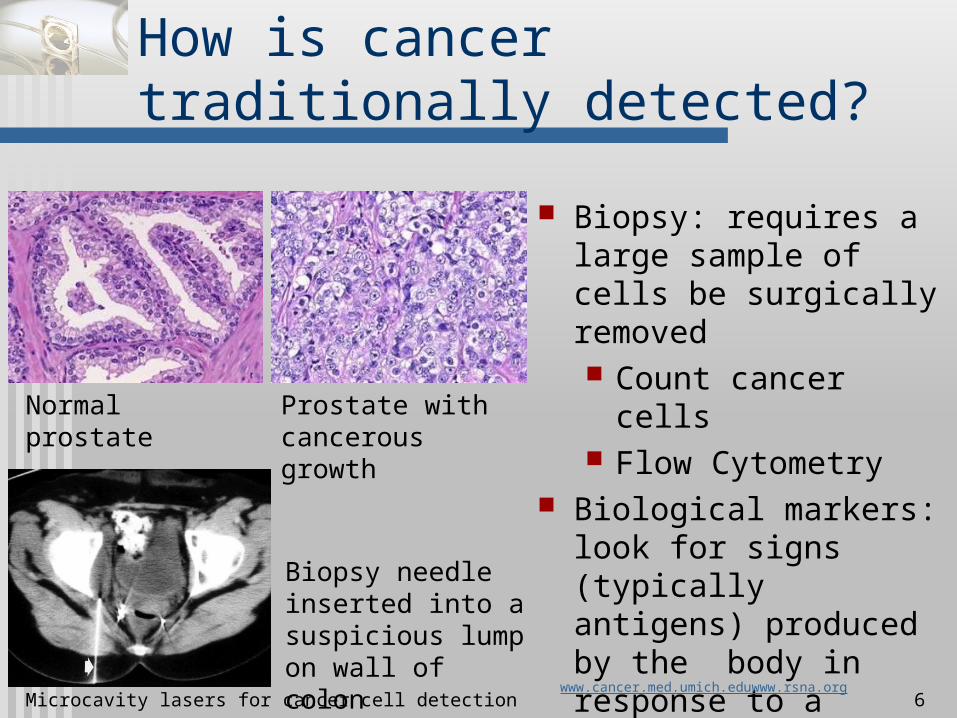
How is cancer traditionally detected?
Normal prostate Prostate with cancerous growth
Biopsy needle inserted into a suspicious lump on wall of colon
Biopsy: requires a large sample of cells be surgically removed Count cancer cells Flow Cytometry
Biological markers: look for signs (typically antigens) produced by the body in response to a specific cancer.
www.cancer.med.umich.eduwww.rsna.org

Microcavity lasers for cancer cell detection 7
How is cancer traditionally detected?
Flow-Cytometry Powerful research
tool capable of detection cancer.
Uses florescence, scattering, and transmission to analyze cells suspended in a laminar fluid flow.
http://www.cancer.umn.edu/page/docs/fcintro.pdfNASA, Cancer Detection Device, SpinOff (1998)
Bench top flow-cytometer
Schematic diagram of flow-cytometer

Microcavity lasers for cancer cell detection 8
Need for instantaneous classification of cells
No instantaneous method for determining if a cell is cancerous currently exist.
Surgeons can only guess how much material must be removed
Samples of removed material must be sent to a lab; the patient is already recovering by the time the results are returned
www.msnbc.com
Knowing how much to cut is especially important when removing delicate brain material.

Microcavity lasers for cancer cell detection 9
The Bio-Cavity Laser concept
Incorporates cells directly into the lasing process.
A micropump pushed cells through tiny channels in the active region of the device.
The active region is pumped by an external laser source
Data is collected and processed by a mini-spectrometer and computer.
www.sandia.gov. News Releases. March 23, 2000
Microcavity lasers for cancer cell detection 10
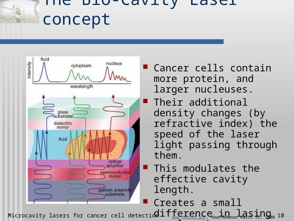
The Bio-Cavity Laser concept
Cancer cells contain more protein, and larger nucleuses.
Their additional density changes (by refractive index) the speed of the laser light passing through them.
This modulates the effective cavity length.
Creates a small difference in lasing wavelength
www.sandia.gov. News Releases. March 23, 2000

Microcavity lasers for cancer cell detection 11
Why MEMS?
Convenience User Patient
Cost Effective Integration with surgical tools Laser cavity needs to be on the
order of cell size

Microcavity lasers for cancer cell detection 12
Optically-pumped VCSEL
Vertical Cavity Surface Emitting Laser (VCSEL)
Theory overview Active layer Upper and lower
mirrors Channel or cavity
Upper mirror
Active layer
Lower mirror
AIR
Glass or semiconductor substrate
Channel region
Substrate material
VCSEL output
AIR
Input from pump laser

Microcavity lasers for cancer cell detection 13
Optical pumping
Frequency of emitted photon
• ν is frequency• ΔE is energy gap• h is Planck’s constant
Population Inversion More electrons in E2
than E1 Necessary for lasing
a b
dc
E1
E2
E3
E1
E2
E3
E1
E2
E3
E1
E2
E3
a b
dc
E1
E2
E3
E1
E2
E3
E1
E2
E3
E1
E2
E3
Adapted from Kasap
h
E

Microcavity lasers for cancer cell detection 14
Quantum wells
Active layer can be bulk GaAs or InGaAs, a single quantum well (SQW), or multiple quantum wells (MQW)
MQW increases efficiency
Active Layer Barrier LayerE(conduction band)
E(valence band)
Active Layer Barrier LayerE(conduction band)
E(valence band)
E
Adapted from Kasap
Microcavity lasers for cancer cell detection 15
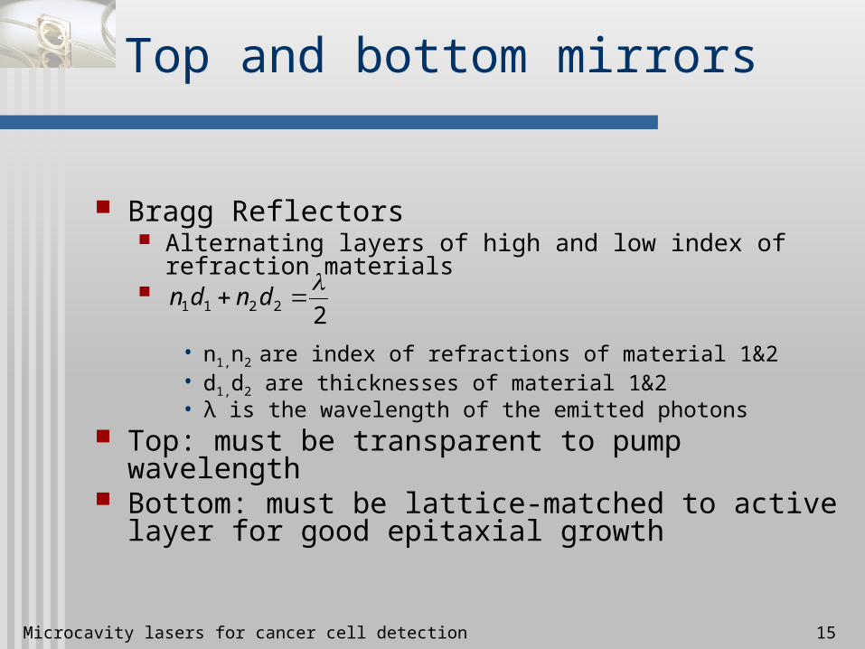
Top and bottom mirrors
Bragg Reflectors Alternating layers of high and low index of refraction
materials
• n1,n2 are index of refractions of material 1&2• d1,d2 are thicknesses of material 1&2• λ is the wavelength of the emitted photons
Top: must be transparent to pump wavelength Bottom: must be lattice-matched to active layer
for good epitaxial growth
22211
dndn
Microcavity lasers for cancer cell detection 16
Cavity length
Distance between top and bottom mirrors Includes thickness of active layer and cavity
L = ½nλ L is cavity length n is an integer λ is the output wavelength of the laser
Necessary for lasing, also alludes to output dependence on the body in the cavity

Microcavity lasers for cancer cell detection 17
Dependence on cell shape
Dielectric Sphere Case
• Δλ is wavelength shift• ξ geometrical factor of the
sphere, ≤1• n is refractive index• xln nth 0 of the lth Hankel
function• L is effective cavity length• p is longitudinal mode index• d is diameter of sphere From Meissner, et al.
d=6 μm (bottom), 10 μm (middle) and 22 μm (top)
d
pLxxn
2
00104

Microcavity lasers for cancer cell detection 18
Pump Laser
Photodetector Display
Spectrometer
Beam Splitter #1
Mirrors
Focusing Lens
Cavity
Analysis Region
System overview
Adapted from P.L. Gourley, U.S. Pat. #5793485
Beam Splitter #2
Microcavity lasers for cancer cell detection 19
Fabrication summary
MBE or MOCVD growth of laser gain medium (VCSEL).
Machining of substrate to obtain fluidic channels and laser microcavity.
Wafer bonding to glass and top Bragg reflector.

Microcavity lasers for cancer cell detection 20
Fabrication process
GaAs or InP Substrate
Paul L. Gourley, U.S. Patent No. 5793485 (1998).

Microcavity lasers for cancer cell detection 21
Fabrication process
Lower distributed Bragg mirror
AlAs/Al0.2Ga0.8As (28.5 periods)
Grown by MBE or MOCVD
Molecular beam epitaxy system

Microcavity lasers for cancer cell detection 22
Fabrication process
Laser Gain region
GaAs/InGaAs multiple quantum wells
Grown by MBE or MOCVD
Metal-organic chemical vapor deposition system
Microcavity lasers for cancer cell detection 23
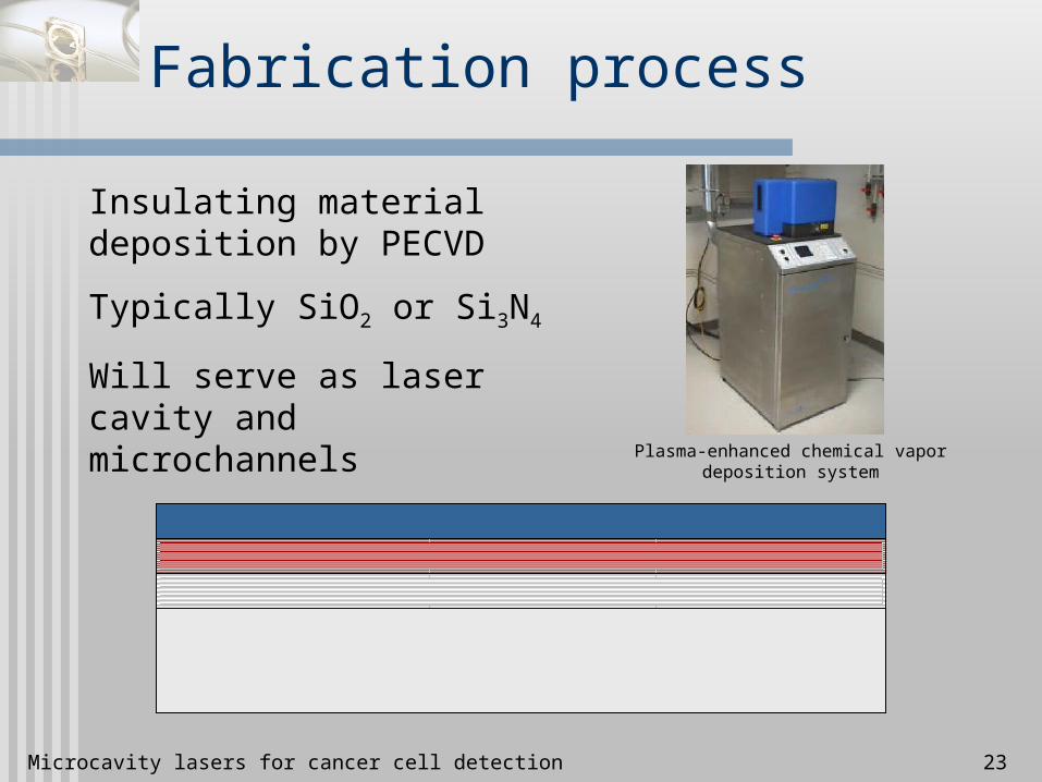
Fabrication process
Insulating material deposition by PECVD
Typically SiO2 or Si3N4
Will serve as laser cavity and microchannels
Plasma-enhanced chemical vapor deposition system
Microcavity lasers for cancer cell detection 24
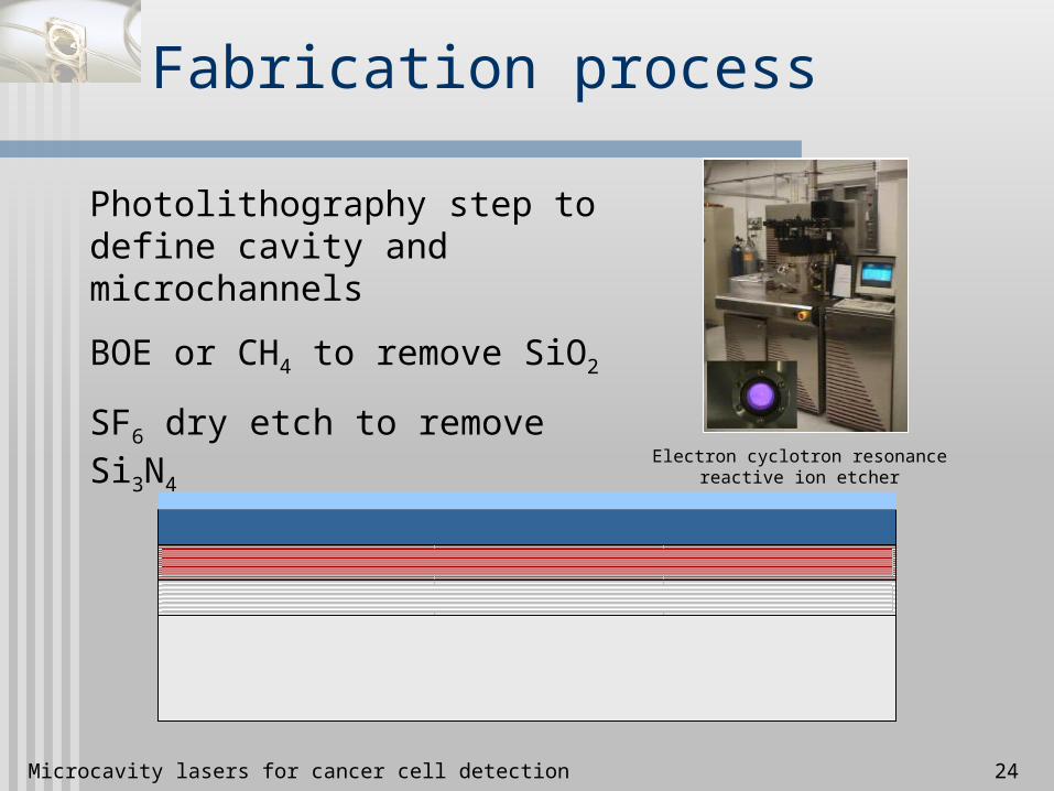
Fabrication process
Photolithography step to define cavity and microchannels
BOE or CH4 to remove SiO2
SF6 dry etch to remove Si3N4Electron cyclotron resonance reactive ion
etcher
Microcavity lasers for cancer cell detection 25
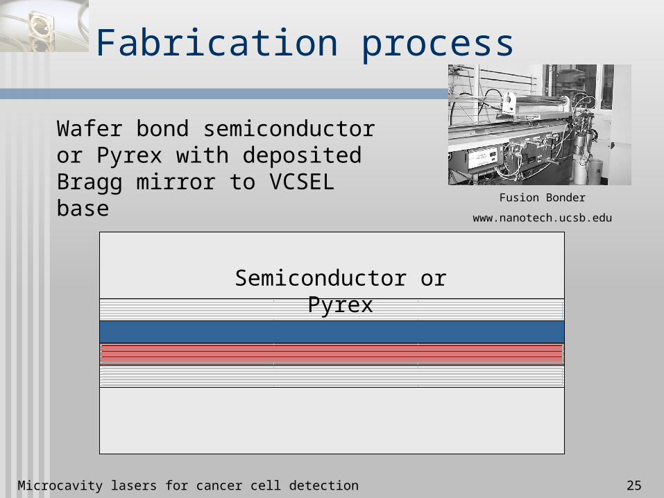
Fabrication process
Wafer bond semiconductor or Pyrex with deposited Bragg mirror to VCSEL base
Semiconductor or Pyrex
Fusion Bonder
www.nanotech.ucsb.edu

Microcavity lasers for cancer cell detection 26
Microcavity laser including microfluidic channels
Analysis Region
Flush Channel Processing Reservoir
Outlet Channel
Staging Area
Valves
Inlet Channel
Reagent Reservoir
Processing Reservoir
1 1
2 2
Adapted from P.L. Gourley, U.S. Pat. #5793485
Laser excitation pulse
Microcavity lasers for cancer cell detection 27
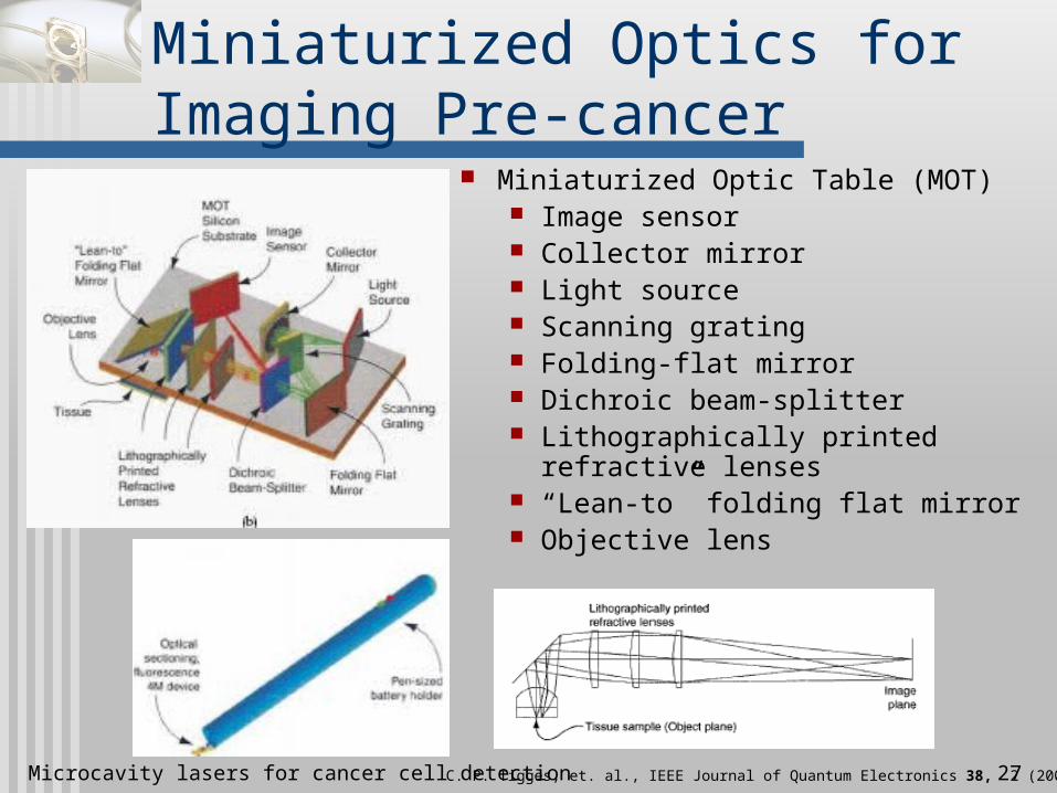
Miniaturized Optics for Imaging Pre-cancer
Miniaturized Optic Table (MOT) Image sensor Collector mirror Light source Scanning grating Folding-flat mirror Dichroic beam-splitter Lithographically printed
refractive lenses “Lean-to” folding flat mirror Objective lens
C. P. Tigges, et. al., IEEE Journal of Quantum Electronics 38, 2 (2002).

Microcavity lasers for cancer cell detection 28
Miniaturized Optical Table (MOT)
Note the silicon spring V-shaped channel Spring displacement Stress in normal direction 150m thick optical
element

Microcavity lasers for cancer cell detection 29
Miniaturized Microscope Objective
Schematic Microscope Objective MOT micromachined
substrate Note: lenses in slots

Microcavity lasers for cancer cell detection 30
Patterning of Optics: Binary Photomask
Lithographically patterned
Binary photomask Black White
Hybrid glass material 150 m thick glass
substrate Older element:
17.8m thick hybrid material
Recent element: 34m thick hybrid material

Microcavity lasers for cancer cell detection 31
Patterning of Optics: Greyscale Photomasks
Greyscale photomask Decreased
polymerization Lenslet array

Microcavity lasers for cancer cell detection 32
Future work
Need reliable methods of transporting fluids into and out of the semiconductor wafer.
Biocompatibility of MEMS and optical devices needs to be addressed.
Need to collaborate with real surgeons to demonstrate feasibility in real operating environment

Microcavity lasers for cancer cell detection 33
Bibliography
P.L. Gourley, J.D. Cox, J.K. Hendricks, A.E. McDonald G.C. Copeland, D.Y. Sasaki, M. Curry, and S.L. Skirboll, “Semiconductor Microcavity Laser Spectroscopy of Intracellular Protein in Human Cancer Cells” Proc. SPIE, 4265, 113-124 (2001).
T. French, P.L. Gourley, and A.E. McDonald, “Optical properties of fluids in microfabricated channels” Proc. SPIE, 2978, 123-128 (1997).
P.L. Gourley and A.E. McDonald, “Semiconductor microlasers with intracavity microfluidics for biomedical applications” Proc. SPIE, 2978, 186-196 (1997).
M.F. Gourley and P.L. Gourley, “Integration of Electro-Optical Mechanical Systems and Medicine: Where are we and Where can we go?” Proc. SPIE, 2978, 197-204 (1997).
Paul L. Gourley, “Resonant-cavity apparatus for cytometry or particle analysis” U.S. Patent No. 5793485, 36 pp. (1998).
American Cancer Society. Facts and Figures 2002 NASA, Cancer Detection Device, SpinOff (1998) (http://www.sti.nasa.gov/tto/index.html) S.O. Kasap, Optoelectronics and Photonics: Principles and Practices, Prentice Hall, Upper Saddle River, NJ, 2001 K. E. Meissner, P. L. Gourley, T. M. Brennan, B. E. Hammons, and A. E. McDonald, “Intracavity spectroscopy in vertical
cavity surface-emitting lasers for micro-optical-mechanical systems,” Applied Physics Letters, vol 69 (11), 9 Sept. 1996

Microcavity lasers for cancer cell detection 34
Thank you!
Any questions?