michael scalora u.s. army research, development, and engineering center
DESCRIPTION
OPTICS BY THE NUMBERS L’Ottica Attraverso i Numeri. Michael Scalora U.S. Army Research, Development, and Engineering Center Redstone Arsenal, Alabama, 35898-5000 & Universita' di Roma "La Sapienza" Dipartimento di Energetica. Rome, April-May 2004. - PowerPoint PPT PresentationTRANSCRIPT

Michael Scalora
U.S. Army Research, Development, and Engineering CenterRedstone Arsenal, Alabama, 35898-5000
&Universita' di Roma "La Sapienza"
Dipartimento di Energetica
OPTICS BY THE NUMBERS
L’Ottica Attraverso i Numeri
Rome, April-May 2004

SVEAT: The Slowly Varying Enevelope Approximation In Time, and The Ability To Inlcude Reflections To All Orders In The BPM Algorithm
From the SVEAT to a Vector BPM: Negative Refraction

2 2 2 2 22 2 2
2 2 2 2 2
22
2 2
( ) 2 ( )2 ( )
42 NL
E E n x E i n x EE ik k n x E
z z c t c t c
i Pc t t
22 22
2 2 2 2
4 nlPn EE
c t c t
( )( , , ) ( , , ) . .i kz tE z x t E z x t e c c

Assuming steady state conditions…
2 2 (3)202 0 0
0 0
( ) 4
in in
n x nE iE i E i E E
F n n
2 2 2 22
2 2 2 2
2 22 2 2
2 2 2
( ) 2 ( )2
4( ) 2 NL
E E n x E i n x EE ik
z z c t c t
k n x E i Pc c t t

2 202 0 0
0 0
0 0
0 0
( ) 4
4
/
NLin in
in
n x nE iE i E i P
F n n
nF Fresnel Number
z k nc
F s all
F
m
Wave front does not distort:Plane Wave propagation
Diffraction is very important

2 2 (3)202 0 0
0 0
( ) 4
in in
n x nE iE i E i E E
F n n
This equation is of the form:
Where:
EHE
2 2 (3)20 02 0
0 0
( ) 4
in in
n x ni i E V
n
iD
nFH
Using the split-step BPM algorithm
0
( ', ) '(0, )
/ 2(0, ) (0, ) / 2
( , ) (0, ) (0, )
(0, )D
H xH
V x x
x
V
E x e E x e E x
e e e E x

2 2 22
2 2 2
2 22 2
2 2
( , , )2
2 ( , , )( , , ) 0
E E n z x y EE ik
z z c t
i n z x y Ek n z x y E
c t c
2 22
2 2
( , , )0
n z x y EE
c t
( )( , , ) ( , , ) . .i kz tE z x t E z x t e c c

2 2 22
2 2 2
2 22 2
2 2
( , , )2
2 ( , , )( , , ) 0
E E n z x y EE ik
z z c t
i n z x y Ek n z x y E
c t c
Apply SVEAT, i.e., SVEA in time only:drop higher temporal derivatives. This assumption means that pulse duration must remain always much longer than the optical cycle at all times. In all kinds of problems, if a pulse is as long as the optical cycle it means trouble for
any approximation. So this is a very good approximation almost always.

2 2 22
2 2 2
2 22 2
2 2
( , , )2
2 ( , , )( , , ) 0
E E n z x y EE ik
z z c t
i n z x y Ek n z x y E
c t c
2 22
2 2
22 2
2
2 ( , , )2
( , , ) 0
E E i n z x y EE ik
z z c t
k n z x y Ec

2 22
2 2
22 2
2
2 ( , , )2
( , , ) 0
E E i n z x y EE ik
z z c t
k n z x y Ec
This equation is first order in time. This suggests writing equation in following form:
2 2 22 2 2
2 2 2
22
i n E E Ek n E E ik
c t c z z

2 2 22 2 2
2 2 2
22
i n E E Ek n E E ik
c t c z z
Now, adopting the usual kind of scaling:
0 0 0 0/ / / /z x x y y ct
2
2 2 202
0 0
14 4
in in
in
E i i E En i n E E
/k cAnd choosing

2
2 2 202
0 0
14 4
in in
in
E i i E En i n E E
This equation is of the form: 2 ( )E
n D V E HE
Which we can ALMOST easily recognized and compare to:
( )E
D V E HE

2
2 2 202
0 0
14 4
in in
in
E i i E En i n E E
N.B.: the differential operator includes ALL longitudinal and spatial derivatives, which means all boundary conditions are left Intact. Integrating this equation must is therefore equivalent to Including longitudinal and transverse reflections to all orders.
2
2 2 202
0 0
14 4
in in
in
E i i E En i n E E
2 ( )E
n D V E HE
2
1EHE
n
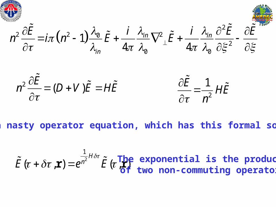
This is a nasty operator equation, which has this formal solution:
2
1
( , ) ( , )H
nE e E
r r The exponential is the product of two non-commuting operators

2
1EHE
n
Here is how I solve the problem:
Why is it important to include the index in the denominator?
EHE
Because that factor accounts for the correct group velocity.
2
1( , ) ( , ) ( , )E E HE
n r r r
2 2 2
1( , ) ( , ) ( ,
1( ( , ))
1, )E E
nE E
nnEH r r r r r
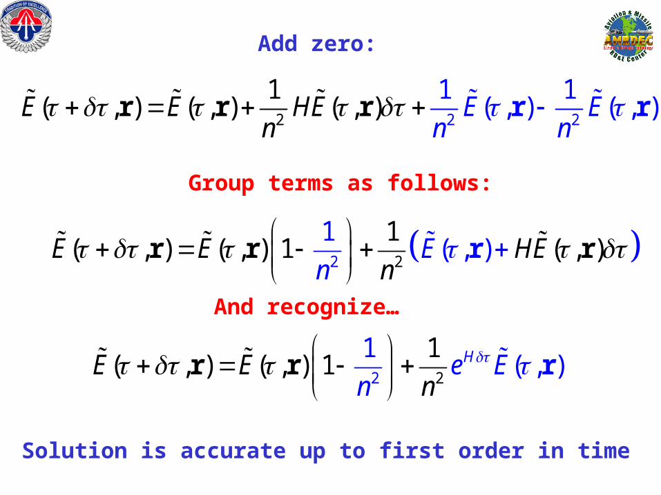
Add zero:
2 2
1( , ) ( , ) 1 , ) ( ,
1( )E
nE E HE
n
r r rr
Group terms as follows:
And recognize…
2 2
1( , )
1( , )( , ) 1 He E
nE E
n
r r r
Solution is accurate up to first order in time

Algorithm:
(1) ( , ) ( , )He EE rr
Which is solution of E
HE
2 2
1( , )
1( , )( , ) 1 He E
nE E
n
r r r
Then algbreically manipulate solution to find
Work very well in all cases except metals. Special considerations must be made in that case.

0
0.25
0.50
0.75
1.00
1.25
-150 -50 50 150
position (microns)
|E|2
n=1n=1.42

0
0.4
0.8
1.2
-150 -50 50 150
position (microns)
|E|2
n=1n=1.42
Red: without the 1/n2 factor in the operator

Example:Assume a PBG structure with cross sectional area as small as 1 mm2,
and a Thickness L~10 mirons. The volume is therefore of order V~10-11 m3. I will further assume that the structure is
not solidly anchored to the earth, i.e., it is free to move. The incident pulse can be tuned
anywhere in the pass band or band gap.The rate of momentum transfer depends on tuning.
mE,B
before

mE,B
after
Pm
E,B

BEc
g
4
1
The total momentum at time t is given by:
dztzBtzEc
tP ),(),(4
1)(
In terms of the Poynting vector dztzSc
tP
),(1
)(2
The momentum stored inside the object is the difference between the initial total momentum and the
instantaneous momentum stored in the field, namely:
dztzSc
tPtPpbg
),(1
)0()(2
dzzSc
tP
)0,(1
)0(2
momentum density

T~0
Tuned inside the gap...1

Ppbg
Pfield
P0
2P0
-P0
...Mirror like interaction
gr cm/sec
time (/c=0.33x10-14 sec.)
2

3Electromagnetic momentum as a function ot position
At different time shots

4At band edge resonance: pulse is almost completely transmitted
With some reflections.

0
1x10⁻⁶
2x10⁻⁶
3x10⁻⁶
0 1x10-12 2x10-12 3x10-12
t (sec.)
P(t) (gr cm/sec)
5
pbg
field

P(z,t)
z
6Electromagnetic momentum as a function ot positionAt different time shots

0
0.02
0.04
0.06
0.08
0.10
0 1x10-12
2x10-12
3x10-12
Time (sec.)
Velocity (cm/sec)
accelerationstage
decelerationstage
<a> ~ 1011 m/sec2

Input Pulse Plane Wave: means no diffraction, even though beam width is finite. I.e., each ray travels straight down.

10 20 30 40 50
EL\1
4
5
6
7
8
9E
L\2
0.1
0.2
0.3
0.4
0.6
0.7 0.8
0.9
Same as slide 1

The structure: Cross section of each column is nearly square.
Z (longitudinal)
x

In this case the square cross section does not cause ray bending due to simple refraction

10.00 18.75 27.50 36.25 45.00
EL\1
4
5
6
7
8
9
EL
\2
0.1
0.1 0.1
0.1
0.1
0.1
0.1
0.1 0.1
0.1
0.1
0.2
0.2
0.2 0.2
0.2
0.2
0.2
0.2
0.2
0.3
0.3
0.3
0.3 0.3
0.4 0.4
0.4
0.4
0.4 0.4
0.4 0.4
0.4
0.5
0.5
0.5
0.5 0.5
0.5
0.5
0.6
0.6
0.6 0.6
0.6
0.7
0.7
0.7
0.7
0.7
0.8 0.8
0.8
Same as slide 4.

The structure: Cross section of each column is nearly circular. The discretization causes slight imperfections, which can be improved byreducing the integration step. The diameters of each column is close to the /4 condition, but not sure.

Another view: 12 columns long, or ~ 4 microns.


11 13 15 17 19 21 23 25
EL\1
4
5
6
7
8
9E
L\2
0.1
0.2
0.2
0.3 0.4 0.5 0.6
0.7
0.7
0.8
Transmitted portion

10 20 30 40 50 60 70 80 90 100
longitudinal position (microns)
0.0
6.4
12.8
19.2
25.6
tran
sves
re p
osit
ion
(m
icro
ns)
0.1
0.1
0.1
0.1 0.1
0.1
0.1
0.1 0.1
0.1
0.1
0.1
0.1
0.1
0.3
0.3 0.3
0.3
0.3
0.3
0.3
0.3
0.3
0.3
0.3
0.3
0.3
0.4
0.4 0.4 0.4
0.4 0.4
0.4
0.4
0.4
0.4
0.4
0.6
0.6
0.6 0.6 0.6
0.6
0.6
0.6
0.6
0.6
0.6
0.7
0.7
0.7
0.7
0.7
0.7
0.7
0.7
0.7
0.7
0.7
0.7
0.9
0.9
0.9
0.9
0.9
0.9
0.9
0.9
0.9
0.9
1.0
1.0
1.0
1.0
1.0
1.0
1.0
1.0
1.1 1.1
1.1 1.1
1.3
1.3
1.4
1.4

10 20 30 40 50 60 70 80 90 100
EL\1
0.0
6.4
12.8
19.2
25.6
EL
\2
0.0 0.0
0.0
0.0
0.0 0.0
0.0
0.0
0.0
0.0
0.1
0.1
0.1
0.1
0.1
0.1
0.1
0.1
0.1
0.1
0.1
0.1
0.1
0.1
0.1
0.1
0.1
0.1
0.2
0.2
0.2
0.2
0.2
0.2
0.2
0.2
0.2
0.2 0.2
0.2
0.2
0.3
0.3
0.3
0.3
0.3
0.3
0.3
0.3
0.4
0.4
0.4
0.4
0.4
0.4
0.4
0.4
0.5
0.5
0.5
0.5
0.5
0.5
0.5
0.5
0.6
0.6
0.6
0.6
0.6
0.6
0.6
0.6
0.6
0.6
0.7
0.7
0.7
0.7
0.7
0.7
0.7
0.7
0.7
0.7
0.7
0.7
0.8
0.8
0.8
0.8 0.8 0
.8 0.8
0.9
0.9
0.9
0.9
1.0
1.0 1.0 1.0 1.1 1.1
1.1 1.1 1.2
1.2
1.2
0.1
0.2
0.3
0.4
0.6
0.7
0.8
0.9
Input


10 20 30 40 50 60 70 80 90 100
EL\1
1
3
5
7
9
11
13
EL
\2
0.0
0.0
0.0
0.0
0.0
0.1 0.1
0.1
0.1
0.1
0.1
0.1
0.1
0.1
0.1
0.1
0.1
0.1
0.2
0.2
0.2
0.2
0.3
0.3
0.3
0.3
0.3
0.3
0.4
0.4
0.4
0.4
0.4
0.4
0.5
0.5
0.5
0.5
0.5
0.5
0.5
0.6 0.6 0.6 0.7
0.0 0.1
0.1 0
.2 0.2 0
.2 0.3
0.3 0
.4 0.4 0
.5 0
.5 0
.5 0.6
0.6
0.7
0.7 0.7 0.8 0.8 0.9 0.9
1.0
Input Gaussian
Output
Output
Output

10 30 50 70 90 110 130 150 170 190
Longitudinal coordinate (in microns)
10
30
50
70
90
110
130
150
170
190
Tra
nsv
erse
Coo
rdin
ate
(in
mic
ron
s)
0.4
0.4
0.4
0.4 0.4
0.4
0.4
0.8
0.8
0.8
0.8
0.8
1.2
1.2
1.6
1.6
2.0
2.0
2.4
2.4
2.8
2.8
3.2
3.2
3.6
3.6 4.0 4.4 4.8 5.2 5.6
6.0 6.4 6.8 7.2
7.6 8.0 8.4 8.8 9.2
9.7 10.
1 1
0.5
10.
9 1
1.3
11.
7 1
2.1
12.
5 1
2.9
13.
3 1
3.7
14.
1 1
4.5
14.
9 1
5.3
15.
7 1
6.1
16.
5 1
6.9
17.
3 1
7.7
18.
1 1
8.5
18.
9 1
9.3
19.
7 2
0.1
20.
5 2
0.9
21.
3 2
1.7
22.1
22.
5 2
2.9
23.
3 2
3.7
24.
1 2
4.5
24.
9 2
5.3
25.
7 2
6.1
26.
5 2
6.9
27.
3 27.7 28.2 28.6 29.0 29.4 29.8
30.2 30.6
31.0 31.4 31.8 32.2 32.6 33.0 33.4 33.8 34.2 34.6
35.0 35.4 35.8 36.2 36.6 37.0 37.4 37.8 38.2 38.6 39.0 39.4
39.8 40.2 40.6 41.0 41.4 41.8 42.2 42.6 43.0 43
.4 4
3.8
44.
2
44.
6 4
5.0
45.
4 4
5.8
46.
2 4
6.7
47.
1 4
7.5
47.
9 4
8.3
n=2 - i 0.02gain
air
Reflections appear to be suppressed

10 30 50 70 90 110 130 150 170 190
Longitudinal coordinate (in microns)
10
30
50
70
90
110
130
150
170
190T
ran
sver
se C
oord
inat
e (i
n m
icro
ns)
0.1
0.1
0.1
0.1
0.1
0.1 0
.1
0.1 0.1
0.1 0.1
0.2
0.2
0.2 0.2
0.2
0.2 0
.2 0
.2
0.3
0.3
0.3
0.3 0.3
0.3
0.3
0.3
0.4
0.4
0.4
0.4
0.4
0.4
0.4
0.4
0.5
0.5
0.5
0.5
0.5
0.5
0.5
0.5
0.6 0.6
0.6
0.6
0.6
0.6
0.6
0.6
0.7
0.7
0.7
0.7
0.7
0.7
0.8
0.8
0.8
0.8
0.8
0.9
0.9
0.9
0.9
0.9
1.0
1.0
1.1
1.1
1.2
1.2
1.3
1.3
1.4
1.4
1.5
1.5
1.6
1.6
1.7
1.7
1.8
1.8
1.9
1.9
2.0
2.0
2.1
2.1
2.2
2.2
2.3
2.3
2.4 2.5
2.6 2.7
2.8
2.9
3.0
3.0
3.1 3.2
3.3 3.4
3.5 3.6 3.7
3.8 3
.9 4
.0 4
.1 4
.2 4.3
4.4
4.5 4.6
4.7 4.8
4.9
5.0 5.1 5.2 5.3
5.4
5.5 5.6 5.7 5.8 5.9
6.0 6.1 6.2 6.3 6.4 6.5 6.6 6.7 6.8 6.9 7.0 7.1 7.2 7.3 7.4 7
.5 7
.6
7.7
7.8
7.9
8.0
8.1
8.2
n=2 - i 0.01gain
air

10 30 50 70 90 110 130 150 170 190
Longitudinal coordinate (in microns)
10
30
50
70
90
110
130
150
170
190T
rans
vers
e C
oord
inat
e (i
n m
icro
ns)
n=2air

10 30 50 70 90 110 130 150 170 190
Longitudinal coordinate (in microns)
10
30
50
70
90
110
130
150
170
190T
ran
sver
se C
oord
inat
e (i
n m
icro
ns)
n=2 + i 0.01
loss
air

10 30 50 70 90 110 130 150 170 190
Longitudinal coordinate (in microns)
10
30
50
70
90
110
130
150
170
190T
ran
sver
se C
oord
inat
e (i
n m
icro
ns)
0.0
0.0
0.0
0.0
0.0
0.0 0.0
0.0
0.0
0.0
0.0
0.0
0.0
0.0
0.0
0.0
0.0
0.0
0.0
0.0
0.1
0.1
0.1
0.1 0.1
0.1 0.1
0.1
0.1
0.1
0.1
0.1
0.1 0.1
0.1
0.1
0.1 0
.1
0.1
0.1
0.1
0.1
0.1
0.1
0.1
0.1
0.1
0.1
0.1
0.1
0.1
0.1
0.1
0.1
0.1 0.1
0.1
0.1
0.1
0.1
0.1
0.1
0.1
0.1
0.1
0.2
0.2
0.2
0.2
0.2
0.2
0.2
0.2
0.2
0.2
0.2
0.2 0.2
0.2 0.2
0.2
0.2
0.2
0.2
0.2 0.2
0.2
0.2
0.2
0.2 0.2 0.2 0
.2
0.2
0.2
0.2
0.2
0.2
0.2
0.2
0.2
0.2
0.2
0.2
0.3
0.3
0.3
0.3
0.3
0.3
0.3
0.3
0.3
0.3
0.3
0.3
0.3
0.3 0.3
0.3
0.3
0.3
0.3
0.3
0.3
0.3
0.3
0.3
0.3
0.3
0.4
0.4
0.4 0.4 0.4
0.4
0.4
0.4
0.4
0.4
0.4
0.4
0.4
0.4
0.4
0.4
0.4
0.4
0.4 0.4
0.4
0.4
0.4
0.4 0.4
0.5
0.5
0.5
0.5
0.5
0.5
0.5
0.5
0.5
0.5
0.5
0.5
0.5
0.5
0.5
0.5
0.5
0.5
0.5
0.5
0.5 0.5 0.5
0.5
0.5
0.5
0.5
0.5
0.6
0.6
0.6
0.6
0.6
0.6 0.6
0.6
0.6
0.6
0.6 0.6
0.6
0.6 0
.6
0.6
0.6
0.6
0.6
0.6
0.6
0.6
0.6
0.6
0.6
0.6
0.7
0.7 0.7
0.7
0.7
0.7
0.7
0.7
0.7
0.7
0.7
0.7
0.7
0.7
0.7
0.7
0.7
0.7
0.7
0.8
0.8
0.8
0.8
0.8
0.8
0.8
0.8
0.8
0.8
0.8
0.8
0.8
0.8
0.8
0.8
0.8
0.8
0.9
0.9
0.9
0.9
0.9
0.9
0.9
0.9
n=2 + i 0.02
loss
air

10 30 50 70 90 110 130 150 170 190
EL\1
10
30
50
70
90
110
130
150
170
190
EL
\2
n=2+i0.01
n=2
n=2-i0.01
The symbols and the lines indicate the location and direction of motion of
the baricenter of the wave packet.

10 20 30 40 50
Longitudinal coordinate (in microns)
10
20
30
40
50T
ran
sver
se C
oo
rdin
ate
(in
mic
ron
s)
0.0
0.0
0.0
0.1
0.1 0.1
0.1
0.2
0.7
air
air
62 nm of Ag

1
( / )
c t
c t
BE
EB
A discontinuity in gives a fundamental problem:An infinite derivative for sudden chnages in
However, the H field is continuous across interfaces, just as E is continuous. Symmetrize
The equations of motion.
c t
c t
HE
EH

yx z
y x
xz
HE H
c t y z
H E
c t zEH
c t y
( )
( ) ( )
( ( , , ) . )
( ( , , ) . ) ( ( , , ) . )
z y
z y z y
i k z k y tx
i k z k y t i k z k y ty z
E y z t e c c
H y z t e c c H y z t e c c
E i
H j k
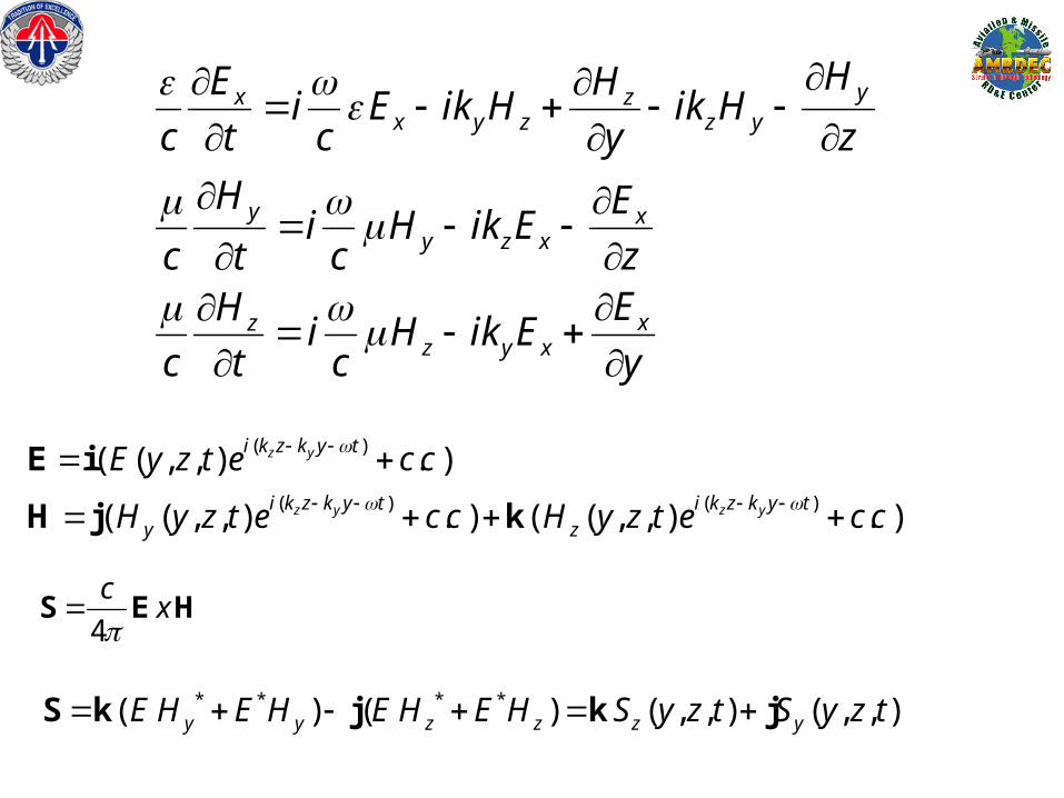
yx zx y z z y
y xy z x
xzz y x
HE Hi E ik H ik H
c t c y z
H Ei H ik E
c t c zEH
i H ik Ec t c y
4
cx
S E H
( )
( ) ( )
( ( , , ) . )
( ( , , ) . ) ( ( , , ) . )
z y
z y z y
i k z k y t
i k z k y t i k z k y ty z
E y z t e c c
H y z t e c c H y z t e c c
E i
H j k
* * * *( ) ( ) ( , , ) ( , , )y y z z z yE H E H E H E H S y z t S y z t S k j k j

( ) ( , , )
( ) ( , , )
yz
z z
z y
yz
y y
z y
P t S y z t dy dz and
P t S y z t dy dz
* * * *( ) ( ) ( , , ) ( , , )y y z z z yE H E H E H E H S y z t S y z t S k j k j

Ex
E points into the paper
H lays on the y-z plane, and so it has components along z and y.
Input field is a gaussian in y and z, incident at 45 degrees
H
kz
y interface
1
2
Hy
Hz
E=Ex i
H=Hy j + Hz k
c t
c t
HE
EH

10 30 50 70 90 110 130 150 170 190
Longitudinal coordinate (in microns)
10
30
50
70
90
110
130
150
170
190T
rans
vers
e C
oord
inat
e (i
n m
icro
ns)
n=2 (=4)air
WAVE-FRONTIncident angle=45 degreesRefraction angle ~20.7 degrees
normal refractionat a dielectricinterface
Red dashed line indicates the major axis of the ellipse. It iscompressed in the direction ofpropagation due to packet slowingdown in that direction to a velocityof c/n

10 20 30 40 50
EL\1
10
20
30
40
50
EL
\2
0.0
0.0
0.1
0.1
0.1
0.1
0.2
0.2
0.3 0.4 0.4
Pulse is incident on a Silver half-space.
= -8.98 + i 0.78=1
For =~500nm
This corresponds to an index
n = 0.13 + i 3
Sy
Sz
S
Sy
Sz
S

-0.05
-0.03
-0.01
0.01
0 10 20 30 40 50
Pplus
z(t)
Py
plus(t)
time (/c)
mom
enta
propagation from air into metal substrate = -8.98 +i0.78=1For =~500nm
The maximum refraction angle into the metalIs ~78 degrees at the time indicated, i.e., near peak.
Test 1
Sy
Sz
S

-75
-25
25
75
0 10 20 30 40 50
Pminus
z(t)
Py
minus(t)
time (/c)
mom
enta
propagation from air into metal substrate
This are the momenta as a function of time in the incidence half-space. The reflection causes the z-component (red) to change sign. With both components negative and nearly equal, it corresponds to a reflection angle of 45 degree. There is some absorption, and so each component is not conserved.
Sy
Sz
S

450
trasmessoS
riflessoS
incidenteS
450
Riassumendo:
i
~79-800
argento, con incidentea ~ 500nm

5.00 13.75 22.50 31.25 40.00
EL1\1
15
25
35
EL1
\2
0.1
0.1
0.1
0.1 0.1
0.1
0.1
0.2
0.2
0.2
0.2 0.2 0
.2
0.2
0.3
0.3
0.3
0.3
0.3 0.3
0.3
0.4
0.4
0.4
0.4
0.4 0
.4
0.4
0.6
0.6
0.6
0.6
0.6
0.6
0.6
0.7
0.7
0.7
0.7 0.7
0.7
0.7
0.8
0.8
0.8
0.8 0.8
0.8
0.9
0.9
0.9
0.9
0.9
=1
S0z
S0y
S0z
S0y
S
S
The ellipse seems to be oriented correctly, but propagation occurs in the “wrong” direction.
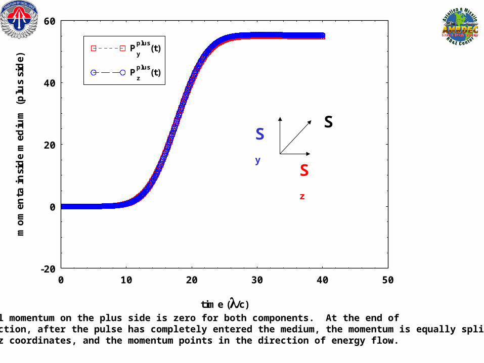
-20
0
20
40
60
0 10 20 30 40 50
Pplus
y(t)
Pz
plus(t)
time (/c)
mom
enta
insi
de
med
ium
(p
lus
sid
e)
The initial momentum on the plus side is zero for both components. At the end of the interaction, after the pulse has completely entered the medium, the momentum is equally split betweenThe x and z coordinates, and the momentum points in the direction of energy flow.
Sy
Sz
S

450
trasmessoS
riflessoS
incidenteS
450
Riassumendo:
450
Quindi anche in questo caso, dove il momento y non e’ conservato (dovrebbe esserlo se l’assorbimento e’ zero)trovo in ogni caso che il vettore di Poynting punta nella direzione di propagazione.
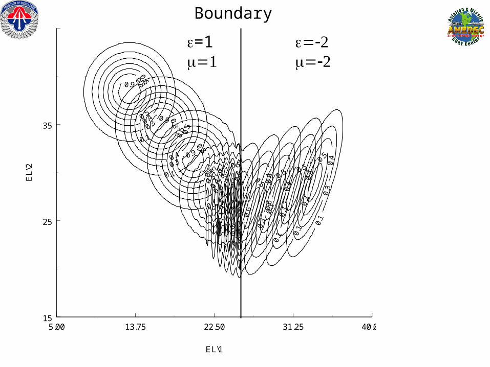
5.00 13.75 22.50 31.25 40.00
EL\1
15
25
35
EL\
2
0.1
0.1
0.1
0.1
0.1
0.1 0
.1
0.1
0.3
0.3
0.3
0.3
0.3
0.3
0.3
0.3
0.4
0.4
0.4
0.4
0.4
0.4
0.4
0.4
0.5
0.5
0.5
0.5
0.5
0.5 0.5 0
.5
0.6
0.6
0.6
0.6
0.6 0
.6
0.8
0.8
0.8
0.8
0.9
0.9
0.9
=1
Boundary

CONCLUSIONS:I AM WILLING TO
BELIEVE
ANYTHING!
(with a grain of salt, of course)