michael l. dyer pe executive engineer. electrical component movement component
TRANSCRIPT

Michael L. Dyer PEExecutive Engineer

Electrical component
Movement component
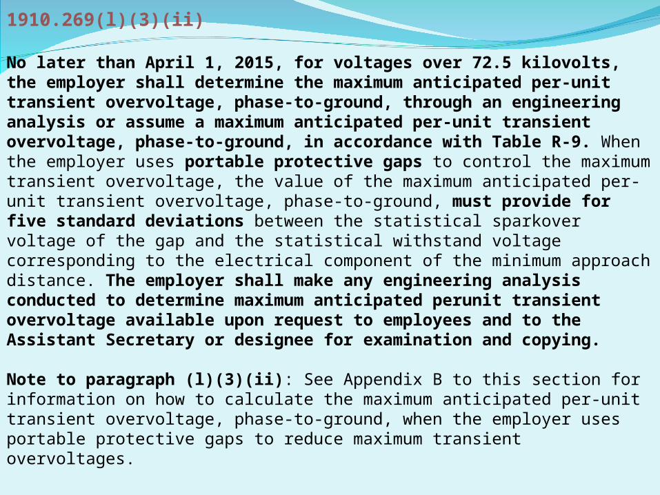
1910.269(l)(3)(ii)
No later than April 1, 2015, for voltages over 72.5 kilovolts, the employer shall determine the maximum anticipated per-unit transient overvoltage, phase-to-ground, through an engineering analysis or assume a maximum anticipated per-unit transient overvoltage, phase-to-ground, in accordance with Table R-9. When the employer uses portable protective gaps to control the maximum transient overvoltage, the value of the maximum anticipated per-unit transient overvoltage, phase-to-ground, must provide for five standard deviations between the statistical sparkover voltage of the gap and the statistical withstand voltage corresponding to the electrical component of the minimum approach distance. The employer shall make any engineering analysis conducted to determine maximum anticipated perunit transient overvoltage available upon request to employees and to the Assistant Secretary or designee for examination and copying.
Note to paragraph (l)(3)(ii): See Appendix B to this section for information on how to calculate the maximum anticipated per-unit transient overvoltage, phase-to-ground, when the employer uses portable protective gaps to reduce maximum transient overvoltages.

Appendix B to §1910.269 -- Working on Exposed Energized Parts
The information in this appendix will assist employers in complying with the minimum approach-distance requirements contained in § 1910.269(l)(3) and (q)(3). Employers must use the technical criteria and methodology presented in this appendix in establishing minimum approach distances in accordance with § 1910.269(l)(3)(i) and Table R-3 and Table R-8 (DC). This appendix provides essential background information and technical criteria for the calculation of the required minimum approach distances for live-line work on electric power generation, transmission, and distribution installations.
Unless an employer is using the maximum transient overvoltages specified in Table R-9 for voltages over 72.5 kilovolts, the employer must use persons knowledgeable in the techniques discussed in this appendix, and competent in the field of electric transmission and distribution system design, to determine the maximum transient overvoltage

TABLE R-3-AC LIVE-LINE WORK MINIMUM APPROACH DISTANCE[The minimum approach distance (MAD; in meters) shall conform to the following equations.]
For phase-to-phase system voltages of 50 V to 300 V: 1
MAD = avoid contact
For phase-to-phase system voltages of 301 V to 5 kV: 1
MAD = M + D, whereD = 0.02 m .......................................................................................M = 0.31 m for voltages up to 750 V and 0.61 m otherwise ...............
the electrical component of the minimum approach distance.the inadvertent movement factor.
For phase-to-phase system voltages of 5.1 kV to 72.5 kV: 1 4
MAD = M + AD, whereM = 0.61 m ......................................................................................................A = the applicable value from Table R-5 .......................................................D = the value from Table R-4 corresponding to the voltage and exposure or the value of the electrical component of the minimum approach distance calculated using the method provided in Appendix B to this section.
the inadvertent movement factor.the altitude correction factor.the electrical component of the minimum approach distance.
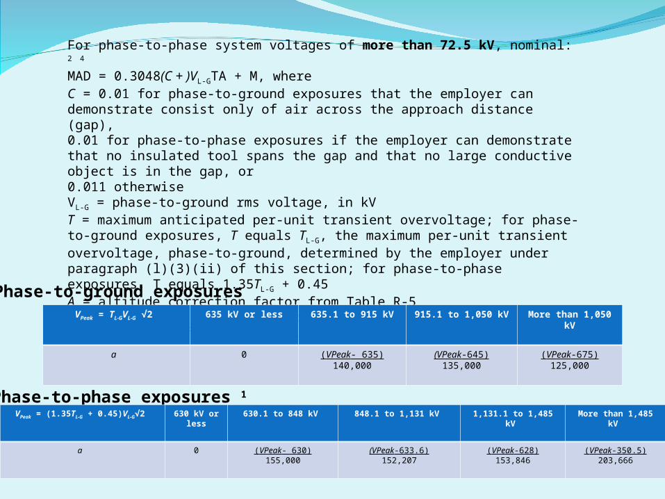
For phase-to-phase system voltages of more than 72.5 kV, nominal: 2 4
MAD = 0.3048(C + )VL-GTA + M, whereC = 0.01 for phase-to-ground exposures that the employer can demonstrate consist only of air across the approach distance (gap),0.01 for phase-to-phase exposures if the employer can demonstrate that no insulated tool spans the gap and that no large conductive object is in the gap, or0.011 otherwiseVL-G = phase-to-ground rms voltage, in kVT = maximum anticipated per-unit transient overvoltage; for phase-to-ground exposures, T equals TL-G, the maximum per-unit transient overvoltage, phase-to-ground, determined by the employer under paragraph (l)(3)(ii) of this section; for phase-to-phase exposures, T equals 1.35TL-G + 0.45A = altitude correction factor from Table R-5M = 0.31 m, the inadvertent movement factora = saturation factor, as follows:
VPeak = TL-GVL-G √2 635 kV or less 635.1 to 915 kV 915.1 to 1,050 kV More than 1,050 kV
a 0 (VPeak- 635)140,000
(VPeak-645)135,000
(VPeak-675)125,000
Phase-to-ground exposures
Phase-to-phase exposures 1
VPeak = (1.35TL-G + 0.45)VL-G√2 630 kV or less
630.1 to 848 kV 848.1 to 1,131 kV 1,131.1 to 1,485 kV More than 1,485 kV
a 0 (VPeak- 630)155,000
(VPeak-633.6)152,207
(VPeak-628)153,846
(VPeak-350.5)203,666

C. Exposed energized parts over 300 volts AC. Paragraph (l)(3)(i) of § 1910.269 requires the employer to establish minimum approach distances no less than the distances computed by Table R-3 for ac systems so that employees can work safely without risk of sparkover.2
Unless the employee is using electrical protective equipment, air is the insulating medium between the employee and energized parts. The distance between the employee and an energized part must be sufficient for the air to withstand the maximum transient overvoltage that can reach the worksite under the working conditions and practices the employee is using. This distance is the minimum air insulation distance, and it is equal to the electrical component of the minimum approach distance.Normal system design may provide or include a means (such as lightning arrestors) to control maximum anticipated transient overvoltages, or the employer may use temporary devices (portable protective gaps) or measures (such as preventing automatic circuit breaker reclosing) to achieve the same result.

Paragraph (l)(3)(ii) of § 1910.269 requires the employer to determine the maximum anticipated per-unit transient overvoltage, phase-to-ground, through an engineering analysis or assume a maximum anticipated per-unit transient overvoltage, phase-to-ground, in accordance with Table R-9, which specifies the following maximums for ac systems: 2012 NESC & IEEE 516 values (2017)72.6 to 420.0 kilovolts-3.5 per unit 72.6 – 362kV 3.0 (3.5)420.1 to 550.0 kilovolts-3.0 per unit 362.1 – 550kV 2.4 (3.0)550.1 to 800.0 kilovolts-2.5 per unit 550.1 – 800kV 2.0 (2.5)

D. Types of exposures. Employees working on or near energized electric power generation, transmission, and distribution systems face two kinds of exposures: Phase-to-ground and phase-to-phase. The exposure is phase-to-ground: (1) With respect to an energized part, when the employee is at ground potential or (2) with respect to ground, when an employee is at the potential of the energized part during live-line barehand work. The exposure is phase-to-phase, with respect to an energized part, when an employee is at the potential of another energized part (at a different potential) during live-line barehand work.

III. Determination of Minimum Approach Distances for AC Voltages Greater Than 300 VoltsA.Voltages of 301 to 5,000 volts. … an assumed minimum air insulation distance of 20 millimeters (1 inch) will protect against sparkover at voltages of 301 to 5,000 volts. Thus, 20 millimeters (1 inch) is the electrical component of the minimum approach distance for these voltages.
B. Voltages of 5.1 to 72.5 kilovolts. …the Occupational Safety and Health Administration bases the methodology for calculating the electrical component of the minimum approach distance on Institute of Electrical and Electronic Engineers (IEEE) Standard 4-1995, Standard Techniques for High-Voltage Testing.
Table 1Sparkover Distance Rod-to-Rod Gap
60 Hz.(kV
peak)
Gap Spacing
(cm)
25 2
36 3
46 4
53 5
60 6
60 Hz.(kV
peak)
Gap Spacing
(cm)
70 8
79 10
86 12
95 14
104 16
60 Hz.(kV
peak)
Gap Spacing
(cm)
112 18
120 20
143 25
167 30
192 35
60 Hz.(kV
peak)
Gap Spacing
(cm)
218 40
243 45
270 50
322 60
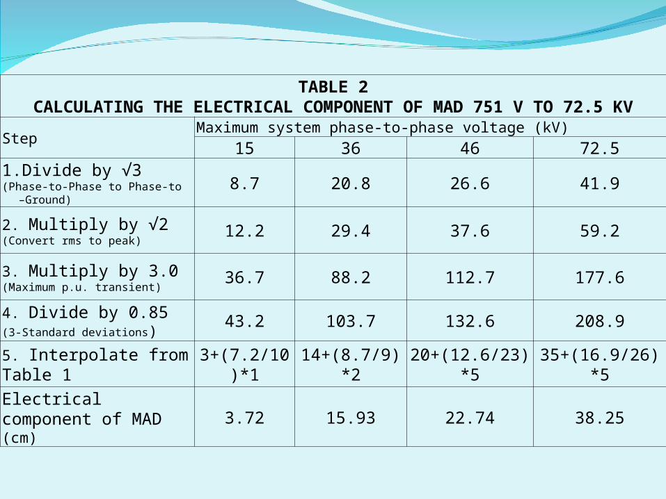
TABLE 2CALCULATING THE ELECTRICAL COMPONENT OF MAD 751 V TO 72.5 KV
StepMaximum system phase-to-phase voltage (kV)
15 36 46 72.5
1. Divide by √3 (Phase-to-Phase to Phase-to –Ground)
8.7 20.8 26.6 41.9
2. Multiply by √2(Convert rms to peak)
12.2 29.4 37.6 59.2
3. Multiply by 3.0(Maximum p.u. transient)
36.7 88.2 112.7 177.6
4. Divide by 0.85(3-Standard deviations)
43.2 103.7 132.6 208.9
5. Interpolate from Table 1
3+(7.2/10)*1 14+(8.7/9)*2 20+(12.6/23)*5 35+(16.9/26)*5
Electrical component of MAD (cm)
3.72 15.93 22.74 38.25

C. Voltages of 72.6 to 800 kilovolts. For voltages of 72.6 kilovolts to 800 kilovolts, this section bases the electrical component of minimum approach distances, before the application of any altitude correction factor, on the following formula:Equation 1-For Voltages of 72.6 kV to 800 kVD = 0.3048(C + a) VL-GTWhere:D = Electrical component of the minimum approach distance in air in meters;C = a correction factor associated with the variation of gap sparkover with voltage;a = A factor relating to the saturation of air at system voltages of 345 kilovolts or higher; 4
VL-G = Maximum system line-to-ground rms voltage in kilovolts-it should be the "actual" maximum, or the normal highest voltage for the range (for example, 10 percent above the nominal voltage); andT = Maximum transient overvoltage factor in per unit.In Equation 1, C is 0.01: (1) For phase-to-ground exposures that the employer can demonstrate consist only of air across the approach distance (gap) and (2) for phase-to-phase exposures if the employer can demonstrate that no insulated tool spans the gap and that no large conductive object is in the gap. Otherwise, C is 0.011.In Equation 1, the term a varies depending on whether the employee's exposure is phase-to-ground or phase-to-phase and on whether objects are in the gap. The employer must use the equations in Table 3 to calculate a. Sparkover test data with insulation spanning the gap form the basis for the equations for phase-to-ground exposures, and sparkover test data with only air in the gap form the basis for the equations for phase-to-phase exposures. The phase-to-ground equations result in slightly higher values of a, and, consequently, produce larger minimum approach distances, than the phase-to-phase equations for the same value of VPeak.
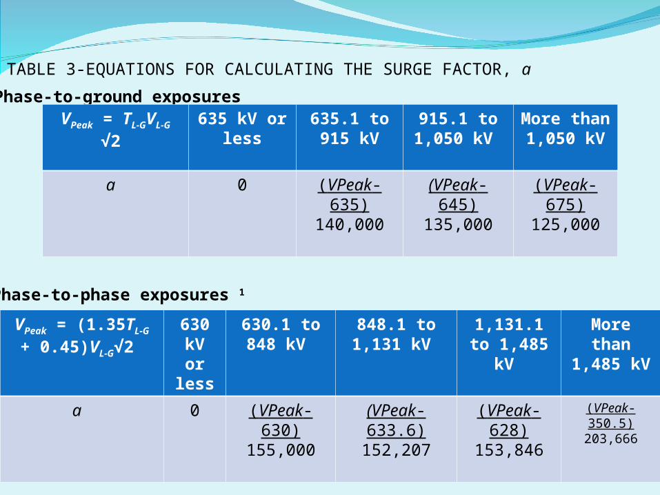
TABLE 3-EQUATIONS FOR CALCULATING THE SURGE FACTOR, a
Phase-to-ground exposuresVPeak = TL-GVL-G
√2 635 kV or
less635.1 to 915 kV
915.1 to 1,050 kV
More than
1,050 kV
a 0 (VPeak- 635)
140,000
(VPeak-645)
135,000
(VPeak-675)
125,000
Phase-to-phase exposures 1
VPeak = (1.35TL-G + 0.45)VL-G√2
630 kV or
less
630.1 to 848 kV
848.1 to 1,131 kV
1,131.1 to 1,485
kV
More than
1,485 kV
a 0 (VPeak- 630)
155,000
(VPeak-633.6)
152,207
(VPeak-628)
153,846
(VPeak-350.5)
203,666

1 Use the equations for phase-to-ground exposures (with VPeak for phase-to-phase exposures) unless the employer can demonstrate that no insulated tool spans the gap and that no large conductive object is in the gap.In Equation 1, T is the maximum transient overvoltage factor in per unit. As noted earlier, § 1910.269(l)(3)(ii) requires the employer to determine the maximum anticipated per-unit transient overvoltage, phase-to-ground, through an engineering analysis or assume a maximum anticipated per-unit transient overvoltage, phase-to-ground, in accordance with Table R-9. For phase-to-ground exposures, the employer uses this value, called TL-
G, as T in Equation 1. IEEE Std 516-2009 provides the following formula to calculate the phase-to-phase maximum transient overvoltage, TL-L, from TL-G:TL-L = 1.35TL-G + 0.45For phase-to-phase exposures, the employer uses this value as T in Equation 1.

Note: The employer must add this distance to the electrical component of the minimum approach distance to obtain the full minimum approach distance.
Voltage range (kV) Distance
m. ft.
0.301 to 0.750 0.31 1.0
0.751 to 72.5 0.61 2.0
72.6 to 800 0.31 1.0
TABLE 4-ERGONOMIC COMPONENT OF MINIMUM APPROACH DISTANCE
CauseMagnitude (per unit)
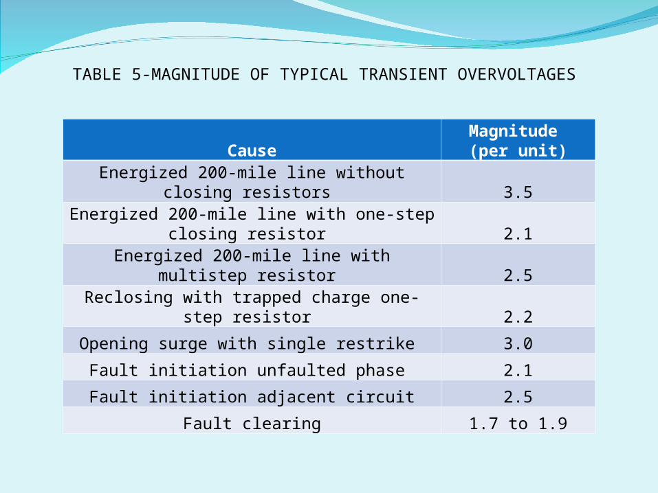
Energized 200-mile line without closing resistors 3.5
Energized 200-mile line with one-step closing resistor 2.1
Energized 200-mile line with multistep resistor 2.5
Reclosing with trapped charge one-step resistor 2.2
Opening surge with single restrike 3.0Fault initiation unfaulted phase 2.1Fault initiation adjacent circuit 2.5
Fault clearing 1.7 to 1.9
TABLE 5-MAGNITUDE OF TYPICAL TRANSIENT OVERVOLTAGES

Standard deviation-air-gap withstand. For each air gap length under the same atmospheric conditions, there is a statistical variation in the breakdown voltage. The probability of breakdown against voltage has a normal (Gaussian) distribution. The standard deviation of this distribution varies with the wave shape, gap geometry, and atmospheric conditions. The withstand voltage of the air gap is three standard deviations (3s) below the critical sparkover voltage. (The critical sparkover voltage is the crest value of the impulse wave that, under specified conditions, causes sparkover 50 percent of the time. An impulse wave of three standard deviations below this value, that is, the withstand voltage, has a probability of sparkover of approximately 1 in 1,000.)
Time-dependent Schrödinger equation (single non-relativistic particle)
Don’t look too close or the wave function will collapse
And the cat in the box will be dead
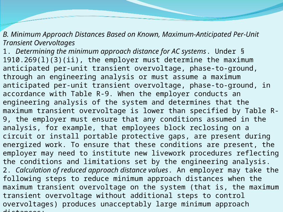
B. Minimum Approach Distances Based on Known, Maximum-Anticipated Per-Unit Transient Overvoltages1. Determining the minimum approach distance for AC systems. Under § 1910.269(l)(3)(ii), the employer must determine the maximum anticipated per-unit transient overvoltage, phase-to-ground, through an engineering analysis or must assume a maximum anticipated per-unit transient overvoltage, phase-to-ground, in accordance with Table R-9. When the employer conducts an engineering analysis of the system and determines that the maximum transient overvoltage is lower than specified by Table R-9, the employer must ensure that any conditions assumed in the analysis, for example, that employees block reclosing on a circuit or install portable protective gaps, are present during energized work. To ensure that these conditions are present, the employer may need to institute new livework procedures reflecting the conditions and limitations set by the engineering analysis.2. Calculation of reduced approach distance values. An employer may take the following steps to reduce minimum approach distances when the maximum transient overvoltage on the system (that is, the maximum transient overvoltage without additional steps to control overvoltages) produces unacceptably large minimum approach distances:
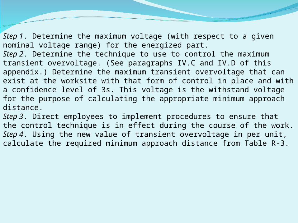
Step 1. Determine the maximum voltage (with respect to a given nominal voltage range) for the energized part.Step 2. Determine the technique to use to control the maximum transient overvoltage. (See paragraphs IV.C and IV.D of this appendix.) Determine the maximum transient overvoltage that can exist at the worksite with that form of control in place and with a confidence level of 3s. This voltage is the withstand voltage for the purpose of calculating the appropriate minimum approach distance.Step 3. Direct employees to implement procedures to ensure that the control technique is in effect during the course of the work.Step 4. Using the new value of transient overvoltage in per unit, calculate the required minimum approach distance from Table R-3.

C. Methods of Controlling Possible Transient Overvoltage Stress Found on a System1. Introduction. There are several means of controlling overvoltages that occur on transmission systems. For example, the employer can modify the operation of circuit breakers or other switching devices to reduce switching transient overvoltages. Alternatively, the employer can hold the overvoltage to an acceptable level by installing surge arresters or portable protective gaps on the system. In addition, the employer can change the transmission system to minimize the effect of switching operations. Section 4.8 of IEEE Std 516-2009 describes various ways of controlling, and thereby reducing, maximum transient overvoltages.
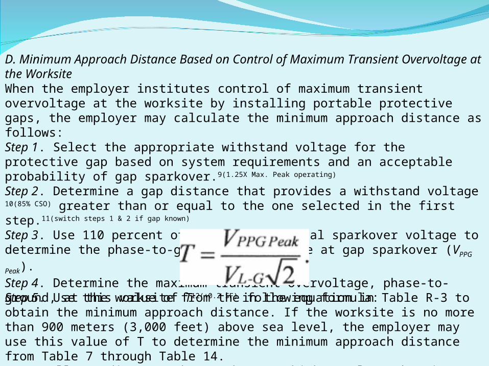
D. Minimum Approach Distance Based on Control of Maximum Transient Overvoltage at the WorksiteWhen the employer institutes control of maximum transient overvoltage at the worksite by installing portable protective gaps, the employer may calculate the minimum approach distance as follows:Step 1. Select the appropriate withstand voltage for the protective gap based on system requirements and an acceptable probability of gap sparkover.9(1.25X Max. Peak operating) Step 2. Determine a gap distance that provides a withstand voltage 10(85% CSO) greater than or equal to the one selected in the first step.11(switch steps 1 & 2 if gap known)
Step 3. Use 110 percent of the gap's critical sparkover voltage to determine the phase-to-ground peak voltage at gap sparkover (VPPG Peak).Step 4. Determine the maximum transient overvoltage, phase-to-ground, at the worksite from the following formula:
Step 5. Use this value of T12(+0.2 SF) in the equation in Table R-3 to obtain the minimum approach distance. If the worksite is no more than 900 meters (3,000 feet) above sea level, the employer may use this value of T to determine the minimum approach distance from Table 7 through Table 14.Note: All rounding must be to the next higher value (that is, always round up).

Sample protective gap calculations.Problem: Employees are to perform work on a 500-kilovolt transmission line at sea level that is subject to transient overvoltages of 2.4 p.u. The maximum operating voltage of the line is 550 kilovolts. Determine the length of the protective gap that will provide the minimum practical safe approach distance. Also, determine what that minimum approach distance isStep 1. Calculate the smallest practical maximum transient overvoltage (1.25 times the crest phase-to-ground voltage): 13
This value equals the withstand voltage of the protective gap.

Step 2. Using test data for a particular protective gap, select a gap that has a critical sparkover voltage greater than or equal to:561kV ÷ 0.85 = 660kVFor example, if a protective gap with a 1.22-m (4.0-foot) spacing tested to a critical sparkover voltage of 665 kilovolts (crest), select this gap spacing.Step 3. The phase-to-ground peak voltage at gap sparkover (VPPG Peak) is 110 percent of the value from the previous step:665kV × 1.10 = 732kVThis value corresponds to the withstand voltage of the electrical component of the minimum approach distance.
Step 4. Use this voltage to determine the worksite value of T:
Step 5. Use this value of T in the equation in Table R-3 to obtain the minimum approach distance, or look up the minimum approach distance in Table 7 through Table 14:MAD = 2.29m (7.6 ft).

Voltage range phase
to phase (kV)
Phase-to-ground exposure
Phase-to-phase exposure
m ft m ft
0.05 to 1.0 Avoid Contact
1.1 to 15.0 0.64 2.10 0.66 2.20
15.1 to 36.0 0.72 2.30 0.77 2.60
36.1 to 46.0 0.77 2.60 0.85 2.80
46.1 to 72.5 0.90 3.00 1.05 3.50
72.6 to 121 0.95 3.20 1.29 4.30
138 to 145 1.09 3.60 1.50 4.90
161 to 169 1.22 4.00 1.71 5.70
230 to 242 1.59 5.30 2.27 7.50
345 to 362 2.59 8.50 3.80 12.50
500 to 550 3.42 11.30 5.50 18.10
765 to 800 4.53 14.90 7.91 26.00
TABLE 6-MINIMUM APPROACH DISTANCES UNTIL MARCH 31, 2015

Voltage range phase
to phase (kV)
Phase-to-ground
exposurePhase-to-phase
exposure
m ft m ft
0.05 to 0.30 Avoid Contact
0.301 to 0.750 0.33 1.09 0.33 1.09
0.751 to 5.0 0.63 2.07 0.63 2.07
5.1 to 15.0 0.65 2.14 0.68 2.24
15.1 to 36.0 0.77 2.53 0.89 2.92
36.1 to 46.0 0.84 2.76 0.98 3.22
46.1 to 72.5 1.00 3.29 1.20 3.94
TABLE R-6 Alternate MINIMUM APPROACH DISTANCE V<=72.5kV

TABLE 14-AC MINIMUM APPROACH DISTANCES-72.6 TO 121.0 KV
Transient Overvoltag
e Factor
Phase-to-ground
exposure
Phase-to-phase exposure
m ft m ft
TABLE 15-AC MINIMUM APPROACH DISTANCES-121.1 TO 145.0 KV
3.5 1.30 (1.09)
4.3 (3.6)1.64 (1.5)
5.4 (4.9)TABLE 16-AC MINIMUM APPROACH DISTANCES-145.1 TO 169.0 KV
3.5 1.46 (1.22)
4.8 (4)1.94
(1.71)6.4 (5.7)
TABLE 17-AC MINIMUM APPROACH DISTANCES-169.1 TO 242.0 KV
3.5 2.01 (1.59)
6.6 (5.3)3.08
(2.27)10.1 (7.5)
3.5 3.41 (2.59)
11.2 (8.5)
5.52 (3.8)
18.1 (12.5)
TABLE 18-AC MINIMUM APPROACH DISTANCES-242.1 TO 362.0 KV
3.5 1.13(0.95)
3.7 (3.2)
1.42 (1.29)
4.7 (4.3)

TABLE 19-AC MINIMUM APPROACH DISTANCES-362.1 TO 420.0 KV
TABLE 20-AC MINIMUM APPROACH DISTANCES-420.1 TO 550.0 KV
TABLE 21-AC MINIMUM APPROACH DISTANCES-550.1 TO 800.0 KV
3.5 4.25 13.9 6.81 22.3
Transient Overvoltag
e Factor
Phase-to-ground
exposure
Phase-to-phase exposure
m ft m ft
3.0 5.07 (3.42)
16.6 (11.3)
8.24 (5.5)
27.0 (18.1)
2.5 6.88 (4.53)
22.6 (14.9)
11.38 (7.91)
37.3 (26)


4.8.2.1 Portable protective air gaps (PPAGs)A PPAG can be employed to provide worker protection by establishing a controlled sparkover path that iscoordinated with the sparkover voltage of the MAD. Recognizing that the protective gap at the worksitemay operate, these gaps are generally installed at an adjacent structure. Figure 3 shows a typical PPAGbeing installed.
