metroshingle - watson metalswatsonmetalsllc.com/docs/metro/shingle/bl_shingle_030909.pdf ·...
TRANSCRIPT

Installation DetailsMetroSHINGLE™
Indicates critical areas of installationMetroSHINGLE™ Installation Details 1©Copyright, all rights reserved, Metro Roof Products 2009
rev 03/09/09
These install details are provided to demonstrate the recommended installation method for Metro Roof products and accessories
The Details and information in this document reflect current roofing practices used in the United States. Consult with Metro Roof Products for additional information
Issued December 29, 2005 Revised March 9th 2009

Installation DetailsMetroSHINGLE™
Indicates critical areas of installationMetroSHINGLE™ Installation Details 2©Copyright, all rights reserved, Metro Roof Products 2009
rev 03/09/09
INTRODUCTION
Installation Tools:• Metro Installation Kit
- 1-Cutter, 1-Foot Bender - 1-Full Panel Bender attachment - 2-Batten Spacers
• Metro SMART-Hand Tool Kit - 12-V Impact Driver - Red & Green Snips - 3” Hand Seamers
- Safety Gloves & Safety Glasses
Other Tools:• Nail Gun• Hammer• Tape Measure• Caulking Gun• Sting-Line
General:These installation details are designed to be used in conjunction with Metro’s SMART-Start On-Site Installer Training Program. A certificate of completion is awarded to those installers who are considered to have satisfactorily completed the Metro SMART-Start On-Site Training Program for each Metro profile.
Metro Batten-Less install methods ensure the simplest application. Starting with perimeter metal flashings & valleys, then followed by field panels installed from the Fascia to the Ridge. The next step is to measure, cut & bend panels to fit the areas around the perimeter of the field panels at Rakes, Ridges, Hips & Valleys. The final step is to install the Trim Caps and a final quality control check of the job.
In cold climate zones with Cathedral Ceilings a Counter-Battten and Batten grid system is suggested to help prevent Ice-Damming.
SMART-Steps to a perfect install:1. Perimeter Flashing & Valley Metal2. Full-Field Panels3. Rake cut sections4. Hip & Valley cut & sections5. Ridge cut & bent sections6. Pipe, Chimney / Skylight flashing7. Trim Caps8. Overall quality control job check

Installation DetailsMetroSHINGLE™
Indicates critical areas of installationMetroSHINGLE™ Installation Details 3©Copyright, all rights reserved, Metro Roof Products 2009
rev 03/09/09
Colored areosol paints should never be used on stone-coated panels & accessories.
CONCEALED Fastened:MetroSHINGLE™ is the only profile that is designed as a CONCEALED fastened system. It incorporates a fastening flange along the entire panel length that receives the fasteners and the panel above then interlocks with the ‘Pittsburgh-lock” female section of the panel beneath to form a weather tight barrier to the weather and conceal the fasteners. The dimensions of this panel are:
Overall Length Range: 52” (1283mm) Overall Depth: 9-¾” (248mm)Side-Lap: 3” (75mm)Front Downturn Nose: 3/8” (9.52mm)Back Up stand: 3/8” (9.52mm)Back Horizontal Flange: 3/4” (20mm)
Materials:Metro panels are produced from Aluminum-zinc alloy coated steel complying with ASTM A792.
Packing and Storage:A pallet of Metro panels contains approximately 20 squares. Care should be taken to store panels under a weather-proof cover or inside in an area free from moisture.
Fasteners:All fasteners (Nails or Screws) used on a Metro roof for panels, trim caps and accessory items shall meet or exceed the corrosion resistant standard as defined in ASTM B-117, (1,000-hr minimum Salt Spray Corrosion Resistance).
For HVHZ (High Velocity Hurricane Zone) areas refer to local code requirements and /or Metro website (www.metroroofs.com) for details.
Sealant/CaulkingOnly exterior grade urethane or (non-acidic) caulking should be used for sealant.
Testing:Metro panels have been tested in accordance with local, national & international building codes. Testing has been conducted to evaluate fire, wind, penetration, water infiltration, and durability resistance. Information regarding specific tests and approvals can be obtained from Metro Roof Products.
Ventilation:Ensure proper attic ventilation as prescribed per local codes. Either Smart Vents or Ridge venting can be installed to achieve adequate ventilation.
Warranty:Metro panels carry a limited warranty for fifty years. This limited warranty is transferable and does not cover damage due to improper handling or installation.
Dissimilar Metals:To avoid adverse corrosion effects caused by dissimilar metals, COPPER and LEAD flashings should not be used with Metro roof
products and accessories. (refer to Metro SMARTbrief #02004)
Finish coatingMinor scuffing of Metro panels can be repaired with a Touch-Up kit from Metro Roof Products. Use the Touch-Up kit Metro basecoat (not caulking). Unfinished flashing materials can be painted with durable acrylic aerosol paints. Colored aerosol paints should never be sprayed on panels or accessories made by Metro Roof Products.
Roofing feltUnless local conditions require otherwise, either one layer of type 30, or two layers of Type 15 lb. roofing felt or equal should be used with Metro panels.
Side-lap
Fastening Flange
Back-interlock
Nose-interlock

Installation DetailsMetroSHINGLE™
Indicates critical areas of installationMetroSHINGLE™ Installation Details 4©Copyright, all rights reserved, Metro Roof Products 2009
rev 03/09/09
MetroSHINGLE™52” x 10.5” - 3.6 lbs.
METRO STONE COATED METALS
Flat-Stock52” x 18” - 5.5 lbs.
Shingle Trim Cap10.5” X 6” - .57 lbs.
Valley Center Cover79” X 4” - 3.5 lbs
Shingle Rake Channel79” X 3.5” - 3 lbs.
Shingle Fascia Starter120” X 1.5” - 2.5 lbs.
Valley Center Cover79” X 5” - 3.5 lbs
Side-Wall Under-pan metal120” x 4” - 5 lbs.
2”
2-1/2”
FL Drip Edge79” X 2” X 3-1/4” 3.3lbs.
Tile Rake Metal79” X 2” X 2” X 1-3/4” - 3.5lbs.
3.5” Fascia Metal79” X 2” X 3-1/2” 3.3lbs.
5” Fascia Metal79” X 3/4” X 5” 5lbs.

Installation DetailsMetroSHINGLE™
Indicates critical areas of installationMetroSHINGLE™ Installation Details 5©Copyright, all rights reserved, Metro Roof Products 2009
rev 03/09/09
METRO STONE COATED METALS
SMART-jack18” x 18” x 4.5” - 1lbs.Fits 1” - 3” Dia., pipes.
SMART-Sleeve Universal Pipe CoverFits pipes 3/4” to 4” in Dia., Avail-able as a single unit or in 6-Pack boxes.
MetroSHINGLE™ SMARTvent59” x 22” x 2” - 12.5 lbs.Net Free Vent Area: 90 in²
METRO PAINTED ACCESSORIES
18” Double ‘V’ Valley Metal120” x 18” x 2” - 12.5 lbs.
Chimney Saddle60” x 16” - 6.75 lbs.
Side-Wall Under-pan metal120” x 4” - 5 lbs.
Drip Edge120” X 2” X 1-1/2” - 1.0lbs.
1-3/8” Z-Bar 79” X 2” X 3-1/4” - 3.3lbs.

Installation DetailsMetroSHINGLE™
Indicates critical areas of installationMetroSHINGLE™ Installation Details 6©Copyright, all rights reserved, Metro Roof Products 2009
rev 03/09/09
UNDERLAYMENT
STARTER STRIP
DRIP-EDGE
Notch
MetroSHINGLES™ are installed on new or existing roofs pitched from at least 3:12 and above. Installation begins with roofi ng edge metals installed as shown, followed by the installation of roofi ng felt being conven-tionally applied. Ice-& Water shield underlay should be installed per local code and product application instructions in areas where icing may occur. For re-roofi ng applications, the existing shingles are to be cut back fl ush with the perimeter of the roof. Consult local codes for other specifi c requirements.
Install starter metal under the felt paper. Fasten using ring shank roofi ng nails spaced 12” apart. For high wind areas contact Metro.
Install Drip-edge metal along all rakes under the felt paper. This can be either painted or stone-coated fi nish.
Notch the Drip-edge to close the gap created by the starter strip.

Installation DetailsMetroSHINGLE™
Indicates critical areas of installationMetroSHINGLE™ Installation Details 7©Copyright, all rights reserved, Metro Roof Products 2009
rev 03/09/09
RAKE METAL
Align rake metal flushwith starter strip lip
Install Rake Metal over Drip-edge metal using roof-ing nails placed in outside channel as shown. Rake Metal is notched to lap at joints leaving a minimum 2” overlap in water channels.
Lap 2” minimum to prevent leakage through seams.
DOUBLE ‘V’ VALLEY METAL
Install 18” Double ‘V’ Valley metal overlapping a min. of 4”. Attach valleys as shown below..
If fastening through the valley metal as shown, fasteners must have a rubber washer covered by metal cap to ensure sealing around the fastener location.
Installation DetailsMetroSHINGLE™
Indicates critical areas of installationMetroSHINGLE™ Installation Details 8©Copyright, all rights reserved, Metro Roof Products 2009
rev 03/09/09
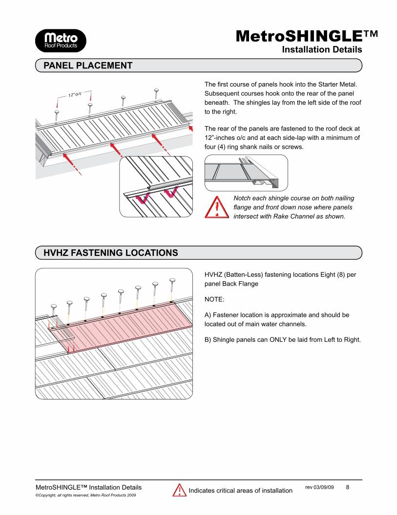
PANEL PLACEMENT
The fi rst course of panels hook into the Starter Metal. Subsequent courses hook onto the rear of the panel beneath. The shingles lay from the left side of the roof to the right.
The rear of the panels are fastened to the roof deck at 12”-inches o/c and at each side-lap with a minimum of four (4) ring shank nails or screws.
Notch each shingle course on both nailing fl ange and front down nose where panels intersect with Rake Channel as shown.
HVHZ FASTENING LOCATIONS
HVHZ (Batten-Less) fastening locations Eight (8) per panel Back Flange
NOTE:
A) Fastener location is approximate and should be located out of main water channels.
B) Shingle panels can ONLY be laid from Left to Right.

Installation DetailsMetroSHINGLE™
Indicates critical areas of installationMetroSHINGLE™ Installation Details 9©Copyright, all rights reserved, Metro Roof Products 2009
rev 03/09/09
PANEL LAYOUT
After laying the fi rst course, subsequent rows are stag-gered to off-set side-laps and prevent stack-bonding lay-out. A stagger key pattern can be created by using off-cuts from one end of the fi rst row on the next row up the roof. Randomly stagger subsequent rows of panels. At valley junctions, mark and cut panels from the center of the valley.
VALLEY PANELS
VALLEY CUT PANELSpanels are installed with either a closed or open valley detail.
CLOSED VALLEYMark & cut the valley angle on the panel at the center-line.
OPEN VALLEYMark & cut the valley panel at one of the outer valley-ribs to create an open valley. If this option is used the valley cut section edge must be folded down 3/8” (9.52mm) to form a hem at the valley shingle edge.

Installation DetailsMetroSHINGLE™
Indicates critical areas of installationMetroSHINGLE™ Installation Details 10©Copyright, all rights reserved, Metro Roof Products 2009
rev 03/09/09
MITER , NOTCH & FOLD
Valley shingle cut sections are turned down 90 de-grees 1/4”-1/2” (6-12mm) into the valley pan.
All MetroSHINGLE™ panels intersecting the valley, shall be notched at both the top (Nail-ing Flange) and the bottom (Nose Interlock)
of each panel to prevent capillary action across the panel underside. Failure to follow this step my result in leaks around the valley.
OPEN valleys (min-6-inches) between each side of the Metro panels are recommended for areas where trees or other debris may block
the valley. This detail facilitates easier periodic clean-ing of the valley pans.
VALLEY COVER
Fasten the valley cover with corrosion resistant stitch screws at alternating courses through the valley cover into the panels.
Valley Cover fasteners only penetrate the MetroSHINGLE™ panel and NOT the valley metal.

Installation DetailsMetroSHINGLE™
Indicates critical areas of installationMetroSHINGLE™ Installation Details 11©Copyright, all rights reserved, Metro Roof Products 2009
rev 03/09/09
FLASHING CHIMNEY OR SIMILAR SQUARE OBJECTS
Measure, cut & fold up the panels across the front of the item being fl ashed.
Install down each side of item being fl ashed a section of the Side-Wall Under-pan metal up under existing counter-fl ashing or install new Z-Bar fl ashing over over side-wall under-pan .
Install the panels after notching the back nailing fl ange & nose where they intersect the side-wall under-pan fl ashing on both sides of the item being fl ashed.
Side-Wall Under-pan Method shown.

Installation DetailsMetroSHINGLE™
Indicates critical areas of installationMetroSHINGLE™ Installation Details 12©Copyright, all rights reserved, Metro Roof Products 2009
rev 03/09/09
At the rear of the item being fl ashed install Chimney Saddle metal after hemming the sides and folding the corners where it protrudes (Min 3” (75mm) past the item being fl ashed.
Trim and fold as necessary to ensure water-tight fi nsh is achieved and seal around corners and alogn back.
Along the back of the Chimney Saddle install a “Metro Short Course Cleat” aligned with the last full course behind the item being fl ashed. This cleat will form the ‘hook’ section for the nose of the panel course above the item being fl ashed.
CHIMNEY SADDLE PREPARATION
CHIMNEY SADDLE INSTALLATION

Installation DetailsMetroSHINGLE™
Indicates critical areas of installationMetroSHINGLE™ Installation Details 13©Copyright, all rights reserved, Metro Roof Products 2009
rev 03/09/09
SHORT COURSE
The Metro Short Course Cleat is used to re-create the back nailing (Hook) fl ange for the Shingle panel above.
Install Cleat in a bed of sealant and secure with stitch screws.
Insert the next full panel above and secure as normal.
HIP & RIDGE PANELS
HIP & RIDGE CUT PANELSAt Hips and Ridges the panels are marked along the center line of the Hip or Ridge and cut 1"-inch past this line to create lapping of the panel at the Hip or Ridge center.
SEALING HIP & RIDGE PANELSApply a self adhering butyl type sealant tape (Max width of 4") down the Hip and across the Ridge.

Installation DetailsMetroSHINGLE™
Indicates critical areas of installationMetroSHINGLE™ Installation Details 14©Copyright, all rights reserved, Metro Roof Products 2009
rev 03/09/09
SMARTVENT
Engage MetroSHINGLE™ SMART-Vent over hole cut into decking to match the vent’s opening,
Install 2 courses of shingle panels over the vent base.
Side-Hem the edges of the MetroSHINGLE(TM) SMART-Vent base.
Install Short Course Cleat along the 3rd course line ontop of the vent base. Seal with caulking where nes-sessary.
Install panels across the back of the vent base lock-ing the front fl ange into the Short Course Cleat as you would a panel.

Installation DetailsMetroSHINGLE™
Indicates critical areas of installationMetroSHINGLE™ Installation Details 15©Copyright, all rights reserved, Metro Roof Products 2009
rev 03/09/09
ROOF PENETRATIONS
New fl ashing jacks are installed at the roof penetrations. Panels are neatly cut around protrusions as required and installed over fl ashings.
Cut lower panel to fi t the vent. Slide the vent fl ashing into place.
Use ‘Stitch’ screws to secure the fl ashing to the sur-face of the Shingle panel, making sure the fasteners are located on the high ribs of the panel.

Installation DetailsMetroSHINGLE™
Indicates critical areas of installationMetroSHINGLE™ Installation Details 16©Copyright, all rights reserved, Metro Roof Products 2009
rev 03/09/09
Fasten the end trim cap at the corners. Install the rest of the trim caps towards the top. Fasten trim caps with ring shank nails or two screws placed on either side of the nailing flange.
Cut off back attachment flange and fold over the two remaining flaps so that it resembles the front of the cap.
Place and fasten the middle trim to enable the trimcaps to face outward towards the rake end.
Cut, fold and attach as shown,
INSTALLING TRIM CAPS
Cut off the corners leaving 2-3” evenly between the two sides.
Fold the ramaining 2-3” to form a flap which engages on the starter strip.