methods of extrusion on demand for high solids...
TRANSCRIPT

METHODS OF EXTRUSION ON DEMAND FOR HIGH SOLIDS LOADING CERAMIC
PASTE IN FREEFORM EXTRUSION FABRICATION
Wenbin Li, Amir Ghazanfari, Ming C. Leu, and Robert G. Landers
Mechanical and Aerospace Engineering Department
Missouri University of Science and Technology, Rolla, MO, USA
Abstract
Fabrication of highly dense parts with complex geometry by paste-extrusion-based solid
freeform fabrication processes requires a precise control of the extrusion flow rate to dispense
material on demand, which is often referred as Extrusion-On-Demand (EOD). The extrusion
process for aqueous ceramic pastes is complex and difficult to control due to their non-Newtonian
behavior, compressibility and inhomogeneity. In this study, three methods of EOD (based on ram
extruder, needle valve, and auger valve) are introduced and investigated for the extrusion of high
solids loading (i.e., >50%, volumetric) aqueous alumina paste. Optimal extrusion process
parameters for these methods are determined through printing tests and analysis. The extrusion
performance in terms of extrusion start and stop accuracy, as well as flow rate consistency, is
compared and analyzed for the three methods. Advantages and disadvantages of these three
methods are also discussed.
Introduction
The freeform extrusion fabrication process deposits ceramic paste layer by layer through
extrusion. The details regarding the principle of the process, equipment setup and material
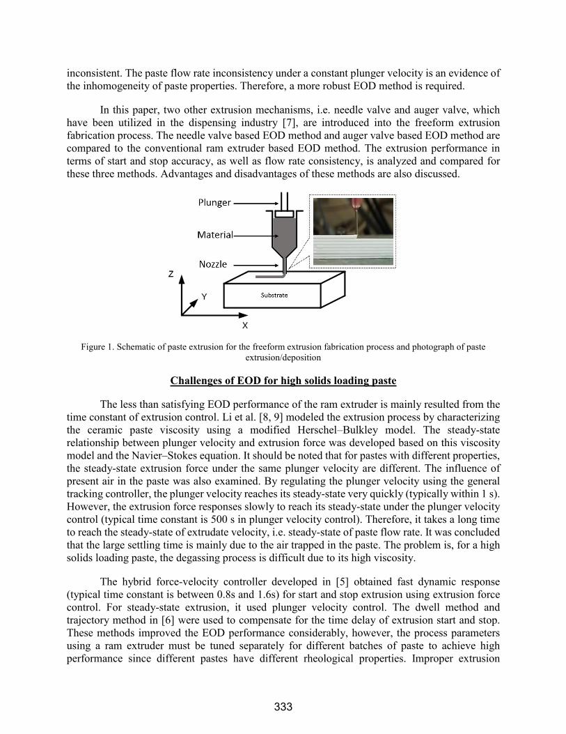
properties can be found in [1-3]. A schematic of the extrusion fabrication system along with a
photograph of the paste extrusion is shown in Figure 1. Paste-extrusion-based solid freeform
fabrication requires a precise control of the extrusion flow rate to fabricate highly dense parts with
complex geometry. The conventional mechanism of paste extrusion for the freeform extrusion
fabrication process is ram extruder, which consists of a syringe and a plunger. Based on the ram
extruder, several methods regulating the extrusion force and plunger velocity were developed.
Zhao et al. [4] designed an adaptive controller with a general tracking control law and implemented
it to regulate the extrusion force. Deuser et al. [5] developed a hybrid force-velocity controller to
regulate both the steady-state extrusion flow rate using a plunger velocity controller and Extrusion-
On-Demand (EOD) using an extrusion force controller. Kulkarni [6] developed a dwell method
and a trajectory method to compensate the delay of extrusion start and stop to improve EOD
performance.
The previous ram extruder based extrusion method improved the EOD performance
considerably. However, the experimental result shows that the paste extrusion control model
parameters vary from batch to batch due to the variation of paste properties. Thus, extrusion
parameters must be tuned for different batches of paste. Also, for the same batch of paste being
extruded under the constant plunger velocity, table speed, raster width and layer thickness, under-
filling and over-filling of material were observed, indicating that the paste flow rate was
332
inconsistent. The paste flow rate inconsistency under a constant plunger velocity is an evidence of
the inhomogeneity of paste properties. Therefore, a more robust EOD method is required.
In this paper, two other extrusion mechanisms, i.e. needle valve and auger valve, which
have been utilized in the dispensing industry [7], are introduced into the freeform extrusion
fabrication process. The needle valve based EOD method and auger valve based EOD method are
compared to the conventional ram extruder based EOD method. The extrusion performance in
terms of start and stop accuracy, as well as flow rate consistency, is analyzed and compared for
these three methods. Advantages and disadvantages of these methods are also discussed.
Figure 1. Schematic of paste extrusion for the freeform extrusion fabrication process and photograph of paste
extrusion/deposition
Challenges of EOD for high solids loading paste
The less than satisfying EOD performance of the ram extruder is mainly resulted from the
time constant of extrusion control. Li et al. [8, 9] modeled the extrusion process by characterizing
the ceramic paste viscosity using a modified Herschel–Bulkley model. The steady-state
relationship between plunger velocity and extrusion force was developed based on this viscosity
model and the Navier–Stokes equation. It should be noted that for pastes with different properties,
the steady-state extrusion force under the same plunger velocity are different. The influence of
present air in the paste was also examined. By regulating the plunger velocity using the general
tracking controller, the plunger velocity reaches its steady-state very quickly (typically within 1 s).
However, the extrusion force responses slowly to reach its steady-state under the plunger velocity
control (typical time constant is 500 s in plunger velocity control). Therefore, it takes a long time
to reach the steady-state of extrudate velocity, i.e. steady-state of paste flow rate. It was concluded
that the large settling time is mainly due to the air trapped in the paste. The problem is, for a high
solids loading paste, the degassing process is difficult due to its high viscosity.
The hybrid force-velocity controller developed in [5] obtained fast dynamic response
(typical time constant is between 0.8s and 1.6s) for start and stop extrusion using extrusion force
control. For steady-state extrusion, it used plunger velocity control. The dwell method and
trajectory method in [6] were used to compensate for the time delay of extrusion start and stop.
These methods improved the EOD performance considerably, however, the process parameters
using a ram extruder must be tuned separately for different batches of paste to achieve high
performance since different pastes have different rheological properties. Improper extrusion
333

parameters for start and stop of extrusion will cause tail effect, head effect and location offset, as
shown in Figure 2. The white part in Figure 2 is a printed filament, and the red dash rounded
rectangle represents the shape of desired filament.
Figure 2. Schematic of tail effect, head effect and location offset for extrusion start and stop
Also, due to the high solids loading, it is more difficult to disperse the binder
homogeneously during the paste preparing process. At the same time, agglomerates form more
easily. These cause the inhomogeneity of paste properties. Under-filling and over-filling of
material were observed under constant velocity printing conditions, indicating that the paste flow
rate was inconsistent, which is considered as an evidence of inhomogeneity in paste properties.
Since the inhomogeneity of paste property is unpredictable, we are considering two other
extrusion methods, namely needle valve and auger valve, in addition to using a ram extruder, to
improve EOD performance, for high solids loading pastes that are compressible and
inhomogeneous.
Mechanisms description and extrusion methods
Discussions of the ram extruder, needle valve and auger value are provided in this section.
Their schematics are depicted in Figure 3.
The ram extruder mechanism consists of a plunger driven by a ram and a syringe. The paste
flow is regulated by controlling the plunger movement. It starts (or stops) extrusion by generating
(or releasing) force on the plunger. Ram extruder is a widely used conventional apparatus for paste
extrusion [10].
The needle valve extrusion mechanism also has a plunger and syringe, similar to the ram
extruder mechanism, except that a shutter needle is added to the flow path. The tip of the shutter
needle is close to the material outlet. The needle is lifted up or pressed down by a pneumatic force,
resulting in the opening and closing of the flow path. The extrusion flow rate is controlled by the
velocity of the plunger or the force applied to the plunger, while the start and stop of extrusion is
controlled by the motion of the shutter needle. The needle valve is widely used in dispensing of
fluids such as solder paste, conductive epoxy and adhesive for SMT (Surface Mount Technology)
line in semiconductor packaging [7].
334
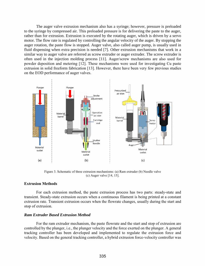
The auger valve extrusion mechanism also has a syringe; however, pressure is preloaded
to the syringe by compressed air. This preloaded pressure is for delivering the paste to the auger,
rather than for extrusion. Extrusion is executed by the rotating auger, which is driven by a servo
motor. The flow rate is regulated by controlling the angular velocity of the auger. By stopping the
auger rotation, the paste flow is stopped. Auger valve, also called auger pump, is usually used in
fluid dispensing when extra precision is needed [7]. Other extrusion mechanisms that work in a
similar way to auger valve are referred as screw extruder or auger extruder. The screw extruder is
often used in the injection molding process [11]. Auger/screw mechanisms are also used for
powder deposition and metering [12]. These mechanisms were used for investigating Cu paste
extrusion in solid freeform fabrication [13]. However, there have been very few previous studies
on the EOD performance of auger valves.
Figure 3. Schematic of three extrusion mechanisms: (a) Ram extruder (b) Needle valve
(c) Auger valve [14, 15].
Extrusion Methods
For each extrusion method, the paste extrusion process has two parts: steady-state and
transient. Steady-state extrusion occurs when a continuous filament is being printed at a constant
extrusion rate. Transient extrusion occurs when the flowrate changes, usually during the start and
stop of extrusion.
Ram Extruder Based Extrusion Method
For the ram extruder mechanism, the paste flowrate and the start and stop of extrusion are
controlled by the plunger, i.e., the plunger velocity and the force exerted on the plunger. A general
tracking controller has been developed and implemented to regulate the extrusion force and
velocity. Based on the general tracking controller, a hybrid extrusion force-velocity controller was
335
developed [5]. A plunger velocity controller was used to ensure a steady extrusion flow rate, and
an extrusion force controller was to regulate the start and stop of the extrusion since this controller
has a much shorter time constant than the plunger velocity controller. The hybrid control scheme
switches from velocity control to force control when extrusion start or stop occurs.
The time constant of the extrusion force controller causes a delay at start and stop of
extrusion. Therefore, compensation is needed to precisely start and stop extrusion. To start
extrusion, the gantry remains stationary for a period of time after the force controller is activated
for extrusion [6]. The amount of this waiting time is referred as the start dwell time ( ). To stop
extrusion, the force controller begins to drop the extrusion force to zero before the gantry reaches
the end of deposition path. The distance between the extrusion stop point and the end of filament
is referred as the early stop distance ( d ). After stopping extrusion, the x-y table decelerates to
compensate the tail effect.
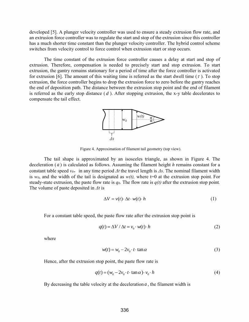
Figure 4. Approximation of filament tail geometry (top view).
The tail shape is approximated by an isosceles triangle, as shown in Figure 4. The
deceleration ( a ) is calculated as follows. Assuming the filament height h remains constant for a
constant table speed v0,in any time period Δt the travel length is Δs. The nominal filament width
is w0, and the width of the tail is designated as w(t), where t=0 at the extrusion stop point. For
steady-state extrusion, the paste flow rate is q0. The flow rate is q(t) after the extrusion stop point. The volume of paste deposited in Δt is
( ) ( )V v t t w t h (1)
For a constant table speed, the paste flow rate after the extrusion stop point is
0( ) / ( )q t V t v w t h (2)
where
0 0( ) 2 tanw t w v t (3)
Hence, after the extrusion stop point, the paste flow rate is
0 0 0( ) ( 2 tan )q t w v t v h (4)
By decreasing the table velocity at the deceleration a , the filament width is
336

0 0 0( 2 tan )( )( )
( ) ( )
w v t vq tw t
v t h v t
(5)
where
0( )v t v a t (6)
In order to compensate the tail effect, i.e. to keep the filament width to w0, let w(t) =w0.
Thus we have
0 0 00
0
( 2 tan )( )
w v t vv t v a t
w
(7)
Hence, the desired deceleration is
2
0
0
2 tanva
w
(8)
Therefore, the deceleration a is constant. A schematic of the ram extruder based method
is shown in Figure 5.
Figure 5. Schematic of ram extruder based extrusion method
Needle Valve Based Extrusion Method
Unlike the ram extruder based method, the start and stop of extrusion in the needle valve
based method is controlled by the shutter needle, which opens and closes the flow path. The hybrid
extrusion force-velocity controller described above is again implemented; however, the control
scheme is adjusted. Instead of dropping the force exerted on the plunger after the extrusion stop
point, the controller switches from the plunger velocity control to force control mode to maintain
337

a constant extrusion force after the flow path is closed by the shutter needle. Then, the controller
switches back to plunger velocity control to start its next extrusion once the flow path is opened.
For steady-state extrusion, this method is identical to the ram extruder based method. The start
dwell, early stop and deceleration strategy are also implemented in this method to compensate for
time delay. A schematic of the needle valve based method is shown in Figure 6.
Figure 6. Schematic of the needle valve based extrusion method
Auger Valve Based Extrusion Method
When using an auger, the paste flow rate is proportional to the angular velocity of the auger.
By maintaining a constant speed of the motor that drives the auger, a constant extrusion flow rate
is obtained. The start and stop of extrusion is achieved by turning the motor on and off. The start
dwell, early stop and deceleration strategy are also implemented in this method to compensate for
time delay. The schematic of auger valve based method is shown in Figure 7.
Figure 7. Schematic of ram auger valve based extrusion method
338

Paste extrusion experiments
In most extrusion based freeform fabrication processes, the extrusion start and stop
accuracy and flow rate consistency are the most important criteria for extrusion performance.
Printing of dash lines is an effective way to evaluate the start and stop accuracy, and printing of
continuous lines is an effective way to evaluate the paste flow rate consistency.
Dash line printing experiments
Dash line printing tests were conducted for all the three extrusion methods. The location
offset,tail effect and head effect of printed dash lines indicate the extrusion start and stop
accuracy. In the dash line printing experiments, the reference paste flow rate, the table speed and
layer thickness are identical for each group. Two groups of dash line printing experiments were
conducted. The first group was done for two different nozzle sizes, and the second group was done
for two different solids loading pastes. Before the tests, extrusion parameters including , d and
a were calibrated for each method using a batch of 60% solids loading paste and a 630 μm nozzle.
Table 1 shows the calibrated extrusion parameters. Same values of parameters were applied for
experiments with 630μm nozzle and 50% solids loading paste, and then for experiments with 400
μm nozzle and 60% solids load paste. The experimental results are discussed in the next section.
Table 1. Extrusion calibration conditions and calibrated extrusion parameters for three methods.
Calibration Conditions Calibrated Extrusion Parameters
Nozzle Diameter (μm)
()
Paste Solids Loading Extrusion Method τ(ms) d (mm) a (mm/s2)
630 60% Ram extruder 450 1.9 -16
Needle valve 70 0.3 0
Auger valve 0 0 0
Continuous line printing experiments
For continuous line printing, the line width consistency is examined. A special cap was
added to the nozzle tip to ensure consistent filament height for the entire filament by restricting
the height of the deposited paste. The normal nozzle and modified nozzle, as well as their printing
schematics, are depicted in Figure 8. The filament height (h), i.e., layer thickness, was restricted
to 150 μm. The reference plunger velocity for the ram extruder was 5 μm/s, which corresponds to
0.198 ml/min of paste flow rate, and the table speed was set to 660 mm/min,which is a typical
printing speed. The layer thickness was set smaller than its typical value (450 μm) to obtain a
larger nominal filament width in order to minimize the filament width measuring error. By
approximating the filament cross-section geometry as a rectangle rounded at the two ends, as
shown in Figure 8,the nominal filament width (w) was calculated to be 2.018 mm.
339

Figure 8. Normal nozzle (left) and nozzle with cap (right) and their printing schematics.
As discussed in the previous section, the ram extruder based method and the needle valve
based method are identical for continuous line printing. Hence, the three extrusion methods were
divided into two groups, the ram extruder/needle valve based method and the auger valve based
method, for the continuous line printing experiments. Each group of experiments was conducted
by printing five continuous serpentine lines using a 630 μm nozzle and the same batch of 60%
solids loading paste. Then, each group of experiments was repeated using 400 μm nozzle and the
same paste. Hence, a total four groups of continuous serpentine lines were printed. Images of the
continuous lines were taken. The filament widths at sampling points were measured by an image
processing software. Pre-processing including thresholding and edge detection was done before
measuring the filament width. The quality of the printed filament was evaluated statistically.
Results and discussion
The results of the dash line printing experiments are compared using the images of printed
dash line segments, as shown in Figures 9 and 10. All the dash lines were printed from right to left,
and the yellow and red lines at the two ends represent the desired segment start and stop points,
respectively.
According to Table 1, the start dwell time in the needle valve and auger valve based
methods are shorter than for the ram extruder based method, resulting in a faster start. By
examining Figures 9 and 10, the dash line segments printed by the needle valve and auger valve
based methods have shorter tails than the ram extruder based method. By further analyzing Figure
9, the dash line segments printed by the ram extruder method have considerable location offset
when the nozzle diameter changes from 630 to 400 μm, indicating a longer start dwell time ( )
and a larger early stop distance ( d ) were needed to compensate for the dynamic response delay.
Figure 10 shows the dash line segments printed by the ram extruder based method have fatter heads
when the paste solids loading changes from 60% to 50%, indicating a shorter start dwell time was
needed. The desired extrusion process parameters for the ram extruder based method are given in
Table 2, which depicts that the values of extrusion parameters vary considerably with the change
of nozzle size and paste solids loading. Hence the ram extruder based method is not robust enough
for extrusion start and stop, while the needle valve/auger valve based method is more robust for
extrusion start and stop.
340

Figure 9. Dash line printing results for 630 μm nozzle (left) and 400 μm nozzle (right), where paste solids loading
is 60%.
Figure 10. Dash line printing results for 60% solids loading paste (left) and 50% solids loading paste (right), where
nozzle diameter is 630 μm.
Table 2. Ram extrusion parameters calibrated for different extrusion conditions. Calibration Conditions Calibrated Extrusion Parameters
Nozzle Diameter(μm)
()
Paste Solids Loading τ(ms) d (mm) a (mm/s2)
400 60% 650 2.2 -18
630 50% 300 1.3 -11
630 60% 450 1.9 -16
As discussed in the previous section, the start and stop delays are caused by the paste
compressibility. An effective way to reduce this time delay is to reduce the amount of paste being
compressed during the start and stop of extrusion. According to Figure 3, the amount of paste
being compressed in the ram extruder is the volume of the entire syringe, represented by the blue
area in Figure 3 (a), which is referred as the operation volume here. The operation volume for
needle valve and auger valve are represented, respectively, by the green area near the material
outlet in Figure 3 (b) and red area near the material outlet in Figure 3 (c). The needle valve and
auger valve have much smaller operation volumes. This contributes to a faster dynamic response.
In this case, the operation volumes of the needle valve and the auger valve are small enough
341

(approximately 0.2 and 0.1 ml, respectively) to be negligible compared to the operation volume of
the ram extruder (up to 50 ml). In Table 1, the start dwell time for the auger valve is 0 ms, and the
early stop distance is 0 mm; the start dwell time for the needle valve is 70ms, and the early stop
distance is 0.3 mm.
Since the ram extruder based method and the needle valve based method are identical for
continuous line printing. The continuous line printing experiments were done using only the needle
valve based method for the ram extruder/needle valve group. In these experiments, five 1778 mm
serpentine lines were printed for each group. In the images taken, a ruler was placed on the
substrate to provide the scale. Figure 11 shows the images of typical printed serpentine lines using
the ram extruder/needle valve based method vs. the auger valve based method. The areas inside
the rectangles (shown in red) are the effective substrates, and measurements were taken only in
these areas. Each group contains five serpentine line images, and 70 measurements were taken for
each image along the printing direction. Hence a total 350 measurements were taken for each group.
The statistical results of continuous line printing are given in Table 3.
Figure 11. Example images of continuous line printed by needle valve (left) and auger valve (right) with 630 μm
nozzle. Both serpentine lines were printed from bottom right to top left.
Table 3. Statistical results of continuous line printing experiments
Group
NO.
Extrusion Condition Statistical Results on Printed Line Width
EOD
Method
Nozzle
Diameter
(μm)
Paste
Solids
Loading
Nominal
value (mm)
Mean
(mm)
Error
(%)
Max.
(mm)
Min.
(mm)
Standard
Deviation
(mm)
1 Needle valve 630 60% 2.018 2.020 0.09 2.545 1.384 0.215
2 Needle valve 400 60% 2.018 1.997 1.04 2.554 1.184 0.239
3 Auger valve 630 60% 2.018 2.083 3.22 2.200 1.900 0.086
4 Auger valve 400 60% 2.018 2.075 2.82 2.180 1.900 0.074
For both the ram extruder/needle valve and the auger valve methods, the differences
between the mean value and nominal (set) value are less than 4%. The standard deviations of the
auger valve groups are considerably smaller than those of the ram extruder/needle valve groups.
The left-side and right-side images in Figure 11 are plotted in Figure 12, section 3, using blue
curve and red curve, respectively. The other four images of each group are plotted in sections 1, 2,
4 and 5 in Figure 12.
From Figure 12, the fluctuation of paste flow rate in the ram extruder/needle valve based
methods can be easily observed. It can also be seen that for the ram extruder/auger valve group,
large filament width fluctuations did not occur pervasively during the printing of one serpentine
line. Instead, the fluctuation occurred in a gradual manner in one serpentine line, instead of
342
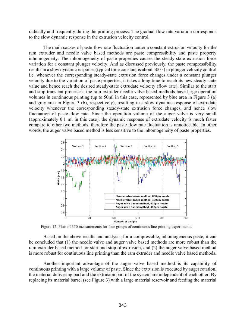
radically and frequently during the printing process. The gradual flow rate variation corresponds
to the slow dynamic response in the extrusion velocity control.
The main causes of paste flow rate fluctuation under a constant extrusion velocity for the
ram extruder and needle valve based methods are paste compressibility and paste property
inhomogeneity. The inhomogeneity of paste properties causes the steady-state extrusion force
variation for a constant plunger velocity. And as discussed previously, the paste compressibility
results in a slow dynamic response (typical time constant is about 500 s) in plunger velocity control,
i.e. whenever the corresponding steady-state extrusion force changes under a constant plunger
velocity due to the variation of paste properties, it takes a long time to reach its new steady-state
value and hence reach the desired steady-state extrudate velocity (flow rate). Similar to the start
and stop transient processes, the ram extruder needle valve based methods have large operation
volumes in continuous printing (up to 50ml in this case, represented by blue area in Figure 3 (a)
and gray area in Figure 3 (b), respectively), resulting in a slow dynamic response of extrudate
velocity whenever the corresponding steady-state extrusion force changes, and hence slow
fluctuation of paste flow rate. Since the operation volume of the auger valve is very small
(approximately 0.1 ml in this case), the dynamic response of extrudate velocity is much faster
compare to other two methods, therefore the paste flow rate fluctuation is unnoticeable. In other
words, the auger valve based method is less sensitive to the inhomogeneity of paste properties.
Figure 12. Plots of 350 measurements for four groups of continuous line printing experiments.
Based on the above results and analysis, for a compressible, inhomogeneous paste, it can
be concluded that (1) the needle valve and auger valve based methods are more robust than the
ram extruder based method for start and stop of extrusion, and (2) the auger valve based method
is more robust for continuous line printing than the ram extruder and needle valve based methods.
Another important advantage of the auger valve based method is its capability of
continuous printing with a large volume of paste. Since the extrusion is executed by auger rotation,
the material delivering part and the extrusion part of the system are independent of each other. By
replacing its material barrel (see Figure 3) with a large material reservoir and feeding the material
343

with a pipe, the auger valve based method can potentially print paste continuously without the
limitation of the material barrel volume. However, the ram extruder and needle valve based
methods are limited by the syringe volume since the printing process has to be paused to refill the
paste or to replace the syringe. Nevertheless, one disadvantage of the auger valve based method is
the relatively easy wear of auger [10, 15] and seal rubber, especially in printing abrasive materials
such as alumina.
Summary and Conclusions
Three methods of Extrusion-On-Demand based on different extrusion mechanisms are
presented for the freeform extrusion fabrication process. The challenges of Extrusion-On-Demand
for high solids loading pastes were discussed. Extrusion parameters were calibrated to compensate
for the time delay in paste extrusion dynamics. Dash line printing experiments were designed and
conducted for each method using different size nozzles and different solids loading pastes to test
the extrusion start and stop accuracy. Continuous line printing experiments were designed and
conducted using 630 μm nozzle and 400 μm nozzle to test the paste flow rate consistency and the
relative performance of these methods. The experimental results were analyzed.
The values of process parameters were calibrated for the three different methods, showing
that the needle valve and the auger valve based methods have much shorter time delay for extrusion
start and stop. The quality of dash line printed by the ram extruder based method varies with
changing extrusion conditions, indicating that the ram extruder based method is not robust enough
for extrusion start and stop. Better dash line quality and repeatability was observed for the needle
valve and auger valve based methods, indicating that these methods are more robust than the ram
extruder based method for extrusion start and stop. By analyzing the three mechanisms, the
operation volume was determined to be an important factor for Extrusion-On-Demand. A smaller
operation volume leads to a faster dynamic response and hence improved robustness.
The results of continuous line printing experiments were analyzed statistically. The ram
extruder and the needle valve based methods have considerably more severe paste flow rate
fluctuations than the auger valve based method, indicating that the auger valve based method is
more robust for continuous printing.
Acknowledgements
The authors gratefully acknowledge the financial supports by the National Energy
Technology Laboratory of the Department of Energy under the contract DE-FE0012272, and the
Intelligent Systems Center at the Missouri University of Science and Technology.
References
[1] Huang, T., Mason, M., Hilmas, G.E., and Leu, M.C., 2006, “Freeze-Form Extrusion
Fabrication of Ultra High Temperature Ceramics,” Materials Science and Technology
Conference, Cincinnati, Ohio, October 15-19.
344

[2] Huang, T., Mason, M., Hilmas, G.E., and Leu, M.C., 2006, “Freeze-Form Extrusion
Fabrication of Ultra High Temperature Ceramics,” Materials Science and Technology
Conference, Cincinnati, Ohio, October 15-19.
[3] Mason, M., Huang, T., Landers, R.G., Leu, M.C., and Hilmas, G.E., 2006, “Freeform
Extrusion of High Solids Loading Ceramic Slurries, Part I: Extrusion Process Modeling,”
Solid Freeform Fabrication Symposium, Austin, Texas, August 14-16.
[4] X. Zhao, R.G. Landers, and M.C. Leu, “Adaptive Extrusion Force Control of Freeze-Form
Extrusion Fabrication Processes,” J. Manuf. Sci. Eng., vol. 132, no. 6, p. 064504, 2010.
[5] Deuser, B.K., Tang, L., Landers, R.G., Leu, M.C., and Hilmas, G.E. (2013). Hybrid
Extrusion Force-Velocity Control Using Freeze-Form Extrusion Fabrication for
Functionally Graded Material Parts. Journal of Manufacturing Science and Engineering,
135(4), 041015.
[6] Kulkarni, P. S. (2009). Development of extrusion on demand for ceramic freeze-form
extrusion fabrication processes. Missouri Univerisy of Science and Technology.
[7] Jianping, L., & Guiling, D. (2004). Technology development and basic theory study of
fluid dispensing - a review. High Density Microsystem Design and Packaging and
Component Failure Analysis, 2004. HDP ’04. Sixth IEEE CPMT Conference on, 198–205.
[8] M. Li, L. Tang, R.G. Landers, and M.C. Leu, “Extrusion Process Modeling for Aqueous-
Based Ceramic Pastes—Part 1: Constitutive Model,” J. Manuf. Sci. Eng., vol. 135, 2013.
[9] M. Li, L. Tang, R.G. Landers, and M.C. Leu, “Extrusion Process Modeling for Aqueous-
Based Ceramic Pastes—Part 2: Experimental Verification,” J. Manuf. Sci. Eng., vol. 135,
2013.
[10] Benbow, J.J., and Bridgwater, J.,Paste Flow and Extrusion. Clarendon Press, Oxford
(1992).
[11] Douglas M. Bryce. Plastic Injection Molding: Manufacturing Process
Fundamentals.Dearborn, MI: Society of Manufacturing Engineers, 1996, pp. 1-2
[12] Yang, S., & Evans, J. R. G. (2007). Metering and dispensing of powder; the quest for
newsolid freeforming techniques. Powder Technology, 178(1), 56–72.
[13] Hong, S., Sanchez, C., Du, H., & Kim, N. (2015). Fabrication of 3D Printed Metal
Structures by Use of High- Viscosity Cu Paste and a Screw Extruder, 44(3), 836–841.
[14] Auger Valve Dispensing, EFD Inc., Lincoln, RI, 2003
[15] Viscotec Inc. “Preeflow® – one for all”. Internet: www.preeflow.com/en/media-
center/videos/, Mar. 14, 2014.
345