methods for correcting multiple errors of information storage devices used in microprocessor...
TRANSCRIPT
A method is considered for ensuring resistance to failure in operational computer memory devices by
utilizing linear correcting codes with a posteriori correction of multiple errors. The proposed method
makes it possible to extend the correcting possibilities of the code, i.e., to determine the configuration of
any error with the minimum code redundancy and the lowest hardware and software costs.
A characteristic feature of modern monitoring and measurement devices is the use of specialized computers intend-
ed for mathematically processing and analyzing the results obtained. In turn, up to 70% of the equipment in the apparatus
considered consists of memory [1], and so the reliability of the information obtained is largely dependent on the functional
reliability of the storage device and the transfer of information. Codes which correct individual errors [1–5] are widely used
in order to increase the reliability of the functioning of these devices. Here it is assumed that it is individual errors which are
most likely to occur in digital devices. Making this assumption, linear codes are decoded using the method of maximum like-
lihood. Erroneous code sets having an error in the same bit form a coset of errors characterized by a definite value of error
syndrome, with the leader of the coset being the error vector.
Decoding is considered to be correct if the error vector really is the leader of the coset, the erroneous code set being
transformed into a code word located at the shortest Hamming distance from it. In practice, this limitation is not always jus-
tified since with the increased complexity of modern computers and also under intense operating conditions, for example when
the power supply voltages depart from their nominal values, the influence of external actions of electromagnetic or radioactive
radiation, etc., increases the probability of faulty correction on account of the appearance of errors of arbitrary multiplicity hav-
ing the same error syndrome as the correction (the appearance of multiple errors which are corrected as a single error).
Therefore, when designing computers which are resistant to failure, it becomes necessary to utilize correcting codes
which rectify multiple errors. However, the correction of multiple errors based on linear codes leads to a sharp increase in
the redundancy of the code and to large hardware costs for encoding and decoding the information, and this not only does
not allow increasing the reliability and confidence in the functioning of the failure-resistant computer but even lowers these
indices.
The main idea for eliminating this contradiction consists in the a posterioricorrection of errors. In order to detect the
errors which arise, a linear correcting code is used which rectifies a single error (requiring the minimum hardware costs) while
the determination of the configuration (the error bits) of a multiple error and its correction are performed from the results of
an analysis of a responding reaction obtained by applying a single test action (requiring a minimum expenditure of time).
Fundamental Concepts and Definitions. Let the rectification of the errors of a code set be provided on the basis
of a linear correcting code which corrects a single error.
Measurement Techniques, Vol. 45, No. 2, 2002
METHODS FOR CORRECTING MULTIPLE ERRORS
OF INFORMATION STORAGE DEVICES USED IN
MICROPROCESSOR FACILITIES OF MEASUREMENT
TECHNOLOGY (A DISCUSSION)
Al-r A. Pavlov and A. A. Pavlov UDC 519.725(047)
Translated from Izmeritel’naya Tekhnika, No. 2, pp. 21–23, February, 2002. Original article submitted June 25, 2001.
0543-1972/02/4502-0141$27.00 ©2002 Plenum Publishing Corporation 141
To each working input set Xis there corresponds a code set
Y = {y1, y2, ..., yk, rk+1, rk+2, ..., rn},
where yi and rj are respectively the values of the signals in the information and control bits.
The vector R of the control bits is a function of the information bits and is determined by the information encoding
rule of the chosen code:
R = {rk+1, rk+2, ..., rn–k} = ƒ(y1, y2, ..., yk).
After reception of the message concerning the information bits,the vector of the control bits Rr is formed and the
error syndrome is determined again:
Es = R ⊕ Rr.
For each working input set Xis providing a definite value of the signals in the information and control bits
Yk = { y1, y2, ..., yk, rk+1, rk+2, ..., rn}, we have a corresponding a test set Tts = { Yk, R r} ⇒ Yt which gives produces the oppo-
site value of the signals in the information and control bits.
Definition 1. We shall consider the inverse value of the result of summing the information and control bits
Yk = { y1, y2, ...,yk, rk+1, rk+2, ..., rn} obtained for a working input set with the information and control bits Yt obtained for the
test set to be the test error vector:
If there is no error, the test error vector will assume a value of zero.
Definition 2. An error which is not manifested in the considered input working set will be called a hidden error.
Example. A variant of single values in the information bits of a Hamming code (r1r2y2r3y1) corresponds to an
error-free code set 01111. When an error is present in the const 1 in the first information bit, we have for the input set con-
sidered an output code set 01111+ (the + sign marks the erroneous bit) which does not differ from the error-free code set.
Definition 3. We shall say that an erroneous code set is “correct” if it does not contain hidden errors. If it does con-
tain such errors, it will be said to be “incorrect.”
Statement 1. Rectification of an “incorrect” erroneous code set by utilizing a test error vector leads to pseudocor-
rection.
Proof. When a test stimulus is applied which provides the opposite value of the information bits,any errors are
detected. In this case, the test error vector indicates the numbers of the erroneous information bits and, in particular, of the
bits containing hidden errors. Since hidden errors correspond to the working input set,their correction based on a test error
vector in turn leads to an error in the correcting code set.
Consequence 1. A posteriori correction of multiple errors is possible under conditions when hidden errors are
revealed (when corrections to the test error vector are formed).
On the basis of the concepts and definitions given,the problem is posed of revealing the configuration of multiple
errors from the results of algebraic operations with the values of the error syndrome Es and test error vector B obtained when
the test stimulus is applied.
Rule for Forming Error Vector Values. The procedure for determining the error vector is based on the following
theoretical postulates.
The encoding of the information bits of the test error vector from the rules of the considered code gives the error
code of the test bits:
Ei = ƒ(Bi).
B Y Yk= ⊕ t .
142
After summing the error syndrome and the error code of the test bits,we obtain the address code of the correction to the hid-
den error
Ec = Es ⊕ Ei.
Based on the values obtained for Es, Ei, and Ec, a decision is taken concerning the correction of errors in the infor-
mation bits when the number of errors in the information bits satisfies the condition d ≤ k – 1. In this case, the decoding strat-
egy includes the following postulates:
– correction is impossible if the bits of the test error vector corresponding to the control bits have zero values;
– the transfer of information bits without correction is permitted if the test error vector contains zero values in the
information bits and unit values (errors) in the control bits;
– correction is forbidden (the signal “device failure” is formed) if all the bits of the test error vector corresponding
to the information bits have unit values (k-fold error) or in the presence of unit values of the signals simultaneously in the
information and control bits of the test error vector;
– when a hidden error appears, the error vector is formed by adding the correction to the test error vector.
Rule for Forming a Correction whena Hidden Error Appears. Let us construct a decision table in order to deter-
mine the correction of the test error vector (corrections to each hidden error). Then the number of corrections forms a set of
cardinality SM = 2k.
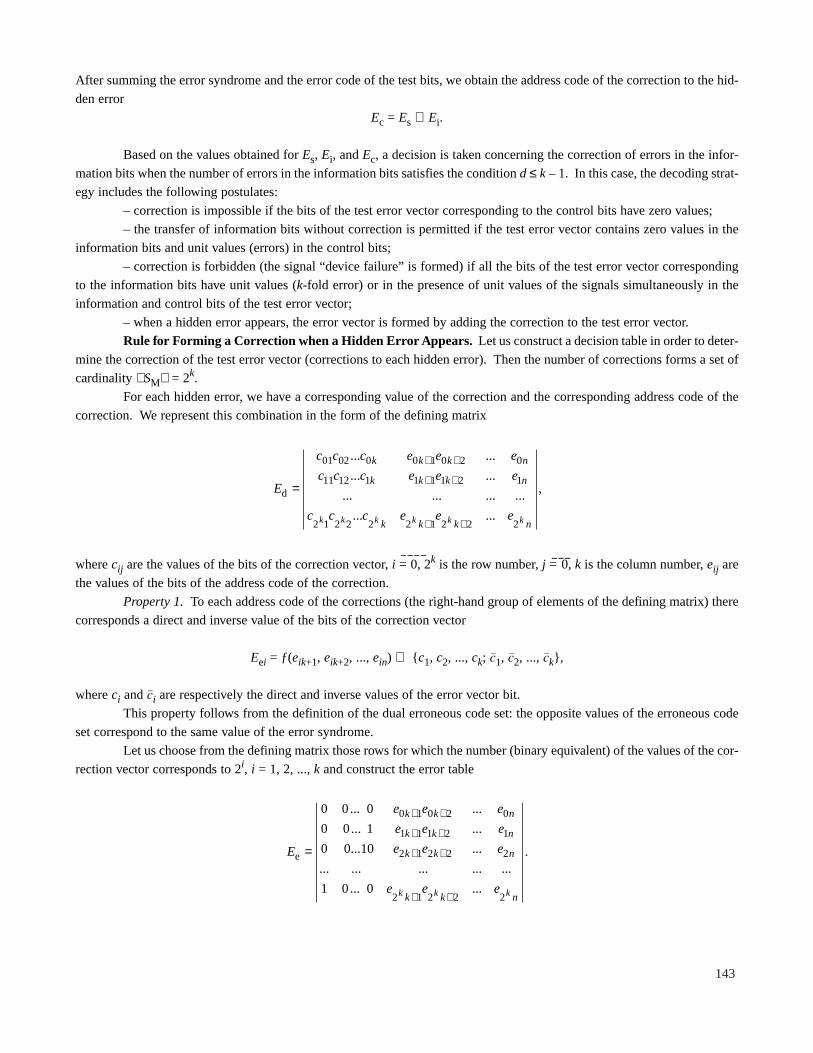
For each hidden error, we have a corresponding value of the correction and the corresponding address code of the
correction. We represent this combination in the form of the defining matrix
where cij are the values of the bits of the correction vector, i = 0, 2k is the row number, j = 0, k is the column number, eij are
the values of the bits of the address code of the correction.
Property 1. To each address code of the corrections (the right-hand group of elements of the defining matrix) there
corresponds a direct and inverse value of the bits of the correction vector
Eei = ƒ(eik+1, eik+2, ..., ein) ⇒ { c1, c2, ..., ck; c1, c2, ..., ck},
where ci and ci are respectively the direct and inverse values of the error vector bit.
This property follows from the definition of the dual erroneous code set:the opposite values of the erroneous code
set correspond to the same value of the error syndrome.
Let us choose from the defining matrix those rows for which the number (binary equivalent) of the values of the cor-
rection vector corresponds to 2i, i = 1, 2, ..., k and construct the error table
E
e e e
e e e
e e e
e e e
k k n
k k n
k k n
k k nk k k
e =
+ +
+ +
+ +
+ +
0 0 0
0 0 1
0 0 10
1 0 0
0 1 0 2 0
1 1 1 2 1
2 1 2 2 2
2 1 2 2 2
... ...
... ...
... ...
... ... ... ... ...
... ...
.
E
c c c e e e
c c c e e e
c c c e e e
k k k n
k k k n
k k k nk k k k k k
d =
+ +
+ +
+ +
01 02 0 0 1 0 2 0
11 12 1 1 1 1 2 1
2 1 2 2 2 2 1 2 2 2
... ...
... ...
... ... ... ...
... ...
,
143

Let us consider the properties of the correction table.
Property 2. In order to choose the correction values,it is necessary to form a correction factor of the direct or inverse
value of the correction bits relative to the considered correction address code.
Thus,multiple errors are corrected by the proposed method by utilizing the values of the information bits of the test
error vector and the values of the correction to the hidden error, i.e., the error vector is of the form
where ! is the value of the correction vector bit (direct and inverse).
Property 3. The correction has an inverse value if all the values of the correction vector bits agree with those of the
corresponding information bits of the test error vector, and it is direct if the opposite is the case.
Example. Let us consider the procedure of constructing a correcting code A(n, k) with a posteriori correction of mul-
tiple errors by using the example of threshold encoding A(5, 3): (r1 = y1 ⊕ y2; r2 = y1 ⊕ y3).
We construct the defining matrix and from it the correction matrix:
Let us postulate that it is necessary to encode the message Y = { y1, y2, y3} ⇒ 001. In this case, the test bits have
values r1r2 ⇒ 01. Thus,the code set is transmitted in the form Yc = 00101.
If no error appears, then the error syndrome Es has zero values. As a result of applying a test stimulus providing the
opposite value of the information bits,we obtain a test error vector B = 00000,i.e., the code of the errors of the test bits is
Ei = 00, Ec = 00 and the values of the control bits of the test vector are Rbr = 00. Since the inverse value of the correction
C = 111 obtained from the correction address code, Ec = 00 does not coincide with the values of the information bits of the
vector B, the direct value of the correction C = 000 is chosen. Thus,the error vector is of the form E = B ⊕ C = 000.
Let an error appear in the first and second information bits when the message is transmitted:Yc* = 1*1*101. Using
the expression given for this case, we find that
B = 11000; Ei = 01; Es = 01; Ec = 00; C = 000; E = 110.
The error vector is equal to the test error vector which indicates an error in the first and second information bits.
Let us postulate that a “correct” error appears in the code set in the first information bit and a hidden error in the
second information bit: Yc* = 1*0*101,then
B = 11000; Ei = 01; Es = 11; Ec = 10; C = 010; E = 100.
Since the inverse correction value C = 101 obtained from the correction table using the correction address code
Ec = 10 does not coincide with the value of the third information bit of the test error vector, we choose the direct forward cor-
rection value C = 101. Then E = 100,i.e., the first information bit is corrected.
E Ed e= =
0 0 0 0 0
0 0 1 0 1
0 1 0 1 0
0 1 1 1 1
1 0 0 1 1
1 0 1 1 0
1 1 0 0 1
1 1 1 0 0
0 0 0 0 0
0 0 1 0 1
0 1 0 1 0
1 0 0 1 1
; .
b b b
c c c
E e e e
k
k
k
1 2
1 2
1 2
...
˜ ˜ ... ˜
...,
⊕=
144
The proposed method makes it possible to detect correct and hidden errors of any multiplicity: and
to correct errors in the information bits of multiplicity d ≤ k – 1.
REFERENCES
1. Yu. L. Sagalovich, Avtonom. Telemekh.,No. 5, 3 (1991).
2. F. J. MacWilliams and N. J. A. Sloane, The Theory of Error Correcting Codes, Parts I and II,North-Holland,
Amsterdam (1977).
3. N. S. Shcherbakov, Self-Correcting Digital Devices[in Russian],Mashinostroenie, Moscow (1975).
4. N. S. Shcherbakov, Reliability of Operation of Digital Devices[in Russian],Mashinostroenie, Moscow (1989).
5. Ya. A. Khetagurov and Yu. P. Rudnev, Improving the Reliability of Digital Devices by Redundancy Coding Methods
[in Russian],Énergiya,Moscow (1974).
6. K. A. Iyudu, Reliability, Monitoring, and Diagnostics of Computers and Systems[in Russian],Vysshaya Shkola,
Moscow (1989).
D Cni
i
n
==∑2
1
;
145