meru access point - fcc id meru access point radio devices communicate with the meru controller and...
TRANSCRIPT
Meru Access Point
Installation Guide
Copyright © Meru Networks, Inc., 2003–2005. All rights reserved.Other names and brands may be claimed as the property of others.
Document Number: 882-70031 Rev. A

Contents
About This Guide . . . . . . . . . . . . . . . . . . . . . . . . . . . . . . ixAudience . . . . . . . . . . . . . . . . . . . . . . . . . . . . . . . . ixIn This Guide . . . . . . . . . . . . . . . . . . . . . . . . . . . . . . ixOther Sources of Information . . . . . . . . . . . . . . . . . . . . . . . . ix
Meru Publications . . . . . . . . . . . . . . . . . . . . . . . . . . . ixExternal References . . . . . . . . . . . . . . . . . . . . . . . . . . x
Typographic Conventions . . . . . . . . . . . . . . . . . . . . . . . . . xContacting Meru . . . . . . . . . . . . . . . . . . . . . . . . . . . . . x
Customer Services and Support . . . . . . . . . . . . . . . . . . . . . . xFCC Compliance . . . . . . . . . . . . . . . . . . . . . . . . . . . . . xi
Declaration of Conformity . . . . . . . . . . . . . . . . . . . . . . . . xi
Chapter 1 About Meru Access Points . . . . . . . . . . . . . . . . . . . . . . . . . 1Meru Access Point Features . . . . . . . . . . . . . . . . . . . . . . . . . 1Meru Access Point Models . . . . . . . . . . . . . . . . . . . . . . . . . 2
AP200. . . . . . . . . . . . . . . . . . . . . . . . . . . . . . . . 2AP150. . . . . . . . . . . . . . . . . . . . . . . . . . . . . . . . 3
Chapter 2 Installing the AP200. . . . . . . . . . . . . . . . . . . . . . . . . . . . . 5Safety Precautions . . . . . . . . . . . . . . . . . . . . . . . . . . . . 5
FCC Safety Compliance Statement . . . . . . . . . . . . . . . . . . . . 5General Safety Guidelines . . . . . . . . . . . . . . . . . . . . . . . . 5Warnings . . . . . . . . . . . . . . . . . . . . . . . . . . . . . . 6
Unpacking the AP200 . . . . . . . . . . . . . . . . . . . . . . . . . . . 6Installation Requirements. . . . . . . . . . . . . . . . . . . . . . . . . . 7Installing the Access Point . . . . . . . . . . . . . . . . . . . . . . . . . 10
Selecting a Location . . . . . . . . . . . . . . . . . . . . . . . . . . 10Attaching the AP200 Antennas . . . . . . . . . . . . . . . . . . . . . . 11Mounting the Access Point. . . . . . . . . . . . . . . . . . . . . . . . 11
Where to Go From Here . . . . . . . . . . . . . . . . . . . . . . . . . . 19Checking LED Activity . . . . . . . . . . . . . . . . . . . . . . . . . . 19
Ethernet Connector LEDs . . . . . . . . . . . . . . . . . . . . . . . . 19AP200 Status LEDs . . . . . . . . . . . . . . . . . . . . . . . . . . 20
Chapter 3 Installing the AP150. . . . . . . . . . . . . . . . . . . . . . . . . . . . 23Safety Precautions . . . . . . . . . . . . . . . . . . . . . . . . . . . . 23
FCC Safety Compliance Statement . . . . . . . . . . . . . . . . . . . . 23General Safety Guidelines . . . . . . . . . . . . . . . . . . . . . . . . 23Warnings . . . . . . . . . . . . . . . . . . . . . . . . . . . . . . 24
Contents iii
Unpacking the AP150 . . . . . . . . . . . . . . . . . . . . . . . . . . . 24Installation Requirements . . . . . . . . . . . . . . . . . . . . . . . . . 26Installing the Access Point . . . . . . . . . . . . . . . . . . . . . . . . . 29
Selecting a Location . . . . . . . . . . . . . . . . . . . . . . . . . . 29Attaching the AP150 Antennas . . . . . . . . . . . . . . . . . . . . . . 30Mounting the Access Point . . . . . . . . . . . . . . . . . . . . . . . 30
Where to Go From Here . . . . . . . . . . . . . . . . . . . . . . . . . . 38Checking LED Activity . . . . . . . . . . . . . . . . . . . . . . . . . . 38
Ethernet Connector LEDs . . . . . . . . . . . . . . . . . . . . . . . . 38AP150 Status LEDs . . . . . . . . . . . . . . . . . . . . . . . . . . 39
Appendix A Specifications . . . . . . . . . . . . . . . . . . . . . . . . . . . . . . . 43FCC Compliance . . . . . . . . . . . . . . . . . . . . . . . . . . . . . 43Wireless Interface . . . . . . . . . . . . . . . . . . . . . . . . . . . . 44Ethernet Interface . . . . . . . . . . . . . . . . . . . . . . . . . . . . 44Physical . . . . . . . . . . . . . . . . . . . . . . . . . . . . . . . . 45
Appendix B Regulatory Information . . . . . . . . . . . . . . . . . . . . . . . . . 47Safety Section . . . . . . . . . . . . . . . . . . . . . . . . . . . . . . 47Federal Communications Commission (FCC) Declaration of Conformity (DoC) & Instructions48
Declaration of Conformity . . . . . . . . . . . . . . . . . . . . . . . 48Instructions . . . . . . . . . . . . . . . . . . . . . . . . . . . . . 49
List of Regulatory Compliance Certifications Summary by Country . . . . . . . . . 50
Appendix C Translated Safety Warnings . . . . . . . . . . . . . . . . . . . . . . . 53Dipole Antenna Installation Warning . . . . . . . . . . . . . . . . . . . . . 54Explosive Device Proximity Warning . . . . . . . . . . . . . . . . . . . . . 55Installation Warning . . . . . . . . . . . . . . . . . . . . . . . . . . . 56Circuit Breaker (15A) Warning . . . . . . . . . . . . . . . . . . . . . . . 57
Appendix D Channels . . . . . . . . . . . . . . . . . . . . . . . . . . . . . . . . . . 59Channels . . . . . . . . . . . . . . . . . . . . . . . . . . . . . . . . 59
IEEE 802.11a. . . . . . . . . . . . . . . . . . . . . . . . . . . . . 59IEEE 802.11b/g . . . . . . . . . . . . . . . . . . . . . . . . . . . . 60
iv Meru Access Point Installation Guide
List of Figures
Figure 1 Meru Wireless LAN (WLAN) ..................................................................................1 Figure 2 AP200 .......................................................................................................................3 Figure 3 AP150 .......................................................................................................................4 Figure 4 AP200 Mounting Bracket .........................................................................................7 Figure 5 AP200 Antenna Connection .....................................................................................12 Figure 6 AP200 Connector Panel ............................................................................................12 Figure 7 AP200 Bracket ..........................................................................................................13 Figure 8 Aligning the AP200 with the Bracket .......................................................................14 Figure 9 Sliding the AP200 into the Bracket ..........................................................................14 Figure 10 Mounting the AP200 to a Suspended Ceiling Rail .................................................15 Figure 11 Mounting the AP200 Above a Suspended Ceiling .................................................17 Figure 12 Box Hanger Mounting Bracket Holes ....................................................................17 Figure 13 Attaching the Mounting Bracket to the Box Hanger ..............................................18 Figure 14 RJ-45 LEDs ............................................................................................................19 Figure 15 AP200 Status LEDs ................................................................................................20 Figure 16 AP150 with Mounting Bracket ...............................................................................26 Figure 17 AP150 Antenna Connection ...................................................................................31 Figure 18 AP150 Connector Panel ..........................................................................................31 Figure 19 AP150 Bracket ........................................................................................................32 Figure 20 Aligning the AP150 with the Bracket .....................................................................33 Figure 21 Sliding the AP150 into the Bracket ........................................................................33 Figure 22 Mounting the AP150 to a Suspended Ceiling Rail .................................................34 Figure 23 Mounting the AP150 Above a Suspended Ceiling .................................................36 Figure 24 Box Hanger Mounting Bracket Holes ....................................................................36 Figure 25 Attaching the Mounting Bracket to the Box Hanger ..............................................37 Figure 26 RJ-45 LEDs ............................................................................................................38 Figure 27 AP150 Status LEDs ................................................................................................39
List of Figures v

vi Meru Access Point Installation Guide
List of Tables
Table 1 AP200 Installation Items.......................................................................................... 9Table 2 AP200 Installation Tools ......................................................................................... 9Table 3 AP200 LED Descriptions ........................................................................................ 21Table 4 AP200-Controller Status Information...................................................................... 21Table 5 AP150 Installation Items.......................................................................................... 28Table 6 AP150 Installation Tools ......................................................................................... 28Table 7 AP150 LED Descriptions ........................................................................................ 40Table 8 AP150-Controller Status Information...................................................................... 40Table 9 AP100 Wireless Interface Specifications................................................................. 44Table 10 AP200 Wireless Interface Specifications............................................................... 44Table 11 IEEE 802.11a Channels ......................................................................................... 59Table 12 IEEE 802.11b/g Channels ...................................................................................... 60
List of Tables vii

viii Meru Controller Installation Guide
Audience
About This Guide
This guide describes the features of the Meru Access Point family, which includes the AP200 and AP100 models. This guide also includes the hardware installation for both access points. The term access point is used interchangeably throughout this document to apply to either model when there are no differences between the models.
Audience
This guide is intended for persons installing the Meru Access Point (AP).
In This Guide
This guide includes the following chapters:
Chapter 1, “About Meru Access Points”
Chapter 2, “Installing the AP100”
Chapter 2, “Installing the AP200”
Other Sources of Information
Additional information is available in the following Meru publications and external references.
Meru PublicationsMeru Wireless LAN System Release Notes
Meru Wireless LAN System Getting Started Guide
Meru Controller Installation Guide
Meru Wireless LAN System Configuration Guide
Meru Wireless LAN System Command Reference
About This Guide ix
Typographic Conventions
External ReferencesStevens, W. R. 1994. TCP/IP Illustrated, Volume 1, The Protocols. Addison-Wesley, Reading, Mass.
Gast, M.S. 2002. 802.11 Wireless Networks, The Definitive Guide. O’Reilly and Associates, Sebastopol, Calif.
Typographic Conventions
This document uses the following typographic conventions to help you locate and identify information:
Contacting Meru
You can visit Meru Networks on the Internet at this URL:
http://www.merunetworks.com
Click the Support menu button to view Meru Customer Services and Support information.
Customer Services and SupportFor assistance, contact Meru Customer Services and Support 24 hours a day at 1-888-637-8952 (1-888-Meru-WLA(N)) or 1-408-215-5305. Email can be sent to [email protected].
Meru Customer Services and Support provide end users and channel partners with the following:
Telephone technical support
Software update support
Spare parts and repair service
Note: Provides extra information, tips, and hints regarding the topic.
Caution! Identifies important information about actions that could result in damage to or loss of data, or could cause the application to behave in unexpected ways.
Warning! Identifies critical information about actions that could result in equipment failure or bodily harm.
x Meru Access Point Installation Guide
FCC Compliance
RMA Procedures
Contact Meru Customer Services and Support for a Return Material Authorization (RMA) for any Meru equipment.
Please have the following available when making a call:
Company and contact information
Equipment model and serial numbers
Meru software release and revision numbers (for example, 3.0.0-35)
A description of the symptoms the problem is manifesting
Network configuration
FCC Compliance
This device complies with part 15 of the FCC Rules. Operation is subject to the following two conditions: (1) This device may not cause harmful interference, and (2) this device must accept any interference received, including interference that may cause undesired operation.
Declaration of ConformityThe AP150 complies with the requirements of the Low Voltage Directive 73/23/EEC and the EMC Directive 89/336/EEC by conforming to the following standards:
Safety: EN 60950:1992 + A1, A2
EMC: EN 55022, EN 50082-1
The AP200 complies the with following standards:
Radio: EN 301.893
EMC: EN 301.489-1, EN 489-17
Safety: EN 60950
The following CE mark is affixed to the AP100 802.11b with 100 mW radios:
Caution! Changes or modifications to the Meru Access Point that are not expressly approved by Meru Networks will void your warranty and could void your authority to operate this equipment.
About This Guide xi
FCC Compliance
Note: This equipment can be used in all EU and EFTA countries. Outdoor use may be restricted to certain frequencies and/or may require a license for operation. For more details, contract Meru Networks.
Note: Combinations of power levels and antennas resulting in a radiated power level above 100 mW equivalent isotropic radiated power (EIRP) are considered as not compliant with the above mentioned directive and are not allowed for use with the European community and other countries that have adopted the European R&TTE directive 1999/5/EC or the CEPT recommendation Rec 70.03 or both.
The following CE mark is affixed to the AP200 802.11a with 40 mW radios:
xii Meru Access Point Installation Guide
Meru Access Point Features
Chapter 1About Meru Access Points
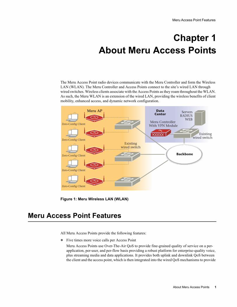
The Meru Access Point radio devices communicate with the Meru Controller and form the Wireless LAN (WLAN). The Meru Controller and Access Points connect to the site’s wired LAN through wired switches. Wireless clients associate with the Access Points as they roam throughout the WLAN. As such, the Meru WLAN is an extension of the wired LAN, providing the wireless benefits of client mobility, enhanced access, and dynamic network configuration.
Figure 1: Meru Wireless LAN (WLAN)
Meru Access Point Features
All Meru Access Points provide the following features:
Five times more voice calls per Access PointMeru Access Points use Over-The-Air QoS to provide fine-grained quality of service on a per-application, per-user, and per-flow basis providing a robust platform for enterprise-quality voice, plus streaming media and data applications. It provides both uplink and downlink QoS between the client and the access point, which is then integrated into the wired QoS mechanisms to provide
Meru AP
About Meru Access Points 1
Meru Access Point Models
end-to-end QoS. Meru Access points deliver a 5-fold increase in voice carrying capacity from the current 5-8 calls per access point to over 30 calls per Meru Access Point with no change to the 802.11 client.
Over five times the scalability of alternate Access PointsMeru Access Points are unique in their ability to dramatically increase performance over alternate APs, even as client density increases. Meru Access Points, can serve over 100 standard 802.11 active data and voice clients per access point, whereas today's systems are limited to about 10-15 data-only clients. This scalability allows corporations to plan for a wireless usage growth without forklift upgrades to the WLAN infrastructure.
Zero-loss handoff means applications are not interruptedMultiple Access Points can be aggregated into a Virtual AP, creating a single wireless network with a wide coverage area that can encompass the entire enterprise campus and provide unparalleled performance and manageability. This breakthrough technology works with any standard 802.11 client device and enables application and security policy persistence while roaming, without requiring the user to re-login or re-authenticate throughout the network coverage area.
Embedded RF monitor for enhanced securityTraditional approaches to wireless security involve separate devices to monitor the air or legacy APs, or access points that periodically become air monitors. Meru Access Points provide continuous RF monitoring, as well as capture information about all devices that the AP can hear, including clients associated with the access point. Meru WLAN Radar—a third generation rogue AP detection software, provides rogue detection and suppression continuously and without any interruption to the VPN sessions and time-sensitive voice applications that operate on the converged wireless LAN in an enterprise. This constant monitoring enables enhanced security with rogue device detection and prevention that is less disruptive and more cost effective than traditional approaches.
Meru Access Point Models
The Meru Radio Access Point is available in two model families: the Access Point 200 and the Access Point 100.
AP200The Meru Dual Radio Access Point 200 family provides two models that conform to the specifications provided by the IEEE 802.11a and 802.11g protocols and provide backward compatibility for the 802.11b protocol. A Meru AP200 works with most standard WiFi clients.
The AP201 houses a single 802.11a/b/g radio device
The AP208 supports a maximum of two radio devices that can simultaneously run two protocols (802.11b, g or bg on interface 1 and 802.11a on interface 2). Alternately the second radio can be configured to run as an RF monitor to the Meru controller, providing real-time status of RF activity to optimize the wireless network.
2 Meru Access Point Installation Guide
Meru Access Point Models
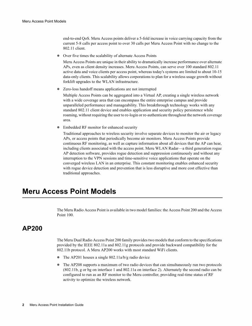
The Access Point 200 (referred hereafter as the AP200, unless specifically referring to the AP201 or AP208) is housed in a metal case with a plastic removable cover. As such, it can be used for plenum installations when the plastic cover is removed.
Figure 2: AP200
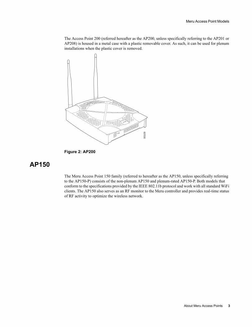
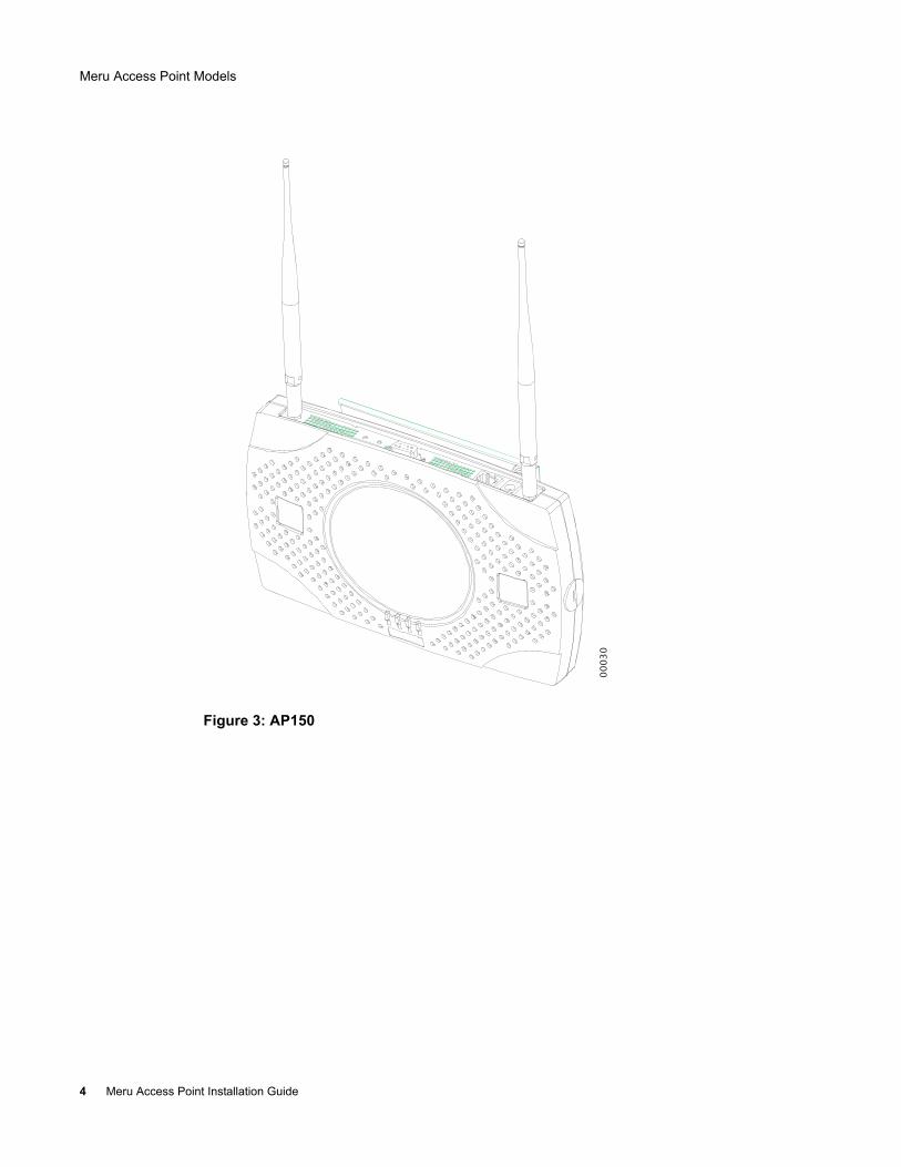
AP150The Meru Access Point 150 family (referred to hereafter as the AP150, unless specifically referring to the AP150-P) consists of the non-plenum AP150 and plenum-rated AP150-P. Both models that conform to the specifications provided by the IEEE 802.11b protocol and work with all standard WiFi clients. The AP150 also serves as an RF monitor to the Meru controller and provides real-time status of RF activity to optimize the wireless network.
AP200
0010
9
About Meru Access Points 3
Meru Access Point Models
Figure 3: AP150
00
03
0
4 Meru Access Point Installation Guide

Safety Precautions
Chapter 2Installing the AP200
This chapter describes how to physically install the Meru AP200. It contains the following sections:
Safety Precautions
Unpacking the AP200
Installation Requirements
Installing the Access Point
Where to Go From Here
Checking LED Activity
Safety Precautions
Follow the guidelines in this section to ensure proper operation and safe use of the access point.
FCC Safety Compliance StatementThe FCC with its action in ET Docket 96-8 has adopted a safety standard for human exposure to radio frequency (RF) electromagnetic energy emitted by FCC certified equipment. When used with approved Meru access point antennas, Meru AP200 products meet the uncontrolled environmental limits found in OET-65 and ANSI C95.1, 1991. Proper installation of this radio according to the instructions found in this manual will result in user exposure that is substantially below the FCC recommended limits.
General Safety GuidelinesDo not touch or move antenna(s) while the unit is transmitting or receiving.
Do not hold any component containing a radio so that the antenna is very close to or touching any exposed parts of the body, especially the face or eyes, while transmitting.
The use of wireless devices in hazardous locations is limited to the constraints posed by the local codes, the national codes, and the safety directors of such environments.
Installing the AP200 5
Unpacking the AP200
WarningsTranslated versions of the following safety warnings are provided in Appendix C.
Unpacking the AP200
The AP200 ships with a mounting bracket and mounting hardware for standard wall mounting. Optional mounting kits are available for mounting the AP200 above or below a hanging ceiling. The AP200 mounting studs are placed so they can be used with brackets supplied by other vendors or to replace an AP100.
Note: The AP200 has a security cable slot so you can secure the AP200 with a standard security cable, such as those used to secure laptop computers.
Warning! In order to comply with FCC radio frequency (RF) exposure limits, dipole antennas should be located at a minimum of 7.9 inches (20 cm) or more from the body of all persons.
Warning! Do not operate your wireless network device near unshielded blasting caps or in an explosive environment unless the device has been modified to be especially qualified for such use.
Warning! Do not work on the system or connect or disconnect cables during periods of lightning activity.
Warning! Read the installation instructions before you connect the system to its power source.
Warning! This product relies on the building's installation for short-circuit (overcurrent) protection. Ensure that a fuse or circuit breaker no larger than 120 VAC, 15A U.S. (240 VAC, 10A international) is used on the phase conductors (all current-carrying conductors).
Warning! Inside antennas must be positioned to observe minimum separation of 20 cm. (~ 8 in.) from all users and bystanders. For the protection of personnel working in the vicinity of inside (downlink) antennas, the following guidelines for minimum distances between the human body and the antenna must be observed.
The installation of the indoor antenna must be such that, under normal conditions, all personnel cannot come within 20 cm. (~ 8.0 in.) from any inside antenna. Exceeding this minimum separation will ensure that the employee or bystander does not receive RF-exposure beyond the Maximum Permissible Exposure according to FCC CFR 47, section 1.1310 i.e. limits for General Population/Uncontrolled Exposure.
6 Meru Access Point Installation Guide
Installation Requirements
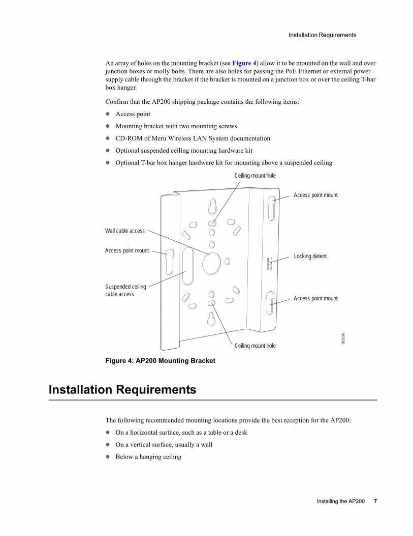
An array of holes on the mounting bracket (see Figure 4) allow it to be mounted on the wall and over junction boxes or molly bolts. There are also holes for passing the PoE Ethernet or external power supply cable through the bracket if the bracket is mounted on a junction box or over the ceiling T-bar box hanger.
Confirm that the AP200 shipping package contains the following items:
Access point
Mounting bracket with two mounting screws
CD-ROM of Meru Wireless LAN System documentation
Optional suspended ceiling mounting hardware kit
Optional T-bar box hanger hardware kit for mounting above a suspended ceiling
Figure 4: AP200 Mounting Bracket
Installation Requirements
The following recommended mounting locations provide the best reception for the AP200:
On a horizontal surface, such as a table or a desk
On a vertical surface, usually a wall
Below a hanging ceiling
Access point mount
Ceiling mount hole
Ceiling mount hole
Access point mount
Access point mount
Locking detent
Wall cable access
Suspended ceilingcable access
0010
0
Installing the AP200 7
Installation Requirements
Above a hanging ceiling tiles (this installation is supported only for the AP200 with the plastic enclosure removed)Suitable for use in environmental air space in accordance with the Section 300-22(c) of the National Electric Code and Sections 2- 128.12 - 010 (3) and 12 - 100 of the Canadian Electrical Code. Part 1. C22. 1. (For AP200 with plastic enclosure removed.)
To complete this installation, you need the items listed in Table 1.
8 Meru Access Point Installation Guide
Installation Requirements
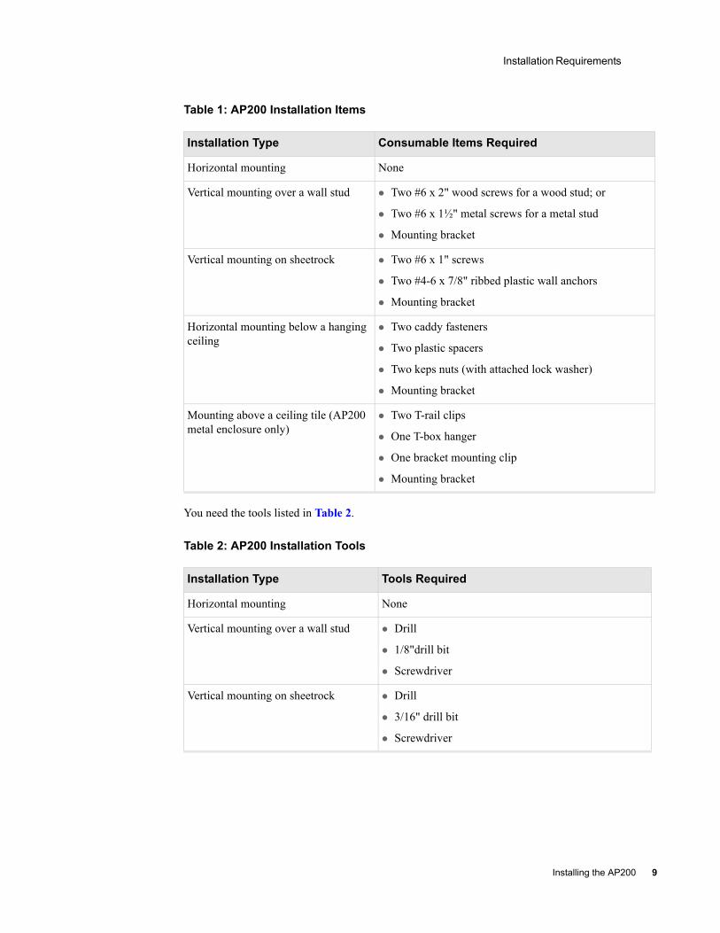
Table 1: AP200 Installation Items
You need the tools listed in Table 2.
Table 2: AP200 Installation Tools
Installation Type Consumable Items Required
Horizontal mounting None
Vertical mounting over a wall stud Two #6 x 2" wood screws for a wood stud; or
Two #6 x 1½" metal screws for a metal stud
Mounting bracket
Vertical mounting on sheetrock Two #6 x 1" screws
Two #4-6 x 7/8" ribbed plastic wall anchors
Mounting bracket
Horizontal mounting below a hanging ceiling
Two caddy fasteners
Two plastic spacers
Two keps nuts (with attached lock washer)
Mounting bracket
Mounting above a ceiling tile (AP200 metal enclosure only)
Two T-rail clips
One T-box hanger
One bracket mounting clip
Mounting bracket
Installation Type Tools Required
Horizontal mounting None
Vertical mounting over a wall stud Drill
1/8"drill bit
Screwdriver
Vertical mounting on sheetrock Drill
3/16" drill bit
Screwdriver
Installing the AP200 9
Installing the Access Point
Installing the Access Point
Selecting a LocationThe AP200 requires a location that meets the following:
Relatively unobstructed access to the stations the AP serves
Power over Ethernet (PoE) connection to the network switch servicing the controller.
APs can obtain their power from 802.3af standard Power over Ethernet (PoE) or external power supply. If an external power supply is utilized to power the AP200, ensure that it is a Listed power supply, marked "Class 2" or "LPS" (Limited Power Source), and rated a minimum of 3.3 V, 4 A. For PoE, the power can be supplied by a PoE-compatible network switch or PoE power injector installed between the switch and the AP200.
Select a location with minimal physical obstructions between the AP and the wireless stations. In an office with cubicles, mounting the APs below a hanging ceiling or the wall near the ceiling provides the least obstructed communications path. For an external power supply connection, ensure the power source is near to where the AP200 will be mounted.
Most installations receive the best coverage using the following guidelines:
Install APs toward the center of the building.
Do not install APs near metal objects, such as heating ducts, metal doors, or electric service panels.
Relative to the ground, orient the antenna up or down, not sideways.
The AP200 is only intended for installation in Environment A as defined in IEEE 802.3af. All interconnected equipment must be contained within the same building, including the interconnected equipment's associated LAN connection.
Horizontal mounting below a hanging ceiling
Screwdriver
Wrench or pliers
Mounting above a hanging ceiling (AP200 metal enclosure only)
Wrench or pliers
Screwdriver
Installation Type Tools Required
Note: The previous guidelines are general guidelines. Each site has its own unique environment. Place access points accordingly.
10 Meru Access Point Installation Guide
Installing the Access Point
Attaching the AP200 AntennasThe AP200 is provided with external antenna ports. Make sure that all external antennas and their associated wiring are located entirely indoors. The external antennas are not suitable for outside use.
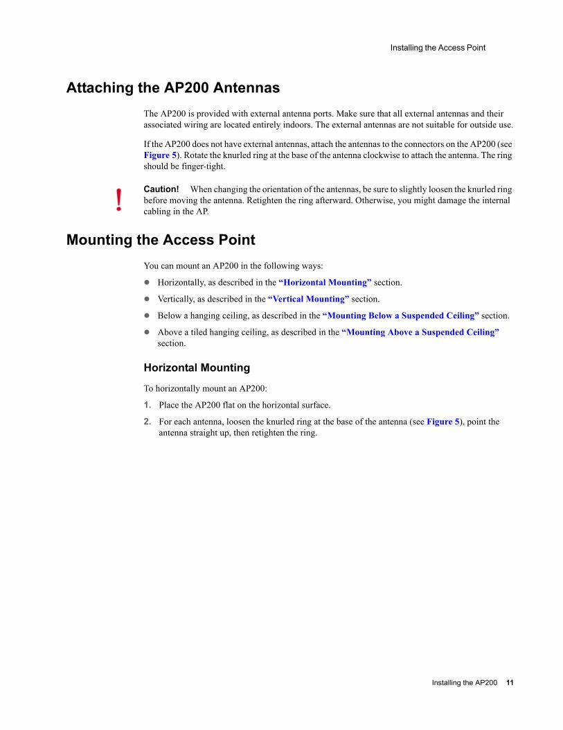
If the AP200 does not have external antennas, attach the antennas to the connectors on the AP200 (see Figure 5). Rotate the knurled ring at the base of the antenna clockwise to attach the antenna. The ring should be finger-tight.
Mounting the Access PointYou can mount an AP200 in the following ways:
Horizontally, as described in the “Horizontal Mounting” section.
Vertically, as described in the “Vertical Mounting” section.
Below a hanging ceiling, as described in the “Mounting Below a Suspended Ceiling” section.
Above a tiled hanging ceiling, as described in the “Mounting Above a Suspended Ceiling” section.
Horizontal Mounting
To horizontally mount an AP200:
1. Place the AP200 flat on the horizontal surface.
2. For each antenna, loosen the knurled ring at the base of the antenna (see Figure 5), point the antenna straight up, then retighten the ring.
Caution! When changing the orientation of the antennas, be sure to slightly loosen the knurled ring before moving the antenna. Retighten the ring afterward. Otherwise, you might damage the internal cabling in the AP.
Installing the AP200 11
Installing the Access Point
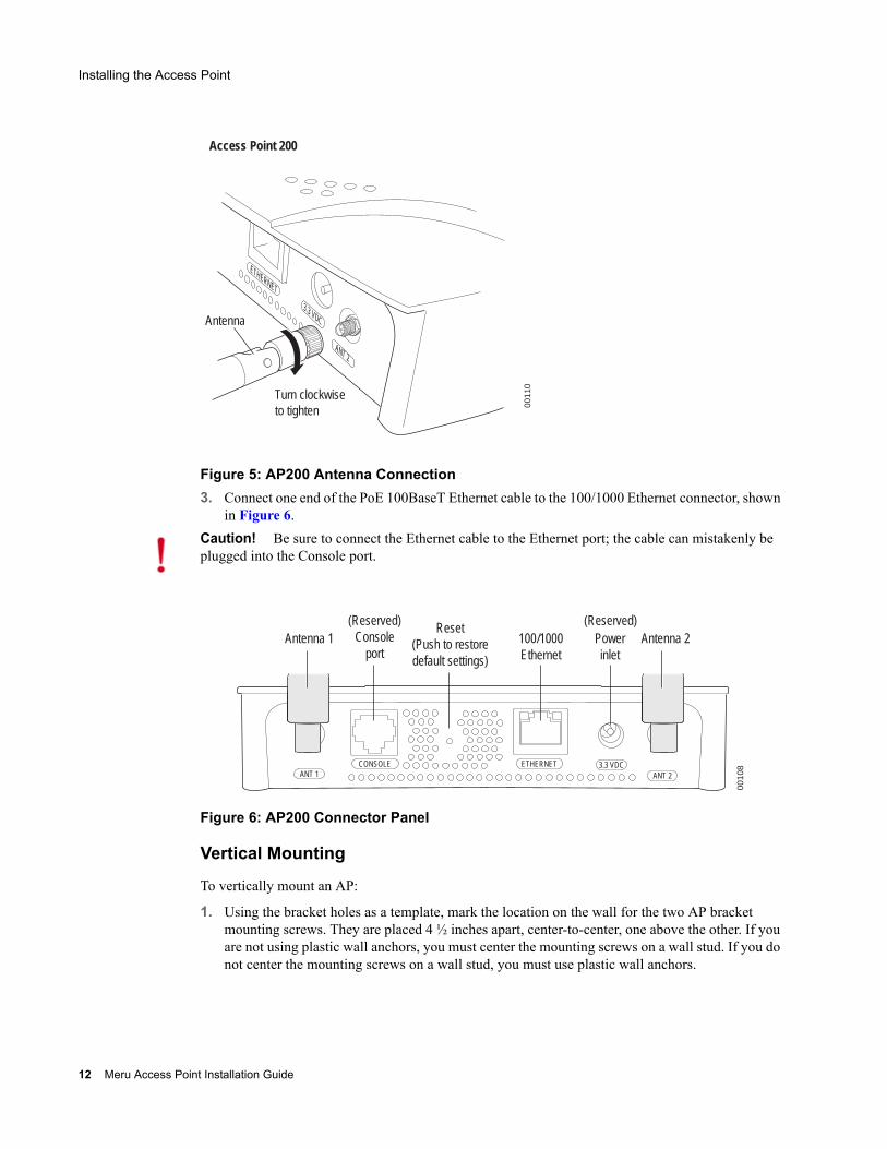
Figure 5: AP200 Antenna Connection3. Connect one end of the PoE 100BaseT Ethernet cable to the 100/1000 Ethernet connector, shown
in Figure 6.
Figure 6: AP200 Connector Panel
Vertical Mounting
To vertically mount an AP:
1. Using the bracket holes as a template, mark the location on the wall for the two AP bracket mounting screws. They are placed 4 ½ inches apart, center-to-center, one above the other. If you are not using plastic wall anchors, you must center the mounting screws on a wall stud. If you do not center the mounting screws on a wall stud, you must use plastic wall anchors.
Turn clockwiseto tighten
Antenna
Access Point 200
ETHERNET
3.3 VDC
ANT 2
0011
0
Caution! Be sure to connect the Ethernet cable to the Ethernet port; the cable can mistakenly be plugged into the Console port.
CONSOLEANT 1 ANT 2
3.3 VDCETHERNET
0010
8
100/1000Ethernet
(Reserved) Console
portAntenna 1 Antenna 2Power
inlet
Reset (Push to restore default settings)
(Reserved)
12 Meru Access Point Installation Guide
Installing the Access Point
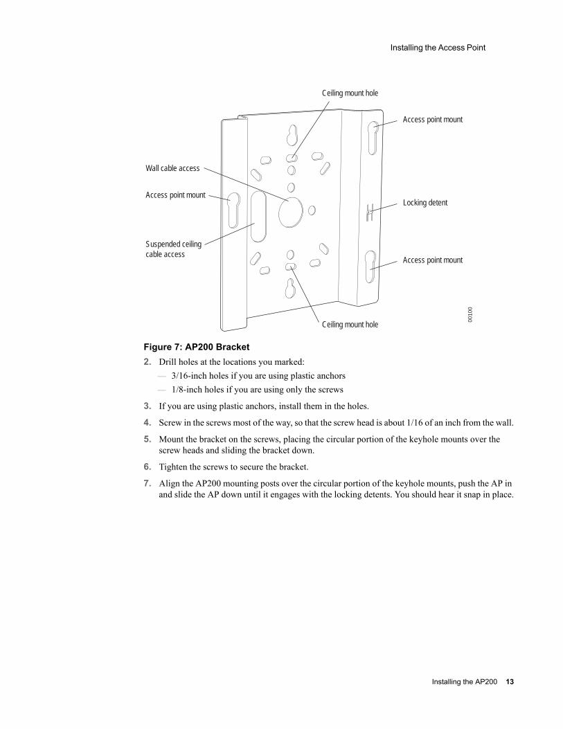
Figure 7: AP200 Bracket2. Drill holes at the locations you marked:
— 3/16-inch holes if you are using plastic anchors— 1/8-inch holes if you are using only the screws
3. If you are using plastic anchors, install them in the holes.
4. Screw in the screws most of the way, so that the screw head is about 1/16 of an inch from the wall.
5. Mount the bracket on the screws, placing the circular portion of the keyhole mounts over the screw heads and sliding the bracket down.
6. Tighten the screws to secure the bracket.
7. Align the AP200 mounting posts over the circular portion of the keyhole mounts, push the AP in and slide the AP down until it engages with the locking detents. You should hear it snap in place.
Access point mount
Ceiling mount hole
Ceiling mount hole
Access point mount
Access point mount
Locking detent
Wall cable access
Suspended ceilingcable access
0010
0
Installing the AP200 13
Installing the Access Point
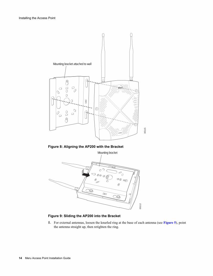
Figure 8: Aligning the AP200 with the Bracket
Figure 9: Sliding the AP200 into the Bracket
8. For external antennas, loosen the knurled ring at the base of each antenna (see Figure 5), point the antenna straight up, then retighten the ring.
0011
5
Mounting bracket attached to wall
AP200
0011
2
Mounting bracket
14 Meru Access Point Installation Guide
Installing the Access Point
9. Connect one end of the PoE 100BaseT Ethernet cable to the 100/1000 Ethernet connector, shown in Figure 6.
Mounting Below a Suspended Ceiling
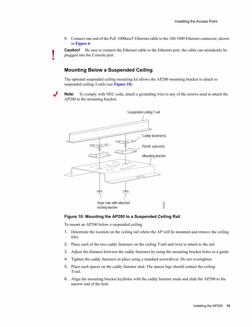
The optional suspended ceiling mounting kit allows the AP200 mounting bracket to attach to suspended ceiling T-rails (see Figure 10).
Note: To comply with NEC code, attach a grounding wire to any of the screws used to attach the AP200 to the mounting bracket.
Figure 10: Mounting the AP200 to a Suspended Ceiling Rail
To mount an AP200 below a suspended ceiling:
1. Determine the location on the ceiling rail where the AP will be mounted and remove the ceiling tiles.
2. Place each of the two caddy fasteners on the ceiling T-rail and twist to attach to the rail.
3. Adjust the distance between the caddy fasteners by using the mounting bracket holes as a guide.
4. Tighten the caddy fasteners in place using a standard screwdriver. Do not overtighten.
5. Place each spacer on the caddy fastener stud. The spacer legs should contact the ceiling T-rail.
6. Align the mounting bracket keyholes with the caddy fastener studs and slide the AP200 to the narrow end of the hole.
Caution! Be sure to connect the Ethernet cable to the Ethernet port; the cable can mistakenly be plugged into the Console port.
Suspended ceiling T-rail
Mounting bracket
Keps nuts with attachedlocking washer
Caddy fastener(s)
Plastic spacer(s)
0010
2
Installing the AP200 15
Installing the Access Point
7. Attach a keps nut to each caddy fastener stud and hand tighten. Do not overtighten.
8. Align the AP200 mounting posts over the circular portion of the keyhole mounts, push the AP in and slide the AP down until it engages with the locking detents (see Figure 9). You should hear it snap in place.
9. For each antenna, loosen the knurled ring at the base of the antenna (see Figure 5), point the antenna straight down, then retighten the ring.
10. Connect one end of the PoE 100BaseT Ethernet cable to the 100/1000 Ethernet connector, shown in (see Figure 6).
Mounting Above a Suspended Ceiling
The optional T-bar box hanger mounting kit allows the AP200 to be mounted above suspended ceiling T-rails (see Figure 11). The installation attaches the T-bar box hanger to the ceiling rails using clips. The AP200 attaches to the mounting bracket that is attached to the T-bar box hanger.
The AP200 antennas should point straight down for this type of installation. You may need to modify thicker tiles to support this installation.
Any Fast Ethernet (FE) cables installed in air-handling spaces should be suitable under NEC Article 800.50 and marked accordingly for use in plenums and air-handling spaces with regard to smoke propagation, such as CL2-P, CL3-P, MPP (Multi Purpose Plenum), or CMP (Communications Plenum).
Caution! Be sure to connect the Ethernet cable to the Ethernet port; the cable can mistakenly be plugged into the Console port.
Note: When installed in air-handling spaces, such as above a suspended ceiling, the AP200 is to be powered via PoE only (PoE is required).
Note: The AP200 with the metal enclosure exposed meets the requirements for fire resistance and low smoke-generating characteristics required by Section 300-22(C) of the National Electrical Code (NEC) for installation in a building’s environmental air space. You must remove the plastic enclosure to reveal the plenum-rated AP200 metal case for installations above a suspended ceiling.
Additionally, you must use Ethernet cable that meets the requirements for operating in environmental air space (in accordance with Section 300-22(C) of the NEC).
16 Meru Access Point Installation Guide
Installing the Access Point
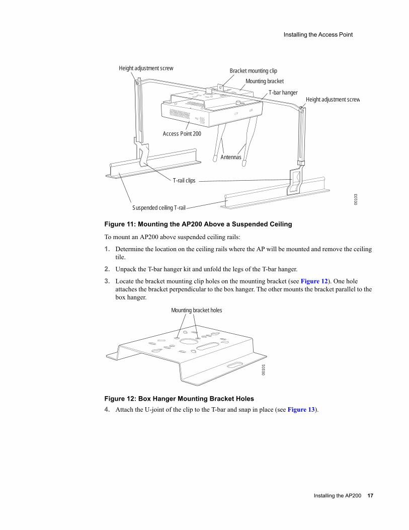
Figure 11: Mounting the AP200 Above a Suspended Ceiling
To mount an AP200 above suspended ceiling rails:
1. Determine the location on the ceiling rails where the AP will be mounted and remove the ceiling tile.
2. Unpack the T-bar hanger kit and unfold the legs of the T-bar hanger.
3. Locate the bracket mounting clip holes on the mounting bracket (see Figure 12). One hole attaches the bracket perpendicular to the box hanger. The other mounts the bracket parallel to the box hanger.
Figure 12: Box Hanger Mounting Bracket Holes4. Attach the U-joint of the clip to the T-bar and snap in place (see Figure 13).
Bracket mounting clip
Mounting bracket
T-bar hangerHeight adjustment screw
Height adjustment screw
Suspended ceiling T-rail
T-rail clips
Antennas
Access Point 200
0010
3
Mounting bracket holes
0010
1
Installing the AP200 17
Installing the Access Point
.
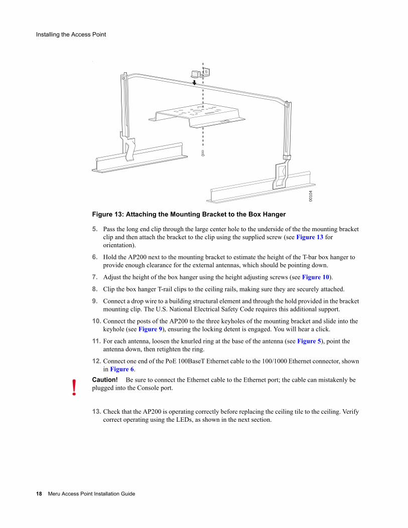
Figure 13: Attaching the Mounting Bracket to the Box Hanger
5. Pass the long end clip through the large center hole to the underside of the the mounting bracket clip and then attach the bracket to the clip using the supplied screw (see Figure 13 for orientation).
6. Hold the AP200 next to the mounting bracket to estimate the height of the T-bar box hanger to provide enough clearance for the external antennas, which should be pointing down.
7. Adjust the height of the box hanger using the height adjusting screws (see Figure 10).
8. Clip the box hanger T-rail clips to the ceiling rails, making sure they are securely attached.
9. Connect a drop wire to a building structural element and through the hold provided in the bracket mounting clip. The U.S. National Electrical Safety Code requires this additional support.
10. Connect the posts of the AP200 to the three keyholes of the mounting bracket and slide into the keyhole (see Figure 9), ensuring the locking detent is engaged. You will hear a click.
11. For each antenna, loosen the knurled ring at the base of the antenna (see Figure 5), point the antenna down, then retighten the ring.
12. Connect one end of the PoE 100BaseT Ethernet cable to the 100/1000 Ethernet connector, shown in Figure 6.
13. Check that the AP200 is operating correctly before replacing the ceiling tile to the ceiling. Verify correct operating using the LEDs, as shown in the next section.
0010
4
Caution! Be sure to connect the Ethernet cable to the Ethernet port; the cable can mistakenly be plugged into the Console port.
18 Meru Access Point Installation Guide
Where to Go From Here
Where to Go From Here
Now that the AP200 is installed, go to the Meru Wireless LAN Getting Started Guide for instructions on initializing the controller and connecting the controller and APs to the Ethernet switch to form the WLAN. Return to this section to check the status of the LEDs once the WLAN is operational.
Checking LED Activity
Access point status LEDs are provided on the Ethernet connector and on the face of the AP200.
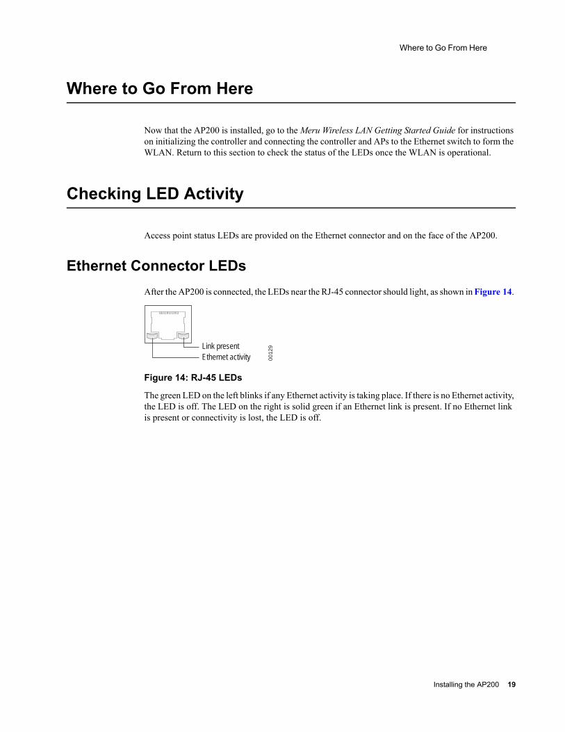
Ethernet Connector LEDsAfter the AP200 is connected, the LEDs near the RJ-45 connector should light, as shown in Figure 14.
Figure 14: RJ-45 LEDs
The green LED on the left blinks if any Ethernet activity is taking place. If there is no Ethernet activity, the LED is off. The LED on the right is solid green if an Ethernet link is present. If no Ethernet link is present or connectivity is lost, the LED is off.
Ethernet activityLink present
0012
9
Installing the AP200 19
Checking LED Activity
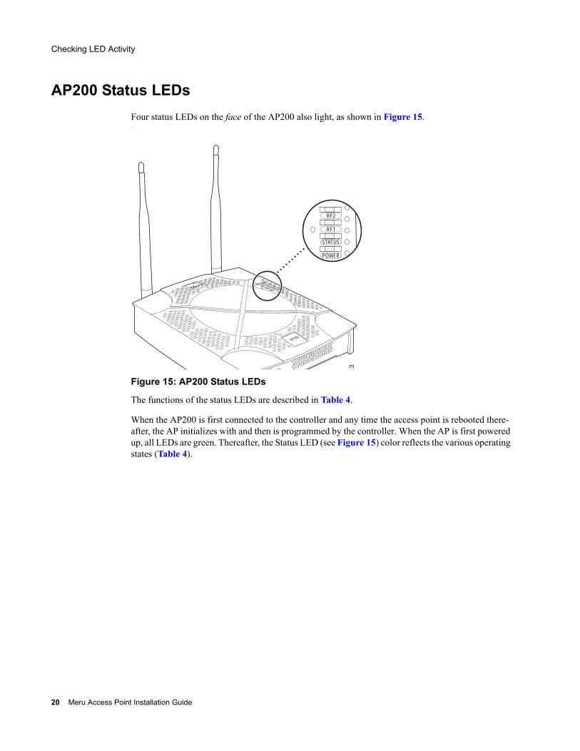
AP200 Status LEDsFour status LEDs on the face of the AP200 also light, as shown in Figure 15..
Figure 15: AP200 Status LEDs
The functions of the status LEDs are described in Table 4.
When the AP200 is first connected to the controller and any time the access point is rebooted there-after, the AP initializes with and then is programmed by the controller. When the AP is first powered up, all LEDs are green. Thereafter, the Status LED (see Figure 15) color reflects the various operating states (Table 4).
AP200
RF2
RF1
STATUS
POWER
11
3
20 Meru Access Point Installation Guide
Checking LED Activity
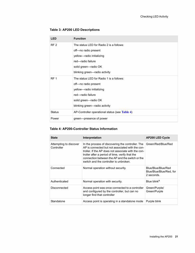
Table 3: AP200 LED Descriptions
Table 4: AP200-Controller Status Information
LED Function
RF 2 The status LED for Radio 2 is a follows:
off—no radio present
yellow—radio initializing
red—radio failure
solid green—radio OK
blinking green—radio activity
RF 1 The status LED for Radio 1 is a follows:
off—no radio present
yellow—radio initializing
red—radio failure
solid green—radio OK
blinking green—radio activity
Status AP-Controller operational status (see Table 4)
Power green—presence of power
State Interpretation AP200 LED Cycle
Attempting to discover Controller
In the process of discovering the controller. The AP is connected but not associated with the con-troller. If the AP does not associate with the con-troller after a period of time, verify that the connection between the AP and the switch or the switch and the controller is unbroken.
Green/Red/Blue/Red
Connected Normal operation without security. Blue/Blue/Blue/RedBlue/Blue/Blue/Red, for 2 seconds.
Authenticated Normal operation with security. Blue blinka
Disconnected Access point was once connected to a controller and configured by the controller, but can no longer find that controller
Green/Purple/Green/Purple
Standalone Access point is operating in a standalone mode Purple blink
Installing the AP200 21
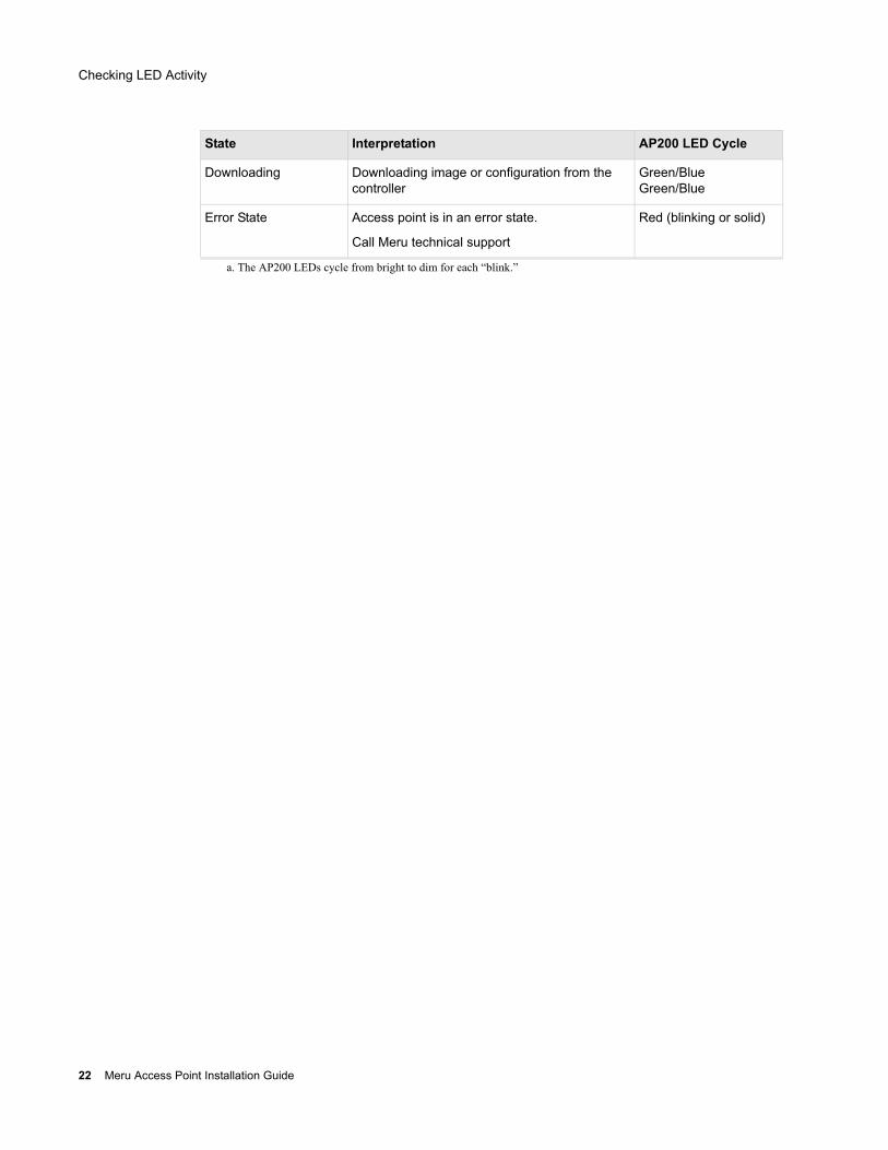
Checking LED Activity
Downloading Downloading image or configuration from the controller
Green/BlueGreen/Blue
Error State Access point is in an error state.
Call Meru technical support
Red (blinking or solid)
a. The AP200 LEDs cycle from bright to dim for each “blink.”
State Interpretation AP200 LED Cycle
22 Meru Access Point Installation Guide
Safety Precautions
Chapter 3Installing the AP150
This chapter describes how to physically install the Meru AP150. It contains the following sections:
Safety Precautions
Unpacking the AP150
Installation Requirements
Installing the Access Point
Where to Go From Here
Checking LED Activity
Safety Precautions
Follow the guidelines in this section to ensure proper operation and safe use of the access point.
FCC Safety Compliance StatementThe FCC with its action in ET Docket 96-8 has adopted a safety standard for human exposure to radio frequency (RF) electromagnetic energy emitted by FCC certified equipment. When used with approved Meru access point antennas, Meru AP150 products meet the uncontrolled environmental limits found in OET-65 and ANSI C95.1, 1991. Proper installation of this radio according to the instructions found in this manual will result in user exposure that is substantially below the FCC recommended limits.
General Safety GuidelinesDo not touch or move antenna(s) while the unit is transmitting or receiving.
Do not hold any component containing a radio so that the antenna is very close to or touching any exposed parts of the body, especially the face or eyes, while transmitting.
The use of wireless devices in hazardous locations is limited to the constraints posed by the local codes, the national codes, and the safety directors of such environments.
Installing the AP150 23

Unpacking the AP150
WarningsTranslated versions of the following safety warnings are provided in Appendix C.
Unpacking the AP150
The AP150 ships with a mounting bracket and mounting hardware for standard wall mounting. Optional mounting kits are available for mounting the AP150 above or below a hanging ceiling. The AP150 mounting studs are placed so they can be used with brackets supplied by other vendors or to replace an AP100.
Note: The AP150 has a security cable slot so you can secure the AP150 with a standard security cable, such as those used to secure laptop computers.
Warning! In order to comply with FCC radio frequency (RF) exposure limits, dipole antennas should be located at a minimum of 7.9 inches (20 cm) or more from the body of all persons.
Warning! Do not operate your wireless network device near unshielded blasting caps or in an explosive environment unless the device has been modified to be especially qualified for such use.
Warning! Do not work on the system or connect or disconnect cables during periods of lightning activity.
Warning! Read the installation instructions before you connect the system to its power source.
Warning! This product relies on the building's installation for short-circuit (overcurrent) protection. Ensure that a fuse or circuit breaker no larger than 120 VAC, 15A U.S. (240 VAC, 10A international) is used on the phase conductors (all current-carrying conductors).
Warning! Inside antennas must be positioned to observe minimum separation of 20 cm. (~ 8 in.) from all users and bystanders. For the protection of personnel working in the vicinity of inside (downlink) antennas, the following guidelines for minimum distances between the human body and the antenna must be observed.
The installation of the indoor antenna must be such that, under normal conditions, all personnel cannot come within 20 cm. (~ 8.0 in.) from any inside antenna. Exceeding this minimum separation will ensure that the employee or bystander does not receive RF-exposure beyond the Maximum Permissible Exposure according to FCC CFR 47, section 1.1310 i.e. limits for General Population/Uncontrolled Exposure.
24 Meru Access Point Installation Guide
Unpacking the AP150
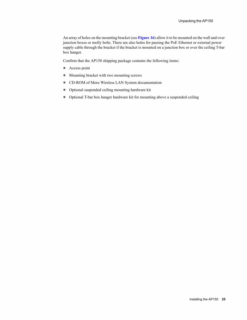
An array of holes on the mounting bracket (see Figure 16) allow it to be mounted on the wall and over junction boxes or molly bolts. There are also holes for passing the PoE Ethernet or external power supply cable through the bracket if the bracket is mounted on a junction box or over the ceiling T-bar box hanger.
Confirm that the AP150 shipping package contains the following items:
Access point
Mounting bracket with two mounting screws
CD-ROM of Meru Wireless LAN System documentation
Optional suspended ceiling mounting hardware kit
Optional T-bar box hanger hardware kit for mounting above a suspended ceiling
Installing the AP150 25
Installation Requirements
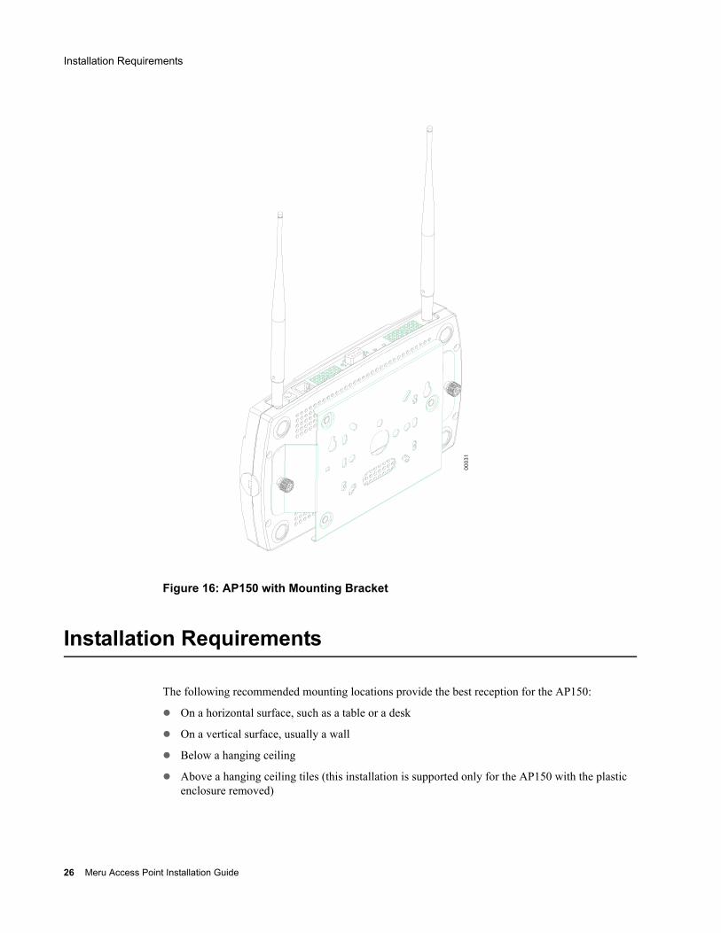
Figure 16: AP150 with Mounting Bracket
Installation Requirements
The following recommended mounting locations provide the best reception for the AP150:
On a horizontal surface, such as a table or a desk
On a vertical surface, usually a wall
Below a hanging ceiling
Above a hanging ceiling tiles (this installation is supported only for the AP150 with the plastic enclosure removed)
00
03
1
26 Meru Access Point Installation Guide
Installation Requirements
Suitable for use in environmental air space in accordance with the Section 300-22(c) of the National Electric Code and Sections 2- 128.12 - 010 (3) and 12 - 100 of the Canadian Electrical Code. Part 1. C22. 1. (For AP150 with plastic enclosure removed.)
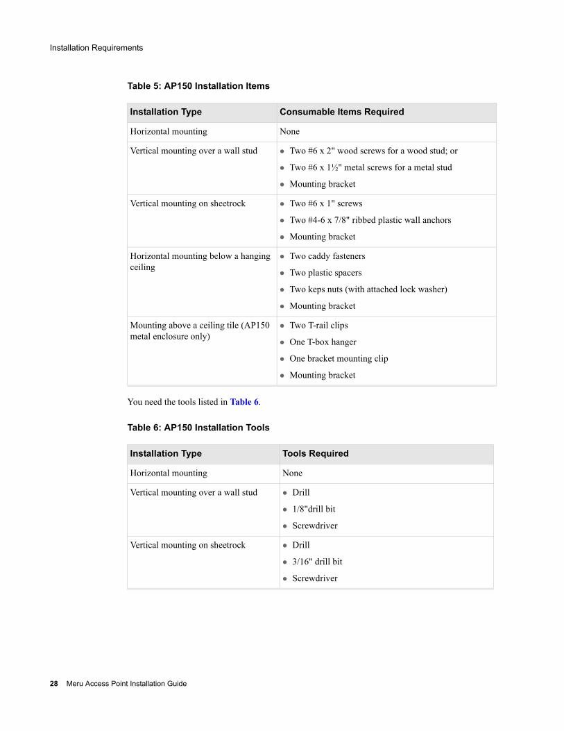
To complete this installation, you need the items listed in Table 5.
Installing the AP150 27
Installation Requirements
Table 5: AP150 Installation Items
You need the tools listed in Table 6.
Table 6: AP150 Installation Tools
Installation Type Consumable Items Required
Horizontal mounting None
Vertical mounting over a wall stud Two #6 x 2" wood screws for a wood stud; or
Two #6 x 1½" metal screws for a metal stud
Mounting bracket
Vertical mounting on sheetrock Two #6 x 1" screws
Two #4-6 x 7/8" ribbed plastic wall anchors
Mounting bracket
Horizontal mounting below a hanging ceiling
Two caddy fasteners
Two plastic spacers
Two keps nuts (with attached lock washer)
Mounting bracket
Mounting above a ceiling tile (AP150 metal enclosure only)
Two T-rail clips
One T-box hanger
One bracket mounting clip
Mounting bracket
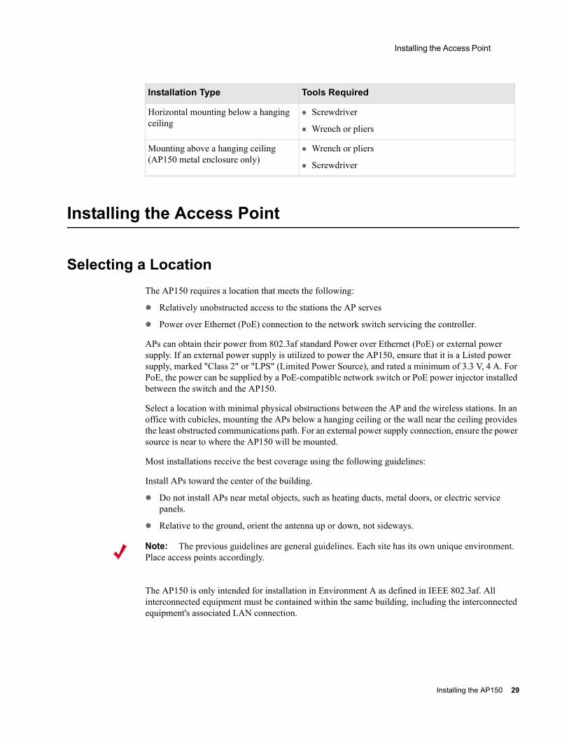
Installation Type Tools Required
Horizontal mounting None
Vertical mounting over a wall stud Drill
1/8"drill bit
Screwdriver
Vertical mounting on sheetrock Drill
3/16" drill bit
Screwdriver
28 Meru Access Point Installation Guide
Installing the Access Point
Installing the Access Point
Selecting a LocationThe AP150 requires a location that meets the following:
Relatively unobstructed access to the stations the AP serves
Power over Ethernet (PoE) connection to the network switch servicing the controller.
APs can obtain their power from 802.3af standard Power over Ethernet (PoE) or external power supply. If an external power supply is utilized to power the AP150, ensure that it is a Listed power supply, marked "Class 2" or "LPS" (Limited Power Source), and rated a minimum of 3.3 V, 4 A. For PoE, the power can be supplied by a PoE-compatible network switch or PoE power injector installed between the switch and the AP150.
Select a location with minimal physical obstructions between the AP and the wireless stations. In an office with cubicles, mounting the APs below a hanging ceiling or the wall near the ceiling provides the least obstructed communications path. For an external power supply connection, ensure the power source is near to where the AP150 will be mounted.
Most installations receive the best coverage using the following guidelines:
Install APs toward the center of the building.
Do not install APs near metal objects, such as heating ducts, metal doors, or electric service panels.
Relative to the ground, orient the antenna up or down, not sideways.
The AP150 is only intended for installation in Environment A as defined in IEEE 802.3af. All interconnected equipment must be contained within the same building, including the interconnected equipment's associated LAN connection.
Horizontal mounting below a hanging ceiling
Screwdriver
Wrench or pliers
Mounting above a hanging ceiling (AP150 metal enclosure only)
Wrench or pliers
Screwdriver
Installation Type Tools Required
Note: The previous guidelines are general guidelines. Each site has its own unique environment. Place access points accordingly.
Installing the AP150 29
Installing the Access Point
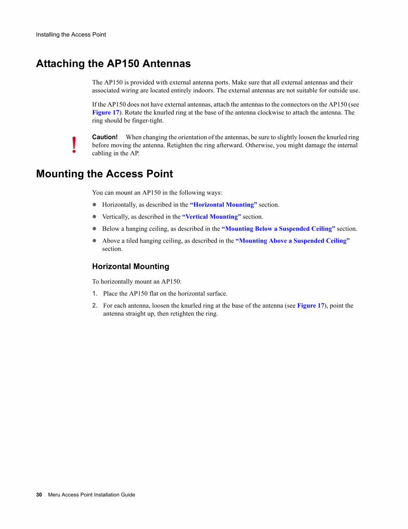
Attaching the AP150 AntennasThe AP150 is provided with external antenna ports. Make sure that all external antennas and their associated wiring are located entirely indoors. The external antennas are not suitable for outside use.
If the AP150 does not have external antennas, attach the antennas to the connectors on the AP150 (see Figure 17). Rotate the knurled ring at the base of the antenna clockwise to attach the antenna. The ring should be finger-tight.
Mounting the Access PointYou can mount an AP150 in the following ways:
Horizontally, as described in the “Horizontal Mounting” section.
Vertically, as described in the “Vertical Mounting” section.
Below a hanging ceiling, as described in the “Mounting Below a Suspended Ceiling” section.
Above a tiled hanging ceiling, as described in the “Mounting Above a Suspended Ceiling” section.
Horizontal Mounting
To horizontally mount an AP150:
1. Place the AP150 flat on the horizontal surface.
2. For each antenna, loosen the knurled ring at the base of the antenna (see Figure 17), point the antenna straight up, then retighten the ring.
Caution! When changing the orientation of the antennas, be sure to slightly loosen the knurled ring before moving the antenna. Retighten the ring afterward. Otherwise, you might damage the internal cabling in the AP.
30 Meru Access Point Installation Guide
Installing the Access Point
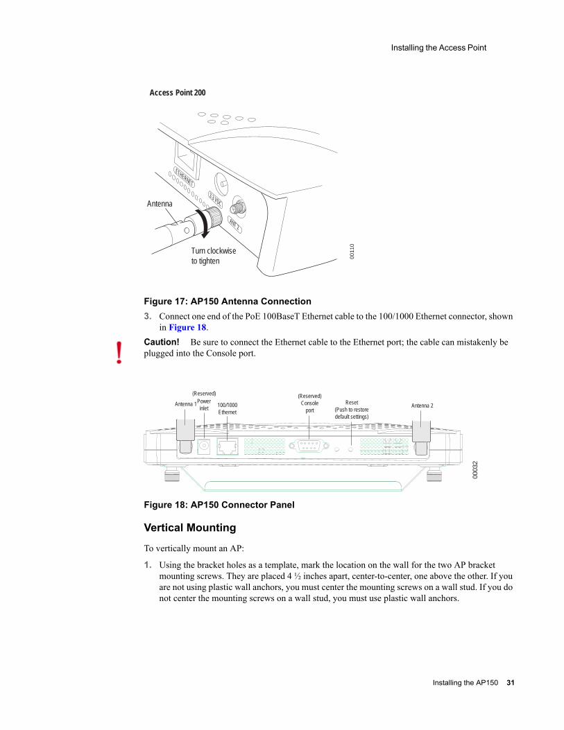
Figure 17: AP150 Antenna Connection3. Connect one end of the PoE 100BaseT Ethernet cable to the 100/1000 Ethernet connector, shown
in Figure 18.
Figure 18: AP150 Connector Panel
Vertical Mounting
To vertically mount an AP:
1. Using the bracket holes as a template, mark the location on the wall for the two AP bracket mounting screws. They are placed 4 ½ inches apart, center-to-center, one above the other. If you are not using plastic wall anchors, you must center the mounting screws on a wall stud. If you do not center the mounting screws on a wall stud, you must use plastic wall anchors.
Turn clockwiseto tighten
Antenna
Access Point 200
ETHERNET
3.3 VDC
ANT 2
0011
0
Caution! Be sure to connect the Ethernet cable to the Ethernet port; the cable can mistakenly be plugged into the Console port.
00032
Antenna 1 Antenna 2Powerinlet
(Reserved)
100/1000Ethernet
(Reserved) Console
portReset
(Push to restore default settings)
Installing the AP150 31
Installing the Access Point
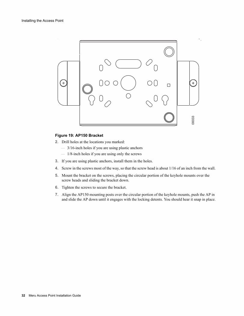
Figure 19: AP150 Bracket2. Drill holes at the locations you marked:
— 3/16-inch holes if you are using plastic anchors— 1/8-inch holes if you are using only the screws
3. If you are using plastic anchors, install them in the holes.
4. Screw in the screws most of the way, so that the screw head is about 1/16 of an inch from the wall.
5. Mount the bracket on the screws, placing the circular portion of the keyhole mounts over the screw heads and sliding the bracket down.
6. Tighten the screws to secure the bracket.
7. Align the AP150 mounting posts over the circular portion of the keyhole mounts, push the AP in and slide the AP down until it engages with the locking detents. You should hear it snap in place.
00033
32 Meru Access Point Installation Guide
Installing the Access Point
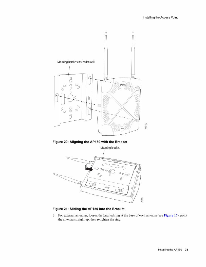
Figure 20: Aligning the AP150 with the Bracket
Figure 21: Sliding the AP150 into the Bracket
8. For external antennas, loosen the knurled ring at the base of each antenna (see Figure 17), point the antenna straight up, then retighten the ring.
0011
5
Mounting bracket attached to wall
AP200
0011
2
Mounting bracket
Installing the AP150 33
Installing the Access Point
9. Connect one end of the PoE 100BaseT Ethernet cable to the 100/1000 Ethernet connector, shown in Figure 18.
Mounting Below a Suspended Ceiling
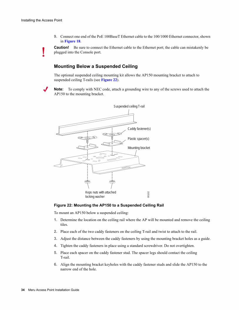
The optional suspended ceiling mounting kit allows the AP150 mounting bracket to attach to suspended ceiling T-rails (see Figure 22).
Note: To comply with NEC code, attach a grounding wire to any of the screws used to attach the AP150 to the mounting bracket.
Figure 22: Mounting the AP150 to a Suspended Ceiling Rail
To mount an AP150 below a suspended ceiling:
1. Determine the location on the ceiling rail where the AP will be mounted and remove the ceiling tiles.
2. Place each of the two caddy fasteners on the ceiling T-rail and twist to attach to the rail.
3. Adjust the distance between the caddy fasteners by using the mounting bracket holes as a guide.
4. Tighten the caddy fasteners in place using a standard screwdriver. Do not overtighten.
5. Place each spacer on the caddy fastener stud. The spacer legs should contact the ceiling T-rail.
6. Align the mounting bracket keyholes with the caddy fastener studs and slide the AP150 to the narrow end of the hole.
Caution! Be sure to connect the Ethernet cable to the Ethernet port; the cable can mistakenly be plugged into the Console port.
Suspended ceiling T-rail
Mounting bracket
Keps nuts with attachedlocking washer
Caddy fastener(s)
Plastic spacer(s)
0010
2
34 Meru Access Point Installation Guide
Installing the Access Point
7. Attach a keps nut to each caddy fastener stud and hand tighten. Do not overtighten.
8. Align the AP150 mounting posts over the circular portion of the keyhole mounts, push the AP in and slide the AP down until it engages with the locking detents (see Figure 21). You should hear it snap in place.
9. For each antenna, loosen the knurled ring at the base of the antenna (see Figure 17), point the antenna straight down, then retighten the ring.
10. Connect one end of the PoE 100BaseT Ethernet cable to the 100/1000 Ethernet connector, shown in (see Figure 18).
Mounting Above a Suspended Ceiling
The optional T-bar box hanger mounting kit allows the AP150 to be mounted above suspended ceiling T-rails (see Figure 23). The installation attaches the T-bar box hanger to the ceiling rails using clips. The AP150 attaches to the mounting bracket that is attached to the T-bar box hanger.
The AP150 antennas should point straight down for this type of installation. You may need to modify thicker tiles to support this installation.
Any Fast Ethernet (FE) cables installed in air-handling spaces should be suitable under NEC Article 800.50 and marked accordingly for use in plenums and air-handling spaces with regard to smoke propagation, such as CL2-P, CL3-P, MPP (Multi Purpose Plenum), or CMP (Communications Plenum).
Caution! Be sure to connect the Ethernet cable to the Ethernet port; the cable can mistakenly be plugged into the Console port.
Note: When installed in air-handling spaces, such as above a suspended ceiling, the AP150 is to be powered via PoE only (PoE is required).
Note: The AP150 with the metal enclosure exposed meets the requirements for fire resistance and low smoke-generating characteristics required by Section 300-22(C) of the National Electrical Code (NEC) for installation in a building’s environmental air space. You must remove the plastic enclosure to reveal the plenum-rated AP150 metal case for installations above a suspended ceiling.
Additionally, you must use Ethernet cable that meets the requirements for operating in environmental air space (in accordance with Section 300-22(C) of the NEC).
Installing the AP150 35
Installing the Access Point
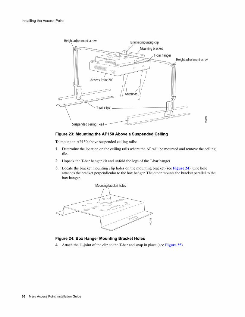
Figure 23: Mounting the AP150 Above a Suspended Ceiling
To mount an AP150 above suspended ceiling rails:
1. Determine the location on the ceiling rails where the AP will be mounted and remove the ceiling tile.
2. Unpack the T-bar hanger kit and unfold the legs of the T-bar hanger.
3. Locate the bracket mounting clip holes on the mounting bracket (see Figure 24). One hole attaches the bracket perpendicular to the box hanger. The other mounts the bracket parallel to the box hanger.
Figure 24: Box Hanger Mounting Bracket Holes4. Attach the U-joint of the clip to the T-bar and snap in place (see Figure 25).
Bracket mounting clip
Mounting bracket
T-bar hangerHeight adjustment screw
Height adjustment screw
Suspended ceiling T-rail
T-rail clips
Antennas
Access Point 200
0010
3
Mounting bracket holes
0010
1
36 Meru Access Point Installation Guide
Installing the Access Point
.
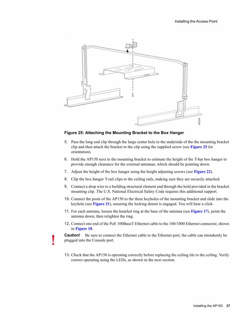
Figure 25: Attaching the Mounting Bracket to the Box Hanger
5. Pass the long end clip through the large center hole to the underside of the the mounting bracket clip and then attach the bracket to the clip using the supplied screw (see Figure 25 for orientation).
6. Hold the AP150 next to the mounting bracket to estimate the height of the T-bar box hanger to provide enough clearance for the external antennas, which should be pointing down.
7. Adjust the height of the box hanger using the height adjusting screws (see Figure 22).
8. Clip the box hanger T-rail clips to the ceiling rails, making sure they are securely attached.
9. Connect a drop wire to a building structural element and through the hold provided in the bracket mounting clip. The U.S. National Electrical Safety Code requires this additional support.
10. Connect the posts of the AP150 to the three keyholes of the mounting bracket and slide into the keyhole (see Figure 21), ensuring the locking detent is engaged. You will hear a click.
11. For each antenna, loosen the knurled ring at the base of the antenna (see Figure 17), point the antenna down, then retighten the ring.
12. Connect one end of the PoE 100BaseT Ethernet cable to the 100/1000 Ethernet connector, shown in Figure 18.
13. Check that the AP150 is operating correctly before replacing the ceiling tile to the ceiling. Verify correct operating using the LEDs, as shown in the next section.
0010
4
Caution! Be sure to connect the Ethernet cable to the Ethernet port; the cable can mistakenly be plugged into the Console port.
Installing the AP150 37
Where to Go From Here
Where to Go From Here
Now that the AP150 is installed, go to the Meru Wireless LAN Getting Started Guide for instructions on initializing the controller and connecting the controller and APs to the Ethernet switch to form the WLAN. Return to this section to check the status of the LEDs once the WLAN is operational.
Checking LED Activity
Access point status LEDs are provided on the Ethernet connector and on the face of the AP150.
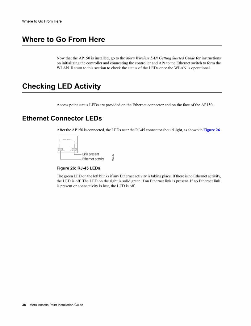
Ethernet Connector LEDsAfter the AP150 is connected, the LEDs near the RJ-45 connector should light, as shown in Figure 26.
Figure 26: RJ-45 LEDs
The green LED on the left blinks if any Ethernet activity is taking place. If there is no Ethernet activity, the LED is off. The LED on the right is solid green if an Ethernet link is present. If no Ethernet link is present or connectivity is lost, the LED is off.
Ethernet activityLink present
0012
9
38 Meru Access Point Installation Guide
Checking LED Activity
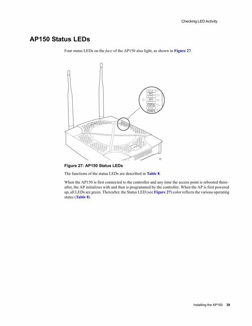
AP150 Status LEDsFour status LEDs on the face of the AP150 also light, as shown in Figure 27..
Figure 27: AP150 Status LEDs
The functions of the status LEDs are described in Table 8.
When the AP150 is first connected to the controller and any time the access point is rebooted there-after, the AP initializes with and then is programmed by the controller. When the AP is first powered up, all LEDs are green. Thereafter, the Status LED (see Figure 27) color reflects the various operating states (Table 8).
AP200
RF2
RF1
STATUS
POWER
11
3
Installing the AP150 39
Checking LED Activity
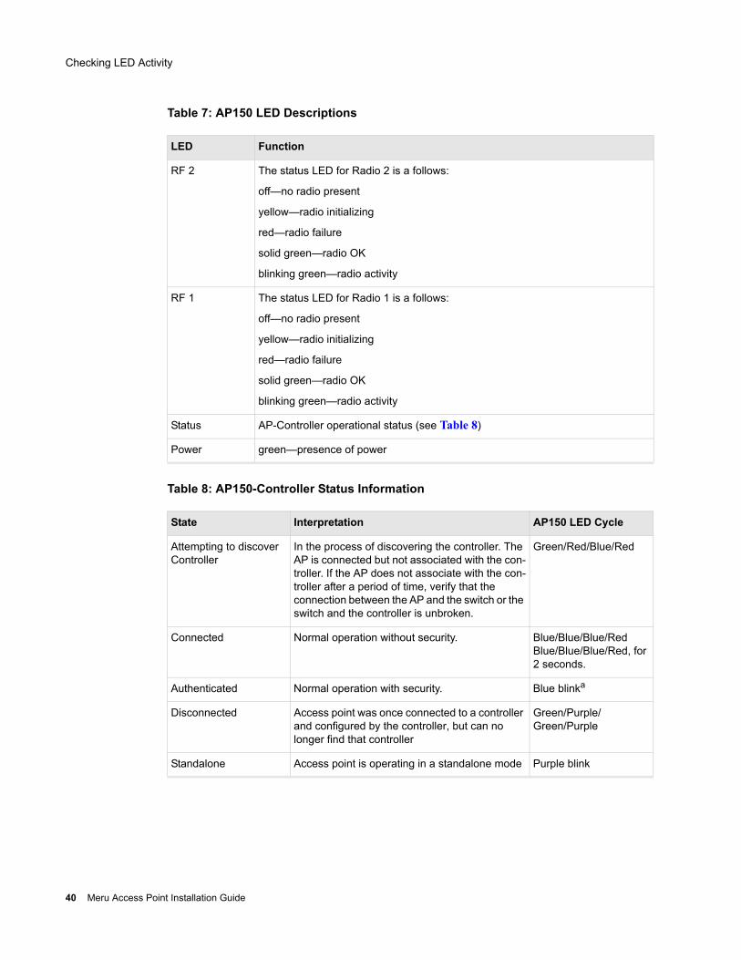
Table 7: AP150 LED Descriptions
Table 8: AP150-Controller Status Information
LED Function
RF 2 The status LED for Radio 2 is a follows:
off—no radio present
yellow—radio initializing
red—radio failure
solid green—radio OK
blinking green—radio activity
RF 1 The status LED for Radio 1 is a follows:
off—no radio present
yellow—radio initializing
red—radio failure
solid green—radio OK
blinking green—radio activity
Status AP-Controller operational status (see Table 8)
Power green—presence of power
State Interpretation AP150 LED Cycle
Attempting to discover Controller
In the process of discovering the controller. The AP is connected but not associated with the con-troller. If the AP does not associate with the con-troller after a period of time, verify that the connection between the AP and the switch or the switch and the controller is unbroken.
Green/Red/Blue/Red
Connected Normal operation without security. Blue/Blue/Blue/RedBlue/Blue/Blue/Red, for 2 seconds.
Authenticated Normal operation with security. Blue blinka
Disconnected Access point was once connected to a controller and configured by the controller, but can no longer find that controller
Green/Purple/Green/Purple
Standalone Access point is operating in a standalone mode Purple blink
40 Meru Access Point Installation Guide
Checking LED Activity
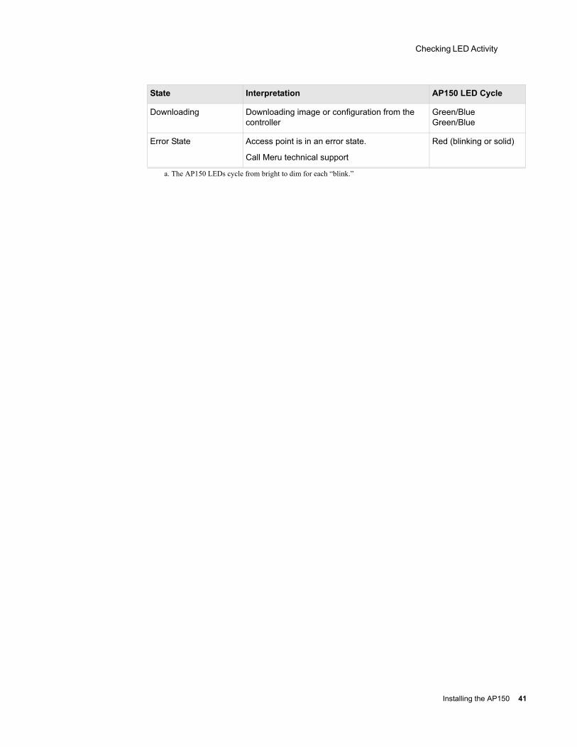
Downloading Downloading image or configuration from the controller
Green/BlueGreen/Blue
Error State Access point is in an error state.
Call Meru technical support
Red (blinking or solid)
a. The AP150 LEDs cycle from bright to dim for each “blink.”
State Interpretation AP150 LED Cycle
Installing the AP150 41

Checking LED Activity
42 Meru Access Point Installation Guide
Appendix ASpecifications
This chapter provides specifications for the Meru Access Points and contains the following sections:
FCC Compliance
Wireless Interface
Ethernet Interface
Physical
FCC Compliance
This device complies with part 15 of the FCC Rules. Operation is subject to the following two conditions: (1) This device may not cause harmful interference, and (2) this device must accept any interference received, including interference that may cause undesired operation.
Caution! Changes or modifications to the Meru Access Point that are not expressly approved by Meru Networks will void your warranty and could void your authority to operate this equipment.
Specifications 43
Wireless Interface
Wireless Interface
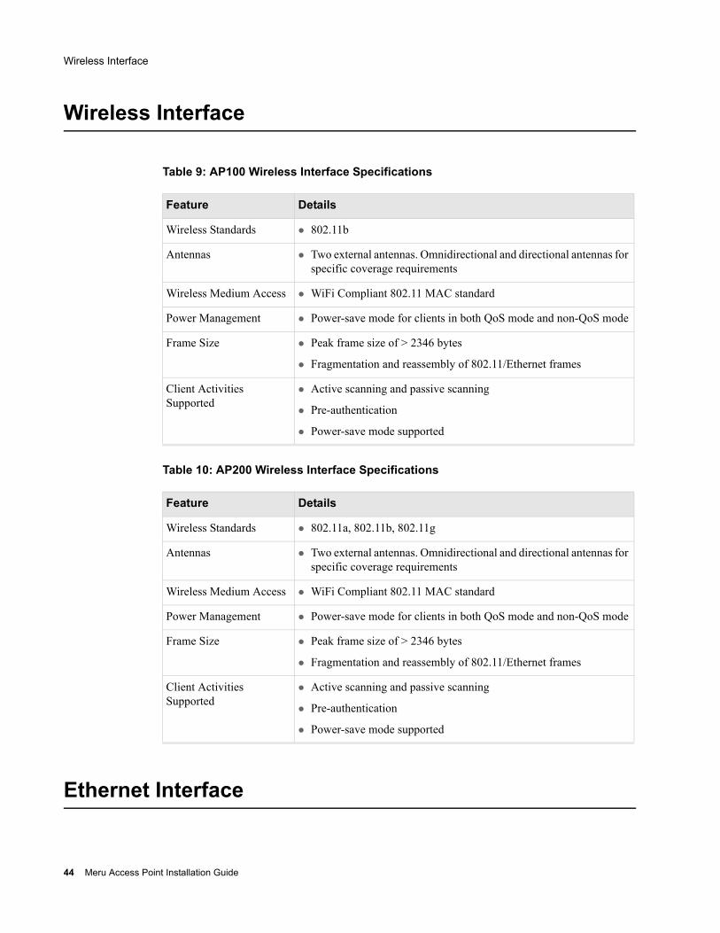
Table 9: AP100 Wireless Interface Specifications
Table 10: AP200 Wireless Interface Specifications
Ethernet Interface
Feature Details
Wireless Standards 802.11b
Antennas Two external antennas. Omnidirectional and directional antennas for specific coverage requirements
Wireless Medium Access WiFi Compliant 802.11 MAC standard
Power Management Power-save mode for clients in both QoS mode and non-QoS mode
Frame Size Peak frame size of > 2346 bytes
Fragmentation and reassembly of 802.11/Ethernet frames
Client Activities Supported
Active scanning and passive scanning
Pre-authentication
Power-save mode supported
Feature Details
Wireless Standards 802.11a, 802.11b, 802.11g
Antennas Two external antennas. Omnidirectional and directional antennas for specific coverage requirements
Wireless Medium Access WiFi Compliant 802.11 MAC standard
Power Management Power-save mode for clients in both QoS mode and non-QoS mode
Frame Size Peak frame size of > 2346 bytes
Fragmentation and reassembly of 802.11/Ethernet frames
Client Activities Supported
Active scanning and passive scanning
Pre-authentication
Power-save mode supported
44 Meru Access Point Installation Guide
Physical
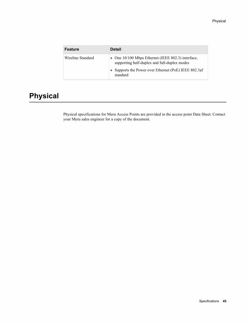
Physical
Physical specifications for Meru Access Points are provided in the access point Data Sheet. Contact your Meru sales engineer for a copy of the document.
Feature Detail
Wireline Standard One 10/100 Mbps Ethernet (IEEE 802.3) interface, supporting half-duplex and full-duplex modes
Supports the Power over Ethernet (PoE) IEEE 802.3af standard
Specifications 45

Physical
46 Meru Access Point Installation Guide

Appendix BRegulatory Information
B-1
This appendix has important regulatory compliance information for the following products:
Wireless Access Point AP200, models AP202 and AP209
Please read this appendix first before installing and operating your product, and follow all instructions provided in the installation chapter. Periodic updates to this document will be posted at www.merunetworks.com.
This appendix contains the following sections:
Safety Section
Federal Communications Commission (FCC) Declaration of Conformity (DoC) & Instructions
List of Regulatory Compliance Certifications Summary by Country
Safety Section
USA and Canada
European Union
The products listed in this appendix have been evaluated to, and comply with, the U.S. and Canadian (Bi National) Standard for Safety of Information Technology Equipment, including Electrical Business Equipment, CAN CSA C22.2, No. 60950-00 * UL 60950 3rd edition, and IEC60950:1999, the Standard for the Safety of Information Technology Equipment.
Your product is intended to be installed, operated, serviced, and maintained by experienced personnel only. When using this device, basic safety precautions should always be followed to reduce the risk of fire, electrical shock, and injury to persons.
Regulatory Information 47
Federal Communications Commission (FCC) Declaration of Conformity (DoC) & Instructions
Note the following:
These products have been evaluated for indoor use only. ?
Installation and use should be in strict accordance with the instructions described in this manual and any supporting documentation.
End use installation must conform to local regulations and codes.
These products are powered by Power Over Ethernet (PoE) only, refer to the installation section for more information.
No user serviceable parts inside. All repairs and service must be performed by trained personnel only. Do not open or disassemble your product. By opening or removing any covers, you may expose yourself to energized parts. Incorrect reassembly of these products can cause a malfunction and/or electric shock when the units are subsequently used.
Do not insert any objects of any shape or size inside the units. Objects may contact energized parts that could result in a risk of fire or personal injury.
Do not remove, alter, or cover the marking label provided.
To avoid the risk of electric shock from lightning, do not operate your unit during an electrical storm.
When using external antenna, refer to the manufacturer’s installation documentation provided with the antenna system, and follow all instructions promptly. Installation must also conform to local regulations and codes.
Federal Communications Commission (FCC) Declaration of Conformity (DoC) & Instructions
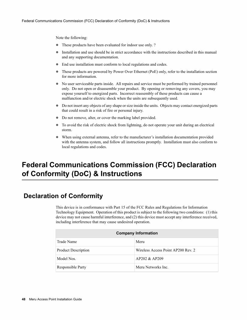
Declaration of ConformityThis device is in conformance with Part 15 of the FCC Rules and Regulations for Information Technology Equipment. Operation of this product is subject to the following two conditions: (1) this device may not cause harmful interference, and (2) this device must accept any interference received, including interference that may cause undesired operation.
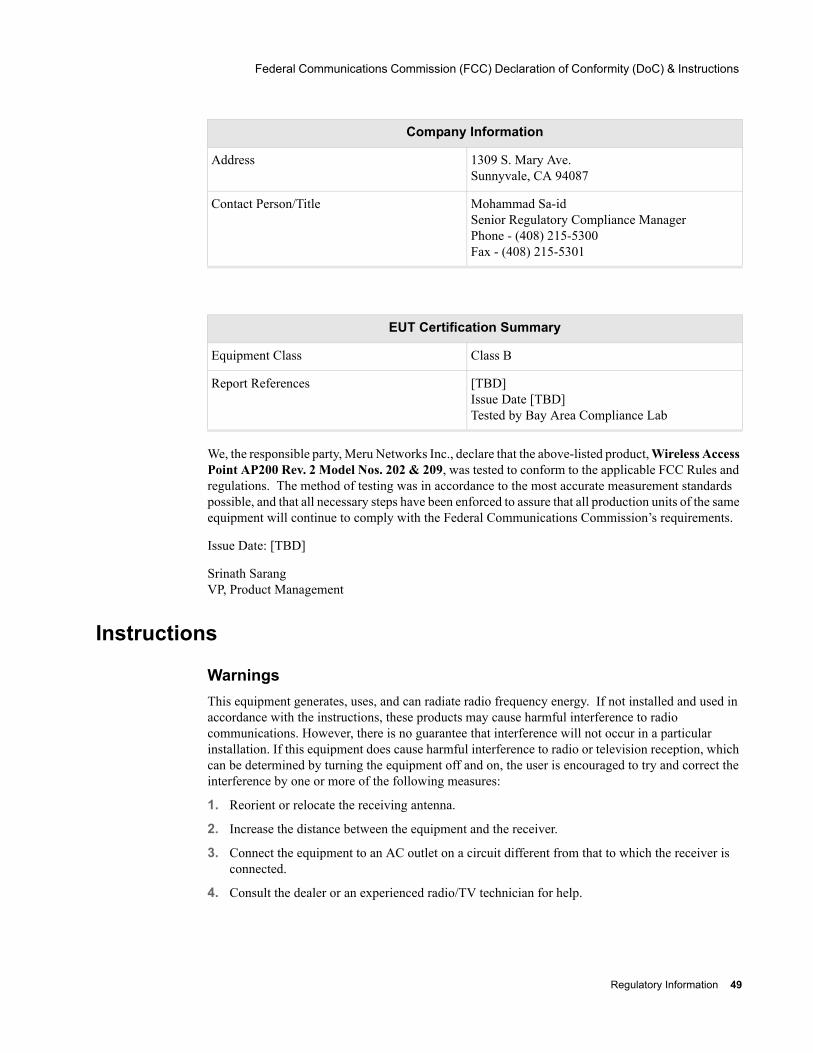
Company Information
Trade Name Meru
Product Description Wireless Access Point AP200 Rev. 2
Model Nos. AP202 & AP209
Responsible Party Meru Networks Inc.
48 Meru Access Point Installation Guide
Federal Communications Commission (FCC) Declaration of Conformity (DoC) & Instructions
We, the responsible party, Meru Networks Inc., declare that the above-listed product, Wireless Access Point AP200 Rev. 2 Model Nos. 202 & 209, was tested to conform to the applicable FCC Rules and regulations. The method of testing was in accordance to the most accurate measurement standards possible, and that all necessary steps have been enforced to assure that all production units of the same equipment will continue to comply with the Federal Communications Commission’s requirements.
Issue Date: [TBD]
Srinath Sarang VP, Product Management
Instructions
Warnings This equipment generates, uses, and can radiate radio frequency energy. If not installed and used in accordance with the instructions, these products may cause harmful interference to radio communications. However, there is no guarantee that interference will not occur in a particular installation. If this equipment does cause harmful interference to radio or television reception, which can be determined by turning the equipment off and on, the user is encouraged to try and correct the interference by one or more of the following measures:
1. Reorient or relocate the receiving antenna.
2. Increase the distance between the equipment and the receiver.
3. Connect the equipment to an AC outlet on a circuit different from that to which the receiver is connected.
4. Consult the dealer or an experienced radio/TV technician for help.
Address 1309 S. Mary Ave. Sunnyvale, CA 94087
Contact Person/Title Mohammad Sa-id Senior Regulatory Compliance Manager Phone - (408) 215-5300 Fax - (408) 215-5301
EUT Certification Summary
Equipment Class Class B
Report References [TBD] Issue Date [TBD] Tested by Bay Area Compliance Lab
Company Information
Regulatory Information 49
List of Regulatory Compliance Certifications Summary by Country
In some situations or environments, the use of wireless devices may be restricted by the proprietor of the building or responsible representatives of the organization. These situations may, for example, include the use of wireless equipment on board airplanes, or in any other environment where the risk of interference to other devices or services is perceived or identified as harmful.
If you are uncertain of the policy that applies on the use of wireless equipment in a specific organization or environment (such as airports), you are encouraged to ask for authorization to use this device prior to turning on the equipment.
Cautions
Exposure to radio frequency radiation
To comply with the FCC radio frequency exposure requirements, the following antenna installation and device operating configurations must be satisfied:
For client devices using an integral antenna, the separation distance between the antenna(s) and any person’s body (including hands, wrists, feet and ankles) must be at least 2.5 cm (1 inch).
For Base Stations and configurations using an approved external antenna, the separation distance between the antenna and any person’s body (including hands, wrists, feet and ankles) must be at least 20 cm (8 inch).
The transmitter shall not be collocated with other transmitters or antennas.
Modifications
The FCC requires the user to be notified that any changes or modifications to this device that are not expressly approved by the manufacturer may void the user’s authority to operate the equipment. The correction of interference caused by unauthorized modification, substitution or attachment will be the responsibility of the user. The manufacturer and its authorized resellers or distributors are not liable for any damage or violation of government regulations that may arise from failing to comply with these guidelines.
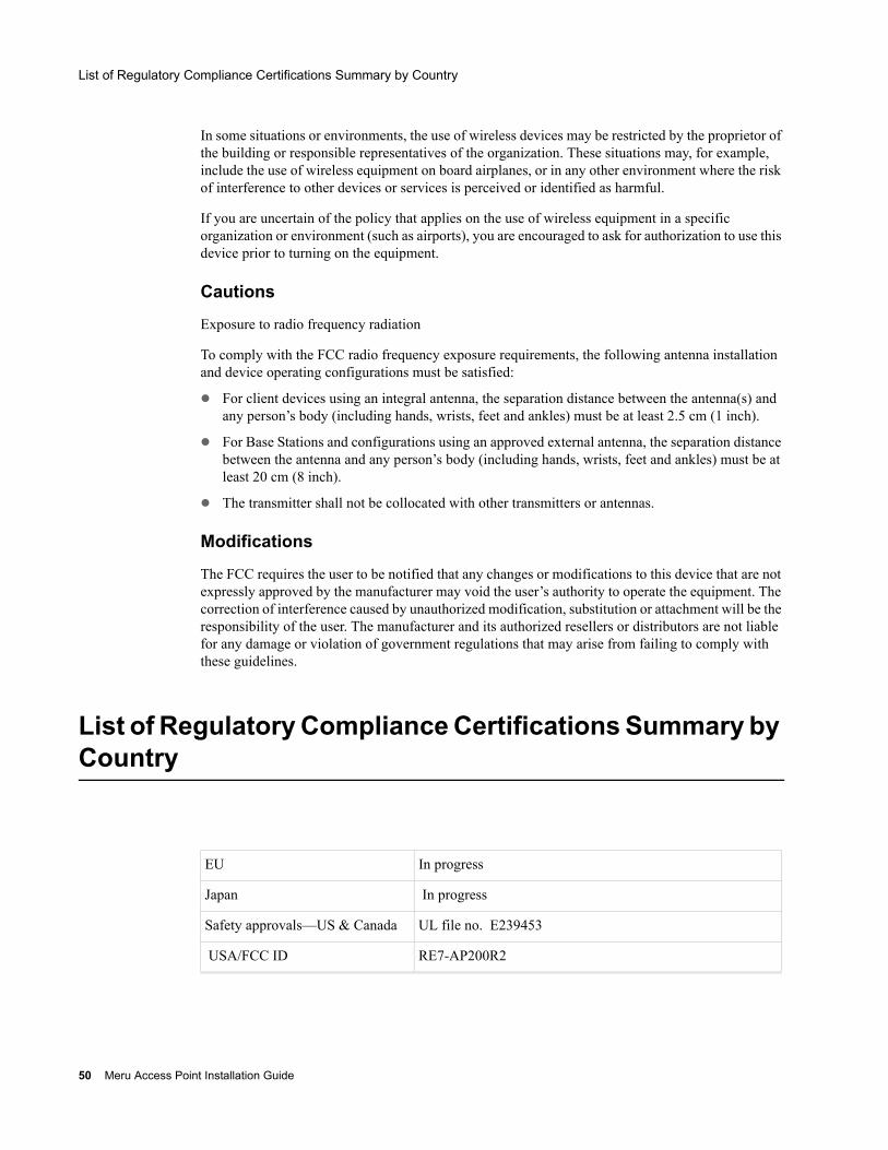
List of Regulatory Compliance Certifications Summary by Country
EU In progress
Japan In progress
Safety approvals—US & Canada UL file no. E239453
USA/FCC ID RE7-AP200R2
50 Meru Access Point Installation Guide

List of Regulatory Compliance Certifications Summary by Country
Regulatory Information 51
List of Regulatory Compliance Certifications Summary by Country
52 Meru Access Point Installation Guide
Appendix CTranslated Safety Warnings
B-1
This appendix provides translations of the safety warnings that appear in this publication. These translated warnings apply to other documents in which they appear in English. The following safety warnings appear in this appendix:
Dipole Antenna Installation Warning
Explosive Device Proximity Warning
Installation Warning
Circuit Breaker (15A) Warning
Translated Safety Warnings 53
Dipole Antenna Installation Warning
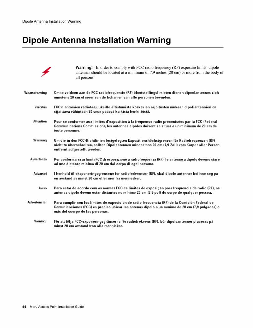
Dipole Antenna Installation Warning
Warning! In order to comply with FCC radio frequency (RF) exposure limits, dipole antennas should be located at a minimum of 7.9 inches (20 cm) or more from the body of all persons.
54 Meru Access Point Installation Guide
Explosive Device Proximity Warning
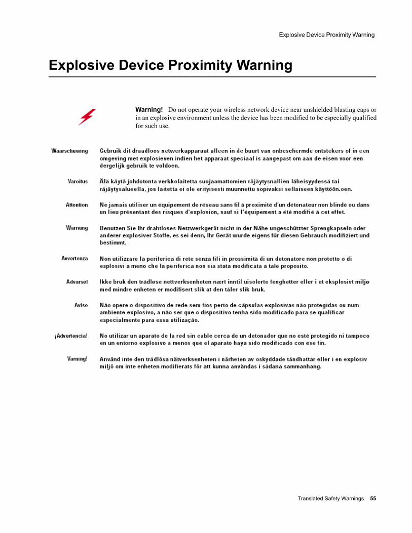
Explosive Device Proximity Warning
Warning! Do not operate your wireless network device near unshielded blasting caps or in an explosive environment unless the device has been modified to be especially qualified for such use.
Translated Safety Warnings 55
Installation Warning
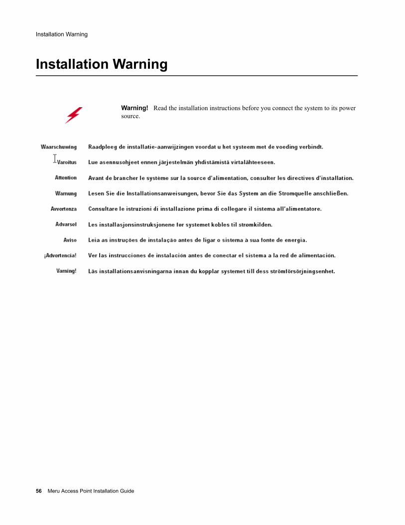
Installation Warning
Warning! Read the installation instructions before you connect the system to its power source.
56 Meru Access Point Installation Guide
Circuit Breaker (15A) Warning
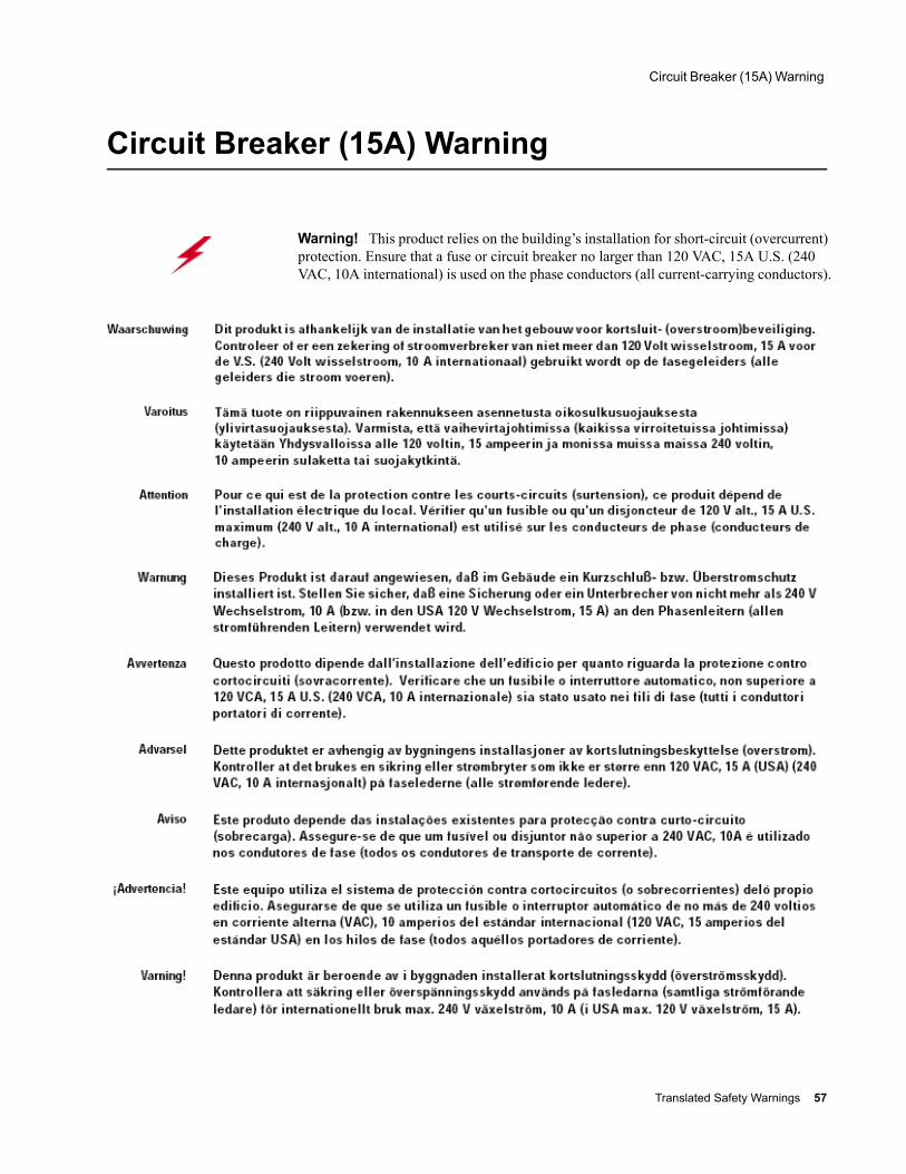
Circuit Breaker (15A) Warning
Warning! This product relies on the building’s installation for short-circuit (overcurrent) protection. Ensure that a fuse or circuit breaker no larger than 120 VAC, 15A U.S. (240 VAC, 10A international) is used on the phase conductors (all current-carrying conductors).
Translated Safety Warnings 57

Circuit Breaker (15A) Warning
58 Meru Access Point Installation Guide
Appendix DChannels
B-1This appendix provides the access point radio channels supported by the world’s regulatory domains.This appendix contains the following section:
Channels
Channels
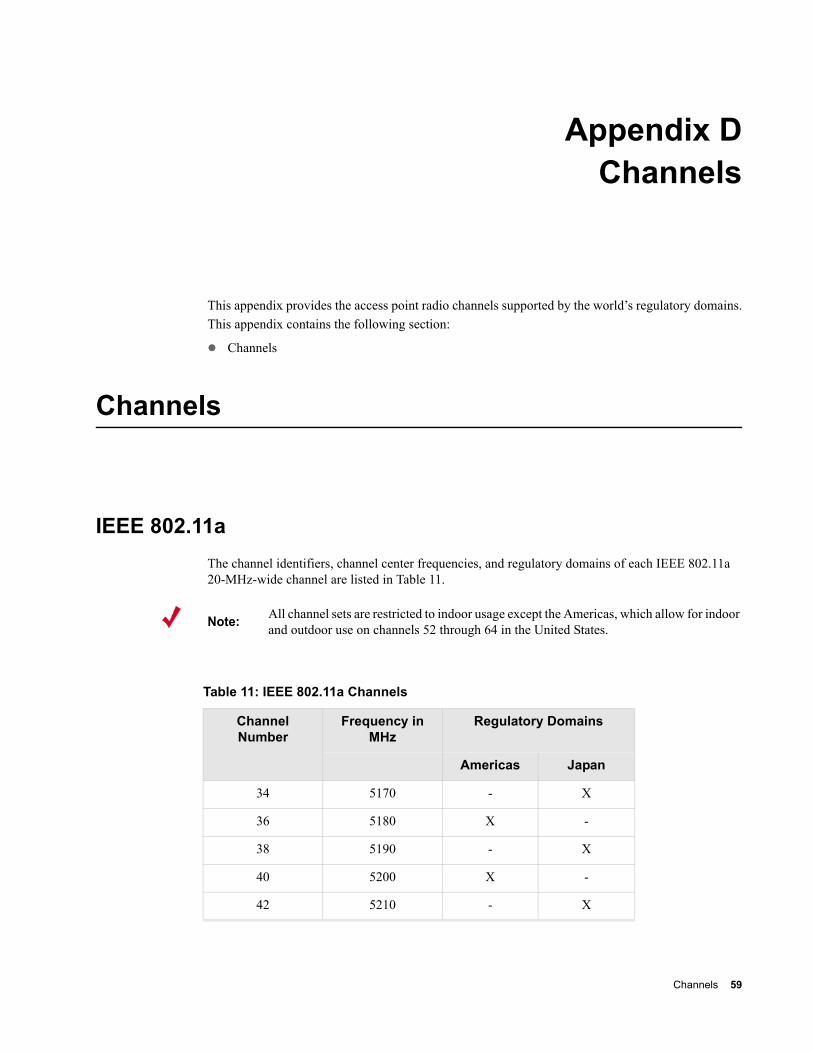
IEEE 802.11aThe channel identifiers, channel center frequencies, and regulatory domains of each IEEE 802.11a 20-MHz-wide channel are listed in Table 11.
Note: All channel sets are restricted to indoor usage except the Americas, which allow for indoor and outdoor use on channels 52 through 64 in the United States.
Table 11: IEEE 802.11a Channels
Channel Number
Frequency in MHz
Regulatory Domains
Americas Japan
34 5170 - X
36 5180 X -
38 5190 - X
40 5200 X -
42 5210 - X
Channels 59
Channels
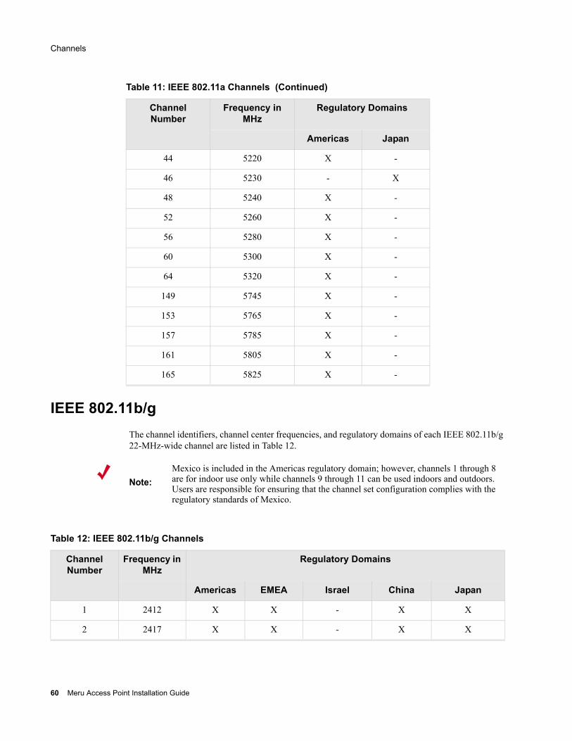
IEEE 802.11b/gThe channel identifiers, channel center frequencies, and regulatory domains of each IEEE 802.11b/g 22-MHz-wide channel are listed in Table 12.
44 5220 X -
46 5230 - X
48 5240 X -
52 5260 X -
56 5280 X -
60 5300 X -
64 5320 X -
149 5745 X -
153 5765 X -
157 5785 X -
161 5805 X -
165 5825 X -
Table 11: IEEE 802.11a Channels (Continued)
Channel Number
Frequency in MHz
Regulatory Domains
Americas Japan
Note:Mexico is included in the Americas regulatory domain; however, channels 1 through 8 are for indoor use only while channels 9 through 11 can be used indoors and outdoors. Users are responsible for ensuring that the channel set configuration complies with the regulatory standards of Mexico.
Table 12: IEEE 802.11b/g Channels
Channel Number
Frequency in MHz
Regulatory Domains
Americas EMEA Israel China Japan
1 2412 X X - X X
2 2417 X X - X X
60 Meru Access Point Installation Guide
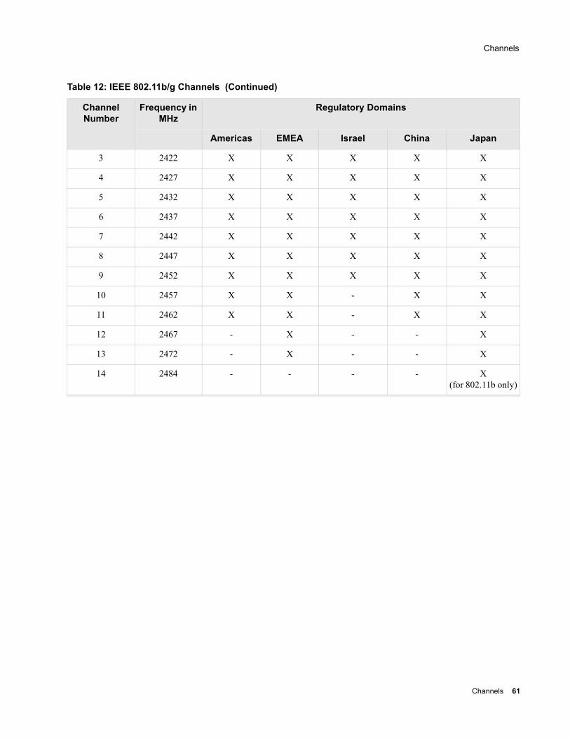
Channels
3 2422 X X X X X
4 2427 X X X X X
5 2432 X X X X X
6 2437 X X X X X
7 2442 X X X X X
8 2447 X X X X X
9 2452 X X X X X
10 2457 X X - X X
11 2462 X X - X X
12 2467 - X - - X
13 2472 - X - - X
14 2484 - - - - X (for 802.11b only)
Table 12: IEEE 802.11b/g Channels (Continued)
Channel Number
Frequency in MHz
Regulatory Domains
Americas EMEA Israel China Japan
Channels 61

Channels
62 Meru Access Point Installation Guide
MERU NETWORKS, INC.Limited Product Warranty
This Limited Product Warranty applies to the original end-user customer of the Meru product which you purchased for your own use, and not for resale (“Product”), from Meru Networks, Inc. (“Meru”) or its authorized reseller (“Reseller”).
Limited Warranties— One-year limited hardware warranty: Meru warrants to you that Meru hardware (other than Third Party Products as
described below) will be free from defects in materials and workmanship for a one-year period after the date of delivery of the applicable product to you from Meru or its Reseller (the “Hardware Warranty Period”). If Meru receives written notice from you of such defects during the Hardware Warranty Period, Meru will, at its option, either repair or replace Meru hardware that Meru determines to be defective. Replacement products may be remanufactured units, and will be warranted for the remainder of the original Hardware Warranty Period, or if greater, for thirty days from delivery of such replacement. Should Meru be unable to repair or replace the Meru hardware, Meru (or its Reseller, as applicable) will refund to you the purchase price of the Product.
— 90-Day Limited Software Warranty: Meru warrants to you that, for a 90-day period after the date of delivery of the applicable product to you from Meru or its Reseller (the “Software Warranty Period”), when properly installed and used, (a) the media on which the Meru software is provided will be free from defects in materials or workmanship; and (b) the Meru software will substantially conform to the functional specifications in the applicable documentation. If Meru receives written notice from you of a breach of this warranty during the Software Warranty Period and is able to repro-duce the defect, Meru will, at its option, either repair or replace the defective Meru software. Should Meru be unable to repair or replace the Meru software, Meru (or its Reseller, as applicable) will refund to you the purchase price of the Product.
ExclusionsThe warranty on the Product shall not apply to defects resulting from the following:
— Alteration or modification of the Product in any way, including without limitation configuration with software or components other than those supplied by Meru or integration with parts other than those supplied by Meru.
— Abuse, damage or otherwise being subjected to problems caused by negligence or misapplication (including without limitation improper or inadequate maintenance or calibration), relocation of the products (including without limitation damage caused by use of other than Meru shipping containers), or use of the products other than as specified in the appli-cable Meru product documentation (including without limitation incompatible operating environments and systems), or improper site preparation or maintenance.
— Damage as a result of accidents, extreme power surge, extreme electromagnetic field, acts of nature or other causes beyond the control of Meru.
— Use of the Product with software, interfacing, parts or supplies not supplied by Meru.
The warranty on the Product does not apply if the Product is sold, or in the case of software, licensed, for free for evaluation or demonstration purposes.
Meru expressly disclaims any warranty or obligation to support the Product for all operating environments – for example, as illustration and not limitation, Meru does not warrant or ensure interoperability of the Product with future telecommunication systems or other future software or hardware.
You understand and acknowledge that the Products may generate, use or radiate radio frequency energy and may interfere with radio communications and/or radio and television receptions if is not used and/or installed in accordance with the documentation for such products. WHILE MERU USES COMMERCIALLY REASONABLE EFFORTS TO ENSURE COMPLIANCE OF THE PRODUCTS WITH APPLICABLE UNITED STATES FEDERAL COMMUNICATIONS
63

COMMISSION AND PROTECT AGAINST HARMFUL INTERFERENCES, YOU ACKNOWLEDGE AND AGREE THAT INTERFERENCES WITH RADIO COMMUNICATIONS AND/OR RADIO AND TELEVISION RECEPTIONS MAY OCCUR AND THAT MERU WILL NOT BE LIABLE FOR ANY DAMAGES OR INCONVENIENCE BASED ON SUCH INTERFERENCES.
Third Party Products - The above Limited Warranties are exclusive of products manufactured by third parties (“Third Party Products”). If such third party manufacturer provides a separate warranty with respect to the Third Party Product, Meru will include such warranty in the packaging of the Meru Product.
Return proceduresTo obtain warranty service you must: (a) obtain a return materials authorization number (“RMA#”) from Meru by contacting [email protected], and (b) deliver the Product, in accordance with the instructions provided by Meru, along with proof of purchase in the form of a copy of the bill of sale including the Product’s serial number, contact information, RMA# and detailed description of the defect, in either its original package or packaging providing the Product with a degree of protection equivalent to that of the original packaging, to Meru at the address below. You agree to obtain adequate insurance to cover loss or damage to the Product during shipment.
If you obtain an RMA# and return the defective Product as described above, Meru will pay the cost of returning the Product to Meru. Otherwise, you agree to bear such cost, and prior to receipt by Meru, you assume risk of any loss or damage to the Product. Meru is responsible for the cost of return shipment to you if the Meru Product is defective.
Returned products which are found by Meru to be not defective, returned out-of-warranty or otherwise ineligible for warranty service will be repaired or replaced at Meru’s standard charges and shipped back to you at your expense.
At Meru’s sole option, Meru may perform repair service on the Product at your facility, and you agree to provide Meru with all reasonable access to such facility and the Product, as required by Meru. On-site repair service may be available and is governed by the specific terms of your purchase.
All replaced parts, whether under warranty or not, are the property of Meru.
Warranty limitationsTHE WARRANTIES SET FORTH ABOVE ARE EXCLUSIVE AND NO OTHER WARRANTY, WHETHER WRITTEN OR ORAL, IS EXPRESSED OR IMPLIED BY MERU, TO THE MAXIMUM EXTENT PERMITTED BY LAW. THERE ARE NO OTHER WARRANTIES RESPECTING THE PRODUCT AND DOCUMENTATION AND SERVICES PROVIDED UNDER THIS AGREEMENT, INCLUDING WITHOUT LIMITATION ANY WARRANTY OF DESIGN, MERCHANTABILITY, FITNESS FOR A PARTICULAR PURPOSE (EVEN IF MERU HAS BEEN INFORMED OF SUCH PURPOSE), TITLE OR AGAINST INFRINGEMENT OF THIRD PARTY RIGHTS. IF ANY IMPLIED WARRANTY CANNOT BE DISCLAIMED UNDER APPLICABLE LAW, THEN SUCH IMPLIED WARRANTY SHALL BE LIMITED IN DURATION TO THE HARDWARE AND SOFTWARE WARRANTY PERIODS DESCRIBED ABOVE.
NO AGENT OF MERU IS AUTHORIZED TO ALTER OR EXCEED THE WARRANTY OBLIGATIONS OF MERU.
MERU SPECIFICALLY DOES NOT WARRANT THAT THE MERU SOFTWARE WILL BE ERROR FREE OR OPERATE WITHOUT INTERRUPTION.
64 Meru Access Point Installation Guide

THE REMEDIES IN THIS LIMITED PRODUCT WARRANTY ARE YOUR SOLE AND EXCLUSIVE REME-DIES, AND MERU’S SOLE AND EXCLUSIVE LIABILITY, FOR BREACH OF THE HARDWARE OR SOFT-WARE WARRANTY SET FORTH ABOVE.
Limitations of LiabilityYou acknowledge and agree that the consideration which you paid to Meru does not include any consideration by Meru of the risk of consequential, indirect or incidental damages which may arise in connection with your use of, or inability to use, the Product. THUS, MERU AND ITS RESELLER WILL NOT BE LIABLE FOR ANY INDIRECT, INCIDENTAL, SPECIAL, PUNITIVE OR CONSEQUENTIAL DAMAGES, INCLUDING WITHOUT LIMITATION LOST PROFITS, LOST BUSINESS, LOST DATA, LOSS OF USE, OR COST OF COVER INCURRED BY YOU ARISING OUT OF OR RELATED TO YOUR PURCHASE OR USE OF, OR INABILITY TO USE, THIS PRODUCT OR THE SERVICES, UNDER ANY THEORY OF LIABILITY, WHETHER IN AN ACTION IN CONTRACT, STRICT LIABILITY, TORT (INCLUDING NEGLIGENCE) OR OTHER LEGAL OR EQUITABLE THEORY, EVEN IF MERU OR ITS RESELLER KNEW OR SHOULD HAVE KNOWN OF THE POSSIBILITY OF SUCH DAMAGES. IN ANY EVENT, THE CUMULATIVE LIABILITY OF MERU OR ITS RESELLER FOR ALL CLAIMS WHATSOEVER RELATED TO THE PRODUCT OR THE SERVICE WILL NOT EXCEED THE PRICE YOU PAID FOR THE PRODUCT OR SERVICES GIVING RISE TO SUCH CLAIMS.
THE LIMITATIONS SET FORTH HEREIN ARE INTENDED TO LIMIT THE LIABILITY OF MERU AND ITS RESELLERS AND SHALL APPLY NOTWITHSTANDING ANY FAILURE OF ESSENTIAL PURPOSE OF ANY LIMITED REMEDY.
The jurisdiction applicable to you may not allow the limitations of liability or damages set forth above, in which case such limitation shall only apply to you to the extent permitted in such jurisdiction.
Additional InformationThis Limited Product Warranty shall be governed by and construed in accordance with the laws of the State of California, U.S.A., exclusive of its conflict of laws principles. The U.N. Convention on Contracts for the International Sale of Goods shall not apply.
This Limited Product Warranty is the entire and exclusive agreement between you and Meru with respect to its subject matter, and any modification or waiver of any provision of this statement is not effective unless expressly set forth in writing by an authorized representative of Meru.
All inquiries or claims made under this Limited Product Warranty must be sent to Meru at the following address:
Meru Networks Inc.,1309 South Mary Avenue, Sunnyvale, CA 94087, USATel: 408-215-5300Fax: 408-215-5301Email: [email protected]
65

66 Meru Access Point Installation Guide

Meru Networks, Inc.1309 South Mary AvenueSunnyvale, CA 94087408-215-5300www.merunetworks.com