merlin | electrical systems manufacture for defence …...poole, dorset bh17 7ba new york, ny11946...
TRANSCRIPT

DataCell II – Installation & Instruction Manual Version 1.0
1
DataCell II
Advanced Battery Monitor
Installation & User Manual
Version 1.0
Merlin Power Systems UK Merlin Power Systems USA Unit 4, Cabot Business Village 332-4 West Montauk Highway
Holyrood Close Hampton Bays Poole, Dorset BH17 7BA New York, NY11946
United Kingdom United States of America
Tel: +44 (0) 1202 697979 Tel: +1 (631) 594 5102 Fax: +44 (0) 1202 691919 Fax: +1 (631) 594 5104
www.merlinpowersystems.com
DataCell II – Installation & Instruction Manual Version 1.0
2
Contents: 1.0 Introduction 3 2.0 Regulatory/Certificate of Conformity 4 3.0 Before You Begin 5 4.0 Package Contents 5 5.0 How DataCell 1 Works 6 6.0 Product Familiarisation 7 7.0 System/Wiring Diagram 8 8.0 Installation Instructions 10 9.0 Datacell Live Settings Window 21 10.0 Loading Custom Battery Types 23 11.0 Safety Considerations 24 12.0 Maintenance 24 13.0 Warranty 24 14.0 To Claim Warranty 24
Version Control: Version Date Description 1.0 08-Oct-13 Initial Release

DataCell II – Installation & Instruction Manual Version 1.0
3
1.0 Introduction Congratulations on your purchase of DataCell II – the World’s most advanced and accurate battery monitor. DataCell II provides the following information for 1, 2, 3 or 4 independent battery banks (number of batteries monitored dependent on model):
Battery Voltage
Current (Net in/out)
Battery SoC% (State of Charge %)
Battery Amp Hours
Time Remaining Until Battery Flat
Battery Temperature
Battery SoH% (State of Health %) DataCell II features a number of inputs and outputs that may be used to fire external alarms or cause a third party device to do something (e.g. start/stop a generator, bring on an external alarm, turn loads on/off etc). DataCell II also has an RS232 data output. This output is used for:
Programming the unit from a PC
Outputting battery information to Merlin Software
Running data logging using Merlin Software
Interfacing with 3rd party equipment DataCell can be used in various different ways. Most popular include:
As a ‘conventional’ battery monitor in conjunction with an optional Merlin LCD/LED Remote Panel.
As a PC interfaced battery monitor (displaying data on the M-Power software or on Merlin Dashboard Software).
As a discrete module where no user interaction is required (for example as a device that enables SoC% based automatic generator start/stop or switching on/off of a load).
DataCell II uses unique and proprietory methods to calculate battery SoC%, SoH% and time remaining. Therefore, please take the time to read and understand this manual before installation and use. Your attention is drawn to Caution! and Warning! statements throughout this manual. Caution! refers to practices that may cause damage to the product or your electrical system. Warning! identifies practices that may cause injury or death. Caution! / Warning! This product is designed for installation by qualified and competent electrical engineers. Qualified and competent engineers will be familiar with safe working practices, local health & safety legislation and the proper and safe use of tools and equipment. Therefore not all obvious practices that may lead to system damage, injury or death are detailed within this manual. If you are in anyway unsure about any aspect of the installation or use of this product, contact your dealer or Merlin Power Systems for advice.

DataCell II – Installation & Instruction Manual Version 1.0
4
Please note that this manual refers to our standard retail product. This product may also be available in an OEM version. The OEM version differs slightly to the retail product. However, the main printed circuit board within product is identical so this manual may be used for setting up the OEM version. Caution! / Warning! If using an OEM version of the product, you may need to refer to additional diagrams and instructions issued by Merlin Power Systems. 2.0 Information For Battery Experts DataCell II uses techniques and algorithms based on years of battery and power system experience. Batteries do not react to circumstances in the way that you sometimes may expect them too. For example, battery SoH can go up as well as down, experts argue about the true definition of 0% SoC (discharge a battery with a lamp so the lamp extinguishes – the battery is flat right? Now leave the battery overnight and turn the lamp back on, the lamp will light up again. Was the battery really ‘flat’ in the first place?). A battery does not discharge or charge in a linear fashion, often the results you are logarithmic and require extensive knowledge to interpret and understand. DataCell II has been extensively tested by EnerSys, the World’s largest battery manufacturer, the UK and US ministries of defence and many other leading bodies. Their results prove that DataCell II is often more accurate than a Bitrode and other laboratory test equipment that costs tens of thousands of pounds. Merlin Power Systems has an extensive library of information about testing batteries, testing battery monitors and recommended test procedures. Please contact Merlin Power Systems engineers who will be pleased to share this data with you. 3.0 Regulatory/Certificate of Conformity
Declaration of Conformity: Merlin Equipment Limited, Trading As Merlin Power Systems hereby declares that the product marketed as DataCell II is in compliance with the requirements of EMC Directive 2004/108/EC and Regulation UN/ECE-R10 Rev.4. Standards to which conformity is declared: - EN 61000-6-3 : 2007 EMC- Emission - EN 61000-6-1 : 2007 EMC- Immunity - IEC 62109-1 :1: 2010 Safety- PV systems - ISO 7637-2 :2: 2011 EMC- Vehicles. Signed:
James Hortop Managing Director Merlin Power Systems UK Date: 9th October 2013

DataCell II – Installation & Instruction Manual Version 1.0
5
4.0 Before You Begin Caution! & Warning!: Working in the vicinity of batteries, engines, engine room equipment and on vehicles, boats and other installations is potentially hazardous. Please ensure that all local and national government guidelines pertaining to Health & Safety Requirements are adhered to. The following identified hazards are not exhaustive:
Wear appropriate PPE (Personnel Protective Equipment). This includes gloves and eye protection.
Ensure that the appropriate tools are available and that they are well maintained.
Ensure that the working area is safe and that potential hazards are identified and mitigated (e.g. working at height, safe lifting practices, availability of a fire extinguisher etc).
Remove positive battery terminals from all batteries within the installation.
Ensure the engine cannot be started.
Ensure that the vehicle/boat cannot be moved.
Ensure that AC power is disconnected and that generators etc cannot be started.
Most Merlin Products are related to batteries. Batteries contain hazardous materials, vent corrosive/toxic gases and are a potential explosion hazard. Ensure that others know of your whereabouts when working in the vicinity of batteries. Ensure that compartments that contain batteries are properly ventilated. Take precautions (such as taping up of terminals) to prevent accidental short-circuit and ignition.
Higher battery voltages are potentially lethal. In all cases, Merlin products are designed for nominal 12 and 24V DC systems. Do not attempt modification or addition to systems where higher voltages may be present (such as electric vehicles or electric marine drives) without consultation with experienced engineers.
110/230V AC systems are lethal. Ensure that supplies are isolated before commencing work. Note that a faulty 110/230V system (or appliance) may inject lethal AC voltages into a DC system. Therefore, ensure that all supplies are switched off (and cannot be switched on) during work.
Do not insert the plugs into DataCell II until all wiring is completed. CAUTION! Do not use welding equipment on the boat or vehicle without first disconnecting AND COMPLETELY REMOVING the DataCell 1. Damage caused by electrical welding is not covered by warranty. 5.0 Package Contents: Each DataCell II product is shipped with: 1x DataCell II CPU (preconfigured for 1, 2, 3 or 4 battery banks) 1x Cable Set (consisting of: Sense Wiring Loom and Input/Output Wiring Loom) 1, 2, 3 or 4x 500A 50mV current measurement shunts 1, 2, 3 or 4x Temperature Sensors 1x FTDI USB to Serial Converter Package 1x RS232 Data Cable 1x Software/Manual CD 1x Fuse kit
DataCell II – Installation & Instruction Manual Version 1.0
6
6.0 How DataCell II Works Caution: DataCell II is designed for 12 and 24V DC common negative ground systems. Do not use on positive ground systems. For installations with multiple battery banks, each must share a common ground. Multiple individual batteries can be monitored but with independent DataCell II units. DataCell II uses a very different method of calculating battery state of charge compared to a conventional battery monitor. It is important that you understand how it works so that you are able to make the most of your DataCell II. The product uses two separate methods to determine true battery SoC%: Model Based Calculation: DataCell II uses the proven Merlin SmartGauge technology of advanced battery modelling and monitoring techniques to determine the state of charge (SoC) of your battery bank as a percentage of its true, currently available, capacity. Amp Hour Counting Calculation: Like a conventional battery monitor, DataCell II also counts amp hours in and out of the battery. Combining the advantages of Amp Hour Counting & Model Based Calculation: Conventional amp hour counting actually provides the most finite accuracy possible when determining battery SoC. However, the amp hour counter must be in synchronisation with the batteries (this is the single biggest problem with conventional amp hour counters which run out of synch within a couple of battery cycles – resulting in very poor accuracy). Model based calculation provides the most repeatable results (with an accuracy of around +10/-5%). However, it never runs out of synchronisation. DataCell II automatically switches between Model Based and Amp Hour Counting (or uses a combination of the two). This method provides not only finite accuracy, but never runs out of synch so returns repeatable, dependendable results. DataCell II will indicate when it is ‘in synch’ with the batteries (and using amp hour calculation (and possibly model based calculations at the same time). When DataCell II is not ‘in synch’ it relies solely on the model based calculations. This is a fully automatic operation. State of Health Calculations Because DataCell II can provide highly accurate SoC results, it can compare the real capacity of the battery at any given time against the manufacturer’s declared Amp Hour (C20) capacity of the battery. This comparison generates the SoH reading. Again, because this is dependent on accurate SoC readings, DataCell II’s SoH accuracy is usually better than 1%. Note that battery SoH can go down as well as up (dependent on how it is being used, temperature etc). Note that as part of the modelling process, DataCell II needs to learn about the health and condition of your battery. Therefore, it requires 2-3 battery cycles to achieve maximum accuracy. Battery Models DataCell II is designed for lead/acid batteries only, including:
DataCell II – Installation & Instruction Manual Version 1.0
7
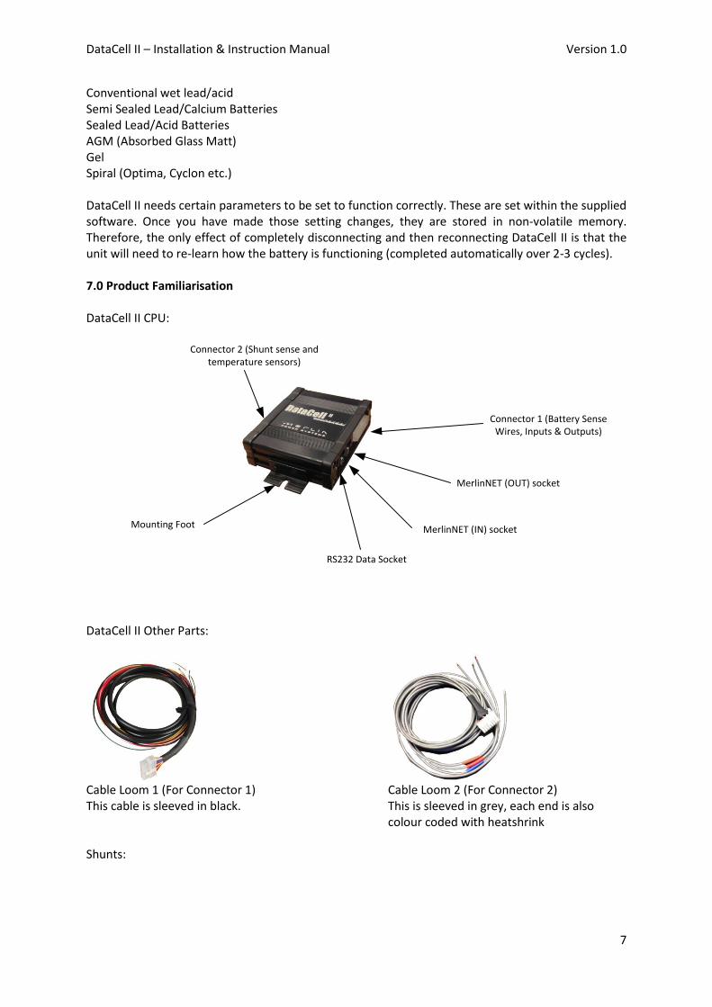
Conventional wet lead/acid Semi Sealed Lead/Calcium Batteries Sealed Lead/Acid Batteries AGM (Absorbed Glass Matt) Gel Spiral (Optima, Cyclon etc.) DataCell II needs certain parameters to be set to function correctly. These are set within the supplied software. Once you have made those setting changes, they are stored in non-volatile memory. Therefore, the only effect of completely disconnecting and then reconnecting DataCell II is that the unit will need to re-learn how the battery is functioning (completed automatically over 2-3 cycles). 7.0 Product Familiarisation DataCell II CPU:
Connector 1 (Battery Sense Wires, Inputs & Outputs)
MerlinNET (OUT) socket
MerlinNET (IN) socket
RS232 Data Socket
Mounting Foot
Connector 2 (Shunt sense and temperature sensors)
DataCell II Other Parts:
Cable Loom 1 (For Connector 1) Cable Loom 2 (For Connector 2) This cable is sleeved in black. This is sleeved in grey, each end is also
colour coded with heatshrink Shunts:
DataCell II – Installation & Instruction Manual Version 1.0
8
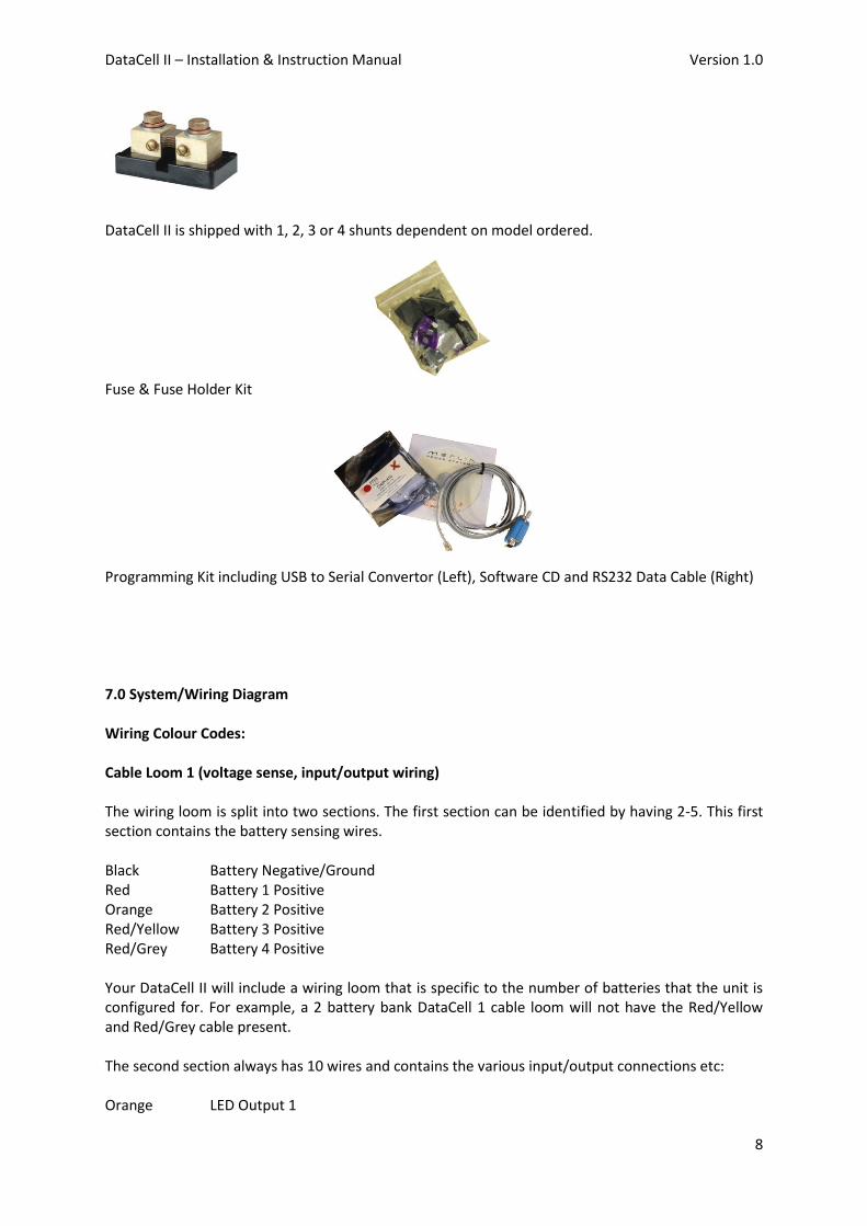
DataCell II is shipped with 1, 2, 3 or 4 shunts dependent on model ordered.
Fuse & Fuse Holder Kit
Programming Kit including USB to Serial Convertor (Left), Software CD and RS232 Data Cable (Right) 7.0 System/Wiring Diagram Wiring Colour Codes: Cable Loom 1 (voltage sense, input/output wiring) The wiring loom is split into two sections. The first section can be identified by having 2-5. This first section contains the battery sensing wires. Black Battery Negative/Ground Red Battery 1 Positive Orange Battery 2 Positive Red/Yellow Battery 3 Positive Red/Grey Battery 4 Positive Your DataCell II will include a wiring loom that is specific to the number of batteries that the unit is configured for. For example, a 2 battery bank DataCell 1 cable loom will not have the Red/Yellow and Red/Grey cable present. The second section always has 10 wires and contains the various input/output connections etc: Orange LED Output 1
DataCell II – Installation & Instruction Manual Version 1.0
9
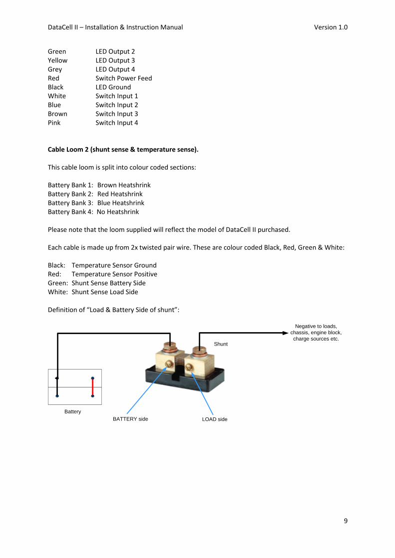
Green LED Output 2 Yellow LED Output 3 Grey LED Output 4 Red Switch Power Feed Black LED Ground White Switch Input 1 Blue Switch Input 2 Brown Switch Input 3 Pink Switch Input 4 Cable Loom 2 (shunt sense & temperature sense). This cable loom is split into colour coded sections: Battery Bank 1: Brown Heatshrink Battery Bank 2: Red Heatshrink Battery Bank 3: Blue Heatshrink Battery Bank 4: No Heatshrink Please note that the loom supplied will reflect the model of DataCell II purchased. Each cable is made up from 2x twisted pair wire. These are colour coded Black, Red, Green & White: Black: Temperature Sensor Ground Red: Temperature Sensor Positive Green: Shunt Sense Battery Side White: Shunt Sense Load Side Definition of “Load & Battery Side of shunt”:
Battery
Shunt
Negative to loads,
chassis, engine block,
charge sources etc.
LOAD sideBATTERY side
DataCell II – Installation & Instruction Manual Version 1.0
10
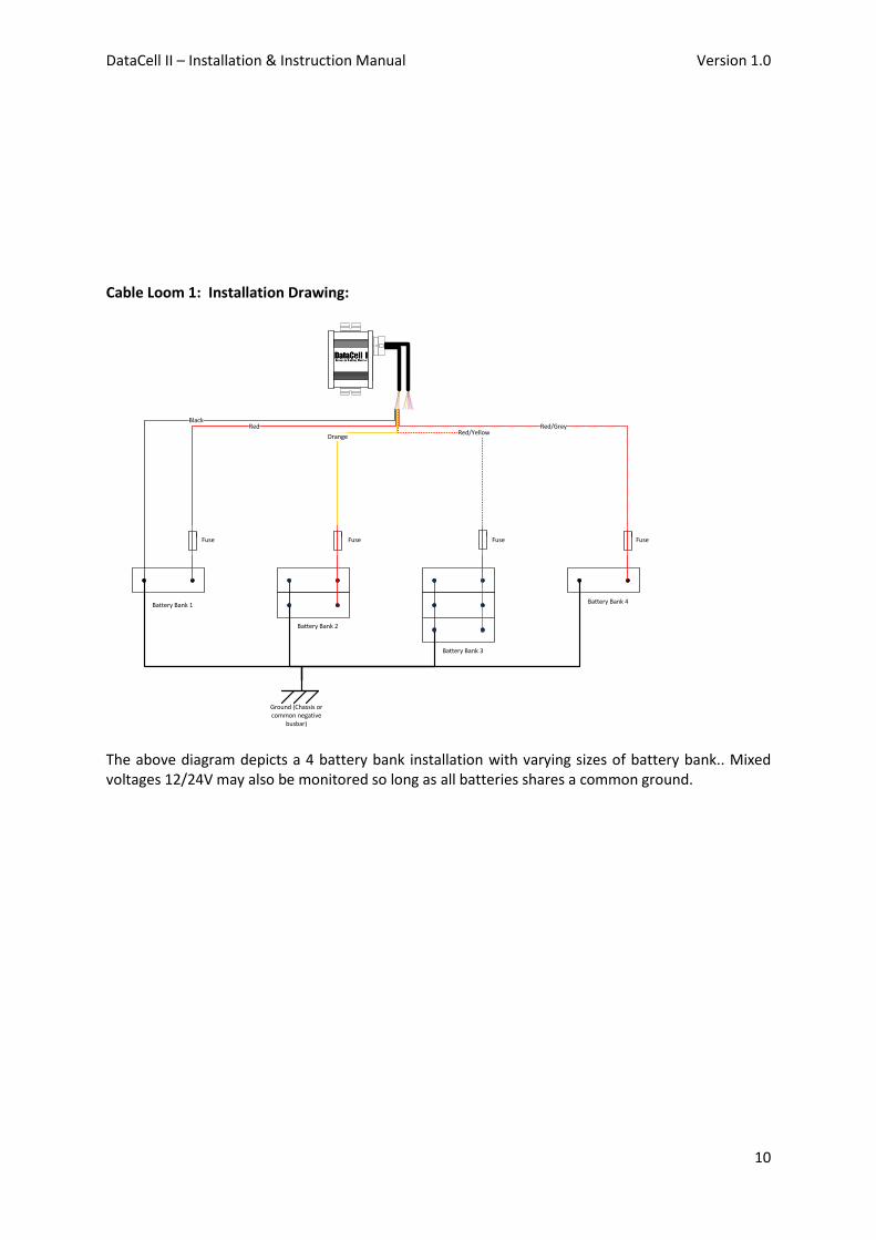
Cable Loom 1: Installation Drawing:
Ground (Chassis or common negative
busbar)
Battery Bank 1
Battery Bank 2
Battery Bank 3
Battery Bank 4
Fuse Fuse Fuse Fuse
BlackRed
OrangeRed/Yellow
Red/Grey
The above diagram depicts a 4 battery bank installation with varying sizes of battery bank.. Mixed voltages 12/24V may also be monitored so long as all batteries shares a common ground.
DataCell II – Installation & Instruction Manual Version 1.0
11
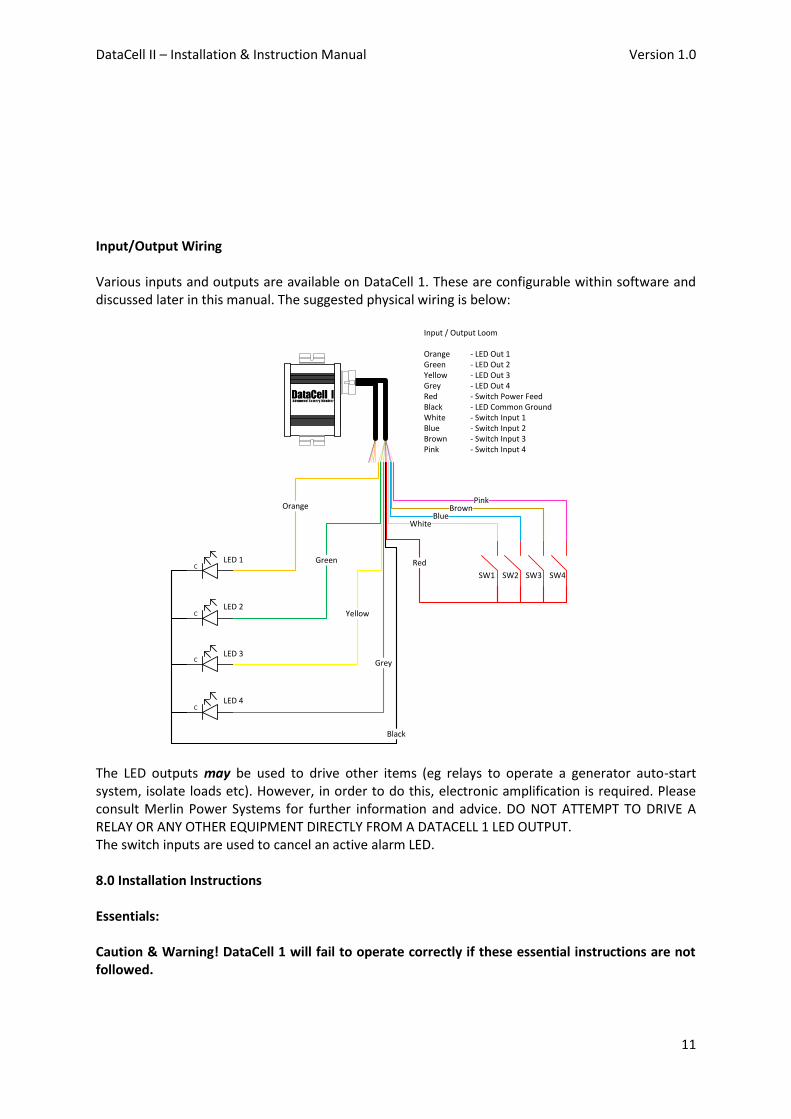
Input/Output Wiring Various inputs and outputs are available on DataCell 1. These are configurable within software and discussed later in this manual. The suggested physical wiring is below:
Input / Output Loom
Orange - LED Out 1Green - LED Out 2Yellow - LED Out 3Grey - LED Out 4Red - Switch Power Feed Black - LED Common Ground White - Switch Input 1Blue - Switch Input 2Brown - Switch Input 3Pink - Switch Input 4
C
C
C
C
LED 1
LED 2
LED 3
LED 4
Orange
Green
Yellow
Grey
Black
Red
WhiteBlue
BrownPink
SW1 SW2 SW3 SW4
The LED outputs may be used to drive other items (eg relays to operate a generator auto-start system, isolate loads etc). However, in order to do this, electronic amplification is required. Please consult Merlin Power Systems for further information and advice. DO NOT ATTEMPT TO DRIVE A RELAY OR ANY OTHER EQUIPMENT DIRECTLY FROM A DATACELL 1 LED OUTPUT. The switch inputs are used to cancel an active alarm LED. 8.0 Installation Instructions Essentials: Caution & Warning! DataCell 1 will fail to operate correctly if these essential instructions are not followed.
DataCell II – Installation & Instruction Manual Version 1.0
12
1. The DataCell 1 unit should be mounted as close as possible to the batteries that are being monitored but not within a battery compartment.
2. The ground wire must go directly to the negative of one of the batteries (not a negative bus bar, chassis or other grounded metal item on board).
3. Each battery sense wire must connect directly to the positive terminal of each battery. Do not connect via switches, bus bars or use another conductor that is connected to the battery terminal. Voltage drop along these will cause the DataCell 1 to monitor the batteries incorrectly.
4. Each battery sense wire should be fused using a 3A inline fuse (supplied) 5. Use only multi stranded 0.75-1mm wire. 6. 90% of technical questions pertaining to installed DataCell 1 accuracy are due to the points
above not being followed. 7. The DataCell 1 CPU is not waterproof. It should not be mounted in areas where it may get
wet or subjected to corrosive vapours. DataCell 1 is not Ignition Protected. Suggested mounting areas are: cabin/cab side of battery compartment bulkhead, within an IP rated cabinet in engine rooms or under bonnet.
Wiring The DataCell 1 is supplied with a wiring loom with 1.5 metres of wire attached. Where possible, use the supplied wiring. Wires may be extended if necessary. Connections to battery terminals, fuses etc should be made using a good quality crimp connectors. For external and connections to open lead/acid batteries, we recommend heatshrink style terminals to provide a corrosion (and thus resistance) free connection. If cables are to be extended, use a good quality double crimp butt connector (preferably of heatshrink type). Use only 0.75 – 1 mm (18-16AWG) multi-stranded cable. Do not use bell wire, telephone wire or RJ wire as a low resistance connection is essential to correct DataCell 1 operation. CAUTION! & WARNING!: Ensure that the battery positive of each battery is removed prior to installation. We recommend making all connections before plugging in the white connector to the DataCell 1 unit. This prevents accidental short-circuit and potential damage to the unit. DataCell 1 should always be left powered up. It consumes a tiny amount of electrical power and does not significantly contribute to parasitic draw. Do not install switches in the sense wires. Mounting Mount the DataCell 1 in a dry, clean environment using screws or bolts through the mounting feet of the unit. Tip: The grub screws that secure the mounting feet may be loosened off to facilitate alignment with pre-drilled mounting holes. Programming & Set Up First Time Power-Up and Computer Connection Once the wiring has been connected, re-attach the positive battery terminals. Plugging the white connector plug of the DataCell wiring loom into the unit will power DataCell 1 up. The remainder of the set-up procedure is completed through software as detailed below:

DataCell II – Installation & Instruction Manual Version 1.0
13
DataCell 1 uses an RS232 Serial Link. This must be used in conjunction with the supplied FTDI USB/Serial Connector. Do not connect the DataCell 1 directly to a serial port on your PC. NOTE: Due to the significant variances in quality and configuration of USB converters, DataCell 1 will only operate with an approved FTDI Converter. This is supplied with the unit. If additional converters are required, they may be sourced directly from your Dealer, Merlin Power Systems or FTDI directly. Before you connect to your PC: You must have the Microsoft .NET framework version 3.5 or later installed on your PC. Some versions of Windows already have this installed: Windows XP ‐ Requires separate .NET install Windows Vista (Service Pack 1) ‐ Requires separate .NET install Windows Vista (Service Pack 2) ‐ .NET already installed Windows 7 ‐ .NET already installed The Microsoft .NET framework may be downloaded for free from Microsoft (enter Microsoft .NET download into your search engine). We recommend only installing this from the Microsoft official website and not third parties. Next, you must configure your PC to work with the FTDI converter. DO NOT CONNECT THE DATACELL RS232 CABLE YET!
1. Go to the FTDI website and download the driver for the USB converter (the link for this is printed on the packet of the converter supplied)
2. Plug the FTDI USB/Serial Converter into a free USB port in your PC. 3. Wait for up to one minute for your PC to recognise the new device. 4. Windows may find the saved driver automatically. If asked for a location of the driver, point
windows to the saved Driver file. 5. Once completed, windows will provide a “This device is ready for use” message. Click start
and type in “Device Manager”. Device Manager can also be found in your Windows Control Panel. When open, look for “Ports”, click on this – the COM ports that the PC is using will be displayed. Against one of these USB Serial Converter will be displayed. Note down the COM port number assigned.
6. You are now ready to connect DataCell 1 to your PC. NOTE: The above instructions are for first time use. The PC should automatically recognise the FTDI converter and the driver etc. It will also remember the COM port assigned. Therefore, if you power down your PC and repower it later, DataCell 1 should automatically be found by the PC – provided that the converter remains plugged into the same USB socket. If the FTDI converter has been unplugged from the computer and plugged back in again, windows may assign a different COM port number. You may need to click “Refresh Comm Ports” under the “Settings” tab in the software. If, when reconnecting the USB converter (perhaps because in normal use you will use the DataCell remote panel), the PC doesn’t seem to ‘find’ the converter ensure that:
DataCell II – Installation & Instruction Manual Version 1.0
14
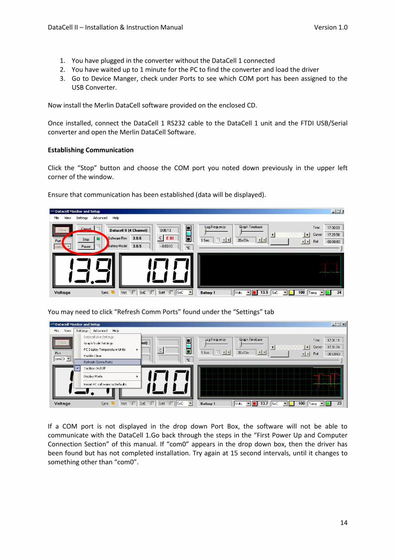
1. You have plugged in the converter without the DataCell 1 connected 2. You have waited up to 1 minute for the PC to find the converter and load the driver 3. Go to Device Manger, check under Ports to see which COM port has been assigned to the
USB Converter. Now install the Merlin DataCell software provided on the enclosed CD. Once installed, connect the DataCell 1 RS232 cable to the DataCell 1 unit and the FTDI USB/Serial converter and open the Merlin DataCell Software. Establishing Communication Click the “Stop” button and choose the COM port you noted down previously in the upper left corner of the window. Ensure that communication has been established (data will be displayed).
You may need to click “Refresh Comm Ports” found under the “Settings” tab
If a COM port is not displayed in the drop down Port Box, the software will not be able to communicate with the DataCell 1.Go back through the steps in the “First Power Up and Computer Connection Section” of this manual. If “com0” appears in the drop down box, then the driver has been found but has not completed installation. Try again at 15 second intervals, until it changes to something other than “com0”.
DataCell II – Installation & Instruction Manual Version 1.0
15
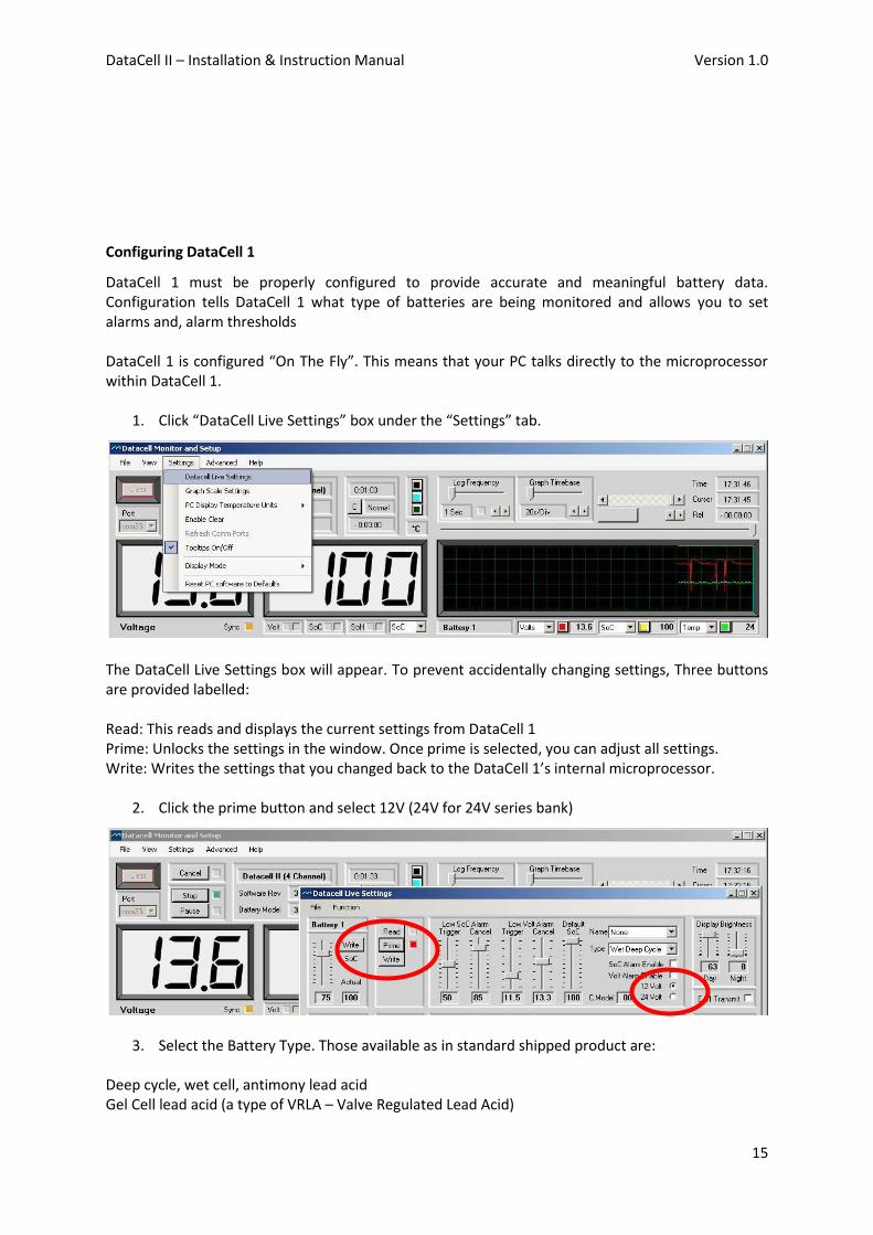
Configuring DataCell 1
DataCell 1 must be properly configured to provide accurate and meaningful battery data. Configuration tells DataCell 1 what type of batteries are being monitored and allows you to set alarms and, alarm thresholds DataCell 1 is configured “On The Fly”. This means that your PC talks directly to the microprocessor within DataCell 1.
1. Click “DataCell Live Settings” box under the “Settings” tab.
The DataCell Live Settings box will appear. To prevent accidentally changing settings, Three buttons are provided labelled: Read: This reads and displays the current settings from DataCell 1 Prime: Unlocks the settings in the window. Once prime is selected, you can adjust all settings. Write: Writes the settings that you changed back to the DataCell 1’s internal microprocessor.
2. Click the prime button and select 12V (24V for 24V series bank)
3. Select the Battery Type. Those available as in standard shipped product are: Deep cycle, wet cell, antimony lead acid Gel Cell lead acid (a type of VRLA – Valve Regulated Lead Acid)

DataCell II – Installation & Instruction Manual Version 1.0
16
AGM – Absorbed Glass Matt (another type of VRLA) Hybrid – calcium/antimony (usually marked as dual purpose or “leisure”) lead acid Carbon Fibre lead acid Maintenance free (wet cells but no way to top up the electrolyte) lead acid Important Note on Type 1 - Use only for genuine AGM batteries: Genuine AGM’s have the electrolyte held in a glass mat but with additional chemicals in the battery. They require lower charge voltages and the off load terminal voltages will be similar to gel cells. Only this type requires DataCell I to be set to AGM Type 1. There are other Glass Mat type batteries without the additional chemicals. This type usually has charge voltages very similar to flooded wet cell batteries. The off load terminal voltages will also be very similar to flooded wet cell batteries. If your AGM batteries are of this type then DataCell I should be set toAGM Type 2
Custom Battery Models: Certain customers may have requested custom battery models for specific makes and models of batteries. If this is the case, Merlin Power Systems will have provided the battery model either on CD or by emailed file. See Loading Custom Battery Types in Section 10.0.
4. The “Default SoC” slider sets the value that the DataCell 1 should assume if power is lost or reset. We normally recommend that this is set at 75%. However, for safety critical applications, it should be set to zero.
5. Low state of charge and voltage trigger and cancel alarm levels are also set and enabled from this page.
Low SoC Trigger: This is the level below which the battery SoC has to fall to trigger the alarm. Alarm Cancel: This is the level at which the battery State of Charge % alarm will automatically cancel. Low Volt Trigger: This is the level below which the battery voltage has to fall to trigger the alarm.Alarm Cancel: This is the level at which the voltage alarm will automatically cancel. SoC Alarm Enable and Volt Alarm Enable boxes must be checked for these alarms to function.
DataCell II – Installation & Instruction Manual Version 1.0
17
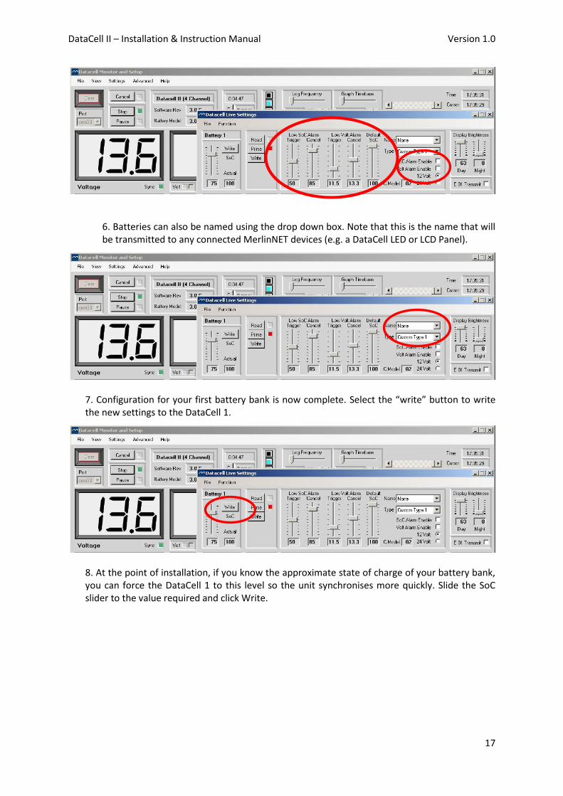
6. Batteries can also be named using the drop down box. Note that this is the name that will be transmitted to any connected MerlinNET devices (e.g. a DataCell LED or LCD Panel).
7. Configuration for your first battery bank is now complete. Select the “write” button to write the new settings to the DataCell 1.
8. At the point of installation, if you know the approximate state of charge of your battery bank, you can force the DataCell 1 to this level so the unit synchronises more quickly. Slide the SoC slider to the value required and click Write.
DataCell II – Installation & Instruction Manual Version 1.0
18
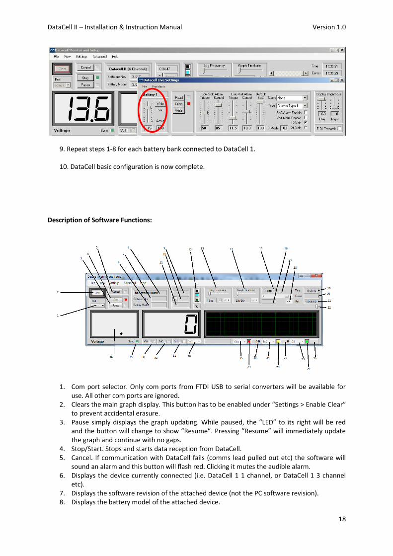
9. Repeat steps 1-8 for each battery bank connected to DataCell 1.
10. DataCell basic configuration is now complete. Description of Software Functions:
1. Com port selector. Only com ports from FTDI USB to serial converters will be available for
use. All other com ports are ignored. 2. Clears the main graph display. This button has to be enabled under “Settings > Enable Clear”
to prevent accidental erasure. 3. Pause simply displays the graph updating. While paused, the “LED” to its right will be red
and the button will change to show “Resume”. Pressing “Resume” will immediately update the graph and continue with no gaps.
4. Stop/Start. Stops and starts data reception from DataCell. 5. Cancel. If communication with DataCell fails (comms lead pulled out etc) the software will
sound an alarm and this button will flash red. Clicking it mutes the audible alarm. 6. Displays the device currently connected (i.e. DataCell 1 1 channel, or DataCell 1 3 channel
etc). 7. Displays the software revision of the attached device (not the PC software revision). 8. Displays the battery model of the attached device.

DataCell II – Installation & Instruction Manual Version 1.0
19
9. Total operation time. Displays the total time DataCell has been operating since it was last powered up.
10. Either “Normal” or “E 01”. E 01 means power has been lost at some point since it was last cleared. This error can only be cleared by clicking the “C” to its left.
11. Total time since E 01 error was generated. 12. Colour buttons. Allows the graph colours (graph background, cursor and graticule) to be
changed. Hover the mouse over the buttons to check which button affects which colour. These settings are saved and remembered the next time the software is used.
13. Log frequency. How often data is written to disc when the software is data logging. 14. Graph timebase. How often the graph is updated. This allows the graph to display any time
period between a total of 8 minutes and 24 hours. 15. Displays the graph update rate. i.e. how often the graph display is updated. 16. If the cursor and graph are not at the home position (i.e. the cursor at far right and the graph
is positioned so that the far right is “Now”) this button will flash and display “Home”. Clicking the button will force the graph to the home position.
17. Adjusts the position of the graph window over the graph. This can also be done by clicking in the graph and dragging the graph to the required position.
18. Cursor fine adjustment. 19. Current time according to the PC system clock. If the PC clock is wrong, so too will this be.
This time clock is used to time stamp logged data. 20. The time at the current cursor position. This was the time according to the system clock
when that data was received. 21. The time of the cursor relative to the right hand side of the graph. 22. Cursor adjustment. 23. Not used for DataCell 1 24. Not used for DataCell 1 25. Not used for DataCell 1 26. Not used for DataCell 1. This will be blank or zero. 27. Displays the graph data at the position of the cursor for this graph line. For DataCell 1 this
will always be SoC. 28. Displays the graph data at the position of the cursor for this graph line. For DataCell 1 this
will always be Volts. 29. Sets the graph colour for this function. 30. Selects the function of this “LCD”. For DataCell 1 this is fixed to SoC 31. Not used for DataCell 1. 32. If a SoC alarm has been set in DataCell, and that alarm has triggered, this LED will light up.
An audible alarm will also sound. Clicking in the checkbox will cancel the audio. The alarm will remain triggered.
33. Does the same as 32 above but for a low volt alarm. 34. “LCD” 35. Sync indicator. Not used for DataCell 1.
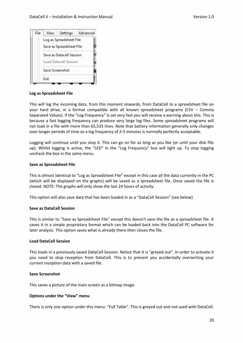
Options under the “File” menu Click the “File” menu bar at the top. You will see the following menu:-
DataCell II – Installation & Instruction Manual Version 1.0
20
Log as Spreadsheet File This will log the incoming data, from this moment onwards, from DataCell to a spreadsheet file on your hard drive, in a format compatible with all known spreadsheet programs (CSV – Comma Separated Values). If the “Log Frequency” is set very fast you will receive a warning about this. This is because a fast logging frequency can produce very large log files. Some spreadsheet programs will not load in a file with more than 65,535 lines. Note that battery information generally only changes over longer periods of time so a log frequency of 2-5 minutes is normally perfectly acceptable. Logging will continue until you stop it. This can go on for as long as you like (or until your disk fills up). Whilst logging is active, the “LED” in the “Log Frequency” box will light up. To stop logging uncheck the box in the same menu. Save as Spreadsheet File This is almost identical to “Log as Spreadsheet File” except in this case all the data currently in the PC (which will be displayed on the graphs) will be saved as a spreadsheet file. Once saved the file is closed. NOTE: The graphs will only show the last 24 hours of activity. This option will also save data that has been loaded in as a “DataCell Session” (see below) Save as DataCell Session This is similar to “Save as Spreadsheet File” except this doesn't save the file as a spreadsheet file. It saves it in a simple proprietary format which can be loaded back into the DataCell PC software for later analysis. This option saves what is already there then closes the file. Load DataCell Session This loads in a previously saved DataCell Session. Notice that it is “greyed out”. In order to activate it you need to stop reception from DataCell. This is to prevent you accidentally overwriting your current reception data with a saved file. Save Screenshot This saves a picture of the main screen as a bitmap image. Options under the “View” menu There is only one option under this menu: “Full Table”. This is greyed out and not used with DataCell.

DataCell II – Installation & Instruction Manual Version 1.0
21
Options under the “Settings” menu DataCell Live Settings Used during setup (See Configuring DataCell 1) Graph Scale Settings This option is greyed out with a DataCell 1. PC Display Temperature Units Not used for DataCell 1. Enable Clear This enables the “Clear” button on the main screen for one operation (to clear graph data). Refresh Comms Port This forces the software to ask Windows what comm ports are currently installed. Handy if another DataCell is plugged in whilst the software is running. Tooltips On/Off Enabled/Disables Windows Tooltips for this software. Display Mode Not used for DataCell 1. Reset PC Software to Defaults Resets all user options (graph colours, display settings etc) to the factory defaults. Options under the “Advanced” menu Enable Zeroing Not used for DataCell 1. Zero Shunt Amplifiers Not used for DataCell 1. Upload Battery Models This opens up another window. See the heading “Upload Battery Models Window” Anti Alias sub items

DataCell II – Installation & Instruction Manual Version 1.0
22
In its basic form Aliasing is a form of digital distortion caused by trying to read data out slower than it was recorded. In our case, if we have the graph set to display a point every 1 minute, but in between those 1 minute intervals there was a spike in (say) battery voltage, the graph will completely miss it. It will not be shown. Enable “Anti Alias” on any channel to make these visible. Note that this uses considerable processing power (in extreme cases the PC has to analyse 24 hours of data every second) which is why it is not on by default. On very slow PCs you might find it simply unable to keep up due to lack of processing power. Help The usual Windows Help information. Explanation of DataCell error codes is also under this heading. 9.0 Datacell Live Settings Window Selecting “DataCell Live Settings” under the “Settings” menu opens up the Live Settings Window:
This is for a single channel DataCell. Any additional channels will show up as a vertical expansion with another identical row for each battery channel. This is the only section of the PC software where actual changes are made to DataCell. All other functions in this software only affect the way data is displayed on the PC. Under the “Function” menu are two more sub menus. These are greyed out with DataCell 1. Dealing with this window:- On the left hand side is a slider with two text boxes below it. The left text box shows the position of the slider. The right text box the actual model based SoC being transmitted by DataCell. This slider allows you to manually set the model based SoC. Set the slider to the required number, click the “Write” button. There will be a short delay; DataCell will then report that as the SoC.
DataCell II – Installation & Instruction Manual Version 1.0
23
“Battery 1” at the top left. This displays the user selected battery name. This name will appear on certain remote displays that are attached and on the PC software. To change the name use the drop down selection box to the right that currently has “None” displayed in it. The main section on the right/centre contains adjustment for a low voltage alarm, a low SoC alarm and several other self explanatory features. Default SoC is the model based SoC DataCell will start off at following a depower/repower. Setting this to the middle of the usual usage range ensures DataCell will reach synchronisation in the shortest possible time. The section just to the left of this contains “Read”, “Prime” and “Write” buttons. There is a simple logic behind these:- The default is “Read” being selected. This is shown by the green “LED” to its right. Notice that all the controls to the right are greyed out. You cannot adjust them. They are showing, and are set to, exactly how DataCell is currently set. This means you cannot accidentally change any settings in DataCell. In order to make a change you click the “Prime” button. Notice the change in LEDs. The controls are now enabled. You can adjust them. Check the SoC Alarm Enable checkbox. This hasn't done anything yet. Click the “Write” button. After a second or so the controls will grey out again and the “Read” button will be active again, but look closely: The SoC Alarm Enable box is now checked. Click “Prime” again. Check the Volt Alarm Enable box. Now click “Read”. The controls go back to their greyed out state, but the box is not checked. You didn't actually set the alarm, because you didn't click the “Write” button. With the exception of the slider on the far left to set the SoC, all functions operate in this same method. It starts off in “Read” so that all settings from DataCell set the controls. You click “Prime”, make any changes you want, then click “Write”. If you don't click “Write” nothing is changed. If you open up the PC software without a DataCell connected you will see these controls in odd positions. As soon as you plug into DataCell you will see them instantly jump to show the current settings. Functions the Live Settings Window Low SoC Alarm:- Trigger. The level below which the SoC has to fall in order to trigger the alarm. Cancel: The level which the SoC has to rise to in order to cancel the alarm. Note: These only operate if the SoC alarm is actually enabled. Low volts Alarm:- Trigger. The level below which the voltage has to fall in order to trigger the alarm. Cancel: The level which the voltage has to rise to in order to cancel the alarm.

DataCell II – Installation & Instruction Manual Version 1.0
24
Note: These only operate if the volt alarm is actually enabled. Default SoC has been covered in the previous section. Name: A drop down selector with a selection of names for the battery/bank. If “None” is selected the battery will be named Battery X where X is the battery channel number. Battery Type: A drop down selector with the various battery models used by the SoC algorithm. It is important to set this to the correct type. You will also notice a custom model in here which is covered elsewhere in this manual. Selection of 12 or 24 volt battery channel. Incorrect selection of voltage causes no harm to DataCell 1 but it will produce incorrect readings. C.Model: This displays a code showing which custom battery model is loaded in to this channel. If this shows “00” then no custom model is loaded. In this case, setting this channel to “Custom Type X (where X is the battery channel) will use Wet Cell Deep Cycle. Display Brightness. Day, Night. These only affect the brightness of remote displays for day mode (brighter display) or night mode (darker display). E 01 Transmit: Selects whether the E 01 error message is transmitted to remote displays. Some prefer this, some prefer not. Functions not applicable to DataCell 1 will always be shown greyed out. 10.0 Loading Custom Battery Types Merlin Power Systems (or your Dealer) will provide the Custom Battery Model on CD or via emailed file. DataCell uses a battery model to calculate battery SoC. Over time, DataCell adjusts the model as it learns about the batteries. Therefore, each battery channel requires its own model to use and continually adjust. This means that for a two channel DataCell you will need to load the battery model in twice (one for each channel), for a four channel DataCell you will need to load the battery model in four times. 1. Save the battery model file (.dcbm) in a known location on your hard drive. 2. Under the Advanced Menu, click on Upload Battery Models 3. A new window will open. You have the ability to upload up to 4 separate battery models. You will be able to assign a different custom model to each channel (or use one of the standard models or a mix). 4. Click on the left hand ‘Upload Model’ and select what to Upload the model as (Model 1, 2, 3 or 4). Then click on file load. Select the .dcbm file you wish to use. 5. Repeat until you have loaded in enough battery models for each channel you wish to use in DataCell (for example if you have a 4 channel DataCell and wish to use the custom type for 2 channels only (and the standard battery types for the others), you would need to upload the model twice.

DataCell II – Installation & Instruction Manual Version 1.0
25
6. Close the window. Go to Settings>DataCell Live Settings. The Live Settings Window will open. For each battery, click Prime. Under Type, Select Custom Type. Repeat for each battery which you wish to use custom models for. Displaying Battery Information There are four options for displaying battery information with DataCell 1: 1. With the supplied DataCell Monitoring & Setup Software 2. With a DataCell Remote Panel 3. With Merlin Dashboard Software 4. On third party equipment Instructions for the remote panel are shipped with the panel. Instructions for the Merlin Dashboard Software reside in the Dashboard Program File on the supplied CD. Use with third party equipment is available by arrangement with Merlin Power Systems. An Interface Control Document (ICD) is available for this purpose. 11.0 Safety Considerations There are no special specific safety considerations (except for observing good installation practices covered elsewhere in this manual) for the DataCell product. Where DataCell 1 is being used as a discrete module for starting/stopping generators, or switching loads on and off safety should be considered. If starting/stopping a generator etc is to become an automatic function, some form of manual override or lock-out is required to ensure safety during generator servicing. Accurate SoC will become critical. Therefore, it is important that DataCell 1 is carefully set up and configured. At the end of life, DataCell contains recyclable components. Please dispose of with other normal electrical waste at your local recycling centre. 12.0 Maintenance DataCell 1 is designed to provide years of trouble-free service. A basic annual check is all that is needed: 1. Wipe over the DataCell 1 CPU with a damp cloth. 2. Check security of the plug and look for any corrosion in the terminals. Corroded terminals will cause inaccurate battery monitoring. 3. Check the condition of the fuses. Any corroded fuses or terminals should be replaced. 13.0 Warranty Merlin Equipment Limited T/a Merlin Power Systems warrants this product free from manufacturing
defect for 2 years from the confirmed date of purchase.
DataCell II – Installation & Instruction Manual Version 1.0
26
Merlin Power Systems will repair or replace faulty product during this period at its sole discretion subject to the failure not being a result or caused by any of the following conditions: 1. Reverse polarity, connection to the incorrect voltage or reverse switch/contactor polarity. 2. Damage caused by incorrect installation that may include (but is not limited to): Incorrect wiring, incorrect sized wiring, Ingress of water, salt, vapour, corrosive gases, diesel, petrol or other distillates of oil. 3. Physical damage/abuse. 4. Damage caused by third party equipment or systems, fire, flood, lightning and other atmospheric phenomena. This warranty expressly excludes all consequential costs including (but not limited to): Loss of use, loss of reputation, cost of installation/engineers time, cost of return freight, any banking charge etc. To Claim Warranty please contact your Dealer. To return goods directly to Merlin, please click on the
warranty tab on www.merlinequipment.com and follow on screen instructions. Merlin Equipment
accepts no liability for goods returned without Returns Authorisation.
Merlin Equipment Ltd & Merlin Power Systems accepts no liability for loss, injury of damage caused
by installing or fitting this equipment. If you do not accept this no liability clause, do not install the
equipment. Please return the goods (carriage paid) in original packaging for a full refund. Installing it
constitutes acceptance of these terms. Please ensure that the goods are suitable and appropriate for
the installation. Full technical details, manuals and expert help is available from Merlin Power
Systems.
Please note that this warranty, exceptions and terms do not infringe your statutory rights that may
vary from country to country and state to state.
14.0 To Claim Warranty
First, please call the dealer where the unit was purchased. Alternatively, contact your Dealer or
Merlin Power Systems for technical support. The majority of problems can be diagnosed and
rectified during a short phone call. If the product requires warranty service, please log on to
www.merlinequipment.com and click on Warranty on the top right hand corner.
IMPORTANT: Power Systems does not accept nor accepts any responsibility for goods that are returned without following the on-line warranty procedures. The warranty procedure not only allows you to register and complete the necessary documentation but also allows you to check when warranty goods are received and their repair/replacement status. Copyright 2013 Merlin Equipment Limited T/A Merlin Power Systems. All Rights Reserved. This publication or parts thereof may not be reproduced in any form, by any
method, for any purpose. For conditions of use and permission to use this manual for publication in other than the English language, contact Merlin Equipment Limited.
MERLIN EQUIPMENT LTD MAKES NO WARRANTY, EITHER EXPRESSED OR IMPLIED, INCLUDING BUT NOT LIMITED TO ANY IMPLIED WARRANTIES OF MERCHANTABILITY OR
FITNESS FOR A PARTICULAR PURPOSE, REGARDING THESE MERLIN PRODUCTS AND MAKES SUCH MERLIN PRODUCTS AVAILABLE SOLELY ON AN “AS IS” BASIS. IN NO
EVENT SHALL MERLIN EQUIPMENT LTD BE LIABLE TO ANYONE FOR SPECIAL, COLLATERAL, INCIDENTAL, OR CONSEQUENTIAL DAMAGES IN CONNECTION WITH OR ARISING
OUT OF PURCHASE OR USE OF THESE MERLIN PRODUCTS. THE SOLE AND EXCLUSIVE LIABILITY TO MERLIN EQUIPMENT LTD., REGARDLESS OF THE FORM OF ACTION,
SHALL NOT EXCEED THE PURCHASE PRICE OF THE MERLIN PRODUCTS DESCRIBED HERE IN. Merlin Equipment Limited reserves the right to revise and improve its products
as it sees fit. This publication describes the state of this product at the time of its publication and may not reflect the product at all times in the future
Installation of the product supplied with this manual constitutes full acceptance of these terms. If you do not agree to them, return the product, unused to Merlin Equipment Limited for a full refund.