memory - bucknell university
TRANSCRIPT
Memory ManagementCSCI 315 Operating Systems Design
Department of Computer Science
Notice: The slides for this lecture are based on those from Operating Systems Concepts, 9th ed., by Silberschatz, Galvin, and Gagne. Many, if not all, the illustrations contained in this presentation come from this source.
CSCI 315 Operating Systems Design 2
Background
• Program must be brought into memory and placed within a process for it to be run.
• Input queue – collection of processes on the disk that are waiting to be brought into memory to run the program.
• User programs go through several steps before being run.
CSCI 315 Operating Systems Design 3
Binding of Instructions and Data to Memory
• Compile time: If memory location known a priori, absolute code can be generated; must recompile code if starting location changes.
• Load time: Must generate relocatable code if memory location is not known at compile time.
• Execution time: Binding delayed until run time if the process can be moved during its execution from one memory segment to another. Need hardware support for address maps (e.g., base and limit registers).
Address binding of instructions and data to memory addresses canhappen at three different stages:
CSCI 315 Operating Systems Design 4
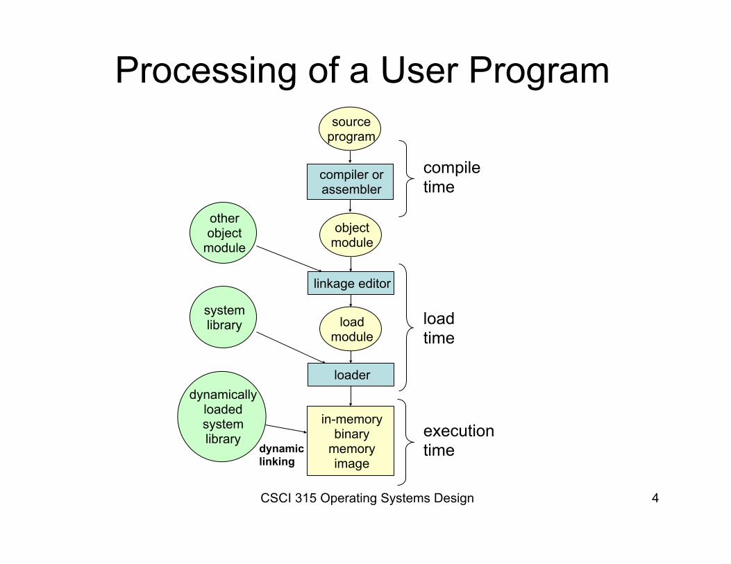
Processing of a User Program source
program
compiler orassembler
objectmodule
linkage editor
loadmodule
loader
in-memorybinary
memoryimage
otherobject
module
systemlibrary
dynamicallyloadedsystemlibrary
compiletime
loadtime
executiontimedynamic
linking
CSCI 315 Operating Systems Design 5
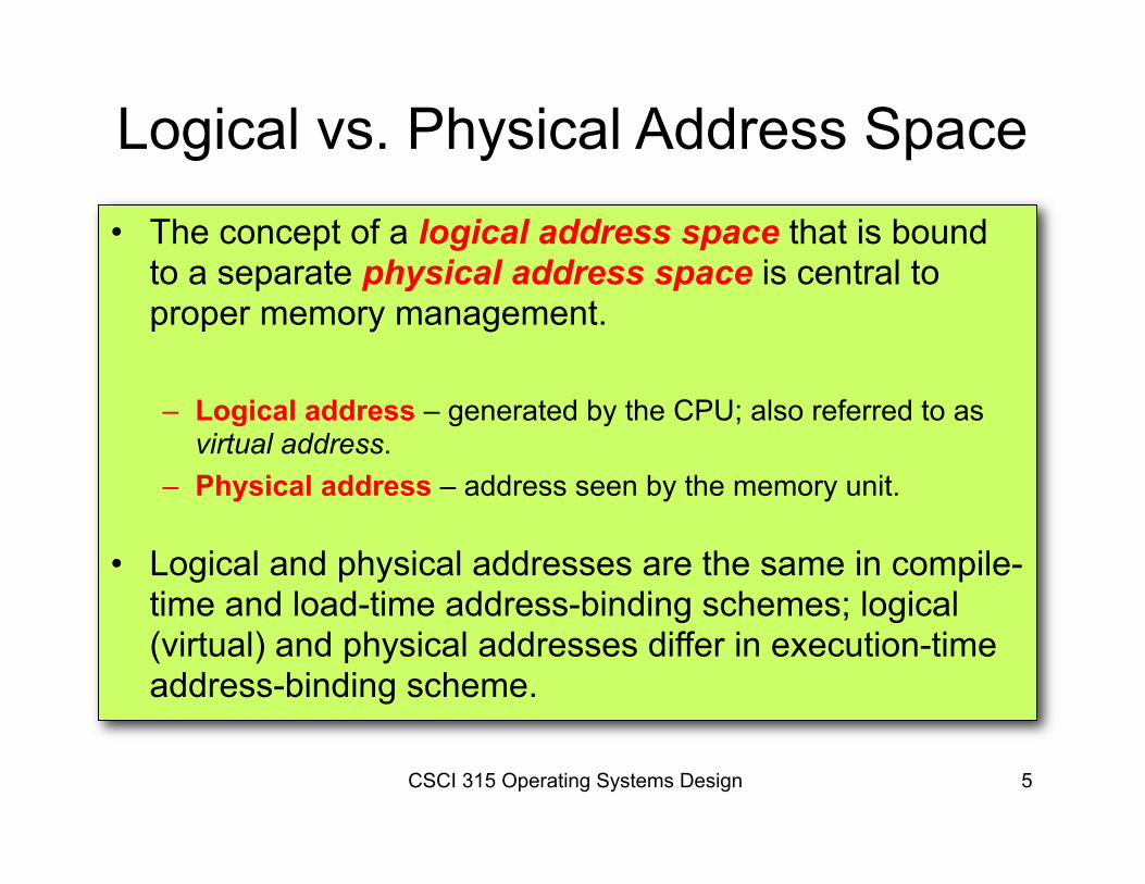
Logical vs. Physical Address Space• The concept of a logical address space that is bound
to a separate physical address space is central to proper memory management.
– Logical address – generated by the CPU; also referred to as virtual address.
– Physical address – address seen by the memory unit.
• Logical and physical addresses are the same in compile-time and load-time address-binding schemes; logical (virtual) and physical addresses differ in execution-time address-binding scheme.
CSCI 315 Operating Systems Design 6
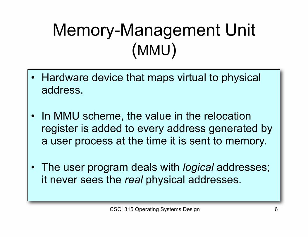
Memory-Management Unit (MMU)
• Hardware device that maps virtual to physical address.
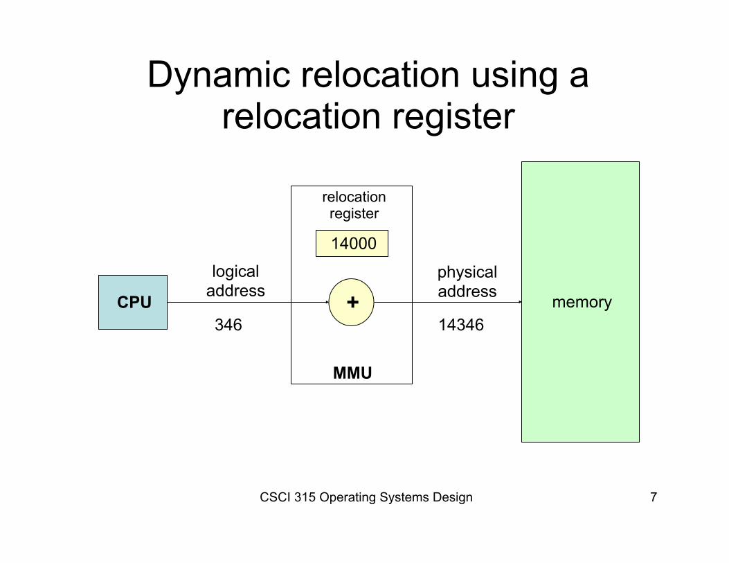
• In MMU scheme, the value in the relocation register is added to every address generated by a user process at the time it is sent to memory.
• The user program deals with logical addresses; it never sees the real physical addresses.
CSCI 315 Operating Systems Design 7
Dynamic relocation using a relocation register
CPU
14000
relocationregister
+
MMU
memory
logicaladdress
physicaladdress
346 14346
CSCI 315 Operating Systems Design 8
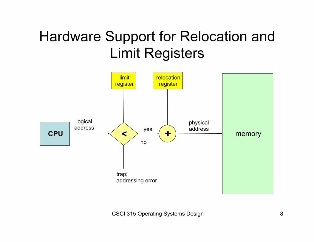
Hardware Support for Relocation and Limit Registers
CPU memory
logicaladdress
physicaladdress< +
relocationregister
limitregister
yes
no
trap;addressing error
CSCI 315 Operating Systems Design 9
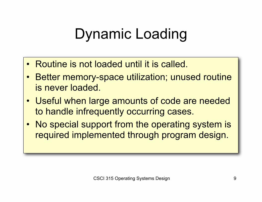
Dynamic Loading
• Routine is not loaded until it is called.• Better memory-space utilization; unused routine
is never loaded.• Useful when large amounts of code are needed
to handle infrequently occurring cases.• No special support from the operating system is
required implemented through program design.
CSCI 315 Operating Systems Design 10
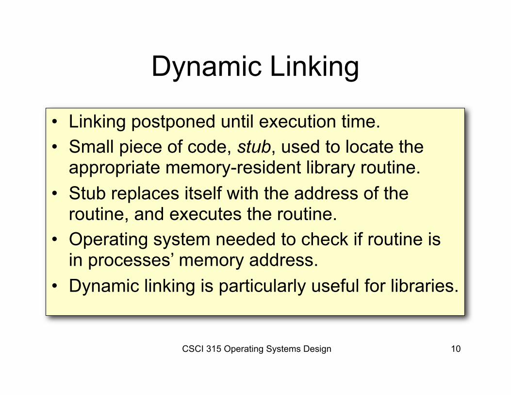
Dynamic Linking
• Linking postponed until execution time.• Small piece of code, stub, used to locate the
appropriate memory-resident library routine.• Stub replaces itself with the address of the
routine, and executes the routine.• Operating system needed to check if routine is
in processes’ memory address.• Dynamic linking is particularly useful for libraries.
CSCI 315 Operating Systems Design 11
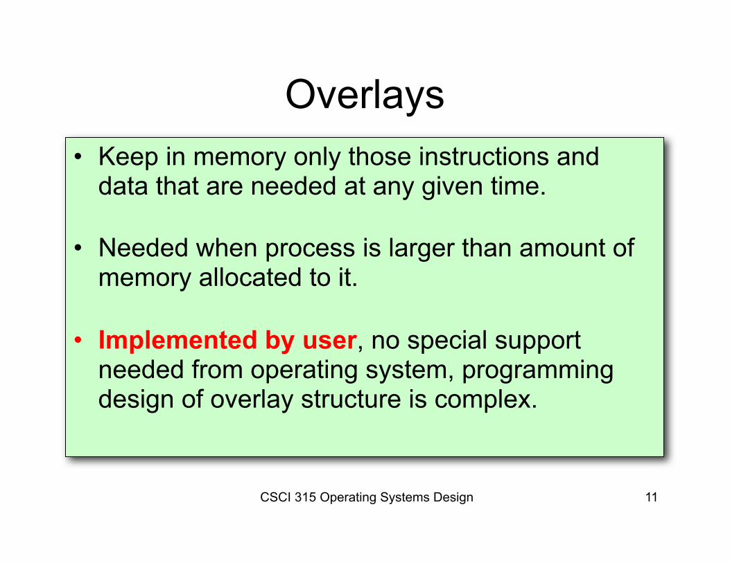
Overlays• Keep in memory only those instructions and
data that are needed at any given time.
• Needed when process is larger than amount of memory allocated to it.
• Implemented by user, no special support needed from operating system, programming design of overlay structure is complex.
CSCI 315 Operating Systems Design 12
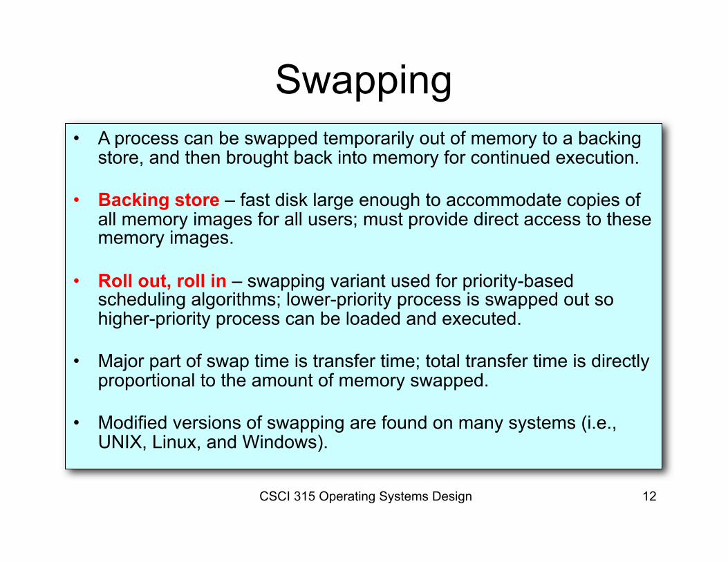
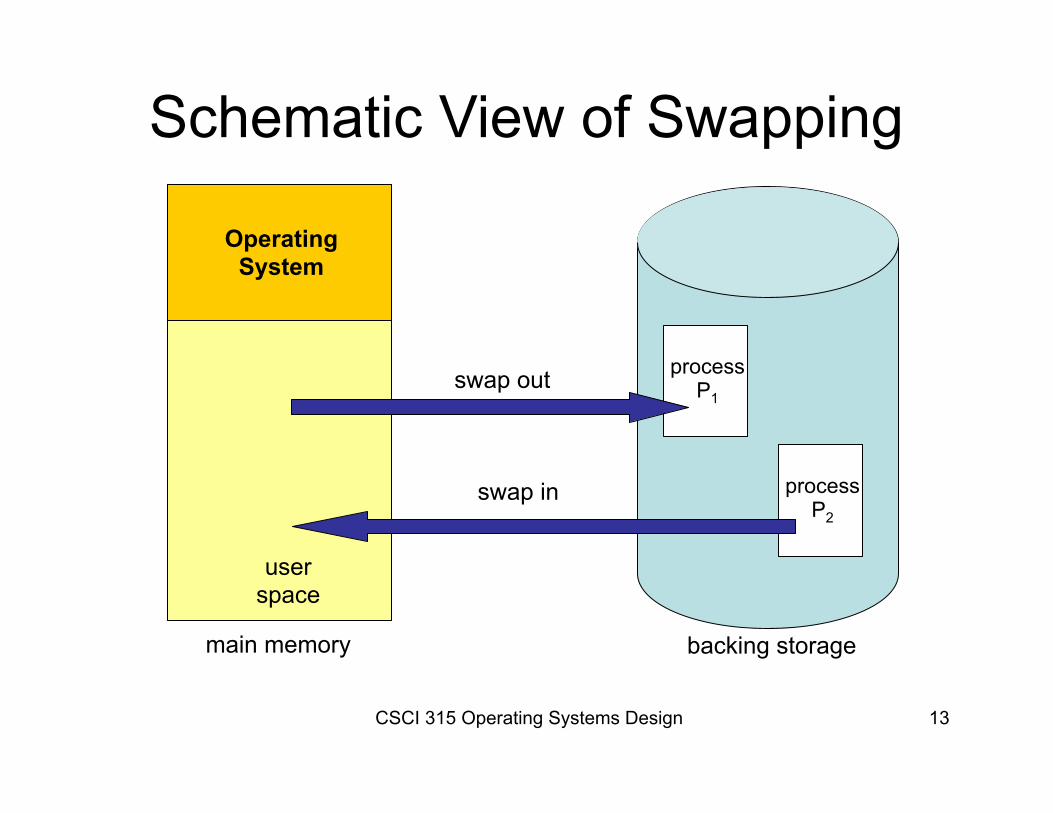
Swapping• A process can be swapped temporarily out of memory to a backing
store, and then brought back into memory for continued execution.
• Backing store – fast disk large enough to accommodate copies of all memory images for all users; must provide direct access to these memory images.
• Roll out, roll in – swapping variant used for priority-based scheduling algorithms; lower-priority process is swapped out so higher-priority process can be loaded and executed.
• Major part of swap time is transfer time; total transfer time is directly proportional to the amount of memory swapped.
• Modified versions of swapping are found on many systems (i.e., UNIX, Linux, and Windows).
CSCI 315 Operating Systems Design 13
Schematic View of Swapping
OperatingSystem
userspace
processP1
processP2
swap out
swap in
main memory backing storage
CSCI 315 Operating Systems Design 14
Contiguous Allocation• Main memory usually into two partitions:
– Resident operating system, usually held in low memory with interrupt vector.
– User processes then held in high memory.
• Single-partition allocation– Relocation-register scheme used to protect user processes from
each other, and from changing operating-system code and data.– Relocation-register contains value of smallest physical address;
limit register contains range of logical addresses – each logical address must be less than the limit register.
CSCI 315 Operating Systems Design 15
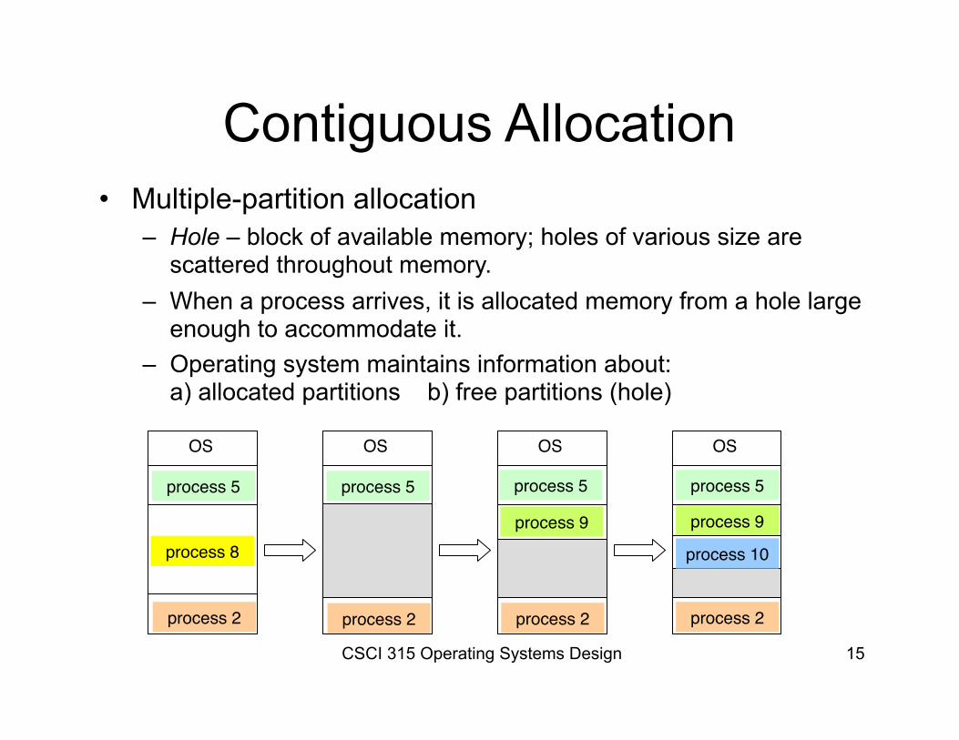
Contiguous Allocation• Multiple-partition allocation
– Hole – block of available memory; holes of various size are scattered throughout memory.
– When a process arrives, it is allocated memory from a hole large enough to accommodate it.
– Operating system maintains information about:a) allocated partitions b) free partitions (hole)
OS
process 5
process 8
process 2
OS
process 5
process 2
OS
process 5
process 2
OS
process 5
process 9
process 2
process 9
process 10
CSCI 315 Operating Systems Design 16
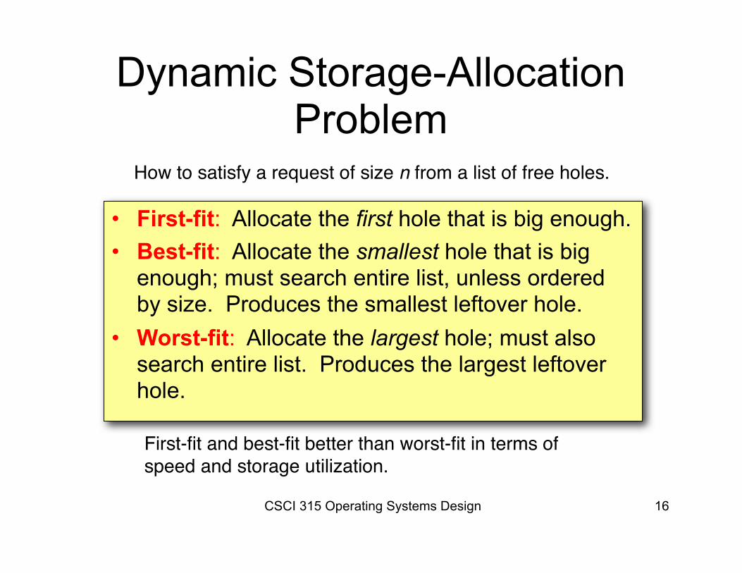
Dynamic Storage-Allocation Problem
• First-fit: Allocate the first hole that is big enough.• Best-fit: Allocate the smallest hole that is big
enough; must search entire list, unless ordered by size. Produces the smallest leftover hole.
• Worst-fit: Allocate the largest hole; must also search entire list. Produces the largest leftover hole.
How to satisfy a request of size n from a list of free holes.
First-fit and best-fit better than worst-fit in terms of speed and storage utilization.
CSCI 315 Operating Systems Design 17
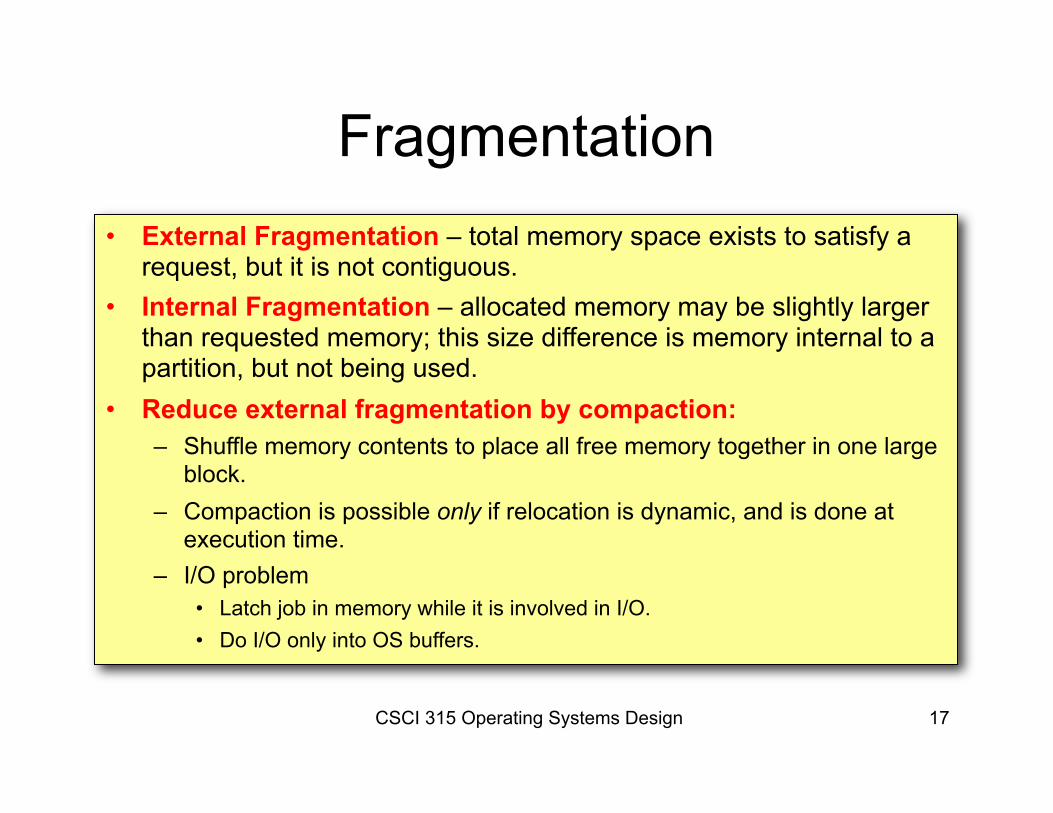
Fragmentation• External Fragmentation – total memory space exists to satisfy a
request, but it is not contiguous.• Internal Fragmentation – allocated memory may be slightly larger
than requested memory; this size difference is memory internal to a partition, but not being used.
• Reduce external fragmentation by compaction:– Shuffle memory contents to place all free memory together in one large
block.– Compaction is possible only if relocation is dynamic, and is done at
execution time.– I/O problem
• Latch job in memory while it is involved in I/O.• Do I/O only into OS buffers.
CSCI 315 Operating Systems Design 17
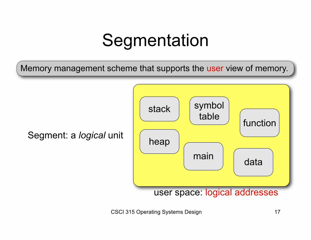
SegmentationMemory management scheme that supports the user view of memory.
Segment: a logical unit
stack
heap
symbol table
main
function
data
user space: logical addresses
CSCI 315 Operating Systems Design 17
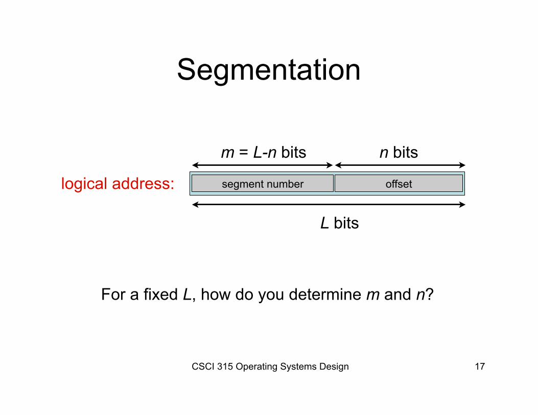
Segmentation
logical address: segment number offset
L bits
n bitsm = L-n bits
For a fixed L, how do you determine m and n?
CSCI 315 Operating Systems Design 17
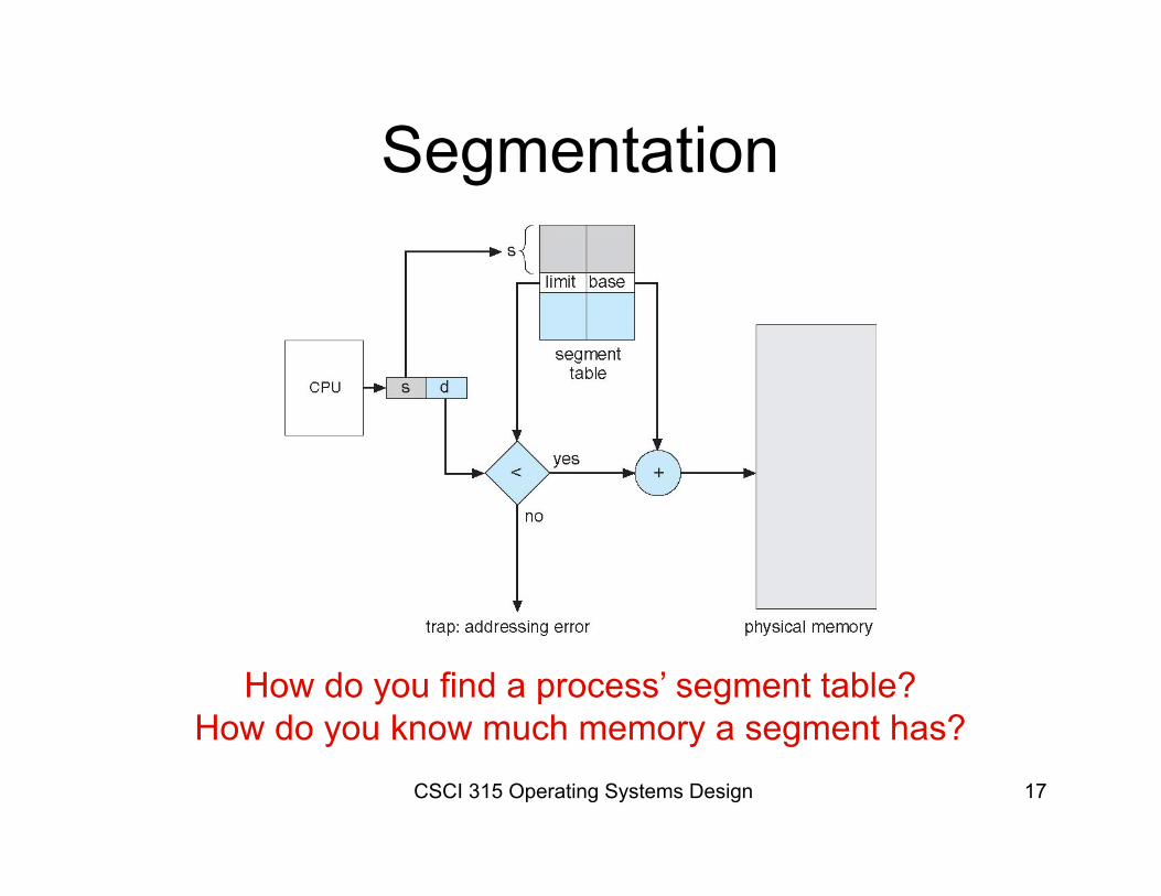
Segmentation
How do you find a process’ segment table?How do you know much memory a segment has?
CSCI 315 Operating Systems Design 17
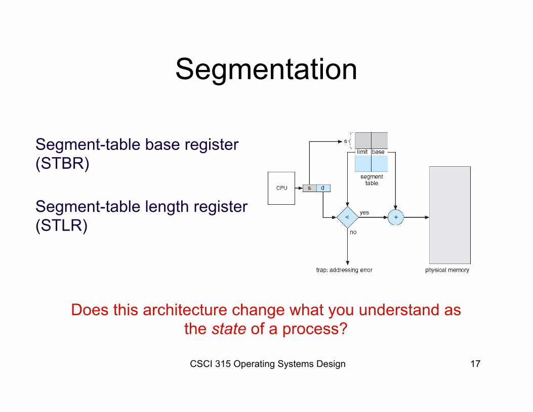
Segmentation
Segment-table base register(STBR)
Segment-table length register(STLR)
Does this architecture change what you understand as the state of a process?
CSCI 315 Operating Systems Design 18
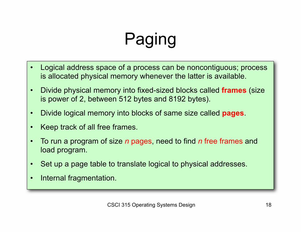
Paging• Logical address space of a process can be noncontiguous; process
is allocated physical memory whenever the latter is available.
• Divide physical memory into fixed-sized blocks called frames (size is power of 2, between 512 bytes and 8192 bytes).
• Divide logical memory into blocks of same size called pages.
• Keep track of all free frames.
• To run a program of size n pages, need to find n free frames and load program.
• Set up a page table to translate logical to physical addresses.
• Internal fragmentation.
CSCI 315 Operating Systems Design 19
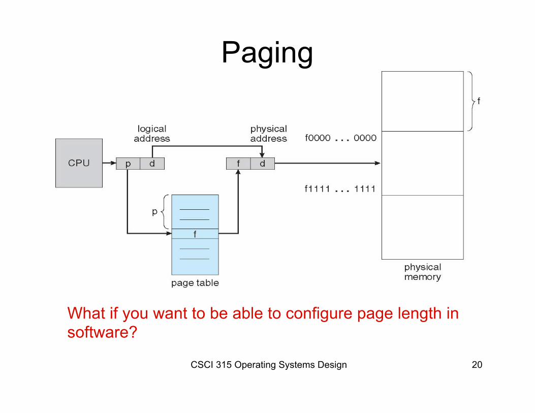
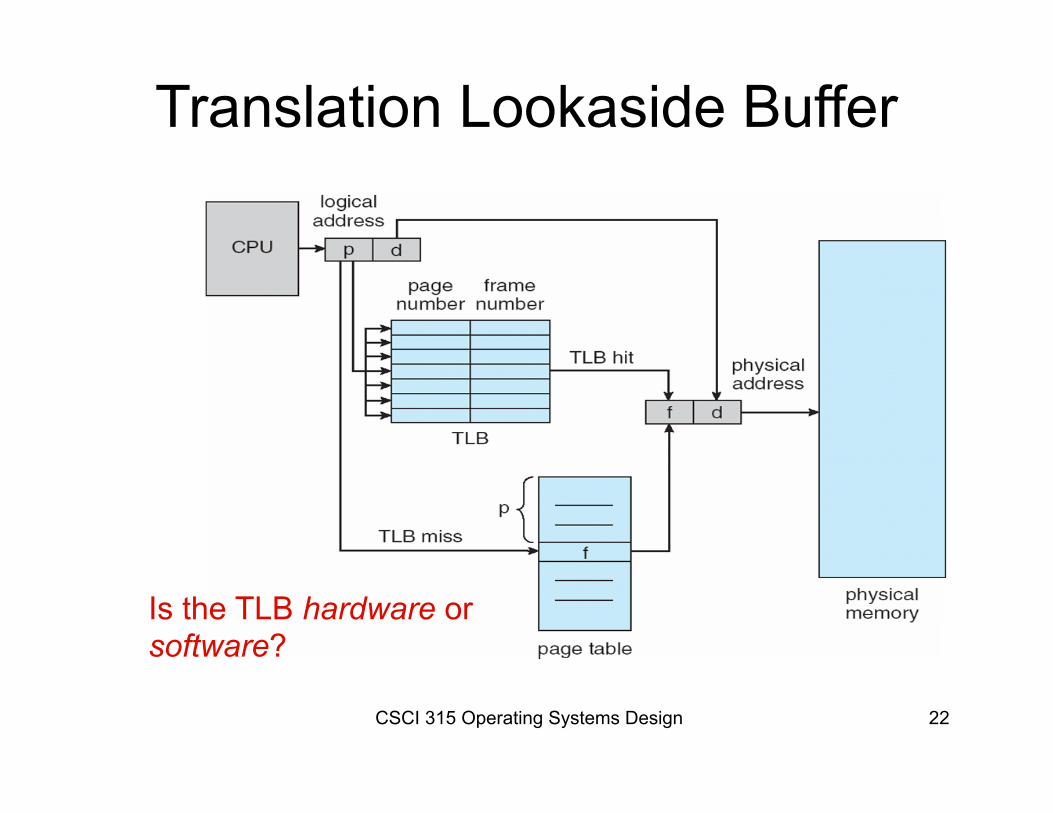
Address generated by CPU is divided into:– Page number (p) – used as an index into a
page table which contains base address of each page in physical memory.
– Page offset (d) – combined with base address to define the physical memory address that is sent to the memory unit.
Address Translation Scheme
CSCI 315 Operating Systems Design 17
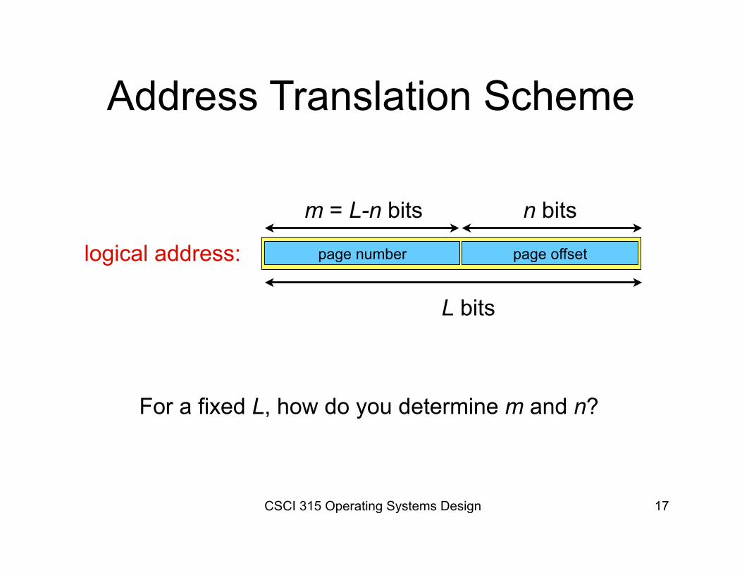
Address Translation Scheme
logical address: page number page offset
L bits
n bitsm = L-n bits
For a fixed L, how do you determine m and n?
CSCI 315 Operating Systems Design 20
Paging
What if you want to be able to configure page length in software?
CSCI 315 Operating Systems Design 17
Paging
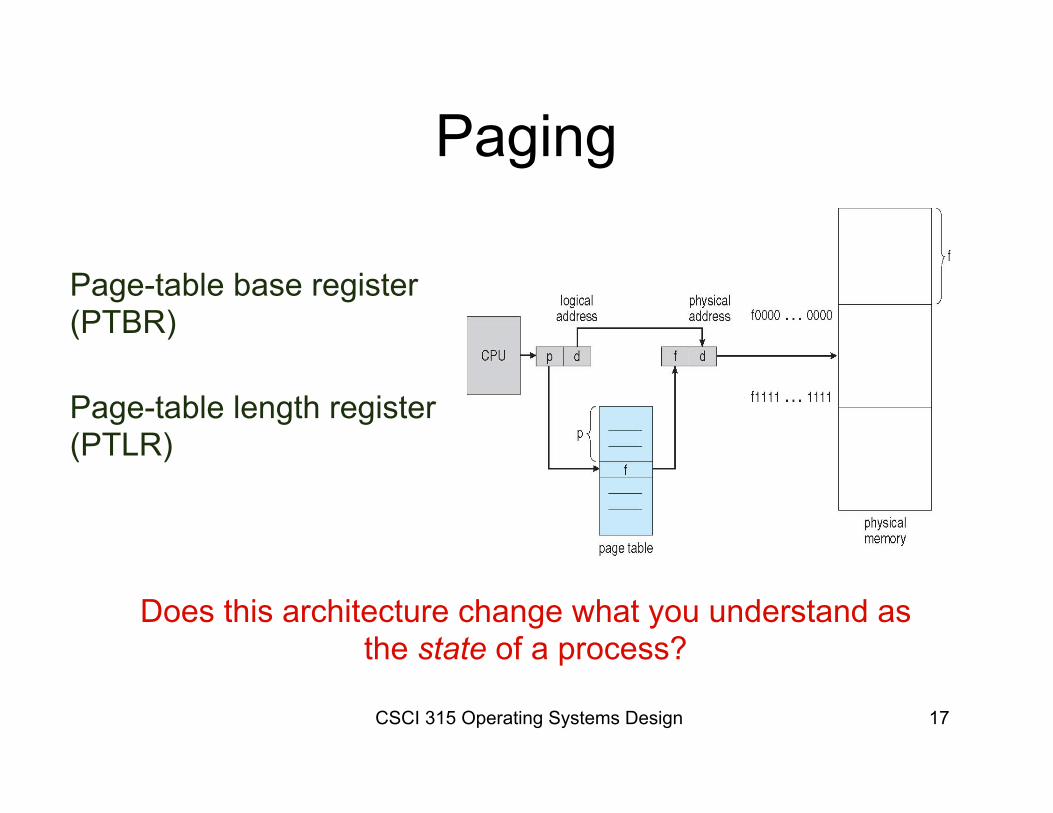
Page-table base register(PTBR)
Page-table length register(PTLR)
Does this architecture change what you understand as the state of a process?
CSCI 315 Operating Systems Design 21
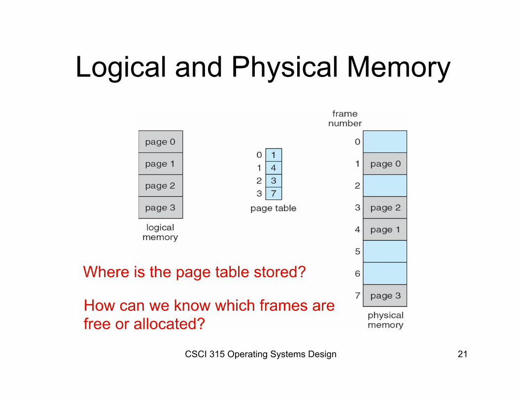
Logical and Physical Memory
Where is the page table stored?
How can we know which frames arefree or allocated?
CSCI 315 Operating Systems Design 22
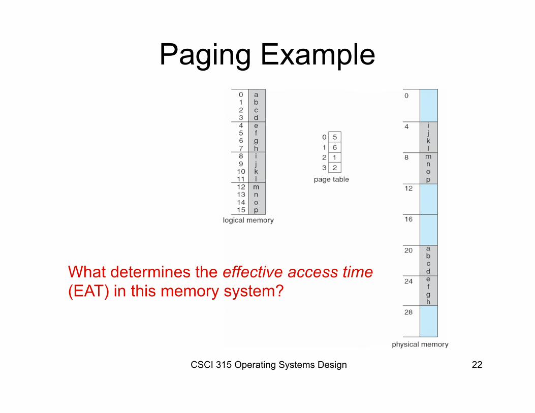
Paging Example
What determines the effective access time(EAT) in this memory system?
CSCI 315 Operating Systems Design 12
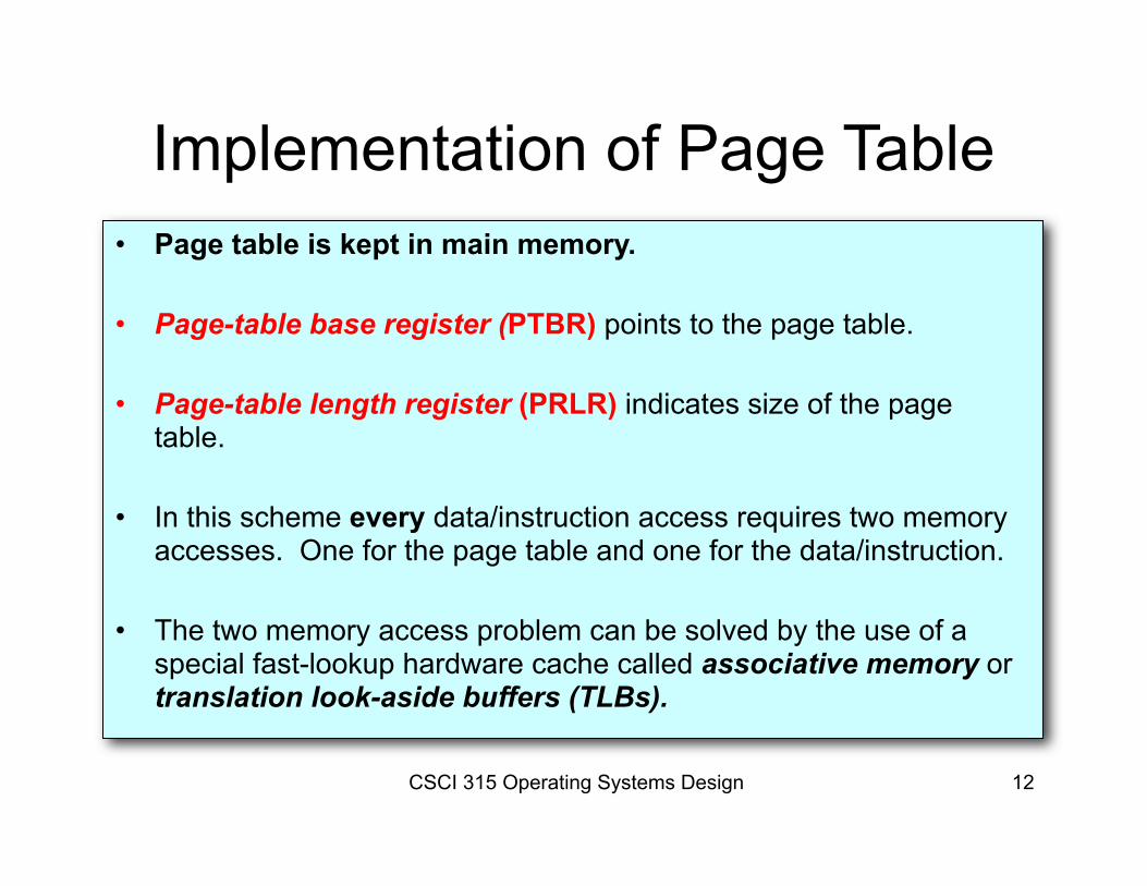
Implementation of Page Table• Page table is kept in main memory.
• Page-table base register (PTBR) points to the page table.
• Page-table length register (PRLR) indicates size of the page table.
• In this scheme every data/instruction access requires two memory accesses. One for the page table and one for the data/instruction.
• The two memory access problem can be solved by the use of a special fast-lookup hardware cache called associative memory or translation look-aside buffers (TLBs).
CSCI 315 Operating Systems Design 13
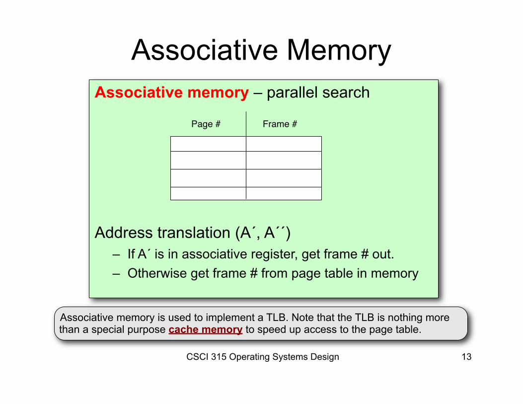
Associative memory – parallel search
Address translation (A´, A´´)
– If A´ is in associative register, get frame # out. – Otherwise get frame # from page table in memory
Associative Memory
Page # Frame #
Associative memory is used to implement a TLB. Note that the TLB is nothing more than a special purpose cache memory to speed up access to the page table.
CSCI 315 Operating Systems Design 22
Translation Lookaside Buffer
Is the TLB hardware orsoftware?
CSCI 315 Operating Systems Design 16
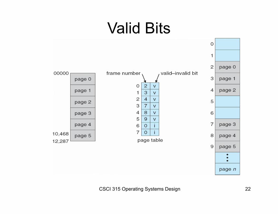
Memory Protection
• Memory protection implemented by associating protection bits with each frame.
• Valid-invalid bit attached to each entry in the page table:– “valid” indicates that the associated page is in the
process’ logical address space, and is thus a legal page.
– “invalid” indicates that the page is not in the process’ logical address space.
CSCI 315 Operating Systems Design 22
Valid Bits
CSCI 315 Operating Systems Design 15
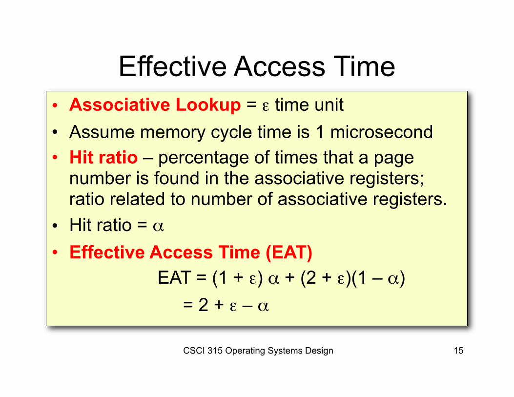
Effective Access Time• Associative Lookup = ε time unit• Assume memory cycle time is 1 microsecond• Hit ratio – percentage of times that a page
number is found in the associative registers; ratio related to number of associative registers.
• Hit ratio = α• Effective Access Time (EAT) EAT = (1 + ε) α + (2 + ε)(1 – α) = 2 + ε – α
CSCI 315 Operating Systems Design 22
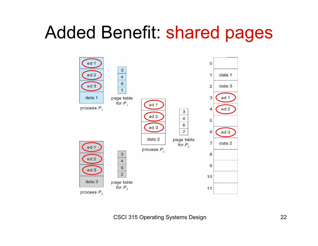
Added Benefit: shared pages
CSCI 315 Operating Systems Design 21
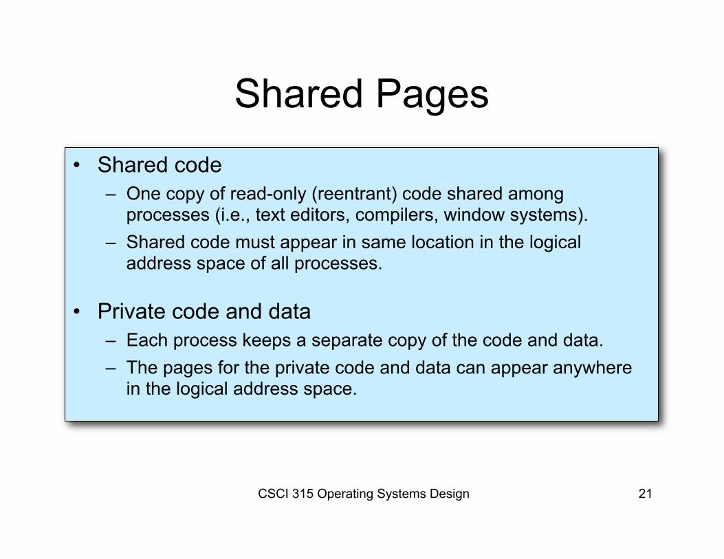
Shared Pages• Shared code
– One copy of read-only (reentrant) code shared among processes (i.e., text editors, compilers, window systems).
– Shared code must appear in same location in the logical address space of all processes.
• Private code and data – Each process keeps a separate copy of the code and data.– The pages for the private code and data can appear anywhere
in the logical address space.
CSCI 315 Operating Systems Design 22
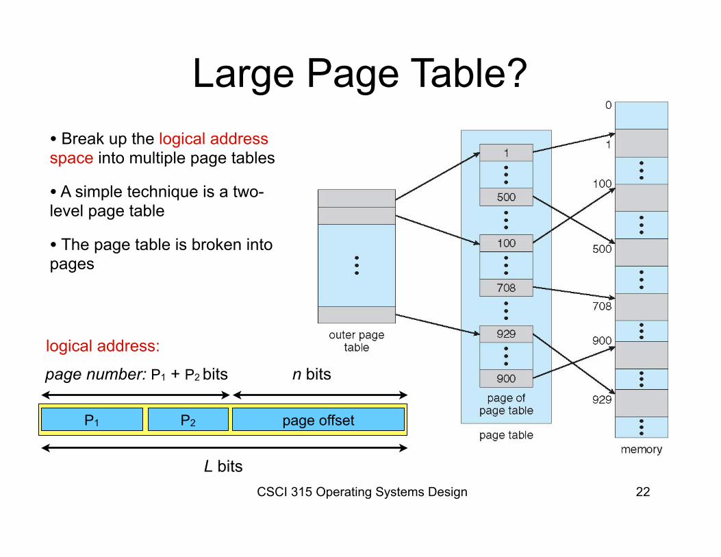
Large Page Table?• Break up the logical address space into multiple page tables
• A simple technique is a two-level page table
• The page table is broken into pages
logical address:
P1 page offset
L bits
n bitspage number: P1 + P2 bits
P2
CSCI 315 Operating Systems Design 22
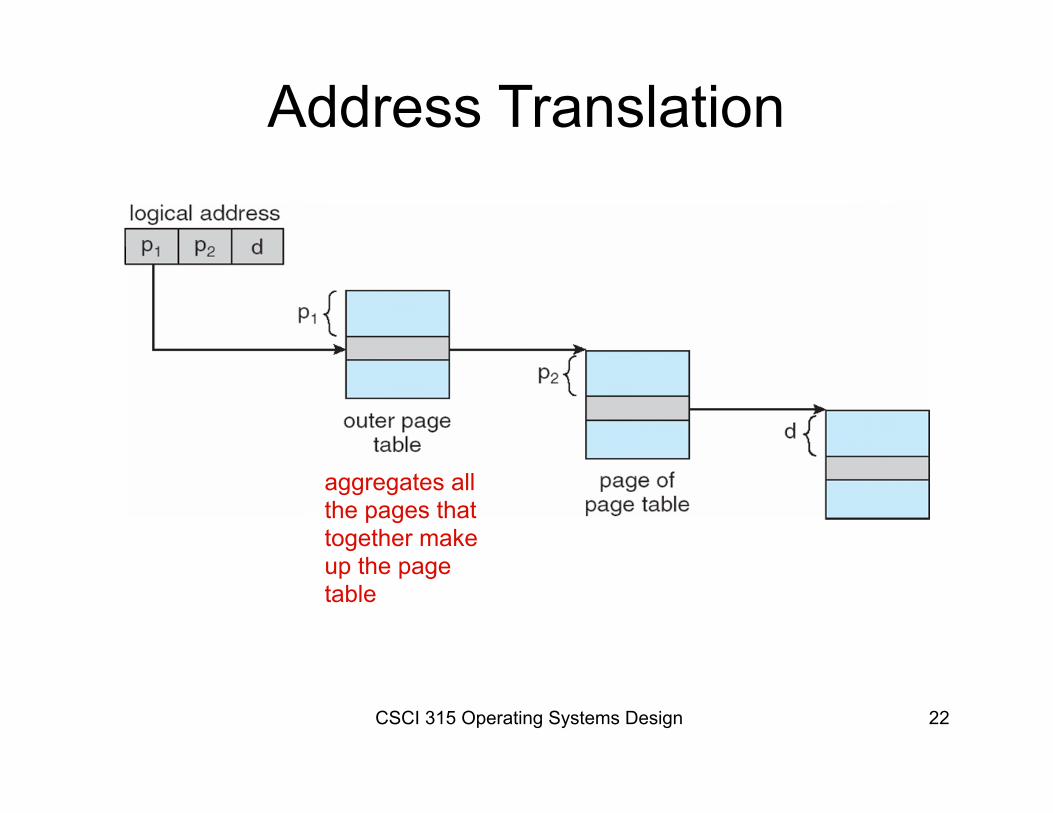
Address Translation
aggregates allthe pages that together make up the page table
CSCI 315 Operating Systems Design 18
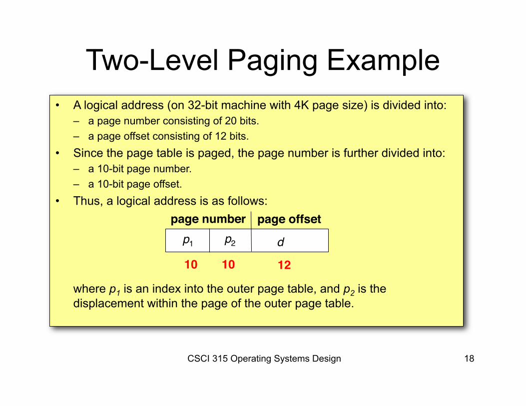
Two-Level Paging Example• A logical address (on 32-bit machine with 4K page size) is divided into:
– a page number consisting of 20 bits.– a page offset consisting of 12 bits.
• Since the page table is paged, the page number is further divided into:– a 10-bit page number. – a 10-bit page offset.
• Thus, a logical address is as follows:
where p1 is an index into the outer page table, and p2 is the displacement within the page of the outer page table.
page number page offsetp1 p2 d
10 10 12