medium voltage hrc fuses - thorne and derrick uk · medium voltage hrc fuses catalogue sheet...
TRANSCRIPT
Medium Voltage HRC FUSES
Catalogue sheet B30/06.03e
2 ABB
1. FEATURES− High rupturing capacity− Short−circuit current limiting− Low rated minimum breaking current (Imin)− Low switching overvoltages (Um)− Can be used with switch disconnector (it is fitted with
a medium−size striker pin)− Dimensions acc. to DIN and IEC Standards.
2. APPLICATIONSThe HRC (high rupturing capacity) fuse−links are used
to protect transformers, capacitor banks, cable andoverhead lines against short−circuits. They protectswitchgears from thermal and electromagnetic effects ofheavy short−circuit currents by limiting the peak currentvalues (cut−off characteristic) and interrupting the currentsin several milliseconds.
The type BWMW fuse−links interrupt overloadcurrents greater than Imin (for the Imin values refer to Table 1).
In situations where overloads lower than Imin are to beinterrupted by the protective system, a switch−disconnector fitted with an overcurrent protecting deviceis to be used together with the type BWMW fuse−links.
BWMW fuse−links can be used with type BWMP,BWMPE, BWMPNS, BWMPNW and BPS−01 fuse−basesas well as type OR5 or NALF switch−disconnectors.
3. ENVIRONMENTAL OPERATING CONDITIONS
BWMW fuse−links can be operated under the followingenvironmental conditions:
− on indoor and outdoor equipment,− at ambient temperatures of −30oC to +40oC,− at relative humidity of ambient air of 100% at
a temperature of +20oC.
4. DESIGNATIONS VERSIONS
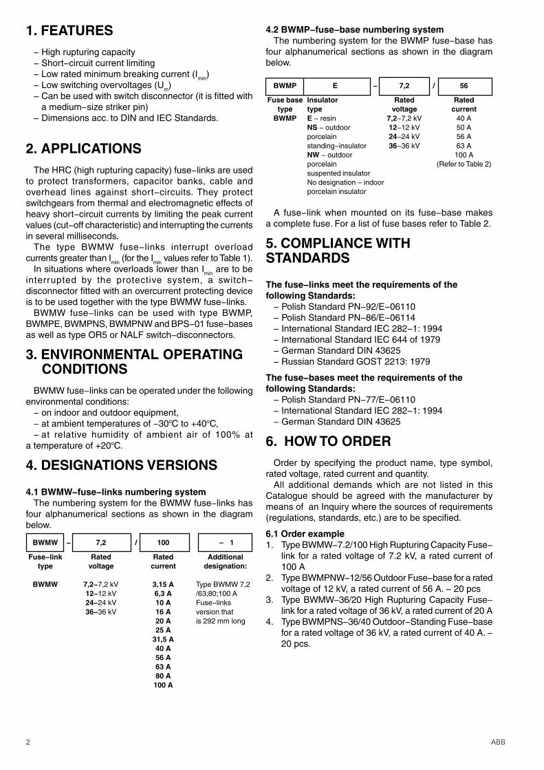
4.1 BWMW−fuse−links numbering systemThe numbering system for the BWMW fuse−links has
four alphanumerical sections as shown in the diagrambelow.
4.2 BWMP−fuse−base numbering systemThe numbering system for the BWMP fuse−base has
four alphanumerical sections as shown in the diagrambelow.
BWMW − 7,2 / 100 – 1
Fuse−link Rated Rated Additionaltype voltage current designation:
BWMW 7,2−7,2 kV 3,15 A12−12 kV 6,3 A24−24 kV 10 A36−36 kV 16 A
20 A25 A
31,5 A40 A56 A63 A80 A
100 A
Type BWMW 7,2/63;80;100 AFuse−linksversion thatis 292 mm long
A fuse−link when mounted on its fuse−base makesa complete fuse. For a list of fuse bases refer to Table 2.
5. COMPLIANCE WITHSTANDARDS
The fuse−links meet the requirements of thefollowing Standards:
− Polish Standard PN−92/E−06110− Polish Standard PN−86/E−06114− International Standard IEC 282−1: 1994− International Standard IEC 644 of 1979− German Standard DIN 43625− Russian Standard GOST 2213: 1979
The fuse−bases meet the requirements of thefollowing Standards:
− Polish Standard PN−77/E−06110− International Standard IEC 282−1: 1994− German Standard DIN 43625
6. HOW TO ORDEROrder by specifying the product name, type symbol,
rated voltage, rated current and quantity.All additional demands which are not listed in this
Catalogue should be agreed with the manufacturer bymeans of an Inquiry where the sources of requirements(regulations, standards, etc.) are to be specified.
6.1 Order example1. Type BWMW−7.2/100 High Rupturing Capacity Fuse−
link for a rated voltage of 7.2 kV, a rated current of100 A
2. Type BWMPNW−12/56 Outdoor Fuse−base for a ratedvoltage of 12 kV, a rated current of 56 A. − 20 pcs
3. Type BWMW−36/20 High Rupturing Capacity Fuse−link for a rated voltage of 36 kV, a rated current of 20 A
4. Type BWMPNS−36/40 Outdoor−Standing Fuse−basefor a rated voltage of 36 kV, a rated current of 40 A. −20 pcs.
BWMP E − 7,2 / 56
Fuse base Insulator Rated Ratedtype type voltage current
BWMP E − resin 7,2−7,2 kV 40 ANS − outdoor 12−12 kV 50 Aporcelain 24−24 kV 56 Astanding−insulator 36−36 kV 63 ANW − outdoor 100 Aporcelain (Refer to Table 2)suspented insulatorNo designation − indoorporcelain insulator
3ABB
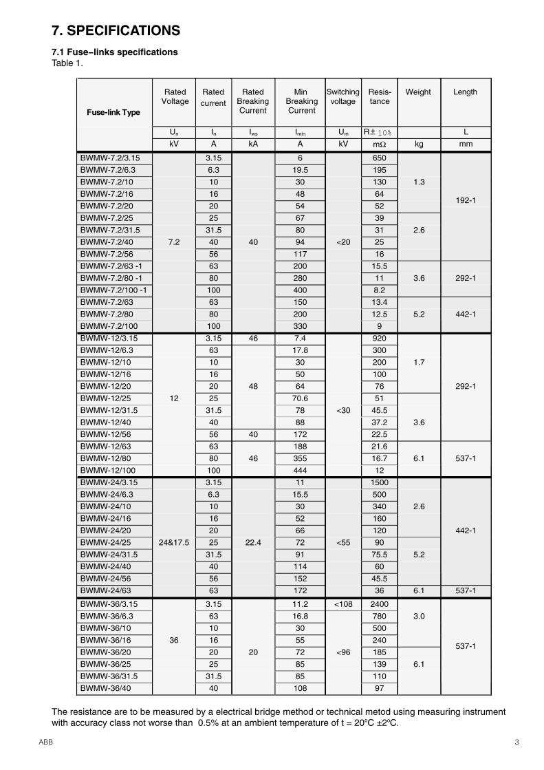
7. SPECIFICATIONS7.1 Fuse−links specificationsTable 1.
10%
The resistance are to be measured by a electrical bridge method or technical metod using measuring instrumentwith accuracy class not worse than 0.5% at an ambient temperature of t = 20oC ±2oC.
4 ABB
Fuse−base typeRatedvoltage
Ratedcurrent
Ratedfrequency
Weight
Related fuse−link
Un In f
kV A Hz kg
BWMP−7,2/567,2
56 5.4 BWMW−7,2/3,15 ¸56
BWMP−7,2/100 100 6.1 BWMW−7,2/63 ¸100
BWMP−12/5612
56 5.6 BWMW−12/3,15 ¸56
BWMP−12/100 100 50;60 6.2 BWMW−12/63 ¸100
BWMP−24/5024
50 8.7 BWMW−24/3,15 ¸50
BWMP−24/63 63 8.9 BWMW−24/63
BWMP−36/40 36 40 15.0 BWMW−36/3,15 ¸40
BWMPE−7,2/567,2
56 3.4 BWMW−7,2/3,15 ¸56
BWMPE−7,2/100 100 4.1 BWMW−7,2/63 ¸100
BWMPE−12/56 12 56 3.6 BWMW−12/3,15 ¸56
BWMPE−12/100 100 50;60 4.2 BWMW−12/63 ¸100
BWMPE−24/50 24 50 4.8 BWMW−24/3,15 ¸50
BWMPE−24/63 63 5.0 BWMW−24/63
BWMPE−36/40 36 40 6.2 BWMW−36/3,15 ¸40
BWMPNS−7,2/567,2
56 BWMW−7,2/3,15 ¸56
BWMPNS−7,2/100 100 BWMW−7,2/63 ¸100
BWMPNS−12/5612
56 BWMW−12/3,15 ¸56
BWMPNS−12/100 100 50;60 BWMW−12/63 ¸100
BWMPNS−24/5024
50 17.6 BWMW−24/3,15 ¸50
BWMPNS−24/63 63 18.1 BWMW−24/63
BWMPNS−36/40 36 40 27.4 BWMW−36/3,15 ¸40
BWMPNW−7,2/567,2
56 BWMW−7,2/3,15 ¸56
BWMPNW−7,2/100 100 BWMW−7,2/63 ¸100
BWMPNW−12/5612
56 BWMW−12/3,15 ¸56
BWMPNW−12/100 100 50;60 BWMW−12/63 ¸100
BWMPNW−24/5024
50 17.6 BWMW−24/3,15 ¸50
BWMPNW−24/63 63 18.1 BWMW−24/63
BWMPNW−36/40 36 40 27.4 BWMW−36/3,15 ¸40
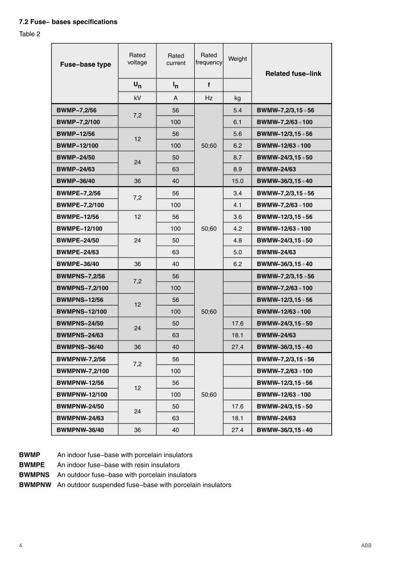
7.2 Fuse− bases specifications
BWMP An indoor fuse−base with porcelain insulators
BWMPE An indoor fuse−base with resin insulators
BWMPNS An outdoor fuse−base with porcelain insulators
BWMPNW An outdoor suspended fuse−base with porcelain insulators
Table 2
5ABB
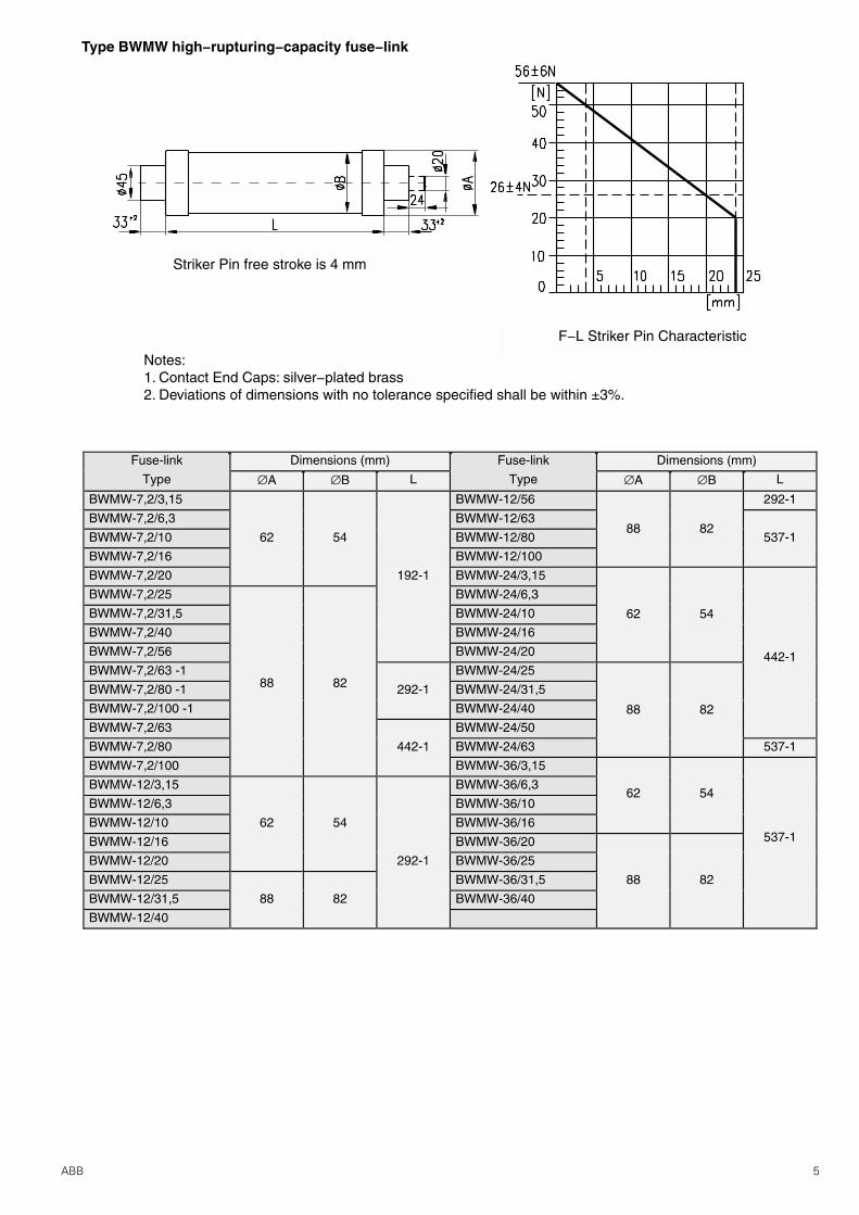
Type BWMW high−rupturing−capacity fuse−link
Notes:1. Contact End Caps: silver−plated brass2. Deviations of dimensions with no tolerance specified shall be within ±3%.
F−L Striker Pin Characteristic
Striker Pin free stroke is 4 mm
6 ABB
8. CONSTRUCTION ANDOPERATION
8.1 Construction and operation of fuse−linksA fuse−link consists of an insulation tube whose both
ends are terminated with end caps. Fuse elements aremade from specially profiled silver wire and are helicallywound on a porcelain winding stick. Additional fusibleelement intended to control operation of the striker pinis located in a coaxial hole of the stick. The fuse interioris filled with arc−quenching material whose chemicalcomposition and granularity have been appropriatelychosen. The fuse−link is sealed at its both ends.
A spring−type striker pin is located in one end−capand its forced movement can be employed to trip anoperating mechanism of a switch−disconnector or totrigger alarm and auxiliary circuits.
The fuse operation depends on automatic one−offinterruption of the fault current in the protected circuitby melting of the fuse element and quenching theelectric arc produced in the fuse−link interior. Theoperation is indicated by the striker pin which has nowmoved to its tripped position.
The fuse−link limits the peak value of the short−circuitcurrent and in consequence effectively protects thecircuit against thermal and electromagnetic effects ofshort−circuits.
8.2 Construction of fuse basesThe fuse−base consists of a steel beam fitted with
a protective earthing terminal and two indoor supportinsulators. Two sets of contacts are mounted on theupper side of the insulator. The set of contacts consistsof a contact spring, compression spring, and terminals.
9. PRINCIPLES OF FUSE−LINKS SELECTION9.1 Selection of rated voltage
The rated voltage for a fuse−link is to be selected in thefollowing way:
− if the fuse−link is to be operated in an earthed neutralthree−phase network, the rated voltage for the fuse−linkis to be equal to at least line−to−line voltage in the circuitto be protected,
− if the fuse−link is to be operated in a single−phasenetwork, the rated voltage for the fuse−link is to be equalto at least 115% of the highest voltage in the circuit to beprotected,
− if the fuse−link is to be operated in an insulated neutralthree−phase network or a network compensated by meansof earth fault neutraliser, the rated voltage for the fuse−link is to be equal to at least 115% of the line−to−linevoltage in this network as double earth faults are possible.
It should be however noted that in situations where a
fuse−link featuring an excessive rated voltage has beenselected, excessively high voltages for the circuit underconsideration might occur. Refer to Table 1 for the limitingovervoltage values for this family of fuse−links. Should itbe necessary to obtain more detailed data on theovervoltages, please call the fuse manufacturer.
9.2 Selection of rated currentThe rated current of a fuse−link is usually greater than
a long−term load for the circuit under consideration. Whileselecting the rated current, the following should be takeninto account.
− long−term current load and operating overloads forthe circuit under consideration,
− transient overloads involved into such actions asswitching power on and off for such equipment astransformers, electric motors, and capacitor banks,
− co−ordination with other devices intended to protectthe circuit under consideration.
The rated current is determined by heating of a singlefuse−link under free air conditions at an ambienttemperature of +10oC to +40oC.
In situations where the fuse−links are to be used inenclosures, cabinets and at places and in a mannermaking heat transfer more difficult or if the fuse−links areto operate at an ambient temperature higher than +35oC,lowering of the rated current value can be required to takethe actual conditions of heat transfer into account.
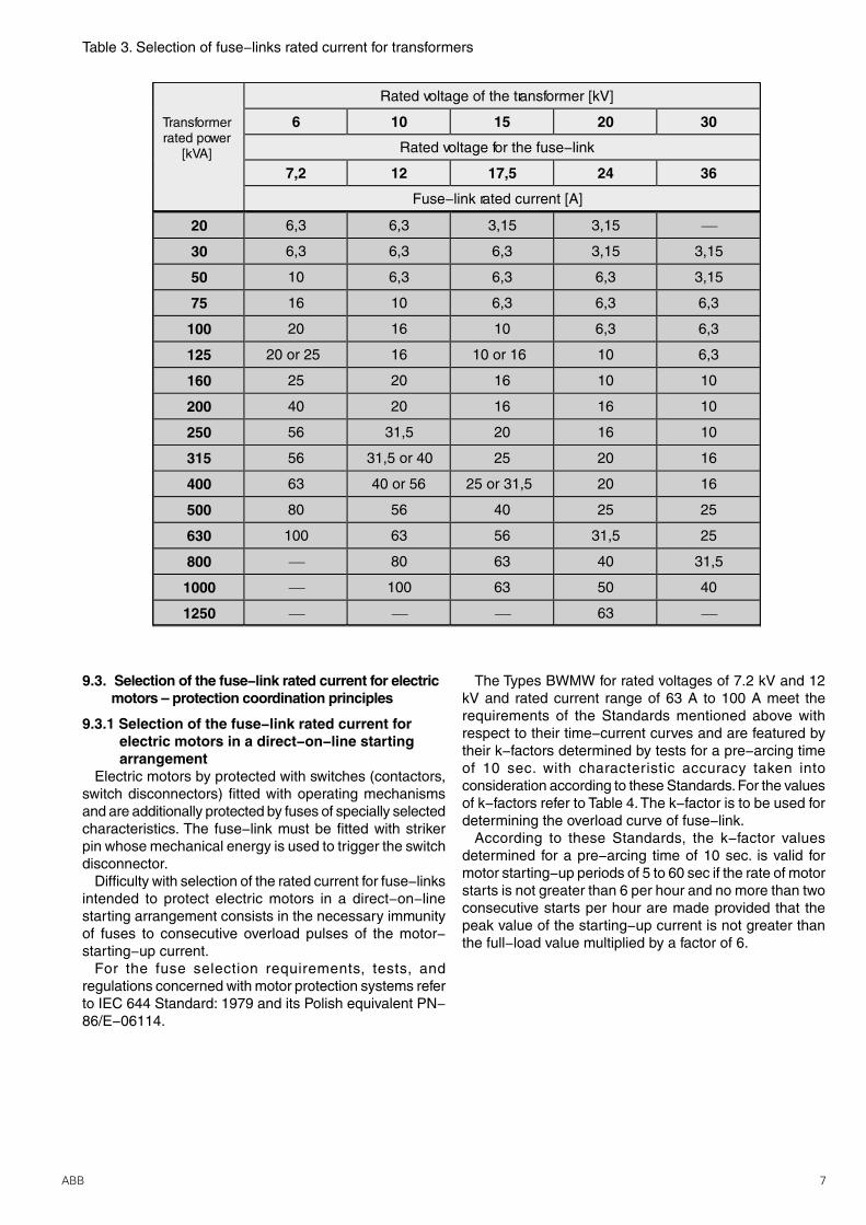
Refer to Table 3 for selection of fuse−links rated currentrecommended for protecting transformers.
The selection presented above has been developed for atransformer overloaded up to 1.5 In when a condition of
if01 > 12 In, is met, where:
i f01 − minimum current value corresponding to a pre−arcingtime of 0.1 sec.I n − rated voltage of the transformer12 In; 0,1 sec. − parameters of the assumed making currentfor the transformer.
However, in situations where actual making current valueand waveform are known the fuse−link is to be selectedindividually. Besides, when a transformer protecting systemis designed, the recommendations of IEC 787 Publicationof 1983 is to be taken into consideration.
It is suggested to test warm the equipment with fuses ata load of 1.5 In for the transformer to be protectedparticularly in cases where the correct selection is doubtfulor the fuses are installed in a manner and at places(enclosures, cabinets, partitions, neat other heat sources,at higher ambient temperatures, and etc.) worsening theheat transfer. Section can be accepted as satisfactory ifthe produced steady state temperature−rise limits do notexceed the values permitted by respective standards.
7ABB
Table 3. Selection of fuse−links rated current for transformers
Rated voltage of the transformer [kV]
Transformerrated power
[kVA]
6 10 15 20 30
Rated voltage for the fuse−link
7,2 12 17,5 24 36
Fuse−link rated current [A]
20 6,3 6,3 3,15 3,15 ¾
30 6,3 6,3 6,3 3,15 3,15
50 10 6,3 6,3 6,3 3,15
75 16 10 6,3 6,3 6,3
100 20 16 10 6,3 6,3
125 20 or 25 16 10 or 16 10 6,3
160 25 20 16 10 10
200 40 20 16 16 10
250 56 31,5 20 16 10
315 56 31,5 or 40 25 20 16
400 63 40 or 56 25 or 31,5 20 16
500 80 56 40 25 25
630 100 63 56 31,5 25
800 ¾ 80 63 40 31,5
1000 ¾ 100 63 50 40
1250 ¾ ¾ ¾ 63 ¾
9.3. Selection of the fuse−link rated current for electricmotors – protection coordination principles
9.3.1 Selection of the fuse−link rated current forelectric motors in a direct−on−line startingarrangement
Electric motors by protected with switches (contactors,switch disconnectors) fitted with operating mechanismsand are additionally protected by fuses of specially selectedcharacteristics. The fuse−link must be fitted with strikerpin whose mechanical energy is used to trigger the switchdisconnector.
Difficulty with selection of the rated current for fuse−linksintended to protect electric motors in a direct−on−linestarting arrangement consists in the necessary immunityof fuses to consecutive overload pulses of the motor−starting−up current.
For the fuse selection requirements, tests, andregulations concerned with motor protection systems referto IEC 644 Standard: 1979 and its Polish equivalent PN−86/E−06114.
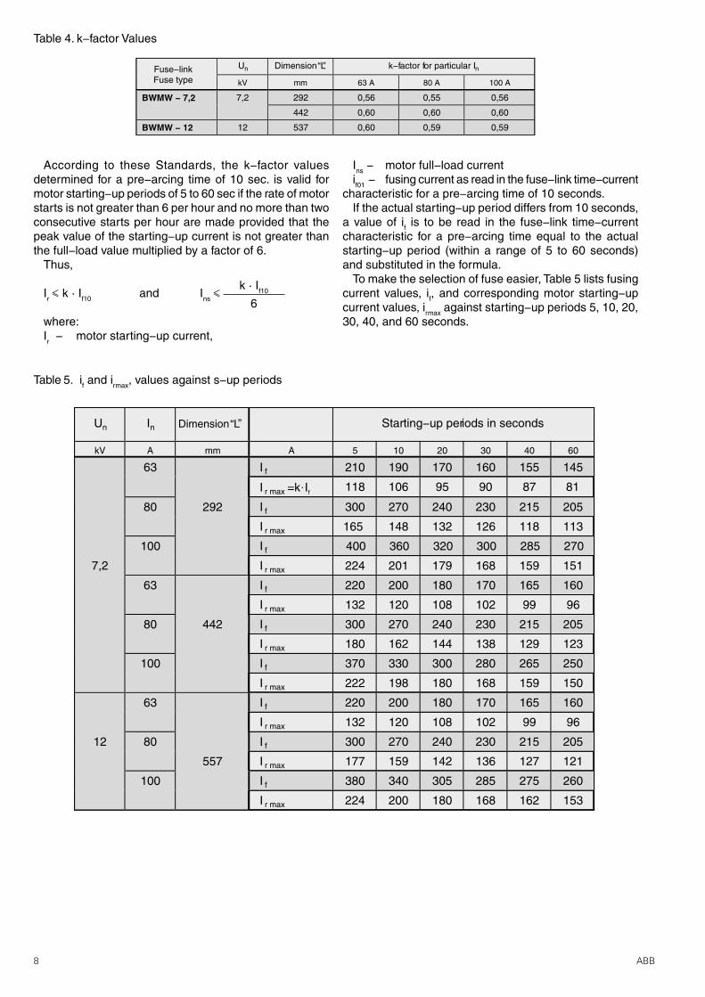
The Types BWMW for rated voltages of 7.2 kV and 12kV and rated current range of 63 A to 100 A meet therequirements of the Standards mentioned above withrespect to their time−current curves and are featured bytheir k−factors determined by tests for a pre−arcing timeof 10 sec. with characteristic accuracy taken intoconsideration according to these Standards. For the valuesof k−factors refer to Table 4. The k−factor is to be used fordetermining the overload curve of fuse−link.
According to these Standards, the k−factor valuesdetermined for a pre−arcing time of 10 sec. is valid formotor starting−up periods of 5 to 60 sec if the rate of motorstarts is not greater than 6 per hour and no more than twoconsecutive starts per hour are made provided that thepeak value of the starting−up current is not greater thanthe full−load value multiplied by a factor of 6.
8 ABB
Fuse−linkFuse type
Un nDimension“L” k−factor for particular I
kV mm 63 A 80 A 100 A
BWMW − 7,2 7,2 292 0,56 0,55 0,56
442 0,60 0,60 0,60
BWMW − 12 12 537 0,60 0,59 0,59
Table 5. if and irmax, values against s−up periods
Un In Dimension“L” Starting−up periods in seconds
kV A mm A 5 10 20 30 40 60
63 I f 210 190 170 160 155 145
I r max =k ×If 118 106 95 90 87 81
80 292 I f 300 270 240 230 215 205
I r max 165 148 132 126 118 113
100 I f 400 360 320 300 285 270
7,2 I r max 224 201 179 168 159 151
63 I f 220 200 180 170 165 160
I r max 132 120 108 102 99 96
80 442 I f 300 270 240 230 215 205
I r max 180 162 144 138 129 123
100 I f 370 330 300 280 265 250
I r max 222 198 180 168 159 150
63 I f 220 200 180 170 165 160
I r max 132 120 108 102 99 96
12 80 I f 300 270 240 230 215 205
557 I r max 177 159 142 136 127 121
100 I f 380 340 305 285 275 260
I r max 224 200 180 168 162 153
Table 4. k−factor Values
k · If10
6
According to these Standards, the k−factor valuesdetermined for a pre−arcing time of 10 sec. is valid formotor starting−up periods of 5 to 60 sec if the rate of motorstarts is not greater than 6 per hour and no more than twoconsecutive starts per hour are made provided that thepeak value of the starting−up current is not greater thanthe full−load value multiplied by a factor of 6.
Thus,
Ir ‰ k · If10 and Ins ‰
where:Ir − motor starting−up current,
Ins − motor full−load currentif01 − fusing current as read in the fuse−link time−current
characteristic for a pre−arcing time of 10 seconds.If the actual starting−up period differs from 10 seconds,
a value of if is to be read in the fuse−link time−currentcharacteristic for a pre−arcing time equal to the actualstarting−up period (within a range of 5 to 60 seconds)and substituted in the formula.
To make the selection of fuse easier, Table 5 lists fusingcurrent values, if, and corresponding motor starting−upcurrent values, irmax against starting−up periods 5, 10, 20,30, 40, and 60 seconds.
9ABB
Ir
6
190
6
Ir
k
190
0,59
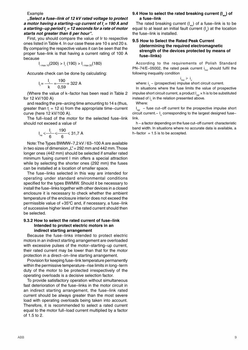
Example„Select a fuse−link of 12 kV rated voltage to protect
a motor having a starting−up current of Ir = 190 A anda starting−up period tr = 12 seconds for a rate of motorstarts not greater than 6 per hour".
First, you should compare the value of Ir to respectiveones listed in Table 4. In our case these are 10 s and 20 s.By comparing the respective values it can be seen that theproper fuse−link is that having a current rating of 100 Abecause
Ir max 10(200) > Ir (190) > Ir max 20(180)
Accurate check can be done by calculating:
If = = = 322 A
(Where the value of k−factor has been read in Table 2for 12 kV/100 A)
and reading the pre−arcing time amounting to 14 s (thus,greater than tr = 12 s) from the appropriate time−currentcurve (here 12 kV/100 A).
The full−load of the motor for the selected fuse−linkshould not exceed a value of
Ins ‰ ‰ ‰ 31,7 A
Note: The Types BWMW−7,2 kV / 63−100 A are availablein two sizes of dimension „L” = 292 mm and 442 mm. Thoselonger ones (442 mm) should be selected if smaller ratedminimum fusing current I min offers a special attractionwhile by selecting the shorter ones (292 mm) the fusescan be installed at a location of smaller space.
The fuse−links selected in this way are intended foroperating under standard environmental conditionsspecified for the types BWMW. Should it be necessary toinstall the fuse−links together with other devices in a closedenclosure it is necessary to check whether the ambienttemperature of the enclosure interior does not exceed thepermissible value of +35oC and, if necessary, a fuse−linkof successive higher level of the rated current should thenbe selected.
9.3.2 How to select the rated current of fuse−link Intended to protect electric motors in an indirect starting arrangement
Because the fuse−links intended to protect electricmotors in an indirect starting arrangement are overloadedwith excessive pulses of the motor−starting−up current,their rated current may be lower than that for the motorprotection in a direct−on−line starting arrangement.
Provision for keeping fuse−link temperature permanentlywithin the permissive temperature−rise limits in long−termduty of the motor to be protected irrespectively of theoperating overloads is a decisive selection factor.
To provide satisfactory operation without simultaneousfast deterioration of the fuse−links in the motor circuit inan indirect starting arrangement, the fuse−link ratedcurrent should be always greater than the most severeload with operating overloads being taken into account.Therefore, it is recommended to select a rated currentequal to the motor full−load current multiplied by a factorof 1.5 to 2.
9.4 How to select the rated breaking current (Iws) ofa fuse−link
The rated breaking current (Iws) of a fuse−link is to beequal to at least an initial fault current (Ip) at the locationthe fuse−link is installed.
9.5 How to Select the Rated Peak Current(determining the required electromagneticstrength of the devices protected by means offuse−links)
According to the requirements of Polish StandardPN−74/E−05002, the rated peak current insz should fulfil thefollowing inequality condition
insz Š iuwhere: iu − (prospective) impulse short circuit current.In situations where the fuse limits the value of prospective
impulse short circuit current, a product Iogr × h is to be substitutedinstead of iu in the relation presented above.
Where:Iogr − fuse cut−off current for the prospective impulse short
circuit current.− Iu corresponding to the largest designed fuse−link.
h − a factor depending on the fuse cut−off current characteristicband width. In situations where no accurate data is available, ah−factor = 1.5 is to be accepted.
10 ABB
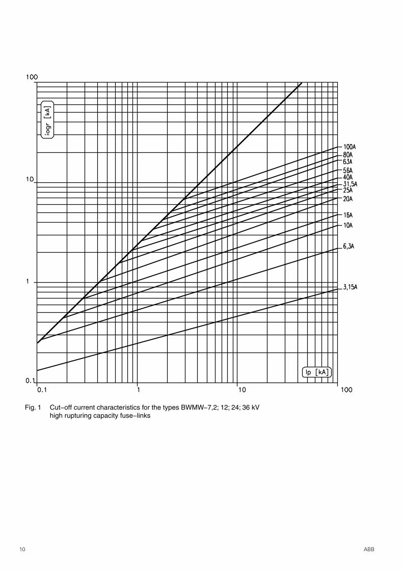
Fig. 1 Cut−off current characteristics for the types BWMW−7,2; 12; 24; 36 kVhigh rupturing capacity fuse−links

11ABB
time
current
time
current
Fig. 2 Time−current characteristics for the types BWMW−7,2/3.15−100 A(63 A excluded; dimension L = 292 mm); BWMW−12/3,15−40A and 63 A and 80 A Fuse−links
I3 Current Designations:
❍ − BWMW−7.2 kV Fuse−links
● − BWMW−12 kV Fuse−links
Fig. 3 Time−current characteristics for the types BWMW−7,2/63A (dimension L = 292 mm);BWMW−24/3,15−63A; BWMW−12/56 and 100 A; and BWMW−36/3,15−40 A Fuse−links
I3 Current Designations:
❍ − BWMW−7.2 kV Fuse−links − BWMW−24 kV Fuse−links
● − BWMW−12 kV Fuse−links − BWMW−36 kV Fuse−links
12 ABB
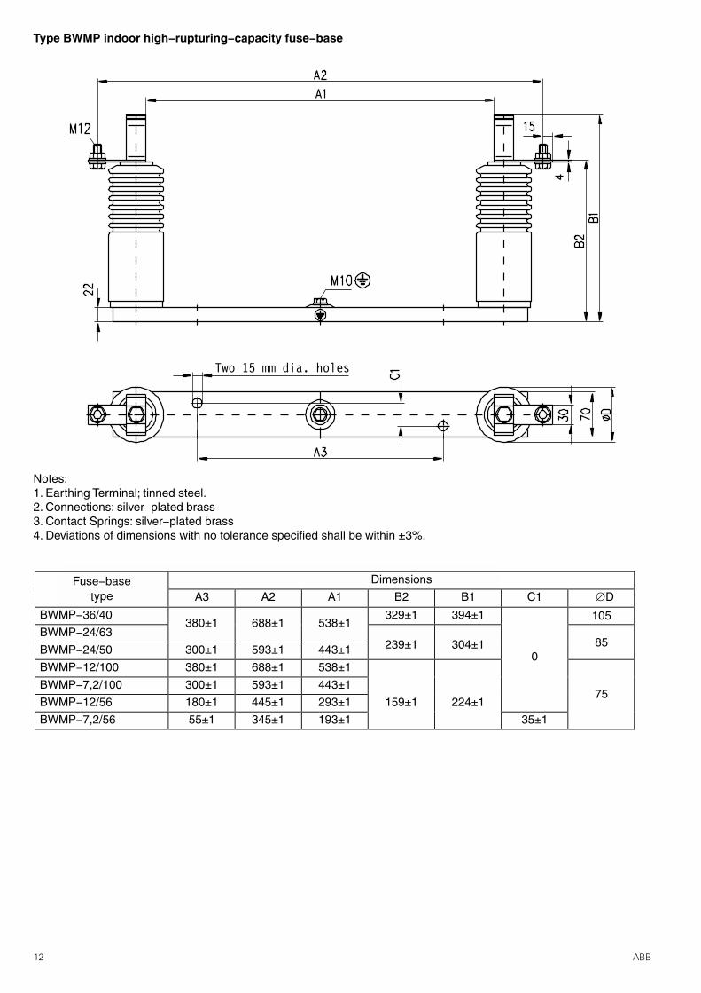
Fuse−base Dimensions
type A3 A2 A1 B2 B1 C ÆD1
BWMP−36/40380±1 688±1 538±1
329±1 394±1
BWMP−24/63
BWMP−24/50 300±1 593±1 443±1 239±1 304±1
BWMP−12/100 380±1 688±1 538±10
105
85
75BWMP−7,2/100 300±1 593±1 443±1
BWMP−12/56 180±1 445±1 293±1 159±1 224±1
BWMP−7,2/56 55±1 345±1 193±1 35±1
Two 15 mm dia. holes
Type BWMP indoor high−rupturing−capacity fuse−base
Notes:1. Earthing Terminal; tinned steel.2. Connections: silver−plated brass3. Contact Springs: silver−plated brass4. Deviations of dimensions with no tolerance specified shall be within ±3%.
13ABB
Two 15 mm dia. holes
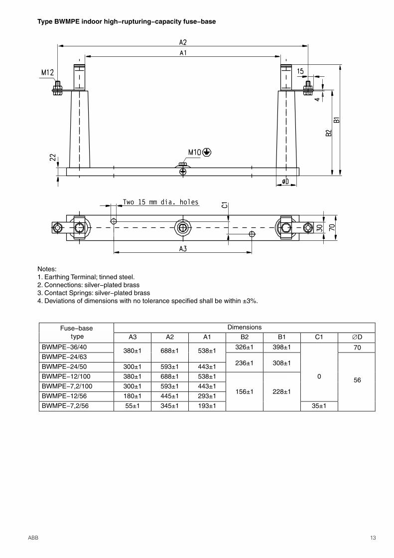
Type BWMPE indoor high−rupturing−capacity fuse−base
Notes:1. Earthing Terminal; tinned steel.2. Connections: silver−plated brass3. Contact Springs: silver−plated brass4. Deviations of dimensions with no tolerance specified shall be within ±3%.
ÆD
70
56
Fuse−base Dimensionstype A3 A2 A1 B2 B1 C1
BWMPE−36/40 380±1 688±1 538±1 326±1 398±1
BWMPE−24/63
BWMPE−24/50 300±1 593±1 443±1 236±1 308±1
BWMPE−12/100 380±1 688±1 538±1 0
BWMPE−7,2/100 300±1 593±1 443±1
BWMPE−12/56 180±1 445±1 293±1156±1 228±1
BWMPE−7,2/56 55±1 345±1 193±1 35±1
14 ABB
Two 15 mm dia. holes
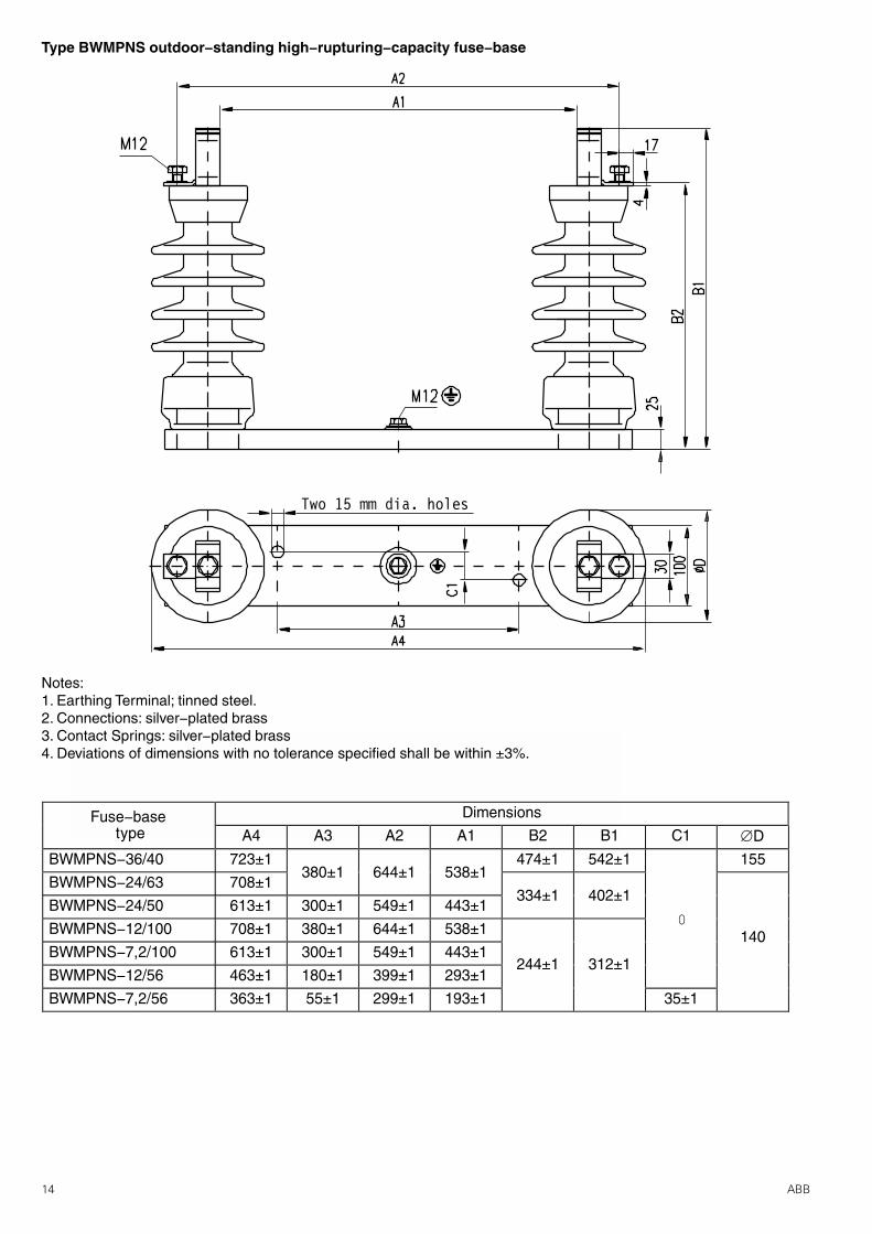
Type BWMPNS outdoor−standing high−rupturing−capacity fuse−base
Notes:1. Earthing Terminal; tinned steel.2. Connections: silver−plated brass3. Contact Springs: silver−plated brass4. Deviations of dimensions with no tolerance specified shall be within ±3%.
ÆDFuse−base Dimensions
type A4 A3 A2 A1 B2 B1 C1
BWMPNS−36/40 723±1380±1 644±1 538±1
474±1 542±1 155
BWMPNS−24/63 708±1334±1 402±1
BWMPNS−24/50 613±1 300±1 549±1 443±1
BWMPNS−12/100 708±1 380±1 644±1 538±1
BWMPNS−7,2/100 613±1 300±1 549±1 443±1244±1 312±1
140
BWMPNS−12/56 463±1 180±1 399±1 293±1
BWMPNS−7,2/56 363±1 55±1 299±1 193±1 35±1
0
15ABB
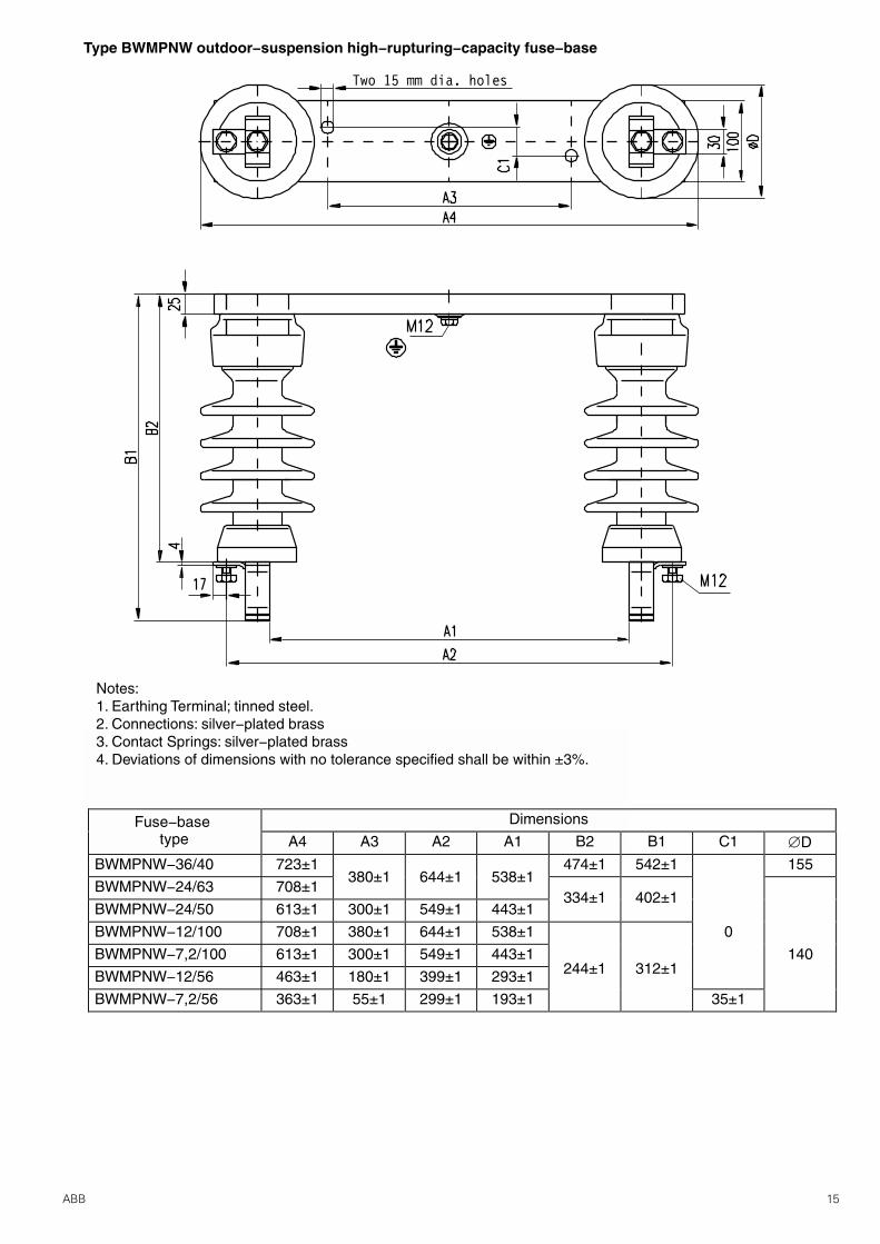
Two 15 mm dia. holes
Type BWMPNW outdoor−suspension high−rupturing−capacity fuse−base
Notes:1. Earthing Terminal; tinned steel.2. Connections: silver−plated brass3. Contact Springs: silver−plated brass4. Deviations of dimensions with no tolerance specified shall be within ±3%.
ÆDFuse−base Dimensions
type A4 A3 A2 A1 B2 B1 C1
BWMPNW−36/40 723±1380±1 644±1 538±1
474±1 542±1 155
BWMPNW−24/63 708±1334±1 402±1
BWMPNW−24/50 613±1 300±1 549±1 443±1
BWMPNW−12/100 708±1 380±1 644±1 538±1 0
BWMPNW−7,2/100 613±1 300±1 549±1 443±1244±1 312±1
140
BWMPNW−12/56 463±1 180±1 399±1 293±1
BWMPNW−7,2/56 363±1 55±1 299±1 193±1 35±1
NewType
Edi
tion
08.2
001
ABB Zwar S.A.Export Department1, ¯egañska Str.PL-04-713 Warsaw, POLANDphone: +48 22/51 52 831fax: +48 22/51 52 659e-mail: [email protected]
www.abb.comwww.abb.pl
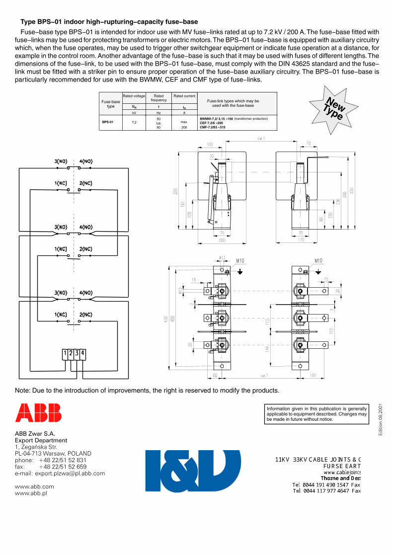
Fuse−base type BPS−01 is intended for indoor use with MV fuse−links rated at up to 7.2 kV / 200 A. The fuse−base fitted withfuse−links may be used for protecting transformers or electric motors. The BPS−01 fuse−base is equipped with auxiliary circuitrywhich, when the fuse operates, may be used to trigger other switchgear equipment or indicate fuse operation at a distance, forexample in the control room. Another advantage of the fuse−base is such that it may be used with fuses of different lengths. Thedimensions of the fuse−link, to be used with the BPS−01 fuse−base, must comply with the DIN 43625 standard and the fuse−link must be fitted with a striker pin to ensure proper operation of the fuse−base auxiliary circuitry. The BPS−01 fuse−base isparticularly recommended for use with the BWMW, CEF and CMF type of fuse−links.
Type BPS−01 indoor high−rupturing−capacity fuse−base
Information given in this publication is generallyapplicable to equipment described. Changes maybe made in future without notice.
Note: Due to the introduction of improvements, the right is reserved to modify the products.