medium-speed synchronous generators - vem group · pdf filemedium-speed synchronous generators...
TRANSCRIPT

Medium-speed synchronous generators
www.vem-group.com
Catalogue 2016

3
Contents
Introduction 4
Product overview 5
Type identification Standards and regulations 11
Features and operating performance 15
Regulation 19
Structural design 23
VEMoDUR insulation system 27
Quality assurance | Documentation | Shipping Packaging and installation | Service 29
Technical Datas and dimensions 33
Legend 40
Content
Medium-speed synchronous generators
5
6
7
8
4
3
2
1

4
Med
ium
-spe
ed s
ynch
rono
us g
ener
ator
s
Introduction
Product overview 1
IntroductionSynchronous machines have always played a major role in our product range at VEM. We at our Sachsenwerk plant have decades of experience in manufacturing high-voltage machines combined with state-of-the-art expertise in:
· Electromagnetic and structural design · High-voltage insulation · Innovative cooling technology · Programmable logic control systems· Rationalised cost-efficient production methods
All of these benefits you will find in our new range of medium-speed three-phase high-voltage generators. We planned and designed this generator range to ensure the following characteristics:
· High efficiency· Long service life· Low installation and commissioning costs· Low maintenance· Low noise emissions
Our synchronous generators are manufactured at the VEM Dresden location’s Sachsenwerk plant, and shipped from there to customers across the globe as stationary installations on land or at sea, on ships and oil platforms.We serve a wide variety of application areas:
· Continuous power in insular systems and parallel power generation· Emergency power· Peak load operation
Our generators may be driven by diesel or gas motors, or water, gas or steam turbines.
Note:We constantly improve on our products. Versions, technical specifications and images are subject to change, and are only binding on written confirmation by the supplier.Motors shown in this brochure are examples for information only, and may include accessories only available at additional cost.
6 7
Med
ium
-spe
ed s
ynch
rono
us g
ener
ator
s
Med
ium
-spe
ed s
ynch
rono
us g
ener
ator
s
Product overview
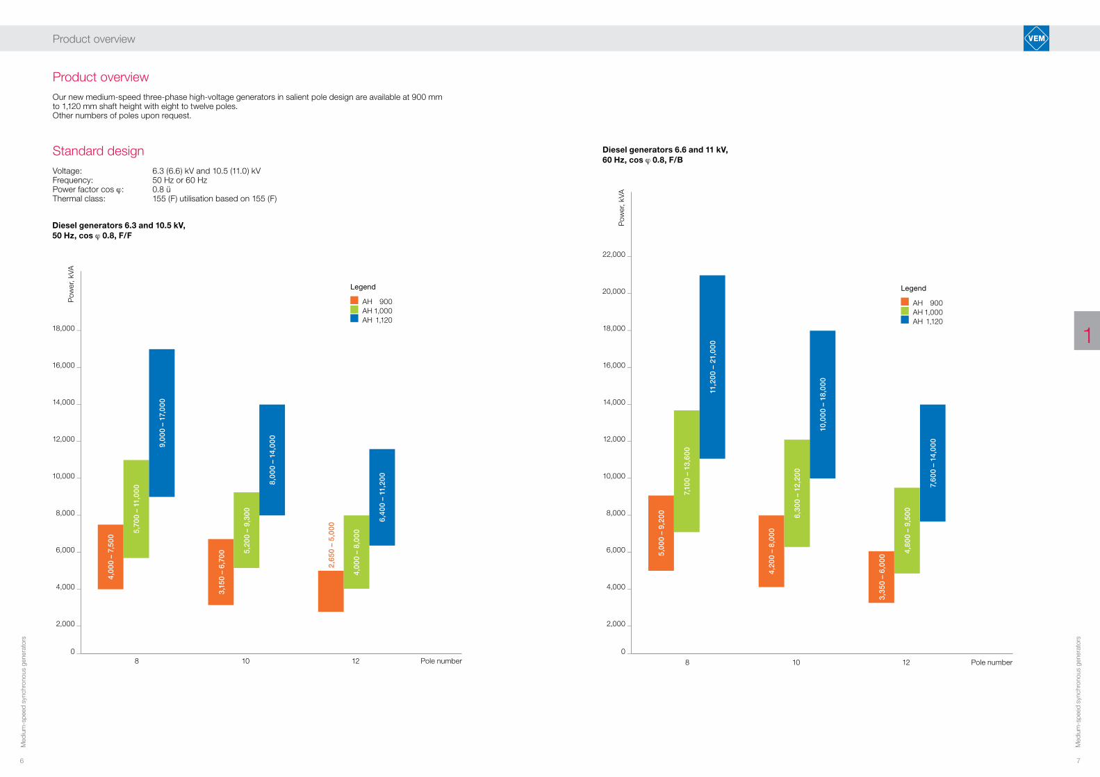
Product overviewOur new medium-speed three-phase high-voltage generators in salient pole design are available at 900 mm to 1,120 mm shaft height with eight to twelve poles.Other numbers of poles upon request.
Standard designVoltage: 6.3 (6.6) kV and 10.5 (11.0) kVFrequency: 50 Hz or 60 HzPower factor cos ϕ: 0.8 üThermal class: 155 (F) utilisation based on 155 (F)
1
Diesel generators 6.3 and 10.5 kV, 50 Hz, cos ϕ 0.8, F/F
18,000 _
16,000 _
14,000 _
12,000 _
10,000 _
8,000 _
6,000 _
4,000 _
2,000 _
0 _ 8 10 12 Pole number
Pow
er, k
VA
Legend
AH 900 AH 1,000 AH 1,120
Diesel generators 6.6 and 11 kV, 60 Hz, cos ϕ 0.8, F/B
22,000 _
20,000 _
18,000 _
16,000 _
14,000 _
12,000 _
10,000 _
8,000 _
6,000 _
4,000 _
2,000 _
0 _
8 10 12 Pole number5,
00
0 –
9,20
0
7,10
0 –
13,6
00
4,20
0 –
8,0
00
6,30
0 –
12,2
00
10,0
00
– 18
,00
0
3,35
0 –
6,0
00
4,80
0 –
9,50
0
7,60
0 –
14,0
00
Pow
er, k
VA
Legend
AH 900 AH 1,000 AH 1,120
4,0
00
– 7,
500
5,70
0 –
11,0
00
9,0
00
– 17
,00
0
3,15
0 –
6,70
0 5,20
0 –
9,30
0
8,0
00
– 14
,00
0
4,0
00
– 8,
00
0
2,65
0 –
5,0
00 6,
400
– 11
,20
0
11,2
00
– 21
,00
0

8 9
Med
ium
-spe
ed s
ynch
rono
us g
ener
ator
s
Med
ium
-spe
ed s
ynch
rono
us g
ener
ator
s
Product overview
Product overviewOur new medium-speed three-phase high-voltage generators in salient pole design are available at 900 mm to 1,120 mm shaft height with eight to twelve poles.Other numbers of poles upon request.
Standard designVoltage: 6.3 (6.6) kV and 10.5 (11.0) kVFrequency: 50 Hz or 60 HzPower factor cos ϕ: 0.8 üThermal class: 155 (F) utilisation based on 130 (B)
1
Diesel generators 6.3 and 10.5 kV, 50 Hz, cos ϕ 0.8, F/B
18,000 _
16,000 _
14,000 _
12,000 _
10,000 _
8,000 _
6,000 _
4,000 _
2,000 _
0 _ 8 10 12 Pole number
3,60
0 –
6,60
0 5,30
0 –
10,0
00
8,0
00
– 15
,50
0
2,80
0 –
5,60
0
4,50
0 –
8,0
00
6,60
0 –
13,0
00
2,50
0 –
4,20
0
3,60
0 –
7,10
0
5,60
0 –
10,0
00
Pow
er, k
VA
Legend
AH 900 AH 1,000 AH 1,120
Diesel generators 6.6 and 11 kV, 60 Hz, cos ϕ 0.8, F/B
18,000 _
16,000 _
14,000 _
12,000 _
10,000 _
8,000 _
6,000 _
4,000 _
2,000 _
0 _
8 10 12 Pole number4,
500
– 8,
00
0
6,60
0 –
12,0
00
10,0
00
– 18
,50
0
3,60
0 –
7,10
0
5.60
0 –
11.0
00
9,0
00
– 16
,00
0
3,0
00
– 5,
200
4,20
0 –
8,30
0
6,60
0 –
12,0
00
Pow
er, k
VA
Legend
AH 900 AH 1,000 AH 1,120

10 11
Med
ium
-spe
ed s
ynch
rono
us g
ener
ator
s
Med
ium
-spe
ed s
ynch
rono
us g
ener
ator
s
1
Product overview
Type identificationStandards and regulations
2
Design versionsOur brushless synchronous generators are usually supplied in the following versions:
· IM B20 (IM 1101)· IM B3 (IM 1001)· IM B25 (IM 2401)· IM B16 (IM 1305)
IP codes and cooling
IP code: IP 23 IP 44Cooling type: IC 0 A1 IC 8 A1 W7
Technical designMatching electrical output power with the motor’s mechan i-cal power and potential overload requirements depending on intake temperature and local installation height plays an important role in selecting a generator. Additional details such as IP code compliance, cooling type, design, bear-ings and foundations, and an ideal choice of excitation system and impact on mains stability and quality naturally also play a role in optimising a generator to local condi-tions. Our project planning department at VEM provides answers to these questions as well as assistance in select-ing the right generator.

12 13
Med
ium
-spe
ed s
ynch
rono
us g
ener
ator
s
Med
ium
-spe
ed s
ynch
rono
us g
ener
ator
s
Type identification | Standards and regulations
Type identificationType identification from our Sachsenwerk plant consist of letters and digits.
Letters Positions 1–5Digits 10–11Letters Positions 12-13
D R A S Y 9 0 2 0 8 W S1 2 3 4 5 6 7 8 9 10 11 12 13 14Position
1 Current type D three-phase current
2 Machine type G Synchronous generator w/ slip ring R Synchronous generator w/o slip ring
3 Cooling, IP code A Self-ventilation (IP 23; IP 24) K Circulation cooling (IP 44) IP 54 on request
4 and 5 Design type (encoded) Intended use and bearings, Deviating voltage and frequency, Explosion protection, design, etc.
6 and 7 Shaft height (encoded)
8 and 9 Laminated core length (encoded)
10 and 11 No. of poles, speed
12 to 14 Additional letter Code letters for special winding designs, pole types and revision level
Standards and regulations Our motors comply with all relevant international standards, as well as the current DIN standards and VDE regulations, for standard versions esp. IEC 60034 - DIN EN 60034 (VDE 0530) with the following parts:
Part 1 Rating and performance IEC 60034-1 – DIN EN 60034-1 (VDE 0530-1)
Part 2 Standard methods for determining losses and efficiency from tests IEC 60034-2- …(several parts) – DIN EN 60034-2- ... (VDE 0530-2- …)
Part 4 Methods for determining synchronous machine quantities from tests IEC 60034-1 – DIN EN 60034-4 (VDE 0530-4)
Part 5 Degrees of protection provided by the integral design of rotating electrical machines (IP code) – Classification IEC 60034-5 – DIN EN 60034-5 (VDE 0530-5)
Part 6 Methods of cooling (IC Code) IEC 60034-6 – DIN EN 60034-6 (VDE 0530-6)
Part 7 Classification of types of constructions and mounting arrangements (IM Code) IEC 60034-7 – DIN EN 60034-7 (VDE 0530-7)
Part 8 Terminal markings and direction of rotation IEC 60034-8 – DIN EN 60034-8 (VDE 0530-8)
Part 9 Noise limits IEC 60034-9 – DIN EN 60034-9 (VDE 0530-9)
Part 14 Mechanical vibration of certain machines with shaft heights 56 mm and higher – Measurement, evaluation and limits of vibration severity IEC 60034-14 – DIN EN 60034-14 (VDE 0530-14)
Part 15 Impulse voltage withstand levels of form-wound stator coils for rotating AC machines IEC 60034-15 – DIN EN 60034-15 (VDE 0530-15)
Part 18 Partial discharge free electrical insulation systems (Type I) used in rotating electrical machines fed from voltage converters – Qualification and quality control tests IEC 60034-18- … (several parts) – DIN EN 60034-18- … (VDE 0530-18- …)
Part 27 Off-line partial discharge measurements on the stator winding insulation of rotating electrical machines DIN CLC/TS 60034-27; VDE V 0530-27
Part 29 Equivalent loading and superposition techniques – Indirect testing to determine temperature rise IEC 60034-29 – DIN EN 60034-29 (VDE 0530-29)
as well as
ISO 10816- … – DIN ISO 10816- … Evaluation of machine vibration by measurements on non-rotating parts (several parts)
ISO 21940-32 – DIN ISO 21940-32 Shaft and fitment key convention
ISO 1940- … – DIN ISO 1940- … Balance quality requirements of rigid rotors... (several parts)
We supply to other standards on request such as pending IEC standards and regulations of all major marine classification societies.
2
-

14 15
Med
ium
-spe
ed s
ynch
rono
us g
ener
ator
s
Med
ium
-spe
ed s
ynch
rono
us g
ener
ator
s
Type identification | Standards and regulations
1Features and
operating performance
3
16 17
Med
ium
-spe
ed s
ynch
rono
us g
ener
ator
s
Med
ium
-spe
ed s
ynch
rono
us g
ener
ator
s
Features and operating performance
Voltage and frequencyThe generators in this range are available in basic designs for rated voltages 6.3 and 10.5 kV for 50 Hz, and 6.6 and 10 kV for 60 Hz. The range for set-point controller amounts to ± 5 % of rated voltage UN. Values in deviation from these nominal voltages and set-point range are available on request.
Voltage waveformOpen-circuit line voltage with corresponding winding de-sign is practically sinusoidal. The total harmonic distortion (THD) lies below the limit set [1].
Stator winding circuitThe stator winding is connected in star configuration. The neutral point is designed to be open for protection and instrument transformer installation.
Overload capacity Our synchronous generators are designed for an overload of 1.5 times rated current for a period of 120 s, and can be operated for one in six hours at 1.1 times rated current taking overload capacity of internal combustion motors into account. The exciter unit is generously dimensioned for dynamic processes. An excitation system ceiling voltage of approximately 2.3-fold for dynamic events is available.
Short-circuit behaviourSudden short-circuit current The peak value for sudden short-circuit current in a short-circuited three-phase generator magnetised to rated voltage is substantially lower than the
ÎS < 21·IN limit according to [1].
Sustained short-circuit currentThe auxiliary generator winding and excitation system are matched in such a way as to generate a necessary short circuit current of approximately 3 x IN for t < 5 s on a three-phase terminal short circuit.
Unbalanced loadA generously dimensioned damper cage allows for unbal-anced load. Our synchronous generators are suitable for permanent unbalanced load of I2/IN < 10 % (inverse current/rated current). However, we recommend aiming towards a balanced load for optimal operation.
Dynamic voltage behaviour Sudden load changes result in voltage changes (
∇
U), which are mainly determined by transient generator dimensions and external connection conditions such as· Output on connection· cos ϕ during connection· Generator at open circuit or on load
Connections on load of around IN and cos ϕ < 0.4 will likely lead to transient voltage drops of
∇
U 15 – 25 %. Transient generator voltage behaviour depends on the time constant in the main generator, exciter and control system. A gener-ously dimensioned excitation system ensures short settling times. The transient voltage settling time is around 600 ms depending on the number of poles and generator output. The generator first reaches the voltage tolerance range after about 300 ms, and remains within the static voltage toler-ance range specified after settling.
Power plant properties and system feedback
The generator, excitation system and voltage controller are perfectly matched to meet the necessary legal requirements for power plants and permissible system feedback for sup-plying power to the national grid.
The requirements and limits on connection to the medium, high and very high-voltage grid in Germany are mainly defined in [5] and [6] with compliance documented by a unit certificate according to [7]. This unit certificate must be is-sued by an accredited certification body with the necessary measurements carried out by a testing laboratory accred-ited in accordance with EN 17025.
We provide support for the certification process on request. This may involve providing a configured simulation model of the electrical system consisting of generator, excitation system and voltage controller [8]; we can also carry out some of the tests and validations for the simulation model required by [9] according to [8] using our own testing facilities. These include harmonic measurements, reactive power supply and some of the measurements involved in low-voltage ride through (LVRT) testing before delivery, which greatly reduces the time and effort that you as our customer will need for commissioning.
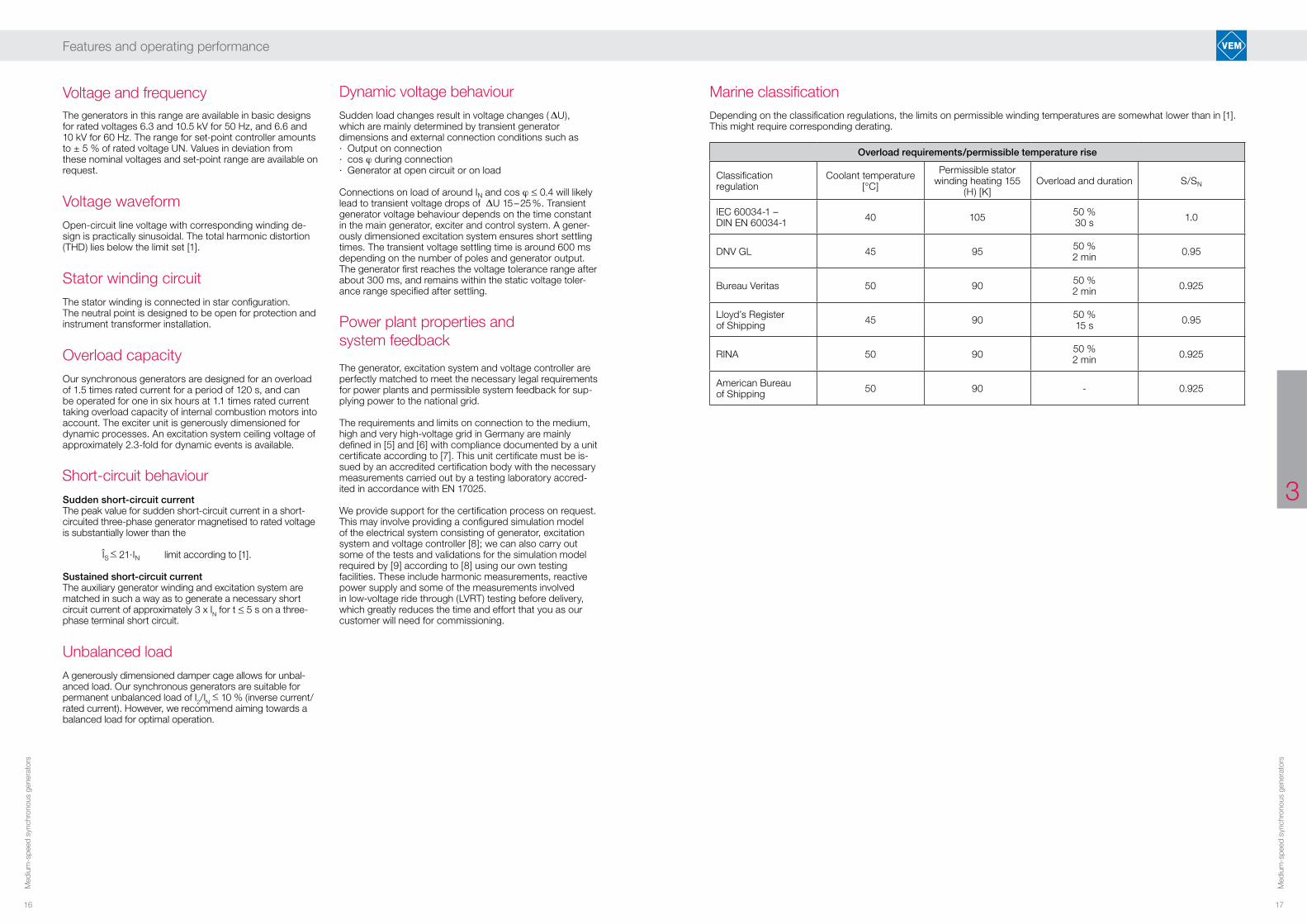
Marine classificationDepending on the classification regulations, the limits on permissible winding temperatures are somewhat lower than in [1]. This might require corresponding derating.
Overload requirements/permissible temperature rise
Classification regulation
Coolant temperature [°C]
Permissible stator winding heating 155
(H) [K]Overload and duration S/SN
IEC 60034-1 –DIN EN 60034-1 40 105 50 %
30 s 1.0
DNV GL 45 95 50 %2 min 0.95
Bureau Veritas 50 90 50 %2 min 0.925
Lloyd’s Register of Shipping 45 90 50 %
15 s 0.95
RINA 50 90 50 %2 min 0.925
American Bureau of Shipping 50 90 - 0.925
3

18 19
Med
ium
-spe
ed s
ynch
rono
us g
ener
ator
s
Med
ium
-spe
ed s
ynch
rono
us g
ener
ator
s
Features and operating performance
1Regulation
4

20 21
Med
ium
-spe
ed s
ynch
rono
us g
ener
ator
s
Med
ium
-spe
ed s
ynch
rono
us g
ener
ator
s
Excitation system with digital controllerThe brushless excitation system with an AC exciter, rotat-ing rectifier bridge, and over-voltage protection circuitry is designed according to established principles.Over-sizing ensures that all operating points are kept within the stable generator power graph as well as overloads, fulfilling all dynamic requirements that apply.
A specifically developed digital exciter box provides excita-tion regulation and control.
The digital controller provides the following basic functions to the operator:· Voltage regulation (± 0.5 %)· Remote set-point adjustment by external contacts· Reactive droop· Frequency-dependent voltage division· Excitation current limit· Automatic remanent voltage build-up· Automatic de-excitation on shut-down· Fast de-excitation· Excitation error messaging· Plug-in configuration and diagnostics
Optional additional functions:· Generator current limit· Reactive power or cos ϕ control· Internal or external reactive power specification· Reactive power limitation· Mode selection by external contacts· Rotating diode defect messaging
Exciter and generator currents are limited using a time-dependent threshold to take both the dynamics and the permissible generator heating into account.
The exciter is installed in a cabinet for wall mounting, and is equipped with an interface for convenient configuration and diagnostics via notebook. The configuration notebook is available as an option.
The excitation system may also be extended by the follow-ing functions without requiring mechanical changes:· Battery excitation· Load-angle limit· Line compensation· Switchable active power stabilisation
The exciter is certified for the following marine classifications: Lloyd’s Register Bureau Veritas Rina
The system is connected via cable connection to the termi-nal strip in the machine’s auxiliary terminal box.
Regulation
Brushless excitation systemA uniform excitation principle is used across the entire output range. By default, an auxiliary winding supplies the exciter unit (Figure 1) to separate it from the voltage level of the main generator. A separately installed permanent-mag-net pilot exciter may optionally replace the auxiliary winding supply to the exciter unit (Figure 2).
A three-phase external pole exciter built into the N-side supplies the excitation current to the pole winding of the main generator, ensuring more than sufficient power for all operating conditions while maintaining continuous short-cir-cuit current. The rectified auxiliary voltage from the auxiliary winding or auxiliary exciter is supplied to the controller, which then supplies the necessary excitation current to the exciter depending on operating state.
Figure 1: Block diagram: brushless excitation system with auxiliary winding
Figure 2: Block diagram: brushless excitation system with permanent magnet generator
4

22 23
Med
ium
-spe
ed s
ynch
rono
us g
ener
ator
s
Med
ium
-spe
ed s
ynch
rono
us g
ener
ator
s
4
Structural design
5
Regulation
The excitation system may optionally be extended to the gener-ator control cabinet, which may include the following functions:· Brushless rotor earth fault and rotor measurement recording· Generator protection with the following functions (not-exhaustive):
· ANSI 87 - Generator differential protection· ANSI 64G - Stator earth fault protection · ANSI 32R - Reverse power protection· ANSI 40 - Under-excitation protection· ANSI 46 - Unbalanced load protection (two-stage)· ANSI 51 - Over-current protection with under- voltage preservation· ANSI 51V - Inverse time overcurrent protection· ANSI 59 - Over-voltage protection· ANSI 27 - Under-voltage protection· ANSI 81 - Frequency protection· ANSI 59 - Over-excitation protection· ANSI 40 - Under-excitation protection· ANSI 64R (1–3 Hz) - Rotor earth fault protection 1–3 Hz· ANSI 50BF - Breaker failure protection
· Generator synchronisation (several synchronising points)The unit is mounted into a standing cabinet.

24 25
Med
ium
-spe
ed s
ynch
rono
us g
ener
ator
s
Med
ium
-spe
ed s
ynch
rono
us g
ener
ator
s
ExciterThe exciter is designed as an external pole machine.The exciter is mounted within the generator. The rotor and the rotating rectifier bridge in the exciter are mounted onto a common hub on the generator shaft.
Ventilation hoodThe ventilation hood design depends on ventilation type.
The inlet and outlet air grilles are arranged on the D and N sides on the left and right in the ventilation hood for ventila-tion type IC 0 A1 with draft ventilation. Generators in this design comply with IP 23.
The air-water heat exchanger is mounted into the ventilation hood in ventilation type IC 8 A1 W7 with air-water cooling. Generators in this design comply with IP 54. Air-water heat exchangers may be designed as double-pipe coolers on request.
The main and auxiliary ventilation terminals as well as current and voltage transformers are located in the ventilation hood in all ventilation types. The main connection cable may lead into the hood from the left or right, and from above or below. The auxiliary power cable leads in from the N side from above or below. All entry plates are not drilled. Bolted cable fastenings or packing frames are also available on request.
MonitoringThe generator is monitored as follows:· 3 PT 100 in the stator winding + 3 in reserve· 1 double PT 100 per bearing shell· The monitor cable may be connected from the terminals using the four-wire technique.
More monitoring elements may be added on request, such as a PT 100 for cooling air, leakage protection, oil level indica-tor, oil sump thermometer and shaft vibration monitoring.
Ventilation hood
Structural design
Structural design
Our three-phase synchronous generators mainly consist of the following assemblies: stator, rotor, bearing shields, friction bearings, an exciter and ventilation hood.
StatorThe stator consists of a welded construction with the stator laminated core shrunken in. The stator core assembly con-sists of insulated dynamo core segments axially clamped on by extrusion billets.The three-phase two-layer winding lies in the open slots in the laminated core. The preformed coils consist of flat copper wire with mica sheet insulation. The main insulation consists of low-binder mica-glass cloth tape. Low-impedance corona shielding on the slot part and high-impedance corona shield-ing on the slot end to prevent corona discharges.The fully insulated coils are secured using slot closures in the slots. The circuit connections are brazed on.The stator winding is vacuum pressure-impregnated using epoxy resin (insulation VEMoDUR®-VPI-155).
RotorThe rotor consists of a forged shaft, shrunk-on rotor yoke with poles, and the exciter rotor.Directly wound laminate cores with salient poles or directly wound individual poles mounted onto the rotor yoke may be used depending on generator size. The field coils consist of copper wire with vitreous enamel insulation. Vacuum-pressure impregnation and field-coil supports arranged in the gaps between the poles ensure the required resistance to stress caused by centrifugal forces. A damper winding consisting of copper rods soldered to the damper segments is mounted onto the heads of the poles.All rotors are dimensioned for 60 Hz operation. The rotor core is pressed on using pressure plates connected to the shaft.
Bearing shieldsThe bearing shields are designed as welded pot bearing shields. The centrings between the end plates and stator eliminate the need for air gap checks, even after dismantling. Radially mounted guides ensure precise tangential position-ing of the bearing shields against the stator housing after dismantling.
Friction bearingThe friction bearings are designed as side flange-mounted bearings screwed to the centring on the bearing shield, and are fitted with a horizontally split casing, a split bearing shell with cast bearing metal, an oil ring and various seals. The bearings comply with IP 44 in the basic version. Additional seals may be used for compliance with higher levels of pro-tection (IP 55).The friction bearings are normally designed as floating bear-ings, and do not take axial loads. They may be supplied in various designs depending on the specific requirements, in-cluding ring oil lubrication, winding oil lubrication, hydrostatic shaft lifting, water cooling, insulated and as a fixed bearing.Any necessary lubrication fittings are available on request.
Stator
Rotor
Friction bearing
26 27
Med
ium
-spe
ed s
ynch
rono
us g
ener
ator
s
Med
ium
-spe
ed s
ynch
rono
us g
ener
ator
s
4
VEMoDUR insulation system
6
Structural design

28 29
Med
ium
-spe
ed s
ynch
rono
us g
ener
ator
s
Med
ium
-spe
ed s
ynch
rono
us g
ener
ator
s
Quality assuranceDocumentation
Shipping, Packaging and installationService
7
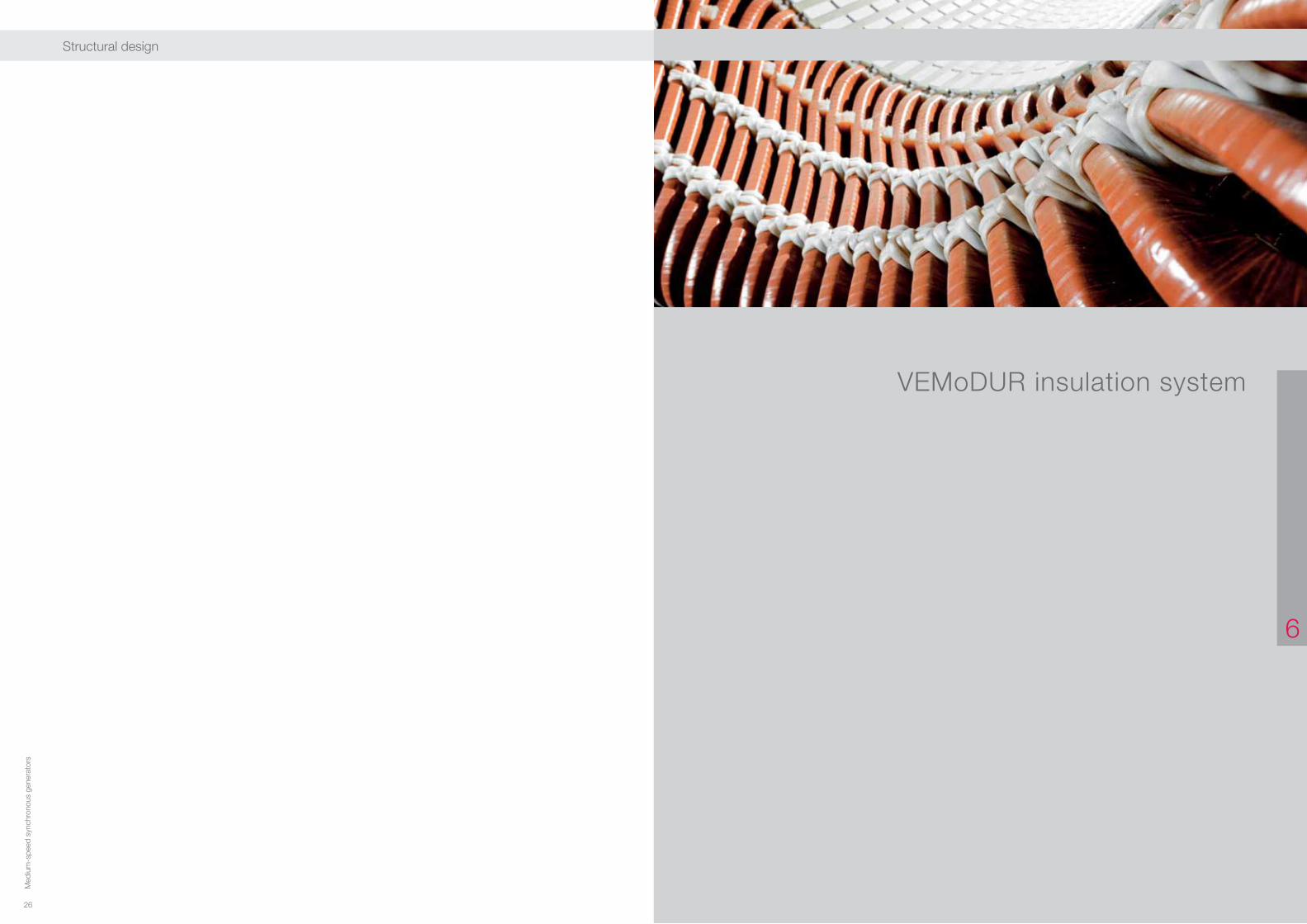
VEMoDUR insulation system
Winding insulation quality plays a major role in operational reliability in electrical machines. VEM Sachsenwerk GmbH’s insulation system have always featured technical solutions that meet international standards in quality parameters while ensuring high levels of reliability and long lifetimes.
We use the VPI technique in every area of high-voltage equipment insulation; we developed VEMoDUR®-VPI-155 at our Sachsenwerk plant and tested it according to [2].
This insulation system has come to be a reference system for future comparative functional assessment according to [3] after decades of operating experience.
The insulation system’s components consisting of wind-ing and main insulation with high proportions of mica and epoxy resin are perfectly matched to one another. Our insu-lation systems are subject to permanent monitoring during the impregnation process for parameters such as:
· Resin viscosity· Impregnation and curing temperature· Pressure dwell times· Low and high pressure· PD level measurements
The insulation hardens in a rotational hardening process.
VEMoDUR insulation system
VEMoDUR plant at VEM
The VPI process ensures high mechanical strength espe-cially in the windings, and excellent electrical resistance especially in high flash-over voltages, while reliably ensuring rated impulse voltages according to [4] in any generator.
The insulation system features a high resistance to humidity – that is, the winding is insensitive to humidity and corrosive gases.
Routine tests include intermediate and final electrical testing on insulation strength including sudden and partial discharge testing, which may be separately agreed and performed on request.
Driers
30 31
Med
ium
-spe
ed s
ynch
rono
us g
ener
ator
s
Med
ium
-spe
ed s
ynch
rono
us g
ener
ator
s
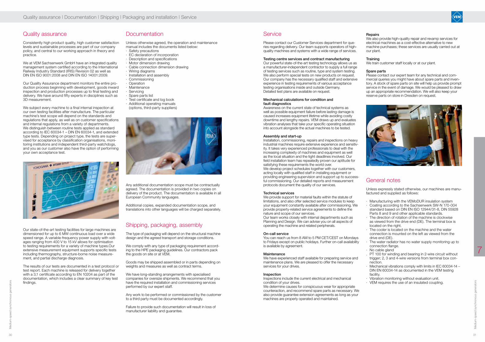
Service RepairsWe also provide high-quality repair and revamp services for electrical machines as a cost-effective alternative to new machine purchases; these services are usually carried out at our plant.
TrainingWe train customer staff locally or at our plant.
Spare partsPlease contact our expert team for any technical and com-mercial queries you might have about spare parts and inven-tory. A stock of spare parts on site will help us provide prompt service in the event of damage. We would be pleased to draw up an appropriate recommendation. We will also keep your reserve parts on store in Dresden on request.
General notesUnless expressly stated otherwise, our machines are manu-factured and supplied as follows:
· Manufacturing with the VEMoDUR insulation system· Coating according to the Sachsenwerk SW-N 170-004
standard based on DIN EN ISO 12944/31-8, DIN 55928 Parts 8 and 9 and other applicable standards.
· The direction of rotation of the machine is clockwise as viewed from the drive end (DE). The terminal box is located on the right.
· The cooler is located on the machine and the water connection is mounted on the left as viewed from the
drive end (DE).· The water radiator has no water supply monitoring up to
connection flange.· No cable gland. PT 100 for winding and bearing in 2-wire circuit without
trigger; 2, 3 and 4-wire versions from terminal box con-nection.
· Mechanical vibrations comply with limits in IEC 60034-14 – DIN EN 60034-14 as documented in the VEM testing facility.
· Vibration monitoring without evaluation unit.· VEM requires the use of an insulated coupling.
7
Quality assurance | Documentation | Shipping | Packaging and installation | Service
Quality assuranceConsistently high product quality, high customer satisfaction levels and sustainable processes are part of our company policy, and central to our working approach in theory and practice.
We at VEM Sachsenwerk GmbH have an integrated quality management system certified according to the International Railway Industry Standard (IRIS) Revision 02 as well as DIN EN ISO 9001:2008 and DIN EN ISO 14001:2009.
Our Quality Assurance department monitors the entire pro-duction process beginning with development, goods inward inspection and production processes up to final testing and delivery. We have around fifty experts in disciplines such as 3D measurement.
We subject every machine to a final internal inspection at our own testing facilities after manufacture. The particular machine’s test scope will depend on the standards and regulations that apply, as well as on customer specifications and internal regulations from a variety of departments. We distinguish between routine tests applied as standard according to IEC 60034-1 – DIN EN 60034-1, and extended type tests. Depending on project type, the tests are super-vised for acceptance by classification organisations, moni-toring institutions and independent third-party watchdogs, and you as our customer also have the option of performing your own acceptance test.
Our state-of-the-art testing facilities for large machines are dimensioned for up to 6 MW continuous load over a wide speed range. A variable-frequency power supply with volt-ages ranging from 400 V to 15 kV allows for optimisation to testing requirements for a variety of machine types.Our extensive measurement equipment supports specific tests including thermography, structure-borne noise measure-ment, and partial discharge diagnosis.
The results of our tests are documented in a test protocol or test report. Each machine is released for delivery together with a 3,1 certificate according to EN 10204 as part of the documentation, which includes a clear summary of key test findings.
DocumentationUnless otherwise agreed, the operation and maintenance manual includes the documents listed below:· Safety precautions· EC declaration of incorporation· Description and specifications· Motor dimension drawing· Cable connection dimension drawing· Wiring diagrams· Installation and assembly· Commissioning· Operation· Maintenance· Servicing· Spare parts list· Test certificate and log book· Additional operating manuals (options, third-party suppliers)
Any additional documentation scope must be contractually agreed. The documentation is provided in two copies on delivery of the product. The documentation is available in all European Community languages.
Additional copies, expanded documentation scope, and translations into other languages will be charged separately.
The type of packaging will depend on the structural machine design and the agreed transport and storage conditions.
We comply with any type of packaging requirement accord-ing to the HPE packaging guidelines. Our contractors pack the goods on site or at VEM.
Goods may be shipped assembled or in parts depending on weights and measures as well as contract terms.
We have long-standing arrangements with specialised companies for oversize shipments. We recommend that you have the required installation and commissioning services performed by our expert staff.
Any work to be performed or commissioned by the customer to a third party must be documented accordingly.
Failure to provide such documentation will result in loss of manufacturer liability and guarantee.
Shipping, packaging, assembly
Please contact our Customer Services department for que-ries regarding delivery. Our team supports operators of high-quality machines and systems with a wide range of services.
Testing centre services and contract manufacturingOur powerful state-of-the-art testing technology allows us as a manufacturer-independent contractor to supply a full range of testing services such as routine, type and system testing. We also perform special tests on new products on request. Our company has the necessary qualified staff and extensive experience in testing requirements of various acceptance testing organisations inside and outside Germany.Detailed test plans are available on request.
Mechanical calculations for condition and fault diagnosticsAwareness on the current state of technical systems as well as possible equipment failure before lasting damage is caused increases equipment lifetime while avoiding costly downtime and lengthy repairs. VEM draws up and evaluates vibration analyses that take your specific operating situation into account alongside the actual machines to be tested.
Assembly and start-upInstallation, commissioning, repairs and inspections on heavy industrial machines require extensive experience and sensitiv-ity. It takes very experienced professionals to deal with the increasing complexity of machines and equipment as well as the local situation and the tight deadlines involved. Our field installation team has repeatedly proven our aptitude for satisfying these requirements the world over.We develop project schedules together with our customers, acting locally with qualified staff in installing equipment or providing engineering supervision and support up to success-ful commissioning. Our detailed reports and measurement protocols document the quality of our services.
Technical servicesWe provide support for material faults within the statute of limitations, and also offer selected service modules to keep your equipment constantly available after commissioning. We provide property-related service agreements to define the nature and scope of our services.Our team works closely with internal departments such as Planning and Design. We can advise you on all aspects of operating the machine and related peripherals.
On-call serviceYou can reach us from 8 AM to 5 PM CET/CEST on Mondays to Fridays except on public holidays. Further on-call availability is available by agreement.
MaintenanceWe have experienced staff available for preparing service and maintenance plans. We are pleased to offer the necessary services for your drives.
InspectionInspections include the current electrical and mechanical condition of your drives.We determine causes for conspicuous wear for appropriate counteraction, and recommend spare parts as necessary. We also provide guarantee extension agreements as long as your machines are properly operated and maintained.

32 33
Med
ium
-spe
ed s
ynch
rono
us g
ener
ator
s
Med
ium
-spe
ed s
ynch
rono
us g
ener
ator
s
Technical datas and dimensions
8
Quality assurance | Documentation | Shipping | Packaging and installation | Service

34 35
Med
ium
-spe
ed s
ynch
rono
us g
ener
ator
s
Med
ium
-spe
ed s
ynch
rono
us g
ener
ator
s
8
Technical datas
8
Generators 6.3 kV, 50 Hzcos ϕ = 0.8 (+), utilisation F/FType DRKSX … with air-water heat exchanger (IC 8 A1 W7), water temperature 38 °C, IP 44Type DRASX … open-circuit air cooling (IC 0 A1), air intake temperature 45 °C, IP 23
Generators for rated voltage 10.5 kV upon request. Generators for rated voltage 11 kV upon request.
Apparentpower
Activepower
Mech. power
Norminalpower
Speed Efficiency Reactances Time constants
Type Sn Pn Pmech In n h 4/4 h 3/4 h 2/4 xd xd' xd" T'do T'd T"d
[kVA] [kW] [kW] [A] [min-1] [%] [%] [%] [%] [%] [%] [s] [s] [ms]
8-pole version
DR.SX 9020-8WS 4000 3200 3293 367 750 97.18 97.05 96.49 132 27 16 3.30 0.66 22DR.SX 9022-8WS 4500 3600 3701 412 750 97.26 97.13 96.56 129 26 16 3.34 0.66 21DR.SX 9025-8WS 5000 4000 4106 458 750 97.41 97.27 96.69 130 25 15 3.49 0.68 21DR.SX 9028-8WS 5700 4560 4678 522 750 97.47 97.39 96.93 150 28 17 3.75 0.71 21DR.SX 9032-8WS 6600 5280 5411 605 750 97.57 97.48 97.01 146 27 16 3.81 0.71 21DR.SX 9036-8WS 7500 6000 6144 687 750 97.65 97.59 97.17 162 30 17 3.99 0.73 21DR.SX 1022-8WS 5700 4560 4677 522 750 97.50 97.33 96.73 137 28 17 3.98 0.80 29DR.SX 1025-8WS 7000 5600 5737 642 750 97.61 97.49 97.00 144 29 17 4.09 0.81 29DR.SX 1028-8WS 8000 6400 6549 733 750 97.73 97.64 97.20 163 32 18 4.37 0.85 29DR.SX 1032-8WS 9000 7200 7363 825 750 97.79 97.65 97.15 144 28 16 4.33 0.83 28DR.SX 1036-8WS 10000 8000 8174 916 750 97.87 97.74 97.24 150 28 16 4.54 0.85 28DR.SX 1040-8WS 11000 8800 8988 1008 750 97.91 97.77 97.27 148 27 16 4.62 0.86 28DR.SX 1125-8WS 9000 7200 7369 825 750 97.71 97.51 96.90 131 27 17 5.29 1.09 37DR.SX 1128-8WS 10000 8000 8178 916 750 97.82 97.63 97.05 140 28 17 5.63 1.13 37DR.SX 1132-8WS 11200 8960 9152 1026 750 97.90 97.73 97.18 151 29 17 5.98 1.17 36DR.SX 1136-8WS 13000 10400 10619 1191 750 97.94 97.80 97.32 159 30 18 6.18 1.18 36DR.SX 1140-8WS 15000 12000 12240 1375 750 98.04 97.90 97.42 158 30 17 6.24 1.18 36DR.SX 1145-8WS 17000 13600 13866 1558 750 98.08 97.94 97.45 152 28 16 6.30 1.18 35
10-pole version
DR.SX 9020-10WS 3150 2520 2604 289 600 96.76 96.69 96.13 107 23 14 3.43 0.73 21DR.SX 9022-10WS 3600 2880 2971 330 600 96.94 96.84 96.26 103 22 14 3.37 0.72 21DR.SX 9025-10WS 4200 3360 3458 385 600 97.17 97.11 96.64 125 26 15 3.76 0.77 21DR.SX 9028-10WS 4750 3800 3905 435 600 97.30 97.26 96.83 136 27 16 3.99 0.80 21DR.SX 9032-10WS 5600 4480 4606 513 600 97.26 97.18 96.68 109 22 14 3.63 0.74 20DR.SX 9036-10WS 6700 5360 5503 614 600 97.41 97.33 96.83 118 23 14 4.00 0.79 20DR.SX 1022-10WS 5200 4160 4281 477 600 97.17 97.06 96.47 108 23 15 3.74 0.77 27DR.SX 1025-10WS 6000 4800 4932 550 600 97.33 97.25 96.73 122 25 15 4.07 0.82 27DR.SX 1028-10WS 6800 5440 5581 623 600 97.47 97.38 96.88 128 25 15 4.28 0.84 27DR.SX 1032-10WS 7500 6000 6151 687 600 97.55 97.44 96.93 128 25 15 4.48 0.86 27DR.SX 1036-10WS 8600 6880 7051 788 600 97.58 97.47 96.95 121 23 14 4.41 0.84 26DR.SX 1040-10WS 9300 7440 7625 852 600 97.57 97.44 96.89 113 22 13 4.38 0.83 26DR.SX 1125-10WS 8000 6400 6563 733 600 97.52 97.35 96.75 122 26 15 4.38 0.94 36DR.SX 1128-10WS 9000 7200 7382 825 600 97.54 97.33 96.69 105 22 13 4.22 0.90 35DR.SX 1132-10WS 10000 8000 8190 916 600 97.68 97.49 96.89 118 24 14 4.66 0.96 35DR.SX 1136-10WS 11200 8960 9165 1026 600 97.76 97.58 97.02 125 25 14 4.88 0.99 35DR.SX 1140-10WS 12500 10000 10224 1146 600 97.81 97.64 97.07 124 25 14 4.95 0.99 35DR.SX 1145-10WS 14000 11200 11444 1283 600 97.87 97.68 97.12 123 24 13 5.07 1.00 34
12-pole version
DR.SX 9020-12WS 2650 2120 2201 243 500 96.33 96.23 95.56 91 25 15 2.26 0.63 21DR.SX 9022-12WS 2850 2280 2367 261 500 96.34 96.20 95.47 84 23 14 2.25 0.62 21DR.SX 9025-12WS 3250 2600 2693 298 500 96.56 96.40 95.69 87 24 14 2.36 0.64 21DR.SX 9028-12WS 3800 3040 3143 348 500 96.71 96.68 96.19 105 28 16 2.57 0.69 21DR.SX 9032-12WS 4250 3400 3513 389 500 96.77 96.70 96.16 98 26 14 2.58 0.68 21DR.SX 9036-12WS 5000 4000 4123 458 500 97.02 96.97 96.48 114 30 16 2.73 0.71 21DR.SX 1022-12WS 4000 3200 3303 367 500 96.87 96.81 96.24 104 28 16 2.97 0.80 28DR.SX 1025-12WS 4500 3600 3707 412 500 97.12 97.07 96.59 122 32 17 3.32 0.86 28DR.SX 1028-12WS 5200 4160 4285 477 500 97.09 97.02 96.48 104 27 16 3.13 0.82 28DR.SX 1032-12WS 6000 4800 4934 550 500 97.28 97.23 96.75 119 30 17 3.39 0.87 28DR.SX 1036-12WS 7000 5600 5752 642 500 97.36 97.33 96.91 127 32 17 3.50 0.88 28DR.SX 1040-12WS 8000 6400 6575 733 500 97.34 97.33 96.92 123 31 17 3.46 0.87 28DR.SX 1125-12WS 6400 5120 5264 587 500 97.26 97.16 96.62 118 28 17 3.24 0.78 36DR.SX 1128-12WS 7200 5760 5914 660 500 97.39 97.30 96.79 124 29 17 3.40 0.80 36DR.SX 1132-12WS 8000 6400 6563 733 500 97.51 97.41 96.91 129 30 17 3.56 0.82 35DR.SX 1136-12WS 9000 7200 7380 825 500 97.56 97.45 96.96 128 29 17 3.62 0.82 35DR.SX 1140-12WS 10000 8000 8202 916 500 97.54 97.41 96.87 116 26 15 3.56 0.81 35DR.SX 1145-12WS 11200 8960 9175 1026 500 97.66 97.56 97.09 131 29 16 3.79 0.84 35
Generators 6.6 kV, 60 Hzcos ϕ = 0.8 (+), utilisation F/FType DRKSX … with air-water heat exchanger (IC 8 A1 W7), water temperature 38 °C, IP 44Type DRASX … open-circuit air cooling (IC 0 A1), air intake temperature 45 °C, IP 23
Apparentpower
Activepower
Mech. power
Norminalpower
Speed Efficiency Reactances Time constants
Type Sn Pn Pmech In n h 4/4 h 3/4 h 2/4 xd xd' xd" T'do T'd T"d
[kVA] [kW] [kW] [A] [min-1] [%] [%] [%] [%] [%] [%] [s] [s] [ms]
8-pole version
DR.SX 9020-8WS 5000 4000 4114 437 900 97.22 97.03 96.35 130 27 16 3.20 0.65 22DR.SX 9022-8WS 5600 4480 4600 490 900 97.39 97.22 96.61 142 28 17 3.39 0.67 22DR.SX 9025-8WS 6300 5040 5172 551 900 97.45 97.27 96.67 140 27 16 3.50 0.68 21DR.SX 9028-8WS 7100 5680 5821 621 900 97.57 97.43 96.88 153 28 17 3.73 0.70 21DR.SX 9032-8WS 8100 6480 6635 709 900 97.66 97.47 96.87 137 26 15 3.71 0.69 21DR.SX 9036-8WS 9200 7360 7533 805 900 97.70 97.54 97.00 146 27 16 3.85 0.71 21DR.SX 1022-8WS 7100 5680 5823 621 900 97.55 97.33 96.67 143 29 17 3.98 0.81 29DR.SX 1025-8WS 8500 6800 6965 744 900 97.63 97.43 96.80 137 27 16 3.97 0.80 29DR.SX 1028-8WS 9500 7600 7775 831 900 97.75 97.56 97.00 148 29 17 4.25 0.83 29DR.SX 1032-8WS 10500 8400 8586 919 900 97.83 97.65 97.10 157 30 17 4.50 0.86 29DR.SX 1036-8WS 12000 9600 9808 1050 900 97.88 97.72 97.19 163 31 17 4.64 0.87 28DR.SX 1040-8WS 13600 10880 11108 1190 900 97.95 97.78 97.24 160 30 17 4.68 0.87 28DR.SX 1125-8WS 11200 8960 9174 980 900 97.67 97.40 96.65 116 24 15 4.89 1.03 36DR.SX 1128-8WS 12500 10000 10230 1093 900 97.75 97.48 96.75 118 24 15 5.15 1.06 36DR.SX 1132-8WS 14000 11200 11445 1225 900 97.86 97.58 96.86 120 24 15 5.41 1.08 36DR.SX 1136-8WS 16000 12800 13075 1400 900 97.90 97.62 96.90 114 23 14 5.38 1.07 35DR.SX 1140-8WS 18500 14800 15097 1618 900 98.03 97.85 97.28 163 31 17 6.25 1.18 35DR.SX 1145-8WS 21000 16800 17139 1837 900 98.02 97.83 97.27 148 28 16 6.19 1.17 35
10-pole version
DR.SX 9020-10WS 4200 3360 3461 367 720 97.07 97.01 96.50 113 24 15 3.34 0.72 21DR.SX 9022-10WS 4800 3840 3951 420 720 97.18 97.15 96.69 121 26 16 3.47 0.73 21DR.SX 9025-10WS 5500 4400 4522 481 720 97.30 97.26 96.78 115 24 15 3.47 0.73 20DR.SX 9028-10WS 6300 5040 5175 551 720 97,40 97.37 96.93 120 25 15 3.60 0.74 20DR.SX 9032-10WS 7000 5600 5742 612 720 97.52 97.45 97.00 122 25 15 3.77 0.76 20DR.SX 9036-10WS 8000 6400 6561 700 720 97.54 97.48 97.01 114 23 14 3.67 0.75 20DR.SX 1022-10WS 6300 5040 5180 551 720 97.29 97.15 96.54 128 26 16 4.05 0.82 27DR.SX 1025-10WS 7200 5760 5914 630 720 97.40 97.28 96.72 137 27 17 4.31 0.85 27DR.SX 1028-10WS 8200 6560 6729 717 720 97.49 97.36 96.81 137 27 16 4.42 0.86 27DR.SX 1032-10WS 9500 7600 7789 831 720 97.57 97.44 96.91 136 26 16 4.50 0.86 27DR.SX 1036-10WS 11000 8800 9018 962 720 97.58 97.44 96.88 120 23 15 4.25 0.82 26DR.SX 1040-10WS 12200 9760 9994 1067 720 97.66 97.52 97.00 127 24 15 4.45 0.84 26DR.SX 1125-10WS 10000 8000 8202 875 720 97.54 97.31 96.64 119 26 15 4.26 0.92 36DR.SX 1128-10WS 11000 8800 9012 962 720 97.65 97.44 96.78 127 27 15 4.57 0.96 36DR.SX 1132-10WS 12500 10000 10230 1093 720 97.75 97.56 96.96 140 29 16 4.88 1.00 35DR.SX 1136-10WS 14000 11200 11450 1225 720 97.82 97.63 97.04 142 29 16 5.04 1.01 35DR.SX 1140-10WS 16000 12800 13079 1400 720 97.87 97.69 97.11 140 28 15 5.05 1.01 35DR.SX 1145-10WS 18000 14400 14706 1575 720 97.92 97.71 97.12 132 26 14 5.08 1.00 35
12-pole version
DR.SX 9020-12WS 3350 2680 2772 293 600 96.67 96.55 95.90 105 29 17 2.35 0.65 21DR.SX 9022-12WS 3750 3000 3103 328 600 96.68 96.55 95.87 98 27 16 2.32 0.64 21DR.SX 9025-12WS 4250 3400 3514 372 600 96.75 96.61 95.91 96 26 15 2.37 0.65 21DR.SX 9028-12WS 4750 3800 3922 416 600 96.89 96.81 96.24 107 29 16 2.55 0.68 21DR.SX 9032-12WS 5300 4240 4375 464 600 96.92 96.74 96.02 92 25 14 2.47 0.66 20DR.SX 9036-12WS 6000 4800 4945 525 600 97.06 96.89 96.23 99 26 14 2.58 0.68 20DR.SX 1022-12WS 4800 3840 3961 420 600 96.94 96.80 96.09 97 26 15 2.86 0.77 28DR.SX 1025-12WS 5600 4480 4608 490 600 97.22 97.09 96.49 115 30 17 3.18 0.84 28DR.SX 1028-12WS 6300 5040 5187 551 600 97.16 97.03 96.39 101 27 15 3.06 0.81 28DR.SX 1032-12WS 7500 6000 6165 656 600 97.33 97.22 96.65 112 29 16 3.24 0.84 28DR.SX 1036-12WS 8500 6800 6980 744 600 97.42 97.33 96.82 122 31 17 3.42 0.87 28DR.SX 1040-12WS 9500 7600 7794 831 600 97.51 97.41 96.90 123 31 17 3.48 0.88 28DR.SX 1125-12WS 7600 6080 6252 665 600 97.25 97.10 96.48 112 27 16 3.18 0.77 36DR.SX 1128-12WS 8750 7000 7188 765 600 97.39 97.24 96.65 115 27 16 3.28 0.78 35DR.SX 1132-12WS 10000 8000 8206 875 600 97.49 97.32 96.71 117 27 16 3.38 0.79 35DR.SX 1136-12WS 11200 8960 9183 980 600 97.57 97.41 96.84 120 27 16 3.49 0.80 35DR.SX 1140-12WS 12500 10000 10243 1093 600 97.63 97.44 96.82 113 26 15 3.45 0.79 35DR.SX 1145-12WS 14000 11200 11459 1225 600 97.74 97.56 97.00 125 28 16 3.69 0.83 35

36 37
Med
ium
-spe
ed s
ynch
rono
us g
ener
ator
s
Med
ium
-spe
ed s
ynch
rono
us g
ener
ator
s
8
Technical datas and dimensions
88
Tota
l mas
s
Roto
r mas
s
Mas
s m
omen
t of
iner
tia
Dimensions mm
Type kg kg kgm² A AA AB AD B BA BB BC BD BE C CB D E F H HA HD L
8-pole version
DRKS. 9020-8WS 18380 6330 960 1950 180 2540 1330 1480 550 2320 840 260 550 560 415 240 410 250 615 985 2665 3490
DRKS. 9022-8WS 19060 6690 1020 1950 180 2540 1330 1480 550 2320 840 260 550 560 415 240 410 250 615 985 2665 3490DRKS. 9025-8WS 20100 7230 1120 1950 180 2540 1330 1480 550 2320 840 260 550 560 415 240 410 250 615 985 2665 3490DRKS. 9028-8WS 21820 8040 1230 1950 180 2540 1330 1810 550 2650 840 260 550 560 415 240 410 250 615 985 2665 3820DRKS. 9032-8WS 23180 8760 1370 1950 180 2540 1330 1810 550 2650 840 260 550 560 415 240 410 250 615 985 2665 3820DRKS. 9036-8WS 24530 9480 1500 1950 180 2540 1330 1810 550 2650 840 260 550 560 415 240 410 250 615 985 2665 3820DRKS. 1022-8WS 24280 8910 1550 2160 200 2760 1440 1620 575 2410 790 285 500 625 480 240 410 250 615 1090 2915 3620DRKS. 1025-8WS 25640 9580 1710 2160 200 2760 1440 1620 575 2410 790 285 500 625 480 240 410 250 615 1090 2915 3620DRKS. 1028-8WS 27000 10260 1860 2160 200 2760 1440 1620 575 2410 790 285 500 625 480 240 410 250 615 1090 2915 3620DRKS. 1032-8WS 29560 11440 2070 2160 200 2760 1440 1980 575 2770 790 285 500 625 480 280 470 290 615 1090 2915 4040DRKS. 1036-8WS 31330 12350 2270 2160 200 2760 1440 1980 575 2770 790 285 500 625 480 280 470 290 615 1090 2915 4040DRKS. 1040-8WS 33100 13250 2470 2160 200 2760 1440 1980 575 2770 790 285 500 625 480 280 470 290 615 1090 2915 4040DRKS. 1125-8WS 30880 12060 2770 2400 200 2980 1552 1785 610 2585 800 320 510 685 540 280 410 290 615 1205 3245 3930DRKS. 1128-8WS 32560 12930 3020 2400 200 2980 1552 1785 610 2585 800 320 510 685 540 280 410 290 615 1205 3245 3930DRKS. 1132-8WS 34740 14100 3350 2400 200 2980 1552 1785 610 2585 800 320 510 685 540 280 410 290 615 1205 3245 3930DRKS. 1136-8WS 37650 15560 3690 2400 200 2980 1552 2175 610 2975 800 320 510 685 540 320 470 330 615 1205 3245 4380DRKS. 1140-8WS 39830 16720 4020 2400 200 2980 1552 2175 610 2975 800 320 510 685 540 320 470 330 615 1205 3245 4380DRKS. 1145-8WS 42610 18180 4440 2400 200 2980 1552 2175 610 2975 800 320 510 685 540 320 470 330 615 1205 3245 4380
10-pole version
DRKS. 9020-10WS 18260 6600 1040 1950 180 2540 1330 1480 550 2320 840 260 550 560 415 240 410 250 615 985 2665 3490DRKS. 9022-10WS 18930 6980 1110 1950 180 2540 1330 1480 550 2320 840 260 550 560 415 240 410 250 615 985 2665 3490DRKS. 9025-10WS 19950 7540 1230 1950 180 2540 1330 1480 550 2320 840 260 550 560 415 240 410 250 615 985 2665 3490DRKS. 9028-10WS 21650 8380 1340 1950 180 2540 1330 1810 550 2650 840 260 550 560 415 240 410 250 615 985 2665 3820DRKS. 9032-10WS 22980 9130 1490 1950 180 2540 1330 1810 550 2650 840 260 550 560 415 240 410 250 615 985 2665 3820DRKS. 9036-10WS 24310 9890 1640 1950 180 2540 1330 1810 550 2650 840 260 550 560 415 240 410 250 615 985 2665 3820DRKS. 1022-10WS 23600 9080 1620 2160 200 2760 1440 1620 575 2410 790 285 500 625 480 240 410 250 615 1090 2915 3620DRKS. 1025-10WS 24890 9780 1780 2160 200 2760 1440 1620 575 2410 790 285 500 625 480 240 410 250 615 1090 2915 3620DRKS. 1028-10WS 26190 10490 1940 2160 200 2760 1440 1620 575 2410 790 285 500 625 480 240 410 250 615 1090 2915 3620DRKS. 1032-10WS 28670 11710 2160 2160 200 2760 1440 1980 575 2770 790 285 500 625 480 280 470 290 615 1090 2915 4040DRKS. 1036-10WS 30350 12660 2380 2160 200 2760 1440 1980 575 2770 790 285 500 625 480 280 470 290 615 1090 2915 4040DRKS. 1040-10WS 32040 13600 2590 2160 200 2760 1440 1980 575 2770 790 285 500 625 480 280 470 290 615 1090 2915 4040DRKS. 1125-10WS 29580 12180 2850 2400 200 2980 1552 1785 610 2585 800 320 510 685 540 280 410 290 615 1205 3245 3930DRKS. 1128-10WS 31140 13090 3110 2400 200 2980 1552 1785 610 2585 800 320 510 685 540 280 410 290 615 1205 3245 3930DRKS. 1132-10WS 33190 14300 3460 2400 200 2980 1552 1785 610 2585 800 320 510 685 540 280 410 290 615 1205 3245 3930DRKS. 1136-10WS 35950 15800 3810 2400 200 2980 1552 2175 610 2975 800 320 510 685 540 320 470 330 615 1205 3245 4380DRKS. 1140-10WS 38000 17020 4160 2400 200 2980 1552 2175 610 2975 800 320 510 685 540 320 470 330 615 1205 3245 4380DRKS. 1145-10WS 40590 18530 4600 2400 200 2980 1552 2175 610 2975 800 320 510 685 540 320 470 330 615 1205 3245 4380
Tota
l mas
s
Roto
r mas
s
Mas
s m
omen
t of
iner
tia
Dimensions mm
Type kg kg kgm² A AA AB AD B BA BB BC BD BE C CB D E F H HA HD L
12-pole version
DRKS. 9020-12WS 18390 6870 1120 1950 180 2540 1330 1480 550 2320 840 260 550 560 415 240 410 250 615 985 2665 3490
DRKS. 9022-12WS 19070 7260 1200 1950 180 2540 1330 1480 550 2320 840 260 550 560 415 240 410 250 615 985 2665 3490
DRKS. 9025-12WS 20110 7850 1330 1950 180 2540 1330 1480 550 2320 840 260 550 560 415 240 410 250 615 985 2665 3490
DRKS. 9028-12WS 21830 8720 1450 1950 180 2540 1330 1810 550 2650 840 260 550 560 415 240 410 250 615 985 2665 3820
DRKS. 9032-12WS 23180 9510 1620 1950 180 2540 1330 1810 550 2650 840 260 550 560 415 240 410 250 615 985 2665 3820
DRKS. 9036-12WS 24540 10300 1780 1950 180 2540 1330 1810 550 2650 840 260 550 560 415 240 410 250 615 985 2665 3820
DRKS. 1022-12WS 23590 9250 1680 2160 200 2760 1440 1620 575 2410 790 285 500 625 480 240 410 250 615 1090 2915 3620
DRKS. 1025-12WS 24900 9980 1850 2160 200 2760 1440 1620 575 2410 790 285 500 625 480 240 410 250 615 1090 2915 3620
DRKS. 1028-12WS 26220 10720 2020 2160 200 2760 1440 1620 575 2410 790 285 500 625 480 240 410 250 615 1090 2915 3620
DRKS. 1032-12WS 28720 11980 2260 2160 200 2760 1440 1980 575 2770 790 285 500 625 480 280 470 290 615 1090 2915 4040
DRKS. 1036-12WS 30430 12960 2490 2160 200 2760 1440 1980 575 2770 790 285 500 625 480 280 470 290 615 1090 2915 4040
DRKS. 1040-12WS 32140 13950 2720 2160 200 2760 1440 1980 575 2770 790 285 500 625 480 280 470 290 615 1090 2915 4040
DRKS. 1125-12WS 29450 12300 2920 2400 200 2980 1552 1785 610 2585 800 320 510 685 540 280 410 290 615 1205 3245 3930
DRKS. 1128-12WS 31040 13240 3190 2400 200 2980 1552 1785 610 2585 800 320 510 685 540 280 410 290 615 1205 3245 3930
DRKS. 1132-12WS 33110 14500 3560 2400 200 2980 1552 1785 610 2585 800 320 510 685 540 280 410 290 615 1205 3245 3930
DRKS. 1136-12WS 35910 16050 3940 2400 200 2980 1552 2175 610 2975 800 320 510 685 540 320 470 330 615 1205 3245 4380
DRKS. 1140-12WS 37980 17310 4300 2400 200 2980 1552 2175 610 2975 800 320 510 685 540 320 470 330 615 1205 3245 4380
DRKS. 1145-12WS 40600 18880 4760 2400 200 2980 1552 2175 610 2975 800 320 510 685 540 320 470 330 615 1205 3245 4380
IC 8 A1 W7 Air-water cooling
Dimension tables for generators in version IC 8 A1 W7; IP 44; IM B3

38 39
Med
ium
-spe
ed s
ynch
rono
us g
ener
ator
s
Med
ium
-spe
ed s
ynch
rono
us g
ener
ator
s
Technical datas and dimensions
IC 0 A1 Open-circuit cooling
Tota
l mas
s
Roto
r mas
s
Mas
s m
omen
t of
iner
tia
Dimensions mm
Type kg kg kgm² A AA AB B BA BB BC BD BE C CB D E F H HA HD L
8-pole version
DRAS. 9020-8WS 17900 6330 960 1950 180 2180 1480 550 2320 840 260 550 560 415 240 410 250 615 985 2280 3490
DRAS. 9022-8WS 18580 6690 1020 1950 180 2180 1480 550 2320 840 260 550 560 415 240 410 250 615 985 2280 3490
DRAS. 9025-8WS 19620 7230 1120 1950 180 2180 1480 550 2320 840 260 550 560 415 240 410 250 615 985 2280 3490
DRAS. 9028-8WS 21330 8040 1230 1950 180 2180 1810 550 2650 840 260 550 560 415 240 410 250 615 985 2280 3820
DRAS. 9032-8WS 22690 8760 1370 1950 180 2180 1810 550 2650 840 260 550 560 415 240 410 250 615 985 2280 3820
DRAS. 9036-8WS 24040 9480 1500 1950 180 2180 1810 550 2650 840 260 550 560 415 240 410 250 615 985 2280 3820
DRAS. 1022-8WS 23610 8910 1550 2160 200 2400 1620 575 2410 790 285 500 625 480 240 410 250 615 1090 2380 3620
DRAS. 1025-8WS 24980 9580 1710 2160 200 2400 1620 575 2410 790 285 500 625 480 240 410 250 615 1090 2380 3620
DRAS. 1028-8WS 26340 10260 1860 2160 200 2400 1620 575 2410 790 285 500 625 480 240 410 250 615 1090 2380 3620
DRAS. 1032-8WS 28890 11440 2070 2160 200 2400 1980 575 2770 790 285 500 625 480 280 470 290 615 1090 2380 4040
DRAS. 1036-8WS 30660 12350 2270 2160 200 2400 1980 575 2770 790 285 500 625 480 280 470 290 615 1090 2380 4040
DRAS. 1040-8WS 32420 13250 2470 2160 200 2400 1980 575 2770 790 285 500 625 480 280 470 290 615 1090 2380 4040
DRAS. 1125-8WS 30040 12060 2770 2400 200 2620 1785 610 2585 800 320 510 685 540 280 410 290 615 1205 2480 3930
DRAS. 1128-8WS 31720 12930 3020 2400 200 2620 1785 610 2585 800 320 510 685 540 280 410 290 615 1205 2480 3930
DRAS. 1132-8WS 33900 14100 3350 2400 200 2620 1785 610 2585 800 320 510 685 540 280 410 290 615 1205 2480 3930
DRAS. 1136-8WS 36790 15560 3690 2400 200 2620 2175 610 2975 800 320 510 685 540 320 470 330 615 1205 2480 4380
DRAS. 1140-8WS 38970 16720 4020 2400 200 2620 2175 610 2975 800 320 510 685 540 320 470 330 615 1205 2480 4380
DRAS. 1145-8WS 41740 18180 4440 2400 200 2620 2175 610 2975 800 320 510 685 540 320 470 330 615 1205 2480 4380
10-pole version
DRAS. 9020-10WS 17780 6600 1040 1950 180 2180 1480 550 2320 840 260 550 560 415 240 410 250 615 985 2280 3490
DRAS. 9022-10WS 18450 6980 1110 1950 180 2180 1480 550 2320 840 260 550 560 415 240 410 250 615 985 2280 3490
DRAS. 9025-10WS 19470 7540 1230 1950 180 2180 1480 550 2320 840 260 550 560 415 240 410 250 615 985 2280 3490
DRAS. 9028-10WS 21160 8380 1340 1950 180 2180 1810 550 2650 840 260 550 560 415 240 410 250 615 985 2280 3820
DRAS. 9032-10WS 22490 9130 1490 1950 180 2180 1810 550 2650 840 260 550 560 415 240 410 250 615 985 2280 3820
DRAS. 9036-10WS 23820 9890 1640 1950 180 2180 1810 550 2650 840 260 550 560 415 240 410 250 615 985 2280 3820
DRAS. 1022-10WS 22940 9080 1620 2160 200 2400 1620 575 2410 790 285 500 625 480 240 410 250 615 1090 2380 3620
DRAS. 1025-10WS 24230 9780 1780 2160 200 2400 1620 575 2410 790 285 500 625 480 240 410 250 615 1090 2380 3620
DRAS. 1028-10WS 25530 10490 1940 2160 200 2400 1620 575 2410 790 285 500 625 480 240 410 250 615 1090 2380 3620
DRAS. 1032-10WS 27990 11710 2160 2160 200 2400 1980 575 2770 790 285 500 625 480 280 470 290 615 1090 2380 4040
DRAS. 1036-10WS 29680 12660 2380 2160 200 2400 1980 575 2770 790 285 500 625 480 280 470 290 615 1090 2380 4040
DRAS. 1040-10WS 31360 13600 2590 2160 200 2400 1980 575 2770 790 285 500 625 480 280 470 290 615 1090 2380 4040
DRAS. 1125-10WS 28730 12180 2850 2400 200 2620 1785 610 2585 800 320 510 685 540 280 410 290 615 1205 2480 3930
DRAS. 1128-10WS 30300 13090 3110 2400 200 2620 1785 610 2585 800 320 510 685 540 280 410 290 615 1205 2480 3930
DRAS. 1132-10WS 32350 14300 3460 2400 200 2620 1785 610 2585 800 320 510 685 540 280 410 290 615 1205 2480 3930
DRAS. 1136-10WS 35090 15800 3810 2400 200 2620 2175 610 2975 800 320 510 685 540 320 470 330 615 1205 2480 4380
DRAS. 1140-10WS 37140 17020 4160 2400 200 2620 2175 610 2975 800 320 510 685 540 320 470 330 615 1205 2480 4380
DRAS. 1145-10WS 39720 18530 4600 2400 200 2620 2175 610 2975 800 320 510 685 540 320 470 330 615 1205 2480 4380
8
Tota
l mas
s
Roto
r mas
s
Mas
s m
omen
t of
iner
tia
Dimensions mm
Type kg kg kgm² A AA AB B BA BB BC BD BE C CB D E F H HA HD L
12-pole version
DRAS. 9020-12WS 17910 6870 1120 1950 180 2180 1480 550 2320 840 260 550 560 415 240 410 250 615 985 2280 3490
DRAS. 9022-12WS 18590 7260 1200 1950 180 2180 1480 550 2320 840 260 550 560 415 240 410 250 615 985 2280 3490
DRAS. 9025-12WS 19630 7850 1330 1950 180 2180 1480 550 2320 840 260 550 560 415 240 410 250 615 985 2280 3490
DRAS. 9028-12WS 21340 8720 1450 1950 180 2180 1810 550 2650 840 260 550 560 415 240 410 250 615 985 2280 3820
DRAS. 9032-12WS 22690 9510 1620 1950 180 2180 1810 550 2650 840 260 550 560 415 240 410 250 615 985 2280 3820
DRAS. 9036-12WS 24050 10300 1780 1950 180 2180 1810 550 2650 840 260 550 560 415 240 410 250 615 985 2280 3820
DRAS. 1022-12WS 22930 9250 1680 2160 200 2400 1620 575 2410 790 285 500 625 480 240 410 250 615 1090 2380 3620
DRAS. 1025-12WS 24240 9980 1850 2160 200 2400 1620 575 2410 790 285 500 625 480 240 410 250 615 1090 2380 3620
DRAS. 1028-12WS 25550 10720 2020 2160 200 2400 1620 575 2410 790 285 500 625 480 240 410 250 615 1090 2380 3620
DRAS. 1032-12WS 28040 11980 2260 2160 200 2400 1980 575 2770 790 285 500 625 480 280 470 290 615 1090 2380 4040
DRAS. 1036-12WS 29750 12960 2490 2160 200 2400 1980 575 2770 790 285 500 625 480 280 470 290 615 1090 2380 4040
DRAS. 1040-12WS 31460 13950 2720 2160 200 2400 1980 575 2770 790 285 500 625 480 280 470 290 615 1090 2380 4040
DRAS. 1125-12WS 28610 12300 2920 2400 200 2620 1785 610 2585 800 320 510 685 540 280 410 290 615 1205 2480 3930
DRAS. 1128-12WS 30200 13240 3190 2400 200 2620 1785 610 2585 800 320 510 685 540 280 410 290 615 1205 2480 3930
DRAS. 1132-12WS 32270 14500 3560 2400 200 2620 1785 610 2585 800 320 510 685 540 280 410 290 615 1205 2480 3930
DRAS. 1136-12WS 35050 16050 3940 2400 200 2620 2175 610 2975 800 320 510 685 540 320 470 330 615 1205 2480 4380
DRAS. 1140-12WS 37120 17310 4300 2400 200 2620 2175 610 2975 800 320 510 685 540 320 470 330 615 1205 2480 4380
DRAS. 1145-12WS 39740 18880 4760 2400 200 2620 2175 610 2975 800 320 510 685 540 320 470 330 615 1205 2480 4380
Dimension tables for generators in version IC 0 A1; IP 23; IM B3

40 41
Med
ium
-spe
ed s
ynch
rono
us g
ener
ator
s
Med
ium
-spe
ed s
ynch
rono
us g
ener
ator
s
Legend Notizen
Legend
[1] IEC 60034-1 – DIN EN 60034-1
[2] IEC 60034-18 – DIN EN 60034-18
[3] VEM publication: Dauerwärmebeständigkeit des Isoliersystems VEMoDUR-VPI-155 (Long-term thermal resistance in the VEMoDUR-VPI-155 insulation system)
[4] IEC 60034-15 – DIN EN 60034-15 (VDE 0530-15)
[5] BDEW – Technical guideline for power-generation plants in the medium-voltage grid, Richtlinie für Anschluss und Parallelbetrieb von Erzeugungsanlagen am Mittelspannungsnetz (Guidelines for connection and parallel operation of production systems in the medium-voltage grid)
[6] Transmission Code 2007, Netz- und Systemregeln der deutschen Übertragungsnetzbetreiber (Grid code for German power transmission companies)
[7] FGW – Technical Guideline for production units and equipment, Part 8: Zertifizierung der elektrischen Eigenschaften von Erzeugungseinheiten und -anlagen am Mittel-, Hoch- und Höchstspannungsnetz (Certification of electrical properties in power-generation units and plants in the medium, high and very high-voltage grid)
[8] FGW – Technical Guideline for production units and equipment, Part 4: Anforderungen an Modellierung und Validierung von Simulationsmodellen der elektrischen Eigenschaften von Erzeugungseinheiten und -anlagen (Requirements for modelling and validating simulation models for electrical properties in power-generation units and plants)
[9] FGW – Technical Guideline for production units and equipment, Part 3: Bestimmung der elektrischen Eigenschaften von Erzeugungseinheiten und -anlagen am Mittel-, Hoch- und Höchstspannungsnetz (Determination of electrical properties of generating units and plants in the medium, high and very high-voltage grid)

42
Med
ium
-spe
ed s
ynch
rono
us g
ener
ator
s
Notizen

44
Printed in Germany. All rights reserved.
www.vem-group.com
© 2016 KOMMUNIKATION SCHNELL GmbH
VMUK_HS02-031-EN-03/16 Printed in Germany. Subject to change.
VEM Holding GmbH
Pirnaer Landstraße 176 01257 Dresden Germany
VEM Sales
Low voltage department
Phone +49 3943 68-3127 Fax +49 3943 68-2440 E-mail: [email protected]
High voltage department
Phone +49 351 208-3237 Fax +49 351 208-1108 E-mail: [email protected]
Drive systems department
Phone +49 351 208-1180 Fax +49 351 208-1185 E-mail: [email protected]
VEM Service
Phone +49 351 208-3237 Fax +49 351 208-1108 E-mail: [email protected]