ee 340 synchronous generators ieebag/ee 340 sync generators i.pdfee 340 synchronous generators i...
TRANSCRIPT
EE 340 Synchronous Generators I
Construction of synchronous machines
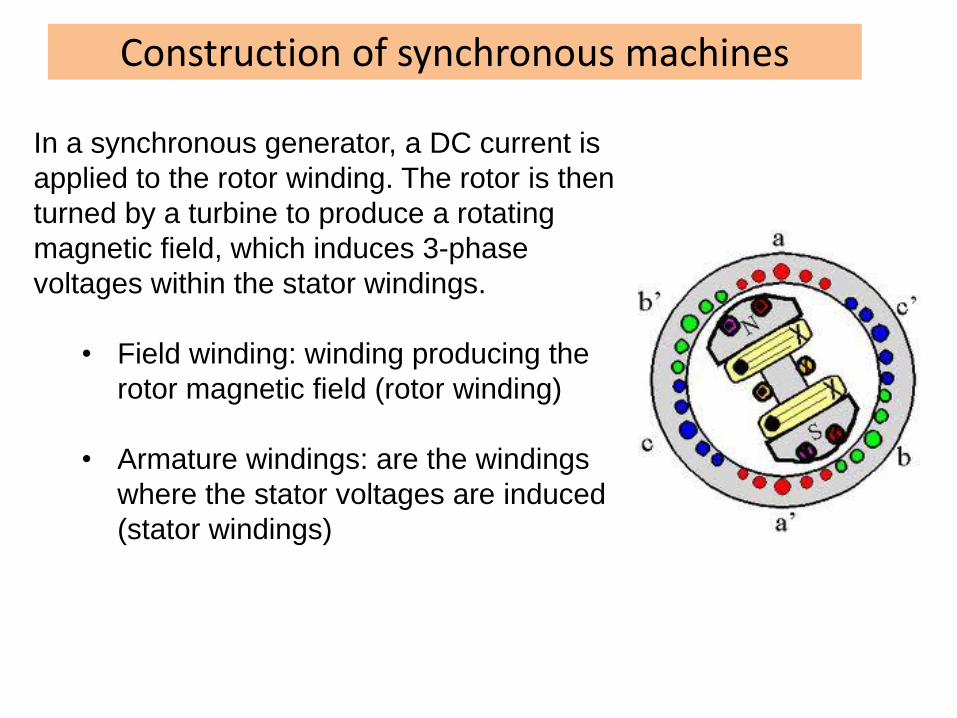
In a synchronous generator, a DC current is
applied to the rotor winding. The rotor is then
turned by a turbine to produce a rotating
magnetic field, which induces 3-phase
voltages within the stator windings.
• Field winding: winding producing the
rotor magnetic field (rotor winding)
• Armature windings: are the windings
where the stator voltages are induced
(stator windings)
Construction of synchronous machines
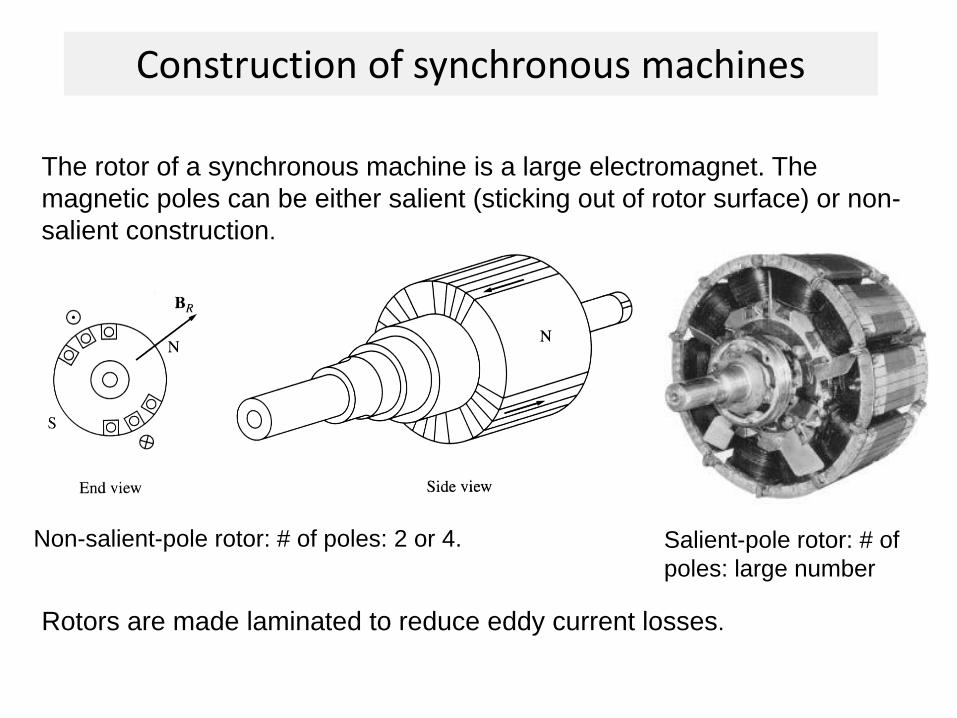
The rotor of a synchronous machine is a large electromagnet. The
magnetic poles can be either salient (sticking out of rotor surface) or non-
salient construction.
Non-salient-pole rotor: # of poles: 2 or 4. Salient-pole rotor: # of
poles: large number
Rotors are made laminated to reduce eddy current losses.
Construction of synchronous machines
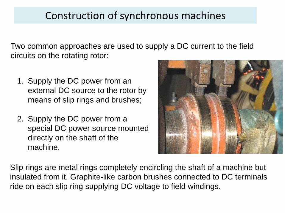
Two common approaches are used to supply a DC current to the field
circuits on the rotating rotor:
1. Supply the DC power from an
external DC source to the rotor by
means of slip rings and brushes;
2. Supply the DC power from a
special DC power source mounted
directly on the shaft of the
machine.
Slip rings are metal rings completely encircling the shaft of a machine but
insulated from it. Graphite-like carbon brushes connected to DC terminals
ride on each slip ring supplying DC voltage to field windings.
Construction of synchronous machines
• On large generators and motors, brushless exciters are used.
• A brushless exciter is a small AC generator whose field
circuits are mounted on the stator and armature circuits are
mounted on the rotor shaft.
• The exciter generator’s 3-phase output is rectified to DC by
a 3-phase rectifier (mounted on the shaft) and fed into the
main DC field circuit.
• It is possible to adjust the field current on the main machine
by controlling the small DC field current of the exciter
generator (located on the stator).
Construction of synchronous machines
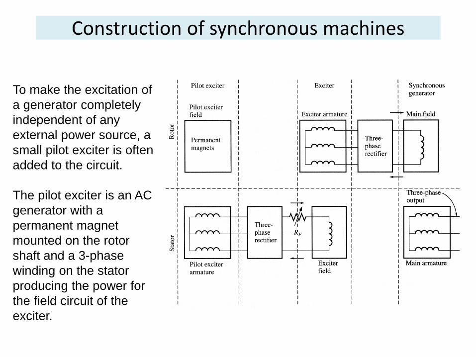
To make the excitation of
a generator completely
independent of any
external power source, a
small pilot exciter is often
added to the circuit.
The pilot exciter is an AC
generator with a
permanent magnet
mounted on the rotor
shaft and a 3-phase
winding on the stator
producing the power for
the field circuit of the
exciter.
Construction of synchronous machines
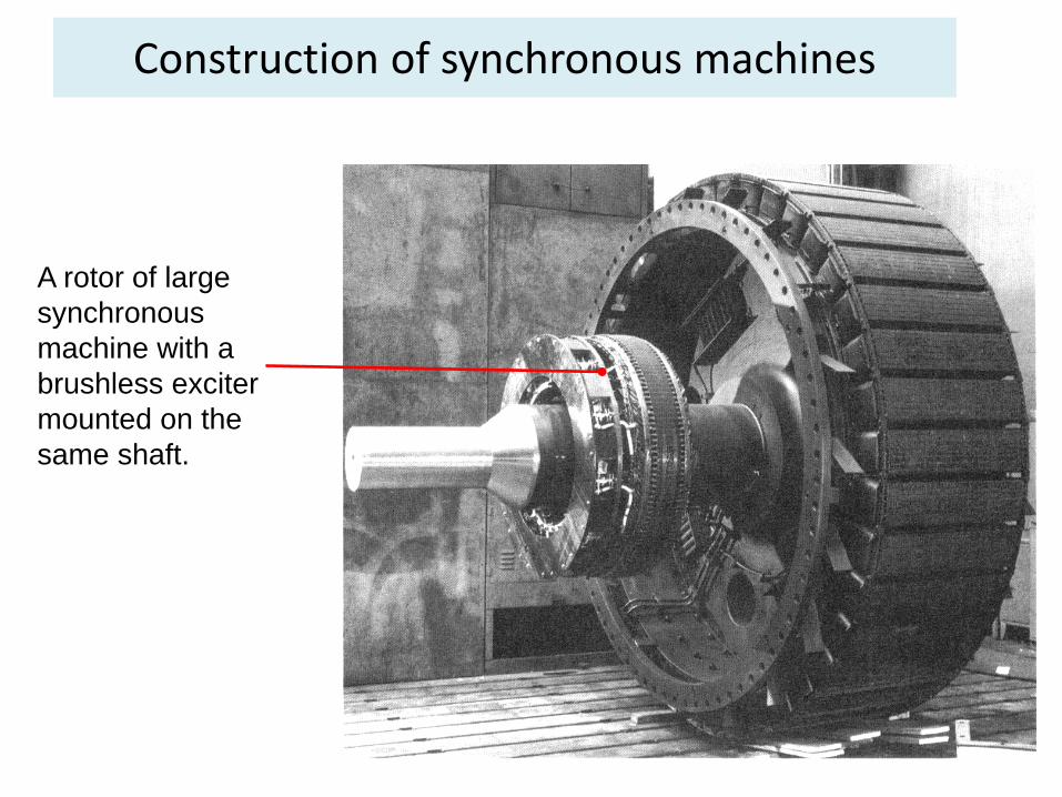
A rotor of large
synchronous
machine with a
brushless exciter
mounted on the
same shaft.
Construction of synchronous machines
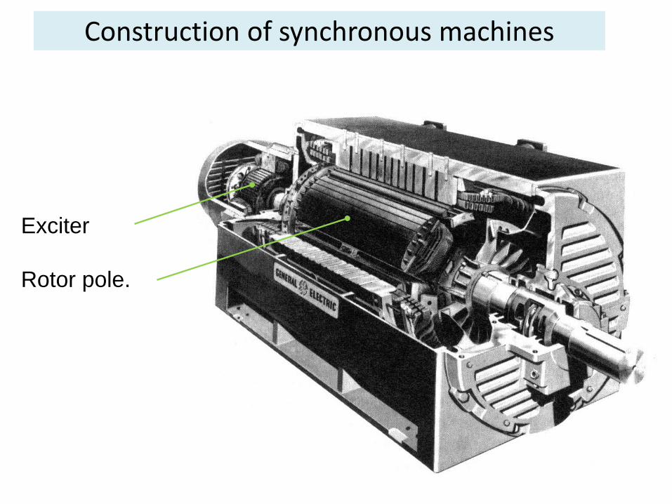
Exciter
Rotor pole.
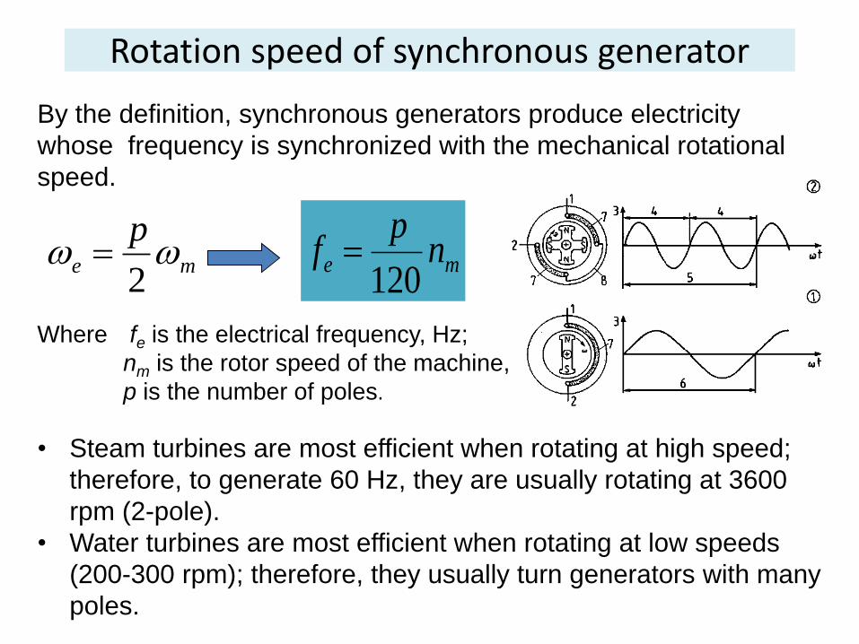
Rotation speed of synchronous generator
By the definition, synchronous generators produce electricity
whose frequency is synchronized with the mechanical rotational
speed.
Where fe is the electrical frequency, Hz;
nm is the rotor speed of the machine, rpm;
p is the number of poles.
• Steam turbines are most efficient when rotating at high speed;
therefore, to generate 60 Hz, they are usually rotating at 3600
rpm (2-pole).
• Water turbines are most efficient when rotating at low speeds
(200-300 rpm); therefore, they usually turn generators with many
poles.
me np
f120
me
p
2
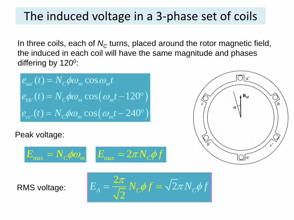
The induced voltage in a 3-phase set of coils
In three coils, each of NC turns, placed around the rotor magnetic field,
the induced in each coil will have the same magnitude and phases
differing by 1200:
'
'
'
( ) cos
( ) cos 120
( ) cos 240
aa C m m
bb C m m
cc C m m
e t N t
e t N t
e t N t
Peak voltage:
max C mE N max 2 CE N f
RMS voltage: 2
22CA CNE Nf f
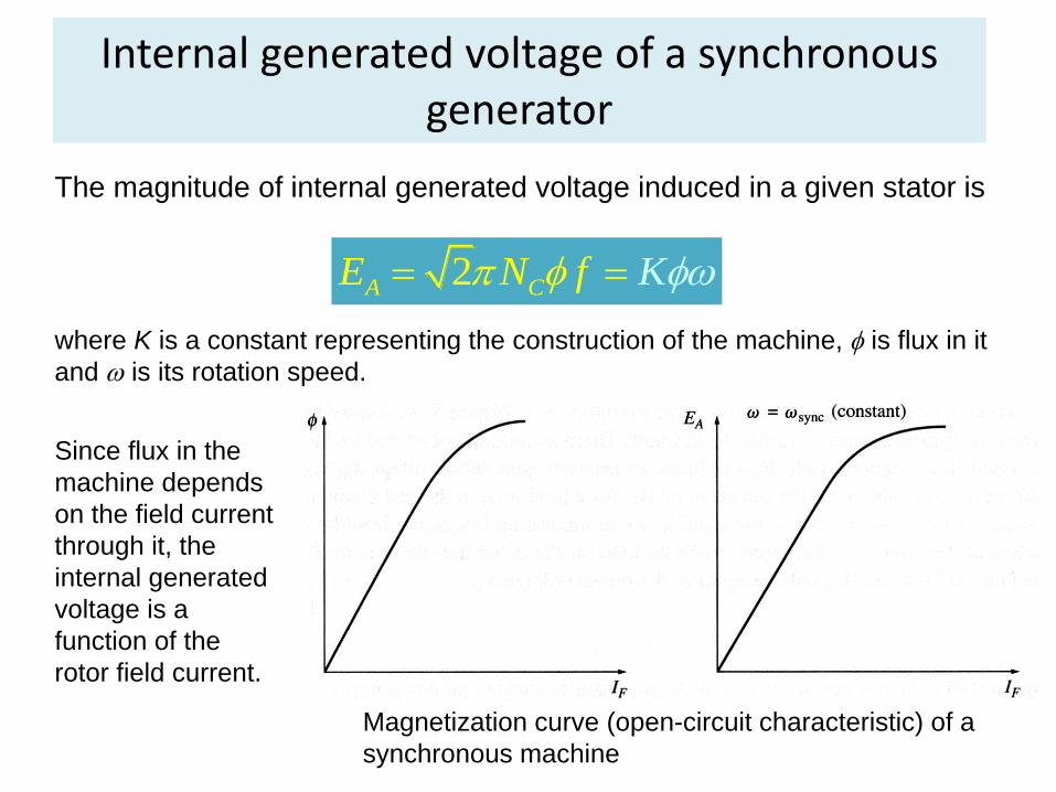
Internal generated voltage of a synchronous generator
The magnitude of internal generated voltage induced in a given stator is
2A CE N f K
where K is a constant representing the construction of the machine, is flux in it
and is its rotation speed.
Since flux in the
machine depends
on the field current
through it, the
internal generated
voltage is a
function of the
rotor field current.
Magnetization curve (open-circuit characteristic) of a
synchronous machine
Equivalent circuit of a synchronous generator
The internally generated voltage in a single phase of a
synchronous machine EA is not usually the voltage appearing
at its terminals. It equals to the output voltage V only when
there is no armature current in the machine. The reasons
that the armature voltage EA is not equal to the output
voltage V are:
1. Distortion of the air-gap magnetic field caused by the
current flowing in the stator (armature reaction);
2. Self-inductance of the armature coils;
3. Resistance of the armature coils;
Equivalent circuit of a synchronous generator
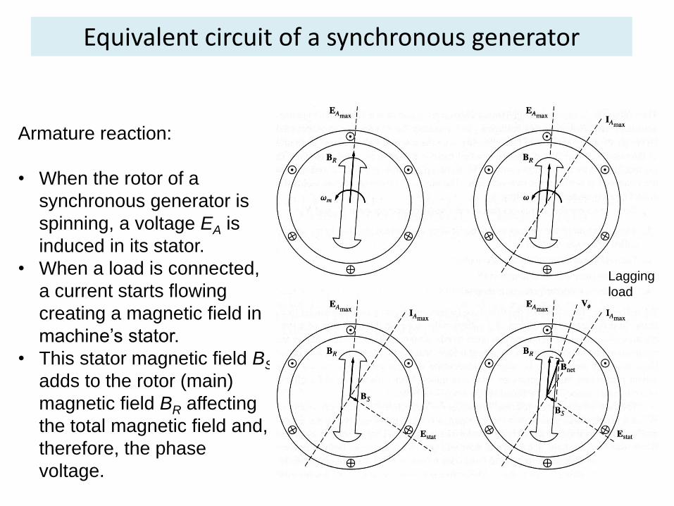
Armature reaction:
• When the rotor of a
synchronous generator is
spinning, a voltage EA is
induced in its stator.
• When a load is connected,
a current starts flowing
creating a magnetic field in
machine’s stator.
• This stator magnetic field BS
adds to the rotor (main)
magnetic field BR affecting
the total magnetic field and,
therefore, the phase
voltage.
Lagging
load
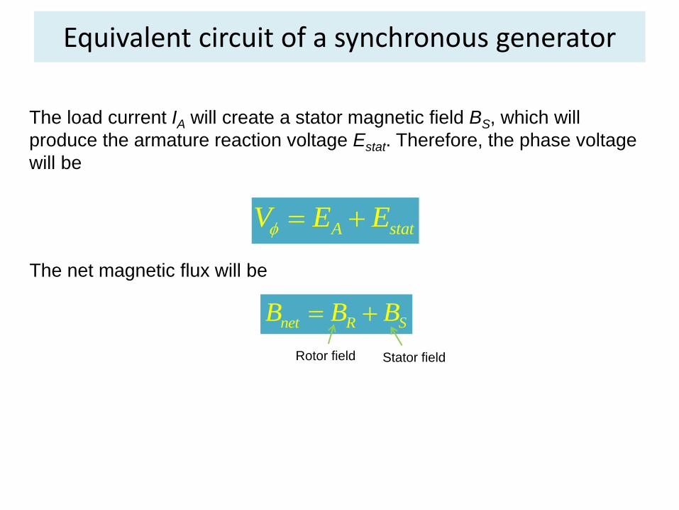
Equivalent circuit of a synchronous generator
The load current IA will create a stator magnetic field BS, which will
produce the armature reaction voltage Estat. Therefore, the phase voltage
will be
A statV E E
The net magnetic flux will be
net R SB B B
Rotor field Stator field
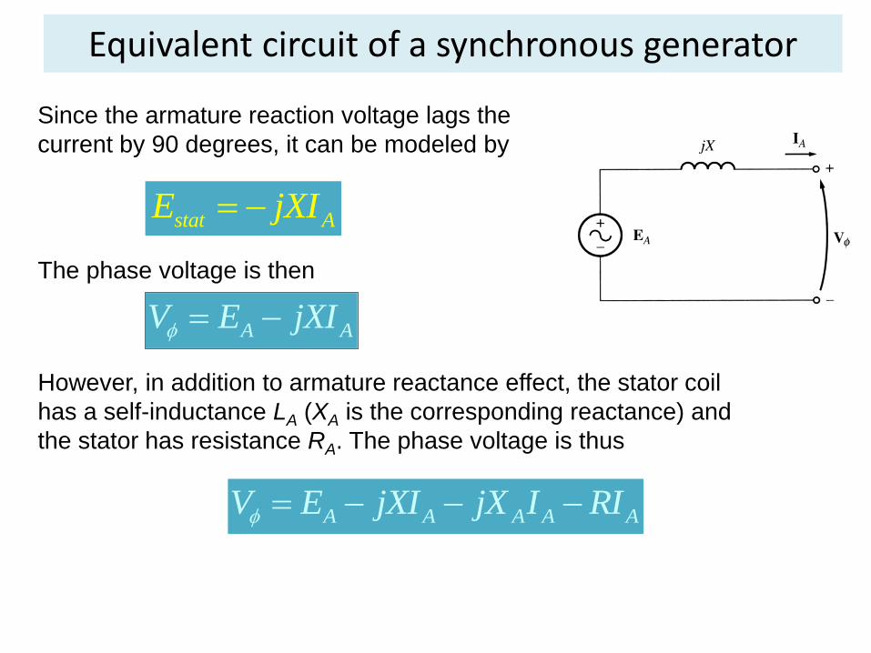
Equivalent circuit of a synchronous generator
Since the armature reaction voltage lags the
current by 90 degrees, it can be modeled by
stat AE jXI
The phase voltage is then
A AV E jXI
However, in addition to armature reactance effect, the stator coil
has a self-inductance LA (XA is the corresponding reactance) and
the stator has resistance RA. The phase voltage is thus
A A A A AV E jXI jX I RI
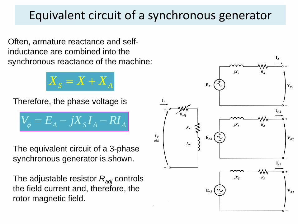
Equivalent circuit of a synchronous generator
Often, armature reactance and self-
inductance are combined into the
synchronous reactance of the machine:
S AX X X
A S A AV E jX I RI
Therefore, the phase voltage is
The equivalent circuit of a 3-phase
synchronous generator is shown.
The adjustable resistor Radj controls
the field current and, therefore, the
rotor magnetic field.
Equivalent circuit of a synchronous generator
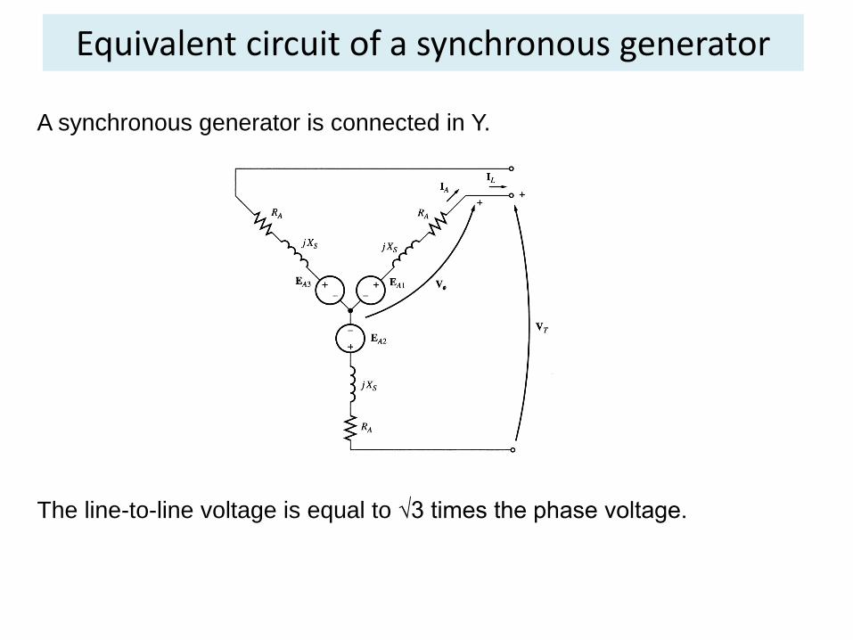
A synchronous generator is connected in Y.
The line-to-line voltage is equal to √3 times the phase voltage.
Equivalent circuit of a synchronous generator
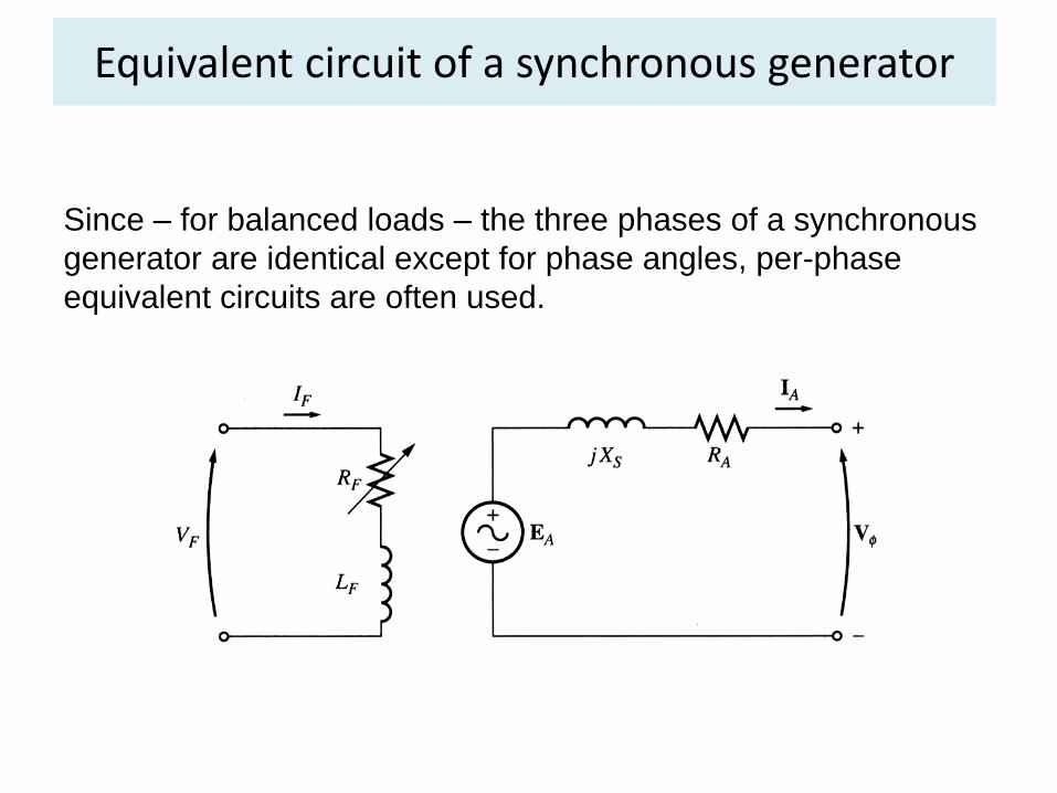
Since – for balanced loads – the three phases of a synchronous
generator are identical except for phase angles, per-phase
equivalent circuits are often used.
Measuring parameters of synchronous generator model
Three quantities must be determined in order to describe the
generator model:
• The relationship between field current and flux (and
therefore between the field current IF and the internal
generated voltage EA);
• The synchronous reactance;
• The armature resistance.
Open circuit Test
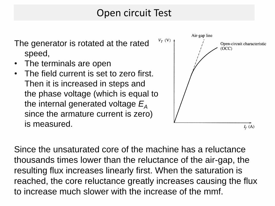
Since the unsaturated core of the machine has a reluctance
thousands times lower than the reluctance of the air-gap, the
resulting flux increases linearly first. When the saturation is
reached, the core reluctance greatly increases causing the flux
to increase much slower with the increase of the mmf.
The generator is rotated at the rated
speed,
• The terminals are open
• The field current is set to zero first.
Then it is increased in steps and
the phase voltage (which is equal to
the internal generated voltage EA
since the armature current is zero)
is measured.
Short Circuit Test
In the short-circuit test,
1. the generator is rotated at the rated speed, with the field
current is set to zero first, and all the terminals are short-
circuited.
2. Next, the field current is increased in steps and the armature
current IA (i.e., short circuit current) is measured as the field
current is increased.
The plot of armature current vs. the field current is referred to as
the short-circuit characteristic (SCC) of the generator.
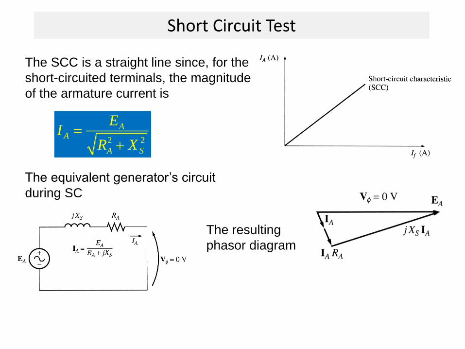
Short Circuit Test
The SCC is a straight line since, for the
short-circuited terminals, the magnitude
of the armature current is
2 2
AA
A S
EI
R X
The equivalent generator’s circuit
during SC
The resulting
phasor diagram
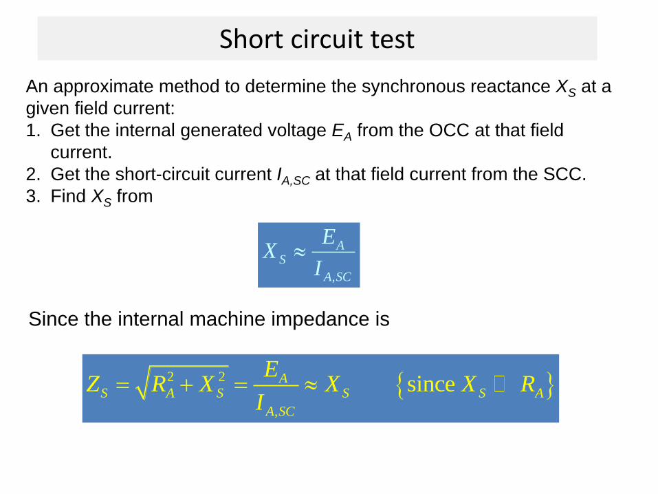
Short circuit test
An approximate method to determine the synchronous reactance XS at a
given field current:
1. Get the internal generated voltage EA from the OCC at that field
current.
2. Get the short-circuit current IA,SC at that field current from the SCC.
3. Find XS from
,
AS
A SC
EX
I
Since the internal machine impedance is
2 2
,
sinceAS A S S S A
A SC
EZ R X X X R
I
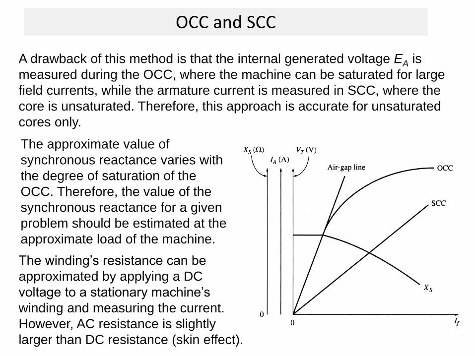
OCC and SCC
A drawback of this method is that the internal generated voltage EA is
measured during the OCC, where the machine can be saturated for large
field currents, while the armature current is measured in SCC, where the
core is unsaturated. Therefore, this approach is accurate for unsaturated
cores only.
The approximate value of
synchronous reactance varies with
the degree of saturation of the
OCC. Therefore, the value of the
synchronous reactance for a given
problem should be estimated at the
approximate load of the machine.
The winding’s resistance can be
approximated by applying a DC
voltage to a stationary machine’s
winding and measuring the current.
However, AC resistance is slightly
larger than DC resistance (skin effect).
Example
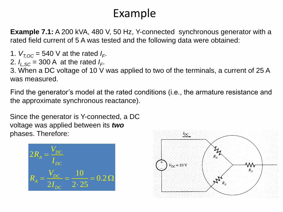
Example 7.1: A 200 kVA, 480 V, 50 Hz, Y-connected synchronous generator with a
rated field current of 5 A was tested and the following data were obtained:
1. VT,OC = 540 V at the rated IF.
2. IL,SC = 300 A at the rated IF.
3. When a DC voltage of 10 V was applied to two of the terminals, a current of 25 A
was measured.
Find the generator’s model at the rated conditions (i.e., the armature resistance and
the approximate synchronous reactance).
Since the generator is Y-connected, a DC
voltage was applied between its two
phases. Therefore:
2
100.2
2 2 25
DCA
DC
DCA
DC
VR
I
VR
I
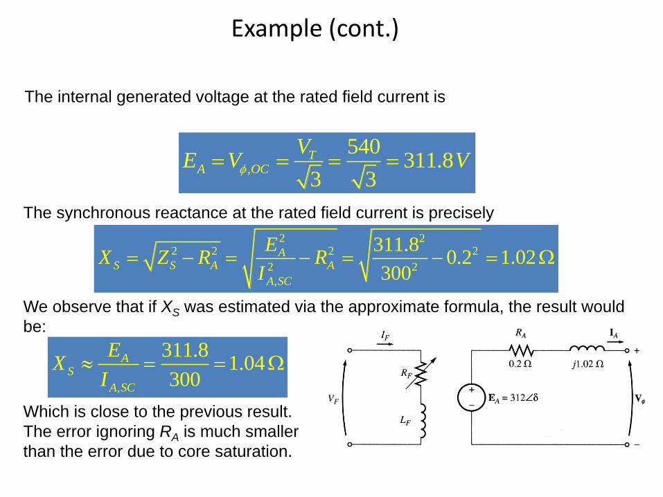
Example (cont.)
The internal generated voltage at the rated field current is
,
540311.8
3 3
TA OC
VE V V
The synchronous reactance at the rated field current is precisely
2 22 2 2 2
2 2
,
311.80.2 1.02
300
AS S A A
A SC
EX Z R R
I
We observe that if XS was estimated via the approximate formula, the result would
be:
,
311.81.04
300
AS
A SC
EX
I
Which is close to the previous result.
The error ignoring RA is much smaller
than the error due to core saturation.
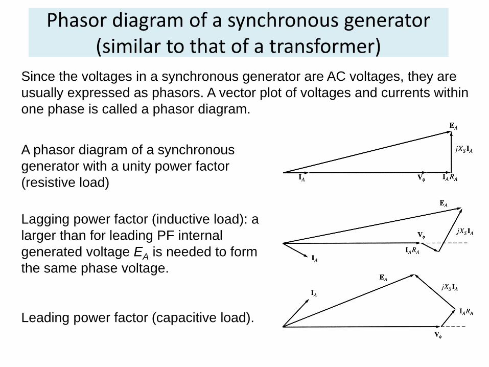
Phasor diagram of a synchronous generator (similar to that of a transformer)
Since the voltages in a synchronous generator are AC voltages, they are
usually expressed as phasors. A vector plot of voltages and currents within
one phase is called a phasor diagram.
A phasor diagram of a synchronous
generator with a unity power factor
(resistive load)
Lagging power factor (inductive load): a
larger than for leading PF internal
generated voltage EA is needed to form
the same phase voltage.
Leading power factor (capacitive load).
The Synchronous generator operating alone
The behavior of a synchronous generator varies greatly under
load depending on the power factor of the load and on
whether the generator is working alone or in parallel with other
synchronous generators.
Although most of the synchronous generators in the world
operate as parts of large power systems, we start our
discussion assuming that the synchronous generator works
alone.
Unless otherwise stated, the speed of the generator is
assumed constant.
The Synchronous generator operating alone
Effects of load changes
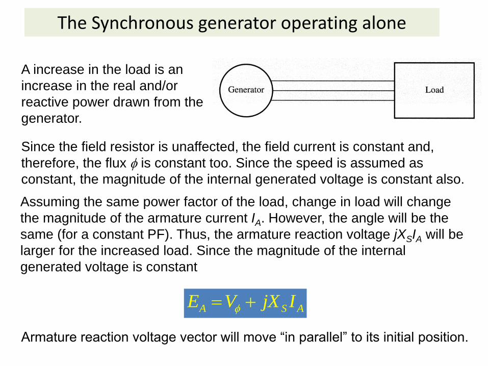
A increase in the load is an
increase in the real and/or
reactive power drawn from the
generator.
Since the field resistor is unaffected, the field current is constant and,
therefore, the flux is constant too. Since the speed is assumed as
constant, the magnitude of the internal generated voltage is constant also.
Assuming the same power factor of the load, change in load will change
the magnitude of the armature current IA. However, the angle will be the
same (for a constant PF). Thus, the armature reaction voltage jXSIA will be
larger for the increased load. Since the magnitude of the internal
generated voltage is constant
A S AE V jX I
Armature reaction voltage vector will move “in parallel” to its initial position.
The Synchronous generator operating alone
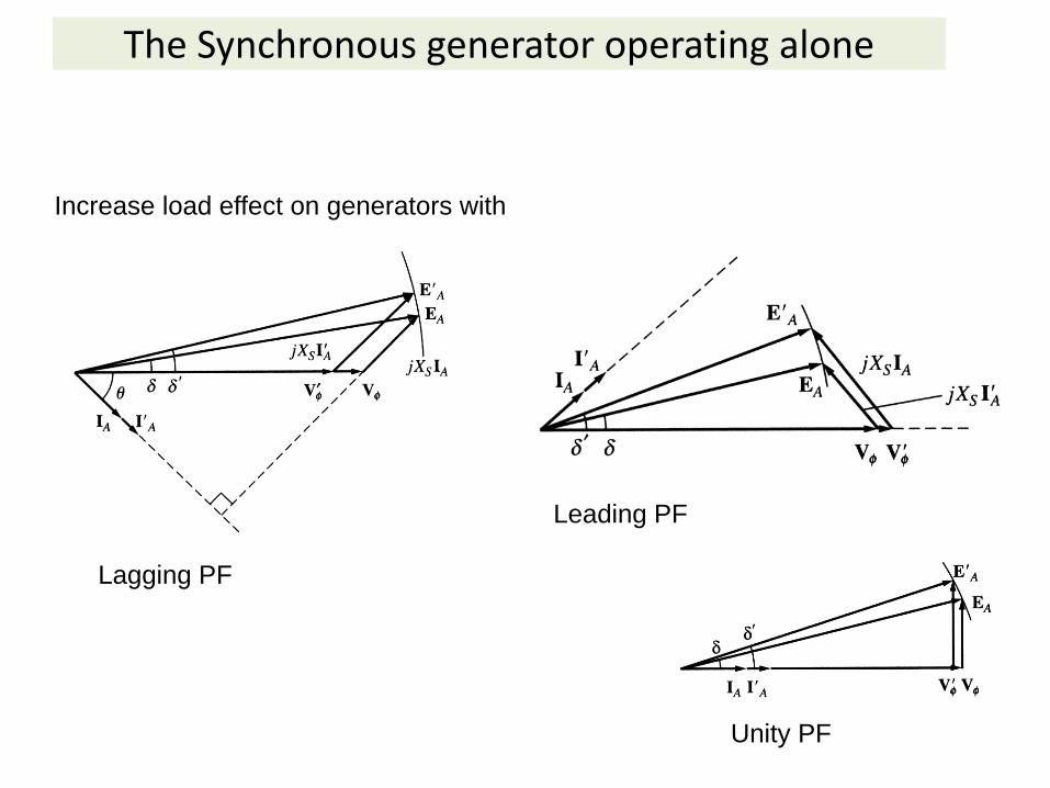
Increase load effect on generators with
Lagging PF
Leading PF
Unity PF
The Synchronous generator operating alone
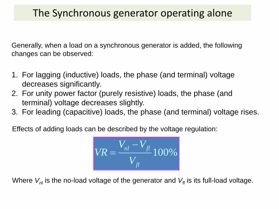
1. For lagging (inductive) loads, the phase (and terminal) voltage
decreases significantly.
2. For unity power factor (purely resistive) loads, the phase (and
terminal) voltage decreases slightly.
3. For leading (capacitive) loads, the phase (and terminal) voltage rises.
Generally, when a load on a synchronous generator is added, the following
changes can be observed:
Effects of adding loads can be described by the voltage regulation:
100%nl fl
fl
V VVR
V
Where Vnl is the no-load voltage of the generator and Vfl is its full-load voltage.
The Synchronous generator operating alone
• A synchronous generator operating at a lagging power factor has a fairly large
positive voltage regulation.
• A synchronous generator operating at a unity power factor has a small positive
voltage regulation.
• A synchronous generator operating at a leading power factor often has a
negative voltage regulation.
Normally, a constant terminal voltage supplied by a generator is desired. Since the
armature reactance cannot be controlled, an obvious approach to adjust the
terminal voltage is by controlling the internal generated voltage EA = K. This
may be done by changing flux in the machine while varying the value of the field
resistance RF, which is summarized:
1. Decreasing the field resistance increases the field current in the generator.
2. An increase in the field current increases the flux in the machine.
3. An increased flux leads to the increase in the internal generated voltage.
4. An increase in the internal generated voltage increases the terminal voltage of
the generator.
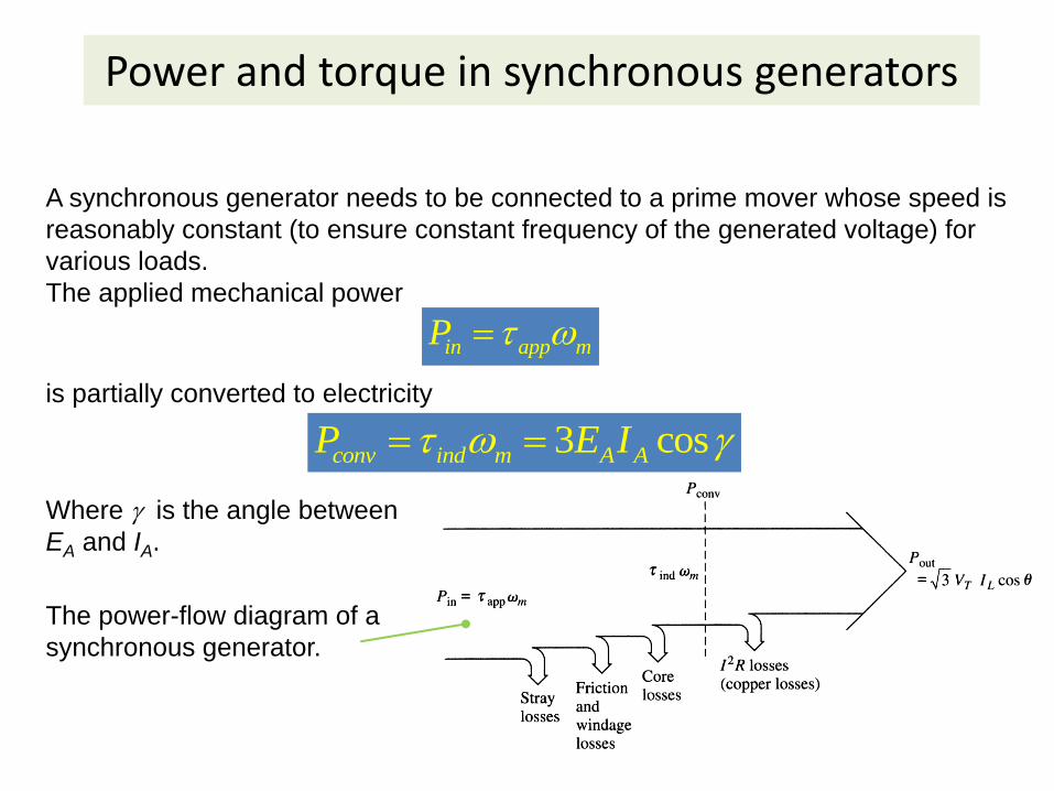
Power and torque in synchronous generators
A synchronous generator needs to be connected to a prime mover whose speed is
reasonably constant (to ensure constant frequency of the generated voltage) for
various loads.
The applied mechanical power
in app mP
is partially converted to electricity
3 cosconv ind m A AP E I
Where is the angle between
EA and IA.
The power-flow diagram of a
synchronous generator.
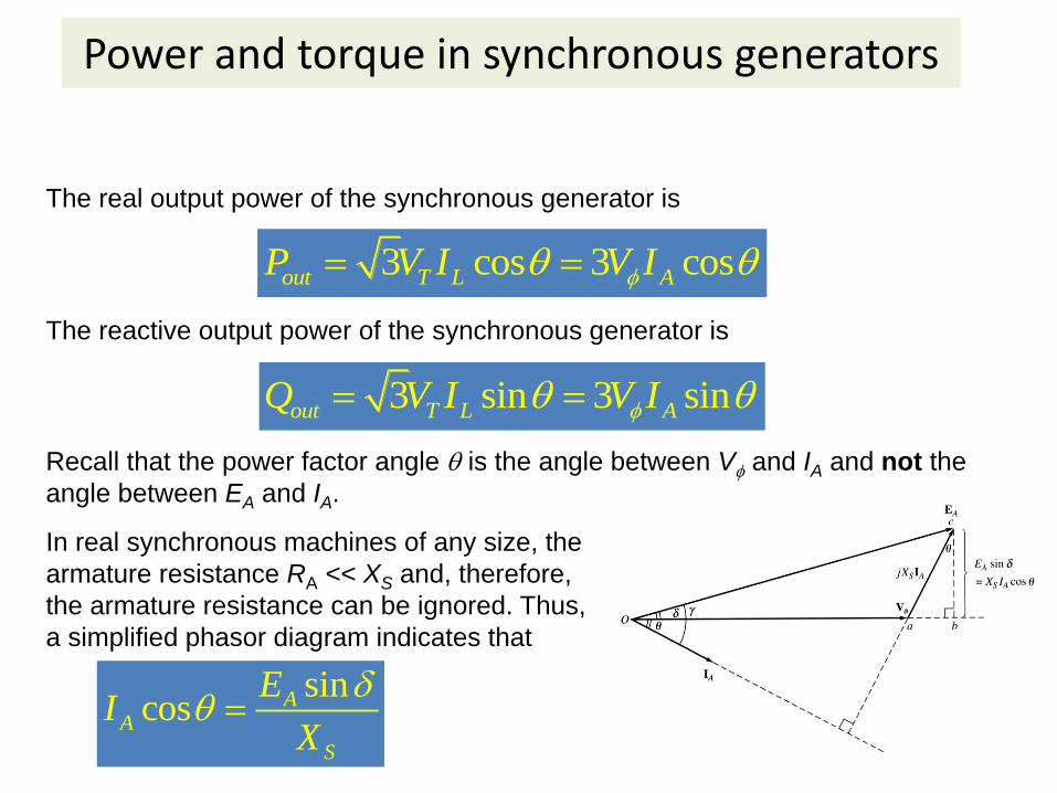
Power and torque in synchronous generators
The real output power of the synchronous generator is
3 cos 3 cosout T L AP V I V I
The reactive output power of the synchronous generator is
3 sin 3 sinout T L AQ V I V I
Recall that the power factor angle is the angle between V and IA and not the
angle between EA and IA.
In real synchronous machines of any size, the
armature resistance RA << XS and, therefore,
the armature resistance can be ignored. Thus,
a simplified phasor diagram indicates that
sincos A
A
S
EI
X
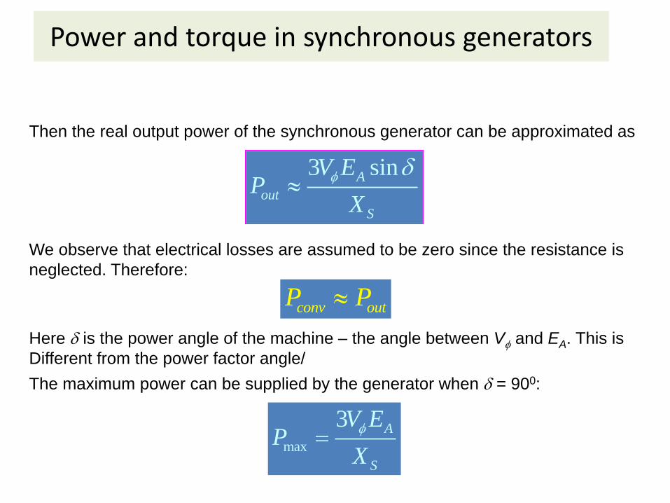
Power and torque in synchronous generators
Then the real output power of the synchronous generator can be approximated as
3 sinA
out
S
V EP
X
We observe that electrical losses are assumed to be zero since the resistance is
neglected. Therefore:
conv outP P
Here is the power angle of the machine – the angle between V and EA. This is
Different from the power factor angle/
The maximum power can be supplied by the generator when = 900:
max
3 A
S
V EP
X
Problems (Chap 5)
• 2-4, 5-14, 15, 16, 17,