measuring mechanical vibrations using an arduino as a ...839696/fulltext01.pdf · physics project...
TRANSCRIPT

Department ofPhysics and AstronomyUppsala UniversityBox 516SE-75120 UppsalaSweden
Department of Physics and AstronomyUppsala University
Papers in the FREIA Report Series are published on internet in PDF format.Download from http://uu.diva-portal.org
FREIA Report 2015/04June 9, 2015
Measuring mechanical vibrationsusing an Arduino as a slave I/O to an
EPICS control system
Adam Hjort & Mans Holmberg
Uppsala University, Uppsala,Sweden

Physics Project with a Research Connection 5 hp, 1FA605 • June 2015
Measuring mechanical vibrations using an Arduinoas a slave I/O to an EPICS control system
Adam Hjort & Måns Holmberg
Supervisor: Volker Ziemann & Konrad Gajewski
Department of Physics and AstronomyUppsala Universitet
Abstract
In this study we have assembled hardware and software to be used for measuring of mechanical vibrationsin the FREIA-laboratory at Uppsala University. We have utilized an Arduino microcontroller as a slaveI/O and equipped it with dual accelerometers to be used for vibration measurements and a serial adapterwhich was used to connect the hardware to an EPICS IOC for analysis. Data from the two accelerometershave then been cross correlated in order to find a transfer function. Our results where in good agreementwith theory.
1 Introduction
It is of utmost importance when designingphysical experiments that one takes into ac-count the mechanical vibrations that may oc-cur and affect the results. There are severalways to measure mechanical vibrations and inthis study we look closer on how to measurethem using an MEMS-based accelerometer [3].By using two accelerometers we can see howvibrations transfers from one point to anotherand thereby gain some information into thecharacteristics of the medium the vibrationspropagated through. To provide the accelerom-eters with power and collect the waveforms,an Arduino microcontroller is being used. TheArduino functions as a slave IO and can be con-nected to either MATLAB or an EPICS controlsystem. During hardware testing a speaker wasused to generate desired sine waves, seen in fig-ure 6. Since this speaker propagates the sounddirectly into the material it is being placed on,it proved excellent as a frequency test devicefor the accelerometers. As an real world exper-iment, we measured the transfer function for avacuum pump at the FREIA-laboratory.
2 Hardware
Figure 1: The Arduino Uno rev. 3
2.1 Arduino
Arduino is an open source microcontroller thathas become very popular amongst students,hobbyists as well as with professionals. It hasa very active community and the low cost ofpurchase makes it an excellent tool to quicklytest and deploy ideas. We have chosen to workwith the reference model Arduino Uno rev. 3that can be seen in figure 1. It measures 68.6x 53.4 mm and weights 25 g. It is based onthe ATmega328 8-bit microcontroller. It has a
1
Physics Project with a Research Connection 5 hp, 1FA605 • June 2015
clock frequency of 16 MHz and a 32 KB flashmemory. It operates at 5 V and can be pow-ered over USB or an external power supply. Onthe board there are 6 analog pins and a totalof 14 digital I/O Pins and 6 of these providePWM output. There are also pins for powermanagement [7].
The analog pins which are the ones we mostlywork with in this project has a resolution of10 bits meaning they can handle 1024 differentvalues. This is usually done by having eachvalue correspond to a voltage between groundand 5 V, however this can be changed by usingthe AREF pin (analog reference pin).
For communication with the Arduino UARTTTL (5V) serial communication is used. Thedigital pins 0 (RX) and 1 (TX) can also be usedto send and receive serial data. In the IDE thereis a built-in serial monitor that can be used tosend and receive information. When connectedover USB to a computer the Arduino showsup as a virtual COM-port and any softwarecapable of serial communication can be used.
2.2 Accelerometer
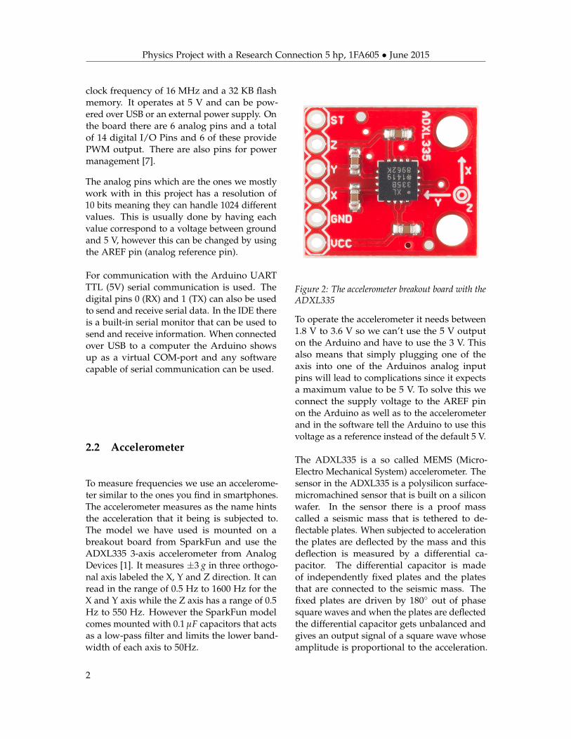
To measure frequencies we use an accelerome-ter similar to the ones you find in smartphones.The accelerometer measures as the name hintsthe acceleration that it being is subjected to.The model we have used is mounted on abreakout board from SparkFun and use theADXL335 3-axis accelerometer from AnalogDevices [1]. It measures ±3 g in three orthogo-nal axis labeled the X, Y and Z direction. It canread in the range of 0.5 Hz to 1600 Hz for theX and Y axis while the Z axis has a range of 0.5Hz to 550 Hz. However the SparkFun modelcomes mounted with 0.1 µF capacitors that actsas a low-pass filter and limits the lower band-width of each axis to 50Hz.
Figure 2: The accelerometer breakout board with theADXL335
To operate the accelerometer it needs between1.8 V to 3.6 V so we can’t use the 5 V outputon the Arduino and have to use the 3 V. Thisalso means that simply plugging one of theaxis into one of the Arduinos analog inputpins will lead to complications since it expectsa maximum value to be 5 V. To solve this weconnect the supply voltage to the AREF pinon the Arduino as well as to the accelerometerand in the software tell the Arduino to use thisvoltage as a reference instead of the default 5 V.
The ADXL335 is a so called MEMS (Micro-Electro Mechanical System) accelerometer. Thesensor in the ADXL335 is a polysilicon surface-micromachined sensor that is built on a siliconwafer. In the sensor there is a proof masscalled a seismic mass that is tethered to de-flectable plates. When subjected to accelerationthe plates are deflected by the mass and thisdeflection is measured by a differential ca-pacitor. The differential capacitor is madeof independently fixed plates and the platesthat are connected to the seismic mass. Thefixed plates are driven by 180� out of phasesquare waves and when the plates are deflectedthe differential capacitor gets unbalanced andgives an output signal of a square wave whoseamplitude is proportional to the acceleration.
2

Physics Project with a Research Connection 5 hp, 1FA605 • June 2015
By using demodulation techniques that aresensitive to the phase-magnitude and directionof the acceleration can be determined. Thesignal is then amplified and taken through a 32kW resistor and now one signal for each axis isavailable. Each signal is then taken through a0.1 µF capacitor that as was mentioned earlieracts as a low-pass filter. The ADXL335 usesone structure for the X, Y and Z axis whichgives the axis high orthogonality that in turnleads to little cross-axis sensitivity [9] [2].
2.3 Serial adapter
To be able to integrate the Arduino into theEPICS environment used at FREIA it needs tobe connected to a serial device server using aD-sub 9 connector. The serial device server inturn gives the device an IP adress and makesit accessible over the network. The Arduinosdigital pin 0 and 1 are by default used asRX (receive) and TX (transmit) but this doesnot mean that one can simply attach D-sub 9connector and get a working connection. Thereason for this is that the Arduino communi-cates with the UART (Universal asynchronousreceiver/transmitter) protocol that sends datawith TTL (Transistor–transistor logic) voltagelevels that are in the interval of 0 V to 5 Vwhile the serial device server uses RS-232 thatuses -15 V to -3 V for 0 and 3 V to 15 V for1. communication. The data sent from UARTcan however be converted to work with RS232devices by feeding the signal through an inte-grated circuit named MAX232. The MAX232is a dual driver/receiver and works by chang-ing the outgoing voltage to be in the RS232compatible interval of approximatively ± 7.5V and the incoming voltage is reduced to bebetween 0 V to 5 V [4].
For a complete view of all hardware usedand how to connect it please see figure 11 inAppendix 7.1.
3 Software
3.1 Arduino
The Arduino microcontroller is programed us-ing the Arduino language, which is based onC/C++, and comes with a user-friendly in-tegrated development environment (IDE) [8].The user only needs to define two functions,to make an executable program: a setup() andloop() function. The setup() function is only ex-ecuted once, and is used to initialize variables,pin modes etc. The loop() function is essen-tially a infinite loop that is called repeatedlyuntil the device is turned off, this is where yourcode is implemented. These types of programsare called cyclic executive programs.
Figure 3: The Arduino IDE.
While one can create a wide variety ofprograms using only these two functions, theloop() function is not ideal for precision highspeed applications. This is because it runscontinuously, without the use of a timer [8]. In-stead, we will be using interrupts, to allow forpredictable timing, which is essential to highspeed data collection. The interrupts are imple-mented using the library MsTimer2 [15]. The
3

Physics Project with a Research Connection 5 hp, 1FA605 • June 2015
library MsTimer2 combines both ease of useand good time resolution (1 ms). The eventsthat triggers the interrupts are internal timeroverflows. Each time a timer overflow, a chosenfunction is called and executed, in our case thiswill be a function that reads an analog pin (ortwo simultaneously). The maximum frequencyof the interrupts is 1 kHz and is determinedby the time resolution of MsTimer2, and hencelimits the speed at which we can sample data.
Listing 1: Reading analog waveform// Reads 512 values of analog pin 0 every// 1 ms using MsTimer2#include <MsTimer2.h>
const int buffer = 512; // Buffer sizeint analogDataArray[buffer];int count = 0;int analogPin = 0;int period = 1; // Period
void getWaveform() {analogDataArray[count] =
analogRead(analogPin);count++;if (count >= buffer){MsTimer2::stop();count = 0;}
}
void setup() {analogReference(EXTERNAL);MsTimer2::set(period, getWaveform);MsTimer2::start();
}
void loop() {}
To read the voltage from an analog pin onboardthe Arduino, we use the function analogRead().The analog to digital converter (ADC) willturn the voltage into an digital signal, rangingfrom 0-1023, where the reference voltage (value1023) is set by the function analogReference().Because the ADXL335 accelerometer operatesusing 3.3 V, the function analogReference() will
be set to EXTERNAL, which indicates that anreference voltage will be applied to the AREFpin. The time used to read an analog inputusing analogRead() is about 100 µs, thereforeit does not limit the frequency of which we cansample [8].
In order to establish serial communicationbetween the Arduino slave and EPICS, weneed call the begin() method of the class Serial.The argument of begin() is the baud rate of thecommunication, which will be set to 115200Bd. Data will be sent and received as human-readable ASCII text, with the methods print()and read(). Listing 2 illustrates the simple codeneeded to establish serial communication.
Listing 2: Exemple showing serial communicationvoid setup() {
Serial.begin(115200);}
void loop() {Serial.println("Hello World");
}
To program a useful Arduino slave IO thatwill be able to respond and perform tasks upondifferent commands sent by the EPICS con-trol system, we will use a switch statement.First we have to read the command sent byEPICS. This can by done by scanning the in-coming characters until the terminator charac-ter is reached, which we have set to newline,shown in Listing 3.
Listing 3: Switch statement, reading serial inputString input;
void setup() {Serial.begin(115200);}
void loop() {while (Serial.available() > 0)
{char lastRecived = Serial.read();input += lastRecived;if (lastRecived == ’\n’){
4
Physics Project with a Research Connection 5 hp, 1FA605 • June 2015
switch (input[0]) {case ’W’:MsTimer2::set(period,
getWaveform);MsTimer2::start();break;default:Serial.println("Error");break;
}input = ""; // Clear recieved buffer.
}}
}
We use a buffer of 512 elements (limited by thememory of the Arduino) to temporarily storethe waveforms on the Arduino, before the datais sent to EPICS or MATLAB [7]. This methodwas not limited by the time delay introducedby constantly sending a command and receiv-ing one data point at a time, which was ourfirst approach.
Appart from acquiring analog values, we alsoimplemented digital I/O. The represetive com-mands are detailed in the appendix 7.2.
3.2 MATLAB
MATLAB is a numerical computing environ-ment that is built around an easy scripting lan-guage, which makes MATLAB perfect for quicktesting and data analysis. First, we initializedthe serial communication between MATLABand the Arduino slave, with the native func-tion serial(). Using this function, we createda serial object and set the parameters DataBits= 8, StopBits = 1, BaudRate = 115200.
serialObj = serial(comPort);set(serialObj, ’DataBits’, 8);set(serialObj, ’StopBits’, 1);set(serialObj, ’BaudRate’, 115200);
Then we implemented our protocol, see Ap-pendix 7.2, into different functions that han-
dled the serial communication. Below is thefunction readWaveform() that reads a wave-form from an analog channel on the Arduino.
function waveform = ...readWaveform(serialObj, analogPin)
output = [’W’, num2str(analogPin), ’?’];fprintf(serialObj, output);input = strsplit(fscanf(serialObj,...’%c’), ’ ’);
if strcmp(output(1:end-1),...cell2mat(input(1)))waveform = str2double(input(2:end));
elseerror(’Error’);
endend
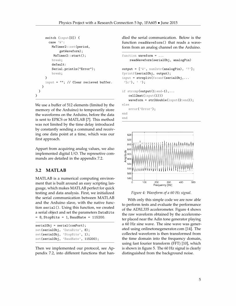
Figure 4: Waveform of a 60 Hz signal.
With only this simple code we are now ableto perform tests and evaluate the performanceof the ADXL335 accelerometer. Figure 4 showsthe raw waveform obtained by the accelerome-ter placed near the Adin tone generator playinga 60 Hz sine wave. The sine wave was gener-ated using onlinetonegenerator.com [14]. Thecollected waveform is then transformed fromthe time domain into the frequency domain,using fast fourier transform (FFT) [10], whichis shown in figure 5. The 60 Hz signal is clearlydistinguished from the background noise.
5

Physics Project with a Research Connection 5 hp, 1FA605 • June 2015
Figure 5: Frequency domain of the waveform infigure 4. Note the logarithmic scale.
To test for the frequency response of theADXL355, we generated a linear chirp from100 Hz to 250 Hz with the Adin tone generatorand collected the data over a period of 15 min[11]. The response is illustrated in figure 7. Alllines with a positive slope is harmonics or thefundamental. The other lines with negativeslope are Nyquist reflections.
Figure 6: The Adin KKBT speaker which has beenused as a tone generator during the experiments.
.
Figure 7: The frequency response of a 100 Hz to250 Hz chirp waveform. The colormap representsthe relative amplitude.
3.3 EPICS
EPICS (Experimental Physics and IndustrialControl System) is an open source softwareenvironment for development and manage-ment of control systems used globally in smalland large scale projects [6]. EPICS is availablefor Windows and Linux and in this projectwe used Scientific Linux 6 as operating sys-tem. The EPICS version used is the standaloneversion CODAC Core System v4.1.0 that isdistributed by the ITER Organization. EPICSutilizes Client/Server and Publish/Subscribetechniques to handle communications. Inan EPICS environment a server is called In-put/Output Controller and is abbreviated IOC.To an IOC multiple sensors and modules canbe attached for measuring and controlling thesystem. Through the Channel Access (CA)network protocol other computers can interactwith the IOCs and read data and send com-mands to them. EPICS is very scalable and asystem can consist of a single IOC for smallprojects to thousands of IOCs for more massiveprojects [6].
On an IOC a protocol file is stored that tellshow the communication with an attached de-vice should be handle. This is done by definingcommands in the file that tells EPICS what datato send and what to expect in return. There
6
Physics Project with a Research Connection 5 hp, 1FA605 • June 2015
is also a database file, where the records aredefined. A record tells what commands willbe available through the CA network. Thereare many different ways records and protocolscan look like and we will show an exampleof how these can be structured to work witheach other. The example shows how we mea-sure a single analog reading from an Arduinothat has been loaded with our serial protocol.When requesting a single analog read from pin0 the user should send A0? to the Arduino.If the value on the pin at the moment is 496the output will be A0 496. We will not coverhow to install EPICS and create an applicationsince there is plenty of guides already availableonline on that topic [5].
There are two files that needs to be config-ured before we can start making our record. Inthe file userPreDriverConf.cmd we configurehow to connect to the Arduino which we havenamed to be ARD0:
drvAsynIPPortConfigure("ARD0","192.168.10.9:4003")
We connect using an IP-adress but other meth-ods are also possible. All the settings for thebaud rate, stop bits and so on are handledby the serial switch so this is not somethingthat needs to be set in this case but for othermethods this can be configured here. In thefile dbToLoad.cmd we specify what database toload when the IOC starts and what name thatshould be assigned to the variables PREFIX andARD_PORT:
dbLoadRecords("strdev.db","PREFIX=STRDEV,ARD_PORT=ARD0")
In the database file strdev.db we have a recordthat looks like this:
record(ai, "$(PREFIX):A0") {field(DTYP, "stream")field(INP, "@accel.proto get_analog(0)
$(ARD_PORT)")field(SCAN, ".5 second")
}
In the first row we state that we want to createa record by writing record, in the parenthe-ses that follows afterward we set what typeof record we will be using. In our exam-ple it says ai meaning it’s an analog inputrecord. After that we see "$(PREFIX):A0"and this is the name of the record that willbe used on the CA network. This is themost conventional way of naming records -"NameOfDevice:Sensor". Next we see threerows of fields, a field is where the settingsfor the record is made. The first row says DTYP(which means device type field) and this setswhat kind of device the record is going to beused with. In our example "stream" meansthat we will be using StreamDevice which isa device support module for EPICS that facil-itates the use of devices that communicatesusing strings [16] [12]. The middle row saysINP which stands for input link, as was saidearlier this is an analog input record so this iswhere we specify where the input will comefrom. The line "@accel.proto get_analog(0)$(ARD_PORT)") specifies what protocol files touse, which in this case is @accel.proto andget_analog what commands to run in the pro-tocol. The (0) is a variable that can be sendalong to the protocol. This means we can usethe same the command in the protocol file fordifferent inputs. The last field says (SCAN, ".5second") and tells how and when a record pro-cesses which in this case is set to fetch a newvalue every 0.5 second. The command beingcalled by the record in the protocol file is lookslike this:
get_analog {out "A\$1?";in "A\$1 %d";
}
The first row says get_analog and is the nameof the command that the records use to call it.Next we see out "A\$1?" and specifies whatcommand will be sent to the Arduino. The \$1will be replaced with the variable that was sentalong from the record which means that thecommand that is sent in this case will be A0?.The last row in "A$1 %d" tells EPICS what to
7

Physics Project with a Research Connection 5 hp, 1FA605 • June 2015
expect back from the Arduino. The A$1 will ofcourse once again translate into A0 and the %dmeans that there will come a signed decimalafterwards representing the value of the analogpin.
Once the protocol and database are preparedthere are several ways to interact with and readdata from the IOC. The most common way isto create a GUI that displays the informationbut the easiest way to see that the applicationworks is to use caget in the terminal. The fol-lowing code shows how to start the applicationcalled accel and read data from the recordthat we created in the example above:
[User@localhost ~]$./target/main/scripts/accel-ioc start
Starting IOC accel [ OK ][User@localhost ~]$ caget STRDEV:A0STRDEV:A0 496
8
Physics Project with a Research Connection 5 hp, 1FA605 • June 2015
4 Results
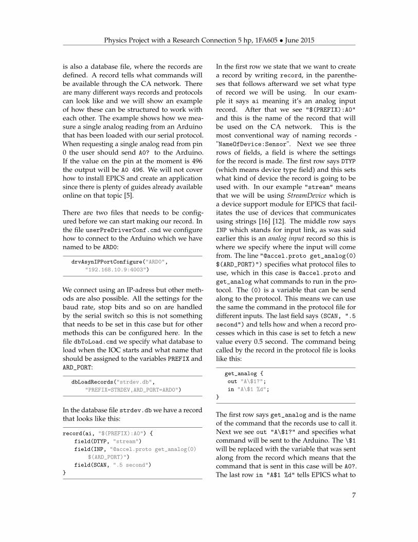
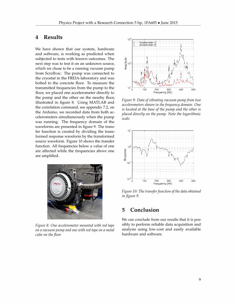
We have shown that our system, hardwareand software, is working as predicted whensubjected to tests with known outcomes. Thenext step was to test it on an unknown source,which we chose to be a running vacuum pumpfrom Scrollvac. The pump was connected tothe cryostat in the FREIA-laboratory and wasbolted to the concrete floor. To measure thetransmitted frequencies from the pump to thefloor, we placed one accelerometer directly tothe pump and the other on the nearby floor,illustrated in figure 8. Using MATLAB andthe correlation command, see appendix 7.2, onthe Arduino, we recorded data from both ac-celerometers simultaneously when the pumpwas running. The frequency domain of thewaveforms are presented in figure 9. The trans-fer function is created by dividing the trans-formed response waveform by the transformedsource waveform. Figure 10 shows the transferfunction. All frequencies below a value of oneare affected while the frequencies above oneare amplified.
Figure 8: One accelerometer mounted with red tapeon a vacuum pump and one with red tape on a metalcube on the floor
Figure 9: Data of vibrating vacuum pump from twoaccelerometers shown in the frequency domain. Oneis located at the base of the pump and the other isplaced directly on the pump. Note the logarithmicscale.
Figure 10: The transfer function of the data obtainedin figure 9.
5 Conclusion
We can conclude from our results that it is pos-sibly to perform reliable data acquisition andanalysis using low-cost and easily availablehardware and software.
9

Physics Project with a Research Connection 5 hp, 1FA605 • June 2015
6 Bibliography
[1] SparkFun Electronics. SparkFun Triple Axis Accelerometer Breakout - ADXL335. https://www.sparkfun.com/products/9269, 2015. [Accessed 22 May 2015].
[2] Analog Devices Inc. ADXL335. http://www.analog.com/en/products/mems/mems-accelerometers/adxl335.html, 2015. [Accessed 22 May 2015].
[3] Commtest Instruments. How is Vibration Measured? http://reliabilityweb.com/index.php/articles/how_is_vibration_measured/, 2006. [Accessed 22 May 2015].
[4] Texas Instruments. MAX232. http://www.ti.com/product/MAX232/description, 2015. [Ac-cessed 22 May 2015].
[5] Pete Jemian. Constant Lighting with EPICS. http://prjemian.github.io/cmd_response/epics/index.html, 2014. [Accessed 22 May 2015].
[6] Argonne National Laboratory. Experimental Physics and Industrial Control System. http://se.mathworks.com/help/matlab/math/fast-fourier-transform-fft.html, 2015. [Accessed22 May 2015].
[7] Arduino LLC. Arduino Uno. http://www.arduino.cc/en/Main/ArduinoBoardUno, 2015.[Accessed 22 May 2015].
[8] Arduino LLC. Language Reference. http://www.arduino.cc/en/Reference/HomePage, 2015.[Accessed 22 May 2015].
[9] Sergey Edward Lyshevski. Nano- and Micro-Electromechanical Systems: Fundamentals of Nano-and Microengineering. CRC Press, 2005.
[10] MathWorks. Fast Fourier Transform (FFT). http://se.mathworks.com/help/matlab/math/fast-fourier-transform-fft.html, 2015. [Accessed 22 May 2015].
[11] MathWorks. Spectrogram. http://se.mathworks.com/help/signal/ref/spectrogram.html,2015. [Accessed 22 May 2015].
[12] W. Eric Norum. How to use StreamDevice and ASYN to create EPICS device support for a simpleserial, GPIB, or network attached device. http://www.aps.anl.gov/epics/modules/soft/asyn/R4-24/HowToDoSerial/HowToDoSerial_StreamDevice.html. [Accessed 22 May 2015].
[13] Friends of Fritzing foundation. Fritzing. http://fritzing.org/home/, 2015. [Accessed 22May 2015].
[14] onlinetonegenerator.com. Online Tone Generator. http://onlinetonegenerator.com, 2015.[Accessed 22 May 2015].
[15] Javier Valencia. MsTimer2 and FlexiTimer2 Libraries. http://www.pjrc.com/teensy/td_libs_MsTimer2.html, 2015. [Accessed 22 May 2015].
[16] Dirk Zimoch. EPICS StreamDevice. http://epics.web.psi.ch/software/streamdevice/doc/, 2011. [Accessed 22 May 2015].
10

Physics Project with a Research Connection 5 hp, 1FA605 • June 2015
7 Appendix
7.1 Circuit diagram
Figure 11: Circuit diagram showing all necessary connections for this project. Note that only the x-axis onthe accelerometers are connected. This diagram was created using the software Fritzing [13].
11
Physics Project with a Research Connection 5 hp, 1FA605 • June 2015
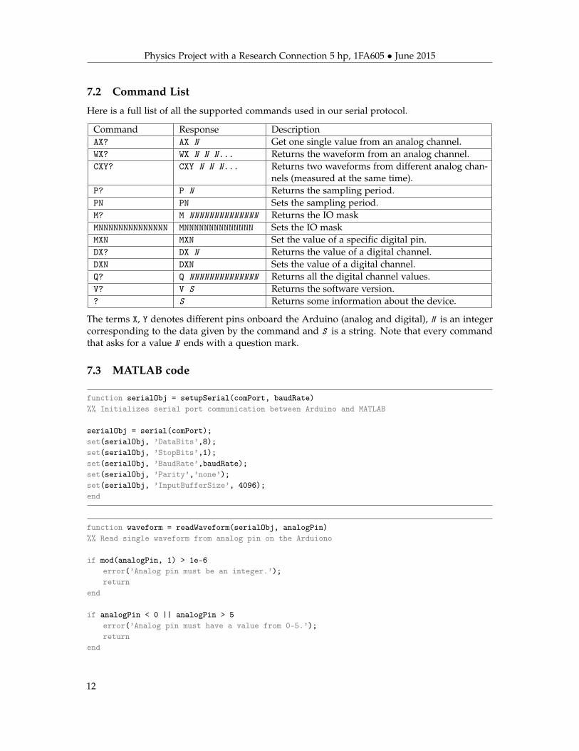
7.2 Command List
Here is a full list of all the supported commands used in our serial protocol.
Command Response DescriptionAX? AX N Get one single value from an analog channel.WX? WX N N N... Returns the waveform from an analog channel.CXY? CXY N N N... Returns two waveforms from different analog chan-
nels (measured at the same time).P? P N Returns the sampling period.PN PN Sets the sampling period.M? M NNNNNNNNNNNNNN Returns the IO maskMNNNNNNNNNNNNNN MNNNNNNNNNNNNNN Sets the IO maskMXN MXN Set the value of a specific digital pin.DX? DX N Returns the value of a digital channel.DXN DXN Sets the value of a digital channel.Q? Q NNNNNNNNNNNNNN Returns all the digital channel values.V? V S Returns the software version.? S Returns some information about the device.
The terms X, Y denotes different pins onboard the Arduino (analog and digital), N is an integercorresponding to the data given by the command and S is a string. Note that every commandthat asks for a value N ends with a question mark.
7.3 MATLAB code
function serialObj = setupSerial(comPort, baudRate)%% Initializes serial port communication between Arduino and MATLAB
serialObj = serial(comPort);set(serialObj, ’DataBits’,8);set(serialObj, ’StopBits’,1);set(serialObj, ’BaudRate’,baudRate);set(serialObj, ’Parity’,’none’);set(serialObj, ’InputBufferSize’, 4096);end
function waveform = readWaveform(serialObj, analogPin)%% Read single waveform from analog pin on the Arduiono
if mod(analogPin, 1) > 1e-6error(’Analog pin must be an integer.’);return
end
if analogPin < 0 || analogPin > 5error(’Analog pin must have a value from 0-5.’);return
end
12
Physics Project with a Research Connection 5 hp, 1FA605 • June 2015
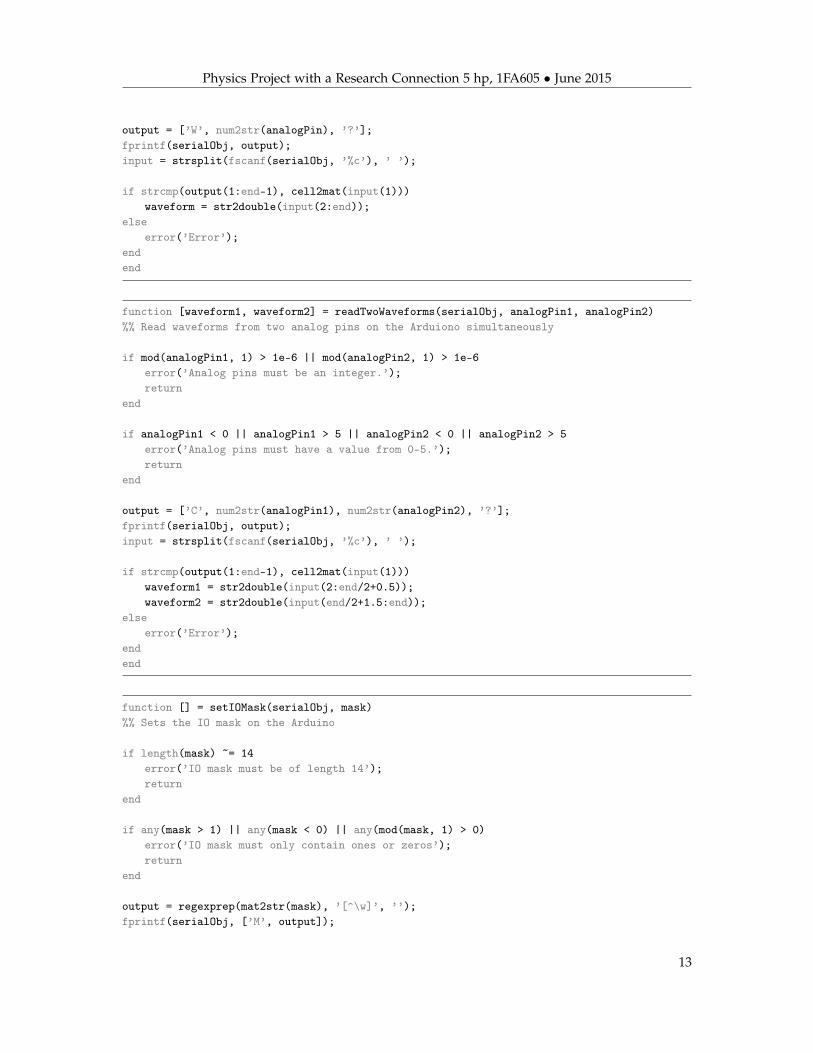
output = [’W’, num2str(analogPin), ’?’];fprintf(serialObj, output);input = strsplit(fscanf(serialObj, ’%c’), ’ ’);
if strcmp(output(1:end-1), cell2mat(input(1)))waveform = str2double(input(2:end));
elseerror(’Error’);
endend
function [waveform1, waveform2] = readTwoWaveforms(serialObj, analogPin1, analogPin2)%% Read waveforms from two analog pins on the Arduiono simultaneously
if mod(analogPin1, 1) > 1e-6 || mod(analogPin2, 1) > 1e-6error(’Analog pins must be an integer.’);return
end
if analogPin1 < 0 || analogPin1 > 5 || analogPin2 < 0 || analogPin2 > 5error(’Analog pins must have a value from 0-5.’);return
end
output = [’C’, num2str(analogPin1), num2str(analogPin2), ’?’];fprintf(serialObj, output);input = strsplit(fscanf(serialObj, ’%c’), ’ ’);
if strcmp(output(1:end-1), cell2mat(input(1)))waveform1 = str2double(input(2:end/2+0.5));waveform2 = str2double(input(end/2+1.5:end));
elseerror(’Error’);
endend
function [] = setIOMask(serialObj, mask)%% Sets the IO mask on the Arduino
if length(mask) ~= 14error(’IO mask must be of length 14’);return
end
if any(mask > 1) || any(mask < 0) || any(mod(mask, 1) > 0)error(’IO mask must only contain ones or zeros’);return
end
output = regexprep(mat2str(mask), ’[^\w]’, ’’);fprintf(serialObj, [’M’, output]);
13
Physics Project with a Research Connection 5 hp, 1FA605 • June 2015
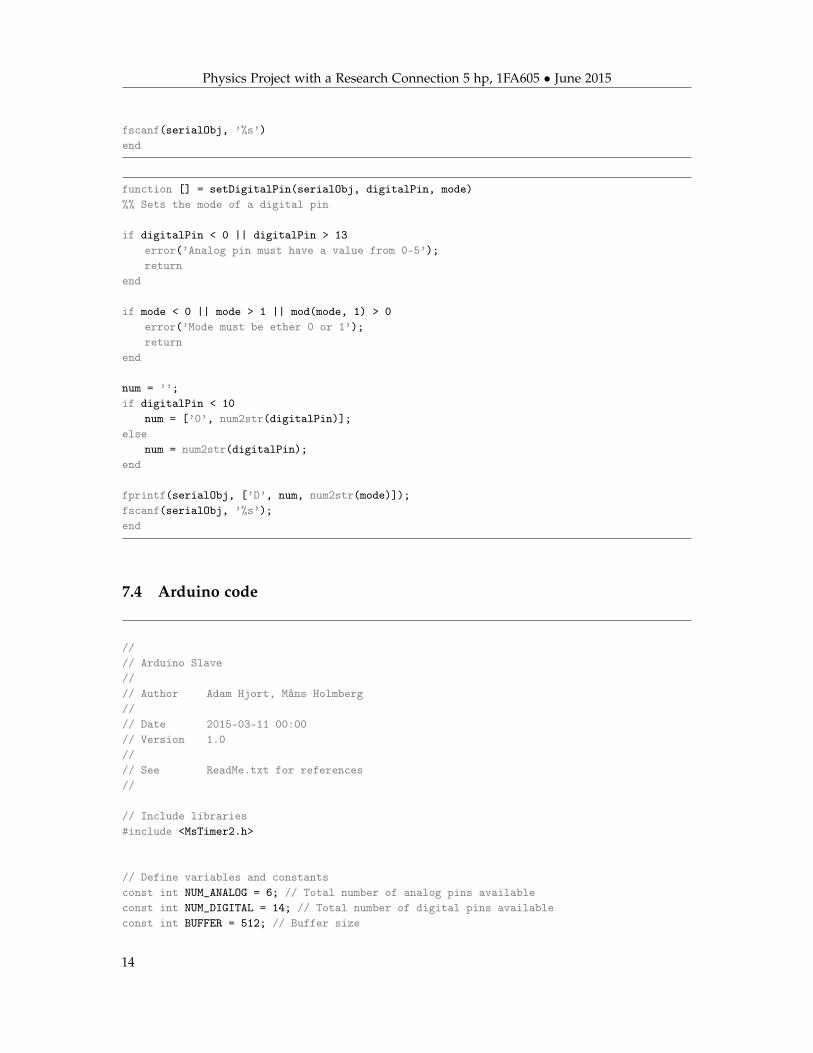
fscanf(serialObj, ’%s’)end
function [] = setDigitalPin(serialObj, digitalPin, mode)%% Sets the mode of a digital pin
if digitalPin < 0 || digitalPin > 13error(’Analog pin must have a value from 0-5’);return
end
if mode < 0 || mode > 1 || mod(mode, 1) > 0error(’Mode must be ether 0 or 1’);return
end
num = ’’;if digitalPin < 10
num = [’0’, num2str(digitalPin)];else
num = num2str(digitalPin);end
fprintf(serialObj, [’D’, num, num2str(mode)]);fscanf(serialObj, ’%s’);end
7.4 Arduino code
//// Arduino Slave//// Author Adam Hjort, Måns Holmberg//// Date 2015-03-11 00:00// Version 1.0//// See ReadMe.txt for references//
// Include libraries#include <MsTimer2.h>
// Define variables and constantsconst int NUM_ANALOG = 6; // Total number of analog pins availableconst int NUM_DIGITAL = 14; // Total number of digital pins availableconst int BUFFER = 512; // Buffer size
14
Physics Project with a Research Connection 5 hp, 1FA605 • June 2015
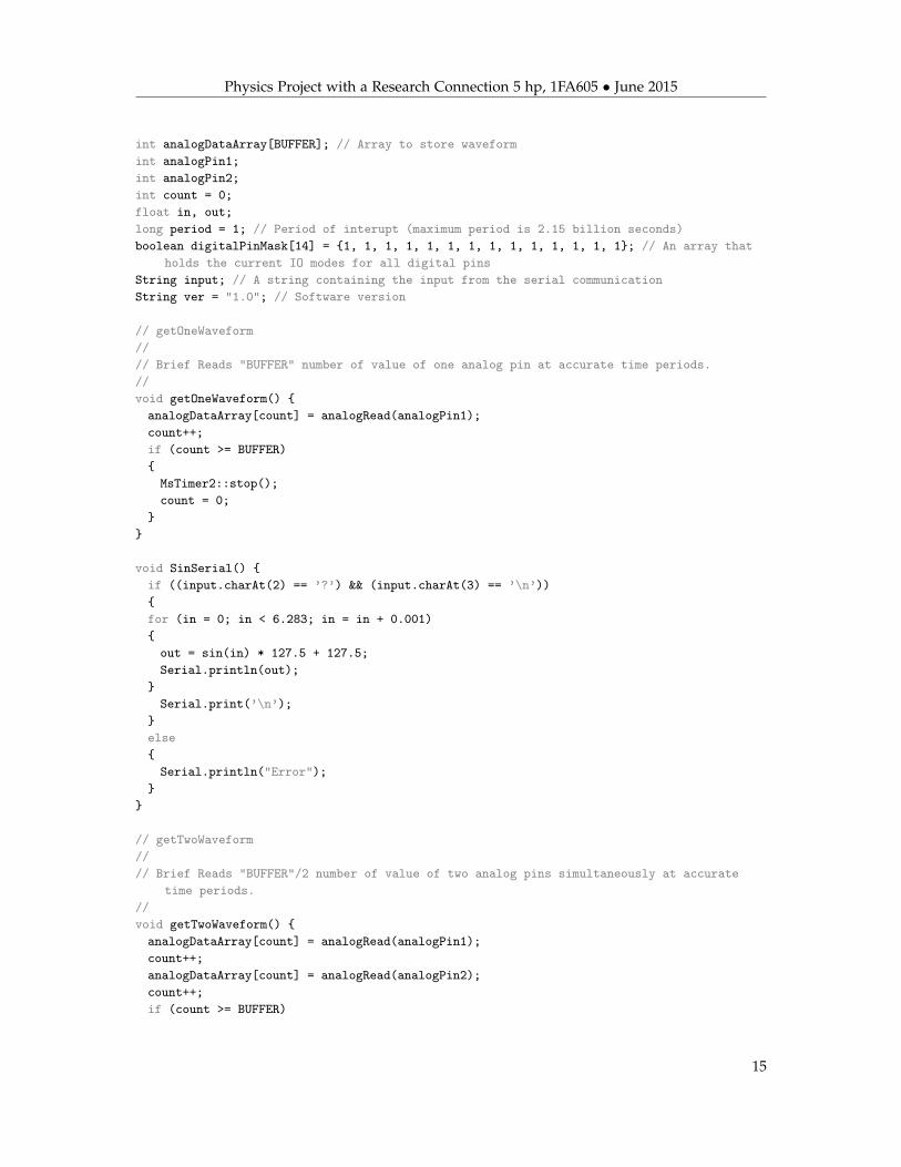
int analogDataArray[BUFFER]; // Array to store waveformint analogPin1;int analogPin2;int count = 0;float in, out;long period = 1; // Period of interupt (maximum period is 2.15 billion seconds)boolean digitalPinMask[14] = {1, 1, 1, 1, 1, 1, 1, 1, 1, 1, 1, 1, 1, 1}; // An array that
holds the current IO modes for all digital pinsString input; // A string containing the input from the serial communicationString ver = "1.0"; // Software version
// getOneWaveform//// Brief Reads "BUFFER" number of value of one analog pin at accurate time periods.//void getOneWaveform() {analogDataArray[count] = analogRead(analogPin1);count++;if (count >= BUFFER){MsTimer2::stop();count = 0;
}}
void SinSerial() {if ((input.charAt(2) == ’?’) && (input.charAt(3) == ’\n’)){for (in = 0; in < 6.283; in = in + 0.001){out = sin(in) * 127.5 + 127.5;Serial.println(out);
}Serial.print(’\n’);
}else{Serial.println("Error");
}}
// getTwoWaveform//// Brief Reads "BUFFER"/2 number of value of two analog pins simultaneously at accurate
time periods.//void getTwoWaveform() {analogDataArray[count] = analogRead(analogPin1);count++;analogDataArray[count] = analogRead(analogPin2);count++;if (count >= BUFFER)
15

Physics Project with a Research Connection 5 hp, 1FA605 • June 2015
{MsTimer2::stop();count = 0;
}}
// analogSerial//// Brief Returns a single value from chosen analog channel.//void analogSerial() {if ((input.charAt(1) > ’/’) && (input.charAt(1) < NUM_ANALOG + ’0’)
&& (input.charAt(2) == ’?’) && (input.charAt(3) == ’\n’)){input.remove(2, 2);Serial.print(input);Serial.print(" ");Serial.print(analogRead(input.charAt(1) - ’0’));Serial.print("\n");
}else{Serial.println("Error");
}}
// waveformSerial//// Brief Retunrs a waveform from chosen analog channel.//void waveformSerial() {if ((input.charAt(1) > ’/’) && (input.charAt(1) < NUM_ANALOG + ’0’)
&& (input.charAt(2) == ’?’) && (input.charAt(3) == ’\n’)){analogPin1 = input.charAt(1) - ’0’;MsTimer2::set(period, getOneWaveform);MsTimer2::start();delay(BUFFER * period);input.remove(2, 2);Serial.print(input);for (int i = 0; i < BUFFER; i++){Serial.print(" ");Serial.print(analogDataArray[i]);analogDataArray[i] = 0;
}Serial.print(’\n’);
}else{Serial.println("Error");
}
16
Physics Project with a Research Connection 5 hp, 1FA605 • June 2015
}
// correlationSerial//// Brief Retunrs two waveforms from chosen analog channels, that was capturet
simultaneously.//void correlationSerial() {if ((input.charAt(1) > ’/’) && (input.charAt(1) < NUM_ANALOG + ’0’)
&& (input.charAt(2) > ’/’) && (input.charAt(2) < NUM_ANALOG + ’0’)&& (input.charAt(1) != input.charAt(2))&& (input.charAt(3) == ’?’) && (input.charAt(4) == ’\n’))
{analogPin1 = input.charAt(1) - ’0’;analogPin2 = input.charAt(2) - ’0’;MsTimer2::set(period, getTwoWaveform);MsTimer2::start();delay(BUFFER * period);input.remove(3, 2);Serial.print(input);for (int i = 0; i < BUFFER; i += 2){Serial.print(" ");Serial.print(analogDataArray[i]);analogDataArray[i] = 0;
}for (int i = 1; i < BUFFER; i += 2){Serial.print(" ");Serial.print(analogDataArray[i]);analogDataArray[i] = 0;
}Serial.print(’\n’);
}else{Serial.println("Error");
}}
// periodSerial//// Brief Can be used to either get or set the sampling period.//void periodSerial() {// Returns the sampling periodint inputLength = input.length();if ((input.charAt(1) == ’?’) && (input.charAt(2) == ’\n’)){input.remove(1, 2);Serial.print(input);Serial.print(" ");
17

Physics Project with a Research Connection 5 hp, 1FA605 • June 2015
Serial.println(period);}// Sets the sampling periodelse if (inputLength > 2 && (input.charAt(inputLength - 1) == ’\n’)){input.remove(0, 1);boolean isCorrect = true;for (int i = 0; i < inputLength - 2; i++){if (input.charAt(i) < ’/’ || input.charAt(i) > ’:’){isCorrect = false;break;
}}if (isCorrect){long tempPeriod = input.toInt();if (tempPeriod > 0){Serial.print("P");Serial.println(tempPeriod);period = tempPeriod;
}else{Serial.println("Error");
}}else{Serial.println("Error");
}}else{Serial.println("Error");
}}
// maskSerial//// Brief Can be used to either get or set the IO mask of the digital pins (1 = input 0 =
output).//void maskSerial() {// Returns the IO mask for the digital pinsint inputLength = input.length();if ((input.charAt(1) == ’?’) && (input.charAt(2) == ’\n’)){input.remove(1, 2);Serial.print(input);
18

Physics Project with a Research Connection 5 hp, 1FA605 • June 2015
Serial.print(" ");for (int i = 1; i < NUM_DIGITAL + 1; i++){if (digitalPinMask[i] == 0){Serial.print("0");
}else{Serial.print("1");
}}Serial.print(’\n’);
}// Sets the IO mask for the digital pinselse if (input.charAt(NUM_DIGITAL + 1) == ’\n’){boolean isCorrect = true;for (int i = 1; i < NUM_DIGITAL + 1; i++){if ((input.charAt(i) != ’0’) && (input.charAt(i) != ’1’)){isCorrect = false;break;
}}if (isCorrect == true){input.remove(NUM_DIGITAL + 1, 1);for (int i = 0; i < NUM_DIGITAL + 1; i++){digitalPinMask[i] = input.charAt(i) - ’0’;pinMode(i, !digitalPinMask[i]);
}Serial.println(input);
}else{Serial.println("Error");
}}// Set the IO status of a specific digital pinelse if ((inputLength > 3) && (inputLength < 6) && (input.charAt(inputLength - 1) ==
’\n’)){input.remove(0, 1);input.remove(inputLength - 1, 1);boolean isCorrect = true;for (int i = 0; i < inputLength - 2; i++){if (input.charAt(i) < ’/’ || input.charAt(i) > ’:’){
19

Physics Project with a Research Connection 5 hp, 1FA605 • June 2015
isCorrect = false;break;
}}int value = input.charAt(inputLength - 3) - ’0’;input.remove(inputLength - 3, 1);if (isCorrect){int digitalPin = input.toInt();if ((digitalPin >= 0) && (digitalPin < NUM_DIGITAL) && (value == 0 || value == 1)){Serial.print("M");Serial.print(digitalPin);Serial.println(value);digitalPinMask[digitalPin + 1] = value;pinMode(digitalPin, !value);
}else{Serial.println("Error");
}}else{Serial.println("Error");
}}else{Serial.println("Error");
}}
// digitalSerial//// Brief Can be used to either get or set the value of a digital pin (1 = low 0 = high).//void digitalSerial() {// Sets the value of a specific digital pinint inputLength = input.length();if ((inputLength > 3) && (inputLength < 6) && (input.charAt(inputLength - 1) == ’\n’)
&& (input.charAt(inputLength - 2) != ’?’)){input.remove(0, 1);input.remove(inputLength - 1, 1);boolean isCorrect = true;for (int i = 0; i < inputLength - 2; i++){if (input.charAt(i) < ’/’ || input.charAt(i) > ’:’){isCorrect = false;break;
20
Physics Project with a Research Connection 5 hp, 1FA605 • June 2015
}}int value = input.charAt(inputLength - 3) - ’0’;input.remove(inputLength - 3, 1);if (isCorrect){int digitalPin = input.toInt();if ((digitalPin >= 0) && (digitalPin < NUM_DIGITAL) && (value == 0 || value == 1)){Serial.print("D");Serial.print(digitalPin);Serial.println(value);digitalWrite(digitalPin, value);
}else{Serial.println("Error");
}}else{Serial.println("Error");
}}// Returns the value of a specific digital pinelse if ((inputLength > 3) && (inputLength < 6) &&
(input.charAt(inputLength - 2) == ’?’) && (input.charAt(inputLength - 1) ==’\n’))
{input.remove(0, 1);input.remove(inputLength - 3, 2);boolean isCorrect = true;for (int i = 0; i < inputLength - 3; i++){if (input.charAt(i) < ’/’ || input.charAt(i) > ’:’){isCorrect = false;break;
}}if (isCorrect){int digitalPin = input.toInt();if ((digitalPin >= 0) && (digitalPin < NUM_DIGITAL)){Serial.print("D");Serial.print(digitalPin);Serial.print(" ");Serial.println(digitalRead(digitalPin));
}else{
21
Physics Project with a Research Connection 5 hp, 1FA605 • June 2015
Serial.println("Error");}
}else{Serial.println("Error");
}}else{Serial.println("Error");
}}
// getAllDigital//// Brief Returns the values of all digital pins (1 = input 0 = output).//void getAllDigital() {if ((input.charAt(1) == ’?’) && (input.charAt(2) == ’\n’)){input.remove(1, 2);Serial.print(input);Serial.print(" ");for (int i = 0; i < NUM_DIGITAL; i++){Serial.print(digitalRead(i));
}Serial.print(’\n’);
}else{Serial.println("Error");
}}
// versionSerial//// Brief Returns current software version//void versionSerial() {if ((input.charAt(1) == ’?’) && (input.charAt(2) == ’\n’)){input.remove(1, 1);Serial.print("V ");Serial.println(ver);
}else{Serial.println("Error");
}}
22

Physics Project with a Research Connection 5 hp, 1FA605 • June 2015
// Setup//// Brief Setup//void setup() {// SetupbitClear(ADCSRA, ADPS0); // Running with high speed clock (set prescale to 16)bitClear(ADCSRA, ADPS1);bitSet(ADCSRA, ADPS2);Serial.begin(115200); // Sets Serial baud rateanalogReference(EXTERNAL); // Configures the reference voltage used for analog input
}
// Loop//// Brief Loop//void loop() {while (Serial.available() > 0)// Adds input char to the string "input" while there still is characters to read
{char lastRecived = Serial.read();input += lastRecived; // Adds last recived char to "input"
if (lastRecived == ’\n’)// Continue to do stuff if the last character recived was a new line
{switch (input[0]) {case ’A’:analogSerial();break;
case ’W’:waveformSerial();break;
case ’C’:correlationSerial();break;
case ’P’:periodSerial();break;
case ’M’:maskSerial();break;
case ’D’:digitalSerial();break;
case ’Q’:getAllDigital();break;
case ’S’:SinSerial();
23

Physics Project with a Research Connection 5 hp, 1FA605 • June 2015
break;case ’V’:versionSerial();break;
case ’?’:// Returns some information about this deviceSerial.println("Arduino slave");Serial.print("Version ");Serial.println(ver);Serial.println("Uppsala University, Sweden");Serial.println("Software written by Adam Hjort and Mans Holmberg");break;
default:Serial.println("Error");break;
}input = ""; // Clear recieved buffer.
}}
}
24