measurements of the young's modulus of hydroxide catalysis...
TRANSCRIPT

Phelps, M., van Veggel, A.-M., Hough, J., Messenger, C., Hughes, D., Cunningham, W.,
Haughian, K. and Rowan, S. (2018) Measurements of the Young’s modulus of
hydroxide catalysis bonds, and the effect on thermal noise in ground-based gravitational
wave detectors. Physical Review D, 97(10), 102004.
There may be differences between this version and the published version. You are
advised to consult the publisher’s version if you wish to cite from it.
http://eprints.gla.ac.uk/162872/
Deposited on: 25 May 2018
Enlighten – Research publications by members of the University of Glasgow
http://eprints.gla.ac.uk

Measurements of the Young’s modulus of hydroxide catalysis bonds, and the effect onthermal noise in ground-based gravitational wave detectors
Margot Phelps1, Anna-Maria van Veggel1, James Hough1, Chris Messenger1,
David Hughes2, William Cunningham1, Karen Haughian1, and Sheila Rowan1
1 SUPA, School of Physics and Astronomy, The University of Glasgow, Glasgow, G12 8QQ, UK and2 SUPA, Institute of Thin Films, Sensors, and Imaging,
University of the West of Scotland, Paisley, UK
With the outstanding results from the detection and observation of gravitational waves fromcoalescing black holes and neutron star inspirals, it is essential that pathways to further improve thesensitivities of the LIGO and VIRGO detectors are explored. There are a number of factors thatpotentially limit the sensitivities of the detectors. One such factor is thermal noise, a component ofwhich results from the mechanical loss in the bond material between the silica fibre suspensions andthe test mass mirrors. To calculate its magnitude, the Young’s modulus of the bond material hasto be known with reasonable accuracy. In this paper we present a new combination of ultrasonictechnology and Bayesian analysis to measure the Young’s modulus of hydroxide catalysis bondsbetween fused silica substrates. Using this novel technique, we measure the bond Young’s modulusto be 18.5±2.0
2.3GPa. We show that by applying this value to thermal noise models of bonded testmasses with suitable attachment geometries, a reduction in suspension thermal noise consistent withan overall design sensitivity improvement allows a factor of 5 increase in event rate to be achieved.
I. INTRODUCTION
In 2015, a gravitational wave (GW) signal from a bi-nary black hole merger passed through the arms of theAdvanced LIGO (aLIGO) interferometers, resulting inthe first direct detection of gravitational waves [1]. Thislong-awaited detection of GWs made worldwide news onehundred years after Einstein first predicted them in 1916[2]. Since then there have been four more binary blackhole inspiral events, as well as the ground-breaking GWdetection of a neutron star inspiral [3–7]. Requiring 50years of technological development before the first de-tection, the extremely low amplitudes of GWs have al-ways proved to be a challenge. To detect these signals,ground-based detectors like aLIGO and VIRGO need tobe sensitive to changes in distance of close to 10−19 m[8] between freely suspended test masses spaced up to4 km apart. Furthermore, for a detector to reliably mea-sure such small displacement changes, it must be isolatedas much as possible from all environmental effects thatcause movement. Ground-based GW systems face an ex-tensive list of fundamental and technical noise sourcesthat limit their performance.In particular the movement of particles driven by ther-mal energy, known as thermal noise, is a limiting noisesource in ground-based detectors [9]. To mitigate thisthe optics, suspensions, and jointing material must allbe constructed of low mechanical dissipation materials.This minimises the off-resonance thermal noise describedby the Fluctuation Dissipation Theorem [10] that im-pacts detector sensitivity.Hydroxide catalysis bonding (HCB), a method of cre-ating chemical bonds between oxides or oxidisable ma-terials with an aqueous hydroxide solution, has beenthe preferred technique for creating the necessary quasi-monolithic optic and suspension systems for current and
future ground-based GW detectors [11–15]. This is dueto the ability of HCBs to form strong, low noise, ultra-high vacuum compatible interfaces that are applicableboth at room temperature [16] and cryogenic tempera-tures [17, 18]. These bonds are currently a core technol-ogy in all operating ground-based detectors, and as suchtheir material properties have to be well understood. Inparticular the density, Poisson ratio, and Young’s modu-lus are necessary to calculate thermal noise. The densityof HCBs was calculated previously [19] and the Poissonratio is inferred to be the same as fused silica. TheYoung’s modulus proved to be challenging to charac-terise due to the bond being thin and in-accessible touse direct contact measurement approaches such as nano-indentation, which is used to determine the Young’s mod-ulus of other materials and coatings [20].One measurement of a HCB’s Young’s modulus is avail-able in the literature, a value of 7.9 GPa [21]. Here abond was altered to make it artificially thick to allow fora nano-indentation measurement. This value has histor-ically been used to determine thermal noise arising fromthe bonds for aLIGO [22].As the sensitivity of detectors improves, it is necessary toattain more accurate values for the bond properties thatdirectly contribute to the overall thermal noise of GWdetectors. Thus a non-destructive technique for attain-ing Young’s modulus values of hydroxide catalysis bondsis outlined in this paper, as well as the results and theirimpact on thermal noise budgets of Advanced LIGO andto the proposed aLIGO A+ upgrade [23].
II. THEORY OF ULTRASONICMEASUREMENTS
The transmission and reflection of ultrasonic wavesthrough materials can be used as a non-destructive

2
method of probing hidden properties [24]. This tech-nology is explored here as a non-destructive means todetermine the Young’s modulus of HCBs.An acoustic wave that passes from one medium to an-other can be expressed in terms of the acoustic impedanceof each medium. The percentage of an incident wave re-flected off a medium change from silica to air is given inEq.1, where Z is the characteristic acoustic impedanceof the medium passed through. Z = ρ · v where v is theacoustic velocity and ρ the density of the medium, wecalculate Zair = 331.4 m/s·1.225 kg/m3 = 406 Rayls andZsilica = 5931 m/s·2200 kg/m3 = 13 · 106 Rayls
Rsilica,air =
∣∣∣∣Zair − Zsilica
Zsilica + Zair
∣∣∣∣ =
∣∣∣∣331.4− 13 · 106
331.4 + 13 · 106
∣∣∣∣ = 0.99
(1)This allows the assumption that the measured amplitudeof the silica-to-air reflection of each sample is 99% of theincident wave, and is used as a proxy for the input signal.An expression for an acoustic pulse reflected from a thinembedded layer that takes into account the layer thick-ness is needed to calculate the signal from the embed-ded HCB. To determine this value we follow the tech-nique outlined in Physical Acoustics [25]. We derivean equation for Rbond from the complex pressure am-plitudes of incident waves, Pincident = Aei(wt−kx) andreflected waves, Preflect = Bei(wt+kx). Applying acousticimpedance continuity boundary conditions at the startand end of the layer, x = 0 and x = L the followingequation is obtained
Rbond =i(Z2
Z1− Z1
Z2) sin(k2L)
2 cos(k2L) + i(Z2
Z1+ Z1
Z2) sin(k2L)
(2)
The first and third mediums are both fused silica, Z1 =Z3. The second medium, the hydroxide catalysis bond,is represented by Z2. L is the bond thickness and k2 isthe wave number of the bond medium.We may use the approximation L → 0 as the thicknessof the bond, L, is of order 100 nm thick while the sub-strates are each 5 mm thick or more, sin(k2L) ≈ k2L andcos(k2L) ≈ 1− (k2L)2/2. This simplifies the equation to
Rbond =i(Z2
Z1− Z1
Z2)k2L
2(1− (k2L)2
2 ) + i(Z2
Z1+ Z1
Z2)k2L
(3)
Assuming the density of HCBs and fused silica are thesame, the impedance terms simplify to ratios of theYoung’s moduli, Z1
Z2≈√
(E2/E1). The wave num-ber k can also be expressed in terms of acoustic ve-locity and the frequency of the ultrasonic transducer,k2 = 2π/λ2 = 2fπ/v2. Additionally dropping L andL2 terms in the denominator due to the small L valuesgives us
Rbond ≈ i
[√E2
E1−√E1
E2
]√ρ
E2πfL (4)
For HCB values of L =7 µm, Eq.2-4 differ by < 2%. Eq.4is used where L <100 nm, as Rbond is expressed only interms of the variable of interest E2 and of known or mea-sured values E1, ρ, pulse frequency f and HCB thickness,L.
III. EXPERIMENTAL METHOD
In this experiment an ultrasonic transducer with a cen-tre frequency 12 MHz and a bandwidth of 6-15 MHz, wascontacted with glycerine to one side of an HCB bondedfused silica doublet. A schematic of the set-up is shownin Fig. 1. As indicated in the schematic, the reflected
FIG. 1. Experiment schematic: The transducer sends out anultrasonic pulse that travels through the fused silica sampleon the right. Signals are reflected back from the embeddedHCB and rear face of the silica sample, received by the sametransducer and recorded.
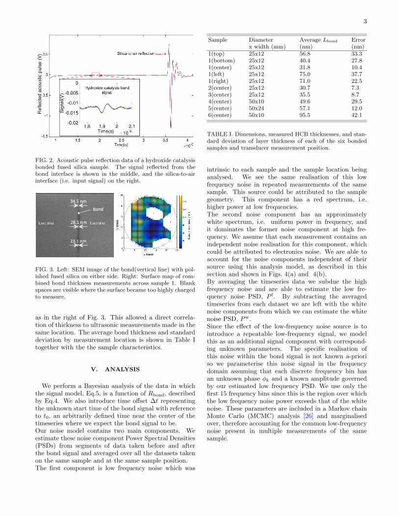
signals were received back to the same transducer thatsent the pulse. The amplitudes and phase of the re-flected signals were recorded for each measurement on a200 MHz oscilloscope and averaged 4096 times to attainthe datasets shown in Fig.2. An un-bonded fused silicacylinder 12 mm long was measured as a calibration sam-ple. The bonded samples were created by joining two6 mm long fused silica discs together with a hydroxidecatalysis bond in the middle, as shown in the schematicin Fig. 1. Six different bonded fused silica discs of thistype were measured in this experiment. Acoustic datafor one of the bonded samples is shown in Fig.2.
IV. BOND THICKNESS MEASUREMENTS
The reflection equation Rbond is linearly dependent onbond thickness L. To measure this directly, the bondedsamples were cut into several slices perpendicular to thebond plane, polished and coated with gold (to reducesurface charging) then imaged in an FEI Nova 200 Dualbeam FIB system scanning electron microscope (SEM),as in the left of Fig. 3.
All the SEM results were combined via linear interpo-lation to produce maps of each sample’s HCB thickness,
3
FIG. 2. Acoustic pulse reflection data of a hydroxide catalysisbonded fused silica sample. The signal reflected from thebond interface is shown in the middle, and the silica-to-airinterface (i.e. input signal) on the right.
FIG. 3. Left: SEM image of the bond(vertical line) with pol-ished fused silica on either side. Right: Surface map of com-bined bond thickness measurements across sample 1. Blankspaces are visible where the surface became too highly chargedto measure.
as in the right of Fig. 3. This allowed a direct correla-tion of thickness to ultrasonic measurements made in thesame location. The average bond thickness and standarddeviation by measurement location is shown in Table Itogether with the the sample characteristics.
V. ANALYSIS
We perform a Bayesian analysis of the data in whichthe signal model, Eq.5, is a function of Rbond, describedby Eq.4. We also introduce time offset ∆t representingthe unknown start time of the bond signal with referenceto t0, an arbitrarily defined time near the center of thetimeseries where we expect the bond signal to be.Our noise model contains two main components. Weestimate these noise component Power Spectral Densities(PSDs) from segments of data taken before and afterthe bond signal and averaged over all the datasets takenon the same sample and at the same sample position.The first component is low frequency noise which was
Sample Diameter Average Lbond Errorx width (mm) (nm) (nm)
1(top) 25x12 56.8 33.31(bottom) 25x12 40.4 27.81(center) 25x12 31.8 10.41(left) 25x12 75.0 37.71(right) 25x12 71.0 22.52(center) 25x12 30.7 7.33(center) 25x12 35.5 8.74(center) 50x10 49.6 29.55(center) 50x24 57.1 12.06(center) 50x10 95.5 42.1
TABLE I. Dimensions, measured HCB thicknesses, and stan-dard deviation of layer thickness of each of the six bondedsamples and transducer measurement position.
intrinsic to each sample and the sample location beinganalysed. We see the same realisation of this lowfrequency noise in repeated measurements of the samesample. This source could be attributed to the samplegeometry. This component has a red spectrum, i.e.higher power at low frequencies.The second noise component has an approximatelywhite spectrum, i.e. uniform power in frequency, andit dominates the former noise component at high fre-quency. We assume that each measurement contains anindependent noise realisation for this component, whichcould be attributed to electronics noise. We are able toaccount for the noise components independent of theirsource using this analysis model, as described in thissection and shown in Figs. 4(a) and 4(b).By averaging the timeseries data we subdue the highfrequency noise and are able to estimate the low fre-quency noise PSD, P l. By subtracting the averagedtimeseries from each dataset we are left with the whitenoise components from which we can estimate the whitenoise PSD, Pw.Since the effect of the low-frequency noise source is tointroduce a repeatable low-frequency signal, we modelthis as an additional signal component with correspond-ing unknown parameters. The specific realisation ofthis noise within the bond signal is not known a-prioriso we parameterise this noise signal in the frequencydomain assuming that each discrete frequency bin hasan unknown phase φk and a known amplitude governedby our estimated low frequency PSD. We use only thefirst 15 frequency bins since this is the region over whichthe low frequency noise power exceeds that of the whitenoise. These parameters are included in a Markov chainMonte Carlo (MCMC) analysis [26] and marginalisedover, therefore accounting for the common low-frequencynoise present in multiple measurements of the samesample.

4
(a) Reflected bond signal and model components vs. time. (b) Reflected bond signal and model components vs. frequency
FIG. 4. Time-domain and frequency-domain examples of the reflected bond signal and corresponding signal components areshown in Figs. 4(a) and 4(b). In both figures, the first term from our model Eq.5 is plotted in dark blue, shown with thecommon low frequency noise term, the second term in Eq.5 in cyan, the combined signal and noise models, s in black. Themeasured data, b is shown here in red. The residuals are also shown in dark green in Fig. 4(a). Each curve represents a set of
curves drawn from the posterior distribution on the unknown parameters R, dt, ~φ.
Our signal model can be represented in the frequencydomain by
s(f ;R,∆t, ~φ) = xRife2πif∆t +
15∑k=1
1
2
√NdtP l
keiφk (5)
where Rif = Rbond from Eq.4, the discrete Fourier trans-form of the input pulse timeseries data is defined by x,the frequency is defined as f , the time offset is ∆t, thetimeseries sampling interval is dt, and the number of sam-ples in the input signal timeseries is N .We use uniform prior probability distributions on the pa-
rameters t0, Rbond, and noise phases ~φ with the followinglimits. The start time t0 ranges between 0 and 0.5 s, andis long enough to fully encompass the reflected pulse sig-nal. The noise phases each ranged from 0 to 2π andRbond ranges between 0 and an amplitude correspondingto the maximum allowed E2 value. Since the bond is asilicate material it should not exceed the Youngs mod-ulus of fused silica, 72 GPa. The measured HCB thick-nesses and associated statistical error are interpreted asa Gaussian prior for L in which the measured value andthe uncertainties represent the mean and standard devi-ation of the Gaussian respectively.The likelihood function, based on a Gaussian noisemodel, is defined as
p(b|R,∆t, ~φ) =∏m
N−1∏k=0
2
πNdtPwmkexp
(−|bmk − smk|
2
NdtPwmk
)(6)
where m indexes over sets of measurements for which thesample and sample location were the same. The quantityb is the Fourier transform of the measured reflected bondsignal.After performing an MCMC analysis to obtain samples
from the posterior probability distribution on the quan-tity R, we combine this with our knowledge of the bondthickness L to generate the posterior on the Youngs mod-ulus of HCBs, E2. This is done using
p(E2|b) ∝n∑j
p(L = L(E2, Rj))
∣∣∣∣ dLdE2
∣∣∣∣ (7)
where the sum is over posterior R samples and the deriva-tive is the Jacobian required to transform the integralover bond thickness L into one over E2. This derivativeand the function L(E2, R) are obtained via Eq.4.A time-domain example of the reflected bond signaland corresponding signal and components is shown inFig. 4(a). The sum of the model and low frequency com-mon noise component, s, match the measured reflectionsignal with residuals consistent with those expected fromthe white noise PSD. In Figure 4(b) the strength of thebond signal against the noise background can be seen inthe frequency domain.Finally a posterior on the Youngs modulus of the bonds,E2, is obtained from each group of measured samplesand is shown in Fig. 5. These posteriors are statisticallyindependent and therefore their product is used to ob-tain an improved result. All input posteriors are broadlyconsistent and the final posterior has support from allinputs. Despite the apparent spread seen in the poste-rior distributions they all share common support for theregion under the final combined posterior. Thus we ob-tain a best estimate value with a 90% confidence range of18.5±2.0
2.3GPa for the Youngs modulus of hydroxide catal-ysis bonds.

5
FIG. 5. Individual E2 posteriors of each measured sample.The final combined posterior is shown in black and a 90%confidence level is shown in blue.
VI. IMPACT ON THE THERMAL NOISE OFGW DETECTORS
Thermal noise affects instrument sensitivity across itsmost sensitive frequency band, 10-100 Hz [27]. The newYoung’s modulus value was used to assess the bond’s con-tribution to thermal noise of GW detectors.This approach utilised Levin’s method [28] to calculatethermal noise as previously used by Cunningham et al[22], who published a figure of 5.4 · 10−22m/
√Hz. Re-
evaluating these aLIGO models using the updated valueof 18.5 GPa for the HCB Young’s modulus gives a newvalue of 5.8 · 10−22m/
√Hz.
Although this represents a 7% increase in the estimatedexcess thermal noise associated with the bonds, both theoriginal and re-calculated values are below the aLIGOthermal noise budget level of 7 · 10−22m/
√Hz [29]. Fu-
ture detectors and detector upgrades will have differenttest mass materials, geometries, operating temperatures,and more stringent thermal noise requirements. In thesecases estimating the bond’s thermal noise contribution asaccurately as possible becomes much more important toensure this technology continues to meet detector designrequirements. One example of this is addressed in thefollowing section, for a bonded test mass geometry thatis suitable for a potential upgrade to aLIGO.
A. A+ aLIGO upgrade ear design and FE thermalnoise analysis
A+, an incremental upgrade to existing aLIGOdetectors is currently being developed. This upgradewill make use of existing aLIGO infrastructure andtechnologies and aims for a 1.7x increase in range overaLIGO, using the binary neutron star inspirals as a
benchmark[23]. In order to meet the sensitivity requiredfor A+ a few key parameters are revisited. The coatingthermal noise budget is proposed to be half of aLIGO,utilising improvements to coating technologies. Theuse of frequency dependent squeezing is also proposedto lower the quantum noise level. With the successfulimplementation of the planned upgrades, the A+ designstrain sensitivity curve would improve enough attain the1.7x increase in range over aLIGO.This increase in range demands a higher detectorsensitivity and thus a lower bond thermal noise budgetof 4 · 10−22m/
√Hz, based on a technical noise budget
of 10% of the total thermal noise at 100 Hz. Here weinvestigate an updated ear design for the A+ upgrade,with the aim of further reducing the bond’s contributionto detector thermal noise to meet the requirements ofthe upgrade. The most straightforward way of doing thiswas to reduce the surface area of the bonds by reducingthe size of the ears on the masses, in comparison tothe original aLIGO ear design [30]. This was done bygoing from two ears per mass to four ears. The ears arepositioned on the mass so that the horns are the samedistance away from each other as they are in aLIGO,now with a space between two ears instead of a singlelong ear. This and an angled ear geometry allow for areduction in area of 34%, while keeping a wide marginof safety in terms of stress on the ear and bonds.A few different geometries of new ears were investigated.A small, angled ear was selected as the best combinationof lower thermal noise, bond strength, and safe deforma-tion of the ear horns under load as shown on the rightof Fig. 6. In this design two ears are positioned on bothsides of an A+ mass, keeping the horn separation thesame as aLIGO, with a space between two smaller earsinstead of the long single aLIGO ear, as shown on theleft in Fig. 6.
To understand how the new HCB Young’s modulus
FIG. 6. Comparisons of ear design geometries for aLIGO andA+
affects noise levels, we have modelled the thermal noisecontribution of the new bonded ear design in Figure 6and compared it to a proposed A+ sensitivity curve.This A+ ear design offers smaller ears while keepingsimilar stresses and horn deformation under gravity tothe aLIGO design. The horn separation and standoffdistance from the test mass also remain the same as the

6
FIG. 7. FE model of an A+ bonded test mass, with the new4 ear design
aLIGO ears. Additionally, this design keeps a safetyfactor of 3 in the bond’s tensile maximum normal stress,a factor based on the ratio of average tensile strength ofHCBs, 16 MPa, and the maximum normal tensile stressin the bond, 5.2 MPa, taking into account a test massload of 40 kg and an ear area that is 34% less per massthen aLIGO ears.The FE model of the selected ear design bonded onto aA+ test mass is shown in Fig. 7. A comparison of thevalues calculated from the ANSYS models of bondedmasses for aLIGO and aLIGO A+ is outlined in Table II.
Parameter of bond per test mass aLIGO A+Horn deformation under gravity (µm) 0.67 0.69Max equivalent stress under gravity (MPa) 9.2 9.3Max tensile stress, normal (MPa) 2.7 5.2Max tensile stress, shear (MPa) ±3.5 ±4.8
Thermal noise, required (·10−22m/√
Hz) 7 4
Thermal noise, modelled (·10−22m/√
Hz) 5.8 3.8
TABLE II. Comparison of aLIGO and aLIGO A+ ear designparameters from FE models
The calculated thermal noise of the new ear design,which assumes a bond thickness of 61 nm, was thereforecalculated from the model to be 3.8 · 10−22m/
√Hz. This
meets the projected A+ thermal noise requirement of4 · 10−22m/
√Hz.
VII. DISCUSSION AND CONCLUSIONS
A new combination of ultrasonic technology andBayesian analysis that measured the material proper-ties of extremely thin layers embedded in brittle sub-strates has been presented here. A best estimate valueof the Young’s modulus of hydroxide catalysis bondsof 18.5±2.0
2.3GPa with a 90% confidence range was at-tained. This new value was used to find an aLIGObond thermal noise of 5.8 ± 0.6 · 10−22m/
√Hz, which
meets the aLIGO bond thermal noise requirement of7 · 10−22m/
√Hz. A new bonded ear design is presented
for the next GW detector upgrade, A+. This design hasa thermal noise for a bonded A+ test mass calculatedhere to be 3.8 · 10−22m/
√Hz, which meets an A+ ther-
mal noise design requirement of 4 · 10−22m/√
Hz. Thisindicates that hydroxide catalysis bonds continue to be agood choice for the construction of quasi-monolithic sus-pensions in GW detectors. In an era of gravitational waveastronomy where the detector sensitivities are pushedever lower and cryogenic technologies are proposed, wewill next use the analysis presented here to probe the ma-terial properties of bonded materials suitable for futurecryogenic detectors, such as sapphire and silicon.
VIII. ACKNOWLEDGEMENTS
The authors would like to thank the UK Scienceand Technology Facilities Council (Grant num-bers ST/I001085/1, ST/J000361/1, ST/L000946/1,ST/N005422/1), the University of Glasgow, the ScottishFunding Council and the Royal Society, A. A. van Veggelis the holder of a Royal Society Dorothy Hodgkin Fel-lowship, grant number DH12001, for financial support.We would like to express our gratitude to our colleaguesin the GEO600 and LIGO Scientific Collaborationfor their interest in this area. The authors gratefullyacknowledge the support of the United States NationalScience Foundation (NSF) for the construction andoperation of the LIGO Laboratory and Advanced LIGOas well as the Science and Technology Facilities Council(STFC) of the United Kingdom, the Max-Planck Society(MPS), and the State of Niedersachsen/Germany forsupport of the construction of Advanced LIGO andconstruction and operation of the GEO600 detector.Additional support for Advanced LIGO was providedby the Australian Research Council. The authors wouldalso like to thank Norna Robertson and Matt Abernathyfor their helpful reviews. LIGO-DOCUMENT-P1700423.

7
[1] B. P. Abbott, others (the LIGO Scientific Collaboration,and VIRGO Collaboration). Observation of gravitationalwaves from a binary black hole merger. Physical ReviewLetters, 2016.
[2] A. Einstein. Die Grundlage der allgemeinen Rela-tivitatstheorie. Annalen der Physik, 354(7):769–822,1916.
[3] B. P. Abbott, others (the LIGO Scientific Collaboration,and VIRGO Collaboration). Gw151226: Observation ofgravitational waves from a 22 solar mass binary blackhole coalescence. Physical Review Letters, 2016.
[4] B. P. Abbott, others (the LIGO Scientific Collaboration,and VIRGO Collaboration). Gw170104: Observation of50 solar mass binary black hole coalescence at redshift0.2. Physical Review Letters, 2017.
[5] B. P. Abbott, others (the LIGO Scientific Collaboration,and VIRGO Collaboration). Gw170814: A three-detectorobservation of gravitational waves from a binary blackhole coalescence. Physical Review Letters, 2017.
[6] B. P. Abbott, others (the LIGO Scientific Collaboration,and VIRGO Collaboration). Gw170817: Observation ofgravitational waves from a binary neutron star inspiral.Physical Review Letters, 2017.
[7] B. P. Abbott, others (the LIGO Scientific Collaboration,and VIRGO Collaboration). Gw170608: Observation ofa 19-solar-mass binary black hole coalescence. Astrophys-ical Journal Letters, 2017.
[8] P.R. Saulson. Fundamentals of Interferometric Gravita-tional Wave Detectors. World Scientific, 1994.
[9] Massimo Bassan, editor. Advanced Interferometerand the Search for Gravitational Waves, volume 404.Springer, 2014.
[10] H. B. Callen and T. A. Welton. Irreversibility and gen-eralized noise. Phys. Rev. 83, 34, 1951.
[11] Harald Luck et al. The upgrade of geo600. In Gravita-tional waves. Proceedings, 8th Edoardo Amaldi Confer-ence, Amaldi 8, New York, USA, June 22-26, 2009.
[12] C Affeldt et al. Advanced techniques in geo 600. Classicaland Quantum Gravity, 27(084003), 2014.
[13] F Acernese et al. Advanced virgo: a second-generationinterferometric gravitational wave detector. Classical andQuantum Gravity, 2014.
[14] G. M. Harry and the LIGO Scientific Collaboration. Ad-vanced ligo: the next generation of gravitational wavedetectors. Classical and Quantum Gravity, 27(8):084006,2010.
[15] Yoichi Aso and others (the KAGRA Collaboration). In-terferometer design of the kagra gravitational wave de-tector. Physical Review D, 2013.
[16] D. H. Gwo. Ultra precise and reliable bonding method:Us6284085B1, 2001.
[17] R. Douglas, A. A. van Veggel, L. Cunningham, K. Haugh-ian, J. Hough, and S. Rowan. Cryogenic and roomtemperature strength of sapphire jointed by hydroxide-catalysis bonding. Classical and Quantum Gravity, 31(045001), 2014.
[18] N. Beveridge, A. A. van Veggel, M. Hendry, P. Murray,R. A. Montgomery, E. Jesse, J. Scott, R. B. Bezensek,L. Cunningham, J. Hough, R. Nawrodt, S. Reid, andS. Rowan. Low-temperature strength tests and sem imag-ing of hydroxide catalysis bonds in silicon. Classical andQuantum Gravity, 2011.
[19] Karen Haughian. Aspects of Materials Research for Ad-vanced and Future Generations of Gravitational WaveDetectors. PhD thesis, University of Glasgow, 2011.
[20] M. R.Abernathy. Mechanical Properties of Coating Ma-terials for Use in the Mirrors of Interferometric Gravita-tional Wave Detectors. PhD thesis, University of Glas-gow, 2012.
[21] E. J. Elliffe. Aspects of Thermal Noise Modeling inGround-Based Gravitational Wave Detetors and Devel-opments of Hydroxide Catalysis Bonding for Space-BasedGravitational Wave Detectors and other Optical Applica-tions. PhD thesis, University of Glasgow, 2005.
[22] L. Cunningham, P.G. Murray, A. Cunningham, E.J. El-liffe, G.D. Hammond, and K. Haughian. Re-evaluationof the mechanical loss factor of hydroxide-catalysis bondsand its significance for the next generation of gravita-tional wave detectors. Physics Letters A, 2010.
[23] M. Zucker. Private communication.[24] Emmanuel P. Papadakis, editor. Ultrasonic Instruments
& Devices. Academic Press, 1999.[25] L. Kinsler et al. Fundamentals of Acoustics 4th Edition.
Wiley, 2000.[26] D. Foreman-Mackey, D. Hogg, D. Lang, and J. Good-
man. emcee: The mcmc hammer. Publications of theAstronomical Society of Pacific, Volume 125, Issue 925,pp. 306, 2013.
[27] S Hild, H Grote, J Degallaix, S Chelkowski, K Danz-mann, A Freise, M Hewitson, J Hough, H Luck, M Pri-jatelj, et al. DC-readout of a signal-recycled gravitationalwave detector. Classical and Quantum Gravity, 26(5):055012, 2009.
[28] Yu. Levin. Internal thermal noise in the ligo test masses:A direct approach. Physical Review D, 1998.
[29] P. Fritschel, D. Coyne, et al. T010075 advanced ligosystems design. Technical report, 2009.
[30] S. M. Aston, M. A. Barton, A. S. Bell, N. Beveridge,B. Bland, A. J. Brummitt, G. Cagnoli, et al. Update onquadruple suspension design for advanced ligo. Classicaland Quantum Gravity, 2012.