measure select granular material in place as the actual
TRANSCRIPT
LAFB WEST GATE DCC Page 1 DIVISION 31/AND OR SECTION 31 00 00
SECTION 31 00 00
EARTHWORK08/08
PART 1 GENERAL
1.1 MEASUREMENT PROCEDURES
1.1.1 Excavation
The unit of measurement for excavation and borrow will be the cubic yard, computed by the average end area method from cross sections taken before and after the excavation and borrow operations, including the excavation for ditches, gutters, and channel changes, when the material is acceptably utilized or disposed of as herein specified. The measurements will include authorized excavation of rock(except for piping trenches that is covered below), authorized excavation of unsatisfactory subgrade soil, and the volume of loose, scattered rocks and boulderscollected within the limits of the work; allowance will be made on the same basis for selected backfill ordered as replacement. The measurement will not include the volume of subgrade material or other material that is scarified or plowed and reusedin-place, and will not include the volume excavated without authorization or the volume of any material used for purposes other than directed. The volume of overburden stripped from borrow pits and the volume of excavation for ditches to drain borrow pits, unless used as borrow material, will not be measured for payment. The measurement will not include the volume of any excavation performed prior to the taking of elevations and measurements of the undisturbed grade.
1.1.2 Piping Trench Excavation
Measure trench excavation by the number of linear feet along the centerline of the trench and excavate to the depths and widths specified for the particular size of pipe. Replace unstable trench bottoms with a selected granular material. Include the additional width at manholes and similar structures, the furnishing, placing and removal of sheeting and bracing, pumping and bailing, and all incidentals necessary to complete the work required by this section.
1.1.3 Rock Excavation for Trenches
Measure and pay for rock excavation by the number of cubic yards of acceptably excavated rock material. Measure the material in place, but base volume on a maximum 30 inches width for pipes 12 inches in diameter or less, and a maximum width of 16 inches greater than the outside diameter of the pipe for pipes over 12 inches in diameter.Provide the measurement to include all authorized overdepth rock excavation as determined by the Contracting Officer. For manholes and other appurtenances, compute volumes of rock excavation on the basis of 1 foot outside of the wall lines of the structures.
LAFB WEST GATE DCC Page 2 DIVISION 31/AND OR SECTION 31 00 00
1.1.4 Topsoil Requirements
Separate excavation, hauling, and spreading or piling of topsoil and related miscellaneous operations will be considered subsidiary obligations of the Contractor, covered under the contract unit price for excavation.
1.1.5 Overhaul Requirements
Allow the unit of measurement for overhaul to be the station-yard. The overhaul distance will be the distance in stations between the center of volume of the overhaul material in its original position and the center of volume after placing, minus the free-haul distance in stations. The haul distance will be measured along the shortest route determined by the Contracting Officer as feasible and satisfactory. Do no measure or waste unsatisfactory materials for overhaul where the length of haul for borrow is within the free-haul limits.
1.1.6 Select Granular Material
Measure select granular material in place as the actual cubic yards replacing wetor unstable material in trench bottoms within the limits shown in authorized overdepth areas. Provide unit prices which include furnishing and placing the granular material, excavation and disposal of unsatisfactory material, and additional requirements for sheeting and bracing, pumping, bailing, cleaning, andother incidentals necessary to complete the work.
1.2 PAYMENT PROCEDURES
Payment will constitute full compensation for all labor, equipment, tools, supplies, and incidentals necessary to complete the work.
1.2.1 Classified Excavation
Classified excavation will be paid for at the contract unit prices per cubic yard for common or rock excavation.
1.2.2 Piping Trench Excavation
Payment for trench excavation will constitute full payment for excavation andbackfilling, including specified overdepth except in rock or unstable trenchbottoms.
1.2.3 Rock Excavation for Trenches
Payment for rock excavation will be made in addition to the price bid for the trenchexcavation, and will include all necessary drilling and blasting and all incidentals necessary to excavate and dispose of the rock. Select granular material, used as backfill replacing rock excavation, will not be paid for separately, but will be included in the unit price for rock excavation.
1.2.4 Unclassified Excavation
Unclassified excavation will be paid for at the contract unit price per cubic yard for unclassified excavation.

LAFB WEST GATE DCC Page 3 DIVISION 31/AND OR SECTION 31 00 00
1.2.5 Classified Borrow
Classified borrow will be paid for at the contract unit prices per cubic yard for common or rock borrow.
1.2.6 Unclassified Borrow
Unclassified borrow will be paid for at the contract unit price per cubic yard for unclassified borrow.
1.2.7 Authorized Overhaul
The number of station-yards of overhaul to be paid for will be the product of numberof cubic yards of overhaul material measured in the original position, multiplied by the overhaul distance measured in stations of 100 feet and will be paid for at the contract unit price per station-yard for overhaul in excess of the free-haul limit as designated in paragraph DEFINITIONS.
1.2.8 Sheeting and Bracing
Sheeting and bracing, when shown or authorized by the Contracting Officer to be left in place, will be paid for as follows:
1.2.8.1 Timber Sheeting
Timber sheeting will be paid for as the number of board feet of lumber below finish grade measured in place prior to backfilling. Include in the measurement sheeting wasted when cut off between the finished grade and 1 foot below the finished grade.
1.2.8.2 Steel Sheeting and Soldier Piles
Steel sheeting, soldier piles, and steel bracing will be paid for according to the number of pounds of steel calculated. Calculate the steel by multiplying the measured in-place length in feet below finish grade by the unit weight of the section in pounds per foot. Obtain unit weight of rolled steel sections from recognized steel manuals.
1.3 CRITERIA FOR BIDDING
Base bids on the following criteria:
a. Surface elevations are as indicated.
b. Pipes or other artificial obstructions, except those indicated, will not be encountered.

LAFB WEST GATE DCC Page 4 DIVISION 31/AND OR SECTION 31 00 00
c. Ground water elevations indicated by the boring log were those existing at the time subsurface investigations were made and do not necessarily represent ground water elevation at the time of construction.
e. Material character is indicated by the boring logs.
f. Hard materials and rock will not be encountered.
1.4 REFERENCES
The publications listed below form a part of this specification to the extent referenced. The publications are referred to within the text by the basic designation only.
AMERICAN ASSOCIATION OF STATE HIGHWAY AND TRANSPORTATION OFFICIALS (AASHTO)
AASHTO T 180 (2015) Standard Method of Test for Moisture-Density Relations of Soils Using a 4.54-kg (10-lb) Rammer and a 457-mm
(18-in.) Drop
AASHTO T 224 (2010) Standard Method of Test for Correction for Coarse Particles in the Soil Compaction Test
AMERICAN WATER WORKS ASSOCIATION (AWWA)
AWWA C600 (2010) Installation of Ductile-Iron Water Mains and Their Appurtenances
AMERICAN WELDING SOCIETY (AWS)
AWS D1.1/D1.1M (2015) Structural Welding Code - Steel
AMERICAN WOOD PROTECTION ASSOCIATION (AWPA)
AWPA C2 (2003) Lumber, Timber, Bridge Ties and Mine Ties - Preservative Treatment by Pressure Processes
AWPA P5 (2015) Standard for Waterborne Preservatives
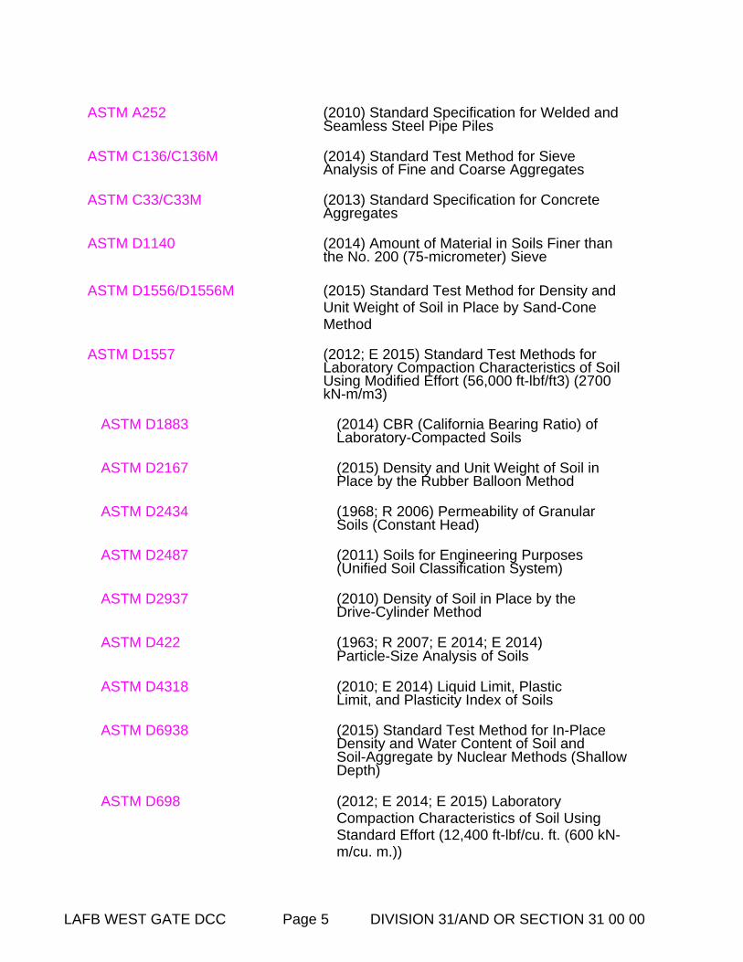
ASTM INTERNATIONAL (ASTM)
ASTM A139/A139M (2004; R 2010) Standard Specification for Electric-Fusion (ARC)-Welded Steel Pipe (NPS 4 and over)
LAFB WEST GATE DCC Page 5 DIVISION 31/AND OR SECTION 31 00 00
ASTM A252 (2010) Standard Specification for Welded and Seamless Steel Pipe Piles
ASTM C136/C136M (2014) Standard Test Method for Sieve Analysis of Fine and Coarse Aggregates
ASTM C33/C33M (2013) Standard Specification for Concrete Aggregates
ASTM D1140 (2014) Amount of Material in Soils Finer than the No. 200 (75-micrometer) Sieve
ASTM D1556/D1556M (2015) Standard Test Method for Density and Unit Weight of Soil in Place by Sand-Cone Method
ASTM D1557 (2012; E 2015) Standard Test Methods for Laboratory Compaction Characteristics of Soil Using Modified Effort (56,000 ft-lbf/ft3) (2700 kN-m/m3)
ASTM D1883 (2014) CBR (California Bearing Ratio) of Laboratory-Compacted Soils
ASTM D2167 (2015) Density and Unit Weight of Soil in Place by the Rubber Balloon Method
ASTM D2434 (1968; R 2006) Permeability of Granular Soils (Constant Head)
ASTM D2487 (2011) Soils for Engineering Purposes (Unified Soil Classification System)
ASTM D2937 (2010) Density of Soil in Place by the Drive-Cylinder Method
ASTM D422 (1963; R 2007; E 2014; E 2014)Particle-Size Analysis of Soils
ASTM D4318 (2010; E 2014) Liquid Limit, Plastic Limit, and Plasticity Index of Soils
ASTM D6938 (2015) Standard Test Method for In-Place Density and Water Content of Soil andSoil-Aggregate by Nuclear Methods (Shallow Depth)
ASTM D698 (2012; E 2014; E 2015) LaboratoryCompaction Characteristics of Soil Using Standard Effort (12,400 ft-lbf/cu. ft. (600 kN-m/cu. m.))
LAFB WEST GATE DCC Page 6 DIVISION 31/AND OR SECTION 31 00 00
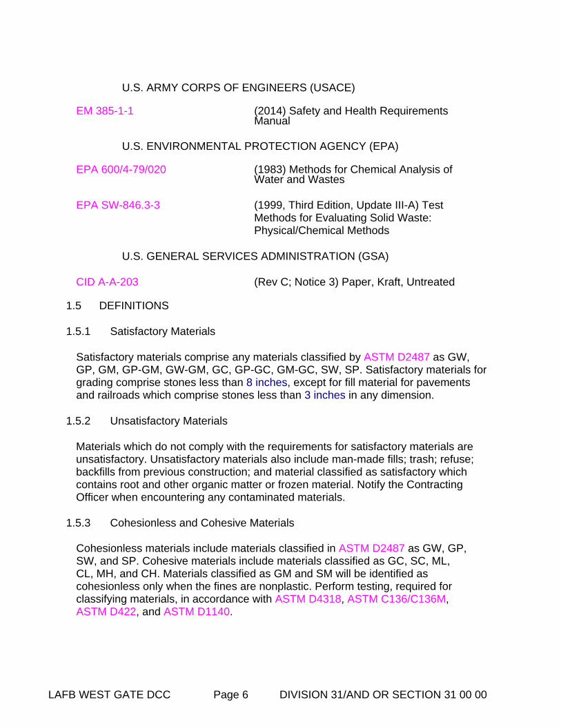
U.S. ARMY CORPS OF ENGINEERS (USACE)
EM 385-1-1 (2014) Safety and Health Requirements Manual
U.S. ENVIRONMENTAL PROTECTION AGENCY (EPA)
EPA 600/4-79/020 (1983) Methods for Chemical Analysis of Water and Wastes
EPA SW-846.3-3 (1999, Third Edition, Update III-A) Test Methods for Evaluating Solid Waste: Physical/Chemical Methods
U.S. GENERAL SERVICES ADMINISTRATION (GSA)
CID A-A-203 (Rev C; Notice 3) Paper, Kraft, Untreated
1.5 DEFINITIONS
1.5.1 Satisfactory Materials
Satisfactory materials comprise any materials classified by ASTM D2487 as GW, GP, GM, GP-GM, GW-GM, GC, GP-GC, GM-GC, SW, SP. Satisfactory materials forgrading comprise stones less than 8 inches, except for fill material for pavements and railroads which comprise stones less than 3 inches in any dimension.
1.5.2 Unsatisfactory Materials
Materials which do not comply with the requirements for satisfactory materials are unsatisfactory. Unsatisfactory materials also include man-made fills; trash; refuse; backfills from previous construction; and material classified as satisfactory which contains root and other organic matter or frozen material. Notify the Contracting Officer when encountering any contaminated materials.
1.5.3 Cohesionless and Cohesive Materials
Cohesionless materials include materials classified in ASTM D2487 as GW, GP,SW, and SP. Cohesive materials include materials classified as GC, SC, ML, CL, MH, and CH. Materials classified as GM and SM will be identified as cohesionless only when the fines are nonplastic. Perform testing, required for classifying materials, in accordance with ASTM D4318, ASTM C136/C136M, ASTM D422, and ASTM D1140.
LAFB WEST GATE DCC Page 7 DIVISION 31/AND OR SECTION 31 00 00
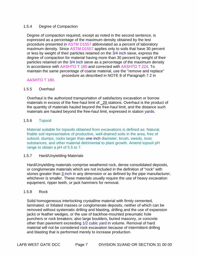
1.5.4 Degree of Compaction
Degree of compaction required, except as noted in the second sentence, is expressed as a percentage of the maximum density obtained by the test procedure presented in ASTM D1557 abbreviated as a percent of laboratory maximum density. Since ASTM D1557 applies only to soils that have 30 percent or less by weight of their particles retained on the 3/4 inch sieve, express the degree of compaction for material having more than 30 percent by weight of theirparticles retained on the 3/4 inch sieve as a percentage of the maximum density in accordance with AASHTO T 180 and corrected with AASHTO T 224. To maintain the same percentage of coarse material, use the "remove and replace"
procedure as described in NOTE 8 of Paragraph 7.2 in AASHTO T 180.
1.5.5 Overhaul
Overhaul is the authorized transportation of satisfactory excavation or borrow materials in excess of the free-haul limit of _20 stations. Overhaul is the product of the quantity of materials hauled beyond the free-haul limit, and the distance such materials are hauled beyond the free-haul limit, expressed in station yards.
1.5.6 Topsoil
Material suitable for topsoils obtained from excavations is defined as: Natural, friable soil representative of productive, well-drained soils in the area, free of subsoil, stumps, rocks larger than one inch diameter, brush, weeds, toxic substances, and other material detrimental to plant growth. Amend topsoil pH range to obtain a pH of 5.5 to 7.
1.5.7 Hard/Unyielding Materials
Hard/Unyielding materials comprise weathered rock, dense consolidated deposits, or conglomerate materials which are not included in the definition of "rock" with stones greater than 3 inch in any dimension or as defined by the pipe manufacturer, whichever is smaller. These materials usually require the use of heavy excavation equipment, ripper teeth, or jack hammers for removal.
1.5.8 Rock
Solid homogeneous interlocking crystalline material with firmly cemented, laminated, or foliated masses or conglomerate deposits, neither of which can be removed without systematic drilling and blasting, drilling and the use of expansionjacks or feather wedges, or the use of backhoe-mounted pneumatic hole punchers or rock breakers; also large boulders, buried masonry, or concrete other than pavement exceeding 1/2 cubic yard in volume. Removal of hard material will not be considered rock excavation because of intermittent drilling and blasting that is performed merely to increase production.
LAFB WEST GATE DCC Page 8 DIVISION 31/AND OR SECTION 31 00 00
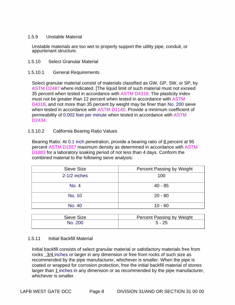
1.5.9 Unstable Material
Unstable materials are too wet to properly support the utility pipe, conduit, or appurtenant structure.
1.5.10 Select Granular Material
1.5.10.1 General Requirements
Select granular material consist of materials classified as GW, GP, SW, or SP, by ASTM D2487 where indicated. [The liquid limit of such material must not exceed 35 percent when tested in accordance with ASTM D4318. The plasticity index must not be greater than 12 percent when tested in accordance with ASTM D4318, and not more than 35 percent by weight may be finer than No. 200 sieve when tested in accordance with ASTM D1140. Provide a minimum coefficient of permeability of 0.002 feet per minute when tested in accordance with ASTM D2434.
1.5.10.2 California Bearing Ratio Values
Bearing Ratio: At 0.1 inch penetration, provide a bearing ratio of 8 percent at 95 percent ASTM D1557 maximum density as determined in accordance with ASTM D1883 for a laboratory soaking period of not less than 4 days. Conform the combined material to the following sieve analysis:
Sieve Size Percent Passing by Weight
2-1/2 inches 100
No. 4 40 - 85
No. 10 20 - 80
No. 40 10 - 60
Sieve Size Percent Passing by WeightNo. 200 5 - 25
1.5.11 Initial Backfill Material
Initial backfill consists of select granular material or satisfactory materials free from rocks 3/4 inches or larger in any dimension or free from rocks of such size as recommended by the pipe manufacturer, whichever is smaller. When the pipe is coated or wrapped for corrosion protection, free the initial backfill material of stones larger than 1 inches in any dimension or as recommended by the pipe manufacturer,whichever is smaller.
LAFB WEST GATE DCC Page 9 DIVISION 31/AND OR SECTION 31 00 00
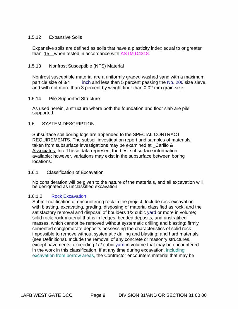
1.5.12 Expansive Soils
Expansive soils are defined as soils that have a plasticity index equal to or greater than 15 when tested in accordance with ASTM D4318.
1.5.13 Nonfrost Susceptible (NFS) Material
Nonfrost susceptible material are a uniformly graded washed sand with a maximum particle size of 3/4 inch and less than 5 percent passing the No. 200 size sieve,and with not more than 3 percent by weight finer than 0.02 mm grain size.
1.5.14 Pile Supported Structure
As used herein, a structure where both the foundation and floor slab are pile supported.
1.6 SYSTEM DESCRIPTION
Subsurface soil boring logs are appended to the SPECIAL CONTRACT REQUIREMENTS. The subsoil investigation report and samples of materials taken from subsurface investigations may be examined at _Carillo & Associates, Inc. These data represent the best subsurface information available; however, variations may exist in the subsurface between boring locations.
1.6.1 Classification of Excavation
No consideration will be given to the nature of the materials, and all excavation will be designated as unclassified excavation.
1.6.1.2 Rock ExcavationSubmit notification of encountering rock in the project. Include rock excavation with blasting, excavating, grading, disposing of material classified as rock, and thesatisfactory removal and disposal of boulders 1/2 cubic yard or more in volume; solid rock; rock material that is in ledges, bedded deposits, and unstratified masses, which cannot be removed without systematic drilling and blasting; firmly cemented conglomerate deposits possessing the characteristics of solid rock impossible to remove without systematic drilling and blasting; and hard materials (see Definitions). Include the removal of any concrete or masonry structures, except pavements, exceeding 1/2 cubic yard in volume that may be encountered in the work in this classification. If at any time during excavation, including excavation from borrow areas, the Contractor encounters material that may be

LAFB WEST GATE DCC Page 10 DIVISION 31/AND OR SECTION 31 00 00
classified as rock excavation, uncover such material and notify the Contracting Officer. Do not proceed with the excavation of this material until the Contracting Officer has classified the materials as common excavation or rock excavation and has taken cross sections as required. Failure on the part of the Contractor to uncover such material, notify the Contracting Officer, and allow ample time for classification and cross sectioning of the undisturbed surface of such material will cause the forfeiture of the Contractor's right of claim to any classification or volume of material to be paid for other than that allowed by the Contracting Officerfor the areas of work in which such deposits occur.
1.6.3 Dewatering Work Plan
Submit procedures for accomplishing dewatering work.
1.7 SUBMITTALS
Government approval is required for submittals with a "G" designation; submittals not having a "G" designation are for Contractor Quality Control approval. Submittalswith an "S" are for inclusion in the Sustainability Notebook, in conformance to Section 01 33 29 SUSTAINABILITY REPORTING. Submit the following in accordance with Section 01 33 00 SUBMITTAL PROCEDURES:
SD-03 Product Data
Utilization of Excavated Materials; G[, [ ]] Rock ExcavationOpening of any Excavation or Borrow Pit Shoulder Construction
SD-06 Test Reports Testing
Borrow Site Testing
Within 24 hours of conclusion of physical tests, submit 3 copies oftest results, including calibration curves and results of calibration tests.
SD-07 Certificates Testing
PART 2 PRODUCTS
2.1 REQUIREMENTS FOR OFFSITE SOILS
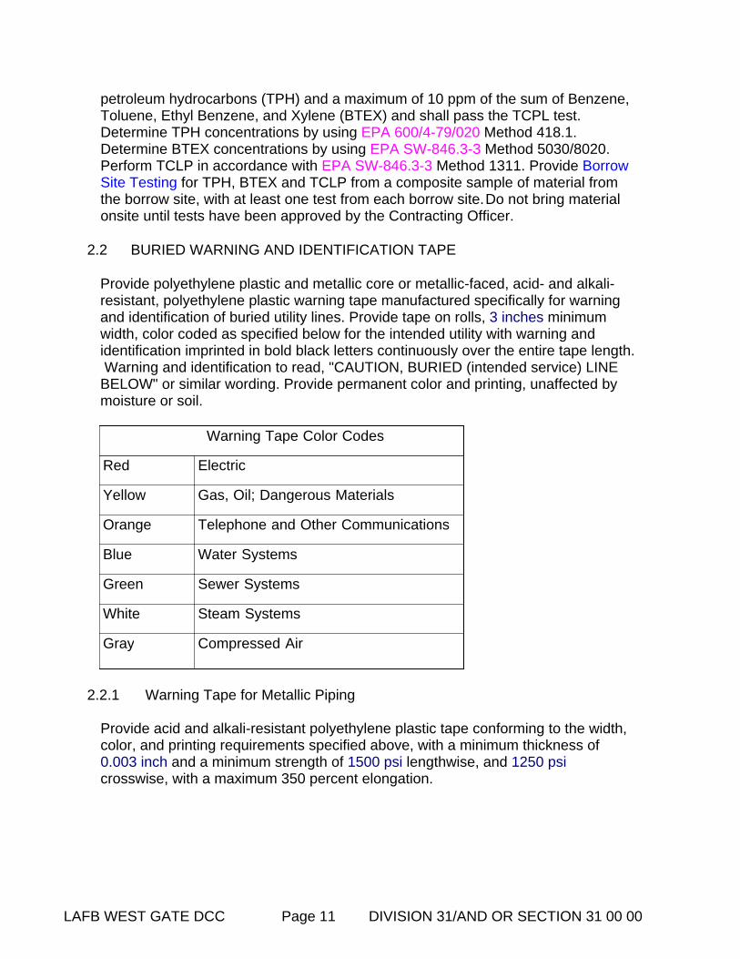
Test offsite soils brought in for use as backfill for Total Petroleum Hydrocarbons (TPH), Benzene, Toluene, Ethyl Benzene, and Xylene (BTEX) and full Toxicity Characteristic Leaching Procedure (TCLP) including ignitability, corrosivity and reactivity. Backfill shall contain a maximum of 100 parts per million (ppm) of total
LAFB WEST GATE DCC Page 11 DIVISION 31/AND OR SECTION 31 00 00
petroleum hydrocarbons (TPH) and a maximum of 10 ppm of the sum of Benzene, Toluene, Ethyl Benzene, and Xylene (BTEX) and shall pass the TCPL test. Determine TPH concentrations by using EPA 600/4-79/020 Method 418.1. Determine BTEX concentrations by using EPA SW-846.3-3 Method 5030/8020. Perform TCLP in accordance with EPA SW-846.3-3 Method 1311. Provide Borrow Site Testing for TPH, BTEX and TCLP from a composite sample of material from the borrow site, with at least one test from each borrow site.Do not bring material onsite until tests have been approved by the Contracting Officer.
2.2 BURIED WARNING AND IDENTIFICATION TAPE
Provide polyethylene plastic and metallic core or metallic-faced, acid- and alkali-resistant, polyethylene plastic warning tape manufactured specifically for warning and identification of buried utility lines. Provide tape on rolls, 3 inches minimum width, color coded as specified below for the intended utility with warning and identification imprinted in bold black letters continuously over the entire tape length. Warning and identification to read, "CAUTION, BURIED (intended service) LINE BELOW" or similar wording. Provide permanent color and printing, unaffected by moisture or soil.
Warning Tape Color Codes
Red Electric
Yellow Gas, Oil; Dangerous Materials
Orange Telephone and Other Communications
Blue Water Systems
Green Sewer Systems
White Steam Systems
Gray Compressed Air
2.2.1 Warning Tape for Metallic Piping
Provide acid and alkali-resistant polyethylene plastic tape conforming to the width, color, and printing requirements specified above, with a minimum thickness of 0.003 inch and a minimum strength of 1500 psi lengthwise, and 1250 psi crosswise, with a maximum 350 percent elongation.

LAFB WEST GATE DCC Page 12 DIVISION 31/AND OR SECTION 31 00 00
2.2.2 Detectable Warning Tape for Non-Metallic Piping
Provide polyethylene plastic tape conforming to the width, color, and printing requirements specified above, with a minimum thickness of 0.004 inch, and a minimum strength of 1500 psi lengthwise and 1250 psi crosswise. Manufacture tape with integral wires, foil backing, or other means of enabling detection by a metal detector when tape is buried up to 3 feet deep. Encase metallic element of the tape in a protective jacket or provide with other means of corrosion protection.
2.3 DETECTION WIRE FOR NON-METALLIC PIPING
Insulate a single strand, solid copper detection wire with a minimum of 12 AWG.
PART 3 EXECUTION
3.1 STRIPPING OF TOPSOIL
Where indicated or directed, strip topsoil to a depth of 4inches. Spread topsoil on areas already graded and prepared for topsoil, or transported and deposited in stockpiles convenient to areas that are to receive application of the topsoil later, or at locations indicated or specified. Keep topsoil separate from other excavated materials, brush, litter, objectionable weeds, roots, stones larger than 2 inches in diameter, and other materials that would interfere with planting and maintenance operations. Remove from the site any surplus of topsoil from excavations and gradings.
3.2 GENERAL EXCAVATION
Perform excavation of every type of material encountered within the limits of the project to the lines, grades, and elevations indicated and as specified. Perform thegrading in accordance with the typical sections shown and the tolerances specified in paragraph FINISHING. Transport satisfactory excavated materials and place in fill or embankment within the limits of the work. Excavate unsatisfactory materials encountered within the limits of the work below grade and replace with satisfactory materials as directed. Include such excavated material and the satisfactory materialordered as replacement in excavation. Dispose surplus satisfactory excavated material not required for fill or embankment in areas approved for surplus material storage or designated waste areas. Dispose unsatisfactory excavated material in designated waste or spoil areas. During construction, perform excavation and fill in a manner and sequence that will provide proper drainage at all times.
Excavate material required for fill or embankment in excess of that produced by excavation within the grading limits from the borrow areas indicated or from otherapproved areas selected by the Contractor as specified.
LAFB WEST GATE DCC Page 13 DIVISION 31/AND OR SECTION 31 00 00
3.2.1 Ditches, Gutters, and Channel Changes
Finish excavation of ditches, gutters, and channel changes by cuttingaccurately to the cross sections, grades, and elevations shown on theDrawings. Do not excavate ditches and gutters below grades shown. Backfillthe excessive open ditch or gutter excavation with satisfactory, thoroughlycompacted, material or with suitable stone or cobble to grades shown.Dispose excavated material as shown or as directed, except in no case allowmaterial be deposited a maximum 4 feet from edge of a ditch.
Maintain excavations free from detrimental quantities of leaves, brush, sticks, trash, and other debris until final acceptance of the work.
3.2.2 Drainage Structures
Make excavations to the lines, grades, and elevations shown, or as directed. Provide trenches and foundation pits of sufficient size to permit the placement andremoval of forms for the full length and width of structure footings and foundations as shown. Clean rock or other hard foundation material of loose debris and cut to a firm, level, stepped, or serrated surface. Remove loose disintegrated rock and thin strata. Do not disturb the bottom of the excavation when concrete or masonry is to be placed in an excavated area. Do not excavate to the final grade level until just before the concrete or masonry is to be placed.
3.2.3 Drainage
Provide for the collection and disposal of surface and subsurface water encountered during construction. Completely drain construction site during periodsof construction to keep soil materials sufficiently dry. Construct storm drainage features (ponds/basins) at the earliest stages of site development, and throughout construction grade the construction area to provide positive surface water runoff away from the construction activity and provide temporary ditches, swales, and other drainage features and equipment as required to maintain dry soils. When unsuitable working platforms for equipment operation and unsuitable soil support for subsequent construction features develop, remove unsuitable material and provide new soil material as specified herein. It is the responsibility of the Contractor to assess the soil and ground water conditions presented by the plans and specifications and to employ necessary measures to permit construction to proceed.
3.2.4 Dewatering
Control groundwater flowing toward or into excavations to prevent sloughing of excavation slopes and walls, boils, uplift and heave in the excavation and to eliminate interference with orderly progress of construction. Do not permit Frenchdrains, sumps, ditches or trenches within 3 feet of the foundation of any structure, except with specific written approval, and after specific contractual provisions for restoration of the foundation area have been made. Take control

LAFB WEST GATE DCC Page 14 DIVISION 31/AND OR SECTION 31 00 00
measures by the time the excavation reaches the water level in order to maintain the integrity of the in situ material. While the excavation is open, maintain the water level continuously, at least 3 feet below the working level. Operate dewatering system continuously until construction work below existing water levels is complete. Submit performance records weekly. Measure and record performance of dewatering system at same time each day by use of observation wells or piezometers installed in conjunction with the dewatering system. Relieve hydrostatic head in previous zones below subgrade elevation in layered soils to prevent uplift.
3.2.5 Trench Excavation Requirements
Excavate the trench as recommended by the manufacturer of the pipe to be installed. Slope trench walls below the top of the pipe, or make vertical, and of such width as recommended in the manufacturer's printed installation manual. Provide vertical trench walls where no manufacturer's printed installation manual is available. Shore trench walls more than 5 feet high, cut back to a stable slope, or provide with equivalent means of protection for employees who may be exposed to moving ground or cave in. Shore vertical trench walls more than 5 feet high. Excavate trenchwalls which are cut back to at least the angle of repose of the soil. Give special attention to slopes which may be adversely affected by weather or moisture content. Do not exceed the trench width below the pipe top of 24 inches plus pipe outside diameter (O.D.) for pipes of less than 24 inches inside diameter, and do not exceed 36 inches plus pipe outside diameter for sizes larger than 24 inches inside diameter. Where recommended trench widths are exceeded, provide redesign, stronger pipe, or special installation procedures by the Contractor. The Contractor is responsible for the cost of redesign, stronger pipe, or special installation procedures without any additional cost to the Government.
3.2.5.1 Bottom Preparation
Grade the bottoms of trenches accurately to provide uniform bearing and support for the bottom quadrant of each section of the pipe. Excavate bell holes to the necessary size at each joint or coupling to eliminate point bearing. Remove stones of 1 inch or greater in any dimension, or as recommended by the pipe manufacturer, whichever is smaller, to avoid point bearing.
3.2.5.2 Removal of Unyielding Material
Where unyielding material is encountered in the bottom of the trench, remove such material _4 inch below the required grade and replaced with suitable materials as provided in paragraph BACKFILLING AND COMPACTION.

LAFB WEST GATE DCC Page 15 DIVISION 31/AND OR SECTION 31 00 00
3.2.5.3 Removal of Unstable Material
Where unstable material is encountered in the bottom of the trench, remove such material to the depth directed and replace it to the proper grade with select granularmaterial as provided in paragraph BACKFILLING AND COMPACTION. When removal of unstable material is required due to the Contractor's fault or neglect in performing the work, the Contractor is responsible for excavating the resulting material and replacing it without additional cost to the Government.
3.2.5.4 Excavation for Appurtenances
Provide excavation for manholes, catch-basins, inlets, or similar structures of sufficient size to permit the placement and removal of forms for the full length and width of structure footings and foundations as shown. Clean rock or loose debris and cut to a firm surface either level, stepped, or serrated, as shown or as directed. Remove loose disintegrated rock and thin strata. Specify removal of unstable material. When concrete or masonry is to be placed in an excavated area, take special care not to disturb the bottom of the excavation. Do not excavate to the finalgrade level until just before the concrete or masonry is to be placed. Jacking, Boring, and Tunneling unless otherwise indicated, provide excavation by open cut except that sections of a trench may be jacked, bored, or tunneled if, in the opinion of the Contracting Officer, the pipe, cable, or duct can be safely and properly installed and backfill can be properly compacted in such sections.
3.2.6 Underground Utilities
The Contractor is responsible for movement of construction machinery and equipment over pipes and utilities during construction. Perform work adjacent to non-Government utilities as indicated in accordance with procedures outlined by utility company. Excavation made with power-driven equipment is not permitted within 2 feet of known Government-owned utility or subsurface construction. For work immediately adjacent to or for excavations exposing a utility or other buried obstruction, excavate by hand. Start hand excavation on each side of the indicated obstruction and continue until the obstruction is uncovered or until clearance for the new grade is assured. Support uncovered lines or other existing work affected by the contract excavation until approval for backfill is granted by the Contracting Officer. Report damage to utility lines or subsurface construction immediately to the Contracting Officer.
3.2.7 Structural Excavation
Ensure that footing subgrades have been inspected and approved by the Contracting Officer prior to concrete placement. Excavate to bottom of pile cap prior to placing or driving piles, unless authorized otherwise by the Contracting Officer. Backfill and compact over excavations and changes in grade due to pile driving operations to 95 percent of ASTM D698 maximum density.
LAFB WEST GATE DCC Page 16 DIVISION 31/AND OR SECTION 31 00 00
3.3 SELECTION OF BORROW MATERIAL
Select borrow material to meet the requirements and conditions of the particular fill or embankment for which it is to be used. Obtain borrow material from the borrow areas within the limits of the project site, selected by the Contractor or from approved private sources. Unless otherwise provided in the contract, the Contractor is responsible for obtaining the right to procure material, pay royalties and other charges involved, and bear the expense of developing the sources, including rights-of-way for hauling from the owners. Borrow material from approved sources on Government-controlled land may be obtained without payment of royalties. Unless specifically provided, do not obtain borrow within thelimits of the project site without prior written approval. Consider necessary clearing, grubbing, and satisfactory drainage of borrow pits and the disposal of debris thereon related operations to the borrow excavation.
3.4 OPENING AND DRAINAGE OF EXCAVATION AND BORROW PITS
Notify the Contracting Officer sufficiently in advance of the opening of any excavation or borrow pit or borrow areas to permit elevations and measurements of the undisturbed ground surface to be taken. Except as otherwise permitted, excavate borrow pits and other excavation areas providing adequate drainage. Transport overburden and other spoil material to designated spoil areas or otherwise dispose of as directed. Provide neatly trimmed and drained borrow pitsafter the excavation is completed.Ensure that excavation of any area, operation of borrow pits, or dumping of spoil material results in minimum detrimental effectson natural environmental conditions.
3.5 SHORING
3.5.1 General Requirements
Submit a Shoring and Sheeting plan for approval 15 days prior to starting work. Submit drawings and calculations, certified by a registered professional engineer, describing the methods for shoring and sheeting of excavations. Finish shoring, including sheet piling, and install as necessary to protect workmen, banks, adjacent paving, structures, and utilities. Remove shoring, bracing, and sheeting as excavations are backfilled, in a manner to prevent caving.
3.5.2 Geotechnical Engineer
Hire a Professional Geotechnical Engineer to provide inspection of excavations and soil/groundwater conditions throughout construction. The Geotechnical Engineer is responsible for performing pre-construction and periodic site visits throughout construction to assess site conditions. The Geotechnical Engineer is responsible for updating the excavation, sheeting and dewatering plans as construction progresses to reflect changing conditions and submit an updated planif necessary. Submit a monthly written report, informing the Contractor and Contracting Officer of the status of the plan and an accounting of the Contractor's adherence to the plan addressing any present or potential problems. The Contracting Officer is responsible for arranging meetings with the Geotechnical Engineer at any time throughout the contract duration.

LAFB WEST GATE DCC Page 17 DIVISION 31/AND OR SECTION 31 00 00
3.6 GRADING AREAS
Where indicated, divide work into grading areas within which satisfactory excavated material will be placed in embankments, fills, and required backfills.Do not haul satisfactory material excavated in one grading area to another grading area except when so directed in writing. Place and grade stockpiles of satisfactoryand wasted materials as specified. Keep stockpiles in a neat and well drained condition, giving due consideration to drainage at all times. Clear, grub, and seal by rubber-tired equipment, the ground surface at stockpile locations; separately stockpile excavated satisfactory and unsatisfactory materials. Protect stockpiles ofsatisfactory materials from contamination which may destroy the quality and fitness of the stockpiled material. If the Contractor fails to protect the stockpiles, and any material becomes unsatisfactory, remove and replace such material with satisfactory material from approved sources.
3.7 FINAL GRADE OF SURFACES TO SUPPORT CONCRETE
Do not excavate to final grade until just before concrete is to be placed. Only use excavation methods that will leave the foundation rock in a solid and unshattered condition. Roughen the level surfaces, and cut the sloped surfaces, as indicated, into rough steps or benches to provide a satisfactory bond. Protect shales from slaking and all surfaces from erosion resulting from ponding or water flow.
3.8 GROUND SURFACE PREPARATION
3.8.1 General Requirements
Remove and replace unsatisfactory material with satisfactory materials, as directed by the Contracting Officer, in surfaces to receive fill or in excavated areas. Scarify the surface to a depth of 6 inches before the fill is started. Plow, step, bench, or break up sloped surfaces steeper than 1 vertical to 4 horizontal so that the fill material will bond with the existing material. When subgrades are less than the specified density, break up the ground surface to a minimum depth of 6 inches, pulverizing, and compacting to the specified density. When the subgrade is part fill and part excavation or natural ground, scarify the excavated or natural ground portion to a depth of 12 inches and compact it as specified for the adjacent fill.
3.8.2 Frozen Material
Do not place material on surfaces that are muddy, frozen, or contain frost. Finish compaction by sheeps foot rollers, pneumatic-tired rollers, steel-wheeled rollers, or other approved equipment well suited to the soil being compacted. Moisten materialas necessary to provide the moisture content that will readily facilitate obtaining the specified compaction with the equipment used.
LAFB WEST GATE DCC Page 18 DIVISION 31/AND OR SECTION 31 00 00
3.9 UTILIZATION OF EXCAVATED MATERIALS
Dispose unsatisfactory materials removing from excavations into designated waste disposal or spoil areas. Use satisfactory material removed from excavations, insofar as practicable, in the construction of fills, embankments, subgrades, shoulders, bedding (as backfill), and for similar purposes. Submit procedure and location for disposal of unused satisfactory material. Submit proposed source of borrow material. Do not waste any satisfactory excavated material without specific written authorization. Dispose of satisfactory material, authorized to be wasted, in designated areas approved for surplus material storage or designated waste areas as directed. Clear and grub newly designated waste areas on Government-controlled land before disposal of waste material thereon. Stockpile and use coarserock from excavations for constructing slopes or embankments adjacent to streams, or sides and bottoms of channels and for protecting against erosion. Do not dispose excavated material to obstruct the flow of any stream, endanger a partly finished structure, impair the efficiency or appearance of any structure, or be detrimental to the completed work in any way.
3.10 BURIED TAPE AND DETECTION WIRE
3.10.1 Buried Warning and Identification Tape
Provide buried utility lines with utility identification tape. Bury tape12 inches below finished grade; under pavements and slabs, bury tape 6 inches below top of subgrade.
3.10.2 Buried Detection Wire
Bury detection wire directly above non-metallic piping at a distance not to exceed12 inches above the top of pipe. Extend the wire continuously and unbroken, from manhole to manhole. Terminate the ends of the wire inside the manholes at each end of the pipe, with a minimum of 3 feet of wire, coiled, remaining accessible in each manhole. Furnish insulated wire over it's entire length. Install wires at manholes between the top of the corbel and the frame, and extend up through the chimney seal between the frame and the chimney seal. For force mains, terminate the wire in the valve pit at the pump station end of the pipe.
3.11 BACKFILLING AND COMPACTION
Place backfill adjacent to any and all types of structures, in successive horizontal layers of loose material not more than 8 inches in depth.
Compact to at least 90 percent laboratory maximum density for cohesive materialsor 95 percent laboratory maximum density for cohesionless materials, to prevent wedging action or eccentric loading upon or against the structure. Backfill material must be within the range of -2 to +2 percent of optimum moisture content at the time of compaction.

LAFB WEST GATE DCC Page 19 DIVISION 31/AND OR SECTION 31 00 00

LAFB WEST GATE DCC Page 20 DIVISION 31/AND OR SECTION 31 00 00
Prepare ground surface on which backfill is to be placed and provide compaction requirements for backfill materials in conformance with the applicable portions of paragraphs GROUND SURFACE PREPARATION. Finish compaction by sheepsfoot rollers, pneumatic-tired rollers, steel-wheeled rollers, vibratory compactors, or other approved equipment.
3.11.1 Trench Backfill
Backfill trenches to the grade shown. Backfill the trench to 2 feet above the top of pipe prior to performing the required pressure tests. Leave the joints and couplings uncovered during the pressure test. Do not backfill the trench until all specified tests are performed.
3.11.1.1 Replacement of Unyielding Material
Replace unyielding material removed from the bottom of the trench with select granular material or initial backfill material.
3.11.1.2 Replacement of Unstable Material
Replace unstable material removed from the bottom of the trench or excavation with select granular material placed in layers not exceeding 6 inches loose thickness.
3.11.1.3 Bedding and Initial Backfill
Provide bedding of the type and thickness shown. Place initial backfill material and compact it with approved tampers to a height of at least one foot above the utility pipe or conduit. Bring up the backfill evenly on both sides of the pipe for the full length of the pipe. Take care to ensure thorough compaction of the fill under the haunches of the pipe. Except as specified otherwise in the individual piping section,provide bedding for buried piping in accordance with AWWA C600, Type 4, except as specified herein. Compact backfill to top of pipe to 95 percent of ASTM D698 maximum density. Provide plastic piping with bedding to spring line of pipe. Providematerials as follows:
LAFB WEST GATE DCC Page 21 DIVISION 31/AND OR SECTION 31 00 00
3.11.1.3.1 Class I
Angular, 0.25 to 1.5 inch, graded stone, including a number of fill materials that have regional significance such as coral, slag, cinders, crushed stone, and crushed shells.
3.11.1.3.2 Class II
Coarse sands and gravels with maximum particle size of 1.5 inch, including variousgraded sands and gravels containing small percentages of fines, generally granularand noncohesive, either wet or dry. Soil Types GW, GP, SW, and SP are included in this class as specified in ASTM D2487.
3.11.1.3.3 Sand
Clean, coarse-grained sand classified as SWORSP Section 31 23 00.00 20 EXCAVATION AND FILL.
3.11.1.3.4 Gravel and Crushed Stone
Clean, coarsely graded natural gravel, crushed stone or a combination thereof identified as _GW in accordance with Section 31 23 00.00 20, EXCAVATION AND FILL.
3.11.1.4 Final Backfill
Fill the remainder of the trench, except for special materials for roadways, railroads and airfields, with satisfactory material. Place backfill material and compact as follows:
3.11.1.4.1 Roadways, Railroads, and Airfields
Place backfill up to the required elevation as specified. Do not permit water flooding or jetting methods of compaction.
3.11.1.4.2 Sidewalks, Turfed or Seeded Areas and Miscellaneous Areas
Deposit backfill in layers of a maximum of 12 inches loose thickness, and compact it to 85 percent maximum density for cohesive soils and 90 percent maximum density for cohesionless soils. Do not permit compaction by water flooding or jetting. Apply this requirement to all other areas not specifically designated above.
LAFB WEST GATE DCC Page 22 DIVISION 31/AND OR SECTION 31 00 00
3.11.2 Backfill for Appurtenances
After the manhole, catch basin, inlet, or similar structure has been constructed and the concrete has been allowed to cure for 5 days, place backfill in such a manner that the structure is not be damaged by the shock of falling earth. Deposit the backfillmaterial, compact it as specified for final backfill, and bring up the backfill evenly on all sides of the structure to prevent eccentric loading and excessive stress.
3.12 SPECIAL REQUIREMENTS
Special requirements for both excavation and backfill relating to the specific utilities are as follows:
3.12.1 Gas Distribution
Excavate trenches to a depth that will provide a minimum 18 inches of cover in rockexcavation and a minimum 24 inch of cover in other excavation. Water Lines.
Excavate trenches to a depth that provides a minimum cover of 3 feet from the existing ground surface, or from the indicated finished grade, whichever is lower, to the top of the pipe.
3.13 EMBANKMENTS
3.13.1 Earth Embankments
Construct earth embankments from satisfactory materials free of organic or frozenmaterial and rocks with any dimension greater than 3 inches. Place the material insuccessive horizontal layers of loose material not more than 8 inches in depth. Spread each layer uniformly on a soil surface that has been moistened or aerated as necessary, and scarified or otherwise broken up so that the fill will bond with the surface on which it is placed. After spreading, plow, disk, or otherwise break up each layer; moisten or aerate as necessary; thoroughly mix; and compact to at least 90 percent laboratory maximum density for cohesive materials or 95 percent laboratory maximum density for cohesionless materials. Backfill material must be within the range of -2 to +2 percent of optimum moisture content at the time of compaction.
Compaction requirements for the upper portion of earth embankments forming subgrade for pavements are identical with those requirements specified in paragraph SUBGRADE PREPARATION. Finish compaction by sheepsfoot rollers,pneumatic-tired rollers, steel-wheeled rollers, vibratory compactors, or other approved equipment.

LAFB WEST GATE DCC Page 23 DIVISION 31/AND OR SECTION 31 00 00
3.14 SUBGRADE PREPARATION
3.14.1 Proof Rolling
Finish proof rolling on an exposed subgrade free of surface water (wet conditions resulting from rainfall) which would promote degradation of an otherwise acceptable subgrade. After stripping, proof roll the existing subgrade of the pavement areas withsix passes of a 15 ton, pneumatic-tired roller. Operate the [roller] [truck] in a systematic manner to ensure the number of passes over all areas, and at speeds between 2-1/2 to 3-1/2 mph. When proof rolling, provide one-half of the passes madewith the roller in a direction perpendicular to the other passes.
Notify the Contracting Officer a minimum of 3 days prior to proof rolling. Perform proof rolling in the presence of the Contracting Officer. Undercut rutting or pumping of material as directed by the Contracting Officer and replace with select material.
3.14.2 Construction
Shape subgrade to line, grade, and cross section, and compact as specified. Include plowing, disking, and any moistening or aerating required to obtain specifiedcompaction for this operation. Remove soft or otherwise unsatisfactory material and replace with satisfactory excavated material or other approved material as directed. Excavate rock encountered in the cut section to a depth of 6 inches below finished grade for the subgrade. Bring up low areas resulting from removal of unsatisfactory material or excavation of rock to required grade with satisfactory materials, and shape the entire subgrade to line, grade, and cross section and compact as specified.
After rolling, the surface of the subgrade for roadways shall not show deviations greater than 1/2 inch when tested with a 12-foot straightedge applied both parallel and at right angles to the centerline of the area.Do not vary the elevation of the finish subgrade more than 0.05 foot from the established grade and cross section.
3.14.3 Compaction
Finish compaction by sheepsfoot rollers, pneumatic-tired rollers, steel-wheeled rollers, vibratory compactors, or other approved equipment. Except for paved areas and railroads, compact each layer of the embankment to at least 95 percent of laboratory maximum density.
3.14.3.2 Subgrade for Pavements
Compact subgrade for pavements to at least 95 percentage laboratorymaximum density for the depth below the surface of the pavement shown. When more than one soil classification is present in the subgrade, thoroughly blend, reshape, and compact the top 6 inch of subgrade.
LAFB WEST GATE DCC Page 24 DIVISION 31/AND OR SECTION 31 00 00
3.16 FINISHING
Finish the surface of excavations, embankments, and subgrades to a smooth and compact surface in accordance with the lines, grades, and cross sections or elevations shown. Provide the degree of finish for graded areas within 0.1 foot of the grades and elevations indicated except that the degree of finish for subgrades specified in paragraph SUBGRADE PREPARATION. Finish gutters and ditches in a manner that will result in effective drainage. Finish the surface of areas to be turfed from settlement or washing to a smoothness suitable for the application of turfing materials. Repair graded, topsoiled, or backfilled areas prior to acceptance of the work, and re-established grades to the required elevations and slopes.
3.16.1 Subgrade and Embankments
During construction, keep embankments and excavations shaped and drained. Maintain ditches and drains along subgrade to drain effectively at all times. Do notdisturb the finished subgrade by traffic or other operation. Protect and maintain the finished subgrade in a satisfactory condition until ballast, subbase, base, or pavement is placed. Do not permit the storage or stockpiling of materials on the finished subgrade. Do not lay subbase, base course, ballast, or pavement until thesubgrade has been checked and approved, and in no case place subbase, base, surfacing, pavement, or ballast on a muddy, spongy, or frozen subgrade.
3.16.2 Capillary Water Barrier
Place a capillary water barrier under concrete floor and area-way slabs grade directly on the subgrade and compact with a minimum of two passes of a hand-operated plate-type vibratory compactor.
3.16.3 Grading Around Structures
Construct areas within 5 feet outside of each building and structure line true-to-grade, shape to drain, and maintain free of trash and debris until final inspection has been completed and the work has been accepted.
3.17 PLACING TOPSOIL
On areas to receive topsoil, prepare the compacted subgrade soil to a 2 inches depth for bonding of topsoil with subsoil. Spread topsoil evenly to a thickness of 4 inch and grade to the elevations and slopes shown. Do not spread topsoil when frozen or excessively wet or dry. Obtain material required for topsoil in excess of that produced by excavation within the grading limits from offsite areas.
LAFB WEST GATE DCC Page 25 DIVISION 31/AND OR SECTION 31 00 00
3.18 TESTING
Perform testing by a Corps validated commercial testing laboratory or the Contractor's validated testing facility. Submit qualifications of the Corps validated commercial testing laboratory or the Contractor's validated testing facilities. If the Contractor elects to establish testing facilities, do not permit work requiring testing until the Contractor's facilities have been inspected, Corps validated and approvedby the Contracting Officer.
a. Determine field in-place density in accordance with ASTM D1556/D1556M ASTM D2167 ASTM D6938. When ASTM D6938 is used, check the calibrationcurves and adjust using only the sand cone method as described inASTM D1556/D1556M. ASTM D6938 results in a wet unit weight of soil in determining the moisture content of the soil when using this method.
b. Check the calibration curves furnished with the moisture gauges along with density calibration checks as described in ASTM D6938; check the calibration of both the density and moisture gauges at the beginning of a job on each different type of material encountered and at intervals as directed by the Contracting Officer. ASTM D2937, use the Drive Cylinder Method only for soft, fine-grained, cohesive soils. When test results indicate, as determined by the Contracting Officer, that compaction is not as specified, remove the material, replace and recompact to meet specification requirements.
c. Perform tests on recompacted areas to determine conformance with specification requirements. Appoint a registered professional civil engineer to certify inspections and test results. These certifications shall state that the tests and observations were performed by or under the direct supervision of the engineer and that the results are representative of the materials or conditions being certified by the tests. The following number of tests, if performed at the appropriate time, will be the minimum acceptable for each type operation.
3.18.1 Fill and Backfill Material Gradation
One test per 1000 cubic yards stockpiled or in-place source material. Determine gradation of fill and backfill material in accordance with ASTM C136.
3.18.2 In-Place Densities
a. One test per 2500 square feet, or fraction hereof, of each lift of fill or backfill areas compacted by other than hand-operated machines.
b. One test per 250 square feet, or fraction thereof, of each lift of fill or backfill areas compacted by hand-operated machines.
c. One test per 100 linear feet, or fraction thereof, of each lift of embankment or backfill for roads.

LAFB WEST GATE DCC Page 26 DIVISION 31/AND OR SECTION 31 00 00
3.18.3 Check Tests on In-Place Densities
If ASTM D6938 is used, check in-place densities by ASTM D1556/D1556M as follows:
a. One check test per lift for each 20,000 square feet, or fraction thereof, of each lift of fill or backfill compacted by other than hand-operated machines.
b. One check test per lift for each 2000 square feet, of fill or backfill areas compacted by hand-operated machines.
c. One check test per lift for each 800 linear feet, or fraction thereof, of embankment or backfill for roads.
3.18.4 Moisture Contents
In the stockpile, excavation, or borrow areas, perform a minimum of two tests per day per type of material or source of material being placed during stable weather conditions. During unstable weather, perform tests as dictated by local conditions and approved by the Contracting Officer.
3.18.5 Optimum Moisture and Laboratory Maximum Density
Perform tests for each type material or source of material including borrow material to determine the optimum moisture and laboratory maximum density values. One representative test per 1000 cubic yards of fill and backfill, or when any change in material occurs which may affect the optimum moisture content or laboratory maximum density.
3.18.6 Tolerance Tests for Subgrades
Perform continuous checks on the degree of finish specified in paragraph SUBGRADE PREPARATION during construction of the subgrades.
3.18.7 Displacement of Sewers
After other required tests have been performed and the trench backfill compacted to the finished grade surface, inspect the pipe to determine whether significant displacement has occurred. Conduct this inspection in the presence of the Contracting Officer. Inspect pipe sizes larger than 36 inches, while inspecting smaller diameter pipe by shining a light or laser between manholes or manhole locations, or by the use of television cameras passed through the pipe. If, in the judgment of the Contracting Officer, the interior of the pipe shows poor alignment orany other defects that would cause improper functioning of the system, replace or repair the defects as directed at no additional cost to the Government.
LAFB WEST GATE DCC Page 27 DIVISION 31/AND OR SECTION 31 00 00
3.19 DISPOSITION OF SURPLUS MATERIAL
Remove surplus material or other soil material not required or suitable for filling or backfilling, and brush, refuse, stumps, roots, and timber from Government property and delivered to a licensed/permitted facility or to a location approved by the Contracting Officer.
-- End of Section --