mdo3000 series mixed domain oscilloscopes service manual · xx mdo3000 series mixed domain...
TRANSCRIPT
xx
MDO3000 SeriesMixed Domain Oscilloscopes
ZZZ
Service Manual
*P077098100*
077-0981-00


MDO3000 SeriesMixed Domain Oscilloscopes
ZZZ
Service Manual
xx
Revision C
WarningThe servicing instructions are for use by qualified personnelonly. To avoid personal injury, do not perform any servicingunless you are qualified to do so. Refer to all safety summariesprior to performing service.www.tek.com
077-0981-00

Copyright © Tektronix. All rights reserved. Licensed software products are owned by Tektronix or its subsidiariesor suppliers, and are protected by national copyright laws and international treaty provisions.
Tektronix products are covered by U.S. and foreign patents, issued and pending. Information in this publicationsupersedes that in all previously published material. Specifications and price change privileges reserved.
TEKTRONIX and TEK are registered trademarks of Tektronix, Inc.
Contacting Tektronix
Tektronix, Inc.14150 SW Karl Braun DriveP.O. Box 500Beaverton, OR 97077USA
For product information, sales, service, and technical support:In North America, call 1-800-833-9200.Worldwide, visit www.tek.com to find contacts in your area.

Table of Contents
Important Safety Information .. . . . . . . . . . . . . . . . . . . . . . . . . . . . . . . . . . . . . . . . . . . . . . . . . . . . . . . . . . . . . . . . . . . . . . . . . . . . . . . . . . . ivGeneral Safety Summary .. . . . . . . . . . . . . . . . . . . . . . . . . . . . . . . . . . . . . . . . . . . . . . . . . . . . . . . . . . . . . . . . . . . . . . . . . . . . . . . . . . . ivService Safety Summary . . . . . . . . . . . . . . . . . . . . . . . . . . . . . . . . . . . . . . . . . . . . . . . . . . . . . . . . . . . . . . . . . . . . . . . . . . . . . . . . . . . . viiTerms in This Manual . . . . . . . . . . . . . . . . . . . . . . . . . . . . . . . . . . . . . . . . . . . . . . . . . . . . . . . . . . . . . . . . . . . . . . . . . . . . . . . . . . . . . . . viiiSymbols and Terms on the Product . . . . . . . . . . . . . . . . . . . . . . . . . . . . . . . . . . . . . . . . . . . . . . . . . . . . . . . . . . . . . . . . . . . . . . . . viii
Preface .. . . . . . . . . . . . . . . . . . . . . . . . . . . . . . . . . . . . . . . . . . . . . . . . . . . . . . . . . . . . . . . . . . . . . . . . . . . . . . . . . . . . . . . . . . . . . . . . . . . . . . . . . . . . . ixManual Conventions. . . . . . . . . . . . . . . . . . . . . . . . . . . . . . . . . . . . . . . . . . . . . . . . . . . . . . . . . . . . . . . . . . . . . . . . . . . . . . . . . . . . . . . . . . ix
Where to Find Operating Information. . . . . . . . . . . . . . . . . . . . . . . . . . . . . . . . . . . . . . . . . . . . . . . . . . . . . . . . . . . . . . . . . . . . . . . . . . . . 1Theory of Operation. . . . . . . . . . . . . . . . . . . . . . . . . . . . . . . . . . . . . . . . . . . . . . . . . . . . . . . . . . . . . . . . . . . . . . . . . . . . . . . . . . . . . . . . . . . . . . . . 3
Power Supply.. . . . . . . . . . . . . . . . . . . . . . . . . . . . . . . . . . . . . . . . . . . . . . . . . . . . . . . . . . . . . . . . . . . . . . . . . . . . . . . . . . . . . . . . . . . . . . . . . . 3I/O Board .. . . . . . . . . . . . . . . . . . . . . . . . . . . . . . . . . . . . . . . . . . . . . . . . . . . . . . . . . . . . . . . . . . . . . . . . . . . . . . . . . . . . . . . . . . . . . . . . . . . . . . 3Main Board, Mezzanine Board, and Analog Board. . . . . . . . . . . . . . . . . . . . . . . . . . . . . . . . . . . . . . . . . . . . . . . . . . . . . . . . 3Front-Panel Board .. . . . . . . . . . . . . . . . . . . . . . . . . . . . . . . . . . . . . . . . . . . . . . . . . . . . . . . . . . . . . . . . . . . . . . . . . . . . . . . . . . . . . . . . . . . . 4
Adjustments . . . . . . . . . . . . . . . . . . . . . . . . . . . . . . . . . . . . . . . . . . . . . . . . . . . . . . . . . . . . . . . . . . . . . . . . . . . . . . . . . . . . . . . . . . . . . . . . . . . . . . . . . 7Maintenance.. . . . . . . . . . . . . . . . . . . . . . . . . . . . . . . . . . . . . . . . . . . . . . . . . . . . . . . . . . . . . . . . . . . . . . . . . . . . . . . . . . . . . . . . . . . . . . . . . . . . . . . . 9
Preventing ESD ... . . . . . . . . . . . . . . . . . . . . . . . . . . . . . . . . . . . . . . . . . . . . . . . . . . . . . . . . . . . . . . . . . . . . . . . . . . . . . . . . . . . . . . . . . . . . . 9Inspection and Cleaning.. . . . . . . . . . . . . . . . . . . . . . . . . . . . . . . . . . . . . . . . . . . . . . . . . . . . . . . . . . . . . . . . . . . . . . . . . . . . . . . . . . . . . . 9Module Removal. . . . . . . . . . . . . . . . . . . . . . . . . . . . . . . . . . . . . . . . . . . . . . . . . . . . . . . . . . . . . . . . . . . . . . . . . . . . . . . . . . . . . . . . . . . . . . 13Troubleshooting. . . . . . . . . . . . . . . . . . . . . . . . . . . . . . . . . . . . . . . . . . . . . . . . . . . . . . . . . . . . . . . . . . . . . . . . . . . . . . . . . . . . . . . . . . . . . . . 15Troubleshooting Procedure . . . . . . . . . . . . . . . . . . . . . . . . . . . . . . . . . . . . . . . . . . . . . . . . . . . . . . . . . . . . . . . . . . . . . . . . . . . . . . . . . . 15Unpacking and Repacking Instructions . . . . . . . . . . . . . . . . . . . . . . . . . . . . . . . . . . . . . . . . . . . . . . . . . . . . . . . . . . . . . . . . . . . . 19
Replaceable Parts List. . . . . . . . . . . . . . . . . . . . . . . . . . . . . . . . . . . . . . . . . . . . . . . . . . . . . . . . . . . . . . . . . . . . . . . . . . . . . . . . . . . . . . . . . . . . . 21Parts Ordering Information .. . . . . . . . . . . . . . . . . . . . . . . . . . . . . . . . . . . . . . . . . . . . . . . . . . . . . . . . . . . . . . . . . . . . . . . . . . . . . . . . . 21Using the Replaceable Parts List . . . . . . . . . . . . . . . . . . . . . . . . . . . . . . . . . . . . . . . . . . . . . . . . . . . . . . . . . . . . . . . . . . . . . . . . . . . . 23
MDO3000 Series Mixed Domain Oscilloscopes Service Manual i

Table of Contents
List of Figures
Figure 1: MDO3000 Series block diagram .. . . . . . . . . . . . . . . . . . . . . . . . . . . . . . . . . . . . . . . . . . . . . . . . . . . . . . . . . . . . . . . . . . . . . 5Figure 2: Removing tabs from the front protective cover. . . . . . . . . . . . . . . . . . . . . . . . . . . . . . . . . . . . . . . . . . . . . . . . . . . . . 13Figure 3: Module locator . . . . . . . . . . . . . . . . . . . . . . . . . . . . . . . . . . . . . . . . . . . . . . . . . . . . . . . . . . . . . . . . . . . . . . . . . . . . . . . . . . . . . . . . . 14Figure 4: Primary troubleshooting procedure . . . . . . . . . . . . . . . . . . . . . . . . . . . . . . . . . . . . . . . . . . . . . . . . . . . . . . . . . . . . . . . . . . 16Figure 5: AC power supply troubleshooting procedure . . . . . . . . . . . . . . . . . . . . . . . . . . . . . . . . . . . . . . . . . . . . . . . . . . . . . . . 17Figure 6: Module isolation troubleshooting procedure. . . . . . . . . . . . . . . . . . . . . . . . . . . . . . . . . . . . . . . . . . . . . . . . . . . . . . . . 18Figure 7: Exploded view, front panel assembly .. . . . . . . . . . . . . . . . . . . . . . . . . . . . . . . . . . . . . . . . . . . . . . . . . . . . . . . . . . . . . . . 26Figure 8: Display, analog board, and main board assembly .. . . . . . . . . . . . . . . . . . . . . . . . . . . . . . . . . . . . . . . . . . . . . . . . . 28Figure 9: Rear chassis and connecting modules . . . . . . . . . . . . . . . . . . . . . . . . . . . . . . . . . . . . . . . . . . . . . . . . . . . . . . . . . . . . . . . 30
ii MDO3000 Series Mixed Domain Oscilloscopes Service Manual

Table of Contents
List of Tables
Table 1: External inspection checklist. . . . . . . . . . . . . . . . . . . . . . . . . . . . . . . . . . . . . . . . . . . . . . . . . . . . . . . . . . . . . . . . . . . . . . . . . . . 11Table 2: Internal inspection checklist . . . . . . . . . . . . . . . . . . . . . . . . . . . . . . . . . . . . . . . . . . . . . . . . . . . . . . . . . . . . . . . . . . . . . . . . . . . 12Table 3: Parts list column descriptions. . . . . . . . . . . . . . . . . . . . . . . . . . . . . . . . . . . . . . . . . . . . . . . . . . . . . . . . . . . . . . . . . . . . . . . . . . 23Table 4: Front panel assembly . . . . . . . . . . . . . . . . . . . . . . . . . . . . . . . . . . . . . . . . . . . . . . . . . . . . . . . . . . . . . . . . . . . . . . . . . . . . . . . . . . . 24Table 5: Display, analog board, and main board . . . . . . . . . . . . . . . . . . . . . . . . . . . . . . . . . . . . . . . . . . . . . . . . . . . . . . . . . . . . . . . 27Table 6: Rear chassis and connecting modules . . . . . . . . . . . . . . . . . . . . . . . . . . . . . . . . . . . . . . . . . . . . . . . . . . . . . . . . . . . . . . . . 29
MDO3000 Series Mixed Domain Oscilloscopes Service Manual iii
Important Safety Information
Important Safety InformationThis manual contains information and warnings that must be followed by the userfor safe operation and to keep the product in a safe condition.
To safely perform service on this product, additional information is provided atthe end of this section. (See page vii, Service Safety Summary.)
General Safety SummaryUse the product only as specified. Review the following safety precautions toavoid injury and prevent damage to this product or any products connected to it.Carefully read all instructions. Retain these instructions for future reference.
Comply with local and national safety codes.
For correct and safe operation of the product, it is essential that you followgenerally accepted safety procedures in addition to the safety precautions specifiedin this manual.
The product is designed to be used by trained personnel only.
Only qualified personnel who are aware of the hazards involved should removethe cover for repair, maintenance, or adjustment.
Before use, always check the product with a known source to be sure it isoperating correctly.
This product is not intended for detection of hazardous voltages.
Use personal protective equipment to prevent shock and arc blast injury wherehazardous live conductors are exposed.
While using this product, you may need to access other parts of a larger system.Read the safety sections of the other component manuals for warnings andcautions related to operating the system.
When incorporating this equipment into a system, the safety of that system is theresponsibility of the assembler of the system.
To avoid fire or personalinjury
Use proper power cord. Use only the power cord specified for this product andcertified for the country of use. Do not use the provided power cord for otherproducts.
Ground the product. This product is grounded through the grounding conductorof the power cord. To avoid electric shock, the grounding conductor must beconnected to earth ground. Before making connections to the input or outputterminals of the product, make sure that the product is properly grounded.
Do not disable the power cord grounding connection.
iv MDO3000 Series Mixed Domain Oscilloscopes Service Manual
Important Safety Information
Power disconnect. The power cord disconnects the product from the powersource. See instructions for the location. Do not position the equipment so thatit is difficult to operate the power cord; it must remain accessible to the user atall times to allow for quick disconnection if needed.
Connect and disconnect properly. Do not connect or disconnect probes or testleads while they are connected to a voltage source.
Use only insulated voltage probes, test leads, and adapters supplied with theproduct, or indicated by Tektronix to be suitable for the product.
Observe all terminal ratings. To avoid fire or shock hazard, observe all ratingsand markings on the product. Consult the product manual for further ratingsinformation before making connections to the product. Do not exceed theMeasurement Category (CAT) rating and voltage or current rating of the lowestrated individual component of a product, probe, or accessory. Use caution whenusing 1:1 test leads because the probe tip voltage is directly transmitted to theproduct.
Do not apply a potential to any terminal, including the common terminal, thatexceeds the maximum rating of that terminal.
Do not float the common terminal above the rated voltage for that terminal.
Do not operate without covers. Do not operate this product with covers or panelsremoved, or with the case open. Hazardous voltage exposure is possible.
Avoid exposed circuitry. Do not touch exposed connections and componentswhen power is present.
Do not operate with suspected failures. If you suspect that there is damage to thisproduct, have it inspected by qualified service personnel.
Disable the product if it is damaged. Do not use the product if it is damagedor operates incorrectly. If in doubt about safety of the product, turn it off anddisconnect the power cord. Clearly mark the product to prevent its furtheroperation.
Before use, inspect voltage probes, test leads, and accessories for mechanicaldamage and replace when damaged. Do not use probes or test leads if they aredamaged, if there is exposed metal, or if a wear indicator shows.
Examine the exterior of the product before you use it. Look for cracks or missingpieces.
Use only specified replacement parts.
Use proper fuse. Use only the fuse type and rating specified for this product.
Do not operate in wet/damp conditions. Be aware that condensation may occur ifa unit is moved from a cold to a warm environment.
MDO3000 Series Mixed Domain Oscilloscopes Service Manual v
Important Safety Information
Do not operate in an explosive atmosphere.
Keep product surfaces clean and dry. Remove the input signals before you cleanthe product.
Provide proper ventilation. Refer to the installation instructions in the manual fordetails on installing the product so it has proper ventilation.
Slots and openings are provided for ventilation and should never be covered orotherwise obstructed. Do not push objects into any of the openings.
Provide a safe working environment. Always place the product in a locationconvenient for viewing the display and indicators.
Avoid improper or prolonged use of keyboards, pointers, and button pads.Improper or prolonged keyboard or pointer use may result in serious injury.
Be sure your work area meets applicable ergonomic standards. Consult with anergonomics professional to avoid stress injuries.
Use only the Tektronix rackmount hardware specified for this product.
Probes and test leads Before connecting probes or test leads, connect the power cord from the powerconnector to a properly grounded power outlet.
Keep fingers behind the finger guards on the probes.
Remove all probes, test leads and accessories that are not in use.
Use only correct Measurement Category (CAT), voltage, temperature, altitude,and amperage rated probes, test leads, and adapters for any measurement.
Beware of high voltages. Understand the voltage ratings for the probe you areusing and do not exceed those ratings. Two ratings are important to know andunderstand:
The maximum measurement voltage from the probe tip to the probe referencelead.
The maximum floating voltage from the probe reference lead to earth ground
These two voltage ratings depend on the probe and your application. Refer to theSpecifications section of the manual for more information.
WARNING. To prevent electrical shock, do not exceed the maximum measurementor maximum floating voltage for the oscilloscope input BNC connector, probetip, or probe reference lead.
Connect and disconnect properly. Connect the probe output to the measurementproduct before connecting the probe to the circuit under test. Connect the
vi MDO3000 Series Mixed Domain Oscilloscopes Service Manual

Important Safety Information
probe reference lead to the circuit under test before connecting the probe input.Disconnect the probe input and the probe reference lead from the circuit under testbefore disconnecting the probe from the measurement product.
Connect and disconnect properly. De-energize the circuit under test beforeconnecting or disconnecting the current probe.
Connect the probe reference lead to earth ground only.
Do not connect a current probe to any wire that carries voltages above the currentprobe voltage rating.
Inspect the probe and accessories. Before each use, inspect the probe andaccessories for damage (cuts, tears, or defects in the probe body, accessories, orcable jacket). Do not use if damaged.
Ground-referenced oscilloscope use. Do not float the reference lead of this probewhen using with ground-referenced oscilloscopes. The reference lead must beconnected to earth potential (0 V).
Service Safety SummaryThe Service Safety Summary section contains additional information required tosafely perform service on the product. Only qualified personnel should performservice procedures. Read this Service Safety Summary and the General SafetySummary before performing any service procedures.
To avoid electric shock. Do not touch exposed connections.
Do not service alone. Do not perform internal service or adjustments of thisproduct unless another person capable of rendering first aid and resuscitation ispresent.
Disconnect power. To avoid electric shock, switch off the product power anddisconnect the power cord from the mains power before removing any covers orpanels, or opening the case for servicing.
Use care when servicing with power on. Dangerous voltages or currents may existin this product. Disconnect power, remove battery (if applicable), and disconnecttest leads before removing protective panels, soldering, or replacing components.
Verify safety after repair. Always recheck ground continuity and mains dielectricstrength after performing a repair.
MDO3000 Series Mixed Domain Oscilloscopes Service Manual vii

Important Safety Information
Terms in This ManualThese terms may appear in this manual:
WARNING. Warning statements identify conditions or practices that could resultin injury or loss of life.
CAUTION. Caution statements identify conditions or practices that could result indamage to this product or other property.
Symbols and Terms on the ProductThese terms may appear on the product:
DANGER indicates an injury hazard immediately accessible as you readthe marking.
WARNING indicates an injury hazard not immediately accessible as youread the marking.
CAUTION indicates a hazard to property including the product.
When this symbol is marked on the product, be sure to consult the manualto find out the nature of the potential hazards and any actions which have tobe taken to avoid them. (This symbol may also be used to refer the user toratings in the manual.)
The following symbol(s) may appear on the product:
viii MDO3000 Series Mixed Domain Oscilloscopes Service Manual

PrefaceThis service manual provides information that you need to troubleshoot,disassemble, and replace parts on the following Tektronix oscilloscopes:
Model Bandwidth Analog channels RF frequency
MDO3012 100 MHz 2 Up to 3 GHz
MDO3014 100 MHz 4 Up to 3 GHz
MDO3022 200 MHz 2 Up to 3 GHz
MDO3024 200 MHz 4 Up to 3 GHz
MDO3032 350 MHz 2 Up to 3 GHz
MDO3034 350 MHz 4 Up to 3 GHz
MDO3052 500 MHz 2 Up to 3 GHz
MDO3054 500 MHz 4 Up to 3 GHz
MDO3102 1 GHz 2 Up to 3 GHz
MDO3104 1 GHz 4 Up to 3 GHz
Manual ConventionsThis manual uses certain conventions that you should become familiar withbefore performing service.
Modules Throughout this manual, any replaceable component, assembly, or part is referredto by the term module.
Replaceable Parts This manual refers to any field-replaceable assembly or mechanical partspecifically by its name or generically as a replaceable part. In general, areplaceable part is any circuit board or assembly, such as the hard disk drive, or amechanical part, such as the I/O port connectors, that is listed in the replaceableparts list.
Safety Symbols and terms related to safety appear in the General Safety Summary.
Information for service procedures appears in both the General Safety Summaryand the Service Safety Summary.
MDO3000 Series Mixed Domain Oscilloscopes Service Manual ix
Preface
x MDO3000 Series Mixed Domain Oscilloscopes Service Manual

Where to Find Operating InformationFor information on installing and operating your oscilloscope, refer to theTektronix MDO3000 Series Mixed Domain Oscilloscopes User Manual, whichwas included on the documentation CD provided with your oscilloscope. Thismanual is available in 11 languages.
MDO3000 Series Mixed Domain Oscilloscopes Service Manual 1

Where to Find Operating Information
2 MDO3000 Series Mixed Domain Oscilloscopes Service Manual

Theory of OperationThis chapter describes the electrical operation of the oscilloscope to the modulelevel. The block diagram shows the oscilloscope module interconnections. (SeeFigure 1 on page 5.)
Power SupplyThe Power Supply board converts AC line voltage to +12 V to power for allinternal circuits.
I/O BoardThe I/O board contains USB ports, an Ethernet port (LAN), a VGA Video port, anAUX OUT BNC connector, and the AFG generator output connector.
Main Board, Mezzanine Board, and Analog BoardThe Main and Analog boards contain the following functions:
Acquisition System The Acquisition system begins with the analog signal path and ends with adigitized signal in memory. The signal enters a channel input, and then passesthrough an attenuator and preamplifier. The analog signal from each preamplifiergoes through a digitizer, and then into acquisition memory. The analog signalfrom each preamplifier is also distributed to a trigger circuit.
All of the inputs (including RF) are routed to the Analog board. The analogchannels are amplified and attenuated through the front-end circuitry, and areoutput to the Main board. The RF channel is the same except that the RF inputsignal is routed through a shared connection with analog CH4. The analog boardhas a controller that is used as an I/O controller for the front-end (Analog board).
Trigger System The Trigger system digitizes the analog signals from the preamplifiers androutes the digitized signal to the Trigger ASIC. Advanced trigger functions areenabled only when the appropriate application modules and supporting softwareare installed.
Display System The Display system combines live waveform data from acquisition memory withmenus and text, and stores this information in display memory. It then uses thisdata to refresh the WVGA display module (LCD).
MDO3000 Series Mixed Domain Oscilloscopes Service Manual 3
Theory of Operation
Processor System The Processor system contains a microprocessor that controls the entireinstrument. The processor system also contains FLASH ROM, system RAM, andinterfaces to USB ports and the Ethernet port.
Power Converter The Mezzanine board converts the +12 V power to other voltages used for theanalog and digital circuitry throughout the system. The +5 V standby power isused to keep the Front Panel powered up at all times that AC power is connectedto the unit.
Front-Panel BoardThe Front Panel board contains a microprocessor that reads the front-panelbuttons and controls, sends this information to the processor system on the Mainboard, and controls power to the system. The Front Panel board also generatesthe probe compensation output signal, provides an interface to the applicationmodules, and controls power to the system.
4 MDO3000 Series Mixed Domain Oscilloscopes Service Manual

Theory of Operation
Figure 1: MDO3000 Series block diagram
MDO3000 Series Mixed Domain Oscilloscopes Service Manual 5
Theory of Operation
6 MDO3000 Series Mixed Domain Oscilloscopes Service Manual
AdjustmentsPlease return the instrument to Tektronix if adjustment is required. There areno adjustment procedures (calibrations) that can be performed by the customer.Calibrations can only be performed at an authorized Tektronix Service Centerand require the use of traceable test equipment (signal sources and measuringequipment) to verify the performance of the instrument.
To determine if adjustment is required, use the Performance Verificationprocedure in the MDO3000 Series Mixed Domain Oscilloscopes Specificationsand Performance Verification manual, available at www.tektronix.com/manuals.Adjustment is also required after instrument repair.
MDO3000 Series Mixed Domain Oscilloscopes Service Manual 7

Adjustments
8 MDO3000 Series Mixed Domain Oscilloscopes Service Manual
MaintenanceThis section contains the information needed to do periodic and correctivemaintenance on the oscilloscope, as well as repackaging instructions for returningthe oscilloscope to Tektronix for service.
Preventing ESDBefore servicing this product, read the General Safety Summary and the ServiceSafety Summary at the front of the manual, and familiarize yourself with thefollowing electrostatic discharge (ESD) information.
CAUTION. Static discharge can damage any semiconductor component in thisoscilloscope.
When performing any service that requires internal access to the oscilloscope,adhere to the following precautions to avoid damaging internal modules and theircomponents due to electrostatic discharge:
1. Minimize handling of static-sensitive circuit boards and components.
2. Transport and store static-sensitive modules in their static protected containersor on a metal rail. Label any package that contains static-sensitive boards.
3. Discharge the static voltage from your body by wearing a grounded antistaticwrist strap while handling these modules. Service static-sensitive modulesonly at a static-free work station.
4. Do not place anything capable of generating or holding a static charge on thework station surface.
5. Handle circuit boards by the edges when possible.
6. Do not slide the circuit boards over any surface.
7. Avoid handling circuit boards in areas that have a floor or work-surfacecovering capable of generating a static charge.
Inspection and CleaningInspection and cleaning are done as preventive maintenance. Preventivemaintenance, when done regularly, may prevent oscilloscope malfunction andenhance its reliability.
Preventive maintenance consists of visually inspecting and cleaning theoscilloscope and using general care when operating it.
MDO3000 Series Mixed Domain Oscilloscopes Service Manual 9

Maintenance
How often you do maintenance depends on the severity of the environment inwhich the oscilloscope is used. A proper time to perform preventive maintenanceis just before oscilloscope adjustment.
General Care The cabinet helps keep dust out of the oscilloscope and should normally be inplace when operating the oscilloscope.
WARNING. To avoid injury, power off the instrument and disconnect it from linevoltage before performing any procedure that follows.
Flat Panel Display Cleaning The display is a soft plastic display and must be treated with care during cleaning.
CAUTION. Improper cleaning agents or methods can damage the flat paneldisplay.
Avoid using abrasive cleaners or commercial glass cleaners to clean the displaysurface.
Avoid spraying liquids directly on the display surface.
Avoid scrubbing the display with excessive force.
Clean the flat panel display surface by gently rubbing the display with aclean-room wipe (such as Wypall Medium Duty Wipes, #05701, available fromKimberly-Clark Corporation).
If the display is very dirty, moisten the wipe with distilled water or a 75%isopropyl alcohol solution and gently rub the display surface. Avoid using excessforce or you may damage the plastic display surface.
Exterior Cleaning
CAUTION. To prevent getting moisture inside the oscilloscope during externalcleaning, use only enough liquid to dampen the cloth or applicator.
Clean the exterior surfaces of the chassis with a dry lint-free cloth or a soft-bristlebrush. If any dirt remains, use a cloth or swab dipped in a 75% isopropyl alcoholsolution. Use a swab to clean narrow spaces around controls and connectors. Donot use abrasive compounds on any part of the chassis that might damage thechassis.
10 MDO3000 Series Mixed Domain Oscilloscopes Service Manual

Maintenance
Clean the power switch using a dampened cleaning towel. Do not spray or wetthe switch directly.
CAUTION. Avoid the use of chemical cleaning agents, which might damage theplastics used in this oscilloscope. Use only deionized water when cleaning themenu buttons or front-panel buttons. Use a 75% isopropyl alcohol solution as acleaner and rinse with deionized water. Before using any other type of cleaner,consult your Tektronix Service Center or representative.
Exterior Inspection Inspect the outside of the oscilloscope for damage, wear, and missing parts,using the following table as a guide. Immediately repair defects that could causepersonal injury or lead to further damage to the oscilloscope.
Table 1: External inspection checklist
Item Inspect for Repair action
Cabinet, front panel, and cover Cracks, scratches, deformations, damagedhardware.
Repair or replace defective module.
Front-panel knobs Missing, damaged, or loose knobs. Repair or replace missing or defectiveknobs.
Connectors Broken shells, cracked insulation, anddeformed contacts. Dirt in connectors.
Repair or replace defective modules. Clearor wash out dirt.
Carrying handle, and cabinet feet Correct operation. Repair or replace defective module.
Accessories Missing items or parts of items, bent pins,broken or frayed cables, and damagedconnectors.
Repair or replace damaged or missingitems, frayed cables, and defective modules.
Interior Inspection To access the inside of the oscilloscope for cleaning and inspection, refer to theexploded view diagrams. (See page 21, Replaceable Parts List.)
Inspect the internal portions of the oscilloscope for damage and wear, using thefollowing table as a guide. Repair any defects immediately.
If any circuit board is repaired or replaced, adjustment is required. (See page 7,Adjustments.)
CAUTION. To prevent damage from electrical arcing, make sure that circuitboards and components are dry before applying power to the oscilloscope.
MDO3000 Series Mixed Domain Oscilloscopes Service Manual 11

Maintenance
Table 2: Internal inspection checklist
Item Inspect for Repair action
Circuit boards Loose, broken, or corroded solderconnections. Burned circuit boards. Burned,broken, or cracked circuit-run plating.
Remove and replace damaged circuit board.
Resistors Burned, cracked, broken, blistered condition. Remove and replace damaged circuit board.
Solder connections Cold solder or rosin joints. Resolder joint and clean with isopropylalcohol.
Capacitors Damaged or leaking cases. Corroded solderon leads or terminals.
Remove and replace damaged circuit board.
Wiring and cables Loose plugs or connectors. Burned, broken,or frayed wiring.
Firmly seat connectors. Repair or replacemodules with defective wires or cables.
Chassis Dents, deformations, and damagedhardware.
Straighten, repair, or replace defectivehardware.
Interior Cleaning 1. Blow off dust with dry, low-pressure, deionized air (approximately 9 psi).
2. Remove any remaining dust with a lint-free cloth dampened in isopropylalcohol (75% solution) and rinsed with warm deionized water. (Acotton-tipped applicator is useful for cleaning in narrow spaces and on circuitboards.)
NOTE. If, after performing steps 1 and 2, a module is clean upon inspection,skip the following steps.
If there is still dust or dirt on the module, the oscilloscope may be spray washedusing a solution of 75% isopropyl alcohol by following these steps:
a. Spray wash dirty parts with isopropyl alcohol and wait 60 seconds for themajority of the alcohol to evaporate.
b. Use hot (120 °F to 140 °F) deionized water to thoroughly rinse them.
c. Dry all parts with low-pressure, deionized air.
d. Dry all components and assemblies in an oven or drying compartmentusing low-temperature (125 °F to 150 °F) circulating air.
Lubrication There is no periodic lubrication required for this oscilloscope.
12 MDO3000 Series Mixed Domain Oscilloscopes Service Manual
Maintenance
Module Removal
WARNING. Only qualified personnel should perform service procedures. Beforeperforming this or any other procedure in this manual, read the General SafetySummary and Service Safety Summary located at the beginning of this manual.Also, to prevent possible injury to service personnel or damage to electricalcomponents, read Preventing ESD. (See page 9, Preventing ESD.)
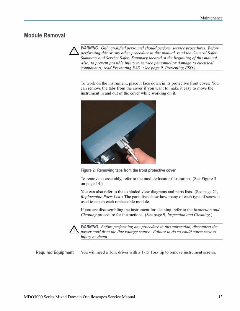
To work on the instrument, place it face down in its protective front cover. Youcan remove the tabs from the cover if you want to make it easy to move theinstrument in and out of the cover while working on it.
Figure 2: Removing tabs from the front protective cover
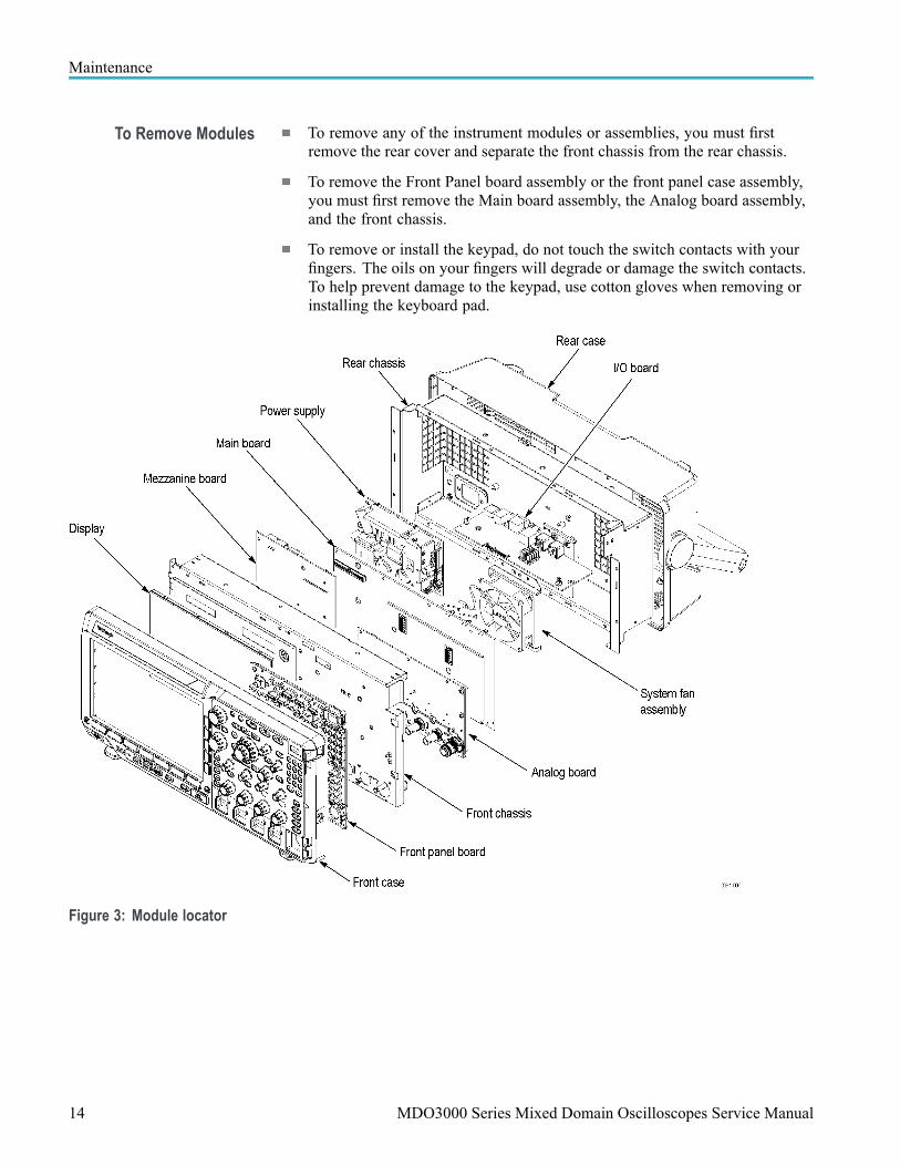
To remove as assembly, refer to the module locator illustration. (See Figure 3on page 14.)
You can also refer to the exploded view diagrams and parts lists. (See page 21,Replaceable Parts List.) The parts lists show how many of each type of screw isused to attach each replaceable module.
If you are disassembling the instrument for cleaning, refer to the Inspection andCleaning procedure for instructions. (See page 9, Inspection and Cleaning.)
WARNING. Before performing any procedure in this subsection, disconnect thepower cord from the line voltage source. Failure to do so could cause seriousinjury or death.
Required Equipment You will need a Torx driver with a T-15 Torx tip to remove instrument screws.
MDO3000 Series Mixed Domain Oscilloscopes Service Manual 13
Maintenance
To Remove Modules To remove any of the instrument modules or assemblies, you must firstremove the rear cover and separate the front chassis from the rear chassis.
To remove the Front Panel board assembly or the front panel case assembly,you must first remove the Main board assembly, the Analog board assembly,and the front chassis.
To remove or install the keypad, do not touch the switch contacts with yourfingers. The oils on your fingers will degrade or damage the switch contacts.To help prevent damage to the keypad, use cotton gloves when removing orinstalling the keyboard pad.
Figure 3: Module locator
14 MDO3000 Series Mixed Domain Oscilloscopes Service Manual
Maintenance
TroubleshootingThis section contains information and procedures to help you isolate a defectivemodule in the MDO3000 Series oscilloscopes.
WARNING. Before performing this or any other procedure in this manual, read theGeneral Safety Summary and Service Safety Summary found at the beginning ofthis manual, and, to prevent possible injury to service personnel or damage toelectrical components, read Preventing ESD. (See page 9, Preventing ESD.)
Adjustment After Repair Instrument adjustment is required after you replace any circuit board. Referto the Adjustments section for information about the adjustment. (See page 7,Adjustments.)
Required Tools andEquipment
You need the following equipment to troubleshoot the instrument.
Tools and Equipment Example
DMM 3.5 digits or above
Test Points Test points on the Main board are shown in the troubleshooting illustration. (SeeFigure 5.)
Troubleshooting ProcedureThe following figures are troubleshooting procedure flowcharts. Use them totroubleshoot an instrument failure. Begin with the Primary troubleshootingprocedure flowchart. (See Figure 4.)
WARNING. Before removing the cabinet, disconnect the power cord from the linevoltage source. Failure to do so could cause serious injury or death.
CAUTION. When you operate the instrument with the cabinet removed, the systemfan will not operate. You must provide an external fan to cool the interior of theinstrument. Failure to do so could cause instrument damage.
MDO3000 Series Mixed Domain Oscilloscopes Service Manual 15
Maintenance
Figure 4: Primary troubleshooting procedure
16 MDO3000 Series Mixed Domain Oscilloscopes Service Manual
Maintenance
Figure 5: AC power supply troubleshooting procedure
NOTE. The test point voltages are printed on the Main board. The +12 V testpoint is on the upper right-hand corner of the board.
MDO3000 Series Mixed Domain Oscilloscopes Service Manual 17

Maintenance
Figure 6: Module isolation troubleshooting procedure
18 MDO3000 Series Mixed Domain Oscilloscopes Service Manual

Maintenance
Unpacking and Repacking InstructionsThis section contains the information needed to unpack the oscilloscope andrepack it for shipment or storage.
Unpacking The oscilloscope and its standard accessories are carefully packed at the factory ina shipping carton. If, upon receipt, damage to the shipping carton is evident, tellthe shipper. Tektronix, Inc. is not responsible for damage caused during shipping.
If you have not already done so, carefully remove the oscilloscope and itsaccessories from the shipping carton and inspect them for damage. Save theshipping carton for repacking or storage.
Repacking Use a corrugated cardboard shipping carton having a test strength of at least 275pounds (125 kg) and with an inside dimension at least six inches (15.25 cm)greater than the instrument dimensions.
If the instrument is being shipped to a Tektronix Service Center, enclose thefollowing information:
The owner’s address
Name and phone number of a contact person
Type and serial number of the instrument
Reason for returning
A complete description of the service required
Seal the shipping carton with an industrial stapler or strapping tape.
Mark the address of the Tektronix Service Center and also your own return addresson the shipping carton in two prominent locations. See www.tektronix.com/serviceto find a service center near you.
Storage The oscilloscope should be stored in a clean, dry environment. The followingenvironmental characteristics apply for both shipping and storage:
Temperature range: –40 °F to +160 °F (–40 °C to +71 °C)
Altitude: To 39,370 feet (12,000 m )
See the Tektronix MDO3000 Series Mixed Domain Oscilloscopes Specificationsand Performance Verification Technical Reference for a complete listing of theenvironmental specifications.
MDO3000 Series Mixed Domain Oscilloscopes Service Manual 19

Maintenance
20 MDO3000 Series Mixed Domain Oscilloscopes Service Manual
Replaceable Parts ListThis chapter contains a list of the replaceable modules for these oscilloscopes.Use this list to identify and order replacement parts.
Parts Ordering InformationReplacement parts are available through your local Tektronix field office orrepresentative.
Changes to Tektronix products are sometimes made to accommodate improvedcomponents as they become available and to give you the benefit of the latestimprovements. Therefore, when ordering parts, it is important to include thefollowing information in your order:
Part number (see Part Number Revision Level below)
Instrument type or model number
Instrument serial number
Instrument modification number, if applicable
If you order a part that has been replaced with a different or improved part, yourlocal Tektronix field office or representative will contact you concerning anychange in part number.
Change information, if any, is located at the rear of this manual.
Part Number RevisionLevel
Tektronix part numbers contain two digits that show the revision level of thepart. For some parts in this manual, you will find the letters XX in place of therevision level number.
When you order parts, Tektronix will provide you with the most current part foryour product type, serial number, and modification (if applicable). At the time ofyour order, Tektronix will determine the part number revision level needed foryour product, based on the information you provide.
MDO3000 Series Mixed Domain Oscilloscopes Service Manual 21
Replaceable Parts List
Module Servicing Modules can be serviced by selecting one of the next three options. Contact yourlocal Tektronix service center or representative for repair assistance.
Module exchange. In some cases you may exchange your module for aremanufactured module. These modules cost significantly less than new modulesand meet the same factory specifications. For more information about the moduleexchange program, call 1-800-833-9200, extension 2.
Module repair and return. You may ship your module to us for repair, after whichwe will return it to you.
New modules. You may purchase replacement modules in the same way as otherreplacement parts.
22 MDO3000 Series Mixed Domain Oscilloscopes Service Manual
Replaceable Parts List
Using the Replaceable Parts ListThis section contains a list of the mechanical and/or electrical components thatare replaceable for the instrument. Use this list to identify and order replacementparts. The following table describes each column in the parts list.
Table 3: Parts list column descriptions
Column Column Name Description
1 Figure & IndexNumber
Items in this section are referenced by figure and index numbers to the exploded viewillustrations that follow the list.
2 Tektronix PartNumber
Use this part number when ordering replacement parts from Tektronix.
3 and 4 Serial Number Column three indicates the serial number at which the part was first effective. Column fourindicates the serial number at which the part was discontinued. No entries indicates thepart is good for all serial numbers.
5 Qty This indicates the quantity of parts used.
6 Name & Description An item name is separated from the description by a colon (:). Because of space limitations,an item name may sometimes appear as incomplete. Use the U.S. Federal Catalog handbookH6-1 for further item name identification.
Abbreviations Abbreviations conform to American National Standard ANSI Y1.1-1972.
Exploded Views Figures 7 through 9 on the following pages show the module-level exploded viewsof the oscilloscopes. Each exploded view is indexed by the numbers in the figure.
MDO3000 Series Mixed Domain Oscilloscopes Service Manual 23
Replaceable Parts List
Table 4: Front panel assembly
Fig. &indexnumber
Tektronixpart number
Serialno.effective
Serial no.discont’d Qty Name & description
7- FRONT PANEL ASSEMBLY
050-3815-xx 1 PARTS REPLACEMENT KIT; 2 CH FRONT PANEL ASSEMBLY; INCLUDES THEFOLLOWING PARTS:
FIGURE NUMBERS 9, 10, 14, 15 and 21
-1
050-3814-xx 1 PARTS REPLACEMENT KIT; 4 CH FRONT PANEL ASSEMBLY; INCLUDES THEFOLLOWING PARTS:
FIGURE NUMBERS 9, 10, 14, 15 and 21
-2 366-0855-xx 2 ASSEMBLY, KNOB: 0.925 DIAMETER, SOFT TOUCH
-3 366-0858-xx 1 KNOB, SHUTTLE SOFT TOUCH
-4 358-0883-00 1 BUSHING (JOG SHUTTLE KNOB)
-5 366-0865-xx 1 KNOB ASSEMBLY, JOG
-6 366-0859-xx 6 ASSEMBLY, KNOB: 0.470 DIAMETER, SOFT TOUCH
-7 366-0853-xx 6 ASSEMBLY, KNOB: 0.685 DIAMETER, SOFT TOUCH
335-2664-00 1 LABEL. FRONT PANEL, OVERLAY, FRENCH
335-2665-00 1 LABEL. FRONT PANEL, OVERLAY, ITALIAN
335-2666-00 1 LABEL. FRONT PANEL, OVERLAY, GERMAN
335-2667-00 1 LABEL. FRONT PANEL, OVERLAY, SPANISH
335-2668-00 1 LABEL. FRONT PANEL, OVERLAY, JAPANESE
335-2669-00 1 LABEL. FRONT PANEL, OVERLAY, PORTUGUESE
335-2670-00 1 LABEL. FRONT PANEL, OVERLAY, SIMPLIFIED CHINESE
335-2671-00 1 LABEL. FRONT PANEL, OVERLAY, TRADITIONAL CHINESE
335-2672-00 1 LABEL. FRONT PANEL, OVERLAY, KOREAN
-8
335-2673-00 1 LABEL FRONT PANEL OVERLAY, RUSSIAN
-9 260-2857-00 1 SWITCH, KEYPAD, ELASTOMERIC, POWER
-10 407-5259-00 1 BRACKET, SUPPORT: POWER SWITCH
SCREW, PT, K35-1.57, PAN HEAD, STL, ZNPL, T-15 TORX DRIVE
- - - - - - DISTRIBUTION OF THE 211-1273-00 SCREWS - - - - - -
2 screws attach the Power switch and bracket to the front case assembly.
2 screws attach the Utility switch and bracket to the front case assembly.
10 screws attach the Front panel assembly to the front case assembly – with contact springs(#17).
-11 211-1273-00 19
5 screws across the bottom of the Front panel assembly attach it to the front case assembly– without contact springs.
-12 260-2889-00 1 SWITCH, KEYPAD, ELASTOMERIC, UTILITY
-13 407-2567-00 1 BRACKET, SUPPORT, UTILITY SWITCH
-14 260-2971-00 1 SWITCH, KEYPAD, ELASTOMERIC, FRONT PANEL
24 MDO3000 Series Mixed Domain Oscilloscopes Service Manual

Replaceable Parts List
Fig. &indexnumber
Tektronixpart number
Serialno.effective
Serial no.discont’d Qty Name & description
7- FRONT PANEL ASSEMBLY
-15 105-1176-00 1 ACTUATOR, SWITCH, 10 KEY
878-0789-xx 1 CIRCUIT BOARD ASSEMBLY, FRONT PANEL, 2 CH-16
878-0764-xx 1 CIRCUIT BOARD ASSEMBLY, FRONT PANEL, 4 CH
-17 131-8139-00 10 CONTACT, SPRING: FRONT PANEL ELEC
-18 351-1109-01 2 GUIDE, KEY; POLY, BAYBLEND FR-110
-19 213-1149-00 2 SCREW, TPG, TF; 2-28 X.5, PLASTITE, FLAT HEAD, PHILLIPS, STL, ZNPL
-20 259-0212-00 1 CIRCUIT, FLEX; 10 KEY
-21 200-5301-00 1 COVER; OPTION KEY DOOR, PC/ABS, FR110, SILVER GRAY
-22 200-5052-00 1 COVER, FRONT PROTECTIVE
MDO3000 Series Mixed Domain Oscilloscopes Service Manual 25

Replaceable Parts List
Figure 7: Exploded view, front panel assembly
26 MDO3000 Series Mixed Domain Oscilloscopes Service Manual

Replaceable Parts List
Table 5: Display, analog board, and main board
Figureandindexno.
Tektronixpart no.
Serialno.effective
Serialno.discont'd Qty. Name and description
8- DISPLAY, ANALOG BOARD & MAIN BOARD-1 850-0252-00 1 FRAME ASSEMBLY, DISPLAY: LCD
-2 441-2740-00 1 CHASSIS ASSEMBLY, FRONT
SCREW, MACHINE: 6–32 x 0.250, PNH, STL, ZNPL, T-15 TORX DRIVE
- - - - - - DISTRIBUTION OF THE 211-1272-00 SCREWS - - - - - -
9 screws attach the LCD assembly to the front chassis.
15 screws attach the Main board assembly to the front chassis.
6 screws attach the Analog board assembly to the front chassis.
12 screws attach the rear chassis to the front chassis: 4 across the top flange of the rearchassis, 2 on each side flange, and 4 across the bottom flange of the front chassis.
-3 211-1272-00 43
1 screw attaches the ground jack to the front chassis.
-4 878-0872-00 1 MEZZANINE BD. Return the instrument to Tektronix for service.
-5 211-1273-00 8 SCREW, PT, K35–1.57, PAN HEAD, STL, ZNPL, T-15 TORX DRIVE
-6 174-6347-xx 1 CABLE; FRONT PANEL TO MEZZANINE
-7 174-6284-xx 1 CABLE, POWER SUPPLY OUTPUT
-8 211-1275-00 8 SCREW
-9 878-0763-xx 1 MAIN BOARD ASSEMBLY. Return the instrument to Tektronix for service. The Main boardand the Attenuator board must be calibrated together if either is found defective.
-10 351-1130-xx 1 GUIDE, PROBE
-11 129-1693-00 1 SPACER, POST
-12 348-1863-xx 1 EMI GASKET
878-0801-xx 1 ATTENUATOR BD, 500 MHz, 2 CH. Return the instrument to Tektronix for service.The Main board and the Attenuator board must be calibrated together if either is founddefective.
878-0784-xx 1 ATTENUATOR BD, 500 MHz, 4 CH. Return the instrument to Tektronix for service.The Main board and the Attenuator board must be calibrated together if either is founddefective.
878-0803-xx 1 ATTENUATOR BD, 1 GHz, 2 CH. Return the instrument to Tektronix for service. The Mainboard and the Attenuator board must be calibrated together if either is found defective.
-13
878-0802-xx 1 ATTENUATOR BD, 1 GHz, 4 CH. Return the instrument to Tektronix for service. The Mainboard and the Attenuator board must be calibrated together if either is found defective.
-14 174-6343-xx 1 CABLE, DISPLAY
-15 131-6643-00 1 CONTACT, ELEC: GROUNDING, ELECTROLESS NICKEL PLATE
-16 131-7622-00 1 CONN, RECEPT; GROUND JACK
-17 407-5324-xx 1 BRACKET, USB
-18 131-6521-xx 1 EMI CLIP
-19 174-5411-xx 1 CABLE, USB HOST
MDO3000 Series Mixed Domain Oscilloscopes Service Manual 27

Replaceable Parts List
Figure 8: Display, analog board, and main board assembly
28 MDO3000 Series Mixed Domain Oscilloscopes Service Manual

Replaceable Parts List
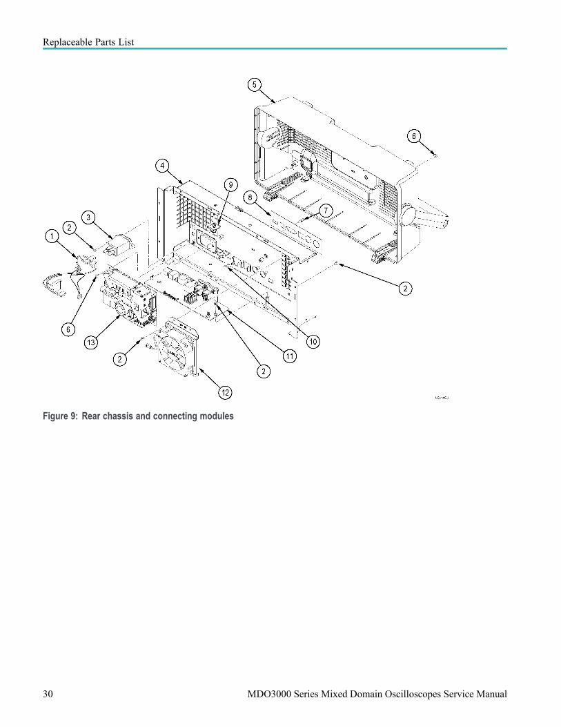
Table 6: Rear chassis and connecting modules
Figureandindexno.
Tektronixpart no.
Serialno.effective
Serialno.discont'd Qty. Name and description
9- REAR CHASSIS, POWER SUPPLY, I/O BOARD-1 174-6286-xx 1 CABLE, AC INPUT
-2 211-1272-00 13 SCREW, MACHINE: 6–32 x 0.250, PNH, STL, ZNPL, T-15 TORX DRIVE
- - - - - - DISTRIBUTION OF THE 211-1272-00 SCREWS - - - - - -
3 screws attach the I/O board to the rear chassis.
2 screws attach the line filter to the rear chassis.
4 screws attach the system fan (#12) to the rear chassis.
4 screws attach the rear chassis to the front chassis.
-3 119-7086-00 1 FILTER, EMI, AC LINE CONNECTOR
-4 441-2741-00 1 CHASSIS ASSEMBLY, REAR
-5 065-0965-00 1 REAR CASE ASSEMBLY
-6 211-1275-xx 4 SCREW
- - - - - - DISTRIBUTION OF THE 211-1275-00 SCREWS - - - - - -
4 screws attach the Power supply circuit board to the rear chassis.
-7 214-3903-00 2 SCREW, JACK; 4-40 X 0.312 LONG, 0.188 H HEX HEAD STAND OFF
-8 335-3149-00 1 LABEL, IO, REAR
-9 343-1736-xx 1 CABLE CLAMP
-10 131-6643-00 1 CONTACT, ELEC: GROUNDING, ELECTROLESS NICKEL PLATE
-11 878-0761-xx 1 I/O BOARD ASSEMBLY
-12 119-8180-00 1 SYSTEM FAN ASSEMBLY, 120 MM, TUBEAXIAL, 12 VDC; SAFETY CONTROLLED,WITH BRACKET
-13 119-8042-00 1 POWER SUPPLY; ROHS COMPLIANT; SAFETY CONTROLLED
MDO3000 Series Mixed Domain Oscilloscopes Service Manual 29
Replaceable Parts List
Figure 9: Rear chassis and connecting modules
30 MDO3000 Series Mixed Domain Oscilloscopes Service Manual