osciloscopios de señal combinada mixed signal … 3 mixed signal oscilloscopes — mso4000 series,...
TRANSCRIPT
Funciones y ventajasEspecificaciones clave de rendimiento Modelosconanchodebandade1GHz,500MHz,350MHz
Modelosde4canalesanálogos
16canalesdigitales(serieMSO)
Frecuenciademuestreodehasta5GS/sentodosloscanales
Longituddegrabaciónde10megapuntosentodosloscanales
Velocidaddecapturadeformasdeondamáxima>50000formasdeonda/s
Conjuntodedisparosavanzados
Funciones fáciles de utilizar LoscontrolesdeWaveInspector®ofrecenunanavegaciónsencillaybúsquedaautomatizadadedatosdeformadeonda.
29medicionesautomáticas,histogramasdeformadeondayanálisisdeFFTparaelanálisisdeformadeondasimplificado.
LainterfazdepuntadepruebaTekVPI®admitepuntasactivas,diferencialesydecorrienteparaunidadesyescalamientoautomático.
PantallaXGAacolorde10,4in(264mm).
Tamañopequeñoyliviano:sólo5,4in(137mm)deprofundidady11lb(5kg).
Conectividad UnpuertohostUSB2.0enelpanelfrontalydosenelpanelposterior,paraalmacenardatos,imprimiryconectaruntecladoUSBdeformarápidaysencilla.
PuertodedispositivosUSB2.0enelpanelposteriorpararealizarunaconexiónsencillaaunequipooimpresióndirectaaunaimpresoracompatibleconPictBridge®.
PuertoEthernet10/100integradoparaconexionesaredypuertodesalidadevideoparaexportarlapantalladelosciloscopioaunmonitoroproyector.
Análisis y disparo serie opcional Opcionesdebúsqueda,decodificaciónydisparoserieautomáticosparaI2C,SPI,USB,CAN,LIN,FlexRay,RS-232/422/485/UARTeI2S/LJ/RJ/TDM.
Análisis y diseño de señal combinada (serie MSO) Autodisparoydecodificaciónybúsquedaautomatizadasenbusesparalelos.
Configuracióndeumbralporcanal.
Disparodecomprobacióndetiempodeestablecimientoyretencióndecanalesmúltiples.
AdquisiciónMagniVu™dealtavelocidadqueproporcionaunaresolucióndesincronizaciónprecisade60,6psencanalesdigitales.
Compatibilidad con aplicaciones opcionales Análisisdeenergía.
AnálisisdevideopersonalizadoyHDTV
Herramientas con amplias funciones para la depuración de diseños de señal combinadaConlaseriedeosciloscopiosdeseñalcombinadaMSO/DPO4000,puedeanalizarhasta20señalesanálogasydigitalesconunúnicoinstrumentoparaencontrarydiagnosticarproblemasrápidamenteendiseñoscomplejos.Anchosdebandadehasta1GHzysobremuestreomínimode5vecesentodosloscanalesgarantizanelrendimientoquenecesitaparaverlosdetallesdeseñalesconcambiosrápidos.LaserieMSO/DPO4000ofreceunalongituddegrabaciónprolongadade10Mpuntosestándarentodosloscanalesquepermitecapturargrandesventanasdeactividaddeseñalmientrasmantieneunaresolucióndesincronizaciónprecisa.
ConloscontrolesdeWaveInspector®paraunanavegacióndeformadeondarápida,análisisdebusesparalelosyserialesautomáticos,yanálisisdeenergíaautomático,elosciloscopioserieMSO/DPO4000deTektronixofrecelasherramientasconampliasfuncionesqueustednecesitaparasimplificaryacelerarladepuracióndesudiseñocomplejo.
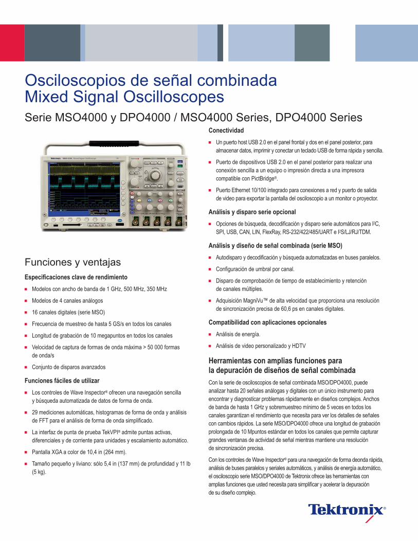
Osciloscopios de señal combinada Mixed Signal OscilloscopesSerie MSO4000 y DPO4000 / MSO4000 Series, DPO4000 Series
DataSheet
www.tektronix.com2
Funciones integrales que aceleran cada etapa de la depuraciónLaserieMSO/DPO4000ofreceunsólidoconjuntodefuncionesqueacelerancadafasedeladepuracióndesudiseño,desdelarápidadeteccióndeunaanomalíaysucaptura,hastalabúsquedadelagrabacióndeformadeondaparaelevento,elanálisisdesuscaracterísticasyelcomportamientodesudispositivo.
DetecciónParadepurarunproblemadediseño,primerodebeconocerqueexiste.Cadaingenierodediseñodedicatiempoalabúsquedadeproblemasensudiseño,unatareaquepuederesultardemandanteyfrustrantesinosecuentaconlasherramientasdedepuraciónadecuadas.
LaserieMSO/DPO4000ofrecelavisualizacióndeseñalesmáscompletadelaindustria,queaportaunarápidapercepcióndelfuncionamientorealdeldispositivo.Lavelocidaddecapturadeformadeondarápida,superiora50000formasdeonda/s,lepermiteverespuriosyotroseventostransitoriospocofrecuentesencuestióndesegundosyasímanifiestalaverdaderanaturalezadelasfallasdeldispositivo.Unapantalladefósforodigitalcongradacióndeintensidadmuestraelhistorialdelaactividaddeunaseñalmediantelaintensificacióndelasáreasdelaseñalqueocurrenconmayorfrecuencia,yasíofreceunapresentaciónvisualdelafrecuenciaconqueocurrenlasanomalías.
CapturaLadeteccióndeunafalladedispositivoessóloelprimerpaso.Acontinuación,debecapturareleventodeinterésparaidentificarlacausadeorigen.
LaserieMSO/DPO4000ofreceunconjuntocompletodedisparos,incluidoslosdisparosrunt,lógico,anchodepulso/espurio,violacióndetiempodeestablecimientoyretención,paqueteserialydatosparalelos,paraquepuedaencontrarrápidamenteelevento.Conunalongituddegrabacióndehasta10Mpuntos,puedecapturarvarioseventosdeinterés,inclusomilesdepaquetesseriales,enunaúnicaadquisiciónparasuanálisisposteriormientrasmantieneunaaltaresoluciónalrealizarlaampliacióndedetallesdeseñalprecisos.
Desdelosdisparosencontenidodepaqueteespecíficohastaladecodificaciónautomáticaenvariosformatosdedatos,laserieMSO/DPO4000ofrececompatibilidadintegradaconelintervalomásamplioenlaindustriadebusesseriales:I2C,SPI,USB,CAN,LIN,FlexRay,RS-232/422/485/UARTeI2S/LJ/RJ/TDM.Lacapacidaddedecodificacióndehastacuatrobusesserialesy/oparalelosenformasimultáneasignificaqueseobtieneunarápidapercepcióndelosproblemasdelsistema.
Parafacilitaraúnmáslasolucióndeproblemasdeinteraccionesdelsistemaencomplejossistemasintegrados,laserieMSO4000ofrece16canalesdigitalesademásdesuscanalesanálogos.Dadoqueloscanalesdigitalesestáncompletamenteintegradosalosciloscopio,puederealizardisparosentodosloscanalesdeentrada,conunarelacióntemporalautomáticadetodaslasseñalesanálogas,digitalesydeserie.LaadquisicióndeMagniVu™dealtavelocidadlepermiteadquirirdetallesdeseñalprecisos(conunaresolucióndehasta60,6ps)alrededordelpuntodedisparoparamedicionesdeprecisión.MagniVuesesencialpararealizarmedicionesdesincronizaciónprecisasparamedicionesdecomprobadordetiemposdeestablecimientoyretención,retrasodelreloj,distorsióndeseñalycaracterizacióndeespurios.
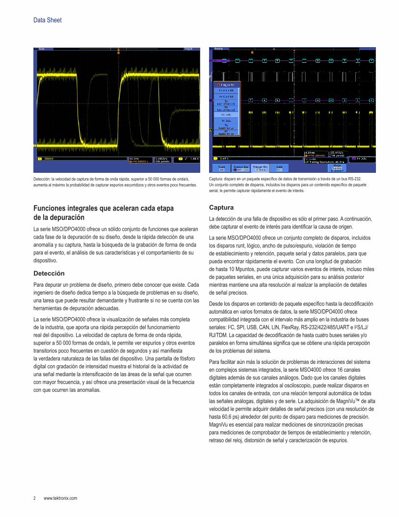
Detección:lavelocidaddecapturadeformadeondarápida,superiora50000formasdeonda/s,aumentaalmáximolaprobabilidaddecapturarespuriosescurridizosyotroseventospocofrecuentes.
Captura:disparoenunpaqueteespecíficodedatosdetransmisiónatravésdeunbusRS-232.Unconjuntocompletodedisparos,incluidoslosdisparosparauncontenidoespecíficodepaqueteserial,lepermitecapturarrápidamenteeleventodeinterés.
www.tektronix.com 3
MixedSignalOscilloscopes—MSO4000Series,DPO4000Series
BúsquedaEncontrareleventodeinterésenunagrabacióndeformadeondaprolongadapuedellevarmuchotiemposinosecuentaconlasherramientasdebúsquedaadecuadas.Conlasactualeslongitudesdegrabaciónqueexcedenelmillóndepuntosdedatos,lalocalizacióndeuneventopuedeimplicareldesplazamientopormilesdepantallasdeactividaddeseñal.
LaserieMSO/DPO4000ofrecelanavegacióndeformadeondaybúsquedamásintegraldelaindustriaconlosinnovadorescontrolesdeWaveInspector®.Estoscontrolesaceleranlaexploraciónyampliaciónenlagrabación.Conunsistemaúnicoderetroalimentaciónporfuerza,puederealizarelmovimientodesdeunextremodelagrabaciónalotroencuestióndesegundos.Lasmarcasdelusuariolepermitenmarcarcualquierubicaciónquedeseetenercomopuntodereferenciaparasufuturainvestigación.Obien,busqueautomáticamenteenlagrabaciónloscriteriosparaladefinición.WaveInspectorbuscaráinstantáneamenteentodalagrabación,incluidoslosdatosdebusesseriales,digitalesyanálogos.Eneltranscurso,marcaráautomáticamentecadaaparicióndesueventodefinidodemodoquepuedamoverseentreloseventosdemanerarápida.
AnálisisVerificarqueelrendimientodesuprototipocoincidaconlassimulacionesycumplaconlosobjetivosdeldiseñodelproyectorequiereelanálisisdesucomportamiento.Lastareaspuedenoscilarentresimplescomprobacionesdetiemposdesubidayanchosdepulsoasofisticadosanálisisdepérdidadeenergíaeinvestigacióndefuentesderuido.
LaserieMSO/DPO4000ofreceunconjuntointegraldeherramientasdeanálisisintegradas,incluidoscursoresdeformadeondaypantalla;29medicionesautomáticas;matemáticasdeformadeondaavanzadas,queincluyenedicióndeecuacionesarbitrarias,histogramasdeformadeonda,análisisdeFFTygráficosdetendenciaparaladeterminaciónvisualdelcambioenlamediciónconeltranscursodeltiempo.Compatibilidadconaplicaciónespecializadaparaanálisisdebusesseriales,diseñodesuministrodealimentación,ydesarrolloydiseñodevideotambiéndisponible.
Pararealizarunanálisismásamplio,NationalInstrument’sLabVIEWSignalExpress™TektronixEditionofrecemásde200funcionesincorporadas,queincluyenanálisisdedominiodefrecuenciaytiempo,pruebasdelímites,registrodedatoseinformespersonalizables.
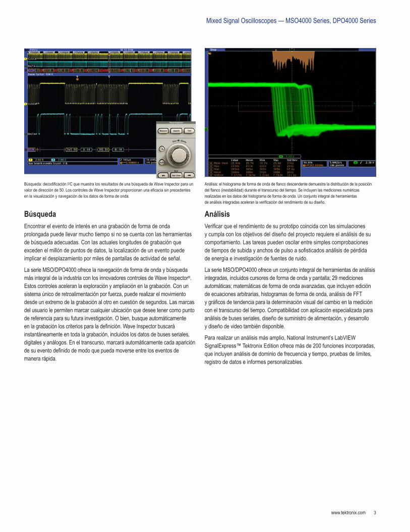
Búsqueda:decodificaciónI2CquemuestralosresultadosdeunabúsquedadeWaveInspectorparaunvalordedirecciónde50.LoscontrolesdeWaveInspectorproporcionanunaeficaciasinprecedentesenlavisualizaciónynavegacióndelosdatosdeformadeonda.
Análisis:elhistogramadeformadeondadeflancodescendentedemuestraladistribucióndelaposicióndelflanco(inestabilidad)duranteeltranscursodeltiempo.Seincluyenlasmedicionesnuméricasrealizadasenlosdatosdelhistogramadeformadeonda.Unconjuntointegraldeherramientasdeanálisisintegradasaceleranlaverificacióndelrendimientodesudiseño.
DataSheet
www.tektronix.com4
Navegación y búsqueda de Wave Inspector®
Unalongituddegrabaciónde10Mpuntosrepresentamilesdepantallasdeinformación.LaserieMSO/DPO4000lepermiteencontrarsueventoensegundosconWaveInspector,lamejorherramientadenavegaciónybúsquedadelaindustria.
WaveInspectorofrecelossiguientescontrolesinnovadores:
Ampliación/ExploraciónUncontroldepanelfrontaldedicadodedosescalonesproporcionauncontrolintuitivoparalaampliaciónylaexploración.Elcontrolinternoajustaelfactordeampliación(oescaladeampliación).Sisegiraenelsentidoalasmanecillasdelreloj,seactivalaampliaciónyseobtienenfactoresdeampliaciónmayoresenformaprogresiva,mientrasquealgirarloensentidocontrarioalasmanecillasdelreloj,seobtienenfactoresdeampliaciónmenoresy,finalmente,sedesactivalaampliación.Yanoesnecesarionavegarporvariosmenúsparaajustarlavistadeampliación.Elcontrolexternoexploraelcuadrodeampliaciónatravésdelaformadeondaparaobtenerrápidamentelapartedelaformadeondadesuinterés.Además,elcontrolexternoutilizaretroalimentaciónporfuerzaparadeterminarconquérapidezsevaaexplorarlaformadeonda.Cuantomássegiraelcontrolexterno,másrápidosedesplazaráelcuadrodeampliación.Ladireccióndeexploraciónsecambiaconsólogirarelcontrolhaciaelotrosentido.
Reproducción/PausaElbotóndedicadodelpanelfrontalReproducción/Pausadesplazaautomáticamentelaformadeondaporlapantallamientrasbuscaanomalíasoalgúneventodeinterés.Ladirecciónyvelocidaddereproducciónsecontrolanmedianteuncontroldeexploraciónintuitivo.Unavezmás,mientrasmásgireelcontrol,másrápidosedesplazarálaformadeonda;elcambiodedirecciónselogracontansólogirarelcontrolenelsentidocontrario.
Marcas del usuarioPresioneelbotóndelpanelfrontalEstablecer marcaparacolocarunaomásmarcasenlaformadeonda.LanavegaciónentrelasmarcasserealizaconsólopresionarlosbotonesAnterior(←)ySiguiente(→)enelpanelfrontal.
Buscar marcasElbotónBuscarlepermitebuscarautomáticamenteenlaadquisiciónlargaeventosdefinidosporelusuario.TodaslasaparicionesdeleventoseresaltanconmarcasdebúsquedaypuedenavegarsehastaellasconlosbotonesdepanelfrontalAnterior(←)ySiguiente(→).Entrelostiposdebúsquedaseincluyenflanco,anchodepulso/espurio,runt,lógico,comprobadordetiemposdeestablecimientoyretención,busesparalelosdetiempodesubidaybajada,eI2C,SPI,USB,CAN,LIN,FlexRay,RS-232/422/485/UARTycontenidodelpaqueteI2S/LJ/RJ/TDM.
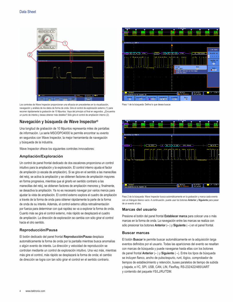
LoscontrolesdeWaveInspectorproporcionanunaeficaciasinprecedentesenlavisualización,navegaciónyanálisisdelosdatosdeformadeonda.Gireelcontroldeexploraciónexterno(1)pararecorrerrápidamentelagrabaciónde10Mpuntos.Vayadelprincipioalfinalensegundos.¿Encuentraunpuntodeinterésydeseaobtenermásdetalles?Sólogireelcontroldeampliacióninterno(2).
Paso1delabúsqueda:Definaloquedeseabuscar.
Paso2delabúsqueda:WaveInspectorbuscaautomáticamenteenlagrabaciónymarcacadaeventoconuntriánguloblancovacío.Acontinuación,puedeusarlosbotonesAnteriorySiguienteparapasardeuneventoalotro.

www.tektronix.com 5
MixedSignalOscilloscopes—MSO4000Series,DPO4000Series
Tecnología de fósforo digitalLatecnologíadefósforodigitaldelaserieMSO/DPO4000ofreceunarápidapercepcióndelfuncionamientorealdesudispositivo.Lavelocidaddecapturadeformadeondarápida,superiora50000formasdeonda/s,lebrindaaltasprobabilidadesdedetectarrápidamenteproblemaspocofrecuentescomunesensistemasdigitales:pulsosrunt,espurios,problemasdesincronizaciónymás.
Lasformasdeondasesuperponenunasconotrasylospuntosdeformadeondaqueocurrenconmayorfrecuenciaseintensifican.Estoresaltarápidamenteloseventosqueocurrenconmayorfrecuenciaeneltranscursodeltiempoo,enelcasodeanomalíaspocofrecuentes,lasqueocurrenconmenorfrecuencia.
ConlaserieMSO/DPO4000,puedeseleccionarlapersistenciainfinitaovariableydeterminarladuracióndelapermanenciaenlapantalladelasadquisicionesdeformadeondaanteriores.Estolepermitedeterminarlafrecuenciaconlaqueocurreunaanomalía.
Análisis y diseño de señal combinada (serie MSO)LososciloscopiosdeseñalcombinadaserieMSO4000ofrecen16canalesdigitales.Estoscanalesestánestrechamenteintegradosenlainterfazdeusuariodelosciloscopioysimplificanelfuncionamientoyfacilitanlaresolucióndeproblemasdeseñalcombinada.
Presentación de formas de onda digital con códigos de coloresLaserieMSO4000haredefinidolaformaenquevisualizalasformasdeondadigitales.Unproblemacomúnquecompartenlosanalizadoreslógicosylososciloscopiosdeseñalcombinadaesdeterminarsieldatoesununoouncerocuandoseamplíanlosuficientecomoparaquelatrazadigitalsemantengaplanaentodalapantalla.LaserieMSO4000poseetrazasdigitalesconcódigodecoloresymuestralosunosenverdeyloscerosenazul.
Latecnologíadefósforodigitalposibilitaunavelocidaddecapturasuperiora50000formasdeonda/syunagradacióndeintensidadentiemporealenlaserieMSO/DPO4000.
LaserieMSOofrece16canalesdigitalesintegradosquelepermitenvisualizaryanalizarseñalesanálogasydigitalesrelacionadastemporalmente.
Mediantelapresentacióndeformasdeondadigitalconcodificacióndecolores,losgrupossecreansimplementealcolocarcanalesdigitalesenformaconjuntaenlapantalla,loquepermitequeloscanalesdigitalespuedanmoversecomoungrupo.Puedeestablecerlosvaloresdeumbralparacadacanalyposibilitarlacompatibilidadhastapara16familiaslógicasdiferentes.
DataSheet
www.tektronix.com6
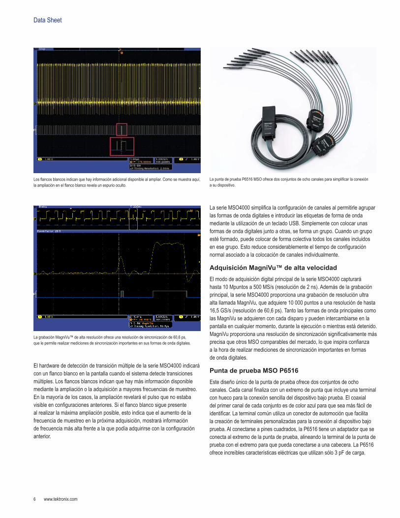
ElhardwarededeteccióndetransiciónmúltipledelaserieMSO4000indicaráconunflancoblancoenlapantallacuandoelsistemadetectetransicionesmúltiples.Losflancosblancosindicanquehaymásinformacióndisponiblemediantelaampliaciónolaadquisiciónamayoresfrecuenciasdemuestreo.Enlamayoríadeloscasos,laampliaciónrevelaráelpulsoquenoestabavisibleenconfiguracionesanteriores.Sielflancoblancosiguepresentealrealizarlamáximaampliaciónposible,estoindicaqueelaumentodelafrecuenciademuestreoenlapróximaadquisición,mostraráinformacióndefrecuenciamásaltafrentealaquepodíaadquirirseconlaconfiguraciónanterior.
LaserieMSO4000simplificalaconfiguracióndecanalesalpermitirleagruparlasformasdeondadigitaleseintroducirlasetiquetasdeformadeondamediantelautilizacióndeuntecladoUSB.Simplementeconcolocarunasformasdeondadigitalesjuntoaotras,seformaungrupo.Cuandoungrupoestéformado,puedecolocardeformacolectivatodosloscanalesincluidosenesegrupo.Estoreduceconsiderablementeeltiempodeconfiguraciónnormalasociadoalacolocacióndecanalesindividualmente.
Adquisición MagniVu™ de alta velocidadElmododeadquisicióndigitalprincipaldelaserieMSO4000capturaráhasta10Mpuntosa500MS/s(resoluciónde2ns).Ademásdelagrabaciónprincipal,laserieMSO4000proporcionaunagrabaciónderesoluciónultraaltallamadaMagniVu,queadquiere10000puntosaunaresolucióndehasta16,5GS/s(resoluciónde60,6ps).TantolasformasdeondaprincipalescomolasMagniVuseadquierenconcadadisparoypuedenintercambiarseenlapantallaencualquiermomento,durantelaejecuciónomientrasestádetenido.MagniVuproporcionaunaresolucióndesincronizaciónsignificativamentemásprecisaqueotrosMSOcomparablesdelmercado,loqueinspiraconfianzaalahoraderealizarmedicionesdesincronizaciónimportantesenformasdeondadigitales.
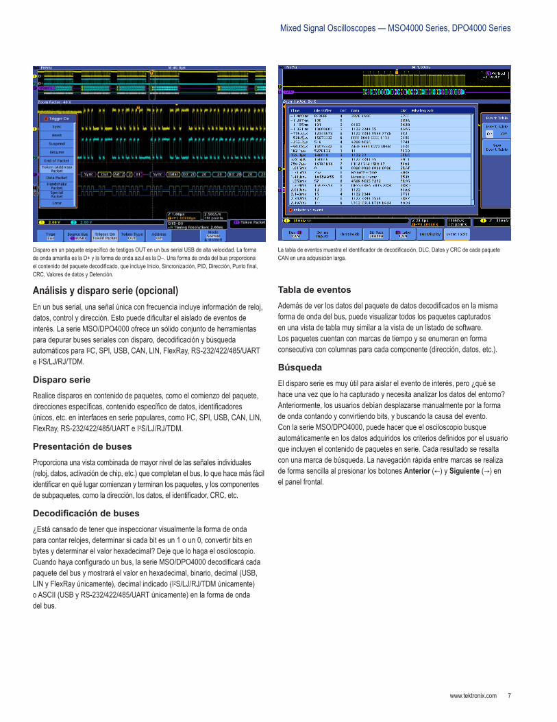
Punta de prueba MSO P6516Estediseñoúnicodelapuntadepruebaofrecedosconjuntosdeochocanales.Cadacanalfinalizaconunextremodepuntaqueincluyeunaterminalconhuecoparalaconexiónsencilladeldispositivobajoprueba.Elcoaxialdelprimercanaldecadaconjuntoesdecolorazulparaqueseamásfácildeidentificar.Laterminalcomúnutilizaunconectordeautomociónquefacilitalacreacióndeterminalespersonalizadasparalaconexiónaldispositivobajoprueba.Alconectarseapinescuadrados,laP6516tieneunadaptadorqueseconectaalextremodelapuntadeprueba,alineandolaterminaldelapuntadepruebaconelextremoparaquepuedaconectarseaunacabecera.LaP6516ofreceincreíblescaracterísticaseléctricasqueutilizansólo3pFdecarga.
Losflancosblancosindicanquehayinformaciónadicionaldisponiblealampliar.Comosemuestraaquí,laampliaciónenelflancoblancorevelaunespuriooculto.
LapuntadepruebaP6516MSOofrecedosconjuntosdeochocanalesparasimplificarlaconexiónasudispositivo.
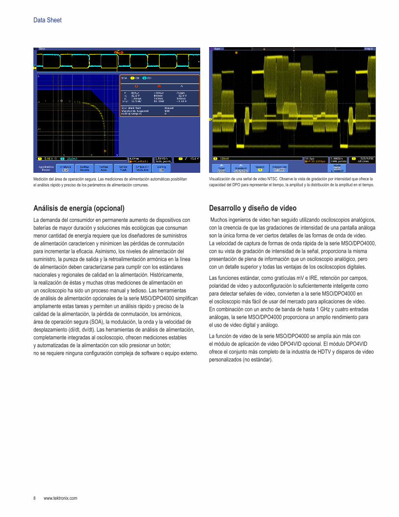
LagrabaciónMagniVu™dealtaresoluciónofreceunaresolucióndesincronizaciónde60,6ps,quelepermiterealizarmedicionesdesincronizaciónimportantesensusformasdeondadigitales.
www.tektronix.com 7
MixedSignalOscilloscopes—MSO4000Series,DPO4000Series
Análisis y disparo serie (opcional)Enunbusserial,unaseñalúnicaconfrecuenciaincluyeinformacióndereloj,datos,controlydirección.Estopuededificultarelaisladodeeventosdeinterés.LaserieMSO/DPO4000ofreceunsólidoconjuntodeherramientasparadepurarbusesserialescondisparo,decodificaciónybúsquedaautomáticosparaI2C,SPI,USB,CAN,LIN,FlexRay,RS-232/422/485/UARTeI2S/LJ/RJ/TDM.
Disparo serieRealicedisparosencontenidodepaquetes,comoelcomienzodelpaquete,direccionesespecíficas,contenidoespecíficodedatos,identificadoresúnicos,etc.eninterfacesenseriepopulares,comoI2C,SPI,USB,CAN,LIN,FlexRay,RS-232/422/485/UARTeI2S/LJ/RJ/TDM.
Presentación de busesProporcionaunavistacombinadademayorniveldelasseñalesindividuales(reloj,datos,activacióndechip,etc.)quecompletanelbus,loquehacemásfácilidentificarenquélugarcomienzanyterminanlospaquetes,yloscomponentesdesubpaquetes,comoladirección,losdatos,elidentificador,CRC,etc.
Decodificación de buses¿Estácansadodetenerqueinspeccionarvisualmentelaformadeondaparacontarrelojes,determinarsicadabitesun1oun0,convertirbitsenbytesydeterminarelvalorhexadecimal?Dejequelohagaelosciloscopio.Cuandohayaconfiguradounbus,laserieMSO/DPO4000decodificarácadapaquetedelbusymostraráelvalorenhexadecimal,binario,decimal(USB,LINyFlexRayúnicamente),decimalindicado(I2S/LJ/RJ/TDMúnicamente)oASCII(USByRS-232/422/485/UARTúnicamente)enlaformadeondadelbus.
Tabla de eventosAdemásdeverlosdatosdelpaquetededatosdecodificadosenlamismaformadeondadelbus,puedevisualizartodoslospaquetescapturadosenunavistadetablamuysimilaralavistadeunlistadodesoftware.Lospaquetescuentanconmarcasdetiempoyseenumeranenformaconsecutivaconcolumnasparacadacomponente(dirección,datos,etc.).
BúsquedaEldisparoserieesmuyútilparaaislareleventodeinterés,pero¿quésehaceunavezquelohacapturadoynecesitaanalizarlosdatosdelentorno?Anteriormente,losusuariosdebíandesplazarsemanualmenteporlaformadeondacontandoyconvirtiendobits,ybuscandolacausadelevento.ConlaserieMSO/DPO4000,puedehacerqueelosciloscopiobusqueautomáticamenteenlosdatosadquiridosloscriteriosdefinidosporelusuarioqueincluyenelcontenidodepaquetesenserie.Cadaresultadoseresaltaconunamarcadebúsqueda.LanavegaciónrápidaentremarcasserealizadeformasencillaalpresionarlosbotonesAnterior(←)ySiguiente(→)enelpanelfrontal.
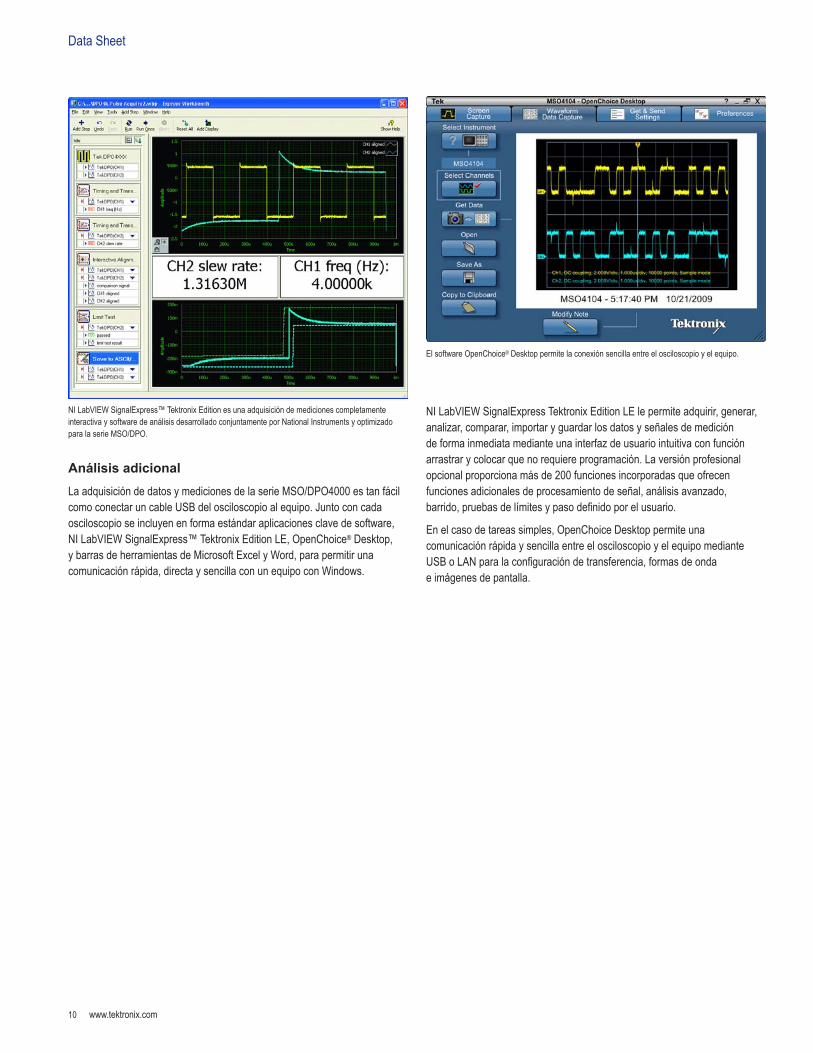
DisparoenunpaqueteespecíficodetestigosOUTenunbusserialUSBdealtavelocidad.LaformadeondaamarillaeslaD+ylaformadeondaazuleslaD–.Unaformadeondadelbusproporcionaelcontenidodelpaquetedecodificado,queincluyeInicio,Sincronización,PID,Dirección,Puntofinal,CRC,ValoresdedatosyDetención.
Latabladeeventosmuestraelidentificadordedecodificación,DLC,DatosyCRCdecadapaqueteCANenunaadquisiciónlarga.
DataSheet
www.tektronix.com8
Análisis de energía (opcional)Lademandadelconsumidorenpermanenteaumentodedispositivosconbateríasdemayorduraciónysolucionesmásecológicasqueconsumanmenorcantidaddeenergíarequierequelosdiseñadoresdesuministrosdealimentacióncaractericenyminimicenlaspérdidasdeconmutaciónparaincrementarlaeficacia.Asimismo,losnivelesdealimentacióndelsuministro,lapurezadesalidaylaretroalimentaciónarmónicaenlalíneadealimentacióndebencaracterizarseparacumplirconlosestándaresnacionalesyregionalesdecalidadenlaalimentación.Históricamente,larealizacióndeéstasymuchasotrasmedicionesdealimentaciónenunosciloscopiohasidounprocesomanualytedioso.LasherramientasdeanálisisdealimentaciónopcionalesdelaserieMSO/DPO4000simplificanampliamenteestastareasypermitenunanálisisrápidoyprecisodelacalidaddelaalimentación,lapérdidadeconmutación,losarmónicos,áreadeoperaciónsegura(SOA),lamodulación,laondaylavelocidaddedesplazamiento(di/dt,dv/dt).Lasherramientasdeanálisisdealimentación,completamenteintegradasalosciloscopio,ofrecenmedicionesestablesyautomatizadasdelaalimentaciónconsólopresionarunbotón;noserequiereningunaconfiguracióncomplejadesoftwareoequipoexterno.
Desarrollo y diseño de videoMuchosingenierosdevideohanseguidoutilizandoosciloscopiosanalógicos,conlacreenciadequelasgradacionesdeintensidaddeunapantallaanálogasonlaúnicaformadeverciertosdetallesdelasformasdeondadevideo.LavelocidaddecapturadeformasdeondarápidadelaserieMSO/DPO4000,consuvistadegradacióndeintensidaddelaseñal,proporcionalamismapresentacióndeplenadeinformaciónqueunosciloscopioanalógico,peroconundetallesuperiorytodaslasventajasdelososciloscopiosdigitales.
Lasfuncionesestándar,comogratículasmVeIRE,retenciónporcampos,polaridaddevideoyautoconfiguraciónlosuficientementeinteligentecomoparadetectarseñalesdevideo,conviertenalaserieMSO/DPO4000enelosciloscopiomásfácildeusardelmercadoparaaplicacionesdevideo.Encombinaciónconunanchodebandadehasta1GHzycuatroentradasanálogas,laserieMSO/DPO4000proporcionaunampliorendimientoparaelusodevideodigitalyanálogo.
LafuncióndevideodelaserieMSO/DPO4000seamplíaaúnmásconelmódulodeaplicacióndevideoDPO4VIDopcional.ElmóduloDPO4VIDofreceelconjuntomáscompletodelaindustriadeHDTVydisparosdevideopersonalizados(noestándar).
Medicióndeláreadeoperaciónsegura.Lasmedicionesdealimentaciónautomáticasposibilitanelanálisisrápidoyprecisodelosparámetrosdealimentacióncomunes.
VisualizacióndeunaseñaldevideoNTSC.ObservelavistadegradaciónporintensidadqueofrecelacapacidaddelDPOpararepresentareltiempo,laamplitudyladistribucióndelaamplitudeneltiempo.

www.tektronix.com 9
MixedSignalOscilloscopes—MSO4000Series,DPO4000Series
Diseñados para facilitar su trabajoAmplia pantalla de alta resoluciónLaserieMSO/DPO4000cuentaconunapantallaXGAacolorde10,4in(264mm)paraverdetallesdeseñalminuciosos.
Controles dedicados del panel frontalLoscontrolesporcanalverticalesproporcionanunfuncionamientosencilloeintuitivo.Yanoesnecesariocompartirunconjuntodecontrolesverticalesparaloscuatrocanales.
ConectividadUnpuertohostUSBdelpanelfrontalpermitelatransferenciasencilladecapturasdepantalla,laconfiguracióndelinstrumentoylosdatosdelaformadeondaaunaunidadUSB.ElpanelposteriorincluyedospuertoshostUSBadicionalesyunpuertodedispositivoUSBparacontrolarelosciloscopiodeformaremotadesdeunequipoopararealizarlaconexiónauntecladoUSB.ElpuertodedispositivoUSBtambiénpuedeusarseparaimprimirdirectamenteenunaimpresoracompatibleconPictBridge®.UnpuertoEthernet10/100integradopermitelaconexiónsencillaaredesyunpuertodesalidadevideopermitelaexportacióndelapantalladelosciloscopioaunmonitoroproyectorexterno.
Factor de forma compactoUnfactordeformaportátilycompactopermiteeltrasladosencillodelaserieMSO/DPO4000entrelaboratoriosy,conunaprofundidaddeapenas5,4in(137mm),lepermiteahorrarespaciovaliosoensubancodepruebas.
Interfaz de la punta de prueba TekVPI®
LainterfazdelapuntadepruebaTekVPIestableceelestándardesimplicidadenlaconexióndepuntas.LaspuntasdepruebaTekVPIincluyencontroleseindicadoresdeestadoyunbotóndemenúdelapuntadepruebaenelmismocuadrodecompensación.Estebotónconduceaunmenúdelapuntadepruebaenlapantalladelosciloscopioconcontrolesyconfiguraciónrelevantesparalapuntadeprueba.LainterfazTekVPIpermitelaconexióndirectadepuntasdecorrientesinnecesidaddeutilizarunsuministrodealimentaciónindependiente.EsposiblecontrolarlaspuntasTekVPIdemaneraremotamedianteUSB,GPIBoEthernet,loqueproporcionasolucionesmásversátilesenentornosATE.
LaserieMSO/DPO4000fuediseñadaparafacilitarsutrabajo.Laampliapantalladealtaresoluciónmuestradetallesdeseñalminuciosos.Loscontrolesdedicadosdepanelfrontalsimplificanelfuncionamiento.ElpuertohostUSBdelpanelfrontallepermitetransferirdeformasencillacapturasdepantalla,laconfiguracióndelinstrumentoylosdatosdelaformadeondaaunaunidadUSB.
ElfactordeformacompactodelaserieMSO/DPO4000liberaunespaciovaliosoensuosciloscopiodebancooescritorio.
LainterfazdelapuntadepruebaTekVPIsimplificalaconexióndelaspuntasalosciloscopio.
DataSheet
www.tektronix.com10
Análisis adicionalLaadquisicióndedatosymedicionesdelaserieMSO/DPO4000estanfácilcomoconectaruncableUSBdelosciloscopioalequipo.Juntoconcadaosciloscopioseincluyenenformaestándaraplicacionesclavedesoftware,NILabVIEWSignalExpress™TektronixEditionLE,OpenChoice®Desktop,ybarrasdeherramientasdeMicrosoftExcelyWord,parapermitirunacomunicaciónrápida,directaysencillaconunequipoconWindows.
NILabVIEWSignalExpressTektronixEditionLElepermiteadquirir,generar,analizar,comparar,importaryguardarlosdatosyseñalesdemedicióndeformainmediatamedianteunainterfazdeusuariointuitivaconfunciónarrastrarycolocarquenorequiereprogramación.Laversiónprofesionalopcionalproporcionamásde200funcionesincorporadasqueofrecenfuncionesadicionalesdeprocesamientodeseñal,análisisavanzado,barrido,pruebasdelímitesypasodefinidoporelusuario.
Enelcasodetareassimples,OpenChoiceDesktoppermiteunacomunicaciónrápidaysencillaentreelosciloscopioyelequipomedianteUSBoLANparalaconfiguracióndetransferencia,formasdeondaeimágenesdepantalla.
NILabVIEWSignalExpress™TektronixEditionesunaadquisicióndemedicionescompletamenteinteractivaysoftwaredeanálisisdesarrolladoconjuntamenteporNationalInstrumentsyoptimizadoparalaserieMSO/DPO.
ElsoftwareOpenChoice®Desktoppermitelaconexiónsencillaentreelosciloscopioyelequipo.
www.tektronix.com 11
MixedSignalOscilloscopes—MSO4000Series,DPO4000Series
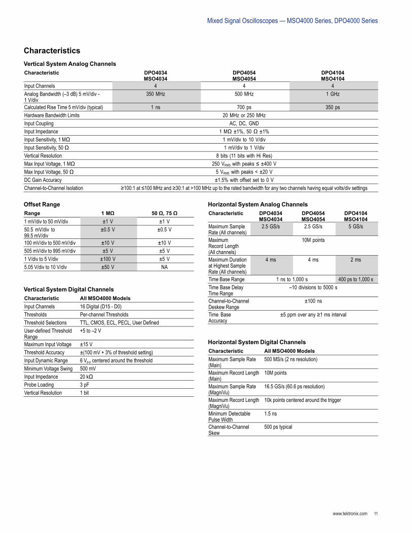
CharacteristicsVertical System Analog ChannelsCharacteristic DPO4034
MSO4034DPO4054MSO4054
DPO4104MSO4104
Input Channels 4 4 4Analog Bandwidth (–3 dB) 5 mV/div -1 V/div
350 MHz 500 MHz 1 GHz
Calculated Rise Time 5 mV/div (typical) 1 ns 700 ps 350 psHardware Bandwidth Limits 20 MHz or 250 MHzInput Coupling AC, DC, GNDInput Impedance 1 MΩ ±1%, 50 Ω ±1%Input Sensitivity, 1 MΩ 1 mV/div to 10 V/divInput Sensitivity, 50Ω 1 mV/div to 1 V/divVertical Resolution 8 bits (11 bits with Hi Res)Max Input Voltage, 1 MΩ 250 VRMS with peaks ≤ ±400 VMax Input Voltage, 50 Ω 5 VRMS with peaks < ±20 VDC Gain Accuracy ±1.5% with offset set to 0 VChannel-to-Channel Isolation ≥100:1 at ≤100 MHz and ≥30:1 at >100 MHz up to the rated bandwidth for any two channels having equal volts/div settings
Offset RangeRange 1 MΩ 50 Ω, 75 Ω1 mV/div to 50 mV/div ±1 V ±1 V50.5 mV/div to99.5 mV/div
±0.5 V ±0.5 V
100 mV/div to 500 mV/div ±10 V ±10 V505 mV/div to 995 mV/div ±5 V ±5 V1 V/div to 5 V/div ±100 V ±5 V5.05 V/div to 10 V/div ±50 V NA
Vertical System Digital ChannelsCharacteristic All MSO4000 ModelsInput Channels 16 Digital (D15 - D0)Thresholds Per-channel ThresholdsThreshold Selections TTL, CMOS, ECL, PECL, User DenedUser-dened ThresholdRange
+5 to –2 V
Maximum Input Voltage ±15 VThreshold Accuracy ±(100 mV + 3% of threshold setting)Input Dynamic Range 6 Vp-p centered around the thresholdMinimum Voltage Swing 500 mVInput Impedance 20 kΩProbe Loading 3 pFVertical Resolution 1 bit
Horizontal System Analog ChannelsCharacteristic DPO4034
MSO4034DPO4054MSO4054
DPO4104MSO4104
Maximum SampleRate (All channels)
2.5 GS/s 2.5 GS/s 5 GS/s
MaximumRecord Length(All channels)
10M points
Maximum Durationat Highest SampleRate (All channels)
4 ms 4 ms 2 ms
Time Base Range 1 ns to 1,000 s 400 ps to 1,000 sTime Base DelayTime Range
–10 divisions to 5000 s
Channel-to-ChannelDeskew Range
±100 ns
Time BaseAccuracy
±5 ppm over any ≥1 ms interval
Horizontal System Digital ChannelsCharacteristic All MSO4000 ModelsMaximum Sample Rate(Main)
500 MS/s (2 ns resolution)
Maximum Record Length(Main)
10M points
Maximum Sample Rate(MagniVu)
16.5 GS/s (60.6 ps resolution)
Maximum Record Length(MagniVu)
10k points centered around the trigger
Minimum DetectablePulse Width
1.5 ns
Channel-to-ChannelSkew
500 ps typical
DataSheet
www.tektronix.com12
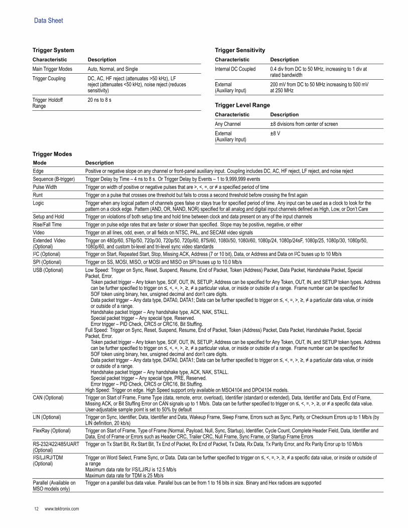
Trigger SystemCharacteristic Description
Main Trigger Modes Auto, Normal, and SingleTrigger Coupling DC, AC, HF reject (attenuates >50 kHz), LF
reject (attenuates <50 kHz), noise reject (reducessensitivity)
Trigger HoldoffRange
20 ns to 8 s
Trigger SensitivityCharacteristic Description
Internal DC Coupled 0.4 div from DC to 50 MHz, increasing to 1 div atrated bandwidth
External(Auxiliary Input)
200 mV from DC to 50 MHz increasing to 500 mVat 250 MHz
Trigger Level RangeCharacteristic Description
Any Channel ±8 divisions from center of screenExternal(Auxiliary Input)
±8 V
Trigger ModesMode DescriptionEdge Positive or negative slope on any channel or front-panel auxiliary input. Coupling includes DC, AC, HF reject, LF reject, and noise rejectSequence (B-trigger) Trigger Delay by Time – 4 ns to 8 s. Or Trigger Delay by Events – 1 to 9,999,999 eventsPulse Width Trigger on width of positive or negative pulses that are >, <, =, or ≠ a specied period of timeRunt Trigger on a pulse that crosses one threshold but fails to cross a second threshold before crossing the rst againLogic Trigger when any logical pattern of channels goes false or stays true for specied period of time. Any input can be used as a clock to look for the
pattern on a clock edge. Pattern (AND, OR, NAND, NOR) specied for all analog and digital input channels dened as High, Low, or Don’t CareSetup and Hold Trigger on violations of both setup time and hold time between clock and data present on any of the input channelsRise/Fall Time Trigger on pulse edge rates that are faster or slower than specied. Slope may be positive, negative, or eitherVideo Trigger on all lines, odd, even, or all elds on NTSC, PAL, and SECAM video signalsExtended Video(Optional)
Trigger on 480p/60, 576p/50, 720p/30, 720p/50, 720p/60, 875i/60, 1080i/50, 1080i/60, 1080p/24, 1080p/24sF, 1080p/25, 1080p/30, 1080p/50,1080p/60, and custom bi-level and tri-level sync video standards
I2C (Optional) Trigger on Start, Repeated Start, Stop, Missing ACK, Address (7 or 10 bit), Data, or Address and Data on I2C buses up to 10 Mb/sSPI (Optional) Trigger on SS, MOSI, MISO, or MOSI and MISO on SPI buses up to 10.0 Mb/sUSB (Optional) Low Speed: Trigger on Sync, Reset, Suspend, Resume, End of Packet, Token (Address) Packet, Data Packet, Handshake Packet, Special
Packet, Error.Token packet trigger – Any token type, SOF, OUT, IN, SETUP; Address can be specied for Any Token, OUT, IN, and SETUP token types. Addresscan be further specied to trigger on ≤, <, =, >, ≥, ≠ a particular value, or inside or outside of a range. Frame number can be specied forSOF token using binary, hex, unsigned decimal and don’t care digits.Data packet trigger – Any data type, DATA0, DATA1; Data can be further specied to trigger on ≤, <, =, >, ≥, ≠ a particular data value, or insideor outside of a range.Handshake packet trigger – Any handshake type, ACK, NAK, STALL.Special packet trigger – Any special type, Reserved.Error trigger – PID Check, CRC5 or CRC16, Bit Stufng.
Full Speed: Trigger on Sync, Reset, Suspend, Resume, End of Packet, Token (Address) Packet, Data Packet, Handshake Packet, SpecialPacket, Error.
Token packet trigger – Any token type, SOF, OUT, IN, SETUP; Address can be specied for Any Token, OUT, IN, and SETUP token types. Addresscan be further specied to trigger on ≤, <, =, >, ≥, ≠ a particular value, or inside or outside of a range. Frame number can be specied forSOF token using binary, hex, unsigned decimal and don’t care digits.Data packet trigger – Any data type, DATA0, DATA1; Data can be further specied to trigger on ≤, <, =, >, ≥, ≠ a particular data value, or insideor outside of a range.Handshake packet trigger – Any handshake type, ACK, NAK, STALL.Special packet trigger – Any special type, PRE, Reserved.Error trigger – PID Check, CRC5 or CRC16, Bit Stufng.
High Speed: Trigger on edge. High Speed support only available on MSO4104 and DPO4104 models.CAN (Optional) Trigger on Start of Frame, Frame Type (data, remote, error, overload), Identier (standard or extended), Data, Identier and Data, End of Frame,
Missing ACK, or Bit Stufng Error on CAN signals up to 1 Mb/s. Data can be further specied to trigger on ≤, <, =, >, ≥, or ≠ a specic data value.User-adjustable sample point is set to 50% by default
LIN (Optional) Trigger on Sync, Identier, Data, Identier and Data, Wakeup Frame, Sleep Frame, Errors such as Sync, Parity, or Checksum Errors up to 1 Mb/s (byLIN denition, 20 kb/s)
FlexRay (Optional) Trigger on Start of Frame, Type of Frame (Normal, Payload, Null, Sync, Startup), Identier, Cycle Count, Complete Header Field, Data, Identier andData, End of Frame or Errors such as Header CRC, Trailer CRC, Null Frame, Sync Frame, or Startup Frame Errors
RS-232/422/485/UART(Optional)
Trigger on Tx Start Bit, Rx Start Bit, Tx End of Packet, Rx End of Packet, Tx Data, Rx Data, Tx Parity Error, and Rx Parity Error up to 10 Mb/s
I2S/LJ/RJ/TDM(Optional)
Trigger on Word Select, Frame Sync, or Data. Data can be further specied to trigger on ≤, <, =, >, ≥, ≠ a specic data value, or inside or outside ofa rangeMaximum data rate for I2S/LJ/RJ is 12.5 Mb/sMaximum data rate for TDM is 25 Mb/s
Parallel (Available onMSO models only)
Trigger on a parallel bus data value. Parallel bus can be from 1 to 16 bits in size. Binary and Hex radices are supported
www.tektronix.com 13
MixedSignalOscilloscopes—MSO4000Series,DPO4000Series
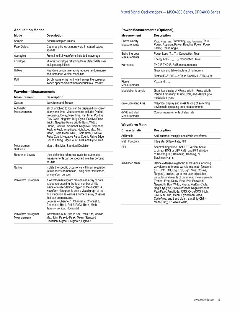
Acquisition ModesMode Description
Sample Acquire sampled valuesPeak Detect Captures glitches as narrow as 2 ns at all sweep
speedsAveraging From 2 to 512 waveforms included in averageEnvelope Min-max envelope reecting Peak Detect data over
multiple acquisitionsHi Res Real-time boxcar averaging reduces random noise
and increases vertical resolutionRoll Scrolls waveforms right to left across the screen at
sweep speeds slower than or equal to 40 ms/div
Waveform MeasurementsMeasurement Description
Cursors Waveform and ScreenAutomaticMeasurements
29, of which up to four can be displayed on-screenat any one time. Measurements include: Period,Frequency, Delay, Rise Time, Fall Time, PositiveDuty Cycle, Negative Duty Cycle, Positive PulseWidth, Negative Pulse Width, Burst Width,Phase, Positive Overshoot, Negative Overshoot,Peak-to-Peak, Amplitude, High, Low, Max, Min,Mean, Cycle Mean, RMS, Cycle RMS, PositivePulse Count, Negative Pulse Count, Rising EdgeCount, Falling Edge Count, Area and Cycle Area
MeasurementStatistics
Mean, Min, Max, Standard Deviation
Reference Levels User-denable reference levels for automaticmeasurements can be specied in either percentor units
Gating Isolate the specic occurrence within an acquisitionto take measurements on, using either the screen,or waveform cursors
Waveform Histogram A waveform histogram provides an array of datavalues representing the total number of hitsinside of a user-dened region of the display. Awaveform histogram is both a visual graph of thehit distribution as well as a numeric array of valuesthat can be measured.Sources – Channel 1, Channel 2, Channel 3,Channel 4, Ref 1, Ref 2, Ref 3, Ref 4, MathTypes – Vertical, Horizontal
Waveform HistogramMeasurements
Waveform Count, Hits in Box, Peak Hits, Median,Max, Min, Peak-to-Peak, Mean, StandardDeviation, Sigma 1, Sigma 2, Sigma 3
Power Measurements (Optional)Measurement Description
Power QualityMeasurements
VRMS, VCrest Factor, Frequency, IRMS, ICrest Factor, TruePower, Apparent Power, Reactive Power, PowerFactor, Phase AnglePower Loss: Ton, Toff, Conduction, TotalSwitching Loss
Measurements Energy Loss: Ton, Toff, Conduction, TotalTHD-F, THD-R, RMS measurementsGraphical and table displays of harmonics
Harmonics
Test to IEC61000-3-2 Class A and MIL-STD-1399RippleMeasurements
Vripple and Iripple
Modulation Analysis Graphical display of +Pulse Width, –Pulse Width,Period, Frequency, +Duty Cycle, and –Duty Cyclemodulation types
Safe Operating Area Graphical display and mask testing of switchingdevice safe operating area measurements
dV/dt and dI/dtMeasurements
Cursor measurements of slew rate
Waveform MathCharacteristic Description
Arithmetic Add, subtract, multiply, and divide waveformsMath Functions Integrate, Differentiate, FFTFFT Spectral magnitude. Set FFT Vertical Scale
to Linear RMS or dBV RMS, and FFT Windowto Rectangular, Hamming, Hanning, orBlackman-Harris
Advanced Math Dene extensive algebraic expressions includingwaveforms, reference waveforms, math functions(FFT, Intg, Diff, Log, Exp, Sqrt, Sine, Cosine,Tangent), scalars, up to two user-adjustablevariables and results of parametric measurements(Period, Freq, Delay, Rise, Fall, PosWidth,NegWidth, BurstWidth, Phase, PosDutyCycle,NegDutyCycle, PosOverShoot, NegOverShoot,PeakPeak, Amplitude, RMS, CycleRMS, High,Low, Max, Min, Mean, CycleMean, Area,CycleArea, and trend plots), e.g.,(Intg(Ch1 –Mean(Ch1)) × 1.414 × VAR1)
DataSheet
www.tektronix.com14
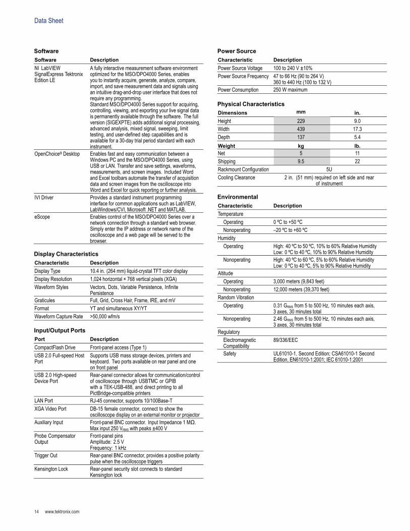
SoftwareSoftware DescriptionNI LabVIEWSignalExpress TektronixEdition LE
A fully interactive measurement software environmentoptimized for the MSO/DPO4000 Series, enablesyou to instantly acquire, generate, analyze, compare,import, and save measurement data and signals usingan intuitive drag-and-drop user interface that does notrequire any programming.Standard MSO/DPO4000 Series support for acquiring,controlling, viewing, and exporting your live signal datais permanently available through the software. The fullversion (SIGEXPTE) adds additional signal processing,advanced analysis, mixed signal, sweeping, limittesting, and user-dened step capabilities and isavailable for a 30-day trial period standard with eachinstrument.
OpenChoice® Desktop Enables fast and easy communication between aWindows PC and the MSO/DPO4000 Series, usingUSB or LAN. Transfer and save settings, waveforms,measurements, and screen images. Included Wordand Excel toolbars automate the transfer of acquisitiondata and screen images from the oscilloscope intoWord and Excel for quick reporting or further analysis.
IVI Driver Provides a standard instrument programminginterface for common applications such as LabVIEW,LabWindows/CVI, Microsoft .NET and MATLAB.
eScope Enables control of the MSO/DPO4000 Series over anetwork connection through a standard web browser.Simply enter the IP address or network name of theoscilloscope and a web page will be served to thebrowser.
Display CharacteristicsCharacteristic DescriptionDisplay Type 10.4 in. (264 mm) liquid-crystal TFT color displayDisplay Resolution 1,024 horizontal × 768 vertical pixels (XGA)Waveform Styles Vectors, Dots, Variable Persistence, Innite
PersistenceGraticules Full, Grid, Cross Hair, Frame, IRE, and mVFormat YT and simultaneous XY/YTWaveform Capture Rate >50,000 wfm/s
Input/Output PortsPort DescriptionCompactFlash Drive Front-panel access (Type 1)USB 2.0 Full-speed HostPort
Supports USB mass storage devices, printers andkeyboard. Two ports available on rear panel and oneon front panel
USB 2.0 High-speedDevice Port
Rear-panel connector allows for communication/controlof oscilloscope through USBTMC or GPIBwith a TEK-USB-488, and direct printing to allPictBridge-compatible printers
LAN Port RJ-45 connector, supports 10/100Base-TXGA Video Port DB-15 female connector, connect to show the
oscilloscope display on an external monitor or projectorAuxiliary Input Front-panel BNC connector. Input Impedance 1 MΩ.
Max input 250 VRMS with peaks ±400 VProbe CompensatorOutput
Front-panel pinsAmplitude: 2.5 VFrequency: 1 kHz
Trigger Out Rear-panel BNC connector, provides a positive polaritypulse when the oscilloscope triggers
Kensington Lock Rear-panel security slot connects to standardKensington lock
Power SourceCharacteristic DescriptionPower Source Voltage 100 to 240 V ±10%Power Source Frequency 47 to 66 Hz (90 to 264 V)
360 to 440 Hz (100 to 132 V)Power Consumption 250 W maximum
Physical CharacteristicsDimensions mm in.Height 229 9.0Width 439 17.3Depth 137 5.4Weight kg lb.Net 5 11Shipping 9.5 22Rackmount Conguration 5UCooling Clearance 2 in. (51 mm) required on left side and rear
of instrument
EnvironmentalCharacteristic DescriptionTemperature
Operating 0 ºC to +50 ºCNonoperating –20 ºC to +60 ºC
HumidityOperating High: 40 ºC to 50 ºC, 10% to 60% Relative Humidity
Low: 0 ºC to 40 ºC, 10% to 90% Relative HumidityNonoperating High: 40 ºC to 60 ºC, 5% to 60% Relative Humidity
Low: 0 ºC to 40 ºC, 5% to 90% Relative HumidityAltitude
Operating 3,000 meters (9,843 feet)Nonoperating 12,000 meters (39,370 feet)
Random VibrationOperating 0.31 GRMS from 5 to 500 Hz, 10 minutes each axis,
3 axes, 30 minutes totalNonoperating 2.46 GRMS from 5 to 500 Hz, 10 minutes each axis,
3 axes, 30 minutes totalRegulatory
ElectromagneticCompatibility
89/336/EEC
Safety UL61010-1, Second Edition; CSA61010-1 SecondEdition, EN61010-1:2001; IEC 61010-1:2001
www.tektronix.com 15
MixedSignalOscilloscopes—MSO4000Series,DPO4000Series
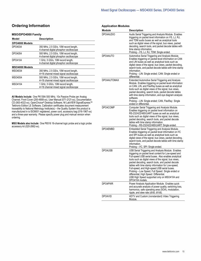
Ordering Information
MSO/DPO4000 FamilyModel DescriptionDPO4000 ModelsDPO4034 350 MHz, 2.5 GS/s, 10M record length,
4-channel digital phosphor oscilloscopeDPO4054 500 MHz, 2.5 GS/s, 10M record length,
4-channel digital phosphor oscilloscopeDPO4104 1 GHz, 5 GS/s, 10M record length,
4-channel digital phosphor oscilloscopeMSO4000 ModelsMSO4034 350 MHz, 2.5 GS/s, 10M record length,
4+16 channel mixed signal oscilloscopeMSO4054 500 MHz, 2.5 GS/s, 10M record length,
4+16 channel mixed signal oscilloscopeMSO4104 1 GHz, 5 GS/s, 10M record length,
4+16 channel mixed signal oscilloscope
All Models Include: One P6139A 500 MHz, 10x Passive Probe per AnalogChannel, Front Cover (200-4908-xx), User Manual (071-2121-xx), DocumentationCD (063-4022-xx), OpenChoice® Desktop Software, NI LabVIEW SignalExpress™Tektronix Edition LE Software, Calibration certicates document measurementtraceability to National Metrology Institute(s) – the Quality System this product ismanufactured in is ISO9001 registered, power cord, accessory bag (016-1967-xx)and a three-year warranty. Please specify power plug and manual version whenordering.
MSO Models also Include: One P6516 16-channel logic probe and a logic probeaccessory kit (020-2662-xx).
Application ModulesModule DescriptionDPO4AUDIO Audio Serial Triggering and Analysis Module. Enables
triggering on packet level information on I2S, LJ, RJ,and TDM audio buses as well as analytical toolssuch as digital views of the signal, bus views, packetdecoding, search tools, and packet decode tables withtime stamp information.Probing – I2S, LJ, RJ, TDM: Single ended.
DPO4AUTO Automotive Serial Triggering and Analysis Module.Enables triggering on packet level information on CANand LIN buses as well as analytical tools such asdigital views of the signal, bus views, packet decoding,search tools, and packet decode tables with time stampinformation.Probing – LIN: Single ended; CAN: Single ended ordifferential.
DPO4AUTOMAX Extended Automotive Serial Triggering and AnalysisModule. Enables triggering on packet level informationon CAN, LIN, and FlexRay buses as well as analyticaltools such as digital views of the signal, bus views,packet decoding, search tools, packet decode tableswith time stamp information, and eye diagram analysissoftware.Probing – LIN: Single ended; CAN, FlexRay: Singleended or differential.
DPO4COMP Computer Serial Triggering and Analysis Module.Enables triggering on packet level information onRS-232/422/485/UART buses as well as analyticaltools such as digital views of the signal, bus views,packet decoding, search tools, and packet decodetables with time stamp information.Probing – RS-232/422/485/UART: Single ended.
DPO4EMBD Embedded Serial Triggering and Analysis Module.Enables triggering on packet level information on I2Cand SPI buses as well as analytical tools such asdigital views of the signal, bus views, packet decoding,search tools, and packet decode tables with time stampinformation.Probing – I2C, SPI: Single ended.
DPO4USB USB Serial Triggering and Analysis Module. Enablestriggering on packet level content for Low-speed andFull-speed USB serial buses. Also enables analyticaltools such as digital views of the signal, bus views,packet decoding, search tools, and packet decodetables with time stamp information for Low-speed,Full-speed, and High-speed USB serial buses.Probing – Low Speed, Full Speed: Single ended ordifferential; High Speed: Differential.USB High Speed supported only on MSO4104 andDPO4104 models.
DPO4PWR Power Analysis Application Module. Enables quickand accurate analysis of power quality, switching loss,harmonics, safe operating area (SOA), modulation,ripple, and slew rate (dI/dt, dV/dt).
DPO4VID HDTV and Custom (nonstandard) Video TriggeringModule.
DataSheet
www.tektronix.com16
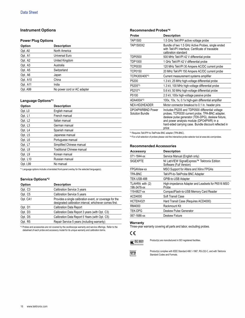
Instrument Options
Power Plug OptionsOption DescriptionOpt. A0 North AmericaOpt. A1 Universal EuroOpt. A2 United KingdomOpt. A3 AustraliaOpt. A5 SwitzerlandOpt. A6 JapanOpt. A10 ChinaOpt. A11 IndiaOpt. A99 No power cord or AC adapter
Language Options*1Option DescriptionOpt. L0 English manualOpt. L1 French manualOpt. L2 Italian manualOpt. L3 German manualOpt. L4 Spanish manualOpt. L5 Japanese manualOpt. L6 Portuguese manualOpt. L7 Simplied Chinese manualOpt. L8 Traditional Chinese manualOpt. L9 Korean manualOpt. L10 Russian manualOpt. L99 No manual*1 Language options include a translated front-panel overlay for the selected language(s).
Service Options*2Option DescriptionOpt. C3 Calibration Service 3 yearsOpt. C5 Calibration Service 5 yearsOpt. CA1 Provides a single calibration event, or coverage for the
designated calibration interval, whichever comes rst.Opt. D1 Calibration Data ReportOpt. D3 Calibration Data Report 3 years (with Opt. C3)Opt. D5 Calibration Data Report 5 Years (with Opt. C5)Opt. R5 Repair Service 5 years (including warranty)*2 Probes and accessories are not covered by the oscilloscope warranty and service offerings. Refer to thedatasheet of each probe and accessory model for its unique warranty and calibration terms.
Recommended Probes*4Probe DescriptionTAP1500 1.5 GHz TekVPI® active voltage probeTAP1500X2 Bundle of two 1.5 GHz Active Probes, single ended
with TekVPI Interface; Certicate of traceablecalibration standard
TDP0500 500 MHz TekVPI 42 V differential probeTDP1000 1 GHz TekVPI 42 V differential probeTCP0030 120 MHz TekVPI 30 Ampere AC/DC current probeTCP0150 20 MHz TekVPI 150 Ampere AC/DC current probeTCPA300/400*3 Current measurement systems amplierP5200 1.3 kV, 25 MHz high-voltage differential probeP5205*3 1.3 kV, 100 MHz high-voltage differential probeP5210*3 5.6 kV, 50 MHz high-voltage differential probeP5100 2.5 kV, 100x high-voltage passive probeADA400A*3 100x, 10x, 1x, 0.1x high-gain differential amplierNEX-HD2HEADER Mictor connector breakout to 0.1 in. header pinsDPO4PWRBND PowerSolution Bundle
Includes P5205 and TDP0500 differential voltageprobes, TCP0030 current probe, TPA-BNC adapter,deskew pulse generator (TEK-DPG), deskew xture,and power analysis module (DPO4PWR) in ahard-sided carrying case. Bundle discount reected inprice
*3 Requires TekVPI®-to-TekProbe BNC adapter (TPA-BNC).*4 For a full selection of probes please visit the interactive probe selector tool at www.tek.com/probes.
Recommended AccessoriesAccessory Description071-1844-xx Service Manual (English only)SIGEXPTE NI LabVIEW SignalExpress™ Tektronix Edition
Software (Full Version)FPGAView-xx MSO Support for Altera and Xilinx FPGAsTPA-BNC TekVPI-to-TekProbe BNC AdapterTEK-USB-488 GPIB-to-USB AdapterTLAHRA with (2)196-3476-xx
High-impedance Adapter and Leadsets for P6516 MSOProbe
119-6827-xx CompactFlash-to-USB Memory Card ReaderACD4000 Soft Transit CaseHCTEK4321 Hard Transit Case (Requires ACD4000)RM4000 Rackmount KitTEK-DPG Deskew Pulse Generator067-1686-xx Deskew Fixture
WarrantyThree-year warranty covering all parts and labor, excluding probes.
Product(s) are manufactured in ISO registered facilities.
Product(s) complies with IEEE Standard 488.1-1987, RS-232-C, and with TektronixStandard Codes and Formats.