may 18, 2015 state of rhode island and providence ... · division of purchases bid no. 7549519 ....
TRANSCRIPT

May 18, 2015
STATE OF RHODE ISLAND AND PROVIDENCE PLANTATION DEPARTMENT OF ADMINISTRATION
DIVISION OF PURCHASES BID NO. 7549519
RHODE ISLAND DEPARTMENT OF TRANSPORTATION
RHODE ISLAND CONTRACT NO.2015-CB-033
FEDERAL-AID PROJECT NO. FAP Nos: BRO-0777(001)
Pleasant Valley Parkway Bridge No. 777
Dean Street to Pleasant Valley Parkway, Acorn Street to Bath Street.
CITY/TOWN OF Providence
COUNTY OF PROVIDENCE
NOTICE TO PROSPECTIVE BIDDERS
ADDENDUM NO. 2 Prospective bidders and all concerned are hereby notified of the following changes in the Plans, Specifications, Proposal and Distribution of Quantities for this contract. These changes shall be incorporated in the Plans, Specifications, Proposal and Distribution of Quantities, and shall become an integral part of the Contract Documents.
A. Clarification
1. Pre-Bid Conference
Attached to this Addendum No. 2 is the sign in sheet from the Pre-Bid Conference held on May 12, 2015 at RIDOT.
B. Contract Dates
1. Bid-Opening Date
Bid-Opening Date Updated To "05/29/2015".
C. Contract Documents
1. General Provisions - Contract Specific
a. CS-i
Delete page CS-i in its entirety and replace it with page CS-i(R-1) attached to this Addendum No. 2. The In-Water Work section has been added.
b. CS-1(R-1)
Delete page CS-1(R-1) in its entirety and replace it with page CS-1(R-2) attached to this Addendum No. 2. The Scope of Work has been revised.
ADDENDUM NO. 2 ATTACHMENTS
Page 1 of 3


Addendum - 2

GENERAL PROVISIONS‐CONTRACT SPECIFIC
INDEX
CS-i
PARAGRAPH TITLE PAGE
1 Brief Scope of Work CS‐1
2 List of Contract Drawings CS‐1
3 Utility & Municipal Notification & Coordination CS‐3
4 Coordination with Other Contracts CS‐4
5 Specialty Items CS‐5
6 Notice to Contractors CS‐5
7 Sequence of Construction and Schedule CS‐8
8 Transportation Management Plan CS‐11
9 Environmental Permits CS‐11
10 Stormwater Pollution Prevention Plan CS‐12
11 In‐Water Work CS‐12
Appendix A – Preliminary Contract Submittal List CS‐13
Appendix B – Coastal Resources Council Management – Assent CS‐18
Appendix C – Army Corp of Engineers Programmatic General
Permit
CS‐24
Appendix D – Rhode Island Department of Environmental
Management – Water Quality Certification
CS‐38
Appendix E – National Grid Guidelines and Specifications CS‐44
Appendix F – Traffic Management Plan CS‐50
Appendix G – Stormwater Pollution Prevention Plan CS‐68
Appendix H – City of Providence Technical Specifications CS‐110
Appendix I – Verizon Schedule CS‐136
Appendix J – DRAFT Remedial General Permit – Conceptual
Approval
CS‐138
Appendix K – DRAFT Remedial General Permit ‐ Application CS‐141
Appendix L – Geotechnical Reports for Informational Purposes CS‐252
Addendum - 2 (R-1)
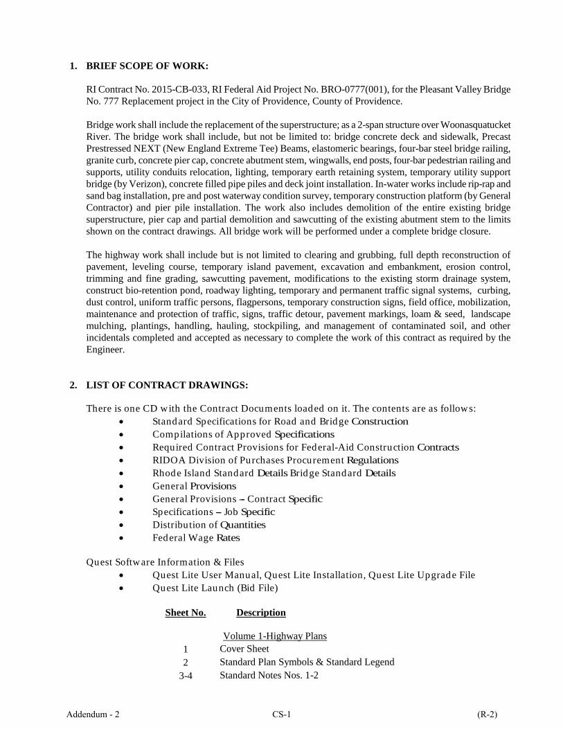
1. BRIEF SCOPE OF WORK:
RI Contract No. 2015-CB-033, RI Federal Aid Project No. BRO-0777(001), for the Pleasant Valley Bridge
No. 777 Replacement project in the City of Providence, County of Providence.
Bridge work shall include the replacement of the superstructure; as a 2-span structure over Woonasquatucket
River. The bridge work shall include, but not be limited to: bridge concrete deck and sidewalk, Precast
Prestressed NEXT (New England Extreme Tee) Beams, elastomeric bearings, four-bar steel bridge railing,
granite curb, concrete pier cap, concrete abutment stem, wingwalls, end posts, four-bar pedestrian railing and
supports, utility conduits relocation, lighting, temporary earth retaining system, temporary utility support
bridge (by Verizon), concrete filled pipe piles and deck joint installation. In-water works include rip-rap and
sand bag installation, pre and post waterway condition survey, temporary construction platform (by General
Contractor) and pier pile installation. The work also includes demolition of the entire existing bridge
superstructure, pier cap and partial demolition and sawcutting of the existing abutment stem to the limits
shown on the contract drawings. All bridge work will be performed under a complete bridge closure.
The highway work shall include but is not limited to clearing and grubbing, full depth reconstruction of
pavement, leveling course, temporary island pavement, excavation and embankment, erosion control,
trimming and fine grading, sawcutting pavement, modifications to the existing storm drainage system,
construct bio-retention pond, roadway lighting, temporary and permanent traffic signal systems, curbing,
dust control, uniform traffic persons, flagpersons, temporary construction signs, field office, mobilization,
maintenance and protection of traffic, signs, traffic detour, pavement markings, loam & seed, landscape
mulching, plantings, handling, hauling, stockpiling, and management of contaminated soil, and other
incidentals completed and accepted as necessary to complete the work of this contract as required by the
Engineer.
2. LIST OF CONTRACT DRAWINGS:
There is one CD with the Contract Documents loaded on it. The contents are as follows:
Standard Specifications for Road and Bridge Construction
Compilations of Approved Specifications
Required Contract Provisions for Federal-Aid Construction Contracts
RIDOA Division of Purchases Procurement Regulations
Rhode Island Standard Details Bridge Standard Details
General Provisions
General Provisions --- Contract Specific
Specifications --- Job Specific
Distribution of Quantities
Federal Wage Rates
Quest Software Information & Files
Quest Lite User Manual, Quest Lite Installation, Quest Lite Upgrade File
Quest Lite Launch (Bid File)
Sheet No. Description
Volume 1-Highway Plans
1 Cover Sheet
2 Standard Plan Symbols & Standard Legend
3-4 Standard Notes Nos. 1-2
Addendum - 2 CS-1 (R-2)
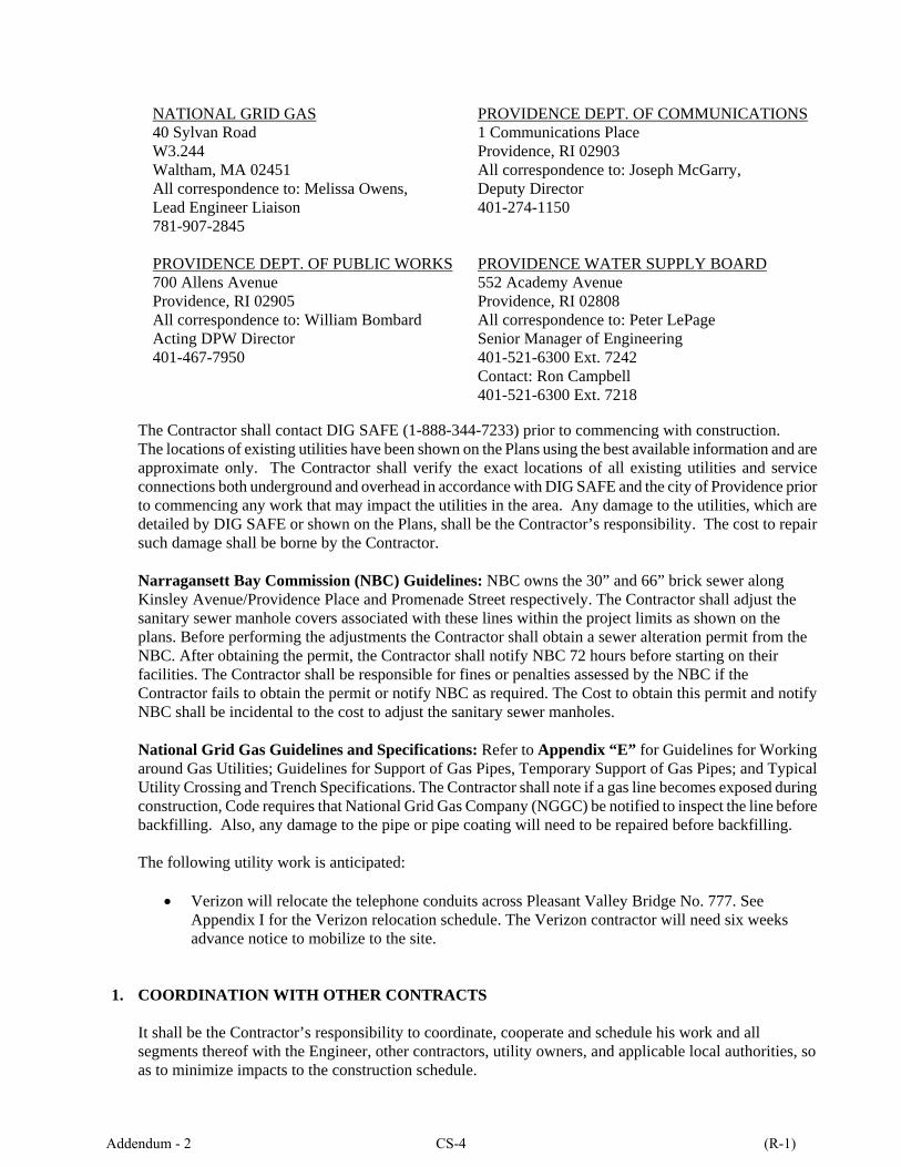
The Contractor shall contact DIG SAFE (1-888-344-7233) prior to commencing with construction. The locations of existing utilities have been shown on the Plans using the best available information and are approximate only. The Contractor shall verify the exact locations of all existing utilities and service connections both underground and overhead in accordance with DIG SAFE and the city of Providence prior to commencing any work that may impact the utilities in the area. Any damage to the utilities, which are detailed by DIG SAFE or shown on the Plans, shall be the Contractor’s responsibility. The cost to repair such damage shall be borne by the Contractor. Narragansett Bay Commission (NBC) Guidelines: NBC owns the 30” and 66” brick sewer along Kinsley Avenue/Providence Place and Promenade Street respectively. The Contractor shall adjust the sanitary sewer manhole covers associated with these lines within the project limits as shown on the plans. Before performing the adjustments the Contractor shall obtain a sewer alteration permit from the NBC. After obtaining the permit, the Contractor shall notify NBC 72 hours before starting on their facilities. The Contractor shall be responsible for fines or penalties assessed by the NBC if the Contractor fails to obtain the permit or notify NBC as required. The Cost to obtain this permit and notify NBC shall be incidental to the cost to adjust the sanitary sewer manholes.
National Grid Gas Guidelines and Specifications: Refer to Appendix “E” for Guidelines for Working around Gas Utilities; Guidelines for Support of Gas Pipes, Temporary Support of Gas Pipes; and Typical Utility Crossing and Trench Specifications. The Contractor shall note if a gas line becomes exposed during construction, Code requires that National Grid Gas Company (NGGC) be notified to inspect the line before backfilling. Also, any damage to the pipe or pipe coating will need to be repaired before backfilling. The following utility work is anticipated:
Verizon will relocate the telephone conduits across Pleasant Valley Bridge No. 777. See Appendix I for the Verizon relocation schedule. The Verizon contractor will need six weeks advance notice to mobilize to the site.
1. COORDINATION WITH OTHER CONTRACTS
It shall be the Contractor’s responsibility to coordinate, cooperate and schedule his work and all segments thereof with the Engineer, other contractors, utility owners, and applicable local authorities, so as to minimize impacts to the construction schedule.
NATIONAL GRID GAS 40 Sylvan Road W3.244 Waltham, MA 02451 All correspondence to: Melissa Owens, Lead Engineer Liaison 781-907-2845
PROVIDENCE DEPT. OF COMMUNICATIONS 1 Communications Place Providence, RI 02903 All correspondence to: Joseph McGarry, Deputy Director 401-274-1150
PROVIDENCE DEPT. OF PUBLIC WORKS 700 Allens Avenue Providence, RI 02905 All correspondence to: William Bombard Acting DPW Director 401-467-7950
PROVIDENCE WATER SUPPLY BOARD 552 Academy Avenue Providence, RI 02808 All correspondence to: Peter LePage Senior Manager of Engineering 401-521-6300 Ext. 7242 Contact: Ron Campbell 401-521-6300 Ext. 7218
Addendum - 2 CS-4 (R-1)
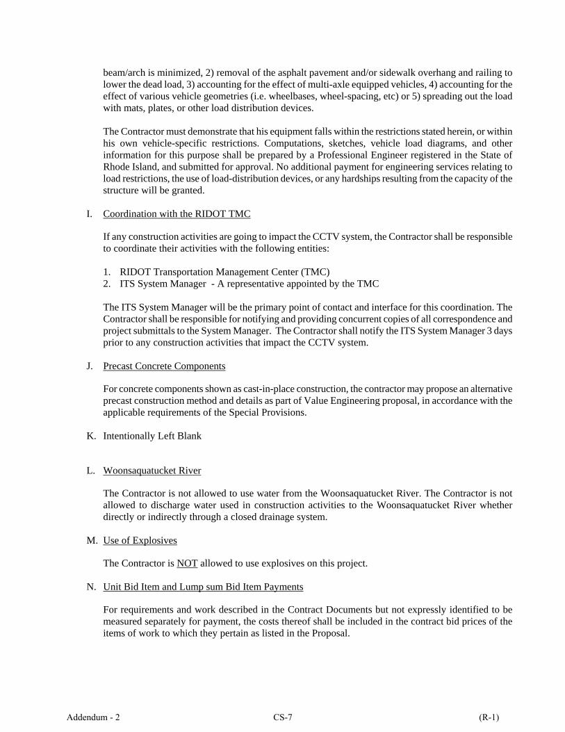
beam/arch is minimized, 2) removal of the asphalt pavement and/or sidewalk overhang and railing to lower the dead load, 3) accounting for the effect of multi-axle equipped vehicles, 4) accounting for the effect of various vehicle geometries (i.e. wheelbases, wheel-spacing, etc) or 5) spreading out the load with mats, plates, or other load distribution devices. The Contractor must demonstrate that his equipment falls within the restrictions stated herein, or within his own vehicle-specific restrictions. Computations, sketches, vehicle load diagrams, and other information for this purpose shall be prepared by a Professional Engineer registered in the State of Rhode Island, and submitted for approval. No additional payment for engineering services relating to load restrictions, the use of load-distribution devices, or any hardships resulting from the capacity of the structure will be granted.
I. Coordination with the RIDOT TMC
If any construction activities are going to impact the CCTV system, the Contractor shall be responsible to coordinate their activities with the following entities: 1. RIDOT Transportation Management Center (TMC) 2. ITS System Manager - A representative appointed by the TMC The ITS System Manager will be the primary point of contact and interface for this coordination. The Contractor shall be responsible for notifying and providing concurrent copies of all correspondence and project submittals to the System Manager. The Contractor shall notify the ITS System Manager 3 days prior to any construction activities that impact the CCTV system.
J. Precast Concrete Components
For concrete components shown as cast-in-place construction, the contractor may propose an alternative precast construction method and details as part of Value Engineering proposal, in accordance with the applicable requirements of the Special Provisions.
K. Intentionally Left Blank
L. Woonsaquatucket River
The Contractor is not allowed to use water from the Woonsaquatucket River. The Contractor is not allowed to discharge water used in construction activities to the Woonsaquatucket River whether directly or indirectly through a closed drainage system.
M. Use of Explosives
The Contractor is NOT allowed to use explosives on this project.
N. Unit Bid Item and Lump sum Bid Item Payments
For requirements and work described in the Contract Documents but not expressly identified to be measured separately for payment, the costs thereof shall be included in the contract bid prices of the items of work to which they pertain as listed in the Proposal.
Addendum - 2 CS-7 (R-1)
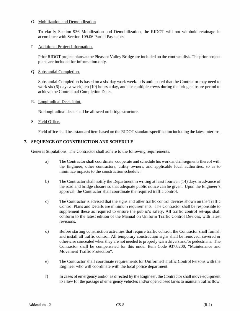
O. Mobilization and Demobilization
To clarify Section 936 Mobilization and Demobilization, the RIDOT will not withhold retainage in accordance with Section 109.06 Partial Payments.
P. Additional Project Information. Prior RIDOT project plans at the Pleasant Valley Bridge are included on the contract disk. The prior project plans are included for information only.
Q. Substantial Completion. Substantial Completion is based on a six-day work week. It is anticipated that the Contractor may need to work six (6) days a week, ten (10) hours a day, and use multiple crews during the bridge closure period to achieve the Contractual Completion Dates.
R. Longitudinal Deck Joint. No longitudinal deck shall be allowed on bridge structure.
S. Field Office. Field office shall be a standard item based on the RIDOT standard specification including the latest interims.
7. SEQUENCE OF CONSTRUCTION AND SCHEDULE
General Stipulations: The Contractor shall adhere to the following requirements:
a) The Contractor shall coordinate, cooperate and schedule his work and all segments thereof with the Engineer, other contractors, utility owners, and applicable local authorities, so as to minimize impacts to the construction schedule.
b) The Contractor shall notify the Department in writing at least fourteen (14) days in advance of the road and bridge closure so that adequate public notice can be given. Upon the Engineer’s approval, the Contractor shall coordinate the required traffic control.
c) The Contractor is advised that the signs and other traffic control devices shown on the Traffic
Control Plans and Details are minimum requirements. The Contractor shall be responsible to supplement these as required to ensure the public’s safety. All traffic control set-ups shall conform to the latest edition of the Manual on Uniform Traffic Control Devices, with latest revisions.
d) Before starting construction activities that require traffic control, the Contractor shall furnish and install all traffic control. All temporary construction signs shall be removed, covered or otherwise concealed when they are not needed to properly warn drivers and/or pedestrians. The Contractor shall be compensated for this under Item Code 937.0200, “Maintenance and Movement Traffic Protection”.
e) The Contractor shall coordinate requirements for Uniformed Traffic Control Persons with the Engineer who will coordinate with the local police department.
f) In cases of emergency and/or as directed by the Engineer, the Contractor shall move equipment
to allow for the passage of emergency vehicles and/or open closed lanes to maintain traffic flow.
Addendum - 2 CS-8 (R-1)

o All final traffic signal equipment shall be fully operational with the exceptionof the P1/P6 and P4 pedestrian signal poles (precast foundations shall be usedfor these poles in order to expedite the installation after the final traffic patternhas been implemented).
o All temporary traffic signal equipment that is not removed the first night shallbe protected using methods approved by the engineer. The cost associated withprotecting existing and temporary signal equipment to the satisfaction of theengineer shall be considered incidental to item code 937.0200 Maintenance andMovement Traffic Protection.
o Install final pavement markings including lane lines and stop lines toaccommodate all travel lanes shown on the final Signing & Striping Plans andTraffic Signal Plans.
o Uncover all proposed final signs and bag/remove conflicting signs (all proposedsigns
The remaining work required to fully implement the final Signing & Striping Plans and Traffic Signal Plans and removal of temporary traffic signal equipment shall be completed within 5 calendar days of opening the bridge
8. TRANSPORTATION MANAGEMENT PLAN
The Transportation Management Plan (TMP) for this project is included as an appendix (See Appendix“F”). The TMP lays out the set of coordinated transportation management strategies that will be used tomanage the work zone safety and mobility impacts of this project. In the event of a discrepancy betweeninformation in the TMP and information elsewhere in the Contract Documents, the former shall govern.
The Department's latest Training Guidelines for Personnel Responsible for Work Zone Safety & Mobilityare available under the "Training" section at http://www.dot.ri.gov/humanresources/index.asp.
9. ENVIRONMENTAL PERMITS
The following environmental permits have been issued for this project:
o Coastal Resources Council Management (CRMC) Assent - (See Appendix “B”).o Army Corps of Engineers (ACOE) Programmatic General Permit (PGP) - (See Appendix “C”).o Rhode Island Department of Environmental Management (RIDEM) Water Quality Certification -
(See Appendix “D”).o Rhode Island Department of Environmental Management (RIDEM) DRAFT Remedial General
Permit Conceptual Approval - (See Appendix “J”).
The Contractor shall adhere to the requirements of these permits.
The Contractor should submit his Final Notice of Intent (NOI) for the RIDEM RIPDES Remedial General Permit to the RIDOT. This includes the preparation of the required permit application forms and supporting documentation for the permit. The RIDOT will sign the application and submit it to the DEM for review and approval. The RIDOT review time is subject to the standard shop drawing review duration of 45 days.
Addendum - 2 CS-11 (R-1)
10. STORMWATER POLLUTION PREVENTION PLAN
Erosion and Sediment Control. The Storm Water Pollution Prevention Plan (SWPPP) details the anticipated erosion & sediment controls required for this project. The Contractor must designate a SWPPP contact person, experienced in storm water management on large construction sites, who is available on site throughout the life of the project, and who has the authority to direct contractor’s personnel and/or subcontractor’s personnel in carrying out corrective actions requested by RIDOT’s SWPPP Inspector and/or Resident Engineer. The Contractor’s designated SWPPP contact person must be available to oversee all SWPPP related activities and to accompany the RIDOT’s SWPPP Inspector, as requested, when inspections are performed. The Contractor shall identify the SWPPP contact person at the Pre-Construction Meeting. The SWPPP contact person should be at the Pre-Construction Meeting if possible. The Stormwater Pollution Prevention Plan (SWPPP) for this project is included as an appendix (See Appendix “G”). The SWPPP provides guidance for complying with the terms and conditions required under the General Permit, however, this document does not negate or eliminate the need to understand and adhere to all applicable RIPDES regulations. In the event of a discrepancy between information in the SWPPP and the CRMC Assent, the latter shall govern.
11. IN-WATER WORK
The in-water work (limited to pile, SOE installation & removal, rip rap and sandbag installation) should only be performed during the low flow season of July 1 to Jan 31. The removal of other items can be outside the date restriction.
Addendum - 2 CS-12 (R-1)

Submittal
No. Description
Spec
No.
Date
Submitted
to RIDOT
Date
Returned to
Contractor
Date
Returned
to RIDOT
Comments
CSL‐051
2 Way Pedestal Mounted
LED Pedestrian Signal
Head 12 Inch with
Countdown Timer 12
Inch
CSL‐052
Accessible Pedestrian
Detector – Pushbutton
with Sign
CSL‐053 Narrow Condition
Impact Attenuator
CSL‐054 Bench ‐ 6’
CSL‐055 Environmental Permit ‐
RIPDES
Addendum - 2 CS-17 (R-1)

THIS PAGE INTENTIONALLY LEFT BLANK
Addendum - 2 CS-39 (R-1)

THIS PAGE INTENTIONALLY LEFT BLANK
Addendum - 2 CS-40 (R-1)
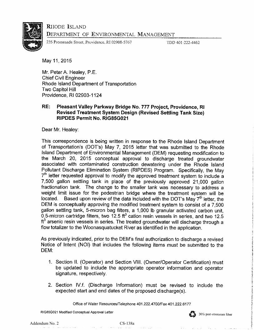
Addendum No. 2 CS-138a

Addendum No. 2 CS-138b

Addendum - 2 CS-152a
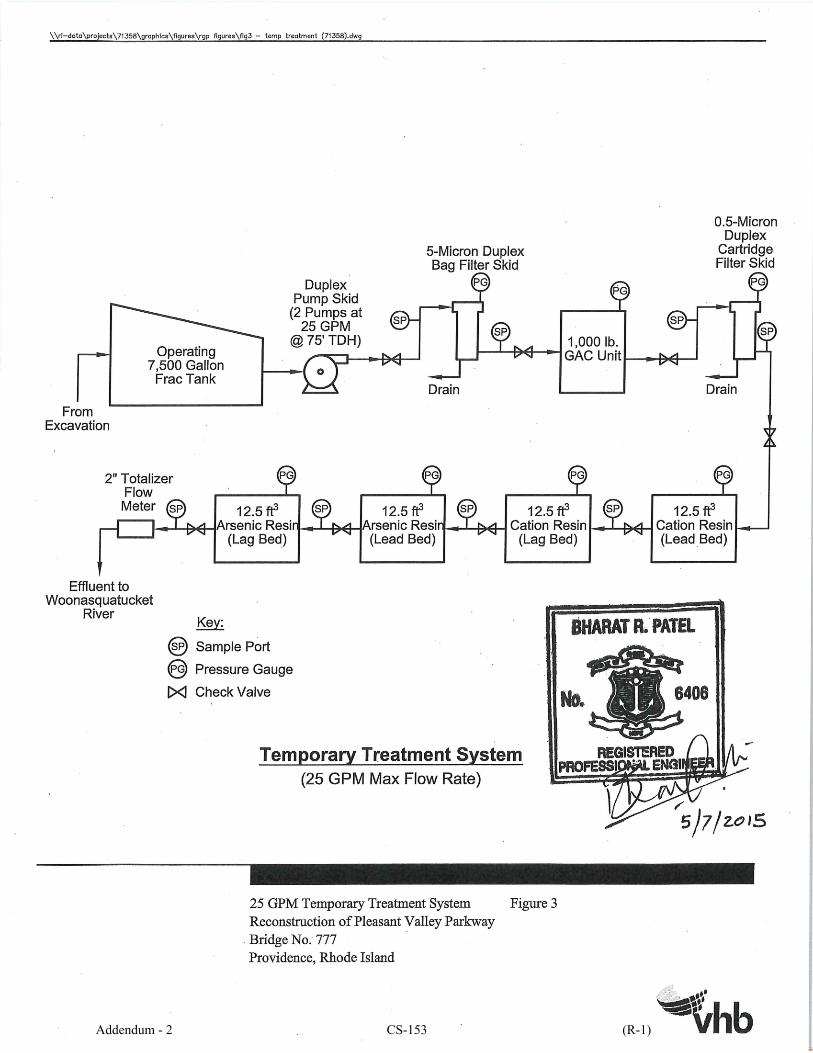
Addendum - 2 CS-153 (R-1)
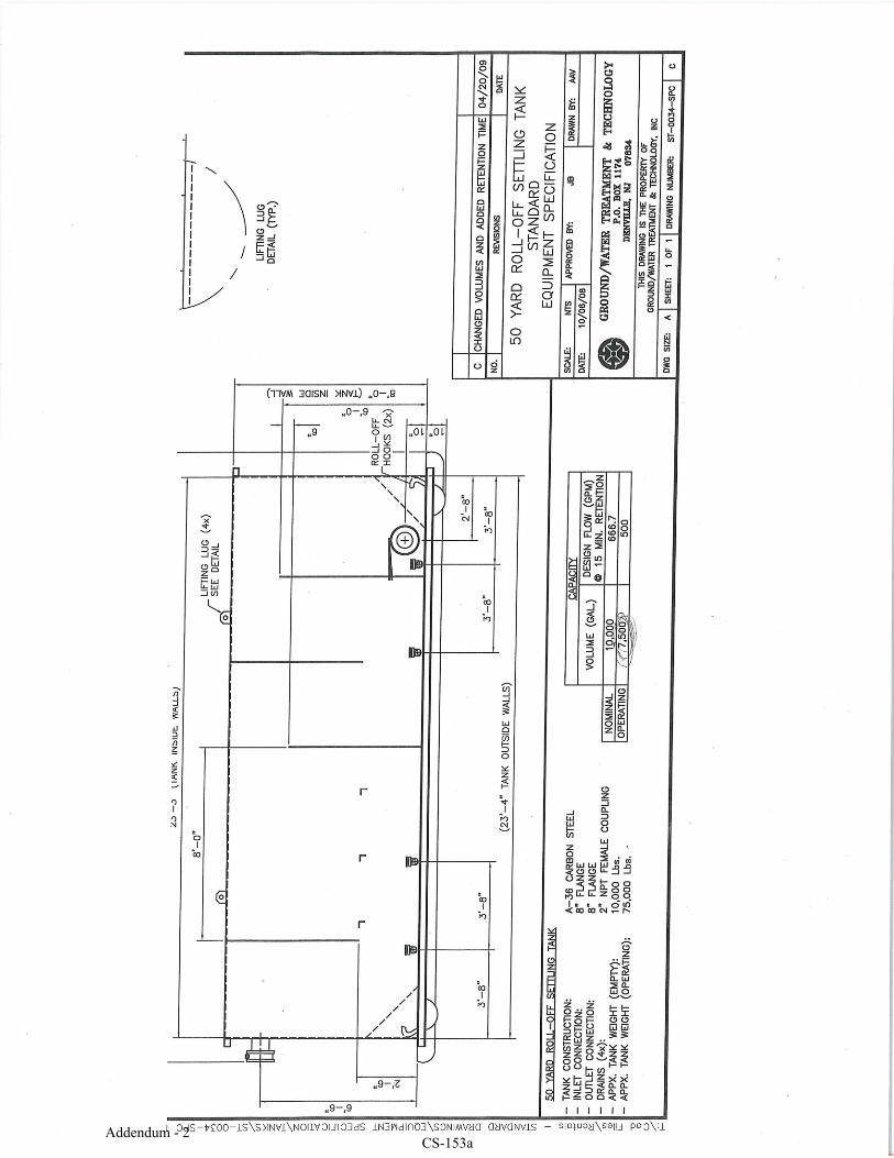
Addendum - 2CS-153a
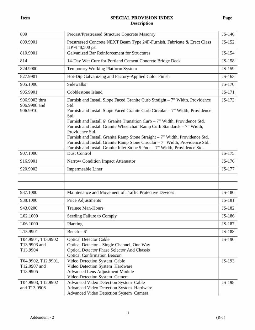
Item SPECIAL PROVISION INDEX Description
Page
ii
809 Precast/Prestressed Structure Concrete Masonry JS-140
809.9901 Prestressed Concrete NEXT Beam Type 24F-Furnish, Fabricate & Erect Class HP ¾”8,500 psi
JS-152
810.9901 Galvanized Bar Reinforcement for Structures JS-154
814 14-Day Wet Cure for Portland Cement Concrete Bridge Deck JS-158
824.9900 Temporary Working Platform System JS-159
827.9901 Hot-Dip Galvanizing and Factory-Applied Color Finish JS-163
905.1000 Sidewalks JS-170
905.9901 Cobblestone Island JS-171
906.9903 thru 906.9908 and 906.9910
Furnish and Install Slope Faced Granite Curb Straight – 7” Width, Providence Std. Furnish and Install Slope Faced Granite Curb Circular – 7” Width, Providence Std. Furnish and Install 6’ Granite Transition Curb – 7” Width, Providence Std. Furnish and Install Granite Wheelchair Ramp Curb Standards – 7” Width, Providence Std. Furnish and Install Granite Ramp Stone Straight – 7” Width, Providence Std. Furnish and Install Granite Ramp Stone Circular – 7” Width, Providence Std. Furnish and Install Granite Inlet Stone 5 Foot – 7” Width, Providence Std.
JS-173
907.1000 Dust Control JS-175
916.9901 Narrow Condition Impact Attenuator JS-176
920.9902 Impermeable Liner JS-177
937.1000 Maintenance and Movement of Traffic Protective Devices JS-180
938.1000 Price Adjustments JS-181
943.0200 Trainee Man-Hours JS-182
L02.1000 Seeding Failure to Comply JS-186
L06.1000 Planting JS-187
L15.9901 Bench – 6’ JS-188
T04.9901, T13.9902 T13.9903 and T13.9904
Optical Detector Cable Optical Detector – Single Channel, One Way Optical Detector Phase Selector And Chassis Optical Confirmation Beacon
JS-190
T04.9902, T12.9901, T12.9907 and T13.9905
Video Detection System Cable Video Detection System Hardware Advanced Lens Adjustment Module Video Detection System Camera
JS-193
T04.9903, T12.9902 and T13.9906
Advanced Video Detection System Cable Advanced Video Detection System Hardware Advanced Video Detection System Camera
JS-198
Addendum - 2 (R-1)

Item SPECIAL PROVISION INDEX Description
Page
iii
T04.9904 Fused and Unfused Premolded Y-Connectors JS-202
T06.9902 PVC Conduit Within Structure JS-203
T08.9901 Decorative Lighting Standard & Luminaire – Type “A” City of Providence JS-204
T08.9902 Decorative Pole Foundation with Bolts JS-207
T08.9904 Reinstall Stockpiled Poles and Luminaires JS-208
T11.9901 thru T11.9905
25-foot Galvanized Steel Mast Arm Traffic Signal post and Foundation, Std. 19.2.0 30-foot Galvanized Steel Mast Arm Traffic Signal Post and Foundation, Std. 19.2.0 45-foot Galvanized Steel Mast Arm Traffic Signal Post and Foundation, Std. 19.2.0 Dual Mast Arm (24x45) Galvanized Steel Mast Arm Signal Post and Foundation, Std. 19.2.0 Traffic Signal Standard Galvanized Steel, Std. 19.3.0 (Modified)
JS-209
T11.9906 Traffic Signal Wood Span Pole, 40 Foot, Class I JS-218
T12.9903 GPS Time Synchronization System JS-220
T12.9904 Actuated Controller, TS-2, Type 2 in Existing Cabinet JS-222
T12.9905 Modify Existing Traffic Signal Controller Cabinet JS-224
T12.9906 Mesh Network Receiver JS-226
T12.9908 Maintenance of Traffic Signal Systems JS-227
T13.1000 Traffic Detectors and Relays JS-229
T13.8210 Accessible Pedestrian Detector - Pushbutton with Sign JS-230
T13.9907 Mesh Network Vandal Resistant Antenna With Cable JS-234
T14.9902 thru T14.9904
1 Way Pedestal Mounted LED Pedestrian Signal Head With Countdown Timer 12 Inch 1 Way Bracket Mounted LED Pedestrian Signal Head With Countdown Timer 12 Inch 2 Way Pedestal Mounted LED Pedestrian Signal Head With Countdown Timer 12 Inch
JS-235
201.9904 Remove and Dispose Bench JS-238
607 Mass Concrete JS-239
Addendum - 2 (R-2)

Job Specific
RIC No. 2015‐CB‐033
Page 1 of 27
SECTION 401
DENSE GRADED HOT MIX ASPHALT (HMA) PAVEMENTS
401.01 DESCRIPTION. This work consists of constructing HMA pavements on prepared
foundations in conformity with the dimensions and details indicated on the Plans, and in
accordance with these Specifications. These Specifications are applicable to all types of Dense
Graded HMA pavements irrespective of aggregate gradation, grade of performance graded asphalt
binder (PGAB), or pavement use.
The HMA shall be composed of a mixture of aggregate, PGAB, and filler if required. The
aggregate shall be sized, graded and combined in such proportions that the resulting mixture meets
the gradation requirements of the job mix formula (JMF).
401.02 MATERIALS.
401.02.1 Aggregates. Aggregates shall meet the applicable requirements of Subsection M.03.02.2
of these Specifications and AASHTO M 323.
401.02.2 Performance Graded Asphalt Binder (PGAB). All grades shall conform to AASHTO
M 320 and R 29. The PGAB shall meet the requirements of PG 64S‐28 with the exception of both
Class 19.0 and mixes designated as “Base Course” which shall incorporate PG 64S‐22 for mixes
with less than 15% RAP. Both Class 19.0 and “Base Course” mixes with 15 to 25 percent RAP
shall incorporate PG 58S‐28.
Should a class of HMA be designated as “Modified”, the binder shall meet the requirements of
PG 64E‐28 and shall incorporate at least 2.0% SBS polymer. The nonrecoverable creep
compliance versus percent recovery of the binder shall be plotted and must fall above the curve
in Figure X1.1 in Appendix X1 of AASHTO M 332.
Should a class of HMA be designated as “with WMA” the Contractor shall use a WMA (Warm
Mix Additive). WMA shall conform to Section 414 of these specifications.
Re‐refined engine oil bottoms (REOB) shall not be used in any PGAB.
401.02.3 Mix Design. HMA mixes shall conform to AASHTO M 323, ʺStandard Specification
for Superpave Volumetric Mix Designʺ. The design procedure shall follow AASHTO R 35
ʺStandard Practice for Superpave Volumetric Design for Hot‐Mix Asphalt (HMA)ʺ. The
optimum binder content (OBC) shall be determined as follows:
a) The OBC for Class 4.75, Class 9.5, and Class 12.5 when not designated as “Base Course” shall
Addendum - 2 JS-41 (R-1)
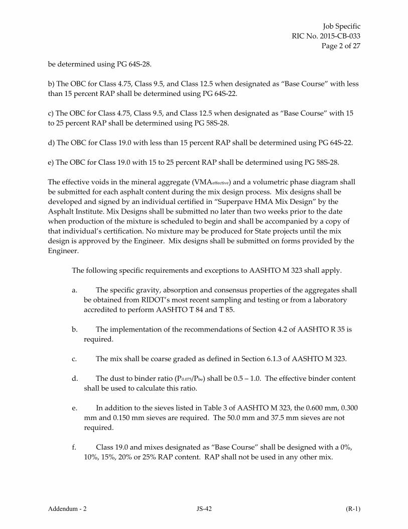
Job Specific
RIC No. 2015‐CB‐033
Page 2 of 27
be determined using PG 64S‐28.
b) The OBC for Class 4.75, Class 9.5, and Class 12.5 when designated as “Base Course” with less
than 15 percent RAP shall be determined using PG 64S‐22.
c) The OBC for Class 4.75, Class 9.5, and Class 12.5 when designated as “Base Course” with 15
to 25 percent RAP shall be determined using PG 58S‐28.
d) The OBC for Class 19.0 with less than 15 percent RAP shall be determined using PG 64S‐22.
e) The OBC for Class 19.0 with 15 to 25 percent RAP shall be determined using PG 58S‐28.
The effective voids in the mineral aggregate (VMAeffective) and a volumetric phase diagram shall
be submitted for each asphalt content during the mix design process. Mix designs shall be
developed and signed by an individual certified in “Superpave HMA Mix Design” by the
Asphalt Institute. Mix Designs shall be submitted no later than two weeks prior to the date
when production of the mixture is scheduled to begin and shall be accompanied by a copy of
that individual’s certification. No mixture may be produced for State projects until the mix
design is approved by the Engineer. Mix designs shall be submitted on forms provided by the
Engineer.
The following specific requirements and exceptions to AASHTO M 323 shall apply.
a. The specific gravity, absorption and consensus properties of the aggregates shall
be obtained from RIDOT’s most recent sampling and testing or from a laboratory
accredited to perform AASHTO T 84 and T 85.
b. The implementation of the recommendations of Section 4.2 of AASHTO R 35 is
required.
c. The mix shall be coarse graded as defined in Section 6.1.3 of AASHTO M 323.
d. The dust to binder ratio (P0.075/Pbe) shall be 0.5 – 1.0. The effective binder content
shall be used to calculate this ratio.
e. In addition to the sieves listed in Table 3 of AASHTO M 323, the 0.600 mm, 0.300
mm and 0.150 mm sieves are required. The 50.0 mm and 37.5 mm sieves are not
required.
f. Class 19.0 and mixes designated as “Base Course” shall be designed with a 0%,
10%, 15%, 20% or 25% RAP content. RAP shall not be used in any other mix.
Addendum - 2 JS-42 (R-1)
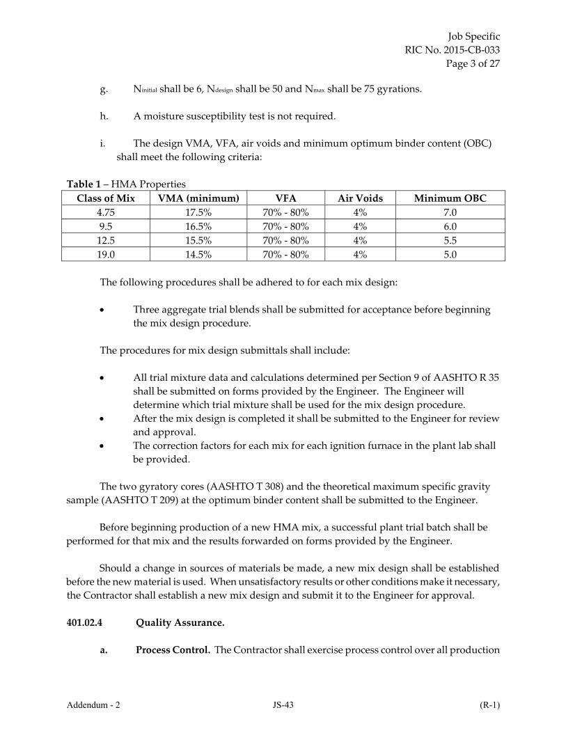
Job Specific
RIC No. 2015‐CB‐033
Page 3 of 27
g. Ninitial shall be 6, Ndesign shall be 50 and Nmax shall be 75 gyrations.
h. A moisture susceptibility test is not required.
i. The design VMA, VFA, air voids and minimum optimum binder content (OBC)
shall meet the following criteria:
Table 1 – HMA Properties
Class of Mix VMA (minimum) VFA Air Voids Minimum OBC
4.75 17.5% 70% ‐ 80% 4% 7.0
9.5 16.5% 70% ‐ 80% 4% 6.0
12.5 15.5% 70% ‐ 80% 4% 5.5
19.0 14.5% 70% ‐ 80% 4% 5.0
The following procedures shall be adhered to for each mix design:
Three aggregate trial blends shall be submitted for acceptance before beginning
the mix design procedure.
The procedures for mix design submittals shall include:
All trial mixture data and calculations determined per Section 9 of AASHTO R 35
shall be submitted on forms provided by the Engineer. The Engineer will
determine which trial mixture shall be used for the mix design procedure.
After the mix design is completed it shall be submitted to the Engineer for review
and approval.
The correction factors for each mix for each ignition furnace in the plant lab shall
be provided.
The two gyratory cores (AASHTO T 308) and the theoretical maximum specific gravity
sample (AASHTO T 209) at the optimum binder content shall be submitted to the Engineer.
Before beginning production of a new HMA mix, a successful plant trial batch shall be
performed for that mix and the results forwarded on forms provided by the Engineer.
Should a change in sources of materials be made, a new mix design shall be established
before the new material is used. When unsatisfactory results or other conditions make it necessary,
the Contractor shall establish a new mix design and submit it to the Engineer for approval.
401.02.4 Quality Assurance.
a. Process Control. The Contractor shall exercise process control over all production
Addendum - 2 JS-43 (R-1)
Job Specific
RIC No. 2015‐CB‐033
Page 4 of 27
operations. This shall require the constant monitoring of equipment, materials, and
production activity such as testing and analysis to ensure that the HMA meets all
applicable requirements and is produced within the allowable tolerances.
b. Acceptance Testing. Acceptance testing will be conducted by the Engineer.
1. Gradation, Binder Content and Air Void Content
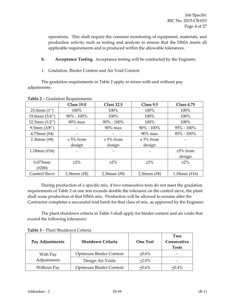
The gradation requirements in Table 2 apply to mixes with and without pay
adjustments:
Table 2 – Gradation Requirements
Class 19.0 Class 12.5 Class 9.5 Class 4.75
25.0mm (1”) 100% 100% 100% 100%
19.0mm (3/4”) 90% ‐ 100% 100% 100% 100%
12.5mm (1/2”) 90% max 90% ‐ 100% 100% 100%
9.5mm (3/8”) ‐ 90% max 90% ‐ 100% 95% ‐ 100%
4.75mm (#4) ‐ ‐ 90% max 85% ‐ 100%
2.36mm (#8) ± 5% from
design
± 5% from
design
± 5% from
design
‐
1.18mm (#16) ‐ ‐ ‐ ±5% from
design
0.075mm
(#200)
≥2% ≥2% ≥2% ≥2%
Control Sieve 2.36mm (#8) 2.36mm (#8) 2.36mm (#8) 1.18mm (#16)
During production of a specific mix, if two consecutive tests do not meet the gradation
requirements of Table 2 or one test exceeds double the tolerance on the control sieve, the plant
shall cease production of that HMA mix. Production will be allowed to resume after the
Contractor completes a successful trial batch for that class of mix, as approved by the Engineer.
The plant shutdown criteria in Table 3 shall apply for binder content and air voids that
exceed the following tolerances:
Table 3 – Plant Shutdown Criteria
Pay Adjustments Shutdown Criteria One Test
Two
Consecutive
Tests
With Pay
Adjustments
Optimum Binder Content +0.6% ‐
Design Air Voids +2.0% ‐
Without Pay Optimum Binder Content +0.6% +0.4%
Addendum - 2 JS-44 (R-1)
Job Specific
RIC No. 2015‐CB‐033
Page 5 of 27
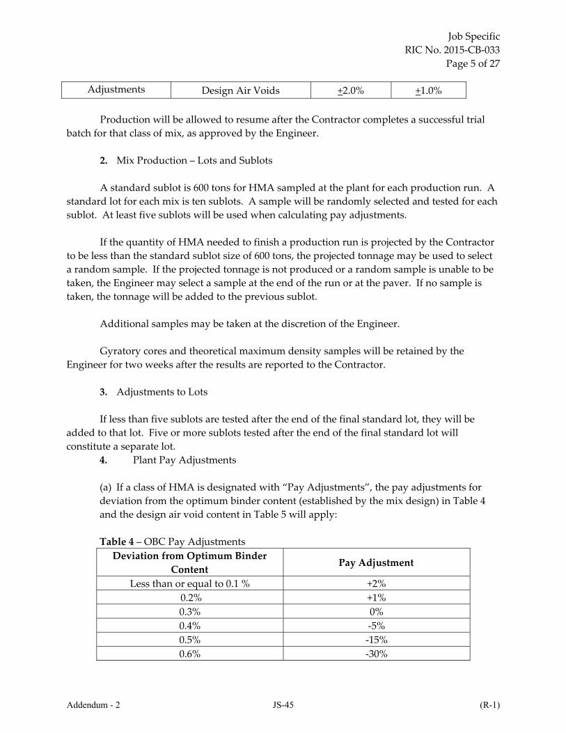
Adjustments Design Air Voids +2.0% +1.0%
Production will be allowed to resume after the Contractor completes a successful trial
batch for that class of mix, as approved by the Engineer.
2. Mix Production – Lots and Sublots
A standard sublot is 600 tons for HMA sampled at the plant for each production run. A
standard lot for each mix is ten sublots. A sample will be randomly selected and tested for each
sublot. At least five sublots will be used when calculating pay adjustments.
If the quantity of HMA needed to finish a production run is projected by the Contractor
to be less than the standard sublot size of 600 tons, the projected tonnage may be used to select
a random sample. If the projected tonnage is not produced or a random sample is unable to be
taken, the Engineer may select a sample at the end of the run or at the paver. If no sample is
taken, the tonnage will be added to the previous sublot.
Additional samples may be taken at the discretion of the Engineer.
Gyratory cores and theoretical maximum density samples will be retained by the
Engineer for two weeks after the results are reported to the Contractor.
3. Adjustments to Lots
If less than five sublots are tested after the end of the final standard lot, they will be
added to that lot. Five or more sublots tested after the end of the final standard lot will
constitute a separate lot.
4. Plant Pay Adjustments
(a) If a class of HMA is designated with “Pay Adjustments”, the pay adjustments for
deviation from the optimum binder content (established by the mix design) in Table 4
and the design air void content in Table 5 will apply:
Table 4 – OBC Pay Adjustments
Deviation from Optimum Binder
Content Pay Adjustment
Less than or equal to 0.1 % +2%
0.2% +1%
0.3% 0%
0.4% ‐5%
0.5% ‐15%
0.6% ‐30%
Addendum - 2 JS-45 (R-1)

Job Specific
RIC No. 2015‐CB‐033
Page 6 of 27
0.7% ‐40%
Greater than 0.7 % ‐50% or Remove and Replace*
Table 5 – Air Void Pay Adjustments
Deviation from Design Air Void
Content Pay Adjustment
Less than or equal to 0.5% +1%
0.6% to 1.0% 0%
1.1% to 1.5% ‐5%
1.6% to 2.0% ‐10%
2.1% to 2.5% ‐30%
2.6% to 3.0% ‐40%
Greater than 3.0% ‐50% or Remove and Replace*
* The decision to make 50% payment or Remove and Replace will be made by the
Engineer
Note: All deviation values will be rounded to the nearest 0.1% before applying pay
adjustments.
(b) Calculation of Pay Adjustments for Production Binder and Air Void Content
For each test, absolute deviations will be used when determining binder and air void
content pay adjustments. Absolute deviations are the values of deviation regardless of
sign (±).
The average of the absolute deviations from the optimum binder content of all of the
sublots in each lot will be used to determine the appropriate pay adjustments for the
lots. The same will apply for air void content. No payment will be made for any
pavement that is removed.
All other tolerances shall conform to the RI Standard Specifications.
c. Independent Assurance Testing. This testing will be performed by the Department in
accordance with the Rhode Island Department of Transportation publication entitled ̋ Schedule for
Sampling, Testing and Certification of Materials.ʺ
401.03 CONSTRUCTION METHODS.
401.03.1 HMA Mixing Plant. Mixing plants shall be of sufficient capacity and coordinated to
adequately handle the proposed production of HMA. The storage yard shall be maintained neat
Addendum - 2 JS-46 (R-1)

Job Specific
RIC No. 2015‐CB‐033
Page 7 of 27
and orderly and the separate stockpiles shall be readily accessible for sampling.
a. Requirements for All Plants.
1. Equipment for Preparation of PGAB. Tanks provided for the storage of PGAB shall be
equipped to heat and hold the material at the required temperatures. The heating shall be accom‐
plished by steam coils, electricity, or other approved means such that no flame shall be in contact
with the tank. The circulating system for the PGAB shall be designed to assure proper and
continuous circulation during the operating period. Provision shall be made for measuring storage
tanks. An adequate sampling valve shall be provided to ensure the safe and proper sampling of the
PGAB.
2. Cold Feed Bins. The plant shall include no fewer than three (3) storage bins of sufficient
capacity to supply the mixer when it is operating at full capacity. Bins shall be arranged to assure
separate and adequate storage of appropriate fractions of the mineral aggregates without
contaminations. They shall also be so constructed that samples can be readily obtained. Separate
dry storage shall be provided for filler or hydrated lime when used and the plant shall be equipped
to feed such material into the mixer.
3. Cold Aggregate Feeder. The plant shall be provided with accurate mechanical means for
uniformly feeding the aggregate into the drier so that uniform production and temperature will be
obtained.
4. Drier. The plant shall include a drier or driers which continuously agitate the aggregate
during the heating and drying process.
5. PGAB Control Unit. Satisfactory means, either by weighing or metering, shall be
provided to obtain the proper amount of PGAB in the mix within the tolerance specified. Means
shall be provided for checking the quantity or rate of flow of PGAB into the mixer.
6. Thermometric Equipment. An armored thermometer of adequate range in temperature
reading shall be fixed in the PGAB feed line at a suitable location near the charging valve at the
mixer unit.
The plant shall also be equipped with either an approved dial‐scale, mercury‐actuated
thermometer, an electric pyrometer, or other approved thermometric instrument so placed at the
discharge chute of the drier as to register automatically the temperature of the exiting material.
The Engineer may require replacement of any malfunctioning or inconsistent thermometer
by an approved temperature sensing and recording apparatus for better regulation of the
temperature of the material.
Addendum - 2 JS-47 (R-1)
Job Specific
RIC No. 2015‐CB‐033
Page 8 of 27
7. Dust Collector. The plant shall be equipped with a dust collector constructed to waste or
return uniformly all or any part of the material collected as directed.
8. Truck Scales. When required, the HMA shall be weighed on approved scales furnished
by the Contractor or on public scales at the Contractorʹs expense. Such scales shall be tested at least
every 60 days or whenever the Engineer deems necessary to assure their accuracy.
9. Scales. Scales shall be so located as to be easily readable from the operatorʹs normal
work station; otherwise a remote readout shall be supplied.
All plant scales, including truck scales, shall be certified at the expense of the Contractor by
a competent and experienced scales technician as follows:
(a) Annually prior to use in State work.
(b) At intervals of not more than 60 calendar days.
(c) At any time ordered by the Engineer.
10. Safety Requirements. Adequate and safe access to sampling points shall be provided.
Guarded ladders to other plant units shall be placed at all points where accessibility to plant
operations is required. Accessibility to the top of truck bodies shall be provided by a platform or
other suitable device, placed in an acceptable location near the testing laboratory, to enable the
Engineer to obtain samples and mixture temperature data. All gears, pulleys, chains, sprockets,
and other dangerous moving parts shall be thoroughly guarded and protected. A clear, clean and
unobstructed passage shall be maintained at all times in and around the truck loading area.
11. HMA Holding Bin. HMA may be stored in surge and storage systems designed for that
purpose. Each surge and storage system must meet the requirements of AASHTO M156, unless
otherwise permitted by the Engineer, and may be inspected by the Department to determine
acceptance at specific holding times.
Acceptance shall be based upon the ability of the holding bin to hold and discharge
mixtures within the quality criteria specified by the mix design and these Specifications.
b. Requirements for Batching Plants.
1. Automatic Proportioning. The plant shall be equipped with automatic proportioning
devices. Such devices shall include equipment for accurately proportioning the various
components of the mixture by weight in the proper sequence. PGAB and aggregates shall be
proportioned by weight. Additives, if required, may be proportioned by volume or weight. The
plant shall be equipped to automatically control the sequence and timing of mixing operations.
There shall be auxiliary interlock cutoff circuits to interrupt and stop the automatic cycling of the
Addendum - 2 JS-48 (R-1)
Job Specific
RIC No. 2015‐CB‐033
Page 9 of 27
batching operations at any time an error in weighing occurs, when an aggregate bin becomes
empty, or when there is a malfunction of any portion of the control system.
2. Recording Equipment. The plant shall be equipped with a digital recorder which will
automatically print the following data on delivery tickets:
(a) Batch weights of each size aggregate. Weights printed may be individual or cumulative.
(b) Total weight of aggregates in batch. The weight printed for the last aggregate batched
shall be the total weight of aggregates in the batch when cumulative weights are used.
(c) Weight of PGAB in batch.
(d) Weight of total batch.
(e) Total weight of batches in truck.
(f) Total weight of PGAB in all batches in truck.
(g) Date mixed.
(h) The time each batch or load began or the time each was completed.
When silos are utilized, the requirements for delivery tickets shall conform to Para. c;
Requirements for Drum Dryer Mixing Plants, of this Subsection. In addition, automated batch
plant printout tickets generated in accordance with Para. b of this Subsection shall be given to the
plant inspector and maintained on file.
There shall be sufficient copies of delivery tickets to provide a copy for the plant inspector
and a copy for the Resident Engineer for permanent project record. The following information shall
also be included on delivery slips:
(i) Name of customer.
(j) Name of project and contract number.
(k) Name of driver and truck number.
(l) Class of HMA.
(m) Additives.
Addendum - 2 JS-49 (R-1)
Job Specific
RIC No. 2015‐CB‐033
Page 10 of 27
3. Equipment Failure. If at any time the automatic proportioning or recording devices
become inoperable, the plant may be allowed to batch and mix HMA for a period of not more than
48 hours from the time of the breakdown, if approved by the Engineer. Written permission of the
Engineer will be required for periods of operation without automatic proportioning facilities longer
than 48 hours.
4. Screens. Plant screens, capable of screening all aggregates to the specified sizes and
proportions and having normal capacities in excess of the full capacity of the mixer, shall be
provided.
5. Hot Aggregate Bins. Hot bin storage of sufficient capacity to ensure uniform and
continuous operation shall be provided. The bins shall be arranged to ensure separate and
adequate storage of appropriate fractions of the aggregate. Each bin shall be provided with
overflow pipes, of such size and at such locations as to prevent backing up of material into other
compartments or bins. Each bin shall be provided with its individual outlet gate, constructed so
that when closed there shall be no leakage. The gates shall cut off quickly and completely. Bins
shall be equipped with adequate tell‐tale devices to indicate the position of the aggregates in the
bins at the lower quarter points. Adequate and convenient facilities shall be provided for obtaining
aggregate samples from each hot bin.
6. Aggregate Scales. Scales for any weigh box or hopper shall be of the springless dial type,
having a full complement of index pointers and shall be of a standard make and design. They shall
be accurate to 0.50 percent, have minimum graduations not greater than 0.50 percent and shall be
readable and sensitive to 0.25 percent or less. The preceding percentages are based on total batch
weight.
7. Batching Controls. Batching controls shall be electrically interlocked with the scales to
prevent cycling or recycling of batching until scales tare zero.
The batching controls shall meet the following tolerances with respect to the various
components weighed in each batch:
Combined Aggregate
Components: ±1.5 percent of total batch weight
PGAB: ±0.1 percent of total batch weight
The total weight of the batch shall not vary more than plus or minus 2 percent from the
theoretical design weight.
8. Time Locking Device. The mixer shall have an accurate time locking device to control
the operation of a complete mixing cycle by locking the weigh box gate, after charging the mixer,
Addendum - 2 JS-50 (R-1)
Job Specific
RIC No. 2015‐CB‐033
Page 11 of 27
until the closing of the mixer discharge gate at the completion of the cycle. It shall lock the PGAB
feed throughout the dry mixing period and shall lock the mixer discharge gate throughout the dry
and wet mixing periods. The dry mixing period is defined as the interval of time between the
opening of the weigh box gate and the commencement of application of the PGAB. The wet mixing
period is the interval of time between the commencement of application of the PGAB and the
opening of the mixer discharge gate.
The control of the timing shall be flexible and capable of being set at intervals of not more
than five seconds throughout the cycles up to three minutes. Changes in mixing time shall be made
only when ordered by the Engineer.
9. Weigh Box or Hopper. The equipment shall include a means for accurately weighing
each size of aggregate in a weigh box or hopper suspended on scales and of ample size to hold a
full batch without hand raking or running over. The gate shall close tightly so that no material is
allowed to leak into the mixer while a batch is being weighed.
10. PGAB Control. The equipment used to measure the PGAB shall be accurate to plus or
minus 0.5 percent. The PGAB bucket shall be a non‐tilting type with a loose sheet metal cover. The
length of the discharge opening trough, bucket or spray bar shall be not less than three‐fourths the
length of the mixer and it shall discharge directly into the mixer. The PGAB bucket, its discharge
valve or valves and spray bar shall be adequately heated. Steam jackets, if used, shall be efficiently
drained and all connections shall be so constructed that they will not interfere with the efficient
operation of the PGAB scales. The capacity of the PGAB bucket shall be at least 15 percent in excess
of the weight of PGAB required in any batch. The plant shall have an adequately heated
quick‐acting, non‐drip, charging valve located directly over the PGAB bucket.
The indicator dial shall have a capacity of at least 15 percent in excess of the quantity of
PGAB used in a batch. The controls shall be constructed so that they may be locked at any dial
setting and will automatically reset to that reading after the addition of PGAB to each batch. The
dial shall be in full view of the mixer operator. The flow of PGAB shall be automatically controlled
so that it will begin when the dry mixing period is over. All of the PGAB required for one batch
shall be discharged in not more than 15 seconds after the flow has started. The size and spacing of
the spray bar openings, trough or PGAB bucket shall provide a uniform application of PGAB the
full length of the mixer. The section of the PGAB line between the charging valve and the spray bar
shall be provided with a valve and outlet for checking the meter when a metering device is
substituted for a PGAB bucket.
11. Mixer. The batch mixer shall be capable of producing a uniform mixture within the job
mix tolerances. If not enclosed, the mixer box shall be equipped with a dust hood to prevent loss of
dust.
The clearance of blades from all fixed and moving parts shall not exceed one inch unless the
Addendum - 2 JS-51 (R-1)

Job Specific
RIC No. 2015‐CB‐033
Page 12 of 27
maximum diameter of the aggregate in the mix exceeds 1¼‐inches, in which case the clearance shall
not exceed 1½‐inches.
12. Access to the mixer platform shall be by adequate and safe stairways. A hoist or pulley
system shall be provided to raise scale calibration equipment, sampling equipment, and other
similar equipment from the ground to the mixer platform and return. There shall be adequate and
unobstructed space on the mixer platform.
c. Requirements for Drum Dryer Mixing Plants.
1. Proportioning. Aggregates and PGAB shall be proportioned by dry weight of the
aggregate. Additives, if required, may be proportioned by volume or weight. The cold aggregate
feeder shall be synchronized with the PGAB delivery system. Satisfactory means shall be provided
to ensure positive interlocking control between each cold bin, the cold aggregate feeder, and the
PGAB delivery system. This interlocking control shall be such that production is interrupted if one
or more cold bins becomes empty, or the flow of either aggregate or PGAB is obstructed.
2. Recording Equipment. The plant shall be equipped with a digital recording device
approved by the Engineer by which the proportion of aggregate supplied by each cold bin, the flow
rates by weight of dry aggregate and of PGAB, and the cumulative weights of dry aggregate and of
PGAB incorporated in the mix are automatically printed. These printed records, showing the date
and time of printing, shall be provided to the Engineer at the start and at the end of each
production period and at any other times or intervals of time as requested.
The plant shall also have a computerized scale system consisting of a weight batcher and/or
a truck scale. Delivery tickets shall be printed on an automatic digital recorder which will print the
following information on delivery tickets:
(a) Date loaded.
(b) Net weight of mixture in truck. When a truck scale is used the net weight of the mixture
shall be automatically calculated by weighing the truck both empty and full.
(c) Time of each load.
There shall be sufficient copies of delivery tickets to provide a copy for the plant inspector
and a copy for the Resident Engineer for permanent project record. The following information shall
also be included on delivery slips:
(a) Name of customer.
(b) Name of project and contract number.
Addendum - 2 JS-52 (R-1)
Job Specific
RIC No. 2015‐CB‐033
Page 13 of 27
(c) Truck identification and name of driver.
(d) Class of HMA.
(e) Additives.
3. Equipment Failure. If at any time the automatic recording device or the computerized
scale system become inoperable, the plant may be allowed to produce HMA for a period of not
more than 48 hours from the time of the breakdown, if approved by the Engineer. Approval will
not be granted unless a satisfactory arrangement is made by the Contractor to weigh the mix.
Written permission of the Engineer will be required for periods of operation longer than 48 hours
during which any required automatic system is not functioning properly.
4. Aggregate Storage. Sufficient storage space shall be provided for each stockpile of
various sized aggregates which shall be kept separated until they have been introduced into the
cold bins that feed the drier. A minimum of four cold feed bins shall be required.
5. Cold Feed System. The plant shall have a device at each cold bin to feed the aggregate
accurately and uniformly. No gravity type feeders will be permitted. Each adjustment opening
shall be provided with indicators graduated to allow proportioning. Each cold bin gate shall be
interlocked in such a manner that production is interrupted if one or more cold bins becomes empty
or the flow is obstructed.
A mineral filler bin, when required, shall be added to the standard plant cold feed bins, and
shall feed the mineral filler at adjustable rates accurately and uniformly. The feeder shall be
interlocked so that production is interrupted if the bin becomes empty or the flow is obstructed.
The weighing equipment for all aggregates including mineral filler shall consist of a contin‐
uous weighing device either as it is proportioned by the individual feeders or after all materials
have been deposited on a common belt. Belt scales shall meet the requirements of N.B.S. Handbook
44 and shall be installed according to the scale manufacturerʹs recommendations.
The plant shall have an adjustable feed rate control for each aggregate cold bin feeder and
mineral filler feeder. The plant shall proportion the total aggregate quantity to the drum mixer
with such accuracy and uniformity that the variation of material per interval of time shall not
exceed an amount equal to 1.5 percent of the total weight of HMA per interval of time.
An automatic aggregate sampling device shall be provided which will divert a representa‐
tive combined aggregate sample, including mineral filler, into a hopper or container for the purpose
of gradation testing. The container shall cut the full width and depth of the aggregate flow. The
sampling point shall be after the aggregate is proportioned and prior to its mixing with PGAB.
Addendum - 2 JS-53 (R-1)
Job Specific
RIC No. 2015‐CB‐033
Page 14 of 27
6. PGAB Control Unit. The PGAB shall be proportioned by a meter accurate to 0.1 percent.
A flow switch designed to interrupt production if the PGAB flow is discontinued shall be installed
in the delivery line between the meter and the mixer.
The PGAB delivery system shall be coupled with the aggregate delivery system to
automatically maintain the required proportions as the aggregate flow varies. The delivery
tolerance for PGAB shall be ±0.2 percent of the total mixture weight.
7. Plant Calibration. The cold feed and PGAB delivery systems shall be calibrated to
insure that the plant is operating within the allowable tolerances. A procedure acceptable to the
Engineer and in accordance with the manufacturerʹs recommendations shall be followed. These
calibrations shall be performed prior to the start of each paving season, and at any other time as
directed by the Engineer.
8. Mixer Unit. The plant shall include a continuous mixer unit having an automatic burner
control and capable of producing a uniform mixture within the job mix tolerances. The mixture
shall be discharged into a HMA holding bin meeting the requirements of Para. a.11 of this
Subsection.
The moisture content of the mixture upon discharge from the mixer shall not exceed 1.5
percent by weight.
401.03.2 Hauling Equipment. Trucks or other equipment used for hauling HMA shall have
tight, clean, smooth metal beds which have been thinly coated with an approved release agent.
No diesel fuel or other material is to be applied to any portion of the vehicle that comes into
contact with the HMA. Any hauling equipment not complying with these Specifications will be
immediately rejected along with its load of HMA. Each truck shall have a cover of canvas or
other suitable material of such size as to protect the mixture from the weather. Truck beds shall
be securely covered and, if necessary, insulated to ensure delivery of the mixture at the
specified temperature. Cleaning of equipment, vehicles, and truck beds in areas to be paved is
prohibited. Any HMA placed in areas where cleaning takes place is subject to rejection by the
Engineer.
a. Material Transfer Vehicle (MTV). A material transfer vehicle (MTV) is required for the
construction of all HMA friction, surface, intermediate and base courses on all limited access
highways. When friction course is used, both the friction course and the underlying layer must be
placed using an MTV.
The MTV shall independently deliver HMA from the hauling equipment to the paving
equipment. A paving hopper insert with a minimum capacity of 14 tons shall be installed in the
hopper of conventional paving equipment when a MTV is used.
Addendum - 2 JS-54 (R-1)
Job Specific
RIC No. 2015‐CB‐033
Page 15 of 27
As a minimum, the MTV shall have a high capacity truck unloading system which will
receive HMA from the hauling equipment; a storage system in the MTV with a minimum capacity
of 15 tons of HMA, and a discharge conveyor with the ability to swivel to either side to deliver the
mixture to the paver while allowing the MTV to operate from an adjacent lane. In addition, the
paving operation must contain a remixing system to blend the mixture prior to placement. The
speed of the paver and MTV shall be adjusted to coordinate with the availability of HMA. Failure
to keep the MTV supplied with HMA may be cause to cease paving operations for that operation.
However, more than 2 stoppages shall result in paving being ceased for that operation.
When an MTV is to be used on a project, the Contractor shall further investigate the possible
movement of the fully or partially loaded MTV on the project. If there are any structures on the
project that the fully or partially loaded MTV will traverse, the Contractor shall request an
Overweight Permit Check from the Department. Such a request shall be made in writing, and shall
include the axle configuration, weights, and the project limits. Operations shall not begin until this
permission is received from the Department and one copy forwarded to the Engineer.
The following is a statewide list of limited access highways (included are travel lanes, auxiliary
lanes, climbing lanes, acceleration and deceleration lanes, ramps, collector/distributor roads, service
roads, and shoulders greater than 8 feet):
I‐95 Connecticut State Line to Massachusetts State Line
I‐195 I‐95 to Massachusetts State Line
I‐295 I‐95 to Massachusetts State Line
US Route 1 Prosser Trail to Wakefield Cut‐Off
RI Route 4 Route 1 to I‐95
US Route 6 Route 102 to Route 101; Route 10 to I‐295
RI Route 10 Park Avenue to Route 6
US Route 6/RI Route 10 Magnolia Street Bridge to I‐95
RI Route 24 Route 114 to Massachusetts State Line
RI Route 37 Natick Avenue to Post Road
RI Route 78 Route 1 to Connecticut State Line
Addendum - 2 JS-55 (R-1)

Job Specific
RIC No. 2015‐CB‐033
Page 16 of 27
RI Route 99 Route 146 to Mendon Road
East Shore Expressway I‐195 to Wampanoag Trail
RI Route 114 East Shore Expressway to Forbes Street
RI Route 138 Route 1 to Admiral Kalbfus Road
RI Route 146 I‐95 to Reservoir Road
RI Route 146 Route 146A to Massachusetts State Line
RI Route 403 Route 4 to Quonset Point
Airport Connector I‐95 to Post Road
Henderson Bridge Waterman Street/So. Angell Street to Broadway
Access Roadway
401.03.3 Pavers. Unless otherwise shown on the Plans, mixtures shall be spread by means of a
mechanical self‐powered paver capable of spreading the mixture true to line, grade and crown as
approved by the Engineer.
HMA pavers shall be self‐contained, power‐propelled units, provided with activated
vibratory screed and solid vibratory screed extenders and capable of spreading and finishing
courses of plant mixed HMA in lane widths applicable to the specified typical section and thickness
shown on the Plans. Pavers used for shoulders and similar construction shall be capable of
spreading and finishing courses of HMA in the widths, depths and cross slopes indicated on the
Plans.
When laying mixtures, the paver shall be capable of being operated at forward speeds
consistent with satisfactory laying of the mixture.
The paver shall be equipped with a receiving hopper having sufficient capacity for a
uniform spreading operation. The hopper shall be equipped with a distribution system to place the
mixture uniformly in front of the screed.
a. Screeding. The screed and screed extenders shall continually vibrate while placing the
mixture and shall effectively produce a finished surface of the required evenness and texture
without tearing, shoving or gouging the mixture. The screed shall be heated to maintain the HMA
at the required placement temperature. Unless otherwise permitted by the Engineer, the screed
extenders shall not extend more than two feet from the edge of the augers or auger extensions.
Addendum - 2 JS-56 (R-1)

Job Specific
RIC No. 2015‐CB‐033
Page 17 of 27
The paver shall be equipped with automatic screed controls with sensors for either or both
sides of the paver, capable of sensing grade from an outside reference line, sensing the transverse
slope of the screed and providing the automatic signals which operate the screed to maintain the
desired grade and transverse slope. The sensor shall be capable of operating from a ski‐type device
or reference beam of not less than 25 feet in length. The sensor shall also have the capability of
operating from a reference line unless the ski‐type device or reference beam can ride on an adjacent,
newly placed lift of HMA. A reference line shall also be used for the first course placed over in‐
place, recycled material.
Reference lines for the control of horizontal alignment shall be provided by the Contractor
subject to the approval of the Engineer.
When a reference line is used for automatic grade control, the Contractor shall furnish and
install all pins, brackets, tensioning devices, wire and accessories necessary for satisfactory
operation of the automatic control equipment using a taut stringline set to grade for reference.
The transverse slope controller shall be capable of maintaining the screed at the desired
slope within plus or minus 0.1 percent. The paver shall be equipped with automatic feeder
controls, properly adjusted to maintain a uniform depth of materials ahead of the screed.
b. Manual Operation. Manual operation will be permitted in the construction of
irregularly shaped and minor areas, on plant mixed seal courses, or where otherwise directed.
401.03.4 Conditioning of Existing Surfaces. Surfaces of curbs, gutters, vertical faces of existing
pavements, and all structures to be in contact with the HMA shall be given a thin, even coating of
tack coat. Care shall be taken to avoid the splattering of surfaces which will not be in contact with
the HMA.
When a tack coat is required, the type and grade and the application methods shall conform
to the applicable provisions of both SECTION M.03; MATERIALS and SECTION 403; ASPHALT
EMULSION TACK COAT, of these Specifications.
401.03.5 Spreading and Finishing. The mixture shall be laid upon an approved cleaned surface,
spread and struck off to the grade and elevation established. HMA pavers shall be used to
distribute the mixture either over the entire width or over such partial width as may be practicable.
The practices and guidelines for placing HMA as outlined in Asphalt Institute Publication
MS‐22, “Construction of Hot Mix Asphalt Pavements” shall be adhered to unless otherwise
permitted by the Engineer.
Unnecessary walking on the uncompacted HMA mat shall not be allowed.
Addendum - 2 JS-57 (R-1)

Job Specific
RIC No. 2015‐CB‐033
Page 18 of 27
Before beginning a new lane, the screed shall be heated to the proper operating temperature
and any clumps of cold material in the paver hopper shall be removed.
No trucks or other equipment shall be allowed on freshly placed HMA unless specifically
permitted by the Engineer.
On areas where irregularities or unavoidable obstacles make the use of mechanical
spreading and finishing equipment impracticable, the mixture shall be placed as close to its final
position as possible. It shall then be spread, raked, and luted by hand tools in a manner which will
minimize segregation and result in the required compacted thickness.
Unless otherwise directed by the Engineer, any layer of HMA called for on side streets or
driveways must be placed to a distance of at least three feet beyond the gutter line at the same time
that layer is being placed on the adjacent project roadway.
a. HMA Designated for “Bridge Decks”. When HMA is being placed on a surface which
is covered with a waterproofing membrane, the following precautions shall be observed:
1. No traffic other than paving equipment shall be allowed on the membrane.
2. The paver must be moved carefully on and off the membrane. Initial proper adjustment
of the paver to the correct depth is very important to prevent tearing the membrane. The
Contractor shall be responsible for making any repairs to the membrane or to the HMA overlay
necessary to correct damage caused by the paving operation, all at its expense.
3. Any and all tears of the membrane by the paver or trucks shall be repaired immediately
to the satisfaction of the Engineer. Vehicle tires shall be clean of any rocks or materials that would
puncture the membrane.
4. Truck drivers shall not make quick stops and starts, nor turn the wheels while parked,
nor cross the deck at an angle.
401.03.6 Compaction. Immediately after the HMA has been spread, struck off, and surface
irregularities adjusted, it shall be thoroughly and uniformly compacted by rolling.
The surface shall be rolled when the mixture is in the proper condition and when rolling
does not cause undue displacement, cracking, and shoving.
Two rollers are required for all paving operations that exceed a daily total of 500 tons,
except in the case of driveway, sidewalk and bridge deck paving operations. The number, weight
and type of roller(s) shall be sufficient to compact the mixture to the required density before it
reaches the minimum compaction temperature. Vibratory rollers used for compaction shall be
operated in the vibratory mode. All rollers used for compaction shall have a minimum operating
weight of ten tons or greater. The use of equipment which results in excessive crushing of the
Addendum - 2 JS-58 (R-1)
Job Specific
RIC No. 2015‐CB‐033
Page 19 of 27
aggregate will not be permitted.
The speed of a roller shall not exceed five miles per hour.
Rollers shall not be parked on HMA. When reversing direction, the action shall be smooth,
not abrupt. The drive wheel shall approach the new mix, not the tiller wheel.
When a vibratory roller is used for finish rolling, it shall be used in the static mode. Finish
rolling shall continue until all roller marks are eliminated.
The motion of the rollers shall be slow enough at all times to avoid displacement of the hot
mixture, and any displacement resulting from reversing the direction of the rollers, or from any
other cause, shall be satisfactorily corrected. The wheels of steel‐wheel rollers shall be kept moist
and clean to prevent adhesion of the fresh material, but an excess of water will not be permitted.
If satisfactory density cannot be obtained in any lift, and if the Engineer determines it to be
structurally inadequate and/or incapable of maintaining material integrity, the Contractor shall
remove and replace any such area at its own expense.
Any mixture that becomes loose and broken, mixed with dirt, or is in any way defective
shall be removed and replaced with fresh hot mixture, which shall then be compacted to conform to
the surrounding area. Any area showing an excess or deficiency of PGAB shall be removed and
replaced. Said removal and replacement shall be at the Contractor’s expense.
For HMA not designated as with “Pay Adjustments” in‐place density shall be a
minimum of 92% of the theoretical maximum density obtained at the plant and will be
determined using a nuclear density gauge or in‐place cores.
If a class of HMA is designated as for “Bridge Decks”, an oscillatory roller with a
minimum operational weight of 8 tons shall be used. For HMA designated as for “Bridge
Decks” and with “Pay Adjustments” the pay adjustments will only apply to binder content and
air voids.
If a class of HMA is designated as for “Leveling” it shall be placed with a paver. A
pneumatic roller with a minimum operational weight of 8 tons shall be used. For HMA
designated as for “Leveling” and with “Pay Adjustments” the pay adjustments will only apply
to binder content and air voids.
If a class of HMA is designated as for “Patching”, “Miscellaneous Work” or “Paved
Waterways” it shall be placed by hand. A vibratory plate compactor or roller shall be used. A
hand tamper may be used only if requested, and such request is approved by the Engineer.
a) In‐Place Density for classes of HMA designated as with “Pay Adjustments”
Addendum - 2 JS-59 (R-1)
Job Specific
RIC No. 2015‐CB‐033
Page 20 of 27
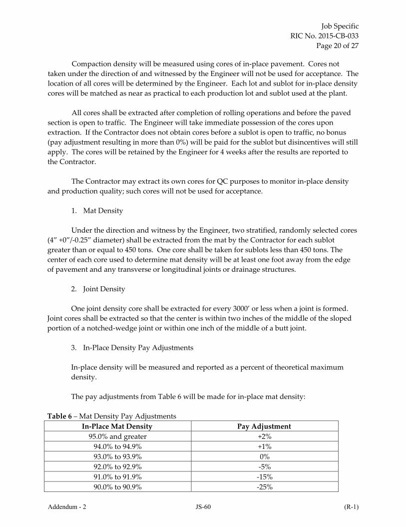
Compaction density will be measured using cores of in‐place pavement. Cores not
taken under the direction of and witnessed by the Engineer will not be used for acceptance. The
location of all cores will be determined by the Engineer. Each lot and sublot for in‐place density
cores will be matched as near as practical to each production lot and sublot used at the plant.
All cores shall be extracted after completion of rolling operations and before the paved
section is open to traffic. The Engineer will take immediate possession of the cores upon
extraction. If the Contractor does not obtain cores before a sublot is open to traffic, no bonus
(pay adjustment resulting in more than 0%) will be paid for the sublot but disincentives will still
apply. The cores will be retained by the Engineer for 4 weeks after the results are reported to
the Contractor.
The Contractor may extract its own cores for QC purposes to monitor in‐place density
and production quality; such cores will not be used for acceptance.
1. Mat Density
Under the direction and witness by the Engineer, two stratified, randomly selected cores
(4” +0”/‐0.25” diameter) shall be extracted from the mat by the Contractor for each sublot
greater than or equal to 450 tons. One core shall be taken for sublots less than 450 tons. The
center of each core used to determine mat density will be at least one foot away from the edge
of pavement and any transverse or longitudinal joints or drainage structures.
2. Joint Density
One joint density core shall be extracted for every 3000’ or less when a joint is formed.
Joint cores shall be extracted so that the center is within two inches of the middle of the sloped
portion of a notched‐wedge joint or within one inch of the middle of a butt joint.
3. In‐Place Density Pay Adjustments
In‐place density will be measured and reported as a percent of theoretical maximum
density.
The pay adjustments from Table 6 will be made for in‐place mat density:
Table 6 – Mat Density Pay Adjustments
In‐Place Mat Density Pay Adjustment
95.0% and greater +2%
94.0% to 94.9% +1%
93.0% to 93.9% 0%
92.0% to 92.9% ‐5%
91.0% to 91.9% ‐15%
90.0% to 90.9% ‐25%
Addendum - 2 JS-60 (R-1)

Job Specific
RIC No. 2015‐CB‐033
Page 21 of 27
89.0% to 89.9% ‐35%
Below 89.0% Remove and Replace
The pay adjustments from Table 7 will be made for in‐place joint density:
Table 7– Joint Density Pay Adjustments
In‐Place Joint Density Pay Adjustment
93.0% and greater +2%
92.0% to 92.9% +1%
91.0% to 91.9% 0%
90.0% to 90.9% ‐5%
89.0% to 89.9% ‐15%
88.0% to 88.9% ‐25%
87.0% to 87.9% ‐35%
Below 87.0% ‐100%
Note: All density values will be rounded to the nearest 0.1% before applying pay adjustments.
In the event material is required to be removed and replaced, the Engineer will determine the
limits of the removal. The required in‐place density will be 1% less for the first lift placed on
gravel subbase.
4. Calculation of Pay Adjustments for In‐Place Density
(i.) For Mat Density:
For each sublot, the bulk specific gravity (Gmb) of the mat density core(s) will be
averaged and then compared to the corresponding plant theoretical maximum specific gravity
(Gmm) to calculate the in‐place density for each sublot. The average of the sublot densities in a
lot will be used to determine the appropriate pay adjustment for that lot. Lot pay adjustments
will be applied to the respective quantity of HMA in each lot.
(ii.) For Joint Density:
For joint density pay adjustment purposes, a joint lot will be defined as 10 joint density
results. However, if less than five joint density results are remaining after the final full joint lot
is formed, they will be added to the previous joint lot. Five or more joint density results
remaining after the final full joint lot will constitute a separate joint lot.
Calculation of in‐place joint density will be determined using the Gmb of joint density
cores and the project average plant Gmm of the respective mix. The average of the individual
joint density results in a joint lot will be used to determine the appropriate pay adjustment for
that joint lot. The calculation of material quantity used to construct the joints will be based on
the joint core density, the specified thickness, a width of one foot and the length of the joint that
Addendum - 2 JS-61 (R-1)

Job Specific
RIC No. 2015‐CB‐033
Page 22 of 27
each core represents. This quantity will be deducted from the total tonnage.
401.03.7 Joints. Placement of the HMA shall be as continuous as possible. Rollers shall not pass
over the unprotected end of a freshly laid mixture unless authorized by the Engineer.
Both longitudinal and transverse joints in successive courses shall be staggered so as not to
be one above the other. Longitudinal joints shall be staggered a minimum of 6 inches and shall be
arranged so that the longitudinal joint in the top course being constructed shall be at the location of
the line dividing the traffic lanes. Any HMA that falls on the cold side of the mat during paving
operations shall be raked onto the hot joint. Care shall be taken to ensure that the material pushed
onto the hot side of the joint remains in the joint area and is not broadcast over the pavement.
Unless otherwise permitted by the Engineer, a notched wedge joint shall be used.
Longitudinal drop‐offs will not be allowed on both sides of a lane. Joints shall be constructed so
that the height of the notch is the same as the nominal maximum aggregate size. The width of
the sloped portion of the joint shall be at least 6” for each inch of lift thickness if the joint will be
exposed to traffic, but in all cases it shall be 12” minimum. Tack coat shall be applied to and
shall completely cover the longitudinal notched wedge joint, using either a brush or the tack
coat distribution truck. Transverse joints and joints at intersections shall be manually brushed
with tack coat, leaving a completely covered face.
401.03.8 Pavement Samples. As directed, the Contractor shall cut samples from the compacted
pavement for testing by the Engineer. Samples of the mixture shall be taken for the full depth of
the course at the locations directed by the Engineer.
Where samples have been taken, new material shall be placed and compacted to conform to
the surrounding area.
401.03.9 Surface Tolerances. At the Engineer’s discretion the surface may be tested at selected
locations, using an approved 10‐foot straightedge furnished by the Contractor. The variation of the
surface from the testing edge of the straightedge between any two contacts with the surface shall at
no point exceed 1/4‐inch. All humps or depressions exceeding the specified tolerance shall be
corrected by removing defective work and replacing it with new material as directed.
401.03.10 Thickness Requirements. The thickness of a pavement shall be that as shown on the
Plans and shall not vary from the specified thickness by more than that specified in Subsection
401.04, below, except as otherwise provided for in resurfacing existing pavements.
401.03.11 Weather Limitations. HMA shall not be placed on any wet surface, or when weather
conditions otherwise prevent the proper handling or finishing of the HMA.
For lifts with a target compacted lift thickness less than or equal to 1.5” both the air and
surface temperature in the shade shall be 45o F or greater. For lifts with a target compacted lift
thickness greater than 1.5” both the air and surface temperature in the shade shall be 40o F or
Addendum - 2 JS-62 (R-1)
Job Specific
RIC No. 2015‐CB‐033
Page 23 of 27
greater. If an approved WMA (warm mix additive) is used both the air and surface temperature
in the shade shall be 35o F or greater regardless of lift thickness. No HMA shall be placed on
frozen ground.
For projects that do not specify pay adjustments all rolling shall be completed before the
temperature of the mat falls below 165o F. The HMA mat (not including WMA modified
pavement) shall be at least 265o F when placed.
401.03.12 Cold Weather Paving. If the existing pavement is removed before the winter shutdown,
the Contractor shall not close the project for the season until a new HMA layer has been placed and
striped with temporary epoxy pavement markings.
401.03.13 Drop‐Offs.
a. Longitudinal Drop‐Offs. A longitudinal drop‐off occurs along the outside edges of
pavement and is the difference in elevation between the top of recently placed HMA pavement and
the top of existing ground (or pavement).
1. For Posted Speeds of 35 mph or Less. Drop‐offs greater than 3 inches but less than 5
inches shall be tapered to a maximum 1‐to‐1 slope to existing ground or pavement. Drop‐offs 5
inches, or greater, shall be tapered to a maximum 4‐to‐1 horizontal to vertical slope to existing
ground or pavement.
2. For Posted Speeds Greater than 35 mph. Longitudinal drop‐offs will not be permitted
within 2 feet of a travel lane. The first 2 feet adjacent to a travel lane must be at grade with the
travel lane. However, should either the sequence of operation required by the Contract or the
Contractor’s approved sequence of operation result in overnight drop‐offs greater than 3 inches
occurring between 2 and 6 feet from the edge of a travel lane, then such drop‐offs shall be tapered
to a 4‐to‐1 horizontal to vertical slope to existing ground or pavement.
All tapers shall be constructed with HMA conforming to the requirements of this SECTION
401 of these Specifications.
Longitudinal drop‐offs within the roadway cross section will not be allowed except as
otherwise detailed on the Plans or as described in a Special Provision.
Longitudinal drop‐offs will not be paid for separately, but will be included in the contract
unit price for HMA pavements as listed in the Proposal.
b. Transverse Drop‐Offs. Transverse drop‐offs occur as follows:
Pavement removal. A transverse drop‐off occurs when pavement removal operations cease
at the end of a working day. The drop‐off is the difference in elevation between the bottom of the
excavated pavement and the top of the existing pavement.
Addendum - 2 JS-63 (R-1)

Job Specific
RIC No. 2015‐CB‐033
Page 24 of 27
Pavement overlay. A transverse drop‐off occurs when pavement overlay operations cease
at the end of a working day. The drop‐off is the difference in elevation between the top of the
overlay pavement and the top of the existing pavement.
If traffic is allowed across either of these drop‐offs during the period prior to the resumption
of pavement removal or pavement overlay operations, tapers must be provided as follows:
1. For Posted Speeds of 35 mph or Less. Transverse drop‐offs in place at the end of a
working day shall be graded at a slope of 2 feet horizontal to 1 inch vertical.
2. For Posted Speeds Greater than 35 mph. Transverse drop‐offs in place at the end of a
working day shall be graded at a slope of 5 feet horizontal to 1 inch vertical.
All slopes shall be constructed with HMA conforming to the requirements of SECTION 401
of these Specifications.
The Contractor shall place “BUMP” signs in accordance with the MUTCD (Manual on
Uniform Traffic Control Devices) at each drop‐off for each direction of traffic.
Prior to the resumption of pavement overlay operations the transition slope shall be
removed as follows: The pavement overlay shall be saw cut back approximately 6 inches to expose
a fresh, full thickness vertical face. This face shall be brush‐painted or pressure sprayed with tack
coat, after which the HMA paving may resume.
Transverse drop‐offs will not be paid for separately, but will be included in the contract unit
prices for HMA pavements as listed in the Proposal.
401.04 METHOD OF MEASUREMENT.
401.04.1 Measurement of HMA Pavement. HMA Pavements will be measured by the number of
tons actually placed in accordance with the Plans and/or as directed by the Engineer.
a. Determination of Thickness. The design thickness of each course as well as of the total
HMA pavement structure shall be that indicated on the Plans, or as ordered by the Engineer.
Prior to the determination of placed thickness, the roadway shall exhibit acceptable
workmanship and all defects shall have been corrected. The placed thickness of HMA pavement
will be determined by cutting or coring holes to full depth. For courses with In‐Place Density Cores
specified, the average thickness of the Density Cores will be used to determine placed thickness.
For courses where In‐Place Density Cores are not specified the following requirements
apply: For projects with less than 1 paved lane mile, two cores will be taken. For projects with 1 to 2
paved lane miles, four cores will be taken. For projects with greater than 2 paved lane miles, two
cores will be taken from each lane mile, except that there will be a minimum of ten cores for the
project, all at the discretion of the Engineer.
Addendum - 2 JS-64 (R-1)
Job Specific
RIC No. 2015‐CB‐033
Page 25 of 27
Cores will be measured in accordance with ASTM D3549; Standard Test Method for
Thickness or Height of Compacted HMA Paving Mixture Specimens. The depth measurement will
be considered as applying for the full width of the lane. Measurements will be made at random
locations determined by the Engineer and all information relative thereto will be recorded in the
project records.
For the determination of thickness, a shoulder width of eight feet or greater will be
considered to be a separate lane of the roadway. A shoulder width of less than eight feet will be
considered part of the adjacent lane. The Contractor shall fill all holes cut or cored in the pavement
with a compacted, dense HMA which is acceptable to the Engineer. If required by the Engineer, the
Contractor shall maintain and control traffic while the pavement samples are being taken and while
the holes are being filled and compacted. Payment will be made for the applicable traffic control
item(s).
b. Adjustment of Tonnage Quantity.
The pavement thickness will be considered acceptable if both of the following requirements
are met:
(a) The total HMA tonnage delivered and placed does not exceed the tonnage calculated
from the approved area measured from the final surface course width by the project length and the
pavement thickness specified in the Contract Documents by more than 5 percent.
and,
(b) When Specification Conformity Analysis (Federal Highway Administration Technical
Advisory T5080.12; dated June 23, 1989) is applied to the entire roadway or sections thereof as
determined by the Engineer, at least 80 percent of the total HMA pavement will have a thickness
that meets the minimum pavement thickness. The minimum pavement thickness is that contained
in the contract documents minus ½‐inch, (e.g., a total pavement thickness of 7 inches will have a
minimum pavement thickness requirement of 6.5 inches).
If the first requirement is not met, no payment will be made for all tonnage exceeding 5
percent, unless unusual field conditions are present and documented (e.g., pavement rutting).
If the second requirement indicates that the pavement thickness is deficient, the Contractor
with permission of the Engineer shall place a correction course not less than one inch in depth after
compaction, provided an acceptable grade and cross section can be achieved. Where an acceptable
grade and cross section cannot be achieved through the above means, the Contractor shall
reconstruct by cutting back and into the pavement a sufficient distance to permit the placement of
an acceptable depth and place new material to achieve the proper depth, cross section and profile.
These areas where a corrective course is placed or reconstruction of the pavement is performed, will
be measured again as though originally constructed; no compensation will be made to the
Contractor for the material removed or removal of materials and disposal thereof or for restoration
Addendum - 2 JS-65 (R-1)

Job Specific
RIC No. 2015‐CB‐033
Page 26 of 27
of affected supporting base or adjacent construction, or for traffic control, adjusting all utility
appurtenances in the roadway or for correcting pavement striping. Compensation will be made for
the additional pavement correction course accepted in place.
Determination of the quantity to be used for adjusted payment or exclusion for payment
will be based on tons per square yard per inch thickness as determined using in‐place density cores
or 96% of the plant core (AASHTO T245) densities if in‐place densities are not available.
Sweeping and cleaning, as included in the items covered by this section, refers to the normal
removal of dust, debris, etc. only. Any sweeping and cleaning necessary due to construction being
held over for the winter season, in accordance with the approved construction schedule, will be
paid for separately.
Work described in Subsection 401.03.4; Conditioning of Existing Surface, will be paid for
at the contract unit prices for the material used.
Tolerance Limitation. Pavement will be considered acceptable when meeting the
specifications. Pavement that is not accepted will be excluded from the tolerance allowance.
When delivery tickets are directly collected by the Engineer from each truck prior to placing in
the hopper, the delivery tickets may be used in the determination of total tonnage delivered and
placed. Delivery tickets not collected directly by the Engineer prior to placing in the hopper will
not be used to determine tonnage.
When delivery tickets are not used to determine tonnage, the accepted total tonnage delivered
and placed will be calculated according to the following formula: [final surface course width] x
[project length] x [specified pavement thickness] x [the average unit weight of all acceptance
density cores] = contract tonnage. If density cores are not required then 96% of the average unit
weight of the plant produced acceptance gyratory cores shall be used.
Payment will be made at full contract unit bid prices with pay adjustments for all accepted
HMA up to 105% of the contract quantity tonnage. Accepted HMA quantities above 105% and
up to 110% of the contract quantity tonnage will be paid at 50% of the contract unit bid price
with the resultant adjusted price further modified by additional pay adjustments as applicable
according to the following formula: Pay adjustments will apply to 50% of the contract unit bid
price for quantities above 105% and up to 110%.
401.05 BASIS OF PAYMENT. The accepted quantity of the HMA will be paid for at its
respective contract unit price per ton as listed in the Proposal. The price so‐stated constitutes
full and complete compensation for all labor, materials and equipment, and for all incidentals
required to finish the work, complete and accepted by the Engineer.
Pay adjustments for binder content, air voids and in‐place density will be added
together to determine a final pay adjustment for both the mat and the joint. If more than one
pay adjustment is negative then only the most negative adjustment will be added to the
Addendum - 2 JS-66 (R-1)

Job Specific
RIC No. 2015‐CB‐033
Page 27 of 27
remaining non‐negative adjustments to determine the final pay adjustment. Pay adjustments
will be applied to the unit bid price for the applicable item code.
Addendum - 2 JS-67 (R-1)

THIS PAGE INTENTIONALLY LEFT BLANK
Addendum - 2 JS-68 (R-1)

THIS PAGE INTENTIONALLY LEFT BLANK
Addendum - 2 JS-69 (R-1)
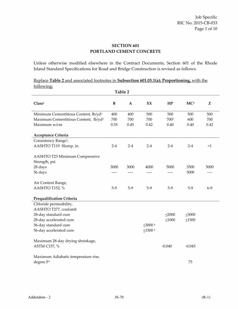
Job Specific
RIC No. 2015‐CB‐033
Page 1 of 10
SECTION 601
PORTLAND CEMENT CONCRETE
Unless otherwise modified elsewhere in the Contract Documents, Section 601 of the Rhode
Island Standard Specifications for Road and Bridge Construction is revised as follows:
Replace Table 2 and associated footnotes in Subsection 601.03.1(a); Proportioning, with the
following:
Table 2
Class1
B A XX
HP
MC2 Z
Minimum Cementitious Content, lb/yd3 400 400 500 500 500 500
Maximum Cementitious Content, lb/yd3 700 700 700 7005 600 700
Maximum w/cm
0.55 0.45 0.42 0.40 0.40 0.42
Acceptance Criteria
Consistency Range3,
AASHTO T119 Slump, in.
2‐4
2‐4
2‐4
2‐4
2‐4
<1
AASHTO T23 Minimum Compressive
Strength, psi
28 days
56 days
3000
‐‐‐‐
3000
‐‐‐‐
4000
‐‐‐‐
5000
‐‐‐‐
3500
5000
5000
‐‐‐‐
Air Content Range,
AASHTO T152, %
5‐9
5‐9
5‐9
5‐9
5‐9
6‐9
Prequalification Criteria
Chloride permeability,
AASHTO T277, coulomb
28‐day standard cure
28‐day accelerated cure
56‐day standard cure
56‐day accelerated cure
<3000 6
<1500 6
<2000
<1000
<3000
<1500
Maximum 28‐day drying shrinkage,
ASTM C157, %
‐0.040
‐0.045
Maximum Adiabatic temperature rise,
degree F4
75
Addendum - 2 JS-70 (R-1)
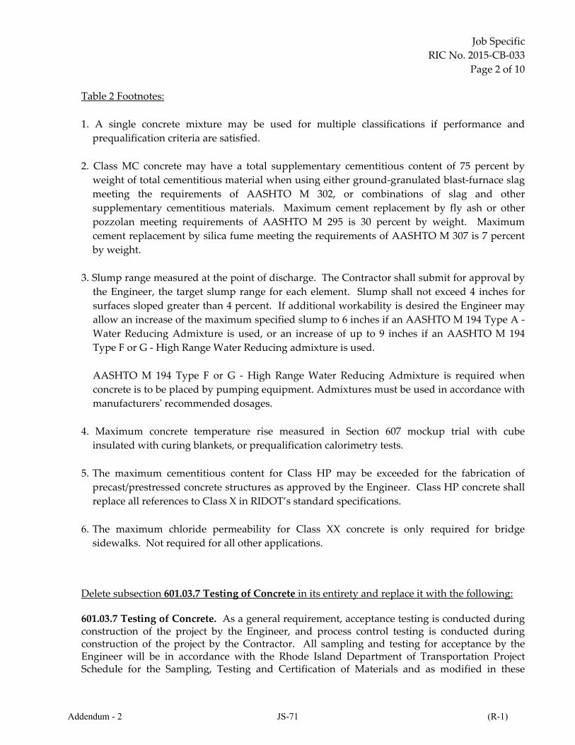
Job Specific
RIC No. 2015‐CB‐033
Page 2 of 10
Table 2 Footnotes:
1. A single concrete mixture may be used for multiple classifications if performance and
prequalification criteria are satisfied.
2. Class MC concrete may have a total supplementary cementitious content of 75 percent by
weight of total cementitious material when using either ground‐granulated blast‐furnace slag
meeting the requirements of AASHTO M 302, or combinations of slag and other
supplementary cementitious materials. Maximum cement replacement by fly ash or other
pozzolan meeting requirements of AASHTO M 295 is 30 percent by weight. Maximum
cement replacement by silica fume meeting the requirements of AASHTO M 307 is 7 percent
by weight.
3. Slump range measured at the point of discharge. The Contractor shall submit for approval by
the Engineer, the target slump range for each element. Slump shall not exceed 4 inches for
surfaces sloped greater than 4 percent. If additional workability is desired the Engineer may
allow an increase of the maximum specified slump to 6 inches if an AASHTO M 194 Type A ‐
Water Reducing Admixture is used, or an increase of up to 9 inches if an AASHTO M 194
Type F or G ‐ High Range Water Reducing admixture is used.
AASHTO M 194 Type F or G ‐ High Range Water Reducing Admixture is required when
concrete is to be placed by pumping equipment. Admixtures must be used in accordance with
manufacturersʹ recommended dosages.
4. Maximum concrete temperature rise measured in Section 607 mockup trial with cube
insulated with curing blankets, or prequalification calorimetry tests.
5. The maximum cementitious content for Class HP may be exceeded for the fabrication of
precast/prestressed concrete structures as approved by the Engineer. Class HP concrete shall
replace all references to Class X in RIDOT’s standard specifications.
6. The maximum chloride permeability for Class XX concrete is only required for bridge
sidewalks. Not required for all other applications. Delete subsection 601.03.7 Testing of Concrete in its entirety and replace it with the following: 601.03.7 Testing of Concrete. As a general requirement, acceptance testing is conducted during construction of the project by the Engineer, and process control testing is conducted during construction of the project by the Contractor. All sampling and testing for acceptance by the Engineer will be in accordance with the Rhode Island Department of Transportation Project Schedule for the Sampling, Testing and Certification of Materials and as modified in these
Addendum - 2 JS-71 (R-1)

Job Specific
RIC No. 2015‐CB‐033
Page 3 of 10
Specifications. Sampling and testing by the Contractor and Engineer shall be in accordance with the applicable requirements as follows:
1. Sampling for temperature, air content, and slump; AASHTO T141. 2. Air Content; AASHTO T152. 3. Slump; AASHTO T119. 4. 28‐Day (56‐day for Class MC) Compressive Strength; AASHTO T23 and AASHTO T22. 5. Unit Weight, AASHTO T121and 6. Temperature; AASHTO T309.
A. Contractor Quality/Process Control of Concrete (QC).
The Contractor is responsible for providing a constructed project to the State meeting the
safety requirements, product quality requirements, and material performance requirements
contained in these plans and specifications. In the production of all Portland cement concrete,
the Contractor shall be responsible for producing concrete that meets or exceeds the specified
performance criteria of all materials during the handling, blending, mixing and placement
operations to insure the performance criteria are consistently obtained.
1. Purpose. The purpose of this Section is to establish minimum requirements for the
Contractorʹs quality control system. It is intended that these requirements be used as a
procedural process in detailing the inspection, sampling and testing deemed necessary to
maintain compliance with the Specification requirements.
2. Scope. This procedure is applicable to Portland cement concrete production, placement and
construction.
3. Requirements
3.1 General. The Contractor shall provide and maintain a quality control system that will
provide reasonable assurance that all materials and products will conform to the Contract
requirements, whether manufactured or processed, by the Contractor, or procured from
suppliers or subcontractors or vendors.
The Contractor shall perform, or have performed, the inspections and tests required to
substantiate product conformance to Contract document requirements and shall also perform, or
have performed, all inspections and tests otherwise required by the Contract. The testing
frequencies shall exceed those shown in Subsection 601.03.7.C. Engineers Acceptance Plan.
The Contractorʹs quality control inspections and tests shall be documented and shall be
available for review by the Engineer throughout the life of the Contract.
The Contractor shall maintain standard equipment and qualified personnel as required
by the Specifications to assure conformance to contract requirements. Procedures will be subject
Addendum - 2 JS-72 (R-1)
Job Specific
RIC No. 2015‐CB‐033
Page 4 of 10
to the approval of the Engineer before the work is started. The Contractor’s QC and test
documentation shall follow ASTM/AASHTO requirements as applicable.
Failure to comply with the provisions of this section may result in the Contractor’s
operations being shut down until they are in compliance with these requirements. There shall
be no claims for additional payment by the Contractor nor will there be an extension of the
project Completion Dates for delays resulting from the shut down of operations and the
Contractor’s obligation for compliance with these requirements.
3.2 Contractor’s Quality Control Plan (QCP). At least sixty days prior to the first
concrete placement, the Contractor shall submit a detailed written Quality Control Plan to the
Engineer for approval. The Quality Control Plan shall describe the Contractors plan to measure
and control material properties and construction activities governed by these Specifications.
At a minimum, the Quality Control Plan shall describe in detail:
a. personnel responsibilities and qualifications for implementing the quality control
plan,
b. location(s) and certification(s) of testing facilities
c. the type and frequency of inspection activities,
d. process control sampling locations, test methods, test frequency and
e. Documentation processes including handling of non‐conforming materials
Concrete shall not be placed without an approved quality control plan.
The QCP shall be maintained to reflect the current status of the operations and any
process control changes to the QC Plan must be submitted to the Engineer in writing. Changes
must be approved by the Engineer before implementation.
3.2 a Personnel.
The Contractor shall employ a Quality Control Plan Administrator with five years
minimum of materials experience and must meet one or more of the following criteria: a
professional engineer licensed in the State of RI, an individual certified by the National Institute
for Certification of Engineering Technologies (NICET) at Level III or above for concrete, or a
North East Transportation Training and Certification Program (NETTCP) QA Administrator.
Prestress Concrete Facilities QC Personnel ‐ The Contractor shall employ a Quality
Control Plan Administrator with five years minimum of prestress concrete production QC
experience and must meet one or more of the following criteria: PCI Level III, an individual
certified by the National Institute for Certification of Engineering Technologies (NICET) at Level
III or above for concrete, or a North East Transportation Training and Certification Program
(NETTCP) QA Administrator.
Addendum - 2 JS-73 (R-1)

Job Specific
RIC No. 2015‐CB‐033
Page 5 of 10
All individuals who sample and test concrete at the point of placement shall possess
current certification for American Concrete Institute (ACI) Concrete Field Testing Technician
Grade 1 in accordance with ACI CP‐1 or NETTCP Concrete Technician.
All individuals who test concrete specimens and concrete materials in the batch plant or
independent testing laboratory shall possess current certification for American Concrete
Institute (ACI) Concrete Laboratory Testing Technician Grade 1 in accordance with ACI CP‐17
or NETTCP Concrete Technician.
The names and credentials of the quality control staff shall be included on the Quality
Control Plan including, but not limited to assigned duties, certifications with expiration date,
telephone contact number(s), and e‐mail address.
The Certified Technician(s) shall be responsible to:
(a) Perform and utilize quality control tests and other quality control practices to assure that delivered materials and proportioning meet the requirements of the mix design(s), including temperature, slump, air content, and strength. (b) Periodically inspect all equipment utilized in transporting, proportioning, mixing, placing, consolidating, finishing, and curing to ensure it is operating properly and that placement, consolidation, finishing, and curing conform to the mix design and other Contract requirements.
3.2 b Testing Facilities.
Specimen storage facilities, sampling, testing, and measuring devices shall be in
accordance with industry standards and shall be properly calibrated in accordance with the
requirements of each method. The quality control plan shall list the calibration frequency.
Upon commencement of construction, a list of measurement devices and date of last
calibration for each device used on the project shall be provided to the Engineer. Spare parts
and calibrated back‐up equipment shall be available on site to minimize impact of equipment
malfunctions during production. Back‐up equipment shall be used if a device is suspected to be
defective. Any defective testing device shall be clearly tagged and/or removed from the site
until repaired and calibration is verified. If non‐standard or alternative sampling methods,
testing procedures, or equipment are proposed to be used, they shall be detailed in the Quality
Control Plan and approved by the Engineer prior to use.
3.2 c. Process Control Activities.
Quality/Process control sampling, testing, and inspection shall be an integral part of the
Contractorʹs quality control system. In addition to the above requirements,
Addendum - 2 JS-74 (R-1)
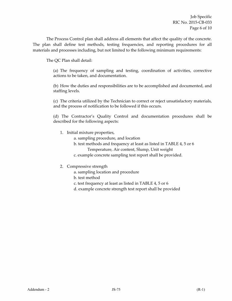
Job Specific
RIC No. 2015‐CB‐033
Page 6 of 10
The Process Control plan shall address all elements that affect the quality of the concrete.
The plan shall define test methods, testing frequencies, and reporting procedures for all
materials and processes including, but not limited to the following minimum requirements: The QC Plan shall detail:
(a) The frequency of sampling and testing, coordination of activities, corrective actions to be taken, and documentation. (b) How the duties and responsibilities are to be accomplished and documented, and staffing levels. (c) The criteria utilized by the Technician to correct or reject unsatisfactory materials, and the process of notification to be followed if this occurs. (d) The Contractor’s Quality Control and documentation procedures shall be described for the following aspects:
1. Initial mixture properties,
a. sampling procedure, and location
b. test methods and frequency at least as listed in TABLE 4, 5 or 6
Temperature, Air content, Slump, Unit weight
c. example concrete sampling test report shall be provided.
2. Compressive strength
a. sampling location and procedure
b. test method
c. test frequency at least as listed in TABLE 4, 5 or 6
d. example concrete strength test report shall be provided
Addendum - 2 JS-75 (R-1)
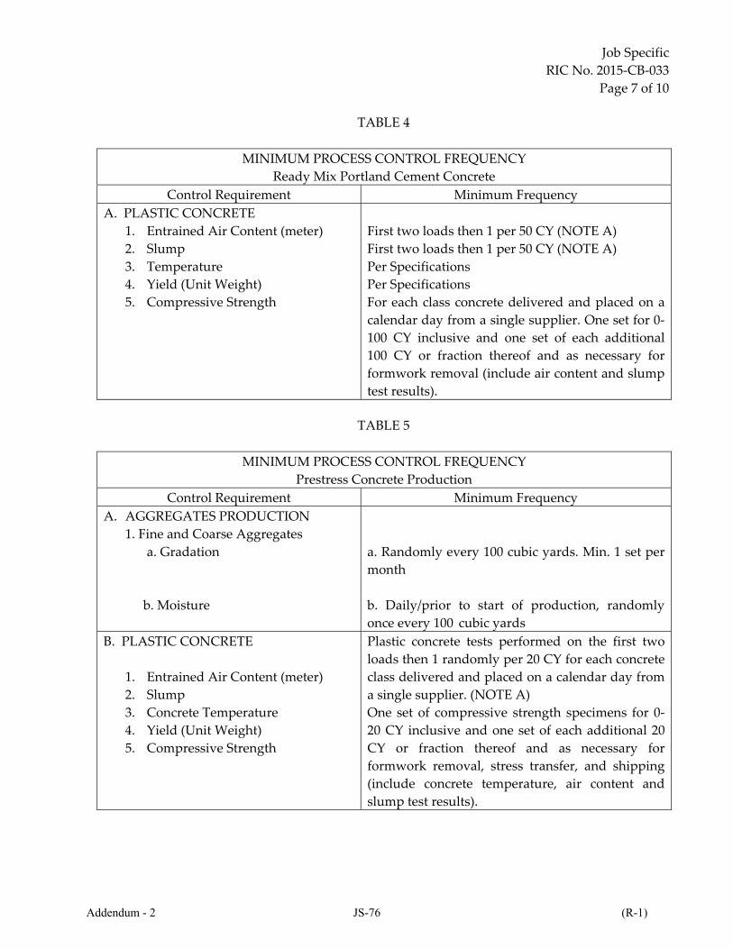
Job Specific
RIC No. 2015‐CB‐033
Page 7 of 10
TABLE 4
MINIMUM PROCESS CONTROL FREQUENCY
Ready Mix Portland Cement Concrete
Control Requirement Minimum Frequency
A. PLASTIC CONCRETE
1. Entrained Air Content (meter)
2. Slump
3. Temperature
4. Yield (Unit Weight)
5. Compressive Strength
First two loads then 1 per 50 CY (NOTE A)
First two loads then 1 per 50 CY (NOTE A)
Per Specifications
Per Specifications
For each class concrete delivered and placed on a
calendar day from a single supplier. One set for 0‐
100 CY inclusive and one set of each additional
100 CY or fraction thereof and as necessary for
formwork removal (include air content and slump
test results).
TABLE 5
MINIMUM PROCESS CONTROL FREQUENCY
Prestress Concrete Production
Control Requirement Minimum Frequency
A. AGGREGATES PRODUCTION
1. Fine and Coarse Aggregates
a. Gradation
b. Moisture
a. Randomly every 100 cubic yards. Min. 1 set per
month
b. Daily/prior to start of production, randomly
once every 100 cubic yards
B. PLASTIC CONCRETE
1. Entrained Air Content (meter)
2. Slump
3. Concrete Temperature
4. Yield (Unit Weight)
5. Compressive Strength
Plastic concrete tests performed on the first two
loads then 1 randomly per 20 CY for each concrete
class delivered and placed on a calendar day from
a single supplier. (NOTE A)
One set of compressive strength specimens for 0‐
20 CY inclusive and one set of each additional 20
CY or fraction thereof and as necessary for
formwork removal, stress transfer, and shipping
(include concrete temperature, air content and
slump test results).
Addendum - 2 JS-76 (R-1)

Job Specific
RIC No. 2015‐CB‐033
Page 8 of 10
TABLE 6
MINIMUM PROCESS CONTROL FREQUENCY
Structural Precast Concrete Production
Control Requirement Minimum Frequency
A. AGGREGATES PRODUCTION
1. Fine and Coarse Aggregates
a. Gradation
b. Moisture
a. Randomly every 50 Cubic Yards. Min. 1 set per
month
b. Daily/prior to start of production, randomly
once every 50 yd3
B. PLASTIC CONCRETE
1. Entrained Air Content
2. Slump
3. Temperature
4. Unit Weight
5. Compressive Strength
Plastic concrete tests performed on the first two
loads then 1 randomly per 20 CY for each concrete
class delivered and placed on a calendar day from
a single supplier. (NOTE A)
One set of compressive strength specimens for 0‐
20 CY inclusive and one set of each additional 20
CY or fraction thereof and as necessary for
formwork removal, and shipping (include air
content and slump test results).
NOTE A Frequency for quality control will vary with the size and type of aggregate or mixture and the batch‐to‐batch variability of the item. NOTE B The Contractor shall test the first two loads. If adjustments are needed the Contractor shall test subsequent loads until conformance to the specification is achieved on two or more subsequent tests.
3.2. d Documentation. The Contractor shall maintain complete records of all inspections and tests. The records shall indicate:
i. the names of the person(s) sampling and testing the material, ii. the nature and number of observations made, iii. the number and type of deficiencies found, iv. the quantities conforming and non‐conforming, and v. the nature of corrective action taken as appropriate.
The Contractorʹs documentation procedures shall be described in the Quality Control
Plan and will be subject to approval by the Engineer prior to the start of the work and thereafter to compliance checks by the Engineer during the progress of the work. The Contractor is referred to the CS pages regarding the “REPORTING OF QUALITY/PROCESS CONTROL TESTING AND SAMPLING RESULTS”.
Addendum - 2 JS-77 (R-1)
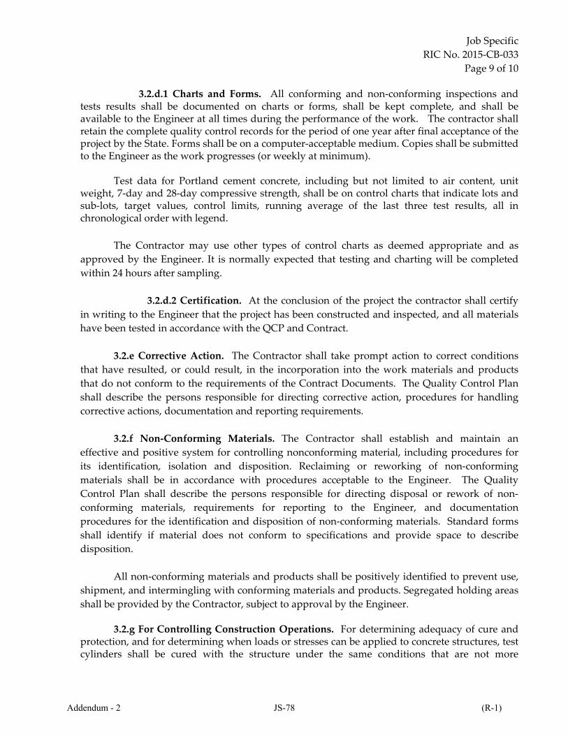
Job Specific
RIC No. 2015‐CB‐033
Page 9 of 10
3.2.d.1 Charts and Forms. All conforming and non‐conforming inspections and
tests results shall be documented on charts or forms, shall be kept complete, and shall be available to the Engineer at all times during the performance of the work. The contractor shall retain the complete quality control records for the period of one year after final acceptance of the project by the State. Forms shall be on a computer‐acceptable medium. Copies shall be submitted to the Engineer as the work progresses (or weekly at minimum).
Test data for Portland cement concrete, including but not limited to air content, unit weight, 7‐day and 28‐day compressive strength, shall be on control charts that indicate lots and sub‐lots, target values, control limits, running average of the last three test results, all in chronological order with legend.
The Contractor may use other types of control charts as deemed appropriate and as
approved by the Engineer. It is normally expected that testing and charting will be completed
within 24 hours after sampling.
3.2.d.2 Certification. At the conclusion of the project the contractor shall certify
in writing to the Engineer that the project has been constructed and inspected, and all materials
have been tested in accordance with the QCP and Contract.
3.2.e Corrective Action. The Contractor shall take prompt action to correct conditions
that have resulted, or could result, in the incorporation into the work materials and products
that do not conform to the requirements of the Contract Documents. The Quality Control Plan
shall describe the persons responsible for directing corrective action, procedures for handling
corrective actions, documentation and reporting requirements.
3.2.f Non‐Conforming Materials. The Contractor shall establish and maintain an
effective and positive system for controlling nonconforming material, including procedures for
its identification, isolation and disposition. Reclaiming or reworking of non‐conforming
materials shall be in accordance with procedures acceptable to the Engineer. The Quality
Control Plan shall describe the persons responsible for directing disposal or rework of non‐
conforming materials, requirements for reporting to the Engineer, and documentation
procedures for the identification and disposition of non‐conforming materials. Standard forms
shall identify if material does not conform to specifications and provide space to describe
disposition.
All non‐conforming materials and products shall be positively identified to prevent use,
shipment, and intermingling with conforming materials and products. Segregated holding areas
shall be provided by the Contractor, subject to approval by the Engineer.
3.2.g For Controlling Construction Operations. For determining adequacy of cure and protection, and for determining when loads or stresses can be applied to concrete structures, test cylinders shall be cured with the structure under the same conditions that are not more
Addendum - 2 JS-78 (R-1)

Job Specific
RIC No. 2015‐CB‐033
Page 10 of 10
favorable than the most unfavorable conditions for the portions of the structure which they represent as described in AASHTO T 23 (ASTM C 31/C 31M), Article 9.4. Sufficient test cylinders shall be made and tested at the appropriate ages to determine when operations such as release of falsework, application of prestressing forces, or placing the structure in service can occur.
Addendum - 2 JS-79 (R-1)

THIS PAGE INTENTIONALLY LEFT BLANK
Addendum - 2 JS-80 (R-1)

THIS PAGE INTENTIONALLY LEFT BLANK
Addendum - 2 JS-81 (R-1)

THIS PAGE INTENTIONALLY LEFT BLANK
Addendum - 2 JS-82 (R-1)

THIS PAGE INTENTIONALLY LEFT BLANK
Addendum - 2 JS-83 (R-1)

THIS PAGE INTENTIONALLY LEFT BLANK
Addendum - 2 JS-84 (R-1)

THIS PAGE INTENTIONALLY LEFT BLANK
Addendum - 2 JS-85 (R-1)

THIS PAGE INTENTIONALLY LEFT BLANK
Addendum - 2 JS-86 (R-1)

THIS PAGE INTENTIONALLY LEFT BLANK
Addendum - 2 JS-87 (R-1)

THIS PAGE INTENTIONALLY LEFT BLANK
Addendum - 2 JS-88 (R-1)

THIS PAGE INTENTIONALLY LEFT BLANK
Addendum - 2 JS-89 (R-1)

THIS PAGE INTENTIONALLY LEFT BLANK
Addendum - 2 JS-90 (R-1)

THIS PAGE INTENTIONALLY LEFT BLANK
Addendum - 2 JS-91 (R-1)

THIS PAGE INTENTIONALLY LEFT BLANK
Addendum - 2 JS-92 (R-1)

THIS PAGE INTENTIONALLY LEFT BLANK
Addendum - 2 JS-93 (R-1)

THIS PAGE INTENTIONALLY LEFT BLANK
Addendum - 2 JS-94 (R-1)

THIS PAGE INTENTIONALLY LEFT BLANK
Addendum - 2 JS-95 (R-1)

THIS PAGE INTENTIONALLY LEFT BLANK
Addendum - 2 JS-96 (R-1)
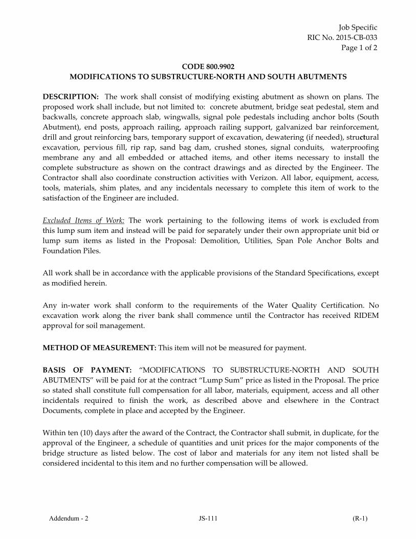
Job Specific
RIC No. 2015-CB-033
Page 1 of 2
CODE 800.9902
MODIFICATIONS TO SUBSTRUCTURE-NORTH AND SOUTH ABUTMENTS
DESCRIPTION: The work shall consist of modifying existing abutment as shown on plans. The
proposed work shall include, but not limited to: concrete abutment, bridge seat pedestal, stem and
backwalls, concrete approach slab, wingwalls, signal pole pedestals including anchor bolts (South
Abutment), end posts, approach railing, approach railing support, galvanized bar reinforcement,
drill and grout reinforcing bars, temporary support of excavation, dewatering (if needed), structural
excavation, pervious fill, rip rap, sand bag dam, crushed stones, signal conduits, waterproofing
membrane any and all embedded or attached items, and other items necessary to install the
complete substructure as shown on the contract drawings and as directed by the Engineer. The
Contractor shall also coordinate construction activities with Verizon. All labor, equipment, access,
tools, materials, shim plates, and any incidentals necessary to complete this item of work to the
satisfaction of the Engineer are included.
Excluded Items of Work: The work pertaining to the following items of work is excluded from
this lump sum item and instead will be paid for separately under their own appropriate unit bid or
lump sum items as listed in the Proposal: Demolition, Utilities, Span Pole Anchor Bolts and
Foundation Piles.
All work shall be in accordance with the applicable provisions of the Standard Specifications, except
as modified herein.
Any in-water work shall conform to the requirements of the Water Quality Certification. No
excavation work along the river bank shall commence until the Contractor has received RIDEM
approval for soil management.
METHOD OF MEASUREMENT: This item will not be measured for payment.
BASIS OF PAYMENT: “MODIFICATIONS TO SUBSTRUCTURE-NORTH AND SOUTH
ABUTMENTS” will be paid for at the contract “Lump Sum” price as listed in the Proposal. The price
so stated shall constitute full compensation for all labor, materials, equipment, access and all other
incidentals required to finish the work, as described above and elsewhere in the Contract
Documents, complete in place and accepted by the Engineer.
Within ten (10) days after the award of the Contract, the Contractor shall submit, in duplicate, for the
approval of the Engineer, a schedule of quantities and unit prices for the major components of the
bridge structure as listed below. The cost of labor and materials for any item not listed shall be
considered incidental to this item and no further compensation will be allowed.
Addendum - 2 JS-111 (R-1)

THIS PAGE INTENTIONALLY LEFT BLANK
Addendum - 2 JS-178 (R-1)

THIS PAGE INTENTIONALLY LEFT BLANK
Addendum - 2 JS-179 (R-1)
Job Specific
RIC No. 2015‐CB‐033
Page 7 of 9
B. This work may require rock excavation, drilling rock or using slurry filled shafts through
whatever materials are encountered to reach the depths indicated on the plans and
specifications. The Contractor shall submit a sequence plan outlining drilling, casing, slurry,
reinforcement and concrete placement procedures for the Engineer to review.
C. Construction of drilled shaft shall be in accordance with AASHTO Standard Specifications for
Highway Bridges 2002 Division II, Section 5 and with U.S.D.O.T. Publication FHWA‐IF‐ 99‐
025, “Drilled Shafts: Construction Procedures and Design Methods.”
D. The maximum allowable horizontal variation of the center of the top of the drilled shaft from
the required location shall be 0.5% of the shaft diameter.
E. The concrete shaft shall not be out of plumb by more than 1% of the total length.
F. Should the depth of drilled shaft extend below the depth shown on the shop drawings, a
minimum of one half of the longitudinal bars required in the upper portion of the shaft shall
be extended the additional length by adding longitudinal reinforcing bars at the bottom of
the cage. Tie or spiral bars shall be continued for the extra depth and the stiffener bars shall
be extended to the final depth. All longitudinal and transverse bars shall be lap spliced or
spliced with mechanical splices. Welding to the reinforcing steel will not be permitted.
G. Approved cylindrical concrete feet (bottom supports) shall be provided to insure that the bottom of the reinforcing cage is maintained the proper distance above the base.
H. The drilled shaft concrete shall be placed as soon as possible after the placement of
reinforcing steel. Concrete shall be placed to the level of the construction joint shown on the
shop drawings. Longitudinal reinforcing shall extend above the construction joint to within
3” of the top of foundation.
I. Casings, if used in drilling operations, shall be removed from the hole. The casing may be
removed as concrete is placed provided a 5 foot head of concrete is maintained, or the casing
may be removed after the concrete has been poured, provided that the concrete has not been
set. Separation of the concrete by hammering or otherwise vibrating the casing during
withdrawal operations shall be avoided.
J. Concrete and placement methods shall conform to the latest RI standard Specifications Sections 601, 808 and the contract Special Provisions.
Constructing the Top of the Foundation
A. The top 12” portion of the concrete foundation shall be formed and reinforced as shown on
the shop drawings. The top surface shall be level within ± 1/8". The top of foundation shall be set to finished grade and finished level. After curing, the forms shall be removed and backfilled with suitable material and compacted in 12-inch layers.
B. The number of conduits in the foundation shall be as shown on the plans. Electrical conduits
Addendum - 2 JS-215 (R-1)
Job Specific
RIC No. 2015‐CB‐033
Page 8 of 9
of the size specified on the plans shall extend 2 feet out from the side of the formed portion of
the foundation. All conduit ends terminating below grade shall be capped with a malleable
iron cap. All above grade conduit ends shall be terminated with an insulated bonding
bushing with tinned insert. Conduit caps shall be installed before the concrete is placed and
shall remain in place until the cable is installed.
C. Rigid metal conduit, drain pipe, anchor rods and the anchor plate shall be placed and secured
in proper position in the formed portion of the top of foundation. A template shall be used to
hold the required anchor rod assembly, ground rod sleeve and conduits in their correct
positions. The orientation of the anchor rods on the bolt circle are important to the
positioning of the handhole on the pole. The anchor rod locations shall be in accordance with
approved shop drawings. Each anchor rod shall be fitted with two leveling nuts and double
nuts above the base plate. Conduits shall extend up from the top of foundation to the height
shown on the plans.
D. Concrete shall be placed in the forms in accordance with the applicable provisions of Section
808.
E. Curing of the concrete shall be performed in accordance with Section 601.
F. Forms shall not be removed until after the concrete has hardened properly and not less than
24 hours after the concrete has been placed.
G. The portions of the foundations that will remain exposed to view shall be finished to the
satisfaction of the Engineer and in conformance with the pertinent requirements of Sub‐
article 6.01.03‐21.
Addendum - 2 JS-216 (R-1)

Job Specific
RIC No. 2015‐CB‐033
Page 1 of 1
CODE 607
MASS CONCRETE
Unless otherwise modified elsewhere in the Contract Documents, Section 607 of the Rhode Island
Standard Specifications for Road and Bridge Construction is revised as follows:
Replace the first paragraph of Subsection 607.01.1, page AC14‐4 of the August 2013 Compilation of
Approved Specifications with the following:
Mass Concrete is defined as any elements so specified on the Plans and any other concrete pour
where the ratio of the total volume to the surface area of the element equals or exceeds 0.6 and has a
minimum dimension of 3 feet in any of the three planes. Calculation of the ratio shall be performed
based on all dimensions measured in feet.
Addendum - 2 JS-239

DEPARTMENT OF TRANSPORTATION
RHODE ISLAND
PROVIDENCE, RHODE ISLAND
PROVIDENCE, RHODE ISLAND
PLEASANT VALLEY PARKWAY
REPLACEMENT OF
BRIDGE NO. 777
GENERAL NOTES - TRAFFIC SIGNALS: LEGEND UTILITY NOTES - VERIZON:
JOB SPECIFIC
PLAN SYMBOLS,
LEGEND & NOTES
SITE SPECIFIC NOTES - RIPDES STORMWATER POLLUTION PREVENTION PLAN:
UTILITY GENERAL NOTE:
GENERAL NOTES:

DEPARTMENT OF TRANSPORTATION
RHODE ISLAND
PROVIDENCE, RHODE ISLAND
PROVIDENCE, RHODE ISLAND
PLEASANT VALLEY PARKWAY
REPLACEMENT OF
BRIDGE NO. 777
DRAINAGE & UTILITY
PLAN NO. 3

DEPARTMENT OF TRANSPORTATION
RHODE ISLAND
PROVIDENCE, RHODE ISLAND
PROVIDENCE, RHODE ISLAND
PLEASANT VALLEY PARKWAY
REPLACEMENT OF
BRIDGE NO. 777
CONSTRUCTION PHASE NO. 1
GENERAL PLAN NO. 2

“ ”
DEPARTMENT OF TRANSPORTATION
RHODE ISLAND
PROVIDENCE, RHODE ISLAND
PROVIDENCE, RHODE ISLAND
PLEASANT VALLEY PARKWAY
REPLACEMENT OF
BRIDGE NO. 777
JOB SPECIFIC
GENERAL NOTES 2
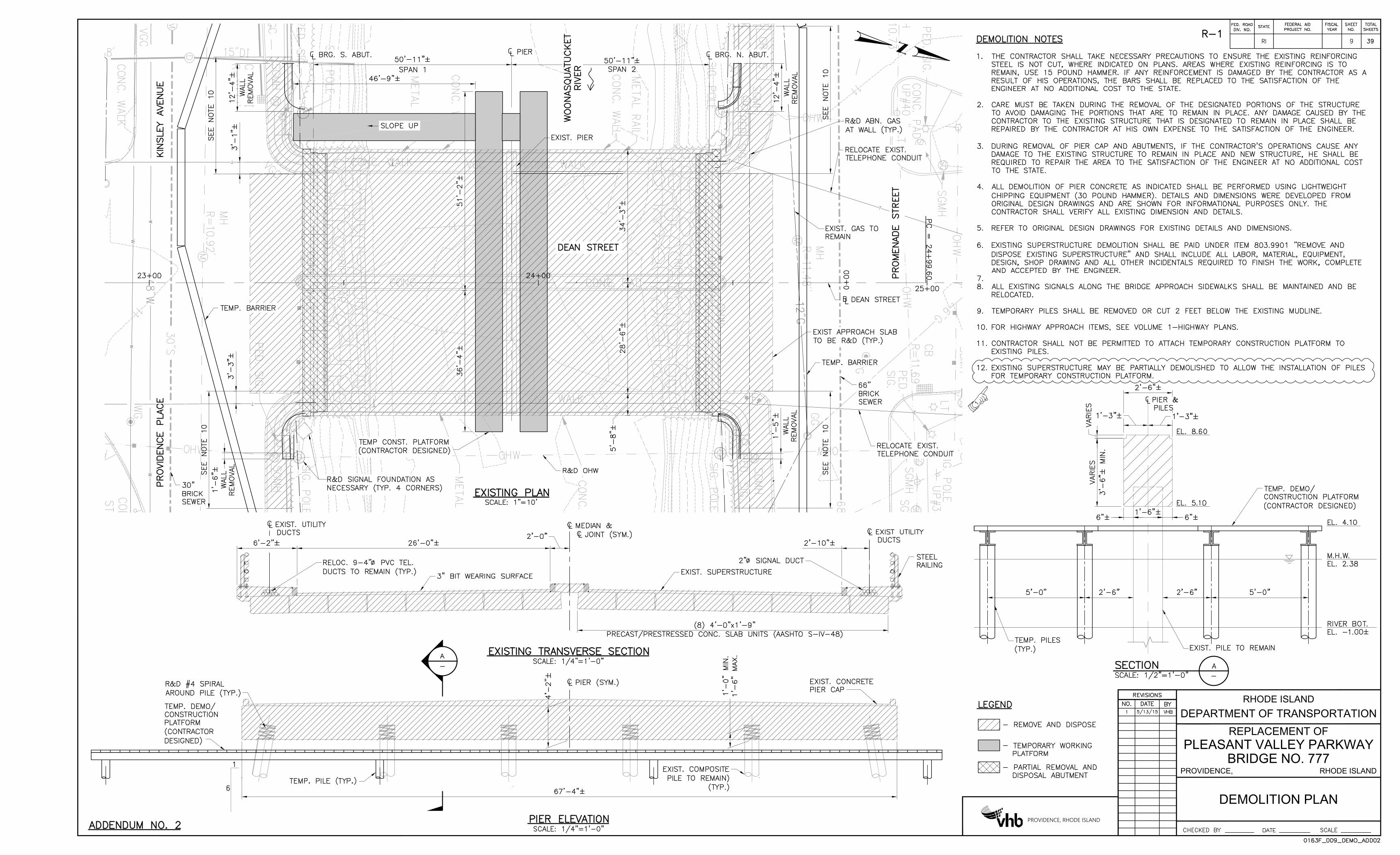
DEMOLITION PLAN
DEPARTMENT OF TRANSPORTATION
RHODE ISLAND
PROVIDENCE, RHODE ISLAND
PROVIDENCE, RHODE ISLAND
PLEASANT VALLEY PARKWAY
REPLACEMENT OF
BRIDGE NO. 777

FOUNDATION PLAN
DEPARTMENT OF TRANSPORTATION
RHODE ISLAND
PROVIDENCE, RHODE ISLAND
PROVIDENCE, RHODE ISLAND
PLEASANT VALLEY PARKWAY
REPLACEMENT OF
BRIDGE NO. 777
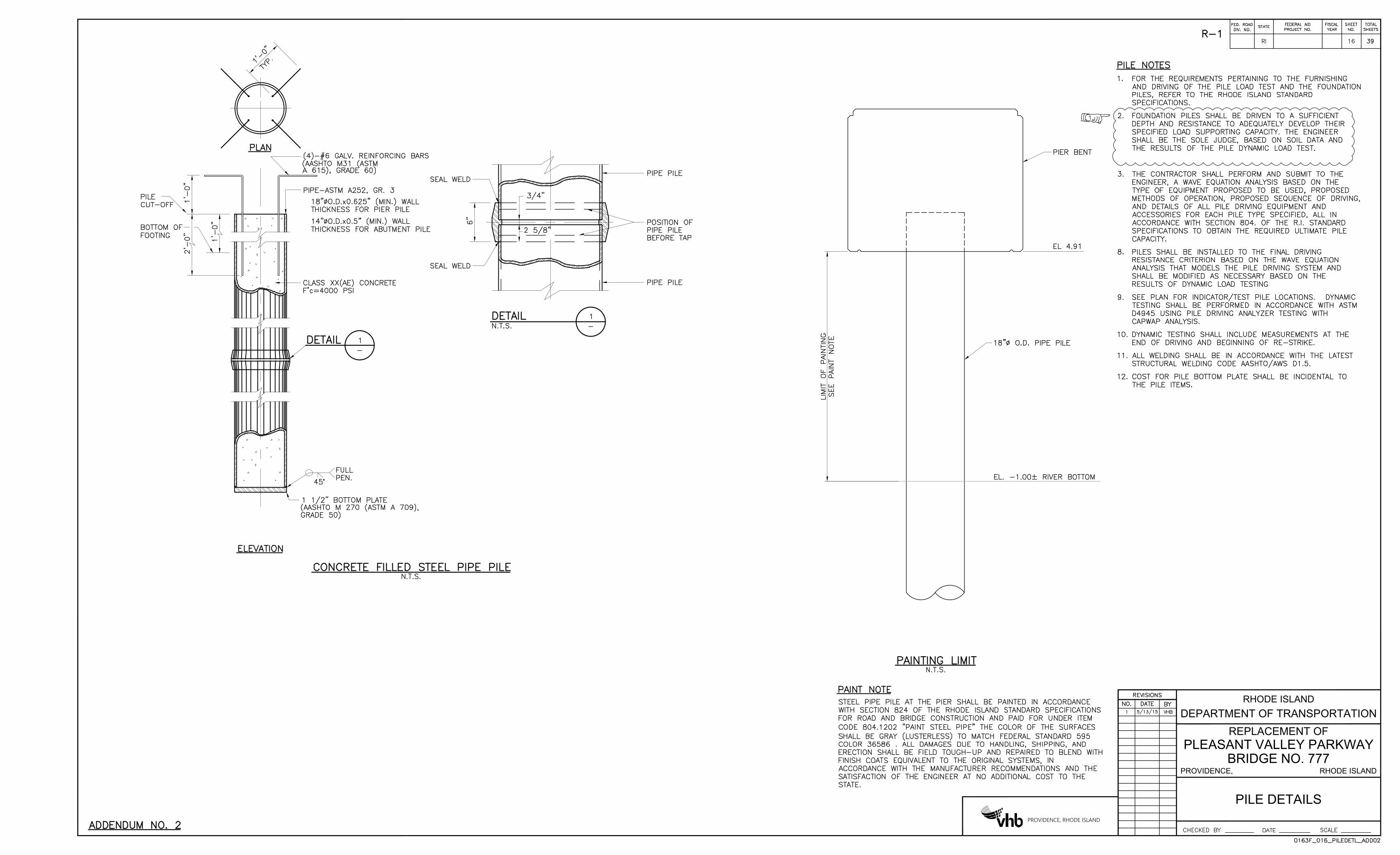
PILE DETAILS
DEPARTMENT OF TRANSPORTATION
RHODE ISLAND
PROVIDENCE, RHODE ISLAND
PROVIDENCE, RHODE ISLAND
PLEASANT VALLEY PARKWAY
REPLACEMENT OF
BRIDGE NO. 777