maurer mechanics
TRANSCRIPT

8/13/2019 Maurer Mechanics
http://slidepdf.com/reader/full/maurer-mechanics 1/407
8/13/2019 Maurer Mechanics
http://slidepdf.com/reader/full/maurer-mechanics 2/407
V

8/13/2019 Maurer Mechanics
http://slidepdf.com/reader/full/maurer-mechanics 3/407

8/13/2019 Maurer Mechanics
http://slidepdf.com/reader/full/maurer-mechanics 4/407
8/13/2019 Maurer Mechanics
http://slidepdf.com/reader/full/maurer-mechanics 5/407
t '-3
,\0 1 1,>
TECHNICAL MECHANICS •
STATICS AND DYNAMICS
BY
EDWARD R. MAURERProfessor of Mechanics in the University of Wisconsin
FOURTH EDITION, REVISED AND ENLARGED
TOTAL ISSUE TWENTY-TWO THOUSAND
NEW YORK
JOHN WILEY & SONS, Inc.
London: CHAPMAN & HALL, Limited
8/13/2019 Maurer Mechanics
http://slidepdf.com/reader/full/maurer-mechanics 6/407
- J ,.
111?Engineering
Library
Copyright, igo3, 1914, 193^
BV
Edward R. Maurer
Stanbope ipress
, GILSON COMP.BOSTON, U.S.A.
H. GILSON COMPANY 19-01

8/13/2019 Maurer Mechanics
http://slidepdf.com/reader/full/maurer-mechanics 7/407
PREFACE
The following paragraph is an adaptation from the preface of the first
edition of this work, published ten years ago; it applies to the present edition.
This book might be described fairly as a theoretical mechanics for students
of engineering. It is not comparable to books commonly called Theoretical
Mechanics, generally intended for students of mathematics or physics; nor
to books commonly titled AppUed IMechanics which generally include a treat-
ment of strength of materials, hydraulics, etc., for students of engineering.
The title Technical Mechanics seems fairly appropriate for this book; and
inasmuch as it is not otherwise used in this country, it was so adopted. On
the theoretical side, practically each subject discussed herein has a direct
bearing on some engineering problem. The applications were selected and
presented for the purpose of illustrating a principle of mechanics and for
training students in the use of such principles, —not to furnish information,
except incidentally, about the structure, machine, or what not to which the
application was made.
Ten years use of the book as a text in the author's classes has suggested
many changes; and in recent years the need of a new collection of problems
has become urgent. Accordingly, a revision was undertaken, and the effort has
resulted in a practically rewritten book. Indeed the only portion of the former
edition used again with little or no change is the present Appendix A. Though
containing fewer pages than the old book, the new one —because of its (nearly
one-third) larger printed page —contains more material than the old.
Inasmuch as Mechanics deals mainly with subjects permanent in character,
the revision consists principally of changes in arrangement and presentation.
Both were determined upon to a large degree by a desire to furnish an ade-
quate course of instruction for students in engineering in one semester, five
times per week. To this end, it was necessary to sacrifice logical order of
arrangement more or less. As in former editions, Statics is presented first
because relatively simpler than Dynamics. Kinematics, as such, is not given
a place. The chapter on Attraction and Stress has not been retained. Dis-
cussion of Friction and Efficiency has been amplified, and Dynamics has been
extended to provide a quantitative explanation of simple gyroscopic action.
Many solved numerical examples have been added to elucidate principles.
The collection of problems to be solved by students has been completely
changed.lU
4942^^5
8/13/2019 Maurer Mechanics
http://slidepdf.com/reader/full/maurer-mechanics 8/407
IV
All of Statics except Arts. 23, 25, 26, and 27 may be mastered with no knowl-
edge of mathematics beyond trigonometry. Calculus methods are used
in Dynamics, but a good knowledge of the elements only of that branch of
mathematics is presupposed. Graphical methods are used freely, as much
as the algebraic in Statics.
The author is pleased to acknowledge with thanks the helpful suggestions
and criticisms of the teaching staff in Mechanics at the University of Ilhnois;
of his colleague, Professor M. O. Withey; and of Professor C. H. Burnside
of Columbia University. He thanks also American Machinist, Engineering
Record, and Engineering News for permission to copy and for gifts of cuts;
and individuals and other journals named in the text for similar favors.
Madison, Wisconsin.
December, 1913.
To the edition above described there has been added a second collection of
problems, pages 354-377; and articles 38, 44, 49, 5^, 5^, 55, 5^, 58 have been
modified.
September, 191 7.
8/13/2019 Maurer Mechanics
http://slidepdf.com/reader/full/maurer-mechanics 9/407
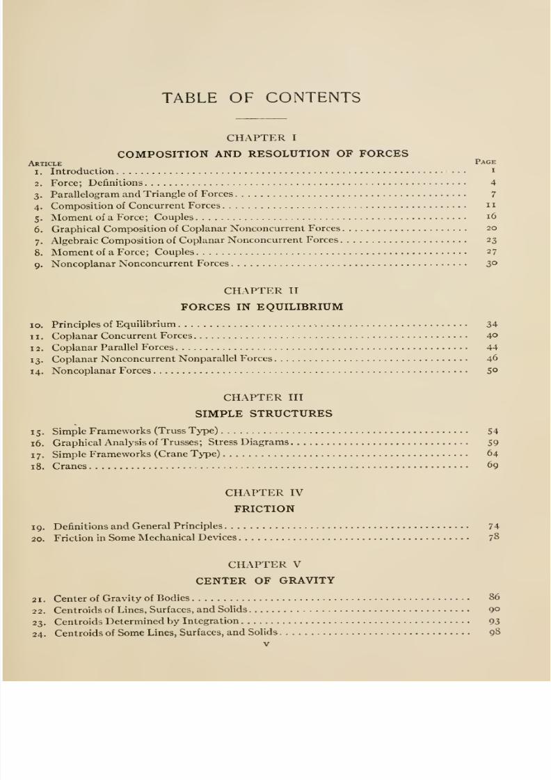
TABLE OF CONTENTS
CHAPTER I
COMPOSITION AND RESOLUTION OF FORCESArticle Page
1. Introduction i
2. Force; Definitions 4
3. Parallelogram and Triangle of Forces 7
4. Composition of Concurrent Forces 11
5. Moment of a Force; Couples16
6. Graphical Composition of Coplanar Nonconcurrent Forces 20
7. Algebraic Composition of Coplanar Nonconcurrent Forces 23
8. Moment of a Force; Couples 27
9. Noncoplanar Nonconcurrent Forces 3°
CHAPTER II
FORCES IN EQUILIBRIUM
10. Principles of Equilibrium - 34
11. Coplanar Concurrent Forces 4°
12. Coplanar Parallel Forces 44
13. Coplanar Nonconcurrent Nonparallel Forces 46
14. Noncoplanar Forces 5°
CHAPTER III
SIMPLE STRUCTURES
15. Simple Frameworks (Truss Type) 54
16. Graphical Analysis of Trusses; Stress Diagrams 59
17. Simple Frameworks (Crane Type) 64
18. Cranes 69
CHAPTER IV
FRICTION
19. Definitions and General Principles 74
20. Friction in Some Mechanical Devices 78
CHAPTER V
CENTER OF GRAVITY
Center of Gravity of Bodies 86
Centroids of Lines, Surfaces, and Solids 9°
23. Centroids Determined by Integration 93
24. Centroids of Some Lines, Surfaces, and Solids 98
V
21.
22.
8/13/2019 Maurer Mechanics
http://slidepdf.com/reader/full/maurer-mechanics 10/407

8/13/2019 Maurer Mechanics
http://slidepdf.com/reader/full/maurer-mechanics 11/407
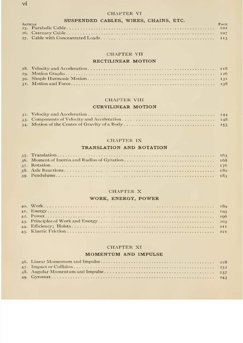
vu
CHAPTER XII
TWO DIMENSIONAL (PLANE) MOTIONArticle Page50. Kinematics of Plane Motion 256
51. Kinetics of Plane Motion 261
52. Rolling Resistance 268
53. Relative Motion 273
CHAPTER XIII
THREE DIMENSIONAL (SOLID) MOTION
54. Body With a Fixed Point, Kinematics of 280
55. Body With a Fixed Point, Kinetics of 284
56. Gyrostat 288
57. Principal Moments of Inertia, and Axes 292
58. Any Solid Motion; Summary of Dynamics 296
APPENDIX A. THEORY OF DIMENSIONS OF UNITS 302
APPENDIX B. MOMENT OF INERTIA OF PLANE AREAS 308
PROBLEMS 323

8/13/2019 Maurer Mechanics
http://slidepdf.com/reader/full/maurer-mechanics 12/407
8/13/2019 Maurer Mechanics
http://slidepdf.com/reader/full/maurer-mechanics 13/407
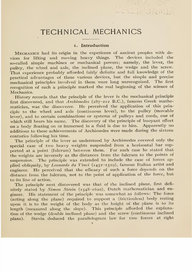
TECHNICAL MECHANICS
I. Introduction
Mechanics had its origin in the experience of ancient peoples with de-
vices for lifting and moving heavy things. The devices included the
so-called simple machines or mechanical powers; namely, the lever, the
pulley, the wheel and axle, the inclined plane, the wedge and the screw.
That experience probably afforded fairly definite and full knowledge of the
practical advantages of these various devices, but the simple and precise
mechanical principles involved in them were long unrecognized. The first
recognition of such a principle marked the real beginning of the science of
Mechanics.
History records that the principle of the lever is the mechanical principle
first discovered, and that Archimedes (287-212 B.C.), famous Greek mathe-
matician, was the discoverer. He perceived the application of this prin-
ciple to the wheel and axle (continuous lever), to the pulley (movable
lever), and to certain combinations or systems of pulleys and cords, one of
which still bears his name. The discovery of the principle of buoyant effort
on a body floating on or immersed in a fluid is due to him. Apparently no
additions to these achievements of Archimedes were made during the sixteen
centuries following his time.
The principle of the lever as understood by Archimedes covered only the
special case of two heavy weights suspended from a horizontal bar sup-
ported at a point (fulcrum) between them. For such case he stated that
the weights are inversely as the distances from the fulcrum to the points of
suspension. The principle was extended to include the case of forces ap-
plied obliquely, by Leonardo da Vinci (145 2-1 5 19), famous Italian artist and
engineer. He perceived that the efficacy of such a force depends on the
distance from the fulcrum, not to the point of application of the force, but
to its line of action.
The principle next discovered was that of the inclined plane, first defi-
nitely stated by Simon Stevin (i 548-1620), Dutch mathematician and en-
gineer. His statement of the principle was somewhat as follows: The force
(acting along the plane) required to support a (frictionless) body resting
upon it is to the weight of the body as the height of the plane is to its
length (measured along the slope). This principle afforded the explana-
tion of the wedge (double inclined plane) and the screw (continuous inclined
plane). Stevin deduced the parallelogram law for two forces at right

8/13/2019 Maurer Mechanics
http://slidepdf.com/reader/full/maurer-mechanics 14/407
2 '' Art. I
•a'n^ies' 'from the principle of the inclined plane; and from his study of
pulleys he noted that what is gained in power is lost in speed. Thus he
caught the first glimpse of two important principles, —that of the parallelo-
gram of forces, and that of virtual velocity or work.
The first discoveries of laws of motion were made by Galileo (i 564-1 642),
Italian astronomer and physicist. For 2000 years it had been believed that
heavy bodies fall more rapidly than light ones. This Galileo disproved by
actual trial at the leaning tower of Pisa. Next he was led to inquire about
the manner in which a body falls, or how the speed changes. He made
several guesses at this law, and finally verified one of them by indirect
experiment and deduction. Up to Galileo's time, it was believed that rest
was the natural condition for a body; and that motion was unnatural,
requiring some outside cause (force) to maintain it, and ceasing only when
the force ceases. Galileo perceived that motion is just as natural as rest;
that motions cease not because they are unnatural, but because of some
influence (force) from the outside operating to reduce the motion and
eventually to destroy it. In short, he discovered the so-called first law of
motion, usually credited to Newton. He invented the telescope.
Huygens (1629-1695), Dutch physicist, made some important contribu-
tions to this science. He developed the theory of the pendulum, determined
the acceleration due to gravity from pendulum obser\^ations, and deduced
certain theorems regarding centrifugal force. He invented the clock pen-
dulimi and escapement.
Newton (1642-1727), English mathematician and physicist, is generally
regarded as the founder of Mechanics. At an early age he began an at-
tempt to explain the motions of the planets, whose orbits and speeds were
then well known, in terms of experience with more familiar motions. He
succeeded in thus explaining many features of the planetary motions, and
established that there are certain principles common to the motion of all
bodies, celestial and terrestial. These principles are generally known as
Newton's laws of motions (see index). His study of planetary motion led
to other great achievements, among which may be mentioned the discovery
of the law of universal gravitation, and the invention of the calculus (also
invented independently by Leibnitz, German mathematician).
Since Newton, no essentially new principle [of Mechanics] has been
stated. All that has been accomplished since his day has been a deductive,
formal, and mathematical development on the basis of Newton's laws. *
Such development consritutes the body of knowledge which we call Me-chanics, or sometimes Rational and Theoretical Mechanics, to distinguish it
from Applied Mechanics. It may be defined as the science of motion, but it
includes the science of rest as a relatively minor part.
* For a full and critical account of that development, see Mach's Science of Me-
chanics, from which the quotation was taken, or Co.x's Mechanics for a good but less
critical account.
8/13/2019 Maurer Mechanics
http://slidepdf.com/reader/full/maurer-mechanics 15/407
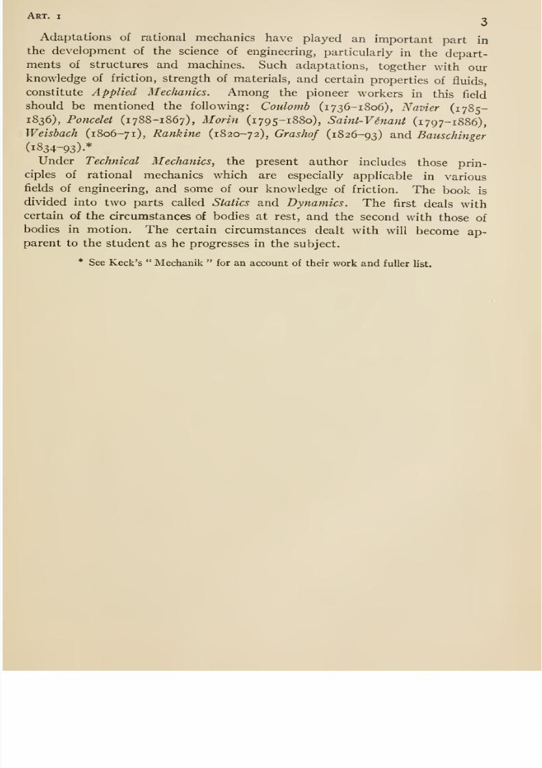
Art. I «
Adaptations of rational mechanics have played an important part in
the development of the science of engineering, particularly in the depart-ments of structures and machines. Such adaptations, together with ourknowledge of friction, strength of materials, and certain properties of fluids,
constitute Applied Mechanics. Among the pioneer workers in this field
should be mentioned the following: Coulomb (1736-1806), Navier (1785-1836), Poncelet (1788-1867), Morin (1795-1880), Saint-Venant (1797-1886),Weisbach (1806-71), Rankine (1820-72), Grashof (1826-93) and Bauschinger
(1834-93).*
Under Technical Mechanics, the present author includes those prin-
ciples of rational mechanics which are especially applicable in various
fields of engineering, and some of our knowledge of friction. The book is
divided into two parts called Statics and Dynamics. The first deals with
certain of the circumstances of bodies at rest, and the second with those of
bodies in motion. The certain circumstances dealt with will become ap-parent to the student as he progresses in the subject.
* See Keek's Mechanik for an account of their work and fuller list.

8/13/2019 Maurer Mechanics
http://slidepdf.com/reader/full/maurer-mechanics 16/407
STATICS
CHAPTER I
COMPOSITION AND RESOLUTION OF FORCES
2. Force; Definitions
Bodies act upon each other in various ways, producing different kinds
of results. Any action of one body upon another which, when exertedalone, would result in motion of the body acted upon, or in change of motion
if the body is already moving, is called force; the word is a general term for
push and pull. Our earliest notions about forces are based on our experience
with forces exerted by or upon ourselves. Through this experience we have
learned that a force has magnitude, place of application, and direction,
sometimes called the characteristics of a force.
To express the magnitude of a force, we must of course compare it to
some other force regarded as a unit. Many units of force are in use; the
most convenient are the so-called gravitation units. They are the earth-
pulls on our standards for measuring quantity of material (as iron, coal,
grain, sugar, etc.), commonly called standards of weight.* The earth-pull
on any of these standards is called by the name of the standard; thus the
earth-pull on the pound standard (also any equal force) is called a pound;
the earth-pull on the kilogram standard (also any equal force) is called a
kilogram, etc. Since the earth-pull on any given thing varies in amountas the thing is transported from place to place, gravitation units of force
are not constant with regard to place. But this variation need not be
regarded in most engineering calculations because any error due to such
disregard is generally smaller than errors due to other approximations in
the calculations. The extreme variation in any gravitation unit is that
between its magnitudes at the highest elevation on the equator and at the
poles; this difference is but 0.6 per cent. For points within the United
States the extreme variation equals about 0.3 per cent. For any two
* In common parlance the word weight is used in at least two senses. Thus, suppose
that a dealer sells coal to a consumer by weight, and engages a teamster to deliver it byweight; to the consumer, the weight of each wagon load represents a certain amount of
useful material, but to the teamster it represents a certain burden on his team due to the
action of gravity on the coal. That is, weight suggests material to the one man andearth-pull to the other.
8/13/2019 Maurer Mechanics
http://slidepdf.com/reader/full/maurer-mechanics 17/407
Art. 2 5
points on the surface of the earth, the variation equals that in the values of
g in the formula
g = 32.0894 (i + 0.0052375 sin^O (i ~ 0.0000000957 e)
computed for the two places; I denotes latitude, and e elevation above sea
level, in feet.
The place of application of most forces with which we shall deal is a
portion of the surface of the body to which the force is applied. A notable
exception is earth-pull, or gravity, which is applied not to the surface of a
body but throughout the same. All such are called distributed forces. The
places of application of some forces are very small compared to the sur-
faces of the bodies to which they are applied, and for many purposes these
places may be regarded as points of application; any such force is called a
concentrated force. The line of action of a concentrated force is a line
indefinite in length, parallel to the direction of the force, and containing its
point of application. A concentrated force may act along its line of action in
one of two ways, —to the right or left, up or down, etc. We say that the sense
of a force is toward the right, toward the left, up, or down as the case maybe. That is, sense refers to arrow-headedness (see next paragraph).
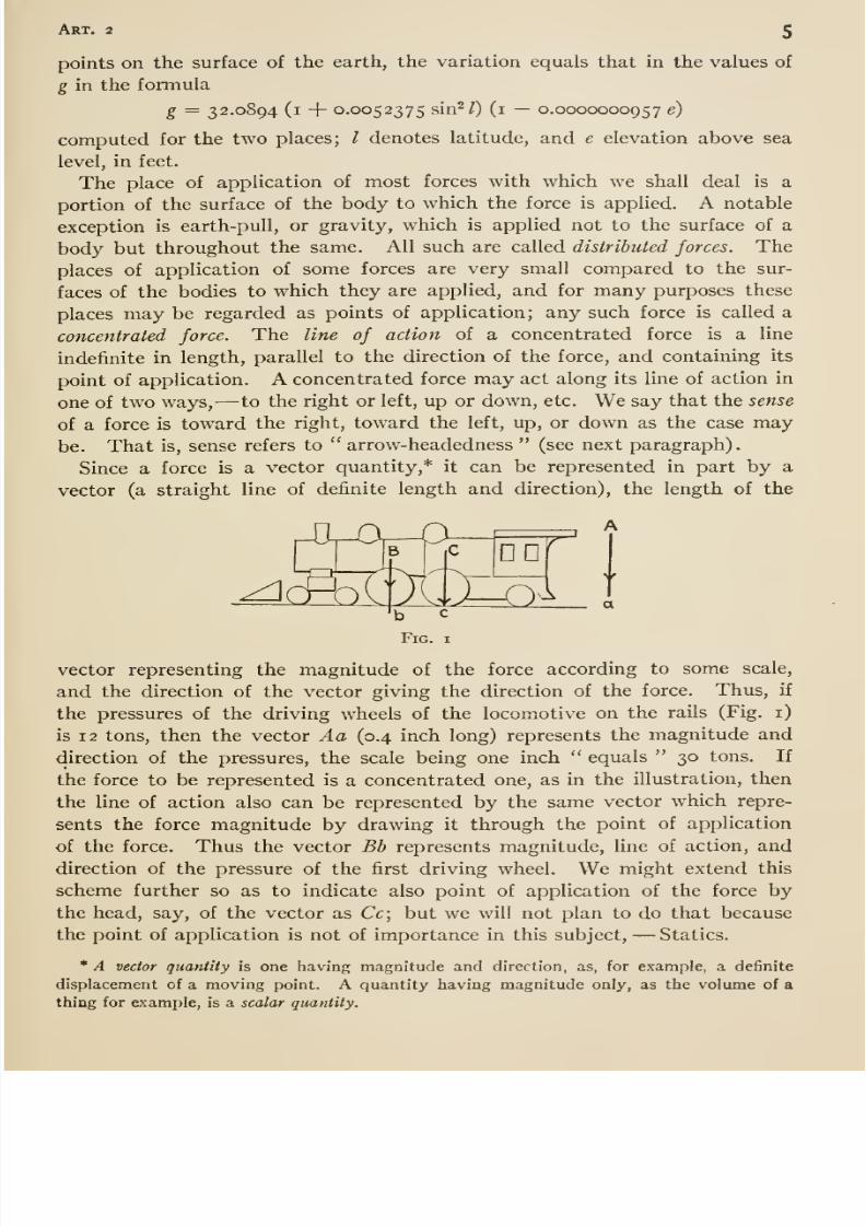
Since a force is a vector quantity,* it can be represented in part by a
vector (a straight line of definite length and direction), the length of the
a
vector representing the magnitude of the force according to some scale,
and the direction of the vector giving the direction of the force. Thus, if
the pressures of the driving wheels of the locomotive on the rails (Fig. i)
is 12 tons, then the vector Aa (0.4 inch long) represents the magnitude and
direction of the pressures, the scale being one inch equals 30 tons. If
the force to be represented is a concentrated one, as in the illustration, then
the line of action also can be represented by the same vector which repre-
sents the force magnitude by drawing it through the point of application
of the force. Thus the vector Bb represents magnitude, line of action, and
direction of the pressure of the first driving wheel. We might extend this
scheme further so as to indicate also point of application of the force by
the head, say, of the vector as Cc; but we will not plan to do that because
the point of application is not of importance in this subject, —Statics.
* A vector quantity is one having magnitude and direction, as, for example, a definite
displacement of a moving point. A quantity having magnitude only, as the volume of a
thing for example, is a scalar quantity.
8/13/2019 Maurer Mechanics
http://slidepdf.com/reader/full/maurer-mechanics 18/407
Chap, i
f
1 \B
Fig. 2
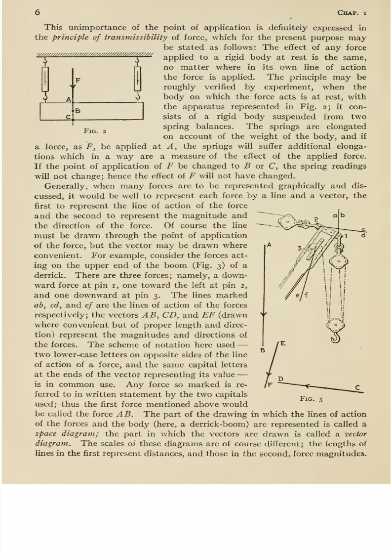
This unimportance of the point of application is definitely expressed in
the principle of transmissibility of force, which for the present purpose maybe stated as follows: The effect of any force
applied to a rigid body at rest is the same,
no matter where in its own line of action
the force is applied. The principle may beroughly verified by experiment, when the
body on which the force acts is at rest, with
the apparatus represented in Fig. 2; it con-
sists of a rigid body suspended from two
spring balances. The springs are elongated
on account of the weight of the body, and if
a force, as F, be applied at A, the springs will suffer additional elonga-
tions which in a way are a measure of the effect of the applied force.
If the point of application of F be changed to B or C, the spring readings
will not change; hence the effect of F will not have changed.
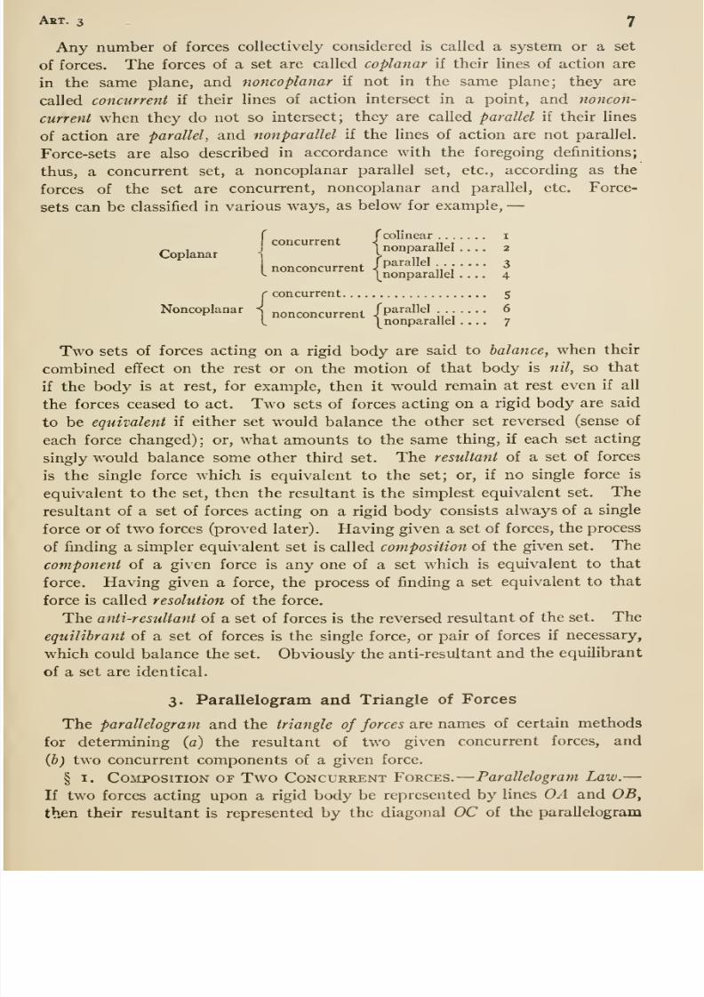
Generally, when many forces are to be represented graphically and dis-
cussed, it would be well to represent each force by a line and a vector, the
first to represent the line of action of the force
and the second to represent the magnitude and
the direction of the force. Of course the line
must be drawn through the point of application
of the force, but the vector may be drawn where
convenient. For example, consider the forces act-
ing on the upper end of the boom (Fig. 3) of a
derrick. There are three forces; namely, a down-
ward force at pin i, one toward the left at pin 2,
and one downward at pin 3. The lines marked
ah, cd, and ef are the lines of action of the forces
respectively; the vectors AB, CD, and EF (drawn
where convenient but of proper length and direc-
tion) represent the magnitudes and directions of
the forces. The scheme of notation here used —two lower-case letters on opposite sides of the line
of action of a force, and the same capital letters
at the ends of the vector representing its value —is in common use. Any force so marked is re-
ferred to in written statement by the two capitals
used; thus the first force mentioned above wouldbe called the force AB. The part of the drawing in which the lines of action
of the forces and the body (here, a derrick-boom) are represented is called a
space diagram; the part in which the vectors are drawn is called a vector
diagram. The scales of these diagrams are of course different; the lengths of
lines in the first represent distances, and those in the second, force magnitudes.
Fig.
8/13/2019 Maurer Mechanics
http://slidepdf.com/reader/full/maurer-mechanics 19/407
Art. 3 7
Any number of forces collectively considered is called a system or a set
of forces. The forces of a set are called coplanar if their lines of action are
in the same plane, and noncoplanar if not in the same plane; they are
called concurrent if their lines of action intersect in a point, and noncon-
current when they do not so intersect; they are called parallel if their lines
of action are parallel, andnonpar allel if the lines of action are not parallel.
Force-sets are also described in accordance with the foregoing definitions;
thus, a concurrent set, a noncoplanar parallel set, etc., according as the
forces of the set are concurrent, noncoplanar and parallel, etc. Force-
sets can be classified in various ways, as below for example^ —
Coplanar
, fcolinear iconcurrent < ,, •
\ nonparallel .... 2
nonconcurrent -^^^^ ^ W i
' ' ^\nonparallel .... 4
concurrent 5
Noncoplanar < nonconcurrent /parallel ._. ..... 6L... ...., „,l^nonparallel .... 7
Two sets of forces acting on a rigid body are said to balance, when their
combined effect on the rest or on the motion of that body is nil, so that
if the body is at rest, for example, then it would remain at rest even if all
the forces ceased to act. Two sets of forces acting on a rigid body are said
to be equivalent if either set would balance the other set reversed (sense of
each force changed); or, what amounts to the same thing, if each set acting
singly would balance some other third set. The resultant of a set of forces
is the single force which is equivalent to the set; or, if no single force is
equivalent to the set, then the resultant is the simplest equivalent set. The
resultant of a set of forces acting on a rigid body consists always of a single
force or of two forces (proved later). Having given a set of forces, the process
of finding a simpler equivalent set is called composition of the given set. The
component of a given force is any one of a set which is equivalent to that
force. Having given a force, the process of finding a set equivalent to that
force is called resolution of the force.
The anti-resultant of a set of forces is the reversed resultant of the set. The
equilibrant of a set of forces is the single force, or pair of forces if necessary,
which could balance the set. Obviously the anti-resultant and the equilibrant
of a set are identical.
3. Parallelogram and Triangle of Forces
The parallelogram and the triangle of forces are names of certain methods
for determining (a) the resultant of two given concurrent forces, and
(b) two concurrent components of a given force.
§ I. Composition of Two Concurrent Forces. —Parallelogram Law. —If two forces acting upon a rigid body be represented by lines OA and OB,
then their resultant is represented by the diagonal OC of the parallelogram
8/13/2019 Maurer Mechanics
http://slidepdf.com/reader/full/maurer-mechanics 20/407
8 Chap, i
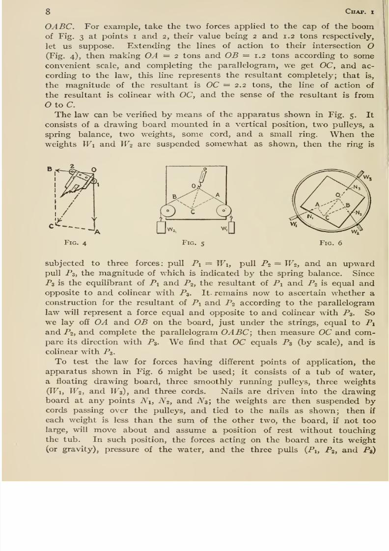
OABC. For example, take the two forces applied to the cap of the boomof Fig. 3 at points i and 2, their value being 2 and 1.2 tons respectively,
let us suppose. Extending the lines of action to their intersection O(Fig. 4), then making OA = 2 tons and OB =1.2 tons according to some
convenient scale, and completing the parallelogram, we get OC, and ac-
cording to the law, this line represents the resultant completely; that is,
the magnitude of the resultant is OC =^2.2 tons, the line of action of
the resultant is colinear with OC, and the sense of the resultant is from
OtoC.The law can be verified by means of the apparatus shown in Fig. 5. It
consists of a drawing board mounted in a vertical position, two pulleys, a
spring balance, two weights, some cord, and a small ring. When the
weights Wi and W2 are suspended somewhat as shown, then the ring is
Fig. 4 Fig. s Fig. 6
subjected to three forces: pull Pi = Wi, pull P2 = W2, and an upwardpull P3, the magnitude of which is indicated by the spring balance. Since
P3 is the equilibrant of Pi and P2, the resultant of Pi and P2 is equal andopposite to and colinear with P3. It- remains now to ascertain whether a
construction for the resultant of Pi and P2 according to the parallelogram
law will represent a force equal and opposite to and colinear with Pg, So
we lay off OA and OB on the board, just under the strings, equal to Pi
and P2, and complete the parallelogram OABC; then measure OC and com-
pare its direction with P3. We find that OC equals P3 (by scale), and is
colinear with P3.
To test the law for forces having different points of application, the
apparatus shown in Fig. 6 might be used; it consists of a tub of water,
a floating drawing board, three smoothly running pulleys, three weights
(Wi, W2, and W3), and three cords. Nails are driven into the drawingboard at any points Ni, N2, and N3; the weights are then suspended bycords passing over the pulleys, and tied to the nails as shown; then if
each weight is less than the sum of the other two, the board, if not too
large, will move about and assume a position of rest without touching
the tub. In such position, the forces acting on the board are its weight
(or gravity), pressure of the water, and the three pulls (Pi, P2, and P»)
8/13/2019 Maurer Mechanics
http://slidepdf.com/reader/full/maurer-mechanics 21/407
Art. 3 g
practically equal to Wi, W2, and W3 respectively. Obviously the first twoforces balance each other; therefore the three pulls also balance, and so
the resultant of Pi and P2 is ec^ual and opposite to and colinear with P3.
We next determine the resultant R of Pi and P2 by the parallelogram law:
extend the lines of action of the pulls Pi and P2 to their intersection 0;
from there lay off OA and OB equal (by some convenient scale) to Pi andP2; complete the parallelogram OABC. Then OC represents R; on compari-
son it will be found, as before, that OC is equal and opposite to and colinear
with P3, and hence OC does represent the magnitude and line of action of
R. Since P3, and hence R, passes through (the intersection of Pi and
P2), this experiment emphasizes the fact that the line of action of the re-
sultant of two concurrent forces passes through their point of concurrence.
The point of application of R might of course be taken anywhere in OC or
its extension; for, so taken, R obviously would balance P3.*
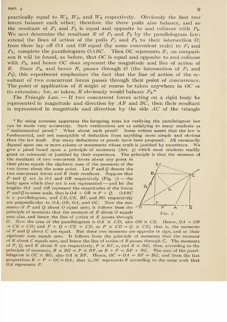
The Triangle Law. —If two concurrent forces acting on a rigid body be
represented in magnitude and direction hy AB and BC, then their resultant
is represented in magnitude and direction by the side ^C of the triangle
* By using accurate apparatus the foregoing tests for verifying the parallelogram law-
can be made very accurately. Such verifications are as satisfying to many students as
mathematical proof. What about such proof? Some writers assert that the law is
fundamental, and not susceptible of deduction from anything more simple and obviousthan the law itself. But many deductions or proofs have been proposed. All necessarily
depend upon one or more axioms or statements whose truth is justified by experience. Wegive a proof based upon a principle of moments (Art. 5) which most students readily
grant as axiomatic or justified by their experience. The principle is that the moment of
the resultant of two concurrent forces about any point in
their plane equals the algebraic sum of the moments of the E/-,_
two forces about the same point. Let P and Q denote the / ~ '~---,, ^two concurrent forces and R their resultant. Suppose that
P and Q act in OA and OB respectively (Fig. 7) —the
body upon which they act is not represented —and let the ^lengths OA and OB represent the magnitudes of the forces /P and Q to some scale, that is OA ^ OB = P ^ Q. OABC /is a parallelogram, and CD, CE, BF, and BG respectively / ^
are perpendicular to OA,OB, OA, and OC. Now the mo- /^_ ^_^ments of P and Q about equal zero; it follows from the '^0 p A Dprinciple of moments that the moment of R about equals Pi^ _
zero also, and hence the line of action of R passes through
0. Now the area of the parallelogram is OA X CD; also OB X CE. Hence, OA -^ OB
= CE^ CD; and P -^ Q = CE ^ CD, or P X CD = Q X CE; that is, the momentsof P and Q about C are equal. But these two moments are opposite in sign, and so their
algebraic sum equals zero. It follows from the principle of moments that the momentof R about C equals zero, and hence the line of action of R passes through C. The momentsof P, Q, and R about B are respectively, P X BF, o, and R X BG; then, according to the
principle of moments, R X BG = P X BF, or R ^ P = BF ^ BG. The area of the paral-
lelogram is OC X BG; also OA X BF. Hence, OC ^ OA = BF ^ BG; and from the last
proportions R ^ P = OC-i-OA; that is, OC represents/? according to the same scale that
OA represents P.
8/13/2019 Maurer Mechanics
http://slidepdf.com/reader/full/maurer-mechanics 22/407
lO Chap, i
Fig. 8
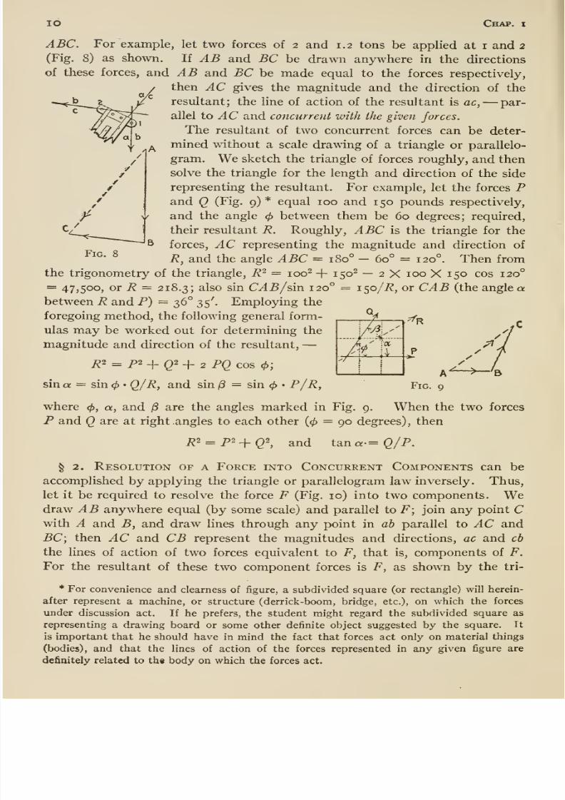
ABC. For example, let two forces of 2 and 1.2 tons be applied at i and 2
(Fig. 8) as shown. li AB and BC be drawn anywhere in the directions
of these forces, and AB and BC be made equal to the forces respectively,
then AC gives the magnitude and the direction of the
resultant; the line of action of the resultant is ac, —par-
allel to ^C and concurrent with the given forces.
The resultant of two concurrent forces can be deter-
mined without a scale drawing of a triangle or parallelo-
gram. We sketch the triangle of forces roughly, and then
solve the triangle for the length and direction of the side
representing the resultant. For example, let the forces Pand Q (Fig. 9) * equal 100 and 150 pounds respectively,
and the angle </> between them be 60 degrees; required,
their resultant R. Rouglily, ABC is the triangle for the
forces, AC representing the magnitude and direction of
R, and the angle ABC = 180° — 60° = 120°. Then from
the trigonometry of the triangle, R^ = 100^ + 150^ — 2 X 100 X 150 cos 120°
= 47,500, or R = 218.3; 2.1so sin CAB/sin 120° = 150/i?, or CAB (the angle abetween R and P) = 36° 35'. Employing the
foregoing method, the following general form-
ulas may be worked out for determining the
magnitude and direction of the resultant, —Ri = p2-\-Qi^ 2 PQ cos <^;
sin a = sin <^ • Q/R, and sin /3 = sin </> • P/R,
where </>, a, and are the angles marked in Fig. 9. When the two forces
P and Q are at right angles to each other (0 = 90 degrees) , then
^2 = p2_|_Q2^ and tarn a-=Q/ P.
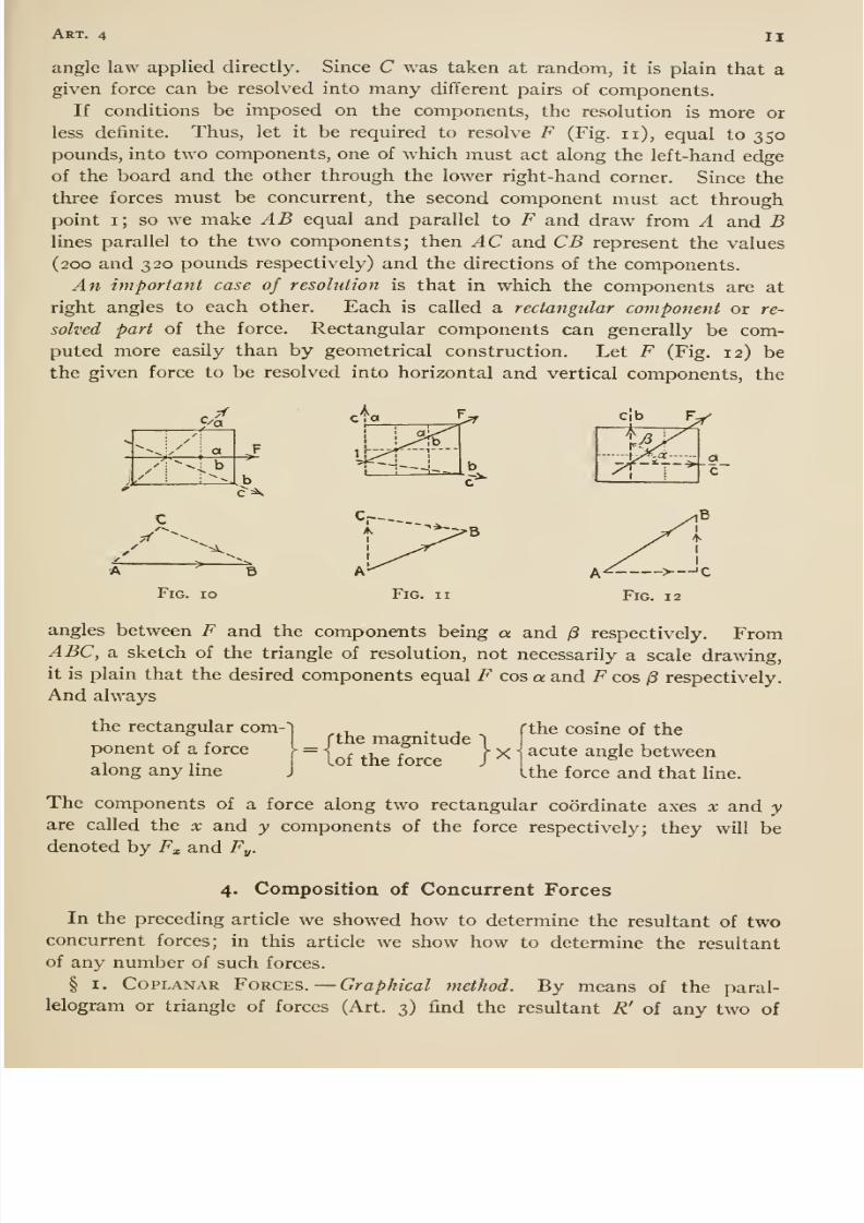
§ 2. Resolution of a Force into Concurrent Components can be
accomplished by applying the triangle or parallelogram law inversely. Thus,
let it be required to resolve the force F (Fig. 10) into two components. Wedraw AB anywhere equal (by some scale) and parallel to F; join any point Cwith A and B, and draw lines through any point in ab parallel to ^C and
BC; then AC and CB represent the magnitudes and directions, ac and cb
the lines of action of two forces equivalent to F, that is, components of F.
For the resultant of these two component forces is F, as shown by the tri-
* For convenience and clearness of figure, a subdivided square (or rectangle) will herein-
after represent a machine, or structure (derrick -boom, bridge, etc.), on which the forces
under discussion act. If he prefers, the student might regard the subdivided square as
representing a drawing board or some other definite object suggested by the square. It
is important that he should have in mind the fact that forces act only on material things
(bodies), and that the lines of action of the forces represented in any given figure are
definitely related to th« body on which the forces act.
8/13/2019 Maurer Mechanics
http://slidepdf.com/reader/full/maurer-mechanics 23/407
Art. 4 II
angle law applied directly. Since C was taken at random, it is plain that a
given force can be resolved into many different pairs of components.
If conditions be imposed on the components, the resolution is more or
less definite. Thus, let it be required to resolve F (Fig. n), equal to 350pounds, into two components, one of which must act along the left-hand edge
of the board and the other through the lower right-hand corner. Since the
three forces must be concurrent, the second component must act through
point i; so we make AB equal and parallel to F and draw from A and Blines parallel to the two components; then AC and CB represent the values
(200 and 320 pounds respectively) and the directions of the components.
An important case of resolution is that in which the components are at
right angles to each other. Each is called a rectangular component or re-
solved part of the force. Rectangular components can generally be com-puted more easily than by geometrical construction. Let F (Fig. 12) be
the given force to be resolved into horizontal and vertical components, the
8/13/2019 Maurer Mechanics
http://slidepdf.com/reader/full/maurer-mechanics 24/407
12 Chap, i
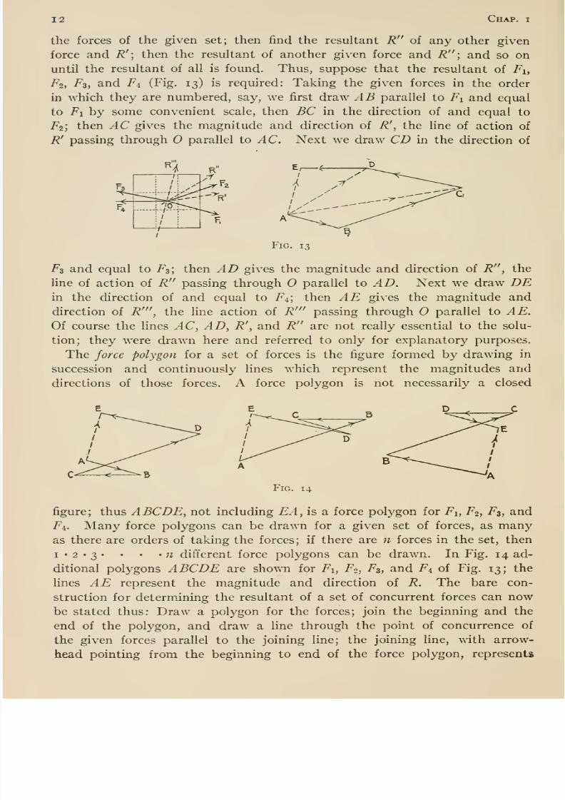
the forces of the given set; then find the resultant R of any other given
force and R'; then the resultant of another given force and R \ and so on
until the resultant of all is found. Thus, suppose that the resultant of Fi,
F2, Fs, and Fi (Fig. 13) is required: Taking the given forces in the order
in which they are numbered, say, we first draw AB parallel to Fi and equal
to Fi by some convenient scale, then BC in the direction of and equal to
F2; then AC gives the magnitude and direction of R', the line of action of
R' passing through O parallel to AC. Next we draw CD in the direction of
Fig. 13
F3 and equal to F3; then AD gives the magnitude and direction of R , the
line of action of R passing through O parallel to AD. Next we draw DEin the direction of and equal to Fi; then AE gives the magnitude and
direction of R' , the line action of R' passing through parallel to AE.Of course the lines AC, AD, R', and R are not really essential to the solu-
tion; they were drawn here and referred to only for explanatory purposes.
The force polygon for a set of forces is the figure formed by drawing in
succession and continuously lines which represent the magnitudes and
directions of those forces. A force polygon is not necessarily a closed
Fig. 14
figure; thus ABCDE, not including EA, is a force polygon for Fi, F2, F3, and
Fi. Many force polygons can be drawn for a given set of forces, as manyas there are orders of taking the forces; if there are n forces in the set, then
I • 2 • 3 • • • '11 different force polygons can be drawn. In Fig. 14 ad-
ditional polygons ABCDE are shown for Fi, F2, F3, and Fi of Fig. 13; the
lines AE represent the magnitude and direction of R. The bare con-
struction for determining the resultant of a set of concurrent forces can nowbe stated thus: Draw a polygon for the forces; join the beginning and the
end of the polygon, and draw a line through the point of concurrence of
the given forces parallel to the joining line; the joining line, with arrow-
head pointing from the beginning to end of the force polygon, represents
8/13/2019 Maurer Mechanics
http://slidepdf.com/reader/full/maurer-mechanics 25/407
Aet. 4 13
the magnitude and direction of the resultant, and the other line its line of
action.
Algebraic Method. —Choose a pair of rectangular axes of resolution, which
let us call X and y axes, with origin at the point of concurrence of the forces
to be compounded; then resolve each force into its x and y components
at the origin, and imagine it replaced by them; the resulting system consists
of forces in ihex and in the 3' axes; next find the resultant of the forces act-
ing in the x axis, and the resultant of those acting in the y axis; finally, get
the resultant of these two rectangular resultants; this is the resultant sought.
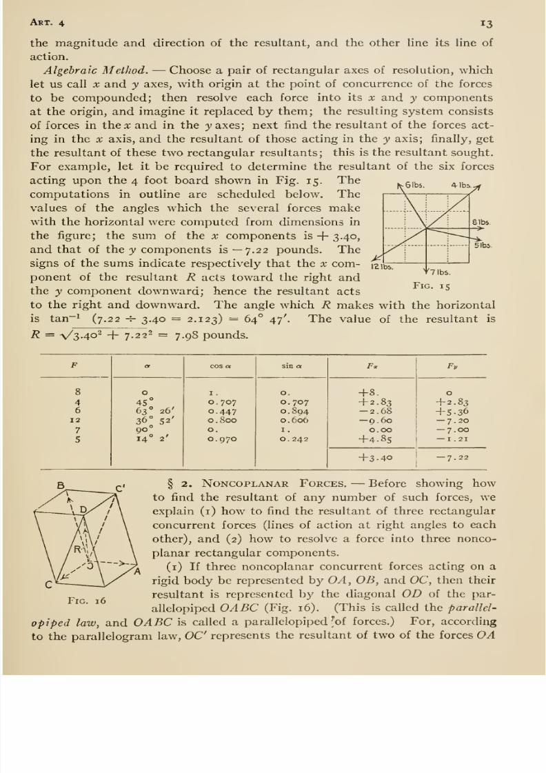
For example, let it be required to determine the resultant of the six forces
acting upon the 4 foot board shown in Fig. 15. Thecomputations in outline are scheduled below. Thevalues of the angles which the several forces makewith the horizontal were computed from dimensions in
the figure; the sum of the x components is + 3.40,
and that of the 3' components is— 7.22 pounds. Thesigns of the sums indicate respectively that the x com-
ponent of the resultant R acts toward the right andthe y component downward; hence the resultant acts
to the right and downward. The angle which R makes with the horizontal
is tan~^ (7.22 -T- 3,40 = 2.123) — 64° 47'- The value of the resultant is
R = \/34o^ + 7.22^ = 7.98 pounds.
5 lbs.
F
8/13/2019 Maurer Mechanics
http://slidepdf.com/reader/full/maurer-mechanics 26/407
14 Chap, i
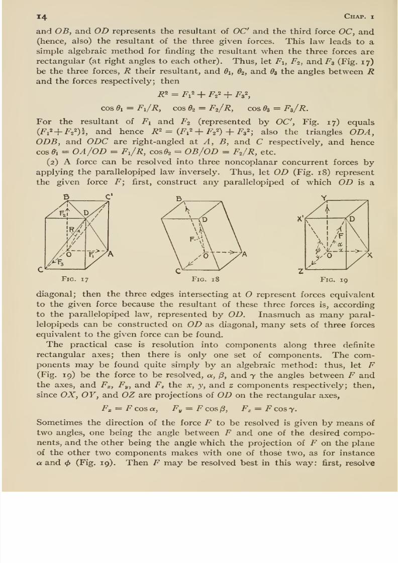
and OB, and OD represents the resultant of OC and the third force OC, and(hence, also) the resultant of the three given forces. This law leads to a
simple algebraic method for finding the resultant when the three forces are
rectangular (at right angles to each other). Thus, let Fi, F2, and F3 (Fig. 17)
be the three forces, R their resultant, and di, 62, and 9$ the angles between Rand the forces respectively; then
R' = Fi^ + F2' + FzS
cos 01 = Fi/R, cos 02 = F2/R, cos ^3 = F3/R.
For the resultant of Fi and F2 (represented by OC, Fig. 17) equals
(Fi^ + Fa^) , and hence R^ = (Fi^ + F2'') + Fs'' ; also the triangles ODA,ODB, and ODC are right-angled Sit A, B, and C respectively, and hence
cos^i = OA/OD = Fi/R, cos ^2 = OB/OD = F2/R, etc.
(2) A force can be resolved into three noncoplanar concurrent forces byapplying the parallelepiped law inversely. Thus, let OD (Fig. 18) represent
the given force F; first, construct any parallel opiped of which OD is a
Fig. 17 Fig. 18 Fig. 19
diagonal; then the three edges intersecting at represent forces equivalent
to the given force because the resultant of these three forces is, according
to the parallelepiped law, representedby OD. Inasmuch as many paral-
lelopipeds can be constructed on OD as diagonal, many sets of three forces
equivalent to the given force can be found.
The practical case is resolution into components along three definite
rectangular axes; then there is only one set of components. The com-ponents may be found quite simply by an algebraic method: thus, let F(Fig. 19) be the force to be resolved, a, 13, and 7 the angles between F andthe axes, and Fx, Fy, and Fg the x, y, and z components respectively; then,
since OX, OY, and OZ are projections of OD on the rectangular axes,
Fx = F cos a, Fy = F cos jS, Fz = F cos 7.
Sometimes the direction of the force F to be resolved is given by means of
two angles, one being the angle between F and one of the desired compo-nents, and the other being the angle which the projection of F on the plane
of the other two components makes with one of those two, as for instance
a and 4> (Fig. 19). Then F may be resolved best in this way: first, resolve
8/13/2019 Maurer Mechanics
http://slidepdf.com/reader/full/maurer-mechanics 27/407
Art. 4 15
it into two components F cos a (along the x axis) and F sin a (in the plane of
the y and 2 axes), and then resolve F sin a into components along the yand 2 axes, that is, F sin a sin and F sin a cos c^.
^ny number of noncoplanar concurrent forces can be compoundedgraphically by means of their force polygon, but this method is not practi-
cable generally, because the polygon is not a plane one; however, it couldbe drawn in plan and elevation so as to furnish the resultant sought.
The algebraic method is preferable; it is carried out as follows: First,
select three rectangular axes of resolution (here called x, y, and 2), with
origin at the point of concurrence of the forces to be compounded; next
resolve each force into its x, y, and 2 components, and imagine it replaced
by them, thus arriving at a set consisting of forces acting in the axes; then
find the resultants of the forces in the x, in the y, and in the 2 axis; finally,
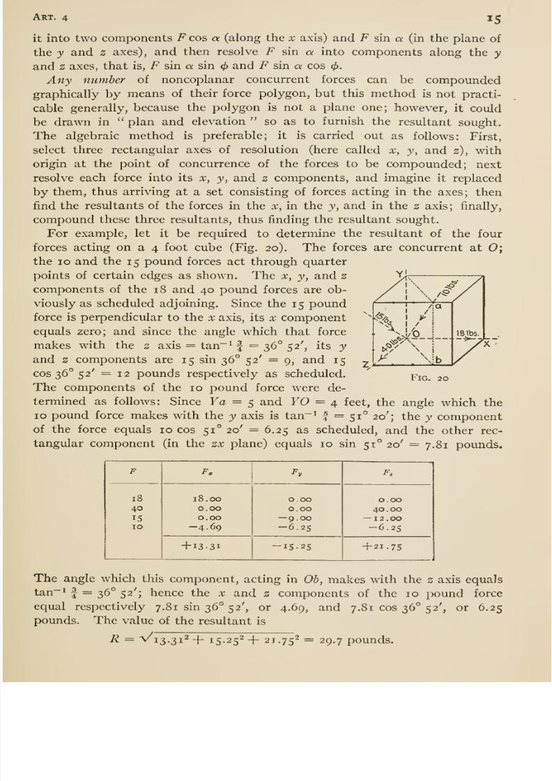
compound these three resultants, thus finding the resultant sought.For example, let it be required to determine the resultant of the four
forces acting on a 4 foot cube (Fig. 20). The forces are concurrent at 0;the 10 and the 15 pound forces act through quarter
points of certain edges as shown. The x, y, and 2
components of the 18 and 40 pound forces are ob-
viously as scheduled adjoining. Since the 15 poundforce is perpendicular to the x axis, its x component
equals zero; and since the angle which that force
makes with the 2 axis = tan~^ f = 36° 52', its yand 2 components are 15 sin 36° 52' = 9, and 15
cos 36° 52' = 12 pounds respectively as scheduled.
The components of the 10 poimd force were de-
termined as follows: Since Ya = 5 and YO = 4 feet, the angle which the
ID pound force makes with the y axis is tan~^ | = 51° 20'; the y componentof the force equals 10 cos 51° 20' = 6.25 as scheduled, and the other rec-
tangular component (in the zx plane) equals 10 sin 51° 20' = 7.81 pounds.
Fig. 20
F
8/13/2019 Maurer Mechanics
http://slidepdf.com/reader/full/maurer-mechanics 28/407
l6 Chap, i
The signs of the sums of the x, y, and z components show that the result-
ant R acts toward the right, downwards and forward. Its angles with the
X, y, and z axes are respectively: cos ' (13.31 -r- 29.7) = 63°; cos~^ (15-25 -j-
29.7) = 59°; cos-i (21.75 -^ 29.7) = 43°.
5. Moment of a Force; Couples*
§ I. The Moment or Torque of a force with respect to a point is the
product of the magnitude of the force and the perpendicular distance be-
tween its line of action and the point. The perpendicular distance is called
the arm of the force with respect to that point, and the point is called anorigin or center oj moments. Experience suggests the notion that the
moment of a force with respect to a point is a measure of the tendency ofthe force to rotate the body about a line through the point and perpen-
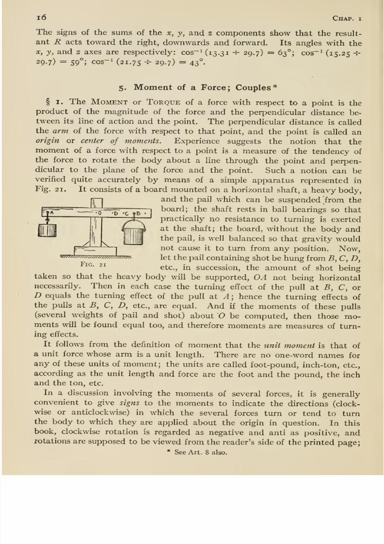
dicular to the plane of the force and the point. Such a notion can be
verified quite accurately by means of a simple apparatus represented in
Fig. 21. It consists of a board mounted on a horizontal shaft, a heavy body,
and the pail which can be suspended horn the
board; the shaft rests in ball bearings so that
practically no resistance to turning is exerted
at the shaft; the board, without the body andthe pail, is well balanced so that gravity wouldnot cause it to turn from any position. Now,let the pail containing shot be hung from B, C, D,
etc., in succession, the amount of shot beingtaken so that the heavy body will be supported, OA not being horizontal
necessarily. Then in each case the turning effect of the pull at B, C, or
D equals the turning effect of the pull at A ; hence the turning effects of
the pulls at B, C, D, etc., are equal. And if the moments of these pulls(several weights of pail and shot) about O be computed, then those mo-ments will be found equal too, and therefore moments are measures of turn-
ing effects.
It follows from the definition of moment that the unit moment is that of
a unit force whose arm is a unit length. There are no one-word names for
any of these units of moment; the units are called foot-pound, inch- ton, etc.,
according as the unit length and force are the foot and the pound, the inch
and the ton, etc.
In a discussion involving the moments of several forces, it is generally
convenient to give signs to the moments to indicate the directions (clock-
wise or anticlockwise) in which the several forces turn or tend to turnthe body to which they are applied about the origin in question. In this
book, clockwise rotation is regarded as negative and anti as positive, androtations are supposed to be viewed from the reader's side of the printed page;
* See Art. 8 also.
8/13/2019 Maurer Mechanics
http://slidepdf.com/reader/full/maurer-mechanics 29/407
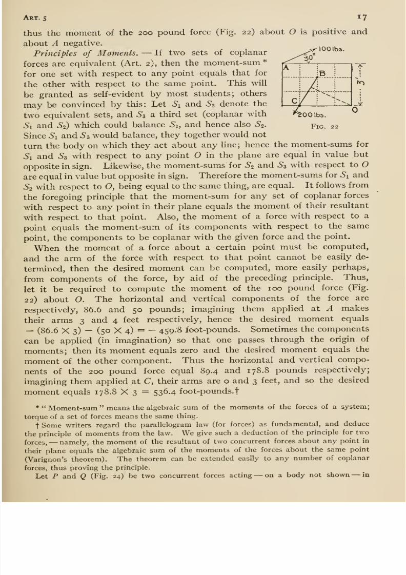
Art. s 17
lOOlbs.
30
A
8/13/2019 Maurer Mechanics
http://slidepdf.com/reader/full/maurer-mechanics 30/407
i8 Chap,
b
8/13/2019 Maurer Mechanics
http://slidepdf.com/reader/full/maurer-mechanics 31/407
Art. s 19
AB represents the resultant of Qi reversed and Pi, and the diagonal
BA represents the resultant of Q2 reversed and P2. Since the resultants are
equal, opposite, and colinear they balance, and so the P couple and the
reversed Q couple balance. Hence, etc. (2) When Pi, P2, Qi and Q2 are
parallel, and the moments of the two couples are equal, then each couple is
equivalent to some third couple, the forces of which intersect Pi, P2, Qi,
and Qi, according to (i). Therefore they are equivalent to each other.
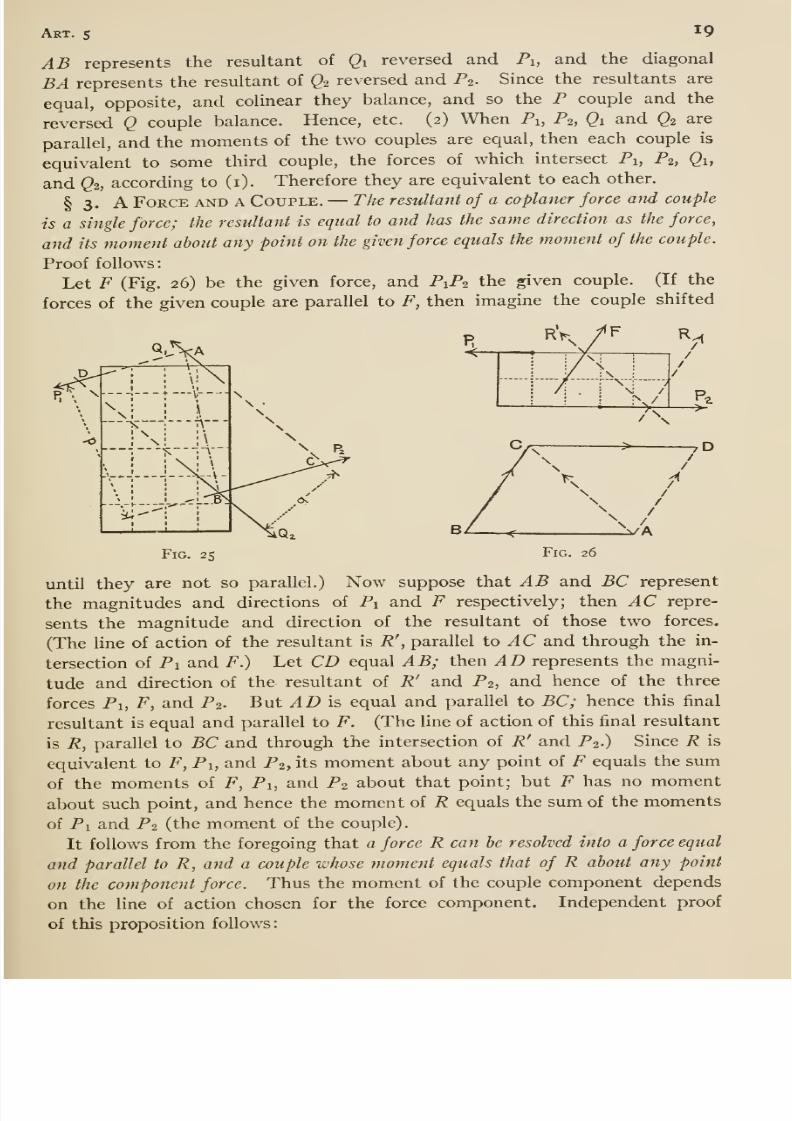
§ 3. A Force and a Couple. —The resultant of a coplaner force and couple
is a single force; the resultant is equal to and has the same direction as the force,
and its moment about any point on the given force equals the moment of the couple.
Proof follows:
Let F (Fig. 26) be the given force, and P1P2 the given couple. (If the
forces of the given couple are parallel to F, then imagine the couple shifted
Fig. 25 Fig. 26
until they are not so parallel.) Now suppose that AB and BC represent
the magnitudes and directions of Pi and F respectively; then AC repre-
sents the magnitude and direction of the resultant of those two forces.
(The line of action of the resultant is R',
parallel to ylC and through the in-
tersection of Pi and F.) Let CD equal AB; then AD represents the magni-
tude and direction of the resultant of R' and P2, and hence of the three
forces Pi, F, and P2. But AD is equal and parallel to BC; hence this final
resultant is equal and parallel to F. (The line of action of this final resultant
is R, parallel to BC and through the intersection of R' and P2.) Since R is
equivalent to F, Pi, and P2, its moment about any point of F equals the sum
of the moments of F, Pi, and P2 about that point; but F has no moment
about such point, and hence the moment of R equals the sum of the moments
of Pi and P2 (the moment of the couple).
It follows from the foregoing that a force R can he resolved into a force equal
and parallel to R, and a couple whose moment equals that of R about any point
on the component force. Thus the moment of the couple component depends
on the line of action chosen for the force component. Independent proof
of this proposition follows
8/13/2019 Maurer Mechanics
http://slidepdf.com/reader/full/maurer-mechanics 32/407
20 Chap, i
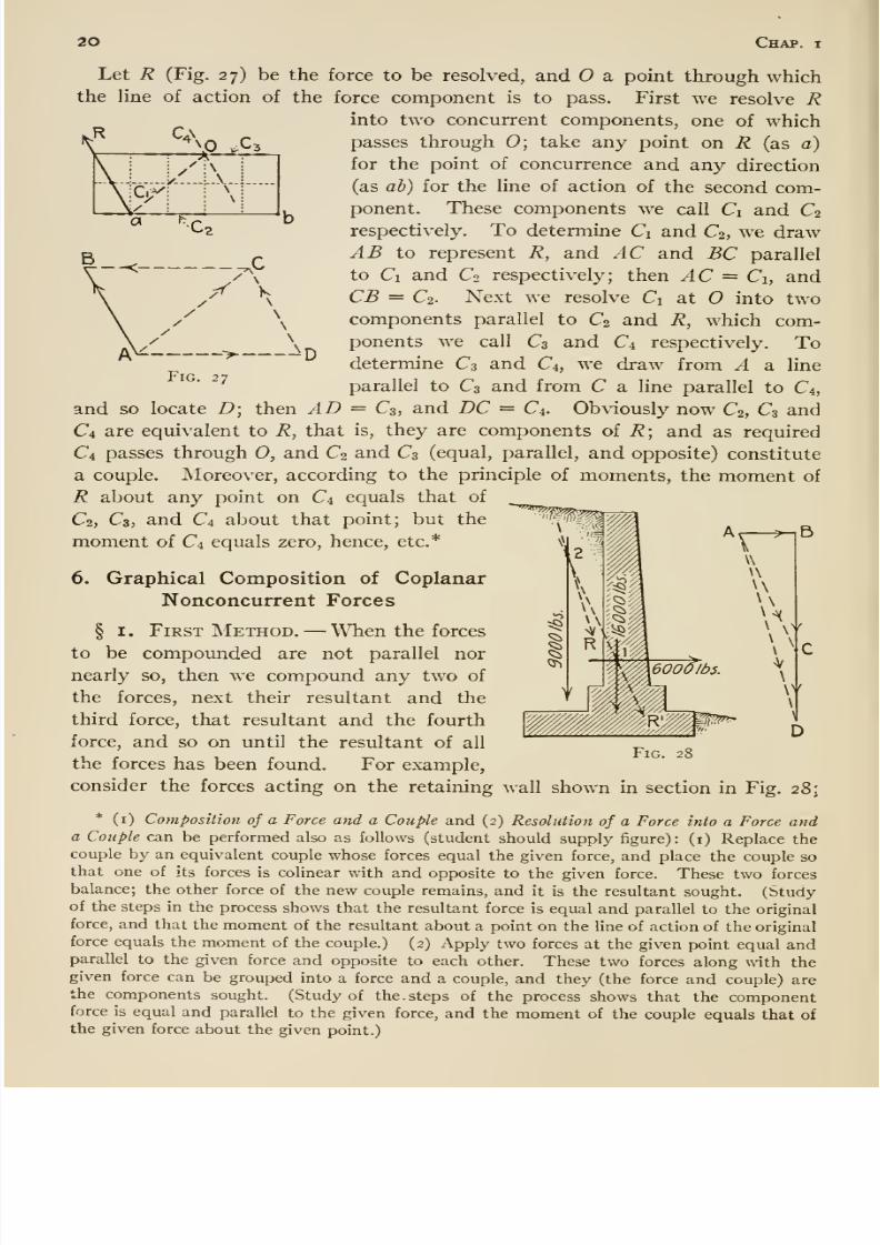
Fig. 27
Let R (Fig. 27) be the force to be resolved, and O a point through whichthe line of action of the force component is to pass. First we resolve R
into two concurrent components, one of which
passes through 0; take any point on R (as a)
for the point of concurrence and any direction
(as ab) for the line of action of the second com-ponent. These components we call Ci and C2
respectively. To determine Ci and C2, we drawAB to represent R, and AC and BC parallel
to Ci and Co respectively; then AC = Ci, andCB = C2. Next we resolve Ci at O into two
components parallel to C2 and R, which com-ponents we call C3 and C4 respectively.
Todetermine Cs and d, we draw from A a line
parallel to C3 and from C a line parallel to d,and so locate D; then AD = C3, and DC = C4. Ob\'iously now C2, C3 and
d are equivalent to R, that is, they are components of R; and as required
d passes through 0, and C2 and d (equal, parallel, and opposite) constitute
a couple. Moreover, according to the principle of moments, the moment of
R about any point on d equals that of
C2, C3,and d about that
point; but the' ' ''^^^f^^M^
moment of d equals zero, hence, etc.*
6. Graphical Composition of Coplanar
Nonconcurrent Forces
§ I. First Method. —When the forces
to be compounded are not parallel nor
nearly so, then we compoimd any two of
the forces, next their resultant and thethird force, that resultant and the fourth
force, and so on until the resultant of all
the forces has been found. For example,
consider the forces acting on the retaining wall shown in section in Fig. 28:
* (i) Composition of a Force and a Couple and (2) Resolution of a Force into a Force anda Couple can be performed also as follows (student should supply figure): (i) Replace thecouple by an equivalent couple whose forces equal the given force, and place the couple so
that one of its forces is colinearwith and opposite to the given force. These two forces
balance; the other force of the new couple remains, and it is the resultant sought. (Studyof the steps in the process shows that the resultant force is equal and parallel to the original
force, and that the moment of the resultant about a point on the line of action of the original
force equals the moment of the couple.) (2) Apply two forces at the given point equal andparallel to the given force and opposite to each other. These two forces along with thegiven force can be grouped into a force and a couple, and they (the force and couple) arethe components sought. (Study of the. steps of the process shows that the componentforce is equal and parallel to the given force, and the moment of the couple equals that of
the given force about the given point.)
Fig. 28
8/13/2019 Maurer Mechanics
http://slidepdf.com/reader/full/maurer-mechanics 33/407
Art. 6 21
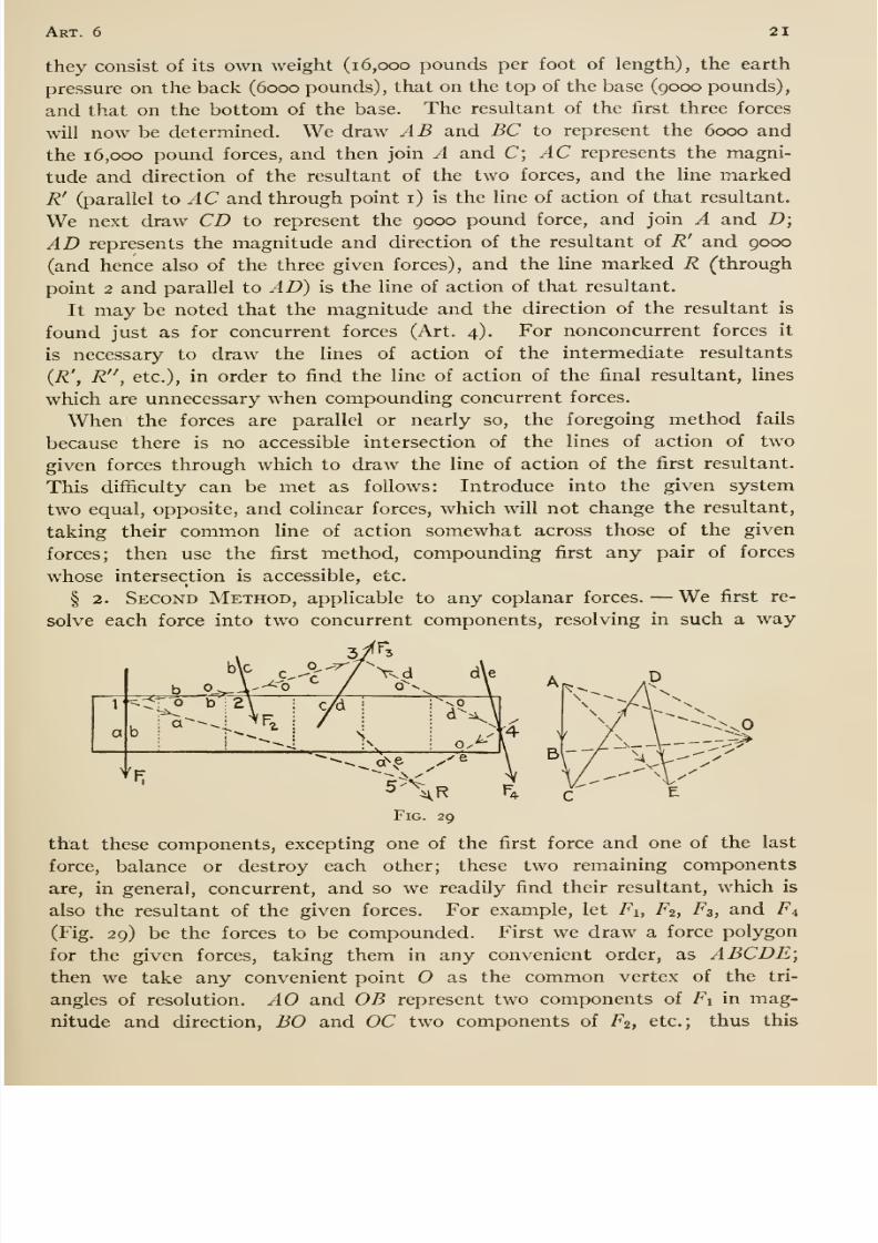
they consist of its own weight (16,000 pounds per foot of length), the earth
pressure on the back (6000 pounds), that on the top of the base (9000 pounds),
and that on the bottom of the base. The resultant of the first three forces
will now be determined. We draw AB and BC to represent the 6000 and
the 16,000 pound forces, and then join A and C; AC represents the magni-
tude and direction of the resultant of the two forces, and the line markedR' (parallel to AC and through point i) is the line of action of that resultant.
We next draw CD to represent the 9000 pound force, and join A and D;
AD represents the magnitude and direction of the resultant of R' and 9000
(and hence also of the three given forces), and the line marked R (through
point 2 and parallel to AD) is the line of action of that resultant.
It may be noted that the magnitude and the direction of the resultant is
found just as for concurrent forces (Art. 4). For nonconcurrent forces it
is necessary to draw the lines of action of the intermediate resultants
(R', R , etc.), in order to find the line of action of the final resultant, lines
which are unnecessary when compounding concurrent forces.
When the forces are parallel or nearly so, the foregoing method fails
because there is no accessible intersection of the lines of action of two
given forces through which to draw the line of action of the first resultant.
This difiiculty can be met as follows: Introduce into the given system
two equal, opposite, and colinear forces, which will not change the resultant,
taking their common line of action somewhat across those of the given
forces; then use the first method, compounding first any pair of forces
whose intersection is accessible, etc.
§ 2. Second Method, applicable to any coplanar forces. —We first re-
solve each force into two concurrent components, resolving in such a way
Fig. 29
that these components, excepting one of the first force and one of the last
force, balance or destroy each other; these two remaining components
are, in general, concurrent, and so we readily find their resultant, which is
also the resultant of the given forces. For example, let Fi, F2, F3, and F4
(Fig. 29) be the forces to be compounded. First we draw a force polygon
for the given forces, taking them in any convenient order, as ABCDE;then we take any convenient point O as the common vertex of the tri-
angles of resolution. AO and OB represent two components of Fi in mag-
nitude and direction, BO and OC two components of F2, etc.; thus this
8/13/2019 Maurer Mechanics
http://slidepdf.com/reader/full/maurer-mechanics 34/407
22 Chap, i
resolution gives several pairs of equal and opposite components, OB andBO, OC and CO, OD and DO. The components of Fi are taken to act
through point i, those of F^ through 2, those of Fz through 3, etc., ti
first point, i, being taken at pleasure on Fi, point 2 where oh intersects F2,
point 3 where oc intersects 7^3; etc. Thus the components OB and BO are
colinear and they balance; likewise OC and CO, and OD and DO. Only the
first and last components AO and OE remain; their resultant is represented
hy AE in magnitude and direction, and its line of action is ae (parallel to
AE through the intersection of ao and oe).
The common vertex of the triangles of resolution (Fig. 29) is the pole
of the force polygon; the lines from the pole to the vertexes of the force
polygon, 0/1, OB, OC, etc., are rays; the line of action of the several forces,
oa, ob, OC, etc., are strings which, considered collectively, is the string or
funicular polygon (also called equilibrium polygon, especially when the given
forces are balanced or in equilibrium). The rays are sometimes referred
to by number, OA being the first, 05 the second, etc.; likewise the strings.
In using this second method, the beginner had best reason out the vari-
ous steps of the construction somewhat as in the foregoing. After somepractice he might use the following aids: (i) The two strings intersecting
on the line of action of any force are parallel to the rays drawn to the endsof that side of the force polygon corresponding to that force, thus the strings
intersecting on be are ob and oc. (2) The string which joins points in the
lines of action of any two forces is parallel to the ray which is drawn to
the common point of the two sides of the force polygon corresponding to
those forces, or, the string joining points on be and cd is parallel to OC.
(3) The bare construction in the second method is simply this: Draw a
force and a string polygon for the forces, then draw a line from the begin-
ning to the end of the force polygon and a parallel line through the inter-
section of the first and last strings; the first line representsthe magnitudeand direction of the resultant (sense being from the beginning to the end of
the force polygon), and the second line is the line of action of the resultant.
This second method is not so simple in principle as the first, but in the
second there is more opportunity for varying the construction to keepthe drawing within convenient limits; thus the pole may be shifted, and the
starting point of the string polygon may be taken anywhere on any of the
given forces. Though many string polygons may be drawn for a given set
of forces, all determine the same line of action of the resultant; that is, theintersections of the first and last strings of all string polygons lie on onestraight line, the line of action of the resultant.
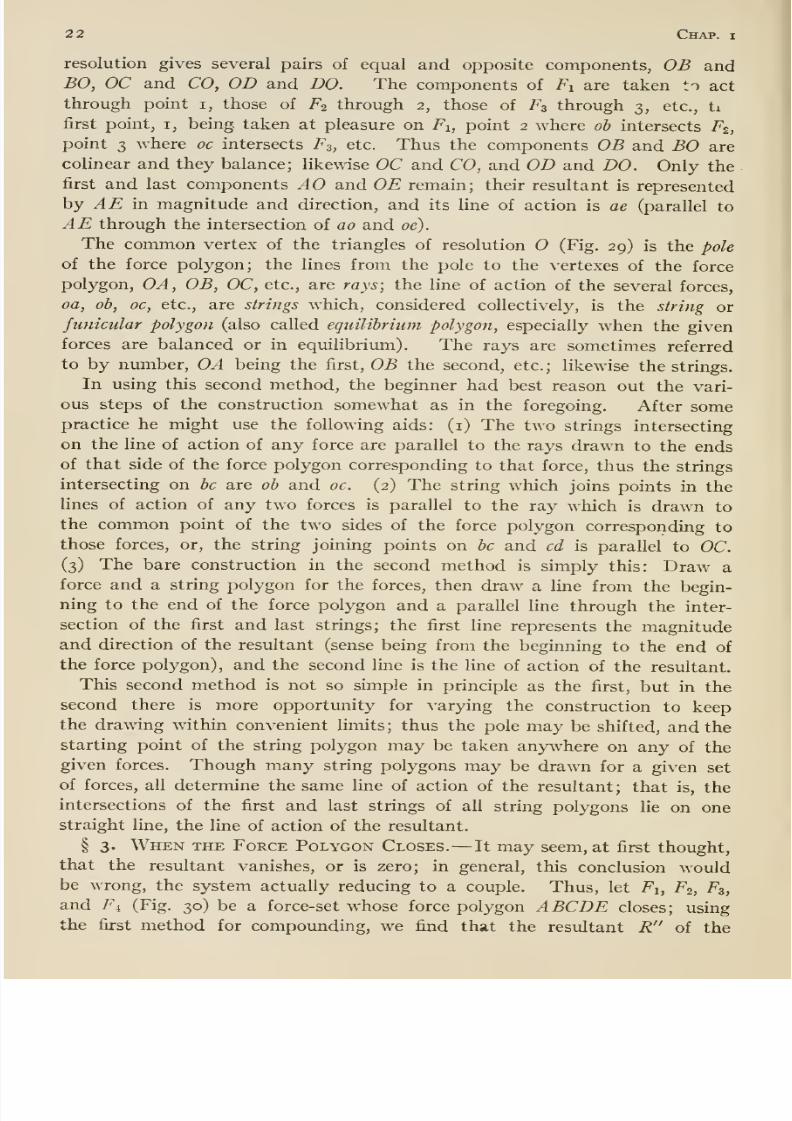
§ 3. When the Force Polygon Closes. —It may seem, at first thought,
that the resultant vanishes, or is zero; in general, this conclusion wouldbe wrong, the system actually reducing to a couple. Thus, let Fi, F2, F3,
and Fi (Fig. 30) be a force-set whose force polygon ABODE closes; using
the first method for compounding, we find that the resultant R of the
8/13/2019 Maurer Mechanics
http://slidepdf.com/reader/full/maurer-mechanics 35/407
Art. 7 23
first three forces is given by ^D in magnitude and in direction, and ad
is its l^e of action; hence* i? is equal, opposite, and parallel to F4, and so
t^ , given force-set reduces to a couple (R , Fi). The arm of this couple is
tne perpendicular distance between Ft and R , and so the moment of the
couple is the product of Fi (or R ) and the arm (according to the scale
of the space diagram) ; the sense of the couple, clockwise, is apparent fromthe relative positions and directions of the forces of the couple as seen in
the space diagram. In Fig. 31 the composition has been made by the
second method; the system reduces to the two components AO (acting in
ao) and OE (acting in oe). These components are equal, opposite, and
parallel, and so the given force-set reduces to a couple. The arm of the
couple is the perpendicular distance between the first and last strings, ao
and oe; the moment of the couple is the product of OA or EO (according
E ^= .—^D i ^^ J^A^Fig. 30 Fig. 31
to the scale of the force diagram) and the arm (according to the scale of
the space diagram) ; the sense is apparent from the space diagram.
The length of the arm and the magnitude of the forces of the couple
depend on the order in which the forces are taken in the force polygon, in
the first method; and upon the position chosen for the pole 0, in the second
method. But the moment of the couple is independent of all these vari-
ations. This fact may be verified by actually compounding a certain force-
set (whose force polygon closes) in several ways, making all these different
variations and thus arriving at different couples. The couples are all
equivalent to the same force-set and so equivalent to each other, and
hence their moments are equal (Art. 5).
7. Algebraic Composition of Coplanar Nonconcurrent Forces
§ I. Parallel Forces.— If the forces be given sign, those in either direc-
tion being called positive and those in the other negative, then the alge-
braic sum of the forces gives the magnitude and sense of the resultant, the
sign of the sum indicating the sense of the resultant. According to the
principle of moments (Art. 5), the moment of the resultant about any point
equals the algebraic sum of the moments of the forces about that point, and
8/13/2019 Maurer Mechanics
http://slidepdf.com/reader/full/maurer-mechanics 36/407
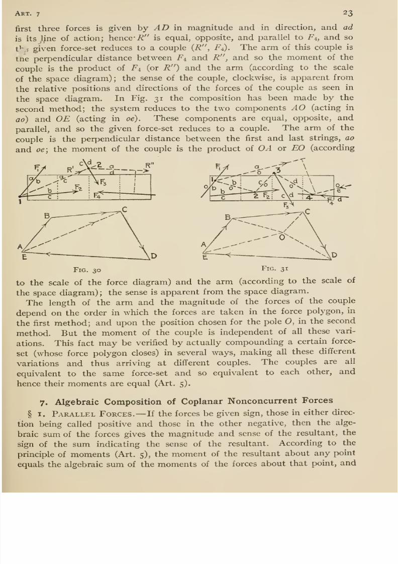
24 Chap, i
20 lbs.
8/13/2019 Maurer Mechanics
http://slidepdf.com/reader/full/maurer-mechanics 37/407
Art. 7 25
A60lb&. 401bvf
20 lbs. SOlbs.
Fig. 34
SOlbs.
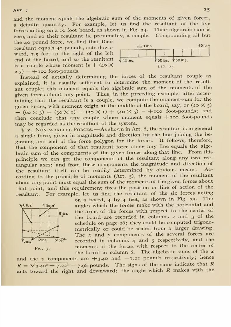
and the moment equals the algebraic sum of the moments of given forces,
a definite quantity. For example, let us find the resultant of the five
forces acting on a 10 foot board, as shown in Fig. 34. Their algebraic sum is
zero, and so their resultant is, presumably, a couple. Compounding all but
the 40 pound force, we find that their
resultant equals 40 pounds, acts down-
ward, 7.5 feet to the right of the left
end of the board, and so the resultant
is a couple whose moment is + (40 X2.5) = -|-ioo foot-pounds.
Instead of actually determining the forces of the resultant couple as
explained, it is usually sufficient to determine the moment of the result-
ant couple; this moment equals the algebraic sum of the moments of the
given forces about any point. Thus, in the preceding example, after ascer-
taining that the resultant is a couple, we compute the moment-sum for the
given forces, wdth moment origin at the middle of the board, say, or (20 X 5)
- (60 X 3) + (30 X i) - (50 X i) + (40 X 5) = +100 foot-pounds; and
then conclude that any couple whose moment equals -fioo foot-pounds
may be regarded as the resultant of the system.
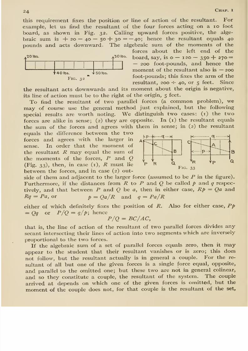
§ 2. NoNPARALLEL FORCES.— As shown in Art. 6, the resultant is in general
a single force, given in magnitude and direction by the line joining the be-
ginning and end of the force polygon for the forces. It follows, therefore,
that the component of that resultant force along any line equals the alge-
braic sum of the components of the given forces along that line. From this
principle we can get the components of the resultant along any two rec-
tangular axes; and from these components the magnitude and direction of
the resultant itself can be readily determined by obvious means. Ac-
cording to the principle of moments (Art. 5), the moment of the resultant
about any point must equal the sum of the moments of the given forces about
that point; and this requirement fixes the position or line of action of the
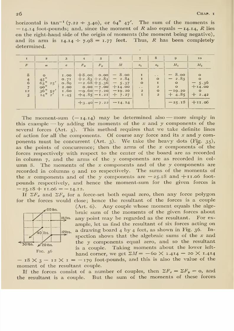
resultant. For example, let us find the resultant of the six forces acting
on a board, 4 by 4 feet, as shown in Fig. 35. The
angles which the forces make with the horizontal and
the arms of the forces with respect to the center of
the board are recorded in columns 2 and 3 of the
schedule on page 26; they could be computed trigono-
metrically or couldbe scaled from a larger drawing.
The X and y components of the several forces are
recorded in columns 4 and 5 respectively, and the
moments of the forces with respect to the center of
the board in column 6. The algebraic sums of the x
^6lbs.
VIbs.51b5^
Fig. 35
y components are +3.40 and -7.22 pounds respectively; henceand the
R = V'3.40^ -|- 7.22^ = 7.98 pounds The signs of the sums indicate that R
acts toward the right and downward; the angle which R makes with the
8/13/2019 Maurer Mechanics
http://slidepdf.com/reader/full/maurer-mechanics 38/407
26 Chap.
horizontal is tan~^ (7.22 -J- 3.40), or 64° 47'. The sum of the moments is
—14.14 foot-pounds; and, since the moment of R also equals —14.14, R lies
on the right-hand side of the origin of moments (the moment being negative),
and its arm is 14.14 -^ 7.98 = 1.77 feet. Thus, R has been completely
determined.
I
8/13/2019 Maurer Mechanics
http://slidepdf.com/reader/full/maurer-mechanics 39/407
Art. 8 27
Fig. 37
about any point equals the sum of the moments of the couples; hence any
couple whose moment equals the sum of the moments of the given couples
may be regarded as the resultant.
8. Moment of a Force ; Couples *
§ I. Moment about a Line. —Art. 5 relates to moments of forces and
to couples with special reference to coplanar forces and couples. In some
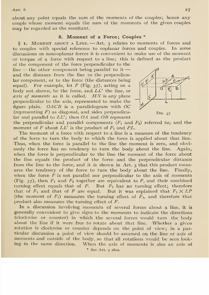
discussions on noncoplanar forces it is convenient to make use of the momentor torque of a force with respect to a line; this is defined as the product
of the component of the force perpendicular to the
line —the other component being parallel to it —and the distance from the line to the perpendicu-
lar component, or to the force (the distances being
equal). For example, let F (Fig. 37), acting on a
body not shown, be the force, and LL' the line, or
axis of moments as it is called. MN is any plane
perpendicular to the axis, represented to make the
figure plain. OACB is a parallelogram with OC(representing F) as diagonal, and sides perpendicu-
lar and parallel to LL'; then OA and OB represent
the perpendicular and parallel components {Fi and F2) referred to; and the
moment of F about LL' is the product of Fi and PL.
The moment of a force with respect to a line is a measure of the tendency
of the force to turn the body to which the force is applied about that line.
Thus, when the force is parallel to the line the moment is zero, and obvi-
ously the force has no tendency to turn the body about the line. Again,
when the force is perpendicular to the line the moment of the force about
the line equals the product of the force and the perpendicular distance
fromthe line to the force,
andit is
shown in Art. 5 thatthis
product meas-ures the tendency of the force to turn the body about the line. Finally,
when the force F is not parallel nor perpendicular to the axis of moments(Fig. 37), then Fi and F2 together are equivalent to F, and their combined
turning effect equals that of F. But F^ has no turning effect; therefore
that of Fi and that of F are equal. But it was explained that Fi X LP(the moment of Fi) measures the turning effect of Fi, and therefore that
product also measures the turning effect of F.
In a discussion involving moments of several forces about a line, it is
generally convenient to give signs to the moments to indicate the directions
(clockwise or counter) in which the several forces would turn the bodyabout the line if it were free to rotate about that line. Whether a given
rotation is clockwise or counter depends on the point of view; in a par-
ticular discussion a point of view should be assumed on the line or axis of
moments and outside of the body, so that all rotations would be seen look-
ing in the same direction. When the axis of moments is also an axis of
* See Art. 5 also.
8/13/2019 Maurer Mechanics
http://slidepdf.com/reader/full/maurer-mechanics 40/407
28 Chap, i
coordinates, then it is customary to view rotations about that axis from
the positive end of the coordinate axis, looking in the negative direction.
Principle of Moments. —If two sets of forces are equivalent (Art. 2),
then the moment-sum for one set with respect to any line equals the mo-
ment-sum for the other set with respect to the same line. This will begranted as self-evident by most students; others may consider this: Let
^1 and 6*2 denote the two equivalent sets of forces, and ^3 a third set which
would balance Si and hence also ^2. Since Sx and ^3 would balance, they
would not turn the body on which they act about any line; hence the
moment-sums for Si and ^'3 with respect to any line are equal in value but
opposite in sign. Likewise, the moment-sums for S2 and S3 with respect
to that same line are equal in value and opposite in sign. The moment-
sums for ^i and S2 being equal to the same thing, are therefore equal.
It follows from the preceding that the moment-sum for any set of forces
with respect to a given line equals the moment of the resultant of those
forces with respect to the same line. Also, the moment of a force about any
line equals the moment-sum of its components with respect to the same
line. This last principle suggests a second method for computing the
moment of a force with respect to a line, more simple than the first method
in some cases: Resolve the force into three rectangular components, one of
which is parallel to the axis of moments; compute the moment of each of
the other two components about the axis, and add the moments alge-
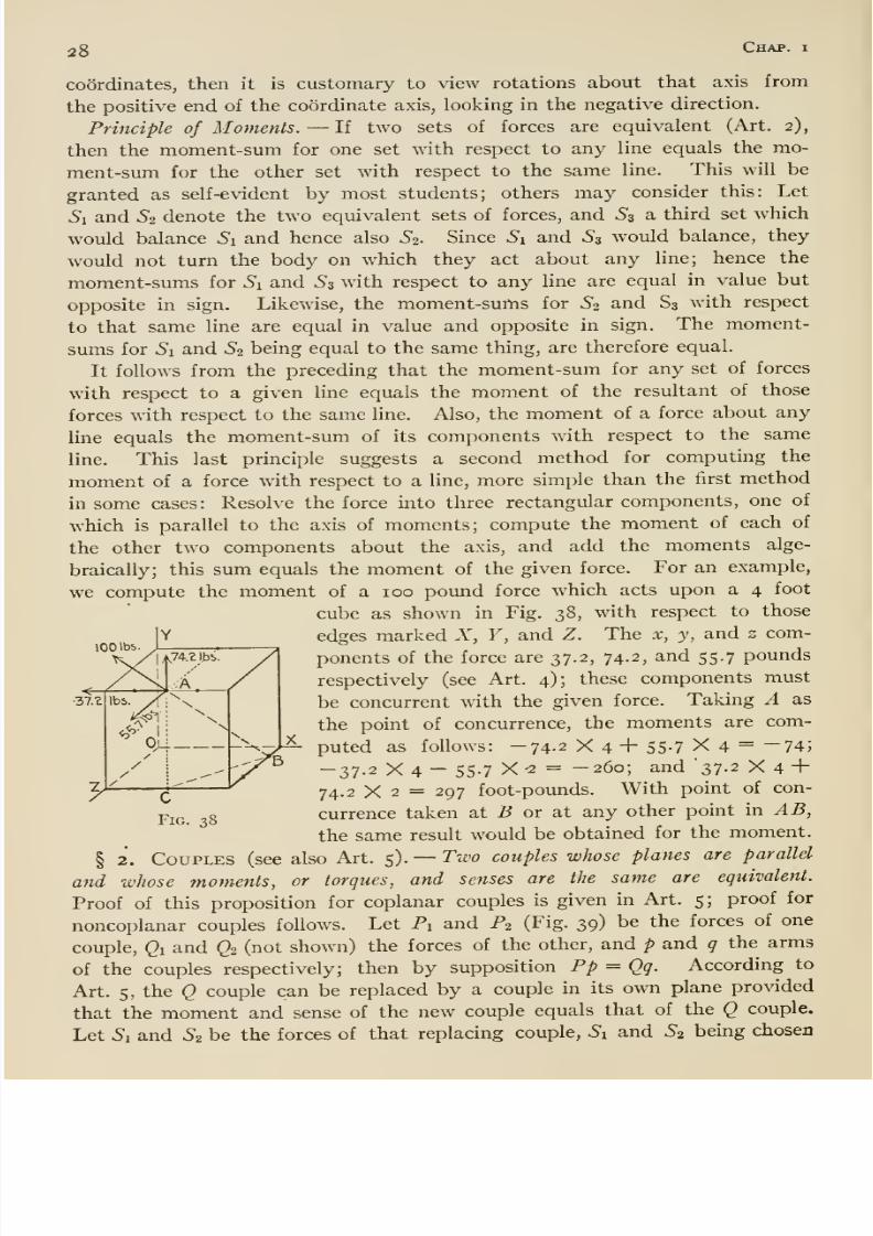
braically; this sum equals the moment of the given force. For an example,
we compute the moment of a 100 pound force which acts upon a 4 foot
cube as shown in Fig. 38, with respect to those
edges marked X, F, and Z. The x, y, and z com-
ponents of the force are 37.2, 74.2, and 55.7 pounds
respectively (see Art. 4); these components must
be concurrent with the given force. Taking A as
the point of concurrence, the moments are com-
puted as follows: -74-2 X 4 + 55-7 X 4 = 74;
-37.2 X 4 - 55.7 X ^ = -260; and '37.2 X 4 +74.2 X 2 = 297 foot-pounds. With point of con-
currence taken at B or at any other point in AB,
the same result would be obtained for the moment.
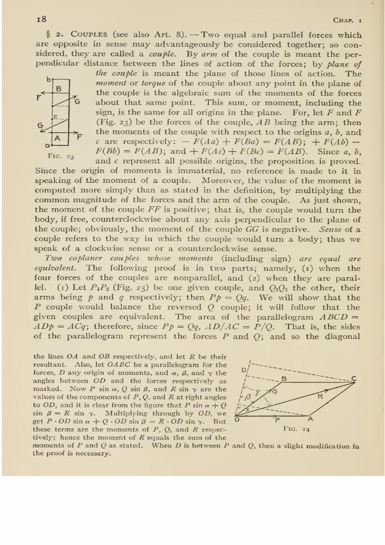
§ 2. Couples (see also Art. 5). —Two couples whose planes are parallel
and whose moments, or torques, and senses are the same are equivalent.
Proof of this proposition for coplanar couples is given in Art. 5; proof for
noncoplanar couples follows. Let Pi and P2 (Fig. 39) be the forces of one
couple, Qi and Q2 (not shown) the forces of the other, and p and q the arms
of the couples respectively; then by supposition Pp = Qq. According to
Art. 5, the (2 couple can be replaced by a couple in its own plane provided
that the moment and sense of the new couple equals that of the Q couple.
Let Si and ^2 be the forces of that replacing couple, Si and ^2 being chosen
100 >b5
37.2
8/13/2019 Maurer Mechanics
http://slidepdf.com/reader/full/maurer-mechanics 41/407
Art. 8 29
Fig. 39
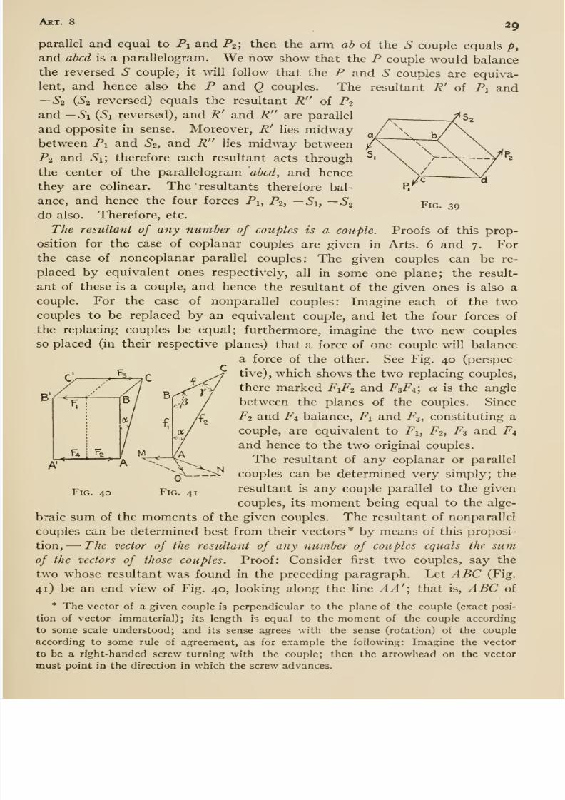
parallel and equal to Pi and P^; then the arm ab of the S couple equals />,
and abed is a parallelogram. We now show that the P couple would balancethe reversed S couple; it will follow that the P and 6* couples are equiva-
lent, and hence also the P and Q couples. The resultant R' of P] and—52 {Si reversed) equals the resultant R of P2
and —S\ (Si reversed), and R' and R are parallel
and opposite in sense. Moreover, R' lies midwaybetween Pi and 52, and R lies midway between
P2 and Si; therefore each resultant acts through
the center of the parallelogram abed, and hence
they are colinear. The ' resultants therefore bal-
ance, and hence the four forces Pi, P2, —Si, —S2do also. Therefore, etc.
The resultant of any number of couples is a eouple. Proofs of this prop-
osition for the case of coplanar couples are given in Arts. 6 and 7. For
the case of noncoplanar parallel couples: The given couples can be re-
placed by equivalent ones respectively, all in some one plane; the result-
ant of these is a couple, and hence the resultant of the given ones is also a
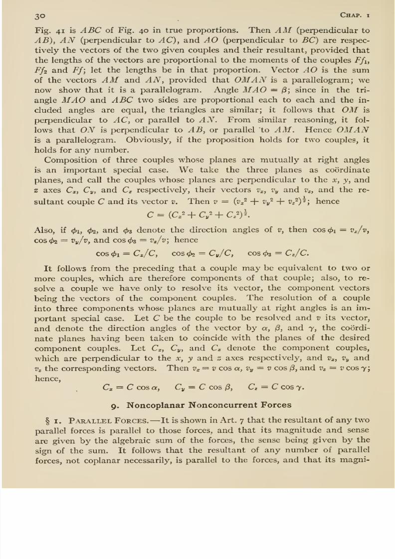
couple. For the case of nonparallel couples: Imagine each of the twocouples to be replaced by an equivalent couple, and let the four forces of
the replacing couples be equal; furthermore, imagine the two new couples
so placed (in their respective planes) that a force of one couple will balance
a force of the other. See Fig. 40 (perspec-
tive), which shows the two replacing couples,
there marked P1P2 and P3P4; ex is the angle
between the planes of the couples. Since
P2 and P4 balance, Pi and P3, constituting a
couple, are equivalent to Pi, P2, P3 and P4
and hence to the two original couples.
The resultant of any coplanar or parallel
couples can be determined very simply; the
resultant is any couple parallel to the given
couples, its moment being equal to the alge-
braic sum of the moments of the given couples. The resultant of nonparallel
couples can be determined best from their vectors* by means of this proposi-
tion, —The vector of the resultant of any number of couples equals the sum
ofthe vectors
ofthose couples.
Proof: Considerfirst
twocouples,
saythe
two whose resultant was found in the preceding paragraph. Let ABC (Fig,
41) be an end view of Fig. 40, looking along the line AA'] that is, ABC of
* The vector of a given couple is perpendicular to the plane of the couple (exact posi-
tion of vector immaterial); its length is equal to the moment of the couple according
to some scale understood; and its sense agrees with the sense (rotation) of the couple
according to some rule of agreement, as for example the following: Imagine the vector
to be a right-handed screw turning with the couple; then the arrowhead on the vector
must point in the direction in which the screw advances.
Fig. 40
8/13/2019 Maurer Mechanics
http://slidepdf.com/reader/full/maurer-mechanics 42/407
3© Chap, i
Fig. 41 is ABC of Fig. 40 in true proportions. Then AM (perpendicular to
AB), AN (perpendicular to AC), and AO (perpendicular to BC) are respec-
tively the vectors of the two given couples and their resultant, provided that
the lengths of the vectors are proportional to the moments of the couples Ffi,
Ffz and Ff; let the lengths be in that proportion. Vector AO is the sumof the vectors AM and AN, provided that OMAN is a parallelogram; wenow show that it is a parallelogram. Angle MAO = 13; since in the tri-
angle MAO and ABC two sides are proportional each to each and the in-
cluded angles are equal, the triangles are similar; it follows that OM is
perpendicular to AC, or parallel to AN. From similar reasoning, it fol-
lows that ON is perpendicular to AB, or parallel to AM. Hence OMANis a parallelogram. Obviously, if the proposition holds for two couples, it
holds for any number.
Composition of three couples whose planes are mutually at right angles
is an important special case. We take the three planes as coordinate
planes, and call the couples whose planes are perpendicular to the x, y, and
axes Cx, Cy, and Cg respectively, their vectors Vx, Vy and Vz, and the re-
sultant couple C and its vector v. Then v = {v^^ + Vy ^ + ^z^)^; hence
Also, if 01, 4>2, and ^3 denote the direction angles of v, then cos </)i = v^/v^
cos 02 = ^vA, and cos 03 = Vz/v\ hence
cos 01 = Cx/C, cos 02 = Cy/C, cos 03 = Cz/C.
It follows from the preceding that a couple may be equivalent to two or
more couples, which are therefore components of that couple; also, to re-
solve a couple we have only to resolve its vector, the component vectors
being the vectors of the component couples. The resolution of a couple
into three components whose planes are mutually at right angles is an im-
portant special case. Let C be the couple to be resolved and v its vector,
and denote the direction angles of the vector by a, /3, and 7, the coordi-
nate planes having been taken to coincide with the planes of the desired
component couples. Let Cx, Cy, and Cz denote the component couples,
which are perpendicular to the x, y and z axes respectively, and Vx, Vy and
Vz the corresponding vectors. Then Vx= v cos a, Vy ^ v cos /3, and Vz = v cos 7;
hence,
Cx = C cos a, Cy = C cos iS, Cz = C cos 7.
9. Noncoplanar Nonconcurrent Forces
§ I. Parallel Forces. —It is shown in Art. 7 that the resultant of any two
parallel forces is parallel to those forces, and that its magnitude and sense
are given by the algebraic sum of the forces, the sense being given by the
sign of the sum. It follows that the resultant of any number of parallel
forces, not coplanar necessarily, is parallel to the forces, and that its magni-
8/13/2019 Maurer Mechanics
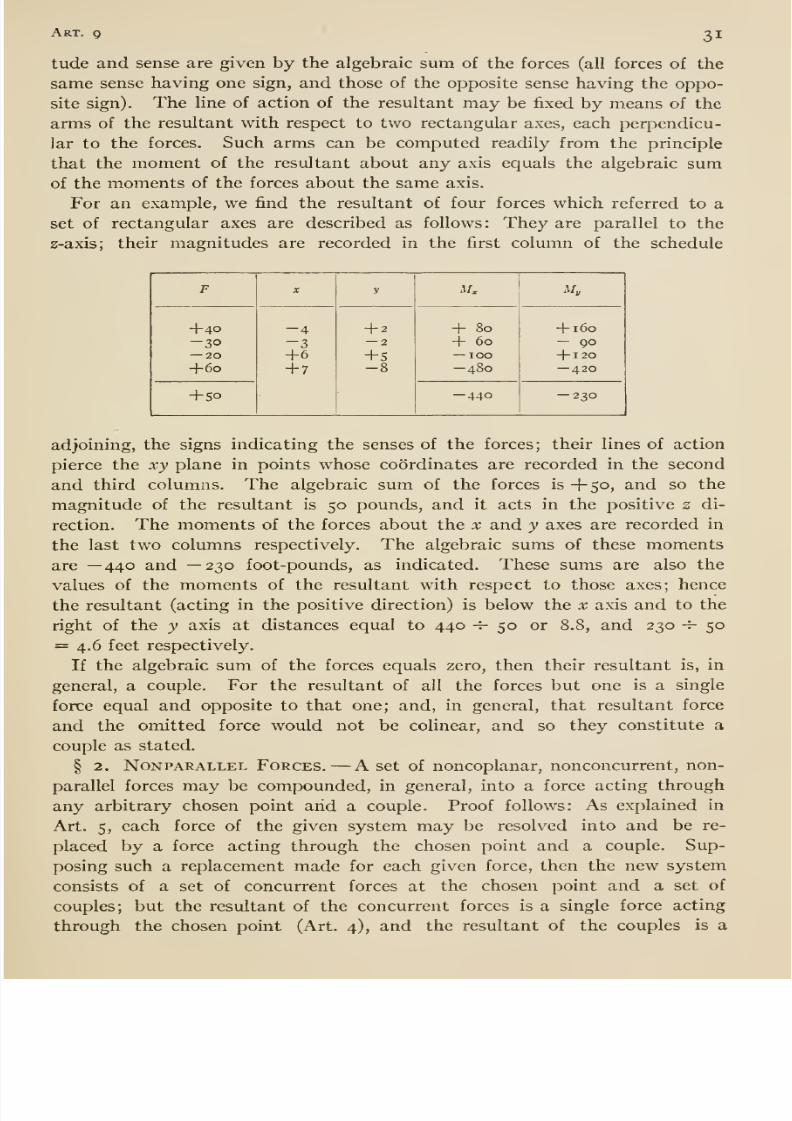
http://slidepdf.com/reader/full/maurer-mechanics 43/407
Art. 9 31
tude and sense are given by the algebraic sum of the forces (all forces of the
same sense having one sign, and those of the opposite sense having the oppo-
site sign). The line of action of the resultant may be fixed by means of the
arms of the resultant with respect to two rectangular axes, each perpendicu-
lar to the forces. Such arms can be computed readily from the principle
that the moment of the resultant about any axis equals the algebraic sumof the moments of the forces about the same axis.
For an example, we find the resultant of four forces which referred to a
set of rectangular axes are described as follows: They are parallel to the
z-axis; their magnitudes are recorded in the first column of the schedule
F
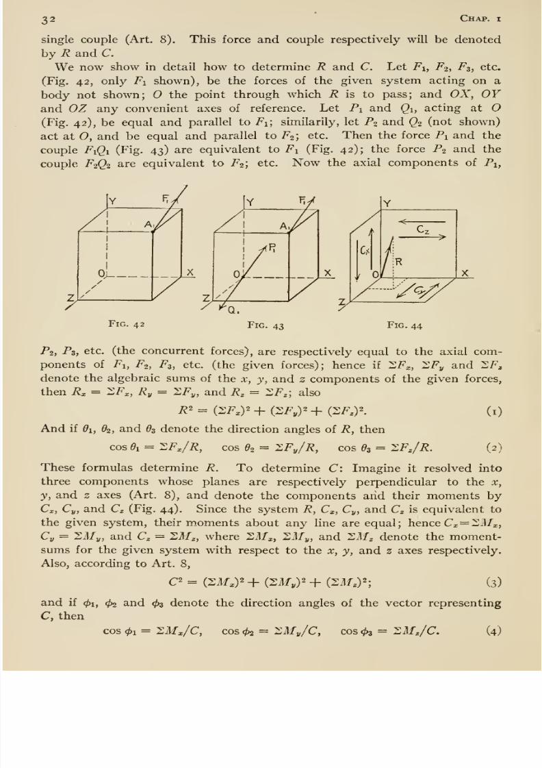
8/13/2019 Maurer Mechanics
http://slidepdf.com/reader/full/maurer-mechanics 44/407
32 Chap, i
single couple (Art. 8). This force and couple respectively will be denoted
by R and C.
We now show in detail how to determine R and C. Let Fi, F2, F3, etc.
(Fig. 42, only T^i shown), be the forces of the given system acting on a
body not shown; O the point through which R is to pass; and OX, OYand OZ any convenient axes of reference. Let Pi and Qi, acting at
(Fig. 42), be equal and parallel to Fi; similarily, let P2 and Q2 (not shown)
act at O, and be equal and parallel to F^; etc. Then the force Pi and the
couple Pi^i (Fig. 43) are equivalent to Pi (Fig. 42); the force P2 and the
couple F2Q2 are equivalent to P2; etc. Now the axial components of Pi,
8/13/2019 Maurer Mechanics
http://slidepdf.com/reader/full/maurer-mechanics 45/407
Art. 9 33
In general, R and C may be compounded into two noncoplanar forces.
For, as explained in Art. 8, C may be shifted about without change of
efifect if only the direction of its plane be unchanged; assume such shift
until one of the forces of C intersects R; then that force and R may be
compounded into a single force R'; there remain R' and the second force
of C, and obviously R' and that force are not coplanar. These two cannot
be compounded; they are the simplest set equivalent to the given system,
and therefore constitute the resultant of the given system. If the plane of
C happens to be parallel to R, then C and R can be compounded into a
single force, and the resultant of the given system is a single force. For
shifting C about until C and R become coplanar, then they may be com-
pounded readily into a single force (Art. 5).
In general, the system of forces has a torque aboutevery line
throughO.
There is one line which is of prime importance, the line about which the
torque is greatest. The torque of the forces about that line is called the or
resultant torque of the system (for the chosen point 0). Since R has no
moment about a line through O, the torque of the system about any such line
equals the torque of C about that line. But the torque of C is greatest about
a line perpendicular to the plane of C; this is the important line mentioned.
The direction of this line is given by equations (4), and the resultant torque
of the system by equations (3). The system of forces has no torque about aline through parallel to the plane of C, (perpendicular to the line or axis of
resultant torque) since R and C have no torque about such line.

8/13/2019 Maurer Mechanics
http://slidepdf.com/reader/full/maurer-mechanics 46/407
8/13/2019 Maurer Mechanics
http://slidepdf.com/reader/full/maurer-mechanics 47/407
Art. io 35
By means of (A) and (B) we can write many equations for any system in
equilibrium. Thus, for a coplanar concurrent system, (A) gives ZFx = o,
ZFy = o, ZFu = o, etc., where x, y, u, etc., are axes of resolution; and
(B) gives 2ilfa = o, I,Mb = o, 2Mc = o, etc., where a, b, c, etc., are origins
of moments in theplane of the forces. Not all of such equilibrium equa-
tions are independent, however; that is, certain ones follow from the others.
Thus, if 2Fx = o for any coplanar concurrent system, then 2F„ does
not necessarily equal zero, but if also ^Fy = o, then the resultant equals
zero, and it follows that SFu = o. That is, 2^Fx = o and SF^ = o are two
independent equations, but any third similar equation (as ZFu = o) is not
independent of them. The independent equations or conditions of equi-
librium for any particular kind of force system are such as are necessary
and sufficient to insure a vanishing resultant. We will now deduce theseindependent conditions of equilibrium for the various classes or kinds of
force systems.
(i) Colinear Forces. —There is one condition of equilibrium. It can be
stated in several forms; namely,
(i) 2/^ = or (2) llMa = o.
Form (i) states that the algebraic sum of the forces equals zero; (2) that
the algebraic sum of the moments of all the forces about any point (not ontheir common line of action) equals zero. On the graphical basis, the condi-
tion of equilibrium is that the force polygon for the forces (degenerated into
a straight line in this case) is a closed one. For if ZF = o, or SM = o, or
the force polygon closes, then there is no resultant.
(ii) Coplanar Concurrent Forces. —There are two independent algebraic con-
ditions of equilibrium. They can be expressed in three forms; namely,
(i) 2Fx = 2F„ = o, (2) 2/? = ZMa = o, or (3) SMa = 2^6 = o.
Form (i) states that the algebraic sums of the components of the forces
along two lines x and y (in the plane of the forces) equal zero; (2) that the
algebraic sum of the components of the forces along any line (as x), and the
algebraic sum of the moments of all the forces about any point, each equal
zero (the point a to be in the plane of the forces, and the line joining a and
0, their point of concurrence, to be inclined to the x axis); and (3) that
the algebraic sums of the moments of all the forces about two points (not
colinear with the point of concurrence of the forces) equal zero. For in
any case the resultant is zero, as will be seen from this: (i) According to
Art. 4, the resultant of the system, if there is one, is a single force R, given
hy R== V(2F,)2-f (2F„)2; and hence if 2Fx = o and 2F„ = o, R must
equal zero. (2) If ^Fx = o, then the resultant, if there is one, must be
perpendicular to the x axis; and if 2Ma = o, then the moment of R about
a equals zero, which requires that R ^ o. (3) The resultant, if there is one,
must pass through the point of concurrence of the given forces; if 2Mo= o
8/13/2019 Maurer Mechanics
http://slidepdf.com/reader/full/maurer-mechanics 48/407
36 Chap, n
then R must pass through a also; if ZMa = o, then R must equal zero, b
not being on Oa.
The graphical condition of equilibrium is that the force polygon for the
forces closes. For, if it does close, then there is no resultant.
(iii) Co planar Nonconcur rent Parallel Forces. —There are two independent
algebraic conditions of equilibrium. They can be expressed in two forms;
namely,(i) S/? = SM = o or (2) -^Ma = ^Mb = o
Form (i) states that the algebraic sum of the forces and the algebraic sum
of the moments of the forces about any point (in the plane of the forces) equal
zero; (2) that the algebraic sums of the moments of the forces about two
points equal zero, the line joining the origins not to be parallel to the forces.
For either set of conditions is necessary and sufficient to make the result-
ant zero, as may be shown thus : In Art. 7 it is shown that the resultant,if there is one, is a single force or a couple. And (i), if 2F = o, then the
resultant is not a force, and if 2M = o, then it is not a couple; and hence
there is no resultant. (2) If Sil/a = o, the resultant is not a couple but a
force, which passes through a; if also ZMb = o, then the moment of the
resultant force about b must be zero, and that requires that the force equals
zero.
There are two graphical conditions of equilibrium, namely, a force and
a string polygon for the forces must close. For if a force polygon closes,
then the resultant, if there is one, is a couple; if a string polygon closes, then
the resultant is not a couple.
(iv) Coplanar Nonconcurrent Nonparallel Forces. —There are three inde-
pendent algebraic conditions of equilibrium. They can be stated in three
forms; namely,(i) 2/^x = ^Fy = 2Ma = o;
(2) Zi^x = 2M„ = ^Mb = o;
and (3) SMa = 2Mb = ^Mc = o.
Form (i) states that the algebraic sums of the components of all the forces
along two lines and the algebraic sum of the moments of the forces about
any point equal zero, the lines and points to be in the plane of the forces;
(2) that the algebraic sums of the components of the forces along any line x
and the algebraic sums of the moments of the forces about two points, a and
b, equal zero, the line x and that joining a and b not to be at right angles;
and (3) that the algebraic sums of the moments of the forces about three
points, a, b, and c, equal zero, the points not to be colinear. For any set of
these conditions is necessary and just sufficient to make the resultant vanish
as may be shown, thus: The resultant, if there is one, is a single force or a
single couple (Art. 7). And (i) if ^Fx = 2Fj, = o, then the resultant is not
force, and if 2M = o, it is not a couple; and hence there is no resultant.
(2) If 2Fx = o, the resultant is a force R perpendicular to the x axis or a
8/13/2019 Maurer Mechanics
http://slidepdf.com/reader/full/maurer-mechanics 49/407
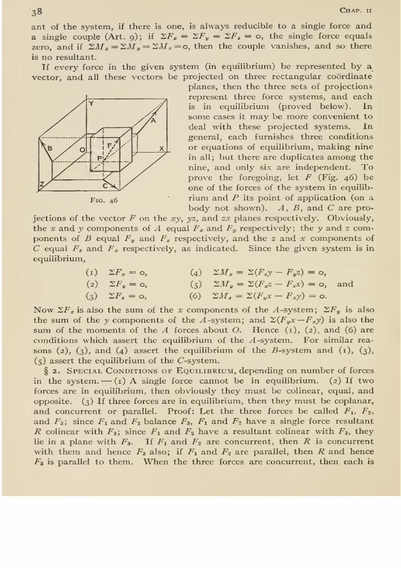
8/13/2019 Maurer Mechanics
http://slidepdf.com/reader/full/maurer-mechanics 50/407
Fig. 46
28 Chap, ii
ant of the system, if there is one, is always reducible to a single force and
a single couple (Art. 9) ; if SF^ = 2Fj, = SF^ = o, the single force equals
zero, and if 21f ^ = 2My = SM^ = o, then the couple vanishes, and so there
is no resultant.
If every force in the given system (in equilibrium) be represented by a
vector, and all these vectors be projectedon three rectangular coordinate
planes, then the three sets of projections
represent three force systems, and each
is in equilibrium (proved below). In
some cases it may be more convenient to
deal with these projected systems. In
general, each furnishes three conditions
or equations of equilibrium, making nine
in all; but there are duplicates amongthe
nine, and only six are independent. Toprove the foregoing, let F (Fig. 46) be
one of the forces of the system in equilib-
rium and P its point of application (on a
body not shown). A, B, and C are pro-
jections of the vector F on the xy, yz, and zx planes respectively. Obviously,
the X and y components of A equal Fx and Fy respectively; the y and z com-
ponents of B equal Fy and F^ respectively, and the z and x components ofC equal F^ and Fx respectively, as indicated. Since the given system is in
and
Now 2Fx is also the sum of the x components of the ^-system; ZFy is also
the sum of the y components of the ^-system; and XiFyX—Fxy) is also the
sum of the moments of the A forces about 0. Hence (i), (2), and (6) are
conditions which assert the equilibrium of the yl -system. For similar rea-
sons (2), (3), and (4) assert the equilibrium of the ^-system and (i), (3),
(5) assert the equilibrium of the C-system.
§ 2. Special Conditions of Equilibrium, depending on number of forces
in the system. —(i) A single force cannot be in equilibrium. (2) If two
forces are in equilibrium, then obviously they must be colinear, equal, and
opposite. (3) If three forces are in equilibrium, then they must be coplanar,
and concurrent or parallel. Proof: Let the three forces be called Fi, F2,
and 7^3; since Fi and F2 balance F3, Fi and F2 have a single force resultant
R colinear with F3; since Fi and F2 have a resultant colinear with F3, they
lie in a plane with F3. If Fi and F2 are concurrent, then R is concurrent
with them and hence F3 also; if Fi and F2 are parallel, then R and hence
F3 is parallel to them. When the three forces are concurrent, then each is
equilibrium,
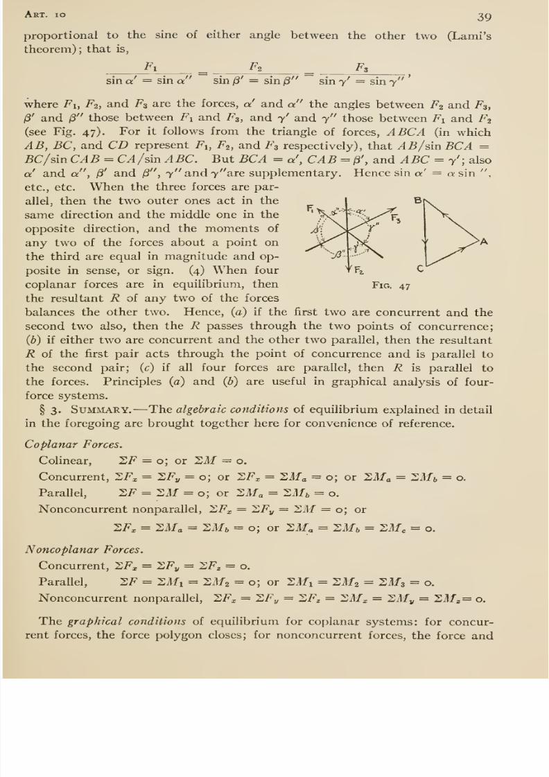
8/13/2019 Maurer Mechanics
http://slidepdf.com/reader/full/maurer-mechanics 51/407
Art. io 39
proportional to the sine of either angle between the other two (Lami's
theorem) ; that is,
Fi ^ F2 ^ Fs
sin a = sin a sin /3' = sin /3 sin 7' = sin 7
'
where Fi, F2, and F3 are the forces, a and a the angles between F2and
F3,
13' and ^ those between Fi and /^s, and y' and 7 those between i^i and F2
(see Fig. 47). For it follows from the triangle of forces, ABCA (in which
AB, BC, and CD represent Fi, F^, and F3 respectively), that ^5/sin5C^ =BC/dn CAB = CA/sin ABC. But BCA = a', CAB = /3', and ABC = y'; also
a' and a , ^' and (S , 7 and 7 are supplementary. Hence sin «' = a sin ,
etc., etc. When the three forces are par-
allel, then the two outer ones act in the
samedirection
andthe middle one in the
opposite direction, and the moments of
any two of the forces about a point on
the third are equal in magnitude and op-
posite in sense, or sign. (4) When four
coplanar forces are in equilibrium, then
the resultant R of any two of the forces
balances the other two. Hence, (a) if the first two are concurrent and the
second two also, then the R passes through the two points of concurrence;Q}) if either two are concurrent and the other two parallel, then the resultant
R of the first pair acts through the point of concurrence and is parallel to
the second pair; (c) if all four forces are parallel, then R is parallel to
the forces. Principles (a) and {b) are useful in graphical analysis of four-
force systems,
§ 3. Summary. —The algebraic conditions of equilibrium explained in detail
in the foregoing are brought together here for convenience of reference.
Coplanar Forces.
Colinear, SF = o; or Sif = o.
Concurrent, 2F^ = 2/^i; = o; or SFx = ^M^ = o; or llMa = ^MbParallel, 2F = 2M = o; or 2Ma = Zilf^ = o.
Nonconcurrent nonparallel, ^Fx = llFy = ZM = o; or
2Fx = ^Ma = ^Mb = o; or SM^ = ^Mb = ZMc = o.
Fig. 47
= o.
Noncoplanar Forces.
Concurrent, ZF^ = ZFy = ZF^ = o.
Parallel, SF = SMi = 2M2 = o; or Sil/i = SATz = 2M3 = o.
Nonconcurrent nonparallel, SF^ = ZFy = XF^ = XMx = 2Af„ = 2ilf , = o.
The graphical conditions of equilibrium for coplanar systems: for concur-
rent forces, the force polygon closes; for nonconcurrent forces, the force and
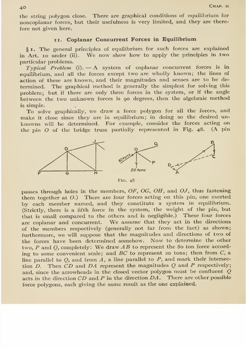
8/13/2019 Maurer Mechanics
http://slidepdf.com/reader/full/maurer-mechanics 52/407
40 Chap, n
the string polygon close. There are graphical conditions of equilibrium for
noncoplanar forces, but their usefulness is very limited, and they are there-
fore not given here.
II. Coplanar Concurrent Forces in Equilibrium
§1. The general principles of equilibrium for such forces are explained
in Art. lo under (ii). We now show how to apply the principles in two
particular problems.
Typical Problem (i). —A system of coplanar concurrent forces is in
equilibrium, and all the forces except two are wholly known; the lines of
action of these are known, and their magnitudes and senses are to be de-
termined. The graphical method is generally the simplest for solving this
problem; but if there are only three forces in the system, or if the angle
between the two unknown forces is 90 degrees, then the algebraic methodis simple.
To solve graphically, we draw a force polygon for all the forces, and
make it close since they are in equilibrium; in doing so the desired un-
knowns will be determined. For example, consider the forces acting on
the pin of the bridge truss partially represented in Fig. 48. (A pin
passes through holes in the members, OF, OG, OH, and OJ, thus fastening
them together at 0.) There are four forces acting on this pin, one exerted
by each member named, and they constitute a system in equilibrium.
(Strictly, there is a fifth force in the system, the weight of the pin, but
that is small compared to the others and is negligible.) These four forces
are coplanar and concurrent. We assume that they act in the directions
of the members respectively (generally not far from the fact) as shown;
furthermore, we will suppose that the magnitudes and directions of two of
the forces have been detennined somehow. Now to determine the other
two, P and Q, completely: We draw AB to represent the 80 ton force accord-
ing to some convenient scale; and BC to represent 20 tons; then from C, a
line parallel to Q, and from A, a line parallel to P, and mark their intersec-
tion D. Then CD and DA represent the magnitudes Q and P respectively;
and, since the arrowheads in the closed vector polygon must be confluent Qacts in the direction CD and P in the direction DA. There are other possible
force polygons, each giving the same result as the one explained.
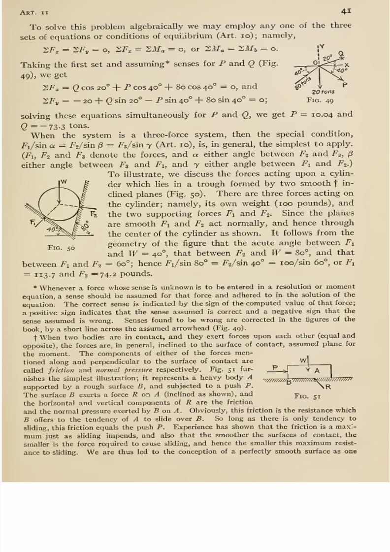
8/13/2019 Maurer Mechanics
http://slidepdf.com/reader/full/maurer-mechanics 53/407
Art. II 41
20 tons
Fig. 49
To solve this problem algebraically we may employ any one of the three
sets of equations or conditions of equilibrium (Art. 10) ; namely,
2Fx = ^Fy = o, 2F^ = ZMa = o, or XMa = SM^ = o.
Taking the first set and assuming* senses for P and Q (Fig.
49), weget
2Fx = Q cos 20° 4- P cos 40° + 80 cos 40° = o, and
ZFy = —20 + (J sin 20° —P sin 40° + 80 sin 40° = o;
solving these equations simultaneously for P and Q, we get P = 10.04 and
(2 =-73-3 tons.
When the system is a three-force system, then the special condition,
Fi/sin a = /^2/sin 13 = Fa/sin y (Art. 10), is, in general, the simplest to apply.
(Fi, F2 and F3 denote the forces, and a either angle between Fo and F3, /3
either angle between F3 and Fi, and 7 either angle between Fi and F2.)
To illustrate, we discuss the forces acting upon a cylin-
der which lies in a trough formed by two smooth f in-
clined planes (Fig. 50). There are three forces acting on
the cylinder; namely, its own weight (100 pounds), and
the two supporting forces Fi and F2. Since the planes
are smooth Fi and F2 act normally, and hence through
the center of the cylinder as shown. It follows from the
geometry of the figure that the acute angle between Fi
and W= 40°, that between F2 and W= 80°, and that
between Fi and F2 = 60°; hence Fi/sin 80° = F2/sin 40° = loo/sin 60°, or F,
= 1 13.7 and F2 =74.2 pounds.
* Whenever a force whose sense is unknown is to be entered in a resolution or moment
equation, a sense should be assumed for that force and adhered to in the solution of the
equation. The correct sense is indicated by the sign of the computed value of that force;
a positive sign indicates that the sense assumed is correct and a negative sign that the
sense assumed is wrong. Senses found to be wrong are corrected in the figures of the
book, by a short line across the assumed arrowhead (Fig. 49).
t When two bodies are in contact, and they exert forces upon each other (equal and
opposite), the forces are, in general, inclined to the surface of contact, assumed plane for
the moment. The components of either of the forces men-
tioned along and perpendicular to the surface of contact are
called friction and normal pressure respectively. Fig. 51 fur-
nishes the simplest illustration; it represents a heavy body A
supported bya rough surface B, and subjected to a push P.
The surface B exerts a force R on A (inclined as shown), and
the horizontal and vertical components of R are the friction
and the normal pressure exerted by B on A. Obviously, this friction is the resistance which
B offers to the tendency of A to slide over B. So long as there is only tendency to
sliding, this friction equals the push P. Experience has shown that the friction is a maxi-
mum just as sliding impends, and also that the smoother the surfaces of contact, the
smaller is the force required to cause sliding, and hence the smaller this maximum resist-
ance to sliding. We are thus led to the conception of a perfectly smooth surface as one
W
'W/////I V^/rmrmrnTTTmnrrm
Fig. 51
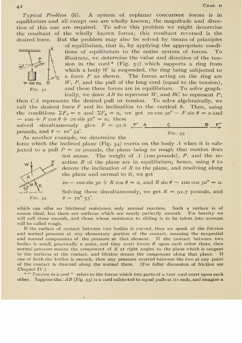
8/13/2019 Maurer Mechanics
http://slidepdf.com/reader/full/maurer-mechanics 54/407
42 Chap, u
nWNWWNWvww.
1fi\
Uc
Typical Problem (ii). A system of coplanar concurrent forces is in
equilibrium and all except one are wholly known; the magnitude and direc-
tion of this one are required. To solve this problem we might determine
the resultant of the w^hoUy known forces; this resultant reversed is the
desired force. But the problem may also be solved by means of principles
of equilibrium, that is, by applying the appropriate condi-
i tions of equilibrium to the entire system of forces. Toillustrate, we determine the value and direction of the ten-
^ sion in the cord* (Fig. 52) which supports a ring from
\ which a body W is suspended, the ring being subjected to
a force P as shown. The forces acting on the ring are
W 100 lbs B W, P, and the pull of the long cord (equal to the tension),
Fig. 52 and these three forces are in equilibrium. To solve graph-
ically, we drawAB
to representW,
andBC
to representP;
then CA represents the desired pull or tension. To solve algebraically, wecall the desired force F and its inclination to the vertical 6. Then, using
the conditions ZFx = o and ZFy = o, we get 20 cos 30° — F sin ^ = o and— 100 + F cos 6 -\- 20 sin 30° = o; these
solved simultaneously give F — 91.6J''
A C B P^
pounds, and 6 — 10° 54'. yig. 53As another example, we determine the
force which the inclined plane (Fig. 54) exerts on the body A whenit is
sub-jected to a pull P = 20 pounds, the plane being so rough that motion does
not ensue. The weight of A (100 pounds), P, and the re-
action R of the plane are in equilibrium; hence, using 6 to
denote the inclination of R to the plane, and resolving along
the plane and normal to it, we get
20 — 100 sin 30 + i? cos 9 = 0, and i^ sin ^ — 100 cos 30° = o.
Solving these simultaneously, weget
R=
91.7 pounds, andFig. 54 6 = 70° 53'.
which can ofifer no frictional resistance, only normal reaction. Such a surface is of
course ideal, but there are surfaces which are nearly perfectly smooth. For brevity wewill call these smooth, and those whose resistance to sliding is to be taken into account
will be called rough.
If the surface of contact between two bodies is curved, then we speak of the friction
and normal pressure at any elementary portion of the contact, meaning the tangential
and normal components of the pressure at that element. If the contact between twobodies is small, practically a point, and they exert forces R upon each other there, then
normal pressure means the component of R at right angles to the plane which is tangent
to the surfaces at the contact, and friction means the component along that plane. If
one or both the bodies is smooth, then any pressure exerted between the two at any point
of the contact is directed along the normal there. (For fuller discussion of friction see
Chapter IV.)
* Tension in a cord refers to the forces which two parts of a taut cord exert upon each
other. Suppose thai; AB (Fig. 53) is a cord subjected to equal pulls at its ends, and imagine a
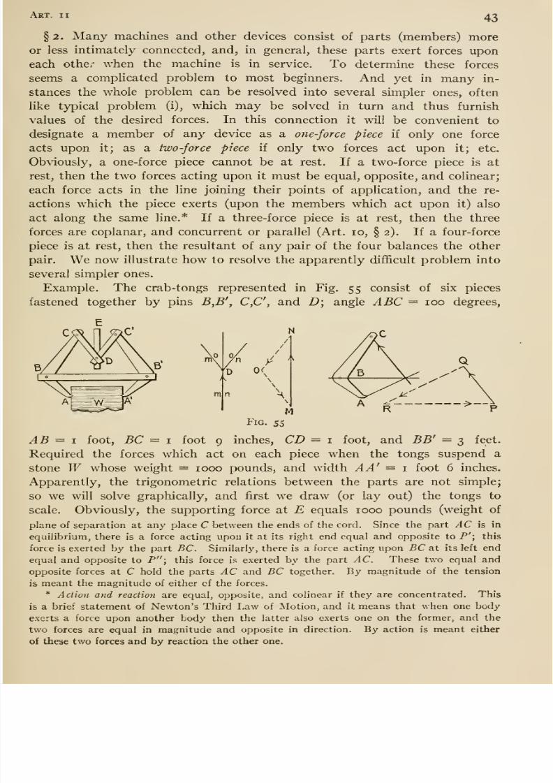
8/13/2019 Maurer Mechanics
http://slidepdf.com/reader/full/maurer-mechanics 55/407
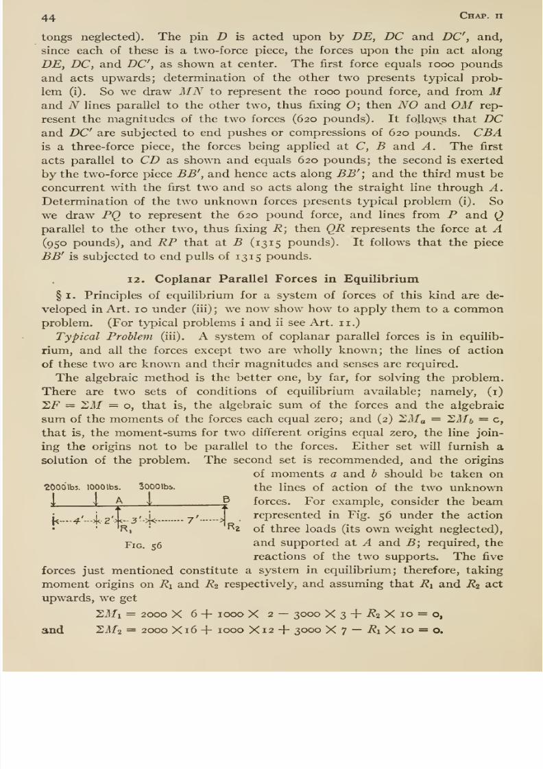
8/13/2019 Maurer Mechanics
http://slidepdf.com/reader/full/maurer-mechanics 56/407
44 Chap, n
tongs neglected). The pin D is acted upon by DE, DC and DC, and,
since each of these is a two-force piece, the forces upon the pin act along
DE, DC, and DC, as shown at center. The first force equals looo pounds
and acts upwards; determination of the other two presents typical prob-
lem (i). So we draw MN to represent the looo pound force, and from Mand N lines parallel to the other two, thus fixing 0; then NO and OM rep-resent the magnitudes of the two forces (620 pounds). It follows that DCand DC are subjected to end pushes or compressions of 620 pounds. CBAis a three-force piece, the forces being applied at C, B and A. The first
acts parallel to CD as shown and equals 620 pounds; the second is exerted
by the two-force piece BB', and hence acts along BB'', and the third must be
concurrent with the first two and so acts along the straight line through A.
Determination of the two unknown forces presents typical problem (i). So
we draw PQ to represent the 620 pound force, and lines from P and Qparallel to the other two, thus fixing R; then QR represents the force at A(950 pounds), and RP that at B (1315 pounds). It follows that the piece
BB' is subjected to end pulls of 13 15 pounds.
12. Coplanar Parallel Forces in Equilibrium
§ I. Principles of equilibrium for a system of forces of this kind are de-
veloped in Art. 10 under (iii) ; we now show how to apply them to a common
problem. (For typical problems i and ii see Art. 11.)
Typical Problem (iii). A system of coplanar parallel forces is in equilib-
rium, and all the forces except two are wholly known; the lines of action
of these two are known and their magnitudes and senses are required.
The algebraic method is the better one, by far, for solving the problem.
There are two sets of conditions of equilibrium available; namely, (i)
27^ = 1,M = o, that is, the algebraic sum of the forces and the algebraic
sum of the moments of the forces each equal zero; and (2) Sifo = 'LMb = c,
that is, the moment-sums for two different origins equal zero, the line join-
ing the origins not to be parallel to the forces. Either set will furnish a
solution of the problem. The second set is recommended, and the origins
of moments a and b should be taken on2000\b5. loooibs. Soooibs. the lines of action of the two unknown
i 1 A i B forces. For example, consider the beam
R.
: / >i<?'M-3->i<- 7' >represented in Fig. 56 under the action
^2 of three loads (its own weight neglected),
Fig. 56 ^^'^ supported at A and B; required, the
reactions of the two supports. The five
forces just mentioned constitute a system in equilibrium; therefore, taking
moment origins on Ri and R2 respectively, and assuming that Ri and R2 act
upwards, we get
SMi = 2000 X 6 + 1000 X 2 — 3000 X 3 + -??2 X 10 = o,
and 21/2 = 2000 X16 + 1000 X12 -f 3000 X 7 — i?i X 10 = o.
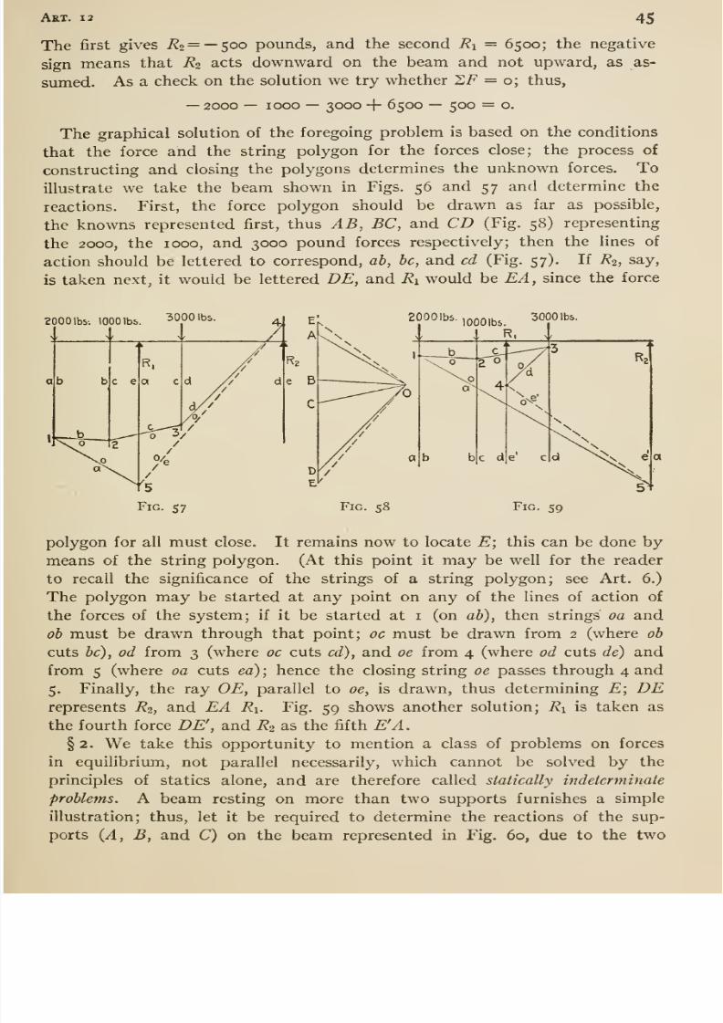
8/13/2019 Maurer Mechanics
http://slidepdf.com/reader/full/maurer-mechanics 57/407
Art. 12 45
The first gives Ri = —$oo pounds, and the second Ri = 6500; the negative
sign means that R2 acts downward on the beam and not upward, as as-
sumed. As a check on the solution we try whether XF = o; thus,
—2000 — 1000 —3000 + 6500 — 500 = o.
The graphical solution of the foregoing problem is based on the conditions
that the force and the string polygon for the forces close; the process of
constructing and closing the polygons determines the unknown forces. Toillustrate we take the beam shown in Figs. 56 and 57 and determine the
reactions. First, the force polygon should be drawn as far as possible,
the knowns represented first, thus AB, BC, and CD (Fig. 58) representing
the 2000, the 1000, and 3000 pound forces respectively; then the lines of
action should be lettered to correspond, ah, he, and cd (Fig. 57). If R2, say,
is taken next, it would be lettered DE, and Ri would be EA, since the force
2000 Ibv. 1000 lbs. ^000 lbs 2000lb5-1000lbs. ^OOO' *-
Fig. S7 Fig. 58 Fig. 59
polygon for all must close. It remains now to locate E; this can be done by
means of the string polygon. (At this point it may be well for the reader
to recall the significance of the strings of a string polygon; see Art. 6.)
The polygon may be started at any point on any of the lines of action of
the forces of the system; if it be started at i (on ah), then strings oa and
oh must be drawn through that point; oc must be drawn from 2 (where oh
cuts he), od from 3 (where oe cuts cd), and oe from 4 (where od cuts de) and
from 5 (where oa cuts ea) ; hence the closing string oe passes through 4 and
5. Finally, the ray OE, parallel to oe, is drawn, thus determining E; DErepresents R2, and EA Ri. Fig. 59 shows another solution; Ri is taken as
the fourth force DE\ and R2 as the fifth E'A.
§ 2. We take this opportunity to mention a class of problems on forces
in equilibrium, not parallel necessarily, which cannot be solved by the
principles of statics alone, and are therefore called statieally indeterminate
problems. A beam resting on more than two supports furnishes a simple
illustration; thus, let it be required to determine the reactions of the sup-
ports {A, B, and C) on the beam represented in Fig. 60, due to the two
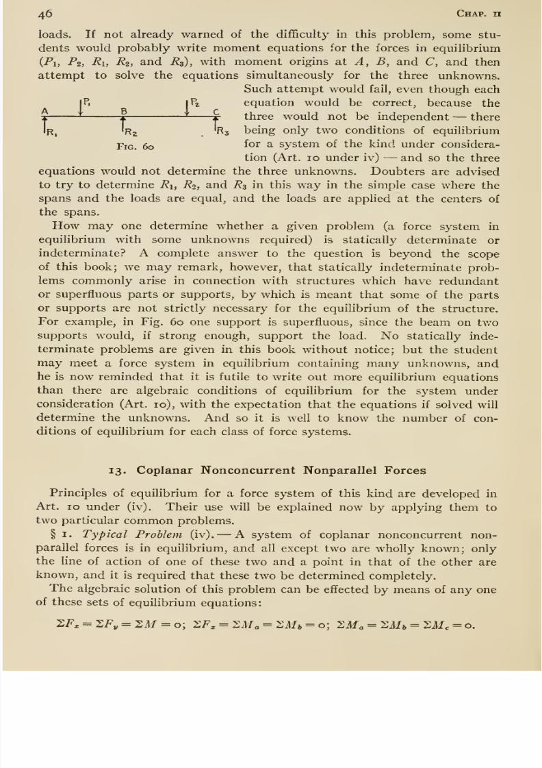
8/13/2019 Maurer Mechanics
http://slidepdf.com/reader/full/maurer-mechanics 58/407
46 Chap, n
loads. If not already warned of the difficulty in this problem, some stu-
dents would probably write moment equations for the forces in equilibrium
(Pi, Pi, Ri, Ri, and Rz), with moment origins at A, B, and C, and then
attempt to solve the equations simultaneously for the three unknowns.
Such attempt would fail, even though eachjP. |Pz equation would be correct, because the
I'^ 1 ^ X- three would not be independent —there
IR, 'rj 'Rj being only two conditions of equilibrium
Fig. 60 ^<^r ^ system of the kind under considera-
tion (Art. 10 under iv) —and so the three
equations would not determine the three unknowns. Doubters are advised
to try to determine Ri, Ro, and R3 in this way in the simple case where the
spans and the loads are equal, and the loads are applied at the centers of
thespans.
How may one determine whether a given problem (a force system in
equilibrium with some unknowns required) is statically determinate or
indeterminate? A complete answer to the question is beyond the scope
of this book; we may remark, however, that statically indeterminate prob-
lems commonly arise in connection with structures which have redundant
or superfluous parts or supports, by which is meant that some of the parts
or supports are not strictly necessary for the equilibrium of the structure.
For example, in Fig. 60 one support is superfluous, since the beam on tv/osupports would, if strong enough, support the load. No statically inde-
terminate problems are given in this book without notice; but the student
may meet a force system in equilibrium containing many unknowns, andhe is now reminded that it is futile to write out more equilibrium equations
than there are algebraic conditions of equilibrium for the system under
consideration (Art. 10), with the expectation that the equations if solved will
determine the unknowns. And so it is well to know the number of con-
ditions of equilibrium for each class of force systems.
13. Coplanar Nonconcurrent Nonparallel Forces
Principles of equilibrium for a force system of this kind are developed in
Art. 10 under (iv). Their use will be explained now by applying them to
two particular common problems.
§ I. Typical Problem (iv). —A system of coplanar nonconcurrent non-
parallel forces is in equilibrium, and all except two are wholly known; only
the line of action of one of these two and a point in that of the other are
known, and it is required that these two be determined completely.
The algebraic solution of this problem can be effected by means of any one
of these sets of equilibrium equations:
SF, = ZFy = XM= o; 2i?x = 2M„ = l^Mb = o; 2Ma = ZMt = Slfc = o.
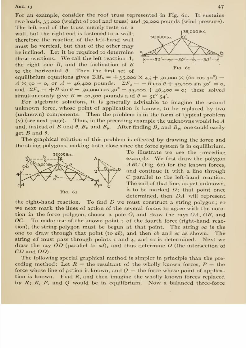
8/13/2019 Maurer Mechanics
http://slidepdf.com/reader/full/maurer-mechanics 59/407
Art. 13 47
SO.OOOlbs
Fig. 61
For an example, consider the roof truss represented in Fig. 61. It sustains
two loads, 3 5, 000 (weight of roof and truss) and 50,000 pounds (wind pressure).
The left end of the truss merely rests on a
wall, but the right end is fastened to a wall;
therefore the reaction of the left-hand wall
must be vertical, but that of the other maybe inclined. Let it be required to determine
these reactions. We call the left reaction Athe right one B, and the inclination of Bto the horizontal 6. Then the first set of
equilibrium equations gives XMb = +35,000 X 45 + 50,000 X (60 cos 30°) —A X go = o, or A = 46,400 pounds. 2F^ = —Bco5d + 50,000 sin 30° = o,
and 2/^y = +B sin 6 — 50,000 cos 30° —35,000 + 46,400 = o; these solved
simultaneously give B = 40,500 pounds and = 51° 54'.
For algebraic solutions, it is generally advisable to imagine the second
unknown force, whose point of application is known, to be replaced by two(unknown) components. Then the problem is in the form of typical problem
(v) (see next page). Thus, in the preceding example the unknowns would be Aand, instead of B and 6, B^ and By. After finding Bj, and By, one could easily
get B and 6.
The graphical solution of this problem is eftected by drawing the force and
the string polygons, making both close since the force system is in equilibrium.To illustrate we use the preceding
example. We first draw the polygon
ABC (Fig. 62) for the known forces,
and continue it with a line through
C parallel to the left-hand reaction.
The end of that line, as yet unknown,is to be marked D; that point once
determined, then DA will representthe right-hand reaction. To find D we must construct a string polygon; so
we next mark the lines of action of the several forces to agree with the nota-
tion in the force polygon, choose a pole 0, and draw the rays OA, OB, andOC. To make use of the known point i of the fourth force (right-hand reac-
tion), the string polygon must be begun at that point. The string oa is the
one to draw through that point (to ab), and then ob and oc as shown. Thestring od must pass through points i and 4, and so is determined. Next we
draw the ray OD (parallel to od), and thus determine D (the intersection of
CD and OD).
The following special graphical method is simpler in principle than the pre-
ceding method: Let R = the resultant of the wholly known forces, P = the
force whose line of action is known, and Q = the force whose point of applica-
tion is known. Find R, and then imagine the wholly known forces replaced
by R; R, P, and Q would be in equilibrium. Now a balanced three- force
35,000 lb5.
Fig. 62
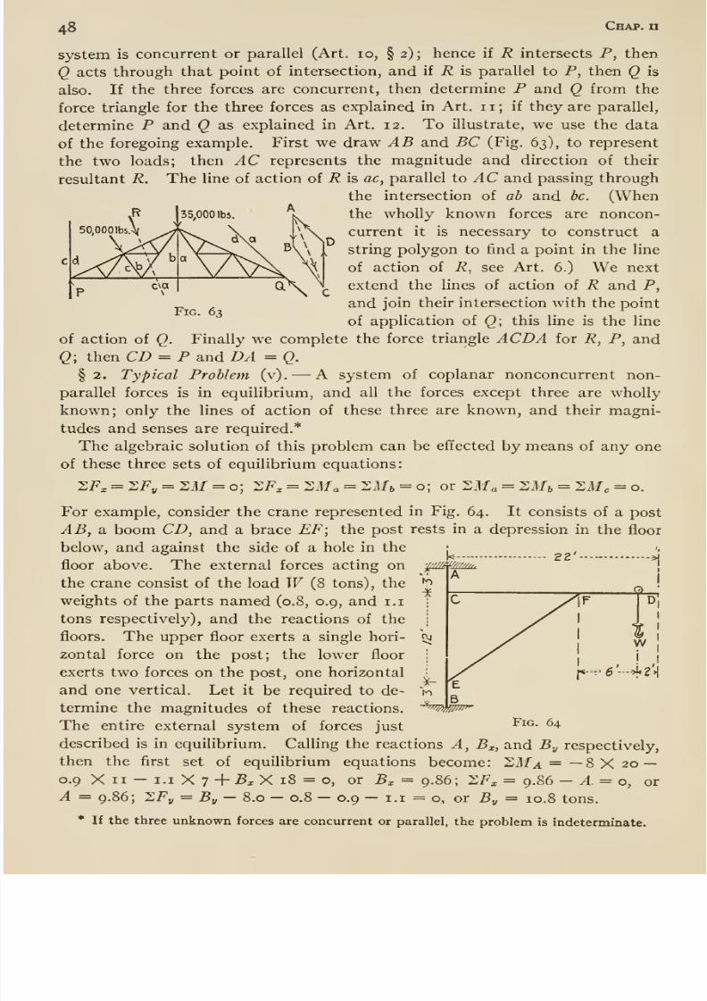
8/13/2019 Maurer Mechanics
http://slidepdf.com/reader/full/maurer-mechanics 60/407
48 Chap, n
50.0001b5.A(
Fig. 63
system is concurrent or parallel (Art. 10, § 2); hence if R intersects P, then
Q acts through that point of intersection, and if R is parallel to P, then Q is
also. If the three forces are concurrent, then determine P and Q from the
force triangle for the three forces as explained in Art. 1 1 ; if they are parallel,
determine P and Q as explained in Art. 12. To illustrate, we use the data
of the foregoing example. First we draw AB and BC (Fig. 63), to represent
the two loads; then AC represents the magnitude and direction of their
resultant R. The line of action of R is ac, parallel to AC and passing through
the intersection of ab and be. (Whenthe wholly known forces are noncon-
current it is necessary to construct a
string polygon to find a point in the line
of action of R, see Art. 6.) We next
extend the lines of action of R and P,
and join their intersection with the point
of application of Q; this line is the line
of action of Q. Finally we complete the force triangle ACDA for R, P, and
Q; then CD = P and DA = Q.
§2. Typical Problem (v). —A system of coplanar nonconcurrent non-
parallel forces is in equilibrium, and all the forces except three are wholly
known; only the lines of action of these three are known, and their magni-
tudes and senses are required.*
The algebraic solution of this problem can be effected by means of any one
of these three sets of equilibrium equations:
SFx = SF„ = 2M = o; 2/^^ = 2Ma = Mlb = o; or l^Ma = ^Ah = ZMc = o.
For example, consider the crane represented in Fig. 64. It consists of a post
AB, a. boom CD, and a brace EF; the post rests in a depression in the floor
below, and against the side of a hole in the
floor above. The external forces acting onthe crane consist of the load W (8 tons), the
weights of the parts named (0.8, 0.9, and i.i
tons respectively), and the reactions of the
floors. The upper floor exerts a single hori-
zontal force on the post; the lower floor
exerts two forces on the post, one horizontal
and one vertical. Let it be required to de-
termine the magnitudes of these reactions.
The entire external system of forces just
described is in equilibrium. Calling the reactions A, B^, and By respectively,
then the first set of equilibrium equations become: 2Ma = —8 X 20 —0.9 X II - I.I X 7 + 5x X 18 = o, or B^ = 9.86; XFj, = 9.86 - A = o, or
A = 9.86; XFy = By —8.0 — 0.8 — 0.9 — I.I = o, or By = 10.8 tons.
* If the three unknown forces are concurrent or parallel, the problem is indeterminate.
'^^''mwi^
Fig. 64
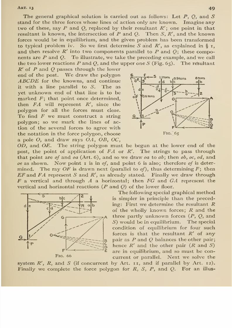
8/13/2019 Maurer Mechanics
http://slidepdf.com/reader/full/maurer-mechanics 61/407
Art. 13 49
0.9tons etons
Fig. 65
The general graphical solution is carried out as follows: Let P, Q, and Sstand for the three forces whose lines of action only are known. Imagine any
two of these, say P and Q, replaced by their resultant R'; one point in that
resultant is known, the intersection of P and Q. Then S, R', and the knownforces would be in equilibrium, and the given problem has been transformed
to typical problem iv. So we first determine S and R', as explained in § i,
and then resolve R' into two components parallel to P and Q; these compo-
nents are P and Q. To illustrate, we take the preceding example, and we call
the two lower reactions P and Q, and the upper one 5 (Fig. 65). The re'sultant
R' of P and Q passes through the lower
end of the post. We draw the polygon
ABCDE for the knowns, and continue
it with a line parallel to S, The as
yet unknown end of that line is to bemarked F; that point once determined,
then FA will represent R' , since the
polygon for all the forces must close.
To find F we must construct a string
polygon; so we mark the lines of ac-
tion of the several forces to agree with
the notation in the force polygon, choose
a pole 0, and draw rays OA, OB, OC,OD, and OE. The string polygon must be begun at the lower end of the
post, the point of application of FA or R'. The strings to pass through
that point are of and oa (Art. 6), and so we draw oa to ab; then ob, oc, od, and
oe as shown. Now point i is in of, and point 6 is also; therefore of is deter-
mined. The ray OF is drawn next (parallel to of), thus determining i^; then
EF and FA represent 5 and R', as already stated. Finally we draw through
F a vertical and through A a horizontal; then FG and GA represent the
vertical and horizontal reactions (P and Q) of the lower floor.
The following special graphical method
is simpler in principle than the preced-
ing: First we determine the resultant Rof the wholly known forces; R and the
three partly unknown forces (P, Q, and
S) would be in equilibrium. The special
condition of equilibrium for four such
forces is that the resultant R' of any
pair as P and Q balances the other pair;
hence R' and the other pair (R and S)
are in equilibrium, and so must be con-
current or parallel. Next we solve the
system R\ R, and S (if concurrent by Art. 11, and if parallel by Art. 12).
Finally we complete the force polygon for R, S, P, and Q. For an illus-
FiG. 66
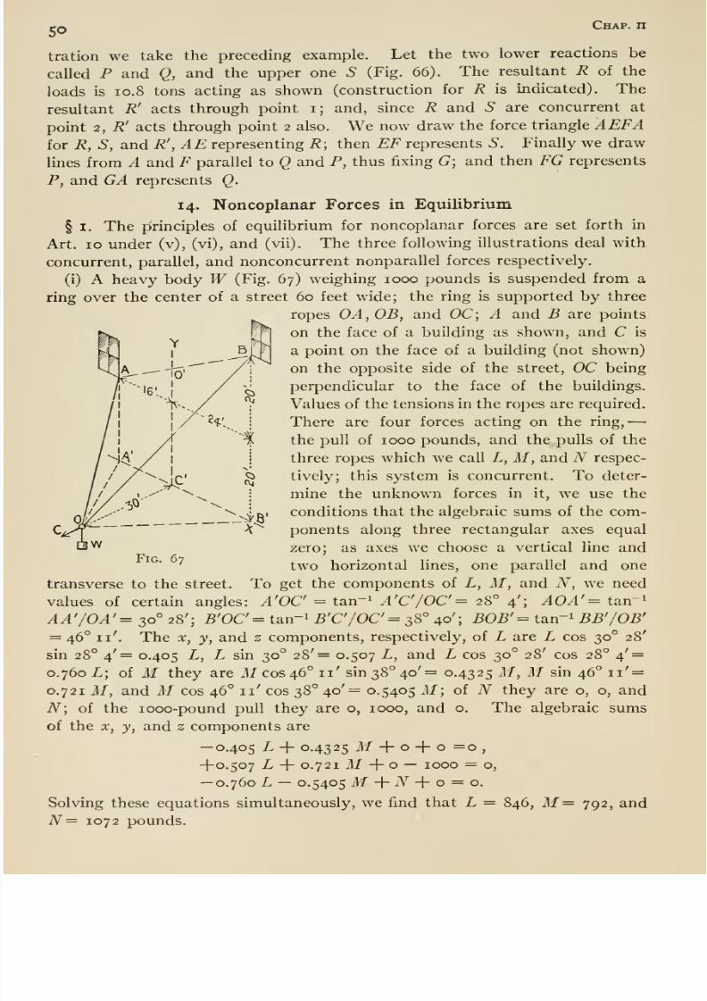
8/13/2019 Maurer Mechanics
http://slidepdf.com/reader/full/maurer-mechanics 62/407
50 Chap, n
tration we take the preceding example. Let the two lower reactions be
called P and Q, and the upper one 5 (Fig. 66). The resultant R of the
loads is I0.8 tons acting as shown (construction for R is indicated). The
resultant R' acts through point i; and, since R and .S are concurrent at
point 2, R' acts through point 2 also. We now draw the force triangle AEFAfor R, S, and R' , AE representing R; then EF represents S. Finally we drawlines from A and F parallel to Q and P, thus fixing G\ and then FG represents
P, and GA represents Q.
14. Noncoplanar Forces in Equilibrium
§ I. The pirinciples of equilibrium for noncoplanar forces are set forth in
Art. 10 under (v), (vi), and (vii). The three following illustrations deal with
concurrent, parallel, and nonconcurrent nonparallel forces respectively.
(i) A heavy body W (Fig. 67) weighing 1000 pounds is suspended from aring over the center of a street 60 feet wide; the ring is supported by three
ropes OA,OB, and OC; A and B are points
on the face of a building as shown, and C is
a point on the face of a building (not shown)
on the opposite side of the street, OC being
perpendicular to the face of the buildings.
Values of the tensions in the ropes are required.
There are four forces acting on the ring,
the pull of 1000 pounds, and the pulls of the
three ropes which we call L, M, and N respec-
tively; this system is concurrent. To deter-
mine the unknown forces in it, we use the
conditions that the algebraic sums of the com-
ponents along three rectangular axes equal
zero; as axes we choose a vertical line and
two horizontal lines, one parallel and oneTo get the components of L, M, and N, we need
values of certain angles: A'OC' = tan-^ A'C'/OC'= 28° 4'; AOA'= tan-i
AA'/OA'= 30° 28'; B'OC^ tan-' B'C'/0C'=s8° 40'; BOB'= tan ' BB'/OB'= 46° 11'. The X, y, and z components, respectively, of L are L cos 30° 28'
sin 28° 4'= 0.405 L, L sin 30° 28'= 0.507 L, and L cos 30° 28' cos 28° 4' =0.760 L; of M they are il/ cos 46° 11' sin 38° 40'= 0.4325 M, M sin 46° ii' =0.721 M, and M cos 46° 11' cos 38° 40'= 0.5405 M; of N they are o, o, and
N\ of the looo-pound pull they are o, 1000, and o. The algebraic sumsof the X, y, and z components are
—0.405 L -\- 0.4325 M -\- o -\- o =0,
-{-0.507 L -f 0.721 M -1- o — 1000 = o,
—0.760 L —0.5405 M+ iV -|- o = o.
Solving these equations simultaneously, we find that L = 846, M= 792, and
N= 1072 pounds.
Fig. 67
transverse to the street
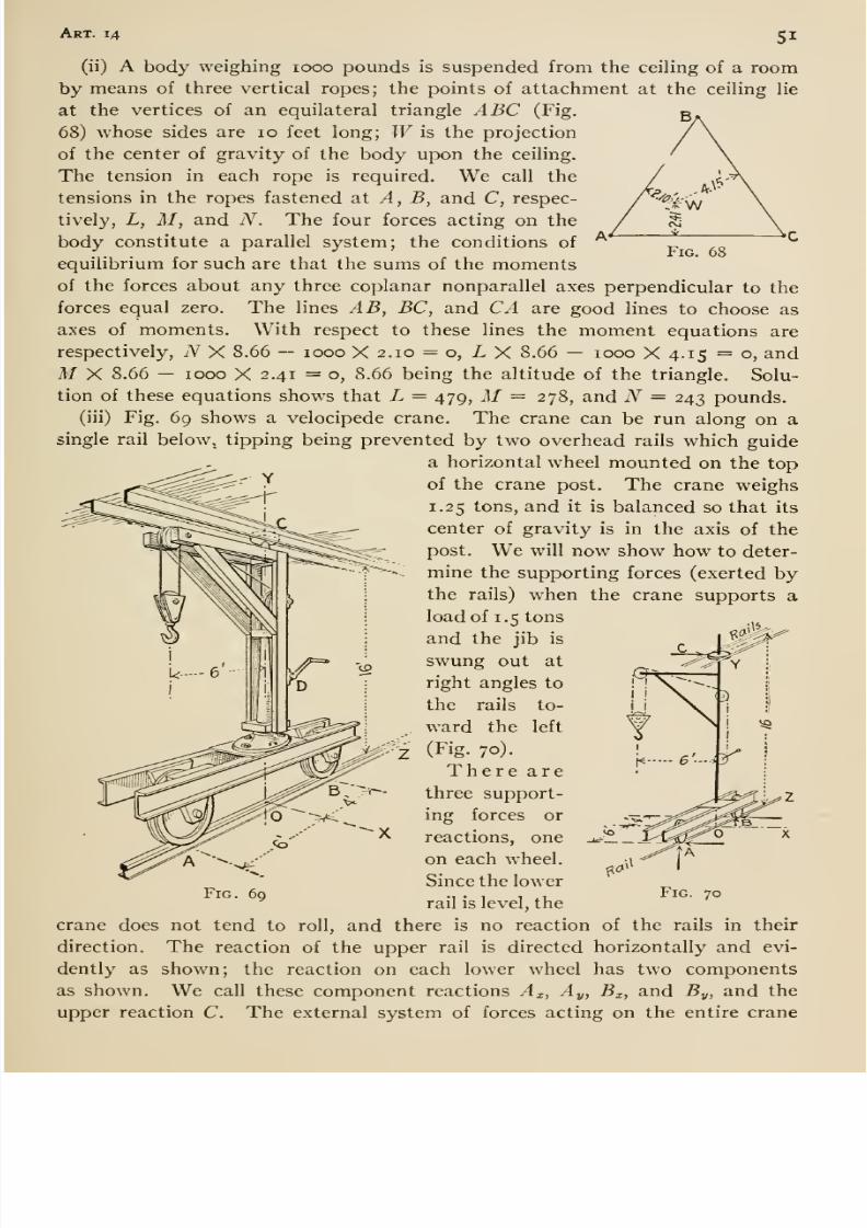
8/13/2019 Maurer Mechanics
http://slidepdf.com/reader/full/maurer-mechanics 63/407
Art. 14 SI
Fig. 68
(ii) A body weighing 1000 pounds is suspended from the ceiling of a roomby means of three vertical ropes; the points of attachment at the ceiling lie
at the vertices of an equilateral triangle ABC (Fig.
68) whose sides are 10 feet long; W is the projection
of the center of gravity of the body upon the ceiling.
The tension in each rope is required. We call the
tensions in the ropes fastened at A, B, and C, respec-
tively, L, M, and N. The four forces acting on the
body constitute a parallel system; the conditions of
equilibrium for such are that the sums of the momentsof the forces about any three coplanar nonparallel axes perpendicular to the
forces equal zero. The lines AB, BC, and CA are good lines to choose as
axes of moments. With respect to these lines the moment equations are
respectively, N X 8.66 — 1000 X 2.10 = o, L X 8.66 — 1000 X 4.15 = o, and
M X 8.66 — 1000 X 2.41 =0, 8.66 being the altitude of the triangle. Solu-
tion of these equations shows that L = 479, M = 278, and N = 243 pounds.
(iii) Fig. 69 shows a velocipede crane. The crane can be run along on a
single rail below, tipping being prevented by two overhead rails which guide
a horizontal wheel mounted on the top
of the crane post. The crane weighs
1.25 tons, and it is balanced so that its
center of gravity is in the axis of the
post. We will now show how to deter-
mine the supporting forces (exerted bythe rails) when the crane supports a
load of 1.5 tons
and the jib is
swung out at
right angles to
the rails to-
ward the left
:(Fig. 70).
There arethree support-
ing forces or
reactions, one
oneach wheel.
Since the lower
rail is level, the
crane does not tend to roll, and there is no reaction of the rails in their
direction. The reaction of the upper rail is directed horizontally and evi-
dently as shown; the reaction on each lower wheel has two components
as shown. We call these component reactions Ax, Ay, Bx, and 5„, and the
1^
Fig. 70
'Vi 'v>
upper reaction C. The external system of forces acting on the entire crane
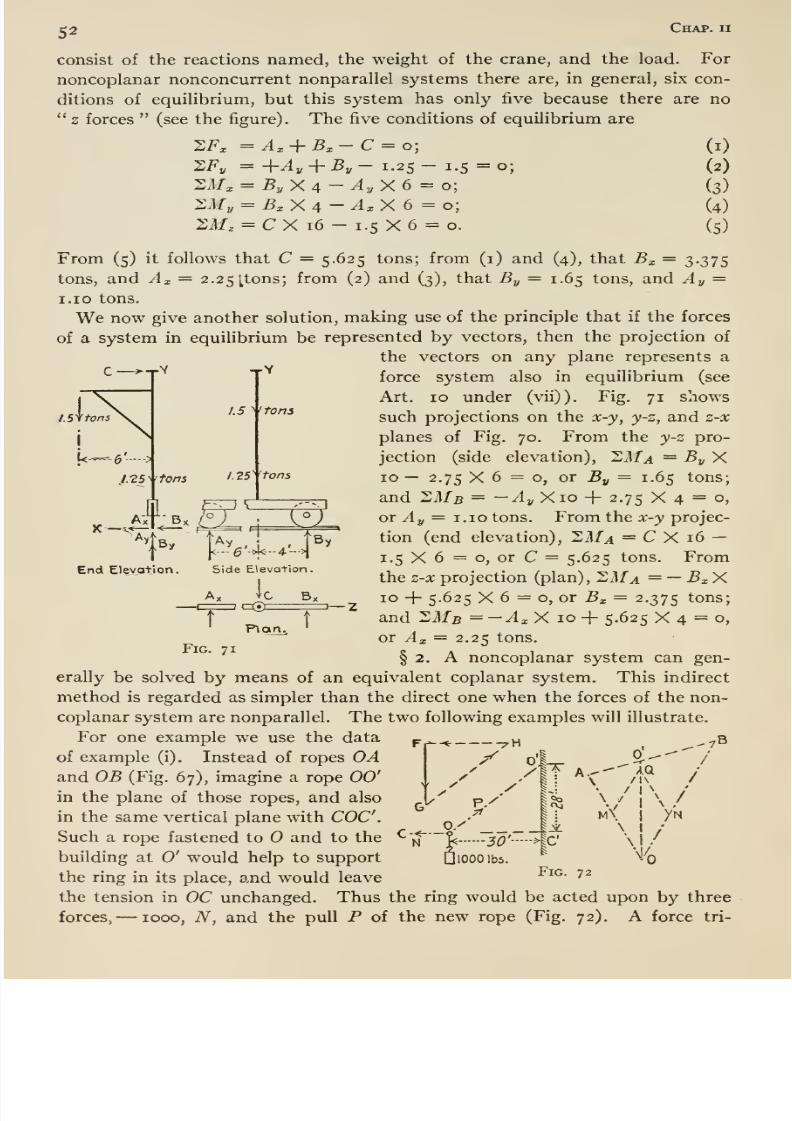
8/13/2019 Maurer Mechanics
http://slidepdf.com/reader/full/maurer-mechanics 64/407
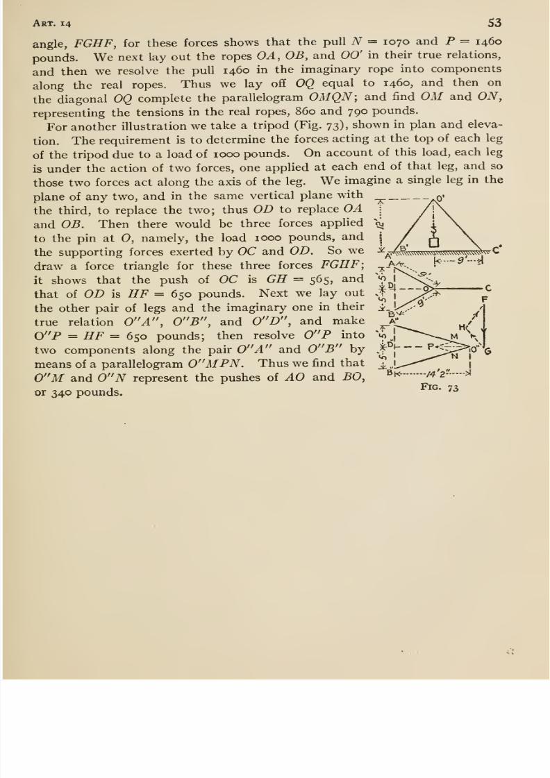
8/13/2019 Maurer Mechanics
http://slidepdf.com/reader/full/maurer-mechanics 65/407
Art. 14 53
angle, FGHF, for these forces shows that the pull N = 1070 and P = 1460
pounds. We next lay out the ropes OA, OB, and 00' in their true relations,
and then we resolve the pull 1460 in the imaginary rope into components
along the real ropes. Thus we lay off OQ equal to 1460, and then on
the diagonal OQ complete the parallelogram OMQN; and find OM and ON,
representing the tensions in the real ropes, 860 and 790 pounds.
For another illustration we take a tripod (Fig. 73), shown in plan and eleva-
tion. The requirement is to determine the forces acting at the top of each leg
of the tripod due to a load of 1000 pounds. On account of this load, each leg
is under the action of two forces, one applied at each end of that leg, and so
those two forces act along the axis of the leg. We imagine a single leg in the
plane of any two, and in the same vertical plane with
the third, to replace the two; thus OD to replace OAand OB. Then there would be three forces applied
to the pin at 0, namely, the load 1000 pounds, and
the supporting forces exerted by OC and OD. So we
draw a force triangle for these three forces FGHF;it shows that the push of OC is GH = 565, and
that of OD is HF =650 pounds. Next we lay out
the other pair of legs and the imaginary one in their
true relation 0 A , 0 B , and 0 D , and make
0 P = HF = 650 pounds; then resolve 0 P into
two components along the pair 0 A and 0 B by
means of a parallelogram 0 MPN. Thus we find that
0 M and 0 N represent the pushes of AO and BO,
or 340 pounds.
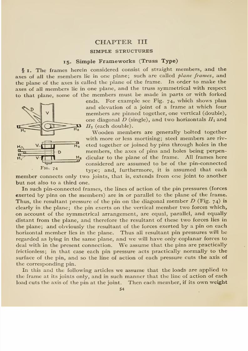
8/13/2019 Maurer Mechanics
http://slidepdf.com/reader/full/maurer-mechanics 66/407
CHAPTER III
SIMPLE STRUCTURES
15. Simple Frameworks (Truss Type)
§ I. The frames herein considered consist of straight members, and the
axes of all the members lie in one plane; such are called plane frames, and
the plane of the axes is called the plane of the frame. In order to make the
axes of all members lie in one plane, and the truss symmetrical with respect
to that plane, some of the members must be made in parts or with forked
ends. For example see Fig. 74, which shows plan
and elevation of a joint of a frame at which four
members are pinned together, one vertical (double),
one diagonal D (single), and two horizontals Hi and
Hi (each double).
Wooden members are generally bolted together
with more or less mortising; steel members are riv-
eted together or joined by pins through holes in the
members, the axes of pins and holes being perpen-
dicular to the plane of the frame. All frames here
considered are assumed to be of the pin-connected
type; and, furthermore, it is assumed that each
member connects only two joints, that is, extends from one joint to another
but not also to a third one.
In such pin-connected frames, the lines of action of the pin pressures (forces
exerted by pins on the members) are in or parallel to the plane of the frame.
Thus, the resultant pressure of the pin on the diagonal member D (Fig. 74) is
clearly in the plane; the pin exerts on the vertical member two forces which,
on account of the symmetrical arrangement, are equal, parallel, and equally
distant from the plane, and therefore the resultant of these two forces lies in
the plane; and obviously the resultant of the forces exerted by a pin on each
horizontal member lies in the plane. Thus all resultant pin pressures will be
regarded as lying in the same plane, and we will have only coplanar forces to
deal with in the present connection.We
assume that the pins are practically
frictionless; in that case each pin pressure acts practically normally to the
surface of the pin, and so the line of action of each pressure cuts the axis of
the corresponding pin.
In this and the following articles we assume that the loads are applied to
the frame at its joints only, and in such manner that the line of action of each
load cuts the axis of the pin at the joint. Then each member, if its own weight
54
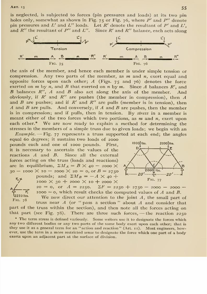
8/13/2019 Maurer Mechanics
http://slidepdf.com/reader/full/maurer-mechanics 67/407
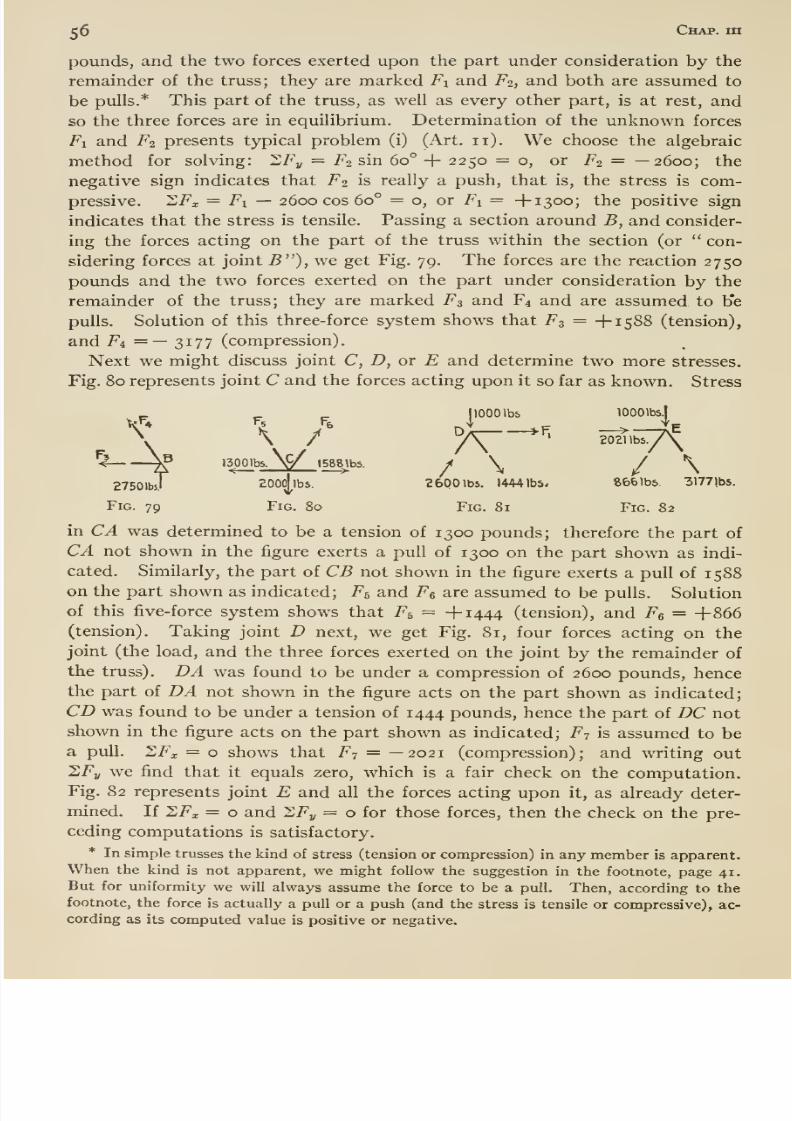
8/13/2019 Maurer Mechanics
http://slidepdf.com/reader/full/maurer-mechanics 68/407
56 Chap, m
pounds, and the two forces exerted upon the part under consideration by the
remainder of the truss; they are marked Fi and F2, and both are assumed to
be pulls.* This part of the truss, as well as every other part, is at rest, and
so the three forces are in equilibrium. Determination of the unknown forces
Fi and Fi presents typical problem (i) (Art, 11). We choose the algebraic
method for solving: 'LFy = F2 sin 60° + 2250 = o, or F2 = —2600; the
negative sign indicates that F2 is really a push, that is, the stress is com-
pressive. SFi = Fi — 2600 cos 60° = o, or Fi = +1300; the positive sign
indicates that the stress is tensile. Passing a section around B, and consider-
ing the forces acting on the part of the truss within the section (or con-
sidering forces at joint 5 ), we get Fig. 79. The forces are the reaction 2750
pounds and the two forces exerted on the part under consideration by the
remainder of the truss; they are marked F3 and F4 and are assumed to b'e
pulls. Solution of this three-force system shows that F3 = +1588 (tension),
and F4 =— 3177 (compression).
Next we might discuss joint C, D, or E and determine two more stresses.
Fig. 80 represents joint C and the forces acting upon it so far as known. Stress
_ ^ ^ 1 1000 lbs lOOOlbs.l
\ \/ K '^'=7\
I3p01 b5. Ny 1588^^5.
/ \ / \gyjOibsT ZOOollba. 2600 lbs. 1444 lbs- 666 lbs. 31771bs.
Fig. 79 Fig. 80 Fig. 81 Fig. 82
in CA was determined to be a tension of 1300 pounds; therefore the part of
CA not shown in the figure exerts a pull of 1300 on the part shown as indi-
cated. Similarly, the part of CB not shown in the figure exerts a pull of 1588on the part shown as indicated; F5 and F^ are assumed to be pulls. Solution
of this five-force system shows that F5 = +1444 (tension), and Fg = +866(tension). Taking joint D next, we get Fig. 81, four forces acting on thejoint (the load, and the three forces exerted on the joint by the remainder of
the truss), DA was found to be under a compression of 2600 pounds, hencethe part of DA not shown in the figure acts on the part shown as indicated;
CD was found to be under a tension of 1444 pounds, hence the part of DC not
shown in the figure acts on the part shown as indicated; F7 is assumed to be
a pull. ZFx = o shows that F^ = —2021 (compression); and writing out
2Fj, we find that it equals zero, which is a fair check on the computation.
Fig. 82 represents joint E and all the forces acting upon it, as already deter-
mined. If 2Fa; = o and SFj, = o for those forces, then the check on the pre-
ceding computations is satisfactory.
* In simple trusses the kind of stress (tension or compression) in any member is apparent.When the kind is not apparent, we might follow the suggestion in the footnote, page 41.
But for uniformity we will always assume the force to be a pull. Then, according to thefootnote, the force is actually a pull or a push (and the stress is tensile or compressive), ac-
cording as its computed value is positive or negative.
27501bil
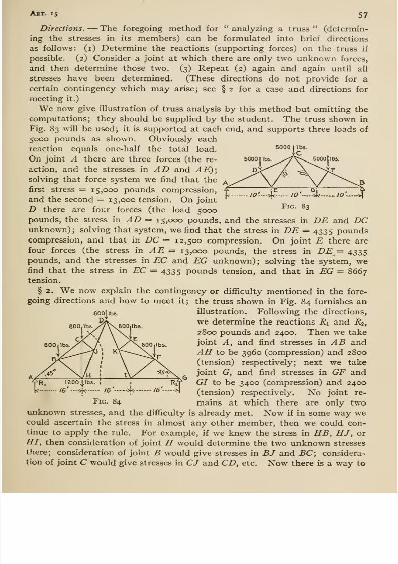
8/13/2019 Maurer Mechanics
http://slidepdf.com/reader/full/maurer-mechanics 69/407
AxT. IS 57
5000 I lbs.
5000 1 lbs.
Directions. —The foregoing method for analyzing a truss (determin-
ing the stresses in its members) can be formulated into brief directions
as follows: (i) Determine the reactions (supporting forces) on the truss if
possible. (2) Consider a joint at which there are only two unknown forces,
and then determine those two. (3) Repeat (2) again and again until all
stresses have been determined. (These directions do not pro\ide for acertain contingency which may arise; see § 2 for a case and directions for
meeting it.)
We now give illustration of truss analysis by this method but omitting the
computations; they should be supplied by the student. The truss shown in
Fig. 83 will be used; it is supported at each end, and supports three loads of
5000 pounds as shown. Obviously each
reaction equals one-half the total load.
On joint A there are three forces (the re-
action, and the stresses in AD and AE)\solving that force system we find that the
first stress = 15,000 pounds compression,
and the second = 13,000 tension. On joint
D there are four forces (the load 5000^^' ^
pounds, the stress \n AD =^ 15,000 pounds, and the stresses in DE and DCunknown); solving that system, we find that the stress in DE = 4335 pounds
compression, and that in DC = 12,500 compression. On joint E there are
four forces (the stress in AE = 13,000 pounds, the stress in DE = 4335pounds, and the stresses in EC and EG unknown) ; solving the system, wefind that the stress in EC = 4335 pounds tension, and that in EG = 8667tension.
§ 2. We now explain the contingency or diflSculty mentioned in the fore-
going directions and how to meet it; the truss shown in Fig. 84 furnishes an
illustration. Following the directions,
we determine the reactions Ri and R2,
2800 pounds and 2400. Then we take
joint A, and find stresses in AB and-43 to be 3960 (compression) and 2800
(tension) respectively; next we take
joint G, and find stresses in GF and
GI to be 3400 (compression) and 2400
(tension) respectively. No joint re-
mains at which there are only two
600 1 lbs
800, lbs
SOOllbb.
aooiibs.
->i<-/e'--->l<-—
Fig. 84
unknown stresses, and the difiiculty is already met. Now if in some way wecould ascertain the stress in almost any other member, then we could con-
tinue to apply the rule. For example, if we knew the stress in HB, HJ, or
HI, then consideration of joint H would determine the two unknown stresses
there; consideration of joint B would give stresses in BJ and BC; considera-
tion of joint C would give stresses in CJ and CD, etc. Now there is a way to
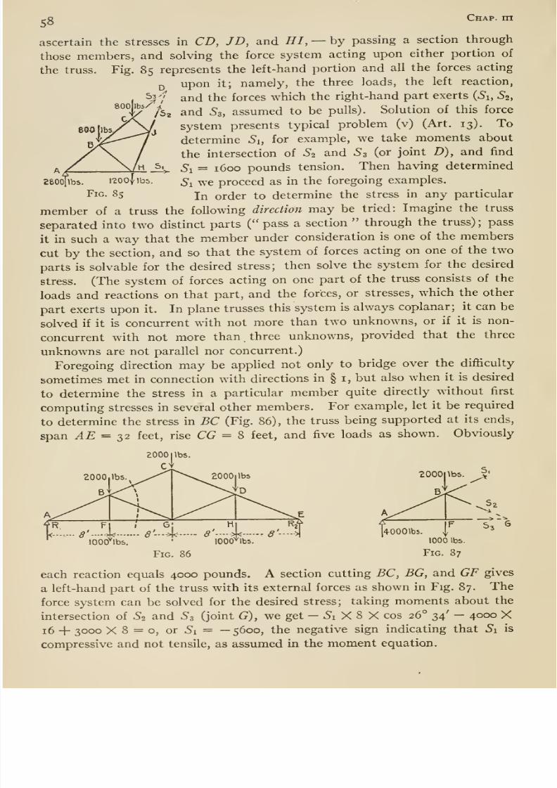
8/13/2019 Maurer Mechanics
http://slidepdf.com/reader/full/maurer-mechanics 70/407
-o Chap, in
ascertain the stresses in CD, JD, and HI, —hy passing a section through
those members, and solving the force system acting upon either portion of
the truss. Fig, 85 represents the left-hand portion and all the forces acting
^ upon it; namely, the three loads, the left reaction,
, ^7 and the forces which the right-hand part exerts (^i, ^2,
^°°' '/ss and 53, assumed to be pulls). Solution of this force
system presents typical problem (v) (Art. 13). To
determine Si, for example, we take moments about
the intersection of ^2 and S3 (or joint D), and find
^ Si= 1600 pounds tension. Then having determined
z&oolibs. 1200 jibs. s^ we proceed as in the foregoing examples.
Fig. 85 In order to determine the stress in any particular
member of a truss the following direction may be tried: Imagine the truss
separated into two distinct parts ( pass a section through the truss); pass
it in such a way that the member under consideration is one of the members
cut by the section, and so that the system of forces acting on one of the two
parts is solvable for the desired stress; then solve the system for the desired
stress. (The system of forces acting on one part of the truss consists of the
loads and reactions on that part, and the forces, or stresses, which the other
part exerts upon it. In plane trusses this system is always coplanar; it can be
solved if it is concurrent with not more than two unknowns, or if it is non-
concurrent with not more than . three unknowns, provided that the three
unknowns are not parallel nor concurrent.)
Foregoing direction may be applied not only to bridge over the difiiculty
sometimes met in connection with directions in § i, but also when it is desired
to determine the stress in a particular member quite directly without first
computing stresses in several other members. For example, let it be required
to determine the stress in BC (Fig. 86), the truss being supported at its ends,
span ^£ = 32 feet, rise CG = 8 feet, and five loads as shown. Obviously
Fig. 86
1000 lbs.
Fig. 87
each reaction equals 4000 pounds. A section cutting BC, BG, and OF gives
a left-hand part of the truss with its external forces as shown in Fig. 87. The
force system can be solved for the desired stress; taking moments about the
intersection of ^2 and ^3 (joint G), we get - 5i X 8 X cos 26° 34' —4000 X16 -f 3000 X 8 = o, or 5i = —5600, the negative sign indicating that Si is
compressive and not tensile, as assumed in the moment equation.
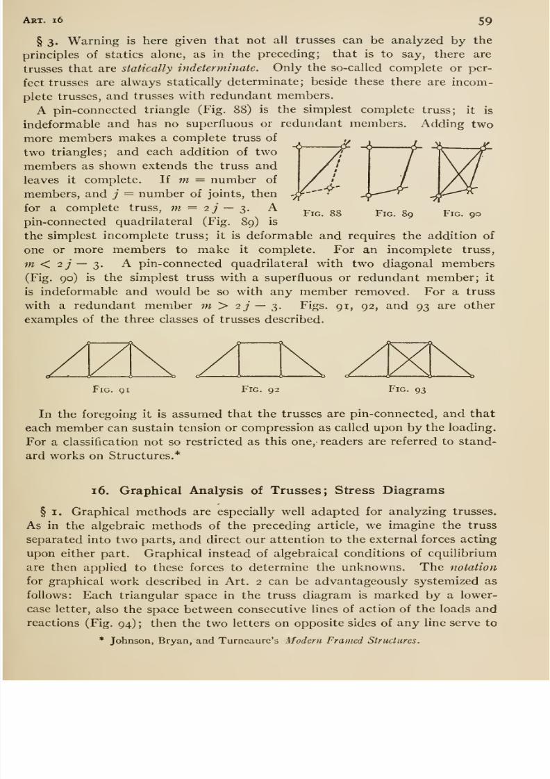
8/13/2019 Maurer Mechanics
http://slidepdf.com/reader/full/maurer-mechanics 71/407
Art. 1 59
§ 3. Warning is here given that not all trusses can be analyzed by the
principles of statics alone, as in the preceding; that is to say, there are
trusses that are statically indeterminate. Only the so-called complete or per-
fect trusses are always statically determinate; beside these there are incom-
plete trusses, and trusses with redundant members.
A pin-connected triangle (Fig. 88) is the simplest complete truss; it is
indeformable and has no superfluous or redundant members. Adding two
more members makes a complete truss of
two triangles; and each addition of two
members as shown extends the truss and
leaves it complete. If m = number of
members, and j = number of joints, then
for a complete truss, m = 2 j — t,. Apin-connected quadrilateral (Fig. 89) is
the simplest incomplete truss; it is deformable and requires the addition of
one or more members to make it complete. For an incomplete truss,
w < 27 — 3. A pin-connected quadrilateral with two diagonal members
(Fig. 90) is the simplest truss with a superfluous or redundant member; it
is indeformable and would be so with any member removed. For a truss
with a redundant member m > 2 j — t,- Figs. 91, 92, and 93 are other
examples of the three classes of trusses described.
Fig. 88 Fig. 89 Fig. 90
Fig. qi Fig. 92 Fig. 93
In the foregoing it is assumed that the trusses are pin-connected, and that
each member can sustain tension or compression as called upon by the loading.
For a classification not so restricted as this one, readers are referred to stand-
ard works on Structures.*
16. Graphical Analysis of Trusses; Stress Diagrams
§ I. Graphical methods are especially well adapted for analyzing trusses.
As in the algebraic methods of the preceding article, we imagine the truss
separated into two parts, and direct our attention to the external forces acting
upon either part. Graphical instead of algebraical conditions of equilibrium
are then applied to these forces to determine the unknowns. The notation
for graphical work described in Art. 2 can be advantageously systemized as
follows: Each triangular space in the truss diagram is marked by a lower-
case letter, also the space between consecutive lines of action of the loads and
reactions (Fig. 94) ; then the two letters on opposite sides of any line serve to
* Johnson, Bryan, and Turncaure's Modern Framed Structures.
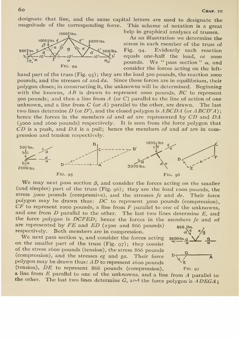
8/13/2019 Maurer Mechanics
http://slidepdf.com/reader/full/maurer-mechanics 72/407
6o Chap, hi
lOOOMbs.
1000 lbs.
designate that line, and the same capital letters are used to designate themagnitude of the corresponding force. This scheme of notation is a great
help in graphical analyses of trusses.
As an illustration we determine the
stress in each member of the truss of
Fig. 94. Evidently each reaction
equals one-half the load, or 2000
pounds. We pass section a, andconsider the forces acting on the left-
hand part of the truss (Fig. 95) ; they are the load 500 pounds, the reaction 2000
pounds, and the stresses cd and da. Since those forces are in equilibrium, their
polygon closes; in constructing it, the unknowns will be determined. Beginning
with the knowns, yl.B is drawn to represent 2000 pounds, BC to represent
500 pounds ; and then a line from A (or C) parallel to the line of action of one
unknown, and a line from C (or A) parallel to the other, are drawn. The last
two lines determine D (or D'), and the closed polygon is A BCDA (or A BCD' A) ;
hence the forces in the members cd and ad are represented by CD and DA(3000 and 2600 pounds) respectively. It is seen from the force polygon that
CD is a push, and DA is a pull; hence the members cd and ad are in com-
pression and tension respectively.
500 lbs
b|a
EOOOlbsD--
Fig. 95
B
->--'A 3000 lbs.
Fig. 96
We may next pass section (3, and consider the forces acting on the smaller(and simpler) part of the truss (Fig.
96);they are the
load 1000 pounds, thestress 3000 pounds (compressive), and the stresses fe and de. Their force
polygon may be drawn thus: DC to represent 3000 pounds (compression),
CF to represent 1000 pounds, a line from F parallel to one of the unknowns,and one from D parallel to the other. The last two lines determine E, andthe force polygon is DCFED; hence the forces in the members fe and edare represented by FE and ED (2500 and 866 pounds)respectively. Both members are in compression.
Wenext
pass section 7, and consider the forces actingon the smaller part of the truss (Fig. 97) ; they consist
of the stress 2600 pounds (tension), the stress 866 pounds(compression), and the stresses eg and ga. Their force
polygon may be drawn thus: AD to represent 2600 pounds(tension), DE to represent 866 pounds (compression),a line from E parallel to one of the unknowns, and a line from A parallel tothe other. The last two lines determine G, and the force polygon is A DEC A;
866 lbs.
^/a
26001b5.d^ a ^L .2—a
D
\?Fig. 97
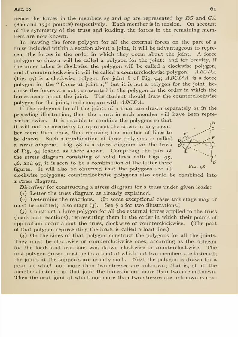
8/13/2019 Maurer Mechanics
http://slidepdf.com/reader/full/maurer-mechanics 73/407
AsT. id 6l
hence the forces in the members eg and ag are represented by EG and GA(866 and 1732 pounds) respectively. Each member is in tension. On account
of the symmetry of the truss and loading, the forces in the remaining mem-bers are now known.
In drawing the force polygon for all the external forces on the part of a
truss included within a section about a joint, it will be advantageous to repre-
sent the forces in the order in which they occur about the joint. A force
polygon so drawn will be called a polygon for the joint; and for brevity, if
the order taken is clockwise the polygon will be called a clockwise polygon,
and if counterclockwise it will be called a counterclockwise polygon. ABCDA(Fig. 95) is a clockwise polygon for joint b of Fig. 94; ABCD' A is a force
polygon for the forces at joint i, but it is not a polygon for the joint, be-
cause the forces are not represented in the polygon in the order in which the
forces occur about the joint. The student should draw the counterclockwise
polygon for the joint, and compare with ABCDA.If the polygons for all the joints of a truss are drawn separately as in the
preceding illustration, then the stress in each member will have been repre-
sented twice. It is possible to combine the polygons so that
it will not be necessary to represent the stress in any mem-ber more than once, thus reducing the number of lines to
be drawn. Such a combination of force polygons is called
a stress diagram. Fig. 98 is a stress diagram for the truss
of Fig. 94 loaded as there shown. Comparing the part of
the stress diagram consisting of solid lines with Figs. 95,
96, and 97, it is seen to be a combination of the latter three
figures. It will also be observed that the polygons are all
clockwise polygons; counterclockwise polygons also could be combined into
a stress diagram.
Directions for constructing a stress diagram for a truss under given loads:
(i) Letter the truss diagram as already explained.
(2) Determine the reactions. (In some exceptional cases this stage may or
must be omitted; also stage (3). See § 2 for two illustrations.)
(3) Construct a force polygon for all the external forces applied to the truss
(loads and reactions), representing them in the order in which their points of
application occur about the truss, clockwise or counterclockwise. (The part
of that polygon representing the loads is called a load line.)
(4)On the sides of that polygon construct the polygons for all the joints.
They must be clockwise or counterclockwise ones, according as the polygon
for the loads and reactions was drawn clockwise or counterclockwise. Thefirst polygon drawn must be for a joint at which but two members are fastened;
the joints at the supports are usually such. Next the polygon is drawn for a
point at which not more than two stresses are unknown; that is, of all the
members fastened at that joint the forces in not more than two are unknown.
Then the next joint at which not more than two stresses are unknown is con-
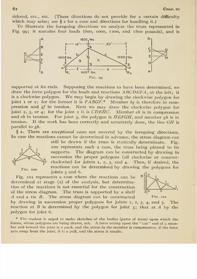
8/13/2019 Maurer Mechanics
http://slidepdf.com/reader/full/maurer-mechanics 74/407
62 Chap, iii
sidered, etc., etc. (These directions do not provide for a certain diflSculty
which may arise; see § 2 for a case and directions for handling it.)
To illustrate the foregoing directions we analyze the truss represented in
Fig. 99; it sustains four loads (600, 1000, 1200, and 1800 pounds), and is
(000
1800
:sH
supported at its ends. Supposing the reactions to have been determined, wedraw the force polygon for the loads and reactions ABCDBF A, at the left; it
is a clockwise polygon. We may begin by drawing the clockwise polygon for
joint I or 2; for the former it is FABGF* Member hg is therefore in com-pression and gf in tension. Next we may draw the clockwise polygon for
joint 2, 3, or 4; for the joint 2 it is CDEHC. Member ch is in compression
and eh in tension. For joint 3, the polygon is HEFGH, and member gh is intension. If the work has been correctly and accurately done, the line GH is
parallel to gh.
§ 2. There are exceptional cases not covered by the foregoing directions.
In case the reactions cannot be determined in advance, the stress diagram can
still be drawn if the truss is statically determinate. Fig.
ii 100 represents such a case, the truss being pinned to its
supports. The diagram can be constructed by drawing in
succession the proper polygons (all clockwise or counter-|r clockwise) for joints i, 2, 3, and 4. Then, if desired, the
reactions can be determined by drawing the polygons for
joints 5 and 6.
Fig. loi represents a case where the reactions can be
determined at stage (2) of the analysis, but determina-
tion of the reactions is not essential for the construction
of the stress diagram. The truss is supported by a shelf
A and a tie B. The stress diagram can be constructed Fig. ioi
by drawing in succession proper polygons for joints i, 2, 3, 4, and 5. Thereaction at B is determined by the polygon for joint 5; that at A by the
polygon for joint 6.
* The student is urged to make sketches of the bodies (parts of truss) upon which the
forces, whose polygons are being drawn, act. A force acting upon the cut end of a mem-ber and toward the joint is a pu'ih, and the stress in the member is compressive; if the force
acts away from the joint, it is a pull, and the stress is tensile.
Fig. 100
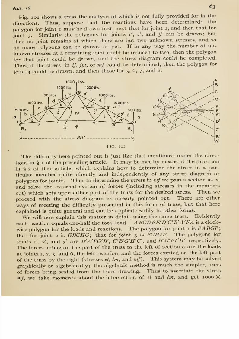
8/13/2019 Maurer Mechanics
http://slidepdf.com/reader/full/maurer-mechanics 75/407
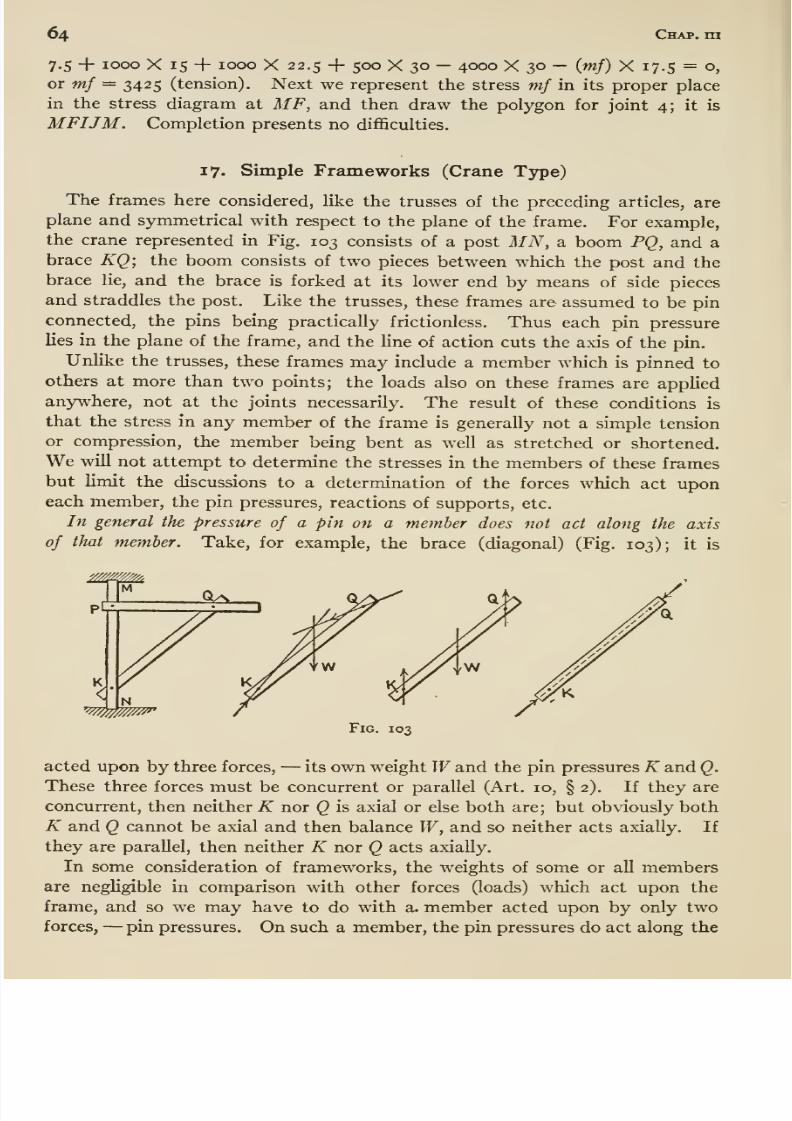
8/13/2019 Maurer Mechanics
http://slidepdf.com/reader/full/maurer-mechanics 76/407
64 Chap, rn
7.5 + 1000 X 15 + 1000 X 22.5 + 500 X 30 —4000 X 30 — {mf) X 17.5 = o,
or mf = 3425 (tension). Next we represent the stress mf in its proper place
in the stress diagram at MF, and then draw the polygon for joint 4; it is
MFIJM. Completion presents no difl&culties.
17. Simple Frameworks (Crane Type)
The frames here considered, like the trusses of the preceding articles, are
plane and symmetrical with respect to the plane of the frame. For example,
the crane represented in Fig. 103 consists of a post MN, a boom PQ, and a
brace KQ; the boom consists of two pieces between which the post and the
brace lie, and the brace is forked at its lower end by means of side pieces
and straddles the post. Like the trusses, these frames are assumed to be pin
connected, the pins being practically frictionless. Thus each pin pressure
lies in the plane of the frame, and the line of action cuts the axis of the pin.
Unlike the trusses, these frames may include a member which is pinned to
others at more than two points; the loads also on these frames are applied
anywhere, not at the joints necessarily. The result of these conditions is
that the stress in any member of the frame is generally not a simple tension
or compression, the member being bent as well as stretched or shortened.
We will not attempt to determine the stresses in the members of these frames
but limit the discussions to a determination of the forces which act uponeach member, the pin pressures, reactions of supports, etc.
In general the pressure of a pin on a member does not act along the axis
of that member. Take, for example, the brace (diagonal) (Fig, 103); it is
, N
Fig. 103
acted upon by three forces, —its own weight Wand the pin pressures K and Q.
These three forces must be concurrent or parallel (Art. 10, § 2). If they areconcurrent, then neither K nor Q is axial or else both are; but obviously both
K and Q cannot be axial and then balance W, and so neither acts axiaUy. If
they are parallel, then neither K nor Q acts axially.
In some consideration of frameworks, the weights of some or all membersare negligible in comparison with other forces (loads) which act upon the
frame, and so we may have to do with a. member acted upon by only two
forces, —pin pressures. On such a member, the pin pressures do act along the
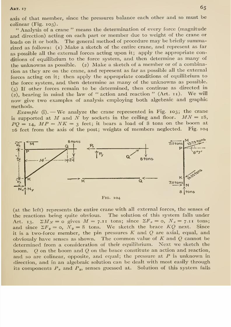
8/13/2019 Maurer Mechanics
http://slidepdf.com/reader/full/maurer-mechanics 77/407
Art. 17 65
axis of that member, since the pressures balance each other and so must be
colinear (Fig. 103).
Analysis of a crane means the determination of every force (magnitude
and direction) acting on each part or member due to weight of the crane or
loads on it or both. The general method of procedure may be briefly summa-
rized as follows: (i) Make a sketch of the entire crane, and represent as far
as possible all the external forces acting upon it; apply the appropriate con-
ditions of equilibrium to the force system, and then determine as many of
the unknowns as possible. (2) Make a sketch of a member or of a combina-
tion as they are on the crane, and represent as far as possible all the external
forces acting on it; then apply the appropriate conditions of eqmUbrium to
the force system, and then determine as many of the unknowns as possible.
(3) If other forces remain to be determined, then continue as directed in
(2), bearing in mind the law of action and reaction (Art. 11). We will
now give two examples of analysis employing both algebraic and graphic
methods.
Example (i).— We analyze the crane represented in Fig. 103; the crane
is supported at M and N by sockets in the ceihng and floor. MN=18,
PQ = 14, MP = NK = 3 feet; it bears a load of 8 tons on the boom at
16 feet from the axis of the post; weights of members neglected. Fig. 104
rA—to
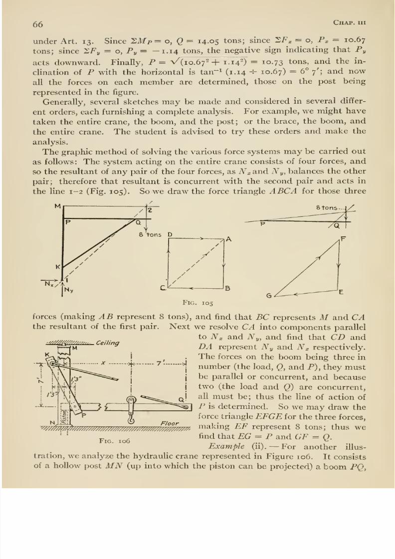
8/13/2019 Maurer Mechanics
http://slidepdf.com/reader/full/maurer-mechanics 78/407
66 Chap, hi
under Art. 13. Since 'LMp= o, Q = 14.05 tons; since 2F;, = o, P^ = 10.67
tons; since XFy = o, Py= -1.14 tons, the negative sign indicating that Py
acts downward. Finally, P = V{io.6f+ 1.14^) = 10.73 tons, and the in-
clination of P with the horizontal is tan^^ (i-i4 ^ 10.67) = 6° 7'; and now
all the forces on each member are determined, those on the post being
represented in the figure.
Generally, several sketches may be made and considered in several differ-
ent orders, each furnishing a complete analysis. For example, we might have
taken the entire crane, the boom, and the post; or the brace, the boom, and
the entire crane. The student is advised to try these orders and make the
analysis.
The graphic method of solving the various force systems may be carried out
as follows: The system acting on the entire crane consists of four forces, and
so the resultant of any pair of the four forces, as Nx and Ny, balances the other
pair; therefore that resultant is concurrent with the second pair and acts in
the line 1-2 (Fig. 105). So we draw the force triangle ABCA for those three
forces (making AB represent 8 tons), and find that BC represents M and CAthe resultant of the first pair. Next we resolve CA into components parallel
to Nx and Ny, and find that CD and. Ceiling DA represent Ny and Nx respectively.
The forces on the boom being three in
number (the load, Q, and P), they mustbe parallel or concurrent, and because
two (the load and Q) are concurrent,
all must be; thus the line of action of
P is determined. So we may draw the
force triangle EFGE for the three forces,
W^^p^///////yy////////^^^^^ making EF represent 8 tons; thus wefind that EG = P and GF = Q.
Example (ii). —For another illus-
tration, we analyze the hydraulic crane represented in Figure 106. It consists
of a hollow post MN (up into which the piston can be projected) a boom PQ,
Floor
Fig. 106
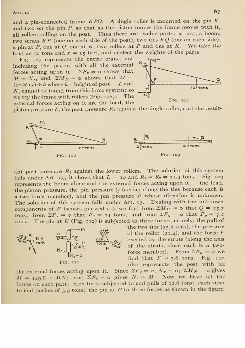
8/13/2019 Maurer Mechanics
http://slidepdf.com/reader/full/maurer-mechanics 79/407
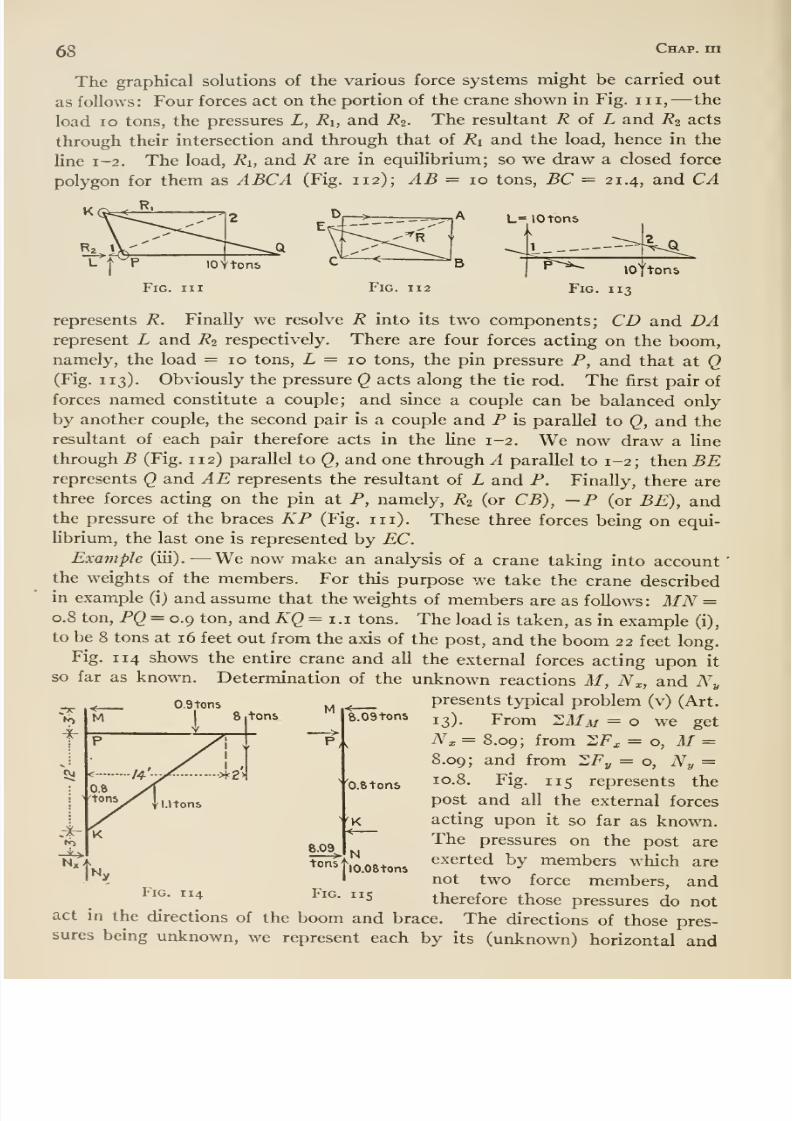
8/13/2019 Maurer Mechanics
http://slidepdf.com/reader/full/maurer-mechanics 80/407
68 Chap, hi
The graphical solutions of the various force systems might be carried out
as follows: Four forces act on the portion of the crane shown in Fig. in, —the
load lo tons, the pressures L, Ri, and R^. The resultant R oi L and R2 acts
through their intersection and through that of Ri and the load, hence in the
line 1-2. The load, Ri, and R are in equilibrium; so we draw a closed force
polygon for them as ABCA (Fig. 112); AB = 10 tons, BC = 21.4, and CA
lOYtons
Fig. Ill Fig. 112
represents R. Finally we resolve R into its two components; CD and DArepresent L and R2 respectively. There are four forces acting on the boom,namely, the load = 10 tons, L = 10 tons, the pin pressure P, and that at Q(Fig. 113). Obviously the pressure Q acts along the tie rod. The first pair of
forces named constitute a couple; and since a couple can be balanced only
by another couple, the second pair is a couple and P is parallel to Q, and the
resultant of each pair therefore acts in the line 1-2. We now draw a line
through B (Fig. 112) parallel to Q, and one through A parallel to 1-2; then BErepresents Q and AE represents the resultant of L and P. Finally, there are
three forces acting on the pin at P, namely, R2 (or CB), —P (or BE), andthe pressure of the braces KP (Fig. in). These three forces being on equi-
librium, the last one is represented by EC.Example (iii). —We now make an analysis of a crane taking into account
the weights of the members. For this purpose we take the crane describedin example (i) and assume that the weights of members are as follows: MN=0.8 ton, PQ = 0.9 ton, and KQ =1.1 tons. The load is taken, as in example (i),
to be 8 tons at 16 feet out from the axis of the post, and the boom 22 feet long.
Fig. 114 shows the entire crane and all the external forces acting upon it
so far as known. Determination of the unknown reactions M, N^, and Nypresents typical problem (v) (Art.
8.09ton5 J3)_ YTom ^AIm = o we get
iVx = 8.09; from 2F^ = 0, M=8.09; and from 2Fy = 0, Ny =10.8. Fig. 115 represents the
post and all the external forces
acting upon it so far as known.The pressures on the post are
exerted by members which are
not two force members, andtherefore those pressures do not
0.9 tonstons
M
8.09^
tons
'0.8 tons
K
NlO.O&tons
Fig. 114 Fig. 115
act in the directions of the boom and brace. The directions of those pres-sures being unknown, we represent each by its (unknown) horizontal and

8/13/2019 Maurer Mechanics
http://slidepdf.com/reader/full/maurer-mechanics 81/407
Art. 1 69
vertical component. The force system acting on the post contains four
unknowns, namely, Px, Py, K^, and Ky. Not all of these unknowns can be
determined from a study of this system alone; but two of them, Px and Kx,
can be so determined. 'LMk = o gives Px = 12.13, ^^^ ^^x — o gives Kx =12.13 tons.
Fig. 116 shows the boom and the forces acting upon it so far as known.
The direction of the pressure at Q is unknown as yet; therefore that pressure
is represented by means of its (unknown) components. Determination of the
pi12.13tons
0.9 tons
Gl6 1 tons
10.95tons
Fig. 116
l2.l3ton5<
->l2.13ton&
Fig. 117
unknowns in the force system presents typical problem (v). 2Fx = o gives
Qx = 12.13 tons; SA/q = o gives Py = 0.95; and 2F„ = o gives Qy = 9.85.
Ha\ing found the value of Py, we find from ZFy = o for Fig. 115 that Ky =
10.95tons.
Tocheck the analysis,
we mightsupply values of the
forcesacting on the brace (Fig. 117), and then test whether the force system is
balanced, that is, whether S/^i = o, XFy = o, and 2M = o.
18. Cranes. —Continued
In this article we show how to analyze three cranes, paying some attention
to the forces due to the hoisting rig. Generally, a pulley is an important part
of such rig. We assume here that the tensions Ti and T2 (Fig. 118) in the ropeor chain on opposite sides of the pulley on which it bears
are equal. This assumption impHes perfect flexibility of
rope or chain and a frictionless pin supporting the pulley.
The pressure P against the pin equals the resultant of
those tensions, or 2 T cos ^ a, and it bisects the angle
between their lines of action. If the Hnes of action are
parallel (a = o), P = 2 T; if they are at right angles
{a = 90°), P = 1.414 T,
Example (i). —Fig. 119 represents a crane supported in a footstep bearing
at the floor and a collar bearing on the wall bracket H. The hoisting rig con-
sists of a simple hand winch mounted on the wall at W, a chain, and pulleys
as shown. Pulley at G is 12 inches in diameter; the load is one-half ton.
The reactions at the supports depend on the hoisting rig, as will be seen fromthe following: On the entire crane, including the top pulley (Fig. 120), there
are acting four forces, namely, the upper reaction U, the lower reactions P,
Fig
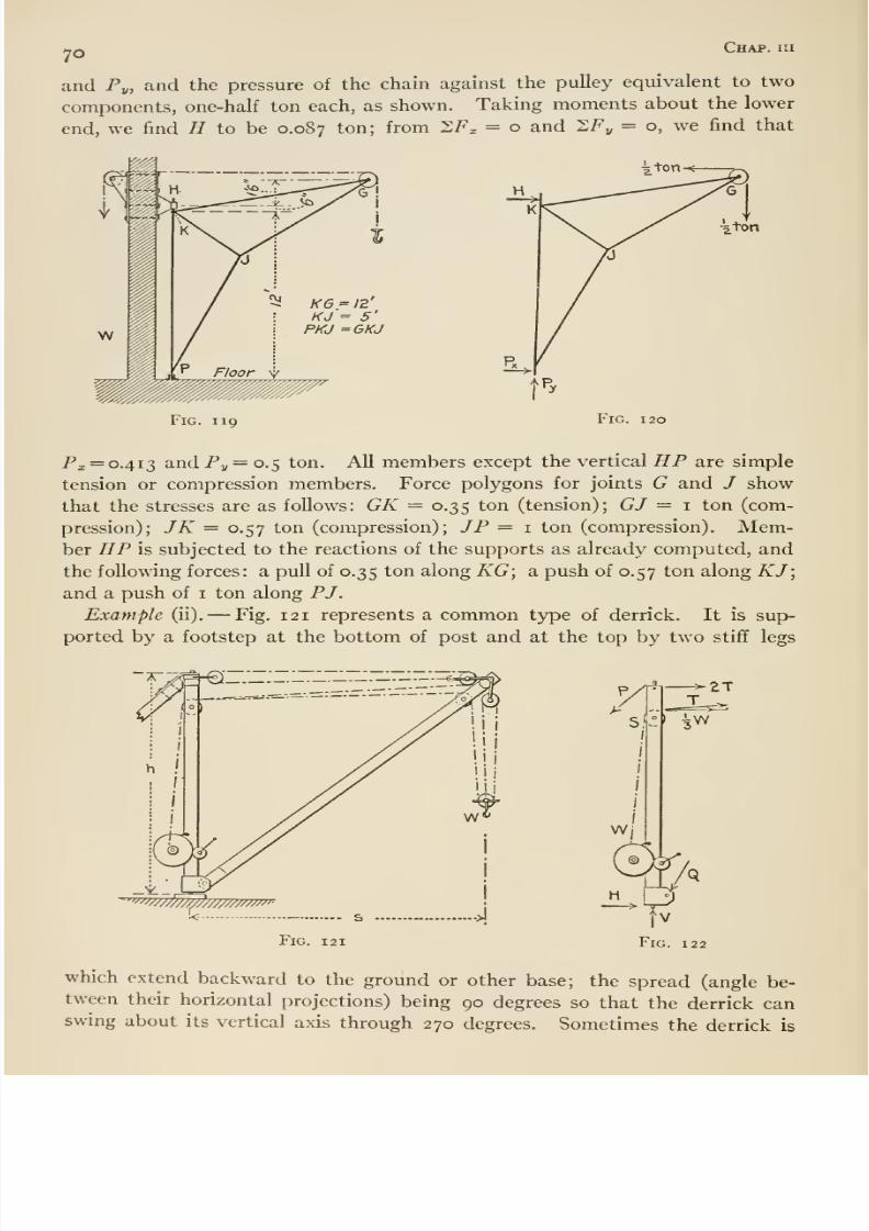
8/13/2019 Maurer Mechanics
http://slidepdf.com/reader/full/maurer-mechanics 82/407
70Chap, iir
and Py, and the pressure of the chain against the pulley equivalent to two
components, one-half ton each, as shown. Taking moments about the lower
end, we find H to be 0.0S7 ton; from SF^ = o and SFj, = o, we find that
5i K6=I2'KJ = 5'
PKJ =6KJ
Fig. 119 Fig. 120
Px = 0.413 and Py = 0.5 ton. All members except the vertical HP are simple
tension or compression members. Force polygons for joints G and / show
that the stresses are as follows: GK = 0.35 ton (tension); GJ = 1 ton (com-
pression); JK = 0.57 ton (compression); JP = i ton (compression). Mem-ber HP is subjected to the reactions of the supports as already computed, and
the following forces: a pull of 0.35 ton along KG; a push of 0.57 ton along KJ;and a push of i ton along PJ.
Example (ii). —Fig. 121 represents a common type of derrick. It is sup-
ported by a footstep at the bottom of post and at the top by two stiff legs
'^W////////////////////'-
Fig. 121
A
>-
^2T
which extend backward to the ground or other base; the spread (angle be-tween their horizontal projections) being 90 degrees so that the derrick canswing about its vertical axis through 270 degrees. Sometimes the derrick is
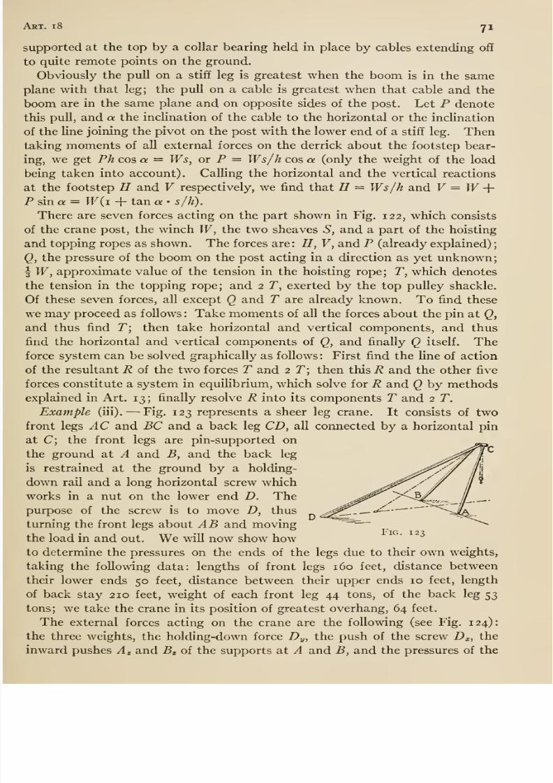
8/13/2019 Maurer Mechanics
http://slidepdf.com/reader/full/maurer-mechanics 83/407
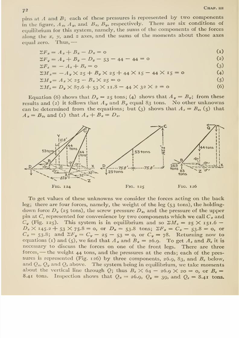
8/13/2019 Maurer Mechanics
http://slidepdf.com/reader/full/maurer-mechanics 84/407
_. Chap, ui72
pins at A and B; each of these pressures is represented by two components
in the figure, A^, Ay, and B^, By, respectively. There are six conditions of
equilibrium for this system, namely, the sums of the components of the forces
along the x, y, and z axes, and the sums of the moments about those axes
equal zero. Thus, —
ZFy= Ay+By- Dy- SS-44- 44=0XF, = - A,-\-B^ = o
•ZM^= -Ay X 25 + J5^ X 25 + 44 X 15 - 44 X 15 = o
2M„=^xX 25-5xX 25 =
S7lf.= I>„X87.6 + 53X 11.8-44X32X 2 =
(i)
(2)
(3)
(4)
(5)
(6)
Equation (6) shows that Dj, = 25 tons; (4) shows that Ay = By-, from these
results and (2) it follows that Ay and By equal 83 tons. No other unknowns
can be determined from the equations; but (3) shows that Az = B^, (5) that
A, = Bx, and (i) that A^-\-B^^D^.
V^
44- tons
ze^-^^l-1
75.8:.^ 75.8'--^ ^^, l>^r;%7 ^'tons
Fig. 125 Fig. 126
To get values of these unknowns we consider the forces acting on the back
leg; there are four forces, namely, the weight of the leg (53 tons), the holding-
down force Dy (25 tons), the screw pressure Dz, and the pressure of the upper
pin at C, represented for convenience by two components which we call Cx andCy (Fig. 125). This system is in equilibrium and so Slfc = 25 X 151. 6 —D^ X 145-2 + 53 X 75-8 = o, or D^ = 53.8 tons; SF^ = C^ - 53.8 = o, or
^' — 53-8; and I^Fy = Cj, — 25 — 53 = o, or Cy = 78. Returning now to
equations (i) and (5), we find that Ax and Bx = 26.9. To get Az and B^ it is
necessary to discuss the forces on one of the front legs. There are three
forces, —the weight 44 tons, and the pressures at the ends; each of the pres-
sures is represented (Fig. 126) by three components, 26.9, 83, and B^ below,
and Qx, Qy and Qz above. The system being in equilibrium, we take momentsabout the vertical line through Q; thus 5^ X 64 — 26.9 X 20 = o, or B^ =8.41 tons. Inspection shows that Qx = 26.9, Qy = 39, and Qz = 8.41 tons.
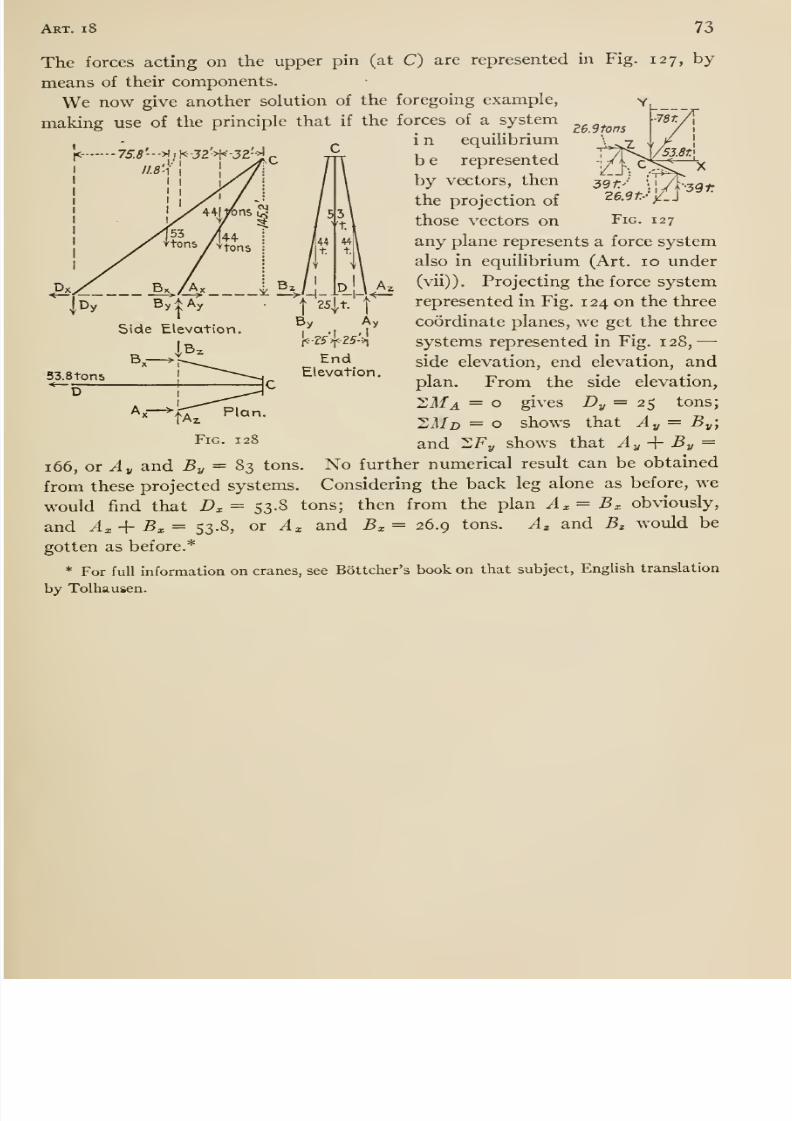
8/13/2019 Maurer Mechanics
http://slidepdf.com/reader/full/maurer-mechanics 85/407
Art. 1 73
lb. 2 tons
|<-75.8'-
->) ; K-J2'>H-32'-i
The forces acting on the upper pin (at C) are represented in Fig. 127, by
means of their components.
We now give another solution of the foregoing example,
making use of the principle that if the forces of a system
i n equilibrium
b e represented
by vectors, then
the projection of
those vectors on Fig. 127
any plane represents a force system
also in equilibrium (Art. 10 under
(vii)). Projecting the force system
represented in Fig. 124 on the three
coordinate planes, we get the three
systems represented in Fig. 128,
side elevation, end elevation, and
plan. From the side elevation,
^Ma = o gives Dy= 2% tons;
2i//> = o shows that Ay = By]
and ^Fy shows that Ay-\- By =
166, or ^1, and By = 83 tons. No further numerical result can be obtained
from these projected systems. Considering the back leg alone as before, we
would find that Z)^ = 53-8 tons; then from the plan A^= Bx obviously,
and Ax+Bx= 53.8, or A^ and -Sx = 26.9 tons. Az and Bz would be
gotten as before.*
* For full information on cranes, see Bottcher's book on that subject, English translation
by Tolhausen.
Side Elevation
53.8ton5* —_
[<-?5''>{<25'>l
EndElevation
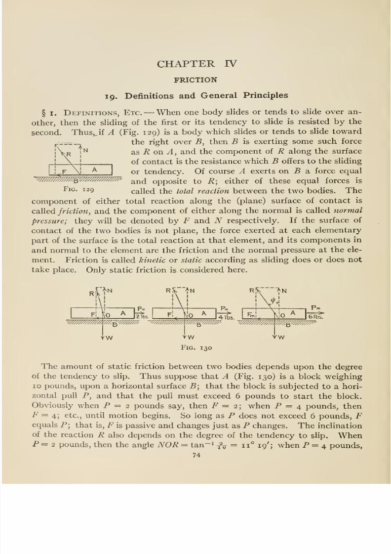
8/13/2019 Maurer Mechanics
http://slidepdf.com/reader/full/maurer-mechanics 86/407
CHAPTER IV
FRICTION
19. Definitions and General Principles
§ I. Definitions, Etc. —When one body slides or tends to slide over an-
other, then the sliding of the first or its tendency to slide is resisted by the
second. Thus,, if A (Fig. 129) is a body which slides or tends to slide toward
the right over B, then B is exerting some such force
as i? on ^, and the component of R along the surface
of contact is the resistance which B offers to the sliding
or tendency. Of course A exerts on 5 a force equal
and opposite to R; either of these equal forces is
called the total reaction between the two bodies. The
component of either total reaction along the (plane) surface of contact is
called friction, and the component of either along the normal is called normal
pressure; they will be denoted by F and N respectively. If the surface of
contact of the two bodies is not plane, the force exerted at each elementary
part of the surface is the total reaction at that element, and its components in
and normal to the element are the friction and the normal pressure at the ele-
ment. Friction is called kinetic or static according as sliding does or does not
take place. Only static friction is considered here.
'W/////^//M^///M/////'//////'
Fig. 129
W////////////. '///.^////////A •'''//////////////y, V///.ii'///////A'5
YW
4 lbs.
'^6'
YWFig. 130
YW
The amount of static friction between two bodies depends upon the degree
of the tendency to slip. Thus suppose that A (Fig. 130) is a block weighing
10 pounds, upon a horizontal surface B\ that the block is subjected to a hori-
zontal pull P, and that the pull must exceed 6 pounds to start the block.
Obviously when P = 2 pounds say, then F = 2; when P = 4 pounds, then
F = 4; etc., until motion begins. So long as P does not exceed 6 pounds, Fequals P; that is, F is passive and changes just as P changes. The inclination
of the reaction R also depends on the degree of the tendency to slip. WhenP = 2 pounds, then the angle NOR = tan-^ f^ = 11° 19'; when P = 4 pounds,
74
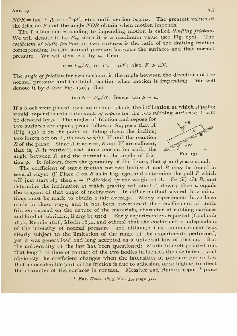
8/13/2019 Maurer Mechanics
http://slidepdf.com/reader/full/maurer-mechanics 87/407
Art. 19 75
NOR = tan-' t% =21° 48'; etc., until motion begins. The greatest values of
the friction F and the angle NOR obtain when motion impends.
The friction corresponding to impending motion is called limiting friction.
We wnll denote it by Fm, since it is a maximum value (see Fig. 130). The
coefficient of static friction for two surfaces is the ratio of the limiting friction
corresponding to any normal pressure between the surfaces and that normal
pressure. We will denote it by /i; then
M = FJN, or F„, = ixN; also, F > nN.
The angle of friction for two surfaces is the angle between the directions of the
normal pressure and the total reaction when motion is impending. We will
denote it by (see Fig. 130); then
tan<^ = Fm/N; hence tan</> = n.
If a block were placed upon an inclined plane, the inclination at which slipping
would impend is called the angle of repose for the two rubbing surfaces; it will
be denoted by p. The angles of friction and repose for
two surfaces are equal; proof follows: Suppose that A \^
(Fig. 131) is on the point of sliding down the incline;
two forces act on A , its own weight Wand the reaction ^^R of the plane. Since A is at rest, R and Ware colinear,
\ffff^
that is, R is vertical; and since motion impends, the <0--^
angle between R and the normal is the angle of fric- ^^^- ^^^
tion (/). It follows, from the geometry of the figure, that and p are equal.
The coefficient of static friction for two bodies A and B may be found in
several ways: (i) Place ^ on 5 as in Fig. 130, and determine the pull P which
will just start A; then fx = P divided by the weight of ^. Or (ii) tilt B, and
determine the inclination at which gravity will start A down; then ju equals
the tangent of that angle of inclination. In either method several determina-
tions must be made to obtain a fair average. Many experiments have been
made in these ways, and it has been ascertained that coefficients of static
friction depend on the nature of the materials, character of rubbing surfaces
and kind of lubricant, if any be used. Early experimenters reported (Coulomb
1871, Rennie 1828, Morin 1834, and others) that the coefficient is independent
of the intensity of normal pressure; and although this announcement was
clearly subject to the limitation of the range of the experiments performed,
yet it was generalized and long accepted as a universal law of friction. But
the universality of the law has been questioned; Morin himself pointed out
that length of time of contact of the two bodies influences the coefficient; and
obviously the coefficient changes when the intensities of pressure get so low
that a considerable part of the friction is due to adhesion, or so high as to affect
the character of the surfaces in contact. Messiter and Hanson report* prac-
* Eng. News, 1895, Vol. 33, page 322.
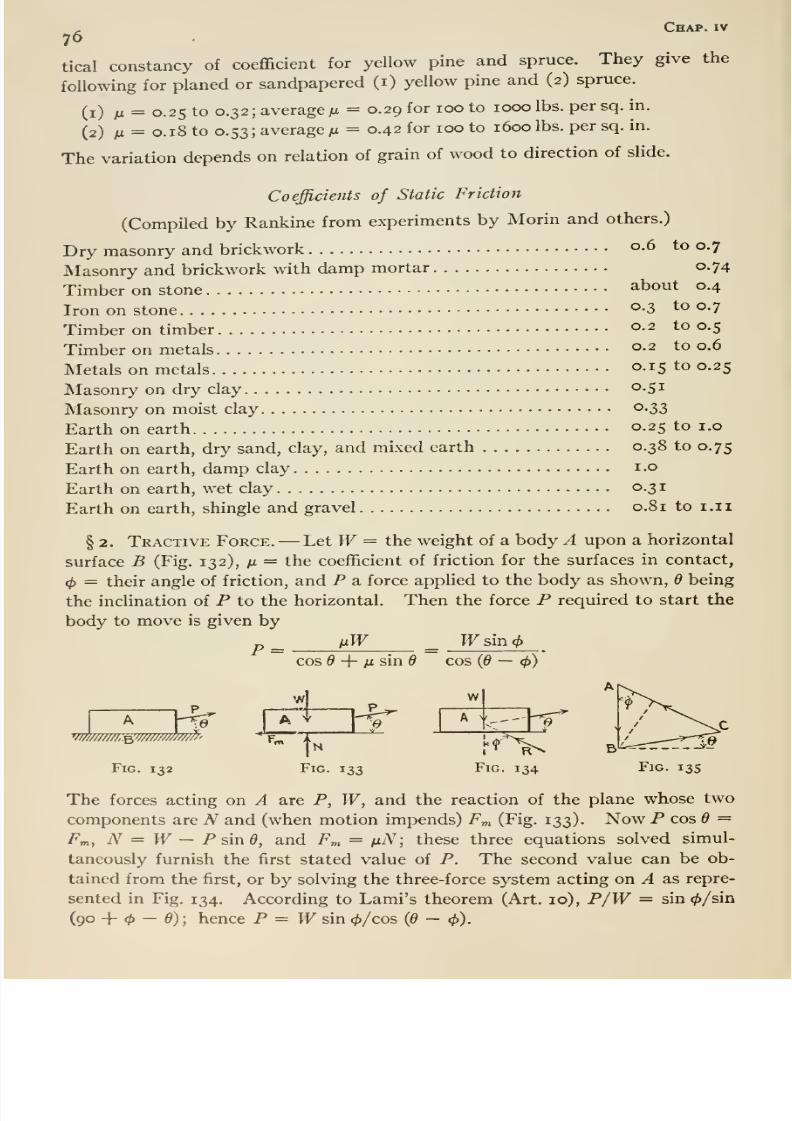
8/13/2019 Maurer Mechanics
http://slidepdf.com/reader/full/maurer-mechanics 88/407
^ Chap, iv
76
tical constancy of coefficient for yellow pine and spruce. They give the
following for planed or sandpapered (i) yellow pine and (2) spruce.
(i) n = 0.25 to 0.32; average M = 0.29 for 100 to 1000 lbs. per sq. in.
(2) M = 0.18 to 0.53; average M = 0.42 for 100 to i6oolbs.per sq. in.
The variation depends on relation of grain of wood to direction of slide.
Coefficients of Static Friction
(Compiled by Rankine from experiments by Morin and others.)
Dry masonry and brickwork o-6 to 0.7
Masonry and brickwork with damp mortar 0.74
Timber on stone about 0.4
Iron on stone^-3 to 0.7
Timber on timber o-2 to 0.5
Timber on metals o-2 to 0.6
Metals on metals o-i5 to 0.25
Masonry on dry clay o-S^
Masonry on moist clay ^-33
Earth on earth 0-25 to i.o
Earth on earth, dry sand, clay, and mixed earth 0.38 to 0.75
Earth on earth, damp clayi-o
Earth on earth, wet clay 0.31
Earth on earth, shingle and gravel 0.81 to i.ii
§ 2. Tractive Force. —Let W= the weight of a body A upon a horizontal
surface B (Fig. 132), m = the coefficient of friction for the surfaces in contact,
<f)= their angle of friction, and P a force applied to the body as shown, 6 being
the inclination of P to the horizontal. Then the force P required to start the
body to move is given by
fxW Wsm(f>P =cos d -\- lisind cos {d —
<f>)
-.6
Fig. 132
4V e
w
Fig. 133 Fig. 134 Fig. 13s
The forces acting on A are P, W, and the reaction of the plane whose two
components are A'' and (when motion impends) Fm (Fig. 133). Now P cos Q =F„, iV = PF — Psin0, and Fm = m^V; these three equations solved simul-
taneously furnish the first stated value of P. The second value can be ob-
tained from the first, or by solving the three-force system acting on A as repre-
sented in Fig. 134. According to Lami's theorem (Art. 10), P/PF = sin 0/sin
(90 -f - 0); hence P = M^ sin 0/cos (6 - (p).
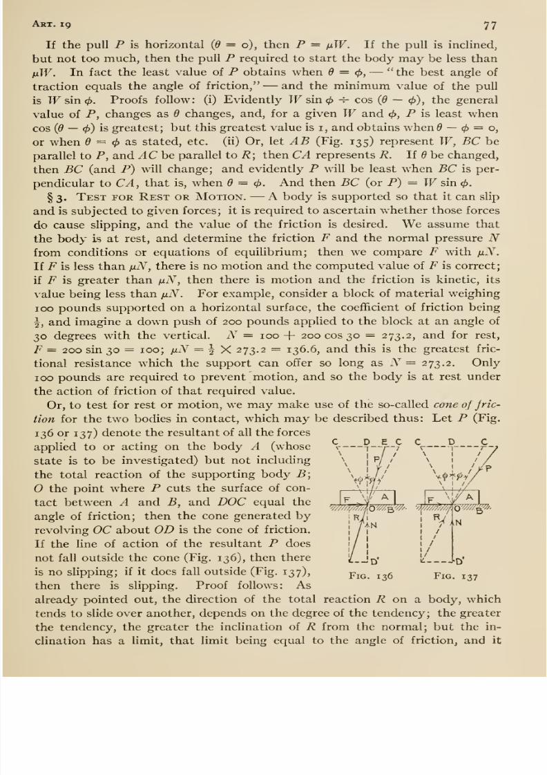
8/13/2019 Maurer Mechanics
http://slidepdf.com/reader/full/maurer-mechanics 89/407
Art. 19 77
If the pull P is horizontal (d = o), then P = /iW. If the pull is inclined,
but not too much, then the pull P required to start the body may be less than
nW. In fact the least value of P obtains when 6 =(f),
— the best angle of
traction equals the angle of friction, —and the minimum value of the pull
is Wsincj). Proofs follow: (i) Evidently Wsincf) -r- cos (0 — 0), the general
value of P, changes as 9 changes, and, for a given Wand <f), P is least when
cos (6 — (j)) is greatest; but this greatest value is i, and obtains when 5 — = o,
or when = </> as stated, etc. (ii) Or, let AB (Fig. 135) represent W, BC be
parallel to P, and AC he parallel to R; then CA represents R. If be changed,
then BC (and P) will change; and evidently P will be least when BC is per-
pendicular to CA, that is, when d = (j). And then BC (or P) = Wsin 0.
§ 3. Test for Rest or Motion. —A body is supported so that it can slip
and is subjected to given forces; it is required to ascertain whether those forces
do cause slipping, and the value of the friction is desired. We assume that
the body is at rest, and determine the friction F and the normal pressure Nfrom conditions or equations of equilibrium; then we compare F with fxN.
If F is less than /jlN, there is no motion and the computed value of F is correct;
if F is greater than fiN, then there is motion and the friction is kinetic, its
value being less than jjlN. For example, consider a block of material weighing
100 pounds supported on a horizontal surface, the coeflEicient of friction being
^, and imagine a down push of 200 pounds applied to the block at an angle of
30 degrees with the vertical. N = 100 + 200 cos 30 = 273.2, and for rest,
F = 200 sin 30 = 100; ijlN = I X 273.2 = 136.6, and this is the greatest fric-
tional resistance which the support can offer so long as N = 273.2. Only
100 pounds are required to prevent motion, and so the body is at rest under
the action of friction of that required value.
Or, to test for rest or motion, we may make use of the so-called cone of jric-
tion for the two bodies in contact, which may be described thus: Let P (Fig.
136or
137)denote the resultant of all the forces
applied to or acting on the body A (whose
state is to be investigated) but not including
the total reaction of the supporting body B;
the point where P cuts the surface of con-
tact between A and B, and DOC equal the
angle of friction; then the cone generated by
revolving OC about OD is the cone of friction.
If the line of action of the resultant P doesnot fall outside the cone (Fig. 136), then there
is no slipping; if it does fall outside (Fig. 137),
then there is slipping. Proof follows: As
already pointed out, the direction of the total reaction i? on a body, which
tends to slide over another, depends on the degree of the tendency; the greater
the tendency, the greater the inclination of R from the normal; but the in-
clination has a limit, that limit being equal to the angle of friction, and it
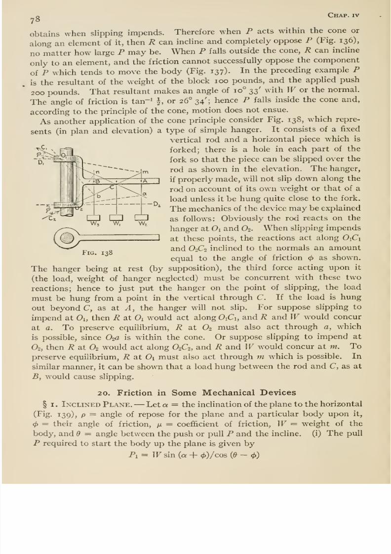
8/13/2019 Maurer Mechanics
http://slidepdf.com/reader/full/maurer-mechanics 90/407
^o Chap, iv
obtains when slipping impends. Therefore when P acts within the cone or
along an element of it, then R can incline and completely oppose P (Fig. 136),
no matter how large P may be. When P falls outside the cone, R can incline
only to an element, and the friction cannot successfully oppose the component
of P which tends to move the body (Fig. 137). In the preceding example P
is the resultant of the weight of the block 100 pounds, and the applied push
200 pounds. That resultant makes an angle of 10° t,2>' '^^'ith Wor the normal.
The angle of friction is tan ^ i or 26° 34'; hence P falls inside the cone and,
according to the principle of the cone, motion does not ensue.
As another application of the cone principle consider Fig. 138, which repre-
sents (in plan and elevation) a type of simple hanger. It consists of a fixed
vertical rod and a horizontal piece which is
forked; there is a hole in each part of the
fork so that the piece can be slipped over the
rod as shown in the elevation. The hanger,
if properly made, will not slip down along the
rod on account of its own weight or that of a
load unless it be hung quite close to the fork.
The mechanics of the device may be explained
as follows: Obviously the rod reacts on the
hanger at Oi and O2. When slipping impends
at these points, the reactions act along OiCi
and O2C2 inclined to the normals an amount
equal to the angle of friction as shown.
The hanger being at rest (by supposition), the third force acting upon it
(the load, weight of hanger neglected) must be concurrent with these two
reactions; hence to just put the hanger on the point of slipping, the load
must be hung from a point in the vertical through C. If the load is hung
out beyond C, as at A, the hanger will not slip. For suppose slipping to
impend at Oi, then R at Ox would act along OiCi, and R and Wwould concur
at a. To preserve equilibrium, R at O2 must also act through a, which
is possible, since O^a is within the cone. Or suppose slipping to impend at
O2, then R at O2 would act along O2C2, and R and Wwould concur at m. To
preserve equilibrium, R at Oi must also act through m which is possible. In
similar manner, it can be shown that a load hung between the rod and C, as at
B, would cause slipping.
SP
Fig. 138
20. Friction in Some Mechanical Devices
§ I. Inclined Plane. —Let a = the inclination of the plane to the horizontal
(Fig. 139), p = angle of repose for the plane and a particular body upon it,
</) = their angle of friction, ^ = coefficient of friction, W= weight of the
body, and 6 = angle between the push or pull P and the incline, (i) The pull
P required to start the body up the plane is given by
Pi = Wsin (a + 0)/cos {6- - 4>)
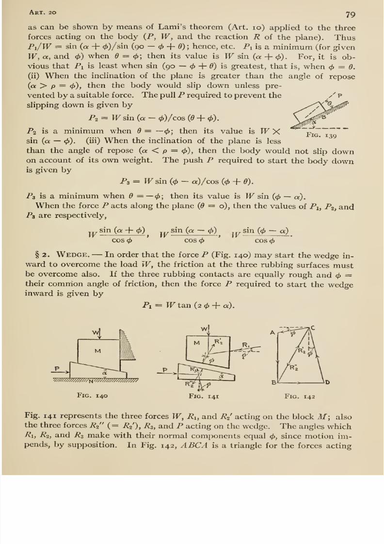
8/13/2019 Maurer Mechanics
http://slidepdf.com/reader/full/maurer-mechanics 91/407
Art. 20 79
as can be shown by means of Lami's theorem (Art. 10) applied to the three
forces acting on the body {P, W, and the reaction R of the plane). ThusPi/W = sin (a + 0)/sin (90 — </> + 0) ; hence, etc. Pi is a minimum (for given
W, a, and </>) when 6 = <f>; then its value is Wsin (a + </>). For, it is ob-
vious that Pi is least when sin (90 —^ + 6) is greatest, that is, when 4> = d.
(ii) When the inclination of the plane is greater than the angle of repose(a > p = </)), then the body would slip down unless pre-
vented by a suitable force. The pull P required to prevent the
slipping down is given by
P2 = Wsin {a - </))/cos (0 + <^).
P2 is a minimum when 6 = —cf); then its value is WXsin (a —4>). (iii) When the inclination of the plane is less
than the angle of repose(a
< p = <^), then the body would not slip downon account of its own weight. The push P required to start the body downis given by
P3 = Wsin (0 - a)/cos {(j> + d).
Ps is a minimum when 6 = —0; then its value is Wsin (</> —a).
When the force P acts along the plane (d = o), then the values of Pi, P2, andP3 are respectively,
Fig. 139
Wsin (a -\- (/))
COS0 Wsin (a — <f))
COS0 Wsin ((f) —a)
COS(f)
§ 2. Wedge. —In order that the force P (Fig. 140) may start the wedge in-
ward to overcome the load W, the friction at the three rubbing surfaces mustbe overcome also. If the three rubbing contacts are equally rough and </> =their common angle of friction, then the force P required to start the wedgeinward is given by
Pi = Wtan (2 -f a).
wm/m/m^wm///////?/////
Fig. 140 Fig. 141 Fig. 142
Fig. 141 represents the three forces W, Ri, and R2 acting on the block M; also
the three forces R2 (= R2), R3, and P acting on the wedge. The angles whichRi, R2, and R3 make with their normal components equal (p, since motion im-pends, by supposition. In Fig. 142, ABCA is a triangle for the forces acting
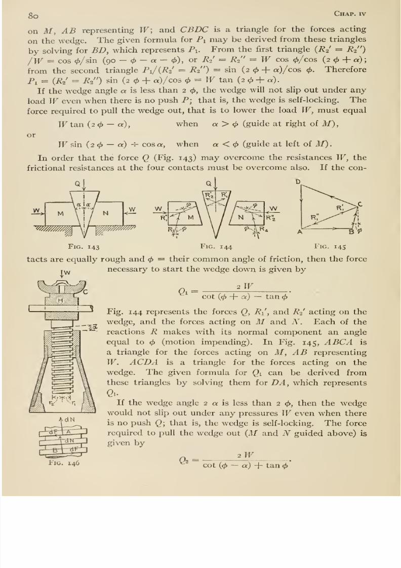
8/13/2019 Maurer Mechanics
http://slidepdf.com/reader/full/maurer-mechanics 92/407
8o Chap, rv
on M, AB representing W; and CBDC is a triangle for the forces acting
on the wedge. The given formula for Pi may be derived from these triangles
by solving for BD, which represents Pi. From the first triangle (R2 = R2 )
/W = cos 0/sin (90 - - a - 0), or R2 = R2 = W cos 0/cos (2 + a)
from the second triangle Pi/{R2 = R% ) = sin (2 + a)/cos 0. Therefore
Pj = [R^' = R^ ) sin (2 + a)/cos = IF tan (2 + a).
If the wedge angle a is less than 2 0, the wedge will not slip out under any
load Weven when there is no push P; that is, the wedge is self-locking. The
force required to pull the wedge out, that is to lower the load W, must equal
Wtan (2 — a), when a > (guide at right of M),
or
Wsm (2 — a) -T- cos a, when a < (guide at left of M).
In order that the force Q (Fig. 143) may overcome the resistances W, thefrictional resistances at the four contacts must be overcome also. If the con-
FiG. 143 Fig. 144 Fig. 14s
tacts are equally rough and = their common angle of friction, then the force
^1
necessary to start the wedge down is given by
2W
Fig. 146
cot (0 + a:) — tan
Fig. 144 represents the forces Q, R\ , and R2 acting on the
wedge, and the forces acting on M and N . Each of the
reactions R makes with its normal component an angle
equal to (motion impending). In Fig. 145, ABCA is
a triangle for the forces acting on i/, AB representing
W. ACDA is a triangle for the forces acting on the
wedge. The given formula for Qi can be derived from
these triangles by solving them for DA, which represents
QuIf the wedge angle 2 a is less than 2 0, then the wedge
would not slip out under any pressures Weven when there
is no push Q; that is, the wedge is self-locking. The force
required to pull the wedge out {M and N guided above) is
given by
'^^^^ cot (0 - a) + tan
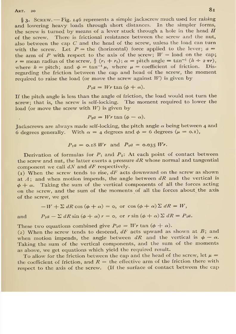
8/13/2019 Maurer Mechanics
http://slidepdf.com/reader/full/maurer-mechanics 93/407
Art. 20 ol
§ 3. Screw. —Fig. 146 represents a simple jackscrew much used for raising
and lowering heavy loads through short distances. In the simpler forms,
the screw is turned by means of a lever stuck through a hole in the head Hof the screw. There is frictional resistance between the screw and the nut,
also between the cap C and the head of the screw, unless the load can turn
with the screw. Let P = the (horizontal) force applied to the lever; a =the arm of P with respect to the axis of the screw; W= load on the cap;
r = mean radius of the screw, | (ri + ra); a = pitch angle = tan-^ (h ^ 2 7rr),
where h = pitch; and </> = tan-^, where m = coefiEicient of friction. Dis-
regarding the friction between the cap and head of the screw, the moment
required to raise the load (or move the screw against W) is given by
Pia = TFr tan (</) + «).
If the pitch angle is less than the angle of friction, the load would not turn the
screw; that is, the screw is self-locking. The moment required to lower the
load (or move the screw with W) is given by
Pia = Wr ta,n (<^ — a).
Jackscrews are always made self -locking, the pitch angle a being between 4 and
6 degrees generally. With a = 4 degrees and = 6 degrees (m = o.i),
PiC = 0.18 Wr and P20 = o-035 Wr.
Derivation of formulas for Pi and P2: At each point of contact between
the screw and nut, the latter exerts a pressure dR whose normal and tangential
component we call dN and dF respectively.
(i) When the screw tends to rise, dF acts downward on the screw as shown
at A ; and when motion impends, the angle between dR and the vertical is
(j) -\- a. Taking the sum of the vertical components of all the forces acting
on the screw, and the sum of the moments of all the forces about the axis
of the screw, we get
-W + ^ dR cos (< > -\- a) = o, or cos ((t>-\- a)'E dR = W,
and Pia — EdR sin (</> + a) r = o, or r sin ((^ -f a) 2 (ii? = Pia.
These two equations combined give Pia = Wr tan (0 + 0;).
(2) When the screw tends to descend, dF acts upward as shown at B; and
when motion impends, the angle between dR and the vertical is<t> — a.
Taking the sum of the vertical components, and the sum of the moments
as above, we get equations which yield the required result.
To allow for the friction between the cap and the head of the screw, let n =
the coefhcient of friction, and R = the effective arm of the friction there with
respect to the axis of the screw. (If the surface of contact between the cap
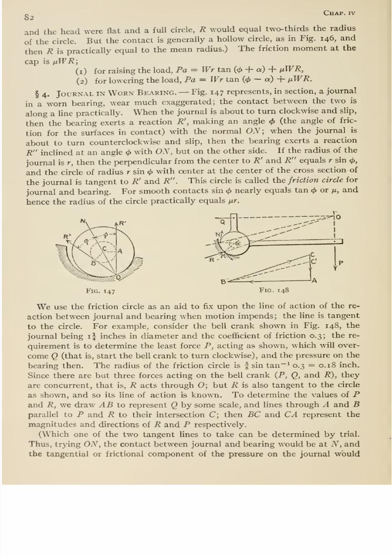
8/13/2019 Maurer Mechanics
http://slidepdf.com/reader/full/maurer-mechanics 94/407
82Chap, iv
and the head were flat and a full circle, R would equal two-thirds the radius
of the circle. But the contact is generally a hollow circle, as in Fig. 146, and
then R is practically equal to the mean radius.) The friction moment at the
cap is ixWR;
(i) for raising the load, Pa = Wr tan (0 + a) + fiWR,
(2) for lowering the load. Pa = Wr tan (</> - a) + fiWR.
§ 4. Journal in Worn Bearing. —Fig. 147 represents, in section, a. journal
in a worn bearing, wear much exaggerated; the contact between the two is
along a Hne practically. When the journal is about to turn clockwise and slip,
then the bearing exerts a reaction R', making an angle <^ (the angle of fric-
tion for the surfaces in contact) with the normal ON; when the journal is
about to turn counterclockwise and slip, then the bearing exerts a reaction
Rinclined at an angle (}> with ON, but on the other side. If the radius of the
journal is r, then the perpendicular from the center to R' and R equals r sin <^,
and the circle of radius r sin </> with center at the center of the cross section of
the journal is tangent to R' and R . This circle is called the friction circle for
journal and bearing. For smooth contacts sin (j) nearly equals tan (j> or /z, and
hence the radius of the circle practically equals iir.
Fig. 147 Fig. 148
We use the friction circle as an aid to fix upon the line of action of the re-
action between journal and bearing when motion impends; the line is tangent
to the circle. For example, consider the bell crank shown in Fig. 148, the
journal being i| inches in diameter and the coefl&cient of friction 0.3; the re-
quirement is to determine the least force P, acting as shown, which will over-
come Q (that is, start the bell crank to turn clockwise), and the pressure on the
bearing then. The radius of the friction circle is f sin tan~^ 0.3 = 0.18 inch.
Since there are but three forces acting on the bell crank {P, Q, and R), they
are concurrent, that is, R acts through 0; but R is also tangent to the circle
as shown, and so its line of action is known. To determine the values of Pand R, we draw AB to represent Q by some scale, and lines through A and Bparallel to P and R to their intersection C; then BC and CA represent the
magnitudes and directions of R and P respectively,
(Which one of the two tangent lines to take can be determined by trial.
Thus, trying ON, the contact between journal and bearing would be at N, and
the tangential or frictional component of the pressure on the journal would
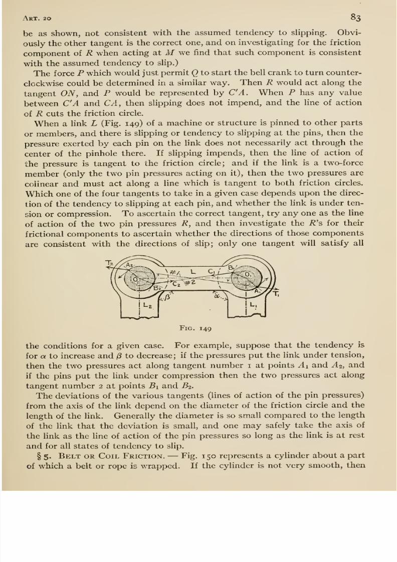
8/13/2019 Maurer Mechanics
http://slidepdf.com/reader/full/maurer-mechanics 95/407
Art. 20 83
be as shown, not consistent with the assumed tendency to slipping. Obvi-
ously the other tangent is the correct one, and on investigating for the friction
component of R when acting at Mwe find that such component is consistent
with the assumed tendency to slip.)
The force P which would just permit Q to start the bell crank to turn counter-
clockwise could be determined in a similar way. Then R would act along the
tangent ON, and P would be represented by C'A. When P has any value
between C'A and CA, then slipping does not impend, and the line of action
of R cuts the friction circle.
When a link L (Fig. 149) of a machine or structure is pinned to other parts
or members, and there is slipping or tendency to slipping at the pins, then the
pressure exerted by each pin on the link does not necessarily act through the
center of the pinhole there. If slipping impends, then the line of action of
the pressure is tangent to the friction circle; and if the link is a two-force
member (only the two pin pressures acting on it), then the two pressures are
colinear and must act along a line which is tangent to both friction circles.
Which one of the four tangents to take in a given case depends upon the direc-
tion of the tendency to slipping at each pin, and whether the link is under ten-
sion or compression. To ascertain the correct tangent, try any one as the line
of action of the two pin pressures R, and then investigate the i?'s for their
frictional components to ascertain whether the directions of those components
are consistent with the directions of slip; only one tangent will satisfy all
Fig. 149
the conditions for a given case. For example, suppose that the tendency is
for a to increase and /3 to decrease; if the pressures put the link under tension,
then the two pressures act along tangent number i at points Ai and A2, and
if the pins put the link under compression then the two pressures act along
tangent number 2 at points Bi and B^.
The deviations of the various tangents (lines of action of the pin pressures)from the axis of the link depend on the diameter of the friction circle and the
length of the link. Generally the diameter is so small compared to the length
of the link that the deviation is small, and one may safely take the axis of
the link as the line of action of the pin pressures so long as the link is at rest
and for all states of tendency to slip.
§ 5. Belt or Coil Friction. —Fig. 150 represents a cyUnder about a part
of which a belt or rope is wrapped. If the cylinder is not very smooth, then
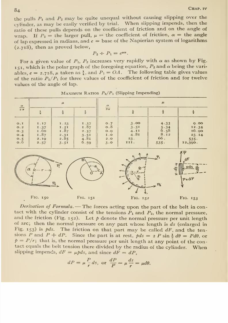
8/13/2019 Maurer Mechanics
http://slidepdf.com/reader/full/maurer-mechanics 96/407
o Chap, iv
the pulls Pi and P2 may be quite unequal without causing slipping over the
cylinder, as may be easily verified by trial. When slipping impends, then the
ratio of these pulls depends on the coefficient of friction and on the angle of
wrap. If P2 = the larger pull, m = the coefficient of friction, a = the angle
of lap expressed in radians, and e = base of the Napierian system of logarithms
(2.718), then as proved below.
For a given value of Pi, P2 increases very rapidly with a as shown by Fig.
151, which is the polar graph of the foregoing equation, P2 and a being the vari-
ables, e= 2.718, M taken as \, and Pi = OA. The following table gives values
of the ratio P2/P1 for three values of the coefficient of friction and for twelve
values of the angle of lap.
Maximum Ratios P2/P1 (Slipping Impending)
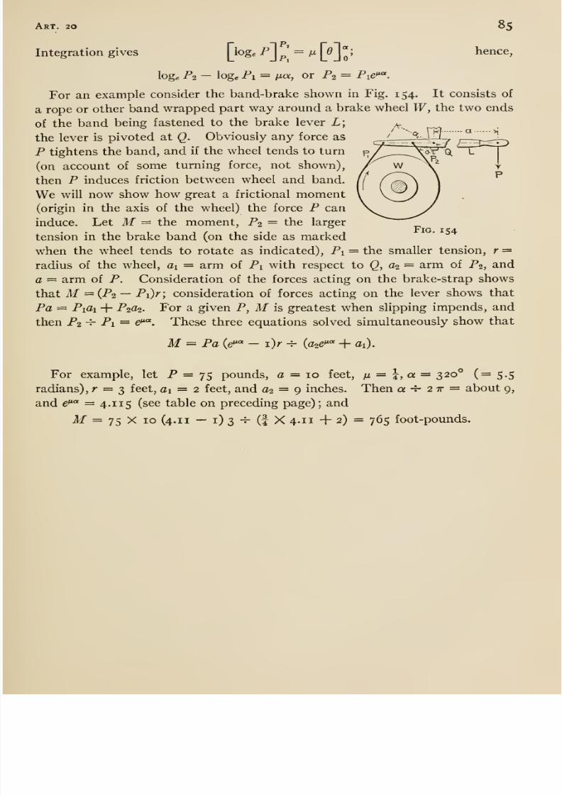
8/13/2019 Maurer Mechanics
http://slidepdf.com/reader/full/maurer-mechanics 97/407
Art. 20 85
Integration gives [ioge Pj^' = fx |^0j ; hence,
loge P2 - log. Pi = ^Jux, or P2 = Pie*^.
For an example consider the band-brake shown in Fig. 154. It consists of
a rope or other band wrapped part way around a brake wheel W, the two endsof the band being fastened to the brake lever L;
the lever is pivoted at Q. Obviously any force as
P tightens the band, and if the wheel tends to turn
(on account of some turning force, not shown),
then P induces friction between wheel and band.
We will now show how great a frictional moment(origin in the axis of the wheel) the force P can
induce. Let M= the moment, P2 = the largertension in the brake band (on the side as marked
when the wheel tends to rotate as indicated), Pi = the smaller tension, r =radius of the wheel, ai = arm of Pi with respect to Q, (h= arm of P2, and
a = arm of P. Consideration of the forces acting on the brake-strap shows
that M={Pi —Pi)r; consideration of forces acting on the lever shows that
Pa = Pifli + P2a2. For a given P, M is greatest when slipping impends, and
then P2 -V- Pi = e*^. These three equations solved simultaneously show that
M= Pa (e'*« - i)r -=- (a^e' ' + ai).
For example, let P = 75 pounds, a = 10 feet, n = I, a = 320° (= 5.5
radians), r = 3 feet, ai = 2 feet, and a2 = 9 inches. Then a -5- 2 tt = about 9,
and e* * = 4.1 15 (see table on preceding page); and
M = 75 X 10 (4.1 1 — i) 3 -T- (I X 4-11 + 2) = 765 foot-pounds.
Fig. 154

8/13/2019 Maurer Mechanics
http://slidepdf.com/reader/full/maurer-mechanics 98/407
CHAPTER V
CENTER OF GRAVITY
21. Center of Gravity of Bodies
§ I. It is shown in Art. 7 that the resultant of two parallel forces Fi and Fj
acting at two points A and B of any body cuts the line A Bin a, point P so that
AP/PB = F2/F1 (Fig. 155). This proportion fixes the position of P, and
since the proportion is independent of the angle between AB and the forces, Pis also, so independent. Therefore ii AB were a rod and Fi and F2 the weightsof two bodies suspended from A and B, then the resultant R of Fi and F2 would
always pass through the same point even if the tilt of the rod were changed
slowly so as to leave the suspending strings parallel. Furthermore, if three
parallel forces be applied at definite points A, B, and C of a body (Fig. 155),
and if R denotes the resultant of Fi and F2 as before and R' the resultant of
R and F3 (and so also the resultant of Fi, Fo, and F3), then CP'/PP' = R/F3.
This proportion fixes P' (in CP), andit is
independent of theangle between
the forces and the plane of ABC. Therefore ii AB and CP be two rods rigidly
fastened at P, and Fi, F2, and F3 the weights of bodies suspended from AB, and C, then the resultant of the three forces would always pass through
P' if the rods were slowly turned about leaving the strings parallel. And so if
any number of parallel forces have definite points of application on a rigid
body, the resultant of the forces always passes through some one definite point
of the body, or of its extension, when the body is turned about so as not to
disturb the parallelism of the forces.This unique point is called the center
or centroid of the parallel forces.
The forces of gravity on all the constituent particles of a body constitute aparallel force system having definite points of application; therefore all those
forces have a centroid. That is, the resultant of the forces of gravity on all
the particles of a body (its weight) always passes through some one definite
point of the body, or of its extension, no matter how the body is turned about;86
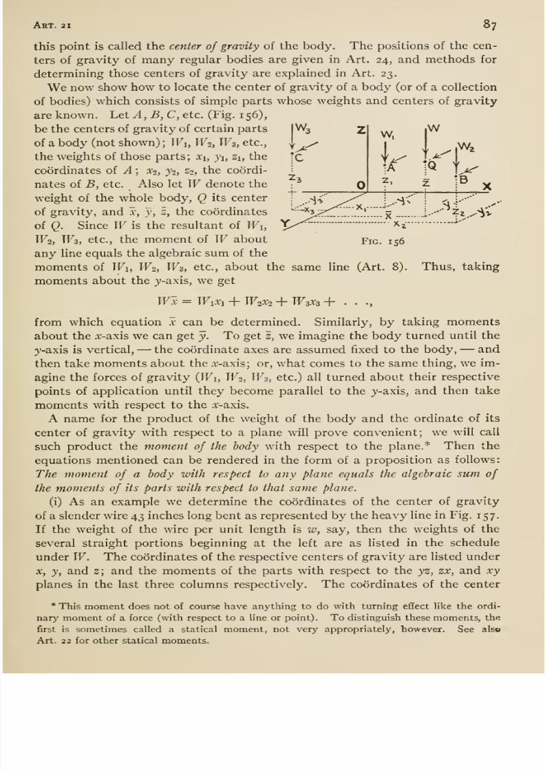
8/13/2019 Maurer Mechanics
http://slidepdf.com/reader/full/maurer-mechanics 99/407
Art. 21 87
this point is called the center of gravity of the body. The positions of the cen-
ters of gravity of many regular bodies are given in Art. 24, and methods for
determining those centers of gravity are explained in Art. 23.
We now show how to locate the center of gravity of a body (or of a collection
of bodies) which consists of simple parts whose weights and centers of gravity
are known. Let yl, B, C, etc. (Fig. 156),
be the centers of gravity of certain parts
of a body (not shown) ; Wi, W2, Ws, etc.,
the weights of those parts; xi, ji, Zi, the
coordinates of A ; X2, }% Z2, the coordi-
nates of B, etc. Also let Wdenote the
weight of the whole body, Q its center
of gravity, and x, y, z, the coordinates
of Q. Since W is the resultant of Wi,
W2, W3, etc., the moment of W about
any Hne equals the algebraic sum of the
moments of Wi, W2, W3, etc., about the same line (Art. 8).
moments about the y-axis, we get
Fig. 156
Thus, taking
Wx = Wixi + W2X2 + W3X3 + •>
from which equation x can be determined.Similarly,
bytaking
momentsabout the x-axis we can get y. To get z, we imagine the body turned until the
y-axis is vertical, —the coordinate axes are assumed fixed to the body, —and
then take moments about the x-axis; or, what comes to the same thing, we im-
agine the forces of gravity (TFi, TF2, TF3, etc.) all turned about their respective
points of application until they become parallel to the y-axis, and then take
moments with respect to the x-axis.
A name for the product of the weight of the body and the ordinate of its
center of gravity with respect to a plane will prove convenient; we will call
such product the moment of the body with respect to the plane.* Then the
equations mentioned can be rendered in the form of a proposition as follows:
The moment of a body with respect to any plane equals the algebraic sum of
the moments of its parts with respect to that same plane.
(i) As an example we determine the coordinates of the center of gravity
of a slender wire 43 inches long bent as represented by the heavy line in Fig. 157.
If the weight of the wire per unit length is w, say, then the weights of the
several straight portions beginning at the left are as listed in the scheduleunder W. The coordinates of the respective centers of gravity are listed under
X, y, and 2; and the moments of the parts with respect to the yz, zx, and xy
planes in the last three columns respectively. The coordinates of the center
* This moment does not of course have anything to do with turning effect like the ordi-
nary moment of a force (with respect to a line or point). To distinguish these moments, the
first is sometimes called a statical moment, not very appropriately, however. See also
Art. 22 for other statical moments.
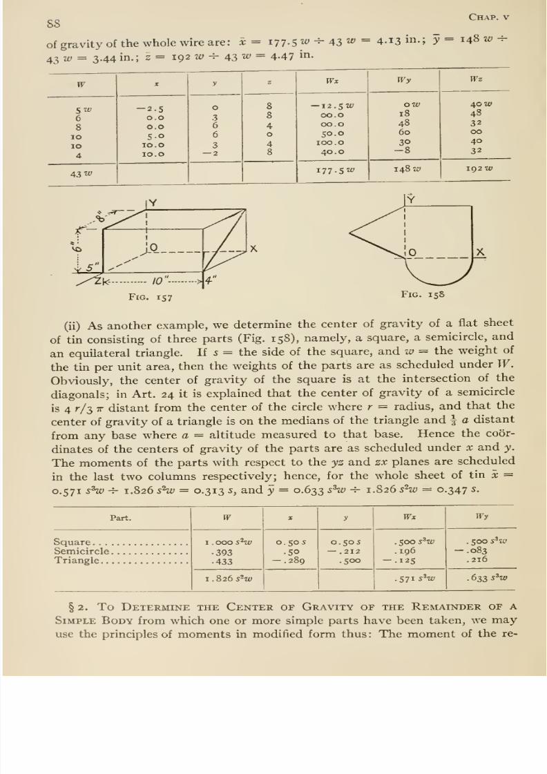
8/13/2019 Maurer Mechanics
http://slidepdf.com/reader/full/maurer-mechanics 100/407
88
of gravity of the whole wire are: x= 177.5 ly -^ 43 «'
43 z£) = 3.44 in.; z = 192 2£; -^ 43 «' = 4-47 in-
Chap, v
4.13 in.; y = 148 w -^
F
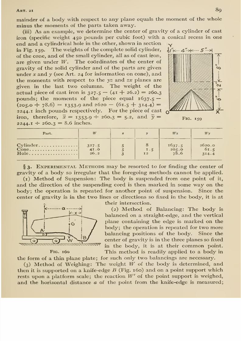
8/13/2019 Maurer Mechanics
http://slidepdf.com/reader/full/maurer-mechanics 101/407
Art. 21 89
mainder of a body with respect to any plane equals the moment of the whole
minus the moments of the parts taken away.
(iii) As an example, we determine the center of gravity of a cylinder of cast
iron (specific weight 450 pounds per cubic foot) with a conical recess in one
end and a cylindrical hole in the other, shown in section yin Fig. 1 59. The weights of the complete solid cylinder, |/ ]<- 4.'.'.>|<— - 5 ->\
of the cone, and of the small cylinder, all as of cast iron,
are given under W. The coordinates of the center of
gravity of the solid cylinder and of the parts are given
under x and y (see Art. 24 for information on cone), and
the moments with respect to the yz and zx planes are
given in the last two columns. The weight of the
actual piece of cast iron is 327.5 — (41 + 26.2) = 260.3
pounds; the moments of the piece equal 1637.5 ~(205.0 + 78,6) = 1353.9 and 2620 - (61.5 + 314.4) =
2244.1 inch pounds respectively. For the piece of cast
iron, therefore, x = 1353.9 -^ 260.3 — 5-2, and y =2244.1 -r- 260.3 = 8.6 inches.
Fig. 159
Part.

8/13/2019 Maurer Mechanics
http://slidepdf.com/reader/full/maurer-mechanics 102/407
Chap, v90
then the horizontal distance from the center of gravity to the knife-edge is
W'a/W. In this manner the horizontal distances of the center of gravity
from several knife-edge supports can be got and the center of gravity located.
• The distance of the center of gravity of a body from the plane through three
points of the body can be determined if the body can be supported at the points
and if certain weighings can be performed as described. Let A, B, and C(behind B and not shown) be three such points of the body (Fig. 161) ; a = dis-
tance of A from the line joining B and C; W= weight of the body; W' =
weight recorded by the scale when A, B, and C are at the same level as shown
I
Fig. 161 Fig. 162
in Fig. 161, and W = weight recorded by the scale when A is higher than B
and C by any amount h (Fig. 162). Then the distance y of the center of gravity
from the plane ABC is given by
Va2 - h^ w' - Wa.' h W
Proof: From the first position it is plain that W'a = Wx; from the second
it follows that W a cos 6 = W{xcosd - ysinO). Solvin g these simultane-
ously we get y = {W - W ) (a cote)/W; but cot^ = Va- - h^ -^ h, hence,
etc.
22. Centroids of Lines, Surfaces, and Solids
§1. Lines, surfaces, and (geometric) solids have no weight, and therefore
they have no center of gravity in the strict sense of the term as defined in the
preceding article. However, we do speak of the center of gravity of those geo-
metric conceptions; and we mean by the term, the center of gravity of the line,
surface, or volume materialized, that is, conceived as a homogeneous slender
wire, thin plate, or body, respectively. The center of gravity of a line, surface,
or solid is sometimes spoken of as the center of gravity of the length (of the
line), area (of the surface), and volume (of the solid). The term centroid has
been proposed as a substitute for center of gravity when applied to lines, sur-
faces, and solids as being more appropriate; the new term is given preference
in this book.
If a given line, surface, or soHd is imagined as materialized, then we can
apply the principle of moments (Art. 21) to it. Thus, \i W= the weight of
the whole materialized line, surface, or solid, Wi, Wi, W2, etc., = the weights
of all the parts into which we imagine it divided, x = the coordinate of the
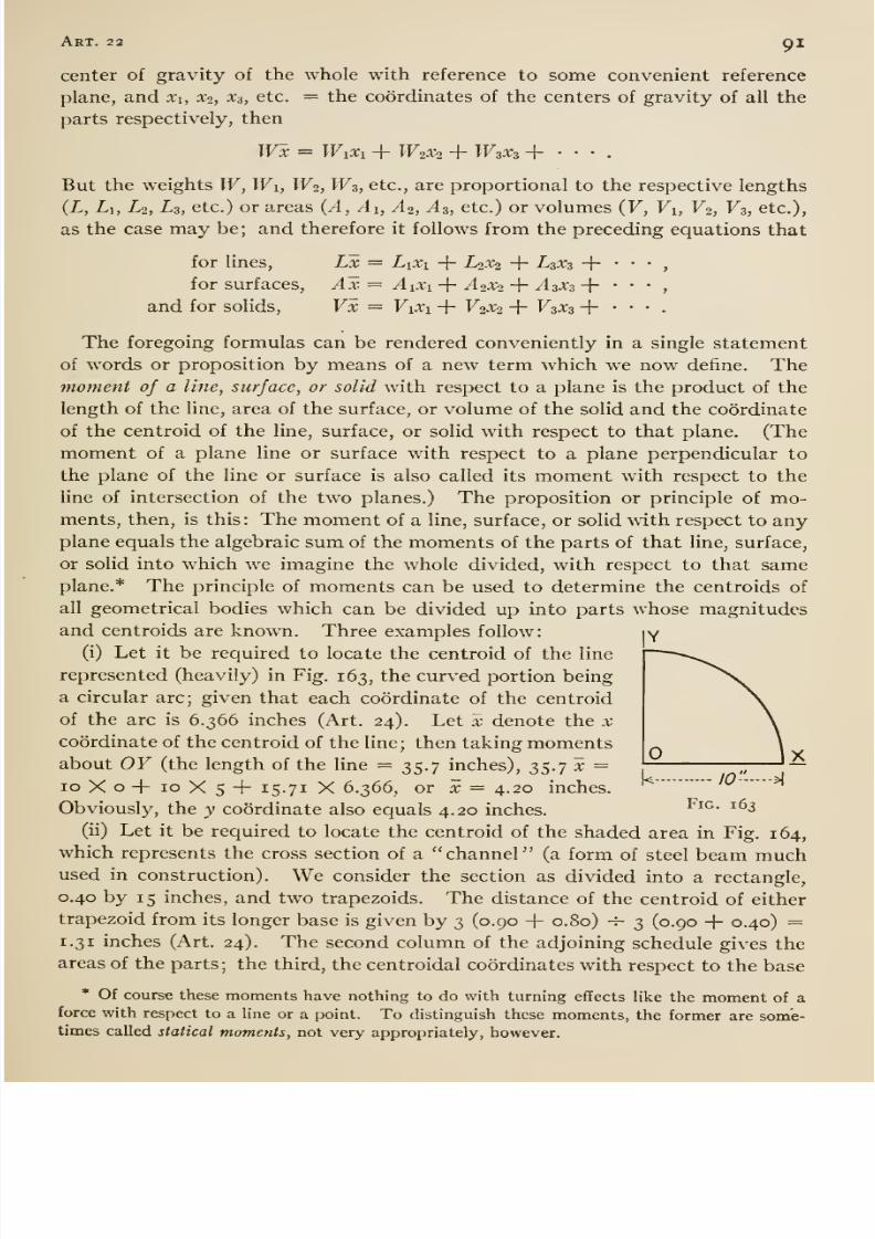
8/13/2019 Maurer Mechanics
http://slidepdf.com/reader/full/maurer-mechanics 103/407
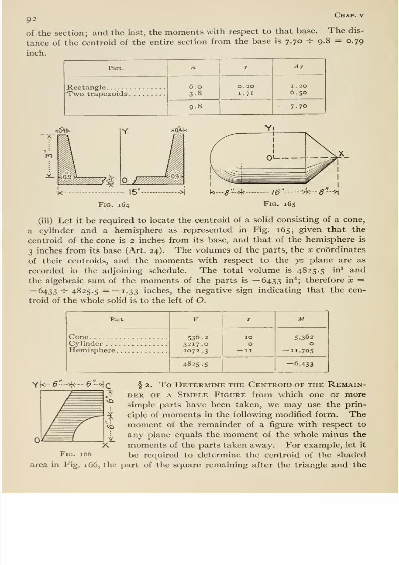
8/13/2019 Maurer Mechanics
http://slidepdf.com/reader/full/maurer-mechanics 104/407
92Chap, v
of the section; and the last, the moments with respect to that base. The dis-
tance of the centroid of the entire section from the base is 7.70 -^ 9.8 = 0.79
inch.
Part.
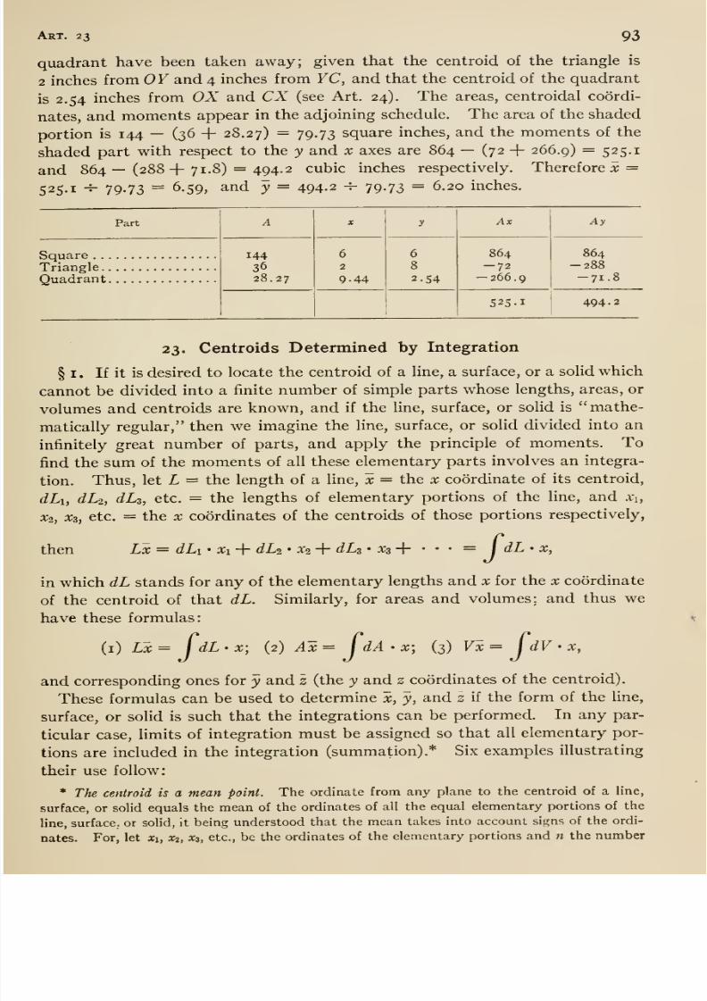
8/13/2019 Maurer Mechanics
http://slidepdf.com/reader/full/maurer-mechanics 105/407
Art. 23 93
quadrant have been taken away; given that the centroid of the triangle is
2 inches from OY and 4 inches from YC, and that the centroid of the quadrant
is 2.54 inches from OX and CX (see Art. 24). The areas, centroidal coordi-
nates, and moments appear in the adjoining schedule. The area of the shaded
portion is 144 — (36
+28.27) — 79-73 square inches, and the moments of the
shaded part with respect to the y and x axes are 864 — (72+266.9) = 525.1
and 864 — (288+ 71.8) = 494.2 cubic inches respectively. Therefore x =
525.1 -^ 79.73 = 6.59, and y = 494-2 -^ 79-73 = 6.20 inches.
Part
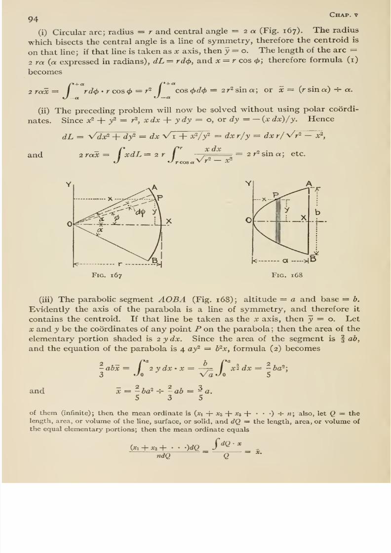
8/13/2019 Maurer Mechanics
http://slidepdf.com/reader/full/maurer-mechanics 106/407
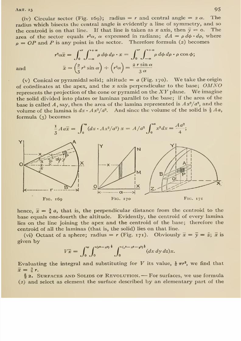
8/13/2019 Maurer Mechanics
http://slidepdf.com/reader/full/maurer-mechanics 107/407
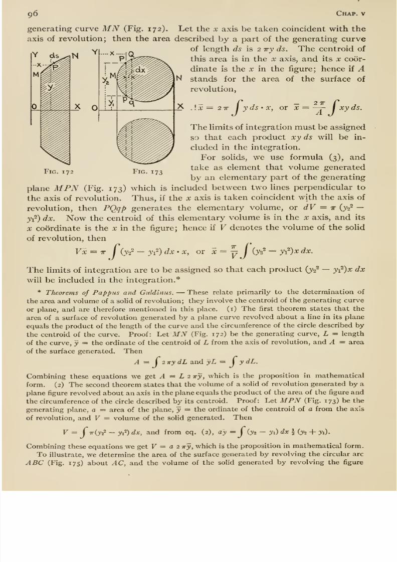
8/13/2019 Maurer Mechanics
http://slidepdf.com/reader/full/maurer-mechanics 108/407
96 Chap, v
generating curve MN (Fig, 172). Let the x axis be taken coincident with the
axis of revolution; then the area described by a part of the generating curve
of length ds is 2 iry ds. The centroid of
this area is in the x axis, and its x coor-
dinate is the X in the figure; hence if Astands for the area of the surface of
revolution,
I TT I yds- X, or :*; = —r- j xy ds.
Fig. 172 Fig. 173
The limits of integration must be assigned
so that each product xy ds will be in-
cluded in the integration.
For solids, we use formula (3), andtake as element that volume generated
by an elementary part of the generating
plane MPN (Fig. 173) which is included between two lines perpendicular to
the axis of revolution. Thus, if the x axis is taken coincident with the axis of
revolution, then PQqp generates the elementary volume, or dV = ir {y^}—
y-^) dx. Now the centroid of this elementary volume is in the x axis, and its
X coordinate is the x in the figure; hence if V denotes the volume of the solid
of revolution, then
Vx = ir I (yi^ —yi^) dx'X, or x=yj {yi^ — yi^)x dx.
The limits of integration are to be assigned so that each product (yi^ —yi^)x dx
will be included in the integration.*
* Theorems of Pappus and Guldinus. —These relate primarily to the determination of
the area and volume of a solid of revolution; they involve the centroid of the generating curve
or plane, and are therefore mentioned in this place, (i) The first theorem states that the
area of a surface of revolution generated by a plane curve revolved about a line in its plane
equals the product of the length of the curve and the circumference of the circle described by
the centroid of the curve. Proof: Let MN (Fig. 172) be the generating curve, L = length
of the curve, y = the ordinate of the centroid of L from the axis of revolution, and A = area
of the surface generated. Then
A = \ 2-KydL and yL = \ y dL.
Combining these equations we get yl = L 2 ivy, which is the proposition in mathematical
form. (2) The second theorem states that the volume of a solid of revolution generated by a
plane figure revolved about an axis in the plane equals the product of the area of the figure and
the circumference of the circle described by its centroid. Proof: Let MPN (Fig. 173) be the
generating plane, a = area of the plane, y = the ordinate of the centroid of a from the axis
of revolution, and V = volume of the solid generated. Then
V = ( Tr{y2^ —y) dx, and from eq. (2), a'y = j iji —yO dx h (^2 + yi).
Combining these equations we get F = o 2 Try, which is the proposition in mathematical form.
To illustrate, we determine the area of the surface generated by revolving the circular arc
ABC (Fig. 175) about AC, and the volume of the solid generated by revolving the figure
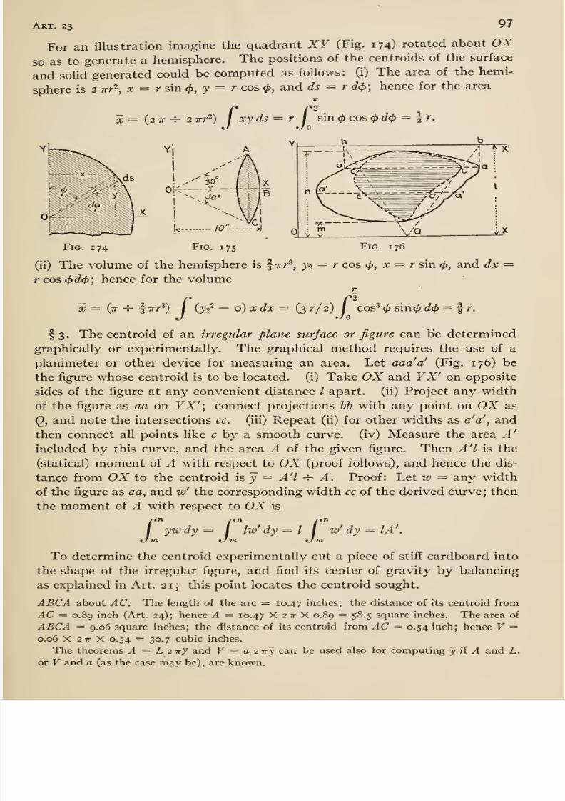
8/13/2019 Maurer Mechanics
http://slidepdf.com/reader/full/maurer-mechanics 109/407
Art. 23 97
For an illustration imagine the quadrant XY (Fig. 174) rotated about OXso as to generate a hemisphere. The positions of the centroids of the surface
and solid generated could be computed as follows: (i) The area of the hemi-
sphere is 2 irr^, X = rsixKl), y = r cos </>, and ds = r d(t>; hence for the areaIT
^ = (2 X -^ 2 TT/-^) I xyds = rJ
sin ^ cos (f>d<l) = ^r.
Fig. 174 Fig. 175 Fig. 176
(ii) The volume of the hemisphere is f xr', j2 = r cos <{), x = r sin </>, and dx =r cos (t>d(f); hence for the volume
X = (tt -4- f^rr^ ) / (js^ — o) ;» (/x = (3 r/2) i cos^ (f) s\n<f) d(f) =
§ 3. Thecentroid of
anirregular plane surface or
figurecan be determined
graphically or experimentally. The graphical method requires the use of a
planimeter or other device for measuring an area. Let aaa'a' (Fig. 176) be
the figure whose centroid is to be located, (i) Take OX and YX' on opposite
sides of the figure at any convenient distance I apart, (ii) Project any width
of the figure as aa on YX' ; connect projections hh with any point on OX as
Q, and note the intersections cc. (iii) Repeat (ii) for other widths as a'a' ^ and
then connect all points like c by a smooth curve, (iv) Measure the area A
included by this curve, and the area A of the given figure. Then A' I is the(statical) moment of A with respect to OX (proof follows), and hence the dis-
tance from OX to the centroid is y = A'l ^ A. Proof: Let w = any width
of the figure as aa, and w' the corresponding width cc of the derived curve; then
the moment of A with respect to OX is
y'wdy= j Iw' dy = I j w'dy = lA'.
To determine the centroid experimentally cut a piece of stiff cardboard into
the shape of the irregular figure, and find its center of gravity by balancing
as explained in Art. 2 1 ; this point locates the centroid sought.
ABCA about AC. The length of the arc = 10.47 inches; the distance of its centroid from
AC = 0.89 inch (Art. 24); hence A = 10.47 X 2 tt X 0.89 = 58.5 square inches. The area of
ABCA = 9.06 square inches; the distance of its centroid from AC = 0.54 inch; hence V =0.06 X 2 IT X 0.54 = 30.7 cubic inches.
The theorems A = L 2i^y and F = a 2 ttj can be used also for computing y if A and Z,,
or V and a (as the case may be), are known.
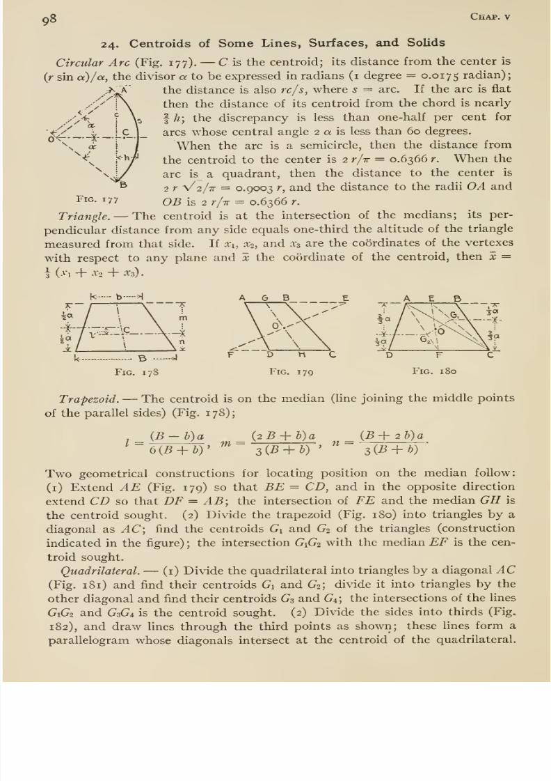
8/13/2019 Maurer Mechanics
http://slidepdf.com/reader/full/maurer-mechanics 110/407
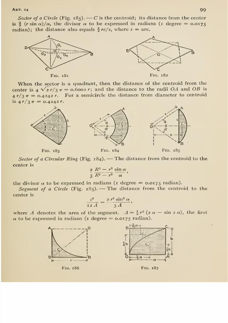
8/13/2019 Maurer Mechanics
http://slidepdf.com/reader/full/maurer-mechanics 111/407
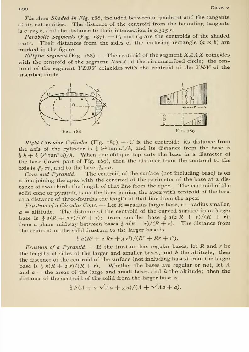
8/13/2019 Maurer Mechanics
http://slidepdf.com/reader/full/maurer-mechanics 112/407
lOO Chap, v
The Area Shaded in Fig. i86, included between a quadrant and the tangents
at its extremities. The distance of the centroid from the bounding tangents
is 0.223 r, and the distance to their intersection is 0.315 r.
Parabolic Segments (Fig. 187). —Ci and d are the centroids of the shaded
parts. Their distances from the sides of the inclosing rectangle (a X b) are
marked in the figure.
Elliptic Segment (Fig. 188). —The centroid of the segment XAAX coincides
with the centroid of the segment XaaX of the. circumscribed circle; the cen-
troid of the segment YBBY coincides with the centroid of the YbbY of the
inscribed circle.
Fig. li Fig. 189
Right Circular Cylinder (Fig. 189). —C is the centroid; its distance from
the axis of the cylinder is \ {r- tan a)/h, and its distance from the base is
1 ^ _|- 1 (^2 ^^^2 Q,)//^ When the oblique top cuts the base in a diameter of
the base (lower part of Fig. 189), then the distance from the centroid to the
axis is x\ irr, and to the base 30 ^^•
Cone and Pyramid. —The centroid of the surface (not including base) is on
a line joining the apex with the centroid of the perimeter of the base at a dis-
tance of two-thirds the length of that line from the apex. The centroid of the
solid cone or pyramid is on the lines joining the apex with centroid of the base
at a distance of three-fourths the length of that line from the apex.
Frustum of a Circular Cone. —Let R = radius larger base, r = radius smaller,
a = altitude. The distance of the centroid of the curved surface from larger
base is I aiR + 2 r)/(R -\- r); from smaller base I a{2 R + r)/iR + r);
from a plane midway between bases i a{R - r)/{R + r). The distance from
the centroid of the solid frustum to the larger base is
I a(R' -\-2Rr-\-s r^)/{R^ + Rr + r^).
Frustum of a Pyramid. —If the frustum has regularbases, let
R andr be
the lengths of sides of the larger and smaller bases, and h the altitude; then
the distance of the centroid of the surface (not including bases) from the larger
base is \h{R-\- 2 r)/(R -\- r). Whether the bases are regular or not, let A
and a = the areas of the large and small bases and h the altitude; then the
distance of the centroid of the solid from the larger base is
lh{A-\-2 VJa + 3 a)/(A -f Vl^-f a).

8/13/2019 Maurer Mechanics
http://slidepdf.com/reader/full/maurer-mechanics 113/407
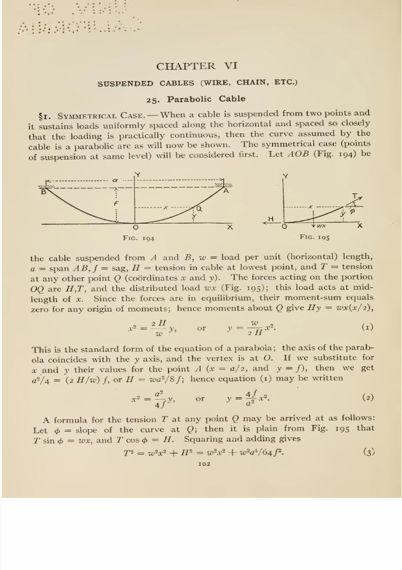
8/13/2019 Maurer Mechanics
http://slidepdf.com/reader/full/maurer-mechanics 114/407
CHAPTER VI
SUSPENDED CABLES (WIRE, CHAIN, ETC.)
25. Parabolic Cable
§1. Symmetrical Case. —When a cable is suspended from two points and
it sustains loads uniformly spaced along the horizontal and spaced so closely
that the loading is practically continuous, then the curve assumed by the
cable is a parabolic arc as will now be shown. The symmetrical case (points
of suspension at same level) will be considered first. Let AOB (Fig. 194) be
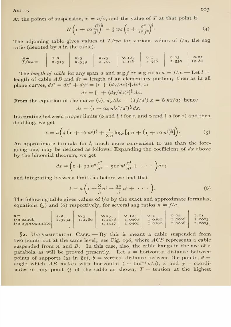
8/13/2019 Maurer Mechanics
http://slidepdf.com/reader/full/maurer-mechanics 115/407
Art. 25 ^°3
At the points of suspension, x = a/ 2, and the value of T at that point is
£? ( I + 16 ^;V = * wa (i + -^J- (4)
The adjoining table gives values of T/wa for various values of f/a, the sag
ratio (denoted by n in the table).
n =T/wa =
I.O
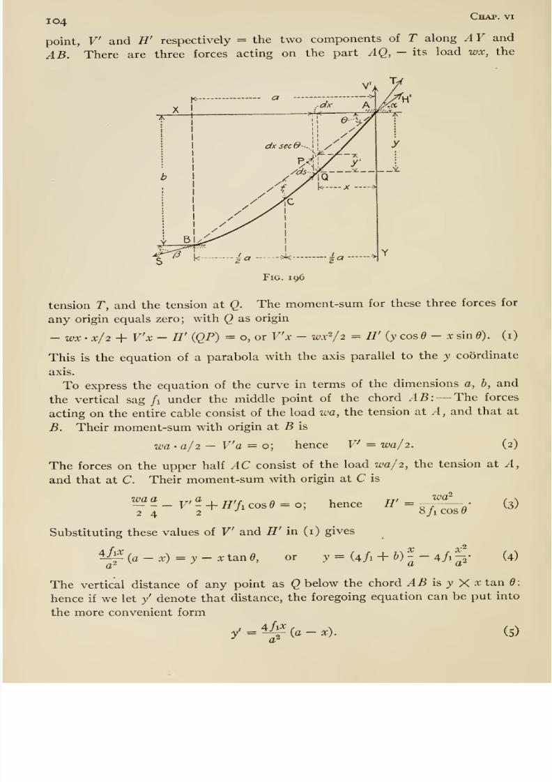
8/13/2019 Maurer Mechanics
http://slidepdf.com/reader/full/maurer-mechanics 116/407
I04 Chap, vi
point, V and H' respectively = the two components of T along AY and
AB. There are three forces acting on the part AQ, - its load wx, the
tension T, and the tension at Q. The moment-sum for these three forces for
any origin equals zero; with Q as origin
- wx • x/2 + V'x - H' (QP) = o, or V'x - wx^/2 = H' (y cos ^ - x sin 6). (i)
This is the equation of a parabola with the axis parallel to the y coordinate
axis.
To express the equation of the curve in terms of the dimensions a, b, and
the vertical sag /i under the middle point of the chord AB: —The forces
acting on the entire cable consist of the load wa, the tension at A, and that at
B. Their moment-sum with origin at B is
wa-a/2 — V'a = o; hence V^ = •wa/2. (2)
The forces on the upper half AC consist of the load wa/2, the tension at A,
and that at C. Their moment-sum with origin at C is
72wa''
'^'•£_rf + H'/,cos9 = o; hence ff' = g^— -,-
Substituting these values of V and H' in (i) gives
^^ {a — x) = y — re tan d,
a^
,-2
or >• = (4/1 + ^)- -4/1-2
(3)
(4)
The vertical distance of any point as Q below the chord AB \s y Xxtand;
hence if we let y' denote that distance, the foregoing equation can be put into
the more convenient form
4/1^y =
a'(a —x). (5)
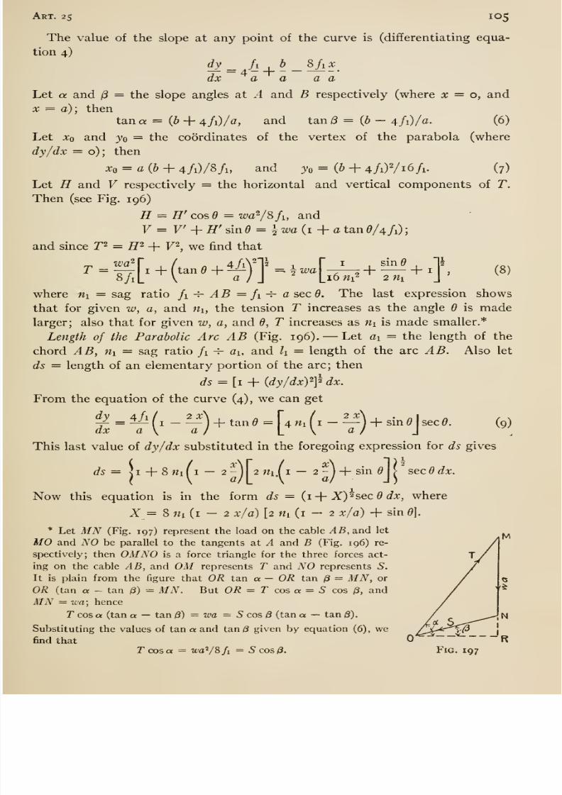
8/13/2019 Maurer Mechanics
http://slidepdf.com/reader/full/maurer-mechanics 117/407
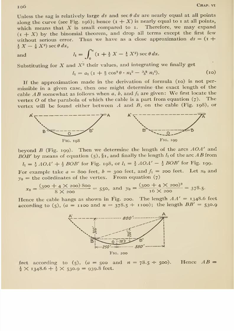
8/13/2019 Maurer Mechanics
http://slidepdf.com/reader/full/maurer-mechanics 118/407
io6 Chap, vi
Unless the sag is relatively large ds and sec d dx are nearly equal at all points
along the curve (see Fig. 196); hence (i + X) is nearly equal to i at all points,
which means that X is small compared to i. Therefore, we may expand
(i _j_ X) by the binomial theorem, and drop all terms except the first few
without serious error. Thus we have as a close approximation ds = {i -\-
iX-^X^)secddx,and ' = / (i + |Z- lX^)secddx.
Substituting for X and X^ their values, and integrating we finally get
/i = fli(i + §cos2 0.«i2- V-«i'). (10)
If the approximation made in the derivation of formula (10) is not per-
missible in a given case, then one might determine the exact length of the
cable AB somewhat as follows when a, b, and/i are given: We first locate the
vertex O of the parabola of which the cable is a part from equation (7). The
vertex will be found either between A and B, on the cable (Fig. 198), or
A'v
B' >
Fig. 198 Fig. 199
—Tfi^^
beyond B (Fig. 199). Then we determine the length of the arcs AOA' and
BOB' by means of equation (5), §1, and finally the length h of the arcAB from
Zi = i AOA' + h BOB' for Fig. 198, or h = ^ AOA' - \ BOB' for Fig. 199.
For example take a = 800 feet, h = 300 feet, and /i = 200 feet. Let Xq and
jQ = the coordinates of the vertex. From equation (7)
(soo + 4 X 200) 800 , (300 + 4X200)2Xf, = -^^^ = tji^o, and Vo = — 7-7^ = i1°-S-° 8X200 ^^ 16X200
Hence the cable hangs as shown in Fig. 200. The length AA' = 1348.6 feet
according to (5), (a = iioo and n = 378.5 -4- iioo); the length BB' = 530.9
^...250'->k- 5S0' —-><
Fig. 200
feet according to (5), (a = 500 and n = 78.5 -f- 500).
i X 1348.6 + i X 530.9 = 939.8 feet.
Hence AB =
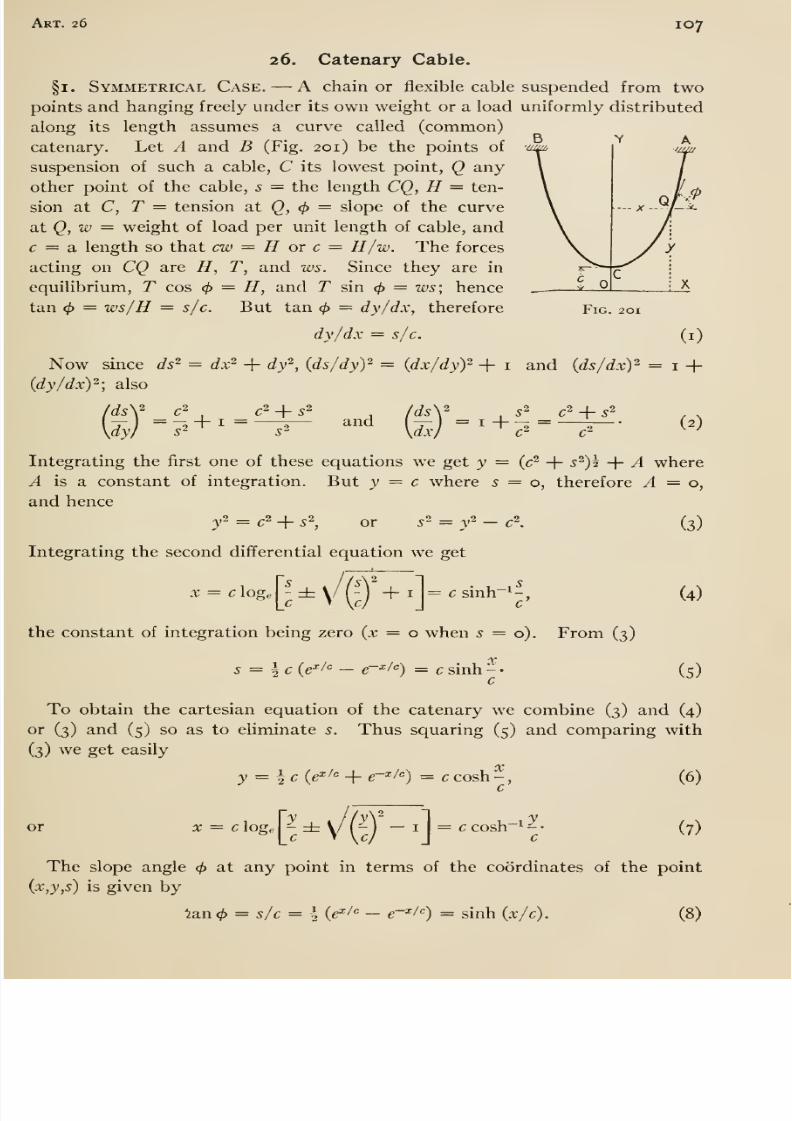
8/13/2019 Maurer Mechanics
http://slidepdf.com/reader/full/maurer-mechanics 119/407
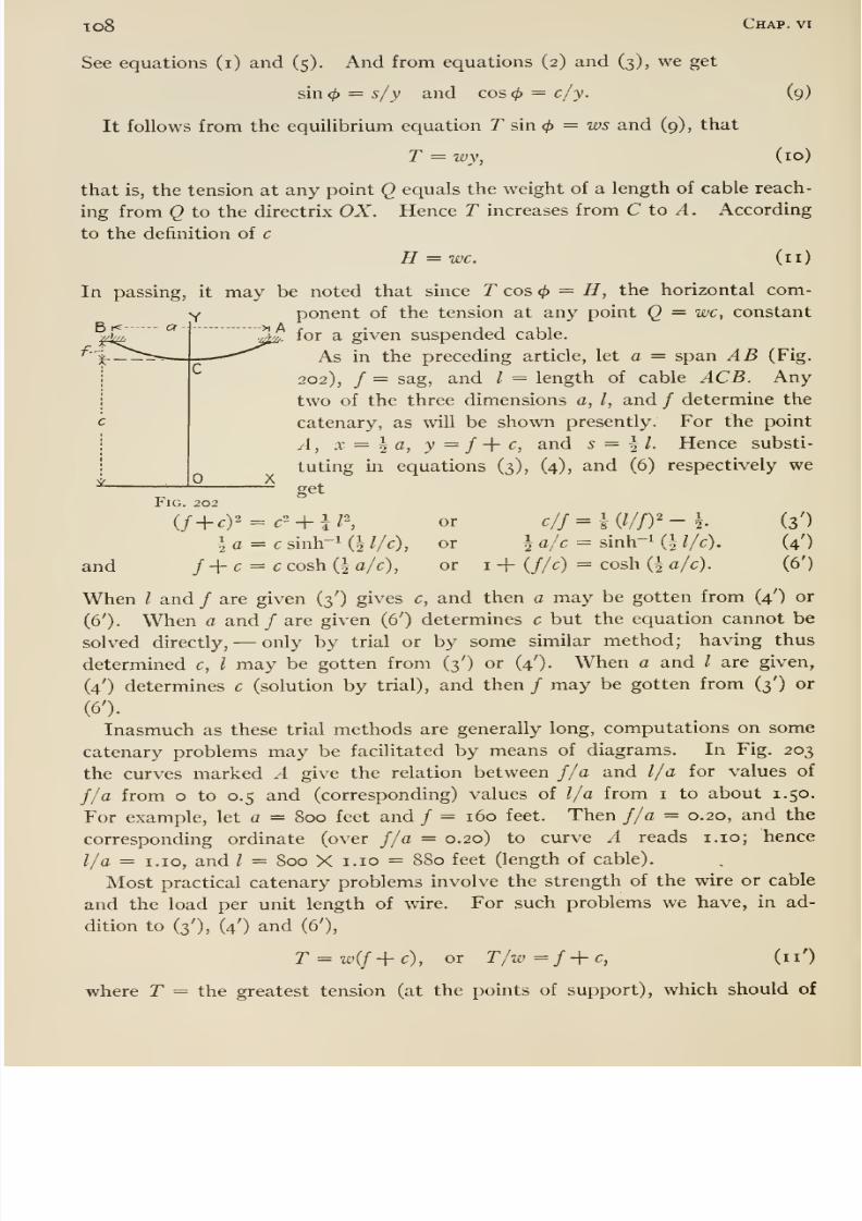
8/13/2019 Maurer Mechanics
http://slidepdf.com/reader/full/maurer-mechanics 120/407
xo8 Chap, vi
See equations (i) and (5). And from equations (2) and (3), we get
sin0 = s/y and cos0 = c/y. (9)
It follows from the equilibrium equation T sin <^ = ws and (9) , that
T — wy, (10)
that is, the tension at any point Q equals the weight of a length of cable reach-
ing from Q to the directrix OX. Hence T increases from C to A. According
to the definition of c
H = wc. (11)
In passing, it may be noted that since T cos ^ = H, the horizontal com-
ponent of the tension at any point Q = wc, constant
^for a given suspended cable.
As in the preceding article, let a = span AB (Fig.
202), / = sag, and / = length of cable ACB. Any
two of the three dimensions a, I, and / determine the
catenary, as will be shown presently. For the point
A, X = I a, y = f -{- c, and s = ^ I. Hence substi-
tuting in equations (3), (4), and (6) respectively we
getFig. 202
(/ + ,)2 = ,2 + i;2^ or clj=\{lljy-\. (3')
\a = c sinh-i (1 //^)^ or 1 ^Ic - sinh-i {\ l/c). (4')
and f-\-c = c cosh (^ a/c), or i + (//c) = cosh (| a/c). (6')
When I and / are given (3') gives c, and then a may be gotten from (4') or
(6'). When a and / are given (6') determines c but the equation cannot be
solved directly, —only by trial or by some sunilar method; having thus
determined c, I may be gotten from (3') or (4'). When a and / are given,
(4') determines c (solution by trial), and then / may be gotten from (3') or(6').
Inasmuch as these trial methods are generally long, computations on some
catenary problems may be facilitated by means of diagrams. In Fig. 203
the curves marked A give the relation between J/ a and l/a for values of
f/a from o to 0.5 and (corresponding) values of l/a from i to about 1.50.
For example, let a = 800 feet and / = 160 feet. Then f/a = 0.20, and the
corresponding ordinate (over f/a = 0.20) to curve A reads i.io; hence
l/a = I.IO, and / = 800 X i.io = 8S0 feet (length of cable).
Most practical catenary problems involve the strength of the wire or cable
and the load per unit length of wire. For such problems we have, in ad-
dition to (3'), (4') and (6'),
T = w(f+c), or T/w=f+c, (11')
where T = the greatest tension (at the points of support), which should of
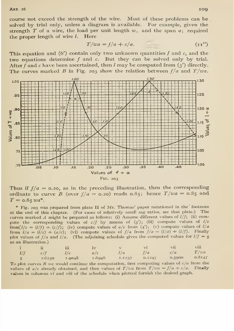
8/13/2019 Maurer Mechanics
http://slidepdf.com/reader/full/maurer-mechanics 121/407
Art. 26 109
course not exceed the strength of the wire. Most of these problems can be
solved by trial only, unless a diagram is available. For example, given the
strength T of a wire, the load per unit length w, and the span a; required
the proper length of wire /. Here
T/wa =f/a-\-
c/a. - (11 )
This equation and (6') contain only two unknown quantities / and c, and the
two equations determine / and c. But they can be solved only by trial.
After/ and c have been ascertained, then I may be computed from (3') directly.
The curves marked B in Fig. 203 show the relation between f/a and T/wa.
I.-30
MS
1.20 O•1-
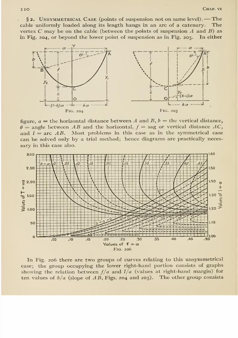
8/13/2019 Maurer Mechanics
http://slidepdf.com/reader/full/maurer-mechanics 122/407
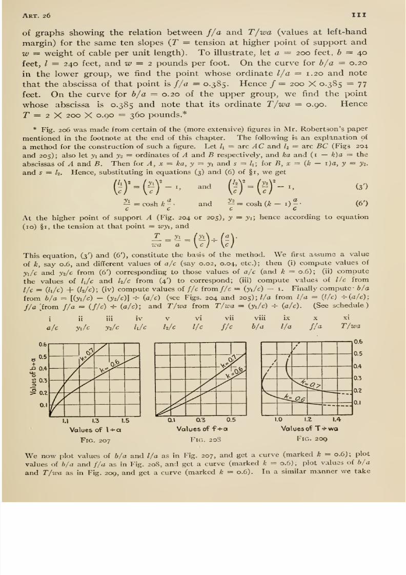
8/13/2019 Maurer Mechanics
http://slidepdf.com/reader/full/maurer-mechanics 123/407
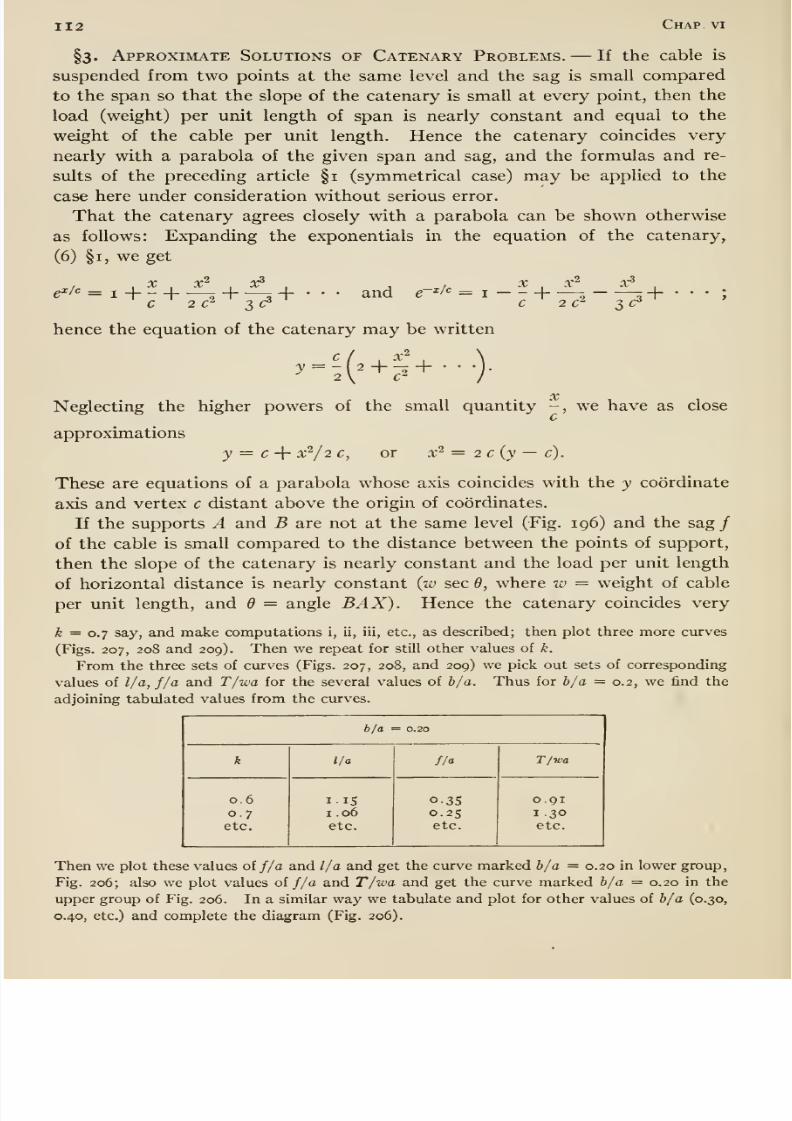
8/13/2019 Maurer Mechanics
http://slidepdf.com/reader/full/maurer-mechanics 124/407
112 Chap, vi
§3. Approximate Solutions of Catenary Problems. —If the cable is
suspended from two points at the same level and the sag is small compared
to the span so that the slope of the catenary is small at every point, then the
load (weight) per unit length of span is nearly constant and equal to the
weight of the cable per unit length. Hence the catenary coincides very
nearly with a parabola of the given span and sag, and the formulas and re-
sults of the preceding article §1 (symmetrical case) may be applied to the
case here under consideration without serious error.
That the catenary agrees closely with a parabola can be shown otherwise
as follows: Expanding the exponentials in the equation of the catenary,
(6) §1, we get
pX/c —+ —20^ 3 c^
andX̂ , x^ oc^ ,
C 2C^ 3 c *
hence the equation of the catenary may be written
3' = 7 2+^ +X
Neglecting the higher powers of the small quantity -, we have as close
approximations
y = c -\- x'^/2 c, or x ^ = 2 c (y — c).
These are equations of a parabola whose axis coincides with the y coordinate
axis and vertex c distant above the origin of coordinates.
If the supports A and B are not at the same level (Fig. ig6) and the sag /of the cable is small compared to the distance between the points of support,
then the slope of the catenary is nearly constant and the load per unit length
of horizontal distance is nearly constant {w sec 6, where iv = weight of cable
per unit length, and = angle BAX). Hence the catenary coincides very
k = 0.7 say, and make computations i, ii, iii, etc., as described; then plot three more curves(Figs. 207, 208 and 209). Then we repeat for still other values of k.
From the three sets of curves (Figs. 207, 208, and 209) we pick out sets of corresponding
values of l/a, f/a and T/wa for the several values of b/a. Thus for b/a = 0.2, we find the
adjoining tabulated values from the curves.
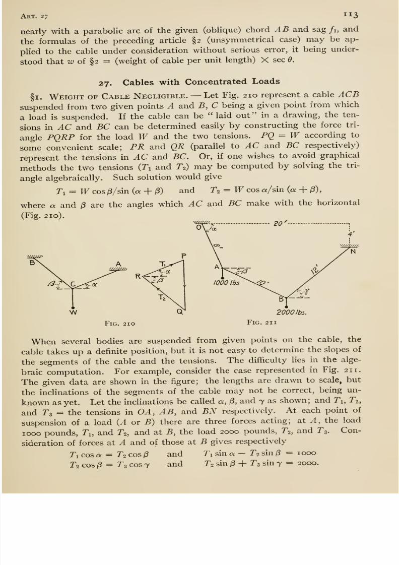
8/13/2019 Maurer Mechanics
http://slidepdf.com/reader/full/maurer-mechanics 125/407
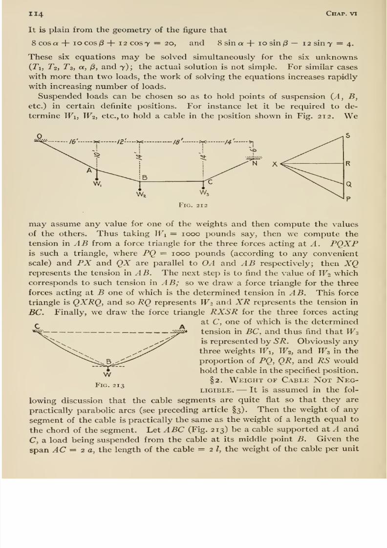
8/13/2019 Maurer Mechanics
http://slidepdf.com/reader/full/maurer-mechanics 126/407
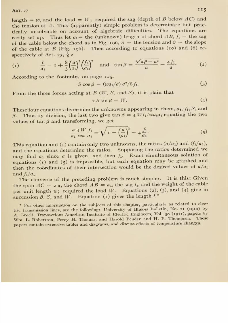
8/13/2019 Maurer Mechanics
http://slidepdf.com/reader/full/maurer-mechanics 127/407
Art. 27 115
length = w, and the load = W; required the sag (depth of B below AC) and
the tension at A. This (apparently) simple problem is determinate but prac-
tically unsolvable on account of algebraic difficulties. The equations are
easily set up. Thus let ai= the (unknown) length of chord AB,fi = the sag
of the cable below the chord as in Fig. 196, S = the tension and ^ = the slope
of the cable at B (Fig. 196). Then according to equations (10) and (6) re-
spectively of Art. 25, § 2
According to the footnote, on page 105.
5cosi3 = (7£'ai/a)aV8/i- (3)
From the three forces acting at B (IF, S, and S), it is plain that
2Ssin^ = W. (4)
These four equations determine the unknowns appearing in them, d, /i, S, and
/3. Thus by division, the last two give tan jS = 4 Wfi/waia; equating the two
values of tan /S and transforming, we get
»iZ/.=v/;rM'_,/.. (5)
ai wa ai \ai/ ai
This equation and (i) contain only two unknowns, the ratios (a/ai) and (/ i/ai),
and the equations determine the ratios. Supposing the ratios determined we
may find ai since a is given, and then /i. Exact simultaneous solution of
equations (i) and (5) is impossible, but each equation may be graphed and
then the coordinates of their intersection would be the desired values of c/ci
and/i/ai.
The converse of the preceding problem is much simpler. It is this: Given
the span AC = 2 a, the chord AB = ax, the sag/i, and the weight of the cable
per unit length w; required the load W. Equations (2), (3), and (4) give in
succession (3, S, and W. Equation (i) gives the length /.*
* For other information on the subjects of this chapter, particularly as related to elec-
tric transmission lines, see the following: University of Illinois Bulletin, No. 11 (191 2) by
A. Gruell; Transactions American Institute of Electric Engineers, Vol. 30 (191 1), papers by
Wm. L. Robertson, Percy H. Thomas, and Harold Pender and H. F. Thompson. These
papers contain extensive tables and diagrams, and discuss effects of temperature changes.

8/13/2019 Maurer Mechanics
http://slidepdf.com/reader/full/maurer-mechanics 128/407
8/13/2019 Maurer Mechanics
http://slidepdf.com/reader/full/maurer-mechanics 129/407
DYNAMICS
8/13/2019 Maurer Mechanics
http://slidepdf.com/reader/full/maurer-mechanics 130/407
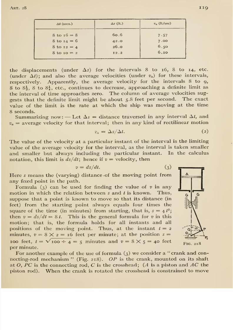
8/13/2019 Maurer Mechanics
http://slidepdf.com/reader/full/maurer-mechanics 131/407
Art. 28 119
At (sees.)
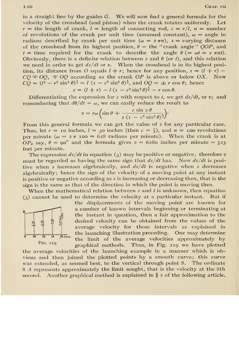
8/13/2019 Maurer Mechanics
http://slidepdf.com/reader/full/maurer-mechanics 132/407
1 20 Chap, vii
in a straight line by the guides G. We will now find a general formula for the
velocity of the crosshead (and piston) when the crank rotates uniformly. Let
r = the length of crank, / = length of connecting rod, c = r/l, n = number
of revolutions of the crank per unit time (assumed constant), co = angle in
radians described by crank per unit time (co = 2ivn), s = varying distance
of the crosshead from its highest position, 6 = the crank angle QOP, andt = time required for the crank to describe the angle 6 {= wt = 2 irnt).
Obviously, there is a definite relation between 5 and d (or /), and this relation
we need in order to get ds/dl or v. When the crosshead is in its highest posi-
tion, its distance from equals / + r; hence for any position, s = {I -\- r) —CQ T OQ, T OQ according as the crank OP is above or below OX. NowCQ = (/2 - r2 sin2 6)'^ = I {i - c^ sin^ 6)^, and 0Q= zLr cos 6; hence
5 = (l -{- r) — I (i — c ^ sin^ d)^ — r cos 6.
Differentiating the expression for s with respect to t, we get ds/dt, or v; and
remembering that dd/dt = w, we can easily reduce the result to
/ c sin 2 \
V 2(1 - c2sin2 0)V
From this general formula we can get the value of v for any particular case.
Thus, let r = 10 inches, / = 30 inches (then c = \), and n = 100 revolutions
per minute (w = 2 tt 100 = 628 radians per minute). When the crank is at
OPq say, d = 90° and the formula gives v = 6280 inches per minute = 523feet per minute.
The expression ds/dt in equation (3) may be positive or negative; therefore v
must be regarded as having the same sign that ds/dt has. Now ds/dt is posi-
tive when s increases algebraically, and ds/dt is negative when s decreases
algebraically; hence the sign of the velocity of a moving point at any instant
is positive or negative according as s is increasing or decreasing then, that is the
sign is the same as that of the direction in which the point is moving then.
When the mathematical relation between 5 and t is unknown, then equation
(3) cannot be used to determine the velocity at a particular instant. But if
the displacements of the moving point are known for
a number of known intervals beginning or terminating at
the instant in question, then a fair approximation to the
4 S ^ ^ desired velocity can be obtained from the values of the
? ?I I average velocity for those intervals as explained in
1 . i the launching illustration preceding. One may determine
the limit of the average velocities approximately byiG- 219
graphical methods. Thus, in Fig. 219 we have plotted
the average velocities of the launching example in a manner which is ob-
vious and then joined the plotted points by a smooth curve; this curve
was extended, as seemed best, to the vertical through point 8. The ordinate
8 A represents approximately the limit sought, that is the velocity at the 8th
second. Another graphical method is explained in § 2 of the following article.
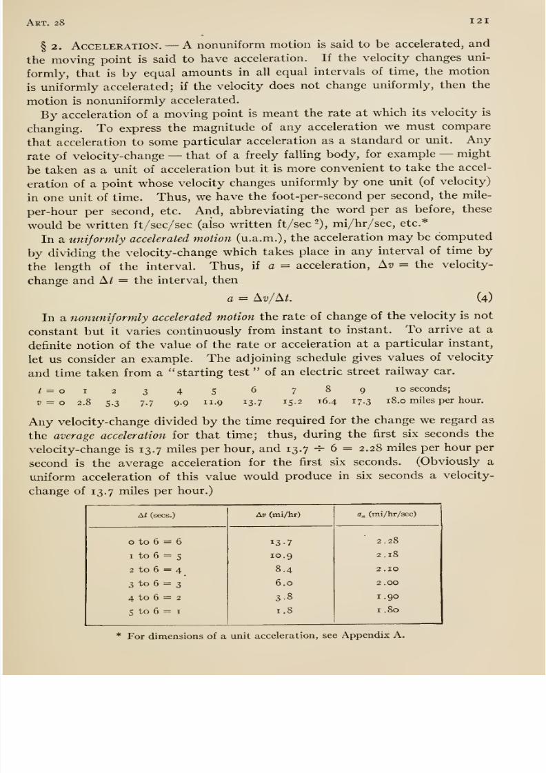
8/13/2019 Maurer Mechanics
http://slidepdf.com/reader/full/maurer-mechanics 133/407
Art. 28 121
§ 2. Acceleration. —A nonuniform motion is said to be accelerated, and
the moving point is said to have acceleration. If the velocity changes uni-
formly, that is by equal amounts in all equal intervals of time, the motion
is uniformly accelerated; if the velocity does not change uniformly, then the
motion is nonuniformly accelerated.
By acceleration of a moving point is meant the rate at which its velocity is
changing. To express the magnitude of any acceleration we must compare
that acceleration to some particular acceleration as a standard or unit. Any
rate of velocity-change —that of a freely falling body, for example —might
be taken as a unit of acceleration but it is more convenient to take the accel-
eration of a point whose velocity changes uniformly by one unit (of velocity)
in one unit of time. Thus, we have the foot-per-second per second, the mile-
per-hour per second, etc. And, abbreviating the word per as before, these
would be written ft/sec/sec (also written ft/sec 2), mi/hr/sec, etc.*
In a unijormly accelerated motion (u.a.m.), the acceleration may be computed
by dividing the velocity-change which takes place in any interval of time by
the length of the interval. Thus, if a = acceleration, ^v = the velocity-
change and A^ = the interval, then
a = ^v/^t. (4)
In a nonuniformly accelerated motion the rate of change of the velocity is not
constant but it varies continuously from instant to instant. To arrive at a
definite notion of the value of the rate or acceleration at a particular instant,
let us consider an example. The adjoining schedule gives values of velocity
and time taken from a starting test of an electric street railway car.
t = o
V = o
I
2.8 5-3
3
7-7
4
9.9
5 6 7 8 9 10 seconds;
II. 9 13.7 15.2 16.4 17.3 18.0 miles per hour.
Any velocity-change divided by the time required for the change we regard as
the average acceleration for that time; thus, during the first six seconds thevelocity-change is 13.7 miles per hour, and 13.7 -^ 6 = 2.28 miles per hour per
second is the average acceleration for the first six seconds. (Obviously a
uniform acceleration of this value would produce in six seconds a velocity-
change of 13.7 miles per hour.)
At (sees.)

8/13/2019 Maurer Mechanics
http://slidepdf.com/reader/full/maurer-mechanics 134/407
J 22 Chap, vn
In the adjoining table we have listed the velocity-changes (under Av)
for the intervals o to 6, i to 6, 2 to 6, etc.; and also the average accel-
eration (under da) for the same intervals. Obviously the average accelera-
tion for the intervals 5I to 6, 5 to 6, etc., continues to decrease, approaching
a definite limit as the interval approaches zero. The column of average
accelerations suggests that the definite limit might be about 1.7 miles per
hour per second. The exact value of the limit is the rate of change of
velocity, or the acceleration, when t was 6 seconds. >
Summarizing now: —Let Ay = the velocity-change in any interval of time
At, and a« = average acceleration for that interval, then in any kind of recti-
linear motionQa = Av/M. (5)
The true value of the acceleration at a particular instant of the interval is the
limiting value of the average acceleration as the time interval is taken smaller
and smaller but always including the particular instant; or in the calculus
notationa = dv/dt = dh/dt\ (6)
Formulas (6), respectively, can be used for finding the value of a in any
rectilinear motion if the relation between v and t or 5 and / are known. Thus
suppose that a point is known to move in a straight line so that the velocity
(in miles per hour) always equals one-tenth of the square of the time(in
seconds) from the start, that is 2; = o.i /-; then a = dv/dt = 0.2 t. This is
the general formula for a in this motion ; for instance, at 3 seconds after start-
ing a = 0.6 miles per hour per second.
For another example of the use of equation (6), we consider the motion of
the crosshead of the crank and connecting-rod mechanism described in § i.
There we found that
/ • /, 1c sin 2 ^ \
V 2(i-c2sin2 0)VDifferentiating this with respect to / and remembering that w is constant, we
get dv/dt or
c cos 2d -\- c^ sin^ d\a = rw^ ( cos 6 -f-
(i-c2sin2 0)^
From this general formula, we can get the value of a for any special case. Thus
as in § I, let r = 10 inches, / = 30 inches (then c = I), and n = 100 revolu-
tions per minute (c<)=27rioo=628 radians per minute). When the crank
is at OPo (Fig. 218), then 6 = go and the formula gives a = — 410 inches
per second per second. For meaning of negative sign, see next paragraph.
The expression dv/dt, equation (6), may be positive or negative; therefore a
must be regarded as having the same sign as has dv/dt. Now dv/dt is positive
when the velocity increases algebraically, and dv/dt is negative when the
velocity decreases algebraically; therefore the sign of the acceleration of a
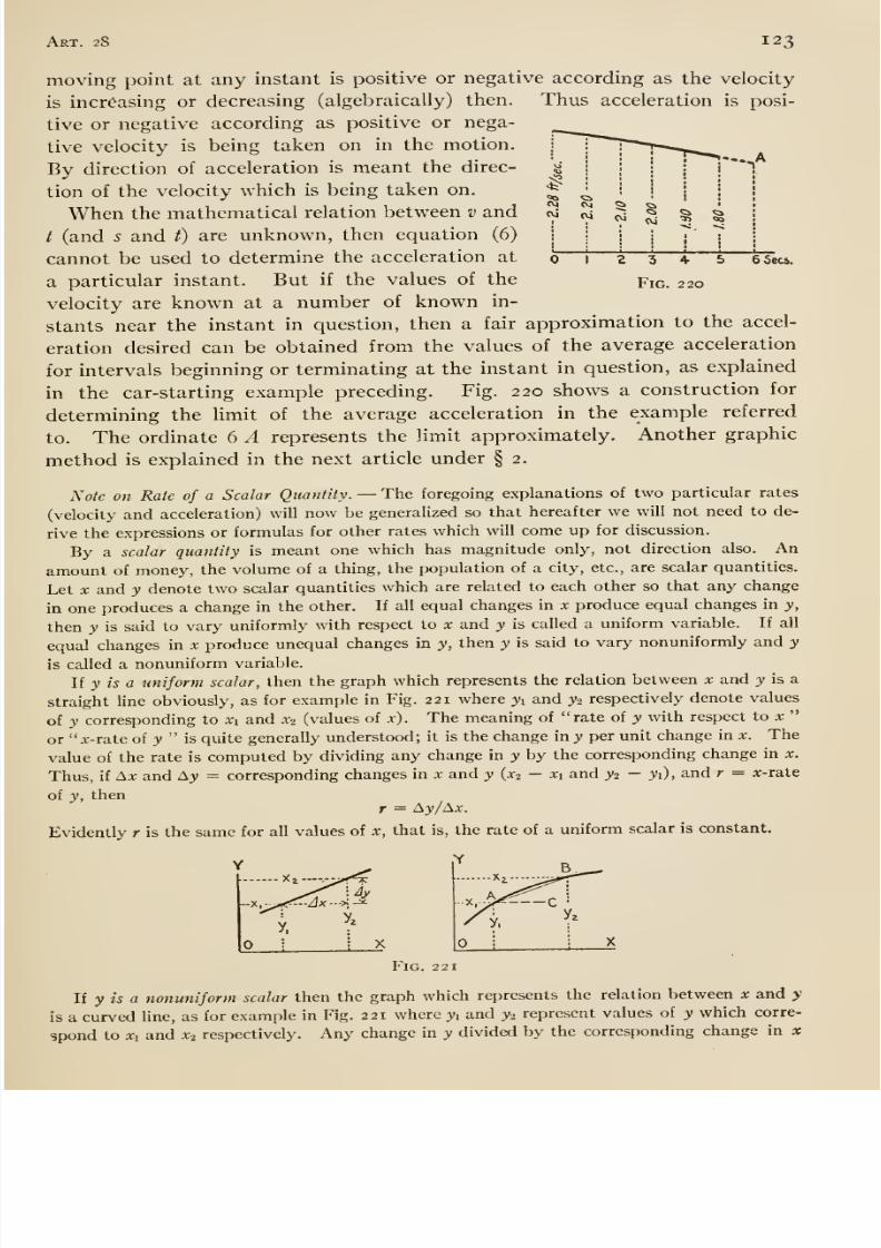
8/13/2019 Maurer Mechanics
http://slidepdf.com/reader/full/maurer-mechanics 135/407
8/13/2019 Maurer Mechanics
http://slidepdf.com/reader/full/maurer-mechanics 136/407
124 Chap, vii
is commonly called the average rate of y with respect to x for the range xi —X\. Thus, if
fa = average x-rate of y for the range Ax (= x^ — x\) in x, then
Ta = ^yl^x.
The average rate is represented by the slope of the chord AB, for tan BAC = ^y/^x.
The value of the average x-rate of y depends on the amount of the range A;r. It approaches
a definite value as Ax is taken smaller and smaller, x-i approaching .vi for instance. This limit-
ing value is taken as the true or instantaneous rate of y at the value y = yi{oix = X\). Thus,
if r = x-rate of y at any value of y, then
r = lim (Ay /Ax) = dy/dx.
The x-rate of y at y = yi is represented by the limit of the slope of the chord ^5 as 5 ap-
proaches A, that is, by the slope of the tangent at A.
By means of the foregoing formula, we can determine the .x-rate of y provided that we know
the precise relation between x and y, that is, the equation y = / (x). In case we do not know
this equation but do know values of y corresponding to several values of x, then we can de-
termine the x-rate of y at one of the values of x approximately. This approximate value can
be obtained from the average rates for ranges of x which begin or terminate at the value of
X for which the rate is desired as already explained in some of the preceding examples.
§ 3. Features of a Motion Determined by Integration. —In the
preceding article we showed how to determine the velocity from the dis-
tance-time {s-t) law, and the acceleration from the velocity-time {v-t) law.
The process, in each case, is one of differentiation. By means of the reverse
process, integration, one may determine the s-l from the v-t law, and the v-t
from the a-t law. We explain further by means of examples.
Suppose that a point moves in a straight line according to the law v = dot
+ 4. In all cases of rectilinear motion v — ds/dt, or ds = v dt; hence in the
present instance, ds = (60 / + 4) dl. Integration gives s = ^ot'^ -\- ^t + C,
where C is a constant to be determined from initial conditions. Let us sup-
pose that s is reckoned from the place where the moving point is when t = o,
or that 5 = when / = o; then substituting these (simultaneous) values of
5 and t in the equation containing C, we get o = o-|-
o + C,or
C= o.
Hencethe s-t law is 5 = 30 f^ + 4 /. We might have integrated between limits,
thus Jds = I (60 / + 4) dt, or 5 = 30 /2 -f 4 /,
t/O
the lower limits being the simultaneous values of s and / from the given initial
conditions.
For another example, we will suppose that a point moves in a straight line
so that a=
cost, initial conditions being v =
4when / = o.
In all cases of rectilinear motion a = dv/dt, or dv = adt; hence, in this
instance, dv = cos tdt. Integration gives t; = sin / + C. Substituting the
(initial) simultaneous values of v and / in this equation we find 4 = o + C, or
C = 4; hence z) = sin / -f 4 is the law sought. Or, integrating between limits
we get
COS tdt, or y —4 = sin t.dv= rt/4 t/0
8/13/2019 Maurer Mechanics
http://slidepdf.com/reader/full/maurer-mechanics 137/407
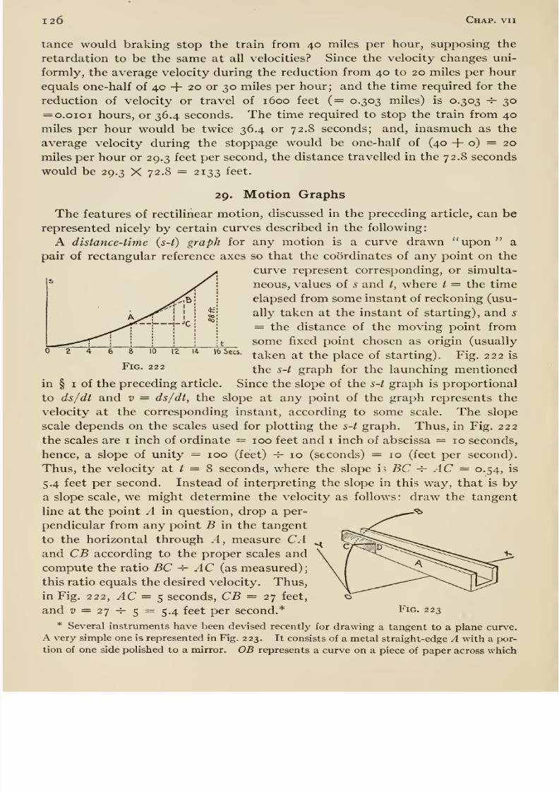
8/13/2019 Maurer Mechanics
http://slidepdf.com/reader/full/maurer-mechanics 138/407
126 Chap, vii
tance would braking stop the train from 40 miles per hour, supposing the
retardation to be the same at all velocities? Since the velocity changes uni-
formly, the average velocity during the reduction from 40 to 20 miles per hour
equals one-half of 4c + 20 or 30 miles per hour; and the time required for the
reduction of velocity or travel of 1600 feet (= 0.303 miles) is 0.303 -^ 30
= 0.0101 hours, or 36.4 seconds. The time required to stop the train from 40
miles per hour would be twice 36.4 or 72.8 seconds; and, inasmuch as the
average velocity during the stoppage would be one-half of (40 -f o) = 20
miles per hour or 29.3 feet per second, the distance travelled in the 72.8 seconds
would be 29.3 X 72.8 = 2133 feet.
29. Motion Graphs
The features of rectilinear motion, discussed in the preceding article, can be
represented nicely by certain curves described in the following:
A distance-time (s-t) graph for any motion is a curve drawn upon a
pair of rectangular reference axes so that the coordinates of any point on the
curve represent corresponding, or simulta-
neous, values of s and t, where t = the time
elapsed from some instant of reckoning (usu-
ally taken at the instant of starting), and 5
= the distance of the moving point from
some fixed point chosen as origin (usually
taken at the place of starting). Fig. 222 is
the s-t graph for the launching mentioned
in § I of the preceding article. Since the slope of the s-t graph is proportional
to ds/dt and v = ds/dt, the slope at any point of the graph represents the
velocity at the corresponding instant, according to some scale. The slope
scale depends on the scales used for plotting the s-t graph. Thus, in Fig. 222
the scales are i inch of ordinate = 100 feet and i inch of abscissa = 10 seconds,
hence, a slope of unity = 100 (feet) ^10 (seconds) = 10 (feet per second).
Thus, the velocity at / = 8 seconds, where the slope h BC -^ AC = 0.54, is
5.4 feet per second. Instead of interpreting the slope in this way, that is bya slope scale, we might determine the velocity as follows: draw the tangent
line at the point A in question, drop a per-
pendicular from any point B in the tangent
to the horizontal through A, measure CAand
CBaccording to the proper scales and
compute the ratio BC h- AC (as measured);
this ratio equals the desired velocity. Thus,
in Fig. 222, AC = 5 seconds, CB = 27 feet,
and ^ = 27 ^ 5 = 5.4 feet per second.*
* Several instruments have been devised recently for drawing a tangent to a plane curve.
A very simple one is represented in Fig. 223. It consists of a metal straight-edge A with a por-
tion of one side polished to a mirror. OB represents a curve on a piece of paper across which
16 Sees.
Fig. 222
Fig. 223
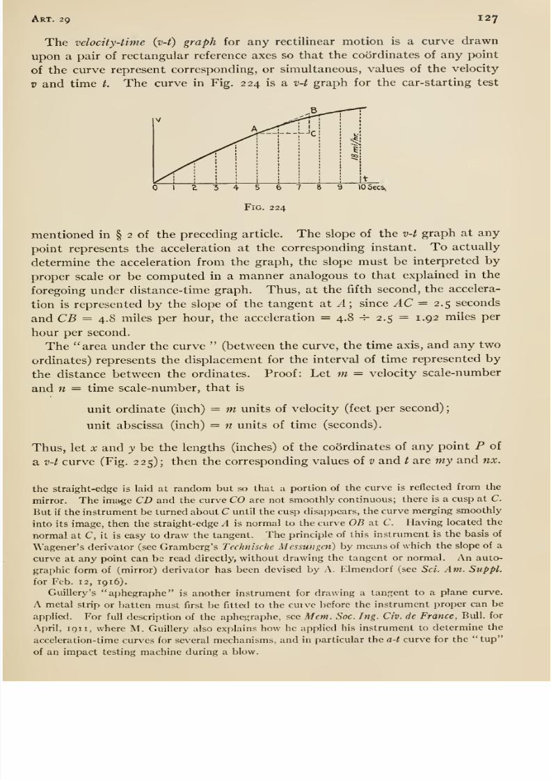
8/13/2019 Maurer Mechanics
http://slidepdf.com/reader/full/maurer-mechanics 139/407
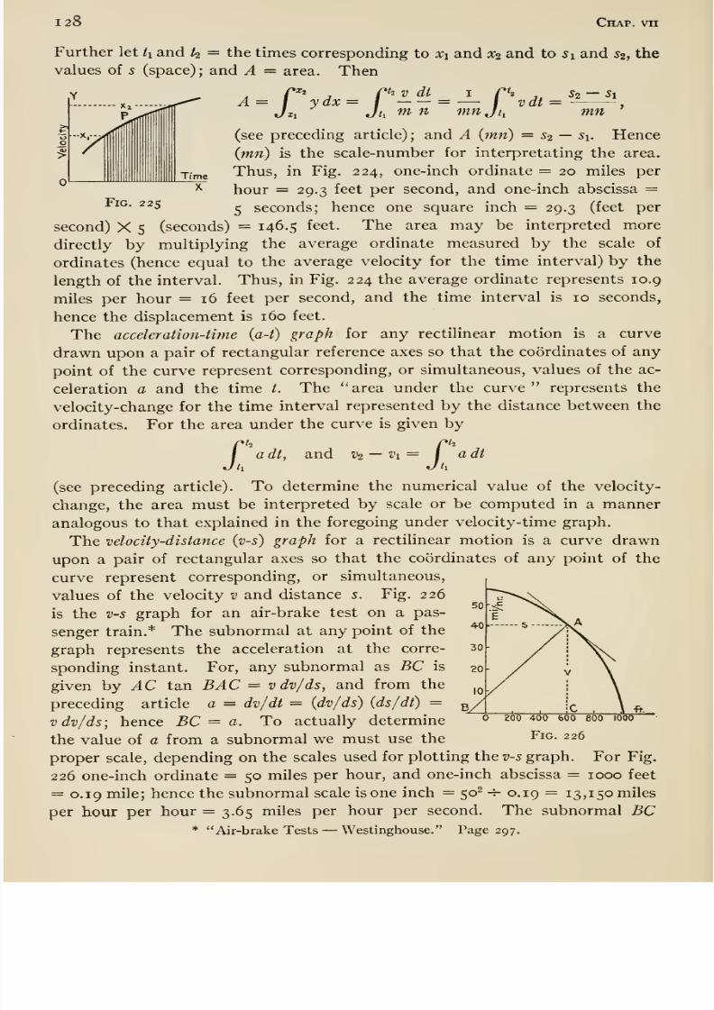
8/13/2019 Maurer Mechanics
http://slidepdf.com/reader/full/maurer-mechanics 140/407
128 Chap, vn
Further let h and k = the times corresponding to Xi and 3C2 and to Si and 52, the
values of s (space) ; and A = area. Then/»^j
, rkv dt I r'2,= 1 ydx = I
= — / vdt = S2 —S1
mn
(see preceding article) ; and A {mn) = s^ —Si. Hence
{mn) is the scale-number for interpretating the area.
Thus, in Fig. 224, one-inch ordinate = 20 miles per
hour = 29.3 feet per second, and one-inch abscissa =Fig. 225
^ seconds; hence one square inch = 29.3 (feet per
second) X 5 (seconds) = 146.5 feet. The area may be interpreted more
directly by multiplying the average ordinate measured by the scale of
ordinates (hence equal to the average velocity for the time interval) by the
length of the interval. Thus, in Fig. 224 the average ordinaterepresents
10.9miles per hour =16 feet per second, and the time interval is 10 seconds,
hence the displacement is 160 feet.
The acceleration-time {a-t) graph for any rectilinear motion is a curve
drawn upon a pair of rectangular reference axes so that the coordinates of any
point of the curve represent corresponding, or simultaneous, values of the ac-
celeration a and the time /. The area under the curve represents the
velocity-change for the time interval represented by the distance between the
ordinates. For the area under the curve is given by
a dt, and Vi —V\= I adth Jh
(see preceding article). To determine the numerical value of the velocity-
change, the area must be interpreted by scale or be computed in a manner
analogous to that explained in the foregoing under velocity-time graph.
The velocity-distance {v-s) graph for a rectilinear motion is a curve drawn
upon a pair of rectangular axes so that the coordinates of any point of the
curve represent corresponding, or simultaneous,
values of the velocity v and distance s. Fig. 226
is the v-s graph for an air-brake test on a pas-
senger train.* The subnormal at any point of the
graph represents the acceleration at the corre-
sponding instant. For, any subnormal as BC is
given by ^C tan BAC = vdv/ds, and from the
preceding article a = dv/dt = {dv/ds) {ds/dt) =vdv/ds; hence BC = a. To actually determine
the value of a from a subnormal we must use the
proper scale, depending on the scales used for plotting the v-s graph. For Fig.
226 one-inch ordinate = 50 miles per hour, and one-inch abscissa = 1000 feet
= 0.19 mile; hence the subnormal scale is one inch = 50' -r- 0.19 = 13,150 miles
per hour per hour = 3.65 miles per hour per second. The subnormal BC* Air-brake Tests —Westinghouse. Page 297.
200 400 60O 800 1000
Fig. 226
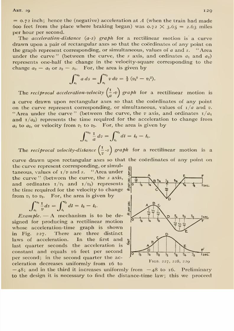
8/13/2019 Maurer Mechanics
http://slidepdf.com/reader/full/maurer-mechanics 141/407
Art. 29 129
= 0.72 inch; hence the (negative) acceleration at A (when the train had made600 feet from the place where braking began) was 0.72 X 3.65 = 2.63 miles
per hour per second.
The acceleration-distance (as) graph for a rectilinear motion is a curve
drawn upon a pair of rectangular axes so that the coordinates of any point on
the graph represent corresponding, or simultaneous, values of a and s. Area
under the curve (between the curve, the 5 axis, and ordinates ai and a2)
represents one-half the change in the velocity-square corresponding to the
change o^ — ai or ^2 — ^i. For, the area is given by
ads = I vdv = ^ {v^ — v^).
motion ishe. reciprocal acceleration-velocity {- -v\ graph for a rectilinear
a curve drawn upon rectangular axes so that the coordinates of any point
on the curve represent corresponding, or simultaneous, values of i/a and v.
Area under the curve (between the curve, the v axis, and ordinates i/ai
and 1/C2) represents the time required for the acceleration to change from
ai to 02, or velocity from Vi to V2- For, the area is given by
^dv= I dt= k- k.I), d Jh
The reciprocal velocity-distance {--s\ graph for a rectilinear motion IS a
curve drawn upon rectangular axes so that the coordinates of any point on
the curve represent corresponding, or simul-
taneous, values of i/v and 5. Area under
the curve (between the curve, the s axis,
and ordinates i/i'i and i/v^) represents
the time required for the velocity to change
from V\ to V2. For, the area is given by
I sec.
dt = t^ — tu
I sec.xample. —A mechanism is to be de-
signed for producing a rectiUnear motion
whose acceleration-time graph is shown
in Fig. 227. There are three distinct
laws of acceleration. In the first and
last quarter seconds the acceleration is
constant and equals 16 feet per second
per second; in the second quarter the ac-
celeration decreases uniformly from 16 to
—48; and in the third it increases uniformly from —48 to 16. Preliminary
to the design it is necessary to find the distance-time law; this we proceed
I'A ^/8 z % %Figs. 227, 228, 229
FI sec.
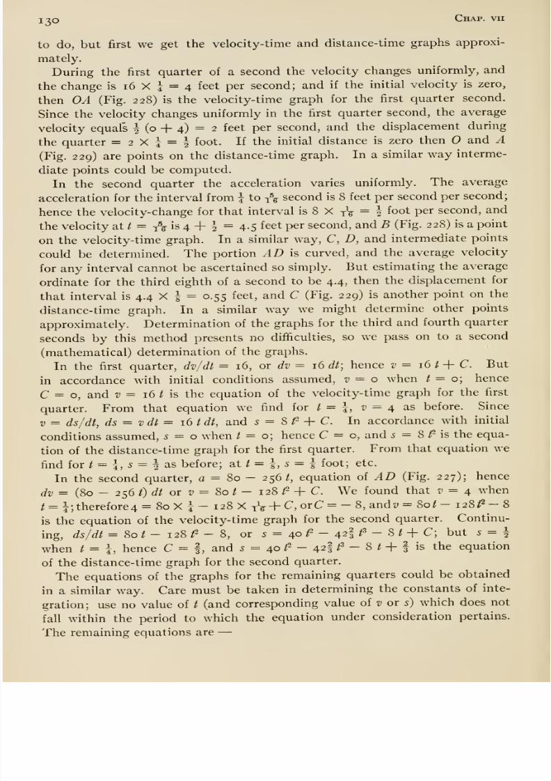
8/13/2019 Maurer Mechanics
http://slidepdf.com/reader/full/maurer-mechanics 142/407
i^o Chap, vii
to do, but first we get the velocity-time and distance-time graphs approxi-
mately.
During the first quarter of a second the velocity changes uniformly, and
the change is i6 X j = 4 feet per second; and if the initial velocity is zero,
then OA (Fig. 228) is the velocity- time graph for the first quarter second.
Since the velocity changes uniformly in the first quarter second, the average
velocity equals | (o -f 4) = 2 feet per second, and the displacement during
the quarter =2X5 = ^ foot. If the initial distance is zero then and A(Fig. 229) are points on the distance-time graph. In a similar way interme-
diate points could be computed.
In the second quarter the acceleration varies uniformly. The average
acceleration for the interval from | to t^ second is 8 feet per second per second;
hence the velocity-change for that interval is 8 X yV = 2 foot per second, and
the velocity at / = /^ is 4 -|- ^ = 4.5 feet per second, and B (Fig. 228) is a point
on the velocity-time graph. In a similar way, C, D, and intermediate points
could be determined. The portion AD is curved, and the average velocity
for any interval cannot be ascertained so simply. But estimating the average
ordinate for the third eighth of a second to be 4.4, then the displacement for
that interval is 4.4 X | = 0.55 feet, and C (Fig. 229) is another point on the
distance- time graph. In a similar way we might determine other points
approximately. Determination of the graphs for the third and fourth quarter
seconds by this method presents no difficulties, so we pass on to a second
(mathematical) determination of the graphs.
In the first quarter, dv/dt = 16, or dv = 16 dt; hence v -^ i6t+ C. But
in accordance with initial conditions assumed, v = o when / = o; hence
C = o, and z; = 16 / is the equation of the velocity-time graph for the first
quarter. From that equation we find for t = I, v = 4 as before. Since
V = ds/dt, ds = vdt = 16 tdt, and s = Sf + C. In accordance with initial
conditions assumed,s = o when / = o; hence C = o, and 5 = 8 ^ is the equa-
tion of the distance-time graph for the first quarter. From that equation we
find for / = I, 5 = I as before; at / = i 5 = | foot; etc.
In the second quarter, c = 80 - 256 /, equation of AD (Fig. 227); hence
dv = (80 - 256 /) (// or t' = 80 / - 128 /2 -f C. We found that v = 4 when
t = i;therefore4 = 80 X i - 128 X tV + C, orC = - 8, andz; =&ot- 128^-8
is the equation of the velocity-time graph for the second quarter. Continu-
ing, ds/dt = 80 / - 128 /2 - 8, or 5 = 40 /^ - 42I /^ - S / -h C; but S — 2
when / = I, hence C = f , and 5 = 40/^
- 42/^ -
8/
+ fis the equation
of the distance-time graph for the second quarter.
The equations of the graphs for the remaining quarters could be obtained
in a similar way. Care must be taken in determining the constants of inte-
gration; use no value of / (and corresponding value of v or s) which does not
fall within the period to which the equation under consideration pertains.
The remaining equations are —
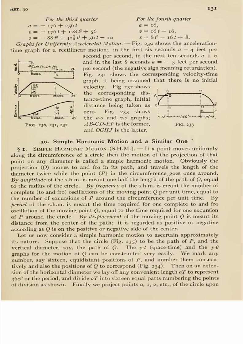
8/13/2019 Maurer Mechanics
http://slidepdf.com/reader/full/maurer-mechanics 143/407
rtRT. 30 131
4ft.persec.persec.
1 16 sees. 24
For the third quarter For the fourth quarter
a = — 176 + 256 1 c = 16,
2, = — 176 / + 128 /2 + 56 z; = 16 / — 16,
5= -88/2 + 421^+56/- 10 5=8/2-16/+ 8.
Graphs for Uniformly Accelerated Motion. —Fig. 230 shows the acceleration-
time graph for a rectilinear motion; in the first six seconds a = 4 feet per
second per second, in the next ten seconds a || o
and in the last 8 seconds a = — 3 feet per second
per second (the negative sign meaning retardation).
Fig. 231 shows the corresponding velocity-time
graph, it being assumed that there is no initial
velocity. Fig. 232 shows
the corresponding dis-
tance-time graph, initial
distance being taken as
zero. Fig. 233 shows
the as and v-s graphs;
AB-CD-EF is the former,
and OGHJ is the latter.
6 sees.
O
3
6 sees. I6secs.24
15sec5.
5
\( 72 M-
Figs. 230, 231, 232
|D
IE IF
I 1
—240' ->k-96'->l
Fig. 233
30. Simple Harmonic Motion and a Similar One
§ I. Simple Harmonic Motion (S.H.M.). —If a point moves uniformly
along the circumference of a circle then the motion of the projection of that
point on any diameter is called a simple harmonic motion. Obviously the
projection {Q) moves to and fro in its path, and travels the length of the
diameter twice while the point (P) in the circumference, goes once around.
By amplitude of the s.h.m. is meant one-half the length of the path of Q, equal
to the radius of the circle, '^y frequency oi the s.h.m. is meant the number of
complete(to
andfro) oscillations of the moving point
Qper unit time, equal to
the number of excursions of P around the circumference per unit time. Byperiod of the s.h.m. is meant the time required for one complete to and fro
oscillation of the moving point Q, equal to the time required for one excursion
of P around the circle. By displacement of the moving point Q is meant its
distance from the center of the path; it is regarded as positive or negative
according as Q is on the positive or negative side of the center.
Let us now consider a simple harmonic motion to ascertain approximately
its nature. Suppose that the circle (Fig. 235) to be the path of P, and thevertical diameter, say, the path of Q. The y-t (space-time) and the y-d
graphs for the motion of Q can be constructed very easily. We mark any
number, say sixteen, equidistant positions of P, and number them consecu-
tively and also the positions of Q to correspond (Fig. 234). Then on an exten-
sion of the horizontal diameter we lay off any convenient length oT to represent
360° or the period, and divide oT into sixteen equal parts numbering the points
of division as shown. Finally we project points o, i, 2, etc., of the circle upon
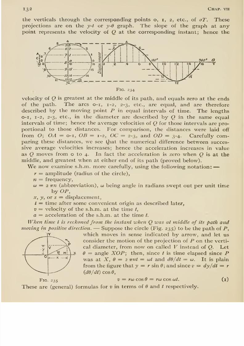
8/13/2019 Maurer Mechanics
http://slidepdf.com/reader/full/maurer-mechanics 144/407
132 Chap, vu
the verticals through the corresponding points o, i, 2, etc., of oT. These
projections are on the y-t or y-d graph. The slope of the graph at anypoint represents the velocity of Q at the corresponding instant; hence the
_2/'
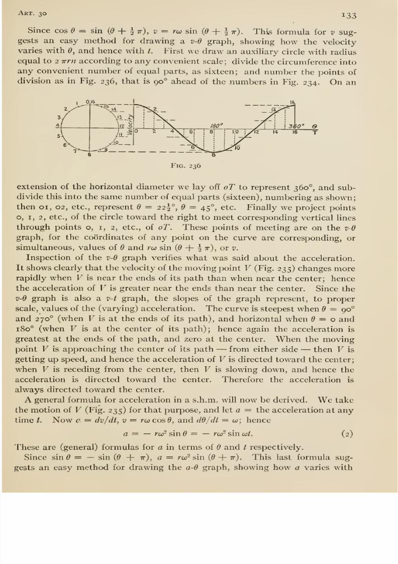
8/13/2019 Maurer Mechanics
http://slidepdf.com/reader/full/maurer-mechanics 145/407
Art. 30 133
Since cos 9 = sin (d -\- ^ir), v = m sin (5 + § tt). This formula for v sug-
gests an easy method for drawing a v-d graph, showing how the velocity
varies with d, and hence with /. First we draw an auxiliary circle with radius
equal to 2 Trn according to any convenient scale; divide the circumference into
any convenient number of equal parts, as sixteen; and number the points of
division as in Fig. 236, that is 90° ahead of the numbers in Fig. 234. On an
Fig. 236
extension of the horizontal diameter we lay off oT to represent 360°, and sub-
divide this into the same number of equal parts (sixteen), numbering as shown;
then 01, 02, etc., represent 6 = 22^°, 6 = 45°, etc. Finally we project points
o, I, 2, etc., of the circle toward the right to meet corresponding vertical lines
through points o, i, 2, etc., of oT. These points of meeting are on the v-9
graph, for the coordinates of any point on the curve are corresponding, orsimultaneous, values of d and rw sin (^ + | tt) , or v.
Inspection of the v-d graph verifies what was said about the acceleration.
It shows clearly that the velocity of the moving point V (Fig. 235) changes morerapidly when V is near the ends of its path than when near the center; hence
the acceleration of V is greater near the ends than near the center. Since the
v-d graph is also a v-t graph, the slopes of the graph represent, to proper
scale, values of the (varying) acceleration. The curve is steepest when 6 = 90°
and 270° (when V is at the ends of its path), and horizontal when = o and180° (when V is at the center of its path); hence again the acceleration is
greatest at the ends of the path, and zero at the center. When the movingpoint V is approaching the center of its path —from either side —then V is
getting up speed, and hence the acceleration of V is directed toward the center;
when V is receding from the center, then V is slowing down, and hence the
acceleration is directed toward the center. Therefore the acceleration is
always directed toward the center.
A general formula for acceleration in a s.h.m. will now be derived. We take
the motion of V (Fig. 235) for that purpose, and let a — the acceleration at any
time /. Now = dv/dt, v = rco cos0, and dd/dl — co; hence
a= — rorsind = — ror sin cct. (2)
These are (general) formulas for a in terms of d and t respectively.
Since sin = — sin {6 + tt), a = rw sin (d -\- ir). This last formula sug-
gests an easy method for drawing the a-9 graph, showing how a varies with
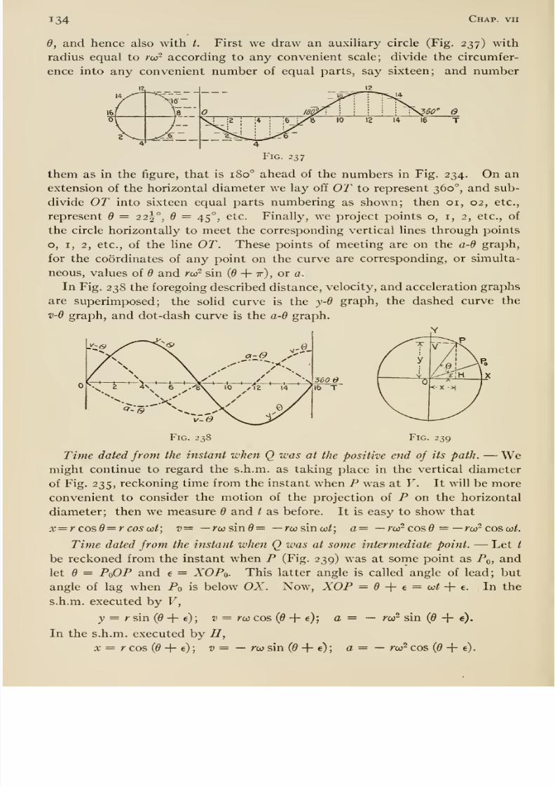
8/13/2019 Maurer Mechanics
http://slidepdf.com/reader/full/maurer-mechanics 146/407
134 Chap, vii
6, and hence also with t. First we draw an auxiUary circle (Fig. 237) with
radius equal to rw- according to any convenient scale; divide the circumfer-
ence into any convenient number of equal parts, say sixteen; and number
Fig. 237
them as in the figure, that is 180° ahead of the numbers in Fig. 234. On an
extension of the horizontal diameter we lay off OT to represent 360°, and sub-
divide OT into sixteen equal parts numbering as shown; then 01, 02, etc.,
represent d = 22^°, 6 = 45°, etc. Finally, we project points o, i, 2, etc., of
the circle horizontally to meet the corresponding vertical lines through points
o, I, 2, etc., of the Hne OT. These points of meeting are on the a-d graph,
for the coordinates of any point on the curve are corresponding, or simulta-
neous, values of 9 and rw^ sin (6 -\-ir), or a.
In Fig. 238 the foregoing described distance, velocity, and acceleration graphs
are superimposed; the solid curve is the y-d graph, the dashed curve the
v-d graph, and dot-dash curve is the a-d graph.
Fig. 238 Fig. 239
Time dated from the instant when Q was at the positive end of its path. —Wemight continue to regard the s.h.m. as taking place in the vertical diameter
of Fig. 235, reckoning time from the instant when P was at Y. It will be more
convenient to consider the motion of the projection of P on the horizontal
diameter; then we measure 6 and / as before. It is easy to show that
x=rcosd = rcoso:t; v= —r(j}sm6= —rcosinw/; a= —rw^ cos = —rco^ cos w/.
Time dated from the instant when Q was at some intermediate point. —Let /
be reckoned from the instant when P (Fig. 239) was at some point as Pq, and
let 6 = PoOP and e = XOPo- This latter angle is called angle of lead; but
angle of lag when Po is below OX. Now, XOP = + e = co/ + e. In the
s.h.m. executed by V,
J = r sin (^ + e) ; v = rco cos (0 -f- e); a = — r(j? sin (0 + e).
In the s.h.m. executed by ZT,
x = r cos (0 -F e) ; z; = — rw sin (5 + e) ; a= — to? cos (0 + e).
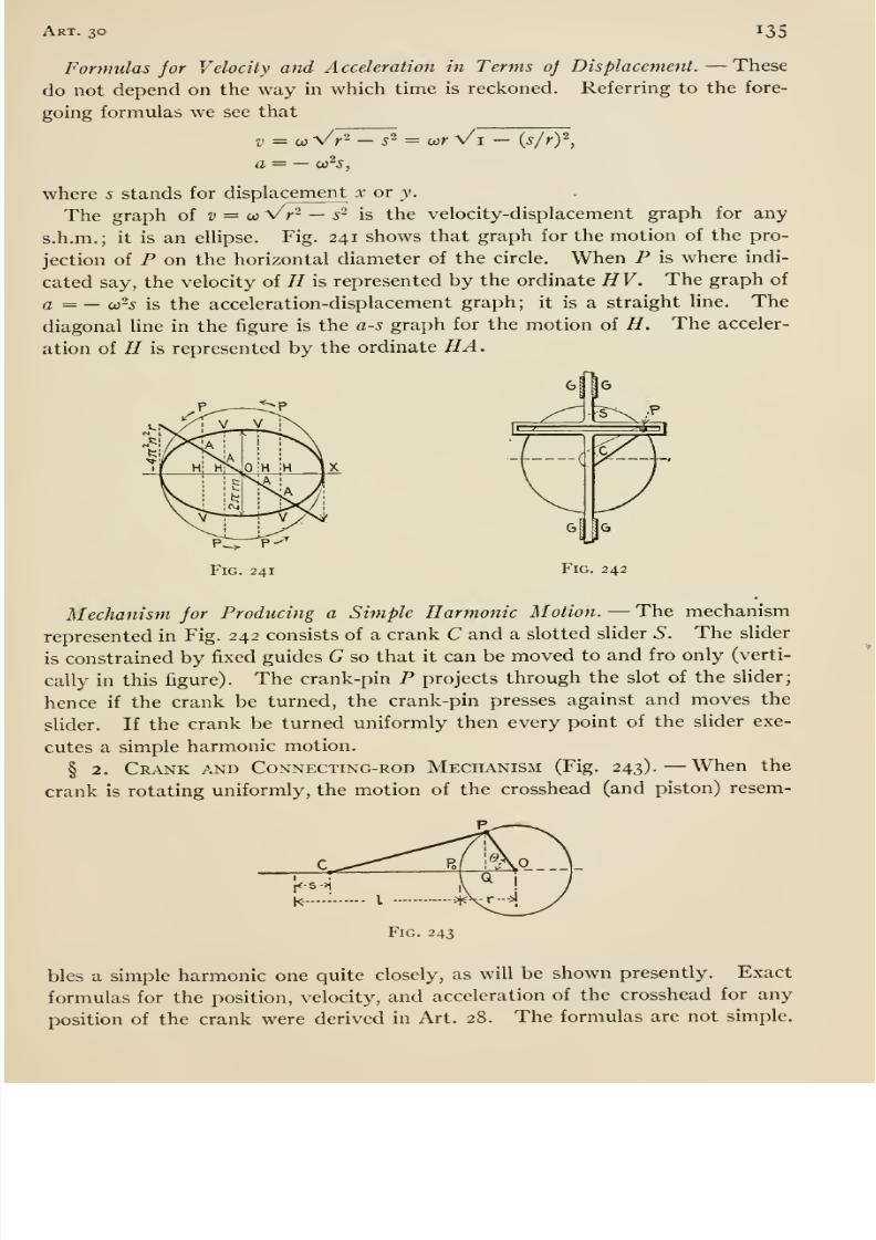
8/13/2019 Maurer Mechanics
http://slidepdf.com/reader/full/maurer-mechanics 147/407
Art. 30 135
Formulas jor Velocity and A cceleration in Terms oj Displacement. —These
do not depend on the way in which time is reckoned. Referring to the fore-
going formulas we see that
V = 0} Vr^ — s ^ = ior Vi — {s/rY,
a co'̂ s.
where 5 stands for displa cement x or y.
The graph oi v = 0: Vr^ — s~ is the velocity-displacement graph for any
s.h.m.; it is an ellipse. Fig. 241 shows that graph for the motion of the pro-
jection of P on the horizontal diameter of the circle. When P is where indi-
cated say, the velocity of H is represented by the ordinate HV. The graph of
a = — co-5 is the acceleration-displacement graph ; it is a straight line. The
diagonal line in the figure is the a-s graph for the motion of H. The acceler-
ation of H is represented by the ordinate HA.
if Hi H
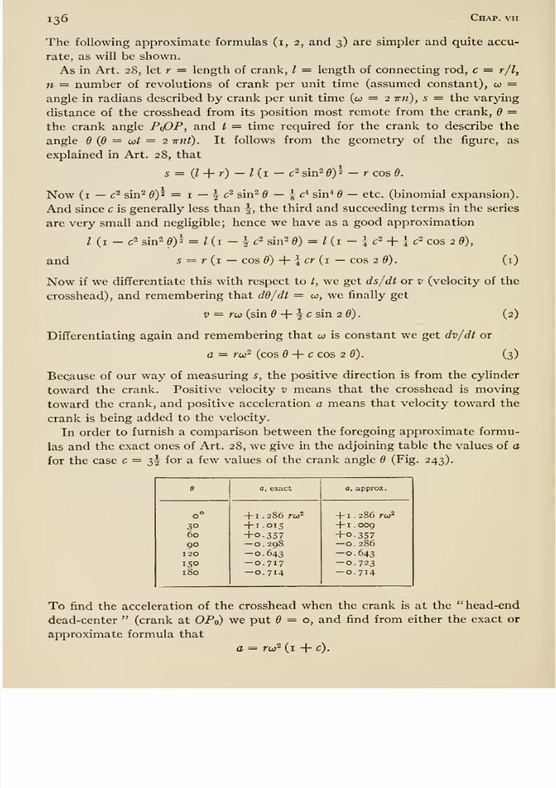
8/13/2019 Maurer Mechanics
http://slidepdf.com/reader/full/maurer-mechanics 148/407
136 Chap, vii
The following approximate formulas (i, 2, and 3) are simpler and quite accu-
rate, as will be shown.
As in Art. 28, let r = length of crank, I = length of connecting rod, c = r/l,
n = number of revolutions of crank per unit time (assumed constant), co =angle in radians described by crank per unit time (co = 2 ttw), s = the varying
distance of the crosshead from its position most remote from the crank, d =the crank angle PdOP, and t = time required for the crank to describe the
angle 6 {Q = oit = 2 -wnt). It follows from the geometry of the figure, as
explained in Art. 28, that
s= {l-\.r) -l{i- c ^ sin2 6)^ - r cos 6.
Now (i —c^ sin^ 0)2 = I —I c^ sin^ 6 — \d^ sin^ 6 — etc. (binomial expansion).
And since c is generally less than \, the third and succeeding terms in the series
are very small and negligible; hence we have as a good approximation
Ui - c2 sin2 0)^ = / (i - i c2 sin^ 0) = / (i - 1 c^ + 1 c^ cos 2 d),
and 5 = r (i —COS0) + 4 cr (i — cos 2 0). (i)
Now if we differentiate this with respect to t, we get ds/dt or v (velocity of the
crosshead), and remembering that dd/dt = co, we finally get
V = r(ji (sin + ^ c sin 26). (2)
Differentiating again and remembering that w is constant we get dv/dt or
a = ru)^ (cos 6 -{- c cos 2 6). (3)
Because of our way of measuring s, the positive direction is from the cylinder
toward the crank. Positive velocity v means that the crosshead is moving
toward the crank, and positive acceleration a means that velocity toward the
crank is being added to the velocity.
In order to furnish a comparison between the foregoing approximate formu-
las and the exact ones of Art. 28, we give in the adjoining table the values of a
for the case c = 32 for a few values of the crank angle d (Fig. 243).
e
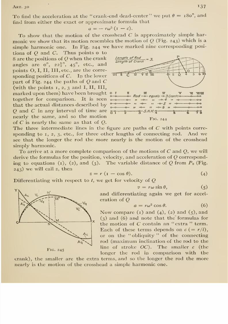
8/13/2019 Maurer Mechanics
http://slidepdf.com/reader/full/maurer-mechanics 149/407
Art. 30 137
Length of RodLength of Crank
0—0-O 1
m w VRod —o- equals -o- J Cranho-
» —o— „ -0-4 i> -o
t> -o— »? -0-5 ~° —;; -o— V -o- Q „ -o
»- J. //.//. -5 ^
yi VUVlll
—o—0-0
-0-0
-0-0
7 8
Fig. 244
To find the acceleration at the crank-end dead-center we put 6 = 180°, and
find from either the exact or approximate formula that
a = — rw- (i — c).
To show that the motion of the crosshead C is approximately simple har-
monic we show that its motion resembles the motion of Q (Fig. 243) which is a
simple harmonic one. In Fig. 244 we have marked nine corresponding posi-
tions of Q and C. Thus points o to
8 are the positions of Q when the crank
angles are 0°, 225°, 45°, etc., and
points O, I, II, III, etc., are the corre-
sponding positions of C. In the lower
part of Fig. 244 the paths of Q and C(with the points i, 2, 3 and I, II, III,
marked upon them) have been brought
together for comparison. It is seen
that the actual distances described by
Q and C in any interval of time are
nearly the same, and so the motion
of C is nearly the same as that of Q.
The three intermediate lines in the figure are paths of C with points corre-
sponding to I, 2, 3, etc., for three other lengths of connecting rod. And we
see that the longer the rod the more nearly is the motion of the crosshead
simply harmonic.
To arrive at a more complete comparison of the motions of C and Q, we will
derive the formulas for the position, velocity, and acceleration of Q correspond-
ing to equations (i), (2), and (3). The variable distance of Q from Po (Fig.
243) we will call z, thens = r (i —cos 6). (4)
Differentiating with respect to /, we get for velocity of
QV = rcc sin 6, (5)
and differentiating again we get for accel-
eration of Qa = ro} ^ cos 9. (6)
Now compare (i) and (4), (2) and (5), and
(3) and (6) and note that the formulas for
the motion of C contain an extra term.
Each of these terms depends on c (= r/l),
or on the obliquity of the connecting
rod (maximum inclination of the rod to the
line of stroke OC). The smaller c (the
longer the rod in comparison with the
crank), the smaller are the extra terms, and so the longer the rod the more
nearly is the motion of the crosshead a simple harmonic one.
Fig. 245
8/13/2019 Maurer Mechanics
http://slidepdf.com/reader/full/maurer-mechanics 150/407
138 Chap, vii
Fig. 245 presents a comparison of the motion of the crosshead C and the
motion of Q. The solid lines refer to the first motion and the dashed lines to
the second. Vc is the velocity-distance {v-s) graph and Ac is the acceleration-
distance (as) graph for the motion of C. Vq is the velocity-distance graph
and Aq is the acceleration-distance graph for the motion of Q. The graphs
for C were drawn for a connecting rod three cranks long (c = i -^ 3). Forlonger rods the graphs for C would come much nearer the graphs for Q.
31. Motion and Force
The preceding discussion of motion deals, for the most part, with displace-
ment, velocity, and acceleration; it does not refer at all to the forces acting
upon the moving bodies. In this article we explain in what manner any rec-
tilinear motion of a rigid body depends upon the forces acting upon it.
§ I. First View and Form of the Fundamental Principle. —In Art.
2 it is explained that the units of force most used by engineers are the so-called
gravitation iinits, equal to the earth-pulls on certain things called standards of
weight. These units have slightly different values at different places; thus
we have the London pound-force, the New York pound-force, etc. Somewriters define the pound-force as any force equal to the earth's attraction on
the standard pound weight at London or at sea level in latitude 45°, thus
making the unit force invariable or an absolute one. Besides these units
there are others; see § 2 of this article.
In Art. 2, we explained also that the word weight is used in at least two
senses in common parlance (see footnote, page 4). But we will continue to
use it in a single sense, to connote the earth-pull on a body, and we employ a
separate word (mass, see § 2 of this article) to connote the amount of substance
or stuff in a body. Our two weighing devices, beam-scale and spring-scale,
differ in a certain feature which is worth noting here. A beam-scale measures
the weight (earth-pull) of a body in terms of the local unit of force, say the
pound force for the place where the weighing is done; a spring-scale measures
the weight of a body in terms of an invariable unit, say the particular pound
force for which the scale was graduated. A beam-scale will not detect the
change in the weight of a body with change of place because the magnitude of
the unit (pull on the poise) changes just as the weight of the body changes.
A spring-scale if sufficiently accurate will detect change in weight with change
of place.
First-hand knowledge of the relation between motion and the forces acting
on the moving body must rest on observation or experiment. Let us consider
a simple case of motion, that of a falling body. The motion takes place under
the action of the weight of the body and the resistance of the surrounding air.
But if the falling body is quite dense, the air resistance is negligible compared
to the weight until the velocity becomes quite large. Observations have shown
that such a body falls with a constant acceleration of about 32 feet per second
per second at moderate velocities, and we infer that any force equal to the
8/13/2019 Maurer Mechanics
http://slidepdf.com/reader/full/maurer-mechanics 151/407
Art. 31 139
weight of the body would, if acting alone on that body, produce an acceleration
of the value stated.
We are now led to inquire what is the effect on a body of an applied force of
some other magnitude, say a force equal to double its weight or one-half its
weight? If we could intensify or dilute the earth-pull upon a body by a
(gravity) lens or screen, then we could make a body fall under a force differing
from its own weight and ascertain the answer to our question by observing the
fall. Unfortunately for our purpose, we cannot so concentrate or dilute the
force of gravity but we can dilute it indirectly by means of an Atwood ma-
chine, designed for that purpose. The essential parts of that machine are a
light pulley P mounted on a smooth horizontal axle (Fig. 246), some blocks of
metal which can be suspended as shown by a light flexible
cord, and a timing device for getting the acceleration of Aand B when the system is allowed to move. Neglecting the
small influence of the pulley, axle, and cord, we regard A and
B as the body moved and the difference in their weights
(Wb — Wa) as the driving force. Experiments with this ma-
chine show that A and B move with constant acceleration,
and when runs are made with various driving forces —all
metal pieces being used each time —then the acceleraUons in the ^^^.,
differeni runs are directly proportional to the driving forces. In
this machine the driving force can be made very small but it cannot be made
larger than the weight of all the metal pieces. It would seem that the force-
acceleration relation stated holds even for driving forces larger than the weight
of the body moved; and we assume that when any forces are applied successively
to the same body so as to make it move in g, straight line, then the accelerations are
proportional to the forces respectively. Or, if F and F' = the magnitudes of two
forces applied to any body in succession, and a and a' = the accelerations
respectively, then
F/F' = a/a'.
If IF = the weight of the body, g = the acceleration due to gravity (IF), Fand a as above, then the foregoing principle gives also F/W = a/g, or as it is
more commonly written, F = (W/g) a.
Generally, a moving body is under the influence of more than one force.
When the body moves in a straight line, the resultant of all the forces acting upon
it is a single force acting in the direction of the acceleration (proved in Art. 35).
Therefore the resultant has no component at right angles to the line of motion;
or, the algebraic sum of the components of all the forces acting on the body along
any line at right angles to the path equals zero. Thus, if the path is taken as an
X axis and two lines at right angles to each other and to the path as y and z
axes, thenSF„=o, 2F, = 0, and ^F, = R,
where SPx, ^Fy, and llF^ stand for the algebraic sums of the x, y, and 2 com-
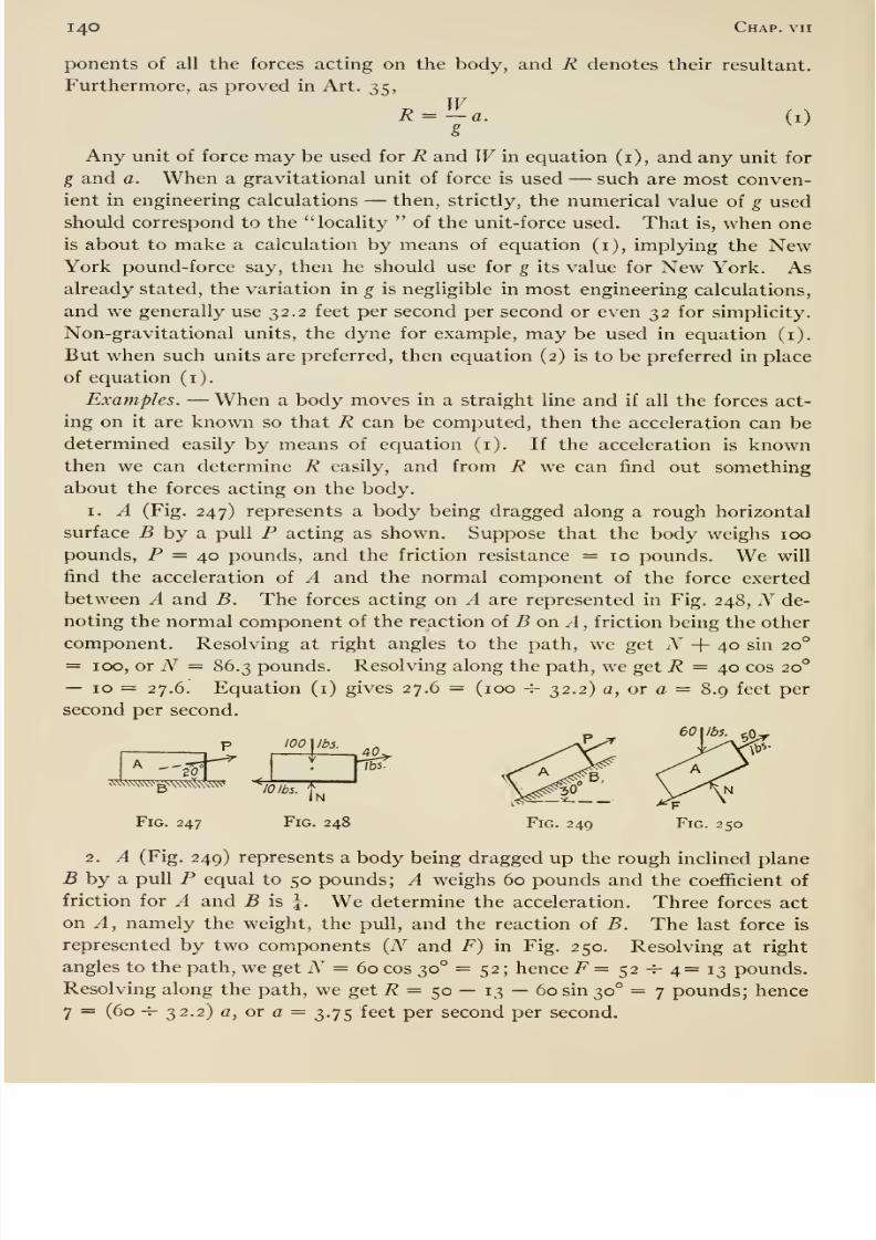
8/13/2019 Maurer Mechanics
http://slidepdf.com/reader/full/maurer-mechanics 152/407
140 Chap, vii
ponents of all the forces acting on the body, and R denotes their resultant.
Furthermore, as proved in Art. 35, W(i)? ^^K = —a.
Any unit of force may be used for R and Win equation (i), and any unit for
g and a. When a gravitational unit of force is used —such are most conven-
ient in engineering calculations —then, strictly, the numerical value of g used
should correspond to the locality of the unit-force used. That is, when one
is about to make a calculation by means of equation (i), implying the NewYork pound-force say, then he should use for g its value for New York. Asalready stated, the variation in g is negligible in most engineering calculations,
and we generally use 32.2 feet per second per second or even 32 for simplicity.
Non-gravitational units, the dyne for example, may be used in equation (i).
But when such units are preferred, then equation (2) is to be preferred in place
of equation (i).
Examples. —When a body moves in a straight line and if all the forces act-
ing on it are known so that R can be computed, then the acceleration can be
determined easily by means of equation (i). If the acceleration is knownthen we can determine R easily, and from R we can find out something
about the forces acting on the body.
I. A (Fig. 247) represents a body being dragged along a rough horizontal
surface 5 by a pull P acting as shown. Suppose that the body weighs 100
pounds, P = 40 pounds, and the friction resistance = 10 pounds. We will
find the acceleration of A and the normal component of the force exerted
between A and B. The forces acting on A are represented in Fig. 248, N de-
noting the normal component of the reaction oi B on A, friction being the other
component. Resolving at right angles to the path, we get N + 40 sin 20°
= 100, or iV = 86.3 pounds. Resolving along the path, we get i? = 40 cos 20°
— 10 = 27.6. Equation (i) gives 27.6 = (100 -r- 32.2) a, or a — 8.9 feet per
second per second.
A _-
tooI /b3.
Fig. 247
1^
/o
Fig. 248
40,lbs.
Fig. 249 Fig. 250
2. A (Fig. 249) represents a body being dragged up the rough inclined plane
5 by a pull P equal to 50 pounds; A weighs 60 pounds and the coefficient of
friction for A and B is I. We determine the acceleration. Three forces act
on A, namely the weight, the pull, and the reaction of B. The last force is
represented by two components (TV and F) in Fig. 250. Resolving at right
angles to the path, we get N = 60 cos 30° = 52 ; hence F = ^2 -^ 4= 1^ pounds.
Resolving along the path, we get 7? = 50 — 13 —60 sin 30° =7 pounds; hence
7 = (60 -^ 32.2) a, or a = 3.75 feet per second per second.
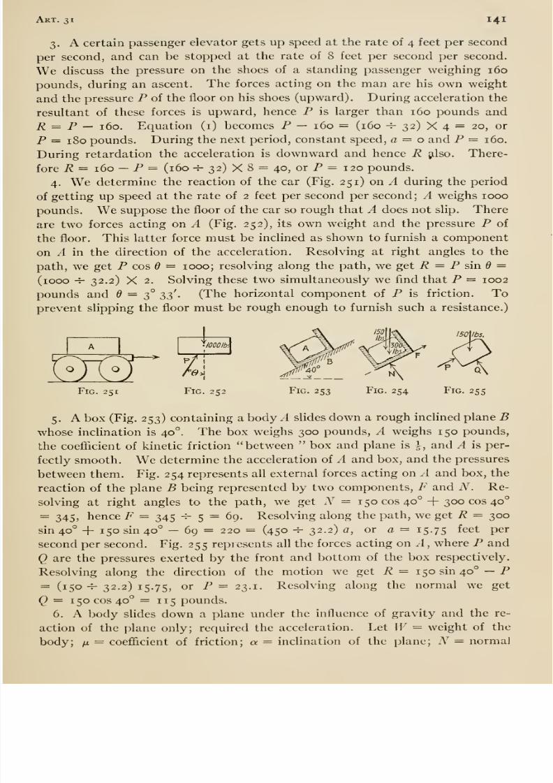
8/13/2019 Maurer Mechanics
http://slidepdf.com/reader/full/maurer-mechanics 153/407
Art. 31 141
3. A certain passenger elevator gets up speed at the rate of 4 feet per second
per second, and can be stopped at the rate of 8 feet per second per second.
We discuss the pressure on the shoes of a standing passenger weighing 160
pounds, during an ascent. The forces acting on the man are his own weight
and the pressure P of the floor on his shoes (upward). During acceleration the
resultant of these forces is upward, hence P is larger than 160 pounds andR = P — 160. Equation (i) becomes P — 160 = (160 -f- 32) X 4 = 20, or
P — 180 pounds. During the next period, constant speed, a = o and P — 160.
During retardation the acceleration is downward and hence R gilso. There-
fore R = 160 —P = (160 -h 32) X 8 = 40, or P = 120 pounds.
4. We determine the reaction of the car (Fig. 251) on A during the period
of getting up speed at the rate of 2 feet per second per second; A weighs 1000
pounds. We suppose the floor of the car so rough that A does not slip. There
are two forces acting on A (Fig. 252), its own weight and the pressure P of
the floor. This latter force must be inclined as shown to furnish a component
on A in the direction of the acceleration. Resolving at right angles to the
path, we get P cos 6 = 1000; resolving along the path, we get R = P sind =
(1000 -^ 32.2) X 2. Solving these two simultaneously we find that P = 1002
pounds and ^ = 3° Zi' • (The horizontal component of P is friction. Toprevent slipping the floor must be rough enough to furnish such a resistance.)
lOOOIbi
^3-1Fig. 251
^6'>i.
Fig. 252 Fig. 253
150Ibi,
8/13/2019 Maurer Mechanics
http://slidepdf.com/reader/full/maurer-mechanics 154/407
142 Chap, vii
pressure; and F = friction. Then resolving forces normally to the path we
get iV = M^ cos a; therefore F = ijlN = /AV cos a. Resolving along the path
we get R = Wsina —F = W(sin a — /jl cos a) = {W -^ g) a, or
a = g (sin a — (J. cos a)
If the plane is perfectly smooth n = o, and a — g sin a.
§ 2. Second View and Form of the Fundamental Principle. —Physi-
cists avoid the (common) double meaning of the word weight by employing
the word mass to connote amount of material, substance, or stuff, in a body,
and weight to connote the earth-pull on the body. Such usage is followed in
this book. Material is measured in different ways; for example, Hquids gen-
erally by gallon, earthwork by cubic yard, cloth by square yard, brick by thou-
sand, iron by ton, etc. But mass means amount of substance as measured
by a beam-scale. Our standards of mass (commonly and legally called stand-
ards of weight ) are the pound and the kilogram. These are certain pieces
of metal preserved in London and Paris respectively. The mass of a body,
measured as just explained, does not change with change of locality, and this
is in accordance with our conception of material, substance, or stuff.
The force-acceleration relation, F = (W/g) a, can be put into an alternative
form which is preferable from some points of view. Thus suppose that two
bodies whose weights at the same place are Wi and W2 are subjected to equal
forces F; let g = the acceleration due to gravity at the place and ai and a^
= the accelerations produced by the two forces F. Then F = (Wi/g) Ci
= Wi/g) 02, or
ai/a2 = W2/W1.
That is, the accelerations of the two bodies are inversely as their weights at the
same place; and since the masses of two bodies are proportional to the
weights (at the same place), the accelerations of the two bodies are inversely
proportional to their masses. This relation and that between the accelerations
produced in a body by two different forces acting singly can be expressed in
one statement as follows: —Whenever a force acts upon a body so as to make it
move in a straight line, then the acceleration produced is proportional to the force
directly and to the mass of the body inversely, or a ^F -^ m. This proportion-
ality can be put into the form of an equation,
F = Kma,
where i^T is a proportionality factor whose value depends on the units used
for expressing magnitudes of F, m, and a. This is the alternative form
mentioned.
We may fix the value of K in two ways: —(i) choose units of F, m, and a
at pleasure, and deduce the value of X; or (2) choose a value of K and units for
any two of the quantities F, m, and a, and then deduce the proper unit for the
third quantity. On plan (i) we choose, for example, the pound-force, the
pound-mass, and the foot per second per second as units for F, m, and a, and
8/13/2019 Maurer Mechanics
http://slidepdf.com/reader/full/maurer-mechanics 155/407
Art. 31 143
then determine K by reference to any motion in which F, m, and a are known.
The motion of a falling body is such a one. Thus when a body weighing
say 10 pounds falls, then F = 10 pounds, m = 10 pounds, and a = about 32.2
feet per second per second, and we have 10 = X X 10 X 32-2, or K = i -i-
32.2. On plan (2) we take K equal to unity for simplicity, and then (i) choose
units of m and a at pleasure, and deduce the proper unit of F; or (ii) chooseunits of F and a at pleasure, and deduce the proper unit of m. (i) Physicists
take the gram as unit mass, and the centimeter per second per second as unit
of acceleration; then the corresponding unit of force {K = i) is such a force as
would give to the gram an acceleration of one centimeter per second per
second. They call this force the dyne, (ii) If we take the pound as unit of
force, the foot per second per second as unit of acceleration, then the corre-
sponding unit of mass (K = i) is such a mass which will sustain an acceleration
of one foot per second per second under the action of a force of one pound.This unit of mass has no generally accepted name, but it is sometimes called
engineers' unit of mass, also slug and gee-pound.
A set of units for which A' = i is called a systematic set of units, also a
kinetic set. We will always use systematic units and thus always have F = ma,
or when several forces make a body move in a straight line,
R = ma. (2)
where R denotes the resultant of those forces. For a falling body R = Wanda = g; thus when systematic units are used
W= mg, or m = W/g. (3)
Therefore R = (W/g) a as in § i.
To arrive at a notion of the magnitude of the unfamiliar units dyne (force)
and slug (mass), let us consider the well-known force-mass-acceleration rela-
tion in the case of a falling body. A body whose mass is one gram, falling at
Paris, falls under the action of a force (earth-pull) of one Paris gram, and hasan acceleration of 981 centimeters per second per second. Hence a force of
0.001019 (= I -H 981) Paris grams would give to a body whose mass is one
gram an acceleration of one centimeter per second per second. Therefore
that force is the dyne, that is
I dyne = 0.001019 Paris grams (force).
A body whose mass is one pound, falling at London, falls under the action of a
force (earth-pull) of one London pound, and has an acceleration of 32.2 feet
per second per second. Hence a force of one London pound would give to a
body whose mass is 32.2 pounds an acceleration of one foot per second per
second. Therefore, that mass is the slug, that is
. I slug = 32.2 pounds (mass).
8/13/2019 Maurer Mechanics
http://slidepdf.com/reader/full/maurer-mechanics 156/407
CHAPTER VIII
CURVILINEAR MOTION
32. Velocity and Acceleration
§ I. Velocity. —In common parlance, velocity of a moving point at a
certain instant means the rate at which the point is describing distance then.
So understood, velocity has magnitude and sign only, and is therefore a scalar
quantity. In the preceding chapter (on rectilinear motion) we used the word
in this sense; in the present chapter weuse the
wordin a broader sense
—so
that it is a vector quantity whose magnitude is the rate at which the moving
point is describing distance at the instant in question and whose direction is
the same as that of the motion then.
If 5 = the (varying) distance of the moving point from some fixed origin
in the path, the distance being measured along the path, then the magnitude
of the velocity at any instant equals the value of ds/dt for that instant. Or if
V = magnitude of velocity,
V = ds/dt. (i)
If the point is moving uniformly, then the rate at which distance is described
is constant, and is given by As/^t, where As is the distance described in any
interval At. The direction of the motion at any instant (and the direction of
the velocity then) is along the tangent to the path at the position of the
moving point at that instant. To illustrate, imagine a lo-foot wheel mounted
on a horizontal axis which points north and south, and suppose that the wheel
is rotating at 180 revolutions per minute clockwise when viewed from the
south. When a certain point on the rim is in its highest position then the
velocity of the point has a magnitude of 2 tt 5 X 180 = 5655 feet per minute,
and the direction of the velocity is horizontal from west to east.
The magnitude part of a velocity is called speed by some writers; we follow
this usage. Thus in the preceding illustration the speed is 5655 feet per minute;
while the wheel turns, the speed of the point is constant but the velocity
changes in direction.
§ 2. Acceleration. —The acceleration of a moving point at any instant
is the rate at which its velocity —not speed —is changing then. If V de-
notes the (varying) velocity of a moving point and v the (varying) speed, then
the definition states that the acceleration is dV/dt and not dv/dt. Inasmuch
as most readers are unfamiliar with the rate of a vector quantity —the rate
chapters in most books on differential calculus deal with rates of scalar quanti-
ties only —we explain in considerable detail just what is meant by the rate ot
144
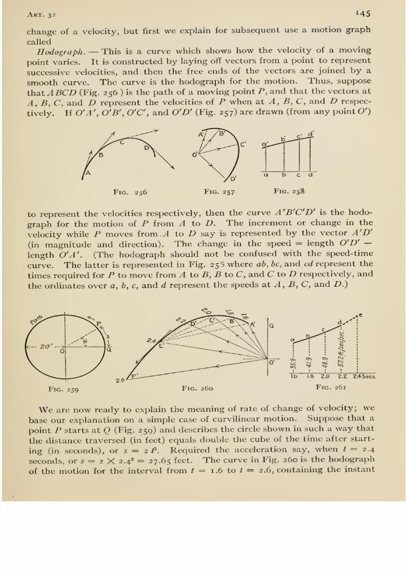
8/13/2019 Maurer Mechanics
http://slidepdf.com/reader/full/maurer-mechanics 157/407
Art. 32 H5
change of a velocity, but first we explain for subsequent use a motion graph
called
Hodo graph. —This is a curve which shows how the velocity of a moving
point varies. It is constructed by laying off vectors from a point to represent
successive velocities, and then the free ends of the vectors are joined by a
smooth curve. The curve is the hodograph for the motion. Thus, suppose
that A BCD (Fig. 256 ) is the path of a moving point P, and that the vectors at
A, B,C, and D represent the velocities of P when at A, B, C, and D respec-
tively. If 0'A\ O'B', O'C, and O'D' (Fig. 257) are drawn (from any point O')
Fig. 256
a bedFig. 258
to represent the velocities respectively, then the curve A'B'C'D' is the hodo-
graph for the motion of P from ^ to D. The increment or change in the
velocity while P moves from /I to D say is represented by the vector A'D'
(in magnitude and direction). The change in the speed = length O'D' —length O'A'. (The hodograph should not be confused with the speed- time
curve. The latter is represented in Fig. 25S where ab, he, and cd represent the
times required for P to move from A to B, B to C, and C to D respectively, and
the ordinates over a, b, c, and d represent the speeds 2XA,B, C, and D.)
Fig. 259 Fig. 260
1.8 2,0 2.2 2.4Secs.
Fig. 261
We are now ready to explain the meaning of rate of change of velocity; we
base our explanation on a simple case of curvilinear motion. Suppose that a
point P starts at Q (Fig. 259) and describes the circle shown in such a way that
the distance traversed (in feet) equals double the cube of the time after start-
ing (in seconds), or 5 = 2 t^. Required the acceleration say, when t = 2.4
seconds, or 5 = 2 X 2.4^ = 27.65 feet. The curve in Fig. 260 is the hodograph
of the motion for the interval from / = 1.6 to i = 2.6, containing the instant
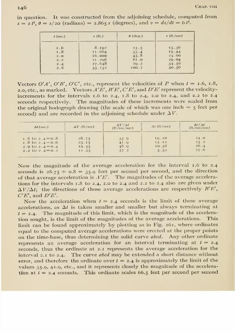
8/13/2019 Maurer Mechanics
http://slidepdf.com/reader/full/maurer-mechanics 158/407
146 Chap, viii
in question. It was constructed from the adjoining schedule, computed from
s = 2t^,d = s/20 (radians) = 2.865 ^ (degrees), and v = ds/dt = 6 P.
t (sec.)
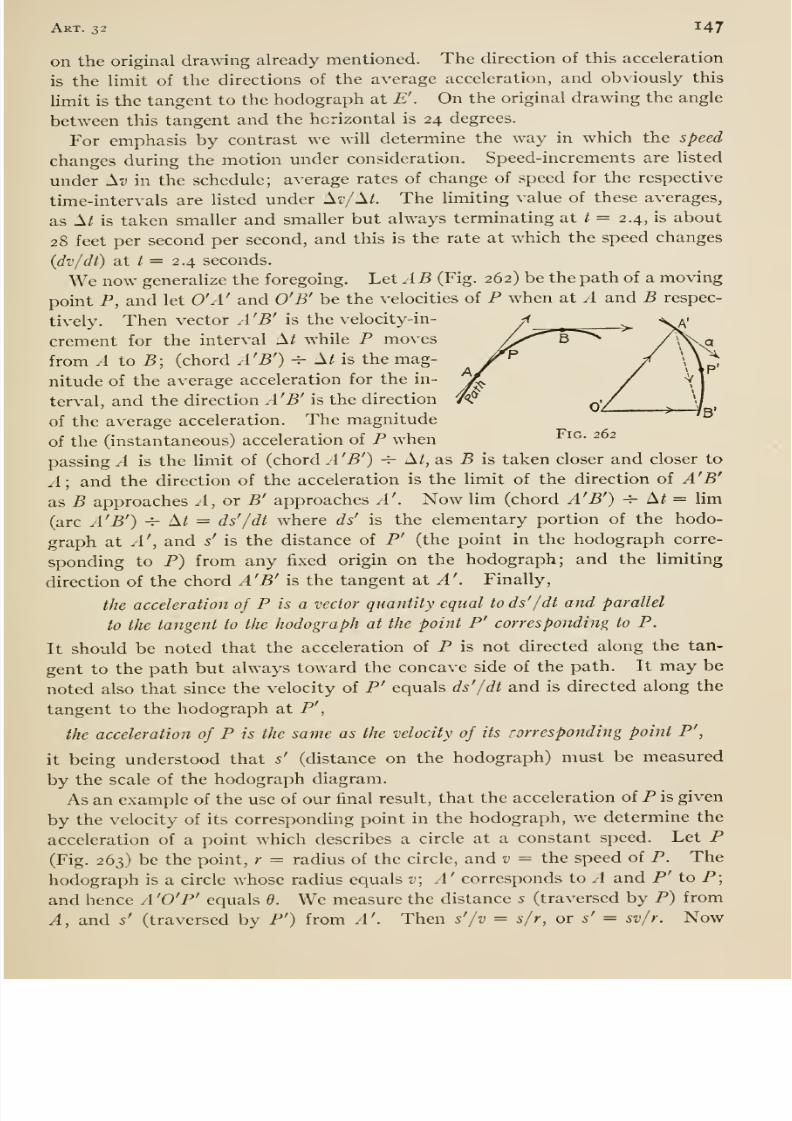
8/13/2019 Maurer Mechanics
http://slidepdf.com/reader/full/maurer-mechanics 159/407
Art. 32 147
on the original drawing already mentioned. The direction of this acceleration
is the limit of the directions of the average acceleration, and obviously this
limit is the tangent to the hodograph at £'. On the original drawing the angle
between this tangent and the horizontal is 24 degrees.
For emphasis by contrast we will determine the way in which the speed
changes during the motion under consideration. Speed-increments are listed
under H-o in the schedule; average rates of change of speed for the respective
time-intervals are listed under A17 A/. The luniting value of these averages,
as A^ is taken smaller and smaller but always termmating at / = 2.4, is about
28 feet per second per second, and this is the rate at which the speed changes
(dv/dt) at / = 2.4 seconds.
We now generalize the foregoing. Let A B (Fig. 262) be the path of a moving
point P, and let O'A' and O'B' be the velocities of P when at .4 and B respec-
tively. Then vector A'B' is the velocity-in-
crement for the interval A/ while P moves
from A to B; (chord A'B') -^ A/ is the mag-
nitude of the average acceleration for the in-
terval, and the direction A'B' is the direction
of the average acceleration. The magnitude
of the (instantaneous) acceleration of P when ^^^- ^^^
passing A is the limit of (chord .1 'B') 4- A/, as B is taken closer and closer to
A] and the direction of the acceleration is the limit of the direction of A'B'
as B approaches A,or B' approaches A'. Now hm (chord A'B') -^ A^ = lim
(arc A'B') -i- A/ = ds' /dt where ds' is the elementary portion of the hodo-
graph at A', and s' is the distance of P' (the point in the hodograph corre-
sponding to P) from any fixed origin on the hodograph; and the limiting
direction of the chord A'B' is the tangent at A'. Finally,
the acceleration of P is a vector quantity equal to ds' /dt and parallel
to the tangent to the hodograph at the point P' corresponding to P.
It should be noted that the acceleration of P is not directed along the tan-
gent to the path but always toward the concave side of the path. It may be
noted also that since the velocity of P' equals ds'/dt and is directed along the
tangent to the hodograph at P',
the acceleration of P is the same as the velocity of its rorresponding point P',
it being understood that s' (distance on the hodograph) must be measured
by the scale of the hodograph diagram.
As an example of the use of our final result, that the acceleration of P is given
by the velocity of its corresponding point in the hodograph, we determine the
acceleration of a point which describes a circle at a constant speed. Let P(Fig. 263) be the point, r = radius of the circle, and v = the speed of P. The
hodograph is a circle whose radius equals v\ A' corresponds to A and P' to P;
and hence A 'O'P' equals 6. We measure the distance 5 (traversed by P) from
A, and s' (traversed by P') from A'. Then s'/v = s/r, or s' = sv/r. Now
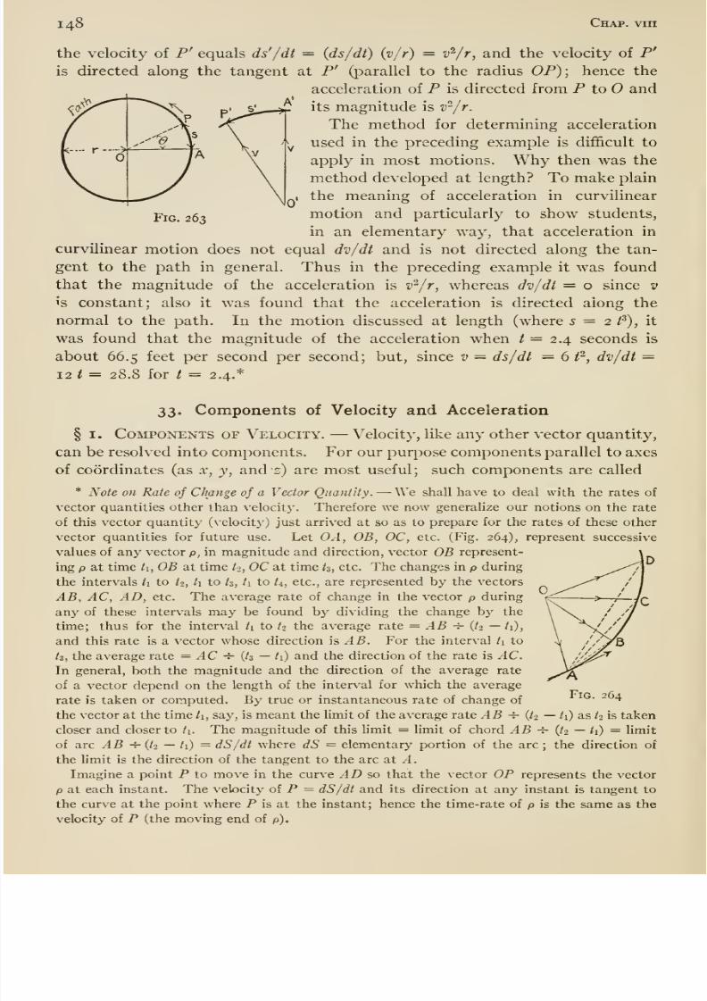
8/13/2019 Maurer Mechanics
http://slidepdf.com/reader/full/maurer-mechanics 160/407
148 Chap, vin
the velocity of P' equals ds' /dt = (ds/dt) (v/r) = v'^/r, and the velocity of P'
is directed along the tangent at P' (parallel to the radius OP); hence the
acceleration of P is directed from P to O and
its magnitude is v^/r.
The method for determining acceleration
used in the preceding example is diflScult to
apply in most motions. Why then was the
method developed at length? To make plain
the meaning of acceleration in curvilinear
motion and particularly to show students,
in an elementary way, that acceleration in
curvilinear motion does not equal dv/dt and is not directed along the tan-
gent to the path in general. Thus in the preceding example it was found
that the magnitude of the acceleration is v^/r, whereas dv/dt = o since v
is constant; also it was found that the acceleration is directed along the
normal to the path. In the motion discussed at length (where 5 = 2 /^), it
was found that the magnitude of the acceleration when / = 2.4 seconds is
about 66.5 feet per second per second; but, smce v = ds/dt = 6 f, dv/dt =12 t = 28.8 for t = 2.4.*
Fig. 263
33. Components of Velocity and Acceleration
§ I. Components of Velocity. —Velocity, like any other vector quantity,
can be resolved into components. For our purpose components parallel to axes
of coordinates (as x, y, and s) are most useful; such components are called
* Note on Rate of Change of a Vector Quantity. —We shall have to deal with the rates of
vector quantities other than velocity. Therefore we now generalize our notions on the rate
of this vector quantity (velocit}') just arrived at so as to prepare for the rates of these other
vector quantities for future use. Let OA, OB, OC, etc. (Fig. 264), represent successive
values of any vector p, in magnitude and direction, vector OB represent-
ing p at time ti, OB at time to, OC at time /s, etc. The changes in p during
the intervals ti to t^, ti to tz, /i to t^, etc., are represented by the vectors
AB, AC, AD, etc. The average rate of change in the vector p during
any of these intervals may be found by dividing the change by the
time; thus for the interval /i to tt the average rate = AB -r- (^2 —/i),
and this rate is a vector whose direction is AB. For the interval t\ to
tz, the average rate = AC -i- {tz —/i) and the direction of the rate is AC.In general, both the magnitude and the direction of the average rate
of a vector depend on the length of the interval for which the average
rate is taken or computed. By true or instantaneous rate of change of
the vector at the time ti, say, is meant the limit of the average rate AB -^ {t2 —/i) as ^2 is taken
closer and closer to ti. The magnitude of this limit = limit of chord AB -h (t-i — ti) = limit
of arc AB -r- {t2 — /i) = dS/dt where dS = elementary portion of the arc ; the direction of
the hmit is the direction of the tangent to the arc at A.
Imagine a point P to move in the curve AD so that the vector OP represents the vector
p at each instant. The velocity of P = dS/dt and its direction at any instant is tangent to
the curve at the point where P is at the instant; hence the time-rate of p is the same as the
velocity of P (the moving end of p).
Fig. 264
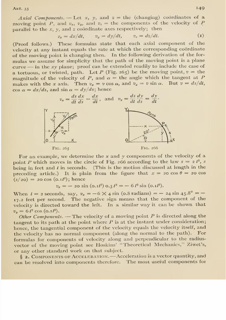
8/13/2019 Maurer Mechanics
http://slidepdf.com/reader/full/maurer-mechanics 161/407
Art. ss 149
Axial Components. —Let x, y, and s = the (changing) coordinates of a
moving point P, and v^, Vy, and v^ = the components of the velocity of Pparallel to the x, y, and s coordinate axes respectively; then
•i'l = dx/dt, Vy = dy/dt, v^ = dz/dt. (i)
(Proof follows.) These formulas state that each axial component of thevelocity at any instant equals the rate at which the corresponding coordinate
of the moving point is changing then. In the following derivation of the for-
mulas we assume for simplicity that the path of the moving point is a plane
curve —in the xy plane; proof can be extended readily to include the case of
a tortuous, or twisted, path. Let P (Fig. 265) be the moving point, v = the
magnitude of the velocity of P, and a = the angle which the tangent at Pmakes with the x axis. Then v^ = v cos a, and Vy = v sin a. But v = ds/dt,
cos a. = dx/ds, and sin a = dy/ds; hence
_ ds dx _ dx ,_dsdv _dy
' dlTs ~Tt' ^ ^ ^ ' '~ dtds ~ dl'
Fig. 265 Fig. 266
For an example, we determine the x and y components of the velocity of a
point P which moves in the circle of Fig. 266 according to the law 5=2 t'̂ , s
being in feet and / in seconds. (This is the motion discussed at length in the
preceding article.) It is plain from the figure that x = 20 cos = 20 cos
(5/20) = 20 cos (o.i^^); hencei)x = — 20 sin (o.i/^) 0.3 1- = —6f sin {p.if).
When / = 2 seconds, say, zj^ = —6 X 4 sin (0.8 radians) = — 24 sin 45.8° = —
17.2 feet per second. The negative sign means that the component of the
velocity is directed toward the left. In a similar way it can be shown that
Vy= 6/^ cos {o.if).
Other Components. —The velocity of a moving point P is directed along the
tangent to its path at the point where P is at the instant under consideration;
hence, the tangential component of the velocity equals the velocity itself, and
the velocity has no normal component (along the normal to the path). For
formulas for components of velocity along and perpendicular to the radius-
vector of the moving point see Hoskins' Theoretical Mechanics, Ziwet's,
or any other standard work on that subject.
§ 2. Components of Acceleration. —Acceleration is a vector quantity, and
can be resolved into components therefore. The most useful components for
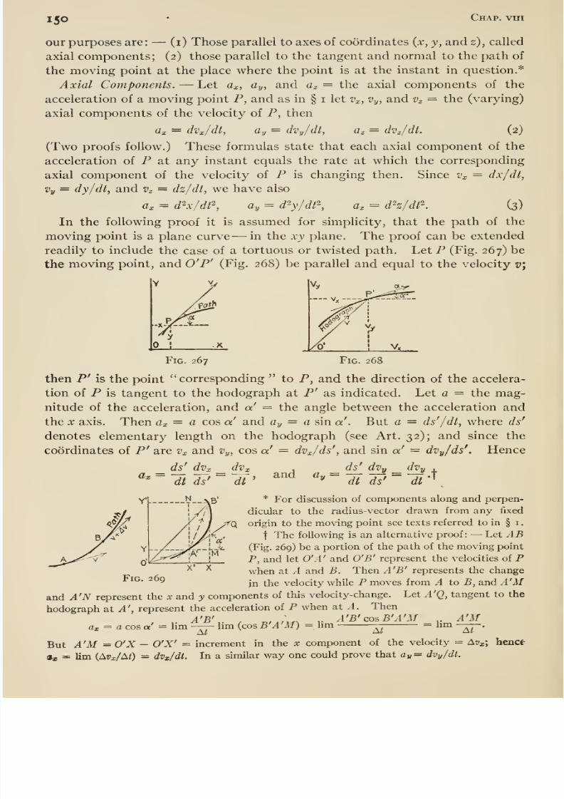
8/13/2019 Maurer Mechanics
http://slidepdf.com/reader/full/maurer-mechanics 162/407
I50 Chap, vtri
our purposes are: —(i) Those parallel to axes of coordinates {x, y, and z), called
axial components; (2) those parallel to the tangent and normal to the path of
the moving point at the place where the point is at the instant in question.*
Axial Components. —Let a^, ay, and az = the axial components of the
acceleration of a moving point P, and as in § i let Vx, Vy, and Vz = the (varying)
axial components of the velocity of P, then
flx = dVx/dt, Oy = dvy/dl, a^ = dvjdt. (2)
(Two proofs follow.) These formulas state that each axial component of the
acceleration of P at any instant equals the rate at which the corresponding
axial component of the velocity of P is changing then. Since Vx = dx/dt,
Vy = dy/dt, and v^ = dz/dt, we have also
ax = d^x/df, ay = d'-y/df^, a, = dh/df^. (3)
In the following proof it is assumed for simplicity, that the path of themoving point is a plane curve ^—in the xy plane. The proof can be extended
readily to include the case of a tortuous or twisted path. LetP (Fig. 267) be
the moving point, and O'P^ (Fig. 268) be parallel and equal to the velocity v\
Fig. 268ig. 267
then P' is the point corresponding to P, and the direction of the accelera-
tion of P is tangent to the hodograph at P' as indicated. Let a = the mag-
nitude of the acceleration, and a' = the angle between the acceleration and
the X axis. Then ax = a cos a and ay = a sin a'. But a = ds'/dt, where ds'
denotes elementary length on the hodograph (see Art. 32); and since the
coordinates of P' are Vx and Vy, cos a' = dvx/ds', and sin a' = dvy/ds'. Hence
_ ds' dvx _ dvx , _ ^ ^ _ ^ 4.
^'~l[tdl'~dt' ^ ^'''' ~ dt ds'
~dt
•
y * For discussion of components along and perpen-
dicular to the radius-vector drawn from any fixed
origin to the moving point see texts referred to in § i
t The following is an alternative proof: —Let AB(Fig. 269) be a portion of the path of the moving point
P, and let O'A' and O'B' represent the velocities of P^ '^ when at A and B. Then A'B' represents the change
^^^' ^9jj^ ^Yic velocity while P moves from A to B, and A'M
and A'N represent the x and y components of this velocity-change. Let A'Q, tangent to the
hodograph at ^', represent the acceleration of P when at A. Then
1 N ,
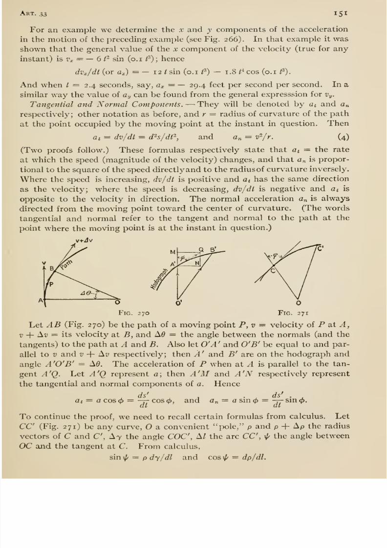
8/13/2019 Maurer Mechanics
http://slidepdf.com/reader/full/maurer-mechanics 163/407

8/13/2019 Maurer Mechanics
http://slidepdf.com/reader/full/maurer-mechanics 164/407
152 Chap, vin
These formulas when applied to the hodograph (Fig. 270) become
sm4> — V dd/ds' and cos 4> = dv/ds'.
Hence
ds' dv dv ,ds' dd dB dd ds v^ ^
dt ds dt dt ds dt ds dt r
For an example we determine the tangential and normal components of the
acceleration in the motion of the two preceding examples. Since 5=2^^,
V = 6 t and dv/dt = 12/ = a«; at / = 2.4 seconds, say, at = 28.8 feet per
second per second. Also a„ = v'^/r = 36 ^^,20 = 1.8 /^; at / = 2.4, a„ = 59.7
feet per second per second.
The {resultant) acceleration can be obtained from its axial or tangential and
normal components. Thus
a = V a/ + Cy^ + flz'- = Vat^ + an\
The angles which a makes with the x, y, and z axes are given respectively by
cos~^ (a^c/a), cos~^ {ay/ a), and cos~^ {az/a).
The angle which a makes with the normal equals tan ^ {at/ an). From a =
{at^ + a„^)5 it appears that a does not equal at {= dv/dt) in general; onJ^ when
an = o. And an{= v^/r) = o only when v = o or r ^ oc, that is, where the
moving point reverses direction of motion or where the radius of curvature is
infinitely great.
* The following is an alternative proof: —Let AB (Fig. 272) be a portion of the path of
the moving point P, and O'A' and O'B' represent the velocities of P when at A and B respec-
tively. Then the curve A'B' is the hodograph for .IB; the chord A'B' represents the change
in the velocity while P moves from A to B; and the tangent A' a represents the accelera-
tion a of P when at A. Let v = the magnitude of the velocity a,t A, v -\- Av = that at B,
Ad — the angle between the normals (and the tangents) at A and B, and the angle be-
tween the acceleration and the velocity at A. Then at = a cos(^ =
,. A'B',. , ^,,„„ ,. A'B' coiEA'B' ,. A'E ,. (ii -}- Ai.) cos Ai* - »hm lim (cos, EAB) = lim = nm ——= lim — =
A^ Ai At At
,. AvcosA6 —v(i —cosA9) ,. Av .„ ,. sin-|A9 dv i ,. Ad ^^ dvhm -r = lim -- cos A0 — 2V hm ———= -j. ti hm —A9 = -y
At At At dt 2 At dt
Referring to the figure it will be seen that a„ = a sin =
,. A'B'.. .. ^.,^,. ,. A'B'^mEA'B' .. EB' (j^±Av)^nA9hm-— —lim (smEA'B') = hm- — = hm—-— = hm — =
At At At At
,. sinAff, ,. Av . ,„ ,. Ad
,dO \ ds -fi
V hm — h lim -— sin Ad = v hm—- + o = v-j-= »- -7; = —•
At At At dt r dt r
t Some students find it diflficult or impossible to realize that acceleration of a point in
curvilinear motion has a component along the normal to the path at the place where themoving point is at the instant in question, notwithstanding detailed calculations (as on pages
145 and 146) for a specific case and mathematical derivation of the general formulas for the
normal component of acceleration.
Let us consider the matter from the perplexed student's own standpoint. He may ask,
If the moving point has an acceleration along the normal, why does it not acquire velocity
along the normal ? If he will grant that velocity cannot be acquired instantaneously but
only with lapse of time, then it is easy to show that velocity is acquired along the normal.
Thus to take a concrete case, suppose that a point P is moving in the curve (Fig. 272); con-
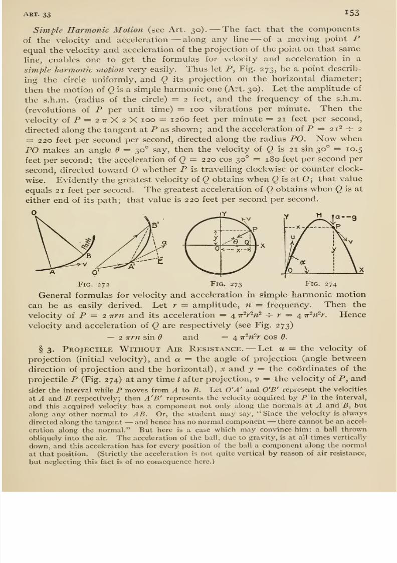
8/13/2019 Maurer Mechanics
http://slidepdf.com/reader/full/maurer-mechanics 165/407
ART. 33 153
Simple Harmonic Motion (see Art. 30). —The fact that the components
of the velocity and acceleration —along any line —of a moving point Pequal the velocity and acceleration of the projection of the point on that same
line, enables one to get the formulas for velocity and acceleration in a
simple harmonic motion very easily. Thus let P, Fig. 273, be a point describ-
ing the circle uniformly, and Q its projection on the horizontal diameter;
then the motion of () is a simple harmonic one (Art. 30). Let the amplitude of
the s.h.m. (radius of the circle) = 2 feet, and the frequency of the s.h.m.
(revolutions of P per unit time) = 100 vibrations per minute. Then the
velocity ofP=27rX2Xioo = i26o feet per minute =21 feet per second,
directed along the tangent at P as shown; and the acceleration of P = 21- -^ 2
= 220 feet per second per second, directed along the radius PO. Now when
PO makes an angle d = 30° say, then the velocity of Q is 21 sin 30° = 10.5
feet per second; the acceleration oiQ = 220 cos 30° = iSo feet per second per
second, directed toward O whether P is travelling clockwise or counter clock-
wise. Evidently the greatest velocity of Q obtains when () is at 0; that value
equals 21 feet per second. The greatest acceleration of Q obtains when Q is at
either end of its path; that value is 220 feet per second per second.
Fig. 273 Fig. 274
General formulas for velocity and acceleration in simple harmonic motion
can be as easily derived. Let r = amplitude, n = frequency. Then the
velocity of P = 2 irrn and its acceleration = 4 ir-r-n^H-
r = 4Trhi^r.
Hencevelocity and acceleration of Q are respectively (see Fig. 273)
— 2 irrn sin d and — 4 ir'^n-r cos 6.
§ 3. Projectile Without Air Resistance. —Let u = the velocity of
projection (initial velocity), and a = the angle of projection (angle between
direction of projection and the horizontal), x and y = the coordinates of the
projectile P (Fig. 274) at any time t after projection, v = the velocity of P, and
sider the interval while P moves from A to B. Let O'A' and O'B' represent the velocities
at A and B respectively; then A'B' represents the velocity acquired by P in the interval,
and this acquired velocity has a component not only along the normals at A and B, but
along any other normal to AB. Or, the student may say, Since the velocity is always
directed along the tangent —and hence has no normal component —there cannot be an accel-
eration along the normal. But here is a case which may convince him: a ball thrown
obliquely into the air. The acceleration of the ball, due to gravity, is at all times vertically
down, and this acceleration has for every position of the ball a component along the normal
at that position. (Strictly the acceleration is not quite vertical by reason of air resistance,
but neglecting this fact is of no consequence here.)
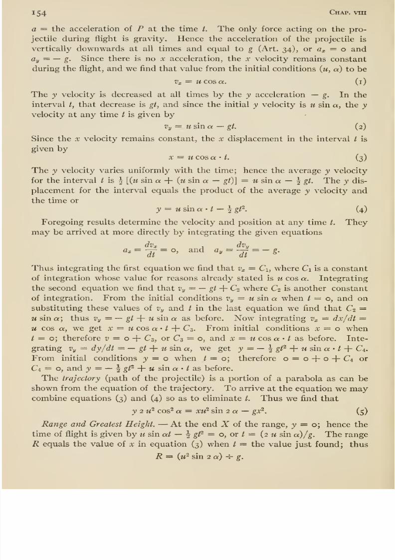
8/13/2019 Maurer Mechanics
http://slidepdf.com/reader/full/maurer-mechanics 166/407
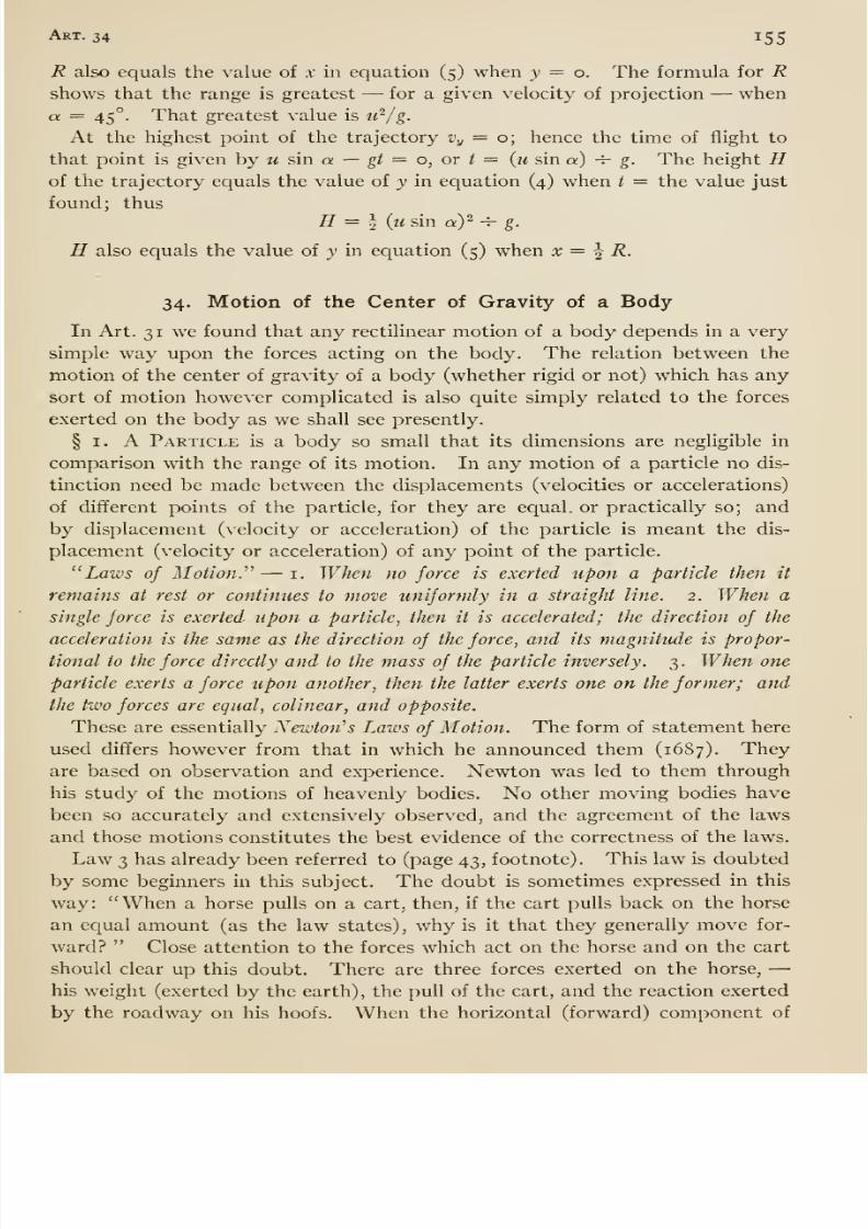
8/13/2019 Maurer Mechanics
http://slidepdf.com/reader/full/maurer-mechanics 167/407
Art. 34 155
R also equals the value of x in equation (5) when y = o. The formula for Rshows that the range is greatest —for a given velocity of projection —when
a = 45°. That greatest value is u'^/g.
At the highest point of the trajectory Vy = o; hence the time of flight to
that point is given by m sin a — g/ = o, or / = {u sin a) -^ g. The height Hof the trajectory equals the value of y in equation (4) when t = the value just
found ; thus
H = ^ {usin a)2 -^ g.
H also equals the value of y in equation (5) when x = ^ R.
34. Motion of the Center of Gravity of a Body
In Art. 3 1 we found that any rectilinear motion of a body depends in a very
simple way upon the forces acting on the body. The relation between the
motion of the center of gravity of a body (whether rigid or not) which has any
sort of motion however complicated is also quite simply related to the forces
exerted on the body as we shall see presently.
§ I. A Particle is a body so small that its dimensions are negligible in
comparison with the range of its motion. In any motion of a particle no dis-
tinction need be made between the displacements (velocities or accelerations)
of different points of the particle, for they are equal, or practically so; and
by displacement (velocity or acceleration) of the particle is meant the dis-
placement (velocity or acceleration) of any point of the particle.
Laws of Motion.' —i. When no force is exerted upon a particle then it
remains at rest or continues to move uniformly in a straight line. 2. When a
single force is exerted upon a particle^ then it is accelerated; the direction of the
acceleration is the same as the direction of the force, and its magnitude is propor-
tional to the force directly and to the mass of the particle inversely. 3. When one
particle exerts a force upon another, then the latter exerts one on the former; and
the two forces are equal, colinear, and opposite.
These are essentially Newton'' s Laws of Motion. The form of statement here
used differs however from that in which he announced them (1687). Theyare based on observation and experience. Newton was led to them through
his study of the motions of heavenly bodies. No other moving bodies have
been so accurately and extensively observed, and the agreement of the laws
and those motions constitutes the best evidence of the correctness of the laws.
Law3
has already been referred to (page43,
footnote). This law is doubted
by some beginners in this subject. The doubt is sometimes expressed in this
way: When a horse pulls on a cart, then, if the cart pulls back on the horse
an equal amount (as the law states), why is it that they generally move for-
ward? Close attention to the forces which act on the horse and on the cart
should clear up this doubt. There are three forces exerted on the horse, —his weight (exerted by the earth), the pull of the cart, and the reaction exerted
by the roadway on his hoofs. When the horizontal (forward) component of
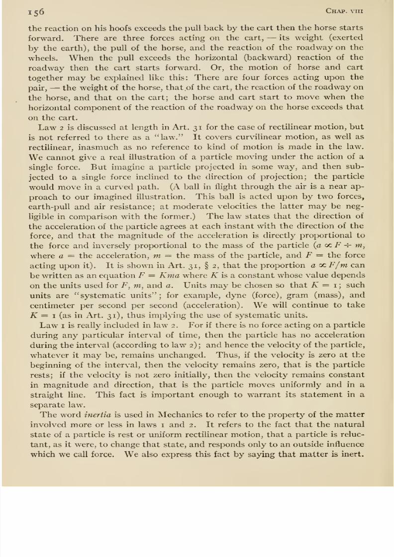
8/13/2019 Maurer Mechanics
http://slidepdf.com/reader/full/maurer-mechanics 168/407
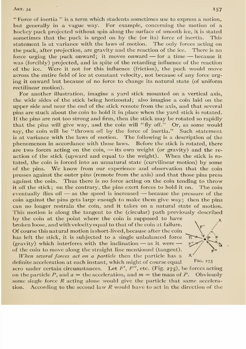
8/13/2019 Maurer Mechanics
http://slidepdf.com/reader/full/maurer-mechanics 169/407
Art. 34 157
Force of inertia is a term which students sometimes use to express a notion,
but generally in a vague way. For example, concerning the motion of a
hockey puck projected without spin along the surface of smooth ice, it is stated
sometimes that the puck is urged on by the (or its) force of inertia. This
statement is at variance with the laws of motion. The only forces acting on
the puck, after projection, are gravity and the reaction of the ice. There is no
force urging the puck onward; it moves onward —for a time —because it
was (forcibly) projected, and in spite of the retarding influence of the reaction
of the ice. Were it not for this influence (friction), the puck would moveacross the entire field of ice at constant velocity, not because of any force urg-
ing it onward but because of no force to change its natural state (of uniform
rectilinear motion).
For another illustration, imagine a yard stick mounted on a vertical axis,
the wide sides of the stick being horizontal; also imagine a coin laid on the
upper side and near the end of the stick remote from the axis, and that several
pins are stuck about the coin to hold it in place when the yard stick is rotated.
If the pins are not too strong and firm, then the stick may be rotated so rapidly
that the pins will give way, and the coin will fly off. Or, as some would
say, the coin will be thrown off by the force of inertia. Such statement
is at variance with the laws of motion. The following is a description of the
phenomenon in accordance with those laws. Before the stick is rotated, there
are two forces acting on the coin, —its own weight (or gravity) and the re-
action of the stick (upward and equal to the weight). When the stick is ro-
tated, the coin is forced into an unnatural state (curvilinear motion) by some
of the pins. We know from our experience and observation that the coin
presses against the outer pins (remote from the axis) and that those pins press
against the coin. Thus there is no force acting on the coin tending to throw
it off the stick; on the contrary, the pins exert forces to hold it on. The coin
eventually flies off —as the speed is increased —because the pressure of the
coin against the pins gets large enough to make them give way; then the pins
can no longer restrain the coin, and it takes on a natural state of motion.
This motion is along the tangent to the (circular) path previously described
by the coin at the point where the coin is supposed to have
broken loose, and with velocity equal to that of the coin at failure.
Of course this natural motion is short-lived, because after the coin
has left the stick, it is subjected to a single unbalanced force
(gravity) which interferes with the inclination —as it were —of the coin to move along the straight line mentioned (tangent).
When several forces act on a particle then the particle has a
definite acceleration at each instant, which might of course equal
zero under certain circumstances. Let F', F , etc. (Fig. 275), be forces acting
on the particle P, and a = the acceleration, and m = the mass of P. Obviously
some single force R acting alone would give the particle that same accelera-
tion. According to the second law R would have to act in the direction of the
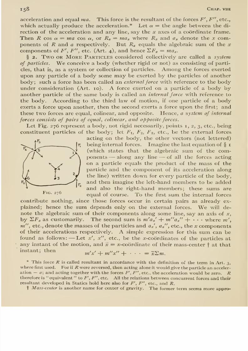
8/13/2019 Maurer Mechanics
http://slidepdf.com/reader/full/maurer-mechanics 170/407
iS8 Chap, vrn
acceleration and equal ma. This force is the resultant of the forces F' , F , etc.,
which actually produce the acceleration.* Let a — the angle between the di-
rection of the acceleration and any line, say the x axes of a coordinate frame.
Then R cos a = ma cos a, or Rx = max where Rx and Ox denote the x com-
ponents of R and a respectively. But Rx equals the algebraic sum of the x
components of F', F , etc. (Art. 4), and hence SFj = mOx.
§ 2. Two OR More Particles considered collectively are called a system
of particles. We conceive a body (whether rigid or not) as consisting of parti-
cles, that is, as a system or collection of particles. Among the forces exerted
upon any particle of a body some may be exerted by the particles of another
body; such a force has been called an external force with reference to the body
under consideration (Art. 10). A force exerted on a particle of a body by
another particle of the same body is called an internal force with reference to
the body. According to the third law of motion, if one particle of a body
exerts a force upon another, then the second exerts a force upon the first; and
these two forces are equal, colinear, and opposite. Hence, a system of internal
forces consists of pairs of equal, colinear, and opposite forces.
Let Fig. 276 represent a body, not rigid necessarily, points i, 2, 3, etc., being
constituent particles of the body; let Fi, F2, F3, etc., be the external forces
acting on the body, the other vectors (not lettered)
being internal forces. Imagine the last equation of § i
(which states that the algebraic sum of the com-
ponents —along any line —of all the forces acting
on a particle equals the product of the mass of the
particle and the component of its acceleration along
the line) wTitten down for every particle of the body,
and then imagine the left-hand members to be added
and also the right-hand members; these sums are
equal of course. To the first sum the internal forces
contribute nothing, since those forces occur in certain pairs as already ex-
plained; hence the sum depends only on the external forces. We will de-
note the algebraic sum of their components along some line, say an axis of x,
Fig. 276
m'a X/
+ m ax + where m',y SFx as customarily. The second sum is
m , etc., denote the masses of the particles and Ox', ax , etc., the x componentsof their accelerations respectively. A simple expression for this sum can be
found as follows: —Let x', x , etc., be the ^-coordinates of the particles at
any instant of the motion, and x = x-coordinate of their mass-centerf
at that
instant; thenm'x' + m x + xZjm.
* This foice R is called resultant in accordance with the definition of the term in Art. 3,
where first used. For if R were reversed, then acting alone it would give the particle an acceler-
ation — a; and acting together with the forces F', F , etc., the acceleration would be zero. Rtherefore is equivalent to F', F , etc. All the relations between concurrent forces and their
resultant developed in Statics hold here also for F', F , etc., and R.
t Mass-center is another name for center of gravity. The former term seems more appro-
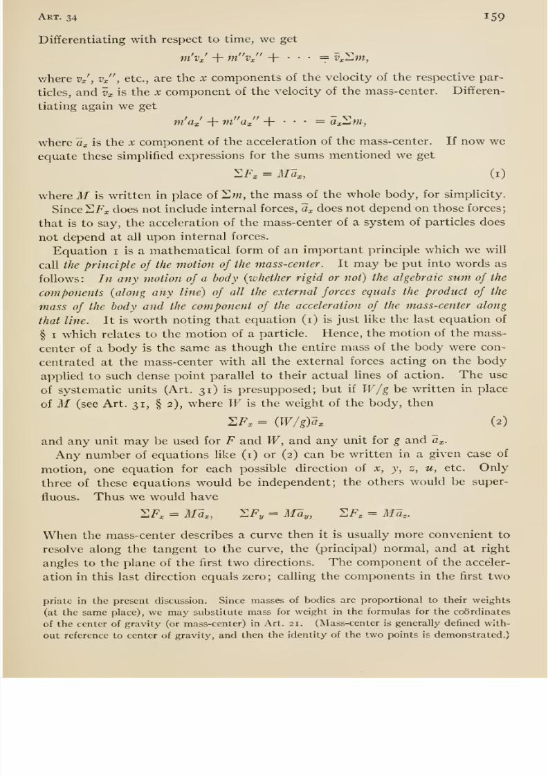
8/13/2019 Maurer Mechanics
http://slidepdf.com/reader/full/maurer-mechanics 171/407
Art. 34 159
Differentiating with respect to time, we get
v/here vj , vj' , etc., are the x components of the velocity of the respective par-
ticles, and Vx is the x component of the velocity of the mass-center. Differen-
tiating again we getm'aj + m ax -}-•••= axSm,
where Ux is the x component of the acceleration of the mass-center. If now we
equate these simplified expressions for the sums mentioned we get
2F, = Max, (i)
where M is written in place of 21 w, the mass of the whole body, for simplicity.
Since 2 Fi does not include internal forces, Cx does not depend on those forces;
that is to say, the acceleration of the mass-center of a system of particles does
not depend at all upon internal forces.
Equation i is a mathematical form of an important principle which we will
call the principle oj the motion of the mass-center. It may be put into words as
follows: In any motion of a body {ivhether rigid or not) the algebraic sum of the
components (along any line) of all the external forces equals the product of the
mass of the body and the component of the acceleration of the mass-center along
that line. It is worth noting that equation (i) is just like the last equation of
§ I which relates to the motion of a particle. Hence, the motion of the mass-
center of a body is the same as though the entire mass of the body were con-
centrated at the mass-center with all the external forces acting on the body
applied to such dense point parallel to their actual lines of action. The use
of systematic units (Art. 31) is presupposed; but if W/g be written in place
of M (see Art. 31, § 2), where Wis the weight of the body, then
ZFx = {W/g)ax (2)
and any unit may be used for F and W, and any unit for g and ax.
Any number of equations like (i) or (2) can be written in a given case of
motion, one equation for each possible direction of x, y, z, u, etc. Only
three of these equations would be independent; the others would be super-
fluous. Thus we would have
SFx = Max, ^Fy = May, 2F, = Ma,.
When the mass-center describes a curve then it is usually more convenient to
resolve along the tangent to the curve, the (principal) normal, and at right
angles to the plane of the first two directions. The component of the acceler-
ation in this last direction equals zero; calling the components in the first two
priate in the present discussion. Since masses of bodies are proportional to their weights
(at the same place), we may substitute mass for weight in the formulas for the coordinates
of the center of gravity (or mass-center) in Art. 21. (Mass-center is generally defined with-
out reference to center of gravity, and then the identity of the two points is demonstrated.)
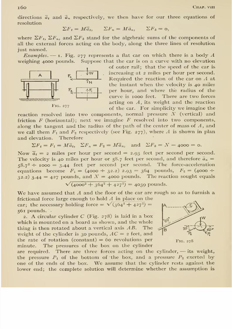
8/13/2019 Maurer Mechanics
http://slidepdf.com/reader/full/maurer-mechanics 172/407
i6o Chap, vin
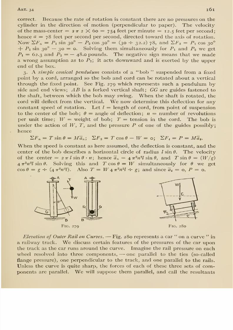
8/13/2019 Maurer Mechanics
http://slidepdf.com/reader/full/maurer-mechanics 173/407
Art. 34 i6i
correct. Because the rate of rotation is constant there are no pressures on the
cylinder in the direction of motion (perpendicular to paper). The velocity
of the mass-center =27r2X6o=754 feet per minute = 12.5 feet per second;
hence fl = 78 feet per second per second, directed toward the axis of rotation.
Now 11F„ = Pi sin 30° —P2 cos 30° = (30 -^- 32.2) 78, and 'LF3 = Pi cos 30°
+ P2 sin 30° — 30 = o. Solving them simultaneously for Pi and P2 we get
Pi = 62.3 and P2 = — 48.0 pounds. The negative sign means that we madea wrong assumption as to P2; it acts downward and is exerted by the upper
end of the box.
3. A simple conical pendulum consists of a bob suspended from a fixed
point by a cord, arranged so the bob and cord can be rotated about a vertical
through the fixed point. See Fig. 279 which represents such a pendulum byside and end views; /1 5 is a forked vertical shaft; GG are guides fastened to
the shaft, between which the bob may swing. When the shaft is rotated, the
cord will deflect from the vertical. We now determine this deflection for any
constant speed of rotation. Let / = length of cord, from point of suspension
to the center of the bob; 6 = angle of deflection; n = number of revolutions
per unit time; W= weight of bob; T — tension in the cord. The bob is
under the action of W, T, and the pressure P of one of the guides possibly;
hence
2P„ = T sin e = AF^n-, SF3 =Tcosd-W= o; ^Ft = P = Mat.When the speed is constant as here assumed, the deflection is constant, and the
center of the bob describes a horizontal circle of radius / sin 6. The velocity
of the center = 2 tt / sin • n ; hence a„ = 4 ir'^nH sin 6, and P sin = (^V/g)
4 ir'^nH sin 6. Solving this and T cos 6 = W simultaneously for d we get
cos^ = g -^ {4Tr^nH). Also T = W4-ir^nH -^ g; and since at = o, P = o.
Fig. 280
on a curve inlevation of Outer Rail on Curves. —Fig. 280 represents a car
a railway track. We discuss certain features of the pressures of the car upon
the track as the car runs around the curve. Imagine the rail pressure on each
wheel resolved into three components, —one parallel to the ties (so-called
flange pressure), one perpendicular to the track, and one parallel to the rails.
Unless the curve is quite sharp, the forces of each of these three sets of com-
ponents are parallel. We will suppose them parallel, and call the resultants
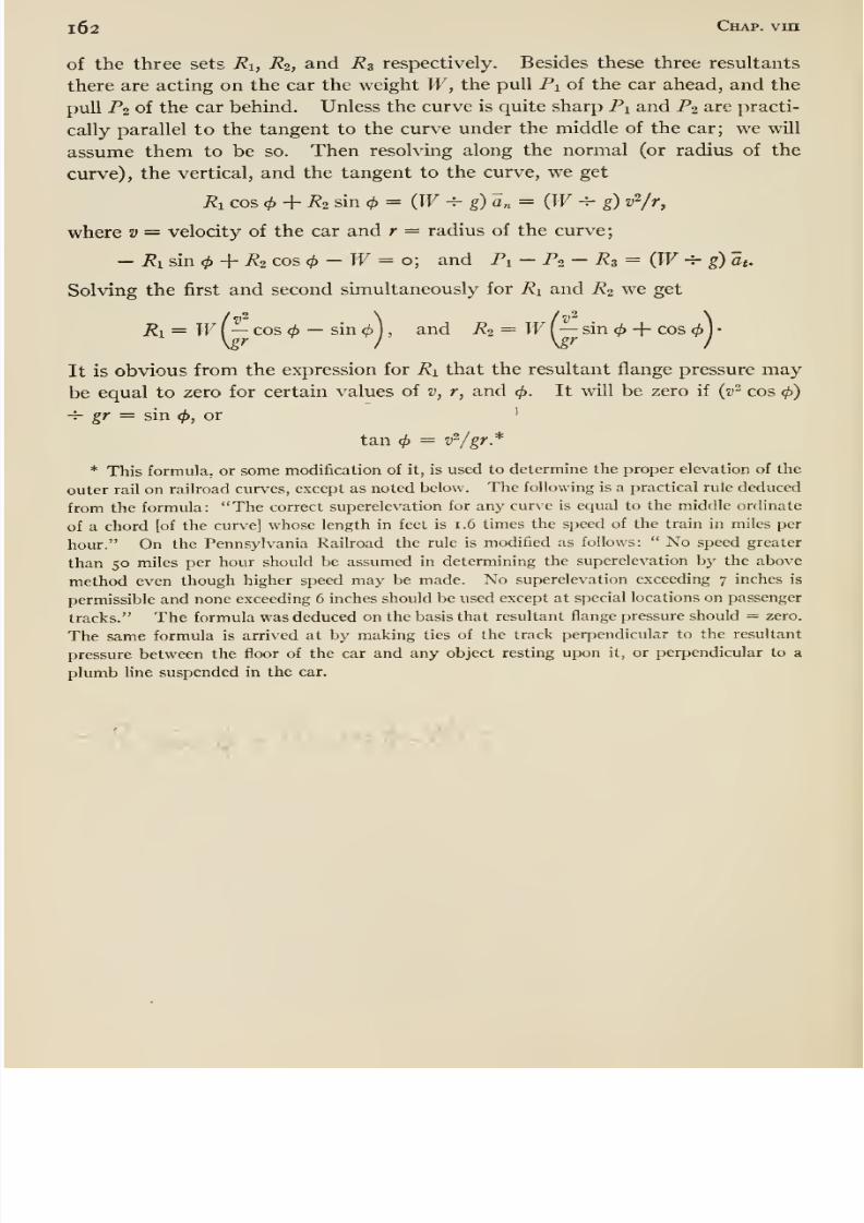
8/13/2019 Maurer Mechanics
http://slidepdf.com/reader/full/maurer-mechanics 174/407
l62 Chap, vin
of the three sets Ri, R2, and R3 respectively. Besides these three resultants
there are acting on the car the weight W, the pull Pi of the car ahead, and the
pull P2 of the car behind. Unless the curve is quite sharp Pi and P2 are practi-
cally parallel to the tangent to the curve under the middle of the car; we will
assume them to be so. Then resolving along the normal (or radius of the
curve), the vertical, and the tangent to the curve, we get
Ri cos <^ + i?2 sin = (W ^ g) a„ = (PF -4- g) v^/r,
where v = velocity of the car and r = radius of the curve;
- Ri sin <p -\- R2 cos (f)- W= o; and Pi - Po - i?3 = (TT -J- g) at.
Solving the first and second sunultaneously for Ri and R2 we get
72, = T^ f—cos <i — sin d)
), and P2 = W( —sin + cos ^ I
•
\gr ^ I \gr I
It is obvious from the expression for Ri that the resultant flange pressure maybe equal to zero for certain values of v, r, and 0. It will be zero if {v- cos 4>)
-^ gr = sin <i>, or '
tan = v^/gr*
* This formula, or some modification of it, is used to determine the proper elevation of the
outer rail on railroad curves, except as noted below. The following is a practical rule deduced
from the formula: The correct superelevation for any curve is equal to the middle ordinate
of a chord [of the curve] whose length in feet is 1.6 times the speed of the train in miles per
hour. On the Pennsylvania Railroad the rule is modified as follows: No speed greater
than 50 miles per hour should be assumed in determining the superelevation by the above
method even though higher speed may be made. No superelevation exceeding 7 inches is
permissible and none exceeding 6 inches should be used except at special locations on passenger
tracks. The formula was deduced on the basis that resultant flange pressure should = zero.
The same formula is arrived at by making ties of the track perpendicular to the resultant
pressure between the floor of the car and any object resting upon it, or perpendicular to a
plumb Une suspended in the car.
- P
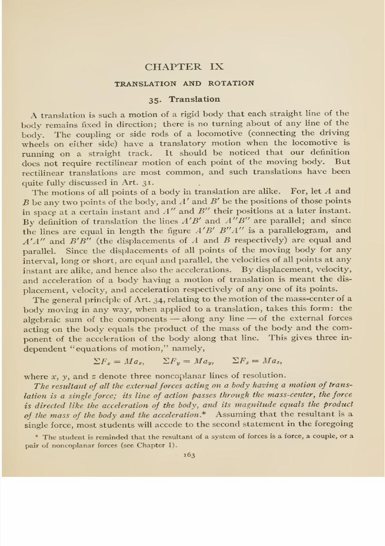
8/13/2019 Maurer Mechanics
http://slidepdf.com/reader/full/maurer-mechanics 175/407
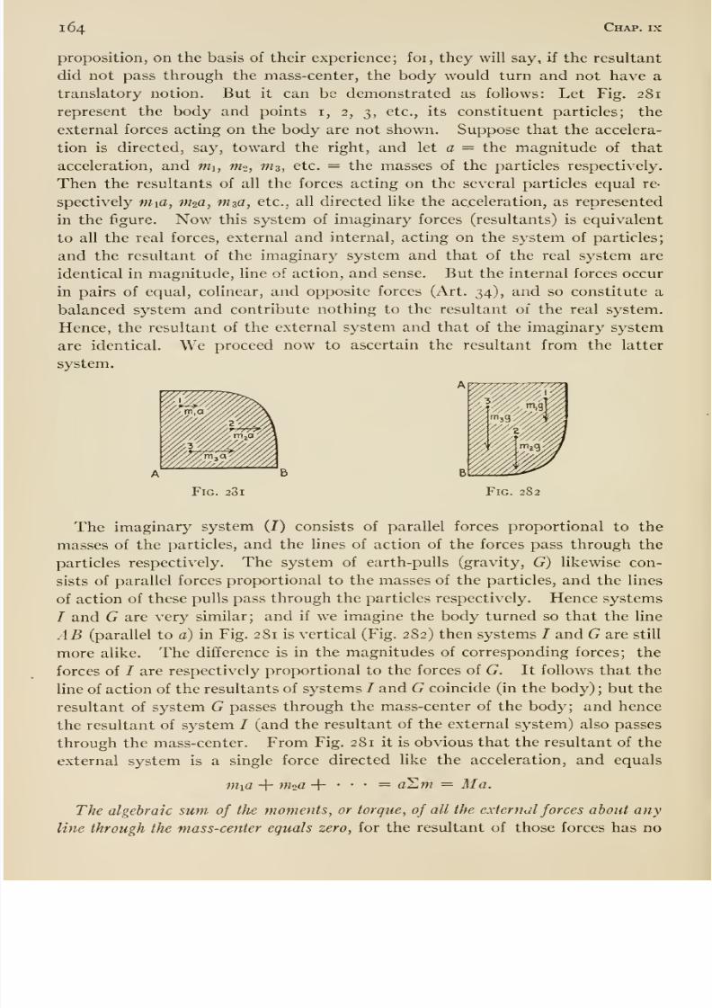
8/13/2019 Maurer Mechanics
http://slidepdf.com/reader/full/maurer-mechanics 176/407
164 Chap, ix
proposition, on the basis of their experience; for, they will say, if the resultant
did not pass through the mass-center, the body would turn and not have a
translatory notion. But it can be demonstrated as follows: Let Fig. 281
represent the body and points i, 2, 3, etc., its constituent particles; the
external forces acting on the body are not shown. Suppose that the accelera-
tion is directed, say, toward the right, and let a = the magnitude of that
acceleration, and m\, W2, m^, etc. = the masses of the particles respectively.
Then the resultants of all the forces acting on the several particles equal re-
spectively mia, in^a, m^a, etc., all directed like the acceleration, as represented
in the figure. Now this system of imaginary forces (resultants) is equivalent
to all the real forces, external and internal, acting on the system of particles;
and the resultant of the imaginary system and that of the real system are
identical in magnitude, line of action, and sense. But the internal forces occur
in pairs of equal, colinear, and opposite forces (Art. 34), and so constitute a
balanced system and contribute nothing to the resultant of the real system.
Hence, the resultant of the external system and that of the imaginary system
are identical. We proceed now to ascertain the resultant from the latter
system.
A
Fig. 23i Fig. 282
The imaginary system (I) consists of parallel forces proportional to the
masses of the particles, and the lines of action of the forces pass through the
particles respectively. The system of earth-pulls (gravity, G) likewise con-
sists of parallel forces proportional to the masses of the particles, and the lines
of action of these pulls pass through the particles respectively. Hence systems
T and G are very similar; and if we imagine the body turned so that the line
AB (parallel to a) in Fig. 281 is vertical (Fig. 282) then systems / and G are still
more alike. The difference is in the magnitudes of corresponding forces; the
forces of / are respectively proportional to the forces of G. It follows that the
line of action of the resultants of systems / and G coincide (in the body) ; but the
resultant of system G passes through the mass-center of the body; and hencethe resultant of system / (and the resultant of the external system) also passes
through the mass-center. From Fig. 281 it is obvious that the resultant of the
external system is a single force directed like the acceleration, and equals
Wifl -\- m2(i + • • • = o^m = Ala.
The algebraic sum of the moments, or torque, of all the external forces about any
line through the mass-center equals zero, for the resultant of those forces has no
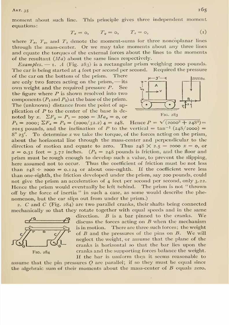
8/13/2019 Maurer Mechanics
http://slidepdf.com/reader/full/maurer-mechanics 177/407
Art. 35 165
ZOOOIbs.
moment about such line. This principle gives three independent m.oment
equations:
r. = o, r, = o, r. = o, (i)
where T^, Ty, and Tz denote the moment-sums for three noncoplanar lines
through the mass-center. Or we may take moments about any three lines
and equate the torques of the external forces about the lines to the moments
of the resultant {Ma) about the same lines respectively.
Examples. —i. A (Fig. 283) is a rectangular prism weighing 2000 pounds.
The car is being started at 4 feet per second per second. Required the pressure
of the car on the bottom of the prism. There
are only two forces acting on the prism, —its
own weight and the required pressure P. See
the figure where P is shown resolved into two
components (Pi and P2) at the base of the prism.
The (unknown) distance from the point of ap-
plication of P to the center of the base is de-
noted by X. HFy = Pi — 2000 = May — o, or
Pi = 2000; HF^ = P2 = (2000/32.2) 4 = 248. Hence P = V(2ooo2 -|- 248^) =
2015 pounds, and the inclination of P to the vertical = tan~^ (248/2000) =8° 25'. To determine x we take the torque, of the forces acting on the prism,
about the horizontal line through the mass-center and perpendicular to the
direction of motion and equate to zero. Thus 248 X 2.5 — 2000 x = o, or
X = 0.31 feet = 3.72 inches. (P2 = 24S pounds is friction, and the floor and
prism must be rough enough to develop such a value, to prevent the slipping,
here assumed not to occur. Thus the coefficient of friction must be not less
than 248 -^ 2000 = 0.124 or about one-eighth. If the coefiicient were less
than one-eighth, the friction developed under the prism, say 200 pounds, could
not give the prism an acceleration of 4 feet per second per second, only 3.22.
Hence the prism would eventually be left behind. The prism is not thrown
off by the force of inertia in such a case, as some would describe the phe-
nomenon, but the car slips out from under the prism.)
2. C and C (Fig. 284) are two parallel cranks, their shafts being connected
mechanically so that they rotate together with equal speeds and in the same
direction. P is a bar pinned to the cranks. Wediscuss the forces acting on B when the mechanism
is in motion. Thereare three such forces ; the weight
of B and the pressures of the pins on B. We will
neglect the weight, or assume that the plane of the
cranks is horizontal so that the bar lies upon the
cranks and the supporting forces balance the weight.
If the bar is uniform then it seems reasonable to
assume that the pin pressures Q are parallel; if so they must be equal since
the algebraic sum of their moments about the mass-center of B equals zero.
-/^ ^^^^ /^
Fig. 284
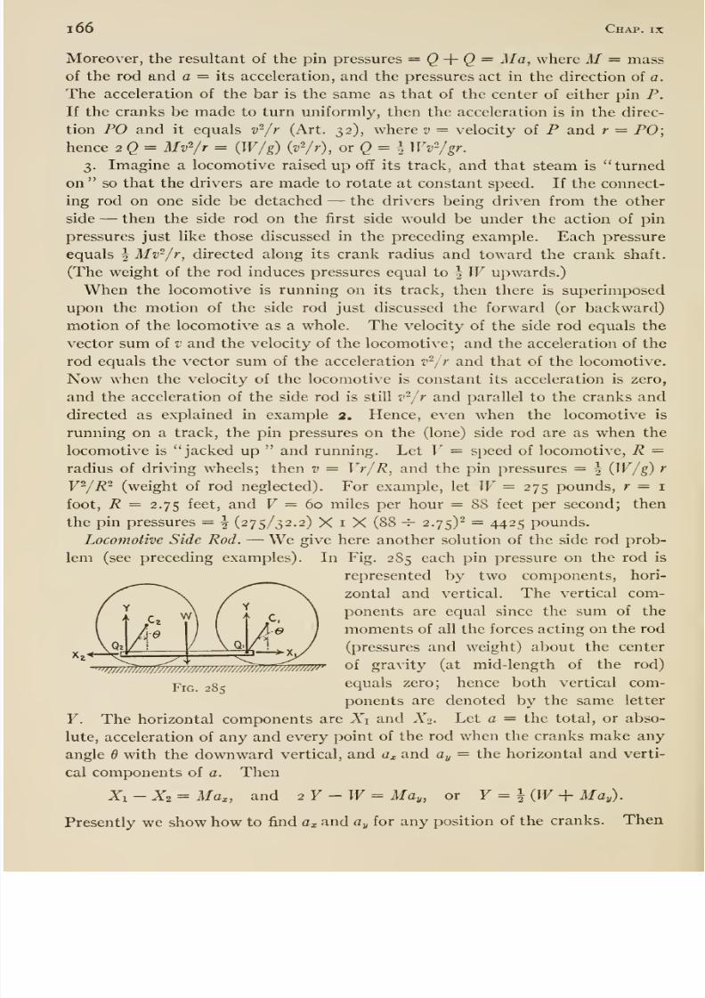
8/13/2019 Maurer Mechanics
http://slidepdf.com/reader/full/maurer-mechanics 178/407
1 66 Chap, ix
Moreover, the resultant of the pin pressures = <3 + Q = Ma, where M= mass
of the rod and a = its acceleration, and the pressures act in the direction of a.
The acceleration of the bar is the same as that of the center of either pin P.
If the cranks be made to turn uniformly, then the acceleration is in the direc-
tion PO and it equals V /r (Art. 32), where v = velocity of P and r — PO;hence 2 Q = Mv^/r = (W/g) {fir), or(^ = \ Wv^gr.
3. Imagine a locomotive raised up off its track, and that steam is turned
on so that the drivers are made to rotate at constant speed. If the connect-
ing rod on one side be detached —the drivers being driven from the other
side —then the side rod on the first side would be under the action of pin
pressures just like those discussed in the preceding example. Each pressure
equals | Mv^/r, directed along its crank radius and toward the crank shaft.
(The weight of the rod induces pressures equal to | PF upwards.)
When the locomotive is running on its track, then there is superimposed
upon the motion of the side rod just discussed the forward (or backward)
motion of the locomotive as a whole. The velocity of the side rod equals the
vector sum of v and the velocity of the locomotive ; and the acceleration of the
rod equals the vector sum of the acceleration V'/r and that of the locomotive.
Now when the velocity of the locomotive is constant its acceleration is zero,
and the acceleration of the side rod is still V /r and parallel to the cranks and
directed as explained in example 2, Hence, even when the locomotive is
running on a track, the pin pressures on the (lone) side rod are as when the
locomotive is jacked up and running. Let V = speed of locomotive, R =radius of driving wheels; then v = Vr/R, and the pin pressures = ^ (W/g) r
V^/R^ (weight of rod neglected). For example, let W=275 pounds, r — i
foot, R = 2.75 feet, and F = 60 miles per hour = 88 feet per second; then
the pin pressures = ^ (275/32.2) X i X (88 -^ 2.75)^ = 4425 pounds.
Locomotive Side Rod. —We give here another solution of the side rod prob-
lem (see precedingexamples).
In Fig. 285 each pinpressure
onthe
rodis
represented by two components, hori-
zontal and vertical. The vertical com-
ponents are equal since the sum of the
moments of all the forces acting on the rod
(pressures and weight) about the center
of gravity (at mid-length of the rod)
equals zero; hence both vertical com-
ponents are denoted by the same letter
The horizontal components are A^i and A2. Let a = the total, or abso-
lute, acceleration of any and every point of the rod when the cranks make any
angle 6 with the downward vertical, and cz^ and ay = the horizontal and verti-
cal components of a. Then
X : —X2 = Max, and
Fig. 285
Y.
2Y-W = May, or Y = ^W + May).
Presently we show how to find ax and ay for any position of the cranks. Then
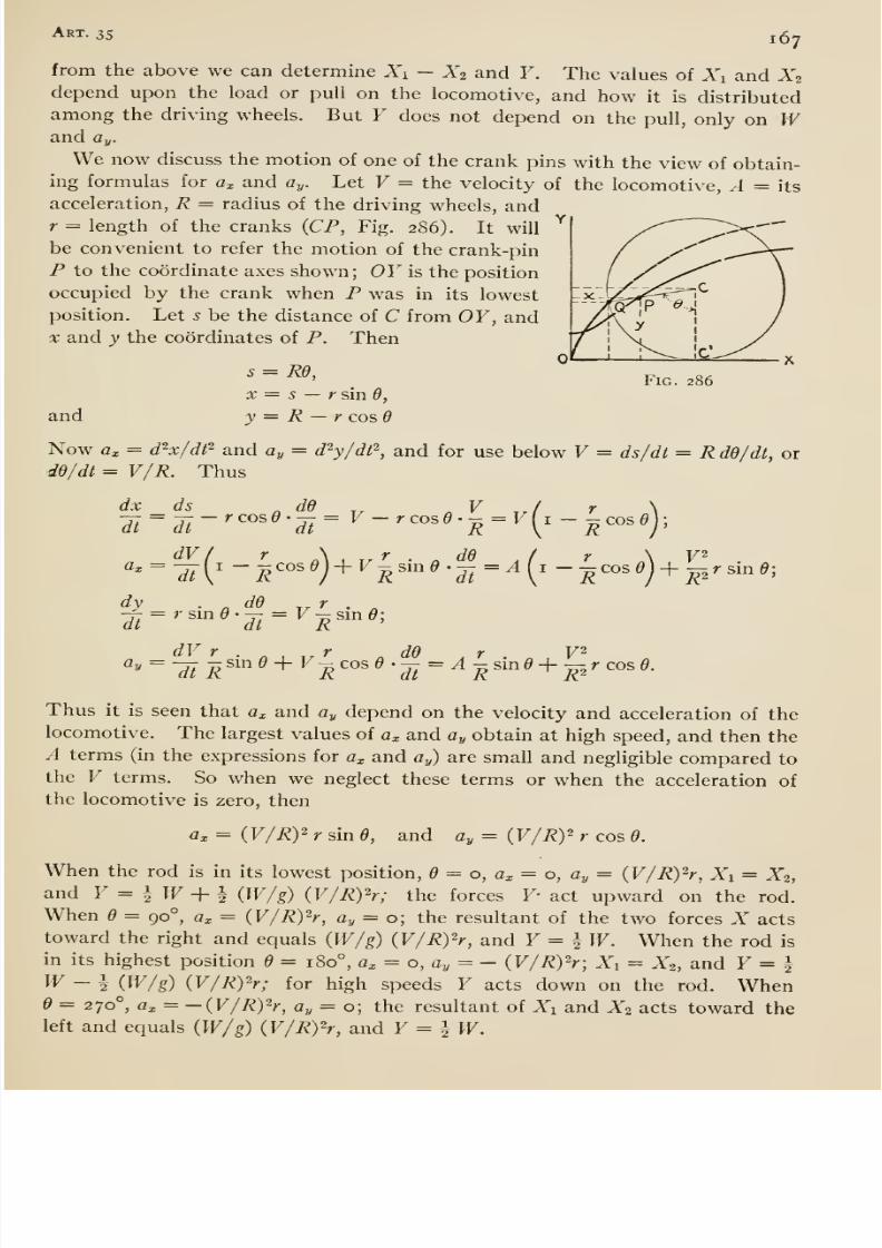
8/13/2019 Maurer Mechanics
http://slidepdf.com/reader/full/maurer-mechanics 179/407
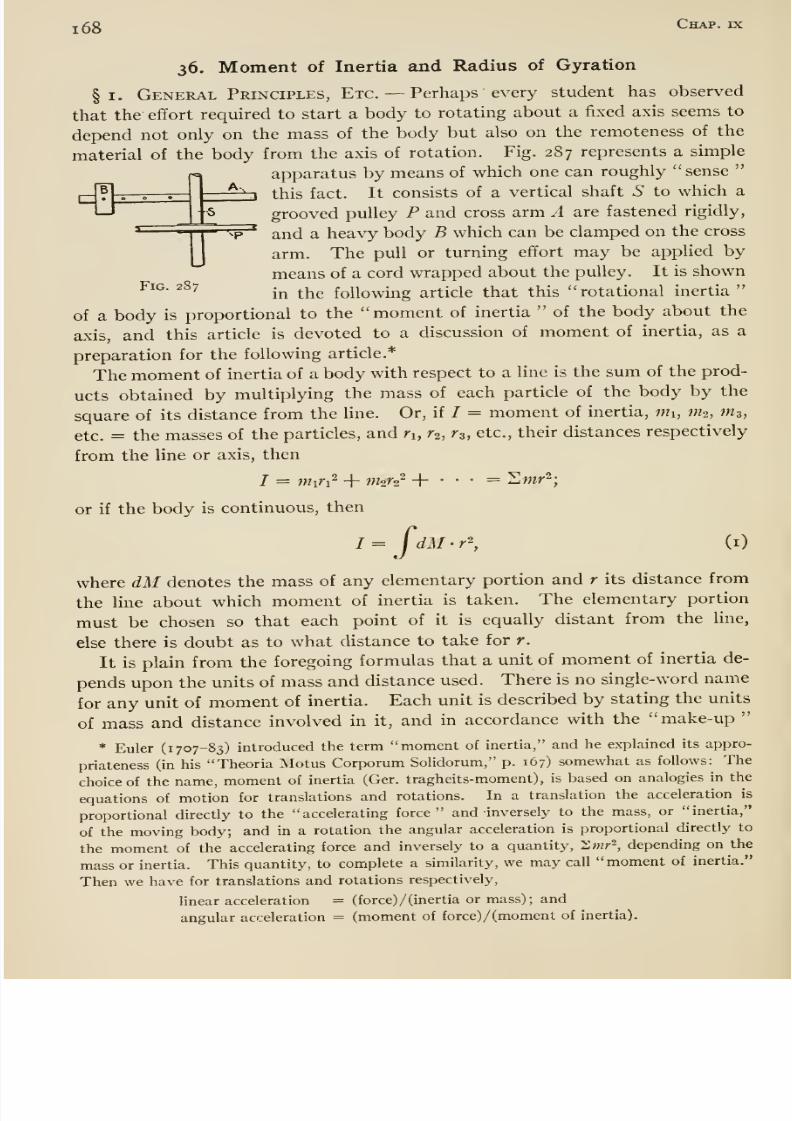
8/13/2019 Maurer Mechanics
http://slidepdf.com/reader/full/maurer-mechanics 180/407
s
r
1 68 Chap, ix
36. Moment of Inertia and Radius of Gyration
§1. General Principles, Etc. —Perhaps every student has observed
that the effort required to start a body to rotating about a fixed axis seems to
depend not only on the mass of the body but also on the remoteness of the
material of the body from the axis of rotation. Fig. 287represents
asimple
apparatus by means of which one can roughly sense
-^ this fact. It consists of a vertical shaft 5 to which a
grooved pulley P and cross arm A are fastened rigidly,
and a heavy body B which can be clamped on the cross
arm. The pull or turning effort may be applied by
means of a cord wrapped about the pulley. It is shownFig. 287 .^ ^^^ following article that this rotational inertia
of a body is proportional to the moment of inertia
of the body about theaxis, and this article is devoted to a discussion of moment of inertia, as a
preparation for the following article.*
The moment of inertia of a body with respect to a line is the sum of the prod-
ucts obtained by multiplying the mass of each particle of the body by the
square of its distance from the line. Or, if / = moment of inertia, mi, mi, m^,
etc. = the masses of the particles, and n, r^, r^, etc., their distances respectively
from the line or axis, then
/ = miTx^ + nhr2^ + • • • = Swr^;
or if the body is continuous, then
/= jdM-r^, (i)
where dM denotes the mass of any elementary portion and r its distance from
the line about which moment of inertia is taken. The elementary portion
must be chosen so that each point of it is equally distant from the line,
else there is doubt as to what distance to take for r.
It is plain from the foregoing formulas that a unit of moment of inertia de-
pends upon the units of mass and distance used. There is no single-word name
for any unit of moment of inertia. Each unit is described by stating the units
of mass and distance involved in it, and in accordance with the make-up
* Euler (1707-83) introduced the term moment of inertia, and he explained its appro-
priateness (in his Theoria Motus Corporum SoHdorum, p. 167) somewhat as follows: The
choice of the name, moment of inertia (Ger. tragheits-moment), is based on analogies in the
equations of motion for translations and rotations. In a translation the acceleration is
proportional directly to the accelerating force and inversely to the mass, or inertia,
of the moving body; and in a rotation the angular acceleration is proportional directly to
the moment of the accelerating force and inversely to a quantity, Xmr~, depending on the
mass or inertia. This quantity, to complete a similarity, we may call moment of inertia.
Then we have for translations and rotations respectively,
linear acceleration = (force) /(inertia or mass); and
angular acceleration = (moment of force)/(moment of inertia).
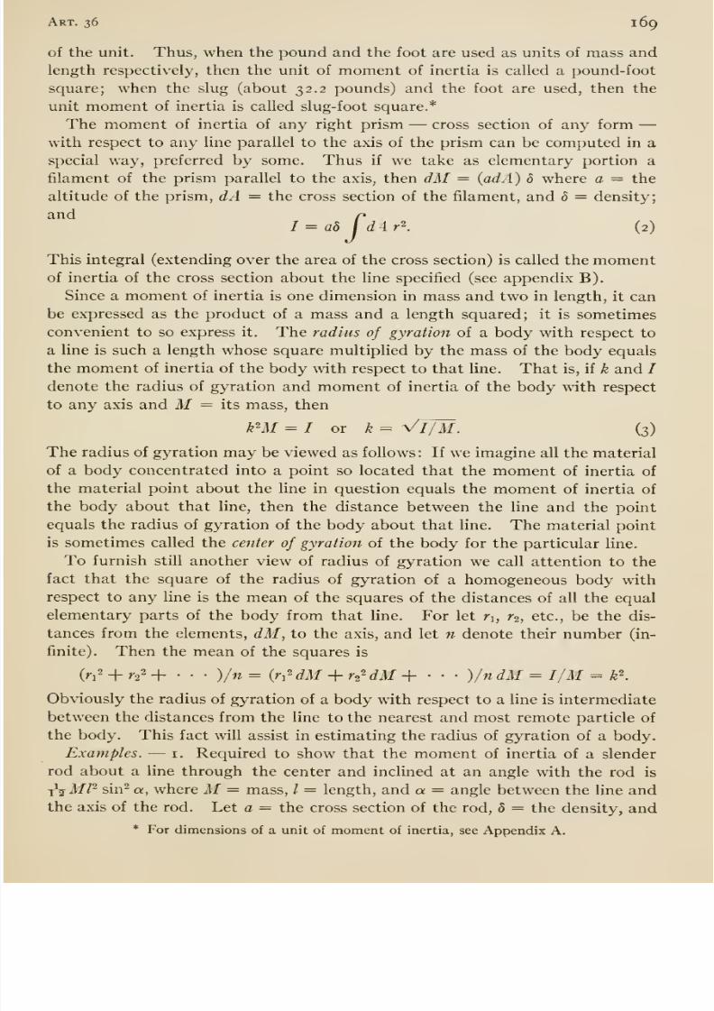
8/13/2019 Maurer Mechanics
http://slidepdf.com/reader/full/maurer-mechanics 181/407
Art. 36 169
of the unit. Thus, when the pound and the foot are used as units of mass and
length respectively, then the unit of moment of inertia is called a pound-foot
square; when the slug (about 32.2 pounds) and the foot are used, then the
unit moment of inertia is called slug-foot square.*
The moment of inertia of any right prism —cross section of any form —with respect to any line parallel to the axis of the prism can be computed in aspecial way, preferred by some. Thus if we take as elementary portion a
filament of the prism parallel to the axis, then dM = {adA) 8 where a = the
altitude of the prism, dA — the cross section of the filament, and 8 = density;
and p1= a8I
dAr\ (2)
This integral (extending over the area of the cross section) is called the momentof inertia of the cross section about the line specified (see appendix B).
Since a moment of inertia is one dimension in mass and two in length, it can
be expressed as the product of a mass and a length squared; it is sometimes
convenient to so express it. The radius of gyration of a body with respect to
a line is such a length whose square multiplied by the mass of the body equals
the momxent of inertia of the body with respect to that line. That is, if k and /
denote the radius of gyration and moment of inertia of the body with respect
to any axis and M = its mass, then
¥M = I or k= y/JjM. (3)
The radius of gyration may be viewed as follows : If we imagine all the material
of a body concentrated into a point so located that the moment of inertia of
the material point about the line in question equals the moment of inertia of
the body about that line, then the distance between the line and the point
equals the radius of gyration of the body about that line. The material point
is sometimes called the center of gyration of the body for the particular line.
To furnish still another view of radius of gyration we call attention to the
fact that the square of the radius of gyration of a homogeneous body with
respect to any line is the mean of the squares of the distances of all the equal
elementary parts of the body from that line. For let r^, r^, etc., be the dis-
tances from the elements, dM, to the axis, and let n denote their number (in-
finite). Then the mean of the squares is
W+ rs^ -f •••)/« = {n^dM + r^^dM + - • • )/ndM = I/M = k\
Obviously the radius of gyration of a body with respect to a line is intermediate
between the distances from the line to the nearest and most remote particle of
the body. This fact will assist in estimating the radius of gyration of a body.
Examples. —i. Required to show that the moment of inertia of a slender
rod about a line through the center and inclined at an angle with the rod is
-x^MP sin^ a, where M= mass, I = length, and a = angle between the line andthe axis of the rod. Let a — the cross section of the rod, 5 = the density, and
* For dimensions of a unit of moment of inertia, see Appendix A.
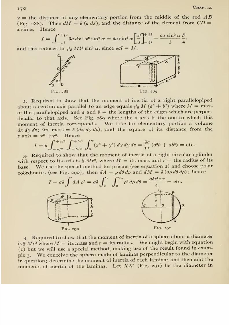
8/13/2019 Maurer Mechanics
http://slidepdf.com/reader/full/maurer-mechanics 182/407
lyo Chap, ix
X = the distance of any elementary portion from the middle of the rod AB(Fig. 288). Then dM = 5 {a dx), and the distance of the element from CD =
X sin a. Hence
I = I 8adx' x^ sm^ a = 8a sm^ a — = '
J-U ISA-u 3 4
and this reduces to yV MP sin^ a, since 8al = M.
Fig. 288 Fig. 289
2. Required to show that the moment of inertia of a right parallelopiped
about a central axis parallel to an edge equals yV M (a- + b-) where M = mass
of the parallelopiped and a and b = the lengths of the edges which are perpen-
dicular to that axis. See Fig. 289 where the s axis is the one to which this
moment of inertia corresponds. We take for elementary portion a volume
dxdydz; its mass = 8 (dxdydz), and the square of its distance from the
z axis = x^+3'^. Hence
I I (x2 + v2) dx dy dz=— {a?b + a¥) = etc.
•a/2 J -b/2 Jo 12
3, Required to show that the moment of inertia of a right circular cylinder
with respect to its axis is | Mr ^, where M= its mass and r = the radius of its
base. We use the special method for prisms (see equation 2) and choose polar
coordinates (see Fig. 290) ; then dA = pdddp and dM = 8 {ap dd dp) ;hence
I=a8 fdAp' = a8 r P^^ dp, ' ''^'^'
'de =etc.
Fig. 290 Fig. 291
4. Required to show that the moment of inertia of a sphere about a diameter
is I Mr^ where M= its mass and r = its radius. We might begin with equation
(i) but we will use a special method, making use of the result found in exam-
ple 3. We conceive the sphere made of laminas perpendicular to the diameter
in question; determine the moment of inertia of each lamina; and then add the
moments of inertia of the laminas. Let XX' (Fig. 291) be the diameter in

8/13/2019 Maurer Mechanics
http://slidepdf.com/reader/full/maurer-mechanics 183/407
Art. 36 171
question, and PQ a section of one of the laminas; then the mass of the laminais b (iry' d̂x) . According to example 3 the moment of inertia of this lamina(cylinder) about its axis (XX') is ^ 5 (iry^ dx)y^. Hence the moment of inertia
of the sphere is
JA 5 (tt/ dx) = ^ ttS
J_(r2 - ^2)2 dx =
j%dw r^ = etc.
§ 2. Parallel Axis Theorem; Reduction or Transformation Formu-las. —There is a simple relation between the moments of inertia (and the
radii of gyration) of a body with respect to parallel lines one of which passes
through the mass-center of the body. By means of this relation we cansimplify many calculations of moment of inertia, and avoid integrations (see
examples following); it may be stated as follows:
The moment of inertia of a body with respect to any line equals its momentof
inertia with respect to a parallel line passing through the mass-center plus the
product of the mass of the body and the square of the distance between the lines.
Or, if / = the first moment of inertia, 7 = the second (for the line through the
mass-center), M= mass, and d = the distance between the parallel lines,
I = l+Md\ (4)
Proof. —Let (Fig. 292) be the mass-center, and P any other point of the
body (not shown), LL the line about which the mo-ment of inert ia is /, and OZ a parallel line (through
the mass-center) about which the moment of inertia
is /. Distance between these parallel lines is d.
For convenience we take x and y axes through O,
the former in the plane of the two parallel lines andthe latter perpendicular to that plane. Let x, y, andz = the coordinates of P. The square of the dis-
tance of P from the z axis equals x'^ + y'^, hence 7= I dM (x ^ -\- y^) . The
square of the distance of P from the line LL equals (d —x)^ + y-, hence
/ = J[{d - xy+y']dM = Jix^ + y')dM + d'JdM -2dJxdM.
Now the first of the last three integrals = /, and the second one = Md ^. If
now we show that the third = o, then formula (4) is proved. The third
integral is proportional to the moment of the body with respect to the yz
plane; but this plane contains the mass-center, and hence the moment equalszero (Arts. 21 and 23). Thus, if Tf = weight of the body,
Fig. 292
JxdM= CxdW/g = (i/g)Wx.
If we divide both sides of equation (4) by M, we get I/M = I/M -f d^, or
k^ = k^-\- d^ (5)
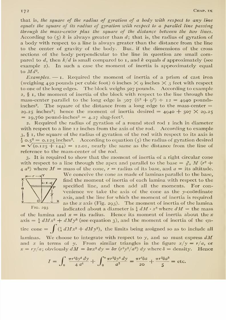
8/13/2019 Maurer Mechanics
http://slidepdf.com/reader/full/maurer-mechanics 184/407
172 Chap. IX
that is, the square of the radius of gyration of a body with respect to any line
equals the square of Us radius of gyration with respect to a parallel line passing
through the mass-center plus the square of the distance between the two lines.
According to (5) k is always greater than d; that is, the radius of gyration of
a body with respect to a line is always greater than the distance from the line
to the center of gravity of the body. But, if the dimensions of the cross
sections of the body perpendicular to the line in question are small com-
pared to d, then k/d is small compared to i , and k equals d approximately (see
example 2). In such a case the moment of inertia is approximately equal
to Md\Examples. —i. Required the moment of inertia of a prism of cast iron
(weighing 450 pounds per cubic foot) 6 inches X 9 inches X 3 feet with respect
to one of the long edges. The block weighs 507 pounds. According to example2, § I, the moment of inertia of the block with respect to the line through the
mass-center parallel to the long edge is 507 (6^ + 9-) -^- 12 = 4940 pounds-
inches^. The square of the distance from a long edge to the mass-center =29.25 inches^; hence the moment of inertia desired = 4940 -f 507 X 29.25
= 19,760 pound-inches^ = 4.27 slug-feet-.
2. Required the radius of gyration of a round steel rod i inch in diameter
with respect to a line 1 2 inches from the axis of the rod. According to example
3, § I, the square of the radius of gyration of the rod with respect to its axis is
5 0.5^ = 0.125 inches^. According to equation (5) the radius of gyration desired
= V (0.125 + 144) = 12.01, nearly the same as the distance from the line of
reference to the mass-center of the rod.
3. It is required to show that the moment of inertia of a right circular cone
with respect to a line through the apex and parallel to the base = j\ M {r^ +4 c^) where Af — mass of the cone, r = radius of its base, and a = its altitude.
We conceive the cone as made of laminas parallel to the base,
find the moment of inertia of each lamina with respect to thespecified line, and then add all the moments. For con-
venience we take the axis of the cone as the ^'-coordinate
axis, and the line for which the moment of inertia is required
as the X axis (Fig. 293). The moment of inertia of the laminaFig. 293 indicated about a diameter is j dM • x ^ where dM = the mass
of the lamina and x = its radius. Hence its moment of inertia about the x
axis = J dMx ^ + dMy ^ (see equation 3), and the moment of inertia of the en-
tire cone = / {\dMx^ + dMy^), the limits being assigned so as to include all
laminas. We choose to integrate with respect to y, and so must express dMand X in terms of y. From similar triangles in the figure x/y = r/a, or
X = ry/a; obviously dM = dirx^dy = 8t (r^y^/a^) dy where 5 = density. Hence
C Trr^hfdy ,C'^Trr^v^dv irr^Sa
,irr^a^
I = I ^^ -f / V-^ =1
—- = etc.Jo 4 a* Jo a 20 s
l«— r ->
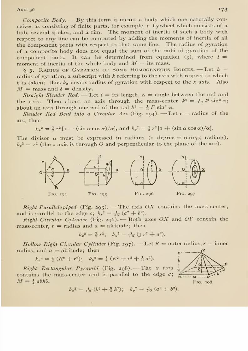
8/13/2019 Maurer Mechanics
http://slidepdf.com/reader/full/maurer-mechanics 185/407
Aet. 36 173
Composite Body. —By this term is meant a body which one naturally con-
ceives as consisting of finite parts, for example, a flywheel which consists of a
hub, several spokes, and a rim. The moment of inertia of such a body with
respect to any line can be computed by adding the moments of inertia of all
the component parts with respect to that same line. The radius of gyration
of a composite body does not equal the sum of the radii of gyration of the
component parts. It can be determined from equation (3), where / =
moment of inertia of the whole body and M = its mass.
§ 3. Radius of Gyration of Some Homogeneous Bodies. —Let k =
radius of gyration, a subscript with k referring to the axis with respect to which
k is taken; thus kx means radius of gyration with respect to the x axis. Also
M = mass and 8 = density.
Straight Slender Rod. —Let / = its length, a = angle between the rod and
the axis. Then about an axis through the mass-center k^ = tV l^ sin^ a;
about an axis through one end of the rod k^ = ^ P sin^ a.
Slender Rod Bent into a Circular Arc (Fig. 294). —Let r = radius of the
arc, then
kx- ^ I'' [i — (sin a cos a)/a\, and ky ^ = | r^ [i + (sin a cos a) /a].
The divisor a must be expressed in radians (i degree = 0.0175 radians).
j^2 = ^2 (^^j^g 2 axis is through O and perpendicular to the plane of the arc).
0-H^
P'iG. 295 Fig. 296 Fig. 297
Right Paralleloplped (Fig. 295).— The axis OX contains the mass-center,
and is parallel to the edge c; kx^ — tV (^^ + ^ )-
Right Circular Cylinder (Fig. 296). —Both axes OX and OY contain the
mass-center, r = radius and a = altitude; then
kx'^hr^ V = tV (3 '-' + «')•
Hollow Right Circular Cylinder (Fig. 297). —Let R = outer radius, r = inner
radius, and a = altitude; then ^^^.^ iY
kx' = h(R' + r'); ky'̂ = HR' + r^~ + U')- I
Right Rectangular Pyramid (Fig. 298). —The x axis ^contains the mass-center and is parallel to the edge a; ^__^_—^,-M= I ahhb. Fig. 298
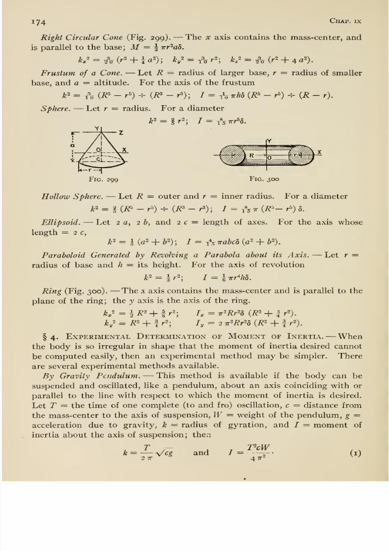
8/13/2019 Maurer Mechanics
http://slidepdf.com/reader/full/maurer-mechanics 186/407
iy4 Chap, ix
Right Circular Cone (Fig. 299). —The x axis contains the mass-center, and
is parallel to the base; M= ^ irr'^ad.
Frustum of a Cone. —Let R = radius of larger base, r = radius of smaller
base, and a = altitude. For the axis of the frustum
sphere. —Let r = radius. For a diameter
k^=ir^; I^^Sirr^b.
z
Fig. 299 Fig. 300
Hollow Sphere. —Let R = outer and r = inner radius. For a diameter
yfe2= |(^5_^)_^ (/23_^). I ^ ^^^Tr{R'-r>)8.
Ellipsoid. —Let 2 a, 2 b, and 2 c = length of axes. For the axis whose
length = 2 c,
k^ = l (a2 _|_ j2) . / = ^^ Trahcb (a2 + b ).
Paraboloid Generated by Revolving a Parabola about its Axis. —Let r =radius of base and h = its height. For the axis of revolution
Ring (Fig. 300). —The x axis contains the mass-center and is parallel to the
plane of the ring; the y axis is the axis of the ring.
K''-hR'+l r-; h = Tf'Rr'd (R' + I r').
ky' = 7^2 _|_ I^.2. 7^ ^ 2 ^2J^r2^ (7^2 _^ I ^2),
§ 4. Experimental Determination of Moment of Inertia. —Whenthe body is so irregular in shape that the moment of inertia desired cannot
be computed easily, then an experimental method may be simpler. There
are several experimental methods available.
By Gravity Pendulum. —This method is available if the body can be
suspended andoscillated, like
apendulum,
aboutan axis coinciding
with orparallel to the line with respect to which the moment of inertia is desired.
Let T = the time of one complete (to and fro) oscillation, c = distance from
the mass-center to the axis of suspension, W= weight of the pendulum, g =acceleration due to gravity, k = radius of gyration, and I = moment of
inertia about the axis of suspension; then
T — VcWk= —Vcg and / = 5- • (i)
2 TT 4 TT'̂
8/13/2019 Maurer Mechanics
http://slidepdf.com/reader/full/maurer-mechanics 187/407
Art. 36 ^75
Above formulas are based on t he fo rmula for the time of oscillation or
period of a pendulum T = 2tv Vk^cg (see Art. 39). If the axis of suspen-
sion does not coincide with the Hne about which the moment of inertia is
desired, then it remains to ''transfer / to that Hne (see § 2).
The desired moment of inertia can be determined without any time obser-
vation as follows: From the same axis about which the suspended body
oscillates suspend a mathematical pendulum, a very small bob with cord
suspension (see Art. 39) ; adjust the length of the cord so that the periods
(times of oscillation) of bob and body become equal; then
k = Vd, and / = Wd/g,.
(2)
where / = the distance from the center of the bob to the axis of suspension
and k, W, c, I have the same meaningas above. The foregoing result is
based on the fact that k^/c (for the pendulum) equals the length / of the
mathematical pendulum (see Art. 39).
By Torsion Potdulum. —The torsion pendulum here referred to would
consist of an elastic wire suspended in a vertical position, the lower end
being fashioned or terminated in a disk so that objects, whose moments of
inertia are to be determined, may be suspended on the wire and made to
oscillate about its axis. Let / = the (observed) period (time of one oscilla-
tion) of the bare pendulum, h = the (observed) period of the pendulum whenit is loaded with a body A which is so regular i.\ shape (as a cube or cyUnder)
that its moment of inertia about the axis of oscillation can be computed
easily, and h = the (observed) period of the pendulum when it is loaded with
the body B whose moment of inertia is desired; further let h = the (com-
puted) moment of inertia of A and I2 = the m.oment B about the axis of
suspension. B should be suspended so that the axis of suspension coincides
with or is parallel to the line (of B) about which the moment of inertia is
desired. Thenl2=h{k-t)^{h-t). (3)
This result is based on the fact that the square of the period of a torsion
pendulum is proportional to the moment of inertia of the pendulum with
respect to the axis of oscillation. Thus, if / = the moment of inertia of the
bare pendulum, and C the proportionality factor, then
f = CI, k^ = C (/ + /i), and /o- = C (/ + A).
These three equations may be combined so as to eliminate C and I and thus
give equation (3).
If B cannot be suspended so as to make the axis of oscillation and the line
(of B) about which the moment of inertia of B is desired coincident, then it
remains to reduce, or transform, h to that line (see § 20 of this article).
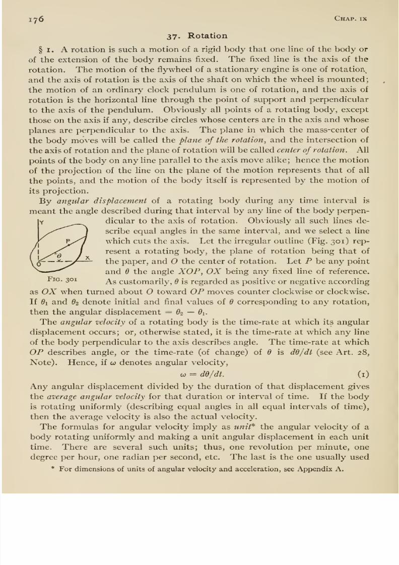
8/13/2019 Maurer Mechanics
http://slidepdf.com/reader/full/maurer-mechanics 188/407
iy6 Chap, ix
37. Rotation
§ I. A rotation is such a motion of a rigid body that one line of the body or
of the extension of the body remains fixed. The fixed line is the axis of the
rotation. The motion of the flywheel of a stationary engine is one of rotatiorv^
and the axis of rotation is the axis of the shaft on which the wheel is mounted;the motion of an ordinary clock pendulum is one of rotation, and the axis of
rotation is the horizontal line through the point of support and perpendicular
to the axis of the pendulum. Obviously all points of a rotating body, except
those on the axis if any, describe circles whose centers are in the axis and whose
planes are perpendicular to the axis. The plane in which the mass-center of
the body moves will be called the plane of the rotation, and the intersection of
the axis of rotation and the plane of rotation will be called center of rotation. All
points of the body on any line parallel to the axis move alike; hence the motion
of the projection of the line on the plane of the motion represents that of all
the points, and the motion of the body itself is represented by the motion of
its projection.
By angular displacement of a rotating body during any time interval is
meant the angle described during that interval by any line of the body perpen-
dicular to the axis of rotation. Obviously all such lines de-
scribe equal angles in the same interval, and we select a line
which cuts the axis. Let the irregular outline (Fig. 301) rep-
resent a rotating body, the plane of rotation being that of
the paper, and the center of rotation. Let P be any point
and 6 the angle XOP, OX being any fixed line of reference.Fig. 301 ^g customarily, 6 is regarded as positive or negative according
as OX when turned about toward OP moves counter clockwise or clockwise.
If di and 6i denote initial and final values of 6 corresponding to any rotation,
then the angular displacement = Oo — 6\.
The angular velocity of a rotating body is the time-rate at which its angular
displacement occurs; or, otherwise stated, it is the time-rate at which any line
of the body perpendicular to the axis describes angle. The time-rate at which
OP describes angle, or the time-rate (of change) of 6 is dd/dt (see Art. 28,
Note). Hence, if co denotes angular velocity,
CO = de/dt. (i)
Any angular displacement divided by the duration of that displacement gives
the average angular velocity for that duration or interval of time. If the bodyis rotating uniformly (describing equal angles in all equal intervals of time),
then the average velocity is also the actual velocity.
The formulas for angular velocity imply as wm/* the angular velocity of a
body rotating uniformly and making a unit angular displacement in each unit
time. There are several such units; thus, one revolution per minute, one
degree per hour, one radian per second, etc. The last is the one usually used
* For dimensions of units of angular velocity and acceleration, see Appendix A,
8/13/2019 Maurer Mechanics
http://slidepdf.com/reader/full/maurer-mechanics 189/407
Art. 37 177
herein. An angular velocity must be regarded as having sign, the same as that
of dd/dt. Since dd/dt is positive or negative according as d increases or de-
creases algebraically, the angular velocity of a rotating body at any instant
is positive or negative according as it is turning in the counter clockwise or
clockwise direction at that time.
The angular acceleration of a rotating body is the time-rate (of change) of
its angular velocity. If, as in the preceding, co denotes the angular velocity,
then the general expression for the time-rate of the angular velocity is do:/dt;
hence if a denotes the angular acceleration,
a = dio/di = d^d/dtK (2)
The change in angular velocity which takes place during any interval of time
divided by the length of the interval gives the average angular acceleration for
that interval. If the velocity changes uniformly, then this average accelera-
tion is also the actual acceleration.
The foregoing formulas imply as unit * the angular acceleration of a body
whose angular velocity is changing uniformly and so that unit angular velocity-
change occurs in each unit time. One revolution per second per second, one
radian per second per second, etc., are such units. An angular acceleration
must be regarded as having sign, —the same as that of dw/dt. Since dw/dt
is positive or negative according as co increases or decreases algebraically, an
angular acceleration is positive or negative according as the angular velocity
is increasing or decreasing (algebraically).
There are simple relations between the linear velocity v and linear acceleration
a of any point P of a rotating body and the angular velocity and acceleration of the
body. Let r — the distance of P from the axis of rotation, s = distance travelled
by P in any time from some fixed point in the path of P, and 6 — the angle
described by the radius to P in that same time. Then s =^ rd ii dhe expressed
in radians; ds/dt — r dd/dt, or
V — roi.
Differentiating again, we find that dv/dt = r do^/dt, or
at = ra; also «„ (= v'^/r) = rco^.
Here at and a„ mean the tangential and normal components of the acceleration
of P (Art. 34).
§ 2. Equation of Motion. —We have already called attention to the
fact (Art. 36, footnote) that in the case of rotation the angular acceleration
is proportional to the algebraic sum of the moments of all the external forces
acting on the body directly and to the moment of inertia of the body inversely,
both moments being about the axis of rotation. Or, if To and Iq be used to
denote these moments, and a = the angular acceleration, then a is proportional
to {Tq -^ Iq) ; and, if systematic units (Art. 4) be used then
To = ha = Mko'a, (3)
* For dimensions of units of angular velocity and acceleration, see Appendix A.

8/13/2019 Maurer Mechanics
http://slidepdf.com/reader/full/maurer-mechanics 190/407
178 Chap, ix
where M = mass of the body and ko = its radius of gyration about the axis of
rotation. If W/g be written for M (Art. 4, § 2), then any unit of force (in-
cluding W), any unit of length, and any unit of time may be used in (3).
The foregoing is called the equation of motion for a rotation; it may be de-
rived from a consideration of the torque, about the axis of rotation, of all
the forces acting on each particle of the body. Let P' (Fig. 302)
represent a particle of the rotating body not shown, m' = its
mass, and a' = its acceleration. Then the resultant of all
the forces acting on P' = m'a' , and the tangential, normal,
and axial components of this force are m'o/, m'an , and o
respectively. Similarly the tangential, normal, and axial
components of the resultant of all the forces acting on theFig. 302 second particle P are m at , m an , and o. All the radial
or normal components are directed toward the axis of rotation, and all the
tangential components clockwise or counter clockwise. Now the torque of all
the forces acting on P' equals the torque of m'at and m'an ; this torque =m'at'r' . Similarly the torque of all the forces acting on P = m ai r
Hence the torque of the forces acting on all the particles equals
m'at'r' + m at r + • • • = m'r'ar' + m r ar + • • • = cvSwr^ = ah.
Now the system of forces acting on all the particles consists of internal and
external forces. The internal forces jointly have no torque since they consist
of pairs of coUnear, equal, and opposite forces. Hence, the torque of the ex-
ternal forces equals Ua.
Examples. —i . Fig. 303 represents a circular disk of cast iron 4 inches thick
and 3 feet in diameter. It is supported on a fixed horizontal shaft 3 inches in
diameter. A cord is wrapped around the disk, and then a pull P = ^...j'_.^
100 pounds is applied to the cord as shown. What is the angular
acceleration of the disk? The external forces acting on the disk andcord are the weight of the disk and cord P, and the reaction of the
shaft. Only one of these, P, has a moment about the axis of rota-
tion. We are assuming that the disk is homogeneous so that the
center of gravity is in the axis of rotation, and that the shaft is'
'^° ^
frictionless. Tq of equation (3) is therefore 100 X 1.5 = 150 foot-pounds.
Now the square of the radius of gyration of the disk about the axis of rotation
is I (1.52 + 0.125^) = 1. 133 feet^ (Art. 36). And since the weight of the disk
is.T053 pounds, its moment of inertia about the axis of rotation is (1053
-^32.2)
1.J33 = 37-0 slug-feet^. Hence the angular acceleration of the disk is 150 -^
37.0 = 4.0 radians per second per second.
2. Suppose that a turning force P in the preceding example is supplied not
by hand but by means of a body suspended from the cord, and suppose
that the body weighs 100 pounds. Obviously the system (disk and suspended
body) moves with acceleration ; hence the two forces acting on the body (gravity
and the pull P of the cord) are not equal or balanced but have a resultant

8/13/2019 Maurer Mechanics
http://slidepdf.com/reader/full/maurer-mechanics 191/407
Art. 37 179
downward (direction of the acceleration of the body). That resultant is
100 —P, and it equals the product of the mass and acceleration of the body,
or 100 —P = (100 -V- 32.2) X a where a = the acceleration. The torque on
the disk is P X i-S, and 1.5 P = /a = 37.0 a. But a = the tangential
acceleration of any point on the rim of the disk = 1.5 X a, or a = 1.5 a.
These three equations
100 - P = (100/32.2) a, 1.5 P = 37.0 a, and a =1.5 a,
solved simultaneously give a = 3.41 radians per second per second, less than
in example i as was to be expected, because the pull P in this example is less
than 100 pounds. The value of P as obtained from the foregoing equations
is 84.1 pounds.
3. In Fig. 304 we take weight of A = 64 pounds,of
P=
96pounds, and of
pulley C = 144 pounds; assume coefficient of friction under B = I ior sliding,
axle friction zero; take diameter of pulley = 2 feet 6 inches, and the radius
of gyration of the pulley about the axis of rotation = 10.6 inches. We show
how to determine the acceleration of the system. Let a = acceleration of A
and B, and a = (angular) acceleration of the pulley. Obviously a = 1.25 a.
Let us now consider the forces acting on each body A, B, and C. On A there
are two, —gravity (64 pounds) and the pull of the cord Pi (see Fig. 305). On
Fig. 304
96 /bs.
B
¥Fig. 306 Fig. 307
B there are three, —gravity (96 pounds), the pull of the cord P2, and the re-
action of the supporting surface D (see Fig. 306 where this latter force is
represented by two components N and F). On the pulley there are three
forces, —gravity (144 pounds), the reaction Q of the axle, and the pressure of
the cord. Since the mass of. the cord is negligible, the tension at any point of
the cord from A to the pulley is Pi, and at any point from B to the pulley it is
P2. Hence the pressure of the cord against the pulley equals the resultant of
Pi and P2 (Fig. 307), and that pressure is equivalent to Pi and P2. Therefore
the equation of motion becomes (Pi - P2) 1.25 = (i44 ^ 32) (10.6 -^ i2ya
= 4.5 X 0.778 X a = 3.5 a. Since the acceleration of B is toward the right,
the resultant force on it acts in that direction and equals P2 - P = P2 - ^ N= P2 -
^, 96 = Po - 19.2; and hence P2 - 19-2 = (96 ^ 32) <i = 3 «• Since
the acceleration of A is downward the resultant force on A acts in that direc-
tion and equals 64 - Pi; hence 64 - Pi = (64 -^ 32) a = 2 a. Now solving
the three equations of motion,
(Pi - ^^2) X 1.25 = 3.5 a, P2 - 19-2 = 3 a> and 64 - Pi = 2 a,
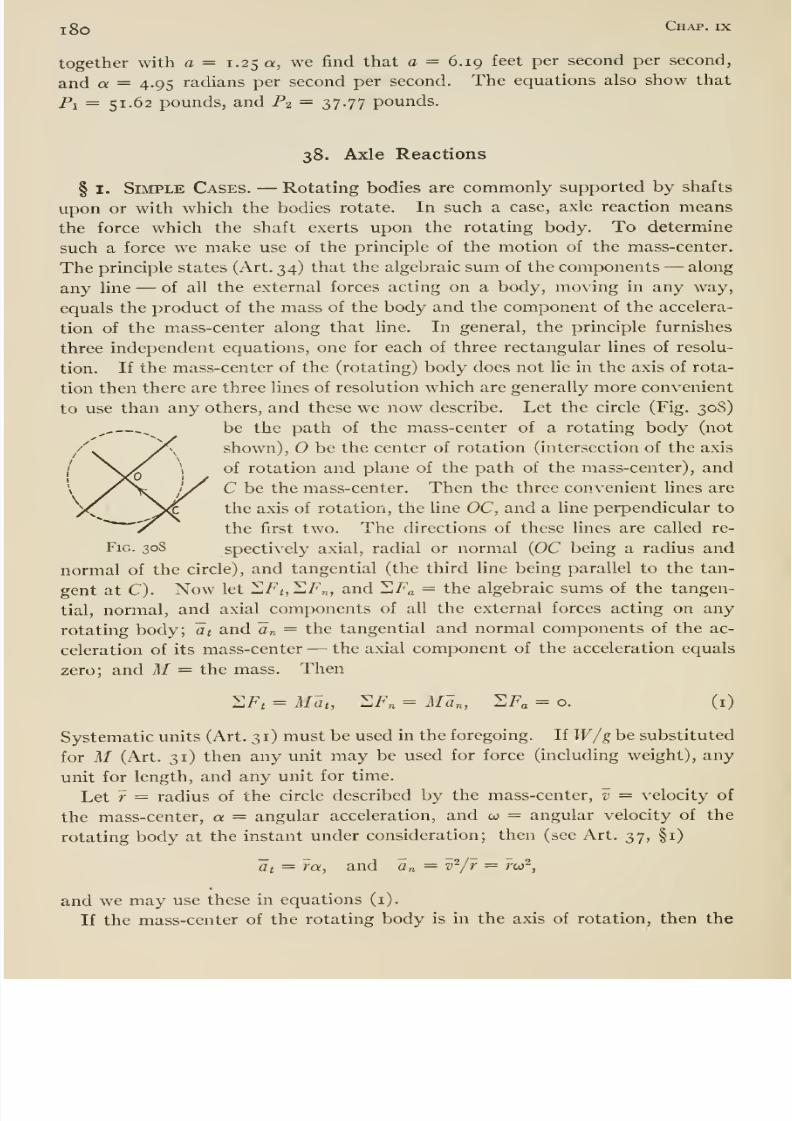
8/13/2019 Maurer Mechanics
http://slidepdf.com/reader/full/maurer-mechanics 192/407
l8o Chap, ix
together with a = 1.25 a, we j&nd that a = 6.19 feet per second per second,
and a = 4.95 radians per second per second. The equations also show that
Pi = 51.62 pounds, and P2 = 37.77 pounds.
38. Axle Reactions
§ I. Simple Cases. —Rotating bodies are commonly supported by shafts
upon or with which the bodies rotate. In such a case, axle reaction means
the force which the shaft exerts upon the rotating body. To determine
such a force we make use of the principle of the motion of the mass-center.
The principle states (Art. 34) that the algebraic sum of the components —along
any line —of all the external forces acting on a body, moving in any way,
equals the product of the mass of the body and the component of the accelera-
tion of the mass-center along that line. In general, the principle furnishes
three independent equations, one for each of three rectangular lines of resolu-
tion. If the mass-center of the (rotating) body does not lie in the axis of rota-
tion then there are three lines of resolution which are generally more convenient
to use than any others, and these we now describe. Let the circle (Fig. 30S)
be the path of the mass-center of a rotating body (not
shown), O be the center of rotation (intersection of the axis
ofrotation
andplane of the path of the mass-center),
andC be the mass-center. Then the three convenient lines are
the axis of rotation, the line OC, and a line perpendicular to
the first two. The directions of these lines are called re-
FiG. 30S spectively axial, radial or normal (OC being a radius and
normal of the circle), and tangential (the third line being parallel to the tan-
gent at C). Now let I1F<,I F„, and ^Fa = the algebraic sums of the tangen-
tial, normal, and axial components of all the external forces acting on any
rotating body; at and a„ = the tangential and normal components of the ac-celeration of its mass-center —the axial component of the acceleration equals
zero; and M= the mass. Then
2F, = Alat, :SF„ = Man, 2F, = o. (i)
Systematic units (Art. 31) must be used in the foregoing. If W/g be substituted
for M (Art. 31) then any unit may be used for force (including weight), any
unit for length, and any unit for time.
Let r = radius of the circle described by the mass-center, v = velocity of
the mass-center, a = angular acceleration, and co = angular velocity of the
rotating body at the instant under consideration; then (see Art. 37, §1)
at = ra, and a„ — v'^/r = rco^,
and we may use these in equations (i).
If the mass-center of the rotating body is in the axis of rotation, then the

8/13/2019 Maurer Mechanics
http://slidepdf.com/reader/full/maurer-mechanics 193/407
Art. 38 181
Fig. 309
acceleration of the mass-center is always zero, and the algebraic sum of the
components of the external forces along any line equals zero.
Examples. —i. AB (Fig. 309) is a bar of wrought iron 1.5 inches (perpen-
dicular to paper) X 4 inches X 6 feet, suspended from a horizontal axis at A.
Suppose that the bar is made to rotate and is then left to it- r,
self rotating under the influence of gravity, the axle reaction,
and the initial velocity given to it. Suppose further that
the initial velocity was such that when the bar gets into the
position shown, the angular velocity is 60 revolutions per
minute. Required the axle reaction in the position shown.
The only forces acting on the body are its weight W= 120
pounds, and the axle reaction represented by two components
Ri and R^. We neglect the axle friction; then the lines of
actions of Ri and R-i cut the axis of rotation, and the equation of motion (Art.
37) becomes IF (2 sin 35°) = la. Now I = (IF/32.2) ^2 = (120/32.2) 7.01;
hence a = 5.26 radians per second per second, and Cj = 2 X 5.26 = 10.52
feet per second per second. The angular velocity, 60 revolutions per minute,
equals 6.28 radians per second; hence a„ = 2 X 6.28^ = 78.8 feet per second
per second. Finally, equations (i) become
120 sin 35° — Ri= (120/32.2) 10.52 = 39.2, and
R2 — 120 cos 35° = (120/32.2) 78.8 = 294.
From the first Ri = 29.7, and from the second R2 = 392 pounds.
2. AB (Fig. 310) is a simple brake for retarding the motion of the drum Cand suspended body IF. Let IF = 2000 pounds, weight of the drum = 1800
pounds, radius of gyration of drum about axis of rotation =2.5 feet, coeflBcient of
Fig. 310
friction between brake and drum = 0.5. Suppose that IF is descending andthe brake pull P is 1000 pounds. Required the axle reaction
onthe
drum.Fig.
311 shows all the forces acting on the drum, —its own weight (1800 poimds),the brake pressure represented by two components N (normal pressure) andF (friction), the pull T of the rope, and the axle reaction represented by twocomponents Ri and R2. From a consideration of the forces acting on the brakeit is plain that N = (1000 X 6.5) -^ 1.5 = 4333 pounds; and hence F = 0.5
X 4333 = 2167 pounds. Now in order to get T we write out the equations
of motion of the drum and the suspended body. Since F is greater than the
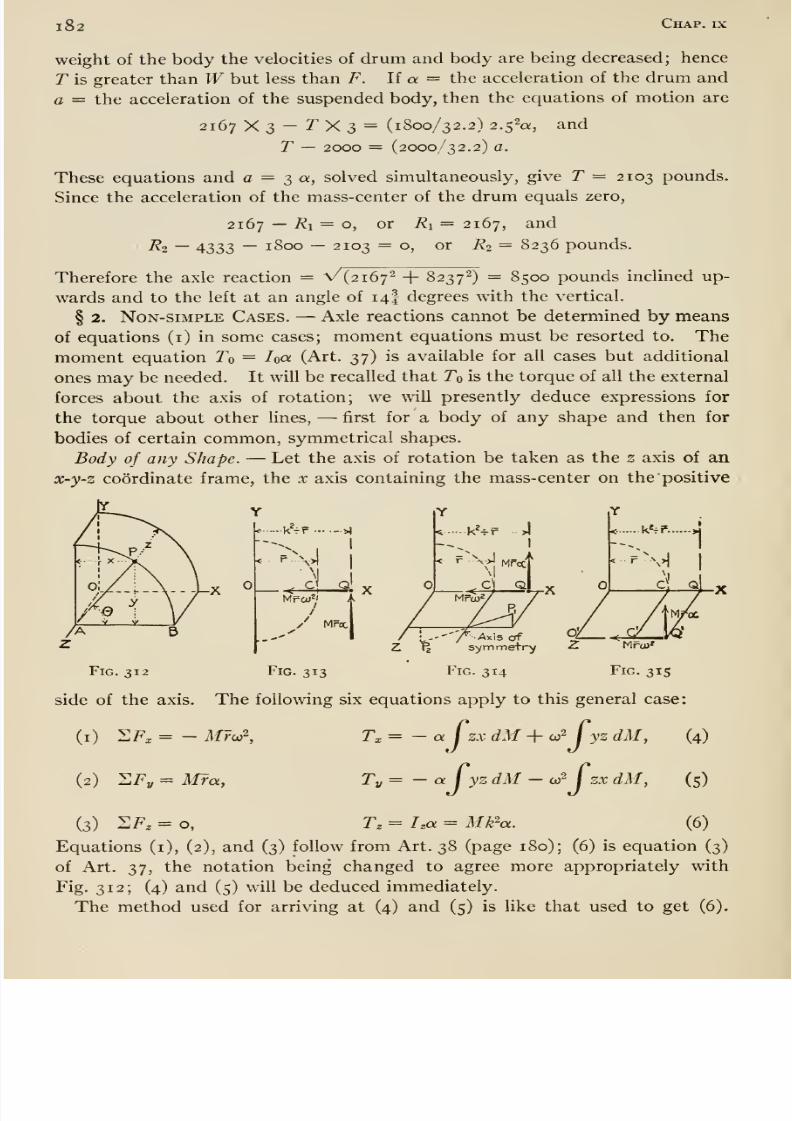
8/13/2019 Maurer Mechanics
http://slidepdf.com/reader/full/maurer-mechanics 194/407
l82 Chap, ix
weight of the body the velocities of drum and body are being decreased; hence
T is greater than Wbut less than F. If a = the acceleration of the drum and
a = the acceleration of the suspended body, then the equations of motion are
2167 y. 2)~ T^ ^ i ^ (1800/32.2) 2.52a, and
T — 2000 = (2000/32.2) a.
These equations and a = T)^^^ solved simultaneously, give T = 2103 pounds.
Since the acceleration of the mass-center of the drum equals zero,
2167 —Ri^ o, or Ri = 2167, and
R2 —4333 — 1800 — 2103 = o, or R2 = 8236 pounds.
Therefore the axle reaction = V{2i6'j'^ + 8237') = 8500 pounds inclined up-
wards and to the left at an angle of 14I degrees with the vertical.
§ 2. Non-simple Cases. —Axle reactions cannot be determined by meansof equations (i) in some cases; moment equations must be resorted to. The
moment equation To = ha (Art. 37) is available for all cases but additional
ones may be needed. It will be recalled that To is the torque of all the external
forces about the axis of rotation; we will presently deduce expressions for
the torque about other lines, —first for a body of any shape and then for
bodies of certain common, symmetrical shapes.
Body of any Shape. —Let the axis of rotation be taken as the z axis of an
x-y-z coordinate frame, the x axis containing the mass-center on the positive
k>x4 I
< S Q. X
I
/ Mrcc
Z t| ' symmetry Z 'Mru)'
Fig. 312 Fig. 313 Fig. 314 Fig. 315
side of the axis. The following six equations apply to this general case:
(i) 2F, = - MFco2,
(2) llFy = M?a,
T,= -a fzx dM + aj2 Cyz dM, (4)
Ty= - a I yzdM -or \ zx dM, (5)
(3) 2F. = 0, T,= ha = Mk'^a. (6)
Equations (i), (2), and (3) follow from Art. 38 (page 180); (6) is equation (3)
of Art. 37, the notation being changed to agree more appropriately with
Fig. 312; (4) and (5) will be deduced immediately.
The method used for arriving at (4) and (5) is like that used to get (6).
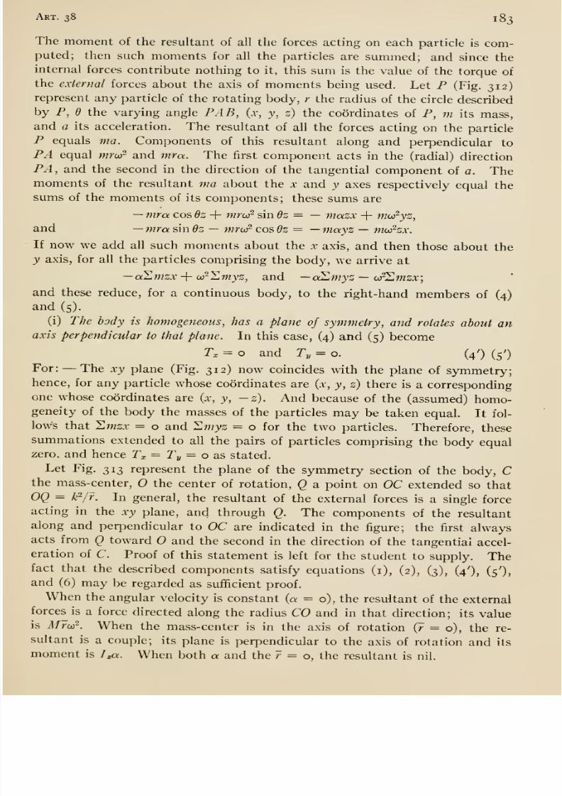
8/13/2019 Maurer Mechanics
http://slidepdf.com/reader/full/maurer-mechanics 195/407
Art. 38 183
The moment of the resultant of all the forces acting on each particle is com-puted; then such moments for all the particles are summed; and since the
internal forces contribute nothing to it, this sum is the value of the torque of
the external forces about the axis of moments being used. Let P (Fig. 312)represent any particle of the rotating body, r the radius of the circle described
by P, e the varying angle PAB, (x, y, z) the coordinates of P, m its mass,and a its acceleration. The resultant of all the forces acting on the particle
P equals ma. Components of this resultant along and perpendicular to
PA equal mrur and mra. The first component acts in the (radial) direction
PA , and the second in the direction of the tangential component of a. Themoments of the resultant ma about the x and y axes respectively equal the
sums of the moments of its components; these sums are
—mra cos 6s + mror sin 6z — — mazx + mcJ'yz,
and —mra sin dz — mroi^ cos 6z = —mayz — moihx.
If now we add all such moments about the x axis, and then those about the
y axis, for all the particles comprising the body, we arrive at
—aLmzx-{- orllmyz, and —allmyz — (j?'Lmzx\
and these reduce, for a continuous body, to the right-hand members of (4)and (5).
(i) The body is homogeneous, has a plane of symmetry, and rotates about an
axis perpendicular to that plane. In this case, (4) and (5) becomeTx = o and Ty = o. (4') (5')
For: —The xy plane (Fig. 312) now coincides with the plane of symmetry;hence, for any particle whose coordinates are (.v, y, 2) there is a correspondingone whose coordinates are (x, y, —z). And because of the (assumed) homo-geneity of the body the masses of the particles may be taken equal. It fol-
lows that Swsx = o and Hmyz = o for the two particles. Therefore, these
summations extended to all the pairs of particles comprising the body equalzero, and hence Tx = Ty = o SiS stated.
Let Fig. 313 represent the plane of the symmetry section of the body, Cthe mass-center, the center of rotation, Q a point on OC extended so that
OQ = k-/r. In general, the resultant of the external forces is a single force
acting in the xy plane, and through Q. The components of the resultant
along and perpendicular to OC are indicated in the figure; the first alwaysacts from Q toward and the second in the direction of the tangential accel-
eration of C. Proof of this statement is left for the student to supply. Thefact that the described components satisfy equations (i), (2), (3), (4'), (5'),
and (6) may be regarded as sufficient proof.
When the angular velocity is constant (a = 6), the resultant of the external
forces is a force directed along the radius CO and in that direction; its valueis Mroi^. When the mass-center is in the axis of rotation (r = o), the re-
sultant is a couple; its plane is perpendicular to the axis of rotation and its
moment is /««. When both a and the r = o, the resultant is nil.
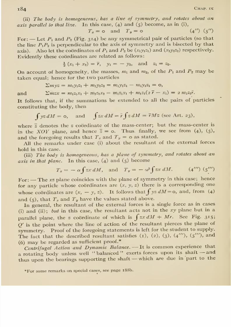
8/13/2019 Maurer Mechanics
http://slidepdf.com/reader/full/maurer-mechanics 196/407
184 Chap- IX
(ii) The body is homogeneous, has a line of symmetry, and rotates about an
axis parallel to that line. In this case, (4) and (5) become, as in (i),
Tx = o and T, = o (4 ) (5 )
For: —Let Pi and P2 (Fig. 314) be any symmetrical pair of particles (so that
the line P1P2 is perpendicular to the axis of symmetry andis
bisected bythat
axis). Also let the coordinates of Pi and P2 be (xiyiZi) and (x2}'2Z2) respectively.
Evidently these coordinates are related as follows:
h (xi + X2) = r, yi= - y2, and Zi = Z2.
On account of homogeneity, the masses, nii and m^, of the Pi and P2 may be
taken equal; hence for the two particles
Hmyz = niiyiZi + m2y2Z2 = wiyiZi —miyiZi = o,
and Smzx = miZiXi + ^W2Z2a-2 = miZiXi + WiZi(2 r — Xi) = 2 miZi?.
It follows that, if the summations be extended to all the pairs of particles
constituting the body, then
fyz dM = o, and jzx dM = rjz dM = rMz (see Art. 23),
where s denotes the 2 coordinate of the mass-center; but the mass-center is
in the XOY plane, and hence i = o. Thus finally, we see from (4), (5),
and the foregoing results that T^, and T^ = o as stated.
All the remarks under case (i) about the resultant of the external forces
hold in this case.
(iii) The body is homogeneous, has a plane of symmetry, and rotates about an
axis in that plane. In this case, (4) and (5) become
r, = - afzx dM, and Ty = - '^ ^zx dM. (4' ) (5' )
Yox: —The xz plane coincides with the plane of symmetry in this case; hence
for any particle whose coordinates are (x, y, z) there is a corresponding one
whose coordinates are {x, - y, z). It follows thatjjs dM^o, and, from (4)
and (5), that T^ and Ty have the values stated above.
In general, the resultant of the external forces is a single force as in cases
(i) and (ii); but in this case, the resultant acts not in the xy plane but in a
parallel plane, the z coordinate of which is jzxdM ^ Mr. See Fig. 315;
Q' is the point where the Une of action of the resultant pierces the plane of
symmetry. Proof of the foregoing statements is left for the student to supply.
The fact that the described resultant satisfies (i), (2), (3), (4' ), (s' ), and
(6) may be regarded as sufficient proof.*
Centrifugal Action and Dynamic Balance. —It is common experience that
a rotating body unless well balanced exerts forces upon its shaft —and
thus upon the bearings supporting the shaft —which are due in part to the
*For some remarks on special cases, see page i88b.
8/13/2019 Maurer Mechanics
http://slidepdf.com/reader/full/maurer-mechanics 197/407
Art. 39185
velocity of rotation. Such parts or components of the forces are said also to
be due to the centrifugal action of the rotating body; and the components
are called centrifugal forces or pulls. A rotating machine part so shaped
or loaded that it exerts no resultant centrifugal pull on its shaft or bearhigs
is said to be in running or dynamic balance.
The common method of designing for running balance consists in arranging
or proportioning the various (simple) parts of the rotating body, a motor
crank shaft for example, so that the centrifugal pulls of all the various parts
will neutralize.* Even after careful design and manufacture of a crank
shaft, say, the running balance may be imperfect. Then mechanical methodsf
are resorted to for completing the task.
The conditions for dynamic balance can be stated with reference to equa-
tions (i) to (6):— (a) The mass-center of the body must be in the axis of
rotation {r= o); this insures standing or static balance. (b) The
products of inertia (see Art. 57) J yzdM &nd jzxdM must equal zero;
this with (a) insures dynamic balance. For:— When these conditions are
fulfilled and the angular velocity is constant, the right-hand members of
equations (i) to (6) equal zero, that is they are equilibrium equations; hence,
the bearing pressures are independent of the motion.
The axis of rotation of a body which is dynamically balanced for that
axis is sometimes called a free axis of the body; for, if the body could be
rotated about that axis and then left to itself entirely free from all external
forces, even gravity, it would continue to rotate about that axis.
39. Pendulums
§ I. Gravity Pendulum. —By this term is meant the common pendulum,
that is a body suspended on a horizontal axis so that it can be made to oscillate
freely under the influence of gravity. A real pendulum is sometimes called a
compound or physical pendulum to distinguish it from an imaginary one con-
sisting of a mass-point or particle suspended by a massless cord; this latter is
called a simple or mathematical pendulum. Let T = the period or time of one
complete or double (to and fro) oscillation, k = the radius of gyration of the
pendulum with respect to the axis of suspension, c = distance from the center
of gravity of the pendulum to that axis, and 2 jS = the angle swept out by the
pendulum in one single oscillation. Then, as will be shown presently, the
period is given closely byT =2T Vk'/cg, (i)
* For a good treatment of dynamic balancing, see the book by Dunkerly or Sharpe on
Balancing of Engines.
t For a description of an ingenious balancing machine, Akimofif's, see American Machinist
for May 18, 1Q16.
X For a theory of balancing of engines based on these conditions extended see Lorenz,
Tecknische Mcchanik, Band I.
8/13/2019 Maurer Mechanics
http://slidepdf.com/reader/full/maurer-mechanics 198/407
1 86 Chap, ix
provided that j8 is small.* Since jS does not appear in this formula the period
of any pendulum is independent of /3; that is all small oscillations of a pendulum
have equal periods or, as we say, they are isochronous. When g is expressed in
feet per second per second then k and c should be expressed in feet; T will be
in seconds.
For the derivation of equation (i) let OG (Fig. 316a) be a pendulum in anyswinging position, O the center of suspension, G the center of gravity; let W=the weight of the pendulum, c = OG, and 6 the (varying) angle which OG makes
with the vertical, regarded as positive when the pendulum is on the right side
of the vertical, as shown. There are three forces acting on the pendulum, —gravity, the supporting force at the knife edge, and the pressure of the sur-
rounding air. The moment of the first force about the axis of suspension is
Wc sin 6; the moments of the other two forces we take as negligible. Hence
the resultant torque on the pendulum in any position = Wc sin 6 practically.
The angular acceleration = <Pd/dfi (see Art. 37); hence according to equation
(3) of that article
Wc sin 6= - {W/g) m^QldC-,
the negative sign being introduced because sin Q and d^d/df are always oppo-
site in sign. It follows readily from the preceding equation that
(Pe/df = - (cg/k )̂ sin = -A sin d,
where A is an abbreviation for cg/k^. We will assume that the greatest valueof 6, that is jS, is so small that sin d and 6 are nearly equal; then as a good
approximation we may substitute 6 for sin 6, and have
deydf = - Ad.
To integrate this simply, let u — dd/dt; then d^O/df = du/dt = (du/dd)
{dd/dt) = {du/dd) u, and hence
(du/dO) u = — Ad, or udu = —Ad dd.
Now integrating and replacing u by dd/dt, we get
where Ci is a constant of integration. Remembering that dd/dt = the angular
velocity of the pendulum, we note that where d = ^, there dd/dt = o; there-
fore for these (simultaneous) values the preceding equation becomes o =-^AjS^-h Ci, or Ci = ^ .4/32, and finally
dd/dt = ±AWp^-d\* The exact value of the period is given by
r = 2,rVFAg[i + (iysin^^-}-(i.^ysin^^+ • • •
].
If /3 = 8 degrees then the bracket above = i. 001 2 2; and for smaller values of the value
of the bracket is still nearer unity. Hence the error in the approximate formula is less
than one-eighth of one per cent if /3 does not exceed 8 degrees.
8/13/2019 Maurer Mechanics
http://slidepdf.com/reader/full/maurer-mechanics 199/407
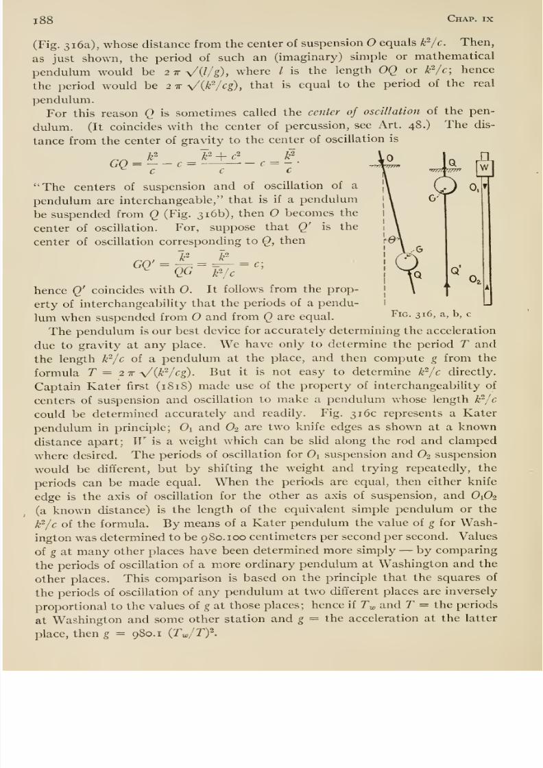
8/13/2019 Maurer Mechanics
http://slidepdf.com/reader/full/maurer-mechanics 200/407
j88 Chap, ix
(Fig. 316a), whose distance from the center of suspension equals k'^/c. Then,
as just shown, the period of such an (imaginary) simple or mathematical
pendulum would be 2TVQ/g), where / is the length OQ or k'^/c; hence
the period would be 2 tt Vik^cg), that is equal to the period of the real
pendulum.
For this reason Q is sometimes called the center of oscillation of the pen-
dulum. (It coincides with the center of percussion, see Art. 48.) The dis-
tance from the center of gravity to the center of oscillation is
GQ = -c
c —c w]
0,
Fig. 316, a, b, c
The centers of suspension and of oscillation of a
pendulum are interchangeable, that is if a pendulum
be suspended from () (Fig. 316b), then becomes thecenter of oscillation. For, suppose that Q' is the
center of oscillation corresponding to (2, then
hence Q' coincides with 0. It follows from the prop-
erty of interchangeability that the periods of a pendu-
lum when suspended from and from Q are equal.
The pendulum is our best device for accurately determining the acceleration
due to gravity at any place. We have only to determine the period T and
the length k^jc of a pendulum at the place, and then compute g from the
formula T = 2 -k y/ {]r I eg) . But it is not easy to determine k^jc directly.
Captain Kater first (18 18) made use of the property of interchangeabiUty of
centers of suspension and oscillation to make a pendulum whose length W-jc
could be determined accurately and readily. Fig. 316c represents a Kater
pendulum in principle; Oi and O2 are two knife edges as shown at a known
distance apart; W is a weight which can be slid along the rod and clamped
where desired. The periods of oscillation for 0\ suspension and O2 suspension
would be different, but by shifting the weight and trying repeatedly, the
periods can be made equal. When the periods are equal, then either knife
edge is the axis of oscillation for the other as axis of suspension, and O1O2
(a known distance) is the length of the equivalent simple pendulum or the
W'lc of the formula. By means of a Kater pendulum the value of g for Wash-
ington was determinedto be
980.100centimeters per second per second. Values
of g at many other places have been determined more simply —by comparing
the periods of oscillation of a more ordinary pendulum at Washington and the
other places. This comparison is based on the principle that the squares of
the periods of oscillation of any pendulum at two different places are inversely
proportional to the values of g at those places ; hence if Ty, and T = the periods
at Washington and some other station and g = the acceleration at the latter
place, then g = 980.1 {Tw/Tf-
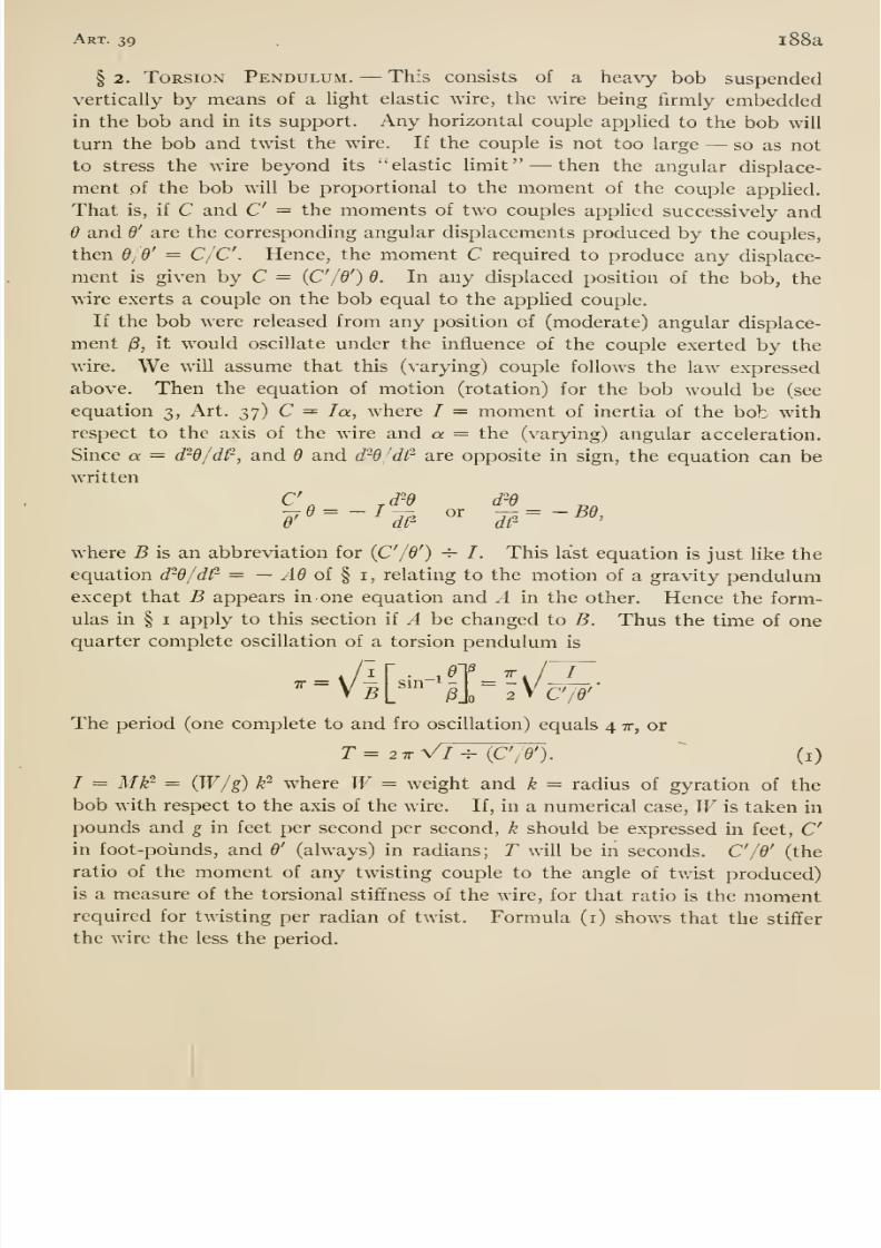
8/13/2019 Maurer Mechanics
http://slidepdf.com/reader/full/maurer-mechanics 201/407
Art. 39 , 1 88a
§ 2. Torsion Pendulum. —This consists of a heavy bob suspended
vertically by means of a Ught elastic wire, the wire being firmly embeddedin the bob and in its support. Any horizontal couple appUed to the bob will
turn the bob and twist the wire. If the couple is not too large —so as not
to stress the wire beyond its elastic limit —then the angular displace-
ment of the bob will be proportional to the moment of the couple applied.
That is, if C and C = the moments of two couples apphed successively and6 and 6' are the corresponding angular displacements produced by the couples,
then 6/6' = C/C. Hence, the moment C required to produce any displace-
ment is given by C = {C'/d') 6. In any displaced position of the bob, the
wire exerts a couple on the bob equal to the appUed couple.
If the bob were released from any position of (moderate) angular displace-
ment j8, it would oscillate under the influence of the couple exertedby the
wire. We will assume that this (varying) couple follows the law expressed
above. Then the equation of motion (rotation) for the bob would be (see
equation 3, Art. 37) C =^ la, where / = moment of inertia of the bob with
respect to the axis of the wire and a. = the (varying) angular acceleration.
Since a = drd/df, and 6 and d d/dt are opposite in sign, the equation can be
written
where B is an abbreviation for {C'/d') -^ /. This last equation is just like the
equation d^6/dt- = — .40 of § i, relating to the motion of a gravity pendulumexcept that B appears in one equation and A in the other. Hence the form-
ulas in § I apply to this section if A be changed to B. Thus the time of onequarter complete oscillation of a torsion pendulum is
TT =
\/|[-iI=^v/c^/6'
The period (one complete to and fro oscillation) equals 4 tt, or
T= 2ir\/l^{C'/d').^
(i)
/ = Mk^ = {W/g) k' where W= weight and k = radius of gyration of the
bob with respect to the axis of the wire. If, in a numerical case, Wis taken in
pounds and g in feet per second per second, k should be expressed in feet, Cin foot-pounds, and 6' (always) in radians; T will be in seconds. C'/d' (the
ratio of the moment of any twisting couple to the angle of twistproduced)
is a measure of the torsional stiffness of the wire, for that ratio is the momentrequired for twisting per radian of twist. Formula (i) shows that the stiffer
the wire the less the period.
8/13/2019 Maurer Mechanics
http://slidepdf.com/reader/full/maurer-mechanics 202/407
i88b Chap, ix
Continued from page 184.
When the angular velocity is constant (a = o), the resultant of the external
forces is a single force R { = Mro)^) acting as shown in Fig. 315 and its dis-
tance from CO is
/ zxdM -T- Mr.
When the mass-centre is in the axis of rotation {r = o), the resultant is a
couple whose moments about the x, y, and axes respectively are
—ai zxdM, — <a~j zxdM, and Mk^a.
When both a and r = o, the resultant is a couple whose moments about
the X,y,
and z axes respectively, are
o, — ar j zxdM, and o.

8/13/2019 Maurer Mechanics
http://slidepdf.com/reader/full/maurer-mechanics 203/407
CHAPTER XWORK, ENERGY, POWER
40. Work
§ I. Definitions, Etc. —Work is a common word and has many mean-
ings (see dictionary), but it is used in a single special sense in Mechanics.
Work is said to be done upon a body by a force —also by the agent exerting
the force —when the point of application of the force moves so that the force
has a component along the path of the point of application. This component
will be called the working component of the force; and the length of the path
of the point of application the distance through which the force acts. The
amount of work done by the force is taken as equal to the product of the
working component and the distance through which the force acts.
The meaning of this measure of work done by a force is clear when the work-
ing component is constant. For example, suppose that the body represented
in Fig. 317 is moved along the line AB by a number of forces, two of which
(indicated) are constant in magnitude and
in direction. During any portion of the _5__ J ^''^r--^--i
motion, as from A to B, the work done by l,,,Jy,,[Zj^Fi is Fi(AB) and the work done by F2 is
'
{F2 cos 6) AB. This expression when written
F (AB cos 6) means the product of the force and the component of the dis-
placement along the line of action of the force, which is a view of amount
of work done by a force sometimes more convenient than the other.
When the working component is not constant in magnitude, then we mayarrive at an expression for the work somewhat like this: —Let AB (Fig. 318)
be the path of the point of application of one of the forces
acting upon a body not shown, and P any point on the
path. Let /' = the force, = the angle between F and
the tangent atP, and ds = the elementary portion of the
path at P. Then the work done by F during the elementaryI^iG. 318
displacement = F cos 4> 'ds or Ftds where Fi means working
or tangential component of F; and the work done by F in the displacement
from A to B = ( Ft ds, limits of integration to be assigned so as to include all
elementary works Ft ds in the motion from A to B. It is worth noting that if
the force F acts normally to the path at all points, then Ft = o always, and
the formula gives zero for the work done by F, as it should.
189
'A
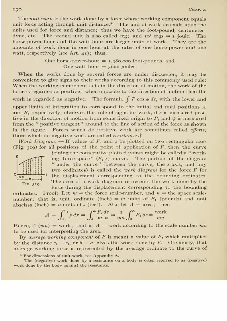
8/13/2019 Maurer Mechanics
http://slidepdf.com/reader/full/maurer-mechanics 204/407
190 Chap, x
The unit work is the work done by a force whose working component equals
unit force acting through unit distance.* The unit of work depends upon the
units used for force and distance; thus we have the foot-pound, centimeter-
dyne, etc. The second unit is also called erg; and 10^ ergs = i joule. Thehorse-power-hour and the watt-hour are larger units of work. They are the
amounts of work done in one hour at the rates of one horse-power and one
watt, respectively (see Art. 41); thus,
One horse-power-hour = 1,980,000 foot-pounds, and
One watt-hour = 3600 joules.
When the works done by several forces are under discussion, it may be
convenient to give signs to their works according to this commonly used rule:
When the working component acts in the direction of motion, the work of the
force is regarded as positive; when opposite to the direction of motion then the
work is regarded as negative. The formula J F cos cf) ds, with the lower and
upper limits of integration to correspond to the initial and final positions Aand B, respectively, observes this rule of signs for work, if s is measured posi-
tive in the direction of motion from some fixed origin to P, and 4> is measured
from the positive tangent around to the line of action of the force as shown
in the figure. Forces which do positive work are sometimes called efforts;
those which do negative work are called resistances. f
Work Diagram. —If values of Ft and 5 be plotted on two rectangular axes
(Fig. 319) for all positions of the point of application of F, then the curve
joining the consecutive plotted points might be called a work-
ing force-space (Ft-s) curve. The portion of the diagram
under the curve (between the curve, the 5-axis, and any
two ordinates) is called the work diagram for the force F for
^i»a->i
' I * the displacement corresponding to the bounding ordinates.
„ The area of a work diagram represents the work done by the
force during the displacement corresponding to the bounding
ordinates. Proof: Let m = the force scale-number, and n = the space scale-
number; that is, unit ordinate (inch) = m units of Ft (pounds) and unit
abscissa (inch) = n units of 5 (feet). Also let A = area; then
/»ij nhp^s I C^ r^ J workA= I ydx= I = — / Ftds=Jx, Ja m n mnja mn
Hence, A {mn) = work; that is, A = work according to the scale number mnto be used for interpreting the area.
By average working component of F is meant a value of Ft which multiplied
by the distance 52 —Si, or b — a, gives the work done by F. Obviously, that
average working force is represented by the average ordinate to the curve of
* For dimensions of unit work, see Appendix A.
t The (negative) work done by a resistance on a body is often referred to as (positive)
work done by the body against the resistance.
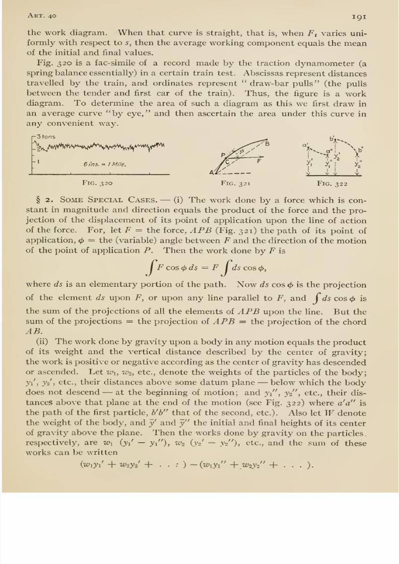
8/13/2019 Maurer Mechanics
http://slidepdf.com/reader/full/maurer-mechanics 205/407
Art. 40 191
the work diagram. When that curve is straight, that is, when Ft varies uni-
formly with respect to s, then the average working component equals the meanof the initial and final values.
Fig. 320 is a fac-simile of a record made by the traction dynamometer (a
spring balance essentially) in a certain train test. Abscissas represent distances
travelled by the train, and ordinates represent draw-bar pulls (the pulls
between the tender and first car of the train). Thus, the figure is a workdiagram. To determine the area of such a diagram as this we first draw in
an average curve by eye, and then ascertain the area under this curve in
any convenient way.
\//^vMv***^^'^^VV'^^^
•3 tons
6 ins. = / Mile.
Fig. 320
V V
Fig. 322
§ 2. Some Special Cases. —(i) The work done by a force which is con-
stant in magnitude and direction equals the product of the force and the pro-
jection of the displacement of its point of application upon the line of action
of the force. For, let F = the force, APB (Fig. 321) the path of its point of
application, ^ = the (variable) angle between ¥ and the direction of the motionof the point of application P. Then the work done by F is
I F cos (j)ds = F j ds cos </>,
where ds is an elementary portion of the path. Now ds cos is the projection
of the element ds upon F, or upon any line parallel to F, and Cds cos <^ is
the sum of the projections of all the elements of APB upon the line. But the
sum of the projections = the projection of APB = the projection of the chord
AB.(ii) The work done by gravity upon a body in any motion equals the product
of its weight and the vertical distance described by the center of gravity;
the work is positive or negative according as the center of gravity has descended
or ascended. Let Wi, w^, etc., denote the weights of the particles of the body;
yii y2 , etc., their distances above some datum plane —below which the bodydoes not descend —at the beginning of motion; and ji ,
jo , etc., their dis-
tances above that plane at the end of the motion (see Fig. 322) where a' a is
the path of the first particle, b'b that of the second, etc.). Also let Wdenote
the weight of the body, and y' and y the initial and final heights of its center
of gravity above the plane. Then the works done by gravity on the particles
respectively, are Wi {yi — y/'), K'2 iyi — y^ ), etc., and the sum of these
works can be written
{wiyi + W2y2 + . . : ) -{wiyi + W2y-i' +...).
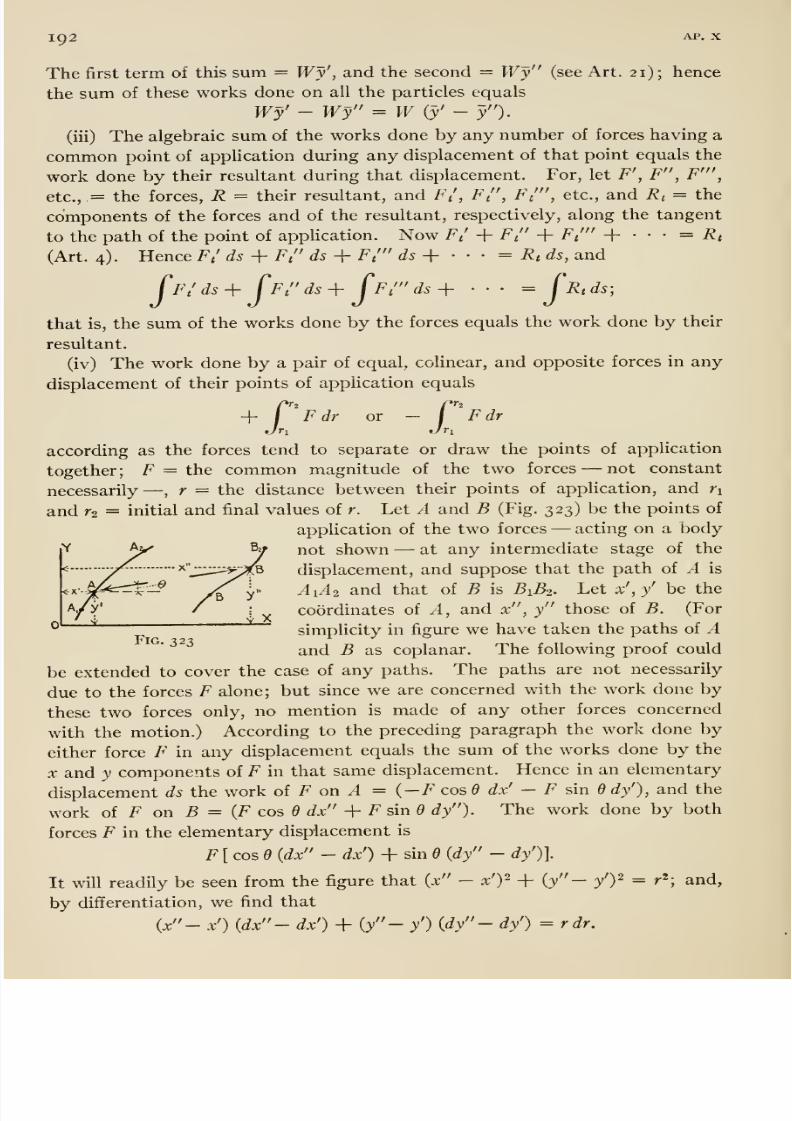
8/13/2019 Maurer Mechanics
http://slidepdf.com/reader/full/maurer-mechanics 206/407
192 AP. X
The first term of this sum = Wy', and the second = Wy (see Art. 21); hence
the sum of these works done on all the particles equals
Wy' - Wy = Wiy'- y ).
(iii) The algebraic sum of the works done by any number of forces having a
common point of application during any displacement of that point equals thework done by their resultant during that displacement. For, let F', F , F' ,
etc., = the forces, R = their resultant, and F/, Ft , F ', etc., and Rt = the
components of the forces and of the resultant, respectively, along the tangent
to the path of the point of application. Now Ft + F + F ' + • • • = Rt
(Art. 4). Hence Ft' ds + Ft ds + F/ ds -\- - • - = Rtds, and
fFt'ds^ fFt ds-\- CFt' ds-\- • • • = fRtds;
that is, the sum of the works done by the forces equals the work done by their
resultant.
(iv) The work done by a pair of equal, colinear, and opposite forces in any
displacement of their points of application equals
X2r^i
Fdr or - I F dr
according as the forces tend to separate or draw the points of application
together; F = the common magnitude of the two forces —not constantnecessarily —
, r = the distance between their points of appHcation, and nand r2 = initial and final values of r. Let A and B (Fig. 323) be the points of
application of the two forces —acting on a body
^ V not shown —at any intermediate stage of the
y^- ^ _;:::^:^^^;^ displacement, and suppose that the path of A is
|p^^-^ /By ^i^^2 and that of B is BA. Let x',y' be the
/y'y.
coordinates of A, and x , y those of B. (For
simplicity in figure we have taken the paths of AFig ^2^ V J ^and B as coplanar. The following proof could
be extended to cover the case of any paths. The paths are not necessarily
due to the forces F alone; but since we are concerned with the work done by
these two forces only, no mention is made of any other forces concerned
with the motion.) According to the preceding paragraph the work done by
either force F in any displacement equals the sum of the works done by the
X and y components of F in that same displacement. Hence in an elementary
displacement ds the work of F on ^ = (-F cos dx' - F sin 6 dy'), and the
work oi F on B = {F cos 6 dx -\- FsinO dy ). The work done by both
forces F in the elementary displacement is
F[cosd (dx - dx') + sin 6 {dy - dy')].
It will readily be seen from the figure that (x - x')- + (y - y')^ = r'; and,
by differentiation, we find that
(x - x') {dx - dx') + {y - y') {dy - dy') = rdr.
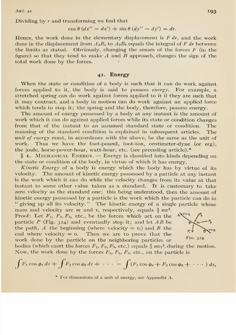
8/13/2019 Maurer Mechanics
http://slidepdf.com/reader/full/maurer-mechanics 207/407
Art. 41 195
Dividing by r and transforming we find that
cos 6 {dx - dx') + sin d {dy - dy') = dr.
Hence, the work done in the elementary displacement is F dr, and the workdone in the displacement from AiBi to A1B2 equals the integral of F dr between
the limits as stated. Obviously, changing the senses of the forces F (in the
figure) so that they tend to make A and B approach, changes the sign of the
total work done by the forces.
41. Energy
When the state or condition of a body is such that it can do work against
forces applied to it, the body is said to possess energy. For example, a
stretched spring can do work against forces applied to it if they are such that
it may contract, and a body in motion can do work against an applied force
which tends to stop it; the spring and the body, therefore, possess energy.
The amount of energy possessed by a body at any instant is the amount of
work which it can do against applied forces while its state or condition changes
from that of the instant to an assumed standard state or condition. Themeaning of the standard condition is explained in subsequent articles. Theunit of energy must, in accordance with the above, be the same as the unit of
work. Thus we have the foot-pound, foot-ton, centimeter-dyne (or erg),
the joule, horse-power-hour, watt-hour, etc. (see preceding article).*
§ I. Mechanical Energy. —Energ>^ is classified into kinds depending on
the state or condition of the body, in virtue of which it has energy.
Kinetic Energy of a body is energy which the body has by virtue of its
velocity. The amount of kinetic energy possessed by a particle at any instant
is the work which it can do while the velocity changes from its value at that
instant to some other value taken as a standard. It is customary to take
zero velocity as the standard one; this being understood, then the amount of
kinetic energy possessed by a particle is the work which the particle can do in'' giving up all its velocity. The kinetic energy of a single particle whose
mass and velocity are m and v, respectively, equals | mv'^.
Proof: Let Fi, Fi, F3, etc., be the forces which act on the
particle P (Fig. 324) and eventually stop it; and let AB he
the path, A the beginning (where velocity = Vi) and B the
end where velocity = o. Then we are to prove that the
work done by the particle on the neighboring particles or
bodies (which exert the forces Fi, F2, F3, etc.) equals | mvi^, during the motion.
Now, the work done by the forces Fi, F2, F3, etc., on the particle is
/ Fi cos (f>ids ^I
Fa cos (f>2 ds +'' ' = / (Fi cos <^i -f- F2 cos 02 + • • • ) ds,
* For dimensions of a unit of energy, see Appendix A.
8/13/2019 Maurer Mechanics
http://slidepdf.com/reader/full/maurer-mechanics 208/407
194 Chap, x
where 4>i, 02, 03, etc., are the angles between Fi. F2, F3, etc., and the direction of
motion (Art. 40). Since the particle P exerts forces on its neighbors, equal
and opposite to Fi, F2, etc., the work done by the particle on its neighbors is
/(Fi cos 01 + F2 cos 02 + • • • ) ds.
But Fi cos 01 + F2 cos 02 + • • • = Jnat = m dv/dt, where at is the tangential
component of the acceleration of the particle; hence the work done by P is
— / m (dv/dt) ds ^ — j m {ds/dt) dv = — j mv dv = ^ mv^.
The kinetic energy of a body (a collection or system or particles) is the
sum of the kinetic energies of the constituent particles of the body. We will
now evaluate this sum for certain common cases, —namely, (i) translation,
(ii) rotation, and (iii) combined translation and rotation.
(i) In translatory motion all particles of the moving body have at each
instant equal velocities; hence, the simi of the kinetic energies of the particles
is \ ntiv- + I WoZ'- + • • • = 2 ^^ (2^0, where Wi, nh, etc., = the masses of
the particles and v = their common velocity at the instant imder consideration.
Or, if M = the mass of the body and E = energy, then
E = ^Mv^ = i(W/g)v\ (i)
If 32.2 is written for g, then v should be expressed in feet per second. E will
be in foot-pounds, foot-tons, etc., according as W is expressed in pounds, or
tons, etc.
(ii) In a rotation about a fixed axis the velocity of any particle of the bodyequals the product of the angular velocity of the body, expressed in radians per
unit time, and the distance from the particle to the axis of rotation (Art. 37).
Hence, the sum of the kinetic energies of the particles of the body is
I mi (ri co)2 -f i 1712 (r^f^y + • • • = | oj^ Zmr-,
where co = the angular velocity of the body at the instant under consideration,
and ri, ^2, etc.,= the distances of the particles respectively from the axis of
rotation. But I,mr^ = the moment of inertia of the body about the axis of
rotation; hence, the kinetic energy is given by
£ = i /co2 = i Mk^o:' = h (W/g) kW', (2)
where I = the moment of inertia described, and k = the radius of gyration of
the body about the axis of rotation. If 32.2 is written for g, then k should be
expressed in feet and co in radians per second (w — 2 -wn where n = revolu-
tions per second). Then E will be in foot-pounds, foot-tons, etc., according
as Wis expressed in pounds, tons, etc.
(iii) A body which has a combined plane translation and rotation (Art. 50),
Uke a wheel rolling, has kinetic energy given by
£ = i M^^ + Hco^ = I {W/g) v' + i (W/g) ¥oi\ (3)
8/13/2019 Maurer Mechanics
http://slidepdf.com/reader/full/maurer-mechanics 209/407
Art. 41 195
where M = mass of the body, v = velocity of the center of gravity, / = the
moment of inertia of the body with respect to an axis through the center of
gravity perpendicular to the plane of the motion, k = radius of gyration with
respect to the same axis, and w = the angular velocity of the motion. Proof
of this formula is given in Art. 51. The portions ^ Mv^ and | /co^ of the kinetic
energy are sometimes called the translational and rotational components,
respectively.
As an example of the use of the preceding formula we find the kinetic energy
of a cylindrical disk, 6 feet in diameter and 400 pounds in weight, which is
rolling so that the center has a velocity of 4 feet per second. M = 400 -i- 32.2
= 12.4 slugs; the square of the radius of gyration of the disk is | 3^ = 4.5 feet^
(see Art. 36); and cxi, the rate at which the wheel is turning, is 4 -^3 radians per
second. Hence
£ = - 12.4 X 4 + - 12.4 X 4.5(4 -^ 3)' = 148.8 foot-pounds.
Potential Energy. —A body may possess energy which is not due to velocity.
Thus two mutually attracting bodies can do work against forces applied to
either or both if allowed to move so that they approach each other; and, as
stated, a compressed or stretched spring can do work against applied forces
if permitted to resmne its natural length. The change of condition or state
in the first case is a change in configuration, a change in the positions of the
bodies relative to each other; and, in the second case, if we conceive of the
spring as consisting of discrete particles, the change is also one in configuration
(of the particles). Energy of a system of particles dependent on configura-
tion of the system is called energy of configuration, and potential energy
more commonly.
The amount of potential energy possessed by a system in any configuration
is the work which it can do in passing from that configuration to any other
taken as a standard, it being understood that no other change of condition
takes place. The standard configuration may be chosen at pleasure, but it is
convenient to so select it that in all other configurations considered the poten-
tial energy is positive.
A most common case of potential energy is that of the earth and an elevated
body. In this case, standard configuration means one in which the body andearth are as near together as possible. Practically, it is necessary to regard
the earth as fixed and the energy as resident in the elevated body. The amountof potential energy of an elevated body is just equal to the work which gravity
would do upon the body during the descent into the standard or lowest position,
and this work is given by Wh (see preceding article), where W = the weight
of the body and h = the distance through wliich the center of gravity of the
body can descend.
§ 2. Other Forms of Energy. —Kinetic energy and potential energy
are often called mechanical energy. It is the opinion of some that all energy
8/13/2019 Maurer Mechanics
http://slidepdf.com/reader/full/maurer-mechanics 210/407
8/13/2019 Maurer Mechanics
http://slidepdf.com/reader/full/maurer-mechanics 211/407
Art. 42 197
with great velocity, and we shall see presently such performance depenas on
the energy which the gun can impart to the shot. A pump is probably called
powerful because it can elevate or transport a large quantity of liquid in a short
space of time, or perform much work per unit time.
Use of the word power in the sense of force was very common in engineering
literature at one time. Such usage is comparatively rare now, but not obso-
lete. Thus we read of the tractive power of a locomotive to denote pull in
the bulletins of the American Locomotive Company. (But Goss in his Loco-
motive Performance, and Henderson in his Locomotive Operation, seem to prefer
tractive force ; and in Locomotive Tests and Exhibits, of the Pennsylvania Rail-
road System at the Louisiana Purchase Exposition, we find tractive effort
to denote that pull.) The other two uses of the word power to denote (i)
work or energy, and (ii) rate at which work is done or energy is transmitted
or transformed are c[uite common. Thus in the same text-book we find:
(i) the actual power utilized is one-half the energy available, and (ii) the
power of the plant is about 470 horse-power (258,500 foot-pounds per
second, see below). And in another book there appear: (i) the power of
the rotating shaft could be converted into electrical energy, and (ii) ' the
power is here measured in kilowatts (one kilowatt equals 10' ergs per second,
see below). It seems probable that this double usage of the word power in
engineering literature will persist. In common with most authors, even those
quoted above, we will define power in a single sense, namely, —as the rate at
which work is done.
Units of Power * like units of work may be classed into gravitational, which
vary slightly with locality, and absolute. Thus, the foot-pound per minute and
the kilogram-meter per second are units of the first class ; also the (practical)
EngUsh and American horse-power = 550 foot-pounds per second
= 33,000 foot-pounds per minute,
Continental horse-power ==^75 kilogram-meters per second= 4500 kilogram-meters per minute.
The dyne-centimeter (or erg) per second is a unit of the second class; also the
watt which is 10'̂ ergs per second, and the (practical)
kilowatt — 1000 watts = io^° ergs per second.
The Bureau of Standards has recently decided to adopt the English and
American horse-power as the exact equivalent of 746 watts, thus making
this horse-power an absolute unit. Thus defined it is the rate of work ex-
pressed by 550 foot-pounds per second at 50° latitude and sea level, approxi-
mately the location of London, where the original experiments were made by
James Watt to determine its value. The ' continental horsepower ' is similarly
most conveniently defined as 736 watts, equivalent to 75 kilogram-meters per
second at latitude 52° 30', or Berlin. f
* For dimensions of a unit of power see Appendix A.
t Circular of the Bureau of Standards, No. 34.
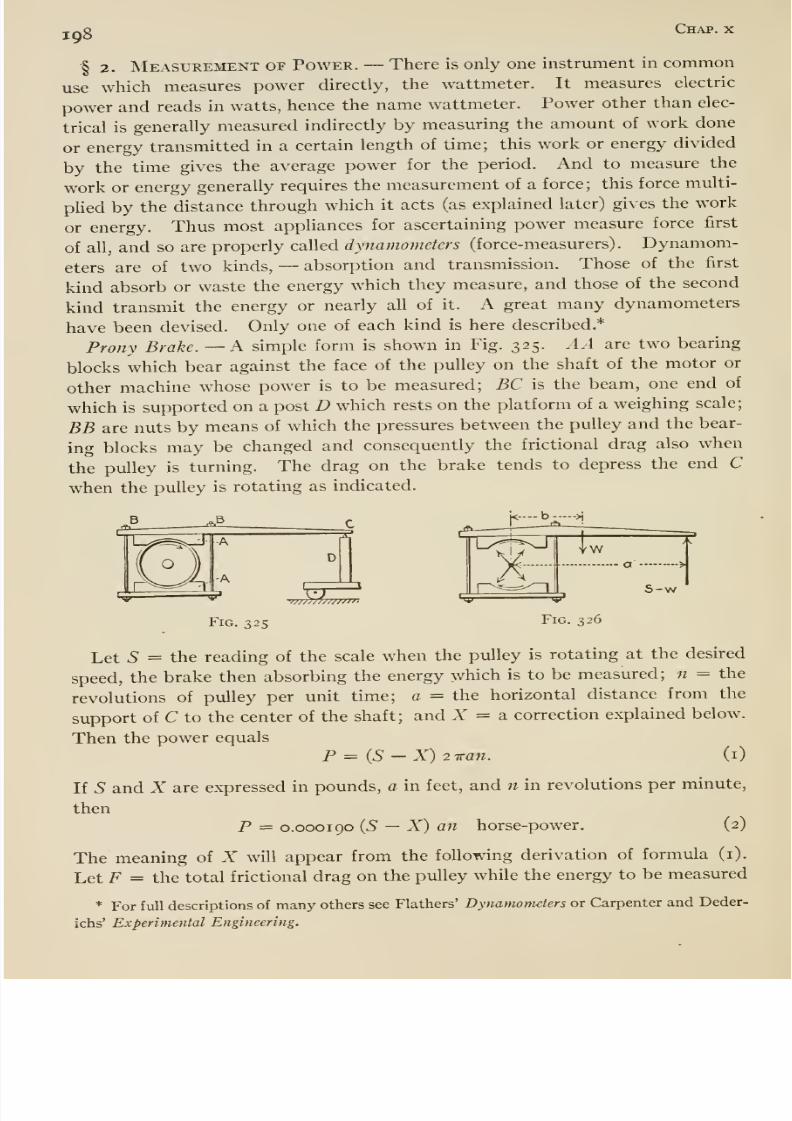
8/13/2019 Maurer Mechanics
http://slidepdf.com/reader/full/maurer-mechanics 212/407
198c^^- '^
§ 2. Measurement of Power. —There is only one instrument in common
use which measures power directly, the wattmeter. It measures electric
power and reads in watts, hence the name wattmeter. Power other than elec-
trical is generally measured indirectly by measuring the amount of work done
or energy transmitted in a certain length of time; this work or energy divided
by the time gives the average power for the period. And to measure the
work or energy generally requires the measurement of a force; this force multi-
pUed by the distance through which it acts (as explained later) gives the work
or energy. Thus most appliances for ascertaining power measure force first
of all, and so are properly called dynamometers (force-measurers). Dynamom-
eters are of two kinds, —absorption and transmission. Those of the first
kind absorb or waste the energy which they measure, and those of the second
kind transmit the energy or nearly all of it. A great many dynamometers
have been devised. Only one of each kind is here described.*
Prony Brake. —k simple form is shown in Fig. 325. AA are two bearing
blocks which bear against the face of the pulley on the shaft of the motor or
other machine whose power is to be measured; BC is the beam, one end of
which is supported on a post D which rests on the platform of a weighing scale;
BB are nuts by means of which the pressures between the pulley and the bear-
ing blocks may be changed and consequently the frictional drag also when
the pulleyis turning. The drag on the brake tends to depress the end C
when the pulley is rotating as indicated.
'w/ nu//f» '
-
Fig. 325 Fig. 326
Let 5 = the reading of the scale when the pulley is rotating at the desired
speed, the brake then absorbing the energy which is to be measured; n = the
revolutions of pulley per unit time; a = the horizontal distance from the
support of C to the center of the shaft; and X = a correction explained below.
Then the power equals
P = (5 - X) 2 -Kan. (i)
If S and X are expressed in pounds, a in feet, and n in revolutionsper minute,
then
P = 0.000190 (5 —X) an horse-power. (2)
The meaning of X will appear from the following derivation of formula (i).
Let F = the total frictional drag on the pulley while the energy to be measured
* For full descriptions of many others see Flathers' Dynamometers or Carpenter and Deder-
ichs' Experimental Engineering.
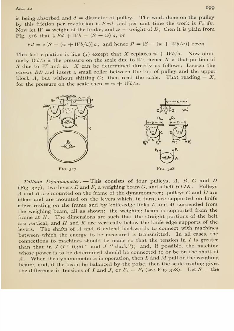
8/13/2019 Maurer Mechanics
http://slidepdf.com/reader/full/maurer-mechanics 213/407
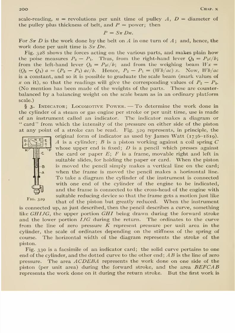
8/13/2019 Maurer Mechanics
http://slidepdf.com/reader/full/maurer-mechanics 214/407
200 Chap, x
scale-reading, n = revolutions per unit time of pulley A, D ^ diameter of
the pulley plus thickness of belt, and P = power; then
P = STrDn.
For Sir D is the work done by the belt on A in one turn of A ; and, hence, the
work done per unit time is Sir Dn.Fig. 328 shows the forces acting on the various parts, and makes plain how
the poise measures P2 — Pi- Thus, from the right-hand lever Qi = Pic/b;
from the left-hand lever Q2 = P2c/b; and from the weighing beam Wx =
(Q2 -Qi)a= (P2 - Pi) ac/b. Hence, P2 - Pi = {Wb/ac) x. Now, Wb/acis a constant, and so it is possible to graduate the scale beam (mark values of
X on it), so that the readings will give the corresponding values of P2 — Pi.
(No mention has been made of the weights of the parts. These are counter-
balanced by a balancing weight on the scale beam as in an ordinary platform
scale.)
§ 3. Indicator; Locomotive Power. —To determine the work done in
the cylinder of a steam or gas engine per stroke or per unit time, use is madeof an instrument called an indicator. The indicator makes a diagram or
card from which the intensity of the pressure on either side of the piston
at any point of a stroke can be read. Fig. 329 represents, in principle, the
original form of indicator as used by James Watt (1736-1819).
A is a cylinder; 5 is a piston working against a coil spring Cwhose upper end is fixed; D is a, pencil which presses against
the card or paper E; F is a frame, movable right and left in
suitable sHdes, for holding the paper or card. When the piston
is moved the pencil simply makes a vertical line on the card;
when the frame is moved the pencil makes a horizontal line.
To take a diagram the cylinder of the instrument is connected
with one end of the cylinder of the engine to be indicated,
and the frame is connected to the cross-head of the engine with
suitable reducing device so that the frame gets a motion just like
that of the piston but greatly reduced. When the instrument
is connected up, as just described, then the pencil describes a curve, something
like GHIJG, the upper portion GHI being drawn during the forward stroke
and the lower portion IJG during the return. The ordinates to the curve
from the line of zero pressure K represent pressure per unit area in the
cylinder, the scale of ordinates depending on the stiffness of the spring of
course. The horizontal width of the diagram represents the stroke of the
piston.
Fig. 330 is a facsimile of an indicator card; the solid curve pertains to one
end of the cylinder, and the dotted curve to the other end; AB is the line of zero
pressure. The area ACDEB A represents the work done on one side of the
piston (per unit area) during the forward stroke, and the area BEFCABrepresents the work done on it during the return stroke. But the first work is
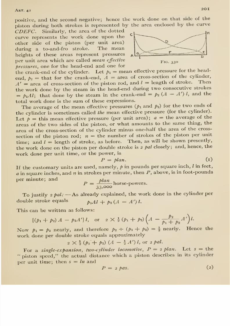
8/13/2019 Maurer Mechanics
http://slidepdf.com/reader/full/maurer-mechanics 215/407
Art. 42 2°^
positive, and the second negative; hence the work done on that side of the
piston during both strokes is represented by the area enclosed by the curve
CDEFC. Similarly, the area of the dotted
curve represents the work done upon the
other side of the piston (per unit area)
during a to-and-fro stroke. The mean
heights of these areas represent pressures
per unit area which are called mean effective ^iq. 330
pressures, one for the head-end and one for
the crank-end of the cylinder. Let pi = mean effective pressure for the head-
end, p2 = that for the crank-end, A = area of cross-section of the cylinder,
A' = area of cross-section of the piston rod, and I = length of stroke. Then
the work done by the steam in the head-end during two consecutive strokes
= piAl; that done by the steam in the crank-end = p2 {A — A') I, and the
total work done is the sum of these expressions.
The average of the mean effective pressures {pi and P2) for the two ends of
the cylinder is sometimes called the mean effective pressure (for the cylinder).
Let p = this mean effective pressure (per unit area) ; a = the average of the
areas of the two sides of the piston, or what amounts to the same thing, the
area of the cross-section of the cylinder minus one-half the area of the cross-
section of the pistonrod; n = the number of strokes of the piston per unit
time; and / = length of stroke, as before. Then, as will be shown presently,
the work done on the piston per double stroke is 2 pal closely; and, hence, the
work done per unit time, or the power, is
F = plan. (i)
If the customary units are used, namely, p in pounds per square inch, / in feet,
a in square inches, and n in strokes per minute, then P, above, is in foot-pounds
per minute; and a^^^
P = — horse-powers.33,000
To justify 2 pal: —As already explained, the work done in the cylinder per
double stroke equals p^^i _[_ p^ (^1 - A') I.
This can be written as follows:
[{Pi + P2)A-P2A']1, or ^ X l(Pi -^ P2) (a - j-^^A'Y
Now pi = p2 nearly, and therefore p2 ^ (pi + P2) = ^ nearly. Hence the
work done per double stroke equals approximately
2 X I {pi-h P2) {A -h ^') I or 2 pal.
For a single-expansion, two-cylinder locomotive, P = 2 plan. Let 5 = the
piston speed, the actual distance which a piston describes in its cylinder
per unit time; then s = In and
P = 2 pas. (2)
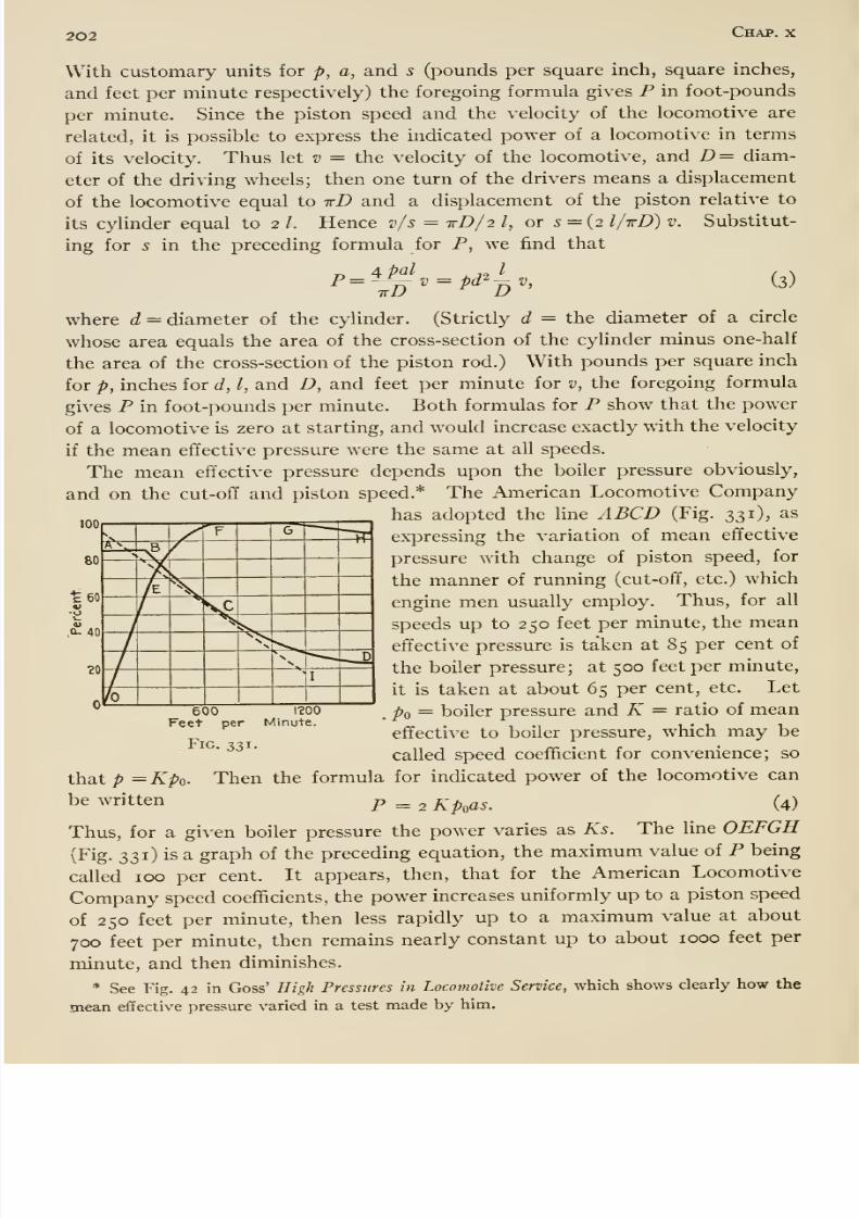
8/13/2019 Maurer Mechanics
http://slidepdf.com/reader/full/maurer-mechanics 216/407
202 Chap, x
With customary units for p, a, and 5 (pounds per square inch, square inches,
and feet per minute respectively) the foregoing formula gives P in foot-pounds
per minute. Since the piston speed and the velocity of the locomotive are
related, it is possible to express the indicated power of a locomotive in terms
of its velocity. Thus let v = the velocity of the locomotive, and D= diam-
eter of the driving wheels; then one turn of the drivers means a displacement
of the locomotive equal to irD and a displacement of the piston relative to
its cylinder equal to 2 /. Hence v/s = xD/2 /, or 5 = (2 l/irD) v. Substitut-
ing for s in the preceding formula for P, we find that
4 pal I
(3)
100
80
•£60
-o
«;q-4o
where c? = diameter of the cylinder. (Strictly d = the diameter of a circle
whose area equals the area of the cross-section of the cyUnder minus one-halfthe area of the cross-section of the piston rod.) With pounds per square inch
for p, inches for d, I, and D, and feet per minute for v, the foregoing formula
gives P in foot-pounds per minute. Both formulas for P show that the power
of a locomotive is zero at starting, and would increase exactly with the velocity
if the mean effective pressure were the same at all speeds.
The mean effective pressure depends upon the boiler pressure obviously,
and on the cut-olT and piston speed.* The American Locomotive Company
has adopted the line A BCD (Fig. 331), as
expressing the variation of mean effective
pressure with change of piston speed, for
the manner of running (cut-ofif, etc.) which
engine men usually employ. Thus, for all
speeds up to 250 feet per minute, the mean
effective pressure is taken at 85 per cent of
the boiler pressure; at 500 feet per minute,
it is taken at about 65 per cent, etc. Let
po = boiler pressure and K = ratio of mean
effective to boiler pressure, which may be
called speed coefficient for convenience; so
that p = Kpo. Then the formula for indicated power of the locomotive can
be written p _ 2 A^o^^. (4)
Thus, for a given boiler pressure the power varies as Ks. The line OEFGH
(Fig. 331) is a graph of the precedingequation, the maximum value of P being
called 100 per cent. It appears, then, that for the American Locomotive
Company speed coefficients, the power increases uniformly up to a piston speed
of 250 feet per minute, then less rapidly up to a maximum value at about
700 feet per minute, then remains nearly constant up to about 1000 feet per
minute, and then diminishes.
* See Fig. 42 in Goss' High Pressures in Locomotive Service, which shows clearly how the
mean effective pressure varied in a test made by him.
?0
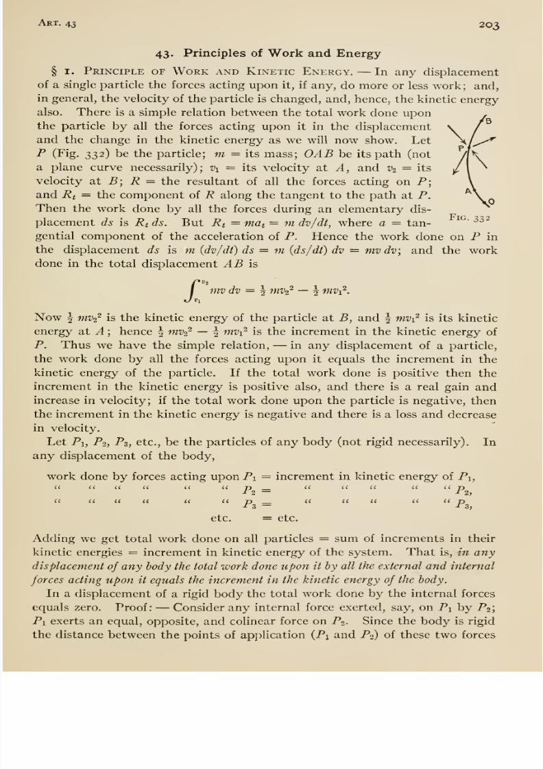
8/13/2019 Maurer Mechanics
http://slidepdf.com/reader/full/maurer-mechanics 217/407
Art. 43 203
43. Principles of Work and Energy
§ I. Principle of Work and Kinetic Energy. —In any displacement
of a single particle the forces acting upon it, if any, do more or less work; and,
in general, the velocity of the particle is changed, and, hence, the kinetic energy
also. There is a simple relation between the total work done uponthe particle by all the forces acting upon it in the displacement
and the change in the kinetic energy as we will now show. Let
P (Fig. 332) be the particle; m = its mass; OAB be its path (not
a plane curve necessarily); Vi = its velocity at A, and v^ = its
velocity at B; R = the resultant of all the forces acting on P;
and Rt = the component of R along the tangent to the path at P.
Then the work done by all the forces during an elementary dis-
placement ds is Rt ds. But Rt = mat = ^ dv/dt, where a = tan-
gential component of the acceleration of P. Hence the work done on P in
the displacement ds is m (dv/dt) ds = m (ds/dt) dv = mv dv; and the workdone in the total displacement AB is
mvdv = ^ mvi^ —\ mv^.
Now ^ mvz^ is the kinetic energy of the particle at B, and | mvi^ is its kinetic
energy at A ; hence | mvz^ —§ nivi^ is the increment in the kinetic energy of
P. Thus we have the simple relation, —in any displacement of a particle,
the work done by all the forces acting upon it equals the increment in the
kinetic energy of the particle. If the total work done is positive then the
increment in the kinetic energy is positive also, and there is a real gain andincrease in velocity; if the total work done upon the particle is negative, then
the increment in the kinetic energy is negative and there is a loss and decrease
in velocity.
Let Pi, P2, P3, etc., be the particles of any body (not rigid necessarily). In
any displacement of the body,
work done by forces acting upon Pi — increment in kinetic energy of Pi,(< a <( i( li p __ <' '< << 'I pII a (( a (I a jj c( a u a ic n
-f 3 — -13,
etc. = etc.
Adding we get total work done on all particles = sum of increments in theirkinetic energies = increment in kinetic energy of the system. That is, in any
displacement of any body the total work done upon it by all the external and internal
forces acting upon it equals the increment in the kinetic energy of the body.
In a displacement of a rigid body the total work done by the internal forces
equals zero. Proof: —Consider any internal force exerted, say, on Pi by P2;
Pi exerts an equal, opposite, and colinear force on Po. Since the body is rigid
the distance between the points of application {Pi and P2) of these two forces
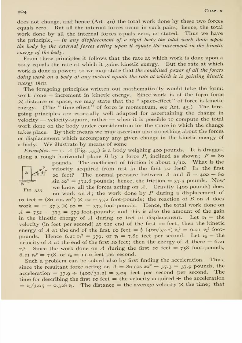
8/13/2019 Maurer Mechanics
http://slidepdf.com/reader/full/maurer-mechanics 218/407
204 Chap, x
does not change, and hence (Art. 40) the total work done by these two forces
equals zero. But all the internal forces occur in such pairs; hence, the total
work done by all the internal forces equals zero, as stated. Thus we have
the principle, —in any displacement of a rigid body the total work done upon
thebody
by the external forces acting upon it equals the increment in the kinetic
energy of the body.
From these principles it follows that the rate at which work is done upon a
body equals the rate at which it gains kinetic energy. But the rate at which
work is done is power; so we may state that the combined power of all the forces
doing work on a body at any instant equals the rate at which it is gaining kinetic
energy then.
The foregoing principles written out mathematically would take the form:
work done = increment in kinetic energy. Since workis of the
formforce
X distance or space, we may state that the space-efifect of force is kinetic
energy. (The time-effect of force is momentum, see Art. 45.) The fore-
going principles are especially well adapted for ascertaining the change in
velocity —velocity-square, rather —when it is possible to compute the total
work done on the body under consideration for the space in which the change
takes place. By their means we may ascertain also something about the forces
or displacement which accompany any given change in the kinetic energy of
a body. We illustrate by means of someExamples. —i. .4 (Fig. 2>2>z) is a body weighing 400 pounds. It is dragged
along a rough horizontal plane B by a force P, inclined as shown; P = 80
pounds. The coefficient of friction is about i/io. What is t)ie
^ velocity acquired from rest in the first 10 feet? In the first
^'-- 20 feet? The normal pressure between A and B = 400 — 80
• f/iii/inii'
B
Fig. 333
sin 20° = 372.6 pounds; hence, the friction = 37.3 pounds. Now'
we know all the forces acting on A . Gravity (400 pounds) does
no work on A ; the work done by P during a displacement of
ID feet = (80 cos 20°) X 10 = 752 foot-pounds; the reaction of B on A does
work = — 37.3 X 10 = — 373 foot-pounds. Hence, the total work done on
yl = y52 — 373 = 379 foot-pounds; and this is also the amount of the gain
in the kinetic energy of A during 10 feet of displacement. Let Vi = the
velocity (in feet per second) at the end of the first 10 feet; then the kinetic
energy of A at the end of the first 10 feet = | (400/32.2) ^r = 6.21 Vi^ foot-
pounds. Hence 6.21 Vi^ = 379, or Vi = 7.81 feet per second. Let V2 = the
velocity of A at the end of the first 20 feet; then the energy of A there = 6.21
V2^. Since the work done on A during the first 20 feet = 758 foot-pounds,
6.21 V2^ = 758, or V2 = ii.o feet per second.
Such a problem can be solved also by first finding the acceleration. Thus,
since the resultant force acting on ^ = 80 cos 20° - 37.3 = 37.9 pounds, the
acceleration = 37.9 ^ (400/32.2) = 3.05 feet per second per second. The
time for describing the first 10 feet = the velocity acquired -^ the acceleration
= ^1/3-05 = 0-328 vi. The distance = the average velocity X the time; that
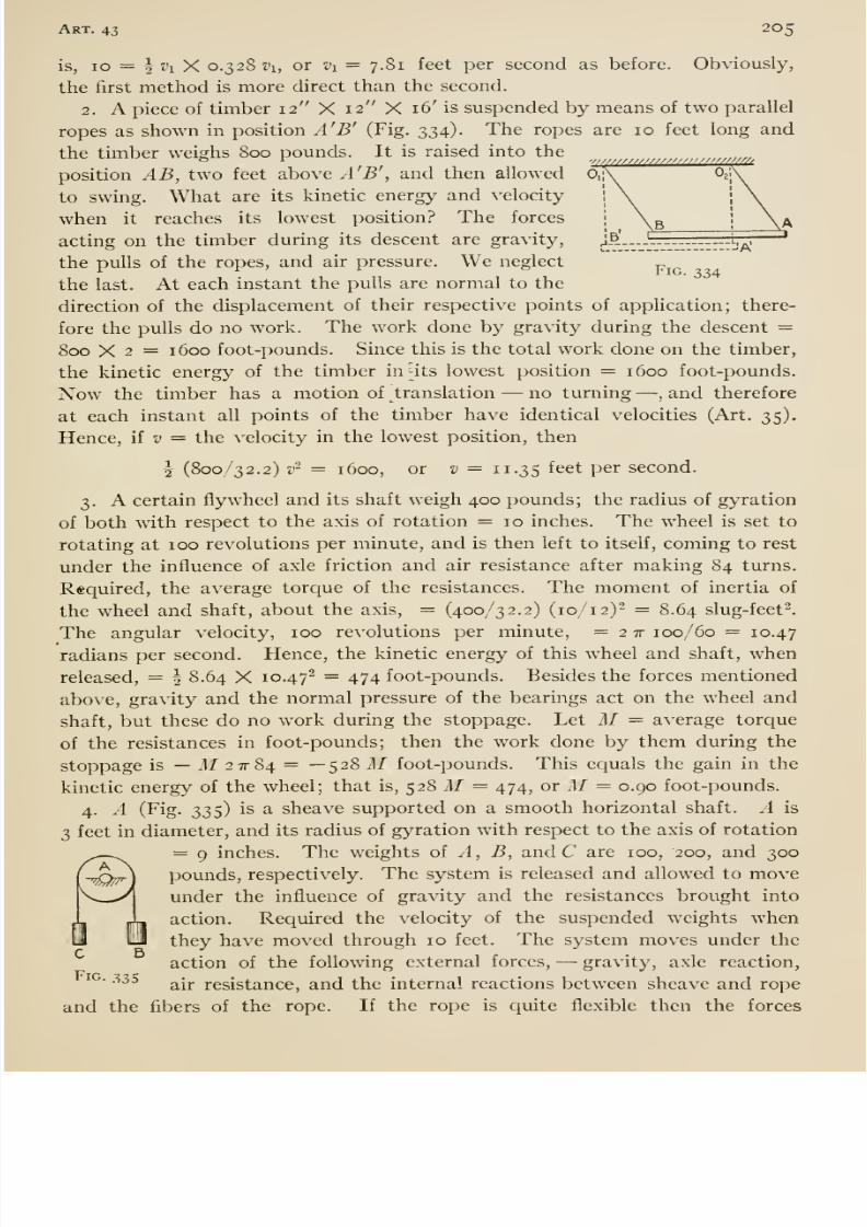
8/13/2019 Maurer Mechanics
http://slidepdf.com/reader/full/maurer-mechanics 219/407
Art. 43 205
Fig. 334
is, 10 = I vi X 0.328111, or Vi = 7.81 feet per second as before. Obviously,
the first method is more direct than the second.
2. A piece of timber 12 X 12 X 16' is suspended by means of two parallel
ropes as shown in position A'B' (Fig. 334). The ropes are 10 feet long and
the timber weighs Soo pounds. It is raised into the
position AB, two feet above A'B', and then allowed
to swing. What are its kinetic energy and velocity
when it reaches its lowest position? The forces
acting on the timber during its descent are gravity,
the pulls of the ropes, and air pressure. We neglect
the last. At each instant the pulls are normal to the
direction of the displacement of their respective points of application; there-
fore the pulls do no work. The work done by gravity during the descent =
800 X 2 = 1600 foot-pounds. Since this is the total work done on the timber,
the kinetic energy of the timber inUts lowest position = 1600 foot-pounds.
Now the timber has a motion of translation —no turning —, and therefore
at each instant all points of the timber have identical velocities (Art. 35).
Hence, ii v = the velocity in the lowest position, then
f (800/32.2) v~ = 1600, or D = 11.35 feet per second.
3. A certain flywheel and its shaft weigh 400 pounds; the radius of gyration
of both with respect to the axis of rotation = 10 inches. The wheel is set to
rotating at 100 revolutions per minute, and is then left to itself, coming to rest
under the influence of axle friction and air resistance after making 84 turns.
Required, the average torque of the resistances. The moment of inertia of
the wheel and shaft, about the axis, = (400/32.2) (10/12)^ = 8.64 slug-feet^.
The angular velocity, 100 revolutions per minute, = 2 tt 100/60 = 10.47
radians per second. Hence, the kinetic energy of this wheel and shaft, when
released, = | 8.64 X 10.47' ~ 474 foot-pounds. Besides the forces mentioned
above, gravity and the normal pressure of the bearings act on the wheel and
shaft, but these do no work during the stoppage. Let M = average torque
of the resistances in foot-pounds; then the work done by them during the
stoppage is —M2^84. = —528 M foot-pounds. This equals the gain in the
kinetic energy of the wheel; that is, $28 M= 474, or M= 0.90 foot-pounds.
4. A (Fig, 335) is a sheave supported on a smooth horizontal shaft. A is
3 feet in diameter, and its radius of gyration with respect to the axis of rotation
= 9 inches. The weights of A, B, and C are 100, 200, and 300
pounds, respectively. The system is released and allowed to moveunder the influence of gravity and the resistances brought into
action. Required the velocity of the suspended weights when
they have moved through 10 feet. The system moves under the
action of the following external forces, —gravity, axle reaction,
air resistance, and the internal reactions between sheave and rope
and the fibers of the rope. If the rope is quite flexible then the forces
A
C 5
Fig. 335
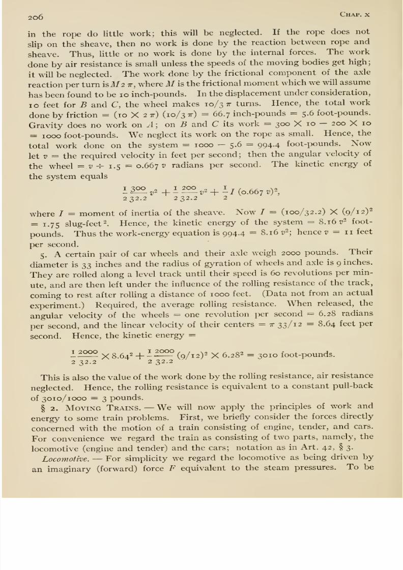
8/13/2019 Maurer Mechanics
http://slidepdf.com/reader/full/maurer-mechanics 220/407
2o6 Chap, x
in the rope do little work; this will be neglected. If the rope does not
slip on the sheave, then no work is done by the reaction between rope and
sheave. Thus, little or no work is done by the internal forces. The work
done by air resistance is small unless the speeds of the moving bodies get high;
it will be neglected. The work done by the frictional component of the axle
reaction per turn isil/2 tt, where Mis the frictional moment which we will assume
has been found to be 10 inch-pounds. In the displacement under consideration,
ID feet for B and C, the wheel makes 10/3 tt turns. Hence, the total work
done by friction = (10 X 2x) (10/3 x) = 66.7 inch-pounds = 5.6 foot-pounds.
Gravity does no work on A; or\. B and C its work = 300 X 10 - 200 X 10
= 1000 foot-pounds. We neglect its work on the rope as small. Hence, the
total work done on the system = 1000 - 5.6 = 994.4 foot-pounds. Now
let V = the required velocity in feet per second; then the angular velocity of
the wheel =.v-^ 1.5 = 0.6677; radians per second. The kinetic energy of
the system equals
I 300 „ . I 200 „ I . N2-^5 v~-\-- V -\- -I {o.ob'jv)^,232.2 232.2 2
where 7 = moment of inertia of the sheave. Now / = (100/32.2) X (9/12)^
= 1.75 slug-feet 2. Hence, the kinetic energy of the system = 8.16 z)^ foot-
pounds. Thus the work-energy equation is 994.4 = 8.16 v-; hence v ^ 11 feet
per second.
5. A certain pair of car wheels and their axle weigh 2000 pounds. Their
diameter is 33 inches and the radius of gyration of wheels and axle is 9 inches.
They are rolled along a level track until their speed is 60 revolutions per min-
ute, and are then left under the influence of the rolling resistance of the track,
coming to rest after rolling a distance of 1000 feet. (Data not from an actual
experiment.) Required, the average rolling resistance. When released, the
angular velocity of the wheels = one revolution per second = 6.28 radians
per second, and the linear velocity of their centers = tt 33/12 = 8.64 feet per
second. Hence, the kinetic energy =
I 2000 _ „ , o ,I 2000
X 8.64- + (9/12)- X 6.282 = 30J0 foot-pounds.2 32.2 2 32.2
This is also the value of the work done by the rolling resistance, air resistance
neglected. Hence, the rolling resistance is equivalent to a constant pull-back
of 3010/1000 =3
pounds.
§ 2. Moving Trains. —We will now apply the principles of work and
energy to some train problems. First, we briefly consider the forces directly
concerned with the motion of a train consisting of engine, tender, and cars.
For convenience we regard the train as consisting of two parts, namely, the
locomotive (engine and tender) and the cars; notation as in Art. 42, § 3.
Locomotive. —For simplicity we regard the locomotive as being driven by
an imaginary (forward) force F equivalent to the steam pressures. To be
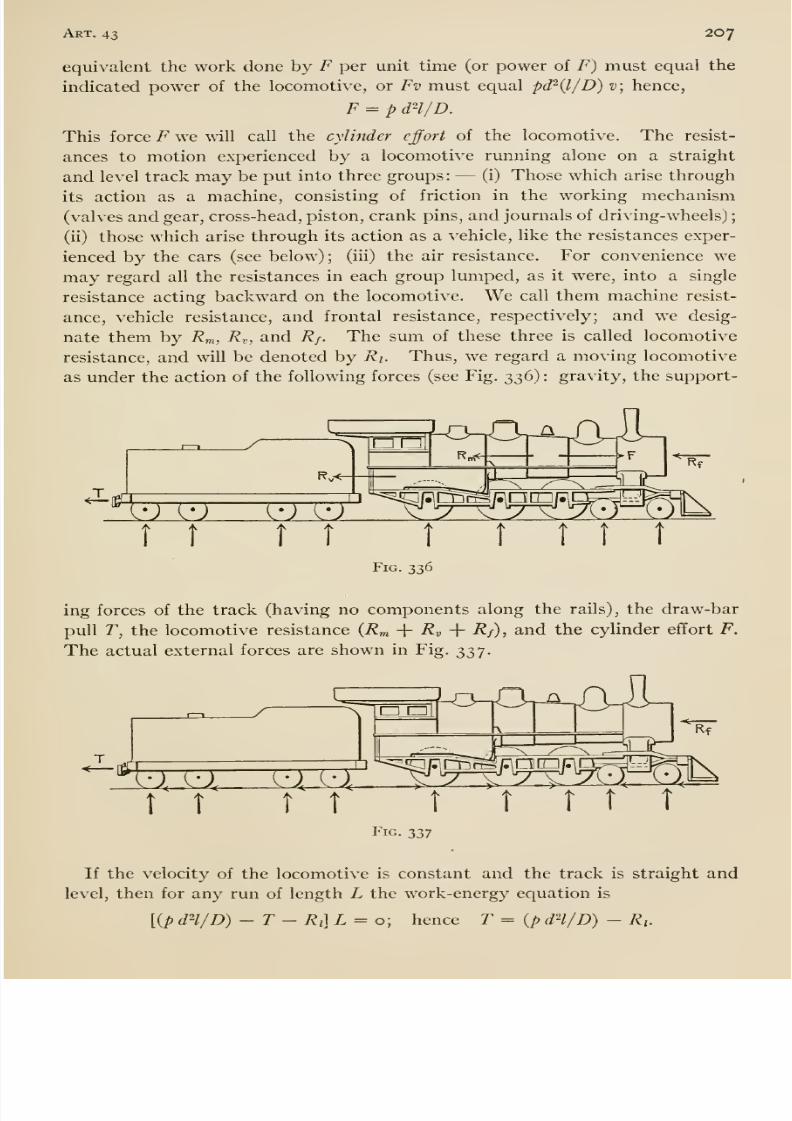
8/13/2019 Maurer Mechanics
http://slidepdf.com/reader/full/maurer-mechanics 221/407
8/13/2019 Maurer Mechanics
http://slidepdf.com/reader/full/maurer-mechanics 222/407
2o8 Chap, x
If the velocity is changing, then the power equation is
where v = velocity of locomotive and a = its acceleration. Hence
T = ip dH/D) - Ri- Ma.
If the locomotive is running on a grade then the grade resistance Rg must be
included in an obvious way.
According to the American Locomotive Company {Bulletin, No. looi), the
resistances in pounds are as follows:
Rf = 0.24 V~, where V is velocity in miles per hour;
R„ = 22.2 X weight on drivers, in tons; and
R^, = the same as for cars (see further on).
The Cars. —The cars are urged forward by only one force, the pull of the
tender on the first car; this is called draw-bar pull. The cars are retarded by
several forces, namely: The rolling resistance of the rails upon the treads of
the car wheels; the journal friction at the axles of the wheels; the air resist-
ance; and miscellaneous forces, due to oscillation and concussion. The laws of these separate resistances are known only in a very general way.
Because of lack of knowledge of these separate items of resistance, and, for
convenience, it is customary to lump them into a single equivalent resist-
ance, called train resistance. Thus we may imagine trains to be without
actual track, journal, air, etc., resistance, but subjected to this equivalent
force, conceived as a single pull backward on the train. A train of cars, then,
may be regarded as moving under the action of four forces, namely, the
draw-bar pull, the train resistance, gravity, and a supporting force exerted by
the track, having no components along the rails.
Many experiments have been made to determine train resistance, special
dynamometer cars (equipped with instruments for measuring and record-
ing speed of train, draw-bar pull, steam pressure, wind velocity and direction,
etc.) being used for that purpose now-a-days. The methods for determining
train resistance are very simple in principle. One method is this: —the loco-
motive drags the cars along a straight, level track at a constant speed; the
draw-bar pull and the speed are measured. Then the (total) train resistance
for that speed equals the draw-bar pull. But level stretches of track are not
always convenient of access, and constant speeds are not easily maintained.
For an experiment on a grade let H = the ascent or descent of the center of
gravity of the train during the experiment, L = the length of the run, W=
weight of cars, T = average draw-bar pull, R = average train resistance.
Then the grade resistance is Rg = ±WH/L, according as the train i
ascending or descending the grade, and the work-energy equation is
{T-Rt- Rg) L = E,
IS
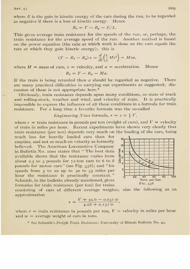
8/13/2019 Maurer Mechanics
http://slidepdf.com/reader/full/maurer-mechanics 223/407
Art. 43 209
where E is the gain in kinetic energy of the cars during the run, to be regarded
as negative if there is a loss of kinetic energy. Hence
Rt = T-Rg- E/L.
This gives average train resistance for the speeds of the run, or, perhaps, the
train resistance for the average speed of the run. Another method is based
on the power equation (the rate at which work is done on the cars equals the
rate at which they gain kinetic energy); this is
dt\2Mv^ )
= Mva,
where M = mass of cars, v = velocity, and a = acceleration. Hence
Rt = T - Rg- Ma.
If the train is being retarded then a should be regarded as negative. There
are many practical difi&culties in carrying out experiments as suggested; dis-
cussion of these is not appropriate here.*
Obviously, train resistance depends upon many conditions, as state of track
and rolling-stock, weather and wind, and velocity of train. It is practically
impossible to express the influence of all these conditions in a formula for train
resistance. For a long time a favorite formula was the so-called
Engineering News formula, r = 2 + j F,
where r = train resistance in pounds per ton (weight of cars), and V = velocity
of train in miles per hour. Recent experiments have shown very clearly that
train resistance (per ton) depends very much on the loading of the cars, being
much less for heavily loaded cars than for
empties, and not so much on velocity as formerly
belie\'ed. The American Locomotive Company
in Bulletin No. looi states that The best dataavailable shows that the resistance varies from
about 2.5 to 3 pounds for 72-ton cars to 6 to 8
pounds for 20-ton cars (see Fig. 338); and for
speeds from 5 to 10 up to 30 to 35 miles per
hour the resistance is practically constant.
Schmidt, in the bulletin already mentioned, gives
formulas for train resistance (per ton) for trains
consisting of cars of different average weights; also the following as anapproximation
_ V -\- 39.6 —0.031 w4.08 -{- 0.152 w
where r = train resistance in pounds per ton, V = velocity in miles per hour
and w = average weight of cars in tons.
* See Schmidt's Freight Train Resistance, University of Illinois Bulletin No. 43.
20 40 60
Tons per Car.
Fig. 338
8/13/2019 Maurer Mechanics
http://slidepdf.com/reader/full/maurer-mechanics 224/407

8/13/2019 Maurer Mechanics
http://slidepdf.com/reader/full/maurer-mechanics 225/407
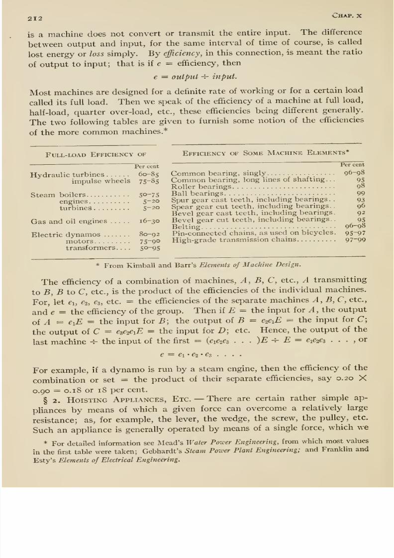
8/13/2019 Maurer Mechanics
http://slidepdf.com/reader/full/maurer-mechanics 226/407
212 Chap.x
is a machine does not convert or transmit the entire input. The difiference
between output and input, for the same interval of time of course, is called
lost energy or loss simply. By efficiency, in this connection, is meant the ratio
of output to input; that is if e = efficiency, then
e — output -i- input.
Most machines are designed for a definite rate of working or for a certain load
called its full load. Then we speak of the efficiency of a machine at full load,
half-load, quarter over-load, etc., these efficiencies being different generally.
The two following tables are given to furnish some notion of the efiiciencies
of the more common machines.*
Full-load Efficiencyof Efficiency of Some Machine Elements*
—Per cent P'̂ ' cent
Hydraulic turbines 60-85 Common bearing, singly 96-98
impulse wheels 75-85 Common bearmg, long Imes of shaftmg. .
.
95
Roller bearings 9^
Steam boilers 50-75 Ballbearings .. .. 99
engines 5-20 Spur gear cast teeth, mcludmg beanngs. . 93
turbines . . 5-20 Spear gear cut teeth, including bearings. . 96
Bevel gear cast teeth, including bearings. 92
Gas and oil engines 16-30 Bevel gear cut teeth, including bearings.
.
95Belting 96-98
Electric dynamos 80-92 Pin-connectedchains, as used on bicycles. 95-97
motors 75-90 High-grade transmission chains 97-99
transformers. . . . 50-95
* From Kimball and Barr's Elements of Machine Design.
The efficiency of a combination of machines. A, B, C, etc., A transmitting
to B, B toC, etc., is the product of the efficiencies of the individual machines.
For, let 61, €2, ez, etc. = the efficiencies of the separate machines A,B,C, etc.,
and e=
theefficiency of the group. Then if £ = the input for A, the output
of ^ = exE = the input for B; the output oi B = CieiE = the input for C;
the output of C = eze^eiE = the input for D; etc. Hence, the output of the
last machine -^ the input of the first = {eie^ez . . . )E -^ E = exe^ez . . . ,or
e = e\' ei' ez . . . .
For example, if a dynamo is run by a steam engine, then the efficiency of the
combination or set = the product of their separate efficiencies, say 0.20 X
0.90= 0.18 or 18 per cent.
§ 2. Hoisting Appliances, Etc. —There are certain rather simple ap-
pHances by means of which a given force can overcome a relatively large
resistance; as, for example, the lever, the wedge, the screw, the pulley, etc.
Such an appliance is generally operated by means of a single force, which we
* For detailed information see IMead's Water Power Engineering, from which most values
in the first table were taken; Gebhardt's Steam Power Plant Engineering; and Franklin and
Esty's Elements of Electrical Engineering.
8/13/2019 Maurer Mechanics
http://slidepdf.com/reader/full/maurer-mechanics 227/407
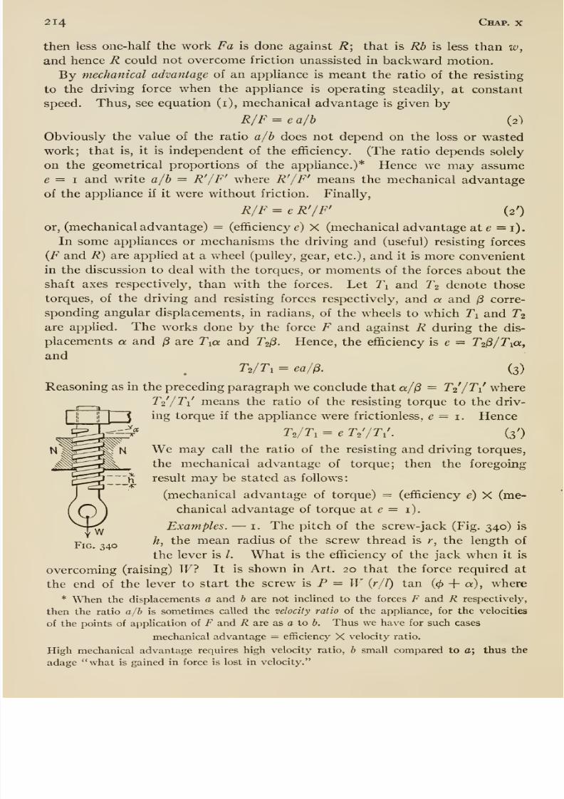
8/13/2019 Maurer Mechanics
http://slidepdf.com/reader/full/maurer-mechanics 228/407
214 Chap, x
then less one-half the work Fa is done against R; that is Rh is less than w,
and hence R could not overcome friction unassisted in backward motion.
By mechanical advantage of an appliance is meant the ratio of the resisting
to the driving force when the appliance is operating steadily, at constant
speed. Thus, see equation (i), mechanical advantage is given by
R/F = e a/b (2)
Obviously the value of the ratio a/h does not depend on the loss or wasted
work; that is, it is independent of the efficiency. (The ratio depends solely
on the geometrical proportions of the appliance.)* Hence we may assume
e = I and write a/b = R'/F' where R'/F' means the mechanical advantage
of the appUance if it were without friction. Finally,
R/F = e R'/F' (2')
or, (mechanical advantage) = (efficiency c) X (mechanical advantage at e =1).In some appliances or mechanisms the driving and (useful) resisting forces
{F and R) are applied at a wheel (pulley, gear, etc.), and it is more convenient
in the discussion to deal with the torques, or moments of the forces about the
shaft axes respectively, than with the forces. Let Ti and T2 denote those
torques, of the driving and resisting forces respectively, and a and /5 corre-
sponding angular displacements, in radians, of the wheels to which Ti and T2
are applied. The works done by the force F and against R during the dis-
placements a and /3 are Tia and T^^. Hence, the efficiency is e = T-S/Txa,
andTs/ri = ea/^. (3)
Reasoning as in the preceding paragraph we conclude that a/jS = T2/T1 where
T2 /Ti means the ratio of the resisting torque to the driv-
ing torque if the appliance were frictionless, e = i. Hence
T,/T, = e T^'/T,'. (3')
We may call the ratio of the resisting and driving torques,the mechanical advantage of torque; then the foregoing
result may be stated as follows:
(mechanical advantage of torque) = (efficiency e) X (me-
chanical advantage of torque at e = i).
Examples. —i. The pitch of the screw-jack (Fig. 340) is
h, the mean radius of the screw thread is r, the length of
the lever is /. What is the efficiency of the jack when it is
overcoming (raising) IF? It is shown in Art. 20 that the force required at
the end of the lever to start the screw is P ==^ W (r/l) tan (^ + a), where
* When the displacements a and b are not inclined to the forces F and R respectively,
then the ratio a/b is sometimes called the velocity ratio of the appliance, for the velocities
of the points of apphcation of F and R are as a to b. Thus we have for such cases
mechanical advantage = efficiency X velocity ratio.
High mechanical advantage requires high velocity ratio, b small compared to a; thus the
adage what is gained in force is lost in velocity.
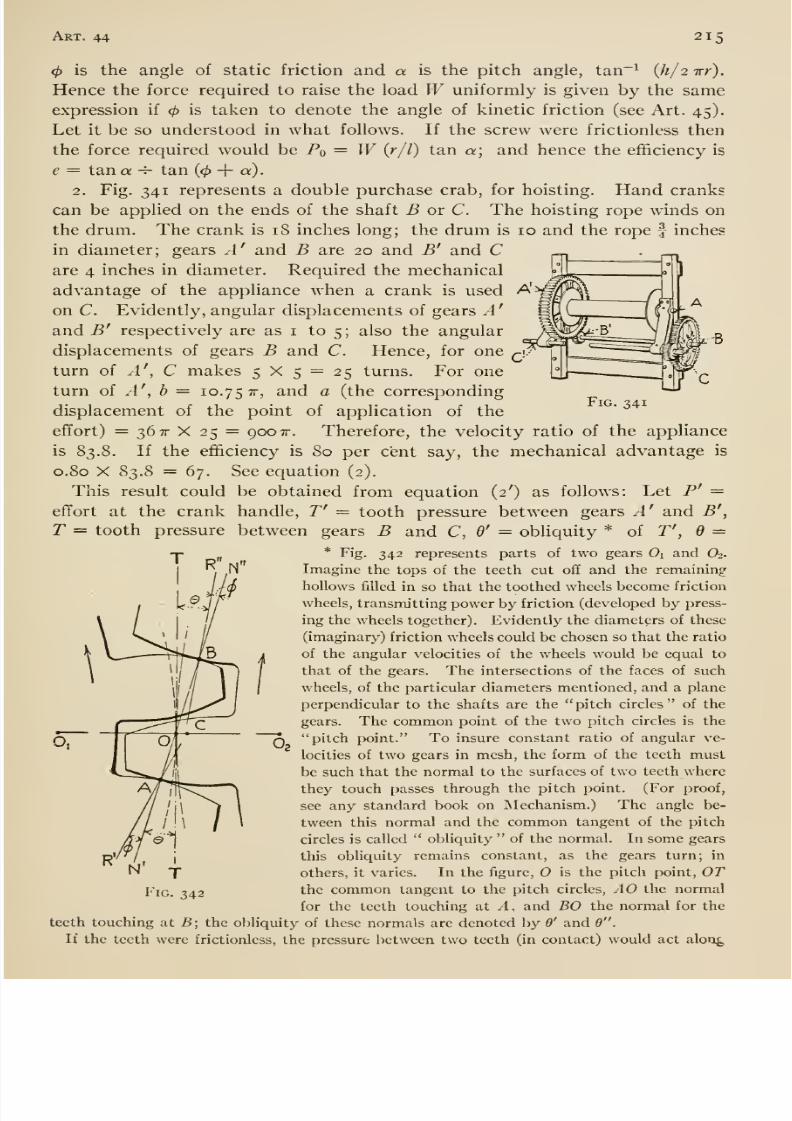
8/13/2019 Maurer Mechanics
http://slidepdf.com/reader/full/maurer-mechanics 229/407
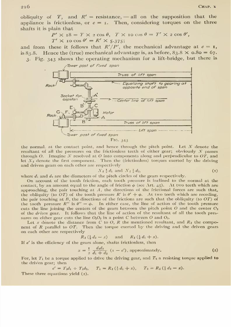
8/13/2019 Maurer Mechanics
http://slidepdf.com/reader/full/maurer-mechanics 230/407
2l6 Chap, x
obliquity of T, and R' = resistance, —all on the supposition that the
appliance is frictionless, or e = i. Then, considering torques on the three
shafts it is plain that
P' X i8 = r X 2 cos ^, r X lo cos ^ = r' X 2 cos 6',
r X locos^' = R' X 5.375;
and from these it follows that R'/P', the mechanical advantage at e = i,
is 83.8. Hence the (true) mechanical advantage is, as before, 83.8 X 0.80 = 67.
3. Fig. 343 shows the operating mechanism for a lift-bridge, but there is
/Tower posf of fixed span
Truss of liff span
ffackEqualizing sinaff '^0 gearing atopposite end of span
Socket for., iL-Acapstan ^ ^ ^TZc^f^FTi^ IThfi s^
T-.' • IT r^
z.
Truss of lift span
'\ |<- Liff span''Tower post of fixed span
Fig. 343
the normal, at the contact pohit, and hence through the pitch point. Let TV denote the
resultant of all the pressures on the frictionless teeth of either gear; obviously iV passes
through 0. Imagine iV resolved at O into components along and perf)endicular to OT, andlet N t denote the first component. Then the (frictionless) torques exerted by the driving
and driven gears on each other are respectively
iVt I dx and A t \ d-i, (i)
where d\ and dt are the diameters of the pitch circles of the gears respectively.
On account of the tooth friction, each tooth pressure is inclined to the normal at the
contact, by an amount equal to the angle of friction <^ (see Art. 45). At two teeth which are
approaching, the pair touching at A, the directions of the frictional forces are such that.,
the obliquity (to OT) of the tooth pressure R' is Q' + 4>. At two teeth which are receding,
the pair touching at B, the directions of the frictions are such that the obliquity (to OT) of
the tooth pressure R is B — <^. In either case, the Hne of action of the tooth pressure
cuts the line joining the centers of the gears between the pitch point O and the center O2
of the driven gear. It follows that the line of action of the resultant of all the tooth pres-
sures on either gear cuts the line O1O2 in a point C between and O2.
Let .V denote the distance from C to 0, R the mentioned resultant, and Rt the compo-
nent of R parallel to OT. Then the torque exerted by the driving and the driven gears
on each other are respectively
Rtildi-x) and Rtihdi+x).
If e' is the efficiency of the gears alone, shafts frictionless, then
did-2(i — e')) approximately. (2)
2 di -\- d2
For, let Ti be a torque applied to drive the driving gear, and Tj a resisting torque applied to
the driven gear; then
e' = Tsrfi ^ T,d2, Ti = Rt ih di + x), T-i = Rt {h d. - x).
These three equations yield (2).
8/13/2019 Maurer Mechanics
http://slidepdf.com/reader/full/maurer-mechanics 231/407
Art. 44 217
a duplicate mechanism on the other end of the Hft span not shown. All
this mechanism rests on and moves with the lift span. There are fixed tower
posts adjacent to the lift span as shown, and on these posts there are fixed
vertical racks which engage spur pinions GG of the operating mechanism.
The pinions are driven by the motors or hand capstans, and thus the Hft span
is raised or lowered. The intermediate drive consists of:
a motor pinion A number of teeth, 18, diameter, 5 . 14 inches
cross shaft gear B 126 36.00
cross shaft bevel pinions CC 20 10 .00
counter shaft bevel gears DD 60 30.00
counter shaft spur pinions EE 15 8.36
operating shaft spur gear FF 52 29 .00
operating shaft pinion GG 15 11 -94
bevel pinion on hand operator A' 16 12.72
bevel gear on hand operator B' 24 19.08
The lift span is accurately counterweighted so that no work is done against
gravity either in raising or lowering; but vertical pressure must be developed
between the racks and the pinions G to overcome the (internal) friction in the
counter weight mechanism. It is estimated that a vertical pressure of 5000
pounds is required at each pinion for lifting the bridge. How great a driving
torque, at each motor, is required to develop this pressure at each pinion G?
Wewill first neglect losses in mechanism. Let 2 T/ be the driving torque
at the motor and T2' the resisting torque at the pinion G. Then the
torque to the cross shaft = 2 T/ -j%^-,
torque to the counter shaft = Ti ~\%^ |§,
and torque to the operating shaft = Ti' VV' In tI = 36.9 T/.
But 36.9 r/ = T2', or T2 jTi = 36.9. We take the efficiencies of the gears
to be as follows: A and 5, 96 per cent; C and D, 92 per cent; E and F, 96
per cent. Then the efficiency of the transmission from the motor to the
pinion G is 0.96 X 0.92 X 0.96 = 0.85, or 85 per cent. Hence the ratio of
the actual driving and resisting torques is T^lT^ = 0.85 X 36.9 = 31.4. The
lever arm of the vertical pressure of the rack against the pinion G is 5.97 + a;
(see footnote on page 216). Since di (diameter of the pitch circle of the rack)
is infinite, equation (2) as written is not usable; it can be written
which, since d\l di = o in the present problem, becomes
% _ 1~ 2 di (i — e') = 2 X 11.94 (i — 0.98, say) = 0.12 inches.
Therefore, the actual resisting torque on the pinion is
5000 X 6.09 = 30,450 inch-pounds = 2537 foot-pounds.
Hence Ti = 2537 -^ 31.4 = 80 foot-pounds, and the required motor torque
is 160 foot-pounds.
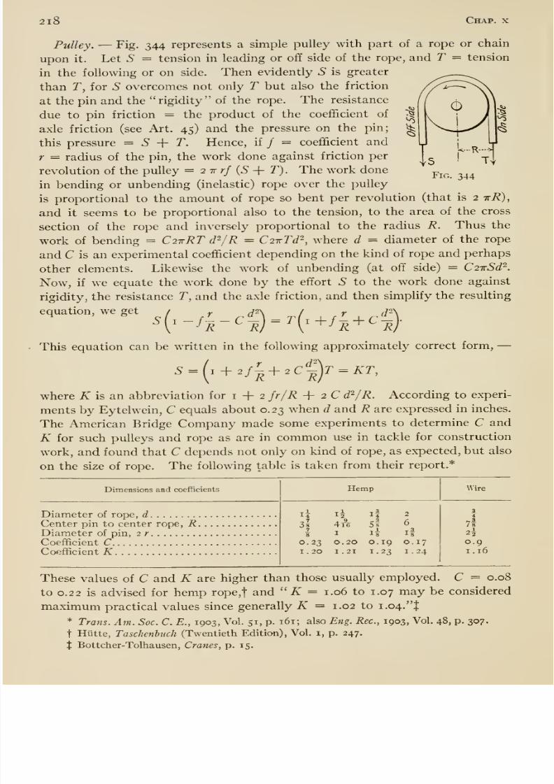
8/13/2019 Maurer Mechanics
http://slidepdf.com/reader/full/maurer-mechanics 232/407
2l8 Chap, x
-^
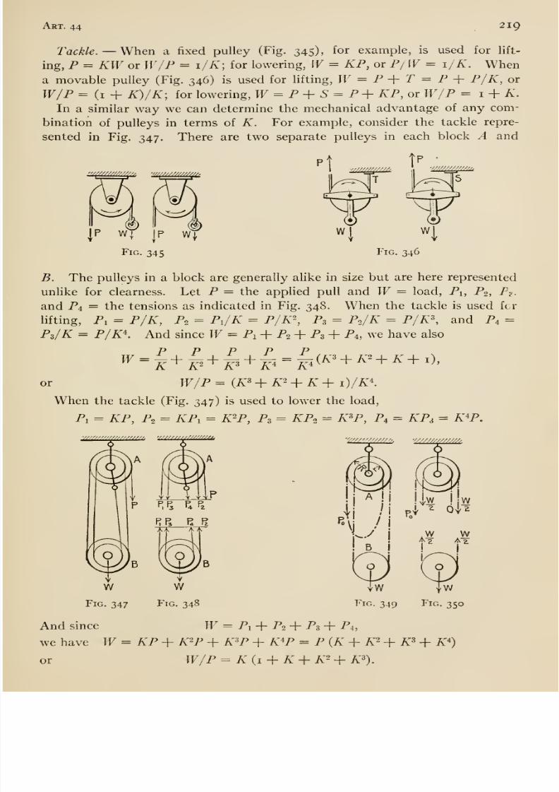
8/13/2019 Maurer Mechanics
http://slidepdf.com/reader/full/maurer-mechanics 233/407
8/13/2019 Maurer Mechanics
http://slidepdf.com/reader/full/maurer-mechanics 234/407
220 Chap, x
Special {Chain) Hoists. —Fig. 349 represents a Weston differential hoist.
The upper block contains two pulleys differing sUghtly in diameter; they are
fastened together. The lower block contains only one pulley. The pulley
grooves have pockets into which the links of the chain fit; thus slipping
of the chain is prevented. The chain is endless and is reeved as shown. If
there were no lost work, then the tension in each portion of the chain to block
B would equal one-half the load (Fig. 350), and the pulls on the block A would
be as indicated in the figure. Now if R and r = the distances from the center
of the pin in block A to the axis of the chain as indicated then moments about
the axis of the pin give
PoR + h ^Vr = \ WR, or W = Pq 2 RliR - r)\
the ratio, HV^o = 2R/{R —r) may be made very large by making R — r small.
The mechanical advantage is
IF W 2 Re =
P Po R-r'
where P = the actual force required to raise W and e = efficiency. These
hoists are made of various capacities up to W = 3 tons; their efficiencies are
relatively low, from about 25 to 40 per cent according to the manufactiu-ers'
lists. In the so-called Duplex and Triplex hoists the upper blocks are screw-
geared and spur-geared respectively. At full load the efficiency of thesehoists varies from about 30 to 40 and from 70 to 80 per cent.
Example. —We will now show how to apply some of the preceding prin-
ciples and formulas in a computation relating to the operating machinery of
the vertical lift bridge represented in Figs. 351 and 352. The Hft span when
down in place rests on two piers. When up it is balanced by two counter-
weights as shown. Each counterweight is suspended by means of two pairs
of one-inch cable; each pair of cables extends upwards from the counterweight,
over a sheave and downward to a point of attachment on the lift span. Ateach corner of the lift span there is a spirally grooved drum carrying two one-
half-inch cables. Each cable has one end attached to its drum; the other end
of the up-haul cable is attached to a point vertically above at the top of the
tower, and the other end of the down-haul cable is similarly attached at the
base of the tower. As the drum is revolved, one cable is wound upon it and
the other is paid out. The tw^o drums at either end of the span are mounted
upon a single cross-shaft A, which carries a bevel gear B. The gears BB mesh
with bevel pinions DD mounted on the longitudinal shaft C which also carries
a bevel gear E. E meshes with a bevel pinion F on a vertical shaft which
carries a capstan head. This capstan head takes a horizontal lever by means
of which a man operates the mechanism. To lift the bridge he rotates the
capstan headed shaft in the proper direction and drives the drums; they wind
the up-haul cable upon themselves and pay out the down-haul cable as already'
described. This winding up necessitates upward motion of the bridge.
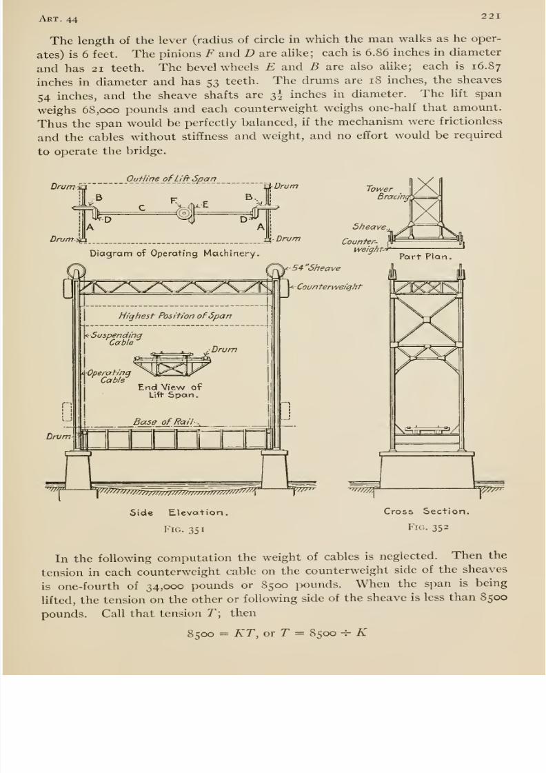
8/13/2019 Maurer Mechanics
http://slidepdf.com/reader/full/maurer-mechanics 235/407
Art. 44221
The length of the lever (radius of circle in which the man walks as he oper-
ates) is 6 feet. The pinions F and D are alike; each is 6.86 inches in diameter
and has 21 teeth. The bevel wheels E and B are also alike; each is 16.87
inches in diameter and has 53 teeth. The drums are 18 inches, the sheaves
54 inches, and the sheave shafts are 3^ inches in diameter. The lift span
weighs 68,000 pounds and each counterweight weighs one-half that amount.Thus the span would be perfectly balanced, if the mechanism were frictionless
and the cables without stiffness and weight, and no effort would be required
to operate the bridge.
Drurriia
1-^
Ouf/m_e_ ofUft^ ^PPJl^
[ADrum%\
Drum
Drum
Diagram of Operating Machinery.
TowerBrat
Sheave^
Counter-weight-
5 4- Sheave
Court terweiqht
7777777rr777777mTmmr,
Side Elevation.
Fig. 351
Cross Section.
Fig. 352
In the following computation the weight of cables is neglected. Then the
tension in each counterweight cable on the counterweight side of the sheaves
is one-fourth of 34,000 pounds or 8500 pounds. When the span is being
lifted, the tension on the other or following side of the sheave is less than 8500
pounds. Call that tension T\ then
8500 = KT, or r = 8500 -^ K
8/13/2019 Maurer Mechanics
http://slidepdf.com/reader/full/maurer-mechanics 236/407
222•
Chap, x
(see under pulley above). We will take K == 1.06; then T = 8020 pounds,
and hence the hft on the span due to counterweights = 8 X 8020 = 64,160
pounds. This leaves 68,000 — 64,160 = 3840 pounds to be furnished by the
four up-haul cables, or 960 pounds apiece.
Let a and b — respectively any corresponding displacements of the effort
at the hand lever and the resistance 960 pounds at each drum; then
b 3.43 21 18
Hence, if the mechanism were frictionless the effort Pq required to produce
960 pounds tension in one rope = 960 H- 50 = 19.2 pounds; and the effort Prequired to produce that tension by means of the actual mechanism = 19.2 -^ e,
where e = the efi&ciency of that part of the mechanism which transmits from
P to the resistance 960 pounds. The efficiency of each pair of gears andnecessary bearings we take as 0.95; the efficiency of a drum about i -h 1.03 =0.97; hence e = 0.95 X 0.95 X 0.97 = 0.875. Therefore P = 19.2 -^ 0.875 ==
22 pounds, and the effort (at the lever) required to develop a tension of 960pounds at the four driuns = 4 X 22 = 88 pounds.
The computation can also be made as follows: —We regard the total force
Q exerted at the hand lever and the force of gravity on the counterweights as
two efforts which overcome the (useful) resistance (gravity on the lift span)
and the wasteful resistances in the entire mechanism. For any rise b of the
lift-span the counterweights descend an equal distance and the hand-lever
effort works through a distance 50 b; and since the efficiency of a sheave =I -^ 1.06 = 0.944, we have
QX SobX 0.875 -f 2 X 34,000 XbX 0.944 -= 68,000 X 6, or (J = 87 pounds.
45. Kinetic Friction
§ I. Kinetic Friction, or Friction of Motion, is the friction between twobodies when sliding actually occurs. The coefficient of kinetic friction for twobodies is the ratio of the kinetic friction to the corresponding normal pressure
between them. The angle of kinetic friction is the angle between the normalpressure and the total pressure (resultant of the normal pressure and the
kinetic friction). One of the so-called laws of friction states that the kinetic
coefficient is less than the static coefficient (Art. 19), and implies that there is
a sudden or abrupt change in the values of the coefficients. Experiments byJenkin and Ewing* on the kinetic coefficients at speeds as low as 0.0002 foot
per second (about f foot per hour) lead them to conclude that it is highly
probable that the kinetic coefficient gradually increases when the velocity
becomes extremely small, so as to pass without discontinuity into the static
coefficient. Experiments by Kimballf also indicate that there is no abrupt
* Phil. Trans. Roy. Soc, 1877, Vol. 167, Part 2.
t Am. Jour. Set., 1877, Vol. 13, p. 353.
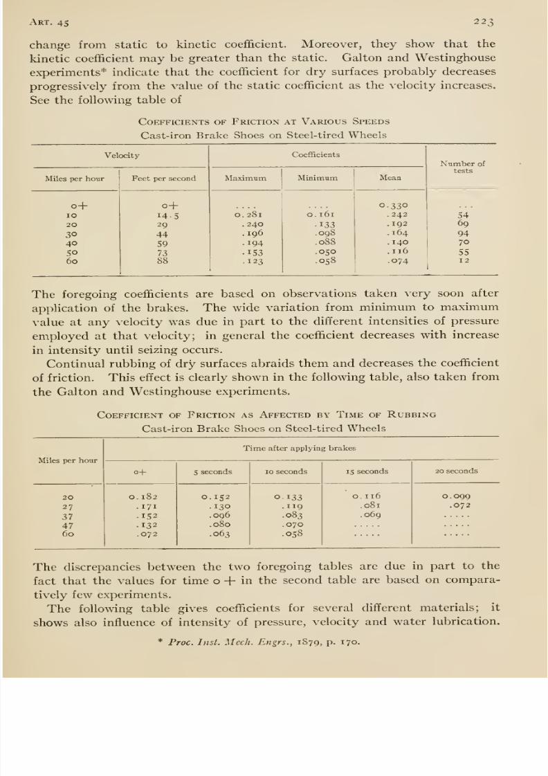
8/13/2019 Maurer Mechanics
http://slidepdf.com/reader/full/maurer-mechanics 237/407
Art. 45 223
change from static to kinetic coefficient. Moreover, they show that the
kinetic coefficient may be greater than the static. Galton and Westinghouse
experiments* indicate that the coefficient for dry surfaces probably decreases
progressively from the value of the static coefficient as the velocity increases.
See the following table of
Coefficients of Friction at Various Speeds
Cast-iron Brake Shoes on Steel-tired Wheels
Velocity

8/13/2019 Maurer Mechanics
http://slidepdf.com/reader/full/maurer-mechanics 238/407
2 24 Chap, x
Coefficients of Friction *
Various Brake-shoe Materials on Steel-tired Wheels
Materials
Cast iron.
Cast iron.
OakOakPoplar. . .
.
Poplar . . .
.
Cast iron.
Cast iron.
OakOakPoplar. . .
Poplar. . .
Pressure,pounds per
square inch
lO
4010401040208040
120
40120
Velocity, miles per hour
433660
43
3230037073041070
15
0.37•30
554072
532826
032055038053
Lubrication
nonenonenonenonenonenonewaterwaterwaterwaterwaterwater
* From Experiments by Ernest Wilson, Engr. News, 1909, Vol. 62, p. 736.
Coefficients of Kinetic Friction (Rough Averages)
Compiled by Rankine from Experiments by Morin and others
Wood on wood, dry . .
soapyMetals on oak, dry . .
.
wet . . .
soapy
.
Metals on elm, dry. .
.
Hemp on oak, dry. . .
.
wet. . .
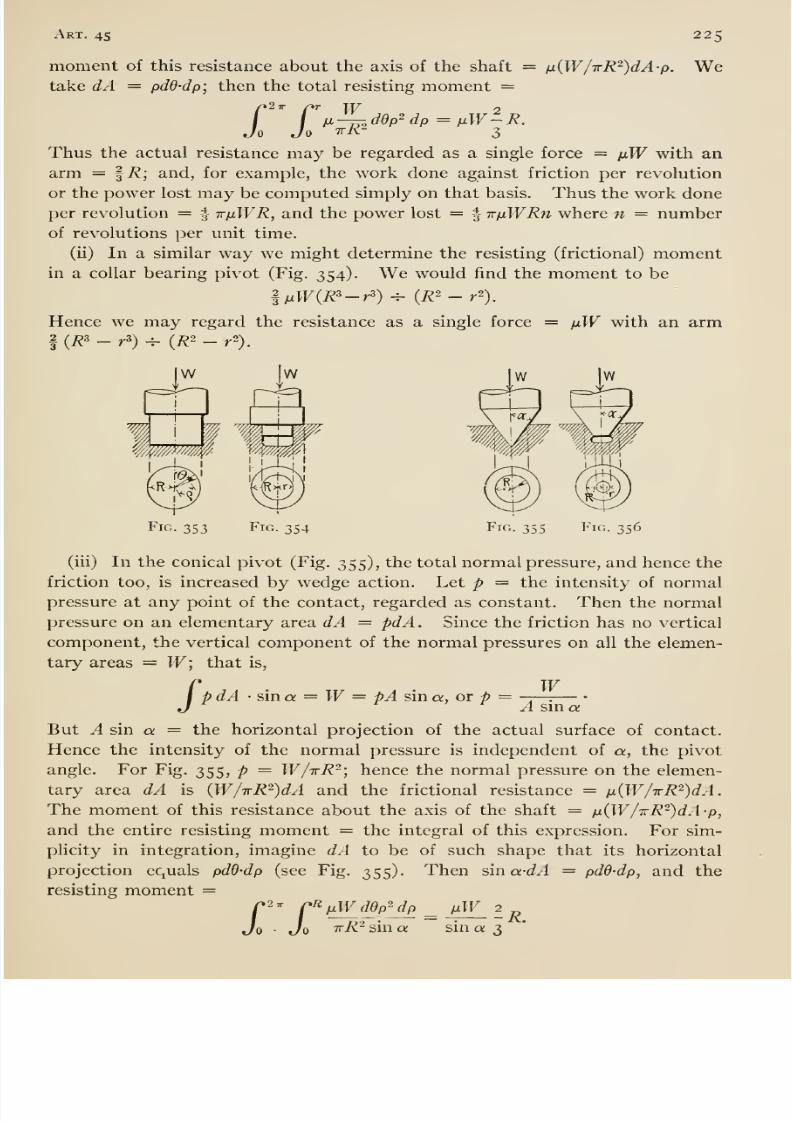
8/13/2019 Maurer Mechanics
http://slidepdf.com/reader/full/maurer-mechanics 239/407
Art. 45 225
moment of this resistance about the axis of the shaft = iJ.(W/irR^)dA-p.
take dA = pdd-dp; then the total resisting moment =We
r TmJo Jo
w-iddp'^dp pW-R.
3
Thus the actual resistance may be regarded as a single force = pW with anarm — ^R; and, for example, the work done against friction per revolution
or the power lost may be computed simply on that basis. Thus the work done
per revolution = | irpWR, and the power lost = | irpWRn where n = numberof revolutions per unit time.
(ii) In a similar way we might determine the resisting (frictional) momentin a collar bearing pivot (Fig. 354). We would find the moment to be
1pW{R^-r^)-^ {R^-r^).
Hence we may regard the resistance as a single force = pW with an arm
f {R^ - r') ^ (i?2 _ r'~).
Fig. 353 Fig. 354 Fig. 355 Fig. 356
(iii) In the conical pivot (Fig. 355), the total normal pressure, and hence the
friction too, is increased by wedge action. Let p = the intensity of normal
pressure at any point of the contact, regarded as constant. Then the normal
pressure on an elementary area dA = pdA . Since the friction has no vertical
component, the vertical component of the normal pressures on all the elemen-
tary areas = W; that is,
WpdA • sina = W= pA sin a, or p =P A sin a
But A sin a = the horizontal projection of the actual surface of contact.
Hence the intensity of the normal pressure is independent of a, the pivot
angle. For Fig. 355, p = W/tR-; hence the normal pressure on the elemen-
tary area dA is {W/irR-)dA and the frictional resistance = p(W/TrR^)dA.The moment of this resistance about the axis of the shaft = p{W/TR^)dA-p,
and the entire resisting moment = the integral of this expression. For sim-
plicity in integration, imagine dA to be of such shape that its horizontal
projection equals pdd-dp (see Fig. 355). Then sin a-dA = pdd-dp, and the
resisting moment =^^pWddp^dp^ pW
irR^ sin a sin a 3Jr»2
7r pL
Jo'-R.
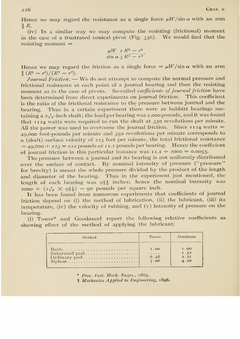
8/13/2019 Maurer Mechanics
http://slidepdf.com/reader/full/maurer-mechanics 240/407
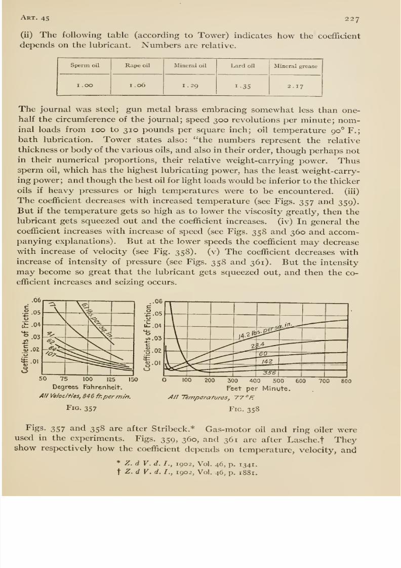
8/13/2019 Maurer Mechanics
http://slidepdf.com/reader/full/maurer-mechanics 241/407
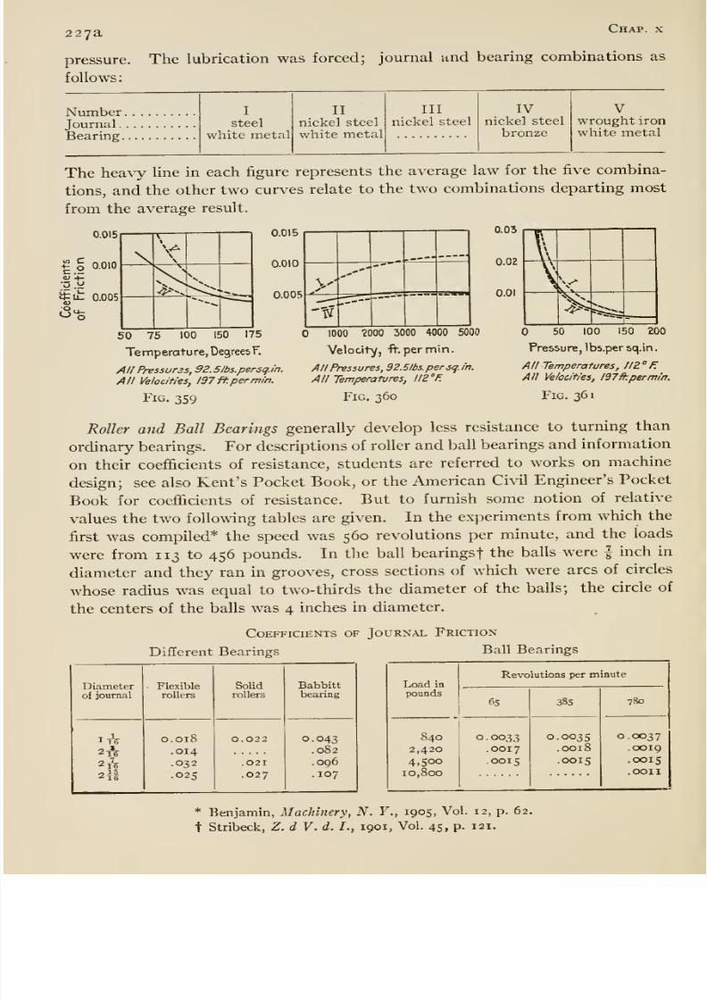
8/13/2019 Maurer Mechanics
http://slidepdf.com/reader/full/maurer-mechanics 242/407
227a Chap, x
pressure. The lubrication was forced; journal and bearing combinations as
follows:
NumberJournalBearing.
I
steel
white metal
IInickel steel
white metal
IIInickel steel
IVnickel steel
bronze
Vwrought ironwhite metal
The heavy line in each figure represents the average law for the five combina-
tions, and the other two curves relate to the two combinations departing most
from the average result.
0.015
^ g 0.010
it a. 0.005
\
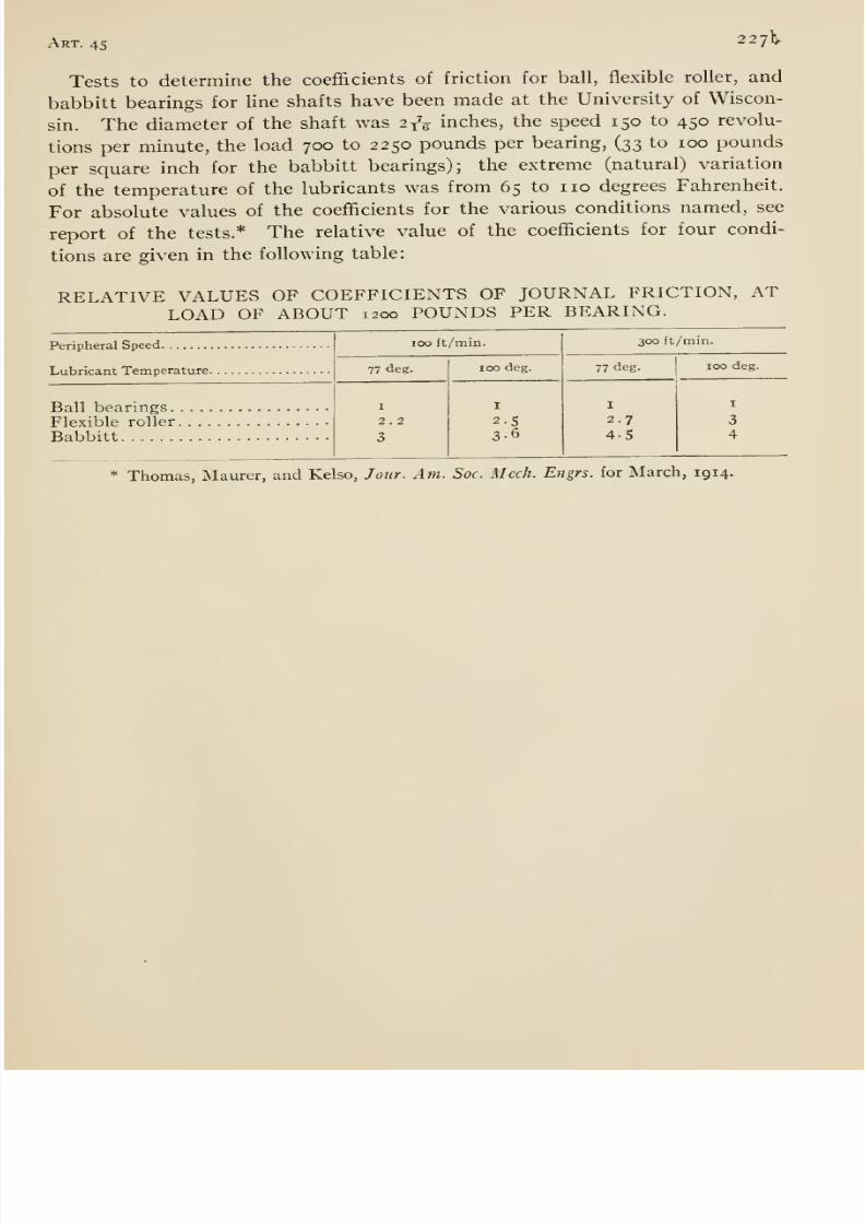
8/13/2019 Maurer Mechanics
http://slidepdf.com/reader/full/maurer-mechanics 243/407
Art. 4522711^
Tests to determine the coefficients of friction for ball, flexible roller, and
babbitt bearings for line shafts have been made at the University of Wiscon-
sin. The diameter of the shaft was 2^^ inches, the speed 150 to 450 revolu-
tions per minute, the load 700 to 2250 pounds per bearing, (33 to 100 pounds
per square inch for the babbittbearings); the extreme (natural) variation
of the temperature of the lubricants was from 65 to no degrees Fahrenheit.
For absolute values of the coefficients for the various conditions named, see
report of the tests.* The relative value of the coefficients for four condi-
tions are given in the following table
RELATIVE VALUES OF COEFFICIENTS OF JOURNAL FRICTION, ATLOAD OF ABOUT 1200 POUNDS PER BEARING.
Peripheral Speed
Lubricant Temperature.
BaH bearings.F]exible roller.
Babbitt
100 ft/min.
77 deg. 100 deg.
I
2-53-6
300ft/min.
77 deg.
I
2.7
4 5
100 deg.
I
3
4
* Thomas, Maurer, and Kelso, Jour. Am. Soc. Mech. Engrs. for March, 1914.
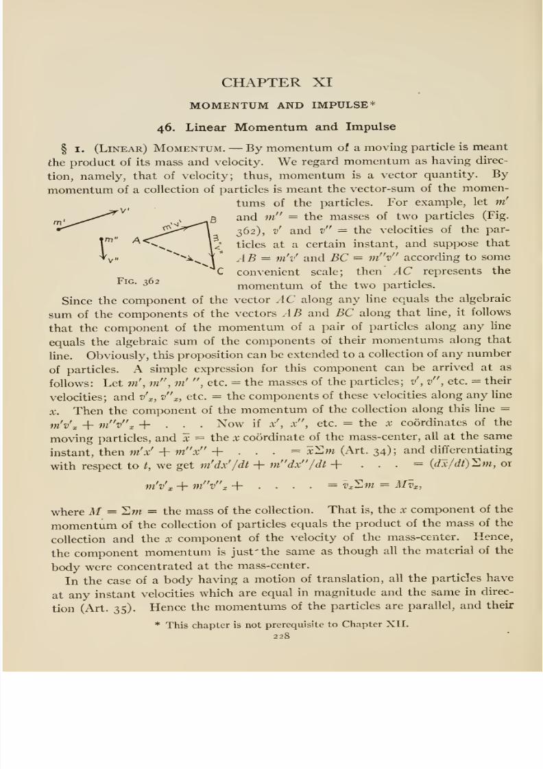
8/13/2019 Maurer Mechanics
http://slidepdf.com/reader/full/maurer-mechanics 244/407

8/13/2019 Maurer Mechanics
http://slidepdf.com/reader/full/maurer-mechanics 245/407
Art. 46 229
vector sum = m'v + m v + . , . = vTtm = Mv, where v = their commonvelocity and M = the mass of the body.
The definition of momentum impUes that the unit of momentum equals the
momentum of a body of unit mass moving with unit velocity. The magnitude
of the unit, therefore, depends on the units of mass and velocity used. Nosingle word has been generally accepted for any unit of momentum. Thedimensional formula for momentum is F'T' (see appendix A), that is, a unit
momentmn is one dimension in force and one in time. Hence, any unit of
momentum may be and commonly is called by names of the units of force and
time used. Thus the unit of momentum in the C.G.S. system is called the
dyne-second; in the ''engineers' system, the pound (force) -second, etc.
In Art. 34 it is explained that the acceleration of the mass-center of any
collection of particles does not depend at all on the forces which the particles
exert upon each other but on the external forces; also that the algebraic sumof the components of the external forces along any line equals the product of
the mass of the system and the component of the acceleration of the mass-
center along that line, that is,
n + i^ x+ . . . = Mi., (i)
where F'x, P x, etc., are the components of the external forces along a line x,
and ax is the x component of the acceleration of the mass-center. Now ax
equals the rate at which the x component of the velocity of the mass-center
changes, that is, ax — dvx/dt, where Vx is the x component of the velocity of the
mass-center; hence, Max = Mdvx/dt = d{Mvx)/dt; and finally
F'x + F x + . . . = d{,Mvx)/dt (2)
But Mvx is the x component of the momentum of the system, and d{Mv^/dt
is the rate at which that component changes; hence the algebraic sum of the
components of the external forces along any line x equals the rate at which the x
component of the linear momentum changes.
The principle just arrived at (equation 2) was derived from the law of motion
of the mass-center (equation i), and it is essentially an alternative form of the
law. But practically the former seems to apply more simply in certain cases
as the following examples show.
Fig. 363 represents a jet of water impinging against a flat plate. Required
the pressure of the jet upon the plate. Let W= the weight of water impinging
per unit time, v = the velocity of the water in the jet, and a = the angle
between the jet and the plate as indicated. We suppose that the water does
not rebound from the plate with any considerable velocity; then the momen-
tum of the water after striking has no component normal to the plate. The
momentum of an amount of water equal to Wbefore striking is {W/g)v, and
the component of that momentum along the normal to the plate = (W/g)v
sin a; hence the change in the (normal) component momentum is iW/g)v sin a.
This change takes place in unit time; therefore, it is the rate at which
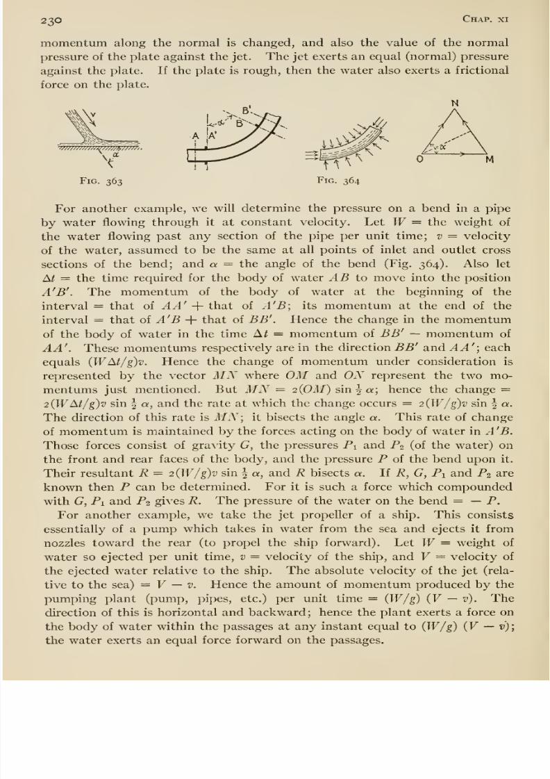
8/13/2019 Maurer Mechanics
http://slidepdf.com/reader/full/maurer-mechanics 246/407
230 Chap, xi
momentum along the normal is changed, and also the value of the normal
pressure of the plate against the jet. The jet exerts an equal (normal) pressure
against the plate. If the plate is rough, then the water also exerts a frictional
force on the plate.
-w/m//w^/w7i^;/w,.
Fig. 363
For another example, we will determine the pressure on a bend in a pipe
by water flowing through it at constant velocity. Let W= the weight of
the water flowing past any section of the pipe per unit time; v = velocity
of the water, assumed to be the same at all points of inlet and outlet cross
sections of the bend; and a = the angle of the bend (Fig. 364). Also let
A^ = the time required for the body of water AB to move into the position
A'B'. The momentum of the body of water at the beginning of the
interval = that of AA' -\- that of A'B; its momentum at the end of the
interval = that oi A'B -\- that of BB' . Hence the change in the momentumof the body of water in the time Ai = momentum of BB' — momentum of
AA'. These momentums respectively are in the direction BB' and AA'; each
equals {WM/g)v. Hence the change of momentum under consideration is
represented by the vector MN where OM and ON represent the two mo-
mentums just mentioned. But MN = 2{0M) sm\a; hence the change =
2{WM/g)v sin ^ a, and the rate at which the change occurs = 2{W/g)v sin ^ a.
The direction of this rate is MN; it bisects the angle a. This rate of change
of momentum is maintained by the forces acting on the body of water in A 'B.
Those forces consist of gravity G, the pressures Pi and P2 (of the water) on
the front and rear faces of the body, and the pressure P of the bend upon it.
Their resultant R = 2{W/g)v sin | a, and R bisects a. If R, G, Pi and P2 are
known then P can be determined. For it is such a force which compounded
with G, Pi and Pi gives R. The pressure of the water on the bend = —P.
For another example, we take the jet propeller of a ship. This consists
essentially of a pump which takes in water from the sea and ejects it from
nozzles toward the rear (to propel the ship forward). Let W= weight of
water so ejected per unit time, v = velocity of the ship, and V — velocity of
the ejected water relative to the ship. The absolute velocity of the jet (rela-
tive to the sea) = V — v. Hence the amount of momentum produced by the
pimiping plant (pump, pipes, etc.) per unit time = (W/g) (V — v). Thedirection of this is horizontal and backward; hence the plant exerts a force on
the body of water within the passages at any instant equal to (W/g) {V — v);
the water exerts an equal force forward on the passages.
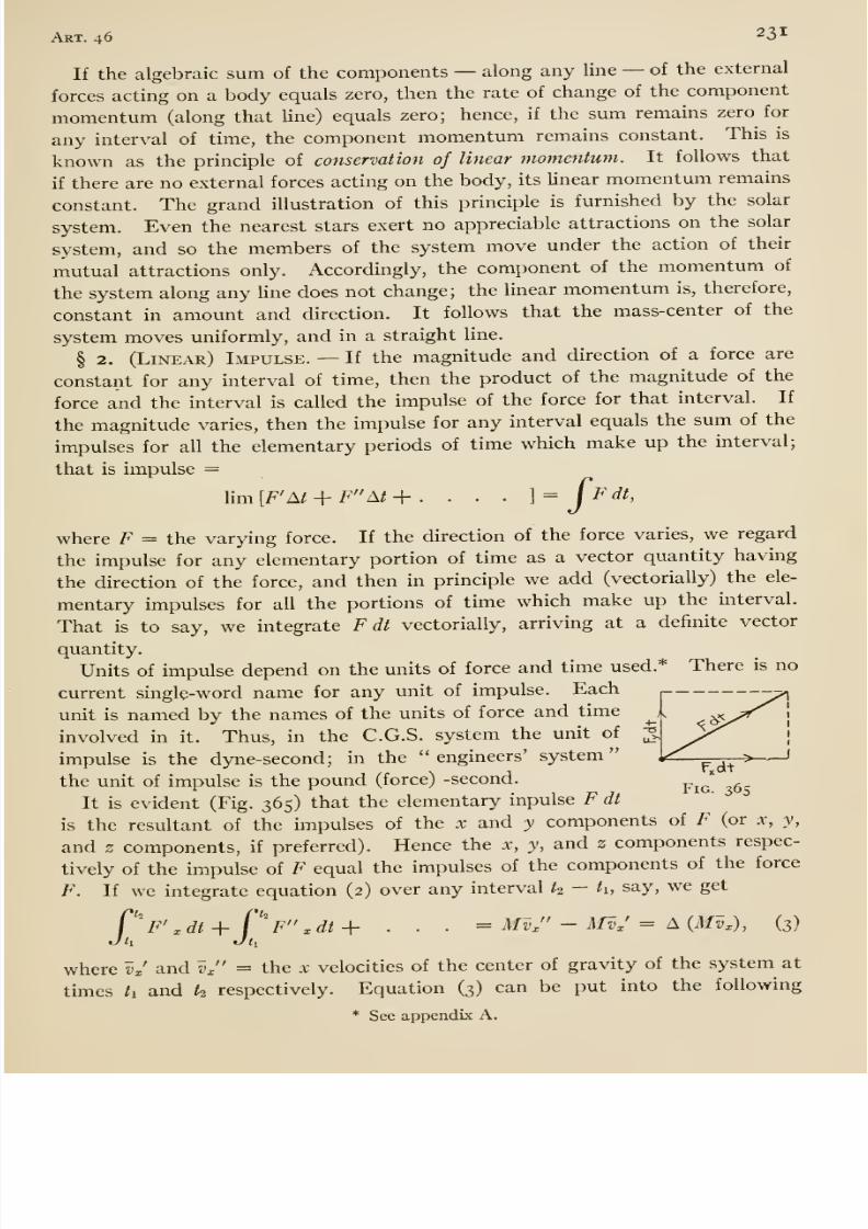
8/13/2019 Maurer Mechanics
http://slidepdf.com/reader/full/maurer-mechanics 247/407
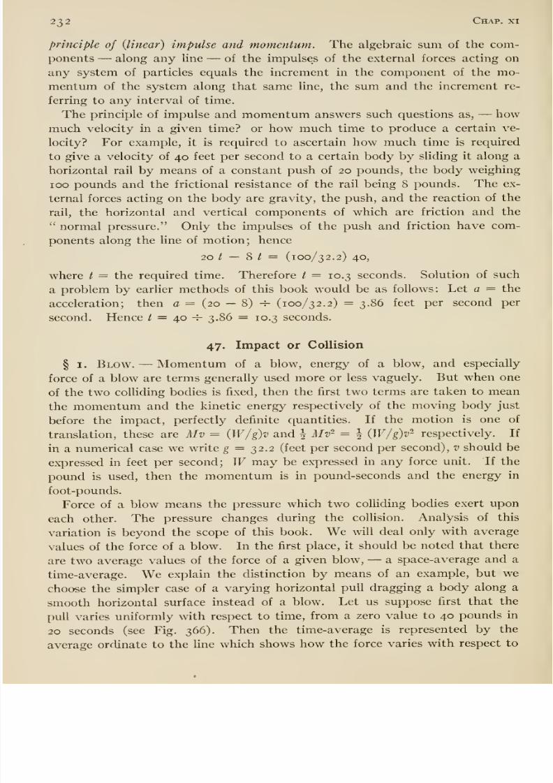
8/13/2019 Maurer Mechanics
http://slidepdf.com/reader/full/maurer-mechanics 248/407
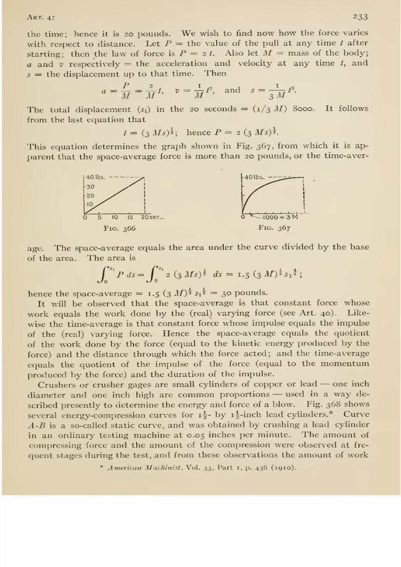
8/13/2019 Maurer Mechanics
http://slidepdf.com/reader/full/maurer-mechanics 249/407
Art. 47 233
the time; hence it is 20 pounds. We wish to find now how the force varies
with respect to distance. Let P = the value of the pull at any time t after
starting; then the law of force is P = 2 ^. Also let M = mass of the body;
a and v respectively = the acceleration and velocity at any time t, and
s = the displacement up to that time. Then
a = -r7 = ir7i, V = Yji , and 5 = —r-^ t\
The total displacement (^i) in the 20 seconds = (1/3 M) 8000. It follows
from the last equation that
t = (3 Ms)^\ hence P = 2 (3 Ms)^.
This equation determines the graph shown in Fig. 367, from which it is ap-
parent thatthe space-average force is more than 20 pounds, or the time-aver-
40 lbs
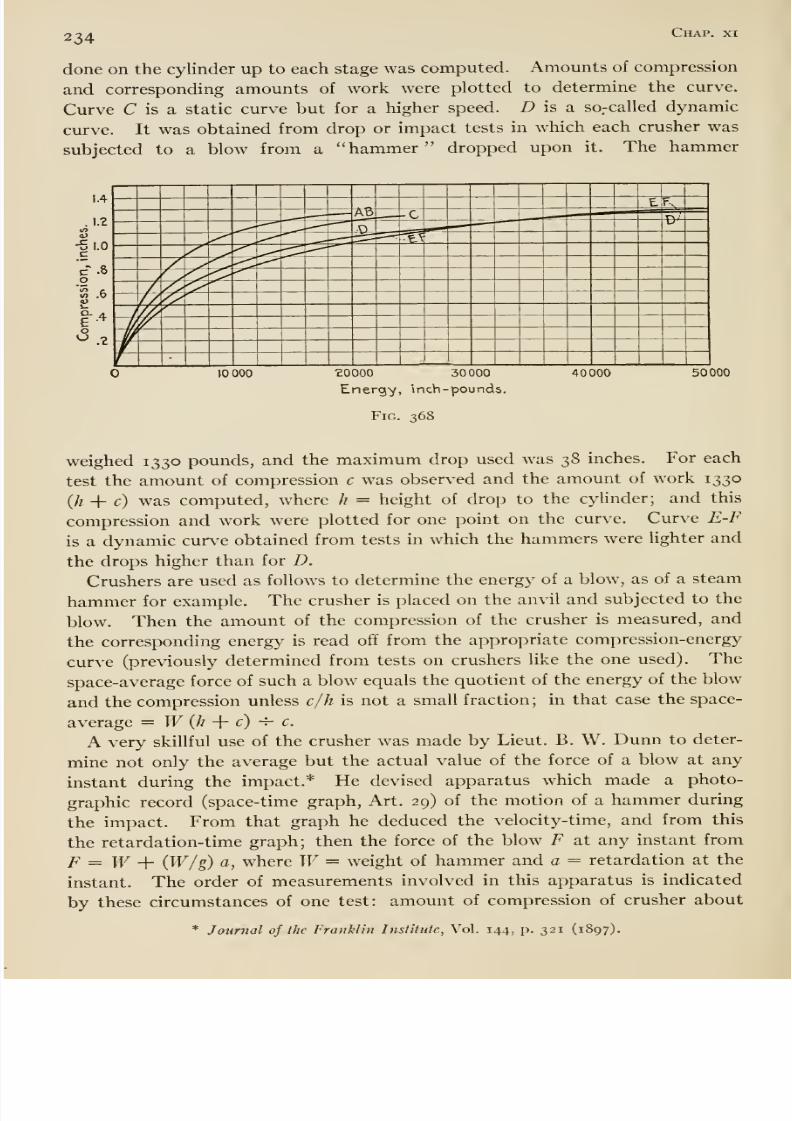
8/13/2019 Maurer Mechanics
http://slidepdf.com/reader/full/maurer-mechanics 250/407
234 Chap, xi
done on the cylinder up to each stage was computed. Amounts of compression
and corresponding amounts of work were plotted to determine the curve.
Curve C is a static curve but for a higher speed. D is a so-called dynamic
curve. It was obtained from drop or impact tests in which each crusher was
subjected to a blow from a hammer dropped upon it. The hammer
co
1-
O-eoU
8/13/2019 Maurer Mechanics
http://slidepdf.com/reader/full/maurer-mechanics 251/407
Art. 47 235
^ inch and time of impact about xmiTT second; the weight of hammer was
^T, pounds and the drop 15 inches. For the copper crushers used the maxi-
mum pressure occurred just before the end of the compression, and its value
was slightly less than twice the space-average.
§ 2. Motion after Collision. —In this section we discuss the changes of
motion of one or both colliding bodies due to the collision in certain compara-
tively simple cases. In most cases of collision the pressures which the colliding
bodies exert on each other are enormous compared with other forces acting
on the bodies. For example, the space-average pressure between two billiard
balls colliding with velocity of 8 feet per second is about 1300 pounds. There-
fore in discussing changes of motion of the bodies during collision we mayneglect the other (ordinary) forces acting on the bodies, gravity for example;
that is we regard the two bodies jointly as under the action of no external
forces. Hence, according to the principle of conservation (Art. 46), the
momentum of the two bodies jointly is not changed by the impact.
If the centers of gravity of two bodies about to collide are moving along the
same straight line, then the collision or impact is called direct; if otherwise,
oblique. If the pressures which two colliding bodies exert upon each other
during impact are directed along the line joining their centers of gravity, then
the impact is called central; if otherwise, eccentric. These are the kinds of
impact called simple, above.
Direct Central Impact. —We assume that the bodies have motions of trans-
lation before impact. Since the impact is supposed to be central, the pressure
(of impact) on each body acts through the center of gravity of that body and
does not turn it. Hence the motion of each body after collision is one of
translation. Let A and B be the two bodies,
Ml and M2 = their masses,
Ui and ih. = their velocities just before impact,
and Vi andV2 = their velocities just after impact respectively.
We regard these velocities as having sign; velocity in one direction (along the
line of motion) being positive, and that in the other being negative. Then the
momentum of the two bodies before impact = MiUi -f- M2M2, and after impact
it = MiVi -\- M2V2. Since the momentums before and after impact are equal,
we haveMiVi + M2V2 = MiUx + 7I/2M2. (i)
The foregoing expressions are correct whether A and B are moving in the same
or opposite directions before or after the impact. Thus, if both are moving
toward the right before impact, at 8 and 10 feet per second say, their momen-tum is 8 ^1/1 -|- 10 7I/2; but if A is moving toward the right and B toward the
left, their momentum is 8 Mi — 10 M2.
It has been learned experimentally that when two spheres A and B collide
directly and centrally the velocity of separation is always less than and opposite'
to the velocity of approach, and the ratio of these two velocities seems to
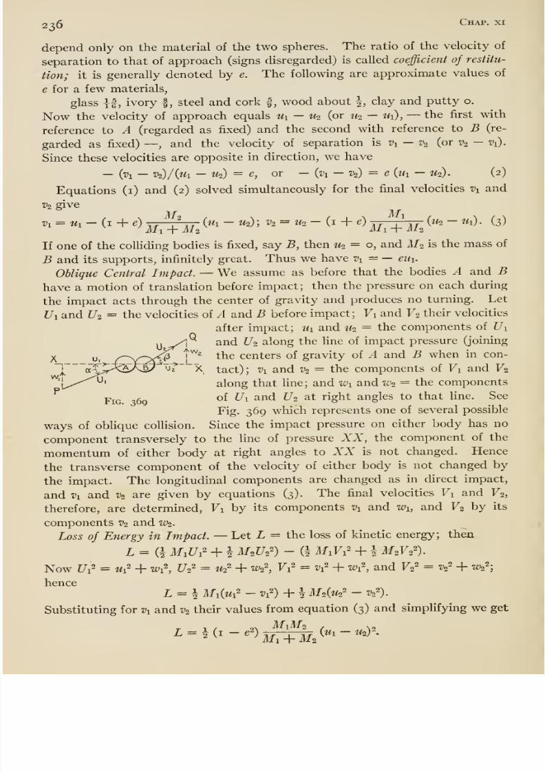
8/13/2019 Maurer Mechanics
http://slidepdf.com/reader/full/maurer-mechanics 252/407
236 Chap, xi
depend only on the material of the two spheres. The ratio of the velocity of
separation to that of approach (signs disregarded) is called coefficient of restitu-
tion; it is generally denoted by e. The following are approximate values of
e for a few materials,
glassII,
ivory |, steel and cork |, wood about \, clay and putty o.
Now the velocity of approach equals Ui — ih (or W2 — Ui), —the first with
reference to A (regarded as fixed) and the second with reference to B (re-
garded as fixed) —, and the velocity of separation is Vi — Vo (or v^ — Vi).
Since these velocities are opposite in direction, we have
— {vi —v^/{ui —U2) = e, or — {vi — V2) = e (th —U2). (2)
Equations (i) and (2) solved simultaneously for the final velocities Vi and
V2 give
v. = u^-(i+e)j^^j^^{u,-u.);v2 = i^-{i + e)j^-^^^^ (3)
If one of the colHding bodies is fixed, say B, then 1^ = o, and M2 is the mass of
B and its supports, infinitely great. Thus we have Vy = — eui.
Oblique Central Impact. —We assume as before that the bodies A and Bhave a motion of translation before impact; then the pressure on each during
the impact acts through the center of gravity and produces no turning. Let
Ui and 1/2 = the velocities of A and B before impact; Vi and F2 their velocities
after impact; Ui and M2 = the components of Uiand U2 along the fine of impact pressure (joining
the centers of gravity of A and B when in con-
tact); V]_ and V2 = the components of Vi and F2^' along that line; and Wi and W2 = the components
Pjg. of Z7i and U2 at right angles to that line. See
Fig. 369 which represents one of several possible
ways of oblique collision. Since the impact pressure on either body has no
component transversely to the line of pressure XX, the component of the
momentum of either body at right angles to XX is not changed. Hence
the transverse component of the velocity of either body is not changed by
the impact. The longitudinal components are changed as in direct impact,
and vi and V2 are given by equations (3). The final velocities Fi and F2,
therefore, are determined, Vi by its components Vi and Wi, and V2 by its
components % and W2.
Loss of Energy in Impact. —Let L = the loss of kinetic energy; then
L = (i M,U^' + i M2U2') - (^ MiFi^ + \ M2V2').
Now f/i^ = wi2 -f wi2, C/2' = ^2^ + W2\ Vi = Vi + Wi , and Fg^ = V2^ + W2^;
henceZ = i MM' - V) + h M2W- ^2^).
Substituting for Vi and V2 their values from equation (3) and simplifying we get
. . „, M1M2 , s.
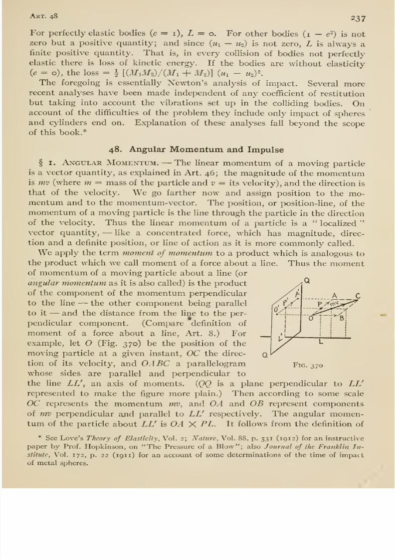
8/13/2019 Maurer Mechanics
http://slidepdf.com/reader/full/maurer-mechanics 253/407
Art. 48 237
For perfectly elastic bodies (e = i), L = o. For other bodies (i — e-) is notzero but a positive quantity; and since (th — ito) is not zero, L is always a
finite positive quantity. That is, in every collision of bodies not perfectly
elastic there is loss of kinetic energy. If the bodies are without elasticity
(e = o), the loss = | [{M,M2)/(Mi + M.)] (ih - u^y.
The foregoing is essentially Newton's analysis of impact. Several morerecent analyses have been made independent of any coefificient of restitution
but taking into account the vibrations set up in the colliding bodies. Onaccount of the difficulties of the problem they include only impact of spheres
and cylinders end on. Explanation of these analyses fall beyond the scope
of this book.*
48. Angular Momentum and Impulse
§ I. Angular Momentum. —The linear momentum of a moving particle
is a vector quantity, as explained in Art. 46 ; the magnitude of the momentumis mv (where m = mass of the particle and v = its velocity), and the direction is
that of the velocity. We go farther now and assign position to the mo-mentum and to the momentum-vector. The position, or position-line, of the
momentum of a moving particle is the line through the particle in the direction
of the velocity. Thus the Hnear momentum of a particle is a locaUzed
vector quantity, —like a concentrated force, which hasmagnitude, direc-
tion and a definite position, or line of action as it is more commonly called.
We apply the term moment of momentum to a product which is analogous to
the product which we call moment of a force about a line. Thus the momentof momentum of a moving particle about a line (or
angular momentimi as it is also called) is the product
of the component of the momentum perpendicular
to the Une -- the other component being parallel
to it —and the distance from the line to the per-pendicular component. (Compare definition of
moment of a force about a line, Art. 8.) For
example, let (Fig. 370) be the position of the
moving particle at a given instant, OC the direc- (
tion of its velocity, and OABC a parallelogram Fig. 370
whose sides are parallel and perpendicular to
the line LL\ an axis of moments. (QQ is a plane perpendicular to LL'
represented to make the figure more plain.) Then according to some scale
OC represents the momentum mv, and OA and OB represent components
of mv perpendicular ajid parallel to LL' respectively. The angular momen-tum of the particle about LL' is OA X PL. It follows from the definition of
* See Love's Theory of Elasticity, Vol. 2; Nature, Vol. 88, p. 531 (1912) for an instructive
paper by Prof. Hopkinson, on The Pressure of a Blow ; also Journal of the Franklin In-
slitutc, Vol. 172, p. 22 (1911) for an account of some determinations of the time of impact
of metal spheres.
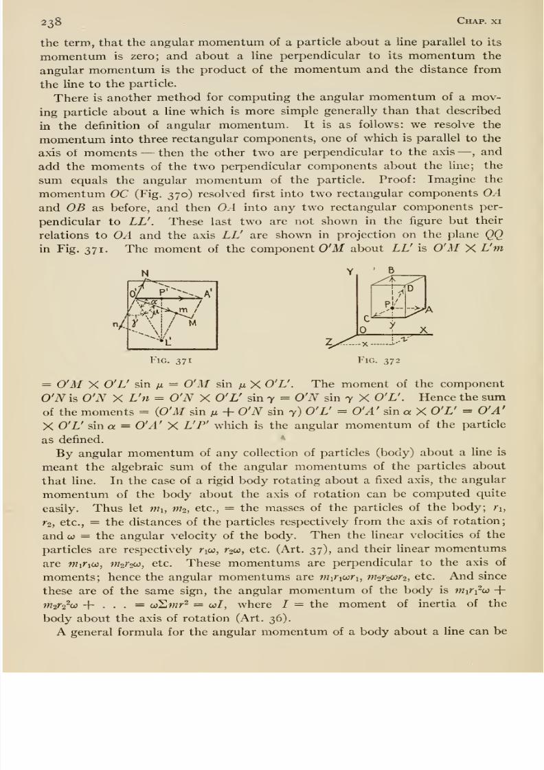
8/13/2019 Maurer Mechanics
http://slidepdf.com/reader/full/maurer-mechanics 254/407
238 Chap, xi
the term, that the angular momentum of a particle about a line parallel to its
momentum is zero; and about a line perpendicular to its momentum the
angular momentum is the product of the momentum and the distance from
the line to the particle.
There is another method for computing the angular momentum of a mov-
ing particle about a line which is more simple generally than that described
in the definition of angular momentum. It is as follows: we resolve the
momentum into three rectangular components, one of which is parallel to the
axis ot moments —then the other two are perpendicular to the axis —, and
add the moments of the two perpendicular components about the line; the
sum equals the angular momentum of the particle. Proof: Imagine the
momentum OC (Fig. 370) resolved first into two rectangular components OAand OB as before, and then OA into any two rectangular components per-
pendicular to LV. These last two are not shown in the figure but their
relations to OA and the axis LL' are shown in projection on the plane QQin Fig. 371. The moment of the component O'M about LL' is O'AI X L'm
' B
U^
X
Fig. 371 Fig. 372
= O'M X O'L' sin fi = O'M sin fx X O'L'. The moment of the component
O'N is O'N X L'n = O'N X O'L' sin 7 = O'N sin 7 X O'L'. Hence the sum
of the moments = (O'M sin fi + O'N sin 7) O'L' = O'A' sin a X O'L' = O'A'
X O'L' sin a = O'A' X L'P' which is the angular momentum of the particle
as defined. *
By angular momentum of any collection of particles (body) about a line is
meant the algebraic sum of the angular momentums of the particles about
that line. In the case of a rigid body rotating about a fixed axis, the angular
momentum of the body about the axis of rotation can be computed quite
easily. Thus let Wi, fth, etc., = the masses of the particles of the body; r\,
1-2, etc., = the distances of the particles respectively from the axis of rotation;
and CO = the angular velocity of the body. Then the linear velocities of the
particles are respectively rico, r2co, etc. (Art. 37), and their linear momentums
are Wiriw, m^roco, etc. These momentums are perpendicular to the axis of
moments; hence the angular momentums are ntiViuri, nhrooir-i, etc. And since
these are of the same sign, the angular momentum of the body is Wi^i^co +miV^cji + . . . = coSwr- = co/, where / = the moment of inertia of the
body about the axis of rotation (Art. 36).
A general formula for the angular momentum of a body about a line can be
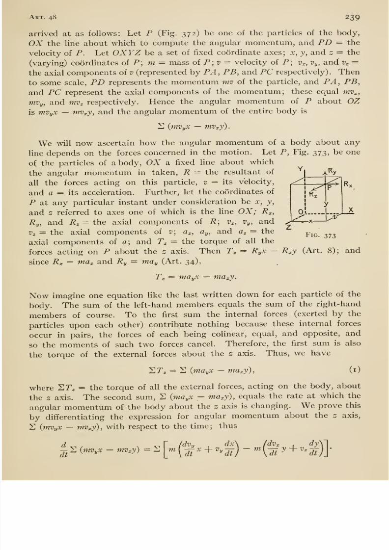
8/13/2019 Maurer Mechanics
http://slidepdf.com/reader/full/maurer-mechanics 255/407
Art. 48 239
arrived at as follows: Let P (Fig. 372) be one of the particles of the body,
OX the line about which to compute the angular momentum, and PD = the
velocity of P. Let OXYZ be a set of fixed coordinate axes; x, j, and z = the
(varying) coordinates of P; m = mass of P; d = velocity of P; v^c, Vy, and v^ =
the axial components of v (represented by PA , PB, and PC respectively). Then
to some scale, PD represents the momentum mv of the particle, and PA, PB,
and PC represent the axial components of the momentum; these equal mv^,
mvy, and mv^ respectively. Hence the angular momentum of P about OZ'J/)
Y.A'^y
-^-x-
R>
is mVyX —mV:,y, and the angular momentum of the entire body is
2 {mVyX —mVxy).
We will now ascertain how the angular momentum of a body about any
line depends on the forces concerned in the motion. Let P,Fig.
373,be one
of the particles of a body, OX a fixed line about which
the angular momentum in taken, R = the resultant of
all the forces acting on this particle, v = its velocity,
and a = its acceleration. Further, let the coordinates of
P at any particular instant under consideration be .v, y,
and s referred to axes one of which is the line OX; R^,
Ry, and R^ = the axial components of R; v^, Vy, and
Vz = the axial components of v; a^, Oy, and Oz = theaxial components of a; and Tz = the torque of all the
forces acting on P about the z axis. Then T^ = RyX - R^y (Art. 8); and
since Rx = ma^ and Ry = may (Art. 34),
Tg = niGyX —maxy.
Now imagine one equation like the last written down for each particle of the
body. The sum of the left-hand members equals the sum of the right-hand
members of course. To the first sum the internal forces (exerted by the
particles upon each other) contribute nothing because these internal forces
occur in pairs, the forces of each being colinear, ecj^ual, and opposite, and
so the moments of such two forces cancel. Therefore, the first sum is also
the torque of the external forces about the 2 axis. Thus, we have
Fig. 373
SPj = 2 {mayX —maxy), (i)
where SP^ = the torque of all the external forces, acting on the body, aboutthe 2 axis. The second sum, 2 {mayX — maxy), equals the rate at which the
angular momentum of the body about the z axis is changing. We prove this
by differentiating the expression for angular momentum about the 2 axis,
S {mVyX — mVxy), with respect to the time; thus
-J- 2 {mVyX —mVxy) = 2at
m(dvy
,dx\ (dvx
, dyW
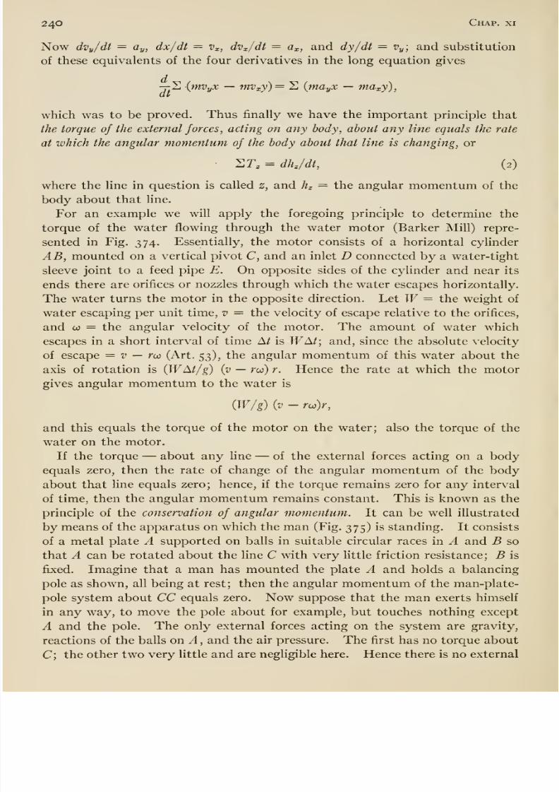
8/13/2019 Maurer Mechanics
http://slidepdf.com/reader/full/maurer-mechanics 256/407
240 Chap, xi
Now dvy/dt = ay, dx/dt = Vx, dvx/dt = d, and dy/dt = Vy-, and substitution
of these equivalents of the four derivatives in the long equation gives
-7- 2 {mVyX —mvxy)= 2 {mayX —maxj),at
which was to be proved. Thus finally we have the important principle that
the torque oj the external forces, acting on any body, about any line equals the rate
at which the angular momentum of the body about that line is changing, or
• 2r, = dh/dt, (2)
where the line in question is called z, and hz = the angular momentum of the
body about that line.
For an example we will apply the foregoing principle to determine the
torque of the water flowing through the water motor (Barker Mill) repre-
sented in Fig. 374. Essentially, the motor consists of a horizontal cylinder
AB, mounted on a vertical pivot C, and an inlet D connected by a water-tight
sleeve joint to a feed pipe E. On opposite sides of the cylinder and near its
ends there are orifices or nozzles through which the water escapes horizontally.
The water turns the motor in the opposite direction. Let W= the weight of
water escaping per unit time, v = the velocity of escape relative to the orifices,
and CO = the angular velocity of the motor. The amount of water which
escapes in a short interval of time A/ is WM; and, since the absolute velocity
of escape = t> — rco (Art. 53), the angular momentum of this water about the
axis of rotation is {WM/g) (v —rw) r. Hence the rate at which the motor
gives angular momentum to the water is
(W/g) {v - rco)r,
and this equals the torque of the motor on the water; also the torque of the
water on the motor. '
If the torque —about any line —of the external forces acting on a body
equals zero, then the rate of change of the angular momentum of the body
about that line equals zero; hence, if the torque remains zero for any interval
of time, then the angular momentum remains constant. This is known as the
principle of the conservation of angular momentum. It can be well illustrated
by means of the apparatus on which the man (Fig. 375) is standing. It consists
of a metal plate A supported on balls in suitable circular races in A and B so
that A can be rotated about the line C with very little friction resistance; B is
fixed. Imagine that a man has mounted the plate A and holds a balancing
pole as shown, all being at rest; then the angular momentum of the man-plate-
pole system about CC equals zero. Now suppose that the man exerts himself
in any way, to move the pole about for example, but touches nothing except
A and the pole. The only external forces acting on the system are gravity,
reactions of the balls on A , and the air pressure. The first has no torque about
C; the other two very little and are negligible here. Hence there is no external
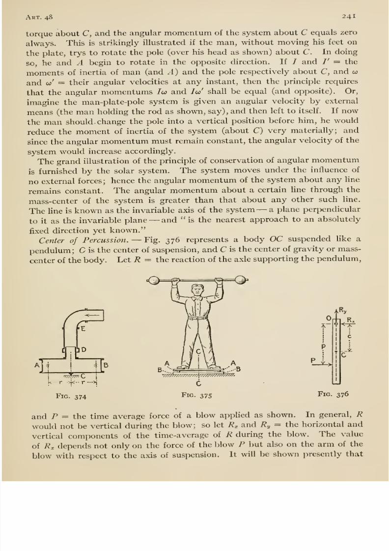
8/13/2019 Maurer Mechanics
http://slidepdf.com/reader/full/maurer-mechanics 257/407
Art. 48 241
torque about C, and the angular momentum of the system about C equals zero
always. This is strikingly illustrated if the man, without moving his feet on
the plate, trys to rotate the pole (over his head as shown) about C. In doing
so, he and A begin to rotate in the opposite direction. If / and /' = the
moments of inertia of man (and .1) and the pole respectively about C, and co
and w' = their angular velocities at any instant, then the principle requires
that the angular momentums /w and Ico' shall be equal (and opposite). Or,
imagine the man-plate-pole system is given an angular velocity by external
means (the man holding the rod as shown, say), and then left to itself. If now
the man should change the pole into a vertical position before him, he would
reduce the moment of inertia of the system (about C) very materially; and
since the angular momentum must remain constant, the angular velocity of the
system would increase accordingly.
The grand illustration of the principle of conservation of angular momentum
is furnished by the solar system. The system moves under the influence of
no external forces; hence the angular momentum of the system about any line
remains constant. The angular momentum about a certain line through the
mass-center of the system is greater than that about any other such line.
The Une is known as the invariable axis of the system —a plane perpendicular
to it as the invariable plane —and ''is the nearest approach to an absolutely
fixed direction yet known.Center of Percussion. —Fig. 376 represents a body OC suspended like a
pendulum; C is the center of suspension, and C is the center of gravity or mass-
center of the body. Let R = the reaction of the axle supporting the pendulum.
J-4
= E
lD
I
k - r >i<- r —
Fig. 374
B
rO
Ry
C
Fig. 376
and P = the time average force of a blow applied as shown. In general, Rwould not be vertical during the blow; so let R^ and Ry = the horizontal and
vertical components of the time-average of R during the blow. The value
of R^ depends not only on the force of the blow P but also on the arm of the
blow with respect to the axis of suspension. It will be shown presently that
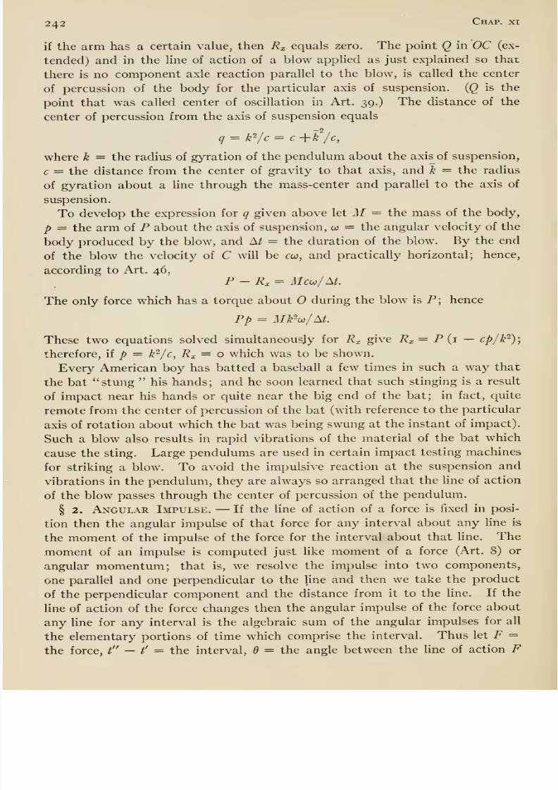
8/13/2019 Maurer Mechanics
http://slidepdf.com/reader/full/maurer-mechanics 258/407
242 Chap, xi
if the arm has a certain value, then Rx equals zero. The point Q in OC (ex-
tended) and in the line of action of a blow applied as just explained so that
there is no component axle reaction parallel to the blow, is called the center
of percussion of the body for the particular axis of suspension. {Q is the
point that was called center of oscillation in Art. 39.) The distance of the
center of percussion from the axis of suspension equals
q = k'^/c = c -\-k /c,
where k = the radius of gyration of the pendulum about the axis of suspension,
c = the distance from the center of gravity to that axis, and k = the radius
of gyration about a Une through the mass-center and parallel to the axis of
suspension.
To develop the expression for q given above let M = the mass of the body,
p = the arm of P about the axis of suspension, co = the angular velocity of the
body produced by the blow, and At = the duration of the blow. By the end
of the blow the velocity of C will be ceo, and practically horizontal; hence,
according to Art. 46,
P - Rx = Mco:/At.
The only force which has a torque about during the blow is P; hence
Pp = M¥ui/M.
These two equations solved simultaneously for R^ give R^ = P (1 — cp/P);
therefore, if ^ = k^/c, Rx = o which was to be shown.
Every American boy has batted a baseball a few times in such a way that
the bat stung his hands; and he soon learned that such stinging is a result
of impact near his hands or quite near the big end of the bat; in fact, quite
remote from the center of percussion of the bat (with reference to the particular
axis of rotation about which the bat was being swung at the instant of impact).
Such a blow also results in rapid vibrations of the material of the bat which
cause the sting. Large pendulums are used in certain impact testing machines
for striking a blow. To avoid the impulsive reaction at the suspension and
vibrations in the pendulum, they are always so arranged that the line of action
of the blow passes through the center of percussion of the pendulum.
§ 2. Angular Impulse. —If the line of action of a force is fixed in posi-
tion then the angular impulse of that force for any interval about any line is
the moment of the impulse of the force for the interval about that Hne. The
moment of an impulse is computed just like moment of a force (Art. 8) or
angular momentum; that is, we resolve the impulse into two components,
one parallel and one perpendicular to the line and then we take the product
of the perpendicular component and the distance from it to the line. If the
line of action of the force changes then the angular impulse of the force about
any line for any interval is the algebraic sum of the angular impulses for all
the elementary portions of time which comprise the interval. Thus let F =
the force, i — /' = the interval, 6 = the angle between the line of action F
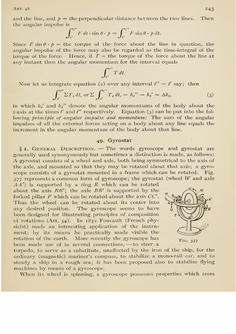
8/13/2019 Maurer Mechanics
http://slidepdf.com/reader/full/maurer-mechanics 259/407
Art. 48 243
and the line, and p = the perpendicular distance between the two lines. Thenthe angular impulse is
Xtnt
F dt-?,md- p= \ F sin d - p dt.
Since F sinO • p — the torque of the force about the line in question, the
angular impulse of the force may also be regarded as the time-integral of the
torque of the force. Hence, if T — the torque of the force about the line at
any instant then the angular momentum for the interval equals
Tdt.£'
Now let us integrate equation (2) over any interval / — /' say; then
r ^T,dt, or 2 r T,dt, = ///' - hj = A/?„ (3)
in which JiJ and lij' denote the angular momentums of the body about the
z axis at the times t' and t respectively. Equation (3) can be put into the fol-
lowing principle of angular impulse and momentum: The sum of the angular
impulses of all the external forces acting on a body about any line equals the
increment in the angular momentum of the body about that line.
49. Gyrostat
§ I. General Description. —The words gyroscope and gyrostat are
generally used synonymously but sometimes a distinction is made, as follows:
A gyrostat consists of a wheel and axle, both being symmetrical to the axis of
the axle, and mounted so that they may be rotated about that axis; a gyro-
scope consists of a gyrostat mounted in a frame which can be rotated. Fig.
377 represents a common form of gyroscope; the gyrostat (wheel Wand axle
A A') is supported by a ring R which can be rotated
about the axis BB'; the axle BB' is supported by the /^^^-^forked pillar F which can be rotated about the axis CC. l\^5^/\^^. .
Thus the wheel can be rotated about its center into t^^^^&A^^any desired position. The gyroscope seems to have ^ IWV>^-/^) ^b'
been designed for illustrating principles of composition ^^^y^JJJof rotations (Art. 54). In 1852 Foucault (French phy- x.^-^^
sicist) made an interesting application of the instru- —i- ^-s^i=P
ment; by its means he practically made visible the k:;--_1_--^
rotation of the earth. More recently the gyroscope hasp^^
been made use of in several connections, —to steer a
torpedo, to serve as a substitute, unaffected by the iron of the ship, for the
ordinary (magnetic) mariner's compass, to stabilize a mono-rail car, and to
steady a ship in a rough sea; it has been proposed also to stabiHze flying
machines by means of a gyroscope.
When its wheel is spinning, a gyroscope possesses properties which seem
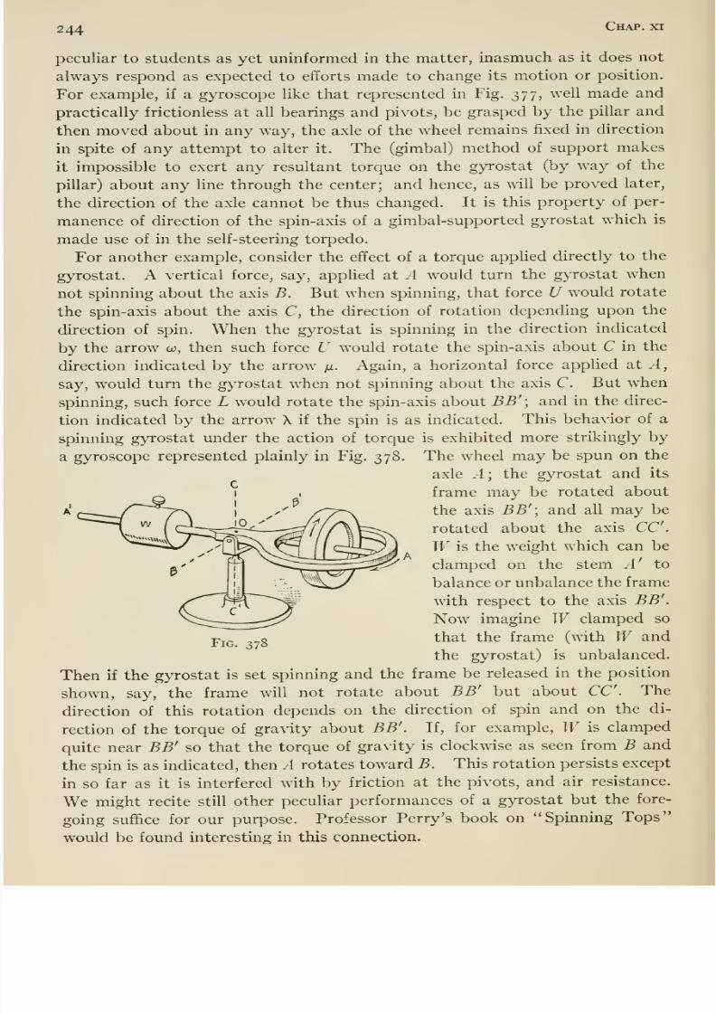
8/13/2019 Maurer Mechanics
http://slidepdf.com/reader/full/maurer-mechanics 260/407
244 Chap, xi
peculiar to students as yet uninformed in the matter, inasmuch as it does not
always respond as expected to efforts made to change its motion or position.
For example, if a gyroscope like that represented in Fig. 377, well made and
practically frictionless at all bearings and pivots, be grasped by the pillar and
then moved about in any way, the axle of the wheel remains fixed in direction
in spite of any attempt to alter it. The (gimbal) method of support makes
it impossible to exert any resultant torque on the gyrostat (by way of the
pillar) about any line through the center; and hence, as will be proved later,
the direction of the axle cannot be thus changed. It is this property of per-
manence of direction of the spin-axis of a gimbal-supported gyrostat which is
made use of in the self-steering torpedo.
For another example, consider the effect of a torque applied directly to the
gyrostat. A vertical force, say, applied at A would turn the gyrostat when
not spinning about the axis B. But when spinning, that force U would rotate
the spin-axis about the axis C, the direction of rotation depending upon the
direction of spin. When the gyrostat is spinning in the direction indicated
by the arrow co, then such force U would rotate the spin-axis about C in the
direction indicated by the arrow fx. Again, a horizontal force applied at A,
say, would turn the gyrostat when not spinning about the axis C. But w^hen
spinning, such force L would rotate the spin-axis about BB'; and in the direc-
tion indicated by the arrow X if the spin is as indicated. This behavior of a
spinning gyrostat under the action of torque is exhibited more strikingly by
a gyroscope represented plainly in Fig. 378. The wheel may be spun on the
axle A; the gyrostat and its
frame may be rotated about
the axis BB'; and all may be
rotated about the axis CC.Wis the weight which can be
clamped on the stem A' to
balance or unbalance the frame
with respect to the axis BB'.
Now imagine W clamped so
that the frame (with W and
the gyrostat) is unbalanced.
Then if the gyrostat is set spinning and the frame be released in the position
shown, say, the frame will not rotate about BB' but about CC. The
direction of this rotation depends on thedirection of spin
andon the di-
rection of the torque of gravity about BB'. If, for example, W is clamped
quite near BB' so that the torque of gravity is clockwise as seen from B and
the spin is as indicated, then A rotates toward B. This rotation persists except
in so far as it is interfered with by friction at the pivots, and air resistance.
We might recite still other peculiar performances of a gyrostat but the fore-
going suffice for our purpose. Professor Perry's book on Spinning Tops
would be found interesting in this connection.
Fig. 378
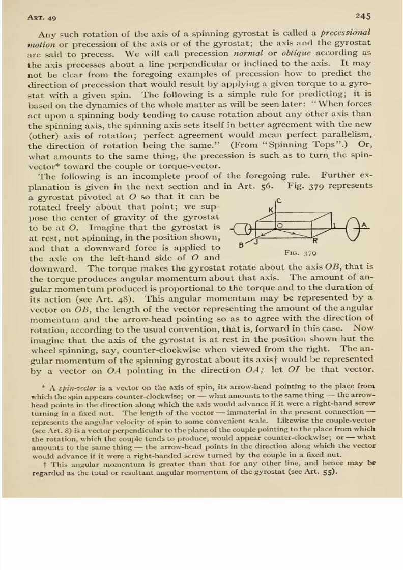
8/13/2019 Maurer Mechanics
http://slidepdf.com/reader/full/maurer-mechanics 261/407
Art. 49 245
Any such rotation of the axis of a spinning gyrostat is called a precessional
motion or precession of the axis or of the gyrostat; the axis and the gyrostat
are said to precess. We will call precession normal or obiique according as
the axis precesses about a line perpendicular or inclined to the axis. It may
not be clear from the foregoing examples of precession how to predict the
direction of precession that would result by applying a given torque to a gyro-
stat with a given spin. The following is a simple rule for predicting; it is
based on the dynamics of the whole matter as will be seen later: When forces
act upon a spinning body tending to cause rotation about any other axis than
the spinning axis, the spinning axis sets itself in better agreement with the new
(other) axis of rotation; perfect agreement would mean perfect parallelism,
the direction of rotation being the same. (From Spinning Tops .) Or,
what amounts to the same thing, the precession is such as to turn the spin-
vector* toward the couple or torque-vector.
The following is an incomplete proof of the foregoing rule. Further ex-
planation is given in the next section and in Art. 56. Fig. 379 represents
a gyrostat pivoted at O so that it can be
rotated freely about that point; we sup-
pose the center of gravity of the gyrostat
to be at O. Imagine that the gyrostat is -TIX
atrest,
notspinning, in the position shown,
y^i^~^^^
and that a downward force is applied to ^
the axle on the left-hand side of and
downward. The torque makes the gyrostat rotate about the axis OB, that is
the torque produces angular momentum about that axis. The amount of an-
gular momentum produced is proportional to the torque and to the duration of
its action (see Art. 48). This angular momentum may be represented by a
vector on OB, the length of the vector representing the amount of the angular
momentum and the arrow-head pointing so as toagree with the direction of
rotation, according to the usual convention, that is, forward in this case. Nowimagine that the axis of the gyrostat is at rest in the position shown but the
wheel spinning, say, counter-clockwise when viewed from the right. The an-
gular momentum of the spinning gyrostat about its axisf would be represented
by a vector on OA pointing in the direction OA; let 01 be that vector.
* A spin-vector is a vector on the axis of spin, its arrow-head pointing to the place from
which the spin appears counter-clockwise; or —what amounts to the same thing —the arrow-
head points in the direction along which the axis would advance if it were a right-hand screw
turning in a fixed nut. The length of the vector —immaterial in the present connection —represents the angular velocity of spin to some convenient scale. Likewise the couple-vector
(see Art. 8) is a vector perpendicular to the plane of the couple pointing to the place from which
the rotation, which the couple tends to produce, would appear counter-clockwise; or —what
amounts to the same thing —the arrow-head points in the direction along which the vector
would advance if it were a right-handed screw turned by the couple in a fixed nut.
t This angular momentum is greater than that for any other line, and hence may bf
regarded as the total or resultant angular momentum of the gyrostat (see Art. 55).
8/13/2019 Maurer Mechanics
http://slidepdf.com/reader/full/maurer-mechanics 262/407
246 Chap, xi
Now suppose that the torque already described comes into action, and let OJrepresent the angular momentum which it would produce in a short interval
of time. This angular momentum added to the original angular momentum
gives OR as the resultant angular momentum of the gyrostat at the end of the
interval. It seems, therefore, that the spin-axis would coincide with OR at
the end of the interval; indeed, that axis does approach OR, that is the spin-
axis turns toward the torque-axis as stated in the rule which v/e undertook
to prove.
The approach just mentioned is not a direct one; the gyrostat yields slightly
to the torque just as though there were no spin; that is the wheel rises (in this
instance) slightly. This is only the first (small) swing of a rapid oscillation
of the spin-axis —nutation as it is called —which accompanies the (more
prominent) precession of thespin-axis
towardthe torque-axis. The (unavoid-
able) friction at the pivot O rapidly damps this oscillation so that the oscilla-
tion generally escapes notice. The mentioned rise of the spin-axis may be
explained as follows: In the approach of that axis toward OR the gyrostat
rotates about OC, due to which it acquires angular momentum about OC,
clockwise when viewed from above; but since there is no torque about OC,
the gyrostat can acquire no (resultant) angular momentum about that line
(see Art. 48 on conservation) ; hence the spin-axis rises so that at each instant
the component along OC of the angular momentum due to spin just equalsthe
angular momentum due to the rotation about OC.
There is another item of gyrostat behavior worth noting here. Suppose
that the gyrostat shown in Fig. 378 to be precessing as already explained.
If the precession be hurried, say by means of a horizontal push applied at .4',
the center of gravity of the frame (with gyrostat and weight) rises; if the
precession be retarded, the center of gravity descends. This behavior is in
accordance with the rule for predicting precession. In the first case we have
a torque about CC; the torque vector is in the direction OC; the spin- vectoris in the direction OA'; and in accordance with the rule OA' turns toward OCthat is the center of gravity rises. In the second case we have a torque about
CC but the torque- vector is OC; and the spin- vector OA' turns toward that
vector, that is the center of gravity descends. Thus we may state as another
rule: Hurry a precession, the gyrostat rises or opposes the torque which causes
the precession; retard a precession, the gyrostat falls, or yields to the torque
which causes the precession.
Self -steering Torpedo. —The gyroscope of such a torpedo is linked to appro-priate valves of a compressed air engine in such a way that any turning of
the spin- axis toward either side of the torpedo causes the engine to turn the
(vertical) rudder of the torpedo in the opposite direction. Prior to projection
of a torpedo, the gimbals are locked so as to hold the spin-axis of the gyrostat
parallel (or inchned at any desired angle) to the axis of the torpedo. During
the discharge of the torpedo, the gyrostat is automatically set spinning and
the gimbals are unlocked. During the flight, the spin-axis continues to point
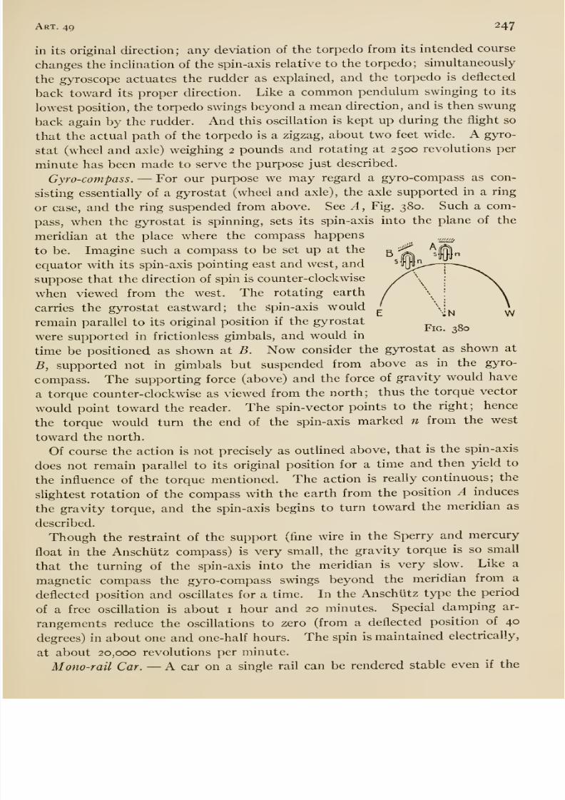
8/13/2019 Maurer Mechanics
http://slidepdf.com/reader/full/maurer-mechanics 263/407
Art. 49 247
in its original direction ; any deviation of the torpedo from its intended course
changes the incHnation of the spin-axis relative to the torpedo; simultaneously
the gyroscope actuates the rudder as explained, and the torpedo is deflected
back toward its proper direction. Like a common pendulum swinging to its
lowest position, the torpedo swings beyond a mean direction, and is then swung
back again by the rudder. And this oscillation is kept up during the flight so
that the actual path of the torpedo is a zigzag, about two feet wide. A gyro-
stat (wheel and axle) weighing 2 pounds and rotating at 2500 revolutions per
minute has been made to serve the purpose just described.
Gyro-compass. —For our purpose we may regard a gyro-compass as con-
sisting essentially of a gyrostat (wheel and axle), the axle supported in a ring
or case, and the ring suspended from above. See A, Fig. 380. Such a com-
pass, when the gyrostatis
spinning,sets its spin-axis into the plane of the
meridian at the place where the compass happens
to be. Imagine such a compass to be set up at the
equator with its spin-axis pointing east and west, and
suppose that the direction of spin is counter-clockwise
when viewed from the west. The rotating earth
carries the gyrostat eastward; the spin-axis would
remain parallel to its original position if the gyrostat
were supported in frictionless gimbals, and would in
time be positioned as shown at B. Now consider the gyrostat as shown at
B, supported not in gimbals but suspended from above as in the gyro-
compass. The supporting force (above) and the force of gravity would have
a torque counter-clockwise as viewed from the north; thus the torque vector
would point toward the reader. The spin- vector points to the right; hence
the torque would turn the end of the spin-axis marked n from the west
toward the north.
Of course the action is not precisely as outUned above, that is the spin-axis
does not remain parallel to its original position for a time and then yield to
the influence of the torque mentioned. The action is really continuous; the
slightest rotation of the compass with the earth from the position A induces
the gravity torque, and the spin-axis begins to turn toward the meridian as
described.
Though the restraint of the support (fine wire in the Sperry and mercury
float in the Anschutz compass) is very small, the gravity torque is so small
that the turning of the spin-axis into the meridian is very slow. Like a
magnetic compass the gyro-compass swings beyond the meridian from a
deflected position and oscillates for a time. In the Anschutz type the period
of a free oscillation is about i hour and 20 minutes. Special damping ar-
rangements reduce the oscillations to zero (from a deflected position of 40
degrees) in about one and one-half hours. The spin is maintained electrically,
at about 20,000 revolutions per minute.
Mono-rail Car. —A car on a single rail can be rendered stable even if the
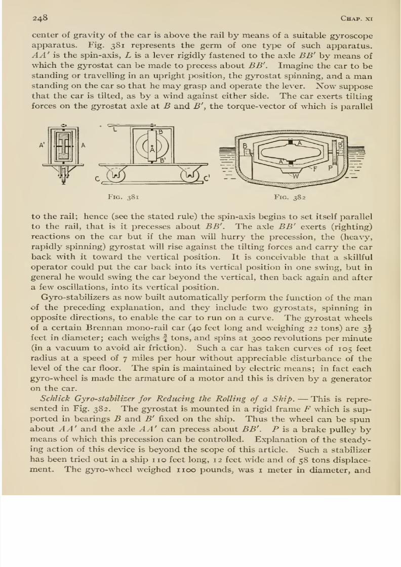
8/13/2019 Maurer Mechanics
http://slidepdf.com/reader/full/maurer-mechanics 264/407
248 Chap, xi
center of gravity of the car is above the rail by means of a suitable gyroscope
apparatus. Fig. 381 represents the germ of one type of such apparatus.
AA' is the spin-axis, Z, is a lever rigidly fastened to the axle BB' by means of
which the gyrostat can be made to precess about BB'. Imagine the car to be
standing or travelling in an upright position, the gyrostat spinning, and amanstanding on the car so that he may grasp and operate the lever. Now suppose
that the car is tilted, as by a wind against either side. The car exerts tilting
forces on the gyrostat axle at B and B', the torque-vector of which is parallel
A'
• =c=
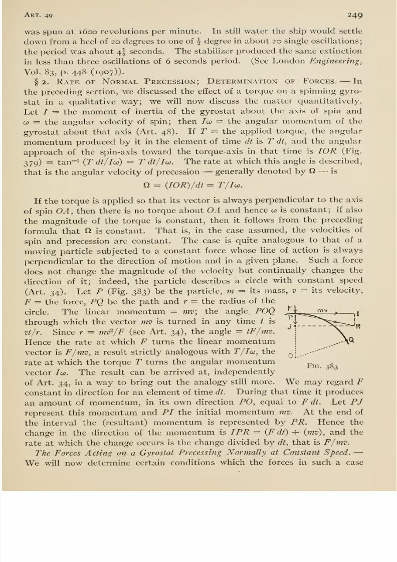
8/13/2019 Maurer Mechanics
http://slidepdf.com/reader/full/maurer-mechanics 265/407
Art. 49 249
was spun at 1600 revolutions per minute. In still water the ship would settle
down from a heel of 20 degrees to one of | degree in about 20 single oscillations;
the period was about 4I seconds. The stabilizer produced the same extinction
in less than three oscillations of 6 seconds period. (See London Engineering,
Vol. 83, p. 448 (1907)).
§2. Rate or Normal Precession; Determination of Forces. —In
the preceding section, we discussed the effect of a torque on a spinning gyro-
stat in a qualitative way; we will now discuss the matter quantitatively.
Let / = the moment of inertia of the gyrostat about the axis of spin and
CO = the angular velocity of spin; then /co — the angular momentum of the
gyrostat about that axis (Art. 48). If T = the applied torque, the angular
momentum produced by it in the element of time dt is T dt, and the angular
approach of the spin-axis toward the torque-axis in that time is lOR (Fig.
379) = tan-i (r dt/Iw) = T dt/Iw. The rate at which this angle is described,
that is the angular velocity of precession —generally denoted by O —is
n = {IOR)/dt = r//co.
If the torque is applied so that its vector is always perpendicular to the axis
of spin OA, then there is no torque about OA and hence co is constant; if also
the magnitude of the torque is constant, then it follows from the preceding
formula that O is constant. That is, in the case assumed, the velocities of
spin and precession are constant. The case is quite analogous to that of a
moving particle subjected to a constant force whose line of action is always
perpendicular to the direction of motion and in a given plane. Such a force
does not change the magnitude of the velocity but continually changes the
direction of it; indeed, the particle describes a circle with constant speed
(Art. 34). Let P (Fig. 383) be the particle, m = its mass, v = its velocity,
F = the force, PQ be the path and r = the radius of the
circle. The linear momentum = mv; the angle. POQ - i.-ja^'^ > ^^I
through which the vector mv is turned in any time / is ,|__7_t^v$r:r^Rvt/r. Since r = mv^/F (see Art. 34), the angle = tF/mv.
Hence the rate at which F turns the linear momentumvector is F/mv, a result strictly analogous with T/Ioj, the
rate at which the torque T turns the angular momentum^^^ ^
vector /o). The result can be arrived at, independently
of Art. 34, in a way to bring out the analogy still more. We may regard Fconstant in direction for an element of time dt. During that time it produces
an amount of momentum, in its own direction PO, equal to F dt. Let PJrepresent this momentum and PI the initial momentum mv. At the end of
the interval the (resultant) momentum is represented by PR. Hence the
change in the direction of the momentum is I PR = {F dt) -=- (mv), and the
rate at which the change occurs is the change divided by dt, that is F/mv.
The Forces Acting on a Gyrostat Precessing Normally at Constant Speed. —We will now determine certain conditions which the forces in such a case
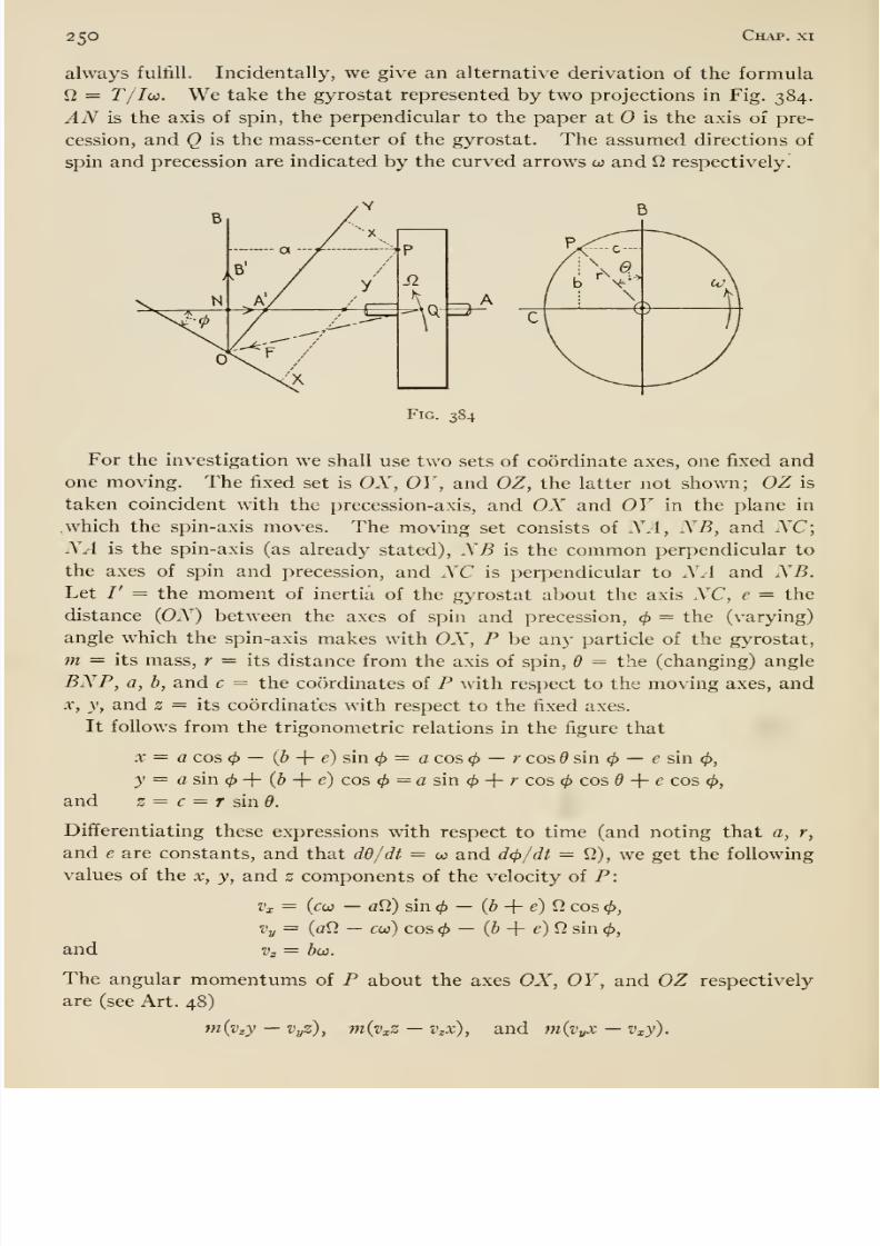
8/13/2019 Maurer Mechanics
http://slidepdf.com/reader/full/maurer-mechanics 266/407
250 Chap, xi
always fulfill. Incidentally, we give an alternative derivation of the formula
12 = T/Iw. We take the gyrostat represented by two projections in Fig. 384.
^A^ is the axis of spin, the perpendicular to the paper at is the axis of pre-
cession, and Q is the mass-center of the gyrostat. The assumed directions of
spin and precession are indicated by the curved arrows oj and 12 respectively.
Fig. 384
For the investigation we shall use two sets of coordinate axes, one fixed andone moving. The fixed set is OX, OY , and OZ, the latter not shown; OZ is
taken coincident with the precession-axis, and OX and OY in the plane in
.which the spin-axis moves. The moving set consists of NA, NB, and NC;NA is the spin-axis (as already stated), NB is the common perpendicular to
the axes of spin and precession, and NC is perpendicular to iV.4 and NB.Let /' = the moment of inertia of the gyrostat about the axis NC, e = the
distance (ON) between the axes of spin and precession, </> = the (varying)
angle which the spin-axis makes with OX, P be any particle of the gyrostat,
m = its mass, r — its distance from the axis of spin, 6 = the (changing) angle
BNP, a, b, and c = the co()rdinates of P with respect to the moving axes, and
X, y, and 2 = its coordinates with respect to the fixed axes.
It follows from the trigonometric relations in the figure that
X = a cos 4) — (b -{ e) sin = a cos 4> — r cos sin </> — e sin 0,
y = c sin + (6 -f e) cos </> = a sin </> 4- '' cos <^ cos 6 -\- e cos <^,
and z = c = f sin ^.
Dififerentiating these expressions with respect to time (and noting that a, r,
and e are constants, and that dd/dt = w and dip/df = 12), we get the following
values of the x, y, and z components of the velocity of P:
Vx = {cw — al2) sin ^ — (6 -f e) 12 cos 0,
Vy = (al2 — ceo) cos — (6 + e) 12 sin 0,
and Vn = b(j3.
The angular momentums of P about the axes OX, OY, and OZ respectively
are (see Art. 48)
in{vzy —VyZ), m(vxZ —Vzx), and m(vyX —Vxy).
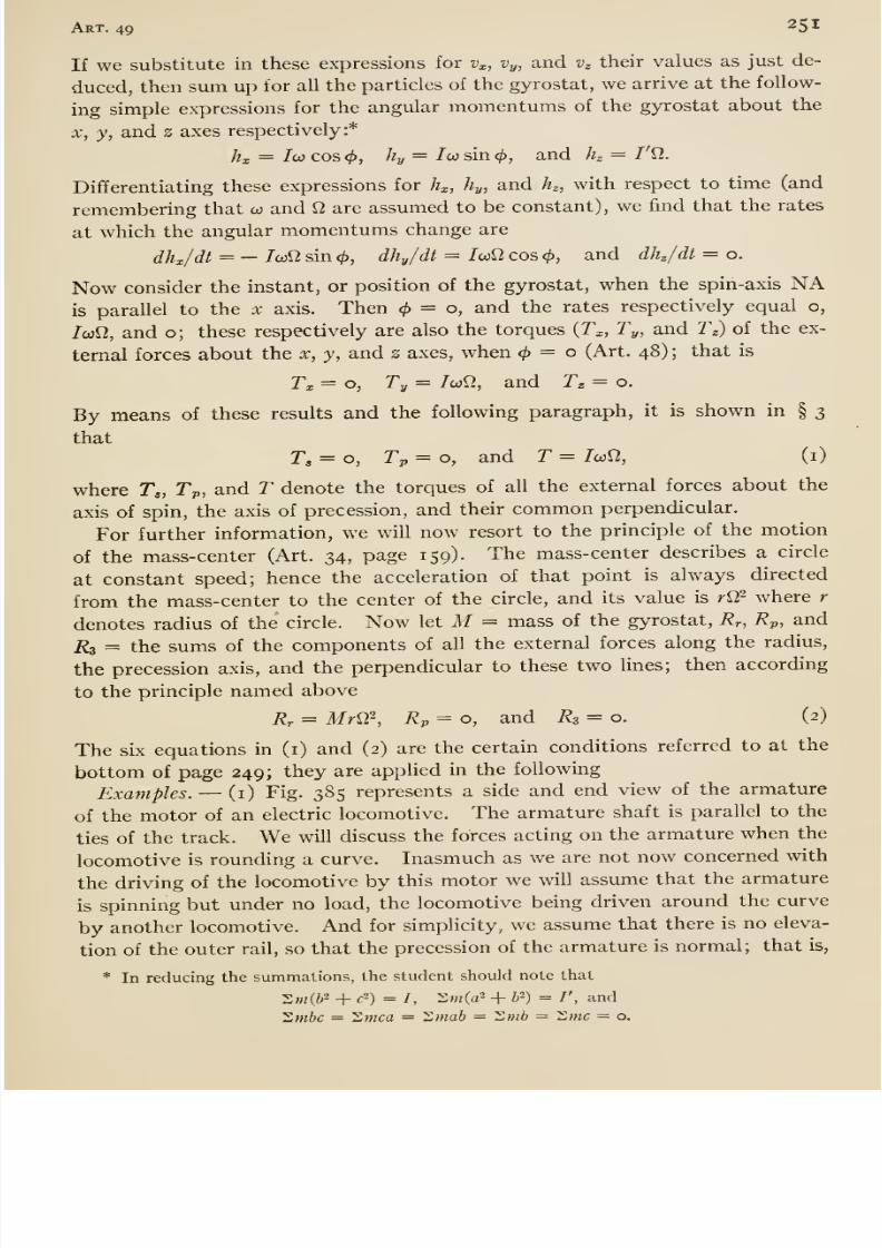
8/13/2019 Maurer Mechanics
http://slidepdf.com/reader/full/maurer-mechanics 267/407
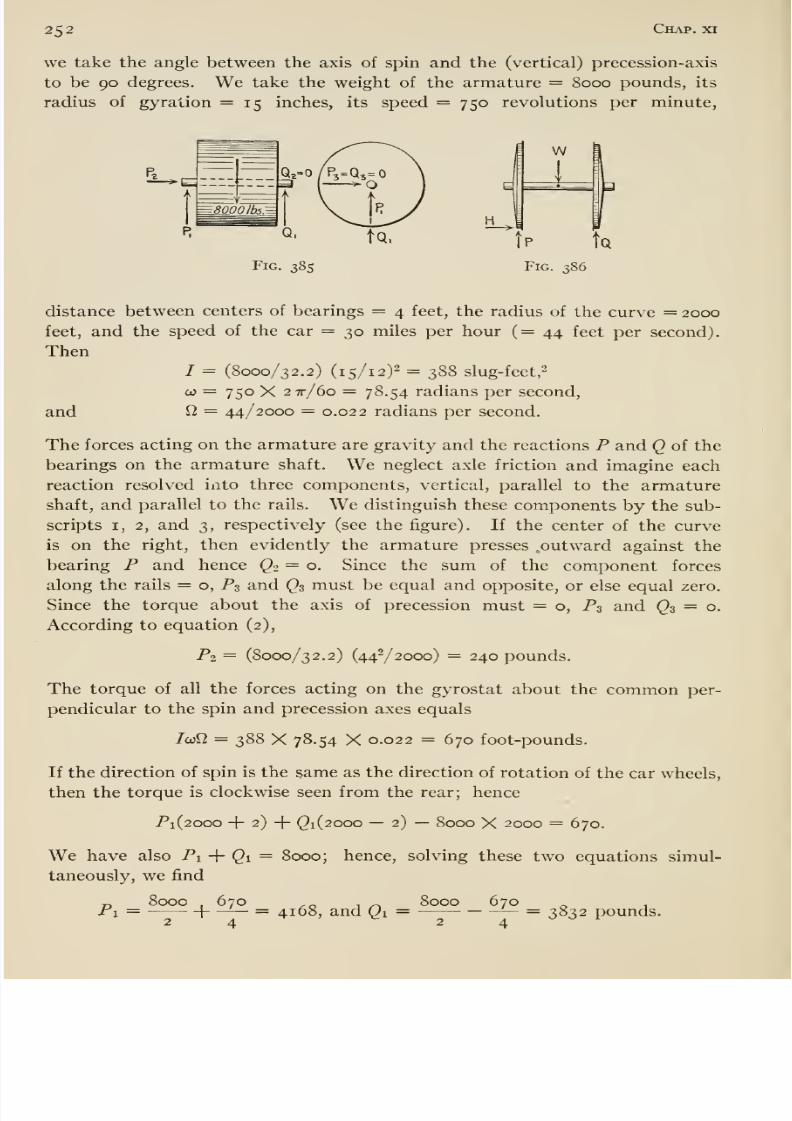
8/13/2019 Maurer Mechanics
http://slidepdf.com/reader/full/maurer-mechanics 268/407
8/13/2019 Maurer Mechanics
http://slidepdf.com/reader/full/maurer-mechanics 269/407
Art. 49 253
If the armature were not spinning (co = o), or the car were running on a straight
track (^ = o) then /c<j12 would equal zero, and hence the reactions Pi and Qi
would equal 4000 pounds. Thus the effect of the spin and precession is to
increase one reaction and decrease the other by 670 -^ 4 = 168 pounds. This
increase and decrease are called the gyrostatic couple or gyrostatic effect.
The force P2 does not depend on the spin of the armature, only on the radius
of the curve and the velocity of the car. It is often described as the centrif-
ugal effect.
(2) Fig. 386 represents a pair of car wheels which we assume to be rounding
a curve. We will determine the forces acting on them. We assume that the
wheels are coned so that there is true rolling; even if there were slipping —because of the excess length of the outer over the inner rail —our results would
be practically correct. We neglect the tilt of the track and so regard the
precession as normal. Let W= the weight of the wheels (including their
axle), M = their mass, k = the radius of gyration of wheels, r = their radius,
T' = velocity of the center of gravity, R = the radius of the curve, and / =
gage of the track. Further let P and Q = the vertical components of the
pressure of the outer and inner rails on the wheels; H = the transverse com-
ponent of the pressure of the outer rail. Besides these there are components
along the rails with which we are not concerned. According to the last of
equations (i),
P{R + y)+Q(R- hf) -WR-Hr = MkWyRv,
and according to the first two of equations (2)
H = MVyR and P -f () = W.
Solving these three simultaneously for P and Q we get
_, W . MVh.MkW-
IRT _ MVh _ MkW^^~
2 Rf Rrf
The first terms in these two expressions are due to gravity. The second
terms are due to centrifugal action; they have the same values as if the wheels
were skidding, that is, they do not depend on the spin of the wheels. The
third terras are due to gyrostatic action; the components of P and Q which
they stand for constitute the so-called gyrostatic couple.
§ 3. Gyrostatic Reaction. —In general, any system of forces can be
compounded into a single force acting through any desired point and a couple
(Art. 9). Let us imagine all the forces acting on a gyrostat which is precess-
ing normally, to be compounded into a force acting through the mass-center
of the gyrostat and a couple. Let these be denoted by F and C respectively;
also let N and n respectively = the number of precessional and spinning
revolutions per unit time, W= the weight of the gyrostat, and k = its
radiusof gyration about the axis of spin.
8/13/2019 Maurer Mechanics
http://slidepdf.com/reader/full/maurer-mechanics 270/407
2^4 Chap, xi
It follows from equations (2), that F is directed from the mass-center Q to
(Fig. 384) and
F = MrS^2 = (p^/g) r/^Trm\ (3)
When = 0, the torques of F and C together, about the x, y, and s axes,
must equal o, /coO, and o respectively. But F has no torques about these
axes; hence C has no torques about the x and 2 axes, and its torque about the
y axis equals /col]. Therefore the plane of the couple C is normal to the per-
pendicular to the spin and precession axes, and
C = l0i^= {W/g) k^ 4 TT^wiV. (4)
The sense of the couple may be described as follows: Imagine a vector laid
ofif on the axis of spin to represent the direction of the spin; then the vector
representing the couple at any instant is parallel to the position which the
spin-vector will occupy at the end of a quarter of the precession period (time
required for one turn about the axis of precession). See Fig. 384; NA is
the spin-vector and NB is the couple-vector.
From the stated facts in regard to F and C, it should be plain that equa-
tions (i) are correct.
The gyrostat exerts reactions on the bodies which exert forces upon it equal
and opposite to those forcesrespectively. Hence those reactions are equiva-
lent to —F and —C, where —F and —C denote a force and a couple respec-
tively equal and opposite to F and C. Now F is independent of the spin (see
equation i) but C depends on it. Hence —Cis called the gyrostatic (part of
the) reaction.
In the examples of the preceding section we determined the forces acting on
certain gyrostats, and it is easy to pick out the gyrostatic reactions. Thus,
in example (i) the armature shaft exerts downward forces of 4168 and 3832
pounds on its left- and right-hand bearings as seen fromthe rear. As already
pointed out each of these pressures is the resultant of two components, thus
4000 +168 and 4000 — 168;
the second components are the gyrostat reaction, that is the couple denoted
by —C. In example (2) the car wheels exert downward pressures equal to
P and Q. The third components of these reactions constitute the gyrostatic
reaction of the wheels.
A side (paddle) wheel steam boat sustains gyrostatic reactions in certain
circumstances. When such a boat is turning, the (pair of) paddle wheels and
shaft exert a gyrostatic couple on the boat which makes the boat heel. When
the boat is, say, travelHng forward and turning to starboard, the couple heels the
boat to port. Likewise a screw-propelled ship sustains a gyrostatic couple
when she is turning; it is due to the precession of the screw and shaft (and
turbine too if so equipped). The couple depresses the bow or stern depending
8/13/2019 Maurer Mechanics
http://slidepdf.com/reader/full/maurer-mechanics 271/407
Art. 49 255
on the direction of turning of the ship and sense of rotation of the screw. It
has been suggested that the gyrostatic reactions to which (comparatively frail)
torpedo-boat destroyers are subject may over-tax their strength. The fact
is, these reactions are quite insignificant compared to other straining actions
which such boats withstand (see J. and J. G. Gray's Treatise on Dynamics,
page 531).
A flying machine is subjected to a gyrostatic reaction of its propeller, shaft
and engine when turning or when describing any curved path. When turning,
the reaction tends to raise or depress the front of the machine, depending on the
circumstances. Propellers being right-hand screws (turning clockwise when
viewed from the rear), the front is raised (unless prevented by the air man)
when he turns to the left. When he makes a dive the couple tends to advance
the side of the machine on the right-hand side of the air man. The flight of
a machine fitted with two screws which rotate in opposite directions is not thus
interfered with by gyrostatic reactions. Each propeller exerts a couple on
the machine but the two couples are always opposite. It has been suggested
that gyrostatic reactions of propellers and motors may have been the cause
of some flying-machine accidents. However, a well-built machine can safely
withstand such reactions even under conditions of legitimate quick diving
and turning. Thus, for a dive or turn at the rate of one revolution in 20
seconds, it has been ascertained* that a loo-horse-power Gnome motor —speed
not stated, but probably about 1 200 revolutions per minute —exerts a gyro-
static couple of 140 foot-pounds; and the (suitable) propeller, a couple of
184 foot-pounds. The forces involved in the couples come upon the flying
machine at the supports of the engine and the propeller shaft, f
* M. O'Gorman in The Aeronautical Journal for April, 1913.
t For a full discussion of the subject of this article, consult Crabtree's Spinning Tops attd
Gyroscopic Motion.
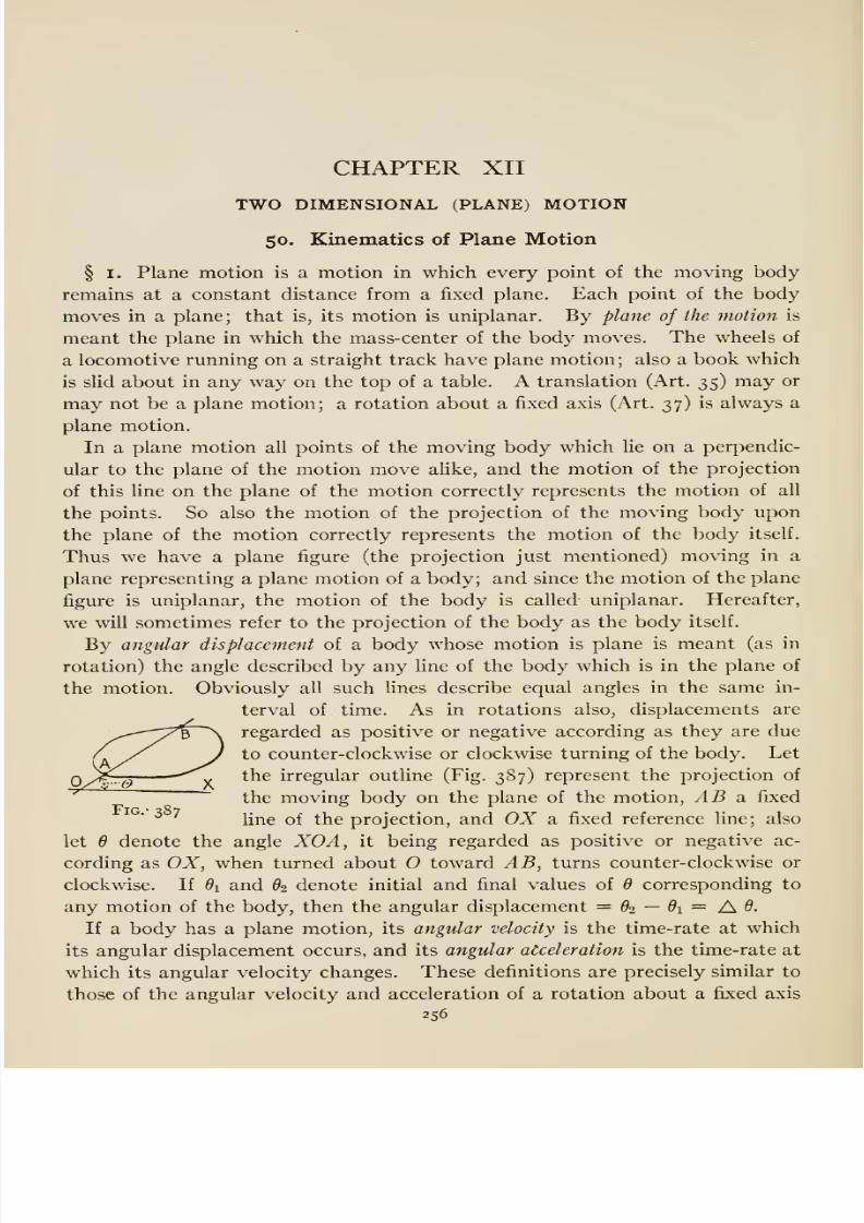
8/13/2019 Maurer Mechanics
http://slidepdf.com/reader/full/maurer-mechanics 272/407
CHAPTER XIITWO DIMENSIONAL (PLANE) MOTION
50. Kinematics of Plane Motion
§ I. Plane motion is a motion in which every point of the moving body
remains at a constant distance from a fixed plane. Each point of the body
moves in a plane; that is, its motion is uniplanar. By plane of the motion is
meant the planein
whichthe
mass-centerof the
bodymoves.
Thewheels of
a locomotive running on a straight track have plane motion ; also a book which
is slid about in any way on the top of a table. A translation (Art. 35) may or
may not be a plane motion; a rotation about a fixed axis (Art. 37) is always a
plane motion.
In a plane motion all points of the moving body which lie on a perpendic-
ular to the plane of the motion move alike, and the motion of the projection
of this line on the plane of the motion correctly represents the motion of all
the points. So also the motion of the projection of the moving body uponthe plane of the motion correctly represents the motion of the body itself.
Thus we have a plane figure (the projection just mentioned) moving in a
plane representing a plane motion of a body; and since the motion of the plane
figure is uniplanar, the motion of the body is called uniplanar. Hereafter,
we will sometimes refer to the projection of the body as the body itself.
By angular displacement of a body whose motion is plane is meant (as in
rotation) the angle described by any line of the body which is in the plane of
the motion. Obviously all such fines describe equal angles in the same in-
terval of time. As in rotations also, displacements are
regarded as positive or negative according as they are due
to counter-clockwise or clockwise turning of the body. Let
the irregular outline (Fig. 387) represent the projection of
the moving body on the plane of the motion, AB n. fixed
^ ^fine of the projection, and OX a fixed reference fine; also
let 6 denote the angle XOA, it being regarded as positive or negative ac-
cording as OX, when turned about toward AB, turns counter-clockwise or
clockwise. If di and 62 denote initial and final values of 6 corresponding to
any motion of the body, then the angular displacement = 62 —Oi = AG.If a body has a plane motion, its angular velocity is the time-rate at which
its angular displacement occurs, and its angular acceleration is the time-rate at
which its angular velocity changes. These definitions are precisely similar to
those of the angular velocity and acceleration of a rotation about a fixed axis
256
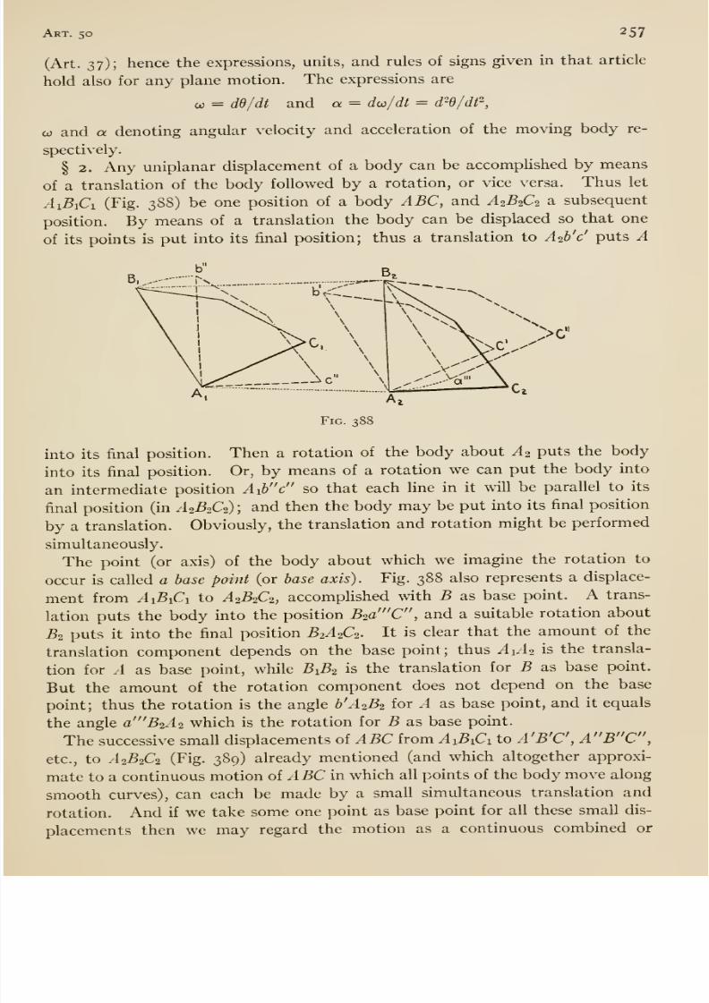
8/13/2019 Maurer Mechanics
http://slidepdf.com/reader/full/maurer-mechanics 273/407
Art. 50 257
(Art. 37); hence the expressions, units, and rules of signs given in that article
hold also for any plane motion. The expressions are
0) = dd/dt and a = do)/dt = d~d/df,
CO and a denoting angular velocity and acceleration of the moving body re-
spectively.
§ 2. Any uniplanar displacement of a body can be accomplished by means
of a translation of the body followed by a rotation, or vice versa. Thus let
AiBiCi (Fig. 3S8) be one position of a body ABC, and A2B2C2 a subsequent
position. By means of a translation the body can be displaced so that one
of its points is put into its final position; thus a translation to A2b'c' puts A
B, ...-
Fig. 388
into its final position. Then a rotation of the body about A2 puts the body
into its final position. Or, by means of a rotation we can put the body into
an intermediate position Aib c so that each Hne in it will be parallel to its
final position (in A2B2C2); and then the body may be put into its final position
by a translation. Obviously, the translation and rotation might be performed
simultaneously.
The point (or axis) of the body aboutwhich we imagine the rotation to
occur is called a base point (or base axis). Fig. 388 also represents a displace-
ment from AiBiCi to A2B2C2, accompHshed with B as base point. A trans-
lation puts the body into the position B2a 'C , and a suitable rotation about
B2 puts it into the final position B2A2C2. It is clear that the amount of the
translation component depends on the base point; thus A1A2 is the transla-
tion for A as base point, while B1B2 is the translation for B as base point.
But the amount of the rotation component does not depend on the base
point; thus the rotation is the angle ^'.42^2 for A as base point, andit
equalsthe angle a 'B2A2 which is the rotation for B as base point.
The successive small displacements of ABC from AiBiCi to A'B'C, A B C ,
etc., to A2B2C2 (Fig. 389) already mentioned (and which altogether approxi-
mate to a continuous motion of ABC in which all points of the body move along
smooth curves), can each be made by a small simultaneous translation and
rotation. And if we take some one point as base point for all these small dis-
placements then we may regard the motion as a continuous combined or
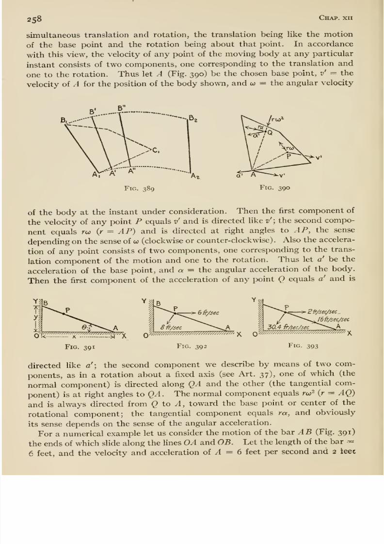
8/13/2019 Maurer Mechanics
http://slidepdf.com/reader/full/maurer-mechanics 274/407
2S8Chap, xii
simultaneous translation and rotation, the translation being like the motion
of the base point and the rotation being about that point. In accordance
with this view, the velocity of any point of the moving body at any particular
instant consists of two components, one corresponding to the translation and
one to the rotation. Thus let A (Fig. 390) be thechosen base point, v' = the
velocity of A for the position of the body shown, and co = the angular velocity
Ar'A'
-.Bg
Fig. 389
of the body at the instant under consideration. Then the first component of
the velocity of any point P equals v' and is directed like v'; the second compo-
nent equals rco {r = AP) and is directed at right angles to AP, the sense
depending on the sense of co (clockwise or counter-clockwise) . Also the accelera-
tion of any point consists of two components, one corresponding to the trans-
lation component of the motion and one to the rotation. Thus let a' be the
acceleration of the base point, and a = the angular acceleration of the body.
Then the first component of the acceleration of any point Q equals a' and is
Fig. 391
/8 -ft/sec ^ ^^A
Fig. 392
-> 2 ft/sec/sec ^
30.4 fi-Aec/sec ^ ' ^AQ w///m////////////////mMm^' ^
Fig. 393
directed like a'\ the second component we describe by means of two com-
ponents, as in a rotation about a fixed axis (see Art. 37), one of which (the
normal component) is directed along QA and the other (the tangential com-ponent) is at right angles to QA. The normal component equals rur {r = AQ)
and is always directed from <3 to ^, toward the base point or center of the
rotational component; the tangential component equals m, and obviously
its sense depends on the sense of the angular acceleration.
For a numerical example let us consider the motion of the bar AB (Fig. 391)
the ends of which slide along the hues OA and OB. Let the length of the bar --=
6 feet, and the velocity and acceleration of ^4 = 6 feet per second and 2 teet
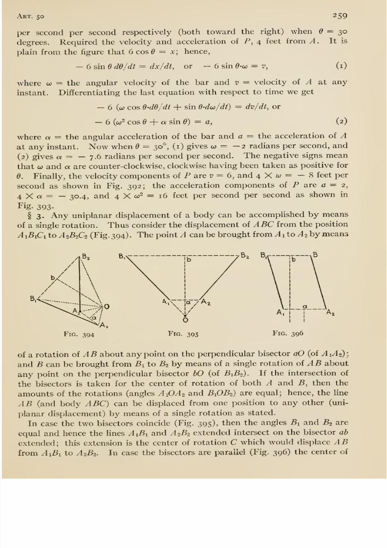
8/13/2019 Maurer Mechanics
http://slidepdf.com/reader/full/maurer-mechanics 275/407
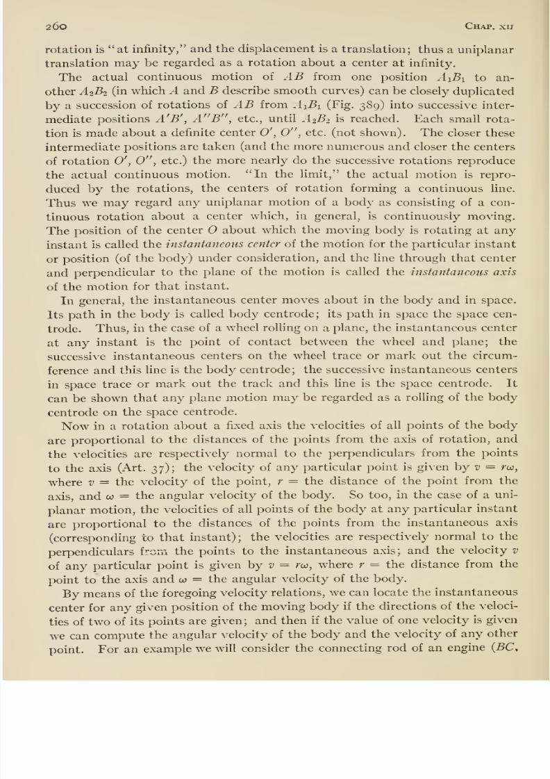
8/13/2019 Maurer Mechanics
http://slidepdf.com/reader/full/maurer-mechanics 276/407
26o Chap. xi7
rotation is at infinity, and the displacement is a translation; thus a uniplanar
translation may be regarded as a rotation about a center at infinity.
The actual continuous motion of AB from one position AiBi to an-
other A2B2 (in which A and B describe smooth curves) can be closely duplicated
by a successionof rotations of
ABfrom
AiBi(Fig.
389)into successive inter-
mediate positions A'B', A B , etc., until .42^2 is reached. Each small rota-
tion is made about a definite center 0', 0 , etc. (not shown). The closer these
intermediate positions are taken (and the more numerous and closer the centers
of rotation 0', 0 , etc.) the more nearly do the successive rotations reproduce
the actual continuous motion. In the limit, the actual motion is repro-
duced by the rotations, the centers of rotation forming a continuous line.
Thus we may regard any uniplanar motion of a body as consisting of a con-
tinuous rotation about a center which, in general, is continuously moving.The position of the center about which the moving body is rotating at any
instant is called the instantaneous center of the motion for the particular instant
or position (of the body) under consideration, and the line through that center
and perpendicular to the plane of the motion is called the instantaneous axis
of the motion for that instant.
In general, the instantaneous center moves about in the body and in space.
Its path in the body is called body centrode; its path in space the space cen-
trode. Thus, in the case of a wheel rolling on a plane, the instantaneous center
at any instant is the point of contact between the wheel and plane; the
successive instantaneous centers on the wheel trace or mark out the circum-
ference and this line is the body centrode; the successive instantaneous centers
in space trace or mark out the track and this line is the space centrode. It
can be shown that any plane motion may be regarded as a rolling of the body
centrode on the space centrode.
Now in a rotation about a fixed axis the velocities of all points of the body
are proportional to the distances of the points from the axis of rotation, andthe velocities are respectively normal to the perpendiculars from the points
to the axis (Art. 37); the velocity of any particular point is given by v = rw,
where v = the velocity of the point, r = the distance of the point from the
axis, and co = the angular velocity of the body. So too, in the case of a uni-
planar motion, the velocities of all points of the body at any particular instant
are proportional to the distances of the points from the instantaneous axis
(corresponding to that instant); the velocities are respectively normal to the
perpendiculars from the points to the instantaneous axis; and the velocity v
of any particular point is given by z^ = rw, where r = the distance from the
point to the axis and co = the angular velocity of the body.
By means of the foregoing velocity relations, we can locate the instantaneous
center for any given position of the moving body if the directions of the veloci-
ties of two of its points are given; and then if the value of one velocity is given
we can compute the angular velocity of the body and the velocity of any other
point. For an example we will consider the connecting rod of an engine {BC,
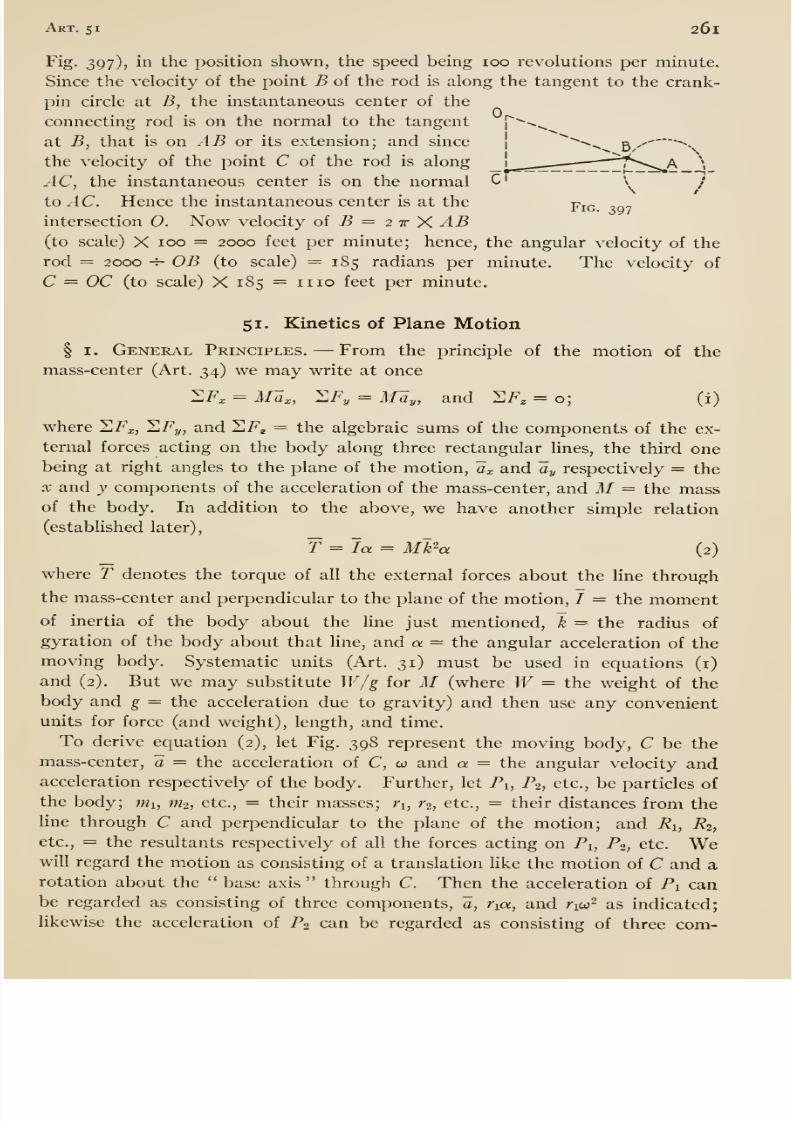
8/13/2019 Maurer Mechanics
http://slidepdf.com/reader/full/maurer-mechanics 277/407
Art. 51 261
Fig. 397), in the position shown, the speed being 100 revolutions per minute.
Since the velocity of the point B of the rod is along the tangent to the crank-
pin circle at B, the instantaneous center of the
connecting rod is on the normal to the tangent
at B, that is on AB or. its extension; and since
the velocity of the point C of the rod is along
AC, the instantaneous center is on the normal C' \ i
to AC. Hence the instantaneous center is at the-pic
intersection O. Now velocity oi B — 2 t Y. AB(to scale) X 100 = 2000 feet per minute; hence, the angular velocity of the
rod = 2000 -^ OB (to scale) = 185 radians per minute. The velocity of
C = OC (to scale) X 185 =1110 feet per minute.
51. Kinetics of Plane Motion
§ I. General Principles. —From the principle of the motion of the
mass-center (Art. 34) we may write at once
^F, = Ma,, HFy = May, and SF, = o; (i)
where SF^, 'ZFy, and HF^ = the algebraic sums of the components of the ex-
ternal forces acting on the body along three rectangular lines, the third one
being at right angles to the plane of the motion, a,and ay respectively
=the
X and y components of the acceleration of the mass-center, and M= the massof the body. In addition to the above, we have another simple relation
(established later),
f = la = Mk'-a (2)
where T denotes the torque of all the external forces about the line through
the mass-center and perpendicular to the plane of the motion, J = the momentof inertia of the body about the line just mentioned, ~k = the radius of
gyration of the body about that hne, and a = the angular acceleration of the
moving body. Systematic units (Art. 31) must be used in equations (i)
and (2). But we may substitute W/g for M (where W= the weight of the
body and g = the acceleration due to gravity) and then use any convenient
units for force (and weight), length, and time.
To derive equation (2), let Fig. 398 represent the moving body, C be the
mass-center, a = the acceleration of C, 00 and a = the angular velocity andacceleration respectively of the body. Further, let Pi, P2, etc., be particles of
the body; mi, m^, etc., = their masses; Vi, r^, etc., = their distances from the
line through C and perpendicular to the plane of the motion; and Ri, R2,
etc., = the resultants respectively of all the forces acting on Pi, P^, etc. Wewill regard the motion as consisting of a translation Uke the motion of C and arotation about the base axis through C. Then the acceleration of Pi canbe regarded as consisting of three components, a, ria, and rico- as indicated;
likewise the acceleration of P2 can be regarded as consisting of three com-
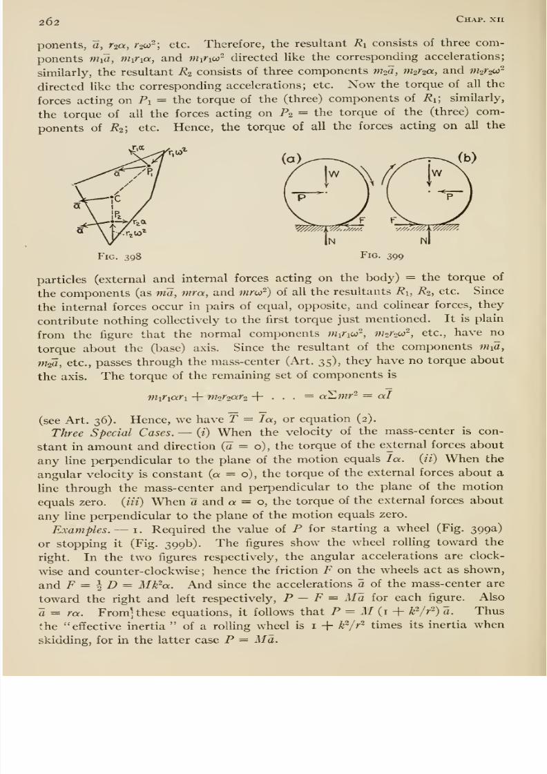
8/13/2019 Maurer Mechanics
http://slidepdf.com/reader/full/maurer-mechanics 278/407
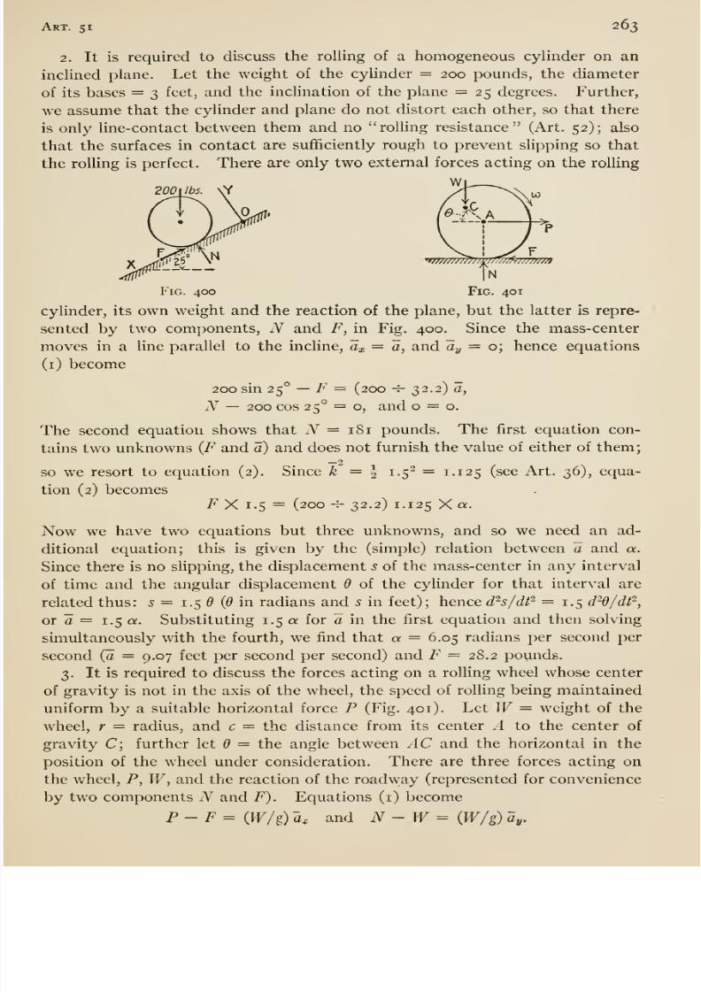
8/13/2019 Maurer Mechanics
http://slidepdf.com/reader/full/maurer-mechanics 279/407
Art. 51 263
2. It is required to discuss the rolling of a homogeneous cylinder on an
inclined plane. Let the weight of the cylinder = 200 pounds, the diameter
of its bases = 3 feet, and the inclination of the plane = 25 degrees. Further,
we assume that the cylinder and plane do not distort each other, so that there
is only line-contact between them and no rolling resistance (Art. 52); also
that the surfaces in contact are sufficiently rough to prevent slipping so that
the roUing is perfect. There are only two external forces acting on the rolling
Wj ^
Fig. 400 Fig. 401
cylinder, its own weight and the reaction of the plane, but the latter is repre-
sented by two components, N and F, in Fig. 400. Since the mass-center
moves in a line parallel to the incline, ax = a, and ay = o; hence equations
(i) become
200 sin 25° —F = (200 -^ 32.2) a,
N — 200 cos 25° = o, and = 0.
The second equation shows that iV = 181 pounds. The first equation con-
tains two unknowns (F and a) and does not furnish the value of either of them;
so we resort to equation (2). Since ^ = | 1.5- = 1.125 (see Art. 36), equa-
tion (2) becomesF X 1.5 = (200 -^ 32.2) 1. 125 X oc.
Now we have two equations but three unknowns, and so we need an ad-
ditional equation; this is given by the (simple) relation between a and a.
Since there is no slipping, the displacement s of the mass-center in any interval
of time and the angular displacement 6 of the cyUnder for that interval are
related thus: .j = 1.5 (6 in radians and s in feet); hence d^s/df^ = i-5 d^O/df^,
or a = 1.5 a. Substituting 1.5 a for a in the first equation and then solving
simultaneously V\^ith the fourth, we find that a = 6.05 radians per second per
second (o = 9.07 feet per second per second) and F = 28. 2 pounds.
3. It is required to discuss the forces acting on a rolling wheel whose center
of gravity is not in the axis of the wheel, the speed of rolling being maintained
uniform by a suitable horizontal force P (Fig. 401). Let W= weight of the
wheel, r — radius, and c = the distance from its center A to the center of
gravity C; further let 6 = the angle between AC and the horizontal in the
position of the wheel under consideration. There are three forces acting on
the wheel, P, W, and the reaction of the roadway (represented for convenience
by two components A^ and F). Equations (i) become
P- F = (Pf /g) ~a, and N - W= {W/g) ay.
8/13/2019 Maurer Mechanics
http://slidepdf.com/reader/full/maurer-mechanics 280/407
264 ^^p- ^^
Since the angular velocity is constant, a = o, and equation (2) becomes
F (r + c sin 6) —Nc cos d —Pc sin d = o.
These equations contain five unknowns {P, F, N, Ux, and ay), and so we
need other equations. Obviously the relations between a^, ay, and d furnish
the additional equations. To determine these let us regard the rolling as con-
sisting of a translation with A as base point and a rotation about A . Then
since A moves uniformly, the acceleration of the translational component = o;
and there being no angular acceleration, the acceleration of the rotational
component of the motion of C is wholly radial (along CA) and equals cor.
Hence a equals cw^ and is directed from C to .4 ; and
' a^ = ceo- cos 0, and ay = — coi ^ sinQ.
Substituting these values of a^ and ay in the first two equations, and solv-
ing them simultaneously with the third we find that
For CO we may write 2 ttw, where n = the number of turns of the wheel per
unit time.
It follows from theforegoing results that
Pand F are always opposite;
that P and F act as shown whenever the center of gravity C is on the left of
the vertical through the center A id between — 90° and + 90°) ; that P and
F act opposite to the directions indicated in the figure when C is on the right
of the vertical through A ; that N always acts upward unless cor sin 6 is
greater than g; that the greatest value of N obtains when C is vertically be-
low A {d -=- 90°) and then N = W (i + coi'^/g). This excess TFccoVg over
W in the value of N is called hammer blow in locomotive parlance, but
the hammer blow of a locomotive driving wheel depends also upon the side
rods attached to the wheel (see Art. 35).
Independence of Translation and Rotation. —Referring to equations (i),
page 261, it will be noted that they contain no term depending on the rota-
tion of the body about the mass-center; therefore, they show that the motion
of the mass-center is entirely independent of the rotation about that point.
And as already pointed out (Art. 34), the acceleration of the mass-center is
the same as though the entire body were concentrated at the mass-center and
all the external forces were applied at that point parallel to their actual lines
of action. Equation (2) contains no term depending on the motion of the
mass-center; therefore, the rotation of the body about the mass-center is
independent of any motion of the mass-center itself. And on comparing
equations (2) with the equation of motion for rotations about fixed axes
(Art. 37), it becomes plain that the external forces produce rotation about a
free (moving) axis through the mass-center as though that axis were fixed.
Thus we have complete independence of translation (of mass-center) and
rotation (about mass-center).
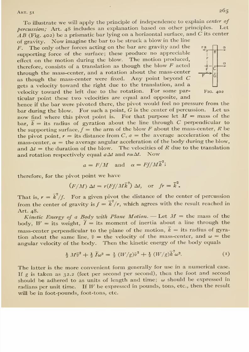
8/13/2019 Maurer Mechanics
http://slidepdf.com/reader/full/maurer-mechanics 281/407
Art. 51 265
To illustrate we will apply the principle of independence to explain center of
percussion; Art. 48 includes an explanation based on other principles. Let
AB (Fig. 402) be a prismatic bar lying on a horizontal surface, and C its center
of gravity. Now imagine the bar to be struck a blow in the line
F. The only otherforces acting on the bar are gravity and the ra
supporting force of the surface; these produce no appreciable\
effect on the motion during the blow. The motion produced,[
therefore, consists of a translation as though the blow F acted -k-
through the mass-center, and a rotation about the mass-center __^
as though the mass-center were fixed. Any point beyond Cgets a velocity toward the right due to the translation, and a
velocity toward the left due to the rotation. For some par- Fig. 402
ticular point these two velocities are equal andopposite, and
hence if the bar were pivoted there, the pivot would feel no pressure from the
bar during the blow. For such a point, G is the center of percussion. Let us
now find where this pivot point is. For that purpose let M = mass of the
bar, k = its radius of gyration about the line through C perpendicular to
the supporting surface,/ = the arm of the blow F about the mass-center, R be
the pivot point, r = its distance from C, a = the average acceleration of the
mass-center, a = the average angular acceleration of the body during the blow,
and M = the duration of the blow. The velocities of R due to the translation
and rotation respectively equal a At and raAt. Now
a = F/M and a = Ff/Mk^l
therefore, for the pivot point we have
(f/M) At = r{Ff/Mt) At, or fr = t.
r2
That is, r =yfe //. For a given pivot
the distance of the center of percussion
from the center of gravity is/ = ^ /r, which agrees with the result reached in
Art. 48.
Kinetic Energy of a Body with Plane Motion. —Let M = the mass of the
body, W= its weight, 7 = its moment of inertia about a line through the
mass-center perpendicular to the plane of the motion, k = its radius of gyra-
tion about the same Une, v = the velocity of the mass-center, and co = the
angular velocity of the body. Then the kinetic energy of the body equals
im' + hr<^'=h (w/gw + \ {wig)k i^\ (I)
The latter is the more convenient form generally for use in a numerical case.
If g is taken as 32.2 (feet per second per second), then the foot and second
should be adhered to as units of length and time; co should be expressed in
radians per unit time. If Wbe ex-pressed in pounds, tons, etc., then the result
will be in foot-pounds, foot-tons, etc.
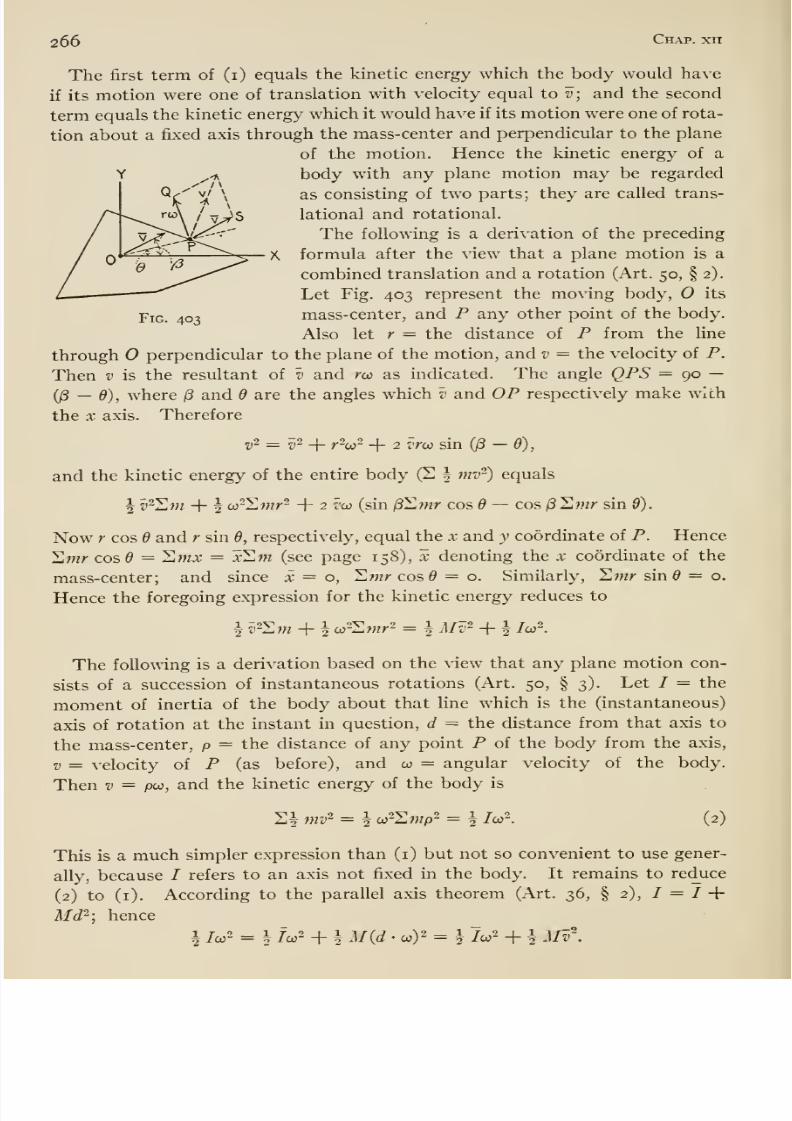
8/13/2019 Maurer Mechanics
http://slidepdf.com/reader/full/maurer-mechanics 282/407
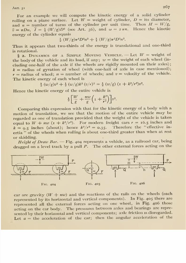
8/13/2019 Maurer Mechanics
http://slidepdf.com/reader/full/maurer-mechanics 283/407
Art. 51 267
For an example we will compute the kinetic energy of a solid cylinder
rolling on a plane surface. Let W= weight of cylinder, D = its diameter,
and n = number of turns of the cylinder per unit time. Then M = W/g,
V = tDh, 7=1 iW/g)D~ (see Art. 36), and co =- 2 im. Hence the kinetic
energy of the cylinder equals
i (W/g)TrWhl' + i (W/g)TrWhi\
Thus it appears that two-thirds of the energy is translational and one-third
is rotational.
§ 2. Dynamics of a Simple Moving Vehicle. ^ Let W= weight of
the body of the vehicle and its load, if any; w = the weight of each wheel (in-
cluding one-half of the axle if the wheels are rigidly mounted on their axles)
k = radius of gyration of wheel (with one-half of axle in case mentioned);
r = radius of wheel; n = number of wheels; and v = velocity of the vehicle.
The kinetic energy of each wheel is
\ (w/gy + h (Wg)k' (v/ry = i (w/g) (i + k^r^y.
Hence the kinetic energy of the entire vehicle is
1 VW nw47 ^
g -^)}Comparing this expression with that for the kinetic energy of a body with a
motion of translation, we see that the motion of the entire vehicle may be
regarded as one of translation provided that the weight of the vehicle is taken
equal to W+ nw (i -\- k^/r-). For modern freight cars r = 16.5 inches and
k = 9.5 inches (about); hence k-/r^ = 0.35. Therefore the effective in-
ertia of the wheels when rolling is about one-third greater than when at rest
or skidding.
Height of Draw Bar. —Fig. 404 represents a vehicle, as a railroad car, being
draggedon a level track by a pull P. The other external forces acting on the
W
/ N
•77777?7;77T^'777777777777777m777777777777/l^.
Fig.404
H ^ ^-
ra^-tr
h
Fig. 406
-5^5^
\
Q
car are gravity iyV -f- nw) and the reactions of the rails on the wheels (each
represented by its horizontal and vertical components). In Fig. 405 there are
represented all the external forces acting on one wheel, in Fig. 406 those
acting on the car body. The pressures between axles and bearings are repre-
sented by their horizontal and vertical components; axle friction is disregarded.
Let a = the acceleration of the car; then the angular acceleration of the
8/13/2019 Maurer Mechanics
http://slidepdf.com/reader/full/maurer-mechanics 284/407
268 Chap, xii
wheels = a/r. Consideration of the forces on the wheel, equation (2), page
261, shows that
Fr = -h?- , or F = —-a.g r g r^
We have also (according to equations i, page 261)
e-. = ^a, or e =f
(. + >Consideration of the forces acting on the car body shows that P —nQ =(W/g)a, or
la.
When applied high up on thecar,
P tends to raise the rear end, decreasingthe rear vertical axle pressures and increasing the forward vertical axle pres-
sures. When applied low, P produces the opposite effect. Obviously, whenapplied in some certain line, P has no such effect on the vertical axle pressures.
We will now locate that line; let h = its height above the plane of the axes
of the axles, and H = the height of the center of gravity of the car bodyand its load above that plane. When the car is at rest {P and Q = o), the
(vertical) pressures of the axles on the car body take on certain values.
If, when P (and nQ) act on the car body, their resultant acts through thecenter of gravity, then those forces do not tend to rotate the car body and
do not affect vertical pressures of or on the axles already mentioned. Thus,
to provide against extra loading or unloading of axles by P (draw-bar effect),
the moments of P and nQ about the transverse horizontal line through the
center of gravity of the car body (and load) should balance. That is, weshould have P{H - h) = nQH,' or
Hh =
+ (nw/W) (i + k^/r^)
52, Rolling Resistance
§ I. Rollers. —In the present connection a roller is taken to differ from
a wheel (of a vehicle) in that the latter sustains its load indirectly through its
axle, while the former has no axle but takes its load directly. When a roller
(or wheel) is made to roll, it experiences more or less resistance from the
track (or roadway) upon which it rolls. Obviously the amount of this resist-
ance depends in large part on the nature of the surfaces in contact and on the
amount of the pressure between them. In the case of an inelastic roadway{A, Fig. 407) the roller leaves a rut, and there is a continual expenditure of
energy in thus (permanently) deforming the track as well as against friction
due to actual rubbing between roller and track. In the case of an elastic
roadway (B, Fig. 407) also, there is rubbing between the roller and the
deforming and recovering portions of the track and consequently friction
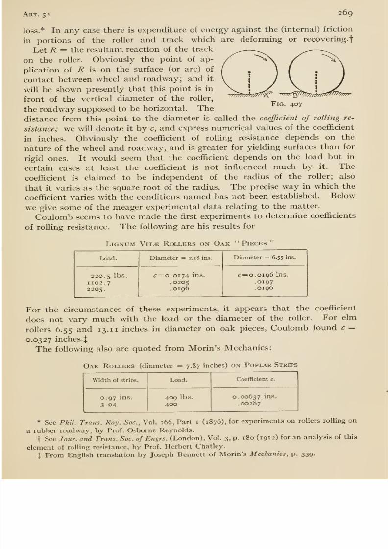
8/13/2019 Maurer Mechanics
http://slidepdf.com/reader/full/maurer-mechanics 285/407
Art. 52 269
loss.* In any case there is expenditure of energy against the (internal) friction
in portions of the roller and track which are deforming or recovering.
Let R = the resultant reaction of the track
on the roller. Obviously the point of ap-
plication of R is on the surface (or arc) of
contact between wheel and roadway; and it
will be shown presently that this point is in
front of the vertical diameter of the roller,
the roadway supposed to be horizontal. The
distance from this point to the diameter is called the coefficient of rolling re-
sistance; we will denote it by c, and express numerical values of the coefficient
in inches. Obviously the coefficient of rolling resistance depends on the
nature of the wheel and roadway, and is greater for yielding surfaces than for
rigid ones. It would seem that the coefficient depends on the load but in
certain cases at least the coefficient is not influenced much by it. The
coefficient is claimed to be independent of the radius of the roller; also
that it varies as the square root of the radius. The precise way in which the
coefficient varies with the conditions named has not been established. Below
we give some of the meager ex-perimental data relating to the matter.
Coulomb seems to have made the first ex-periments to determine coefficients
of rolUng resistance. The following are his results for
Lignum Vit.e Rollers on Oak Pieces
Load.
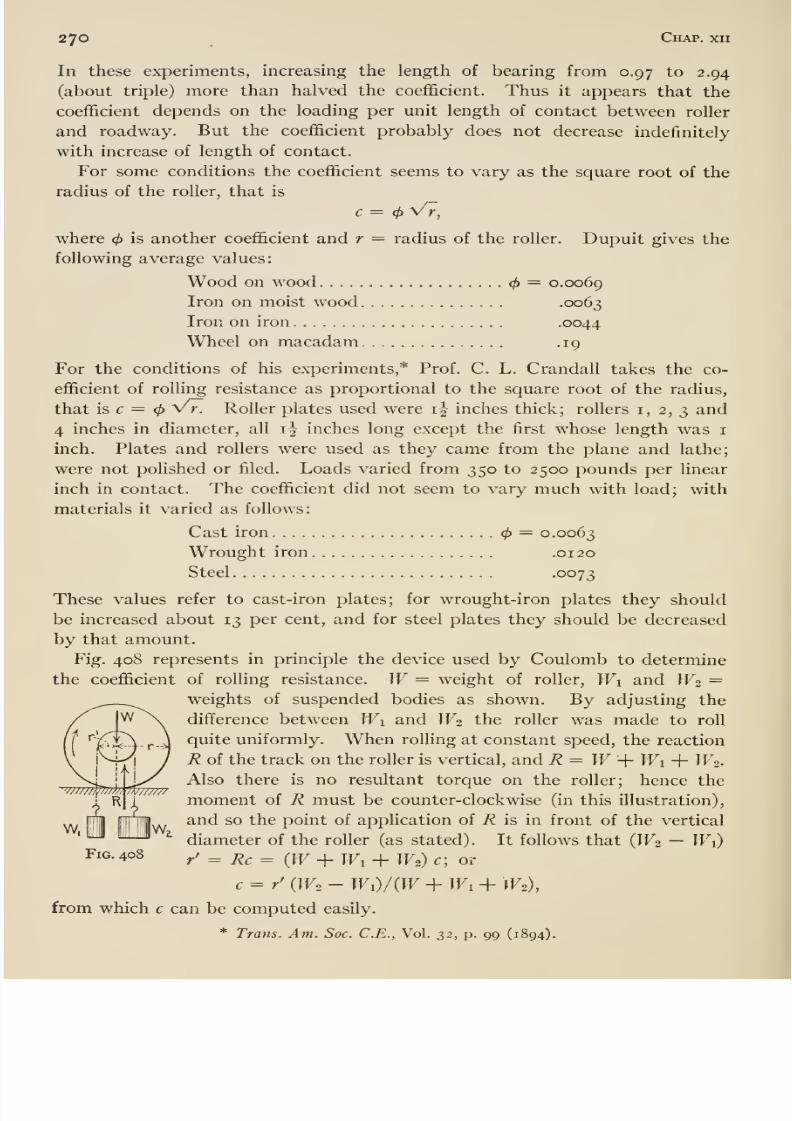
8/13/2019 Maurer Mechanics
http://slidepdf.com/reader/full/maurer-mechanics 286/407
270 Chap, xii
In these experiments, increasing the length of bearing from 0.97 to 2.94
(about triple) more than halved the coefficient. Thus it appears that the
coefficient depends on the loading per unit length of contact between roller
and roadway. But the coefficient probably does not decrease indefinitely
with increaseof length of contact.
For some conditions the coefficient seems to vary as the square root of the
radius of the roller, that is
c = </) V7,
where <f> is another coefficient and r = radius of the roller. Dupuit gives the
following average values:
Wood on wood = 0.0069
Iron on moist wood .0063
Iron on iron .0044
Wheel on macadam .19
For the conditions of his experiments,* Prof. C. L. Crandall takes the co-
efficient of rolling resistance as proportional to the square root of the radius,
that is c = V r. Roller plates used were i| inches thick; rollers i, 2, 3 and
4 inches in diameter, all i| inches long except the first whose length was i
inch. Plates and rollers were used as they came from the plane and lathe;
were not polished or filed. Loads varied from 350 to 2500 pounds per linearinch in contact. The coefficient did not seem to vary much with load; with
materials it varied as follows:
Cast iron = 0.0063
Wrought iron .0120
Steel -0073
These values refer to cast-iron plates; for wrought-iron plates they should
be increased about 13 per cent, and for steel plates they should be decreased
by that amount.
Fig. 408 represents in principle the device used by Coulomb to determine
the coefficient of rolling resistance. W= weight of roller, Wi and W2 =weights of suspended bodies as shown. By adjusting the
difference between Wi and W2 the roller was made to roll
quite uniformly. When rolling at constant speed, the reaction
R of the track on the roller is vertical, and R = W-\- Wi + W^-
Also there is no resultant torque on the roller; hence the
moment of R must be counter-clockwise (in this illustration),
and so the point of application of R is in front of the vertical
diameter of the roller (as stated). It follows that (IF2 — W\)
/ = Re = (W + Wi -hW2)c; or
c = / (W2 - Wi)/iW + Wi-\- W2),
from which c can be computed easily.
* Trans. Am. Soc. C.E., Vol. 32, p. 99 (1894).
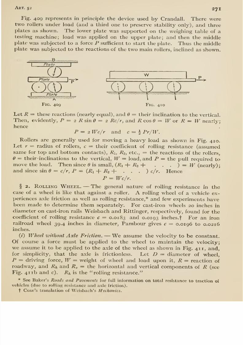
8/13/2019 Maurer Mechanics
http://slidepdf.com/reader/full/maurer-mechanics 287/407
Art. 52 27
Fig. 409 represents in principle the device used by Crandall. There weretwo rollers under load (and a third one to preserve stability only), and three
plates as shown. The lower plate was supported on the weighing table of atesting machine; load was applied on the upper plate; and then the middleplate was subjected to a force P sufficient to start the plate. Thus the middle
plate was subjected to the reactions of the two main rollers, inclined as shown.
I Plate I
n wPlate \-^^ I
' ' —1-^>
'^'//////////////A'
Plate
—'^'//?^/i(J/////W///////7//tp////////////m/^///////'
Fig. 409 Fig. 410
Let R = these reactions (nearly equal), and Q = their inclination to the vertical.
Then, evidently, P = 2 i? sin ^ = 2 Rclr^ and Rco&d = Wor R = Wnearly;
henceP = 2 Wc/r and c = i Pr/W.
Rollers are generally used for moving a heavy load as shown in Fig. 410.
Let r = radius of rollers, c = their coefficient of rolHng resistance (assumedsame for top and bottom contacts), Ri, R2, etc., = the reactions of the rollers,
6 = their 'inclinations to the vertical, W= load, and P = the pull required to
mo\'e the load. Then since 6 is small, (i?i + -^2 + • . . ) = W (nearly)
and since sin d = c/r, P = (Ri -{- R2 -\- . . . ) c/r. Hence
P = Wc/r.
§ 2. Rolling Wheel. —The general nature of rolling resistance in the
case of a wheel is hke that againsta
roller.
A rolHng wheel of a vehicle ex-periences axle friction as well as rolling resistance,* and few experiments havebeen made to determine them separately. For cast-iron wheels 20 inches in
diameter on cast-iron rails Weisbach and Rittinger, respectively, found for the
coefficient of rolling resistance c = 0.0183 and 0.0193 inches.f For an iron
railroad wheel 39.4 inches in diameter, Pambour gives c = 0.0196 to 0.0216
inches.
(i) Wheel without Axle Friction. —We assume the velocity to be constant.
Of course a force must be applied to the wheel to maintain the velocity;we assume it to be applied to the axle of the wheel as shown in Fig. 411, and,
for simplicity, that the axle is frictionless. Let D = diameter of wheel,
P = driving force, W= weight of wheel and load upon it, R = reaction of
roadway, and Rh and 7?„ = the horizontal and vertical components of R (see
Fig. 411b and c). Rh is the rolling resistance.
* See Baker's Roads and Pavements for full information on total resistance to traction oi
vehicles (due to roUinR resistance and axle friction).
tCoxe's translation of
Weisbach's Mechanics.
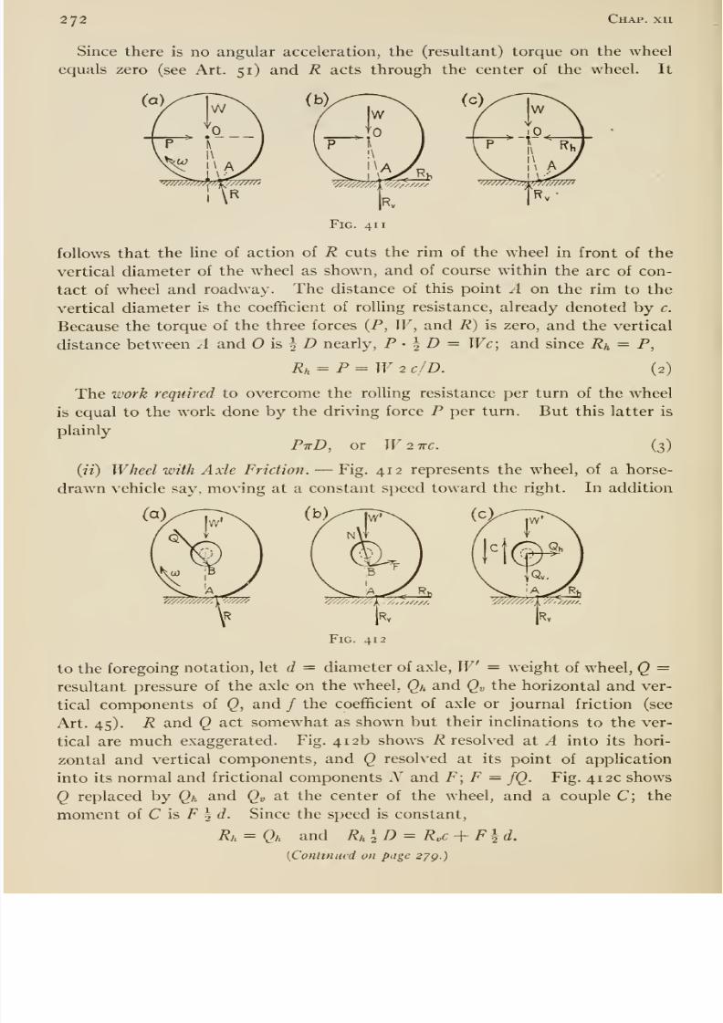
8/13/2019 Maurer Mechanics
http://slidepdf.com/reader/full/maurer-mechanics 288/407
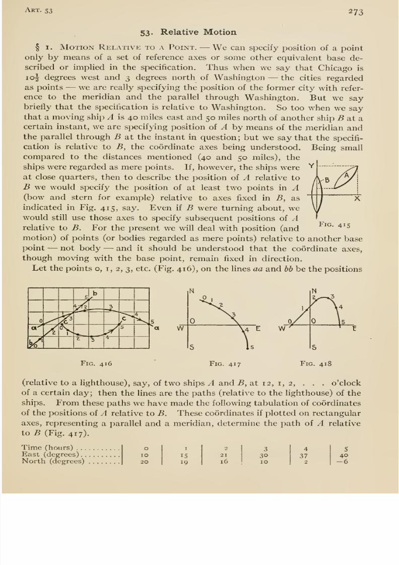
8/13/2019 Maurer Mechanics
http://slidepdf.com/reader/full/maurer-mechanics 289/407
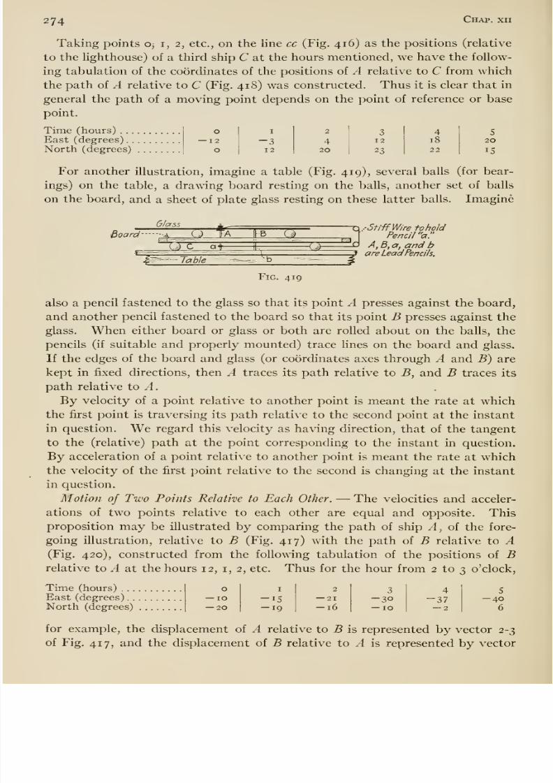
8/13/2019 Maurer Mechanics
http://slidepdf.com/reader/full/maurer-mechanics 290/407
274 Chap, xn
Taking points o; i, 2, etc., on the line cc (Fig. 416) as the positions (relative
to the lighthouse) of a third ship C at the hours mentioned, we have the follow-
ing tabulation of the coordinates of the positions of A relative to C from which
the path of A relative to C (Fig. 418) was constructed. Thus it is clear that in
general the path of a moving point depends on the point of reference or base
point.
Time (hours)East (degrees)North (degrees)

8/13/2019 Maurer Mechanics
http://slidepdf.com/reader/full/maurer-mechanics 291/407
Art. 53 275
-E
Fig. 420
2-3 of Fig. 420. Apparently these vectors are equal and parallel (also opposite)
and it seems that such displacement vectors would be equal, parallel, and
opposite for any interval of time. If this be true, then
it follows that the rates at which these displacements occur
(the relative velocities) are equal and opposite at each
instant; andif
thevelocities are always equal and op-
posite then their rates of change (the relative acceler-
ations) are also equal and opposite at each instant.
To prove that displacements such as mentioned in the
preceding illustration are equal and opposite, we will use
the glass-board illustration. Suppose that the pencils A and B are attached
at the middle points of the glass and board respectively, and that at a certain
instant glass and board are in the positions shown at
(i) in Fig. 421, and ata later instant in positions shown
at (2); the table is not shown. Ai and Bi and A2 and
A) B2 are the corresponding positions of the pencil points.
During this displacement, A will have traced some such
line as A'A2 and B the line B'B2. A^A' is equal and
parallel to B1B2; hence A1B1B2A' is a parallelogram,
and A'B2 and AiBi are equal and parallel. BiB' is
equal and parallel to ^1^12; hence BiA^A^B' is a par-
allelogram, and B'A2 and BiAi are equal andparallel.
It follows that A'B2B'A2 is a parallelogram, and so
A'A2 and B'B2 are equal and parallel. That is, the
displacement of A relative to B (chord A'Ai) is equal
and parallel to the displacement of B relative to A (chord B'Bi). Obviously
the senses of the displacements are opposite.
Motions of Two Points Relative to a Third Point. —For convenience we re-
gard the third point as fixed, and call velocities and accelerations relative to
that point as absolute. To illustrate this case we will modify the glass-
board apparatus as follows: Imagine another pencil a rigidly fastened to the
glass plate so it presses against the table as shown directly under A, and Bextended downward so that its lower end b presses on the table. Then when
the glass and board are moved about without turning, a and b draw the paths
of A and B relative to any (third) point as C on the table; and as already
stated, A and B draw their paths relative to each other.
In this case two problems arise: (a) Given the velocity (or acceleration) of
a point relative to a second point, and the absolute velocity (or acceleration)
of the second; required the absolute velocity (or acceleration) of the first
point, (b) Given the absolute velocities (or accelerations) of two points;
required the velocity (or acceleration) of either of the two points relative to
the other.
(a) To do this problem we merely need to add (vectorially) , or compound, the
velocity (or acceleration) of the first point relative to the second and the abso-
421
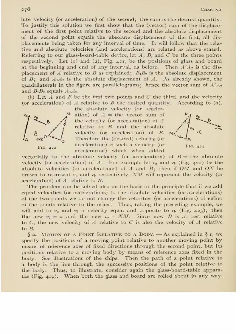
8/13/2019 Maurer Mechanics
http://slidepdf.com/reader/full/maurer-mechanics 292/407
276 Chap, xii
lute velocity (or acceleration) of the second; the sum is the desired quantity.
To justify this solution we first show that the (vector) sum of the displace-
ment of the first point relative to the second and the absolute displacement
of the second point equals the absolute displacement of the first, all dis-
placements being taken for any interval of time. It will follow that the rela-
tive and absolute velocities (and accelerations) are related as above stated.
Referring to our glass-board-table device, let A , B, and C be the three points
respectively. Let (i) and (2), Fig. 421, be the positions of glass and board
at the beginning and end of any interval, as before. Then A'Ao is the dis-
placement of A relative to B as explained; ^1-62 is the absolute displacement
of B; and A1A2 is the absolute displacement of ^. As already shown, the
quadrilaterals in the figure are parallelograms; hence the vector sum oi A'A2
and B1B2 equals A1A2.
(b) Let A and B be the first two points and C the third, and the velocity
(or acceleration) of A relative to B the desired quantity. According to (a),
the absolute velocity (or acceler-
ation) of A = the vector sum of
the velocity (or acceleration) of Arelative to B and the absolute
velocity (or acceleration) of B.
Therefore the (desired) velocity (or
acceleration) is such a velocity (or
acceleration) which when added
vectorially to the absolute velocity (or acceleration) of 5 = the absolute
velocity (or acceleration) of A. For example let Va and Vb (Fig. 422) be the
absolute velocities (or accelerations) of A and B; then if OM and ON be
drawn to represent Va and % respectively, NM will represent the velocity (or
acceleration) of A relative to B.
The problem can be solvedalso
onthe basis of the principle that if
we addequal velocities (or accelerations) to the absolute velocities (or accelerations)
of the two points we do not change the velocities (or accelerations) of either
of the points relative to the other. Thus, taking the preceding example, we
will add to Va and Vb a velocity equal and opposite to Vb (Fig. 423); then
the new Vb = o and the new Va = NM. Since now B is at rest relative
to C, the new velocity of A relative to C is also the velocity of A relative
to B.
§ 2. Motion or a Point Relative to a Body. —As explained in § i, wespecify the positions of a moving point relative to another moving point by
means of reference axes of fixed directions through the second point, but its
positions relative to a moving body by means of reference axes fixed in the
body. See illustrations of the ships. Then the path of a point relative to
a body is the fine through the successive positions of the point relative to
the body. Thus, to illustrate, consider again the glass-board-table appara-
tus (Fig. 419). When both the glass and board are rolled about in any way,
//
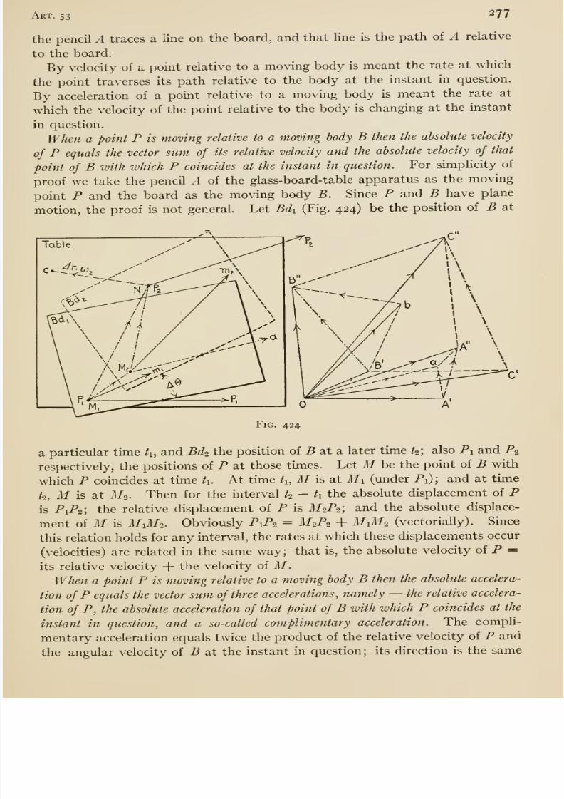
8/13/2019 Maurer Mechanics
http://slidepdf.com/reader/full/maurer-mechanics 293/407
Art. 53 277
the pencil A traces a line on the board, and that line is the path of A relative
to the board.
By velocity of a point relative to a moving body is meant the rate at which
the point traverses its path relative to the body at the instant in question.
By acceleration of a point relative to a moving body is meant the rate at
which the velocity of the point relative to the bodyis
changingat the instant
in question.
When a point P is moving relative to a moving body B then the absolute velocity
of P equals the vector sum of its relative velocity and the absolute velocity of that
point of B with which P coincides at the instant in question. For simplicity of
proof we take the pencil A of the glass-board-table apparatus as the moving
point P and the board as the moving body B. Since P and B have plane
motion, the proof is not general. Let Bdi (Fig. 424) be the position of B at
Fig. 424
a particular time /i, and Bdi the position of 5 at a later time ^2; also Pi and P2respectively, the positions of P at those times. Let M be the point of B with
which P coincides at time ti. At time /i, M is at Mi (under Pi) ; and at time
/2, M is at M2. Then for the interval t^ — ti the absolute displacement of Pis PiP2; the relative displacement of P is M2P2; and the absolute displace-
ment of M is M1M2. Obviously P1P2 = M'2P2 + MiM^ (vectorially). Since
this relation holds for any interval, the rates at which these displacements occur
(velocities) are related in the same way; that is, the absolute velocity of P =
its relative velocity + the velocity of M.When a point P is moving relative to a moving body B then the absolute accelera-
tion of P equals the vector sum of three accelerations, namely —the relative accelera-
tion of P, the absolute acceleration of that point of B with which P coincides at the
instant in question, and a so-called complimentary acceleration. The compli-
mentary acceleration equals twice the product of the relative velocity of P and
the angular velocity of B at the instant in question; its direction is the same
8/13/2019 Maurer Mechanics
http://slidepdf.com/reader/full/maurer-mechanics 294/407
278 Chap, xii
as that of the Hnear velocity of p where Pp is a vector representing the relative
velocity of P due to the angular velocity of B.
For simphcity again we restrict the proof to plane motions. Let Pipi
(Fig. 424) = the relative velocity of P at the time h, and If iWi ^ the absolute
velocity of M at that instant. The vector simi of these two velocities
equals the absolute velocity of P at the time h. Making OA' and OB' to
represent these velocities respectively, we get the diagonal OC to represent
the absolute velocity of P at the time h. Let N be the point of the board with
which P coincides at the time k; N is under P2 then. The velocity of N (at
time k) equals the vector simi of the velocity of i/2 and the velocity of TV
about M2. Now the velocity of A' about I/2 equals the product of M-2.N
and the angular velocity of the board (at time h), or Ar X C02, where Ar = MoNand C02 = the angular velocity. The direction of this velocity Ar • C02 is perpen-
dicular to M2N as indicated (assuming that C02 is counter-clockwise). OBand bB are equal and parallel to Mim^ and Ar'C02 respectively; hence
OB is the velocity of N at time h. Now let Po_p-i (= OA ) be the relative
velocity of P at time h- Then the diagonal OC of the parallelogram on OAand OB is the absolute velocity of P at time to. Therefore C'C is the incre-
ment in the absolute velocity of P for the interval h — h- It follows readily
from the geometry of the figure that
C'C=
A'A +B'B , (i)
vectorial addition being understood here and in the following.
Now let Mia = P\pi and the angle between these vectors equal the angular
displacement Ad of the board during the interval /2 — k- Then the increment
in the relative velocity of P for that interval equals the difference between the
vectors Mia and Pipi- Oa is equal and parallel to Mia; hence aA is that
difference. Therefore
A'A = A'a+ Avr = 2Vr sin i A9 + Avr,
where Vr means relative velocity of P at time h. Since Ob is equal and parallel
to Mimi (velocity of M at time /o), B'b is the increment in the velocity of Mduring the interval h — h', and since bB = Ar'Ui,
B'B = A%n + Ar • C02,
where Vm means velocity of M. Substituting the foregoing values of A'A
and B'B in equation (i), we get
C'C = Azv
+Avr^ +2Vr sin | A^ -j- Ar - on. (2)
Now let At = h — h, and ^ approach ti, then we get
,. C'C ,. At..,
,. Av^n , ,. Ad ... Arhm—7— = lim -—- + hm—- + Vr lim -— + lim —(02.
At At At At At
The left-hand member is the absolute acceleration of P; the first term of the
right-hand member is the relative acceleration of P; the second term is the
acceleration of M. Lim {A6/ At) = wi, the angular velocity of the board at
8/13/2019 Maurer Mechanics
http://slidepdf.com/reader/full/maurer-mechanics 295/407
Art. 53 279
time/i; hence the third term = ZJrCOi. Lim (Ar/A/)co2 = lim (Ar/At) X limw2
= Vr^i. Hence the third and fourth terms are equal in magnitude, and if their
directions —they are vectors —are parallel, then their smn = 2 VrWi. The
direction of the third term is the limiting direction of A' a, perpendicular to
OA' or Vr obviously. The direction of the fourth term is the limiting direction
of bB or Nc. Now Nc is always (as /2 approaches h) perpendicular to M2P2;and since 1/2^2 is the relative displacement of P, the Umiting direction of
M2P2 is Pipi (or Vr). Hence the limiting direction of Nc is perpendicular to Vr.
Thus the sum of the last two terms = 2 Vrcoi, and it has the direction mentioned,
perpendicular to tv- And this sum is the so-called complimentary acceleration;
it is called also acceleration of Coriolis after him who first discovered the rela-
tion between the accelerations under discussion.
{Continued from page 272 )
From the last equation on that page and Rv = Qv ^- W, it follows that
Rh = Qh={Q. + W')^ + F^- (4)
In most cases of vehicles, Qv is nearly equal to Q, and W is neghgible com-
pared to Qv ; therefore we may write as a close approximation
The work required to overcome rolling resistance and axle friction is fur-
nished by Qh. Per turn of the wheel, that work is
QtjvD = ((?„ + W) 2 TC + Qhd = TT (2 c + /J) (?. (5)
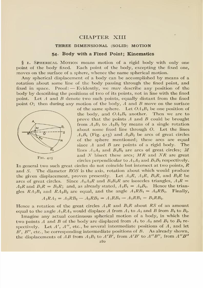
8/13/2019 Maurer Mechanics
http://slidepdf.com/reader/full/maurer-mechanics 296/407
CHAPTER XIII
THREE DIMENSIONAL (SOLID) MOTION
54. Body with a Fixed Point; Kinematics
§ I. Spherical Motion means motion of a rigid body with only one
point of the body fixed. Each point of the body, excepting the fixed one,
moves on the surface of a sphere, whence the name spherical motion.
Any spherical displacement of a body can be accomplished by means of a
rotation about some line of the body passing through the fixed point, and
fixed in space. Proof: —Evidently, we mav describe any position of the
body by describing the positions of two of its points, not in line with the fixed
point. Let A and B denote two such points, equally distant from the fLxed
point 0; then during any motion of the body, A and B move on the surface
of the same sphere. Let OAiBi be one position of
the body, and OA2B2 another. Then we are to
prove that the points A and B could be brought
from AiBi to .42^2 by means of a single rotation
about some fixed line through 0. Let the lines
.4 1^1 (Fig. 425) and A2B2 be arcs of great circles
of the sphere mentioned; these arcs are equal
since A and B are points of a rigid body. The
fines A1A2 and B1B2 are arcs of great circles; M_ and N bisect these arcs; MR and NR are greatFig a2^
circles perpendicular to ^1-42 and B1B2 respectively.
In general two such great circles do not coincide but intersect at two points, Rand S. The diameter ROS is the axis, rotation about which would produce
the given displacement, proven presently. Let AiR, A2R, BiR, and B2R be
arcs of great circles. Since A1A2R and B1B2R are isosceles triangles, AiR =
A2R and BiR = BoR; and, as already stated, AiBi = .42^2. Hence the trian-
gles RAiBi and RA2B2 are equal, and the angle AiRBi = A2RB2. Finally,
A1RA2 = A1RB2 —A2RB2 = A1RB2 - AiRBi = B1RB2.
Hence a rotation of the great circles A^R and BiR about RS of an amoimt
equal to the angle A1RA2 would displace A from ^1 to ^2 and B from Bi to B2.
Imagine any actual continuous spherical motion of a body, in which the
two points A and B of the body are displaced from ^1 to yl2 and Bi to B2 re-
spectively. Let A', A , etc., be several intermediate positions of A, and let
B', B , etc., be corresponding intermediate positions of B. As already shown,
the displacements of AB from AiB^ to A'B', from A'B' to A B , from A B280
8/13/2019 Maurer Mechanics
http://slidepdf.com/reader/full/maurer-mechanics 297/407
Art. 54 281
to A 'B ', etc., might be accomplished by single rotations about definite
fixed lines R'OS', R'VS , R 'OS ', etc. If a large number of intermediatepositions A'B', A B , etc., be assumed, and if the successive rotations beaccomplished in times equal to the times required for the actual displace-
ments in the continuous motion, then the succession of rotations would closely
resemble the actual continuous motion. The more numerous the interme-diate positions, and the more numerous the succession of single rotations,
the more closely would the succession resemble the actual motion. In the
limit, the succession would reproduce the actual motion; hence we mayregard any spherical motion of a body as consisting of a continuous rotation
about a line through the fixed point, the fine continually shifting about in the
body and in space. The Kne about which the body is rotating at any instant
is the instantaneous axis (of rotation) at that instant.
At any particular instant of a spherical motion, the body is rotating aboutthe instantaneous axis at a definite rate; this rate is called the angular velocity
of the body at that instant. We will, generally, denote magnitude of angular
velocity by co. In a rotation about a fixed axis, the (linear) velocity of anypoint of the body equals the product of the angular velocity and the perpen-
dicular distance (or radius) from the point to the axis; and the direction of
the Unear velocity is perpendicular to the plane of the radius and the axis. Sotoo in a spherical motion, the linear velocity of any point of the body at anyinstant equals the product of the angular velocity at that instant and the
radius (perpendicular from the point to the instantaneous axis for that in-
stant); the direction of that velocity is perpendicular to the plane of the
radius and the axis.
Any angular velocity oj may be represented by means of a vector laid off
on the corresponding instantaneous axis; the length of the vector is madeequal to co according to some convenient scale, and the sense of the vector
indicates the direction of the rotation according to some convention. Wewill always associate direction with angular velocity in the way just described;
that is, we regard angular velocity as a vector quantity. In a spherical mo-tion, angular velocity changes in direction continuously; it may or may not
change in amount too. In any case, the rate at which the (vector) angular
velocity is changing at any instant is called the angular acceleration at that
instant. (See page 148 for note on rate of change of a vector quantity.) This
rate or acceleration has a definite amount and direction at each instant, andhence is a vector quantity too. We will use a to denote the magnitude of anangular acceleration.
§ 2. Composition and Resolution op Angular Velocities. —Imagine
a body P to be rotating about a line li fixed in a body A ; and that A is rotating
about a line h>, intersecting h and fixed in a body B (Fig. 426). For conve-
nience we call the motion of P relative to B its absolute motion, and we regard
this absolute motion as a resultant motion consisting of the (component)
rotations about h and h- We will show presently that the absolute motion
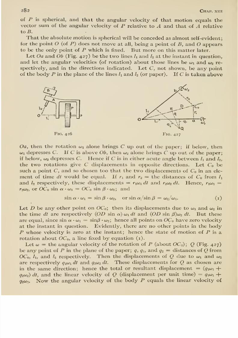
8/13/2019 Maurer Mechanics
http://slidepdf.com/reader/full/maurer-mechanics 298/407
282 Chap, xiii
of P is spherical, and that the angular velocity of that motion equals the
vector sum of the angular velocity of P relative to A and that of A relative
toB.
That the absolute motion is spherical will be conceded as almost self-evident;
for the point (of P) does not move at all, being a point of B, and O appears
to be the only point of P which is fixed. But more on this matter later.
Let Oa and Oh (Fig. 427) be the two lines h and h at the instant in question,
and let the angular velocities (of rotation) about those lines be coi and C02 re-
spectively, and in the directions indicated. Let C, not shown, be any point
of the body P in the plane of the lines h and h (or paper). If C is taken above
Fig. 426
Oa, then the rotation coi alone brings C up out of the paper; if below, then
cui depresses C. If C is above Oh, then C02 alone brings C up out of the paper;
if below, 002 depresses C. Hence if C is in either acute angle between h and h,
the two rotations give C displacements in opposite directions. Let Co be
such a point C, and so chosen too that the two displacements of Co in an ele-
ment of time dt would be equal. If ri and r^ = the distances of Co from hand h respectively, these displacements = ricoi dt and r^2 dt. Hence, /iwi =
^2^2, or OCo sin a-on = OCosin
/3• wo;
andsin a- coi = sin j8 • ooo, or sin a/ sin (3 = 0)2/0)1. (i)
Let D be any other point on OCo; then its displacements due to oji and 0)2 in
the time dt are respectively (OD sin a) wi dt and {OD sin /3)o)2 dt. But these
are equal, since sin a • oji = sin/3 • 0)2; hence all points on OCo have zero velocity
at the instant in question. Evidently, there are no other points in the body
P whose velocity is zero at the instant; hence the state of motion of P is a
rotation about OCo, a Hne fixed by equation (i).
Let 0) = the angular velocity of the rotation of P (about OCo); Q (Fig. 427)
be any point of P in the plane of the paper; q, gi, and g2 = distances of Q from
OCo, h, and k respectively. Then the displacements of Q due to o)i and 0)2
are respectively gio:i dt and ^2^2 dt. These displacements for Q as chosen are
in the same direction; hence the total or resultant displacement = (910)1 -f-
92W2) dt, and the linear velocity of Q (displacement per unit time) = ^lOJi +5'2Wp,. Now the angular velocity of the body P equals the linear velocity of
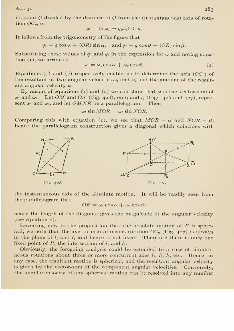
8/13/2019 Maurer Mechanics
http://slidepdf.com/reader/full/maurer-mechanics 299/407
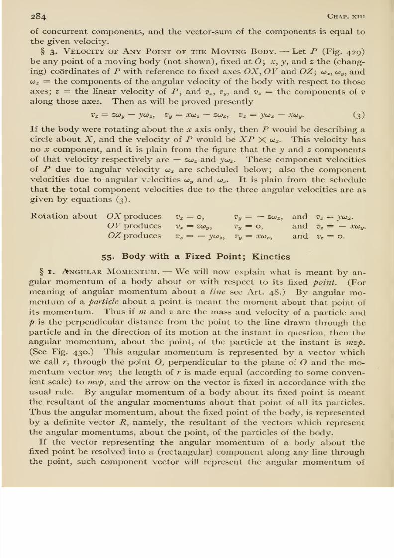
8/13/2019 Maurer Mechanics
http://slidepdf.com/reader/full/maurer-mechanics 300/407
284 Chap, xiii
of concurrent components, and the vector-sum of the components is equal to
the given velocity.
§ 3. Velocity of Any Point of the Moving Body. —Let P (Fig. 429)
be any point of a moving body (not shown), fixed at 0; x, y, and z the (chang-
ing) coordinates of P with reference to fixed axes OX, OY and OZ; co^, co^, and
o3z = the components of the angular velocity of the body with respect to those
axes; v = the linear velocity of P; and Vx, Vy, and v^ = the components of v
along those axes. Then as will be proved presently
I'x = ZOOy —ycOz, Vy = X(j3z —SWx, Vz = JCOx XOiy. (3)
If the body were rotating about the x axis only, then P would be describing a
circle about X, and the velocity of P would be XP X co^. This velocity has
no X component, and it is plain from the figure that the y and z components
of that velocity respectively are — zwx and jco^. These component velocities
of P due to angular velocity cox are scheduled below; also the component
velocities due to angular velocities cOy and w^. It is plain from the schedule
that the total component velocities due to the three angular velocities are as
given by equations (3).
Rotation about OX produces
OY produces
OZ produces
55. Body with a Fixed Point; Kinetics
§ I. Angular Momentum. —We will now explain what is meant by an-
gular momentum of a body about or with respect to its fixed point. (For
meaning of angular momentum about a line see Art. 48.) By angular mo-mentum of a particle about a point is meant the moment about that point of
itsmomentum. Thus
if
m andv are the
mass and velocity of a particle andp is the perpendicular distance from the point to the line drawn through the
particle and in the direction of its motion at the instant in question, then the
angular momentum, about the point, of the particle at the instant is mvp.
(See Fig. 430.) This angular momentum is represented by a vector which
we call r, through the point 0, perpendicular to the plane of O and the mo-mentum vector mv; the length of r is made equal (according to some conven-
ient scale) to mvp, and the arrow on the vector is fixed in accordance with the
usual rule. By angular momentum of a body about its fixed point is meantthe resultant of the angular momentums about that point of all its particles.
Thus the angular momentum, about the fixed point of the body, is represented
by a definite vector R, namely, the resultant of the vectors which represent
the angular momentums, about the point, of the particles of the body.
If the vector representing the angular momentum of a body about the
fixed point be resolved into a (rectangular) component along any line through
the point, such component vector will represent the angular momentum of
Vx = 0,
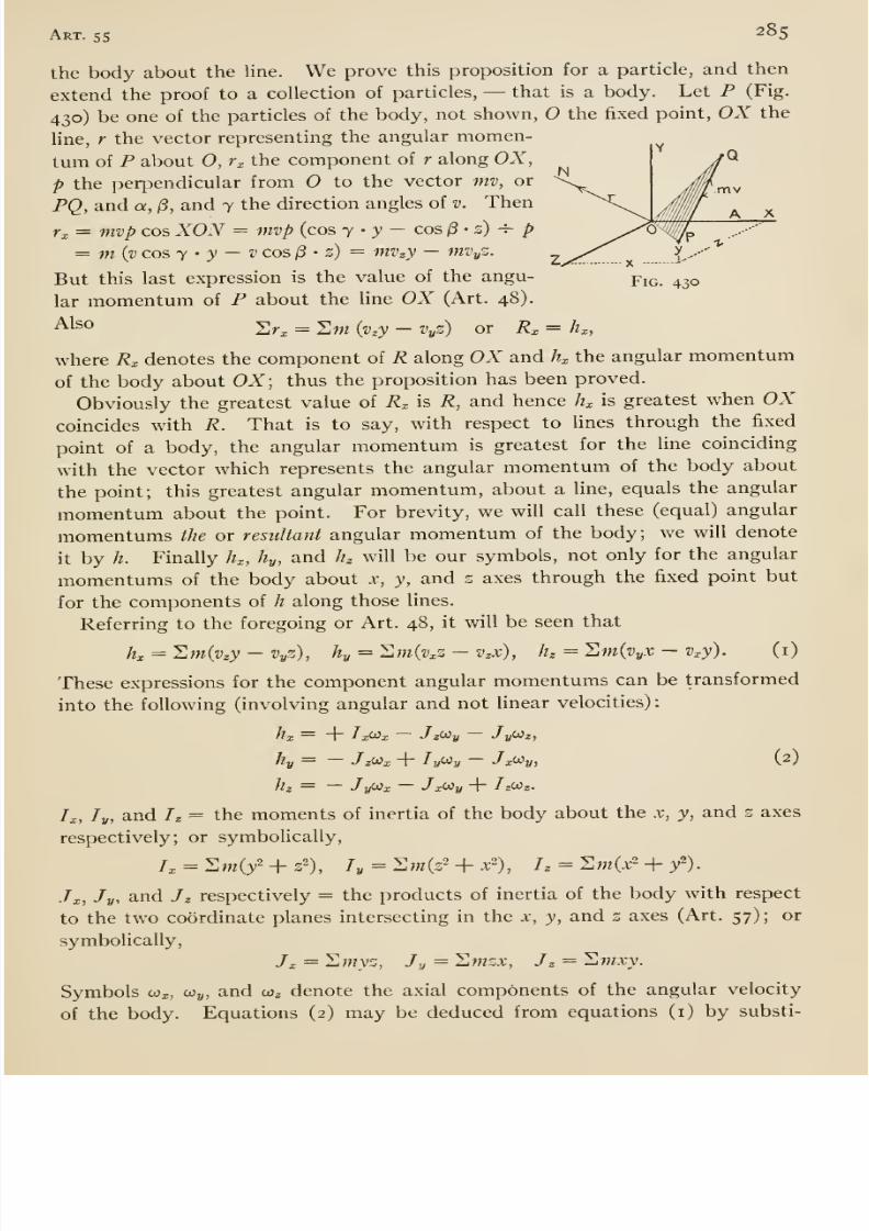
8/13/2019 Maurer Mechanics
http://slidepdf.com/reader/full/maurer-mechanics 301/407
Art. 55 285
the body about the line. We prove this proposition for a particle, and then
extend the proof to a collection of particles, —that is a body. Let P (Fig.
430) be one of the particles of the body, not shown, the fixed point, OX the
line, r the vector representing the angular momen-
tum of P about 0, r^ the component of r along OX,
p the perpendicular from O to the vector mv, or \^^^^
PQ, and a, /3, and 7 the direction angles of v. Then ^\Vi = mvp cos XON = mvp (cos y - y — cos 13- z) ^ p ^
= m (vcosy ' y —vcos^ ' z) = mvzy —mvyZ. ^^ y_..--
But this last expression is the value of the angu- y\q,. 430
lar momentum of P about the line OX (Art. 48).
Al^o Sr^ = 2w {v^y —Vyz) or R^ = h^,
where R^ denotes the component of R along OX and /?x the angular momentum
of the body about OX; thus the proposition has been proved.
Obviously the greatest value of Rx is R, and hence Jh is greatest when OXcoincides with R. That is to say, with respect to lines through the fixed
point of a body, the angular momentum is greatest for the line coinciding
with the vector which represents the angular momentum of the body about
the point; this greatest angular momentum, about a line, equals the angular
momentumabout the point. For brevity, we will call these (equal) angular
momentums the or resultant angular momentum of the body; we will denote
it by h. Finally h^, hy, and hz will be our symbols, not only for the angular
momentums of the body about x, y, and z axes through the fixed point but
for the components of h along those lines.
Referring to the foregoing or Art. 48, it will be seen that
hx = ^m{vzy-VyZ), hy = '^m{vxZ - v^x), h=^m{vyX - v^y). (i)
These expressions for the component angular momentums can be transformed
into the following (involving angular and not linear velocities)
hx = + Ix^x — JzWy — Jy(Jiz,
hy = —J zWx + ly<J^y — J x^y, \V
hz — — J^jix ~ Jxi^y + ^zW«.
/;,, /„, and Iz = the moments of inert ia of the body about the x, y, and 2 axes
respectively; or symbolically,
/, = Sm(/ + 32), [y = ^m(z'-\-x'), Tz = ^m{x'-{-y^).
J^, Jy, and Jz respectively = the products of inertia of the body with respect
to the two coordinate planes intersecting in the x, y, and z axes (Art. 57); or
symbolically,
Jx = '^myz, Jy = Zmzx, Jz = Swxy.
Symbols oox, coy, and coz denote the axial components of the angular velocity
of the body. Equations (2) may be deduced from equations (i) by substi-
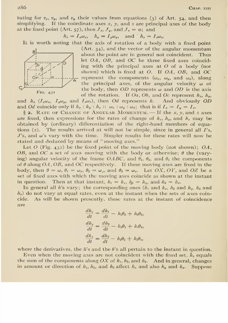
8/13/2019 Maurer Mechanics
http://slidepdf.com/reader/full/maurer-mechanics 302/407
286 Chap, xiii
tuting for v^, Vy, and Vy their values from equations (3) of Art. 54, and then
simplifying. If the coordinate axes x, y, and s are principal axes of the bodyat the fixed point (Art. 57), then /x, Jy, and Jz = o; and
It is worth noting that the axis of rotation of a body with a fixed point
(Art. 54), and the vector of the angular momentumabout the point are in general not coincident. Thuslet OA, OB, and OC be three fixed axes coincid-
ing with the principal axes at O of a body (not
shown) which is fixed at O. If OA, OB, and OC-}^ represent the components (co^, Wy, and coj), along
the principal axes, of the angular velocity co of
thebody, then OD represents w and OD
isthe axis
of the rotation. If Oa, Ob, and Oc represent hx, hy,
and hz (TxCJx, ly^yj ^^^ J^z^z), then Od represents h. And obviously ODand Od coincide only if Jh : hy : hz :: co^ : ojj^ : ojz; that is if /^ = / „ = Iz.
§ 2. Rate of Change or Angular Momentum. —If the x, y, and s axes
are fixed, then expressions for the rates of change of hx, hy, and hz may be
obtained by (ordinary) differentiation of the right-hand members of equa-
tions (2). The results arrived at will not be simple, since in general all /'s,
/'s, and co's vary with the time. Simpler results for these rates will now bestated and deduced by means of moving axes.
Let (Fig. 432) be the fixed point of the moving body (not shown); OA,OB, and OC a set of axes moving with the body or otherwise; d the (vary-
ing) angular velocity of the frame OABC, and di, 62, and 83 the components
of 6 along OA , OB, and OC respectively. If these moving axes are fixed in the
body, then 9 = co, di = o)x, 62 = o}y, and 63 = ojz. Let OX, OY, and OZ be a
set of fixed axes with which the moving axes coincide as shown at the instant
in question. Then at that instant, hi = h^, hp. = //.,,, and hz = hz.
In general all /z's vary; the corresponding ones {]i\ and hj^, hi and hy, hz and
//z) do not vary at equal rates, even at the instant when the sets of axes coin-
cide. As will be shown presently, these rates at the instant of coincidence
are
- h^z + hdi,
-hdi + hds,
dhz dh 1 Q X 1 a
where the derivatives, the /2's and the 0's all pertain to the instant in question.
Even when the moving axes are not coincident with the fixed set, hj^ equals
the sum of the components along OA' of hi, ho, and hs. And in general, changes
in amount or direction of hi, h^, and h^ affect hx and also hy and hz. Suppose
dhx
dt
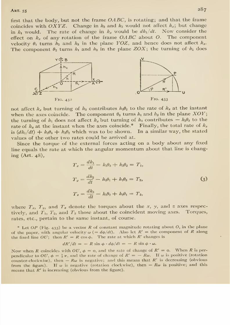
8/13/2019 Maurer Mechanics
http://slidepdf.com/reader/full/maurer-mechanics 303/407
Art. 55 287
first that the body, but not the frame OABC, is rotating; and that the frame
coincides with OXYZ. Change in Ih and I13 would not affect h^; but change
in hi would. The rate of change in h^ would be dhy/dt. Now consider the
effect on hx of any rotation of the frame OABC about 0. The component
velocity di turns Ih and Jh in the plane YOZ, and hence does not affect K.
The component 62 turns hi and hs in the plane ZOX; the turning of hi does
YCbB
Fig. 432
not affect ^^ but turning of hs contributes ^3^2 to the rate of h^ at the instant
when the axes coincide. The component d^ turns hi and //2 in the plane XOY;
the turning of h does not affect h^ but turning of ^ contributes —h^Os to the
rate of hx at the instant when the axes coincide.* Finally, the total rate of hx
is (dhi/di) + /72^3 + h02 which was to be shown. In a similar way, the stated
values of the other two rates could be arrived at.
Since the torque of the external forces acting on a body about any fixed
line equals the rate at which the angular momentum about that line is chang-
ing (Art. 48),
dlh
dtTx- h^dz + /?3^2 = Ti,
dho
Ty=Yt-^''^' + ^1^3 = ^2,
T^ = ^- hA + //29i = ^3,dt
(3)
where Tx, Ty, and T^ denote the torques about the x, y, and 2 axes respec-
tively, and Ti, T2, and ^3 those about the coincident moving axes. Torques,
rates, etc., pertain to the same instant, of course.
*
Let OP(Fig.
433)be a vector R of constant magnitude rotating about O, in the plane
of the paper, with angular velocity co (= d<j>/dO. Also let R' = the component of R along
the fixed line OU; then R' = R cos <>. The rate at which R' changes is
dR'/dt = - i? sin (/) • d<t>/dl = - 7? sin <^ • «.
Now when R coincides with OU, </> = o, and the rate of change of R' = o. When R is per-
pendicular to OU, <t>= ^TT, and the rate of change of /?' = - i?w. If w is positive (rotation
counter-clockwise), then - Ru is negative; and this means that R' is decreasing (obvious
from the figure). If w is negative (rotation clockwise), then — Rw is positive; and this
means that R' is increasing (obvious from the figure).
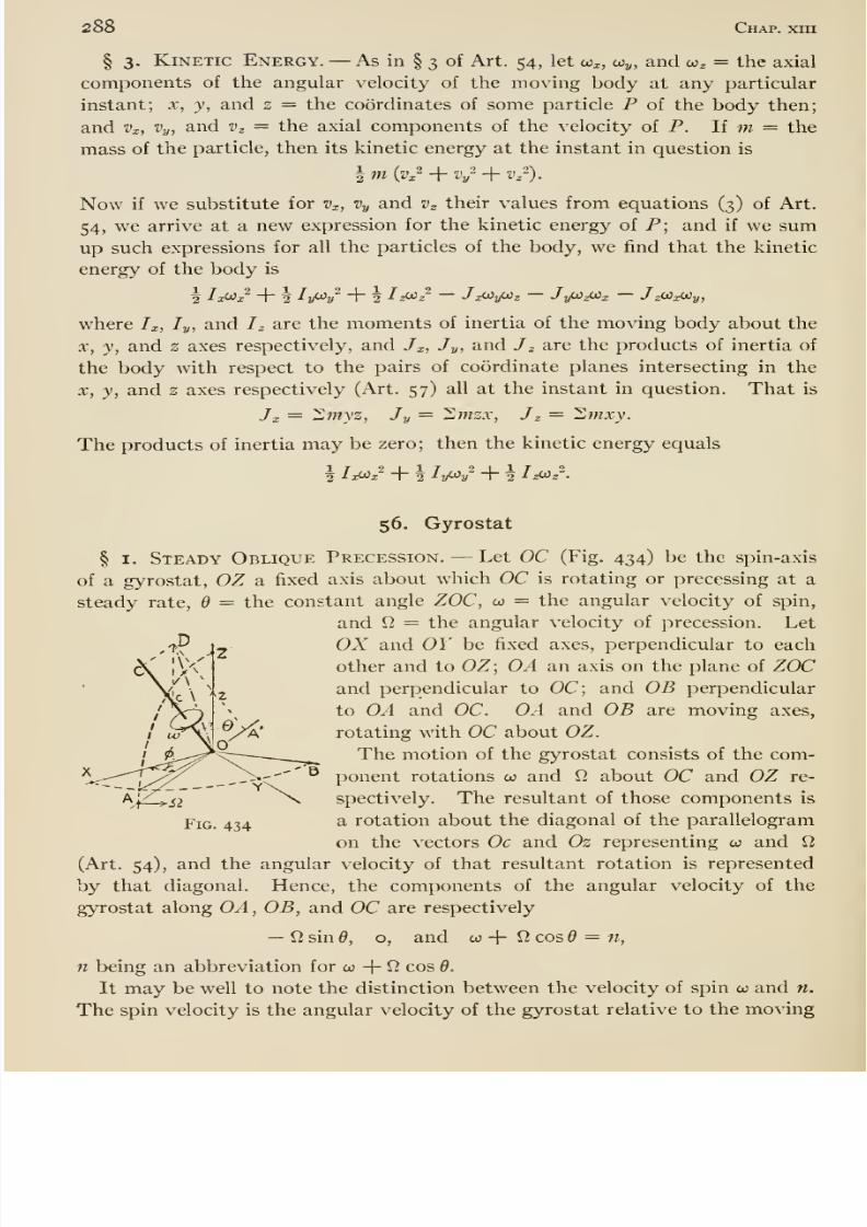
8/13/2019 Maurer Mechanics
http://slidepdf.com/reader/full/maurer-mechanics 304/407
288 Chap, xm
§ 3. Kinetic Energy. —As in § 3 of Art. 54, let co^, o)y, and co^ = the axial
components of the angular velocity of the moving body at any particular
instant; x, y, and z = the coordinates of some particle P of the body then;
and Vx, Vy, and Vz = the axial components of the velocity of P. If m = the
mass of the particle, then its kinetic energy at the instant in question is
Now if we substitute for Vx, Vy and Vz their values from equations (3) of Art.
54, we arrive at a new expression for the kinetic energy of P; and if we sumup such expressions for all the particles of the body, we find that the kinetic
energy of the body is
x^x J Z^xWy,2 I^J^v' + \ ^^? ~ J^yOiz —JyOiz(Jix
where Ix, ly, and I^ are the moments of inertia of the moving body about the
X, y, and 2 axes respectively, and Jx, Jy, and J ^ are the products of inertia of
the body with respect to the pairs of coordinate planes intersecting in the
X, y, and z axes respectively (Art. 57) all at the instant in question. That is
Jx = 2wyz, Jy — Zmzx, J^ = Swxy.
The products of inertia may be zero ; then the kinetic energy equals
56. Gyrostat
§ I. Steady Oblique Precession. —Let OC (Fig. 434) be the spin-axis
of a gyrostat, OZ a fixed axis about which OC is rotating or precessing at a
steady rate, d = the constant angle ZOC, w = the angular velocity of spin,
and fi = the angular velocity of precession. Let
OX and OY be fixed axes, perpendicular to each
other and to OZ; OA an axis on the plane of ZOC
and perpendicular to OC; and OB perpendicularto OA and OC. OA and OB are moving axes,
rotating with OC about OZ.
The motion of the gyrostat consists of the com-
ponent rotations co and ^ about OC and OZ re-
spectively. The resultant of those components is
a rotation about the diagonal of the parallelogram
on the vectors Oc and Oz representing w and Q,
(Art. 54), and the angular velocity of that resultant rotation is representedby that diagonal. Hence, the components of the angular velocity of the
gyrostat along OA, OB, and OC are respectively
—12 sin Q, o, and 00 -f 12 cos 6 = n,
n being an abbreviation for co + fi cos d.
It may be well to note the distinction between the velocity of spin co and n.
The spin velocity is the angular velocity of the gyrostat relative to the moving
Fig. 434
8/13/2019 Maurer Mechanics
http://slidepdf.com/reader/full/maurer-mechanics 305/407
Art. $6 289
frame OABC; it is the product of 2 tt and the number of times per unit time
which a point on the gyrostat pierces the plane ZOC. The angular velocity n
is the component of the absolute angular velocity of the gyrostat along the
fixed line with which OC happens to coincide at the instant in question. Since
OA, OB, and OC are principal axes of the gyrostat (Art. 57), the angular mo-
mentums of the gyrostat about these axes are respectively
—^ 12 sin 6, o, and C (co + 12 cos 6) = Cn,
where A and C denote the moments of inertia of the gyrostat about OA and
OC respectively.
Since the entire frame of axes OABC is rotating about OZ with angular
velocity 12, the components of that velocity along OA, OB, and OC are re-
spectively,
— 12 sin 6, o, and 12 cos 9.
Substituting now in equation (3) of Art. 55, we get as the required values of
the torques of the external forces about the axes OA, OB, and OC respectively
Ti = o,
Tz = Cn 12 sin - /1 12- sin d cos 6,
and T3 = o.
Therefore for steady spin and precession, there must be no torque about any
line in the plane of the spin and precession axes {Ti and Tz = o) but a torqueequal to
Cn 12 sin - ^ 12- sin 6 cos d
about a line perpendicular to those axes and through the fixed point.
Let us now consider whether a gyrostat may precess steadily under the in-
fluence of gravity and the pivot reaction only. Let W= the weight of the
gyrostat, and h = the distance of its center of gravity from the pivot; then the
torques of gravity about OA, OB, and OC are respectively o, Wh sin 6, and o.
We assume that the pivot is so well made that the torques of the reaction
about the lines mentioned equal zero practically. Hence the gyrostat is not
subjected to any torque about OA and OC but to a torque Wh sin d about OB.
If now the quantities W, h, d, etc., be given such values that
Wh sin 6 = Cnn sind - A 12= sin d cos 9,
then all the conditions for steady precession will be satisfied. Evidently
such values can be assigned, in general. Indeed if we solve the preceding
equation for 12, we get
Cn± V(C^n^- 4 AWh cos d)12 =
2 A cos 6
from which it is plain that in general there are two possible velocities of pre-
cession for a given gyrostat, spin 00, and inclination 6. But if C~n = 4 AWhcos 6, then there is only one value of 12; and if CV' < 4 AWh cos d, then
12 is imaginary, and the gyrostat will not precess under the conditions imposed.
8/13/2019 Maurer Mechanics
http://slidepdf.com/reader/full/maurer-mechanics 306/407
2QO Chap, xin
A gyrostat whose center of gravity is at the pivot will precess steadily for
certain conditions of impressed spin, precession, and obliquity. For, suppose
that spin, precession, and obliquity are so arranged that Cn = A^cosd;
then Ts = o, that is no torque is required to maintain the precession. Hence
the gyrostat, with center of gravity at the pivot, would continue to precess.
It may be instructive to consider the follov/ing alternative analysis. Let
hi, hi, and h be the angular momentums about OA, OB, and OC respectively;
and hx, hy, and h those about OX, OY, and OZ. Then
hx = {h cos 6 + hs sin 9) cos xf/,
hy = {hi cos d + hs sin 6) sin ^,
and h = —hi sin- d -\- h cos 6.
Now hi, h, and hz are constant (see preceding page for their values) ; the only
variable in the right-hand members is xl/; and since the x, y, and z axes are
fixed in direction, the rates at which h^, hy, and hz change are respectively
—(hi cos + ^3 sin d) Q, sin xj/, (hi cos 6 + hs sin d) 12 cos \}/, and o.
Now consider the instant when OC lies in the plane ZOX; then i/' = o, and
the rates are o, (hi cos 6 -\- h sin 6) 2, and o. Hence the torques about OXand OZ are zero, and that about OY (the perpendicular to the axes of spin
and precession) is
(/?i cos ^ + /?3 sin 0)12= - A^^sind cosd -{- CnQsind.
This result agrees with that arrived at by the first method.
Gyrostat in a Case. —The foregoing analysis must be modified for a spin-
ning gyrostat in a frame or case which does not spin but merely precesses
with the axis of spin. Let y4 and C be moments of inertia of the spinning part
as before, and A' and C the corresponding moments of inertia of the case.
Then the angular momentums of the case about the axes OA, OB, and OC(Fig. 434) are respectively
-^'12 sine, o, and C^cosO.
These may be added to the earlier expressions for corresponding momentums
of the spinning part to arrive at values of the angular momentums of the entire
gyroscope. Then substituting in equation (3) of Art. 55 as before, we find
that the necessary torques about OA, OB, and OC for steady precession are
respectively
Ti = o,
Ti= (Cw + C 12 cos 0)12 sine- (^ + ^') ^'sin^cose,
and Tz = o,
where w = w -f 12 cos 6 as before.
§ 2. Unsteady Oblique Precession. —Imagine a gyrostat to have
been started spinning in some way, and then released and left to itself on a
frictionless pivot under the action of the pivot reaction and gravity. The
subsequent motion will now be investigated.
Let Wo = the angular velocity of spin, and 0o = the angle between the axis
8/13/2019 Maurer Mechanics
http://slidepdf.com/reader/full/maurer-mechanics 307/407
Ar; ^6 291
of spin and the vertical at release. Let Fig. 434 represent the gyrostat at
some instant after its release; w = the velocity of spin (velocity of the gyro-
stat relative to the plane ZOC) ; Q = the velocity of turning of the plane ZOC(which we will continue to call velocity of precession); and d = the angle
ZOC. We do not assume w, fi, and d to be constants.
At the instant of release, when there is not yet any motion of the axes OABC,the total angular velocity of the gyrostat is coo. At a later instant the angular
velocity of the gyrostat is the resultant of its velocity of spin 00 (relative to
the frame OABC) and the angular velocity of the frame. Now this latter
velocity has the following components along OA, OB, and OC respectively,
Osin^, d* and 12 cos 0;
hence the (resultant) angular velocity of the gyrostat has the following com-
ponents along OA , OB, and OC respectively,
— 12 sin 6, 6, and cu + 12 cos 9 = n,
where n is an abbreviation for 00 + cos 6 as in §1. And the angular mo-
mentums about those same lines are
—Ailsind, Bd, and Cn.
According to equation (3), Art. 55, the rate at which the angular momentumabout OC is changing is
Cn-^A9. sin d - 6 - Bd^smd;
but this rate equals zero since there is no torque about OC. And because
A = B, Cn = o; hence n is constant, and therefore always equals its initial
value, that is,
n — o.
This does not mean that the spin velocity, co, is constant.
Since there isno torque about the
(fixed) axisOZ,
theangular momentumabout that line remains constant; thus that angular momentum at any instant
equals its initial value, or
A 12 sin 6' X sin + Ccoo cos 6 = Cojq cos 60.
This equation shows that
12 = Ccoo (cos do - cos d)~ A sin2 d, (i)
from which one may compute the velocity of the plane ZOC, or the velocity of
precession.Investigation of the (nutational) motion of the spin-axis in the (azimuthal)
plane ZOC can be made simplest by means of the princii)le of work and kinetic
energy (Art. 43). From the instant of release of the gyrostat to any subse-
quent instant, gravity does an amount of work on the gyrostat equal to the
product of the weight and the vertical descent of the center of gravity. If,
* According to this ifluxional) notation, a symbol with a dot over it means the time rate
of the quantity represented by the symbol; thus d means dd/dl, s means ds/dl, etc.
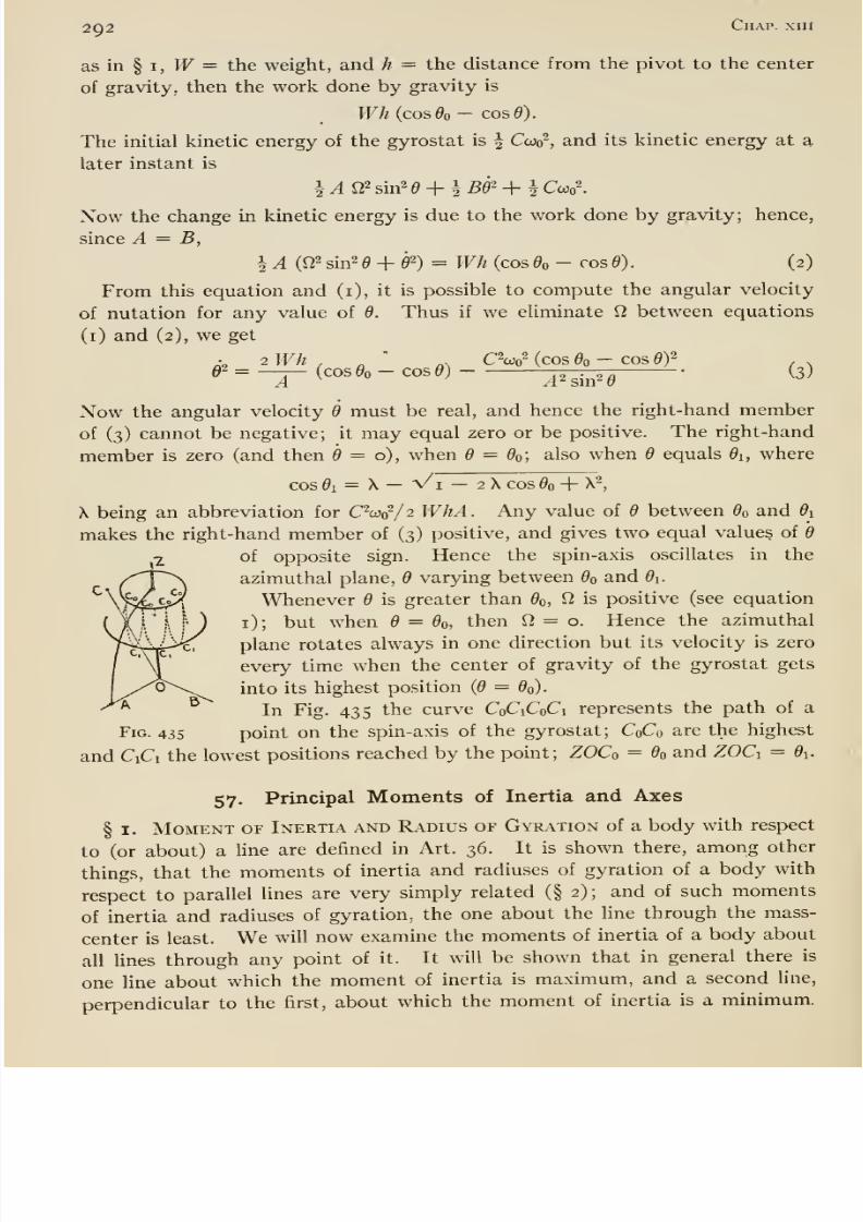
8/13/2019 Maurer Mechanics
http://slidepdf.com/reader/full/maurer-mechanics 308/407
292 Chap, xril
as in § I, PF = the weight, and h = the distance from the pivot to the center
of gravity, then the work done by gravity is
Wh {cos da - cos e).
The initial kinetic energy of the gyrostat is \ Coo<?, and its kinetic energy at a
later instant is
Now the change in kinetic energy is due to the work done by gravity; hence,
since A = B,
i A (f22 sin2 d^d'^) = Wh (cos 6^ - cos d). (2)
From this equation and (i), it is possible to compute the angular velocity
of nutation for any value of 6. Thus if we eliminate S2 between equations
(i) and (2), we get
• 2Wh . ' .- cw (cos d, - cos ey02 = —̂ (COS0O - cos^j AHmH ^^'
Now the angular velocity d must be real, and hence the right-hand member
of (3) cannot be negative; it may equal zero or be positive. The right-hand
member is zero (and then d = 0), when 6 — do; also when d equals di, where
cos 01 = \— Vi — 2 X cos 00 + X^,
X being an abbreviation for CW/2 WhA. Any value of d between do and di
makes the right-hand member of (3) positive, and gives two equal values of d
of opposite sign. Hence the spin-axis oscillates in the
azimuthal plane, d varying between do and di.
Whenever d is greater than do, ^ is positive (see equation
i); but when d = do, then Q, = o. Hence the azimuthal
plane rotates always in one direction but its velocity is zero
every time when the center of gravity of the gyrostat gets
into its highest position {d = do).
In Fig. 435 the curve CoCiCoCi represents the path of a
Fig. 435 point on the spin-axis of the gyrostat; CoCo are the highest
and CiCi the lowest positions reached by the point; ZOCo = do and ZOCi = di.
57. Principal Moments of Inertia and Axes
§ I. Moment of Inertia and Radius of Gyration of a body with respect
to (or about) a line are defined in Art. 36. It is shown there, among other
things, that the moments of inertia and radiuses of gyration of a body with
respect to parallel lines are very simply related (§ 2); and of such moments
of inertia and radiuses of gyration, the one about the line through the mass-
center is least. We will now examine the moments of inertia of a body about
all lines through any point of it. It will be shown that in general there is
one Une about which the moment of inertia is maximum, and a second line,
perpendicular to the first, about which the moment of inertia is a minimum.
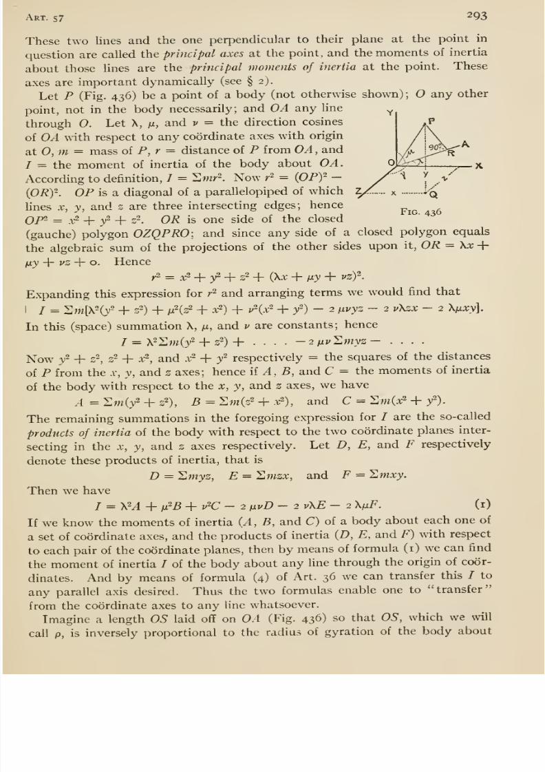
8/13/2019 Maurer Mechanics
http://slidepdf.com/reader/full/maurer-mechanics 309/407
Art. 57 293
These two lines and the one perpendicular to their plane at the point in
question are called the principal axes at the point, and the moments of inertia
about those lines are the principal moments of inertia at the point. These
axes are important dynamically (see § 2).
Let P (Fig. 436) be a point of a body (not otherwise shown) ; any other
point, not in the body necessarily; and OA any line
through 0. Let X, /x, and v = the direction cosines
of OA yviih respect to any coordinate axes with origin
at 0, m = mass oi P,r = distance of P from OA , and
/ = the moment of inertia of the body about OA.
According to definition, I = Smr^. Now r^ = (OPf -
(ORy. OP is a diagonal of a parallelopiped of which
lines X, y, and s are three intersecting edges; hence^^^ ^
Qp2 = ^.2 -f ^2 _|_ 22 Q]^ is one side of the closed'
^^
(gauche) polygon OZQPRO: and since any side of a closed polygon equals
the algebraic sum of the projections of the other sides upon it, OR = \x +/xy + j'S + o. Hence
y2 = ^ + y2 _j. 22 + (\x + juy + vzf.
Ex-panding this expression for r^ and arranging terms we would find that
I / = 2m[X2(/ + 2^) + /x2(22 + ^2) _j_ ^2(^2 -f 3,2) - 2 fiVVZ - 2 v\ZX - 2 X/XXy].
In this (space) summation X, m, and v are constants; hence7 = X22m(/ + 22) + .... - 2 iJiv'^jnyz - ....
Now y2 + 22, 32 + X-, and x ^ + / respectively = the squares of the distances
of P from the .v, y, and z axes; hence ii A, B, and C = the moments of inertia
of the body with respect to the x, y, and z axes, we have
^=2m(/ + s2), 5 = 2w(s2 + .t2), and C ^^mix -\- y^).
The remaining summations in the foregoing expression for / are the so-called
products of inertia of the body with respect to the twocoordinate planes inter-
secting in the x, y, and z axes respectively. Let D, E, and F respectively
denote these products of inertia, that is
D = Jlmyz, E = I^mzx, and F = I,mxy.
Then we have
I = \-A+ ix^B +v^C- 2 (jLvD - 2v\E- 2 X/xF. (i)
If we know the moments of inertia (A, B, and C) of a body about each one of
a set of coordinate axes, and the products of inertia (D, E, and F) with respect
to each pair of the coordinate planes, then by means of formula (i) we can find
the moment of inertia / of the body about any line through the origin of coor-
dinates. And by means of formula (4) of Art. 36 we can transfer this I to
any parallel axis desired. Thus the two formulas enable one to transfer
from the coordinate axes to any line whatsoever.
Imagine a length OS laid off on OA (Fig. 436) so that OS, which we will
call p, is inversely proportional to the radius of gyration of the body about
8/13/2019 Maurer Mechanics
http://slidepdf.com/reader/full/maurer-mechanics 310/407
294 Chap, xiii
OA. That is, ii k = the radius of gyration and K a factor of proportionality,
then p = K/k. Such points 5 for all lines OA would lie on the surface of an
ellipsoid (proved presently) called the momental ellipsoid of the body for the
selected point 0. Let X, Y, and Z = the coordinates of S; they equal pX,
p/i, and pv respectively. Then equation (i) multipUed by p^ reduces to
AX'' + BY^ + CZ2 - 2 DZY - 2 EYX - 2 FXY = K^M, (2)
where M = the mass of the body. This is the equation of an ellipsoid with
center at (see any standard work on Analytic Geometry).
In general, the axes of an ellipsoid are unequal in length. Hence the
radius of gyration (and the moment of inertia) about the shortest axis of the
momental ellipsoid is greater than the radius of gyration (and moment of
inertia) about any other line through the center of the ellipsoid, and the mo-
ment of inertia about the longest axis is less than that about any other line
through the center. Thus we have shown that there are two lines at right
angles to each other through any point of a body (or of its extension) about
which the moments of inertia of the body are maximum and minimum. The
momental ellipsoid might of course be one of revolution in a special case,
or even a sphere.
If two of the products of inertia equal zero, say E and F, then the equation
of the momental eUipsoid is
AX^ + 5F2 + CZ2 - 2 DYZ = Km,which shows that the ellipsoid is symmetrical with respect to the yz plane.
Hence the x axis coincides with one of the axes of the ellipsoid, that is with
one of the principal axes of the body at the point O. If the three products
of inertia equal zero, then the ellipsoid is symmetrical with respect to the three
coordinate planes, and hence each coordinate axis is a principal axis at the
origin. Then if h, h, and h denote the principal moments of inertia, formula
(i) becomes/ = X2/i + m'/2 + V'h.
Symmetrical Bodies. —If a homogeneous body is symmetrical with respect
to a plane, then any line perpendicular to the plane is a principal axis at the
point where it pierces the plane. For, take such line as the x axis, and the y
•and z axes in the plane. Then for every particle of the body whose coordi-
nates are a, 6, and c, there is another one whose coordinates are — a, b, and
c; hence Hmzx and Hmxy = o, and therefore as explained the x axis is a
principal axis at the origin of coordinates.
If a homogeneous body has two planes of symmetry at right angles to each
other, then their intersection is a principal axis at every point of that line.
For if the two planes be taken as coordinate planes and any plane perpendic-
ular to them as the third coordinate plane, then it is obvious that the three
products of inertia equal zero; hence the intersection of the planes of sym-
metry (one of the coordinate axes) is a principal axis at the origin of coordi-
nates (taken at any point on the intersection).
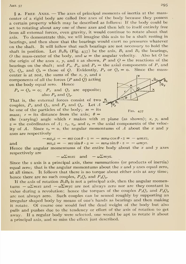
8/13/2019 Maurer Mechanics
http://slidepdf.com/reader/full/maurer-mechanics 311/407
Art. 57 295
Fig. 437
§ 2. Free Axes. —The axes of principal moments of inertia at the mass-
center of a rigid body are called free axes of the body because they possess
a certain property which may be described as follows: If the body could be
set to rotating about any one of these axes and then left to itself entirely free
from all external forces, even gravity, it would continue to rotate about that
axis. To demonstrate this, we will imagine this axis to be a shaft resting in
bearings, and then show that the bearings would exert no pressures whatever
on the shaft. It will follow that such bearings are not necessary to hold the
shaft in position. Let B1B2 (Fig. 437) be the axis, Bi and B^ the bearings,
the mass-center of the body, and co = the angular velocity. Also let O be
the origin of the axes x, y, and z as shown, P and Q -= the reactions of the
bearings on the shaft; and P^, Py, and Pz = the axial components of P, and
Qx, Qy, and Qz = those of Q. Evidently, Pz or Qz = o. Since the mass-
center is at rest, the sums of the x, y, and z
components of all the forces (P and Q) acting
on the body equal zero. Hence
Pg = Q^ = o] Px and Qx are opposite;
also Py and Qy.
That is, the external forces consist of two
couples, Px and Qx, and Py and Qy. Let Abe one of the particles of the body; m = its
mass; r = its distance from the axis; d ==
the (varying) angle which r makes with xz plane (as shown); x, y, and
2 = the coordinates of A ; z'x, Vy, and v^ = the axial components of the veloc-
ity of A. Since v^ = o, the angular momentums of A about the x and y
axes are respectively
—mVyZ = — mv cos 6 • z = — mroi cos d -z = —oomxz,
and mVxZ = — mvsind ' z = — mru sin • z = —wmyz.
Hence the angular momentums of the entire body about the x and y axesrespectively are
—w^mxz and —coSmyz.
Since the z axis is a principal axis, these summations (or products of inertia)
equal zero; that is the angular momentums about the x and y axes equal zero,
at all times. It follows that there is no torque about either axis at any time;
hence there are no such couples, PxQx and PyQy
If the axis of rotation ByBi is not a principal axis, then the angular momen-
tums —oiZmxz and —wSwyz are not always zero nor are they constant in
value during a revolution; hence the torques of the couples PxQx and PyQy
are not always zero. Such couples can be sensed roughly by supporting an
irregular shaped body by means of one's hands as bearings and then making
it rotate. Of course one would feel the dead weight of the body but also
pulls and pushes due to the tendency or effort of the axis of rotation to get
away. If a regular body were selected, one would be apt to rotate it about
a principal axis, and so miss the effect just described.

8/13/2019 Maurer Mechanics
http://slidepdf.com/reader/full/maurer-mechanics 312/407
2q6 Chap, xiii
In general a body has three free axes, the axes of greatest, least, and meanmoments of inertia —axes through the mass-center being understood. There
is an interesting difference among these axes, namely, rotation about the axis
of greatest or least moment of inertia is stable, while rotation about the axis
of mean moment is unstable. That is, if the body were set rotating about
either of the first two axes, then any slight deviation of the axis of rotation
from such principal axis would not be followed by continually increasing
deviations; but if the initial rotation be about the axis of mean moment then
slight deviation is followed by still greater change. Explanation of these
properties would take us too far afield.
58. Any Motion of a Rigid Body; Summary of D3niamics
§ I. Any Motion or a Rigid Body. —A rigid body can be displaced
from one position A into another position B by means of a translation followed
by a rotation. For, it is obvious that a translation can be selected so as to
move any chosen point of the body from its original position (in A) into its
final position (in B). From this intermediate position, the body can be put
into its final position by means of a rotation (of suitable amount) about a
(certain) fixed axis through the final position of (see Art. 54). The displace-
ment might be effected in the reverse order, that is a rotation followed by a
translation. For, a rotation about a fixed line through the base point
could be made so as to put the two lines OP and OQ, P and Q being two points
of the body not in line with 0, parallel to their final positions (in B)\ and a
suitable translation would put those lines (and the body) into their final
positions.
Evidently, the rotation and the translation could be made simultaneously.
Therefore any actual motion of a body from one position into another maybe regarded as a succession of infinitesimal simultaneous translations and
rotations. All the translations mayrefer
to the same base point, but in gen-eral the successive rotations do not occur about the same line of the body.
Thus we may regard any motion of a rigid body as consisting of a translation
(in which each point of the body moves just like the base point), combined with
a rotation about a line through the base point, the hne shifting about in the
body, generally. There is not only such (kinematic) independence of trans-
lation and rotation as just explained, but if we take the center of gravity
as base point, then there is also independence of translation and rotation
dynamically. That is to say, we may ascertain the translation (or motionof the center of gravity) quite independently of the rotation; and the rota-
tion about the center of gravity quite independently of the translation. Weproceed to demonstrate this independence.
As already shown in Art. 34, the acceleration of the mass-center of a body(even if not rigid) may be determined as though all the material of the bodywere concentrated at the mass-center, and all the external forces were applied
at that (dense) point. Therefore if Rx, Ry, and Rz denote the algebraic sums
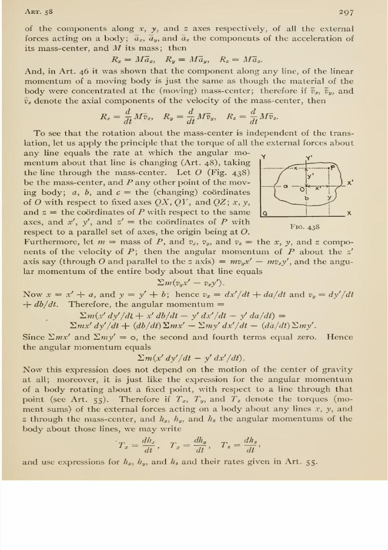
8/13/2019 Maurer Mechanics
http://slidepdf.com/reader/full/maurer-mechanics 313/407
Art. 58 297
of the components along x, y, and 2 axes respectively, of all the external
forces acting on a body; a^, Oy, and Cj the components of the acceleration of
its mass-center, and M its mass; then
R:c = MUj:, Ry = May, Rz = MUz.
And, in Art. 46 it was shown that the component along any line, of the linear
momentum of a moving body is just the same as though the material of the
body were concentrated at the (moving) mass-center; therefore if Vx, Vy, and
Vz denote the axial components of the velocity of the mass-center, then
Rx= ^^ AIV„ Ry = - MVy, K^=Jf
Mvz.
To see that the rotation about the mass-center is independent of the trans-
lation, let us apply the principle that the torque of all the external forces about
any line equals the rate at which the angular mo-mentum about that line is changing (Art. 48), taking
the line through the mass-center. Let O (Fig. 438)
be the mass-center, and P any other point of the mov-
ing body; a, b, and c = the (changing) coordinates
of with respect to fixed axes QX, QY , and QZ] x, y,
and 2 = the coordinates of P with respect to the same
axes, and x',
y', and z' = the coordinates of P with
respect to a parallel set of axes, the origin being at 0.Furthermore, let m = mass of P, and t'., Vy, and Vz = the x, y, and 2 compo-
nents of the velocity of P; then the angular momentum of P about the z'
axis say (through O and parallel to the 2 axis) = mvyx' — mv^y' , and the angu-
lar momentum of the entire body about that Une equals
Umi^Pyx' — Vxy').
Now X = x' -\- a, and y = y' -\- b; hence Vx = dx'/dt + da/dt and Vy = dy'/dt
-\- db/dt. Therefore, the angular momentum =
Sw(.r' dy'/di + x' db/dt - y' dx'/dt - y' da/dt) =Hmx' dy'/dt + (db/dt) Jlmx' - ^my' dx'/dt - {da/dl) Y.my'
Since Swx' and Hmy' = o, the second and fourth terms equal zero. Hence
the angular momentum equals
. llmix' dy'/dt - y' dx'/dt)
Now this expression does not depend on the motion of the center of gravity
at all; moreover, it is just like the expression for the angular momentumof a body rotating about a fixed point, with respect to a line through that
point (see Art. 55). Therefore if Tx, Ty, and Tz denote the torques (mo-
ment sums) of the external forces acting on a body about any lines .v, y, and
2 through the mass-center, and hx, hy, and hg the angular momentums of the
body about those lines, we may write
T -—i r - ^ T =^'~dt' ' dt' ' dt'
and use expressions for hx, hy, and hz and their rates given in Art. 55.
8/13/2019 Maurer Mechanics
http://slidepdf.com/reader/full/maurer-mechanics 314/407
298 Chap, xni
To further emphasize the independence of motion of the mass-center and
the motion of the body ^bout that point, let us consider the kinetic energy of
a body having any motion. Let (Fig. 438) be the center of mass of the body.
We will regard the motion as consisting of a translation like the motion of 0,
and a rotation about some line through O. Let Vi, Vy, and Vz be the axial
components of the velocity of 0; Ux- (^y, and Uz the axial components of the
angular velocity about 0. Then the components of the velocity of any par-
ticle P are (see Art. 54)
Vj; = Vx-{- z'iCy — y'wz,
Vy=Vy-\- x'Uz — z'cOx,
Vz ^ Vz-\- j'cOx — .v'cOy.
Since the kinetic energy of the particle is h mv^ = \m (vx' + Vy^ + vj^), the
kinetic energy of the body is 2 ^ mv ^, or
I M(Vx^ + Vy- + Vz^)-\- \ IjfJix + 2 ^\f^y + 2 ^if^z — Japi^z — /yWzOJx —J Jji^y.
Now the first term of this expression equals \ Mv^, and is the value which
the kinetic energy would have if all the material were concentrated at the
mass-center and were moving with it. The remainder of the expression is
the value which the kinetic energy of the body would have if the center of mass
were fixed (Art. 55).
Once more, let us consider the angular momentum of a body with respect
to a fixed line, say the z axis of Fig. 438. From the definition (Art. 48) the
angular momentum about the s axis of the particle P is
mivyX — Vxy) = ni[{vy-]- x'iOz — z'wx) -v — (^x + s'ojy — y'w^y],
and the angular momentum of the body equals the sum of all such expressions
as the last, or
M(VyX — V^) — JyUix — Jii^y + Jz^z-
Now the first term is the value which the angular momentum would have if
all the material were concentrated at the center of mass and moving with it;
the remainder of the expression is the value which the angular momentumwould have if the mass-center were fixed (see Art. 55).
§2. Summary; Motion of a Rigid Body. —The following summaryis based upon the order of development of dynamics followed in this book;
it may therefore be regarded as a brief review.
Motion of Translation (rectilinear or otherwise). —- The resultant of all the
external forces acting on the body is a single force. Its line of action passes
through the mass-center, and hence the external forces have no torque about
any line through that point. The resultant and the acceleration of the mov-
ing body have the same direction ; hence the algebraic sum of the components
of the external forces at right angles to the acceleration equals zero. Theacceleration is proportional to the resultant directly and to the mass of the
body inversely; or a = R/M (where a = acceleration, R = resultant, and
M = mass) if systematic units be used. The (linear) momentum of the body
8/13/2019 Maurer Mechanics
http://slidepdf.com/reader/full/maurer-mechanics 315/407
Art. 58 299
= Mv = (W/g)v, where v = velocity, W= weight, and g = acceleration due
to gravity. The kinetic energy of the body = | Mv^ = | (W/g) v^.
Rotation about a Fixed Axis. —The torque of all the external forces about
the axis of rotation and the angular acceleration of the rotating body are alike
in sense. The angular acceleration is proportional to the torque directly
and to the moment of inertia of the body (with respect to the axis of rotation)
inversely; or a = T/I (where a = angular acceleration, T = torque, and/ = moment of inertia), if systematic units be used. (It is generally con-
venient to take I = Mk^ = (W/g) h^ where k = radius of gyration of the bodyabout the axis of rotation.) We have also
SF„ = Man, ^Ft = Mat, and 2F3 = o.
The summations mean the algebraic sums of the components of the external
forces —including the axle reaction if any —along three certain lines, namely,
—(i) the perpendicular to the axis of rotation through the mass-center, (2)
the perpendicular to the plane of the line just mentioned and the axis of rota-
tion, and (3) the axis of rotation. Symbols a„ and at denote the components
of the acceleration of the mass-center along the first two lines respectively;
an = ro)^ and at = ra, where r = the distance from the mass-center to the
axis of rotation, co = the angular velocity, and a = the angular acceleration
of the body. If the angular velocity is constant then I1F( = o; if the mass-
center is in the axis of rotation, then the three summations equal zero.
The angular momentum of the body = loo — Mk^oj = (W/g) k^co; its kinetic
energy = i /co^ = i MyfeW = i {W/g) kW.Uniplanar Motion. —It may be regarded as a combined translation and
rotation. Motion of the mass-center is given by
SFx = Max and llFy = May,
where SF^ and HFy respectively mean the algebraic sums of the componentsof the external forces along axes x and y in the plane of the motion; and a^
and ay = the x and y components of the acceleration of the mass-center. Therotation of the body about the mass-center is given by T = la, where T =the torque of the external forces about the perpendicular to the plane of the
motion through the mass-center, / = the moment of inertia of the body about
that line, and a = the angular acceleration of the body. The kinetic energy
of the body is given by \ Mv^ + | loo^, where v = the velocity of the mass-
center and CO = the angular velocity of the body at the instant in question.
Rotation about a Fixed Point. —The principle of motion of the mass-center
(§ 3) furnishes three independent equations of motion of the mass-center like
2Fx = Md„where the symbols have meanings already explained. The axes x, y, and z
must not be parallel. The principle of torque and angular momentum fur-
nishes three independent equations like
Tx = dhx/dt,
8/13/2019 Maurer Mechanics
http://slidepdf.com/reader/full/maurer-mechanics 316/407
300 Chap, xiii
where Tx is the torque of the forces acting on the body about any line x, and //^
is the angular momentum of the body about the same line. That line and
the other two may be taken at pleasure; generally hnes through the fixed
point are simplest.
Any {Solid) Motion. —Motion of the mass-center and rotation about the
mass-center are independent (§ i). We may treat these motions separately;
the first as the motion of a particle whose mass equals that of the body under
the action of forces Uke those acting on the body; the second as though the
body were fixed at the mass-center.
§ 3. Summary; Motion of Any System of Particles, Solid or Fluid.
—We will call the system a body but without implying that it is rigid except
as noted.
Principle of Motion of Mass-Center. —The motion of the mass-center does
not depend at all on the internal forces; it moves just as if all the material
of the moving body were concentrated at the mass-center and all the external
forces were applied to that (dense) point in their actual directions of course.
Thus the component of the acceleration of the mass-center along any line
is proportional to the algebraic sum of the components of the external forces
along that line directly and to the mass of the body inversely. Or, if sys-
tematic units are used a^ = 2Fx -^ M, where ax and S/^x = the mentioned
component acceleration and algebraic sum respectively and M = mass. The
foregoing equation is generally written
2F^ = Max.
Principle of Force and Momentum. —The algebraic sum of the components
—along any line —of the external forces acting on the body at any instant
equals the rate at which the component (along the same Une) of the momen-
tum of the body is changing them. Or
where Vx = the component of the velocity of the mass-center along the line
called X. Mvx — the x component of the linear momentum of the body.
Principle of Impulse and Momentum. —The algebraic sum of the impulses
of the components —along any line —of all the external forces for any in-
terval equals the increment in the component of the momentum of the body
along that line for that interval. Or
^r Fxdt = Mvx - MvJ.
Principle of Torque. —The torque of all the external forces, acting on any
body, equals the torque of the resultants of all the forces acting on the par-
ticles of the body, all torques being taken about any line. An expression
for this latter torque was deduced in Art. 48, the line about which torque was
taken being called a z coordinate axis; it is 21w {ayX — axj), where m. = the
mass of any particle, x and y = the coordinates of the particle, and ax and
8/13/2019 Maurer Mechanics
http://slidepdf.com/reader/full/maurer-mechanics 317/407
i:
Art. 58 301
Oy = the X and y components of its acceleration all at the instant in question.
Thus the principle gives
Tg = 2w(oyX — ax}'),
where Tg means the torque of all the external forces about the z axis.
Principle of Torque and Angular Momentum. —The torque of the external
forces acting on the moving body about any line equals the rate at which the
angular momentum of the body about that line is changing (Art. 48). Or
Tz = —'^{mVyX — mvjry),
the torque and angular momentum being taken about a z axis of a coordinate
frame. If, in a given case, there is no torque during an interval then the
angular momentum about that line remains constant; this is the principle of
conservation of angular momentum.Principle of Angular Impulse and Momentum. —The angular impulse of all
the external forces —about any line —for any interval equals the increment
in the angular momentum of the body about that line and for that interval.
Or
Tzdt = AH (mVyX —mv^y).'i'
Principle of Work and Kinetic Energy. —The total work done upon a body
by all the external and internal forces during any displacement of the bodyequals the increment in the kinetic energy of the body during the interval.
If the total work is positive then there is a real gain; if negative, then there
is loss. If the body is a rigid one, the internal forces do no work; the total
work done upon the body by the external forces equals the increment in its
kinetic energy.
Principle of Conservation of Energy. —If a body is isolated so that it is
beyond the influence of other bodies, then during any change of condition
of the body, the amount of its energy remains constant. There may be atransfer of energy from one part of the body to another, but the total gain
or loss in one part is exactly equivalent to the loss or gain in the remainder.
D'Alembert's Principle, not heretofore discussed. —The resultant of all the
forces acting on any particle of a body is called the effective force for that par-
ticle. Its magnitude equals the product of the mass and acceleration of the
particle; its direction is the same as that of the acceleration. The group of
effective forces for all the particles of a body is called the effective system (of
forces) for the body. It should be noted that these forces are fictitious or
imaginary, equivalent respectively to the actual forces acting upon the par-
ticles. The principle may be stated in two forms: —(a) The external system
of forces and the effective system are equivalent, and (b) the external system
and the reversed effective system jointly balance, or are in equilibrium.
8/13/2019 Maurer Mechanics
http://slidepdf.com/reader/full/maurer-mechanics 318/407
APPENDIX A
THEORY OF DIMENSIONS OF UNITS
§ I. Dimensions of Units. —The magnitude of a quantity is expressed
by stating how many times larger it is than a standard quantity of the same
kind and naming the standard. Thus, we say that a certain distance is lo
miles, meaning that the distance is lo times as great as the standard distance,
the mile. The number expressing the relation between the magnitude of
the quantity and the standard (the number lo in the illustration) is called the
numeric (or numerical value) of the quantity, and the standard is called the
unit.
A unit for measuring any kind of quantity may be selected arbitrarily, but
it must of course be a quantity of the same kind as the quantity to be measured.
Thus, as unit of velocity we might select the velocity of light, as unit of area
the area of one face of a silver dollar, etc. Many units in use are arbitrarily
chosen, that is without reference to another unit (for example, the bushel and
the degree); but generally it is convenient practically to define them with
reference to each other. All mechanical and nearly all physical quantities
can be defined in terms of three arbitrarily selected units, not dependent on
any other units. These are called fundamental units, and the others, defined
with reference to them, derived units. It is customary in works on theoretical
mechanics and physics to choose as fundamental the units of
length, mass, and time;
but it is sometimes more convenient to take as fundamental the units of
length, force, and time.
We give an analysis of derived units with reference to each of these sets of
fundamentals, and two tables in which the absolute units are referred to the
first set of fundamentals and the gravitational units to the second set. But
either set might serve as fundamentals for all absolute and gravitational
units.
A statement of the way in which a derived unit depends on the funda-
mental units involved in it is called a statement of the dimensions of the
unit. For example,
one square yard _ (one yard, or three feet)^ __
one square foot (one foot)^
302
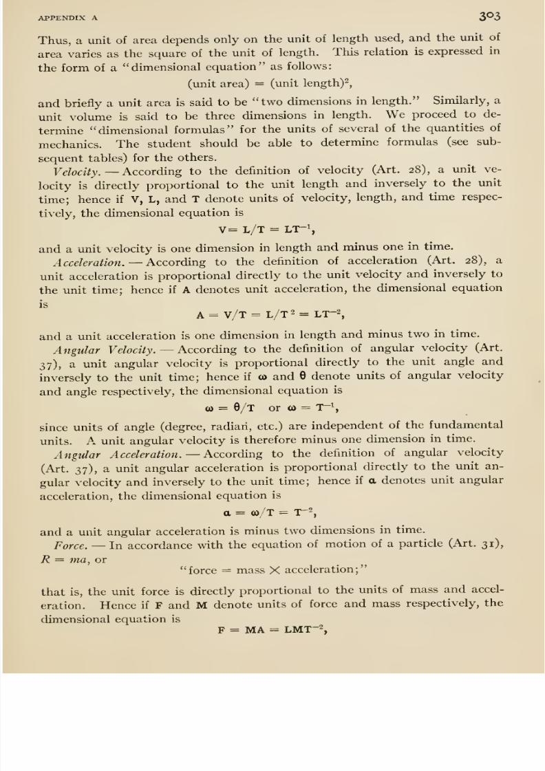
8/13/2019 Maurer Mechanics
http://slidepdf.com/reader/full/maurer-mechanics 319/407
APPENDIX A 3®3
Thus, a unit of area depends only on the unit of length used, and the unit of
area varies as the square of the unit of length. This relation is expressed in
the form of a dimensional equation as follows:
(unit area) = (unit length)^,
and briefly a unit area is said to be two dimensions in length. Similarly, a
unit volume is said to be three dimensions in length. We proceed to de-
termine dimensional formulas for the vmits of several of the quantities of
mechanics. The student should be able to determine formulas (see sub-
sequent tables) for the others.
Fe/oaVj. —According to the definition of velocity (Art. 28), a unit ve-
locity is directly proportional to the unit length and inversely to the unit
time; hence if V, L, and T denote units of velocity, length, and time respec-
tively, thedimensional equation is
V= L/T = LT-S
and a unit velocity is one dimension in length and minus one in time.
Acceleration. —According to the definition of acceleration (Art. 28), a
unit acceleration is proportional directly to the unit velocity and inversely to
the unit time; hence if A denotes unit acceleration, the dimensional equation
is
and a unit acceleration is one dimension in length and minus two in time.
Angular Velocity. —According to the definition of angular velocity (Art.
37), a unit angular velocity is proportional directly to the unit angle and
inversely to the unit time; hence if <o and 6 denote units of angular velocity
and angle respectively, the dimensional equation is
(0 = 6/T or (0 = T-\
since units of angle (degree, radian, etc.) are independent of the fundamental
units. A unit angular velocity is therefore minus one dimension in time.
Angular Acceleration. —kccording to the definition of angular velocity
(Art. 37), a unit angular acceleration is proportional directly to the unit an-
gular velocity and inversely to the unit time; hence if a denotes unit angular
acceleration, the dimensional equation is
a = a)/T = T-2,
and a unit angular acceleration is minus two dimensions in time.
Force. —In accordance with the equation of motion of a particle (Art. 31),
R = ma, or
force = mass X acceleration;
that is, the unit force is directly proportional to the units of mass and accel-
eration. Hence if F and M denote units of force and mass respectively, the
dimensional equation is
F = MA = LMT-2,
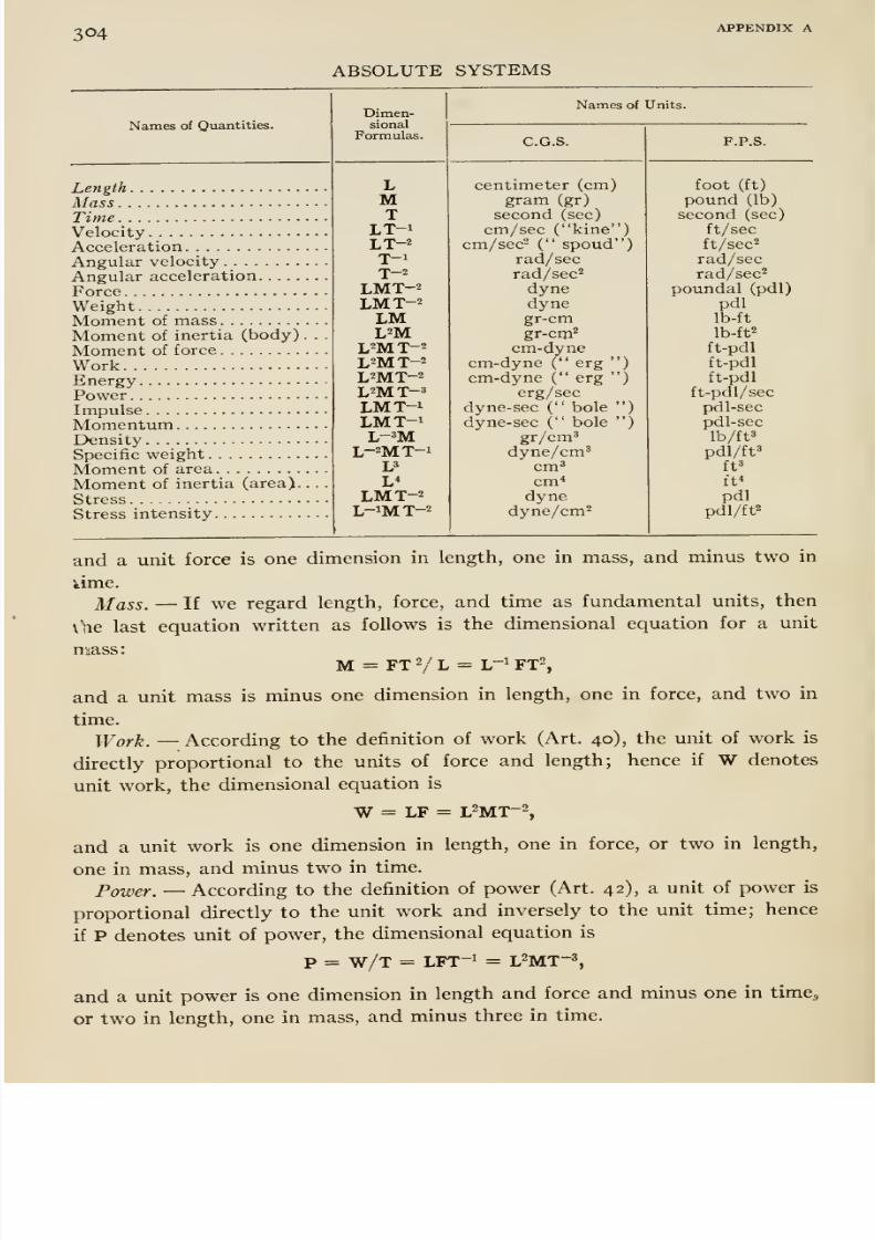
8/13/2019 Maurer Mechanics
http://slidepdf.com/reader/full/maurer-mechanics 320/407
304 APPENDIX A
ABSOLUTE SYSTEMS
Names of Quantities.
LengthMassTimeVelocityAccelerationAngular velocityAngular accelerationForceWeightMoment of massMoment of inertia (body)
Moment of forceWorkEnergyPowerImpulseMomentumDensitySpecific weightMoment of areaMoment of inertia (area).
StressStress intensity
Dimen-sional
Formulas.
Names of Units.
C.G.S.
LMT
LT-iLT-2
T-if—
LMT-2LMT-2
LML2M
L2MT-2L^MT-^L2MT-2L=MT-3LMT-iLMT-iL-^M
L-2MT-1UL*
LMT-2L-iMT-2
centimeter (cm)gram (gr)
second (sec)
cm/sec ( kine )cm/sec^ ( spoud )
rad/secrad/sec^
dynedyne
gr-cmgr-cqi^
cm-dynecm-dyne ( erg )
cm-dyne ( erg )
erg/secdyne-sec ( bole )
dyne-sec ( bolegr/cm^
dyne/cm'cm'cm*
dynedyne/cm^
')
F.P.S.
foot (ft)
pound (lb)
second (sec)
ft/secft/sec^
rad/secrad/sec^
poundal (pdl)pdl
Ib-ft
Ib-ft^
ft-pdlft-pdlft-pdl
ft-pdl/secpdl-secpdl-sec
lb/ft'
pdl/ft»ft'
ft*
pdlpdl/ft2
and a unit force is one dimension in length, one in mass, and minus two in
kime.
Mass. —If we regard length, force, and time as fundamental units, then
\\ie last equation written as follows is the dimensional equation for a unit
mass:M = FTVL = L-1FT2,
and a unit mass is minus one dimension in length, one in force, and two in
time.
Work. —According to the definition of work (Art. 40), the unit of work is
directly proportional to the units of force and length; hence if W denotes
unit work, the dimensional equation is
W= LF = L2MT-2,
and a unit work is one dimension in length, one in force, or two in length,
one in mass, and minus twoin time.
Power. —According to the definition of power (Art. 42), a unit of power is
proportional directly to the unit work and inversely to the unit time; hence
if P denotes unit of power, the dimensional equation is
p = w/T = LFT-i = L^MT-s,
and a unit power is one dimension in length and force and minus one in time^
or two in length, one in mass, and minus three in time.
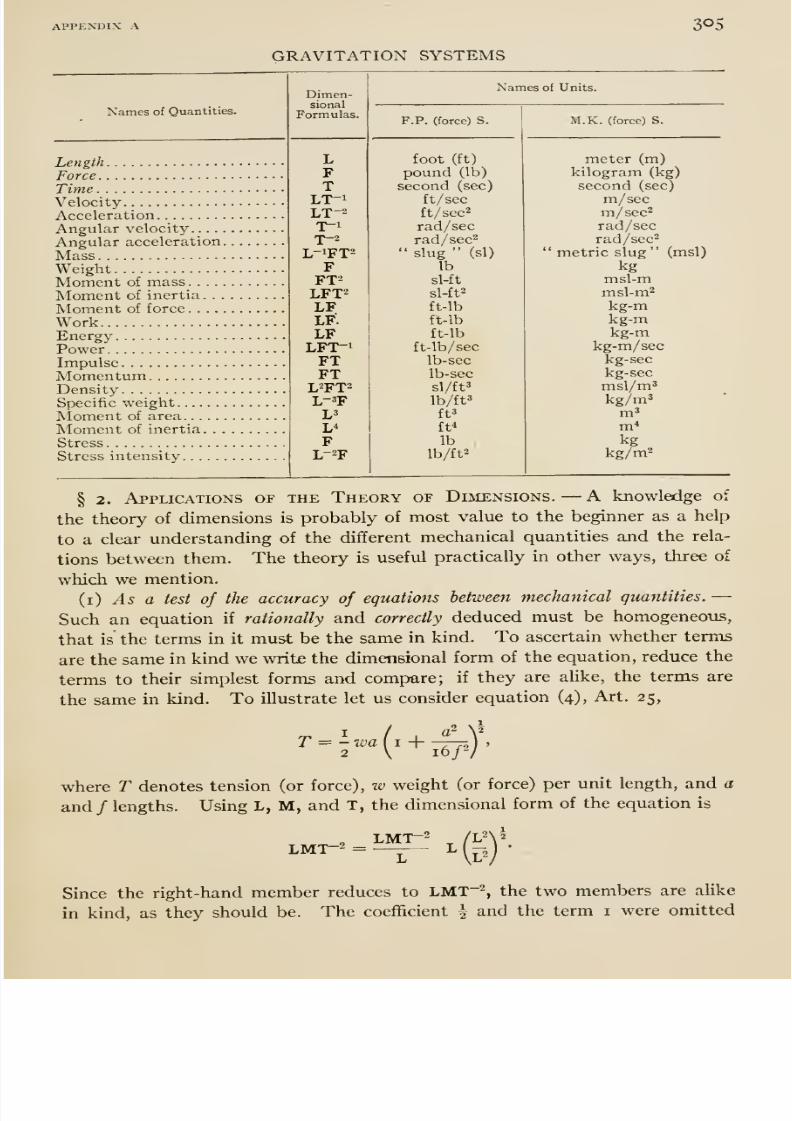
8/13/2019 Maurer Mechanics
http://slidepdf.com/reader/full/maurer-mechanics 321/407
APPENDIX A 305
GRAVITATION SYSTEMS
Names of Quantities.
LengthForceTimeVelocityAccelerationAngular velocity. . . .
Angular accelerationMassWeightMoment of mass. . . .
Moment of inertia. . ,
Moment of force ....
WorkEnergyPowerImpulseMomentumDensitySpecific weightMoment of areaMoment of inertia. .
StressStress intensity
Names of Units.
P.P. (force) S. M.K. (force) S.
foot (ft)
pound (lb)
second (sec)
ft/ secft/sec'^
rad/secrad/sec^
slug (si)
lb
meter (m)kilogram (kg)
second (sec)
m/secm/sec''
rad/secrad/sec^
metric slug
kg(msl)
sl-ft
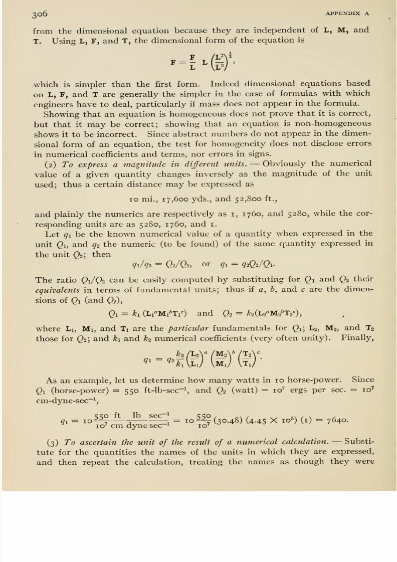
8/13/2019 Maurer Mechanics
http://slidepdf.com/reader/full/maurer-mechanics 322/407
3o6 APPENDIX A
from the dimensional equation because they are independent of L, M, and
T. Using L, F, and T, the dimensional form of the equation is
)'
which is simpler than the first form. Indeed dimensional equations based
on L, F, and T are generally the simpler in the case of formulas with which
engineers have to deal, particularly if mass does not appear in the formula.
Showing that an equation is homogeneous does not prove that it is correct,
but that it may be correct; showing that an equation is non-homogeneous
shows it to be incorrect. Since abstract numbers do not appear in the dimen-
sional form of an equation, the test for homogeneity does not disclose errors
in numerical coefficients and terms, nor errors in signs.
(2) To express a magnitude in different units. —Obviously the numerical
value of a given quantity changes inversely as the magnitude of the unit
used; thus a certain distance may be expressed as
10 mi., 17,600 yds., and 52,800 ft.,
and plainly the numerics are respectively as i, 1760, and 5280, while the cor-
responding units are as 5280, 1760, and i.
Let qibe the known numerical value of a quantity when expressed in the
unit ^1, and 92 the numeric (to be found) of the same quantity expressed in
the unit Q2; then
qi/g2 = Q2/Q1, or gi = g-iQi/Qi-
The ratio Q1/Q2 can be easily computed by substituting for Qi and Q2 their
eguivalents in terms of fundamental units; thus if a, b, and c are the dimen-
sions of Qi (and Q2),
Qi= ki (Li°Mi*Ti^) and
Q2= ^2(L2''M2''T2=),
where Li, Mi, and Ti are the particular fundamentals for Qi; L2, M2, and T2
those for Q2; and ki and k2 numerical coefficients (very often unity). Finally,
k2 fuy /MoV (I2
As an example, let us determine how many watts in 10 horse-power. Since
Qi (horse-power) = 550 ft-lb-sec~S and Q2 (watt) = 10^ ergs per sec. = 10^
cm-dyne-sec~^,
qt;o ft lb sec~^ i;SO/ o\ / ^^ ^\ / \ ^gi = 10^ —-.
zi = 10^(30.48) (4.45 X io5) (i) = 7640.10' cm dyne sec ^ 10^
(3) To ascertain the unit of the result of a numerical calculation. —Substi-
tute for the quantities the names of the units in which they are expressed,
and then repeat the calculation, treating the names as though they were
8/13/2019 Maurer Mechanics
http://slidepdf.com/reader/full/maurer-mechanics 323/407
APPENDIX A 307
algebraic quantities. The reduced answer is the name of the unit of the
numerical answer. Thus in the formula for the elongation of a rod due to a
pull at each end, Pl/AE (wherein P denotes pull, I length of the rod, A area
of cross-section, and E Young's modulus for the material), suppose that P =
10,000 lbs., / = 50 in., .4 = 0.5 in , E = 30,000,000 lbs/in^; the calculations
for elongation and name of unit are
10,000 X tjo , lbs X in lbs X in X in^= 0.33, and • 0^1. ,. 2 = -2 s^ IK. = •
0.5 X 30,000,000 ^^' in- X lbs/in in^ X lbs
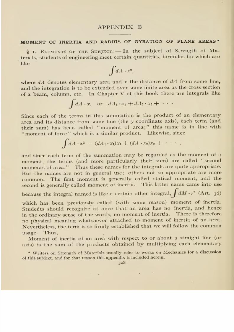
8/13/2019 Maurer Mechanics
http://slidepdf.com/reader/full/maurer-mechanics 324/407
APPENDIX B
MOMENT OF INERTIA AND RADIUS OF GYRATION OF PLANE AREAS*
§ I. Elements of the Subject. —In the subject of Strength of Ma-
terials, students of engineering meet certain quantities, formulas for which are
like
dA • x^,Pwhere dA denotes elementary area and x the distance of dA from some line,
and the integration is to be extended over some finite area as the cross section
of a beam, column, etc. In Chapter V of this book there are integrals like
/ dA 'X, or dAi- Xi + dAi • X2 + •
Since each of the terms in this summation is the product of an elementary-
area and its distance from some line (the y coordinate axis), each term (and
their simi) has been called moment of area; this name is in line with
moment of force which is a similar product. Likewise, since
/ dA • x ^ = {dAi • x{)xi + {dA • a;2):^2 +
and since each term of the summation may be regarded as the moment of a
moment, the terms (and more particularly their sum) are called second
moments of area. Thus these names for the integrals are quite appropriate.
But the names are not in general use; others not so appropriate are more
common. The first moment is generally called statical moment, and the
secondis generally called moment of inertia. This latter name came into use
because the integral named is like a certain other integral, / dM • r^ (Art. 36)
which has been previously called (with some reason) moment of inertia.
Students should recognize at once that an area has no inertia, and hence
in the ordinary sense of the words, no moment of inertia. There is therefore
no physical meaning whatsoever attached to moment of inertia of an area.
Nevertheless, the term is so firmly established that we will follow the common
usage. Thus,Moment of inertia of an area with respect to or about a straight line (or
axis) is the sum of the products obtained by multiplying each elementary
* Writers on Strength of Materials usually refer to works on Mechanics for a discussion
of this subject, and for that reason this appendix is included herein.
308
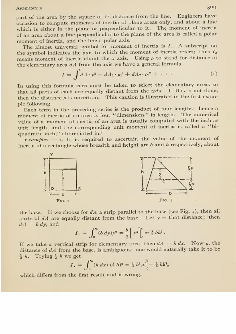
8/13/2019 Maurer Mechanics
http://slidepdf.com/reader/full/maurer-mechanics 325/407
Appendix b 309
part of the area by the square of its distance from the line. Engineers have
occasion to compute moments of inertia of plane areas only, and about a line
which is either in the plane or perpendicular to it. The moment of inertia
of an area about a Hne perpendicular to the plane of the area is called a polar
moment of inertia, and the Une a polar axis.
The almost universal symbol for moment of inertia is /. A subscript onthe symbol indicates the axis to which the moment of inertia refers; thus /;,
means moment of inertia about the x axis. Using p to stand for distance of
the elementary area dA from the axis we have a general formula
(i)/ = fdA . p2 = J^i . pi^ + dA2 • P2' +
In using this formula care must be taken to select the elementary areas so
that all parts of each are equally distant from the axis. If this is not done,
then the distance p is uncertain. This caution is illustrated in the first exam-
ple following.
Each term in the preceding series is the product of four lengths; hence a
moment of inertia of an area is four dimensions in length. The numerical
value of a moment of inertia of an area is usually computed with the inch as
unit length, and the corresponding unit moment of inertia is called a bi-
quadratic inch, abbreviated in.*
Examples. —i. Itis required to ascertain the value of the moment of
inertia of a rectangle whose breadth and height are b and h respectively, about
the base. If we choose for dA a strip parallel to the base (see Fig. i), then all
parts of dA are equally distant from the base. Let y = that distance; then
dA = b dy, and
=J\bdy)f
= ^^^y''^^ = ibh'.
If we take a vertical strip for elementary area, then dA = h dx. Now p, the
distance of dA from the base, is ambiguous; one would naturally take it to be
I h. Trying | /? we get
h= f\hdx){hhY = \h'[x]=lbh\Jo
which differs from the first result and is wrong.
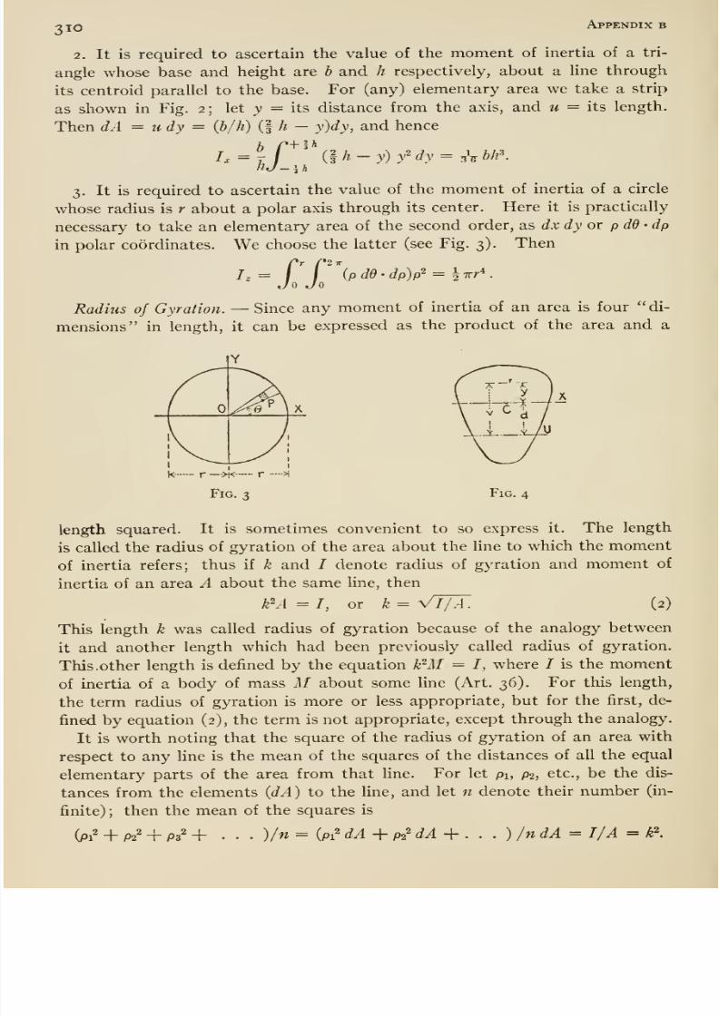
8/13/2019 Maurer Mechanics
http://slidepdf.com/reader/full/maurer-mechanics 326/407
310 Appendix b
2. It is required to ascertain the value of the moment of inertia of a tri-
angle whose base and height are h and h respectively, about a hne through
its centroid parallel to the base. For (any) elementary area we take a strip
as shown in Fig. 2; let y = its distance from the axis, and u = its length.
Then dA = u dy = (b/h) (f h — y)dy, and hence
/x =7 / ilh-y) f dy = ^\ bh\lij-\h
3. It is required to ascertain the value of the moment of inertia of a circle
whose radius is r about a polar axis through its center. Here it is practically
necessary to take an elementary area of the second order, as dx dy or p dd • dp
in polar coordinates. We choose the latter (see Fig. 3). Then
Jo Jo(pdd-dp)p'^ = ^Trr*.
Radius of Gyration. —Since any moment of inertia of an area is four di-
mensions in length, it can be expressed as the product of the area and a
Fig.
length squared. It is sometimes convenient to so express it. The length
is called the radius of gyration of the area about the line to which the moment
of inertia refers; thus if k and I denote radius of gyration and moment of
inertia of an area A about the same Une, then
(2)^A or Vl/A.
This length k was called radius of gyration because of the analogy between
it and another length which had been previously called radius of gyration.
This. other length is defined by the equation k'^AI = /, where / is the moment
of inertia of a body of mass M about some line (Art. 36). For this length,
the term radius of gyration is more or less appropriate, but for the first, de-
fined by equation (2), the term is not appropriate, except through the analogy.
It is worth noting that the square of the radius of gyration of an area with
respect to any line is the mean of the squares of the distances of all the equal
elementary parts of the area from that hne. For let pi, P2, etc., be the dis-
tances from the elements (dA) to the line, and let n denote their number (in-
finite) ; then the mean of the squares is
W-\-P2^-\-P3'+ • • •)/n= {pi' dA + P2' dA -{- . . . )/ndA = I/A = k\
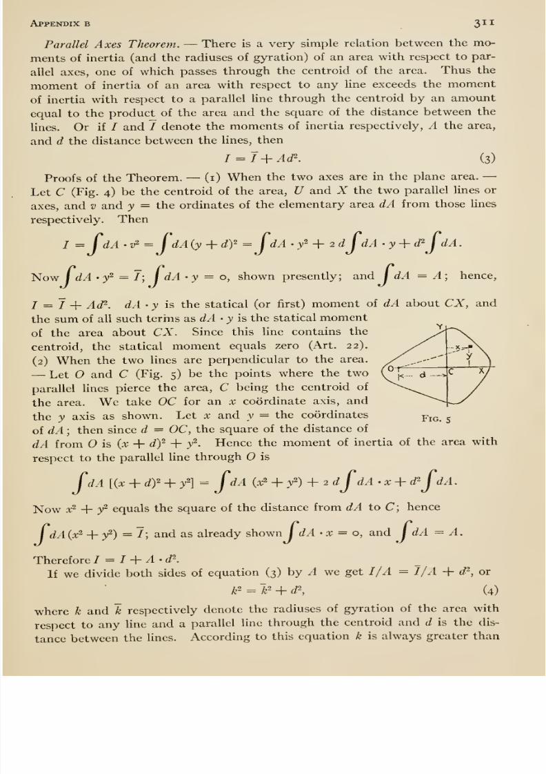
8/13/2019 Maurer Mechanics
http://slidepdf.com/reader/full/maurer-mechanics 327/407
Appendix b 311
Parallel Axes Theorem. —There is a very simple relation between the mo-
ments of inertia (and the radiuses of gyration) of an area with respect to par-
allel axes, one of which passes through the centroid of the area. Thus the
moment of inertia of an area with respect to any hne exceeds the moment
of inertia with respect to a parallel line through the centroid by an amoimt
equal to the product of the area and the square of the distance between the
lines. Or if / and / denote the moments of inertia respectively, A the area,
and d the distance between the lines, then
I = l+Ad\ (3)
Proofs of the Theorem. —(i) When the two axes are in the plane area. —Let C (Fig. 4) be the centroid of the area, U and X the two parallel lines or
axes, and v and y = the ordinates of the elementary area dA from those lines
respectively. Then
/ = ^dA'v =JdA(y + dy =JdA •/ + 2dJdA-y-\-d^JdA.
NowI
dA -y^ = J;f
dA ' y = o, shown presently; and j dA = A; hence,
I = 1 + Ad^. dA • y is the statical (or first) moment of dA about CX, and
the sum of all such terms a.s dA -y is the statical moment
of the area about CX. Since this line contains the
centroid, the statical moment equals zero (Art. 22).
(2) When the two lines are perpendicular to the area.
—Let and C (Fig. 5) be the points where the two
parallel lines pierce the area, C being the centroid of
the area. We take OC for an x coordinate axis, and
the y axis as shown. Let x and y = the coordinates
of dA ; then since d = OC, the square of the distance of
dA from is {x -\- df + y ^. Hence the moment of inertia of the area with
respect to the parallel line through is
fdA [{x + df + /] = JdA (x2 + /) + 2 dJdA . X + d^JdA.
Now x^ + / equals the square of the distance from dA to C; hence
/ dA{x^ 4- /) =7; and as already shown I dA - x = o, and j dA = A.
Therefore I = I + A-d^.
If we divide both sides of equation (3) by A we get I/A = I/A -f d ^, or
k^=~k'i- d\ (4)
where k and k respectively denote the radiuses of gyration of the area with
respect to any line and a parallel line through the centroid and d is the dis-
tance between the lines. According to this equation k is always greater than
Fig. 5
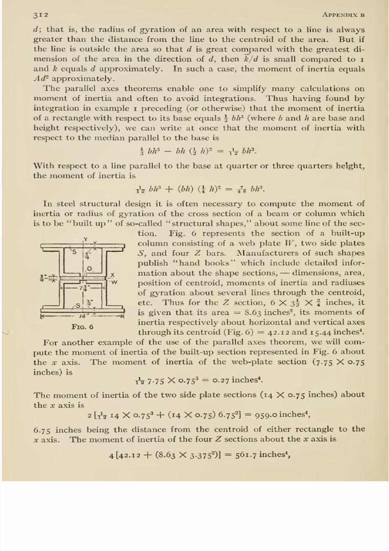
8/13/2019 Maurer Mechanics
http://slidepdf.com/reader/full/maurer-mechanics 328/407
312 Appendix b
d; that is, the radius of gyration of an area with respect to a Hne is always
greater than the distance from the line to the centroid of the area. But if
the line is outside the area so that d is great compared with the greatest di-
mension of the area in the direction of d^ then k/d is small compared to i
and k equals d approximately. In such a case, the moment of inertia equals
Ad^ approximately.
The parallel axes theorems enable one to simplify many calculations on
moment of inertia and often to avoid integrations. Thus having found byintegration in example i preceding (or otherwise) that the moment of inertia
of a rectangle with respect to its base equals \ h¥ (where b and h are base and
height respectively), we can write at once that the moment of inertia with
respect to the median parallel to the base is
\ b¥ - hh (i hy- =tV
bh\
With respect to a line parallel to the base at quarter or three quarters height,
the moment of inertia is
tV bh' + (bh) (i hy = 74? bh'
51
In steel structural design it is often necessary to compute the moment of
inertia or radius of gyration of the cross section of a beam or column which
is to be built up of so-called structural shapes, about some Une of the sec-
tion. Fig. 6 represents the section of a built-up
column consisting of a web plate W, two side plates
S, and four Z bars. Manufacturers of such shapes
publish hand books which include detailed infor-
mation about the shape sections, —dimensions, area,
position of centroid, moments of inertia and radiuses
of gyration about several lines through the centroid,
etc. Thus for the Z section, 6 X 3I X f inches, it
is given that its area = 8.63 inches^, its moments of
inertia respectively about horizontal and vertical axes
through its centroid (Fig. 6) =42.12 and 15.44 inches*.
For another example of the use of the parallel axes theorem, we will com-
pute the moment of inertia of the built-up section represented in Fig. 6 about
—-^if—7| - -^
X
w
Fig. 6
the X axis,
inches) is
The moment of inertia of the web-plate section (7.75 X 0.75
tV 7*75 X 0.75' = 0.27 inches*.
The moment of inertia of the two side plate sections (14 X 0.75 inches) about
the X axis is
2 [tV 14 X 0.753 + (14 X 0.75) 6.752] = 959.0 inches*,
6.75 inches being the distance from the centroid of either rectangle to the
X axis. The moment of inertia of the four Z sections about the x axis is
4 [42.12 -f (8.63 X 3-375^)] = 561.7 inches*,
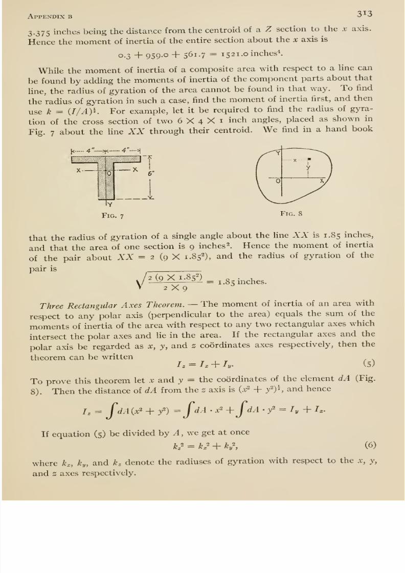
8/13/2019 Maurer Mechanics
http://slidepdf.com/reader/full/maurer-mechanics 329/407
Appendix b 3 o
3.375 inches being the distance from the centroid of a Z section to the x axis.
Hence the moment of inertia of the entire section about the x axis is
0.3 + 959.0 + 561.7 = 1 52 1. cinches^.
While the moment of inertia of a composite area with respect to a Une can
be fomid by adding the moments of inertia of the component parts about that
line, the radius of gyration of the area cannot be found in that way. To find
the radius of gyration in such a case, find the moment of inertia first, and then
use k = {I /AY'. For example, let it be required to find the radius of gyra-
tion of the cross section of two 6 X 4 X i inch angles, placed as shown in
Fig. 7 about the line XX through their centroid. We find in a hand book
[<._.. 4 —>,<-
m i
Y
Fig. 7
6
±.
Fig. 8
that the radius of gyration of a single angle about the line XX is 1.85 inches,
and that the area of one section is 9 inches 2. Hence the moment of inertia
of the pair about XX = 2 (9 X 1.852), and the radius of gyration of the
pair is
V' 2 (9 X 1.85-)
2X9= 1.85 inches.
Three Rectangular Axes Theorem. —The moment of inertia of an area with
respect to any polar axis (perpendicular to the area) equals the sum of the
moments of inertia of the area with respect to any two rectangular axes which
intersect the polar axes and he in the area. If the rectangular axes and the
polar axis be regarded as x, y, and z coordinates axes respectively, then the
theorem can be written/, = /, + /,. (5)
To prove this theorem let x and y = the coordinates of the element dA (Fig.
8). Then the distance of dA from the z axis is {x^ + /)^ and hence
/, = p/l(x2 + /) =fdA ' .v'' +JdA . / = /^ + /^.
If equation (5) be divided by ^, we get at once
h^ = K^ + ky\ (6)
where K, ky, and k^ denote the radiuses of gyration with respect to the x, y,
and 2 axes respectively.
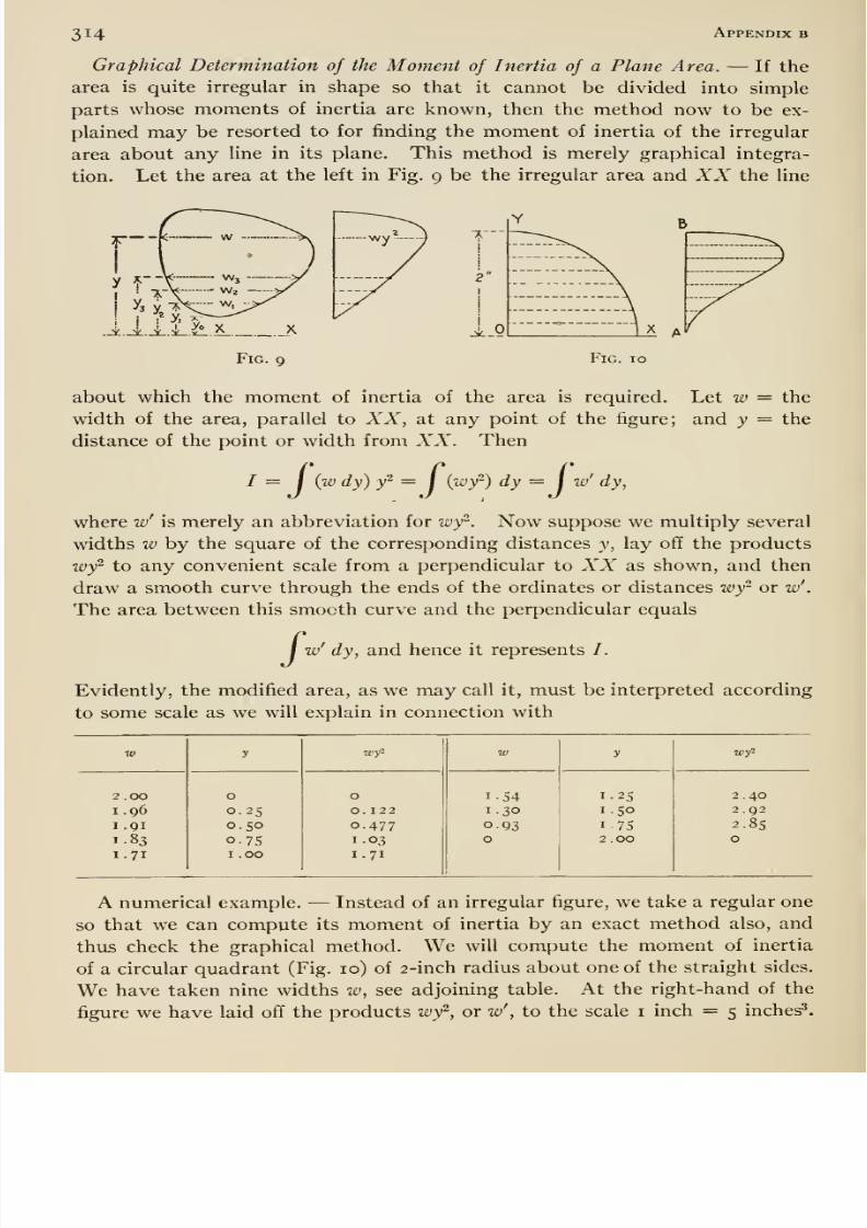
8/13/2019 Maurer Mechanics
http://slidepdf.com/reader/full/maurer-mechanics 330/407
314 Appendix b
Graphical Determination of the Moment of Inertia of a Plane Area. —If the
area is quite irregular in shape so that it cannot be divided into simple
parts whose moments of inertia are known, then the method now to be ex-
plained may be resorted to for finding the moment of inertia of the irregular
area about any Hne in its plane. This method is merely graphical integra-
tion. Let the area at the left in Fig. 9 be the irregular area and XX the line
1k-
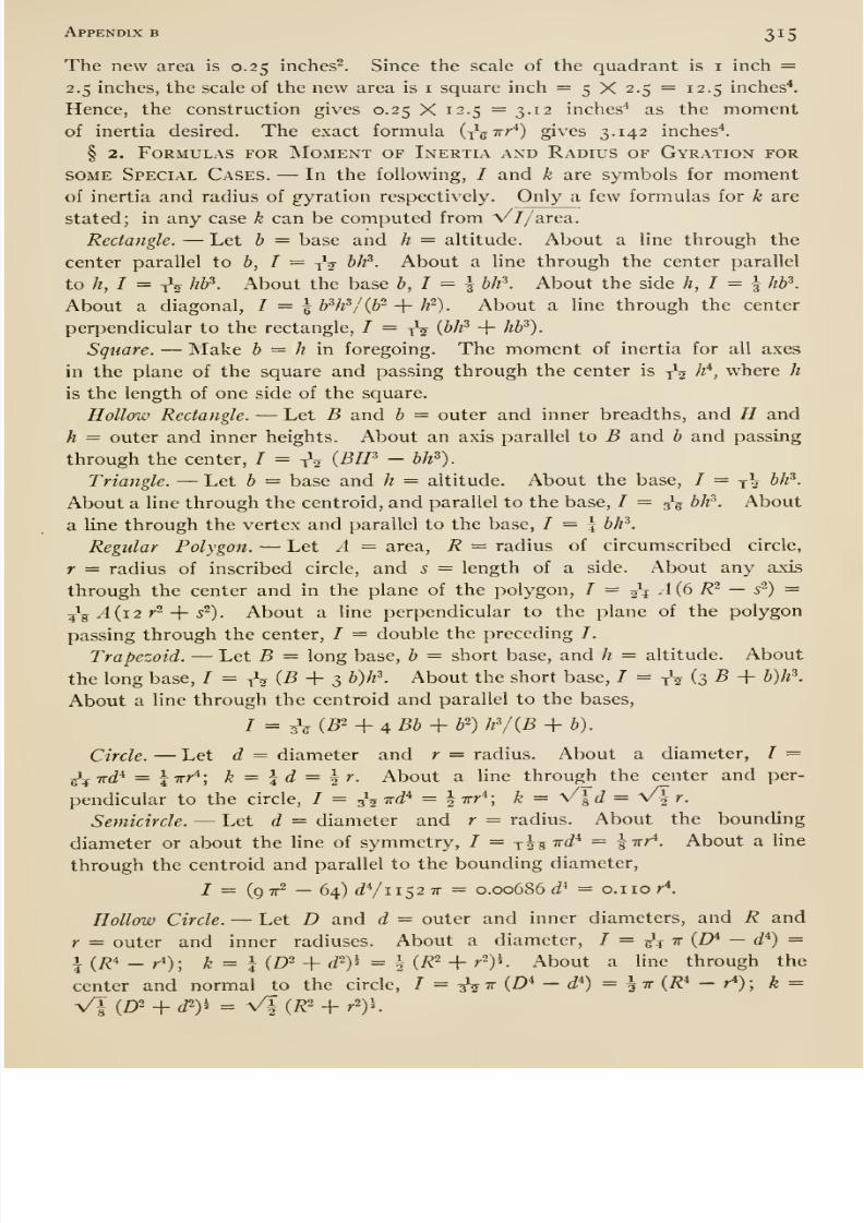
8/13/2019 Maurer Mechanics
http://slidepdf.com/reader/full/maurer-mechanics 331/407
Appendix b 315
The new area is 0.25 inches^. Since the scale of the quadrant is i inch =2.5 inches, the scale of the new area is i square inch = 5 X 2.5 = 12.5 inches*.
Hence, the construction gives 0.25 X 12.5 = 3.12 inches'* as the momentof inertia desired. The exact formula i^^Trr*) gives 3.142 inches*.
§ 2. Formulas for Moment of Inertia and Radius of Gyration for
SOME Special Cases. —In the following, / and k are symbols for momentof inertia and radius of gyration respectively. Only a few formulas for k are
stated; in any case k can be computed from V//area.
Rectangle. —Let b = base and h = altitude. About a line through the
center parallel to b, / = tV b¥- About a line through the center parallel
to h, I = tV hb\ About the base b, I = I b¥. About the side h, I = \ hb\
About a diagonal, 1 = 1 bW/Qf- + h ^)- About a line through the center
perpendicular to the rectangle, / = yV (^^^ + ^^^)-
Square. —Make b = h m foregoing. The moment of inertia for all axes
in the plane of the square and passing through the center is ^^ h^, where h
is the length of one side of the square.
Hollow Rectangle. —Let B and b = outer and inner breadths, and H and
h = outer and inner heights. About an axis parallel to B and b and passing
through the center, I = tV (BH^ - bh^).
Triangle. —Let b = base and h = altitude. About the base, / = ^\ bh^.
About a line through the centroid, and parallel to the base, / = 5^ bh^. About
a line through the vertex and parallel to the base, 1 = 1 bh^.
Regular Polygon. —Let A = area, R = radius of circumscribed circle,
r = radius of inscribed circle, and s = length of a side. About any axis
through the center and in the plane of the polygon, / = 0^4 A (6 R^ — s ') =
5^5 y4(i2 r^ + 5^). About a line perpendicular to the plane of the polygon
passing through the center, / = double the preceding /.
Trapezoid. —Let B = long base, b = short base, and h = altitude. About
the long base, / = yV (^ + 3 W^^- About the short base, / = tV (3 ^ + ^)^^-
About a line through the centroid and parallel to the bases.
Circle. —Let d = diameter and r = radius. About a diameter, I =
^^Tj-d* = lirr*; k = \d = \r. About a line through the center and per-
pendicular to the circle, / = ^^i^d'^ = ^tt/-*; ^ = V| J = Vf r.
Semicircle. —Let d = diameter and r = radius. About the bounding
diameter or about the line of symmetry, / = jis 7r<i* = | irr*. About a line
through the centroid and parallel to the bounding diameter,
7 = (qtt^ — 64) JVii52 7r = 0.00686 c/* = 0.1 10 r*.
Hollow Circle. —Let D and d = outer and inner diameters, and R and
r = outer and inner radiuses. About a diameter, I = ^^^ t (D* — d*) =i(/?4_^). ^ ^ 1 (£)2 ^ j2)5 = 1 (7^2 _|_ y2)j_ About a line through the
center and normal to the circle, I = ^tv{D^ - d*) = ^ ir {R^ - r*) ; k =
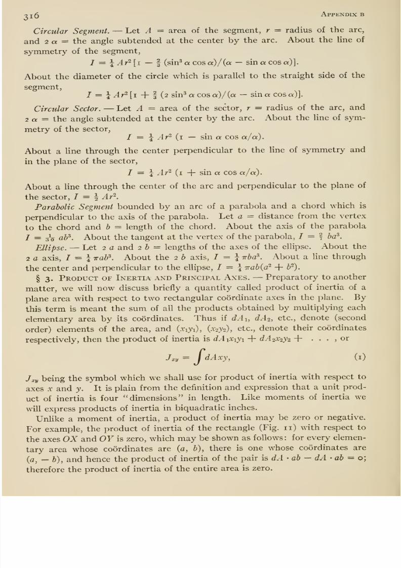
8/13/2019 Maurer Mechanics
http://slidepdf.com/reader/full/maurer-mechanics 332/407
oj5 Appendix b
Circular Segment. —Let A = area of the segment, r = radius of the arc,
and 2 a = the angle subtended at the center by the arc. About the line of
symmetry of the segment,
/ = J Ar^ [i — 3 (sin^ « cos a)/{a —sin a cos a)].
Aboutthe diameter of the circle which is parallel to the straight side of the
segment,I — \ Ar'^\\ + f (2 sin^acosQ;)/(a — sin a cos a)].
Circular Sector. —Let A = area of the sector, r = radius of the arc, and
2 a = the angle subtended at the center by the arc. About the line of sym-
metry of the sector,
I — i Ar~ (i — sin a cos a/a).
About a line through the center perpendicular to the Une of symmetry and
in the plane of the sector,
I — \ Ar- {1 -{ sin a cos a/ a).
About a line through the center of the arc and perpendicular to the plane of
the sector, I = \ Ar ^.
Parabolic Segment bounded by an arc of a parabola and a chord which is
perpendicular to the axis of the parabola. Let a = distance from the vertex
to the chord and b = length of the chord. About the axis of the parabola
1 = 3V aP. About the tangentat the vertex of the parabola, / =
fba^.
Ellipse. —Let 2 a and 2 b = lengths of the axes of the ellipse. About the
2 a axis, / = i Trab^. About the 2 b axis, / = i Tba^. About a line through
the center and perpendicular to the ellipse, / = 5 -Kabiar + b').
§ 3. Product of Inertia and Principal Axes. —Preparatory to another
matter, we will now discuss briefly a quantity called product of inertia of a
plane area with respect to two rectangular coordinate axes in the plane. By
this term is meant the sum of all the products obtained by multiplying each
elementary area by its coordinates. Thus if dAi, dAi, etc., denote (secondorder) elements of the area, and (xiji), (xaVa), etc., denote their coordinates
respectively, then the product of inertia is dAiXiji + dA20C2y2 + . . . , or
J. = / dAxy, (i)
J XV being the symbol which we shall use for product of inertia with respect to
axes X and y. It is plain from the definition and expression that a unit prod-
uct of inertia is four dimensions in length.Like moments of inertia we
will express products of inertia in biquadratic inches.
Unlike a moment of inertia, a product of inertia may be zero or negative.
For example, the product of inertia of the rectangle (Fig. 11) with respect to
the axes OX and OY is zero, which may be shown as follows: for every elemen-
tary area whose coordinates are (c, 6), there is one whose coordinates are
(a, — b), and hence the product of inertia of the pair is dA ' ab —dA • ah = o\
therefore the product of inertia of the entire area is zero.
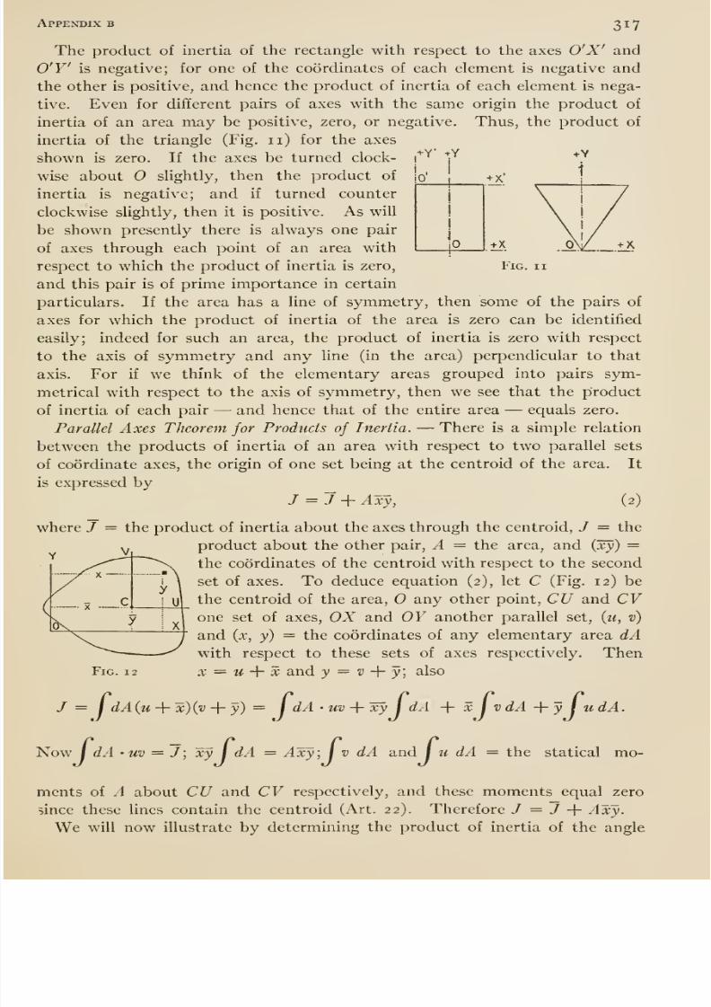
8/13/2019 Maurer Mechanics
http://slidepdf.com/reader/full/maurer-mechanics 333/407
Appendix b 317
The product of inertia of the rectangle with respect to the axes O'X' and
O'Y' is negative; for one of the coordinates of each element is negative and
the other is positive, and hence the product of inertia of each element is nega-
tive. Even for different pairs of axes with the same origin the product of
inertia of an area may be positive, zero, or negative. Thus, the product of
inertia of the triangle (Fig. 11) for the axesshown is zero. If the axes be turned clock-
wise about slightly, then the product of
inertia is negative; and if turned counter
clockwise slightly, then it is positive. As will
be shown presently there is always one pair
of axes through each point of an area with
respect to which the product of inertia is zero,
and this pair is of prime importance in certain
particulars. If the area has a line of symmetry, then some of the pairs of
axes for which the product of inertia of the area is zero can be identified
easily; indeed for such an area, the product of inertia is zero with respect
to the axis of symmetry and any line (in the area) perpendicular to that
axis. For if we think of the elementary areas grouped into pairs sym-
metrical with respect to the axis of symmetry, then we see that the product
of inertia of each pair —and hence that of the entire area —equals zero.
Parallel Axes Theorem for Products of Inertia. —There is a simple relation
between the products of inertia of an area with respect to two parallel sets
of coordinate axes, the origin of one set being at the centroid of the area. It
is expressed by
/ = / -f Axy, (2)
where / = the product of inertia about the axes through the centroid, / = the
product about the other pair, A — the area, and (xy) =
the coordinates of the centroid with respect to the secondset of axes. To deduce equation (2), let C (Fig. 12) be
the centroid of the area, any other point, CU and CVone set of axes, OX and OY another parallel set, {u, v)
and {x, y) = the coordinates of any elementary area dAwith respect to these sets of axes respectively. Then
X = u -\- X and y = v -^ y; alsoig. 12
J = I dA(u + x){v -{- y) =^ I dA'
uv -\- xy j dA-\-
x j vdA -\- y I udA.
ow / dA 'UV = J; xy j dA = Axy; j v dA and I ;u dA — the statical mo-
ments of A about CU and CV respectively, and these moments equal zero
since these lines contain the centroid (Art. 22). Therefore J = J -\- Axy.
We will now illustrate by determining the product of inertia of the angle
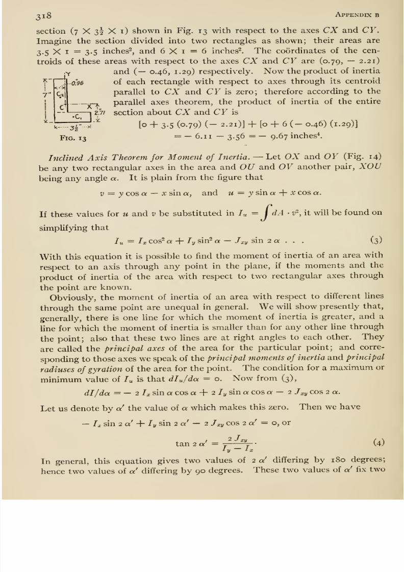
8/13/2019 Maurer Mechanics
http://slidepdf.com/reader/full/maurer-mechanics 334/407
•c.
-2 1 Appendix b
section (7 X 32 X i) shown in Fig. 13 with respect to the axes CX and CY.
Imagine the section divided into two rectangles as shown; their areas are
3.5 X I = 3-5 inches^, and 6X1=6 inches^. The coordinates of the cen-
troids of these areas with respect to the axes CX and CY are (0.79, — 2.21)
.y and (— 0.46, 1.29) respectively. Now the product of inertia
.•0.96 of each rectangle with respect to axes through its centroid
parallel to CX and CF is zero; therefore according to the
- parallel axes theorem, the product of inertia of the entire
27/ section about CX and CF is
k- . jr- .
/[o + 3-5 (0-79) (- 2.21)] + [o + 6 (- 0.46) (1.29)]
Fig. 13 = - 6.1 1 - 3.56 = - 9.67 inches*.
InclinedAxis Theorem for Moment of Inertia.
—Let OX and OY (Fig. 14)
be any two rectangular axes in the area and OU and OV another pair, XOUbeing any angle a. It is plain from the figure that
1} = y cos a —X sin a, and u = ysina -{- x cos a.
If these values for u and v be substituted in /„ = / dA • v^, it will be found on
simplifying that
lu = Ix cos^ a + /y sin- a — /ly sin 2 « . . . (3)
With this equation it is possible to find the moment of inertia of an area with
respect to an axis through any point in the plane, if the moments and the
product of inertia of the area with respect to two rectangular axes through
the point are known.
Obviously, the moment of inertia of an area with respect to different Unes
through the same point are unequal in general. We will show presently that,
generally, there is one Hne for which the moment of inertia is greater, and a
line for which the moment of inertia is smaller than for any other Une through
the point; also that these two lines are at right angles to each other. They
are called the principal axes of the area for the particular point; and corre-
sponding to those axes we speak of the principal moments of inertia and principal
radiuses of gyration of the area for the point. The condition for a maximum or
minimum value of /„ is that dljda = o. Now from (3),
dl/da = — 2 /x sin a cos a + 2 ly sin a: cos a — 2 J^y cos 2 a.
Let us denote by a the value of a which makes this zero. Then we have
— Ix sin 2 a -{ ly sin 2 a' — 2 Jxy cos 2 a' = o, or
tan 2a' =J J^^j
' (4)ly ix
In general, this equation gives two values of 2 a differing by 180 degrees;
hence two values of a differing by 90 degrees. These two values of a fix two
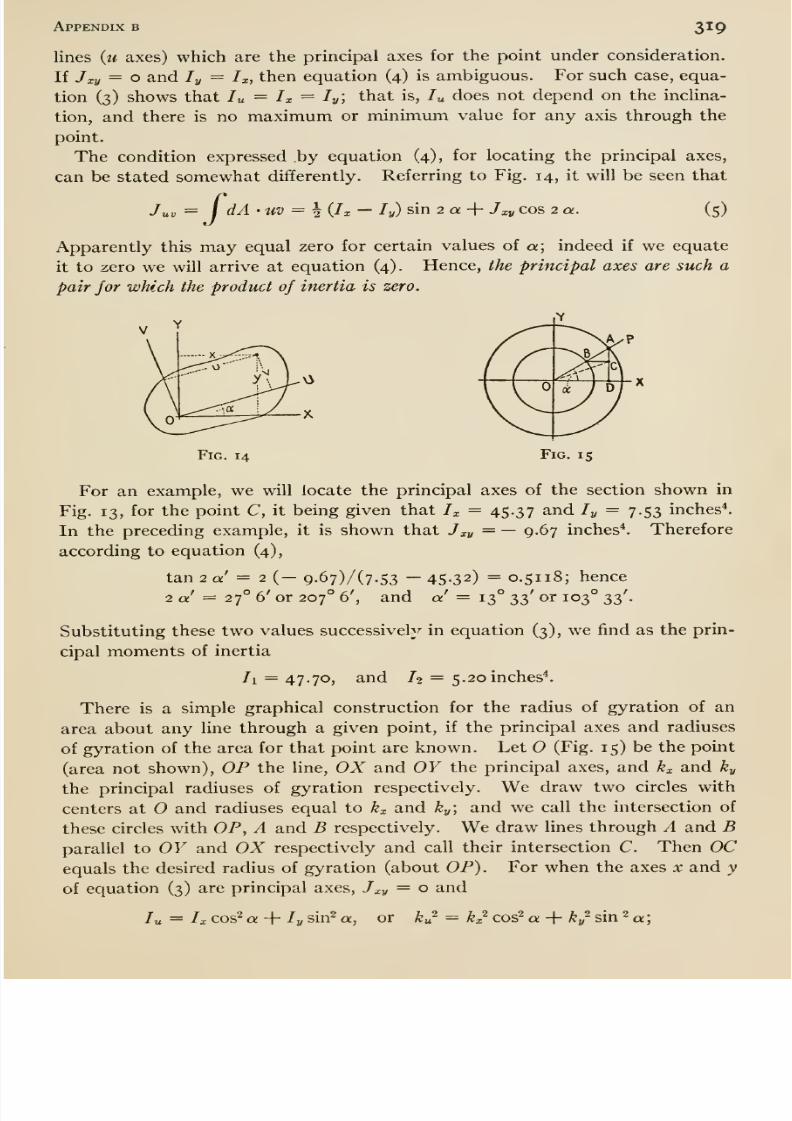
8/13/2019 Maurer Mechanics
http://slidepdf.com/reader/full/maurer-mechanics 335/407
Appendix b 319
lines (w axes) which are the principal axes for the point under consideration.
If Jxy = o and ly = h, then equation (4) is ambiguous. For such case, equa-
tion (3) shows that lu = h = ly', that is, /„ does not depend on the inclina-
tion, and there is no maximum or minimum value for any axis through the
point.
The condition expressed by equation (4), for locating the principal axes,
can be stated somewhat differently. Referring to Fig. 14, it will be seen that
Juv =I
dA'UV = ^ {Ix — ly) sin 2 Q + Jxy COS 2 a. (5)
Apparently this may equal zero for certain values of a; indeed if we equate
it to zero we will arrive at equation (4). Hence, the principal axes are such a
pair for which the product of inertia is zero.
Fig. 14 Fig. is
For an example, we will locate the principal axes of the section shown in
Fig. 13, for the point C, it being given that Ix = 45-37 and ly = 7.53 inches*.
In the preceding example, it is shown that Jxy = — 9.67 inches*. Therefore
according to equation (4),
tan 2 a = 2 (- 9-67)/(7-53 - 45-32) = 0.5118; hence
2 a' = 27° 6' or 207° 6', and a' = 13° 33' or 103° 33'.
Substituting these two values successively in equation (3), we find as the prin-cipal moments of inertia
71 = 47.70, and /2 = 5.20 inches'*.
There is a simple graphical construction for the radius of gyration of an
area about any line through a given point, if the principal axes and radiuses
of gyration of the area for that point are known. Let O (Fig. 15) be the point
(area not shown), OP the line, OX and OY the principal axes, and kx and ky
the principal radiuses of gyration respectively. We draw two circles withcenters at and radiuses equal to kx and ky-, and we call the intersection of
these circles with OP, A and B respectively. We draw Hnes through A and Bparallel to OY and OX respectively and call their intersection C. Then OCequals the desired radius of gyration (about OP). For when the axes x and y
of equation (3) are principal axes, Jxy = o and
Ix cos^ a -\- ly sin- a, or ku^ = kx^ cos'* a -{ ky^ sin 2 a;
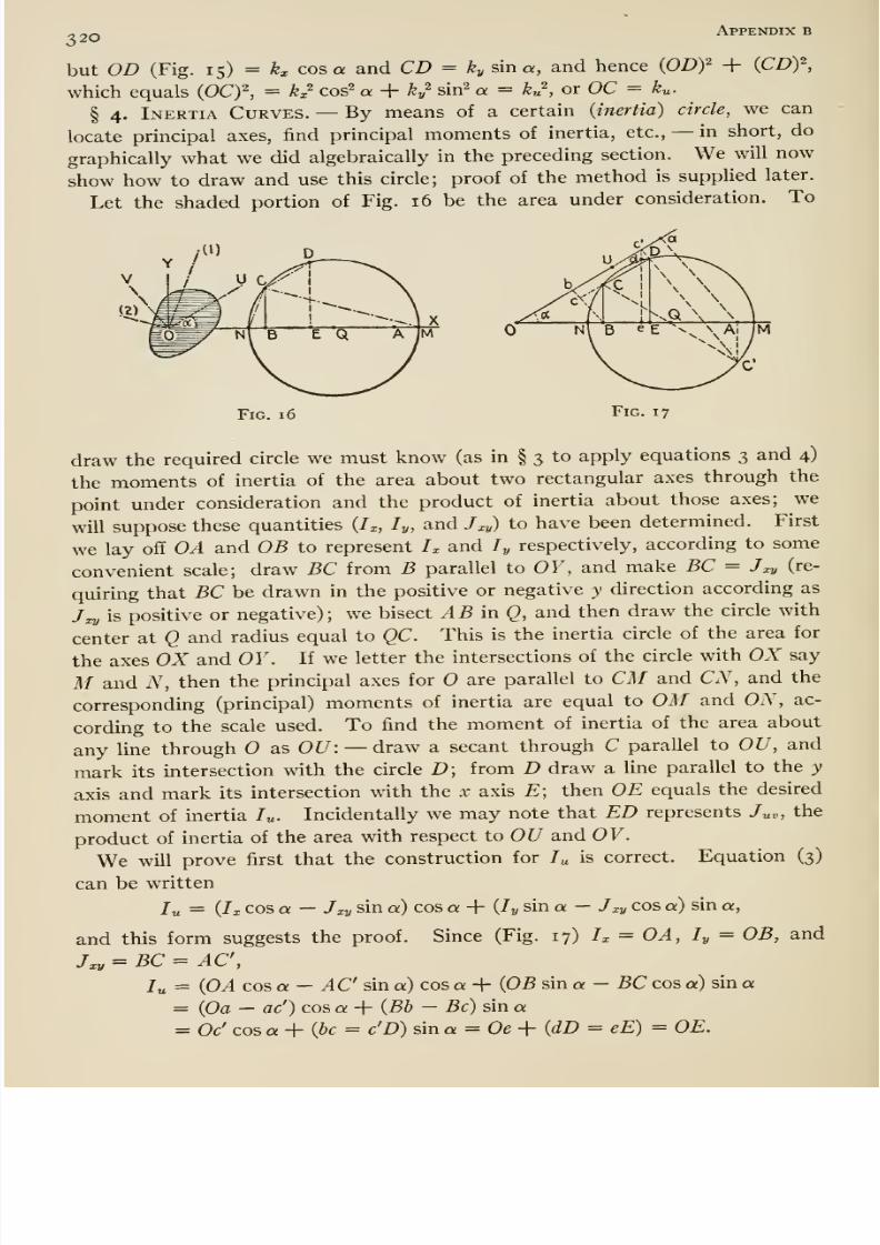
8/13/2019 Maurer Mechanics
http://slidepdf.com/reader/full/maurer-mechanics 336/407
320APPEhfDIX B
but OD (Fig. 15) ^ kx cos a and CD = kySma, and hence {ODf + (CD)^,
which equals {OCf, = k^^ cos^ « + ky^ sin^ a = ku\ or OC = ^u-
§ 4. Inertia Curves. —By means of a certain {inertia) circle, we can
locate principal axes, find principal moments of inertia, etc., —in short, do
graphically what we did algebraically in the preceding section. We will now
show how to draw and use this circle; proof of the method is supplied later.
Let the shaded portion of Fig. 16 be the area under consideration. To
Fig. 16 Fig. 17
draw the required circle we must know (as in § 3 to apply equations 3 and 4)
the moments of inertia of the area about two rectangular axes through the
point under consideration and the product of inertia about those axes; we
will suppose these quantities {h, ly, and J^cy) to have been determined. First
we lay off OA and OB to represent h and /„ respectively, according to some
convenient scale; draw BC from B parallel to OF, and make BC = Jxy (re-
quirmg that BC be drawn in the positive or negative y direction according as
7x2/ is positive or negative); we bisect AB in Q, and then draw the circle with
center at Q and radius equal to QC. This is the inertia circle of the area for
the axes OX and OY. If we letter the intersections of the circle with OX say
M and N, then the principal axes for are parallel to CM and CN, and the
corresponding (principal) moments of inertia are equal to OM and ON, ac-
cording to the scale used. To find the moment of inertia of the area about
any line through as OC/: —draw a secant through C parallel to OU, and
mark its intersection with the circle D; from D draw a line parallel to the y
axis and mark its intersection with the x axis E; then OE equals the desired
moment of inertia /„. Incidentally we may note that ED represents /„„, the
product of inertia of the area with respect to OU and OV.
We will prove first that the construction for /„ is correct. Equation (3)
can be written
lu = {h cos a — Jxy sin a) cos a + (ly sin a — Jxy cos a) sin a,
and this form suggests the proof. Since (Fig. 17) h = OA, ly = OB, and
J^ = BC = AC,
lu = (OA cos a —AC sin a) cos a + (OB sin a - BC cos a) sin a
= (Oa — ac') cos a + (Bb —Be) sin a= Oc' cos a+{bc^ c'D) sin a = Oe-\-{dD = eE) = OE.
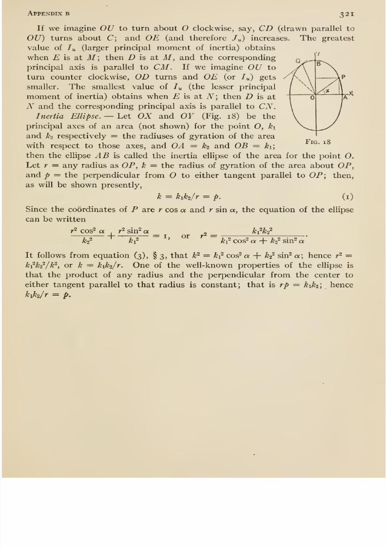
8/13/2019 Maurer Mechanics
http://slidepdf.com/reader/full/maurer-mechanics 337/407
Appendix b 321
If we imagine OU to turn about O clockwise, say, CD (drawn parallel to
OU) turns about C; and OE (and therefore /„) increases. The greatest
value of lu (larger principal moment of inertia) obtains
when £ is at M; then D is at M, and the corresponding
principal axis is parallel to CM. If we imagine 0^ to
turn counter clockwise, OD turns and OE (or /„) gets
smaller. The smallest value of /„ (the lesser principal
moment of inertia) obtains when £ is at iV; then D is at
N and the corresponding principal axis is parallel to CN.Inertia Ellipse. —Let OX and OY (Fig. 18) be the
principal axes of an area (not shown) for the point 0, ki
and ^2 respectively = the radiuses of gyration of the area
with respect to those axes, and OA = ^2 and OB = ki,
then the ellipse AB is called the inertia ellipse of the area for the point O.
Let r = any radius as OP, k = the radius of gyration of the area about OP,and p — the perpendicular from to either tangent parallel to OP; then,
as will be shown presently,
k = kiki/r = p. (i)
Since the coordinates of P are r cos a and r sin a, the equation of the ellipse
can be written
Fig. 18
r ^ cos^ ako^
+ r^ sin^ ah'
= I, or r^ = h^h^k^ cos^ a + k'^ sin^ a
It follows from equation (3), § 3, that k^ = k^ cos^ a + ^2^ sin^ a; hence r^ =kik^/k ^, ox k = kiki/r. One of the well-known properties of the ellipse is
that the product of any radius and the perpendicular from the center to
either tangent parallel to that radius is constant; that is rp = kiki] hence
kiki/r = p.

8/13/2019 Maurer Mechanics
http://slidepdf.com/reader/full/maurer-mechanics 338/407
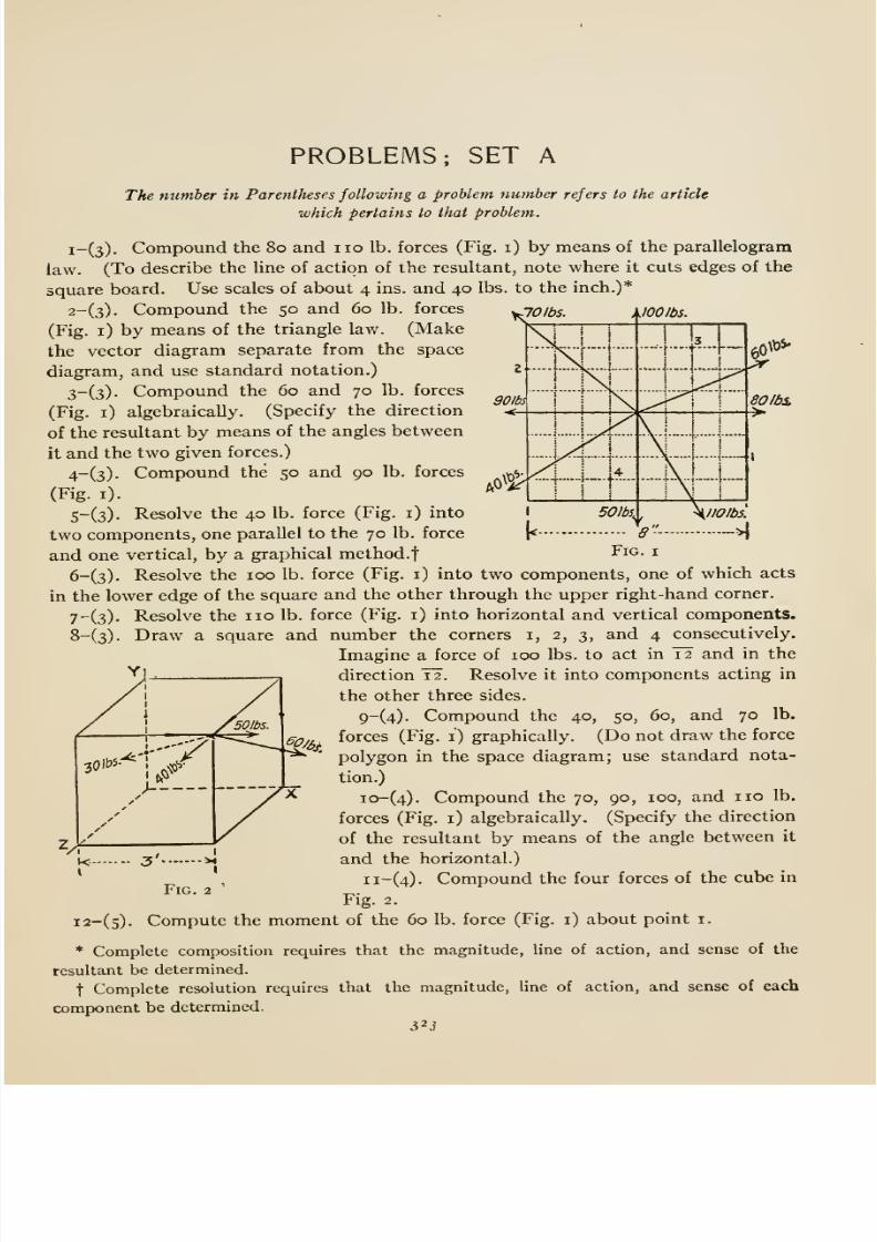
8/13/2019 Maurer Mechanics
http://slidepdf.com/reader/full/maurer-mechanics 339/407
PROBLEMS; SET A
The number in Parentheses following a problem number refers to the article
which pertains to that problem.
i-(3). Compound the 80 and no lb. forces (Fig. i) by means of the parallelogram
law. (To describe the line of action of the resultant, note where it cuts edges of the
square board. Use scales of about 4 ins. and 40 lbs. to the inch.)*
2-(3). Compound the 50 and 60 lb. forces
(Fig. i) by means of the triangle law. (Make
the vector diagram separate from the spacediagram, and use standard notation.)
3-(3). Compound the 60 and 70 lb. forces
(Fig. i) algebraically. (Specify the direction
of the resultant by means of the angles between
it and the two given forces.)
4-(3). Compound the 50 and 90 lb. forces
(Fig. i).
5-(3). Resolve the 40 lb. force (Fig. i) into
two components, one parallel to the 70 lb. force
and one vertical, by a graphical method.
6-(3). Resolve the 100 lb. force (Fig. i) into two components, one of which acts
in the lower edge of the square and the other through the upper right-hand corner.
7^(3). Resolve the no lb. force (Fig. i) into horizontal and vertical components.
8-(3). Draw a square and number the corners i, 2, 3, and 4 consecutively.
Imagine a force of 100 lbs. to act in I2 and in the
direction '12'. Resolve it into components acting in
the other three sides.9-(4). Compound the 40, 50, 60, and 70 lb.
forces (Fig. i) graphically. (Do not draw the force
polygon in the space diagram; use standard nota-
tion.)
io-(4). Compound the 70, 90, 100, and no lb.
forces (Fig. i) algebraically. (Specify the direction
of the resultant by means of the angle between it
and the horizontal.)
ii-(4). Compound the four forces of the cube in
Fig. 2.
i2-(s). Compute the moment of the 60 lb. force (Fig. i) about point i.
* Complete composition requires that the magnitude, line of action, and sense of the
resultant be determined.
t Complete resolution requires that the magnitude, line of action, and sense of each
component be determined.
32J
VT
/
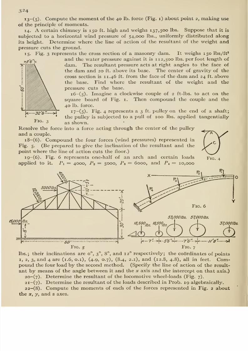
8/13/2019 Maurer Mechanics
http://slidepdf.com/reader/full/maurer-mechanics 340/407
324
i3~(5)- Compute the moment of the 40 lb. force (Fig. i) about point 2, making use
of the principle of moments.
14. A certain chimney is 150 ft. high and weighs 137,500 lbs. Suppose that it is
subjected to a horizontal wind pressure of 54,000 lbs., uniformly distributed along
its height. Determine where the hne of action of the resultant of the weight and
pressure cuts the ground.15. Fig. 3 represents the cross section of a masonry dam. It weighs 150 lbs/ft'
and the water pressure against it is 112,500 lbs. per foot length of
dam. The resultant pressure acts at right angles to the face of
the dam and 20 ft. above its base. The center of gravity of the
cross section is 11.46 ft. from the face of the dam and 24 ft. above
the base. Find where the resultant of the weight and the
pressure cuts the base.
i6-(5). Imagine a clockwise couple of 2 ft-lbs. to act on the
square board of Fig. i. Then compound the couple and the
40 lb. force.
i7-(5). Fig. 4 represents a 3 ft. pulley on the end of a shaft;
the pulley is subjected to a pull of 100 lbs. applied tangentially
as shown.
Resolve the force into a force acting through the center of the pulley
and a couple.
i8-(6). Compound the four forces (wind pressures) represented in
Fig. 5. (Be prepared to give the incUnation of the resultant and the
point where the line of action cuts the floor.)
i9-(6). Fig. 6 represents one-half of an arch and certain loads
applied to it. Pi = 4000, P2 = 5000, P3 = 6000, and P4 = 10,000
/S,000
53,000lb5. SZOOOIbs.
I8,500,^^_ I8,500i^^_
.^Sl
37,000/bs.
< gQ' - •>1 (<--7-->|<-5^>K 76- >f J/ 8 •*
Fig. 5 Fig. 7
lbs.; their inclinations are 0°, 3°, 8°, and 12° respectively; the coordinates of points
I, 2, 3, and 4 are (1.6, o.i), (4.9, 0.7), (8.4, 2.1), and (12.8, 4.8), all in feet. Com-pound the four load by the second method. (Specify the line of action of the result-
ant by means of the angle between it and the x axis and the intercept on that axis.)
20-(7). Determine the resultant of the locomotive wheel-loads (Fig. 7).
2i-(7). Determine the resultant of the loads described in Prob. 19 algebraically.
22-(8). Compute the moments of each of the forces represented in Fig. 2 about
the X, y, and z axes.
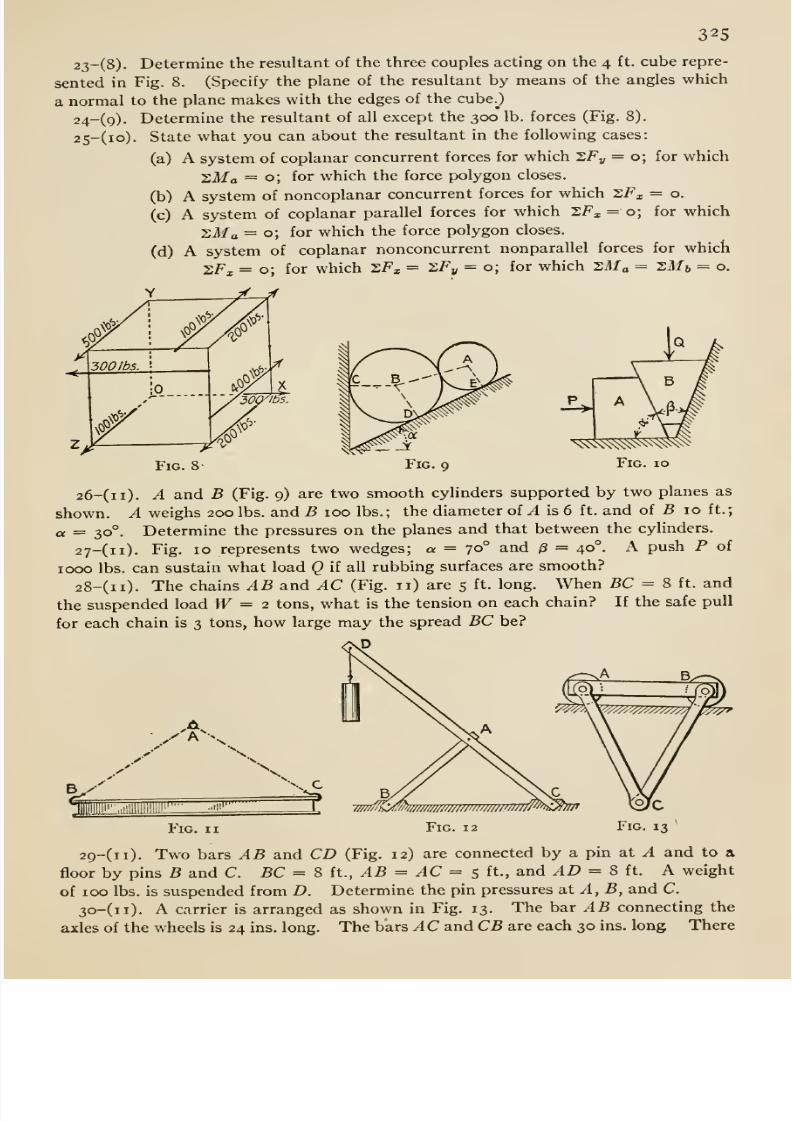
8/13/2019 Maurer Mechanics
http://slidepdf.com/reader/full/maurer-mechanics 341/407
325
23-(8). Determine the resultant of the three couples acting on the 4 ft. cube repre-
sented in Fig. 8. (Specify the plane of the resultant by means of the angles which
a normal to the plane makes with the edges of the cube.^)
24-(9). Determine the resultant of all except the 300 lb. forces (Fig. 8).
25-(io). State what you can about the resultant in the following cases:
(a) A system of coplanar concurrent forces for which SF„ = 0; for whichSMa = 0; for which the force polygon closes.
(b) A system of noncoplanar concurrent forces for which SF^ = o.
(c) A system of coplanar parallel forces for which SF^, = o; for which
zMa = o; for which the force polygon closes.
(d) A system of coplanar nonconcurrent nonparallel forces for which
ZF^ =0; for which zFx = 2F„ = 0; for which SM„ = sMb = o.
Fig. 8 Fig. 9 Fig. 10
26-(ii). A and B (Fig. 9) are two smooth cylinders supported by two planes as
shown. A weighs 200 lbs. and B 100 lbs.; the diameter of ^ is 6 ft. and of B 10 ft.;
a = 30°. Determine the pressures on the planes and that between the cylinders.
27-(ii). Fig. 10 represents two wedges; a = 70° and = 40°. A push P of
1000 lbs. can sustain what load Q if all rubbing surfaces are smooth?
28-(ii). The chains AB and AC (Fig. 11) are 5 ft. long. When BC = 8 ft. and
the suspended load W= 2 tons, what is the tension on each chain? If the safe pull
for each chain is 3 tons, how large may the spread BC be?
Fig. II
29-(ii). Two bars AB and CD (Fig. 12) are connected by a pin at A and to a
floor by pins B and C. BC = 8 ft., AB = AC = $ ft., and AD = 8 ft. A weight
of 100 lbs. is suspended from D. Determine the pin pressures at yl, B, and C.
30-(ii). A carrier is arranged as shown in Fig. 13. The bar AB connecting the
axles of the wheels is 24 ins. long. The bars AC and CB are each 30 ins. long There

8/13/2019 Maurer Mechanics
http://slidepdf.com/reader/full/maurer-mechanics 342/407
326
is a load of 1200 lbs. at C.
g/////////////////////////////////////////////
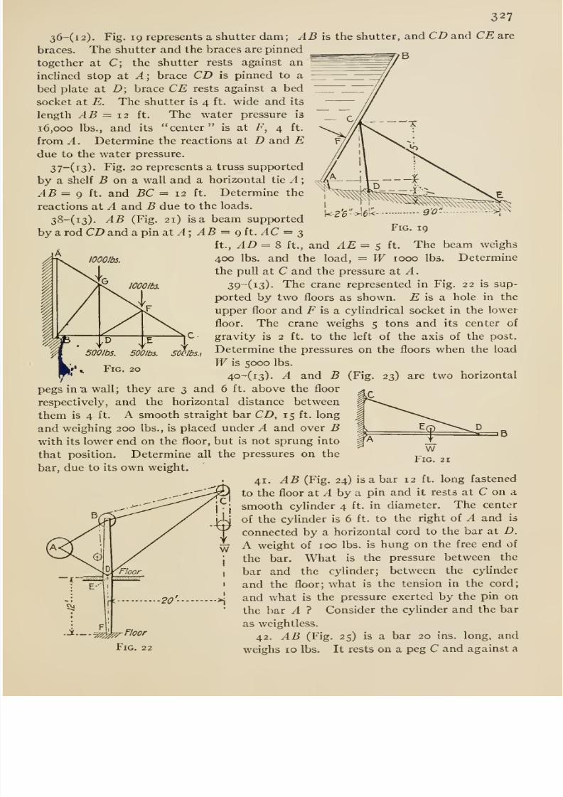
8/13/2019 Maurer Mechanics
http://slidepdf.com/reader/full/maurer-mechanics 343/407
327
36-(i2). Fig. 19 represents a shutter dam; AB is the shutter, and CD and CE are
braces. The shutter and the braces are pinned
together at C; the shutter rests against an
inclined stop at A; brace CD is pinned to a
bed plate at D; brace CE rests against a bed
socket at E. The shutter is 4 ft. wide and its
length AB = 12 ft. The water pressure is
16,000 lbs., and its center is at F, 4 ft.
from A. Determine the reactions at D and Edue to the water pressure.
37~(i3)- Fig. 20 represents a truss supported
by a shelf 5 on a wall and a horizontal tie A ;
AB = g ft. and BC = 12 ft. Determine the
reactions at A and B due to the loads.
38-(i3). AB (Fig. 21) is a beam supported
by a rod CD and a pin a.t A; AB = git. AC = 3
ft, AD = 8 ft.,
400 lbs. and theOGO/is.
U-2'6
Fig. 19
and ^E = 5 ft. The beam weighs
Determineoad, = W 1000 lbs.
the pull at C and the pressure at A.
39-(i3). The crane represented in Fig. 22 is sup-
ported by two floors as shown. £ is a hole in the
upper floor and F is a cylindrical socket in the lower
floor. The crane weighs 5 tons and its center of
gravity is 2 ft. to the left of the axis of the post.
Determine the pressures on the floors when the load
Wis 5000 lbs.
40-(i3). A and B (Fig. 23) are two horizontal
pegs in a wall; they are 3 and 6 ft. above the floor
respectively, and the horizontal distance between
them is 4 ft. A smooth straight bar CD, 15 ft. long
and weighing 200 lbs., is placed under A and over Bwith its lower end on the floor, but is not sprung into
that position. Determine all the pressures on the
bar, due to its own weight.
41. AB (Fig. 24) is a bar 12 ft. long fastened
to the floor at ^ by a pin and it rests at C on a
smooth cylinder 4 ft. in diameter. The center
of the cylinder is 6 ft. to the right of A and is
connected by a horizontal cord to the bar at D.
A weight of 100 lbs. is hung on the free end of
the bar. Whatis the pressure between the
bar and the cylinder; between the cyUnder
and the floor; what is the tension in the cord;
j.; 2o'- >i^^^ what is the pressure exerted by the pin on
the bar A ? Consider the cyUnder and the bar
as weightless.
42. AB (Fig. 25) is a bar 20 ins. long, and
weighs 10 lbs. It rests on a peg C and against a
?vj
.jf._.
Fig. 22
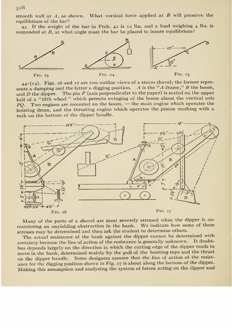
8/13/2019 Maurer Mechanics
http://slidepdf.com/reader/full/maurer-mechanics 344/407
328
smooth wall at ^ , as shown. What vertical force applied at B will preserve the
equilibrium of the bar?
43. If the weight of the bar in Prob. 42 is 12 lbs. and a load weighing 4 lbs. is
suspended at B, at what angle must the bar be placed to insure equilibrium?
/77777777777777777777P777777?
Fig. 23 Fig. 24. Fig. 25
44-(i4). Figs. 26 and 27 are two outline views of a steam shovel; the former repre-
sents a dumping and the latter a digging position. A is the ̂ -frame, B the boom,
and D the dipper. The pin P (axis perpendicular to the paper) is seated on the upper
half of a fifth wheel which permits swinging of the boom about the vertical axis
FQ. Two engines are mounted on the boom, —the main engine which operates the
hoisting drum, and the thrusting engine which operates the pinion meshing with a
rack on the bottom of the dipper handle.
•i/f|<-3'6 *l*--#'6 -*'
Fig. 26 Fig. 27
Many of the parts of a shovel are most severely stressed when the dipper is en-
countering an unyielding obstruction in the bank. We indicate how some of these
stresses may be determined and then ask the student to determine others.
The actual resistance of the bank against the dipper cannot be determined with
certainty because the line of action of the resistance is generally unknown. It doubt-
less depends largely on the direction in which the cutting edge of the dipper tends to
move in the bank, determined mainly by the pull of the hoisting rope and the thrust
on the dipper handle. Some designers assume that the hne of action of the resist-
ance for the digging position shown in Fig. 27 is about along the bottom of the dipper.
Making this assumption and analyzing the system of forces acting on the dipper and
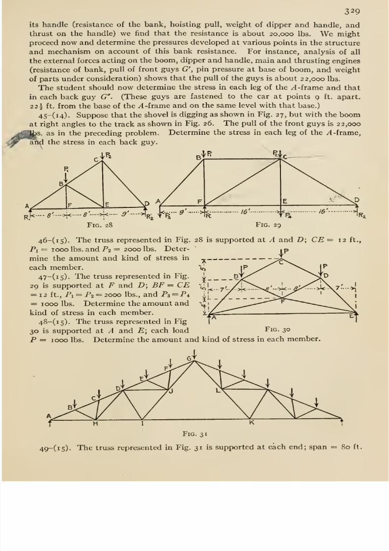
8/13/2019 Maurer Mechanics
http://slidepdf.com/reader/full/maurer-mechanics 345/407
329
its handle (resistance of the bank, hoisting pull, weight of dipper and handle, andthrust on the handle) we find that the resistance is about 20,000 lbs. We might
proceed now and determine the pressures developed at various points in the structure
and mechanism on account of this bank resistance. For instance, analysis of all
the external forces acting on the boom, dipper and handle, main and thrusting engines
(resistance of bank, pull of front guys G', pin pressure at base of boom, and weight
of parts under consideration) shows that the pull of the guys is about 22,000 lbs.
The student should now determine the stress in each leg of the /I -frame and that
in each back guy G . (These guys are fastened to the car at points 9 ft. apart.
22 1 ft. from the base of the ^ -frame and on the same level with that base.)
45-(i4). Suppose that the shovel is digging as shown in Fig. 27, but with the boomat right angles to the track as shown in Fig. 26. The pull of the front guys is 22,000
s. as in the preceding problem. Determine the stress in each leg of the /1-frame,
and the stress in each back guy.\
Fig. 28 Fig. 29
46-(i5). The truss represented in Fig. 28 is supported at A and D; CE = 12 ft.,
Pi = 1000 lbs. and P2 = 2000 lbs. Deter-
mine the amount and kind of stress in
each member.
47~(i5)- The truss represented in Fig.
29 is supported at F and D; BF = CE= 12 ft.. Pi = P2 = 2000 lbs., and P3 = P4
= 1000 lbs. Determine the amount and
kind of stress in each member.48-(i5). The truss represented in Fig
30 is supported at A and E; each load
P = 1000 lbs
Fig. 30
Determine the amount and kind of stress in each member.
Fig. 31
49-(i5). The truss represented in Fig. 31 is supported at each end; span = 80 ft.
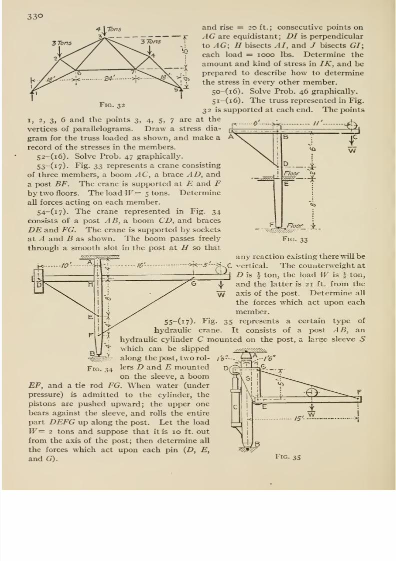
8/13/2019 Maurer Mechanics
http://slidepdf.com/reader/full/maurer-mechanics 346/407
330
Fig. 32
I, 2, 3, 6 and the points 3, 4, 5,
vertices of parallelograms. Draw a stress dia-
gram for the truss loaded as shown, and make a
record of the stresses in the members.
52-(i6). Solve Prob. 47 graphically.53-(i7). Fig. ;^^ represents a crane consisting
of three members, a boom AC, a. brace AD, and
a post BF. The crane is supported at E and Fby two floors. The load W= 5 tons. Determine
all forces acting on each member.
54-(i7). The crane represented in Fig. 34
consists of a post AB, a. boom CD, and braces
DE and FG. The crane is supported by sockets
at A and B as shown. The boom passes freely
through a smooth slot in the post at H so that
and rise = 20 ft. ; consecutive points on
AG are equidistant; DI is perpendicular
to ^G; H bisects AI, and / bisects GI;
each load = 1000 lbs. Determine the
amount and kind of stress in IK, and be
prepared to describe how to determine
the stress in every other member.
5o-(i6). Solve Prob. 46 graphically.
Si-(i6). The truss represented in Fig.
32 is supported at each end. The points
7 are at the- II' A
—-;??9Z -^
B
D
-*r-
^ w
Floor ^1
I
_]^ \j Floor J;_
Fig. 33
any reaction existing there will be
xC vertical. The counterweight at
O is I ton, the load W is \ ton,
and the latter is 21 ft. from the
axis of the post. Determine all
the forces which act upon each
member.
55-(i7). Fig. 35 represents a certain type of
hydrauhc crane. It consists of a post AB, an
hydraulic cylinder C mounted on the post, a large sleeve 5
mFig. 34
which can be slipped
along the post, two rol-
lers D and E mounted
on the sleeve, a boomEF, and a tie rod FG. When water (under
pressure) is admitted to the cylinder, thepistons are pushed upward; the upper one
bears against the sleeve, and rolls the entire
part DEFG up along the post. Let the load
W= 2 tons and suppose that it is 10 ft. out
from the axis of the post; then determine all
the forces which act upon each pin {D, E,
and G). Fig. 35
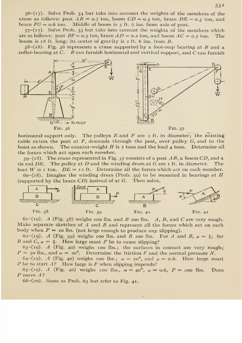
8/13/2019 Maurer Mechanics
http://slidepdf.com/reader/full/maurer-mechanics 347/407
331
56-(i7). Solve Prob. 54 but take into account the weights of the members of the
crane as follows: post AB = 0.7 ton, boom CD = 0.5 ton, brace DE = 0.3 ton, andbrace FG = 0.6 ton. Middle of boom is 5 ft. 6 ins. from axis of post.
57-(i7). Solve Prob. 53 but take into account the weights of the members whichare as follows: post BF= 0.5 ton, brace AD = 0.2 ton, and boom AC = 0.7 ton. Theboom is 18 ft. long; its center of gravity is 2 ft. 6 ins. from B.
58-(i8). Fig. 36 represents a crane supported by a foot-step bearing at B and acollar-bearing at C. B can furnish horizontal and vertical support, and C can furnish
- ^^^'''
6^ >-To Hoist
Fig. 36 Fig. 37
horizontal support only. The pulleys E and F are i ft. in diameter; the noisting
cable enters the post at F, descends through the post, over pulley G, and to the
hoist as shown. The counter-weight H is 2 tons and the load 4 tons. Determine all
the forces which act upon each member.
S9-(i8). The crane represented in Fig. 37 consists of a post AB, a boom CD, and a
tie rod DE. The pulley at D and the winding drum at G are i ft. in diameter. The
load Wis I ton. DE = 12 ft. Determine all the forces which act on each member.
6o-(i8). Imagine the winding drum (Prob. 59) to be mounted in bearings at H(supported by the brace CD) instead of at G. Then solve.
B
c
A Cord
t B
mmmmmmcc
wmmm///B
Fig. 38 Fig. 39 Fig. 40 Fig. 41
6i-(i9). A (Fig. 38) weighs 100 lbs. and B 200 lbs. A, B, and C are very rough.
Make separate sketches of A and B and represent all the forces which act on each
body when P = 20 lbs. (not large enough to produce any shpping).
62-(i9). A (Fig. 39) weighs 100 lbs. and B 200 lbs. For A and B, ft = I; for
B and C, fi = f. How large must P be to cause shpping?63~(i9)- -4 (Fig. 40) weighs 100 lbs.; the surfaces in contact are very rough;
P = 50 lbs., and a = 20°. Determine the friction F and the normal pressure N.64-(i9). A (Fig. 40) weighs 100 lbs.; a = 20°, and /x = 0.6. How large must
P be to start A ? How large is F when slipping impends?65-(i9). A (Fig. 40) weighs 100 lbs., a = 40°, /j = 0.6, P = 200 lbs. Does
P move A ?
66-(2o). Same as Prob. 63 but refer to Fig. 41.
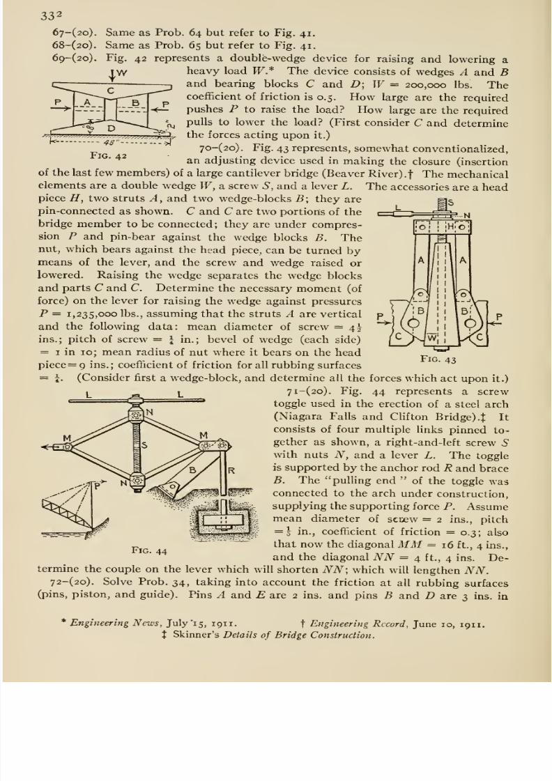
8/13/2019 Maurer Mechanics
http://slidepdf.com/reader/full/maurer-mechanics 348/407
Same as Prob. 64 but refer to Fig. 41.
Same as Prob. 65 but refer to Fig. 41,
Fig. 42 represents a double-wedge device for raising and lowering a
heavy load W* The device consists of wedges A and Band bearing blocks C and D; W= 200,000 lbs. Thecoefficient of friction is 0.5. How large are the required
pushes P to raise the load? How large are the requiredpulls to lower the load? (First consider C and determine
jX.-^w,M^^^,„.Z,v?w.jj^,^^^v^^y the forces acting upon it.)
7o-(2o). Fig. 43 represents, somewhat conventionalized,^^ an adjusting device used in making the closure (insertion
of the last few members) of a large cantilever bridge (Beaver River) .f The mechanicalelements are a double wedge IF, a screw 5 , and a lever L. The accessories are a headpiece ZT, two struts A, and two wedge-blocks B\ they are
pin-connected as shown. C and C are two portions of the
bridge member to be connected; they are under compres-sion P and pin-bear against the wedge blocks B. Thenut, which bears against the head piece, can be turned bymeans of the lever, and the screw and wedge raised or
lowered. Raising the wedge separates the wedge blocks
and parts C and C Determine the necessary moment (of
force) on the lever for raising the wedge against pressures
P = 1,235,000 lbs., assuming that the struts A are vertical
andthe following
data: mean diameter of screw = 4^ins.; pitch of screw = I in.; bevel of wedge (each side)
Fig. 43= I in 10; mean radius of nut where it bears on the head
piece=9 ins.; coefficient of friction for all rubbing surfaces
= J. (Consider first a wedge-block, and determine all the forces which act upon it.)
7i-(2o). Fig. 44 represents a screw
toggle used in the erection of a steel arch
(Niagara Falls and Clifton Bridge). t It
consists of four multiple links pinned to-
gether as shown, a right-and-left screw 5with nuts N, and a lever L. The toggle
is supported by the anchor rod R and brace
B. The pulling end of the toggle wasconnected to the arch under construction,
supplying the supporting force P. Assumemean diameter of screw = 2 ins., pitch
= 5 in., coefficient of friction = 0.3 ; also
that now the diagonal MM= 16 ft., 4 ins.,
and the diagonal NN = 4 ft., 4 ins. De-FlG. 44
termine the couple on the lever which will shorten NN; which will lengthen NN.72-(2o). Solve Prob. 34, taking into account the friction at all rubbing surfaces
(pins, piston, and guide). Pins A and E are 2 ins. and pins B and D are 3 ins. in
* Engifieering News, July '15, 1911. f Engineering Record, June 10, 1911.
t Skinner's Details of Bridge Construction.
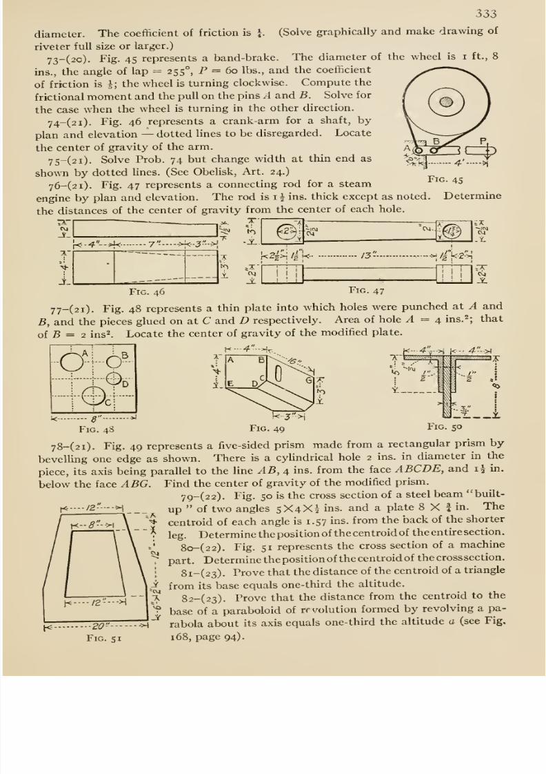
8/13/2019 Maurer Mechanics
http://slidepdf.com/reader/full/maurer-mechanics 349/407
333
diameter. The coefficient of friction is i. (Solve graphically and make drawing of
riveter full size or larger.)
73-(2o). Fig. 45 represents a band-brake. The diameter of the wheel is i ft., 8
ins., the angle of lap = 255°, P = 60 lbs., and the coefficient
of friction is i; the wheel is turning clockwise. Compute the
fractional moment and the pull on the pins A and B. Solve for
the case when the wheel is turning in the other direction.
74-(2i). Fig. 46 represents a crank-arm for a shaft, by
plan and elevation —dotted Unes to be disregarded. Locate
the center of gravity of the arm.
75-(2i). Solve Prob. 74 but change width at thin end as
shown by dotted lines. (See Obelisk, Art. 24.)
76-(2i). Fig. 47 represents a connecting rod for a steam
engine by plan and elevation
the distances of the center of gravity from the center of each hole.
1
4'---
Fig. 45
The rod is i J ins. thick except as noted. Determine
Jl.
i_
[<.-4 -H< 7 -->k-J -H
a-
7: el CM~CM. MCM
CM
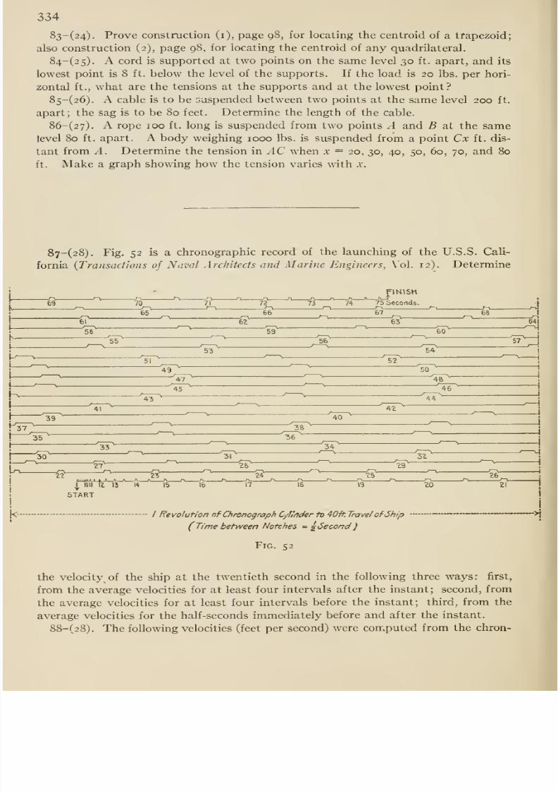
8/13/2019 Maurer Mechanics
http://slidepdf.com/reader/full/maurer-mechanics 350/407
334
83-(24). Prove construction (i), page 98, for locating the centroid of a trapezoid;
also construction (2), page 98, for locating the centroid of any quadrilateral.
84-(2 5). A cord is supported at two points on the same level 30 ft. apart, and its
lowest point is 8 ft. below the level of the supports. If the load is 20 lbs. per hori-
zontal ft., what are the tensions at the supports and at the lowest point?
85-(26). A cable is to be suspended between two points at the same level 200 ft.
apart; the sag is to be 80 feet. Determine the length of the cable.
86-(27). A rope 100 ft. long is suspended from two points A and B at the samelevel 80 ft. apart. A body weighing 1000 lbs. is suspended from a point Cx ft. dis-
tant from A. Determine the tension in AC when x = 20, 30, 40, 50, 60, 70, and 80
ft. Make a graph showing how the tension varies with x.
87-(28). Fig. 52 is a chronographic record of the launching of the U.S.S. Cali-
fornia {Transactions of Naval Architects and Marine Engineers, Vol. 12). Determine
FINISH
74 75 Seconds.
/ Revolution of Chronograph CyfMer iv 40-ft. Travel of Ship
(Time between Notches = g6econd
Fig. 52
the velocity of the ship at the twentieth second in the following three ways: first,
from the average velocities for at least four intervals after the instant ; second, from
the average velocities for at least four intervals before the instant; third, from the
average velocities for the half-seconds immediately before and after the instant.
88-(28). The following velocities (feet per second) were computed from the chron-
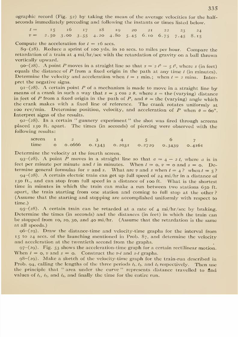
8/13/2019 Maurer Mechanics
http://slidepdf.com/reader/full/maurer-mechanics 351/407
335
ographic record (Fig. 52) by taking the mean of the average velocities for the half-
seconds immediately preceding and following the instants or times listed below.
t= 15 16 17 18 19 20 21 22 23 24
v= 2.50 3.00 3.55 4.20 4.80 5.45 6.10 6.75 7.45 8.15
Compute the acceleration for / = 16 sees.
89-(28). Reduce a sprint of 100 yds. in 10 sees, to miles per hour. Compare the
retardation of a train at 4 mi/hr/sec with the retardation of gravity on a ball thrownvertically upward.
90-(28) . A point P moves in a straight line so that s = 2fi — ^f, where 5 (in feet)
equals the distance of P from a fixed origin in the path at any time / (in minutes).
Determine the velocity and acceleration when / = i min.; when t = 2 mins. Inter-
pret the negative signs.
9i-(28). A certain point P of a mechanism is made to move in a straight Une bymeans of a crank in such a way that 5 =
3cos 2 (9,
where5 =
the (varying) distancein feet of P from a fixed origin in the path of P, and e = the (varying) angle whichthe crank makes with a fixed line of reference. The crank rotates uniformly at100 rev/min. Determine position, velocity, and acceleration of P when e = 60°.
Interpret signs of the results.
92-(28). In a certain gunnery experiment the shot was fired through screens
placed 150 ft. apart. The times (in seconds) of piercing were observed with the
following results:
screen
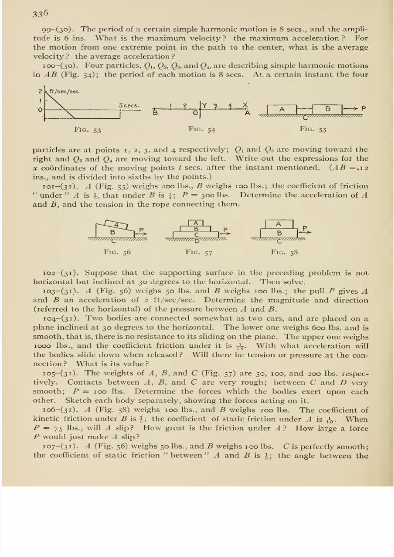
8/13/2019 Maurer Mechanics
http://slidepdf.com/reader/full/maurer-mechanics 352/407
336
99~(3o)- The period of a certain simple harmonic motion is 8 sees., and the ampli-
tude is 6 ins. What is the maximum velocity ? the maximum acceleration ? For
the motion from one extreme point in the path to the center, what is the average
velocity? the average acceleration?
ioo-(3o). Four particles, Qi, Qi, Q3, and Q^, are describing simple harmonic motions
in AB (Fig.54);
the period of each motion is 8 sees. At a certain instant the four
5 sees.
BY 3 X
B>/////////>////////r'f^i'^w/MW////w,
Fig. 53 Fig. 54 Fig. 55
particles are at points i, 2, 3, and 4 respectively; Qy and ^3 are moving toward the
right and Q^ and Q^^ are moving toward the left. Write out the expressions for the
X coordinates of the moving points / sees, after the instant mentioned. {AB =.12
ins., and is divided into sixths by the points.)
ioi-(3i). A (Fig. 55) weighs 200 lbs., B weighs 100 lbs.; the coefficient of friction
under .-1 is \, that under 5 is }; P = 300 lbs. Determine the acceleration of -4
and B, and the tension in the rope connecting them.
B•»r/j/>///^//j////'/////,
Fig. 56
1I
B I
''mTTTTTTTTT^TTTTTTTmr.
Fig. 57
B• 'WW/Wr ' ^M////U-X'-
Fig. 58
i02-(3i). Suppose that the supporting surface in the preceding problem is not
horizontal but inclined at 30 degrees to the horizontal. Then solve.
io3-(3i). A (Fig. 56) weighs 50 lbs. and B weighs 100 lbs.; the pull P gives Aand B an acceleration of 2 ft/sec/sec. Determine the magnitude and direction
(referred to the horizontal) of the pressure between A and B.
io4-(3i). Two bodies are connected somewhat as two cars, and are placed on a
plane inclined at 30 degrees to the horizontal. The lower one weighs 600 lbs. and is
smooth, that is, there is no resistance to its sliding on the plane. The upper one weighs
1000 lbs., and the coefficient friction under it is y ^. With what acceleration will
the bodies slide down when released ? WiU there be tension or pressure at the con-
nection ? What is its value ?
io5-(3i). The weights of .1, B, and C (Fig. 57) are 50, 100, and 200 lbs. respec-
tively. Contacts between .4, B, and C are very rough; between C and D very
smooth; P = 100 lbs. Determine the forces which the bodies exert upon eachother. Sketch each body separately, showing the forces acting on it.
io6-(3i). A (Fig. 58) weighs 100 lbs., and B weighs 200 lbs. The coefficient of
kinetic friction under -B is |; the coefficient of static friction under A is ^\. WhenP = 75 lbs., will A slip? How great is the friction under .4? How large a force
P would- just make .4 slip?
io7-(3i). A (Fig. 56) weighs 50 lbs., and B weighs 100 lbs. C is perfectly smooth;
the coefl&cient of static friction between A and .B is ^; the angle between the
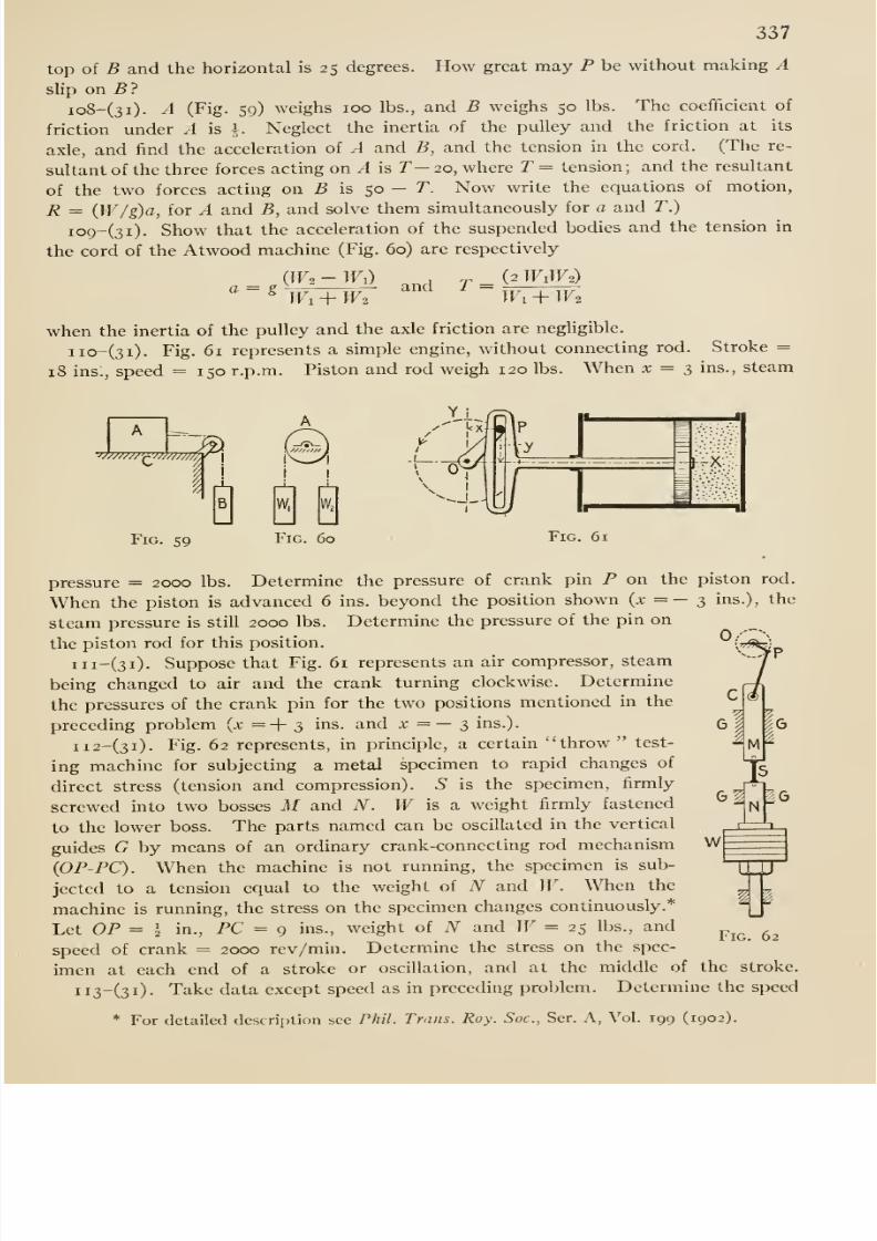
8/13/2019 Maurer Mechanics
http://slidepdf.com/reader/full/maurer-mechanics 353/407
337
top of B and the horizontal is 25 degrees. How great may P be without making A
slip on 5 ?
io8-(3i). A (Fig. 59) weighs 100 lbs., and B weighs 50 lbs. The coefficient of
friction under A is \. Neglect the inertia of the pulley and the friction at its
axle, and find the acceleration of A and B, and the tension in the cord. (The re-
sultant of the three forces acting on Ais
T—20, where T = tension; and the resultant
of the two forces acting on 5 is 50 — T. Now write the equations of motion,
R = {W/g)a, for A and B, and solve them simultaneously for a and T.)
io9-(3i). Show that the acceleration of the suspended bodies and the tension in
the cord of the Atwood machine (Fig. 60) are respectively
(2 W1W2)(iK-Il) and TWi + IF2 Wi^Wi
when the inertia of the pulley and the axle friction are negligible.
iio-(3i). Fig. 61 represents a simple engine, without connecting rod. Stroke =18 ins:, speed = 150 r.p.m. Piston and rod weigh 120 lbs. When x = 3 ins., steam
A
'^w//mhr^[
i'
B
Fig. 59 Fig. 60 Fig. 61
M
pressure = 2000 lbs. Determine the pressure of crank pin P on the piston rod.
When the piston is advanced 6 ins. beyond the position shown (x = — 3 ins.), the
steam pressure is still 2000 lbs. Determine the pressure of the pin on
the piston rod for this position.
iii-(3i). Suppose that Fig. 61 represents an air compressor, steam
being changed to air and the crank turning clockwise. Determine
the pressures of the crank pin for the two positions mentioned in the
preceding problem (x =+ 3 ins. and x =— 3 ins.).
ii2-(3i). Fig. 62 represents, in prmciple, a certain throw test-
ing machine for subjecting a metal specimen to rapid changes of
direct stress (tension and compression). S is the specimen, firmly
screwed into two bosses M and N. W is a weight firmly fastened
to the lower boss. The parts named can be oscillated in the vertical
guides G by means of an ordinary crank-connecting rod mechanism
(OP-PC). When the machine is not running, the specimen is sub-
jected to a tension equal to the weight of N and W. When the
machine is running, the stress on the specimen changes continuously.*
Let OP = I in., PC = g ins., weight of N and W= 25 lbs., and
speed of crank = 2000 rev/min. Determine the stress on the spec-
imen at each end of a stroke or oscillation, and at the middle of the stroke.
ii3-(3i)- Take data except speed as in preceding problem. Determine the speed
* For detailed description see Phil. Trans. Roy. Soc, Ser. A, Vol. 199 (1902).
g-In^g
1
Fig. 62
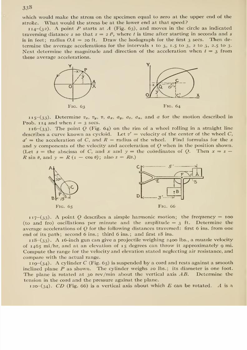
8/13/2019 Maurer Mechanics
http://slidepdf.com/reader/full/maurer-mechanics 354/407
338
which would make the stress on the specimen equal to zero at the upper end of the
stroke. What would the stress be at the lower end at that speed ?
ii4-(32). A point P starts at A (Fig. 63), and moves in the circle as indicated
traversing distance s so that s = 2 fi, where t is time after starting in seconds and 5
is in feet; radius OA = 20 ft. Draw the hodograph for the first 3 sees. Then de-
termine the average accelerations for the intervals i to 3, 1.5 to 3, 2 to 3, 2.5 to 3.
Next determine the magnitude and direction of the acceleration when t = 3 from
these average accelerations.
YY

8/13/2019 Maurer Mechanics
http://slidepdf.com/reader/full/maurer-mechanics 355/407
339
5' SB
Vi^-
D.3' *Fig. 67
—
body resting on E, and B is suspended by means of a cord fastened to A as shown.
A weighs 10 lbs. and B weighs 20 lbs. Suppose that E makes 30 rev/min; then
compute the pressure at the stop S. The centers of A and B are 5 and 3 ft. from
CD respectively. (Neglect friction under A, a,t B and the pulley axle.)
i2i-(34). Suppose that ,1 and B in Prob. 120 are rough, the coefi&cients of static
friction beingj
for each.What
rate of rotationwould
lift
B?i22-(34). T (Fig. 67)' is a horizontal whirling
table. A and B are spheres connected by an elastic
cord, the tension in which is 30 lbs. when the table
is at rest. A weighs ir lbs. and B weighs 40 lbs.
What are the pressures of the stops S' and S against
the spheres when the table is rotated about CD at 20
rev/min ?
i23-(35). Suppose that the floor of the car and A (Fig. 283, Art. 35) are very
rough so that A will not slip on the car; then ascertain how great an acceleration of
the car would result in tipping of Ai24-(35). Suppose that the coefBcient of friction in Prob. 123 is i. If the ap-
plied push on the car is gradually increased, thus increasing the acceleration grad-
ually, will .1 sUp or tip eventually ?
Fig. 68 Fig. 69
2
W///////Ay/^^//////////////A
Fig. 70
-^zft^MI^
i2S-(35). The Scotch cross-head (Fig. 61) described in Prob. no presses against
the stuffing box and on the cylinder by reason of the weight of the cross-head and
the pressure of the crank-pin on it. Suppose that the center of gravity of the cross-
head is 1 5 ins. from the center of the slot, the center of the piston is 24 ins. from
the same point, and the center of the stuffing box is 13 ins. from 0. Determine the
pressures mentioned when the circumstances are as in Prob. no (steam pressure =
2000 lbs., etc.).
i26-(36). Show that the moment of inertia of the slender wire AB (Fig. 68)
about the x-axis is § Mr\\ — (sin a. cos a)/a\, where M = mass of the wire.
i27-(36). Show that the moment of inertia of a right circular cone about its axis is
I'ij Mr'', where M = the mass of the cone and r = the radius of its base.
i28-(36). Show that the moment of inertia of the ring or torus (Fig. 69) about
the 2-axis is M (R^ + 5 r^), where M = the mass of the ring.
i29-(36). The length of a homogeneous right elliptic prism is /, and the semi-
axes of its cross section are a and b. Prove that the radius of gyration of the
prism with respect to a line through its center of gravity parallel to the axis b is
i30-(36). Fig. 70 is a section of a cast-iron flywheel; there are six spokes. The
cross section of each spoke is elliptical, the axes of the ellipse being 2 inches and 5^
ins. long. Compute the moments of inertia of rim, spokes, and hub with respect to
the axis of the wheel; also the radius of gyration of the wheel about that axis.
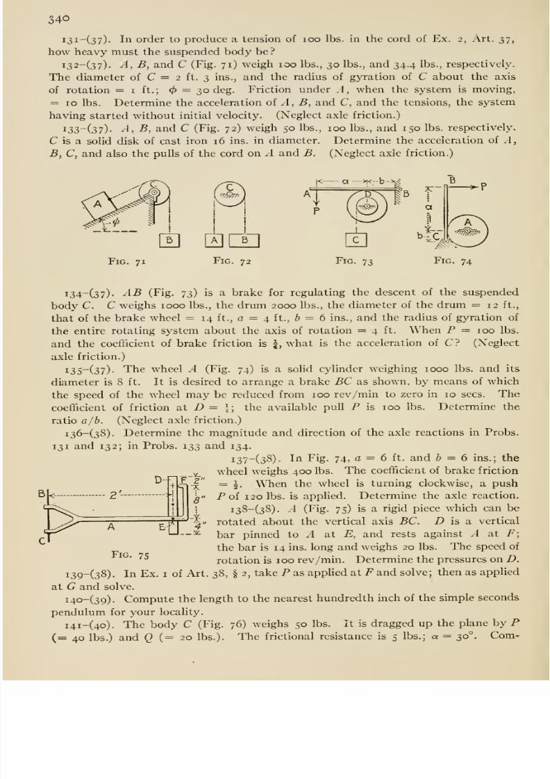
8/13/2019 Maurer Mechanics
http://slidepdf.com/reader/full/maurer-mechanics 356/407
340
i3i-(37)- In order to produce a tension of loo lbs. in the cord of Ex. 2, Art. 37,
how heavy must the suspended body be ?
i32-(37)- A, B, and C (Fig. 71) weigh 100 lbs., 30 lbs., and 34.4 lbs., respectively.
The diameter of C = 2 ft. 3 ins., and the radius of gyration of C about the axis
of rotation = i f t. ; = 30 deg. Friction under .1 , when the system is moving,
= ID lbs. Determine the acceleration of A, B, and C, and the tensions, the system
having started without initial velocity. (Neglect axle friction.)
i33~(37)- A, B, and C (Fig. 72) weigh 50 lbs., 100 lbs., and 150 lbs. respectively.
C is a solid disk of cast iron 16 ins. in diameter. Determine the acceleration of A,
B, C, and also the pulls of the cord on A and B. (Neglect axle friction.)
Fig. 71 Fig. 72 Fig. 74
i34-(37). AB (Fig. 73) is a brake for regulating the descent of the suspended
body C. C weighs 1000 lbs., the drum 2000 lbs., the diameter of the drum =12 ft.,
that of the brake wheel = 14 ft., a = 4 ft., 6 = 6 ins., and the radius of gyration of
the entire rotating system about the axis of rotation = 4 ft. When P = 100 lbs.
and the coefficient of brake friction is |, what is the acceleration of C? (Neglect
axle friction.)
135^(37) • The wheel A (Fig. 74) is a solid cylinder weighing 1000 lbs. and its
diameter is 8 ft. It is desired to arrange a brake BC as shown, by means of which
the speed of the wheel may be reduced from 100 rev/min to zero in 10 sees. The
coefficient of friction at D = \; the available pull P is 100 lbs. Determine the
ratio a/h. (Neglect axle friction.)
i36-(38). Determine the magnitude and direction of the axle reactions in Probs.
131 and 132; in Probs. 133 and 134.
137^(38) • Iri Fig. 74, a = 6 ft. and & = 6 ins.; the
wheel weighs 400 lbs. The coefficient of brake friction
= |. When the wheel is turning clockwise, a push
Pof 120 lbs. is appUed. Determine the axle reaction.
i38-(38). A (Fig. 75) is a rigid piece which can be
rotated about the vertical axis BC. D is a vertical
bar pinned to A at E, and rests against A at F;
the bar is 14 ins. long and weighs 20 lbs. The speed of'^
rotation is 100 rev/min. Determine the pressures on D.
i3g-(38). In Ex. i of Art. 38, § 2, take P as applied at F and solve; then as appUed
at G and solve.
i4o-(39) . Compute the length to the nearest hundredth inch of the simple seconds
pendulum for your locality.
i4i-(4o). The body C (Fig. 76) weighs 50 lbs. It is dragged up the plane by P(=40 lbs.) and Q {= 20 lbs.). The frictional resistance is 5 lbs.; a = 30°. Com-
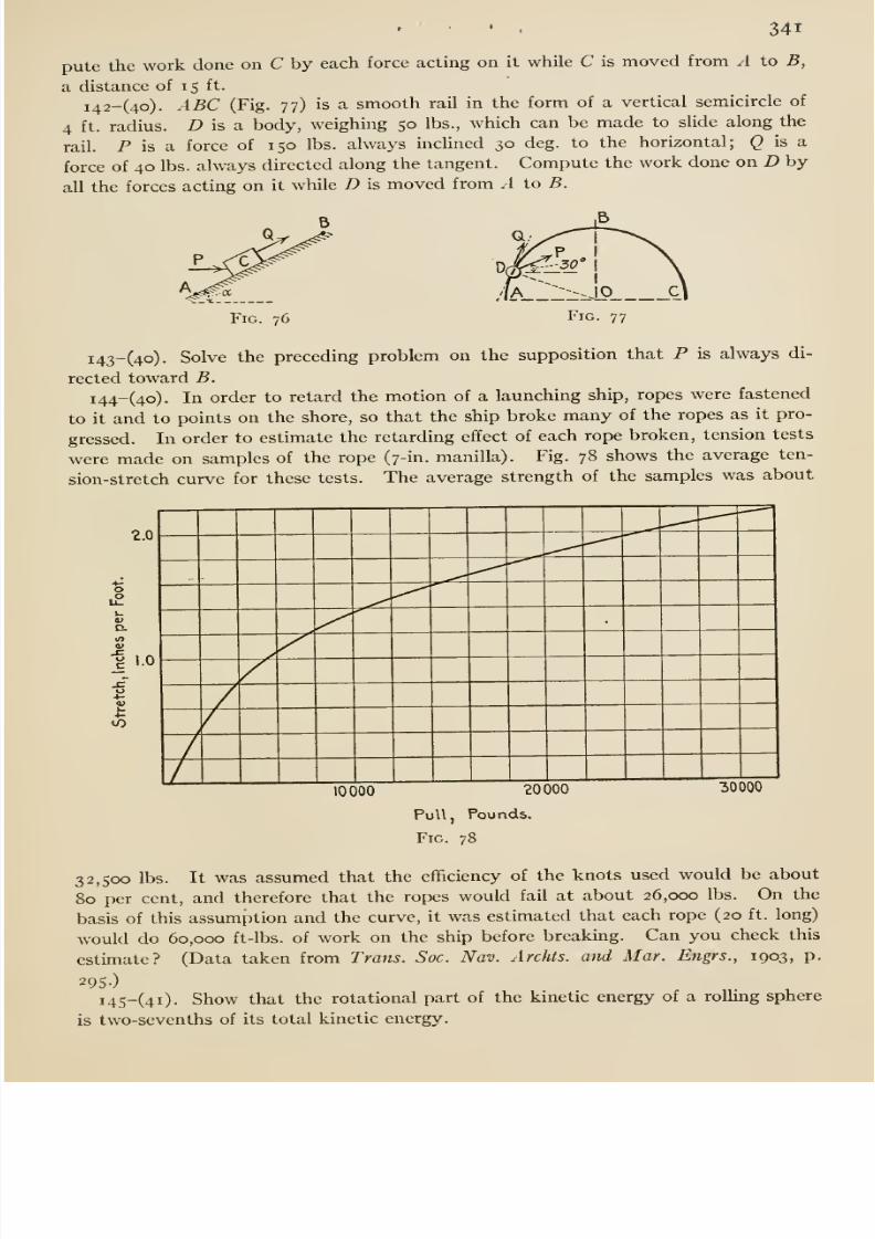
8/13/2019 Maurer Mechanics
http://slidepdf.com/reader/full/maurer-mechanics 357/407
» > , 341
pute the work done on C by each force acting on it while C is moved from A to B,
a distance of i s ft.
i42-(4o). ABC (Fig. 77) is a smooth rail in the form of a vertical semicircle of
4 ft. radius. D is a. body, weighing 50 lbs., which can be made to slide along the
rail. P is a force of 150 lbs. always inclined 30 deg. to the horizontal; Q is a
force of 40 lbs. always directed along the tangent. Compute the work done on D by
all the forces acting on it while D is moved from .1 to B.
Fig. 76 Fig. 77
i43-(4o). Solve the preceding problem on the supposition that P is always di-
rected toward B.
i44-(4o). In order to retard the motion of a launching ship, ropes were fastened
to it and to points on the shore, so that the ship broke many of the ropes as it pro-
gressed. In order to estimate the retarding effect of each rope broken, tension tests
were made on samples of the rope (7-in. manilla). Fig. 78 shows the average ten-
sion-stretch curve for these tests. The average strength of the samples was about
Vain0)
«0
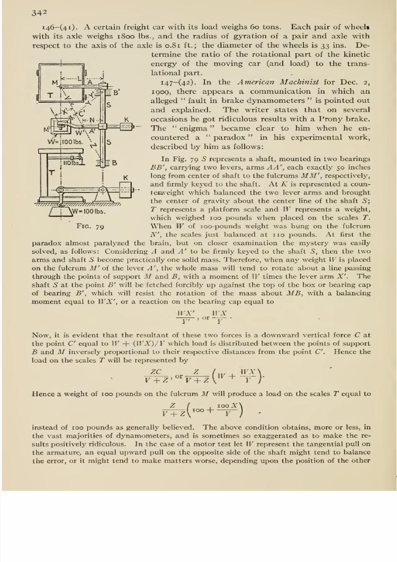
8/13/2019 Maurer Mechanics
http://slidepdf.com/reader/full/maurer-mechanics 358/407
342
i46-(4i). A certain freight car with its load weighs 60 tons. Each pair of wheel*
with its axle weighs 1800 lbs., and the radius of gyration of a pair and axle with
respect to the axis of the axle is 0.81 ft.; the diameter of the wheels is ^:^ ins. De-
termine the ratio of the rotational part of the kinetic
energy of the moving car (and load) to the trans-
lational part.
i47-(42). In the American Machinist for Dec. 2,
1909, there appears a communication in which an
alleged favdt in brake dynamometers is pointed out
and explained. The writer states that on several
occasions he got ridiculous results with a Prony brake.
The enigma became clear to him when he en-
countered a paradox in his experimental work,
described by him as follows:
In Fig. 79 S represents a shaft, mounted in two bearings
BB', carrying two levers, arms AA', each exactly 50 inches
long from center of shaft to the fulcrums MM', respectively,
and firmly keyed to the shaft. At K is represented a coun-
tecweight which balanced the two lever arms and brought
the center of gravity about the center line of the shaft S;
T represents a platform scale and W represents a weight,
which weighed 100 pounds when placed on the scales T.
When W of loo-pounds weight was hung on the fulcrum
N', the scales just balanced at
nopounds. At first the
paradox almost paralyzed the brain, but on closer examination the mystery was easily
solved, as follows: Considering A and A' to be firmly keyed to the shaft S, then the two
arms and shaft S become practically one solid mass. Therefore, when an}^ weight IF is placed
on the fulcrum M' of the lever A', the whole mass will tend to rotate about a line passing
through the points of support M and B, with a moment of W times the lever arm X'. The
shaft 5 at the point B' will be fetched forcibly up against the top of the box or bearing cap
of bearing B', which will resist the rotation of the mass about MB, with a balancing
moment equal to WX', or a reaction on the bearing cap equal to
WX' WX~T^ . or -y- •
yTy^W 'IOOlbs.
Fig. 79
Now, it is evident that the resultant of these two forces is a downward vertical force C at
the point C equal to IF + {WX)/Y which load is distributed between the points of support
B and M inversely proportional to their respective distances from the point C Hence the
load on the scales T will be represented by
ZC Z ( WX\F-I-Z'^V + Z V Y j
Hence a weightof
100 pounds on the fulcrum Mwill
produce a load on the scales Tequal to
V + ZI
,iooZ\
instead of 100 pounds as generally believed. The above condition obtains, more or less, in
the vast majorities of dynamometers, and is sometimes so exaggerated as to make the re-
sults positively ridiculous. In the case of a motor test let IF represent the tangential pull on
the armature, an equal upward pull on the opposite side of the shaft might tend to balance
the error, or it might tend to make matters worse, depending upon the position of the other
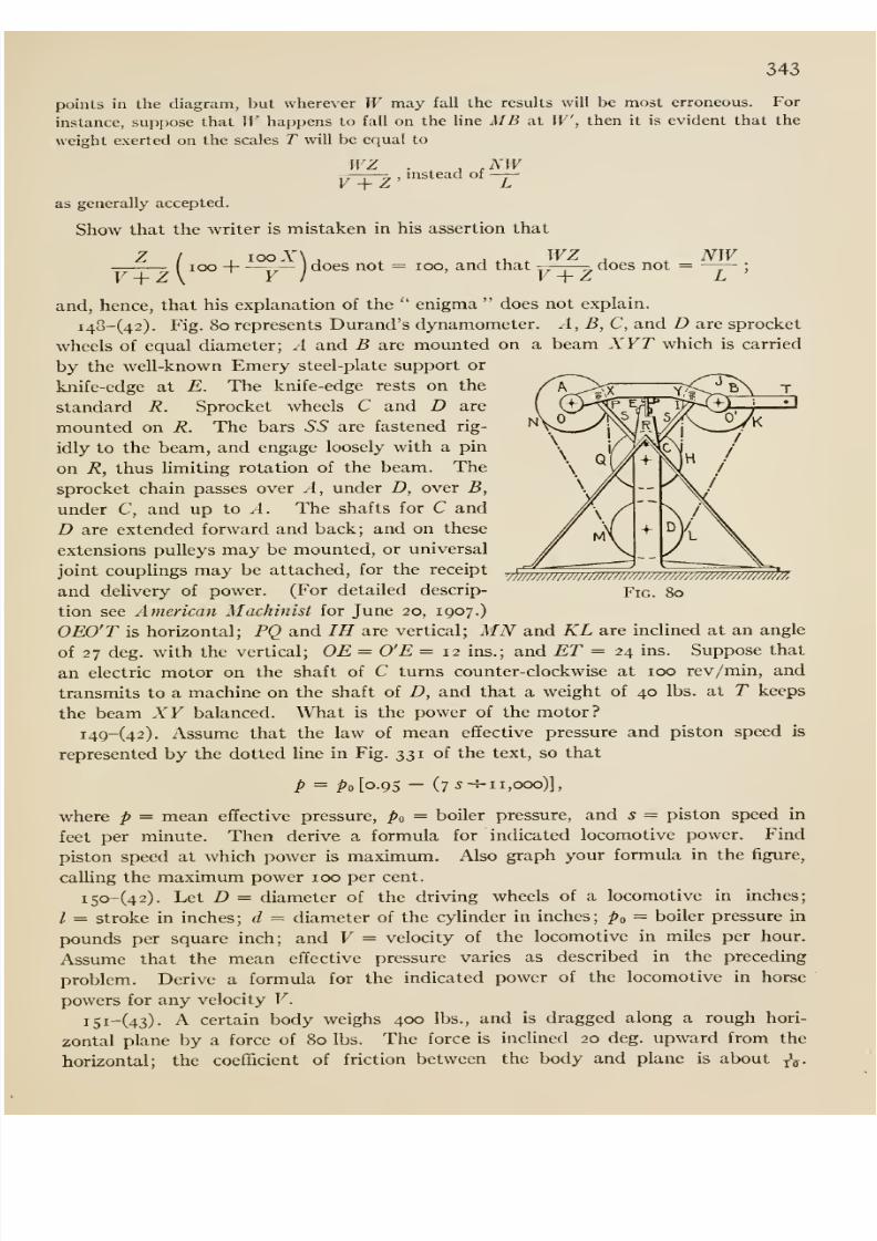
8/13/2019 Maurer Mechanics
http://slidepdf.com/reader/full/maurer-mechanics 359/407
343
points in the diagram, but wherever W may fall the results will be most erroneous. For
instance, suppose that IF happens to fall on the line MB at W, then it is evident that the
weight exerted on the scales T will be equal to
^^^^,msteadof —as generally accepted.
Show that the writer is mistaken in his assertion that
( loo H :^ —)
does not = loo, and thatWZ
V + Zdoes not = NW
v}//////7iJ/J// ///////////J///////////////m777777^,
V + Z
and, hence, that his explanation of the enigma does not explain.
i4o-(42). Fig. 80 represents Durand's dynamometer. A, B,C, and D are sprocket
wheels of equal diameter; A and B are mounted on a beam XYT which is carried
by the well-known Emery steel-plate support or
knife-edge at E. The knife-edge rests on the
standard R. Sprocket wheels C and D are
mounted on R. The bars ^^ are fastened rig-
idly to the beam, and engage loosely with a pin
on R, thus limiting rotation of the beam. The
sprocket chain passes over A, under D, over B,
under C, and up to A. The shafts for C and
D are extended forward and back; and on these
extensions puUeys maybe mounted, or universal
joint couplings may be attached, for the receipt
and delivery of power. (For detailed descrip- Fig. 80
tion see American Machinist for June 20, 1907.)
OEO'T is horizontal; PQ and IH are vertical; MNand KL are inclined at an angle
of 27 deg. with the vertical; OR = O'E = 12 ins.; and ET = 24 ins. Suppose that
an electric motor on the shaft of C turns counter-clockwise at 100 rev/min, and
transmits to a machine on the shaft of D, and that a weight of 40 lbs. at T keeps
the beam XY balanced. What is the power of the motor?
i49-(42). Assume that the law of mean effective pressure and piston speed is
represented by the dotted line in Fig. 331 of the text, so that
p = ^o[o.9S - (7-^-^11,000)],
where p = mean effective pressure, po = boiler pressure, and s = piston speed in
feet per minute. Then derive a formula for indicated locomotive power. Find
piston speed at which power is maximum. Also graph your formula in the figure,
calling the maximum power 100 per cent.
i5<>-(42). Let D = diameter of the driving wheels of a locomotive in inches;
/ = stroke in inches ; d = diameter of the cylinder in inches; po = boiler pressure in
pounds per square inch; and V = velocity of the locomotive in miles per hour.
Assume that the mean effective pressure varies as described in the preceding
problem. Derive a formula for the indicated power of the locomotive in horse
powers for any velocity V.
iSi-(43)- A certain body weighs 400 lbs., and is dragged along a rough hori-
zontal plane by a force of 80 lbs. The force is inclined 20 deg. upward from the
horizontal; the coefficient of friction between the body and plane is about j\.
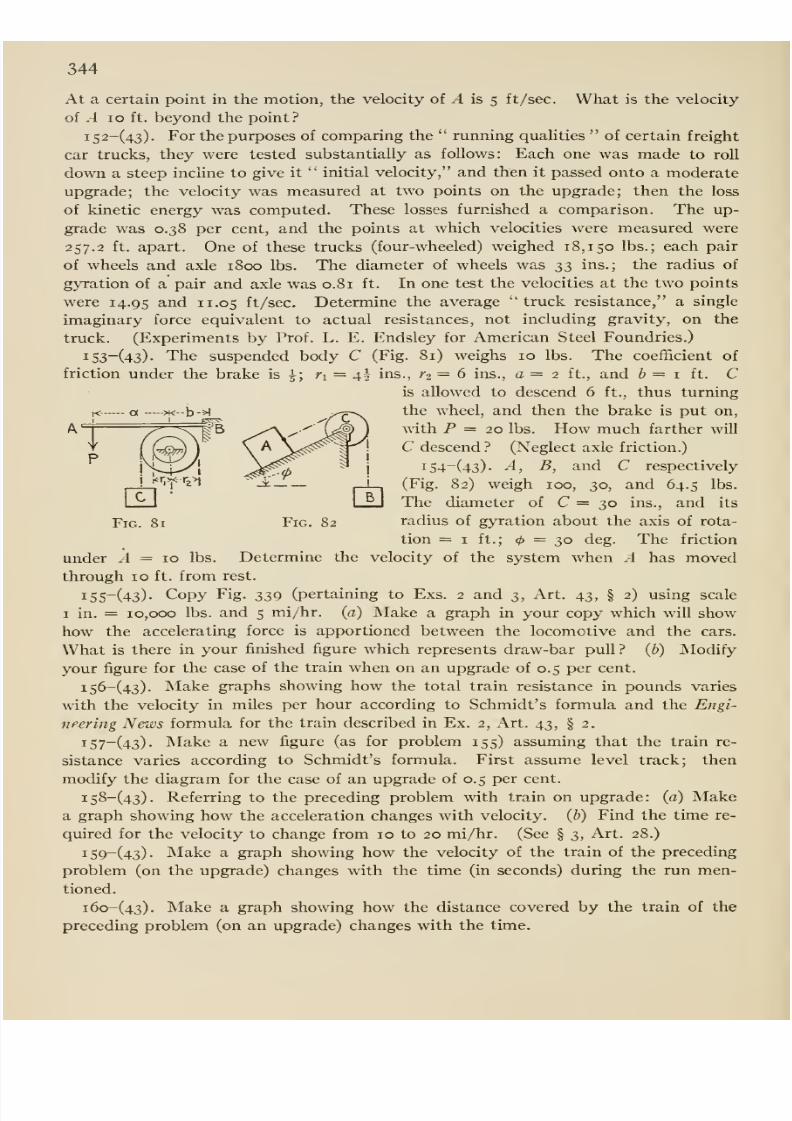
8/13/2019 Maurer Mechanics
http://slidepdf.com/reader/full/maurer-mechanics 360/407
344
At a certain point in the motion, the velocity of ^ is 5 ft/sec. What is the velocity
of A 10 ft. beyond the point?
i52-(43). For the purposes of comparing the running quahties of certain freight
car trucks, they were tested substantially as follows: Each one was made to roU
down a steep incline to give it initial velocity, and then it passed onto a moderate
upgrade; the velocity was measured at two points on the upgrade; then the loss
of kinetic energy was computed. These losses furnished a comparison. The up-
grade was 0.38 per cent, and the points at which velocities were measured were
257.2 ft. apart. One of these trucks (four-wheeled) weighed 18,150 lbs.; each pair
of wheels and axle 1800 lbs. The diameter of wheels was ^;i ins.; the radius of
gyration of a pair and axle was 0.81 ft. In one test the velocities at the two points
were 14.95 ^.nd 11.05 ft/sec. Determine the average ''truck resistance, a single
imaginary force equivalent to actual resistances, not including gravity, on the
truck. (Experiments by Prof. L. E. Endsley for American Steel Foundries.)
i53-(43). The suspended body C (Fig. 81) weighs 10 lbs. The coefficient offriction under the brake is ^; n = 4^ ins., ^2 = 6 ins., a = 2 ft., and b = 1 it. C
is allowed to descend 6 ft., thus turning
the wheel, and then the brake is put on,
with P = 20 lbs. How much farther will
C descend? (Neglect axle friction.)
i54-(43). A, B, and C respectively
(Fig. 82) weigh 100, 30, and 64.5 lbs.
The diameter of C = 30 ins., and its
radius of gyration about the axis of rota-
tion = I ft.; = 30 deg. The friction
under A = 10 lbs. Determine the velocity of the system when A has movedthrough 10 ft. from rest.
i55-(43). Copy Fig. 339 (pertaining to Exs. 2 and 3, Art. 43, § 2) using scale
I in. = 10,000 lbs. and 5 mi/hr. (a) Make a graph in your copy which will show
how the accelerating force is apportioned between the locomotive and the cars.
What is there in your finished figure which represents draw-bar pull? (b) Modify
yourfigure for the case of the train when on an upgrade of
0.5per cent.
i56-(43). Make graphs showing how the total train resistance in pounds varies
with the velocity in miles per hour according to Schmidt's formula and the Engi-
neering News formula for the train described in Ex. 2, Art. 43, § 2.
i57-(43). Make a new figure (as for problem 155) assuming that the train re-
sistance varies according to Schmidt's formula. First assume level track; then
modify the diagram for the case of an upgrade of 0.5 per cent.
i58-(43). Referring to the preceding problem with train on upgrade: (a) Makea graph showing how the acceleration changes with velocity, (h) Find the time re-
quired for the velocity to change from 10 to 20 mi/hr. (See § 3, Art. 28.)
i59-(43). Make a graph showing how the velocity of the train of the preceding
problem (on the upgrade) changes with the time (in seconds) during the run men-
tioned.
i6o-(43). Make a graph showing how the distance covered by the train of the
preceding problem (on an upgrade) changes with the time.
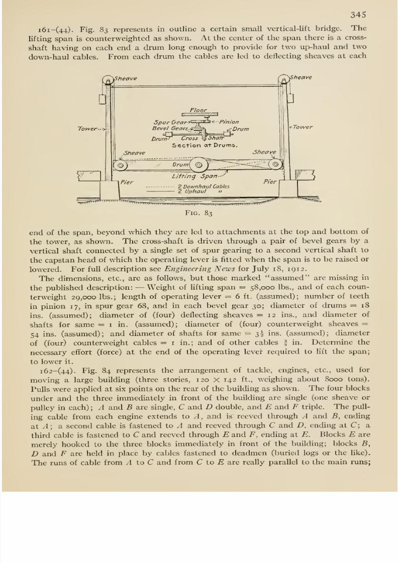
8/13/2019 Maurer Mechanics
http://slidepdf.com/reader/full/maurer-mechanics 361/407
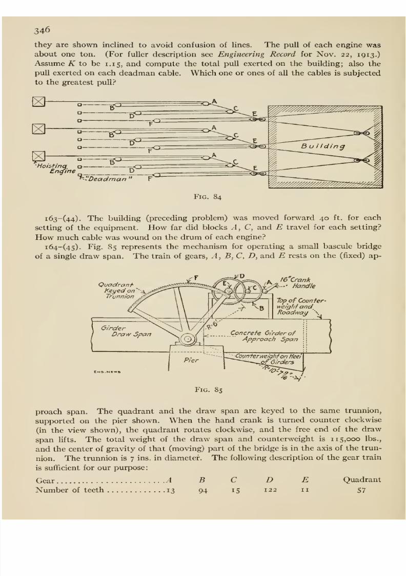
8/13/2019 Maurer Mechanics
http://slidepdf.com/reader/full/maurer-mechanics 362/407
346
they are shown inclined to avoid confusion of lines. The pull of each engine wasabout one ton. (For fuller description see Engineering Record for Nov. 22, 1913.)
Assume i^ to be 1.15, and compute the total pull exerted on the building; also the
pull exerted on each deadman cable. Which one or ones of all the cables is subjected
to the greatest pull?
„ ^ohtincf^ o O
Engine D _^ Deadman ' F
Fig. 84
i63-(44). The building (preceding problem) was moved forward 40 ft. for each
setting of the equipment. How far did blocks .4, C, and E travel for each setting?
How much cable was wound on the drum of each engine?
i64-(45). Fig. 85 represents the mechanism for operating a small bascule bridge
of a single draw span. The train of gears, A , B, C, D, and E rests on the (fixed) ap-
QuadraniKeyed or7''xTrunnion
GirderDraw Span
EmO . NC-MQ
16 Crank'' Handle
Top of Counfer-weighi and_Roadway \
Concrete Girder of
Approach Span
,_<ounferweihhf on Meet
f Girders
Fig. 85
proach span. The quadrant and the draw span are keyed to the same trunnion,
supported on the pier shown. When the hand crank is turned counterclockwise
(in the view shown), the quadrant rotates clockwise, and the free end of the draw
span lifts. The total weight of the draw span and counterweight is 115,000 lbs.,
and the center of gravity of that (moving) part of the bridge is in the axis of the trun-
nion. The trunnion is 7 ins. in diameter. The following description of the gear train
is sufficient for our purpose:
Gear A B C D E Quadrant
Number of teeth 13 94 15 122 11 57

8/13/2019 Maurer Mechanics
http://slidepdf.com/reader/full/maurer-mechanics 363/407
347
(For fuller description see Engineering News for July 24, 1913, or the paper by
the designer, Prof. L. E. Moore, in Engineering and Contracting for Aug. 13, 1913-)
Determine how large a force applied to the crank handle at right angles to the crank
is required to raise the draw span.
i65-(45). Fig. 86 represents in plan certain elements of the downstream (miter)
gate of the lock at the Keokuk Dam. Each leaf of the gate is hung on hinges some-
what like an ordinary door; but the lower hinge is a hemispherical pivot or pintle
Fig. 86
and ii takes up all the direct weight of the leaf, the upper hinge taking up only hori-
zontal pull. Each leaf is opened and closed by means of an operating strut AB,
pinned to the top of the leaf and to the rim of a horizontal bull-wheel; each wheel
is driven by an engine through a train of gears. Each leaf weighs 463,000 lbs.; the
distance from its center of gravity to the (vertical) axis of its hinges is 31 ft. 8 ins.;
the distance between the hinges is 48 ft.; the diameter of the upper hinge pin is 12
ins.; the radius of the pintle is 9 ins. Assume coefficients of friction for pin and
pintle to be 0.05 and 0.15respectively. Determine the reactions at the hinge pin
and pintle due to the weight of the leaf, and the moment of the frictional resistance
to swinging, about the axis of the hinges.
i66-(45). Fig. 87 represents certain details of the operating mechanism for the lock
gate described in the preceding problem. It will be noticed that when the gate is
wide open, the axis of the operating strut is over the center of the bull-wheel. The
dimensions, proportions, etc., are such that a turn of the wheel through 180° from
the position shown closes the leaf; and then the center of the wheel is again in Hne
with the axis of the strut. From a large drawing, we have scaled the arms of the
thrust of the strut with respect to the axes of rotation of the leaf and bull-wheel for
thirteen positions of the strut, corresponding respectively to the open position of the
wheel, 15° turn, 30° turn, etc. (see adjoining table). Compute the torque required
on the bull-wheel for overcoming the frictional resistance at the hinges for each of
the thirteen positions, neglecting the frictional resistance at the pins of the strut,
at the center pin of the wheel and at the rollers under the rim of the wheel. Make a
curve which shows how this torque varies with 6. What docs the area under the curve
represent?
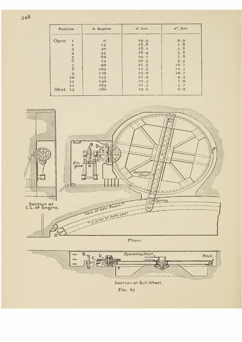
8/13/2019 Maurer Mechanics
http://slidepdf.com/reader/full/maurer-mechanics 364/407
348
Position
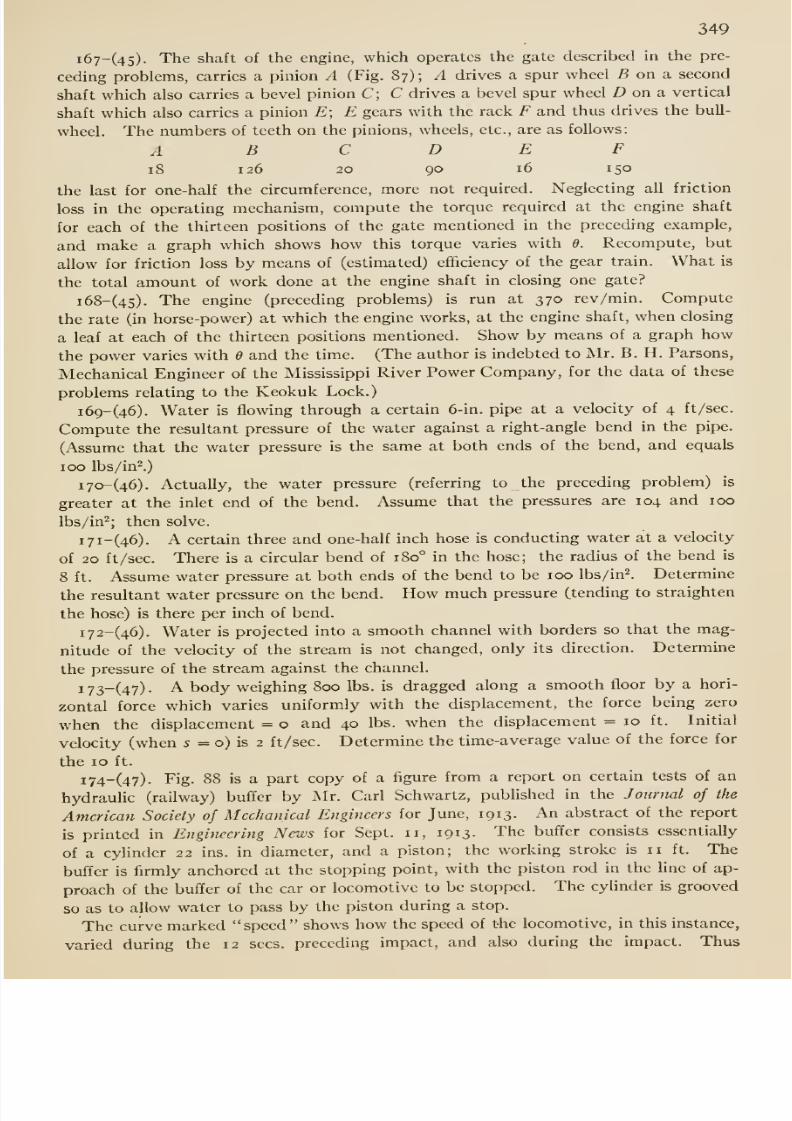
8/13/2019 Maurer Mechanics
http://slidepdf.com/reader/full/maurer-mechanics 365/407
349
i67-(45)- The shaft of the engine, which operates the gate described in the pre-
ceding problems, carries a pinion A (Fig. 87); A drives a spur wheel 5 on a second
shaft which also carries a bevel pinion C; C drives a bevel spur wheel Z) on a vertical
shaft which also carries a pinion E; E gears with the rack F and thus drives the bull-
wheel. The numbers of teeth on the pinions, wheels, etc., are as follows:
AB C D E F
18 126 20 90 16 150
the last for one-half the circumference, more not required. Neglecting all friction
loss in the operating mechanism, compute the torque required at the engine shaft
for each of the thirteen positions of the gate mentioned in the preceding example,
and make a graph which shows how this torque varies with e. Recompute, but
allow for friction loss by means of (estimated) efficiency of the gear train. What is
the total amount of work done at the engine shaft in closing one gate?
i68-(45). The engine (preceding problems) is run at 370 rev/min. Compute
the rate (in horse-power) at which the engine works, at the engine shaft, when closing
a leaf at each of the thirteen positions mentioned. Show by means of a graph how
the power varies with and the time. (The author is indebted to Mr. B. H. Parsons,
Mechanical Engineer of the Mississippi River Power Company, for the data of these
problems relating to the Keokuk Lock.)
i69-(46). Water is flowing through a certain 6-in. pipe at a velocity of 4 ft/sec.
Compute the resultant pressure of the water against a right-angle bend in the pipe.
(Assume that the water pressure is the same at both ends of the bend, and equals
100 lbs/in^.)
1 70- (46). Actually, the water pressure (referring to the preceding problem) is
greater at the inlet end of the bend. Assume that the pressures are 104 and 100
lbs/in^; then solve.
i7i-(46). A certain three and one-half inch hose is conducting water at a velocity
of 20 ft /sec. There is a circular bend of 180° in the hose; the radius of the bend is
8 ft. Assume water pressure at both ends of the bend to be 100 lbs/in^. Determine
the resultant water pressure on the bend. How much pressure (tending to straighten
the hose) is there per inch of bend.
i72-(46). Water is projected into a smooth channel with borders so that the mag-nitude of the velocity of the stream is not changed, only its direction. Determine
the pressure of the stream against the channel.
i73_(4y). A body weighing 800 lbs. is dragged along a smooth floor by a hori-
zontal force which varies uniformly with the displacement, the force being zero
when the displacement = o and 40 lbs. when the displacement = 10 ft. Initial
velocity (when 5 = o) is 2 ft/sec. Determine the time-average value of the force for
the 10 ft.
i74-(47). Fig. 88 is a part copy of a figure from a report on certain tests of an
hydraulic (railway) buffer by Mr. Carl Schwartz, published in the Journal of the
American Society of Mechanical Engineers for June, 1913. An abstract of the report
is printed in Engineering News for Sept. 11, 1913. The buffer consists essentially
of a cylinder 22 ins. in diameter, and a piston; the working stroke is 11 ft. The
buffer is firmly anchored at the stopping point, with the piston rod in the line of ap-
proach of the buffer of the car or locomotive to be stopped. The cylinder is grooved
so as to allow water to pass by the piston during a stop.
The curve marked speed shows how the speed of the locomotive, in this instance,
varied during the 12 sees,preceding impact, and also during the impact. Thus
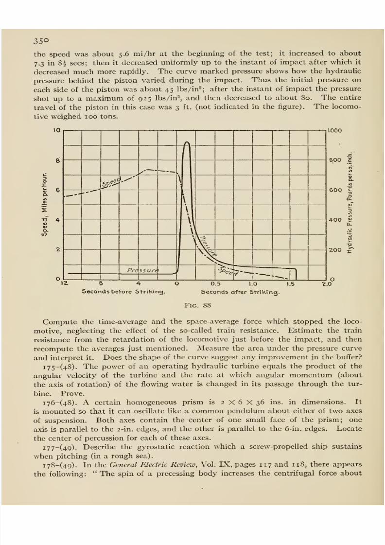
8/13/2019 Maurer Mechanics
http://slidepdf.com/reader/full/maurer-mechanics 366/407
350
the speed was about 5.6 mi/hr at the beginning of the test; it increased to about
7.3 in 8^ sees; then it decreased uniformly up to the instant of impact after which it
decreased much more rapidly. The curve marked pressure shows how the hydrauhc
pressure behind the piston varied during the impact. Thus the initial pressure on
each side of the piston was about 45 lbs/in^; after the instant of impact the pressure
shot up to a maximum of 925 lbs/in'^, and then decreased to about 80. The entire
travel of the piston in this case was 3 ft. (not indicated in the figure). The locomo-
tive weighed 100 tons.
10
1:
3
OX
o. ,.^-
u0)
D-
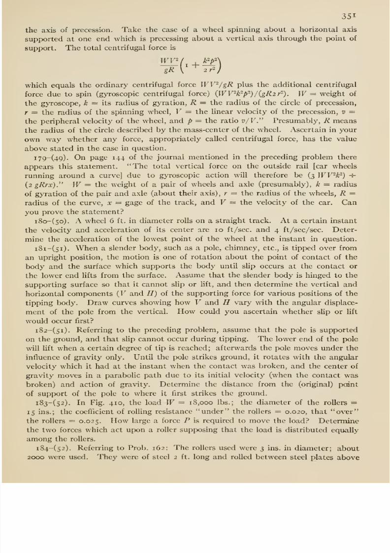
8/13/2019 Maurer Mechanics
http://slidepdf.com/reader/full/maurer-mechanics 367/407
351
the axis of precession. Take the case of a wheel spinning about a horizontal axis
supported at one end which is precessing about a vertical axis through the point of
support. The total centrifugal force is
which equals the ordinary centrifugal force WV^/gR plus the additional centrifugal
force due to spin (gyroscopic centrifugal force) {WV^k'^p-)/{gR2r'^). W= weight of
the gyroscope, k — its radius of gyration, R = the radius of the circle of precession,
r = the radius of the spinning wheel, V = the hnear velocity of the precession, v =
the peripheral velocity of the wheel, and p = the ratio v/V.' Presumably, R means
the radius of the circle described by the mass-center of the wheel. Ascertain in your
own way whether any force, appropriately called centrifugal force, has the value
above stated in the case in question.
i79-(49). On page 144 of the journal mentioned in the preceding problem there
appears this statement. The total vertical force on the outside rail [car wheels
running around a curve] due to gyroscopic action will therefore be (3 WV^k ^) -i-
{2gRrx). W= the weight of a pair of wheels and axle (presumably), k = radius
of gyration of the pair and axle (about their axis) , r = the radius of the wheels, R =radius of the curve, x = gage of the track, and V = the velocity of the car. Canyou prove the statement?
i8o-(5o). A wheel 6 ft. in diameter rolls on a straight track. At a certain instant
the velocity and acceleration of its center are 10 ft/sec. and 4 ft /sec/sec. Deter-
mine the acceleration of the lowest point of the wheel at the instant in question.
i8i-(5i). When a slender body, such as a pole, chimney, etc., is tipped over from
an upright position, the motion is one of rotation about the point of contact of the
body and the surface which supports the body until slip occurs at the contact or
the lower end Ufts from the surface. Assume that the slender body is hinged to the
supporting surface so that it cannot slip or Hft, and then determine the vertical and
horizontal components {V and H) of the supporting force for various positions of the
tipping body. Draw curves showing how V and H vary with the angular displace-
ment of the pole from the vertical. How could you ascertain whether slip or hft
would occur first?
i82-(5i). Referring to the preceding problem, assume that the pole is supported
on the ground, and that sUp cannot occur during tipping. The lower end of the pole
will lift when a certain degree of tip is reached; afterwards the pole moves under the
influence of gravity only. Until the pole strikes ground, it rotates with the angular
velocity which it had at the instant when the contact was broken, and the center of
gravity moves in a parabolic path due to its initial velocity (when the contact was
broken) and action of gravity. Determine the distance from the (original) point
of support of the pole to where it first strikes the ground.
i83-(52). In Fig. 410, the load W= 18,000 lbs.; the diameter of the roUers =
15 ins.; the coefficient of rolling resistance under the rollers = 0.020, that over
the rollers = 0.025. How large a force P is required to move the load? Determine
the two forces which act upon a roller supposing that the load is distributed equally
among the rollers.
i84-(52). Referring to Prob. 162: The rollers used were 3 ins. in diameter; about
2000 were used. They were of steel 2 ft. long and rolled between steel plates above
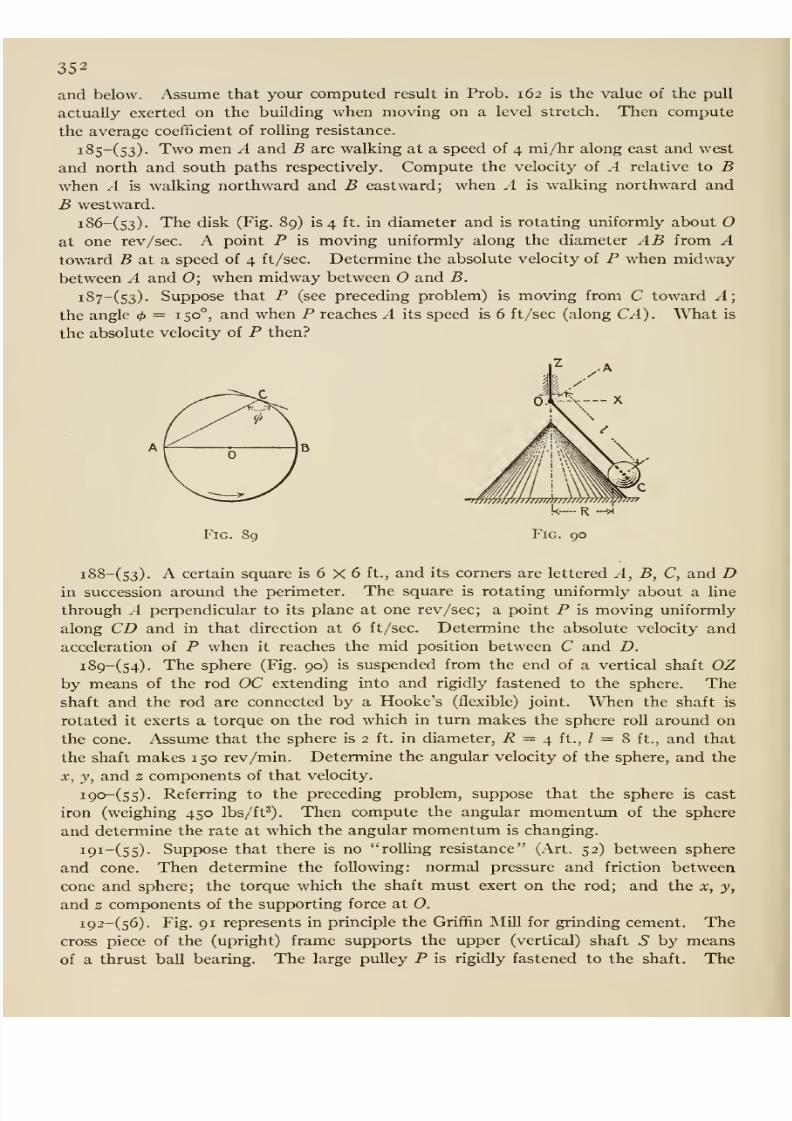
8/13/2019 Maurer Mechanics
http://slidepdf.com/reader/full/maurer-mechanics 368/407
352
and below. Assume that yoiir computed result in Prob. 162 is the value of the pull
actually exerted on the building when moving on a level stretch. Then compute
the average coefficient of rolling resistance.
i85-(53). Two men A and B are walking at a speed of 4 mi/hr along east and west
and north and south paths respectively. Compute the velocity of A relative to Bwhen A is walking northward and B eastward; when A is walking northward and
B westward.
i86-(s3). The disk (Fig. 89) is 4 ft. in diameter and is rotating uniformly about Oat one rev/sec. A point P is moving uniformly along the diameter AB from Atoward B at a speed of 4 ft/sec. Determine the absolute velocity of P when midway
between A and 0; when midway between and B.
i87-(53). Suppose that P (see preceding problem) is moving from C toward A;
the angle <i>— 150°, and when P reaches A its speed is 6 ft /sec (along CA). What is
the absolute velocity of P then?
Fig. 89
i88-(53). A certain square is 6 X 6 ft., and its corners are lettered A, B, C, and Din succession around the perimeter. The square is rotating uniformly about a Une
through .4 perpendicular to its plane at one rev /sec; a point P is moving uniformly
along CD and in that direction at 6 ft/sec. Determine the absolute velocity and
acceleration of P when it reaches the mid position between C and D.
i89-(54). The sphere(Fig.
90)is suspended from the
endof
avertical
shaft OZby means of the rod OC extending into and rigidly fastened to the sphere. Theshaft and the rod are connected by a Hooke's (flexible) joint. When the shaft is
rotated it exerts a torque on the rod which in turn makes the sphere roll around on
the cone. Assume that the sphere is 2 ft. in diameter, R = 4 ft., / = 8 ft., and that
the shaft makes 1 50 rev/min. Determine the angular velocity of the sphere, and the
X, y, and z components of that velocity.
i9o-(55). Referring to the preceding problem, suppose that the sphere is cast
iron (weighing 450 lbs/ft^). Then compute the angular momentimi of the sphere
and determine the rate at which the angular momentum is changing.
i9i-(55). Suppose that there is no rolling resistance (Art. 52) between sphere
and cone. Then determine the following: normal pressure and friction between
cone and sphere; the torque which the shaft must exert on the rod; and the x, y,
and z components of the supporting force at 0.
i92-(56). Fig. 91 represents in principle the Griffin Mill for grinding cement. Thecross piece of the (upright) frame supports the upper (vertical) shaft S by means
of a thrust ball bearing. The large pulley P is rigidly fastened to the shaft. The
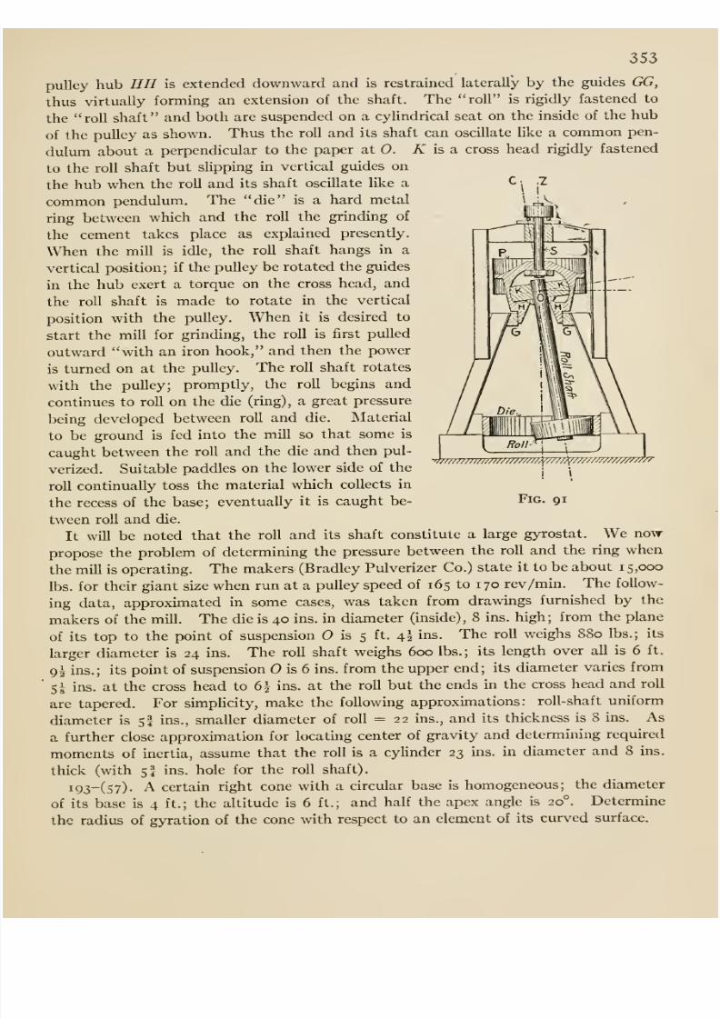
8/13/2019 Maurer Mechanics
http://slidepdf.com/reader/full/maurer-mechanics 369/407
353
pulley hub HH is extended downward and is restrained laterally by the guides GG,
thus virtually forming an extension of the shaft. The roll is rigidly fastened to
the roll shaft and both are suspended on a cylindrical seat on the inside of the hub
of the pulley as shown. Thus the roll and its shaft can oscillate like a common pen-
dulum about a perpendicular to the paper at 0. K is a cross head rigidly fastened
to the roll shaft but slippingin vertical guides on
the hub when the roU and its shaft oscUlate like a
common pendulum. The die is a hard metal
ring between which and the roll the grinding of
the cement takes place as explained presently.
When the mill is idle, the roU shaft hangs in a
vertical position; if the pulley be rotated the guides
in the hub exert a torque on the cross head, and
the roll shaft is made to rotate in the vertical
position with the pulley. When it is desired to
start the mill for grinding, the roll is first puUed
outward with an iron hook, and then the power
is turned on at the pulley. The roll shaft rotates
with the pulley; promptly, the roll begins and
continues to roll on the die (ring), a great pressure
being developed between roll and die. Material
to be ground is fed into the mill so that some is
caught between the roll and the die and then pul-
verized. Suitable paddles on the lower side of the
roU continually toss the material which collects in
the recess of the base; eventually it is caught be-
tween roU and die.
It will be noted that the roll and its shaft constitute a large gyrostat. We now
propose the problem of determining the pressure between the roll and the ring when
the mill is operating. The makers (Bradley Pulverizer Co.) state it to be about 15,000
lbs. for their giant size when run at a pulley speed of 165 to 1 70 rev/min. The follow-
ing data, approximated in some cases, was taken from drawings furnished by themakers of the mill. The die is 40 ins. in diameter (inside), 8 ins. high; from the plane
of its top to the point of suspension is 5 ft. 4I ins. The roU weighs 880 lbs.; its
larger diameter is 24 ins. The roll shaft weighs 600 lbs. ; its length over all is 6 ft.
9^ ins.; its point of suspension is 6 ins. from the upper end; its diameter varies from'
5 1 ins. at the cross head to 6| ins. at the roll but the ends in the cross head and roll
are tapered. For simpUcity, make the following approximations: roll-shaft uniform
diameter is 5I ins., smaller diameter of roll = 22 ins., and its thickness is 8 ins. As
a further close approximation for locating center of gravity and determining required
moments of inertia, assume that the roll is a cylinder 23 ins. in diameter and 8 ins.
thick (with 5I ins. hole for the roll shaft).
i93-(57). A certain right cone with a circular base is homogeneous; the diameter
of its base is 4 ft.; the altitude is 6 ft.; and half the apex angle is 20°. Determine
the radius of gyration of the cone with respect to an element of its curved surface.
>///w////w/ //////////^/////Y/w/w/////////^'
Fig. 91
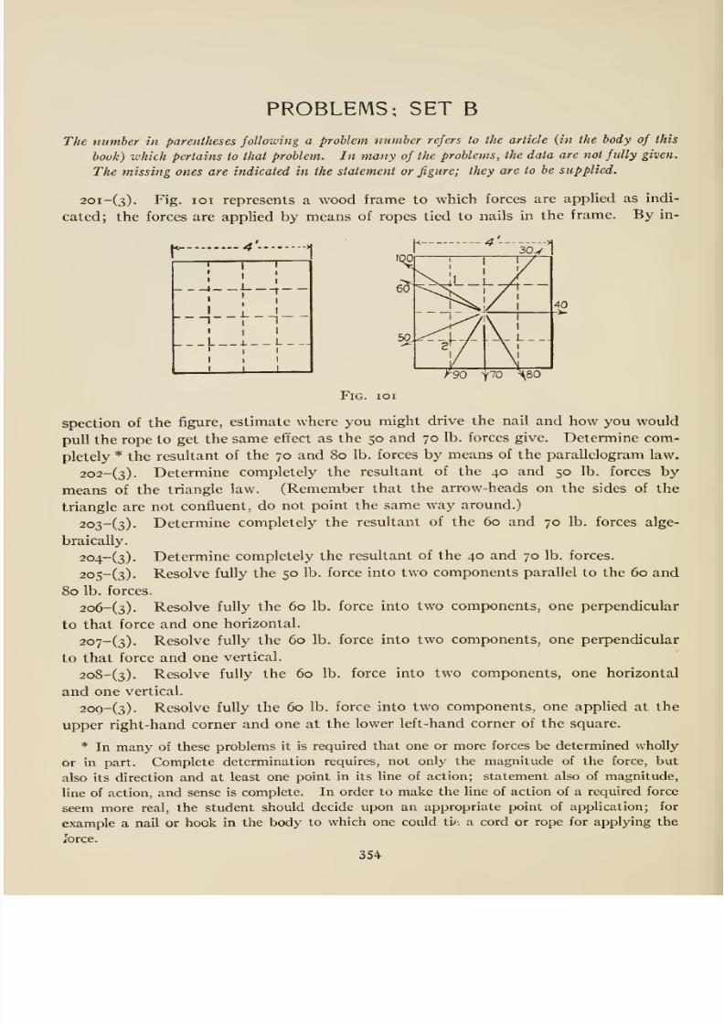
8/13/2019 Maurer Mechanics
http://slidepdf.com/reader/full/maurer-mechanics 370/407
PROBLEMS; SET B
The number in parentheses following a problem mimber referslo
thearticle
{in the body ofthis
book) which pertains lo that problem. In many of the problems, the data are not fully given.
The missing ones are indicated in the statement or figure; they are to be supplied.
2oi-(3). Fig. loi represents a wood frame to which forces are appUed as indi-
cated; the forces are applied by means of ropes tied to nails in the frame. By in-
*- 4 >
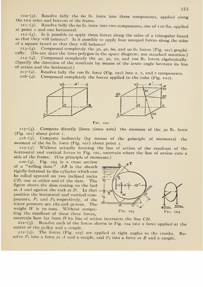
8/13/2019 Maurer Mechanics
http://slidepdf.com/reader/full/maurer-mechanics 371/407
355
2io-(3). Resolve fully the 60 lb. force into three components, applied alongthe two sides and bottom of the frame.
2ii-(3). Resolve fully the 60 lb. force into two components, one of 120 lbs. appliedat point I and one horizontal.
2i2-(3). Is it possible to apply three forces along the sides of a triangular boardso that
they will balance? Is it possible to apply four unequal forces along the sidesof a square board so that they will balance?
2i3-(4)- Compound completely the 30, 40, 60, and 90 lb. forces (Fig. loi) graphi-cally. (Do not draw the force polygon in the space diagram; use standard notation.)
2i4-(4). Compound completely the 40, 50, 70, and 100 lb. forces algebraically.(Specify the direction of the resultant by means of the acute angle between its lineof action and the horizontal.)
2i5-(4). Resolve fully the 100 lb. force (Fig. 102) into x, y, and z components.2i6-(4). Compound completely the forces applied to the cube (Fig. 102).
YU--- 4 - ->i
I
jo
Fig. 102
2i7-(5)- Compute directly (force times arm) the moment of the 50 lb. force
(Fig. loi) about point i.
2i8-(5). Compute indirectly (by means of the principle of moments) themoment of the 60 lb. force (Fig. loi) about point 2.
2i9-(5)- Without actually locating the line of action of the resultant of thehorizontal and vertical forces in Fig. loi, ascertain where the line of action cuts aside of the frame. (Use principle of moments.)
2 20-(5). Fig. 103 is a cross sectionof a rolling dam. AB is the sheath
rigidly fastened to the cylinder which canbe rolled upward on two inclined racks
CD, one at either end of the dam. Thefigure shows the dam resting on the bedat A and against the rack at B. In that
position the horizontal and vertical com-ponents, Pi and Pi respectively, of the
water pressure are 180 and 30 tons. Theweight W is 70 tons. Without compu-ting the resultant of these three forces,
\^vv\\w\\vw
Fig. 103 Fig. 104
ascertain how far from D its line of action intersects the Hne CD.22i-(s). Resolve each of the forces shown in Fig. 104 into a force applied at the
center of the pulley and a couple.
222-(5). The forces (Fig. 105) arc applied at right angles to the cranks. Re-solve Pi into a force at A and a couple, and P2 into a force at B and a couple.
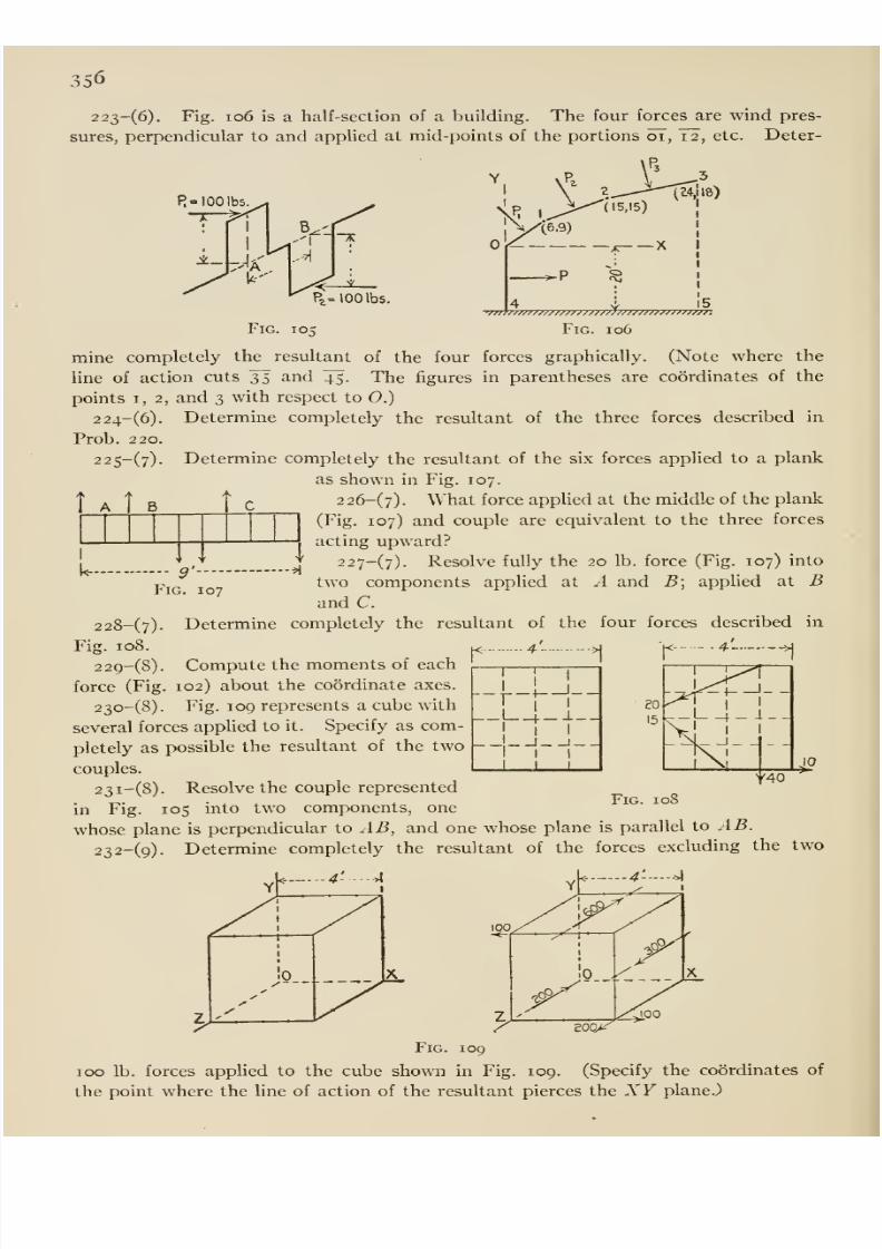
8/13/2019 Maurer Mechanics
http://slidepdf.com/reader/full/maurer-mechanics 372/407
356
223-(6). Fig. io6 is a half-section of a building. The four forces are wind pres-
sures, perpendicular to and applied at mid-points of the portions oi, T2, etc. Deter-
R= 100 lbs. ^
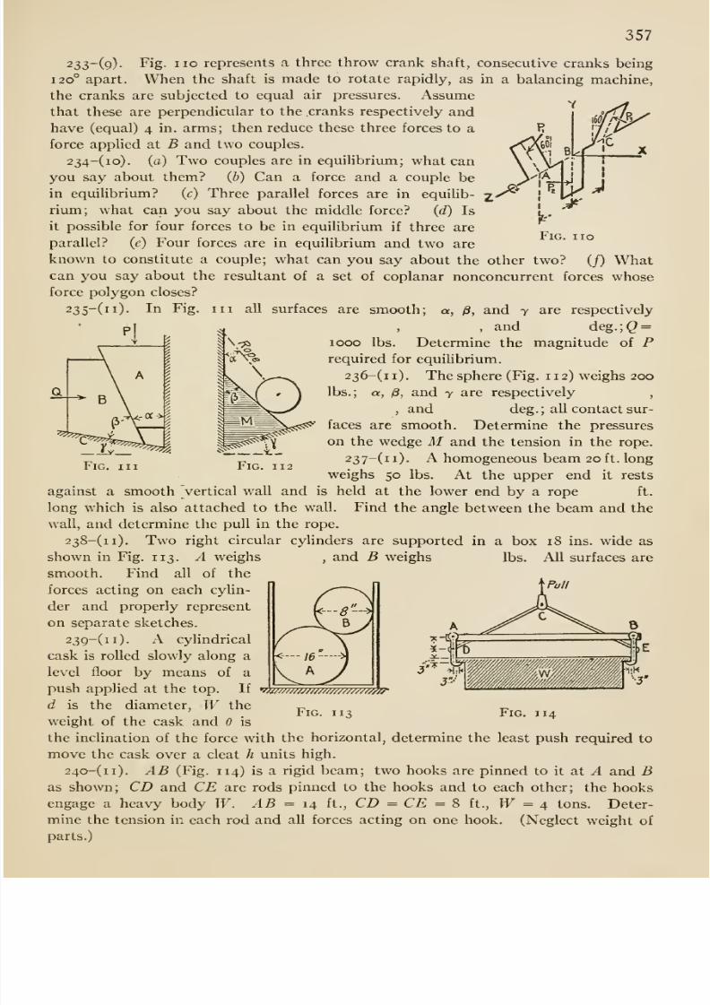
8/13/2019 Maurer Mechanics
http://slidepdf.com/reader/full/maurer-mechanics 373/407
357
no
233-(q)- Fig. no represents a three throw crank shaft, consecutive cranks being
120° apart. When the shaft is made to rotate rapidly, as in a balancing machine,
the cranks are subjected to equal air pressures. Assumethat these are perpendicular to the .cranks respectively and
have (equal) 4 in. arms; then reduce these three forces to a
force applied at B and two couples.
234-(io). (a) Two couples are in equiUbrium; what can
you say about them? (h) Can a force and a couple be
in equilibrium? (c) Three parallel forces are in equilib-
rium; what can you say about the middle force? {d) Is
it possible for four forces to be in equilibrium if three are
parallel? (c) Four forces are in equilibrium and two are
known to constitute a couple; what can you say about the other two? (/) Whatcan you say about the resultant of a set of coplanar nonconcurrent forces whoseforce polygon closes?
surfaces are smooth; a, /3, and 7 are respectively
, and deg.;(2 =
1000 lbs. Determine the magnitude of Prequired for equilibrium.
236-(ii). The sphere (Fig. 112) weighs 200
lbs.; a, /8, and 7 are respectively,
, and deg.; all contact sur-
faces are smooth. Determine the pressures
on the wedge M and the tension in the rope.
237-(ii). A homogeneous beam 20ft. long
weighs 50 lbs. At the upper end it rests
held at the lower end by a rope ft.
Ill
Find the angle between the beam and the
against a smooth vertical wall and is
long which is also attached to the wall
wall, and determine the pull in the rope.
238-(ii). Two right circular cylinders are supported in a box 18 ins. wide as
shown in Fig. 113. A weighs
smooth. Find all of the
forces acting on each cylin-
der and properly represent
on separate sketches.
239-(ii). A cylindrical
cask is rolled slowly along a
level floor by means of a
push applied at the top. If
d is the diameter, W theweight of the cask and is
and B weighs lbs. All surfaces are
17777777777777777777777777^^
Fig. 113 Fig. 114
the inclination of the force with the horizontal, determine the least push required to
move the cask over a cleat h units high.
24o-(ii). AB (Fig. 114) is a rigid beam; two hooks are pinned to it at A and Bas shown; CD and CE are rods pinned to the hooks and to each other; the hooks
engage a heavy body W. AB = 14 ft., CD = CE = 8 ft., W = 4 tons. Deter-
mine the tension in each rod and all forces acting on one hook. (Neglect weight of
parts.)
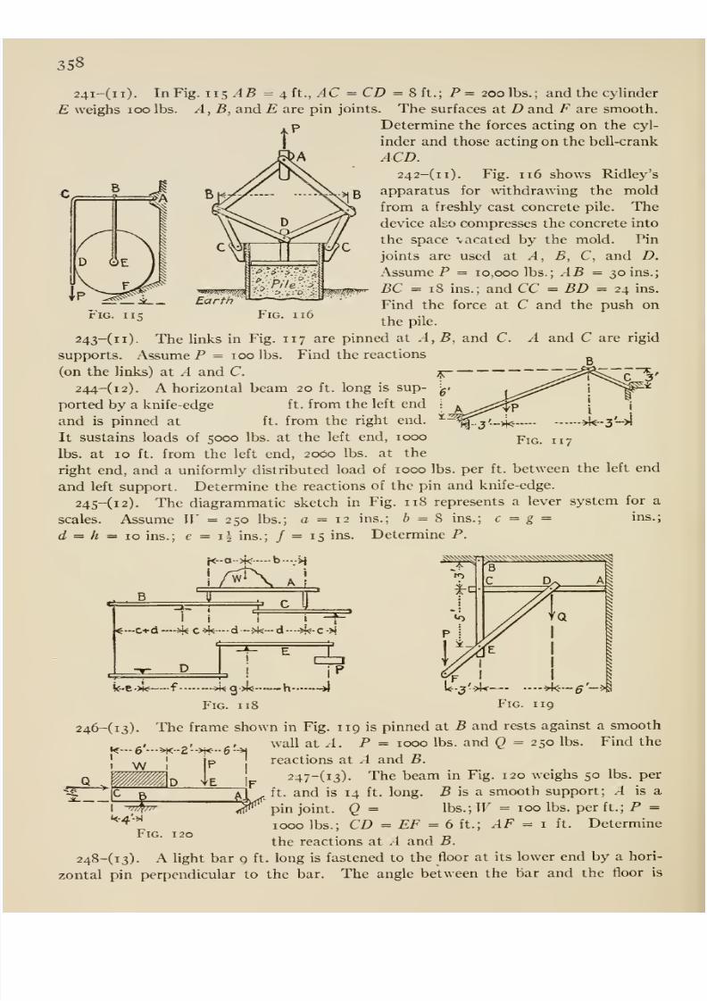
8/13/2019 Maurer Mechanics
http://slidepdf.com/reader/full/maurer-mechanics 374/407
358
t'
24i-(ii). In Fig. IIS ^5 =4 ft., AC = CD = 8 ft.; P = 200 lbs.; and the cylinder
E weighs 100 lbs. A, B, and E are pin joints. The surfaces at D and F are smooth.
Determine the forces acting on the cyl-
inder and those acting on the bell-crank
ACD.242-(ii). Fig. 116
showsRidley's
apparatus for withdrawing the mold
from a freshly cast concrete pile. Thedevice also compresses the concrete into
the space vacated by the mold. Pin
joints are used at A, B, C, and D.
Assume P = 10,000 lbs.; AB = 30 ins.;
BC = 18 ins.; and CC = BD = 24 ins.
Find the force at C and the push on
the pile.
c^
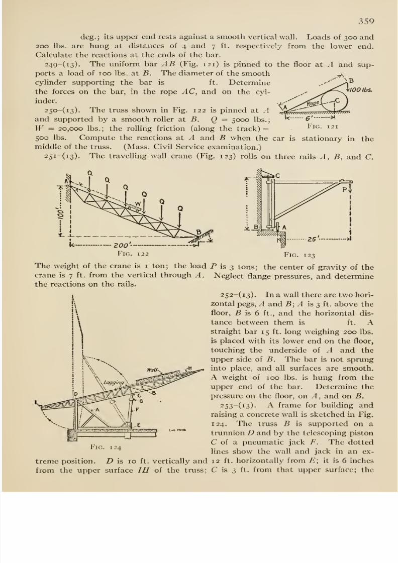
8/13/2019 Maurer Mechanics
http://slidepdf.com/reader/full/maurer-mechanics 375/407
359
100 lbs.
deg.; its upper end rests against a smooth vertical wall. Loads of 300 and200 lbs. are hung at distances of 4 and 7 ft. respectively from the lower end.
Calculate the reactions at the ends of the bar.
24g-(i3). The uniform bar AB (Fig. 121) is pinned to the floor at A and sup-
ports a load of 100 lbs. at 5. The diameter of the smooth
cylinder supporting the bar is ft. Determine
the forces on the bar, in the rope AC, and on the cyl-
inder.
250-(i3). The truss shown in Fig. 122 is pinned at .1
and supported by a smooth roller at B. Q = 5000 lbs.;
W = 20,000 lbs.; the rolling friction (along the track) =
500 lbs. Compute the reactions at A and B when the car is stationary in the
middle of the truss. (Mass. Civil Service examination.)
25i-(i3).The
travelling wallcrane
(Fig.123) rolls on three rails A, B, and C.
Fig. 123
The weight of the crane is i ton; the load P is 3 tons; the center of gravity of the
crane is 7 ft. from the vertical through A. Neglect flange pressures, and determinethe reactions on the rails.
252-(i3). In a wall there are two hori-
zontal pegs, A and B; A is 3 ft. above the
floor, B is 6 ft., and the horizontal dis-
tance between them is ft. Astraight bar 15 ft. long weighing 200 lbs.
is placed with its lower end on the floor,
touching the underside of A and the
upper side of B. The bar is not sprung
into place, and all surfaces are smooth.
A weight of 100 lbs. is hung from the
upper end of the bar. Determine the
pressure on the floor, on A, and on B.
253-(i3). A frame for building and
raising a concrete wall is sketched in Fig.
124. The truss B is supy^orted on a
trunnion D and by the telescoping piston
C of a pneumatic jack F. The dotted
lines show the wall and jack in an ex-
treme position. D is 10 ft. vertically and 12 ft. horizontally from E; it is 6 inches
from the upper surface IH of the truss; C is 3 ft. from that upper surface; the
Fig. 124
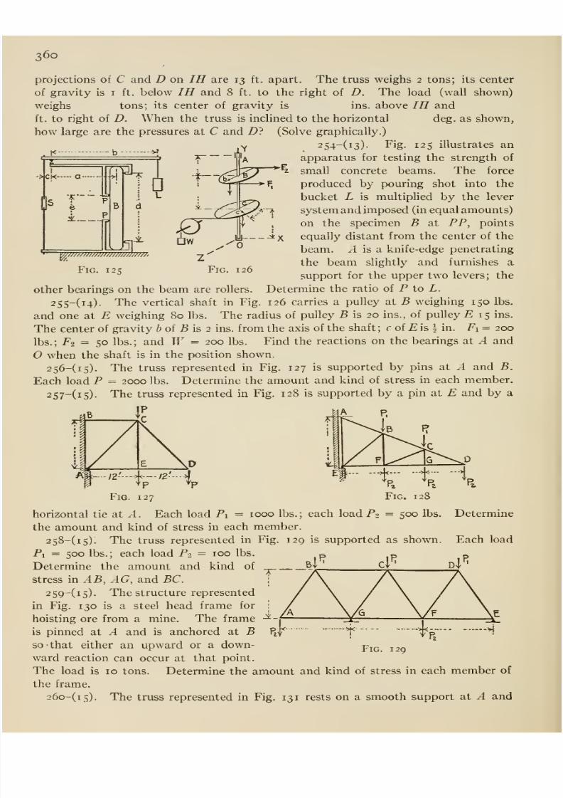
8/13/2019 Maurer Mechanics
http://slidepdf.com/reader/full/maurer-mechanics 376/407
360
-b
f̂
HCK a
0^ e
H
projections of C and D on IH are 13 ft. apart. The truss weighs 2 tons; its center
of gravity is i ft. below IH and 8 ft. to the right of D. The load (wall shown)
weighs tons; its center of gravity is ins. above IH and
ft. to right of D. When the truss is inclined to the horizontal deg. as shown,
how large are the pressures at C and D? (Solve graphically.)
2 54-(i3). Fig. 125 illustrates an'A apparatus for testing the strength of
jl3J-^ i ,^fe? *^^ small concrete beams. The force
produced by pouring shot into the
bucket L is multiplied by the lever
system and imposed (in equal amounts)
on the specimen B at PP, points
equally distant from the center of the
beam. ^ is a knife-edge penetrating
the beam slightly and furnishes a
support for the upper two levers; the
Determine the ratio of P to L.
126 carries a pulley at B weighing 150 lbs.
a
W7777777777777m7777m77,7777)
Fig. 125
other bearings on the beam are rollers.
255-(i4). The vertical shaft in Fig
and one at E weighing 80 lbs. The radius of pulley B is 20 ins., of pulley E 15 ins.
The center of gravity i of S is 2 ins. from the axis of the shaft; f of £ is J in. Fi = 200
lbs.; Fi = 50 lbs.; and W = 200 lbs. Find the reactions on the bearings at A and
when the shaft is in the position shown.
256-(i5). The truss represented in Fig. 127 is supported by pins at .-1 and B.
Each load P = 2000 lbs. Determine the amount and kind of stress in each member.
257-(i5). The truss represented in Fig. 128 is supported by a pin at E and by a
.'^-
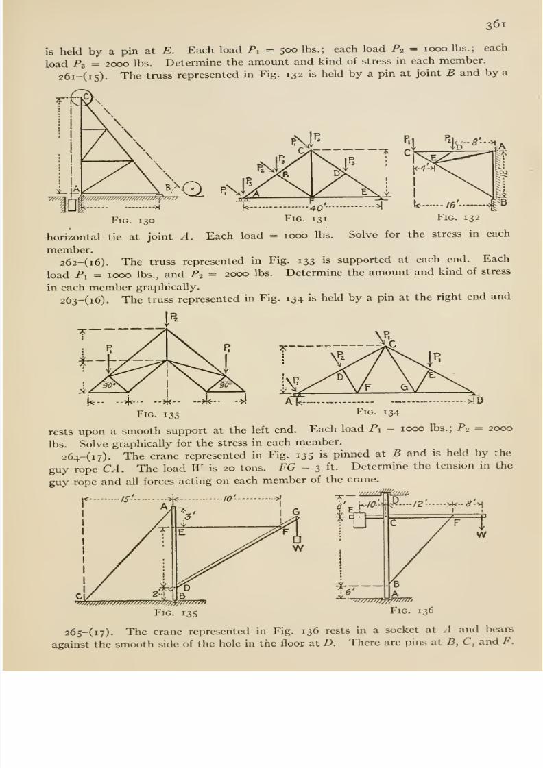
8/13/2019 Maurer Mechanics
http://slidepdf.com/reader/full/maurer-mechanics 377/407
361
is held by a pin at E. Each load Pi = 500 lbs.; each load Pi = 1000 lbs.; each
load Pz = 2000 lbs. Determine the amount and kind of stress in each member.
26i-(i5). The truss represented in Fig. 132 is held by a pin at joint B and by a
Fig. 130
Hf 40'- ^
Fig. 131
horizontal tie at joint A. Each load = 1000 lbs. Solve for the stress in each
member.
262-(i6). The truss represented in Fig. 133 is supported at each end. Each
load Px = 1000 lbs., and P2 = 2000 lbs. Determine the amount and kind of stress
in each member graphically.
263-(i6). The truss represented in Fig. 134 is held by a pin at the right end and
->i<-- --^-- —A<— --> A.k--^
Fig. 133 Fig. 134
rests upon a smooth support at the left end.Each load Pi = 1000 lbs.; Pi = 2000
lbs. Solve graphically for the stress in each member.
264-(i7). The crane represented in Fig. 135 is pinned at B and is held by the
guy rope CA. The load W is 20 tons. PG = 3 ft. Determine the tension in the
guy rope and all forces acting on each member of the crane.
S' \<-/0'^.'yP--/z' >K-<9->i
Fig. 13s
Tw
Fig. 136
26s-(i7). The crane represented in Fig. 136 rests in a socket at A and bears
against the smooth side of the hole in the floor at D. There are pins at B, C, and P.
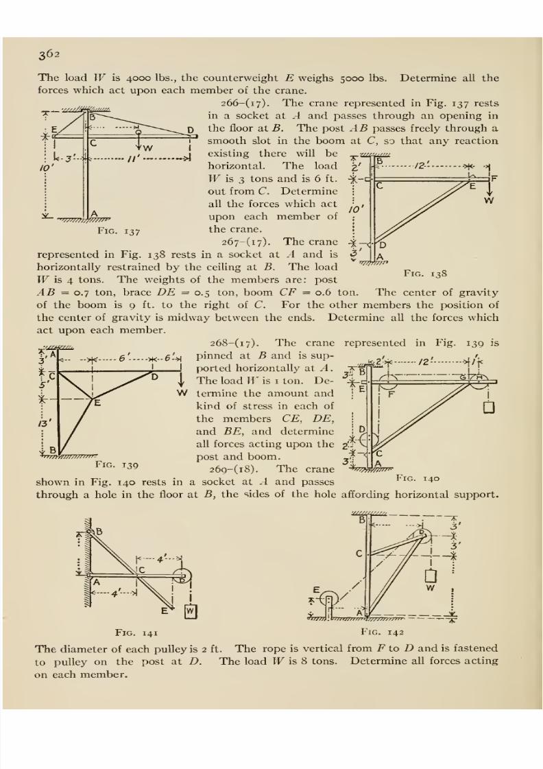
8/13/2019 Maurer Mechanics
http://slidepdf.com/reader/full/maurer-mechanics 378/407
362
B
The load W is 4000 lbs., the counterweight E weighs 5000 lbs. Determine all the
forces which act upon each member of the crane.
266-(i7). The crane represented in Fig. 137 rests
in a socket at A and passes through an opening in
the floor at B. The post AB passes freely through a
smooth slot in the boom at C, so that any reaction
existing there will be
horizontal. The load
PF is 3 tons and is 6 ft.
out from C. Determine
all the forces which act
upon each member of
the crane.
267-(i7). The crane
represented in Fig. 138 rests in a socket at A and is
horizontally restrained by the ceiling at B. The load
PF is 4 tons. The weights of the members are: post
AB = 0.7 ton, brace DE = 0.5 ton, boom CF = 0.6 ton. The center of gravity
of the boom is 9 ft. to the right of C. For the other members the position of
the center of gravity is midway between the ends. Determine all the forces which
act upon each member.
Fig. 137
WW77'
Fig. 138
•'jmiiii.
->K--6-^
^•W/WWrr.
Fig. 139
268-(i7). The crane
pinned at B and is sup-
ported horizontally at A.
The load IF is i ton. De-
termine the amount and
kind of stress in each of
the members C£, DE,and BE, and determine
all forces acting upon the
post and boom.
26g-(i8). The crane
represented in Fig. 139 is
140shown in Fig. 140 rests in a socket at A and passes
through a hole in the floor at B, the sides of the hole affording horizontal support.
r-
-f^^ ^
Fig. 141
The diameter of each pulley is 2 ft
to pulley on the post at B.
on each member.
Fig. 142
The rope is vertical from F to D and is fastened
The load W is 8 tons. Determine all forces acting
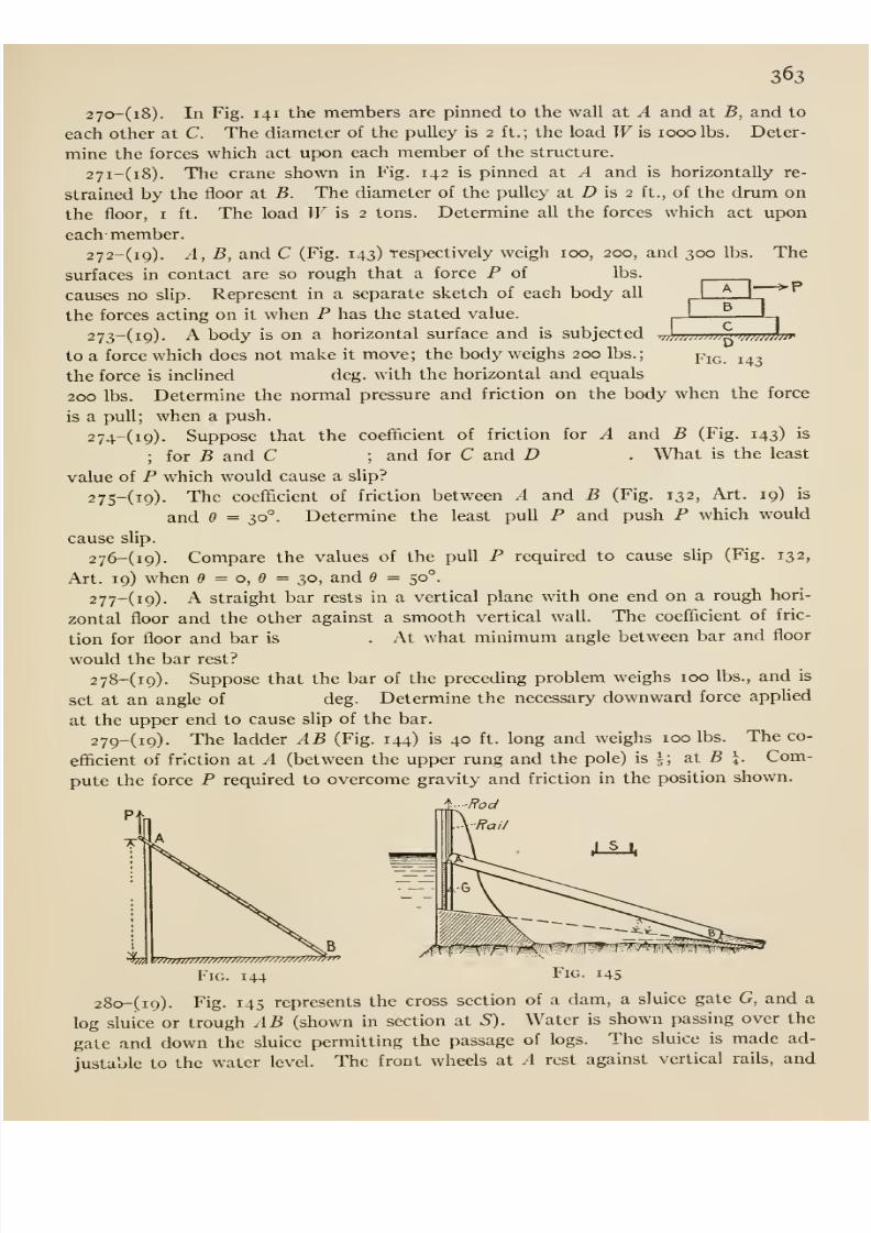
8/13/2019 Maurer Mechanics
http://slidepdf.com/reader/full/maurer-mechanics 379/407
363
to;
Fig. 143
27o-(i8). In Fig. 141 the members are pinned to the wall at A and at i5, and to
each other at C. The diameter of the pulley is 2 ft.; the load Wis 1000 lbs. Deter-
mine the forces which act upon each member of the structure.
27i-(i8). The crane shown in Fig. 142 is pinned at A and is horizontally re-
strained by the floor at B. The diameter of the pulley at Z) is 2 ft., of the drum on
the floor, i ft. The load W is 2 tons. Determineall
the forces which act uponeach- member.
272-(i9). A, B, and C (Fig. 143) respectively weigh 100, 200, and 300 lbs. The
surfaces in contact are so rough that a force P of lbs.
causes no slip. Represent in a separate sketch of each body all
the forces acting on it when P has the stated value.
273-(i9). A body is on a horizontal surface and is subjected
to a force which does not make it move; the body weighs 200 lbs.;
the force is incUned deg. with the horizontal and equals
200 lbs. Determine the normal pressure and friction on the body when the force
is a pull; when a push.
2 74-(i9). Suppose that the coefficient of friction for A and B (Fig. 143) is
; for B and C ; and for C and D . What is the least
value of P which would cause a slip?
275-(i9). The coefficient of friction between A and B (Fig. 132, Art. 19) is
and e =30°. Determine the least pull P and push P which would
cause slip.
276-(i9). Compare the values of the pull P required to cause slip (Fig. 132,
Art. 19) when = o, e = 30, and 9 = 50°.
277-(i9)- A straight bar rests in a vertical plane with one end on a rough hori-
zontal floor and the other against a smooth vertical wall. The coefficient of fric-
tion for floor and bar is . At what minimum angle between bar and floor
would the bar rest?
278-(i9). Suppose that the bar of the preceding problem weighs 100 lbs., and is
set at an angle of deg. Determine the necessary downward force applied
at the upper end to cause slip of the bar.
279-(i9). The ladder AB (Fig. 144) is 40 ft. long and weighs 100 lbs. The co-
efficient of friction at A (between the upper rung and the pole) is ^; at 5 j. Com-
pute the force P required to overcome gravity and friction in the position shown.
-ffod
'to
Fig. Fig.144 riG. 145
28o-(i9). Fig. 145 represents the cross section of a dam, a sluice gate G, and a
log sluice or trough AB (shown in section at S). Water is shown passing over the
gate and down the sluice permitting the passage of logs. The sluice is made ad-
justable to the water level. The front wheels at A rest against vertical rails, and
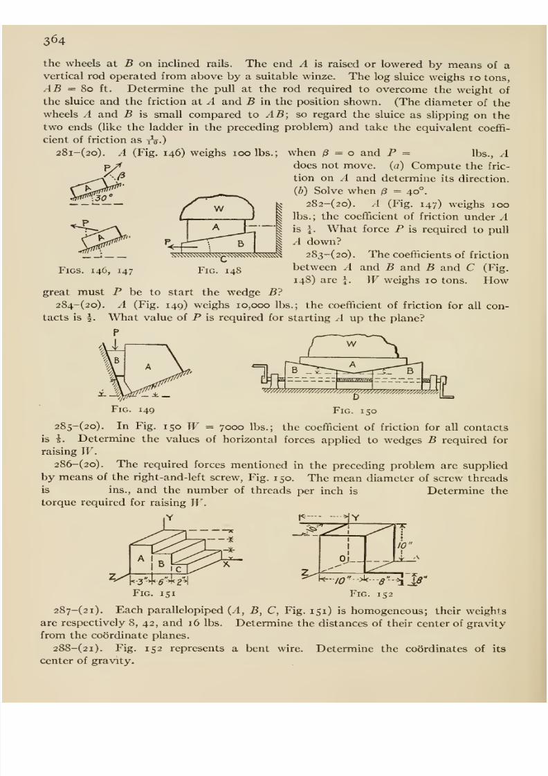
8/13/2019 Maurer Mechanics
http://slidepdf.com/reader/full/maurer-mechanics 380/407
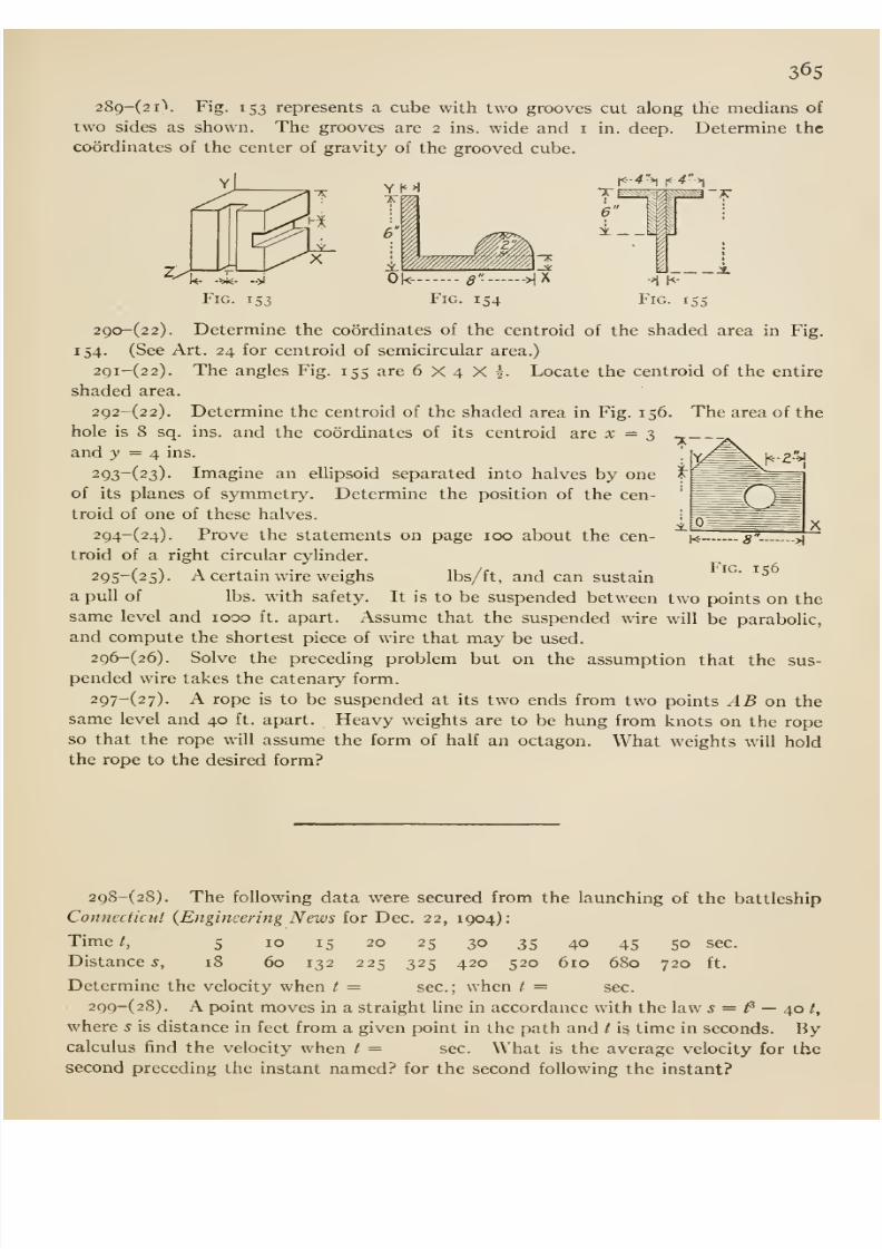
8/13/2019 Maurer Mechanics
http://slidepdf.com/reader/full/maurer-mechanics 381/407
365
289-(2i). Fig. 153 represents a cube with two grooves cut along the medians of
two sides as shown. The grooves are 2 ins. wide and i in. deep. Determine the
coordinates of the center of gravity of the grooved cube.
t<- 4 >t i< 4 >t
Ok- 8 - -MX
Fig. 154
_x
29a-(22). Determine the coordinates of the centroid of the shaded area in Fig.
154. (See Art. 24 for centroid of semicircular area.)
29i-(22). The angles Fig. 155 are 6X4X5. Locate the centroid of the entire
shaded area.
292-(2 2). Determine the centroid of the shaded area in Fig. 156. The area of the
hole is 8 sq. ins. and the coordinates of its centroid are x =2>
and y = ^ ins.
293-(23). Imagine an ellipsoid separated into halves by one
of its planes of symmetry. Determine the position of the cen-
troid of one of these halves.
294-(24). Prove the statements on page 100 about the cen-
troid of a right circular cylinder.
29S~(25)- A certain wire weighs lbs/ft, and can sustain
a pull of lbs. with safety. It is to be suspended between two points on the
same level and 1000 ft. apart. Assume that the suspended wire will be parabolic,
and compute the shortest piece of wire that may be used.
296-(26). Solve the preceding problem but on the assumption that the sus-
pended wire takes the catenary form.
297-(27). A rope is to be suspended at its two ends from two points AB on the
same level and 40 ft. apart. Heavy weights are to be hung from knots on the ropeso that the rope will assume the form of half an octagon. What weights will hold
the rope to the desired form?
298-(28). The following data were secured from the launching of the battleship
Conneclicut {Engineering News for Dec. 22, 1904):
Time /, 5 10 15 20 25 30 35 40 45 50 sec.
Distances, 18 60 132 225 325 420 520 610 680 720 ft.
Determine the velocity when t = sec; when / = sec.
299-(28). A point moves in a straight line in accordance with the law s = ^ —40 t,
where s is distance in feet from a given point in the path and t i? time in seconds. Bycalculus find the velocity when t = sec. What is the average velocity for the
second preceding the instant named? for the second following the instant?
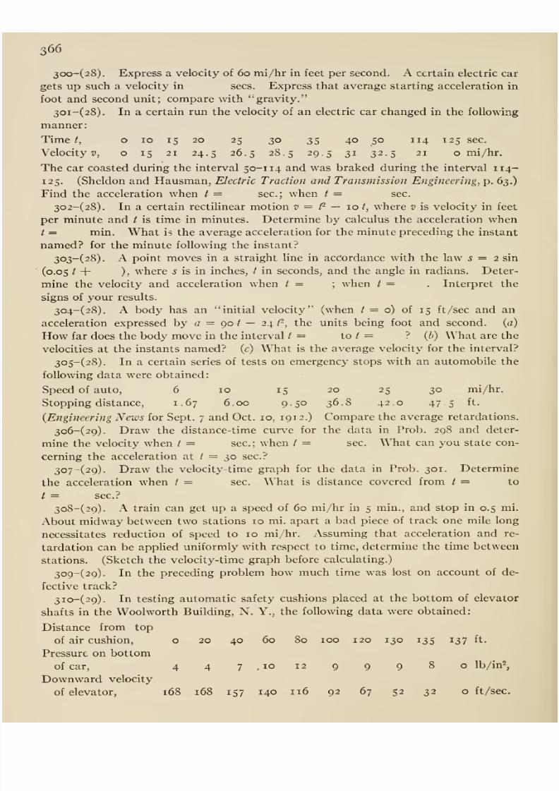
8/13/2019 Maurer Mechanics
http://slidepdf.com/reader/full/maurer-mechanics 382/407
366
3oo-(28). Express a velocity of 60 mi/hr in feet per second. A certain electric car
gets up such a velocity in sees. Express that average starting acceleration in
foot and second unit; compare with gravity.
30i-(28). In a certain run the velocity of an electric car changed in the following
manner:
Timet, o 10 1520
25 30 35 40 50 114 125sec.
Velocity^), o 15 21 24.5 26.5 28.5 29.5 31 32.5 21 o mi/hr.
The car coasted during the interval 50-114 and was braked during the interval 114-
125. (Sheldon and Hausman, Electric Traction and Transmission Engineering, p. 63.)
Find the acceleration when t — sec; when / = sec.
302-(28). In a certain rectilinear motion v = /- — 10 /, where v is velocity in feet
per minute and / is time in minutes. Determine by calculus the acceleration whent = min. What is the average acceleration for the minute preceding the instant
named? for the minute following the instant?
303- (28). A point moves in a straight line in accordance with the law 5 = 2 sin
(0.05 / + ). where 5 is in inches, / in seconds, and the angle in radians. Deter-
mine the velocity and acceleration when t = ; when / =. Interpret the
signs of your results.
304-(28), A body has an initial velocity (when / = o) of 15 ft /sec and an
acceleration expressed by a = 90 / — 24 /-, the units being foot and second, (a)
How far does the body move in the interval / = to / = ? (b) What are the
velocities at the instants named? (c) What is the average velocity for the interval?
305-(28). In a certain series of tests on emergency stops with an automobile the
following data were obtained:
Speed of auto, 6 10 15 20 25 30 mi/hr.
Stopping distance, 1.67 6.00 9.50 36.8 42.0 47.5 ft.
{Engineering News for Sept. 7 and Oct. 10, 191 2.) Compare the average retardations.
3o6-(29). Draw the distance-time curve for the data in Prob. 298 and deter-
mine the velocity when / = sec; when /= sec. What can you state con-
cerning the acceleration at / = 30 sec?
307-(29). Draw the velocity-time graph for the data in Prob. 301. Determine
the acceleration when / = sec. What is distance covered from / = to
/ = sec?
3o8-(29). A train can get up a speed of 60 mi/hr in 5 min., and stop in 0.5 mi.
About midway between two stations 10 mi. apart a bad piece of track one mile long
necessitates reduction of speed to 10 mi/hr. Assuming that acceleration and re-
tardation can be applied uniformly with respect to time, determine the time between
stations. (Sketch the velocity-time graph before calculating.)
309-(29). In the preceding problem how much time was lost on account of de-
fective track?
3io-(29). In testing automatic safety cushions placed at the bottom of elevator
shafts in the Wool worth Building, N. Y., the following data were obtained:
Distance from top
of air cushion, o 20 40 60 80 100 120 130 135 137 ft.
Pressure on bottom
of car, 4 4 7, 10 12 9 9 9 8 o Ib/in^,
Downward velocity
of elevator, 168 168 157 140 116 92 67 52 32 oft/sec.
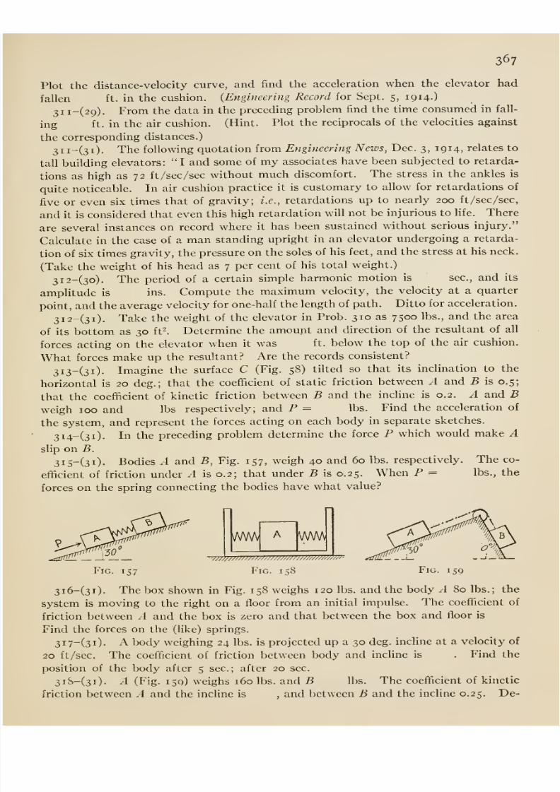
8/13/2019 Maurer Mechanics
http://slidepdf.com/reader/full/maurer-mechanics 383/407
367
Plot the distance-velocity curve, and find the acceleration when the elevator had
fallen ft. in the cushion. {Engineering Record for Sept. 5, 1914-)
31 1-(29). From the data in the preceding problem find the time consumed in fall-
ing ft. in the air cushion. (Hint. Plot the reciprocals of the velocities against
the corresponding distances.)
3ii-(3i). The following quotation from Engineering News, Dec. 3, 1914, relates to
tall building elevators: I and some of my associates have been subjected to retarda-
tions as high as 72 ft /sec/sec without much discomfort. The stress in the ankles is
quite noticeable. In air cushion practice it is customary to allow for retardations of
five or even six times that of gravity; i.e., retardations up to nearly 200 ft /sec /sec,
and it is considered that even this high retardation will not be injurious to hfe. There
are several instances on record where it has been sustained without serious injury.
Calculate in the case of a man standing upright in an elevator undergoing a retarda-
tion of six times gravity,the pressure on the soles of his feet, and the stress at his neck.
(Take the weight of his head as 7 per cent of his total weight.)
3i2-(3o). The period of a certain simple harmonic motion is' sec, and its
amplitude is ins. Compute the maximum velocity, the velocity at a quarter
point, and the average velocity for one-half the length of path. Ditto for acceleration.
3i2-(3i). Take the weight of the elevator in Prob. 310 as 7500 lbs., and the area
of its bottom as 30 ft'. Determine the amount and direction of the resultant of all
forces acting on the elevator when it was ft. below the top of the air cushion.
What forces make up the resultant? Are the records consistent?
3i3-(3i). Imagine the surface C (Fig. 58) tilted so that its inclination to the
horizontal is 20 deg.; that the coefficient of static friction between A and B is 0.5;
that the coefficient of kinetic friction between B and the incline is 0.2. A and Bweigh 100 and lbs respectively, and P = lbs. Find the acceleration of
the system, and represent the forces acting on each body in separate sketches.
3i4-(3i). In the preceding problem determine the force P which would make Aslip on B.
3i5-(3i). Bodies .4 and B, Fig. 157, weigh 40 and 60 lbs. respectively. The co-
efficient of friction under A is 0.2; that under 5 is 0.25. When P = lbs., the
forces on the spring connecting the bodies have what value?
^VWV ww\
'vtttttttttttttttttttttttttttttpttttmtp
Fig. 158 Fig. 159
3i6-(3i). The box shown in Fig. 158 weighs 120 lbs. and the body A 80 lbs.; thesystem is moving to the right on a floor from an initial impulse. The coefficient of
friction between A and the box is zero and that between the box and floor is
Find the forces on the (like) springs.
3i7-(3i). A body weighing 24 lbs. is projected up a 30 deg. incline at a velocity of
20 ft/sec. The coefficient of friction between body and incUne is . Find the
position of the body after 5 sec; after 20 sec
3i8-(3i). A (Fig. 159) weighs 160 lbs. and B lbs. The coefficient of kinetic
friction between A and the incUne is , and between B and the incline 0.25. De-
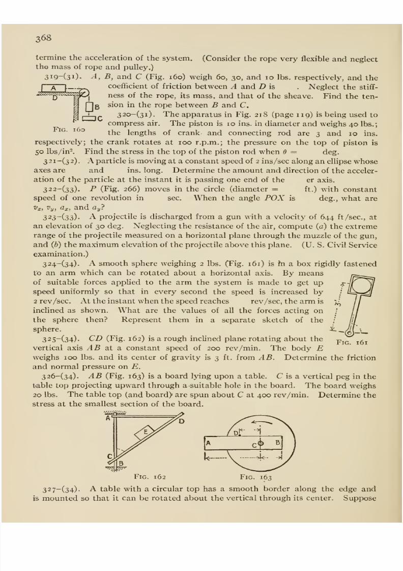
8/13/2019 Maurer Mechanics
http://slidepdf.com/reader/full/maurer-mechanics 384/407
368
(Consider the rope very flexible and neglectermine the acceleration of the system,
tho mass of rope and pulley,)
3i9-(3i)- A, B, and C (Fig. i6o) weigh 60, 30, and 10 lbs. respectively, and the
coefl&cient of friction between A and D is . Neglect the stiff-
ness of the rope, its mass, and that of the sheave. Find the ten-
sion in the rope between B and C.
32o-(3i). The apparatus in Fig. 218 (page 119) is being used to
compress air. The piston is 10 ins. in diameter and weighs 40 lbs.;
the lengths of crank and connecting rod are 3 and 10 ins.
respectively; the crank rotates at 100 r.p.m.; the pressure on the top of piston is
50 lbs/in-. Find the stress in the top of the piston rod when 6 = deg.
3 2 1-(3 2) . A particle is moving at a constant speed of 2 ins/sec along an ellipse whoseaxes are and ins. long. Determine the amount and direction of the acceler-
ation of the particle at the instant it is passing one end of the er axis.
322-(33). P (Fig. 266) moves in the circle (diameter = ft.) with constant
speed of one revolution in sec. When the angle POX is deg., what are
Vx, i'„, Cr, and «„?
FlG. 160
x, ^-y, J, U-
323-(33). A projectile is discharged from a gun with a velocity of 644 ft/sec, at
an elevation of 30 deg. Neglecting the resistance of the air, compute (o) the extreme
range of the projectile measured on a horizontal plane through the muzzle of the gun,
and Q}) the maximum elevation of the projectile above this plane. (U. S. Civil Service
examination.)
324-(34). A smooth sphere weighing 2 lbs. (Fig. 161) is hi a box rigidly fastenedto an arm which can be rotated about a horizontal axis. By means
of suitable forces applied to the arm the system is made to get upspeed uniformly so that in every second the speed is increased by2 rev /sec. At the instant when the speed reaches rev /sec, the arm is
inclined as shown. What are the values of all the forces acting on
the sphere then? Represent them in a separate sketch of the
sphere.
32 5-(34). CD (Fig. 162) is a rough incUned plane rotating about the
vertical axis AB at a constant speed of 200 rev/min. The body Eweighs icx) lbs. and its center of gravity is 3 ft. from AB. Determine the friction
and normal pressure on E.
326-(34). AB (Fig. 163) is a board lying upon a table. C is a vertical peg in the
table top projecting upward through a suitable hole in the board. The board weighs
20 lbs. The table top (and board) are spun about C at 400 rev/min. Determine the
stress at the smallest section of the board.
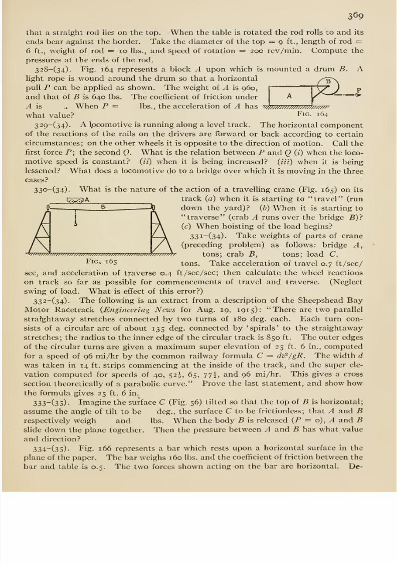
8/13/2019 Maurer Mechanics
http://slidepdf.com/reader/full/maurer-mechanics 385/407
p
369
that a straight rod lies on the top. When the table is rotated the rod rolls to and its
ends bear against the border. Take the diameter of the top — 9 ft., length of rod =6 ft., weight of rod = 10 lbs., and speed of rotation = 200 rev/min. Compute the
pressures at the ends of the rod.
328-(34). Fig. 164 represents a block A upon which is mounted a drum B. Alight rope is wound around the drum so that a horizontalpull P can be applied as shown. The weight of A is 960,
and that of B is 640 lbs. The coefficient of friction under
A is .. When P = lbs., the acceleration of A has ' '/h;m;w//wwh///w-
what value? I'^i^- 164
329-(34). A Ipcomotive is running along a level track. The horizontal componentof the reactions of the rails on the drivers are forward or back according to certain
circumstances; on the other wheels it is opposite to the direction of motion. Call the
first force P; the second Q. What is the relation between P and Q (i) when the loco-
motive speed is constant? (//) when it is being increased? (iii) when it is being
lessened? What does a locomotive do to a bridge over which it is moving in the three
cases?
33o-(34)- What is the nature of the action of a travelling crane (Fig. 165) on its
i:^^;^A track (a) when it is starting to travel (run
down the yard)? (b) When it is starting to
traverse (crab A runs over the bridge B)?
(c) When hoisting of the load begins?
33i-(34). Take weights of parts of crane(preceding problem) as follows: bridge A,
^^7777T7777777777m777777777777m7777777/77 7^^77777777h- tOUS; Crab B, tOnS ; load C,^^°* ^^5 tons. Take acceleration of travel 0.7 ft/sec/
sec, and acceleration of traverse 0.4 ft/sec/sec; then calculate the wheel reactions
on track so far as possible for commencements of travel and traverse. (Neglect
swing of load. What is effect of this error?)
332-(34). The following is an extract from a description of the Sheepshead BayMotor Racetrack (Engineering News for Aug. 19, 1915): There are two parallel
stra?ghtaway stretches connected by two turns of 180 deg. each. Each turn con-
sists of a circular arc of about 135 deg. connected by 'spirals' to the straightaway
stretches; the radius to the inner edge of the circular track is 850 ft. The outer edges
of the circular turns are given a maximum super elevation of 25 ft. 6 in., computed
for a speed of 96 mi/hr by the common railway formula C = dv^/gR. The width d
was taken in 14 ft. strips commencing at the inside of the track, and the super ele-
vation computed for speeds of 40, 52I, 65, yyf , and 96 mi/hr. This gives a cross
section theoretically of a parabolic curve. Prove the last statement, and show howthe formula gives 25 ft. 6 in.
333-(35). Imagine the surface C (Fig. 56) tilted so that the top of B is horizontal;
assume the angle of tilt to be deg., the surface C to be frictionless; that A and Brespectively weigh and lbs. When the body B is released (P = o), ^ and Bslide down the plane together. Then the pressure between A and B has what value
and direction?
334~(3S)- Fig- 166 represents a bar which rests upon a horizontal surface in the
plane of the paper. The bar weighs 160 lbs. and the coefficient of friction between the
bar and table is 0.5. The two forces shown acting on the bar are horizontal. De-
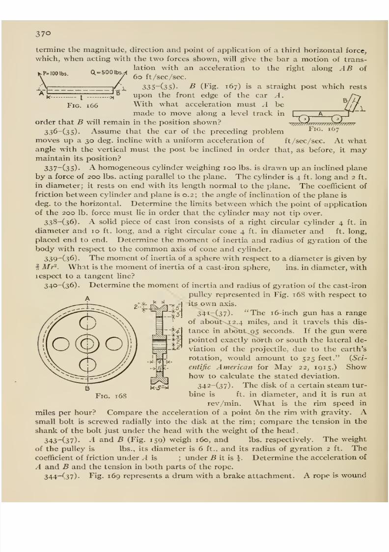
8/13/2019 Maurer Mechanics
http://slidepdf.com/reader/full/maurer-mechanics 386/407
370
^P= 100 lbs. =500 Ibs^
I
Fig. i66
B
termine the magnitude, direction and point of application of a third horizontal force,
which, when acting with the two forces shown, will give the bar a motion of trans-
lation with an acceleration to the right along AB of
6o ft/sec/sec.
33S~(35)- B (Fig. 167) is a straight post which rests
uponthe front
edgeof
the car A.With what acceleration must .1 be
made to move along a level track in
order that B will remain in the position shown?
336-(35). Assume that the car of the preceding problem
moves up a 30 deg. incline with a uniform acceleration of ft/sec/sec. At whatangle with the vertical must the post be inclined in order that, as before, it maymaintain its position?
337-(35)- A homogeneous cylinder weighing 100 lbs. is drawn up an inclined plane
by a force of 200 lbs. acting parallel to the plane. The cylinder is 4 ft. long and 2 ft.
in diameter; it rests on end with its length normal to the plane. The coefficient of
friction between cyHnder and plane is 0.2; the angle of inclination of the plane is
deg. to the horizontal. Determine the limits between which the point of application
of the 200 lb. force must lie in order that the cylinder may not tip over.
338-(36). A solid piece of cast iron consists of a right circular cylinder 4 ft. in
diameter and 10 ft. long, and a right circular cone 4 ft. in diameter and ft. long,
placed end to end. Determine the moment of inertia and radius of gyration of the
body with respect to the common axis of cone and cylinder.
339^(36). The moment of inertia of a sphere with respect to a diameter is given byi Mr-. What is the moment of inertia of a cast-iron sphere, ins. in diameter, with
respect to a tangent line?
340-(36). Determine the moment of inertia and radius of gyration of the cast-iron
pulley represented in Fig. 168 with respect to
its own axis.
34i-(37). The 16-inch gun has a range
of about 42.4 miles, and it travels this dis-
tance in about^^5 seconds. If the gun werepointed exactly ndrth or south the lateral de-
viation of the projectile, due to the earth's
rotation, would amount to 525 feet. (5a-
cntific American for May 22, 191 5.) Showhow to calculate the stated deviation.
342-(37). The disk of a certain steam tur-
FiG. 168 bine is ft. in diameter, and it is run at
rev/min. What is the rim speed in
miles per hour? Compare the acceleration of a point on the rim with gravity. Asmall bolt is screwed radially into the disk at the rim; compare the tension in the
shank of the bolt just under the head with the weight of the head
.
343-(37). -4 and B (Fig. 159) weigh 160, and lbs. respectively. The weight
of the pulley is lbs., its diameter is 6 ft., and its radius of gyration 2 ft. The
coefficient of friction under .-1 is ; under B it is \. Determine the acceleration of
A and B and the tension in both parts of the rope.
344-(37). Fig. 169 represents a drum with a brake attachment. A rope is wound
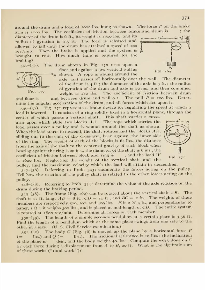
8/13/2019 Maurer Mechanics
http://slidepdf.com/reader/full/maurer-mechanics 387/407
371
around the drum and a load of 2000 lbs. hung as shown. The force P on the brake
arm is 1000 lbs. The coefficient of friction between brake and drum is ;the
diameter of the drum is 6 ft., its weight is 1800 lbs., and its _ ,^, >k>^^'>||
radius of gyration is 2.5 ft. The load is released and i__ i^ =J
1l-rr/^)
mc.w
169
allowed to fall until the drum has attained a speed of 100
rev/min. Then the brake is applied and the system is
brought to rest. How much time is required for the
braking?
345-(37)- The drum shown in Fig. 170 rests upon a
floor and against a low vertical wall as
shown. A rope is wound around the
axle and passes off horizontally over the wall. The diameter
of the drum is 4 ft.; the diameter of the axle is 3 ft.; the radius
of gyration of the drum and axle is 20 ins., and their combined
weight is 180 lbs. The coefficient of friction between drum
and floor is and between drum and wall 0.2. The pull P = 200 lbs. Deter-
mine the angular acceleration of the drum, and all forces which act upon it.
346-(37). Fig. 171 represents a brake device for regulating the speed at which a
load is lowered. It consists of a ring solidly fixed in a horizontal plane, through the
center of which passes a vertical shaft. This shaft carries a cross-
arm upon which slide two blocks -4.-1. The rope which carries the
load passes over a pulley and is wound around the shaft as shown.
When the load starts to descend, the shaft rotates and the blocks AA,shding out to the ends of the cross-arm, bear against the inner side
of the ring. The weight of each of the blocks is 64 lbs., the distance
from the axis of the shaft to the center of gravity of each block when
bearing against the ring is 20 ins., the diameter of the shaft is 6 ins., the
coefficient of friction between block and ring is , and the load Wis 1600 lbs. Neglecting the weight of the vertical shaft and the
pulley, find the maximum velocity which the load will attain in descending.
347-(38)- Referring to Prob. 343: enumerate the forces acting on the pulley.
Tell how the reaction of the pulley shaft is related to the other forces acting on the
pulley.
348-(38). Referring to Prob. 344: determine the value of the axle reaction on the
drum during the braking period.
349-(38). The frame (Fig. 162) can be rotated about the vertical shaft AB. The
shaft is 12 ft. long; AD ^ % ft., CD = 10 ft., and BC = 2 ft. The weights of these
members are respectively 500, 200, and 400 lbs. 72 is 2 X 4 ft., and perpendicular to
paper, i ft.; it weighs 300 lbs., and is placed at mid-length of CD. The entire system
is rotated at 1800 rev/min. Determineall forces on each member.
35o-(3o)- The length of a simple seconds pendulum at a certain place is 3.56 ft.
Find the length of a pendulum which at the same place swings from one side to the
other in 5 sees. (U. S. Civil Service examination.)
3Si-(4o). The body C (Fig. 76) is moved up the plane by a horizontal force P
(= lbs.) and Q (= lbs.). The frictional resistance is 10 lbs.; the incUnation
of the plane is deg., and the body weighs 40 lbs. Compute the work done on C
by each force during a displacement from A to B, 20 ft. What is the algebraic sum
of these works ( total work )?
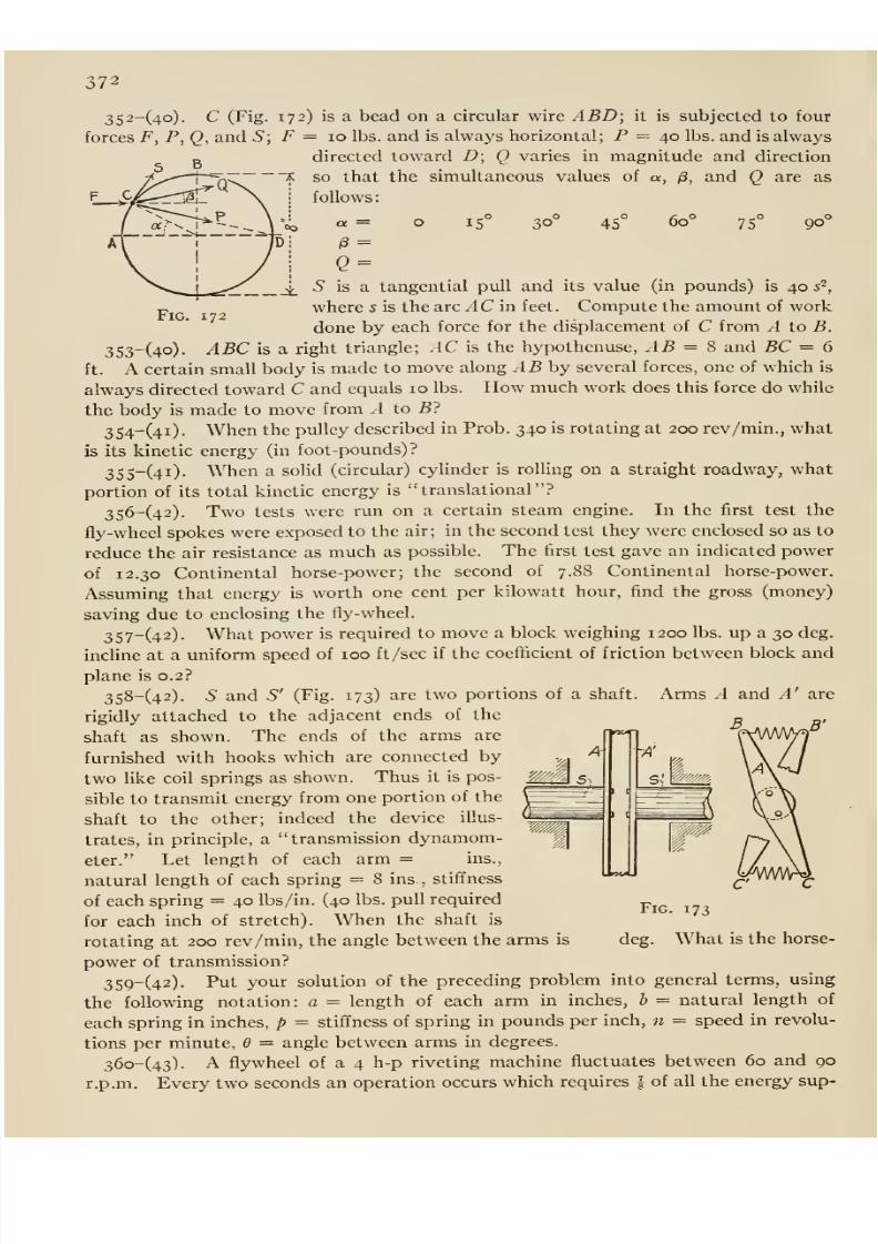
8/13/2019 Maurer Mechanics
http://slidepdf.com/reader/full/maurer-mechanics 388/407
372
352-(4o). C (Fig. 172) is a bead on a circular wire ABD; it is subjected to four
forces F, P, Q, and 5; F = 10 lbs. and is always horizontal; P = 40 lbs. and is always
directed toward D; Q varies in magnitude and direction
so that the simultaneous values of a, /3, and Q are as
follows:
60°15 30 45 75 90
/3 =
Q =
5 is a tangential pull and its value (in pounds) is 40 s~,
where 5 is the arc AC in feet. Compute the amount of work
done by each force for the displacement of C from A to B.
3S3-(4o). ABC is a. right triangle; AC is the hypothenuse, AB = 8 and BC = 6
ft. A certain small body is made to move along AB by several forces, one of which is
always directed toward C and equals 10 lbs. How much work does this force do while
the body is made to move from A to B?
354-(4i). When the pulley described in Prob. 340 is rotating at 200 rev/min., what
is its kinetic energy (in foot-pounds)?
35S-(4i). When a solid (circular) cylinder is rolling on a straight roadway, what
portion of its total kinetic energy is translational ?
356-(42). Two tests were run on a certain steam engine. In the first test the
fly-wheel spokes were exposed to the air; in the second test they were enclosed so as to
reduce the air resistance as much as possible. The first test gave an indicated power
of 12.30 Continental horse-power; the second of 7.88 Continental horse-power.Assuming that energy is worth one cent per kilowatt hour, find the gross (money)
saving due to enclosing the fly-wheel.
357-(42). What power is required to move a block weighing 1200 lbs. up a 30 deg.
incline at a uniform speed of 100 ft /sec if the coefficient of friction between block and
plane is 0.2?
358-(42). S and S' (Fig. 173) are two portions of a shaft. Arms A and A' are
rigidly attached to the adjacent ends of the
shaft as shown. The ends of the arms are
furnished with hooks which are connected by
two like coil springs as shown. Thus it is pos-
sible to transmit energy from one portion of the
shaft to the other; indeed the device illus-
trates, in principle, a transmission dynamom-
eter. Let length of each arm = ins.,
natural length of each spring = 8 ins., stiffness
of each spring = 40 lbs/in. (40 lbs. pull required
for each inch of stretch). When the shaft is
rotating at 200 rev/min, the angle between the arms is
power of transmission?
359-(42). Put your solution of the preceding problem into general terms, using
the following notation: a = length of each arm in inches, b = natural length of
each spring in inches, p = stiffness of spring in pounds per inch, n = speed in revolu-
tions per minute, d = angle between arms in degrees.
36o-(43). A flywheel of a 4 h-p riveting machine fluctuates between 60 and 90
r.p.m. Every two seconds an operation occurs which requires | of all the energy sup-
deg.
Fig. 173
What is the horse-
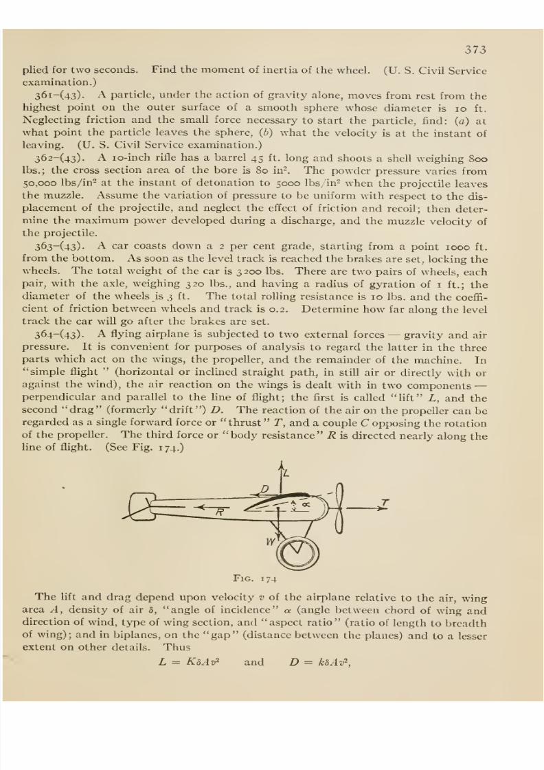
8/13/2019 Maurer Mechanics
http://slidepdf.com/reader/full/maurer-mechanics 389/407
373
plied for two seconds. Find the moment of inertia of the wheel. (U. S. Civil Service
examination.)
36i-(43). A particle, under the action of gravity alone, moves from rest from the
highest point on the outer surface of a smooth sphere whose diameter is lo ft.
Neglecting friction and the small force necessary to start the particle, find: (a) at
what point the particle leaves the sphere, {b) what the velocity isat the instant of
leaving. (U. S. Civil Service examination.)
362-(43). A lo-inch rifle has a barrel 45 ft. long and shoots a shell weighing 800lbs.; the cross section area of the bore is 80 in-. The powder pressure varies from
50,000 lbs/in- at the instant of detonation to 5000 lbs/in- when the projectile leaves
the muzzle. Assume the variation of pressure to be uniform with respect to the dis-
placement of the projectile, and neglect the effect of friction and recoil; then deter-
mine the maximum power developed during a discharge, and the muzzle velocity of
the projectile.
363-(43). A car coasts down a 2 per cent grade, starting from a point 1000 ft.
from the bottom. As soon as the level track is reached the brakes are set, locking the
wheels. The total weight of the car is 3200 lbs. There are two pairs of wheels, each
pair, with the axle, weighing 320 lbs., and having a radius of gyration of i ft.; the
diameter of the wheels is 3 ft. The total rolling resistance is 10 lbs. and the coeffi-
cient of friction between wheels and track is 0.2. Determine how far along the level
track the car will go after the brakes are set.
364-(43). A flying airplane is subjected to two external forces —gravity and air
pressure. It is convenient for purposes of analysis to regard the latter in the three
parts which act on the wings, the propeller, and the remainder of the machine. In
simple flight (horizontal or inclined straight path, in still air or directly with or
against the wind), the air reaction on the wings is dealt with in two components —perpendicular and parallel to the line of flight; the first is called lift L, and the
second drag (formerly drift ) D. The reaction of the air on the propeller can beregarded as a single forward force or thrust T, and a couple C opposing the rotation
of the propeller. The third force or body resistance R is directed nearly along the
Une of flight. (See Fig. 174.)
Fig. 174
The lift and drag depend upon velocity v of the airplane relative to the air, wingarea A, density of air 8, angle of incidence a (angle between chord of wing anddirection of wind, type of wing section, and aspect ratio (ratio of length to breadthof wing); and in biplanes, on the gap (distance between the planes) and to a lesser
extent on other details. Thus
L = KdAv'^ and D = kbAv^,
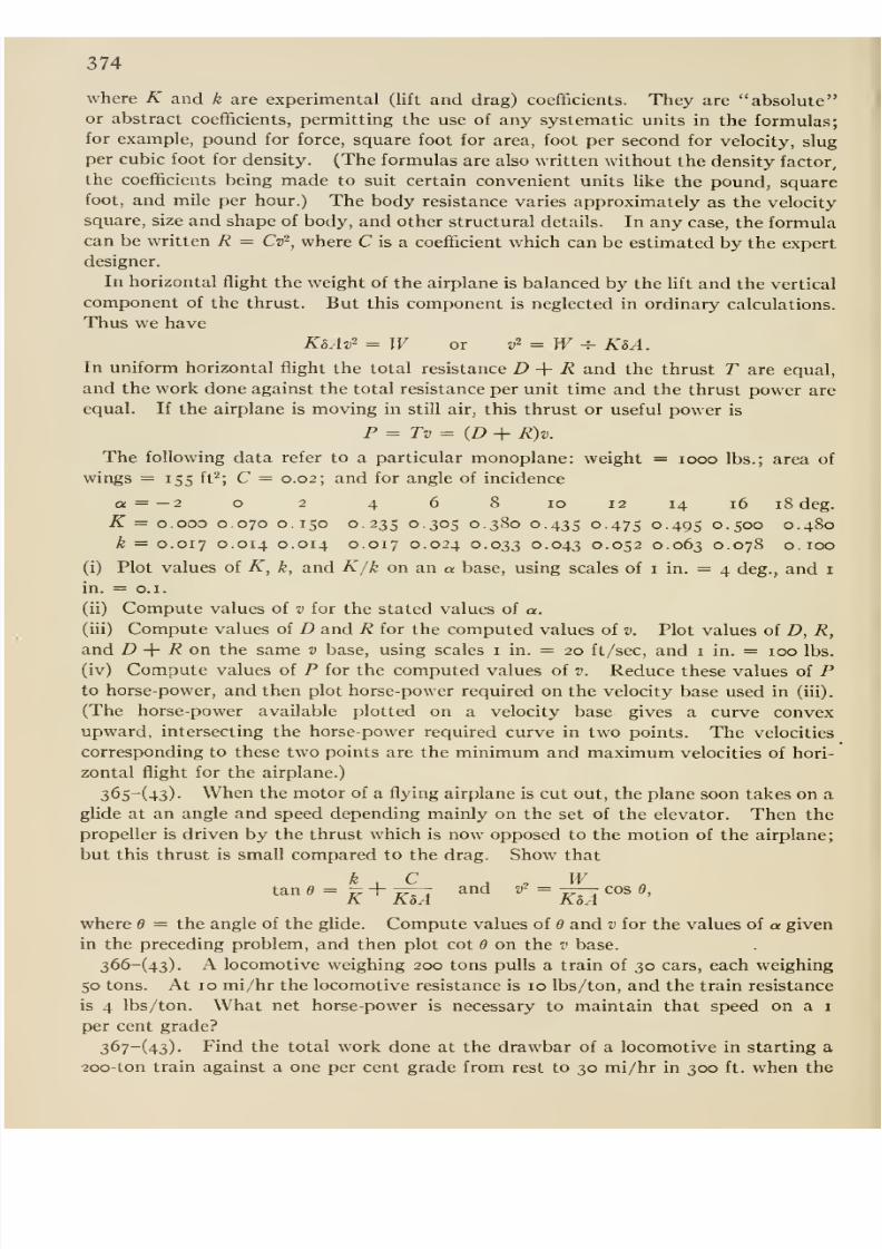
8/13/2019 Maurer Mechanics
http://slidepdf.com/reader/full/maurer-mechanics 390/407
374
where K and k are experimental (lift and drag) coefficients. They are absoluteor abstract coefficients, permitting the use of any systematic units in the formulas;
for example, pound for force, square foot for area, foot per second for velocity, slug
per cubic foot for density. (The formulas are also written without the density factor,
the coefficients being made to suit certain convenient units like the pound, squarefoot, and mile per hour.) The body resistance varies approximately as the velocity
square, size and shape of body, and other structural details. In any case, the formulacan be written R = Cv^, where C is a coefficient which can be estimated by the expert
designer.
In horizontal flight the weight of the airplane is balanced by the lift and the vertical
component of the thrust. But this component is neglected in ordinary calculations.
Thus we have
KhAv = W or v'^=W^ K5A.
In uniform horizontal flight the total resistance D + R and the thrust T are equal,
and the work done against the total resistance per unit time and the thrust power areequal. If the airplane is moving in still air, this thrust or useful power is
P = Tv = {D + R)v.
The following data refer to a particular monoplane: weight = looo lbs.; area of
wings = 155 ft^; C = 0.02; and for angle of incidence
a = —2 o 2 4 6 8 10 12 14 16 18 deg.
K = 0.000 0.070 0.150 0.235 0.305 0.380 0.435 0-475 0-495 o-5oo 0.480k = 0.017 0.014 0.014 0.017 0.024 0.033 0.043 0.052 0.063 0.078 O.IOO
(i) Plot values of K, k, and K/k on an « base, using scales of i in. = 4 deg., and i
in. = o.i.
(ii) Compute values of v for the stated values of a.
(iii) Compute values of D and R for the computed values of v. Plot values of D, R,
and D -\- R on the same v base, using scales i in. = 20 ft/sec, and i in. = 100 lbs.
(iv) Compute values of P for the computed values of v. Reduce these values of Pto horse-power, and then plot horse-power required on the velocity base used in (iii).
(The horse-power available plotted on a velocity base gives a curve convex
upward, intersecting the horse-power required curve in two points. The velocities
corresponding to these two points are the minimum and maximum velocities of hori-
zontal ffight for the airplane.)
365-(43). When the motor of a flying airplane is cut out, the plane soon takes on a
gUde at an angle and speed depending mainly on the set of the elevator. Then the
propeller is driven by the thrust which is now opposed to the motion of the airplane;
but this thrust is small compared to the drag. Show that
where d = the angle of the glide. Compute values of 9 and v for the values of a given
in the preceding problem, and then plot cot 6 on the v base.
366-(43). A locomotive weighing 200 tons pulls a train of 30 cars, each weighing
50 tons. At 10 mi/hr the locomotive resistance is 10 lbs/ton, and the train resistance
is 4 lbs/ton. What net horse-power is necessary to maintain that speed on a i
per cent grade?
367-(43). Find the total work done at the drawbar of a locomotive in starting a
200-ton train against a one per cent grade from rest to 30 mi/hr in 300 ft. when the
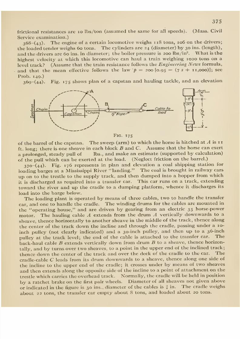
8/13/2019 Maurer Mechanics
http://slidepdf.com/reader/full/maurer-mechanics 391/407
375
frictional resistances are lo lbs/ton (assumed the same for all speeds). (Mass. Civil
Service examination.)
368-(43). The engine of a certain locomotive weighs ii8 tons, io6 on the drivers;
the loaded tender weighs 60 tons. The cylinders are 24 (diameter) by 30 ins. (length),
and the drivers are 60 ins. in diameter; the boiler pressure is 200 lbs/in-. What is the
highest velocity at which this locomotive can haul a train weighing looo tons on a
level track? (Assume that the train resistance follows the Engineering News formula,
and that the mean effective follows the law p = 200(0.95 — (7 5 -i- 11,000)]; see
Prob. 149.)
369-(44). Fig. 175 shows plan of a capstan and hauling tackle, and an elevation
-^-A
IS'-
c-S
Arm
i
Fig. 17s
of the barrel of the capstan. The sweep (arm) to which the horse is hitched at ^ is 11
ft. long; there is one sheave in each block B and C. Assume that the horse can exert
a prolonged, steady pull of lbs., and make an estimate (supported by calculation)
of the pull which can be exerted at the load. (Neglect friction on the barrel.)
37o-(44). Fig. 176 represents in plan and elevation a coal shipping station for
loading barges at a Mississippi River landing. The coal is brought in railway cars
up on to the trestle to the supply track, and then dumped into a hopper from which
it is discharged as required into a transfer car. This car runs on a track, extending
toward the river and up the cradle to a dumping platform, whence it discharges its
load into the barge below.
The loading plant is operated by means of three cables, two to handle the transfer
car, and one to handle the cradle. The winding drums for the cables are mounted in
the operating house, and are driven by gearing from an electric 35 horse-power
motor. The hauling cable A extends from the drum A vertically downwards to a
sheave, thence horizontally to another sheave in the middle of the track, thence along
the center of the track down the incline and through the cradle, passing under a 10-
inch pulley (not clearly indicated) and a 30-inch pulley, and then up to a 36-inch
pulley at the track level; the end of the cable is attached to the transfer car. The
back-haul cable B extends vertically down from drum 5 to a sheave, thence horizon-
tally, and by turns over two sheaves, to apoint in the upper end of the inclined track;
thence down the center of the track and over the deck of the cradle to the car. The
cradle-cable C leads from its drum downwards to a sheave, thence along one side of
the incline to the upper end of the cradle; it crosses under by means of two sheaves
and then extends along the opposite side of the incline to a point of attachment on the
trestle which carries the overhead track. Normally, the cradle will be held in position
by a ratchet brake on the first pair wheels. Diameter of all sheaves not given above
or indicated in the figure is 30 ins., diameter of the cables is H in. The cradle weighs
about 22 tons, the transfer car empty about 8 tons, and loaded about 20 tons.
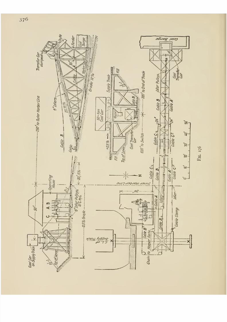
8/13/2019 Maurer Mechanics
http://slidepdf.com/reader/full/maurer-mechanics 392/407
376
ot--.
o
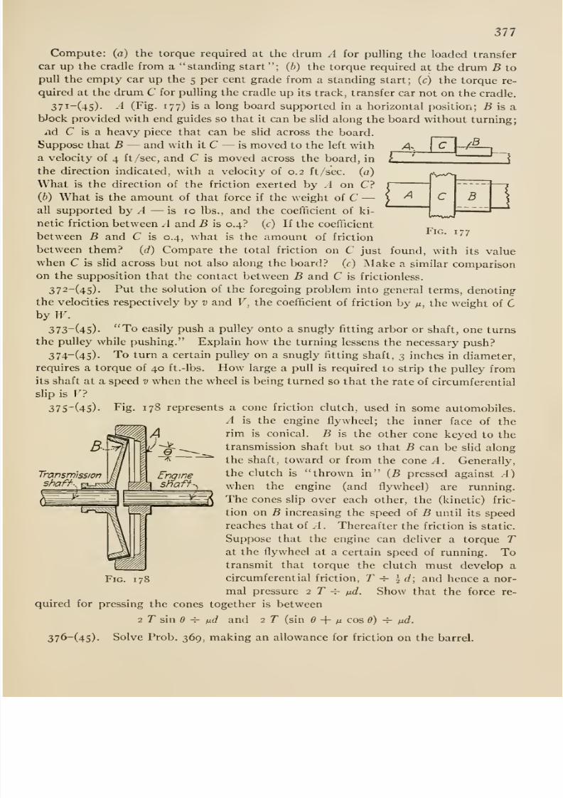
8/13/2019 Maurer Mechanics
http://slidepdf.com/reader/full/maurer-mechanics 393/407
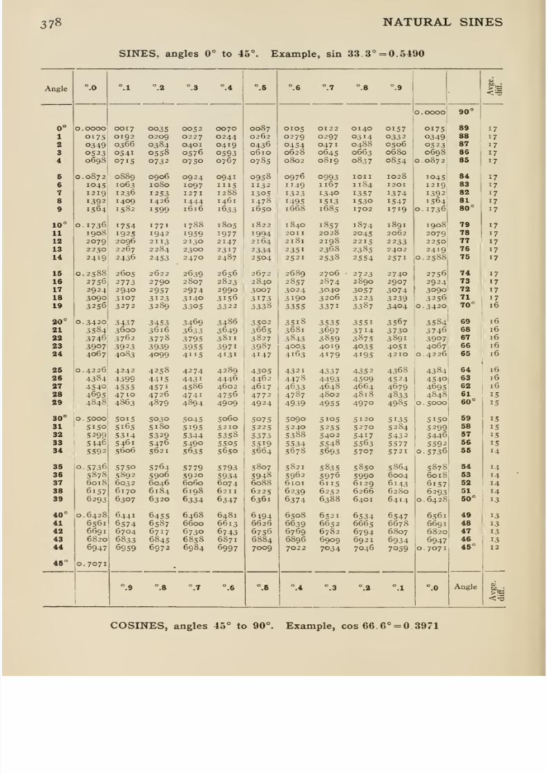
8/13/2019 Maurer Mechanics
http://slidepdf.com/reader/full/maurer-mechanics 394/407
378 NATURAL SINES
SINES, angles 0° to 45°. Example, sin 33.3° = 0.5490
Angle
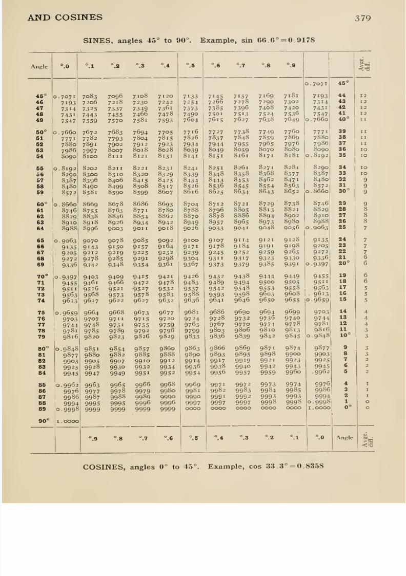
8/13/2019 Maurer Mechanics
http://slidepdf.com/reader/full/maurer-mechanics 395/407
AND COSINES 379
SINES, angles 45° to 90°. Example, sin 66.6° = 0.9178
Angle
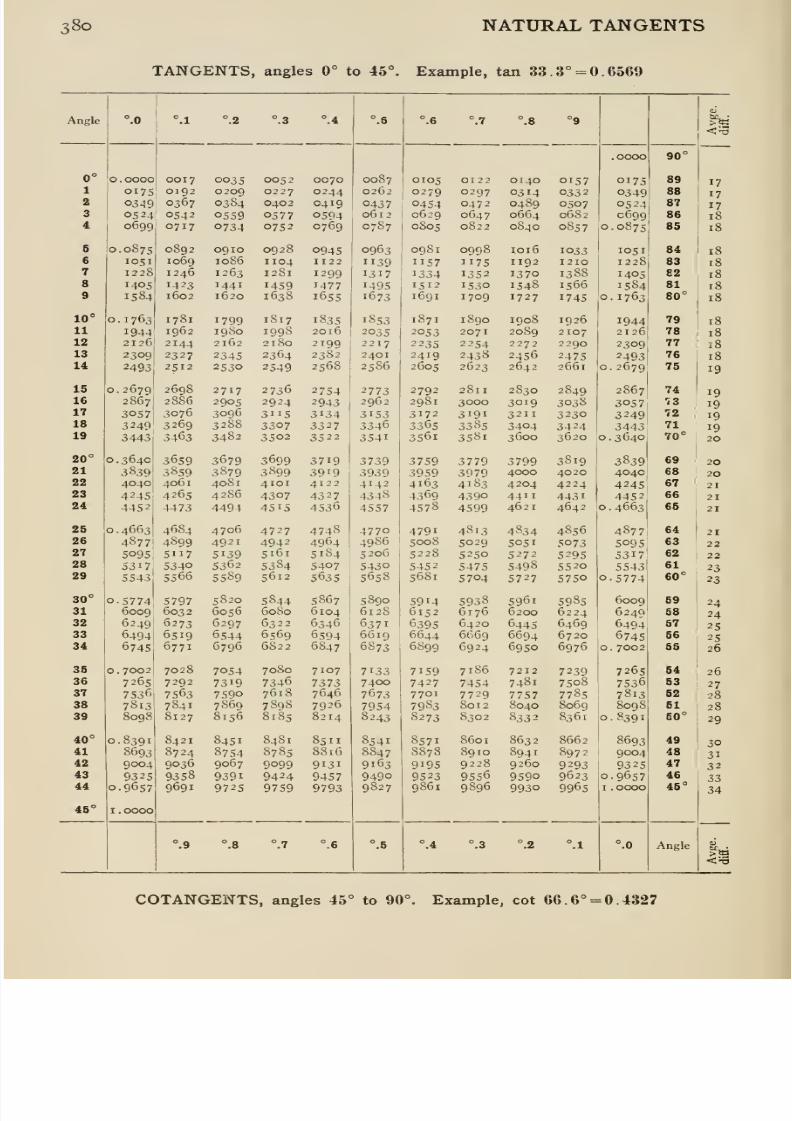
8/13/2019 Maurer Mechanics
http://slidepdf.com/reader/full/maurer-mechanics 396/407
38o NATURAL TANGENTS
TANGENTS, angles 0° to 45°. Example, tan 33. 3° = 0.6569
Angle
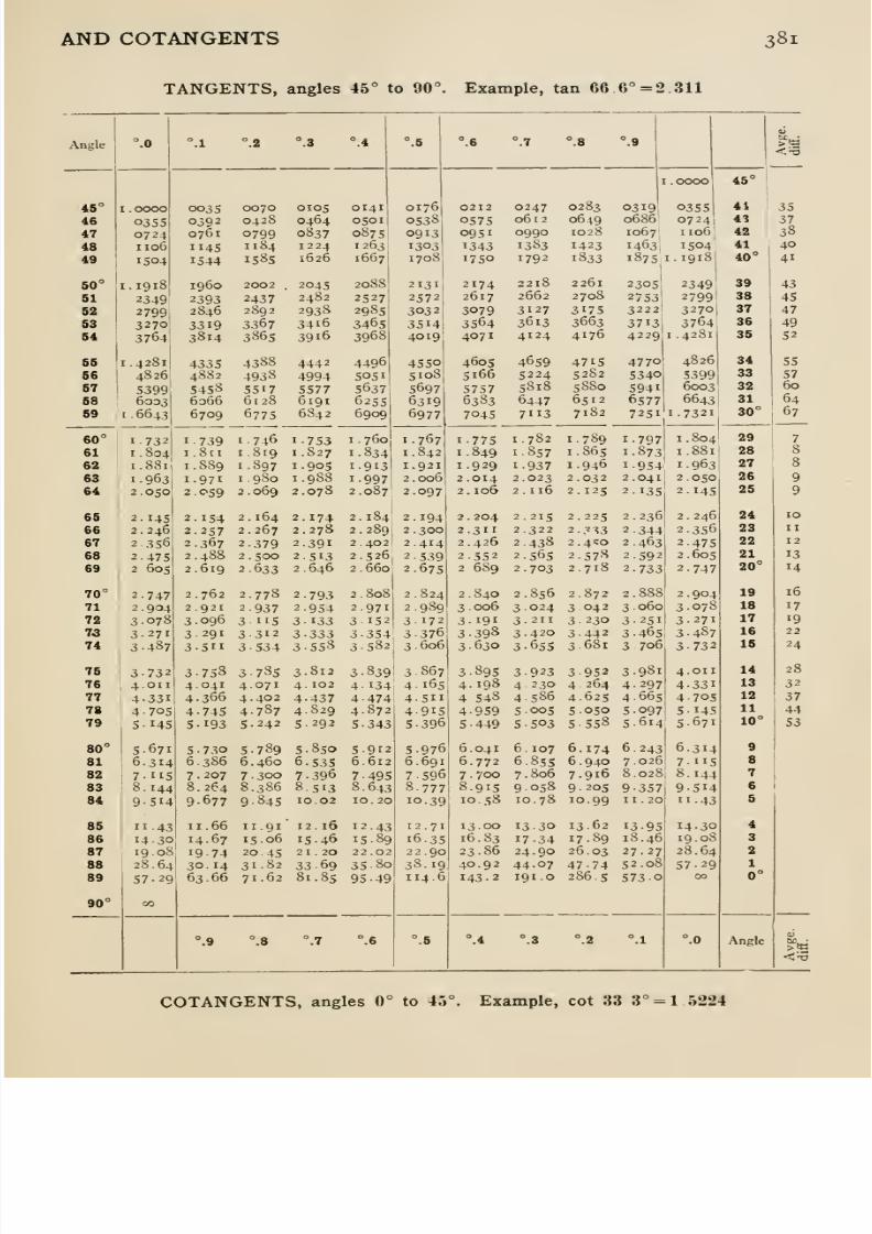
8/13/2019 Maurer Mechanics
http://slidepdf.com/reader/full/maurer-mechanics 397/407
AND COTANGENTS 381
TANGENTS, angles 45° to 90°. Example, tan 66 6° = 2 311
Angle
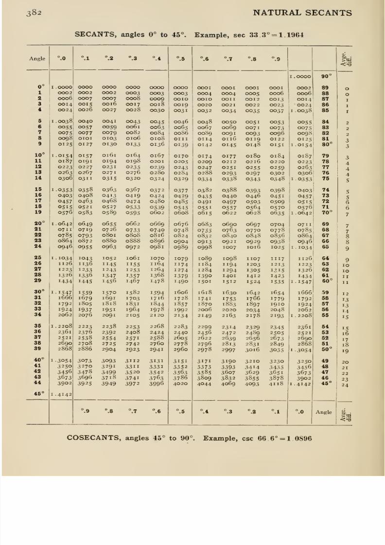
8/13/2019 Maurer Mechanics
http://slidepdf.com/reader/full/maurer-mechanics 398/407
382 NATURAL SECANTS
SECANTS, angles 0° to 45°. Example, sec 33 3° = 1.1964
Angle
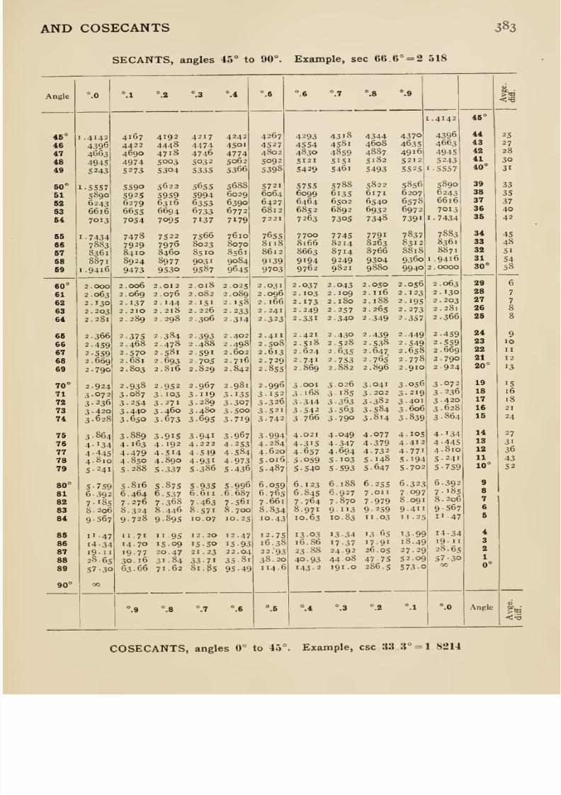
8/13/2019 Maurer Mechanics
http://slidepdf.com/reader/full/maurer-mechanics 399/407
AND COSECANTS 383
SECANTS, angles 45° to 90°. Example, sec 66.6° = 2 518
Angle

8/13/2019 Maurer Mechanics
http://slidepdf.com/reader/full/maurer-mechanics 400/407
8/13/2019 Maurer Mechanics
http://slidepdf.com/reader/full/maurer-mechanics 401/407
INDEX(Numbers refer to pages.)
Acceleration, 121, 144.
angular, 177.
components, 150
graphs, 128.
Action and reaction, 43.
Amplitude of simple harmonic motion, 131.
Analysis of a truss, 57.
Angle of repose, 75.
Angular acceleration, 177.
impulse, 237.
momentum, 237.
velocity, 176, 281.
Anti-resultant, 7.
Arm of a couple, 18.
Atwood's machine, 139.
Band brake, 85.
Belt friction, 83.
Blow, 232.
Cables, 103.
Catenary, 107.
Center of gravity, 87.
experimental determination, 8g
motion of, 155.
Center of gyration, 169.
Center of percussion, 241.
Centroid, 86, 90, 98.
Coefficient of friction, 75, 222.
Collision, 232.
Composition of
angular velocities, 281.
couples, 29.
forces, 7.
Conical pendulum, 161.
Conservation of
angular momentum, 240.
energy, 300.
Couples, 18, 28.
Cranes, analysis of, 64.
D'Alembert's principle, 300.
Dimensions of units, 302.
Dynamometers, 198, 199,
Dyne, 143.
Efficiency, 211, 212.
Elevation of outer rail, 161,
Energy, 193, 195.
Equilibrant, 7.
Equilibrium, 34.
Erg, 190.
Force
characteristics, 4.
definition, 4.
external, 34, 158.
internal, 34, 158.
line of action of, 5.
moment of, 16.
polygon, 12.
sense of, 5.
tractive, 76.
transmissibility of, 6.
Forces
cohnear, 7.
composition of, 7.
concurrent, 7.
coplanar, 7.
parallelogram of, 7.
parallelopiped of, 13.
resolution of, 7.
triangle of, 7.
Force of inertia, 157.
Frameworks, 54, 64.
Free axes, 294.
Frequency
of simple harmonic motion, 131.
Friction, 74, 221.
Friction of
belts, 84.
inclined planes, 78.
journals, 82, 225.
pivots, 223.
screws, 81.
wedges, 79.
Friction, rolling, 268.
38s
8/13/2019 Maurer Mechanics
http://slidepdf.com/reader/full/maurer-mechanics 402/407
386
Geepound, 143.
Graphs, 126.
Gravity, acceleration of, 5.
Gyration, center of, 169.
radius of, 169, 292, 310.
Gyro-compass, 247.
Gyroscope, 243.
Gyro-stabilizer, 247, 248.
Gyrostat, 243, 288.
Gyrostatic reaction, 253.
Harmonic motion, 131.
Hodograph, 145.
Hoists, 212.
Horse-power, 197.
Horse-power-hour, 190.
Impact, 232.
Impulse, angular, 242.
linear, 231.
Inclined plane, 78, 214.
Indicator, 200.
Indicator card, 201.
Inertia, 156.
circle, 320.
ellipse, 321.
moment of, 168, 292, 308.
product of, 293, 316.
Input, 211.
Instantaneous axis, 281.
center, 260.
Joule, 190.
Journal friction, 82.
Kilogram, 4.
Kinetic Energy, 193.
Lami's theorem, 39.
Laws of motion, 155.
Lever, i.
Locomotive:
cylinder effort, 206.
side rods, 166.
Mass, 142.
Mass-center, 158.
Momentcenter of, 16.
moment-sum, 17.
of momentum, 237origin of, 16.
statical, 91.
Moment of
a body, 87.
a couple, 18.
a force, 16, 27.
a line, 91.
a solid, 91.
a surface, 91.
Moment of inertia, 168, 292, 308.
graphical determination, 320.
inclined axis theorem, 318.
parallel axes theorem, 171, 311.
principal axes of, 292, 318.
rectangular axes theorem, 313.
Moments, principle of, 17, 28.
Momentum, angular, 237.
linear, 228.
moment of, 237.
Mono-rail car, 247.
Motion
curvilinear, 144.
graphs, 126.
laws of, 155.
non-uniform, 118.
precessional, 245.
plane, 256.
rectilinear, 118.
relative, 273.
rotational, 176.
simple harmonic, 131.
solid, 280.
spherical, 280.
translational, 163.
uniform, 118.
imiformly accelerated, 121, 125.
Motion of
center of gravity, 155.
of rotation, 176.
of translation, 163.
Newton's laws, 2, 155.
Outer rail, elevation of, 161.
Output, 211.
Parallelogram of forces, 7.
Parallelepiped of forces, 13.
Parallel axes theorem, 171, 311.
Particle, 155.
Pendulum, gravity, 182.
torsional, 187.
Percussion, center of.
Period of simple harmonic motion, 131.
Pole, 22.
8/13/2019 Maurer Mechanics
http://slidepdf.com/reader/full/maurer-mechanics 403/407
387
Polygon equilibrium, 22.
funicular, 22.
of forces, 12.
string, 22.
Potential energy, 195.
Pound, 4.
Power, 196.
measurement of, 198.
of a locomotive, 200.
Precession, 245, 288.
Principal axes, 000, 000.
Principles of
dynamics, 297.
moments, 17, 28.
work and energy, 203.
Problems, statically indeterminate, 43.
Product of inertia, 293, 316.
Projectile, 153.
Prony brake, 198.
Pulley, 69, 217.
Radius of gyration, 169, 310.
parallel axis theorem, 171.
Rate of a
scalar quantity, 123.
vector quantity, 148.
Rays, 22.
Rectangular axes theorem.
Relative motion, 273.
Repose, angle of, 5.
Resolution of
acceleration, 149.
couples, 30.
forces, 7.
velocity, 150, 000.
Resultant, 7.
Rolling resistance, 268.
Rotation, 176.
Speed, 144.
Spherical motion, 54
Statical moment, 91.
Statically indeterminate problems, 45, 59.
Stress, 55.
Stress diagrams, 59.
String polygon, 22.
Tackle, 218.
Tension in a cord, 42.
Theoreminclined axis,
Lami's, 39.
Pappus', 96.
parallel axes, 171, 311.
rectangular axes, 313.Torpedo, 246.
Torque, 16.
Torsion pendulum, 187.
Train resistance, 208.
Translation, 163.
Triangle of forces, 7.
Truss, analysis of, 57, 59.
Units
absolute, 138.
dimensions of, 302.
fundamental, 302.
gravitation, 4.
systematic, 143.
Vector diagrams, 6.
Vector quantity, 5.
rate of, 148.
Velocity, 118, 144.
angular, 176.
components of, 148.
graphs, 127, 128.
Scalar quantity, 5.
rate of a, 123.
Screw, 81, 216.
Simple harmonic motion, 131.
Slug, 143-
Space diagram, 6.
Watt, 197.
Watt-hour, 190.
Wedge, 79, 215.
Work, 189.
Work and energy,
principle of, 203.
(Numbers refer to pages. )

8/13/2019 Maurer Mechanics
http://slidepdf.com/reader/full/maurer-mechanics 404/407

8/13/2019 Maurer Mechanics
http://slidepdf.com/reader/full/maurer-mechanics 405/407
8/13/2019 Maurer Mechanics
http://slidepdf.com/reader/full/maurer-mechanics 406/407
*S3r-
THIS BOOK IS DUE ON THE LAST DATESTAMPED BELOW
1AN INITIAL FINE OF 25 CENTSWILL BE ASSESSED FOR FAILURE TO RETURNTHIS BOOK ON THE DATE DUE. THE PENALTYWILL INCREASE TO SO CENTS ON THE FOURTH
DAY AND TO$1.00 ON THE SEVENTH DAY
OVERDUE.
ENGfN^Fr-;-h LIBRARY^ ' ^J I Q/IP194^
QCT 2 7 \mttttr
ii£a- c •?
MAY t^ 1^49
10m-7,'44(1064s)
8/13/2019 Maurer Mechanics
http://slidepdf.com/reader/full/maurer-mechanics 407/407
YC 32523
494295 ^Engineering
Library
UNIVERSITY OF CALIFORNIA LIBRARY