masters thesis: suction bucket buckling
TRANSCRIPT

Suction bucket bucklingBuckling behaviour of suction buckets during installa-tion in layered soils
Y. Welschen
Mas
tero
fScie
nce
Thes
is


Suction bucket bucklingBuckling behaviour of suction buckets during installation in layered
soils
Master of Science Thesis
For the degree of Master of Science in Offshore and DredgingEngineering at Delft University of Technology
Y. Welschen1371835
August 20, 2015
Faculty of Mechanical, Maritime and Materials Engineering (3mE) · Delft University ofTechnology · SPT Offshore

Copyright c© Y. WelschenAll rights reserved.Cover photo courtesy of ....

Abstract
In the offshore industry, suction buckets can be used as foundation piles. For the oil and gassector they are generally designed as one off. For offshore wind-turbines however, founda-tions are often built in larger quantities. This shifts the balance between design costs andfabrication costs. For large quantities it is economically attractive to optimize the design ofsuction buckets for the amount of material needed. Optimizing the costs of a wind-turbinefoundation is an important factor, since wind energy development is mainly dependent onsubsidies. For this thesis, bucket dimensions were used that represent the typical geometryrange of foundations for the offshore wind industry. Starting from a diameter of 6 to 12 meter,a fixed length of 8 meter and a wall thickness varying between 25 to 50 millimeters.
Bucket foundations are categorized as thin shell structures, which are loaded by externalpressure. They are therefore sensitive to structural buckling. It is important to find thebest balance between cost effectiveness by material reduction and resistance against buckling.Buckling checks for shell elements are covered by industry standards. The (offshore) industrygenerally uses these standards for buckling design. Conservative modeling standards, basedon non-layered homogeneous clay or sand, are currently used for conventional suction bucketdesign. In reality however, the seabed is often non-homogeneous. More detailed modellingwould lead to a more optimal and therefore cost-effective design.
Four different design methods were analysed and compared in this thesis. These designmethods are commonly used for design against buckling failure of cylindrical shells in theoffshore industry. The focus of this study is on buckling of unstiffened shells due to axial andcircumferential stresses.An analysis of the strengths and weaknesses of each method reveals the most appropriatemethod for usage in suction bucket design.
Two soil types were introduced which, depending on their permeability, apply lateral loads onthe suction bucket. They also cause friction during installation and provide lateral supportto the shell. For the installation resistance, several (non-)layered soil configurations wereanalysed. From the comparison it was concluded which configurations require the highest
Master of Science Thesis Y. Welschen

ii
installation pressure, and are therefore the most critical for buckling.
In this thesis research the analytically derived critical buckling pressure of a closed thin-walledcylindrical shell is explained. This is done in order to determine the total safety factor fromthe selected buckling design method and to validate the finite element model from FEMAPsoftware. The buckling stresses of a cylinder were derived for different boundary conditions.For pinned-pinned boundary conditions, the selected buckling design method shows an ad-ditional safety factor for the critical buckling pressure, compared to the analytical method.Looking at the geometry and installation procedure of a suction bucket, the boundary condi-tions during installation are not only pinned-pinned, but start off being pinned-free. Becauseat the beginning of installation, the tip is free and from a certain penetration depth the tipis restrained by the soil.
With the use of FEMAP, a finite element model was made of the influence of the soil onthe buckling pressure of the shell during installation. This was done for homogeneous non-layered and layered soils. Also different bedding constant profiles where compared for differentsoil configurations.The models showed the influence of the differential pore water pressure on the critical buck-ling pressure during installation.Finally, conclusions were made on the performed research and recommendations were givenfor practical use of the results.
Y. Welschen Master of Science Thesis

Table of Contents
Preface xiii
1 Introduction 11-1 SPT Offshore . . . . . . . . . . . . . . . . . . . . . . . . . . . . . . . . . . . . 11-2 Background information . . . . . . . . . . . . . . . . . . . . . . . . . . . . . . . 1
1-2-1 Foundations for offshore wind turbines . . . . . . . . . . . . . . . . . . . 11-2-2 Suction piles . . . . . . . . . . . . . . . . . . . . . . . . . . . . . . . . . 21-2-3 Buckling during installation . . . . . . . . . . . . . . . . . . . . . . . . . 31-2-4 Soil structure interaction . . . . . . . . . . . . . . . . . . . . . . . . . . 4
1-3 Problem definition . . . . . . . . . . . . . . . . . . . . . . . . . . . . . . . . . . 51-4 Objective . . . . . . . . . . . . . . . . . . . . . . . . . . . . . . . . . . . . . . . 61-5 Approach . . . . . . . . . . . . . . . . . . . . . . . . . . . . . . . . . . . . . . . 7
1-5-1 Research framework . . . . . . . . . . . . . . . . . . . . . . . . . . . . . 81-6 Limitations . . . . . . . . . . . . . . . . . . . . . . . . . . . . . . . . . . . . . . 91-7 Motivation . . . . . . . . . . . . . . . . . . . . . . . . . . . . . . . . . . . . . . 9
1-7-1 Scientific relevance . . . . . . . . . . . . . . . . . . . . . . . . . . . . . 91-7-2 Commercial relevance . . . . . . . . . . . . . . . . . . . . . . . . . . . . 91-7-3 Personal motivation . . . . . . . . . . . . . . . . . . . . . . . . . . . . . 10
2 Buckling design methods 112-1 Introduction to buckling . . . . . . . . . . . . . . . . . . . . . . . . . . . . . . . 112-2 Design for buckling limit state, Eurocode . . . . . . . . . . . . . . . . . . . . . . 12
2-2-1 Code application & design tolerances . . . . . . . . . . . . . . . . . . . . 122-2-2 Buckling design . . . . . . . . . . . . . . . . . . . . . . . . . . . . . . . 152-2-3 Evaluation . . . . . . . . . . . . . . . . . . . . . . . . . . . . . . . . . . 19
2-3 Design for submarines, Germanischer Lloyd . . . . . . . . . . . . . . . . . . . . . 212-3-1 Code application & design tolerances . . . . . . . . . . . . . . . . . . . . 21
Master of Science Thesis Y. Welschen

iv Table of Contents
2-3-2 Buckling design . . . . . . . . . . . . . . . . . . . . . . . . . . . . . . . 232-3-3 Evaluation . . . . . . . . . . . . . . . . . . . . . . . . . . . . . . . . . . 26
2-4 Buckling strength of shells, DNV-GL . . . . . . . . . . . . . . . . . . . . . . . . 282-4-1 Code application & design tolerances . . . . . . . . . . . . . . . . . . . . 282-4-2 Buckling design . . . . . . . . . . . . . . . . . . . . . . . . . . . . . . . 302-4-3 Evaluation . . . . . . . . . . . . . . . . . . . . . . . . . . . . . . . . . . 33
2-5 Buckling and Ultimate Strength Assessment for Cylindrical Shells, ABS . . . . . 352-5-1 Buckling design . . . . . . . . . . . . . . . . . . . . . . . . . . . . . . . 362-5-2 Evaluation . . . . . . . . . . . . . . . . . . . . . . . . . . . . . . . . . . 38
2-6 Conclusion . . . . . . . . . . . . . . . . . . . . . . . . . . . . . . . . . . . . . . 39
3 Installation in (non-)layered soils 433-1 General soil behaviour . . . . . . . . . . . . . . . . . . . . . . . . . . . . . . . . 43
3-1-1 Sand . . . . . . . . . . . . . . . . . . . . . . . . . . . . . . . . . . . . . 443-1-2 Clay . . . . . . . . . . . . . . . . . . . . . . . . . . . . . . . . . . . . . 45
3-2 Suction installation in non-layered, homogeneous soils . . . . . . . . . . . . . . . 453-2-1 Installation in sand . . . . . . . . . . . . . . . . . . . . . . . . . . . . . 453-2-2 Installation in clay . . . . . . . . . . . . . . . . . . . . . . . . . . . . . . 46
3-3 Soil-structure interaction . . . . . . . . . . . . . . . . . . . . . . . . . . . . . . 473-3-1 Suction assisted penetration resistance . . . . . . . . . . . . . . . . . . . 473-3-2 Lateral soil loads during suction assisted penetration . . . . . . . . . . . 533-3-3 Lateral soil support during suction assisted penetration . . . . . . . . . . 54
3-4 Installation in layered soils . . . . . . . . . . . . . . . . . . . . . . . . . . . . . . 573-4-1 Installation in sand over clay . . . . . . . . . . . . . . . . . . . . . . . . 573-4-2 Installation in clay over sand . . . . . . . . . . . . . . . . . . . . . . . . 583-4-3 Soil-structure interaction . . . . . . . . . . . . . . . . . . . . . . . . . . 58
3-5 Modeling of layered soils . . . . . . . . . . . . . . . . . . . . . . . . . . . . . . 613-5-1 Resistance modeling . . . . . . . . . . . . . . . . . . . . . . . . . . . . . 623-5-2 Lateral soil loading modeling . . . . . . . . . . . . . . . . . . . . . . . . 623-5-3 Lateral soil support modeling . . . . . . . . . . . . . . . . . . . . . . . . 623-5-4 Constraints . . . . . . . . . . . . . . . . . . . . . . . . . . . . . . . . . 63
3-6 Conclusion . . . . . . . . . . . . . . . . . . . . . . . . . . . . . . . . . . . . . . 63
4 Model developed for buckling of suction buckets 654-1 Analytic method . . . . . . . . . . . . . . . . . . . . . . . . . . . . . . . . . . . 65
4-1-1 Stress design in thin-walled cylindrical shell . . . . . . . . . . . . . . . . 654-1-2 Buckling stress of a thin walled panel . . . . . . . . . . . . . . . . . . . 674-1-3 Buckling stress of a thin walled cylindrical shell . . . . . . . . . . . . . . 694-1-4 Conclusion . . . . . . . . . . . . . . . . . . . . . . . . . . . . . . . . . . 74
4-2 SPT Offshore approach . . . . . . . . . . . . . . . . . . . . . . . . . . . . . . . 754-2-1 Application for sand . . . . . . . . . . . . . . . . . . . . . . . . . . . . . 75
Y. Welschen Master of Science Thesis

Table of Contents v
4-2-2 Application for clay . . . . . . . . . . . . . . . . . . . . . . . . . . . . . 764-3 Finite Element Analysis . . . . . . . . . . . . . . . . . . . . . . . . . . . . . . . 77
4-3-1 Critical pressure for pin-pin boundary conditions . . . . . . . . . . . . . . 774-3-2 Critical pressure for pin-free boundary conditions . . . . . . . . . . . . . 784-3-3 Conclusion . . . . . . . . . . . . . . . . . . . . . . . . . . . . . . . . . . 79
4-4 Case study for installation in layered soils . . . . . . . . . . . . . . . . . . . . . 794-4-1 Installation in non-layered soils . . . . . . . . . . . . . . . . . . . . . . . 804-4-2 Installation in layered soils . . . . . . . . . . . . . . . . . . . . . . . . . 84
4-5 Conclusion . . . . . . . . . . . . . . . . . . . . . . . . . . . . . . . . . . . . . . 86
5 Conclusion and Recommendations 895-1 Conclusion . . . . . . . . . . . . . . . . . . . . . . . . . . . . . . . . . . . . . . 895-2 Recommendations . . . . . . . . . . . . . . . . . . . . . . . . . . . . . . . . . . 93
A Soil-structure interaction 97A-1 Influence of soil stiffness on shell stress . . . . . . . . . . . . . . . . . . . . . . . 97A-2 Suction assisted installation in non-layered soil . . . . . . . . . . . . . . . . . . . 98A-3 Suction assisted installation in layered soil . . . . . . . . . . . . . . . . . . . . . 99
B Linear finite element modeling 101B-1 Validity of theory by Pinna . . . . . . . . . . . . . . . . . . . . . . . . . . . . . 101B-2 Main features for FE models . . . . . . . . . . . . . . . . . . . . . . . . . . . . 101B-3 Difference in results between including and excluding of top load . . . . . . . . . 103B-4 FE models for different penetration depths in sand . . . . . . . . . . . . . . . . 104B-5 First buckling modes for different penetration depths in sand . . . . . . . . . . . 105
Master of Science Thesis Y. Welschen

vi Table of Contents
Y. Welschen Master of Science Thesis

List of Figures
1-1 Fixed foundations for offshore wind turbines[2] . . . . . . . . . . . . . . . . . . . 21-2 Suction bucket installation principle . . . . . . . . . . . . . . . . . . . . . . . . 31-3 Research framework . . . . . . . . . . . . . . . . . . . . . . . . . . . . . . . . . 8
2-1 Dimple measurement of shells in two directions[3] . . . . . . . . . . . . . . . . . 152-2 Loads on unstiffened cylindrical shells[3] . . . . . . . . . . . . . . . . . . . . . . 162-3 Radial deviations [4] . . . . . . . . . . . . . . . . . . . . . . . . . . . . . . . . . 222-4 Geometrical situation of frames stiffeneing the cylindrical shell[4] . . . . . . . . . 252-5 Local out of roundness and out of straightness[5] . . . . . . . . . . . . . . . . . 302-6 Coordinate system representation[6] . . . . . . . . . . . . . . . . . . . . . . . . 312-7 Critical cylinder buckling pressures according to the different methods . . . . . . 42
3-1 Change in stiffnes to compression . . . . . . . . . . . . . . . . . . . . . . . . . . 443-2 Example of a single grain structure(left) and a clay structure(right)[Soil Survey
Staff 1951] . . . . . . . . . . . . . . . . . . . . . . . . . . . . . . . . . . . . . . 453-3 Groundwater flow during installation in sand(left) and installation in clay(right) . 463-4 Illustration of the pressure parameters during installation in sand . . . . . . . . . 483-5 Required suction for installation in sand with reduced soil resistance due to flow . 503-6 Required suction for installation in undrained sand . . . . . . . . . . . . . . . . . 513-7 Required suction for installation in clay . . . . . . . . . . . . . . . . . . . . . . . 523-8 Schematic representation of differential porewater pressure development on a suc-
tion bucket during suction assisted installation in sand . . . . . . . . . . . . . . 533-9 differential pressure on a suction bucket during suction assisted installation in sand 543-10 Differential pressure on a suction bucket during suction assisted installation in clay 543-11 Construction of the bedding constant with the numbers of Table 3-1[7] . . . . . 563-12 Required suction for installation in sand over clay . . . . . . . . . . . . . . . . . 59
Master of Science Thesis Y. Welschen
viii List of Figures
3-13 Required suction for installation in clay over sand . . . . . . . . . . . . . . . . . 603-14 Lateral soil loading during suction assisted installation in sand over clay . . . . . 603-15 Lateral soil loading during suction assisted installation in clay over sand . . . . . 613-16 Required installation pressure during suction assisted installation in layered soil . 63
4-1 Pressure in unstiffened cylindrical shell . . . . . . . . . . . . . . . . . . . . . . . 664-2 Stress-strain diagram for structural steel in tension[8] . . . . . . . . . . . . . . . 674-3 Pressure on a plate . . . . . . . . . . . . . . . . . . . . . . . . . . . . . . . . . 684-4 Number of waves into which the cylinder buckles in circumferential direction[9] . 714-5 Critical buckling pressure for thin-walled cylindrical shell . . . . . . . . . . . . . 714-6 Critical lateral buckling pressure for thin-walled cylindrical shell with different buck-
ling lobe (n) curves . . . . . . . . . . . . . . . . . . . . . . . . . . . . . . . . . 724-7 Critical lateral buckling pressure for thin-walled cylindrical shell with pinned-free
boundary conditions . . . . . . . . . . . . . . . . . . . . . . . . . . . . . . . . . 744-8 Critical lateral buckling pressure for thin-walled cylindrical shell with pinned-pinned
boundary conditions modeled in FEMAP . . . . . . . . . . . . . . . . . . . . . . 784-9 Critical lateral buckling pressure for thin-walled cylindrical shell with pinned-free
boundary conditions modeled in FEMAP . . . . . . . . . . . . . . . . . . . . . . 794-10 An example of the FE model of an eight meter cylinder, installed in four meters of
sand . . . . . . . . . . . . . . . . . . . . . . . . . . . . . . . . . . . . . . . . . 804-11 Critical lateral buckling pressure for thin-walled cylindrical shell per penetrationdepth
in sand . . . . . . . . . . . . . . . . . . . . . . . . . . . . . . . . . . . . . . . . 814-12 An example of the first buckling mode deformation of an eight meter cylinder,
installed in four meters of sand . . . . . . . . . . . . . . . . . . . . . . . . . . . 814-13 Critical lateral buckling pressure for thin-walled cylindrical shell per penetration
depth in clay . . . . . . . . . . . . . . . . . . . . . . . . . . . . . . . . . . . . . 824-14 Critical lateral buckling pressure for thin-walled cylindrical shell per penetrationdepth
in sand (blue) & clay (red) . . . . . . . . . . . . . . . . . . . . . . . . . . . . . 834-15 Buckling pressure during installation in sand modeled in FEMAP compared to the
SPT approach . . . . . . . . . . . . . . . . . . . . . . . . . . . . . . . . . . . . 834-16 Buckling pressure during installation in clay modeled in FEMAP compared to the
SPT approach . . . . . . . . . . . . . . . . . . . . . . . . . . . . . . . . . . . . 844-17 Critical lateral buckling pressure for thin-walled cylindrical shell per penetrationdepth
in sand over clay . . . . . . . . . . . . . . . . . . . . . . . . . . . . . . . . . . . 854-18 Critical lateral buckling pressure for thin-walled cylindrical shell per penetrationdepth
in clay over sand . . . . . . . . . . . . . . . . . . . . . . . . . . . . . . . . . . . 864-19 Critical lateral buckling pressure for thin-walled cylindrical shell per penetrationdepth
in sand over clay (green) and only sand (blue) . . . . . . . . . . . . . . . . . . . 87
A-1 Required suction for installation in sand . . . . . . . . . . . . . . . . . . . . . . 98A-2 Required suction for installation in undrained sand . . . . . . . . . . . . . . . . . 98A-3 Required suction for installation in clay . . . . . . . . . . . . . . . . . . . . . . . 99A-4 Required suction for installation in clay over sand . . . . . . . . . . . . . . . . . 99A-5 Required suction for installation in sand over clay . . . . . . . . . . . . . . . . . 100
Y. Welschen Master of Science Thesis

List of Figures ix
B-1 Critical axial buckling pressure for thin-walled cylindrical shells with pinned-freeboundary conditions according to Pinna[36] and compared to FEMAP results . . 101
B-2 Critical lateral buckling pressure for thin-walled cylindrical shell with pinned-pinnedboundary conditions modeled in FEMAP . . . . . . . . . . . . . . . . . . . . . . 103
B-3 Critical lateral buckling pressure for thin-walled cylindrical shell with pinned-freeboundary conditions modeled in FEMAP . . . . . . . . . . . . . . . . . . . . . . 103
B-4 All FE models for different penetration depths in sand . . . . . . . . . . . . . . . 104B-5 All buckling eigenvalue deformation indications of the FE models for different pen-
etration depths in sand . . . . . . . . . . . . . . . . . . . . . . . . . . . . . . . 105
Master of Science Thesis Y. Welschen

x List of Figures
Y. Welschen Master of Science Thesis

List of Tables
2-1 Recommended values for out-of-roundness tolerance parameter Ur,max . . . . . . 132-2 Recommended maximum values for non-intended eccentricities ea,max . . . . . . 132-3 Recommended values for non-intended eccentricities tolerance parameter Ue,max 142-4 Recommended values for dimple tolerance parameter U0,max . . . . . . . . . . . 152-5 Values of fabrication quality parameter Q . . . . . . . . . . . . . . . . . . . . . 172-6 Values of ατ and αθ based on fabrication quality . . . . . . . . . . . . . . . . . 172-7 Values of λ0, β and η . . . . . . . . . . . . . . . . . . . . . . . . . . . . . . . 182-8 Safety (material) factors for allowable stress . . . . . . . . . . . . . . . . . . . . 232-9 Recommended values for cylindrical structure diameter tolerance . . . . . . . . . 292-10 Tolerance for curved plate assembly . . . . . . . . . . . . . . . . . . . . . . . . 292-11 Buckling coefficients for unstiffened cylindrical shells mode a)Shell buckling . . . 332-12 Recommended values for diameter tolerance[10] . . . . . . . . . . . . . . . . . . 352-13 Tolerance for curved plate assembly . . . . . . . . . . . . . . . . . . . . . . . . 352-14 Summary of boundary conditions per method . . . . . . . . . . . . . . . . . . . 412-15 Short summary of discussed methods . . . . . . . . . . . . . . . . . . . . . . . . 42
3-1 Characteristic values of horizontal bedding constant during stress increase[7] . . . 56
B-1 FE-units . . . . . . . . . . . . . . . . . . . . . . . . . . . . . . . . . . . . . . . 102B-2 FE-material . . . . . . . . . . . . . . . . . . . . . . . . . . . . . . . . . . . . . 102
Master of Science Thesis Y. Welschen

xii List of Tables
Y. Welschen Master of Science Thesis

Preface
This document is dedicated to the Master of Science graduation thesis of Yonna Welschen.This thesis is the final part of the curriculum of the master specialization Bottom FoundedStructures, Arctic and Wind at the department Offshore and Dredging Engineering at DelftUniversity of Technology (TU Delft).
The thesis includes a research conducted during the period of November 2014 to August 2015.This research is done for the structural department of Suction Pile Technology Offshore (SPTOffshore), and involves cooperation between TU Delft and SPT Offshore in Woerden. Themain part of this research is conducted at SPT Offshore in Woerden.
This report describes the work done during this period as well as the theoretical backgroundrequired to conduct this work.
I would like to thank my supervisors Prof.dr.ir. M.L. Kaminski, dr.ir. S.A. Miedema,ir. O.J. Dijkstra, ir. K.A. Debska-Nowak, ir. P.S. van Lieshout and my colleagues at SPTOffshore for their assistance during the writing of this thesis.
Finally, I would like to thank Joris van Kruijssen, my family, housemates and friends for theirloving help and support during this graduation project.
IMPORTANT NOTE: The content of this report is confidential and should not be distributedor published.
Master of Science Thesis Y. Welschen

xiv Preface
Y. Welschen Master of Science Thesis

Chapter 1
Introduction
1-1 SPT Offshore
Suction Pile Technology Offshore (SPT offshore) is a Dutch offshore company that has a spe-cialization in suction pile foundations, Self Installing Platforms (SIPs)r and offshore trans-former substations.In addition, SPT has developed a Self Installing Wind Turbine (SIWT) concept, which allowstransport and installation of a wind turbine foundation, already attached to a pre-assembledwind turbine. This last concept makes it possible to have a flexible schedule and a low-costand noise-free installation.SPT Offshore offers a detailed design of offshore structures, including, fabrication, transportand installation engineering. They perform concept studies on a regular basis to identify costsavings of suction pile founded structures.Furthermore, SPT Offshore offers suction piles, Suction Pile Clusters (SPC) and SuctionEmbedded Anchors (SEA)r for the mooring of floating units, subsea structures and subseapipelines. Their remotely controlled suction pumps are suitable for water depths from 5m upto 3000m.SPT Offshore is a subsidiary of the Royal Volker Wessels Stevin group, a Dutch group of 125contractor companies with more than 15,000 employees working worldwide. The SPT officeis located in Woerden, The Netherlands[11].
1-2 Background information
1-2-1 Foundations for offshore wind turbines
The increase of wind turbines are a sign of the growth of renewable energies. The market foroffshore wind farms is predicted to expand rapidly in the next decade[1]. This growth is forexample possible because of the wide availability of offshore space and wind.The investment and operation costs for offshore wind energy are much higher than those for
Master of Science Thesis Y. Welschen

2 Introduction
onshore wind energy. Due to the dependency on subsidies of this market and considering itspredicted expansion, it is key to design and install wind farms in a most economic way.The expenses of foundations and their installation in shallow water, constitute about onethird of the total cost of an offshore wind farm. For wind turbines located in deeper water,the foundation costs can even be as high as 50 % of the total costs[1].Usually, regular foundations for the oil and gas industry are used for the fixed foundationof an offshore wind turbine. Examples of these foundations are mono pile, tripod, jacket orgravity based foundations, of which most have hammer driven foundation piles or requirea large amount of materials (see figure 1-1). For a noise-free foundation installation andrelatively light foundation, suction piles provide a good and economic alternative.
Figure 1-1: Fixed foundations for offshore wind turbines[2]
1-2-2 Suction piles
In the offshore industry, suction piles (also known as suction buckets), can be used as anchorand foundation piles. They are usually installed in clay or sand but can also be placed inlayered soils.A suction bucket consists of a steel thin walled cylinder (also called the skirt) that is closedby a steel plate at the top (from now on referred to as the lid). From the total amount ofsteel of a suction bucket, approximately 50% is used for the skirt.The installation of a suction bucket can be divided in two stages. The initial penetrationof the pile is dependent on the effective weight of the suction bucket and the resistance ofthe soil. The second stage of the installation is done by pumping water out of the cylinderthrough the lid, while its open bottom is enclosed by the seabed. This pumping causes adifferential pressure on the bucket, which pulls the bucket into the seabed (see figure 1-2).The water flow in sandy soils at the bottom of the suction bucket, reduces the tip resistance.Buckets that are used for the foundation of wind turbines are considered to be shallow or
Y. Welschen Master of Science Thesis

1-2 Background information 3
Figure 1-2: Suction bucket installation principle
intermediate foundations, depending on their embedment depth/width ratio[12].The foundation embedment ratio λ depends on foundation type and soil conditions. λ forsands typically varies between 0.5 and 1 with a maximum pile diameter of 15 meter. For claysλ typically lies between 1 and 6, with a maximum pile diameter of 5 meters. Typical wallthicknesses are D/75, D/100 and D/200, depending on the under pressures in the bucket[12].However, nowadays even wall thicknesses of D/275 are used.As mentioned earlier; an important attribute of suction bucket foundations in comparison tothe conventional hammered pile foundations, is that their installation procedure is associatedwith much lower underwater noise production. This is a great advantage with relation toenvironmental issues regarding the disturbance of the surrounding ecosystem. However, arisk of using thin walled cylinders in combination with differential pressures upto 350 kPa, isthe possibility of failure due to buckling.
1-2-3 Buckling during installation
The suction installation phase governs the selection of the suction pile wall thickness. Whilethe pile is penetrated with suction force, the risk of shell buckling under inner under pressurehas to be considered[13].Collapse of the bucket during installation is a structural failure caused by buckling.Buckling is a non-linear effect that for example can be observed in thin-walled structuresthat are subjected to pressure loads[14]. Bucket foundations are categorized as thin shellstructures and are therefore sensitive to structural buckling[15].
Buckling checks for shell elements are covered by the industry standards, but these guide-lines consider the distance, l, between effective supports of a ring stiffened cylinder, as aninput parameter to the buckling strength assessment. The sole ring stiffened section in asuction pile is at the top lid plate. During installation, support down the pile is provided bythe inner and outer soil. It is thus essential to accurately define the "buckling length", LB [13].
Master of Science Thesis Y. Welschen

4 Introduction
Buckling propagates down the pile to a depth where shell has virtually not deformed: thisdefines the buckling length. In all previous cases the buckling length has proven to exceedthe pile stick-up length.This means that only after a certain depth under the seabed, the soil provides sufficientstiffening to prevent buckling of the shell and act as a bulkhead.From performed analyses, the following observations are made:
• For a given geometry (D,H, t), the buckling length LB does not depend on the overallpile length L, but on L−H (see figure 1-2)
• For given stick-up heightH, overall length L and diameterD (with respect to wall thick-ness t) of medium length suction buckets, the buckling length LB varies only slightlywith shell thickness t (with respect to pile diameter D). While varying D or t, a changein buckling length is associated with a change in the number of shell areas(n) on thecircumference of the shell, where buckling occurs. Therefore, the dependence of thebuckling length LB on D or t disappears for a dependency on n only[13].
While non-linear FE methods for buckling analysis, can cater to satisfy most effects of imper-fection and residual stresses in shells, they are time-consuming and expensive and thereforenot suitable for engineering design in the industry[16]. The industry mostly uses linear FEmethods for design purposes.
1-2-4 Soil structure interaction
Nowadays perhaps the biggest engineering challenges faced by the geotechnical engineer arethe interaction between engineering and installation, the limitation of codified methods andthe resulting uncertainties around pile-soil interaction[13].Two methodologies are currently used for the assessment of skirt penetration resistance ofsuction piles in very soft to soft clay’s:
• The empirical method based on the piezocone penetration test (PCPT) cone resistanceqc
• The classical bearing capacity method based on the undrained shear strength
The so-called "qc method" has been calibrated on skirt penetration tests in over- consolidated,low plasticity clay’s and sands of the North Sea. Special care should therefore be taken whenusing this methodology in other geographical areas.For the classical method the penetration resistance Qtot is calculated as the sum of the sideshear along the skirt walls Qside[13].
For geotechnical sizing, it is common to use appropriate FE analyses as a reference tool toaccess the "ground truth"[13].
Y. Welschen Master of Science Thesis

1-3 Problem definition 5
1-3 Problem definition
Generally, suction buckets for the oil and gas sector are designed per project as one off.Offshore wind-turbine foundations on the other hand, are often built in larger quantities,which shifts the balance between design engineering and fabrication costs. With the cost offoundations going as high as 50% of the project costs[1], it is economically very attractive tooptimize the design of suction buckets for size and thus price.
When installing a suction bucket, buckling is one of the most critical failure modes.[15] Sincethe skirt of the bucket is penetrated into the seabed, it is very difficult to determine if bucklinghas occurred and to what extent.Conservative modeling standards, based on non layered homogeneous clay or sand, are cur-rently used for conventional suction bucket design. In reality however the seabed is often anon homogeneous soil, this is especially the case in areas where wind farms are installed. Lessconservative modeling would therefore likely result in the desired, more cost-effective design.
Foundations are a vital part of an offshore wind farm, their failure can be catastrophic. Earlierfailure of some suction bucket prototypes for wind turbine foundation clearly underlines thevulnerability of the concept[15].As an example; The installation of a suction bucket for an Enercon E112 4.5 MW plant inHooksiel near Wilhelmshaven in April 2005 failed because buckling occurred in the shell[17].All that is mentioned above, shows that it is important to find the best balance between costeffectiveness by material optimization and resistance against buckling.
Further research, development and prototype testing are therefore necessary in order to:
a) eliminate all major risks associated with the installation of suction bucket foundations
b) increase the cost-efficiency of the suction bucket foundation concept[15]
c) increase knowledge on soil-structure interaction with respect to buckling load and re-sistance
Master of Science Thesis Y. Welschen

6 Introduction
1-4 Objective
The objective of this thesis is to analyze the elastic buckling behaviour of suction bucketsduring installation in layered soil conditions.
Research question:
What is the influence of layered soil on the elastic buckling behaviour of a suction bucketduring installation?
1. What methods are available for design against buckling of cylindrical shells?
(a) How are these methods applicable on suction buckets?(b) Which one is most appropriate for this problem and why?(c) Can this method be adjusted, how?
2. What is the elastic buckling pressure of cylindrical shells?
3. What loads are exerted on a suction bucket during suction assisted installation in layeredsoil?
(a) What causes these loads?
4. How can soil-structure interaction be modeled?
Y. Welschen Master of Science Thesis
1-5 Approach 7
1-5 Approach
To reach the objective of this thesis, the following steps will be taken:
• An analytic research to consider existing theories and methods
• A comparing analysis between existing methods
• A comparison of finite element modeling results with current method results
• Modelling of soil-structure interaction
• Analyzing results
• Make conclusions and recommendations
Master of Science Thesis Y. Welschen

8 Introduction
1-5-1 Research framework
Figure 1-3: Research framework
Y. Welschen Master of Science Thesis

1-6 Limitations 9
1-6 Limitations
The research for this thesis is performed while considering the following limitations:
1. Only a limit amount of geometries will be analysed to obtain data for this research. Thegeometries that are chosen, are based on typical diameters and wall-thicknesses, usedby SPT Offshore. The diameters are 6, 9 and 12 meters. A fixed length of 8 meters anda wall thickness varying between 25 to 50 millimeters.
2. To find the influence of installation in layered soils, two soil types will be used formodelling purposes. A "medium" sand and a "weak" clay will be analysed in fourdifferent layer configurations.
3. For soil modelling purposes, the soil layers are assumed to be perfect and infinitelylong. Additionally, the soil is assumed not to fail during modelling of suction assistedinstallation.
4. For FE analysis, the installation steps (soil penetration depth) that will be taken, are1 meter. This determines the amount of analyses that will be performed.
5. A typical installation pressure for installation of suction bucket foundations is 350 kPa.This pressure will therefore be used as a design load.
1-7 Motivation
1-7-1 Scientific relevance
Literature shows that there is knowledge on buckling behaviour of suction buckets while in-stalling in homogeneous soils. Installation of suction buckets in layered soil is discussed withreference to plugging or piping. Additionally, small scale tests have been carried out to ex-amine the behaviour of suction piles during installation by percussion in layered soil. Thereis however no specific literature found on buckling of suction buckets during installation inlayered soils by continuous pumping.Combining the knowledge of buckling design methods of cylindrical shells and that of soiltransition properties will add a new research topic to literature on suction buckets.
1-7-2 Commercial relevance
SPT Offshore is an independent offshore contractor and market leader in suction pile foun-dations and anchors used for offshore platforms/floaters used in the oil and gas industry andoffshore wind farms.SPT Offshore has designed, fabricated and installed over 400 suction piles/anchors worldwide.In August 2014, SPT has installed the world’s first suction pile founded jacket for an offshorewind turbine (SPT offshore, 2014).Since offshore wind farms are installed in water depths where the seabed cannot be considered
Master of Science Thesis Y. Welschen
10 Introduction
as a homogeneous soil, it is important to know what influence the non homogeneity of the soilhas on the structural integrity of a suction pile (i.e. suction bucket). It is unknown what theinfluence of the seabed formation is on the buckling behaviour of a bucket. When this infor-mation is known, the design of a suction bucket could likely be made more cost efficient, dueto the saving of materials. This knowledge can additionally be used to make an in-house toolfor SPT Offshore, to reduce the time consuming and project specific finite element modeling.
1-7-3 Personal motivation
The majority of the work that will be described in this thesis shall be performed at SPTOffshore in Woerden.The reasons for conducting my master thesis at this company are as follows:
1. Doing a masters in offshore engineering and having previously worked for the innovationdepartment of a medium to large offshore contractor, made me want to experience whatit is like to be working for a smaller company in the offshore branch. Due to the fact thatI really enjoyed working on a innovation department, I was happy to do my graduationproject for a progressive company like SPT Offshore.
2. The offshore branch is dominated by oil and gas projects. However, renewable offshoreenergy is a fast growing business that I am enthusiastic about due to the requiredefficiency and technical innovation that it brings along. These requirements make it acomplex and interesting field that I believe is valuable for the future energy demand.
3. The research problem is quite a complex subject. However, I am pleased to be workingon a subject that is familiar to me, as my background is in mechanical engineering.Next to that, I like to challenge myself, especially in this finalizing phase of my studies.
4. It motivates me that the thesis subject is practical and its solution can be of direct usefor SPT Offshore.
Finally, I really value the fact that I can combine scientific research with gaining experiencein the field of offshore engineering.
Y. Welschen Master of Science Thesis
Chapter 2
Buckling design methods
Buckling checks for shell elements are covered by industry standards. These standards areused by the (offshore) industry for design to avoid buckling failure.This chapter will give a short introduction to buckling of cylindrical shells. In addition, it willdiscuss the following four different design methods that are used nowadays for design againstbuckling failure of cylindrical shells in the offshore industry:
• Eurocode 3 - Part 1-6:2007, by Comité Européen de Normalisation (CEN)
• Germanischer Lloyd III-2-1_e, by Germanischer Lloyd (GL)
• DNV-RP-C202:2013, by Det Norske Veritas-Germanischer Lloyd (DNV-GL)
• ABS-B_and_US_Guide_e-Feb14, by American Bureau of Shipping (ABS)
Keeping in mind the objective of this thesis, the focus in discussing these methods will be onbuckling of unstiffened shells due to axial and circumferential stresses.Finally the most appropriate method for usage in suction bucket design will be selected basedon an analysis of the strengths and weaknesses of each method.
2-1 Introduction to buckling
Buckling is an instability of a structure often observed at thin walled structures due to com-pressive stresses in that structure. Experience shows that in some cases thin steel shells maynot fail on account of high stresses surpassing the strength of material, but owing to insuffi-cient elastic stability of these members[9].Buckling will generally occur slightly before the calculated elastic buckling strength of astructure. The elastic buckling strength is the elastic stability limit which is, among others,dependent on the Young’s modulus of the material.Cylindrical shell structures, by virtue of their one shell geometry, carry their applied loads
Master of Science Thesis Y. Welschen

12 Buckling design methods
primarily by direct stresses lying in their plane accompanied by a little or no bending.External hydrostatic pressure induces compressive stress resultants in the cylindrical shellsand may cause buckling at a pressure, much lower than the axisymmetric yield.
2-2 Design for buckling limit state, Eurocode
The Eurocode standard gives the requirements for design against the ultimate limit state ofbuckling of cylindrical shells. They use the following definition of buckling: The ultimate limitstate where the structure suddenly loses its stability under membrane compression and/orshear. It leads either to large displacements or to the structure being unable to carry theapplied loads.[3]
2-2-1 Code application & design tolerances
The limits that are used for application of this standard to structures are as follows:
Design metal temperatures: -50◦C to +300◦CRadius to thickness ratio: 20 to 5000
For materials that have nonlinear stress-strain curves, a reduced value should be used as areplacement for the tangent value of Young’s modulus E. When analyzing the critical load orstress, the secant modulus at the 0,2% proof stress should be used. This 0,2% proof stressshould be used to represent the yield stress fy in all expressions mentioned in this section.The stress-strain curve should be obtained from EN 1993-1-5 Annex C[18] for carbon steels.The radius of cylindrical shells analysed in this code should be taken as the middle shellradius, normal to the axis of revolution.A requirement for buckling limit state (LS3) of short shells is that the rotational restraintshould be included as a boundary condition.For LS3 this code takes all relevant combined actions in account that cause compressive orshear membrane stresses in the shell wall. The characteristic buckling stresses determined inthis section include imperfections based on geometric tolerances that are discussed below.The quality level of the tolerances defined below are divided in fabrication classes A, B andC.Since the lowest fabrication tolerance class gives the highest tolerance, it should govern thedesign. Next to this, no tolerance interactions shall be considered.The values for partial factors and other reliability parameters have been selected assumingthat an appropriate level of workmanship and quality management applies[19]. The designvalues can be established by means of: Empirical relationships with measured physical prop-erties or from previous experience. The partial factors are based on statistical evaluation ofexperimental data and field observations[20].
Out of roundness tolerance
The out of roundness is defined as:
Ur = dmax − dmindnom
(2-1)
Y. Welschen Master of Science Thesis
2-2 Design for buckling limit state, Eurocode 13
Where:dmax = the maximum measured internal diameterdmin = the minimum measured internal diameterdnom = the nominal internal diameter
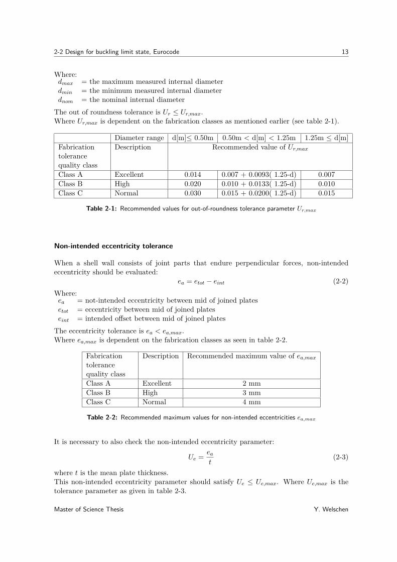
The out of roundness tolerance is Ur ≤ Ur,max.Where Ur,max is dependent on the fabrication classes as mentioned earlier (see table 2-1).
Diameter range d[m]≤ 0.50m 0.50m < d[m] < 1.25m 1.25m ≤ d[m]Fabricationtolerancequality class
Description Recommended value of Ur,max
Class A Excellent 0.014 0.007 + 0.0093( 1.25-d) 0.007Class B High 0.020 0.010 + 0.0133( 1.25-d) 0.010Class C Normal 0.030 0.015 + 0.0200( 1.25-d) 0.015
Table 2-1: Recommended values for out-of-roundness tolerance parameter Ur,max
Non-intended eccentricity tolerance
When a shell wall consists of joint parts that endure perpendicular forces, non-intendedeccentricity should be evaluated:
ea = etot − eint (2-2)Where:ea = not-intended eccentricity between mid of joined platesetot = eccentricity between mid of joined plateseint = intended offset between mid of joined plates
The eccentricity tolerance is ea < ea,max.Where ea,max is dependent on the fabrication classes as seen in table 2-2.
Fabricationtolerancequality class
Description Recommended maximum value of ea,max
Class A Excellent 2 mmClass B High 3 mmClass C Normal 4 mm
Table 2-2: Recommended maximum values for non-intended eccentricities ea,max
It is necessary to also check the non-intended eccentricity parameter:
Ue = eat
(2-3)
where t is the mean plate thickness.This non-intended eccentricity parameter should satisfy Ue ≤ Ue,max. Where Ue,max is thetolerance parameter as given in table 2-3.
Master of Science Thesis Y. Welschen

14 Buckling design methods
Fabricationtolerancequality class
Description Recommended value of Ue,max
Class A Excellent 0.14Class B High 0.20Class C Normal 0.30
Table 2-3: Recommended values for non-intended eccentricities tolerance parameter Ue,max
Dimple tolerance
When meridional compressive stresses are present, the depth 4w0 (see figure 2-1) of dim-ples in the shell, including across welds, should be measured in both the meridional andcircumferential directions using gauges of length:
lgx = 4√rt (2-4)
In case of circumferential compressive stresses or shear stresses the gauge length for circum-ferential measurement should be:
lgθ = 2.3(l2rt)0.25 (2-5)
while lgθ ≤ rAnd across welds in both direction the gauge length should be:
lgw = 25t (2-6)
while lgθ ≤ 500mmWhere:l = meridional length of shell segmentt = wall thicknessr = radius
The dimple depth parameters are subsequently:
U0x = 4w0x/lgx (2-7)U0θ = 4w0θ/lgθ (2-8)U0w = 4w0w/lgw (2-9)
The parameters should satisfy the following conditions:
U0x ≤ U0,max (2-10)U0θ ≤ U0,max (2-11)U0w ≤ U0,max (2-12)
Where the values of U0,max are given in table 2-4.The final given tolerance is as follows: If a shell is continuously supported. At the interfaceof that support, the flatness of it should not have a slope in circumferential direction greaterthan βθ=0.1%=0.001 rad.
Y. Welschen Master of Science Thesis

2-2 Design for buckling limit state, Eurocode 15
Fabricationtolerancequality class
Description Recommended value of U0,max
Class A Excellent 0.006Class B High 0.010Class C Normal 0.016
Table 2-4: Recommended values for dimple tolerance parameter U0,max
Figure 2-1: Dimple measurement of shells in two directions[3]
2-2-2 Buckling design
Design values of stresses
The design stresses σx,Ed = nx,Ed and σθ,Ed = nθ,Ed should be taken as the compressivemembrane stresses from Linear shell analysis. When the loading and support of the cylindricalshell are pure axisymmetric, membrane theory can be used.
σx,Ed = − Fx2πrt −
1t
∫ l
0pxdx (2-13)
σθ,Ed = qs
(r
t
)(2-14)
Where:qs = the suction pressure in the cylindert = the wall thickness of the cylinderr = the middle radius of the cylinderl = the length of the cylinder
And all other variables as given in figure 2-2.
Design resistance
The buckling resistance is represented by the buckling stresses. The design buckling stressesare:
σx,Rd = σx,Rk/γM1, σθ,Rd = σθ,Rk/γM1 (2-15)
Master of Science Thesis Y. Welschen

16 Buckling design methods
Figure 2-2: Loads on unstiffened cylindrical shells[3]
Where the partial factor γM1 should be taken as specified in National code, with a minimumof 1.1.The characteristic buckling stresses are calculated by multiplying the characteristic yieldstrength by the buckling reduction factors χ :
σx,Rk = χxfyk, σθ,Rk = χθfyk (2-16)
χx and χθ are a function of the relative slenderness of the shell λ from:
χ = 1 when λ ≤ λ0
χ = 1− β(λ−λ0λp−λ0
)ηwhen λ0 < λ < λp
χ = α
λ2 when λp ≤ λ
(2-17)
where:α = the elastic imperfection reduction factorβ = the plastic range factorη = the interaction exponentλ0 = the squash limit relative slenderness
plastic limit relative slenderness λp should be determined from:
λp =√
α
1− β (2-18)
The relative shell slenderness parameters for different stress components should be determinedfrom:
λx =√fyk/σx,Rcr, λθ =
√fyk/σθ,Rcr (2-19)
The elastic critical buckling stresses σx,Rcr, σθ,Rcr are calculated as follows:
σx,Rcr = 0.605ECxt
r(2-20)
σθ,Rcr = 0.92E(Cθω
)(t
r
)(2-21)
Y. Welschen Master of Science Thesis

2-2 Design for buckling limit state, Eurocode 17
where ω is the dimensionless length parameter:
ω = l
r
√r
t= l√
rt(2-22)
This critical buckling stress is dependent on the length and the boundary conditions of thecylindrical shell. The influence of the length and boundary conditions are represented by theexternal pressure buckling factors. For medium-length cylinders that are welded to a stifftop-plate and have a stiffener at the bottom, the external pressure buckling factors are:Cθ = 1.25Cx = 1.0Cτ = 1.0The meridional elastic imperfection reduction factor αx should be obtained from:
αx = 0.621 + 1.91(4wk/t)1.44 (2-23)
4wk = 1Q
√r
tt (2-24)
Where the meridional compression fabrication quality parameter Q can be found in table 2-5.
Fabricationtolerancequality class
Description Q
Class A Excellent 40Class B High 25Class C Normal 16
Table 2-5: Values of fabrication quality parameter Q
The elastic imperfection reduction factor for the other two stress components can be foundin table 2-6.
Fabricationtolerancequality class
Description ατ and αθ
Class A Excellent 0.75Class B High 0.65Class C Normal 0.50
Table 2-6: Values of ατ and αθ based on fabrication quality
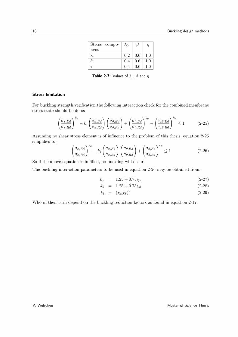
The plastic range factor β, interaction exponent η and the squash limit relative slendernessλ0 for different stress components can be found in table 2-7.
Master of Science Thesis Y. Welschen
18 Buckling design methods
Stress compo-nent
λ0 β η
x 0.2 0.6 1.0θ 0.4 0.6 1.0τ 0.4 0.6 1.0
Table 2-7: Values of λ0, β and η
Stress limitation
For buckling strength verification the following interaction check for the combined membranestress state should be done:(
σx,Edσx,Rd
)kx− ki
(σx,Edσx,Rd
)(σθ,Edσθ,Rd
)+(σθ,Edσθ,Rd
)kθ+(τxθ,Edτxθ,Rd
)kτ≤ 1 (2-25)
Assuming no shear stress element is of influence to the problem of this thesis, equation 2-25simplifies to: (
σx,Edσx,Rd
)kx− ki
(σx,Edσx,Rd
)(σθ,Edσθ,Rd
)+(σθ,Edσθ,Rd
)kθ≤ 1 (2-26)
So if the above equation is fulfilled, no buckling will occur.
The buckling interaction parameters to be used in equation 2-26 may be obtained from:
kx = 1.25 + 0.75χx (2-27)kθ = 1.25 + 0.75χθ (2-28)ki = (χxχθ)2 (2-29)
Who in their turn depend on the buckling reduction factors as found in equation 2-17.
Y. Welschen Master of Science Thesis

2-2 Design for buckling limit state, Eurocode 19
2-2-3 Evaluation
This paragraphs lists the strengths and weaknesses of the explained design method.
Strengths:
• The code works according to the LRFD format, which is considered less conservativethan the Working Stress Design (WSD)
• All relevant load combinations causing compressive membrane or shear membrane stressesin the shell should be accounted for when checking LS3.[3]
• The strength under limit state LS3 depends strongly on the quality of construction,hence the strength assessment should account for the associated requirements for exe-cution tolerances as for example out of roundness, eccentricity and dimples. For thispurpose, three classes of geometrical tolerances, termed "fabrication quality classes" aregiven.
• A base ring, intended to transfer local support forces into the shell, should not beseparated from the shell. It supports in an assessment of limit state LS3.
• The circumferential design stress can be adjusted for internal suction caused by venting,internal partial vacuum or other phenomena.
Weaknesses:
• The Eurocode does not clearly state why the buckling interaction parameters are cal-culated with the given values in their formula.
• There is no source or explanation available of the plastic range for interaction, the inter-action exponent, the limit relative slenderness and the fabrication quality parameters.
• The circumferential design stress is calculated the same for both internal as externalpressure.
• LS3 depends strongly on primary stress states but may be affected by secondary stressstates, which are not included in the proposed calculations.
Summary of the method application
Load and resistance factors:The factors that account for imperfections and residual stresses are included in the bucklingresistance calculations. In addition, this standard works with design stresses. This meansthat the chosen load factors (according to national annex) are already included in the loadsthat are used in the calculations.The buckling resistance is dependent on the characteristic buckling stress and the partialmaterial factor γM1:
1.1 ≤ γM1 and based on National Codes.
Master of Science Thesis Y. Welschen
20 Buckling design methods
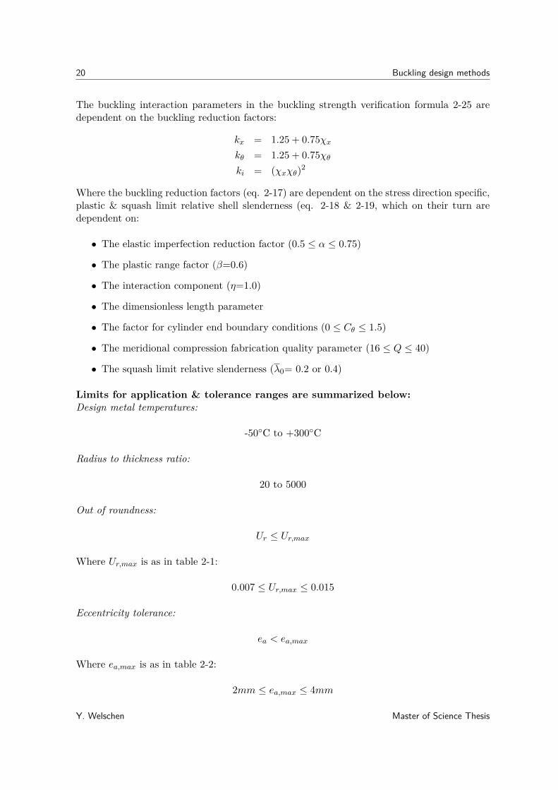
The buckling interaction parameters in the buckling strength verification formula 2-25 aredependent on the buckling reduction factors:
kx = 1.25 + 0.75χxkθ = 1.25 + 0.75χθki = (χxχθ)2
Where the buckling reduction factors (eq. 2-17) are dependent on the stress direction specific,plastic & squash limit relative shell slenderness (eq. 2-18 & 2-19, which on their turn aredependent on:
• The elastic imperfection reduction factor (0.5 ≤ α ≤ 0.75)
• The plastic range factor (β=0.6)
• The interaction component (η=1.0)
• The dimensionless length parameter
• The factor for cylinder end boundary conditions (0 ≤ Cθ ≤ 1.5)
• The meridional compression fabrication quality parameter (16 ≤ Q ≤ 40)
• The squash limit relative slenderness (λ0= 0.2 or 0.4)
Limits for application & tolerance ranges are summarized below:Design metal temperatures:
-50◦C to +300◦C
Radius to thickness ratio:
20 to 5000
Out of roundness:
Ur ≤ Ur,max
Where Ur,max is as in table 2-1:
0.007 ≤ Ur,max ≤ 0.015
Eccentricity tolerance:
ea < ea,max
Where ea,max is as in table 2-2:
2mm ≤ ea,max ≤ 4mm
Y. Welschen Master of Science Thesis
2-3 Design for submarines, Germanischer Lloyd 21
And the non-intended eccentricity parameter:
Ue ≤ Ue,max
Where Ue,max is as in table 2-3:
0.14 ≤ Ue,max ≤ 0.30
Dimple depth parameters:
U0x ≤ U0,max
U0θ ≤ U0,max
U0w ≤ U0,max
Where values of U0,max are as in table 2-4:
0.006 ≤ U0,max ≤ 0.016
For a continuously supported shell. At the interface of that support, the flatness should nothave a slope in circumferential direction greater than βθ=0.1%=0.001 rad.
2-3 Design for submarines, Germanischer Lloyd
For the purpose of the rules in this chapter, the definition of a submarine is: Manned militaryfloating and surface-independent vessel [4].The pressure hull of a submarine is mainly cylindrical shaped pressure vessel and subjectedto external hydro-static pressure and axial loads. These matching properties with suctionbuckets, make them interesting to assess for buckling design in this report.In contrast to suction buckets, the cylindrical pressure hull is usually stiffened with ringsand/or stringers [21]. Nevertheless, due to the outer hydro-static pressure their bucklingdesign method is still interesting to evaluate.
2-3-1 Code application & design tolerances
The method of calculation presented in this chapter takes account of fabrication relevantdeviations from the ideal shape of the shell (e.g. out-of-roundness). Fabrication tolerances asdefined in this section should be applied.Conical shells are calculated in sections, each of which is treated as a cylindrical shell.Overall collapse of the design is regarded as buckling of the hull structure between bulkheads,deep frames or dished ends.This method assumes that both elastic and elastic-plastic behaviour can occur in the materi-als of the shell structure. However, calculations relating to the allowable stress being exceededare based on the assumption that the behaviour of the material is elastic.At the collapse pressure of a submarine, the stress may lie in the elastic or the elastic-plastic
Master of Science Thesis Y. Welschen
22 Buckling design methods
range of the material.
The maximum permissible out-of-roundness is ±0.2% of the nominal pressure hull diame-ter. The following formulas apply to 24 measuring points distributed uniformly around thecircumference:
ui = wi −A−B sinϕi − C cosϕi (2-30)
A = 124(w1 + w2 + w3 + ...wn) (2-31)
B = 112(w1 sinϕ1 + w2 sinϕ2 + w3 sinϕ3 + ...wn sinϕn) (2-32)
C = 112(w1 cosϕ1 + w2 cosϕ2 + w3 cosϕ3 + ...wn cosϕn) (2-33)
Where:i = measuring points 1 to n (for this formula n = 24)wi = measured value of the curve shape at measuring point iui = calculated out-of-roundness of the pressure hull at measuring point iϕi = angle at measuring point
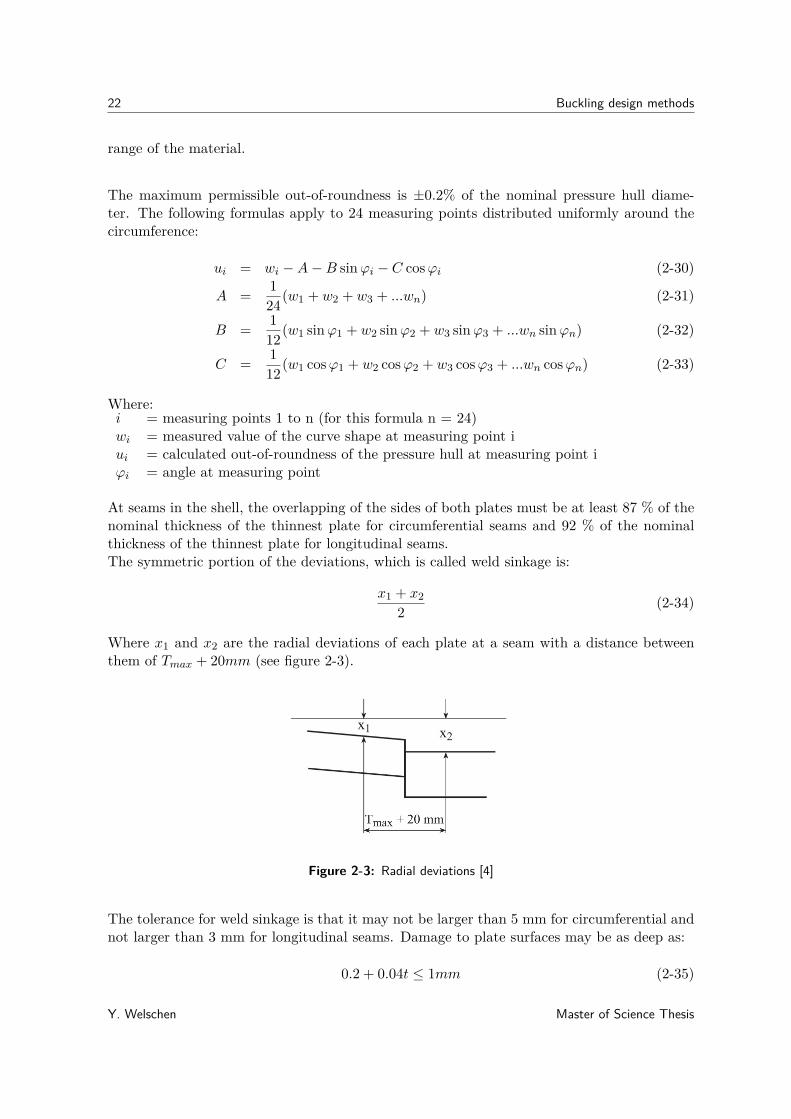
At seams in the shell, the overlapping of the sides of both plates must be at least 87 % of thenominal thickness of the thinnest plate for circumferential seams and 92 % of the nominalthickness of the thinnest plate for longitudinal seams.The symmetric portion of the deviations, which is called weld sinkage is:
x1 + x22 (2-34)
Where x1 and x2 are the radial deviations of each plate at a seam with a distance betweenthem of Tmax + 20mm (see figure 2-3).
Figure 2-3: Radial deviations [4]
The tolerance for weld sinkage is that it may not be larger than 5 mm for circumferential andnot larger than 3 mm for longitudinal seams. Damage to plate surfaces may be as deep as:
0.2 + 0.04t ≤ 1mm (2-35)
Y. Welschen Master of Science Thesis
2-3 Design for submarines, Germanischer Lloyd 23
2-3-2 Buckling design
Resistance factors
The maximum allowable stress to be used in the stress calculation is the lowest of the followingtwo values:
Rm,20◦
A,ReH,tB
(2-36)
Where:Rm,20◦ = guaranteed minimum tensile strength [N/mm2] at room temperatureReH,t = guaranteed yield point or minimum value of 0.2 % proof stress at design temperature
The safety factors A and B are shown in table 2-8.
Nominal diving pressure Test diving pressure Collapse pressureMaterial A B A’ B’ A” B”Ferritic materials 2.7 1.7 - 1.1 - 1Austenitic materials 2.7 1.7 - 1.1 - 1Titanium 2.7 1.7 - 1.1 - 1
Table 2-8: Safety (material) factors for allowable stress
Calculation of stresses in a uniformly stiffened cylinder
The circumferential stress of the unstiffened pressure hull, the radial displacement betweenframes and the radial displacement at frames are:
σu = −pRmh
(2-37)
wm = −pR2m
Eh
(1− ν
2
){1− AeffF2
Aeff + tSth+ LhF1
}(2-38)
wsp = −pR2m
Eh
(1− ν
2
){1− AeffF2
Aeff + tSth+ LhF1(2-39)cosh(η1θ) cos(η2θ) =
√1−ν2
3F4F2
+ γ
4η1η2sinh(η1θ) sin(η2θ)
Where:Rm = Mean radius of a cylindrical shellh = Shell thickness after deduction of corrosion allowanceE = Young’s modulusν = Poisson’s ratiop = Calculation pressure
Master of Science Thesis Y. Welschen
24 Buckling design methods
and:
γ = p
p∗(2-40)
p∗ = 2Eh2
R2m
√3(1− ν2)
(2-41)
η1 = 12√
1− γ (2-42)
η2 = 12√
1 + γ (2-43)
θ = 2LLeff
(2-44)
L = LSp − tSt (2-45)
Leff = 24√
3(1− ν2)√Rmh (2-46)
Aeff = ASpRmRSp
(2-47)
F1 = 4θ
cosh2 η1θ − cos2 η2θcosh η1θ sinh η1θ
η1+ cos η2θ sin η2θ
η2
(2-48)
F2 =cosh η1θ sin η2θ
η2+ sinh η1θ cos η2θ
η1cosh η1θ sinh η1θ
η1+ cos η2θ sin η2θ
η2
(2-49)
F3 =√
31− ν2
− cosh η1θ sinh η1θ
η1+ cos η2θ sin η2θ
η2cosh η1θ sinh η1θ
η1+ cos η2θ sin η2θ
η2
(2-50)
F4 =√
31− ν2
cosh η1θ sin η2θ
η2− sinh η1θ cos η2θ
η1cosh η1θ sinh η1θ
η1+ cos η2θ sin η2θ
η2
(2-51)
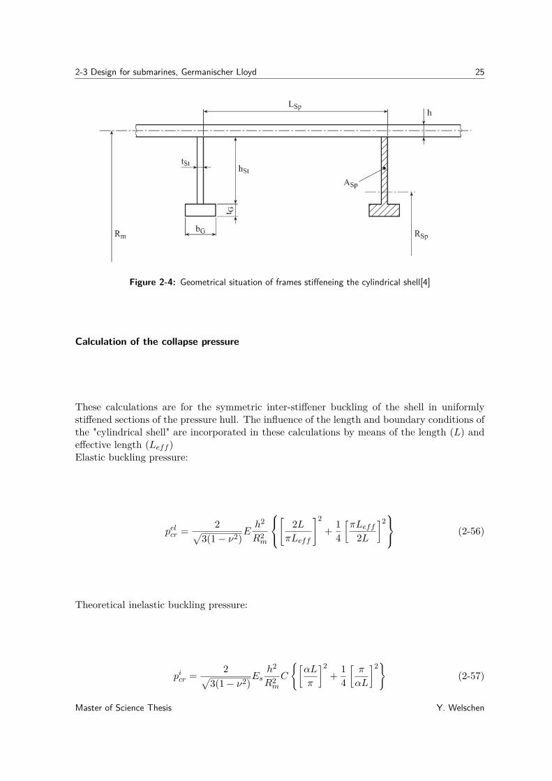
Of which all dimension are given in figure 2-4.The mean membrane stress in longitudinal, circumferential direction between and at framesare respectively:
σMx = −pRm2h (2-52)
σMϕ,m = EwmRm
+ νσMx (2-53)
σMϕ,Sp = EwSpRm
+ νσMx (2-54)
The circumferential stress in the frame σSp follows from the radial deflection:
σSp = EwSpR
(2-55)
where R is the radius that the stress depends on.
Y. Welschen Master of Science Thesis
2-3 Design for submarines, Germanischer Lloyd 25
Figure 2-4: Geometrical situation of frames stiffeneing the cylindrical shell[4]
Calculation of the collapse pressure
These calculations are for the symmetric inter-stiffener buckling of the shell in uniformlystiffened sections of the pressure hull. The influence of the length and boundary conditions ofthe "cylindrical shell" are incorporated in these calculations by means of the length (L) andeffective length (Leff )Elastic buckling pressure:
pelcr = 2√3(1− ν2)
Eh2
R2m
[
2LπLeff
]2
+ 14
[πLeff
2L
]2 (2-56)
Theoretical inelastic buckling pressure:
picr = 2√3(1− ν2)
Esh2
R2m
C
{[αL
π
]2+ 1
4
[π
αL
]2}
(2-57)
Master of Science Thesis Y. Welschen

26 Buckling design methods
Where:
α =4
√√√√√3(A2A1− ν2
pA2
12A2
1
)R2mh
2 (2-58)
C =
√√√√A1A2 − ν2pA
212
1− ν2p
(2-59)
νp = 0.5− EsE
(0.5− ν) (2-60)
Es = σνεν
(2-61)
Et = dσνdεν
(2-62)
A1 = 1− 1− Et/Es4(1− ν2
p)K2H[(2− νp)− (1− 2νp)k]2 (2-63)
A2 = 1− 1− Et/Es4(1− ν2
p)K2H[(1− 2νp)− (2− νp)k]2 (2-64)
A12 = 1 + 1− Et/Es4νp(1− ν2
p)K2H[(2− νp)− (1− 2νp)k][(1− 2νp)− (2− νp)k] (2-65)
H = 1 + 1− Et/Es4(1− ν2
p)K2
{[(2− νp)− (1− 2νp)k]2 − 3(1− ν2
p)}
(2-66)
k =σMϕ,mσMx
(2-67)
K2 = 1− k = k2 (2-68)
For instability it has to be proven, that the collapse pressure, which is the theoretical inelas-tic buckling pressure multiplied by the reduction factor r, is at least equal to the calculationpressure of the pressure hull.
picr · r ≥ Collapse diving pressure (CDP ) (2-69)
With the reduction factor:
r = 1− 0.25e− 1
2
(pelcrpicr−1)
(2-70)
2-3-3 Evaluation
This paragraphs lists the strengths and weaknesses of the explained design method.
Strengths:
• Fabrication tolerances like out of roundness are included in these rules.
• Resistance safety factors are listed and described for different materials, which meansthat no additional codes or national annexes are required.
Y. Welschen Master of Science Thesis

2-3 Design for submarines, Germanischer Lloyd 27
• Stress strain ratio is included.
• Assumptions are made that both elastic and elastic-plastic behaviour can occur.
• It is reasonably easy to exclude of the influence of stiffeners in the calculations.
• Symmetric and asymmetric buckling between frames are considered.
Weaknesses:
• The code works according to the WSD format, which is considered to be more conser-vative than the LRFD format.
• collapse pressure is calculated for conical stiffened shells.
• The calculated structure is more complex than a cylindrical shell.
• Overall collapse of the design is regarded as buckling of the hull structure betweenbulkheads, deep frames or dished ends.
• Hydro-static pressures on submarines is not evenly distributed around the structure dueto wave forces.
• Factors in stress calculations are without influence of stiffeners.
• Submarines are built up out of more plates, and therefore more welds than cylindricalshells for suction buckets.
Resistance factors:The factors that account for imperfections and residual stresses are included in the bucklingresistance calculations. The buckling resistance is dependent on the characteristic bucklingstress and the partial material factor.The allowable stress safety factors A and B as can be found in 2-8:
A = 2.7B = 1.7
The reduction factor r for the collapse pressure is calculated as in 2-70
Tolerance ranges are summarized below:Out of roundness:
ui ≤ ±0,2% of the nominal diameter
Overlapping of plate sides at seams:
• At least 87 % of the nominal thickness of the thinnest plate for circumferential seams
• At least 92 % of the nominal thickness of the thinnest plate for longitudinal seams.
Master of Science Thesis Y. Welschen

28 Buckling design methods
Weld sinkage for respectively circumferential and longitudinal seams:
x1 + x22 ≤ 5mm
x1 + x22 ≤ 3mm
With a distance between x1and x2 of Tmax + 20mm
Damage to plate surfaces may me as deep as:
0.2 + 0.04t ≤ 1mm
2-4 Buckling strength of shells, DNV-GL
DNV-GL’s Recommended Practice (RP) for the buckling strength of shells covers the bucklingstability of shell structures, while using the load and resistance factor design format (LRFD)for closed cylinders and cylindrical shells. This means that the material- (resistance) and loadfactors are used as safety factors.
2-4-1 Code application & design tolerances
The following assumptions are made:
• Shell edges are supported by ring frames, bulk heads or end closure
• The radius that is used in the calculations of this recommended practice is the mid-planeradius.
This RP shows methods for analyzing different buckling modes, which are considered to besemi-empirical.This is substantiated by some cases that show no existing conformity between experimen-tal and theoretical buckling loads. This disparity is caused by geometric imperfections andresidual stresses in fabricated structures. These imperfections and stresses are not includedas explicit parameters in equations for buckling resistance.This implies that methods for buckling analysis are established by an assumed level of im-perfections.DNV OS-C401[5] gives the tolerance requirements that reflect this level of imperfections. Thegeometrical and stress constraints given in this RP for a cylindrical shell after its fabrication,are discussed below.The degree of cold deformation of structural elements shall be less than 5%, unless otherwiseagreed and qualified.The plastic deformation e may be calculated by the following, simplified formula for single-curvature deformation.Cold rolling or pressing of plates to cylindrical forms:
e = t
2Rc + t100% (2-71)
Y. Welschen Master of Science Thesis

2-4 Buckling strength of shells, DNV-GL 29
where:t = material thicknessRc = forming radius
For maximum fabrication tolerances as shown below, reference is made to the IACS Rec.47Shipbuilding and Repair Standard[10].Cylindrical structure diameter:
Standard ±D/200 mm max. + 5 mmLimit ±D/150 mm max. 7.5 mm
Table 2-9: Recommended values for cylindrical structure diameter tolerance
The limit to ovality of the cylindrical structure is:
dmax - dmin ≤ 0.02 x dmax
For assembly of curved plates:
Item Standard Limit RemarksLength and Breadth ± 4 mm ± 8 mm measuredDistortion ± 10 mm ± 20 mm along theSquareness ± 10 mm ± 15 mm girthDeviation of interior members from plate 5 mm ± 10 mm
Table 2-10: Tolerance for curved plate assembly
Straightness of members shall be within the tolerances described below:Max. deviation from the nominal radius measured at ring stiffener or bulkhead
δ = (ra − r) = 0.005r
Where:ra = actual distance from the cylinder axis to the shell wallr = nominal radius of the shell
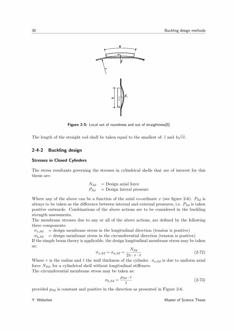
For local out of roundness and local out of straightness the tolerance is a maximum imper-fection of: δ = 0.01g
1+g/r (see figure 2-5).Where:g = length of template or rod.
The length of the circular template shall be the smallest of: s, 1.15√l√rt and π r2 .
Where:s = stiffener spacing (of longitudinal stiffeners)l = distance between rings or bulkhead
Master of Science Thesis Y. Welschen
30 Buckling design methods
Figure 2-5: Local out of roundness and out of straightness[5]
The length of the straight rod shall be taken equal to the smallest of: l and 4√rt.
2-4-2 Buckling design
Stresses in Closed Cylinders
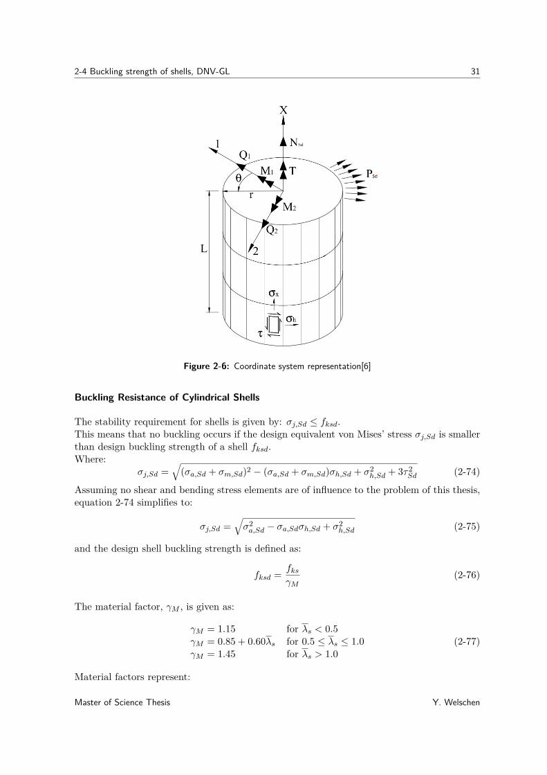
The stress resultants governing the stresses in cylindrical shells that are of interest for thisthesis are:
NSd = Design axial forcePSd = Design lateral pressure
Where any of the above can be a function of the axial co-ordinate x (see figure 2-6). PSd isalways to be taken as the difference between internal and external pressures, i.e. PSd is takenpositive outwards. Combinations of the above actions are to be considered in the bucklingstrength assessments.The membrane stresses due to any or all of the above actions, are defined by the followingthree components:σx,Sd = design membrane stress in the longitudinal direction (tension is positive)σh,Sd = design membrane stress in the circumferential direction (tension is positive)
If the simple beam theory is applicable, the design longitudinal membrane stress may be takenas:
σx,Sd = σa,Sd = NSd
2π · r · t (2-72)
Where r is the radius and t the wall thickness of the cylinder. σa,Sd is due to uniform axialforce NSd, for a cylindrical shell without longitudinal stiffeners.The circumferential membrane stress may be taken as:
σh,Sd = pSd · rt
(2-73)
provided pSd is constant and positive in the direction as presented in Figure 2-6.
Y. Welschen Master of Science Thesis
2-4 Buckling strength of shells, DNV-GL 31
Figure 2-6: Coordinate system representation[6]
Buckling Resistance of Cylindrical Shells
The stability requirement for shells is given by: σj,Sd ≤ fksd.This means that no buckling occurs if the design equivalent von Mises’ stress σj,Sd is smallerthan design buckling strength of a shell fksd.Where:
σj,Sd =√
(σa,Sd + σm,Sd)2 − (σa,Sd + σm,Sd)σh,Sd + σ2h,Sd + 3τ2
Sd (2-74)
Assuming no shear and bending stress elements are of influence to the problem of this thesis,equation 2-74 simplifies to:
σj,Sd =√σ2a,Sd − σa,Sdσh,Sd + σ2
h,Sd (2-75)
and the design shell buckling strength is defined as:
fksd = fksγM
(2-76)
The material factor, γM , is given as:
γM = 1.15 for λs < 0.5γM = 0.85 + 0.60λs for 0.5 ≤ λs ≤ 1.0γM = 1.45 for λs > 1.0
(2-77)
Material factors represent:
Master of Science Thesis Y. Welschen
32 Buckling design methods
• Possible unfavourable deviations in the resistance of materials from the characteristicvalues
• Possible reduced resistance of the materials in the structure, as a whole, as comparedwith the characteristic values deduced from test specimens.
This implies that the material factors are based on empirical grounds.The characteristic buckling strength, fks is:
fks = fy√1 + λ
4s
(2-78)
Where the reduced shell slenderness is:
λ2s = fy
σj,Sd
[σa0,SdfEa
+ σm0,SdfEm
+ σh0,SdfEh
+ τSdfEτ
](2-79)
Assuming no shear and bending stress elements are of influence to the problem of this thesis,equation 2-80 simplifies to:
λ2s = fy
σj,Sd
[σa0,SdfEa
+ σh0,SdfEh
](2-80)
With:
σa0,Sd ={
0 ifσa,Sd ≥ 0−σa,Sd ifσa,Sd < 0
}(2-81)
σh0,Sd ={
0 ifσh,Sd ≥ 0−σh,Sd ifσh,Sd < 0
}(2-82)
and the elastic buckling strength is:
fE = Cπ2E
12(1− ν2)
(t
l
)2(2-83)
based on a shell supported on each side by stiffeners or bulkheads, the reduced bucklingcoefficient may be calculated as:
C = ψ
√1 +
(ρξ
ψ
)2(2-84)
The curvature parameter Z is defined as:
Zl = l2
rt
√1− ν2 (2-85)
Where:l = the buckling lengthν = the poisson ratio
ψ, ξ and ρ are given in table 2-11
Y. Welschen Master of Science Thesis

2-4 Buckling strength of shells, DNV-GL 33
ψ ξ ρ
Axial stress 1 0.702Zl 0.5(1 + r
150t)−0.5
Lateral pressure1) 4 1.04√Zl 0.6
Hydrostatic pressure2) 2 1.04√Zl 0.6
NOTE 1: Lateral pressure coefficient ψ= 4, accounts for lateral pressure on the cylindershell only.NOTE 2: Hydrostatic pressure, ψ= 2, accounts for the effect of the lateral pressure on thecylinder shell and the end cap (i.e. axial stresses due to pressure on the end cap shall notbe included in the calculation of axial stress, σa).
Table 2-11: Buckling coefficients for unstiffened cylindrical shells mode a)Shell buckling
For lateral or hydrostatic pressure the following verification check should be done:
l
r> 2.25
√r
t(2-86)
If equation 2-86 is valid, then:
fEh = 0.25E(t
r
)2(2-87)
Column buckling
The column buckling strength should be assessed if:(kLcic
)2≥ 2.5E
fy(2-88)
where:k = effective length factor (dependent on column end restraints)LC = total cylinder lengthiC =
√IC/AC = radius of gyration of cylinder section
IC = moment of inertia of the complete cylinder section (about weakest axis)including longitudinal stiffeners/internal bulkheads if any
AC = cross sectional area of complete cylinder section; including longitudinalstiffeners/internal bulkheads if any.
Since equation 2-88 is never valid for suction buckets as discussed in this thesis, this sectionof the DNV-GL code will not be discussed further.
2-4-3 Evaluation
This paragraphs lists the strengths and weaknesses of the explained design method.
Strengths:
• The code works according to the LRFD format, which is considered less conservativethan the Working Stress Design (WSD)
Master of Science Thesis Y. Welschen
34 Buckling design methods
• Imperfections, non-linearities, residual stresses & possible interaction between local andglobal buckling are accounted for.
• Buckling is analysed for combined stresses, which is applicable to the thesis objective.
• Design longitudinal stress is calculated according to the well known Beam theory (Euler-Bernoulli/Timoshenko)
• Stresses in shells near bulkheads can be checked for local yielding, based on von Mises& circumferential stress at bulkhead with respect to its thickness (tb)
• Hydrostatic pressure accounts for the effect of lateral pressure on shell and end cap
• Accounted for interaction between shell and column buckling
Weaknesses:
• The code is for closed cylinders and cylindrical shells, which are not accurate enoughrepresentations of suction buckets. A cylindrical shell that is closed at one side wouldbe more appropriate.
• Geometric imperfections and residual stresses are not included as explicit parametersin equations for buckling resistance.
• A simplified formula is used for single curvature deformation, that can be used forresidual stress calculation.
Load and resistance factors:The factors that account for imperfections and residual stresses are included in the bucklingresistance calculations. In addition, this RP works with design stresses. This means thatthe chosen load factors (according to DNV-os-C101[22] or other relevant code) are alreadyincluded in the loads that are used in the calculations.The design buckling resistance is dependent on the characteristic buckling strength and thepartial material factor γM1:
1.15 ≤ γM1 ≤ 1.45
The buckling strength is dependent on the reduced shell slenderness, which on its turn isdependent on:
• Stress dependent shell buckling coefficients
• The buckling length
• The curvature parameter
Limits for application & tolerance ranges are summarized below:Cold deformation:
e ≤ 5%
Y. Welschen Master of Science Thesis

2-5 Buckling and Ultimate Strength Assessment for Cylindrical Shells, ABS 35
Standard ±D/200 mm max. + 5 mmLimit ±D/150 mm max. 7.5 mm
Table 2-12: Recommended values for diameter tolerance[10]
Cylindrical structure diameter:Ovality limit:
dmax - dmin ≤ 0.02 x dmax
Tolerance rates for assembly of curved plates:
Item Standard Limit RemarksLength and Breadth ± 4 mm ± 8 mm measuredDistortion ± 10 mm ± 20 mm along theSquareness ± 10 mm ± 15 mm girthDeviation of interior members from plate 5 mm ± 10 mm
Table 2-13: Tolerance for curved plate assembly
Straightness of members tolerance:
δ = (ra − r) = 0.005r
For local out of roundness and local out of straightness tolerance:
δ ≤ 0.01g1+g/r
2-5 Buckling and Ultimate Strength Assessment for CylindricalShells, ABS
The ABS has written a guide for Buckling and Ultimate Strength Assessment for OffshoreStructures [23], while using the working stress design (WSD) method.This guide states that the amplitude and shape of any imperfections in a cylinder have a bigimpact on the buckling strength.Nearly all effects of imperfections as initial distortions, misalignment and residual stresses dueto welding are incorporated in the formulations of this guide. The imperfection and toleranceson which the strength criteria of this guide are based on, can for example be found in [10]and are equal to those in section 2-4 about the DNV-GL RP.The primary loading conditions that are considered are static and combined loading in normaloperations, as defined in [23].
Master of Science Thesis Y. Welschen

36 Buckling design methods
2-5-1 Buckling design
This guide uses a maximum allowable strength utilization factor (η) for application to thepredicted strength. η is the inverse of a safety factor, defined in 2-89.When assuming normal operation of an offshore installation, the maximum allowable strengthutilization factor is to take the following value:
η = 0.60ψ (2-89)
Where the adjustment factor ψ for shell buckling of stiffened shells is:
ψ = 0.833 if σCij ≤ 0.55σ0 (2-90)ψ = 0.629 + 0.371σCij/σ0 if σCij > 0.55σ0 (2-91)
Where :σCij = critical buckling stress of cylindrical shell, which is representing the buckling stressesfor axial compression and external pressure (see eq. 2-92 & 2-96)σ0 = specified minimum yield point, N/cm2.The critical buckling stress for axial compression is calculated as follows:
[σCxR] ={
σExR for σExR ≤ Prσ0
σ0[1− Pr(1− Pr) σ0
σExR
]for σExR > Prσ0
(2-92)
with:Pr = proportional linear elastic limit of the structure, 0.6 for steelσExR = ρxRCσCExR = elastic compressive buckling stress for an imperfect cylindrical shellσCExR = 0.605Etr = classical compressive buckling stress for a perfect cylindrical shellC = length dependent coefficient
={
1.0 for z ≥ 2.851.425/z + 0.175z for z < 2.85 (2-93)
ρxR = nominal or lower bound knock-down factor to allow for shape imperfections
=
0.75 + 0.003z
(1− r
300t)
for z < 10.75− 0.142(z − 1)0.4 + 0.003z
(1− r
300t)
for 1 ≤ z < 200.35− 0.0002 rt for 20 ≤ z
(2-94)
(2-95)
with:z = Batdorf parameter l2
rt
√1− ν2
l = length between adjacent ring stiffeners (unsupported)r = mean radius of cylindrical shellt = thickness of cylindrical shellE = modulus of elasticity, 2.06 x 10⁷ N/cm2 for steelν = Poisson’s ratio, 0.3 for steel
Y. Welschen Master of Science Thesis
2-5 Buckling and Ultimate Strength Assessment for Cylindrical Shells, ABS 37
The critical buckling stress for external pressure:
σCθR = ΦσEθR (2-96)
where the elastic hoop buckling stress for a cylindrical shell that has a ring stiffener at eachend, is:
σEθR = ρθRqCEθR(r + 0.5t)
t(2-97)
andΦ = plasticity reduction factor
= 1 for ∆ ≤ 0.55= 0.45
∆ + 0.18 for 0.55 < ∆ ≤ 1.6= 1.31
1+1.15∆ for 1.6 < ∆ < 6.25= 1/∆ for ∆ ≥ 6.25
(2-98)
with∆ = σEθR/σ0 (2-99)
ρθR = 0.8 = nominal or lower bound knock-down factor to allow for shape imperfections.qCEθR = Elastic buckling pressure, which is calculated as follows:
1.27EA1.18L +0.5
(tr
)2for AL ≤ 2.5
0.92EAL
(tr
)2for 2.5 < AL ≤ 0.208
(rt
)0.836C−1.061
p E(tr
)3for 0.208
(rt
)< AL ≤ 2.85
(rt
)0.275E
(tr
)3for 2.85
(rt
)< AL
(2-100)
AL =√z
(1− ν2)1/4 − 1.17 + 1.068k (2-101)
Cp = AL/(r/t) (2-102)k = 0.5 for hydrostatic pressure (2-103)
For the buckling limit state of unstiffened cylindrical shells subjected to axial compressionand external pressure the following strength criterion is to be satisfied:(
σxησCxR
)2− ϕR
(σx
ησCxR
)(σθ
ησCθR
)+(
σθησCθR
)2≤ 1 (2-104)
Where the longitudinal stress σx in accordance with beam theory may be taken as:σa = stress due to axial force
σa = P
2πrt (2-105)
The hoop stress σθ may be taken as:
σθ = q(r + 0.5t)t
(2-106)
And the coefficient for interaction between longitudinal and hoop stresses is:
ϕR = σCxR + σCθRσ0
− 1.0 (2-107)
Master of Science Thesis Y. Welschen

38 Buckling design methods
with:P = axial forcer = mean radius of cylindrical shellt = thickness of cylindrical shellq = external pressure
2-5-2 Evaluation
This paragraphs lists the strengths and weaknesses of the explained design method.
Strengths:
• An estimate of the average strength of the considered components is provided, whileachieving the lowest standard deviation when compared with nonlinear analyses andmechanical tests
• Generally, the effects of imperfections in the form of initial distortions, misalignment’sand weld-induced residual stresses are implicitly incorporated in the buckling formula-tions
Weaknesses:
• The method works according to the WSD format, which is considered more conservativethan the LRFD method.
• This guide gives a adjustment factor based on the presence of stiffeners.
• For stress calculations of unstiffened shells, ring stiffened shells are used. This is notvery accurate.
Allowable strength utilization factors:Since existing methodologies and their safety factors are the base of the criteria in this guide,it can be concluded that it is based on calculations that are semi-empirically defined.
The maximum allowable strength utilization factor:
η = 0.60ψ
The adjustment factor ψ:
ψ = 0.833 if σCij ≤ 0.55σ0
ψ = 0.629 + 0.371σCij/σ0 if σCij > 0.55σ0
Tolerance ranges used in this guide:The tolerances are taken as in the IACS Rec.47 Shipbuilding and Repair Standard [10] andare therefore the same as discussed in section 2-4.Resistance factors and parameters:Proportional linear elastic limit:
Y. Welschen Master of Science Thesis

2-6 Conclusion 39
Pr = 0.6
Length dependent coefficient for elastic compressive buckling stress for an imperfect cylindricalshell:
C ={
1.0 for z ≥ 2.851.425/z + 0.175z for z < 2.85
Classical compressive buckling stress for a perfect cylindrical shell:
σCExR = 0.605Etr
Nominal or lower bound knock-down factor for axial compression:
ρxR =
0.75 + 0.003z
(1− r
300t)
for z < 10.75− 0.142(z − 1)0.4 + 0.003z
(1− r
300t)
for 1 ≤ z < 200.35− 0.0002 rt for 20 ≤ z
Φ = plasticity reduction factor= 1 for ∆ ≤ 0.55= 0.45
∆ + 0.18 for 0.55 < ∆ ≤ 1.6= 1.31
1+1.15∆ for 1.6 < ∆ < 6.25= 1/∆ for ∆ ≥ 6.25
Nominal or lower bound knock-down factor for external pressure:
ρθR = 0.8
Factors in equations for elastic buckling pressure:
1.27EA1.18L +0.5
(tr
)2for AL ≤ 2.5
0.92EAL
(tr
)2for 2.5 < AL ≤ 0.208
(rt
)0.836C−1.061
p E(tr
)3for 0.208
(rt
)< AL ≤ 2.85
(rt
)0.275E
(tr
)3for 2.85
(rt
)< AL
AL =√z
(1− v2)1/4 − 1.17 + 1.068k
Cp = AL/(r/t)k = 0.5 for hydrostatic pressure
2-6 Conclusion
When comparing the buckling design methods in the previous sections of this chapter, it isclear that the biggest difference is in the way that safety factors and parameters are used.
Master of Science Thesis Y. Welschen

40 Buckling design methods
Factors and tolerances for imperfections
All the methods include factors and tolerances for imperfections like out of roundness andlocal out of roundness (or dimples). This implies that methods for buckling analysis areestablished by an assumed level of imperfections. In addition, they are all considered to besemi-empirical.Eurocode also includes eccentricity, a temperature range and radius to thickness ratio range.Germanischer Lloyd doesn’t include any additional geometrical tolerances and only accountsfor misalignment of plates and dimples at welds.DNV-GL also includes tolerances for cold deformation, ovality, diameter and straightness inits method.ABS additionally incorporates the effects of imperfections in the form of weld-induced residualstresses in the buckling formulations.Furthermore the same tolerances are used in ABS as in the DNV-GL method.
Distinct differences between codes
The Eurocode uses the LRFD method for buckling strength calculations, this is important forthe approach of this thesis because it is based on the nominal strength of cylinders. This codeincorporates three fabrication quality classes to define safety factors and parameters. Thisgives extra design options, which can make the calculations more design specific. However,the code does not clearly state why the buckling interaction parameters are calculated withthe given values in their formula. This also counts for the plastic range for interaction, theinteraction exponent, the limit relative slenderness and the fabrication quality parameters.The Eurocode is mostly used for Civil engineering sector and not for the offshore sector. Fromother Eurocodes it can be concluded that the used design values in this code are establishedby means of empirical relationships with measured physical properties or from previous ex-perience. And the partial factors are based on statistical evaluation of experimental data andfield observations.
The Germanischer Lloyd uses the WSD method for buckling strength calculations. This isnot favourable for the approach of this thesis, because it is based on the nominal strengthof cylinders. Besides this, the WSD method is considered to be more conservative than theLRFD method. Another disadvantage of this method is, that the considered shell for designagainst buckling of submarine hulls is more complex than a unstiffened cylindrical shell. Thismakes it not suitable enough for the problem described in this thesis.Reasons for this complexity are stated below:
• The method is based on symmetric and asymmetric buckling between stiffener frames.
• Overall collapse of the design is regarded as buckling of the hull structure betweenbulkheads, deep frames or dished ends.
• Submarine hulls are built from more plate components than shells of suction buckets
DNV-GL also uses the LRFD method for buckling strength calculations, this is important forthe approach of this thesis because it is based on the nominal strength of cylinders. Their
Y. Welschen Master of Science Thesis
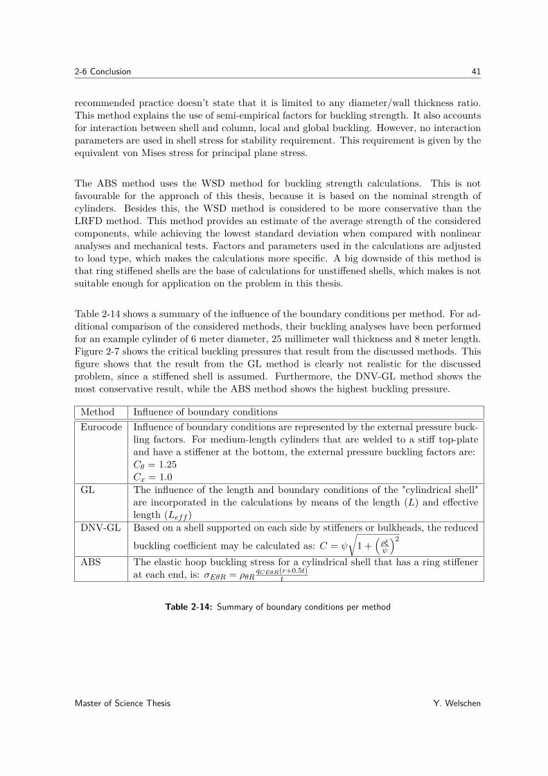
2-6 Conclusion 41
recommended practice doesn’t state that it is limited to any diameter/wall thickness ratio.This method explains the use of semi-empirical factors for buckling strength. It also accountsfor interaction between shell and column, local and global buckling. However, no interactionparameters are used in shell stress for stability requirement. This requirement is given by theequivalent von Mises stress for principal plane stress.
The ABS method uses the WSD method for buckling strength calculations. This is notfavourable for the approach of this thesis, because it is based on the nominal strength ofcylinders. Besides this, the WSD method is considered to be more conservative than theLRFD method. This method provides an estimate of the average strength of the consideredcomponents, while achieving the lowest standard deviation when compared with nonlinearanalyses and mechanical tests. Factors and parameters used in the calculations are adjustedto load type, which makes the calculations more specific. A big downside of this method isthat ring stiffened shells are the base of calculations for unstiffened shells, which makes is notsuitable enough for application on the problem in this thesis.
Table 2-14 shows a summary of the influence of the boundary conditions per method. For ad-ditional comparison of the considered methods, their buckling analyses have been performedfor an example cylinder of 6 meter diameter, 25 millimeter wall thickness and 8 meter length.Figure 2-7 shows the critical buckling pressures that result from the discussed methods. Thisfigure shows that the result from the GL method is clearly not realistic for the discussedproblem, since a stiffened shell is assumed. Furthermore, the DNV-GL method shows themost conservative result, while the ABS method shows the highest buckling pressure.
Method Influence of boundary conditionsEurocode Influence of boundary conditions are represented by the external pressure buck-
ling factors. For medium-length cylinders that are welded to a stiff top-plateand have a stiffener at the bottom, the external pressure buckling factors are:Cθ = 1.25Cx = 1.0
GL The influence of the length and boundary conditions of the "cylindrical shell"are incorporated in the calculations by means of the length (L) and effectivelength (Leff )
DNV-GL Based on a shell supported on each side by stiffeners or bulkheads, the reduced
buckling coefficient may be calculated as: C = ψ
√1 +
(ρξψ
)2
ABS The elastic hoop buckling stress for a cylindrical shell that has a ring stiffenerat each end, is: σEθR = ρθR
qCEθR(r+0.5t)t
Table 2-14: Summary of boundary conditions per method
Master of Science Thesis Y. Welschen

42 Buckling design methods
Figure 2-7: Critical cylinder buckling pressures according to the different methods
Method selection
Based on the reasons discusses in the previous subsection and the method properties summa-rized in Table 2-15, the DNV-GL method will be used as a reference method for the bucklingproblem in this thesis.In addition to the previous evaluation there are some more practical reasons for choosing theDNV-GL method. DNV-GL writes recommended practices that are mainly based on experi-ence in offshore projects in the North sea. The market for offshore wind energy is still verybig in the North sea and will keep on growing.Since SPT offshore is a Dutch based company, they are close to and experienced in offshoreNorth sea projects and will therefore have a big chance in winning future tenders in that area.This standard is also widely used and recognized in the offshore industry.SPT offshore already uses the DNV-GL method for design against buckling failure. Thismeans that they are familiar with the code, which makes it easier to discuss the code withSPT and use it for the problem in this thesis.
Method D/t Designmethod
material (fm)/safety factor(fs)
strength criterion
Eurocode 40 ≤ D/t ≤ 10000 LRFD As in nationalcode(fm ≥ 1.1)
(σx,Edσx,Rd
)kx− ki
(σx,Edσx,Rd
)(σθ,Edσθ,Rd
)+(σθ,Edσθ,Rd
)kθ≤ 1
GL n/a (t ≥ 6mm) WSD 1.7 ≤ fs ≤ 2.7 2√3(1− ν2)
Esh2
R2m
C
{[αL
π
]2+ 1
4
[ παL
]2}· r ≤ σMxϕ,m
DNV-GL D/t > 12 LRFD 1.15 ≤ fm ≤1.45
√σ2a,Sd − σa,Sdσh,Sd + σ2
h,Sd ≤ fksd
ABS 135 ≤ D/t ≤ 1000 WSD 2 ≤ fs ≤ 2.65(
σxησCxR
)2− ϕR
(σx
ησCxR
)(σθ
ησCθR
)+(
σθησCθR
)2≤ 1
Table 2-15: Short summary of discussed methods
Y. Welschen Master of Science Thesis

Chapter 3
Installation in (non-)layered soils
Some knowledge on soil mechanics is required to model all loads on suction buckets duringinstallation. In this chapter an introduction to two different soil types will be given. Inaddition, the geotechnical aspects of installation in those two different soil types will bediscussed. Following these sections, the installation in layered soil will be discussed.
3-1 General soil behaviour
Since suction buckets are usually installed in soils that contain predominantly clay or sand,these are the two soil types that will be discussed in this chapter. This thesis covers soilbehaviour below the seabed, therefore throughout this report the soil conditions are consideredto be saturated. This means that all pores and voids between the soil particles are completelyfilled with sea water.Soils reacts differently to stresses than other materials do. This is due to the fact that theparticles can move relative to each other. This holds for both of the soils discussed in thissection. Another outstanding property of soil is that it is not linear elastic. An example ofthis is that soil reacts stiffer under pressure (see figure 3-1). This stiffening of soil is causedby decreasing void size between particles, which makes it possible for the particles to have abigger contact surface.Due to the fact that the voids between grains in saturated soils are filled with water, theprinciple of effective stress is introduced. When the pressure in the water in a void is p andthe stress between the surrounding particles including that water pressure is σ, the effectivestress in the soil is:
σ′ = σ − p (3-1)
This principle shows that a part of the stress in a soil is transferred by water. The forcesbetween sand particles are different than between clay particles. The following subsectionwill therefore discuss specific sand and clay properties.
Master of Science Thesis Y. Welschen

44 Installation in (non-)layered soils
Figure 3-1: Change in stiffnes to compression
3-1-1 Sand
Sandy soils are defined as non-cohesive soils with grain sizes from 0.063 mm to 2 mm[24].Sand is generally well permeable and, when pre-loaded by compression, quite stiff. Sandparticles can have different shapes, from sharp edged to more rounded grains (see figure 3-2).The friction and strength of sand is dependent on the shape of the particles and the packingof the grains. The packing of grains can be expressed as the density or void ratio of the soil.These depend on the volume of the pores and the volume of the grains of the soil.Non-cohesive soil like sand cannot transfer tensile stresses, it can only transfer compressivenormal stresses. However, when the shear stresses are small compared to normal stressesthey can also be transmitted [24]. Depending on the loading period, sand behaviour can beclassified as drained or undrained.Drained behaviour can be explained as the response of a loaded sand structure while the porewater is able to flow in and out of that structure. This means that the loading is longerthan the time that the water needs to flow through the soil. The boundary condition for astructure with drained behaviour is:
∆p = 0 (3-2)
Consequently, undrained behaviour, is the response of a loaded sand structure while the porewater is not able to flow in and out of that sand formation. If soil is loaded very shortly, itwill behave undrained. This means that there is no time for the pore water to drain out ofthe soil. The boundary condition of a sand structure that behaves undrained is:
∆p = ∆σ (3-3)
When loading a sand soil that is densely packed and an individual grain is thus well wrappedby other grains, dilatation may occur. This occurs when a grain stack is loaded by shear,which causes the grains to shove and roll over each other. This can only happen if the grainsslightly move apart, which increases the volume between the grains. This volume expansioncauses a large local under-pressure in the voids. When a soil is completely saturated, waterwill want to flow towards the expanded voids. If the surrounding soil is not permeable enoughor if it is closed off from the surrounding water (undrained behaviour), the effective stresseswill increase due to the decreasing water pressure. This means that the loaded soil has a
Y. Welschen Master of Science Thesis
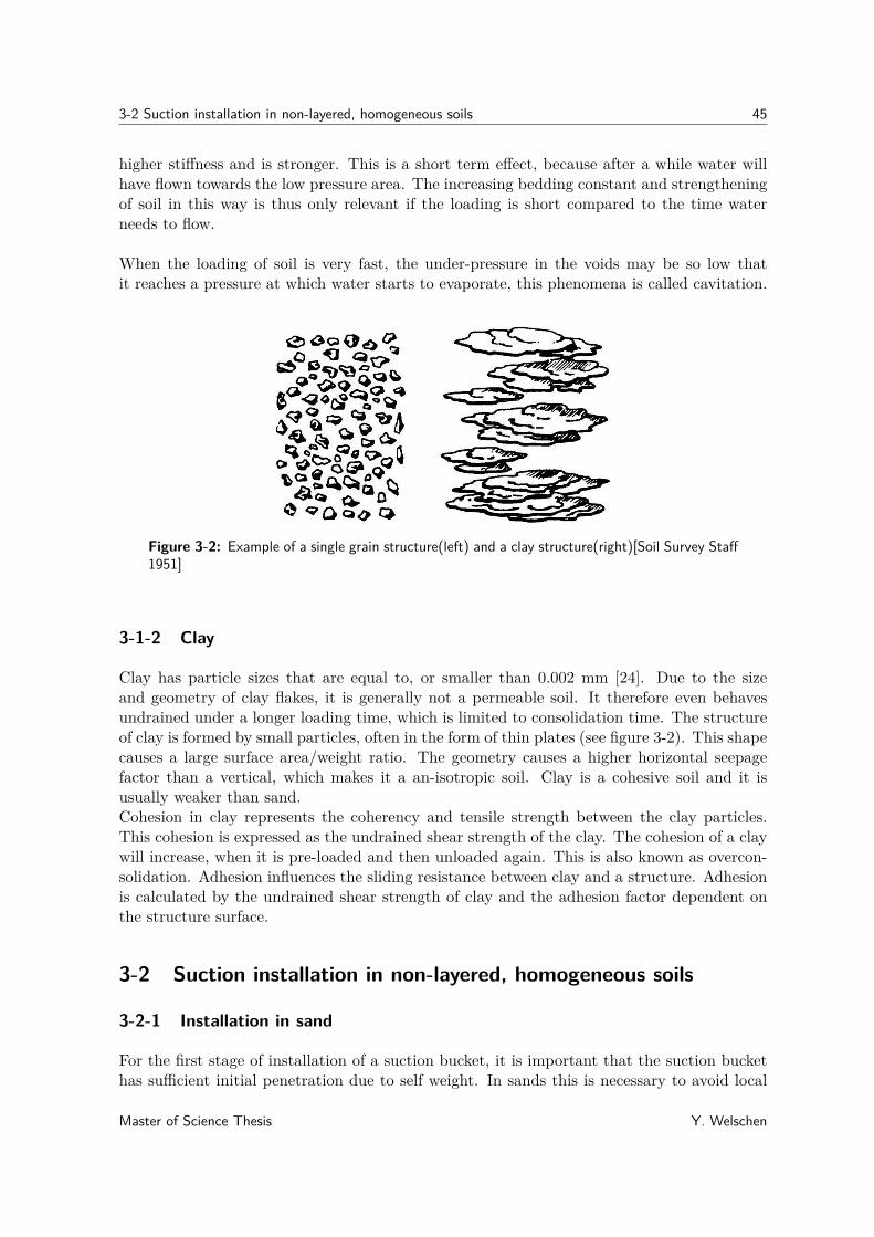
3-2 Suction installation in non-layered, homogeneous soils 45
higher stiffness and is stronger. This is a short term effect, because after a while water willhave flown towards the low pressure area. The increasing bedding constant and strengtheningof soil in this way is thus only relevant if the loading is short compared to the time waterneeds to flow.
When the loading of soil is very fast, the under-pressure in the voids may be so low thatit reaches a pressure at which water starts to evaporate, this phenomena is called cavitation.
Figure 3-2: Example of a single grain structure(left) and a clay structure(right)[Soil Survey Staff1951]
3-1-2 Clay
Clay has particle sizes that are equal to, or smaller than 0.002 mm [24]. Due to the sizeand geometry of clay flakes, it is generally not a permeable soil. It therefore even behavesundrained under a longer loading time, which is limited to consolidation time. The structureof clay is formed by small particles, often in the form of thin plates (see figure 3-2). This shapecauses a large surface area/weight ratio. The geometry causes a higher horizontal seepagefactor than a vertical, which makes it a an-isotropic soil. Clay is a cohesive soil and it isusually weaker than sand.Cohesion in clay represents the coherency and tensile strength between the clay particles.This cohesion is expressed as the undrained shear strength of the clay. The cohesion of a claywill increase, when it is pre-loaded and then unloaded again. This is also known as overcon-solidation. Adhesion influences the sliding resistance between clay and a structure. Adhesionis calculated by the undrained shear strength of clay and the adhesion factor dependent onthe structure surface.
3-2 Suction installation in non-layered, homogeneous soils
3-2-1 Installation in sand
For the first stage of installation of a suction bucket, it is important that the suction buckethas sufficient initial penetration due to self weight. In sands this is necessary to avoid local
Master of Science Thesis Y. Welschen

46 Installation in (non-)layered soils
piping effects. Piping can be explained as water canals through the sand, caused by internalerosion of the soil[25]. This results in a direct connection between the inside and outsidewater of the bucket, which consequently means no pressure difference can be created in thebucket.Before the second suction induced installation stage starts, the pumping of water is initiated.This causes a lower pressure inside the suction bucket relative to its surrounding water-pressure. The under-pressure that is created in the suction bucket makes the pore water,near the bottom of the suction bucket, flow into the bucket (see figure 3-3). This flow ofwater passes the tip of the skirt, hereby reducing the tip resistance by decreasing the effectivestress at the tip. This decrease is dependent on the density of the soil. The pumping andwater flow causes the pressure in the bucket to gently drop, which increases the pressuredifference on the bucket and causes the bucket to penetrate itself into the seabed. The bucketpressure keeps dropping until the pore-water and pumping flow are constant. The installationends when the required penetration depth is reached.
Figure 3-3: Groundwater flow during installation in sand(left) and installation in clay(right)
3-2-2 Installation in clay
For the first stage of installation of a suction bucket in clay, it is also important that thesuction bucket has sufficient initial penetration due to self weight. It should be penetrateddeep enough, to make sure that the clay provides a good seal for the shell of the suctionbucket.The second suction induced installation stage, starts when the pumping of water is initiated.This causes a lower pressure inside the suction bucket relative to its surrounding water-pressure. The difference with installation in sand is that, owing to the low permeability,negligible groundwater flow is induced by this under pressure. The under pressure that iscreated in the suction bucket, generates the driving force that is required to penetrate thebucket into the seabed. If the suction pressure is too high, then plug failure can occur. Plugfailure is tensile failure of the soil plug in the bucket at foundation tip level. The installationends when the required penetration depth is reached. When this required depth is reached,the pump is removed from the suction bucket, leaving the differential pressure on the suctionbucket to be zero.
Y. Welschen Master of Science Thesis
3-3 Soil-structure interaction 47
3-3 Soil-structure interaction
When a structure is installed in soil, the two interact with each other. The soil reactions arebelieved to be highly dependent on soil permeability and time[26]. Since sand and clay have adifferent permeability and time dependence, soil-structure interactions are different for sandand clay.The loads that the soil exerts on the skirt of the bucket during installation are the verticaltip and wall resistance, the inner and the outer normal pressure which also provides lateralsupport to the shell.
3-3-1 Suction assisted penetration resistance
As mentioned in Chapter 1, there are two different approaches to predict the soil resistanceduring installation. The first one being the effective stress-approach and the second one beingthe CPT-approach. These approaches can be distinguished by their key-input parameters.For the effective stress approach these are the soil friction angle and effective unit weight,while the CPT-approach uses the cone resistance and shape factors. According to Romp[2013] the best method to predict soil resistance during the self-weight penetration phasefrom an engineering point of view, is the CPT-approach. This is preferred because a singlefactor is used for the relation to the measured resistance. However, Romp additionally statesthat the effective stress approach by Houlsby & Byrne [2005] also describes the stress reduc-tion for suction-assisted installation phase. This makes that approach more useful, but it isnot applicable to layered soils. This is due to the fact that the effective stress approach isonly applicable in sand. In clay the influence of effective stress is negligible and undrainedshear strength is dominating [27]. Some adjustments are therefore made by using a simplifiedHoulsby & Byrne method. The following subsections describe the resistance calculations ac-cording to the effective stress-approach for suction assisted installation in sand [28] and theundrained strength of clay [27]
SandThe installation of a suction bucket in sand is considered to be a drained process. During thesuction assisted phase, the friction on the inside of the skirt is not equal to the friction on theoutside. This is because wall friction in sand is significantly influenced by skirt compartmentwater pressure, decreased by suction, and increased by excess pressure[26].The absolute pressure in the suction bucket can be defined as:
Pi = pa + γwhw − ps (3-4)
On the tip of the bucket, the excess pore pressure is a · ps. The absolute pressure at the tipis therefore:
Pt = pa + γw(hw + h)− a · ps (3-5)
Where (see Figure 3-4):
Master of Science Thesis Y. Welschen

48 Installation in (non-)layered soils
pa = the atmospheric pressure around the suction bucketγw = unit weight of waterhw = height of water above mud lineh = installed depth of suction bucketa = ratio of excess pore pressure at tip of skirt to beneath the baseps = suction in bucket with respect to ambient seabed water pressure
Figure 3-4: Illustration of the pressure parameters during installation in sand
with:
a1(z) = 0.45− 0.36[1− exp
(− h
0.48D
)](3-6)
a(z) = kf · a1(1− a1) + a1 · kf
(3-7)
kf = kiko
(3-8)
Where according to field experience and laboratory test kf ≈ 3[28]. Equations 3-4 and 3-5 show that there are average hydraulic gradients on the outside and inside of the bucket,respectively being: a · ps/γwh (downward) and (1− a)ps/γwh (upward).Assuming the pore water distribution in- and outside the bucket is linear with depth, theeffective stress of soil is calculated while replacing γ′ by γ′+a·ps/h outside and γ′−(1−a)ps/hinside the suction bucket.With:
γ′ = γ − γw (3-9)
Where γ = unit weight of the soil.
Due to these changes in effective unit weight, it is assumed that the internal vertical ef-fective stress is reduced to such an extent, that failure entirely involves inward movementof soil[28]. According to the effective stress method by Houlsby & Byrne[28], the total soil
Y. Welschen Master of Science Thesis

3-3 Soil-structure interaction 49
resistance against installation of the suction bucket that accounts for suction is:
Fv + ps
(πD2
i
4
)=∫ h
0σ′vodz(K tan δ)o(πDo) +
∫ h
0σ′vidz(K tan δ)i(πDi)
+(σ′viNq + γ′tNγ)(πDt)(3-10)
The external and internal vertical effective stresses are respectively calculated as follows:
σ′vo =(γ′ + a · ps
h
)Zo
[exp
(h
Zo
)− 1
](3-11)
σ′vi =[γ′ − (1− a)ps
h
]Zi
[exp
(h
Zi
)− 1
](3-12)
Substituting equations 3-11 and 3-12 into equation 3-10 and solving it results in a soil resis-tance of:
Fv + ps
(πD2
i
4
)=(γ′ + a · ps
h
)Z2o
[exp
(h
Zo
)− 1−
(h
Zo
)](K tan δ)o(πDo)
+[γ′ − (1− a)ps
h
]Z2i
[exp
(h
Zi
)− 1−
(h
Zi
)](K tan δ)i(πDi)
+{[γ′ − (1− a)ps
h
]Zi
[exp
(h
Zi
)− 1
]Nq + γ′tNγ
}(πDt)
(3-13)
Where:Fv = The effective vertical load on the suction bucketDi = The inner diameterDo = The outer diameterD = Mean diametert = Wall thicknessγ′ = the effective unit weight of soilZo = Do(m2 − 1)/(4(K tan δ)o)Zi = Di/(4(K tan δ)i)m = Dm/Do
Dm = Diameter at which shear stress is equal to zeroK = Factor between horizontal and vertical stress in soilδ = Angle of friction between soil and bucket wallNq = Bearing capacity factor for overburdenNγ = Bearing capacity factor for self-weight
Where the factor Nq can be calculated by the classical soil mechanics formula for shallowfoundations by Prandtl[24]. And the factor Nγ can be calculated by the classical soil mechan-ics formula for shallow foundations by for example Brinch Hansen[24].
Due to the complexity of this method, the effective stress method by Houlsby & Byrne willbe used in a simplified form in this thesis. This simplified method ignores the influence ofthe downward friction from the bucket on the vertical soil stress. This means that the termsrepresenting this friction influence, will be excluded from the calculation.
Master of Science Thesis Y. Welschen

50 Installation in (non-)layered soils
Applying this simplification for equation 3-13 results in a total resistance of:
Fv + ps
(πD2
i
4
)=(γ′ + a · pss
h
)h2
2 (K tan δ)o(πDo)
+[γ′ − (1− a)pss
h
]h2
2 (K tan δ)i(πDi) +{[γ′ − (1− a)pss
h
]hNq + γ′tNγ
}(πDt)
(3-14)
The resistance based pressure, that is needed for a cylinder with D = 6m and t = 25m,per installation depth is plotted in Figure 3-5. For this plot the sand has a effective unitweight of γ′ = 10kN/m3 and a friction angle of φ′ = 40◦, which is used to derive the frictionangle δ between the soil and the bucket wall. Where this angle of friction is estimated tobe tan δ = 2/3 tanφ′ according to DNV[29]. The soil pressure coefficient of K = 0.8 isused, which is recommended by API[2000][30]. Figure 3-5 compares the simplified methodof Houlsby & Byrne (where pss = ps) with the method that is used by SPT Offshore. Tocompare both methods properly, the input conditions need to be similar. This is done byusing the same geometry and relating the qc values to the internal friction angle of the sand.Based on field experience of SPT Offshore this results in a qc that increases from 0 to 14.08MPa with increasing penetration depth up to 8 meters.
Figure 3-5: Required suction for installation in sand with reduced soil resistance due to flow
From Figure 3-5 it can be seen that the installation pressure for both methods agree quite wellfor the highest expected SPT values. This means that the simplified Houlsby & Byrne method,gives reasonable results and can be used further in this thesis for installation-pressures insands. Figure 3-6 shows the plot of the required suction for installation in sand without flowof water (undrained, pss = 0) . More installation pressures per depth for different diametersand wall thicknesses can be found in Appendix A. The graphs in this appendix shows thatthe diameter has more influence on the installation-pressure than the wall-thickness.
Y. Welschen Master of Science Thesis

3-3 Soil-structure interaction 51
Figure 3-6: Required suction for installation in undrained sand
ClayThe installation of a suction bucket in clay is considered to be an undrained process. Duringthe suction assisted phase, the friction on the inside of the skirt is believed to be equal tothe friction on the outside[26]. This is due to the undrained strength of clay. This strengthis assumed to increase linearly with depth according to equation 3-15.
su = su0 + ρ · z (3-15)
Where:su = The undrained shear strengthsu0 = The undrained shear strength at mudlineρ = Rate of change of shear strength with depthz = Depth from mudline
As with sand, the pressure in the suction pile during suction assisted installation in clay is:
Pi = pa + γwhw − ps (3-16)
In clay however, the pore water pressure doesn’t vary with depth. Only directly below thetop plate a decrease in pore pressure is found, below the mud-line the pore-water pressure isequal on the in and outside of the suction bucket. This is due to the fact that clay is generallya non-permeable soil, as mentioned before. The resistance during penetration is expressed asthe sum of the adhesion on the in- and outside of the suction bucket and the end bearing ofthe bottom rim. These first two terms are obtained by using usual pile design, the last termis obtained by the classical soil mechanics formula for shallow foundations by Prandtl andfor example Brinch Hansen[24]. According to the method by Houlsby& Byrne[27], the totalresistance of the suction bucket that accounts for suction in clay is:
Fv + ps
(πD2
o
4
)= hαosu1(πDo) + hαisu1(πDi) + (γ′hNq + su2Nc)(πDt) (3-17)
Where:
Master of Science Thesis Y. Welschen

52 Installation in (non-)layered soils
h = installed depth of suction bucketps = suction in bucket with respect to ambient seabed water pressureαo = adhesion factor on the outside of the suction bucketαi = adhesion factor on the inside of the suction bucket
And:
su1 = suo + ρh/2 (3-18)su2 = suo + ρh (3-19)
With:su1 = The average undrained shear strength between mudline and installation depth hsu2 = The undrained shear strength at installation depth h
Since equation 3-17 is quite extensive for prediction of the clay resistance, some simplificationsare made. Firstly, the adhesion factors on the in and outside are assumed to be equal, so:α = αo = αi. Secondly, the undrained shear strength su is assumed to be uniform withdepth, so: su = su1 = su2 and ρ = 0. For the case plotted in Figure 3-7 a clay is chosen withsu = 25kPa, α = 0.65, γ′c = 8kN/m3, Nq = 1 and Nc = 6.2
(1 + 0.34arctan
(zD
))according
to DNV[31] for zD ≤ 4.5.
Figure 3-7: Required suction for installation in clay
Figure 3-7 compares the simplified method of Houlsby & Byrne with the method that is usedby SPT Offshore for a cylinder with D = 6m and t = 25m. To compare both methodsproperly, the input conditions need to be similar. This is done by matching the qc values tothe undrained shear strength of the clay, which results in qc = 500kPa, based on the empiricalcorrelation : su = qc
Nktwhere the cone factor Nkt = 20. From Figure 3-7 it can be seen that
the installation pressure for both methods agree quite well for the most probable SPT values.This means that the simplified Houlsby & Byrne method can be used further in this thesisfor installation-pressures in clay. More installation pressures per depth for different diametersand wall thicknesses can be found in Appendix A. The graph in this appendix shows that thediameter has more influence on the installation-pressure than the wall-thickness.
Y. Welschen Master of Science Thesis

3-3 Soil-structure interaction 53
3-3-2 Lateral soil loads during suction assisted penetration
During the suction assisted penetration of a suction bucket, a uniform differential pressureis established on the bucket above mudlevel. However, the part of the suction bucket thatis already penetrated in the seabed experiences a different differential pressure. This differ-ential pressure is the difference between the inner and outer pressure of the suction bucket.Furthermore, it is dependent on the permeability of the soil and the soil type.
SandSince sand is usually a well permeable soil, it can be assumed that during suction assisted pen-etration the differential pore water pressure in the soil will linearly drop from the differentialpressure on the upper part of the bucket, to zero at the tip of the suction bucket (see Figure3-9). This phenomena can be explained as follows: When there is no suction, the pore waterpressure on the in- and outside of the bucket are equal over the entire bucket length. Thedifferential pressure is then zero. When suction is applied and the bucket is penetrating theseabed with a constant speed, the under pressure in the bucket causes a differential pressureon the bucket (see Figure 3-8). In the part of the bucket that is not penetrated in the soil,the pressure is uniform. However, due to the flow in the soil the pore water pressure in thebucket increases linearly with depth, upto the bucket tip. Subtracting this inner pore waterpressure from the outer pore water pressure results in a differential pore water pressure asshown in Figure 3-9.
Figure 3-8: Schematic representation of differential porewater pressure development on a suctionbucket during suction assisted installation in sand
Master of Science Thesis Y. Welschen

54 Installation in (non-)layered soils
Figure 3-9: differential pressure on a suction bucket during suction assisted installation in sand
ClayClay’s are usually not well permeable. It is assumed that the suction assisted installationtime is much lower than the necessary time that’s needed for seepage in clay. This meansthat there is no pressure gradient within the clay during installation. The difference betweenthe inner and outer pressure of the penetrated part of the suction bucket (i.e. the differentialpressure), for suction assisted installation in clay is therefore zero (see Figure 3-10).
Figure 3-10: Differential pressure on a suction bucket during suction assisted installation in clay
3-3-3 Lateral soil support during suction assisted penetration
The critical suction for design against buckling is dependent on the effective buckling lengthof the suction bucket. Down the bucket skirt, horizontal support can only be expected from
Y. Welschen Master of Science Thesis

3-3 Soil-structure interaction 55
the inner and outer soil. The effective buckling length is therefore a function of unsupportedheight and mutual stiffness ratio between cylinder wall and seabed soils[31]. This stiffness isonly present during compression in soil. The soil stiffness during compression is expressedas the bedding constant of a soil in kN/m3. To define the effective buckling length, it isnecessary to find out at which depth below mud line the soil provides enough horizontalsupport to provide a ring stiffening effect. This subsection explains the horizontal supportgiven by the soil that is related to the penetration depth.
As mentioned in subsection 3-1, the bedding constant of soil increases with continuing com-pression or increasing isotropic stress. Because in the seabed stresses usually increase withdepth, it can be assumed that the vertical bedding constant increases with depth[24]. Physi-cal testing has shown that stiffness during compression increases linearly with isotropic stress.However, others think that this is only true for clay and that sand stiffness increases withthe square root of the isotropic stress. As a first approximation it is therefore usually statedthat the stiffness of soil increases linearly with the stress. For homogeneous soil, only loadedby its own weight, this means that the vertical compression stiffness increases linearly withdepth[24].
The bedding constant of a soil can be derived from stress and volume displacements. Asmentioned previously, the vertical stress in a homogeneous, non-layered soil is quite easy todetermine. However, for horizontal support down the bucket skirt, the horizontal compres-sion stiffness and thus the horizontal stress needs to be known. The horizontal effective stress(σ′xx) can be written as a function of the vertical effective stress (σ′zz):
σ′xx = K · σ′zz = K · γ′ · z (3-20)
WhereK is the horizontal soil pressure coefficient, which gives the ratio between the horizontaland vertical effective stress. K can be a random function of the depth z, but it is expectedthat K is much less dependent of depth than the horizontal stress itself. Since the verticalstresses increase linearly with depth, such a course is also likely for the horizontal stresses[24].The magnitude of K depends on the soil type and the circumstances in which it finds itself.Usually the horizontal stresses are lower than the vertical stresses, which means that K < 1.The geological origin and the history of the soil is also of importance for this. In most casesthe soil history is complicated, which makes is difficult to predict the value of K. The soilpressure coefficient for neutral soil pressures can be derived by the correlation of Jaky:
K0 ≈ 1− sinφ′ (3-21)
Since this equation is not based on any theory, it is better to define the horizontal soil stressesfrom measurements in the field.
To use the horizontal stresses for defining the soil bedding constant, a deformation is needed.Since the deformations during buckling of a suction bucket skirt are unknown, the beddingconstant can also be obtained from field experiences. In this case, the industry uses for ex-ample information for the construction of sheet piles from "Damwandconstructies" [7] to gainthis knowledge. For the construction of sheet piles, data measurements have been collectedfrom Dutch practice (see Table 3-1). This table belongs to Figure 3-11 which shows the secantlines of the curve that illustrates the non-linear relation between stress and deformation ofsoil (σ = Kh · y). This method will also be used to define the soil compression stiffness in thisthesis. A reason for this is that the only needed input, are values that result directly from
Master of Science Thesis Y. Welschen

56 Installation in (non-)layered soils
CPT. Next to that, sheet piles are also steel thin-walled structures, just like suction buck-ets. And the soils they are installed in are also usually saturated. In addition, this methodis Nationally used and SPT Offshore already uses it to define the compression stiffness fornon-layered soils.Since the deformations that cause buckling are assumed to be very small, the bedding constantvalues will be obtained using the first secant line of Figure 3-11. This line is related to thefirst column of Table 3-1. This means that the maximum horizontal soil pressure is higherthan the neutral soil pressure, but lower than half of the characteristic value of the maximumhorizontal soil pressure during passive stress increase. Looking at Table 3-1 and its subscripts,it is clear that note number two is applicable to the scope of this thesis, since a low beddingconstant will increase the buckling length of the suction bucket, which is unfavorable fordesign against buckling failure.
secant-values kh(kN/m3)p0 < ph < 0.5p1)
ea:h:p:rep 0.5pea:h:p:rep ≤ ph ≤ 0.8pea:h:p:rep 0.8pea:h:p:rep < ph ≤ pea:h:p:rep12) 23) 12) 23) 12) 23)
sand qc (MPa)loose 5 12000 27000 6000 13500 3000 6750medium 15 20000 45000 10000 22500 5000 11250dense 25 40000 90000 20000 45000 10000 22500clay cu (kPa)loose 25 2000 4500 800 1800 500 1125medium 50 4000 9000 2000 4500 800 1800dense 200 6000 13500 4000 9000 2000 45001) use the values in this column with active soil pressure pea:h:p:rep2) characteristic value of the lower average when a low bedding constant is unfavorable3) characteristic value of the higher average when a high bedding constant is unfavorablep0 is the neutral soil pressure (kN/m2)pea:h:p:rep is the characteristic value of the maximum horizontal soil pressure during
passive stress increase (kN/m2)ph is the maximum horizontal soil pressure (kN/m2) for the trajectory of the
bedding constant
Table 3-1: Characteristic values of horizontal bedding constant during stress increase[7]
Figure 3-11: Construction of the bedding constant with the numbers of Table 3-1[7]
The bedding constant values can be chosen from Table 3-1 when the cone resistance (qc) forsand and the undrained shear strength (su) for clay are known with respect to the penetration
Y. Welschen Master of Science Thesis

3-4 Installation in layered soils 57
depth from, for example, measurements in the field. This way the bedding constant that isrelated to the penetration depth can be used to define the horizontal support given by thesoil.
For the dependency on the depth, the relation between the dimensionless elasticity (EoedErefoed
) of
the soil and the dimensionless vertical effective stress ( σ′vpref
) according to Janbu[1963] is:
Eoed = Erefoed
(σ′vpref
)m(3-22)
Where:m ≈ 0.5 for sandm ≈ 0.8 to 1.0 for clay
This means that there is a quadratic relation between the depth and horizontal stiffness insand. Taking m ≈ 1.0 for clay, shows that there is a linear relation between the depth andhorizontal stiffness in clay. An example of the influence that this soil stiffness would have onthe stress in the shell, can be found in Appendix A.An influence on the horizontal support of the soil that should also be considered, is the heaveof soil inside the suction bucket during suction assisted penetration. This heave is caused bythe volume displacement of soil, caused by the skirt penetration. In case of sand the heaveis also caused by loosening of sand due to porewater flow. This causes an extra lateral forinward shell displacement. Since the plug heave is usually around two and never higher thansix percent of the total skirt length. The influence of the plug stick up height is negligiblewith regard to the lateral support and will not be considered in the continuing of this thesis.
3-4 Installation in layered soils
The seabed rarely exists of a homogeneous non-layered soil, but tends to be built up fromdifferent soil layers deposited throughout history. When the seabed exists of layers clay andsand, the configuration of these layers is important for the influence on the suction assistedinstallation of a suction bucket. The seabed can for example exist of a clay layer over sand ora sand layer over clay. The differences between the installation of a suction bucket in thesetwo configurations will be explained in this section.
3-4-1 Installation in sand over clay
When a suction bucket is installed in clay that is overlaid by sand, each soil layer will likelyact as described in section 3-2. The most important difference is that, when the tip of thesuction bucket has passed the sand and reaches the clay layer, the groundwater flow in sandwill be blocked. This causes the differential pressure in the sand to change from a gradientprofile, to a uniform differential pressure on the bucket, over the height of the sand layer. Theother difference for the soil-structure interaction is that the behaviour of both soils has to beaccounted for when considering the resistance, load and support of the seabed. The detailsof these phenomena will be described in the subsection regarding soil-structure interaction.
Master of Science Thesis Y. Welschen
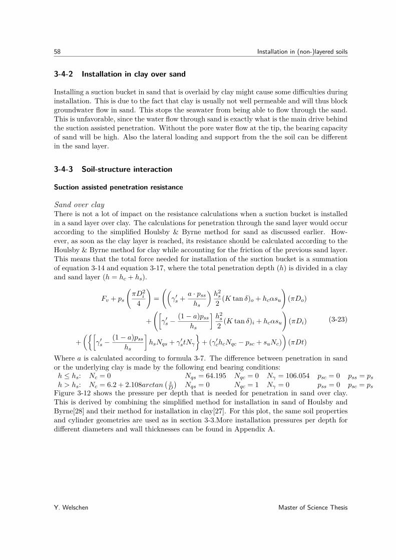
58 Installation in (non-)layered soils
3-4-2 Installation in clay over sand
Installing a suction bucket in sand that is overlaid by clay might cause some difficulties duringinstallation. This is due to the fact that clay is usually not well permeable and will thus blockgroundwater flow in sand. This stops the seawater from being able to flow through the sand.This is unfavorable, since the water flow through sand is exactly what is the main drive behindthe suction assisted penetration. Without the pore water flow at the tip, the bearing capacityof sand will be high. Also the lateral loading and support from the the soil can be differentin the sand layer.
3-4-3 Soil-structure interaction
Suction assisted penetration resistance
Sand over clayThere is not a lot of impact on the resistance calculations when a suction bucket is installedin a sand layer over clay. The calculations for penetration through the sand layer would occuraccording to the simplified Houlsby & Byrne method for sand as discussed earlier. How-ever, as soon as the clay layer is reached, its resistance should be calculated according to theHoulsby & Byrne method for clay while accounting for the friction of the previous sand layer.This means that the total force needed for installation of the suction bucket is a summationof equation 3-14 and equation 3-17, where the total penetration depth (h) is divided in a clayand sand layer (h = hc + hs).
Fv + ps
(πD2
i
4
)=((
γ′s + a · psshs
)h2s
2 (K tan δ)o + hcαsu
)(πDo)
+([γ′s −
(1− a)psshs
]h2s
2 (K tan δ)i + hcαsu
)(πDi)
+({[
γ′s −(1− a)pss
hs
]hsNqs + γ′stNγ
}+ (γ′chcNqc − psc + suNc)
)(πDt)
(3-23)
Where a is calculated according to formula 3-7. The difference between penetration in sandor the underlying clay is made by the following end bearing conditions:h ≤ hs: Nc = 0 Nqs = 64.195 Nqc = 0 Nγ = 106.054 psc = 0 pss = psh > hs: Nc = 6.2 + 2.108arctan
(zD
)Nqs = 0 Nqc = 1 Nγ = 0 pss = 0 psc = ps
Figure 3-12 shows the pressure per depth that is needed for penetration in sand over clay.This is derived by combining the simplified method for installation in sand of Houlsby andByrne[28] and their method for installation in clay[27]. For this plot, the same soil propertiesand cylinder geometries are used as in section 3-3.More installation pressures per depth fordifferent diameters and wall thicknesses can be found in Appendix A.
Y. Welschen Master of Science Thesis
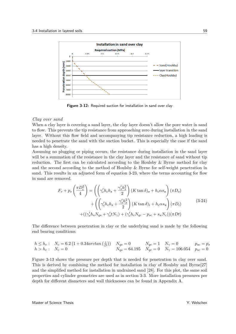
3-4 Installation in layered soils 59
Figure 3-12: Required suction for installation in sand over clay
Clay over sandWhen a clay layer is covering a sand layer, the clay layer doesn’t allow the pore water in sandto flow. This prevents the tip resistance from approaching zero during installation in the sandlayer. Without this flow field and accompanying tip resistance reduction, a high loading isneeded to penetrate the sand with the suction bucket. This is especially the case if the sandhas a high density.Assuming no plugging or piping occurs, the resistance during installation in the sand layerwill be a summation of the resistance in the clay layer and the resistance of sand without tipreduction. The first can be calculated according to the Houlsby & Byrne method for clayand the second according to the method of Houlsby & Byrne for self-weight penetration insand. This results in an adjusted form of equation 3-23, where the terms accounting for flowin sand are removed.
Fv + ps
(πD2
i
4
)=((
γ′chchs + γ′sh2s
2
)(K tan δ)o + hcαsu
)(πDo)
+((
γ′chchs + γ′sh2s
2
)(K tan δ)i + hcαsu
)(πDi)
+((γ′shsNqs + γ′stNγ) + (γ′chcNqc − psc + suNc))(πDt)
(3-24)
The difference between penetration in clay or the underlying sand is made by the followingend bearing conditions:
h ≤ hc : Nc = 6.2(1 + 0.34arctan
(zD
))Nqs = 0 Nqc = 1 Nγ = 0 psc = ps
h > hc : Nc = 0 Nqs = 64.195 Nqc = 0 Nγ = 106.054 psc = 0
Figure 3-13 shows the pressure per depth that is needed for penetration in clay over sand.This is derived by combining the method for installation in clay of Houlsby and Byrne[27]and the simplified method for installation in undrained sand [28]. For this plot, the same soilproperties and cylinder geometries are used as in section 3-3. More installation pressures perdepth for different diameters and wall thicknesses can be found in Appendix A.
Master of Science Thesis Y. Welschen
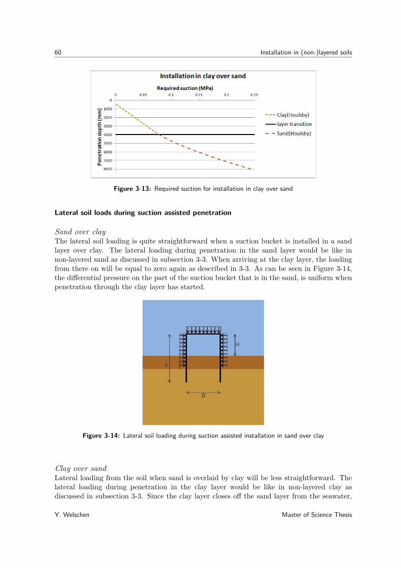
60 Installation in (non-)layered soils
Figure 3-13: Required suction for installation in clay over sand
Lateral soil loads during suction assisted penetration
Sand over clayThe lateral soil loading is quite straightforward when a suction bucket is installed in a sandlayer over clay. The lateral loading during penetration in the sand layer would be like innon-layered sand as discussed in subsection 3-3. When arriving at the clay layer, the loadingfrom there on will be equal to zero again as described in 3-3. As can be seen in Figure 3-14,the differential pressure on the part of the suction bucket that is in the sand, is uniform whenpenetration through the clay layer has started.
Figure 3-14: Lateral soil loading during suction assisted installation in sand over clay
Clay over sandLateral loading from the soil when sand is overlaid by clay will be less straightforward. Thelateral loading during penetration in the clay layer would be like in non-layered clay asdiscussed in subsection 3-3. Since the clay layer closes off the sand layer from the seawater,
Y. Welschen Master of Science Thesis

3-5 Modeling of layered soils 61
almost no pressure gradient will be able to form in the sand. This leads to a differentialpressure of zero for both the clay as the underlying sand layer (see Figure 3-15).
Figure 3-15: Lateral soil loading during suction assisted installation in clay over sand
Lateral soil support during suction assisted penetration
Sand over clayAs explained in subsection 3-3, the horizontal soil compression stiffness increases with depthand is dependent on the horizontal stress and deformation.Because the clay is loaded by the sand layer, depending on the unit weight and height of thesand layer, it can be differently loaded (since sand can have a different density than clay).This can influence the lateral support from the clay to the bucket skirt. For the covering sandlayer the bedding constant will be as explained in subsection 3-3. Both bedding constantvalues can be obtained from Table 3-1, based on the qc values of the sand and cu values ofthe clay layer.
Clay over sandBecause the sand is loaded by the clay layer, depending on the unit weight and height of theclay layer, it can be differently packed (since clay can have a different density than sand).This can influence the lateral support from the sand to the bucket skirt. For that clay layerthe bedding constant will be as explained in subsection 3-3. Both bedding constant valuescan be obtained from Table 3-1, based on the qc values of the sand and cu values of the claylayer.
3-5 Modeling of layered soils
This section explains how the soil-structure interactions, for suction assisted penetration ofa suction bucket in layered soil, will be modeled in the Finite Element Modeling And Post-processing (FEMAP) program and analyzed using NX Nastran 8.0. As explained in subsection
Master of Science Thesis Y. Welschen
62 Installation in (non-)layered soils
3-4-3, there are three main effects that influence the buckling behaviour of a suction bucket.Those are the vertical resistance that defines the required installation suction pressure, thelateral loading and the lateral support from the soil on the suction bucket skirt.
3-5-1 Resistance modeling
The resistance, that occurs during suction assisted installation of a suction bucket in layeredsoil, is given in subsection 3-4-3.
The resistance formulas 3-24 and 3-23 are used to know what pressure is needed per depth, toinstall the suction bucket. That pressure will be modeled in FEMAP, as illustrated in figures3-9 and 3-10.
3-5-2 Lateral soil loading modeling
When the installation pressure per penetration depth is known, this will be used to modelthe lateral loads in the soil. Depending on the soil layering configuration, a circumferentialpressure will be applied according to Figure 3-14 and 3-15.
3-5-3 Lateral soil support modeling
The soil compression stiffness will be modeled by spring elements, where the spring-constant isdependent on the bedding-constant per depth and the element-surface. These spring-elementswill have a stiffness in the element axis system. The bedding-constant will be selected basedon previous used soil properties. For simplification of the quadratic relation between thedepth and horizontal stiffness in sand, a uniform bedding constant average will be used formodeling purposes. For horizontal support during penetration in clay, according to equation3-22, a linear relation between the depth and bedding constant will be used.in order to predict how much influence the stiffness of the soil has on the stress in the shell,the strain/displacement relationship of a cylindrical shell is analysed. The stress in the shelldue to lateral pressure is:
σθ =(P − k∆r
A )t
(3-25)
Where:k = the stiffness of the soilA = the the surface on which the stiffness applies
And∆r = r − (2πr −∆l)
2π (3-26)
With, ∆l = lε.Where l is the circumference of the cylinder and the stress/strain relationship is:
ε = σθE
(3-27)
Y. Welschen Master of Science Thesis

3-6 Conclusion 63
3-5-4 Constraints
The main specific features for the FE-models of the suction caisson are presented below:
• The models of suction caisson shall be constructed as axisymmetric
• The models shall be constructed from thin plate elements which will be arranged in themid-plane of structural components.
• FE-Models consist of the following parts: shell
The suction pile model in FEMAP will be restrained at the bottom in vertical direction. Thisis because of the fact that the other directions are already restrained by the spring elements.
3-6 Conclusion
Looking at this chapter it can be concluded that for the installation resistance, a sand layercovered by clay will cause a higher installation pressure compared to only sand or clay. Thiscan have a negative influence on the structural integrity of the suction bucket. A clay layercovered by sand will cause a lower installation pressure, compared to only clay. But comparedto installation in sand, this is only the case for the 12 and 9 meter diameter buckets and notfor the 6 meter. The installation pressures for a cylinder of D = 6m and t = 25mm of bothlayer configurations are shown in figure 3-16
Figure 3-16: Required installation pressure during suction assisted installation in layered soil
From the graphs in Appendix A, it can be concluded that the diameter of a cylinder has moreinfluence on the penetration resistance than the wall thickness does.When considering the lateral soil loading, a clay layer covered by sand will have a negativeinfluence on the structural integrity of the suction bucket with respect to non-layered clayeyseabed. And a sand layer covered by clay will have a positive effect on the structural integrityof the suction bucket with respect to non-layered sandy seabed.
The Support that is given to the bucket skirt by the layered seabed is highly dependent onthe density and the thickness of the top layer of the seabed. In general however, when a sand
Master of Science Thesis Y. Welschen

64 Installation in (non-)layered soils
is covered by a clay the support will be less, due to the fact that clay is usually less stiff thansand. The other way around, a clay covered by sand will give more support due to the factthat sand is usually stiffer than clay.
Y. Welschen Master of Science Thesis

Chapter 4
Model developed for buckling ofsuction buckets
As an introduction to this chapter, the correlation between loads on a thin-walled shell andstresses in that shell are explained. Secondly, the principle buckling stress calculations ofa simply supported panel are derived. This panel has vertical and horizontal loads actingon its middle plane. As a next step, the critical buckling pressure of closed thin walledcylindrical shell is explained. This will be done in order to obtain the total safety factor fromthe DNV-GL method and validate the FE model. In the second section, the approach usedby SPT-offshore for design against buckling failure will be discussed. Finally the bucklingpressure of cylindrical shells will be modeled in FEMAP for different installation depths.
4-1 Analytic method
The following calculations are established while assuming that the self-weight of the structuresis not of influence on the stress in the structures. In addition, the loads on the structures areassumed to be uniform.
4-1-1 Stress design in thin-walled cylindrical shell
In order to find out if shell buckling will occur due to a differential pressure on the closedcylinder, it is important to define the stress as a function of this pressure.The pressure on the cylinder induces two kinds of stresses in the shell; one in vertical x-direction and one in circumferential θ-direction (see figure 4-1).
Master of Science Thesis Y. Welschen

66 Model developed for buckling of suction buckets
Figure 4-1: Pressure in unstiffened cylindrical shell
These stresses are calculated as described below.
Fx = P ·Al (4-1)
Al = 14πD
2 (4-2)
σx = FxAe
(4-3)
Ae = 14π(D2 − (D − 2t)2) (4-4)
With:Fx = the vertical force on the lid of the shellP = the pressure on the shellAl = the surface of the lid exposed to pressureD = the outer diameter of the cylindrical shellt = the wall thickness of the cylindrical shellAe = the surface of the edge of the shell
Substituting equation 4-2 into 4-1 and equations 4-1 and 4-4 into 4-3, gives a vertical stressequation of:
σx = PD2
D2 − (D − 2t)2 (4-5)
The cylindrical shells that are of relevance to this thesis, are categorized to be thin-walled.This is due to their wall thickness which is not greater than one twentieth of their diameter [?].
Y. Welschen Master of Science Thesis

4-1 Analytic method 67
This means that the stress is uniform over the wall-thickness[32]. Therefore thin-walled shellscan be treated as a surface, which makes it possible to use the Young-Laplace equation forestimating the circumferential (hoop) stress created by an internal pressure on a thin-walledcylindrical pressure vessel:
σθ = Pr
t(4-6)
The resulting principal (maximum) stress due to these two plane stresses can be calculatedby means of:
σ1,2 = σx + σθ2 ±
√(σx − σθ
2
)2(4-7)
Yield stress
According to the principal stress theory, failure of a material subjected to pressure, will occurwhen the highest principal stress is equal to the yield stress of the material. The yield stressis defined as the elastic limit of a material. It is identified by the the stress at which thestress-strain curve for axial loading deviates by a strain of 0.2% from the linear-elastic lineas shown in Figure 4-2. According to the norm NEN-EN 10025-3:2004 nl [33], the minimumyield strength of structural steel S355 is 345 MPa. This is based on the most frequent usedsteel for suction buckets by SPT Offshore and a wall thickness in the range of:
16mm < t ≤ 40mm
Figure 4-2: Stress-strain diagram for structural steel in tension[8]
4-1-2 Buckling stress of a thin walled panel
Calculating the buckling stresses in a thin walled cylindrical shell is not a very straight forwardtask due to the geometry of the shell. Therefore this section will first discuss the stresses ina small section of a cylindrical shell, like a panel. Figure 4-3 shows a panel under axial loadand its coordinate system.
Master of Science Thesis Y. Welschen
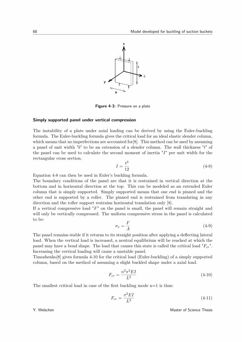
68 Model developed for buckling of suction buckets
Figure 4-3: Pressure on a plate
Simply supported panel under vertical compression
The instability of a plate under axial loading can be derived by using the Euler-bucklingformula. The Euler-buckling formula gives the critical load for an ideal elastic slender column,which means that no imperfections are accounted for[8]. This method can be used by assuminga panel of unit width "b" to be an extension of a slender column. The wall thickness "t" ofthe panel can be used to calculate the second moment of inertia "I" per unit width for therectangular cross section.
I = t3
12 (4-8)
Equation 4-8 can then be used in Euler’s buckling formula.The boundary conditions of the panel are that it is restrained in vertical direction at thebottom and in horizontal direction at the top. This can be modeled as an extended Eulercolumn that is simply supported. Simply supported means that one end is pinned and theother end is supported by a roller. The pinned end is restrained from translating in anydirection and the roller support restrains horizontal translation only [8].If a vertical compressive load "F " on the panel is small, the panel will remain straight andwill only be vertically compressed. The uniform compressive stress in the panel is calculatedto be:
σx = F
A(4-9)
The panel remains stable if it returns to its straight position after applying a deflecting lateralload. When the vertical load is increased, a neutral equilibrium will be reached at which thepanel may have a bend shape. The load that causes this state is called the critical load "Fcr".Increasing the vertical loading will cause a unstable panel.Timoshenko[8] gives formula 4-10 for the critical load (Euler-buckling) of a simply supportedcolumn, based on the method of assuming a slight buckled shape under a axial load.
Fcr = n2π2EI
L2 (4-10)
The smallest critical load in case of the first buckling mode n=1 is thus:
Fcr = π2EI
L2 (4-11)
Y. Welschen Master of Science Thesis

4-1 Analytic method 69
Where L= the length of the panel and E= the Young’s modulus.When translating equation 4-11 to the critical stress in a panel per unit width "b", equation4-8 should be substituted into 4-11. According to Hooke’s law, the factor 1/(1 − ν2) shouldbe included and the critical load per unit width becomes:
Fcr = π2Et3
12L2(1− ν2) (4-12)
Where ν = the poisson ratio.
The modeling method where a slight buckle shape is assumed due to vertical compressionforces on the middle plane, accounts for a larger stability of a continuous plate than thestability of an isolated strip or column[9]. This is accounted for by the second term in theequation for the critical stress per unit width:
σcr = π2Et2
12L2(1− ν2)
(1 + L2
b2
)2
(4-13)
Simply supported panel under combined vertical and horizontal compression
Since the compressive loads on a cylindrical shell cause axial and circumferential stressesalong the middle plane of the shell, this section will consider the critical stress in a panel dueto compression in two perpendicular directions.Timoshenko[9] derives the differential equation for the critical buckling loads of this problemby means of the energy method. This results in the following equation for axial and horizontalstresses:
σx + σθL2
b2= π2Et2
12L2(1− ν2)
(1 + L2
b2
)2
(4-14)
It is seen that for the critical stress of either of the two stress components, the other stresscomponent should be known. Fortunately, in this research problem the two stress componentsin a cylindrical shell are dependent on the same load. The following section will explain howthese stress components both depend on the external pressure.
4-1-3 Buckling stress of a thin walled cylindrical shell
Critical pressure for pin-pin boundary conditions
This subsection discusses buckling of a cylindrical shell under combined axial and uniformlateral pressure according to Timoshenko’s theory of elastic stability. Three differential equa-tions of equilibrium are used to determine the small displacements u, v and w during buckling.Assuming simply supported edges of the cylinder, these displacements are:
u = A sinnθ cos mπxL
(4-15)
v = B cosnθ sin mπxL
(4-16)
w = C sinnθ sin mπxL
(4-17)
Master of Science Thesis Y. Welschen

70 Model developed for buckling of suction buckets
Where:n = the number of half waves into which the cylinder buckles in circumferential directionθ = the angle at which the displacement occursx = is the distance from the center of the cylinder lengthm = the number of half waves into which the cylinder buckles in axial direction
Substituting these displacements into the three differential equations of equilibrium of forces,three homogeneous linear equations are derived. By equating the determinant of these equa-tions to zero, the value of the critical pressure is obtained. Any axial pressure makes thecritical value of the lateral pressure diminish and the presence of lateral pressure produces adecrease in the critical value of the axial pressure[9]. Assuming a closed shell under uniformexternal pressure is thin-walled and only considering the principal terms of the force equilib-rium equation, a simplified formula is given by von Mises for the critical value of the lateralpressure:
pcr = E · travg
1n2 + 1
2(πravg/L)2
1[n2(L/πravg)2 + 1]2 + t2
12r2avg(1− ν2)
[n2 +
(πravgL
)2]2
(4-18)Where ravg is the mean radius of the cylinder and n can be derived from [34]:
n =
√α
4
√3.5x
(1− ν2)− α2 (4-19)
Where n is usually the closest integer to the calculated value and:
α = πD
2L (4-20)
x = 13(t/D)2 (4-21)
This equation is valid for the following ranges of D/t and L/D:
50 ≤ D/t ≤ 66623 (4-22)
0.1 ≤ L/D ≤ 10 (4-23)
The integer values of n can also be taken from Figure 4-4.
It should be noted that no reduction or safety factors are included in Timoshenko method.For 1331
3 ≤ D/t ≤ 26623 ,
23 ≤ L/D ≤ 4
3 , E = 210GPa and ν = 0.3 the critical bucklingpressures are plotted in Figure 4-5. Next to D/t, also L/D is varied to see what its influenceis on the buckling pressure. In the same chart, for the same geometries, the critical bucklingpressures are plotted according to the DNV-GL method. The results from the DNV-GL datain this chart are derived while excluding the material factor (γM ) that is normally used as asafety factor. In addition, to have a most accurate comparison, the influence of the pressure onthe end cap, due to hydrostatic pressure, is included in the DNV-GL calculations. Figure 4-5shows that the critical buckling pressure, derived with the method from Timoshenko, doesn’tagree very well with that of DNV-GL. The differences is not found in the progression of thecurves, but in the average difference with a factor of 0.58. This difference is likely to be caused
Y. Welschen Master of Science Thesis
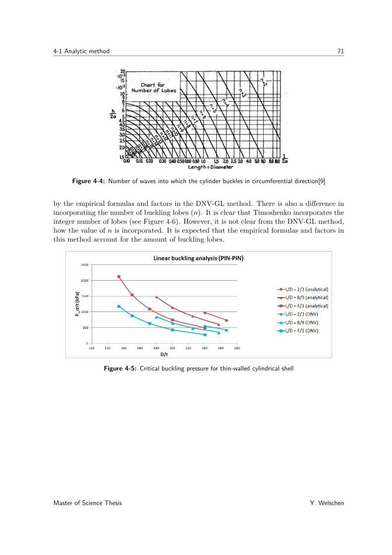
4-1 Analytic method 71
Figure 4-4: Number of waves into which the cylinder buckles in circumferential direction[9]
by the empirical formulas and factors in the DNV-GL method. There is also a difference inincorporating the number of buckling lobes (n). It is clear that Timoshenko incorporates theinteger number of lobes (see Figure 4-6). However, it is not clear from the DNV-GL method,how the value of n is incorporated. It is expected that the empirical formulas and factors inthis method account for the amount of buckling lobes.
Figure 4-5: Critical buckling pressure for thin-walled cylindrical shell
Master of Science Thesis Y. Welschen

72 Model developed for buckling of suction buckets
Figure 4-6: Critical lateral buckling pressure for thin-walled cylindrical shell with different bucklinglobe (n) curves
Critical pressure for pin-free boundary conditions
Since the DNV-GL method adopts the simply supported condition, subsection 4-1-3 explainsthe critical buckling pressure for a thin-walled cylindrical shell that has pin-pin classicalboundary conditions. As a matter of fact, all methods that are discussed in Chapter 2 arebased on pin-pin boundary conditions (see Table 2-14). However, when considering the geome-try and installation procedure of a suction bucket, the boundary conditions during installationare generally between pin-free and pin-pin[35]. This is because the amount of support that thesoil gives to the tip of the suction bucket varies with depth. Assuming that at the beginningof soil penetration, the tip is free and with increasing penetration depth the constraints ofthe tip increases, depending on the bedding constant per depth of the soil. From a certaindepth the tip is pinned again. Additionally, Pinna[2003] states that suction buckets actingas a foundation, may even be modelled as clamped-free. This is because a heavy top plateis usually required in this case, to function as a structural member. Nevertheless, due to thefact that a heavy top-plate is not always the case, the most conservative boundary conditions(pinned-free) will be assumed. This section will therefore contain calculations of the criticalbuckling pressure for a cylindrical shell with pin-free boundary conditions.These boundary conditions for cylindrical shells are important to analyze, because they arelikely to represent the lower bound buckling strength during installation[36]. The definitionof a free boundary condition is that it is free to deform without stress restrictions. While apinned edge can not move in any direction but is free to rotate.According to Vodenitcharova and Ansourian, the critical pressure for buckling of a pin-freecylindrical shell is the same as the critical pressure for a free-free cylindrical shell of doublethe length, but only for a buckling wave number of two[37].To define the critical buckling pressure of a thin-walled cylinder, Pinna uses the strain-
Y. Welschen Master of Science Thesis
4-1 Analytic method 73
displacement relationships by Brush & Almroth[1975]:
εz = ∂zu(θ, z) + 12β
2z (4-24)
εθ = ∂θv(θ, z) + w(θ, z)r
12 + β2
θ (4-25)
γθz = ∂θu(θ, z)r
+ ∂zv(θ, z) + βθβz (4-26)
βθ = −∂θw(θ, z)r
(4-27)
βz = −∂zw(θ, z) (4-28)
Equations of equilibrium of the shell are then defined, based on displacements u(θ, z), v(θ, z)and w(θ, z). In each direction, the equilibrium equations are:
r∂zNz + ∂θNzθ = 0 (4-29)r∂zNzθ + ∂θNθ = 0 (4-30)
Nθ = P (θ, z)r (4-31)
Where:
Nz = C(εz + νεθ) (4-32)Nθ = C(εθ + νεz) (4-33)
Nzθ = C1− ν
2 γzθ (4-34)
With:C = Ecyt
1− νcy(4-35)
According to Pinna[36], the displacement functions required for the pinned-free boundaryconditions are:
u = sin(nθ)∑i
Ai
(z
L
)i−1(4-36)
v = cos(nθ)∑i
Ai+j
(z
L
)i(4-37)
w = sin(nθ)∑i
Ai+2j
(z
L
)i(4-38)
Where: z= is the z-axis direction along the length(L) of the cylinder
Assuming that P (θ, z) = Pcr(θ, z) and Nθ0 = Pcr(θ, z).Using the Rayleigh-Ritz method and substituting equations 4-36 to 4-38 into equations 4-29to 4-31, results in a variational expression in terms of the displacements and unknown coeffi-cients Ai, Ai+j and Ai+2j and the buckling load Pcr.To determine the buckling load, it is then necessary to minimize the variational expression.The result of this operation can then be written in matrix form, of which the eigenvalues are
Master of Science Thesis Y. Welschen

74 Model developed for buckling of suction buckets
used to find the buckling load[36].When substituting z = 0 into the displacement equations, it is seen that there is free ax-ial displacement. Since this freedom would cause rigid body motions for a pinned-free shellunder hydrostatic loading, one edge should also be restrained in axial direction. Pinna doesthis by including a linear elastic variable restraint at the pinned edge of the cylinder. Whenthe stiffness (ks) of this elastic restraint increases, it decreases the freedom of the cylinder inaxial direction. The result of analysis done by Pinna for a axially loaded shell, shows thata pinned-free shell has a factor α lower buckling load than a pinned-pinned shell. For fullyaxially restrained pinned-free shells, Pinna concludes that the buckling loads changes withα = 0.38, compared to a pinned-pinned shell. This is based on cylinders with a Bathdorfvalue (Z) of: 100 ≤ Z ≤ 1725 thus for 200 ≤ D/t ≤ 3460. Appendix B illustrates the result ofthis theory. It is seen that with an average tolerance of 1.2%, the theory of Pinna is valid forthe geometries analysed in this thesis for only axial loading. For combined axial and lateralloaded shells, the theory by Pinna must be verified. This is done by FE analysis, as can befound in Section 4-3.
4-1-4 Conclusion
Instead of assuming pinned-pinned boundary conditions, it is more accurate to look at bound-ary conditions changing from pinned-free to pinned-pinned during installation. According toPinna [36], there are a few cylinder geometries (where D/t < 200) that were analysed before,for which the pinned-free critical buckling pressure cannot analytically be derived. However,Figure B-1 in Appendix B shows that for the analysed geometries, this is not the case. Fig-ure 4-7 shows the critical buckling pressures for cylindrical shells in which the α-factor forpinned-free boundary conditions is included.
Figure 4-7: Critical lateral buckling pressure for thin-walled cylindrical shell with pinned-freeboundary conditions
For comparison, this figure also shows the critical buckling pressure of the DNV-GL method.As can be expected, Figure 4-7 shows that the buckling pressure of a pinned-free cylinderis much lower than that calculated with the DNV-GL (pinned-pinned shell) method. Thebuckling pressure of a pinned-free cylinder is approximately 0.67 times smaller than that of
Y. Welschen Master of Science Thesis

4-2 SPT Offshore approach 75
the DNV-GL method.
4-2 SPT Offshore approach
The approach that SPT Offshore uses to design suction buckets against buckling failure isbased on the DNV-GL recommended practice [6]. There are, however, some distinct differ-ences between suction buckets and the structures that are discussed in the DNV-GL method.Figure 2-6 shows a typical structure with stiffeners that is considered by DNV-GL, wherethe length between the ring stiffeners is given to be "l". A suction bucket doesn’t have aring-frame on its lower part to give lateral support to the shell. But during installation, thesoil surrounds the bottom part of the shell completely and gives some lateral support.The SPT approach, determines the magnitude of the lateral support by the soil and relatesthe buckling length to the penetration depth.With the knowledge of this relation, the DNV-GL code is used to calculate the shell buck-ling resistance. This knowledge is obtained by performing a linear buckling analysis. Linearbuckling is the theoretical point at which the structure starts to buckle elastically.
4-2-1 Application for sand
In case of sandy soils, the approach that SPT uses is valid for suction buckets and penetrationdepths where:
D/t ≤ 275 (4-39)0.5 ≤ L/D ≤ 1.5 (4-40)
0.182L ≤ Lp ≤ 0.818L (4-41)
Where:L = bucket lengthD = average bucket diametert = bucket wall thicknessLp = penetration depth
The support to the shell from a bedding constant of 10000 kN/m3 is modeled in FEMAP(using Nastran NX). Where this bedding constant, is represented by springs. The soil pressuredrop in sand is assumed to be linear and the spring constant is calculated as follows:
ks = Ae · cb (4-42)
Where:ks = spring constant for sandAe = element surfacecb = bedding constant of soil
The suction bucket model is only restrained at bottom in vertical direction.
Master of Science Thesis Y. Welschen

76 Model developed for buckling of suction buckets
Finally, from modeling cylinders of different geometries, three formulas are derived to obtainthe buckling length "lb" that can be used for "l" in the DNV-Gl code:(
lbHp
)L/D=0.5
= 17.327(LpL
)3− 17.764
(LpL
)2+ 5.9738Lp
L+ 0.82 (4-43)
(lbHp
)L/D=1.0
= 7.5329(LpL
)3− 8.4339
(LpL
)2+ 3.4325Lp
L+ 0.712 (4-44)
(lbHp
)L/D=1.5
= 5.3678(LpL
)3− 6.1232
(LpL
)2+ 2.5607Lp
L+ 0.73 (4-45)
Where:Hp = protruding lengthlb = buckling length
Formulas for other L/D ratios can be approximated by linear interpolation of formulas 4-43,4-44 and 4-45.
4-2-2 Application for clay
In case of clayey soils, the approach that SPT uses is valid for suction buckets where:
D/t ≤ 275 (4-46)8m ≤ L ≤ 14m (4-47)
D = 5m (4-48)
Where:L = bucket lengthD = average bucket diametert = bucket wall thickness
The support to the shell from the bedding constant, from 600 to 1600kN/m3 is modeled inANSYS (using linear 4-node square elements). Where the bedding constant is represented bysprings. There is no soil pressure drop in clay but the soil stiffness varies linearly with depthand the spring constant is calculated as follows:
kc = Ae · cb (4-49)
Where:kc = spring constant for clayAe = element surfacecb = bedding constant of soil (varying linearly with depth for clay)
The suction bucket model is restrained at bottom in vertical direction and at the top in anydirection.
To use the DNV-GL method, from modeling cylinders of different geometries, the followingconservative factors for the shell buckling length are determined: (lb = γb ·Hp).
Y. Welschen Master of Science Thesis

4-3 Finite Element Analysis 77
• γb = 1.6, for penetration depths > 0.5D.
• γb = 2.0− 0.4 Lp0.5Do , for penetration depth 0m until 0.5D.
4-3 Finite Element Analysis
By dividing a structure in a finite amount of elements, connected by nodes with certainconstraints, it is possible to predict a more accurate behavior of that structure. This methodis called a Finite Element (FE) method. During this thesis the FE modeling program FEMAP11.0 will be used, to model the influence of the soil-structure interaction on the bucklingpressure of the suction bucket. This program is chosen, since it is already extensively usedby SPT Offshore for suction bucket design.To use FEMAP for the modeling of soil structure interaction, it needs to be validated first.This section will therefore compare the calculations from section 4-1-3, with the results fromFE-models. After modeling the problems, they will be solved with NX Nastran 8.0.
4-3-1 Critical pressure for pin-pin boundary conditions
The main specific features of the FE-models of the suction bucket are presented in AppendixB.For the complete structural analysis of the pinned-pinned shell matching the Timoshenkoapproach, the simply supported constraint set has been applied to the top edge. This is doneby applying anti-axisymmetric constraint set (TX=TY=RZ=1; TZ=RX=RY=0) to the topand bottom curve of the suction bucket shell. To prevent rigid body motions, four nodesat the top curve are additionally constrained in axial direction (TZ=1). The top plate isn’tincluded in the FE model, since it is not necessary to model this when the top edge is alreadymodeled to be simply supported.The following load sets have been applied in the FE-model:
1. lateral differential pressure loads
2. vertical differential pressure loads
Where the value of the applied pressure is 0.35 MPa and the vertical loads are the surfacesof the suction bucket top plate multiplied by the differential pressure. The vertical loads areapplied to the top and bottom curve of the shell. The results from a combination of load set1 and 2 will be used for comparison with the analytical method, since that agrees with theThimoshenko’s method.The model results from combined load sets 1 and 2, compared to the ones from load set 1, canbe found in Appendix B. Comparing the results in this appendix shows an average differenceof 3.7%.
For the same geometries as in section 4-1-3, the critical buckling pressures derived withFEMAP are plotted in Figure 4-8. In the same graph the analytical results from section 4-1-3are plotted. The graph shows that the results are a good match. The average difference is2.2%. This difference might be caused by the exclusion of the higher order terms in Timo-shenko’s method. While FEMAP incorporates the effect of the differential stiffness, which
Master of Science Thesis Y. Welschen

78 Model developed for buckling of suction buckets
includes higher-order strain displacement relationships that are functions of the geometry,element type, and applied loads[38].
Figure 4-8: Critical lateral buckling pressure for thin-walled cylindrical shell with pinned-pinnedboundary conditions modeled in FEMAP
4-3-2 Critical pressure for pin-free boundary conditions
For the complete structural analysis of the pinned-free shell, matching the Timoshenko theory,the simply supported constraint set has been applied to the top edge. This is done by apply-ing anti-axisymmetric constraint set (TX=TY=RZ=1; TZ=RX=RY=0) to the top curve ofthe suction bucket shell. No constraints (TX=TY=TZ=RX=RY=RZ=0) are applied to thebottom curve of the suction bucket. Four nodes at the top curve are additionally constrainedin axial direction (TZ=1), to prevent rigid body motions. The top plate is again not includedin the FE model, since it is not necessary to model this when the top edge is already modeledas simply supported.For the suction bucket the following load sets have been applied to the FE-model:
1. lateral differential pressure loads
2. vertical differential pressure loads
Where the value of the applied pressure is 0.35 MPa and the vertical loads are the surfacesof the suction bucket top plate multiplied by the differential pressure. The vertical loads areapplied to the top and bottom curve of the shell. The results from a combination of loadset 1 and 2 will be used for comparison with the analytical method, since that agrees withThimoshenko’s method. The model results from combined load sets 1 and 2, compared to theones from load set 1, can be found in Appendix B. Comparing the results in this appendixshows an average difference of 2%.For the same geometries as in section 4-1-3, the critical buckling pressures derived withFEMAP are plotted in Figure 4-9. In the same graph the results from Pinna’s approach
Y. Welschen Master of Science Thesis

4-4 Case study for installation in layered soils 79
of section 4-1-3 are plotted. The results show that the buckling modes and the bucklingpressures are not the same. This is likely due to the fact that the factor α = 0.38 is derivedfor only axially loaded shells and therefor not suited for shells under combined lateral andaxial loading. Additionally, the FE models were axially constrained in only four points onthe top curve, while the models used by Pinna were axially constrained over the whole topcurve. Pinna assumes that the top plate gives significant axial restraints, which may be veryunconservative [36].
Figure 4-9: Critical lateral buckling pressure for thin-walled cylindrical shell with pinned-freeboundary conditions modeled in FEMAP
4-3-3 Conclusion
From the previous two subsection it can be concluded that Finite Element modeling inFEMAP is an appropriate method for defining the buckling strength of a pinned-pinnedcylindrical shell. For the tested geometries, the average difference between the analytical andthe FE method is 2%. Figure 4-9 shows the buckling pressure for these shells derived with thefactor α and the FE analysis results from FEMAP. It can be seen that these results are muchdifferent. This means that the factor α cannot be used to analytically derive the bucklingpressure of a pinned-free shell under combined lateral and axial loading.
4-4 Case study for installation in layered soils
To model the influence of the soil-structure interaction on buckling during installation inlayered soil, first the influence of non-layered soil needs to be modeled. This will be donein FEMAP according to Section 3-2. The next step is to model the buckling loads duringinstallation in layered soil. This will also be done in FEMAP according to Section 3-4. Thesoil profile that will be used in these models are a clay layer of four meters, covered by a sandlayer of four meters and vice-versa. Furthermore, the exact same soil parameters will be usedas in the preceding part of this thesis. Finally, the non-layered and layered model results willbe analysed and compared to each other and SPT’s approach.
Master of Science Thesis Y. Welschen

80 Model developed for buckling of suction buckets
4-4-1 Installation in non-layered soils
SandFor the complete buckling analysis of installing a pinned-free shell in sand, matching theTimoshenko approach, the simply supported constraint set from subsection 4-3-2 has beenapplied to the top edge. For the suction bucket shell, a lateral uniform pressure has beenapplied to the stick up height of the FE-model. On the penetrated part, a linear decreasinglateral pressure is applied. Where the value of the uniform pressure is 0.35 MPa and thelinear pressure decreases from 0.35 MPa to 0 MPa at the bottom tip (represented as thearrows with number 1 in Figure 4-10). To minimize the amount of variables, only lateralloading will be included in this analysis, since the axial load has a negligible influence onthe buckling load (see Appendix B). The part of the shell that is penetrated in the sand isattached to fixed springs with a spring stiffness in radial direction of 200 N/mm (matchingthe used sand properties from section 3-3-1). However, these springs are attached from 0.9meters below the mudline, since the same section shows that there is almost no resistanceand thus neglectable stress in the first 0.9 meters. Figure 4-10 is an example of the FE modelof a cylindrical shell installed in four meters of sand. An illustration of the models for allinstallation depths in sand can be found in appendix B. For the same geometries as in section4-1-3, the critical buckling pressures per installation depth in sand derived with FEMAP areplotted in Figure 4-11.
Figure 4-10: An example of the FE model of an eight meter cylinder, installed in four meters ofsand
In the same graph the results of maximum installation pressure due to resistance in sand,from section 3-3-1 are plotted. The results show that for the chosen soil properties andgeometries, the penetration pressure needed per installation depth will not reach the bucklingpressure per installation depth of the cylinder. It is also seen that with increasing penetrationdepth, the buckling pressure shows a increasing growth. This is due to the fact that withdeeper penetration, the buckling length of the cylinder decreases, which results in a higherbuckling pressure. See Figure 4-12 for an example of a deformation plot for a first bucklingeigenvalue.A noticeable observation is that the curves show a jump for an installation depthup to three meters. This is likely to be caused by a changing amount of buckling lobes (n),when the cylindrical shell changes from a pinned-free shell to one with an edge of springs atthe free end.
Y. Welschen Master of Science Thesis

4-4 Case study for installation in layered soils 81
Figure 4-11: Critical lateral buckling pressure for thin-walled cylindrical shell per penetra-tiondepth in sand
The change in buckling lobes is due to the change in effective buckling length of the shell.
Figure 4-12: An example of the first buckling mode deformation of an eight meter cylinder,installed in four meters of sand
Master of Science Thesis Y. Welschen

82 Model developed for buckling of suction buckets
ClayThe boundary conditions that were used for the previous analysis, will again be used for thecomplete buckling analysis of installing a pinned-free shell in clay. For the suction bucket shell,a lateral uniform pressure has been applied to the stick up height of the FE-model. Where thevalue of the uniform pressure is 0.35 MPa. Here again only lateral loading will be included inthis analysis, since the axial load has a negligible influence on the buckling load. The part ofthe shell that is penetrated in the clay is attached to fixed springs with a spring stiffness inradial direction of 5 N/mm increasing linearly with depth (matching the used clay propertiesfrom section 3-3-1). These springs are however attached from 0.5 meters below the mudlinedown, since the same section shows that there is almost no resistance and thus negligiblestress and support in the first 0.5 meters. For the same geometries as in section 4-1-3, thecritical buckling pressures per installation depth in clay derived with FEMAP are plottedin Figure 4-13. Figure 4-13 also shows the results of maximum installation pressure due to
Figure 4-13: Critical lateral buckling pressure for thin-walled cylindrical shell per penetrationdepth in clay
resistance in clay, from section 3-3-1. The results show that for the chosen soil properties andgeometries, the penetration pressure needed per installation depth will not reach the bucklingpressure per installation depth of the cylinder. It is also seen that with increasing penetrationdepth, the buckling pressure shows a higher increasing growth than with installation in sand.This is due to the fact that with deeper penetration, the bedding constant increases. Thiscauses the buckling length of the cylinder to first not decrease a lot, but below some depthdecrease more rapidly with depth, which results in a higher buckling pressure.
conclusion
The results of FE analysis for installation in non-layered soil that are presented in figure 4-14show that from 3 meters installation depth, the buckling pressure in clay is higher than thatin sand. This indicates that, for the analysed geometries and soils, the clay stiffness afterthree meter, results in more stability than the stiffness in sand including the differential porewater pressure.
Y. Welschen Master of Science Thesis

4-4 Case study for installation in layered soils 83
Figure 4-14: Critical lateral buckling pressure for thin-walled cylindrical shell per penetra-tiondepth in sand (blue) & clay (red)
The FE model results for installation in non-layered soil are factored with the empirical DNV-GL factor of 0.58, as derived in section 4-1-3. Then, for comparison, they are plotted next tothe results of the SPT approach for similar conditions. The two are compared for a cylindricalshell with a diameter of 6 meters, length of 8 meter and varying wall thickness between 25and 45 mm. Figure 4-15 and 4-16 show the difference between both analyses for installation
Figure 4-15: Buckling pressure during installation in sand modeled in FEMAP compared to theSPT approach
in sand and clay.Figure 4-15 shows that the model for installation in sand in FEMAP gives similar results asthe SPT approach for sandy soils. The average difference is ±1.9%, for installation between 2and 7 meters penetration depth. The SPT approach is only valid for a penetration length big-
Master of Science Thesis Y. Welschen
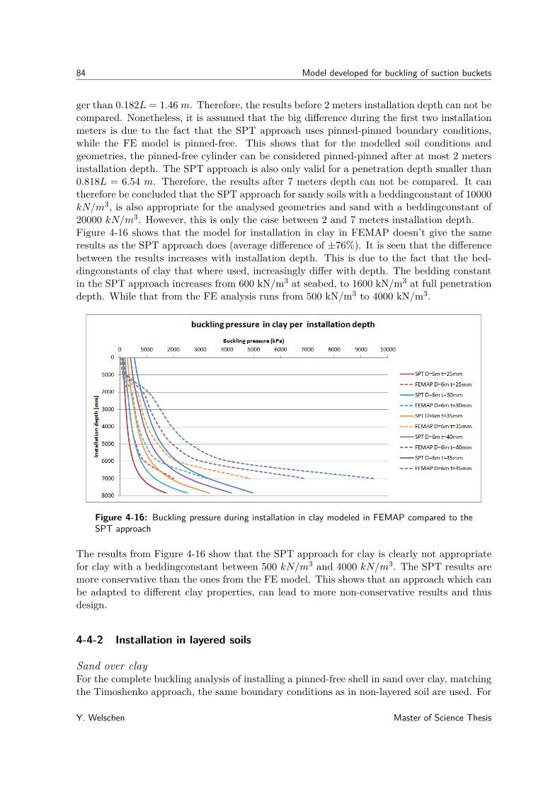
84 Model developed for buckling of suction buckets
ger than 0.182L = 1.46 m. Therefore, the results before 2 meters installation depth can not becompared. Nonetheless, it is assumed that the big difference during the first two installationmeters is due to the fact that the SPT approach uses pinned-pinned boundary conditions,while the FE model is pinned-free. This shows that for the modelled soil conditions andgeometries, the pinned-free cylinder can be considered pinned-pinned after at most 2 metersinstallation depth. The SPT approach is also only valid for a penetration depth smaller than0.818L = 6.54 m. Therefore, the results after 7 meters depth can not be compared. It cantherefore be concluded that the SPT approach for sandy soils with a beddingconstant of 10000kN/m3, is also appropriate for the analysed geometries and sand with a beddingconstant of20000 kN/m3. However, this is only the case between 2 and 7 meters installation depth.Figure 4-16 shows that the model for installation in clay in FEMAP doesn’t give the sameresults as the SPT approach does (average difference of ±76%). It is seen that the differencebetween the results increases with installation depth. This is due to the fact that the bed-dingconstants of clay that where used, increasingly differ with depth. The bedding constantin the SPT approach increases from 600 kN/m3 at seabed, to 1600 kN/m3 at full penetrationdepth. While that from the FE analysis runs from 500 kN/m3 to 4000 kN/m3.
Figure 4-16: Buckling pressure during installation in clay modeled in FEMAP compared to theSPT approach
The results from Figure 4-16 show that the SPT approach for clay is clearly not appropriatefor clay with a beddingconstant between 500 kN/m3 and 4000 kN/m3. The SPT results aremore conservative than the ones from the FE model. This shows that an approach which canbe adapted to different clay properties, can lead to more non-conservative results and thusdesign.
4-4-2 Installation in layered soils
Sand over clayFor the complete buckling analysis of installing a pinned-free shell in sand over clay, matchingthe Timoshenko approach, the same boundary conditions as in non-layered soil are used. For
Y. Welschen Master of Science Thesis

4-4 Case study for installation in layered soils 85
the suction bucket shell, a lateral uniform pressure has been applied to the stick up height ofthe FE-model. During penetration in the top sand layer, a linear decreasing lateral pressureis applied on the penetrated shell part. Where the value of the uniform pressure is 0.35 MPaand the linear pressure decreases from 0.35 MPa to 0 at the bottom tip of the shell. Whenthe bottom tip of the shell reaches the clay layer, the linear decreasing pressure in the sandchanges to a uniform lateral pressure on the shell. Again, for simplicity, only lateral loadingwill be included in this analysis.The part of the shell that is penetrated in the sand is attached to fixed springs with a springstiffness in radial direction of 200 N/mm (matching the used sand properties from section3-3-1). These springs are however attached from 0.9 meters below the mudline, since thesame section shows that there is almost no resistance and thus negligible stress in the first0.9 meters. The part of the shell that is penetrated in the underlying clay is attached to fixedsprings with a spring stiffness in radial direction of 5 N/mm increasing linearly with depth(matching the used clay properties from section 3-3-1). For the same geometries as in section4-1-3, the critical buckling pressures per installation depth in sand derived with FEMAP areplotted in Figure 4-17.
Figure 4-17: Critical lateral buckling pressure for thin-walled cylindrical shell per penetra-tiondepth in sand over clay
clay over sandFor the complete buckling analysis of installing a pinned-free shell in clay over sand, matchingthe Timoshenko approach, the same boundary conditions as in non-layered soil are used. Forthe suction bucket shell, a lateral uniform pressure has been applied to the stick up heightof the FE-model. Where the value of the uniform pressure is 0.35 MPa. No differential porewater pressure is applied to the shell in either the clay or the underlying sand.Again, for simplicity, only lateral loading will be included in this analysis. The part of theshell that is penetrated in the clay, is attached to fixed springs with a spring stiffness in radialdirection of 5 N/mm increasing linearly with depth (matching the used clay properties fromsection 3-3-1). These springs are however attached down from 0.5 meters below the mudline,since the same section shows that there is almost no resistance and thus negligible stressand support in the first 0.5 meters. The underlying part that is penetrated into the sand is
Master of Science Thesis Y. Welschen

86 Model developed for buckling of suction buckets
attached to fixed springs with a spring stiffness in radial direction of 200 N/mm (matchingthe used sand properties from section 3-3-1). For the same geometries as in section 4-1-3, thecritical buckling pressures per installation depth in clay over sand derived with FEMAP areplotted in Figure 4-18.
Figure 4-18: Critical lateral buckling pressure for thin-walled cylindrical shell per penetra-tiondepth in clay over sand
4-5 Conclusion
The results of the FE analysis for installation in layered soils that are presented in Figure4-19, show that the configuration of sand over clay has a negative influence on the bucklingcapacity from an installation depth below the layer transition, compared to installation insand. Which is also the case compared to clay, for installation depths below one meter (aswas seen earlier in Figure 4-14).Figure 4-19 shows that even though there is a differential pore water pressure in sand, itstill results in a higher buckling pressure than with an underlying clay layer. This differenceincreases from an average of 6% to 26% with increasing penetration depth. This decrease instrength after layer transition, is due to both the the decrease in beddingconstant and theincrease in porewater pressure in the top sand layer.When plotting the results of the buckling pressure for installation in clay over sand comparedto installation in only clay, all the curves overlap one each other (equal to Figure 4-18). Whichshows that the configuration of clay over sand has no influence on the buckling capacity,compared to installation in only clay. This means that the increase in bedding-constant withdepth for clay has an important influence on the buckling strength for deeper penetration.This also shows that from a certain installation depth, the stiffness of the sand does not giveany additional support compared to the support that the clay gives. Which indicates thatfrom a certain penetration depth and bedding constant, the shell can be considered fullysupported in radial direction.
Y. Welschen Master of Science Thesis

4-5 Conclusion 87
Figure 4-19: Critical lateral buckling pressure for thin-walled cylindrical shell per penetra-tiondepth in sand over clay (green) and only sand (blue)
Master of Science Thesis Y. Welschen

88 Model developed for buckling of suction buckets
Y. Welschen Master of Science Thesis
Chapter 5
Conclusion and Recommendations
5-1 Conclusion
The objective of this thesis was to analyze the elastic buckling behaviour of suction bucketsduring installation in layered soil conditions.
The following research question was formulated:
What is the influence of layered soil on the buckling behaviour of a suction bucket duringinstallation?To answer this research question, the results from each thesis section are first explained below.
Methods for buckling design
Several codes and recommended practices for offshore construction, contain methods that areapplicable to the design of cylindrical shells against buckling. The following four methodshave been studied; Eurocode, Germanischer Lloyd (GL), Det Norske Veritas-GermanischerLloyd (DNV-GL) and American Bureau of Shipping (ABS). These methods are either basedon Load Resistance Factor Design (LRFD) or Working Stress Design (WSD). The LRFDmethod is considered to be more progressive than WSD. This is due to the fact that forLRFD the safety factors can be adjusted for both the load and resistance of the structure,while for WSD this can only be done for the resistance. This makes LRFD a more appropriateapproach for design against buckling failure, since both the loading and the resistance containsome uncertainties. A suction bucket can be modeled as a thin walled cylindrical shell witha top plate, for this reason the methods mentioned above are applicable to the bucklingdesign of suction buckets. All of the considered methods consider a thin-walled cylindricalshell that has external hydrostatic loading. The recommended practice from DNV-GL is themost useful for the considered problem, since it uses a LRFD method and it is not limited to
Master of Science Thesis Y. Welschen
90 Conclusion and Recommendations
any diameter/wall thickness ratio. There are some additional practical reasons for choosingthe DNV-GL method. The most important one is that it is a widely used and recognizedstandard. In addition, SPT offshore already uses the DNV-GL method for design againstbuckling failure. This means that they are familiar with the code, which makes it easier todiscuss the code with SPT and use it as a basis for the problem in this thesis.
Buckling modelling
In order to extract the total safety factor from the DNV-GL method and validate the FEmodel, the critical buckling pressure of closed thin walled cylindrical shell is explained. Thisis done according to Timoshenko’s theory. The buckling pressure of a cylindrical shell is highlydependent on its geometry and boundary conditions. For a pinned-pinned shell length (L)and diameter-wall thickness ratio (D/t) of the analysed shell lengths, the buckling pressuredecreases as a power function of the increasing D/t. For the analysed geometries the poweris around -2.5.
When comparing the DNV-GL method to the shell buckling theory of Timoshenko, DNV-GLgives an average lower buckling pressure of 43%. Which means that on top of the materialfactor, DNV-GL uses additional safety factor of 0.57. This difference is likely to be caused bythe the empirical formulas and factors in the DNV-GL method. Another important differenceis that Timoshenko incorporates the integer number of buckling lobes (n). However, it is notclear from the DNV-GL method, how the value of n is incorporated. It is expected that theempirical formulas and factors in this method account for the amount of buckling lobes.
Literature shows that the boundary conditions of a suction bucket changes from pinned-freeto pinned-pinned during installation. While the DNV-GL method is based on pinned-pinnedboundary conditions.This creates a window for improvement of the DNV-GL method, by for example implementingoptions for different boundary conditions. This same literature explains that the bucklingpressure of a cylindrical shell with pinned-free boundary conditions is a factor α = 0.38 lower,than that of one with pinned-pinned boundary conditions. However, this theory is only validfor 200 ≤ D/t ≤ 3460.
Finite Element analysis
During this thesis FE modeling is used, to model the influence of the soil-structure inter-action on the buckling pressure of the suction bucket. To validate this method, the resultsfrom Timoshenko’s analytical method are compared to the results from FE-models for bothpinned-pinned and pinned-free boundary conditions.For the pinned-pinned case, the same boundary conditions as in the analytical methodare used in the FE-model, by applying anti-axisymmetric constraint set (TX=TY=RZ=1;TZ=RX=RY=0) to the top and bottom curve of the suction bucket shell. To prevent rigidbody motions, four nodes at the top curve are additionally constrained in axial direction.Two different load sets have been applied; one with axial loading and one without, to showthe influence of the axial stress on the buckling load. The presence of the axial load, onlyinfluences the buckling pressure with a difference of 3.7% compared to only applying lateralload.
Y. Welschen Master of Science Thesis

5-1 Conclusion 91
Comparing the FE results with Timoshenko’s, shows an average difference of 2.2%. The simi-larity of the results shows that FE modeling is a good tool for solving buckling problems. Theminor difference that is present, might be caused by the exclusion of the higher order terms inTimoshenko’s method. While the FE method incorporates higher-order strain displacementrelationships, which gives more accuracy to the results.
The same approach is used for modeling pinned-free shells. The anti-axisymmetric constraintset; however, is only applied to the top curve this time. To compare the critical bucklingloads for both methods, the buckling mode needs to be known. Since literature doesn’t statehow the number of buckling lobes (n) changes with the factor α = 0.38, n was calculated withthe theoretical effective length for clamped-free boundary conditions Leff = 2L. However,this showed some unlikely discontinuities in the results. After varying the theoretical effectivelength, it was found that it should be in the range of: 1.59L ≤ Leff ≤ 1.89L. Comparingthese FE results with Timoshenko’s again shows similar results. But below a D/t of 200,the critical buckling pressures derived from FE analysis are much higher. This matches thegiven D/t application range for usage of the factor α = 0.38. The average difference for the"allowable" D/t is 5.1%. This shows that, for limited geometries, the methods are also a goodmatch in case of pinned-free boundary conditions.The similarity of both FE models to the theory, are a good basis for using FEMAP softwareto model soil-structure interaction.
soil-structure interaction
During suction assisted installation of a suction bucket in soil there are four load types exertedon the shell. These are the uniform differential pressure, the soil friction force, the lateral soildifferential pressure and the lateral soil stiffness. During installation in layered soils, some ofthese loads change after layer transition. The uniform differential pressure on the stick upheight of the cylinder doesn’t change in layered soil with respect to non-layered soil. Thisdifferential pressure is caused by the difference between the inner and outer pressure inducedby suction. This load is used as a non-factored modeling load, which is considered to berealistic.The soil friction force does change after layer transition. When a sand layer is covering a claylayer, the maximum friction for 6 meter diameter shell is higher than for sand. For 9 and12 meter diameter the maximum friction is lower than for sand. This is due to the fact thatwhen arriving in the clay layer, the tip resistance suddenly decreases.
When clay is covering sand, the maximum resistance during installation is in all cases higherthan for installation in non-layered soil. This is due to the fact that the tip resistance insand without flow is much higher than in clay or sand with flow. The differential pore wa-ter pressure changes when clay is covered by sand. When the layer transition is reached,the differential pore water pressure in sand changes from linearly decreasing to homogeneouswith depth. This is caused by the clay layer, which blocks the groundwater flow. Whensand is covered by clay, there is no change in differential pore water pressure when the layertransition is reached. The resistance that the soil causes during suction assisted installation,can be calculated using the bearing capacity method. This gives an indication of the neededsuction during penetration. This results in Pressure-penetration diagrams, which show that
Master of Science Thesis Y. Welschen

92 Conclusion and Recommendations
installation in clay requires more pressure than in sand except for a bucket with a diameterof 12 meter. The pore water pressure and the soil stiffness can both be modeled with theFinite Element software FEMAP. The pore water pressure is modeled by a linear decreasingor uniform load. The soil stiffness, which may vary with depth, is modeled by fixed springsin radial shell direction.
The influence of layered soil on the buckling behaviour of a suction bucket during suctionassisted installation, can be simplified to that of a thin walled cylindrical shell.
From the results of finite element modeling of thin-walled cylindrical shells during installationin layered soils the following can be concluded:
• The configuration of sand over clay has a negative influence on the buckling capacityfrom an installation depth below the layer transition, compared to installation in onlysand. This is also the case when comparing it to installation in clay, for all depths below2 meters. This shows that even though there is a linear differential pore water pressurein sand, installation in only sand still results in a higher buckling pressure than with anunderlying clay layer. This is due to the fact that, after layer transition, the pore waterpressure profile changes. The linear decreasing differential pressure in sand changes toa uniform differential pressure. Additionally, the bedding constant of clay is much lowerthan in sand.
• The configuration of clay over sand has no influence on the buckling capacity, comparedto installation in only clay. This means that the increase in bedding-constant with depthfor clay has an important influence on the buckling strength for deeper penetration. Thisalso shows that from a certain installation depth, the stiffness of the sand does not giveany additional support compared to the support that the clay gives. This indicatesthat from a certain soil stiffness, the shell can be considered fully supported in radialdirection.
• Compared to installation in only sand, the installation in clay over sand, for analysedgeometries, shows a higher critical buckling pressure after three meters penetrationdepth. This means that the clay stiffness after three meter gives more stability thanthe stiffness in sand including the differential pore water pressure. This is due to theincreasing soil stiffness with depth of clay.
SPT approach
From Section 4-4 it can be concluded that the model developed in this thesis, for installationin sand, shows matching results with the SPT approach.The difference in results for installation models in clay, shows that the beddingconstant ofclay has a big influence on the buckling pressure during installation.For installation in both clay and sand, the difference in results for the first penetration me-ters is due to the difference in boundary conditions. The SPT approach uses pinned-pinnedboundary conditions, while for the FE analysis, pinned-free boundary conditions were used.This shows that after 2 meters installation, the pinned-free cylinder acts as a pinned-pinnedcylinder again.
Y. Welschen Master of Science Thesis

5-2 Recommendations 93
5-2 Recommendations
The research in this thesis explains the soil-structure interaction, that occurs during suctionbucket installation in layered soil. This section will discuss recommendations and suggestionsfor the buckling analysis of suction buckets for installation in layered soil.
Soil-structure interaction
In order to gain more insight in the influence of the soil properties on the buckling behaviourof a suction bucket, it is recommended to look into the following subjects:
• This thesis only covers two specific soil types for a layer configuration. In order to findcorrelations between the soil types and influence on the buckling pressure of a suctionbucket, it is advised to analyze multiple soil types for more different bucket geometries.This could lead to a design method which can be widely applied.
• Section 3-3-1 explains that, in the penetration resistance formula, the influence that thefriction has on the vertical stress in the soil, is not considered. This is excluded, sinceit is assumed not to be important for the influence of layered soil on the resistance,compared to non-layered soil. in addition, it is assumed not to have a big influence onthe installation resistance.However, it might be interesting to know how big this influence is and thus if it isappropriate to neglect.
• For the lateral support that the soil gives to the shell, plug loosening for sand is notconsidered in this thesis. Plug loosening is caused by pore water flow and volumedisplacement of soil. During installation in sand, plug loosening will reduce the beddingconstant on the inside of the bucket. Therefore it is advised to analyse the influence ofplug loosening on the critical buckling pressure of a suction bucket.
Finite element modeling
The FEM program FEMAP was used for modeling in this thesis. To efficiently use theknowledge that was gained during this thesis, the following suggestions are given:
• The clay bedding constant should be modeled as linear over depth, but due to limitationsin FEMAP for this thesis it was modeled step-wise. It is recommended to find a way ofmodeling the stiffness in FE to be linear over depth, which will increase the accuracyof the model results.
• Material inelasticity will lower the buckling strength of a structure. However, thisphenomena is not considered in eigenvalue theories. It is therefore recommended toperform additional research on the effect of material inelasticity to the buckling pressureof cylindrical shells.
Master of Science Thesis Y. Welschen
94 Conclusion and Recommendations
• To get more insight in their method, it is recommended to acquire information from DNVabout how the empirical values in their method where derived and what they represent.In addition it would be useful to know if and how the DNV method incorporates theamount of buckling lobes (n). Since these need to be known in order to find the correcteigenvalues from FE analysis in FEMAP.
• The main source for design failure, is the dependence of the critical buckling pressure ofcylindrical shells on small deviations from the nominal circular shape of the structure.With non-linear FE modeling, different imperfections can be accounted for. It is thereforsuggested to perform non-linear FE analysis. This would likely result in more realisticbuckling pressures. However, this thesis showed that these imperfections are alreadycovered by the safety factor that is derived from the difference between the DNV-GLmethod and FE analysis. Therefore, SPT should first verify if the benefits of non-linearmodeling for particular projects are worth the effort.
• When performing an FE analysis for similar problems, it is recommended to use theloads and constraints as was done in this thesis. While they are a realistic representationof the actual loading and constraints as were found in theory.
• A manual for modeling similar problem could be extracted from this thesis.
Testing
To gain more insight in the soil-structure interaction, it is highly recommended to performphysical model tests. Their results can indicate how the stiffness of the soil in the bucket haschanged after installation. And how the friction influences the vertical stress in the soil.
SPT approach
Based on the results of Section 4-4, the following recommendations are given with respect tothe SPT approach for design against buckling failure:
• The existing SPT approach for design against buckling failure for installation in sand,is appropriate to be used for sand with a bedding constant higher than 10000 kN/m3.Since the SPT approach is based on a bedding constant of 10000 kN/m3 and it hasproven to be valid for the analysed geometries in this thesis.
• Pinned-free boundary conditions for the first two penetration meters can be includedin the SPT approach. In order to exclude any possibility for this installation stage tobe governing for buckling failure.
• For design against buckling failure during installation in clay, it is recommended toinclude the possibility to choose from more clay types in the SPT approach. This willlikely result in a better approximation of the buckling length.
• For installation in sand over clay, neither one of the SPT approaches can be usedfor design against buckling failure. It would therefore be recommended to develop anew approach for this soil configuration, based on the SPT approach for sand and anapproach for different clay types.
Y. Welschen Master of Science Thesis
5-2 Recommendations 95
• For the installation in clay over sand, the SPT approach for installation in clay can beused. However, it is again recommended to include the possibility to choose from moreclay types in the SPT approach.
Master of Science Thesis Y. Welschen

96 Conclusion and Recommendations
Y. Welschen Master of Science Thesis

Appendix A
Soil-structure interaction
A-1 Influence of soil stiffness on shell stress
The circumferential stress in the cylindrical shell is calculated as follows:
σθ = (Pdiff − Psoil)rt
(A-1)
The strain in the cylinder is:ε = σθ
E(A-2)
And the difference in circumference of the cylinder:
∆l = lε = 2πrε (A-3)
Which is used to calculate the difference in radius:
∆r = r − l −∆l2π (A-4)
Where the pressure of the soil on the element is:
Psoil = k∆rAelement
(A-5)
A cylinder is considered with D = 6 m and t= 25 mm. As well as a loading of 350 kPa, abeddingconstant of 20000 kN/m3= 0.02 N/mm3 and a mesh of 100 mm. This means thatthe spring constant on one element is 200 N/mm. After solving and iterating equations A-1to A-5 for this case , it is found that the soil "pushes" back with a pressure of 11.6 kPa.This results in a circumferential stress of 40.6 MPa instead of the stress of 42 MPa, which itwould’ve been if there was no soil present.
Master of Science Thesis Y. Welschen

98 Soil-structure interaction
A-2 Suction assisted installation in non-layered soil
Figure A-1: Required suction for installation in sand
Figure A-2: Required suction for installation in undrained sand
Y. Welschen Master of Science Thesis

A-3 Suction assisted installation in layered soil 99
Figure A-3: Required suction for installation in clay
A-3 Suction assisted installation in layered soil
Figure A-4: Required suction for installation in clay over sand
Master of Science Thesis Y. Welschen

100 Soil-structure interaction
Figure A-5: Required suction for installation in sand over clay
Y. Welschen Master of Science Thesis

Appendix B
Linear finite element modeling
B-1 Validity of theory by Pinna
Figure B-1: Critical axial buckling pressure for thin-walled cylindrical shells with pinned-freeboundary conditions according to Pinna[36] and compared to FEMAP results
With an average tolerance of 1.2%, Pinna’s theory is valid for the geometries analysed in thisthesis.
B-2 Main features for FE models
Finite Element modelling and post processing is performed with FEMAP 11.0. The FEanalysis itself is done by using NX Nastran 8.0.
• The models of suction buckets are constructed as axi-symmetric.
Master of Science Thesis Y. Welschen
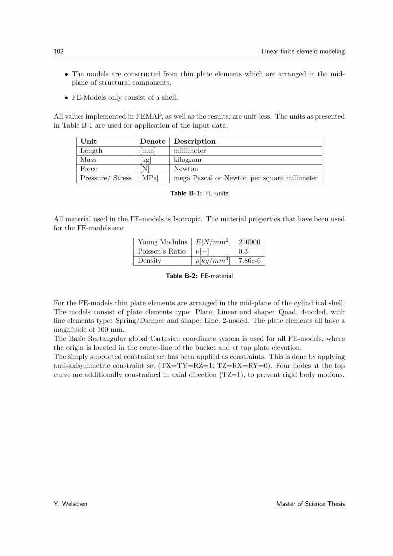
102 Linear finite element modeling
• The models are constructed from thin plate elements which are arranged in the mid-plane of structural components.
• FE-Models only consist of a shell.
All values implemented in FEMAP, as well as the results, are unit-less. The units as presentedin Table B-1 are used for application of the input data.
Unit Denote DescriptionLength [mm] millimeterMass [kg] kilogramForce [N] NewtonPressure/ Stress [MPa] mega Pascal or Newton per square millimeter
Table B-1: FE-units
All material used in the FE-models is Isotropic. The material properties that have been usedfor the FE-models are:
Young Modulus E[N/mm2] 210000Poisson’s Ratio ν[−] 0.3Density ρ[kg/mm3] 7.86e-6
Table B-2: FE-material
For the FE-models thin plate elements are arranged in the mid-plane of the cylindrical shell.The models consist of plate elements type: Plate, Linear and shape: Quad, 4-noded, withline elements type: Spring/Damper and shape: Line, 2-noded. The plate elements all have amagnitude of 100 mm.The Basic Rectangular global Cartesian coordinate system is used for all FE-models, wherethe origin is located in the center-line of the bucket and at top plate elevation.The simply supported constraint set has been applied as constraints. This is done by applyinganti-axisymmetric constraint set (TX=TY=RZ=1; TZ=RX=RY=0). Four nodes at the topcurve are additionally constrained in axial direction (TZ=1), to prevent rigid body motions.
Y. Welschen Master of Science Thesis

B-3 Difference in results between including and excluding of top load 103
B-3 Difference in results between including and excluding of topload
Figure B-2: Critical lateral buckling pressure for thin-walled cylindrical shell with pinned-pinnedboundary conditions modeled in FEMAP
Figure B-3: Critical lateral buckling pressure for thin-walled cylindrical shell with pinned-freeboundary conditions modeled in FEMAP
Master of Science Thesis Y. Welschen

104 Linear finite element modeling
B-4 FE models for different penetration depths in sand
Figure B-4: All FE models for different penetration depths in sand
Y. Welschen Master of Science Thesis
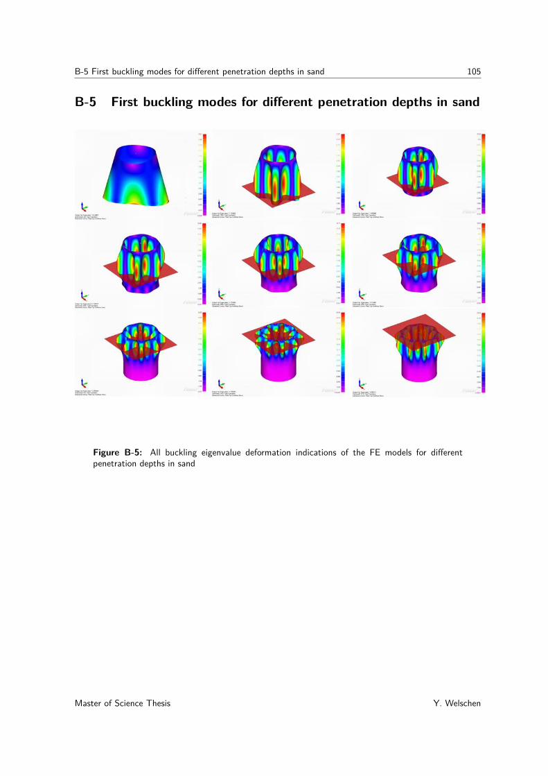
B-5 First buckling modes for different penetration depths in sand 105
B-5 First buckling modes for different penetration depths in sand
Figure B-5: All buckling eigenvalue deformation indications of the FE models for differentpenetration depths in sand
Master of Science Thesis Y. Welschen
106 Linear finite element modeling
Y. Welschen Master of Science Thesis

Bibliography
[1] S. Madsen, L. Andersen, and L. Ibsen, “Numerical buckling analysis of large suctioncaissons for wind turbines on deep water,” Engineering Structures, vol. 57, pp. 443–452,Dec. 2013.
[2] A. Czyzewski, “Wind energy gets serial.”
[3] CEN, “Eurocode 3 - Design of steel structures - Part 1-6: Strength and Stability of ShellStructures,” vol. 6, no. 2007, 2009.
[4] G. L. Se, “Rules for Classification and Construction Materials and Welding,” tech. rep.,2009.
[5] Det Norske Veritas (DNV), “DNV-OS-C401 Fabrication and Testing of Offshore Struc-tures,” no. October, 2013.
[6] Det Norske Veritas (DNV), “DNV-RP-C202 Buckling Strength of Shells,” no. January,2013.
[7] CUR, “Damwandconstructies 1,” vol. 1, no. 6.
[8] J. M. Gere and S. P. Timoshenko, Mechanics of materials. 1990.
[9] S. P. Timoshenko, Theory of elastic stability. 1961.
[10] International Association for Classification Societies(IACS), “Recommandation No.47:Shipbuilding and Repair Quality Standard,” no. 1996, 2013.
[11] SPT Offshore, “www.sptoffshore.com.”
[12] S. Kay, “Suction Foundations,” no. July, 2012.
[13] D. Colliard and R. Wallerand, “Design and installation of suction piles in west africadeepwaters,” 2008.
[14] F. V. Keulen, “Advanced Mechanics Part : Continuum Mechanics,” 2015.
Master of Science Thesis Y. Welschen

108 Bibliography
[15] C. L. Bakmar, “The Monopod Bucket Foundation Recent Experience and ChallengesAhead,” no. May, 2009.
[16] P. K. Das, A. Thavalingam, S. Hauch, and Y. Bai, “A new look into the buckling andultimate strength criteria of stiffened shells for reliability analysis,” pp. 1–8, 2001.
[17] K. Lesny, Foundations for Offshore Wind Turbines. 2010.
[18] CEN, “BS EN 1993-1-5:2006 - Eurocode 3: Design of steel structures - Part 1-5: Generalrules - Plated structural elements,” Eurocode 3, vol. 5, no. 2006, 2006.
[19] Eurocode 3, “NEN-EN 1993-1-1,” 2003.
[20] CEN, “BS EN 1990:2002 - Eurocode 0 - Basis of structural design,” Eurocode 0, vol. 1990,no. 2002, 2002.
[21] R. Burcher and L. Rydill, “Concepts in Submarine design,” 1994.
[22] Det Norske Veritas (DNV), “Design of Offshore Steel Structures , General ( Lrfd Method),” no. April, 2011.
[23] American Bureau of Shipping (ABS), “Buckling and Ultimate Strength Assessment forOffshore Structures,” vol. 2004, no. February, 2005.
[24] A. Verruijt, “Grondmechanica,” 1993.
[25] R. Romp, “Installation-effects of suction caissons in non-standard soil conditions,”no. October, 2013.
[26] T. Tjelta, T. R. Guttormsen, N. Geotechnical lnst, and J. Hermstad, “Large-Scale Pen-etration Test at a Deepwater Site,” 1986.
[27] G. T. Houlsby and B. W. Byrne, “Design Procedures for Installation of Suction Caissonsin clay and other soils,”
[28] G. T. Houlsby and B. W. Byrne, “Design procedures for installation of suction caissons insand,” Proceedings of the ICE - Geotechnical Engineering, vol. 158, no. July, pp. 135–144,2005.
[29] Det Norske Veritas(DNV), “CN 30.4 Foundations,” 1992.
[30] “API RP 2A WSD 21st edition,” 2000.
[31] Det Norske Veritas (DNV), “Geotechnical design and installation of suction anchors inclay,” 2005.
[32] A. F. Liu, Mechanics and Mechanisms of Fracture: An Introduction.
[33] CEN, “BS-EN 10025_Hot rolled products of structural steels_11_2004.”
[34] F. Dwight, Windenburg, and C. Trilling, “Collapse by Instability of Thin CylindricalShells Under External Pressure,” pp. 819–825, 1935.
Y. Welschen Master of Science Thesis

109
[35] K. Yuan-hung, W. Bo-siou, and M. International, “Suction Pile Allowable Suction Pres-sure Envelopes Based on Soil Failure and Structural Buckling,” 2015.
[36] R. Pinna, “Buckling of suction caissons during installation,” 2003.
[37] T. Vodenitcharova and P. Ansourian, “Buckling of circular cylindrical shells subject touniform lateral pressure,” Engineering Structures, vol. 18, no. 8, pp. 604–614, 1996.
[38] FEMAP 11.0, “FEMAP 11.0.”
Master of Science Thesis Y. Welschen
110 Bibliography
Y. Welschen Master of Science Thesis